JP2021532864A - Centrifugal drive expansion of intravascular pumps without inducers and impeller blades and / or expandable and foldable impeller enclosures - Google Patents
Centrifugal drive expansion of intravascular pumps without inducers and impeller blades and / or expandable and foldable impeller enclosuresDownload PDFInfo
- Publication number
- JP2021532864A JP2021532864AJP2021504749AJP2021504749AJP2021532864AJP 2021532864 AJP2021532864 AJP 2021532864AJP 2021504749 AJP2021504749 AJP 2021504749AJP 2021504749 AJP2021504749 AJP 2021504749AJP 2021532864 AJP2021532864 AJP 2021532864A
- Authority
- JP
- Japan
- Prior art keywords
- impeller
- blood pump
- pump assembly
- blade
- assembly according
- Prior art date
- Legal status (The legal status is an assumption and is not a legal conclusion. Google has not performed a legal analysis and makes no representation as to the accuracy of the status listed.)
- Ceased
Links
Images


Classifications
- A—HUMAN NECESSITIES
- A61—MEDICAL OR VETERINARY SCIENCE; HYGIENE
- A61M—DEVICES FOR INTRODUCING MEDIA INTO, OR ONTO, THE BODY; DEVICES FOR TRANSDUCING BODY MEDIA OR FOR TAKING MEDIA FROM THE BODY; DEVICES FOR PRODUCING OR ENDING SLEEP OR STUPOR
- A61M60/00—Blood pumps; Devices for mechanical circulatory actuation; Balloon pumps for circulatory assistance
- A61M60/10—Location thereof with respect to the patient's body
- A61M60/122—Implantable pumps or pumping devices, i.e. the blood being pumped inside the patient's body
- A61M60/126—Implantable pumps or pumping devices, i.e. the blood being pumped inside the patient's body implantable via, into, inside, in line, branching on, or around a blood vessel
- A61M60/148—Implantable pumps or pumping devices, i.e. the blood being pumped inside the patient's body implantable via, into, inside, in line, branching on, or around a blood vessel in line with a blood vessel using resection or like techniques, e.g. permanent endovascular heart assist devices
- A—HUMAN NECESSITIES
- A61—MEDICAL OR VETERINARY SCIENCE; HYGIENE
- A61M—DEVICES FOR INTRODUCING MEDIA INTO, OR ONTO, THE BODY; DEVICES FOR TRANSDUCING BODY MEDIA OR FOR TAKING MEDIA FROM THE BODY; DEVICES FOR PRODUCING OR ENDING SLEEP OR STUPOR
- A61M60/00—Blood pumps; Devices for mechanical circulatory actuation; Balloon pumps for circulatory assistance
- A61M60/10—Location thereof with respect to the patient's body
- A61M60/122—Implantable pumps or pumping devices, i.e. the blood being pumped inside the patient's body
- A61M60/126—Implantable pumps or pumping devices, i.e. the blood being pumped inside the patient's body implantable via, into, inside, in line, branching on, or around a blood vessel
- A61M60/13—Implantable pumps or pumping devices, i.e. the blood being pumped inside the patient's body implantable via, into, inside, in line, branching on, or around a blood vessel by means of a catheter allowing explantation, e.g. catheter pumps temporarily introduced via the vascular system
- A—HUMAN NECESSITIES
- A61—MEDICAL OR VETERINARY SCIENCE; HYGIENE
- A61M—DEVICES FOR INTRODUCING MEDIA INTO, OR ONTO, THE BODY; DEVICES FOR TRANSDUCING BODY MEDIA OR FOR TAKING MEDIA FROM THE BODY; DEVICES FOR PRODUCING OR ENDING SLEEP OR STUPOR
- A61M60/00—Blood pumps; Devices for mechanical circulatory actuation; Balloon pumps for circulatory assistance
- A61M60/20—Type thereof
- A61M60/205—Non-positive displacement blood pumps
- A61M60/216—Non-positive displacement blood pumps including a rotating member acting on the blood, e.g. impeller
- A—HUMAN NECESSITIES
- A61—MEDICAL OR VETERINARY SCIENCE; HYGIENE
- A61M—DEVICES FOR INTRODUCING MEDIA INTO, OR ONTO, THE BODY; DEVICES FOR TRANSDUCING BODY MEDIA OR FOR TAKING MEDIA FROM THE BODY; DEVICES FOR PRODUCING OR ENDING SLEEP OR STUPOR
- A61M60/00—Blood pumps; Devices for mechanical circulatory actuation; Balloon pumps for circulatory assistance
- A61M60/40—Details relating to driving
- A61M60/403—Details relating to driving for non-positive displacement blood pumps
- A61M60/408—Details relating to driving for non-positive displacement blood pumps the force acting on the blood contacting member being mechanical, e.g. transmitted by a shaft or cable
- A61M60/411—Details relating to driving for non-positive displacement blood pumps the force acting on the blood contacting member being mechanical, e.g. transmitted by a shaft or cable generated by an electromotor
- A—HUMAN NECESSITIES
- A61—MEDICAL OR VETERINARY SCIENCE; HYGIENE
- A61M—DEVICES FOR INTRODUCING MEDIA INTO, OR ONTO, THE BODY; DEVICES FOR TRANSDUCING BODY MEDIA OR FOR TAKING MEDIA FROM THE BODY; DEVICES FOR PRODUCING OR ENDING SLEEP OR STUPOR
- A61M60/00—Blood pumps; Devices for mechanical circulatory actuation; Balloon pumps for circulatory assistance
- A61M60/50—Details relating to control
- A61M60/508—Electronic control means, e.g. for feedback regulation
- A61M60/538—Regulation using real-time blood pump operational parameter data, e.g. motor current
- A61M60/546—Regulation using real-time blood pump operational parameter data, e.g. motor current of blood flow, e.g. by adapting rotor speed
- A—HUMAN NECESSITIES
- A61—MEDICAL OR VETERINARY SCIENCE; HYGIENE
- A61M—DEVICES FOR INTRODUCING MEDIA INTO, OR ONTO, THE BODY; DEVICES FOR TRANSDUCING BODY MEDIA OR FOR TAKING MEDIA FROM THE BODY; DEVICES FOR PRODUCING OR ENDING SLEEP OR STUPOR
- A61M60/00—Blood pumps; Devices for mechanical circulatory actuation; Balloon pumps for circulatory assistance
- A61M60/50—Details relating to control
- A61M60/508—Electronic control means, e.g. for feedback regulation
- A61M60/538—Regulation using real-time blood pump operational parameter data, e.g. motor current
- A61M60/554—Regulation using real-time blood pump operational parameter data, e.g. motor current of blood pressure
- A—HUMAN NECESSITIES
- A61—MEDICAL OR VETERINARY SCIENCE; HYGIENE
- A61M—DEVICES FOR INTRODUCING MEDIA INTO, OR ONTO, THE BODY; DEVICES FOR TRANSDUCING BODY MEDIA OR FOR TAKING MEDIA FROM THE BODY; DEVICES FOR PRODUCING OR ENDING SLEEP OR STUPOR
- A61M60/00—Blood pumps; Devices for mechanical circulatory actuation; Balloon pumps for circulatory assistance
- A61M60/80—Constructional details other than related to driving
- A61M60/802—Constructional details other than related to driving of non-positive displacement blood pumps
- A61M60/804—Impellers
- A61M60/806—Vanes or blades
- A61M60/808—Vanes or blades specially adapted for deformable impellers, e.g. expandable impellers
- A—HUMAN NECESSITIES
- A61—MEDICAL OR VETERINARY SCIENCE; HYGIENE
- A61M—DEVICES FOR INTRODUCING MEDIA INTO, OR ONTO, THE BODY; DEVICES FOR TRANSDUCING BODY MEDIA OR FOR TAKING MEDIA FROM THE BODY; DEVICES FOR PRODUCING OR ENDING SLEEP OR STUPOR
- A61M2205/00—General characteristics of the apparatus
- A61M2205/33—Controlling, regulating or measuring
- A61M2205/3365—Rotational speed
Landscapes
- Health & Medical Sciences (AREA)
- Heart & Thoracic Surgery (AREA)
- Engineering & Computer Science (AREA)
- Cardiology (AREA)
- Life Sciences & Earth Sciences (AREA)
- Mechanical Engineering (AREA)
- Anesthesiology (AREA)
- Biomedical Technology (AREA)
- Hematology (AREA)
- Animal Behavior & Ethology (AREA)
- General Health & Medical Sciences (AREA)
- Public Health (AREA)
- Veterinary Medicine (AREA)
- Vascular Medicine (AREA)
- External Artificial Organs (AREA)
Abstract
Translated fromJapaneseDescription
Translated fromJapanese 関連出願の相互参照
本出願は、2019年7月29日に出願された「インデューサを有さない血管内ポンプならびにインペラブレードおよび/または拡張かつ折畳み可能なインペラ筐体の遠心力駆動拡張(IINTRAVASCULAR PUMP WITHOUT INDUCER AND CENTRIFUGAL FORCE-DRIVEN EXPANSION OF IMPELLER BLADES AND/OR EXPANDABLE AND COLLAPSIBLE IMPELLER HOUSING)」と題された米国非仮特許出願第16/524554号の優先権を主張し、さらに、2018年7月30日に出願された「遠心力駆動拡張を伴う血管内ポンプ(INTRAVASCULAR PUMP WITH CENTRIFUGAL FORCE-DRIVEN EXPANSION)」と題された米国仮特許出願第62/711,740号の優先権を主張する。当該各出願の内容全体はここに引用により援用される。Mutual reference to related applications This application is filed on July 29, 2019, "IINTRAVAS CULAR for intravascular pumps without inducers and impeller blades and / or for expandable and foldable impeller enclosures. PUMP WITHOUT INDUCER AND CENTRIFUGAL FORCE-DRIVEN EXPANSION OF IMPELLER BLADES AND / OR EXPANDABLE AND COLLAPSIBLE IMPELLER HOUSING) " Claims the priority of US provisional patent application No. 62/711,740 entitled "INTRAVASCULAR PUMP WITH CENTRIFUGAL FORCE-DRIVEN EXPANSION" filed on the 1st. The entire content of each such application is incorporated herein by reference.
連邦政府資金による研究開発の記載
該当なしFederally funded R & D description Not applicable
発明の背景
発明の分野
本発明は、拡張かつ折畳み可能な入口領域を有する血管内血液ポンプに関する。Background of the Invention The Field of the Invention The present invention relates to an intravascular blood pump having an expandable and foldable inlet region.
関連技術の説明
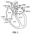
図1を参照すると、ヒトの心臓は、4つの部屋と、心臓を通過する順方向(順行性)の血流を補助する4つの心臓弁とを含む。部屋は、左心房、左心室、右心房および右心室を含む。4つの心臓弁は、僧帽弁、三尖弁、大動脈弁および肺動脈弁を含む。Description of Related Techniques With reference to FIG. 1, the human heart contains four chambers and four heart valves that aid in antegrade blood flow through the heart. Rooms include left atrium, left ventricle, right atrium and right ventricle. The four heart valves include the mitral valve, tricuspid valve, aortic valve and pulmonary valve.
僧帽弁は、左心房と左心室との間に位置し、左心房への逆流を防ぐために一方通行の弁としての機能を果たすことによって、左心房から左心室への血流を制御するのを助ける。同様に、三尖弁は、右心房と右心室との間に位置する一方で、大動脈弁および肺動脈弁は、心臓から離れるように血液を流す動脈内に位置する半月弁である。これらの弁はすべて、順方向(順行性)の血流を可能にするように開口した尖頭を有する一方通行の弁である。通常は機能している弁尖頭は、逆方向の血液によって加えられる圧力を受けて閉じて、血液の逆流(逆行)を防止する。 The mitral valve, located between the left atrium and the left ventricle, controls blood flow from the left atrium to the left ventricle by acting as a one-way valve to prevent regurgitation into the left atrium. To help. Similarly, the tricuspid valve is located between the right atrium and the right ventricle, while the aortic and pulmonary valves are semilunar valves located within the arteries that allow blood to flow away from the heart. All of these valves are one-way valves with cusps that are open to allow antegrade blood flow. The normally functioning valve leaflet closes under the pressure applied by the blood in the opposite direction, preventing blood reflux (retrograde).
そのため、図示するように、通常の血流は体から戻る脱酸素化血液を含み、そこで血流は上大静脈および下大静脈を介して右心房によって受け取られ、次に右心室に送り込まれるが、これは三尖弁によって制御されるプロセスである。右心室は、脱酸素化血液を肺動脈を介して肺に送るように機能し、そこで血液は再酸素化され、肺静脈を介して左心房に戻される。 Thus, as shown, normal blood flow includes deoxidized blood returning from the body, where blood flow is received by the right atrium via the superior and inferior vena cava and then delivered to the right ventricle. , This is a process controlled by the tricuspid valve. The right ventricle functions to send deoxidized blood through the pulmonary arteries to the lungs, where the blood is reoxygenated and returned to the left atrium via the pulmonary veins.
心臓疾患は、死亡率が高い健康問題である。手術中に短期間の緊急の支援を提供するため、または、患者が危機を乗り切るのを助けるように一時的なつなぎの支援として、一時的な機械式血液ポンプ装置がますます頻繁に用いられている。これらの一時的な血液ポンプは、数年にわたって開発され進化して、心臓のポンプ作用を短期的に補い左心室または右心室補助装置として血流を補っており、左心室補助装置(「LVAD」)が現在最も一般に使用されている装置である。 Heart disease is a health problem with a high mortality rate. Temporary mechanical blood pumping devices are increasingly being used to provide short-term emergency assistance during surgery or as temporary tethering assistance to help patients survive the crisis. There is. These temporary blood pumps have been developed and evolved over the years to supplement the pumping action of the heart in the short term and to supplement blood flow as a left or right ventricular assist device, the left ventricular assist device (“LVAD”). ) Is currently the most commonly used device.
公知の一時的なLVAD装置は通常、経皮的に、たとえば大腿動脈を通って送達されて、装置の本体が大動脈弁にまたがって配設されている状態で、患者の左心室にLVAD入口を、および、患者の上行大動脈に出口を設けるまたは位置決めする。当業者であれば理解するように、患者の大腿動脈へのアクセスを可能にするために、患者の鼠径部下方に切れ目を入れてもよい。医師であれば、上行大動脈に到達するまで大腿動脈および下行大動脈を通ってガイドワイヤを平行移動させ、その後カテーテルまたは送達シースを平行移動させるであろう。その後、回転ドライブシャフトが取付けられたLVADを、送達カテーテルまたはシースルーメンを通って平行移動させて、ドライブシャフトの近位端を患者の外側で露出させ、電気モータなどの原動機、またはドライブシャフトおよび関連するLVADインペラを回転させそれらの回転速度を制御するための等価物と連結されたままにすることが可能である。 Known transient LVAD devices are usually delivered percutaneously, eg, through the femoral artery, with the LVAD entrance into the patient's left ventricle with the body of the device located across the aortic valve. , And an exit is provided or positioned in the patient's ascending aorta. As one of ordinary skill in the art will understand, a cut may be made below the patient's groin to allow access to the patient's femoral artery. The physician would translate the guidewire through the femoral and descending aortas until they reach the ascending aorta, and then translate the catheter or delivery sheath. The LVAD fitted with a rotary drive shaft is then translated through a delivery catheter or see-through men to expose the proximal end of the drive shaft outside the patient, a prime mover such as an electric motor, or the drive shaft and related. It is possible to rotate the LVAD impellers to keep them coupled with equivalents to control their rotational speed.
一時的な軸流血液ポンプは一般に、(1)ポンプのインペラと接続された装置に一体化されたモータによって動力が供給されるポンプ(米国特許第5,147,388号および第5,275,580号を参照)、ならびに(2)ポンプのインペラに接続されたドライブシャフトに回転トルクを供給する外部モータによって動力が供給されるポンプ(本明細書においてその全体が援用によって引用される、Wamplerの米国特許第4,625,712号およびSummersの米国特許第5,112,349号を参照)の2種類からなる。 Temporary axial blood pumps are generally (1) pumps powered by a motor integrated into a device connected to the impeller of the pump (US Pat. Nos. 5,147,388 and 5,275). (See No. 580), as well as (2) a pump powered by an external motor that supplies rotational torque to the drive shaft connected to the impeller of the pump (indicated herein by reference in its entirety, Wampler's. It consists of two types (see US Pat. No. 4,625,712 and Summers' US Pat. No. 5,112,349).
LVADおよびRVAD(右心補助装置)を含む公知の一時的な心室補助装置(「VAD」)は通常、一体化モータを有しているものであろうと外部モータを有しているものであろうと、流入端部から流出端部への順番で列挙される、筐体内に搭載された以下の要素を含む。これらの要素は、流入アパーチャ(複数可)、技術において流入アパーチャまたは入口からインペラへ流れを向ける構成要素として知られる流れインデューサ、回転インペラ、ならびに、技術において回転インペラによって生成される回転流れを軸方向流れにまっすぐにするように機能するまたは方向を変えると知られている流れディフューザおよび/または流出構造、ならびに例示的な従来技術のポンプおよび/またはインペラアセンブリの図2の断面切断図に示される流出アパーチャ(複数可)である。 Known temporary ventricular assist devices (“VAD”), including LVADs and RVADs (right heart assist devices), typically have an integrated motor or an external motor. , Includes the following elements mounted within the enclosure, listed in order from the inflow end to the outflow end. These elements are centered around the inflow aperture (s), the flow inducer known in technology as the inflow aperture or the component that directs the flow from the inlet to the impeller, the rotary impeller, and the rotary flow generated by the rotary impeller in technology. A flow diffuser and / or outflow structure known to function or divert to straighten a directional flow, as well as an exemplary prior art pump and / or impeller assembly shown in FIG. 2 cross-cutting diagram. Outflow aperture (s).
図2では、心室において流入する血流が流入アパーチャ(複数可)(図示せず)を通って装置筐体に入り、周囲の筐体14によって画成されたものを通過して流れ、最終的にインペラ/ポンプアセンブリ4に入るように、公知の装置2が流入端(遠位端)が図面の左側にあり流出端(近位)が右側にある状態で向けられている。そこで、流入する血液は、回転するインペラ8によって前方に付勢される前に、流れインデューサ6に向かい合う。その後血流は、流れディフューザ9によって変更されることがあり、流出して筐体の流出アパーチャ(複数可)10を介して大動脈内に流入する。 In FIG. 2, the inflowing blood flow in the ventricle enters the device housing through the inflow aperture (s) (not shown), passes through what is defined by the surrounding
公知のVADまたはLVAD装置はさらに、送達構成および機能または動作構成を備え、とりわけ送達シースを通る非外傷性の送達を容易にするために、送達構成は機能または動作構成よりも薄く直径が小さい。別の言い方をすれば、さまざまな手段によって、VADもしくはLVADの筐体、および/またはインペラのブレードは、機能または動作構成を実現するために拡張されてもよく、送達構成を実現するために折畳まれてもよい。しかしながら、公知の装置はインペラブレードおよび/または筐体の折畳みならびに拡張を行い、拡張されたまたは動作している構成の間の移動を可能にし、および/またはインペラに近接する一体化モータを必要とするために、折畳みかつ拡張可能な筐体が、インペラの少なくとも一部を取囲む。たとえば、米国特許第7,027,875号、第7,927,068号、および第8,992,163号を参照。 Known VAD or LVAD devices further comprise a delivery configuration and a functional or operational configuration, the delivery configuration being thinner and smaller in diameter than the functional or operational configuration, particularly to facilitate non-traumatic delivery through the delivery sheath. In other words, by various means, the VAD or LVAD enclosure and / or the blades of the impeller may be extended to achieve a functional or operational configuration and may be folded to achieve a delivery configuration. It may be folded. However, known devices require an integrated motor that folds and expands the impeller blades and / or housing, allows movement between expanded or operating configurations, and / or is close to the impeller. A foldable and expandable housing surrounds at least a portion of the impeller. See, for example, US Pat. Nos. 7,027,875, 7,927,068, and 8,992,163.
公知のLVAD装置は典型的には、大動脈弓を収容するために角度の付いた筐体を備え、その角度または湾曲は一般に135°の範囲である。 Known LVAD devices typically include an angled enclosure to accommodate the aortic arch, the angle or curvature of which is generally in the range of 135 °.
筐体内に一体化モータを有するLVAD装置は、非外傷性の血管内の平行移動および心臓内での位置決めを可能にするために十分小さいものでなければならない。装置の一部を折畳むためにさまざまな手段が知られているが、筐体および/またはインペラもしくはブレードなどの部品を含むカテーテルまたは送達シース内で、折畳まれた装置のサイズは一体化モータによって制限される場合がある。 The LVAD device with an integrated motor within the enclosure must be small enough to allow translational movement within non-traumatic blood vessels and positioning within the heart. Various means are known for folding parts of the device, but within a catheter or delivery sheath containing parts such as the housing and / or impeller or blade, the size of the folded device is determined by an integrated motor. May be restricted.
さらに、公知のLVAD装置は送達構成を含み、この構成では、筐体および/またはインペラ、たとえばインペラ上のブレードの直径が小さくなる場合があり、送達カテーテルまたはシースから遠位方向に送達されると、折畳まれた要素が拡張可能になる。これらの装置は、いくつかの点で制限がある。第一に、折畳みおよび拡張は、インペラが占める筐体の少なくとも一部を含む。第二に、筐体の流入領域、すなわち、回転歯車および固定インデューサまたは整流器に対して遠位方向の領域は、カニューレまたは筐体を通って血流を最適化するチャンスの領域を含む。公知のLVADまたはVAD装置は、このチャンスを利用しない。第三に、公知のLVADまたはVAD装置は、ポンプ内へ流入すると血液に向かい合う固定インデューサまたは整流器を含むが、これは、とりわけ血栓症および/または溶血の一因となり得る。第4に、VADまたはLVAD装置の断面輪郭を小さくすることは、本明細書で説明する理由、装置の筐体にわたってまたはこれに沿って導線を延在する必要があるためさらに困難になる設計上の要求から重要であり、導線は、たとえば、モータもしくはセンサ(複数可)もしくは他の動作動力要素で動力を供給するおよび/またはこれと通信するために用いられ得る。これに関連して、導線は断面輪郭、ならびに、隣接する導線間の絶縁および/もしくは間隔をそのような絶縁および/もしくは間隔が必要であるまたは所望される場合に可能な限り低く保つために、輪郭を小さくする必要がある。 In addition, known LVAD devices include a delivery configuration in which the diameter of the blade on the housing and / or impeller, eg, the impeller, may be reduced and delivered distally from the delivery catheter or sheath. , Folded elements become expandable. These devices have some limitations. First, folding and expansion include at least part of the housing occupied by the impeller. Second, the inflow region of the enclosure, i.e., the region distal to the rotary gear and the fixed inducer or rectifier, includes the region of opportunity to optimize blood flow through the cannula or enclosure. Known LVAD or VAD devices do not take advantage of this opportunity. Third, known LVAD or VAD devices include a fixed inducer or rectifier that faces the blood as it flows into the pump, which can contribute specifically to thrombosis and / or hemolysis. Fourth, reducing the cross-sectional contour of a VAD or LVAD device becomes even more difficult due to the reasons described herein, the need to extend leads across or along the housing of the device. Important from the requirements of, the leads can be used, for example, to power and / or communicate with a motor or sensor (s) or other operating power element. In this regard, the conductors shall keep the cross-sectional contour as well as the insulation and / or spacing between adjacent conductors as low as possible if such insulation and / or spacing is required or desired. The contour needs to be small.
本発明のさまざまな実施形態が特にこれらの問題に取り組んでいる。
図面および以下の詳細な説明は、発明のこれらおよび他の実施形態をより詳細に例示する。Various embodiments of the invention address these issues in particular.
The drawings and the following detailed description illustrate these and other embodiments of the invention in more detail.
発明の詳細な説明
本発明のさまざまな実施形態は一般に、患者において血液をポンプで送込むための機械的な補助装置に向けられる。経皮的かつ経脈管的に送達される、改良された一時的なLVADまたはVAD血液ポンプについて本明細書で説明する。Detailed Description of the Invention Various embodiments of the invention are generally directed to mechanical assistive devices for pumping blood in a patient. An improved transient LVAD or VAD blood pump delivered percutaneously and transvascularly is described herein.
図3を参照すると、例示的なLVAD血液ポンプ100が図示され、図の左側に流入口12が位置し、装置の右側に流出口10が位置する。モータは、患者の体の外側の装置の近位端に設けられ、かつ、回転ドライブシャフトと接続されると図示されており、回転ドライブシャフトは、インペラまたはロータ8またはポンプアセンブリと接続される。しかしながら、技術においてよく知られているように、モータは、装置自体の筐体内に設けられてもよく、モータはロータ8またはインペラまたはポンプアセンブリの近位側に搭載されることが典型的である。これらの構成のいずれも、本明細書で説明するような本発明のさまざまな実施形態と共に用いることが可能である。 Referring to FIG. 3, an exemplary
外側筐体14の全長は、入口または流入アパーチャ12から出口または流出アパーチャ10まで、比較的一定の直径を含むと図示されている。ガイドワイヤ16が、入口アパーチャ12に到達するまで装置の外面に沿って位置し、入口アパーチャ12において、カニューレCのルーメンに入り、図示するようにそこから遠位方向に延在する。ガイドワイヤ16はそのため、インペラまたはロータ8またはポンプアセンブリを通過しない。図3に示す構成は、導入部または送達シースまたはカテーテル200内で圧縮された拡張可能な領域102を有する送達構成を含み得る。 The overall length of the
概して図面を参照すると、装置100は、インペラまたはロータまたはポンプアセンブリを取囲む筐体の直径が送達中または回転中に変化しないように、インペラまたはロータまたはポンプアセンブリに対して遠位方向に位置する場合もある拡張可能な領域102を含み得る。別の言い方をすると、拡張不能な近位領域122を設けてもよく、拡張不能な近位領域122は少なくとも、インペラまたはロータまたはポンプアセンブリを含み、このアセンブリを取囲む筐体は、感知できるほどに拡張または収縮しないが弾性でもよい。さらに、拡張不能な遠位領域124が、少なくとも入口アパーチャ12を含む入口領域を少なくとも含んで設けられてもよい。拡張可能な領域102はそのため、近位端と遠位端とを含む。拡張可能な領域102の近位端は拡張不能な近位領域122の遠位端に当接する、またはこれに隣接する一方で、拡張可能な領域102の遠位端は、拡張不能な遠位領域124の近位端に当接する、またはこれに隣接する。しかしながら、拡張不能な領域(複数可)122、124を取囲む筐体Hは弾性でも柔軟でもよいが、これらは付勢されて拡張するように配設されない。 Generally referring to the drawings,
代替的に、図3の装置100の筐体Hは拡張不能でもよい。
図4は装置100の拡張可能な実施形態を示し、折畳まれ変形した拡張可能な領域への/からの例示的な拡張した変形していない拡張可能な領域への直径の変化を破線で示し、この拡張可能な領域は、インペラ、ロータおよび/またはポンプアセンブリの端に対して遠位方向の地点から中空のカニューレに沿って、入口アパーチャにまさに近位する点まで遠位方向に延在する。拡張可能な領域102は、12〜20Fr、より好ましくは16〜20Frの範囲の変形していない最大直径に拡張し得る。これとは対照的に、拡張されていない領域は、9〜12Frの範囲の実質的に固定された直径にとどまる。Alternatively, the housing H of the
FIG. 4 shows an expandable embodiment of the
続けて図3および図4ならびに残りの図を参照すると、装置100は通常、拡張構成に部分的にまたは完全に付勢され得る拡張可能な領域102を含んでもよく、そのため、拡張を容易にし付勢されて拡張可能な材料または構造を含む。拡張可能な領域102の例示的な構成は、外側材料、たとえば、技術において知られているような下地支持構造の拡張に対応するプラスチックもしくはポリマー材料で構成された外装または被覆またはスリーブで取り囲まれた支持構造130を含み得る。支持構造130は、形状記憶材料、たとえばニチノールまたはこれと類似の材料で形成されてもよい。他の材料は、金、タンタル、ステンレス鋼、金属合金、航空宇宙合金、ならびに/または比較的熱および冷気にさらされると拡張し収縮するポリマーを含むポリマーを含み得る。他の場合、拡張可能な領域102の少なくとも一部、たとえば以下で説明する拡張可能な中央部分104は、ポリマーのスリーブ、または拡張および折畳みを可能にするならびに/または拡張および折畳みに対応するように構成された他の材料のスリーブを含んでもよく、支持構造130は省略されてもよい。図4は、インペラアセンブリと接続され、患者の体の外部に位置する電気モータなどの原動機と接続された回転ドライブシャフトを示す。しかしながら、本明細書で説明する本発明のさまざまな実施形態は、その内部で一体化されたモータを含む、すなわち、外部モータを含まない血液ポンプと組合わせて用いてもよい。上述のように、装置100はさらに、拡張可能な筐体Hもしくは領域102を含んでもよい、または、拡張不能でもよい。 With reference to FIGS. 3 and 4 and the rest of the figure, the
本明細書で説明される実施形態の多くでは、拡張可能な領域102は、近位移行部分、拡張可能な中央部分および/または遠位移行部分との間で区別する必要または理由はなく、1つの拡張可能な領域を含み得る。 In many of the embodiments described herein, there is no need or reason for the
本発明の拡張可能な領域102は通常、拡張可能な領域102の拡張および折畳みに適合するポリマー被覆または外装によって取囲まれた支持構造130を含み得る。 The
さらに、支持構造130は、相互作用するおよび/もしくは相互接続されたワイヤならびに/または支柱で形成された一連のセルで形成され、構造の折畳みおよび付勢された拡張を可能にする拡張可能なステント状の構造、たとえば、技術において知られているようなステントを含み得る。たとえば、本明細書においてその全体が援用によって引用される、Kanesakaの米国特許出願第5,776,183号、Pinchukの米国特許出願第5,019,090号、Towerの米国特許出願第5,161,547号、Savinの米国特許出願第4,950,227号、Fontaineの米国特許出願第5,314,472号、Wiktorの米国特許出願第4,886,062号および第4,969,458号、ならびにHillsteadの米国特許出願第4,856,516号を参照。 In addition, the
本明細書で説明する拡張可能な領域102は例示にすぎず、いかなる点でも制限的なものではない。そのため、血液ポンプ装置100のどのような拡張可能な筐体Hも、血液ポンプ筐体内でまたはこれに沿って、導線もしくは導体Eの絶縁および/または間隔および/または輪郭の減少または一体化に関する本発明のさまざまな実施形態に容易に適合可能である。拡張可能な領域102は、拡張および折畳みが可能な1つの領域も含み得る。 The
ここで図5を参照すると、例示定なポンプアセンブリまたはインペラアセンブリ200が示される。 Here, with reference to FIG. 5, an exemplary pump assembly or
まず、流れインデューサ6と流れディフューザ9とを含む図2に示す公知のインペラアセンブリと対照的に、図5の例示的なポンプまたはインペラアセンブリでは、公知のポンプで見られるインペラアセンブリの流れインデューサ6と流れディフューザ9とが完全に取り除かれている。流入する血流の効果的な制御または操作にインデューサ6および/またはディフューザ9が必要でない用途、ならびに、少なくともインデューサ6と回転インペラ8の遠位端との間の付加的な固定表面積および相互接続によって血栓症のリスクが増加する用途が見られる。そのため、流れインデューサの助けを借りずに、またはこれを必要とせずに、ポンプまたはインペラアセンブリを作動させて所定の速度で回転させることによって、血液がカニューレを通って流れるようにする。それによって、流れディフューザまたは整流装置の助けを借りずに、またはこれを必要とせずに、インペラブレード11を回転させることによって、血液がブレード11を含む回転インペラ8に直接流れ、出口アパーチャ10において装置のカニューレまたはルーメンから出るようにする。 First, in contrast to the known impeller assembly shown in FIG. 2, which includes a flow inducer 6 and a flow diffuser 9, in the exemplary pump or impeller assembly of FIG. 5, the flow inducer of the impeller assembly found in known pumps. 6 and the flow diffuser 9 have been completely removed. Applications that do not require the inducer 6 and / or diffuser 9 for effective control or operation of inflowing blood flow, as well as additional fixed surface area and mutual at least between the inducer 6 and the distal end of the
ここで図6Aおよび図6Bを参照すると、血液ポンプ装置300の他の実施形態は、図示するように遠心力駆動拡張機構を含む。図6Aは折畳まれた送達構成を示す一方で、図6Bは拡張された動作構成のポンプアセンブリ領域を示す。 Here, with reference to FIGS. 6A and 6B, another embodiment of the
そのため、インペラ筐体Hは、技術において知られる上述のような拡張可能なステントフレームを含み得る。インペラ筐体Hはそれゆえ、送達および後退中に、折畳まれた送達構成と拡張された動作構成との間で移動可能である。装置300は、インペラ筐体Hを図6Aの折畳まれた送達/後退構成にするシース(図示されないが、技術において公知である)を通って送達可能である。装置300が送達シースのルーメンの遠位端の外側に延在する場合、拡張するように付勢され得るインペラ筐体Hは、送達シースルーメンの締付けから解放されると、図6Bの拡張された動作構成を実現し得る。インペラ筐体Hは、装置筐体を送達シースルーメン内まで後退させることによって、折畳まれた送達構成に戻されてもよい。 As such, the impeller enclosure H may include an expandable stent frame as described above known in the art. The impeller enclosure H is therefore movable between the folded delivery configuration and the extended operating configuration during delivery and retreat. The
折畳みかつ拡張可能なインペラ筐体Hの構成と組み合わせて、インペラに取付けられたブレードも折畳まれた構成と拡張された動作構成との間で移動して、送達および後退中に関連するインペラ8およびブレード11を有するインペラ筐体Hの外径をさらに減少させ得る。 In combination with the configuration of the foldable and expandable impeller enclosure H, the blades attached to the impeller also move between the folded configuration and the expanded operating configuration, and the
そのため、単にブレード(複数可)11に対して遠心力を生成するのに十分な速度でインペラを回転させて、ブレード(複数可)11を後退した状態から図6Bに示すような延在または拡張した状態まで移動させることによって、図6Aの後退したブレードを開いてもよい。流体流動力がこの遷移を補助し得る間、ブレード(複数可)11は、遠心力のみによって拡張するように、すなわち、ブレード(複数可)11は本実施形態では、拡張に際して補助する流体力の必要または助けがない状態で、真空で動作構成に拡張または延在するように構成され得る。 Therefore, simply rotate the impeller at a speed sufficient to generate centrifugal force with respect to the blade (s) 11 and extend or extend the blade (s) 11 from the retracted state as shown in FIG. 6B. The retracted blade of FIG. 6A may be opened by moving it to the desired state. While the fluid flow force can assist in this transition, the blade (s) 11 expands only by centrifugal force, i.e. the blade (s) 11 in this embodiment of the fluid force assists in expansion. It can be configured to extend or extend to a working configuration in a vacuum without the need or help.
例示的なインペラ筐体11は、これらの機構によって、14fr〜9frの例示的な範囲で遷移し得る。 The
そのため、上述のように、インペラ筐体11は自己拡張し得る、たとえば、ステント状フレームまたは他の形状記憶材料でもよい。ブレード(複数可)11は、開くと/拡張すると延在または拡張位置に係止するように適合されてもよいため、ブレード(複数可)11が折畳まれる場合に係止力を超える力を必要とする。他の実施形態では、ブレード(複数可)11は、付勢された後退位置または付勢された拡張位置を呈し得る。 Therefore, as described above, the
図示された実施形態では、インペラ筐体Hと、筐体H、インペラ8およびブレード(複数可)11を含む関連アセンブリとを送達シースルーメン内まで遠位方向に後退させることによって、ブレード(複数可)11は、インペラ筐体Hの後退と同時におよび実質的に同じ態様で後退し、それによって、インペラハブ(図5を参照)に対してブレード(複数可)11を折畳ませるだけでなく筐体Hも折畳ませて、折畳まれた送達/後退構成を実現し得る。 In the illustrated embodiment, the blades (s) are retracted distally into the delivery see-through men with the impeller housing H and the associated assembly including the housing H, the
いくつかの実施形態では、径方向外側に押す外部に向かう力をインペラ筐体Hに対して生成する、ドライブシャフトの回転とそれによって生じるインペラアセンブリ11の回転とによって、インペラ筐体Hは拡張されても、および/または折畳まれてもよく、インペラ筐体Hは折畳み構成から拡張構成まで移動する。この拡張された地点で、インペラ筐体Hは、係止機構を用いて拡張構成に保持されてもよい、または、ブレード(複数可)11の回転から生じる径方向外側に向かう流体力が生成されることによって拡張構成に保持されてもよい。 In some embodiments, the impeller housing H is extended by the rotation of the drive shaft and the resulting rotation of the
いくつかの実施形態では、インペラは、まず、インペラ筐体Hの近位後退ゾーンまたは後退ゾーンまで遠位方向に引っ張られてもよく、その後、インペラ筐体Hおよびインペラブレード(複数可)11が折畳み構成まで後退する送達シースのルーメン内に、変更されたアセンブリが遠位方向に押込まれても後退されてもよい。 In some embodiments, the impeller may first be pulled distally to the proximal or retracted zone of the impeller enclosure H, followed by the impeller enclosure H and the impeller blades (s) 11. The modified assembly may be pushed or retracted distally into the lumen of the delivery sheath that retracts to the folded configuration.
他の実施形態では、インペラ8の回転を逆にすることは、延在した/拡張したブレード(複数可)11を折畳まれた位置に移動させるのに役立ち、いくつかの実施形態では、拡張したブレード(複数可)11を送達シース内に後退させることによってブレード(複数可)11の折畳みが完了可能になるように、係止された拡張ブレード(複数可)11が解除される。 In other embodiments, reversing the rotation of the
場合によっては、ブレード(複数可)11は折畳まれるように付勢されてもよく、閾値インペラ8の回転速度が、拡張された動作構成に達するようにブレード(複数可)11の付勢された折畳みを超えるのに十分な遠心力を生成するために必要である。インペラ8の回転速度を拡張/折畳み閾値よりも遅くすることによって、ブレード(複数可)11は、インペラハブに対して折畳まれる。 In some cases, the blade (s) 11 may be urged to fold, and the blade (s) 11 may be urged so that the rotational speed of the
さらに、ブレード(複数可)11に対する付勢折畳み力とインペラ8の可変回転速度との組合わせは、動作中に、インペラ11に沿って、ブレード(複数可)11のピッチ、たとえばインペラハブに対するブレード(複数可)11の角度を変更するために用いられ得る。ブレード(複数可)11を拡張させ始めるのに最低閾値拡張回転速度を必要とし得る一方で、ブレード(複数可)11を完全に拡張するのにより早い回転速度を必要とし得る。そのため、最低閾値拡張回転速度と完全拡張回転速度との間の回転速度が、効果的に無限の可能な大きさのインペラハブに対してブレードピッチを生成するために用いられてもよく、それによって、オペレータはこれによって生じる可変ブレードピッチと回転速度との組合わせを用いて、より効果的に目標血流量および/または圧力を実現し得る。 Further, the combination of the urging folding force with respect to the blade (s) 11 and the variable rotational speed of the
図7〜図9は、上述した機構によってインペラハブの外側に拡張可能な、またはインペラハブ内に少なくとも部分的に折畳み可能な、拡張可能なブレード(複数可)11を含むインペラ8の実施形態のさらに別の開示を以下に示す。インペラ筐体Hは図7〜図9に示されていないが、これらの実施形態は、インペラ筐体Hを含むがこれに限定されない前述の開示に従って機能する。 7-9 are still another embodiment of the
本明細書で説明したすべての場合において、インペラ8の回転速度は、最低閾値拡張回転速度より速い場合、拡張が完全になる回転速度まで、ブレード(複数可)11によって実現される拡張の度合いに比例し、ブレード(複数可)11は、拡張位置に「係止」され得る、または本明細書で説明したような回転速度に従ってインペラハブ内に/外へ自由に移動し得る。そのため、回転速度が最低閾値拡張回転速度と完全拡張回転速度との間の場合、拡張の度合いは、インペラ8の回転速度を調整することによって変更可能である。 In all cases described herein, the rotational speed of the
さらに、本明細書で説明したように、インペラ筐体Hの拡張および収縮は、ブレード(複数可)11の拡張および後退があってもなくても行われ得る。ブレード(複数可)11の後退および拡張の実施形態がない状態で行われる場合、折畳み構成のインペラ筐体Hは、ブレード(複数可)11の径方向に測定された直径に制限される。ブレード(複数可)11の後退および拡張の実施形態がある状態で行われる場合、折畳み可能な直径をインペラハブの径方向直径によって制限することが可能である。 Further, as described herein, expansion and contraction of the impeller enclosure H may occur with or without expansion and retreat of the blade (s) 11. The impeller housing H in the folded configuration is limited to the diameter measured in the radial direction of the blade (s) 11 when performed without the retracted and expanded embodiments of the blade (s) 11. When the retracting and expanding embodiments of the blade (s) 11 are performed in a certain state, the foldable diameter can be limited by the radial diameter of the impeller hub.
本発明の説明および本明細書の上述の説明は、例示的なものであり、本発明の範囲を限定するように意図されたものではない。さまざまな実施形態の特徴を、本発明の意図する範囲内で他の実施形態と組み合わせることが可能である。本明細書を研究することにより、本明細書で開示された実施形態の変形形態および修正形態が可能となり、実施形態のさまざまな要素の実用的な代替物および同等物が、当業者によって理解されるであろう。本明細書で開示される実施形態のこれらおよび他の変形形態ならびに修正形態は、本発明の範囲および精神の範囲内で可能である。 The description of the present invention and the above description herein are exemplary and are not intended to limit the scope of the invention. It is possible to combine the features of various embodiments with other embodiments within the scope of the invention. By studying the present specification, variations and modifications of the embodiments disclosed herein are possible, and practical alternatives and equivalents of the various elements of the embodiments will be understood by those of skill in the art. Will be. These and other variants and modifications of the embodiments disclosed herein are possible within the scope and spirit of the invention.
Claims (25)
Translated fromJapaneseインペラ筐体と、前記筐体内に動作可能に配設されたインペラと、インペラハブにおいて前記インペラに動作可能に取付けられた少なくとも1つのブレードとを含む血液ポンプを備え、
前記インペラ筐体および前記少なくとも1つのブレードは各々、折畳みまたは後退位置と拡張位置との間で移動するように適合され、
前記ブレードの前記拡張構成への拡張は、前記少なくとも1つのブレードを前記後退位置から拡張させる大きさの遠心力を生成するのに十分な回転速度で、動作可能に接続されたモータで前記インペラを回転させることによって実現される、血液ポンプアセンブリ。It ’s a blood pump assembly.
A blood pump comprising an impeller enclosure, an impeller operably disposed within the enclosure, and at least one blade operably attached to the impeller at the impeller hub.
The impeller housing and the at least one blade are each adapted to move between a folded or retracted position and an extended position.
Extension of the blades to the expansion configuration is to operably connect the impeller with a motor connected at a rotational speed sufficient to generate a centrifugal force large enough to expand the at least one blade from the retracted position. A blood pump assembly realized by rotating.
Applications Claiming Priority (5)
| Application Number | Priority Date | Filing Date | Title |
|---|---|---|---|
| US201862711740P | 2018-07-30 | 2018-07-30 | |
| US62/711,740 | 2018-07-30 | ||
| US16/524,554US11541224B2 (en) | 2018-07-30 | 2019-07-29 | Intravascular pump without inducer and centrifugal force-driven expansion of impeller blades and/or expandable and collapsible impeller housing |
| US16/524,554 | 2019-07-29 | ||
| PCT/US2019/044053WO2020028312A1 (en) | 2018-07-30 | 2019-07-30 | Intravascular pump without inducer and centrifugal force-driven expansion of impeller blades and/or expandable and collapsible impeller housing |
Publications (1)
| Publication Number | Publication Date |
|---|---|
| JP2021532864Atrue JP2021532864A (en) | 2021-12-02 |
Family
ID=69179469
Family Applications (1)
| Application Number | Title | Priority Date | Filing Date |
|---|---|---|---|
| JP2021504749ACeasedJP2021532864A (en) | 2018-07-30 | 2019-07-30 | Centrifugal drive expansion of intravascular pumps without inducers and impeller blades and / or expandable and foldable impeller enclosures |
Country Status (5)
| Country | Link |
|---|---|
| US (2) | US11541224B2 (en) |
| EP (1) | EP3829673A4 (en) |
| JP (1) | JP2021532864A (en) |
| CN (1) | CN112399867A (en) |
| WO (1) | WO2020028312A1 (en) |
Cited By (1)
| Publication number | Priority date | Publication date | Assignee | Title |
|---|---|---|---|---|
| JP2024545345A (en)* | 2021-12-21 | 2024-12-05 | ファインハート | Intraventricular heart pump with narrow head |
Families Citing this family (31)
| Publication number | Priority date | Publication date | Assignee | Title |
|---|---|---|---|---|
| US12029647B2 (en) | 2017-03-07 | 2024-07-09 | 4C Medical Technologies, Inc. | Systems, methods and devices for prosthetic heart valve with single valve leaflet |
| DE102018201030B4 (en) | 2018-01-24 | 2025-10-16 | Kardion Gmbh | Magnetic dome element with magnetic bearing function |
| DE102018207611A1 (en) | 2018-05-16 | 2019-11-21 | Kardion Gmbh | Rotor bearing system |
| DE102018207575A1 (en) | 2018-05-16 | 2019-11-21 | Kardion Gmbh | Magnetic face turning coupling for the transmission of torques |
| DE102018208538A1 (en) | 2018-05-30 | 2019-12-05 | Kardion Gmbh | Intravascular blood pump and process for the production of electrical conductors |
| DE102018208550A1 (en) | 2018-05-30 | 2019-12-05 | Kardion Gmbh | A lead device for directing blood flow to a cardiac assist system, cardiac assist system, and method of making a lead device |
| DE102018208541A1 (en) | 2018-05-30 | 2019-12-05 | Kardion Gmbh | Axial pump for a cardiac assist system and method of making an axial pump for a cardiac assist system |
| DE102018208539A1 (en) | 2018-05-30 | 2019-12-05 | Kardion Gmbh | A motor housing module for sealing an engine compartment of a motor of a cardiac assist system and cardiac assistance system and method for mounting a cardiac assist system |
| US20190365538A1 (en)* | 2018-06-04 | 2019-12-05 | 4C Medical Technologies, Inc. | Devices, systems and methods for preventing prolapse of native cardiac valve leaflets |
| DE102018210076A1 (en) | 2018-06-21 | 2019-12-24 | Kardion Gmbh | Method and device for detecting a state of wear of a cardiac support system, method and device for operating a cardiac support system and cardiac support system |
| DE102018210058A1 (en) | 2018-06-21 | 2019-12-24 | Kardion Gmbh | Stator blade device for guiding the flow of a fluid flowing out of an outlet opening of a heart support system, heart support system with stator blade device, method for operating a stator blade device and manufacturing method |
| DE102018211327A1 (en) | 2018-07-10 | 2020-01-16 | Kardion Gmbh | Impeller for an implantable vascular support system |
| DE102018212153A1 (en) | 2018-07-20 | 2020-01-23 | Kardion Gmbh | Inlet line for a pump unit of a cardiac support system, cardiac support system and method for producing an inlet line for a pump unit of a cardiac support system |
| US11541224B2 (en)* | 2018-07-30 | 2023-01-03 | Cardiovascular Systems, Inc. | Intravascular pump without inducer and centrifugal force-driven expansion of impeller blades and/or expandable and collapsible impeller housing |
| CN112654389A (en) | 2018-08-07 | 2021-04-13 | 开迪恩有限公司 | Bearing device for a cardiac support system and method for flushing an intermediate space in a bearing device for a cardiac support system |
| US11857441B2 (en) | 2018-09-04 | 2024-01-02 | 4C Medical Technologies, Inc. | Stent loading device |
| US11452628B2 (en) | 2019-04-15 | 2022-09-27 | 4C Medical Technologies, Inc. | Loading systems for collapsible prosthetic heart valve devices and methods thereof |
| US11931253B2 (en) | 2020-01-31 | 2024-03-19 | 4C Medical Technologies, Inc. | Prosthetic heart valve delivery system: ball-slide attachment |
| US12133797B2 (en) | 2020-01-31 | 2024-11-05 | 4C Medical Technologies, Inc. | Prosthetic heart valve delivery system: paddle attachment feature |
| DE102020102474A1 (en) | 2020-01-31 | 2021-08-05 | Kardion Gmbh | Pump for conveying a fluid and method for manufacturing a pump |
| US12053375B2 (en) | 2020-03-05 | 2024-08-06 | 4C Medical Technologies, Inc. | Prosthetic mitral valve with improved atrial and/or annular apposition and paravalvular leakage mitigation |
| US11992403B2 (en) | 2020-03-06 | 2024-05-28 | 4C Medical Technologies, Inc. | Devices, systems and methods for improving recapture of prosthetic heart valve device with stent frame having valve support with inwardly stent cells |
| EP3884969A1 (en)* | 2020-03-27 | 2021-09-29 | Abiomed Europe GmbH | Blood pump |
| EP4210809A1 (en)* | 2020-09-14 | 2023-07-19 | Kardion GmbH | Cardiovascular support pump having an impeller with a variable flow area |
| US20230405298A1 (en)* | 2020-10-08 | 2023-12-21 | Shifamed Holdings, Llc | Intravascular blood pumps and methods of use |
| CN115474950A (en)* | 2021-06-15 | 2022-12-16 | 浙江迪远医疗器械有限公司 | Blood pump capable of preventing blood coagulation |
| WO2023283751A1 (en)* | 2021-07-12 | 2023-01-19 | 苏州心擎医疗技术有限公司 | Device for assisting heart in event of heart failure |
| CN114949584A (en)* | 2022-02-25 | 2022-08-30 | 浙江迪远医疗器械有限公司 | Blood pump |
| CN116870356A (en)* | 2023-06-28 | 2023-10-13 | 安徽通灵仿生科技有限公司 | Catheter pump assembly and control system thereof |
| CN116999688B (en)* | 2023-08-07 | 2024-05-14 | 安徽通灵仿生科技有限公司 | Impeller and right ventricle auxiliary device thereof |
| CN119327031B (en)* | 2024-10-28 | 2025-10-03 | 同济大学 | Left ventricular assist device |
Citations (7)
| Publication number | Priority date | Publication date | Assignee | Title |
|---|---|---|---|---|
| JPS5985234U (en)* | 1982-11-27 | 1984-06-08 | 株式会社メテク | Drainage tube fixture |
| JPH0644738U (en)* | 1992-11-24 | 1994-06-14 | 稔 北川 | Hose sandwiched water container |
| US6003819A (en)* | 1997-12-30 | 1999-12-21 | Hall; Carl L. | Pivoting and telecoping hose support |
| JP2011120713A (en)* | 2009-12-10 | 2011-06-23 | Jms Co Ltd | Connection structure |
| JP2014050509A (en)* | 2012-09-06 | 2014-03-20 | Clean Chemical Kk | Priming drainage treatment tablet for artificial dialysis apparatus and priming method using the same |
| JP2017048881A (en)* | 2015-09-03 | 2017-03-09 | アズビル株式会社 | Wiring holding structure |
| JP2019013371A (en)* | 2017-07-05 | 2019-01-31 | 東レ・メディカル株式会社 | Drainage funnel |
Family Cites Families (40)
| Publication number | Priority date | Publication date | Assignee | Title |
|---|---|---|---|---|
| US4919647A (en) | 1988-10-13 | 1990-04-24 | Kensey Nash Corporation | Aortically located blood pumping catheter and method of use |
| SE501215C2 (en) | 1992-09-02 | 1994-12-12 | Oeyvind Reitan | catheter Pump |
| US5527159A (en) | 1993-11-10 | 1996-06-18 | The United States Of America As Represented By The Administrator Of The National Aeronautics And Space Administration | Rotary blood pump |
| DE29804046U1 (en) | 1998-03-07 | 1998-04-30 | Günther, Rolf W., Prof. Dr.med., 52074 Aachen | Percutaneously implantable, self-expanding axial pump for temporary heart support |
| US6245007B1 (en) | 1999-01-28 | 2001-06-12 | Terumo Cardiovascular Systems Corporation | Blood pump |
| JP3063140U (en) | 1999-04-16 | 1999-10-19 | 伯亮 楊 | Cooling fan blades |
| DE10059714C1 (en) | 2000-12-01 | 2002-05-08 | Impella Cardiotech Ag | Intravasal pump has pump stage fitted with flexible expandible sleeve contricted during insertion through blood vessel |
| AU2003236497A1 (en) | 2002-06-11 | 2003-12-22 | Walid Aboul-Hosn | Expandable blood pump and related methods |
| US7393181B2 (en) | 2004-09-17 | 2008-07-01 | The Penn State Research Foundation | Expandable impeller pump |
| DE102004054714A1 (en) | 2004-11-12 | 2006-05-24 | Impella Cardiosystems Gmbh | Foldable intravascular insertable blood pump |
| CN102380135A (en) | 2006-03-23 | 2012-03-21 | 宾州研究基金会 | Heart assist device with expandable impeller pump |
| US9028392B2 (en) | 2006-12-01 | 2015-05-12 | NuCardia, Inc. | Medical device |
| KR100976496B1 (en) | 2007-03-20 | 2010-08-18 | 엘지전자 주식회사 | Fan |
| US8079948B2 (en) | 2007-08-29 | 2011-12-20 | NuCardia, Inc. | Article comprising an impeller |
| US8439859B2 (en) | 2007-10-08 | 2013-05-14 | Ais Gmbh Aachen Innovative Solutions | Catheter device |
| US8489190B2 (en) | 2007-10-08 | 2013-07-16 | Ais Gmbh Aachen Innovative Solutions | Catheter device |
| EP2194278A1 (en)* | 2008-12-05 | 2010-06-09 | ECP Entwicklungsgesellschaft mbH | Fluid pump with a rotor |
| CN102481398A (en)* | 2009-07-01 | 2012-05-30 | 宾夕法尼亚州研究基金会 | Blood pump with expandable cannula |
| EP2298373A1 (en) | 2009-09-22 | 2011-03-23 | ECP Entwicklungsgesellschaft mbH | Fluid pump with at least one turbine blade and a seating device |
| FR2954453B1 (en) | 2009-12-23 | 2012-03-09 | Vallourec Mannesmann Oil & Gas | ASSEMBLY FOR CARRYING OUT A THREADED SEAL, METHOD FOR SCREWING AND DISCRIMINATING SUCH A SEAL AND USE OF SUCH JOINT IN AN UNDERWATER UPLINK |
| EP2338540A1 (en) | 2009-12-23 | 2011-06-29 | ECP Entwicklungsgesellschaft mbH | Delivery blade for a compressible rotor |
| EP2338541A1 (en) | 2009-12-23 | 2011-06-29 | ECP Entwicklungsgesellschaft mbH | Radial compressible and expandable rotor for a fluid pump |
| EP2399639A1 (en)* | 2010-06-25 | 2011-12-28 | ECP Entwicklungsgesellschaft mbH | System for introducing a pump |
| EP2407186A1 (en) | 2010-07-15 | 2012-01-18 | ECP Entwicklungsgesellschaft mbH | Rotor for a pump, produced with an initial elastic material |
| WO2012094641A2 (en) | 2011-01-06 | 2012-07-12 | Thoratec Corporation | Percutaneous heart pump |
| US20120209375A1 (en) | 2011-02-11 | 2012-08-16 | Gilbert Madrid | Stability device for use with percutaneous delivery systems |
| US9327067B2 (en)* | 2012-05-14 | 2016-05-03 | Thoratec Corporation | Impeller for catheter pump |
| US8721517B2 (en) | 2012-05-14 | 2014-05-13 | Thoratec Corporation | Impeller for catheter pump |
| US9872947B2 (en) | 2012-05-14 | 2018-01-23 | Tc1 Llc | Sheath system for catheter pump |
| US9421311B2 (en) | 2012-07-03 | 2016-08-23 | Thoratec Corporation | Motor assembly for catheter pump |
| US9358329B2 (en) | 2012-07-03 | 2016-06-07 | Thoratec Corporation | Catheter pump |
| EP2692369B1 (en) | 2012-07-31 | 2015-04-15 | Rheinisch-Westfälische Technische Hochschule Aachen | Axial flow blood pump device |
| US11077294B2 (en) | 2013-03-13 | 2021-08-03 | Tc1 Llc | Sheath assembly for catheter pump |
| EP2868331B1 (en) | 2013-11-01 | 2016-07-13 | ECP Entwicklungsgesellschaft mbH | Pump, in particular blood pump |
| US9770543B2 (en) | 2015-01-22 | 2017-09-26 | Tc1 Llc | Reduced rotational mass motor assembly for catheter pump |
| US10350341B2 (en) | 2015-03-20 | 2019-07-16 | Drexel University | Impellers, blood pumps, and methods of treating a subject |
| WO2016185473A1 (en) | 2015-05-18 | 2016-11-24 | Magenta Medical Ltd. | Blood pump |
| US10918773B2 (en) | 2018-03-26 | 2021-02-16 | Tci Llc | Collapsible and self-expanding cannula for a percutaneous heart pump and method of manufacturing |
| EP3784305B1 (en) | 2018-04-24 | 2024-01-10 | Tc1 Llc | Percutaneous heart pump transitionable between separated and operational configurations |
| US11541224B2 (en)* | 2018-07-30 | 2023-01-03 | Cardiovascular Systems, Inc. | Intravascular pump without inducer and centrifugal force-driven expansion of impeller blades and/or expandable and collapsible impeller housing |
- 2019
- 2019-07-29USUS16/524,554patent/US11541224B2/enactiveActive
- 2019-07-30JPJP2021504749Apatent/JP2021532864A/ennot_activeCeased
- 2019-07-30WOPCT/US2019/044053patent/WO2020028312A1/ennot_activeCeased
- 2019-07-30CNCN201980045216.0Apatent/CN112399867A/enactivePending
- 2019-07-30EPEP19845091.8Apatent/EP3829673A4/ennot_activeWithdrawn
- 2022
- 2022-12-01USUS18/073,153patent/US12171993B2/enactiveActive
Patent Citations (7)
| Publication number | Priority date | Publication date | Assignee | Title |
|---|---|---|---|---|
| JPS5985234U (en)* | 1982-11-27 | 1984-06-08 | 株式会社メテク | Drainage tube fixture |
| JPH0644738U (en)* | 1992-11-24 | 1994-06-14 | 稔 北川 | Hose sandwiched water container |
| US6003819A (en)* | 1997-12-30 | 1999-12-21 | Hall; Carl L. | Pivoting and telecoping hose support |
| JP2011120713A (en)* | 2009-12-10 | 2011-06-23 | Jms Co Ltd | Connection structure |
| JP2014050509A (en)* | 2012-09-06 | 2014-03-20 | Clean Chemical Kk | Priming drainage treatment tablet for artificial dialysis apparatus and priming method using the same |
| JP2017048881A (en)* | 2015-09-03 | 2017-03-09 | アズビル株式会社 | Wiring holding structure |
| JP2019013371A (en)* | 2017-07-05 | 2019-01-31 | 東レ・メディカル株式会社 | Drainage funnel |
Cited By (2)
| Publication number | Priority date | Publication date | Assignee | Title |
|---|---|---|---|---|
| JP2024545345A (en)* | 2021-12-21 | 2024-12-05 | ファインハート | Intraventricular heart pump with narrow head |
| JP7752248B2 (en) | 2021-12-21 | 2025-10-09 | ファインハート | Intraventricular heart pump with narrow head |
Also Published As
| Publication number | Publication date |
|---|---|
| EP3829673A1 (en) | 2021-06-09 |
| US12171993B2 (en) | 2024-12-24 |
| CN112399867A (en) | 2021-02-23 |
| US11541224B2 (en) | 2023-01-03 |
| EP3829673A4 (en) | 2022-04-20 |
| WO2020028312A1 (en) | 2020-02-06 |
| US20200030507A1 (en) | 2020-01-30 |
| US20230091425A1 (en) | 2023-03-23 |
Similar Documents
| Publication | Publication Date | Title |
|---|---|---|
| US12171993B2 (en) | Intravascular blood pump with external motor and centrifugal force-driven expansion of impeller blades and/or expandable and collapsible impeller housing | |
| JP7047184B2 (en) | Intravascular pump with proximal and distal pressure or flow sensors as well as distal sensor tracking | |
| CN112004565B (en) | Intravascular pump with expandable region | |
| US11202900B2 (en) | Intravascular pump with controls and display screen on handle | |
| JP7052143B2 (en) | Intravascular pumps with dilated and foldable entrance areas and methods thereof | |
| JP7073530B2 (en) | Intravascular pump with expandable distal area | |
| US10729833B2 (en) | Intravascular pump with expandable region at least partially collapsible into recesses defined between impeller blades | |
| US11141580B2 (en) | Intravascular blood pump system with integrated conductor(s) in housing and methods thereof | |
| JP2021522953A (en) | Intravascular pumps with integrated insulating conductors and methods thereof |
Legal Events
| Date | Code | Title | Description |
|---|---|---|---|
| A521 | Request for written amendment filed | Free format text:JAPANESE INTERMEDIATE CODE: A523 Effective date:20210202 | |
| A621 | Written request for application examination | Free format text:JAPANESE INTERMEDIATE CODE: A621 Effective date:20220228 | |
| A977 | Report on retrieval | Free format text:JAPANESE INTERMEDIATE CODE: A971007 Effective date:20230329 | |
| A131 | Notification of reasons for refusal | Free format text:JAPANESE INTERMEDIATE CODE: A131 Effective date:20230404 | |
| A521 | Request for written amendment filed | Free format text:JAPANESE INTERMEDIATE CODE: A523 Effective date:20230607 | |
| A01 | Written decision to grant a patent or to grant a registration (utility model) | Free format text:JAPANESE INTERMEDIATE CODE: A01 Effective date:20230926 | |
| A045 | Written measure of dismissal of application [lapsed due to lack of payment] | Free format text:JAPANESE INTERMEDIATE CODE: A045 Effective date:20240130 |