JP2021525505A - Electric motor - Google Patents
Electric motorDownload PDFInfo
- Publication number
- JP2021525505A JP2021525505AJP2021516542AJP2021516542AJP2021525505AJP 2021525505 AJP2021525505 AJP 2021525505AJP 2021516542 AJP2021516542 AJP 2021516542AJP 2021516542 AJP2021516542 AJP 2021516542AJP 2021525505 AJP2021525505 AJP 2021525505A
- Authority
- JP
- Japan
- Prior art keywords
- stator
- rotor
- output shaft
- traction
- electric motor
- Prior art date
- Legal status (The legal status is an assumption and is not a legal conclusion. Google has not performed a legal analysis and makes no representation as to the accuracy of the status listed.)
- Granted
Links
Images


Classifications
- H—ELECTRICITY
- H02—GENERATION; CONVERSION OR DISTRIBUTION OF ELECTRIC POWER
- H02K—DYNAMO-ELECTRIC MACHINES
- H02K41/00—Propulsion systems in which a rigid body is moved along a path due to dynamo-electric interaction between the body and a magnetic field travelling along the path
- H02K41/06—Rolling motors, i.e. motors having the rotor axis parallel to the stator axis and following a circular path as the rotor rolls around the inside or outside of the stator ; Nutating motors, i.e. having the rotor axis parallel to the stator axis inclined with respect to the stator axis and performing a nutational movement as the rotor rolls on the stator
- H02K41/065—Nutating motors
- H—ELECTRICITY
- H02—GENERATION; CONVERSION OR DISTRIBUTION OF ELECTRIC POWER
- H02K—DYNAMO-ELECTRIC MACHINES
- H02K41/00—Propulsion systems in which a rigid body is moved along a path due to dynamo-electric interaction between the body and a magnetic field travelling along the path
- H02K41/06—Rolling motors, i.e. motors having the rotor axis parallel to the stator axis and following a circular path as the rotor rolls around the inside or outside of the stator ; Nutating motors, i.e. having the rotor axis parallel to the stator axis inclined with respect to the stator axis and performing a nutational movement as the rotor rolls on the stator
- H—ELECTRICITY
- H02—GENERATION; CONVERSION OR DISTRIBUTION OF ELECTRIC POWER
- H02K—DYNAMO-ELECTRIC MACHINES
- H02K7/00—Arrangements for handling mechanical energy structurally associated with dynamo-electric machines, e.g. structural association with mechanical driving motors or auxiliary dynamo-electric machines
- H02K7/10—Structural association with clutches, brakes, gears, pulleys or mechanical starters
- H02K7/116—Structural association with clutches, brakes, gears, pulleys or mechanical starters with gears
- H—ELECTRICITY
- H02—GENERATION; CONVERSION OR DISTRIBUTION OF ELECTRIC POWER
- H02K—DYNAMO-ELECTRIC MACHINES
- H02K9/00—Arrangements for cooling or ventilating
- H02K9/19—Arrangements for cooling or ventilating for machines with closed casing and closed-circuit cooling using a liquid cooling medium, e.g. oil
- H02K9/193—Arrangements for cooling or ventilating for machines with closed casing and closed-circuit cooling using a liquid cooling medium, e.g. oil with provision for replenishing the cooling medium; with means for preventing leakage of the cooling medium
- H—ELECTRICITY
- H02—GENERATION; CONVERSION OR DISTRIBUTION OF ELECTRIC POWER
- H02K—DYNAMO-ELECTRIC MACHINES
- H02K7/00—Arrangements for handling mechanical energy structurally associated with dynamo-electric machines, e.g. structural association with mechanical driving motors or auxiliary dynamo-electric machines
- H02K7/003—Couplings; Details of shafts
Landscapes
- Engineering & Computer Science (AREA)
- Power Engineering (AREA)
- Physics & Mathematics (AREA)
- Chemical & Material Sciences (AREA)
- Combustion & Propulsion (AREA)
- Electromagnetism (AREA)
- Connection Of Motors, Electrical Generators, Mechanical Devices, And The Like (AREA)
- Valve Device For Special Equipments (AREA)
- Transition And Organic Metals Composition Catalysts For Addition Polymerization (AREA)
- Glass Compositions (AREA)
- Synchronous Machinery (AREA)
- Permanent Magnet Type Synchronous Machine (AREA)
Abstract
Translated fromJapaneseDescription
Translated fromJapanese技術分野
本発明は、電気モータと、そのようなモータの動作に関する。Technical Fields The present invention relates to electric motors and the operation of such motors.
背景
電気モータを特徴付け得る方法の1つは、そのトルク密度(すなわち、単位モータ体積で実現可能なトルク)によるものである。特に高いトルク密度が必要な多くの用途に関しては、油圧モータがより実用的であることが分かっており、これは、電気モータで高いトルク密度を実現することが困難であるからである。従来のモータは、電磁素子を備えるステータと、中心回転軸の周囲でステータに関して回転するロータを有する。ステータ及び/又はロータは電気的に作動されて接線方向の磁力を生成し、それがトルクを発生させる。接線方向の力に加えて、電気モータはステータとロータとの間に磁力の結果である法線力(半径方向圧力と呼ばれることもある)も生成し、これはその大きさにおいて接線方向の力より大きい。典型的なモータにおいて、半径方向圧力はロータ全体にわたって慎重にバランスがとられて、ステータとロータとの衝突が防止される。偏心動作で動くロータを使用することによって法線力の利用を試みている例もある。Background One of the methods that can characterize an electric motor is by its torque density (ie, the torque that can be achieved with a unit motor volume). Hydraulic motors have been found to be more practical, especially for many applications that require high torque densities, because it is difficult to achieve high torque densities with electric motors. A conventional motor has a stator with an electromagnetic element and a rotor that rotates about the stator around a central axis of rotation. The stator and / or rotor are electrically actuated to generate a tangential magnetic force, which produces torque. In addition to the tangential force, the electric motor also produces a normal force (sometimes called radial pressure) that is the result of the magnetic force between the stator and the rotor, which in its magnitude is a tangential force. Greater. In a typical motor, the radial pressure is carefully balanced throughout the rotor to prevent collisions between the stator and the rotor. There is also an example of trying to utilize the normal force by using a rotor that moves by eccentric movement.
少なくとも部分的に半径方向圧力を利用して、容認可能な程度にスムーズな動力伝達のトルクを発生させる新規なモータの設計が必要である。 There is a need to design new motors that utilize radial pressure, at least in part, to generate an acceptablely smooth power transmission torque.
概要
本発明の1つの態様は、回転軸を画定する出力シャフトと、出力シャフトに回転可能に連結されたロータと、揺動トラクション接合部によってロータに機械的に連結されたステータと、を有し、ステータに関するロータの揺動中にロータの傾斜軸が出力シャフトの回転軸の周囲で前進する電気モータを特徴とする。ロータとステータの表面は動的ギャップの境界を画定し、そこにモータの電気的作動により磁場が生成されて、ロータとステータとの間に力を生じさせる。トラクション接合部とギャップは、出力シャフトの回転軸を含む平面内で、トラクション接合部がギャップと接するステータ表面に関して斜めになるように配置される。Overview One aspect of the invention has an output shaft that defines a rotating shaft, a rotor that is rotatably connected to the output shaft, and a stator that is mechanically connected to the rotor by a swinging traction junction. It features an electric motor in which the tilt axis of the rotor advances around the rotation axis of the output shaft during the swing of the rotor with respect to the stator. The surface of the rotor and stator demarcates a dynamic gap in which a magnetic field is generated by the electrical operation of the motor, creating a force between the rotor and the stator. The traction joint and the gap are arranged in a plane including the rotation axis of the output shaft so that the traction joint is oblique with respect to the surface of the stator in contact with the gap.
幾つかの実施形態において、ロータは第一のロータであり、ステータは第一のステータであり、揺動トラクション接合部は第一の揺動トラクション接合部である。モータはまた、出力シャフトに回転可能に連結された第二のロータと、第二の揺動トラクション接合部によって第二のロータに機械的に連結された第二のステータと、を含み、第二のステータに関する第二のロータの揺動中に第二のロータの傾斜軸が前進して、出力シャフトの回転軸に関して円錐面を画定する。第二のロータと第二のステータの表面はギャップの境界を画定し、そこにモータの電気的作動によって磁場が生成されて、第二のロータと第二のステータとの間に力を生じさせる。 In some embodiments, the rotor is the first rotor, the stator is the first stator, and the rocking traction joint is the first rocking traction joint. The motor also includes a second rotor rotatably connected to the output shaft and a second stator mechanically connected to the second rotor by a second rocking traction joint. During the swing of the second rotor with respect to the stator of the second rotor, the tilt axis of the second rotor advances to define a conical surface with respect to the rotation axis of the output shaft. The surfaces of the second rotor and the second stator demarcate the gap, where a magnetic field is generated by the electrical operation of the motor, creating a force between the second rotor and the second stator. ..
幾つかの例において、第一及び第二のロータは出力シャフトに、モータの動作中、第一及び第二のロータ軸が出力シャフトの回転軸に関して反対方向に傾斜するように連結される。 In some examples, the first and second rotors are connected to the output shaft so that the first and second rotor shafts tilt in opposite directions with respect to the rotation axis of the output shaft during motor operation.
幾つかのケースにおいて、前進する第一の揺動トラクション接合部係合点は、前進する第二の揺動トラクション接合部係合点と第一のステータに関して回転整列する。 In some cases, the advancing first oscillating traction junction engagement point is rotationally aligned with the advancing second oscillating traction junction engagement point with respect to the first stator.
第一及び第二のロータは、第一及び第二の揺動トラクション接合部間に軸方向に配置されてよく、又は第一及び第二の揺動トラクション接合部は第一及び第二のロータ間に配置されてよい。 The first and second rotors may be arranged axially between the first and second rocking traction joints, or the first and second rocking traction joints may be the first and second rotors. It may be placed in between.
幾つかのモータにおいて、ロータは、相互に対して、及び出力シャフトの回転軸に対して垂直な2つの独立した傾斜軸を画定するジンバルによって出力シャフトに回転可能に連結される。 In some motors, the rotor is rotatably connected to the output shaft by a gimbal that defines two independent tilted axes that are perpendicular to each other and to the axis of rotation of the output shaft.
幾つかの例において、ステータ表面は円筒形である。このようなケースにおいて、ロータ表面は円錐台形であってよい。 In some examples, the stator surface is cylindrical. In such cases, the rotor surface may be conical trapezoidal.
多くの実施形態において、動的エアギャップは半径方向のエアギャップである。「半径方向の」エアギャップとは、ステータとロータとの間の、アクティブ磁束経路に沿ったエアギャップであって、ギャップを横切る最小抵抗の経路がロータの回転軸に関して軸方向又は接線方向より半径方向に向かうエアギャップを意味する。エアギャップは、それがロータの周囲の地点ごとに、及び時間と共に、ロータの揺動によってその寸法を変化させるという点で動的である。 In many embodiments, the dynamic air gap is a radial air gap. A "radial" air gap is the air gap between the stator and rotor along the active magnetic flux path, where the path of minimum resistance across the gap is more radial or tangential to the rotor's axis of rotation. It means an air gap in the direction. The air gap is dynamic in that it changes its dimensions by swinging the rotor from point to point around the rotor and over time.
幾つかの構成において、ステータは、それに関連する巻線を有するステータ磁極を有し、半径方向のエアギャップは半径方向にステータ磁極の内部にある。好ましくは、揺動中の何れの時点においても、トラクション接合部の最大トラクション係合点と最小動的エアギャップ地点が回転軸の反対側に配置される。 In some configurations, the stator has a stator pole with windings associated with it, with a radial air gap inside the stator pole in the radial direction. Preferably, the maximum traction engagement point and the minimum dynamic air gap point of the traction junction are located on opposite sides of the rotation axis at any time during the swing.
幾つかの他の構成において、ステータは、それに関連する巻線を有するステータ磁極を有し、半径方向のエアギャップは半径方向にステータ磁極の反駆動側にある。好ましくは、揺動中の何れの時点においても、トラクション接合部の最大トラクション係合点は、出力シャフトの、瞬間的な最小動的エアギャップ地点と同じ側に配置される。 In some other configurations, the stator has a stator pole with windings associated with it, and the radial air gap is radially opposite to the stator pole. Preferably, at any point during the swing, the maximum traction engagement point of the traction junction is located on the same side of the output shaft as the momentary minimum dynamic air gap point.
幾つかの実施形態において、トラクション接合部は、ステータの歯群と噛み合うロータの歯群を特徴とする。幾つかのケースにおいて、ロータの歯群はステータの歯群より多くの歯を含む。好ましくは、ロータの歯群とステータの歯群の歯の総数間には1本の差があり、揺動トラクション接合部が1回揺動すると、ステータに関するロータの回転位置は、歯1本分の円周方向のピッチだけ変化する。 In some embodiments, the traction junction is characterized by a rotor tooth group that meshes with the stator tooth group. In some cases, the rotor tooth group contains more teeth than the stator tooth group. Preferably, there is one difference between the total number of teeth in the rotor tooth group and the total number of teeth in the stator tooth group, and when the swing traction joint swings once, the rotation position of the rotor with respect to the stator is one tooth. Only the pitch in the circumferential direction of is changed.
幾つかのケースにおいて、トラクション接合部はまた、揺動中、ステータのテーパ状の停止面に当たって転動するように配置された、ロータのテーパ状エッジ面を特徴とする。 In some cases, the traction junction also features a tapered edge surface of the rotor that is arranged to roll against the tapered stop surface of the stator during rocking.
幾つかの構成において、ステータは、出力シャフトを受ける軸受けを支持するステータエンドキャップを含み、ステータエンドキャップはステータの歯を特徴とする。 In some configurations, the stator comprises a stator end cap that supports a bearing that receives the output shaft, and the stator end cap features the teeth of the stator.
幾つかの例において、トラクション接合部は、法線荷重を受けると反作用面と転動係合する弾性摩擦面を特徴とする。 In some examples, the traction joint is characterized by an elastic friction surface that rolls and engages with the reaction surface when subjected to a normal load.
幾つかの構成において、トラクション接合部は、半径方向に動的エアギャップの反駆動側にある。他の構成において、トラクション接合部は、半径方向に動的エアギャップの内部にある。 In some configurations, the traction junction is radially opposite to the dynamic air gap. In other configurations, the traction junction is radially inside the dynamic air gap.
幾つかの実施形態において、ステータは、ロータの周囲で円周方向に離間された、独立してアクティベート可能な複数の巻線を有する。巻線は、前進する揺動トラクション接合部係合点の前に連続的にアクティベートして、ロータの回転を起こさせる。モータはまた、ステータの巻線をアクティベートするように動作可能なスイッチ群を有する巻線コントローラも含んでいてよい。 In some embodiments, the stator has multiple windings that are circumferentially spaced around the rotor and can be activated independently. The windings are continuously activated in front of the forward swing traction joint engagement point to cause the rotor to rotate. The motor may also include a winding controller with a set of switches that can operate to activate the windings of the stator.
幾つかの構成において、ステータの複数の隣接する巻線は、巻線群として同時にアクティベート可能であり、ステータは、ステータの周囲に離間された複数のそのような巻線群を含む。 In some configurations, the plurality of adjacent windings of the stator can be activated simultaneously as a winding group, and the stator includes a plurality of such winding groups spaced around the stator.
幾つかの実施形態において、ステータは、ステータ巻線に関連付けられる、円周方向に離間された磁極を有する。磁極は、積層体の軸方向の積重ねにより形成されてよい。好ましくは、積層体は、すべてのステータ巻線を開いた後少なくとも1分間にわたり、ロータにおいて少なくとも100ガウスの残留磁極を有するように形成される。このような残留磁極は、例えば、ステータの無励磁化の後にロータ位置を保持するのを助けることができる。 In some embodiments, the stator has circumferentially spaced magnetic poles associated with the stator windings. The magnetic poles may be formed by stacking the laminated bodies in the axial direction. Preferably, the laminate is formed to have at least 100 gauss of residual poles in the rotor for at least 1 minute after opening all stator windings. Such residual magnetic poles can help hold the rotor position after, for example, the unexcited magnetization of the stator.
幾つかのケースにおいて、揺動トラクション接合部は、ロータをステータに関してステータ磁極のピッチとほぼ等しい距離だけ回転前進させるように構成される。 In some cases, the swing traction junction is configured to rotate the rotor forward with respect to the stator by a distance approximately equal to the pitch of the stator poles.
幾つかの実施形態において、トラクション接合部は、ステータの静止トラクション面と係合するロータのトラクション面を特徴とし、ステータのトラクション面はステータピッチ円錐を画定し、ステータピッチ円錐角は4〜40度である。幾つかのケースにおいて、ロータのトラクション面はロータピッチ円錐を画定し、ロータピッチ円錐角とステータピッチ円錐角との差は10度未満、好ましくは7.5度未満、より好ましくは5度未満である。 In some embodiments, the traction junction features a rotor traction surface that engages the stationary traction surface of the stator, the traction surface of the stator defines a stator pitch cone, and the stator pitch cone angle is 4-40 degrees. Is. In some cases, the traction surface of the rotor defines a rotor pitch cone, and the difference between the rotor pitch cone angle and the stator pitch cone angle is less than 10 degrees, preferably less than 7.5 degrees, more preferably less than 5 degrees. be.
幾つかの構成において、ロータは、ステータ内、例えばステータ磁極間に配置される。幾つか他のケースにおいて、ロータはステータの磁極の周囲に延びる。 In some configurations, the rotor is located within the stator, eg, between the stator poles. In some other cases, the rotor extends around the magnetic poles of the stator.
幾つかの例において、ロータは半径方向に延び、円周方向に離間される歯を有し、その遠位端面は動的エアギャップと接する。遠位端面は、ステータの磁極に向かって半径方向に外側を向くか、又はステータの磁極に向かって半径方向に内側を向いてもよい。 In some examples, the rotor extends radially and has teeth that are separated in the circumferential direction, the distal end face of which is in contact with the dynamic air gap. The distal end face may face outward radially toward the magnetic poles of the stator, or may face inward radially toward the magnetic poles of the stator.
幾つかのケースにおいて、ステータは、ステータの巻線に関連付けられる、円周方向に離間された磁極を有する。幾つかの例において、離間された歯の各々は、軸方向に離間された複数の歯突出部を特徴とし、各ステータ磁極は、軸方向に離間された複数の磁極突出部を特徴とする。好ましくは、歯突出部と磁極突出部は、最小動的エアギャップ地点において軸方向に整列される。 In some cases, the stator has circumferentially spaced magnetic poles associated with the windings of the stator. In some examples, each of the separated teeth is characterized by a plurality of axially spaced tooth protrusions, and each stator pole is characterized by a plurality of axially spaced pole protrusions. Preferably, the tooth overhang and the pole overhang are axially aligned at the minimum dynamic air gap point.
ロータは、幾つかの実施形態において、エアギャップに隣接する強磁性材料の複数の積層体を有する。 The rotor, in some embodiments, has a plurality of laminates of ferromagnetic materials adjacent to the air gap.
幾つかのケースにおいて、揺動トラクション接合部に注油が行われる。例えば、モータは、注油システムにより揺動トラクション接合部の中へと案内される流動可能な潤滑剤を含んでいてよい。モータは、幾つかの構成において、潤滑剤の流れがモータの動作中に揺動トラクション接合部へと案内されるようにするポンプを備える能動的注油システムを含む。幾つかの構成において、出力シャフトは流動可能な潤滑剤をトラクション接合部に案内するように配置される注油ポートを画定する。注油ポートは、例えばその上にロータが取り付けられるジンバルによって画定される注油チャネルと流体連通していてよい。 In some cases, the rocking traction joint is lubricated. For example, the motor may include a flowable lubricant that is guided into the rocking traction joint by a lubrication system. The motor includes, in some configurations, an active lubrication system with a pump that allows the flow of lubricant to be guided to the rocking traction joint during the operation of the motor. In some configurations, the output shaft defines a lubrication port that is arranged to guide the flowable lubricant to the traction joint. The lubrication port may have fluid communication with, for example, a lubrication channel defined by a gimbal on which the rotor is mounted.
幾つかのモータ構成は、トラクション接合部に注油するために潤滑剤をレールから噴霧するように配置された少なくとも1つのノズルを備える注油レールを有する。 Some motor configurations have a lubrication rail with at least one nozzle arranged to spray lubricant from the rail to lubricate the traction joint.
本発明の他の態様は、回転軸を画定する出力シャフトと、出力シャフトに傾斜可能接続手段において連結されたロータと、ロータに隣接して配置され、動的エアギャップを画定するステータと、を含む電気モータを特徴とする。ステータは複数の巻線を有し、その各々が、磁場を生成して、ロータのそれぞれの側をステータに向かって引き、複数の巻線の逐次的アクティベーションに応答してロータをステータに関して揺動させて、傾斜可能な接続手段を累進的に傾斜させるように構成される。傾斜可能接続手段は、ロータから出力シャフトへとトルクを伝達するように配置されたジンバルを特徴とする。 Another aspect of the present invention is an output shaft that defines a rotating shaft, a rotor that is connected to the output shaft in a tiltable connecting means, and a stator that is located adjacent to the rotor and defines a dynamic air gap. It features an electric motor that includes. The stator has multiple windings, each of which creates a magnetic field that pulls each side of the rotor towards the stator and rocks the rotor with respect to the stator in response to sequential activation of the multiple windings. It is configured to move to progressively tilt the tiltable connecting means. The tiltable connection means features a gimbal arranged to transmit torque from the rotor to the output shaft.
幾つかの実施形態において、ロータは第一のロータであり、ステータは第一のステータであり、動的エアギャップは第一の動的エアギャップであり、傾斜可能接続手段は第一の傾斜可能接続手段である。モータはまた、出力シャフトに回転可能に連結された第二のロータと、第二のロータから出力シャフトへとトルクを伝達するように構成された第二のジンバルを特徴とする第二の傾斜可能接続手段によって第二のロータに機械的に連結された第二のステータも含む。第二のロータと第二のステータの表面は第二の動的エアギャップの境界を策定し、その間に、モータの電気的作動によって磁場が生成され、第二のロータ及び第二のステータ間に力を発生させる。 In some embodiments, the rotor is the first rotor, the stator is the first stator, the dynamic air gap is the first dynamic air gap, and the tiltable connecting means is the first tiltable. It is a connection means. The motor also features a second rotor rotatably connected to the output shaft and a second gimbal configured to transfer torque from the second rotor to the output shaft. It also includes a second stator that is mechanically connected to the second rotor by connecting means. The surface of the second rotor and the second stator defines the boundary of the second dynamic air gap, during which a magnetic field is generated by the electrical operation of the motor, between the second rotor and the second stator. Generate force.
幾つかのケースにおいて、第一及び第二のロータは出力シャフトに、モータの動作中、第一及び第二のロータ軸が出力シャフトの回転軸に関して反対方向に傾くように連結される。 In some cases, the first and second rotors are connected to the output shaft so that the first and second rotor shafts tilt in opposite directions with respect to the rotation axis of the output shaft during motor operation.
幾つかの配置において、前進する第一の動的エアギャップ最小位置は、第一のステータに関して、前進する第二の動的エアギャップ最小位置と回転整列される。 In some arrangements, the forward first dynamic air gap minimum position is rotationally aligned with the forward second dynamic air gap minimum position with respect to the first stator.
幾つかの例において、第一のステータは第一のロータに、第一の揺動トラクション接合部によって機械的に連結され、第二のステータは第二のロータに、第二の揺動トラクション接合部によって機械的に連結され、ステータに関するロータの揺動中、各ロータのそれぞれの傾斜軸は出力シャフトの回転軸に関して前進する。第一及び第二のロータは、第一及び第二の揺動トラクション接合部間に軸方向に配置されてよく、又は例えば第一及び第二の揺動トラクション接合部は、第一及び第二のロータ間に配置される。 In some examples, the first stator is mechanically connected to the first rotor by a first rocking traction joint and the second stator is mechanically connected to the second rotor by a second rocking traction joint. Mechanically connected by the portions, while the rotor swings with respect to the stator, each tilt axis of each rotor advances with respect to the rotation axis of the output shaft. The first and second rotors may be arranged axially between the first and second rocking traction joints, or, for example, the first and second rocking traction joints may be first and second. It is placed between the rotors of.
幾つかのケースにおいて、ステータ表面は円筒形である。ロータ表面は円錐台形であってよい。 In some cases, the stator surface is cylindrical. The rotor surface may be conical trapezoidal.
幾つかのモータにおいて、動的エアギャップは半径方向のエアギャップである。幾つかのケースにおいて、ステータは、ステータ巻線に関連付けられるステータ磁極を特徴とし、半径方向のエアギャップは、半径方向にステータ磁極の内部にある。ステータはロータに、揺動中の何れの地点においても、トラクション接合部の最大トラクション係合点と最小動的エアギャップ地点が回転軸の反対側に配置されるように構成された揺動トラクション接合部によって機械的に連結されてよい。幾つかの他のケースにおいて、ステータは、ステータ巻線に関連付けられるステータ磁極を特徴とし、半径方向のエアギャップは、半径方向にステータ磁極の反駆動側にある。ステータはロータに、揺動中の何れの地点においても、トラクション接合部の最大トラクション係合点が出力シャフトの、瞬間的な最小動的エアギャップ地点と同じ側に配置されるように構成された揺動トラクション接合部によって機械的に連結されてよい。 In some motors, the dynamic air gap is the radial air gap. In some cases, the stator features a stator pole associated with the stator winding, with a radial air gap inside the stator pole in the radial direction. The stator is configured on the rotor so that the maximum traction engagement point and the minimum dynamic air gap point of the traction joint are located on opposite sides of the rotation axis at any point during rocking. May be mechanically connected by. In some other cases, the stator features a stator pole associated with the stator winding, and the radial air gap is radially opposite to the stator pole. The stator is configured on the rotor so that the maximum traction engagement point of the traction joint is located on the same side of the output shaft as the momentary minimum dynamic air gap point at any point during rocking. It may be mechanically connected by a dynamic traction joint.
幾つかの実施形態において、ステータはロータに、ステータの歯群と噛み合うロータの歯群を特徴とする揺動トラクション接合部によって機械的に連結される。幾つかのケースにおいて、ロータの歯群はステータの歯群より多くの歯を含む。好ましくは、ロータの歯群の歯とステータの歯群の歯の総数には1本の差があり、揺動トラクション接合部の1回の揺動で、ステータに関するロータの回転位置が歯1本分の円周方向のピッチだけ変化する。 In some embodiments, the stator is mechanically connected to the rotor by a oscillating traction joint characterized by a group of rotor teeth that mesh with the group of teeth of the stator. In some cases, the rotor tooth group contains more teeth than the stator tooth group. Preferably, there is a difference of one in the total number of teeth in the rotor tooth group and the teeth in the stator tooth group, and one swing of the swing traction joint causes the rotor to rotate with respect to the stator by one tooth. Only the pitch in the circumferential direction of the minute changes.
幾つかの構成において、トラクション接合部はまた、揺動中にステータのテーパ状の停止面に当たって転動するように配置されたロータのテーパ状のエッジ面も特徴とする。 In some configurations, the traction junction also features a tapered edge surface of the rotor that is arranged to roll against the tapered stop surface of the stator during rocking.
ステータの幾つかの例は、出力シャフトを支える軸受けを支持するステータエンドキャップを含み、ステータエンドキャップはステータの歯を特徴とする。 Some examples of stators include a stator end cap that supports a bearing that supports an output shaft, which features the teeth of the stator.
トラクション接合部は例えば、半径方向に動的エアギャップの反駆動側又は、半径方向に動的エアギャップの駆動側にあってよい。 The traction junction may be, for example, on the opposite drive side of the dynamic air gap in the radial direction or on the drive side of the dynamic air gap in the radial direction.
幾つかの配置において、ステータはロータに、法線荷重を受けて反作用面と転動係合する弾性摩擦面を特徴とする揺動トラクション接合部によって機械的に連結される。 In some arrangements, the stator is mechanically connected to the rotor by a oscillating traction joint characterized by an elastic friction surface that rolls and engages with the reaction surface under normal load.
幾つかの実施形態において、ステータの複数の隣接する巻線は、巻線群として同時にアクティベート可能であり、ステータは、ステータの周囲に離間された複数のこのような多数巻線群を含む。 In some embodiments, the plurality of adjacent windings of the stator can be activated simultaneously as a winding group, and the stator includes a plurality of such multiple winding groups spaced around the stator.
幾つかの例において、ステータはそれぞれのステータ巻線に関連付けられる、円周方向に離間された磁極を有する。磁極は、積層体の軸方向の積重ねによって形成されてよい。 In some examples, the stator has circumferentially spaced magnetic poles associated with each stator winding. The magnetic poles may be formed by the axial stacking of the laminates.
幾つかの実施形態において、ステータはロータに、ステータの静止トラクション面と係合するロータのトラクション面を特徴とする揺動トラクション接合部によって機械的に連結され、ステータのトラクション面はステータピッチ円錐を画定し、ステータピッチ円錐角は4〜40度である。好ましくは、ロータのトラクション面はロータピッチ円錐を画定し、ロータピッチ円錐角とステータピッチ円錐角との差は10度未満、より好ましくは7.5度未満、さらにより好ましくは5度未満である。 In some embodiments, the stator is mechanically connected to the rotor by a swinging traction joint characterized by a rotor traction surface that engages the stationary traction surface of the stator, and the traction surface of the stator has a stator pitch cone. Defined, the stator pitch cone angle is 4-40 degrees. Preferably, the traction surface of the rotor defines a rotor pitch cone, and the difference between the rotor pitch cone angle and the stator pitch cone angle is less than 10 degrees, more preferably less than 7.5 degrees, even more preferably less than 5 degrees. ..
幾つかのケースにおいて、ロータは、半径方向に延び、円周方向に離間された歯を特徴とし、その遠位端面は動的エアギャップと接する。遠位端面は例えば、ステータの磁極に向かって半径方向に外側を向くか、又はステータの磁極に向かって半径方向に内側を向いてよい。ステータがステータ巻線に関連付けられる円周方向に離間された磁極を特徴とする幾つかの構成において、離間された歯の各々は、軸方向に離間された複数の歯突出部を有し、各ステータ磁極は、軸方向に離間された複数の磁極突出部を有する。好ましくは、歯突出部と磁極突出部は、最小動的エアギャップ地点において軸方向に整列する。 In some cases, the rotor features radially extending, circumferentially spaced teeth whose distal end faces contact the dynamic air gap. The distal end face may, for example, face outward radially toward the magnetic poles of the stator or inward radially toward the magnetic poles of the stator. In some configurations in which the stator features circumferentially spaced magnetic poles associated with the stator windings, each of the separated teeth has a plurality of axially spaced tooth protrusions, respectively. The stator poles have a plurality of axially spaced pole protrusions. Preferably, the tooth protrusion and the pole protrusion are axially aligned at the minimum dynamic air gap point.
幾つかの例において、ロータは、エアギャップに隣接する強磁性材料の複数の積層体を特徴とする。 In some examples, the rotor features multiple laminates of ferromagnetic material adjacent to the air gap.
幾つかの実施形態において、ステータは揺動トラクション接合部によって機械的に連結され、揺動トラクション接合部は、モータの動作中、潤滑剤の流れが揺動トラクション接合部へと案内されるようにするポンプを含む能動的注油システムによって注油される。幾つかの例において、出力シャフトは、流動可能な潤滑剤をトラクション接合部に案内するように配置された注油ポートを画定する。注油ポートは、例えばジンバルにより画定される注油チャネルと流体連通してよい。幾つかの構成において、モータは、トラクション接合部に注油するためにレールから潤滑剤を噴霧するように配置された少なくとも1つのノズルを有する注油レールを含む。 In some embodiments, the stator is mechanically connected by a oscillating traction junction so that the oscillating traction junction guides the flow of lubricant to the oscillating traction junction during motor operation. Lubricate by an active lubrication system that includes a pump. In some examples, the output shaft defines a lubrication port arranged to guide the flowable lubricant to the traction joint. The lubrication port may communicate fluidly with, for example, a lubrication channel defined by a gimbal. In some configurations, the motor includes a lubrication rail having at least one nozzle arranged to spray lubricant from the rail to lubricate the traction joint.
本発明の他の態様は、回転軸を画定する出力シャフトと、傾斜可能接続手段において出力シャフトに連結されるロータと、ロータに隣接して配置されて、動的エアギャップを画定するステータと、を含む電気モータを特徴とする。ステータは複数の巻線を有し、各々は、磁場を発生させて、ロータのそれぞれの側をステータに向かって引き、複数の巻線の逐次的なアクティベーションに応答してロータをステータに関して揺動させ、傾斜可能接続手段を累進的に傾斜させるように構成される。動的エアギャップは、ロータの外周面により境界が定められ、ロータとステータとの間の磁気連結は主として半径方向になされる。 Another aspect of the invention includes an output shaft that defines a rotating shaft, a rotor that is connected to the output shaft in a tiltable connecting means, and a stator that is located adjacent to the rotor and defines a dynamic air gap. It features an electric motor that includes. The stator has multiple windings, each generating a magnetic field, pulling each side of the rotor towards the stator and rocking the rotor with respect to the stator in response to sequential activation of the multiple windings. It is configured to move and progressively tilt the tiltable connecting means. The dynamic air gap is bounded by the outer peripheral surface of the rotor, and the magnetic connection between the rotor and the stator is mainly in the radial direction.
幾つかの例において、ロータの外周面はテーパ状である。 In some examples, the outer peripheral surface of the rotor is tapered.
幾つかの実施形態において、ロータは第一のロータであり、ステータは第一のステータであり、動的エアギャップは第一の動的エアギャップであり、傾斜可能接続手段は第一の傾斜可能接続手段であり、モータはまた、出力シャフトに回転可能に連結された第二のロータと、第二のロータに第二の傾斜可能接続手段によって機械的に連結された第二のステータも特徴とする。第二のロータと第二のステータの表面は第二の動的エアギャップの境界を画定し、その中にモータの電気的作動によって磁場が生成され、第二のロータと第二のステータとの間に力を生じさせる。 In some embodiments, the rotor is the first rotor, the stator is the first stator, the dynamic air gap is the first dynamic air gap, and the tiltable connecting means is the first tiltable. A connecting means, the motor also features a second rotor rotatably connected to the output shaft and a second stator mechanically connected to the second rotor by a second tiltable connecting means. do. The surface of the second rotor and the second stator demarcates the boundary of the second dynamic air gap, in which a magnetic field is generated by the electrical operation of the motor, between the second rotor and the second stator. Create a force in between.
幾つかの構成において、第一及び第二のロータは出力シャフトに、モータの動作中、第一及び第二のロータ軸が出力シャフトの回転軸に関して反対側に傾くように連結される。 In some configurations, the first and second rotors are connected to the output shaft so that the first and second rotor shafts are tilted oppositely with respect to the rotation axis of the output shaft during motor operation.
好ましくは、前進する第一の動的エアギャップ最小位置は、第一のステータに関して、前進する第二の動的エアギャップ最小位置と回転整列する。 Preferably, the first forward dynamic air gap minimum position is rotationally aligned with the forward second dynamic air gap minimum position with respect to the first stator.
幾つかの実施形態において、第一のステータは第一のロータに、第一の揺動トラクション接合部によって機械的に連結され、第二のステータは第二のロータに、第二の揺動トラクション接合部によって機械的に連結され、ロータのステータに関する揺動中に、各ロータのそれぞれの傾斜軸は出力シャフトの回転軸の周囲で前進する。例えば、第一及び第二のロータは、第一及び第二の揺動トラクション接合部間に軸方向に配置されてよく、又は第一及び第二の揺動トラクション接合部は、第一及び第二のロータ間に配置されてよい。 In some embodiments, the first stator is mechanically connected to the first rotor by a first rocking traction joint, the second stator is to the second rotor, and the second rocking traction. Mechanically connected by a joint, each rotor's respective tilt axis advances around the rotation axis of the output shaft during rocking with respect to the rotor stator. For example, the first and second rotors may be arranged axially between the first and second rocking traction joints, or the first and second rocking traction joints may be the first and second rocking traction joints. It may be placed between the two rotors.
ステータがステータ巻線に関連付けられるステータ磁極を含む幾つかの例において、半径方向のエアギャップは半径方向にステータ磁極の内部にある。ステータがロータに揺動トラクション接合部によって機械的に連結されるケースでは、好ましくは、揺動中の何れの時点においても、トラクション接合部の最大トラクション係合点と最小動的エアギャップ地点は回転軸の反対側に配置される。 In some examples where the stator comprises a stator pole associated with a stator winding, the radial air gap is radially inside the stator pole. In the case where the stator is mechanically connected to the rotor by a swinging traction joint, the maximum traction engagement point and the minimum dynamic air gap point of the traction joint are preferably the axis of rotation at any point during the swing. Placed on the opposite side of.
ステータがステータ巻線に関連付けられるステータ磁極を含む他の幾つかの例において、半径方向のエアギャップは半径方向にステータ磁極の反駆動側にある。ステータがロータに揺動トラクション接合部によって機械的に連結されるケースでは、好ましくは、揺動中の何れの時点においても、トラクション接合部の最大トラクション係合点は、出力シャフトの、瞬間的な最小動的エアギャップ地点と同じ側に配置される。 In some other examples where the stator includes a stator pole associated with a stator winding, the radial air gap is radially opposite to the stator pole. In the case where the stator is mechanically connected to the rotor by a swing traction joint, the maximum traction engagement point of the traction joint is preferably the momentary minimum of the output shaft at any point during swing. It is located on the same side as the dynamic air gap point.
幾つかの実施形態において、ステータはロータに、ステータの歯群と噛み合うロータの歯群を特徴とする揺動トラクション接合部によって機械的に連結される。幾つかのケースでは、ロータの歯群はステータの歯群より多くの歯を含む。好ましくは、ロータの歯群とステータの歯群の歯の総数には1本の差があり、揺動トラクション接合部が1回揺動すると、ステータに関するロータの回転位置が歯1本分の円周方向のピッチだけ変化する。 In some embodiments, the stator is mechanically connected to the rotor by a oscillating traction joint characterized by a group of rotor teeth that mesh with the group of teeth of the stator. In some cases, the rotor tooth group contains more teeth than the stator tooth group. Preferably, there is a difference of one in the total number of teeth between the rotor tooth group and the stator tooth group, and when the swing traction joint swings once, the rotation position of the rotor with respect to the stator is a circle equivalent to one tooth. Only the pitch in the circumferential direction changes.
幾つかの例において、トラクション接合部はまた、揺動中、ステータのテーパ状の停止面に当たって転動するように配置されたロータのテーパ状のエッジ面も特徴とする。幾つかのケースにおいて、ステータは出力シャフトを支える軸受けを支持するステータエンドキャップを有し、ステータエンドキャップはステータの歯を特徴とする。トラクション接合部は例えば、半径方向に動的エアギャップの反駆動側にあるか、半径方向に動的エアギャップの駆動側にあってよい。 In some examples, the traction junction also features a tapered edge surface of the rotor that is arranged to roll against the tapered stop surface of the stator during rocking. In some cases, the stator has a stator end cap that supports a bearing that supports the output shaft, and the stator end cap features the teeth of the stator. The traction junction may, for example, be on the opposite side of the dynamic air gap in the radial direction or on the drive side of the dynamic air gap in the radial direction.
幾つかの構成において、ステータはロータに、法線荷重を受けて反作用面と転動係合する弾性摩擦面を含む揺動トラクション接合部によって機械的に連結される。 In some configurations, the stator is mechanically connected to the rotor by a oscillating traction joint that includes an elastic friction surface that rolls and engages with the reaction surface under normal load.
幾つかのモータにおいて、ステータの複数の隣接する巻線は、巻線群として同時にアクティベート可能であり、ステータは、ステータの周囲に離間された複数のこのような巻線群を特徴とする。 In some motors, a plurality of adjacent windings of the stator can be activated simultaneously as a winding group, and the stator is characterized by a plurality of such winding groups spaced around the stator.
ステータがロータに、ステータの静止トラクション面と係合するロータのトラクション面を特徴とする揺動トラクション接合部によって機械的に連結される幾つかの実施形態において、ステータのトラクション面はステータピッチ円錐を画定し、ステータピッチ円錐角は4〜40度である。好ましくは、ロータのトラクション面はロータピッチ円錐を画定し、ロータピッチ円錐角とステータピッチ円錐角との差は10度未満、より好ましくは7.5度未満、さらにより好ましくは5度未満である。 In some embodiments in which the stator is mechanically connected to the rotor by a swinging traction joint characterized by a rotor traction surface that engages the stator's stationary traction surface, the stator traction surface has a stator pitch cone. Defined, the stator pitch cone angle is 4-40 degrees. Preferably, the traction surface of the rotor defines a rotor pitch cone, and the difference between the rotor pitch cone angle and the stator pitch cone angle is less than 10 degrees, more preferably less than 7.5 degrees, even more preferably less than 5 degrees. ..
幾つかの配置において、ロータはステータ内に配置される。 In some arrangements, the rotor is arranged in the stator.
幾つかの構成において、ロータは、半径方向に延びる、円周方向に離間された歯を特徴とし、その遠位端面は動的エアギャップと接する。遠位端面は例えば、ステータの磁極に向かって半径方向に外側に、又はステータの磁極に向かって半径方向に内側に向いてよい。ステータがステータ巻線に関連付けられる円周方向に離間された磁極を特徴とする幾つかのケースにおいて、離間された歯の各々は軸方向に離間された複数の歯突出部を有し、各ステータ磁極は、軸方向に離間された複数の磁極突出部を有する。好ましくは、歯突出部と磁極突出部は、最小動的エアギャップ地点と軸方向に整列する。 In some configurations, the rotor features radially extending, circumferentially spaced teeth whose distal end faces contact the dynamic air gap. The distal end face may, for example, face outward radially toward the magnetic poles of the stator or inward radially toward the magnetic poles of the stator. In some cases where the stator features circumferentially spaced magnetic poles associated with the stator windings, each of the separated teeth has a plurality of axially spaced tooth protrusions, and each stator The magnetic poles have a plurality of magnetic pole protrusions that are axially spaced apart. Preferably, the tooth overhang and the pole overhang are axially aligned with the minimum dynamic air gap point.
幾つかのケースにおいて、ロータは、エアギャップに隣接する強磁性材料の複数の積層体を有する。 In some cases, the rotor has multiple laminates of ferromagnetic material adjacent to the air gap.
ステータがロータに揺動トラクション接合部によって機械的に連結される幾つかの構成において、揺動トラクション接合部は、モータの動作中に潤滑剤の流れが揺動トラクション接合部へと案内されるようにするポンプを含む能動的注油システムによって注油される。幾つかの例において、出力シャフトは、流動可能潤滑剤をトラクション接合部へと案内するように配置された注油ポートを画定する。モータは、トラクション接合部に注油するために、レールから潤滑剤を噴霧するように配置された少なくとも1つのノズルを有する注油レールを含んでいてよい。 In some configurations where the stator is mechanically connected to the rotor by a rocking traction joint, the rocking traction joint is such that the flow of lubricant is guided to the rocking traction joint during motor operation. Lubricate by an active lubrication system that includes a pump. In some examples, the output shaft defines a lubrication port arranged to guide the flowable lubricant to the traction joint. The motor may include a lubrication rail having at least one nozzle arranged to spray lubricant from the rail to lubricate the traction joint.
幾つかの例において、ロータは、相互に、及び出力シャフトの回転軸に垂直な2つの独立した傾斜軸を画定するジンバルによって出力シャフトに回転連結される。 In some examples, the rotors are rotationally connected to the output shaft by gimbals that define two independent tilted axes that are perpendicular to each other and the axis of rotation of the output shaft.
本発明のまた別の態様は、電気モータの操作方法を特徴とする。方法は、ロータに隣接して配置され、ロータの外周面により動的エアギャップを画定するステータの第一のコイルを作動させて、ロータとステータとの間の磁気連結が主として半径方向になるようにすることを含み、ロータはモータの出力シャフトに傾斜可能接続手段において連結される。方法はまた、ステータの第二のコイルであって、第一のコイルから円周方向に離間される第二のコイルを作動させることと、その後、ステータの第三のコイルであって、第一及び第二のコイルの両方から円周方向に離間された第三のコイルを作動させること、も含み、第二のコイルは第一及び第三のコイル間に配置される。第一、第二、及び第三のコイルを逐次的に作動させることによって、ロータは出力シャフト軸の周囲で揺動し、それによって出力シャフトを回転させる。 Another aspect of the present invention is characterized by a method of operating an electric motor. The method is to operate the first coil of the stator, which is placed adjacent to the rotor and defines the dynamic air gap by the outer peripheral surface of the rotor, so that the magnetic connection between the rotor and the stator is predominantly radial. The rotor is connected to the output shaft of the motor in a tiltable connecting means. The method is also to actuate the second coil of the stator, the second coil, which is circumferentially spaced from the first coil, and then the third coil of the stator, the first. And to operate a third coil circumferentially spaced from both the second coil, the second coil is located between the first and third coils. By sequentially operating the first, second, and third coils, the rotor swings around the output shaft shaft, thereby rotating the output shaft.
幾つかの例において、ロータは第一のロータであり、ステータは第一のステータであり、動的エアギャップは第一の動的エアギャップであり、傾斜可能接続手段は第一の傾斜可能接続手段であり、モータはまた、出力シャフトに回転可能に連結された第二のロータと、第二のロータに第二の傾斜可能接続手段によって機械的に連結された第二のステータも特徴とする。方法は、第二のステータのコイルを逐次的に作動させて、第二のロータを出力シャフト軸の周囲で揺動させることを含み、第一及び第二のロータは累積トルクを伝達する。 In some examples, the rotor is the first rotor, the stator is the first stator, the dynamic air gap is the first dynamic air gap, and the tiltable connecting means is the first tiltable connection. As a means, the motor also features a second rotor rotatably connected to the output shaft and a second stator mechanically connected to the second rotor by a second tiltable connecting means. .. The method comprises sequentially actuating the coils of the second stator to swing the second rotor around the output shaft shaft, the first and second rotors transmitting cumulative torque.
幾つかのケースにおいて、第一及び第二のロータは出力シャフトに、モータの動作中、第一及び第二のロータ軸が出力シャフトの回転軸に関して反対方向に傾くように連結される。 In some cases, the first and second rotors are connected to the output shaft so that the first and second rotor shafts tilt in opposite directions with respect to the rotation axis of the output shaft during motor operation.
幾つかの例において、第二のロータと第二のステータは共同で第二の動的エアギャップを画定し、モータの動作中、前進する第一のダイナミックエアギャップ最小位置は、第一のステータに関して、前進する第二の動的エアギャップ最小位置と回転整列する。 In some examples, the second rotor and the second stator jointly define the second dynamic air gap, and the minimum position of the first dynamic air gap that advances during motor operation is the first stator. Aligns rotationally with the minimum position of the second dynamic air gap that moves forward.
幾つかのケースにおいて、第一のステータは第一のロータに第一の揺動トラクション接合部によって機械的に連結され、第二のステータは第二のロータに第二の揺動トラクション接合部によって機械的に連結され、ロータのステータに関する揺動中に、各ロータのそれぞれの傾斜軸は出力シャフトの回転軸の周囲で前進する。 In some cases, the first stator is mechanically connected to the first rotor by a first rocking traction joint and the second stator is mechanically connected to a second rotor by a second rocking traction joint. Mechanically coupled, each rotor's respective tilt axis advances around the rotation axis of the output shaft during rocking with respect to the rotor stator.
幾つかの例において、第二のステータの、逐次的にアクティベートされるコイルの各々は、第一のステータのそれぞれのコイルと共にアクティベートされる。 In some examples, each of the sequentially activated coils of the second stator is activated with the respective coil of the first stator.
幾つかのケースにおいて、第一のステータの第一、第二、及び第三のコイル並びに第二のステータの、逐次的にアクティベートされるコイルは、共同で同時にアクティベートされるコイルペアを形成し、各ペアは、第一のステータのコイルと、第一のステータのコイルと円周方向に整列された第二のステータのコイルの両方を特徴とする。 In some cases, the first, second, and third coils of the first stator and the sequentially activated coils of the second stator form a jointly and simultaneously activated coil pair, respectively. The pair features both a coil of the first stator and a coil of the first stator and a coil of the second stator aligned circumferentially.
幾つかのケースにおいて、ステータの第一のコイルをアクティベートすることは、ステータの複数の円周方向に隣接する巻線を、第二のコイル又は第三のコイルを含まない巻線群として同時にアクティベートすることを含む。 In some cases, activating the first coil of the stator simultaneously activates multiple circumferentially adjacent windings of the stator as a second or third coil-free winding group. Including to do.
ステータがロータに揺動トラクション接合部によって機械的に連結される幾つかの例において、方法はまた、モータの動作中に流動可能な潤滑剤を揺動トラクション接合部へと案内することも含む。流動可能な潤滑剤を案内することは、潤滑剤が出力シャフトの注油ポートを通じて流れるようにすること及び/又は潤滑剤をモータ内の注油レールのノズルから噴霧することを含んでいてよい。 In some examples where the stator is mechanically connected to the rotor by a oscillating traction junction, the method also includes guiding a fluidizable lubricant to the oscillating traction junction during motor operation. Guiding the flowable lubricant may include allowing the lubricant to flow through the lubrication port on the output shaft and / or spraying the lubricant from the nozzle of the lubrication rail in the motor.
本明細書で使用されるかぎり、「電気モータ」という用語は、電気モータ及び発電機を指す。 As used herein, the term "electric motor" refers to electric motors and generators.
本発明の他の態様によれば、電気モータは、機械的動作インタフェースに沿って配置され、磁気的動作インタフェースに沿って位置する第一の磁気コンポーネントに動作的に接続された第一のトラクションコンポーネントを有する軌道アセンブリを含む。モータはまた、回転軸の周囲に軸受けを介して接続され、軌道アセンブリを中心回転軸に沿って配置された出力シャフトに動作的に接続し、その結果、回転自由度を得る複数のジンバルリングを備えるジンバルアセンブリを有する。モータはまた、同じく機械的動作インタフェースに沿って配置され、同じく磁気的動作インタフェースに沿って配置された第二の磁気コンポーネントに動作的に接続された第二のトラクションコンポーネントを備える静止アセンブリを有する。機械的動作及び磁気的動作インタフェースは、異なる表面間にある。 According to another aspect of the invention, the electric motor is a first traction component that is arranged along a mechanical motion interface and is operatively connected to a first magnetic component located along the magnetic motion interface. Includes orbital assembly with. The motor is also connected via bearings around the axis of rotation, operably connecting the track assembly to an output shaft located along the central axis of rotation, resulting in multiple gimbal rings for rotational freedom. Has a gimbal assembly to be equipped. The motor also has a stationary assembly with a second traction component operatively connected to a second magnetic component, also arranged along the mechanical operation interface and also arranged along the magnetic operation interface. Mechanical and magnetic operating interfaces are between different surfaces.
少なくとも1つの磁気コンポーネントは複数の磁極を特徴とする。関係する回路は、磁極を所定のシーケンスで電磁的にアクティベートするように構成される。電磁的アクティベーションの結果として、第一及び第二の磁気コンポーネント間に偏心磁力が生じ、それによって軌道アセンブリを、ジンバルアセンブリにより画定される仮想旋回点の周囲で静止アセンブリに関して偏心的に並進させる。第一及び第二の磁気コンポーネント間の圧縮(引力)は、第一のトラクションコンポーネントと第二のトラクションコンポーネントの機械的連通を介して接線方向の推力に変換されて、ジンバルアセンブリを介して出力シャフトに伝えられる。 At least one magnetic component features multiple magnetic poles. The circuits involved are configured to electromagnetically activate the magnetic poles in a predetermined sequence. As a result of electromagnetic activation, an eccentric magnetic force is generated between the first and second magnetic components, thereby eccentrically translating the orbital assembly around the virtual swivel point defined by the gimbal assembly with respect to the stationary assembly. The compression (attractive force) between the first and second magnetic components is converted to tangential thrust through the mechanical communication between the first and second traction components and the output shaft via the gimbal assembly. Is told to.
幾つかのケースにおいて、軌道アセンブリのトラクションコンポーネントは、その磁気コンポーネントに直接連結される。例えば、トラクションコンポーネントは、ロータ積層体群に直接取り付けられた歯車を特徴としてよい。又は、それは支持板を介して磁気コンポーネントに間接的に連結されてもよい。支持板は、軌道磁気コンポーネント、その関連するトラクションコンポーネント、及びジンバルアセンブリの間に、低質量の、構造的に剛直な、幾何学的に一貫した整列を提供するかもしれない。このような支持板は、従来の技術により、合金鋼、カーボンファイバ複合材料、又はアルミニウム合金等の構造的に適当な材料から製造されてよい。幾つかの用途において、トラクションコンポーネントを支持板の中に単独のコンポーネントとして組み込むことが構造的に有利であるかもしれない。支持板はまた、ジンバルアセンブリに直接連結されて、構造的整列を保持しながらトルクを伝えてもよい。支持板は、ジンバルリングに動作的に連結されてよい別のコンポーネントを含んでいてよいが、幾つかの用途において、ジンバルリングを支持板に直接組み込み、単独のコンポーネントとすることが有利であるかもしれない。 In some cases, the traction component of the orbital assembly is directly connected to its magnetic component. For example, the traction component may feature gears attached directly to the rotor laminates. Alternatively, it may be indirectly connected to the magnetic component via a support plate. The support plate may provide a low mass, structurally rigid, geometrically consistent alignment between the orbital magnetic component, its associated traction component, and the gimbal assembly. Such a support plate may be manufactured from a structurally suitable material such as an alloy steel, a carbon fiber composite material, or an aluminum alloy by a conventional technique. In some applications, it may be structurally advantageous to incorporate the traction component into the support plate as a single component. The support plate may also be directly connected to the gimbal assembly to deliver torque while maintaining structural alignment. The support plate may include another component that may be operatively connected to the gimbal ring, but in some applications it may be advantageous to integrate the gimbal ring directly into the support plate into a single component. unknown.
軌道アセンブリのコンポーネントは、固定、溶接、接着剤結合、及び機械的締まり結合等の、所望の構造的剛直性及び耐久性を実現するための従来の技術を使って組み立てられてよい。支持板は、同様の技術を使ってジンバルアセンブリに連結されてよく、又は、ジンバルリングの役割を果たす支持板のケースでは、支持板は、回転軸受け接合面を介して第二のジンバルリングに動作的に連結されてよい。 The components of the track assembly may be assembled using conventional techniques to achieve the desired structural rigidity and durability, such as fixing, welding, adhesive bonding, and mechanical tightening bonding. The support plate may be connected to the gimbal assembly using similar techniques, or in the case of a support plate that acts as a gimbal ring, the support plate operates into a second gimbal ring via the rotating bearing joint surface. May be connected.
トラクションコンポーネントは、ゴム又はウレタン等の高摩擦柔軟材料、歯車又はトラクションレール等の剛直摩擦接合部であってよく、又は駆動レールに連結された歯車若しくは駆動レールに連結されたゴム製Oリング等、複数の構造からの要素を組み合わせてよい。駆動レールは、ステータに関する軌道ロータの移動限界を画定して、一貫した動作を提供してよい。歯車式トラクションコンポーネントは、内巻きの、若しくは円に似た歯のプロファイルを有していても、直線カット若しくはヘリカルカットされていても、凹状、凸状、ベベルカットされていても、又はその何れかの組合せであってもよい。ステータ及びロータは各々、トラクションコンポーネントに連結されてもよく、それによってモータの動作により転動する円錐形の接合面に沿った係合がなされてもよい。 The traction component may be a high friction flexible material such as rubber or urethane, a rigid friction joint such as a gear or traction rail, or a gear connected to a drive rail or a rubber O-ring connected to a drive rail, etc. Elements from multiple structures may be combined. The drive rail may define the movement limit of the track rotor with respect to the stator to provide consistent operation. Geared traction components may have inwardly wound or circular tooth profiles, straight or helical cuts, concave, convex, bevel cuts, or either. It may be a combination of the above. The stator and rotor may each be connected to a traction component, which may be engaged along a conical joint surface that rolls with the action of the motor.
モータは、出力シャフトとステータハウジングを結合する1つ又は複数の軸受けを含んでいてよい。このような軸受けは、滑り軸受け、流体軸受け、又は転がり軸受けであってよく、これらはラジアル荷重、アキシャル荷重、又はその組合せを支持してよい。シャフト軸受けはまた、ラジアル及びアキシャル荷重の組合せを支持する複数のラジアル及びスラスト軸受けであってもよい。テーパ状転がり軸受け又はアンギュラ軸受けは、予想されるシャフト荷重から、自動車応用にとって好ましい。軸受けは、永久的に注油されても、能動的注油を必要としてもよい。 The motor may include one or more bearings that connect the output shaft to the stator housing. Such bearings may be sliding bearings, fluid bearings, or rolling bearings, which may support radial loads, axial loads, or a combination thereof. The shaft bearing may also be a plurality of radial and thrust bearings that support a combination of radial and axial loads. Tapered rolling bearings or angular bearings are preferred for automotive applications due to the expected shaft load. Bearings may be permanently lubricated or may require active lubrication.
磁気コンポーネントの1つ又は両方は、鉄、鉄合金、酸化鉄、アルニコ若しくは磁性材料等の中実の強磁性材料、積層電気用鋼、鉄コバルト鋼、又はアモルファス合金等の積層強磁性材料、又は圧粉メタルコア若しくは焼結磁気複合材等の中実の複合材料を含んでいてよく、又は、このような材料の組合せを特徴としてもよい。ステータコアの強磁性材料は、低い残留保持力を有し、磁気的に柔らかいと考えられてよく、例えば電気コア鉄、焼結磁気複合材、又は軟質磁気材料等、又は高い残留保持力を有し、アルニコ若しくは硬質磁気材料等、磁気的に硬いと考えられてよい。柔らかいコア材料により、比較的低いヒステリシス損失でのステータ磁極の効率的で素早い逐次的励磁が可能となるかもしれず、他方で、硬いコア材料により、磁極の励磁が行われなない場合にロータの固定された位置的安定性が実現されるかもしれない。これらの材料は、従来の方法、例えば機械加工、ダイスタンプ法、レーザカット、又は圧縮成形を使ってパターン化されてよく、溶接、クリンピング、固定、又は接着剤結合等の従来の方法を使って必要に応じて組み立てられてよい。 One or both of the magnetic components are solid ferromagnetic materials such as iron, iron alloys, iron oxide, alnico or magnetic materials, laminated ferromagnetic materials such as laminated electrical steel, iron cobalt steel, or amorphous alloys, or It may contain a solid composite material such as a dust metal core or a sintered magnetic composite material, or may be characterized by a combination of such materials. The ferromagnetic material of the stator core has a low residual holding power and may be considered to be magnetically soft, for example, electric core iron, sintered magnetic composite material, soft magnetic material, etc., or has a high residual holding power. , Alnico, hard magnetic material, etc., may be considered to be magnetically hard. A soft core material may allow efficient and rapid sequential excitation of the stator poles with relatively low hysteresis loss, while a hard core material may lock the rotor in the absence of magnetic pole excitation. Hysteretic stability may be achieved. These materials may be patterned using conventional methods such as machining, die stamping, laser cutting, or compression molding, using conventional methods such as welding, crimping, fixation, or adhesive bonding. It may be assembled as needed.
ロータコアは、励起されたステータとの磁気連通を容易にするかもしれない補足的な磁気外面を提供するように配置された強磁性材料であってよい。ロータは、実質的に均一であってよく、又は、ロータの最大半径とステータの最小半径に関する干渉を可能にする磁気連通を実現するためのスロットを有していてもよい。代替的に、外面は実質的に均一であってよい。表面はまた、動作中にロータコアの高さを通じて一定の最小エアギャップが得られるように、テーパ状に研削されてもよい。 The rotor core may be a ferromagnetic material arranged to provide a complementary magnetic outer surface that may facilitate magnetic communication with the excited stator. The rotor may be substantially uniform or may have slots to provide magnetic communication that allows interference between the maximum radius of the rotor and the minimum radius of the stator. Alternatively, the outer surface may be substantially uniform. The surface may also be tapered to obtain a constant minimum air gap through the height of the rotor core during operation.
ジンバルアセンブリは好ましくは、ロータコアと出力シャフトとの間に、低摩擦のトルク伝達機構を提供する。ジンバルアセンブリは、単列転がり軸受、複列単式転がり軸受、又は流体若しくは中実潤滑ジャーナル軸受けの形態のジンバル軸受けを有していてよい。単式針軸受け等の複列転がり軸受は、動作中の軸受け面の摩耗を均一にするために使用されてよい。 The gimbal assembly preferably provides a low friction torque transfer mechanism between the rotor core and the output shaft. The gimbal assembly may have single row rolling bearings, double row single rolling bearings, or gimbal bearings in the form of fluid or solid lubrication journal bearings. Double row rolling bearings, such as single needle bearings, may be used to even out the wear of the bearing surface during operation.
ステータは、ステータハウジングに固定されて動作中にステータコアが静止したままに保持されるようにするステータコア、ステータコアと磁束経路を形成して、磁極の励磁によってステータコア内の磁場の強度が増大されるようにする複数のステータ歯、及び直接的な機械的接続により、又はステータハウジングを通じて間接的にステータコアに連結されるハウジングトラクションプレートを含んでいてよい。ステータ歯は、ステータヨーク、又はバック鉄心から突出してよく、それによってステータスロットができる。ハウジングトラクションプレートはまた、軌道ロータとステータとの間の機械的整列を支持するためにも使用されてよい。ステータコアは、1つの連続的な材料又は一連の個別のコンポーネントを含んでいてよい。連続する材料のほうがより高い寸法一貫性を提供するかもしれないが、ステータハウジングにより機械的に整列された状態で保持される一連の個別のステータ磁極によれば、効率的な製造と組立が可能となるかもしれない。 The stator forms a magnetic flux path with the stator core, which is fixed to the stator housing so that the stator core is held stationary during operation, so that the magnetic field strength in the stator core is increased by the excitation of the magnetic poles. It may include multiple stator teeth, and a housing traction plate that is connected to the stator core either by direct mechanical connection or indirectly through the stator housing. The stator teeth may project from the stator yoke or back core, thereby forming a status lot. The housing traction plate may also be used to support the mechanical alignment between the track rotor and the stator. The stator core may include one continuous material or a series of individual components. Continuous materials may provide higher dimensional consistency, but a series of individual stator poles held mechanically aligned by the stator housing allows for efficient manufacturing and assembly. May become.
ステータは、駆動側にあっても反駆動側にあっても、又は駆動側と反駆動側の両方にあってもよい。複数のステータ−ロータ磁極セットが相互に関して同心円状に配置されてもよく、それによって、動作中、複数の同心円状、すなわち入れ子状のロータ磁極の電磁励起から生じる力が1つのジンバルアセンブリに伝えられる。 The stator may be on the driving side, on the counter-driving side, or on both the driving side and the counter-driving side. Multiple stator-rotor pole sets may be arranged concentrically with respect to each other, thereby transmitting the force generated by the electromagnetic excitation of the plurality of concentric, or nested rotor poles, to one gimbal assembly during operation. ..
ステータ磁極によって、電気的に隔離されている間に、電力用電子部品とステータコアとの間の電磁通信が可能となる。ステータ磁極は、絶縁された、若しくはエナメル被覆磁石ワイヤ等の導電ワイヤコイル、又は絶縁された銅棒等の複数の溶接された導電棒を含んでいてよい。ステータハウジングは、動作中、ステータコアに構造的支持を提供する。ステータハウジングは、ステータコアの直接的な機械的延長部であっても、別のコンポーネントであってもよい。 The stator poles allow electromagnetic communication between the electronic components for power and the stator core while being electrically isolated. The stator poles may include a conductive wire coil such as an insulated or enamel-coated magnet wire, or a plurality of welded conductive rods such as an insulated copper rod. The stator housing provides structural support to the stator core during operation. The stator housing may be a direct mechanical extension of the stator core or another component.
モータは、従来の電力用電気スイッチを使って制御される電力用電気アセンブリによって電源供給されてよく、これは、並列誘導負荷リアクタを使用することによって、デュアルロータ構成の中の2つのロータ間の相対速度のバランスをとるために並列ドライブの中に配線されてよい。 The motor may be powered by a power electrical assembly controlled using a conventional power electrical switch, which is between two rotors in a dual rotor configuration by using a parallel inductive load reactor. It may be wired in parallel drives to balance relative speeds.
モータの磁気エアギャップは、ロータコアの円周に沿って一貫していない。後述のモータにおいて、コア材料はステータコアに関するロータコアの複雑な3次元軌道運動による「壁」から生じる壊滅的なダメージを防止するために、非ゼロのエアギャップを保持しなければならない。モータの動作中のエアギャップの変化と相互作用点は、ステータとロータとの間の距離の平面にわたり変化するかもしれない。しかしながら、好ましい最小エアギャップは、例えば0.05〜2.0ミリメートル、より好ましくは0.5〜1.5ミリメートル、さらにより好ましくは0.75〜1ミリメートルであってよい。理解すべき点として、エアギャップは、空気以外の流体で満たされてもよい。 The magnetic air gap of the motor is inconsistent along the circumference of the rotor core. In motors described below, the core material must maintain a non-zero air gap to prevent catastrophic damage from the "wall" due to the complex three-dimensional orbital motion of the rotor core with respect to the stator core. Changes in the air gap and points of interaction during motor operation may vary over the plane of distance between the stator and rotor. However, the preferred minimum air gap may be, for example, 0.05-2.0 mm, more preferably 0.5-1.5 mm, even more preferably 0.75-1 mm. It should be understood that the air gap may be filled with a fluid other than air.
モータの機械的接触面は、ギアオイル等の従来の液体潤滑剤、グリース等の半固体潤滑剤、グラファイト若しくはMoS2等の乾燥潤滑剤、又はナイロン若しくは含油金属等の自己潤滑面を使って受動的に注油されてもよい。 The mechanical contact surface of the motor is passively used with conventional liquid lubricants such as gear oil, semi-solid lubricants such as grease, dry lubricants such as graphite or MoS2, or self-lubricating surfaces such as nylon or oil-impregnated metal. It may be lubricated.
能動的注油によれば、電気コイル及び機械的接触面から熱を吸収する媒質を提供することによって、より高い電力密度が実現されるかもしれない。能動的注油システムは、流体潤滑剤をモータ中で循環させることによって、表面の間欠的又は連続的注油を提供するために使用されてよい。例えば、流体ポンプは、流体潤滑剤を流体ポンプから流体ラインを介してモータへと機械的に送り出してよく、そこで潤滑剤は指向性ノズルを介して放出され、モータ内の特定の場所への能動的注油及び/又は流体冷却を提供してよい。すると、流体は重力によってモータのベースのオイルパンの中に回収されて、戻り流体ラインを介してポンプに還流し、再循環され得る。このようにして、モータロータアセンブリは、注油されて、水に浸漬されていない環境中で動作してよい。それに加えて、潤滑剤の一部は、熱交換器を通過して、潤滑剤に熱を与えるか、又はそこから熱を除去して、各用途の具体的なニーズに合うように潤滑剤の温度及び/又は粘度を調整してよい。 According to active lubrication, higher power densities may be achieved by providing a medium that absorbs heat from the electric coil and mechanical contact surfaces. An active lubrication system may be used to provide intermittent or continuous lubrication of the surface by circulating the fluid lubricant in the motor. For example, a fluid pump may mechanically pump fluid lubricant from the fluid pump through a fluid line to the motor, where the lubricant is discharged through a directional nozzle and is active to a specific location within the motor. Lubrication and / or fluid cooling may be provided. The fluid can then be collected by gravity into the oil pan at the base of the motor, refluxed through the return fluid line to the pump, and recirculated. In this way, the motor rotor assembly may operate in an environment that is lubricated and not submerged in water. In addition, some of the lubricant passes through a heat exchanger to heat the lubricant or remove heat from it so that it meets the specific needs of each application. The temperature and / or viscosity may be adjusted.
潤滑剤は、機械的接触面に注油するために使用される何れの従来の流体であってもよい。動作条件において、潤滑剤は1〜500センチポアズの範囲内の低粘性流体、例えばモータオイル、500〜2,000センチポアズの範囲の中粘性流体、例えばギアオイル、又は2,000センチポアズを超える範囲の高粘性半流体、例えばグリースであってよい。潤滑剤はまた、水性流体であってもよく、これは硫酸官能基化グラフェン等、潤滑性材料を含んでいても、含まなくてもよい。 The lubricant may be any conventional fluid used to lubricate the mechanical contact surface. In operating conditions, the lubricant is a low viscosity fluid in the range of 1 to 500 centipores, such as motor oil, a medium viscous fluid in the range of 500 to 2,000 cm pores, such as gear oil, or a high viscosity in the range of more than 2,000 cm pores. It may be a semi-fluid, for example grease. The lubricant may also be an aqueous fluid, which may or may not contain a lubricating material such as sulfuric acid functionalized graphene.
モータは、モータアセンブリ内で放出された潤滑剤を重力により回収し、それを戻り流体ラインに向かって案内する回収パンを含んでいてよい。 The motor may include a recovery pan that collects the lubricant released in the motor assembly by gravity and guides it back towards the fluid line.
注油システムは流体ポンプを有していてよく、これは潤滑剤に圧力勾配を提供し、その結果、流体システム内で循環させる。このようなポンプは、ロータリポンプ等の定容積型ポンプでも、ギア又はピストンポンプ等の可変容量型ポンプでもよい。ポンプは、機械的又は電気的動力源に動作的に接続されてよく、モータの動作中、連続的又は間欠的に動作してよい。ウェットサンプ能動的注油システムは、1つの流体ポンプを有していてよく、これは回収パンに動作的に接続されて、オイルを流体ラインを通じて注油対象システム内で循環させる。このケースでは、オイル供給の大部分が回収パンの中にある。代替的に、複数の流体ポンプがドライサンプ能動的注油構成で動作してよく、この場合、回収パンからの流体は継続的に、好ましくは断面積に関して高い高さを有する保持タンク内に送出され、第二のポンプは流体を別の制御された流速でモータに戻るように送出して、潤滑剤の循環を完結させてよい。 The lubrication system may have a fluid pump, which provides a pressure gradient for the lubricant, resulting in circulation within the fluid system. Such a pump may be a constant volume pump such as a rotary pump or a variable displacement pump such as a gear or piston pump. The pump may be operatively connected to a mechanical or electrical power source and may operate continuously or intermittently during the operation of the motor. Wet sump active lubrication systems may have one fluid pump, which is operatively connected to a recovery pan to circulate oil through the fluid line within the lubrication target system. In this case, most of the oil supply is in the recovery pan. Alternatively, multiple fluid pumps may operate in a dry sump active lubrication configuration, in which the fluid from the recovery pan is continuously and preferably delivered into a holding tank having a high cross-sectional area. The second pump may pump the fluid back to the motor at another controlled flow rate to complete the lubricant circulation.
注油システムは、潤滑剤をモータアセンブリの中の特定の場所、例えばトラクションプレート、ジンバル軸受け、及びステータ磁極に案内する1つ又は複数の指向性ノズルを有していてよい。 The lubrication system may have one or more directional nozzles that guide the lubricant to specific locations within the motor assembly, such as traction plates, gimbal bearings, and stator poles.
出力シャフトは、遊星歯車等の追加のギアトレインに入力を提供してもよい。 The output shaft may provide inputs to additional gear trains such as planetary gears.
本明細書で開示される本発明の各種の例は、特に高いトルク密度を提供でき、車両の推進のためのほか、定置式システムにおいても、基本的にスムーズな出力シャフトのパワーを提供するために使用できる。設計コンセプトは、シャフトのパワーを発生させるために法線力、軸方向の力、及び接線方向の力をより有効に利用でき、1つを利用するために他を犠牲にするといった従来のトレードオフの一部がなされない。 The various examples of the invention disclosed herein are capable of providing particularly high torque densities, for vehicle propulsion, as well as for providing essentially smooth output shaft power in stationary systems. Can be used for. The design concept is the traditional trade-off that normal, axial, and tangential forces can be used more effectively to generate shaft power, and one is sacrificed to use the other. Part of is not done.
本発明の1つ又は複数の実施形態の詳細が添付の図面と以下の説明の中に示されている。本発明の他の特徴、目的、及び利点は、説明と図面から、また特許請求の範囲から明らかとなるであろう。 Details of one or more embodiments of the invention are shown in the accompanying drawings and in the description below. Other features, objectives, and advantages of the present invention will become apparent from the description and drawings and from the claims.
図面の説明
各種の図面中の同様の参照記号は同様の要素を示す。 Similar reference symbols in various drawings indicate similar elements.
詳細な説明
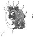
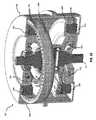
まず図1及び2を参照すると、電気モータ10は、モータハウジング14に関して回転可能な出力シャフト12を有し、これは本説明文の中では、モータコンポーネントの回転及びその他の運動に関する基準と考えられる。使用中、出力シャフト12は、適当な電力及び信号によって電気的に作動されるとモータ12が回転力をそこに付加する他の物体に連結されるであろう。図2においてわかるように、出力シャフト12はモータの中を通って延び、両端で露出しており、これは、回転力をモータの両端で伝達できることを意味する。ハウジング14は、出力シャフト12の回転軸16の周囲で回転対称であるように示されているが、何れの外形であってもよく、一般に、ハウジングを他の構造に固定して、モータの動作中にハウジングの回転を防止するための手段を含む。Detailed Description First, referring to FIGS. 1 and 2, the
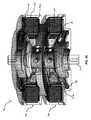
次に図3を参照すると、モータ10は2つのロータ18a及び18bを含み、各々がステータに関連付けられる。ロータ18aは、ステータ20aの中に配置され、ロータ18bはステータ20bの中に配置される。以下により詳しく説明するように、ステータ20a内の電気活動は、適正に制御されて、ロータ18aの運動を駆動し、ステータ20b内の同様の電気活動はロータ18bの運動を駆動する。ロータ18a及び18bはどちらも出力シャフト12に回転可能に連結され、その結果として得られるロータの運動の回転成分はすべて出力シャフト12に伝達され、それによって出力シャフトを回転させる。説明しやすくするために、モータの各端で出力シャフトを支持する軸受けは省略されている。 Next, referring to FIG. 3, the
しかしながら、従来の回転型電気モータとは異なり、ロータ18a及び18bの運動は純粋に回転ではない。後述のように、各ロータはステータに関して揺動し、この運動は、ロータがステータの表面に当たって転動し、他方でロータの傾斜軸が出力シャフトの周囲で前進して、概して円錐表面を掃引するウォブリングと説明することができる。各ロータとそれに関連付けられるステータとの間の有効エアギャップは一般に、それが従来のラジアルギャップモータのように、ロータの外周面とこれに隣接するステータの内周との間にあるという点で半径方向である。しかしながら、ロータの揺動により、このモータのエアギャップは動的であり、すなわち、これは揺動サイクル中にロータの周囲の何れかの特定の地点において変化し、これについては後述する。 However, unlike conventional rotary electric motors, the motion of
図3においてわかるように、ロータ18aはその上面に歯群を担持しており、それが、関連付けられるステータ20aの静止エンドキャップ24のロータ歯群22と係合する。ロータ18bは、同様の歯群(この図では見えない)を有し、それがステータ20bのエンドキャップの歯と係合する。この例において、噛み合っている歯群は揺動トラクション接合部を形成し、そこにおいて揺動ロータがステータ上で揺動し、係合点は、ロータの傾斜軸の前進と同期してロータの周囲で前進する。これをトラクション接合部と呼ぶが、これは、それがステータに関するロータの回転スリップを防止する役割を果たすからである。ステータの揺動運動によって、トラクション接合部の歯の大部分が何れの時点においても負荷を支え、トラクションの負荷は一度に複数の歯に分散される。図の例の幾つかにおいて、何れの時点でも一度に歯の少なくとも3分の1がトルクを伝えている。円状の歯の場合、何れの時点においても歯の半分に負荷がかかっているかもしれない。トラクション接合部に沿って歯を含む実施では、歯は主として軸方向に噛み合う。すなわち、インタフェースは軸方向の負荷又は磁気エアギャップに垂直な負荷を伝達する。本開示全体を通じて、トラクション接合部に沿って噛み合っている歯の例は、軸方向に噛み合っていると考えることができる。トラクション接合部の他の例は、噛み合う歯を特徴としない。幾つかの実施において、このようなトラクション接合部に沿った接触は、主として軸方向である。1つの代替案では、トラクション接合部は、剛直金属面間にある(鉄道の車輪とレールとの間で生じるような)金属−金属摩擦によってトラクションが可能となる。このレールは、相対圧力を上昇させるように斜めであってよく、中実の高摩擦材料、例えば弾性ゴム又はその他のエラストマで被覆されるか、幾つかの自動車用連続可変トランスミッションで使用されているような摩擦流体を利用してもよい。レールは、ロータによってのみ機械的負荷を受けても、又は第二の機械的前負荷を含んでいてもよい。第二の機械的前負荷の場合、ステータとロータとの間のデルタ角は好ましくは10度より大きく、そうでなければ、前負荷のタイミングはステータのコイルとは独立して制御し、駆動しなければならない。 As can be seen in FIG. 3, the
次に、図4及び5を参照すると、各ステータ20a及び20bは、強磁性ステータコア28に関連付けられる個別に励起可能な巻線又はコイル群26を特徴とする。コア28は、例えば複数のステータ突出部を有していてよく、これはステータヨーク又はバック鉄心から突出してよく、それによってステータのスロット及び磁極ができる。ステータコアは、1つの連続する材料によっても、又はモータへと組み立てられる個別のコンポーネントの組合せによってもよい。連続的材料はより高い寸法一貫性を提供するかもしれず、他方で、ステータハウジングにより機械的整合状態に保持される個別のステータ磁極群によって、効率的な製造及び組立が可能となるかもしれない。ステータ突出部の終端は、拡散していても、まっすぐであっても、又はステータの突出部及びバック鉄心又はヨークに関して下にあってもよい。この例では、ステータ突出部はまっすぐであり、ヨークからエアギャップにおけるその遠位端へと一定の断面積を有する。 Next, referring to FIGS. 4 and 5, each
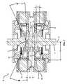
この例におけるロータの外周面は円錐形に研削され、他方で、ロータの内面は概して円筒面を画定する。図4において、上側ロータ18aは、出力シャフト12に関して左に傾斜しているように示されており、他方で、下側ロータ18bは反対方向に傾いている。この位置で、ロータとステータ面との間のエアギャップ28は、図の中の各ロータの左側においてギャップの軸方向に長さに沿って概して一定の半径方向の幅を有し、他方で、各ロータの右側では、エアギャップはその長さに沿って変化し、ロータ間の空間に向かって減少する。ロータ18aの傾斜軸30は、出力シャフト12の静止した回転軸32に関して4.34度の角度をなす。ロータ18aが揺動して、ステータ20aの異なるコイル26に向かって累進的に傾くと、その傾斜軸30は、出力シャフト軸に沿った出力シャフトとロータ18aとの間のジンバル接続手段34の高さのAに頂点を有する円錐面を掃引する。図の傾斜位置では、ロータとステータとの間のエアギャップ磁気抵抗は、左側のコイル26において最小であり、右側のコイルで最大となる。左のギャップを横切って示される曲がった矢印は単純に、ステータの周囲でその位置のわずかに前にあるコイルが励起されて、ギャップを横切る磁束を発生させ、ステータの反対側のコイルは励起されないことを示しているにすぎない。後でさらに説明するように、これによってステータとロータとの間に圧縮波、すなわち前進する半径方向の圧縮力が作られ、ロータの揺動を起こさせる。図5に示される傾斜位置では、図4に示される位置から揺動サイクルの半分の位置にあり、ロータとステータとの間のエアギャップ磁気抵抗は右側のコイル26で最小であり、左側のコイルで最大である。ロータの傾斜は、各ステータのエンドキャップのテーパ状停止面36と隣接するロータのテーパ状エッジ面38との間の転動接触により限定される。 The outer peripheral surface of the rotor in this example is ground into a conical shape, while the inner surface of the rotor generally defines a cylindrical surface. In FIG. 4, the
前進する圧縮波とロータ揺動との間の関係は、図6に示される単純モデルに関して説明することができる。平坦ディスク40は、その一端が点Bで平面上に乗る剛直軸42に取り付けられる。ディスクと軸は、軸の端とディスクの縁により点B及びCにおいて平面上に支持される。ディスクは、Dのような、接触点C付近でディスク縁を押し下げることによって、平面上で転動させることができる。同じ効果は、ディスクの縁と平面との間の引力によって、Dにおいてディスクの縁を引き下げることによっても生じさせることができる。ディスクが転動を始めると、転動は、ディスクを平面に向かって、常に瞬間的な接触点Cの少し先の地点において連続的に引き、接触点Bの軸42は静止したままにすることによって、無限に続けることができる。結果として得られる転動又は揺動は、例えば、子供のおもちゃのコマが、直立した回転を停止した後に受ける運動となるであろう。ディスクの縁は平面上で転動し、摺動しない。同様に、ステータの各コイルの励起によって、ロータを引っ張る局所的引力が発生する。最小半径方向エアギャップ地点の先頭側で(好ましくは、15〜60度先)コイルを連続的に励起することによって、ロータは傾いているコマのように揺動させることができ、ステータのエンドキャップの停止面に当たって転動する。しかしながら、図6の単純モデルの動作と図4及び5のモータの動作との間の重要な違いは、単純モデルにおいて、圧縮又は引力は、ディスクの縁と平面との間の、転動面そのものにより境界が定められるギャップを横切って発生する。ディスクが点Bの周囲で転動すると、ディスクの転動する縁と平面との間の距離は、ディスクの縁と平面との間の引き付け合いが作動する距離だけ変化する。このモデルでは、これらは同じである。 The relationship between the forward compression wave and the rotor swing can be described with respect to the simple model shown in FIG. The
他方で、図4及び5のモータにおいて、ロータの転動面が揺動中に移動する距離は、基本的に軸方向であり、表面36及び38間の最大空間であり、これは有効エアギャップ幅が最小であるとき、例えば図5の右側で発生し、引き付け合う圧縮力が作動するギャップ(磁気エアギャップ)は基本的に半径方向である。これによって、揺動は、有効磁気エアギャップより転動インタフェースにおいてはるかに大きな変位の変化を生じさせる。この特定の例では、それによって、ロータも傾斜させることができ、転動接触点は常にロータの、圧縮波の反対側とすることができる。モータを、転動接触点と圧縮波が出力シャフト軸の概して反対側となるようにモータを構成することによって、相対的トラクション接合部ピッチ速度がより低速となるため、より小さいパッケージングとより高い切替周波数を実現できる。反対に、モータを転動接触点と圧縮波が出力シャフト軸の概して同じ側で前進するように構成することにより(図20及び21のモータの例の場合)、ジンバルを通じたねじり力成分を利用しなくてもよいという点で、有利な短い機械的負荷の経路が提供される。 On the other hand, in the motors of FIGS. 4 and 5, the distance that the rolling surface of the rotor moves during swing is basically the axial direction, which is the maximum space between the
再び図4及び5を参照すると、ロータのうちの一方の質量加速度により生じる軸方向及び半径方向の慣性力は、2つのロータの反対方向への揺動による他方のロータのそれらとバランスがとられる。揺動は事実上、ロータ間でモータを2等分する横平面に関して相互に対称である。2つのロータの前進する磁気係合点は、現実的に相互に10度以内である。概してバランスがとれているものの、常に一方のロータにおいては、他方と比べてわずかな遅れがあり、電力用電子部品は常に、わずかに遅く移動するほうを加速させるようにする。ジンバル内の累積公差等により、最大3度の滑動が生じるかもしれない。 Referring again to FIGS. 4 and 5, the axial and radial inertial forces generated by the mass acceleration of one of the rotors are balanced with those of the other rotor due to the opposite swing of the two rotors. .. The swings are virtually symmetrical with respect to the horizontal plane that divides the motor into two equal parts between the rotors. The advancing magnetic engagement points of the two rotors are practically within 10 degrees of each other. Although generally balanced, there is always a slight delay in one rotor compared to the other, and the power electronics always try to accelerate the slightly slower movement. Due to cumulative tolerances within the gimbal, etc., a maximum of 3 degrees of sliding may occur.
それぞれロータ18a及び18bを出力シャフト12に接続するジンバル34a及び34bは、典型的に2つのリングを有する交差軸ジンバルアセンブリであり、それによって揺動時に360度の自由な傾斜を可能にしながら、出力シャフト軸32の周囲でトルクを伝達する。必要な自由度を提供するために、出力シャフトはジンバルの内側リングに内側横ピン(これらの図では見えない)によって固定され、ジンバルの内側リングは、内側ピンと90度の角度で横ピンによりロータに固定される。固定されたコンポーネントは、注油される軸受け面上でピンの周囲で自由に回転する。 The gimbals 34a and 34b, which connect the
次に図7を参照すると、この例では、ステータエンドキャップのテーパ状の停止面36が、出力シャフト軸に対する垂線に関して25.00度のステータ円錐角βを画定し、ロータのテーパ状のエッジ面38はロータの傾斜軸に対する垂線に関して22.83度のロータ円錐角度γを画定する。動作中のロータの傾斜はしたがって、+/−2.17度であり、これは揺動中のロータとステータとの間の歯の係合のインデキシングを可能にするのにちょうど十分である。ロータとステータとの間のトラクション接合部の一部である歯の係合は、ロータ歯群44がステータ歯群46と噛み合うことを特徴とする。ステータに関するロータ(及びそれゆえ、出力シャフト)の回転前進を生じさせるために、ロータの周囲の歯の数は、ステータの周囲の歯の数とは異なり、それによって、ロータがその揺動中にステータの周囲で転動すると、ロータの回転インデキシングは、歯のピッチに歯の数の差を乗じたものと等しくなる。この例では、ステータエンドキャップは各々59の歯を有し、ロータは各々60の歯を有しており、すなわち、係合するステータエンドキャップより1本多い。換言すれば、ステータ磁極を逐次的に励磁し、圧縮波を発生させてモータの周囲での丸1回転を完了させると、ロータの1つの完全な揺動サイクルが起こり、出力シャフトを歯1本分と等しい回転量だけ、すなわちこの例では6度だけ前進させる。 Next, referring to FIG. 7, in this example, the
モータコントローラ電力用電子部品は、リラクタンスモータのようにステータコイルを連続して励磁するように構成できる。図8は、適当なモータコントローラの簡略図を示しており、プロセッサ48はスイッチ50を制御して、ステータ磁極26a、26b、及び26cを逐次的に励起する。図9も参照すると、このような逐次的アクティベーションによって揺動を起こさせ、傾斜軸がモータを見下ろしたときにロータ軸の周囲で時計回り方向に前進することになる。シーケンスを逆転させると、反対方向への前進が起こり、すなわち、モータは何れの方向にも全負荷で駆動できることを意味する。図8には3つのスイッチだけが示されているが、モータコントローラは各ステータ磁極について1つのスイッチ、すなわち、図9のステータ配置に示される24のコイルを励起するための24のスイッチを有することになると理解されたい。再び図5を参照すると、2つのロータの揺動は対称であるため、2つのステータの回転整列される磁極ペアを一緒に励起させることができる。換言すれば、上側ステータの一番左に示される磁極26は、下側ステータの一番左に示される磁極26と同時に、同じ持続時間にわたって励起されることになる。2つのステータの回転整列された磁極ペアはしたがって、同じスイッチを介して並行して励起できる。例えば、図9に示されるツインステータモータのためのモータコントローラは、合計24のスイッチを必要とすることになる。代替的に、隣接する磁極ペアは、共通のスイッチを介して直列に配線されてもよいが、このような場合、2つの移動するロータのうち瞬間的に速い方は、わずかにより大きい逆EMFを発生させ、より低速の磁極と比較して、瞬間的により多くの相対電力を引き出すことになり、それによってさらに加速度がつき、相対速度が分離される。それに対して、別のロータの隣接する磁極の並列配線は、並列揺動負荷により、ネガティブフィードバック機構を提供する可能性がある。その意味で、これはセルフバランシングと考えることができ、振動の可能性の低い、よりスムーズな出力トルクを生成することができる。 The electronic component for motor controller power can be configured to continuously excite the stator coil like a reluctance motor. FIG. 8 shows a simplified diagram of a suitable motor controller, in which the processor 48 controls the switch 50 to sequentially excite the
モータステータ磁極の何れにも電流が流れないと、理論上、ロータを所定の位置保持するための内部のモータ力がない。ステータ積層体又はコアは、適切な程度の残留磁気を有する強磁性材料から形成でき、それによってロータは最後に励起された磁極に最も引き付けられた状態に保持される。 If no current flows through any of the motor stator poles, theoretically there is no internal motor force to hold the rotor in place. The stator laminate or core can be formed from a ferromagnetic material with a suitable degree of residual magnetism, which keeps the rotor most attracted to the last excited magnetic pole.
次に、図10を参照すると、ロータのテーパ状のエッジ面38は円錐台形表面を画定し、それがロータの揺動中にステータのエンドキャップの、それと対になるテーパ状表面の周囲で転動する。この例において、接触面は、歯の反駆動側にあるが、他の例では、駆動側に位置付けることもでき、又は幾つかのケースでは、歯自体を、対になる歯のプロファイル自体がロータの傾きを限定するような「ゼロギャップ」転動用として設計することもできる。噛み合う歯は、ロータから出力シャフトへと伝達されるトルクに反応する役割を果たし、何れの適当なプロファイルとすることもできる。 Next, referring to FIG. 10, the tapered
再び図7を参照すると、前述のように、出力シャフト軸32上の、ロータがその上で旋回するジンバルの傾斜中心に対応する高さに頂点を有するロータの円錐角γを画定するのは、テーパ状のエッジ面38である。この頂点Eをロータの焦点と呼ぶ。モータ10は、ロータ軸32とエアギャップ29の名目上の半径方向位置との間の、約75mmの半径方向距離としての動作半径Rwを有し、これは基本的にステータ磁極の内径の半分である。図のモータの名目上の全体的な直径は25cmである。鏡面31はモータを2つのロータ間の中央で二分し、各焦点Eから約19mmの距離だけ均等に離間される。2つのロータ/ジンバルアセンブリは基本的に、鏡面に関して相互に対称である。ロータ焦点Eは、ロータジンバルアセンブリの中心軸上にロータの揺動運動の中心を確立することによって特定できる。幾何学的に、焦点はステータ及びロータ円錐の両方の頂点にある。これらの円錐の角度を使って、歯の大きさ、磁極が移動する角距離、磁極が移動する半径方向距離、揺動運動、及び動作角度を含むモータの幾何学の物理的特徴の多くが導き出される。これらの幾何学的関係のほか、ギア比は、モータの全体的な幾何学を決定する上で重要である。 Referring again to FIG. 7, as described above, it is the defining cone angle γ of the rotor on the
各ロータの揺動により生じる、この図では図の左側のエアギャップを図の右側のエアギャップと比較することによってわかる、エアギャップの動的性質。前述のように、エアギャップはモータの動作中、ロータが中心軸の周囲でステータに関して揺動すると動的に変化する。動作中、最小の、すなわちロータがその閉位置にある時のエアギャップは、ステータとロータとの間の最大磁気整列が起こる地点である。この最小地点でのエアギャップは、名目上、横0.25mmであってよいが、交差平面にわたり変化してもよい。この最小エアギャップ位置において、ロータの、その円周位置の歯はステータのそれらと係合せず、その代わりに移行している。その瞬間に、その円周位置から180度離れた歯が係合し、エアギャップは最大位置にある。この最大の、すなわちロータがその開位置にある時のエアギャップは、ステータとロータの磁気整列が最小となる地点である。再び、この最大エアギャップ地点で、歯はトラクション接合部と係合する。この最大地点でのエアギャップは中心から中心が6.86mmであってよく、そのうちの1.0mmはロータとステータ間の半径方向の分離、6.60mmは縦方向のミスアラインメントである。ロータの積層体がエアギャップに面する歯を有する後述の実施形態の場合、これらのロータ積層体の歯は好ましくは最小エアギャップ位置にあるステータ磁極と整列し、最大エアギャップ位置では磁極とのミスアラインメントが最大となる。 The dynamic nature of the air gap, which is caused by the swing of each rotor, can be seen by comparing the air gap on the left side of the figure with the air gap on the right side of the figure. As mentioned above, the air gap changes dynamically as the rotor swings around the central axis with respect to the stator during motor operation. During operation, the minimum, i.e., the air gap when the rotor is in its closed position, is where the maximum magnetic alignment between the stator and rotor occurs. The air gap at this minimum point may be nominally 0.25 mm wide, but may vary over the intersection plane. At this minimum air gap position, the teeth of the rotor at its circumferential position do not engage with those of the stator and instead transition. At that moment, the
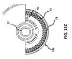
図11A〜Cは、完全な1揺動サイクルから得られるロータ/シャフト回転を連続的に示す。図11Aから始まり、インデックスマーク60はロータ面上で、ステータエンドキャップの切断縁と整列した状態で示されている。ステータコイルは、圧縮波がステータの周囲で180度前進し、ロータ軸が同様な180度の揺動又は1揺動サイクルの半分を通じて傾斜するようなシーケンスでアクティベートされ、その後、図11Bのインデックスマークは、ロータが基本的に歯のピッチの半分に等しい分、すなわちこのケースでは約3度回転したことを示している。ステータコイルの全部がアクティベートされて、丸360度の圧縮波が作られ、ロータの完全な揺動が完了した後(図11C)、ロータと出力シャフトは全体で歯1本のピッチ、すなわち約6度の回転をなしている。1回の完全な揺動によって、ロータは例えば、図4に示される位置から図5に示される位置へと移動し、図4に示される位置に戻ることになる。 11A-C continuously show the rotor / shaft rotations obtained from a complete swing cycle. Starting from FIG. 11A, the
電気モータは、動作中にかなりの熱を発生する可能性があり、冷却する必要がある。さらに、動作する機械的コンポーネント及び接触面にとって、特に高周波数での動作中には、能動的注油が有利となり得る。幾つかの用途に関して、例えば水とオイル等、別々の流体を冷却剤と注油にそれぞれ使用できる。また別の場合、オイル等の流体を冷却剤と注油の両方に使用できる。以下の説明の中で、流体は冷却剤、注油、又は必要に応じて両方を指す。 Electric motors can generate significant heat during operation and need to be cooled. In addition, active lubrication can be advantageous for operating mechanical components and contact surfaces, especially during operation at high frequencies. For some applications, separate fluids, such as water and oil, can be used for coolant and lubrication, respectively. In other cases, fluids such as oil can be used for both coolant and lubrication. In the description below, fluid refers to coolant, lubrication, or, if necessary, both.
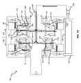
次に、図12を参照すると、モータ14aは出力シャフトに沿って離間された2つのロータを有し、その各々がジンバルで取り付けられている。図12の断面図は、ジンバルアセンブリの一方を通っており、シャフト12aに取り付けられたジンバルスピンドル106を示す。スピンドル106は内側アクスルを画定し、そこに内側ジンバルリング110が取り付けられて、内側ジンバルリング110の中に固定された2つの内側ジンバル軸受け112a間で旋回する。内側ジンバルリング110自体は、内側アクスルに対して垂直な外側アクスルを画定し、そこに外側ジンバルリング113が取り付けられて、外側ジンバルリング113の中に固定された2つの外側ジンバル軸受け112bの中で旋回する。ジンバル軸受け112a、112bは、スピンドルリングの穴の中にロックリングによって固定され、例えば青銅やバビットメタル若しくはその他の滑り摩耗面、又はローラ要素を有することができる。 Next, referring to FIG. 12, the motor 14a has two rotors separated along the output shaft, each of which is attached with a gimbal. A cross-sectional view of FIG. 12 shows a
図13も参照すると、モータ10aは、モータ出力シャフト12a内の穴102を通ってモータの中に送出される流体によって冷却及び注油される。この図では、左側のロータを通る断面は、図12の線12A−12Aに沿って切断されており、右側のロータの断面は、左のロータのそれに関して90度である図12の線12B−12Bに沿って切断されて、内側及び外側ジンバル軸受け112a、112bの両方を示している。ジンバルアセンブリ内の軸受けの比較的高周波数の動作から、ジンバル軸受けの能動的注油は、出力シャフトにクロス穴を形成して、流体をクロス穴通路104を介してこれらの軸受けに供給することによって実現できる。ここで、ジンバルアセンブリの内側リング110には、ジンバルスピンドル106を通るオリフィス108によって直接流体を供給でき、他方で、ジンバルアセンブリの外側リング113には、内側ジンバルリングの外側のジンバル軸受けを通るオリフィス114から流体を供給できる。オリフィスは、高速での損失の原因となる流体の溜まりを防止するように定量型であってよい。ジンバル軸受けを通るアパーチャ116によって、ジンバルから出てステータ巻線に向かう半径方向の流れが可能となる。図14に示されるように、定量型オリフィスプラグ118が内側ジンバルリングの半径方向の流路108の駆動側の端で旋回して、流れの一部を交差経路120に沿って軸方向に案内して、歯車接合面122及びシャフト軸受け124に供給してよい。同様のプラグ(図示せず)を外側ジンバルリングのチャネル114(図13)の出力端に提供してもよい。代替的に、又はそれに加えて、溝124によって流体を歯車接合面及び軸受けに出力シャフトから直接供給できる。シャフト軸受け125は、その反駆動側でシールされてよく、又は流れが軸受けを通り、サンプに戻れるようになっていてもよい。 Also referring to FIG. 13, the
再び図13を参照すると、出力シャフト12aを通って流される潤滑剤/冷却材流体はすべて、最終的に貯蔵部126へと排出され、これはモータの下面へと開き、構造的にステータハウジングの一部とすることができる。ポンプ128は流体130を貯蔵部から吸引して、流体の連続流を加圧された状態で出力シャフトの穴102へと送達する。 Referring again to FIG. 13, all the lubricant / coolant fluid flowing through the
次に、図15を参照すると、モータ10bは2つの圧縮注油/冷却レール132を有し、これはステータ端板に取り付けられており、歯車接合面へと向けられて、トラクション制御面を注油及び/又は冷却するために流体のミスト又は流れを連続的に供給する一連のノズル134を画定する。レールは、ポンプ(図示せず)によって供給され、流体は再循環される。ロータとステータとの間で転動する歯車接合面は、速度、トルク、及びパッケージングの制約の違いに合わせて調整できる。図16のモータ10bは例えば、図4のモータ10と同様であるが、ステータ及びロータ円錐角がそれぞれ30及び28度と、より高い。ステータ及びロータはまた、この例では歯の数がより少なく、それぞれ59及び60本であり、その結果、ある出力速度に対して電気的サイクリング周波数が低くなる。円錐角がより高いことにより、また、ある出力速度におけるジンバル軸受け上の動的荷重も減少する。それに対して、図17のモータ10cのステータ及びロータ円錐角はそれぞれ20及び18度と、図4のモータ10より低い。この構成は、低RPMの用途に特に好適である。それによって得られるステータアセンブリの全体の長さもまた、その結果として減少する。ロータの切替周波数及び動作中の傾斜エンベロープは、歯の数と円錐角に依存する。 Next, referring to FIG. 15, the
転動するトラクション接合部と磁気インタフェースの相対位置は、様々であってよい。上述の図において、トラクション接合部は磁気インタフェースの、回転方向には駆動側、基本的に軸方向には反駆動側にある。図18及び19は、トラクション接合部136が半径方向に磁気インタフェース138の反駆動側にあり、軸方向にステータ磁極の反駆動側に位置付けられているモータ10dを示す。トラクション接合部の前進する係合点もまた、前進する最小エアギャップ位置と整列し、それによって負荷経路(ロータ上のトルク入力とトルク出力との間)は有利な点として、短く、ロータを横切らない。これによって、ロータをより薄い壁厚とより軽量な材料で設計することが可能となり、ロータは重負荷を受けている間の変形により耐えられるようになるかもしれない。さらに、この設計によって歯車接触面積がより大きくなるかもしれず、その結果、ある電気的活性化周波数について、歯車ピッチ速度がより高くなるのと引き換えに歯車の圧力が低くなる。 The relative positions of the rolling traction junction and the magnetic interface may vary. In the above figure, the traction junction is on the drive side in the rotational direction and basically on the counter-drive side in the axial direction of the magnetic interface. 18 and 19 show a
図20及び21は、ステータハウジングにその縁において固定されたトラクションプレート140のそれぞれの側で、モータの軸方向に駆動側にあるステータトラクション面を有するモータ10eを示す。この設計により、ステータ端板の構造と加工が容易になる。トラクションプレートは、焼結鋼から、又は鍛造物として形成されてよい。両方のロータのトラクション接合部の前進する係合点は回転整列されるため、一方のロータによりトラクションプレートに加えられる負荷の軸方向の成分はすべて、他方のロータからの同様の負荷とバランスがとられる。この設計は、負荷経路が短く、ピッチ速度が低い、高トルク動作に特に好適である可能性があり、2つの別々のステータトラクションプレートを取り付けることから生じる機械的冗長性が低減するかもしれない。 20 and 21 show a
次に、図22及び23を参照すると、モータ10fはアウタロータモータと歯車積層モータを兼ねている。アウタロータモータとは、各ステータ・ロータペア間の半径方向エアギャップがステータ磁極の半径方向の外側の面にあることを意味する。各ロータ200はカップ型で、対応するステータ202の周囲に延び、それは対応するクラムシェルハウジングカップ206の環状ボス204に押し嵌められる。各ハウジングボス204はステータ歯46を担持し、これはロータ歯44と噛み合う。各ロータのスカートは一連の歯204を担持し、これは半径方向に内側にステータの磁極208に向かって延び、有効エアギャップ29を画定する。ロータの有効ギャップ面をこのように構成することにより、幾つかの利点を提供できる。それは磁気回路の最大インダクタンスを低下させるかもしれない(活性ステータ磁極が隣接するロータ歯と整列しているとき)が、最小インダクタンスも低下させる(ステータ磁極208が隣接するロータ歯204間に位置するとき)。このモータから得られる利用可能な仕事は、最大及び最小インダクタンスの差によって異なるため、ロータ歯間の強磁性材料を取り除いても、インダクタンスの変化から得られる仕事をそれほど低減させないかもしれない。さらに、これは、ギャップ29における磁束経路に利用可能な表面積を有意に増大させるほか、軽量化することもできる。 Next, referring to FIGS. 22 and 23, the
図24のモータ10gもまた、歯車積層ロータ220a及び220bを有しているが、図7のモータ10のそれと同様のインナロータ構成によるものである。このケースでは、ロータ歯204は半径方向に外側に面して、ステータの内面とエアギャップ29を画定する。図25に示されるように、ロータ積層歯204の数はロータ歯44の数と同じであり、これはステータ磁極222の数より1つ多い。この例において、60のステータ磁極と61の積層歯があり、それによって2、3、4、5、又はさらには6の磁極に均等に分けることができる。 The
上述のモータの何れにおいても、隣接するステータ磁極群はモータの動作中、一緒に、同じ磁気の向きで作動させることができる。例えば、図25に示されるモータ10gにおいて、磁極220a、220b、及び220cの各々の周囲の巻線は、すべての巻線が同じ方向である1つの巻線群224を形成でき、磁極222d、222e、及び222fの各々の周囲の巻線は、共同で第二の巻線群226を形成できる。動作中、巻線群224のすべてを1つの電気スイッチに並列に配線でき、巻線群226のすべてを他の電気スイッチに並列に配線でき、それによって磁極群224が共同で動作し、磁極群226が共同で動作する。隣接する複数の磁極を同時に作動させることによって、最小インダクタンスを低下させ、利用可能な仕事を増大させることもできる。ある磁極群の各磁極をそれ自体のコイルで包囲する代わりに、1本のコイルをある群の磁極の全部の周囲に巻き回すことができる。もちろん、複数のステータ磁極を動作ユニットとしてともに結合する際、ステータ磁極の総数は、各群の磁極の数の整数倍とすべきである。 In any of the motors described above, adjacent stator poles can be operated together in the same magnetic orientation during motor operation. For example, in the
モータの動作サイクル中のインダクタンスの最大の変化はまた、その他の構造変更によって、軸方向へのギャップ構造の有効な相対運動をさらに利用することによっても実現できる。図26のモータ10hは、図22のモータ10fと同様であるが、各ステータ磁極228が細分されて3つの磁極突出部230を形成し、これらは軸方向に離間され、共通の背部232によって接続されている点が異なる。同様に、各ロータ歯234は細分されて軸方向に離間された3つの歯突出部236を形成する。最小ギャップ位置(図の左側)において、磁極突出部は歯突出部と軸方向に整列される。最大ギャップ位置(図の右側)では、歯突出部は概して、磁極突出部との最大ミスアラインメントであり、これはインダクタンスを大きく低下させる。この例は3つの歯突出部及び3つの磁極突出部を有し、歯突出部間及び磁極突出部間の軸方向の空間は、中央の歯突出部及び中央の磁極突出部と基本的に同じ軸方向の寸法を有しているが、各ロータ歯及び各磁極突出部の2若しくは4、又はそれより多い突出部を有するその他の例も想定される。好ましくは、各磁極の突出部の数は、各積層歯の突出部の数と等しい。 The maximum change in inductance during the motor's operating cycle can also be achieved by further utilizing the effective relative motion of the axial gap structure, with other structural changes. The motor 10h of FIG. 26 is similar to the
図26の分割磁極/歯構成は、揺動ロータ式モータでは、磁気ギャップと接するロータ構造が磁気キャップと接するステータ構造に関して移動する距離は、揺動によって生じる半径方向の変位のみより大きいことを利用するのに役立つ。図27を参照すると、点「F」はロータの最小ギャップ位置におけるロータ歯204の基準点を表し、点「G」はロータの次の最大ギャップ位置における(すなわち、1/2揺動サイクル後の)ロータ歯の同じ点を表す。線分FGの長さは、半サイクル中に移動した距離の総計を表し、軸方向の変位240、半径方向の変位242、及び接線方向の変位244のコンピレーションである。ロータ歯及び磁極の軸方向の細分は、揺動中のロータ歯の軸方向の変位240を利用するのを助ける。 The split magnetic pole / tooth configuration of FIG. 26 utilizes that in a swing rotor motor, the distance traveled by the rotor structure in contact with the magnetic gap with respect to the stator structure in contact with the magnetic cap is greater than only the radial displacement caused by the swing. Helps to do. Referring to FIG. 27, the point "F" represents the reference point of the
上述のモータの何れも、動的エネルギーから電気エネルギーを発生させるように制御できる(例えばモータを回生制動させるため)。これは、圧縮波のタイミングを交互にして、ステータの電流が最小エアギャップの地点で(又は、最小エアギャップの地点からわずかに遅れて)パルスを打ち、拡張中に順方向EMFを発生させるようにすることによって実現されてよい。このようにして、電流を発生させ、関連するバッテリに貯蔵されるように案内することができ、その間に減速トルクがロータに印加されて、モータが低速化されるが、モータは出力シャフトに印加されるトルクによって機械的に逆駆動不可である。 Any of the motors described above can be controlled to generate electrical energy from dynamic energy (eg, to regeneratively brake the motor). This alternates the timing of the compression waves so that the stator current pulsates at the point of the minimum air gap (or slightly behind the point of the minimum air gap), generating a forward EMF during expansion. It may be realized by. In this way, a current can be generated and guided to be stored in the associated battery, during which deceleration torque is applied to the rotor to slow down the motor, but the motor is applied to the output shaft. It is not possible to reverse drive mechanically due to the torque generated.
強磁性化合物を産生するかもしれない磁性流体等の強磁性潤滑剤、コバルトめっき等の強磁性表面コーティング、又はホウ化処理等の表面処理は、転動摩擦を減少させ、表面硬度を高めるために使用されてよい。硬質強磁性コーティングはまた、低表面粗さ、機械的研磨、及びより低い比較的摩擦の大きい動作もサポートしてよい。これらの材料は、従来の方法を使ってシステムを被覆し、又はそれに添加されてよい。 Ferromagnetic lubricants such as ferrofluids that may produce ferromagnetic compounds, ferromagnetic surface coatings such as cobalt plating, or surface treatments such as boring are used to reduce rolling friction and increase surface hardness. May be done. Rigid ferromagnetic coatings may also support low surface roughness, mechanical polishing, and lower relatively frictional operation. These materials may coat or add to the system using conventional methods.
モータ設計のその他の技術的詳細は、2017年8月8日に出願された、“High Torque Density Electric Motor and/or Generator”と題する係属中の特許出願第15/549,659号に記載されており、その内容を、参照することにより、全文が記載されているかのように本願に援用する。 Other technical details of the motor design can be found in the pending patent application No. 15 / 549,659 entitled "High Torque Density Electric Motor and / or Generator" filed August 8, 2017. By referring to the contents, the contents are incorporated in the present application as if the full text is described.
幾つかの例を例示の目的で説明されているが、上記の説明は、付属の特許請求の範囲により定義される本発明の範囲を限定しようとするものではない。現在及び将来、以下の特許請求の範囲内の他の例や改良がある。 Although some examples have been described for illustrative purposes, the above description is not intended to limit the scope of the invention as defined by the appended claims. There are other examples and improvements within the scope of the claims below, now and in the future.
Claims (31)
Translated fromJapanese前記出力シャフトに回転可能に連結された揺動ロータと、
前記ロータに揺動トラクション接合部によって機械的に連結されたステータであって、それによって前記ロータの前記ステータに関する揺動中に前記ロータの傾斜軸が前記出力シャフトの前記回転軸の周囲で前進するようなステータと、
を含む電気モータにおいて、
前記ロータと前記ステータの表面は半径方向の動的ギャップの境界を画定し、そこに前記モータの電気的作動により磁場が生成されて、前記ロータと前記ステータとの間に力を生じさせ、
前記トラクション接合部と前記ギャップは、前記出力シャフトの前記回転軸を含む平面内で、前記トラクション接合部が前記ギャップと接する前記ステータ表面に関して斜めになるように配置される
電気モータ。The output shaft that defines the axis of rotation and
A swing rotor rotatably connected to the output shaft,
A stator mechanically coupled to the rotor by a swing traction joint, whereby the tilted shaft of the rotor advances around the rotating shaft of the output shaft during swinging of the rotor with respect to the stator. With a stator like
In electric motors including
The surfaces of the rotor and the stator demarcate a radial dynamic gap in which a magnetic field is generated by the electrical operation of the motor to generate a force between the rotor and the stator.
An electric motor in which the traction joint and the gap are arranged so as to be oblique with respect to the surface of the stator in which the traction joint is in contact with the gap in a plane including the rotation axis of the output shaft.
前記出力シャフトに回転可能に連結された第二の揺動ロータと、
前記第二の揺動ロータに、第二の揺動トラクション接合部によって機械的に連結された第二のステータであって、前記第二の揺動ロータの前記第二のステータに関する揺動中に前記第二の揺動ロータの傾斜軸が前進して、前記出力シャフトの前記回転軸に関して円錐面を画定する第二のステータ
を含み、
前記第二の揺動ロータと前記第二のステータの表面は半径方向のギャップの境界を画定し、そこに前記モータの電気的作動により磁場が生成されて、前記第二の揺動ロータと前記第二のステータとの間に力を生じさせる、
請求項1に記載の電気モータ。The rocking rotor is the first rocking rotor, the stator is the first stator, the rocking traction joint is the first rocking traction joint, and the motor is
A second swing rotor rotatably connected to the output shaft,
A second stator mechanically connected to the second swing rotor by a second swing traction joint during swinging of the second swing rotor with respect to the second stator. The tilt axis of the second rocking rotor advances and includes a second stator defining a conical surface with respect to the rotation axis of the output shaft.
The surfaces of the second rocking rotor and the second stator demarcate a radial gap, in which a magnetic field is generated by the electrical operation of the motor to generate the second rocking rotor and the second rocking rotor. Generate a force with the second stator,
The electric motor according to claim 1.
前記出力シャフトに傾斜可能接続手段において連結される揺動ロータと、
前記ロータに隣接して配置されて動的エアギャップを画定するステータであって、前記ステータは複数の巻線を有し、各々が磁場を発生させるように構成され、前記ロータのそれぞれの側を前記ステータに向かって引き、前記ロータが、複数の巻線の逐次的アクティベーションに応答して前記ステータに関して揺動するようにして、前記傾斜可能接続手段を累進的に傾斜させるステータと、
を含む電気モータにおいて、
前記動的エアギャップは、前記ロータの外周面によって境界が定められ、それによって前記ロータ及びステータ間の磁気連結が主として半径方向になり、
前記ステータは前記揺動ロータに揺動トラクション接合部によって機械的に連結され、前記ロータの前記ステータに関する揺動中に、前記ロータのそれぞれの傾斜軸が前記出力シャフトの回転軸の周囲で前進し、前記トラクション接合部は、ステータ歯群と軸方向に噛み合うように構成されたロータ歯群を含む
電気モータ。The output shaft that defines the axis of rotation and
An oscillating rotor connected to the output shaft in a tiltable connecting means,
A stator arranged adjacent to the rotor to define a dynamic air gap, the stator having a plurality of windings, each configured to generate a magnetic field, each side of the rotor. A stator that progressively tilts the tiltable connecting means by pulling towards the stator and causing the rotor to swing with respect to the stator in response to sequential activation of a plurality of windings.
In electric motors including
The dynamic air gap is bounded by the outer peripheral surface of the rotor, whereby the magnetic connection between the rotor and the stator is predominantly radial.
The stator is mechanically connected to the swing rotor by a swing traction joint, and during swing of the rotor with respect to the stator, each tilt axis of the rotor advances around the rotation axis of the output shaft. The traction joint is an electric motor including a rotor tooth group configured to mesh with a stator tooth group in the axial direction.
揺動ロータに隣接して配置され、前記ロータの外周面により境界が定められる動的エアギャップを画定するステータの第一のコイルを作動させて、前記ロータ及びステータ間の磁気連結が主として半径方向になるようにすることであって、前記揺動ロータは前記モータの出力シャフトに傾斜可能接続手段において連結されるようなことと、
前記ステータの第二のコイルであって、前記第一のコイルから円周方向に離間される第二のコイルを作動させることと、
前記ステータの第三のコイルであって、前記第一及び第二のコイルの両方から円周方向に離間された第三のコイルを作動させることであって、前記第二のコイルは前記第一及び第三のコイル間に配置されるようなことと、
を含み、
前記第一のコイル、前記第二のコイル、及び第三のコイルを逐次的に作動させることによって、前記ロータは前記出力シャフト軸の周囲で揺動し、それによって前記出力シャフトを回転させ、
前記ステータは、前記揺動ロータに揺動トラクション接合部によって機械的に連結され、前記ロータの前記ステータに関する揺動中、前記ロータのそれぞれの傾斜軸が前記出力シャフトの回転軸の周囲で前進し、前記トラクション接合部は、ステータ歯群と軸方向に噛み合うロータ歯群を含む、
方法。In the operation method of the electric motor
By activating the first coil of the stator, which is located adjacent to the swing rotor and defines a dynamic air gap defined by the outer peripheral surface of the rotor, the magnetic connection between the rotor and the stator is predominantly radial. The swing rotor is connected to the output shaft of the motor by a tiltable connecting means.
Activating the second coil of the stator, which is separated from the first coil in the circumferential direction,
The third coil of the stator, which operates the third coil circumferentially separated from both the first and second coils, is the first coil. And to be placed between the third coils,
Including
By sequentially operating the first coil, the second coil, and the third coil, the rotor swings around the output shaft shaft, thereby rotating the output shaft.
The stator is mechanically connected to the swing rotor by a swing traction joint, and each tilt axis of the rotor advances around the rotation axis of the output shaft during swing of the rotor with respect to the stator. The traction joint includes a group of rotor teeth that mesh axially with the group of stator teeth.
Method.
Priority Applications (1)
| Application Number | Priority Date | Filing Date | Title |
|---|---|---|---|
| JP2023212542AJP7645976B2 (en) | 2018-05-23 | 2023-12-15 | Electric motor |
Applications Claiming Priority (3)
| Application Number | Priority Date | Filing Date | Title |
|---|---|---|---|
| US201862675207P | 2018-05-23 | 2018-05-23 | |
| US62/675,207 | 2018-05-23 | ||
| PCT/US2019/033811WO2019226929A1 (en) | 2018-05-23 | 2019-05-23 | Electric motor |
Related Child Applications (1)
| Application Number | Title | Priority Date | Filing Date |
|---|---|---|---|
| JP2023212542ADivisionJP7645976B2 (en) | 2018-05-23 | 2023-12-15 | Electric motor |
Publications (2)
| Publication Number | Publication Date |
|---|---|
| JP2021525505Atrue JP2021525505A (en) | 2021-09-24 |
| JP7615024B2 JP7615024B2 (en) | 2025-01-16 |
Family
ID=68617289
Family Applications (2)
| Application Number | Title | Priority Date | Filing Date |
|---|---|---|---|
| JP2021516542AActiveJP7615024B2 (en) | 2018-05-23 | 2019-05-23 | Electric motor |
| JP2023212542AActiveJP7645976B2 (en) | 2018-05-23 | 2023-12-15 | Electric motor |
Family Applications After (1)
| Application Number | Title | Priority Date | Filing Date |
|---|---|---|---|
| JP2023212542AActiveJP7645976B2 (en) | 2018-05-23 | 2023-12-15 | Electric motor |
Country Status (8)
| Country | Link |
|---|---|
| US (3) | US11451124B2 (en) |
| EP (1) | EP3797470A4 (en) |
| JP (2) | JP7615024B2 (en) |
| CN (1) | CN112740523A (en) |
| AU (3) | AU2019272884B2 (en) |
| CA (1) | CA3100969A1 (en) |
| MX (1) | MX2020012568A (en) |
| WO (1) | WO2019226929A1 (en) |
Cited By (1)
| Publication number | Priority date | Publication date | Assignee | Title |
|---|---|---|---|---|
| CN115955054A (en)* | 2023-03-02 | 2023-04-11 | 常州双联磁电科技有限公司 | Small axial flux motor |
Families Citing this family (9)
| Publication number | Priority date | Publication date | Assignee | Title |
|---|---|---|---|---|
| CN112740523A (en) | 2018-05-23 | 2021-04-30 | Tau电机股份有限公司 | motor |
| CN109944806B (en)* | 2019-04-23 | 2024-08-13 | 迎新科技(中国)有限公司 | Parallel double-pump liquid guide device and liquid cooling heat dissipation system thereof |
| JP2023510606A (en) | 2020-01-16 | 2023-03-14 | タウ モーターズ,インコーポレイテッド | electric motor |
| KR102435814B1 (en)* | 2020-09-22 | 2022-08-24 | 네덱(주) | Multicopter Motor |
| US20220107396A1 (en)* | 2020-10-07 | 2022-04-07 | Luminar, Llc | Elevation motor design and mirror placement |
| JP2024509201A (en)* | 2021-03-05 | 2024-02-29 | タウ モーターズ,インコーポレイテッド | Wireless power transmission in electrical machines with AC and DC rotor coils |
| EP4246782A1 (en)* | 2022-03-17 | 2023-09-20 | Rimac Technology LLC | Drive system |
| CN116526792B (en)* | 2023-03-08 | 2024-08-16 | 金陵科技学院 | An outer rotor permanent magnet motor with a composite air gap magnetic circuit |
| US20240413728A1 (en)* | 2023-06-12 | 2024-12-12 | Magvad LLC | Magnetic drive apparatus for translating rotational motion to nutational motion |
Citations (4)
| Publication number | Priority date | Publication date | Assignee | Title |
|---|---|---|---|---|
| JPS6122752A (en)* | 1984-07-10 | 1986-01-31 | Kokusai Gijutsu Kaihatsu Kk | Motor |
| JPH02104782U (en)* | 1989-02-08 | 1990-08-21 | ||
| JP2004353780A (en)* | 2003-05-29 | 2004-12-16 | Toyota Motor Corp | Vehicle drive device and FR-type hybrid vehicle equipped with the vehicle drive device |
| JP2015142454A (en)* | 2014-01-29 | 2015-08-03 | キヤノン株式会社 | Actuator and multi-joint robot arm |
Family Cites Families (25)
| Publication number | Priority date | Publication date | Assignee | Title |
|---|---|---|---|---|
| US3249776A (en) | 1962-06-13 | 1966-05-03 | Bendix Corp | Nutation motor |
| US3294994A (en) | 1963-05-10 | 1966-12-27 | Bendix Corp | Nutation motor or generator |
| FR85038E (en) | 1963-12-30 | 1965-05-28 | Electric motor | |
| US3341725A (en)* | 1965-07-15 | 1967-09-12 | John F Gifford | Electric motor having a nutative element |
| US3452227A (en) | 1966-10-21 | 1969-06-24 | Elvin C Welch | Motor with gyrating rotor |
| US3456139A (en) | 1967-12-11 | 1969-07-15 | Mesur Matic Electronics Corp | Wobble drum step motor |
| US3530322A (en) | 1968-04-24 | 1970-09-22 | Mesur Matic Electronics Corp | Step motor with variable tilt |
| US3585426A (en)* | 1969-10-06 | 1971-06-15 | Mesur Matic Electronics Corp | Vibration compensation for wobble plate step motors |
| DE2135929B1 (en) | 1971-07-17 | 1972-12-21 | Saia Ag, Murten (Schweiz) | DEVICE FOR GENERATING A ROTATING MOTION WITH AT LEAST ONE PULSING DRIVE FORCE |
| FR2423906A1 (en) | 1978-04-19 | 1979-11-16 | Sfaire Soc Fr Applic Ind Rural | SYNCHRONOUS ELECTRIC MOTOR WITH VERY LOW ROTORIC INERTIA WITH BALANCED CONICAL MOVEMENT |
| JPH02104782A (en) | 1988-08-08 | 1990-04-17 | Kishiyuu Mengiyou Kk | Waterproof sheet capable of producing pattern in wetting and umbrella using the same |
| US4906881A (en)* | 1989-02-28 | 1990-03-06 | Eaton Corporation | Nutating motor with automatic engagement and disengagement of hand wheel with output shaft |
| US5309041A (en)* | 1993-05-04 | 1994-05-03 | Nihon Riken Kabushiki Kaisha | Nutating step motor |
| US5804898A (en)* | 1995-09-12 | 1998-09-08 | Nihon Riken Co., Ltd. | Electric motor utilizing magnetic energy of permanent magnet |
| US5832675A (en) | 1997-04-09 | 1998-11-10 | David Zuares | Prefabricated post base flashing |
| US6371137B1 (en)* | 1998-12-03 | 2002-04-16 | Robert A. Heath | Tank cleaning apparatus |
| AU5277900A (en) | 1999-05-19 | 2000-12-05 | Johnson Outdoors Inc. | Nutational motor |
| US6401401B1 (en) | 2000-10-20 | 2002-06-11 | Mark F. Williams | Multi-component flashing systems |
| DE102005061188B4 (en) | 2005-12-21 | 2007-10-18 | Keiper Gmbh & Co.Kg | Gear stage of an actuator |
| DE102009002587A1 (en)* | 2009-04-23 | 2010-10-28 | Robert Bosch Gmbh | Electric wobble motor for use as drive utilized for driving e.g. aggregate in vehicle, has two crown wheels, where one of crown wheels comprises symmetry axis that is inclined at angle to symmetry axis of other crown wheel |
| US9404489B1 (en)* | 2013-03-23 | 2016-08-02 | The Boeing Company | Peristaltic pump system and method using a virtual ellipse motor |
| DE102014001263B4 (en) | 2014-01-30 | 2017-06-01 | Gregor Puchhammer | wobble mechanism |
| US10404135B2 (en) | 2015-02-10 | 2019-09-03 | Indiana University Research And Technology Corporation | High torque density electric motor and/or generator |
| US10177641B2 (en)* | 2016-07-26 | 2019-01-08 | The Boeing Company | Stator assembly including stator elements with slotted stator cores for use in an electrical motor |
| CN112740523A (en)* | 2018-05-23 | 2021-04-30 | Tau电机股份有限公司 | motor |
- 2019
- 2019-05-23CNCN201980047346.8Apatent/CN112740523A/enactivePending
- 2019-05-23CACA3100969Apatent/CA3100969A1/enactivePending
- 2019-05-23WOPCT/US2019/033811patent/WO2019226929A1/ennot_activeCeased
- 2019-05-23MXMX2020012568Apatent/MX2020012568A/enunknown
- 2019-05-23EPEP19806841.3Apatent/EP3797470A4/enactivePending
- 2019-05-23JPJP2021516542Apatent/JP7615024B2/enactiveActive
- 2019-05-23USUS16/963,950patent/US11451124B2/enactiveActive
- 2019-05-23AUAU2019272884Apatent/AU2019272884B2/enactiveActive
- 2022
- 2022-08-05USUS17/882,135patent/US11870319B2/enactiveActive
- 2023
- 2023-06-07AUAU2023203552Apatent/AU2023203552B2/enactiveActive
- 2023-06-21USUS18/338,705patent/US20230336065A1/enactivePending
- 2023-10-20AUAU2023251511Apatent/AU2023251511B2/enactiveActive
- 2023-12-15JPJP2023212542Apatent/JP7645976B2/enactiveActive
Patent Citations (4)
| Publication number | Priority date | Publication date | Assignee | Title |
|---|---|---|---|---|
| JPS6122752A (en)* | 1984-07-10 | 1986-01-31 | Kokusai Gijutsu Kaihatsu Kk | Motor |
| JPH02104782U (en)* | 1989-02-08 | 1990-08-21 | ||
| JP2004353780A (en)* | 2003-05-29 | 2004-12-16 | Toyota Motor Corp | Vehicle drive device and FR-type hybrid vehicle equipped with the vehicle drive device |
| JP2015142454A (en)* | 2014-01-29 | 2015-08-03 | キヤノン株式会社 | Actuator and multi-joint robot arm |
Cited By (1)
| Publication number | Priority date | Publication date | Assignee | Title |
|---|---|---|---|---|
| CN115955054A (en)* | 2023-03-02 | 2023-04-11 | 常州双联磁电科技有限公司 | Small axial flux motor |
Also Published As
| Publication number | Publication date |
|---|---|
| US11870319B2 (en) | 2024-01-09 |
| EP3797470A4 (en) | 2021-06-30 |
| US20230336065A1 (en) | 2023-10-19 |
| CA3100969A1 (en) | 2019-11-28 |
| US11451124B2 (en) | 2022-09-20 |
| MX2020012568A (en) | 2021-04-28 |
| AU2023203552A1 (en) | 2023-07-06 |
| AU2023203552B2 (en) | 2023-08-24 |
| EP3797470A1 (en) | 2021-03-31 |
| CN112740523A (en) | 2021-04-30 |
| AU2019272884A1 (en) | 2020-12-17 |
| US20210384811A1 (en) | 2021-12-09 |
| JP7615024B2 (en) | 2025-01-16 |
| JP2024023694A (en) | 2024-02-21 |
| JP7645976B2 (en) | 2025-03-14 |
| US20220376597A1 (en) | 2022-11-24 |
| WO2019226929A1 (en) | 2019-11-28 |
| AU2019272884B2 (en) | 2023-03-16 |
| AU2023251511A1 (en) | 2023-11-09 |
| AU2023251511B2 (en) | 2024-06-06 |
Similar Documents
| Publication | Publication Date | Title |
|---|---|---|
| JP7645976B2 (en) | Electric motor | |
| JP4799199B2 (en) | In-wheel motor drive device | |
| WO2015186467A1 (en) | In-wheel motor drive device | |
| JP5620826B2 (en) | Cycloid reducer and in-wheel motor drive device | |
| US11682945B2 (en) | High torque density electric motor/generator with rolling element | |
| JP2018100718A (en) | Power device | |
| CN104417342B (en) | Electric motor | |
| CN203617838U (en) | Pump for conveying medium | |
| JP5010484B2 (en) | Cycloid reducer and in-wheel motor drive device | |
| JP2012171420A (en) | Device for driving in-wheel motor | |
| CN100447444C (en) | Vibration damping of rotating shafts | |
| JP2008202746A (en) | Lubricating structure for vehicle speed reducing part and in-wheel motor drive mechanism | |
| JP2008309264A (en) | Cycloid reduction gear and in-wheel motor drive device | |
| HK40052481A (en) | Electric motor | |
| JP4859489B2 (en) | Wheel drive structure for railway vehicles | |
| JP5808561B2 (en) | In-wheel motor drive device | |
| WO2015025827A1 (en) | Vehicle wheel drive device | |
| JP2016038086A (en) | Wheel driving device | |
| JP2016056926A (en) | Wheel driving device | |
| JP4918051B2 (en) | Motor drive device and in-wheel motor drive device | |
| JP2022068030A (en) | Transaxle | |
| CN113090725A (en) | Rotary transmission device and transmission method | |
| CN115182985A (en) | Eccentric circle transmission method and device without gear structure | |
| JP2015128931A (en) | In-wheel motor drive device | |
| US20100058882A1 (en) | Oscillating or Low Speed Electric Machine Apparatus |
Legal Events
| Date | Code | Title | Description |
|---|---|---|---|
| A621 | Written request for application examination | Free format text:JAPANESE INTERMEDIATE CODE: A621 Effective date:20220404 | |
| A977 | Report on retrieval | Free format text:JAPANESE INTERMEDIATE CODE: A971007 Effective date:20230327 | |
| A131 | Notification of reasons for refusal | Free format text:JAPANESE INTERMEDIATE CODE: A131 Effective date:20230328 | |
| A521 | Request for written amendment filed | Free format text:JAPANESE INTERMEDIATE CODE: A523 Effective date:20230628 | |
| A02 | Decision of refusal | Free format text:JAPANESE INTERMEDIATE CODE: A02 Effective date:20230818 | |
| A521 | Request for written amendment filed | Free format text:JAPANESE INTERMEDIATE CODE: A523 Effective date:20231215 | |
| A911 | Transfer to examiner for re-examination before appeal (zenchi) | Free format text:JAPANESE INTERMEDIATE CODE: A911 Effective date:20240130 | |
| A912 | Re-examination (zenchi) completed and case transferred to appeal board | Free format text:JAPANESE INTERMEDIATE CODE: A912 Effective date:20240222 | |
| A61 | First payment of annual fees (during grant procedure) | Free format text:JAPANESE INTERMEDIATE CODE: A61 Effective date:20241227 | |
| R150 | Certificate of patent or registration of utility model | Ref document number:7615024 Country of ref document:JP Free format text:JAPANESE INTERMEDIATE CODE: R150 |