JP2021522881A - Devices and methods for shrinking prosthetic implants - Google Patents
Devices and methods for shrinking prosthetic implantsDownload PDFInfo
- Publication number
- JP2021522881A JP2021522881AJP2020560754AJP2020560754AJP2021522881AJP 2021522881 AJP2021522881 AJP 2021522881AJP 2020560754 AJP2020560754 AJP 2020560754AJP 2020560754 AJP2020560754 AJP 2020560754AJP 2021522881 AJP2021522881 AJP 2021522881A
- Authority
- JP
- Japan
- Prior art keywords
- heart valve
- valve
- prosthetic heart
- holding
- distal
- Prior art date
- Legal status (The legal status is an assumption and is not a legal conclusion. Google has not performed a legal analysis and makes no representation as to the accuracy of the status listed.)
- Granted
Links
Images


Classifications
- A—HUMAN NECESSITIES
- A61—MEDICAL OR VETERINARY SCIENCE; HYGIENE
- A61F—FILTERS IMPLANTABLE INTO BLOOD VESSELS; PROSTHESES; DEVICES PROVIDING PATENCY TO, OR PREVENTING COLLAPSING OF, TUBULAR STRUCTURES OF THE BODY, e.g. STENTS; ORTHOPAEDIC, NURSING OR CONTRACEPTIVE DEVICES; FOMENTATION; TREATMENT OR PROTECTION OF EYES OR EARS; BANDAGES, DRESSINGS OR ABSORBENT PADS; FIRST-AID KITS
- A61F2/00—Filters implantable into blood vessels; Prostheses, i.e. artificial substitutes or replacements for parts of the body; Appliances for connecting them with the body; Devices providing patency to, or preventing collapsing of, tubular structures of the body, e.g. stents
- A61F2/02—Prostheses implantable into the body
- A61F2/24—Heart valves ; Vascular valves, e.g. venous valves; Heart implants, e.g. passive devices for improving the function of the native valve or the heart muscle; Transmyocardial revascularisation [TMR] devices; Valves implantable in the body
- A61F2/2409—Support rings therefor, e.g. for connecting valves to tissue
- A—HUMAN NECESSITIES
- A61—MEDICAL OR VETERINARY SCIENCE; HYGIENE
- A61F—FILTERS IMPLANTABLE INTO BLOOD VESSELS; PROSTHESES; DEVICES PROVIDING PATENCY TO, OR PREVENTING COLLAPSING OF, TUBULAR STRUCTURES OF THE BODY, e.g. STENTS; ORTHOPAEDIC, NURSING OR CONTRACEPTIVE DEVICES; FOMENTATION; TREATMENT OR PROTECTION OF EYES OR EARS; BANDAGES, DRESSINGS OR ABSORBENT PADS; FIRST-AID KITS
- A61F2/00—Filters implantable into blood vessels; Prostheses, i.e. artificial substitutes or replacements for parts of the body; Appliances for connecting them with the body; Devices providing patency to, or preventing collapsing of, tubular structures of the body, e.g. stents
- A61F2/02—Prostheses implantable into the body
- A61F2/24—Heart valves ; Vascular valves, e.g. venous valves; Heart implants, e.g. passive devices for improving the function of the native valve or the heart muscle; Transmyocardial revascularisation [TMR] devices; Valves implantable in the body
- A61F2/2412—Heart valves ; Vascular valves, e.g. venous valves; Heart implants, e.g. passive devices for improving the function of the native valve or the heart muscle; Transmyocardial revascularisation [TMR] devices; Valves implantable in the body with soft flexible valve members, e.g. tissue valves shaped like natural valves
- A61F2/2415—Manufacturing methods
- A—HUMAN NECESSITIES
- A61—MEDICAL OR VETERINARY SCIENCE; HYGIENE
- A61F—FILTERS IMPLANTABLE INTO BLOOD VESSELS; PROSTHESES; DEVICES PROVIDING PATENCY TO, OR PREVENTING COLLAPSING OF, TUBULAR STRUCTURES OF THE BODY, e.g. STENTS; ORTHOPAEDIC, NURSING OR CONTRACEPTIVE DEVICES; FOMENTATION; TREATMENT OR PROTECTION OF EYES OR EARS; BANDAGES, DRESSINGS OR ABSORBENT PADS; FIRST-AID KITS
- A61F2/00—Filters implantable into blood vessels; Prostheses, i.e. artificial substitutes or replacements for parts of the body; Appliances for connecting them with the body; Devices providing patency to, or preventing collapsing of, tubular structures of the body, e.g. stents
- A61F2/02—Prostheses implantable into the body
- A61F2/24—Heart valves ; Vascular valves, e.g. venous valves; Heart implants, e.g. passive devices for improving the function of the native valve or the heart muscle; Transmyocardial revascularisation [TMR] devices; Valves implantable in the body
- A61F2/2427—Devices for manipulating or deploying heart valves during implantation
- A61F2/243—Deployment by mechanical expansion
- A61F2/2433—Deployment by mechanical expansion using balloon catheter
- A—HUMAN NECESSITIES
- A61—MEDICAL OR VETERINARY SCIENCE; HYGIENE
- A61F—FILTERS IMPLANTABLE INTO BLOOD VESSELS; PROSTHESES; DEVICES PROVIDING PATENCY TO, OR PREVENTING COLLAPSING OF, TUBULAR STRUCTURES OF THE BODY, e.g. STENTS; ORTHOPAEDIC, NURSING OR CONTRACEPTIVE DEVICES; FOMENTATION; TREATMENT OR PROTECTION OF EYES OR EARS; BANDAGES, DRESSINGS OR ABSORBENT PADS; FIRST-AID KITS
- A61F2/00—Filters implantable into blood vessels; Prostheses, i.e. artificial substitutes or replacements for parts of the body; Appliances for connecting them with the body; Devices providing patency to, or preventing collapsing of, tubular structures of the body, e.g. stents
- A61F2/02—Prostheses implantable into the body
- A61F2/24—Heart valves ; Vascular valves, e.g. venous valves; Heart implants, e.g. passive devices for improving the function of the native valve or the heart muscle; Transmyocardial revascularisation [TMR] devices; Valves implantable in the body
- A61F2/2427—Devices for manipulating or deploying heart valves during implantation
- A61F2/2436—Deployment by retracting a sheath
- A—HUMAN NECESSITIES
- A61—MEDICAL OR VETERINARY SCIENCE; HYGIENE
- A61F—FILTERS IMPLANTABLE INTO BLOOD VESSELS; PROSTHESES; DEVICES PROVIDING PATENCY TO, OR PREVENTING COLLAPSING OF, TUBULAR STRUCTURES OF THE BODY, e.g. STENTS; ORTHOPAEDIC, NURSING OR CONTRACEPTIVE DEVICES; FOMENTATION; TREATMENT OR PROTECTION OF EYES OR EARS; BANDAGES, DRESSINGS OR ABSORBENT PADS; FIRST-AID KITS
- A61F2/00—Filters implantable into blood vessels; Prostheses, i.e. artificial substitutes or replacements for parts of the body; Appliances for connecting them with the body; Devices providing patency to, or preventing collapsing of, tubular structures of the body, e.g. stents
- A61F2/02—Prostheses implantable into the body
- A61F2/24—Heart valves ; Vascular valves, e.g. venous valves; Heart implants, e.g. passive devices for improving the function of the native valve or the heart muscle; Transmyocardial revascularisation [TMR] devices; Valves implantable in the body
- A61F2/2442—Annuloplasty rings or inserts for correcting the valve shape; Implants for improving the function of a native heart valve
- A61F2/2466—Delivery devices therefor
- A—HUMAN NECESSITIES
- A61—MEDICAL OR VETERINARY SCIENCE; HYGIENE
- A61F—FILTERS IMPLANTABLE INTO BLOOD VESSELS; PROSTHESES; DEVICES PROVIDING PATENCY TO, OR PREVENTING COLLAPSING OF, TUBULAR STRUCTURES OF THE BODY, e.g. STENTS; ORTHOPAEDIC, NURSING OR CONTRACEPTIVE DEVICES; FOMENTATION; TREATMENT OR PROTECTION OF EYES OR EARS; BANDAGES, DRESSINGS OR ABSORBENT PADS; FIRST-AID KITS
- A61F2/00—Filters implantable into blood vessels; Prostheses, i.e. artificial substitutes or replacements for parts of the body; Appliances for connecting them with the body; Devices providing patency to, or preventing collapsing of, tubular structures of the body, e.g. stents
- A61F2/95—Instruments specially adapted for placement or removal of stents or stent-grafts
- A61F2/9522—Means for mounting a stent or stent-graft onto or into a placement instrument
- A61F2/9524—Iris-type crimpers
- A—HUMAN NECESSITIES
- A61—MEDICAL OR VETERINARY SCIENCE; HYGIENE
- A61L—METHODS OR APPARATUS FOR STERILISING MATERIALS OR OBJECTS IN GENERAL; DISINFECTION, STERILISATION OR DEODORISATION OF AIR; CHEMICAL ASPECTS OF BANDAGES, DRESSINGS, ABSORBENT PADS OR SURGICAL ARTICLES; MATERIALS FOR BANDAGES, DRESSINGS, ABSORBENT PADS OR SURGICAL ARTICLES
- A61L2/00—Methods or apparatus for disinfecting or sterilising materials or objects other than foodstuffs or contact lenses; Accessories therefor
- A61L2/0005—Methods or apparatus for disinfecting or sterilising materials or objects other than foodstuffs or contact lenses; Accessories therefor for pharmaceuticals, biologicals or living parts
- A61L2/0082—Methods or apparatus for disinfecting or sterilising materials or objects other than foodstuffs or contact lenses; Accessories therefor for pharmaceuticals, biologicals or living parts using chemical substances
- A61L2/0094—Gaseous substances
- A—HUMAN NECESSITIES
- A61—MEDICAL OR VETERINARY SCIENCE; HYGIENE
- A61F—FILTERS IMPLANTABLE INTO BLOOD VESSELS; PROSTHESES; DEVICES PROVIDING PATENCY TO, OR PREVENTING COLLAPSING OF, TUBULAR STRUCTURES OF THE BODY, e.g. STENTS; ORTHOPAEDIC, NURSING OR CONTRACEPTIVE DEVICES; FOMENTATION; TREATMENT OR PROTECTION OF EYES OR EARS; BANDAGES, DRESSINGS OR ABSORBENT PADS; FIRST-AID KITS
- A61F2/00—Filters implantable into blood vessels; Prostheses, i.e. artificial substitutes or replacements for parts of the body; Appliances for connecting them with the body; Devices providing patency to, or preventing collapsing of, tubular structures of the body, e.g. stents
- A61F2/95—Instruments specially adapted for placement or removal of stents or stent-grafts
- A61F2002/9505—Instruments specially adapted for placement or removal of stents or stent-grafts having retaining means other than an outer sleeve, e.g. male-female connector between stent and instrument
Landscapes
- Health & Medical Sciences (AREA)
- Cardiology (AREA)
- Engineering & Computer Science (AREA)
- Biomedical Technology (AREA)
- Life Sciences & Earth Sciences (AREA)
- General Health & Medical Sciences (AREA)
- Veterinary Medicine (AREA)
- Public Health (AREA)
- Animal Behavior & Ethology (AREA)
- Transplantation (AREA)
- Oral & Maxillofacial Surgery (AREA)
- Vascular Medicine (AREA)
- Heart & Thoracic Surgery (AREA)
- Mechanical Engineering (AREA)
- Chemical & Material Sciences (AREA)
- Chemical Kinetics & Catalysis (AREA)
- Medicinal Chemistry (AREA)
- Molecular Biology (AREA)
- Epidemiology (AREA)
- Manufacturing & Machinery (AREA)
- Prostheses (AREA)
Abstract
Translated fromJapaneseDescription
Translated fromJapanese本出願は、一般に、補綴心臓弁などの補綴移植片を縮めるための装置および関連する方法に関する。 The application generally relates to devices and related methods for shrinking prosthetic implants, such as prosthetic heart valves.
人の心臓は様々な弁膜症を患う可能性がある。これらの弁膜症は、心臓の相当の機能不全をもたらし、人工弁による自然弁の置き換えを最終的には必要とする可能性がある。いくつかの知られている人工弁と、人にこれらの人工弁を移植するいくつかの知られている方法とがある。従来の心臓切開手術と関連付けられる欠点のため、経皮の低侵襲手術法が大きな注目を集めている。ある技術では、補綴心臓弁は、カテーテル法を用いて、はるかにより低い侵襲性の処置で移植されるように構成されている。例えば、折り畳み可能な経カテーテルによる補綴心臓弁が、圧縮または縮められ、送達装置で圧縮された状態で経皮的に導入され、所望の位置において、機能する大きさへと拡張させることができる。 The human heart can suffer from a variety of valvular diseases. These valvular diseases result in significant cardiac dysfunction and may ultimately require replacement of the natural valve with a prosthetic valve. There are some known prosthetic valves and some known methods of transplanting these prosthetic valves into a person. Percutaneous minimally invasive surgery has received a great deal of attention due to the shortcomings associated with traditional cardiotomy. In one technique, the prosthetic heart valve is configured to be implanted with a much less invasive procedure using catheterization. For example, a foldable transcatheter prosthetic heart valve can be compressed or contracted, introduced percutaneously in a compressed state with a delivery device, and expanded to a functional size at a desired location.
このような経カテーテルによる補綴弁は自己拡張可能またはバルーンで拡張可能であり得る。バルーンで拡張可能な補綴弁は、身体における治療部位へと進む前に、最初の大きな直径からより小さい直径まで典型的には縮められる。縮める前、バルーンで拡張可能な補綴弁は、カテーテルシャフトにおける膨張可能なバルーンに典型的には配置される。移植部位へと送達されると、バルーンは、補綴弁をその機能する大きさまで拡張させるために膨張させられ得る。自己拡張補綴弁は、より小さい直径まで典型的には縮められてからシースへと挿入される。身体における配置の後にシースは後退させられ、補綴弁は身体の内部で拡張する。 Such transcatheter prosthetic valves can be self-expandable or balloon-expandable. A balloon-expandable prosthetic valve is typically contracted from the initial large diameter to a smaller diameter before proceeding to the treatment site in the body. Prior to contraction, the balloon-expandable prosthetic valve is typically placed on the inflatable balloon on the catheter shaft. Upon delivery to the implantation site, the balloon can be inflated to expand the prosthetic valve to its functional size. The self-expanding prosthetic valve is typically retracted to a smaller diameter before being inserted into the sheath. After placement in the body, the sheath is retracted and the prosthetic valve expands inside the body.
本明細書に開示されているのは、縮められた補綴移植片を被験者の身体の中の展開部位へと送達するために使用できる、補綴移植片を送達装置において縮めるための装置、システム、および関連する方法の例示の実施形態である。一部の実施では、送達装置は、被験者の心臓など、血管系を通じて補綴移植片を送達するために使用できる。 Disclosed herein are devices, systems, and devices for shrinking a prosthetic implant in a delivery device that can be used to deliver the collapsed prosthetic implant to a deployment site within the subject's body. It is an exemplary embodiment of the relevant method. In some practices, the delivery device can be used to deliver the prosthetic implant through the vascular system, such as the subject's heart.
本開示の特定の実施形態は、保持装置と非自己拡張可能補綴心臓弁とを備える組立体に関係する。補綴心臓弁は拡張構成から圧縮構成へと径方向に圧縮可能である。保持装置は、補綴心臓弁を拡張構成において保持するように構成され、補綴心臓弁を送達装置の弁装着部分において縮めることができるように補綴心臓弁を縮め装置に挿入させるように構成され得る。 A particular embodiment of the present disclosure relates to an assembly comprising a holding device and a non-self-expandable prosthetic heart valve. The prosthetic heart valve can be compressed radially from an expanded configuration to a compressed configuration. The retention device may be configured to hold the prosthetic heart valve in an extended configuration and to insert the prosthetic heart valve into the contraction device so that the prosthetic heart valve can be contracted at the valve mounting portion of the delivery device.
一部の実施形態では、保持装置は、補綴心臓弁が拡張構成にあるときに補綴心臓弁を保持装置に固定するように構成され、補綴心臓弁が送達装置の弁装着部分において拡張構成から圧縮構成へと圧縮されるときに補綴心臓弁を保持装置から解放するように構成される1つ以上の保留部材を備え得る。 In some embodiments, the retention device is configured to secure the prosthetic heart valve to the retention device when the prosthetic heart valve is in the expansion configuration, and the prosthetic heart valve compresses from the expansion configuration at the valve-mounted portion of the delivery device. It may comprise one or more retaining members configured to release the prosthetic heart valve from the holding device when compressed into the configuration.
一部の実施形態では、補綴心臓弁が拡張構成にあるとき、各々の保留部材の遠位部分は補綴心臓弁へと遠位に延び得る。補綴心臓弁が圧縮構成にあるとき、各々の保留部材の遠位部分は補綴心臓弁の近位に配置され得る。 In some embodiments, when the prosthetic heart valve is in an expanded configuration, the distal portion of each retaining member may extend distally to the prosthetic heart valve. When the prosthetic heart valve is in a compressed configuration, the distal portion of each retaining member may be located proximal to the prosthetic heart valve.
一部の実施形態では、保留部材の各々は、保留部材の遠位端において径方向外向きに延びる突出部を有し得る。各々の突出部は、補綴心臓弁が拡張構成にあるとき、補綴心臓弁の開口部へと径方向外向きに延びるように構成され得る。 In some embodiments, each of the retaining members may have a radial outward extension at the distal end of the retaining member. Each protrusion may be configured to extend radially outwardly into the opening of the prosthetic heart valve when the prosthetic heart valve is in the extended configuration.
一部の実施形態では、保持装置は第1の部分と第2の部分とを備え得る。1つ以上の保留部材は第2の部分から遠位に延びることができ、第1の部分の遠位面に対して軸方向に移動可能であり得る。 In some embodiments, the holding device may include a first portion and a second portion. One or more retaining members can extend distally from the second portion and may be axially movable with respect to the distal surface of the first portion.
一部の実施形態では、補綴心臓弁が近位に細長くなるのを第1の部分の遠位面が防止する一方で、補綴心臓弁が遠位に細長くなることができるように、補綴心臓弁が拡張構成から圧縮構成へと縮められるとき、補綴心臓弁は一方向に細長くなることができる。 In some embodiments, the prosthesis heart valve allows the prosthesis heart valve to be distally elongated, while the distal surface of the first portion prevents the prosthesis heart valve from being proximally elongated. The prosthesis heart valve can be elongated in one direction when is contracted from an expanded configuration to a compressed configuration.
一部の実施形態では、保留部材は、拡張構成において補綴心臓弁に結合するために、第1の部分の遠位面に対して遠位に延びるように構成でき、補綴心臓弁が径方向に圧縮されるとき、補綴心臓弁を解放した後、第1の部分の遠位面に対して近位に移動するように構成できる。 In some embodiments, the retaining member can be configured to extend distally to the distal surface of the first portion to connect to the prosthesis heart valve in the extended configuration, with the prosthesis heart valve longitudinally. When compressed, it can be configured to move proximal to the distal surface of the first portion after releasing the prosthetic heart valve.
一部の実施形態では、補綴心臓弁が保持装置によって保持される場合、補綴心臓弁が拡張構成にあり、保留部材によって保持装置に固定されるとき、補綴心臓弁の近位端部分が第1の部分の遠位面に当接できる。 In some embodiments, when the prosthesis heart valve is held by a retaining device, the proximal end portion of the prosthesis heart valve is first when the prosthesis heart valve is in an extended configuration and is secured to the holding device by a retaining member. Can abut on the distal surface of the part.
一部の実施形態では、保持装置の第2の部分は、1つ以上の保留部材に対応する1つ以上の傾斜突起を備えてもよく、各々の傾斜突起は、補綴心臓弁が拡張構成にあるときに保留部材が補綴心臓弁の内部空間へと遠位に滑り込むことができるように、対応する保留部材における傾斜部材と境界を接することができる。 In some embodiments, the second portion of the holding device may include one or more tilted protrusions corresponding to one or more retaining members, each tilted protrusion having a prosthetic heart valve extended configuration. At some point, the retaining member can border the tilting member of the corresponding retaining member so that it can slide distally into the internal space of the prosthetic heart valve.
一部の実施形態では、保持装置は、第2の部分を第1の部分に対して近位に付勢するように構成される1つ以上の付勢部材を備え得る。 In some embodiments, the holding device may include one or more urging members configured to urge the second portion proximally to the first portion.
一部の実施形態では、第2の部分は1つ以上の腕部を備えてもよく、各々の腕部の遠位端は、保留部材が補綴心臓弁に結合されるとき、第1の部分の遠位面に対して遠位に延びることができる。 In some embodiments, the second portion may comprise one or more arms, the distal end of each arm being the first portion when the retaining member is attached to the prosthetic heart valve. Can extend distal to the distal surface of the.
一部の実施形態では、少なくとも1つの腕部は、周方向において一対の隣接する保留部材の間に配置され得る。保留部材は、補綴心臓弁が拡張構成にあるときに腕部に対して径方向外向きに延び得る。保留部材は、補綴心臓弁が径方向に圧縮されるとき、径方向内向きに圧縮され、腕部の少なくとも一部分と径方向で位置合わせすることができる。 In some embodiments, at least one arm may be placed between a pair of adjacent retaining members in the circumferential direction. The retaining member may extend radially outward with respect to the arm when the prosthetic heart valve is in the expanded configuration. The retaining member is radially inwardly compressed when the prosthesis heart valve is compressed radially and can be radially aligned with at least a portion of the arm.
一部の実施形態では、各々の腕部の遠位端は、縮め顎部と境界を接するように構成される傾斜面を、縮め顎部の径方向内向きの移動が、傾斜面に力を発揮でき、対応する腕部を第1の部分に対して近位に移動させるために駆り立てることができるように備え得る。 In some embodiments, the distal end of each arm has an inclined surface configured to border the contracted jaw, and the radial inward movement of the contracted jaw exerts a force on the inclined surface. It can be exerted and prepared to be able to drive the corresponding arm to move proximal to the first part.
一部の実施形態では、組立体は、送達装置のシャフトに解放可能に結合され、保持装置に解放可能に結合されるように構成される位置決め装置をさらに備え得る。 In some embodiments, the assembly may further comprise a positioning device configured to be releasably coupled to the shaft of the delivery device and releasably coupled to the holding device.
一部の実施形態では、位置決め装置は、シャフトの一部分と締まり嵌めを形成する大きさとされる軸方向に延びる通路を定める内面を有する本体を備え得る。 In some embodiments, the positioning device may comprise a body having an inner surface that defines an axially extending passage sized to form a tight fit with a portion of the shaft.
一部の実施形態では、シャフトの一部分は、弁装着部分に対してあらかじめ定められた距離で遠位に位置付けられ得る。 In some embodiments, a portion of the shaft may be located distal to the valve mounting portion at a predetermined distance.
一部の実施形態では、本体の内面は、本体の近位端から本体の遠位端へと延びる周方向に配向された複数の溝の列を、本体がシャフトに結合されるときに殺菌ガスが複数の溝を通じて通路へと浸透できるように備え得る。 In some embodiments, the inner surface of the body is a row of circumferentially oriented grooves extending from the proximal end of the body to the distal end of the body, a germicidal gas when the body is coupled to the shaft. Can be prepared to penetrate the passage through multiple grooves.
一部の実施形態では、保持装置は、位置決め装置の1つ以上の第2の結合部材と嵌め合い可能である1つ以上の第1の結合部材を備え得る。 In some embodiments, the holding device may include one or more first coupling members that can be fitted with one or more second coupling members of the positioning device.
一部の実施形態では、組立体は縮め装置をさらに備え得る。縮め装置は、補綴心臓弁を拡張構成から圧縮構成へと径方向で圧縮するように構成され得る。保持装置は、縮め装置の1つ以上の第4の結合部材と嵌め合い可能である1つ以上の第3の結合部材を備え得る。 In some embodiments, the assembly may further comprise a shrinking device. The contractor may be configured to radially compress the prosthetic heart valve from an expanded configuration to a compressed configuration. The holding device may include one or more third coupling members that can be fitted with one or more fourth coupling members of the shrinking device.
本開示の特定の実施形態は、補綴心臓弁移植のためのシステムにも関係する。システムは、補綴心臓弁を拡張構成において保留し、送達装置のシャフトに装着され、補綴心臓弁を送達装置の弁装着部分において径方向拡張構成から径方向圧縮構成へと縮めるために、縮め装置への補綴心臓弁の挿入を可能にするように構成される位置決め保持組立体を備え得る。 Certain embodiments of the present disclosure also relate to systems for prosthetic heart valve transplantation. The system holds the prosthesis heart valve in the expansion configuration and mounts it on the shaft of the delivery device to the contraction device to contract the prosthesis heart valve from the radial expansion configuration to the radial compression configuration at the valve mounting portion of the delivery device. A positioning and holding assembly configured to allow insertion of a prosthetic heart valve may be provided.
一部の実施形態では、位置決め保持組立体は、送達装置のシャフトに解放可能に結合されるように構成される位置決め部分と、補綴心臓弁が送達装置の弁装着部分において縮められる間に補綴心臓弁を径方向拡張構成において解放可能に保留するように構成される保持部分とを備え得る。 In some embodiments, the positioning hold assembly has a positioning portion configured to be releasably coupled to the shaft of the delivery device and a prosthetic heart while the prosthetic heart valve is retracted at the valve mounting portion of the delivery device. It may include a retaining portion configured to hold the valve releasably in a radial extension configuration.
一部の実施形態では、位置決め部分および保持部分は互いから分離可能であり得る。 In some embodiments, the positioning portion and the holding portion may be separable from each other.
一部の実施形態では、位置決め部分および保持部分は互いから非分離可能であり得る。 In some embodiments, the positioning portion and the holding portion may be non-separable from each other.
一部の実施形態では、保持部分は、補綴心臓弁が拡張構成にあるときに補綴心臓弁を保持部分に固定するように構成され、補綴心臓弁が送達装置の弁装着部分において拡張構成から圧縮構成へと縮められるときに補綴心臓弁を保持部分から解放するように構成される1つ以上の保留部材を備え得る。 In some embodiments, the holding portion is configured to secure the prosthetic heart valve to the holding portion when the prosthetic heart valve is in the extended configuration, and the prosthetic heart valve compresses from the expanded configuration at the valve-mounted portion of the delivery device. It may comprise one or more retaining members configured to release the prosthetic heart valve from the holding portion when retracted into the configuration.
一部の実施形態では、補綴心臓弁が拡張構成にあるとき、各々の保留部材の遠位部分は補綴心臓弁へと遠位に延び得る。補綴心臓弁が圧縮構成にあるとき、各々の保留部材の遠位部分は補綴心臓弁の近位に配置され得る。 In some embodiments, when the prosthetic heart valve is in an expanded configuration, the distal portion of each retaining member may extend distally to the prosthetic heart valve. When the prosthetic heart valve is in a compressed configuration, the distal portion of each retaining member may be located proximal to the prosthetic heart valve.
一部の実施形態では、保留部材の各々は、保留部材の遠位端において径方向外向きに延びる突出部を有し得る。各々の突出部は、補綴心臓弁が拡張構成にあるとき、補綴心臓弁の開口部へと径方向外向きに延びるように構成され得る。 In some embodiments, each of the retaining members may have a radial outward extension at the distal end of the retaining member. Each protrusion may be configured to extend radially outwardly into the opening of the prosthetic heart valve when the prosthetic heart valve is in the extended configuration.
一部の実施形態では、保持部分は第1の部分と第2の部分とを備え得る。1つ以上の保留部材は第2の部分から遠位に延びることができ、第1の部分の遠位面に対して軸方向に移動可能であり得る。 In some embodiments, the holding portion may comprise a first portion and a second portion. One or more retaining members can extend distally from the second portion and may be axially movable with respect to the distal surface of the first portion.
一部の実施形態では、補綴心臓弁が近位に細長くなるのを第1の部分の遠位面が防止する一方で、補綴心臓弁が遠位に細長くなることができるように、補綴心臓弁が拡張構成から圧縮構成へと縮められるとき、補綴心臓弁は一方向に細長くなることができる。 In some embodiments, the prosthesis heart valve allows the prosthesis heart valve to be distally elongated, while the distal surface of the first portion prevents the prosthesis heart valve from being proximally elongated. The prosthesis heart valve can be elongated in one direction when is contracted from an expanded configuration to a compressed configuration.
一部の実施形態では、複数の保留部材は、拡張構成において補綴心臓弁に結合するために、第1の部分の遠位面に対して遠位に延びるように構成でき、補綴心臓弁が径方向に圧縮されるとき、補綴心臓弁を解放した後、第1の部分の遠位面に対して近位に移動するように構成できる。 In some embodiments, the plurality of retaining members can be configured to extend distally to the distal surface of the first portion in order to connect to the prosthetic heart valve in an extended configuration, with the prosthetic heart valve diameter. When compressed in the direction, it can be configured to move proximal to the distal surface of the first portion after releasing the prosthetic heart valve.
一部の実施形態では、補綴心臓弁が保持部分によって保持される場合、補綴心臓弁が拡張構成にあり、複数の保留部材によって保持部分に固定されるとき、補綴心臓弁の近位端部分が第1の部分の遠位面に当接できる。 In some embodiments, when the prosthetic heart valve is held by a holding portion, the proximal end portion of the prosthetic heart valve is in an expanded configuration and is secured to the holding portion by a plurality of retaining members. Can abut on the distal surface of the first part.
一部の実施形態では、第2の部分は、複数の保留部材に対応する複数の傾斜突起を備え得る。各々の傾斜突起は、補綴心臓弁が拡張構成にあるときに保留部材が補綴心臓弁の内部空間へと遠位に滑り込むことができるように、対応する保留部材における傾斜部材と境界を接することができる。 In some embodiments, the second portion may include a plurality of tilted projections corresponding to the plurality of retaining members. Each tilted process may border the tilting member of the corresponding retaining member so that the retaining member can slide distally into the interior space of the prosthetic heart valve when the prosthetic heart valve is in the extended configuration. can.
一部の実施形態では、保持部分は、第2の部分を第1の部分に対して近位に付勢するように構成される1つ以上の付勢部材を備え得る。 In some embodiments, the holding portion may comprise one or more urging members configured to urge the second portion proximally to the first portion.
一部の実施形態では、第2の部分は1つ以上の腕部を備え得る。各々の腕部の遠位端は、保留部材が補綴心臓弁に結合されるとき、第1の部分の遠位面に対して遠位に延びることができる。 In some embodiments, the second part may comprise one or more arms. The distal end of each arm can extend distal to the distal surface of the first portion when the retaining member is attached to the prosthetic heart valve.
一部の実施形態では、少なくとも1つの腕部は、周方向において一対の隣接する保留部材の間に配置され得る。保留部材は、補綴心臓弁が拡張構成にあるときに腕部に対して径方向外向きに延び得る。保留部材は、補綴心臓弁が径方向に圧縮されるとき、径方向内向きに圧縮され、腕部の少なくとも一部分と径方向で位置合わせすることができる。 In some embodiments, at least one arm may be placed between a pair of adjacent retaining members in the circumferential direction. The retaining member may extend radially outward with respect to the arm when the prosthetic heart valve is in the expanded configuration. The retaining member is radially inwardly compressed when the prosthesis heart valve is compressed radially and can be radially aligned with at least a portion of the arm.
一部の実施形態では、各々の腕部の遠位端は、縮め装置の縮め顎部と境界を接するように構成される傾斜面を、縮め顎部の径方向内向きの移動が、傾斜面に力を発揮でき、対応する腕部を第1の部分に対して近位に移動させるために駆り立てることができるように備え得る。 In some embodiments, the distal end of each arm has an inclined surface configured to border the contracting jaw of the contractor, with radial inward movement of the contracting jaw. Can be prepared to exert force and to be able to drive the corresponding arm to move proximal to the first part.
一部の実施形態では、位置決め部分は、シャフトの一部分と締まり嵌めを形成する大きさとされる軸方向に延びる通路を定める内面を有する本体を備え得る。 In some embodiments, the positioning portion may comprise a body having an inner surface that defines an axially extending passage sized to form a tight fit with a portion of the shaft.
一部の実施形態では、シャフトの一部分は、弁装着部分に対してあらかじめ定められた距離で遠位に位置付けられ得る。 In some embodiments, a portion of the shaft may be located distal to the valve mounting portion at a predetermined distance.
一部の実施形態では、本体の内面は、本体の近位端から本体の遠位端へと延びる周方向に配向された複数の溝の列を、本体がシャフトに結合されるときに殺菌ガスが複数の溝を通じて通路へと浸透できるように備え得る。 In some embodiments, the inner surface of the body is a row of circumferentially oriented grooves extending from the proximal end of the body to the distal end of the body, a germicidal gas when the body is coupled to the shaft. Can be prepared to penetrate the passage through multiple grooves.
一部の実施形態では、位置決め保持組立体は、縮め装置の1つ以上の相補的な結合部材に嵌め合い可能である1つ以上の結合部材をさらに備え得る。 In some embodiments, the positioning and holding assembly may further comprise one or more coupling members that can be fitted into one or more complementary coupling members of the shrink device.
本開示の特定の実施形態は、送達装置において補綴心臓弁を縮める方法にさらに関係する。方法は、位置決め保持組立体によって保留される補綴心臓弁が縮め装置へと挿入されるように、送達装置のシャフトに装着される位置決め保持組立体に縮め装置を結合するステップと、送達装置の弁装着部分において補綴心臓弁を拡張構成から圧縮構成へと径方向で圧縮するように縮め装置を作動させるステップとを含み得る。 Certain embodiments of the present disclosure further relate to methods of contracting a prosthetic heart valve in a delivery device. The method involves coupling the compression device to a positioning retention assembly mounted on the shaft of the delivery device so that the prosthetic heart valve held by the positioning retention assembly is inserted into the compression device, and the valve of the delivery device. It may include the step of activating the contraction device to compress the prosthetic heart valve radially from the extended configuration to the compressed configuration at the mounting portion.
一部の実施形態では、方法は、拡張構成における補綴心臓弁を位置決め保持組立体に結合するステップをさらに含み得る。 In some embodiments, the method may further include the step of connecting the prosthetic heart valve in the extended configuration to the positioning and holding assembly.
一部の実施形態では、方法は、位置決め保持組立体を送達装置のシャフトにおける所定の場所に装着するステップをさらに含み得る。所定の場所は、送達装置の弁装着部分に対して離間され得る。 In some embodiments, the method may further include mounting the positioning and holding assembly in place on the shaft of the delivery device. The predetermined location may be separated from the valve mounting portion of the delivery device.
一部の実施形態では、位置決め保持組立体は、送達装置のシャフトに解放可能に結合される位置決め部分と、補綴心臓弁を解放可能に保留する保持部分とを備え得る。 In some embodiments, the positioning and holding assembly may include a positioning portion that is releasably coupled to the shaft of the delivery device and a holding portion that releasably holds the prosthetic heart valve.
一部の実施形態では、位置決め保持組立体を装着する行為は、位置決め部分を送達装置のシャフトにおける所定の場所に結合することと、保持部分を位置決め装置に結合することとを含み得る。 In some embodiments, the act of mounting the positioning and holding assembly may include joining the positioning portion in place on the shaft of the delivery device and coupling the holding portion to the positioning device.
一部の実施形態では、縮め装置を作動させる行為は補綴心臓弁を位置決め保持組立体から解放することができる。 In some embodiments, the act of activating the contraction device can release the prosthetic heart valve from the positioning and holding assembly.
一部の実施形態では、補綴心臓弁の圧縮は、補綴心臓弁の近位端部分が弁装着部分の近位端と固定的に位置合わせされ、補綴心臓弁の遠位端部分が、補綴心臓弁が圧縮構成にあるとき、弁装着部分の遠位端と位置合わせするまで圧縮の間に遠位に延びるように、補綴心臓弁が一方向に細長くなることを引き起こすことができる。 In some embodiments, the compression of the prosthesis heart valve is such that the proximal end of the prosthesis heart valve is fixedly aligned with the proximal end of the valve mounting portion and the distal end of the prosthesis heart valve is the prosthesis heart. When the valve is in a compression configuration, it can cause the prosthetic heart valve to elongated in one direction so that it extends distally during compression until it is aligned with the distal end of the valve attachment.
一部の実施形態では、方法は、補綴心臓弁が弁装着部分において縮められた後、位置決め保持組立体を送達装置から結合解除するステップをさらに含み得る。 In some embodiments, the method may further comprise the step of disengaging the positioning and holding assembly from the delivery device after the prosthetic heart valve has been retracted at the valve mounting portion.
一部の実施形態では、方法は、位置決め保持組立体が送達装置から結合解除された後、送達装置を補綴心臓弁と共に縮め装置から取り外すステップをさらに含み得る。 In some embodiments, the method may further include removing the delivery device from the contraction device along with the prosthetic heart valve after the positioning and holding assembly has been discoupled from the delivery device.
一部の実施形態では、位置決め保持組立体は、補綴心臓弁に解放可能に結合するように構成される1つ以上の保留部材を備え得る。位置決め保持組立体は1つ以上の腕部をさらに備え得る。各々の腕部は、保留部材が補綴心臓弁に結合されるとき、補綴心臓弁の内部空間へと遠位に延びることができる。 In some embodiments, the positioning and holding assembly may comprise one or more retaining members configured to be releasably coupled to the prosthetic heart valve. The positioning and holding assembly may further include one or more arms. Each arm can extend distally into the interior space of the prosthetic heart valve when the retaining member is coupled to the prosthetic heart valve.
一部の実施形態では、縮め装置を作動させる行為は、1つ以上の保留部材を補綴心臓弁から結合解除するように、1つ以上の保留部材を径方向内向きに押すことができる。 In some embodiments, the act of activating the contraction device can push one or more holding members radially inward so as to disengage one or more holding members from the prosthetic heart valve.
一部の実施形態では、縮め装置を作動させる行為は、1つ以上の腕部を、補綴心臓弁に対して近位に、補綴心臓弁から離すように押すことができる。 In some embodiments, the act of activating the contraction device can push one or more arms proximal to the prosthetic heart valve and away from the prosthetic heart valve.
本開示の特定の実施形態は、補綴心臓弁のための保持装置にも関係する。保持装置は、補綴心臓弁が径方向拡張構成にあるとき、補綴心臓弁を保持装置に固定するように構成され、補綴心臓弁が縮め装置で径方向拡張構成から径方向圧縮構成へと圧縮されるとき、補綴心臓弁を保持装置から解放するように構成される1つ以上の保留部材を備え得る。 Certain embodiments of the present disclosure also relate to retention devices for prosthetic heart valves. The retainer is configured to secure the prosthetic valve to the retainer when the prosthetic valve is in the radial expansion configuration, and the prosthetic valve is compressed by the contractor from the radial expansion configuration to the radial compression configuration. At that time, one or more retaining members configured to release the prosthetic heart valve from the holding device may be provided.
一部の実施形態では、保留部材の各々は、保留部材の遠位端において径方向外向きに延びる突出部を有し得る。各々の突出部は、補綴心臓弁が拡張構成にあるとき、補綴心臓弁の開口部へと径方向外向きに延びるように構成され得る。 In some embodiments, each of the retaining members may have a radial outward extension at the distal end of the retaining member. Each protrusion may be configured to extend radially outwardly into the opening of the prosthetic heart valve when the prosthetic heart valve is in the extended configuration.
一部の実施形態では、補綴心臓弁が拡張構成にあるとき、各々の保留部材の遠位部分は補綴心臓弁へと遠位に延び得る。補綴心臓弁が圧縮構成にあるとき、各々の保留部材の遠位部分は補綴心臓弁の近位に配置され得る。 In some embodiments, when the prosthetic heart valve is in an expanded configuration, the distal portion of each retaining member may extend distally to the prosthetic heart valve. When the prosthetic heart valve is in a compressed configuration, the distal portion of each retaining member may be located proximal to the prosthetic heart valve.
一部の実施形態では、保持装置は、保持装置を縮め装置に固定するように構成される弁位置合わせ部分をさらに備え得る。保留部材は、弁位置合わせ部分の遠位面に対して移動可能であり得る。 In some embodiments, the holding device may further include a valve alignment portion configured to secure the holding device to the shrinking device. The retaining member may be movable relative to the distal surface of the valve alignment portion.
一部の実施形態では、補綴心臓弁が拡張構成にあるとき、補綴心臓弁の近位端部分が弁位置合わせ部分の遠位面に当接できる。 In some embodiments, when the prosthetic heart valve is in an expanded configuration, the proximal end portion of the prosthetic heart valve can abut on the distal surface of the valve alignment portion.
一部の実施形態では、保持装置は、保留部材を弁位置合わせ部分に対して近位に付勢するように構成される1つ以上の付勢部材をさらに備え得る。 In some embodiments, the holding device may further comprise one or more urging members configured to urge the retaining member proximal to the valve alignment portion.
一部の実施形態では、保持装置は1つ以上の腕部をさらに備え得る。各々の腕部の遠位端は、保留部材が補綴心臓弁に結合されるとき、弁位置合わせ部分の遠位面に対して遠位に延びることができる。 In some embodiments, the holding device may further comprise one or more arms. The distal end of each arm can extend distal to the distal surface of the valve alignment portion when the retaining member is coupled to the prosthetic heart valve.
一部の実施形態では、少なくとも1つの腕部は、周方向において一対の隣接する保留部材の間に配置され得る。保留部材は、補綴心臓弁が拡張構成にあるときに腕部に対して径方向外向きに延び得る。保留部材は、補綴心臓弁が縮め装置で径方向に圧縮されるとき、径方向内向きに圧縮され、腕部の少なくとも一部分と径方向で位置合わせすることができる。 In some embodiments, at least one arm may be placed between a pair of adjacent retaining members in the circumferential direction. The retaining member may extend radially outward with respect to the arm when the prosthetic heart valve is in the expanded configuration. The retaining member can be radially inwardly compressed and radially aligned with at least a portion of the arm when the prosthesis heart valve is radially compressed by the contractor.
一部の実施形態では、各々の腕部の遠位端は、縮め装置と境界を接するように構成される傾斜面を、縮め装置の作動において、縮め装置が、傾斜面に力を発揮でき、対応する腕部を弁位置合わせ部分に対して近位に駆り立てることができるように備え得る。 In some embodiments, the distal end of each arm has an inclined surface configured to border the contractor, and in the actuation of the contractor, the contractor can exert force on the inclined surface. The corresponding arm may be provided so that it can be driven proximal to the valve alignment portion.
さらに、本開示の特定の実施形態は、送達装置において補綴心臓弁を位置決めするための位置決め装置に関係する。位置決め装置は、本体と、補綴心臓弁保持装置の1つ以上の相補的な結合部材と嵌め合い可能である1つ以上の結合部材とを備え得る。本体は、送達装置のシャフトと締まり嵌めを形成する大きさとされる軸方向に延びる通路を定める内面を備え得る。 Further, a particular embodiment of the present disclosure relates to a positioning device for positioning a prosthetic heart valve in a delivery device. The positioning device may include a body and one or more coupling members that can be fitted with one or more complementary coupling members of the prosthetic heart valve holding device. The body may include an inner surface that defines an axially extending passage sized to form a tight fit with the shaft of the delivery device.
一部の実施形態では、本体の内面は、本体の近位端から本体の遠位端へと延びる周方向に配向された複数の溝の列を、本体がシャフトに結合されるときに殺菌ガスが複数の溝を通じて通路へと浸透できるように備え得る。 In some embodiments, the inner surface of the body is a row of circumferentially oriented grooves extending from the proximal end of the body to the distal end of the body, a germicidal gas when the body is coupled to the shaft. Can be prepared to penetrate the passage through multiple grooves.
本開示の様々な革新は、組み合わせまたは別々で使用できる。このまとめは、詳細な記載において以下においてさらに記載されている単純化された形態において、概念の選択を導入するために提供されている。このまとめは、請求されている主題の重要な特徴または必要不可欠な特徴を特定するように意図されていないし、請求されている主題の範囲を限定するために使用されるように意図されてもいない。本開示の前述または他の目的、特徴、および利点は、添付の図面を参照して進行する以下の詳細な記載からより明らかとなる。 The various innovations in this disclosure may be used in combination or separately. This summary is provided to introduce a selection of concepts in the simplified form further described below in the detailed description. This summary is not intended to identify the material or essential features of the claimed subject matter, nor is it intended to be used to limit the scope of the claimed subject matter. .. The aforementioned or other objectives, features, and advantages of the present disclosure will become more apparent from the following detailed description proceeding with reference to the accompanying drawings.
本記載の目的について、本開示の実施形態の特定の態様、利点、および新規の特徴が本明細書に記載されている。開示されている方法、装置、およびシステムは、何らかの形で限定するとして解釈されるべきではない。代わりに、本開示は、単独で、ならびに、互いとの様々な組み合わせおよび下位の組み合わせで、様々な開示されている実施形態のすべての新規および非自明の特徴および態様に向けられている。方法、装置、およびシステムは、それらの特定の態様、特徴、または組み合わせに限定されず、開示されている実施形態は、何らかの1つ以上の特定の利点が存在すること、または、問題が解決されることを必要としない。 For the purposes described herein, specific aspects, advantages, and novel features of the embodiments of the present disclosure are described herein. The disclosed methods, devices, and systems should not be construed as limiting in any way. Instead, the present disclosure is directed to all novel and non-trivial features and aspects of the various disclosed embodiments, alone and in various combinations and subordinate combinations with each other. The methods, devices, and systems are not limited to their particular aspects, features, or combinations, and the disclosed embodiments have some one or more specific advantages, or the problem is solved. Does not need to be.
補綴心臓弁が例示の折り畳み可能な補綴装置として使用されている、開示されている技術は、ステントおよび/または弁修復装置など、様々な他の種類の折り畳み可能な補綴装置と共に使用できることは、最初に留意されるべきである。 The technique disclosed, in which the prosthetic heart valve is used as an exemplary foldable prosthesis device, can be used with various other types of foldable prosthetic devices, such as stents and / or valve repair devices, first. Should be noted.
様々な理由のため、補綴心臓弁はその拡張した状態において保管および出荷され得る。経血管移植処置のための補綴心臓弁である場合、補綴心臓弁は、送達装置の指定された配置領域(「縮め領域」または「弁装着部分」とも称される)において縮められ得る。多くの例において、高い正確性および精度が縮める間に必要とされる。 For a variety of reasons, prosthetic heart valves can be stored and shipped in their expanded state. If it is a prosthetic heart valve for a transvascular graft procedure, the prosthetic heart valve can be contracted in a designated placement area of the delivery device (also referred to as the "contracted area" or "valve mounting portion"). In many cases, high accuracy and accuracy are needed while shrinking.
指定された配置領域との縮められた補綴心臓弁の正確で精度の高い位置合わせは、例えば、補綴心臓弁が縮める処置の間に長手方向に細長くなり得るため、困難である可能性がある。さらに、縮め領域は、縮め装置の縮め顎部によって使用者の視点から見えなくされ、縮める処置の間に補綴心臓弁の場所を見るのを難しくさせる可能性がある。 Accurate and accurate alignment of the contracted prosthetic heart valve with the specified placement area can be difficult, for example, because the prosthetic heart valve can become elongated in the longitudinal direction during the contraction procedure. In addition, the contraction area can be obscured from the user's point of view by the contraction jaw of the contractor, making it difficult to see the location of the prosthetic heart valve during the contraction procedure.
補綴心臓弁が時には最適とは言えない位置において縮められる可能性があるが、補綴心臓弁が縮められた後にそれを所定位置へと滑らせることで調節が行え得る。補綴心臓弁の弁尖に起こり得る損傷のため、このような調節は薦められない。これは、送達システム全体および補綴心臓弁を廃棄する必要さえあり、これらは両方とも高価で無駄である。 The prosthetic heart valve can sometimes be retracted in a suboptimal position, but adjustment can be made by sliding the prosthetic heart valve into place after it has been contracted. Such adjustments are not recommended due to possible damage to the leaflets of the prosthetic heart valve. This even requires the entire delivery system and prosthetic heart valves to be discarded, both of which are expensive and wasteful.
また、補綴心臓弁が送達装置において正しく配向されたことを確実にするために、特段の注意が払われなければならない。例えば、経大腿での送達法については、補綴弁は第1の配向において送達装置に装着され(補綴弁の入口が、大動脈の位置における移植のための出口に対して遠位に装着され)、経心室法については、補綴心臓弁は第2の配向において送達装置に装着される(補綴弁の出口が、大動脈の位置における移植のための入口に対して遠位に装着される)。 Special care must also be taken to ensure that the prosthetic heart valve is properly oriented in the delivery device. For example, for transfemoral delivery, the prosthetic valve is attached to the delivery device in the first orientation (the entrance of the prosthetic valve is attached distal to the exit for implantation at the aortic location). For transventricular methods, the prosthetic heart valve is attached to the delivery device in a second orientation (the outlet of the prosthetic valve is attached distal to the entrance for implantation at the aortic location).
結果として、縮める処置は、非常に熟練した臨床専門医によって通常は実施される必要があり、時間が掛かる。そのため、補綴心臓弁をより素早く、より容易に、より正確に縮めるための向上した装置および方法に対する要求がある。 As a result, the shrinking procedure usually needs to be performed by a very skilled clinical specialist and is time consuming. Therefore, there is a need for improved devices and methods for faster, easier, and more accurate contraction of prosthetic heart valves.
本明細書で開示されているのは、例えば、補綴心臓弁を、より正確に、より迅速に、および/または、より再現可能に縮めることができる様々な装置および方法である。開示されている装置および方法は、とりわけ、縮める処置を実施する人に要求される技量および/または訓練のレベルを低減することができる。さらに、これはこのような処置に関連するコストを低減することができる。 Disclosed herein are, for example, various devices and methods capable of contracting a prosthetic heart valve more accurately, more quickly, and / or more reproducibly. The disclosed devices and methods can, among other things, reduce the level of skill and / or training required of the person performing the shrinking procedure. In addition, this can reduce the costs associated with such procedures.
補綴心臓弁
図1は例示の補綴心臓弁10を示している。弁10は、いくつかの主な構成要素、すなわち、ステントまたはフレーム12と、弁構造14と、スカート組立体16とを有し得る。Prosthetic heart valve Figure 1 shows an exemplary
フレーム12は、環状の形を有することができ、補綴心臓弁の入口端24および出口端26を定める。弁構造14は、補綴心臓弁の入口端24から出口端26への方向において補綴心臓弁10を通じて血液を流すことができるように、および、出口端26から入口端24への方向において補綴心臓弁を通る血液の流れを阻止するように構成され得る。フレーム12は、フレーム12の複数の開放セル30を集合的に定める複数の支柱28を備え得る。弁構造14は、生来の組織(例えば、心膜組織)および/または様々な合成材料のいずれかから作られ得る1つ以上の弁尖18(図示された実施形態では3つ)を備え得る。 The
フレーム12は、技術的に知られている様々な適切な塑性的に拡張可能な材料(例えば、ステンレス鋼、コバルト-クロム合金など)または自己拡張材料(例えば、ニチノール)のいずれかから作られ得る。塑性的に拡張可能な材料から構築される場合、フレーム12(延いては、弁10)は、送達装置において径方向圧縮構成に縮められ、次に、患者の内部で膨張可能バルーンまたは他の適切な拡張機構によって拡張させることができる。自己拡張材料から構築される場合、フレーム12(延いては、弁10)は、径方向圧縮構成へと縮められ、送達装置のシースまたは同等の機構への挿入によって圧縮構成において抑えることができる。身体の内部に入ると、弁は送達シースから進ませることができ、これによって弁をその機能する大きさまで拡張させることができる。 The
補綴心臓弁10は、心臓の自然な大動脈弁輪および/または自然な弁輪に埋め込まれるように適合させられ得る。補綴心臓弁の関する追加の詳細は、米国特許第9,393,110号、米国特許第8,449,599号、米国特許第7,999,394号、米国特許第7,510,575号、米国特許出願公開第2016/0317301号、および米国特許出願第15/664,430号(2017年7月31日出願)に見出すことができ、これらはすべて本明細書において参照により組み込まれている。 The
装着組立体
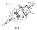
図2に示されているように、補綴心臓弁10は、例示の装着組立体100を用いて送達装置50に容易に正確に装着できる。装着組立体100は、送達装置50に解放可能に装着または結合できる位置決め装置180(位置合わせクリップとも称される)を備え得る。装着組立体100は、位置決め装置180に解放可能に結合され得る保持装置110をさらに備え得る。また、補綴心臓弁10は保持装置110に解放可能に結合でき、保持装置110は、以下においてさらに記載されているように、位置決め装置180に結合されるとき、補綴弁を送達装置50において縮めるために、補綴心臓弁を送達装置に対して所定の位置および所定の配向で保持する。Mounted Assembly As shown in FIG. 2, the
後でより完全に記載されているように、装着組立体100は、縮め装置160(図4A)などの縮め装置をさらに備え得る。保持装置110は縮め装置160に解放可能に結合でき、縮め装置の作動は、送達装置50において補綴心臓弁10を縮めることができる。 As described more fully later, the mounting
図2および図5Aを参照すると、補綴心臓弁10の流出端26は、保持装置110に結合され得るか、または、保持装置110によって支持され得る。他の実施形態では、補綴心臓弁10の流入端24は、保持装置110に結合され得るか、または、保持装置110によって支持され得る。補綴心臓弁10の配向が補綴心臓弁を移植するために使用される送達技術に依存することは、理解されるべきである。図2は、補綴弁を経大腿での送達法で自然大動脈弁に送達するために、流入端24に対して近位に位置決めされた補綴弁の流出端26を保持する保持装置110を示している。代替で、保持装置110は、補綴弁を経心室での送達法で自然大動脈弁に送達するために、流出端26に対して近位の補綴弁の流入端24を保持することができる。 With reference to FIGS. 2 and 5A, the
補綴心臓弁10を保持装置110に結合することは、例えば、製造過程および/または包装過程の一部として行うことができる。同じく製造過程および/または包装過程の一部として、事前に結合/事前に組み立てされた補綴心臓弁10および保持装置110が、補綴心臓弁10が保持装置110に結合された配向に対応する送達装置と共に包装され得る(例えば、補綴心臓弁が図2に示された経大腿の配向で保持装置に結合される場合、経大腿の送達装置は補綴心臓弁と共に包装される)。したがって、補綴心臓弁の配向と送達装置の配向とを合致させることは、例えば、補綴心臓弁10を逆に装着し、したがって、送達装置に対して正しくない配向で装着する(例えば、経大腿で配向された補綴心臓弁を経心室の送達装置に装着する、またはその逆)潜在的な手順の間違いを低減または排除することができる。 Coupling the
具体的な実施形態では、位置決め装置180は、保持装置110が最終使用者によって(保持装置110に事前に結合された補綴心臓弁10と共に)位置決め装置180に結合されるとき、補綴心臓弁10が、後に続く縮めのために送達装置の弁装着部分に対して正確に位置決めされるように、所定の場所において送達装置に事前に装着され得る。したがって、この手法では、保持装置110と補綴心臓弁10とから成る組立体が送達装置とは別に保管できるが(補綴心臓弁が保存液において保管されるときなど)、最終使用者は保持装置110を手術室において位置決め装置180に容易に連結することができ、これは、移植の直前に後に続く縮めのために、送達装置に対して所望の場所において補綴心臓弁を自動的に位置決めし、それによって、処置時間を短縮し、処置の間違いの可能性を低減する。 In a specific embodiment, the
具体的な実施形態では、事前に結合/事前に組み立てされた補綴心臓弁10および保持装置110は位置決め装置180に事前に結合でき、位置決め装置180はさらに、最終的な配向で送達装置に事前に装着され、最終使用者への出荷のために無菌包装で一緒に包装される。この手法では、最終使用者(例えば医師)が、保持装置110を位置決め装置180に結合する必要がないか、または、位置決め装置180を送達装置に装着する必要がなく、そのため処置時間をさらに短縮できる。このような実施形態は、補綴心臓弁が送達装置とは別に保存液において保存される必要がない場合、有利であり得る。例えば、いわゆる乾燥した組織の弁尖を有する補綴心臓弁は、補綴心臓弁が乾燥状態で(保存液に浸されていない)保管できるように、製造過程の間に処理される。 In a specific embodiment, the pre-coupled / pre-assembled
一部の実施形態では、保持装置110と位置決め装置180とは分離可能な構成要素ではなく、代わりに、送達装置に装着され、補綴心臓弁10を解放可能に保持するように構成される単一の保持および位置決めの装置を備える。このような実施形態は、例えば、補綴心臓弁が乾燥状態で保管できる場合に使用できる。保持および位置決めの装置は送達装置に事前に装着でき、補綴心臓弁は保持および位置決めの装置に事前に結合でき、すべての3つの構成要素は、出荷および保管ために同じ無菌包装に収容できる。保持および位置決めの装置は、補綴弁を保持するように構成される保持部分と、送達装置に装着されるように構成される位置決め部分とを備え得る。 In some embodiments, the
本明細書で使用されるとき、「事前に結合」、「事前に組み立て」、または「事前に装着」という用語は、包装され、製造者から販売業者または最終使用者(例えば病院)へと出荷される前に、製造者によって、2つの構成要素が一緒に結合もしくは組み立てられていること、または、1つの構成要素が他の構成要素に装着されていることを意味する。 As used herein, the terms "pre-combined," "pre-assembled," or "pre-installed" are packaged and shipped from the manufacturer to the distributor or end user (eg, hospital). It means that the two components are joined or assembled together by the manufacturer, or that one component is attached to the other component before it is done.
補綴心臓弁と送達装置とを正確に対にすることをさらに支援するために、構成要素のうちの1つ以上は、色付きの印で、または、補綴弁を移植するために使用される送達技術を代表する他の種類の視覚的な印で色分けされてもよい。例えば、補綴心臓弁が経大腿の送達のために保持装置110に結合されるとき、保持装置110は第1の色(例えば赤色)とでき、経大腿の送達のために構成される送達装置および/または位置決め装置も同じ第1の色とできる。別の例として、補綴心臓弁が経心室の送達のために保持装置110に結合されるとき、保持装置110は第2の色(例えば緑色)とでき、経心室の送達のための送達装置および/または位置決め装置も同じ第2の色とできる。この手法では、色分けは組立者および/もしくは使用者の選択を助けることができる、ならびに/または、補綴心臓弁と送達装置とが正確に対にされることを確実にすることができる。 To further assist in the exact pairing of the prosthetic heart valve and the delivery device, one or more of the components are marked with a colored mark or the delivery technique used to implant the prosthetic valve. It may be color-coded with other types of visual markings that represent. For example, when the prosthesis heart valve is coupled to the
送達装置
図3Aおよび図3Bは、一実施形態による送達装置50を示している。送達装置50は、取っ手52と、取っ手52から遠位に延びる外側シャフト58とを備え得る。送達装置50は、取っ手52から遠位に外側シャフト58を同軸に貫いて延びる内側シャフト60も備え得る。内側シャフト60は、補綴心臓弁が患者の身体への送達のために内側シャフトへと装着され得るため、移植カテーテルとも称され得る。一部の実施形態では、内側シャフト60は外側シャフト58に対して移動可能であり得る(つまり、内側シャフトは外側シャフトに対して、または、外側シャフトは内側シャフトに対して、回転および/または軸方向に移動させることができる)。Delivery Device Figures 3A and 3B show
送達装置50は、内側シャフト60の遠位端部分に結合されるノーズコーン64をさらに有し得る。内側シャフト60は、ノーズコーン64の近位において隣接して位置付けられた弁装着部分(または、指定された配置領域)62を有し得る。弁装着部分62は近位端68と遠位端66とを有し得る。近位端68と遠位端66との間で測定される弁装着部分62の軸方向長さLは、移植カテーテル60において完全に縮められるとき、補綴心臓弁10の軸方向長さにおおよそ等しくなることができる。送達装置50は、内側シャフト60にそれぞれ装着された近位停止部74および遠位停止部76も有することができ、近位停止部と遠位停止部との間の空間は弁装着部分を定めている。近位停止部74は、外側シャフトの遠位端部分59に、および/または、内側シャフト60の外面に装着できる。遠位停止部76はノーズコーン64の近位端部分として形成できるが、他の実施形態では、別に形成され、ノーズコーンおよび/または内側シャフト60の外面に固定され得る。 The
図示されていないが、案内ワイヤが内側シャフト60の中心内腔およびノーズコーン64の内側内腔を通じて延びることができ、それによって送達装置50は、患者の血管系へと挿入される案内ワイヤにわたって進ませることができる。 Although not shown, the guide wire can extend through the central lumen of the
取っ手52は、外側シャフト58を位置決めおよび/または操縦するように構成され得る。例えば、取っ手52は、外側シャフト58を内側シャフト60の周りに回転させるように、および/または、外側シャフト58をその長手方向軸に沿って内側シャフト60に対して滑らせるように構成されている作動機構(例えば、回転可能ノブ)を備え得る。 The
送達装置50の遠位部は、外側シャフト58の剛性を犠牲にすることなく、蛇行する生体構造を通過できるように、十分な柔軟性を有する操縦可能部分56を備え得る。また、送達装置50は、操縦可能部分56を所与の方向において湾曲させるように、または、操縦可能部分56を真っ直ぐにさせるように構成された1つ以上の引っ張りワイヤ(図示せず)を備え得る。 The distal portion of the
例えば、引っ張りワイヤは、外側シャフト58における内腔を通じて延びることができる。引っ張りワイヤの遠位端は、外側シャフト58の遠位端部分59にしっかりと固定され得る。引っ張りワイヤの近位端は、取っ手52に位置付けられる操縦機構(例えば、図示されている回転可能ノブ78、ボタンなど)に動作可能に連結され得る。操縦機構を作動させることは、引っ張りワイヤにおける張力を増加または低下させることができ、これによって操縦可能部分56を曲げさせるかまたは真っ直ぐにさせることができる。 For example, the pull wire can extend through the lumen in the
一部の実施形態では、外側シャフト58の遠位末端80が、送達装置(弁装着部分62、近位停止部74、遠位停止部76、およびノーズコーン64を含む)の比較的硬い遠位の真っ直ぐな部分の全長を最小限にするように近位停止部74の近位で直ぐ隣接するように位置決めされ、それによって送達装置50の追跡性能を向上させることができる。一部の実施形態では、引っ張りワイヤの遠位端は、操縦可能部分56の全長を最小限にするために、外側シャフトの遠位末端80またはその若干近位において外側シャフト58に固定され得る。 In some embodiments, the
図3Aおよび図3Bに示されている実施形態は、弁装着部分62上に位置する内側シャフト60に装着された膨張可能バルーン54を有する。バルーン54の近位端部分54pは近位停止部74にわたって延び得、外側シャフト58の遠位端部分59の外面に固定され得る。バルーン54の遠位端部分54dは遠位停止部76にわたって延び得、ノーズコーン64の外面に固定され得る。 The embodiment shown in FIGS. 3A and 3B has an
描写されているように、バルーン54は、近位肩部67と、遠位肩部65と、肩部65、67の間に配置される中間部分69とを有し得る。近位肩部67は弁装着部分62の近位端68とおおよそ位置合わせさせられ、遠位肩部65は弁装着部分62の遠位端66とおおよそ位置合わせさせられ得る。バルーン54の近位肩部67と遠位肩部65との両方は、中間部分69のそれぞれの端から近位停止部74および遠位停止部76まで径方向外向きに末広がりとなり、それによって概してドッグボーンの形とされたバルーン54を定めることができる。この手法では、近位肩部および遠位肩部はバルーンの傾斜した表面を定める。 As depicted, the
バルーン54は、取っ手52に位置付けられたポート53へと延びる外側シャフト58の膨張流体導管(図示せず)に、膨張流体(例えば生理食塩水)がポート53および膨張流体導管を介してバルーン54へと供給されるときにバルーン54が折り畳み構成から拡張構成へと膨張させられ得るように、流動的に結合され得る。 The
一部の実施形態では、補綴心臓弁10は、弁装着部分62上に位置するバルーン54において縮められ得る。したがって、移植部位において、バルーン54は、補綴心臓弁10をその完全に機能する大きさまで拡張させるために膨張させられ得る。傾斜した肩部67および65は、例えば、補綴心臓弁10の滑らかな拡張を容易にすることができ、拡張の間にバルーン54に対する補綴心臓弁の位置決めを維持することができる。傾斜した肩部は、移植の後のバルーン54のより容易な回収を容易にすることもできる。 In some embodiments, the
他の実施形態(図示せず)では、自己拡張補綴心臓弁が縮められ、送達装置のシースへと挿入され得る。身体における配置の後にシースは引き込まれ、補綴心臓弁は身体の内部で拡張することができる。 In other embodiments (not shown), the self-expanding prosthetic heart valve can be contracted and inserted into the sheath of the delivery device. After placement in the body, the sheath is retracted and the prosthetic heart valve can be dilated inside the body.
送達装置に関する追加の詳細は、例えば、米国特許第9,339,384号および米国特許出願公開第2017/0065415号において見出すことができ、それらの両方が本明細書において参照により組み込まれている。 Additional details regarding the delivery device can be found, for example, in US Pat. No. 9,339,384 and US Patent Application Publication No. 2017/0065415, both of which are incorporated herein by reference.
縮め装置
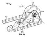
図4Aは、例示の実施形態によれば、縮め装置160を示している。縮め装置160は、顎部170の中心軸171の周りに配置されている複数の顎部170を曝す窓部または開口部172を有し得る。顎部170は、それらの内側端同士の間に可変の大きさとされた縮め開口174を定め得る。顎部170は、筐体176を備える回転部分の中に位置付けられ、筐体176に連結されて筐体176から延びるレバーまたは取っ手177の形態での作動装置に動作可能に連結され得る。Shrinking Device Figure 4A shows a shrinking
縮め装置160は、スタンドまたは基部として作用できるフレーム178をさらに備え得る。縮め装置160は、保持装置110に解放可能に結合するように構成される結合機構を備え得る。例えば、図4Aに描写されている実施形態では、フレーム178の近位面または前面166が、後でより完全に記載されているように、保持装置110の1つ以上の対応するタブと嵌まり合って係合するように構成されている1つ以上の捕獲部168(例えば、図示されている実施形態では3つ)を有し得る。図示されているように、捕獲部168は窓部172に対して径方向外向きに突出し得る。捕獲部168は窓部172の周りで周方向に分配されてもよい。 The
図4Aは、「開」位置における縮め開口174を示しており、開口174が比較的大きい直径を有するように顎部170は径方向外向きの位置に移動している。「開」位置では、拡張した環状の移植片(例えば、補綴心臓弁10)が縮め開口174へと挿入され得る。 FIG. 4A shows the contracted
図4Bは、縮め開口174へと挿入された補綴心臓弁10および送達装置50の弁装着部分62を示している。例えばレバー177を下向きに押すことによって、縮め装置160を作動させると、縮め開口174を「開」位置から「閉」位置または収縮位置へと移動させる。レバー177によって閉位置へと移動させられるとき、顎部170は、縮め開口174の大きさを縮小し、送達装置50の弁装着部分62における補綴心臓弁を圧縮するように、互いに向けて径方向内向きに移動する。 FIG. 4B shows the valve-mounted
縮め装置および関連する縮め方法の例示の実施形態は、米国特許出願公開第2015/0336150号、米国特許出願公開第2015/0190225号、米国特許出願公開第2013/0030418号、および米国特許第7,999,394号においてさらに記載されており、それらの開示は本明細書において参照により組み込まれている。 Examples of shrinking devices and related shrinking methods are U.S. Patent Application Publication No. 2015/0336150, U.S. Patent Application Publication No. 2015/0190225, U.S. Patent Application Publication No. 2013/0030418, and U.S. Patent No. 7,999,394. Further described in, their disclosures are incorporated herein by reference.
装着過程
図5A〜図5Dは、1つの例示の実施形態による、送達装置50において補綴心臓弁10を縮める方法を示している。補綴心臓弁10は、図5A〜図5Bにおいて拡張構成で示されており、図5Dにおいて圧縮構成で示されている。概して、圧縮構成における補綴心臓弁10は、拡張構成においてよりも、長い軸方向寸法と小さい径方向断面寸法とを有する。Wearing Process FIGS. 5A-5D show a method of contracting the
図5Aに示されているように、補綴心臓弁10は、弁と保持装置との組立体を形成するために、保持装置110に結合され得る。位置決め装置180は、所定の場所において、送達装置50の外側シャフト58に結合され得る。例えば、位置決め装置180の近位端は、外側シャフト58における目印70(図5B)と位置合わせさせられ、外側シャフトに対する不用意な移動(回転および軸方向の移動)に抗して外側シャフト58に固定され得る。目印70は、移植カテーテル60の弁装着部分62に対して離間され得る。目印70と弁装着部分62の近位端68との間の軸方向距離Dは、後でさらに詳述されているように、補綴心臓弁を弁装着部分62と位置合わせするためにあらかじめ決定され得る。 As shown in FIG. 5A, the
図5Bに示されているように、弁と保持装置との組立体は、送達装置50上に位置決めされ、位置決め装置180に結合され得る。送達カテーテル50に対する位置決め装置180の位置決めは、補綴心臓弁10を送達装置50に対して位置合わせするように構成され得る。例えば、保持装置110の近位端部分は位置決め装置180の遠位端に解放可能に結合され得る。送達装置50における位置決め装置180の場所があらかじめ決定されているため、送達装置50における補綴心臓弁10(保持装置110に結合されている)の場所もあらかじめ決定され得る。明確には、保持装置110が位置決め装置180に結合されるとき、補綴心臓弁10の近位端は弁装着部分62の近位端68と位置合わせさせられ得る。 As shown in FIG. 5B, the assembly of the valve and the holding device can be positioned on the
位置決め装置、保持装置および補綴弁が図5Bに示されているように送達装置に装着されて、補綴心臓弁10および送達装置50は、図5Cに示されているように、縮め装置160へと挿入され得る。保持装置110(位置決め装置180と一緒に)は縮め装置160に結合されて、補綴心臓弁10を縮め装置160の縮め顎部170に対して位置合わせすることができる。 A positioning device, a holding device and a prosthetic valve are attached to the delivery device as shown in FIG. 5B, and the
このように縮め装置に結合されるとき、縮め装置における捕獲部168との保持装置110の係合は、補綴弁10を縮め開口174内の所望の場所に配置するのに、および、補綴心臓弁および送達装置を縮め装置に対する移動に抗して保留するのに効果的である。先に記載したように、位置決め装置180は、保持装置110および補綴弁10を、送達装置に対して固定の場所で保留する。したがって、保持装置が図5Cに示されているように縮め装置に結合されるとき、補綴弁10は、弁装着部分62において補綴弁を後で縮めるために、縮め装置の中で送達装置に沿う所望の場所で保持される。有利には、使用者は、補綴弁を縮め顎部および弁装着部分62に対して手作業で位置決めする必要がなく、縮め装置を動作させる間にそれらの位置を保持する必要がない。 When coupled to the shrink device in this way, the engagement of the
そのため、縮め装置160は、図5Dに示されているように、補綴心臓弁10を送達装置50において縮めるために使用できる。後でより完全に記載されているように、縮め装置160を作動させることで、補綴心臓弁10を保持装置110から解放させることができる。また、縮め装置160を作動させることは、補綴心臓弁10を拡張構成から圧縮構成へと径方向で圧縮することができる。縮められた補綴心臓弁10は、縮小した径方向の断面寸法を有し、保持装置110から結合解除されるため、送達装置50は、縮められた補綴心臓弁10と一緒に、装着組立体100から取り外すことができる。 Therefore, the
これらの構成要素と、構成要素を使用するための様々な方法とは、以下においてさらに記載されている。 These components and the various methods for using them are further described below.
位置決め装置
図6は、位置決め装置180の1つの例示の実施形態を示している。図示されているように、図示されている実施形態における位置決め装置180は、ヒンジ部材186によって互いにヒンジで連結される第1の部分182および第2の部分184を備える二枚貝のような構成を有する本体181を備え得る。第1の部分182および第2の部分184は、開位置(図6に示されている)と閉位置(図5Cに示されている)との間で互いに対して旋回させることができる。位置決め装置180は、送達装置50に装着されている間に本体181を閉位置で保留するように構成されている、概して符号183で示されている留め付け機構または掛かり止め機構も備え得る。Positioning Device FIG. 6 shows one exemplary embodiment of the
本体181は、送達装置50の外側シャフトを受け入れる中心通路または内腔188を定める内面185を有し得る。中心通路188は、目印70の遠位で隣接する外側シャフト58の一部分72と締まり嵌めまたは摩擦嵌めを形成するような大きさとされ得る。具体的な実施形態では、本体181が一部分72の周りで閉位置にあるとき、一部分72との締まり嵌めは、通常の使用および取り扱いの間、位置決め装置をシャフトに対する回転移動および軸方向の移動に対して不動に保持するのに十分である。 The
目印70は環状の肩部もしくは隆条部とできるか、または、シャフト58に形成または印刷された線もしくは他の種類の視覚的な印とできることは、留意されるべきである。図示されている実施形態では、一部分72は、位置決め装置180の隣接する面に当接し、外側シャフト58に沿っての近位方向への位置決め装置の軸方向の移動を防止することができる環状の肩部70を定めるように、一部分72の近位のシャフト58の部分と比較して小さい外径を有し得る。 It should be noted that the
閉構成(例えば、図2および図5A〜図5C)では、第1の部分182および第2の部分184は、外側シャフト58の一部分72が本体181によって完全に包囲されるように、留め付け機構183によって閉位置で保持されている。 In a closed configuration (eg, FIGS. 2 and 5A-5C), the
描写されている実施形態では、留め付け機構183は、ヒンジ部材186と反対において第1の部分182の内面に位置付けられる外向きに延びる突出部183b(図5D)と、ヒンジ部材186の反対において第2の部分184の内面に位置付けられる内向きに延びる突出部183a(図5D)とを備える。突出部183a、183bは、互いとのスナップフィット連結を形成するように相補的な形および大きさとされ得る。したがって、第1の部分182および第2の部分184は、図5Cに示されているように、突出部183aが突出部183bにわたって滑り、突出部183bの隣接面に係合するまで、突出部183aを突出部183bに対して押し進めることで、閉構成にさせることができる。位置決め装置を閉じるとき、第2の部分184は、突出部183aに突出部183b上を通過させるために若干撓むかまたは変形することができ、それによって、第1の部分182に対して閉位置において第2の部分184を保持するために元の形に戻る。位置決め装置180を開くためには、第2の部分184は第1の部分182から離すようにこじ開けられて、第2の部分184が開位置に向けて旋回させられるとき、突出部183aに突出部183b上を元へと通過させることができる。代替の実施形態では、クリップ、フック、錠、鍵、クラップ、スナップ、ボタン、バックル、ジッパ、面ファスナ、磁石など、様々な他の種類の留め付け機構が第1の部分182および第2の部分184を閉位置で保留するために使用されてもよい。 In the embodiment depicted, the
図5Dにおいてさらに示されているように、本体181の内面185は、本体181の近位端190から本体181の遠位端192へと延びる1つ以上の溝路191を備え得る。各々の溝路191は、内面185に形成され、軸方向に離間され、周方向に配向された複数の溝194を有し得る。2つの溝路191が図5Dおよび図6に示されているが(1つが第1の部分182の内面にあり、1つが第2の部分184の内面にある)、本体181が内面185において周方向に配置される任意の数の溝路191を有し得ることは、理解されるべきである。位置決め装置が閉じられるとき、第1の部分182における各々の溝が、本体181の内面185に沿って360度にわたって延びる完全な溝を定めるために第2の部分184におけるそれぞれの溝と対にされるように、第1の部分182における溝は第2の部分184におけるそれぞれの溝と位置合わせすることができる。 As further shown in FIG. 5D, the
溝路191が内面185に空所を作り出し、本体181を通じて延びているため、殺菌ガスは、本体181が外側シャフト58に閉位置で結合されているとしても、溝路191を通じて中心通路188へと浸透するかまたは流れることができる。したがって、位置決め装置180が送達装置50に結合されるとき、中心の通路188を通じて延びる位置決め装置180の内面185と外側シャフト58の外面との両方が殺菌ガスによって殺菌できる。例えば、補綴弁と装着組立体の構成要素とが最終使用者によって包装から取り外され、図5Bに示されているように送達装置において組み立てられた後(何らかの構成要素がすでに事前に組み立てられていないかまたは事前に装着されていない場合)、補綴弁、送達装置50、および装着組立体のいずれかの再殺菌が移植の前に必要であると思われる場合は、これらの構成要素をエチレンオキシド殺菌過程(または他の殺菌ガス)に曝すことができる。 Since the
代替の実施形態では、溝194のうちの1つ以上は、本体181を通じて外面から内面185へと延びる1つ以上のスロットによって置き換えられてもよい。閉構成では、スロットは殺菌のために殺菌ガスを中心通路188へと浸透または流すことができる。 In an alternative embodiment, one or more of the
また、位置決め装置180は、本体181の遠位端192に隣接して第1の部分182に連結されたフランジ196を有し得る。フランジ196は本体181より大きい径方向の直径を有し得る。特定の実施形態では、1つ以上のタブ198がフランジ196の外側縁から径方向外向きに突出してもよい。フランジ196および/またはタブ198は、例えば、後でさらに詳述されているように、位置決め装置180を保持装置110に結合するために使用できる。 The
結合機構
図5A〜図5Dは、保持装置110が位置決め装置180に結合され、保持装置110が縮め装置160に結合される手法をさらに示している。Coupling Mechanisms FIGS. 5A-5D further show how the holding
例えば、図5Aに示されているように、保持装置110の近位端はフランジ116を有してもよく、フランジ116は、位置決め装置180のフランジ196に解放可能に結合されるようにせ構成され得る。保持装置110のフランジ116は、縮め装置160に解放可能に結合されるように構成され得る。 For example, as shown in FIG. 5A, the proximal end of the holding
特定の実施形態では、保持装置110のフランジ116は、フランジ116の近位面から軸方向外向きに突出する1つ以上の捕獲部118を有し得る。保持装置の捕獲部118は、位置決め装置180のフランジ196に位置付けられる1つ以上のタブ198と相補的である内部凹所を有し得る。別の言い方をすれば、保持装置110の捕獲部118は、位置決め装置180の対応するタブ198と嵌まり合って係合することができるように、大きさ、形、および位置が決められ得る。 In certain embodiments, the
図5Cにおいて最も良く示されているように、各々の捕獲部118は、周方向に円弧を拡げることができ、開端114と、開端114の反対の閉端115とを有し得る。捕獲部118は、捕獲部118の開端114および閉端115が周方向で並置されるように連続的に配置され得る。したがって、保持装置110と位置決め装置180との間の結合および結合解除は、位置決め装置のタブ198が保持装置の捕獲部118の開端114に隣接する状態で保持装置110のフランジ116を位置決め装置180のフランジ196に当てて配置し、次に、タブ198をそれぞれの捕獲部118の中に位置決めするために保持装置110を位置決め装置180に対して同軸で回転させることで達成され得る。 As best shown in FIG. 5C, each
例えば、保持装置110は、タブ198が開端114を通じて捕獲部118の内部凹所へと挿入され得る一方で、その挿入が捕獲部118の閉端115によって制限され得るように、保持装置110を一方向(例えば時計回り方向)に回転させることで、位置決め装置180に結合され得る。逆に、保持装置110と位置決め装置180との間での結合解除は、タブ198が開端114を通じて出ることができるように、保持装置110を反対方向(例えば反時計回り方向)に回転させることで達成され得る。 For example, the holding
具体的な実施形態では、捕獲部118は、位置決め装置と保持装置とを一緒に保持し、通常の使用および取り扱いの間にそれら2つの構成要素の間の相対移動を防止するのに十分である締まり嵌めまたは摩擦嵌めをタブ198と形成するように、大きさおよび形が定められ得る。一部の実施形態では、捕獲部118および/またはタブ198は、位置決め装置および保持装置を一緒に保留するのを助けるために、一方の構成要素に形成される突出部、および、その突出部を受け入れる他方の構成要素に形成される対応する戻り止めなど、追加の特徴を備え得る。 In a specific embodiment, the
特定の実施形態では、保持装置110のフランジ116は、フランジ116の外側縁から径方向外向きに突出する1つ以上のタブ119をさらに備え得る。先に記載したように、縮め装置160の前面166は、縮め装置160の近位面から軸方向外向きに突出する1つ以上の捕獲部168を有し得る。縮め装置の捕獲部168は、保持装置110のフランジ116に位置付けられる1つ以上のタブ119と相補的である内部凹所を有し得る。別の言い方をすれば、縮め装置160の捕獲部168は、保持装置110の対応するタブ119と嵌まり合って係合することができるように、大きさ、形、および位置が決められ得る。 In certain embodiments, the
一部の実施形態では、各々のタブ119は、フランジ116の概して平坦な突出部または延在部であり得る(例えば図5A〜図5D)。他の実施形態では、各々のタブ119は、フランジ116から外向きに延びる片持ちアームを備え得る(例えば図7A〜図7C)。また、タブ119および/または捕獲部168は、保持装置110と縮め装置160とを一緒に保留するのを助けるために追加の特徴を備え得る。例えば、図7A〜図7Cに示されているように、各々のタブ119は、片持ちアームから外向きに突出する小さいコブまたは突出部117を備え得る。コブ117は、保持装置110を縮め装置160において保留するのを助けるために、縮め装置の対応する捕獲部168において形成されている相補的に配置された戻り止め(図示せず)と係合するように構成され得る。 In some embodiments, each
図5Cおよび図5Dにおいて最も良く示されているように、各々の捕獲部168は、周方向に円弧を拡げることができ、開端164と、開端164の反対の閉端165とを有し得る。捕獲部168は、捕獲部168の開端164および閉端165が周方向で並置されるように連続的に配置され得る。したがって、縮め装置160と保持装置110との間の結合および結合解除は、タブ119が捕獲部の開端164に隣接する状態で保持装置110のフランジ166を縮め装置160の前面166に当てて配置し、次に、保持装置110を縮め装置160に対して同軸で回転させることで達成され得る。 As best shown in FIGS. 5C and 5D, each
例えば、保持装置110と縮め装置160との間の結合は、タブ119が開端164を通じて捕獲部168の内部凹所へと挿入され得る一方で、その挿入が捕獲部168の閉端165によって制限され得るように、保持装置110を一方向(例えば時計回り方向)に回転させることで達成され得る。逆に、保持装置110と縮め装置160との間での結合解除は、タブ119が開端164を通じて出ることができるように、保持装置110を反対方向(例えば反時計回り方向)に回転させることで達成され得る。 For example, the coupling between the holding
具体的な実施形態では、捕獲部168は、保持装置110を縮め装置160において保持し、通常の使用および取り扱いの間にそれら2つの構成要素の間の相対移動を防止するのに十分である締まり嵌めまたは摩擦嵌めをタブ119と形成するように、大きさおよび形が定められ得る。一部の実施形態では、捕獲部168および/またはタブ119は、保持装置を縮め装置160において保留するのを助けるために、一方の構成要素に形成される突出部(例えば突出部117)、および、その突出部を受け入れる他方の構成要素に形成される対応する戻り止めなど、追加の特徴を備え得る。 In a specific embodiment, the
代替の実施形態では、保持装置110は、捕獲部118およびタブ119の独立したセットを有していなくてもよい。例えば、保持装置110は1つ以上の一体化した結合部材(図示せず)を有してもよく、結合部材の各々は、位置決め装置180における対応するタブ198のための捕獲部、および、縮め装置160における対応する捕獲部168のためのタブの両方として機能するように構成され得る。別の言い方をすれば、保持装置110における一体化した結合部材は、位置決め装置180におけるタブ198と、縮め装置160における捕獲部168とに嵌まり合って係合するように構成され得る。 In an alternative embodiment, the holding
代替の実施形態(図示せず)では、対応する捕獲部およびタブの相対位置は切り替えられてもよい。例えば、位置決め装置180は、保持装置110に位置付けられる1つ以上のタブと嵌まり合って係合することができる1つ以上の捕獲部を有し得る。同様に、縮め装置160は、保持装置110に位置付けられる1つ以上の捕獲部と嵌まり合って係合することができる1つ以上のタブを有し得る。 In an alternative embodiment (not shown), the relative positions of the corresponding captures and tabs may be switched. For example, the
さらに、図5A〜図5Dは、相補的に構成されたタブと捕獲部とが、保持装置110と位置決め装置180との間、および、縮め装置160と保持装置110との間において結合機構を実施するために使用されていることを示しているが、描写されている実施形態が例示の目的だけのためであって限定ではないことは、理解されるべきである。保持装置110と位置決め装置180との間、および、縮め装置160と保持装置110との間で結合を達成するために、クリップ、フック、錠、鍵、クラップ、スナップ、ボタン、バックル、ジッパ、面ファスナ、磁石など、他の結合機構を独立または組み合わせで採用することもできる。 Further, in FIGS. 5A-5D, the complementary tabs and captures implement a coupling mechanism between the holding
保持装置
保持装置110は、補綴心臓弁10を拡張構成において保持するように構成され、補綴心臓弁10を送達装置50の弁装着部分62において縮めることができるように補綴心臓弁10を縮め装置160に挿入させるように構成され得る。Retaining device The holding
一部の実施形態では、保持装置110は、補綴心臓弁10が拡張構成にあるとき、補綴心臓弁10を保持装置110に固定するように構成され、補綴心臓弁10が縮め装置で拡張構成から圧縮構成へと圧縮されるとき、補綴心臓弁10を保持装置110から解放するように構成される1つ以上の保留部材を備え得る。 In some embodiments, the
以下に記載されている保持装置110の実施形態は、特定の構造的な構成で配置される弁位置合わせ部分および弁保留部分を備えるが、他の構造の構成は同じ機能を達成することも可能であることは理解されるべきであり、これらも本開示の範囲内にある。例えば、一部の実施形態では、弁位置合わせ部分は弁保留部分の内部に配置され得る。一部の実施形態では、弁位置合わせ部分と弁保留部分とは一体品とでき、互いから分離可能である必要はない。一部の実施形態では、保留部材は保持装置110の任意の部分に位置付けられ得る。一部の実施形態では、保留部材の各々は、伸縮する手法で軸方向に延ばされたり後退させられたりすることができる軸方向に延びる伸縮可能な梁を備え得る。 The holding
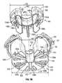
ここで図7A〜図7Cを参照すると、保持装置110は、第1の部分(「弁位置合わせ部分」とも称される)120と第2の部分(「弁保留部分」とも称される)140とを備え得る。後で記載されているように、弁保留部分140は弁位置合わせ部分120へと同軸で挿入され得る。さらに、弁保留部分140は中心軸112に沿って弁位置合わせ部分120に対して近位または遠位に移動することができる。 Referring here to FIGS. 7A-7C, the holding
図7Bに示されているように、弁保留部分140は、中心軸112を貫いて近位板150の外周部154から延びる空所152を有することを除いて概して円筒の形を有し得る近位板150を備え得る。空所152は、中心軸112の近くにおいてより狭く(例えば内側幅W2)、周辺部の近くにおいてより広い(例えば外側幅W2')幅を有し得る。 As shown in FIG. 7B, the
弁保留部分140は、集合的に保留部材142と称される複数の弁保留部材142a、142b、142cをさらに備え得る(3つが示されている)。弁保留部分140は、集合的に腕部146と称される複数の延在腕部146a、146b、146c、146dも備えてもよく(4つが示されている)、それらは板150の遠位面から軸方向に延びている。図7Aに示されているように、各々の保留部材142は、板150の遠位面から軸方向に延びる片持ち梁145と、梁145の遠位端部分から径方向外向きに延びる突出部144とを備え得る。保留部材142は、後でさらに記載されているように、補綴弁10を保持装置110において解放可能に保持するように構成される。腕部146は縮め装置160の縮め顎部170と係合するように構成され、縮め顎部170は、縮める過程の間、弁位置合わせ部分120に対する弁保留部分140の移動を作り出し、後でさらに記載されているように、保留部材142を補綴心臓弁10から係合解除させる。 The
複数の保留部材142は、概して均一なパターンで互いに対して周方向で位置決めされ得る。例えば、図7A〜図7Cは、周方向において互いから約120度で離間されている3つの保留部材142を示している。保留部材のうちの2つ142a、142cは空所152の両側に対称的に位置付けられ、第3の保留部材142bは空所152の直径方向における反対に位置付けられ得る。 The plurality of retaining
複数の腕部146は、概して均一なパターンで互いに対して周方向で位置決めされ得る。例えば、図7A〜図7Cは、周方向において互いから約90度で離間されている4つの腕部146を示している。4つの腕部146は空所152の周りに概して対称的に位置付けることができる(つまり、2つの腕部146a、146bは一方の側に位置付けられ、2つの腕部146c、146dは空洞152の反対側に位置付けられる)。 The plurality of
一部の実施形態では、少なくとも1つの腕部146は、周方向において一対の隣接する保留部材142の間に配置され得る。例えば、描写されている実施形態では、空所152の上縁の近くの2つの腕部146a、146dは2つの保留部材142a、142cの間に位置付けられ、1つの腕部146bは保留部材142aと142bとの間に位置付けられ、1つの腕部146cは保留部材142bと142cとの間に位置付けられている。 In some embodiments, at least one
図7Cに示されているように、弁位置合わせ部分120は、本体130と、本体130の近位端に連結されたフランジ116とを備え得る。本体130は、中心軸112を貫いて本体130の外周部134から延びる空所132を有することを除いて概して円筒の形を有し得る。図7Bを参照すると、空所132は、中心軸112の近くにおいてより狭く(例えば内側幅W1)、周辺の近くにおいてより広い(例えば外側幅W1')幅を有し得る。 As shown in FIG. 7C, the
概して、図7Bを参照すると、弁位置合わせ部分120の本体130の直径D1は弁保留部分140の近位板150の直径D2より大きくできる。一方、弁位置合わせ部分120の空所132の幅は、弁保留部分140が図8に示されているように弁位置合わせ部分120へと挿入され得るように、弁保留部分140における空所152の幅より小さくできる(例えば、W1<W2およびW1'<W2')。 In general, referring to FIG. 7B, the diameter D1 of the
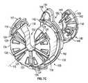
再び図7Cおよび図8を参照すると、弁位置合わせ部分120の本体130は、本体の近位面に開放する中空の内部空間136を定め得る。内部空間136は、保留部材142、腕部146、および近位板150を含め、弁保留部分140を収容する大きさおよび形とされ得る。図8に示されているように、弁保留部分140の空所152と弁位置合わせ部分120の空所132との間に適切な位置合わせがある場合、弁保留部分140は、本体130の前面における近位開口部を通じて中空の内部空間136の中および/または外へと滑るように構成され得る。 With reference to FIGS. 7C and 8 again, the
本体130は、中空の内部空間136の壁を定める遠位面122をさらに有し得る。図示されているように、遠位面122は、弁保留部分140の複数の腕部146の遠位端部分を受け入れるように大きさ、形、および位置がそれぞれ決められる複数の開口124(例えば、4つの開口124a、124b、124c、および124dが示されている)を備え得る。また、本体130は、弁保留部分140の複数の保留部材142の遠位端部分を受け入れるように大きさ、形、および位置がそれぞれ決められる複数の補助開口126(例えば、3つの補助開口126a、126b、および126cが示されている)をさらに備え得る。 The
補助開口126は、遠位面122に隣接して遠位面122に対して近位に凹まされ得る。補助開口126は複数の開口124より径方向で長くなり得る。補助開口126の各々は外周部134から本体130の空所132へと延び得る。 The
開口124の周方向の位置および補助開口126の周方向の位置は、対応する腕部146の周方向の位置および保留部材142の周方向の位置とそれぞれ概して合致するように構成され得る。 The circumferential position of the
例えば、複数の開口124は、概して均一なパターンで互いに対して周方向で位置決めされ得る。図7Bに示されているように、4つの開口124は周方向において互いから約90度で離間でき、4つの開口124は空所132の周りに概して対称に位置付けられ得る(つまり、2つの開口124a、124bは一方の側に位置付けられ、2つの開口124c、124dは空所132の反対の側に位置付けられる)。 For example, the plurality of
同様に、複数の補助開口126は、概して均一なパターンで互いに対して周方向で位置決めされ得る。図示されているように、3つの補助開口126は周方向において互いから約120度で離間され得る。補助開口のうちの2つ126a、126cは空所132の両側に対称的に位置付けられ得、第3の補助開口126bは空所132の直径方向における反対に位置付けられ得る。 Similarly, the plurality of
特定の実施形態では、遠位面122は、外周部134から本体130の空所132へと各々が延び得る複数の凹所128をさらに備え得る。図7Bに描写されているように、例えば、2つの凹所128は、第3の補助開口126bの両側に対称的に位置付けることができ、第3の補助開口126bと約60度の角度を各々形成する。 In certain embodiments, the
適切な位置合わせである場合、図7Aに示されているように、複数の腕部146が対応する開口124を通じて延びることができるように、および、複数の保留部材142が対応する補助開口126を通じて延びることができるように、弁保留部分140は弁位置合わせ部分120へと挿入され得る。したがって、弁位置合わせ部分120に対する弁保留部分140の遠位への移動は、腕部146の遠位端部分および保留部材142の遠位端部分を、弁位置合わせ部分120の遠位面122に対して遠位に押すことができる。逆に、弁位置合わせ部分120に対する弁保留部分140の近位への移動は、腕部146の遠位端部分および保留部材142の遠位端部分を、弁位置合わせ部分120の遠位面122に対して近位に引き込むことができる。 With proper alignment, as shown in FIG. 7A, the plurality of
図7A〜図7Cに描写されている実施形態は4つの腕部146(および4つの対応する開口)と3つの保留部材142(および3つの対応する補助開口126)とを示しているが、任意の数の腕部(および対応する開口)と任意の数の保留部材(および対応する補助開口)とが使用され得ることは理解されるべきである。さらに、腕部(および対応する開口)と保留部材(および対応する補助開口)とが周方向において互いから等しく離間される必要はない。 The embodiments depicted in FIGS. 7A-7C show four arms 146 (and four corresponding openings) and three retaining members 142 (and three corresponding auxiliary openings 126), but are optional. It should be understood that a number of arms (and corresponding openings) and any number of retaining members (and corresponding auxiliary openings) can be used. Moreover, the arm (and corresponding opening) and the retaining member (and corresponding auxiliary opening) need not be equally separated from each other in the circumferential direction.
弁保持体境界部
先に記載したように、径方向に拡張可能および圧縮可能な補綴移植片が保持装置110に解放可能に結合され得る。明確には、補綴心臓弁10などの補綴移植片が弁保留部分140に解放可能に結合でき、保持装置110の弁位置合わせ部分120に対して遠位に位置決めされ得る。Valve Holder Boundary As described above, a radially expandable and compressible prosthetic implant can be releasably coupled to the
例えば、図8および図9Aは、補綴心臓弁10を拡張構成で保持する保持装置110の異なる図を示している。図9Bは、補綴心臓弁10が保持装置110から取り外され、送達装置50のバルーン54において縮められた後の保持装置110を示している。 For example, FIGS. 8 and 9A show different views of the
補綴心臓弁10が拡張構成にあるとき、補綴心臓弁10の直径DEは空所132の内側幅W1より概して大きくなり得る(例えば図9A参照)。したがって、保持装置110は、補綴心臓弁10が拡張構成にあるとき、補綴心臓弁10の近位への移動を防止することができる。しかしながら、補綴心臓弁10が圧縮構成にあるとき、補綴心臓弁10の直径DCは空所132の内側幅W1より小さくなり得る(例えば図9B参照)。したがって、縮めの後、送達装置50は、それにおいて縮められた補綴心臓弁10と一緒に、保持装置110から空所132を通じて近位へ引き込むことができる。When the
一部の実施形態では、保持装置110は、弁保留部分140を弁位置合わせ部分120に対して近位へ付勢する付勢機構を備え得る。一例では、図8は、ピストン部材148の形態であり得る弁位置合わせ部分120に位置付けられるそれぞれの隣接する表面と境界を接する弁保留部分140に位置付けられる2つの付勢部材138を示している。 In some embodiments, the holding
保留部材142が補綴心臓弁10に結合されるとき、バネ板または付勢バネなどの付勢部材138は、予荷重が掛けられ、接触するピストン部材148に対して付勢力を発揮することができる。保留部材142が補綴心臓弁10に対して縮め顎部170によって内向きに押されるとき、付勢部材138からの付勢力は、保留腕部を補綴弁から近位へ移動させるように、弁保留部分を弁位置合わせ部分に対して移動させる。付勢機構は、同様の極を伴う2つの磁石(図示せず)の間で発生させられる電磁気の反発力など、任意の機械的および/または非機械的な手段を用いて実施され得る。また、任意の数の付勢部材が保持装置において採用され得る。付勢部材は、弁位置合わせ部分120および弁保留部分140とは別の構成用であってもよい。 When the retaining
図10は、一実施形態による、補綴心臓弁10と保持装置110との間の結合境界部の一部分の拡大図を示している。補綴心臓弁10は、内部空間35を定める拡張構成で示されている。 FIG. 10 shows an enlarged view of a part of the coupling boundary between the
前述したように、各々の保留部材142は、梁145の遠位端部分から径方向外向きに延びる突出部144を備え得る。片持ち梁145の各々は、外向き方向に予荷重が掛けられ得るかまたは付勢され得る。したがって、突出部144の各々は、補綴心臓弁10が拡張構成にあるとき、補綴心臓弁10の内部空間35から補綴心臓弁の一部分を通じて補綴心臓弁10の外側の場所へと延び得る。この手法では、保留部材142は補綴心臓弁10を保持装置110に引っ掛けることができる。 As mentioned above, each retaining
一部の実施形態では、各々の突出部144が、梁145の遠位端部分と接合する基礎部分144bと、基礎部分144bに対して径方向外向きに突出するヘッド部分144hとを備え得る。一部の実施形態では、基礎部分144bは、径方向外向きで、梁145に対して概して垂直に延びる近位面144vを有し得る。一部の実施形態では、ヘッド部分144hは、先端部分144tに向けて傾斜または湾曲する近位傾斜面144sを有し得る。近位傾斜面144sは近位鉛直面144vから先端部分144tへと延び得る。 In some embodiments, each
一部の実施形態では、基礎部分144bは先端部分144tより大きい長手方向の寸法WDを有し得る。一部の実施形態では、突出部144は、その長手方向の寸法WDが基礎部分144bから先端部分144tへと漸進的に小さくなるように、概して先細りの形を有し得る。In some embodiments, the base portion 144b may have alongitudinal dimension W D greater than the tip portion 144t. In some embodiments, the projecting
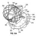
図10に示されているように、補綴心臓弁10の近位端部分は、フレーム12の複数の近位の結節または頂部38によって定めることができ、結節または頂部38の各々は、フレームの周方向で隣接する斜めの2つの支柱28の交差部において形成され得る。図示されているように、各々の突出部144は、隣接する開放セル30を通じて径方向外向きに延び得る。また、梁145は、フレーム12の内面に対して径方向外向きに付勢されるように予荷重が掛けられ得る。したがって、図示されている実施形態における保留部材142は、保留部材の外向きの付勢力を介して、および、選択された頂部38におけるフレームの支柱へと引っ掛かる突出部144によって、フレーム12(延いては、補綴弁)を保持装置にしっかりと保持することができる。 As shown in FIG. 10, the proximal end portion of the
前述したように、1つ以上の付勢部材は、弁保留部分140を弁位置合わせ部分120に対して近位に付勢するように保持装置110へと組み込まれ得る。また、基礎部分144bの近位面144vは、隣接する近位の結節38と、その結節38において交差する2つの斜めの支柱28とに係合することができる。このようにして、付勢部材は保留部材142を近位へと駆り立て、これがさらに弁位置合わせ部分120の遠位面122に対してフレーム12を駆り立てる。 As mentioned above, one or more urging members may be incorporated into the holding
図10に示されているように、近位の結節38のうちの少なくとも一部(例えば、符号38a)は保持装置110の弁位置合わせ部分120の遠位面122と直接的な接触にある。したがって、突出部144によってフレーム12に適用される(近位方向における)力にも拘らず、遠位面122は、補綴心臓弁10が圧縮構成にない限り、フレーム12の近位への移動を阻止することができる(注:圧縮構成では、先に記載したように、補綴心臓弁10の直径が空所132の内側の幅より小さいため、すべての近位の結節38は空所132の中に位置付けられる)。それでもなお、保留部材142によって加えられる力は、それらの近位の結節38aを遠位面122と接触させたままにすることができる。 As shown in FIG. 10, at least a portion of the proximal nodule 38 (eg, reference numeral 38a) is in direct contact with the
一部の実施形態では、近位の結節38のうちの一部(例えば、符号38b)は、空所132、補助開口126、または凹所128と位置合わせさせられ得、そのためそれらは遠位面122と直接的に接触しない。それでもなお、すべての近位の結節38a、38bは遠位面122と概して同一平面状であり得る。 In some embodiments, some of the proximal nodules 38 (eg, reference numeral 38b) can be aligned with
図10に示されているように、保持装置110の各々の腕部146は、腕部146の遠位端部分に沿って傾斜面147を備え得る。傾斜面147は、径方向においてある程度外方を向き、軸方向においてある程度遠位を向くように配向され得る。補綴心臓弁10が拡張構成にあるとき、傾斜面147の少なくとも内側部分147iは補綴心臓弁10の内部空間35へと延びることができる。また、傾斜面147の外側部分147oは、フレーム12に対して径方向外側で、および弁位置合わせ部分120の遠位面122に対して遠位に位置付けることができる。 As shown in FIG. 10, each
一部の実施形態では、保留部材142は、補綴心臓弁10が拡張構成にあるときに腕部146に対して径方向外向きに延び得る。例えば、突出部144の先端部分144tは、補綴心臓弁10が拡張構成にあるとき、腕部146の傾斜面147(外側部分147oを含む)に対して径方向外向きに延びることができる。 In some embodiments, the retaining
補綴心臓弁10が縮め装置160で拡張構成から圧縮構成へと縮められるとき、縮め装置160の顎部170は保持装置110の保留部材142を補綴心臓弁10の内部空間35へと径方向内向きに押す。顎部170は、腕部146も移動させ、そのため、保留部材142が補綴弁から引き込まれるまで、弁保留部分140を補綴心臓弁10に対して軸方向で近位に移動させる。顎部170を引き続き移動させることで、補綴弁を送達装置において縮めさせる。この手法では、縮め装置160が作動させられるとき、補綴心臓弁は弁保持体110から解放される。この過程は後でさらに記載されている。 When the
図11Aは、保持装置210の別の実施形態に結合された補綴心臓弁10を示しており、保持装置210は保持装置110と同様の構造および弁境界部を有する。例えば、保持装置210は、後に記載されているようないくつかの追加の特徴を除いて、図7A〜図7Cに示されているような弁位置合わせ部分120および弁保留部分140も備え得る。 FIG. 11A shows a
図11Aに示されているように、保持装置210は保留部材142の各々のための傾斜した境界部を備え得る。明確には、保持装置210の弁位置合わせ部分120は内向きに延びる複数の傾斜突起260を備え得る。各々の傾斜突起260は、対応する保留部材142に対して径方向外向きに位置決めされ得る。各々の傾斜突起260は、ある程度径方向内方を向き、ある程度軸方向近位を向くように配向された傾斜内側面262を有し得る。 As shown in FIG. 11A, the holding
対応するように、各々の保留部材142は、対応する突起260に隣接する傾斜突出部264を有し得る。各々の傾斜突出部264は、ある程度径方向外方を向き、ある程度軸方向遠位を向くように配向された傾斜外側面266を有し得る。傾斜外側面266は、隣接する突起260の対応する傾斜内側面262に対して相補的に位置、大きさ、および形が決められ得る。したがって、傾斜突起260は、傾斜内側面262と傾斜外側面266との間の滑り係合によって、対応する傾斜突出部264と境界を接するように構成され得る。 Correspondingly, each retaining
保持装置210は、弁保留部分140を弁位置合わせ部分120に対して近位へ付勢する付勢機構も備え得る。図11Bは付勢機構の代替の実施形態を示しており、保持装置210の弁位置合わせ部分120に位置付けられた付勢部材238が、保持装置210の弁保留部分140に位置付けられた対応するピストン部材248と境界を接している。保留部材142が補綴心臓弁10に結合されるとき、付勢部材238は、ピストン部材248によって、荷重の掛かる位置へと遠位に押される。保留部材142が補綴心臓弁10から解放されるとき、付勢部材238はその荷重の掛かっていない位置へと戻り、ピストン部材148を近位方向において押す。 The holding
補綴心臓弁10を保持装置210に装着するために、弁保留部分140は弁位置合わせ部分120に対して遠位に移動させられ得る。保留部材142と、対応する傾斜突起260との間の傾斜した境界部のため、保留部材142の遠位端部分(突出部144を含む)は、補綴心臓弁10が拡張構成にあるとき、補綴心臓弁10の内部空間35へと容易に挿入され得るように、径方向内向きに移動する。次に、片持ち梁145が外向きに傾き、その予荷重の掛かる位置に向けて戻るとき、突出部144は、補綴心臓弁10の内部空間35からフレーム12の開口部を通じて補綴心臓弁10の外側の場所まで延びることで、補綴心臓弁10を「掴む」ことができる。 To attach the
逆に、保留部材142が、例えば、後でより完全に記載されるような縮める過程の間、補綴心臓弁10から解放されるとき、弁保留部分140は、付勢部材238の力の下で、および/または、縮め顎部170と腕部146との間の接触を通じて、弁位置合わせ部分120に対して近位方向に移動するように駆り立てられ得る(傾斜した腕部146は、図11A〜図11Bの実施形態において任意選択である)。弁保留部分140が近位へと移動させられるとき、保留部材142の遠位端部分は、傾斜した表面のため、フレームのセル30から解放するために補綴弁に対して径方向内向きに移動する。弁保留部分140を引き続き移動させることで、保留部材142の遠位端部分を補綴心臓弁10の内部空間35から引き込む。 Conversely, when the retaining
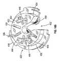
縮める過程
図12A〜図12Bは、1つの例示の実施形態による、送達装置50において補綴心臓弁10を縮める方法を示している。描写されている実施形態では、保持装置110が縮め装置160に結合されるとき、縮め装置160の顎部170の近位の縁は弁位置合わせ部分120の遠位面122と位置合わせさせられる。Shrinking Process Figures 12A-12B show a method of shrinking the
図12Aに示されているように、縮め装置160の作動の間、縮め装置160の閉じている顎部170は、各々の突出部144の先端部分144t(補綴心臓弁の外側にある)に最初に接触することができる。顎部170がさらに閉じて縮め開口174の大きさを縮小するとき、顎部は突出部144をフレーム12に対して径方向内向きに押す。基礎部分144bの近位面144vが補綴心臓弁10の内部空間35へと押された後、突出部144によってフレーム12に加えられる把持力は、フレーム12がここではヘッド部分144hの近位傾斜面144sと境界を接するため低下する。保持装置110における付勢部材が保留部材142を近位方向において駆り立てるため、突出部144は、付勢部材の力の下で近位へ移動するとき、滑り落ちてフレーム12の把持を解放する。 As shown in FIG. 12A, during the actuation of the
顎部170が径方向内向きに閉じ続けるとき、顎部170は腕部146の傾斜面147と境界を接し、傾斜面147において滑る。例えば、閉じている顎部170は傾斜面147の外側部分147oと接し、傾斜面147において径方向内向きに滑ることができる。結果として、閉じている顎部170は、傾斜面147に力を発揮することができ、腕部146と、延いては保留部材142とを、弁位置合わせ部分120に対して近位方向において移動させることができる。腕部146の遠位端部分が補綴心臓弁10の内部空間35から近位に引き込むとき、閉じている顎部170はフレーム12と接し、径方向内向きの圧力をフレーム12に加えることができる。結果として、補綴心臓弁10は径方向に圧縮させられ得る。腕部146(および保留部材142)が内部空間35から完全に排出されるとき、補綴心臓弁10は送達装置において圧縮構成へと完全に縮められ得る。 When the
補綴心臓弁10を縮めることでフレーム12を軸方向に細長くさせる。しかしながら、フレーム12は、補綴心臓弁10が縮め装置160で拡張構成から径方向に圧縮されるときに補綴心臓弁10の近位端部分を弁位置合わせ部分120の遠位面122と接触したままにできるため、遠位方向(つまり、図12Bに矢印Aによって指示されている方向)において細長くすることができる。先に記載したように、補綴心臓弁10が圧縮構成にない限り、フレーム12の近位の結節38aのうちの少なくとも一部は弁位置合わせ部分120の遠位面122に当接している。したがって、遠位面122は、縮める過程の間にフレーム12が近位方向に細長くなるのを防止する障壁として供することができる。 By contracting the
図12A〜図12Bに示されているように、保持装置110は、保持装置110が送達装置50に装着された位置決め装置180に結合されるとき、弁位置合わせ部分120の遠位面122が弁装着部分62の近位端68と位置合わせされるように構成され得る。したがって、補綴心臓弁10の近位端は、縮める過程の間に弁装着部分62の近位端68と正確に位置合わせされ得る。先に記載したように、弁装着部分62の軸方向長さLは、補綴心臓弁10が圧縮構成にあるとき、補綴心臓弁10の軸方向長さとおおよそ等しくなり得る。補綴弁が近位方向において細長くなることから防止されているため、補綴心臓弁10が完全に圧縮されるとき、補綴心臓弁10の遠位端は、弁装着部分62の遠位端66と正確に位置合わせされることになり得る。そのため、開示されている装置の組立体および方法は、例えば、送達装置50のバルーン54における補綴心臓弁10の素早く容易で正確な縮めを助けることができる。 As shown in FIGS. 12A-12B, the holding
代替の実施形態
図15A〜図15Bは、保持装置310の別の実施形態に結合された補綴心臓弁のフレーム12を示しており、保持装置310は異なる弁保留/解放機構を有する。保持装置310は弁位置合わせ部分320と1つ以上の弁保留部材340とを備える。描写した実施形態では、3つの弁保留部材340が示されているが、1つ、2つ、または4つ以上の弁保留部材340が含まれ得ることは、理解されるべきである。各々の弁保留部材340はヘッド部分342と本体部分344とテイル部分346とを備え得る。Alternative Embodiments FIGS. 15A-15B show a prosthetic
弁位置合わせ部分320は、本体部分330と、本体部分330の近位端に連結されたフランジ316とを有し得る。フランジ316は、前述したように、位置決め装置180および/または縮め装置160に解放可能に結合するように構成され得る。本体部分330は、その中心軸を貫いて本体部分330の外周部334から延びる空所332を有することを除いて概して円筒の形を有し得る。 The
本体部分330は、複数の開口324を備え得る遠位面322を有する。例えば、図15Aに描写されている実施形態では、3つの開口324が周方向において互いから約120度で離間されている。開口324のうちの2つは空所332の両側に対称的に位置付けられ得、第3の開口324は空所332の直径方向における反対に位置付けられ得る。 The
本体部分330は、遠位面322とフランジ316との間に位置付けられ、外周部334から径方向内向きに延びる複数の内側パネル326を有し得る。図15Aに示されているように、各々の内側パネル326は、対応する開口324の近位で反対にあるように位置決めおよび配向され得る。 The
後で記載しているように、弁保留部材340は、図15A〜図15Bに示されているような弁係合位置から、図15Cに示されているような弁解放位置を通って、図15Dに示されているような収容位置へと移行させることができる。 As described later, the
弁係合位置では(例えば、図15A〜図15B参照)、各々の弁保留部材340は、対応する内側パネル326から、遠位面322における対応する開口324を通じて、軸方向に延びることができる。ヘッド部分342は、本体部分344およびテイル部分346に対して径方向外向きに突出し、テイル部分346は、対応する内側パネル326に結合される。明確には、各々のヘッド部分342は、補綴心臓弁の開放したフレームセルを通じて径方向外向きに延びることができる。それによって、ヘッド部分342は、フレーム12の支柱部分を把持し、補綴心臓弁を径方向拡張構成において保留することができる。 In the valve engagement position (see, eg, FIGS. 15A-15B), each
描写されている実施形態では、各々の内側パネル326は棚部材336を備え、弁保留部材340のテイル部分346が棚部材336に解放可能に固定されるように構成される。例えば、テイル部分346の近位端部分は、棚部材336の中間に位置付けられる溝338に受け入れられることができ、溝338を包囲する隆条部339は、テイル部分346に適用される力がないかまたは不十分であるとき、テイル部分346が溝338から外れるのを防止することができる。 In the embodiment depicted, each
一部の実施形態では、弁保留部材340の本体部分344は、弁位置合わせ部分320の本体部分330にヒンジで連結されている。例えば、図15A〜図15Bに描写されている実施形態では、弁保留部材340の本体部分344は、隣接する開口324にわたって延び、遠位面322に結合されているヒンジ345を備える。そのようにして、弁位置合わせ部分320のテイル部分346が棚部材336から取り外されるとき(例えば、溝338から外れるとき)、弁位置合わせ部分320はヒンジ345の周りに旋回することができる。 In some embodiments, the
補綴弁の縮めは、前述したように、縮め装置160の作動によって達成され得る。縮め装置160の閉じている顎部170は、フレーム12に対して弁保留部材340のヘッド部分342を径方向内向きに押すことができる。ヘッド部分342がフレーム12の把持を失った後、弁保留部材340は弁解放位置へと移行され(例えば、図15C参照)、補綴弁は径方向圧縮構成に縮められ得る。 The shrinkage of the prosthetic valve can be achieved by the operation of the
閉じている顎部170がヘッド部分342に十分な力を加えるとき、力はテイル部分346に伝達され、それによってテイル部分346は隆条部339の抵抗を上回り、棚部材336から外れることができる。一部の実施形態では、テイル部分346は、加えられた力に応じて若干撓み、それによってテイル部分346が棚部材336から外れるのを容易にすることができるように、弾性の材料を備え得る。 When the
顎部170が縮める過程の間に閉じ続けるとき、顎部170はヘッド部分342を径方向内向きに押し続けることができ、ヘッド部分342が遠位面322の近位に位置付けられ、弁保留部材340が収容位置へと移行されるまで(例えば、図15D参照)、対応する弁保留部材340をヒンジ345の周りに回転させることができる。 When the
一部の実施形態では、弁保留部材340は、弁係合位置にあるときに付勢され、収容位置にあるときに付勢されないように構成される付勢部材(図示せず)を備え得る。このようにして、テイル部分346が棚部材336から外された後、付勢力は弁保留部材340を収容位置へと移動させることができる、または、その移動を容易にすることができる。すべての弁保留部材340が収容位置にあるとき、補綴心臓弁は送達装置において圧縮構成へと完全に縮められ得る。 In some embodiments, the
図16A〜図16Dは、補綴弁のフレーム12を保留および解放するための保持装置410の代替の実施形態を示している。保持装置410は弁位置合わせ部分420と1つ以上の弁保留部材440とを備える。描写した実施形態では、3つの弁保留部材440が示されているが、1つ、2つ、または4つ以上の弁保留部材440が含まれ得ることは、理解されるべきである。 16A-16D show an alternative embodiment of the holding
図16Bに示されているように、弁位置合わせ部分420は、本体部分430と、本体部分430の近位端に連結されたフランジ416とを有し得る。フランジ416は、前述したように、位置決め装置180および/または縮め装置160に解放可能に結合するように構成され得る。本体部分430は、その中心軸を貫いて本体部分430の外周部434から延びる空所432を有することを除いて概して円筒の形を有し得る。本体部分430は、複数の開口424を備え得る遠位面422を有する。例えば、図16Bは遠位面422における7つの開口424を示している。 As shown in FIG. 16B, the
図16Aに示されているように、各々の弁保留部材440は基礎部分442と第1の脚部444と第2の脚部446とを備え得る。第1の脚部444および第2の脚部446は基礎部分442から延び、2つの片持ち梁を形成している。各々の脚部444、446の遠位端部分は脚部に対して垂直な力を加えることで撓むことができる。基礎部分442はフランジ416の近位に位置決めされ、第1の脚部444および第2の脚部446は弁位置合わせ部分420を貫いて延び、2つの隣接する開口424を通じて遠位面422の遠位へとさらに延びることができる。 As shown in FIG. 16A, each
第1の脚部444は概して基礎部分442に対して垂直である。第1の脚部444の遠位端部分447が棚部448を備え得る。棚部448と基礎部分442との間の距離は、基礎部分442がフランジ416の近位端に当接するかまたは隣接するとき、第1の脚部444の遠位端部分447が遠位面422の遠位にあり、第1の脚部444が貫いて延びる開口に隣接する場所において棚部448が遠位面422に圧し掛かることができるように、弁位置合わせ部分420の軸方向長さとほとんど同じかまたは若干長い。棚部448が遠位面422に圧し掛かるとき、弁保留部材440は、弁位置合わせ部分420に解放可能に結合され、弁位置合わせ部分420に対する軸方向の移動が規制される。 The
第2の脚部446は、第1の脚部444と概して平行である近位部分450と、第1の脚部444に対して斜めであり、第1の脚部444から離れるように傾斜する遠位部分452とを備える。遠位部分452の先端部分454は、フレーム12の一部分と係合することができる切込みまたはフック456を形成するように径方向外向きに延び得る。第1の脚部444および第2の脚部446が2つの隣接する開口424を通じて延びるとき、第2の脚部446の先端部分は補綴心臓弁の開放フレームセルを貫いて径方向外向きに延びるように構成されている。それによって、第2の脚部446における切込み456は、フレーム12の支柱部分を把持し、補綴心臓弁を径方向拡張構成において保留することができる(例えば、図16B参照)。 The
一部の実施形態では、フレーム12は保持装置410から離れて保持され得る。例えば、フレーム12が、径方向拡張構成において(図16C)、または、縮める過程の間(図16D)、弁保留部材440によって保留されるとき、フレーム12の近位端は、遠位面422から所定の距離で離間され得る。 In some embodiments, the
弁保留部材440は、近位方向において第1の脚部444および第2の脚部446を近位方向において駆り立てるように構成された、図16Dに示されているようなコイルバネなどの付勢部材458をさらに備え得る。一部の実施形態では、付勢部材458は第2の脚部446の近位部分450に結合され得る。他の実施形態では、付勢部材458は第1の脚部444に結合され得る。なおも他の実施形態では、付勢部材458は第1の脚部444と第2の脚部446との両方に結合され得る。図示されている実施形態では、バネは第1の脚部444および第2の脚部446の周りに配置され、バネの一端は基礎部分442の隣接する表面に当接し、バネの反対の端は本体部分430の近位面の隣接する表面に当接する(近位面は遠位面422の反対である)。この手法では、バネは、近位の方向において基礎部分442に対して付勢力を発揮する。付勢部材458が付勢位置にあり(例えば、バネが完全に圧縮されているとき)、第2の脚部446がフレーム12と係合されるとき、第1の脚部444における棚部448は、第2の脚部446をフレーム12と係合させたままとし、付勢部材458の付勢力に抗して脚部444、446の近位への移動を防止するために、遠位面422に圧し掛かり、遠位面422と係合することができる。 The
補綴弁の縮めは、前述したように、縮め装置160の作動によって達成され得る。一部の実施形態では、縮め装置160の閉じている顎部170は、第2の脚部446の先端部分454と第1の脚部444の遠位端部分447との両方にほとんど同時に径方向内向きで押し付くことができる。第2の脚部446の先端部分454に押し付くことで、切込み456にフレーム12の把持を失わせることができ、第1の脚部444の遠位端部分447に押し付くことで、棚部448を遠位面422から解放させることができる。 The shrinkage of the prosthetic valve can be achieved by the operation of the
棚部448が遠位面422から解放されるとき、付勢部材458も解放され、したがって付勢部材458はその付勢されていない位置へと戻ることができる。付勢部材458は近位方向において基礎部分442に押し付くことができ、それによって、弁保留部材440の脚部444、446を、弁位置合わせ部分420に対して近位に、フレーム12の近位の場所まで移動させることができる。すべての弁保留部材440がフレーム12の内部空間から移動させられるとき、補綴心臓弁は送達装置において圧縮構成へと完全に縮められ得る。 When the
他の実施形態では、縮め装置160の閉じている顎部170は、第1の脚部444の遠位端部分447に押し付くことなく、第2の脚部446の先端部分454だけに径方向内向きで押し付くことができる(および、切込み456にフレーム12の把持を失わせることができる)。例えば、閉じている顎部170が第2の脚部446の先端部分454に十分な力を加えるとき、第1の脚部444も、棚部448が遠位面422から解放され得るように径方向に撓むことができる。一部の実施形態では、第1の脚部444の径方向の撓みは、基礎部分442を通じて第2の脚部446の先端部分454に加えられる力の伝達によって引き起こされ得る。他の実施形態では、第2の脚部446が縮める力によって十分に撓まれるとき、撓んだ第2の脚部446は第1の脚部444に押し付き、第1の脚部444を撓ませることができる。 In another embodiment, the
組立体包装
以下において、保持装置110が組立体包装を記載するための例として使用されているが、前述した他の保持装置(例えば、符号210、310、および410)が同じ原理に従って使用されもよいことは理解されるべきである。Assembly packaging In the following, the holding
一部の実施形態では、拡張構成における補綴心臓弁10が、製造者によって保持装置110に事前に結合され得る。保持装置に事前に結合された保持装置110および補綴心臓弁10から成る組立体は、販売業者または最終使用者への出荷のために容器の内部に置かれ得る。 In some embodiments, the
図13は容器104の一実施形態を示している。一部の実施形態では、容器104はフランジ105に連結され得る。描写されているように、容器104は、プルタブ108を伴うヒンジ付きキャップ107によって閉じられ得る上方開口部106を有し得る。代替で、容器は、ネジ付きキャップ(図示せず)によって閉じられ得るネジ付き開口部を有し得る。容器104は、保持装置110を容器104の内部に解放可能に固定するように構成される係留機構109(例えば、内部の骨格またはフレームの構造)を、保持装置110が係留機能に結合されると容器102に対して移動できないように備え得る。したがって、容器104は、保持装置110と補綴心臓弁10との組立体の安全な保管および輸送のために使用され得る。 FIG. 13 shows one embodiment of the
容器104(キャップ107を含む)は漏れなしおよび/または気密となるように構成され得る。例示の実施形態では、容器104は保存液/水和液で満たすことができ、そのため、容器104に保留される保持装置110および補綴心臓弁10は保存液/水和液に沈められ得る。具体的には、特定の実施形態では、補綴弁の弁尖18を出荷および保管の間に保存液に沈めたままにすることが望ましい。製造過程の後で移植の前に、補綴心臓弁10は、弁構造(弁尖)が必要とするように、保持装置110と共に事前に条件付けされ得る。 Container 104 (including cap 107) can be configured to be leak-free and / or airtight. In an exemplary embodiment, the
図14は、1つ以上の構成要素を備え得る例示の包装組立体40(「ツールキット」とも称され得る)を示している。描写されているように、包装組立体40は、以下の装置、すなわち、送達装置50、縮め装置160、位置決め装置180、装填装置44、バルーン54を膨張させるために膨張流体をポート53へと注入するための注射器46、タイマ48などのうちの1つ以上を制限なく保留するように構成される複数の凹所43を有するトレイ42を備え得る。 FIG. 14 shows an exemplary packaging assembly 40 (which may also be referred to as a “toolkit”) that may include one or more components. As depicted, the
図示されているように、位置決め装置180は送達装置50のシャフトに事前に装着され得る。また、トレイ42は、必要に応じてコントラスト食塩水および/またはヘパリン食塩水を保持するように構成された1つ以上の凹所または井戸45を含むことができる。トレイ42は、トレイ内に保持される様々な構成要素と共に殺菌され、出荷および保管の間に内部の無菌環境を維持する包囲体(封止されたプラスチック包囲体など)の中に収容され得る。他の実施形態では、包装組立体40は、補綴心臓弁10と保持装置110とを保留する容器104を含むこともできる。 As shown, the
一部の実施形態では、補綴弁および保持装置の組立体は位置決め装置180に事前に結合でき、位置決め装置180は、図14に示されているように送達装置に事前に装着され得る。補綴弁、保持装置、ならびに送達装置の位置決め装置および遠位端部分は、補綴弁の弁尖のための水和流体を収容する湿潤保管区画室の中に収容でき、湿潤保管区画室は、図14に示されている他の区画室を収容するより大きい乾燥保管区画室の中に収容されている。 In some embodiments, the prosthetic valve and holding device assembly can be pre-coupled to the
先に記載したように、補綴弁の弁尖18(典型的には、ウシの心膜組織または他の生来もしくは合成の組織から作られる)は、完全または実質的に脱水させられ、水和流体なしで保管できるように製造過程の間に処理される「乾燥弁尖」であり得る。本明細書で使用されるとき、「乾燥」または「実質的に乾燥」は、間質水のすべてまたはほとんどすべてが組織から除去されていることを意味する。乾燥保管のために組織弁尖を処理するための方法が、米国特許第8,007,992号と、2008年12月18日に出願された米国特許公開第2009/0164005号とに開示されており、それらの文献の両方が本明細書において参照により組み込まれている。 As mentioned earlier, the prosthetic valve leaflet 18 (typically made from bovine pericardial tissue or other native or synthetic tissue) is completely or substantially dehydrated and hydrated fluid. It can be a "dry valve leaflet" that is processed during the manufacturing process so that it can be stored without. As used herein, "dry" or "substantially dry" means that all or almost all of the interstitial water has been removed from the tissue. Methods for treating tissue flaps for dry storage are disclosed in U.S. Pat. No. 8,007,992 and U.S. Patent Publication No. 2009/0164005, filed December 18, 2008. Both references are incorporated herein by reference.
補綴弁が乾燥組織の弁尖を含む場合、補綴弁は保持装置110に事前に結合でき、保持装置110は位置決め装置180にさらに事前に結合でき、位置決め装置180は送達装置50にさらに事前に装着され得る。これらの構成要素のすべてが同じ無菌の乾燥した包囲体に一緒に包装され得る。 If the prosthetic valve contains a leaflet of dry tissue, the prosthetic valve can be pre-coupled to the
また、先に詳述されているように、補綴弁、保持装置、および位置決め装置が出荷および保管のために送達装置にすべて装着されている実施形態では、保持装置および位置決め装置は、より大きな包括的な保持および位置決めの装置の2つの分割可能ではない部分であってもよい。 Also, as detailed above, in embodiments where the prosthetic valve, holding device, and positioning device are all fitted to the delivery device for shipping and storage, the holding device and positioning device are more comprehensive. It may be two non-dividable parts of a functional holding and positioning device.
前述した実施形態に加えて、番号の付けられた例の以下の一覧も本開示の範囲内にある。 In addition to the embodiments described above, the following list of numbered examples is also within the scope of this disclosure.
例の一覧List of examples
1. 保持装置と、拡張構成から圧縮構成へと径方向に圧縮可能である非自己拡張可能補綴心臓弁とを備え、保持装置は、補綴心臓弁を拡張構成において保持するように構成され、補綴心臓弁を送達装置の弁装着部分において縮めることができるように補綴心臓弁を縮め装置に挿入させるように構成される、組立体。 1. The retention device comprises a non-self-expandable prosthesis heart valve that is radially compressible from an extended configuration to a compressed configuration, and the retainer is configured to hold the prosthesis heart valve in the expanded configuration and is a prosthesis. An assembly configured to insert a prosthetic heart valve into a contraction device so that the heart valve can be contracted at the valve attachment portion of the delivery device.
2. 保持装置は、補綴心臓弁が拡張構成にあるときに補綴心臓弁を保持装置に固定するように構成され、補綴心臓弁が送達装置の弁装着部分において拡張構成から圧縮構成へと圧縮されるときに補綴心臓弁を保持装置から解放するように構成される1つ以上の保留部材を備える、例1に記載の組立体。 2. The retention device is configured to secure the prosthetic heart valve to the retention device when the prosthetic heart valve is in the expansion configuration, and the prosthetic heart valve is compressed from the expansion configuration to the compression configuration at the valve mounting portion of the delivery device. The assembly according to Example 1, comprising one or more retaining members configured to release the prosthetic heart valve from the holding device when
3. 補綴心臓弁が拡張構成にあるとき、各々の保留部材の遠位部分は補綴心臓弁へと遠位に延び、補綴心臓弁が圧縮構成にあるとき、各々の保留部材の遠位部分は補綴心臓弁の近位に配置される、例2に記載の組立体。 3. When the prosthesis heart valve is in the dilated configuration, the distal portion of each retaining member extends distally to the prosthesis heart valve, and when the prosthesis heart valve is in the compression configuration, the distal portion of each retaining member The assembly according to Example 2, which is located proximal to the prosthesis heart valve.
4. 保留部材の各々は、保留部材の遠位端において径方向外向きに延びる突出部を有し、各々の突出部は、補綴心臓弁が拡張構成にあるとき、補綴心臓弁の開口部へと径方向外向きに延びるように構成される、例2または例3に記載の組立体。 4. Each of the retaining members has a radial outward extension at the distal end of the retaining member, and each overhang into the opening of the prosthesis heart valve when the prosthesis heart valve is in the extended configuration. The assembly according to Example 2 or Example 3, which is configured to extend radially outward.
5. 保持装置は第1の部分と第2の部分とを備え、1つ以上の保留部材は第2の部分から遠位に延び、第1の部分の遠位面に対して軸方向に移動可能である、例2から例4のいずれか1つに記載の組立体。 5. The holding device comprises a first part and a second part, one or more retaining members extending distally from the second part and moving axially with respect to the distal surface of the first part. The assembly according to any one of Examples 2 to 4, which is possible.
6. 補綴心臓弁が近位に細長くなるのを第1の部分の遠位面が防止する一方で、補綴心臓弁が遠位に細長くなることができるように、補綴心臓弁が拡張構成から圧縮構成へと縮められるとき、補綴心臓弁は一方向に細長くなる、例5に記載の組立体。 6. The prosthesis heart valve compresses from the dilated configuration so that the prosthesis heart valve can be distally elongated while the distal surface of the first part prevents the prosthesis heart valve from becoming proximally elongated. The assembly according to Example 5, wherein the prosthesis heart valve elongated in one direction when retracted into a configuration.
7. 保留部材は、拡張構成において補綴心臓弁に結合するために、第1の部分の遠位面に対して遠位に延びるように構成され、補綴心臓弁が径方向に圧縮されるとき、補綴心臓弁を解放した後、第1の部分の遠位面に対して近位に移動するように構成される、例5または例6に記載の組立体。 7. The retaining member is configured to extend distally to the distal surface of the first portion to connect to the prosthetic heart valve in the extended configuration, when the prosthetic heart valve is radially compressed. The assembly according to Example 5 or Example 6, which is configured to move proximally to the distal surface of the first portion after the prosthesis heart valve is released.
8. 補綴心臓弁が保持装置によって保持される場合、補綴心臓弁が拡張構成にあり、保留部材によって保持装置に固定されるとき、補綴心臓弁の近位端部分が第1の部分の遠位面に当接する、例7に記載の組立体。 8. When the prosthesis heart valve is held by the holding device, the proximal end of the prosthesis heart valve is distal to the first part when the prosthesis heart valve is in an extended configuration and is secured to the holding device by a retaining member. The assembly according to Example 7, which abuts against a surface.
9. 保持装置の第2の部分は、1つ以上の保留部材に対応する1つ以上の傾斜突起を備え、各々の傾斜突起は、補綴心臓弁が拡張構成にあるときに保留部材が補綴心臓弁の内部空間へと遠位に滑り込むことができるように、対応する保留部材における傾斜部材と境界を接する、例5から例8のいずれか1つに記載の組立体。 9. The second part of the retainer comprises one or more tilted projections corresponding to one or more retaining members, each tilting protrusion having the retaining member in the prosthetic heart when the prosthetic heart valve is in the extended configuration. The assembly according to any one of Examples 5 to 8, which borders an inclined member in a corresponding retaining member so that it can slide distally into the internal space of the valve.
10. 保持装置は、第2の部分を第1の部分に対して近位に付勢するように構成される1つ以上の付勢部材を備える、例5から例9のいずれか1つに記載の組立体。 10. The holding device is provided in any one of Examples 5 to 9 with one or more urging members configured to urge the second portion proximally to the first portion. The assembly described.
11. 第2の部分は1つ以上の腕部を備え、各々の腕部の遠位端は、保留部材が補綴心臓弁に結合されるとき、第1の部分の遠位面に対して遠位に延びる、例5から例10のいずれか1つに記載の組立体。 11. The second part comprises one or more arms, the distal end of each arm being far from the distal surface of the first part when the retaining member is attached to the prosthetic heart valve. The assembly according to any one of Examples 5 to 10, extending to the position.
12. 少なくとも1つの腕部は、周方向において一対の隣接する保留部材の間に配置され、保留部材は、補綴心臓弁が拡張構成にあるときに腕部に対して径方向外向きに延び、保留部材は、補綴心臓弁が径方向に圧縮されるとき、径方向内向きに圧縮され、腕部の少なくとも一部分と径方向で位置合わせする、例11に記載の組立体。 12. At least one arm is located between a pair of adjacent retaining members in the circumferential direction, the retaining member extending radially outward with respect to the arm when the prosthetic heart valve is in the extended configuration. The assembly according to Example 11, wherein the retaining member is compressed radially inward when the prosthetic heart valve is compressed radially and is radially aligned with at least a portion of the arm.
13. 各々の腕部の遠位端は、縮め顎部と境界を接するように構成される傾斜面を、縮め顎部の径方向内向きの移動が、傾斜面に力を発揮し、対応する腕部を第1の部分に対して近位に移動させるために駆り立てるように備える、例11または例12に記載の組立体。 13. The distal end of each arm has an inclined surface that is configured to border the contracted jaw, and the radial inward movement of the contracted jaw exerts a force on the inclined surface and corresponds to it. The assembly according to Example 11 or Example 12, wherein the arm is provided to be driven to move proximally to the first portion.
14. 送達装置のシャフトに解放可能に結合され、保持装置に解放可能に結合されるように構成される位置決め装置をさらに備える、例1から13のいずれか一項に記載の組立体。 14. The assembly according to any one of Examples 1 to 13, further comprising a positioning device configured to be releasably coupled to the shaft of the delivery device and releasably coupled to the holding device.
15. 位置決め装置は、シャフトの一部分と締まり嵌めを形成する大きさとされる軸方向に延びる通路を定める内面を備える本体を備える、例14に記載の組立体。 15. The assembly according to Example 14, wherein the positioning device comprises a body having an inner surface that defines an axially extending passage that is sized to form a tight fit with a portion of the shaft.
16. シャフトの一部分は、弁装着部分に対してあらかじめ定められた距離で遠位に位置付けられる、例15に記載の組立体。 16. The assembly according to Example 15, wherein the portion of the shaft is located distal to the valve mounting portion at a predetermined distance.
17. 本体の内面は、本体の近位端から本体の遠位端へと延びる周方向に配向された複数の溝の列を、本体がシャフトに結合されるときに殺菌ガスが複数の溝を通じて通路へと浸透できるように備える、例15または例16に記載の組立体。 17. The inner surface of the body is a row of circumferentially oriented grooves extending from the proximal end of the body to the distal end of the body, through which the germicidal gas passes through the grooves as the body is coupled to the shaft. The assembly according to Example 15 or Example 16, which is provided to allow penetration into the aisle.
18. 保持装置は、位置決め装置の1つ以上の第2の結合部材と嵌め合い可能である1つ以上の第1の結合部材を備える、例14から例17のいずれか1つに記載の組立体。 18. The set according to any one of Examples 14 to 17, wherein the holding device comprises one or more first coupling members that can be fitted with one or more second coupling members of the positioning device. Three-dimensional.
19. 組立体は、補綴心臓弁を拡張構成から圧縮構成へと径方向で圧縮するように構成される縮め装置をさらに備え、保持装置は、縮め装置の1つ以上の第4の結合部材と嵌め合い可能である1つ以上の第3の結合部材を備える、例1から例18のいずれか1つに記載の組立体。 19. The assembly further comprises a shrinking device configured to compress the prosthetic heart valve from an extended configuration to a compression configuration in the radial direction, and the holding device is with one or more fourth coupling members of the shrinking device. The assembly according to any one of Examples 1 to 18, comprising one or more fitting third coupling members.
20. 補綴心臓弁移植のためシステムであって、補綴心臓弁を拡張構成において保留し、送達装置のシャフトに装着され、補綴心臓弁を送達装置の弁装着部分において径方向拡張構成から径方向圧縮構成へと縮めるために、縮め装置への補綴心臓弁の挿入を可能にするように構成される位置決め保持組立体を備えるシステム。 20. A system for prosthetic heart valve implantation, in which the prosthetic heart valve is held in an extended configuration and mounted on the shaft of the delivery device, and the prosthetic heart valve is radially compressed from the radial expansion configuration at the valve mounting portion of the delivery device. A system with a positioning hold assembly configured to allow insertion of a prosthetic heart valve into a shrink device to shrink into a configuration.
21. 位置決め保持組立体は、送達装置のシャフトに解放可能に結合されるように構成される位置決め部分と、補綴心臓弁が送達装置の弁装着部分において縮められる間に補綴心臓弁を径方向拡張構成において解放可能に保留するように構成される保持部分とを備える、例20に記載のシステム。 21. The positioning retention assembly has a positioning portion configured to be releasably coupled to the shaft of the delivery device and a radial extension of the prosthetic heart valve while the prosthetic heart valve is retracted at the valve mounting portion of the delivery device. The system according to Example 20, comprising a holding portion configured to be releasably held in the configuration.
22. 位置決め部分および保持部分は互いから分離可能である、例21に記載のシステム。 22. The system according to Example 21, wherein the positioning and holding parts are separable from each other.
23. 位置決め部分および保持部分は互いから非分離可能である、例21に記載のシステム。 23. The system according to Example 21, wherein the positioning and holding parts are non-separable from each other.
24. 保持部分は、補綴心臓弁が拡張構成にあるときに補綴心臓弁を保持部分に固定するように構成され、補綴心臓弁が送達装置の弁装着部分において拡張構成から圧縮構成へと縮められるときに補綴心臓弁を保持部分から解放するように構成される1つ以上の保留部材を備える、例21に記載のシステム。 24. The holding portion is configured to secure the prosthetic heart valve to the holding portion when the prosthetic heart valve is in the extended configuration, and the prosthetic heart valve is retracted from the expanded configuration to the compressed configuration at the valve mounting portion of the delivery device. The system according to Example 21, comprising one or more retaining members that are sometimes configured to release the prosthetic heart valve from the holding portion.
25. 補綴心臓弁が拡張構成にあるとき、各々の保留部材の遠位部分は補綴心臓弁へと遠位に延び、補綴心臓弁が圧縮構成にあるとき、各々の保留部材の遠位部分は補綴心臓弁の近位に配置される、例24に記載のシステム。 25. When the prosthesis heart valve is in the dilated configuration, the distal portion of each retaining member extends distally to the prosthesis heart valve, and when the prosthesis heart valve is in the compression configuration, the distal portion of each retaining member The system according to Example 24, which is located proximal to the prosthetic heart valve.
26. 保留部材の各々は、保留部材の遠位端において径方向外向きに延びる突出部を有し、各々の突出部は、補綴心臓弁が拡張構成にあるとき、補綴心臓弁の開口部へと径方向外向きに延びるように構成される、例24または例25に記載のシステム。 26. Each of the retaining members has a radial outward extension at the distal end of the retaining member, and each overhang into the opening of the prosthesis heart valve when the prosthesis heart valve is in the extended configuration. The system according to Example 24 or 25, which is configured to extend radially outward.
27. 保持部分は第1の部分と第2の部分とを備え、1つ以上の保留部材は第2の部分から遠位に延び、第1の部分の遠位面に対して軸方向に移動可能である、例24から26のいずれか1つに記載のシステム。 27. The holding portion comprises a first portion and a second portion, and one or more retaining members extend distally from the second portion and move axially with respect to the distal surface of the first portion. The system according to any one of Examples 24 to 26, which is possible.
28. 補綴心臓弁が近位に細長くなるのを第1の部分の遠位面が防止する一方で、補綴心臓弁が遠位に細長くなることができるように、補綴心臓弁が拡張構成から圧縮構成へと縮められるとき、補綴心臓弁は一方向に細長くなる、例27に記載のシステム。 28. The prosthesis heart valve compresses from the dilated configuration so that the prosthesis heart valve can be distally elongated while the distal surface of the first part prevents the prosthesis heart valve from becoming proximally elongated. The system according to Example 27, wherein the prosthetic heart valve elongated in one direction when contracted into a configuration.
29. 複数の保留部材は、拡張構成において補綴心臓弁に結合するために、第1の部分の遠位面に対して遠位に延びるように構成され、補綴心臓弁が径方向に圧縮されるとき、補綴心臓弁を解放した後、第1の部分の遠位面に対して近位に移動するように構成される、例27または例28に記載のシステム。 29. Multiple retaining members are configured to extend distally to the distal surface of the first portion to connect to the prosthesis heart valve in the extended configuration, and the prosthesis heart valve is compressed radially. The system according to Example 27 or 28, wherein when the prosthetic heart valve is released, it is configured to move proximally to the distal surface of the first part.
30. 補綴心臓弁が保持部分によって保持される場合、補綴心臓弁が拡張構成にあり、複数の保留部材によって保持部分に固定されるとき、補綴心臓弁の近位端部分が第1の部分の遠位面に当接する、例29に記載のシステム。 30. When the prosthetic heart valve is held by the holding part, when the prosthetic heart valve is in an extended configuration and is secured to the holding part by multiple retaining members, the proximal end of the prosthetic heart valve is the first part. The system according to Example 29, which abuts on the distal surface.
31. 第2の部分は、複数の保留部材に対応する複数の傾斜突起を備え、各々の傾斜突起は、補綴心臓弁が拡張構成にあるときに保留部材が補綴心臓弁の内部空間へと遠位に滑り込むことができるように、対応する保留部材における傾斜部材と境界を接する、例27から例30のいずれか1つに記載のシステム。 31. The second part comprises a plurality of tilted protrusions corresponding to multiple retaining members, each tilted protrusion distant from the retaining member into the internal space of the prosthetic heart valve when the prosthetic heart valve is in the extended configuration. The system according to any one of Examples 27 to 30, which borders an inclined member in a corresponding retaining member so that it can slide into a position.
32. 保持部分は、第2の部分を第1の部分に対して近位に付勢するように構成される1つ以上の付勢部材を備える、例27から例31のいずれか1つに記載のシステム。 32. The holding portion comprises one or more urging members configured to urge the second portion proximal to the first portion, from Example 27 to Example 31. Described system.
33. 第2の部分は1つ以上の腕部を備え、各々の腕部の遠位端は、保留部材が補綴心臓弁に結合されるとき、第1の部分の遠位面に対して遠位に延びる、例27から例32のいずれか1つに記載のシステム。 33. The second part comprises one or more arms, the distal end of each arm being far from the distal surface of the first part when the retaining member is attached to the prosthetic heart valve. The system according to any one of Examples 27 to 32, extending to the rank.
34. 少なくとも1つの腕部は、周方向において一対の隣接する保留部材の間に配置され、保留部材は、補綴心臓弁が拡張構成にあるときに腕部に対して径方向外向きに延び、保留部材は、補綴心臓弁が径方向に圧縮されるとき、径方向内向きに圧縮され、腕部の少なくとも一部分と径方向で位置合わせする、例33に記載のシステム。 34. At least one arm is located between a pair of adjacent retaining members in the circumferential direction, the retaining member extending radially outward with respect to the arm when the prosthetic heart valve is in the extended configuration. The system of Example 33, wherein the retaining member is compressed radially inward when the prosthesis heart valve is compressed radially and is radially aligned with at least a portion of the arm.
35. 各々の腕部の遠位端は、縮め装置の縮め顎部と境界を接するように構成される傾斜面を、縮め顎部の径方向内向きの移動が、傾斜面に力を発揮し、対応する腕部を第1の部分に対して近位に移動させるために駆り立てるように備える、例33または例34に記載のシステム。 35. The distal end of each arm exerts a force on the tilted surface, which is configured to border the contracting jaw of the contractor, and the radial inward movement of the contracting jaw exerts force on the tilted surface. The system according to Example 33 or 34, wherein the corresponding arm is prepared to be driven to move proximally to the first portion.
36. 位置決め部分は、シャフトの一部分と締まり嵌めを形成する大きさとされる軸方向に延びる通路を定める内面を備える本体を備える、例21に記載のシステム。 36. The system of Example 21, wherein the positioning portion comprises a body having an inner surface that defines an axially extending passage that is sized to form a tight fit with a portion of the shaft.
37. シャフトの一部分は、弁装着部分に対してあらかじめ定められた距離で遠位に位置付けられる、例36に記載のシステム。 37. The system according to Example 36, wherein a portion of the shaft is located distal to the valve mounting portion at a predetermined distance.
38. 本体の内面は、本体の近位端から本体の遠位端へと延びる周方向に配向された複数の溝の列を、本体がシャフトに結合されるときに殺菌ガスが複数の溝を通じて通路へと浸透できるように備える、例36または例37に記載のシステム。 38. The inner surface of the body is a row of circumferentially oriented grooves extending from the proximal end of the body to the distal end of the body, through which the germicidal gas passes through the grooves as the body is coupled to the shaft. The system according to Example 36 or 37, which is prepared to penetrate the passage.
39. 位置決め保持組立体は、縮め装置の1つ以上の相補的な結合部材に嵌め合い可能である1つ以上の結合部材をさらに備える、例20から例38のいずれか1つに記載のシステム。 39. The system according to any one of Examples 20 to 38, wherein the positioning and holding assembly further comprises one or more coupling members that can be fitted to one or more complementary coupling members of the shrink device. ..
40. 送達装置において補綴心臓弁を縮める方法であって、位置決め保持組立体によって保留される補綴心臓弁が縮め装置へと挿入されるように、送達装置のシャフトに装着される位置決め保持組立体に縮め装置を結合するステップと、送達装置の弁装着部分において補綴心臓弁を拡張構成から圧縮構成へと径方向で圧縮するように縮め装置を作動させるステップとを含む方法。 40. A method of contracting a prosthetic heart valve in a delivery device, on a positioning and holding assembly mounted on the shaft of the delivery device so that the prosthetic heart valve held by the positioning and holding assembly is inserted into the contraction device. A method comprising coupling a shrink device and activating the shrink device to compress the prosthetic heart valve radially from an extended configuration to a compressed configuration at the valve mounting portion of the delivery device.
41. 拡張構成における補綴心臓弁を位置決め保持組立体に結合するステップをさらに含む、例40に記載の方法。 41. The method of Example 40, further comprising the step of connecting the prosthetic heart valve to the positioning and holding assembly in the extended configuration.
42. 位置決め保持組立体を送達装置のシャフトにおける所定の場所に装着するステップをさらに含み、所定の場所は、送達装置の弁装着部分に対して離間される、例40または例41に記載の方法。 42. The method of Example 40 or Example 41, further comprising mounting the positioning and holding assembly in place on the shaft of the delivery device, the place being separated from the valve mounting portion of the delivery device. ..
43. 位置決め保持組立体は、送達装置のシャフトに解放可能に結合される位置決め部分と、補綴心臓弁を解放可能に保留する保持部分とを備える、例42に記載の方法。 43. The method of Example 42, wherein the positioning retention assembly comprises a positioning portion that is releasably coupled to the shaft of the delivery device and a retention portion that releasably holds the prosthetic heart valve.
44. 位置決め保持組立体を装着する行為は、位置決め部分を送達装置のシャフトにおける所定の場所に結合することと、保持部分を位置決め装置に結合することとを含む、例43に記載の方法。 44. The method of Example 43, wherein the act of mounting the positioning and holding assembly comprises joining the positioning portion in place on the shaft of the delivery device and the holding portion to the positioning device.
45. 縮め装置を作動させる行為は補綴心臓弁を位置決め保持組立体から解放する、例40から例44のいずれか1つに記載の方法。 45. The method of any one of Examples 40 to 44, wherein the act of activating the contraction device releases the prosthetic heart valve from the positioning and holding assembly.
46. 補綴心臓弁の圧縮は、補綴心臓弁の近位端部分が弁装着部分の近位端と固定的に位置合わせされ、補綴心臓弁の遠位端部分が、補綴心臓弁が圧縮構成にあるとき、弁装着部分の遠位端と位置合わせするまで圧縮の間に遠位に延びるように、補綴心臓弁が一方向に細長くなることを引き起こす、例40から例45のいずれか1つに記載の方法。 46. For compression of the prosthesis heart valve, the proximal end of the prosthesis heart valve is fixedly aligned with the proximal end of the valve mounting part, and the distal end of the prosthesis heart valve is in the compression configuration of the prosthesis heart valve. In one of Examples 40 to 45, which causes the prosthetic heart valve to elongated in one direction so that it extends distally during compression until it aligns with the distal end of the valve attachment. The method described.
47. 補綴心臓弁が弁装着部分において縮められた後、位置決め保持組立体を送達装置から結合解除するステップをさらに含む、例40から例46のいずれか1つに記載の方法。 47. The method of any one of Examples 40-46, further comprising disengaging the positioning hold assembly from the delivery device after the prosthetic heart valve has been retracted at the valve attachment portion.
48. 位置決め保持組立体が送達装置から結合解除された後、送達装置を補綴心臓弁と共に縮め装置から取り外すステップをさらに含む、例47に記載の方法。 48. The method of Example 47, further comprising removing the delivery device from the contraction device along with the prosthetic heart valve after the positioning retention assembly has been discoupled from the delivery device.
49. 位置決め保持組立体は、補綴心臓弁に解放可能に結合するように構成される1つ以上の保留部材を備え、位置決め保持組立体は1つ以上の腕部をさらに備え、各々の腕部は、保留部材が補綴心臓弁に結合されるとき、補綴心臓弁の内部空間へと遠位に延びる、例40から例48のいずれか1つに記載の方法。 49. The positioning retention assembly comprises one or more retaining members configured to be releasably coupled to the prosthetic heart valve, and the positioning retention assembly further comprises one or more arms, each arm. The method according to any one of Examples 40 to 48, wherein when the retaining member is coupled to the prosthetic heart valve, it extends distally into the internal space of the prosthetic heart valve.
50. 縮め装置を作動させる行為は、1つ以上の保留部材を補綴心臓弁から結合解除するように、1つ以上の保留部材を径方向内向きに押す、例49に記載の方法。 50. The method of Example 49, wherein the act of activating the contraction device pushes one or more retaining members radially inward so as to disengage one or more retaining members from the prosthetic heart valve.
51. 縮め装置を作動させる行為は、1つ以上の腕部を、補綴心臓弁に対して近位に、補綴心臓弁から離すように押す、例49または例50に記載の方法。 51. The method of Example 49 or Example 50, wherein the act of activating the contraction device pushes one or more arms proximally to the prosthetic heart valve away from the prosthetic heart valve.
52. 補綴心臓弁のための保持装置であって、補綴心臓弁が径方向拡張構成にあるとき、補綴心臓弁を保持装置に固定するように構成され、補綴心臓弁が縮め装置で径方向拡張構成から径方向圧縮構成へと圧縮されるとき、補綴心臓弁を保持装置から解放するように構成される1つ以上の保留部材を備える保持装置。 52. A retainer for a prosthesis heart valve that is configured to secure the prosthesis heart valve to the retainer when the prosthesis heart valve is in a radial dilation configuration, and the prosthesis heart valve is radially dilated with a contractor. A retainer with one or more retaining members configured to release the prosthetic heart valve from the retainer when compressed from configuration to radial compression configuration.
53. 保留部材の各々は、保留部材の遠位端において径方向外向きに延びる突出部を有し、各々の突出部は、補綴心臓弁が拡張構成にあるとき、補綴心臓弁の開口部へと径方向外向きに延びるように構成される、例52に記載の保持装置。 53. Each of the retaining members has a radial outward extension at the distal end of the retaining member, and each overhang into the opening of the prosthesis heart valve when the prosthesis heart valve is in the extended configuration. The holding device according to Example 52, which is configured to extend radially outwardly.
54. 補綴心臓弁が拡張構成にあるとき、各々の保留部材の遠位部分は補綴心臓弁へと遠位に延び、補綴心臓弁が圧縮構成にあるとき、各々の保留部材の遠位部分は補綴心臓弁の近位に配置される、例52または例53に記載の保持装置。 54. When the prosthesis heart valve is in the dilated configuration, the distal portion of each retaining member extends distally to the prosthesis heart valve, and when the prosthesis heart valve is in the compression configuration, the distal portion of each retaining member The holding device according to Example 52 or Example 53, which is located proximal to the prosthesis heart valve.
55. 保持装置を縮め装置に固定するように構成される弁位置合わせ部分をさらに備え、保留部材は、弁位置合わせ部分の遠位面に対して移動可能である、例52から例54のいずれか1つに記載の保持装置。 55. Any of Examples 52 to 54, further comprising a valve alignment portion configured to secure the holding device to the contracting device, the retaining member being movable with respect to the distal surface of the valve alignment portion. Or one of the holding devices described.
56. 補綴心臓弁が拡張構成にあるとき、補綴心臓弁の近位端部分が弁位置合わせ部分の遠位面に当接する、例55に記載の保持装置。 56. The holding device according to Example 55, wherein when the prosthetic heart valve is in an expanded configuration, the proximal end portion of the prosthetic heart valve abuts on the distal surface of the valve alignment portion.
57. 保留部材を弁位置合わせ部分に対して近位に付勢するように構成される1つ以上の付勢部材をさらに備える、例55または例56に記載の保持装置。 57. The holding device according to Example 55 or Example 56, further comprising one or more urging members configured to urge the retaining member proximal to the valve alignment portion.
58. 1つ以上の腕部をさらに備え、各々の腕部の遠位端は、保留部材が補綴心臓弁に結合されるとき、弁位置合わせ部分の遠位面に対して遠位に延びる、例55から例57のいずれか1つに記載の保持装置。 58. Further comprising one or more arms, the distal end of each arm extending distally to the distal surface of the valve alignment portion when the retaining member is coupled to the prosthetic heart valve. The holding device according to any one of Examples 55 to 57.
59. 少なくとも1つの腕部は、周方向において一対の隣接する保留部材の間に配置され、保留部材は、補綴心臓弁が拡張構成にあるときに腕部に対して径方向外向きに延び、保留部材は、補綴心臓弁が縮め装置で径方向に圧縮されるとき、径方向内向きに圧縮され、腕部の少なくとも一部分と径方向で位置合わせする、例58に記載の保持装置。 59. At least one arm is located between a pair of adjacent retaining members in the circumferential direction, the retaining member extending radially outward with respect to the arm when the prosthetic heart valve is in the extended configuration. The holding device according to Example 58, wherein the retaining member is compressed radially inward when the prosthetic heart valve is radially compressed by the contractor and is radially aligned with at least a portion of the arm.
60. 各々の腕部の遠位端は、縮め装置と境界を接するように構成される傾斜面を、縮め装置の作動において、縮め装置が、傾斜面に力を発揮し、対応する腕部を弁位置合わせ部分に対して近位に駆り立てるように備える、例58または例59に記載の保持装置。 60. The distal end of each arm has an inclined surface configured to border the contractor, and in the actuation of the contractor, the contractor exerts a force on the inclined surface to provide the corresponding arm. The holding device according to Example 58 or Example 59, which is provided to be driven proximally to the valve alignment portion.
61. 送達装置において補綴心臓弁を位置決めするための位置決め装置であって、本体と、補綴心臓弁保持装置の1つ以上の相補的な結合部材と嵌め合い可能である1つ以上の結合部材とを備え、本体は、送達装置のシャフトと締まり嵌めを形成する大きさとされる軸方向に延びる通路を定める内面を備える、位置決め装置。 61. A positioning device for positioning a prosthetic heart valve in a delivery device, with the body and one or more coupling members that can be fitted to one or more complementary coupling members of the prosthetic heart valve holding device. The body comprises an inner surface that defines an axially extending passage sized to form a tight fit with the shaft of the delivery device.
62. 本体の内面は、本体の近位端から本体の遠位端へと延びる周方向に配向された複数の溝の列を、本体がシャフトに結合されるときに殺菌ガスが複数の溝を通じて通路へと浸透できるように備える、例61に記載の位置決め装置。 62. The inner surface of the body is a row of circumferentially oriented grooves extending from the proximal end of the body to the distal end of the body, through which the germicidal gas passes through the grooves as the body is coupled to the shaft. The positioning device according to Example 61, which is provided so that it can penetrate into a passage.
63. 補綴心臓弁のための保持装置であって、本体部分と、1つ以上の保留部材とを備え、各々の保留部材は、補綴心臓弁を径方向拡張構成において保留するように構成されるヘッド部分と、ヘッド部分が補綴心臓弁を径方向拡張構成において保留するときに本体部分の棚部材に結合されるテイル部分とを備え、テイル部分は、補綴心臓弁がヘッド部分から外され、径方向圧縮構成へと縮められ得るようにヘッド部分が径方向内向きに圧縮されるとき、棚部材から結合解除するように構成される、保持装置。 63. A retainer for a prosthetic heart valve, comprising a body portion and one or more retaining members, each retaining member configured to retain the prosthetic heart valve in a radial extension configuration. It comprises a head portion and a tail portion that is coupled to a shelf member of the body portion when the head portion holds the prosthetic heart valve in a radial expansion configuration, the tail portion having the prosthetic heart valve removed from the head portion and having a diameter. A holding device configured to disengage from a shelf member when the head portion is compressed radially inward so that it can be shrunk into a directional compression configuration.
64. 補綴心臓弁のための保持装置であって、本体部分と、1つ以上の保留部材とを備え、各々の保留部材は第1の脚部と第2の脚部と付勢部材とを備え、第2の脚部は、第1の脚部が付勢部材を付勢構成で保留するために本体部分と係合するとき、補綴心臓弁を径方向拡張構成において保留するように構成され、第2の脚部が補綴心臓弁を第2の脚部から解放するために径方向内向きに圧縮されるとき、第1の脚部は、本体部分と係合解除して付勢部材を解放し、これによって保留部材を本体部分から離すように移動させる非付勢構成へと戻すように構成される、保持装置。 64. A holding device for a prosthesis heart valve, comprising a body portion and one or more retaining members, each retaining member having a first leg, a second leg and an urging member. The second leg is configured to hold the prosthesis heart valve in the radial extension configuration when the first leg engages the body portion to hold the urging member in the urging configuration. When the second leg is compressed radially inward to release the prosthesis heart valve from the second leg, the first leg disengages with the body portion and disengages the urging member. A holding device configured to release and thereby return to a non-urgent configuration that moves the retaining member away from the body portion.
一般的な留意事項
開示されている実施形態の一部の動作が、都合の良い提示のために特定の連続した順番で記載されているが、この手法の記載は、特定の順番が本明細書に述べられている明確な言葉によって要求されていない場合、再編成を包含していることは理解されるべきである。例えば、連続して記載されている動作は、ある場合には、再編成されてもよいか、または、同時に実施されてもよい。さらに、単純化のために、添付されている図は、開示されている方法が他の方法との組み合わせで使用できる様々な方法を示さない可能性がある。また、本記載は、開示されている方法を記載するために、「提供する」または「達成する」などの用語を使用することがある。これらの用語は、実施される実際の動作の高度の抽象化である。これらの用語に対応する実際の動作は、特定の実施に応じて変わる可能性があり、本記載を考慮して見られるとき、当業者によって容易に認識可能である。General Notes Although some of the actions of the disclosed embodiments are described in a particular contiguous order for convenient presentation, the description of this technique is described herein in a particular order. It should be understood that it embraces reorganization if not required by the explicit language stated in. For example, the actions described in succession may, in some cases, be reorganized or performed simultaneously. Moreover, for simplicity, the attached figure may not show the various methods that the disclosed method can be used in combination with other methods. The description may also use terms such as "provide" or "achieve" to describe the disclosed method. These terms are a high degree of abstraction of the actual behavior performed. The actual behavior corresponding to these terms may vary depending on the particular practice and is readily recognizable to those skilled in the art when viewed in light of this description.
開示されている実施形態が、補綴装置を送達し、心臓の自然な弁輪(例えば、肺弁輪、僧帽弁輪、および三尖弁輪)のいずれかにおいて補綴装置を移植するように適合でき、様々な送達の手法(例えば、逆行性、順行性、経中隔、経心室、経心房など)のいずれかと使用できることは、理解されるべきである。 The disclosed embodiments are adapted to deliver the prosthetic device and implant the prosthetic device in any of the natural annulus of the heart (eg, lung annulus, mitral annulus, and tricuspid annulus). It should be understood that it can be used with any of a variety of delivery techniques (eg, retrograde, anterograde, transmitral, transventricular, transatrial, etc.).
本明細書で使用されるとき、「近位」という用語は、使用者により近く、移植部位からさらに離れる装置の位置、方向、または部分を言っている。本明細書で使用されるとき、「遠位」という用語は、使用者からさらに離れ、移植部位により近い装置の位置、方向、または部分を言っている。したがって、例えば、装置の近位への動作は、移植部位から離れ使用者に向かう装置の動作であり(例えば、患者の身体から出る動作)、一方、装置の遠位への動作は、使用者から離れ移植部位に向かう装置の動作である(例えば、患者の身体へ入る動作)。「長手方向」および「軸方向」という用語は、他に明示的に定められていない場合、近位方向および遠位方向において延びる軸を言っている。また、保持装置110、位置決め装置180、縮め装置160、送達装置50、および補綴弁10(保持装置または送達装置に装着されるとき)を参照する場合、「近位」は、送達装置の取っ手および使用者により近い装置の位置、方向、または部分を言っており、一方、「遠位」は、送達装置の取っ手および使用者からさらに離れる装置の位置、方向、または部分を言っている。 As used herein, the term "proximal" refers to the location, orientation, or portion of a device that is closer to the user and further away from the implantation site. As used herein, the term "distal" refers to the location, orientation, or portion of a device that is further away from the user and closer to the implantation site. Thus, for example, the proximal movement of the device is the movement of the device away from the implant site and towards the user (eg, the movement out of the patient's body), while the distal movement of the device is the movement of the user. The movement of the device away from and towards the transplant site (eg, the movement of entering the patient's body). The terms "longitudinal" and "axial" refer to axes that extend in the proximal and distal directions, unless otherwise explicitly defined. Also, when referring to the
本明細書で使用されるとき、「おおよそ」および「約」という用語は、記載された値と、記載された値の10%以内である任意の値とを意味する。例えば、「約90度」は、81〜99度の間の、それらの値を含む任意の値を意味する。 As used herein, the terms "approximately" and "about" mean the stated value and any value within 10% of the stated value. For example, "about 90 degrees" means any value between 81 and 99 degrees, including those values.
本出願および請求項において使用されているように、「1つ」および「その」といった単数形は、文脈が他に明確に指定していない場合、複数形を含んでいる。また、「含む」という用語は「備える」を意味する。さらに、「結合」および「連結」という用語は、物理的、機械的、化学的、磁気的、および/または電気的に繋げられることを概して意味し、特定の反対の言葉のない場合、結合または連結された項目同士の間の中間要素の存在を排除しない。 As used in this application and claims, the singular forms such as "one" and "that" include the plural unless the context explicitly specifies otherwise. Also, the term "including" means "preparing." In addition, the terms "bonding" and "connecting" generally mean physically, mechanically, chemically, magnetically, and / or electrically connected, and in the absence of a specific opposite, bond or Does not exclude the existence of intermediate elements between concatenated items.
方向および他の相対的な言及(例えば、内側、外側など)は、本明細書において図面および原理の詳述を容易にするために使用され得るが、限定となるように意図されていない。例えば、「内側」、「外側」、「内部」、「外部」などの特定の用語が使用されてもよい。このような用語は、適用可能である場合、具体的には図示された実施形態に関して、相対的な関係を取り扱うとき、記載のいくらかの明確性を提供するために使用される。しかしながら、このような用語は、絶対的な関係、位置、および/または配向の意味を含むように意図されていない。本明細書で使用されるとき、「および/または」は、「および」または「または」と、「および」および「または」とを意味する。 Directional and other relative references (eg, inside, outside, etc.) may be used herein to facilitate detailing the drawings and principles, but are not intended to be limiting. For example, specific terms such as "inside," "outside," "inside," and "outside" may be used. Such terms are used, where applicable, to provide some clarity of description when dealing with relative relationships, specifically with respect to the illustrated embodiments. However, such terms are not intended to include the meaning of absolute relationships, positions, and / or orientations. As used herein, "and / or" means "and" or "or" and "and" and "or".
本開示の原理が適用され得る多くの可能な実施形態を考慮して、図示された実施形態が単なる例であり、請求されている主題の範囲を限定するとして取られるべきではないことは、認識されるべきである。むしろ、請求された主題の範囲は、以下の請求項およびそれらの等価によって定められる。 It is acknowledged that, given the many possible embodiments to which the principles of the present disclosure may apply, the illustrated embodiments are merely examples and should not be taken as limiting the scope of the claimed subject matter. It should be. Rather, the scope of the claimed subject matter is defined by the following claims and their equivalents.
10 補綴心臓弁
12 ステント、フレーム
14 弁構造
16 スカート組立体
18 弁尖
24 入口端、流入端
26 出口端、流出端
28 支柱
30 開放セル
35 内部空間
38 結節、頂部
38a、38b 結節
40 包装組立体、ツールキット
42 トレイ
43 凹所
44 装填装置
45 凹所、井戸
46 注射器
48 タイマ
50 送達装置、送達カテーテル
52 取っ手
53 ポート
54 膨張可能バルーン
54d 遠位端部分
54p 近位端部分
56 操縦可能部分
58 外側シャフト
59 遠位端部分
60 内側シャフト、移植カテーテル
62 弁装着部分、指定された配置領域
64 ノーズコーン
65 遠位肩部
66 遠位端
67 近位肩部
68 近位端
69 中間部分
70 目印、肩部
72 外側シャフト58の一部分
74 近位停止部
76 遠位停止部
78 回転可能ノブ
80 遠位末端
100 装着組立体
102 容器
104 容器
105 フランジ
106 上方開口部
107 ヒンジ付きキャップ
108 プルタブ
109 係留機構
110 保持装置、弁保持体
112 中心軸
114 開端
115 閉端
116 フランジ
117 コブ、突出部
118 捕獲部
119 タブ
120 第1の部分、弁位置合わせ部分
122 遠位面
124、124a、124b、124c、124d 開口
126、126a、126c 補助開口
126b 第3の補助開口
128 凹所
130 本体
132 空所
134 外周部
136 内部空間
138 付勢部材
140 第2の部分、弁保留部分
142 保留部材
142a、142c 弁保留部材
142b 弁保留部材、第3の保留部材
144 突出部
144b 基礎部分
144h ヘッド部分
144s 近位傾斜面
144t 先端部分
144v 近位鉛直面、近位面
145 片持ち梁
146 腕部
146a、146b、146c、146d 延在腕部
147 傾斜面
147i 内側部分
147o 外側部分
148 ピストン部材
150 近位板
152 空所
154 外周部
160 縮め装置
164 開端
165 閉端
166 近位面、前面
168 捕獲部
170 縮め顎部
171 中心軸
172 窓部、開口部
174 縮め開口
176 筐体
177 レバー、取っ手
178 フレーム
180 位置決め装置
181 本体
182 第1の部分
183 留め付け機構、掛かり止め機構
183a、183b 突出部
184 第2の部分
185 内面
186 ヒンジ部材
188 中心通路、内腔
190 近位端
191 溝路
192 遠位端
194 溝
196 フランジ
198 タブ
210 保持装置
238 付勢部材
248 ピストン部材
260 傾斜突起
262 傾斜内側面
264 傾斜突出部
266 傾斜外側面
310 保持装置
316 フランジ
320 弁位置合わせ部分
322 遠位面
324 開口
326 内側パネル
330 本体部分
332 空所
334 外周部
336 棚部材
338 溝
339 隆条部
340 弁保留部材
342 ヘッド部分
344 本体部分
345 ヒンジ
346 テイル部分
410 保持装置
416 フランジ
420 弁位置合わせ部分
422 遠位面
424 開口
430 本体部分
432 空所
434 外周部
440 弁保留部材
442 基礎部分
444 第1の脚部
446 第2の脚部
447 遠位端部分
448 棚部
450 近位部分
452 遠位部分
454 先端部分
456 切込み、フック
458 付勢部材
D 目印70と弁装着部分62の近位端68との間の軸方向距離
D1 本体130の直径
D2 近位板150の直径
DC 圧縮構成における補綴心臓弁10の直径
DE 拡張構成における補綴心臓弁10の直径
L 弁装着部分62の軸方向長さ
W1 空所132の内側幅
W1' 空所132の外側幅
W2 空所152の内側幅
W2' 空所152の外側幅
WD 突出部144の長手方向の寸法10 Prosthetic heart valve
12 stent, frame
14 valve structure
16 Skirt assembly
18 Valve tip
24 Entrance end, inflow end
26 Exit end, outflow end
28 props
30 open cell
35 interior space
38 nodules, top
38a, 38b nodules
40 packaging assembly, toolkit
42 tray
43 recess
44 Loading device
45 recesses, wells
46 syringe
48 timer
50 Delivery device, delivery catheter
52 Handle
53 ports
54 Inflatable balloon
54d Distal end
54p Proximal end
56 Maneuverable part
58 outer shaft
59 Distal end
60 Inner shaft, implant catheter
62 Valve mounting area, designated placement area
64 nose cone
65 Distal shoulder
66 Distal end
67 Proximal shoulder
68 Proximal end
69 middle part
70 landmarks, shoulders
72 Part of the
74 Proximal stop
76 Distal stop
78 Rotable knob
80 distal end
100 mounting assembly
102 container
104 container
105 flange
106 Upper opening
107 Hinged cap
108 pull tab
109 mooring mechanism
110 Retaining device, valve holder
112 Central axis
114 Al-Fatiha
115 Closed
116 Flange
117 bumps, protrusions
118 Capture Department
119 tabs
120 1st part, valve alignment part
122 Distal surface
124, 124a, 124b, 124c, 124d openings
126, 126a, 126c Auxiliary opening
126b Third auxiliary opening
128 recess
130 body
132 vacant space
134 Perimeter
136 interior space
138 Biasing member
140 Second part, valve holding part
142 Reservation member
142a, 142c valve holding member
142b Valve holding member, third holding member
144 Overhang
144b Foundation part
144h head part
144s Proximal slope
144t tip
144v Proximal vertical face, proximal face
145 Cantilever
146 Arms
146a, 146b, 146c, 146d Extended arm
147 slope
147i inner part
147o outer part
148 Piston member
150 Proximal plate
152 vacant space
154 Perimeter
160 shrink device
164 Al-Fatiha
165 Closed
166 Proximal surface, front surface
168 Capture Department
170 Shrinking chin
171 central axis
172 Windows, openings
174 Shrinking opening
176 housing
177 lever, handle
178 frames
180 Positioning device
181 body
182 First part
183 Fastening mechanism, hooking mechanism
183a, 183b Overhang
184 Second part
185 Inner surface
186 Hinge member
188 Central passage, lumen
190 Proximal end
191 Groove
192 Distal end
194 groove
196 Flange
198 tabs
210 Retaining device
238 Biasing member
248 Piston member
260 Inclined protrusion
262 Inclined inner surface
264 Inclined protrusion
266 Inclined outer surface
310 Retaining device
316 flange
320 valve alignment part
322 Distal surface
324 opening
326 inner panel
330 body part
332 vacant space
334 Perimeter
336 Shelf member
338 groove
339 Ryujobu
340 Valve holding member
342 Head part
344 body part
345 hinge
346 tail part
410 Holding device
416 Flange
420 Valve alignment part
422 Distal surface
424 opening
430 body part
432 vacant space
434 Perimeter
440 valve holding member
442 Foundation part
444 1st leg
446 Second leg
447 Distal end
448 Shelf
450 Proximal part
452 Distal part
454 tip
456 Notch, hook
458 urging member
Axial distance between
Diameter of
Diameter of
The diameter of the
Diameter of
Axial length of L
Inner width of W1
Outer width of
Inner width of W2
Outer width of
Longitudinal dimension of WD protrusion 144
Claims (20)
Translated fromJapanese拡張構成から圧縮構成へと径方向に圧縮可能である非自己拡張可能な補綴心臓弁と
を備え、
前記保持装置は、前記補綴心臓弁を前記拡張構成において保持するように構成され、かつ前記補綴心臓弁を送達装置の弁装着部分において縮めることができるように前記補綴心臓弁を縮め装置に挿入させるように構成される、組立体。Holding device and
Equipped with a non-self-expandable prosthetic heart valve that can be compressed radially from an expanded configuration to a compressed configuration
The holding device is configured to hold the prosthetic heart valve in the extended configuration, and the prosthetic heart valve is inserted into the shrinking device so that the prosthetic heart valve can be contracted at the valve mounting portion of the delivery device. Assembled so as to be constructed.
前記補綴心臓弁が径方向拡張構成にあるとき、前記補綴心臓弁を前記保持装置に固定するように構成され、前記補綴心臓弁が縮め装置で前記径方向拡張構成から径方向圧縮構成へと圧縮されるとき、前記補綴心臓弁を前記保持装置から解放するように構成される1つ以上の保留部材を備える保持装置。A holding device for prosthetic heart valves
When the prosthetic heart valve is in the radial expansion configuration, the prosthetic heart valve is configured to be fixed to the holding device, and the prosthetic heart valve is compressed by the contraction device from the radial expansion configuration to the radial compression configuration. A holding device comprising one or more holding members configured to release the prosthetic heart valve from the holding device when
Priority Applications (1)
| Application Number | Priority Date | Filing Date | Title |
|---|---|---|---|
| JP2024019639AJP2024055901A (en) | 2018-04-30 | 2024-02-13 | Apparatus and method for shortening a prosthetic implant - Patents.com |
Applications Claiming Priority (3)
| Application Number | Priority Date | Filing Date | Title |
|---|---|---|---|
| US201862664532P | 2018-04-30 | 2018-04-30 | |
| US62/664,532 | 2018-04-30 | ||
| PCT/US2019/028831WO2019212812A1 (en) | 2018-04-30 | 2019-04-24 | Devices and methods for crimping prosthetic implants |
Related Child Applications (1)
| Application Number | Title | Priority Date | Filing Date |
|---|---|---|---|
| JP2024019639ADivisionJP2024055901A (en) | 2018-04-30 | 2024-02-13 | Apparatus and method for shortening a prosthetic implant - Patents.com |
Publications (2)
| Publication Number | Publication Date |
|---|---|
| JP2021522881Atrue JP2021522881A (en) | 2021-09-02 |
| JP7438977B2 JP7438977B2 (en) | 2024-02-27 |
Family
ID=66821306
Family Applications (2)
| Application Number | Title | Priority Date | Filing Date |
|---|---|---|---|
| JP2020560754AActiveJP7438977B2 (en) | 2018-04-30 | 2019-04-24 | Apparatus and method for shortening prosthetic grafts |
| JP2024019639APendingJP2024055901A (en) | 2018-04-30 | 2024-02-13 | Apparatus and method for shortening a prosthetic implant - Patents.com |
Family Applications After (1)
| Application Number | Title | Priority Date | Filing Date |
|---|---|---|---|
| JP2024019639APendingJP2024055901A (en) | 2018-04-30 | 2024-02-13 | Apparatus and method for shortening a prosthetic implant - Patents.com |
Country Status (21)
| Country | Link |
|---|---|
| US (2) | US12357456B2 (en) |
| EP (2) | EP3787561B1 (en) |
| JP (2) | JP7438977B2 (en) |
| KR (1) | KR102771352B1 (en) |
| CN (2) | CN118902688A (en) |
| AU (1) | AU2019261897B2 (en) |
| BR (1) | BR112020021003A2 (en) |
| CA (1) | CA3097895A1 (en) |
| CL (1) | CL2020002791A1 (en) |
| CR (1) | CR20200490A (en) |
| DE (1) | DE112019002229T5 (en) |
| DK (1) | DK3787561T3 (en) |
| ES (1) | ES2914508T3 (en) |
| IL (2) | IL278331B2 (en) |
| MX (1) | MX2020010814A (en) |
| MY (1) | MY207931A (en) |
| PL (1) | PL3787561T3 (en) |
| PT (1) | PT3787561T (en) |
| SG (1) | SG11202010349SA (en) |
| WO (1) | WO2019212812A1 (en) |
| ZA (1) | ZA202006548B (en) |
Families Citing this family (32)
| Publication number | Priority date | Publication date | Assignee | Title |
|---|---|---|---|---|
| JP2007527742A (en) | 2004-02-03 | 2007-10-04 | アトリア メディカル インク | Apparatus and method for controlling pressure in a living body |
| US12186176B2 (en) | 2009-05-04 | 2025-01-07 | V-Wave Ltd. | Shunt for redistributing atrial blood volume |
| US8579964B2 (en) | 2010-05-05 | 2013-11-12 | Neovasc Inc. | Transcatheter mitral valve prosthesis |
| US9554897B2 (en) | 2011-04-28 | 2017-01-31 | Neovasc Tiara Inc. | Methods and apparatus for engaging a valve prosthesis with tissue |
| US9308087B2 (en) | 2011-04-28 | 2016-04-12 | Neovasc Tiara Inc. | Sequentially deployed transcatheter mitral valve prosthesis |
| US9572665B2 (en) | 2013-04-04 | 2017-02-21 | Neovasc Tiara Inc. | Methods and apparatus for delivering a prosthetic valve to a beating heart |
| EP3291773A4 (en) | 2015-05-07 | 2019-05-01 | The Medical Research, Infrastructure, And Health Services Fund Of The Tel Aviv Medical Center | TEMPORARY INTERAURICULAR SHUNTS |
| CA3007660A1 (en) | 2015-12-15 | 2017-06-22 | Neovasc Tiara Inc. | Transseptal delivery system |
| US10433952B2 (en) | 2016-01-29 | 2019-10-08 | Neovasc Tiara Inc. | Prosthetic valve for avoiding obstruction of outflow |
| CA3042588A1 (en) | 2016-11-21 | 2018-05-24 | Neovasc Tiara Inc. | Methods and systems for rapid retraction of a transcatheter heart valve delivery system |
| US11291807B2 (en) | 2017-03-03 | 2022-04-05 | V-Wave Ltd. | Asymmetric shunt for redistributing atrial blood volume |
| CA3073834A1 (en) | 2017-08-25 | 2019-02-28 | Neovasc Tiara Inc. | Sequentially deployed transcatheter mitral valve prosthesis |
| WO2019142152A1 (en) | 2018-01-20 | 2019-07-25 | V-Wave Ltd. | Devices and methods for providing passage between heart chambers |
| US10898698B1 (en) | 2020-05-04 | 2021-01-26 | V-Wave Ltd. | Devices with dimensions that can be reduced and increased in vivo, and methods of making and using the same |
| CN113271890B (en) | 2018-11-08 | 2024-08-30 | 内奥瓦斯克迪亚拉公司 | Ventricular deployment of transcatheter mitral valve prosthesis |
| CA3132873A1 (en) | 2019-03-08 | 2020-09-17 | Neovasc Tiara Inc. | Retrievable prosthesis delivery system |
| CA3135753C (en) | 2019-04-01 | 2023-10-24 | Neovasc Tiara Inc. | Controllably deployable prosthetic valve |
| US12226602B2 (en)* | 2019-04-03 | 2025-02-18 | V-Wave Ltd. | Systems for delivering implantable devices across an atrial septum |
| US11491006B2 (en) | 2019-04-10 | 2022-11-08 | Neovasc Tiara Inc. | Prosthetic valve with natural blood flow |
| US11779742B2 (en) | 2019-05-20 | 2023-10-10 | Neovasc Tiara Inc. | Introducer with hemostasis mechanism |
| JP7520897B2 (en) | 2019-06-20 | 2024-07-23 | ニオバスク ティアラ インコーポレイテッド | Thin prosthetic mitral valve |
| WO2021194976A1 (en)* | 2020-03-26 | 2021-09-30 | Medtronic, Inc. | Clamshell iris-style crimper for medical devices |
| US11844713B2 (en)* | 2020-08-06 | 2023-12-19 | Medtronic, Inc. | Iris-style crimpers for medical devices |
| EP4487822A3 (en) | 2020-08-24 | 2025-04-09 | Edwards Lifesciences Corporation | Commissure marker for a prosthetic heart valve |
| PL4203851T3 (en)* | 2020-08-31 | 2025-06-23 | Edwards Lifesciences Corporation | Systems and methods for crimping and device preparation |
| US11234702B1 (en) | 2020-11-13 | 2022-02-01 | V-Wave Ltd. | Interatrial shunt having physiologic sensor |
| WO2022159609A1 (en)* | 2021-01-21 | 2022-07-28 | Edwards Lifesciences Corporation | Systems and methods for holding prosthetic implants |
| CN222426330U (en)* | 2022-09-09 | 2025-02-07 | 爱德华兹生命科学公司 | System for dry storage of bioprosthetic heart valves |
| WO2024137198A1 (en)* | 2022-12-20 | 2024-06-27 | Edwards Lifesciences Corporation | Mounting assembly for crimping a prosthetic valve |
| WO2025064644A1 (en)* | 2023-09-21 | 2025-03-27 | Edwards Lifesciences Corporation | Packaging assembly for delivery apparatus for implantable medical device |
| US12296122B2 (en) | 2023-10-18 | 2025-05-13 | V-Wave Ltd. | Hybrid devices with dimensions that can be adjusted in vivo and methods of manufacturing thereof |
| US20250134685A1 (en)* | 2023-10-27 | 2025-05-01 | Medtronic, Inc. | Systems for dry tissue valves and methods of use thereof |
Citations (7)
| Publication number | Priority date | Publication date | Assignee | Title |
|---|---|---|---|---|
| JP2009507567A (en)* | 2005-09-09 | 2009-02-26 | エドワーズ ライフサイエンシーズ コーポレイション | Artificial valve crimping device |
| US20100292779A1 (en)* | 2009-05-15 | 2010-11-18 | Helmut Straubinger | Device for compressing a stent and a system as well as a method for loading a stent into a medical delivery system |
| WO2011025981A1 (en)* | 2009-08-28 | 2011-03-03 | 3F Therapeutics, Inc. | Transapical delivery device and method of use |
| US20120101569A1 (en)* | 2010-10-26 | 2012-04-26 | Paul Mearns | Devices and Methods for Loading a Prosthesis onto a Delivery System |
| US20130261742A1 (en)* | 2012-03-28 | 2013-10-03 | Sorin Group Italia S.r.I. | Kit for the manipulation of implantable medical devices |
| US20140260097A1 (en)* | 2013-03-15 | 2014-09-18 | Edwards Lifesciences Corporation | Automated crimping of transcatheter heart valves |
| US20160128819A1 (en)* | 2014-09-24 | 2016-05-12 | Sorin Group Italia S.r.I. | Holder for heart valve prostheses, corresponding storage arrangement, delivery instrument and kit |
Family Cites Families (222)
| Publication number | Priority date | Publication date | Assignee | Title |
|---|---|---|---|---|
| DE9034C (en) | F. NIX in Neufs | Adjustable wrench | ||
| US1438681A (en) | 1920-03-31 | 1922-12-12 | John Bath & Co Inc | Ring gauge |
| US1493515A (en) | 1923-04-07 | 1924-05-13 | Rajah Auto Supply Co | Crimping machine |
| US2079498A (en) | 1934-06-28 | 1937-05-04 | Harry A Douglas | Compressing tool |
| US2664996A (en) | 1950-02-28 | 1954-01-05 | Murex Ltd | Adjustable die |
| US2787925A (en) | 1954-06-08 | 1957-04-09 | Buchanan Electrical Prod Corp | Wire crimping tool with cam-slot actuating means |
| US2974367A (en) | 1954-09-29 | 1961-03-14 | Western Electric Co | Apparatus for making splicing-sleeve assemblies |
| US3154978A (en) | 1962-07-09 | 1964-11-03 | United Wire & Supply Corp | Tube pointer |
| DE1428630A1 (en) | 1963-10-02 | 1968-11-28 | Dynamit Nobel Ag | Device for influencing the pressure of projectile propellant charges |
| US3417598A (en) | 1966-08-19 | 1968-12-24 | Manco Mfg Co | Apparatus for pointing work pieces |
| US3695087A (en) | 1970-08-26 | 1972-10-03 | Arthur H Tuberman | Method and apparatus for pointing tubes |
| US4035849A (en) | 1975-11-17 | 1977-07-19 | William W. Angell | Heart valve stent and process for preparing a stented heart valve prosthesis |
| US4350036A (en) | 1980-02-07 | 1982-09-21 | Vale Industries Inc. | Apparatus for pointing work pieces |
| US4308744A (en) | 1980-02-08 | 1982-01-05 | United Wire & Supply Corporation | Tube pointer |
| US4454657A (en) | 1980-07-25 | 1984-06-19 | Japan Aviation Electronics Industry Limited | Aperture setting device |
| DE3331721C2 (en) | 1983-09-02 | 1986-06-05 | Peter 6000 Frankfurt Schröck | Radial press for workpieces with a cylindrical outer surface |
| US4592340A (en) | 1984-05-02 | 1986-06-03 | Boyles Paul W | Artificial catheter means |
| JPS63158064A (en) | 1986-12-23 | 1988-07-01 | テルモ株式会社 | Blood vessel dilating catheter |
| US5266073A (en) | 1987-12-08 | 1993-11-30 | Wall W Henry | Angioplasty stent |
| US4994077A (en) | 1989-04-21 | 1991-02-19 | Dobben Richard L | Artificial heart valve for implantation in a blood vessel |
| US5318529A (en) | 1989-09-06 | 1994-06-07 | Boston Scientific Corporation | Angioplasty balloon catheter and adaptor |
| US5059177A (en) | 1990-04-19 | 1991-10-22 | Cordis Corporation | Triple lumen balloon catheter |
| US5411552A (en) | 1990-05-18 | 1995-05-02 | Andersen; Henning R. | Valve prothesis for implantation in the body and a catheter for implanting such valve prothesis |
| DK124690D0 (en) | 1990-05-18 | 1990-05-18 | Henning Rud Andersen | FAT PROTECTION FOR IMPLEMENTATION IN THE BODY FOR REPLACEMENT OF NATURAL FLEET AND CATS FOR USE IN IMPLEMENTING A SUCH FAT PROTECTION |
| US5176698A (en) | 1991-01-09 | 1993-01-05 | Scimed Life Systems, Inc. | Vented dilatation cathether and method for venting |
| US5370685A (en) | 1991-07-16 | 1994-12-06 | Stanford Surgical Technologies, Inc. | Endovascular aortic valve replacement |
| AU658932B2 (en) | 1991-10-18 | 1995-05-04 | Ethicon Inc. | Endoscopic tissue manipulator |
| US5192297A (en) | 1991-12-31 | 1993-03-09 | Medtronic, Inc. | Apparatus and method for placement and implantation of a stent |
| US5230352A (en) | 1992-03-04 | 1993-07-27 | American Cyanamid Company | Medical suturing device, a single-strike die mechanism, and a method of using said die mechanism for forming the medical suturing device |
| US5325845A (en) | 1992-06-08 | 1994-07-05 | Adair Edwin Lloyd | Steerable sheath for use with selected removable optical catheter |
| US5261263A (en) | 1992-12-21 | 1993-11-16 | Whitesell Eric J | Crimping pliers with radially opposed jaws |
| GB9226936D0 (en) | 1992-12-24 | 1993-02-17 | Hartley Bernard M | Adjustable aperature |
| US5437083A (en) | 1993-05-24 | 1995-08-01 | Advanced Cardiovascular Systems, Inc. | Stent-loading mechanism |
| US5824044A (en) | 1994-05-12 | 1998-10-20 | Endovascular Technologies, Inc. | Bifurcated multicapsule intraluminal grafting system |
| US5728068A (en) | 1994-06-14 | 1998-03-17 | Cordis Corporation | Multi-purpose balloon catheter |
| JP3970341B2 (en) | 1994-06-20 | 2007-09-05 | テルモ株式会社 | Vascular catheter |
| US5554185A (en) | 1994-07-18 | 1996-09-10 | Block; Peter C. | Inflatable prosthetic cardiovascular valve for percutaneous transluminal implantation of same |
| US5632760A (en) | 1994-10-20 | 1997-05-27 | Cordis Corporation | Balloon catheter for stent implantation |
| US5599305A (en) | 1994-10-24 | 1997-02-04 | Cardiovascular Concepts, Inc. | Large-diameter introducer sheath having hemostasis valve and removable steering mechanism |
| US5779688A (en) | 1994-10-28 | 1998-07-14 | Intella Interventional Systems, Inc. | Low profile balloon-on-a-wire catheter with shapeable and/or deflectable tip and method |
| DE19507347C1 (en) | 1995-03-02 | 1996-09-12 | Rennsteig Werkzeuge Gmbh | Crimping pliers for wire end ferrules |
| US5639274A (en) | 1995-06-02 | 1997-06-17 | Fischell; Robert E. | Integrated catheter system for balloon angioplasty and stent delivery |
| DE19532846A1 (en) | 1995-09-06 | 1997-03-13 | Georg Dr Berg | Valve for use in heart |
| US5591195A (en) | 1995-10-30 | 1997-01-07 | Taheri; Syde | Apparatus and method for engrafting a blood vessel |
| US5626604A (en) | 1995-12-05 | 1997-05-06 | Cordis Corporation | Hand held stent crimping device |
| US6579305B1 (en) | 1995-12-07 | 2003-06-17 | Medtronic Ave, Inc. | Method and apparatus for delivery deployment and retrieval of a stent comprising shape-memory material |
| US5749921A (en) | 1996-02-20 | 1998-05-12 | Medtronic, Inc. | Apparatus and methods for compression of endoluminal prostheses |
| US20050245894A1 (en) | 1996-05-20 | 2005-11-03 | Medtronic Vascular, Inc. | Methods and apparatuses for drug delivery to an intravascular occlusion |
| US6217585B1 (en) | 1996-08-16 | 2001-04-17 | Converge Medical, Inc. | Mechanical stent and graft delivery system |
| US5836952A (en) | 1996-08-21 | 1998-11-17 | Cordis Corporation | Hand-held stent crimper |
| US6007543A (en) | 1996-08-23 | 1999-12-28 | Scimed Life Systems, Inc. | Stent delivery system with stent securement means |
| JP3968444B2 (en) | 1996-08-23 | 2007-08-29 | ボストン サイエンティフィック サイムド,インコーポレイテッド | Stent delivery mechanism with stent fixation device |
| US5968068A (en) | 1996-09-12 | 1999-10-19 | Baxter International Inc. | Endovascular delivery system |
| US5913871A (en) | 1996-09-25 | 1999-06-22 | Medtronic, Inc. | Balloon modification for improved stent fixation and deployment |
| US5749890A (en) | 1996-12-03 | 1998-05-12 | Shaknovich; Alexander | Method and system for stent placement in ostial lesions |
| EP0850607A1 (en) | 1996-12-31 | 1998-07-01 | Cordis Corporation | Valve prosthesis for implantation in body channels |
| US6143016A (en) | 1997-04-21 | 2000-11-07 | Advanced Cardiovascular Systems, Inc. | Sheath and method of use for a stent delivery system |
| US6019777A (en) | 1997-04-21 | 2000-02-01 | Advanced Cardiovascular Systems, Inc. | Catheter and method for a stent delivery system |
| US7748248B2 (en) | 2005-03-23 | 2010-07-06 | Boston Scientific Scimed, Inc. | Stent crimping mechanisms |
| US5810873A (en) | 1997-07-15 | 1998-09-22 | Advanced Cardiovascular Systems, Inc. | Stent crimping tool and method of use |
| US5918511A (en) | 1997-08-28 | 1999-07-06 | Board Of Supervisors Of Louisiana State University And Agricultural And Mechanical College | Adjustable socket wrench |
| AU9478498A (en) | 1997-09-11 | 1999-03-29 | Genzyme Corporation | Articulating endoscopic implant rotator surgical apparatus and method for using same |
| US6167605B1 (en) | 1997-09-12 | 2001-01-02 | Advanced Cardiovascular Systems, Inc. | Collet type crimping tool |
| US5916147A (en) | 1997-09-22 | 1999-06-29 | Boury; Harb N. | Selectively manipulable catheter |
| US5961536A (en) | 1997-10-14 | 1999-10-05 | Scimed Life Systems, Inc. | Catheter having a variable length balloon and method of using the same |
| US6769161B2 (en) | 1997-10-16 | 2004-08-03 | Scimed Life Systems, Inc. | Radial stent crimper |
| US5992000A (en) | 1997-10-16 | 1999-11-30 | Scimed Life Systems, Inc. | Stent crimper |
| US6027510A (en) | 1997-12-08 | 2000-02-22 | Inflow Dynamics Inc. | Stent delivery system |
| US6530952B2 (en) | 1997-12-29 | 2003-03-11 | The Cleveland Clinic Foundation | Bioprosthetic cardiovascular valve system |
| US6251092B1 (en) | 1997-12-30 | 2001-06-26 | Medtronic, Inc. | Deflectable guiding catheter |
| US6082990A (en) | 1998-02-17 | 2000-07-04 | Advanced Cardiovascular Systems, Inc. | Stent crimping tool |
| US6174327B1 (en) | 1998-02-27 | 2001-01-16 | Scimed Life Systems, Inc. | Stent deployment apparatus and method |
| US6009614A (en) | 1998-04-21 | 2000-01-04 | Advanced Cardiovascular Systems, Inc. | Stent crimping tool and method of use |
| US5893852A (en) | 1998-04-28 | 1999-04-13 | Advanced Cardiovascular Systems, Inc. | Stent crimping tool and method of use |
| US6527979B2 (en) | 1999-08-27 | 2003-03-04 | Corazon Technologies, Inc. | Catheter systems and methods for their use in the treatment of calcified vascular occlusions |
| EP0976415B1 (en)* | 1998-07-31 | 2005-05-11 | Becton, Dickinson and Company | A needle shield for a prefillable syringe |
| US6051002A (en) | 1998-10-09 | 2000-04-18 | Advanced Cardiovascular Systems, Inc. | Stent crimping device and method of use |
| US6074381A (en) | 1998-10-22 | 2000-06-13 | Isostent, Inc. | Cylindrical roller stent crimper apparatus with radiation shield |
| US5951540A (en) | 1998-10-22 | 1999-09-14 | Medtronic, Inc. | Device and method for mounting stents |
| US6125523A (en) | 1998-11-20 | 2000-10-03 | Advanced Cardiovascular Systems, Inc. | Stent crimping tool and method of use |
| US6364870B1 (en) | 1998-12-22 | 2002-04-02 | Medinol Ltd. | Apparatus and method for securing a stent on a balloon |
| US6558418B2 (en) | 1999-01-26 | 2003-05-06 | Edwards Lifesciences Corporation | Flexible heart valve |
| US6500147B2 (en) | 1999-02-22 | 2002-12-31 | Medtronic Percusurge, Inc. | Flexible catheter |
| DE19907646A1 (en) | 1999-02-23 | 2000-08-24 | Georg Berg | Valve for blood vessels uses flap holders and counterpart holders on stent to latch together in place and all channeled for guide wire. |
| US6514228B1 (en) | 1999-03-05 | 2003-02-04 | Scimed Life Systems, Inc. | Balloon catheter having high flow tip |
| US6858034B1 (en) | 1999-05-20 | 2005-02-22 | Scimed Life Systems, Inc. | Stent delivery system for prevention of kinking, and method of loading and using same |
| US6544279B1 (en) | 2000-08-09 | 2003-04-08 | Incept, Llc | Vascular device for emboli, thrombus and foreign body removal and methods of use |
| US7892201B1 (en) | 1999-08-27 | 2011-02-22 | Gore Enterprise Holdings, Inc. | Balloon catheter and method of mounting same |
| US6352547B1 (en) | 1999-09-22 | 2002-03-05 | Scimed Life Systems, Inc. | Stent crimping system |
| US6387117B1 (en) | 1999-09-22 | 2002-05-14 | Scimed Life Systems, Inc. | Stent crimping system |
| US6360577B2 (en) | 1999-09-22 | 2002-03-26 | Scimed Life Systems, Inc. | Apparatus for contracting, or crimping stents |
| US6383171B1 (en) | 1999-10-12 | 2002-05-07 | Allan Will | Methods and devices for protecting a passageway in a body when advancing devices through the passageway |
| US6471672B1 (en) | 1999-11-10 | 2002-10-29 | Scimed Life Systems | Selective high pressure dilation balloon |
| FR2815844B1 (en) | 2000-10-31 | 2003-01-17 | Jacques Seguin | TUBULAR SUPPORT FOR THE PERCUTANEOUS POSITIONING OF A REPLACEMENT HEART VALVE |
| US7018406B2 (en) | 1999-11-17 | 2006-03-28 | Corevalve Sa | Prosthetic valve for transluminal delivery |
| FR2800984B1 (en) | 1999-11-17 | 2001-12-14 | Jacques Seguin | DEVICE FOR REPLACING A HEART VALVE PERCUTANEOUSLY |
| US6458153B1 (en) | 1999-12-31 | 2002-10-01 | Abps Venture One, Ltd. | Endoluminal cardiac and venous valve prostheses and methods of manufacture and delivery thereof |
| US6309383B1 (en) | 2000-01-20 | 2001-10-30 | Isostent, Inc. | Stent crimper apparatus with radiation shied |
| MXPA02007426A (en) | 2000-01-31 | 2003-10-14 | Cook Biotech Inc | Stent valves and uses of same. |
| US6454799B1 (en) | 2000-04-06 | 2002-09-24 | Edwards Lifesciences Corporation | Minimally-invasive heart valves and methods of use |
| US6629350B2 (en) | 2000-06-08 | 2003-10-07 | Tom Motsenbocker | Stent crimping apparatus and method |
| US6568235B1 (en) | 2000-08-10 | 2003-05-27 | Advanced Cardiovascular Systems, Inc. | Assembly for crimping an intraluminal device or measuring the radial strength of the intraluminal device and method of use |
| US6840081B2 (en) | 2000-08-10 | 2005-01-11 | Advanced Cardiovascular Systems, Inc. | Assembly for crimping an intraluminal device or measuring the radial strength of the intraluminal device and method of use |
| WO2002022054A1 (en) | 2000-09-12 | 2002-03-21 | Gabbay S | Valvular prosthesis and method of using same |
| US7510572B2 (en) | 2000-09-12 | 2009-03-31 | Shlomo Gabbay | Implantation system for delivery of a heart valve prosthesis |
| US6461382B1 (en) | 2000-09-22 | 2002-10-08 | Edwards Lifesciences Corporation | Flexible heart valve having moveable commissures |
| US6618921B1 (en) | 2000-11-16 | 2003-09-16 | Scimed Life Systems, Inc. | Bare stent ship and crimp device |
| FR2817142B1 (en)* | 2000-11-24 | 2003-05-16 | Sofradim Production | PROSTHETIC FASTENER AND TRANSCUTANEOUS INSERTION DEVICE |
| EP1341487B1 (en) | 2000-12-15 | 2005-11-23 | Angiomed GmbH & Co. Medizintechnik KG | Stent with valve |
| US6682553B1 (en) | 2000-12-28 | 2004-01-27 | Advanced Cardiovascular Systems, Inc. | System and method for stent retention |
| US6764504B2 (en) | 2001-01-04 | 2004-07-20 | Scimed Life Systems, Inc. | Combined shaped balloon and stent protector |
| EP1355590B1 (en) | 2001-01-30 | 2008-12-10 | Edwards Lifesciences AG | Medical system for remodeling an extravascular tissue structure |
| US7011094B2 (en) | 2001-03-02 | 2006-03-14 | Emphasys Medical, Inc. | Bronchial flow control devices and methods of use |
| US7556646B2 (en) | 2001-09-13 | 2009-07-07 | Edwards Lifesciences Corporation | Methods and apparatuses for deploying minimally-invasive heart valves |
| US7374571B2 (en) | 2001-03-23 | 2008-05-20 | Edwards Lifesciences Corporation | Rolled minimally-invasive heart valves and methods of manufacture |
| US6733525B2 (en) | 2001-03-23 | 2004-05-11 | Edwards Lifesciences Corporation | Rolled minimally-invasive heart valves and methods of use |
| WO2002076700A1 (en) | 2001-03-26 | 2002-10-03 | Machine Solutions, Inc. | Balloon folding technology |
| US6585718B2 (en) | 2001-05-02 | 2003-07-01 | Cardiac Pacemakers, Inc. | Steerable catheter with shaft support system for resisting axial compressive loads |
| US6776765B2 (en) | 2001-08-21 | 2004-08-17 | Synovis Life Technologies, Inc. | Steerable stylet |
| US6893460B2 (en) | 2001-10-11 | 2005-05-17 | Percutaneous Valve Technologies Inc. | Implantable prosthetic valve |
| US6962597B2 (en) | 2001-10-24 | 2005-11-08 | Scimed Life Systems, Inc. | Inner member support block |
| US7594926B2 (en) | 2001-11-09 | 2009-09-29 | Boston Scientific Scimed, Inc. | Methods, systems and devices for delivering stents |
| US20070073389A1 (en) | 2001-11-28 | 2007-03-29 | Aptus Endosystems, Inc. | Endovascular aneurysm devices, systems, and methods |
| US7137993B2 (en) | 2001-12-03 | 2006-11-21 | Xtent, Inc. | Apparatus and methods for delivery of multiple distributed stents |
| US20030120341A1 (en) | 2001-12-21 | 2003-06-26 | Hani Shennib | Devices and methods of repairing cardiac valves |
| DE20321838U1 (en) | 2002-08-13 | 2011-02-10 | JenaValve Technology Inc., Wilmington | Device for anchoring and aligning heart valve prostheses |
| US6931899B2 (en) | 2002-08-16 | 2005-08-23 | Machine Solutions, Inc. | Swaging technology |
| AU2003270056A1 (en) | 2002-08-31 | 2004-03-19 | Machine Solutions, Inc. | Hand held stent crimping apparatus and method |
| US7137184B2 (en) | 2002-09-20 | 2006-11-21 | Edwards Lifesciences Corporation | Continuous heart valve support frame and method of manufacture |
| US7152452B2 (en) | 2002-12-26 | 2006-12-26 | Advanced Cardiovascular Systems, Inc. | Assembly for crimping an intraluminal device and method of use |
| US7010953B2 (en) | 2003-02-04 | 2006-03-14 | Interface Associates, Inc. | Swaging machine and method of use |
| US7487579B2 (en) | 2003-03-12 | 2009-02-10 | Boston Scientific Scimed, Inc. | Methods of making medical devices |
| US7399315B2 (en) | 2003-03-18 | 2008-07-15 | Edwards Lifescience Corporation | Minimally-invasive heart valve with cusp positioners |
| US7096554B2 (en) | 2003-04-04 | 2006-08-29 | Boston Scientific Scimed, Inc. | Protective loading of stents |
| AU2004233848B2 (en) | 2003-04-24 | 2010-03-04 | Cook Medical Technologies Llc | Artificial valve prosthesis with improved flow dynamics |
| US8500792B2 (en) | 2003-09-03 | 2013-08-06 | Bolton Medical, Inc. | Dual capture device for stent graft delivery system and method for capturing a stent graft |
| US7758625B2 (en) | 2003-09-12 | 2010-07-20 | Abbott Vascular Solutions Inc. | Delivery system for medical devices |
| US7553324B2 (en) | 2003-10-14 | 2009-06-30 | Xtent, Inc. | Fixed stent delivery devices and methods |
| US7069794B2 (en) | 2003-11-10 | 2006-07-04 | Machine Solutions, Inc. | Radial expansion force measurement technology |
| US8603160B2 (en) | 2003-12-23 | 2013-12-10 | Sadra Medical, Inc. | Method of using a retrievable heart valve anchor with a sheath |
| US7887574B2 (en) | 2003-12-23 | 2011-02-15 | Scimed Life Systems, Inc. | Stent delivery catheter |
| US7284401B2 (en) | 2004-01-12 | 2007-10-23 | Boston Scientific Scimed, Inc. | Stent reducing system and device |
| US6889579B1 (en) | 2004-01-23 | 2005-05-10 | Loggerhead Tools Llc | Adjustable gripping tool |
| US7225518B2 (en) | 2004-02-23 | 2007-06-05 | Boston Scientific Scimed, Inc. | Apparatus for crimping a stent assembly |
| US7207204B2 (en) | 2004-02-26 | 2007-04-24 | Boston Scientific Scimed, Inc. | Crimper |
| CA2813136A1 (en) | 2004-02-27 | 2005-09-15 | Aortx, Inc. | Prosthetic heart valve delivery systems and methods |
| US7143625B2 (en) | 2004-04-16 | 2006-12-05 | Boston Scientific Scimed, Inc. | Stent crimper |
| US7021114B2 (en) | 2004-04-16 | 2006-04-04 | Boston Scientific Scimed, Inc. | Stent crimper |
| BRPI0510107A (en) | 2004-04-23 | 2007-09-25 | 3F Therapeutics Inc | implantable protein valve |
| CA2563426C (en) | 2004-05-05 | 2013-12-24 | Direct Flow Medical, Inc. | Unstented heart valve with formed in place support structure |
| CA2569876C (en) | 2004-06-16 | 2013-10-08 | Machine Solutions, Inc. | Tissue prosthesis processing technology |
| US7389670B1 (en) | 2004-07-26 | 2008-06-24 | Abbott Laboratories | Stent crimping system |
| US7704277B2 (en) | 2004-09-14 | 2010-04-27 | Edwards Lifesciences Ag | Device and method for treatment of heart valve regurgitation |
| AT500930B1 (en)* | 2004-10-25 | 2007-03-15 | Pharma Consult Ges M B H & Co | METHOD AND DEVICE FOR LYOPHILIZING, RECONSTITUTING AND DISTRIBUTING A RECONSTITUTED ACTIVE SUBSTANCE |
| US7578838B2 (en) | 2005-01-12 | 2009-08-25 | Cook Incorporated | Delivery system with helical shaft |
| SE531468C2 (en) | 2005-04-21 | 2009-04-14 | Edwards Lifesciences Ag | An apparatus for controlling blood flow |
| JP4912395B2 (en) | 2005-05-24 | 2012-04-11 | エドワーズ ライフサイエンシーズ コーポレイション | Rapid placement prosthetic heart valve |
| US7938851B2 (en) | 2005-06-08 | 2011-05-10 | Xtent, Inc. | Devices and methods for operating and controlling interventional apparatus |
| US8157851B2 (en) | 2005-06-08 | 2012-04-17 | Xtent, Inc. | Apparatus and methods for deployment of multiple custom-length prostheses |
| US7780723B2 (en) | 2005-06-13 | 2010-08-24 | Edwards Lifesciences Corporation | Heart valve delivery system |
| US8167932B2 (en) | 2005-10-18 | 2012-05-01 | Edwards Lifesciences Corporation | Heart valve delivery system with valve catheter |
| US7785366B2 (en) | 2005-10-26 | 2010-08-31 | Maurer Christopher W | Mitral spacer |
| US8778017B2 (en) | 2005-10-26 | 2014-07-15 | Cardiosolutions, Inc. | Safety for mitral valve implant |
| US8449606B2 (en) | 2005-10-26 | 2013-05-28 | Cardiosolutions, Inc. | Balloon mitral spacer |
| US8764820B2 (en) | 2005-11-16 | 2014-07-01 | Edwards Lifesciences Corporation | Transapical heart valve delivery system and method |
| EP1959864B1 (en) | 2005-12-07 | 2018-03-07 | Medtronic, Inc. | Connection systems for two piece prosthetic heart valve assemblies |
| US8147541B2 (en) | 2006-02-27 | 2012-04-03 | Aortx, Inc. | Methods and devices for delivery of prosthetic heart valves and other prosthetics |
| WO2007109621A2 (en) | 2006-03-20 | 2007-09-27 | Xtent, Inc. | Apparatus and methods for deployment of linked prosthetic segments |
| US20070239254A1 (en) | 2006-04-07 | 2007-10-11 | Chris Chia | System for percutaneous delivery and removal of a prosthetic valve |
| US20070244546A1 (en) | 2006-04-18 | 2007-10-18 | Medtronic Vascular, Inc. | Stent Foundation for Placement of a Stented Valve |
| US7651938B2 (en) | 2006-06-07 | 2010-01-26 | Advanced Micro Devices, Inc. | Void reduction in indium thermal interface material |
| EP2397108B1 (en) | 2006-09-08 | 2013-08-07 | Edwards Lifesciences Corporation | Apparatus for treating a defective heart valve |
| US8029556B2 (en) | 2006-10-04 | 2011-10-04 | Edwards Lifesciences Corporation | Method and apparatus for reshaping a ventricle |
| CN103933612B (en) | 2006-10-27 | 2016-06-22 | 爱德华兹生命科学公司 | Biological tissue for Srgery grafting |
| US20080288077A1 (en)* | 2006-12-28 | 2008-11-20 | Spinal Kinetics, Inc. | Prosthetic Disc Assembly Having Natural Biomechanical Movement |
| US20100121425A1 (en) | 2007-04-05 | 2010-05-13 | Tamotsu Shimada | Stent delivery system |
| ATE545392T1 (en) | 2007-04-27 | 2012-03-15 | Terumo Corp | SYSTEM FOR APPLYING A STENT |
| US20080294230A1 (en) | 2007-05-24 | 2008-11-27 | Cook Incorporated | Apparatus and methods for deploying self-expanding stents |
| CA2690936A1 (en) | 2007-06-22 | 2008-12-31 | Noah Roth | Heatable delivery device |
| US8006535B2 (en) | 2007-07-12 | 2011-08-30 | Sorin Biomedica Cardio S.R.L. | Expandable prosthetic valve crimping device |
| US8326878B2 (en) | 2007-07-19 | 2012-12-04 | Carnegie Research, Inc. | System for and method of processing business personnel information |
| US8747458B2 (en)* | 2007-08-20 | 2014-06-10 | Medtronic Ventor Technologies Ltd. | Stent loading tool and method for use thereof |
| WO2009026563A2 (en) | 2007-08-23 | 2009-02-26 | Direct Flow Medical, Inc. | Translumenally implantable heart valve with formed in place support |
| US8114154B2 (en) | 2007-09-07 | 2012-02-14 | Sorin Biomedica Cardio S.R.L. | Fluid-filled delivery system for in situ deployment of cardiac valve prostheses |
| US20090138079A1 (en) | 2007-10-10 | 2009-05-28 | Vector Technologies Ltd. | Prosthetic heart valve for transfemoral delivery |
| ES2781686T3 (en) | 2007-12-14 | 2020-09-04 | Edwards Lifesciences Corp | Leaflet Junction Frame for a Prosthetic Valve |
| US8357387B2 (en) | 2007-12-21 | 2013-01-22 | Edwards Lifesciences Corporation | Capping bioprosthetic tissue to reduce calcification |
| US8157853B2 (en) | 2008-01-24 | 2012-04-17 | Medtronic, Inc. | Delivery systems and methods of implantation for prosthetic heart valves |
| EP3912597A1 (en) | 2008-02-29 | 2021-11-24 | Edwards Lifesciences Corporation | Expandable member for deploying a prosthetic device |
| US20090276040A1 (en) | 2008-05-01 | 2009-11-05 | Edwards Lifesciences Corporation | Device and method for replacing mitral valve |
| US9061119B2 (en) | 2008-05-09 | 2015-06-23 | Edwards Lifesciences Corporation | Low profile delivery system for transcatheter heart valve |
| PL4223257T3 (en) | 2008-06-06 | 2024-09-23 | Edwards Lifesciences Corporation | LOW-PROFILE TRANSCATHETIC HEART VALVE |
| US8323335B2 (en) | 2008-06-20 | 2012-12-04 | Edwards Lifesciences Corporation | Retaining mechanisms for prosthetic valves and methods for using |
| US7976574B2 (en) | 2008-08-08 | 2011-07-12 | Advanced Cardiovascular Systems, Inc. | Delivery system with variable delivery rate for deploying a medical device |
| US8652202B2 (en) | 2008-08-22 | 2014-02-18 | Edwards Lifesciences Corporation | Prosthetic heart valve and delivery apparatus |
| CA2737272A1 (en) | 2008-09-22 | 2010-03-25 | Boston Scientific Scimed, Inc. | Biasing a catheter balloon |
| WO2010040009A1 (en) | 2008-10-01 | 2010-04-08 | Cardiaq Valve Technologies, Inc. | Delivery system for vascular implant |
| US9149376B2 (en) | 2008-10-06 | 2015-10-06 | Cordis Corporation | Reconstrainable stent delivery system |
| US8308798B2 (en) | 2008-12-19 | 2012-11-13 | Edwards Lifesciences Corporation | Quick-connect prosthetic heart valve and methods |
| US20100174363A1 (en) | 2009-01-07 | 2010-07-08 | Endovalve, Inc. | One Piece Prosthetic Valve Support Structure and Related Assemblies |
| US8112857B2 (en) | 2009-01-20 | 2012-02-14 | Abbott Laboratories Vascular Enterprises Limited | Stent crimping device |
| US9066785B2 (en) | 2009-04-06 | 2015-06-30 | Medtronic Vascular, Inc. | Packaging systems for percutaneously deliverable bioprosthetic valves |
| CA2961053C (en) | 2009-04-15 | 2019-04-30 | Edwards Lifesciences Cardiaq Llc | Vascular implant and delivery system |
| US8439970B2 (en) | 2009-07-14 | 2013-05-14 | Edwards Lifesciences Corporation | Transapical delivery system for heart valves |
| US8449599B2 (en) | 2009-12-04 | 2013-05-28 | Edwards Lifesciences Corporation | Prosthetic valve for replacing mitral valve |
| US20110137331A1 (en) | 2009-12-07 | 2011-06-09 | Michael Walsh | Perfusion device |
| US8475523B2 (en) | 2010-02-17 | 2013-07-02 | Medtronic, Inc. | Distal tip assembly for a heart valve delivery catheter |
| DK4233795T3 (en) | 2010-10-05 | 2024-08-26 | Edwards Lifesciences Corp | Prosthetic heart valve |
| US9155619B2 (en) | 2011-02-25 | 2015-10-13 | Edwards Lifesciences Corporation | Prosthetic heart valve delivery apparatus |
| US9119716B2 (en) | 2011-07-27 | 2015-09-01 | Edwards Lifesciences Corporation | Delivery systems for prosthetic heart valve |
| US10010412B2 (en) | 2011-07-27 | 2018-07-03 | Edwards Lifesciences Corporation | Conical crimper |
| US9827093B2 (en) | 2011-10-21 | 2017-11-28 | Edwards Lifesciences Cardiaq Llc | Actively controllable stent, stent graft, heart valve and method of controlling same |
| US8652145B2 (en) | 2011-12-14 | 2014-02-18 | Edwards Lifesciences Corporation | System and method for crimping a prosthetic valve |
| EP2906147A1 (en)* | 2012-10-09 | 2015-08-19 | Biotronik AG | Crimping tool for a prosthetic device and method for crimping a prosthetic device with a crimping tool |
| US9308346B2 (en)* | 2013-02-01 | 2016-04-12 | Medtronic, Inc. | Devices and methods for crimping and loading a collapsible device into a delivery system |
| EP4000560B1 (en)* | 2013-09-16 | 2024-08-21 | Boston Scientific Medical Device Limited | A loading tube apparatus for compressing/loading stent-valves |
| US9757232B2 (en) | 2014-05-22 | 2017-09-12 | Edwards Lifesciences Corporation | Crimping apparatus for crimping prosthetic valve with protruding anchors |
| US10376363B2 (en) | 2015-04-30 | 2019-08-13 | Edwards Lifesciences Cardiaq Llc | Replacement mitral valve, delivery system for replacement mitral valve and methods of use |
| US10588744B2 (en) | 2015-09-04 | 2020-03-17 | Edwards Lifesciences Corporation | Delivery system for prosthetic heart valve |
| US10603165B2 (en) | 2016-12-06 | 2020-03-31 | Edwards Lifesciences Corporation | Mechanically expanding heart valve and delivery apparatus therefor |
| US10869759B2 (en) | 2017-06-05 | 2020-12-22 | Edwards Lifesciences Corporation | Mechanically expandable heart valve |
| US10709591B2 (en)* | 2017-06-06 | 2020-07-14 | Twelve, Inc. | Crimping device and method for loading stents and prosthetic heart valves |
- 2019
- 2019-04-24PTPT197298771Tpatent/PT3787561T/enunknown
- 2019-04-24EPEP19729877.1Apatent/EP3787561B1/enactiveActive
- 2019-04-24CACA3097895Apatent/CA3097895A1/enactivePending
- 2019-04-24SGSG11202010349SApatent/SG11202010349SA/enunknown
- 2019-04-24CNCN202411037178.3Apatent/CN118902688A/enactivePending
- 2019-04-24ESES19729877Tpatent/ES2914508T3/enactiveActive
- 2019-04-24DKDK19729877.1Tpatent/DK3787561T3/enactive
- 2019-04-24AUAU2019261897Apatent/AU2019261897B2/enactiveActive
- 2019-04-24MXMX2020010814Apatent/MX2020010814A/enunknown
- 2019-04-24CNCN201980038975.4Apatent/CN112272546B/enactiveActive
- 2019-04-24ILIL278331Apatent/IL278331B2/enunknown
- 2019-04-24KRKR1020207033902Apatent/KR102771352B1/enactiveActive
- 2019-04-24ILIL315630Apatent/IL315630A/enunknown
- 2019-04-24EPEP22162091.7Apatent/EP4035630A1/enactivePending
- 2019-04-24DEDE112019002229.6Tpatent/DE112019002229T5/enactivePending
- 2019-04-24MYMYPI2020005623Apatent/MY207931A/enunknown
- 2019-04-24WOPCT/US2019/028831patent/WO2019212812A1/ennot_activeCeased
- 2019-04-24BRBR112020021003-0Apatent/BR112020021003A2/enunknown
- 2019-04-24PLPL19729877Tpatent/PL3787561T3/enunknown
- 2019-04-24JPJP2020560754Apatent/JP7438977B2/enactiveActive
- 2019-04-24CRCR20200490Apatent/CR20200490A/enunknown
- 2020
- 2020-10-20USUS17/074,868patent/US12357456B2/enactiveActive
- 2020-10-21ZAZA2020/06548Apatent/ZA202006548B/enunknown
- 2020-10-27CLCL2020002791Apatent/CL2020002791A1/enunknown
- 2024
- 2024-02-13JPJP2024019639Apatent/JP2024055901A/enactivePending
- 2025
- 2025-06-04USUS19/227,812patent/US20250295491A1/enactivePending
Patent Citations (7)
| Publication number | Priority date | Publication date | Assignee | Title |
|---|---|---|---|---|
| JP2009507567A (en)* | 2005-09-09 | 2009-02-26 | エドワーズ ライフサイエンシーズ コーポレイション | Artificial valve crimping device |
| US20100292779A1 (en)* | 2009-05-15 | 2010-11-18 | Helmut Straubinger | Device for compressing a stent and a system as well as a method for loading a stent into a medical delivery system |
| WO2011025981A1 (en)* | 2009-08-28 | 2011-03-03 | 3F Therapeutics, Inc. | Transapical delivery device and method of use |
| US20120101569A1 (en)* | 2010-10-26 | 2012-04-26 | Paul Mearns | Devices and Methods for Loading a Prosthesis onto a Delivery System |
| US20130261742A1 (en)* | 2012-03-28 | 2013-10-03 | Sorin Group Italia S.r.I. | Kit for the manipulation of implantable medical devices |
| US20140260097A1 (en)* | 2013-03-15 | 2014-09-18 | Edwards Lifesciences Corporation | Automated crimping of transcatheter heart valves |
| US20160128819A1 (en)* | 2014-09-24 | 2016-05-12 | Sorin Group Italia S.r.I. | Holder for heart valve prostheses, corresponding storage arrangement, delivery instrument and kit |
Also Published As
| Publication number | Publication date |
|---|---|
| JP2024055901A (en) | 2024-04-19 |
| WO2019212812A1 (en) | 2019-11-07 |
| EP3787561A1 (en) | 2021-03-10 |
| BR112020021003A2 (en) | 2021-01-19 |
| KR20210005917A (en) | 2021-01-15 |
| AU2019261897A1 (en) | 2020-11-05 |
| PL3787561T3 (en) | 2022-07-04 |
| EP3787561B1 (en) | 2022-03-16 |
| IL278331A (en) | 2020-12-31 |
| DK3787561T3 (en) | 2022-05-30 |
| CN112272546B (en) | 2024-08-20 |
| CL2020002791A1 (en) | 2021-01-29 |
| CR20200490A (en) | 2021-02-12 |
| ZA202006548B (en) | 2021-09-29 |
| EP4035630A1 (en) | 2022-08-03 |
| ES2914508T3 (en) | 2022-06-13 |
| DE112019002229T5 (en) | 2021-02-25 |
| US20250295491A1 (en) | 2025-09-25 |
| CA3097895A1 (en) | 2019-11-07 |
| IL315630A (en) | 2024-11-01 |
| MX2020010814A (en) | 2020-10-28 |
| US20210030533A1 (en) | 2021-02-04 |
| JP7438977B2 (en) | 2024-02-27 |
| PT3787561T (en) | 2022-05-27 |
| AU2019261897B2 (en) | 2025-01-23 |
| CN112272546A (en) | 2021-01-26 |
| IL278331B1 (en) | 2024-10-01 |
| US12357456B2 (en) | 2025-07-15 |
| MY207931A (en) | 2025-03-27 |
| CN118902688A (en) | 2024-11-08 |
| IL278331B2 (en) | 2025-02-01 |
| SG11202010349SA (en) | 2020-11-27 |
| KR102771352B1 (en) | 2025-02-24 |
Similar Documents
| Publication | Publication Date | Title |
|---|---|---|
| JP2021522881A (en) | Devices and methods for shrinking prosthetic implants | |
| US11589984B2 (en) | Devices and methods for delivery of valve prostheses | |
| US11712337B2 (en) | Delivery systems and methods of implantation for prosthetic heart valves | |
| US11318012B2 (en) | Apparatus and methods for delivery of prosthetic mitral valve | |
| CN109996581B (en) | Methods and systems for rapid retrieval of transcatheter heart valve delivery systems | |
| JP6718459B2 (en) | Expandable epicardial pad and device and methods of delivery thereof | |
| CN113017922B (en) | Device and system for docking a heart valve | |
| CN105142578B (en) | Systems and methods for ensuring safe and rapid deployment of prosthetic heart valves | |
| KR20200024750A (en) | Delivery system for transcatheter artificial heart valve | |
| EP2877121B1 (en) | Trans-aortic surgical syringe-type device for deployment of a prosthetic valve | |
| US20230310149A1 (en) | Prosthetic heart valve device, system, and methods | |
| HK40077216A (en) | Device and method for crimping prosthetic implants | |
| KR20240137665A (en) | Methods for arranging such prostheses in heart valve prostheses and implantable devices |
Legal Events
| Date | Code | Title | Description |
|---|---|---|---|
| A621 | Written request for application examination | Free format text:JAPANESE INTERMEDIATE CODE: A621 Effective date:20220415 | |
| A977 | Report on retrieval | Free format text:JAPANESE INTERMEDIATE CODE: A971007 Effective date:20230512 | |
| A131 | Notification of reasons for refusal | Free format text:JAPANESE INTERMEDIATE CODE: A131 Effective date:20230522 | |
| A601 | Written request for extension of time | Free format text:JAPANESE INTERMEDIATE CODE: A601 Effective date:20230822 | |
| A521 | Request for written amendment filed | Free format text:JAPANESE INTERMEDIATE CODE: A523 Effective date:20231023 | |
| TRDD | Decision of grant or rejection written | ||
| A01 | Written decision to grant a patent or to grant a registration (utility model) | Free format text:JAPANESE INTERMEDIATE CODE: A01 Effective date:20240115 | |
| A61 | First payment of annual fees (during grant procedure) | Free format text:JAPANESE INTERMEDIATE CODE: A61 Effective date:20240214 | |
| R150 | Certificate of patent or registration of utility model | Ref document number:7438977 Country of ref document:JP Free format text:JAPANESE INTERMEDIATE CODE: R150 |