JP2021521987A - Head stabilization system with adjustable filling pad and usage - Google Patents
Head stabilization system with adjustable filling pad and usageDownload PDFInfo
- Publication number
- JP2021521987A JP2021521987AJP2020560197AJP2020560197AJP2021521987AJP 2021521987 AJP2021521987 AJP 2021521987AJP 2020560197 AJP2020560197 AJP 2020560197AJP 2020560197 AJP2020560197 AJP 2020560197AJP 2021521987 AJP2021521987 AJP 2021521987A
- Authority
- JP
- Japan
- Prior art keywords
- chamber
- patient
- head
- cushion
- pressure
- Prior art date
- Legal status (The legal status is an assumption and is not a legal conclusion. Google has not performed a legal analysis and makes no representation as to the accuracy of the status listed.)
- Granted
Links
- 230000006641stabilisationEffects0.000titledescription64
- 238000011105stabilizationMethods0.000titledescription64
- 230000000087stabilizing effectEffects0.000claimsabstractdescription58
- 239000000463materialSubstances0.000claimsabstractdescription48
- 239000007788liquidSubstances0.000claimsabstractdescription12
- 239000007787solidSubstances0.000claimsabstractdescription4
- 239000012530fluidSubstances0.000claimsdescription261
- 238000000034methodMethods0.000claimsdescription68
- 239000000945fillerSubstances0.000claimsdescription58
- 238000004891communicationMethods0.000claimsdescription15
- 239000000499gelSubstances0.000abstractdescription11
- 239000007789gasSubstances0.000abstractdescription2
- 238000010586diagramMethods0.000abstract1
- 230000007246mechanismEffects0.000description94
- PIOKUWLZUXUBCO-FJFJXFQQSA-N[[(2R,3S,4S,5R)-5-(6-amino-2-fluoropurin-9-yl)-3,4-dihydroxyoxolan-2-yl]methoxy-hydroxyphosphoryl] phosphono hydrogen phosphateChemical compoundC1=NC=2C(N)=NC(F)=NC=2N1[C@@H]1O[C@H](COP(O)(=O)OP(O)(=O)OP(O)(O)=O)[C@@H](O)[C@@H]1OPIOKUWLZUXUBCO-FJFJXFQQSA-N0.000description84
- 230000017531blood circulationEffects0.000description77
- 210000001519tissueAnatomy0.000description64
- 210000003625skullAnatomy0.000description18
- 230000000295complement effectEffects0.000description17
- 208000014674injuryDiseases0.000description17
- 230000002829reductive effectEffects0.000description17
- 230000008733traumaEffects0.000description16
- 230000036961partial effectEffects0.000description14
- 230000009467reductionEffects0.000description14
- 230000006835compressionEffects0.000description10
- 238000007906compressionMethods0.000description10
- 230000005484gravityEffects0.000description8
- 238000012986modificationMethods0.000description8
- 230000004048modificationEffects0.000description8
- 230000008569processEffects0.000description8
- 238000009827uniform distributionMethods0.000description8
- 241000284156Clerodendrum quadriloculareSpecies0.000description7
- 239000000853adhesiveSubstances0.000description7
- 230000001070adhesive effectEffects0.000description7
- 238000004140cleaningMethods0.000description7
- 230000006378damageEffects0.000description7
- 230000007423decreaseEffects0.000description7
- 239000006260foamSubstances0.000description7
- 230000001954sterilising effectEffects0.000description7
- 238000004659sterilization and disinfectionMethods0.000description7
- 230000003247decreasing effectEffects0.000description6
- 230000008859changeEffects0.000description5
- 230000000451tissue damageEffects0.000description5
- 231100000827tissue damageToxicity0.000description5
- 230000009471actionEffects0.000description4
- 238000003384imaging methodMethods0.000description3
- 230000036544postureEffects0.000description3
- 230000001737promoting effectEffects0.000description3
- 230000007704transitionEffects0.000description3
- 238000013519translationMethods0.000description3
- 230000000740bleeding effectEffects0.000description2
- 230000000977initiatory effectEffects0.000description2
- 230000000670limiting effectEffects0.000description2
- 238000005259measurementMethods0.000description2
- 208000027418Wounds and injuryDiseases0.000description1
- 230000006978adaptationEffects0.000description1
- 230000008878couplingEffects0.000description1
- 238000010168coupling processMethods0.000description1
- 238000005859coupling reactionMethods0.000description1
- 238000013461designMethods0.000description1
- 238000007599dischargingMethods0.000description1
- 238000006073displacement reactionMethods0.000description1
- 239000004503fine granuleSubstances0.000description1
- 239000008187granular materialSubstances0.000description1
- 238000007726management methodMethods0.000description1
- 239000011236particulate materialSubstances0.000description1
- 230000000284resting effectEffects0.000description1
- 239000011343solid materialSubstances0.000description1
- 239000000126substanceSubstances0.000description1
- 239000013589supplementSubstances0.000description1
- 238000001356surgical procedureMethods0.000description1
- 230000035922thirstEffects0.000description1
- 239000011345viscous materialSubstances0.000description1
Images


Classifications
- A—HUMAN NECESSITIES
- A61—MEDICAL OR VETERINARY SCIENCE; HYGIENE
- A61B—DIAGNOSIS; SURGERY; IDENTIFICATION
- A61B90/00—Instruments, implements or accessories specially adapted for surgery or diagnosis and not covered by any of the groups A61B1/00 - A61B50/00, e.g. for luxation treatment or for protecting wound edges
- A61B90/10—Instruments, implements or accessories specially adapted for surgery or diagnosis and not covered by any of the groups A61B1/00 - A61B50/00, e.g. for luxation treatment or for protecting wound edges for stereotaxic surgery, e.g. frame-based stereotaxis
- A61B90/14—Fixators for body parts, e.g. skull clamps; Constructional details of fixators, e.g. pins
- A—HUMAN NECESSITIES
- A61—MEDICAL OR VETERINARY SCIENCE; HYGIENE
- A61B—DIAGNOSIS; SURGERY; IDENTIFICATION
- A61B90/00—Instruments, implements or accessories specially adapted for surgery or diagnosis and not covered by any of the groups A61B1/00 - A61B50/00, e.g. for luxation treatment or for protecting wound edges
- A61B90/06—Measuring instruments not otherwise provided for
- A—HUMAN NECESSITIES
- A61—MEDICAL OR VETERINARY SCIENCE; HYGIENE
- A61B—DIAGNOSIS; SURGERY; IDENTIFICATION
- A61B90/00—Instruments, implements or accessories specially adapted for surgery or diagnosis and not covered by any of the groups A61B1/00 - A61B50/00, e.g. for luxation treatment or for protecting wound edges
- A61B90/50—Supports for surgical instruments, e.g. articulated arms
- A61B90/57—Accessory clamps
- A—HUMAN NECESSITIES
- A61—MEDICAL OR VETERINARY SCIENCE; HYGIENE
- A61G—TRANSPORT, PERSONAL CONVEYANCES, OR ACCOMMODATION SPECIALLY ADAPTED FOR PATIENTS OR DISABLED PERSONS; OPERATING TABLES OR CHAIRS; CHAIRS FOR DENTISTRY; FUNERAL DEVICES
- A61G13/00—Operating tables; Auxiliary appliances therefor
- A61G13/10—Parts, details or accessories
- A61G13/12—Rests specially adapted therefor; Arrangements of patient-supporting surfaces
- A61G13/1205—Rests specially adapted therefor; Arrangements of patient-supporting surfaces for specific parts of the body
- A61G13/121—Head or neck
- A—HUMAN NECESSITIES
- A61—MEDICAL OR VETERINARY SCIENCE; HYGIENE
- A61G—TRANSPORT, PERSONAL CONVEYANCES, OR ACCOMMODATION SPECIALLY ADAPTED FOR PATIENTS OR DISABLED PERSONS; OPERATING TABLES OR CHAIRS; CHAIRS FOR DENTISTRY; FUNERAL DEVICES
- A61G13/00—Operating tables; Auxiliary appliances therefor
- A61G13/10—Parts, details or accessories
- A61G13/12—Rests specially adapted therefor; Arrangements of patient-supporting surfaces
- A61G13/126—Rests specially adapted therefor; Arrangements of patient-supporting surfaces with specific supporting surface
- A61G13/1265—Rests specially adapted therefor; Arrangements of patient-supporting surfaces with specific supporting surface having inflatable chambers
- A—HUMAN NECESSITIES
- A61—MEDICAL OR VETERINARY SCIENCE; HYGIENE
- A61G—TRANSPORT, PERSONAL CONVEYANCES, OR ACCOMMODATION SPECIALLY ADAPTED FOR PATIENTS OR DISABLED PERSONS; OPERATING TABLES OR CHAIRS; CHAIRS FOR DENTISTRY; FUNERAL DEVICES
- A61G13/00—Operating tables; Auxiliary appliances therefor
- A61G13/10—Parts, details or accessories
- A61G13/12—Rests specially adapted therefor; Arrangements of patient-supporting surfaces
- A61G13/126—Rests specially adapted therefor; Arrangements of patient-supporting surfaces with specific supporting surface
- A61G13/127—Rests specially adapted therefor; Arrangements of patient-supporting surfaces with specific supporting surface having chambers filled with liquid or gel
- A—HUMAN NECESSITIES
- A61—MEDICAL OR VETERINARY SCIENCE; HYGIENE
- A61G—TRANSPORT, PERSONAL CONVEYANCES, OR ACCOMMODATION SPECIALLY ADAPTED FOR PATIENTS OR DISABLED PERSONS; OPERATING TABLES OR CHAIRS; CHAIRS FOR DENTISTRY; FUNERAL DEVICES
- A61G13/00—Operating tables; Auxiliary appliances therefor
- A61G13/10—Parts, details or accessories
- A61G13/12—Rests specially adapted therefor; Arrangements of patient-supporting surfaces
- A61G13/128—Rests specially adapted therefor; Arrangements of patient-supporting surfaces with mechanical surface adaptations
- A61G13/1285—Rests specially adapted therefor; Arrangements of patient-supporting surfaces with mechanical surface adaptations having modular surface parts, e.g. being replaceable or turnable
- A—HUMAN NECESSITIES
- A61—MEDICAL OR VETERINARY SCIENCE; HYGIENE
- A61B—DIAGNOSIS; SURGERY; IDENTIFICATION
- A61B90/00—Instruments, implements or accessories specially adapted for surgery or diagnosis and not covered by any of the groups A61B1/00 - A61B50/00, e.g. for luxation treatment or for protecting wound edges
- A61B90/06—Measuring instruments not otherwise provided for
- A61B2090/064—Measuring instruments not otherwise provided for for measuring force, pressure or mechanical tension
- A61B2090/065—Measuring instruments not otherwise provided for for measuring force, pressure or mechanical tension for measuring contact or contact pressure
- A—HUMAN NECESSITIES
- A61—MEDICAL OR VETERINARY SCIENCE; HYGIENE
- A61B—DIAGNOSIS; SURGERY; IDENTIFICATION
- A61B90/00—Instruments, implements or accessories specially adapted for surgery or diagnosis and not covered by any of the groups A61B1/00 - A61B50/00, e.g. for luxation treatment or for protecting wound edges
- A61B90/08—Accessories or related features not otherwise provided for
- A61B2090/0807—Indication means
- A61B2090/0811—Indication means for the position of a particular part of an instrument with respect to the rest of the instrument, e.g. position of the anvil of a stapling instrument
- A—HUMAN NECESSITIES
- A61—MEDICAL OR VETERINARY SCIENCE; HYGIENE
- A61G—TRANSPORT, PERSONAL CONVEYANCES, OR ACCOMMODATION SPECIALLY ADAPTED FOR PATIENTS OR DISABLED PERSONS; OPERATING TABLES OR CHAIRS; CHAIRS FOR DENTISTRY; FUNERAL DEVICES
- A61G2203/00—General characteristics of devices
- A61G2203/30—General characteristics of devices characterised by sensor means
- A61G2203/32—General characteristics of devices characterised by sensor means for force
- A—HUMAN NECESSITIES
- A61—MEDICAL OR VETERINARY SCIENCE; HYGIENE
- A61G—TRANSPORT, PERSONAL CONVEYANCES, OR ACCOMMODATION SPECIALLY ADAPTED FOR PATIENTS OR DISABLED PERSONS; OPERATING TABLES OR CHAIRS; CHAIRS FOR DENTISTRY; FUNERAL DEVICES
- A61G2203/00—General characteristics of devices
- A61G2203/30—General characteristics of devices characterised by sensor means
- A61G2203/34—General characteristics of devices characterised by sensor means for pressure
Landscapes
- Health & Medical Sciences (AREA)
- Life Sciences & Earth Sciences (AREA)
- Veterinary Medicine (AREA)
- Engineering & Computer Science (AREA)
- Biomedical Technology (AREA)
- Animal Behavior & Ethology (AREA)
- General Health & Medical Sciences (AREA)
- Public Health (AREA)
- Surgery (AREA)
- Heart & Thoracic Surgery (AREA)
- Nuclear Medicine, Radiotherapy & Molecular Imaging (AREA)
- Oral & Maxillofacial Surgery (AREA)
- Pathology (AREA)
- Medical Informatics (AREA)
- Molecular Biology (AREA)
- Neurosurgery (AREA)
- Dispersion Chemistry (AREA)
- Chemical & Material Sciences (AREA)
- Otolaryngology (AREA)
- Apparatus For Radiation Diagnosis (AREA)
- Accommodation For Nursing Or Treatment Tables (AREA)
- Surgical Instruments (AREA)
Abstract
Translated fromJapaneseDescription
Translated fromJapanese本出願は、2018年4月26日に出願された「弧機構を有する頭部安定化システム及び方法」と題する米国仮特許出願第62/662,874号、及び2018年4月26日に出願された「カセット機構を有する頭部安定化システム及び方法」と題する米国仮特許出願第62/662,855号に対する優先権を主張するものであり、その開示が参照により本明細書に組み込まれる。 This application is filed in US Provisional Patent Application No. 62 / 662,874, entitled "Head Stabilization Systems and Methods with Arc Mechanisms," filed April 26, 2018, and filed April 26, 2018. It claims priority to US Provisional Patent Application No. 62 / 662,855 entitled "Head Stabilization Systems and Methods with Cassette Mechanisms", the disclosure of which is incorporated herein by reference.
開示されるシステム及び方法は、患者安定化の分野に関し、特に、頭部安定化機器として知られている安定化機器を用いた頭部及び首の安定化に関する。前記頭部安定化機器は頭部固定機器(以下、「HFDs」または単数形で「HFD」ともいう)ともいう。HFDは、様々な外科処置及び他の医療処置の間、例えば、特定の姿勢で患者頭部を確実に支持することが望ましい頭部または首の外科手術または検査の間に用いられることがある。処置や好みの理由により特定の方法で患者を位置付けることが必要な場合があるため、全てのHFDが必要な患者安定化を提供するのに最適であるとは限らない。様々な安定化機器が製作され使用されてきたが、本発明者よりも前に本明細書に記載の発明を製作し使用してきた者はいないと考えられる。 The disclosed systems and methods relate to the field of patient stabilization, in particular to head and neck stabilization using a stabilizing device known as a head stabilizing device. The head stabilizing device is also referred to as a head fixing device (hereinafter, also referred to as "HFDs" or "HFD" in the singular form). HFD may be used during various surgical and other medical procedures, such as during head or neck surgery or examination where it is desirable to ensure that the patient's head is supported in a particular position. Not all HFDs are optimal to provide the required patient stabilization, as it may be necessary to position the patient in a particular way for treatment or preference reasons. Although various stabilizing devices have been manufactured and used, it is considered that no one has manufactured and used the invention described in the present specification before the present inventor.
本明細書は、発明を具体的に示し明確に請求する特許請求の範囲により結論付けられるが、本発明は添付の図面と併せて特定の実施例についての以下の説明からより良好に理解されると考えられる。添付の図面において、同一の参照符号は同一の要素を特定する。 Although the present specification is concluded by the claims that specify and clearly claim the invention, the invention is better understood from the following description of a particular embodiment in conjunction with the accompanying drawings. it is conceivable that. In the accompanying drawings, the same reference numerals identify the same elements.
図面は決して限定することを意図するものではなく、発明の様々な実施形態は、図面において必ずしも表されていない他の方法を含め、様々な他の方法で実施され得ることが企図される。本明細書に組み込まれ本明細書の一部を形成する添付の図面は、本発明のいくつかの態様を示し、本記載と共に本発明の原理を説明する役目を果たすが、本発明は示される厳密な配置に限定されるものではないことが理解される。 The drawings are by no means intended to be limiting, and it is contemplated that various embodiments of the invention may be practiced in a variety of other ways, including other methods not necessarily represented in the drawings. The accompanying drawings, which are incorporated herein and form part of this specification, show some aspects of the invention and serve to illustrate the principles of the invention with this description, but the invention is shown. It is understood that it is not limited to strict placement.
本発明の特定の実施例の以下の説明は、本発明の範囲を限定するために用いられるべきではない。本発明の他の実施例、特徴、態様、実施形態、及び利点が、以下の説明から当業者にとって明らかになるであろう。認識されるように、本発明は、全て本発明から逸脱することなく、他の異なる態様及び明白な態様が可能である。したがって、図面及び説明は、本質的に例示的であると見なされるべきであり、限定的と見なされるべきではない。 The following description of a particular embodiment of the invention should not be used to limit the scope of the invention. Other embodiments, features, embodiments, embodiments, and advantages of the present invention will become apparent to those skilled in the art from the following description. As will be appreciated, the present invention is capable of other different and obvious aspects, all without departing from the present invention. Therefore, drawings and descriptions should be considered exemplary in nature and not limiting.
I.弧機構を有する例示的な頭部固定機器
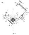
特定の医療処置の間、HFDを用いて患者の頭部を安定化することが必要であり、または望ましいことがある。医療チーム及びそれらの器具への最良のアクセスをもたらすように患者を位置付けることが望ましいことがある。これは、患者が、腹臥位、仰臥位、または、患者の頭部が患者の左半身及び右半身を定義する矢状面から左または右に回転された中間位置にある場合がある。これらの位置、および患者頭部を安定化するその他の位置に適応する際、HFD自体の調整機能は、患者を確実に安定化して患者頭部の移動またはズレが回避されるようにする上での要素となる。ここで図面を参照すると、図1〜図5は医療処置の間に患者の頭部を支持し安定化するように構成された例示的なHFD(100)を示す。HFD(100)は、中央頭部支持部(110)と、弧部材(140)と、頭蓋クランプ(170)と、操作部(190)とを有する。I. An exemplary head fixation device with an arc mechanism It may be necessary or desirable to use HFD to stabilize the patient's head during certain medical procedures. It may be desirable to position the patient to provide the best access to the medical team and their instruments. This may be in the prone, supine, or intermediate position where the patient's head is rotated left or right from the sagittal plane that defines the patient's left and right halves. When adapting to these positions, and other positions that stabilize the patient's head, the adjustment function of the HFD itself is in ensuring that the patient is stabilized and that movement or displacement of the patient's head is avoided. It becomes an element of. With reference to the drawings here, FIGS. 1-5 show an exemplary HFD (100) configured to support and stabilize the patient's head during a medical procedure. The HFD (100) has a central head support portion (110), an arc member (140), a skull clamp (170), and an operation portion (190).
中央頭部支持部(110)は、本体(112)と、本体(112)上の取付機構(114)とを有し、取付機構(114)は、直接的に、または1若しくはそれ以上の中間構造を介して間接的に手術台または他の構造と連結するように構成されたスターバーストの形式である。いくつかの例において、pro med instruments GmbHから入手可能な基部ユニットなどの基部ユニットが手術台に取り付けられ、取付機構(114)は当該基部ユニットと連結する。いくつかの例において、スイベルアダプタまたはpro med instruments GmbHから入手可能な他のアダプタなどのアダプタが基部ユニットと連結してもよく、中央頭部支持部(110)の取付機構(114)は当該アダプタと連結する。本明細書における教示を考慮すれば、中央頭部支持部(110)を手術台などの安定した構造と連結する様々な方法が当業者には明らかであろう。 The central head support (110) has a body (112) and a mounting mechanism (114) on the body (112), the mounting mechanism (114) directly or in between one or more. It is a form of starburst configured to indirectly connect to the operating table or other structure through the structure. In some examples, a base unit, such as a base unit available from promed instruments GmbH, is attached to the operating table and the attachment mechanism (114) is coupled to the base unit. In some examples, adapters such as swivel adapters or other adapters available from promed instruments GmbH may be coupled to the base unit and the mounting mechanism (114) of the central head support (110) may be such adapter. Connect with. Considering the teachings herein, various methods of connecting the central head support (110) to a stable structure such as an operating table will be apparent to those skilled in the art.
中央頭部支持部(110)はまた、本体(112)と連結しクッション(118)を保持または維持する基部(116)を有する。クッション(118)は、接着剤、ネジ若しくはフック及びループなどの機械的留め具、または当業者にとって明らかな他の方法によって基部(116)と連結することができる。いくつかの例において、クッション(118)は、当該クッション(118)を使用後に廃棄可能または洗浄及び殺菌のために取り外しできるように、基部(116)と選択的に連結されている。クッション(118)は、HFD(100)を用いて患者を支持及び安定化するときに患者の頭部と接触するように構成されている。図7の本実施例において、基部(116)は、ネジまたはボルトなどの留め具を用いて基部(116)と連結されたディスク(120)によって本体(112)と連結する。ディスク(120)は、本体(112)において定義されたスロット(122)内で受けられる。いくつかの例において、ディスク(120)はスロット(122)内で回転自在なように構成されており、取り付けられた基部(116)及びクッション(118)が回転自在に調整できるようになっている。 The central head support (110) also has a base (116) that connects to the body (112) and holds or maintains the cushion (118). The cushion (118) can be connected to the base (116) by adhesive, mechanical fasteners such as screws or hooks and loops, or other methods apparent to those skilled in the art. In some examples, the cushion (118) is selectively coupled to the base (116) so that the cushion (118) can be disposed of after use or removed for cleaning and sterilization. The cushion (118) is configured to contact the patient's head when supporting and stabilizing the patient using the HFD (100). In this embodiment of FIG. 7, the base (116) is connected to the body (112) by a disc (120) connected to the base (116) using fasteners such as screws or bolts. The disk (120) is received in the slot (122) defined in the body (112). In some examples, the disc (120) is configured to be rotatable within the slot (122) so that the attached base (116) and cushion (118) are rotatably adjustable. ..
使用中、中央頭部支持部(110)は、患者の頭部に水平支持を提供するように構成されている。このように、中央頭部支持部(110)は、患者の頭部が中央頭部支持部によって支持されるときに、患者頭部の下方に延在する平面を定義する。本実施例において、中央頭部支持部(110)は、中央頭部支持部(110)によって定義された平面が床に平行し、または中央頭部支持部(110)上で重力の方向に直交するように位置付けられる。さらに、中央頭部支持部(110)は、クッション(118)の中心を通って延在し中央頭部支持部(110)の重力の方向と平行な中心軸(A1)を定義する。 During use, the central head support (110) is configured to provide horizontal support to the patient's head. Thus, the central head support (110) defines a plane that extends below the patient's head when the patient's head is supported by the central head support. In this embodiment, the central head support (110) has a plane defined by the central head support (110) parallel to the floor or orthogonal to the direction of gravity on the central head support (110). Positioned to do. Further, the central head support (110) defines a central axis (A1) that extends through the center of the cushion (118) and is parallel to the direction of gravity of the central head support (110).
HFD(100)の弧部材(140)は、中央頭部支持部(110)と連結する。本実施例において、弧部材(140)は、湾曲細長部材(142)と、当該湾曲細長部材(142)と一元的に形成されたコネクタ(144)とを有する。いくつかの他の例では、コネクタ(144)は、ネジ、ボルトなどの着脱可能な留め具によって細長部材(142)と連結する。本明細書における教示を考慮すれば、弧部材(140)を中央頭部支持部(110)と連結する他の方法が当業者には明らかであろう。コネクタ(144)は、以下でさらに詳細に説明されるように、弧部材(140)を中央頭部支持部(110)の本体(112)と連結する。 The arc member (140) of the HFD (100) is connected to the central head support portion (110). In this embodiment, the arc member (140) has a curved elongated member (142) and a connector (144) integrally formed with the curved elongated member (142). In some other examples, the connector (144) is connected to the elongated member (142) by removable fasteners such as screws, bolts and the like. Considering the teachings herein, other methods of connecting the arc member (140) to the central head support (110) will be apparent to those skilled in the art. The connector (144) connects the arc member (140) to the body (112) of the central head support (110), as described in more detail below.
弧部材(140)の細長部材(142)は、或る弧長さを有する湾曲形状を定義する。この構成により、弧部材(140)はさらに、クッション(118)上に位置付けられているときの患者頭部の中心ポイントから細長部材(142)の断面の中間のポイントまでの中心軸(A1)に沿った距離を表す湾曲の半径を定義する。本実施例において、弧長さは、中央頭部支持部(110)によって定義された中心軸(A1)から約45度オフセットまで弧部材(140)に沿ったいずれかの方向に頭蓋クランプ(170)を位置付けることを可能にするのに十分な長さである。この頭蓋クランプ(170)の位置付けについては以下でさらに詳述する。単なる例であって限定するものではないが、いくつかの実施例において、弧部材(140)は、約200〜約350ミリメートルの弧長さを有することができ、約120〜約200ミリメートルの湾曲の半径を定義することができる。例えば、一実施例において、弧部材(140)は、約293ミリメートルの弧長さを有する約152ミリメートルの湾曲の半径を定義する。当然、それらの特定の寸法は全ての例において必要とされるものではなく、本明細書における教示を考慮すれば他の好適な寸法が当業者には明らかであろう。 The elongated member (142) of the arc member (140) defines a curved shape having a certain arc length. With this configuration, the arc member (140) is further aligned with the central axis (A1) from the central point of the patient's head when positioned on the cushion (118) to the middle point of the cross section of the elongated member (142). Defines the radius of curvature that represents the distance along. In this embodiment, the arc length is the cranial clamp (170) in any direction along the arc member (140) from the central axis (A1) defined by the central head support (110) to an offset of about 45 degrees. ) Is long enough to allow it to be positioned. The positioning of the cranial clamp (170) will be described in more detail below. In some embodiments, by way of example only, but not limited to, the arc member (140) can have an arc length of about 200 to about 350 mm and a curvature of about 120 to about 200 mm. Radius can be defined. For example, in one embodiment, the arc member (140) defines a radius of curvature of about 152 mm with an arc length of about 293 mm. Of course, those particular dimensions are not required in all examples, and other suitable dimensions will be apparent to those skilled in the art given the teachings herein.
本実施例において、弧部材(140)の湾曲細長部材(142)は台形状の外形を有するように構成されている。弧部材(140)のこの形状により、弧部材(140)は、弧部材(140)を受けるように構成された相補的形状のスロット(152)を備えたポジションアダプタ(150)と係合することができる。本実施例において、ポジションアダプタ(150)のスロット(152)、及び弧部材(140)の細長部材(142)の外形は、湾曲蟻継ぎ状境界面を形成する。本明細書における教示を考慮すれば、用いうるスロット(152)及び弧部材(140)の外形についてその他の相補的形状が当業者には明らかであろう。 In this embodiment, the curved elongated member (142) of the arc member (140) is configured to have a trapezoidal outer shape. Due to this shape of the arc member (140), the arc member (140) engages a position adapter (150) with a complementary shaped slot (152) configured to receive the arc member (140). Can be done. In this embodiment, the outer shapes of the slot (152) of the position adapter (150) and the elongated member (142) of the arc member (140) form a curved dovetail interface. Considering the teachings herein, other complementary shapes of the available slots (152) and arc members (140) will be apparent to those skilled in the art.
頭蓋クランプ(170)は、当涯頭蓋クランプ(170)が弧部材(140)沿って選択的に移動可能または調整可能なように弧部材(140)と連結することができる。本実施例において、頭蓋クランプ(170)は、ポジションアダプタ(150)を介して弧部材(140)と間接的に連結するが、他の例では、HFD(100)は、頭蓋クランプ(170)が弧部材(140)と直接的に連結するように修正されてもよい。弧部材(140)に沿って頭蓋クランプ(170)を移動させまたは調整することにより、頭蓋クランプ(170)の位置は中央頭部支持部(110)に対して調整可能である。さらに、患者の頭部が中央頭部支持部(110)によって支持されるとき、少なくともいくつかの実施例では、弧部材(140)に沿った頭蓋クランプ(170)の移動は、患者頭部の周りで同軸または実質的に同軸で頭蓋クランプ(170)の位置を変える。同様の観点において、患者は当該患者を左半身及び右半身に分割する矢状面を定義し、その矢状面に沿って長手方向に延在する軸は患者によって定義される長手方向軸と見なされる。概して、この長手方向軸は患者の頭部から患者の足に延在する。少なくともいくつかの実施例では、弧部材(140)に沿った頭蓋クランプ(170)の移動は、患者によって定義されたこの長手方向軸を中心に頭蓋クランプ(170)の位置を変える。上述したように、いくつかの例において、頭蓋クランプ(170)は、中央頭部支持部(110)によって定義された中心軸(A1)から約45度まで、中央頭部支持部(110)及び患者の長手方向軸に対していずれかの方向に調整可能である。このように、HFD(100)は、中央頭部支持部(110)によって支持される患者頭部のいずれかの側で頭蓋クランプ(170)を最大約45度斜め横向きに位置付けることを可能にする。本明細書における教示を考慮すれば、当業者は、約45度よりも大きい頭蓋クランプ(170)の位置調整が達成できるように、弧部材(140)の弧長さが延ばされてもよいことが明らかであろう。 The cranial clamp (170) can be coupled to the arc member (140) so that the cranial clamp (170) can be selectively moved or adjusted along the arc member (140) for the rest of the life. In this embodiment, the cranial clamp (170) is indirectly connected to the arc member (140) via the position adapter (150), but in another example, the HFD (100) is a cranial clamp (170). It may be modified to be directly connected to the arc member (140). By moving or adjusting the cranial clamp (170) along the arc member (140), the position of the cranial clamp (170) is adjustable with respect to the central head support (110). Further, when the patient's head is supported by the central head support (110), in at least some embodiments, the movement of the cranial clamp (170) along the arc member (140) is the movement of the patient's head. Reposition the cranial clamp (170) coaxially or substantially coaxially around. In a similar aspect, the patient defines a sagittal plane that divides the patient into the left and right halves, and the axis extending longitudinally along the sagittal plane is considered the longitudinal axis defined by the patient. Is done. Generally, this longitudinal axis extends from the patient's head to the patient's feet. In at least some embodiments, the movement of the cranial clamp (170) along the arc member (140) repositions the cranial clamp (170) around this longitudinal axis defined by the patient. As mentioned above, in some examples, the cranial clamp (170) is the central head support (110) and up to about 45 degrees from the central axis (A1) defined by the central head support (110). It can be adjusted in either direction with respect to the patient's longitudinal axis. Thus, the HFD (100) allows the cranial clamp (170) to be positioned obliquely laterally up to about 45 degrees on either side of the patient's head supported by the central head support (110). .. Given the teachings herein, one of ordinary skill in the art may extend the arc length of the arc member (140) so that position adjustment of the cranial clamp (170) greater than about 45 degrees can be achieved. It will be clear.
頭蓋クランプ(170)は、ロック部材(172)と、伸長バー(174)のペアとを有する。ロック部材(172)は、伸長バー(174)を受けるように構成された開口部(176)のペアを有する。伸長バー(174)はロック部材(172)に対し、および互いに独立して移動可能である。さらに、ロック部材(172)は、それぞれの伸長バー(174)を係合させて、伸長バー(174)を適格な位置に固定し、または伸長バー(174)の調整を可能にするように構成されたロック部(178)のペアを有する。このように、各伸長バー(174)は歯型ラック(180)を有し、各ロック部(178)はロック部材(172)内に存在する相補的な形状の歯型部分を有し、ロック部材(172)は、それと関連付けられた歯型ラック(180)と係合し、または係脱するように移動可能である。例えば、ロック部(178)は最初、歯型部分が歯型ラック(180)と係合し、それによりロック部材(172)に対して伸長バー(174)の位置をロックまたは固定するように、バネまたは他の構造によって付勢されている。各ロック部(178)は、ロック部(178)の歯型部分を歯型ラック(180)から係脱させるようロック部材(172)から下方向にまたは離れるように引き出されてもよく、それにより、ロック部材(172)及び他方の伸長バー(174)に対する伸長バー(174)の横方向の移動が可能になる。 The cranial clamp (170) has a lock member (172) and a pair of extension bars (174). The locking member (172) has a pair of openings (176) configured to receive an extension bar (174). The extension bar (174) can move relative to the locking member (172) and independently of each other. Further, the locking member (172) is configured to engage the respective extension bars (174) to secure the extension bar (174) in a suitable position or to allow adjustment of the extension bar (174). It has a pair of locked portions (178). As described above, each extension bar (174) has a tooth mold rack (180), and each lock portion (178) has a complementary shape tooth mold portion existing in the lock member (172) and is locked. The member (172) is movable to engage or disengage with its associated toothed rack (180). For example, the locking portion (178) initially engages the tooth profile portion with the tooth profile rack (180), thereby locking or fixing the position of the extension bar (174) to the locking member (172). It is urged by a spring or other structure. Each locking portion (178) may be pulled downward or away from the locking member (172) so that the tooth profile portion of the locking portion (178) is disengaged from the tooth profile rack (180). , The extension bar (174) can be moved laterally with respect to the lock member (172) and the other extension bar (174).
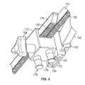
本実施例において、伸長バー(174)は、一方がロック部材(172)内のその位置に関して他方に取って代わることができるように相互に交換可能である。各伸長バー(174)はさらに、安定化アセンブリ(186)を受けるように構成された穴(184)を有する上端部分(182)を有する。安定化アセンブリ(186)は、患者の頭部と接触し、患者の頭部に側方支持及び安定化を提供するように構成されている。本実施例において、安定化アセンブリ(186)は、単一のピンまたは二重ピンアセンブリの形式をとってもよい。さらに、安定化アセンブリ(186)は安定化アセンブリ(186)によって患者頭部に加えられた圧力を調整するためのトルクネジ(141)を含んでもよい。他の例では、安定化アセンブリ(186)は単一チャンバまたはマルチチャンバパッドの形式をとってもよい。本実施例に戻ると、各伸長バー(174)は、直立部分(188)と、長手方向軸を定義する直立部分(188)を伴う基部(189)とを有する。本実施例において、各々のそれぞれの穴(184)は、各々のそれぞれの伸長バー(174)の直立部分(188)によって定義される長手方向軸からオフセットされる。さらに、ロック部材(172)内で伸長バー(174)が位置付けられるとき、それらの穴(184)は、互いに反対方向にオフセットされ、各穴(184)を通って延在する共通軸(A2)と位置合わせされ共通軸(A2)を共有するようになっている。さらに、各伸長バー(174)は、伸長バー(174)の少なくとも一部に沿って位置付け可能な1若しくはそれ以上の付属物を受けるように構成されたレールを定義する。 In this embodiment, the extension bars (174) are interchangeable so that one can replace the other with respect to its position within the locking member (172). Each extension bar (174) further has an upper end portion (182) with a hole (184) configured to receive a stabilizing assembly (186). The stabilization assembly (186) is configured to contact the patient's head and provide lateral support and stabilization to the patient's head. In this embodiment, the stabilizing assembly (186) may take the form of a single pin or double pin assembly. In addition, the stabilizing assembly (186) may include a torque screw (141) for adjusting the pressure applied to the patient's head by the stabilizing assembly (186). In another example, the stabilizing assembly (186) may take the form of a single chamber or multi-chamber pad. Returning to this embodiment, each extension bar (174) has an upright portion (188) and a base (189) with an upright portion (188) that defines the longitudinal axis. In this embodiment, each hole (184) is offset from the longitudinal axis defined by the upright portion (188) of each extension bar (174). Further, when the extension bars (174) are positioned within the locking member (172), their holes (184) are offset in opposite directions and extend through each hole (184) to a common shaft (A2). It is aligned with and shares the common axis (A2). Further, each extension bar (174) defines a rail configured to receive one or more appendages that can be positioned along at least a portion of the extension bar (174).
上述したように、頭蓋クランプ(170)は弧部材(140)と連結する。本実施例において、頭蓋クランプ(170)のロック部材(172)は、ポジションアダプタ(150)と連結し、ポジションアダプタ(150)は次いで、上述したように弧部材(140)と連結する。本実施例において、ポジションアダプタ(150)とロック部材(172)との間の連結は蟻継ぎを用いる。このように、ポジションアダプタ(150)はロック部材(172)の突起部(175)を受けるように構成されたスロット(154)を有する。本実施例において、突起部は台形状の外形を有し、スロット(154)はスロット(154)内で突起部(175)を受けることができるように相補的な外形の形状を有する。 As mentioned above, the cranial clamp (170) is connected to the arc member (140). In this embodiment, the locking member (172) of the skull clamp (170) is connected to the position adapter (150), and the position adapter (150) is then connected to the arc member (140) as described above. In this embodiment, a dovetail joint is used for the connection between the position adapter (150) and the lock member (172). As described above, the position adapter (150) has a slot (154) configured to receive the protrusion (175) of the lock member (172). In this embodiment, the protrusion has a trapezoidal outer shape, and the slot (154) has a complementary outer shape so that the protrusion (175) can be received in the slot (154).
ポジションアダプタ(150)とロック部材(172)との間の連結は選択的に調整可能である。より具体的には、ロック部材(172)はポジションアダプタ(150)に対して垂直にまたは長手方向に調整することができる。この調整により、頭蓋クランプ(170)の安定化アセンブリ(186)と中央頭部支持部(110)との間の距離の調整が可能になる。例えば、患者の方位、患者頭部のサイズ、または他のパラメータに応じて、頭蓋クランプ(170)及びそれに付随する安定化アセンブリ(186)は、中央頭部支持部(110)からより近くまたはより遠くに移動させる必要があることがある。 The connection between the position adapter (150) and the locking member (172) is selectively adjustable. More specifically, the locking member (172) can be adjusted perpendicularly or longitudinally to the position adapter (150). This adjustment allows adjustment of the distance between the stabilizing assembly (186) of the cranial clamp (170) and the central head support (110). For example, depending on the patient's orientation, patient head size, or other parameters, the cranial clamp (170) and associated stabilizing assembly (186) may be closer or closer to the central head support (110). You may need to move it far.
ポジションアダプタ(150)とロック部材(172)との間の調整を説明する更なる観点において、ポジションアダプタ(150)の側壁(158)は平面を定義し、ロック部材(172)はこの平面に沿って並進移動式に調整可能である。このポジションアダプタ(150)に対するロック部材(172)の移動または調整は、上述したように中央頭部支持部(110)に対するロック部材(172)及びその連結された構成要素の間隔を変更する。 To further illustrate the adjustment between the position adapter (150) and the locking member (172), the side wall (158) of the position adapter (150) defines a plane, and the locking member (172) is along this plane. It can be adjusted in translational movement. The movement or adjustment of the locking member (172) with respect to the position adapter (150) changes the spacing of the locking member (172) and its connected components with respect to the central head support (110) as described above.
HFD(100)の操作部(190)は、弧部材(140)に沿って頭蓋クランプ(170)の位置を選択的に固定するように構成されている。操作部(190)はまた、ポジションアダプタ(150)に対する頭蓋クランプ(170)の位置を選択的に固定することにより中央頭部支持部(110)に対する頭蓋クランプ(170)の位置を選択的に固定するように構成されている。本実施例において、HFD(100)のこの二重固定機構は、弧部材(140)に沿った頭蓋クランプ(170)の位置及び中央頭部支持部(110)に対する頭蓋クランプ(170)の位置の両方を実質的に同時に選択的に固定することを可能にする。 The operating portion (190) of the HFD (100) is configured to selectively fix the position of the skull clamp (170) along the arc member (140). The operating unit (190) also selectively fixes the position of the skull clamp (170) with respect to the central head support (110) by selectively fixing the position of the skull clamp (170) with respect to the position adapter (150). It is configured to do. In this embodiment, this double fixation mechanism of the HFD (100) is the position of the cranial clamp (170) along the arc member (140) and the position of the cranial clamp (170) with respect to the central head support (110). Allows both to be selectively clamped at virtually the same time.
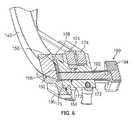
図6を参照すると、操作部(190)はノブ(194)に連結されたネジ棒(192)を有する。ロック部材(172)は操作部(190)のネジ棒(192)を受けるように構成されたネジ穴(173)を有する。ネジ穴(173)はロック部材(172)の片側から反対側へ貫通する。本実施例において、ネジ穴(173)は突起部(175)を通って延在する。操作部(190)はさらに、ポジションアダプタ(150)の側壁(158)の切欠き部(156)内に位置付け可能な圧縮プレート(196)を有する。片側において、切欠き部(156)を含む側壁(158)はロック部材(172)の突起部(175)を受けるスロット(154)の一部を定義する。反対側では、切欠き部(156)を含む側壁(158)は弧部材(140)を受けるスロット(152)の一部を定義する。このように、切欠き部(156)はポジションアダプタ(150)のスロット(152、154)を連結する。 Referring to FIG. 6, the operating unit (190) has a screw rod (192) connected to a knob (194). The lock member (172) has a screw hole (173) configured to receive the screw rod (192) of the operating unit (190). The screw hole (173) penetrates from one side to the other side of the lock member (172). In this embodiment, the screw hole (173) extends through the protrusion (175). The operating unit (190) further has a compression plate (196) that can be positioned within the notch (156) of the side wall (158) of the position adapter (150). On one side, the side wall (158), including the notch (156), defines a portion of the slot (154) that receives the protrusion (175) of the locking member (172). On the opposite side, the side wall (158), including the notch (156), defines a portion of the slot (152) that receives the arc member (140). In this way, the notch (156) connects the slots (152, 154) of the position adapter (150).
使用中、操作部(190)のノブ(194)は、ネジ棒(192)とネジ穴(173)との間のネジ式係合に基づきノブ(194)が回転する方向に応じて、ポジションアダプタ(150)に向かってまたはポジションアダプタ(150)から離れるようにロック部材(172)を並進移動させる。ポジションアダプタ(150)から離れるようにロック部材(172)を並進移動させることによって、ネジ棒(192)の端部は、切欠き部(156)内に存在する圧縮プレート(196)と接触し、ポジションアダプタ(150)のスロット(152)内に存在する弧部材(140)に向かって圧縮プレート(196)を動かす。圧縮プレート(196)は、切欠き部(156)に適合され、または切欠き部(156)と合致するように寸法付けられており、それにより、操作部(190)の十分な回転によって圧縮プレート(196)が弧部材(140)に拘束されて弧部材(140)に対しポジションアダプタ(150)を固定するようになっている。 During use, the knob (194) of the operating unit (190) is a position adapter depending on the direction in which the knob (194) rotates based on the screw type engagement between the screw rod (192) and the screw hole (173). The locking member (172) is translated towards (150) or away from the position adapter (150). By translating the locking member (172) away from the position adapter (150), the end of the screw rod (192) comes into contact with the compression plate (196) present in the notch (156). The compression plate (196) is moved toward the arc member (140) existing in the slot (152) of the position adapter (150). The compression plate (196) is fitted to the notch (156) or sized to match the notch (156), whereby the compression plate is provided by sufficient rotation of the operating part (190). (196) is constrained by the arc member (140) to fix the position adapter (150) to the arc member (140).
この同様の様式において、ロック部材(172)の突起部(175)がポジションアダプタ(150)から離れるように移動することにより、突起部(175)はスロット(154)の側壁に拘束されてポジションアダプタ(150)に対しロック部材(172)を固定する。このロック及びロック解除構成により、頭蓋クランプ(170)は、操作部(190)のノブ(194)の最小限の回転で、弧部材(140)に対し、及び中央頭部支持部(110)に対して調整することができる。例えば、単なる例であって限定するものではないが、一例では、HFD(100)は、操作部(190)のノブ(194)のわずか4分の1の回転により調整可能状態から固定状態に移行することができる。当然、他の例では、HFD(100)は操作部(190)のより大きな又はより小さな回転で調整可能状態から固定状態にHFD(100)を移動させるように構成されていてもよい。 In this similar fashion, the protrusion (175) of the locking member (172) moves away from the position adapter (150) so that the protrusion (175) is constrained to the side wall of the slot (154) and is the position adapter. The lock member (172) is fixed to (150). With this locking and unlocking configuration, the cranial clamp (170) is attached to the arc member (140) and to the central head support (110) with minimal rotation of the knob (194) of the operating unit (190). Can be adjusted against. For example, by example, but not limited to, the HFD (100) transitions from the adjustable state to the fixed state by rotating only a quarter of the knob (194) of the operating unit (190). can do. Of course, in another example, the HFD (100) may be configured to move the HFD (100) from the adjustable state to the fixed state with a larger or smaller rotation of the operating unit (190).
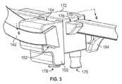
図7及び8を参照すると、中央頭部支持部(110)は中央頭部支持部(110)と弧部材(140)との間の間隔を調整するように構成されている。上述したように、弧部材(140)はコネクタ(144)を有する。コネクタ(144)は中央頭部支持部(110)の本体(112)と調整可能に連結する。図示されるように、本体(112)内にはスロット(124)がある。本実施例において、スロット(124)はディスク(120)を受けるスロット(122)の真下に位置付けられる。スロット(124)はコネクタ(144)の一部を受ける。示されるように、コネクタ(144)はスロット(124)内で受けられるように構成された上位梁部分(146)を有する。梁部分(146)の外形はスロット(124)に対して相補的な形状を有する。本実施例において、梁部分(146)及びスロット(124)は、共に蟻継ぎ境界面を形成する。このように、コネクタ(144)はスロット(124)に沿って並進移動可能であり、スロット(124)は弧部材(140)と中央頭部支持部(110)間の間隔を調整する。 With reference to FIGS. 7 and 8, the central head support portion (110) is configured to adjust the distance between the central head support portion (110) and the arc member (140). As mentioned above, the arc member (140) has a connector (144). The connector (144) is adjustablely connected to the main body (112) of the central head support (110). As shown, there is a slot (124) in the body (112). In this embodiment, the slot (124) is positioned directly below the slot (122) that receives the disk (120). The slot (124) receives a portion of the connector (144). As shown, the connector (144) has an upper beam portion (146) configured to be received within the slot (124). The outer shape of the beam portion (146) has a shape complementary to the slot (124). In this embodiment, the beam portion (146) and the slot (124) both form a dovetail interface. In this way, the connector (144) can be translated along the slot (124), which adjusts the spacing between the arc member (140) and the central head support (110).
スロット(124)内でのコネクタ(144)の調整機能を制御するために、中央頭部支持部(110)はロック機構(149)を含む操作部(148)を有し、このロック機構(149)は、梁部分(146)と接触して圧縮係合により本体(112)に対しその位置を固定し、または少なくとも十分にコネクタ(144)の並進移動を可能にするようロック機構(149)を梁部分(146)との接触から係脱させることにより本体(112)に対してコネクタ(144)のスライド可能な調整をできるようにする。梁部分(146)とロック機構(149)の接触を制御するために、操作部(148)は回転するレバー(147)を含む。レバー(147)の回転によりロック機構(149)は、レバー(147)の回転方向に応じて梁部分(146)に向かって又は梁部分(146)から離れるように移動する。操作部(148)は、中央頭部支持部(110)の本体(112)のネジ穴(126)を通って延在するネジ棒(145)を含む。レバー(147)は穴(143)を含み、穴(143)はレバー(147)とネジ棒(145)が一体となって回転するような固定方法でネジ棒(145)に連結されている。レバー(147)の回転によりネジ棒(145)が回転し、その回転方向に基づいて梁部分(146)に向かって又は梁部分(146)から離れるようにネジ棒(145)が並進移動するようになっている。梁部分(146)に向かうネジ棒(145)の並進移動はロック機構(149)駆動しコネクタ(144)の梁部分(146)と接触させ、それにより、コネクタ(144)の位置、したがって中央頭部支持部(110)に対する弧部材(140)の位置を固定する。同様に、梁部分(146)から離れるネジ棒(145)の並進移動はコネクタ(144)の梁部分(146)とロック機構(149)を係脱させ、それにより、コネクタ(144)の位置、したがって中央頭部支持部(110)に対する弧部材(140)の位置を調整できるようにする。上述した構成では、コネクタ(144)は、中央頭部支持部(110)に対する弧部材(140)の位置を変更するよう、中央頭部支持部(110)によって定義された平面に沿ってまたはその平面に平行に調整可能である。 In order to control the adjustment function of the connector (144) in the slot (124), the central head support portion (110) has an operation portion (148) including a lock mechanism (149), and the lock mechanism (149) is provided. ) Fixes its position relative to the body (112) by compressive engagement in contact with the beam portion (146), or at least sufficiently provides a locking mechanism (149) to allow translational movement of the connector (144). By engaging and disengaging from contact with the beam portion (146), the connector (144) can be slidably adjusted with respect to the main body (112). To control the contact between the beam portion (146) and the locking mechanism (149), the operating unit (148) includes a rotating lever (147). The rotation of the lever (147) causes the locking mechanism (149) to move toward or away from the beam portion (146) depending on the direction of rotation of the lever (147). The operation unit (148) includes a screw rod (145) extending through a screw hole (126) of the main body (112) of the central head support portion (110). The lever (147) includes a hole (143), and the hole (143) is connected to the screw rod (145) by a fixing method such that the lever (147) and the screw rod (145) rotate together. The rotation of the lever (147) causes the screw rod (145) to rotate, and the screw rod (145) translates toward or away from the beam portion (146) based on the direction of rotation. It has become. The translational movement of the threaded rod (145) towards the beam portion (146) drives the locking mechanism (149) to bring it into contact with the beam portion (146) of the connector (144), thereby the position of the connector (144), and thus the central head. The position of the arc member (140) with respect to the portion support portion (110) is fixed. Similarly, the translational movement of the screw rod (145) away from the beam portion (146) causes the beam portion (146) of the connector (144) to engage and disengage the locking mechanism (149), thereby the position of the connector (144). Therefore, the position of the arc member (140) with respect to the central head support portion (110) can be adjusted. In the configuration described above, the connector (144) may or may not follow the plane defined by the central head support (110) to reposition the arc member (140) with respect to the central head support (110). It can be adjusted parallel to the plane.
II.単方向弧を有する例示的な頭部固定機器
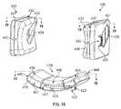
患者頭部の安定化を伴う特定の医療処置、特に、処置を通じて撮像が用いられる場合におけるそれらの処置では、空間を節約する設計でHFDを用いることが望ましいことがある。これは、いくつかの撮像機器内で利用可能な小空間に基づき得るものであり、及び/またはこれは、撮像出力におけるアーチファクトに寄与し得る物質の量を減らすことに基づき得る。図9及び10を参照すると、別の例示的なHFD(200)が示されている。このHFD(200)は、HFD(100)と多くの点で類似するが、より短い弧部材を使用し、それにより、HFD(200)の全体的なサイズ及び質量を削減する。HFD(200)の機構は、以下で説明されるものを除き、HFD(100)に関して上述した機構と同一である。したがって、簡潔性のために、上述したHFD(100)の機構は、以下で説明する差異を除き、HFD(200)に等しく適用される。II. An exemplary head fixation device with a unidirectional arc Use HFD in a space-saving design for certain medical procedures involving stabilization of the patient's head, especially those procedures where imaging is used throughout the procedure. May be desirable. This can be based on the small space available within some imaging equipment and / or it can be based on reducing the amount of material that can contribute to the artifacts in the imaging output. With reference to FIGS. 9 and 10, another exemplary HFD (200) is shown. This HFD (200) is similar to the HFD (100) in many respects, but uses shorter arc members, thereby reducing the overall size and mass of the HFD (200). The mechanism of the HFD (200) is the same as that described above with respect to the HFD (100), except as described below. Therefore, for brevity, the mechanism of HFD (100) described above applies equally to HFD (200), except for the differences described below.
HFD(200)は、上述したように中央頭部支持部(110)と、頭蓋クランプ(170)と、操作部(190)とを有する。ただし、HFD(200)では、弧部材(240)が上述した弧部材(140)に取って代わる。弧部材(240)は単方向弧部材として構成されている。すなわち、HFD(200)により、弧部材(240)は、中央頭部支持部(110)の真下から弓型経路に沿う1方向に外側に向かって延在する。このように、中央頭部支持部(110)と弧部材(240)との間の連結は、中央頭部支持部(110)が弧部材(240)の1端部と連結し、弧部材(240)が中央頭部支持部(110)から離れる方へ単一方向に延在したままとなるようになっている。 The HFD (200) has a central head support portion (110), a skull clamp (170), and an operation portion (190) as described above. However, in the HFD (200), the arc member (240) replaces the arc member (140) described above. The arc member (240) is configured as a unidirectional arc member. That is, due to the HFD (200), the arc member (240) extends outward in one direction along the bow-shaped path from directly below the central head support portion (110). In this way, in the connection between the central head support portion (110) and the arc member (240), the central head support portion (110) is connected to one end of the arc member (240), and the arc member ( 240) remains unidirectionally extending away from the central head support (110).
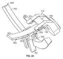
更なる具体的な観点において、弧部材(240)は湾曲細長部材(242)とコネクタ(244)とを有する。本実施例において、湾曲細長部材(242)は、第1の端部(241A)と第2の端部(241B)とを有する。第1の端部(214A)及び第2の端部(241B)の各々に近接して取付区域(230)のペアがあり、各取付区域(230)ではネジ穴(233)のペアを有する。また、コネクタ(244)は、ネジ穴(234)のペアと、ネジ穴(234)のペアを通って延在し湾曲細長部材(242)においてネジ穴(233)のペアの1つによって受けられるように構成された留め具(236)のペアとを有する。このように、コネクタ(244)は、取付区域(230)のいずれか1つにおいて細長部材(242)に取り付けられるように構成されている。コネクタ(144)に関して上述したように、コネクタ(244)はコネクタ(144)が行うのと同様の様式で中央頭部支持部(110)と連結する。 From a more specific point of view, the arc member (240) has a curved elongated member (242) and a connector (244). In this embodiment, the curved elongated member (242) has a first end portion (241A) and a second end portion (241B). There is a pair of mounting areas (230) in close proximity to each of the first end (214A) and the second end (241B), and each mounting area (230) has a pair of screw holes (233). Also, the connector (244) extends through a pair of screw holes (234) and a pair of screw holes (234) and is received by one of the pair of screw holes (233) in the curved elongated member (242). It has a pair of fasteners (236) configured as described above. As described above, the connector (244) is configured to be attached to the elongated member (242) in any one of the attachment areas (230). As mentioned above with respect to the connector (144), the connector (244) is connected to the central head support (110) in the same manner as the connector (144) does.
いくつかの例において、弧部材(240)は、単方向弧の代わりに、または単方向弧に加えて半弧として説明することができる。この構成では、弧部材(240)の湾曲細長部材(242)は弧長さ及び湾曲の半径を定義する。上述したように、湾曲の半径は、クッション(118)上に位置付けられるときの患者頭部の中心ポイントから細長部材(242)の断面の中間のポイントまでの中心軸(A1)に沿った距離を表す。本実施例において、弧長さは、中央頭部支持部(110)によって定義された中心軸(A1)から約45度オフセットまでの弧部材(240)に沿った1方向に頭蓋クランプ(170)を位置付けることを可能にする十分な長さである。単なる例であって限定するものではないが、いくつかの実施例では、弧部材(240)は、約120〜約200ミリメートルの弧長さを有することができ、約120〜約200ミリメートルの湾曲の半径を定義することができる。例えば、一実施例において、弧部材(240)は約170ミリメートルの弧長さを有する約152ミリメートルの湾曲の半径を定義する。当然、それらの特定の寸法は、全ての例において必要とされるものではなく、他の好適な寸法が本明細書における教示を考慮すれば当業者には明らかであろう。 In some examples, the arc member (240) can be described as a half-arc instead of or in addition to the unidirectional arc. In this configuration, the curved elongated member (242) of the arc member (240) defines the arc length and the radius of curvature. As mentioned above, the radius of curvature is the distance along the central axis (A1) from the central point of the patient's head when positioned on the cushion (118) to the midpoint of the cross section of the elongated member (242). show. In this embodiment, the arc length is the cranial clamp (170) in one direction along the arc member (240) from the central axis (A1) defined by the central head support (110) to an offset of about 45 degrees. It is long enough to allow it to be positioned. In some embodiments, by way of example only, but not limited to, the arc member (240) can have an arc length of about 120-about 200 mm and a curvature of about 120-about 200 mm. Radius can be defined. For example, in one embodiment, the arc member (240) defines a radius of curvature of about 152 mm with an arc length of about 170 mm. Of course, those particular dimensions are not required in all examples, and other suitable dimensions will be apparent to those skilled in the art given the teachings herein.
本実施例において、弧部材(240)の湾曲細長部材(242)は台形状の外形を有するように構成されている。弧部材(240)のこの形状により、弧部材(240)は当該弧部材(240)を受けるように構成された相補的形状のスロット(152)を有するポジションアダプタ(150)と係合することが可能となる。本実施例において、ポジションアダプタ(150)のスロット(152)及び弧部材(240)の細長部材(242)の外形は湾曲蟻継ぎ状境界面を形成する。本明細書における教示を考慮すれば、用いうるスロット(152)及び弧部材(240)の外形についてその他の相補的形状が当業者には明らかであろう。 In this embodiment, the curved elongated member (242) of the arc member (240) is configured to have a trapezoidal outer shape. This shape of the arc member (240) allows the arc member (240) to engage with a position adapter (150) having a complementary shaped slot (152) configured to receive the arc member (240). It will be possible. In this embodiment, the outer shapes of the slot (152) of the position adapter (150) and the elongated member (242) of the arc member (240) form a curved dovetail interface. Considering the teachings herein, other complementary shapes of the available slots (152) and arc members (240) will be apparent to those skilled in the art.
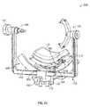
HFD(200)を用いる際、弧部材(240)の単方向の性質を理由に患者の方位が最初に決定される。例えば、患者の頭部はその患者の矢状面に対して一方の側または他方の側に回転する。中央頭部支持部(110)によって支持されるときの患者頭部の回転方向に基づいて、弧部材(240)のコネクタ(244)は、第1の端部(241A)近くの取付区域(230)または第2の端部(241B)近くの取付区域(230)のいずれかにおいて湾曲細長部材(242)に取り付けられる。一例において、患者の頭部がその患者の矢状面に対して第1の方向に回転するとき、弧部材(240)についての所望の仕組みによって、湾曲細長部材(242)が第1の方向とは反対に延在するようになる。このように、湾曲細長部材(242)は患者の矢状面から離れるように延在し、湾曲細長部材(242)がその患者の頭部の背後に延在するようになっている。単なる例示的な実施例であって限定するものではないが、図11はHFD(200)を示し、HFD(200)を用いて頭部が患者の矢状面に対して第1の方向に回転された患者を安定化させることを示す。弧部材(240)は、コネクタ(244)が湾曲細長部材(242)の第2の端部(241B)において取付区域(230)に取り付けられるように構成されている。このように、湾曲細長部材(242)は、当該湾曲細長部材(242)が患者の頭部の背後に延在するよう、第1の方向とは反対に、及び患者の矢状面から離れるように延在する。 When using the HFD (200), the orientation of the patient is first determined because of the unidirectional nature of the arc member (240). For example, the patient's head rotates to one side or the other side with respect to the patient's sagittal plane. Based on the direction of rotation of the patient's head when supported by the central head support (110), the connector (244) of the arc member (240) has a mounting area (230) near the first end (241A). ) Or the attachment area (230) near the second end (241B) to be attached to the curved elongated member (242). In one example, when the patient's head rotates in the first direction with respect to the patient's sagittal plane, the curved elongated member (242) will be in the first direction by the desired mechanism for the arc member (240). Will be extended on the contrary. Thus, the curved elongated member (242) extends away from the sagittal plane of the patient, and the curved elongated member (242) extends behind the patient's head. By way of example only, but not limited to, FIG. 11 shows the HFD (200), which is used to rotate the head in the first direction with respect to the patient's sagittal plane. Shows that it stabilizes the patient. The arc member (240) is configured such that the connector (244) is attached to the attachment area (230) at the second end (241B) of the curved elongated member (242). Thus, the curved elongated member (242) is oriented in the opposite direction to the first direction and away from the patient's sagittal plane so that the curved elongated member (242) extends behind the patient's head. Extends to.
上述したように、頭蓋クランプ(170)は頭蓋クランプ(170)が弧部材(140)と連結するのと同様の様式において弧部材(240)と連結する。HFD(200)により、頭蓋クランプ(170)は、中央頭部支持部(110)によって定義された中心軸(A1)から約45度まで、中央頭部支持部(110)及び患者の長手方向軸に対して1方向に調整可能である。このように、HFD(200)は、中央頭部支持部(110)によって支持される患者頭部のいずれかの側で頭蓋クランプ(170)を最大約45度斜め横向きに位置付けることを可能にする。 As mentioned above, the cranial clamp (170) connects to the arc member (240) in the same manner that the cranial clamp (170) connects to the arc member (140). By HFD (200), the cranial clamp (170) is about 45 degrees from the central axis (A1) defined by the central head support (110), the central head support (110) and the longitudinal axis of the patient. It can be adjusted in one direction. Thus, the HFD (200) allows the cranial clamp (170) to be positioned obliquely laterally up to about 45 degrees on either side of the patient's head supported by the central head support (110). ..
さらに、コネクタ(244)が弧部材(240)の湾曲細長部材(242)のいずれかの端部と連結可能なため、HFD(200)は、湾曲細長部材(242)とコネクタ(244)の選択された取付位置に応じて弧部材(240)がいずれかの方向に中央頭部支持部(110)から離れるように延在するよう構成することができる。その結果、半弧または単方向弧部材(240)を有するHFD(200)は、一患者の使用に適するよう構成することができ、当該患者は、頭部が中央頭部支持部(110)によって支持され患者の矢状面に対していずれかの方向に回転されるように位置付けられ得る。すなわち、HFD(200)により、弧部材(240)は第1の方位及び第2の方位のうちの選択された1つにおいて中央頭部支持部(110)と連結可能であると考えることができる。第2の方位では、弧部材(240)は、第1の方向に中央頭部支持部(110)の真下から外側に向かって延在するものであり、第1の方向は、弧部材(240)が第1の方位にあるときに中央頭部支持部(110)の真下から外側に向かって延在する第2の方向と反対である。 Further, since the connector (244) can be connected to any end of the curved elongated member (242) of the arc member (240), the HFD (200) can select the curved elongated member (242) and the connector (244). The arc member (240) can be configured to extend away from the central head support portion (110) in either direction depending on the mounting position. As a result, the HFD (200) with a semi-arc or unidirectional arc member (240) can be configured to be suitable for use by a patient, who is headed by a central head support (110). It can be supported and positioned to rotate in either direction with respect to the patient's sagittal plane. That is, according to the HFD (200), it can be considered that the arc member (240) can be connected to the central head support portion (110) in the selected one of the first orientation and the second orientation. .. In the second orientation, the arc member (240) extends outward from directly below the central head support portion (110) in the first direction, and the arc member (240) extends in the first direction. ) Is in the first orientation, which is opposite to the second direction extending outward from directly below the central head support (110).
単方向弧または半弧を有するHFD(200)のいくつかの他の例では、頭蓋クランプと弧部材との間の連結は、頭蓋クランプのいずれの側から頭蓋クランプと弧部材とを結合可能にするように構成されるようHFD(200)が修正されてもよい。このように、弧部材と頭蓋クランプの取付は対称的であると見なされる。本明細書における教示を考慮すれば、頭蓋クランプと単方向弧部材を連結する他の方法が当業者には明らかであろう。 In some other examples of HFDs (200) with unidirectional or semi-arcs, the connection between the cranial clamp and the arc member allows the cranial clamp and the arc member to be coupled from either side of the cranial clamp. The HFD (200) may be modified to be configured to do so. Thus, the attachment of the arc member and the cranial clamp is considered symmetrical. Other methods of connecting the cranial clamp and the unidirectional arc member will be apparent to those skilled in the art in view of the teachings herein.
III.圧力制御旋回式クッションを有する例示的な頭部固定機器
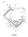
様々な患者の位置付けに適応する十分な調整機能をHFDに提供するために、別の望ましい機構ではHFDのクッションに選択的な旋回式調整を組み込むことができる。クッションに組み込むことができる他の機構は、クッションと患者との間の接触圧力の管理または制御に関する。図12は、別のHFD(300)を表しており、当該別のHFD(300)には、HFD(100)に多くの点で類似するが、旋回式クッションに関する機構が組み込まれ、また、接触圧力の制御を補助する機構が組み込まれている。HFD(300)の機構は、以下で説明するものを除き、HFD(100)に関して上述した機構と同じである。したがって、簡潔性のために、上述したHFD(100)の機構は、以下で説明する差異を除き、HFD(300)に等しく適用される。III. An exemplary head-fixing device with a pressure-controlled swivel cushion In order to provide the HFD with sufficient adjustment capabilities to accommodate different patient positions, another desirable mechanism is to provide the HFD cushion with a selective swivel adjustment. Can be incorporated. Other mechanisms that can be incorporated into the cushion relate to the management or control of the contact pressure between the cushion and the patient. FIG. 12 represents another HFD (300), which is similar to the HFD (100) in many respects, but incorporates a mechanism relating to a swivel cushion and also contacts. A mechanism is built in to assist in pressure control. The mechanism of the HFD (300) is the same as that described above with respect to the HFD (100), except as described below. Therefore, for brevity, the mechanism of HFD (100) described above applies equally to HFD (300), except for the differences described below.
HFD(300)は、上述したような弧部材(140)と、頭蓋クランプ(170)と、操作部(190)とを有する。ただし、HFD(300)では、中央頭部支持部(310)は上述した中央頭部支持部(110)に取って代わる。図12及び図13を参照すると、中央頭部支持部(310)は本体(312)と、本体(312)上の取付機構(314)とを有し、この場合、取付機構(314)は直接的に、または1若しくはそれ以上の中間構造を介して間接的に手術台または他の構造と連結するように構成されたスターバーストの形態である。例えば、いくつかの例において、pro med instruments GmbHから入手可能な基部ユニットなどの基部ユニットが手術台に取り付けられ、取付機構(314)は当該基部ユニットと連結する。いくつかの例において、スイベルアダプタまたはpro med instruments GmbHから入手可能な他のアダプタなどのアダプタが基部ユニットと連結してもよく、中央頭部支持部(310)の取付機構(314)は当該アダプタと連結する。本明細書における教示を考慮すれば、中央頭部支持部(310)を手術台などの安定した構造と連結する様々な方法が当業者には明らかであろう。 The HFD (300) has an arc member (140) as described above, a skull clamp (170), and an operation unit (190). However, in the HFD (300), the central head support portion (310) replaces the above-mentioned central head support portion (110). With reference to FIGS. 12 and 13, the central head support (310) has a body (312) and a mounting mechanism (314) on the body (312), in which case the mounting mechanism (314) is direct. It is a form of starburst configured to be connected to the operating table or other structure either, or indirectly through one or more intermediate structures. For example, in some examples, a base unit, such as a base unit available from promed instruments GmbH, is attached to the operating table and the attachment mechanism (314) is coupled to the base unit. In some examples, adapters such as swivel adapters or other adapters available from promed instruments GmbH may be coupled to the base unit and the mounting mechanism (314) of the central head support (310) may be such adapter. Connect with. Considering the teachings herein, various methods of connecting the central head support (310) to a stable structure such as an operating table will be apparent to those skilled in the art.
また、中央頭部支持部(310)は、本体(312)と連結しクッション(318)を保持または維持する基部(316)を有する。クッション(318)は、接着剤、ネジ若しくはフック及びループなどの機械的留め具、または当業者にとって明らかな他の方法で基部(316)と連結することができる。いくつかの例において、クッション(318)は、当該クッション(318)を使用後に廃棄可能または洗浄及び殺菌のために取り外しできるように、基部(316)と選択的に連結されている。クッション(318)は、HFD(300)を用いて患者を支持及び安定化するときに患者の頭部と接触するように構成されている。本実施例において、基部(316)は、本体(312)から外向き上方向に延在するアーム(320)のペアによって本体(312)と連結する。基部(316)は連結部材(322)を有し、当該連結部材(322)は基部(316)を横切って延在する軸を定義する。連結部材(322)は穴の(323)のペアを有し、当該ペアの各穴(323)は各アーム(320)の各穴(321)と位置合わせされている。連結部材(322)によって定義された軸は当該軸が旋回軸を定義するように連結部材(322)の穴(323)に沿って延在し、それにより、その旋回軸を中心に基部(316)及び連結されたクッション(318)が旋回可能になっている。留め具(325)のペアは、アーム(320)の穴(321)を通って延在し、連結部材(322)の穴(323)に係合して基部(316)と中央頭部支持部(310)の本体(312)を旋回可能に連結する。留め具(325)は、基部(316)及び連結されたクッション(318)の位置を固定するよう締め付けられてもよく、逆に、当該留め具(325)は、基部(316)及び連結されたクッション(318)の旋回可能な調整を可能にするよう緩められてもよい。 In addition, the central head support portion (310) has a base portion (316) that is connected to the main body (312) and holds or maintains the cushion (318). The cushion (318) can be connected to the base (316) by adhesive, mechanical fasteners such as screws or hooks and loops, or other methods apparent to those skilled in the art. In some examples, the cushion (318) is selectively coupled to the base (316) so that the cushion (318) can be disposed of after use or removed for cleaning and sterilization. The cushion (318) is configured to contact the patient's head when supporting and stabilizing the patient using the HFD (300). In this embodiment, the base (316) is connected to the main body (312) by a pair of arms (320) extending outward and upward from the main body (312). The base (316) has a connecting member (322), which defines an axis extending across the base (316). The connecting member (322) has a pair of holes (323), and each hole (323) of the pair is aligned with each hole (321) of each arm (320). The axis defined by the connecting member (322) extends along the hole (323) of the connecting member (322) so that the axis defines the swivel axis, thereby the base (316) centered on the swivel axis. ) And the connected cushion (318) are swivelable. A pair of fasteners (325) extends through the hole (321) in the arm (320) and engages the hole (323) in the connecting member (322) to engage the base (316) and central head support. The main body (312) of (310) is rotatably connected. The fastener (325) may be tightened to secure the position of the base (316) and the connected cushion (318), and conversely, the fastener (325) is connected to the base (316). The cushion (318) may be loosened to allow swivel adjustment.
使用中、中央頭部支持部(310)は、患者の頭部に水平支持を提供するように構成されている。このように、中央頭部支持部(310)は、患者の頭部が中央頭部支持部によって支持されるときに患者の頭部に対して下方に延在する平面を定義する。本実施例において、中央頭部支持部(310)は、中央頭部支持部(310)によって定義された平面が基部(316)及び連結されたクッション(318)の旋回動作に基づいて調整され得るように位置付けられる。したがって、中央頭部支持部(310)によって定義された平面は、床に平行し、または中央頭部支持部(310)上で重力の方向に直交することに限定されるものではない。図12及び図15を参照すると、患者の頭部の異なる位置、すなわち、図12に示されるようなコンコルド位置及び図15に示されるような仰臥位に適応するよう、2つの異なる方位に旋回する基部(316)を備えたHFD(300)が示されている。 During use, the central head support (310) is configured to provide horizontal support to the patient's head. Thus, the central head support (310) defines a plane that extends downward with respect to the patient's head when the patient's head is supported by the central head support. In this embodiment, the central head support (310) may be adjusted based on the swiveling motion of the cushion (318) to which the plane defined by the central head support (310) is connected to the base (316). It is positioned as. Therefore, the plane defined by the central head support (310) is not limited to being parallel to the floor or orthogonal to the direction of gravity on the central head support (310). With reference to FIGS. 12 and 15, the patient turns in two different directions to adapt to different positions of the patient's head, namely the Concorde position as shown in FIG. 12 and the supine position as shown in FIG. An HFD (300) with a base (316) is shown.
図13を参照すると、中央頭部支持部(310)は、中央頭部支持部(310)と弧部材(140)との間の間隔を調整するように構成されている。上述したように、弧部材(140)はコネクタ(144)を有する。コネクタ(144)は中央頭部支持部(310)の本体(312)と調整可能に連結する。図示されるように、本体(312)内にはスロット(324)がある。スロット(324)はコネクタ(144)の一部を受ける。示されるように、コネクタ(144)は上位梁部分(146)を有し、当該上位梁部分(146)はスロット(324)内に受けられるように構成されている。梁部分(146)の外形はスロット(324)に対して相補的な形状を有する。本実施例において、梁部分(146)及びスロット(324)は共に蟻継ぎ境界面を形成する。このように、コネクタ(144)はスロット(324)に沿って並進移動可能であり、スロット(324)は弧部材(140)と中央頭部支持部(310)との間の間隔を調整する。スロット(324)内でコネクタ(144)の調整機能を制御するために、中央頭部支持部(310)はHFD(100)に関して上述したような操作部(148)及びロック機構(149)を有する。HFD(300)では、操作部(148)及びロック機構(149)は、HFD(100)に関して上述したのと同様の様式で構成され動作可能である。この構成では、コネクタ(144)は、中央頭部支持部(310)に対して弧部材(140)の位置を変更するよう、中央頭部支持部(310)によって定義された平面に沿って、または当該平面に平行に調整可能である。 Referring to FIG. 13, the central head support portion (310) is configured to adjust the distance between the central head support portion (310) and the arc member (140). As mentioned above, the arc member (140) has a connector (144). The connector (144) is adjustablely connected to the main body (312) of the central head support (310). As shown, there is a slot (324) in the body (312). The slot (324) receives a portion of the connector (144). As shown, the connector (144) has an upper beam portion (146), and the upper beam portion (146) is configured to be received in the slot (324). The outer shape of the beam portion (146) has a shape complementary to the slot (324). In this embodiment, the beam portion (146) and the slot (324) both form a dovetail interface. In this way, the connector (144) can be translated along the slot (324), which adjusts the spacing between the arc member (140) and the central head support (310). To control the adjustment function of the connector (144) within the slot (324), the central head support (310) has an operating unit (148) and a locking mechanism (149) as described above for the HFD (100). .. In the HFD (300), the operating unit (148) and the locking mechanism (149) are configured and operational in the same manner as described above for the HFD (100). In this configuration, the connector (144) follows the plane defined by the central head support (310) to reposition the arc member (140) with respect to the central head support (310). Alternatively, it can be adjusted parallel to the plane.
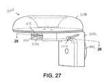
図14を参照すると、HFD(300)のクッション(318)は第1のチャンバ(319)を有し、当該第1のチャンバ(319)は流体が充填されるように構成された内部空間(317)を有する。流体は気体または液体であってよい。第1のチャンバ(319)は、内部空間(317)へのアクセスをもたらすように構成されたポート(301)を含む。流体は、第1のチャンバ(319)内で内部空間(317)に方向付けられ、あるいは第1のチャンバ(319)の内部空間(317)から抜き出され又は排出され得る。第1のチャンバ(319)から流体を排出するとき、流体の全てまたは一部を内部空間(317)から解放または排出することができる。 Referring to FIG. 14, the cushion (318) of the HFD (300) has a first chamber (319), which is an internal space (317) configured to be filled with fluid. ). The fluid may be a gas or a liquid. The first chamber (319) includes a port (301) configured to provide access to the interior space (317). The fluid can be directed into the interior space (317) within the first chamber (319) or withdrawn or drained from the interior space (317) of the first chamber (319). When draining the fluid from the first chamber (319), all or part of the fluid can be released or drained from the interior space (317).
クッション(318)はさらに、第2のチャンバ(1319)を有し、第2のチャンバ(1319)は形状適合材料が充填されるように構成されている。本実施例において、第1のチャンバ(319)は第2のチャンバ(1319)に対して下方に位置付けられる。さらに、第2のチャンバ(1319)は頭部の患者と接触するように構成されている。本明細書における教示を考慮すれば、第1のチャンバ及び第2のチャンバ(319、1319)の相対位置は、その他の例では切り替えられてもよいことが当業者には明らかであろう。一例では、形状適合材料は、ゲル、発泡体、または微粒材料のいずれか1つである。本明細書における教示を考慮すれば、クッション(318)で使用可能な他の形状適合材料が当業者には明らかであろう。 The cushion (318) further has a second chamber (1319), the second chamber (1319) being configured to be filled with a shape-matching material. In this embodiment, the first chamber (319) is positioned below the second chamber (1319). In addition, the second chamber (1319) is configured to come into contact with the patient on the head. Given the teachings herein, it will be apparent to those skilled in the art that the relative positions of the first and second chambers (319, 1319) may be switched in other examples. In one example, the shape-matching material is any one of gel, foam, or fine-grained material. Considering the teachings herein, other shape-adapting materials that can be used with cushions (318) will be apparent to those of skill in the art.
上述したクッション(318)の構成では、クッション(318)は、頭部が中央頭部支持部(310)によって支持されるときに患者頭部との接触圧力の均一な分布を提供するように構成されている。また、接触圧力はポート(301)を介して流体を第1のチャンバ(319)に充填することにより増大させることができる。逆に、接触圧力は上述したように第1のチャンバ(319)から流体を排出することにより減少させることができる。接触圧力を低下させることにより、血流がクッション(318)と接触している患者頭部の領域に回復し得る。いくつかの例において、全ての例で必要とされるものではないが、第1のチャンバ(319)からの流体の相当な排出により、クッション(318)が収縮または縮小し、クッション(318)が患者の頭部と接触しないような高さになる。上記と同様に、クッション(318)と患者との間の接触が不足する程度まで接触圧力を低下させることにより、クッション(318)と接触していた患者頭部の領域に血流が回復し得る。接触圧力を低下させ血流を回復させることにより組織外傷または損傷を回避することができ、またはそのリスクが低減する。さらに、組織の或る領域に血流を回復させる際に患者の安定化を犠牲にしないように、クッション(318)と患者の頭部との間の接触圧力を低下させるときに安定化アセンブリ(186)によって安定化を維持することができる。いくつかの例において、クッション(318)と接触している組織領域に血流を回復させる十分な時間が経過したら、流体を第1のチャンバ(319)に充填することによって再び接触圧力を増大させ、強化された若しくはより高い程度の安定化を提供し、または復元することができる。 In the cushion (318) configuration described above, the cushion (318) is configured to provide a uniform distribution of contact pressure with the patient's head when the head is supported by the central head support (310). Has been done. Also, the contact pressure can be increased by filling the first chamber (319) with fluid through the port (301). Conversely, the contact pressure can be reduced by draining the fluid from the first chamber (319) as described above. By reducing the contact pressure, blood flow can be restored to the area of the patient's head that is in contact with the cushion (318). In some examples, but not required in all examples, significant drainage of fluid from the first chamber (319) causes the cushion (318) to contract or contract, causing the cushion (318) to shrink. The height should be such that it does not come into contact with the patient's head. Similar to the above, blood flow can be restored to the area of the patient's head that was in contact with the cushion (318) by reducing the contact pressure to the extent that the contact between the cushion (318) and the patient is insufficient. .. Tissue trauma or damage can be avoided or the risk is reduced by reducing contact pressure and restoring blood flow. In addition, a stabilizing assembly (stable assembly) when reducing the contact pressure between the cushion (318) and the patient's head so as not to sacrifice patient stabilization in restoring blood flow to an area of tissue. Stabilization can be maintained by 186). In some examples, after sufficient time has passed to restore blood flow to the tissue area in contact with the cushion (318), the contact pressure is increased again by filling the first chamber (319) with fluid. It can provide, or restore, an enhanced or higher degree of stabilization.
IV.側方パッドとマルチチャンバクッションとを有する例示的な非侵襲式頭部固定機器
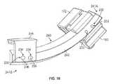
いくつかの例において、安定化アセンブリがピンの代わりにパッドの形式を有する非侵襲式のHFD構成が望ましいことがあり、その場合、パッドが側方安定化を提供する。さらに、パッドは、特定の組織領域への血流の促進を助け組織損傷または外傷のリスクを回避または低減するよう、特定の接触圧力制御機構を伴うように構成されていてもよい。図16を参照すると、例示的なHFD(400)が示されており、当該HFD(400)には、HFD(100)に多くの点で類似するが、非侵襲式安定化を提供するよう安定化アセンブリ(186)に対してパッド(430)が組み込まれている。また、HFD(400)はHFD(300)に関して説明したようなクッション(318)にいくつかの点で類似する旋回式クッション(418)を含む。HFD(400)はさらに、パッド(430)が患者の頭部と接触する安定化接触領域において、及びクッション(418)が患者の頭部と接触する下方安定化接触領域において圧力を制御するのを補助する機構を含む。HFD(400)の機構は、以下で説明するものを除き、HFD(100)に関して上述した機構と同じである。したがって、簡潔性のために、上述したHFD(100)の機構は、以下で説明される差異を除き、HFD(400)に等しく適用される。IV. Illustrative non-invasive head-fixing device with side pads and multi-chamber cushions In some examples, a non-invasive HFD configuration in which the stabilizing assembly has the form of a pad instead of a pin may be desirable. , In that case, the pad provides lateral stabilization. In addition, the pads may be configured with specific contact pressure control mechanisms to aid in facilitating blood flow to specific tissue areas and avoid or reduce the risk of tissue damage or trauma. Referring to FIG. 16, an exemplary HFD (400) is shown, which is similar to the HFD (100) in many respects but stable to provide non-invasive stabilization. A pad (430) is incorporated for the chemical assembly (186). The HFD (400) also includes a swivel cushion (418) that is somewhat similar to the cushion (318) as described for the HFD (300). The HFD (400) further controls pressure in the stabilized contact area where the pad (430) contacts the patient's head and in the downward stabilized contact area where the cushion (418) contacts the patient's head. Includes auxiliary mechanism. The mechanism of the HFD (400) is the same as that described above with respect to the HFD (100), except as described below. Therefore, for brevity, the mechanism of HFD (100) described above applies equally to HFD (400), except for the differences described below.
HFD(400)は、上述したような弧部材(140)と、頭蓋クランプ(170)と、操作部(190)とを有する。また、HFD(400)はHFD(300)に関して上述した中央頭部支持部(310)と同様の中央頭部支持部(410)を有するが、中央頭部支持部(410)は上述したクッション(318)の代わりにクッション(418)を含む。図16を参照すると、中央頭部支持部(410)は、本体(412)と、本体(412)上の取付機構(414)とを有し、取付機構(414)は、直接的に、または1若しくはそれ以上の中間構造を介して間接的に手術台または他の構造と連結するように構成されたスターバーストの形式である。例えば、いくつかの例において、pro med instruments GmbHから入手可能な基部ユニットなどの基部ユニットが手術台に取り付けられ、取付機構(414)は当該基部ユニットと連結する。いくつかの例において、スイベルアダプタまたはpro med instruments GmbHから入手可能な他のアダプタなどのアダプタが基部ユニットと連結してもよく、中央頭部支持部(410)の取付機構(414)は当該アダプタと連結する。本明細書における教示を考慮すれば、中央頭部支持部(410)を手術台などの安定した構造と連結する様々な方法が当業者には明らかであろう。 The HFD (400) has an arc member (140) as described above, a skull clamp (170), and an operation unit (190). Further, the HFD (400) has a central head support portion (410) similar to the central head support portion (310) described above with respect to the HFD (300), but the central head support portion (410) has the cushion (410) described above. Includes a cushion (418) instead of 318). Referring to FIG. 16, the central head support portion (410) has a body (412) and a mounting mechanism (414) on the body (412), the mounting mechanism (414) either directly or. It is a form of starburst configured to indirectly connect to the operating table or other structure via one or more intermediate structures. For example, in some examples, a base unit, such as a base unit available from promed instruments GmbH, is attached to the operating table and the attachment mechanism (414) is coupled to the base unit. In some examples, adapters such as swivel adapters or other adapters available from promed instruments GmbH may be coupled to the base unit and the mounting mechanism (414) of the central head support (410) may be such adapter. Connect with. Considering the teachings herein, various methods of connecting the central head support (410) to a stable structure such as an operating table will be apparent to those skilled in the art.
中央頭部支持部(410)はまた、本体(412)と連結しクッション(418)を保持または維持する基部(416)を有する。クッション(318)は、接着剤、ネジ若しくはフック及びループなどの機械的留め具、または当業者にとって明らかな他の方法で基部(416)と連結することができる。いくつかの例において、クッション(418)は、当該クッション(418)を使用後に廃棄可能または洗浄及び殺菌のために取り外しできるように、基部(416)と選択的に連結されている。クッション(418)は、HFD(400)を用いて患者を支持及び安定化するときに患者の頭部と接触するように構成されている。本実施例において、基部(416)は、本体(412)から外向き上方向に延在するアーム(420)のペアによって本体(412)と連結する。基部(416)は、基部(416)を横切って延在する軸を定義する連結部材(422)を有する。連結部材(422)は各側に穴(423)のペアを有し、当該ペアの各穴(423)は各アームの(420)の各穴(421)と位置合わせされている。連結部材(422)によって定義された軸は当該軸が旋回軸を定義するように連結部材(422)の穴(423)に沿って延在し、それにより、その旋回軸を中心に基部(416)及び連結されたクッション(418)が旋回可能になっている。留め具(425)のペアは、アーム(420)の穴(421)を通って延在し、連結部材(422)の穴(423)に係合して、基部(416)を中央頭部支持部(410)の本体(412)に旋回可能に連結する。留め具(425)は、基部(416)及び連結されたクッション(418)の位置を固定するよう締め付けられてもよく、逆に、留め具(425)は、基部(416)及び連結されたクッション(418)の旋回可能な調整を可能にするよう緩められてもよい。 The central head support (410) also has a base (416) that connects to the body (412) and holds or maintains the cushion (418). The cushion (318) can be connected to the base (416) by adhesive, mechanical fasteners such as screws or hooks and loops, or other methods apparent to those skilled in the art. In some examples, the cushion (418) is selectively coupled to the base (416) so that the cushion (418) can be disposed of after use or removed for cleaning and sterilization. The cushion (418) is configured to contact the patient's head when supporting and stabilizing the patient using the HFD (400). In this embodiment, the base (416) is connected to the body (412) by a pair of arms (420) extending outward and upward from the body (412). The base (416) has a connecting member (422) that defines an axis extending across the base (416). The connecting member (422) has a pair of holes (423) on each side, and each hole (423) of the pair is aligned with each hole (421) of (420) of each arm. The axis defined by the connecting member (422) extends along the hole (423) of the connecting member (422) so that the axis defines a swivel axis, thereby centering on the swivel axis at the base (416). ) And the connected cushion (418) are swivelable. A pair of fasteners (425) extends through the hole (421) in the arm (420) and engages the hole (423) in the connecting member (422) to support the base (416) in the central head. It is rotatably connected to the main body (412) of the unit (410). The fastener (425) may be tightened to secure the position of the base (416) and the connected cushion (418), and conversely, the fastener (425) may be tightened to secure the position of the base (416) and the connected cushion (418). It may be loosened to allow the swivel adjustment of (418).
使用中、中央頭部支持部(410)は、患者の頭部に水平支持を提供するように構成されている。このように、中央頭部支持部(410)は、患者の頭部が中央頭部支持部によって支持されるときに患者の頭部に対して下方に延在する平面を定義する。本実施例において、中央頭部支持部(410)は、中央頭部支持部(410)によって定義された平面が基部(416)及び連結されたクッション(418)の旋回動作に基づいて調整され得るように位置付けられている。したがって、中央頭部支持部(410)によって定義された平面は、床に平行し、または中央頭部支持部(410)上で重力の方向に直交することに限定されるものではない。 During use, the central head support (410) is configured to provide horizontal support to the patient's head. Thus, the central head support (410) defines a plane that extends downward with respect to the patient's head when the patient's head is supported by the central head support. In this embodiment, the central head support (410) may be adjusted based on the swiveling motion of the cushion (418) to which the plane defined by the central head support (410) is connected to the base (416). It is positioned as. Therefore, the plane defined by the central head support (410) is not limited to being parallel to the floor or orthogonal to the direction of gravity on the central head support (410).
図16を参照すると、中央頭部支持部(410)は中央頭部支持部(410)と弧部材(140)との間の間隔を調整するように構成されている。上述したように、弧部材(140)はコネクタ(144)を有する。コネクタ(144)は中央頭部支持部(410)の本体(412)と調整可能に連結する。図示されるように、本体(412)内にはスロット(424)がある。スロット(424)はコネクタ(144)の一部を受ける。図示されるように、コネクタ(144)はスロット(424)内で受けられるように構成された上位梁部分(146)を有する。梁部分(146)の外形はスロット(424)に対して相補的な形状を有する。本実施例において、梁部分(146)及びスロット(424)は共に蟻継ぎ境界面を形成する。このように、コネクタ(144)はスロット(424)に沿って並進移動可能であり、それは弧部材(140)と中央頭部支持部(410)間の間隔を調整する。スロット(424)内でコネクタ(144)の調整機能を制御するために、中央頭部支持部(410)は、HFD(100)に関して上述したような操作部(148)とロック機構(149)を有する。HFD(400)では、操作部(148)及びロック機構(149)はHFD(100)に関して上述したのと同様の様式で構成され動作可能である。この構成では、コネクタ(144)は、中央頭部支持部(410)に対して弧部材(140)の位置を変更するように、中央頭部支持部(410)によって定義された平面に沿ってまたは平面に平行に調整可能である。 Referring to FIG. 16, the central head support portion (410) is configured to adjust the distance between the central head support portion (410) and the arc member (140). As mentioned above, the arc member (140) has a connector (144). The connector (144) is adjustablely connected to the main body (412) of the central head support (410). As shown, there is a slot (424) in the body (412). The slot (424) receives a portion of the connector (144). As shown, the connector (144) has an upper beam portion (146) configured to be received within the slot (424). The outer shape of the beam portion (146) has a shape complementary to the slot (424). In this embodiment, the beam portion (146) and the slot (424) both form a dovetail interface. In this way, the connector (144) can be translated along the slot (424), which adjusts the spacing between the arc member (140) and the central head support (410). In order to control the adjustment function of the connector (144) within the slot (424), the central head support (410) has an operating unit (148) and a locking mechanism (149) as described above for the HFD (100). Have. In the HFD (400), the operating unit (148) and the locking mechanism (149) are configured and operational in the same manner as described above for the HFD (100). In this configuration, the connector (144) follows the plane defined by the central head support (410) so as to reposition the arc member (140) with respect to the central head support (410). Or it can be adjusted parallel to the plane.
図16〜図19を参照すると、上述したようにHFD(400)はパッド(430)を有する。パッド(430)は、筐体(431)と、第1のチャンバ(432)と、第2のチャンバ(433)とを有する。穴または切欠き部(434)が、筐体(431)、第1のチャンバ(432)、及び第2のチャンバ(433)を通って延在する。穴(434)は、過度な圧縮及び圧力から患者の耳を保護し代わりに患者の頭蓋に対してそのような圧力及び圧縮力を方向付けるように安定化の間に患者の耳を受けるように構成されるよう位置する。また、筐体(431)上には環状フランジ(435)が位置し、環状フランジ(435)は、安定化アセンブリ(186)の残りと連結するように構成されたスロット(436)を定義する。本実施例において、安定化アセンブリはカラー(437)を含み、カラー(437)はスロット(436)内に適合するフランジ(438)を有する。この構成では、パッド(430)は、図5について上記に示したように穴(184)によって定義され穴(184)を通って延在する軸を中心に調整することができる。 Referring to FIGS. 16-19, the HFD (400) has a pad (430) as described above. The pad (430) has a housing (431), a first chamber (432), and a second chamber (433). A hole or notch (434) extends through the housing (431), the first chamber (432), and the second chamber (433). The hole (434) protects the patient's ear from excessive compression and pressure and instead receives the patient's ear during stabilization to direct such pressure and compression force against the patient's skull. Positioned to be composed. Also, an annular flange (435) is located on the housing (431), which defines a slot (436) configured to connect with the rest of the stabilizing assembly (186). In this embodiment, the stabilizing assembly comprises a collar (437), which has a flange (438) that fits within the slot (436). In this configuration, the pad (430) can be adjusted about an axis defined by the hole (184) as shown above for FIG. 5 and extending through the hole (184).
パッド(430)の第1のチャンバ(432)は流体が充填されるように構成された内部空間(439)を定義する。前記流体は、気体若しくは液体、またはそれらの組み合わせであってよい。また、第1のチャンバ(432)と連結し第1のチャンバ(432)の内部空間(439)へのアクセスをもたらす開閉可能なポート(440)もある。このように、流体は、ポート(440)によって第1のチャンバ(432)の内部空間(439)に配送することができ、あるいは第1のチャンバ(432)の内部空間(439)から排出または抜き出すことができる。 The first chamber (432) of the pad (430) defines an interior space (439) configured to be filled with fluid. The fluid may be a gas, a liquid, or a combination thereof. There is also an openable and closable port (440) that connects to the first chamber (432) and provides access to the interior space (439) of the first chamber (432). In this way, the fluid can be delivered to the interior space (439) of the first chamber (432) by the port (440), or drained or withdrawn from the interior space (439) of the first chamber (432). be able to.
図18及び図20を参照すると、パッド(430)が各安定化アセンブリ(186)で用いられる場合、いくつかの例において、ポート(440)は、チューブ、ホース、または導管(441)によって連結される。チューブ(441)は、弁(457)に連結されていてもよく、さらに、以下でさらに説明するような流体リザーバ(459)に連結されていてもよい。この構成では、複数のパッド(430)の第1のチャンバ(432)を連結することにより、第1のチャンバ(432)内の圧力は同じになり、圧力は、第1のチャンバ(432)により多くの流体が充填されて圧力が増大し、または第1のチャンバ(432)から流体が排出されて圧力が減少するよう同様の態様で変化する。 With reference to FIGS. 18 and 20, when the pad (430) is used in each stabilizing assembly (186), in some examples the port (440) is connected by a tube, hose, or conduit (441). NS. The tube (441) may be connected to a valve (457) or further to a fluid reservoir (459) as described further below. In this configuration, by connecting the first chambers (432) of the plurality of pads (430), the pressure in the first chamber (432) becomes the same, and the pressure is increased by the first chamber (432). It changes in a similar manner so that more fluid is filled and the pressure increases, or the fluid is drained from the first chamber (432) and the pressure decreases.
図示の例に示されるように、第1のチャンバ(432)は、筐体(431)と第2のチャンバ(433)との間に位置する。当然、他の例では、本明細書における教示を考慮すれば、第1のチャンバ(432)及び第2のチャンバ(433)の位置が切り替えられてもよいことが当業者には明らかであろう。パッド(430)の第2のチャンバ(433)は、クッション(318)に関して上述したような形状適合材料が充填されるように構成されている。本実施例において、第2のチャンバ(433)は、患者の頭部に隣接し、患者の頭部と接触するように位置付けられている。一例では、第2のチャンバ(433)内の形状適合材料は、ゲル、発泡体、微粒材料、またはそのような材料の組み合わせのいずれか1つである。本明細書における教示を考慮すれば、パッド(430)の第2のチャンバ(433)で使用可能な他の形状適合材料が当業者には明らかであろう。 As shown in the illustrated example, the first chamber (432) is located between the housing (431) and the second chamber (433). Of course, in other examples, it will be apparent to those skilled in the art that the positions of the first chamber (432) and the second chamber (433) may be switched in view of the teachings herein. .. The second chamber (433) of the pad (430) is configured to be filled with the shape-matching material as described above for the cushion (318). In this embodiment, the second chamber (433) is positioned adjacent to the patient's head and in contact with the patient's head. In one example, the shape-matching material in the second chamber (433) is any one of gels, foams, fine-grained materials, or a combination of such materials. Considering the teachings herein, other shape-matching materials that can be used in the second chamber (433) of the pad (430) will be apparent to those skilled in the art.
上述したパッド(430)の構成では、パッド(430)は、頭部がパッド(430)を有する安定化アセンブリ(186)によって支持されるときに患者頭部との接触圧力の均一な分布を提供するように構成されている。さらに、接触圧力は流体を流体制御システム(444)を表す図20に示されるようなポート(440)を介して又はポート(440)と連結されたチューブ(441)を介して第1のチャンバ(432)に充填することにより増大させることができる。逆に、接触圧力は、上述したように第1のチャンバ(432)から流体を排出することにより低下させることができる。接触圧力を低下させることにより、血流がパッド(430)と接触している患者頭部の領域に回復し得る。いくつかの例において、全ての例で必要とされるものではないが、第1のチャンバ(432)からの流体の相当な排出により、パッド(430)が患者頭部に安定化のための十分な接触圧力を加えないようなサイズに収縮または縮小し得る。少なくともいくつかの例において、安定化させるのに十分な接触圧力は安定化圧力ということができる。パッド(430)と患者との間の安定化圧力が不足する程度まで接触圧力を低下させることにより、パッド(430)と以前接触しており安定化圧力下にあった患者頭部のこの領域に血流が回復し得る。接触圧力を低下させ血流を回復させることにより組織外傷または損傷を回避することができ、またはそのリスクが低減する。さらに、パッド(430)と患者頭部との間の接触圧力を低下させるときに中央頭部支持部(410)のクッション(418)によって患者頭部の支持を維持し、組織のある領域に血流を回復させるときに患者の支持を犠牲にしないようにすることができる。いくつかの例において、パッド(430)と接触している組織領域への血流を回復させる十分な時間が経過すると、流体を第1のチャンバ(432)に充填することにより再び接触圧力を増大させて強化された若しくはより高い程度の安定化を提供または復元することができる。 In the pad (430) configuration described above, the pad (430) provides a uniform distribution of contact pressure with the patient head when the head is supported by a stabilizing assembly (186) with the pad (430). It is configured to do. In addition, the contact pressure causes the fluid to flow through the first chamber (441) via a port (440) as shown in FIG. 20 representing the fluid control system (444) or through a tube (441) connected to the port (440). It can be increased by filling 432). Conversely, the contact pressure can be reduced by draining the fluid from the first chamber (432) as described above. By reducing the contact pressure, blood flow can be restored to the area of the patient's head that is in contact with the pad (430). In some cases, but not required in all cases, due to the considerable drainage of fluid from the first chamber (432), the pad (430) is sufficient to stabilize the patient's head. It can shrink or shrink to a size that does not apply any contact pressure. In at least some examples, the contact pressure sufficient to stabilize can be referred to as the stabilizing pressure. By reducing the contact pressure to the extent that the stabilizing pressure between the pad (430) and the patient is insufficient, this area of the patient's head that was previously in contact with the pad (430) and was under stabilizing pressure Blood flow can be restored. Tissue trauma or damage can be avoided or the risk is reduced by reducing contact pressure and restoring blood flow. In addition, the cushion (418) of the central head support (410) maintains support of the patient's head as the contact pressure between the pad (430) and the patient's head is reduced, and blood flows into areas of tissue. It is possible to avoid sacrificing patient support when restoring flow. In some examples, after sufficient time has passed to restore blood flow to the tissue area in contact with the pad (430), the contact pressure is increased again by filling the first chamber (432) with fluid. It can be enhanced or provided or restored to a higher degree of stabilization.
HFD(400)のいくつかの例において、側方に位置付けされている両パッド(430)はチューブ(441)を介して連結され、それらのパッド(430)は各パッド(430)内が常に同一の圧力に維持される。いくつかの他の例では、側方に位置付けされている両パッド(430)をチューブ(441)と連結する必要はなく、したがって、各パッド(430)は、その圧力の観点で他のパッドから独立して制御することができる。さらにまた、様々な弁の配置がチューブ(441)と共に組み込まれてもよく、それにより、パッド(430)が、チューブ(441)を介して連結される場合であっても、独立して制御されるように構成することができる。本明細書における教示を考慮すれば、パッド(430)を構成し、中の圧力を制御する他の方法が当業者には明らかであろう。単なる例であって限定するものではないが、パッド(430)内の圧力要求は、上述したように弧部材(140)に沿って頭蓋クランプ(170)をスライドすることにより頭蓋クランプ(170)が患者の頭部周りで回転された場合の患者の位置によって異なってもよい。 In some examples of HFD (400), both laterally positioned pads (430) are connected via a tube (441), and the pads (430) are always the same in each pad (430). The pressure is maintained. In some other examples, it is not necessary to connect both laterally positioned pads (430) to the tube (441), so each pad (430) is from the other pad in terms of its pressure. It can be controlled independently. Furthermore, various valve arrangements may be incorporated with the tube (441), whereby the pads (430) are independently controlled, even when connected via the tube (441). Can be configured to Considering the teachings herein, other methods of constructing the pad (430) and controlling the pressure in it will be apparent to those skilled in the art. By way of example only, but not limited to, the pressure requirement within the pad (430) is such that the cranial clamp (170) slides along the arc member (140) along the arc member (140) as described above. It may vary depending on the patient's position when rotated around the patient's head.
図16及び図17を参照すると、HFD(400)のいくつかの例において、パッド(430)が患者頭部に加える圧力はトルクネジ(443)を用いて調整可能である。トルクネジ(443)は安定化アセンブリ(186)の1つの構成要素である。トルクネジ(443)を締め付けると、パッド(430)によって患者頭部に加えられた圧力が増大する。図示の例では、単一のトルクネジ(443)がHFD(400)の片側にあり、2つのパッド(430)がチューブ(441)によって連結され、トルクネジ(443)の作動が両パッド(430)における圧力を変化させるようになっている。いくつかの他の例では、複数のトルクネジ(443)が用いられてもよく、パッド(430)がチューブ(441)によって連結されなくてもよいように、パッド(430)の各々と1つのトルクネジが関連付けられていてもよい。HFD(400)を用いるいくつかの例において、初期安定化はトルクネジ(443)を用いて達成することができる。最初にトルクネジ(443)を設定した後、パッド(430)の第1のチャンバ(432)内の流体の量を調整することにより、例えば、圧力を増大させるよう第1のチャンバ(432)により多くの流体を方向付けることにより、または圧力を減少させるよう第1のチャンバ(432)から流体を排出することにより、その後の圧力調整を行いうる。すなわち、いくつかの例において、トルクネジ(443)が含まれるか否かに関わらず、各パッド(430)によってもたらされる接触圧力はトルクネジ(443)とは別個に独立して制御または調整することができる。いくつかの例において、トルクネジ(443)は、完全に省略することができ、従来の頭蓋ピンアセンブリに置き換えることができる。本明細書における教示を考慮すれば、図20に示されるようなトルクネジ(443)、流体制御システム(444)、または両方の組み合わせのいずれかを用いる他の方法が当業者には明らかであろう。 With reference to FIGS. 16 and 17, in some examples of HFD (400), the pressure exerted by the pad (430) on the patient's head can be adjusted using the torque screw (443). The torque screw (443) is one component of the stabilizing assembly (186). Tightening the torque screw (443) increases the pressure exerted on the patient's head by the pad (430). In the illustrated example, a single torque screw (443) is on one side of the HFD (400), two pads (430) are connected by a tube (441), and the operation of the torque screw (443) is on both pads (430). It is designed to change the pressure. In some other examples, multiple torque screws (443) may be used, and each of the pads (430) and one torque screw so that the pads (430) do not have to be connected by a tube (441). May be associated. In some examples with HFD (400), initial stabilization can be achieved with torque screws (443). By first setting the torque screw (443) and then adjusting the amount of fluid in the first chamber (432) of the pad (430), for example, more in the first chamber (432) to increase the pressure. Subsequent pressure adjustments can be made by directing the fluid in or by draining the fluid from the first chamber (432) to reduce the pressure. That is, in some examples, the contact pressure provided by each pad (430), with or without the torque screw (443), can be controlled or adjusted independently of the torque screw (443). can. In some examples, the torque screw (443) can be completely omitted and replaced with a conventional cranial pin assembly. Considering the teachings herein, one of ordinary skill in the art will be apparent to those skilled in the art using either a torque screw (443), a fluid control system (444), or a combination of both, as shown in FIG. ..
図18及び図19を参照すると、HFD(400)は、上述したような中央頭部支持部(410)の基部(416)と連結されたクッション(418)を有する。HFD(400)のクッション(418)は第1のチャンバ(445)を有するマルチチャンバ構造を有し、第1のチャンバは流体が充填されるように構成された内部空間(446)を有する。流体は気体または液体であってよい。第1のチャンバ(445)は内部空間(446)へのアクセスをもたらすように構成されたポート(447)を含む。流体は、第1のチャンバ(445)内で内部空間(446)に方向付けられてもよく、あるいは第1のチャンバ(445)の内部空間(446)から抜き出され又は排出されてもよい。第1のチャンバ(445)から流体を排出するとき、流体の全てまたは一部を内部空間(446)から解放または排出することができる。クッション(418)はさらに、流体が充填されるように構成された内部空間(449)を有する第2のチャンバ(448)を有し、あるいは流体は、第2のチャンバ(448)の内部空間(449)から抜き出され若しくは排出されてもよい。第2のチャンバ(448)から流体を排出するとき、流体の全てまたは一部を内部空間(449)から解放または排出することができる。本実施例において、第1のチャンバ(445)の内部空間(446)及び第2のチャンバ(448)の内部空間(449)は当該第1のチャンバ及び第2のチャンバ(445、448)の内部空間(446、449)間に延在する連結チューブ(450)によって流体連通している。 With reference to FIGS. 18 and 19, the HFD (400) has a cushion (418) connected to the base (416) of the central head support (410) as described above. The cushion (418) of the HFD (400) has a multi-chamber structure with a first chamber (445), the first chamber having an internal space (446) configured to be filled with fluid. The fluid may be a gas or a liquid. The first chamber (445) includes a port (447) configured to provide access to the interior space (446). The fluid may be directed to the interior space (446) within the first chamber (445), or may be withdrawn or drained from the interior space (446) of the first chamber (445). When draining the fluid from the first chamber (445), all or part of the fluid can be released or drained from the interior space (446). The cushion (418) further has a second chamber (448) having an internal space (449) configured to be filled with the fluid, or the fluid has an internal space (448) of the second chamber (448). It may be extracted or discharged from 449). When draining the fluid from the second chamber (448), all or part of the fluid can be released or drained from the interior space (449). In this embodiment, the internal space (446) of the first chamber (445) and the internal space (449) of the second chamber (448) are inside the first chamber and the second chamber (445, 448). The fluid is communicated by a connecting tube (450) extending between the spaces (446, 449).
クッション(418)はさらに、第1のチャンバ(445)と第2のチャンバ(448)間に位置付けられた第3のチャンバ(451)を有する。この構成では、第1のチャンバ及び第2のチャンバ(445、448)が集合的に外部チャンバのペアを定義する一方、第3のチャンバ(451)が中間チャンバを定義する。第3のチャンバ(451)はまた、内部空間(452)を有し、連結チューブ(450)が第3のチャンバ(451)の内部空間(452)を通って延在する。第3のチャンバの内部空間(452)は、第1のチャンバ及び第2のチャンバ(445、448)と同様に流体が充填されるように構成されている。流体は、内部空間(452)に追加され又は内部空間(452)から除去されてもよく、それによりクッション(418)のこの領域内の圧力を変化させることができる。第3のチャンバ(451)は第1のチャンバ(445)と同様にポート(453)を有する。ポート(453)は、内部空間(452)へのアクセスをもたらし、流体を内部空間(452)に方向付け、または流体を内部空間(452)から排出するのに用いられる。 The cushion (418) further has a third chamber (451) located between the first chamber (445) and the second chamber (448). In this configuration, the first chamber and the second chamber (445, 448) collectively define a pair of outer chambers, while the third chamber (451) defines an intermediate chamber. The third chamber (451) also has an interior space (452), with a connecting tube (450) extending through the interior space (452) of the third chamber (451). The interior space (452) of the third chamber is configured to be filled with fluid in the same manner as the first chamber and the second chamber (445, 448). The fluid may be added to or removed from the interior space (452), thereby varying the pressure within this region of the cushion (418). The third chamber (451) has a port (453) similar to the first chamber (445). The port (453) is used to provide access to the interior space (452), direct the fluid to the interior space (452), or drain the fluid from the interior space (452).
クッション(418)はさらに、各々、形状適合材料が充填されるように構成された、第4のチャンバ(454)、第5のチャンバ(455)、及び第6のチャンバ(456)を有する。第1のチャンバ(445)は第4のチャンバ(454)に対して下方に位置付けられ、第4のチャンバ(454)は患者の頭部に接触するように構成されている。第2のチャンバ(448)は第5のチャンバ(455)に対し下方に位置付けられ、第5のチャンバ(455)は患者の頭部と接触するように構成されている。第3のチャンバ(451)は第6のチャンバ(456)に対し下方に位置付けられ、第6のチャンバ(456)は患者の頭部と接触するように構成されている。本明細書における教示を考慮すれば、第1のチャンバ及び第4のチャンバ(445、454)、第2のチャンバ及び第5のチャンバ(448、455)、並びに第3のチャンバ及び第6のチャンバ(451、456)の相対位置は、他の例では切り替えられてもよいことが当業者には明らかであろう。一例では、第4のチャンバ、第5のチャンバ、及び第6のチャンバ(454、455、456)内の形状適合材料は、ゲル、発泡体、微粒材料、またはそれらの組み合わせのいずれか1つである。本明細書における教示を考慮すれば、クッション(418)で使用可能な他の形状適合材料が当業者には明らかであろう。 The cushion (418) further has a fourth chamber (454), a fifth chamber (455), and a sixth chamber (456), each configured to be filled with a shape-matching material. The first chamber (445) is positioned below the fourth chamber (454) and the fourth chamber (454) is configured to contact the patient's head. The second chamber (448) is positioned below the fifth chamber (455) and the fifth chamber (455) is configured to contact the patient's head. The third chamber (451) is positioned below the sixth chamber (456) and the sixth chamber (456) is configured to contact the patient's head. Considering the teachings herein, the first and fourth chambers (445, 454), the second and fifth chambers (448, 455), and the third and sixth chambers It will be apparent to those skilled in the art that the relative position of (451, 456) may be switched in other examples. In one example, the shape-matching material in the fourth chamber, fifth chamber, and sixth chamber (454, 455, 456) is any one of gel, foam, fine grain material, or a combination thereof. be. Considering the teachings herein, other shape-adapting materials that can be used with cushions (418) will be apparent to those of skill in the art.
上述したクッション(418)の構成により、クッション(418)は、流体及びそれぞれの内部空間(446、449、452)の各々による調整の方法に応じて様々な圧力プロファイルを提供するように構成されている。例えば、いくつかの例において、第3のチャンバ(451)が、その内部空間(452)に第1のチャンバ及び第2のチャンバ(445、448)の内部空間(446、449)にあるのと同じ単位体積あたりの流体量を保持するように構成されている場合、接触圧力の均一な分散が達成され得る。更なる他の例では、外部チャンバが釣り合った圧力を有する一方、中間チャンバが外部チャンバ内の圧力よりも高いまたは低い圧力を有してもよい。さらに、外部チャンバと中間チャンバとの間で異なる圧力を有するこの構成では、患者頭部の確実な安定化を維持しつつクッション(418)の一部と接触している患者組織のある領域への血流を促進する方法を提供するように制御された様式で流体を排出および/または追加することができる。 Due to the configuration of the cushion (418) described above, the cushion (418) is configured to provide different pressure profiles depending on the method of adjustment by the fluid and each of the respective interior spaces (446, 449, 452). There is. For example, in some examples, the third chamber (451) is in its interior space (452) in the interior space (446, 449) of the first chamber and the second chamber (445, 448). Uniform distribution of contact pressure can be achieved if configured to maintain the same amount of fluid per unit volume. In yet another example, the outer chamber may have a balanced pressure, while the intermediate chamber may have a pressure higher or lower than the pressure inside the outer chamber. In addition, in this configuration with different pressures between the outer and intermediate chambers, to certain areas of patient tissue that are in contact with part of the cushion (418) while maintaining a secure stabilization of the patient's head. Fluid can be drained and / or added in a controlled manner to provide a method of promoting blood flow.
単なる例であって限定するものではないが、一例では、患者は、最初、患者頭部の部分に同一の接触圧力を加えるパッド(430)を有するHFD(400)を用いて安定化される。この初期の安定化では、クッション(418)は、外部チャンバ及び中間チャンバも患者頭部の背面部分に同一の接触圧力を加えるように構成されている。本実施例において、HFD(400)は仰臥位にある患者に用いられるが、これは全ての実施例において必要なわけではなく、HFD(400)は他の姿勢の患者に用いてもよい。いくらかの時間の経過後に、パッド(430)及び/またはクッション(418)内の圧力を操作して、患者頭部の組織がHFD(400)の一部と接触する領域への血流を回復または増加させることができる。さらに、この圧力操作には、組織への血流の増加を促進するための短時間の圧力軽減または圧力低下、それに続く、或る時間の経過後に安定化を高めるための圧力増大が含まれる。さらに、この圧力操作は、パッド(430)及び/またはクッション(418)のチャンバ間で交互に行うことができる。この交互の様式を用いることにより、HFD(400)と接触している組織領域では、許容可能な程度の安定化を維持しつつ、血流の回復または増加の処置がなされる。 In one example, but not limited to, the patient is initially stabilized with an HFD (400) having a pad (430) that applies the same contact pressure to the portion of the patient's head. In this initial stabilization, the cushion (418) is configured so that the outer and intermediate chambers also apply the same contact pressure to the dorsal portion of the patient's head. In this example, HFD (400) is used for patients in the supine position, but this is not necessary in all examples and HFD (400) may be used for patients in other postures. After some time, the pressure in the pad (430) and / or cushion (418) is manipulated to restore or restore blood flow to the area where the tissue of the patient's head contacts part of the HFD (400). Can be increased. In addition, this pressure manipulation includes a short pressure reduction or pressure reduction to promote an increase in blood flow to the tissue, followed by a pressure increase to increase stabilization after a period of time. Further, this pressure operation can be alternated between the chambers of the pad (430) and / or the cushion (418). By using this alternating mode, the tissue region in contact with the HFD (400) is treated to restore or increase blood flow while maintaining an acceptable degree of stabilization.
交互圧力軽減及び復元シーケンスの例は、第1の工程として、初期の安定化が構築された後、患者頭部のパッド(430)が接触する部分に血流を回復させる時間量を与えるようパッド(430)における圧力を低下させる工程を含むことができる。いくつかのそのような実施例では、パッド(430)における圧力は全く低下されなくてもよく、圧力軽減シーケンスはマルチチャンバクッション(418)に制限されてもよいことに留意されたい。また、他の実施例では、第1の工程は、マルチチャンバクッション(418)に対する圧力軽減工程またはプロセスを実行し、その後、パッド(430)の一方若しくは両方に対する圧力軽減工程を実行してもよい。ただし、本実施例では、パッド(430)における圧力が低下し、パッド(430)と接触している患者の組織領域への血流が増加したいくらかの時間の経過後、パッド(430)における圧力は次いで、その初期レベルまで復元される。 An example of an alternating pressure relief and restoration sequence is a pad to give the contact area of the patient's head pad (430) time to restore blood flow after the initial stabilization has been established, as a first step. The step of reducing the pressure in (430) can be included. Note that in some such embodiments, the pressure at the pad (430) may not be reduced at all and the pressure relief sequence may be limited to the multichamber cushion (418). Also, in other embodiments, the first step may perform a pressure relieving step or process on the multichamber cushion (418) followed by a pressure relieving step on one or both of the pads (430). .. However, in this example, the pressure at the pad (430) has decreased and the pressure at the pad (430) has increased after some time of increase in blood flow to the tissue area of the patient in contact with the pad (430). Is then restored to its initial level.
その後、第3のチャンバ(451)によって定義された中間チャンバはその圧力を低下させるよう排出される。この動作は、中間チャンバにおいて患者頭部に加えられた力または圧力を低下させ、したがって、中間チャンバと接触している患者頭部の背面領域への血流を増加させることができる。この場合、第1のチャンバ及び第2のチャンバ(445、448)によって集合的に定義された外部チャンバは、それらの元の圧力若しくは初期の圧力に留まり、または排出された中間チャンバにより患者の頭部からのそれらの領域内の力における増大に基づいてより高い圧力を経験する。したがって、中間チャンバと接触している組織領域がこの領域における組織外傷のリスクを防止または低下させるよう血流増加または血流回復の時間を受けている間、外部チャンバ及びパッド(430)は患者の頭部に安定化を提供する。 The intermediate chamber defined by the third chamber (451) is then discharged to reduce its pressure. This action can reduce the force or pressure applied to the patient's head in the intermediate chamber and thus increase blood flow to the dorsal region of the patient's head in contact with the intermediate chamber. In this case, the outer chambers collectively defined by the first chamber and the second chambers (445,448) remain in their original or initial pressures, or are discharged by the intermediate chambers of the patient's head. Experience higher pressures based on the increase in force in those areas from the chamber. Therefore, while the tissue area in contact with the intermediate chamber is undergoing time for increased or restored blood flow to prevent or reduce the risk of tissue trauma in this area, the external chamber and pad (430) are of the patient's. Provides stabilization to the head.
更なる簡潔性のために、クッション(418)の中間チャンバは、流体を収容するように構成された第3のチャンバ(451)と、形状適合材料により構成された第6のチャンバ(456)との両方を有する。同様に、外部チャンバのペアでは、外部チャンバの一方は、流体を収容するように構成された第1のチャンバ(445)と、形状適合材料により構成された第4のチャンバ(454)とを有する。また、外部チャンバの他方は、流体を収容するように構成された第2のチャンバ(448)と、形状適合材料により構成された第5のチャンバ(455)とを有する。本明細書における教示を考慮すれば理解されるように、外部チャンバ及び中間チャンバ内の上述した圧力軽減は、第1のチャンバ、第2のチャンバ、及び第3のチャンバ(445、448、451)それぞれの内部空間(446、449、452)内で流体体積を変化させることによって起こり、当該圧力軽減に基づく血流の増加は形状適合材料を有する第4のチャンバ、第5のチャンバ、及び第6のチャンバ(454、455、456)それぞれと接触している組織領域において起こる。HFD(400)及び他のHFDについてのその他の構成では、流体充填チャンバは患者の頭部と接触するチャンバであってもよく、形状適合包含チャンバはそれぞれの流体充填チャンバの真下または下方に位置しうる。本明細書における教示を考慮すれば、HFD(400)及び他のHFDのチャンバについてのその他の構成が当業者には明らかであろう。 For further simplicity, the intermediate chamber of the cushion (418) includes a third chamber (451) configured to contain the fluid and a sixth chamber (456) constructed of shape-matching material. Has both. Similarly, in a pair of external chambers, one of the external chambers has a first chamber (445) configured to contain the fluid and a fourth chamber (454) configured to contain the shape-matching material. .. The other of the outer chambers also has a second chamber (448) configured to contain the fluid and a fifth chamber (455) constructed of a shape-matching material. As will be appreciated in light of the teachings herein, the pressure relief described above within the outer and intermediate chambers is the first chamber, the second chamber, and the third chamber (445, 448, 451). The increase in blood flow due to the pressure reduction caused by varying the fluid volume within each internal space (446, 449, 452) is caused by a fourth chamber, a fifth chamber, and a sixth chamber having a shape-matching material. It occurs in the tissue area in contact with each of the chambers (454, 455, 456). In other configurations for the HFD (400) and other HFDs, the fluid filling chamber may be a chamber that contacts the patient's head and the shape-matching inclusion chamber is located directly below or below each fluid filling chamber. sell. Considering the teachings herein, other configurations for HFD (400) and other HFD chambers will be apparent to those of skill in the art.
圧力軽減シーケンスの上記実施例に再度戻ると、クッション(418)の中間チャンバにおける圧力が低下し、中間チャンバ、具体的には第6のチャンバ(456)と接触している患者の組織領域への血流が増加したいくらかの時間の経過後、クッション(418)の中間チャンバにおける圧力は次いで、その初期レベルに復元される。その後、外部チャンバのペアは、第1のチャンバ及び第2のチャンバ(445、448)それぞれから流体を排出しまたは抜き出すことによって、それらの圧力を低下させるよう排出される。この動作は、外部チャンバにおいて患者の頭部に加えられた力または圧力を低下させ、したがって、外部チャンバと接触している患者頭部のこれらの領域への、より詳細には第4のチャンバ及び第5のチャンバ(454、455)それぞれと接触している領域への血流を増加させることができる。この場合、中間チャンバは、パッド(430)と共にその元の圧力または初期の圧力に留まる。したがって、外部チャンバと接触している組織領域がこの領域における組織外傷のリスクを防止または低下させるよう血流増加または血流回復の時間を受けている間、中間チャンバ及びパッド(430)は患者の頭部に安定化を提供する。 Returning to the above embodiment of the pressure relief sequence, the pressure in the intermediate chamber of the cushion (418) is reduced to the tissue area of the patient in contact with the intermediate chamber, specifically the sixth chamber (456). After some time of increased blood flow, the pressure in the intermediate chamber of the cushion (418) is then restored to its initial level. The pair of external chambers are then drained to reduce their pressure by draining or draining fluid from each of the first and second chambers (445, 448). This action reduces the force or pressure applied to the patient's head in the outer chamber and thus to these areas of the patient's head in contact with the outer chamber, more specifically the fourth chamber and Blood flow to the area in contact with each of the fifth chambers (454, 455) can be increased. In this case, the intermediate chamber remains at its original pressure or initial pressure with the pad (430). Therefore, while the tissue area in contact with the external chamber is undergoing time for increased or restored blood flow to prevent or reduce the risk of tissue trauma in this area, the intermediate chamber and pad (430) are of the patient's. Provides stabilization to the head.
クッション(418)の外部チャンバにおける圧力が低下し、外部チャンバ、具体的には第4のチャンバ及び第5のチャンバ(454、455)と接触している患者の組織領域への血流が増加したいくらかの時間の経過後、クッション(418)の外部チャンバにおける圧力は次いで、その初期レベルに復元される。上述した圧力軽減工程は、組織損傷または外傷のリスク低減を支援するために、必要に応じて又は所望に応じて複数回実施することができる。さらに、これらの圧力軽減動作は、上記環境を必要とし、または要求するような任意の順序で完了することができ、上述した実施例の順序が必要な順序または唯一の順序若しくはシーケンスと見なされるべきではない。 Pressure in the outer chamber of the cushion (418) decreased and increased blood flow to the patient's tissue area in contact with the outer chamber, specifically the fourth and fifth chambers (454, 455). After some time has passed, the pressure in the outer chamber of the cushion (418) is then restored to its initial level. The pressure reduction steps described above can be performed multiple times as needed or as desired to assist in reducing the risk of tissue damage or trauma. In addition, these pressure relief operations can be completed in any order that requires or requires the environment described above, and the order of the embodiments described above should be considered the required order or the only order or sequence. is not it.
HFD(400)では、上述したように、チューブ(441)を介したパッド(430)の第1のチャンバ(432)間の流体連通により、各パッド(430)における圧力を同一にすることができ、また同時に調整することができ、それにより、パッド(430)における圧力が変化する間、それが同一の様式において同程度に行われるようになっている。パッド(430)が概して患者頭部の両側に位置する場合では、パッド(430)の第1のチャンバ(432)間の流体連通により、それぞれのパッド(430)によって患者頭部の両側に加えられた力の差を変えることなく、パッド(430)内の圧力を変化させてパッド(430)により接触された組織領域への血流を促進することができる。この構成は、患者の頭部を移動させたり位置を変更させたりすることなく、パッド(430)内の圧力を変化させることができる。 In the HFD (400), as described above, the pressure in each pad (430) can be made the same by the fluid communication between the first chambers (432) of the pads (430) via the tube (441). It can also be adjusted at the same time so that it is done to the same extent in the same fashion while the pressure on the pad (430) changes. When the pads (430) are generally located on both sides of the patient's head, fluid communication between the first chambers (432) of the pads (430) adds them to both sides of the patient's head by each pad (430). The pressure in the pad (430) can be changed to promote blood flow to the tissue area contacted by the pad (430) without changing the difference in force. This configuration can change the pressure in the pad (430) without moving or repositioning the patient's head.
例えば、一実施例において、各パッド(430)により患者頭部の各側面に加えられた初期の力は約20ニュートンであってもよく、したがって、各パッド(430)により加えられた力が同一であるから、その力の差はゼロである。例示的なの圧力軽減プロセスが実行されたとき、各パッド(430)によって患者頭部の各側に加えられる力はここで、約50ニュートンであってもよく、したがって、各パッド(430)により加えられた力が同一に留まることから、その力の差はゼロに維持される。HFD(400)の図示の例では、パッド(430)はチューブ(441)によって流体連通されているが、これは、全ての例において必要とされるわけではない。例えば、いくつかの他の例では、パッド(430)は第1のチャンバ(432)内の流体体積に基づいてそれらの圧力に関し独立して調整可能または制御可能であってもよい。 For example, in one embodiment, the initial force applied by each pad (430) to each side of the patient's head may be about 20 Newtons, thus the force applied by each pad (430) is the same. Therefore, the difference in power is zero. When an exemplary pressure relief process is performed, the force exerted by each pad (430) on each side of the patient's head may now be approximately 50 Newtons, and thus exerted by each pad (430). Since the applied forces remain the same, the difference in forces is maintained at zero. In the illustrated example of HFD (400), the pad (430) is fluidized by a tube (441), which is not required in all examples. For example, in some other examples, the pads (430) may be independently adjustable or controllable with respect to their pressure based on the volume of fluid in the first chamber (432).
パッド(430)と同様に、上述したようなHFD(400)では、連結チューブ(450)を介したクッション(418)の第1のチャンバ(445)と第2のチャンバ(448)間の流体連通により、クッション(418)の各外部チャンバにおける圧力を同一にすることができ、また同時に調整することができ、それにより、クッション(418)の外部チャンバにおける圧力が変化する間、それが同一の様式において同程度に行われる。図示され説明されるように、患者の頭部を左半身及び右半身に分割する矢状面を中心にクッション(418)の外部チャンバが実質的に対称的に位置するように、クッション(418)の外部チャンバは、仰臥位にあるときに概して患者頭部の矢状面の両側に位置する。クッション(418)の外部チャンバ間の流体連通により、クッション(418)の各外部チャンバによって患者頭部に加えられた力の差を変えることなく、クッション(418)の当該外部チャンバ内の圧力を変化させて、クッション(418)の外部チャンバによって接触している組織領域への血流を促進することができる。この構成は、患者の頭部を移動させたり位置を変更させたりすることなく、すなわち、クッション(418)の一方の外部チャンバに他の外部チャンバと比較して不均一な力が加えられたことにより患者の長手方向軸を中心とする回転が生じてしまうことなく、クッション(418)の外部チャンバ内の圧力を変化させることができる。 Similar to the pad (430), in the HFD (400) as described above, fluid communication between the first chamber (445) and the second chamber (448) of the cushion (418) via the connecting tube (450). Allows the pressure in each outer chamber of the cushion (418) to be the same and can be adjusted simultaneously so that it is in the same mode while the pressure in the outer chamber of the cushion (418) changes. Is done to the same extent. As illustrated and illustrated, the cushion (418) is located substantially symmetrically with respect to the sagittal plane that divides the patient's head into the left and right halves. The external chambers of the patient are generally located on both sides of the sagittal plane of the patient's head when in the supine position. Fluid communication between the outer chambers of the cushion (418) changes the pressure in the outer chamber of the cushion (418) without changing the difference in force applied to the patient's head by each outer chamber of the cushion (418). It is possible to promote blood flow to the tissue area in contact by the external chamber of the cushion (418). This configuration did not move or reposition the patient's head, i.e., a non-uniform force was applied to one external chamber of the cushion (418) compared to the other external chamber. This allows the pressure in the outer chamber of the cushion (418) to be varied without causing rotation about the longitudinal axis of the patient.
V.例示的な流体制御システム及び方法
ここで、図20を参照すると、HFD(400)を有する流体制御システム(444)が概略的に示されている。上記に詳述したように、HFD(400)は、患者の頭部に側方安定化を提供するパッド(430)と、水平支持及び安定化を提供するクッション(418)とを含む。図20に示されるように、トルクネジ(443)は、パッド(430)が患者頭部に加える圧力を増大または減少させることができるようにパッド(430)の1つと連結する。連結チューブ(441)はパッド(430)を共に連結し、それによりそれらパッド(430)が流体連通するようになっている。上述したように、連結チューブ(441)は各パッド(430)の第1のチャンバ(432)を連結する。この構成では、各パッド(430)における圧力は同一であり、各パッド(430)は患者の頭部に同一の力を分け与える。V. Illustrative Fluid Control Systems and Methods Here, with reference to FIG. 20, a fluid control system (444) with an HFD (400) is schematically shown. As detailed above, the HFD (400) includes a pad (430) that provides lateral stabilization to the patient's head and a cushion (418) that provides horizontal support and stabilization. As shown in FIG. 20, the torque screw (443) is connected to one of the pads (430) so that the pressure exerted by the pad (430) on the patient's head can be increased or decreased. The connecting tube (441) connects the pads (430) together so that the pads (430) are in fluid communication. As described above, the connecting tube (441) connects the first chamber (432) of each pad (430). In this configuration, the pressure at each pad (430) is the same and each pad (430) exerts the same force on the patient's head.
また、連結チューブ(441)には弁(457)が連結されている。弁(457)は、パッド(430)から流体を選択的に排出してパッド(430)内の圧力を低下させ、または追加の流体がパッド(430)へ流れてパッド(430)内の圧力を増大させることができるように構成されている。弁(457)はポンプ(458)と連結し、ポンプ(458)は、所望に応じてパッド(430)に追加の流体を供給するように構成されている。いくつかの例において、ポンプ(458)はまた、排出または抜き出された流体をパッド(430)から離れるように方向付けるよう構成され得る。流体リザーバ(459)がポンプ(458)と流体連通している。流体リザーバ(459)は、ポンプ(458)を介して配送されることとなる追加の流体をパッド(430)に提供するように構成されている。いくつかの例において、パッド(430)から流体を排出することは、パッド(430)から流体リザーバ(459)へ流体を移動させるよう弁(457)を開放し、ポンプ(458)を動作させることを伴う。ポンプ(458)はまた、流体リザーバ(459)がいくつかの例において省略されてもよいように、流体リザーバ(459)なしに用いうる。そのような例では、ポンプ(458)は、周囲環境からパッド(430)に空気を配送するように構成されていてもよい。同様に、そのような例では、パッド(430)から流体を排出することは、流体リザーバ(459)に排出する代わりに、パッド(430)から周囲環境に空気を再度排出することを伴ってもよい。いくつかの実施例では、流体リザーバ(459)自体を周囲環境と見なすことができる。 Further, a valve (457) is connected to the connecting tube (441). The valve (457) selectively drains fluid from the pad (430) to reduce the pressure in the pad (430), or additional fluid flows to the pad (430) to relieve pressure in the pad (430). It is configured to be able to increase. A valve (457) is connected to a pump (458), which is configured to supply additional fluid to the pad (430) if desired. In some examples, the pump (458) may also be configured to direct the discharged or drawn fluid away from the pad (430). The fluid reservoir (459) communicates with the pump (458). The fluid reservoir (459) is configured to provide the pad (430) with additional fluid that will be delivered via the pump (458). In some examples, draining the fluid from the pad (430) opens the valve (457) to move the fluid from the pad (430) to the fluid reservoir (459) and operates the pump (458). Accompanied by. The pump (458) can also be used without the fluid reservoir (459), as the fluid reservoir (459) may be omitted in some examples. In such an example, the pump (458) may be configured to deliver air from the ambient environment to the pad (430). Similarly, in such an example, draining fluid from the pad (430) may involve draining air from the pad (430) back into the ambient environment instead of draining it into the fluid reservoir (459). good. In some embodiments, the fluid reservoir (459) itself can be considered as the ambient environment.
流体制御システム(444)についての簡略化された構成を有する一例では、流体リザーバ(459)が省略され、ポンプ(458)は、圧力計を備え手動で動作するように構成されたハンドポンプまたはフットポンプを有する。本実施例において、ポンプ(458)は、パッド(430)及びクッション(418)内の流体体積及び圧力を調整するよう、様々な弁(457、460、461)と選択的に連結可能である。いくつかの例において、図25に示されるものなど、流体制御システム(480)は、複数の弁(457、460、461)の代わりに用いうる切り替え可能な単一の弁(463)を有することができる。そのような例では、弁(463)は、ポンプ(458)およびクッション(418)のそれぞれのポート(447、453)と連結する。また図示されるように、弁(463)は、連結チューブ(441)を介してパッド(430)と連結することもできるが、この追加の流体連通は、全ての例において必要とされるわけではなく、また別個の流体制御システムによって制御されてもよい。流体制御システム(480)内の流体を制御する場合、弁(463)は、流体がクッション(418)および/またはパッド(430)の流体保持チャンバのいずれかに方向付けられうるように構成されている。さらに、弁(463)は、クッション(418)および/またはパッド(430)のチャンバのうちの2つ以上に流体を同時に方向付けるように構成することができる。ポンプ(458)は圧力計(462)を有するように構成され、圧力計(462)は弁(463)が能動的に流体連通するチャンバ内の圧力を示すように構成されている。本明細書における教示を考慮すれば、様々な流体制御システムについてのその他の構成が当業者には明らかであろう。例えば、流体を方向付けるために、単一のポンプまたは複数のポンプが用いられてもよく、単一の弁または複数の弁が用いられてもよく、また、様々なポート及び連結チューブが用いられてもよいことが理解されよう。 In one example having a simplified configuration for the fluid control system (444), the fluid reservoir (459) is omitted and the pump (458) is a hand pump or foot configured to operate manually with a pressure gauge. Has a pump. In this embodiment, the pump (458) can be selectively coupled with various valves (457, 460, 461) to regulate the fluid volume and pressure in the pads (430) and cushion (418). In some examples, the fluid control system (480), such as that shown in FIG. 25, has a single switchable valve (463) that can be used in place of the plurality of valves (457, 460, 461). Can be done. In such an example, the valve (463) connects to the respective ports (447, 453) of the pump (458) and cushion (418). As shown, the valve (463) can also be connected to the pad (430) via a connecting tube (441), but this additional fluid communication is not required in all examples. It may be controlled by a separate fluid control system. When controlling the fluid in the fluid control system (480), the valve (463) is configured so that the fluid can be directed to either the cushion (418) and / or the fluid retention chamber of the pad (430). There is. In addition, the valve (463) can be configured to simultaneously direct fluid to two or more of the chambers of the cushion (418) and / or the pad (430). The pump (458) is configured to have a pressure gauge (462), which is configured to indicate the pressure in the chamber through which the valve (463) actively communicates with the fluid. Other configurations for various fluid control systems will be apparent to those skilled in the art in light of the teachings herein. For example, a single pump or multiple pumps may be used to direct the fluid, a single valve or multiple valves may be used, and various ports and connecting tubes may be used. It will be understood that it may be.
本実施例において、ポンプ(458)はまた、クッション(418)のそれぞれのポート(447、453)と連結した2つの他の弁(460、461)を連結する。弁(460、461)は、弁(457)と同様に構成され、したがって、ポンプ(458)も流体リザーバ(459)からクッション(418)の外部チャンバ及び中間チャンバのいずれかまたは両方に追加の流体を提供するように動作することができる。HFD(400)に関して上述したように、流体はクッション(418)の第1のチャンバ及び第3のチャンバ(445、451)に提供される。さらに、この構成では、流体は、一実施例において弁(460、461)を介して当該流体を大気に排出することによって、あるいは弁(460、461)を開放しポンプ(458)を動作させて当該流体を流体リザーバ(459)に移すことによって、クッション(418)から排出または抜き出すことができる。本明細書における教示を考慮すれば、パッド(430)及びクッション(418)内の圧力を操作するよう流体制御システム(444)を構成及び動作させる他の方法が当業者には明らかであろう。 In this embodiment, the pump (458) also connects two other valves (460, 461) that are connected to the respective ports (447, 453) of the cushion (418). The valves (460, 461) are configured similar to the valves (457), so the pump (458) also has additional fluid from the fluid reservoir (459) to either or both of the outer and intermediate chambers of the cushion (418). Can act to provide. As mentioned above for the HFD (400), the fluid is provided to the first and third chambers (445, 451) of the cushion (418). Further, in this configuration, the fluid is discharged into the atmosphere through a valve (460, 461) in one embodiment, or the valve (460, 461) is opened to operate the pump (458). By transferring the fluid to the fluid reservoir (459), it can be drained or withdrawn from the cushion (418). Considering the teachings herein, other methods of configuring and operating the fluid control system (444) to manipulate the pressure in the pads (430) and cushions (418) will be apparent to those skilled in the art.
図21は、HFD(400)のマルチチャンバクッション(418)で使用可能な別の例示的な流体制御システム(470)を示す。流体制御システム(470)は、外部チャンバ及び中間チャンバが上述したような交互様式において排出および再充填可能な流体制御を提供するように構成されている。繰り返しとなるが上述したように、この交互排出または圧力軽減は、患者頭部の特定の領域への血流を増加させる一方、患者頭部の適切な安定化を維持する機能を提供する。 FIG. 21 shows another exemplary fluid control system (470) that can be used with the HFD (400) multi-chamber cushion (418). The fluid control system (470) is configured such that the outer and intermediate chambers provide drainable and refillable fluid control in an alternating fashion as described above. Again, as mentioned above, this alternating drainage or pressure relief provides the ability to increase blood flow to specific areas of the patient's head while maintaining proper stabilization of the patient's head.
図21に図示の例に示されるように、流体制御システム(470)はポンプ(471)を有し、当該ポンプ(471)は流体を収容する流体リザーバ(472)に連結されている。流体制御システム(470)において、ポンプ(471)はさらに、2つの弁(473、474)と連結する。その1つの弁(473)はクッション(418)の第1のチャンバ(445)のポート(447)と連結し、もう1つの弁(474)はクッション(418)の第3のチャンバ(448)のポート(453)と連結する。ポンプ(471)、流体リザーバ(472)、弁(473、474)、及びポート(447、453)間の連結によってそれらの構成要素が流体連通し、その結果、それらの構成要素間で流体を移送することができる。したがって、流体制御システム(470)は、クッション(418)に流体を方向付け、またはクッション(418)から流体を抜き出し若しくは排出するように構成されている。上述したように、クッション(418)の第1のチャンバ(445)は、チューブ(450)によって第2のチャンバ(448)と連結し、それにより流体変化が同一の様式において同程度に両チャンバ(445、448)に影響を与え、外部チャンバのペアが同一の圧力を有するようになっている。 As shown in the illustrated example in FIG. 21, the fluid control system (470) has a pump (471), which is connected to a fluid reservoir (472) that houses the fluid. In the fluid control system (470), the pump (471) is further coupled with two valves (473, 474). One valve (473) is connected to the port (447) of the first chamber (445) of the cushion (418), and the other valve (474) is of the third chamber (448) of the cushion (418). Connect with the port (453). The connections between the pump (471), fluid reservoir (472), valves (473, 474), and ports (447, 453) allow those components to communicate with each other, thus transferring fluid between them. can do. Therefore, the fluid control system (470) is configured to direct the fluid to the cushion (418) or to draw or drain the fluid from the cushion (418). As mentioned above, the first chamber (445) of the cushion (418) is connected to the second chamber (448) by a tube (450) so that the fluid changes are comparable in both chambers (in the same fashion). Affecting 445,448), the pair of external chambers now have the same pressure.
第1のチャンバ(445)の内部空間(446)内で、流体制御システム(470)は圧力センサ(475)を含む。いくつかの他の例では、圧力センサ(475)は代わりに第2のチャンバ(448)の内部空間(449)内に配置することができる。流体制御システム(470)はさらに、第3のチャンバ(451)の内部空間(452)内に位置する圧力センサ(476)を含む。本実施例において、圧力センサ(475、476)は制御ユニット(477)と連結する。図示の実施例では、制御ユニット(477)も第3のチャンバ(451)の内部空間(452)内に位置する。いくつかの他の例では、制御ユニット(477)はクッション(418)内またはクッション(418)の外側の他の位置に配置することができる。また、制御ユニット(477)には弁(473、474)及びポンプ(471)が連結されている。制御ユニット(477)、ポンプ(471)、弁(473、474)、及びセンサ(475、476)間の連結によってそれらの構成要素が電気通信し、その結果、電気信号がそれらの構成要素間で送受信できるようになる。本明細書に記載の信号を送受信する構成要素は、それらの構成要素内に収容されているバッテリによって電力供給される。当然、他の例では、構成要素内のバッテリの代わりにまたは構成要素内のバッテリに加えて、別個の電源が用いられてもよい。本明細書における教示を考慮すれば、本明細書に記載の構成要素に電力を供給する他の方法が当業者には明らかであろう。 Within the interior space (446) of the first chamber (445), the fluid control system (470) includes a pressure sensor (475). In some other examples, the pressure sensor (475) can instead be placed in the interior space (449) of the second chamber (448). The fluid control system (470) further includes a pressure sensor (476) located within the interior space (452) of the third chamber (451). In this embodiment, the pressure sensor (475, 476) is connected to the control unit (477). In the illustrated embodiment, the control unit (477) is also located within the interior space (452) of the third chamber (451). In some other examples, the control unit (477) can be placed in other positions within the cushion (418) or outside the cushion (418). A valve (473, 474) and a pump (471) are connected to the control unit (477). The connections between the control unit (477), pump (471), valves (473, 474), and sensors (475, 476) cause those components to telecommunications, resulting in electrical signals between those components. You will be able to send and receive. The components that transmit and receive the signals described herein are powered by batteries contained within those components. Of course, in other examples, a separate power source may be used in place of or in addition to the battery within the component. Given the teachings herein, other methods of powering the components described herein will be apparent to those of skill in the art.
図21について上述した構成では、動作中、流体制御システム(470)は、制御ユニット(477)が圧力センサ(475、476)からの信号を用いて第1のチャンバ、第2のチャンバ、及び第3のチャンバ(445、448、451)内の流体体積を変化させるように動作可能となるよう構成することができる。例えば、患者の頭部がHFD(400)により安定化されたいくらかの時間の経過後、HFD(400)に接触した特定の組織領域に血流を回復させて、上述したような組織外傷または損傷のリスクを低下させるよう、患者の頭部に対する圧力を選択的に軽減することが望ましいことがある。流体制御システム(470)では、制御ユニット(477)は、命令セットを実行して、それにより、前に流体が排出または抜き出された各チャンバへ再び流体を配送することによって圧力を増大させる前に、組織への血流が増加する時間ができるように流体を排出または抜き出すことによって圧力を軽減させるような交互の様式で、クッション(418)の外部チャンバのペア及び中間チャンバが操作されるようプログラムすることができる。 In the configuration described above with respect to FIG. 21, during operation, the fluid control system (470) has a first chamber, a second chamber, and a second chamber in which the control unit (477) uses signals from the pressure sensor (475, 476). It can be configured to be operational to vary the volume of fluid in the chambers of 3 (445, 448, 451). For example, after some time the patient's head has been stabilized by HFD (400), blood flow is restored to specific tissue areas in contact with HFD (400), resulting in tissue trauma or injury as described above. It may be desirable to selectively reduce the pressure on the patient's head to reduce the risk of. In the fluid control system (470), the control unit (477) executes an instruction set, thereby increasing the pressure by redelivering the fluid to each chamber where the fluid was previously drained or withdrawn. To operate the pair of outer chambers and intermediate chambers of the cushion (418) in an alternating fashion that reduces pressure by draining or bleeding fluid to allow time for increased blood flow to the tissue. Can be programmed.
単なる例であって限定するものではないが、流体制御システム(470)を用いる圧力軽減の1つの交互シーケンスは、制御ユニット(477)において、圧力センサ(475)が既定値に達するまで流体が第1のチャンバ及び第2のチャンバ(445、448)から排出または抜き出される第1の圧力軽減動作またはプロセスを開始することによって実施され得る。既定値は、圧力センサ(475)の読取り値の減少率であってもよく、あるいはそれは患者の安定性に影響を与えることなく組織領域への血流を増加させるように決定されうる選択された圧力値であってもよい。圧力センサ(475)が既定値に達すると、既定の待機時間が確保され、この場合、外部チャンバと接触している組織領域への血流の回復または増加のための時間が提供される。既定の待機時間の経過後、制御ユニット(477)は、センサ(475)が圧力についての前記既定値に達するまで、第1のチャンバ及び第2のチャンバ(445、448)に流体を方向付けて、流体を追加する信号をポンプ(471)及び弁(473)に送信する。この既定値は、圧力軽減サイクルが始まる前のクッション(418)の外部チャンバにおける圧力と同一であってよく、または異なる圧力値であってもよい。 By way of example only, but not limited to, one alternating sequence of pressure relief using the fluid control system (470) is that in the control unit (477), the fluid is thirst until the pressure sensor (475) reaches a predetermined value. It can be performed by initiating a first pressure relief operation or process that is ejected or withdrawn from the first chamber and the second chamber (445, 448). The default value may be the rate of decrease in the reading of the pressure sensor (475), or it may be determined to increase blood flow to the tissue area without affecting patient stability. It may be a pressure value. When the pressure sensor (475) reaches a predetermined value, a predetermined waiting time is secured, in which case time is provided for restoration or increase of blood flow to the tissue area in contact with the external chamber. After the elapse of the predetermined standby time, the control unit (477) directs the fluid to the first and second chambers (445, 448) until the sensor (475) reaches the predetermined value for pressure. , Sends a signal to add fluid to the pump (471) and valve (473). This default value may be the same as or different from the pressure in the outer chamber of the cushion (418) before the pressure reduction cycle begins.
外部チャンバが患者頭部に十分な安定力を提供するよう再充填され十分な圧力を有する場合、次に、制御ユニット(477)は、圧力センサ(476)が既定値に到達するまで流体を第3のチャンバ(451)から排出または抜き出す第2の圧力軽減動作またはプロセスを開始する。既定値は、圧力センサ(476)の読取り値の減少率であってもよく、またはそれは、患者の安定性に影響を与えることなく組織領域への血流を増加させるように決定されうる選択された圧力値であってもよい。圧力センサ(476)が既定値に到達すると、既定の待機時間が確保され、この場合、中間チャンバと接触している組織領域への血流の回復または増加のための時間が提供される。その既定の待機時間の経過後、制御ユニット(477)は、センサ(476)が圧力についての既定値に到達するまで、第3のチャンバ(451)に流体を方向付け流体を追加する信号をポンプ(471)及び弁(474)に送信する。この既定値は、圧力軽減サイクルが始まる前のクッション(418)の中間チャンバにおける圧力と同一であってもよく、または異なる圧力値であってもよい。この時点から、交互サイクルが完了すると、後続の交互サイクルがその直後またはいくらかの時間の経過後に続く。 If the external chamber is refilled to provide sufficient stability to the patient's head and has sufficient pressure, then the control unit (477) pumps the fluid until the pressure sensor (476) reaches a predetermined value. Initiate a second pressure relief operation or process of draining or withdrawing from chamber 3 (451). The default value may be the rate of decrease in the reading of the pressure sensor (476), or it can be determined to increase blood flow to the tissue area without affecting patient stability. It may be a pressure value. When the pressure sensor (476) reaches a predetermined value, a predetermined waiting time is secured, in which case time is provided for restoration or increase of blood flow to the tissue area in contact with the intermediate chamber. After that predetermined standby time has elapsed, the control unit (477) pumps a signal to direct the fluid into the third chamber (451) and add the fluid until the sensor (476) reaches the default value for pressure. Send to (471) and valve (474). This default value may be the same as or different from the pressure in the intermediate chamber of the cushion (418) before the pressure reduction cycle begins. From this point on, when the alternating cycle is complete, subsequent alternating cycles follow immediately afterwards or after some time has elapsed.
本明細書における教示を考慮すれば、流体制御システム(470)を構成及び動作させる他の方法が当業者には明らかであろう。例えば、いくつかの例において、センサ(475、476)、弁(473、474)、ポンプ(471)、及び/または制御ユニット(477)は、クッション(418)内の圧力及び流体データを視覚的に表示できる出力ディスプレイと連結されてもよい。他の例では、このデータは、ディスプレイを有する機器に無線で送信されてもよく、例えば、流体制御システム(470)は、コンピュータまたはタブレットにインストールされたアプリケーションを介して動作可能であってもよい。またさらに、他の例では、制御ユニット(477)はクッション(418)の外側に位置してもよく、さらに、制御ユニット(477)は、クッション(418)の両チャンバおよびパッド(430)の1若しくはそれ以上からの流体配送及び抜き出しを制御できるように、同様のセンサ及び弁を用いてパッド(430)と連結されていてもよい。またさらに、いくつかの例において、センサ(475、476)の一方または両方が効果的にポンプ(471)の一部となり、またはポンプ(471)内にあるように、ポンプ(471)は圧力の統合測定部を含む。 Considering the teachings herein, other methods of configuring and operating the fluid control system (470) will be apparent to those skilled in the art. For example, in some examples, sensors (475, 476), valves (473, 474), pumps (471), and / or control units (477) visually display pressure and fluid data in cushions (418). It may be connected to an output display that can be displayed on. In another example, this data may be transmitted wirelessly to a device having a display, for example, the fluid control system (470) may be operational via an application installed on a computer or tablet. .. Furthermore, in another example, the control unit (477) may be located outside the cushion (418), and the control unit (477) is one of both chambers and pads (430) of the cushion (418). Alternatively, it may be coupled to the pad (430) using similar sensors and valves so that fluid delivery and withdrawal from above can be controlled. Furthermore, in some examples, the pump (471) is of pressure, such that one or both of the sensors (475, 476) are effectively part of the pump (471), or are within the pump (471). Includes integrated measurement unit.
VI.弧部材及び湾曲部材を有する例示的な頭部固定機器
いくつかの例示的なHFDに関して上述したように、特定の実施例では、連結される弧部材及び頭蓋クランプは、患者の頭部を支持するHFDのクッションに向かってまたはクッションから離れるよう或る程度まで調整可能である。図22は別の例示的なHFD(500)を表し、このHFD(500)には、この種類の調整機能を含むが、以下でさらに説明するように異なる弧部材(540)及び湾曲部材(502)が組み込まれている。VI. Exemplary Head Fixing Equipment with Arc and Curved Members As mentioned above for some exemplary HFDs, in certain embodiments, the connected arc and cranial clamps support the patient's head. It can be adjusted to some extent towards or away from the cushion of the HFD. FIG. 22 represents another exemplary HFD (500), which includes this type of adjustment function, but with different arc members (540) and curved members (502) as further described below. ) Is incorporated.
図22〜図24を参照すると、HFD(500)は、上述したHFD(300)に類似するが、HFD(500)は上述した弧部材(140)の代わりに弧部材(540)を組み込み、また、HFD(500)は湾曲部材(502)を含む。HFD(500)は上述したような頭蓋クランプ(170)及び操作部(190)を有する。HFD(500)はまた、HFD(300)に関して上述したような中央頭部支持部(310)及び旋回式クッション(318)を有する。クッション(318)は、クッション(418、118)などの他のクッションと置き換えられてもよいことに留意すべきである。本明細書における教示を考慮すれば、クッション(318)の代わりにクッション(118、418)を組み込む方法が当業者には明らかであろう。HFD(500)はさらに、患者の頭部を安定化するためにピンが用いられているHFD(300)と同様の安定化アセンブリ(186)を含む。HFD(500)は、HFD(400)に関して上述したパッド(430)が他の例で示したピンに取って代わるように修正されてもよいことに留意すべきである。本明細書における教示を考慮すれば、ピンの代わりに安定化アセンブリ(186)に対してパッド(430)を組み込む方法が当業者には明らかであろう。述べたように、以下で説明するものを除き、HFD(500)の機構は、HFD(300)に関して上述した機構と同じである。したがって、簡潔性のために、上述したHFD(300)の機構は上記及び以下で説明する差異を除き、HFD(500)に等しく適用される。 With reference to FIGS. 22-24, the HFD (500) is similar to the HFD (300) described above, but the HFD (500) incorporates an arc member (540) in place of the arc member (140) described above. , HFD (500) includes a curved member (502). The HFD (500) has a cranial clamp (170) and an operating unit (190) as described above. The HFD (500) also has a central head support (310) and a swivel cushion (318) as described above for the HFD (300). It should be noted that the cushion (318) may be replaced with other cushions such as the cushion (418, 118). Considering the teachings herein, one of ordinary skill in the art will appreciate how to incorporate the cushion (118, 418) instead of the cushion (318). The HFD (500) further includes a stabilization assembly (186) similar to the HFD (300) in which pins are used to stabilize the patient's head. It should be noted that the HFD (500) may be modified such that the pad (430) described above with respect to the HFD (400) replaces the pins shown in other examples. Given the teachings herein, one of ordinary skill in the art will appreciate how to incorporate the pad (430) into the stabilizing assembly (186) instead of the pin. As mentioned, the mechanism of the HFD (500) is the same as that described above for the HFD (300), except as described below. Therefore, for brevity, the mechanism of HFD (300) described above applies equally to HFD (500), except for the differences described above and below.
HFD(500)では、中央頭部支持部(310)及び弧部材(540)は、中央頭部支持部(310)と弧部材(540)との間の間隔を調整するように構成されている。上述したような弧部材(140)でなすのと同様の様式で弧部材(540)が頭蓋クランプ(170)と連結するため、中央頭部支持部(310)と弧部材(540)との間の間隔調整も中央頭部支持部(310)と頭蓋クランプ(170)との間の間隔を調整する。弧部材(540)はコネクタ(544)を有する。コネクタ(544)は図22〜図24の図示の例に示されるような湾曲部材(502)と調整可能に連結する。湾曲部材(502)は細長部分(503)と梁部分(504)とを有する。図示されるように、コネクタ(544)内にはスロット(545)がある。スロット(545)は湾曲部材(502)の細長部分(503)を受ける。また示されるように、湾曲部材(502)はさらに、中央頭部支持部(310)の本体(312)と連結する。図示されるように、本体(312)内にはスロット(324)がある。スロット(324)は湾曲部材(502)の梁部分(504)を受ける。この構成により、湾曲部材(502)の細長部分(503)は弧長さ及び湾曲の半径を定義する。湾曲の半径は、クッション(318)上に位置付けられるときの患者頭部の中心ポイントから細長部分(503)の断面の中間におけるポイントまでの距離を表す。単なる例であって限定するものではないが、いくつかの実施例では、湾曲部材(502)は、約80〜約180ミリメートルの弧長さを有することができ、約120〜約200ミリメートルの湾曲の半径を定義することができる。例えば、一実施例では、湾曲部材(502)は、約123ミリメートルの弧長さを有する約162ミリメートルの湾曲の半径を定義する。当然、それらの特定の寸法は、全ての例において必要とされるわけではなく、本明細書における教示を考慮すれば他の好適な寸法が当業者には明らかであろう。 In the HFD (500), the central head support portion (310) and the arc member (540) are configured to adjust the distance between the central head support portion (310) and the arc member (540). .. Since the arc member (540) is connected to the skull clamp (170) in the same manner as that of the arc member (140) as described above, the space between the central head support portion (310) and the arc member (540). Also adjusts the distance between the central head support (310) and the cranial clamp (170). The arc member (540) has a connector (544). The connector (544) is tunably connected to a curved member (502) as shown in the illustrated examples of FIGS. 22-24. The curved member (502) has an elongated portion (503) and a beam portion (504). As shown, there is a slot (545) inside the connector (544). The slot (545) receives an elongated portion (503) of a curved member (502). Also, as shown, the curved member (502) is further connected to the body (312) of the central head support (310). As shown, there is a slot (324) in the body (312). The slot (324) receives the beam portion (504) of the curved member (502). With this configuration, the elongated portion (503) of the curved member (502) defines the arc length and the radius of curvature. The radius of curvature represents the distance from the central point of the patient's head to a point in the middle of the cross section of the elongated portion (503) when positioned on the cushion (318). In some embodiments, by way of example only, but not limited to, the curved member (502) can have an arc length of about 80-about 180 mm and a curvature of about 120-about 200 mm. Radius can be defined. For example, in one embodiment, the curved member (502) defines a radius of curvature of about 162 mm with an arc length of about 123 mm. Of course, those particular dimensions are not required in all examples, and other suitable dimensions will be apparent to those skilled in the art given the teachings herein.
本実施例において、湾曲部材(502)の細長部分(503)の外形はスロット(545)に対して相補的な形状を有する。さらに、梁部分(504)の外形はスロット(324)に対して相補的な形状を有する。本実施例において、細長部分(503)及びスロット(545)は断面において共に蟻継ぎ境界面を形成し、梁部分(504)及びスロット(324)は断面において共に蟻継ぎ境界面を形成する。このように、弧部材(540)は、湾曲部材(502)の細長部分(503)に沿ってそのスロット(545)と共にコネクタ(544)を移動させることによって、中央頭部支持部(310)に対して調整可能である。また、弧部材(540)は、中央頭部支持部(310)のスロット(324)に沿って湾曲部材(502)の梁部分(504)を移動させることによって、中央頭部支持部(310)に対して調整可能である。よって、この構成は、複数の方法を、本実施例では弧部材(540)、その連結された頭蓋クランプ(170)、及び中央頭部支持部(310)の間の間隔を調整する2つの方法を提供する。 In this embodiment, the outer shape of the elongated portion (503) of the curved member (502) has a shape complementary to the slot (545). Further, the outer shape of the beam portion (504) has a shape complementary to the slot (324). In this embodiment, the elongated portion (503) and the slot (545) both form a dovetail interface in cross section, and the beam portion (504) and the slot (324) both form a dovetail interface in cross section. Thus, the arc member (540) reaches the central head support (310) by moving the connector (544) along with its slot (545) along the elongated portion (503) of the curved member (502). On the other hand, it is adjustable. Further, the arc member (540) moves the beam portion (504) of the curved member (502) along the slot (324) of the central head support portion (310), thereby moving the central head support portion (310). Is adjustable for. Thus, this configuration provides a plurality of methods, in this embodiment, two methods of adjusting the spacing between the arc member (540), its connected cranial clamp (170), and the central head support (310). I will provide a.
本実施例において、湾曲部材(502)の細長部分(503)に沿って弧部材(540)のコネクタ(544)のスロット(545)を移動させることは、弧または湾曲経路に沿って起こる。このように、弧部材(540)は湾曲部材(502)に対して回転自在であり、回転はコネクタ(544)のスロット(545)及び湾曲部材(502)の細長部分(503)の境界面に沿って起こる。本実施例において、スロット(545)は湾曲の半径を有し、湾曲部材(502)の細長部分(503)は湾曲の合致した半径を定義する。 In this embodiment, moving the slot (545) of the connector (544) of the arc member (540) along the elongated portion (503) of the curved member (502) occurs along the arc or curved path. Thus, the arc member (540) is rotatable with respect to the curved member (502), and the rotation is at the interface between the slot (545) of the connector (544) and the elongated portion (503) of the curved member (502). Happens along. In this embodiment, the slot (545) has a radius of curvature, and the elongated portion (503) of the curved member (502) defines a radius that matches the curvature.
湾曲部材(502)は、本実施例において、弧部材(540)の湾曲細長部材(542)に垂直に方位付けられる。すなわち、弧部材(540)の湾曲細長部材(542)によって定義された平面は湾曲部材(502)の細長部分(503)の長手方向弧によって定義された平面に垂直である。この構成では、患者の頭部がHFD(500)のクッション(318)によって支持されることにより、弧部材(540)は患者の長手方向軸の方向に沿って患者の頭部周りで回転自在である。この調整は、弧部材(540)の湾曲細長部材(542)に沿って頭蓋クランプ(170)を調整できることに関する上述の調整に加え、患者を確実に安定化するための別の調整を補足し提供する。したがって、この構成により、頭蓋クランプ(170)が弧部材(540)と連結されることで、頭蓋クランプ(170)は、患者の頭部を通って延在する患者の長手方向軸を中心に、および患者の頭部を通って延在する患者の長手方向軸に沿っての両方において、患者頭部の周りで回転自在に調整することができる。この範囲の調整は、患者頭部への安定化アセンブリ(186)の適切な配置または位置付けを促進することを支援する。 The curved member (502) is oriented perpendicular to the curved elongated member (542) of the arc member (540) in this embodiment. That is, the plane defined by the curved elongated member (542) of the arc member (540) is perpendicular to the plane defined by the longitudinal arc of the elongated portion (503) of the curved member (502). In this configuration, the patient's head is supported by the cushion (318) of the HFD (500) so that the arc member (540) is rotatable around the patient's head along the direction of the patient's longitudinal axis. be. This adjustment supplements and provides another adjustment to ensure patient stabilization, in addition to the above adjustments relating to the ability to adjust the cranial clamp (170) along the curved elongated member (542) of the arc member (540). do. Thus, with this configuration, the cranial clamp (170) is connected to the arc member (540) so that the cranial clamp (170) is centered on the patient's longitudinal axis extending through the patient's head. And can be rotatably adjusted around the patient's head, both along the patient's longitudinal axis extending through the patient's head. Adjustment of this range assists in facilitating proper placement or positioning of the stabilizing assembly (186) on the patient's head.
上述したように、弧部材(540)はまた、HFD(500)の中央頭部支持部(310)に対して並進移動することができる。この並進移動は梁部分(504)及びスロット(324)の境界面に沿って起こる。このように、弧部材(540)が中央頭部支持部(310)に対して調整されるとき、湾曲部材(502)の梁部分(504)はスロット(324)内で線形式に並進移動する。上述した他の調整と組み合わせたこの調整は、患者の頭部上で安定化アセンブリ(186)及び頭蓋クランプ(170)を配置または位置付けすることに関する更なる程度の自由度を提供する。本明細書における教示を考慮すれば、HFD(500)と共に、確実な患者の安定化のための安定化アセンブリ(186)の適切な配置を提供するための弧部材(540)及び湾曲部材(502)を構成する他の方法が当業者には明らかであろう。 As mentioned above, the arc member (540) can also translate with respect to the central head support (310) of the HFD (500). This translational movement occurs along the interface between the beam portion (504) and the slot (324). Thus, when the arc member (540) is adjusted relative to the central head support (310), the beam portion (504) of the curved member (502) linearly moves within the slot (324). .. This adjustment, in combination with the other adjustments described above, provides an additional degree of freedom regarding the placement or positioning of the stabilizing assembly (186) and cranial clamp (170) on the patient's head. Considering the teachings herein, along with the HFD (500), arc members (540) and curved members (502) to provide proper placement of the stabilizing assembly (186) for reliable patient stabilization. ) Will be apparent to those skilled in the art.
上述したような湾曲部材(502)の細長部分(503)に沿った弧部材(540)の回転式調整機能を制御するために、弧部材(540)のコネクタ(544)は、当該コネクタ(544)内でロック機構を制御する操作部(548)を有するものであり、当該ロック機構は湾曲部材(502)の細長部分(503)に沿ってコネクタ(544)の相対位置を選択的に固定する。操作部(548)及びロック機構は、HFD(100)に関して上述したような操作部(148)及びロック機構(149)と類似する。同様に、中央頭部支持部(310)のスロット(324)に沿った湾曲部材(502)の梁部分(504)の並進移動式調整機能を制御するために、中央頭部支持部(310)はHFD(100)に関して上述したような操作部(148)及びロック機構(149)を有する。HFD(500)により、操作部(148)及びロック機構(149)は、HFD(100)に関して上述したのと同様の様式で構成され動作可能である。本明細書における教示を考慮すれば、湾曲部材(502)に対して弧部材(540)の調整機能を制御し、また中央頭部支持部(310)に対して湾曲部材(502)の調整機能を制御するようにHFD(500)を修正し得る他の方法が当業者には明らかであろう。 In order to control the rotary adjustment function of the arc member (540) along the elongated portion (503) of the curved member (502) as described above, the connector (544) of the arc member (540) is the connector (544). ) Has an operation unit (548) that controls the lock mechanism, and the lock mechanism selectively fixes the relative position of the connector (544) along the elongated portion (503) of the curved member (502). .. The operating unit (548) and locking mechanism are similar to the operating unit (148) and locking mechanism (149) as described above with respect to the HFD (100). Similarly, the central head support (310) is used to control the translational movement adjustment function of the beam portion (504) of the curved member (502) along the slot (324) of the central head support (310). Has an operating unit (148) and a locking mechanism (149) as described above for the HFD (100). With the HFD (500), the operating unit (148) and the locking mechanism (149) are configured and operational in the same manner as described above for the HFD (100). Considering the teachings herein, the adjusting function of the arc member (540) with respect to the curved member (502) is controlled, and the adjusting function of the curved member (502) with respect to the central head support portion (310). Other methods of modifying the HFD (500) to control the HFD (500) will be apparent to those skilled in the art.
VII.カセット機構を有する例示的な頭部固定機器
図26〜図30は、医療処置中に患者の頭部を支持および安定化するのに使用できるように構成された例示的なHFD(1000)を示す。HFD(1000)は、中央頭部支持部(1100)と、位置決めアセンブリ(1200)によって中央頭部支持部(1100)に連結可能な頭蓋クランプ(1001)とを有する。VII. An exemplary head-fixing device with a cassette mechanism FIGS. 26-30 show an exemplary HFD (1000) configured to be used to support and stabilize a patient's head during a medical procedure. .. The HFD (1000) has a central head support (1100) and a cranial clamp (1001) that can be connected to the central head support (1100) by a positioning assembly (1200).
中央頭部支持部(1100)は、本体(1102)と、本体(1102)上の取付機構(1104)とを有し、取付機構(1104)は、直接的に、または1若しくはそれ以上の中間構造を介して間接的に手術台またはその他の構造と連結するように構成されたスターバーストの形式にある。例えば、いくつかの例において、pro med instruments GmbHから入手可能な基部ユニットなどの基部ユニットが手術台に取り付けられ、取付機構(1104)は当該基部ユニットと連結する。いくつかの例において、スイベルアダプタまたはpro med instruments GmbHから入手可能な他のアダプタなどのアダプタが基部ユニットと連結してもよく、中央頭部支持部(1100)の取付機構(1104)は当該アダプタと連結する。本明細書における教示を考慮すれば、中央頭部支持部(1100)を手術台などの安定した構造と連結する様々な方法が当業者には明らかであろう。 The central head support (1100) has a body (1102) and a mounting mechanism (1104) on the body (1102), with the mounting mechanism (1104) directly or in between one or more. It is in the form of a starburst configured to indirectly connect to the operating table or other structure through the structure. For example, in some examples, a base unit, such as a base unit available from promed instruments GmbH, is attached to the operating table and the attachment mechanism (1104) is coupled to the base unit. In some examples, adapters such as swivel adapters or other adapters available from promed instruments GmbH may be coupled to the base unit and the mounting mechanism (1104) of the central head support (1100) is such adapter. Connect with. Considering the teachings herein, various methods of connecting the central head support (1100) to a stable structure such as an operating table will be apparent to those skilled in the art.
中央頭部支持部(1100)はまた、本体(1102)と連結しクッション(1108)を保持または維持する基部(1106)を有する。クッション(1108)は、接着剤、ネジ若しくはフック及びループなどの機械的留め具、または当業者にとって明らかな他の方法で基部(1106)と連結することができる。いくつかの例において、クッション(1108)は、当該クッション(1108)を使用後に廃棄可能または洗浄及び殺菌のために取り外しできるように、基部(1106)と選択的に連結されている。クッション(1108)は、HFD(1000)が患者を支持および安定化するために使用されるときに患者の頭部と接触するように構成されている。本実施例において、基部(1106)は、ネジまたはボルトなどの留め具を用いて基部(1106)と連結されたディスク(1110)によって本体(1102)と連結する。ディスク(1110)は本体(1102)において定義されたスロット(1112)内で受けられる。本実施例において、ディスク(1110)はスロット(1112)内で回転自在であり、取り付けられた基部(1106)およびクッション(1108)が回転自在に調整できるようなっている。本実施例において、ディスク(1110)およびスロット(1112)の機構および構造は上述した機構と同一または類似である。 The central head support (1100) also has a base (1106) that connects to the body (1102) and holds or maintains the cushion (1108). The cushion (1108) can be connected to the base (1106) by adhesive, mechanical fasteners such as screws or hooks and loops, or other methods apparent to those skilled in the art. In some examples, the cushion (1108) is selectively coupled to the base (1106) so that the cushion (1108) can be disposed of after use or removed for cleaning and sterilization. The cushion (1108) is configured to contact the patient's head when the HFD (1000) is used to support and stabilize the patient. In this embodiment, the base (1106) is connected to the main body (1102) by a disk (1110) connected to the base (1106) using fasteners such as screws or bolts. The disk (1110) is received in the slot (1112) defined in the body (1102). In this embodiment, the disc (1110) is rotatable within the slot (1112), and the attached base (1106) and cushion (1108) are rotatably adjustable. In this embodiment, the mechanism and structure of the disk (1110) and slot (1112) are the same or similar to those described above.
クッション(1108)は形状適合材料を収容するように構成されており、当該形状適合材料は、液体、ガス、またはゲルなどの流体とすることができる。一例では、形状適合材料は、ゲル、発泡体、または微粒材料のいずれかである。本明細書の教示を考慮すれば、クッション(1108)で使用可能な他の形状適合材料が当業者には明らかであろう。 The cushion (1108) is configured to contain a shape-fitting material, which can be a fluid such as a liquid, gas, or gel. In one example, the shape-matching material is either a gel, a foam, or a fine-grained material. Considering the teachings herein, other shape-adapting materials that can be used with cushions (1108) will be apparent to those of skill in the art.
使用中、中央頭部支持部(1110)は、患者の頭部に水平支持を提供するように構成されている。このように、中央頭部支持部(1100)は、患者の頭部が中央頭部支持部によって支持されているときに患者の頭部に対して下方に延びる平面を定義する。本実施例において、中央頭部支持部(1100)は、中央頭部支持部(1100)によって定義された平面が床に平行し、または中央頭部支持部(1100)上で重力の方向に直交するように位置付けられる。さらに、中央頭部支持部(1100)は、クッション(1108)の中心を通って延在し、中央頭部支持部(1100)の重力の方向と平行な中心軸(A1)を定義する。 During use, the central head support (1110) is configured to provide horizontal support to the patient's head. Thus, the central head support (1100) defines a plane that extends downward with respect to the patient's head when the patient's head is supported by the central head support. In this embodiment, the central head support (1100) has a plane defined by the central head support (1100) parallel to the floor or orthogonal to the direction of gravity on the central head support (1100). Positioned to do. Further, the central head support (1100) extends through the center of the cushion (1108) and defines a central axis (A1) parallel to the direction of gravity of the central head support (1100).
HFD(1000)の位置決めアセンブリ(1200)は中央頭部支持部(1100)と連結する。本実施例において、位置決めアセンブリ(1200)は、カセットキャリア(1202)と、コネクタ(1204)と、操作部(1206)と、ロッキングインサート(1208)とを有する。中央頭部支持部(1100)との連結において、コネクタ(1204)は梁部分(1210)を含み、当該梁部分(1210)は、中央頭部支持部(1100)のスロット(1114)によってスライド式に受けられ、ディスク(1110)を受けるスロット(1112)の下に設置される。このように、中央頭部支持部(1100)は、中央頭部支持部(1100)と位置決めアセンブリ(1200)との間の間隔を調整するように構成されている。位置決めアセンブリ(1200)は、以下でさらに説明するように頭蓋クランプ(1001)にさらに連結されるので、中央頭部支持部(1100)は、それ自体と頭蓋クランプ(1001)との間の間隔を調整するように構成されていると考えることができる。梁部分(1210)の外形はスロット(1114)に対して相補的な形状を有する。本実施例において、梁部分(1210)とスロット(1114)は共に蟻継ぎ状境界面を形成する。このように、コネクタ(1204)はスロット(1114)に沿って並進移動可能であり、スロット(1114)は位置決めアセンブリ(1200)と中央頭部支持部(1100)との間の間隔を調整する。 The positioning assembly (1200) of the HFD (1000) is connected to the central head support (1100). In this embodiment, the positioning assembly (1200) has a cassette carrier (1202), a connector (1204), an operating unit (1206), and a locking insert (1208). In connection with the central head support (1100), the connector (1204) includes a beam portion (1210), which is slidable by a slot (1114) in the central head support (1100). It is installed under the slot (1112) that receives the disc (1110). As described above, the central head support portion (1100) is configured to adjust the distance between the central head support portion (1100) and the positioning assembly (1200). The positioning assembly (1200) is further coupled to the cranial clamp (1001) as further described below, so that the central head support (1100) provides a distance between itself and the cranial clamp (1001). It can be thought of as being configured to adjust. The outer shape of the beam portion (1210) has a shape complementary to the slot (1114). In this embodiment, the beam portion (1210) and the slot (1114) both form a dovetail interface. In this way, the connector (1204) can be translated along the slot (1114), which adjusts the spacing between the positioning assembly (1200) and the central head support (1100).
スロット(1114)内のコネクタ(1204)の調整機能を制御するために、中央頭部支持部(1100)はロック機構(1118)を含む操作部(1116)を有するものであり、当該ロック機構(1118)は、梁部分(1210)に接触して圧縮係合によりスロット(1114)内で本体(1102)に対してその位置を固定し、あるいは、少なくともコネクタ(1204)の並進移動を十分に可能にするようロック機構(1118)が梁部分(1210)との接触から外れることによって本体(1102)に対するコネクタ(1204)のスライド式調整を可能にする。ロック機構(1118)と梁部分(1210)との接触を制御するために、操作部(1116)は回転するレバー(1120)を含む。レバー(1120)の回転によりロック機構(1118)はレバー(1120)が回転する方向に応じて、梁部分(1210)に向かって、または梁部分(1210)から離れるように移動する。操作部(1116)は中央頭部支持部(1100)の本体(1102)のネジ穴(1124)を通って延在するネジ棒(1122)を含む。レバー(1120)はネジ棒(1122)と係合するネジ穴(1126)を含む。ネジ棒(1122)はロック機構(1118)と連結する。レバー(1120)を回転させるとネジ棒(1122)が回転し、ネジ棒(1122)が本体(1102)のネジ穴(1124)内で、梁部分(1210)に向かって、または梁部分(1210)から離れる方向に移動する。ネジ棒(1122)を梁部分(1210)に向けて並進移動させると、ロック機構(1118)がコネクタ(1204)の梁部分(1210)と接触し、それにより中央頭部支持部(1100)に対してコネクタ(1204)の位置が固定される。同様に、ネジ棒(1122)を梁部分(1210)から離れるように並進移動させると、ロック機構(1118)が梁部分(1210)から離れるように移動してコネクタ(1204)の調整が可能になる。上記構成において、コネクタ(1204)の上記調整可能な動きは、中央頭部支持部(1100)によって定義された平面に沿い、または平行である。本明細書の教示を考慮すれば、位置決めアセンブリ(1200)を中央頭部支持部(1100)に連結する他の方法が当業者には明らかであろう。 In order to control the adjustment function of the connector (1204) in the slot (1114), the central head support portion (1100) has an operation portion (1116) including a lock mechanism (1118), and the lock mechanism (1116) is included. The 1118) is in contact with the beam portion (1210) and fixed in position with respect to the body (1102) within the slot (1114) by compressive engagement, or at least the connector (1204) can be sufficiently translated. The locking mechanism (1118) is disengaged from contact with the beam portion (1210) to allow sliding adjustment of the connector (1204) to the body (1102). The operating unit (1116) includes a rotating lever (1120) to control contact between the locking mechanism (1118) and the beam portion (1210). The rotation of the lever (1120) causes the locking mechanism (1118) to move towards or away from the beam portion (1210), depending on the direction in which the lever (1120) rotates. The operating unit (1116) includes a screw rod (1122) extending through a screw hole (1124) in the body (1102) of the central head support (1100). The lever (1120) includes a screw hole (1126) that engages the screw rod (1122). The screw rod (1122) is connected to the locking mechanism (1118). When the lever (1120) is rotated, the screw rod (1122) rotates, and the screw rod (1122) is moved toward the beam portion (1210) in the screw hole (1124) of the main body (1102) or toward the beam portion (1210). ) Move away from. When the screw rod (1122) is translated into the beam portion (1210), the locking mechanism (1118) comes into contact with the beam portion (1210) of the connector (1204), thereby reaching the central head support (1100). On the other hand, the position of the connector (1204) is fixed. Similarly, when the screw rod (1122) is translated away from the beam portion (1210), the locking mechanism (1118) moves away from the beam portion (1210) and the connector (1204) can be adjusted. Become. In the above configuration, the adjustable movement of the connector (1204) is along or parallel to the plane defined by the central head support (1100). Considering the teachings herein, other methods of connecting the positioning assembly (1200) to the central head support (1100) will be apparent to those skilled in the art.
位置決めアセンブリ(1200)のコネクタ(1204)はカセットキャリア(1202)とさらに連結する。コネクタ(1204)はカセットキャリア(1202)のフランジ(1214)を受けるように構成されたスロット(1212)を含む。この実施例では、フランジ(1214)の外形はスロット(1212)の外形に対して相補的な形状を有する。例えば、フランジ(1214)とスロット(1212)は共に蟻継ぎ状境界面を形成する。このように、カセットキャリア(1202)は、コネクタ(1204)のスロット(1212)に沿って並進移動可能であり、それにより、以下で説明するように、カセットキャリア(1202)に連結する頭蓋クランプ(1001)と中央頭部支持部(1100)との間の間隔を調整する。 The connector (1204) of the positioning assembly (1200) is further connected to the cassette carrier (1202). The connector (1204) includes a slot (1212) configured to receive the flange (1214) of the cassette carrier (1202). In this embodiment, the outer shape of the flange (1214) has a shape complementary to the outer shape of the slot (1212). For example, the flange (1214) and slot (1212) both form a dovetail interface. Thus, the cassette carrier (1202) can be translated along the slot (1212) of the connector (1204), thereby connecting the cranial clamp (1202) to the cassette carrier (1202), as described below. Adjust the distance between 1001) and the central head support (1100).
カセットキャリア(1202)とコネクタ(1204)との間の連結は、上述した並進調整に加えて、さらに回転調整するものとして構成されている。例えば、カセットキャリア(1202)のフランジ(1214)はコネクタ(1204)のスロット(1212)内で回転自在である。この回転運動により、カセットキャリア(1202)および後述するようにそれに取り付けられた頭蓋クランプ(1001)を、コネクタ(1204)および上述したようにそれに取り付けられた中央頭部支持部(1100)に対して回転調整することができる。したがって、この実施例において、位置決めアセンブリ(1200)は中央頭部支持部(1100)に対して回転的および並進的に頭蓋クランプ(1001)を調整できるように構成されている。これにより、頭蓋クランプ(1001)を、中央頭部支持部(1100)およびその上に置く患者頭部に対して上下させるができる。また、これにより、中央頭部支持部(1100)に置かれている患者頭部を中心に頭蓋クランプ(1001)を回転させることができる。さらに、この二重調整は、カセットキャリア(1202)とコネクタ(1204)間において、位置決めアセンブリ(1200)内で単一の連結境界において提供される。頭蓋クランプ(1001)と連結されたカセットキャリア(1202)の中央頭部支持部(1100)に対する回転の調整可能範囲について、本例では、頭蓋クランプ(1001)は中央頭部支持部(1100)によって定義される中心軸(A1)から最大約45度オフセットするまでいずれかの方向に回転することができる。本明細書の教示を考慮すれば、中央頭部支持部(1100)に対して頭蓋クランプ(1001)をより多くおよびより少ない量または程度に調整する他の方法が当業者には明らかであろう。 The connection between the cassette carrier (1202) and the connector (1204) is configured to be further rotationally adjusted in addition to the translational adjustments described above. For example, the flange (1214) of the cassette carrier (1202) is rotatable within the slot (1212) of the connector (1204). This rotational movement causes the cassette carrier (1202) and the cranial clamp (1001) attached to it as described below to the connector (1204) and the central head support (1100) attached to it as described above. The rotation can be adjusted. Therefore, in this embodiment, the positioning assembly (1200) is configured to be able to rotate and translate the cranial clamp (1001) with respect to the central head support (1100). This allows the cranial clamp (1001) to move up and down with respect to the central head support (1100) and the patient's head placed on it. This also allows the skull clamp (1001) to rotate around the patient's head placed on the central head support (1100). Further, this double adjustment is provided between the cassette carrier (1202) and the connector (1204) at a single connection boundary within the positioning assembly (1200). Regarding the adjustable range of rotation of the cassette carrier (1202) connected to the cranial clamp (1001) with respect to the central head support (1100), in this example, the cranial clamp (1001) is provided by the central head support (1100). It can rotate in either direction up to a maximum offset of about 45 degrees from the defined central axis (A1). In view of the teachings herein, other methods of adjusting the cranial clamp (1001) to more and less amount or degree with respect to the central head support (1100) will be apparent to those skilled in the art. ..
位置決めアセンブリ(1200)は操作部(1206)をさらに含む。操作部(1206)は、回転位置および並進位置の両方でカセットキャリア(1202)の位置をコネクタ(1204)とともに選択的に固定するように構成されている。説明し図示した上記構成では、操作部(1206)は中央頭部支持部(1100)に対して回転位置および並進位置の両方で頭蓋クランプ(1001)の位置を選択的に固定するように構成されている。さらに、単一の操作部(1206)はこれらの調整の両方を実質的に同時に選択的に固定するように構成されている。 The positioning assembly (1200) further includes an operating unit (1206). The operating unit (1206) is configured to selectively fix the position of the cassette carrier (1202) together with the connector (1204) in both the rotational and translational positions. In the above configuration described and illustrated, the operating unit (1206) is configured to selectively fix the position of the skull clamp (1001) to the central head support (1100) in both rotational and translational positions. ing. Further, a single operating unit (1206) is configured to selectively fix both of these adjustments at substantially the same time.
図示の例では、操作部(1206)は、ノブ(1218)に連結されたネジ棒(1216)を有する。カセットキャリア(1202)は、操作部(1206)のネジ棒(1216)を受けるように構成されたネジ穴(1220)を有する。ネジ穴(1220)は、カセットキャリア(1202)にわたりその一方の側から他方の側まで延在する。この実施例では、ネジ穴(1220)はフランジ(1214)を通って延在し、ネジ棒(1216)の端部はスロット(1212)内でコネクタ(1204)に接触する。 In the illustrated example, the operating unit (1206) has a screw rod (1216) connected to a knob (1218). The cassette carrier (1202) has screw holes (1220) configured to receive the screw rods (1216) of the operating unit (1206). The screw holes (1220) extend from one side to the other across the cassette carrier (1202). In this embodiment, the screw hole (1220) extends through the flange (1214) and the end of the screw rod (1216) contacts the connector (1204) in the slot (1212).
操作部(1206)のノブ(1218)を回転させると、ネジ棒(1216)とネジ穴(1220)との間のネジ込み係合に基づきノブ(1218)が回転する方向に応じてカセットキャリア(1202)がコネクタ(1204)に向かって、またはコネクタ(1204)から離れるように移動する。カセットキャリア(1202)をコネクタ(1204)に向かって並進移動させることにより、フランジ(1214)はコネクタ(1204)に向かって移動し、フランジ(1214)とコネクタ(1204)のスロット(1212)との境界面に十分な間隙または空間ができ、上述したようにカセットキャリア(1202)が回転的および並進的に調整できるようになっている。操作部(1206)を用いてカセットキャリア(1202)をコネクタ(1204)から離れるように並進移動させることにより、フランジ(1214)が、コネクタ(1204)から離れ、フランジ(1214)とスロット(1212)間において境界面を形成するスロット(1222)の内壁(1222)に接触するようになっており、それにより、フランジ(1214)がスロット(1212)の内壁(1222)を拘束してしてカセットキャリア(1202)がコネクタ(1204)に対して固定される。これにより、回転位置と並進位置の両方が固定される。 When the knob (1218) of the operation unit (1206) is rotated, the cassette carrier (1218) is rotated according to the direction in which the knob (1218) is rotated based on the screwed engagement between the screw rod (1216) and the screw hole (1220). 1202) moves towards or away from the connector (1204). By translating the cassette carrier (1202) towards the connector (1204), the flange (1214) moves towards the connector (1204), between the flange (1214) and the slot (1212) of the connector (1204). Sufficient gaps or spaces are created at the interface so that the cassette carrier (1202) can be adjusted rotationally and translationally as described above. By translating the cassette carrier (1202) away from the connector (1204) using the controls (1206), the flange (1214) is separated from the connector (1204) and the flange (1214) and slot (1212). It comes into contact with the inner wall (1222) of the slot (1222) that forms the interface between them, whereby the flange (1214) constrains the inner wall (1222) of the slot (1212) to the cassette carrier. (1202) is fixed to the connector (1204). As a result, both the rotation position and the translation position are fixed.
この実施例では、操作部(1206)の回転は、位置決めアセンブリ(1200)を調整可能状態から固定状態に移行させるのに最小限の回転運動のみを必要とする。例えば、単なる例であって限定するものではないが、一例において位置決めアセンブリ(1200)は操作部(1206)のノブ(1218)のわずか4分の1回転で調整可能状態から固定状態に移行することができる。当然、他の例では、位置決めアセンブリ(1200)は、操作部(1206)のより多くの又はより少ないない回転で位置決めアセンブリ(1200)を調整可能状態から固定状態に移行できるように構成されていてもよい。 In this embodiment, the rotation of the operating unit (1206) requires only minimal rotational movement to move the positioning assembly (1200) from the adjustable state to the fixed state. For example, in one example, the positioning assembly (1200) transitions from the adjustable state to the fixed state with only a quarter turn of the knob (1218) of the operating unit (1206), which is merely an example and is not limited. Can be done. Of course, in another example, the positioning assembly (1200) is configured to allow the positioning assembly (1200) to transition from an adjustable state to a fixed state with more or less rotation of the operating unit (1206). May be good.
図26に示すように、頭蓋クランプ(1001)は位置決めアセンブリ(1200)と連結する。より具体的には、頭蓋クランプ(1001)は、当該頭蓋クランプ(1001)が位置決め部材(1200)に対して選択的に移動可能または調整可能であるように、位置決めアセンブリ(1200)と連結する。図示の例では、カセットキャリア(1202)は、頭蓋クランプ(1001)のカセット(1002)を受けるように構成された空間(1225)を定義する側壁(1224)のペアを有する。カセットキャリア(1202)は、各側壁(1224)上に、カセット(1002)が2つの突起部(1226)によって下から保持されるようなサイズの内向き突起部(1226)を含む。この構成では、カセット(1002)はカセットキャリア(1202)に対して並進移動可能であり、当該並進移動はカセット(1002)によって定義される長手方向軸に沿って行われる。このように位置決めアセンブリ(1200)に対して頭蓋クランプ(1001)を移動または調整することにより、位置決めアセンブリ(1200)が中央頭部支持部(1100)に連結するため、中央頭部支持部(1100)に対して頭蓋クランプ(1001)の位置を調整することができる。さらに、図26に示すように、例えば、それは、頭蓋クランプ(1001)を中心軸(A1)から少なくとも最大約45度のオフセットにより回転調整することを可能にし、また、カセットキャリア(1202)に対するカセット(1002)の位置を調整することにより頭蓋クランプ(1001)を中央頭部支持部(1100)のクッション(1108)中心に保つことを可能にする。頭蓋クランプ(1001)をクッション(1108)の中心に保つことで、クッション(1108)に載っている患者の頭部がより着実に安定化しうる。 As shown in FIG. 26, the cranial clamp (1001) is connected to the positioning assembly (1200). More specifically, the cranial clamp (1001) is coupled to the positioning assembly (1200) such that the cranial clamp (1001) is selectively movable or adjustable with respect to the positioning member (1200). In the illustrated example, the cassette carrier (1202) has a pair of side walls (1224) that define the space (1225) configured to receive the cassette (1002) of the cranial clamp (1001). The cassette carrier (1202) includes on each side wall (1224) an inwardly protruding portion (1226) sized such that the cassette (1002) is held from below by two protrusions (1226). In this configuration, the cassette (1002) is translatable with respect to the cassette carrier (1202), and the translation is along the longitudinal axis defined by the cassette (1002). By moving or adjusting the skull clamp (1001) with respect to the positioning assembly (1200) in this way, the positioning assembly (1200) is connected to the central head support portion (1100), so that the central head support portion (1100) is connected. ), The position of the skull clamp (1001) can be adjusted. Further, as shown in FIG. 26, for example, it allows the cranial clamp (1001) to be rotationally adjusted with an offset of at least about 45 degrees from the central axis (A1) and the cassette with respect to the cassette carrier (1202). Adjusting the position of (1002) makes it possible to keep the cranial clamp (1001) centered on the cushion (1108) of the central head support (1100). By keeping the cranial clamp (1001) in the center of the cushion (1108), the patient's head resting on the cushion (1108) can be more steadily stabilized.
さらに、患者の頭部が中央頭部支持部(1100)によって支持されている場合、少なくともいくつかの例では、コネクタ(1204)に対するカセットキャリア(1202)の回転に基づく頭蓋クランプ(1001)の回転運動、およびカセットキャリア(1202)に対するカセット(1002)の並進に基づく並進運動は、患者頭部を中心に同心円状または実質的に同心円状に頭蓋クランプ(1001)の位置を変更する。同様に、患者は患者を左半身と右半身に分割する矢状面を定義し、矢状面に沿って長手方向に延びる軸は患者によって定義される長手方向軸と見なされる。概して、この長手方向軸は患者の頭部から患者の足まで延在する。少なくともいくつかの例において、上記頭蓋クランプ(1001)の動きは、患者によって定義されたこの長手方向軸を中心に頭蓋クランプ(1001)の位置を変える。上述したように、いつくかの例では、頭蓋クランプ(1001)は、中央頭部支持部(1100)および患者の長手方向軸に対して、中央頭部支持部(1100)によって定義される中心軸(A1)から最大約45度いずれかの方向に調整可能である。このように、HFD(1000)は、中央頭部支持部(1100)によって支持される患者頭部のいずれかの側で頭蓋クランプ(1001)を最大約45度斜め横向きに位置付けることを可能にする。本明細書の教示を考慮すれば、約45度よりも大きい又はより小さい調整を達成するためのHFD(1000)への修正が当業者には明らかであろう。 Further, if the patient's head is supported by a central head support (1100), at least in some cases, the rotation of the cranial clamp (1001) based on the rotation of the cassette carrier (1202) with respect to the connector (1202). The movement, and the translational movement based on the translation of the cassette (1002) relative to the cassette carrier (1202), repositions the cranial clamp (1001) concentrically or substantially concentrically around the patient's head. Similarly, the patient defines the sagittal plane that divides the patient into the left and right halves, and the axis extending longitudinally along the sagittal plane is considered the longitudinal axis defined by the patient. In general, this longitudinal axis extends from the patient's head to the patient's feet. In at least some examples, the movement of the cranial clamp (1001) repositions the cranial clamp (1001) around this longitudinal axis defined by the patient. As mentioned above, in some examples, the cranial clamp (1001) is the central axis defined by the central head support (1100) with respect to the central head support (1100) and the longitudinal axis of the patient. It can be adjusted in any direction up to about 45 degrees from (A1). Thus, the HFD (1000) allows the cranial clamp (1001) to be positioned obliquely laterally up to about 45 degrees on either side of the patient's head supported by the central head support (1100). .. Considering the teachings herein, those skilled in the art will appreciate modifications to HFD (1000) to achieve adjustments greater than or less than about 45 degrees.
ここで、頭蓋クランプ(1001)の更なる詳細に目を向けると、図26に示されるように、頭蓋クランプ(1001)は、カセット(1002)と、伸長バー(1004)のペアとを有する。カセット(1002)は伸長バー(1004)を受けるように構成された開口部(1006)のペアを有する。伸長バー(1004)は、カセット(1002)に対して、および互いに独立して移動可能である。さらに、カセット(1002)は、それぞれの伸長バー(1004)に係合して伸長バー(1004)を適格な位置に固定し、または伸長バー(1004)の調整を可能にするように構成されたロック部(1008)のペアを有する。このように、各伸長バー(1004)は歯型ラック(1010)を有し、また、各ロック部(1008)はカセット(1002)内に存在する相補的形状の歯型部分を有し、それは歯型ラック(1010)をそれに付随するものと係合または係脱するよう移動可能である。例えば、ロック部(1008)は最初、歯型部分が歯型ラック(1010)と係合し、それによりカセット(1002)に対して伸長バー(1004)の位置をロックまたは固定するように、バネまたは他の構造によって付勢されている。各ロック部(1008)は、ロック部(1008)の歯型部分を歯型ラック(1010)から係脱させるようカセット(1002)から下方向にまたは離れるように引き出されてもよく、それにより、カセット(1002)及び他方の伸長バー(1004)に対する伸長バー(1004)の横方向の移動が可能になる。このように、カセット(1002)はロック部材と見なすことができる。 Looking at more details of the cranial clamp (1001), as shown in FIG. 26, the cranial clamp (1001) has a pair of cassettes (1002) and extension bars (1004). The cassette (1002) has a pair of openings (1006) configured to receive an extension bar (1004). The extension bar (1004) is movable relative to the cassette (1002) and independently of each other. Further, the cassette (1002) is configured to engage with each extension bar (1004) to secure the extension bar (1004) in a suitable position or to allow adjustment of the extension bar (1004). It has a pair of locks (1008). Thus, each extension bar (1004) has a tooth profile rack (1010), and each lock portion (1008) has a complementary shaped tooth profile portion that resides within the cassette (1002). The toothed rack (1010) can be moved to engage or disengage with its attendants. For example, the locking portion (1008) initially springs so that the tooth profile portion engages with the tooth profile rack (1010), thereby locking or fixing the position of the extension bar (1004) with respect to the cassette (1002). Or it is urged by other structures. Each locking portion (1008) may be pulled downward or away from the cassette (1002) to disengage the tooth profile portion of the locking portion (1008) from the tooth profile rack (1010), thereby. The extension bar (1004) can be moved laterally with respect to the cassette (1002) and the other extension bar (1004). In this way, the cassette (1002) can be regarded as a lock member.
本実施例において、伸長バー(1004)は、一方がカセット(1002)内のその位置に関して他方に取って代わることができるように相互に交換可能である。各伸長バー(1004)はさらに、安定化アセンブリ(1016)を受けるように構成された穴(1014)を有する上端部分(1012)を有する。安定化アセンブリ(1016)は、患者の頭部と接触し、患者の頭部に側方支持及び安定化を提供するように構成されている。本実施例において、安定化アセンブリ(1016)は、単一のピンまたは二重ピンアセンブリの形式をとってもよい。さらに、安定化アセンブリ(1016)は安定化アセンブリ(1016)によって患者の頭部に加えられた力または圧力を調整するためのトルクネジ(1018)を含んでもよい。他の例では、安定化アセンブリ(1016)は単一のチャンバパッドまたはマルチチャンバパッドの形式をとり得る。本実施例に戻ると、各伸長バー(1004)は、直立部分(1020)と、長手方向軸を定義する直立部分(1020)を伴う基部(1022)とを有する。本実施例において、各々のそれぞれの穴(1014)は、各々のそれぞれの伸長バー(1004)の直立部分(1020)によって定義される長手方向軸からオフセットされる。さらに、伸長バー(1004)がカセット(1002)内において位置付けられるとき、穴(1014)は反対方向にオフセットされ、各穴(1014)を通って延在する共通軸(A2)と位置合わせされ当該共通軸(A2)を共有するようになっている。さらに、各伸長バー(1004)は、伸長バー(1004)の少なくとも一部に沿って位置付け可能な1若しくはそれ以上の付属物を受けるように構成されたレールを定義する。 In this embodiment, the extension bars (1004) are interchangeable so that one can replace the other with respect to its position within the cassette (1002). Each extension bar (1004) further has an upper end portion (1012) with a hole (1014) configured to receive a stabilizing assembly (1016). The stabilization assembly (1016) is configured to contact the patient's head and provide lateral support and stabilization to the patient's head. In this embodiment, the stabilizing assembly (1016) may take the form of a single pin or double pin assembly. In addition, the stabilizing assembly (1016) may include a torque screw (1018) for adjusting the force or pressure applied to the patient's head by the stabilizing assembly (1016). In another example, the stabilizing assembly (1016) may take the form of a single chamber pad or a multi-chamber pad. Returning to this embodiment, each extension bar (1004) has an upright portion (1020) and a base (1022) with an upright portion (1020) that defines the longitudinal axis. In this embodiment, each hole (1014) is offset from the longitudinal axis defined by the upright portion (1020) of each extension bar (1004). Further, when the extension bar (1004) is positioned within the cassette (1002), the holes (1014) are offset in opposite directions and aligned with the common shaft (A2) extending through each hole (1014). The common axis (A2) is shared. Further, each extension bar (1004) defines a rail configured to receive one or more appendages that can be positioned along at least a portion of the extension bar (1004).
上述したように、頭蓋クランプ(1001)のカセット(1002)は、位置決めアセンブリ(1200)のカセットキャリア(1202)に対して選択的に並進移動するように構成されている。図26および図32を参照すると、本実施例において、カセット(1002)はさらに歯型ラック(1024)を有する。カセットキャリア(1202)はさらにロッキングインサート(1208)を有する。ロッキングインサート(1208)は、カセット(1002)の歯型ラック(1024)を補完し、選択的に係合するように構成された歯型ラックを有する。ロッキングインサート(1208)が係脱位置にあるとき、カセット(1002)はカセットキャリア(1202)に対して並進移動することができる。上述したように、この並進運動は中央頭部支持部(1100)に対する頭蓋クランプ(1001)の調整を可能にする。ロッキングインサート(1208)が係合位置にあるとき、この場合、その歯型ラックがカセット(1002)の歯型ラック(1024)と係合するものであり、カセット(1002)はカセットキャリア(1202)に対して位置決定または固定される。固定されると、頭蓋クランプ(1001)は、中央頭部支持部(1100)に対して固定され、位置決めアセンブリ(1200)に対するカセット(1002)の長手方向軸に沿った並進移動ができないようになる。 As described above, the cassette (1002) of the cranial clamp (1001) is configured to selectively translate with respect to the cassette carrier (1202) of the positioning assembly (1200). With reference to FIGS. 26 and 32, in this embodiment the cassette (1002) further has a toothed rack (1024). The cassette carrier (1202) also has a locking insert (1208). The locking insert (1208) has a toothed rack configured to complement and selectively engage the toothed rack (1024) of the cassette (1002). When the locking insert (1208) is in the disengaged position, the cassette (1002) can be translated relative to the cassette carrier (1202). As mentioned above, this translational movement allows adjustment of the cranial clamp (1001) with respect to the central head support (1100). When the locking insert (1208) is in the engaging position, in this case the tooth rack engages the tooth rack (1024) of the cassette (1002), which is the cassette carrier (1202). Positioned or fixed to. Once fixed, the cranial clamp (1001) is fixed to the central head support (1100) and is unable to translate along the longitudinal axis of the cassette (1002) with respect to the positioning assembly (1200). ..
図29および図30を参照すると、ロッキングインサート(1208)は、操作部(1206)のカラー(1228)との締り嵌めによってカセットキャリア(1202)と所定の位置に保持される。この例では、上述したように位置アセンブリ(1200)を調整できるよう操作部(1206)を緩めると、カラー(1228)とロッキングインサート(1208)との間の締り嵌めがさらに緩む。したがって、この状態では、ロッキングインサート(1208)は、カセットキャリア(1202)の側壁(1224)によって定義される空間(1225)から離れるように外向きにスライドすることができる。ロッキングインサート(1208)のこの動きにより、ロッキングインサート(1208)の歯型ラックがカセット(1002)の歯型ラック(1024)から係脱し、それにより上述したようにカセット(1002)をカセットキャリア(1202)に対して調整できるようになっている。上述したように位置アセンブリ(1200)が調整できないよう操作部(1206)が締められると、操作部(1206)のカラー(1228)がロッキングインサート(1208)を押し、ロッキングインサート(1208)がカセットキャリア(1202)内に完全に挿入または装着されるようになっている。この状態では、ロッキングインサート(1208)の歯型ラックはカセット(1002)の歯型ラック(1024)と係合し、カセット(1002)が上述したようにカセットキャリア(1202)に対して位置決めまたは固定される。 With reference to FIGS. 29 and 30, the locking insert (1208) is held in place with the cassette carrier (1202) by a tight fit with the collar (1228) of the operating unit (1206). In this example, loosening the operating section (1206) so that the positional assembly (1200) can be adjusted as described above further loosens the tight fit between the collar (1228) and the locking insert (1208). Thus, in this state, the locking insert (1208) can slide outward away from the space (1225) defined by the side wall (1224) of the cassette carrier (1202). This movement of the locking insert (1208) causes the tooth rack of the locking insert (1208) to disengage from the tooth rack (1024) of the cassette (1002), thereby causing the cassette (1002) to disengage from the cassette carrier (1202) as described above. ) Can be adjusted. When the operating unit (1206) is tightened so that the position assembly (1200) cannot be adjusted as described above, the collar (1228) of the operating unit (1206) pushes the locking insert (1208) and the locking insert (1208) is the cassette carrier. It is designed to be completely inserted or mounted in (1202). In this state, the tooth rack of the locking insert (1208) engages the tooth rack (1024) of the cassette (1002) and the cassette (1002) is positioned or fixed to the cassette carrier (1202) as described above. Will be done.
上記構成は、コネクタ(1204)のスロット(1212)内でのカセットキャリア(1202)のフランジ(1214)の回転および並進移動による、およびカセットキャリア(1202)に対するカセット(1002)の並進移動による、中央頭部支持部(1100)に対する頭蓋クランプ(1001)の調整機能を説明および示す。さらに、この例では、単一の操作部(1206)の操作によりHFD(1000)が操作モードに応じて調整可能状態または固定状態になる。このように、操作部(1206)は、3つの異なる調整に関して調整のためにHFD(1000)を実質的に同時にロックまたはロック解除するように動作可能である。他の例では、このような実質的に同時のロックおよびロック解除調整機構は必要なく、これは順次起こってもよい。また、いくつかの他の例では、操作部(1206)がカセットキャリア(1202)から十分に後退して、カラー(1228)およびカセットキャリア(1202)間にロッキングインサート(1208)を配置し挿入し又はカセットキャリア(1202)からロッキングインサート(1208)を取り外すための十分な空間が存在するときに、ロッキングインサート(1208)を取り外し、またはカセットキャリア(1202)内に挿入することができる。本明細書の教示を考慮すれば、操作部(1206)およびその動作性を変更する他の方法が当業者には明らかであろう。 The configuration is centered by the rotation and translational movement of the flange (1214) of the cassette carrier (1202) within the slot (1212) of the connector (1202) and by the translational movement of the cassette (1002) relative to the cassette carrier (1202). The adjustment function of the skull clamp (1001) with respect to the head support portion (1100) will be described and shown. Further, in this example, the operation of a single operating unit (1206) puts the HFD (1000) in an adjustable or fixed state depending on the operating mode. In this way, the operating unit (1206) can operate to lock or unlock the HFD (1000) substantially simultaneously for adjustment with respect to three different adjustments. In another example, such substantially simultaneous locking and unlocking adjustment mechanisms are not required and this may occur sequentially. Also, in some other examples, the operating unit (1206) is sufficiently retracted from the cassette carrier (1202) to place and insert a locking insert (1208) between the collar (1228) and the cassette carrier (1202). Alternatively, the locking insert (1208) can be removed or inserted into the cassette carrier (1202) when there is sufficient space to remove the locking insert (1208) from the cassette carrier (1202). Considering the teachings herein, one of ordinary skill in the art will be familiar with the operating unit (1206) and other methods of modifying its operability.
VIII.例示的な圧力制御旋回式クッション
様々な患者の位置決めに対応するための十分な調整機能をHFDに提供するに際し、他の望ましい機構ではHFDのクッションに選択的な旋回調整を組み込みうる。クッションに組み込みうる他の機構は、クッションと患者との間の接触圧力を管理または制御することに関する。図33はHFD(1000)の中央頭部支持部(1100)の代わりに使用できる中央頭部支持部(1310)を示す。中央頭部支持部(1310)には旋回式クッション機構と接触圧力の制御を補助する機構が組み込まれている。VIII. An exemplary pressure-controlled swivel cushion In providing the HFD with sufficient adjustment functionality to accommodate the positioning of various patients, other desirable mechanisms may incorporate selective swivel adjustment into the cushion of the HFD. Other mechanisms that can be incorporated into the cushion relate to managing or controlling the contact pressure between the cushion and the patient. FIG. 33 shows a central head support (1310) that can be used in place of the central head support (1100) of the HFD (1000). The central head support portion (1310) incorporates a swivel cushion mechanism and a mechanism that assists in controlling the contact pressure.
中央頭部支持部(1310)は、位置決めアセンブリ(1200)のコネクタ(1204)の梁部分(1210)を受けるスロット(1324)を有する。中央頭部支持部(1310)は、さらに、本体(1312)と、本体(1312)上の取付機構(1314)とを有し、この場合、取付機構(1314)は、直接的に、または1若しくはそれ以上の中間構造を介して間接的に手術台または他の構造と連結するように構成されたスターバーストの形式である。例えば、いくつかの例において、pro med instruments GmbHから入手可能な基部ユニットなどの基部ユニットが手術台に取り付けられ、取付機構(1314)は当該基部ユニットと連結する。いくつかの例において、スイベルアダプタまたはpro med instruments GmbHから入手可能な他のアダプタなどのアダプタが基部ユニットと連結してもよく、中央頭部支持部(1310)の取付機構(1314)は当該アダプタと連結する。本明細書における教示を考慮すれば、中央頭部支持部(1310)を手術台などの安定した構造と連結する様々な方法が当業者には明らかであろう。 The central head support (1310) has a slot (1324) that receives the beam portion (1210) of the connector (1204) of the positioning assembly (1200). The central head support (1310) further comprises a body (1312) and a mounting mechanism (1314) on the body (1312), in which case the mounting mechanism (1314) is either directly or 1 It is a form of starburst configured to indirectly connect to the operating table or other structure via an intermediate structure or higher. For example, in some examples, a base unit, such as a base unit available from promed instruments GmbH, is attached to the operating table and the attachment mechanism (1314) is coupled to the base unit. In some examples, adapters such as swivel adapters or other adapters available from promed instruments GmbH may be coupled to the base unit and the mounting mechanism (1314) of the central head support (1310) may be such adapter. Connect with. Considering the teachings herein, various methods of connecting the central head support (1310) to a stable structure such as an operating table will be apparent to those skilled in the art.
中央頭部支持部(1310)はまた、本体(1312)と連結しクッション(1318)を保持または維持する基部(1316)を有する。クッション(1318)は、接着剤、ネジ若しくはフック及びループなどの機械的留め具、または当業者にとって明らかな他の方法で基部(1316)と連結することができる。いくつかの例において、クッション(1318)は、当該クッション(1318)を使用後に廃棄可能または洗浄及び殺菌のために取り外しできるように、基部(1316)と選択的に連結されている。クッション(1318)は、HFD(1000)を用いて患者を支持及び安定化するときに患者の頭部と接触するように構成されている。本実施例において、基部(1316)は、本体(1312)から外向き上方向に延在するアーム(1320)のペアによって本体(1312)と連結する。基部(1316)は連結部材(1322)を有し、当該連結部材(1322)は基部(1316)を横切って延在する軸を定義する。連結部材(1322)は穴のペアを有し、各穴は各アーム(1320)のそれぞれの穴と位置合わせされている。連結部材(1322)によって定義された軸は当該軸が旋回軸を定義するように連結部材(1322)の穴に沿って延在し、それにより、その旋回軸を中心に基部(1316)及び連結されたクッション(1318)が旋回可能である。留め具(1325)のペアは、アーム(1320)の穴を通って延在し、連結部材(1322)の穴に係合して基部(1316)と中央頭部支持部(1310)の本体(1312)を旋回可能に連結する。留め具(1325)は、基部(1316)及び連結されたクッション(1318)の位置を固定するよう締め付けられてもよく、逆に、当該留め具(1325)は、基部(1316)及び連結されたクッション(1318)の旋回可能な調整を可能にするよう緩められてもよい。 The central head support (1310) also has a base (1316) that connects to the body (1312) and holds or maintains the cushion (1318). The cushion (1318) can be connected to the base (1316) by mechanical fasteners such as adhesives, screws or hooks and loops, or other methods apparent to those skilled in the art. In some examples, the cushion (1318) is selectively coupled to the base (1316) so that the cushion (1318) can be disposed of after use or removed for cleaning and sterilization. The cushion (1318) is configured to contact the patient's head when supporting and stabilizing the patient using the HFD (1000). In this embodiment, the base (1316) is connected to the main body (1312) by a pair of arms (1320) extending outward and upward from the main body (1312). The base (1316) has a connecting member (1322), which defines an axis extending across the base (1316). The connecting member (1322) has a pair of holes, and each hole is aligned with a hole in each arm (1320). The axis defined by the connecting member (1322) extends along the hole of the connecting member (1322) so that the axis defines the swivel axis, thereby connecting the base (1316) and the connection around the swivel axis. The cushion (1318) is swivelable. A pair of fasteners (1325) extends through a hole in the arm (1320) and engages in a hole in the connecting member (1322) to engage the body of the base (1316) and central head support (1310). 1312) is rotatably connected. The fastener (1325) may be tightened to fix the position of the base (1316) and the connected cushion (1318), and conversely, the fastener (1325) is connected to the base (1316). The cushion (1318) may be loosened to allow swivel adjustment.
使用中、中央頭部支持部(1310)は患者の頭部に水平支持を提供するように構成されている。このように、中央頭部支持部(1310)は、患者の頭部が中央頭部支持部によって支持されるときに当該患者の頭部に対して下方に延在する平面を定義する。本実施例において、中央頭部支持部(1310)は、中央頭部支持部(1310)によって定義された平面が基部(1316)及び連結されたクッション(1318)の旋回動作に基づいて調整され得るように位置付けられていてよい。したがって、中央頭部支持部(1310)によって定義された平面は、床に平行し、または中央頭部支持部(1310)上で重力の方向に直交することに限定されるものではない。 During use, the central head support (1310) is configured to provide horizontal support to the patient's head. Thus, the central head support (1310) defines a plane that extends downward with respect to the patient's head when the patient's head is supported by the central head support. In this embodiment, the central head support (1310) can be adjusted based on the swiveling motion of the cushion (1318) to which the plane defined by the central head support (1310) is connected to the base (1316). It may be positioned as such. Therefore, the plane defined by the central head support (1310) is not limited to being parallel to the floor or orthogonal to the direction of gravity on the central head support (1310).
中央頭部支持部(1310)は、中央頭部支持部(1100)および位置決めアセンブリ(1200)に関して上述したのと同様の方法で、中央頭部支持部(1310)と位置決めアセンブリ(1200)との間の間隔を調整するように構成されている。例えば、コネクタ(1204)は中央頭部支持部(1310)の本体(1312)と調整可能に連結する。図示されるように、本体(1312)内にはスロット(1324)がある。スロット(1324)はコネクタ(1204)の梁部分(1210)を受ける。梁部分(1210)の外形はスロット(1324)に対して相補的な形状を有する。本実施例において、梁部分(1210)とスロット(1324)は共に蟻継ぎ状境界面を形成する。このように、コネクタ(1204)はスロット(1324)に沿って並進移動可能であり、それは位置決めアセンブリ(1200)と中央頭部支持部(1310)間の間隔を調整する。スロット(1324)内でのコネクタ(1204)の調整機能を制御するために、中央頭部支持部(1310)は操作部(1116)とロック機構(1118)とを有し、これらは、上記と同じ方法で構成され、また操作可能である。この構成では、コネクタ(1204)は、中央頭部支持部(1310)に対する位置決めアセンブリ(1200)の位置を変更するよう、中央頭部支持部(1310)によって定義される平面に沿ってまたは平行に調整可能である。 The central head support (1310) comprises the central head support (1310) and the positioning assembly (1200) in the same manner as described above for the central head support (1100) and the positioning assembly (1200). It is configured to adjust the spacing between them. For example, the connector (1204) is adjustablely connected to the body (1312) of the central head support (1310). As shown, there is a slot (1324) in the body (1312). The slot (1324) receives the beam portion (1210) of the connector (1204). The outer shape of the beam portion (1210) has a shape complementary to the slot (1324). In this embodiment, the beam portion (1210) and the slot (1324) both form a dovetail interface. In this way, the connector (1204) can be translated along the slot (1324), which adjusts the spacing between the positioning assembly (1200) and the central head support (1310). In order to control the adjustment function of the connector (1204) in the slot (1324), the central head support portion (1310) has an operating portion (1116) and a locking mechanism (1118), which are described above. It is configured and operable in the same way. In this configuration, the connector (1204) is along or parallel to the plane defined by the central head support (1310) to reposition the positioning assembly (1200) with respect to the central head support (1310). It is adjustable.
クッション(1318)は第1のチャンバ(2319)を有し、当該第1のチャンバ(2319)は流体が充填されるように構成された内部空間(1317)を有する。流体は気体または液体であってよい。第1のチャンバ(2319)は、内部空間(1317)へのアクセスをもたらすように構成されたポート(1301)を含む。流体は、第1のチャンバ(2319)内で内部空間(1317)に方向付けられ、あるいは第1のチャンバ(2319)の内部空間(1317)から抜き出され又は排出され得る。第1のチャンバ(2319)から流体を排出するとき、流体の全てまたは一部を内部空間(1317)から解放または排出することができる。 The cushion (1318) has a first chamber (2319), the first chamber (2319) having an internal space (1317) configured to be filled with fluid. The fluid may be a gas or a liquid. The first chamber (2319) includes a port (1301) configured to provide access to the interior space (1317). The fluid can be directed into the interior space (1317) within the first chamber (2319) or withdrawn or drained from the interior space (1317) of the first chamber (2319). When draining the fluid from the first chamber (2319), all or part of the fluid can be released or drained from the interior space (1317).
クッション(1318)はさらに、第2のチャンバ(1321)を有し、第2のチャンバ(1321)は形状適合材料が充填されるように構成されている。本実施例において、第1のチャンバ(2319)は第2のチャンバ(1321)に対して下方に位置付けられる。さらに、第2のチャンバ(1321)は頭部の患者と接触するように構成されている。本明細書における教示を考慮すれば、第1のチャンバ及び第2のチャンバ(2319、1321)の相対位置は、その他の例では切り替えられてもよいことが当業者には明らかであろう。一例では、形状適合材料は、ゲル、発泡体、または微粒材料のいずれか1つである。本明細書における教示を考慮すれば、クッション(1318)で使用可能な他の形状適合材料が当業者には明らかであろう。 The cushion (1318) further has a second chamber (1321), the second chamber (1321) being configured to be filled with shape-matching material. In this embodiment, the first chamber (2319) is positioned below the second chamber (1321). In addition, the second chamber (1321) is configured to come into contact with the patient on the head. Given the teachings herein, it will be apparent to those skilled in the art that the relative positions of the first chamber and the second chamber (2319, 1321) may be switched in other examples. In one example, the shape-matching material is any one of gel, foam, or fine-grained material. Considering the teachings herein, other shape-adapting materials that can be used with cushions (1318) will be apparent to those of skill in the art.
上述したクッション(1318)の構成では、クッション(1318)は、頭部が中央頭部支持部(1310)によって支持されるときに患者頭部との接触圧力の均一な分布を提供するように構成されている。また、システムが頭蓋ピンと共に使用するよう構成されている場合、接触圧力はポート(1301)を介して流体を第1のチャンバ(2319)に充填することにより増大させることができる。逆に、上述したように接触圧力は第1のチャンバ(2319)から流体を排出することにより減少させることができる。接触圧力を低下させることにより、血流がクッション(1318)と接触している患者頭部の領域に回復し得る。いくつかの例において、全ての例で必要とされるものではないが、第1のチャンバ(2319)からの流体の相当な排出により、クッション(1318)が収縮または縮小し、クッション(1318)が患者の頭部と接触しないような高さになり、あるいは患者頭部へ十分な圧力が加わらないようになる。上記と同様に、クッション(1318)と患者との間の接触圧力が不足する程度まで接触圧力を低下させることにより、クッション(1318)で安定化されていた患者頭部のこの領域に血流が回復し得る。接触圧力を低下させ血流を回復させることにより組織外傷または損傷を回避することができ、またはそのリスクが低減する。さらに、組織の或る領域に血流を回復させる際に患者の安定化を犠牲にしないように、クッション(1318)と患者頭部との間の接触圧力を低下させるときに安定化アセンブリ(1016)によって安定化を維持することができる。いくつかの例において、クッション(1318)と接触している組織領域に血流を回復させる十分な時間が経過したら、流体を第1のチャンバ(319)に充填することにより再び接触圧力を増大させ、強化された若しくはより高い程度の安定化を提供または復元することができる。 In the cushion (1318) configuration described above, the cushion (1318) is configured to provide a uniform distribution of contact pressure with the patient's head when the head is supported by the central head support (1310). Has been done. Also, if the system is configured for use with a cranial pin, the contact pressure can be increased by filling the first chamber (2319) with fluid through the port (1301). Conversely, as described above, the contact pressure can be reduced by draining the fluid from the first chamber (2319). By reducing the contact pressure, blood flow can be restored to the area of the patient's head that is in contact with the cushion (1318). In some examples, but not required in all examples, significant drainage of fluid from the first chamber (2319) causes the cushion (1318) to contract or contract, causing the cushion (1318) to contract. The height is such that it does not come into contact with the patient's head, or sufficient pressure is not applied to the patient's head. Similar to the above, blood flow to this region of the patient's head stabilized by the cushion (1318) by reducing the contact pressure to the extent that the contact pressure between the cushion (1318) and the patient is insufficient. Can recover. Tissue trauma or damage can be avoided or the risk is reduced by reducing contact pressure and restoring blood flow. In addition, the stabilizing assembly (1016) when reducing the contact pressure between the cushion (1318) and the patient's head so as not to sacrifice patient stabilization in restoring blood flow to an area of tissue. ) Can maintain stabilization. In some examples, after sufficient time has passed to restore blood flow to the tissue area in contact with the cushion (1318), the contact pressure is increased again by filling the first chamber (319) with fluid. It can provide or restore an enhanced or higher degree of stabilization.
IX.側方パッドとマルチチャンバクッションを有する例示的な非侵襲式構成
いくつかの例において、安定化アセンブリがピンの代わりにパッドの形式を有する非侵襲式のHFD構成が望ましいことがあり、その場合、パッドが側方安定化を提供する。さらに、パッドは、特定の組織領域への血流の促進を助け組織損傷または外傷のリスクを回避または低減するよう、特定の接触圧力制御機構を伴うように構成することができる。図34は、HFD(1000)による非侵襲式安定化を提供するための安定化アセンブリ(1016)用のパッド(1430)を示す。図34はまた、HFD(1000)の中央頭部支持部(1100)の代わりに用いることができる中央頭部支持部(1410)も示す。中央頭部支持部(1410)には、上述した中央頭部支持部(1310)と同様に、旋回式クッション機構と接触圧力の制御を補助する機構が組み込まれている。中央頭部支持部(1410)は、クッション(1418)がクッション(1318)に取って代わる点で中央頭部支持部(1310)と異なる。上述したクッション(1318)と同様に、パッド(1430)には、当該パッド(1430)が患者頭部に接触する安定化接触領域の圧力を制御するのを補助する機構が含まれている。IX. Illustrative non-invasive configuration with side pads and multi-chamber cushions In some examples, a non-invasive HFD configuration in which the stabilizing assembly has the form of a pad instead of a pin may be desirable, in which case. The pad provides lateral stabilization. In addition, the pads can be configured with specific contact pressure control mechanisms to help promote blood flow to specific tissue areas and avoid or reduce the risk of tissue damage or trauma. FIG. 34 shows a pad (1430) for a stabilization assembly (1016) to provide non-invasive stabilization by HFD (1000). FIG. 34 also shows a central head support (1410) that can be used in place of the central head support (1100) of the HFD (1000). Similar to the central head support portion (1310) described above, the central head support portion (1410) incorporates a swivel cushion mechanism and a mechanism that assists in controlling the contact pressure. The central head support (1410) differs from the central head support (1310) in that the cushion (1418) replaces the cushion (1318). Similar to the cushion (1318) described above, the pad (1430) includes a mechanism that assists the pad (1430) in controlling the pressure in the stabilized contact area in contact with the patient's head.
中央頭部支持部(1410)は、位置決めアセンブリ(1200)のコネクタ(1204)の梁部分(1210)を受けるスロット(1424)を有する。中央頭部支持部(1410)はさらに、本体(1412)と、本体(1412)上の取付機構とを有し、この場合、取付機構は、直接的に、または1若しくはそれ以上の中間構造を介して間接的に手術台または他の構造と連結するように構成されたスターバーストの形式である。例えば、いくつかの例において、pro med instruments GmbHから入手可能な基部ユニットなどの基部ユニットが手術台に取り付けられ、取付機構は当該基部ユニットと連結する。いくつかの例において、スイベルアダプタまたはpro med instruments GmbHから入手可能な他のアダプタなどのアダプタが基部ユニットと連結してもよく、中央頭部支持部(1410)の取付機構は当該アダプタと連結する。本明細書における教示を考慮すれば、中央頭部支持部(1410)を手術台などの安定した構造と連結する様々な方法が当業者には明らかであろう。 The central head support (1410) has a slot (1424) that receives the beam portion (1210) of the connector (1204) of the positioning assembly (1200). The central head support (1410) further comprises a body (1412) and a mounting mechanism on the body (1412), where the mounting mechanism directly or has one or more intermediate structures. It is a form of starburst configured to indirectly connect to the operating table or other structure through it. For example, in some examples, a base unit, such as a base unit available from promed instruments GmbH, is attached to the operating table and the attachment mechanism is coupled to the base unit. In some examples, adapters such as swivel adapters or other adapters available from promed instruments GmbH may be coupled to the base unit and the mounting mechanism of the central head support (1410) is coupled to such adapters. .. Considering the teachings herein, various methods of connecting the central head support (1410) to a stable structure such as an operating table will be apparent to those skilled in the art.
中央頭部支持部(1410)はまた、本体(1412)と連結しクッション(1418)を保持または維持する基部(1416)を有する。クッション(1418)は、接着剤、ネジ若しくはフック及びループなどの機械的留め具、または当業者にとって明らかな他の方法で基部(1416)と連結することができる。いくつかの例において、クッション(1418)は、当該クッション(1418)を使用後に廃棄可能または洗浄及び殺菌のために取り外しできるように、基部(1416)と選択的に連結されている。クッション(1418)は、HFD(1000)を用いて患者を支持及び安定化するときに患者の頭部と接触するように構成されている。本実施例において、基部(1416)は、本体(1412)から外向き上方向に延在するアーム(1420)のペアによって本体(1412)と連結する。基部(1416)は連結部材(1422)を有し、当該連結部材(1422)は基部(1416)を横切って延在する軸を定義する。連結部材(1422)は各側に穴のペアを有し、各穴は各アーム(1420)のそれぞれの穴と位置合わせされている。連結部材(1422)によって定義された軸は当該軸が旋回軸を定義するように連結部材(1422)の穴に沿って延在し、それにより、その旋回軸を中心に基部(1416)及び連結されたクッション(1418)が旋回可能である。留め具(1425)のペアは、アーム(1420)の穴を通って延在し、連結部材(1422)の穴に係合して基部(1416)と中央頭部支持部(1410)の本体(1412)を旋回可能に連結する。留め具(1425)は、基部(1416)及び連結されたクッション(1418)の位置を固定するよう締め付けられてもよく、逆に、当該留め具(1425)は、基部(1416)及び連結されたクッション(1418)の旋回可能な調整を可能にするよう緩められてもよい。 The central head support (1410) also has a base (1416) that connects to the body (1412) and holds or maintains the cushion (1418). The cushion (1418) can be connected to the base (1416) by mechanical fasteners such as adhesives, screws or hooks and loops, or other methods apparent to those skilled in the art. In some examples, the cushion (1418) is selectively coupled to the base (1416) so that the cushion (1418) can be disposed of after use or removed for cleaning and sterilization. The cushion (1418) is configured to contact the patient's head when supporting and stabilizing the patient using the HFD (1000). In this embodiment, the base (1416) is connected to the main body (1412) by a pair of arms (1420) extending outward and upward from the main body (1412). The base (1416) has a connecting member (1422), which defines an axis extending across the base (1416). The connecting member (1422) has a pair of holes on each side, and each hole is aligned with a hole in each arm (1420). The axis defined by the connecting member (1422) extends along the hole in the connecting member (1422) so that the axis defines a swivel axis, thereby connecting the base (1416) and the connection around the swivel axis. The cushion (1418) is swivelable. A pair of fasteners (1425) extends through a hole in the arm (1420) and engages in a hole in the connecting member (1422) to engage the body of the base (1416) and central head support (1410). 1412) are rotatably connected. The fastener (1425) may be tightened to secure the position of the base (1416) and the connected cushion (1418), and conversely, the fastener (1425) is connected to the base (1416). The cushion (1418) may be loosened to allow swivel adjustment.
使用中、中央頭部支持部(1410)は患者の頭部に水平支持を提供するように構成されている。このように、中央頭部支持部(1410)は、患者の頭部が中央頭部支持部によって支持されるときに当該患者の頭部に対して下方に延在する平面を定義する。本実施例において、中央頭部支持部(1410)は、中央頭部支持部(1410)によって定義された平面が基部(1416)及び連結されたクッション(1418)の旋回動作に基づいて調整され得るように位置付けられていてよい。したがって、中央頭部支持部(1410)によって定義された平面は、床に平行し、または中央頭部支持部(1410)上で重力の方向に直交することに限定されるものではない。 During use, the central head support (1410) is configured to provide horizontal support to the patient's head. Thus, the central head support (1410) defines a plane that extends downward with respect to the patient's head when the patient's head is supported by the central head support. In this embodiment, the central head support (1410) may be adjusted based on the swiveling motion of the cushion (1418) to which the plane defined by the central head support (1410) is connected to the base (1416). It may be positioned as such. Therefore, the plane defined by the central head support (1410) is not limited to being parallel to the floor or orthogonal to the direction of gravity on the central head support (1410).
中央頭部支持部(1410)は、中央頭部支持部(1100)および位置決めアセンブリ(1200)に関して上述したのと同様の方法で、中央頭部支持部(1410)と位置決めアセンブリ(1200)間の間隔を調整するように構成されている。例えば、コネクタ(1204)は中央頭部支持部(1410)の本体(1412)に調整可能に連結する。図示されるように、本体(1412)内にはスロット(1424)がある。スロット(1424)はコネクタ(1204)の梁部分(1210)を受ける。梁部分(1206)の外形はスロット(1424)に対して相補的な形状を有する。本実施例において、梁部分(1206)とスロット(1424)は共に蟻継ぎ状境界面を形成する。このように、コネクタ(1204)はスロット(1424)に沿って並進移動可能であり、それは位置決めアセンブリ(1200)と中央頭部支持部(1410)間の間隔を調整する。スロット(1424)内でのコネクタ(1204)の調整機能を制御するために、中央頭部支持部(1410)は操作部(1116)とロック機構(1118)とを有し、これらは、上記と同じ方法で構成され、また操作可能である。この構成では、コネクタ(1204)は、中央頭部支持部(1410)に対する位置決めアセンブリ(1200)の位置を変更するよう、中央頭部支持部(1410)によって定義される平面に沿ってまたは平行に調整可能である。 The central head support (1410) is located between the central head support (1410) and the positioning assembly (1200) in the same manner as described above for the central head support (1100) and the positioning assembly (1200). It is configured to adjust the spacing. For example, the connector (1204) is adjustablely connected to the body (1412) of the central head support (1410). As shown, there is a slot (1424) in the body (1412). The slot (1424) receives the beam portion (1210) of the connector (1204). The outer shape of the beam portion (1206) has a shape complementary to the slot (1424). In this embodiment, the beam portion (1206) and the slot (1424) both form a dovetail interface. In this way, the connector (1204) can be translated along the slot (1424), which adjusts the spacing between the positioning assembly (1200) and the central head support (1410). In order to control the adjustment function of the connector (1204) in the slot (1424), the central head support portion (1410) has an operating portion (1116) and a locking mechanism (1118), which are described above. It is configured and operable in the same way. In this configuration, the connector (1204) is along or parallel to the plane defined by the central head support (1410) to reposition the positioning assembly (1200) with respect to the central head support (1410). It is adjustable.
パッド(1430)は、筐体(1431)と、第1のチャンバ(1432)と、第2のチャンバ(1433)とを有する。穴または切欠き部(1434)が、筐体(1431)、第1チャンバ(1432)、および第2チャンバ(1433)を通って延在する。穴(1434)は、過度な圧縮及び圧力から患者の耳を保護し代わりに患者の頭蓋に対してそのような圧力及び圧縮力を方向付けるように安定化の間に患者の耳を受けるよう構成されるよう位置する。また、筐体(1431)上には環状フランジ(1435)が位置し、環状フランジ(1435)は安定化アセンブリ(1016)の残りと連結するように構成されたスロット(1436)を定義する。本実施例において、安定化アセンブリはカラー(1437)を含み、当該カラー(1437)はスロット(1436)内に適合するフランジ(1438)を有する。この構成では、パッド(1430)は、図26について上記に示したように穴(1014)によって定義され、当該穴(1014)を通って延在する軸を中心に調整することができる。 The pad (1430) has a housing (1431), a first chamber (1432), and a second chamber (1433). A hole or notch (1434) extends through the housing (1431), first chamber (1432), and second chamber (1433). The hole (1434) is configured to protect the patient's ear from excessive compression and pressure and instead receive the patient's ear during stabilization to direct such pressure and compression force against the patient's skull. Positioned to be. Also, an annular flange (1435) is located on the housing (1431), which defines a slot (1436) configured to connect with the rest of the stabilizing assembly (1016). In this embodiment, the stabilizing assembly comprises a collar (1437), which collar (1437) has a flange (1438) that fits within the slot (1436). In this configuration, the pad (1430) is defined by a hole (1014) as shown above for FIG. 26 and can be adjusted around an axis extending through the hole (1014).
パッド(1430)の第1のチャンバ(1432)は、流体が充填されるように構成された内部空間(1439)を定義する。前記流体は、液体若しくは気体、またはそれらの組み合わせであってよい。また、第1のチャンバ(1432)と連結し第1のチャンバ(1432)の内部空間(1439)へのアクセスをもたらす開閉可能なポート(1440)もある。このように、流体はポート(1440)によって第1のチャンバ(1432)の内部空間(1439)に配送することができ、あるいは第1のチャンバ(1432)の内部空間(1439)から排出または抜き出すことができる。 The first chamber (1432) of the pad (1430) defines an interior space (1439) configured to be filled with fluid. The fluid may be a liquid, a gas, or a combination thereof. There is also an openable and closable port (1440) that connects to the first chamber (1432) and provides access to the interior space (1439) of the first chamber (1432). In this way, the fluid can be delivered to the interior space (1439) of the first chamber (1432) by the port (1440), or drained or withdrawn from the interior space (1439) of the first chamber (1432). Can be done.
パッド(1430)が各安定化アセンブリ(1016)で用いられる場合、いくつかの例において、ポート(1440)は、チューブ、ホース、または導管(1441)によって連結される。チューブ(1441)は、弁(1457)に連結されてもよく、さらに、以下でさらに説明するような流体リザーバ(1459)に連結されてもよい。この構成では、複数のパッド(1430)の第1のチャンバ(1432)を連結することにより、第1のチャンバ(1432)内の圧力は同じになり、圧力は、第1のチャンバ(1432)により多くの流体が充填されて圧力が増大し、または第1のチャンバ(1432)から流体が排出されて圧力が減少するように同様の様態で変化する。 When the pads (1430) are used in each stabilization assembly (1016), in some examples the ports (1440) are connected by tubes, hoses, or conduits (1441). The tube (1441) may be connected to a valve (1457) or further to a fluid reservoir (1459) as described further below. In this configuration, by connecting the first chambers (1432) of the plurality of pads (1430), the pressure in the first chamber (1432) becomes the same, and the pressure is increased by the first chamber (1432). It changes in a similar manner so that more fluid is filled and the pressure increases, or the fluid is drained from the first chamber (1432) and the pressure decreases.
第1のチャンバ(1432)は、筐体(1431)と第2のチャンバ(1433)との間に位置する。当然、他の例では、本明細書における教示を考慮すれば、第1のチャンバ(1432)及び第2のチャンバ(1433)の位置が切り替えられてもよいことが当業者には明らかであろう。パッド(1430)の第2のチャンバ(1433)は、クッション(1318)に関して上述したような形状適合材料が充填されるように構成されている。本実施例において、第2のチャンバ(1433)は、患者の頭部と隣接し、患者の頭部と接触するよう位置付けられている。一例では、第2のチャンバ(1433)内の形状適合材料は、ゲル、発泡体、微粒材料、またはそのような材料の組み合わせのいずれか1つである。本明細書における教示を考慮すれば、パッド(1430)の第2のチャンバ(1433)で使用可能な他の形状適合材料が当業者には明らかであろう。 The first chamber (1432) is located between the housing (1431) and the second chamber (1433). Of course, in other examples, it will be apparent to those skilled in the art that the positions of the first chamber (1432) and the second chamber (1433) may be switched in view of the teachings herein. .. The second chamber (1433) of the pad (1430) is configured to be filled with the shape-matching material as described above for the cushion (1318). In this embodiment, the second chamber (1433) is positioned adjacent to the patient's head and in contact with the patient's head. In one example, the shape-matching material in the second chamber (1433) is any one of gels, foams, fine-grained materials, or a combination of such materials. Considering the teachings herein, other shape-matching materials that can be used in the second chamber (1433) of the pad (1430) will be apparent to those skilled in the art.
上述したパッド(1430)の構成では、パッド(1430)は、頭部がパッド(1430)を有する安定化アセンブリ(1016)によって支持されるときに患者頭部との接触圧力の均一な分布を提供するように構成されている。さらに、接触圧力は、流体制御システム(1444)を表す図35に示されるようなポート(1440)を介して、またはポート(1440)と連結されたチューブ(1441)を介して流体を第1のチャンバ(1432)に充填することにより増大させることができる。逆に、接触圧力は、上述したような第1のチャンバ(1432)から流体を排出することにより低下させることができる。接触圧力を低下させることにより、血流はパッド(1430)と接触している患者頭部の領域に回復し得る。いくつかの例において、全ての例で必要とされるものではないが、第1のチャンバ(1432)からの流体の相当な排出により、パッド(1430)が患者の頭部に十分な接触圧力を加えないようなサイズに収縮または縮小し得る。上記と同様に、パッド(1430)と患者間の接触が不足する程度まで接触圧力を低下させることにより、パッド(1430)と接触していた患者頭部の領域に血流が回復し得る。接触圧力を低下させ血流を回復させることにより組織外傷または損傷を回避することができ、またはそのリスクが低減する。さらに、パッド(1430)と患者頭部との間の接触圧力を低下させるときに中央頭部支持部(1410)のクッション(1418)によって患者頭部の支持を維持し、組織のある領域に血流を回復させるときに患者の支持を犠牲にしないようにすることができる。いくつかの例において、パッド(1430)と接触している組織領域への血流を回復させる十分な時間が経過すると、流体を第1のチャンバ(1432)に充填することにより再び接触圧力を増大させて強化された若しくはより高い程度の安定化を提供または復元することができる。 In the pad (1430) configuration described above, the pad (1430) provides a uniform distribution of contact pressure with the patient head when the head is supported by a stabilizing assembly (1016) with the pad (1430). It is configured to do. In addition, the contact pressure first draws the fluid through a port (1440) as shown in FIG. 35 representing the fluid control system (1444) or through a tube (1441) connected to the port (1440). It can be increased by filling the chamber (1432). Conversely, the contact pressure can be reduced by draining the fluid from the first chamber (1432) as described above. By reducing the contact pressure, blood flow can be restored to the area of the patient's head that is in contact with the pad (1430). In some cases, but not required in all cases, due to the considerable drainage of fluid from the first chamber (1432), the pad (1430) exerts sufficient contact pressure on the patient's head. Can shrink or shrink to a size that does not add. Similarly, by reducing the contact pressure to the extent that contact between the pad (1430) and the patient is insufficient, blood flow can be restored to the area of the patient's head that was in contact with the pad (1430). Tissue trauma or damage can be avoided or the risk is reduced by reducing contact pressure and restoring blood flow. In addition, the cushion (1418) on the central head support (1410) maintains support for the patient's head as the contact pressure between the pad (1430) and the patient's head is reduced, and blood flows into areas of tissue. It is possible to avoid sacrificing patient support when restoring flow. In some examples, after sufficient time has passed to restore blood flow to the tissue area in contact with the pad (1430), the contact pressure is increased again by filling the first chamber (1432) with fluid. It can be enhanced or provided or restored to a higher degree of stabilization.
パッド(1430)を有するように構成されたHFD(1000)のいくつかの例において、側方に位置付けされている両パッド(1430)はチューブ(1441)を介して連結され、当該パッド(1430)が各パッド(1430)内で常に同じ圧力に保たれている。いくつかの他の例では、側方に位置付けされている両パッド(1430)をチューブ(1441)で連結する必要はなく、したがって各パッド(1430)はその圧力に関して互いに独立して制御することができる。さらに、様々なバルブ配置がチューブ(1441)と共に組み込まれてもよく、それにより、パッド(1430)はチューブ(1441)を介して連結されている場合であっても独立して制御されるように構成することができる。本明細書の教示を考慮すれば、パッド(1430)を構成しその中の圧力を制御する他の方法が当業者には明らかであろう。単なる例であって限定するものではないが、パッド(1430)内の圧力要求は上述したように頭蓋クランプ(800)が患者の頭部周りで回転された場合の患者の位置によって異なってもよい。 In some examples of HFDs (1000) configured to have pads (1430), both laterally positioned pads (1430) are connected via a tube (1441) and said pad (1430). Is always kept at the same pressure within each pad (1430). In some other examples, it is not necessary to connect both laterally positioned pads (1430) with a tube (1441), so that each pad (1430) can control its pressure independently of each other. can. In addition, various valve arrangements may be incorporated with the tube (1441) so that the pads (1430) are independently controlled even when connected via the tube (1441). Can be configured. Considering the teachings herein, other methods of constructing and controlling the pressure in the pad (1430) will be apparent to those skilled in the art. By way of example only, but not limited to, the pressure requirements within the pad (1430) may vary depending on the patient's position when the cranial clamp (800) is rotated around the patient's head as described above. ..
パッド(1430)を有するように構成されたHFD(1000)のいくつかの例において、患者頭部に加えるパッド(1430)の圧力はトルクネジ(1443)を用いて調整可能である。トルクネジ(1443)は安定化アセンブリ(816)の1つの構成要素である。トルクネジ(1443)を締め付けると、パッド(1430)によって患者頭部に加えられる圧力が増大する。図示の例では、単一のトルクネジ(1443)が片側にあり、2つのパッド(1430)がチューブ(1441)によって連結され、トルクネジ(1443)の操作により両パッド(1430)における圧力が変化するようになっている。いくつかの他の例では、複数のトルクネジ(1443)が用いられてもよく、パッド(4130)がチューブ(1441)によって連結されなくてもよいように、パッド(1430)の各々と1つのトルクネジが関連付けられていてもよい。いくつかの例において、初期安定化はトルクネジ(1443)を用いて達成することができる。最初にトルクネジ(1443)を設定した後、パッド(1430)の第1のチャンバ(1432)内の流体の量を調整することにより、例えば、圧力を増大させるよう第1のチャンバ(1432)により多くの流体を方向付けることにより、または圧力を減少させるよう第1のチャンバ(1432)から流体を排出することにより、その後の圧力調整を行いうる。すなわち、いくつかの例において、トルクネジ(1443)が含まれるか否かに関わらず、パッド(1430)の各々によってもたらされる接触圧力は、トルクネジ(1443)とは別個に独立して制御または調整することができる。いくつかの例において、トルクネジ(1443)は完全に省略することができ、従来の頭蓋ピンアセンブリに置き換えることができる。本明細書における教示を考慮すれば、図35に示されるようなトルクネジ(1443)、流体制御システム(1444)、または両方の組み合わせのいずれかを用いる他の方法が当業者には明らかであろう。 In some examples of HFD (1000) configured to have a pad (1430), the pressure of the pad (1430) applied to the patient's head can be adjusted using a torque screw (1443). The torque screw (1443) is one component of the stabilizing assembly (816). Tightening the torque screw (1443) increases the pressure exerted by the pad (1430) on the patient's head. In the illustrated example, a single torque screw (1443) is on one side, two pads (1430) are connected by a tube (1441), and the pressure on both pads (1430) is changed by the operation of the torque screw (1443). It has become. In some other examples, multiple torque screws (1443) may be used, and each of the pads (1430) and one torque screw so that the pads (4130) do not have to be connected by a tube (1441). May be associated. In some examples, initial stabilization can be achieved using a torque screw (1443). By first setting the torque screw (1443) and then adjusting the amount of fluid in the first chamber (1432) of the pad (1430), for example, more in the first chamber (1432) to increase the pressure. Subsequent pressure adjustments can be made by directing the fluid in or by draining the fluid from the first chamber (1432) to reduce the pressure. That is, in some examples, the contact pressure provided by each of the pads (1430), with or without the torque screw (1443), is controlled or adjusted independently of the torque screw (1443). be able to. In some examples, the torque screw (1443) can be completely omitted and replaced with a conventional cranial pin assembly. Considering the teachings herein, one of ordinary skill in the art will be apparent to those skilled in the art using either a torque screw (1443), a fluid control system (1444), or a combination of both, as shown in FIG. ..
上述したように、HFD(1000)はクッション(418)を備えた中央頭部支持部(1410)を有するように構成することができる。クッション(1418)は第1のチャンバ(1445)を有するマルチチャンバ構造を有し、第1のチャンバ(1445)は流体が充填されるように構成された内部空間(1446)を有する。流体は気体または液体であってよい。第1のチャンバ(1445)は内部空間(1446)へのアクセスをもたらすように構成されたポート(1447)を含む。流体は、第1のチャンバ(1445)内で内部空間(1446)に方向付けられてもよく、あるいは第1のチャンバ(1445)の内部空間(1446)から抜き出され又は排出されてもよい。第1のチャンバ(1445)から流体を排出するとき、流体の全てまたは一部を内部空間(1446)から解放または排出することができる。クッション(1418)はさらに、流体が充填されるように構成された内部空間(1449)を有する第2のチャンバ(1448)を有し、あるいは流体は第2のチャンバ(1448)の内部空間(1449)から抜き出され若しくは排出されてもよい。第2のチャンバ(1448)から流体を排出するとき、流体の全てまたは一部を内部空間(1449)から解放または排出することができる。本実施例において、第1のチャンバ(1445)の内部空間(1446)及び第2のチャンバ(1448)の内部空間(1449)は当該第1のチャンバ及び第2のチャンバ(1445、1448)の内部空間(1446、1449)間に延在する連結チューブ(1450)によって流体連通している。 As mentioned above, the HFD (1000) can be configured to have a central head support (1410) with a cushion (418). The cushion (1418) has a multi-chamber structure with a first chamber (1445), the first chamber (1445) having an interior space (1446) configured to be filled with fluid. The fluid may be a gas or a liquid. The first chamber (1445) includes a port (1447) configured to provide access to the interior space (1446). The fluid may be directed to the interior space (1446) within the first chamber (1445), or may be withdrawn or drained from the interior space (1446) of the first chamber (1445). When draining the fluid from the first chamber (1445), all or part of the fluid can be released or drained from the interior space (1446). The cushion (1418) further has a second chamber (1448) having an internal space (1449) configured to be filled with the fluid, or the fluid has an internal space (1449) of the second chamber (1448). ) May be extracted or discharged. When draining the fluid from the second chamber (1448), all or part of the fluid can be released or drained from the interior space (1449). In this embodiment, the internal space (1446) of the first chamber (1445) and the internal space (1449) of the second chamber (1448) are inside the first chamber and the second chamber (1445, 1448). Fluid communication is provided by connecting tubes (1450) extending between spaces (1446, 1449).
クッション(1418)はさらに、第1のチャンバ(1445)と第2のチャンバ(1448)間に位置付けられた第3のチャンバ(1451)を有する。この構成では、第1のチャンバ及び第2のチャンバ(1445、1448)が集合的に外部チャンバのペアを定義する一方、第3のチャンバ(1451)が中間チャンバを定義する。3のチャンバ(1451)はまた、内部空間(1452)を有し、連結チューブ(1450)が第3のチャンバ(1451)の内部空間(1452)を通って延在する。第3のチャンバの内部空間(1452)は、第1のチャンバ及び第2のチャンバ(1445、1448)と同様に流体が充填されるように構成されている。流体は内部空間(1452)に追加され又は内部空間(1452)から除去されてよく、それによりクッション(1418)のこの領域内で圧力を変化させることができる。第3のチャンバ(1451)は第1のチャンバ(1445)と同様にポート(1453)を有する。ポート(1453)は、内部空間(1452)へのアクセスをもたらし、流体を内部空間(1452)に方向付け、または流体を内部空間(1452)から排出するのに用いられる。 The cushion (1418) further has a third chamber (1451) located between the first chamber (1445) and the second chamber (1448). In this configuration, the first chamber and the second chambers (1445, 1448) collectively define a pair of outer chambers, while the third chamber (1451) defines an intermediate chamber. The third chamber (1451) also has an interior space (1452), with a connecting tube (1450) extending through the interior space (1452) of the third chamber (1451). The interior space (1452) of the third chamber is configured to be filled with fluid like the first and second chambers (1445, 1448). The fluid may be added to or removed from the interior space (1452), thereby varying the pressure within this region of the cushion (1418). The third chamber (1451) has a port (1453) similar to the first chamber (1445). The port (1453) is used to provide access to the internal space (1452), direct the fluid to the internal space (1452), or drain the fluid from the internal space (1452).
クッション(1418)はさらに、各々が形状適合材料により充填されるように構成された、第4のチャンバ(1454)、第5のチャンバ(1455)、及び第6のチャンバ(1456)を有する。第1のチャンバ(1445)は第4のチャンバ(1454)に対して下方に位置付けられ、第4のチャンバ(1454)は患者の頭部と接触するように構成されている。第2のチャンバ(1448)は第5のチャンバ(1455)に対し下方に位置付けられ、第5のチャンバ(1455)は患者の頭部と接触するように構成されている。第3のチャンバ(1451)は第6のチャンバ(1456)に対し下方に位置付けられ、第6のチャンバ(1456)は患者の頭部と接触するように構成されている。本明細書における教示を考慮すれば、第1のチャンバ及び第4のチャンバ(1445、1454)、第2のチャンバ及び第5のチャンバ(1448、1455)、並びに第3のチャンバ及び第6のチャンバ(1451、1456)の相対位置は、他の例では切り替えられてもよいことが当業者には明らかであろう。一例では、第4のチャンバ、第5のチャンバ、及び第6のチャンバ(1454、1455、1456)内の形状適合材料は、ゲル、発泡体、微粒材料、またはそれらの組み合わせのいずれか1つである。本明細書における教示を考慮すれば、クッション(1418)で使用可能な他の形状適合材料が当業者には明らかであろう。 The cushion (1418) further has a fourth chamber (1454), a fifth chamber (1455), and a sixth chamber (1456), each configured to be filled with a shape-matching material. The first chamber (1445) is positioned below the fourth chamber (1454) and the fourth chamber (1454) is configured to contact the patient's head. The second chamber (1448) is positioned below the fifth chamber (1455) and the fifth chamber (1455) is configured to contact the patient's head. The third chamber (1451) is positioned below the sixth chamber (1456) and the sixth chamber (1456) is configured to be in contact with the patient's head. Considering the teachings herein, the first and fourth chambers (1445, 1454), the second and fifth chambers (1448, 1455), and the third and sixth chambers. It will be apparent to those skilled in the art that the relative positions of (1451, 1456) may be switched in other examples. In one example, the shape-matching material in the fourth chamber, fifth chamber, and sixth chamber (1454, 1455, 1456) is any one of gel, foam, fine granule material, or a combination thereof. be. Considering the teachings herein, other shape-adapting materials that can be used with cushions (1418) will be apparent to those of skill in the art.
上述したクッション(1418)の構成により、クッション(1418)は、流体及びそれぞれの内部空間(1446、1449、1452)の各々による調整の方法に応じて様々な圧力プロファイルを提供するように構成されている。例えば、いくつかの例において、第3のチャンバ(1451)が、その内部空間(1452)に第1のチャンバ及び第2のチャンバ(1445、1448)の内部空間(1446、1449)にあるのと同じ単位容積あたりの流体量を保持するように構成されている場合、接触圧力の均一な分散が達成され得る。更なる他の例では、外部チャンバが釣り合った圧力を有する一方、中間チャンバが外部チャンバ内の圧力よりも高いまたは低い圧力を有してもよい。さらに、外部チャンバと中間チャンバとの間で異なる圧力を有するこの構成では、患者頭部の確実な安定化を維持しつつクッション(1418)の一部と接触している患者組織のある領域への血流を促進する方法を提供するように制御された様式で流体を排出および/または追加することができる。 Due to the configuration of the cushion (1418) described above, the cushion (1418) is configured to provide different pressure profiles depending on the method of adjustment by the fluid and each of the respective interior spaces (1446, 1449, 1452). There is. For example, in some examples, a third chamber (1451) is located in its internal space (1452) in the internal space (1446, 1449) of the first chamber and the second chamber (1445, 1448). Uniform distribution of contact pressure can be achieved if configured to maintain the same amount of fluid per unit volume. In yet another example, the outer chamber may have a balanced pressure, while the intermediate chamber may have a pressure higher or lower than the pressure inside the outer chamber. In addition, in this configuration with different pressures between the outer and intermediate chambers, to certain areas of patient tissue that are in contact with part of the cushion (1418) while maintaining a secure stabilization of the patient's head. Fluid can be drained and / or added in a controlled manner to provide a method of promoting blood flow.
単なる例であって限定するものではないが、一例では、患者は最初、患者頭部の部分に同一の接触圧力を加えるパッド(1430)により安定化される。この初期の安定化では、クッション(1418)は、外部チャンバ及び中間チャンバも患者の頭部の背面部分に同一の接触圧力を加えるように構成されている。本実施例において、HFD(1000)は仰臥位にある患者に用いられるが、これは全ての実施例において必要なわけではなく、HFD(1000)は他の姿勢の患者に用いてもよい。いくらかの時間の経過後に、パッド(1430)及び/またはクッション(1418)内の圧力を操作して、HFD(1000)の一部に接触する患者頭部の組織領域への血流を回復または増加させることができる。さらに、この圧力操作には、組織への血流の増加を促進するための短時間の圧力軽減または圧力低下、それに続く、或る時間の経過後に安定化を高めるための圧力増大が含まれる。さらに、この圧力操作は、パッド(1430)及び/またはクッション(1418)のチャンバ間で交互に行うことができる。この交互の様式を用いることにより、HFD(1000)と接触している組織領域では、許容可能な程度の安定化を維持しつつ、血流の回復または増加による処理がなされる。 In one example, but not limited to, the patient is initially stabilized by a pad (1430) that applies the same contact pressure to the portion of the patient's head. In this initial stabilization, the cushion (1418) is configured so that the external and intermediate chambers also apply the same contact pressure to the dorsal portion of the patient's head. In this example, HFD (1000) is used for patients in the supine position, but this is not necessary in all examples and HFD (1000) may be used for patients in other postures. After some time, the pressure in the pad (1430) and / or cushion (1418) is manipulated to restore or increase blood flow to the tissue area of the patient's head that contacts part of the HFD (1000). Can be made to. In addition, this pressure manipulation includes a short pressure reduction or pressure reduction to promote an increase in blood flow to the tissue, followed by a pressure increase to increase stabilization after a period of time. Further, this pressure operation can be alternated between the chambers of the pad (1430) and / or the cushion (1418). By using this alternating mode, the tissue region in contact with HFD (1000) is treated by restoring or increasing blood flow while maintaining an acceptable degree of stabilization.
圧力軽減及び復元の交互シーケンスの例は、第1の工程として、初期の安定化が構築された後、患者頭部のパッド(1430)が接触する部分に血流を回復させる時間量を与えるようパッド(1430)における圧力を低下させる工程を含むことができる。いくつかのそのような実施例では、パッド(1430)における圧力は全く低下されなくてもよく、圧力軽減シーケンスはマルチチャンバクッション(1418)に制限されてもよいことに留意されたい。また、他の実施例では、第1の工程は、マルチチャンバクッション(1418)に対する圧力軽減工程またはプロセスを実行し、その後、パッド(1430)の一方若しくは両方に対して圧力軽減工程を実行してもよいことに留意されたい。ただし、本実施例では、パッド(1430)における圧力が低下し、パッド(1430)と接触している患者の組織領域への血流が増加したいくらかの時間の経過後、パッド(1430)における圧力は次いで、その初期レベルまで復元される。 An example of an alternating sequence of pressure relief and restoration is to give, as a first step, the amount of time to restore blood flow to the contact area of the patient's head pad (1430) after the initial stabilization has been established. A step of reducing the pressure on the pad (1430) can be included. Note that in some such embodiments, the pressure at the pad (1430) may not be reduced at all and the pressure relief sequence may be limited to the multichamber cushion (1418). Also, in another embodiment, the first step performs a pressure relieving step or process on the multichamber cushion (1418) and then a pressure relieving step on one or both of the pads (1430). Please note that it is also good. However, in this example, the pressure at the pad (1430) has decreased and the pressure at the pad (1430) has increased after some time has passed and the blood flow to the tissue area of the patient in contact with the pad (1430) has increased. Is then restored to its initial level.
その後、第3のチャンバ(1451)によって定義された中間チャンバはその圧力を低下させるよう排出される。この動作は、中間チャンバにおける患者頭部に加えられた力または圧力を低下させ、したがって、中間チャンバと接触している患者頭部の背面領域への血流を増加させることができる。この場合、第1のチャンバ及び第2のチャンバ(1445、1448)によって集合的に定義された外部チャンバは、それらの元の圧力若しくは初期の圧力に留まり、または高い圧力を経験する。したがって、中間チャンバと接触している組織領域がこの領域における組織外傷のリスクを防止または低下させるよう血流増加または血流回復の時間を受けている間、外部チャンバ及びパッド(1430)は患者の頭部に安定化を提供する。 The intermediate chamber defined by the third chamber (1451) is then discharged to reduce its pressure. This action can reduce the force or pressure applied to the patient's head in the intermediate chamber and thus increase blood flow to the dorsal region of the patient's head in contact with the intermediate chamber. In this case, the outer chambers collectively defined by the first chamber and the second chambers (1445, 1448) remain at their original pressure or initial pressure, or experience high pressure. Therefore, while the tissue area in contact with the intermediate chamber is undergoing time for increased or restored blood flow to prevent or reduce the risk of tissue trauma in this area, the external chamber and pad (1430) are of the patient. Provides stabilization to the head.
さらなる簡潔性のために、クッション(1418)の中間チャンバは、流体を収容するように構成された第3のチャンバ(1451)と、形状適合材料により構成された第6のチャンバ(1456)との両方を有する。同様に、外部チャンバのペアでは、一方の外部チャンバは、流体を収容するように構成された第1のチャンバ(1445)と、形状適合材料により構成された第4のチャンバ(1454)とを有する。また、他方の外部チャンバは、流体を収容するように構成された第2のチャンバ(1448)と、形状適合材料により構成された第5のチャンバ(1455)とを有する。本明細書における教示を考慮すれば理解されるように、外部チャンバ及び中間チャンバ内の上述した圧力軽減は、第1のチャンバ、第2のチャンバ、及び第3のチャンバ(1445、1448、451)のそれぞれの内部空間(1446、1449、1452)内で流体体積を変化させることによって起こり、当該圧力軽減に基づく血流の増加は形状適合材料を有する第4のチャンバ、第5のチャンバ、及び第6のチャンバ(1454、1455、1456)それぞれと接触している組織領域において起こる。その他の構成では、流体充填チャンバは患者の頭部と接触するチャンバであってもよく、形状適合包含チャンバはそれぞれの流体充填チャンバの真下または下方に位置し得る。本明細書における教示を考慮すれば、チャンバについてのその他の構成が当業者には明らかであろう。 For further simplicity, the intermediate chamber of the cushion (1418) is composed of a third chamber (1451) configured to contain the fluid and a sixth chamber (1456) constructed of shape-matching material. Has both. Similarly, in a pair of external chambers, one external chamber has a first chamber (1445) configured to contain the fluid and a fourth chamber (1454) constructed of shape-matching material. .. The other outer chamber also has a second chamber (1448) configured to contain the fluid and a fifth chamber (1455) constructed of shape-matching material. As will be appreciated in light of the teachings herein, the pressure relief described above in the outer and intermediate chambers is the first chamber, the second chamber, and the third chamber (1445, 1448, 451). The increase in blood flow due to the pressure reduction is caused by varying the fluid volume within each of the internal spaces (1446, 1449, 1452) of the, fourth chamber, fifth chamber, and fifth chamber with shape-matching material. It occurs in the tissue area in contact with each of the 6 chambers (1454, 1455, 1456). In other configurations, the fluid filling chamber may be a chamber that contacts the patient's head, and the shape-adapting inclusion chamber may be located directly below or below the respective fluid filling chamber. Other configurations for the chamber will be apparent to those skilled in the art in light of the teachings herein.
圧力軽減シーケンスの上記例に再び戻ると、クッション(1418)の中間チャンバにおける圧力が低下し、中間チャンバ、具体的には第6のチャンバ(1456)と接触している患者の組織領域への血流が増加したいくらかの時間が経過した後、クッション(1418)の中間チャンバにおける圧力は次いで、その初期のレベルに復元される。その後、外部チャンバのペアは、第1のチャンバ及び第2のチャンバ(1445、1448)それぞれから流体を排出しまたは抜き出すことにより、それらの圧力を低下させるよう排出される。この動作は、外部チャンバで患者頭部に加えられた力または圧力を低下させ、したがって、外部チャンバと接触している患者頭部のこれらの領域への、より具体的には第4のチャンバ及び第5のチャンバ(1454、1455)それぞれと接触している領域への血流を増加させることができる。この場合、中間チャンバがより高い圧力を経験する一方、パッド(1430)がそれらの元の圧力または初期の圧力に留まる。したがって、外部チャンバと接触している組織領域がこの領域における組織外傷のリスクを防止または低下させるよう血流増加または血流回復の時間を受けている間、中間チャンバ及びパッド(1430)は患者の頭部に安定化を提供する。 Returning to the above example of the pressure relief sequence, the pressure in the intermediate chamber of the cushion (1418) is reduced and blood flows into the tissue area of the patient in contact with the intermediate chamber, specifically the sixth chamber (1456). After some time of increased flow, the pressure in the intermediate chamber of the cushion (1418) is then restored to its initial level. The pair of external chambers are then drained to reduce their pressure by draining or draining fluid from each of the first and second chambers (1445, 1448). This action reduces the force or pressure applied to the patient's head in the outer chamber and thus to these areas of the patient's head in contact with the outer chamber, more specifically the fourth chamber and Blood flow to the area in contact with each of the fifth chambers (1454, 1455) can be increased. In this case, the intermediate chamber experiences higher pressure, while the pads (1430) remain at their original or initial pressure. Therefore, while the tissue area in contact with the external chamber is undergoing time for increased or restored blood flow to prevent or reduce the risk of tissue trauma in this area, the intermediate chamber and pad (1430) are of the patient. Provides stabilization to the head.
クッション(1418)の外部チャンバにおける圧力が低下し、外部チャンバ、具体的には第4のチャンバ及び第5のチャンバ(1454、1455)と接触している患者の組織領域への血流が増加したいくらかの時間の経過後、クッション(1418)の外部チャンバにおける圧力は次いで、その初期レベルに復元される。上述した圧力軽減工程は、組織損傷または外傷のリスク低減を支援するために、必要に応じて又は所望に応じて複数回実施することができる。さらに、これらの圧力軽減動作は、上記環境を必要とし、または要求するような任意の順序で完了することができ、上述した実施例の順序が必要な順序または唯一の順序若しくはシーケンスと見なされるべきではない。 Pressure in the outer chamber of the cushion (1418) decreased and increased blood flow to the tissue area of the patient in contact with the outer chamber, specifically the fourth and fifth chambers (1454, 1455). After some time has passed, the pressure in the outer chamber of the cushion (1418) is then restored to its initial level. The pressure reduction steps described above can be performed multiple times as needed or as desired to assist in reducing the risk of tissue damage or trauma. In addition, these pressure relief operations can be completed in any order that requires or requires the environment described above, and the order of the embodiments described above should be considered the required order or the only order or sequence. is not it.
上述したようにパッド(1430)と中央頭部支持部(1410)とを有するように構成されたHFD(1000)では、チューブ(1441)を介したパッド(1430)の第1のチャンバ(1432)間の流体連通により、各パッド(1430)における圧力を同一にすることができ、また同時に調整することができ、それにより、パッド(1430)における圧力が変化する間、それが同一の様式において同程度で行われるようになっている。パッド(1430)が概して患者頭部の両側に位置する場合では、パッド(1430)の第1のチャンバ(1432)間の流体連通により、それぞれのパッド(1430)によって患者頭部の両側に加えられた力の差を変えることなく、パッド(1430)内の圧力を変化させてパッド(1430)に接触している組織領域への血流を促進することができる。この構成は、患者の頭部を移動させたり位置を変更させたりすることなく、パッド(1430)内の圧力を変化させることができる。 In the HFD (1000) configured to have the pad (1430) and the central head support (1410) as described above, the first chamber (1432) of the pad (1430) via the tube (1441). The fluid communication between them allows the pressure at each pad (1430) to be the same and can be adjusted simultaneously so that it is the same in the same fashion while the pressure at the pad (1430) changes. It is supposed to be done by the degree. When the pads (1430) are generally located on both sides of the patient's head, fluid communication between the first chambers (1432) of the pads (1430) adds them to both sides of the patient's head by each pad (1430). It is possible to change the pressure in the pad (1430) to promote blood flow to the tissue region in contact with the pad (1430) without changing the difference in force. This configuration can change the pressure in the pad (1430) without moving or repositioning the patient's head.
例えば、一実施例において、各パッド(1430)により患者頭部の各側に加えられた初期の力は約20ニュートンであってもよく、したがって、各パッド(1430)により加えられた力が同一であるから、その力の差はゼロである。例示的な圧力軽減工程が実行されると、各パッド(1430)によって患者頭部の各側に加えられる力はここで、約50ニュートンであってもよく、したがって、各パッド(1430)により加えられた力が同一に留まることから、その力の差はゼロに維持される。同様に、本実施例では、パッド(1430)はチューブ(1441)によって流体連通されるが、これは全ての例において必要とされるわけではない。例えば、いくつかの他の例では、パッド(1430)は第1のチャンバ(1432)内の流体体積に基づいてそれらの圧力に関し独立して調整可能または制御可能であってもよい。 For example, in one embodiment, the initial force applied by each pad (1430) to each side of the patient's head may be about 20 Newtons, thus the force applied by each pad (1430) is the same. Therefore, the difference in power is zero. When an exemplary pressure relief step is performed, the force exerted by each pad (1430) on each side of the patient's head may now be approximately 50 Newtons, and thus exerted by each pad (1430). Since the applied forces remain the same, the difference in forces is maintained at zero. Similarly, in this example, the pad (1430) is fluidized by a tube (1441), which is not required in all examples. For example, in some other examples, the pads (1430) may be independently adjustable or controllable with respect to their pressure based on the volume of fluid in the first chamber (1432).
パッド(1430)と同様に、連結チューブ(1450)を介したクッション(1418)の第1のチャンバ(1445)と第2のチャンバ(1448)間の流体連通により、クッション(1418)の各外部チャンバにおける圧力を同一にすることができ、また同時に調整することができ、それにより、クッション(1418)の外部チャンバにおける圧力が変化する間、それが同一の様式において同程度に行われる。図示され説明されるように、患者の頭部を左半身及び右半身に分割する矢状面を中心にクッション(1418)の外部チャンバが対称的に位置するように、クッション(1418)の外部チャンバは、仰臥位にあるときに概して患者頭部の矢状面の両側に位置する。クッション(1418)の外部チャンバ間の流体連通により、クッション(1418)の各外部チャンバにより患者頭部に加えられた力の差を変えることなく、クッション(1418)の当該外部チャンバ内の圧力を変化させて、クッション(1418)の外部チャンバにより接触している組織領域への血流を促進することができる。この構成は、患者の頭部を移動させたり位置を変更させたりすることなく、すなわち、クッション(1418)の他方の外部チャンバと比較して一方の外部チャンバに不均一な力が加えられたことにより患者の長手方向軸を中心とする回転が生じてしまうことなく、クッション(1418)の外部チャンバ内の圧力を変化させることができる。 Similar to the pad (1430), each outer chamber of the cushion (1418) by fluid communication between the first chamber (1445) and the second chamber (1448) of the cushion (1418) via a connecting tube (1450). The pressure in the cushion (1418) can be made the same and can be adjusted at the same time, so that it is done to the same extent in the same fashion while the pressure in the outer chamber of the cushion (1418) changes. As illustrated and illustrated, the external chamber of the cushion (1418) is located symmetrically about the sagittal plane that divides the patient's head into the left and right halves. Is generally located on both sides of the sagittal plane of the patient's head when in the supine position. Fluid communication between the outer chambers of the cushion (1418) changes the pressure in the outer chamber of the cushion (1418) without changing the difference in force applied to the patient's head by each outer chamber of the cushion (1418). It is possible to promote blood flow to the tissue area in contact with the external chamber of the cushion (1418). This configuration did not move or reposition the patient's head, i.e., a non-uniform force was applied to one external chamber compared to the other external chamber of the cushion (1418). This allows the pressure in the outer chamber of the cushion (1418) to be varied without causing rotation about the longitudinal axis of the patient.
X.例示的な流体制御システムおよび方法
図35は、概略的に示されるように、パッド(1430)とクッション(1418)とを有するように構成されたHFD(1000)で使用可能な流体制御システム(1444)を示す。上記で詳述したように、パッド(1430)は患者の頭部に側方安定化をもたらし、クッション(1418)は水平支持及び安定化をもたらす。トルクネジ(1443)はパッド(1430)が患者頭部に加える圧力を増大または減少させることができるようにパッド(1430)の1つと連結する。連結チューブ(1441)はパッド(1430)を共に連結し、それによりそれらパッド(1430)が流体連通するようになっている。上述したように、連結チューブ(1441)は各パッド(1430)の第1のチャンバ(432)を連結する。この構成では、各パッド(1430)における圧力は同一であり、各パッド(1430)は患者の頭部に同一の力を分け与える。X. An exemplary fluid control system and method FIG. 35 is a fluid control system (1444) that can be used with an HFD (1000) configured to have a pad (1430) and a cushion (1418), as schematically shown. ) Is shown. As detailed above, the pad (1430) provides lateral stabilization to the patient's head and the cushion (1418) provides horizontal support and stabilization. The torque screw (1443) is connected to one of the pads (1430) so that the pressure exerted by the pad (1430) on the patient's head can be increased or decreased. The connecting tube (1441) connects the pads (1430) together, thereby allowing the pads (1430) to communicate with the fluid. As mentioned above, the connecting tube (1441) connects the first chamber (432) of each pad (1430). In this configuration, the pressure at each pad (1430) is the same and each pad (1430) exerts the same force on the patient's head.
また、連結チューブ(1441)には弁(1457)が連結されている。弁(1457)は、パッド(1430)から流体を選択的に排出してパッド(4130)内の圧力を低下させ、または追加の流体がパッド(1430)へ流れてパッド(1430)内の圧力を増大させることができるように構成されている。弁(1457)はポンプ(1458)に連結しており、ポンプ(1458)は所望に応じてパッド(1430)に追加の流体を供給するように構成されている。いくつかの例において、ポンプ(1458)はまた、排出または抜き出された流体をパッド(1430)から離れるように方向付けるよう構成され得る。流体リザーバ(1459)がポンプ(1458)と流体連通している。流体リザーバ(1459)は、ポンプ(1458)を介して配送されることとなる追加の流体をパッド(1430)に提供するように構成されている。いくつかの例において、パッド(1430)から流体を排出することは、パッド(1430)から流体リザーバ(1459)へ流体を移動させるよう弁(1457)を開放し、ポンプ(1458)を動作させることを伴う。ポンプ(1458)はまた、流体リザーバ(1459)がいくつかの例において省略されてもよいように、流体リザーバ(1459)なしに用い得る。そのような例では、ポンプ(1458)は周囲環境からパッド(1430)に空気を配送するように構成されていてもよい。同様に、そのような例では、パッド(1430)から流体を排出することは、流体リザーバ(1459)に排出する代わりに、パッド(1430)から周囲環境に空気を再び排出することを伴ってもよい。いくつかの実施例では、流体リザーバ(1459)自体を周囲環境と見なすことができる。 A valve (1457) is connected to the connecting tube (1441). The valve (1457) selectively drains fluid from the pad (1430) to reduce the pressure in the pad (4130), or additional fluid flows to the pad (1430) to relieve pressure in the pad (1430). It is configured so that it can be increased. A valve (1457) is connected to a pump (1458), which is configured to supply additional fluid to the pad (1430) if desired. In some examples, the pump (1458) may also be configured to direct the discharged or drawn fluid away from the pad (1430). The fluid reservoir (1459) communicates with the pump (1458). The fluid reservoir (1459) is configured to provide the pad (1430) with additional fluid that will be delivered via the pump (1458). In some examples, draining fluid from the pad (1430) opens the valve (1457) to move the fluid from the pad (1430) to the fluid reservoir (1459) and operates the pump (1458). Accompanied by. The pump (1458) can also be used without the fluid reservoir (1459) so that the fluid reservoir (1459) may be omitted in some examples. In such an example, the pump (1458) may be configured to deliver air from the ambient environment to the pad (1430). Similarly, in such an example, draining fluid from the pad (1430) may involve draining air from the pad (1430) back into the ambient environment instead of draining it into the fluid reservoir (1459). good. In some embodiments, the fluid reservoir (1459) itself can be considered as the ambient environment.
流体制御システム(1444)についての簡略化された構成を有する一例では、流体リザーバ(1459)が省略され、ポンプ(1458)は、圧力計を備え手動で動作するように構成されたハンドポンプまたはフットポンプを有する。本実施例において、ポンプ(1458)は、パッド(1430)及びクッション(1418)内の流体体積及び圧力を調整するよう、様々な弁(1457、1460、1461)と選択的に連結可能である。いくつかの例において、図37に示されるものなど、流体制御システム(1480)は、複数の弁(1457、1460、1461)の代わりに使用し得る切り替え可能な単一の弁(1463)を有することができる。そのような例では、弁(1463)は、ポンプ(1458)およびクッション(1418)のそれぞれのポート(1447、1453)と連結する。また、図示されるように、弁(1463)は、連結チューブ(1441)を介してパッド(1430)と連結することもできるが、この追加の流体連通は、全ての例において必要とされるわけではなく、また別個の流体制御システムによって制御されてもよい。流体制御システム(1480)内の流体を制御するとき、弁(1463)は、流体がクッション(1418)および/またはパッド(1430)の流体保持チャンバのいずれかに方向付けられ得るように構成されている。さらに、弁(1463)は、クッション(1418)および/またはパッド(1430)のチャンバのうちの2つ以上に流体を同時に方向付けるように構成することができる。ポンプ(1458)は圧力計(1462)を有するように構成され、当該圧力計(1462)は弁(1463)が能動的に流体連通するチャンバ内の圧力を示すように構成されている。本明細書における教示を考慮すれば、様々な流体制御システムについてのその他の構成が当業者には明らかであろう。例えば、流体を方向付けるために、単一のポンプまたは複数のポンプが用いられてもよく、単一の弁または複数の弁が用いられてもよく、また、様々なポート及び連結チューブが用いられてもよいことが理解されよう。 In one example with a simplified configuration for the fluid control system (1444), the fluid reservoir (1459) is omitted and the pump (1458) is a hand pump or foot configured to operate manually with a pressure gauge. Has a pump. In this embodiment, the pump (1458) can be selectively coupled with various valves (1457, 1460, 1461) to regulate the fluid volume and pressure in the pads (1430) and cushions (1418). In some examples, the fluid control system (1480), such as that shown in FIG. 37, has a single switchable valve (1463) that can be used in place of multiple valves (1457, 1460, 1461). be able to. In such an example, the valve (1463) connects to the respective ports (1447, 1453) of the pump (1458) and cushion (1418). Also, as shown, the valve (1463) can be connected to the pad (1430) via a connecting tube (1441), but this additional fluid communication is required in all examples. Instead, it may also be controlled by a separate fluid control system. When controlling the fluid in the fluid control system (1480), the valve (1463) is configured so that the fluid can be directed to either the cushion (1418) and / or the fluid retention chamber of the pad (1430). There is. In addition, the valve (1463) can be configured to simultaneously direct fluid to two or more of the chambers of the cushion (1418) and / or the pad (1430). The pump (1458) is configured to have a pressure gauge (1462), which is configured to indicate the pressure in the chamber through which the valve (1463) actively communicates with the fluid. Other configurations for various fluid control systems will be apparent to those skilled in the art in light of the teachings herein. For example, a single pump or multiple pumps may be used to direct the fluid, a single valve or multiple valves may be used, and various ports and connecting tubes may be used. It will be understood that it may be.
本実施例において、ポンプ(1458)はまた、クッション(1418)のそれぞれのポート(1447、1453)と連結した2つの他の弁(1460、1461)を連結する。弁(1460、1461)は、弁(1457)と同様に構成され、したがって、ポンプ(1458)も流体リザーバ(1459)からクッション(1418)の外部チャンバ及び中間チャンバのいずれかまたは両方に追加の流体を提供するように動作することができる。上述したように、流体はクッション(1418)の第1のチャンバ及び第3のチャンバ(1445、1451)に提供される。さらに、この構成では、流体は、一実施例において弁(1460、1461)を介して当該流体を大気に排出することによって、あるいは弁(1460、1461)を開放しポンプ(1458)を動作させて当該流体を流体リザーバ(1459)に移すことによって、クッション(1418)から排出または抜き出すことができる。本明細書における教示を考慮すれば、パッド(1430)及びクッション(1418)内の圧力を操作するよう流体制御システム(1444)を構成及び動作させる他の方法が当業者には明らかであろう。 In this embodiment, the pump (1458) also connects two other valves (1460, 1461) connected to the respective ports (1447, 1453) of the cushion (1418). The valves (1460, 1461) are configured similar to the valves (1457), so the pump (1458) also has additional fluid from the fluid reservoir (1459) to either or both of the outer and intermediate chambers of the cushion (1418). Can act to provide. As mentioned above, the fluid is provided to the first and third chambers (1445, 1451) of the cushion (1418). Further, in this configuration, the fluid is discharged into the atmosphere through a valve (1460, 1461) in one embodiment, or the valve (1460, 1461) is opened to operate the pump (1458). The fluid can be drained or withdrawn from the cushion (1418) by transferring it to the fluid reservoir (1459). Considering the teachings herein, other methods of configuring and operating the fluid control system (1444) to manipulate the pressure in the pads (1430) and cushions (1418) will be apparent to those skilled in the art.
図36は、マルチチャンバクッション(1418)を有するように構成されている場合のHFD(600)で使用可能な別の例示的な流体制御システム(470)を示す。流体制御システム(1470)は、外部チャンバ及び中間チャンバが上述したような交互様式において排出および再充填可能な流体制御を提供するように構成されている。繰り返しとなるが上述したように、この交互の排出または圧力軽減は、患者頭部の特定の領域への血流を増加させる一方、患者頭部の適切な安定化を維持する機能を提供する。 FIG. 36 shows another exemplary fluid control system (470) that can be used with the HFD (600) when configured to have a multi-chamber cushion (1418). The fluid control system (1470) is configured such that the outer and intermediate chambers provide drainable and refillable fluid control in an alternating fashion as described above. Again, as mentioned above, this alternating drainage or pressure relief provides the ability to increase blood flow to specific areas of the patient's head while maintaining proper stabilization of the patient's head.
図36に図示の例に示されるように、流体制御システム(1470)はポンプ(1471)を有し、当該ポンプ(1471)は流体を収容する流体リザーバ(1472)に連結されている。流体制御システム(1470)では、ポンプ(1471)はさらに、2つの弁(1473、1474)と連結する。当該弁(1473)の一方はクッション(1418)の第1のチャンバ(1445)のポート(1447)と連結し、他方の弁(1474)はクッション(1418)の第3のチャンバ(1448)のポート(1453)と連結する。ポンプ(1471)、流体リザーバ(1472)、弁(1473、1474)、及びポート(1447、1453)間の連結によってそれらの構成要素が流体連通し、その結果、それらの構成要素間で流体を移送することができる。したがって、流体制御システム(1470)は、クッション(1418)に流体を方向付け、またはクッション(1418)から流体を抜き出し若しくは排出するように構成されている。上述したように、クッション(1418)の第1のチャンバ(1445)はチューブ(1450)によって第2のチャンバ(1448)と連結し、それにより、流体変化が同一の様式において同程度に両チャンバ(1445、1448)に影響を与え、外部チャンバのペアが同一の圧力を有するようになっている。 As shown in the illustrated example in FIG. 36, the fluid control system (1470) has a pump (1471), which is connected to a fluid reservoir (1472) that houses the fluid. In the fluid control system (1470), the pump (1471) is further coupled with two valves (1473, 1474). One of the valves (1473) is connected to the port (1447) of the first chamber (1445) of the cushion (1418), and the other valve (1474) is the port of the third chamber (1448) of the cushion (1418). Connect with (1453). The connections between the pump (1471), fluid reservoir (1472), valves (1473, 1474), and ports (1447, 1453) allow those components to communicate with each other, thus transferring fluid between them. can do. Therefore, the fluid control system (1470) is configured to direct the fluid to the cushion (1418) or to draw or drain the fluid from the cushion (1418). As mentioned above, the first chamber (1445) of the cushion (1418) is connected to the second chamber (1448) by a tube (1450), whereby both chambers (1448) have the same degree of fluid change in the same fashion. Affecting 1445, 1448), the pair of external chambers now have the same pressure.
第1のチャンバ(1445)の内部空間(1446)内で、流体制御システム(1470)は圧力センサ(1475)を含む。いくつかの他の例では、圧力センサ(1475)は代わりに第2のチャンバ(1448)の内部空間(1449)内に配置することができる。流体制御システム(1470)はさらに、第3のチャンバ(1451)の内部空間(1452)内に位置する圧力センサ(1476)を含む。本実施例において、圧力センサ(1475、1476)は制御ユニット(1477)と連結する。図示の実施例では、制御ユニット(1477)も第3のチャンバ(1451)の内部空間(1452)内に位置する。いくつかの他の例では、制御ユニット(1477)はクッション(1418)内またはクッション(1418)の外側の他の位置に配置することができる。また、制御ユニット(1477)には弁(1473、1474)及びポンプ(1471)が連結されている。制御ユニット(1477)、ポンプ(1471)、弁(1473、1474)、及びセンサ(1475、1476)間の連結によってそれらの構成要素が電気通信し、その結果、電気信号がそれらの構成要素間で送受信できるようになる。信号を送受信する本明細書に記載の構成要素は、それらの構成要素内に収容されたバッテリによって電力供給される。当然、他の例では、構成要素内のバッテリの代わりにまたは構成要素内のバッテリに加えて、別個の電源が用いられてもよい。本明細書における教示を考慮すれば、本明細書に記載の構成要素に電力を供給する他の方法が当業者には明らかであろう。 Within the internal space (1446) of the first chamber (1445), the fluid control system (1470) includes a pressure sensor (1475). In some other examples, the pressure sensor (1475) can instead be placed in the interior space (1449) of the second chamber (1448). The fluid control system (1470) further includes a pressure sensor (1476) located within the internal space (1452) of the third chamber (1451). In this embodiment, the pressure sensors (1475, 1476) are connected to the control unit (1477). In the illustrated embodiment, the control unit (1477) is also located within the interior space (1452) of the third chamber (1451). In some other examples, the control unit (1477) can be placed in other positions within the cushion (1418) or outside the cushion (1418). Further, a valve (1473, 1474) and a pump (1471) are connected to the control unit (1477). The connections between the control unit (1477), pump (1471), valves (1473, 1474), and sensors (1475, 1476) cause those components to telecommunications, resulting in electrical signals between those components. You will be able to send and receive. The components described herein that transmit and receive signals are powered by batteries contained within those components. Of course, in other examples, a separate power source may be used in place of or in addition to the battery within the component. Given the teachings herein, other methods of powering the components described herein will be apparent to those of skill in the art.
図36について上述した構成では、流体制御システム(1470)は、動作中、制御ユニット(1477)が圧力センサ(1475、1476)からの信号を用いて第1のチャンバ、第2のチャンバ、及び第3のチャンバ(1445、1448、1451)内の流体体積を変化させるように動作可能となるよう構成することができる。例えば、患者の頭部が安定化されたいくらかの時間の経過後、HFD(1000)に接触する特定の組織領域に血流を回復させて、上述したように組織外傷または損傷のリスクを低下させるよう、患者頭部に対する圧力を選択的に軽減することが望ましいことがある。流体制御システム(1470)では、制御ユニット(1477)は、命令セットを実行して、それにより、前に流体が排出または抜き出された各チャンバへ再び流体を配送することによって圧力を増大させる前に、流体を排出または抜き出すことによって圧力を軽減させて組織への血流が増加する時間ができるように、交互の様式でクッション(1418)の外部チャンバのペア及び中間チャンバが操作されるようプログラムすることができる。 In the configuration described above with respect to FIG. 36, during operation of the fluid control system (1470), the control unit (1477) uses signals from pressure sensors (1475, 1476) to provide a first chamber, a second chamber, and a second chamber. It can be configured to be operational to vary the volume of fluid in the three chambers (1445, 1448, 1451). For example, after some time the patient's head is stabilized, it restores blood flow to specific tissue areas in contact with HFD (1000), reducing the risk of tissue trauma or damage as described above. As such, it may be desirable to selectively relieve pressure on the patient's head. In the fluid control system (1470), the control unit (1477) executes an instruction set, thereby increasing the pressure by redelivering the fluid to each chamber where the fluid was previously drained or withdrawn. Programmed to operate the pair of outer chambers and intermediate chambers of the cushion (1418) in an alternating fashion so that there is time to relieve pressure and increase blood flow to the tissue by draining or bleeding fluid. can do.
単なる例であって限定するものではないが、流体制御システム(1470)を用いる圧力軽減の1つの交互シーケンスは、圧力センサ(1475)が既定値に達するまで、流体が第1のチャンバ及び第2のチャンバ(1445、1448)から排出または抜き出される第1の圧力軽減動作またはプロセスを制御ユニット(1477)で開始することによって実施され得る。既定値は、圧力センサ(1475)の読取り値の減少率であってもよく、あるいはそれは患者の安定性に影響を与えることなく組織領域への血流を増加させるように決定されうる選択された圧力値であってもよい。圧力センサ(1475)が既定値に達すると、既定の待機時間が確保され、この場合、外部チャンバと接触している組織領域への血流の回復または増加のための時間が提供される。その既定の待機時間の経過後、制御ユニット(1477)は、センサ(1475)が圧力についての前記既定値に達するまで、第1のチャンバ及び第2のチャンバ(1445、1448)に流体を方向付けて流体を追加する信号をポンプ(1471)及び弁(1473)に送信する。この既定値は、圧力軽減サイクルが始まる前のクッション(1418)の外部チャンバにおける圧力と同一であってよく、または異なる圧力値であってもよい。 By way of example only, but not limited to, one alternating sequence of pressure relief using the fluid control system (1470) is one in which the fluid is in the first chamber and second chamber until the pressure sensor (1475) reaches a predetermined value. A first depressurization operation or process of draining or withdrawing from the chambers (1445, 1448) may be performed by initiating the control unit (1477). The default value may be the rate of decrease in the reading of the pressure sensor (1475), or it may be determined to increase blood flow to the tissue area without affecting patient stability. It may be a pressure value. When the pressure sensor (1475) reaches a predetermined value, a predetermined waiting time is secured, in which case time is provided for restoration or increase of blood flow to the tissue area in contact with the external chamber. After the elapse of that predetermined standby time, the control unit (1477) directs the fluid to the first and second chambers (1445, 1448) until the sensor (1475) reaches the predetermined value for pressure. Signals to add fluid to the pump (1471) and valve (1473). This default value may be the same as or different from the pressure in the outer chamber of the cushion (1418) before the pressure reduction cycle begins.
外部チャンバが、再充填され患者の頭部に十分な安定力を提供するのに十分な圧力を有する場合、次に、制御ユニット(1477)は、圧力センサ(1476)が既定値に到達するまで流体が第3のチャンバ(1451)から排出または抜き出される第2の圧力軽減動作またはプロセスを開始する。既定値は、圧力センサ(1476)の読取り値の減少率であってもよく、またはそれは、患者の安定性に影響を与えることなく組織領域への血流を増加させるように決定されうる選択された圧力値であってもよい。圧力センサ(1476)が既定値に到達すると、既定の待機時間が確保され、この場合、中間チャンバと接触している組織領域への血流の回復または増加のための時間が提供される。その既定の待機時間の経過後、制御ユニット(1477)は、センサ(1476)が圧力についての既定値に到達するまで、第3のチャンバ(1451)に流体を方向付け流体を追加する信号をポンプ(1471)及び弁(1474)に送信する。この既定値は、圧力軽減サイクルが始まる前のクッション(1418)の中間チャンバにおける圧力と同一であってもよく、または異なる圧力値であってもよい。この時点から、交互サイクルが完了すると、後続の交互サイクルがその直後またはいくらかの時間の経過後に続くこととなる。 If the external chamber has sufficient pressure to refill and provide sufficient stability to the patient's head, then the control unit (1477) will continue until the pressure sensor (1476) reaches the default value. Initiate a second pressure relief operation or process in which the fluid is drained or withdrawn from the third chamber (1451). The default value may be the rate of decrease in the reading of the pressure sensor (1476), or it may be determined to increase blood flow to the tissue area without affecting patient stability. It may be a pressure value. When the pressure sensor (1476) reaches a predetermined value, a predetermined waiting time is secured, in which case time is provided for restoration or increase of blood flow to the tissue area in contact with the intermediate chamber. After that predetermined standby time has elapsed, the control unit (1477) pumps a signal to direct the fluid into the third chamber (1451) and add the fluid until the sensor (1476) reaches the default value for pressure. Send to (1471) and valve (1474). This default value may be the same as or different from the pressure in the intermediate chamber of the cushion (1418) before the pressure reduction cycle begins. From this point on, when the alternating cycle is complete, subsequent alternating cycles will follow immediately afterwards or after some time has elapsed.
本明細書における教示を考慮すれば、流体制御システム(1470)を構成及び動作させる他の方法が当業者には明らかであろう。例えば、いくつかの例において、センサ(1475、1476)、弁(1473、1474)、ポンプ(1471)、及び/または制御ユニット(1477)は、クッション(1418)内の圧力及び流体データを視覚的に表示できる出力ディスプレイと連結されてもよい。他の例では、このデータは、ディスプレイを有する機器に無線で送信されてもよく、例えば、流体制御システム(1470)は、コンピュータまたはタブレットにインストールされたアプリケーションを介して動作可能であってもよい。またさらに、他の例では、制御ユニット(1477)はクッション(1418)の外側に配置されてもよく、さらに、制御ユニット(1477)は、クッション(1418)の両チャンバおよびパッド(1430)の1若しくはそれ以上からの流体配送及び抜き出しを制御することできるように、同様のセンサ及び弁を用いてパッド(1430)と連結されていてもよい。またさらに、いくつかの例において、センサ(1475、1476)の一方または両方が効果的にポンプ(1471)の一部となり、またはポンプ(1471)内にあるように、ポンプ(1471)は圧力の統合測定部を含む。 Considering the teachings herein, other methods of configuring and operating the fluid control system (1470) will be apparent to those skilled in the art. For example, in some examples, sensors (1475, 1476), valves (1473, 1474), pumps (1471), and / or control units (1477) visually display pressure and fluid data in cushions (1418). It may be connected to an output display that can be displayed on. In another example, this data may be transmitted wirelessly to a device having a display, for example, the fluid control system (1470) may be operational via an application installed on a computer or tablet. .. Furthermore, in another example, the control unit (1477) may be located outside the cushion (1418), and the control unit (1477) is one of both chambers and pads (1430) of the cushion (1418). Alternatively, it may be coupled to the pad (1430) using similar sensors and valves so that fluid delivery and withdrawal from above can be controlled. Furthermore, in some examples, the pump (1471) is of pressure, such that one or both of the sensors (1475, 1476) are effectively part of the pump (1471), or are within the pump (1471). Includes integrated measurement unit.
XI.調整可能な充填式側方パッドを有する例示的な頭部固定機器
いくつかの例において、安定化アセンブリがピンの代わりにパッドの形式を有する非侵襲式のHFD構成が望ましいことがあり、その場合、パッドが側方安定化を提供する。さらに、パッドは、特定の組織領域への血流の促進を助け組織損傷または外傷のリスクを回避または低減するよう、特定の接触圧力制御機構を伴うように構成されてもよい。図38を参照すると、例示的なHFD(1500)が示されており、当該HFD(1500)は、HFD(400)に多くの点で類似するが、HFD(400)で示されるパッド(430)ではなくパッド(1530)が組み込まれ、また弧部材(140)を有さない。HFD(1500)はまた、HFD(400)に関して説明したクッション(418)と同様のクッション(1518)を含む。HFD(1500)はさらに、パッド(1530)が患者の頭部と接触する安定化接触領域において、及びクッション(1518)が患者の頭部と接触する安定化接触領域において圧力を制御するのを補助する機構を含む。XI. Illustrative Head Fixation Equipment with Adjustable Refillable Side Pads In some examples, a non-invasive HFD configuration in which the stabilizing assembly has the form of a pad instead of a pin may be desirable. , Pads provide lateral stabilization. In addition, the pads may be configured with specific contact pressure control mechanisms to aid in facilitating blood flow to specific tissue areas and avoid or reduce the risk of tissue damage or trauma. With reference to FIG. 38, an exemplary HFD (1500) is shown, which is similar to the HFD (400) in many respects, but the pad (430) represented by the HFD (400). Instead, a pad (1530) is incorporated and there is no arc member (140). The HFD (1500) also includes a cushion (1518) similar to the cushion (418) described with respect to the HFD (400). The HFD (1500) further assists in controlling pressure in the stabilized contact area where the pad (1530) contacts the patient's head and in the stabilized contact area where the cushion (1518) contacts the patient's head. Including the mechanism to do.
HFD(1500)は、上記頭蓋クランプ(170)および操作部(190)と同様の頭蓋クランプ(1570)および操作部(1590)を有し、上述した弧部材(140)を有さない。操作部(1590)を回転させて頭蓋クランプ(1570)のアームを調整することができ、それによりパッド(1530)間の位置が調整される。この点について、HFD(1500)は側方頭部支持部(1600)を有し、当該側方頭部支持部(1600)はパッド(1530)を有する。HFD(1500)はまた、HFD(400)に関して上述した中央頭部支持部(410)と同様の中央頭部支持部(1510)も有するが、この中央頭部支持部(1510)には上記クッション(418)の代わりにクッション(1518)が含まれている。図38を参照すると、中央頭部支持部(1510)は、本体(1512)と、本体(1512)上の取付機構(1514)とを有し、取付機構(1514)は直接的に、または1若しくはそれ以上の中間構造を介して間接的に手術台または他の構造と連結するように構成されたスターバーストの形態である。例えば、いくつかの例において、pro med instruments GmbHから入手可能な基部ユニットなどの基部ユニットが手術台に取り付けられ、取付機構(1514)は当該基部ユニットと連結する。いくつかの例において、スイベルアダプタまたはpro med instruments GmbHから入手可能な他のアダプタなどのアダプタが基部ユニットと連結してもよく、中央頭部支持部(1510)の取付機構(1514)は当該アダプタと連結する。本明細書における教示を考慮すれば、中央頭部支持部(1510)を手術台などの安定した構造と連結する様々な方法が当業者には明らかであろう。 The HFD (1500) has a cranial clamp (1570) and an operating portion (1590) similar to the cranial clamp (170) and the operating portion (190), and does not have the arc member (140) described above. The arm of the cranial clamp (1570) can be adjusted by rotating the operating unit (1590), thereby adjusting the position between the pads (1530). In this regard, the HFD (1500) has a lateral head support (1600) and the lateral head support (1600) has a pad (1530). The HFD (1500) also has a central head support (1510) similar to the central head support (410) described above with respect to the HFD (400), but the central head support (1510) has the cushion. A cushion (1518) is included instead of (418). Referring to FIG. 38, the central head support portion (1510) has a body (1512) and a mounting mechanism (1514) on the body (1512), the mounting mechanism (1514) directly or 1 It is a form of starburst configured to indirectly connect to the operating table or other structure via an intermediate structure or higher. For example, in some examples, a base unit, such as a base unit available from promed instruments GmbH, is attached to the operating table and the attachment mechanism (1514) is coupled to the base unit. In some examples, adapters such as swivel adapters or other adapters available from promed instruments GmbH may be coupled to the base unit and the mounting mechanism (1514) of the central head support (1510) may be such adapter. Connect with. Considering the teachings herein, various methods of connecting the central head support (1510) to a stable structure such as an operating table will be apparent to those skilled in the art.
中央頭部支持部(1510)はまた、本体(1512)と連結しクッション(1518)を保持または維持する基部(1516)を有する。クッション(1518)は、接着剤、ネジ若しくはフック及びループなどの機械的留め具、または当業者にとって明らかな他の方法によって基部(1516)と連結することができる。いくつかの例において、クッション(1518)は、当該クッション(1518)を使用後に廃棄可能または洗浄及び殺菌のために取り外しできるように、基部(1516)と選択的に連結されている。クッション(1518)は、HFD(1500)を用いて患者を支持及び安定化するときに患者の頭部と接触するように構成されている。本実施例において、基部(1516)は本体(1512)から外向き上方向に延在するアーム(1520)のペアによって本体(1512)と連結する。いくつかの構成において、全ての構成で必要ではないが、使用中、中央頭部支持部(1510)は患者の頭部に水平支持を提供するように構成されている。 The central head support (1510) also has a base (1516) that connects to the body (1512) and holds or maintains the cushion (1518). The cushion (1518) can be connected to the base (1516) by mechanical fasteners such as adhesives, screws or hooks and loops, or other methods apparent to those skilled in the art. In some examples, the cushion (1518) is selectively coupled to the base (1516) so that the cushion (1518) can be disposed of after use or removed for cleaning and sterilization. The cushion (1518) is configured to contact the patient's head when supporting and stabilizing the patient using the HFD (1500). In this embodiment, the base (1516) is connected to the main body (1512) by a pair of arms (1520) extending outward and upward from the main body (1512). In some configurations, but not required in all configurations, the central head support (1510) is configured to provide horizontal support to the patient's head during use.
図示の実施形態では、HFD(1500)の中央頭部支持部(1510)が頭蓋クランプ(1570)と結合されて示されている。いくつかの他の例において、中央頭部支持部(1510)は、上述したように弧部材(140)および/またはカセットキャリア(1202)を介して頭蓋クランプ(1570)と結合されている。本明細書の教示を考慮すれば、中央頭部支持部(1510)を頭蓋クランプ(1570)と結合するための更なる他の好適な構成が当業者には明らかであろう。 In the illustrated embodiment, the central head support (1510) of the HFD (1500) is shown coupled with the cranial clamp (1570). In some other examples, the central head support (1510) is coupled to the cranial clamp (1570) via an arc member (140) and / or a cassette carrier (1202) as described above. Considering the teachings herein, additional suitable configurations for coupling the central head support (1510) with the cranial clamp (1570) will be apparent to those skilled in the art.
図38〜図41を参照すると、上述したようにHFD(1500)はパッド(1530)を有する。パッド(1530)は筐体(1531)とチャンバ(1532)とを有する。穴または切欠き部(1534)が筐体(1531)およびチャンバ(1532)を通って延在する。穴(1534)は、過度な圧縮及び圧力から患者の耳を保護し代わりに患者の頭蓋に対してそのような圧力及び圧縮力を方向付けるように、安定化の間、患者の耳を受けるよう構成されるように位置する。また、筐体(1531)上には環状フランジ(1535)が位置し、環状フランジ(1535)は安定化アセンブリの残りと連結するように構成されたスロット(1536)を定義する。本実施例において、安定化アセンブリはカラー(1537)を含み、カラー(1537)はスロット(1536)内に適合するフランジ(1538)を有する。この構成では、パッド(1530)は、図5に示したように穴(184)によって定義され穴(184)を通って延在する軸を中心に調整することができる。 Referring to FIGS. 38-41, the HFD (1500) has a pad (1530) as described above. The pad (1530) has a housing (1531) and a chamber (1532). A hole or notch (1534) extends through the housing (1531) and chamber (1532). The hole (1534) receives the patient's ear during stabilization so as to protect the patient's ear from excessive compression and pressure and instead direct such pressure and compressive force against the patient's skull. Located to be configured. Also, an annular flange (1535) is located on the housing (1531), which defines a slot (1536) configured to connect with the rest of the stabilizing assembly. In this embodiment, the stabilizing assembly comprises a collar (1537), which has a flange (1538) that fits within the slot (1536). In this configuration, the pad (1530) can be adjusted about an axis defined by the hole (184) and extending through the hole (184) as shown in FIG.
パッド(1530)のチャンバ(1532)は、充填材(1602)が充填されるように構成された内部空間(1539)を定義する。いくつかの例において、充填材は流体であり、当該流体は、液体、気体、またはそれらの組み合わせであってよい。更なる他の例では、充填材は固体材料であり、粒子または粒状材料とすることができる。更なるいくつかの他の例において、充填材は、いくつかの観点で固体および液体の両方の特性を有するゲルまたは他の粘性材料である。これらの充填材は全て、接触する表面の形状に適合するような形状適合材料とすることができ、またそのように見なされる。パッド(1530)のチャンバ(1532)にはポート(1540)も含まれており、当該ポート(1540)は、開閉可能で、チャンバ(1532)の内部空間(1539)に連結されて当該内部空間(1539)へのアクセスを可能にする。このように、充填材は、ポート(1540)によりチャンバ(1532)の内部空間(1539)に配送することができ、または排出若しくは抜き出すことができる。図示の実施形態では、チャンバ(1532)は、単一の内部空間(1539)を有し、加える圧力および安定化を変更または制御するのに用いられる間、充填材を調整可能に充填できる。更なる他の例では、チャンバ(1532)は上述したようにマルチチャンバパッドを形成するよう複数の内部空間を含んでもよい。 The chamber (1532) of the pad (1530) defines an interior space (1539) configured to be filled with the filler (1602). In some examples, the filler is a fluid, which may be a liquid, a gas, or a combination thereof. In yet another example, the filler is a solid material and can be a particulate or granular material. In some further examples, the filler is a gel or other viscous material that has both solid and liquid properties in some respects. All of these fillers can and are considered shape-fitting materials that match the shape of the surfaces they come into contact with. The chamber (1532) of the pad (1530) also includes a port (1540), which is openable and closable and is connected to the interior space (1539) of the chamber (1532). Allow access to 1539). In this way, the filler can be delivered to the interior space (1539) of the chamber (1532) by the port (1540), or discharged or withdrawn. In the illustrated embodiment, the chamber (1532) has a single interior space (1539) and can be adjustedly filled with filler while used to alter or control the applied pressure and stabilization. In yet another example, the chamber (1532) may include a plurality of interior spaces to form a multi-chamber pad as described above.
図40を参照すると、パッド(1530)が各安定化アセンブリで用いられる場合、いくつかの例において、ポート(1540)は、チューブ、ホース、または導管によって連結される。チューブは、弁に連結されてもよく、さらに、上述したように流体リザーバに連結されてもよい。この構成では、複数のパッド(1530)のチャンバ(1532)を連結することにより、各パッドのチャンバ(1532)内の圧力は同じになり、その圧力は、チャンバ(1532)により多くの充填材が充填されて圧力が増大し、またはチャンバ(1532)から充填材が取り除かれて圧力が減少するように同様の態様で変化する。 With reference to FIG. 40, when the pads (1530) are used in each stabilization assembly, in some examples the ports (1540) are connected by tubes, hoses, or conduits. The tube may be connected to a valve or further to a fluid reservoir as described above. In this configuration, by connecting the chambers (1532) of a plurality of pads (1530), the pressure in the chamber (1532) of each pad becomes the same, and the pressure becomes more filler in the chamber (1532). It changes in a similar manner so that it is filled and the pressure increases, or the filler is removed from the chamber (1532) and the pressure decreases.
上述したパッド(1530)の構成では、パッド(1530)は、頭部がパッド(1530)を有する安定化アセンブリ(186)によって支持されるときに患者頭部との接触圧力の均一な分布を提供するように構成されている。さらに、ポート(1540)を介してより多くの充填材をチャンバ(1532)に充填することにより接触圧力を増大させることができる。逆に、上述したようにチャンバ(1532)から充填材を排出または取り除くことにより接触圧力を低下させることができる。接触圧力を低下させることにより、血流がパッド(1530)と接触している患者頭部の領域に回復し得る。いくつかの例において、全ての例で必要とされるものではないが、チャンバ(1532)からの充填材の相当な除去または排出により、パッド(1530)が患者頭部に十分な安定化のための接触圧力を加えないようなサイズに収縮または縮小し得る。少なくともいくつかの例において、安定化させるのに十分な接触圧力は安定化圧力ということができる。パッド(1530)と患者との間の安定化圧力が不足する程度まで接触圧力を低下させることにより、以前パッド(1530)と接触しており安定化圧力下にあった患者頭部のこの領域に血流が回復し得る。接触圧力を低下させ血流を回復させることにより、組織外傷または損傷を回避することができ、またはそのリスクを低減させることができる。さらに、パッド(1530)と患者頭部との間の接触圧力を低下させるときに中央頭部支持部(1510)のクッション(1518)によって患者頭部の支持を維持し、組織のある領域に血流を回復させるときに患者の支持を犠牲にしないようにすることができる。いくつかの例において、パッド(1530)と接触している組織領域への血流を回復させる十分な時間が経過すると、充填材をチャンバ(1532)に充填することにより再び接触圧力を増大させて強化された若しくはより高い程度の安定化を提供または復元することができる。全ての例において、パッド(1530)が患者頭部に接触している領域への血流の一部または全てを回復させるためにパッド(1530)と患者頭部との間の全安定化圧力が不足する程度までパッド(1530)内の圧力を下げる必要はないことを理解すべきである。 In the pad (1530) configuration described above, the pad (1530) provides a uniform distribution of contact pressure with the patient head when the head is supported by a stabilizing assembly (186) with the pad (1530). It is configured to do. In addition, the contact pressure can be increased by filling the chamber (1532) with more filler through the port (1540). Conversely, the contact pressure can be reduced by discharging or removing the filler from the chamber (1532) as described above. By reducing the contact pressure, blood flow can be restored to the area of the patient's head that is in contact with the pad (1530). In some cases, but not required in all cases, due to significant removal or drainage of filler from the chamber (1532), the pad (1530) is adequately stabilized on the patient's head. Can shrink or shrink to a size that does not apply contact pressure. In at least some examples, the contact pressure sufficient to stabilize can be referred to as the stabilizing pressure. By reducing the contact pressure to the extent that the stabilizing pressure between the pad (1530) and the patient is insufficient, this region of the patient's head that was previously in contact with the pad (1530) and under stabilizing pressure Blood flow can be restored. By reducing contact pressure and restoring blood flow, tissue trauma or damage can be avoided or the risk thereof can be reduced. In addition, the cushion (1518) of the central head support (1510) maintains support of the patient's head as the contact pressure between the pad (1530) and the patient's head is reduced, and blood flows into areas of tissue. It is possible to avoid sacrificing patient support when restoring flow. In some examples, after sufficient time has passed to restore blood flow to the tissue area in contact with the pad (1530), the contact pressure is increased again by filling the chamber (1532) with filler. It can provide or restore an enhanced or higher degree of stabilization. In all examples, the total stabilizing pressure between the pad (1530) and the patient's head is to restore some or all of the blood flow to the area where the pad (1530) is in contact with the patient's head. It should be understood that it is not necessary to reduce the pressure in the pad (1530) to the extent that it is insufficient.
HFD(1500)のいくつかの例において、両方の側方パッド(1530)は、常に同じ圧力に保たれる。他のいくつかの例では、各パッド(1530)は、その圧力と充填材の量に関して他のパッドから独立して制御可能である。すなわち、各パッド(1530)内の圧力および/または充填材量の独立した制御を有するそのような例では、上記のような連結チューブは省略されてよく、または充填材を方向付けるための様々なバルブを含み得る。本明細書の教示を考慮すれば、パッド(1530)を構成し内部の圧力を制御する他の方法が当業者には明らかであろう。 In some examples of HFD (1500), both side pads (1530) are always kept at the same pressure. In some other examples, each pad (1530) can be controlled independently of the other pads with respect to its pressure and amount of filler. That is, in such an example having independent control of the pressure and / or the amount of filler in each pad (1530), the connecting tube as described above may be omitted or various for orienting the filler. May include valves. Considering the teachings herein, other methods of configuring the pad (1530) to control internal pressure will be apparent to those of skill in the art.
図38および図39を参照すると、HFD(1500)のいくつかの例において、患者の頭部に適用される圧力パッド(1530)はトルクネジ(1543)を用いて調整可能である。トルクネジ(1543)は安定化アセンブリの1つの構成要素であってよい。トルクネジ(1543)を締めると、パッド(1530)によって患者頭部に加えられる圧力が増大する。一例において、単一のトルクネジ(1543)がHFD(1500)の片側にあり、パッド(1530)はトルクネジ(1543)の操作によって両パッド(1530)の圧力が変化するようにチューブで連結されている。他の例では、複数のトルクネジ(1543)を用いることができ、各パッド(1530)に1つのトルクネジが関連付けられていてもよい。複数のトルクネジ(1543)を用いるいくつかの例では、パッド(1530)は上記チューブによって連結されていない。HFD(1500)を用いるいくつかの例において、初期安定化はトルクネジ(1543)を用いて達成することができる。最初にトルクネジ(1543)を設定した後、パッド(1530)のチャンバ(1532)内の充填材の量を調整することにより、例えば、圧力を増大させるようチャンバ(1532)により多くの充填材を方向付けることにより、または圧力を減少させるようチャンバ(1532)から充填材を取り除き又は排出することにより、その後の圧力調整を行うことができる。すなわち、いくつかの例では、トルクネジ(1543)が含まれているかどうかに関係なく、各パッド(1530)によって提供される接触圧力は、トルクネジ(1543)とは独立して個別に制御または調整することができる。いくつかの例において、トルクネジ(1543)は、完全に省略することができ、従来の頭蓋ピンアセンブリに置き換えることができる。本明細書の教示を考慮すれば、トルクネジ(1543)および/または充填量のいずれかを用いてパッド(1530)内の圧力を制御する他の方法が当業者には明らかであろう。 With reference to FIGS. 38 and 39, in some examples of HFD (1500), the pressure pad (1530) applied to the patient's head is adjustable using a torque screw (1543). The torque screw (1543) may be one component of the stabilizing assembly. Tightening the torque screw (1543) increases the pressure exerted by the pad (1530) on the patient's head. In one example, a single torque screw (1543) is on one side of the HFD (1500), and the pads (1530) are connected by tubes so that the pressure of both pads (1530) is changed by the operation of the torque screw (1543). .. In another example, a plurality of torque screws (1543) may be used, and one torque screw may be associated with each pad (1530). In some examples with multiple torque screws (1543), the pads (1530) are not connected by the tube. In some examples with HFD (1500), initial stabilization can be achieved with a torque screw (1543). By first setting the torque screw (1543) and then adjusting the amount of filler in the chamber (1532) of the pad (1530), for example, directing more filler into the chamber (1532) to increase pressure. Subsequent pressure adjustments can be made by applying or by removing or draining the filler from the chamber (1532) to reduce the pressure. That is, in some examples, the contact pressure provided by each pad (1530) is controlled or adjusted independently of the torque screw (1543), whether or not the torque screw (1543) is included. be able to. In some examples, the torque screw (1543) can be completely omitted and replaced with a conventional cranial pin assembly. Considering the teachings herein, other methods of controlling the pressure in the pad (1530) using either the torque screw (1543) and / or the filling amount will be apparent to those of skill in the art.
図40および図41を参照すると、HFD(1500)は、上述したように中央頭部支持部(1510)の基部(1516)に連結するクッション(1518)を有する。本実施例において、HFD(1500)のクッション(1518)は第1のチャンバ(1545)を有するマルチチャンバ構造を含み、当該第1のチャンバ(1545)は充填材が充填されるように構成された内部空間(1546)を有する。第1のチャンバ(1545)は内部空間(1546)へのアクセスをもたらすように構成されたポート(1547)を含む。充填材は、第1のチャンバ(1545)内の内部空間(1546)に方向付けられ、または第1のチャンバ(1545)の内部空間(1546)から抜き出され又は排出され得る。第1のチャンバ(1545)から充填材を排出または除去する場合、充填材の全部または一部を内部空間(1546)から解放または排出することができる。クッション(1518)は第2のチャンバ(1548)をさらに含み、当該第2のチャンバ(1548)は充填材が充填されるように構成された内部空間(1549)を有し、または充填材は第2のチャンバ(1548)の内部空間(1549)から抜き出され又は排出され得る。充填材を第2のチャンバ(1548)から排出または除去する場合、充填材の全部または一部を内部空間(1549)から解放または排出することができる。本実施例において、第1のチャンバ(1545)の内部空間(1546)および第2のチャンバ(1548)の内部空間(1549)は、当該第1のチャンバおよび第2のチャンバ(1545、1548)の内部空間(1546、1549)間に延びる連結チューブ(1550)により流体連通している。 With reference to FIGS. 40 and 41, the HFD (1500) has a cushion (1518) that connects to the base (1516) of the central head support (1510) as described above. In this embodiment, the cushion (1518) of the HFD (1500) comprises a multi-chamber structure having a first chamber (1545), the first chamber (1545) being configured to be filled with filler. It has an internal space (1546). The first chamber (1545) includes a port (1547) configured to provide access to the interior space (1546). The filler can be directed to the interior space (1546) within the first chamber (1545) or withdrawn or ejected from the interior space (1546) of the first chamber (1545). When draining or removing the filler from the first chamber (1545), all or part of the filler can be released or drained from the interior space (1546). The cushion (1518) further comprises a second chamber (1548), the second chamber (1548) having an internal space (1549) configured to be filled with the filler, or the filler being the first. It can be withdrawn or ejected from the internal space (1549) of the second chamber (1548). When the filler is discharged or removed from the second chamber (1548), all or part of the filler can be released or discharged from the interior space (1549). In this embodiment, the internal space (1546) of the first chamber (1545) and the internal space (1549) of the second chamber (1548) are those of the first chamber and the second chamber (1545, 1548). Fluid communication is provided by connecting tubes (1550) extending between the internal spaces (1546, 1549).
クッション(1518)はさらに、第1のチャンバ(1545)と第2のチャンバ(1548)間に配置された第3のチャンバ(1551)を含む。この構成では、第1および第2のチャンバ(1545、1548)が集合的に外部チャンバのペアを定義する一方、第3のチャンバ(1551)が中間チャンバを定義する。第3のチャンバ(1551)もまた、内部空間(1552)を有し、連結チューブ(1550)が第3のチャンバ(1551)の内部空間(1552)を通って延在する。第3のチャンバ(1551)の内部空間(1552)は、第1のチャンバおよび第2のチャンバ(1545、1548)と同様に充填材が充填されるように構成されている。充填材は内部空間(1552)に追加され又は内部空間から除去されてもよく、それによりクッション(1518)のこの領域内の圧力を変化させることができる。第3のチャンバ(1551)は第1のチャンバ(1545)と同様のポート(1553)を有する。ポート(1553)は、内部空間(1552)へのアクセスを提供し、充填材を内部空間(1552)に方向付け、または充填材を内部空間(1552)から排出若しくは除去するのに用いられる。図示の実施形態は、3つのチャンバ(1545、1548、1551)を有するクッション(1518)を示しているが、クッション(1518)は任意の好適な数の1若しくはそれ以上のチャンバを有し得ることを理解されたい。 The cushion (1518) further includes a third chamber (1551) located between the first chamber (1545) and the second chamber (1548). In this configuration, the first and second chambers (1545, 1548) collectively define a pair of outer chambers, while the third chamber (1551) defines an intermediate chamber. The third chamber (1551) also has an interior space (1552), with a connecting tube (1550) extending through the interior space (1552) of the third chamber (1551). The interior space (1552) of the third chamber (1551) is configured to be filled with filler similar to the first chamber and the second chambers (1545, 1548). The filler may be added to or removed from the interior space (1552), thereby varying the pressure within this region of the cushion (1518). The third chamber (1551) has a port (1553) similar to that of the first chamber (1545). The port (1553) provides access to the internal space (1552) and is used to direct the filler to the internal space (1552) or to eject or remove the filler from the internal space (1552). The illustrated embodiment shows a cushion (1518) having three chambers (1545, 1548, 1551), but the cushion (1518) can have any suitable number of one or more chambers. I want you to understand.
上記クッション(1518)の構成により、クッション(1518)は、充填材及びそれぞれの内部空間(1546、1549、1552)の各々による調整の方法に応じて様々な圧力プロファイルを提供するように構成されている。例えば、いくつかの例において、第3のチャンバ(1551)が、その内部空間(1552)に第1のチャンバ及び第2のチャンバ(1545、1548)の内部空間(1546、1549)にあるのと同じ単位容積あたりの流体量を保持するように構成されている場合、接触圧力の均一な分散が達成され得る。更なる他の例では、外部チャンバが釣り合った圧力を有する一方、中間チャンバが外部チャンバ内の圧力よりも高いまたは低い圧力を有してもよい。さらに、外部チャンバと中間チャンバとの間で異なる圧力を有するこの構成では、患者頭部の確実な安定化を維持しつつクッション(1518)の一部と接触している患者組織のある領域への血流を促進する方法を提供するように制御された様式で充填材料を除去および/または追加することができる。 With the configuration of the cushion (1518), the cushion (1518) is configured to provide different pressure profiles depending on the method of adjustment by each of the filler and the respective interior spaces (1546, 1549, 1552). There is. For example, in some examples, the third chamber (1551) is in its internal space (1552) in the internal space (1546, 1549) of the first chamber and the second chamber (1545, 1548). Uniform distribution of contact pressure can be achieved if configured to maintain the same amount of fluid per unit volume. In yet another example, the outer chamber may have a balanced pressure, while the intermediate chamber may have a pressure higher or lower than the pressure inside the outer chamber. In addition, in this configuration with different pressures between the outer and intermediate chambers, to certain areas of patient tissue that are in contact with part of the cushion (1518) while maintaining reliable stabilization of the patient's head. Filling material can be removed and / or added in a controlled manner to provide a method of promoting blood flow.
単なる例であって限定するものではないが、一例では、患者は、最初、患者頭部の一部に同一の接触圧力を加えるパッド(1530)を有するHFD(1500)を用いて安定化される。この初期の安定化では、クッション(1518)は、外部チャンバ及び中間チャンバが患者頭部の他の部分にも同一の接触圧力を加えるように構成されている。本実施例において、HFD(1500)は仰臥位にある患者に用いられるが、これは全ての実施例において必要なわけではなく、HFD(1500)は他の姿勢の患者に用いてもよい。いくらかの時間の経過後、パッド(1530)及び/またはクッション(1518)内の圧力を操作して、HFD(1500)の一部と接触する患者頭部の組織領域への血流を回復または増加させることができる。さらに、この圧力操作には、組織への血流の増加を促進するための短時間の圧力軽減または圧力低下、それに続く、或る時間の経過後に安定化を高めるための圧力増大が含まれる。さらに、この圧力操作は、パッド(1530)及び/またはクッション(1518)のチャンバ間で交互に行うことができる。この交互の様式を用いることにより、HFD(1500)と接触している組織領域では、許容可能な程度の安定化を維持しつつ、血流の回復または増加の処置がなされる。 In one example, but not limited to, the patient is initially stabilized with an HFD (1500) having a pad (1530) that applies the same contact pressure to a portion of the patient's head. .. In this initial stabilization, the cushion (1518) is configured such that the external and intermediate chambers apply the same contact pressure to other parts of the patient's head. In this example, HFD (1500) is used for patients in the supine position, but this is not necessary in all examples and HFD (1500) may be used for patients in other postures. After some time, the pressure in the pad (1530) and / or cushion (1518) is manipulated to restore or increase blood flow to the tissue area of the patient's head that contacts part of the HFD (1500). Can be made to. In addition, this pressure manipulation includes a short pressure reduction or pressure reduction to promote an increase in blood flow to the tissue, followed by a pressure increase to increase stabilization after a period of time. Further, this pressure manipulation can be alternated between the chambers of the pad (1530) and / or the cushion (1518). By using this alternating mode, the tissue region in contact with the HFD (1500) is treated to restore or increase blood flow while maintaining an acceptable degree of stabilization.
XII.例示的な組み合わせ
以下の実施例は、本明細書における教示を組み合わせ又は適用しうる様々な非網羅的な方法に関する。以下の実施例は、本出願または本出願の後続の提出書類のいずれかの時点において提示されうるいずれかの請求項の対象範囲を制限することを意図していないことを理解すべきである。放棄は意図していない。以下の実施例は、単なる例示を目的に提供されているに過ぎない。本明細書における様々な教示は他の多くの方法で配置され適用されてもよいことが企図される。また、いくつかの変形例は、以下の実施例で言及される特定の特徴を省略しうることが企図される。したがって、発明者または発明者に関与した継承者によって後に別段に明確に示されない限り、以下で言及される態様または特徴のいずれも重要であると考えられるべきではない。以下に言及するもの以外の追加機構を含む、本出願または本出願に関連するその後の提出書類に請求項が提示された場合、それらの追加機構は特許性に関連する理由で追加されたと推定されないものとする。XII. Illustrative Combinations The following examples relate to various non-exhaustive methods to which the teachings herein can be combined or applied. It should be understood that the following examples are not intended to limit the scope of any claim that may be presented at any time in this application or any subsequent submission of this application. Abandonment is not intended. The following examples are provided for purposes of illustration only. It is contemplated that the various teachings herein may be arranged and applied in many other ways. It is also contemplated that some modifications may omit certain features referred to in the examples below. Therefore, none of the aspects or features referred to below should be considered important unless otherwise explicitly stated later by the inventor or the successor involved in the inventor. If claims are presented in this application or subsequent filings relating to this application, including additional mechanisms other than those mentioned below, those additional mechanisms are not presumed to have been added for patentable reasons. It shall be.
実施例1
医療処置中に患者の頭部を支持および安定化するための医療機器は、直接的に、または1若しくはそれ以上の中間構造を介して間接的に手術台と連結するように構成されている。前記医療機器は、(a)1若しくはそれ以上の側方頭部支持部であって、当該1若しくはそれ以上の側方頭部支持部の各々は前記患者の頭部に側方支持を提供するように構成されている、前記側方頭部支持部と、(b)前記患者の頭部に接触するように構成された1若しくはそれ以上のパッドとを有する。前記1若しくはそれ以上のパッドの各々は前記1若しくはそれ以上の側方頭部支持部のそれぞれ1つと連結可能である。前記1若しくはそれ以上のパッドの各々は充填材を選択的に保持するように構成されたチャンバを有するものであり、前記チャンバは、さらに、当該チャンバ内の充填材の量を変更するよう前記充填材を調整可能に充填できるように構成されている。Example 1
Medical devices for supporting and stabilizing the patient's head during a medical procedure are configured to be directly or indirectly connected to the operating table via one or more intermediate structures. The medical device is (a) one or more lateral head supports, each of the one or more lateral head supports providing lateral support to the patient's head. It has the lateral head support configured as described above and (b) one or more pads configured to contact the patient's head. Each of the one or more pads can be connected to each one of the one or more lateral head supports. Each of the one or more pads has a chamber configured to selectively hold the filler, which further fills the chamber so as to alter the amount of the filler in the chamber. It is configured so that the material can be filled in an adjustable manner.
実施例2
実施例1に記載の機器において、さらに、(c)前記患者の頭部に水平支持を提供するように構成された中央頭部支持部と、(d)前記中央頭部支持部と連結可能なクッションであって、前記患者の頭部と接触するように構成されている、前記クッションとを有するものである、機器。Example 2
In the device according to Example 1, it is possible to further (c) connect a central head support configured to provide horizontal support to the patient's head and (d) connect the central head support. A device having a cushion that is configured to come into contact with the patient's head.
実施例3
実施例1〜2のいずれか1つ以上に記載の機器において、前記充填材は、液体、固体、ゲル、気体、流体、形状適合材料、およびそれらの組み合わせのうちの選択された1つを有するものである機器。Example 3
In the equipment according to any one or more of Examples 1-2, the filler comprises a selected one of a liquid, a solid, a gel, a gas, a fluid, a shape-matching material, and a combination thereof. Equipment that is a thing.
実施例4
実施例1〜2のいずれか1つ以上に記載の機器において、前記充填材は空気を含むものである、機器。Example 4
The device according to any one or more of Examples 1 and 2, wherein the filler contains air.
実施例5
実施例1〜4のいずれか1つ以上に記載の機器において、2つの側方頭部支持部と、2つのパッドとを有するものである機器。Example 5
The device according to any one or more of Examples 1 to 4, wherein the device has two lateral head supports and two pads.
実施例6
実施例1〜5のいずれか1つ以上に記載の機器において、前記2つのパッドそれぞれのチャンバは、それらの充填材の量を独立して制御可能なように構成されている、機器。Example 6
In the device according to any one or more of Examples 1 to 5, the chambers of the two pads are configured so that the amount of their filler can be controlled independently.
実施例7
実施例1〜5のいずれか1つ以上に記載の機器において、前記2つのパッドそれぞれのチャンバは、それらの充填材の量を一斉に調整可能なように構成されている、機器。Example 7
In the device according to any one or more of Examples 1 to 5, the chamber of each of the two pads is configured so that the amount of the filler thereof can be adjusted all at once.
実施例8
実施例1〜7のいずれか1つ以上に記載の機器において、前記チャンバは前記充填材が充填されるように構成された内部空間を有するものであり、前記チャンバは前記内部空間へのアクセスをもたらすように構成されたポートを有するものである、機器。Example 8
In the equipment according to any one or more of Examples 1 to 7, the chamber has an internal space configured to be filled with the filler, and the chamber has access to the internal space. A device that has a port that is configured to bring.
実施例9
実施例1〜8のいずれか1つ以上に記載の機器において、前記チャンバは、さらに、前記充填材の全部または一部が前記内部空間から解放され排出されるように構成されている、機器。Example 9
In the device according to any one or more of Examples 1-8, the chamber is further configured such that all or part of the filler is released from the interior space and discharged.
実施例10
実施例1〜9のいずれか1つ以上に記載の機器において、さらに、充填材を前記パッドへ選択的に移送する、前記パッドの前記チャンバに連結可能なポンプを有するものである、機器。Example 10
The device according to any one or more of Examples 1-9, further comprising a pump connectable to the chamber of the pad that selectively transfers the filler to the pad.
実施例11
医療処置中に患者の頭部を支持および安定化するための医療機器は、直接的に、または1若しくはそれ以上の中間構造を介して間接的に手術台と連結するように構成されている。前記医療機器は、(a)2若しくはそれ以上の側方頭部支持部であって、各々が前記患者の頭部に側方支持を提供するように構成されているものである、前記側方頭部支持部と、(b)前記患者の頭部と接触するように構成された2若しくはそれ以上のパッドであって、各々が前記2若しくはそれ以上の側方頭部支持部のそれぞれ1つと連結可能であり、当該2若しくはそれ以上のパッドの各々は第1の充填材を受容するように構成された第1のチャンバを有するものである、前記パッドと、(c)前記患者の頭部に水平支持を提供するように構成された中央頭部支持部と、(d)前記中央頭部支持部に連結可能なクッションであって、前記患者の頭部に接触するように構成されているものであり、このクッションは第2の充填材を受容するように構成された第2のチャンバを有するものである、前記クッションとを有する。Example 11
Medical devices for supporting and stabilizing the patient's head during a medical procedure are configured to be directly or indirectly connected to the operating table via one or more intermediate structures. The medical device is (a) 2 or more lateral head supports, each configured to provide lateral support to the patient's head, said lateral. A head support and (b) two or more pads configured to contact the patient's head, each with one of the two or more lateral head supports. The pad and (c) the patient's head, which are connectable and each of the two or more pads has a first chamber configured to receive the first filler. A central head support that is configured to provide horizontal support to the patient and (d) a cushion that can be connected to the central head support and is configured to come into contact with the patient's head. The cushion has said cushion, which has a second chamber configured to receive a second filler.
実施例12
実施例11に記載の機器において、前記第1の充填材および前記第2の充填材は同一である、機器。Example 12
In the apparatus according to the eleventh embodiment, the first filler and the second filler are the same.
実施例13
実施例11〜12のいずれか1つ以上に記載の機器において、前記クッションはマルチチャンバ構造を有するものである、機器。Example 13
The device according to any one or more of Examples 11-12, wherein the cushion has a multi-chamber structure.
実施例14
実施例11〜13のいずれか1つ以上に記載の機器において、さらに、前記2若しくはそれ以上のパッドそれぞれの第1のチャンバを流体連通させる連結部材を有するものである、機器。Example 14
The device according to any one or more of Examples 11 to 13, further comprising a connecting member that allows fluid communication of the first chamber of each of the two or more pads.
実施例15
実施例1〜14のいずれか1つ以上に記載の機器において、さらに、弧機構有するものである、機器。Example 15
The device according to any one or more of Examples 1 to 14, further comprising an arc mechanism.
実施例16
実施例1〜14のいずれか1つ以上に記載の機器において、さらに、カセット機構を有するものである、機器。Example 16
The device according to any one or more of Examples 1 to 14, further comprising a cassette mechanism.
XIII.その他
本明細書に説明されている教示、説明、実施形態、実施例などのいずれか1つ若しくはそれ以上は、本明細書に説明されている他の教示、説明、実施形態、実施例などのいずれか1つ若しくはそれ以上と組み合わされてもよいことが理解されよう。したがって、以下に説明する教示、説明、実施形態、実施例などは、相互に分離していると見なされるべきではない。本明細書の教示を考慮すれば、本明細書の教示を組み合わせることができる様々な好適な方法が当業者には明らかであろう。そのような修正及び変形は特許請求の範囲内に含まれることが意図される。XIII. Others Any one or more of the teachings, explanations, embodiments, examples, etc. described herein may be other teachings, descriptions, embodiments, examples, etc. described herein. It will be appreciated that it may be combined with any one or more. Therefore, the teachings, descriptions, embodiments, examples, etc. described below should not be considered as separate from each other. Considering the teachings herein, various suitable methods of combining the teachings herein will be apparent to those skilled in the art. Such modifications and modifications are intended to be included in the claims.
単なる例であって限定するものではないが、側方パッド(1530)は、示した各側方パッドまたは側方ピンの代わりに、本明細書に記載のHFDのいずれかで用いることができる。さらに、本明細書に記載のHFDのいずれかに関して示し記載した様々な側方パッドは本明細書に記載の他の任意のHFDで用いることができる。また、本明細書に記載のHFDのいずれかに関して示し記載した様々な中央頭部支持部およびクッションは、本明細書に記載の他の任意のHFDで用いることができる。さらに、いくつかの例では、中央頭部支持部およびそのクッションが完全に省略されてもよい。同様に、本明細書の教示を考慮すれば、本明細書の教示を組み合わせることができる様々な好適な方法が当業者にとって容易に明らかであろう。そのような修正および変形は特許請求の範囲内に含まれることが意図される。 By way of example only, but not limited to, the side pads (1530) can be used in any of the HFDs described herein in place of each of the indicated side pads or pins. In addition, the various side pads shown and described for any of the HFDs described herein can be used with any of the other HFDs described herein. Also, the various central head supports and cushions shown and described for any of the HFDs described herein can be used with any of the other HFDs described herein. Moreover, in some examples, the central head support and its cushion may be omitted altogether. Similarly, considering the teachings herein, various suitable methods of combining the teachings herein will be readily apparent to those of skill in the art. Such modifications and modifications are intended to be included in the claims.
本発明の様々な実施形態を示し説明してきたが、本発明の範囲から逸脱することなく、本明細書で説明した方法及びシステムの更なる適応が当業者による好適な修正によって達成され得る。そのような潜在的な修正のいくつかが言及されてきたが、その他のものが当業者には明らかであろう。例えば、上述した実施例、実施形態、幾何学形状、材料、寸法、比率、及び工程などは、例示的であり、必須ではない。したがって、本発明の範囲は、以下の請求項の観点で考慮されるべきであり、明細書及び図面において示され説明された構造及び動作の詳細に限定されないものと理解される。 Although various embodiments of the present invention have been shown and described, further adaptation of the methods and systems described herein can be achieved by suitable modifications by those skilled in the art without departing from the scope of the present invention. Some of such potential modifications have been mentioned, but others will be apparent to those skilled in the art. For example, the above-mentioned examples, embodiments, geometric shapes, materials, dimensions, ratios, processes, etc. are exemplary and not essential. Therefore, it is understood that the scope of the present invention should be considered in view of the following claims and is not limited to the structural and operational details shown and described in the specification and drawings.
Claims (14)
Translated fromJapanese(a)1若しくはそれ以上の側方頭部支持部であって、各々が前記患者の頭部に側方支持を提供するように構成されている、前記側方頭部支持部と、
(b)前記患者の頭部に接触するように構成された1若しくはそれ以上のパッドであって、各々が前記1若しくはそれ以上の側方頭部支持部のそれぞれ1つと連結可能であり、当該1若しくはそれ以上のパッドの各々は充填材を選択的に保持するように構成されたチャンバを有するものであり、前記チャンバは、さらに、当該チャンバ内の充填材の量を変更するよう前記充填材を調整可能に充填できるように構成されている、前記パッドと
を有する医療機器。A medical device for supporting and stabilizing the patient's head during a medical procedure, configured to be directly or indirectly connected to the operating table via one or more intermediate structures. This medical device is
(A) One or more lateral head supports, each of which is configured to provide lateral support to the patient's head.
(B) One or more pads configured to contact the patient's head, each connectable to one or more of the one or more lateral head supports. Each of the one or more pads has a chamber configured to selectively hold the filler, which further comprises varying the amount of filler in the chamber. A medical device having said pad and which is configured to be adjustable to fill.
(c)前記患者の頭部に水平支持を提供するように構成された中央頭部支持部と、
(d)前記中央頭部支持部と連結可能なクッションであって、前記患者の頭部と接触するように構成されているクッションと
を有するものである、機器。In the apparatus according to claim 1, further
(C) A central head support configured to provide horizontal support to the patient's head.
(D) A device having a cushion that can be connected to the central head support portion and that is configured to come into contact with the patient's head.
(a)2若しくはそれ以上の側方頭部支持部であって、前記2若しくはそれ以上の側方頭部支持部の各々は前記患者の頭部に側方支持を提供するように構成されているものである、前記側方頭部支持部と、
(b)前記患者の頭部と接触するように構成された2若しくはそれ以上のパッドであって、 前記2若しくはそれ以上のパッドの各々は前記2若しくはそれ以上の側方頭部支持部のそれぞれ1つと連結可能であり、前記2若しくはそれ以上のパッドの各々は第1の充填材を受容するように構成された第1のチャンバを有するものである、前記パッドと、
(c)前記患者の頭部に水平支持を提供するように構成された中央頭部支持部と、
(d)前記中央頭部支持部に連結可能なクッションであって、前記患者の頭部に接触するように構成されているものであり、このクッションは第2の充填材を受容するように構成された第2のチャンバを有するものである、前記クッションと
を有する医療機器。A medical device for supporting and stabilizing the patient's head during a medical procedure, configured to be directly or indirectly connected to the operating table via one or more intermediate structures. This medical device is
(A) Two or more lateral head supports, each of the two or more lateral head supports configured to provide lateral support to the patient's head. With the lateral head support, which is
(B) Two or more pads configured to come into contact with the patient's head, each of the two or more pads of each of the two or more lateral head supports. With the pads, which are articulated with one, each of the two or more pads has a first chamber configured to receive a first filler.
(C) A central head support configured to provide horizontal support to the patient's head.
(D) A cushion that can be connected to the central head support portion and is configured to be in contact with the patient's head, and the cushion is configured to receive a second filler. A medical device having the cushion and the like, which has a second chamber.
Applications Claiming Priority (5)
| Application Number | Priority Date | Filing Date | Title |
|---|---|---|---|
| US201862662855P | 2018-04-26 | 2018-04-26 | |
| US201862662874P | 2018-04-26 | 2018-04-26 | |
| US62/662,855 | 2018-04-26 | ||
| US62/662,874 | 2018-04-26 | ||
| PCT/IB2019/000497WO2019207359A1 (en) | 2018-04-26 | 2019-04-26 | Head stabilization system with adjustable-fill pads and method of use |
Publications (3)
| Publication Number | Publication Date |
|---|---|
| JP2021521987Atrue JP2021521987A (en) | 2021-08-30 |
| JPWO2019207359A5 JPWO2019207359A5 (en) | 2022-04-12 |
| JP7449546B2 JP7449546B2 (en) | 2024-03-14 |
Family
ID=67384164
Family Applications (1)
| Application Number | Title | Priority Date | Filing Date |
|---|---|---|---|
| JP2020560197AActiveJP7449546B2 (en) | 2018-04-26 | 2019-04-26 | Head stabilization system with adjustable filling pad and method of use |
Country Status (6)
| Country | Link |
|---|---|
| US (1) | US20190328478A1 (en) |
| EP (1) | EP3784162B1 (en) |
| JP (1) | JP7449546B2 (en) |
| CN (1) | CN112261914A (en) |
| BR (1) | BR112020021472A2 (en) |
| WO (1) | WO2019207359A1 (en) |
Families Citing this family (15)
| Publication number | Priority date | Publication date | Assignee | Title |
|---|---|---|---|---|
| US20180001107A1 (en) | 2016-07-01 | 2018-01-04 | Btl Holdings Limited | Aesthetic method of biological structure treatment by magnetic field |
| US11247039B2 (en) | 2016-05-03 | 2022-02-15 | Btl Healthcare Technologies A.S. | Device including RF source of energy and vacuum system |
| US11534619B2 (en) | 2016-05-10 | 2022-12-27 | Btl Medical Solutions A.S. | Aesthetic method of biological structure treatment by magnetic field |
| US10583287B2 (en) | 2016-05-23 | 2020-03-10 | Btl Medical Technologies S.R.O. | Systems and methods for tissue treatment |
| US10556122B1 (en) | 2016-07-01 | 2020-02-11 | Btl Medical Technologies S.R.O. | Aesthetic method of biological structure treatment by magnetic field |
| US11141219B1 (en) | 2016-08-16 | 2021-10-12 | BTL Healthcare Technologies, a.s. | Self-operating belt |
| EP4473933A3 (en)* | 2017-08-15 | 2025-02-26 | pro med instruments GmbH | Head stabilization system with cassette features |
| EP3668440B1 (en) | 2017-08-15 | 2021-08-04 | Pro Med Instruments GmbH | Head stabilization system with arc features |
| US12156689B2 (en) | 2019-04-11 | 2024-12-03 | Btl Medical Solutions A.S. | Methods and devices for aesthetic treatment of biological structures by radiofrequency and magnetic energy |
| ES2926904T3 (en) | 2019-04-11 | 2022-10-31 | Btl Medical Solutions A S | Device for the aesthetic treatment of biological structures using radiofrequency and magnetic energy |
| WO2021224678A1 (en) | 2020-05-04 | 2021-11-11 | Btl Medical Technologies S.R.O. | Device and method for unattended treatment of a patient |
| US11878167B2 (en) | 2020-05-04 | 2024-01-23 | Btl Healthcare Technologies A.S. | Device and method for unattended treatment of a patient |
| EP4415812A1 (en) | 2021-10-13 | 2024-08-21 | BTL Medical Solutions a.s. | Devices for aesthetic treatment of biological structures by radiofrequency and magnetic energy |
| US11896816B2 (en) | 2021-11-03 | 2024-02-13 | Btl Healthcare Technologies A.S. | Device and method for unattended treatment of a patient |
| LT7074B (en)* | 2022-12-07 | 2024-07-25 | Kauno technologijos universitetas | Stereotactic frame positioning system |
Citations (3)
| Publication number | Priority date | Publication date | Assignee | Title |
|---|---|---|---|---|
| JPS52125388U (en)* | 1976-03-22 | 1977-09-22 | ||
| GB2262435A (en)* | 1991-12-20 | 1993-06-23 | Wellington Ophthalmic Laser Te | Head support |
| US7117551B1 (en)* | 2003-12-01 | 2006-10-10 | Integra Ohio, Inc. | Head support system |
Family Cites Families (20)
| Publication number | Priority date | Publication date | Assignee | Title |
|---|---|---|---|---|
| US4354284A (en)* | 1981-01-28 | 1982-10-19 | The Regents Of The University Of Michigan | Protective liner for outdoor headgear |
| EP0263862B2 (en)* | 1986-04-09 | 1996-04-10 | Constructions Industrielles De La Mediterranee- Cnim | Method, device and padded product for maintaining an object |
| GB8728150D0 (en)* | 1987-12-02 | 1988-01-06 | Inst Of Neurology Queen Square | Head fixation apparatus |
| US5311882A (en)* | 1993-07-08 | 1994-05-17 | Gagne George J | Tomography head restraint |
| US20060123548A1 (en)* | 2004-12-14 | 2006-06-15 | Heath Clifton C | Automatically configured hydraulic support pillow |
| US7213883B2 (en)* | 2005-05-26 | 2007-05-08 | Richard Charnitski | Head rest |
| US20080077151A1 (en)* | 2006-01-23 | 2008-03-27 | Bob Kring | Method and Apparatus for Restraining a Patient's Leg During Leg Surgical and Interventional Procedures |
| US7797773B1 (en)* | 2009-05-27 | 2010-09-21 | Wilk Peter J | Neck rest with attached head support |
| WO2012153289A1 (en)* | 2011-05-12 | 2012-11-15 | Koninklijke Philips Electronics N.V. | Patient interface device including a pneumatically adjusting forehead support |
| US10682196B2 (en)* | 2011-10-02 | 2020-06-16 | Pro Med Instruments Gmbh | Head fixation device and apparatus for securing components thereto |
| EP2744551B1 (en)* | 2011-10-03 | 2016-05-18 | Koninklijke Philips N.V. | Cushion with selectively variable softness/stiffness |
| US9456943B2 (en)* | 2013-08-22 | 2016-10-04 | Prs Medical Technologies, Inc. | Conformable support system |
| US20160106508A1 (en)* | 2014-10-15 | 2016-04-21 | Vanderbilt University | Structure for supporting a medical device on a patient during surgical procedures |
| CN204562489U (en)* | 2015-01-07 | 2015-08-19 | 江苏安惠医疗器械有限公司 | A kind of cervical vertebra tractor |
| ES2579285B1 (en)* | 2015-02-09 | 2017-07-07 | Mat Global Solutions, S.L. | Protective lining attachable to the inner surface of a helmet, a helmet that comprises it and its use to reduce the rotational acceleration transmitted to a user |
| WO2017009716A1 (en)* | 2015-07-13 | 2017-01-19 | Grotenhuis Joachim Andreas | Non-invasive head stabilization system |
| CN105125286A (en)* | 2015-07-16 | 2015-12-09 | 中国科学院苏州生物医学工程技术研究所 | Medical head fixing device and manufacturing method thereof |
| WO2017089457A1 (en)* | 2015-11-27 | 2017-06-01 | Pearl Technology Ag | Restraining device for a medical imaging or medical therapy system with integrated immobilization of a body part |
| EP4473933A3 (en)* | 2017-08-15 | 2025-02-26 | pro med instruments GmbH | Head stabilization system with cassette features |
| EP3668440B1 (en)* | 2017-08-15 | 2021-08-04 | Pro Med Instruments GmbH | Head stabilization system with arc features |
- 2019
- 2019-04-26CNCN201980038468.0Apatent/CN112261914A/enactivePending
- 2019-04-26EPEP19742251.2Apatent/EP3784162B1/enactiveActive
- 2019-04-26USUS16/395,909patent/US20190328478A1/enactivePending
- 2019-04-26WOPCT/IB2019/000497patent/WO2019207359A1/ennot_activeCeased
- 2019-04-26BRBR112020021472-8Apatent/BR112020021472A2/enactiveSearch and Examination
- 2019-04-26JPJP2020560197Apatent/JP7449546B2/enactiveActive
Patent Citations (3)
| Publication number | Priority date | Publication date | Assignee | Title |
|---|---|---|---|---|
| JPS52125388U (en)* | 1976-03-22 | 1977-09-22 | ||
| GB2262435A (en)* | 1991-12-20 | 1993-06-23 | Wellington Ophthalmic Laser Te | Head support |
| US7117551B1 (en)* | 2003-12-01 | 2006-10-10 | Integra Ohio, Inc. | Head support system |
Also Published As
| Publication number | Publication date |
|---|---|
| EP3784162A1 (en) | 2021-03-03 |
| BR112020021472A2 (en) | 2021-01-19 |
| JP7449546B2 (en) | 2024-03-14 |
| EP3784162B1 (en) | 2024-11-20 |
| US20190328478A1 (en) | 2019-10-31 |
| CN112261914A (en) | 2021-01-22 |
| WO2019207359A1 (en) | 2019-10-31 |
Similar Documents
| Publication | Publication Date | Title |
|---|---|---|
| JP2021521987A (en) | Head stabilization system with adjustable filling pad and usage | |
| JP7300138B2 (en) | Head stabilization system with stabilizing element with multiple chambers and method of stabilizing the head with the stabilizing element | |
| JP7251809B2 (en) | Head stabilization system and method with cassette mechanism | |
| JP2016187563A (en) | Limb positioner | |
| EP3813724B1 (en) | Jaw support device | |
| BR112020002502B1 (en) | HEAD STABILIZATION DEVICE FOR STABILIZING A PATIENT'S HEAD | |
| US20250312221A1 (en) | Headrest for positioning a person's head in preparation for a treatment and method of use thereof | |
| WO2014008237A1 (en) | Limb support device and system and methods of using the same | |
| CN114504393A (en) | Spinal surgery stabilizing device |
Legal Events
| Date | Code | Title | Description |
|---|---|---|---|
| A521 | Request for written amendment filed | Free format text:JAPANESE INTERMEDIATE CODE: A523 Effective date:20220404 | |
| A621 | Written request for application examination | Free format text:JAPANESE INTERMEDIATE CODE: A621 Effective date:20220404 | |
| A977 | Report on retrieval | Free format text:JAPANESE INTERMEDIATE CODE: A971007 Effective date:20230517 | |
| A131 | Notification of reasons for refusal | Free format text:JAPANESE INTERMEDIATE CODE: A131 Effective date:20230620 | |
| A601 | Written request for extension of time | Free format text:JAPANESE INTERMEDIATE CODE: A601 Effective date:20230919 | |
| A601 | Written request for extension of time | Free format text:JAPANESE INTERMEDIATE CODE: A601 Effective date:20231120 | |
| A521 | Request for written amendment filed | Free format text:JAPANESE INTERMEDIATE CODE: A523 Effective date:20231212 | |
| TRDD | Decision of grant or rejection written | ||
| A01 | Written decision to grant a patent or to grant a registration (utility model) | Free format text:JAPANESE INTERMEDIATE CODE: A01 Effective date:20240206 | |
| A61 | First payment of annual fees (during grant procedure) | Free format text:JAPANESE INTERMEDIATE CODE: A61 Effective date:20240223 | |
| R150 | Certificate of patent or registration of utility model | Ref document number:7449546 Country of ref document:JP Free format text:JAPANESE INTERMEDIATE CODE: R150 |