JP2021521482A - Thin lens optical module especially for autofocus - Google Patents
Thin lens optical module especially for autofocusDownload PDFInfo
- Publication number
- JP2021521482A JP2021521482AJP2020556867AJP2020556867AJP2021521482AJP 2021521482 AJP2021521482 AJP 2021521482AJP 2020556867 AJP2020556867 AJP 2020556867AJP 2020556867 AJP2020556867 AJP 2020556867AJP 2021521482 AJP2021521482 AJP 2021521482A
- Authority
- JP
- Japan
- Prior art keywords
- lens
- optical device
- piston
- lens barrel
- volume
- Prior art date
- Legal status (The legal status is an assumption and is not a legal conclusion. Google has not performed a legal analysis and makes no representation as to the accuracy of the status listed.)
- Pending
Links
Images


Classifications
- G—PHYSICS
- G02—OPTICS
- G02B—OPTICAL ELEMENTS, SYSTEMS OR APPARATUS
- G02B13/00—Optical objectives specially designed for the purposes specified below
- G02B13/001—Miniaturised objectives for electronic devices, e.g. portable telephones, webcams, PDAs, small digital cameras
- G02B13/009—Miniaturised objectives for electronic devices, e.g. portable telephones, webcams, PDAs, small digital cameras having zoom function
- G—PHYSICS
- G02—OPTICS
- G02B—OPTICAL ELEMENTS, SYSTEMS OR APPARATUS
- G02B3/00—Simple or compound lenses
- G02B3/12—Fluid-filled or evacuated lenses
- G02B3/14—Fluid-filled or evacuated lenses of variable focal length
- G—PHYSICS
- G02—OPTICS
- G02B—OPTICAL ELEMENTS, SYSTEMS OR APPARATUS
- G02B13/00—Optical objectives specially designed for the purposes specified below
- G02B13/001—Miniaturised objectives for electronic devices, e.g. portable telephones, webcams, PDAs, small digital cameras
- G02B13/0055—Miniaturised objectives for electronic devices, e.g. portable telephones, webcams, PDAs, small digital cameras employing a special optical element
- G02B13/0065—Miniaturised objectives for electronic devices, e.g. portable telephones, webcams, PDAs, small digital cameras employing a special optical element having a beam-folding prism or mirror
- G—PHYSICS
- G02—OPTICS
- G02B—OPTICAL ELEMENTS, SYSTEMS OR APPARATUS
- G02B13/00—Optical objectives specially designed for the purposes specified below
- G02B13/001—Miniaturised objectives for electronic devices, e.g. portable telephones, webcams, PDAs, small digital cameras
- G02B13/0055—Miniaturised objectives for electronic devices, e.g. portable telephones, webcams, PDAs, small digital cameras employing a special optical element
- G02B13/0075—Miniaturised objectives for electronic devices, e.g. portable telephones, webcams, PDAs, small digital cameras employing a special optical element having an element with variable optical properties
- G—PHYSICS
- G02—OPTICS
- G02B—OPTICAL ELEMENTS, SYSTEMS OR APPARATUS
- G02B13/00—Optical objectives specially designed for the purposes specified below
- G02B13/08—Anamorphotic objectives
- G02B13/12—Anamorphotic objectives with variable magnification
- G—PHYSICS
- G02—OPTICS
- G02B—OPTICAL ELEMENTS, SYSTEMS OR APPARATUS
- G02B15/00—Optical objectives with means for varying the magnification
- G—PHYSICS
- G02—OPTICS
- G02B—OPTICAL ELEMENTS, SYSTEMS OR APPARATUS
- G02B15/00—Optical objectives with means for varying the magnification
- G02B15/14—Optical objectives with means for varying the magnification by axial movement of one or more lenses or groups of lenses relative to the image plane for continuously varying the equivalent focal length of the objective
- G02B15/142—Optical objectives with means for varying the magnification by axial movement of one or more lenses or groups of lenses relative to the image plane for continuously varying the equivalent focal length of the objective having two groups only
Landscapes
- Physics & Mathematics (AREA)
- General Physics & Mathematics (AREA)
- Optics & Photonics (AREA)
- Lens Barrels (AREA)
- Lenses (AREA)
- Mechanical Light Control Or Optical Switches (AREA)
- Automatic Focus Adjustment (AREA)
Abstract
Translated fromJapaneseDescription
Translated fromJapanese本発明は、調整可能な焦点距離を有するレンズを含む光学装置に関する。 The present invention relates to an optical device including a lens having an adjustable focal length.
そのような光学装置に関して、設置スペースが小さい焦点調整可能なレンズを提供することが望ましい。 For such optics, it is desirable to provide a focus-adjustable lens with a small installation space.
この課題は、請求項1の特徴を有する光学装置によって解決される。 This problem is solved by an optical device having the characteristics of
本発明の好ましい実施形態は、それぞれの従属請求項に記載され、以下に記載される。 Preferred embodiments of the present invention are set forth in their respective dependent claims and are described below.
請求項1によれば、光学ズーム装置は、調整可能な焦点距離を有するレンズを備え、上記レンズは、レンズ容積と、上記レンズ容積に接続されるリザーバ容積とを囲む容器を備え、上記2つの容積は、透明な液体で満たされ、上記容器は、前面および背面(特に、前面は、背面から離れて面する)を有する平坦な側壁構造と、弾性的に変形可能で透明な膜と、透明なカバー要素と弾性的に変形可能な壁部分とをさらに備え、上記膜は、上記側壁構造の上記背面に接続され、上記カバー要素は、上記レンズ容積が上記カバー要素と上記膜との間に配置されるように、上記側壁構造の上記前面に接続され、上記壁部分は、上記リザーバ容積に隣接して配置され、上記壁部分は、内側と、上記内側から離れて面する外側を備え、上記内側は、上記リザーバ容積に存在する上記液体に接触し、上記レンズは、上記膜に接続され、上記膜の領域を画定するレンズ整形器をさらに備え、この領域は、調整可能な曲率を有し、レンズ容積内の上記液体に接触し、上記レンズは、上記壁部分の上記外側に接続され、上記外側に作用して、上記リザーバ容積から上記レンズ容積に、または上記レンズ容積から上記リザーバ容積に、液体をポンピングするように構成され、その結果、上記膜の上記領域の上記曲率を変化させ、それとともに上記レンズの上記焦点距離を変化させる。 According to
特に、側壁構造に関して平坦という概念は、側壁構造が、レンズの光軸に垂直な方向の側壁構造の延長部よりも小さい、前面または背面に垂直な方向の厚さを含むことを意味する。特に、膜とカバー要素とは、レンズの光軸の方向に向かい合っている。特に、カバー要素および/または膜は、光軸に対して垂直に延在する。 In particular, the concept of flatness with respect to the side wall structure means that the side wall structure includes a thickness in the direction perpendicular to the front or back that is smaller than an extension of the side wall structure in the direction perpendicular to the optical axis of the lens. In particular, the film and the cover element face each other in the direction of the optical axis of the lens. In particular, the cover element and / or film extends perpendicular to the optical axis.
さらに、特に、レンズ成形機は、好ましくは、容器に対して固定され、すなわち、カバー要素または側壁構造に対して移動しない。 Moreover, in particular, the lens molding machine is preferably fixed to the container, i.e., does not move relative to the cover element or sidewall structure.
特に、本発明によって、磁石および電気コイルをベースとし得るアクチュエータを含むことのできる薄型液体レンズを提供することが可能になる。 In particular, the present invention makes it possible to provide thin liquid lenses that can include actuators that can be based on magnets and electric coils.
本発明によるアプローチは、異なる有効開口部に容易にスケーラブルであり、三方向(例えば、アクチュエータ方向を指していない全ての方向)における装置の外寸を最小化することができる。 The approach according to the invention is easily scalable to different effective openings and can minimize the outer dimensions of the device in three directions (eg, all directions not pointing to the actuator direction).
特に、レンズの形状は、例えば、非対称アクチュエータ/ポンプ構成を使用することによって、電子装置(例えば、スマートフォン)の可能なカメラ表示領域を最大化するために、有利にカスタマイズ可能である。 In particular, the shape of the lens can be advantageously customized to maximize the possible camera display area of the electronic device (eg, smartphone), for example by using an asymmetric actuator / pump configuration.
さらに、液体レンズの容器は、曲がった形状を備えることができ、特に、その結果、レンズの容器を光学装置の構成要素(レンズ鏡筒など)に適合させ、設置スペースを最小化する構成要素に関する配置が可能になる。以下、対応する実施形態について詳細に説明する。 In addition, the container of the liquid lens can be provided with a curved shape, and in particular, with respect to components that, as a result, adapt the container of the lens to the components of the optics (such as the lens barrel) and minimize the installation space. Placement is possible. Hereinafter, the corresponding embodiment will be described in detail.
特に、本発明は、以下のような多種多様な異なる用途に適用することができる。
・最小高さを加えることによる液体レンズを用いたモバイルカメラにおけるオートフォーカス
・携帯電話カメラのマクロ
・バーコード走査システム
・医療用途
・ロボット用途
・マシンビジョン用途
・監視カメラ
・IOT装置
・ドローンIn particular, the present invention can be applied to a wide variety of different uses, such as:
・ Autofocus in mobile cameras using liquid lenses by adding minimum height ・ Macro / barcode scanning system for mobile phone cameras ・ Medical applications ・ Robot applications ・ Machine vision applications ・ Surveillance cameras ・ IOT devices ・ Drones
特に、ピストンは、壁部分の外側に押し付けて、リザーバ容積からレンズ容積内に液体をポンピングするように、または外部に引っ張って、レンズ容積からリザーバ容積内に液体をポンピングするように移動可能である。液体が非圧縮性であるために、液体をレンズ容積内にポンピングすると、(平坦な領域から始まる)レンズの前記領域の曲率が増加し、それによって、レンズ容積からリザーバ容積内へ液体を除去しながら、焦点屈折力は、前記領域の曲率を再び低下させる。したがって、2つの容積の間で液体をポンピングすることによって、膜の前記領域の曲率を(例えば、凹面から凸面へ、または平坦から凸面へ)調整することができ、その結果、容器は、調整可能な曲率を有するレンズを形成する。したがって、容器を通過する(例えば、カバー要素、レンズ容積内の液体、および膜を通過する)光は、膜の前記領域の曲率によって画定される焦点距離に従って屈折される。 In particular, the piston can be moved to push the outside of the wall portion to pump the liquid from the reservoir volume into the lens volume, or to pull outward to pump the liquid from the lens volume into the reservoir volume. .. Because the liquid is incompressible, pumping the liquid into the lens volume increases the curvature of that region of the lens (starting from the flat region), thereby removing the liquid from the lens volume into the reservoir volume. However, the focal power causes the curvature of the region to decrease again. Thus, by pumping the liquid between the two volumes, the curvature of the region of the membrane can be adjusted (eg, concave to convex, or flat to convex), so that the container is adjustable. A lens having a good curvature is formed. Thus, light passing through the vessel (eg, passing through the cover element, the liquid within the lens volume, and the membrane) is refracted according to the focal length defined by the curvature of the region of the membrane.
特に、本発明の一実施形態によれば、側壁構造は、レンズ容積の少なくとも一部を収容するための貫通開口部と、リザーバ容積の少なくとも一部を収容するための隣接する凹部とを備えるプレート部材を備える。特に、プレート部材のこの凹部は、プレート部材の(更なる)貫通開口部であってもよい。 In particular, according to one embodiment of the invention, the sidewall structure is a plate comprising a through opening for accommodating at least a portion of the lens volume and an adjacent recess for accommodating at least a portion of the reservoir volume. It is equipped with a member. In particular, this recess in the plate member may be a (further) through opening in the plate member.
さらに、本発明の一実施形態によれば、レンズ整形器は、膜の前記領域を画定するために、膜と接触する円形縁部によって画定される貫通開口部を備える。 Further, according to one embodiment of the invention, the lens shaper comprises a through opening defined by a circular edge in contact with the film to define said region of the film.
本発明の一実施形態によれば、膜は、プレート部材とレンズ整形器との間に配置される。ここで、特に、レンズ整形器は、更なるプレート部材によって形成され得、レンズ整形器(更なるプレート部材)は、前記円形縁部によって画定される前記貫通開口部と、ピストンが作用する前記壁部分を露出するように構成される更なる貫通開口部とを備える。あるいは、レンズ整形器は、リング部材によって形成することができる。 According to one embodiment of the invention, the film is placed between the plate member and the lens shaper. Here, in particular, the lens shaper can be formed by additional plate members, the lens shaper (further plate member) having the through opening defined by the circular edge and the wall on which the piston acts. It is provided with an additional through opening configured to expose the portion. Alternatively, the lens shaper can be formed by a ring member.
さらに、本発明の代替実施形態によれば、膜は、レンズ整形器を介してプレート部材に接続され、その結果、レンズ整形器は、膜とプレート部材との間に配置される。ここで、特に、レンズ整形器は、更なるプレート部材によって形成することができ、レンズ整形器の円形縁部によって区切られるレンズ整形器の貫通開口部は、レンズ容積の一部を収容し、レンズ整形器(更なるプレート部材)は、リザーバ容積の一部を収容するための更なる貫通開口部を備える。 Further, according to an alternative embodiment of the present invention, the film is connected to the plate member via a lens shaper, so that the lens shaper is placed between the film and the plate member. Here, in particular, the lens shaper can be formed by additional plate members, and the through openings of the lens shaper, separated by the circular edges of the lens shaper, accommodate a portion of the lens volume and the lens. The orthopedic device (additional plate member) is provided with an additional through opening for accommodating a portion of the reservoir volume.
更なる代替的な実施形態によれば、レンズ整形器は、プレート部材自体によって形成され、レンズ整形器の円形縁部は、プレート部材の前記貫通開口部の円形縁部によって形成される。 According to a further alternative embodiment, the lens shaper is formed by the plate member itself, and the circular edge of the lens shaper is formed by the circular edge of the through opening of the plate member.
さらに、本発明の一実施形態によれば、プレート部材は、プリント回路基板であり、前記円形縁部は、プリント回路基板のエッチングされた金属層(例えば、銅によって形成されるか、または銅を含む金属)によって形成される。 Further, according to one embodiment of the invention, the plate member is a printed circuit board, the circular edge of which is formed of an etched metal layer of the printed circuit board (eg, copper or copper. Formed by (including metal).
あるいは、プレート部材または更なるプレート部材の側壁構造は、金属、プラスチック材料、ポリマーから形成され得るか、またはそれらを含み得る。特に、側壁構造、またはプレート部材もしくは更なるプレート部材は、射出成形部品とすることができる。 Alternatively, the side wall structure of the plate member or additional plate member may be formed from or include metal, plastic materials, polymers. In particular, the side wall structure, or plate member or additional plate member can be an injection molded part.
さらに、本発明の一実施形態によれば、カバー要素がプレート部材の貫通開口部および/またはプレート部材の凹部を覆うように、カバー要素がプレート部材に接続される。 Further, according to one embodiment of the present invention, the cover element is connected to the plate member so that the cover element covers the through opening of the plate member and / or the recess of the plate member.
更なる実施形態によれば、更なる膜が、プレート部材とカバー要素との間に配置される。更なる膜は、プレート部材の貫通開口部および/または凹部を覆うことができる。特に、更なる膜は、液体とレンズのカバー要素との間の屈折率整合を改善するように適合され得る。 According to a further embodiment, an additional film is placed between the plate member and the cover element. The additional membrane can cover the through openings and / or recesses of the plate member. In particular, additional films may be adapted to improve the index of refraction matching between the liquid and the lens cover element.
さらに、一実施形態によれば、カバー要素は、以下の材料、すなわち、ガラス、プラスチック材料、ポリマーのうちの1つから形成することができ、またはこれらの材料のうちの1つを含むことができる。 Further, according to one embodiment, the cover element can be formed from, or includes one of, one of the following materials: glass, plastic material, polymer. can.
また、本発明の一実施形態によれば、リザーバ容積は、レンズの光軸に垂直な方向で、レンズ容積に対向して配置される。したがって、特に、レンズ容積に対するリザーバ容積の配置は、光軸に対して非対称である。特に、これにより、光軸方向の比較的小さい高さを特に含む容器のレンズ容積部分をレンズ鏡筒の上部に配置することができ(これはレンズ鏡筒の設置高さに、小さい高さのみを追加する)、一方、嵩張ったパーツ(例えば、ピストンが作用する前記壁部分の外側に接続されたピストンを含む容器のリザーバ容積部分)をレンズ鏡筒に対して横方向に配置することができる。 Further, according to one embodiment of the present invention, the reservoir volume is arranged so as to face the lens volume in the direction perpendicular to the optical axis of the lens. Therefore, in particular, the arrangement of the reservoir volume with respect to the lens volume is asymmetric with respect to the optical axis. In particular, this allows the lens volume portion of the container, which specifically includes a relatively small height in the optical axis direction, to be placed on top of the lens barrel (this is only a small height at the installation height of the lens barrel). On the other hand, bulky parts (eg, the reservoir volume portion of the container containing the piston connected to the outside of the wall portion on which the piston acts) can be placed laterally with respect to the lens barrel. can.
好ましい実施形態によれば、ピストンが接続される前記壁部分は、レンズの膜の一部分によって形成され、この場合、好ましくは、側壁構造またはプレート部材の裏側全体を覆う。 According to a preferred embodiment, the wall portion to which the piston is connected is formed by a portion of the lens film, which in this case preferably covers the entire backside of the side wall structure or plate member.
さらに、また別の実施形態によれば、容器は、レンズ容積を囲む第一の部分と、リザーバ容積を囲む第二の部分とを備え、第一の部分は、第二の部分と鈍角をなす(すなわち、前記角度は90°より大きく180°より小さい)。また、ここでは、容器のリザーバ部分は、容器がレンズの面側に配置されている場合、容器のレンズ容積部分に対してある角度で延びるため、レンズ鏡筒に対して横方向に配置することができる。 Yet another embodiment of the container comprises a first portion surrounding the lens volume and a second portion surrounding the reservoir volume, the first portion having an obtuse angle with the second portion. (That is, the angle is greater than 90 ° and less than 180 °). Further, here, when the container is arranged on the surface side of the lens, the reservoir portion of the container extends at a certain angle with respect to the lens volume portion of the container, so that the reservoir portion is arranged laterally with respect to the lens barrel. Can be done.
さらに、本発明の一実施形態によれば、光学装置は、レンズ鏡筒を備え、レンズ鏡筒は、レンズ鏡筒の内部空間の周りに延び、レンズ鏡筒は、内部空間内に互いの上に重ねて配置された複数の剛性レンズをさらに備え、レンズ鏡筒は、レンズ鏡筒の内部空間に光が入射して剛性レンズを通過することができる開口部を区切る面側を備え、面側は、レンズ鏡筒の側方外面に接続され、側方外面は、内部空間の周囲に延びる。 Further, according to one embodiment of the invention, the optical device comprises a lens barrel, the lens barrel extends around the internal space of the lens barrel, and the lens barrels are above each other in the internal space. The lens barrel is further provided with a plurality of rigid lenses arranged on top of each other, and the lens barrel is provided with a surface side that separates an opening through which light can enter the internal space of the lens barrel and pass through the rigid lens. Is connected to the lateral outer surface of the lens barrel, and the lateral outer surface extends around the internal space.
さらに、光学装置は、光学画像センサを備えることができ、光学画像センサは、レンズ鏡筒の内部空間に、またはレンズ鏡筒の前に配置することができ、その結果、剛性レンズは、画像センサに面し、レンズ鏡筒(すなわち、その中の剛性レンズ)の光軸に沿ってレンズ鏡筒の前記開口部に入る光は、剛性レンズを通過して、光学画像センサに衝突することができる。 In addition, the optics can include an optical image sensor, which can be placed in the internal space of the lens barrel or in front of the lens barrel, so that the rigid lens is an image sensor. Light entering the opening of the lens barrel along the optical axis of the lens barrel (ie, the rigid lens therein) facing the lens can pass through the rigid lens and collide with the optical image sensor. ..
さらに、本発明の一実施形態によれば、レンズは、レンズの容器に接続されたハウジングをさらに備え、その結果、ハウジングが容器とともにピストンを囲むようになる。 Further, according to one embodiment of the invention, the lens further comprises a housing connected to the lens container, so that the housing surrounds the piston with the container.
特に、一実施形態によれば、容器および/またはハウジングは、レンズ鏡筒に接続され、その結果、容器がレンズ鏡筒の面側に配置され、レンズ容積がレンズ鏡筒の剛性レンズに面し、ピストンがレンズ(またはレンズ鏡筒)の光軸に垂直な方向でレンズ鏡筒の側面に面するようなる。また、特に、ピストンのハウジングは、レンズ鏡筒の側面に配置されている。 In particular, according to one embodiment, the container and / or housing is connected to the lens barrel so that the container is located on the surface side of the lens barrel and the lens volume faces the rigid lens of the lens barrel. , The piston faces the side surface of the lens barrel in the direction perpendicular to the optical axis of the lens (or lens barrel). In particular, the housing of the piston is arranged on the side surface of the lens barrel.
さらに、一実施形態によれば、容器および/またはハウジングは、レンズ鏡筒に接着される。 Further, according to one embodiment, the container and / or housing is glued to the lens barrel.
さらに、本発明の一実施形態によれば、容器および/またはハウジングは、レンズ鏡筒に嵌合するように配置(または接続)される。 Further, according to one embodiment of the invention, the container and / or housing is arranged (or connected) to fit into the lens barrel.
さらに、一実施形態では、容器は、ピストンが壁部分の外側に押し付けられるピストンの第一の移動方向でピストン用のストッパを形成する。さらに、特に、ピストンをハウジングで囲むことにより、ピストンが壁部分の外側で引っ張られるピストンの第二の移動方向でピストン用のストッパを提供することができる。更なる実施形態によれば、ハウジングは、前記移動方向に垂直な方向でピストン用のストッパを形成することもできる。したがって、レンズのハウジングおよび/または容器は、磁石が接続され、磁石を支持する膜/壁部分の保護を改善する(例えば、機械的衝撃による)磁石の移動を抑制するのに役立つ。 Further, in one embodiment, the container forms a stopper for the piston in the first direction of movement of the piston, which is pressed against the outside of the wall portion. Further, in particular, by surrounding the piston with a housing, it is possible to provide a stopper for the piston in a second direction of movement of the piston in which the piston is pulled outside the wall portion. According to a further embodiment, the housing can also form a stopper for the piston in a direction perpendicular to the moving direction. Thus, the lens housing and / or container helps to prevent the movement of the magnet (eg, due to mechanical impact) to which the magnet is connected and improves the protection of the film / wall portion that supports the magnet.
さらに、本発明の代替実施形態によれば、ピストンのための別個のハウジングを提供する代わりに、レンズ鏡筒の面側は、ピストンを受け入れるための凹部を備えることができ、容器は、ここで、レンズ鏡筒の面側に接続され(特に接着され)、その結果、レンズ容積がレンズ鏡筒の剛性レンズに面し、ピストンが壁部分の外側からレンズ鏡筒の面側の凹部内に突出するようになる。ここで、レンズ鏡筒自体は、ピストンのためのハウジングを提供する。 Further, according to an alternative embodiment of the present invention, instead of providing a separate housing for the piston, the face side of the lens barrel can be provided with a recess for receiving the piston, where the container. , Connected to the surface side of the lens barrel (especially glued), so that the lens volume faces the rigid lens of the lens barrel and the piston protrudes from the outside of the wall into the recess on the surface side of the lens barrel. Will come to do. Here, the lens barrel itself provides a housing for the piston.
また、ここで、特に、凹部の底部またはその上に配置されたプリント回路基板は、ピストンが壁部分の外側を引っ張るピストンの第二の移動方向でピストン用のストッパを形成することができる。さらに、凹部の内側は、ピストンの第一および第二の移動方向に垂直な方向でピストン用のストッパを形成することができる。さらに、ここでも、容器は、ピストンが壁部分の外側に押し付けられるピストンの第一の移動方向でピストン用のストッパを形成することができる。 Also, here, in particular, the printed circuit board disposed at or above the bottom of the recess can form a stopper for the piston in the second direction of movement of the piston, where the piston pulls the outside of the wall portion. Further, the inside of the recess can form a stopper for the piston in a direction perpendicular to the first and second movement directions of the piston. Further, again, the container can form a stopper for the piston in the first direction of movement of the piston, which is pressed against the outside of the wall portion.
さらに、本発明の一実施形態によれば、ピストンのハウジング(またはレンズ鏡筒の凹部)は、内部空間(またはレンズ鏡筒の凹部)の通気を可能にするために、ピストンがハウジング(またはレンズ鏡筒)の外側に配置されるハウジング(または凹部)の内部空間を接続する空気ダクトを備える。 Further, according to one embodiment of the present invention, the housing (or recess of the lens barrel) of the piston allows the piston to vent the internal space (or recess of the lens barrel) so that the piston housing (or lens). It is provided with an air duct that connects the internal space of the housing (or recess) arranged outside the lens barrel).
さらに、本発明の一実施形態によれば、ハウジング(またはレンズ鏡筒の凹部)は、ハウジング(または凹部)の内部空間をレンズ鏡筒の内部空間と接続して、レンズ鏡筒の内部空間の通気を可能にする更なる空気ダクトを備える。代替として(または追加として)、光学装置は、レンズ鏡筒の内部空間をレンズ鏡筒の外側に接続する更なる空気ダクトを備えることができる。 Further, according to one embodiment of the present invention, the housing (or the concave portion of the lens barrel) connects the internal space of the housing (or the concave portion) with the internal space of the lens barrel to form the internal space of the lens barrel. It is equipped with an additional air duct that allows ventilation. As an alternative (or in addition), the optics may include an additional air duct that connects the interior space of the lens barrel to the outside of the lens barrel.
レンズのレンズ鏡筒への設置スペース節約接続を提供する代わりに、レンズを折り畳みプリズムのような他の光学部品に有利な方法で接続することもできる。ここで、レンズの容器は、折り畳みプリズムの表面に接続(特に接着)することができる。特に、容器は、レンズの膜が折り畳みプリズムの前記表面とレンズのカバー要素との間に配置されるように、折り畳みプリズムの前記表面に接続される。また、ここで、光学装置は、上述したようなレンズ鏡筒を備えることができ、レンズ鏡筒は、好ましくは、折り畳みプリズムと光学装置の光学画像センサとの間の光学装置の光路内に配置される。特に、レンズ鏡筒は、オートフォーカスおよび/または光学画像安定化を提供するために、画像センサに対して移動するように構成することができる。しかしながら、このような構成においても、レンズは、オートフォーカス機能を実行することができ、特に、マクロショットを生成することもできる。 Instead of providing a space-saving connection for the lens to the lens barrel, the lens can also be connected in a favorable way to other optics such as folding prisms. Here, the lens container can be connected (particularly adhered) to the surface of the folding prism. In particular, the container is connected to the surface of the folding prism such that the lens film is placed between the surface of the folding prism and the cover element of the lens. Further, here, the optical device may include a lens barrel as described above, and the lens barrel is preferably arranged in the optical path of the optical device between the folding prism and the optical image sensor of the optical device. Will be done. In particular, the lens barrel can be configured to move relative to the image sensor to provide autofocus and / or optical image stabilization. However, even in such a configuration, the lens can perform the autofocus function and, in particular, can generate macro shots.
さらに、本発明の一実施形態によれば、光学装置は、ピストンが壁部分の外側に押し付けられてリザーバ容積からレンズ容積内に液体をポンピングし、膜の前記領域の曲率(例えば、平坦から凸状)およびそれに伴うレンズの焦点距離を変化させるように(例えば、平坦から凸状)するように、および/または、アクチュエータが、ピストンが壁部分の外側で引っ張られてレンズ容積からリザーバ容積内に液体をポンピングし、膜の前記領域の曲率(例えば、凸状から凸状または平坦でない)およびそれに伴うレンズの前記焦点距離を変化させるように、ピストンがレンズ容積の外側で液体をリザーバ容積内にポンピングするように、ピストンを移動させるように構成される、アクチュエータを備える。 Further, according to one embodiment of the invention, the optics are such that the optics are pressed against the outside of the wall portion to pump a liquid from the reservoir volume into the lens volume and the curvature of the region of the film (eg, flat to convex). To change the focal length of the lens (eg, flat to convex) and / or the actuator pulls the piston outside the wall portion from the lens volume into the reservoir volume. The piston pumps the liquid into the reservoir volume outside the lens volume so as to pump the liquid and change the curvature of the region of the film (eg, convex to convex or non-flat) and the associated focal length of the lens. It comprises an actuator configured to move the piston to pump.
さらに、本発明の一実施形態によれば、ピストンは磁石を含み、磁石は特にアクチュエータの構成要素を形成する。 Further, according to one embodiment of the invention, the piston comprises a magnet, which in particular forms a component of the actuator.
さらに、本発明の一実施形態によれば、磁石は、スペーサを介して壁部の外側に接続される。 Further, according to one embodiment of the invention, the magnet is connected to the outside of the wall via a spacer.
さらに、本発明の一実施形態によれば、アクチュエータは、コイルに電流が流れると、磁石と相互作用してピストンを移動させるように構成された導電性コイルを備え、特に、ピストンの移動方向、例えば、壁部分の外側に押し付けて壁部分の外側に向かう方向(第一の移動方向)か、または壁部分の外側から引き離す方向(第二の移動方向)かは、コイルを流れる電流の方向(磁石の磁化の所与の向きについて)に依存する。特に、光学装置は、前記電流を制御するドライバ回路を備えることができる。 Further, according to one embodiment of the present invention, the actuator comprises a conductive coil configured to interact with a magnet to move the piston when an electric current flows through the coil, particularly in the direction of movement of the piston. For example, the direction of pressing against the outside of the wall portion toward the outside of the wall portion (first movement direction) or the direction of pulling away from the outside of the wall portion (second movement direction) is the direction of the current flowing through the coil (the direction of current movement). Depends on a given direction of magnetization of the magnet). In particular, the optical device can include a driver circuit that controls the current.
さらに、本発明の一実施形態によれば、コイルは、(例えば仮想の)巻回軸の周りに延びる巻線を備える導電体を備え、特に、巻回軸はレンズの光軸に平行に、および/または容器の壁部分に垂直に延びる。 Further, according to one embodiment of the invention, the coil comprises a conductor with windings extending around a (eg, virtual) winding axis, in particular the winding axis is parallel to the optical axis of the lens. And / or extend perpendicular to the wall portion of the container.
特に、一実施形態によれば、コイルは、巻回軸の方向で磁石に面し、磁石の磁化は、巻回軸に平行に延びることを特徴とする。代替として、磁石は、磁石がコイルの巻線によって囲まれた空間(例えば空隙)内に少なくとも部分的に配置されるように配置することもできる。また、ここで、磁石は、巻回軸に平行に延びる磁化を備えることもできる。さらに、代替として、磁石が少なくとも部分的に前記空間内に配置される場合、またはコイルの巻線によって囲まれる前記空間内に完全に配置される場合、磁石は、径方向に着磁されたリング磁石、すなわち、その径方向に延びる磁化を備えるリング磁石であってもよい。ここで、特に、磁化は巻回軸に垂直に延びている。 In particular, according to one embodiment, the coil faces the magnet in the direction of the winding axis, and the magnetization of the magnet extends parallel to the winding axis. Alternatively, the magnet can be arranged such that the magnet is at least partially located in a space (eg, a gap) surrounded by the windings of the coil. Also, here, the magnet can also be provided with a magnetization that extends parallel to the winding axis. Further, as an alternative, if the magnet is at least partially placed in the space, or completely placed in the space surrounded by coil windings, the magnet is a radially magnetized ring. It may be a magnet, that is, a ring magnet having a magnetization extending in the radial direction thereof. Here, in particular, the magnetization extends perpendicular to the winding axis.
さらに、本発明の一実施形態によれば、コイルは、プレート部材に一体化され、特に、リザーバ容積を収容するプレート部材の凹部の境界に沿って延び、特に、磁石は、第一の移動方向でコイルに面し、特に、磁石は、コイルの巻回軸に平行に延びる磁化を備える。 Further, according to one embodiment of the invention, the coil is integrated with the plate member and extends along the boundary of the recess of the plate member which accommodates the reservoir volume, in particular the magnet in the first direction of movement. Facing the coil at, in particular, the magnet has a magnetization that extends parallel to the winding axis of the coil.
さらに、一実施形態によれば、磁化は、ピストンの第一または第二の移動方向に平行に、および/またはレンズの光軸に平行に延びることができる。 Further, according to one embodiment, the magnetization can extend parallel to the first or second direction of movement of the piston and / or parallel to the optical axis of the lens.
また、本発明の一実施形態によれば、コイルは、レンズ鏡筒の面側の凹部の底部に配置されるプリント回路基板(上記参照)に一体化されるか、レンズ鏡筒の面側の凹部の底部に配置されるか、レンズ鏡筒の面側の凹部の底部に一体化されるかの一つである。特に、磁石は、ピストンの第二の移動方向でコイルに面することができる。さらに、特に、磁石は、巻回軸に平行に延びる磁化を備えることができる。さらに、特に、コイルを備えるプリント回路基板は、可撓性導体を介して、光学装置に電気的接触を提供するように構成された更なる(例えば、可撓性)コネクタに接続することができ、特に、画像センサおよびレンズに(例えば、レンズのアクチュエータに)電気的接触を提供することができる。 Further, according to one embodiment of the present invention, the coil is integrated with a printed circuit board (see above) arranged at the bottom of a recess on the surface side of the lens barrel, or on the surface side of the lens barrel. It is either arranged at the bottom of the recess or integrated with the bottom of the recess on the surface side of the lens barrel. In particular, the magnet can face the coil in the second direction of movement of the piston. Moreover, in particular, the magnet can be provided with a magnetization that extends parallel to the winding axis. Further, in particular, a printed circuit board with a coil can be connected via a flexible conductor to an additional (eg, flexible) connector configured to provide electrical contact to the optics. In particular, electrical contact can be provided to the image sensor and the lens (eg, to the actuator of the lens).
さらに、本発明の一実施形態によれば、レンズ鏡筒は、レンズ鏡筒内に成形された電気コネクタを備え、電気コネクタは、コイルにハンダ付けされる2つの第一の端部とともにレンズ鏡筒から突出し、特に電気コネクタは、ハンダ付け可能な電気接点を形成する2つの第二の端部とともにレンズ鏡筒から突出する。 Further, according to one embodiment of the invention, the lens barrel comprises an electrical connector formed within the lens barrel, which is a lens mirror with two first ends soldered to the coil. Projecting from the barrel, in particular the electrical connector, protrudes from the lens barrel with two second ends forming a solderable electrical contact.
さらに、本発明の一実施形態によれば、ピストンのハウジングは、壁部分に面する底部と、ハウジングの底部をレンズの容器に接続する側壁とを備える。 Further, according to one embodiment of the invention, the piston housing comprises a bottom facing the wall portion and a side wall connecting the bottom of the housing to the lens container.
さらに、本発明の一実施形態によれば、コイルは、ピストンの第二の移動方向で、磁石がコイルに面するように、ハウジングの底部に一体化されるか、またはハウジングの底部に配置される。ここで、磁石は、コイルの巻回軸に平行に延びる磁化を備えることができる。 Further, according to one embodiment of the invention, the coil is integrated with the bottom of the housing or placed at the bottom of the housing so that the magnet faces the coil in the second direction of movement of the piston. NS. Here, the magnet can be provided with a magnetization that extends parallel to the winding axis of the coil.
さらに、本発明の一実施形態によれば、コイルは、ハウジングの側壁に一体化されるか、またはハウジングの側壁に配置され、特に、磁石は、コイルの巻線によって囲まれた空間(例えば空隙)内に少なくとも部分的または完全に配置される。ここで、特に、磁石は、巻回軸に平行に延びる磁化(軸方向に着磁された)、または巻回軸に垂直に延びる(径方向に着磁された)磁化を備えることができる。 Further, according to one embodiment of the invention, the coil is integrated into the side wall of the housing or is located on the side wall of the housing, in particular the magnet is a space surrounded by windings of the coil (eg voids). ) At least partially or completely placed. Here, in particular, the magnet can be provided with a magnetization that extends parallel to the winding axis (magnetized in the axial direction) or that extends perpendicular to the winding axis (magnetized in the radial direction).
さらに、本発明の一実施形態によれば、アクチュエータは、ピストンを移動させるための形状記憶合金から形成された部材を備え、前記部材は、特に、ピストンをピストンのハウジングまたはレンズ鏡筒に接続し、特に、前記部材は、ピストンを壁部分の外側で引っ張らせる状態を備える。また、アクチュエータは、ピストン構造に関する押し/引き動作を可能にするために、複数の形状記憶合金部材を備えてもよい。 Further, according to one embodiment of the invention, the actuator comprises a member formed of a shape memory alloy for moving the piston, which in particular connects the piston to the piston housing or lens barrel. In particular, the member comprises a state in which the piston is pulled outside the wall portion. The actuator may also include a plurality of shape memory alloy members to allow push / pull operations with respect to the piston structure.
以下では、本発明の更なる特徴および実施形態が、特許請求の範囲に添付された図面を参照して説明される。 Further features and embodiments of the present invention will be described below with reference to the drawings attached to the claims.
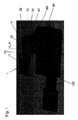
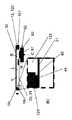
本発明は、例えば図1〜図4に示すような光学装置1、例えばカメラに関する。特に、光学装置1は、調整可能な焦点距離を有するレンズを備え、レンズ10は、レンズ容積Vを囲む容器11と、レンズ容積Vに接続されるリザーバ容積Rとを備える。2つの容積R、Vは、透明な液体Lで満たされる。容器11は、前面12aおよび背面12bを備える平坦な側壁構造12と、弾性的に変形可能で透明な膜20と、透明なカバー要素30と、弾性的に変形可能な壁部分22とをさらに備え(例えば、図3を参照)、膜20は、側壁構造12の背面12bに接続され、カバー要素30は、レンズ容積Vがカバー要素30と膜20との間に配置されるように、側壁構造12の前面12aに接続される。したがって、光は、カバー要素30、透明な液体Lで満たされたレンズ容積V、および膜20を通過することができる。レンズ容積Vに隣接する膜20の領域21の曲率を変化させることによって、レンズ10の焦点距離を調整することができ、これについては以下に詳細に説明する。 The present invention relates to, for example, an
さらに、前記壁部分22は、リザーバ容積Rに隣接して配置され、壁部分Rは、内側22aと、前記内側22aから離れて面する外側22bとを含み、内側22aは、リザーバ容積R内に存在する液体Lに接触する(例えば、図3を参照)。 Further, the
膜20が画定された正確な曲率を展開させることを確実にするために、レンズ10は、膜20に接続され、膜20の、例えば、円形領域21を画定するレンズ整形器40をさらに備え、この領域21は、調整可能な曲率を有し、レンズ容積V内の液体Lに接触する。この曲率を調整し、これとともにレンズ10の焦点距離を調整するために、レンズ10は、壁部分22の外側22bに接続され、リザーバ容積Rからレンズ容積V内に、またはその逆に、液体Lをポンピングするために前記外側22bに作用するように構成された可動ピストン50をさらに備える。好ましくは、壁部分22は、膜20の一部分によって形成される。特に、ピストン50は、レンズ10の容器11に接続されたハウジング80によって囲むことができる(例えば、図1および図3を参照)。 To ensure that the
レンズ10の焦点距離の調整は、例えば、カメラのオートフォーカス機能の作動原理を示す図3に例示的に示されている。ここで、前記領域21の曲率は、図3(A)に示される平坦な状態から図3(B)に示される凸状の状態に、液体Lをリザーバ容積Rからレンズ容積V内にポンピングすることによって変化し、こうして、レンズ容積V内の液体Lは、前記領域21に押し付けられ、次いで、凸状の曲率を生じる。その結果、ピストンが膜20の部分22を引っ張った場合、液体Lはリザーバ容積R内にポンピングで戻され、領域21の曲率は、平坦な状態に戻って小さくなることができる。ピストンを反対の移動方向B、B’、すなわち膜20の前記部分22の外側22bに向かう方向と、それから離れる方向とに連続的に移動させることができるという事実のために、焦点距離は、ある特定の範囲にわたって、例えば、ピストンストローク、ピストン面積、および光学レンズ面積によって与えられる特定の範囲にわたって、連続的に調整することができる。 The adjustment of the focal length of the
図1および図3に示すように、レンズの容器11は、特に設置スペースを節約して、レンズ鏡筒60上に配置されるようになっている。特に、このようなレンズ鏡筒60は、円周方向に延び、複数の剛性レンズ62が互いの上部に配置された内部空間61を取り囲んでいる。さらに、レンズ鏡筒60は、光がレンズ鏡筒60の内部空間61に入って、剛性レンズ通過することのできる開口部64を区切る面側63を備える。さらに、レンズ鏡筒60は、内部空間61の周囲に延びる側方外面65を備える。 As shown in FIGS. 1 and 3, the
レンズ鏡筒60は、レンズ鏡筒60を通過する光をレンズ鏡筒60の光軸A’に沿って、光学装置(例えば、カメラ)の画像センサ70上に偏向させ、レンズ10(例えば、焦点距離の調整)は、画像センサ70によって提供される光学的オートフォーカスフィードバック信号によって駆動することができる。 The
特に、図1および図3に示すように、リザーバ容積Rは、レンズ10の光軸Aに垂直な方向で、レンズ容積Vに対向して配置されている。 In particular, as shown in FIGS. 1 and 3, the reservoir volume R is arranged so as to face the lens volume V in the direction perpendicular to the optical axis A of the
一般に、容器10は、レンズLの光軸Aの方向に比較的低い高さを備えることができ、一方、膜部分22に接続されたリザーバ容積Rおよびピストン50を含む部分は、前記高さ方向に(光軸Aに沿って)より大きな設置スペースを必要とする。 In general, the
しかしながら、レンズ10の容器11の設計によって、光軸Aに関して容器11/リザーバ容積Rの非対称配置が可能となり、こうして、レンズ鏡筒60には、0.5mmより小さくなり得る低い高さだけが追加される。特に、容器11の非対称配置によって、レンズを携帯電話のディスプレイのエッジに移動させることが可能になる。 However, the design of the
特に、図1および図3に示すように、容器11およびハウジング80は、レンズ鏡筒60に、好ましくは取り付けられ、特に接着され、その結果、容器11がレンズ鏡筒60の面側63に配置され、レンズ容積Vがレンズ鏡筒60の剛性レンズ62に面し、またピストン50およびハウジング80がレンズ10の光軸Aに対して垂直(または光軸Aに一致するレンズ鏡筒60の光軸A’に対して垂直)方向にレンズ鏡筒60の側方外面65に面する。さらに、特に、ピストン50のハウジング80は、レンズ鏡筒60の側方外面65上に、嵌合するように配置される。 In particular, as shown in FIGS. 1 and 3, the
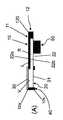
レンズ鏡筒上のレンズ10の配置とは別に、非対称配置は、図3に示されている折り畳みプリズム3のような他の光学部品と併せて使用することもできる。この実施形態によれば、容器11は、レンズ10の膜20が折り畳みプリズム3の表面3aとレンズ10のカバー要素30との間に配置されるように、折り畳みプリズム3の表面3aに接続され、特に接着される。このハウジング80/ピストン50は、プリズムに対して横方向に配置することができるので、高さ方向の設置スペースを節約する。 Apart from the arrangement of the
また、ここで、光学装置1は、レンズ鏡筒60(上記参照)を備えることができ、レンズ鏡筒60は、好ましくは、折り畳みプリズム3と光学装置1の光学画像センサ70との間の光学装置1の光路P内に配置される。特に、レンズ鏡筒60は、オートフォーカスおよび/または光学画像安定化を提供するために、画像センサ70に対して移動するように構成することができる。しかしながら、レンズ10は、またオートフォーカスおよびマクロも提供することができる。 Further, here, the
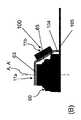
図4は、本発明による光学装置1の更なる実施形態を示し、この実施形態によって、ピストン50を囲むための追加のハウジング80を省略することが可能になる。 FIG. 4 shows a further embodiment of the
ここで、ピストン50を受け入れるために、レンズ鏡筒60の面側63に凹部66が形成され、レンズ10の容器11は、レンズ鏡筒60の面側63に接続され、特に接着され、その結果、レンズ容積Vがレンズ鏡筒60の剛性レンズ62に面し、またピストン50が壁部22の外側22bから凹部66内に突出するようになる。このように、本実施形態では、レンズ鏡筒60によってピストン50を囲むハウジングが形成されている。 Here, in order to receive the
特に、このような構成を達成するために、レンズ鏡筒60の外形は、アクチュエータのための空間を収容するようになっており、特にピストン50のための空洞を提供する。さらに、ピストン50を移動させるためのコイル101を、凹部66の底部66a上に配置されたプリント回路基板(PCB)103に一体化することができ、コイル101は、可撓性導体104を介して、光学装置1に電気的に接触させるのに役立つ、レンズ鏡筒60の底部の更なる可撓性コネクタ105に接続することができる。 In particular, in order to achieve such a configuration, the outer shape of the
特に、図4に示す構成は、コイル101がPCB103としてエッチングされた状態でフレックステール104を持ち上げ、PCBを凹部66内に接着することによって、効率的に確立することができる。その後、膜20の部分22に接続されたピストン50を有するレンズ10をレンズ鏡筒60に接着し、ピストン50を凹部66に受け入れる。これにより、AFドライバのコイル101への極めて単純化された電気的接続を生成することができる。 In particular, the configuration shown in FIG. 4 can be efficiently established by lifting the
以下において、図5〜図13は、レンズの容器11の異なる可能な設計を、特にレンズ整形器40の設計に関して示す。さらに、図14〜図17は、容積V、Rの間で液体Lをポンピングするようにピストン50を対向する移動方向B、B’に移動させるためのアクチュエータ100(例えば、双方向マイクロポンプ)の設計に関する。 In the following, FIGS. 5 to 13 show different possible designs of the
特に、図5(A)および図5(B)に示す実施形態によれば、レンズ10の容器11の側壁構造12(例えば、金属、ガラス、またはプラスチックから形成される)は、プレート部材120によって形成することができ、プレート部材120は、レンズ容積Vの少なくとも一部分を収容するための貫通開口部121と、リザーバ容積Rの少なくとも一部分を収容するための対向する凹部122とを備える。特に、プレート部材120は、カバー要素30(例えば、ガラス)と膜20との間に配置され、膜20は、プレート部材120の背面12bに接続され、カバー要素30は、プレート部材120の前面12aに接続され、こうして、レンズ容積Vは、カバー要素30および膜20によって覆われるようになり、凹部122は、膜22のみによって、特に、膜20の一体パーツを形成する前記弾性壁部分22によって覆われるようになる。しかしながら、部分22は、別個のパーツであってもよい。 In particular, according to the embodiments shown in FIGS. 5 (A) and 5 (B), the side wall structure 12 (for example, formed of metal, glass, or plastic) of the
膜20の前記曲率調整可能領域21を画定するために、更なるプレート部材40によって形成される(例えば、金属、ガラス、またはプラスチックから形成される)レンズ整形器40が提供され、膜20は、プレート部材120とレンズ整形器40との間に配置される。特に、レンズ整形器40は、前記領域21を画定するために、膜20と接触する円形縁部42によって画定される貫通開口部41を備える。リザーバ容積Rの壁部分22を露出させるために、ピストン50がリザーバ容積Rと相互作用することができるように、レンズ整形器40は、更なる貫通開口部43を備える。ここで、レンズ整形器40は、レンズ鏡筒60に対する距離ホルダとしても機能する。さらに、レンズ整形器40は、凸状の状態であるときに領域21に保護を提供する。 To define the curvature
図6は、代替的な実施形態を示し、図5と比較して、レンズ整形器40とプレート部材120の位置が入れ替わっており、その結果、レンズ整形器40を介して薄膜20がプレート部材120に接続されるようになっている。これは、レンズ整形器40が薄膜20とプレート部材120との間に配置されていることが知っていることを意味する。ここで、レンズ整形器40の貫通開口部41はレンズ容積Vに寄与する一方、更なる貫通開口部43はリザーバ容積Rに寄与する。 FIG. 6 shows an alternative embodiment in which the
図7は、図5に示す実施形態の変形例を示し、ここでは、レンズ整形器40は、膜20の領域21を画定するための貫通開口部41および円形縁部42を備えるリング部材40によって形成される(例えば、金属、ガラス、またはプラスチックから形成される)。プレート部材120の更なる貫通開口部122も、膜20によって覆われる(すなわち、部分22は、膜20の一体パーツである)。 FIG. 7 shows a modification of the embodiment shown in FIG. 5, in which the
さらに、図8は、レンズ10の実施形態を示し、ここでは、レンズ整形器40(例えば、金属、ガラス、またはプラスチックから形成される)がプレート部材120自体によって形成され、レンズ整形器40の円形縁部42がプレート部材120の前記開口部121の円形縁部42によって形成される。さらに、プレート部材120の凹部122は、貫通開口部として形成されている。ここで、両方の貫通開口部121、122は、カバー要素30によって前面12aが覆われ、膜20によって背面12bが覆われている。 Further, FIG. 8 shows an embodiment of the
図9は、図8に示す実施形態の変形例を示し、ここで、カバー要素30は、プレート部材120の貫通開口部121を覆う円形カバー要素30である。凹部(すなわち、貫通開口部)122も閉じるために、更なる膜25が設けられ、カバー要素30とプレート部材120との間に配置される。こうして、弾性壁部分25、22によってリザーバ容積が前面12aおよび背面12bで覆われる。 FIG. 9 shows a modified example of the embodiment shown in FIG. 8, where the
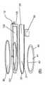
図10に示すように、レンズ10の容器10は、また原則として、曲がった形状を備えることができ、こうして、装置1の設置スペースを最小化するレンズ鏡筒60に関する配置が可能になる。 As shown in FIG. 10, the
このために、容器11は、レンズ容積Vを含む第一の部分11aと、リザーバ容積Rを含む第二の部分11bとを含み、第一の部分11aは、容器11の第二の部分11bに対して鈍角Wで延在する(図10(A)参照)。これによって、図10(B)に示す容器11の位置が可能になり、ここで、容器の第一の部分11aは、レンズ鏡筒の面側63に配置され、こうして、膜20の前記領域21およびレンズ容積Vがレンズ鏡筒の剛性レンズ62に面するようになり、容器11の第二の部分11bは、レンズ鏡筒60に対して横方向に配置され、レンズ10の光軸Aに垂直な方向(またはレンズ鏡筒60の光軸A’に垂直な方向)にレンズ鏡筒60の側方外面65に面する。 For this purpose, the
さらに、既に上述したように、全てのレンズ設計において、液体Lとカバー要素30との間の屈折率整合を改善するために、カバー要素(例えば、ガラス)の下に更なる膜25を配置することができる。 Further, as already mentioned above, in all lens designs, an
さらに、上述した全てのプレート部材120は、(例えば、プレート部材120の深さエッチングおよび/または射出成形の代わりに)複数の平坦な要素を互いの上に積み重ねることによって形成することもできる。 Further, all the
さらに、図12に示すように、レンズ10をレンズ鏡筒60上に取り付ける(例えば、接着する)とき、空気ダクト(例えば、エアスリットまたはエアギャップ)を好ましくはレンズ領域に提供し、その結果、膜20の撓みが生じ得るようになる(過圧または負圧を補償するための空気交換)。同じことは、ハウジング80または凹部66にも当てはまる。レンズ鏡筒の内部空間61を、ハウジングの内部空間85(または凹部66)、またはハウジング80(または凹部66)用の空気ダクト84、およびレンズ鏡筒の内部空間61の通気を可能にする更なる空気ダクト67を介して通気することができるように、ハウジング80(または凹部66)の空気ダクト84および85の形で1つの共通の空気交換を行うことができる。特に、全ての3つの空気ダクト84、86、67が存在することもある。単にダクト84、86が使用される構成は、レンズ領域(すなわち、レンズ鏡筒60の内部空間61)に入り得る粒子がより少ないという利点を有する。 Further, as shown in FIG. 12, when the
さらに、図13は、レンズ10の容器11の設計のさらに別の実施形態を示し、これは、図8に示す実施形態の変形例に対応する。特に、図13によれば、プレート部材120はプリント回路基板であり、レンズ整形器40の前記円形縁部42は、プリント回路基板120のエッチングされた金属層44(例えば、銅によって形成されるか、または銅を含む金属)によって形成される。 Furthermore, FIG. 13 shows yet another embodiment of the design of the
このような頂部(例えば、銅)層のエッチングによって、高品質なレンズ整形器40が得られる。プレート部材120の貫通孔121は、正確な直径でドリル加工することができるが、光学的品質は求められない。このため、非常に小さく、低コストで、薄いレンズ10を構築することが可能になる。 Etching of such a top (eg, copper) layer gives the
あるいは、本明細書に記載される側壁構造12、またはプレート部材120もしくは更なるプレート部材40は、金属、プラスチック材料、ポリマーから形成することができ、またはこれらを含むことができる。特に、側壁構造12、またはプレート部材120もしくは更なるプレート部材120は、射出成形され得る。一般に、カバー要素30は、ガラス、プラスチック材料、ポリマーから形成することができ、またはこれらを含むことができる。 Alternatively, the
さらに、図14〜図17は、本発明で使用可能な異なる可能なアクチュエータの設計を示す。 In addition, FIGS. 14-17 show different possible actuator designs that can be used in the present invention.
例えば、図14〜図17に示すように、光学装置1は、(例えば、膜20の)前記部分22に接続されているレンズ10のピストン50を動かすように構成されたアクチュエータ100を備える。特に、アクチュエータは、ピストン(例えばレンズの光軸Aに沿って)を第一の移動方向Bに移動させるように構成され、その結果、ピストン50が壁部分22の外側22bに押し付けられ、リザーバ容積Rからレンズ容積Vに液体Lをポンピングすることで、レンズ10の膜20の前記領域21の曲率を変化(例えば、増加)させ、それとともに、レンズ10の焦点距離を変化(例えば、低下)させる。さらに、アクチュエータ100は、ピストン50を反対の第二の移動方向B’に移動させるように構成され、その結果、ピストン50が壁部分22の外側22bで引っ張り、液体Lをレンズ容積Vからリザーバ容積R内にポンピングすることで、レンズ10の膜20の前記領域21の曲率を変化させ、それとともにレンズ10の焦点距離を変化させる。 For example, as shown in FIGS. 14-17, the
具体的には、図14、図15および図17に示すように、ピストン50は、磁石51を備え、この磁石51は、好ましくは、磁石51とリザーバ容積Rの壁部分22との間に配置されたスペーサ52によって前記壁部分22(例えば、膜20の一部)に接続されている。 Specifically, as shown in FIGS. 14, 15 and 17, the
さらに、図14、図15および図17に示すように、アクチュエータ100は、磁石51と相互作用して、ピストン50を前記移動方向B、B’に移動させるように構成された導電性コイル101を備える。 Further, as shown in FIGS. 14, 15 and 17, the
特に、それぞれのコイル101は、巻回軸Cの周りに延びる巻線102aを備える導電体102を備え、特に、巻回軸Cは、レンズの光軸Aに平行に、および/または容器11の壁部分22に垂直に延びる。 In particular, each
非常に薄い設計を達成するために、コイル101は、図13に示すように、プレート部材(PCB)120に一体化することができ、ここで、磁石51は、ピストン(50)の第一の移動方向Bで、コイル101に面する。さらに、磁石51は、巻回軸Cに平行に(または移動方向B、B’に平行に、またはレンズ10の光軸Aに平行に)延びる磁化Mを備えることができる。 To achieve a very thin design, the
さらに、図4と関連して説明したように、コイル101は、レンズ鏡筒60の面側63の凹部66の底部66aに配置されたプリント回路基板103に一体化することもできる。あるいは、それは、前記凹部66の底部66aに配置されてもよく、または前記底部66aに一体化されてもよい。 Further, as described in connection with FIG. 4, the
さらに、図14〜図17に示す実施形態では、レンズ10は、ハウジング80をさらに備え(ハウジングは、本明細書で説明するように、レンズ鏡筒の凹部66によって形成することもできる)、ハウジング80は、壁部分22に面する底部80aと、ハウジング80の底部80aをレンズ10の容器11に接続する側壁80bとを備える。 Further, in the embodiments shown in FIGS. 14-17, the
特に、図14に示す実施形態によれば、コイル101は、ハウジング80の底部80aに一体化されるか、またはハウジング80の底部80aに配置されて、その結果、ピストン50の第二の移動方向B’で、磁石51がコイル101に面するようになる。さらに、磁石51は、コイル101の巻回軸Cに平行に延びる磁化Mを備える。コイル101内の光学装置1によって提供される電流Iの方向に応じて、ピストン50は、(磁石とコイルとの間の双極子−双極子相互作用により)、リザーバ容積Rからレンズ容積V内に液体Lをポンピングする第一の移動方向Bに移動するか(例えば、領域21に凸曲率を与えるために)、またはレンズ容積からリザーバ容積R内に液体Lをポンピングする第二の移動方向B’に移動するか(例えば、凸曲率を減少させて平坦な状態に戻すために)のいずれかである。 In particular, according to the embodiment shown in FIG. 14, the
図15は、代替的な実施形態を示し、ここで(図14とは対照的に)、コイル191は、101がハウジング80の側壁80bに一体化されるか、あるいはハウジング80の側壁80bに配置される。ここで、磁石51は、コイル101の巻線102aによって囲まれた空間107(例えば、エアギャップ)内に少なくとも部分的にまたは完全に配置され、磁石51は、巻回軸Cに平行に(または光軸Aに平行に、または移動方向B、B’に平行に)延びる磁化Mを備えることができる。 FIG. 15 shows an alternative embodiment, where (in contrast to FIG. 14), the coil 191 has 101 integrated into the
図17は、図15に示す実施形態の変形例を示し、ここで、磁石50は、径方向に着磁されたリング磁石であり、すなわち、それぞれの磁化Mは、コイル101の巻回軸Cに垂直に(または、光軸または移動方向B、B’に垂直に)延びている。 FIG. 17 shows a modification of the embodiment shown in FIG. 15, where the
図16は、磁石51を必要としない代替アクチュエータの設計を示す。ここで、アクチュエータ100は、ピストン50を移動させるための形状記憶合金から形成された部材200を備え、この部材200は、ピストン50をピストン50の前記ハウジング80(またはレンズ鏡筒60)に接続する。特に、前記部材200は、部材200が形状記憶合金部材(例えば、ワイヤ)の長さを縮めることにより、ピストン50を壁部分22で引っ張らせる状態を備える。両方向形状記憶合金構成では、ピストン50の押し引きが可能であり、すなわち、前記部材200の代わりに、アクチュエータは、ピストン50を壁部分22に押し付け、またはピストン50を壁部分22で引っ張るように構成された両方向形状記憶合金構造を含むことができる。 FIG. 16 shows the design of an alternative actuator that does not require a
図14〜図17にさらに示すように、容器11は、ピストン50の第一の移動方向Bで、ピストン50用のストッパ81を形成することもできる。さらに、ハウジング80は、ピストン50の反対の第二の移動方向B’で、ピストン50用のストッパ82を形成することもできる。さらに、ハウジングは、ピストン50の前記移動方向B、B’に垂直な方向で、ピストン50用のストッパ83を提供してもよい。これらのストッパ81、82、83により、膜20/壁部分22を機械的損傷から保護することができる。 As further shown in FIGS. 14 to 17, the
携帯電話のレンズ鏡筒60およびその上に配置されたレンズ10の概略平面図(A)、(B)および(C)を示す図18に示すように、本発明によるレンズ10の容器11と、特にハウジング80の設計は、携帯電話の表示領域を最適化し、最大化するレンズ鏡筒60に対するレンズ10の配置を可能にする。 As shown in FIG. 18 showing schematic plan views (A), (B) and (C) of the
この点に関し、図18(A)は、リザーバ容積Rがレンズ鏡筒のコーナー領域60bに配置された構成を示し、図18(B)は、リザーバ容積Rがレンズ鏡筒60のエッジ60cに沿って中心に配置された構成を示す。さらに、図18(C)は、リザーバ容積Rがレンズ鏡筒60のエッジ60c上に配置されているが、レンズ鏡筒60からエッジ60cを過ぎて突出している構成を示している。 In this regard, FIG. 18A shows a configuration in which the reservoir volume R is arranged in the
さらに、一般に、レンズ10(特に、レンズのアクチュエータ100のコイル101に)は、ピンヘッダ、フレックスケーブル(例えば、専用コネクタなし)またはハーフビアを使用することによって、特に、レンズ10をカメラモジュールに直接接続することによって、電気的に接触させることができる。図19に示す好ましい変形によれば、電気的な接続は、インサート成形された金属片106を介して、下方に引き下げることができる。 Further, in general, the lens 10 (particularly to the
換言すれば、レンズ鏡筒60は、レンズ鏡筒60内に(例えば、インサート成形によって)成形された電気コネクタ106を備えることができ、電気コネクタ106は、コイル101にハンダ付けされる(またはその他の方法で電気的に接続される)2つの第一の端部106aとともにレンズ鏡筒60から突出し、特に電気コネクタ106は、プリント回路基板または可撓性コネクタ105上に配置された電気接点に、例えば、ハンダ付けされる2つの第二の端部106bとともにレンズ鏡筒60から反対側に突出する。 In other words, the
最後に、図20は、リザーバ容積R(およびピストン50)の形状が任意であり、互いに異なる可能性があることを示す。特に、図20は、リザーバ容積およびレンズ容積の異なる可能な形状を示し、特に、レンズ容積Vは、円形断面(A)、(B)を備えることができ、リザーバ容積Rは、円形形状から逸脱することができ、例えば、正方形(A)または楕円形(B)の断面を備えることができる。 Finally, FIG. 20 shows that the shape of the reservoir volume R (and piston 50) is arbitrary and can be different from each other. In particular, FIG. 20 shows possible shapes with different reservoir volumes and lens volumes, in particular the lens volume V can have circular cross sections (A) and (B) and the reservoir volume R deviates from the circular shape. Can include, for example, a square (A) or oval (B) cross section.
さらに、電気コイルに基づいて、本明細書に記載される全てのアクチュエータは、巻きコイルまたはPCBコイル(例えば、PCBに一体化されたコイル)とすることができるコイルを含むことができる。特に、PCBコイルの場合、ドライバをコイル101のPCB上に直接ハンダ付けし、例えばI2C、SPIなどのデジタル信号を用いて制御することができる。 Further, based on the electric coil, all actuators described herein can include a coil that can be a winding coil or a PCB coil (eg, a coil integrated into a PCB). In particular, in the case of a PCB coil, the driver can be soldered directly onto the PCB of the
Claims (36)
Translated fromJapaneseApplications Claiming Priority (5)
| Application Number | Priority Date | Filing Date | Title |
|---|---|---|---|
| EP18168346.7 | 2018-04-19 | ||
| EP18168346 | 2018-04-19 | ||
| EP18193557.8 | 2018-09-10 | ||
| EP18193557 | 2018-09-10 | ||
| PCT/EP2019/060384WO2019202166A2 (en) | 2018-04-19 | 2019-04-23 | Thin lens optical module, particularly for autofocus |
Publications (1)
| Publication Number | Publication Date |
|---|---|
| JP2021521482Atrue JP2021521482A (en) | 2021-08-26 |
Family
ID=66290419
Family Applications (2)
| Application Number | Title | Priority Date | Filing Date |
|---|---|---|---|
| JP2020556867APendingJP2021521482A (en) | 2018-04-19 | 2019-04-23 | Thin lens optical module especially for autofocus |
| JP2020556895APendingJP2021521483A (en) | 2018-04-19 | 2019-04-23 | Optical zoom device |
Family Applications After (1)
| Application Number | Title | Priority Date | Filing Date |
|---|---|---|---|
| JP2020556895APendingJP2021521483A (en) | 2018-04-19 | 2019-04-23 | Optical zoom device |
Country Status (6)
| Country | Link |
|---|---|
| US (2) | US20210124095A1 (en) |
| EP (2) | EP3781968A2 (en) |
| JP (2) | JP2021521482A (en) |
| KR (2) | KR20200144552A (en) |
| CN (2) | CN112136069A (en) |
| WO (2) | WO2019202164A2 (en) |
Families Citing this family (8)
| Publication number | Priority date | Publication date | Assignee | Title |
|---|---|---|---|---|
| US20210325575A1 (en)* | 2018-02-10 | 2021-10-21 | Optotune Ag | Orientation independent coma compensating liquid lens |
| US20220075101A1 (en)* | 2018-12-28 | 2022-03-10 | Optotune Consumer Ag | Lens comprising an adjustable optical power |
| CN210839753U (en)* | 2019-11-13 | 2020-06-23 | 晋城三赢精密电子有限公司 | Periscopic zooming camera module |
| KR20210078420A (en) | 2019-12-17 | 2021-06-28 | 옵토튠 컨슈머 아게 | Liquid lens with a laterally arranged pump portion |
| US12393000B2 (en)* | 2020-02-25 | 2025-08-19 | Zebra Technologies Corporation | Optical arrangement for small size wide angle auto focus imaging lens for high resolution sensors |
| CN112817133A (en)* | 2021-01-13 | 2021-05-18 | 北京航空航天大学 | Unmanned aerial vehicle shooting system based on liquid zoom camera |
| KR102597158B1 (en)* | 2021-02-19 | 2023-11-02 | 삼성전기주식회사 | Optical imaging system |
| CN115704944A (en) | 2021-08-12 | 2023-02-17 | 奈科特伦斯瑞士股份公司 | objective lens |
Citations (6)
| Publication number | Priority date | Publication date | Assignee | Title |
|---|---|---|---|---|
| JP2009251244A (en)* | 2008-04-04 | 2009-10-29 | Sony Corp | Conversion lens, conversion lens device, and imaging device |
| JP2011008121A (en)* | 2009-06-26 | 2011-01-13 | Sony Corp | Varifocal lens, camera module, and electronic equipment |
| JP2012520486A (en)* | 2009-03-13 | 2012-09-06 | ノウルズ エレクトロニクス リミテッド ライアビリティ カンパニー | Lens assembly apparatus and method |
| JP2014163963A (en)* | 2013-02-21 | 2014-09-08 | Univ Of Tokyo | Liquid device |
| JP2016525718A (en)* | 2013-07-26 | 2016-08-25 | ノールズ エレクトロニクス,リミテッド ライアビリティ カンパニー | Optical apparatus and method |
| WO2017149092A2 (en)* | 2016-03-02 | 2017-09-08 | Optotune Ag | Optical device, particularly camera, particularly comprising autofocus, image stabilization and super resolution |
Family Cites Families (26)
| Publication number | Priority date | Publication date | Assignee | Title |
|---|---|---|---|---|
| JPH0749404A (en)* | 1993-08-05 | 1995-02-21 | Nippondenso Co Ltd | Lens with variable focal point |
| US7646544B2 (en)* | 2005-05-14 | 2010-01-12 | Batchko Robert G | Fluidic optical devices |
| DE60334023D1 (en)* | 2002-10-25 | 2010-10-14 | Koninkl Philips Electronics Nv | ZOOM LENS |
| JP4897680B2 (en)* | 2004-07-20 | 2012-03-14 | エージェンシー フォー サイエンス, テクノロジー アンド リサーチ | Variable focus micro lens |
| JP5119567B2 (en)* | 2004-09-30 | 2013-01-16 | カシオ計算機株式会社 | camera |
| WO2006088514A2 (en)* | 2004-11-05 | 2006-08-24 | The Regents Of The University Of California | Fluidic adaptive lens systems with pumping systems |
| FR2883987B1 (en)* | 2005-03-31 | 2008-02-01 | Varioptic Sa | OPTICAL SYSTEM FOR IMAGING POWER-ADJUSTING IMAGE |
| US7227682B2 (en)* | 2005-04-08 | 2007-06-05 | Panavision International, L.P. | Wide-range, wide-angle compound zoom with simplified zooming structure |
| WO2008010124A1 (en)* | 2006-07-13 | 2008-01-24 | Koninklijke Philips Electronics N. V. | Zoom optical system, and camera and device therewith |
| GB0621065D0 (en)* | 2006-10-23 | 2006-11-29 | Silver Joshua D | Variable focus lens and spectacles |
| US7369321B1 (en)* | 2007-01-16 | 2008-05-06 | University Of Central Florida Research Foundation, Inc. | Variable-focus liquid lens |
| CN101821658B (en)* | 2007-12-04 | 2014-02-26 | 黑眼睛光学有限公司 | Zoom lens and camera system |
| KR20110015569A (en)* | 2008-04-23 | 2011-02-16 | 다르마틸레케 사만 | Variable Optical Systems and Components |
| US8659835B2 (en)* | 2009-03-13 | 2014-02-25 | Optotune Ag | Lens systems and method |
| EP2417488B1 (en)* | 2009-04-10 | 2013-11-06 | Blackeye Optics, LLC | Zoom optical system comprising liquid lenses |
| JP2011013582A (en)* | 2009-07-03 | 2011-01-20 | Sony Corp | Zoom lens, camera module, electronic equipment, and method for designing zoom lens |
| KR101680300B1 (en)* | 2009-08-31 | 2016-11-28 | 삼성전자주식회사 | Liquid lens and method for manufacturing the same |
| KR101912092B1 (en)* | 2010-10-05 | 2018-10-26 | 삼성전자 주식회사 | Fluidic lens |
| KR101206949B1 (en)* | 2011-04-28 | 2012-11-30 | 경북대학교 산학협력단 | Fluid pressure liquid lens |
| WO2015024136A1 (en)* | 2013-08-20 | 2015-02-26 | Optotune Ag | Optical zoom lens with two liquid lenses |
| EP2860556A1 (en)* | 2013-10-08 | 2015-04-15 | Optotune AG | Tunable Lens Device |
| FR3015699B1 (en)* | 2013-12-20 | 2016-02-05 | Wavelens | OPTICAL DEVICE FOR STABILIZING IMAGES |
| EP2952850A1 (en)* | 2014-06-03 | 2015-12-09 | Optotune AG | Optical device, particularly for tuning the focal length of a lens of the device by means of optical feedback |
| FR3029644B1 (en)* | 2014-12-04 | 2018-01-12 | Webster Capital Llc | AUTOFOCUS CAMERA AND VARIABLE FOCAL OPTICAL DEVICE INTENDED TO BE INTEGRATED WITH SUCH A CAMERA |
| WO2016202392A1 (en)* | 2015-06-17 | 2016-12-22 | Optotune Ag | Temperature drift compensation for liquid lenses |
| EP3770650B1 (en)* | 2016-04-29 | 2022-11-16 | LG Innotek Co., Ltd. | Camera module including liquid lens |
- 2019
- 2019-04-23JPJP2020556867Apatent/JP2021521482A/enactivePending
- 2019-04-23WOPCT/EP2019/060381patent/WO2019202164A2/ennot_activeCeased
- 2019-04-23USUS17/048,622patent/US20210124095A1/ennot_activeAbandoned
- 2019-04-23CNCN201980032867.6Apatent/CN112136069A/enactivePending
- 2019-04-23EPEP19719826.0Apatent/EP3781968A2/ennot_activeWithdrawn
- 2019-04-23KRKR1020207030785Apatent/KR20200144552A/ennot_activeAbandoned
- 2019-04-23EPEP19719825.2Apatent/EP3781974A2/ennot_activeWithdrawn
- 2019-04-23JPJP2020556895Apatent/JP2021521483A/enactivePending
- 2019-04-23CNCN201980033185.7Apatent/CN112189151A/enactivePending
- 2019-04-23WOPCT/EP2019/060384patent/WO2019202166A2/ennot_activeCeased
- 2019-04-23USUS17/048,620patent/US20210116682A1/ennot_activeAbandoned
- 2019-04-23KRKR1020207030791Apatent/KR20200144553A/ennot_activeCeased
Patent Citations (7)
| Publication number | Priority date | Publication date | Assignee | Title |
|---|---|---|---|---|
| JP2009251244A (en)* | 2008-04-04 | 2009-10-29 | Sony Corp | Conversion lens, conversion lens device, and imaging device |
| JP2012520486A (en)* | 2009-03-13 | 2012-09-06 | ノウルズ エレクトロニクス リミテッド ライアビリティ カンパニー | Lens assembly apparatus and method |
| JP2011008121A (en)* | 2009-06-26 | 2011-01-13 | Sony Corp | Varifocal lens, camera module, and electronic equipment |
| JP2014163963A (en)* | 2013-02-21 | 2014-09-08 | Univ Of Tokyo | Liquid device |
| JP2016525718A (en)* | 2013-07-26 | 2016-08-25 | ノールズ エレクトロニクス,リミテッド ライアビリティ カンパニー | Optical apparatus and method |
| WO2017149092A2 (en)* | 2016-03-02 | 2017-09-08 | Optotune Ag | Optical device, particularly camera, particularly comprising autofocus, image stabilization and super resolution |
| JP2019514038A (en)* | 2016-03-02 | 2019-05-30 | オプトチューン コンシューマー アーゲー | Optical device, in particular a camera including in particular automatic focusing, image stabilization and super-resolution |
Also Published As
| Publication number | Publication date |
|---|---|
| CN112189151A (en) | 2021-01-05 |
| EP3781968A2 (en) | 2021-02-24 |
| WO2019202164A3 (en) | 2019-12-05 |
| KR20200144552A (en) | 2020-12-29 |
| WO2019202164A2 (en) | 2019-10-24 |
| JP2021521483A (en) | 2021-08-26 |
| EP3781974A2 (en) | 2021-02-24 |
| US20210124095A1 (en) | 2021-04-29 |
| WO2019202166A3 (en) | 2019-12-05 |
| WO2019202166A2 (en) | 2019-10-24 |
| CN112136069A (en) | 2020-12-25 |
| KR20200144553A (en) | 2020-12-29 |
| US20210116682A1 (en) | 2021-04-22 |
Similar Documents
| Publication | Publication Date | Title |
|---|---|---|
| JP2021521482A (en) | Thin lens optical module especially for autofocus | |
| US12248241B2 (en) | Camera lens barrel, camera module, and optical device | |
| KR20220057495A (en) | Actuator and camera module including the same | |
| US11934033B2 (en) | Lens driving device, camera module and optical apparatus | |
| TWI726766B (en) | Camera module and electronic device | |
| CN104508550B (en) | camera module | |
| JP4509942B2 (en) | Lens transfer device with improved assembly | |
| KR102337594B1 (en) | Driving mechanism, camera module and electronic device | |
| EP3133440A1 (en) | Camera module and optical instrument | |
| KR20100125978A (en) | Lens Actuator for Magnet Movement Type Image Imaging | |
| CN108540696A (en) | Camera model | |
| US11971652B2 (en) | Camera actuator and camera module including the same | |
| CN111856693B (en) | Lens driving module and electronic device | |
| US9063389B2 (en) | Camera module | |
| KR20210132986A (en) | Camera actuator and camera module including the same | |
| CN111435214A (en) | Camera module and electronic device with same | |
| CN210428039U (en) | Focal length adjusting device and mobile terminal | |
| KR20220011519A (en) | Camera actuator and camera module including the same | |
| KR20190031804A (en) | Camera Module | |
| CN116953875A (en) | Variable focal length lens device and camera module | |
| KR101906908B1 (en) | Voice coil motor | |
| CN116457724A (en) | Camera device and optical instrument | |
| KR20180044526A (en) | Camera module and optical apparatus | |
| CN111953895B (en) | Focusable imaging device | |
| KR102865110B1 (en) | Camera lens module and portable terminal |
Legal Events
| Date | Code | Title | Description |
|---|---|---|---|
| A521 | Request for written amendment filed | Free format text:JAPANESE INTERMEDIATE CODE: A523 Effective date:20201217 | |
| A621 | Written request for application examination | Free format text:JAPANESE INTERMEDIATE CODE: A621 Effective date:20220420 | |
| A977 | Report on retrieval | Free format text:JAPANESE INTERMEDIATE CODE: A971007 Effective date:20220928 | |
| A131 | Notification of reasons for refusal | Free format text:JAPANESE INTERMEDIATE CODE: A131 Effective date:20221108 | |
| A601 | Written request for extension of time | Free format text:JAPANESE INTERMEDIATE CODE: A601 Effective date:20230208 | |
| A601 | Written request for extension of time | Free format text:JAPANESE INTERMEDIATE CODE: A601 Effective date:20230410 | |
| A521 | Request for written amendment filed | Free format text:JAPANESE INTERMEDIATE CODE: A523 Effective date:20230508 | |
| A02 | Decision of refusal | Free format text:JAPANESE INTERMEDIATE CODE: A02 Effective date:20230606 |