JP2021520255A - Embolic device with improved reduced diameter coating - Google Patents
Embolic device with improved reduced diameter coatingDownload PDFInfo
- Publication number
- JP2021520255A JP2021520255AJP2020554276AJP2020554276AJP2021520255AJP 2021520255 AJP2021520255 AJP 2021520255AJP 2020554276 AJP2020554276 AJP 2020554276AJP 2020554276 AJP2020554276 AJP 2020554276AJP 2021520255 AJP2021520255 AJP 2021520255A
- Authority
- JP
- Japan
- Prior art keywords
- embolic device
- embolic
- devices
- angiopathy
- stage
- Prior art date
- Legal status (The legal status is an assumption and is not a legal conclusion. Google has not performed a legal analysis and makes no representation as to the accuracy of the status listed.)
- Pending
Links
Images


Classifications
- A—HUMAN NECESSITIES
- A61—MEDICAL OR VETERINARY SCIENCE; HYGIENE
- A61B—DIAGNOSIS; SURGERY; IDENTIFICATION
- A61B17/00—Surgical instruments, devices or methods
- A61B17/12—Surgical instruments, devices or methods for ligaturing or otherwise compressing tubular parts of the body, e.g. blood vessels or umbilical cord
- A61B17/12022—Occluding by internal devices, e.g. balloons or releasable wires
- A61B17/12027—Type of occlusion
- A61B17/12031—Type of occlusion complete occlusion
- A—HUMAN NECESSITIES
- A61—MEDICAL OR VETERINARY SCIENCE; HYGIENE
- A61B—DIAGNOSIS; SURGERY; IDENTIFICATION
- A61B17/00—Surgical instruments, devices or methods
- A61B17/12—Surgical instruments, devices or methods for ligaturing or otherwise compressing tubular parts of the body, e.g. blood vessels or umbilical cord
- A61B17/12022—Occluding by internal devices, e.g. balloons or releasable wires
- A61B17/12099—Occluding by internal devices, e.g. balloons or releasable wires characterised by the location of the occluder
- A61B17/12109—Occluding by internal devices, e.g. balloons or releasable wires characterised by the location of the occluder in a blood vessel
- A61B17/12113—Occluding by internal devices, e.g. balloons or releasable wires characterised by the location of the occluder in a blood vessel within an aneurysm
- A—HUMAN NECESSITIES
- A61—MEDICAL OR VETERINARY SCIENCE; HYGIENE
- A61B—DIAGNOSIS; SURGERY; IDENTIFICATION
- A61B17/00—Surgical instruments, devices or methods
- A61B17/12—Surgical instruments, devices or methods for ligaturing or otherwise compressing tubular parts of the body, e.g. blood vessels or umbilical cord
- A61B17/12022—Occluding by internal devices, e.g. balloons or releasable wires
- A61B17/12131—Occluding by internal devices, e.g. balloons or releasable wires characterised by the type of occluding device
- A61B17/1214—Coils or wires
- A61B17/12145—Coils or wires having a pre-set deployed three-dimensional shape
- A—HUMAN NECESSITIES
- A61—MEDICAL OR VETERINARY SCIENCE; HYGIENE
- A61B—DIAGNOSIS; SURGERY; IDENTIFICATION
- A61B17/00—Surgical instruments, devices or methods
- A61B17/12—Surgical instruments, devices or methods for ligaturing or otherwise compressing tubular parts of the body, e.g. blood vessels or umbilical cord
- A61B17/12022—Occluding by internal devices, e.g. balloons or releasable wires
- A61B17/12131—Occluding by internal devices, e.g. balloons or releasable wires characterised by the type of occluding device
- A61B17/1214—Coils or wires
- A61B17/12154—Coils or wires having stretch limiting means
- A—HUMAN NECESSITIES
- A61—MEDICAL OR VETERINARY SCIENCE; HYGIENE
- A61B—DIAGNOSIS; SURGERY; IDENTIFICATION
- A61B17/00—Surgical instruments, devices or methods
- A61B17/12—Surgical instruments, devices or methods for ligaturing or otherwise compressing tubular parts of the body, e.g. blood vessels or umbilical cord
- A61B17/12022—Occluding by internal devices, e.g. balloons or releasable wires
- A61B17/12131—Occluding by internal devices, e.g. balloons or releasable wires characterised by the type of occluding device
- A61B17/12163—Occluding by internal devices, e.g. balloons or releasable wires characterised by the type of occluding device having a string of elements connected to each other
- A—HUMAN NECESSITIES
- A61—MEDICAL OR VETERINARY SCIENCE; HYGIENE
- A61B—DIAGNOSIS; SURGERY; IDENTIFICATION
- A61B17/00—Surgical instruments, devices or methods
- A61B17/12—Surgical instruments, devices or methods for ligaturing or otherwise compressing tubular parts of the body, e.g. blood vessels or umbilical cord
- A61B17/12022—Occluding by internal devices, e.g. balloons or releasable wires
- A61B17/12131—Occluding by internal devices, e.g. balloons or releasable wires characterised by the type of occluding device
- A61B17/12168—Occluding by internal devices, e.g. balloons or releasable wires characterised by the type of occluding device having a mesh structure
- A61B17/12172—Occluding by internal devices, e.g. balloons or releasable wires characterised by the type of occluding device having a mesh structure having a pre-set deployed three-dimensional shape
- A—HUMAN NECESSITIES
- A61—MEDICAL OR VETERINARY SCIENCE; HYGIENE
- A61B—DIAGNOSIS; SURGERY; IDENTIFICATION
- A61B17/00—Surgical instruments, devices or methods
- A61B17/0057—Implements for plugging an opening in the wall of a hollow or tubular organ, e.g. for sealing a vessel puncture or closing a cardiac septal defect
- A61B2017/00575—Implements for plugging an opening in the wall of a hollow or tubular organ, e.g. for sealing a vessel puncture or closing a cardiac septal defect for closure at remote site, e.g. closing atrial septum defects
- A61B2017/00632—Occluding a cavity, i.e. closing a blind opening
- A—HUMAN NECESSITIES
- A61—MEDICAL OR VETERINARY SCIENCE; HYGIENE
- A61B—DIAGNOSIS; SURGERY; IDENTIFICATION
- A61B17/00—Surgical instruments, devices or methods
- A61B2017/00743—Type of operation; Specification of treatment sites
- A61B2017/00778—Operations on blood vessels
- A—HUMAN NECESSITIES
- A61—MEDICAL OR VETERINARY SCIENCE; HYGIENE
- A61B—DIAGNOSIS; SURGERY; IDENTIFICATION
- A61B17/00—Surgical instruments, devices or methods
- A61B2017/00831—Material properties
- A61B2017/00867—Material properties shape memory effect
- A—HUMAN NECESSITIES
- A61—MEDICAL OR VETERINARY SCIENCE; HYGIENE
- A61B—DIAGNOSIS; SURGERY; IDENTIFICATION
- A61B17/00—Surgical instruments, devices or methods
- A61B17/12—Surgical instruments, devices or methods for ligaturing or otherwise compressing tubular parts of the body, e.g. blood vessels or umbilical cord
- A61B17/12022—Occluding by internal devices, e.g. balloons or releasable wires
- A61B2017/1205—Introduction devices
- A—HUMAN NECESSITIES
- A61—MEDICAL OR VETERINARY SCIENCE; HYGIENE
- A61F—FILTERS IMPLANTABLE INTO BLOOD VESSELS; PROSTHESES; DEVICES PROVIDING PATENCY TO, OR PREVENTING COLLAPSING OF, TUBULAR STRUCTURES OF THE BODY, e.g. STENTS; ORTHOPAEDIC, NURSING OR CONTRACEPTIVE DEVICES; FOMENTATION; TREATMENT OR PROTECTION OF EYES OR EARS; BANDAGES, DRESSINGS OR ABSORBENT PADS; FIRST-AID KITS
- A61F2/00—Filters implantable into blood vessels; Prostheses, i.e. artificial substitutes or replacements for parts of the body; Appliances for connecting them with the body; Devices providing patency to, or preventing collapsing of, tubular structures of the body, e.g. stents
- A61F2/01—Filters implantable into blood vessels
- A61F2/011—Instruments for their placement or removal
- A—HUMAN NECESSITIES
- A61—MEDICAL OR VETERINARY SCIENCE; HYGIENE
- A61F—FILTERS IMPLANTABLE INTO BLOOD VESSELS; PROSTHESES; DEVICES PROVIDING PATENCY TO, OR PREVENTING COLLAPSING OF, TUBULAR STRUCTURES OF THE BODY, e.g. STENTS; ORTHOPAEDIC, NURSING OR CONTRACEPTIVE DEVICES; FOMENTATION; TREATMENT OR PROTECTION OF EYES OR EARS; BANDAGES, DRESSINGS OR ABSORBENT PADS; FIRST-AID KITS
- A61F2/00—Filters implantable into blood vessels; Prostheses, i.e. artificial substitutes or replacements for parts of the body; Appliances for connecting them with the body; Devices providing patency to, or preventing collapsing of, tubular structures of the body, e.g. stents
- A61F2/01—Filters implantable into blood vessels
- A61F2002/016—Filters implantable into blood vessels made from wire-like elements
- A—HUMAN NECESSITIES
- A61—MEDICAL OR VETERINARY SCIENCE; HYGIENE
- A61F—FILTERS IMPLANTABLE INTO BLOOD VESSELS; PROSTHESES; DEVICES PROVIDING PATENCY TO, OR PREVENTING COLLAPSING OF, TUBULAR STRUCTURES OF THE BODY, e.g. STENTS; ORTHOPAEDIC, NURSING OR CONTRACEPTIVE DEVICES; FOMENTATION; TREATMENT OR PROTECTION OF EYES OR EARS; BANDAGES, DRESSINGS OR ABSORBENT PADS; FIRST-AID KITS
- A61F2/00—Filters implantable into blood vessels; Prostheses, i.e. artificial substitutes or replacements for parts of the body; Appliances for connecting them with the body; Devices providing patency to, or preventing collapsing of, tubular structures of the body, e.g. stents
- A61F2/01—Filters implantable into blood vessels
- A61F2002/018—Filters implantable into blood vessels made from tubes or sheets of material, e.g. by etching or laser-cutting
- A—HUMAN NECESSITIES
- A61—MEDICAL OR VETERINARY SCIENCE; HYGIENE
- A61F—FILTERS IMPLANTABLE INTO BLOOD VESSELS; PROSTHESES; DEVICES PROVIDING PATENCY TO, OR PREVENTING COLLAPSING OF, TUBULAR STRUCTURES OF THE BODY, e.g. STENTS; ORTHOPAEDIC, NURSING OR CONTRACEPTIVE DEVICES; FOMENTATION; TREATMENT OR PROTECTION OF EYES OR EARS; BANDAGES, DRESSINGS OR ABSORBENT PADS; FIRST-AID KITS
- A61F2250/00—Special features of prostheses classified in groups A61F2/00 - A61F2/26 or A61F2/82 or A61F9/00 or A61F11/00 or subgroups thereof
- A61F2250/0058—Additional features; Implant or prostheses properties not otherwise provided for
- A61F2250/0059—Additional features; Implant or prostheses properties not otherwise provided for temporary
- A—HUMAN NECESSITIES
- A61—MEDICAL OR VETERINARY SCIENCE; HYGIENE
- A61M—DEVICES FOR INTRODUCING MEDIA INTO, OR ONTO, THE BODY; DEVICES FOR TRANSDUCING BODY MEDIA OR FOR TAKING MEDIA FROM THE BODY; DEVICES FOR PRODUCING OR ENDING SLEEP OR STUPOR
- A61M25/00—Catheters; Hollow probes
- A61M25/01—Introducing, guiding, advancing, emplacing or holding catheters
- A61M25/06—Body-piercing guide needles or the like
- A61M25/0662—Guide tubes
- A61M2025/0681—Systems with catheter and outer tubing, e.g. sheath, sleeve or guide tube
- A—HUMAN NECESSITIES
- A61—MEDICAL OR VETERINARY SCIENCE; HYGIENE
- A61M—DEVICES FOR INTRODUCING MEDIA INTO, OR ONTO, THE BODY; DEVICES FOR TRANSDUCING BODY MEDIA OR FOR TAKING MEDIA FROM THE BODY; DEVICES FOR PRODUCING OR ENDING SLEEP OR STUPOR
- A61M25/00—Catheters; Hollow probes
- A61M25/10—Balloon catheters
- A61M2025/1043—Balloon catheters with special features or adapted for special applications
- A61M2025/1047—Balloon catheters with special features or adapted for special applications having centering means, e.g. balloons having an appropriate shape
Landscapes
- Health & Medical Sciences (AREA)
- Life Sciences & Earth Sciences (AREA)
- Surgery (AREA)
- Veterinary Medicine (AREA)
- Animal Behavior & Ethology (AREA)
- Vascular Medicine (AREA)
- Public Health (AREA)
- Engineering & Computer Science (AREA)
- Biomedical Technology (AREA)
- Heart & Thoracic Surgery (AREA)
- General Health & Medical Sciences (AREA)
- Molecular Biology (AREA)
- Nuclear Medicine, Radiotherapy & Molecular Imaging (AREA)
- Medical Informatics (AREA)
- Reproductive Health (AREA)
- Neurosurgery (AREA)
- Surgical Instruments (AREA)
- Cardiology (AREA)
- Oral & Maxillofacial Surgery (AREA)
- Transplantation (AREA)
Abstract
Translated fromJapaneseDescription
Translated fromJapanese(関連出願の相互参照)
本願は、2018年4月4日に出願された、米国仮特許出願第62/652,441号の優先権および利点を主張し、参照することによって全体として本明細書に組み込む。(Cross-reference of related applications)
The present application claims and incorporates the priorities and advantages of US Provisional Patent Application No. 62 / 652,441, filed April 4, 2018, herein as a whole by reference.
一般に、本発明の種々の実施形態は、動脈瘤および他の血管障害の低侵襲性治療において使用するための塞栓デバイスに関し、より具体的には、血管障害の縮径部の改良された充填および/または被覆を達成するように成形および/または構成され得る、塞栓デバイスに関する。 In general, various embodiments of the invention relate to embolic devices for use in the minimally invasive treatment of aneurysms and other angiopathy, more specifically with improved filling and reduced diameter of angiopathy. / Or relating to an embolic device that can be molded and / or configured to achieve a coating.
一般に、動脈瘤は、血管の壁内に空洞を形成する、腫脹または膨隆である。1つのタイプの動脈瘤は、脳動脈瘤であって、これは、脳の動脈内に形成される。脳動脈瘤は、初期症状を伴わずに、突然発症し得、著しい疼痛を引き起こさせ得る。一般に、脳動脈瘤症例の15%において、患者は、脳動脈瘤の発症に応じて、突然死し、脳動脈瘤症例の別の15%において、患者は、医療治療下で死亡し、脳動脈瘤症例の30%において、患者は、治療後に生き延びるが、急性後遺症を被る。したがって、脳動脈瘤(または任意の動脈瘤)は、非常に懸念される発症である。 Generally, an aneurysm is a swelling or bulge that forms a cavity within the wall of a blood vessel. One type of aneurysm is a cerebral aneurysm, which is formed within an artery in the brain. Cerebral aneurysms can develop suddenly and cause significant pain without initial symptoms. Generally, in 15% of cases of cerebral aneurysm, the patient died suddenly in response to the development of the cerebral aneurysm, and in another 15% of cases of cerebral aneurysm, the patient died under medical treatment and the cerebral artery. In 30% of cases of aneurysms, patients survive after treatment but suffer from acute aftereffects. Therefore, cerebral aneurysms (or any aneurysms) are of great concern.
動脈瘤および他の類似血管障害の治療は、多くの場合、動脈瘤または障害によって形成される空洞内へのマイクロコイルの設置を伴う。そうすることは、血液を凝塊させ、血液の付加的流入を防止し、動脈瘤または障害が破裂するリスク(すなわち、塞栓症)を減少させることができる。効果的であるために、塞栓マイクロコイルは、血液の付加的流入を防止するために十分であるが、破裂を引き起こさせる過剰な圧力ではない量の圧力を印加しなければならない。 Treatment of aneurysms and other similar vascular disorders often involves the placement of microcoils within the cavities formed by the aneurysms or disorders. Doing so can clot blood, prevent additional influx of blood, and reduce the risk of rupture of an aneurysm or disorder (ie, embolism). To be effective, the embolic microcoil is sufficient to prevent the additional influx of blood, but must apply an amount of pressure that is not excessive pressure to cause rupture.
塞栓デバイスの重要な特徴は、動脈瘤の縮径部、すなわち、動脈瘤が血管に衝合する開口部を遮断するその能力である。そのような遮断は、過剰な量の血液が、動脈瘤の中に流動し、さらなる膨隆または破裂のリスクに曝さないことを確実にするために重要である。動脈瘤縮径部を遮断するための以前のアプローチは、縮径部をステント状または編組構造で被覆することを含む。これらのアプローチは、時として、効果的であるが、依然として、改良のための機会が存在する。 An important feature of the embolic device is its ability to block the reduced diameter of the aneurysm, the opening where the aneurysm abuts the blood vessel. Such blocking is important to ensure that excessive amounts of blood do not flow into the aneurysm and are not at risk of further swelling or rupture. Previous approaches to blocking aneurysm contractions involved covering the contractions with a stent-like or braided structure. These approaches are sometimes effective, but there are still opportunities for improvement.
故に、動脈瘤の縮径部の改良された充填するおよび/または遮断を達成する、改良された塞栓デバイスの必要性が存在する。 Therefore, there is a need for an improved embolic device that achieves improved filling and / or blocking of the aneurysm contraction.
種々の実施形態では、本発明は、従来のデバイスより改良された充填および縮径部遮断を達成する、改良された塞栓デバイスに関する。特に、本デバイスは、縮径部遮断を改良することが観察されている、本発明の形状に形成されることができる。例示的形状は、下記により詳細に説明されるように、渦巻形状および無限大形状を含む。 In various embodiments, the present invention relates to an improved embolic device that achieves better filling and reduced diameter blocking than conventional devices. In particular, the device can be formed in the shape of the invention, which has been observed to improve reduced diameter blocking. Illustrative shapes include spiral and infinite shapes, as described in more detail below.
加えて、従来のデバイスにおける満足の行かない縮径部遮断に有意に寄与することが発見されている、1つの要因は、動脈瘤内に設置された塞栓デバイスの部分が、多くの場合、動脈瘤内で平衡を見出す間、偏移または移動することである。これは、例えば、動脈瘤が複雑な形状(例えば、分岐、二葉等)を有し、動脈瘤内の塞栓デバイスの部分が動脈瘤の内部表面の部分に接触するために拡張するとき、生じ得る。動脈瘤内のデバイスの部分の移動は、縮径部を遮断する塞栓デバイスの部分の関連付けられた偏移/移動を引き起こさせ得、これは、遮断を損なわせ得る。したがって、いくつかの側面では、本明細書に説明される本発明は、2つの治療要素、すなわち、動脈瘤内への設置のための1つと、縮径部の遮断のためのもう1つとを含む、塞栓デバイスを含む。2つの治療要素は、動脈瘤に送達されると、治療要素が独立した運動自由度を有することを可能にする、相互接続要素を用いて取り付けられることができる。 In addition, one factor that has been found to contribute significantly to the unsatisfactory contraction blockage in conventional devices is that the portion of the embolic device placed within the aneurysm is often an artery. Shifting or moving while finding equilibrium within the aneurysm. This can occur, for example, when the aneurysm has a complex shape (eg, bifurcation, bilobed, etc.) and the portion of the embolic device within the aneurysm expands to contact a portion of the inner surface of the aneurysm. .. Movement of a portion of the device within the aneurysm can cause an associated shift / movement of the portion of the embolic device that blocks the contractile portion, which can impair the blockage. Thus, in some aspects, the invention described herein provides two therapeutic elements, one for placement within an aneurysm and one for blocking the contractile portion. Including, including embolic devices. Once delivered to the aneurysm, the two therapeutic elements can be attached using interconnect elements that allow the therapeutic elements to have independent degrees of freedom of movement.
一般に、一側面では、発明の実施形態は、血管障害を治療する際に使用するための塞栓デバイスを特徴とする。塞栓デバイスは、一連の交互する狭小部分と連結部分を含む、可撓性構造を含むことができ、各連結部分は、少なくとも1つの平面内の開口部を取り囲む。構造は、拘束されないとき、渦巻形状を形成するように適合されることができる。 In general, on one side, embodiments of the invention feature embolic devices for use in treating angiopathy. The embolic device can include a flexible structure that includes a series of alternating narrow portions and connecting portions, each connecting portion surrounding an opening in at least one plane. The structure can be adapted to form a spiral shape when unconstrained.
種々の実施形態では、構造は、コイル、平坦シート、薄膜、および/またはそれらの組み合わせを含むことができる。構造は、白金、ニチノール、それらの合金、および/またはそれらの組み合わせを含む、材料を含むことができる。ある場合には、構造は、0.0005インチ〜0.027インチの範囲内の厚さを含む。ある場合には、各狭小部分は、螺旋状に巻装されたコイルを含み、各連結部分は、平坦シートおよび/または薄膜を含む。塞栓デバイスの少なくとも一部は、放射線不透過性であることができる。各狭小部分は、近接する連結部分に固定して取り付けられることができる。ある場合には、塞栓デバイスは、各狭小部分と近接する連結部分との間の歪み緩和要素(例えば、溶融された縫合糸材料、溶融されたポリマー等)を含むことができる。ある場合には、各連結部分は、菱形状の形状を含む。 In various embodiments, the structure can include coils, flat sheets, thin films, and / or combinations thereof. The structure can include materials including platinum, nitinol, alloys thereof, and / or combinations thereof. In some cases, the structure comprises a thickness in the range of 0.0005 inches to 0.027 inches. In some cases, each narrow portion comprises a spirally wound coil and each connecting portion comprises a flat sheet and / or a thin film. At least some of the embolic devices can be radiation opaque. Each narrow portion can be fixedly attached to an adjacent connecting portion. In some cases, the embolic device can include a strain mitigating factor (eg, melted suture material, melted polymer, etc.) between each narrow portion and the adjacent connecting portion. In some cases, each connecting portion comprises a diamond-shaped shape.
種々の実施形態では、各連結部分は、塞栓デバイスがマイクロカテーテル内に配置されると、圧縮するように適合される。各連結部分はさらに、マイクロカテーテルからの塞栓デバイスの展開に応じて、拡張するように適合されることができる。ある場合には、狭小部分と連結部分は、一貫した間隔で交互する。他の場合には、狭小部分と連結部分は、一貫しない間隔で交互する。塞栓デバイスは、構造にわたって配置される、カバー要素を含むことができる。塞栓デバイスは、塞栓デバイスを1つ以上の異なる塞栓デバイスに取り付けるために(例えば、直列に)塞栓デバイスの端部に配置される、相互接続要素を含むことができる。 In various embodiments, each connecting portion is adapted to compress when the embolic device is placed within the microcatheter. Each connecting part can be further adapted to expand as the embolic device is deployed from the microcatheter. In some cases, the narrowed parts and the connected parts alternate at consistent intervals. In other cases, the narrowed portion and the connected portion alternate at inconsistent intervals. The embolic device can include cover elements that are arranged across the structure. The embolic device can include interconnect elements that are placed at the ends of the embolic device (eg, in series) to attach the embolic device to one or more different embolic devices.
一般に、別の側面では、発明の実施形態は、別の血管障害を治療する際に使用するための塞栓デバイスを特徴とする。塞栓デバイスは、拘束されないとき、少なくとも1つの無限大形状部分を形成するように適合される、可撓性構造を含むことができる。無限大形状部分は、単一点において交差する、2つの隣接するループを含むことができる。 In general, in another aspect, embodiments of the invention feature an embolic device for use in treating another angiopathy. The embolic device can include a flexible structure that, when unconstrained, is adapted to form at least one infinitely shaped portion. The infinite shape portion can include two adjacent loops that intersect at a single point.
種々の実施形態では、構造は、コイル、平坦シート、薄膜、および/またはそれらの組み合わせを含む。構造は、白金、ニチノール、それらの合金、および/またはそれらの組み合わせを含む、材料を含むことができる。いくつかの事例では、構造は、0.0005インチ〜0.027インチの範囲内の厚さを含む。ある場合には、可撓性構造は、少なくとも2つの無限大形状部分を形成する。無限大形状部分のうちの少なくとも2つは、相互に整合し、覆うように配列されることができ、および/または少なくとも2つの無限大形状部分は、血管障害の内部のまわりに円周方向に配列されることができる。少なくとも1つの無限大形状部分は、別の無限大形状部分と垂直になるように回転されることができる。塞栓デバイスは、構造にわたって配置される、カバー要素を含むことができる。塞栓デバイスは、塞栓デバイスを1つ以上の異なる塞栓デバイスに取り付けるために(例えば、直列に)塞栓デバイスの端部に配置される、相互接続要素を含むことができる。 In various embodiments, the structure comprises a coil, a flat sheet, a thin film, and / or a combination thereof. The structure can include materials including platinum, nitinol, alloys thereof, and / or combinations thereof. In some cases, the structure comprises a thickness in the range of 0.0005 inches to 0.027 inches. In some cases, the flexible structure forms at least two infinitely shaped portions. At least two of the infinitely shaped parts can be aligned and arranged to cover each other, and / or at least two infinitely shaped parts are circumferentially around the interior of the angiopathy. Can be arranged. At least one infinite shape portion can be rotated so as to be perpendicular to another infinity shape portion. The embolic device can include cover elements that are arranged across the structure. The embolic device can include interconnect elements that are placed at the ends of the embolic device (eg, in series) to attach the embolic device to one or more different embolic devices.
一般に、さらに別の側面では、発明の実施形態は、血管障害を治療する際に使用するための多段階塞栓デバイスを特徴とする。多段階塞栓デバイスは、第1の塞栓デバイスと、第1の塞栓デバイスと異なる第2の塞栓デバイスと、第1の塞栓デバイスおよび第2の塞栓デバイスを継合し、残りがともに継合される間、第1の塞栓デバイスと第2の塞栓デバイスとの間の独立した運動自由度を可能にする、相互接続要素とを含むことができる。 In general, in yet another aspect, embodiments of the invention feature a multi-stage embolic device for use in treating angiopathy. The multi-stage embolic device joins a first embolic device, a second embolic device different from the first embolic device, a first embolic device and a second embolic device, and the rest are spliced together. Meanwhile, interconnect elements can be included that allow independent degree of freedom of movement between the first embolic device and the second embolic device.
種々の実施形態では、第1の塞栓デバイスは、枠組デバイスを含み、第2の塞栓デバイスは、充填デバイスを含む。ある場合には、血管障害への多段階塞栓デバイスの展開に応じて、第1の塞栓デバイスは、血管障害の縮径部を遮断するように適合され、第2の塞栓デバイスは、血管障害の内部を占有するように適合される。第1の塞栓デバイスおよび/または第2の塞栓デバイスは、コイル、平坦シート、薄膜、および/またはそれらの組み合わせを含むことができる。第1の塞栓デバイスおよび/または第2の塞栓デバイスは、白金、ニチノール、それらの合金、および/またはそれらの組み合わせを含むことができる。いくつかの事例では、第1の塞栓デバイスおよび/または第2の塞栓デバイスは、0.0005インチ〜0.027インチの範囲内の厚さを含む。ある場合には、第1の塞栓デバイスおよび/または第2の塞栓デバイスは、拘束されないとき、渦巻形状を形成するように適合される。相互接続要素は、連結されたループおよび/またはニチノールコイルを含むことができる。多段階塞栓デバイスはさらに、第1の塞栓デバイスおよび第2の塞栓デバイスのそれぞれと異なる少なくとも1つの付加的塞栓デバイスと、第2の塞栓デバイスおよび付加的塞栓デバイスを直接的におよび/または間接的に継合する少なくとも1つの付加的相互接続要素とを含むことができる。付加的相互接続要素は、残りがともに継合される間、第2の塞栓デバイスと付加的塞栓デバイスとの間の独立した運動自由度を可能にする。多段階塞栓デバイスは、第1の塞栓デバイスおよび/または第2の塞栓デバイスにわたって配置される、カバー要素を含むことができる。 In various embodiments, the first embolic device comprises a framework device and the second embolic device comprises a filling device. In some cases, depending on the deployment of the multi-stage embolic device for angiopathy, the first embolic device is adapted to block the reduced diameter of the angiopathy and the second embolic device is for the angiopathy. Fitted to occupy the interior. The first embolic device and / or the second embolic device can include a coil, a flat sheet, a thin film, and / or a combination thereof. The first embolic device and / or the second embolic device can include platinum, nitinol, alloys thereof, and / or combinations thereof. In some cases, the first embolic device and / or the second embolic device comprises a thickness in the range of 0.0005 inches to 0.027 inches. In some cases, the first embolic device and / or the second embolic device is adapted to form a spiral shape when unconstrained. The interconnect element can include connected loops and / or nitinol coils. The multi-stage embolic device further comprises at least one additional embolic device, which is different from each of the first and second embolic devices, and the second and additional embolic devices directly and / or indirectly. Can include at least one additional interconnect element that is coupled to. The additional interconnect elements allow an independent degree of freedom of movement between the second embolic device and the additional embolic device while the rest are spliced together. The multi-stage embolic device can include a cover element that is placed across the first embolic device and / or the second embolic device.
一般に、さらに別の側面では、発明の実施形態は、血管障害を治療するための方法を特徴とする。本方法は、多段階塞栓デバイスを血管障害に送達するステップを含むことができる。多段階塞栓デバイスは、第1の塞栓デバイスと、第1の塞栓デバイスと異なる第2の塞栓デバイスと、第1の塞栓デバイスおよび第2の塞栓デバイスを継合し、残りがともに継合される間、第1の塞栓デバイスと第2の塞栓デバイスとの間の独立した運動自由度を可能にする、相互接続要素とを含んでもよい。本方法はさらに、第2の塞栓デバイスを血管障害の内部内に配置することと、第1の塞栓デバイスを配置し、血管障害の縮径部を遮断することとを含むことができる。 In general, in yet another aspect, embodiments of the invention feature methods for treating angiopathy. The method can include delivering a multistage embolic device to angiopathy. The multi-stage embolic device joins a first embolic device, a second embolic device different from the first embolic device, a first embolic device and a second embolic device, and the rest are spliced together. In the meantime, it may include an interconnect element that allows an independent degree of freedom of movement between the first embolic device and the second embolic device. The method can further include disposing a second embolic device within the interior of the angiopathy and disposing a first embolic device to block the reduced diameter portion of the angiopathy.
種々の実施形態では、第1の塞栓デバイスおよび第2の塞栓デバイスの一方は、枠組デバイスを含み、他方の塞栓デバイスは、充填デバイスを含む。第1の塞栓デバイスおよび/または第2の塞栓デバイスは、コイル、平坦シート、薄膜、および/またはそれらの組み合わせを含むことができる。第1の塞栓デバイスおよび/または第2の塞栓デバイスは、白金、ニチノール、それらの合金、および/またはそれらの組み合わせを含むことができる。いくつかの事例では、第1の塞栓デバイスおよび/または第2の塞栓デバイスは、0.0005インチ〜0.027インチの範囲内の厚さを含む。ある場合には、第1の塞栓デバイスおよび/または第2の塞栓デバイスは、拘束されないとき、渦巻形状を形成する。相互接続要素は、連結されたループおよび/またはニチノールコイルを含むことができる。多段階塞栓デバイスはさらに、第1の塞栓デバイスおよび第2の塞栓デバイスのそれぞれと異なる少なくとも1つの付加的塞栓デバイスと、第2の塞栓デバイスおよび付加的塞栓デバイスを直接的におよび/または間接的に継合する少なくとも1つの付加的相互接続要素とを含むことができる。付加的相互接続要素は、残りがともに継合される間、第2の塞栓デバイスと付加的塞栓デバイスとの間の独立した運動自由度を可能にし、本方法はさらに、付加的塞栓デバイスを血管障害の内部内に配置することを含むことができる。多段階塞栓デバイスは、第1の塞栓デバイスおよび/または第2の塞栓デバイスにわたって配置される、カバー要素を含むことができる。 In various embodiments, one of the first embolic device and the second embolic device comprises a framework device and the other embolic device comprises a filling device. The first embolic device and / or the second embolic device can include a coil, a flat sheet, a thin film, and / or a combination thereof. The first embolic device and / or the second embolic device can include platinum, nitinol, alloys thereof, and / or combinations thereof. In some cases, the first embolic device and / or the second embolic device comprises a thickness in the range of 0.0005 inches to 0.027 inches. In some cases, the first embolic device and / or the second embolic device form a spiral shape when unconstrained. The interconnect element can include connected loops and / or nitinol coils. The multi-stage embolic device further comprises at least one additional embolic device, which is different from each of the first and second embolic devices, and the second and additional embolic devices directly and / or indirectly. Can include at least one additional interconnect element that is coupled to. The additional interconnect element allows an independent degree of freedom of movement between the second embolic device and the additional embolic device while the rest are spliced together, and the method further vascularizes the additional embolic device. It can include placement within the fault. The multi-stage embolic device can include a cover element that is placed across the first embolic device and / or the second embolic device.
これらおよび他の目的は、本明細書に開示される本発明の実施形態の利点および特徴とともに、以下の説明、付随の図面、および請求項の参照を通して、より明白となるであろう。さらに、本明細書に説明される種々の実施形態の特徴は、相互に排他的ではなく、種々の組み合わせおよび順列で存在することができることを理解されたい。 These and other objectives, along with the advantages and features of embodiments of the invention disclosed herein, will become more apparent through the following description, accompanying drawings, and reference to the claims. Moreover, it should be understood that the features of the various embodiments described herein are not mutually exclusive and can exist in various combinations and permutations.
図面では、同様の参照文字は、概して、異なる図全体を通して同一部品を指す。また、図面は、必ずしも、正確な縮尺ではなく、強調が、代わりに、概して、本発明の原理を図示することに応じて置かれる。以下の説明では、本発明の種々の実施形態は、以下の図面を参照して説明される。 In drawings, similar reference characters generally refer to the same part throughout different drawings. Also, the drawings are not necessarily on an exact scale, and emphasis is placed instead, in general, in accordance with illustrating the principles of the invention. In the following description, various embodiments of the present invention will be described with reference to the following drawings.
本発明の実施形態は、塞栓デバイスのための改良された設計および改良されたデバイスを使用する方法を対象とする。縮径部遮断は、塞栓デバイスが血管障害を治療する際にどの程度効果的であるかに直接影響を及ぼす、塞栓デバイスを通して動脈瘤の中に通過し得る流体の量を決定するので、塞栓デバイスのための重要な機能である。本発明の実施形態は、従来のデバイスより改良された縮径部遮断および他の性能パラメータを達成する、形状および/または構成を有する、塞栓デバイスを含む。 Embodiments of the present invention cover improved designs for embolic devices and methods of using improved devices. The embolic device determines the amount of fluid that can pass through the aneurysm through the embolic device, which directly affects how effective the embolic device is in treating angiopathy. Is an important feature for. Embodiments of the present invention include an embolic device having a shape and / or configuration that achieves reduced diameter cutoff and other performance parameters that are improved over conventional devices.
一般に、本明細書に説明される塞栓デバイスは全て、任意の公知の形態、例えば、マイクロコイル(例えば、裸白金コイル)、平坦シート、薄膜、それらの組み合わせ等をとることができるが、いくつかの事例では、特定のデバイスは、これらの形態のうちの1つのみを有するように本明細書に説明され得る。加えて、本明細書に説明される塞栓デバイスは全て、任意の好適な材料、例えば、形状記憶材料(例えば、ニチノール)、白金、それらの組み合わせ等から形成されることができるが、いくつかの事例では、特定のデバイスは、これらの材料のうちの1つのみから形成されるように本明細書に説明され得る。さらに、種々の事例では、本明細書に説明される塞栓デバイスは全て、例えば、米国特許公開第US−2016−0022275−A1号(これは、参照することによって全体として本明細書に組み込まれる)に説明されるように、カバー要素によって被覆される構造(例えば、マイクロコイル、平坦シート、薄膜等)を含むことができる。 In general, all embolic devices described herein can take any known form, such as microcoils (eg, bare platinum coils), flat sheets, thin films, combinations thereof, etc. In this case, a particular device may be described herein as having only one of these forms. In addition, all embolic devices described herein can be formed from any suitable material, such as shape memory materials (eg, nitinol), platinum, combinations thereof, etc. In the case, a particular device can be described herein as being formed from only one of these materials. Moreover, in various cases, all embolic devices described herein are, for example, US Patent Publication No. US-2016-0022275-A1 (which is incorporated herein by reference in its entirety). Can include structures covered by cover elements (eg, microcoils, flat sheets, thin films, etc.) as described in.
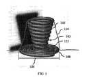
本発明の種々の実施形態では、塞栓デバイスは、構造から形成される。例えば、図1に示されるように、塞栓デバイス100は、動脈瘤104への展開に応じて、渦巻形状を形成するように適合されてもよい(参照番号104はまた、任意の他の血管障害または類似解剖学的構造にも適用され得る)。本明細書で使用されるように、塞栓デバイス100の形状は、構造102を形成するために使用されるマイクロ形状とは対照的に、塞栓デバイス100自体(またはその一部)によって形成されるマクロ形状を指す。例えば、いくつかの事例では、塞栓デバイス100は、図2に示されるように、渦巻状に巻装されたワイヤ200から形成される、構造102を含む。図2の実施例では、構造102は、渦巻状に巻装されるが、それへと塞栓デバイスを作成するように形成される、マクロ形状は、渦巻状に巻装されず、代わりに、一連の湾曲した葉状形状のループを形成する。したがって、塞栓デバイス100の形状が、本明細書に説明されるとき、本マクロ形状の意味を有するものとして理解されたい。 In various embodiments of the invention, the embolic device is formed from a structure. For example, as shown in FIG. 1, the
図1に示されるように、塞栓デバイス100は、縮径部106、例えば、血管と動脈瘤104の空洞との間の開口部を有する、血管障害104を治療するために使用されることができる。いくつかの事例では、塞栓デバイス100は、動脈瘤縮径部106内に配置され、および/またはそれを遮断する、部分108と、動脈瘤104の空洞内に配置される別の部分110とを含むことができる。一般に、縮径部106を遮断する部分108は、任意の形状、例えば、図1に示されるように、渦巻形状をとることができる。部分108の渦巻形状は、任意の好適な3次元形状、例えば、円盤(図1に示されるように)、球形、半球形(または部分的球形)、円錐等で形成されることができる。渦巻形状を有する部分108は、従来のデバイスより縮径部106の改良された遮断を達成することが観察されている。動脈瘤104の空洞内に配置される部分110もまた、任意の形状をとることができ、これは、動脈瘤縮径部106を遮断する部分108と同一または異なる形状であることができる。例えば、図1に示されるように、部分110は、渦巻形状を有することができるが、他の実施形態では、ランダムまたは非幾何学的形状を含む、他の形状を有することができる。部分110の渦巻はまた、任意の好適な3次元形状、例えば、円盤、球形、半球形(または部分的球形)、円錐(図1に示されるように)等で形成されることができる。 As shown in FIG. 1, the
従来のデバイスを用いて被られる1つの問題は、動脈瘤縮径部を遮断する際のその有効性が、時として、再現可能様式で達成することが困難であり得る、治療部位への送達に応じたデバイスの配向によって有意に影響されることである。本発明の実施形態は、動脈瘤104の中への設置に応じたその配向にかかわらず、動脈瘤縮径部106を効果的に遮断する、または、ある場合には、従来のデバイスより多くの配向(例えば、配向の大部分)において動脈瘤縮径部106を遮断する、塞栓デバイスを特徴とすることによって、本問題を解決する。 One problem suffered with conventional devices is the delivery to the treatment site, whose effectiveness in blocking the aneurysm diameter can sometimes be difficult to achieve in a reproducible manner. It is significantly affected by the orientation of the corresponding device. Embodiments of the invention effectively block the
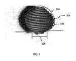
大部分(または、ある場合には、全て)の配向において動脈瘤縮径部106を遮断する、デバイスの一実施例は、図3に示される塞栓デバイス300であって、これは、略球状渦巻形状を有する。ある幾何学的形状が、本明細書で説明されるが、種々の実施形態では、形状の完璧な幾何学的バージョンの35%以内、例えば、25%、10%、5%、2%、および/または1%においてその寸法の全てを有する、形状も含む。図3に図示されるように、塞栓デバイス300は、任意の360度配向において動脈瘤104の中に展開され、依然として、縮径部106を効果的に遮断し、また、動脈瘤の内壁(内皮)に接触することができる。いくつかの事例では、略球状の渦巻形状の塞栓デバイス300は、デバイス300全体を通して組織の連続成長を可能にすることができる。例えば、塞栓デバイス300は、組織が動脈瘤空洞内で成長するための連続経路を提供することができ、これは、動脈瘤104の治癒を可能にし、および/または加速させることができる。 An embodiment of a device that blocks the
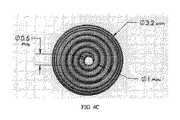
塞栓デバイス300の例示的寸法は、図4A−4Cに示される。主直径(図2における要素204参照)は、約0.010インチであることができる。デバイスの高さ(最上コイルと最下コイルとの間の距離)は、約3.1mmであることができる。球状渦巻の最広部分の直径は、約3.2mmであることができる。最下コイルの外径は、約1.0mmであることができ、最下コイルの内径は、約0.5mmであることができる。最上コイルは、最下コイルと類似寸法を有することができる。 Illustrative dimensions of the
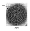
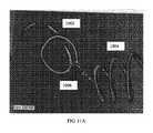
種々の実施形態では、本発明の塞栓デバイスは、平坦シート(例えば、ニチノールから形成される)から形成されることができる。一般に、平坦シートは、任意の好適な形状に形成されることができる。例えば、図5A−5Bは、渦巻形状における、平坦シートから形成される例示的塞栓デバイス500a、500bの上面図を示す。上記に述べられるように、渦巻は、任意の好適な3D形状、例えば、円盤、球形、半球形(または部分的球形)、円錐等をとることができる。平坦シートはまた、例えば、0.0001インチ〜0.030インチの範囲内、0.0005インチ〜0.027インチの範囲内、0.001インチ〜0.025インチの範囲内、0.002インチ〜0.020インチの範囲内、0.003インチ〜0.015インチの範囲内、0.004インチ〜0.010インチの範囲内、0.006インチ〜0.008インチの範囲内の任意の望ましい厚さを有することができる。別の実施形態では、平坦シートは、0.002インチ〜0.004インチの範囲内の厚さを有する。いくつかの事例では、平坦シートの幅は、例えば、図5Aにおける塞栓デバイス500aによって示されるように、一定幅を有する。他の事例では、平坦シートの幅は、例えば、図5Bにおける塞栓デバイス500bによって示されるように、抜き勾配状またはテーパ状(例えば、減少または増加)幅を有する。 In various embodiments, the embolic device of the present invention can be formed from a flat sheet (eg, formed from nitinol). In general, the flat sheet can be formed into any suitable shape. For example, FIGS. 5A-5B show top views of exemplary
種々の実施形態では、図6に示されるように、塞栓デバイス600は、接続領域606において2つの渦巻要素602、604を接続することによって形成されることができる。一般に、渦巻要素602、604は、任意の好適な構造、例えば、マイクロコイル、平坦シート(図6に示されるように)、薄膜等から形成されることができる。一般に、接続された渦巻要素は、任意の3D形状、例えば、円盤、球形、半球形(または部分的球形)、円錐等を形成することができる。図6を参照すると、一実施例として、第1の渦巻要素602の端部点608が、ページから手前側に引動されると、円錐形状の渦巻が、形成される。別の実施例として、第2の渦巻要素604の端部点610もまた、ページの向こう側に押動される場合、球形形状の渦巻が、形成される。一般に、渦巻要素602、604は、任意の好適な技法、例えば、溶接(例えば、レーザ、アーク、抵抗、摩擦撹拌)、はんだ、鑞接、拡散接合、接着剤継合、および相互接続要素(例えば、下記に説明されるように)等を使用して、接続領域606において継合されることができる。他の実施形態では、渦巻要素602、604は両方とも、単一材料片から切断(例えば、レーザ切断)されることができる(すなわち、渦巻要素602、604は、相互と一元構造である)。 In various embodiments, as shown in FIG. 6, the
種々の実施形態では、塞栓デバイス700は、例えば、図7に示されるように、交互する狭小部分702と連結部分704を含むことができる。連結部分704は、図7に示されるように、少なくとも1つの平面、例えば、ページの平面内の開口部を取り囲む。一般に、連結部分704は、任意の好適な形状、例えば、菱形状(例えば、図7および8に示されるように)、円形、長方形、三角形等を有することができる。一般に、塞栓デバイス700は、任意の好適な構造、例えば、コイル、平坦シート、薄膜、それらの組み合わせ等から形成されることができる。例えば、図7に示されるように、狭小部分702は、平坦シート材料の単一細片(または開口部をそれらの間に伴わない、平坦シート材料の複数の細片)から形成されることができ、連結部分704は、開口部のまわりに周を画定する、またはそれを取り囲む、平坦シート材料のうちの少なくとも2つの細片によって形成されることができる。塞栓デバイス700はまた、例えば、0.0001インチ〜0.030インチの範囲内、0.0005インチ〜0.027インチの範囲内、0.001インチ〜0.025インチの範囲内、0.002インチ〜0.020インチの範囲内、0.003インチ〜0.015インチの範囲内、0.004インチ〜0.010インチの範囲内、0.006インチ〜0.008インチの範囲内の任意の望ましい厚さを有することができる。別の実施形態では、塞栓デバイスは、0.002インチ〜0.004インチの範囲内の厚さを有する。 In various embodiments, the
いくつかの事例では、例えば、図8に示されるように、狭小部分は、コイル区画802を含む。ある場合には、コイル区画802は、別の構造(例えば、平坦シート、薄膜等)にわたって配置される。他の場合には、コイル区画802は、別の構造にわたって配置されない。一般に、コイル区画802は、任意の公知の技法を使用して、例えば、縫合糸を各コイル区画802の端部上に溶融させて、連結部分704に取り付けられることができる。縫合糸を各コイル区画802の端部上に溶融させることはまた、コイル区画802が連結部分704間に位置付けられたまま保つことができる。いくつかの事例では、連結部分704は、近接する狭小部分に固定して取り付けられることができ、歪み緩和要素804が、その部分間の歪みを緩和するために使用されることができる。歪み緩和要素は、任意の好適な材料、例えば、縫合糸材料、溶融されたポリマー(例えば、ポリプロピレン、ポリエチレン、高密度ポリエチレン、低密度ポリエチレン、ポリウレタン、ポリエーテルブロックアミド、ポリアミド、ポリマー接着剤等)等から形成されることができる。 In some cases, for example, as shown in FIG. 8, the narrow portion comprises a
種々の実施形態では、本明細書に説明される塞栓デバイスは、マイクロカテーテルを使用して、血管障害内に導入され、送達され、位置付けられ、埋め込まれることができる。マイクロカテーテルは、例えば、0.015インチ〜0.035インチ(例えば、0.016インチ〜0.021インチ)の内径を有する、可撓性の小径カテーテルであることができる。マイクロカテーテルは、患者の大腿動脈または鼠径部面積内に設置された導入器シース/誘導カテーテルの組み合わせによって導入されてもよい。いくつかの事例では、マイクロカテーテルは、ガイドワイヤ(例えば、蛇行性脈管内を前進されるように設計されるより可撓性の遠位ワイヤ区分を伴う、長いトルク伝達可能近位ワイヤ区分)を用いて、血管障害の中に誘導される。そのようなガイドワイヤは、蛍光透視法を使用して可視であってもよく、最初に、血管障害にアクセスするために使用され、それによって、マイクロカテーテルがそれにわたって障害の中に前進されることを可能にしてもよい。 In various embodiments, the embolic devices described herein can be introduced, delivered, positioned, and implanted within an angiopathy using a microcatheter. The microcatheter can be, for example, a flexible small diameter catheter with an inner diameter of 0.015 inches to 0.035 inches (eg, 0.016 inches to 0.021 inches). The microcatheter may be introduced by a combination of introducer sheath / induction catheters placed within the femoral artery or inguinal area of the patient. In some cases, the microcatheter has a guide wire (eg, a long torque transferable proximal wire compartment with a more flexible distal wire compartment designed to advance in a tortuous vessel). Induced during vascular disorders. Such guidewires may be visible using fluorescence fluoroscopy and are first used to access angiopathy, thereby advancing the microcatheter into the obstruction across it. May be possible.
いくつかの事例では、いったんマイクロカテーテルの先端が、血管障害にアクセスすると、ガイドワイヤは、カテーテル管腔から除去される。塞栓デバイスが、次いで、マイクロカテーテルの近位開放端の中に設置され、送達機構を用いて、マイクロカテーテルを通して前進されてもよい。塞栓デバイスは、任意の好適な構造、例えば、デバイスの近位端上のループ706(図7)を介して、送達機構に取り付けられてもよい。いくつかの事例では、塞栓デバイスが、マイクロカテーテルの管腔内に配置される間、直線化された形態にある。ユーザ(例えば、医師)は、数回、塞栓デバイスを前進および/または後退させ、障害内で塞栓デバイスの望ましい位置を取得してもよい。いったん塞栓デバイスが、満足の行くように位置付けられると、障害の中に解放されることができる。解放することに応じて、デバイスは、その展開された形状、例えば、上記に説明される渦巻形状または任意の他の所望の構成を形成してもよい。いくつかの事例では、血管障害の中への展開に応じて、形状の形成は、塞栓デバイスを形成するために使用される材料(例えば、ニチノール)の形状記憶性によって引き起こされる。 In some cases, once the tip of the microcatheter has access to angiopathy, the guidewire is removed from the catheter lumen. The embolic device may then be placed in the proximal open end of the microcatheter and advanced through the microcatheter using a delivery mechanism. The embolic device may be attached to the delivery mechanism via any suitable structure, eg, a loop 706 (FIG. 7) on the proximal end of the device. In some cases, the embolic device is in a linearized form while being placed within the lumen of the microcatheter. The user (eg, physician) may advance and / or retract the embolic device several times to obtain the desired position of the embolic device within the obstacle. Once the embolic device is satisfactorily positioned, it can be released into an obstacle. Depending on the release, the device may form its unfolded shape, eg, the spiral shape described above or any other desired configuration. In some cases, in response to deployment into angiopathy, shape formation is caused by the shape memory of the material used to form the embolic device (eg, nitinol).
送達プロセスの種々の段階における本明細書に説明される塞栓デバイスの形状に関するさらなる説明は、有益である。塞栓デバイスは、概して、例えば、デバイスがパッケージングまたは患者に送達される前の手術室内において存在するであろうように、拘束されない構成では、特定の形状を有するように製造される。特定の形状は、本明細書に説明される塞栓デバイス形状のいずれかを含むことができる。送達の間、塞栓デバイスは、マイクロカテーテル内にフィットし、それを通して送達され得るように(上記に説明されるように)、直線化される。いったんマイクロカテーテルから血管障害に展開されると、塞栓デバイスは、それが有するように製造された形状をリフォームすることができる(例えば、形状記憶材料によって補助される)。しかしながら、いくつかの事例では、塞栓デバイスは、血管障害および他の周囲構造によって課される拘束に基づいて、それが有するように製造された形状に正確にリフォームしなくてもよい。 Further description of the shape of the embolic device described herein at various stages of the delivery process is informative. Embolic devices are generally manufactured to have a particular shape in an unconstrained configuration, for example, as would be present in the operating room prior to packaging or delivery to the patient. The particular shape can include any of the embolic device shapes described herein. During delivery, the embolic device fits within the microcatheter and is linearized so that it can be delivered through it (as described above). Once deployed from a microcatheter to an angiopathy, the embolic device can remodel the shape it is manufactured to (eg, assisted by a shape memory material). However, in some cases, the embolic device does not have to be precisely remodeled into the shape it is manufactured to, based on the constraints imposed by angiopathy and other surrounding structures.
種々の実施形態では、図7に示される塞栓デバイス700の連結部分704は、送達の間、塞栓デバイス700がマイクロカテーテル内に位置するとき、圧潰することができる(例えば、開口部は、より狭くなることができる)。連結部分704は、次いで、血管障害への塞栓デバイスの展開に応じて、拡張することができる(例えば、開口部は、より広くなることができる)。これは、塞栓デバイス700が、より少ない摩擦を伴って、マイクロカテーテルを通してより容易に送達されることを可能にする一方、また、展開に応じて、動脈瘤の縮径部を効果的に遮断することができる。いくつかの事例では、コイル区画802はさらに、マイクロカテーテルを通した送達の間、塞栓デバイスの摩擦を低減させることができる。一実施例として、コイル区画802の形状は、マイクロカテーテルの管腔の形状により良好に合致することができる。別の実施例として、コイル区画802は、塞栓デバイスの可撓性および展性を増加させることができる。別の実施例として、コイル区画802は、マイクロカテーテルの内部表面とより少ない摩擦を発生させる、材料から形成されることができる。コイル区画802はまた、例えば、連結部分704が非放射線不透過性材料から形成される場合、送達の間、塞栓デバイスが視認され得るように、放射線不透過性材料(例えば、白金)から形成されることができる。 In various embodiments, the connecting
種々の実施形態では、動脈瘤104は、例えば、図9A−9Cに示されるように、少なくとも1つの無限大形状部分を形成するように成形される、塞栓デバイスによって治療されることができる。本明細書で使用されるように、用語「無限大形状」は、共通点(例えば、点906)において交差する、2つのループ(例えば、ループ902、904)によって形成される任意の形状、例えば、8の字形状、連珠形形状等を指す。本明細書に定義されるように、他の文脈における用語「無限大形状」の任意の特定の幾何学的または数学的使用にもかかわらず、無限大形状によって形成される2つのループは、異なるサイズまたは同一サイズであることができる。いくつかの事例では、塞栓デバイス900は、相互の上にスタックされた、例えば、相互に整合し、覆うように配列される(図9B参照)、または、ある場合には、動脈瘤の内側の周のまわりに円周方向に配列される(図9C参照)、複数の無限大形状部分902a、902b、902cを含むことができる。いくつかの事例では、塞栓デバイス900は、第1の軸に沿って配列される、第1の群の無限大形状部分908(1つ以上の無限大形状部分を含み得る)と、第1の軸に対してある角度(例えば、約15°、約30°、約45°、約60°、約75°、および約90°)で配列されるように回転される、第2の群の無限大形状部分910(1つ以上の無限大形状部分を含み得る)とを含むことができる。例えば、第2の群の無限大形状部分は、第1の軸と略垂直に配列されることができる。図9Aおよび9Bは両方とも、相互と略垂直に配列される無限大形状部分を示すが、いくつかの事例では、無限大形状部分は全て、同一軸に沿って配列される、例えば、相互に整合されることができる。他の事例では、単一無限大形状部分のみが、形成される。さらに、いくつかの事例では、無限大形状部分は、動脈瘤の縮径部106を遮断するが、他の事例では、無限大形状部分は、動脈瘤の他の部分内に位置することができる。例えば、図9Cに示されるように、塞栓デバイスは、展開に続いて、動脈瘤または他の血管障害の内部の周のまわりに円周方向に配列され得る、一連の無限大形状部分を形成することができる。そのような配列は、動脈瘤の枠組化に寄与し得る。無限大形状部分はまた、他のパターンで配列されることもできる。一般に、ランダムパターンを含む、任意のパターンが、使用されることができる。そのようなパターン内では、各無限大形状部分は、任意の回転配向で、かつ別の無限大形状部分に対して任意の望ましい重複を伴って配列されることができる。 In various embodiments, the
種々の実施形態では、複数の塞栓デバイスが、相互接続要素を用いて継合されることができる。本発明者らは、動脈瘤空洞の内部を充填するデバイスの部分が移動すると(例えば、空洞の内壁と密着するように拡張するために)、動脈瘤縮径部を遮断するデバイスの部分もまた移動または偏移させ得、これが、縮径部を遮断する際、デバイスの有効性に影響を及ぼし得ることを識別している。 In various embodiments, multiple embolic devices can be spliced together using interconnect elements. We also see a portion of the device that blocks the aneurysm diameter as the portion of the device that fills the interior of the aneurysm cavity moves (eg, to expand into close contact with the inner wall of the cavity). It has been identified that it can be moved or displaced, which can affect the effectiveness of the device in blocking the reduced diameter portion.
本問題および他の問題に対する解決策として、本発明の実施形態は、それらがともに継合されたままである間、各塞栓デバイスの独立した運動自由度および/または相対的位置付けを可能にする、相互接続要素によって継合される、少なくとも2つの塞栓デバイスを含む、多段階塞栓デバイスを含む。例えば、図10に示されるように、多段階塞栓デバイス1000は、第1の塞栓デバイス1002と、第2の塞栓デバイス1004とを含むことができる。いくつかの事例では、第1の塞栓デバイス1002は、第2の塞栓デバイス1004と異なる。本明細書で使用されるように、第2の塞栓デバイス1004と異なる第1の塞栓デバイス1002は、それらが、2つの別個のデバイスであって、一元構造またはモノリシック構造の単一デバイスの別個の部分ではないことを意味する。第2の塞栓デバイス1004と異なる第1の塞栓デバイス1002は、第1の塞栓デバイス1002が、第2の塞栓デバイス1004と非一元構造(または非モノリシック構造)であることを意味する。換言すると、第1の塞栓デバイス1002は、第2の塞栓デバイス1004と一体的に形成されない。第2の塞栓デバイス1004と異なる第1の塞栓デバイス1002は、デバイス1002、1004が、任意の他の差異を有することを要求しないが、種々の事例では、デバイス1002、1004は、他の差異を有することができる。例えば、第1の塞栓デバイスおよび第2の塞栓デバイス1002、1004は、同一または異なる寸法(長さ、内径、外径等)、同一または異なる堅度、同一または異なる多孔率等を有することができる。一般に、第1の塞栓デバイスは、任意の形態をとることができる。例えば、第1の塞栓デバイス1002は、動脈瘤の縮径部を遮断する、枠組デバイスであることができる。種々の事例では、第1の塞栓デバイス1002は、上記に説明される特定の形状のいずれか、例えば、渦巻形状、無限大形状等を形成することができる。一般に、第2の塞栓デバイス1004もまた、任意の形態をとることができる。例えば、第2の塞栓デバイス1004は、動脈瘤の内部空洞を充填する、充填デバイスであることができる。種々の事例では、第2の塞栓デバイス1004は、上記に説明される特定の形状のいずれか、例えば、渦巻形状、無限大形状等を形成することができる、またはランダムまたは非幾何学的形状をとることができる。種々の実施形態では、第1の塞栓デバイス1002および第2の塞栓デバイス1004は、図10に示される場所だけではなく、動脈瘤104内またはそのまわりの任意の場所に位置することができる。 As a solution to this problem and other problems, embodiments of the present invention allow for independent motion freedom and / or relative positioning of each embolic device while they remain spliced together. Includes multi-stage embolic devices, including at least two embolic devices joined by connecting elements. For example, as shown in FIG. 10, the multi-stage
一般に、相互接続要素1006は、塞栓デバイス1002、1004を継合し、それらがともに継合されたままである間、各塞栓デバイスの独立した運動自由度および/または相対的位置付けを可能にする、任意の構造を含むことができる。本明細書で使用されるように、独立した運動自由度は、塞栓デバイス間の運動に関する唯一の拘束が、それらが結合されたままであることを意味する。種々の事例では、結合点を中心とした任意の移動が、可能性として考えられる。その結果、動脈瘤空洞内の第2の塞栓デバイス1004の運動は、必ずしも、第1の塞栓デバイス1002の対応する運動が動脈瘤の縮径部を遮断する結果をもたらさない。いくつかの事例では、本運動自由度を可能にすることは、一元構造の単一コイル(または他のデバイス)の別個の部分を使用することとは対照的に、相互接続要素を使用して2つの塞栓デバイスを継合する利点を表す。単一コイル(または他のデバイス)の別個の部分は、ある程度の独立性を有し得るが、それらは、概して、一元構造のコイル(または他のデバイス)を製造する製造上の現実性に起因して、より拘束される。対照的に、いくつかの事例では、相互接続要素を用いて2つの異なる塞栓デバイスを継合することは、デバイス間のはるかに高い運動自由度を与えることができる。一般に、相互接続要素1006は、図10に示される場所だけではなく、デバイス間に独立した運動自由度を有することが有利である場所に応じて、動脈瘤内またはそのまわりの任意の場所に位置することができる。 In general, the
いくつかの非限定的実施例として、相互接続要素は、2つの連結されたループ、ニチノールコイル(ある場合には、別の相互接続要素、他の場合には、それ自体を被覆する)、フックおよびループスキーム、ヒンジ、縫合要素、孔およびループ、ボールおよびソケットスキーム、ピボットジョイント、ボールおよびピボットジョイント、ユニバーサルジョイント、サドルジョイント、1つ以上の自由度を伴う任意の機械的関節運動式ジョイント、またはそれらの組み合わせを含むことができる。いくつかの事例では、相互接続要素1006は、第1の塞栓デバイス1002および第2の塞栓デバイス1004のある部分から形成されることができる。例えば、相互接続要素1006の1つの構成要素は、第1の塞栓デバイス1002の遠位端または近位端に形成されるループであることができ(例えば、第1の塞栓デバイス1002と一元構造または一体型である)、相互接続要素1006の別の構成要素は、第2の塞栓デバイス1004の遠位端または近位端に形成されるループであることができる(例えば、第2の塞栓デバイス1004と一元構造または一体型である)。他の事例では、相互接続要素1006は、第1の塞栓デバイス1002または第2の塞栓デバイス1004のいずれかと一元構造ではなく、または一体型ではなく(すなわち、相互接続要素は、第1の塞栓デバイスおよび第2の塞栓デバイス1002、1004のそれぞれと非一元構造または非モノリシック構造である、または非一体型である)、代わりに、第1の塞栓デバイスおよび第2の塞栓デバイス1002、1004に締結される、接着される、および/または取り付けられる。他の事例では、相互接続要素1006は、第1の塞栓デバイスおよび第2の塞栓デバイス1002、1004の一方と一元構造または一体型であって、他方の塞栓デバイスと非一元構造または非モノリシック構造または非一体型である。種々の実施形態では、採用される特定の構造にかかわらず、第1の塞栓デバイス1002、第2の塞栓デバイス1004、および相互接続要素1006のうちの2つは、相互に非一元構造である。 As some non-limiting examples, the interconnect elements are two articulated loops, a nitinol coil (in some cases, another interconnect element, in other cases, covering itself), a hook. And loop schemes, hinges, stitching elements, holes and loops, ball and socket schemes, pivot joints, ball and pivot joints, universal joints, saddle joints, any mechanical range of motion joints with one or more degrees of freedom, or Combinations thereof can be included. In some cases, the
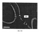
図11A−Cは、例示的相互接続要素1006の異なる図を示す、写真である。図11A−Bは、2つの連結されたループから形成される、例示的相互接続要素1006を描写する。図11Cは、ニチノールコイル(例えば、第1の塞栓デバイスおよび第2の塞栓デバイス1002、1004と異なるコイル)によって被覆される2つの連結されたループから形成される、例示的相互接続要素1006を描写する。いくつかの実施形態では、相互接続要素1006は、それ自体では別の相互接続要素を被覆しない、ニチノールコイルを含むことができる。図11Cに示されるように、その中に相互接続要素1006がニチノールコイルを含む、いくつかの事例では、ニチノールコイルは、第1の塞栓デバイスおよび第2の塞栓デバイス1002、1004に接着される。一般に、ニチノールコイル(または塞栓デバイス1002、1004の一方または両方に接着された任意の他の相互接続構造)は、任意の公知の技法を使用して、塞栓デバイス1002、1004の一方または両方に接着されることができる。いくつかの実装では、望ましい接着技法は、(ある場合には、望ましくない堅度の長さをもたらす)相互接続要素1006と塞栓デバイス1002、1004との間の端間固定を生産するために要求される長さを最小限にしながら、適正な材料生体適合性および強度を特徴とする。一実施例として、はんだ(例えば、金、銀、または他の望ましいはんだ材料)が、ニチノールコイル相互接続要素1006を塞栓デバイス1002、1004に付着するために使用されることができる。他の例示的接着技法は、接着剤、溶接(例えば、レーザ、アーク、スポット)、鑞接、拡散接合等の使用を含む(但し、限定されない)。 11A-C are photographs showing different views of the
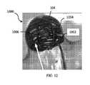
図12は、モデル動脈瘤104内に送達される例示的多段階塞栓デバイス1000を示す、写真である。ある事例では、相互接続要素1006は、血管障害に送達され、送達以外の治療周期にわたって血管障害に留まるように意図される、2つの要素を継合する。そのような事例では、相互接続要素1006は、塞栓デバイスを、塞栓デバイスを血管障害に送達するために使用されるデバイス(例えば、マイクロカテーテルまたは送達プッシャ)に継合しない。 FIG. 12 is a photograph showing an exemplary multi-stage
種々の実施形態では、2つを上回る塞栓デバイスが、1つを上回る相互接続要素を使用して、例えば、並列に、ともに継合されることができる。代替として、2つを上回る塞栓デバイスが、1つを上回る相互接続要素(例えば、最大で塞栓デバイスの数より1つ少ない数)を使用して、直列に、ともに継合されることができる。直列および並列配列の組み合わせもまた、検討される。一般に、任意の数(例えば、2、3、4、5、10等)の塞栓デバイスが、継合されることができる。図13に示されるように、塞栓デバイス1000は、第1の相互接続要素1006aを用いて第2の塞栓デバイス1004と直列に継合される、第1の塞栓デバイス1002と、第2の相互接続要素1006bを用いて第3の塞栓デバイス1008と直列に継合される、第2の塞栓デバイス1004とを含むことができる。一般に、第3の塞栓デバイス1008は、任意の形態をとることができる(任意の付加的塞栓デバイスも同様であり得る)。例えば、第3の塞栓デバイス1008は、動脈瘤の内部空洞をさらに充填する、最終デバイスであることができる。種々の事例では、第3の塞栓デバイス1008(および任意の付加的塞栓デバイス)は、上記に説明される特定の形状のいずれか、例えば、渦巻形状、無限大形状等を形成することができる、またはランダムまたは非幾何学的形状をとることができる。第3の塞栓デバイス1008(および任意の付加的塞栓デバイス)は、動脈瘤内またはそのまわりの任意の場所に位置することができる。 In various embodiments, more than two embolic devices can be spliced together, eg, in parallel, using more than one interconnect element. Alternatively, more than two embolic devices can be spliced together in series using more than one interconnect element (eg, up to one less than the number of embolic devices). Combinations of serial and parallel arrays are also considered. In general, any number of embolic devices (eg, 2, 3, 4, 5, 10, etc.) can be spliced together. As shown in FIG. 13, the
種々の実施形態では、多段階塞栓デバイス1000の塞栓デバイス(例えば、1002、1004、1008)はそれぞれ、異なる性質を有し、相互に異なるように挙動することができる。一般に、任意の塞栓デバイス性質は、塞栓デバイス間で可変であることができる。例えば、塞栓デバイスのいくつかまたは全ては、異なるサイズ、形状、長さ、堅度、多孔率等を有することができる。他の事例では、塞栓デバイスのいくつかまたは全ては、同一のいくつかまたは全ての性質を有することができる。塞栓デバイス性質の本カスタマイズ可能かつ独立した本質は、オペレータ(例えば、医師)に、従来のデバイスを用いた場合より高い、コイルを成形し、展開および位置付けを制御するための自由度を可能にすることができる。一実施例として、オペレータは、最初に、第1の方向に位置付けられ、次いで、第1の方向に対してある角度(例えば、15°、30°、45°、60°、75°、90°等)で異なる方向に位置付けられるように枢動するように、コイルを送達することができる。 In various embodiments, the embolic devices of the multi-stage embolic device 1000 (eg, 1002, 1004, 1008) have different properties and can behave differently from each other. In general, any embolic device property can be variable between embolic devices. For example, some or all of the embolic devices can have different sizes, shapes, lengths, firmness, porosity, etc. In other cases, some or all of the embolic devices can have some or all of the same properties. This customizable and independent nature of the embolic device nature gives operators (eg, physicians) more freedom to shape, deploy and position the coil than with conventional devices. be able to. As an embodiment, the operator is first positioned in a first direction and then at an angle (eg, 15 °, 30 °, 45 °, 60 °, 75 °, 90 °) with respect to the first direction. Etc.), the coil can be delivered so that it is pivoted so that it is positioned in a different direction.
上記に述べられるように、種々の実施形態では、本明細書に説明される塞栓デバイスは、カバー要素によって被覆される、またはカバー要素によって被覆されない、構造(例えば、マイクロコイル、平坦シート、薄膜等)を含むことができる。多段階塞栓デバイス1000を参照すると、種々の実施形態では、個々の塞栓デバイス(例えば、1002、1004、1008等)のいずれかが、いずれも、または全てが、カバー要素によって被覆される、または被覆されないことができる。 As described above, in various embodiments, the embolic devices described herein are structures (eg, microcoils, flat sheets, thin films, etc.) that are covered or uncovered by cover elements. ) Can be included. With reference to the multi-stage
本願のいずれかの場所(例えば、幾何学的形状に関する単語「実質的に」の使用)で明示的に説明されない限り、本明細書で使用されるように、用語「実質的に」または「約」が、定量的値の前にあるとき、本開示はまた、具体的定量的値自体だけではなく、別様に示されない、または推測されない限り、公称値からの±10%の変動も含む。 As used herein, the term "substantially" or "approx." When preceded by a quantitative value, the disclosure also includes not only the specific quantitative value itself, but also ± 10% variation from the nominal value unless otherwise indicated or inferred.
本発明のある実施形態が説明されたが、本明細書に開示される概念を組み込む他の実施形態も、本発明の精神および範囲から逸脱することなく使用されてもよいことが、当業者に明白となるであろう。故に、説明される実施形態は、あらゆる点において、制限ではなく、例証にすぎないと見なされるべきである。 Although certain embodiments of the present invention have been described, those skilled in the art will appreciate that other embodiments incorporating the concepts disclosed herein may also be used without departing from the spirit and scope of the invention. It will be obvious. Therefore, the embodiments described should be considered in all respects as merely illustrations, not restrictions.
Claims (46)
Translated fromJapanese可撓性構造であって、前記可撓性構造は、一連の交互する狭小部分および連結部分を備え、各連結部分は、少なくとも1つの平面内の開口部を取り囲む、可撓性構造
を備え、
前記構造は、拘束されないとき、渦巻形状を形成するように適合される、塞栓デバイス。An embolic device for use in treating angiopathy, said embolic device.
A flexible structure, said flexible structure comprising a series of alternating narrow portions and connecting portions, each connecting portion comprising a flexible structure surrounding an opening in at least one plane.
The embolic device, wherein the structure is adapted to form a spiral shape when unconstrained.
各狭小部分と前記近接する連結部分との間の歪み緩和要素をさらに備える、請求項1に記載の塞栓デバイス。Each narrow part is fixedly attached to the adjacent connecting part,
The embolic device according to claim 1, further comprising a strain mitigating element between each narrow portion and the adjacent connecting portion.
可撓性構造であって、前記可撓性構造は、拘束されないとき、少なくとも1つの無限大形状部分を形成するように適合される、可撓性構造
を備え、
前記無限大形状部分は、単一点において交差する2つの隣接するループを備える、塞栓デバイス。An embolic device for use in treating angiopathy, said embolic device.
A flexible structure comprising a flexible structure that, when unconstrained, is adapted to form at least one infinitely shaped portion.
The infinitely shaped portion is an embolic device comprising two adjacent loops that intersect at a single point.
第1の塞栓デバイスと、
前記第1の塞栓デバイスと異なる第2の塞栓デバイスと、
相互接続要素であって、前記相互接続要素は、前記第1の塞栓デバイスおよび第2の塞栓デバイスを継合し、残りがともに継合される間、前記第1の塞栓デバイスと第2の塞栓デバイスとの間の独立した運動自由度を可能にする、相互接続要素と
を備える、多段階塞栓デバイス。A multi-stage embolic device for use in treating angiopathy, said multi-stage embolic device.
The first embolic device and
A second embolic device different from the first embolic device,
An interconnect element, the interconnect element splices the first embolic device and the second embolic device, and while the rest are spliced together, the first embolic device and the second embolic device. A multi-stage embolic device with interconnect elements that allow independent degree of freedom of movement with the device.
少なくとも1つの付加的相互接続要素であって、前記少なくとも1つの付加的相互接続要素は、直接的におよび間接的にのうちの少なくとも1つで、前記第2の塞栓デバイスおよび付加的塞栓デバイスを継合し、残りがともに継合される間、前記第2の塞栓デバイスと付加的塞栓デバイスとの間の独立した運動自由度を可能にする、少なくとも1つの付加的相互接続要素と
をさらに備える、請求項28に記載の多段階塞栓デバイス。With at least one additional embolic device different from each of the first embolic device and the second embolic device.
At least one additional interconnect element, said at least one additional interconnect element, directly and indirectly, at least one of the second embolic device and the additional embolic device. It further comprises at least one additional interconnect element that allows an independent degree of freedom of movement between the second embolic device and the additional embolic device while spliced and the rest are spliced together. 28. The multi-stage embolic device according to claim 28.
多段階塞栓デバイスを前記血管障害に送達するステップであって、前記多段階塞栓デバイスは、
第1の塞栓デバイスと、
前記第1の塞栓デバイスと異なる第2の塞栓デバイスと、
前記第1の塞栓デバイスおよび第2の塞栓デバイスを継合し、残りがともに継合される間、前記第1の塞栓デバイスと第2の塞栓デバイスとの間の独立した運動自由度を可能にする、相互接続要素と
を備える、ステップと、
前記第2の塞栓デバイスを前記血管障害の内部内に配置するステップと、
前記第1の塞栓デバイスを配置し、前記血管障害の縮径部を遮断するステップと
を含む、方法。A method for treating angiopathy, said method.
A step of delivering a multi-stage embolic device to the angiopathy, wherein the multi-stage embolic device is:
The first embolic device and
A second embolic device different from the first embolic device,
Allows independent movement freedom between the first and second embolic devices while splicing the first and second embolic devices and the rest together. With, with interconnect elements, with steps,
The step of placing the second embolic device inside the angiopathy and
A method comprising the step of disposing the first embolic device and blocking the reduced diameter portion of the angiopathy.
前記第1の塞栓デバイスおよび第2の塞栓デバイスのそれぞれと異なる少なくとも1つの付加的塞栓デバイスと、
少なくとも1つの付加的相互接続要素であって、前記少なくとも1つの付加的相互接続要素は、直接的におよび間接的にのうちの少なくとも1つで、前記第2の塞栓デバイスおよび付加的塞栓デバイスを継合し、残りがともに継合される間、前記第2の塞栓デバイスと付加的塞栓デバイスとの間の独立した運動自由度を可能にする、少なくとも1つの付加的相互接続要素と
を備え、
前記方法はさらに、前記少なくとも1つの付加的塞栓デバイスを前記血管障害の内部内に配置することを含む、請求項38に記載の方法。The multi-stage embolic device further
With at least one additional embolic device different from each of the first embolic device and the second embolic device.
At least one additional interconnect element, said at least one additional interconnect element, directly and indirectly, at least one of the second embolic device and the additional embolic device. It comprises at least one additional interconnect element that allows an independent degree of freedom of movement between the second embolic device and the additional embolic device while spliced and the rest are spliced together.
38. The method of claim 38, wherein the method further comprises placing the at least one additional embolic device within the angiopathy.
Priority Applications (1)
| Application Number | Priority Date | Filing Date | Title |
|---|---|---|---|
| JP2023133402AJP7669433B2 (en) | 2018-04-04 | 2023-08-18 | Embolic device with improved necking coverage - Patents.com |
Applications Claiming Priority (3)
| Application Number | Priority Date | Filing Date | Title |
|---|---|---|---|
| US201862652441P | 2018-04-04 | 2018-04-04 | |
| US62/652,441 | 2018-04-04 | ||
| PCT/US2019/025770WO2019195540A2 (en) | 2018-04-04 | 2019-04-04 | Embolic device with improved neck coverage |
Related Child Applications (1)
| Application Number | Title | Priority Date | Filing Date |
|---|---|---|---|
| JP2023133402ADivisionJP7669433B2 (en) | 2018-04-04 | 2023-08-18 | Embolic device with improved necking coverage - Patents.com |
Publications (2)
| Publication Number | Publication Date |
|---|---|
| JP2021520255Atrue JP2021520255A (en) | 2021-08-19 |
| JPWO2019195540A5 JPWO2019195540A5 (en) | 2022-04-12 |
Family
ID=66484123
Family Applications (2)
| Application Number | Title | Priority Date | Filing Date |
|---|---|---|---|
| JP2020554276APendingJP2021520255A (en) | 2018-04-04 | 2019-04-04 | Embolic device with improved reduced diameter coating |
| JP2023133402AActiveJP7669433B2 (en) | 2018-04-04 | 2023-08-18 | Embolic device with improved necking coverage - Patents.com |
Family Applications After (1)
| Application Number | Title | Priority Date | Filing Date |
|---|---|---|---|
| JP2023133402AActiveJP7669433B2 (en) | 2018-04-04 | 2023-08-18 | Embolic device with improved necking coverage - Patents.com |
Country Status (6)
| Country | Link |
|---|---|
| US (1) | US11819215B2 (en) |
| EP (1) | EP3773252B1 (en) |
| JP (2) | JP2021520255A (en) |
| CN (1) | CN112153946B (en) |
| ES (1) | ES3035267T3 (en) |
| WO (1) | WO2019195540A2 (en) |
Families Citing this family (11)
| Publication number | Priority date | Publication date | Assignee | Title |
|---|---|---|---|---|
| US11357511B2 (en) | 2008-05-01 | 2022-06-14 | Aneuclose Llc | Intrasacular aneurysm occlusion device with globular first configuration and bowl-shaped second configuration |
| US11583289B2 (en) | 2008-05-01 | 2023-02-21 | Aneuclose Llc | Aneurysm-occluding mesh ribbon with a series of loops or segments having distal-to-proximal variation in size, shape, and/or orientation |
| US11471163B2 (en) | 2008-05-01 | 2022-10-18 | Aneuclose Llc | Intrasaccular aneurysm occlusion device with net or mesh expanded by string-of-pearls embolies |
| US11464518B2 (en) | 2008-05-01 | 2022-10-11 | Aneuclose Llc | Proximal concave neck bridge with central lumen and distal net for occluding cerebral aneurysms |
| US11471164B2 (en) | 2008-05-01 | 2022-10-18 | Aneuclose Llc | Methods of occluding a cerebral aneurysm by inserting embolic members or material into an intrasacular implant |
| US11484322B2 (en) | 2018-01-03 | 2022-11-01 | Aneuclose Llc | Aneurysm neck bridge with a closeable opening or lumen through which embolic material is inserted into the aneurysm sac |
| CN114098878B (en)* | 2020-08-31 | 2024-02-20 | 微创神通医疗科技(上海)有限公司 | Hemangioma plugging device, hemangioma plugging treatment device and hemangioma plugging system |
| WO2023034420A1 (en) | 2021-08-31 | 2023-03-09 | Incumedx Inc. | Embolic device with improved neck coverage |
| CN113855145B (en)* | 2021-10-29 | 2023-06-30 | 微创神通医疗科技(上海)有限公司 | Hemangioma plugging device, hemangioma plugging treatment device and hemangioma plugging system |
| WO2024147031A1 (en)* | 2023-01-08 | 2024-07-11 | Yousefiroshan Hamed | A novel device design and true mockup to treat intracranial aneurysms |
| US20250057540A1 (en)* | 2023-08-18 | 2025-02-20 | Ndi Tip Teknolojileri Anonim Sirket | Embolic coil, system, and method for making multiple self-adaptive loops with improved anchoring and filling |
Citations (8)
| Publication number | Priority date | Publication date | Assignee | Title |
|---|---|---|---|---|
| US20020177855A1 (en)* | 1999-10-04 | 2002-11-28 | Greene George R. | Method of manufacturing expansile filamentous embolization devices |
| US20030199887A1 (en)* | 2002-04-23 | 2003-10-23 | David Ferrera | Filamentous embolization device and method of use |
| WO2007136768A2 (en)* | 2006-05-19 | 2007-11-29 | Mako Surgical Corp. | Method and apparatus for controlling a haptic device |
| JP2010534108A (en)* | 2007-07-25 | 2010-11-04 | エイジーエイ メディカル コーポレイション | Knitted occlusion device having a repetition of expanded volume portions separated by a joint portion |
| US20140371777A1 (en)* | 2013-06-14 | 2014-12-18 | Artventive Medical Group, Inc. | Implantable luminal devices |
| WO2016108241A1 (en)* | 2014-12-31 | 2016-07-07 | Endostream Medical Ltd. | Device for restricting blood flow to aneurysms |
| US20170224350A1 (en)* | 2016-02-10 | 2017-08-10 | Microvention, Inc. | Devices for Vascular Occlusion |
| US20170319214A1 (en)* | 2016-04-01 | 2017-11-09 | Artventive Medical Group, Inc. | Occlusive implant and delivery system |
Family Cites Families (79)
| Publication number | Priority date | Publication date | Assignee | Title |
|---|---|---|---|---|
| US5853418A (en) | 1995-06-30 | 1998-12-29 | Target Therapeutics, Inc. | Stretch resistant vaso-occlusive coils (II) |
| US5769884A (en) | 1996-06-27 | 1998-06-23 | Cordis Corporation | Controlled porosity endovascular implant |
| EP1011532B1 (en) | 1997-04-23 | 2014-05-07 | Ethicon Endo-Surgery, Inc. | Bifurcated stent and distal protection system |
| US5935148A (en)* | 1998-06-24 | 1999-08-10 | Target Therapeutics, Inc. | Detachable, varying flexibility, aneurysm neck bridge |
| US6755856B2 (en) | 1998-09-05 | 2004-06-29 | Abbott Laboratories Vascular Enterprises Limited | Methods and apparatus for stenting comprising enhanced embolic protection, coupled with improved protection against restenosis and thrombus formation |
| US6602261B2 (en)* | 1999-10-04 | 2003-08-05 | Microvention, Inc. | Filamentous embolic device with expansile elements |
| US6342063B1 (en) | 2000-01-26 | 2002-01-29 | Scimed Life Systems, Inc. | Device and method for selectively removing a thrombus filter |
| US6530934B1 (en) | 2000-06-06 | 2003-03-11 | Sarcos Lc | Embolic device composed of a linear sequence of miniature beads |
| US6603994B2 (en)* | 2000-12-28 | 2003-08-05 | Scimed Life Systems, Inc. | Apparatus and method for internally inducing a magnetic field in an aneurysm to embolize aneurysm with magnetically-controllable substance |
| CA2452953A1 (en) | 2001-07-18 | 2003-01-30 | The Research Foundation Of State University Of New York | Stent vascular intervention device and method |
| US9861517B2 (en) | 2001-07-26 | 2018-01-09 | Cook Medical Technologies Llc | Vessel closure member, delivery apparatus, and method of inserting the member |
| US6802851B2 (en)* | 2001-09-20 | 2004-10-12 | Gordia Neurovascular, Inc. | Stent aneurysm embolization method using collapsible member and embolic coils |
| US8262689B2 (en) | 2001-09-28 | 2012-09-11 | Advanced Cardiovascular Systems, Inc. | Embolic filtering devices |
| WO2005037138A2 (en) | 2003-10-14 | 2005-04-28 | Peacock James C Iii | Aneurysm treatment system and method |
| WO2005042081A1 (en) | 2003-10-28 | 2005-05-12 | Peacock James C Iii | Embolic filter device and related systems and methods |
| US7763011B2 (en) | 2003-12-22 | 2010-07-27 | Boston Scientific Scimed, Inc. | Variable density braid stent |
| US8500751B2 (en) | 2004-03-31 | 2013-08-06 | Merlin Md Pte Ltd | Medical device |
| US9675476B2 (en) | 2004-05-25 | 2017-06-13 | Covidien Lp | Vascular stenting for aneurysms |
| CA2758946C (en) | 2004-05-25 | 2014-10-21 | Tyco Healthcare Group Lp | Vascular stenting for aneurysms |
| US20050267510A1 (en)* | 2004-05-26 | 2005-12-01 | Nasser Razack | Device for the endovascular treatment of intracranial aneurysms |
| US20050283220A1 (en) | 2004-06-22 | 2005-12-22 | Gobran Riad H | Blood flow diverters for the treatment of intracranial aneurysms |
| WO2006044632A2 (en) | 2004-10-15 | 2006-04-27 | Cordis Neurovascular, Inc. | Remodeling device for aneurysms |
| US7608089B2 (en)* | 2004-12-22 | 2009-10-27 | Boston Scientific Scimed, Inc. | Vaso-occlusive device having pivotable coupling |
| US20080147111A1 (en)* | 2005-01-03 | 2008-06-19 | Eric Johnson | Endoluminal Filter With Fixation |
| US20060178696A1 (en) | 2005-02-04 | 2006-08-10 | Porter Stephen C | Macroporous materials for use in aneurysms |
| US20060271097A1 (en) | 2005-05-31 | 2006-11-30 | Kamal Ramzipoor | Electrolytically detachable implantable devices |
| US20070016283A1 (en) | 2005-06-28 | 2007-01-18 | Stout Medical Group, Inc. | Micro-thin film structures for cardiovascular indications |
| WO2007013977A2 (en) | 2005-07-21 | 2007-02-01 | The Research Foundation Of State University Of New York | Stent vascular intervention device and methods for treating aneurysms |
| CA2627554A1 (en) | 2005-10-27 | 2007-05-03 | Martin S. Dieck | Partially covered stent devices and methods of use |
| US20070142859A1 (en) | 2005-12-19 | 2007-06-21 | Boston Scientific Scimed, Inc. | Embolic coils |
| US20070299461A1 (en) | 2006-06-21 | 2007-12-27 | Boston Scientific Scimed, Inc. | Embolic coils and related components, systems, and methods |
| US9339367B2 (en) | 2006-09-11 | 2016-05-17 | Edwards Lifesciences Ag | Embolic deflection device |
| WO2008064206A2 (en) | 2006-11-20 | 2008-05-29 | Boston Scientific Scimed, Inc. | Mechanically detachable vaso-occlusive device |
| US8636791B1 (en) | 2006-11-21 | 2014-01-28 | Seshadri Raju | Venous stent |
| US20080281350A1 (en) | 2006-12-13 | 2008-11-13 | Biomerix Corporation | Aneurysm Occlusion Devices |
| US20090112251A1 (en)* | 2007-07-25 | 2009-04-30 | Aga Medical Corporation | Braided occlusion device having repeating expanded volume segments separated by articulation segments |
| US10813779B2 (en)* | 2008-04-25 | 2020-10-27 | CARDINAL HEALTH SWITZERLAND 515 GmbH | Stent attachment and deployment mechanism |
| US20160374690A9 (en)* | 2010-10-21 | 2016-12-29 | Robert A. Connor | Devices and Methods for Occluding a Cerebral Aneurysm |
| US9179918B2 (en)* | 2008-07-22 | 2015-11-10 | Covidien Lp | Vascular remodeling device |
| WO2010028314A1 (en) | 2008-09-05 | 2010-03-11 | Pulsar Vascular, Inc. | Systems and methods for supporting or occluding a physiological opening or cavity |
| TWI516244B (en) | 2009-04-20 | 2016-01-11 | 大塚醫療器材股份有限公司 | Delivery assembly for occlusion device using mechanical interlocking coupling mechanism |
| US20110054515A1 (en) | 2009-08-25 | 2011-03-03 | John Bridgeman | Device and method for occluding the left atrial appendage |
| EP2805680B1 (en) | 2009-09-04 | 2017-10-25 | Pulsar Vascular, Inc. | Systems for enclosing an anatomical opening |
| US9095342B2 (en) | 2009-11-09 | 2015-08-04 | Covidien Lp | Braid ball embolic device features |
| US9358140B1 (en) | 2009-11-18 | 2016-06-07 | Aneuclose Llc | Stent with outer member to embolize an aneurysm |
| US8568471B2 (en)* | 2010-01-30 | 2013-10-29 | Abbott Cardiovascular Systems Inc. | Crush recoverable polymer scaffolds |
| US8425548B2 (en) | 2010-07-01 | 2013-04-23 | Aneaclose LLC | Occluding member expansion and then stent expansion for aneurysm treatment |
| DE102010027106A1 (en) | 2010-07-14 | 2012-01-19 | Siemens Aktiengesellschaft | Flow diverter for interrupting and bypassing blood flow into aneurysm of cerebral vessels in e.g. brain during aneurysm treatment, has stents, where diverter is designed so that diverter includes size and shape covering only aneurysm region |
| US10010327B2 (en)* | 2010-12-16 | 2018-07-03 | Lawrence Livermore National Security, Llc | Expandable implant and implant system |
| US20120245614A1 (en)* | 2011-03-21 | 2012-09-27 | William Joseph Drasler | Branch and Truncal Vessel Occluder |
| KR101480514B1 (en) | 2011-05-26 | 2015-01-09 | 재단법인 아산사회복지재단 | Stent for cerebral aneurysm coil embolization |
| CN103582460B (en) | 2011-06-03 | 2019-03-19 | 帕尔萨维斯库勒公司 | Aneurysm devices and related systems and methods with additional anchoring mechanism |
| US8696731B2 (en)* | 2011-06-10 | 2014-04-15 | DePuy Synthes Products, LLC | Lock/floating marker band on pusher wire for self-expanding stents or medical devices |
| US9119625B2 (en) | 2011-10-05 | 2015-09-01 | Pulsar Vascular, Inc. | Devices, systems and methods for enclosing an anatomical opening |
| US20130123901A1 (en) | 2011-11-14 | 2013-05-16 | Robert A. Connor | Stent with in situ determination of wall areas with differences in porosity |
| EP2785261A4 (en) | 2011-12-02 | 2015-10-07 | Inceptus Medical LLC | EMBOLIC PROTECTION DEVICE AND METHOD OF USE |
| US10603043B2 (en)* | 2012-01-17 | 2020-03-31 | Endoshape, Inc. | Occlusion device for a vascular or biological lumen |
| US20150010581A1 (en) | 2012-02-28 | 2015-01-08 | Ben Gurion University Of The Negev Research And Development Authority | Combined therapy of alpha-1-antitrypsin and temporal t-cell depletion for preventing graft rejection |
| US9155540B2 (en) | 2012-03-30 | 2015-10-13 | DePuy Synthes Products, Inc. | Embolic coil detachment mechanism with heating element and kicker |
| EP2846707A4 (en)* | 2012-05-04 | 2016-11-30 | Interventco Llc | Device and method for filling of aneurysm or body cavity |
| EP2887887B1 (en)* | 2012-08-22 | 2021-12-29 | Phenox GmbH | Implant |
| WO2014128313A1 (en)* | 2013-02-21 | 2014-08-28 | Castaño Duque Carlos | Device for supporting and positioning occlusive elements |
| US20140277397A1 (en) | 2013-03-12 | 2014-09-18 | DePuy Synthes Products, LLC | Variable porosity intravascular implant and manufacturing method |
| US9907684B2 (en) | 2013-05-08 | 2018-03-06 | Aneuclose Llc | Method of radially-asymmetric stent expansion |
| GB2516423B (en) | 2013-07-10 | 2015-07-15 | Cook Medical Technologies Llc | Vascular closure device |
| US20160151141A1 (en) | 2013-07-17 | 2016-06-02 | Lake Region Manufacturing, Inc. | High Flow Embolic Protection Device |
| CN108186074A (en)* | 2014-02-27 | 2018-06-22 | 因库麦迪斯有限公司 | For treating the framework microcoils of vascular diseases |
| US20150327868A1 (en) | 2014-05-13 | 2015-11-19 | Ndi Tip Teknolojileri Anonim Sirketi | Retractable and rapid disconnect, floating diameter embolic coil product and delivery system |
| CN203885667U (en) | 2014-06-06 | 2014-10-22 | 微创神通医疗科技(上海)有限公司 | Stent |
| CA2955953A1 (en) | 2014-07-25 | 2016-01-28 | Incumedx, Inc. | Covered embolic coils |
| CN107427377B (en) | 2015-01-12 | 2019-09-03 | 微仙美国有限公司 | bracket |
| US20170042551A1 (en) | 2015-08-13 | 2017-02-16 | The Brain Protection Company PTY LTD | Implantable damping devices for treating dementia and associated systems and methods of use |
| US10314593B2 (en) | 2015-09-23 | 2019-06-11 | Covidien Lp | Occlusive devices |
| WO2017106567A1 (en) | 2015-12-15 | 2017-06-22 | Nsvascular, Inc. | Intrasaccular thin-film flow diverters and related methods |
| CN205729568U (en)* | 2016-01-29 | 2016-11-30 | 深圳迈德科技有限公司 | Vena cava filter |
| CN109688973B (en) | 2016-06-21 | 2021-05-28 | 内流医疗有限公司 | Medical device for treating vascular malformations |
| US20180049859A1 (en)* | 2016-08-16 | 2018-02-22 | Spartan Micro, Inc. | Intravascular flow diversion devices |
| CN206651896U (en)* | 2016-12-16 | 2017-11-21 | 中国人民解放军第四军医大学 | A kind of support for inferior vena cava obstruction treatment |
| CN106491174A (en) | 2016-12-20 | 2017-03-15 | 北京久事神康医疗科技有限公司 | A kind of callable blood flow guider |
- 2019
- 2019-04-04JPJP2020554276Apatent/JP2021520255A/enactivePending
- 2019-04-04EPEP19723527.8Apatent/EP3773252B1/enactiveActive
- 2019-04-04ESES19723527Tpatent/ES3035267T3/enactiveActive
- 2019-04-04USUS16/375,516patent/US11819215B2/enactiveActive
- 2019-04-04WOPCT/US2019/025770patent/WO2019195540A2/ennot_activeCeased
- 2019-04-04CNCN201980033335.4Apatent/CN112153946B/enactiveActive
- 2023
- 2023-08-18JPJP2023133402Apatent/JP7669433B2/enactiveActive
Patent Citations (8)
| Publication number | Priority date | Publication date | Assignee | Title |
|---|---|---|---|---|
| US20020177855A1 (en)* | 1999-10-04 | 2002-11-28 | Greene George R. | Method of manufacturing expansile filamentous embolization devices |
| US20030199887A1 (en)* | 2002-04-23 | 2003-10-23 | David Ferrera | Filamentous embolization device and method of use |
| WO2007136768A2 (en)* | 2006-05-19 | 2007-11-29 | Mako Surgical Corp. | Method and apparatus for controlling a haptic device |
| JP2010534108A (en)* | 2007-07-25 | 2010-11-04 | エイジーエイ メディカル コーポレイション | Knitted occlusion device having a repetition of expanded volume portions separated by a joint portion |
| US20140371777A1 (en)* | 2013-06-14 | 2014-12-18 | Artventive Medical Group, Inc. | Implantable luminal devices |
| WO2016108241A1 (en)* | 2014-12-31 | 2016-07-07 | Endostream Medical Ltd. | Device for restricting blood flow to aneurysms |
| US20170224350A1 (en)* | 2016-02-10 | 2017-08-10 | Microvention, Inc. | Devices for Vascular Occlusion |
| US20170319214A1 (en)* | 2016-04-01 | 2017-11-09 | Artventive Medical Group, Inc. | Occlusive implant and delivery system |
Also Published As
| Publication number | Publication date |
|---|---|
| EP3773252A2 (en) | 2021-02-17 |
| ES3035267T3 (en) | 2025-09-01 |
| JP7669433B2 (en) | 2025-04-28 |
| EP3773252B1 (en) | 2025-06-04 |
| CN112153946B (en) | 2024-05-28 |
| CN112153946A (en) | 2020-12-29 |
| US20190307546A1 (en) | 2019-10-10 |
| WO2019195540A2 (en) | 2019-10-10 |
| JP2023144097A (en) | 2023-10-06 |
| US11819215B2 (en) | 2023-11-21 |
| WO2019195540A3 (en) | 2019-11-21 |
Similar Documents
| Publication | Publication Date | Title |
|---|---|---|
| JP7669433B2 (en) | Embolic device with improved necking coverage - Patents.com | |
| JP6796688B2 (en) | Stent | |
| JP7358109B2 (en) | Convoluted delivery system for embolic braids | |
| CN111031936B (en) | flow attenuation device | |
| JP6568506B2 (en) | Occlusion device | |
| CN105007842B (en) | Devices for Complementary Medical Therapy | |
| CN102762156B (en) | Systems and methods for closing anatomical openings | |
| CN104487024B (en) | Stents and Stent Delivery Devices | |
| US9421026B2 (en) | Coated endoluminal filters | |
| JP2022532912A (en) | Systems and methods for treating aneurysms | |
| JP2019524342A (en) | Intravascular diverter | |
| JP6352006B2 (en) | Braided expansion ring with markers | |
| EP3906863A2 (en) | Double layer braid for occlusion of aneurysms | |
| US20160175085A1 (en) | Enhanced fluorogenic endoluminal filter structure | |
| JP7736716B2 (en) | Expandable tube for intravascular deployment - Patent Application 20070122997 | |
| JP2022065652A (en) | Inverting braided aneurysm treatment system and method | |
| CN118055733A (en) | Embolic device with improved neck coverage | |
| HK40082775A (en) | Expandable tube for deployment within blood vessel | |
| HK1129558A1 (en) | An aneurysm occlusion device | |
| HK1129558B (en) | An aneurysm occlusion device |
Legal Events
| Date | Code | Title | Description |
|---|---|---|---|
| A521 | Request for written amendment filed | Free format text:JAPANESE INTERMEDIATE CODE: A523 Effective date:20220404 | |
| A621 | Written request for application examination | Free format text:JAPANESE INTERMEDIATE CODE: A621 Effective date:20220404 | |
| A977 | Report on retrieval | Free format text:JAPANESE INTERMEDIATE CODE: A971007 Effective date:20230217 | |
| A131 | Notification of reasons for refusal | Free format text:JAPANESE INTERMEDIATE CODE: A131 Effective date:20230221 | |
| A601 | Written request for extension of time | Free format text:JAPANESE INTERMEDIATE CODE: A601 Effective date:20230518 | |
| A02 | Decision of refusal | Free format text:JAPANESE INTERMEDIATE CODE: A02 Effective date:20231010 |