JP2021518535A - Distance measurement using projection patterns of various densities - Google Patents
Distance measurement using projection patterns of various densitiesDownload PDFInfo
- Publication number
- JP2021518535A JP2021518535AJP2020550117AJP2020550117AJP2021518535AJP 2021518535 AJP2021518535 AJP 2021518535AJP 2020550117 AJP2020550117 AJP 2020550117AJP 2020550117 AJP2020550117 AJP 2020550117AJP 2021518535 AJP2021518535 AJP 2021518535A
- Authority
- JP
- Japan
- Prior art keywords
- pattern
- row
- distance sensor
- projected
- artifacts
- Prior art date
- Legal status (The legal status is an assumption and is not a legal conclusion. Google has not performed a legal analysis and makes no representation as to the accuracy of the status listed.)
- Pending
Links
Images


Classifications
- G—PHYSICS
- G01—MEASURING; TESTING
- G01S—RADIO DIRECTION-FINDING; RADIO NAVIGATION; DETERMINING DISTANCE OR VELOCITY BY USE OF RADIO WAVES; LOCATING OR PRESENCE-DETECTING BY USE OF THE REFLECTION OR RERADIATION OF RADIO WAVES; ANALOGOUS ARRANGEMENTS USING OTHER WAVES
- G01S17/00—Systems using the reflection or reradiation of electromagnetic waves other than radio waves, e.g. lidar systems
- G01S17/88—Lidar systems specially adapted for specific applications
- G01S17/89—Lidar systems specially adapted for specific applications for mapping or imaging
- G—PHYSICS
- G06—COMPUTING OR CALCULATING; COUNTING
- G06T—IMAGE DATA PROCESSING OR GENERATION, IN GENERAL
- G06T7/00—Image analysis
- G06T7/50—Depth or shape recovery
- G06T7/521—Depth or shape recovery from laser ranging, e.g. using interferometry; from the projection of structured light
- G—PHYSICS
- G01—MEASURING; TESTING
- G01C—MEASURING DISTANCES, LEVELS OR BEARINGS; SURVEYING; NAVIGATION; GYROSCOPIC INSTRUMENTS; PHOTOGRAMMETRY OR VIDEOGRAMMETRY
- G01C3/00—Measuring distances in line of sight; Optical rangefinders
- G01C3/02—Details
- G01C3/06—Use of electric means to obtain final indication
- G01C3/08—Use of electric radiation detectors
- G—PHYSICS
- G01—MEASURING; TESTING
- G01S—RADIO DIRECTION-FINDING; RADIO NAVIGATION; DETERMINING DISTANCE OR VELOCITY BY USE OF RADIO WAVES; LOCATING OR PRESENCE-DETECTING BY USE OF THE REFLECTION OR RERADIATION OF RADIO WAVES; ANALOGOUS ARRANGEMENTS USING OTHER WAVES
- G01S17/00—Systems using the reflection or reradiation of electromagnetic waves other than radio waves, e.g. lidar systems
- G01S17/02—Systems using the reflection of electromagnetic waves other than radio waves
- G01S17/06—Systems determining position data of a target
- G01S17/08—Systems determining position data of a target for measuring distance only
- G—PHYSICS
- G06—COMPUTING OR CALCULATING; COUNTING
- G06T—IMAGE DATA PROCESSING OR GENERATION, IN GENERAL
- G06T7/00—Image analysis
- G06T7/20—Analysis of motion
- G06T7/246—Analysis of motion using feature-based methods, e.g. the tracking of corners or segments
- G—PHYSICS
- G06—COMPUTING OR CALCULATING; COUNTING
- G06T—IMAGE DATA PROCESSING OR GENERATION, IN GENERAL
- G06T2207/00—Indexing scheme for image analysis or image enhancement
- G06T2207/10—Image acquisition modality
- G06T2207/10028—Range image; Depth image; 3D point clouds
- G—PHYSICS
- G06—COMPUTING OR CALCULATING; COUNTING
- G06T—IMAGE DATA PROCESSING OR GENERATION, IN GENERAL
- G06T2207/00—Indexing scheme for image analysis or image enhancement
- G06T2207/10—Image acquisition modality
- G06T2207/10048—Infrared image
- G—PHYSICS
- G06—COMPUTING OR CALCULATING; COUNTING
- G06T—IMAGE DATA PROCESSING OR GENERATION, IN GENERAL
- G06T2207/00—Indexing scheme for image analysis or image enhancement
- G06T2207/30—Subject of image; Context of image processing
- G06T2207/30241—Trajectory
Landscapes
- Engineering & Computer Science (AREA)
- Physics & Mathematics (AREA)
- General Physics & Mathematics (AREA)
- Electromagnetism (AREA)
- Remote Sensing (AREA)
- Radar, Positioning & Navigation (AREA)
- Computer Vision & Pattern Recognition (AREA)
- Theoretical Computer Science (AREA)
- Computer Networks & Wireless Communication (AREA)
- Multimedia (AREA)
- Optics & Photonics (AREA)
- Measurement Of Optical Distance (AREA)
- Length Measuring Devices By Optical Means (AREA)
- Image Analysis (AREA)
- Optical Radar Systems And Details Thereof (AREA)
Abstract
Translated fromJapaneseDescription
Translated fromJapaneseこの出願は、その全体が本願に引用して援用される2018年3月20日出願の米国仮特許出願第62/645,185号の優先権を主張する。 This application claims the priority of US Provisional Patent Application No. 62 / 645,185, filed March 20, 2018, which is incorporated herein by reference in its entirety.
米国特許出願第14/920,246号、第15/149,323号、及び第15/149,429号は、距離センサの様々な構成を記載する。このような距離センサは、セキュリティ、ゲーム、無人車両の制御、及び他の用途を含め、様々な用途において有用なことがある。 U.S. Patent Applications 14/920, 246, 15/149, 323, and 15/149, 429 describe various configurations of distance sensors. Such distance sensors can be useful in a variety of applications, including security, gaming, unmanned vehicle control, and other applications.
これらの出願に記載された距離センサは、人間の目には実質的に見えない波長の光(例えば、赤外線)のビームを視野内へと投影する(例えば、レーザ、回折光学素子、及び/又は他の連携構成要素を備える)投影システムを含む。光のビームを、広げて、適切な受光システム(例えば、レンズ、画像取り込み装置、及び/又は他の構成要素)によって検出することができる(ドット、破線、又は他のアーティファクトの)パターンを作り出す。パターンが視野内の被写体の上へと投射されると、センサの受光システムにより取り込むことができる視野の1つ以上の画像のパターンの現れ方(例えば、ドット、破線、又は他のアーティファクトの位置関係)に基づいて、センサから被写体までの距離を計算することができる。被写体の形状及び寸法もまた決定することができる。 The distance sensors described in these applications project a beam of light (eg, infrared) with a wavelength substantially invisible to the human eye into the field of view (eg, a laser, a diffractive optical element, and / or). Includes projection system (with other coordination components). The beam of light is expanded to create a pattern (of dots, dashed lines, or other artifacts) that can be detected by a suitable light receiving system (eg, a lens, image capture device, and / or other component). When a pattern is projected onto a subject in the field of view, the appearance of the pattern in one or more images in the field of view that can be captured by the sensor's light receiving system (eg, the positional relationship of dots, dashed lines, or other artifacts). ), The distance from the sensor to the subject can be calculated. The shape and dimensions of the subject can also be determined.
例えば、パターンの現れ方は、被写体までの距離で変化することがある。例として、パターンがドットのパターンを含む場合に、ドットは、被写体がセンサに近いときには互いに密接して現れることがあり、被写体がセンサからさらに離れているときには互いにさらに離れて現れることがある。 For example, the appearance of the pattern may change depending on the distance to the subject. As an example, if the pattern contains a pattern of dots, the dots may appear in close proximity to each other when the subject is close to the sensor, and may appear further away from each other when the subject is further away from the sensor.
1つの例では、方法は、光のパターンを被写体の上へと投影するように距離センサのパターン投影機に命令することであって、上記パターンが投影アーティファクトの複数の平行な行を含み、上記複数の平行な行のうちの第1の行内の上記投影アーティファクトの空間密度が上記複数の平行な行のうちの第2の行内の上記投影アーティファクトの空間密度とは異なる、パターン投影機に命令することと、上記被写体の画像を取得するように上記距離センサのカメラに命令することであって、上記画像が上記光のパターンを含む、カメラに命令することと、上記画像の解析に基づいて上記距離センサから上記被写体までの距離を計算することとを含む。 In one example, the method is to instruct the pattern projector of the distance sensor to project a pattern of light onto the subject, the pattern comprising a plurality of parallel rows of projection artifacts. Command the pattern projector that the spatial density of the projected artifact in the first row of the plurality of parallel rows is different from the spatial density of the projected artifact in the second row of the plurality of parallel rows. Based on the fact that the camera of the distance sensor is instructed to acquire the image of the subject, the image is instructed to the camera including the pattern of light, and the analysis of the image is performed. Includes calculating the distance from the distance sensor to the subject.
もう1つの例では、非一時的な機械可読記憶媒体は、プロセッサによって実行可能な命令を用いて符号化される。実行されたときに、上記命令は、上記プロセッサに、光のパターンを被写体の上へと投影するように距離センサのパターン投影機に命令することであって、上記パターンが投影アーティファクトの複数の平行な行を含み、上記複数の平行な行のうちの第1の行内の上記投影アーティファクトの空間密度が上記複数の平行な行のうちの第2の行内の上記投影アーティファクトの空間密度とは異なる、パターン投影機に命令すること、上記被写体の画像を取得するように上記距離センサのカメラに命令することであって、上記画像が上記光のパターンを含む、カメラに命令することと、上記画像の解析に基づいて上記距離センサから上記被写体までの距離を計算することとを含む動作を実行させる。 In another example, the non-transitory machine-readable storage medium is encoded with instructions that can be executed by the processor. When executed, the command is to instruct the processor to project a pattern of light onto the subject's pattern projector, which is a plurality of parallel projection artifacts. The spatial density of the projected artifact in the first row of the plurality of parallel rows is different from the spatial density of the projected artifact in the second row of the plurality of parallel rows. To instruct the pattern projector, to instruct the camera of the distance sensor to acquire the image of the subject, and to instruct the camera that the image includes the pattern of light, and to instruct the camera of the image. An operation including calculating the distance from the distance sensor to the subject based on the analysis is performed.
もう1つの例では、距離センサは、光のパターンを被写体の上へと投影するためのパターン投影機であって、上記パターンが投影アーティファクトの複数の平行な行を含み、上記複数の平行な行のうちの第1の行内の上記投影アーティファクトの空間密度が上記複数の平行な行のうちの第2の行内の上記投影アーティファクトの空間密度とは異なる、パターン投影機と、上記被写体の画像を取得するためのカメラであって、上記画像が上記光のパターンを含む、カメラと、上記画像の解析に基づいて上記距離センサから上記被写体までの距離を計算するための処理システムとを含む。 In another example, the distance sensor is a pattern projector for projecting a pattern of light onto a subject, wherein the pattern includes a plurality of parallel rows of projection artifacts. Acquires an image of the pattern projector and the subject, wherein the spatial density of the projected artifacts in the first row of the above is different from the spatial density of the projected artifacts in the second row of the plurality of parallel rows. The camera includes a camera in which the image includes the pattern of light, and a processing system for calculating the distance from the distance sensor to the subject based on the analysis of the image.
本開示は、様々な密度の投影パターンを使用する距離測定のための装置、方法、及び非一時的なコンピュータ可読媒体を幅広く記述する。上に論じたように、米国特許出願第14/920,246号、第15/149,323号、及び第15/149,429号に記載されたものなどの距離センサは、被写体を含む視野内に(例えば、ドット、破線、又は他のアーティファクトの)パターンを作り出すように広がる光のビームを投影することにより被写体までの距離(並びに、可能性として、被写体の形状及び寸法)を決定する。人間の目には実質的に見えないが、(例えば、受光システムの)適切な検出器には見える波長の光を放射する1つ以上のレーザ光源から、光のビームを投影することができる。被写体までの三次元距離を次いで、検出器へのパターンの現れ方に基づいて計算することができる。 The present disclosure broadly describes devices, methods, and non-transitory computer-readable media for distance measurement using projection patterns of various densities. As discussed above, distance sensors such as those described in U.S. Patent Applications 14/920, 246, 15/149, 323, and 15/149, 429 are in the field of view, including the subject. The distance to the subject (and possibly the shape and dimensions of the subject) is determined by projecting a beam of light that spreads to create a pattern (eg, dots, dashed lines, or other artifacts). A beam of light can be projected from one or more laser sources that emit light of a wavelength that is virtually invisible to the human eye but visible to a suitable detector (eg, in a light receiving system). The three-dimensional distance to the subject can then be calculated based on how the pattern appears on the detector.
多数の投影ビームがある場合には、個々の投影アーティファクトの軌跡の動きが重なることがあり、このことが、個々の投影アーティファクト及びそれらの動きを識別することをさらに難しくさせる。これは順に、投影アーティファクトの動きがそれらの現れ方に影響を及ぼすので、距離測定を複雑にする。この問題は、パターンの密度が特に高いときに(例えば、距離を測定しようとする被写体が距離センサに非常に近いときに、典型的には、距離が小さいほどパターン密度が大きくなるときに生じるはずであるように)悪化するようになる。他方で、高密度パターンが、行うべきより高い分解能の距離測定を可能にするので、高密度パターンが典型的には望ましい。 In the presence of a large number of projected beams, the trajectory movements of the individual projection artifacts may overlap, which makes it even more difficult to identify the individual projection artifacts and their movements. This, in turn, complicates distance measurements, as the movement of projected artifacts affects how they appear. This problem should occur when the pattern density is particularly high (for example, when the subject trying to measure the distance is very close to the distance sensor, typically the smaller the distance, the higher the pattern density. It gets worse (as it is). On the other hand, high density patterns are typically desirable as they allow for higher resolution distance measurements to be made.
本開示の例は、密度がパターン全体にわたって変化する投影パターンを提供する。例えば、パターンは、複数のドットの線を含むことができ、ここでは第1の線の密度(例えば、ドットの近さ)が相対的に高く、そして隣接する第2の線の密度が相対的に低い(例えば、第1の線よりも低い)。より低い密度の線は、ドットの軌跡の重なりを示す可能性が低く、これがより低い密度の線内の個々のドットを識別することを容易にする。より低い密度の線内のドットが一旦識別されると、この知識を、より高い密度の線内のドットの軌跡を識別しそして見分けるために使用することができ、正確で高い分解能の距離測定が行われることを可能にする。 The examples of the present disclosure provide a projection pattern in which the density varies throughout the pattern. For example, a pattern can contain lines of multiple dots, where the density of the first line (eg, dot proximity) is relatively high, and the density of adjacent second lines is relative. Low (eg, lower than the first line). Lower density lines are less likely to indicate overlapping dot trajectories, which makes it easier to identify individual dots within the lower density lines. Once the dots in the lower density lines are identified, this knowledge can be used to identify and discriminate the trajectories of the dots in the higher density lines, providing accurate and high resolution distance measurements. Allows it to be done.
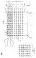
図1は、米国特許出願第14/920,246号、第15/149,323号、及び第15/149,429号に記載された距離センサのうちのいずれかなどの距離センサの光投影システムにより投影されることがある例の投影パターン100を図示する。図示したように、パターンは、グリッドを形成するように配列された複数のドット1021〜102n(以降、個別に「ドット102」と呼ぶ又は集合的に「ドット102」と呼ぶ)を含む。ドット102は、破線、x、等などの他の形を取ることができる、したがって、図1では、例の目的でドットを採用する。ドット102は、グリッドのx軸及びy軸に沿って配列され、その結果、複数の行1041〜104m(以降、個別に「行104」と呼ぶ又は集合的に「行104」と呼ぶ)及び複数の列1061〜106p(以降、個別に「列106」と呼ぶ又は集合的に「列106」と呼ぶ)が形成される。この配列は、y軸に平行である(例えば、行に直交する)中心線108に関して対称である。ドット102の軌跡は、x軸に平行である(例えば、沿って動く)。FIG. 1 shows an optical projection system for a distance sensor, such as any of the distance sensors described in U.S. Patent Applications 14/920, 246, 15/149, 323, and 15/149, 429. The
1つの例では、4つの隣接するドット102の任意のセットを、四辺形を形成するようにつなぐことができる。1つの例では、四辺形は、図1に凡例により示されたような6つの形状:a,−a、b、−b、c、又はcのうちの1つを取ることができる。さらなる例では、追加の形状が可能なことがある。すべての6つの四辺形a,−a、b、−b、c、及びcが繰り返されずにx軸に沿って連続して使用されるときには、その6つの四辺形は「ユニット」を構成する。図1では、パターン100の各々の行104は、中心線108の各々の側に1つのユニットを含む。ユニットは、任意の順番の四辺形a,−a、b、−b、c、及びcを含むことができる。図1に図示した例では、2つの異なるユニットが、交互に変わる方式で使用される。例えば、第1のユニットが行1041で使用され、異なる第2のユニットが行1042で使用され、そしてユニットは、行104mまで交互に変わる方式でこのように繰り返される。言い換えると、第1のユニット及び第2のユニットは、y軸に沿って交互に変わる。In one example, any set of four adjacent dots 102 can be connected to form a quadrilateral. In one example, the quadrilateral can take one of six shapes: a, -a, b, -b, c, or c, as shown by the legend in FIG. In a further example, additional shapes may be possible. When all six quadrilaterals a, -a, b, -b, c, and c are used consecutively along the x-axis without repetition, the six quadrilaterals constitute a "unit". In FIG. 1, each row 104 of the
四辺形が、ドット102の相対的な位置又はパターンを単に示すために図1に図示され、そして距離センサにより投影される実際の投影アーティファクトを含まないことに留意すべきである。例えば、図2は、高密度パターンに拡大された図1のパターン100を図示する。 It should be noted that the quadrilateral is illustrated in FIG. 1 simply to indicate the relative position or pattern of the dots 102 and does not include the actual projected artifacts projected by the distance sensor. For example, FIG. 2 illustrates
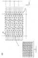
図3は、米国特許出願第14/920,246号、第15/149,323号、及び第15/149,429号に記載された距離センサのうちのいずれかなどの距離センサの光投影システムにより投影されることがあるもう1つの例の投影パターン300を図示する。図示したように、パターンは、グリッドを形成するように配列された複数のドット3021〜302n(以降、個別に「ドット302」と呼ぶ又は集合的に「ドット302」と呼ぶ)を含む。ドット302は、破線、x、等などの他の形を取ることができ、したがって、図3では、例の目的でドットを採用する。ドット302は、グリッドのx軸及びy軸に沿って配列され、その結果、複数の行3041〜304m(以降、個別に「行304」と呼ぶ又は集合的に「行304」と呼ぶ)及び複数の列3061〜306p(以降、個別に「列306」と呼ぶ又は集合的に「列306」と呼ぶ)が形成される。この配列は、y軸に平行である中心線308に関して対称である。ドット302の軌跡は、x軸に平行である(例えば、沿って動く)。FIG. 3 shows an optical projection system for a distance sensor, such as any of the distance sensors described in U.S. Patent Applications 14/920, 246, 15/149, 323, and 15/149, 429. Another
集合的に、複数の行304を、「ラインセット」と呼ぶことができる。ラインセットは、このケースでは、互いに平行な少なくとも2つの行を含み、ここではラインセット内の行のうちの少なくとも2つが、異なるパターン密度(ドット302の分布又は間隔)を示す。例えば、ラインセットが2行に限定される場合、一方の行が、高密度ドット分布を有することがあり、他方の行が(互いに相対的に)低密度ドット分布を有することがある。さらなる例では、(例えば、y軸に沿った)少なくとも2つの行同士の間の間隔は、全体のパターン(例えば、パターン300)内の他の行同士の間の間隔よりも小さいことがある。 Collectively, a plurality of rows 304 can be referred to as a "line set". The line set includes at least two rows parallel to each other in this case, where at least two of the lines in the line set exhibit different pattern densities (distribution or spacing of dots 302). For example, if the line set is limited to two rows, one row may have a high density dot distribution and the other row may have a low density dot distribution (relative to each other). In a further example, the spacing between at least two rows (eg, along the y-axis) may be less than the spacing between other rows in the overall pattern (eg, pattern 300).
1つの例では、行304は、相対的に高密度のパターンと相対的に低密度のパターンとの間で交互に変わることがある。相対的に低密度のパターンは、相対的に高密度のパターンよりもドット302同士の間でより大きな間隔を示すことがある。例えば、行3041のドット302を、対へとグループ分けすることができ、ここではある対内の各々のドット302同士の間の間隔はdである。行3041内の各々の対同士の間の間隔は、順に2dであってもよい。しかしながら、行3042のドット302同士の間の間隔は、3dであってもよい。このように、行3042のパターンは、行3041のパターンと比較して低密度のものである。In one example, rows 304 may alternate between relatively dense patterns and relatively low density patterns. A relatively low density pattern may show a greater spacing between the dots 302 than a relatively dense pattern. For example,the dots 302 in line 304 1 can be grouped into pairs, where the spacing between each dot 302 in a pair is d. The spacing between each pair in line 3041 may in turn be 2d. However, the spacing between the dots 302 inline 304 2 may be 3d. As described above, the pattern ofline 304 2 has a lower density than the pattern ofline 304 1.
行3043のドット302同士の間の間隔は、2dと4dとの間で交互に変わることがある。このように行3043のパターンは、行3042のパターンと比較して低密度のものである。行3044のドット302を、3つのセットにグループ分けすることができ、ここではセット内の各々のドット302同士の間の間隔はdである。行3044内の各々のセットの間の間隔は、順に2dであってもよい。このように、行3044のパターンは、行3041、3042、及び3043のパターンと比較して高密度のものである。The spacing between the dots 302 in line 3043 may alternate between 2d and 4d. As described above, the patternof line 304 3 has a lower density than the pattern ofline 304 2. The dots 302 of line 3044 can be grouped into three sets, where the spacing between each dot 302 in the set is d. The spacing between each set in line 3044 may in turn be 2d. Thus, the pattern in rows 3044 is denser than the patterns in rows 3041 , 3042 , and 3043.
このように、パターン300の各々の行304の相対的なパターン密度は、変わることがある。任意の数の異なる密度を、パターン300では使用することができる。例えば、パターン300は、低密度行と高密度行との間で交互に変わってもよい。あるいは、様々な可能な密度の行304のランダムな配列を、使用してもよい。 Thus, the relative pattern density of each row 304 of
いずれにせよ、共通行304内に存在するすべてのドット302は、共線的である。すなわち、共通行内に存在するすべてのドット302は、y軸上のそれら自体の位置に関して変化しない。しかしながら、y軸に沿った行同士の間の間隔は、変化することがある。例えば、図3に図示したように、行3041と3042との間、及び3043と3044との間の間隔は、y1である。しかしながら、y軸を下る行3042と3043との間、及び行3044と次の行304との間の間隔は、y2である。In any case, all the dots 302 present in the common row 304 are collinear. That is, all dots 302 present in the common row do not change with respect to their own position on the y-axis. However, the spacing between rows along the y-axis can vary. For example, as illustrated in FIG. 3, the spacing betweenrows 304 1 and 3042 and between 3043 and 3044 is y1.However, the spacing between rows 304 2 and 3043 down the y-axis and between row 3044 and the next row 304 is y2.
その上、高密度行及び低密度行を含む隣接する対がある場合、高密度行と低密度行との間の間隔を、いずれの行のドット同士の間の間隔よりも小さくすることができる。例えば、高密度行3041及び低密度行3042(また、それぞれ参照符号a1及びa2により示される)の対を見ると、行3041と行3042との間の間隔、すなわちy1、は、行3041及び行3042内のドット302同士の間の間隔d、2d、及び3dよりも小さい。Moreover, if there are adjacent pairs containing high density rows and low density rows, the spacing between the high density rows and the low density rows can be smaller than the spacing between the dots in any row. .. For example, looking at the pair of high density row 3041 and low density row 3042 (also indicated by reference numerals a1 and a2, respectively),the spacing between row 304 1 and row 3042 , i.e. y1, is: It is less than the spacing d, 2d, and 3d between the dots 302 in rows 3041 and 3042.
パターン300を、例えば、米国特許出願第14/920,246号、第15/149,323号、及び第15/149,429号に記載されたような、1つ以上の回折光学素子と組み合わせて垂直共振器面発光レーザ(VCSEL)アレイ310により投影することができる。1つの例では、VCSELチップ上の穴(例えば、レーザを収容する空洞)の配列を、パターン300を生成するように指定することができる。例えば、パターン300と同様に、穴の配列を、一連の行として指定することができ、そこでは各々の行の穴同士の間の間隔は、変わることがある。
例えば、VCSELアレイ310のVCSEL穴配置を、「穴ラインセット」から構成することができる。このケースでは、穴ラインセットは、互いに平行な少なくとも2つの穴ライン(又は穴の行)を含むことができ、これが穴の異なる密度(分布又は間隔)を示す。例えば、一方の穴ラインは、穴の高密度分布を示すことがあり、ところが他方の穴ラインは、(互いに相対的に)穴の低密度分布を示す。さらなる例では、(例えば、y軸に沿った)少なくとも2つの穴ライン同士の間の間隔は、この少なくとも2つの穴ラインとVCSELアレイの他の穴ラインとの間の間隔よりも狭いことがある。 For example, the VCSEL hole arrangement of the
図4は、米国特許出願第14/920,246号、第15/149,323号、及び第15/149,429号に記載された距離センサのうちのいずれかなどの距離センサの光投影システムにより投影されることがあるもう1つの例の投影パターン400を図示する。図示したように、パターンは、グリッドを形成するように配列された複数のドット4021〜402n(以降、個別に「ドット402」と呼ぶ又は集合的に「ドット402」と呼ぶ)を含む。ドット402は、破線、x、等などの他の形を取ることができ、したがって、図4では、例の目的でドットを採用する。ドット402は、グリッドのx軸及びy軸に沿って配列され、その結果、複数の行a〜f及び複数の列1〜12が形成される。ドット402の軌跡は、x軸に平行である(例えば、沿って動く)。FIG. 4 shows an optical projection system for a distance sensor, such as any of the distance sensors described in U.S. Patent Applications 14/920, 246, 15/149, 323, and 15/149, 429. Another
集合的に、複数の行a〜fを、「ラインセット」と呼ぶことができる。ラインセットは、このケースでは互いにすべて平行な複数の行を含み、ここではラインセット内の行のうちの少なくとも2つが異なるパターン密度(ドット402の分布又は間隔)を示す。さらなる例では、(例えば、y軸に沿った)行同士の間の間隔もまた、そのラインセット内のすべての行について同じである。 Collectively, a plurality of rows a to f can be referred to as a "line set". The line set includes multiple lines that are all parallel to each other in this case, where at least two of the lines in the line set show different pattern densities (distribution or spacing of dots 402). In a further example, the spacing between rows (eg, along the y-axis) is also the same for all rows in that line set.
図4の例では、行a、b、c、d、e、及びfの各々は、図示したように、ドット402同士の間の間隔に関して異なるパターン密度を示すことがある。例えば、パターン密度は、行aで最大であり、行fで最小であってもよく、行b、c、d、及びeでは最小密度と最大密度との間のどこかになる。その上、行のパターン、すなわち、順番a、b、c、d、e、fが、y軸に沿って何回も繰り返されることがある。図4に図示した例では、行のパターンは、4回繰り返される。すなわち、行a〜fの4つのグループがある。 In the example of FIG. 4, each of the rows a, b, c, d, e, and f may show different pattern densities with respect to the spacing between the dots 402, as illustrated. For example, the pattern density may be maximum in row a, minimum in row f, and somewhere between the minimum and maximum densities in rows b, c, d, and e. Moreover, the row pattern, i.e., the order a, b, c, d, e, f, may be repeated many times along the y-axis. In the example illustrated in FIG. 4, the row pattern is repeated four times. That is, there are four groups in rows a to f.
パターン400を、例えば、米国特許出願第14/920,246号、第15/149,323号、及び第15/149,429号に記載されたような1つ以上の回折光学素子と組み合わせて垂直共振器面発光レーザ(VCSEL)アレイ410により投影することができる。1つの例では、VCSELチップ上の穴(例えば、レーザを収容する空洞)の配列を、パターン400を生成するように指定することができる。例えば、パターン400と同様に、穴の配列を、一連の行として指定することができ、ここでは各々の行の穴同士の間の間隔が、変わることがある。
例えば、VCSELアレイ410のVCSEL穴配置を、複数の「穴ラインセット」から構成することができる。このケースでは、穴ラインセットは、互いにすべて平行な複数の穴ライン(又は穴の行)を含むことができ、ここでは穴ラインセット内の少なくとも2つのラインが、穴の異なる密度(分布又は間隔)を示す。さらなる例では、(例えば、y軸に沿った)穴ライン同士の間の間隔は、すべての穴ラインに関して同じであってもよい。 For example, the VCSEL hole arrangement of the
図5は、米国特許出願第14/920,246号、第15/149,323号、及び第15/149,429号に記載された距離センサのうちのいずれかなどの距離センサの光投影システムにより投影されることがあるもう1つの例の投影パターン500を図示する。図示したように、パターンは、グリッドを形成するように配列された複数のドット5021〜502n(以降、個別に「ドット502」と呼ぶ又は集合的に「ドット502」と呼ぶ)を含む。ドット502は、破線、x、等などの他の形を取ることができ、したがって、図5では、例の目的でドットを採用する。図4におけるように、ドット502は、グリッドのx軸及びy軸に沿って配列され、その結果、複数の行a〜f及び複数の列1〜12が形成される。ドット502の軌跡は、x軸に平行である(例えば、沿って動く)。FIG. 5 is an optical projection system for a distance sensor, such as any of the distance sensors described in US Patent Applications 14/920, 246, 15/149, 323, and 15/149, 429. Another
図4におけるように、行a、b、c、d、e、及びfの各々は、図示したように、ドット502同士の間の間隔に関して異なるパターン密度を示すことがある。例えば、パターン密度は、行aで最大であり、行fで最小であってもよく、行b、c、d、及びeでは最小密度と最大密度との間のどこかになる。その上、行のパターン、すなわち、順番a、b、c、d、e、fが、y軸に沿って何回も繰り返されることがある。図5に図示した例では、行のパターンは、4回繰り返される。すなわち、行a〜fの4つのグループがある。 As shown in FIG. 4, each of the rows a, b, c, d, e, and f may show different pattern densities with respect to the spacing between the dots 502, as illustrated. For example, the pattern density may be maximum in row a, minimum in row f, and somewhere between the minimum and maximum densities in rows b, c, d, and e. Moreover, the row pattern, i.e., the order a, b, c, d, e, f, may be repeated many times along the y-axis. In the example illustrated in FIG. 5, the row pattern is repeated four times. That is, there are four groups in rows a to f.
パターン500を、例えば、米国特許出願第14/920,246号、第15/149,323号、及び第15/149,429号に記載されたような1つ以上の回折光学素子と組み合わせて垂直共振器面発光レーザ(VCSEL)アレイ510により投影することができる。1つの例では、VCSELチップ上の穴(例えば、レーザを収容する空洞)の配列を、パターン500を生成するように指定することができる。例えば、パターン500と同様に、穴の配列を、一連の行として指定することができ、ここでは各々の行の穴同士の間の間隔は、変わることがある。
図6は、米国特許出願第14/920,246号、第15/149,323号、及び第15/149,429号に記載された距離センサのうちのいずれかなどの距離センサの光投影システムにより投影されることがあるもう1つの例の投影パターン600を図示する。図示したように、パターンは、グリッドを形成するように配列された複数のドット6021〜602n(以降、個別に「ドット602」と呼ぶ又は集合的に「ドット602」と呼ぶ)を含む。ドット602は、破線、x、等などの他の形を取ることができ、したがって、図6では、例の目的でドットを採用する。図4及び図5のように、ドット602は、グリッドのx軸及びy軸に沿って配列され、その結果、複数の行a〜f及び複数の列1〜12が形成される。ドット602の軌跡は、x軸に平行である(例えば、沿って動く)。FIG. 6 is an optical projection system for a distance sensor, such as any of the distance sensors described in US Patent Applications 14/920, 246, 15/149, 323, and 15/149, 429. Another
図4〜図5におけるように、行a、b、c、d、e、及びfの各々は、図示したように、ドット602同士の間の間隔に関して異なるパターン密度を示すことがある。例えば、パターン密度は、行aで最大であり、行fで最小であってもよく、そして行b、c、d、及びeでは最小密度と最大密度との間のどこかになる。その上、行のパターン、すなわち、順番a、b、c、d、e、fが,y軸に沿って何回も繰り返されることがある。図6に図示した例では、行のパターンは、4回繰り返される。すなわち、行a〜fの4つのグループがある。 As in FIGS. 4-5, each of rows a, b, c, d, e, and f may show different pattern densities with respect to the spacing between dots 602, as illustrated. For example, the pattern density may be maximum in row a, minimum in row f, and somewhere between the minimum and maximum densities in rows b, c, d, and e. Moreover, the row pattern, ie, the order a, b, c, d, e, f, may be repeated many times along the y-axis. In the example illustrated in FIG. 6, the row pattern is repeated four times. That is, there are four groups in rows a to f.
パターン600を、例えば、米国特許出願第14/920,246号、第15/149,323号、及び第15/149,429号に記載されたような1つ以上の回折光学素子と組み合わせて垂直共振器面発光レーザ(VCSEL)アレイ610により投影することができる。1つの例では、VCSELチップ上の穴(例えば、レーザを収容する空洞)の配列を、パターン600を生成するように指定することができる。例えば、パターン600と同様に、穴の配列を、一連の行として指定することができ、ここでは各々の行の穴同士の間の間隔は、変わることがある。
図7は、本開示による、様々な密度の投影パターンを使用する距離測定のための方法700の1つの例を図示する流れ図である。方法700を、例えば、距離センサのプロセッサ又は図8に図示したプロセッサ802などのプロセッサにより実行することができる。例の目的で、方法700を、処理システムにより実行されるとして説明する。 FIG. 7 is a flow diagram illustrating one example of the
方法700を、ステップ702において始めることができる。ステップ704では、処理システムは、光のパターンを距離センサのカメラの視野内の被写体へと投影するように距離センサの投影システム(例えば、レーザ光源、回折光学素子、レンズ、及び又は他の構成要素を含む光学系のセット)に命令することができる。1つの例では、光のパターンは、人間の目には実質的に見えない波長で放射される光(例えば、赤外線)を含むことができる。パターンは、ドット、破線、x、又は他の投影アーティファクトの複数の平行な行を含むことができる。個々の行のパターン密度は、変わることがある。言い換えると、複数の行のうちの少なくとも2つが、投影アーティファクトの異なる空間密度を示す。例えば、複数の行のうちのいくつかは、複数の行のうちの他と比較してより高いパターン密度(例えば、投影アーティファクトのより密接した間隔)を有することがある。
ステップ706では、処理システムは、被写体の画像を取得するように距離センサのカメラに命令することができ、ここでは画像が光のパターンを含む。1つの例では、カメラは、赤外線検出器及び魚眼レンズを備えることができる。 In
ステップ708では、処理システムは、被写体までの距離を決定するために画像を処理することができる。例えば、米国特許出願第14/920,246号、第15/149,323号、及び第15/149,429号に記載された方法のうちのいずれかを、距離を計算するために使用することができる。1つの例では、パターン内の投影アーティファクトの軌跡に一部は基づいて、被写体までの距離を決定することができる。さらなる例では、パターンの低密度行内の投影アーティファクトの軌跡を、被写体に対するセンサの動きを決定するために使用することができる。動きを知ることは、順に、パターンの高密度行内の投影アーティファクトの軌跡を識別することを可能にする。高密度行内の投影アーティファクトの軌跡を知ることは、順に、高分解能の距離情報を決定することを可能にすることができる。あるいは、処理システムは、距離計算のための遠隔処理システムへ第1の画像及び第2の画像を送ることができる。 In
方法700は、ステップ710で終わることができる。
明示的に特定しないとはいえ、上に説明した方法700のブロック、機能、又は動作のうちのいくつかが、特定の用途のために記憶すること、表示すること及び/又は出力することを含むことができることに留意すべきである。言い換えると、方法700において論じたいずれかのデータ、レコード、フィールド、及び/又は中間結果を、特定の用途に応じてもう1つの装置に記憶する、表示する、及び/又は出力することができる。さらにその上、決定する動作を列挙する又は判断を含む図7のブロック、機能、又は動作は、決定する動作の2つの分岐が実行されることを意味しない。言い換えると、決定する動作の分岐のうちの一方は、決定する動作の結果に応じて実行されなくてもよい。 Although not explicitly specified, some of the blocks, functions, or actions of
図8は、センサから被写体までの距離を計算するための例の電子デバイス800の高水準のブロック図を描く。それはそうとして、電子デバイス800を、距離センサなどの電子デバイス又はシステムのプロセッサとして実装することができる。 FIG. 8 depicts a high-level block diagram of an example
図8に描かれたように、電子デバイス800は、ハードウェアプロセッサ素子802、例えば、中央処理装置(CPU)、マイクロプロセッサ、又はマルチコアプロセッサ、メモリ804、例えば、ランダムアクセスメモリ(RAM)及び/又は読出し専用メモリ(ROM)、センサから被写体までの距離を計算するためのモジュール805、並びに様々な入力/出力デバイス806、例えば、テープドライブ、フロッピドライブ、ハードディスクドライブ又はコンパクトディスクドライブを含むがこれらに限定されない記憶デバイス、受信機、送信機、ディスプレイ、出力ポート、入力ポート、及びキーボード、キーパッド、マウス、マイクロフォン、カメラ、レーザ光源、LED光源、等、などのユーザ入力デバイスを備える。 As depicted in FIG. 8, the
1つのプロセッサ素子が示されるが、電子デバイス800が複数のプロセッサ素子を採用することができることに留意すべきである。さらにその上、1つの電子デバイス800が図に示されるが、上に論じたような方法が特定の例示的な例のために分散型方式又は並列方式で実施される、すなわち、上記の方法のブロック又は全体の方法が多数の電子デバイス又は並列電子デバイスの全体にわたって実施される場合には、この図の電子デバイス800は、これらの多数の電子デバイスの各々を代表するものとする。 Although one processor element is shown, it should be noted that the
本開示を、機械可読命令により及び/又は、例えば、特定用途集積回路(ASIC)、フィールドプログラマブルゲートアレイ(FPGA)を含めプログラマブル論理アレイ(PLA)、若しくはハードウェア装置上に展開されたステートマシンを使用して、機械可読命令とハードウェアとの組合せで実施することができ、汎用コンピュータ又はいずれかの他のハードウェア等価物、例えば、上に論じた方法に関係するコンピュータ可読命令を、上に開示した方法のブロック、機能及び/又は動作を実行するようにハードウェアプロセッサを構成するために使用することができることに留意すべきである。 The present disclosure is made by machine-readable instructions and / or, for example, a programmable logic array (PLA) including an application specific integrated circuit (ASIC), a field programmable gate array (FPGA), or a state machine deployed on a hardware device. It can be implemented in combination with machine-readable instructions and hardware, using a general purpose computer or any other hardware equivalent, eg, computer-readable instructions related to the methods discussed above, above. It should be noted that it can be used to configure the hardware processor to perform blocks, functions and / or operations of the disclosed methods.
1つの例では、センサから被写体までの距離を計算するための本モジュール又はプロセッサ805のための命令及びデータ、例えば、機械可読命令を、方法700に関連して上に論じたようなブロック、機能又は動作を実施するために、メモリ804へとロードし、そしてハードウェアプロセッサ素子802により実行することができる。さらにその上、ハードウェアプロセッサが「動作」を実行するために命令を実行するときには、このことは、直接動作を実行する及び/又は動作を実行するためにもう1つのハードウェア装置又は構成要素、例えば、コプロセッサ、等を円滑にさせる、管理する、若しくは協同するハードウェアプロセッサを含むはずである。 In one example, instructions and data for the module or processor 805 for calculating the distance from the sensor to the subject, such as machine-readable instructions, are blocks, functions as discussed above in connection with
上に説明した方法に関係する機械可読命令を実行するプロセッサを、プログラムしたプロセッサ又は専用プロセッサとして認識することができる。それはそうとして、本開示のセンサから被写体までの距離を計算するための本モジュール805を、実体的な又は物理的な(広く非一時的な)コンピュータ可読記憶デバイス又は媒体、例えば、揮発性メモリ、不揮発性メモリ、ROMメモリ、RAMメモリ、磁気若しくは光ドライブ、デバイス若しくはディスケット、等に記憶することができる。より具体的に、コンピュータ可読記憶デバイスは、安全センサシステムのコンピュータ若しくはコントローラなどのプロセッサ又は電子デバイスによりアクセスされるデータ及び/又は命令などの情報を記憶する能力を提供する任意の物理デバイスを備えることができる。 A processor that executes a machine-readable instruction related to the method described above can be recognized as a programmed processor or a dedicated processor. That being said, the module 805 for calculating the distance from the sensor of the present disclosure to a subject is provided with a substantive or physical (widely non-temporary) computer-readable storage device or medium, such as volatile memory. It can be stored in a non-volatile memory, a ROM memory, a RAM memory, a magnetic or optical drive, a device or a diskette, or the like. More specifically, a computer-readable storage device comprises any physical device that provides the ability to store information such as data and / or instructions accessed by a processor or electronic device such as a computer or controller of a safety sensor system. Can be done.
上に開示した及び他の特徴及び機能の変形形態、又はその代替形態を、多くの他の異なるシステム又はアプリケーションへと組み合わせることができることが認識されるだろう。様々な現在のところ予期されない又は予想されない代替形態、変形、又はその中の変形形態を引き続いて行うことができ、これらもまた別記の特許請求の範囲により含まれるものである。 It will be appreciated that variants of the features and functions disclosed above, or alternatives thereof, can be combined with many other different systems or applications. Various currently unexpected or unexpected alternative forms, variants, or variants within it may be subsequently performed, which are also included in the claims.
Claims (20)
Translated fromJapanese前記処理システムによって、前記被写体の画像を取得するように前記距離センサのカメラに命令することであって、前記画像が前記光のパターンを含む、カメラに命令することと、
前記処理システムによって、前記画像の解析に基づいて前記距離センサから前記被写体までの距離を計算することと、
を含むことを特徴とする方法。The distance sensor processing system commands the pattern projector of the distance sensor to project a pattern of light onto the subject, wherein the pattern contains a plurality of parallel rows of projection artifacts. Command the pattern projector that the spatial density of the projected artifact in the first row of the plurality of parallel rows is different from the spatial density of the projected artifact in the second row of the plurality of parallel rows. That and
Instructing the camera of the distance sensor to acquire an image of the subject by the processing system, and instructing the camera that the image contains the pattern of light.
The processing system calculates the distance from the distance sensor to the subject based on the analysis of the image.
A method characterized by including.
前記第1の行内の前記投影アーティファクトの前記空間密度が、前記第1の行内の前記投影アーティファクト同士の間の間隔から構成され、
前記第2の行内の前記投影アーティファクトの前記空間密度が、前記第2の行内の前記投影アーティファクト同士の間の間隔から構成される、
ことを特徴とする方法。The method according to claim 1.
The spatial density of the projected artifacts in the first row consists of the spacing between the projected artifacts in the first row.
The spatial density of the projected artifacts in the second row consists of the spacing between the projected artifacts in the second row.
A method characterized by that.
前記第1の行内の前記投影アーティファクト同士の間の前記間隔が、前記第2の行内の前記投影アーティファクト同士の間の前記間隔よりも大きい、
ことを特徴とする方法。The method according to claim 2.
The distance between the projected artifacts in the first row is greater than the distance between the projected artifacts in the second row.
A method characterized by that.
前記第1の行の長さ全体にわたり前記第1の行内の前記投影アーティファクト同士の間の前記間隔に変化がある、
ことを特徴とする方法。The method according to claim 2.
There is a change in the spacing between the projected artifacts within the first row over the entire length of the first row.
A method characterized by that.
前記変化が繰り返されるパターンを含む、
ことを特徴とする方法。The method according to claim 4.
Including a pattern in which the changes are repeated,
A method characterized by that.
前記処理システムによって、前記第1の行内の前記投影アーティファクトのうちの1つの第1の軌跡を識別することであり、前記第1の行内の前記投影アーティファクトの前記空間密度が前記第2の行内の前記投影アーティファクトの前記空間密度よりも小さい、第1の軌跡を識別することと、
前記処理システムによって、前記第1の軌跡に基づいて、前記被写体に対する前記距離センサの動きを識別することと、
前記処理システムによって、前記動きに基づいて、前記第2の行内の前記投影アーティファクトのうちの1つの第2の軌跡を識別することと、
前記第2の軌跡に基づいて前記距離を計算することと、
を含むことを特徴とする方法。The method according to claim 1, wherein the calculation can be performed.
The processing system identifies the first locus of one of the projected artifacts in the first row, where the spatial density of the projected artifact in the first row is within the second row. Identifying a first trajectory that is less than the spatial density of the projected artifact,
The processing system identifies the movement of the distance sensor with respect to the subject based on the first locus.
The processing system identifies the second trajectory of one of the projected artifacts in the second row based on the movement.
To calculate the distance based on the second locus,
A method characterized by including.
前記第1の軌跡及び前記第2の軌跡が、前記複数の平行な行に平行である、
ことを特徴とする方法。The method according to claim 6.
The first locus and the second locus are parallel to the plurality of parallel rows.
A method characterized by that.
前記第1の行内の前記投影アーティファクトが互いに共線状であり、
前記第2の行内の前記投影アーティファクトが互いに共線状である、
ことを特徴とする方法。The method according to claim 1.
The projected artifacts in the first row are collinear with each other and
The projected artifacts in the second row are collinear with each other,
A method characterized by that.
前記複数の平行な行の行同士の間の間隔が、前記パターンの長さ全体にわたって変化する、
ことを特徴とする方法。The method according to claim 8.
The spacing between the rows of the plurality of parallel rows varies over the length of the pattern.
A method characterized by that.
前記光のパターンが、人間の目には見えない波長の光を含む、
ことを特徴とする方法。The method according to claim 1.
The pattern of light includes light of a wavelength invisible to the human eye.
A method characterized by that.
前記波長が赤外である、
ことを特徴とする方法。The method according to claim 10.
The wavelength is infrared,
A method characterized by that.
光のパターンを被写体の上へと投影するように前記距離センサのパターン投影機に命令することであり、前記パターンが投影アーティファクトの複数の平行な行を含み、前記複数の平行な行のうちの第1の行内の前記投影アーティファクトの空間密度が前記複数の平行な行のうちの第2の行内の前記投影アーティファクトの空間密度とは異なる、パターン投影機に命令することと、
前記被写体の画像を取得するように前記距離センサのカメラに命令することであり、前記画像が前記光のパターンを含む、カメラに命令することと、
前記画像の解析に基づいて前記距離センサから前記被写体までの距離を計算することと、
を含むことを特徴とする非一時的な機械可読記憶媒体。A non-temporary machine-readable storage medium encoded with instructions that can be executed by a processor of a distance sensor, the non-temporary machine that causes the processor to perform an operation when executed. In a readable storage medium, the above operation
Is to instruct the pattern projector of the distance sensor to project a pattern of light onto the subject, the pattern containing a plurality of parallel rows of projection artifacts, of the plurality of parallel rows. Commanding the pattern projector that the spatial density of the projected artifact in the first row is different from the spatial density of the projected artifact in the second row of the plurality of parallel rows.
Instructing the camera of the distance sensor to acquire an image of the subject, and instructing the camera that the image contains the pattern of light.
To calculate the distance from the distance sensor to the subject based on the analysis of the image,
A non-temporary machine-readable storage medium characterized by containing.
光のパターンを被写体の上へと投影するためのパターン投影機であって、前記パターンが投影アーティファクトの複数の平行な行を含み、前記複数の平行な行のうちの第1の行内の前記投影アーティファクトの空間密度が前記複数の平行な行のうちの第2の行内の前記投影アーティファクトの空間密度とは異なる、パターン投影機と、
前記被写体の画像を取得するためのカメラであって、前記画像が前記光のパターンを含む、カメラと、
前記画像の解析に基づいて前記距離センサから前記被写体までの距離を計算するための処理システムと、
を備えることを特徴とする距離センサ。It ’s a distance sensor,
A pattern projector for projecting a pattern of light onto a subject, wherein the pattern contains a plurality of parallel rows of projection artifacts, the projection within the first row of the plurality of parallel rows. With a pattern projector, the spatial density of the artifact is different from the spatial density of the projected artifact in the second row of the plurality of parallel rows.
A camera for acquiring an image of the subject, wherein the image includes the pattern of light.
A processing system for calculating the distance from the distance sensor to the subject based on the analysis of the image, and
A distance sensor characterized by being equipped with.
前記パターン投影機が、前記パターンを形成する光を放射するように構成された垂直共振器面発光レーザを備える、
ことを特徴とする距離センサ。The distance sensor according to claim 13.
The pattern projector comprises a vertical resonator surface emitting laser configured to emit light forming the pattern.
A distance sensor characterized by that.
前記第1の行内の前記投影アーティファクトの前記空間密度が、前記第1の行内の前記投影アーティファクト同士の間の間隔から構成され、
前記第2の行内の前記投影アーティファクトの前記空間密度が、前記第2の行内の前記投影アーティファクト同士の間の間隔から構成される、
ことを特徴とする距離センサ。The distance sensor according to claim 13.
The spatial density of the projected artifacts in the first row consists of the spacing between the projected artifacts in the first row.
The spatial density of the projected artifacts in the second row consists of the spacing between the projected artifacts in the second row.
A distance sensor characterized by that.
前記第1の行の長さ全体にわたり前記第1の行内の前記投影アーティファクト同士の間の間隔に変化がある、
ことを特徴とする距離センサ。The distance sensor according to claim 13.
There is a variation in the spacing between the projected artifacts within the first row over the entire length of the first row.
A distance sensor characterized by that.
前記変化が繰り返されるパターンを含む、
ことを特徴とする距離センサ。The distance sensor according to claim 16.
Including a pattern in which the changes are repeated,
A distance sensor characterized by that.
前記複数の平行な行の行同士の間の間隔が、前記パターンの長さ全体にわたって変化する、
ことを特徴とする距離センサ。The distance sensor according to claim 13.
The spacing between the rows of the plurality of parallel rows varies over the length of the pattern.
A distance sensor characterized by that.
前記光のパターンが、人間の目には見えない波長の光を含む、
ことを特徴とする距離センサ。The distance sensor according to claim 13.
The pattern of light includes light of a wavelength invisible to the human eye.
A distance sensor characterized by that.
前記波長が赤外である、
ことを特徴とする距離センサ。
The distance sensor according to claim 19.
The wavelength is infrared,
A distance sensor characterized by that.
Applications Claiming Priority (3)
| Application Number | Priority Date | Filing Date | Title |
|---|---|---|---|
| US201862645185P | 2018-03-20 | 2018-03-20 | |
| US62/645,185 | 2018-03-20 | ||
| PCT/US2019/022412WO2019182881A1 (en) | 2018-03-20 | 2019-03-15 | Distance measurement using projection patterns of varying densities |
Publications (1)
| Publication Number | Publication Date |
|---|---|
| JP2021518535Atrue JP2021518535A (en) | 2021-08-02 |
Family
ID=67985409
Family Applications (1)
| Application Number | Title | Priority Date | Filing Date |
|---|---|---|---|
| JP2020550117APendingJP2021518535A (en) | 2018-03-20 | 2019-03-15 | Distance measurement using projection patterns of various densities |
Country Status (7)
| Country | Link |
|---|---|
| US (1) | US11062468B2 (en) |
| EP (1) | EP3769121A4 (en) |
| JP (1) | JP2021518535A (en) |
| KR (1) | KR102854874B1 (en) |
| CN (1) | CN112166345A (en) |
| TW (1) | TW201946032A (en) |
| WO (1) | WO2019182881A1 (en) |
Families Citing this family (12)
| Publication number | Priority date | Publication date | Assignee | Title |
|---|---|---|---|---|
| WO2018106671A2 (en) | 2016-12-07 | 2018-06-14 | Magik Eye Inc. | Distance sensor including adjustable focus imaging sensor |
| WO2019070806A1 (en) | 2017-10-08 | 2019-04-11 | Magik Eye Inc. | Calibrating a sensor system including multiple movable sensors |
| WO2019070867A2 (en) | 2017-10-08 | 2019-04-11 | Magik Eye Inc. | Distance measurement using a longitudinal grid pattern |
| CN114827573A (en) | 2018-03-20 | 2022-07-29 | 魔眼公司 | Adjusting camera exposure for three-dimensional depth sensing and two-dimensional imaging |
| JP7292315B2 (en)* | 2018-06-06 | 2023-06-16 | マジック アイ インコーポレイテッド | Distance measurement using high density projection pattern |
| WO2020033169A1 (en) | 2018-08-07 | 2020-02-13 | Magik Eye Inc. | Baffles for three-dimensional sensors having spherical fields of view |
| US11483503B2 (en) | 2019-01-20 | 2022-10-25 | Magik Eye Inc. | Three-dimensional sensor including bandpass filter having multiple passbands |
| WO2020197813A1 (en) | 2019-03-25 | 2020-10-01 | Magik Eye Inc. | Distance measurement using high density projection patterns |
| WO2020231747A1 (en) | 2019-05-12 | 2020-11-19 | Magik Eye Inc. | Mapping three-dimensional depth map data onto two-dimensional images |
| JP7569376B2 (en) | 2019-12-01 | 2024-10-17 | マジック アイ インコーポレイテッド | Enhancing triangulation-based 3D distance measurements using time-of-flight information |
| KR20220122645A (en) | 2019-12-29 | 2022-09-02 | 매직 아이 인코포레이티드 | Associating 3-D coordinates with 2-D feature points |
| WO2021138677A1 (en) | 2020-01-05 | 2021-07-08 | Magik Eye Inc. | Transferring the coordinate system of a three-dimensional camera to the incident point of a two-dimensional camera |
Citations (2)
| Publication number | Priority date | Publication date | Assignee | Title |
|---|---|---|---|---|
| JP2013224895A (en)* | 2012-04-23 | 2013-10-31 | Sharp Corp | Three dimensional measuring device |
| WO2016157593A1 (en)* | 2015-03-27 | 2016-10-06 | 富士フイルム株式会社 | Range image acquisition apparatus and range image acquisition method |
Family Cites Families (132)
| Publication number | Priority date | Publication date | Assignee | Title |
|---|---|---|---|---|
| JPS58199236A (en)* | 1982-05-14 | 1983-11-19 | Seidensha:Kk | Carrying truck installed with crane |
| US4914460A (en) | 1987-05-29 | 1990-04-03 | Harbor Branch Oceanographic Institution Inc. | Apparatus and methods of determining distance and orientation |
| US4954962A (en) | 1988-09-06 | 1990-09-04 | Transitions Research Corporation | Visual navigation and obstacle avoidance structured light system |
| JPH0451112A (en) | 1990-06-19 | 1992-02-19 | Fujitsu Ltd | Multi-slit light projector |
| JPH08555A (en) | 1994-06-16 | 1996-01-09 | Fuji Photo Optical Co Ltd | Illumination device of endoscope |
| US5699444A (en) | 1995-03-31 | 1997-12-16 | Synthonics Incorporated | Methods and apparatus for using image data to determine camera location and orientation |
| JP3328111B2 (en) | 1995-08-23 | 2002-09-24 | 日本電気株式会社 | Spatial distance measuring method and spatial distance measuring device |
| US6038415A (en) | 1997-07-18 | 2000-03-14 | Minolta Co., Ltd. | Image forming apparatus and image-carrier cartridge device which is employed in the same |
| EP0898245B1 (en) | 1997-08-05 | 2004-04-14 | Canon Kabushiki Kaisha | Image processing method and apparatus |
| US5980454A (en) | 1997-12-01 | 1999-11-09 | Endonetics, Inc. | Endoscopic imaging system employing diffractive optical elements |
| US5870136A (en) | 1997-12-05 | 1999-02-09 | The University Of North Carolina At Chapel Hill | Dynamic generation of imperceptible structured light for tracking and acquisition of three dimensional scene geometry and surface characteristics in interactive three dimensional computer graphics applications |
| AUPP299498A0 (en) | 1998-04-15 | 1998-05-07 | Commonwealth Scientific And Industrial Research Organisation | Method of tracking and sensing position of objects |
| US7193645B1 (en) | 2000-07-27 | 2007-03-20 | Pvi Virtual Media Services, Llc | Video system and method of operating a video system |
| US6937350B2 (en) | 2001-06-29 | 2005-08-30 | Massachusetts Institute Of Technology | Apparatus and methods for optically monitoring thickness |
| US7940299B2 (en) | 2001-08-09 | 2011-05-10 | Technest Holdings, Inc. | Method and apparatus for an omni-directional video surveillance system |
| GB2395261A (en) | 2002-11-11 | 2004-05-19 | Qinetiq Ltd | Ranging apparatus |
| TWI247104B (en) | 2003-02-26 | 2006-01-11 | Hon Hai Prec Ind Co Ltd | A measuring method for pattern of light guide plate |
| DE10308383A1 (en) | 2003-02-27 | 2004-09-16 | Storz Endoskop Produktions Gmbh | Method and optical system for measuring the topography of a measurement object |
| KR100764419B1 (en) | 2004-02-09 | 2007-10-05 | 강철권 | Device for measuring 3d shape using irregular pattern and method for the same |
| US7191056B2 (en) | 2005-01-04 | 2007-03-13 | The Boeing Company | Precision landmark-aided navigation |
| JP2006313116A (en) | 2005-05-09 | 2006-11-16 | Nec Viewtechnology Ltd | Distance tilt angle detection device, and projector with detection device |
| JP4644540B2 (en) | 2005-06-28 | 2011-03-02 | 富士通株式会社 | Imaging device |
| US20070091174A1 (en) | 2005-09-30 | 2007-04-26 | Topcon Corporation | Projection device for three-dimensional measurement, and three-dimensional measurement system |
| JP4760391B2 (en) | 2006-01-13 | 2011-08-31 | カシオ計算機株式会社 | Ranging device and ranging method |
| JP4799216B2 (en) | 2006-03-03 | 2011-10-26 | 富士通株式会社 | Imaging device having distance measuring function |
| US7375803B1 (en) | 2006-05-18 | 2008-05-20 | Canesta, Inc. | RGBZ (red, green, blue, z-depth) filter system usable with sensor systems, including sensor systems with synthetic mirror enhanced three-dimensional imaging |
| JP4889373B2 (en) | 2006-05-24 | 2012-03-07 | ローランドディー.ジー.株式会社 | Three-dimensional shape measuring method and apparatus |
| WO2008066742A1 (en) | 2006-11-22 | 2008-06-05 | Geng Z Jason | Wide field-of-view reflector and method of designing and making same |
| TWI320480B (en) | 2007-04-23 | 2010-02-11 | Univ Nat Formosa | One diffraction 6 degree of freedom optoelectronic measurement system |
| US8282485B1 (en) | 2008-06-04 | 2012-10-09 | Zhang Evan Y W | Constant and shadowless light source |
| US8531650B2 (en) | 2008-07-08 | 2013-09-10 | Chiaro Technologies LLC | Multiple channel locating |
| US8334900B2 (en) | 2008-07-21 | 2012-12-18 | The Hong Kong University Of Science And Technology | Apparatus and method of optical imaging for medical diagnosis |
| JP2010091855A (en) | 2008-10-09 | 2010-04-22 | Denso Corp | Laser beam irradiation device |
| JP5251419B2 (en) | 2008-10-22 | 2013-07-31 | 日産自動車株式会社 | Distance measuring device and distance measuring method |
| CN101794065A (en) | 2009-02-02 | 2010-08-04 | 中强光电股份有限公司 | projection display system |
| US20100223706A1 (en) | 2009-03-03 | 2010-09-09 | Illinois Tool Works Inc. | Welding helmet audio communication systems and methods with bone conduction transducers |
| JP5484098B2 (en) | 2009-03-18 | 2014-05-07 | 三菱電機株式会社 | Projection optical system and image display apparatus |
| JP4991787B2 (en) | 2009-04-24 | 2012-08-01 | パナソニック株式会社 | Reflective photoelectric sensor |
| US8320621B2 (en) | 2009-12-21 | 2012-11-27 | Microsoft Corporation | Depth projector system with integrated VCSEL array |
| US20110188054A1 (en) | 2010-02-02 | 2011-08-04 | Primesense Ltd | Integrated photonics module for optical projection |
| JP5499985B2 (en) | 2010-08-09 | 2014-05-21 | ソニー株式会社 | Display assembly |
| WO2012023256A2 (en) | 2010-08-19 | 2012-02-23 | Canon Kabushiki Kaisha | Three-dimensional measurement apparatus, method for three-dimensional measurement, and computer program |
| JP5163713B2 (en) | 2010-08-24 | 2013-03-13 | カシオ計算機株式会社 | Distance image sensor, distance image generation device, distance image data acquisition method, and distance image generation method |
| US8830637B2 (en) | 2010-08-31 | 2014-09-09 | Texas Instruments Incorporated | Methods and apparatus to clamp overvoltages for alternating current systems |
| US20120056982A1 (en) | 2010-09-08 | 2012-03-08 | Microsoft Corporation | Depth camera based on structured light and stereo vision |
| US8593535B2 (en) | 2010-09-10 | 2013-11-26 | Apple Inc. | Relative positioning of devices based on captured images of tags |
| EP2433716A1 (en) | 2010-09-22 | 2012-03-28 | Hexagon Technology Center GmbH | Surface spraying device with a nozzle control mechanism and a corresponding method |
| TWI428558B (en) | 2010-11-10 | 2014-03-01 | Pixart Imaging Inc | Ranging method, ranging system and processing software |
| JP5815940B2 (en) | 2010-12-15 | 2015-11-17 | キヤノン株式会社 | Distance measuring device, distance measuring method, and program |
| JP6023087B2 (en) | 2011-02-04 | 2016-11-09 | コーニンクレッカ フィリップス エヌ ヴェKoninklijke Philips N.V. | Method for recording image, method for obtaining 3D information from image, camera system |
| JP5746529B2 (en) | 2011-03-16 | 2015-07-08 | キヤノン株式会社 | Three-dimensional distance measuring device, three-dimensional distance measuring method, and program |
| EP2685811B1 (en) | 2011-03-17 | 2016-03-02 | Mirobot Ltd. | System and method for three dimensional teat modeling for use with a milking system |
| JP2014122789A (en) | 2011-04-08 | 2014-07-03 | Sanyo Electric Co Ltd | Information acquisition device, projection device, and object detector |
| JP5830270B2 (en) | 2011-05-24 | 2015-12-09 | オリンパス株式会社 | Endoscope apparatus and measuring method |
| JP6025830B2 (en) | 2011-06-07 | 2016-11-16 | クレアフォーム・インコーポレイテッドCreaform Inc. | Sensor positioning for 3D scanning |
| KR101974651B1 (en) | 2011-06-22 | 2019-05-02 | 성균관대학교산학협력단 | Measuring method of 3d image depth and a system for measuring 3d image depth using boundary inheritance based hierarchical orthogonal coding |
| US10054430B2 (en) | 2011-08-09 | 2018-08-21 | Apple Inc. | Overlapping pattern projector |
| KR101605224B1 (en) | 2011-10-05 | 2016-03-22 | 한국전자통신연구원 | Method and apparatus for obtaining depth information using optical pattern |
| DE102012108567B4 (en) | 2011-10-05 | 2017-04-27 | Electronics And Telecommunications Research Institute | Method of obtaining depth information using a light pattern |
| TW201329509A (en) | 2012-01-10 | 2013-07-16 | Walsin Lihwa Corp | 3D scan device and 3D scan method thereof |
| US9986208B2 (en) | 2012-01-27 | 2018-05-29 | Qualcomm Incorporated | System and method for determining location of a device using opposing cameras |
| JP2015513070A (en) | 2012-01-31 | 2015-04-30 | スリーエム イノベイティブ プロパティズ カンパニー | Method and apparatus for measuring the three-dimensional structure of a surface |
| JP5800082B2 (en) | 2012-03-01 | 2015-10-28 | 日産自動車株式会社 | Distance measuring device and distance measuring method |
| CN104220838B (en) | 2012-03-28 | 2016-12-21 | 富士通株式会社 | Filming apparatus |
| US9590122B2 (en) | 2012-05-18 | 2017-03-07 | Siemens Healthcare Diagnostics Inc. | Fish eye lens analyzer |
| DK2872030T3 (en)* | 2012-07-10 | 2017-03-06 | Wavelight Gmbh | METHOD AND APPARATUS FOR DETERMINING THE OPTICAL ABERRATIONS OF AN EYE |
| US20140016113A1 (en)* | 2012-07-13 | 2014-01-16 | Microsoft Corporation | Distance sensor using structured light |
| JP2014020978A (en) | 2012-07-20 | 2014-02-03 | Fujitsu Ltd | Irradiation device, ranging device, and calibration program and calibration method of irradiation device |
| EP2696590B1 (en) | 2012-08-06 | 2014-09-24 | Axis AB | Image sensor positioning apparatus and method |
| US9741184B2 (en) | 2012-10-14 | 2017-08-22 | Neonode Inc. | Door handle with optical proximity sensors |
| KR20200105965A (en) | 2012-10-24 | 2020-09-09 | 시리얼 테크놀로지즈 에스.에이. | Illumination device |
| US9285893B2 (en) | 2012-11-08 | 2016-03-15 | Leap Motion, Inc. | Object detection and tracking with variable-field illumination devices |
| DE102012112321B4 (en)* | 2012-12-14 | 2015-03-05 | Faro Technologies, Inc. | Device for optically scanning and measuring an environment |
| JP6241793B2 (en) | 2012-12-20 | 2017-12-06 | パナソニックIpマネジメント株式会社 | Three-dimensional measuring apparatus and three-dimensional measuring method |
| US10466359B2 (en) | 2013-01-01 | 2019-11-05 | Inuitive Ltd. | Method and system for light patterning and imaging |
| US9691163B2 (en) | 2013-01-07 | 2017-06-27 | Wexenergy Innovations Llc | System and method of measuring distances related to an object utilizing ancillary objects |
| US8768559B1 (en) | 2013-01-22 | 2014-07-01 | Qunomic Virtual Technology, LLC | Line projection system |
| US9142019B2 (en) | 2013-02-28 | 2015-09-22 | Google Technology Holdings LLC | System for 2D/3D spatial feature processing |
| US10105149B2 (en) | 2013-03-15 | 2018-10-23 | Board Of Regents Of The University Of Nebraska | On-board tool tracking system and methods of computer assisted surgery |
| US9364167B2 (en) | 2013-03-15 | 2016-06-14 | Lx Medical Corporation | Tissue imaging and image guidance in luminal anatomic structures and body cavities |
| US20140307055A1 (en)* | 2013-04-15 | 2014-10-16 | Microsoft Corporation | Intensity-modulated light pattern for active stereo |
| US20140320605A1 (en) | 2013-04-25 | 2014-10-30 | Philip Martin Johnson | Compound structured light projection system for 3-D surface profiling |
| CN103559735B (en) | 2013-11-05 | 2017-03-01 | 重庆安钻理科技股份有限公司 | A kind of three-dimensional rebuilding method and system |
| EP3092601A4 (en) | 2014-01-06 | 2017-11-29 | Eyelock Llc | Methods and apparatus for repetitive iris recognition |
| GB2522248A (en) | 2014-01-20 | 2015-07-22 | Promethean Ltd | Interactive system |
| KR102166691B1 (en) | 2014-02-27 | 2020-10-16 | 엘지전자 주식회사 | Device for estimating three-dimensional shape of object and method thereof |
| US9526427B2 (en) | 2014-03-21 | 2016-12-27 | Hypermed Imaging, Inc. | Compact light sensors with symmetrical lighting |
| US9307231B2 (en) | 2014-04-08 | 2016-04-05 | Lucasfilm Entertainment Company Ltd. | Calibration target for video processing |
| US10147198B2 (en) | 2014-04-30 | 2018-12-04 | Shinano Kenshi Co., Ltd. | Measurement device |
| JP5829306B2 (en) | 2014-05-12 | 2015-12-09 | ファナック株式会社 | Range sensor placement position evaluation device |
| US10207193B2 (en) | 2014-05-21 | 2019-02-19 | Universal City Studios Llc | Optical tracking system for automation of amusement park elements |
| US9699393B2 (en) | 2014-06-26 | 2017-07-04 | Semiconductor Components Industries, Llc | Imaging systems for infrared and visible imaging with patterned infrared cutoff filters |
| KR20160020323A (en) | 2014-08-13 | 2016-02-23 | 옥은호 | Consisting of parallel infrared projector and the camera module, the distance measuring sensor |
| JP6370177B2 (en) | 2014-09-05 | 2018-08-08 | 株式会社Screenホールディングス | Inspection apparatus and inspection method |
| US10268906B2 (en) | 2014-10-24 | 2019-04-23 | Magik Eye Inc. | Distance sensor with directional projection beams |
| WO2016070318A1 (en) | 2014-11-04 | 2016-05-12 | SZ DJI Technology Co., Ltd. | Camera calibration |
| US20160128553A1 (en) | 2014-11-07 | 2016-05-12 | Zheng Jason Geng | Intra- Abdominal Lightfield 3D Endoscope and Method of Making the Same |
| WO2016094439A1 (en) | 2014-12-08 | 2016-06-16 | Munoz Luis Daniel | Device, system and methods for assessing tissue structures, pathology, and healing |
| KR102369792B1 (en) | 2015-03-05 | 2022-03-03 | 한화테크윈 주식회사 | Photographing apparatus and photographing method |
| JP6484072B2 (en) | 2015-03-10 | 2019-03-13 | アルプスアルパイン株式会社 | Object detection device |
| WO2016151918A1 (en) | 2015-03-26 | 2016-09-29 | 富士フイルム株式会社 | Distance-image acquisition device and distance-image acquisition method |
| US9694498B2 (en)* | 2015-03-30 | 2017-07-04 | X Development Llc | Imager for detecting visual light and projected patterns |
| JP6360621B2 (en) | 2015-03-30 | 2018-07-18 | 富士フイルム株式会社 | Distance image acquisition device and distance image acquisition method |
| US10488192B2 (en) | 2015-05-10 | 2019-11-26 | Magik Eye Inc. | Distance sensor projecting parallel patterns |
| EP3295119A4 (en) | 2015-05-10 | 2019-04-10 | Magik Eye Inc. | Distance sensor |
| CN107613842B (en) | 2015-05-29 | 2019-09-24 | 奥林巴斯株式会社 | Lighting device and measuring device |
| US20160377414A1 (en)* | 2015-06-23 | 2016-12-29 | Hand Held Products, Inc. | Optical pattern projector |
| KR20170005649A (en) | 2015-07-06 | 2017-01-16 | 엘지전자 주식회사 | 3d camera module and mobile terminal comprising the 3d camera module |
| DE102015115011A1 (en) | 2015-09-08 | 2017-03-09 | Valeo Schalter Und Sensoren Gmbh | Laser scanner for motor vehicles |
| US10176554B2 (en) | 2015-10-05 | 2019-01-08 | Google Llc | Camera calibration using synthetic images |
| JP6597150B2 (en) | 2015-10-09 | 2019-10-30 | 富士通株式会社 | Distance measuring device, distance measuring method, distance measuring program, and table creation method |
| FR3042610B1 (en) | 2015-10-14 | 2018-09-07 | Quantificare | DEVICE AND METHOD FOR RECONSTRUCTING THE HEAD AND BODY INTO THREE DIMENSIONS |
| US10225544B2 (en)* | 2015-11-19 | 2019-03-05 | Hand Held Products, Inc. | High resolution dot pattern |
| WO2017090111A1 (en) | 2015-11-25 | 2017-06-01 | 三菱電機株式会社 | Three-dimensional image measurement device and method |
| KR20170094968A (en) | 2016-02-12 | 2017-08-22 | 엘지이노텍 주식회사 | Member for measuring depth between camera module, and object and camera module having the same |
| US11030775B2 (en) | 2016-03-17 | 2021-06-08 | Flir Systems, Inc. | Minimal user input video analytics systems and methods |
| CN113727000A (en) | 2016-05-27 | 2021-11-30 | 松下知识产权经营株式会社 | Image pickup system |
| US9686539B1 (en) | 2016-06-12 | 2017-06-20 | Apple Inc. | Camera pair calibration using non-standard calibration objects |
| WO2018106671A2 (en) | 2016-12-07 | 2018-06-14 | Magik Eye Inc. | Distance sensor including adjustable focus imaging sensor |
| US20180227566A1 (en) | 2017-02-06 | 2018-08-09 | Microsoft Technology Licensing, Llc | Variable field of view and directional sensors for mobile machine vision applications |
| US11025887B2 (en)* | 2017-02-27 | 2021-06-01 | Sony Corporation | Field calibration of stereo cameras with a projector |
| US10769914B2 (en) | 2017-06-07 | 2020-09-08 | Amazon Technologies, Inc. | Informative image data generation using audio/video recording and communication devices |
| CN107703641B (en)* | 2017-09-08 | 2019-12-13 | 深圳奥比中光科技有限公司 | structured light projection module and depth camera |
| WO2019070867A2 (en) | 2017-10-08 | 2019-04-11 | Magik Eye Inc. | Distance measurement using a longitudinal grid pattern |
| WO2019070806A1 (en) | 2017-10-08 | 2019-04-11 | Magik Eye Inc. | Calibrating a sensor system including multiple movable sensors |
| US10679076B2 (en) | 2017-10-22 | 2020-06-09 | Magik Eye Inc. | Adjusting the projection system of a distance sensor to optimize a beam layout |
| CN107748475A (en)* | 2017-11-06 | 2018-03-02 | 深圳奥比中光科技有限公司 | Structured light projection module, depth camera and the method for manufacturing structured light projection module |
| CN114827573A (en) | 2018-03-20 | 2022-07-29 | 魔眼公司 | Adjusting camera exposure for three-dimensional depth sensing and two-dimensional imaging |
| JP7292315B2 (en) | 2018-06-06 | 2023-06-16 | マジック アイ インコーポレイテッド | Distance measurement using high density projection pattern |
| WO2020033169A1 (en) | 2018-08-07 | 2020-02-13 | Magik Eye Inc. | Baffles for three-dimensional sensors having spherical fields of view |
| WO2020117785A1 (en) | 2018-12-08 | 2020-06-11 | Magik Eye Inc. | Vertical cavity surface emitting laser-based projector |
| US11483503B2 (en) | 2019-01-20 | 2022-10-25 | Magik Eye Inc. | Three-dimensional sensor including bandpass filter having multiple passbands |
- 2019
- 2019-03-15JPJP2020550117Apatent/JP2021518535A/enactivePending
- 2019-03-15USUS16/354,360patent/US11062468B2/enactiveActive
- 2019-03-15CNCN201980033707.3Apatent/CN112166345A/enactivePending
- 2019-03-15EPEP19770544.5Apatent/EP3769121A4/ennot_activeWithdrawn
- 2019-03-15KRKR1020207029807Apatent/KR102854874B1/enactiveActive
- 2019-03-15WOPCT/US2019/022412patent/WO2019182881A1/ennot_activeCeased
- 2019-03-20TWTW108109481Apatent/TW201946032A/enunknown
Patent Citations (2)
| Publication number | Priority date | Publication date | Assignee | Title |
|---|---|---|---|---|
| JP2013224895A (en)* | 2012-04-23 | 2013-10-31 | Sharp Corp | Three dimensional measuring device |
| WO2016157593A1 (en)* | 2015-03-27 | 2016-10-06 | 富士フイルム株式会社 | Range image acquisition apparatus and range image acquisition method |
Also Published As
| Publication number | Publication date |
|---|---|
| CN112166345A (en) | 2021-01-01 |
| KR20200123849A (en) | 2020-10-30 |
| WO2019182881A1 (en) | 2019-09-26 |
| KR102854874B1 (en) | 2025-09-04 |
| US20190295270A1 (en) | 2019-09-26 |
| EP3769121A1 (en) | 2021-01-27 |
| TW201946032A (en) | 2019-12-01 |
| US11062468B2 (en) | 2021-07-13 |
| EP3769121A4 (en) | 2021-12-29 |
Similar Documents
| Publication | Publication Date | Title |
|---|---|---|
| JP2021518535A (en) | Distance measurement using projection patterns of various densities | |
| JP7133554B2 (en) | Range sensor with adjustable focus image sensor | |
| JP7292315B2 (en) | Distance measurement using high density projection pattern | |
| JP6484072B2 (en) | Object detection device | |
| US10488192B2 (en) | Distance sensor projecting parallel patterns | |
| JP7534330B2 (en) | Mapping 3D depth map data onto 2D images | |
| EP3295119A1 (en) | Distance sensor | |
| US11474209B2 (en) | Distance measurement using high density projection patterns | |
| WO2020117785A1 (en) | Vertical cavity surface emitting laser-based projector | |
| CN106796107B (en) | structured light for 3D sensing | |
| KR20220122645A (en) | Associating 3-D coordinates with 2-D feature points | |
| JP2023504157A (en) | Improving triangulation-based 3D range finding using time-of-flight information | |
| US10609365B2 (en) | Light ray based calibration system and method | |
| JP7656629B2 (en) | Diffractive optical element with collimator function | |
| JP2022165078A (en) | Three-dimensional measuring device, system, and method for manufacturing articles | |
| JP7711104B2 (en) | Light source for structured light, structured light projection device and system - Patents.com | |
| JP2014085282A (en) | Information acquisition device and object detection device |
Legal Events
| Date | Code | Title | Description |
|---|---|---|---|
| A621 | Written request for application examination | Free format text:JAPANESE INTERMEDIATE CODE: A621 Effective date:20220309 | |
| A131 | Notification of reasons for refusal | Free format text:JAPANESE INTERMEDIATE CODE: A131 Effective date:20230404 | |
| A02 | Decision of refusal | Free format text:JAPANESE INTERMEDIATE CODE: A02 Effective date:20231024 |