JP2021516144A - Portable respiratory therapy and inhalation / breath measuring device and related methods - Google Patents
Portable respiratory therapy and inhalation / breath measuring device and related methodsDownload PDFInfo
- Publication number
- JP2021516144A JP2021516144AJP2020570405AJP2020570405AJP2021516144AJP 2021516144 AJP2021516144 AJP 2021516144AJP 2020570405 AJP2020570405 AJP 2020570405AJP 2020570405 AJP2020570405 AJP 2020570405AJP 2021516144 AJP2021516144 AJP 2021516144A
- Authority
- JP
- Japan
- Prior art keywords
- drug
- portable inhaler
- pressure
- atomizer
- processing circuit
- Prior art date
- Legal status (The legal status is an assumption and is not a legal conclusion. Google has not performed a legal analysis and makes no representation as to the accuracy of the status listed.)
- Granted
Links
- 238000000034methodMethods0.000titleclaimsdescription27
- 238000002644respiratory therapyMethods0.000titledescription2
- 239000003814drugSubstances0.000claimsabstractdescription233
- 229940079593drugDrugs0.000claimsabstractdescription229
- 230000007246mechanismEffects0.000claimsabstractdescription70
- 239000007788liquidSubstances0.000claimsabstractdescription32
- 239000002245particleSubstances0.000claimsabstractdescription29
- 238000012545processingMethods0.000claimsdescription118
- 230000000241respiratory effectEffects0.000claimsdescription18
- 230000004044responseEffects0.000claimsdescription17
- 238000001514detection methodMethods0.000claimsdescription9
- 230000005540biological transmissionEffects0.000claimsdescription4
- 230000007613environmental effectEffects0.000claimsdescription3
- 238000012377drug deliveryMethods0.000abstractdescription54
- 238000010586diagramMethods0.000abstractdescription2
- 238000005259measurementMethods0.000description28
- 238000004891communicationMethods0.000description21
- 230000006870functionEffects0.000description14
- QVGXLLKOCUKJST-UHFFFAOYSA-Natomic oxygenChemical compound[O]QVGXLLKOCUKJST-UHFFFAOYSA-N0.000description10
- 229910052760oxygenInorganic materials0.000description10
- 239000001301oxygenSubstances0.000description10
- 239000008280bloodSubstances0.000description8
- 210000004369bloodAnatomy0.000description8
- 238000004422calculation algorithmMethods0.000description7
- 239000012530fluidSubstances0.000description7
- 208000006673asthmaDiseases0.000description5
- 238000012544monitoring processMethods0.000description5
- 238000005507sprayingMethods0.000description5
- 239000003795chemical substances by applicationSubstances0.000description4
- 230000036541healthEffects0.000description4
- 229940124597therapeutic agentDrugs0.000description4
- 208000006545Chronic Obstructive Pulmonary DiseaseDiseases0.000description3
- NDAUXUAQIAJITI-UHFFFAOYSA-NalbuterolChemical compoundCC(C)(C)NCC(O)C1=CC=C(O)C(CO)=C1NDAUXUAQIAJITI-UHFFFAOYSA-N0.000description3
- 238000004364calculation methodMethods0.000description3
- 230000008859changeEffects0.000description3
- 230000005484gravityEffects0.000description3
- 230000003434inspiratory effectEffects0.000description3
- 230000008569processEffects0.000description3
- 230000029058respiratory gaseous exchangeEffects0.000description3
- 206010020751HypersensitivityDiseases0.000description2
- 208000026935allergic diseaseDiseases0.000description2
- 230000007815allergyEffects0.000description2
- 238000004458analytical methodMethods0.000description2
- 238000000889atomisationMethods0.000description2
- 230000004888barrier functionEffects0.000description2
- 230000001413cellular effectEffects0.000description2
- 239000000284extractSubstances0.000description2
- 238000009434installationMethods0.000description2
- 210000004072lungAnatomy0.000description2
- 239000003595mistSubstances0.000description2
- 239000006199nebulizerSubstances0.000description2
- 229960002052salbutamolDrugs0.000description2
- 238000013125spirometryMethods0.000description2
- 239000007921spraySubstances0.000description2
- FYTIZSKUAAWPPR-UHFFFAOYSA-M[Br-].CC(C)(C)NCC(O)C1=CC=C(O)C(CO)=C1.CC(C)[N+]1(C)C(C2)CCC1CC2OC(=O)C(CO)C1=CC=CC=C1Chemical compound[Br-].CC(C)(C)NCC(O)C1=CC=C(O)C(CO)=C1.CC(C)[N+]1(C)C(C2)CCC1CC2OC(=O)C(CO)C1=CC=CC=C1FYTIZSKUAAWPPR-UHFFFAOYSA-M0.000description1
- 230000004913activationEffects0.000description1
- 239000003708ampulSubstances0.000description1
- 238000003491arrayMethods0.000description1
- 230000006399behaviorEffects0.000description1
- 238000005452bendingMethods0.000description1
- 239000002131composite materialSubstances0.000description1
- 238000011109contaminationMethods0.000description1
- 230000007423decreaseEffects0.000description1
- 230000006866deteriorationEffects0.000description1
- 201000010099diseaseDiseases0.000description1
- 208000037265diseases, disorders, signs and symptomsDiseases0.000description1
- 239000006185dispersionSubstances0.000description1
- 229940003373duonebDrugs0.000description1
- 230000000694effectsEffects0.000description1
- 239000011521glassSubstances0.000description1
- 238000002664inhalation therapyMethods0.000description1
- 238000004519manufacturing processMethods0.000description1
- 239000000463materialSubstances0.000description1
- 239000002184metalSubstances0.000description1
- 239000002547new drugSubstances0.000description1
- 230000000737periodic effectEffects0.000description1
- 239000004033plasticSubstances0.000description1
- 230000009467reductionEffects0.000description1
- 230000000717retained effectEffects0.000description1
- 239000007787solidSubstances0.000description1
- 229910001220stainless steelInorganic materials0.000description1
- 239000010935stainless steelSubstances0.000description1
Images


Classifications
- A—HUMAN NECESSITIES
- A61—MEDICAL OR VETERINARY SCIENCE; HYGIENE
- A61B—DIAGNOSIS; SURGERY; IDENTIFICATION
- A61B5/00—Measuring for diagnostic purposes; Identification of persons
- A61B5/48—Other medical applications
- A61B5/4848—Monitoring or testing the effects of treatment, e.g. of medication
- A—HUMAN NECESSITIES
- A61—MEDICAL OR VETERINARY SCIENCE; HYGIENE
- A61M—DEVICES FOR INTRODUCING MEDIA INTO, OR ONTO, THE BODY; DEVICES FOR TRANSDUCING BODY MEDIA OR FOR TAKING MEDIA FROM THE BODY; DEVICES FOR PRODUCING OR ENDING SLEEP OR STUPOR
- A61M11/00—Sprayers or atomisers specially adapted for therapeutic purposes
- A61M11/02—Sprayers or atomisers specially adapted for therapeutic purposes operated by air or other gas pressure applied to the liquid or other product to be sprayed or atomised
- A—HUMAN NECESSITIES
- A61—MEDICAL OR VETERINARY SCIENCE; HYGIENE
- A61B—DIAGNOSIS; SURGERY; IDENTIFICATION
- A61B5/00—Measuring for diagnostic purposes; Identification of persons
- A61B5/08—Measuring devices for evaluating the respiratory organs
- A61B5/087—Measuring breath flow
- A61B5/0871—Peak expiratory flowmeters
- A—HUMAN NECESSITIES
- A61—MEDICAL OR VETERINARY SCIENCE; HYGIENE
- A61M—DEVICES FOR INTRODUCING MEDIA INTO, OR ONTO, THE BODY; DEVICES FOR TRANSDUCING BODY MEDIA OR FOR TAKING MEDIA FROM THE BODY; DEVICES FOR PRODUCING OR ENDING SLEEP OR STUPOR
- A61M11/00—Sprayers or atomisers specially adapted for therapeutic purposes
- A61M11/005—Sprayers or atomisers specially adapted for therapeutic purposes using ultrasonics
- A—HUMAN NECESSITIES
- A61—MEDICAL OR VETERINARY SCIENCE; HYGIENE
- A61M—DEVICES FOR INTRODUCING MEDIA INTO, OR ONTO, THE BODY; DEVICES FOR TRANSDUCING BODY MEDIA OR FOR TAKING MEDIA FROM THE BODY; DEVICES FOR PRODUCING OR ENDING SLEEP OR STUPOR
- A61M15/00—Inhalators
- A61M15/0001—Details of inhalators; Constructional features thereof
- A61M15/0021—Mouthpieces therefor
- A—HUMAN NECESSITIES
- A61—MEDICAL OR VETERINARY SCIENCE; HYGIENE
- A61M—DEVICES FOR INTRODUCING MEDIA INTO, OR ONTO, THE BODY; DEVICES FOR TRANSDUCING BODY MEDIA OR FOR TAKING MEDIA FROM THE BODY; DEVICES FOR PRODUCING OR ENDING SLEEP OR STUPOR
- A61M15/00—Inhalators
- A61M15/0065—Inhalators with dosage or measuring devices
- A61M15/0066—Inhalators with dosage or measuring devices with means for varying the dose size
- A—HUMAN NECESSITIES
- A61—MEDICAL OR VETERINARY SCIENCE; HYGIENE
- A61M—DEVICES FOR INTRODUCING MEDIA INTO, OR ONTO, THE BODY; DEVICES FOR TRANSDUCING BODY MEDIA OR FOR TAKING MEDIA FROM THE BODY; DEVICES FOR PRODUCING OR ENDING SLEEP OR STUPOR
- A61M15/00—Inhalators
- A61M15/0085—Inhalators using ultrasonics
- B—PERFORMING OPERATIONS; TRANSPORTING
- B05—SPRAYING OR ATOMISING IN GENERAL; APPLYING FLUENT MATERIALS TO SURFACES, IN GENERAL
- B05B—SPRAYING APPARATUS; ATOMISING APPARATUS; NOZZLES
- B05B12/00—Arrangements for controlling delivery; Arrangements for controlling the spray area
- B05B12/004—Arrangements for controlling delivery; Arrangements for controlling the spray area comprising sensors for monitoring the delivery, e.g. by displaying the sensed value or generating an alarm
- B05B12/006—Pressure or flow rate sensors
- B05B12/008—Pressure or flow rate sensors integrated in or attached to a discharge apparatus, e.g. a spray gun
- B—PERFORMING OPERATIONS; TRANSPORTING
- B05—SPRAYING OR ATOMISING IN GENERAL; APPLYING FLUENT MATERIALS TO SURFACES, IN GENERAL
- B05B—SPRAYING APPARATUS; ATOMISING APPARATUS; NOZZLES
- B05B12/00—Arrangements for controlling delivery; Arrangements for controlling the spray area
- B05B12/02—Arrangements for controlling delivery; Arrangements for controlling the spray area for controlling time, or sequence, of delivery
- B—PERFORMING OPERATIONS; TRANSPORTING
- B05—SPRAYING OR ATOMISING IN GENERAL; APPLYING FLUENT MATERIALS TO SURFACES, IN GENERAL
- B05B—SPRAYING APPARATUS; ATOMISING APPARATUS; NOZZLES
- B05B17/00—Apparatus for spraying or atomising liquids or other fluent materials, not covered by the preceding groups
- B05B17/04—Apparatus for spraying or atomising liquids or other fluent materials, not covered by the preceding groups operating with special methods
- B05B17/06—Apparatus for spraying or atomising liquids or other fluent materials, not covered by the preceding groups operating with special methods using ultrasonic or other kinds of vibrations
- B05B17/0607—Apparatus for spraying or atomising liquids or other fluent materials, not covered by the preceding groups operating with special methods using ultrasonic or other kinds of vibrations generated by electrical means, e.g. piezoelectric transducers
- B05B17/0653—Details
- B05B17/0676—Feeding means
- G—PHYSICS
- G16—INFORMATION AND COMMUNICATION TECHNOLOGY [ICT] SPECIALLY ADAPTED FOR SPECIFIC APPLICATION FIELDS
- G16H—HEALTHCARE INFORMATICS, i.e. INFORMATION AND COMMUNICATION TECHNOLOGY [ICT] SPECIALLY ADAPTED FOR THE HANDLING OR PROCESSING OF MEDICAL OR HEALTHCARE DATA
- G16H20/00—ICT specially adapted for therapies or health-improving plans, e.g. for handling prescriptions, for steering therapy or for monitoring patient compliance
- G16H20/10—ICT specially adapted for therapies or health-improving plans, e.g. for handling prescriptions, for steering therapy or for monitoring patient compliance relating to drugs or medications, e.g. for ensuring correct administration to patients
- G16H20/13—ICT specially adapted for therapies or health-improving plans, e.g. for handling prescriptions, for steering therapy or for monitoring patient compliance relating to drugs or medications, e.g. for ensuring correct administration to patients delivered from dispensers
- A—HUMAN NECESSITIES
- A61—MEDICAL OR VETERINARY SCIENCE; HYGIENE
- A61B—DIAGNOSIS; SURGERY; IDENTIFICATION
- A61B2505/00—Evaluating, monitoring or diagnosing in the context of a particular type of medical care
- A61B2505/07—Home care
- A—HUMAN NECESSITIES
- A61—MEDICAL OR VETERINARY SCIENCE; HYGIENE
- A61B—DIAGNOSIS; SURGERY; IDENTIFICATION
- A61B2560/00—Constructional details of operational features of apparatus; Accessories for medical measuring apparatus
- A61B2560/04—Constructional details of apparatus
- A61B2560/0431—Portable apparatus, e.g. comprising a handle or case
- A—HUMAN NECESSITIES
- A61—MEDICAL OR VETERINARY SCIENCE; HYGIENE
- A61M—DEVICES FOR INTRODUCING MEDIA INTO, OR ONTO, THE BODY; DEVICES FOR TRANSDUCING BODY MEDIA OR FOR TAKING MEDIA FROM THE BODY; DEVICES FOR PRODUCING OR ENDING SLEEP OR STUPOR
- A61M11/00—Sprayers or atomisers specially adapted for therapeutic purposes
- A61M11/006—Sprayers or atomisers specially adapted for therapeutic purposes operated by applying mechanical pressure to the liquid to be sprayed or atomised
- A61M11/007—Syringe-type or piston-type sprayers or atomisers
- A—HUMAN NECESSITIES
- A61—MEDICAL OR VETERINARY SCIENCE; HYGIENE
- A61M—DEVICES FOR INTRODUCING MEDIA INTO, OR ONTO, THE BODY; DEVICES FOR TRANSDUCING BODY MEDIA OR FOR TAKING MEDIA FROM THE BODY; DEVICES FOR PRODUCING OR ENDING SLEEP OR STUPOR
- A61M16/00—Devices for influencing the respiratory system of patients by gas treatment, e.g. ventilators; Tracheal tubes
- A61M16/0003—Accessories therefor, e.g. sensors, vibrators, negative pressure
- A61M2016/0015—Accessories therefor, e.g. sensors, vibrators, negative pressure inhalation detectors
- A61M2016/0018—Accessories therefor, e.g. sensors, vibrators, negative pressure inhalation detectors electrical
- A61M2016/0021—Accessories therefor, e.g. sensors, vibrators, negative pressure inhalation detectors electrical with a proportional output signal, e.g. from a thermistor
- A—HUMAN NECESSITIES
- A61—MEDICAL OR VETERINARY SCIENCE; HYGIENE
- A61M—DEVICES FOR INTRODUCING MEDIA INTO, OR ONTO, THE BODY; DEVICES FOR TRANSDUCING BODY MEDIA OR FOR TAKING MEDIA FROM THE BODY; DEVICES FOR PRODUCING OR ENDING SLEEP OR STUPOR
- A61M16/00—Devices for influencing the respiratory system of patients by gas treatment, e.g. ventilators; Tracheal tubes
- A61M16/0003—Accessories therefor, e.g. sensors, vibrators, negative pressure
- A61M2016/0027—Accessories therefor, e.g. sensors, vibrators, negative pressure pressure meter
- A—HUMAN NECESSITIES
- A61—MEDICAL OR VETERINARY SCIENCE; HYGIENE
- A61M—DEVICES FOR INTRODUCING MEDIA INTO, OR ONTO, THE BODY; DEVICES FOR TRANSDUCING BODY MEDIA OR FOR TAKING MEDIA FROM THE BODY; DEVICES FOR PRODUCING OR ENDING SLEEP OR STUPOR
- A61M16/00—Devices for influencing the respiratory system of patients by gas treatment, e.g. ventilators; Tracheal tubes
- A61M16/0003—Accessories therefor, e.g. sensors, vibrators, negative pressure
- A61M2016/003—Accessories therefor, e.g. sensors, vibrators, negative pressure with a flowmeter
- A61M2016/0033—Accessories therefor, e.g. sensors, vibrators, negative pressure with a flowmeter electrical
- A61M2016/0036—Accessories therefor, e.g. sensors, vibrators, negative pressure with a flowmeter electrical in the breathing tube and used in both inspiratory and expiratory phase
- A—HUMAN NECESSITIES
- A61—MEDICAL OR VETERINARY SCIENCE; HYGIENE
- A61M—DEVICES FOR INTRODUCING MEDIA INTO, OR ONTO, THE BODY; DEVICES FOR TRANSDUCING BODY MEDIA OR FOR TAKING MEDIA FROM THE BODY; DEVICES FOR PRODUCING OR ENDING SLEEP OR STUPOR
- A61M2205/00—General characteristics of the apparatus
- A61M2205/02—General characteristics of the apparatus characterised by a particular materials
- A61M2205/0272—Electro-active or magneto-active materials
- A61M2205/0294—Piezoelectric materials
- A—HUMAN NECESSITIES
- A61—MEDICAL OR VETERINARY SCIENCE; HYGIENE
- A61M—DEVICES FOR INTRODUCING MEDIA INTO, OR ONTO, THE BODY; DEVICES FOR TRANSDUCING BODY MEDIA OR FOR TAKING MEDIA FROM THE BODY; DEVICES FOR PRODUCING OR ENDING SLEEP OR STUPOR
- A61M2205/00—General characteristics of the apparatus
- A61M2205/07—General characteristics of the apparatus having air pumping means
- A—HUMAN NECESSITIES
- A61—MEDICAL OR VETERINARY SCIENCE; HYGIENE
- A61M—DEVICES FOR INTRODUCING MEDIA INTO, OR ONTO, THE BODY; DEVICES FOR TRANSDUCING BODY MEDIA OR FOR TAKING MEDIA FROM THE BODY; DEVICES FOR PRODUCING OR ENDING SLEEP OR STUPOR
- A61M2205/00—General characteristics of the apparatus
- A61M2205/33—Controlling, regulating or measuring
- A61M2205/3331—Pressure; Flow
- A61M2205/3334—Measuring or controlling the flow rate
- A—HUMAN NECESSITIES
- A61—MEDICAL OR VETERINARY SCIENCE; HYGIENE
- A61M—DEVICES FOR INTRODUCING MEDIA INTO, OR ONTO, THE BODY; DEVICES FOR TRANSDUCING BODY MEDIA OR FOR TAKING MEDIA FROM THE BODY; DEVICES FOR PRODUCING OR ENDING SLEEP OR STUPOR
- A61M2205/00—General characteristics of the apparatus
- A61M2205/33—Controlling, regulating or measuring
- A61M2205/3331—Pressure; Flow
- A61M2205/3344—Measuring or controlling pressure at the body treatment site
- A—HUMAN NECESSITIES
- A61—MEDICAL OR VETERINARY SCIENCE; HYGIENE
- A61M—DEVICES FOR INTRODUCING MEDIA INTO, OR ONTO, THE BODY; DEVICES FOR TRANSDUCING BODY MEDIA OR FOR TAKING MEDIA FROM THE BODY; DEVICES FOR PRODUCING OR ENDING SLEEP OR STUPOR
- A61M2205/00—General characteristics of the apparatus
- A61M2205/35—Communication
- A61M2205/3546—Range
- A61M2205/3553—Range remote, e.g. between patient's home and doctor's office
- A—HUMAN NECESSITIES
- A61—MEDICAL OR VETERINARY SCIENCE; HYGIENE
- A61M—DEVICES FOR INTRODUCING MEDIA INTO, OR ONTO, THE BODY; DEVICES FOR TRANSDUCING BODY MEDIA OR FOR TAKING MEDIA FROM THE BODY; DEVICES FOR PRODUCING OR ENDING SLEEP OR STUPOR
- A61M2205/00—General characteristics of the apparatus
- A61M2205/35—Communication
- A61M2205/3546—Range
- A61M2205/3569—Range sublocal, e.g. between console and disposable
- A—HUMAN NECESSITIES
- A61—MEDICAL OR VETERINARY SCIENCE; HYGIENE
- A61M—DEVICES FOR INTRODUCING MEDIA INTO, OR ONTO, THE BODY; DEVICES FOR TRANSDUCING BODY MEDIA OR FOR TAKING MEDIA FROM THE BODY; DEVICES FOR PRODUCING OR ENDING SLEEP OR STUPOR
- A61M2205/00—General characteristics of the apparatus
- A61M2205/35—Communication
- A61M2205/3576—Communication with non implanted data transmission devices, e.g. using external transmitter or receiver
- A61M2205/3584—Communication with non implanted data transmission devices, e.g. using external transmitter or receiver using modem, internet or bluetooth
- A—HUMAN NECESSITIES
- A61—MEDICAL OR VETERINARY SCIENCE; HYGIENE
- A61M—DEVICES FOR INTRODUCING MEDIA INTO, OR ONTO, THE BODY; DEVICES FOR TRANSDUCING BODY MEDIA OR FOR TAKING MEDIA FROM THE BODY; DEVICES FOR PRODUCING OR ENDING SLEEP OR STUPOR
- A61M2205/00—General characteristics of the apparatus
- A61M2205/35—Communication
- A61M2205/3576—Communication with non implanted data transmission devices, e.g. using external transmitter or receiver
- A61M2205/3592—Communication with non implanted data transmission devices, e.g. using external transmitter or receiver using telemetric means, e.g. radio or optical transmission
- A—HUMAN NECESSITIES
- A61—MEDICAL OR VETERINARY SCIENCE; HYGIENE
- A61M—DEVICES FOR INTRODUCING MEDIA INTO, OR ONTO, THE BODY; DEVICES FOR TRANSDUCING BODY MEDIA OR FOR TAKING MEDIA FROM THE BODY; DEVICES FOR PRODUCING OR ENDING SLEEP OR STUPOR
- A61M2205/00—General characteristics of the apparatus
- A61M2205/50—General characteristics of the apparatus with microprocessors or computers
- A61M2205/502—User interfaces, e.g. screens or keyboards
- A61M2205/505—Touch-screens; Virtual keyboard or keypads; Virtual buttons; Soft keys; Mouse touches
- A—HUMAN NECESSITIES
- A61—MEDICAL OR VETERINARY SCIENCE; HYGIENE
- A61M—DEVICES FOR INTRODUCING MEDIA INTO, OR ONTO, THE BODY; DEVICES FOR TRANSDUCING BODY MEDIA OR FOR TAKING MEDIA FROM THE BODY; DEVICES FOR PRODUCING OR ENDING SLEEP OR STUPOR
- A61M2205/00—General characteristics of the apparatus
- A61M2205/50—General characteristics of the apparatus with microprocessors or computers
- A61M2205/52—General characteristics of the apparatus with microprocessors or computers with memories providing a history of measured variating parameters of apparatus or patient
- A—HUMAN NECESSITIES
- A61—MEDICAL OR VETERINARY SCIENCE; HYGIENE
- A61M—DEVICES FOR INTRODUCING MEDIA INTO, OR ONTO, THE BODY; DEVICES FOR TRANSDUCING BODY MEDIA OR FOR TAKING MEDIA FROM THE BODY; DEVICES FOR PRODUCING OR ENDING SLEEP OR STUPOR
- A61M2205/00—General characteristics of the apparatus
- A61M2205/58—Means for facilitating use, e.g. by people with impaired vision
- A61M2205/581—Means for facilitating use, e.g. by people with impaired vision by audible feedback
- A—HUMAN NECESSITIES
- A61—MEDICAL OR VETERINARY SCIENCE; HYGIENE
- A61M—DEVICES FOR INTRODUCING MEDIA INTO, OR ONTO, THE BODY; DEVICES FOR TRANSDUCING BODY MEDIA OR FOR TAKING MEDIA FROM THE BODY; DEVICES FOR PRODUCING OR ENDING SLEEP OR STUPOR
- A61M2205/00—General characteristics of the apparatus
- A61M2205/58—Means for facilitating use, e.g. by people with impaired vision
- A61M2205/582—Means for facilitating use, e.g. by people with impaired vision by tactile feedback
- A—HUMAN NECESSITIES
- A61—MEDICAL OR VETERINARY SCIENCE; HYGIENE
- A61M—DEVICES FOR INTRODUCING MEDIA INTO, OR ONTO, THE BODY; DEVICES FOR TRANSDUCING BODY MEDIA OR FOR TAKING MEDIA FROM THE BODY; DEVICES FOR PRODUCING OR ENDING SLEEP OR STUPOR
- A61M2205/00—General characteristics of the apparatus
- A61M2205/58—Means for facilitating use, e.g. by people with impaired vision
- A61M2205/583—Means for facilitating use, e.g. by people with impaired vision by visual feedback
- A61M2205/584—Means for facilitating use, e.g. by people with impaired vision by visual feedback having a color code
- A—HUMAN NECESSITIES
- A61—MEDICAL OR VETERINARY SCIENCE; HYGIENE
- A61M—DEVICES FOR INTRODUCING MEDIA INTO, OR ONTO, THE BODY; DEVICES FOR TRANSDUCING BODY MEDIA OR FOR TAKING MEDIA FROM THE BODY; DEVICES FOR PRODUCING OR ENDING SLEEP OR STUPOR
- A61M2205/00—General characteristics of the apparatus
- A61M2205/82—Internal energy supply devices
- A61M2205/8206—Internal energy supply devices battery-operated
- A—HUMAN NECESSITIES
- A61—MEDICAL OR VETERINARY SCIENCE; HYGIENE
- A61M—DEVICES FOR INTRODUCING MEDIA INTO, OR ONTO, THE BODY; DEVICES FOR TRANSDUCING BODY MEDIA OR FOR TAKING MEDIA FROM THE BODY; DEVICES FOR PRODUCING OR ENDING SLEEP OR STUPOR
- A61M2206/00—Characteristics of a physical parameter; associated device therefor
- A61M2206/10—Flow characteristics
- A61M2206/11—Laminar flow
- A—HUMAN NECESSITIES
- A61—MEDICAL OR VETERINARY SCIENCE; HYGIENE
- A61M—DEVICES FOR INTRODUCING MEDIA INTO, OR ONTO, THE BODY; DEVICES FOR TRANSDUCING BODY MEDIA OR FOR TAKING MEDIA FROM THE BODY; DEVICES FOR PRODUCING OR ENDING SLEEP OR STUPOR
- A61M2230/00—Measuring parameters of the user
- A61M2230/20—Blood composition characteristics
- A61M2230/205—Blood composition characteristics partial oxygen pressure (P-O2)
- A—HUMAN NECESSITIES
- A61—MEDICAL OR VETERINARY SCIENCE; HYGIENE
- A61M—DEVICES FOR INTRODUCING MEDIA INTO, OR ONTO, THE BODY; DEVICES FOR TRANSDUCING BODY MEDIA OR FOR TAKING MEDIA FROM THE BODY; DEVICES FOR PRODUCING OR ENDING SLEEP OR STUPOR
- A61M2230/00—Measuring parameters of the user
- A61M2230/40—Respiratory characteristics
- A61M2230/46—Resistance or compliance of the lungs
- B—PERFORMING OPERATIONS; TRANSPORTING
- B05—SPRAYING OR ATOMISING IN GENERAL; APPLYING FLUENT MATERIALS TO SURFACES, IN GENERAL
- B05B—SPRAYING APPARATUS; ATOMISING APPARATUS; NOZZLES
- B05B15/00—Details of spraying plant or spraying apparatus not otherwise provided for; Accessories
- B05B15/50—Arrangements for cleaning; Arrangements for preventing deposits, drying-out or blockage; Arrangements for detecting improper discharge caused by the presence of foreign matter
- B05B15/58—Arrangements for cleaning; Arrangements for preventing deposits, drying-out or blockage; Arrangements for detecting improper discharge caused by the presence of foreign matter preventing deposits, drying-out or blockage by recirculating the fluid to be sprayed from upstream of the discharge opening back to the supplying means
- B—PERFORMING OPERATIONS; TRANSPORTING
- B05—SPRAYING OR ATOMISING IN GENERAL; APPLYING FLUENT MATERIALS TO SURFACES, IN GENERAL
- B05B—SPRAYING APPARATUS; ATOMISING APPARATUS; NOZZLES
- B05B9/00—Spraying apparatus for discharge of liquids or other fluent material, without essentially mixing with gas or vapour
- B05B9/03—Spraying apparatus for discharge of liquids or other fluent material, without essentially mixing with gas or vapour characterised by means for supplying liquid or other fluent material
- B05B9/04—Spraying apparatus for discharge of liquids or other fluent material, without essentially mixing with gas or vapour characterised by means for supplying liquid or other fluent material with pressurised or compressible container; with pump
- B05B9/08—Apparatus to be carried on or by a person, e.g. of knapsack type
- B05B9/0805—Apparatus to be carried on or by a person, e.g. of knapsack type comprising a pressurised or compressible container for liquid or other fluent material
- B05B9/0838—Apparatus to be carried on or by a person, e.g. of knapsack type comprising a pressurised or compressible container for liquid or other fluent material supply being effected by follower in container, e.g. membrane or floating piston, or by deformation of container
Landscapes
- Health & Medical Sciences (AREA)
- Engineering & Computer Science (AREA)
- Life Sciences & Earth Sciences (AREA)
- Public Health (AREA)
- General Health & Medical Sciences (AREA)
- Veterinary Medicine (AREA)
- Animal Behavior & Ethology (AREA)
- Biomedical Technology (AREA)
- Heart & Thoracic Surgery (AREA)
- Anesthesiology (AREA)
- Hematology (AREA)
- Bioinformatics & Cheminformatics (AREA)
- Pulmonology (AREA)
- Medical Informatics (AREA)
- Chemical & Material Sciences (AREA)
- Biophysics (AREA)
- Physics & Mathematics (AREA)
- Surgery (AREA)
- Pathology (AREA)
- Analytical Chemistry (AREA)
- Molecular Biology (AREA)
- Medicinal Chemistry (AREA)
- Epidemiology (AREA)
- Primary Health Care (AREA)
- Fluid Mechanics (AREA)
- Physiology (AREA)
- Medical Preparation Storing Or Oral Administration Devices (AREA)
- Infusion, Injection, And Reservoir Apparatuses (AREA)
- Medicinal Preparation (AREA)
- Measurement Of The Respiration, Hearing Ability, Form, And Blood Characteristics Of Living Organisms (AREA)
Abstract
Translated fromJapaneseDescription
Translated fromJapanese関連出願の相互参照
本願は、その開示全体を引用して本明細書に援用する「携帯用呼吸治療及び吸入・呼気測定装置並びに関連方法」と題する2018年3月5日付けで提出された米国特許出願第62/638,658号の優先権を主張する。Cross-reference to related applications The United States, filed March 5, 2018, entitled "Portable Respiratory Therapy and Inhalation / Breath Measuring Devices and Related Methods," which is incorporated herein by reference in its entirety. Claim the priority of Patent Application No. 62 / 638,658.
技術分野
本開示は、概ね吸入器の分野に関し、より詳細には携帯吸入療法に関する装置、システム及び方法、並びに吸入・呼気測定器に関する。Technical Fields The present disclosure relates generally to the field of inhalers, and more specifically to devices, systems and methods for portable inhalation therapy, as well as inhalation and breath measuring instruments.
吸入装置のような噴霧器は、治療薬を吸入によって患者に送出するために使用される。既存の装置では、投薬は薬剤源の手動操作により実行できるが、これでは薬剤を、患者当人及び患者の状態に合わせて設定された投薬量で送出する装置の機能を制限することがある。同様に、患者は自分の状態の重症度に気がついていないため、装置が投薬量を制御できる場合でも、装置が薬剤を適切な投薬量で十分に効果的に届けることができず、患者の状態の重症度を患者に示せない場合がある。幾つかの既存のシステムは、薬剤送出のために表面張力又は重力に基づく機構を実装しているが、これらのシステムは、単一の配向(例えば、直立配向)でのみ使用可能なので、機能的にしばしば制限されている。 A nebulizer, such as an inhaler, is used to deliver a therapeutic agent to a patient by inhalation. In existing devices, dosing can be performed by manual manipulation of the drug source, which may limit the ability of the device to deliver the drug at a dosage set according to the patient and the patient's condition. Similarly, because the patient is unaware of the severity of his condition, even if the device can control the dosage, the device cannot deliver the drug sufficiently effectively at the appropriate dosage and the patient's condition. The severity of the disease may not be shown to the patient. Some existing systems implement surface tension or gravity based mechanisms for drug delivery, but these systems are functional as they can only be used in a single orientation (eg, upright orientation). Often restricted to.
本開示の一態様によれば、携帯用吸入器は、薬剤貯蔵部材と、流量制御機構と、アトマイザーと、薬剤送出部材と、圧力センサとを含む。前記薬剤貯蔵部材は、薬剤を貯蔵するよう構成されている。前記流量制御機構は、前記薬剤貯蔵部材により貯蔵されている前記薬剤に力を印加させて、前記薬剤を前記アトマイザーに運ぶよう構成されている。前記アトマイザーは、前記薬剤から液体粒子を発生させるよう構成されている。前記薬剤送出部材は、前記アトマイザーから排出開口部まで延伸する送出チャンネルを含む。前記薬剤送出部材は、前記送出チャンネル内に前記薬剤を受け取り、前記開口部を介して前記薬剤を分配供給するよう構成されている。前記圧力センサは、前記送出チャンネル内の空気の流量に対応した圧力を検出し、前記検出した圧力の指示を出力するよう構成されている。 According to one aspect of the present disclosure, the portable inhaler includes a drug storage member, a flow control mechanism, an atomizer, a drug delivery member, and a pressure sensor. The drug storage member is configured to store the drug. The flow rate control mechanism is configured to apply a force to the drug stored by the drug storage member to carry the drug to the atomizer. The atomizer is configured to generate liquid particles from the drug. The drug delivery member includes a delivery channel extending from the atomizer to the discharge opening. The drug delivery member is configured to receive the drug in the delivery channel and distribute and supply the drug through the opening. The pressure sensor is configured to detect a pressure corresponding to the flow rate of air in the delivery channel and output an instruction of the detected pressure.
いくつかの実施形態では、前記携帯用吸入器は、処置の前、最中、及び/又は後に気道測定データを収集且つ/又は追跡するよう構成されている。いくつかの実施形態では、前記携帯用吸入器は、処置の前、最中、及び後に気道測定データを受信するよう構成されたBluetoothなどの通信モジュールを含むことができる。 In some embodiments, the portable inhaler is configured to collect and / or track airway measurement data before, during, and / or after treatment. In some embodiments, the portable inhaler may include a communication module such as Bluetooth configured to receive airway measurement data before, during, and after the procedure.
いくつかの実施形態では、前記携帯用吸入器は、血中酸素濃度を収集するために組込式パルス酸素計を含めることができる。ユーザが前記携帯用吸入器を保持している間に前記組込式パルス酸素計が血中酸素濃度を求めることができるように、前記組込式パルス酸素計は前記携帯用吸入器上で寸法決め且つ構成されている。前記携帯用吸入器は、血中酸素濃度と共に前記通気路測定データを収集して、気道の状態と血中酸素濃度との相関関係を求めるよう構成できる。いくつかの実施形態では、前記携帯用吸入器は、終日にわたって測定値を受信又は取得するよう構成でき、これら測定値は、地理的位置(都市と田舎)、アレルギーマップ、空気の質、花粉の数、及び天気のようなその時点における他の特定の変数に結び付けられる。いくつかの実施形態では、前記携帯用吸入器は、この携帯用吸入器の現在地を特定するためGPSのような位置センサを含むことができる。前記位置センサから得られたその位置を用いて、その位置に関する特定の変数の値を求めることができる。経時的な前記データを格納することによって個人の喘息の状態に貴重な予測的先見性がもたらされることになる(例えば、前記花粉の数が一定レベルを超えている又は湿度が特定のパーセンテージを超えているときに喘息が悪化するなど)。前記データは、特定の知的所有権下にあるアルゴリズム及び計算を用いて評価できる。前記情報は、知識に基づいた健康管理の決定を医療供給者が下せるようにする実用的な情報を提供できる。 In some embodiments, the portable inhaler can include an embedded pulsed oximeter to collect blood oxygen levels. The embedded pulsed inhaler is dimensioned on the portable inhaler so that the embedded pulsed oxygen meter can determine the blood oxygen concentration while the user holds the portable inhaler. It is decided and composed. The portable inhaler can be configured to collect the airway measurement data along with the blood oxygen concentration to determine the correlation between the airway condition and the blood oxygen concentration. In some embodiments, the portable inhaler can be configured to receive or obtain measurements throughout the day, which are geographic location (city and countryside), allergy map, air quality, pollen. It is tied to other specific variables at the time, such as numbers, and weather. In some embodiments, the portable inhaler may include a position sensor such as GPS to locate the current location of the portable inhaler. The position obtained from the position sensor can be used to determine the value of a particular variable for that position. Storing the data over time will provide valuable predictive foresight to an individual's asthma status (eg, pollen counts above a certain level or humidity above a certain percentage). Asthma worsens when you are). The data can be evaluated using algorithms and calculations under specific intellectual property rights. The information can provide practical information that allows the healthcare provider to make informed health care decisions.
いくつかの実施形態では、前記携帯用吸入器は、薬剤を貯蔵する取り外し可能なカートリッジを含むことができる。前記携帯用吸入器は、前記取り外し可能なカートリッジが前記携帯用吸入器及び前記圧電装置内に挿入される箇所に近位の場所からの流体経路を含むことができる。カートリッジを使用することで、前記噴霧手順を開始するのが容易で労力も少なくなるため、使用の障壁が少なく、処方された薬剤をより正確に摂取できる。カートリッジハウジングは、その取り付け及び取り外し時に接触触覚フィードバックを与え、その動作をさらに単純化できる。 In some embodiments, the portable inhaler may include a removable cartridge for storing the drug. The portable inhaler may include a fluid path from a location proximal to where the removable cartridge is inserted into the portable inhaler and the piezoelectric device. By using the cartridge, it is easy to start the spraying procedure and less labor is required, so that there are fewer barriers to use and the prescribed drug can be taken more accurately. The cartridge housing can provide tactile feedback during its installation and removal, further simplifying its operation.
本開示の一態様によれば、携帯用吸入器は、ノズルと、アトマイザーと、薬剤カートリッジと、流量制御機構と、処理回路とを含む。前記ノズルは、排出口及び少なくとも1つの通気口に結合された送出チャンネルを形成する。前記アトマイザーは前記送出チャンネルに隣接しており、薬剤を受け取り且つ当該薬剤から液体粒子を発生し、当該発生された液体粒子を前記ノズルの前記排出口から出力するよう構成されている。前記薬剤カートリッジは、前記薬剤を貯蔵するよう構成されると共に、前記アトマイザーに薬剤チャンネルを介して結合されている。前記流量制御機構は、前記薬剤を前記薬剤カートリッジから前記アトマイザーまで駆動するため、前記薬剤カートリッジ内の前記薬剤に力を印加するよう構成されている。前記処理回路は、前記流量制御機構の動作を、トリガ条件が満足されたことに応答して制御するよう構成されている。 According to one aspect of the present disclosure, the portable inhaler includes a nozzle, an atomizer, a drug cartridge, a flow control mechanism, and a processing circuit. The nozzle forms a delivery channel coupled to an outlet and at least one vent. The atomizer is adjacent to the delivery channel and is configured to receive a drug, generate liquid particles from the drug, and output the generated liquid particles from the outlet of the nozzle. The drug cartridge is configured to store the drug and is coupled to the atomizer via a drug channel. The flow rate control mechanism is configured to apply a force to the drug in the drug cartridge in order to drive the drug from the drug cartridge to the atomizer. The processing circuit is configured to control the operation of the flow rate control mechanism in response to the satisfaction of the trigger condition.
本開示の一態様によれば、携帯用吸入器を動作させる方法は、送出チャンネルに関連付けられた圧力を圧力センサによって検出する段階であって、前記送出チャンネルは、ノズルによって形成されると共に排出口及び少なくとも1つの通気口に結合されている、検出する段階と、前記圧力がトリガ条件を満足することを1つ以上のプロセッサによって判断する段階と、薬剤を薬剤カートリッジから薬剤チャンネルを介してアトマイザーまで駆動するため、前記1つ以上のプロセッサによって、流量制御機構に前記薬剤カートリッジ内に貯蔵された前記薬剤に力を印加させる段階と、前記アトマイザーによって、前記薬剤から液体粒子を発生させる段階と;前記液体粒子を、前記排出口を介して前記排出口から出力する。 According to one aspect of the present disclosure, the method of operating the portable inhaler is the step of detecting the pressure associated with the delivery channel by a pressure sensor, the delivery channel being formed by a nozzle and an outlet. And the step of detecting, coupled to at least one vent, the step of determining that the pressure satisfies the trigger condition by one or more processors, and the drug from the drug cartridge to the atomizer via the drug channel. To drive, the flow control mechanism applies a force to the drug stored in the drug cartridge, and the atomizer generates liquid particles from the drug; The liquid particles are output from the discharge port through the discharge port.
本開示の一態様によれば、携帯用吸入器は、ノズルと、圧力センサと、圧電アトマイザーと、薬剤カートリッジと、流量制御機構と、処理回路とを含む。前記ノズルは、排出口、センサ開口部、及び少なくとも1つの通気口に結合された送出チャンネルを形成する。前記圧力センサは、前記センサ開口部に結合されると共に前記送出チャンネルの圧力を検出するよう構成されている。前記アトマイザーは前記送出チャンネルに隣接しており、薬剤を受け取り且つ当該薬剤から液体粒子を発生し、当該発生された液体粒子を前記ノズルの前記排出口から出力するよう構成されている。前記薬剤カートリッジは、前記薬剤を貯蔵するよう構成されると共に、前記アトマイザーに薬剤チャンネルを介して結合されている。前記流量制御機構は、前記薬剤を前記薬剤カートリッジから前記アトマイザーまで駆動するため、前記薬剤カートリッジ内の前記薬剤に力を印加するよう構成されている。前記処理回路は、前記アトマイザー及び前記流量制御機構の動作を、トリガ条件が満足されたことに応答して制御するよう構成されており、前記トリガ条件は、前記圧力センサによって検出された前記圧力又はユーザ入力の少なくとも一方に基づく。 According to one aspect of the present disclosure, the portable inhaler includes a nozzle, a pressure sensor, a piezoelectric atomizer, a drug cartridge, a flow control mechanism, and a processing circuit. The nozzle forms a delivery channel coupled to an outlet, a sensor opening, and at least one vent. The pressure sensor is configured to be coupled to the sensor opening and to detect the pressure of the delivery channel. The atomizer is adjacent to the delivery channel and is configured to receive a drug, generate liquid particles from the drug, and output the generated liquid particles from the outlet of the nozzle. The drug cartridge is configured to store the drug and is coupled to the atomizer via a drug channel. The flow rate control mechanism is configured to apply a force to the drug in the drug cartridge in order to drive the drug from the drug cartridge to the atomizer. The processing circuit is configured to control the operation of the atomizer and the flow rate control mechanism in response to the satisfaction of the trigger condition, and the trigger condition is the pressure or the pressure detected by the pressure sensor. Based on at least one of user inputs.
次の詳細な説明及び添付した図面は、様々な流体制御システム、方法、及び構成要素を記載し且つ示す。これら説明及び図面は、当業者が、1つ以上の流体制御システム及び/又は構成要素を製造し、使用できるように、且つ/又は1つ以上の方法を実施できるように記載されている。これらは、いかなる意味でも請求項の範囲を限定することを意図したものではない。 The following detailed description and attached drawings describe and show various fluid control systems, methods, and components. These descriptions and drawings are described so that one of ordinary skill in the art can manufacture and use one or more fluid control systems and / or components and / or implement one or more methods. These are not intended to limit the scope of the claims in any way.
「例えば」、「等」、「一例として」、「又は」、及び文法的に関連した用語の使用は、特段の記載がなければ非排他的な選択肢を示す。「オプションで」及び文法的に関連した用語の使用は、続いて記載される要素、事象、特徴、又は状況が存在/発生することも存在/発生しないこともあることを意味し、さらに、その説明は、上記要素、事象、特徴、又は状況が存在する例及びそれらが存在しない例を示す。「取り付けられている」及び「結合されている」という用語、並びに文法的に関連した用語の使用は、2つ以上の要素及び/又は装置の固定された、解放可能な、又は一体的な結合を言い、それらの間に1つ以上の他の要素が介在している状態もいない状態もある。よって、「取り付けられている」及び「結合されている」という用語、並びに文法的に関連用語は、それらの間に1つ以上の他の要素が介在している状態で、これら2つ以上の要素及び/又は装置を解放可能に又は固定的に取り付けることを含む。本明細書では、「近位」及び「遠位」という用語は、解剖学的配置に関連して記載される特定の要素又は特徴の軸方向の対向端部を記載するのに用いられる。 The use of "eg", "etc.", "as an example", "or", and grammatically related terms indicate non-exclusive options unless otherwise stated. The use of "optionally" and grammatically related terms means that the elements, events, features, or situations described subsequently may or may not exist, and in addition, their. The description shows an example in which the above elements, events, features, or situations exist and examples in which they do not exist. The use of the terms "attached" and "combined", as well as grammatically related terms, is a fixed, releasable, or integral combination of two or more elements and / or devices. In some states, there is one or more other elements intervening between them. Thus, the terms "attached" and "combined", as well as grammatically related terms, are more than one of these, with one or more other elements intervening between them. Includes releasable or fixed attachment of elements and / or devices. As used herein, the terms "proximal" and "distal" are used to describe the axially opposed ends of a particular element or feature described in relation to an anatomical arrangement.
携帯用吸入器に関わる既存の解決策では、患者と当該患者の現状に合わせた薬剤量を供給することと、患者の呼吸の質を判断する(例えば、肺がどのぐらい良好に機能しているかを判断する)ため患者の吸入及び呼気の特徴を測定することの両方を行うことは典型的には困難である。既存の解決策は、典型的には、例えば薬剤をマウスピースまで重力供給できるように垂直に保持されたときのみに適切に機能するなど、携帯用吸入器が限られた配向で使用されることを要件としている。本願解決策は、正確な投薬及び呼気測定を可能にすることに加え装置を任意の配向で使用可能にすることで、携帯用吸入器の薬剤送出及び呼気測定を向上させるシステム、方法、及び装置を提供する。いくつかの実施形態では、携帯用吸入器は、薬剤貯蔵部材と、流量制御機構と、アトマイザーと、薬剤送出部材と、圧力センサとを含む。薬剤貯蔵部材は、薬剤を貯蔵するよう構成されている。流量制御機構は、薬剤貯蔵部材により貯蔵されている薬剤に力を印加させて、薬剤をアトマイザーに運ぶよう構成されている。アトマイザーは、薬剤から液体粒子を発生させるよう構成されている。薬剤送出部材は、アトマイザーから排出開口部まで延伸する送出チャンネルを含む。薬剤送出部材は、送出チャンネル内で薬剤を受け取り、開口部を介して薬剤を分配供給する(dispense)よう構成されている。圧力センサは、送出チャンネル内の空気の流量に対応した圧力を検出し、検出した圧力の指示を出力するよう構成されている。 Existing solutions for portable inhalers are to supply the patient and the patient's current state of the drug and to determine the patient's respiratory quality (eg, how well the lungs are functioning). It is typically difficult to both measure the patient's inhalation and exhalation characteristics. Existing solutions typically allow the portable inhaler to be used in a limited orientation, for example to function properly only when the drug is held vertically to allow gravity to be delivered to the mouthpiece. Is a requirement. The solution of the present application is a system, method, and device that improves drug delivery and breath measurement in a portable inhaler by allowing the device to be used in any orientation in addition to enabling accurate dosing and breath measurement. I will provide a. In some embodiments, the portable inhaler includes a drug storage member, a flow control mechanism, an atomizer, a drug delivery member, and a pressure sensor. The drug storage member is configured to store the drug. The flow rate control mechanism is configured to apply a force to the drug stored by the drug storage member to carry the drug to the atomizer. The atomizer is configured to generate liquid particles from the drug. The drug delivery member includes a delivery channel that extends from the atomizer to the discharge opening. The drug delivery member is configured to receive the drug within the delivery channel and dispense the drug through the opening. The pressure sensor is configured to detect a pressure corresponding to the flow rate of air in the delivery channel and output an indication of the detected pressure.
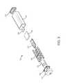
図1を参照すると、本開示の一実施形態による携帯用吸入器1が示されている。携帯用吸入器100は、薬剤送出部材110及び本体120を含む。薬剤送出部材110は、薬剤送出部材110がそれを介して薬剤を送出(例えば、本体120に貯蔵された薬剤を送出)できる排出開口部304を画定する。 With reference to FIG. 1, a portable inhaler 1 according to an embodiment of the present disclosure is shown. The
図2A-2Bを参照すると、本開示の一実施形態による携帯用吸入器100の本体120及び内部アッセンブリ130が示されている。本体120は、内部アッセンブリ130を覆うよう構成されたカバー部材122を含む。カバー部材122は、ユーザの手で把持されるように構成できる。いくつかの実施形態では、カバー部材122は、内部アッセンブリ130又は薬剤送出部材110の少なくとも1つに取り外し可能に結合されている。例えば、カバー部材122は、薬剤貯蔵部材(例えば、図3に示した薬剤貯蔵部材150)にアクセスできるよう携帯用吸入器100から取り外しできる。 With reference to FIGS. 2A-2B, the
図3を参照すると、本開示の一実施形態による携帯用吸入器100の分解組立図が示されている。いくつかの実施形態では、アダプタ装置100はプレート140を含む。プレート140は、排出開口部304の反対側で薬剤送出部材110の側部に取り付けられるよう構成できる。 With reference to FIG. 3, an exploded view of the
いくつかの実施形態では、携帯用吸入器100は薬剤貯蔵部材150を含む。薬剤貯蔵部材150は、薬剤を貯蔵する容器(例えば、ボトル)を含むことができる。薬剤貯蔵部材150は、ガラス、プラスチック、金属(例えば、ステンレス鋼)、複合材料、又は自動化又は噴霧化用の薬剤に適合した任意の他の材料製でよい。薬剤貯蔵部材150は円筒形状を備えることができる。薬剤は、アルブテロールなどの喘息薬又は噴霧器と共に使用できる任意の他の薬剤とすることができる。 In some embodiments, the
いくつかの実施形態では、携帯用吸入器100は支持構造体160を含む。支持構造体160は、携帯用吸入器100内の定位置で薬剤貯蔵部材150を支持する(例えば保持)する(例えば、薬剤送出部材110及び流量制御機構190に対して薬剤貯蔵部材150を固定する)よう構成できる。薬剤貯蔵部材150は、支持構造体160に取り外し可能に結合できる。薬剤貯蔵部材160は、支持構造体140及び/又は薬剤送出部材110に取り外し可能に結合できる。 In some embodiments, the
携帯用吸入器100は処理回路170を含むことができる。処理回路170は、プロセッサ及びメモリを含む処理回路を含むことができる。このプロセッサは、特定用途向けプロセッサ、特定用途向けIC(ASIC)、1つ以上の利用者書き込み可能ゲートアレイ(FPGA)、一群の処理要素、又は他の適切な電子処理要素として実装できる。このメモリは、本開示に記載された様々なユーザ又はクライアントプロセス、レイヤー、及びモジュールを完成し且つ促進するためのデータ及びコンピュータコードを格納する1つ以上のデバイス(例えば、RAM、ROM、フラッシュメモリ、ハードディスク記憶装置)である。メモリは、揮発性若しくは不揮発性メモリとすること又は含むことができ、本開示に記載された発明概念の様々な動作及び情報構造をサポートするデータベース構成要素、オブジェクトコード構成要素、スクリプト構成要素又は他の任意種類の情報構造を含むことができる。メモリは、プロセッサに通信可能に接続され、本明細書に記載された1つ以上のプロセスを実行するためにコンピュータコード又は命令モジュールを含む。メモリは、本明細書に記載されているシステム及び方法をプロセッサに実行させる様々な回路、ソフトウェアエンジン、及び/又はモジュールを含むことができる。 The
図3に示したように、処理回路170は回路基板を用いて実装されている。回路基板は、Bluetoothアンテナ及び/又はWiFiアンテナのような通信素子も含むことができる。携帯用吸入器100は、携帯電話のような携帯用通信機器などの電子装置との間で信号を送受信するよう構成できる。例えば、携帯用吸入器100は、その電子装置から患者投薬量情報を受信し、その電子装置に吸入又は呼気データ(例えば、肺活量測定データ)を送信できる。携帯用吸入器100は電源180を含むことができる。いくつかの実施形態では、電源180はバッテリを含む。電源180は充電式バッテリでよい。電源180は、処理回路170、流量制御機構190、及び/又はアトマイザー(例えば、図3に示したアトマイザー340)を含む携帯用吸入器100の機械的及び電気構成要素の動作を行うのに十分な電力(例えば、電圧、電流、又は他の電気波形)を出力するよう構成できる。例えば、電源180は、電源180が出力する電圧を、流量制御機構190及びアトマイザー340を動作させるために用いる-50V乃至50V(75Vなどのより高いピーク・トゥ・ピーク電圧まで昇圧できる);直流電圧;一定範囲の周波数及びデューティーサイクルを備えた周期電圧を含む電圧に変換できるドライブ素子(例えば、ドライバ)を含む又はそれに結合できる。いくつかの実施形態では、電源180は、3V以上で5V以下の電圧(例えば、複数セル構成では3.7V;3V以上で5V以下の電圧の倍数)を出力するよう構成されている。電源180は、閾値回数の使用サイクル(例えば、少なくとも10回の使用サイクル;少なくとも50回の使用サイクル)にわたって、携帯用吸入器100の機械的及び電気構成要素の動作を行うのに十分な容量を備えることができる。いくつかの実施形態では、電源180は、200 mAh以上で1000 mAh以下(例えば、500 mAh)の容量を備えている。 As shown in FIG. 3, the
携帯用吸入器100は流量制御機構190を含むことができる。流量制御機構190は、薬剤貯蔵部材150に貯蔵されている薬剤に力を印加させるよう構成されており、これが薬剤をアトマイザー(例えば、アトマイザー340)まで運び、薬剤送出部材110を介して送出されるようにする。いくつかの実施形態では、流量制御機構190は、圧力を薬剤に印加する空気流を駆動するよう構成された圧電ダイアフラムなどのマイクロブロアを含む。いくつかの実施形態では、流量制御機構190は、液体が薬剤貯蔵部材150から流量制御機構190まで(反対方向に)流れるのを防止する逆止め弁を含んでいる。 The
携帯用吸入器100は、取り外し可能な端部キャップ200を含むことができる。取り外し可能な端部キャップ200を取り外して、例えば、再充電又は取替のために電源180にアクセスし又は取り出すためカバー部材122にアクセスできる。 The
図4を参照すると、本開示の一実施形態による携帯用吸入器100によって行われる治療薬の送出及び測定動作を示す携帯用吸入器100の断面図が示されている。薬剤送出部材100は、薬剤を分配供給するためのノズルとして構成できる。薬剤送出部材110は、例えば、ユーザが薬剤送出部材110に呼気又はそれkら吸気するためのマウスピースとして構成してもよい。いくつかの実施形態では、薬剤送出部材110は送出チャンネル300を画定する。送出チャンネル300は、アトマイザー開口部309に向かって排出開口部304に垂直方向に延伸する第1流路303(例えば、図4に示したように破線で境界線を引いた)を含む。薬剤は、排出開口部304を介して薬剤送出部材110から分配供給できる。 Referring to FIG. 4, a cross-sectional view of the
薬剤送出部材110は、送出チャンネル300の少なくとも一部を画定するノズル壁305を含む。いくつかの実施形態では、ノズル壁305により画定されている送出チャンネル300の差し渡し距離は、排出開口部304から排出開口部304に対向する薬剤送出部材110の一端に向かって(例えば、アトマイザー開口部309に向かって)大きくなる。よって、送出チャンネル300の断面積が排出開口部304から離れる方向で増大し、結果として排出開口部304からアトマイザー開口部309に向かって圧力が減少する。いくつかの実施形態では、排出開口部304からアトマイザー開口部309へ向かう圧力減少によって、圧力センサ354によって検出される正確性が向上する。 The
いくつかの実施形態では、送出チャンネル300は、1つ以上の側面開口部308(例えば、通気口)まで延伸する側面チャンネル306を含む。側面開口部308は空気が送出チャンネル300に入ることを許容する一方で、空気が排出開口部304から分配供給されるが(例えば、吸入時に)、逆もまた同様である。図4の実線矢印で示したように、空気が排出開口部304を介して送出チャンネル300に入ると、その空気は、送出チャンネル300を通過して側面チャンネル306から出る。いくつかの実施形態では、側面開口部308は、空気が単に送出チャンネル300に押し込まれてそこから引き出されるようするのでなく(例えば、送出チャンネル300が排出開口部304での1つの開口部しか備えていなかった場合)、送出チャンネル300を通過できるようにすることで、携帯用吸入器100の操作性を向上させる。この空気の通過は、圧力センサ354(圧力センサ354が較正されている圧力に一致した空気の通過から得られる圧力範囲のおかげで、空気がセンサ開口部352に押し込まれ又は引き出されることに比べて、センサ開口部352を通過する空気に基づいてより正確な圧力値を与えるよう構成できる)の動作も向上させることができる。 In some embodiments, the
いくつかの実施形態では、携帯用吸入器100は、側面チャンネル306内で層流を引き起こすように構成されている。例えば、アトマイザー開口部309を形成するノズル壁305と端部壁310との間の距離d1は、側面チャンネル306内で層流を予期される動作条件(例えば、概ね華氏-50度と華氏120度との間の気温;典型的なヒトの吸入又は呼気流量に対応した流量)で発生させるよう構成できる。ノズル壁305の形状(例えば、曲がりの角度又は形状の変化)は、層流を発生させるよう構成できる。 In some embodiments, the
薬剤貯蔵部材150は、薬剤326を貯蔵するよう構成されている。薬剤326は液状とすることができる。薬剤貯蔵部材150は、流量制御機構190から力を受けるよう構成できる。例えば、流量制御機構190は、流動チャンネル322内の空気に圧力を印加して(破線矢印で示した)、この空気を駆動して薬剤326に圧力を印加させることができる。いくつかの実施形態では、流量制御機構190は、薬剤326を任意配向の(例えば、重力の方向にかかわらず)アトマイザー340へと駆動するのに十分な閾値圧力を上回る出力圧を、空気に印加するよう構成されている。 The
薬剤326は、薬剤チャンネル330を介してアトマイザー340まで流動できる(一点鎖線矢印で示したように)。薬剤326は、薬剤チャンネル330内を流動する間は、液体の状態(例えば、連続状態;薬剤が薬剤チャンネル330内で液体粒子を形成しない;薬剤が、薬剤チャンネル330の寸法と類似の大きさのサイズを備えた大型液滴を形成する)を維持することができ、又は薬剤は、第1サイズ閾値より大きい液体粒子サイズ(例えば、平均液体粒子サイズ)を備えている。いくつかの実施形態では、第1サイズ閾値は1ミリメートルより大きい。薬剤チャンネル330は、流量制御機構190によって駆動される薬剤326の流れが、所定期間内に一定投薬量の薬剤326を与えるには狭すぎる閾値直径を上回る直径を備えることができる。 The
アトマイザー340は、薬剤326から液体粒子(例えば、液体粒子の分散ミスト)を発生するよう構成されている(送出チャンネル300で小さい破線矢印で示したように)。例えば、アトマイザー340は、薬剤326から、第2サイズ閾値未満の液体粒子サイズを備えた液体粒子を発生でき、この場合、第2サイズ閾値は第1サイズ閾値以下である。いくつかの実施形態では、第2サイズ閾値は10ナノメートルより大きく、100マイクロメートルより小さい。アトマイザー340は噴霧器を含むことができる。アトマイザー340は、薬剤326の速度を排出開口部304に向けた方向で増加させるよう構成できる。いくつかの実施形態では、アトマイザー340は、薬剤326から液体粒子を発生させるよう構成された圧電素子を含む。圧電素子は、液体粒子を発生するために振動メッシュを振動させることができる。振動メッシュは、概ね1マイクロメートルから10マイクロメートル台のミクロ穴を備えることができ、振動メッシュの振動が薬剤326から液体粒子を発生させる。 The
処理回路170は流量制御機構190の動作を制御できる。いくつかの実施形態では、処理回路170は、流量制御機構190の動作を制御することで携帯用吸入器100により送出される薬剤326の投薬量を制御できる。例えば、処理回路170は、流量制御機構190の動作の持続時間を投薬量の値にマッピングした投薬量データベースを含むことができる。流量制御機構190は、所定の圧力を、処理回路170から受信した制御信号に基づいて印加するよう構成すればよい。処理回路170は、投薬量値を受信し又は求め、投薬量データベースから対応する動作持続時間を取り出し、その動作時間を示す流動信号を発生し、その流動信号を流量制御機構190まで送信して流量制御機構190に選択した期間を動作させることができる。携帯用吸入器100から分配供給される投薬量は、流量制御機構190によって印加される圧力及び流量制御機構190によって印加される圧力の持続時間の関数でよいことは理解されるはずである。処理回路170は、付加的又は代替的に、流量制御機構190によって出力される圧力を制御して、所望の投薬量が携帯用吸入器100から分配供給されるように構成してもよい。 The
処理回路170はアトマイザー340の動作を制御できる。例えば、処理回路170は、アトマイザー340を動作させる(例えば、薬剤326から液体粒子を発生させ且つ/又は薬剤の排出開口部304に向かう方向への速度を増加させる)ための制御信号をアトマイザー340に送信できる。いくつかの実施形態では、処理回路170は、流量制御機構190の動作に対応した所定時間にわたってアトマイザー340を動作させるよう構成されている。例えば、処理回路170は、流量制御機構190の動作を第1時点で開始し、アトマイザー340の動作を、第1時点に続く第1時間遅れより遅くない第2時点で開始できる。よって、処理回路170は、流量制御機構190によって薬剤326が薬剤貯蔵部材150から薬剤チャンネル330を介してアトマイザー340まで駆動される間は、アトマイザー340が動作することを保証できる。いくつかの実施形態では、第1時間遅れは、薬剤326が薬剤貯蔵部材150からアトマイザー340まで流れるのに必要な時間に対応する。処理回路170は、第2時間遅れ分だけ第1時点の後である第3時点でアトマイザー340の動作を終了できる。第2時間遅れは、所望の投薬量の薬剤326から液体粒子を発生するのにアトマイザー340が必要とする持続時間に応答する。様々な実施形態では、流量制御機構190及びアトマイザー340の動作タイミングを制御することで、処理回路170は、携帯用吸入器100に正確な薬剤投薬量を分配供給させることができる。第1時間遅れ又は第2時間遅れの少なくとも一方は:(1)流量制御機構190の出力圧;(2)薬剤貯蔵部材150からアトマイザー340までの薬剤チャンネル330内での距離;(3)アトマイザー340の噴霧化率(例えば、アトマイザー340による薬剤の分配供給の割合)のうち少なくとも1つの関数に対応できる。 The
携帯用吸入器100は圧力センサ354を含む。圧力センサ354は、センサチャンネル350内でセンサ開口部352を介して側面チャンネル306に流体結合されている。図4に示したように、センサ開口部352は、送出チャンネル300の第1流路303の外に位置できる。いくつかの実施形態では、センサ開口部352の位置は、例えば第1流路303内の空気流からのクロスフロー又は乱流効果(例えば、吸入又は呼気による)を減少させることによって、圧力センサ354により検出される圧力の正確性を向上させる。センサ開口部352は、端部壁310と同一平面に位置でき、これがよりセンサ開口部352における乱流を減少させうる。圧力センサ354は差圧センサでよい。圧力センサ354は、MEMS(微小電子機械システム)デバイスでよい。いくつかの実施形態では、圧力センサ354は、センサ開口部352における圧力を示す圧力信号(例えば、センサ開口部352における圧力に対応した電圧)を出力するよう構成されている。圧力センサ354によって検出された圧力は、送出チャンネル300内の空気流量を示すことができ、この流量は圧力に基づいて算出できる。 The
携帯用吸入器100はオーバースピルチャンネル360を含むことができる。オーバースピルチャンネル360は、アトマイザー340を薬剤貯蔵部材150に流体結合できる。いくつかの実施形態では、オーバースピルチャンネル360は、アトマイザー340に隣接して配置されたオーバースピルチャンバ362を含み、これが、アトマイザー340を介して送出チャンネル300内に分配供給されない薬剤326を受け取ることができる。オーバースピルチャンネル360は薬剤チャンネル330から分離させることができ、未使用の薬剤が、オーバースピルチャンバ362を介してオーバースピルチャンネル360に流入する前にアトマイザー340付近を流れる。いくつかの実施形態では、アトマイザー340を薬剤貯蔵部材150に流体結合することで(例えば、薬剤チャンネル330とは別個の経路に沿って)、オーバースピルチャンネル360は、薬剤326をアトマイザー340まで駆動するために流量制御機構190が印加しなければならない力を減らすことができる。例えば、薬剤326が薬剤貯蔵部材150から流出して薬剤チャンネル330を介してアトマイザー340に至る際に、アトマイザー340に隣接した薬剤チャンネル330内の空気を、オーバースピルチャンネル360を介して移動させて薬剤貯蔵部材150に戻すことができる。いくつかの実施形態では、オーバースピルチャンバ362に加え又は代替的に、携帯用吸入器100は、アトマイザー340に隣接した圧力が閾値圧力より大きいときは、アトマイザー340からオーバースピルチャンネル360を介して薬剤貯蔵部材150までの流路を開くよう構成された逆止め弁を含むことができる。 The
いくつかの実施形態では、流量制御機構190は、薬剤貯蔵部材150に取り付けられたプランジャを含む。処理回路170は、プランジャを薬剤貯蔵部材150内で駆動させて薬剤326を薬剤貯蔵部材150の外へ出すよう構成されたプランジャアクチュエータ(例えば、リニアアクチュエーター)の動作を制御できる。処理回路170は、このプランジャが駆動された距離に基づいて薬剤326の投薬量を制御するよう構成できる。 In some embodiments, the
いくつかの実施形態では、処理回路170は圧力信号に基づいて圧力を算出できる。例えば、処理回路170は、電圧値を圧力値にマッピングした(例えば、圧力センサ354の所定の較正に基づいて)ルックアップデーブルを含み、圧力信号の電圧に対応した圧力値を取り出すためにルックアップ検索を行うことができる。いくつかの実施形態では、処理回路170は、電圧を圧力値に変換するために較正関数(例えば、電圧を圧力に変換する関数)を実行するよう構成されている。 In some embodiments, the
処理回路170は、算出した圧力に基づいて送出チャンネル300における空気流の流量(例えば、毎分のリットル数など単位時間の空気量)を算出できる。例えば、処理回路170は、圧力を流量に関連付ける(例えば、携帯用吸入器100の較正に基づいて)ルックアップデーブル又はアルゴリズムを格納してもよく、算出した圧力に基づいてルックアップデーブルから流量を取り出すか又は所定の圧力を用いてアルゴリズムを実行することの少なくとも一方によって流量を求めるよう構成できる。いくつかの実施形態では、処理回路170は圧力信号に基づいて流量を算出できる(例えば、電圧などの圧力信号パラメータを流量に関連付けるルックアップデーブル又はアルゴリズムを用いて)。例えば、流量を圧力信号に基づいて直接求めると、処理回路170を動作させるのに必要な計算資源を減少させることができるので、処理回路170のサイズ又はそれにより用いられる電力の少なくとも1つを減少させることができる。検出圧力を流量に変換するのに使用される較正関数は、圧力を流量に関連付けられた1つ以上の中間変数(例えば、速度)に関連付けることができ、処理回路170は、中間変数を取り出し且つ送出チャンネル300の寸法などの携帯用吸入器100の既知のパラメータに基づいて流量を計算するよう構成してもよいことは理解されるはずである。 The
いくつかの実施形態では、処理回路170は、圧力信号に基づいて吸入(又は呼気)の持続時間を算出できる。たとえば、処理回路170は、複数の時系列圧力信号(又は電圧値又は流量値)を受信し、これら複数の圧力信号それぞれを圧力閾値と比較し、1つ以上の圧力信号が圧力閾値より大きい期間に基づいて持続期間を求める。 In some embodiments, the
いくつかの実施形態では、処理回路170は、携帯用吸入器のユーザの呼吸の特性を特定するためなどに、肺活量測定アルゴリズムを実行するよう構成されている。例えば、処理回路170は、複数の圧力信号を用いて、ユーザによる吸入又は呼気の少なくとも一方に対応する空気流の量を計算できる。いくつかの実施形態では、処理回路170は、複数の空気流サイクル(例えば、呼気サイクルと吸気サイクルとの組合せ)を圧力信号に基づいて検出し、ユーザの肺を通る空気流の量、並びに/又はユーザの吸気及び/若しくは呼気の割合(例えば、流速)などの肺活量測定パラメータを計算するよう構成されている。処理回路170は、1回以上の空気流サイクルにおける平均値などの肺活量測定パラメータを計算できる。いくつかの実施形態では、処理回路170は、例えば、履歴及び/又は所定の肺活量測定パラメータを瞬間パラメータ値と比較することで、肺活量測定パラメータを求める自動較正アルゴリズムを実行するよう構成されている。 In some embodiments, the
いくつかの実施形態では、処理回路170は呼吸案内指標を出力するよう構成されている。この呼吸案内指標は、呼吸/肺活量測定特性を検出するために使用できる呼吸運動(例えば、吸入及び/又は呼気)をユーザに指示するよう構成できる。携帯用吸入器100又は遠隔携帯用電子装置は、出力装置(例えば、表示装置、音声出力装置、触覚フィードバック装置、触感フィードバック装置)を含んでもよく、処理回路170は、出力装置に呼吸案内指標を出力させるための制御信号を出力装置に送信できる。いくつかの実施形態では、処理回路170は、呼吸案内指標の出力に応答して圧力センサ354からの圧力データの格納及び/又は分析を開始できる。いくつかの実施形態では、処理回路170は、圧力データの検出と、呼吸運動が圧力データに基づいて適切に行われているかどうかとの判断に基づいて、修正した呼吸案内指標をリアルタイムで出力できる。処理回路170は、呼吸運動における複数ステップを行うための指示を示す複数の呼吸案内指標を出力できる。代表的な例では、処理回路170は第1制御信号を送信して、ユーザに携帯用吸入器100から吸入させる指示を示す第1色を表示装置(例えば、LED照明又は表示器)に出力させることができ;第1の所定期間の経過後(例えば、第1制御信号の出力に応答して開始されるタイマーの終了に基づいて)、携帯用吸入器100内へユーザに呼気させる指示を示す第2色を表示装置に出力させる第2制御信号を送信し、第2の所定期間の経過後、ユーザに呼気を中断させる指示を示す色を表示装置に出力させる第3制御信号を送信できる。 In some embodiments, the
処理回路170は、流量制御機構190又はアトマイザー340の少なくとも一方の動作をトリガ入力に基づいて制御できる。いくつかの実施形態では、処理回路170は、薬剤送出部材110を介した吸入を検出することによってトリガ入力を受信する。例えば、処理回路170は、圧力センサ354から受信された圧力信号を定期的に監視し、圧力信号の圧力値をトリガ閾値と比較できる。トリガ閾値は、典型的な又は予期されるユーザの吸入に関連付けられた最小圧力に対応する圧力値に較正できる。圧力値がトリガ閾値より大きいという判断に応答して、処理回路170は、流量制御機構190及び/又はアトマイザー340の動作を開始して、任意の投薬量の薬剤326(ユーザに合わせたものでよい)を送出できる。 The
いくつかの実施形態では、処理回路170はユーザ入力装置からトリガ信号を受信する。例えば、携帯用吸入器100は、作動されると、作動されたことに応答してユーザ入力信号を送信するよう構成されたボタン、スイッチ、又は他のユーザ入力を含むことができる。いくつかの実施形態では、処理回路170は遠隔装置(例えば、携帯用電子装置)からトリガ信号を受信する。例えば、処理回路170は、携帯用電子装置(トリガ信号に対応するユーザ入力を受け取るためのユーザインターフェースを提供するアプリケーションを実行できる)からトリガ信号をワイヤレス通信として受信できる。 In some embodiments, the
処理回路170は、ユーザデータベースに格納されたユーザデータに基づいて携帯用吸入器100によって送出される薬剤326の投薬量を算出できる。ユーザインターフェースは1人以上のユーザを投薬量にマッピングできる。処理回路170は、所定の又は識別されたユーザに基づいてユーザデータベースから投薬量を取り出すことができる。例えば、携帯用吸入器100は特定のユーザに関連付けることができる。 The
いくつかの実施形態では、処理回路170は、圧力センサ354によって検出される圧力データに基づいて携帯用吸入器100によって送出される薬剤326の投薬量を算出できる。例えば、処理回路170は圧力データを用いて、ユーザの呼吸の特性(フローボリューム又は流量などの吸入及び/又は呼気特性)を算出し、算出した特性に基づいてユーザの状態を判断できる。処理回路170は、呼吸特性を1つ以上の状態にマッピングする状態データベースを含み、算出した特性に基づいて状態データベースから状態を取り出すことができる。付加的に又は代替的に、処理回路170は、ユーザの状態を呼吸の算出された特性に基づいて判断するための状態関数を実行するよう構成できる。いくつかの実施形態では、こうして取り出された又は算出された状態は投薬量を示すことができ、又は、処理回路170が、算出された状態に基づいて投薬量を決定する(又は状態を投薬量にマッピングする投薬量データベースから投薬量を取得する)ための投薬量関数を実行できる。処理回路170は、圧力データ(又は呼吸/肺活量測定特性などの圧力データを用いて計算される他のパラメータ)に基づいてユーザデータベースのユーザデータを更新して、携帯用吸入器100にユーザサイクルでの投薬量送出を更新できる。 In some embodiments, the
コンピュータ処理動作は、携帯用吸入器100の処理回路170によって実行されるように本明細書では記載されているが、様々な動作が携帯用電子装置の処理回路などの遠隔処理装置で実行できることは理解されるであろう。例えば、携帯用吸入器100は、投薬量値のルックアップデーブルを格納でき、これは携帯用電子装置からの更新データ信号の受信に応答して更新すればよい。携帯用吸入器100は、生データ(例えば、圧力センサ354からの出力)を携帯用電子装置に送信するよう構成できる一方で、携帯用電子装置は、投薬量レベル、呼吸/肺活量測定特性、又は計算を必要とする他の値を計算する。よって、処理回路170のサイズ及び/又はその動作に必要な計算資源を減らすことができ、これによって携帯用吸入器100のサイズ、重量、及び/又は複雑さを減少できる。 Although computer processing operations are described herein as being performed by the
図5A-5Cを参照すると、本開示の一実施形態による薬剤貯蔵部材150の支持構造体400が示されている。支持構造体400は、プレート140及び排出プレート405を含む。プレート140は、アトマイザー340を支持するよう構成されている。排出プレート405は、薬剤チャンネル330(図3を参照のこと)を通って流れる薬剤貯蔵部材150からの薬剤326を受け取るよう構成された薬剤チャンネル開口部410を形成できる。薬剤貯蔵部材150は、流量制御機構190から空気圧を受けるよう構成された空気流入力開口部415を形成できる。プレート140及び排出プレート405は、薬剤貯蔵部材150により画定された平面p1(例えば、空気流入力開口部415の反対側で薬剤貯蔵部材150の側部に接する)を超えて延伸でき、これにより薬剤チャンネル330は、薬剤貯蔵部材150に隣接した空間を介してアトマイザー340まで延伸できる。いくつかの実施形態では、支持構造体400は、支持構造体160に取り外し可能に結合されるよう構成されており、これによって新たな薬剤を薬剤貯蔵部材150に容易に付加できるようになる。 With reference to FIGS. 5A-5C, the
図6を参照すると、本開示の一実施形態による携帯用吸入器600が示されている。携帯用吸入器600は携帯用吸入器100の特徴を組み込むことができ、携帯用吸入器600を参照して記載する様々な機能は、携帯用吸入器100により実行でき、その反対も同様である。携帯用吸入器600は、薬剤送出部材604及び薬剤送出部材604結合される本体608を含む。薬剤送出部材604は、薬剤送出部材604がそれを介して薬剤を送出(例えば、本体608に貯蔵された薬剤を送出)できる排出開口部612を画定する。薬剤送出部材604はマウスピースでよい。 With reference to FIG. 6, a portable inhaler 600 according to an embodiment of the present disclosure is shown. The portable inhaler 600 can incorporate the features of the
携帯用吸入器600は、比較的小さいフォームファクターを備えることができ、携帯性及び操作性を促進する。例えば、携帯用吸入器600には、概ね127 mm (例えば、127 mm;90 mm以上で150 mm以下;110 mm以上で140 mm以下;120 mm 以上で135 mm以下)の高さh1と、概ね45 mm (例えば、20 mm以上で70 mm以下;30 mm以上で60 mm以下;40 mm 以上で50 mm以下)の長さl1と、概ね30 mm (例えば、10 mm以上で50 mm以下;20 mm 以上で40 mm以下;25 mm 以上で35 mm以下)の幅w1を画定できる。 The portable inhaler 600 can be provided with a relatively small form factor, facilitating portability and maneuverability. For example, the portable inhaler 600 has a height h1 of approximately 127 mm (for example, 127 mm; 90 mm or more and 150 mm or less; 110 mm or more and 140 mm or less; 120 mm or more and 135 mm or less). Length l1 of 45 mm (for example, 20 mm or more and 70 mm or less; 30 mm or more and 60 mm or less; 40 mm or more and 50 mm or less) and approximately 30 mm (for example, 10 mm or more and 50 mm or less; 20) A width w1 of 40 mm or less when mm or more and 35 mm or less when 25 mm or more can be defined.
図7を参照すると、本開示の一実施形態による携帯用吸入器600の分解組立図が示されている。携帯用吸入器600は、端部キャップ708を結合できる本体608のカバー704を含む。携帯用吸入器600は処理回路712を含む。処理回路712は処理回路170に似たものでよい。処理回路712は、ドライバ716を含む又はそれと結合させることができる。ドライバ716は、アトマイザー760の動作を(例えば、図8を参照してさらに記載する流量制御機構812の動作を制御することによって)制御する。携帯用吸入器600は電源720を含み、処理回路712はこれを用いてアトマイザー760の動作を制御できる。例えば、ドライバ716は、DC 3V電圧を電源720から受けて、それを流量制御機構812又はアトマイザー760の使用に適した範囲(例えば、-50Vから50V)まで上げることができる。 Referring to FIG. 7, an exploded view of the portable inhaler 600 according to an embodiment of the present disclosure is shown. The portable inhaler 600 includes a
携帯用吸入器600は、薬剤カートリッジ752を支持する支持構造体724を含む。支持構造体724は、圧力センサ732に結合された第1ベース728を含むことができる。第1チューブ736(例えば、チャンネル)は、流量制御機構812を薬剤カートリッジ752に接続することができる。第2チューブ740(例えば、チャンネル)は、圧力センサ732を薬剤送出部材604に接続することができる。第3チューブ744(例えば、チャンネル)は、薬剤カートリッジ752をアトマイザー760に接続する。チューブ736、740、及び744は、対応する構成要素に結合するような形状を備えることができる一方で、携帯用吸入器600の小さいフォームファクターを可能としている。 The portable inhaler 600 includes a
支持構造体724は、薬剤カートリッジ752と第1ベース728との間で薬剤カートリッジ752に隣接可能な第2ベース748を含むことができる。カートリッジカバー756は、例えば薬剤カートリッジ752の蓋として機能させるため、第2ベース748から薬剤カートリッジ752の反対側で薬剤カートリッジ752に隣接させることができる。いくつかの実施形態では、携帯用吸入器600は、カートリッジカバー756と結合して薬剤カートリッジ752を封止できるキャップ780を含む。 The
携帯用吸入器600はアトマイザー760を含む。アトマイザー760は、薬剤カートリッジ752から薬剤送出部材604内部への薬剤の流れを制御できる。いくつかの実施形態では、アトマイザー760は、圧電ディスクなどの圧電素子764及びメッシュ768を含む。アトマイザー760は磁石772を含むことができる。 The portable inhaler 600 includes an
携帯用吸入器600は第3ベース776を含むことができる。第3ベース776は、アトマイザー760を薬剤送出部材604に接続して、アトマイザー760から出力される薬剤を薬剤送出部材604に流入させることができる。第3ベース776は、薬剤送出部材604を圧力センサ732に第2チューブ740を介して接続できる。 The portable inhaler 600 can include a
いくつかの実施形態では、携帯用吸入器600はユーザインターフェース要素784を含む。ユーザインターフェース要素784は、ユーザ入力装置(例えば、ボタン、スイッチ)又は照明(例えば、LED照明)の少なくとも一方を含むことができる。ユーザインターフェース要素784は、例えば命令を受信して携帯用吸入器600を起動するため、ボタン押圧などのユーザ入力を受け取り、そのユーザ入力を処理回路712に送信できる。 In some embodiments, the portable inhaler 600 comprises a
図8を参照すると、本開示の一実施形態による携帯用吸入器600の断面図が示されている。図8に示したように、薬剤送出部材604は通気口804を形成する。ユーザが薬剤送出部材604に息を吹き込んだときなどに、通気口804は、空気を薬剤送出部材604を通過させて通気口804から排気させることができる。 Referring to FIG. 8, a cross-sectional view of the portable inhaler 600 according to an embodiment of the present disclosure is shown. As shown in FIG. 8, the
第3ベース776はセンサ開口部808を形成できる。センサ開口部808は、薬剤送出部材604を第2チューブ740及び圧力センサ732に流体結合できる。例えば、ユーザが薬剤送出部材604に息を吹き込む際などの、薬剤送出部材604内の空気圧の変化は、第2チューブ740内の空気圧の対応する変化に基づいて圧力センサ732によって検出できる。 The
携帯用吸入器600は、マイクロブロアのような流量制御機構812を含むことができる。流量制御機構812はドライバ716によって制御できる。流量制御機構812は、第1チューブ736内の空気に圧力を印加して、この空気を駆動して圧力を薬剤カートリッジ752内の薬剤に印加させることで、薬剤が薬剤カートリッジ752から押し出され第3チューブ74に入り、次にアトマイザー760に流入される。ドライバ716は、薬剤送出部材604を介して出力するため、アトマイザー760に薬剤をミスト912に変容させることができる。 The portable inhaler 600 can include a
ここで図9を参照すると、携帯用吸入器600の断面図が示されており、ここでは本開示の一実施形態による携帯用吸入器600が薬剤送出モード900で動作している。薬剤送出モード900では、処理回路712は、流量制御機構812に空気を駆動させて薬剤カートリッジ752内に流動させる。薬剤カートリッジ752内の薬剤908に対して空気804によって印加される得られた圧力によって、薬剤908が、第3チューブ744を通過してアトマイザー760まで流動する。 Here, referring to FIG. 9, a cross-sectional view of the portable inhaler 600 is shown, in which the portable inhaler 600 according to one embodiment of the present disclosure is operating in
ここで図10を参照すると、携帯用吸入器600の断面図が示されており、ここでは本開示の一実施形態による携帯用吸入器600が測定モード1000で動作している。例えば、ユーザから受け取った(例えば、ユーザによって排出開口部612に吹き込まれた)空気1004は、薬剤送出部材604を通過し、センサ開口部808を介して第2チューブ740に流入して圧力センサ732に達するので、圧力センサ732がユーザから受け取った空気804に関する圧力データを検出可能となる。空気1004の一部は、通気口804を介して薬剤送出部材604から出ることができる。 Here, referring to FIG. 10, a cross-sectional view of the portable inhaler 600 is shown, in which the portable inhaler 600 according to one embodiment of the present disclosure is operating in
ここで図11を参照すると、本開示の一実施形態による薬剤送出部材604の詳細図が示されている。薬剤送出部材604は、排出開口部612と第3ベース776との間で延伸するディフューザー1104を含む。ディフューザー1104は、排出開口部612と、通気口804と、センサ開口部808と、アトマイザー760との間の流体連通を実現できる。ディフューザー1104は、排出開口部612から通気口804まで延伸するディフューザー表面1104を含むことができる。ディフューザー表面1104は、排出開口部612から通気口804に向かうにしたがって直径及び/又は断面積が増大できる。例えば、ディフューザー表面1104は、排出開口部612から通気口804(さらにセンサ開口部808とアトマイザー760)に向かうにしたがって直径が増大する円錐形表面でよく、これによって、排出開口部612から通気口804に向かってディフューザー1104内の圧力を低下させるこができる。 Here, with reference to FIG. 11, a detailed view of the
図7をさらに参照すると、パルス薬用量噴霧を実行するには、処理回路712を用いて携帯用吸入器600の構成要素の動作を制御すればよい。例えば、処理回路712によって、ユーザが吸入を行っている間に、一定投与量の薬剤を送出できるので、1回の処置に必要な投薬量を少なくできる。例えば、典型的な噴霧用アルブテロールアンプルは2.5 mg/mLである。しかし、本解決策は、1回の処置で概ね0.2 mgの薬用量を出力するパルス薬用量噴霧を行って、薬剤カートリッジ604及びその内部の薬剤の寿命を延ばすことができる。例えば、吸入時のみに薬剤を送出するなど、吸入の検出に応答して薬剤が送出されるようにすることで、処理回路712を用いてパルス薬用量噴霧を行うことができ、薬剤カートリッジ604が多数回の薬用量(例えば、5回分の薬用量)を保持可能とし、そのため、各処置の後に薬剤カートリッジ604を取り替える必要性を緩和できる。いくつかの実施形態では、薬剤カートリッジ604は、アルブテロール及び臭化イプラトロピウム(例えば、DUONEB)の治療薬などの慢性閉塞性肺疾患(COPD)の治療薬を蓄えている。COPDの悪化はしばしば入院に至るが、パルス薬用量噴霧を用いることで、処理回路712は、ユーザに送出の必要がある薬剤量を減少させ、COPDが悪化した際に、ユーザが十分な薬剤を使用できない可能性を低下させる。 Further referring to FIG. 7, to perform pulsed dose spraying,
図12を参照すると、処理回路712は、圧力センサ732から受信した圧力データを用いて肺活量測定を行うことができる。例えば、処理回路712は、受信した圧力データを、例えば上述の較正関数に基づいて体積データ(例えば、流量)に変換できる。処理回路712は、時間の関数として、体積などの測定値1204を計算できる。測定値1204に基づいて、処理回路712は、1秒(FEV1) 1208で最大努力呼気肺活量(FEV)などのパラメータを計算できる。FEV1は、処理回路712が携帯用吸入器600に吹き込まれている空気を圧力データに基づいて検出した第1時点から、第1時点の1秒後までに携帯用吸入器600に吹き込まれた体積を表す。処理回路712は、努力性肺活量(FVC) 1212を、携帯用吸入器600に吹き込まれた総空気量(例えば、第1時点から開始される)として計算できる。処理回路712はFEV1とFVCの比を計算できる。例えば、処理回路712は、FEV1データを用いてユーザの呼吸をより正確に監視でき(例えば、ユーザの努力に依存しうるピーク流量と比較して)、FEV1データを被験者の健康に関する他のパラメータと相関させ、FEV1を被験者の健康の予測量として使用できるようにする相関関係を与えることができる。 Referring to FIG. 12, the
処理回路712は体積データを用いて、流量(例えば、L/s)を体積(例えば、L)の関数として示す流量ループ1216を生成することができる。例えば、処理回路712は、ユーザの呼気1220と吸気1224を識別できる。処理回路712は、最大呼気流量(PEF)、最大中間呼気流量(MEF)、努力性呼気流量(FEF)などのパラメータを様々な主要管理点で計算でき(例えば、総呼気体積の25%を示すFEF25%;総呼気体積の50%を示すFEF50%;総呼気体積の75%を示すFEF75%)、且つ努力性吸気流量を主要管理点で計算できる(例えば、総吸気体積の25%を示すFEF25%;総吸気体積の50%を示すFEF50%;総吸気体積の75%を示すFEF75%)。処理回路712は、例えば肺活量測定データに関する縦モード解析を可能とするため、ユーザのこの情報をデータベースに維持できる。The
処理回路712は、肺活量測定データを様々な他の変数と比較するチャート1228を生成できる。例えば、処理回路712は、ピーク流量1232を空気質指数(AQI)パラメータ1236と比較するチャート1228を生成できる。処理回路712は、AQIパラメータ1236データを遠隔源から(例えば、処理回路710を参照して説明する通信電子機器を介して)受信できる。処理回路712は、汚染、気温、湿度、花粉指数、及び位置などのパラメータに関するパラメータデータを受信し、相関関係を実行してこうしたパラメータと肺活量測定データとの関係を算出できる。 The
図13を参照すると、本開示の一実施形態による被験者監視システム1300が示されている。被験者監視システム1300は、携帯用吸入器1304(例えば、携帯用吸入器100、携帯用吸入器600)及び遠隔電子装置1308を含むことができる。遠隔電子装置1308は、携帯用電子装置又は携帯用吸入器1304と通信するサーバでよい(携帯用吸入器1304と遠隔電子装置1308との間の中間手段としての携帯用電子装置の使用を含むことができる)。遠隔電子装置1308は、処理回路1312、ユーザインターフェース1316、及び通信回路1320を含むことができる。処理回路1312は、処理回路170及び712に似たものでよく、それらを参照して説明した例えば、圧力データに基づいて体積データを計算し、その体積データを汚染、温度、湿度、花粉指数、及び位置などのパラメータ(例えば、インターネットなどの遠隔データソース1324を介して通信回路1320によって受信された)と比較するなどの機能を行うことができる。ユーザインターフェース1316は、ユーザ入力を受け取り、被験者監視システム1300の動作に関する情報を提示できる。ユーザインターフェース1300は、ボタン、ダイヤル、スライダー、キー、などのユーザから入力を受け取る1つ以上のユーザ入力装置を含むことができる。ユーザインターフェース1300は、1つ以上の表示装置(例えば、OLED、LED、LCD、CRT 表示装置)、スピーカー、触覚フィードバック装置、又は情報をユーザに与える他の出力装置を含むことができる。通信回路1320は、様々なシステム、デバイス、又はネットワークとデータ通信を行うための有線又は無線インターフェース(例えば、ジャック、アンテナ、送信機、受信機、トランシーバ、ワイヤ端子など)を含むことができる。例えば、通信回路1320は、イーサネットに基づいた通信ネットワークを介してデータを送受信するためのイーサネットカード及びポートを含むことができる。通信回路1320は、ワイヤレス通信ネットワークを介して通信するためのWiFiトランシーバを含むことができる。通信回路1320は、企業内情報通信網(例えば、棟内LAN)、広域通信網(例えば、インターネット、セルラーネットワーク)を介して通信でき、且つ/又は直接通信を行うこともできる(例えば、NFC、Bluetooth)。いくつかの実施形態では、通信回路1320は有線及び/又は無線通信を行うことができる。例えば、通信回路1320は、1つ以上の無線トランシーバ(例えば、Wi-Fiトランシーバ、Bluetoothトランシーバ、NFCトランシーバ、セルラートランシーバ)を含むことができる。いくつかの実施形態では、遠隔電子装置1308は、位置センサ1332(例えば、GPSセンサ、加速度計)を含み、これが位置データを処理回路1312に送信でき、処理回路1312がこの位置データを携帯用吸入器1304から受信したデータと相互に関連させられる。 Referring to FIG. 13, a
処理回路1312はユーザデータベース1328を維持できる。ユーザデータベース1328は、処理回路712が実行する計算を参照して説明したように、吸気及び呼気データなどの携帯用吸入器1304によって取り込まれたデータを含むことができる。ユーザデータベース1328はユーザの投薬量情報を格納できる。ユーザデータベース1328は、位置センサ1332から受信した位置データを格納でき、処理回路1312は、その位置データを他のデータに(例えば、当該他のデータが検出された時間に基づいて)マッピングできる。 The
遠隔電子装置1308は、ユーザインターフェース1316を介して提示するための様々な出力を生成できる。例えば、図14A及び14Bを参照すると、遠隔電子装置1308は、名前、年齢、及び性別などのユーザデータと、天気データ及び大気質データなどの環境データを含む遠隔ソースデータとを含むことができる第1インターフェース1404提示できる。遠隔電子装置1308は、ピーク流量チャート1412などの肺活量測定データを含むことができる第2インターフェース1408を提示できる。遠隔電子装置1308は、携帯用吸入器1304から受信した情報及び/又はユーザデータベース1328内に維持されている情報に基づいてピーク流量チャート1412を生成できる。遠隔電子装置1308は、図12を参照して説明したチャート1228などの肺活量測定データを含むことができる第3インターフェース1416を提示できる。遠隔電子装置1308は、特定位置における空気の質1428の指示などの位置に基づくデータを含むことができる第4インターフェース1420を提示できる。図14に示したように、処理回路1312は、空気の質に基づいて推奨投薬量を計算し、その推奨投薬量に関する推奨1432を含むように第4インターフェース1420を生成できる。処理回路1312は、例えば第3インターフェース1416を生成するために、肺活量測定データと環境データとの間の関係を特定できる。 The remote
図15を参照すると、本開示の一実施形態による携帯用吸入器を動作させる方法1500が示されている。方法1500は、図1-5Cを参照して説明した携帯用吸入器100及び/又は図6-14を参照して説明した携帯用吸入器600によって実行できる。方法1500の一部として実行される計算プロセスは遠隔装置(例えば、携帯用電子装置、遠隔サーバ)によって実行すればよい。 Referring to FIG. 15, a
1505において、トリガ信号が受信される(又は発生される)。このトリガ信号は、携帯用電子装置の薬剤送出部材で行われる吸入を示す圧力信号に基づいて受け取ることができる。例えば、この圧力信号によって示された圧力値を吸入に関連付けられたトリガ閾値と比較でき、圧力値がトリガ閾値より大きい場合は、トリガ信号が受信される(又は生成される)ようにできる。いくつかの実施形態では、トリガ信号はユーザ入力に基づいて受け取られる。いくつかの実施形態では、トリガ信号は、遠隔装置からの制御信号として受け取られる。 At 1505, a trigger signal is received (or generated). This trigger signal can be received based on a pressure signal indicating inhalation performed by the drug delivery member of the portable electronic device. For example, the pressure value indicated by this pressure signal can be compared to the trigger threshold associated with inhalation, and if the pressure value is greater than the trigger threshold, the trigger signal can be received (or generated). In some embodiments, the trigger signal is received based on user input. In some embodiments, the trigger signal is received as a control signal from the remote device.
1510において、薬剤の投薬量が求められる。投薬量は、ユーザデータベース内のルックアップテーブルから投薬量を取り出すことによって求めてもよい。投薬量は、圧力データに基づいて求められたユーザの呼吸/肺活量測定特性に基づいて求めてもよい。いくつかの実施形態では、ユーザデータベースは最大投薬量を含むが、圧力データが最大投薬量を上回る投薬量にマッピングする場合はその限りではない。 At 1510, the dosage of the drug is sought. The dosage may be determined by retrieving the dosage from a look-up table in the user database. Dosing may be determined based on the user's respiratory / vital capacity measurement characteristics determined based on pressure data. In some embodiments, the user database includes the maximum dosage, unless the pressure data maps to a dosage above the maximum dosage.
1515において、携帯用吸入器の流量制御機構は、求めた投薬量に基づいて作動される。流量制御機構は、投薬量に対応した第1持続時間にわたって作動させることができる。持続時間は、流量制御機構によって薬剤に印加される圧力に、又は流量制御機構から携帯用吸入器の薬剤貯蔵部材内に流入する空気流量に対応させればよい。 At 1515, the flow control mechanism of the portable inhaler is activated based on the determined dosage. The flow control mechanism can be operated for a first duration corresponding to the dosage. The duration may correspond to the pressure applied to the drug by the flow control mechanism or to the flow rate of air flowing from the flow control mechanism into the drug storage member of the portable inhaler.
1520において、携帯用吸入器のアトマイザーが投薬量に基づいて作動される。アトマイザーの作動は、薬剤から液体粒子を発生させる段階及び/又は薬剤の速度を携帯用吸入器の排出開口部に向かって増加させる段階を含むことができる。アトマイザーは、投薬量に対応した第2持続時間にわたり作動させることができる。第2持続時間は、この薬剤投薬量の液体粒子を発生し且つ/又はアトマイザーを介して排出開口部まで分配供給するのに十分な時間に対応させればよい。アトマイザーは、流量制御機構の作動に続き第1時間遅れの後に第2持続時間が経過するまで作動できる。第1時間遅れは、この投薬量の薬剤が薬剤貯蔵部材からアトマイザーまで流動するのに必要な時間に対応できる。アトマイザーの作動が、薬剤を患者まで排出開口部を介して送出できる。 At 1520, the atomizer of the portable inhaler is activated based on the dosage. The operation of the atomizer can include the step of generating liquid particles from the drug and / or the step of increasing the rate of the drug towards the discharge opening of the portable inhaler. The atomizer can be operated for a second duration corresponding to the dosage. The second duration may correspond to a time sufficient to generate and / or distribute the liquid particles of this drug dosage to the discharge opening via the atomizer. The atomizer can operate until the second duration elapses after the first time delay following the operation of the flow control mechanism. The first hour delay can accommodate the time required for this dosage of drug to flow from the drug storage member to the atomizer. The actuation of the atomizer can deliver the drug to the patient through the drainage opening.
いくつかの実施形態では、携帯用吸入器は、処置の前、最中、及び/又は後に気道測定データを収集且つ/又は追跡するよう構成されている。いくつかの実施形態では、携帯用吸入器は、処置の前、最中、及び後に気道測定データを受信するよう構成されたBluetoothなどの短通信モジュールを含むことができる。 In some embodiments, the portable inhaler is configured to collect and / or track airway measurement data before, during, and / or after treatment. In some embodiments, the portable inhaler can include a short communication module such as Bluetooth configured to receive airway measurement data before, during, and after the procedure.
いくつかの実施形態では、携帯用吸入器は、血中酸素濃度を収集するために組込式パルス酸素計を含めることができる。ユーザが携帯用吸入器を保持している間に組込式パルス酸素計が血中酸素濃度を求めることができるように、組込式パルス酸素計は携帯用吸入器において寸法決め且つ構成されている。携帯用吸入器は、血中酸素濃度と共に通気路測定データを収集して、気道の状態と血中酸素濃度との相関関係を求めるよう構成できる。いくつかの実施形態では、携帯用吸入器は、終日にわたり測定値を受信又は取得するよう構成でき、これら測定値は、地理的位置(都市と田舎)、アレルギーマップ、空気の質、花粉の数、及び天気のようなその時点における他の特定の変数に結び付けられる。いくつかの実施形態では、携帯用吸入器は、この携帯用吸入器の現在地を特定するためGPSのような位置センサを含むことができる。位置センサから得られた位置を用いて、その位置に関する特定の変数の値を求めることができる。経時的なこのデータを格納することによって個人の喘息の状態に貴重な予測的先見性がもたらされることになる(例えば、花粉数が一定レベルを超えている又は湿度が特定のパーセンテージを超えているときに喘息が悪化するなど)。このデータは、特定の知的所有権下にあるアルゴリズム及び計算を用いて評価できる。この情報は、知識に基づく健康管理の決定を医療供給者が下せるようにする実用的な情報を提供できる。 In some embodiments, the portable inhaler can include an embedded pulsed oximeter to collect blood oxygen levels. The embedded pulsed inhaler is sized and configured in the portable inhaler so that the embedded pulsed oxygen meter can determine the blood oxygen concentration while the user holds the portable inhaler. There is. A portable inhaler can be configured to collect airway measurement data along with blood oxygen levels to determine the correlation between airway status and blood oxygen levels. In some embodiments, the portable inhaler can be configured to receive or obtain measurements throughout the day, which are geographical location (city and countryside), allergy map, air quality, pollen count. , And other specific variables at the time, such as weather. In some embodiments, the portable inhaler can include a position sensor such as GPS to locate the current location of the portable inhaler. The position obtained from the position sensor can be used to determine the value of a particular variable for that position. Storing this data over time will provide valuable predictive foresight to an individual's asthma status (eg, pollen counts above a certain level or humidity above a certain percentage). Sometimes asthma gets worse). This data can be evaluated using algorithms and calculations under certain intellectual property rights. This information can provide practical information that allows healthcare providers to make informed health care decisions.
いくつかの実施形態では、この携帯用吸入器は、薬剤を貯蔵する取り外し可能なカートリッジを含むことができる。携帯用吸入器は、取り外し可能なカートリッジが携帯用吸入器及び圧電装置内に挿入される箇所に近位の場所からの流体経路を含むことができる。カートリッジを使用することで、噴霧手順を開始するのが容易で労力も少なくなるため、使用の障壁が少なく、処方された薬剤をより正確に摂取できる。カートリッジハウジングは、その取り付け及び取り外し時に接触触覚フィードバックを与え、その動作をさらに単純化できる。 In some embodiments, the portable inhaler may include a removable cartridge for storing the drug. The portable inhaler can include a fluid path from a location proximal to where the removable cartridge is inserted into the portable inhaler and piezoelectric device. The use of cartridges makes it easier and less labor intensive to initiate the spraying procedure, thus reducing the barriers to use and allowing the prescribed drug to be taken more accurately. The cartridge housing can provide tactile feedback during its installation and removal, further simplifying its operation.
Claims (20)
Translated fromJapanese排出口及び少なくとも1つの通気口に結合された送出チャンネルを形成するノズルと;
前記送出チャンネルに隣接したアトマイザーであって、薬剤を受け取り且つ当該薬剤から液体粒子を発生し、当該発生された液体粒子を前記ノズルの前記排出口から出力するよう構成されたアトマイザーと;
前記薬剤を貯蔵するよう構成された薬剤カートリッジであって、前記アトマイザーに薬剤チャンネルを介して結合された薬剤カートリッジと;
前記薬剤を前記薬剤カートリッジから前記アトマイザーまで駆動するため、前記薬剤カートリッジ内の前記薬剤に力を印加するよう構成された流量制御機構と;
前記流量制御機構の動作を、トリガ条件が満足されたことに応答して制御するよう構成された処理回路とを含む、携帯用吸入器。A portable inhaler:
With a nozzle forming an outlet and a delivery channel coupled to at least one vent;
With an atomizer adjacent to the transmission channel, which is configured to receive a drug, generate liquid particles from the drug, and output the generated liquid particles from the outlet of the nozzle;
With a drug cartridge configured to store the drug and coupled to the atomizer via a drug channel;
With a flow control mechanism configured to apply a force to the drug in the drug cartridge to drive the drug from the drug cartridge to the atomizer;
A portable inhaler comprising a processing circuit configured to control the operation of the flow control mechanism in response to satisfaction of a trigger condition.
前記携帯用吸入器は前記センサ開口部に結合された圧力センサを含み、当該圧力センサは前記送出チャンネルに関連付けられた圧力を検出し、当該検出圧力を前記処理回路に与えるよう構成されている、請求項1に記載の携帯用吸入器。The nozzle forms a sensor opening coupled to the delivery channel;
The portable inhaler includes a pressure sensor coupled to the sensor opening, which is configured to detect the pressure associated with the delivery channel and apply the detected pressure to the processing circuit. The portable inhaler according to claim 1.
送出チャンネルに関連付けられた圧力を圧力センサによって検出する段階であって、前記送出チャンネルは、ノズルによって形成されると共に排出口及び少なくとも1つの通気口に結合されている、検出する段階と;
前記圧力がトリガ条件を満足することを1つ以上のプロセッサによって判断する段階と;
薬剤を薬剤カートリッジから薬剤チャンネルを介してアトマイザーまで駆動するため、前記1つ以上のプロセッサによって、流量制御機構に前記薬剤カートリッジ内に貯蔵された前記薬剤に力を印加させる段階と;
前記アトマイザーによって、前記薬剤から液体粒子を発生させる段階と;
前記液体粒子を、前記排出口を介して前記排出口から出力する段階とを含む、方法。How to operate a portable inhaler:
A step of detecting the pressure associated with a delivery channel by a pressure sensor, wherein the delivery channel is formed by a nozzle and coupled to an outlet and at least one vent;
The stage where one or more processors determine that the pressure satisfies the trigger condition;
In order to drive the drug from the drug cartridge to the atomizer via the drug channel, the flow control mechanism applies a force to the drug stored in the drug cartridge by the one or more processors;
The step of generating liquid particles from the drug by the atomizer;
A method comprising the step of outputting the liquid particles from the discharge port through the discharge port.
前記1つ以上のプロセッサによって、前記流量制御機構又は前記アトマイザーの少なくとも一方を、前記算出された投薬量に関連付けられた対応する持続時間にわたり動作させる段階とを含む、請求項11に記載の方法。With the step of calculating the pulsed dosage of the drug delivered by the one or more processors based on the detected pressure;
11. The method of claim 11, comprising the step of operating at least one of the flow control mechanism or the atomizer by the one or more processors over the corresponding duration associated with the calculated dosage.
前記1つ以上のプロセッサによって、前記パラメータと位置又は環境要因の少なくとも一方との関係を特定する段階と;
前記1つ以上のプロセッサによって前記関係の指示を出力する段階とを含む、請求項11に記載の方法。With the step of calculating the parameters associated with the amount of inspired or exhaled air by the one or more processors based on the pressure data;
With the step of identifying the relationship between the parameter and at least one of the location or environmental factors by the one or more processors;
11. The method of claim 11, comprising the step of outputting the relevant instructions by the one or more processors.
排出口、センサ開口部、及び少なくとも1つの通気口に結合された送出チャンネルを形成するノズルと;
前記センサ開口部に結合された圧力センサであって、前記送出チャンネルの圧力を検出するよう構成された圧力センサと;
前記送出チャンネルに隣接した圧電アトマイザーであって、薬剤を受け取り且つ当該薬剤から液体粒子を発生し、当該発生された液体粒子を前記ノズルの前記排出口から出力するよう構成された圧電アトマイザーと;
前記薬剤を貯蔵するよう構成された薬剤カートリッジであって、前記アトマイザーに薬剤チャンネルを介して結合された薬剤カートリッジと;
前記薬剤を前記薬剤カートリッジから前記アトマイザーまで駆動するため、前記薬剤カートリッジ内の前記薬剤に力を印加するよう構成された流量制御機構と;
前記アトマイザー及び前記流量制御機構の動作を、トリガ条件が満足されたことに応答して制御するよう構成された処理回路であって、前記トリガ条件は、前記圧力センサによって検出された前記圧力又はユーザ入力の少なくとも一方に基づく、処理回路とを含む、携帯用吸入器。A portable inhaler:
With nozzles forming outlets, sensor openings, and delivery channels coupled to at least one vent;
With a pressure sensor coupled to the sensor opening and configured to detect the pressure of the delivery channel;
A piezoelectric atomizer adjacent to the transmission channel, which is configured to receive a drug, generate liquid particles from the drug, and output the generated liquid particles from the discharge port of the nozzle;
With a drug cartridge configured to store the drug and coupled to the atomizer via a drug channel;
With a flow control mechanism configured to apply a force to the drug in the drug cartridge to drive the drug from the drug cartridge to the atomizer;
A processing circuit configured to control the operation of the atomizer and the flow control mechanism in response to the satisfaction of the trigger condition, wherein the trigger condition is the pressure detected by the pressure sensor or the user. A portable inhaler, including a processing circuit, based on at least one of the inputs.
Priority Applications (1)
| Application Number | Priority Date | Filing Date | Title |
|---|---|---|---|
| JP2023129949AJP7634613B2 (en) | 2018-03-05 | 2023-08-09 | Portable respiratory therapy and inhalation/exhalation measurement devices and related methods |
Applications Claiming Priority (3)
| Application Number | Priority Date | Filing Date | Title |
|---|---|---|---|
| US201862638658P | 2018-03-05 | 2018-03-05 | |
| US62/638,658 | 2018-03-05 | ||
| PCT/US2019/020716WO2019173314A1 (en) | 2018-03-05 | 2019-03-05 | Portable inhalation therapeutic and inhalation and exhalation measuring devices and related methods |
Related Child Applications (1)
| Application Number | Title | Priority Date | Filing Date |
|---|---|---|---|
| JP2023129949ADivisionJP7634613B2 (en) | 2018-03-05 | 2023-08-09 | Portable respiratory therapy and inhalation/exhalation measurement devices and related methods |
Publications (2)
| Publication Number | Publication Date |
|---|---|
| JP2021516144Atrue JP2021516144A (en) | 2021-07-01 |
| JP7331022B2 JP7331022B2 (en) | 2023-08-22 |
Family
ID=67846297
Family Applications (2)
| Application Number | Title | Priority Date | Filing Date |
|---|---|---|---|
| JP2020570405AActiveJP7331022B2 (en) | 2018-03-05 | 2019-03-05 | Portable respiratory therapy and inhalation/expiration measurement devices and related methods |
| JP2023129949AActiveJP7634613B2 (en) | 2018-03-05 | 2023-08-09 | Portable respiratory therapy and inhalation/exhalation measurement devices and related methods |
Family Applications After (1)
| Application Number | Title | Priority Date | Filing Date |
|---|---|---|---|
| JP2023129949AActiveJP7634613B2 (en) | 2018-03-05 | 2023-08-09 | Portable respiratory therapy and inhalation/exhalation measurement devices and related methods |
Country Status (8)
| Country | Link |
|---|---|
| US (2) | US10953164B2 (en) |
| EP (2) | EP3762076B1 (en) |
| JP (2) | JP7331022B2 (en) |
| CN (2) | CN112074316B (en) |
| AU (1) | AU2019231195A1 (en) |
| CA (1) | CA3132450A1 (en) |
| ES (1) | ES2926329T3 (en) |
| WO (1) | WO2019173314A1 (en) |
Families Citing this family (11)
| Publication number | Priority date | Publication date | Assignee | Title |
|---|---|---|---|---|
| CN209316722U (en)* | 2018-05-18 | 2019-08-30 | 华健 | A kind of sealing microgrid spray module of integral type |
| US11439348B1 (en)* | 2019-03-19 | 2022-09-13 | Lena Saleh | Apparatus, systems and methods for affecting the physiological condition of a user |
| CN111250332B (en)* | 2020-03-20 | 2022-12-27 | 乐比(广州)健康产业有限公司 | Ultrasonic atomizer |
| USD1006212S1 (en) | 2020-04-03 | 2023-11-28 | Aptar Radolfzell Gmbh | Evaluation unit for inhalers |
| CN111346774B (en)* | 2020-04-07 | 2021-05-14 | 绍兴市载沣智能科技有限公司 | A paint spraying device for mechanical equipment and accessories with anti-drip and flocculation |
| USD943733S1 (en)* | 2020-04-30 | 2022-02-15 | Aptar Radolfzell Gmbh | Evaluation unit for inhalers |
| GB2603109A (en)* | 2020-12-29 | 2022-08-03 | Kyoungwoo Kim Blick | Nebuliser mouthpiece |
| WO2023081489A1 (en)* | 2021-11-08 | 2023-05-11 | Dendro Technologies, Inc. | Inhalation and exhalation devices |
| TWI793016B (en)* | 2022-05-20 | 2023-02-11 | 國立清華大學 | Atomizer for adaptively generating pharmaceutical aerosols of different particle sizes |
| CN117679591B (en)* | 2023-12-27 | 2024-04-26 | 华中科技大学同济医学院附属同济医院 | Atomization system and control method thereof |
| CN117942466A (en)* | 2024-02-27 | 2024-04-30 | 大连思攀科技有限公司 | Soft aerosol trigger and use method thereof |
Citations (3)
| Publication number | Priority date | Publication date | Assignee | Title |
|---|---|---|---|---|
| JP2003522003A (en)* | 2000-02-11 | 2003-07-22 | メディック−エイド リミテッド | Drug administration device |
| US20150165137A1 (en)* | 2012-10-26 | 2015-06-18 | Vectura Gmbh | Inhalation device for use in aerosol therapy |
| JP2017536141A (en)* | 2014-09-16 | 2017-12-07 | メディチューナー アーベーMedituner Ab | Computer controlled dosing system |
Family Cites Families (31)
| Publication number | Priority date | Publication date | Assignee | Title |
|---|---|---|---|---|
| WO1994016759A1 (en)* | 1991-03-05 | 1994-08-04 | Miris Medical Corporation | An automatic aerosol medication delivery system and methods |
| US5277196A (en) | 1992-03-31 | 1994-01-11 | The United States Of America As Represented By The Department Of Health And Human Services | Portable spirometer with improved accuracy |
| FR2701399B1 (en) | 1993-02-16 | 1995-03-31 | Valois | Portable spray device with actuation triggered by inhalation. |
| US6205999B1 (en)* | 1995-04-05 | 2001-03-27 | Aerogen, Inc. | Methods and apparatus for storing chemical compounds in a portable inhaler |
| US8820316B2 (en)* | 2000-02-11 | 2014-09-02 | Respironics Respiratory Drug Delivery (Uk) Ltd | Drug delivery apparatus |
| US8109266B2 (en)* | 2004-02-20 | 2012-02-07 | Pneumoflex Systems, Llc | Nebulizer having flow meter function |
| DE102004009435A1 (en)* | 2004-02-24 | 2005-12-08 | Boehringer Ingelheim International Gmbh | atomizer |
| EP2043713B1 (en)* | 2006-03-30 | 2016-06-15 | CareFusion 2200, Inc. | Nebulizer with flow-based fluidic control |
| JP2010529894A (en)* | 2007-06-15 | 2010-09-02 | スパンドーファー,マイケル | Drug delivery and monitoring system for ventilators |
| US8261738B2 (en)* | 2007-07-24 | 2012-09-11 | Respironics Respiratory Drug Delivery (Uk) Ltd. | Apparatus and method for maintaining consistency for aerosol drug delivery treatments |
| US20090151718A1 (en)* | 2007-12-13 | 2009-06-18 | Next Safety, Inc. | Apparatuses and Methods for Diagnosing and Treating Respiratory Conditions |
| SMT202000393T1 (en)* | 2010-08-24 | 2020-09-10 | Jt Int Sa | Inhalation device including substance usage controls |
| KR101903028B1 (en)* | 2012-03-09 | 2018-10-02 | 벡투라 게엠베하 | Mixing channel for an inhalation device and inhalation device |
| CN104582774A (en)* | 2012-08-13 | 2015-04-29 | 皇家飞利浦有限公司 | Handheld dyspnea treatement device with drug and gas delivery |
| EP2914320B1 (en)* | 2012-10-31 | 2019-12-04 | Inhaletech LLC | Systems for administering pulmonary medication |
| US10019555B2 (en) | 2013-10-19 | 2018-07-10 | Cohero Health, Inc. | Interactive respiratory device usage tracking system |
| WO2015066562A2 (en)* | 2013-10-31 | 2015-05-07 | Knox Medical Diagnostics | Systems and methods for monitoring respiratory function |
| WO2015109259A1 (en)* | 2014-01-16 | 2015-07-23 | Focusstart Respiratory Llc | Systems and methods for managing pulmonary medication delivery |
| US10307080B2 (en) | 2014-03-07 | 2019-06-04 | Spirosure, Inc. | Respiratory monitor |
| CN103876744B (en)* | 2014-03-26 | 2016-08-24 | 深圳市理邦精密仪器股份有限公司 | Water trap, method and system for gas sampling |
| GB2524779A (en) | 2014-04-02 | 2015-10-07 | Cigtronica Ltd | Inhalation device |
| RU2721064C2 (en)* | 2014-06-30 | 2020-05-15 | Сике Медикал Лтд. | Flow-controlled inhaler |
| IL316543A (en)* | 2014-08-28 | 2024-12-01 | Norton Waterford Ltd | Compliance Monitoring Unit for Inhaler |
| CA2958891A1 (en)* | 2014-08-28 | 2016-03-03 | Microdose Therapeutx, Inc. | Tidal dry powder inhaler with miniature pressure sensor activation |
| EP3220986B1 (en)* | 2014-11-20 | 2022-11-09 | Cognita Labs, LLC | Apparatus to measure, aid and correct the use of inhalers |
| US10058661B2 (en) | 2014-12-04 | 2018-08-28 | Norton (Waterford) Limited | Inhalation monitoring system and method |
| US11027081B2 (en)* | 2015-07-07 | 2021-06-08 | Koninklijke Philips N.V. | Method and systems for patient airway and leak flow estimation for non-invasive ventilation |
| CN205515831U (en)* | 2015-11-27 | 2016-08-31 | 江苏鹿得医疗电子股份有限公司 | Breathe in and respond to medical ultrasonic atomization ware of intermittent type air supply formula in area |
| US20170182267A1 (en)* | 2015-12-28 | 2017-06-29 | Lunatech, Llc | Electronic Vapor Device Spirometer |
| CN105457136A (en)* | 2016-01-07 | 2016-04-06 | 李振翮 | Intelligent atomizing device of breathing machine |
| PL3528697T3 (en)* | 2016-10-20 | 2024-09-02 | Healthup S.A. | Portable spirometer |
- 2019
- 2019-03-05ESES19763677Tpatent/ES2926329T3/enactiveActive
- 2019-03-05WOPCT/US2019/020716patent/WO2019173314A1/ennot_activeCeased
- 2019-03-05EPEP19763677.2Apatent/EP3762076B1/enactiveActive
- 2019-03-05CNCN201980029710.8Apatent/CN112074316B/enactiveActive
- 2019-03-05JPJP2020570405Apatent/JP7331022B2/enactiveActive
- 2019-03-05AUAU2019231195Apatent/AU2019231195A1/ennot_activeAbandoned
- 2019-03-05USUS16/613,542patent/US10953164B2/enactiveActive
- 2019-03-05CNCN202211233787.7Apatent/CN115444400A/enactivePending
- 2019-03-05CACA3132450Apatent/CA3132450A1/enactivePending
- 2019-03-05EPEP22181692.9Apatent/EP4085950A1/enactivePending
- 2021
- 2021-03-22USUS17/208,442patent/US12048800B2/enactiveActive
- 2023
- 2023-08-09JPJP2023129949Apatent/JP7634613B2/enactiveActive
Patent Citations (3)
| Publication number | Priority date | Publication date | Assignee | Title |
|---|---|---|---|---|
| JP2003522003A (en)* | 2000-02-11 | 2003-07-22 | メディック−エイド リミテッド | Drug administration device |
| US20150165137A1 (en)* | 2012-10-26 | 2015-06-18 | Vectura Gmbh | Inhalation device for use in aerosol therapy |
| JP2017536141A (en)* | 2014-09-16 | 2017-12-07 | メディチューナー アーベーMedituner Ab | Computer controlled dosing system |
Also Published As
| Publication number | Publication date |
|---|---|
| CA3132450A1 (en) | 2019-09-12 |
| EP3762076A1 (en) | 2021-01-13 |
| WO2019173314A1 (en) | 2019-09-12 |
| US20210379300A1 (en) | 2021-12-09 |
| US12048800B2 (en) | 2024-07-30 |
| US20200069891A1 (en) | 2020-03-05 |
| EP3762076B1 (en) | 2022-06-29 |
| JP2023145780A (en) | 2023-10-11 |
| AU2019231195A1 (en) | 2020-10-22 |
| US10953164B2 (en) | 2021-03-23 |
| CN112074316B (en) | 2022-10-21 |
| JP7331022B2 (en) | 2023-08-22 |
| EP3762076A4 (en) | 2021-04-28 |
| EP4085950A1 (en) | 2022-11-09 |
| CN115444400A (en) | 2022-12-09 |
| ES2926329T3 (en) | 2022-10-25 |
| JP7634613B2 (en) | 2025-02-21 |
| CN112074316A (en) | 2020-12-11 |
Similar Documents
| Publication | Publication Date | Title |
|---|---|---|
| JP7634613B2 (en) | Portable respiratory therapy and inhalation/exhalation measurement devices and related methods | |
| EP3414687B1 (en) | Medical evaluation device | |
| US11610473B2 (en) | Control device for aerosol nebulizer system | |
| JP6305994B2 (en) | Method and system for monitoring pulmonary function of a patient | |
| JP2022009685A (en) | Compliance monitoring module for inhalers | |
| US20160325058A1 (en) | Systems and methods for managing pulmonary medication delivery | |
| US20090151718A1 (en) | Apparatuses and Methods for Diagnosing and Treating Respiratory Conditions | |
| JP2020500632A (en) | Inhaler | |
| US20210268212A1 (en) | Breath measurement device |
Legal Events
| Date | Code | Title | Description |
|---|---|---|---|
| A621 | Written request for application examination | Free format text:JAPANESE INTERMEDIATE CODE: A621 Effective date:20220225 | |
| A977 | Report on retrieval | Free format text:JAPANESE INTERMEDIATE CODE: A971007 Effective date:20221227 | |
| A131 | Notification of reasons for refusal | Free format text:JAPANESE INTERMEDIATE CODE: A131 Effective date:20230117 | |
| A601 | Written request for extension of time | Free format text:JAPANESE INTERMEDIATE CODE: A601 Effective date:20230414 | |
| A601 | Written request for extension of time | Free format text:JAPANESE INTERMEDIATE CODE: A601 Effective date:20230612 | |
| A521 | Request for written amendment filed | Free format text:JAPANESE INTERMEDIATE CODE: A523 Effective date:20230629 | |
| TRDD | Decision of grant or rejection written | ||
| A01 | Written decision to grant a patent or to grant a registration (utility model) | Free format text:JAPANESE INTERMEDIATE CODE: A01 Effective date:20230711 | |
| A61 | First payment of annual fees (during grant procedure) | Free format text:JAPANESE INTERMEDIATE CODE: A61 Effective date:20230809 | |
| R150 | Certificate of patent or registration of utility model | Ref document number:7331022 Country of ref document:JP Free format text:JAPANESE INTERMEDIATE CODE: R150 |