JP2021512756A - Launch lever assembly for surgical linear staplers - Google Patents
Launch lever assembly for surgical linear staplersDownload PDFInfo
- Publication number
- JP2021512756A JP2021512756AJP2020563833AJP2020563833AJP2021512756AJP 2021512756 AJP2021512756 AJP 2021512756AJP 2020563833 AJP2020563833 AJP 2020563833AJP 2020563833 AJP2020563833 AJP 2020563833AJP 2021512756 AJP2021512756 AJP 2021512756A
- Authority
- JP
- Japan
- Prior art keywords
- lever
- arm
- jaw
- assembly
- proximal
- Prior art date
- Legal status (The legal status is an assumption and is not a legal conclusion. Google has not performed a legal analysis and makes no representation as to the accuracy of the status listed.)
- Granted
Links
Images


Classifications
- A—HUMAN NECESSITIES
- A61—MEDICAL OR VETERINARY SCIENCE; HYGIENE
- A61B—DIAGNOSIS; SURGERY; IDENTIFICATION
- A61B17/00—Surgical instruments, devices or methods
- A61B17/11—Surgical instruments, devices or methods for performing anastomosis; Buttons for anastomosis
- A61B17/115—Staplers for performing anastomosis, e.g. in a single operation
- A—HUMAN NECESSITIES
- A61—MEDICAL OR VETERINARY SCIENCE; HYGIENE
- A61B—DIAGNOSIS; SURGERY; IDENTIFICATION
- A61B17/00—Surgical instruments, devices or methods
- A61B17/068—Surgical staplers, e.g. containing multiple staples or clamps
- A61B17/072—Surgical staplers, e.g. containing multiple staples or clamps for applying a row of staples in a single action, e.g. the staples being applied simultaneously
- A61B17/07207—Surgical staplers, e.g. containing multiple staples or clamps for applying a row of staples in a single action, e.g. the staples being applied simultaneously the staples being applied sequentially
- A—HUMAN NECESSITIES
- A61—MEDICAL OR VETERINARY SCIENCE; HYGIENE
- A61B—DIAGNOSIS; SURGERY; IDENTIFICATION
- A61B17/00—Surgical instruments, devices or methods
- A61B17/11—Surgical instruments, devices or methods for performing anastomosis; Buttons for anastomosis
- A61B17/1114—Surgical instruments, devices or methods for performing anastomosis; Buttons for anastomosis of the digestive tract, e.g. bowels or oesophagus
- A—HUMAN NECESSITIES
- A61—MEDICAL OR VETERINARY SCIENCE; HYGIENE
- A61B—DIAGNOSIS; SURGERY; IDENTIFICATION
- A61B17/00—Surgical instruments, devices or methods
- A61B2017/00367—Details of actuation of instruments, e.g. relations between pushing buttons, or the like, and activation of the tool, working tip, or the like
- A—HUMAN NECESSITIES
- A61—MEDICAL OR VETERINARY SCIENCE; HYGIENE
- A61B—DIAGNOSIS; SURGERY; IDENTIFICATION
- A61B17/00—Surgical instruments, devices or methods
- A61B2017/0042—Surgical instruments, devices or methods with special provisions for gripping
- A61B2017/00446—Surgical instruments, devices or methods with special provisions for gripping for use only by lefthanded or only by righthanded persons
- A—HUMAN NECESSITIES
- A61—MEDICAL OR VETERINARY SCIENCE; HYGIENE
- A61B—DIAGNOSIS; SURGERY; IDENTIFICATION
- A61B17/00—Surgical instruments, devices or methods
- A61B2017/00477—Coupling
- A—HUMAN NECESSITIES
- A61—MEDICAL OR VETERINARY SCIENCE; HYGIENE
- A61B—DIAGNOSIS; SURGERY; IDENTIFICATION
- A61B17/00—Surgical instruments, devices or methods
- A61B17/068—Surgical staplers, e.g. containing multiple staples or clamps
- A61B17/072—Surgical staplers, e.g. containing multiple staples or clamps for applying a row of staples in a single action, e.g. the staples being applied simultaneously
- A61B2017/07214—Stapler heads
- A61B2017/0725—Stapler heads with settable gap between anvil and cartridge, e.g. for different staple heights at different shots
- A—HUMAN NECESSITIES
- A61—MEDICAL OR VETERINARY SCIENCE; HYGIENE
- A61B—DIAGNOSIS; SURGERY; IDENTIFICATION
- A61B17/00—Surgical instruments, devices or methods
- A61B17/068—Surgical staplers, e.g. containing multiple staples or clamps
- A61B17/072—Surgical staplers, e.g. containing multiple staples or clamps for applying a row of staples in a single action, e.g. the staples being applied simultaneously
- A61B2017/07214—Stapler heads
- A61B2017/07285—Stapler heads characterised by its cutter
- A—HUMAN NECESSITIES
- A61—MEDICAL OR VETERINARY SCIENCE; HYGIENE
- A61B—DIAGNOSIS; SURGERY; IDENTIFICATION
- A61B90/00—Instruments, implements or accessories specially adapted for surgery or diagnosis and not covered by any of the groups A61B1/00 - A61B50/00, e.g. for luxation treatment or for protecting wound edges
- A61B90/03—Automatic limiting or abutting means, e.g. for safety
- A61B2090/037—Automatic limiting or abutting means, e.g. for safety with a frangible part, e.g. by reduced diameter
- A—HUMAN NECESSITIES
- A61—MEDICAL OR VETERINARY SCIENCE; HYGIENE
- A61B—DIAGNOSIS; SURGERY; IDENTIFICATION
- A61B90/00—Instruments, implements or accessories specially adapted for surgery or diagnosis and not covered by any of the groups A61B1/00 - A61B50/00, e.g. for luxation treatment or for protecting wound edges
- A61B90/08—Accessories or related features not otherwise provided for
- A61B2090/0801—Prevention of accidental cutting or pricking
- A61B2090/08021—Prevention of accidental cutting or pricking of the patient or his organs
- A—HUMAN NECESSITIES
- A61—MEDICAL OR VETERINARY SCIENCE; HYGIENE
- A61B—DIAGNOSIS; SURGERY; IDENTIFICATION
- A61B90/00—Instruments, implements or accessories specially adapted for surgery or diagnosis and not covered by any of the groups A61B1/00 - A61B50/00, e.g. for luxation treatment or for protecting wound edges
- A61B90/08—Accessories or related features not otherwise provided for
- A61B2090/0813—Accessories designed for easy sterilising, i.e. re-usable
- A—HUMAN NECESSITIES
- A61—MEDICAL OR VETERINARY SCIENCE; HYGIENE
- A61B—DIAGNOSIS; SURGERY; IDENTIFICATION
- A61B90/00—Instruments, implements or accessories specially adapted for surgery or diagnosis and not covered by any of the groups A61B1/00 - A61B50/00, e.g. for luxation treatment or for protecting wound edges
- A61B90/08—Accessories or related features not otherwise provided for
- A61B2090/0814—Preventing re-use
Landscapes
- Health & Medical Sciences (AREA)
- Surgery (AREA)
- Life Sciences & Earth Sciences (AREA)
- Biomedical Technology (AREA)
- Nuclear Medicine, Radiotherapy & Molecular Imaging (AREA)
- Engineering & Computer Science (AREA)
- Heart & Thoracic Surgery (AREA)
- Medical Informatics (AREA)
- Molecular Biology (AREA)
- Animal Behavior & Ethology (AREA)
- General Health & Medical Sciences (AREA)
- Public Health (AREA)
- Veterinary Medicine (AREA)
- Physiology (AREA)
- Surgical Instruments (AREA)
Abstract
Translated fromJapaneseDescription
Translated fromJapanese胃腸吻合などの一部の外科手術では、組織の1つ以上の層をクランプし、クランプされた組織層を切断し、組織層を通るようステープルを駆動し、組織層の切断された端部の近くで、切断された組織層同士を実質的にシールすることが所望され得る。このような手術で使用され得る1つのこのような器具が、リニアカッティングステープラである。リニアカッティングステープラは、一般に、第1のジョーと、第2のジョーと、第1のジョーを第2のジョーに対してクランプするためのレバーと、第1のジョー又は第2のジョーのいずれかに関連するアンビルと、ステープルアンビルと対向するジョーと関連付けられたステープルカートリッジと、リニアカッティングステープラの残りの部分に対して移動可能な発射アセンブリと、を含む。第1のジョー及び第2のジョーは、ジョー間の組織を把持するために互いに対して枢動することができる。ステープルは、発射アセンブリの一部がステープルカートリッジを介して作動し、ステープルをステープルカートリッジの外に、組織を介して、アンビルに対して駆動できる一方で、またステープルカートリッジとステープルアンビルとの間で捕捉された組織も切断するようにステープルカートリッジに配置される。 In some surgeries, such as gastrointestinal anastomosis, one or more layers of tissue are clamped, the clamped panniculus is cut, and the staples are driven through the panniculus, at the cut end of the panniculus. In close proximity, it may be desired to substantially seal the cut tissue layers together. One such instrument that can be used in such surgery is a linear cutting stapler. Linear cutting staplers generally include a first jaw, a second jaw, a lever for clamping the first jaw to a second jaw, and either a first jaw or a second jaw. Includes anvils associated with the staples, staple cartridges associated with the jaws facing the stapler anvils, and a firing assembly that is movable with respect to the rest of the linear cutting stapler. The first jaw and the second jaw can be pivoted relative to each other to grip the tissue between the jaws. The staples are captured between the staple cartridge and the staple anvil, while part of the firing assembly operates through the staple cartridge and the staple can be driven out of the staple cartridge, through the tissue, against the anvil. The stapled tissue is also placed on the staple cartridge to cut it.
様々な種類の外科用ステープル留め器具及び関連構成要素が作製され使用されてきたが、本発明者(ら)以前には、添付の特許請求の範囲に記載されている発明を誰も作製又は使用したことがないものと考えられる。 Various types of surgical staple fasteners and related components have been made and used, but prior to the present inventors, no one has made or used the inventions described in the appended claims. It is believed that he has never done so.
本明細書は、本技術を具体的に指摘し、かつ明確にこの技術を特許請求する、特許請求の範囲により完結するが、本技術は、以下のある特定の実施例の説明を添付図面と併せ読むことでよりよく理解されるものと考えられ、図面において同様の参照符号は同じ要素を特定する。
図面は、いかなる方法でも限定することを意図しておらず、本技術の様々な実施形態は、図面に必ずしも描写されていないものを含め、その他の様々な方法で実施し得ることが企図される。本明細書に組み込まれ、本明細書の一部を成す添付の図面は、本技術のいくつかの態様を示しており、その説明と共に本技術の原理を説明するのに役立つものであるが、本技術は、示される厳密な配置に限定されないことが理解される。 The drawings are not intended to be limited in any way, and it is contemplated that various embodiments of the technique may be implemented in a variety of other ways, including those not necessarily depicted in the drawings. .. The accompanying drawings, which are incorporated herein and form part of this specification, show some aspects of the art and are helpful in explaining the principles of the art along with their description. It is understood that the technique is not limited to the exact arrangement shown.
本技術の特定の実施例の以下の説明は、その範囲を限定する目的で用いられるべきではない。本技術の他の実施例、特徴、態様、実施形態、及び利点は、実例として、本技術を実施する上で想到される最良の態様の1つである以下の説明により、当業者には明らかとなるであろう。理解されるように、本明細書に記載される技術は、いずれもその技術から逸脱することなく、その他の異なる、かつ明らかな態様が可能である。したがって、図面及び説明は、限定的な性質のものではなく、例示的な性質のものとみなされるべきである。 The following description of a particular embodiment of the technique should not be used for the purpose of limiting its scope. Other embodiments, features, embodiments, embodiments, and advantages of the present technology will be apparent to those skilled in the art by the following description, which is, by way of example, one of the best possible embodiments of the present technology. Will be. As will be appreciated, none of the techniques described herein are capable of other different and obvious aspects without departing from that technique. Therefore, drawings and descriptions should be considered of exemplary nature, not of limited nature.
本開示の明瞭さのために、「近位」、「遠位」、「上」、及び「下」という用語は、人間又はロボットである外科用器具の操作者に対して、本明細書で定義する。用語「近位」とは、人間又はロボットである外科用器具の操作者により近く、かつ、外科用器具の外科用エンドエフェクタから更に離れた要素の位置を意味する。用語「遠位」とは、外科用器具の外科用エンドエフェクタにより近く、かつ、人間又はロボットである外科用器具の操作者から更に離れた要素の位置を意味する。よって、「近位」、「遠位」、「上」、及び「下」という用語は、相対的な用語であり、本明細書に記載の発明を不必要に制限することは意図されない。 For the clarity of the present disclosure, the terms "proximal," "distal," "upper," and "lower" are used herein to refer to an operator of a surgical instrument that is a human or robot. Define. The term "proximal" means the location of an element that is closer to the operator of the surgical instrument, which is a human or robot, and further away from the surgical end effector of the surgical instrument. The term "distal" means the location of an element that is closer to the surgical end effector of the surgical instrument and further away from the operator of the surgical instrument, which is a human or robot. Thus, the terms "proximal," "distal," "upper," and "lower" are relative terms and are not intended to unnecessarily limit the inventions described herein.
I.例示のリニアカッティングステープラの概説
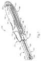
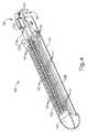
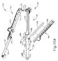
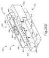
図1は、胃腸吻合などの任意の好適な処置に使用され得る例示的な外科用リニアカッティングステープラ(100)を示す。リニアカッティングステープラ(100)は、ステープルカートリッジチャネル(122)を有する第1の部分(102)と、アンビルチャネル(130)を有する第2の部分(104)と、第1の部分(102)のカートリッジチャネル(122)と選択的に連結し得るステープルカートリッジアセンブリ(150)と、発射アセンブリ(200)と、を含む。以下でより詳細に説明するように、第1の部分(102)及びステープルカートリッジアセンブリ(150)は、第2の部分(104)と枢動可能に連結して、エンドエフェクタ(120)の対向する半分の間に捕捉された組織をクランプ、切断、及びステープル留めすることができるエンドエフェクタ(120)を形成し得る。I. Overview of an Illustrated Linear Cutting Stapler FIG. 1 shows an exemplary surgical linear cutting stapler (100) that can be used for any suitable procedure such as gastroenterostomy. The linear cutting stapler (100) is a cartridge of a first portion (102) having a staple cartridge channel (122), a second portion (104) having an anvil channel (130), and a first portion (102). Includes a staple cartridge assembly (150) that can be selectively coupled to the channel (122) and a launch assembly (200). As will be described in more detail below, the first portion (102) and staple cartridge assembly (150) are pivotally connected to the second portion (104) and face the end effector (120). It is possible to form an end effector (120) that can clamp, cut, and staple the captured tissue between the halves.
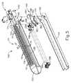
図3〜6にて最もよく見られるように、発射アセンブリ(200)は、作動ビーム(202)と、ステープルカートリッジアセンブリ(150)の内部に収容されたステープルスレッドアセンブリ(160)と、アクチュエータ(204)(「発射ノブ」とも呼ばれる)と、枢動アーム(206)と、を含む。作動ビーム(202)は遠位端(201)から近位端(203)へと延びている。作動ビーム(202)は、第1の部分(102)の内部に摺動可能に収容される。枢動アーム(206)はアクチュエータ(204)を作動ビーム(202)の遠位端(201)と接続する。アクチュエータ(204)及び枢動アーム(206)は、作動ビーム(202)(図11Aに示される)のいずれかの側面へ、近位位置(図1に示される)から枢動してもよく、それによって、操作者が、部分(102、104)が適切に連結され、エンドエフェクタ(120)が完全閉鎖位置にあるときに、発射アセンブリ(200)を器具(100)の第1の面(116)又は第2の面(117)のいずれかから作動させることができる。器具(100)が適切に連結され、エンドエフェクタ(120)が完全閉鎖位置にあるとき、第1の部分(102)及び第2の部分(104)は、アクチュエータ(204)の並進に適応するように寸法決めされたスロット(118)を画定することを理解されたい。本実施例では、以下でより詳細に説明されるように、作動ビーム(202)は、ステープルカートリッジアセンブリ(150)が第1の部分(102)と好適に連結されているときに、ステープルスレッドアセンブリ(160)と連結するように動作可能であり、これにより、アクチュエータ(204)は、器具(100)の第1の面(116)又は第2の面(117)に沿って摺動してもよい。これにより、作動ビーム(202)及びステープルスレッドアセンブリ(160)を、カートリッジアセンブリ(150)を通って遠位に駆動して、器具(100)を発射する。 As most often seen in FIGS. 3-6, the launch assembly (200) includes an actuating beam (202), a staple thread assembly (160) housed inside a staple cartridge assembly (150), and an actuator (204). ) (Also referred to as the "launch knob") and the staple arm (206). The working beam (202) extends from the distal end (201) to the proximal end (203). The working beam (202) is slidably housed inside the first portion (102). The pivot arm (206) connects the actuator (204) to the distal end (201) of the working beam (202). The actuator (204) and the pivot arm (206) may be pivoted from a proximal position (shown in FIG. 1) to any side of the working beam (202) (shown in FIG. 11A). Thereby, the operator can place the launch assembly (200) on the first surface (116) of the instrument (100) when the parts (102, 104) are properly connected and the end effector (120) is in the fully closed position. ) Or the second surface (117). When the instrument (100) is properly connected and the end effector (120) is in the fully closed position, the first part (102) and the second part (104) adapt to the translation of the actuator (204). It should be understood that the dimensioned slot (118) is defined in. In this embodiment, the actuating beam (202) is a staple thread assembly when the staple cartridge assembly (150) is suitably coupled to the first portion (102), as described in more detail below. It can operate to connect with (160) so that the actuator (204) can slide along the first surface (116) or second surface (117) of the appliance (100). Good. This drives the actuating beam (202) and staple thread assembly (160) distally through the cartridge assembly (150) to launch the instrument (100).
本実施例では、アクチュエータ(204)は、作動ビーム(202)を駆動するために器具(100)のいずれかの面(116、117)に枢動するように構成されているが、これは、アクチュエータ(204)が、本明細書の教示を鑑みることで当業者に明らかな任意の手段を介して、第1の部分(102)又は第2の部分(104)と摺動可能に連結することができるので、単に任意選択のものである。一実施例では、アクチュエータ(204)は、エンドエフェクタ(120)が完全閉鎖位置にあるときにアクチュエータ(204)が枢動し得ないように、第1の面(116)又は第2の面(117)と厳密に関連付けられてもよい。別の例では、器具(100)が2つのアクチュエータ(204)を含んでもよいように、第1の面(116)及び第2の面(117)の両方に位置付けられたアクチュエータ(204)が存在してもよい。 In this embodiment, the actuator (204) is configured to pivot to any surface (116, 117) of the instrument (100) to drive the working beam (202). The actuator (204) is slidably coupled to the first portion (102) or second portion (104) via any means apparent to those skilled in the art in view of the teachings herein. Is possible, so it is simply an optional one. In one embodiment, the actuator (204) is mounted on a first surface (116) or a second surface (116) so that the actuator (204) cannot pivot when the end effector (120) is in a fully closed position. It may be strictly associated with 117). In another example, there is an actuator (204) positioned on both the first surface (116) and the second surface (117) so that the appliance (100) may include two actuators (204). You may.
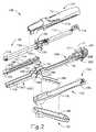
図3に見られるように、第1の部分(102)は、第1の近位フレーム(110)と、ステープルカートリッジチャネル(122)と、ラッチレバー(180)と、を含む。第1の近位フレーム(110)は、近位端(103)からステープルカートリッジチャネル(122)内へ遠位に延在する。本実施例では、第1の近位フレーム(110)及びステープルカートリッジチャネル(122)は、一体構造を有する細長いカートリッジチャネル部材を画定するように一体的に形成される。ラッチレバー(180)は、ピン(182)を介してステープルカートリッジチャネル(122)又は第1の近位フレーム(110)のいずれかに枢動可能に連結される。第1の近位フレーム(110)は、操作者が好適な処置を行う間に操作者が器具(100)を制御することができるように、十分なグリップを促進するように構成されたハンドルカバー(108)と連結されてもよい。ハンドルカバー(108)は、本明細書の教示を鑑みた当業者に明らかであるように、任意の好適な手段によって第1の近位フレーム(110)と連結してよい。あるいは、ハンドルカバー(108)は、第1の近位フレーム(110)と一体的に連結されてもよく、又は更には省略されてもよい。 As seen in FIG. 3, the first portion (102) includes a first proximal frame (110), a staple cartridge channel (122), and a latch lever (180). The first proximal frame (110) extends distally into the staple cartridge channel (122) from the proximal end (103). In this embodiment, the first proximal frame (110) and the staple cartridge channel (122) are integrally formed so as to define an elongated cartridge channel member having an integral structure. The latch lever (180) is pivotally coupled to either the staple cartridge channel (122) or the first proximal frame (110) via a pin (182). The first proximal frame (110) is a handle cover configured to facilitate sufficient grip so that the operator can control the instrument (100) while the operator performs a suitable procedure. It may be connected with (108). The handle cover (108) may be coupled to the first proximal frame (110) by any suitable means, as will be apparent to those skilled in the art in light of the teachings herein. Alternatively, the handle cover (108) may be integrally connected to the first proximal frame (110), or may even be omitted.
第1の近位フレーム(110)は、発射アセンブリ(200)の作動ビーム(202)を摺動可能に収容するチャネルを画定する。近位端(103)は、1つ以上の側方ピン又は突起部(111)を含む。突起部(111)は、第1及び第2の部分(102、104)を最初に枢動可能に連結するために、第2の部分(104)の溝(115)を受容するように構成されている。本実施例では、突起部(111)は、ポスト(107)を介して第1の近位フレーム(110)の残りの部分から隆起しているが、これは単に任意選択のものである。例えば、突起部(111)は、第1の近位フレーム(110)の側壁を横切って側方に延在する単一のピンを含んでもよい。当然ながら、本明細書の教示を鑑みた当業者に明らかであるように、任意の好適な手段の最初に枢動で連結する第1の部分(102)及び第2の部分(104)が使用され得る。 The first proximal frame (110) defines a channel that slidably accommodates the working beam (202) of the launch assembly (200). The proximal end (103) includes one or more lateral pins or protrusions (111). The protrusion (111) is configured to receive the groove (115) of the second portion (104) in order to first pivotally connect the first and second portions (102, 104). ing. In this embodiment, the protrusion (111) is raised from the rest of the first proximal frame (110) via the post (107), which is merely optional. For example, the protrusion (111) may include a single pin extending laterally across the side wall of the first proximal frame (110). Of course, as will be apparent to those skilled in the art in light of the teachings herein, the first part (102) and second part (104) that are pivotally connected at the beginning of any suitable means are used. Can be done.
簡潔に上述したように、ステープルカートリッジチャネル(122)は、第1の近位フレーム(110)から遠位に延在する。図2にて見られるように、ステープルカートリッジチャネル(122)は、ステープルカートリッジアセンブリ(150)と選択的に連結及び分離するように寸法決めされる。ステープルカートリッジチャネル(122)は、底壁(126)と、底壁(126)の対向する端部から延在する2つの対向する側壁(124)と、を含む。壁(124、126)は、図4にて見られるように、ステープルカートリッジアセンブリ(150)の少なくとも一部を受容するように寸法決めされる。更に、側壁(124)は、ステープルカートリッジアセンブリ(150)の近位端によって画定される連結切欠き(140)を受容するように構成された、内側に延在する側方突出部(図示せず)を含む。連結切欠き(140)は、操作者がステープルカートリッジアセンブリ(150)をステープルカートリッジチャネル(122)に選択的に取り付ける及び取り外すことができるように、側壁(124)の内向きに延在する側方突出部(図示せず)とスナップ嵌め又は圧入するように寸法決めされてもよい。連結切欠き(140)及び内向きに延在する側方突出部(図示せず)を使用して、ステープルカートリッジアセンブリ(150)をステープルカートリッジチャネル(122)と選択的に連結させるが、本明細書の教示を鑑みた当業者に明らかであるように、任意の他の好適な連結手段を使用することができる。ステープルカートリッジチャネル(122)の側壁(124)はまた、ノッチ又は凹部(127)をそれぞれ画定するサイドフランジ(128)を含む。凹部(127)は、エンドエフェクタ(120)が第1の部分(102)に対して完全閉鎖位置にあるように(図10Dに示すように)第2の部分(104)が枢動するときに、第2の部分(104)のラッチ突起部(131)を受容するように寸法決めされる。 As briefly mentioned above, the staple cartridge channel (122) extends distally from the first proximal frame (110). As seen in FIG. 2, the staple cartridge channel (122) is dimensioned to selectively connect and disconnect from the staple cartridge assembly (150). The staple cartridge channel (122) includes a bottom wall (126) and two opposing side walls (124) extending from opposite ends of the bottom wall (126). The walls (124, 126) are sized to accept at least a portion of the staple cartridge assembly (150), as seen in FIG. In addition, the side wall (124) is an inwardly extending lateral protrusion (not shown) configured to receive a connecting notch (140) defined by the proximal end of the staple cartridge assembly (150). )including. The connecting notch (140) laterally extends inwardly on the side wall (124) so that the operator can selectively attach and detach the staple cartridge assembly (150) to the staple cartridge channel (122). It may be sized for snap fitting or press fitting with protrusions (not shown). The staple cartridge assembly (150) is selectively coupled to the staple cartridge channel (122) using a connecting notch (140) and an inwardly extending lateral protrusion (not shown). Any other suitable connecting means can be used, as will be apparent to those skilled in the art in light of the teachings of the document. The side wall (124) of the staple cartridge channel (122) also includes a side flange (128) defining a notch or recess (127), respectively. The recess (127) is when the second portion (104) is pivoted so that the end effector (120) is in a completely closed position with respect to the first portion (102) (as shown in FIG. 10D). , Dimensioned to receive the latch protrusion (131) of the second portion (104).
簡潔に上述したように、ラッチレバー(180)は、ピボットピン(182)を介して第1の部分(102)の残りの部分に枢動可能に連結される。ラッチレバー(180)は、近位延在アーム(184)及び遠位ラッチ本体(188)を含む。近位延在アーム(184)がステープルカートリッジチャネル(122)に向かって遠位ラッチ本体(188)を枢動させるように、ピン(182)を中心に第1の近位フレーム(110)に向かって枢動でき、遠位ラッチ本体(188)が第2の部分(104)と係合し、第2の部分(104)を第1の部分(102)に向かって枢動させて、エンドエフェクタ(120)を部分的閉鎖位置(図10Cに示すように)から完全閉鎖位置(図10Dに示すように)まで移行させることができる。 As briefly described above, the latch lever (180) is pivotally coupled to the rest of the first portion (102) via a pivot pin (182). The latch lever (180) includes a proximal extension arm (184) and a distal latch body (188). Along the pin (182) towards the first proximal frame (110) so that the proximal extension arm (184) pivots the distal latch body (188) towards the staple cartridge channel (122). The distal latch body (188) engages the second portion (104) and pivots the second portion (104) towards the first portion (102), resulting in an end effector. (120) can be moved from a partially closed position (as shown in FIG. 10C) to a fully closed position (as shown in FIG. 10D).
近位延在アーム(184)は、操作者が好適な処置を行う間に操作者がアーム(184)を把持し得るように、十分なグリップを促進するために近位延在アーム(186)と連結されてもよい。連結アーム(186)は、本明細書の教示を鑑みる当業者に明らかなように、任意の好適な手段によって近位延在アーム(184)と連結し得る。あるいは、アームカバー(186)は、近位延在アーム(184)と一体的に連結されてもよく、又は更には省略されてもよい。 The proximal extension arm (184) is a proximal extension arm (186) to facilitate sufficient grip so that the operator can grip the arm (184) while the operator performs the appropriate procedure. May be concatenated with. The connecting arm (186) can be connected to the proximal extension arm (184) by any suitable means, as will be apparent to those skilled in the art in light of the teachings herein. Alternatively, the arm cover (186) may be integrally connected to the proximal extension arm (184) or may even be omitted.
遠位ラッチ本体(188)は、一対のフック(189)を含む。遠位ラッチ本体(188)はまた、フック(189)に対して近位に位置する対応する一対のラッチ切欠き(185)を画定する。以下でより詳細に説明するように、各フック(189)は、第2の部分(104)の個々のラッチ突起部(131)と最初に接触し、次いで捕捉するように寸法決めされ、これにより、遠位ラッチ本体(188)は、各ラッチ突起部(131)の少なくとも一部の周囲に巻き付いて、第2の部分(104)を第1の部分(102)に向かって更に枢動させることができる。また、以下で更に詳細に説明するように、各ラッチ切欠き(185)は、エンドエフェクタ(120)が第1の部分(102)に対して閉鎖位置にあるときに、それぞれのラッチ突起部(131)を受容するように寸法決めされる。 The distal latch body (188) includes a pair of hooks (189). The distal latch body (188) also defines a pair of corresponding latch notches (185) located proximal to the hook (189). As described in more detail below, each hook (189) is sized to first contact and then capture the individual latch protrusions (131) of the second portion (104). , The distal latch body (188) wraps around at least a portion of each latch protrusion (131) to further pivot the second portion (104) towards the first portion (102). Can be done. Also, as will be described in more detail below, each latch notch (185) will have its own latch projection (185) when the end effector (120) is in the closed position with respect to the first portion (102). It is sized to accept 131).
図4〜6にて最もよく見られるように、ステープルカートリッジアセンブリ(150)は、各々がそれぞれのステープル(171)を駆動するように構成されたカートリッジ本体(152)、パン(154)、及び複数のステープルドライバ(168)を含む。カートリッジ本体(152)は、複数のステープル空洞(151)、スロット(156)、及び連結切欠き(140)を画定する。ステープルドライバ(168)及びそれぞれのステープル(171)は、対応するステープル空洞(151)の内部に摺動可能に収容される。第1の部分(102)及び第2の部分(104)が一緒に連結されると、ステープルカートリッジアセンブリ(150)及びステープルカートリッジチャネル(122)は、エンドエフェクタ(120)の一部を形成する。以下でより詳細に説明するように、ステープルカートリッジアセンブリ(150)は、ステープルスレッドアセンブリ(160)がカートリッジアセンブリ(150)を通って作動し得て、エンドエフェクタ(120)の2つの半体の間に捕捉された組織を同時に切断及びステープル留めするために、発射アセンブリ(200)のステープルスレッドアセンブリ(160)を収容又は受容するように構成される。 As most often seen in FIGS. 4-6, the staple cartridge assembly (150) has a cartridge body (152), pan (154), and a plurality, each configured to drive a respective staple (171). Includes staple driver (168). The cartridge body (152) defines a plurality of staple cavities (151), slots (156), and connecting notches (140). The staple driver (168) and each staple (171) are slidably housed inside the corresponding staple cavity (151). When the first portion (102) and the second portion (104) are connected together, the staple cartridge assembly (150) and staple cartridge channel (122) form part of the end effector (120). As described in more detail below, the staple cartridge assembly (150) allows the staple thread assembly (160) to operate through the cartridge assembly (150) and is between the two halves of the end effector (120). It is configured to contain or accept the staple thread assembly (160) of the launch assembly (200) to simultaneously cut and staple the tissue captured in the.
上述したように、カートリッジ本体(152)の連結切欠き(140)は、ステープルカートリッジチャネル(122)の側壁(124)の内側に延在する側方突出部(図示せず)とスナップ嵌めするように寸法決めされてもよく、これにより、操作者は、ステープルカートリッジアセンブリ(150)をステープルカートリッジチャネル(122)に選択的に取り付け、取り外すことができる。カートリッジ本体(152)は、遠位ノーズ(153)を含む。ステープルカートリッジアセンブリ(150)がカートリッジチャネル(122)と適切に連結されているとき、遠位ノーズ(153)は、カートリッジチャネル(122)から遠位に延在して非外傷性先端部を提供することができる。 As described above, the connecting notch (140) of the cartridge body (152) snaps into a lateral protrusion (not shown) extending inward of the side wall (124) of the staple cartridge channel (122). The staple cartridge assembly (150) can be selectively attached to and detached from the staple cartridge channel (122) by the operator. The cartridge body (152) includes a distal nose (153). When the staple cartridge assembly (150) is properly coupled to the cartridge channel (122), the distal nose (153) extends distally from the cartridge channel (122) to provide a non-traumatic tip. be able to.
更に、カートリッジ本体(152)は、ステープルデッキ(158)を含む。ステープルデッキ(158)は、ステープル空洞(151)を部分的に画定し、ステープル空洞(151)は、カートリッジ本体(152)の内部からステープルデッキ(158)の開放端部に向かって延在する。ステープル空洞(151)はそれぞれ、対応するステープルドライバ(168)及びステープル(171)を収容する。同様に、ステープルデッキ(158)は、カートリッジ本体(152)の内部からステープルデッキ(158)の開放端部に向かって延在するスロット(156)を部分的に画定する。スロット(156)は、ステープルスレッドアセンブリ(160)がカートリッジ本体(152)を通って遠位方向に摺動する際に切断部材(164)が組織を切断し得るように、スレッド本体(162)の一部及びステープルスレッドアセンブリ(160)の切断部材(164)を摺動可能に受容するように寸法決めされる。 Further, the cartridge body (152) includes a staple deck (158). The staple deck (158) partially defines the staple cavity (151), which extends from the inside of the cartridge body (152) toward the open end of the staple deck (158). The staple cavity (151) houses the corresponding staple driver (168) and staple (171), respectively. Similarly, the staple deck (158) partially defines a slot (156) extending from the inside of the cartridge body (152) toward the open end of the staple deck (158). The slot (156) is of the thread body (162) so that the cutting member (164) can cut the tissue as the staple thread assembly (160) slides distally through the cartridge body (152). It is sized to slidably receive a portion and a cutting member (164) of the staple thread assembly (160).
パン(154)は、可撓性アーム(155)を含んでもよい。可撓性アーム(155)は、パン(154)がスナップ嵌め又は圧入の関係でカートリッジ本体(152)と連結することができるように、カートリッジ本体(152)と係合するよう構成され得る。パン(154)は、ステープルドライバ(168)及びステープル(171)がそれぞれのステープル空洞(151)内に挿入された後、カートリッジ本体(152)と連結することができる。したがって、パン(154)は、ステープルドライバ(168)の床として機能し得る。 The pan (154) may include a flexible arm (155). The flexible arm (155) may be configured to engage the cartridge body (152) so that the pan (154) can be connected to the cartridge body (152) in a snap fit or press fit relationship. The pan (154) can be connected to the cartridge body (152) after the staple driver (168) and staple (171) have been inserted into the respective staple cavities (151). Therefore, the pan (154) can function as the floor of the staple driver (168).
本実施例では、カートリッジ本体(152)は、ステープルカートリッジアセンブリ(150)の近位端付近に位置するスレッドアセンブリハウジング(170)を含む。スレッドアセンブリハウジング(170)は、発射アセンブリ(200)のステープルスレッドアセンブリ(160)を最初に収容するように構成されている。スレッドアセンブリハウジング(170)は、遠位に面する開口部を有する空洞(174)を画定する本体(172)を含む。本体(172)及び空洞(174)は、発射前にスレッドアセンブリ(160)の切断部材(164)を収容するように寸法決めされ、したがって、切断部材(164)のためのシースとして作用する。発射されると、切断部材(164)は、空洞(174)の遠位に面する開口部を介してスレッドアセンブリハウジング(170)から出ることができる。 In this embodiment, the cartridge body (152) includes a thread assembly housing (170) located near the proximal end of the staple cartridge assembly (150). The thread assembly housing (170) is configured to first accommodate the staple thread assembly (160) of the launch assembly (200). The thread assembly housing (170) includes a body (172) that defines a cavity (174) with a distally facing opening. The body (172) and cavity (174) are sized to accommodate the cutting member (164) of the thread assembly (160) prior to launch and therefore act as a sheath for the cutting member (164). When fired, the cutting member (164) can exit the thread assembly housing (170) through a distally facing opening in the cavity (174).
図7及び図8で最もよく見えるように、スレッドアセンブリ(160)は、スレッド本体(162)及び切断部材(164)を含む。切断部材(164)は、切断縁部(165)と、ロックアーム(166)とを含む。スレッド本体(162)は、切欠き(161)及びスロット(163)を画定する。スロット(163)は、切断部材(164)及びスレッド本体(162)が一緒に作動し得るように、切断部材(164)の一部を受容するように寸法決めされる。切断部材(164)は、スロット(163)との推論された嵌合を介して、接着剤の使用によって、スレッド本体(162)と連結することができ、又は任意の他の好適な方法が、本明細書の教示を鑑みる当業者に明らかである。あるいは、切断部材(164)は、本明細書の教示を鑑みる当業者に明らかであるように、一体的な接続、溶接などの任意の好適な方法によって、スレッド本体(162)と連結してもよい。切欠き(161)は、ステープルカートリッジアセンブリ(150)がステープルカートリッジチャネル(122)に適切に取り付けられたときに、作動ビーム(202)の遠位端(201)と連結するように寸法決めされる。したがって、適切に連結されると、作動ビーム(202)は、スレッドアセンブリ(160)をカートリッジ本体(152)を通って長手方向に駆動することができる。作動ビーム(202)は、例示的な使用中にスレッドアセンブリ(160)と連結されるため、作動ビーム(202)はまた、カートリッジ本体(152)によって画定されるスロット(156)内で摺動するように寸法決めされることを理解されたい。 As best visible in FIGS. 7 and 8, the thread assembly (160) includes a thread body (162) and a cutting member (164). The cutting member (164) includes a cutting edge (165) and a lock arm (166). The thread body (162) defines a notch (161) and a slot (163). The slot (163) is sized to accept a portion of the cutting member (164) so that the cutting member (164) and the thread body (162) can operate together. The cutting member (164) can be connected to the thread body (162) by the use of an adhesive via an inferred fit with the slot (163), or any other suitable method. It will be apparent to those skilled in the art in view of the teachings herein. Alternatively, the cutting member (164) may be connected to the thread body (162) by any suitable method, such as integral connection, welding, as will be apparent to those skilled in the art in view of the teachings herein. Good. The notch (161) is sized to connect with the distal end (201) of the working beam (202) when the staple cartridge assembly (150) is properly attached to the staple cartridge channel (122). .. Thus, when properly coupled, the working beam (202) can drive the thread assembly (160) longitudinally through the cartridge body (152). Since the working beam (202) is coupled to the thread assembly (160) during exemplary use, the working beam (202) also slides within the slot (156) defined by the cartridge body (152). Please understand that it is sized as.
スレッド本体(162)はまた、カートリッジ本体(152)のステープル空洞(151)を通るそれぞれの細長い溝(図示せず)の内部で長手方向に摺動するように寸法決めされた複数のカム表面(167)を含む。具体的には、カム表面(167)は、ステープルドライバ(168)をステープルデッキ(158)に向かって作動させるために、ステープル空洞(151)内で、ステープルドライバ(168)の傾斜面(169)に対して係合及びカムするように構成されている。次いで、ステープルドライバ(168)は、対応するステープル(171)をステープル空洞(151)を通ってステープルデッキ(158)から離れるように駆動する。 The thread body (162) also has a plurality of cam surfaces sized to slide longitudinally within each elongated groove (not shown) through the staple cavity (151) of the cartridge body (152). 167) is included. Specifically, the cam surface (167) within the staple cavity (151) in order to actuate the staple driver (168) towards the staple deck (158) is an inclined surface (169) of the staple driver (168). It is configured to engage and cam with respect to. The staple driver (168) then drives the corresponding staple (171) away from the staple deck (158) through the staple cavity (151).
上述したように、ステープルスレッドアセンブリ(160)は、ステープルカートリッジアセンブリ(150)がステープルカートリッジチャネル(122)と好適に連結されたときに、発射アセンブリ(200)の残りの部分と連結するように構成される。本実施例では、発射アセンブリ(200)のステープルスレッドアセンブリ(160)は、カートリッジアセンブリ(150)と関連付けられ、カートリッジアセンブリ(150)が使用され廃棄された後に、ステープルスレッドアセンブリ(160)も同様にするようにする。したがって、追加のカートリッジアセンブリ(150)がステープルカートリッジチャネル(122)内に装填されるとき、新しいステープルスレッドアセンブリ(160)が存在する。ただし、これは単に任意選択的である。例えば、ステープルスレッドアセンブリ(160)は、同じステープルスレッドアセンブリ(160)が複数のステープルカートリッジアセンブリ(150)と共に複数回使用され得るように、発射アセンブリ(200)の残りの部分に固定されるか、ないしは別の方法で連結されてもよい。このような例では、カートリッジ本体(152)は、スレッドアセンブリハウジング(170)を必要としない。ステープルスレッドアセンブリ(160)がステープルカートリッジアセンブリ(150)、ステープルカートリッジチャネル(122)、又は第1の近位フレーム(110)のいずれかに組み込まれ得る様々な方法が、本明細書を鑑みる当業者に明らかである。 As mentioned above, the staple thread assembly (160) is configured to connect with the rest of the firing assembly (200) when the staple cartridge assembly (150) is suitably connected with the staple cartridge channel (122). Will be done. In this embodiment, the staple thread assembly (160) of the launch assembly (200) is associated with the cartridge assembly (150), and so is the staple thread assembly (160) after the cartridge assembly (150) has been used and discarded. To do. Therefore, when an additional cartridge assembly (150) is loaded into the staple cartridge channel (122), a new staple thread assembly (160) is present. However, this is simply optional. For example, the staple thread assembly (160) may be secured to the rest of the launch assembly (200) so that the same staple thread assembly (160) can be used multiple times with multiple staple cartridge assemblies (150). Or they may be concatenated in another way. In such an example, the cartridge body (152) does not require a thread assembly housing (170). Various methods by which the staple thread assembly (160) can be incorporated into any of the staple cartridge assembly (150), staple cartridge channel (122), or first proximal frame (110) are those skilled in the art in view of the present specification. It is clear to.
図2及び図3に示されるように、器具(100)の第2の部分(104)は、第2の近位フレーム(114)と、アンビルチャネル(130)と、ラッチ突起部(131)と、アンビルプレート(134)と、を含む。第2の近位フレーム(114)は、アンビルチャネル(130)において溝(115)を画定する近位端から延在する。本実施例では、第2の近位フレーム(114)及びアンビルチャネル(130)は、一体構造を有する細長いアンビルチャネル部材を画定するように一体的に形成される。第2の近位フレーム(114)は、操作者が好適な処置を行う間に操作者が器具(100)を制御することができるように、十分なグリップを促進するように構成されたハンドルカバー(112)と連結されてもよい。ハンドルカバー(112)と第2の近位フレーム(114)は、本明細書の教示を鑑みた当業者に明らかであるように、任意の好適な手段によって互いに連結されてもよい。あるいは、ハンドルカバー(112)は、第2の近位フレーム(114)と一体的に連結されてもよく、又は更には省略されてもよい。第2の近位フレーム(114)はまた、エンドエフェクタ(120)が完全閉鎖位置にあるとき(図10Dに示すように)発射アセンブリ(200)の諸部分が第1の部分(102)及び第2の部分(104)に対して作動することを可能にするように構成されたチャネルを画定してもよい。 As shown in FIGS. 2 and 3, the second portion (104) of the instrument (100) includes a second proximal frame (114), an anvil channel (130), and a latching protrusion (131). , Anvil plate (134), and the like. The second proximal frame (114) extends from the proximal end defining the groove (115) in the anvil channel (130). In this embodiment, the second proximal frame (114) and the anvil channel (130) are integrally formed so as to define an elongated anvil channel member having an integral structure. The second proximal frame (114) is a handle cover configured to facilitate sufficient grip so that the operator can control the instrument (100) while the operator performs a suitable procedure. It may be connected with (112). The handle cover (112) and the second proximal frame (114) may be connected to each other by any suitable means, as will be apparent to those skilled in the art in light of the teachings herein. Alternatively, the handle cover (112) may be integrally connected to the second proximal frame (114), or may even be omitted. The second proximal frame (114) also has parts of the launch assembly (200) in the first part (102) and the first part (102) when the end effector (120) is in the fully closed position (as shown in FIG. 10D). Channels may be defined that are configured to allow operation for the second portion (104).
第2の部分(104)は、遠位ノーズ(139)で遠位に終端する。遠位ノーズ(139)は、非外傷性先端部を設けるために、アンビルチャネル(130)から遠位に延在してもよい。図9に示すように、アンビルプレート(134)の近位端は、第1の部分(102)及び第2の部分(104)が互いに向かって枢動するとき、スレッドアセンブリハウジング(170)を受容するように寸法決めされた凹部(179)を画定する。以下でより詳細に説明するように、ラッチ突起部(131)は、アンビルチャネル(130)から側方に離れる方向に延在し、遠位ラッチ本体(180)と相互作用して、アンビルプレート(134)をステープルカートリッジアセンブリ(150)に向かって引き寄せるように寸法決めされる。 The second portion (104) terminates distally at the distal nose (139). The distal nose (139) may extend distally from the anvil channel (130) to provide a non-traumatic tip. As shown in FIG. 9, the proximal end of the anvil plate (134) accepts the thread assembly housing (170) when the first portion (102) and the second portion (104) pivot toward each other. A recess (179) sized to do so is defined. As described in more detail below, the latch projection (131) extends laterally away from the anvil channel (130) and interacts with the distal latch body (180) to form an anvil plate (131). 134) is sized to pull towards the staple cartridge assembly (150).
アンビルプレート(134)は、複数のステープル成形ポケット(132)及びスロット(133)を画定する。ステープル成形ポケット(132)は、アンビルチャネル(130)がステープルカートリッジチャネル(122)に向かって完全閉鎖位置へと枢動されるときに、各ステープル成形ポケット(132)が対応するステープル空洞(151)と整列するように、アンビルプレート(134)に沿って位置付けられる(図1、図10D、及び図11A〜図11Bに示すように)。したがって、スレッド本体(162)のカム表面(167)が、上記の説明に従ってステープルドライバ(168)を作動させると、ステープル(171)は、ステープル空洞(151)を通ってステープルデッキ(158)から離れるように、組織を通って、かつ対応するステープル成形ポケット(132)に対して駆動され、これにより、ステープル(171)は、略「U」字形から略「B」字形に変換されて、適切に組織をステープル留めするようにする。スロット(133)は、アンビルチャネル(130)が完全閉鎖位置へと枢動されるとき、スロット(133)は、ステープルカートリッジアセンブリ(150)のスロット(156)と側方に整列するように寸法決めされる(図1、図10D、及び図11A〜図11Bに示すように)。スロット(133)は、例示的な使用中に切断部材(164)がアンビル表面(134)とステープルデッキ(158)との間に捕捉された組織を切断することができるように、ステープルスレッドアセンブリ(160)がステープルカートリッジアセンブリ(150)を通して駆動される際に、切断部材(164)の一部を摺動可能に受容するように寸法決めされる。 The anvil plate (134) defines a plurality of stapled pockets (132) and slots (133). The stapled pockets (132) are the staple cavities (151) that each stapled pocket (132) corresponds to when the anvil channel (130) is pivoted towards a fully closed position towards the staple cartridge channel (122). Positioned along the anvil plate (134) so as to align with (as shown in FIGS. 1, 10D, and 11A-11B). Thus, when the cam surface (167) of the thread body (162) activates the staple driver (168) as described above, the staples (171) move away from the staple deck (158) through the staple cavities (151). As such, driven through the tissue and against the corresponding staple molding pockets (132), the staples (171) are properly converted from an approximately "U" shape to a substantially "B" shape. Try to staple the tissue. The slot (133) is dimensioned so that when the anvil channel (130) is pivoted to a fully closed position, the slot (133) is laterally aligned with the slot (156) of the staple cartridge assembly (150). (As shown in FIGS. 1, 10D, and 11A-11B). The slot (133) is a staple thread assembly (133) that allows the cutting member (164) to cut the tissue trapped between the anvil surface (134) and the staple deck (158) during exemplary use. As the 160) is driven through the staple cartridge assembly (150), it is sized to slidably receive a portion of the cutting member (164).
図9で最もよく分かるように、本実施例の器具(100)の第2の部分(104)は、ステープル高調整機構(136)を更に含む。調整機構(136)は、例えば1つ以上のカム特徴部(図示せず)を介してアンビルプレート(134)と動作可能に連結され、一対の使用者が係合可能な突起部(138)を含む。調節機構(136)は、アンビルチャネル(130)に対して、アンビルプレート(134)をアンビルチャネル(130)に対して上げるか下げるために、2つ以上の長手方向位置の間で選択的に移動可能であり、それによって、第1及び第2の器具部分(102、104)が完全閉鎖位置で一緒に連結されるときに、アンビルプレート(134)とステープルデッキ(158)との間の間隙距離(又は「組織間隙」)を調節する。より厚い厚さの組織をステープル留めするために、より長い間隙距離、したがってより高いステープルの高さを、設けてもよい。同様に、より薄い厚さの組織をステープル留めするために、より短い間隙距離、したがってより低いステープルの高さを設けてもよい。ステープル高調整機構(136)は単に任意選択のものであり、他の実施例では省略されてもよいことが理解されるであろう。器具(100)のいくつかの変形形態では、アンビルプレート(134)の形態で示されるアンビル表面は、アンビルチャネル(130)に対して固定されてもよい。例えば、アンビル表面は、アンビルチャネル(130)と一体的に形成されてもよい。 As best seen in FIG. 9, the second portion (104) of the instrument (100) of this embodiment further includes a staple height adjusting mechanism (136). The adjusting mechanism (136) is operably connected to the anvil plate (134) via, for example, one or more cam features (not shown) to provide a pair of user-engageable protrusions (138). Including. The adjusting mechanism (136) selectively moves between two or more longitudinal positions to raise or lower the anvil plate (134) relative to the anvil channel (130) relative to the anvil channel (130). It is possible, thereby the clearance distance between the anvil plate (134) and the staple deck (158) when the first and second instrument parts (102, 104) are connected together in a fully closed position. (Or "tissue gap") is adjusted. Longer clearance distances and thus higher staple heights may be provided to staple thicker thicknesses of tissue. Similarly, shorter gap distances and thus lower staple heights may be provided to staple thinner thicknesses of tissue. It will be appreciated that the staple height adjustment mechanism (136) is merely optional and may be omitted in other embodiments. In some variants of the instrument (100), the anvil surface shown in the form of an anvil plate (134) may be fixed relative to the anvil channel (130). For example, the anvil surface may be formed integrally with the anvil channel (130).
外科用リニアカッティングステープラ(100)は、2011年3月15日発行の「Surgical Stapling Instrument with Cutting Member Arrangement」と題された米国特許第7,905,381号;2011年6月7日発行の「Surgical Stapler with Apparatus for Adjusting Staple Height」と題された米国特許第7,954,686号;2013年1月8日発行の「Surgical Stapler Having A Closure Mechanism」と題された米国特許第8,348,129号;及び2014年7月29日発行の「Linear Cutting and Stapling Device with Selectively Disengagable Cutting Member」と題された米国特許第8,789,740号の1つ以上の教示に従って更に構成され、動作可能であってもよい。これらの参考文献のそれぞれの開示内容は参照により本明細書に組み込まれる。 The Surgical Linear Cutting Stapler (100) is a US Pat. No. 7,905,381; issued June 7, 2011, entitled "Surgical Stapleing Instrument with Cutting Member Arrangement", issued March 15, 2011. US Pat. No. 7,954,686 entitled "Surgical Stapler with Apparatus for Adjusting Staple Height"; "Surgical Stapler Having A Blue, US Pat. 129; and further configured in accordance with one or more of the teachings of US Pat. No. 8,789,740, entitled "Linear Cutting and Stapling Device with Selectively Disengaged Cutting Member", published July 29, 2014. It may be. The disclosure of each of these references is incorporated herein by reference.
図10A〜図11Bは、器具(100)の例示的な使用を示す。詳細には、図10A〜10Dは、第1の部分(102)と第2の部分(104)との例示的な連結を示し、エンドエフェクタ(120)が開放位置(図10B)から部分的閉鎖位置(図10C)に移行し、最後に完全閉鎖位置(図10D)へと移行するようにする、第1の部分(102)と第2の部分(104)との枢動を示す。図11A〜図11Bは、エンドエフェクタ(120)が完全閉鎖位置にあるときの器具(100)の例示的な発射を示す。 10A-11B show exemplary use of instrument (100). In particular, FIGS. 10A-10D show an exemplary connection between the first portion (102) and the second portion (104), with the end effector (120) partially closed from the open position (FIG. 10B). It shows the pivot between the first part (102) and the second part (104), which causes the transition to the position (FIG. 10C) and finally to the fully closed position (FIG. 10D). 11A-11B show an exemplary launch of the instrument (100) when the end effector (120) is in a fully closed position.
図10Aは、第2の部分(204)から完全に取り外された第1の部分(102)を示す。更に、ステープルカートリッジアセンブリ(150)は、上の説明に従ってステープルカートリッジチャネル(122)に好適に取り付けられる。この時点では、胃腸吻合中などの処置の最中の操作者は、組織の内腔がアンビルプレート(134)及びカートリッジアセンブリ(150)の両方と適切に関連付けられるように、第2の部分(104)及びカートリッジアセンブリ(150)の各遠位ノーズ(139、153)の上に、及びそれを越えて、組織の内腔を配置することを望む場合がある。この時点では、操作者は、第1の部分(102)を第2の部分(104)と最初に枢動可能に連結する準備において、第2の部分(104)の溝(115)を第1の部分(102)の対応する側方突出部(111)と整列させることができる。 FIG. 10A shows the first portion (102) completely removed from the second portion (204). Further, the staple cartridge assembly (150) is suitably attached to the staple cartridge channel (122) as described above. At this point, the operator during a procedure, such as during a gastroenterostomy, has a second portion (104) so that the lumen of the tissue is properly associated with both the anvil plate (134) and the cartridge assembly (150). ) And each distal nose (139, 153) of the cartridge assembly (150), and beyond, it may be desired to place the lumen of tissue. At this point, the operator first mobilizes the groove (115) of the second portion (104) in preparation for first pivotally connecting the first portion (102) to the second portion (104). Can be aligned with the corresponding lateral protrusion (111) of the portion (102).
次に、図10Bに示すように、操作者は、第1の部分(102)及び第2の部分(104)が枢動可能に連結されるが、エンドエフェクタ(120)が開放位置にあるように、側方突出部(111)を対応する溝(115)に挿入することができる。第1の部分(102)及び第2の部分(104)は、側方突出部(111)によって画定される軸を中心に互いに対して枢動することができる。この時点では、ラッチレバー(180)は、第2の部分(104)のいずれの部分とも接触していない。加えて、ラッチレバー(180)は、近位延在アーム(184)が第1の近位フレーム(110)から離れるように枢動するように、開放位置にある。 Next, as shown in FIG. 10B, the operator so that the first portion (102) and the second portion (104) are pivotally connected, but the end effector (120) is in the open position. The lateral protrusion (111) can be inserted into the corresponding groove (115). The first portion (102) and the second portion (104) can be pivoted relative to each other about an axis defined by a lateral protrusion (111). At this point, the latch lever (180) is not in contact with any portion of the second portion (104). In addition, the latch lever (180) is in the open position so that the proximal extension arm (184) is pivoted away from the first proximal frame (110).
次に、図10Cに示すように、操作者は、最初にアンビルチャネル(130)及びアンビルプレート(134)をカートリッジチャネル(122)及びステープルカートリッジアセンブリ(150)に向かって枢動させ、フック(189)が最初にラッチ突起部(131)に接触するようにラッチレバー(180)を部分的に枢動させることができる。この時点では、エンドエフェクタ(120)は、部分的閉鎖位置にある。図10C〜図10D間で最もよく示されるように、フック(189)が最初にラッチ突起部(131)に接触した後、操作者は、近位延在アーム(184)を第1の近位フレーム(110)に向かって更に回転させて、遠位ラッチ本体(188)が、ラッチ突起部(131)を、遠位ラッチ本体(188)の表面に沿ってラッチ切欠き(185)に向けて駆動することができる。ラッチ突起部(131)がラッチ切欠き(185)に向かって駆動されると、アンビルチャネル(130)及びアンビルプレート(134)は、エンドエフェクタ(120)が閉鎖位置にあるように、カートリッジチャネル(122)及びステープルカートリッジアセンブリ(150)に向かって更に回転する。更に、ラッチ突起部(131)はまた、各ラッチ突起部(131)がそれぞれのラッチ切欠き(185)と凹部(127)との組み合わせによって包囲され、エンドエフェクタ(120)を閉鎖位置に効果的にラッチするように、ステープルカートリッジチャネル(122)の凹部(127)に向かって駆動される。ラッチ切欠き(185)及び凹部(127)は、エンドエフェクタ(120)は完全閉鎖位置にある間に、ラッチ突起部(131)とインターフェースするように寸法決めされてもよく、その結果、ラッチ突起部(131)及び枢動ピン(182)が、器具(100)の長手方向軸と実質的に垂直である垂直軸(VA)に沿って延在する。これは、好適な使用中の閉鎖力の強化に対して機械的な利点を提供し得る。 The operator then first pivots the anvil channel (130) and anvil plate (134) towards the cartridge channel (122) and staple cartridge assembly (150) and hooks (189), as shown in FIG. 10C. ) Can be partially pivoted so that the latch lever (131) first contacts the latch protrusion (131). At this point, the end effector (120) is in a partially closed position. As best shown between FIGS. 10C and 10D, after the hook (189) first contacts the latch protrusion (131), the operator attaches the proximal extension arm (184) to the first proximal. Further rotated towards the frame (110), the distal latch body (188) directs the latch projection (131) toward the latch notch (185) along the surface of the distal latch body (188). Can be driven. When the latch projection (131) is driven towards the latch notch (185), the anvil channel (130) and anvil plate (134) are placed in the cartridge channel (120) so that the end effector (120) is in the closed position. 122) and further rotation towards the staple cartridge assembly (150). Further, the latch protrusions (131) are also surrounded by a combination of the respective latch notches (185) and recesses (127), and the end effector (120) is effectively placed in the closed position. It is driven towards the recess (127) of the staple cartridge channel (122) so as to latch into. The latch notch (185) and recess (127) may be sized to interface with the latch projection (131) while the end effector (120) is in the fully closed position, resulting in the latch projection. A portion (131) and a pivot pin (182) extend along a vertical axis (VA) that is substantially perpendicular to the longitudinal axis of the instrument (100). This may provide a mechanical advantage for the preferred strengthening of the closing force during use.
図11A〜図11Bは、完全閉鎖位置にあるエンドエフェクタ(120)を有する器具(100)の例示的な発射を示す。図11Aで最も良く見えるように、操作者は、アクチュエータ(204)を器具(100)のいずれかの面(116、117)に枢動させることができる。本実施例では、アクチュエータ(204)は、器具(100)の第2の面(117)に枢動されている。次に、操作者は、作動ビーム(202)及びスレッド(160)が発射されるように、アクチュエータ(204)をスロット(118)内のエンドエフェクタ(120)に向かって遠位に押すことができ、それにより上記の説明に従って、ステープル留めデッキ(158)とアンビルプレート(134)との間に捕捉された組織をステープル留め及び切断する。器具(100)が発射されると、操作者はアクチュエータ(204)を図11Aに示す位置に近位に引いて戻し、次いでアクチュエータ(204)を図1に示す位置に戻すように回転させ、したがって、発射ストロークを完了することができる。次いで、操作者は、近位延在アーム(184)が第1の近位フレーム(110)から離れるようにラッチレバー(180)を枢動して、エンドエフェクタ(120)を完全閉鎖位置から部分的閉鎖位置へと開放することができる。操作者は、ラッチレバー(180)を更に枢動させて、遠位ラッチ本体(188)がラッチ突起部(131)をもはや捕捉しないようにしてもよい。次いで、操作者は、所望であれば、第1の部分(102)及び第2の部分(104)を互いに分離し、ステープルカートリッジアセンブリ(150)を交換することができる。 11A-11B show an exemplary launch of an instrument (100) with an end effector (120) in a completely closed position. As best seen in FIG. 11A, the operator can pivot the actuator (204) to any surface (116, 117) of the instrument (100). In this embodiment, the actuator (204) is pivoted to the second surface (117) of the appliance (100). The operator can then push the actuator (204) distally towards the end effector (120) in the slot (118) so that the actuating beam (202) and thread (160) are fired. , Thereby, stapling and cutting the tissue trapped between the stapling deck (158) and the anvil plate (134), as described above. When the instrument (100) is fired, the operator pulls the actuator (204) proximally back to the position shown in FIG. 11A and then rotates the actuator (204) back to the position shown in FIG. , Can complete the firing stroke. The operator then pivots the latch lever (180) so that the proximal extension arm (184) is separated from the first proximal frame (110) to partially retract the end effector (120) from the fully closed position. It can be opened to a closed position. The operator may further pivot the latch lever (180) so that the distal latch body (188) no longer captures the latch protrusion (131). The operator can then separate the first portion (102) and the second portion (104) from each other and replace the staple cartridge assembly (150), if desired.
II.二面発射レバーを有する例示的なリニアカッティングステープラ
上述したように、アクチュエータ(204)は、枢動アーム(206)を介して作動ビーム(202)の遠位端(201)に枢動可能に連結されてもよい。したがって、操作者は、発射アセンブリ(100)を作動させるために、図1に示すように、アクチュエータ(204)を完全近位位置から第1の面(116)又は第2の面(117)のいずれかに枢動させることができる。しかし、枢動アーム(206)はアクチュエータ(204)を作動ビーム(202)に接続するので、作動ビーム(202)を並進させるためにアクチュエータ(204)を押す力は、枢動アーム(206)が、発射中に枢動アーム(206)に付与された力に起因して、破断又はスナップ留めすることを惹起できる。アクチュエータ(204)は、発射中に作動ビーム(202)から側方にオフセットされるので、枢動アーム(206)の中の曲げモーメントが誘導でき、これはまた、発射中に枢動アーム(206)の破断又はスナップにつながり得る。枢動アーム(206)は、器具の側面(116、117)のいずれかに枢動するように寸法決めされるため、枢動アーム(206)が器具(100)の反対の側面(116、117)に向かって回転することを妨げ得るため、例示的な使用の間に破断するのを防ぐべく枢動アーム(206)を1つの側面(116、117)で構造的に補強することが困難であり得る。II. An exemplary linear cutting stapler with a two-sided firing lever As described above, the actuator (204) is pivotally coupled to the distal end (201) of the actuating beam (202) via a pivot arm (206). May be done. Therefore, in order to activate the launch assembly (100), the operator moves the actuator (204) from the fully proximal position to the first surface (116) or the second surface (117), as shown in FIG. It can be pivoted to either. However, since the pivot arm (206) connects the actuator (204) to the actuating beam (202), the force pushing the actuator (204) to translate the actuating beam (202) is exerted by the pivot arm (206). Due to the force applied to the pivot arm (206) during launch, it can trigger a break or snap. The actuator (204) is offset laterally from the actuating beam (202) during firing so that a bending moment in the pivot arm (206) can be induced, which also leads to the pivot arm (206) during firing. ) Can lead to breakage or snap. Since the pivot arm (206) is sized to pivot on one of the sides (116, 117) of the instrument, the pivot arm (206) is located on the opposite side (116, 117) of the instrument (100). ), So it is difficult to structurally reinforce the pivot arm (206) with one side surface (116, 117) to prevent it from breaking during exemplary use. possible.
あるいは、上述したように、アクチュエータ(204)は、器具の1つの側面(116、117)に厳密に限定されてもよく、それにより、アクチュエータ(204)を作動ビーム(202)に接続するアーム又はビームを構造的に強化することができる。しかし、器具の一方の面に限定された単一のアクチュエータ(204)を有することにより、操作者が発射中に器具(100)の第1の部分(102)及び第2の部分(104)を把持し得る方法の総計を制限し得る。例えば、場合によっては、操作者は、アクチュエータ(204)が摺動可能に連結されているのと反対側にある器具(100)の側面(116、117)で、発射アセンブリ(200)を作動させることが、より好都合であることを見出すことができる。 Alternatively, as described above, the actuator (204) may be strictly limited to one side surface (116, 117) of the appliance, whereby the arm or arm connecting the actuator (204) to the working beam (202). The beam can be structurally strengthened. However, by having a single actuator (204) limited to one side of the appliance, the operator can see the first part (102) and the second part (104) of the appliance (100) during firing. It can limit the total number of methods that can be gripped. For example, in some cases, the operator activates the launch assembly (200) on the side surface (116, 117) of the appliance (100) opposite to which the actuator (204) is slidably connected. Can be found to be more convenient.
あるいは、同様に上述したように、器具(100)は、作動ビーム(202)の近位端(201)に取り付けられた2つのアクチュエータ(204)を有してもよく、1つのアクチュエータ(204)は第1の面(116)に位置し、他方のアクチュエータ(204)は第2の面(117)に位置する。しかし、両方のアクチュエータ(204)が作動ビーム(202)の近位端(201)に取り付けられているため、操作者が作動ビーム(202)を発射するために第1の手で1つのアクチュエータ(204)を把持すると、器具(100)の他方の側面に位置するアクチュエータ(204)もまた、作動ビーム(202)と共に移動する。把持されていないアクチュエータ(204)の並進は、操作者が第2の手で器具(100)の第1及び第2の部分(102、104)にある把持部と干渉し得る。例えば、把持されていないアクチュエータ(204)は、第1及び第2の部分(102、104)を制御する第2の手の掌に対して摺動することができる。 Alternatively, similarly as described above, the appliance (100) may have two actuators (204) attached to the proximal end (201) of the working beam (202), one actuator (204). Is located on the first surface (116) and the other actuator (204) is located on the second surface (117). However, since both actuators (204) are attached to the proximal end (201) of the working beam (202), the operator has one actuator (120) in the first hand to fire the working beam (202). When the 204) is gripped, the actuator (204) located on the other side of the instrument (100) also moves with the working beam (202). The translation of the non-grasped actuator (204) allows the operator to interfere with the grips in the first and second portions (102, 104) of the instrument (100) with the second hand. For example, the non-grasped actuator (204) can slide with respect to the palm of the second hand controlling the first and second portions (102, 104).
したがって、望ましいことに、1つのアクチュエータが他方のアクチュエータと比較してリニアステープラの反対の面からアクセス可能である一対のアクチュエータを有する発射アセンブリを設けることができる。加えて、上の説明に従って、例示的な使用中、把持されたアクチュエータが作動ビームを駆動する間に、把持されていないアクチュエータが近位位置に留まるようにすることが望ましい場合がある。あるいは、1つのアクチュエータが各々の側面からアクセス可能であり、両方のアクチュエータが作動ビームに連結される、一対のアクチュエータを有する発射アセンブリを設けることが望ましい場合がある。しかし、上記の例とは異なり、把持されていないアクチュエータが、作動ビームに向かって側方内側に延在して、例示的な使用中に第1及び第2の部分(102、104)の把持を妨げないように、非突出の外形を設けることが更に望ましい場合がある。 Therefore, it is desirable to provide a launch assembly with a pair of actuators in which one actuator is accessible from the opposite side of the linear stapler as compared to the other actuator. In addition, as described above, it may be desirable to ensure that the non-grasped actuator stays in the proximal position while the gripped actuator drives the working beam during exemplary use. Alternatively, it may be desirable to provide a launch assembly with a pair of actuators, one actuator accessible from each side and both actuators connected to the working beam. However, unlike the above example, the non-grasped actuator extends laterally inward towards the working beam to grip the first and second parts (102, 104) during exemplary use. It may be more desirable to provide a non-protruding outer shape so as not to interfere with the above.
A.独立した作動の両面発射レバーの例示的な発射アセンブリ
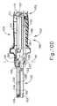
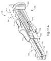
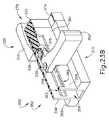
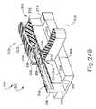
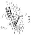
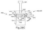
図12〜図14は、各々上述した発射アセンブリ(200)と第1の部分(102)の近位端(103)の代わりとなる、器具(100)に容易に組み込まれ得る例示的な代替的発射アセンブリ(300)と、例示的な代替の第1の部分(350)の例示的な代替的な近位端(352)とを示す。第1の部分(350)は、第1の近位フレーム(351)及び近位キャップ(370)を含み、一方で発射アセンブリは、第1のレバー(310)(すなわち、アクチュエータ又は発射ノブ)と、第2のレバー(320)(すなわち、アクチュエータ又は発射ノブ)と、ステープルスレッドアセンブリ(342)内に遠位に延在する作動ビーム(330)と、を含む。A. Illustrative Launch Assemblies for Independently Acting Double-sided Launch Lever FIGS. 12-14 show instruments (103) that replace the proximal ends (103) of the launch assembly (200) and first portion (102) described above, respectively. An exemplary alternative launch assembly (300) that can be easily incorporated into the 100) and an exemplary alternative proximal end (352) of the exemplary alternative first portion (350) are shown. The first portion (350) includes a first proximal frame (351) and a proximal cap (370), while the launch assembly is with a first lever (310) (ie, actuator or launch knob). , A second lever (320) (ie, an actuator or launch knob) and an actuating beam (330) extending distally within the staple thread assembly (342).
以下により詳細に記載されるように、第1のレバー(310)及び第2のレバー(320)は、第1の部分(350)の反対の面に関連付けられる。第1のレバー(310)及び第2のレバー(320)は、完全近位位置(図12〜図13、図23A、及び図24Aに示すように)から、互いに独立して発射前の側方位置(図23B及び図24Bに示されるように)に枢動するように構成されている。更に、以下でより詳細に説明するように、第1のレバー(310)及び第2のレバー(320)は、互いに独立して発射前の側方位置と発射済み位置との間で長手方向に作動するように構成され、上記の説明に従って、作動ビーム(330)及びステープルスレッドアセンブリ(342)を駆動して、エンドエフェクタ(120)間に捕捉された組織をステープル留め及び切断する。加えて、側方位置に対して枢動しないレバー(310、320)は、作動ビーム(330)の発射中、完全近位位置に留まることができる。レバー(310、320)はまた、レバー(310、320)のスナップを防止するのを助けるために、構造的に強化されてもよい。したがって、操作者は、レバー(310、320)を使用して作動ビーム(330)を発射できる一方で、他のレバー(310、320)は、妨害されない位置に留まる。 As described in more detail below, the first lever (310) and the second lever (320) are associated with the opposite surface of the first portion (350). The first lever (310) and the second lever (320) are lateral to each other independently of each other from the fully proximal position (as shown in FIGS. 12-13, 23A, and 24A). It is configured to pivot to a position (as shown in FIGS. 23B and 24B). Further, as will be described in more detail below, the first lever (310) and the second lever (320) are independent of each other in the longitudinal direction between the pre-launch lateral position and the pre-launch position. It is configured to actuate and drives the actuating beam (330) and staple thread assembly (342) to staple and cut the tissue captured between the end effectors (120) as described above. In addition, the levers (310, 320) that do not pivot with respect to the lateral position can remain in the fully proximal position during the firing of the working beam (330). The levers (310, 320) may also be structurally reinforced to help prevent snapping of the levers (310, 320). Thus, the operator can use the levers (310, 320) to fire the working beam (330), while the other levers (310, 320) remain unobstructed.
近位キャップ(370)は、停止ブロック(374)及びロック突出部(374)を含む。以下でより詳細に説明するように、停止ブロック(374)は、レバー(310、320)が発射アセンブリ(300)及び第1の部分(350)が適切に組み立てられた後に第1の部分(350)と切り離され得ないように、第1及び第2のレバー(310、320)の遠位並進を防止するように寸法決めされる。また、以下で更に詳細に説明するように、ロック突出部(374)は、レバー(310、320)が完全近位位置にあるときに、レバー(310、320)の第1の部分(350)に対する望ましくない移動又は偶発的な移動を防止するために、レバー(310、320)の選択された部分と相互作用するように構成される。 The proximal cap (370) includes a stop block (374) and a lock protrusion (374). As described in more detail below, the stop block (374) has a first part (350) after the levers (310, 320) have properly assembled the firing assembly (300) and the first part (350). ), And are sized to prevent distal translation of the first and second levers (310, 320). Also, as described in more detail below, the lock protrusion (374) is the first portion (350) of the lever (310, 320) when the lever (310, 320) is in the fully proximal position. It is configured to interact with selected parts of the levers (310, 320) to prevent unwanted or accidental movements relative to.
第1の近位フレーム(351)は、上記の第1の近位フレーム(110)と実質的に類似していてもよく、違いは以下で詳述される。したがって、第1の近位フレーム(351)は、一体構造の細長いカートリッジチャネル部材を画定するために、ステープルカートリッジチャネル(122)内に遠位に延在し得る。上述の第1の近位フレーム(110)と同様に、第1の近位フレーム(351)は、発射アセンブリ(300)の作動ビーム(330)を摺動可能に収容するチャネル(358)を画定する。チャネル(358)は、近位キャップ(370)の停止ブロック(372)を受容するように寸法決めされた開放近位端(359)で終端する。示されていないが、近位端(352)は、第2の部分(104)と最初に枢動可能に連結するために、1つ以上の側方ピンを含んでもよい。 The first proximal frame (351) may be substantially similar to the first proximal frame (110) described above, the differences being detailed below. Thus, the first proximal frame (351) may extend distally within the staple cartridge channel (122) to define an integral elongated cartridge channel member. Similar to the first proximal frame (110) described above, the first proximal frame (351) defines a channel (358) that slidably accommodates the working beam (330) of the launch assembly (300). To do. The channel (358) terminates at an open proximal end (359) sized to receive the stop block (372) of the proximal cap (370). Although not shown, the proximal end (352) may include one or more lateral pins to initially pivotally connect to the second portion (104).
第1の近位フレーム(351)は、プラットフォーム(368)と、第1の面(354)と、第2の面(356)と、を含む。プラットフォーム(368)は、発射アセンブリ(300)が作動されている間に第1及び第2のレバー(310、320)を摺動可能に支持するように寸法決めされる。しかし、プラットフォーム(368)は単に任意のものであることを理解されたい。器具(100)が第1の部分(102)を有し、第2の部分(103)は、アクチュエータ(204)の並進に適応するスロット(118)を協働するように画定しているが、第1の近位フレーム(351)の第1の面(354)は、上部スロット(360)を画定し、第1の近位フレーム(351)の第2の面(356)は、下部スロット(362)を画定する。上部スロット(360)及び下部スロット(362)は、第1のレバー(310)及び第2のレバー(320)をそれぞれ摺動可能に収容する。上部スロット(360)及び下部スロット(362)は、作動ビーム(330)が上記の説明に従って発射ストロークを完了し得るように、第1の近位フレーム(351)に沿って適切な距離を遠位に延在することを理解されたい。 The first proximal frame (351) includes a platform (368), a first surface (354), and a second surface (356). The platform (368) is sized to slidably support the first and second levers (310, 320) while the launch assembly (300) is in operation. However, it should be understood that the platform (368) is simply arbitrary. Although the instrument (100) has a first portion (102) and a second portion (103) coordinating a slot (118) that adapts to the translation of the actuator (204), The first surface (354) of the first proximal frame (351) defines the upper slot (360) and the second surface (356) of the first proximal frame (351) is the lower slot (356). 362) is defined. The upper slot (360) and the lower slot (362) slidably accommodate the first lever (310) and the second lever (320), respectively. The upper slot (360) and lower slot (362) are distally appropriate distances along the first proximal frame (351) so that the working beam (330) can complete the firing stroke as described above. Please understand that it extends to.
以下でより詳細に説明するように、上部スロット(360)及び下部スロット(362)は、第1のレバー(310)及び第2のレバー(320)が作動ビーム(330)と適切に連結できるように、互いに垂直にオフセットされる。上部スロット(360)及び下部スロット(362)の両方は、初期連結窓(364)及び枢動ロック窓(366)を画定する。以下で更に詳細に説明するように、初期連結窓(364)は、レバー(310、320)を作動ビーム(330)と最初に枢動可能にかつ摺動可能に連結するために、レバー(310、320)の一部分を受容するように寸法決めされる。枢動ロック窓(366)は、レバー(310、320)が側方に延在する位置へと枢動するときにレバー(310、320)の一部分を受容するように寸法決めされる。 As described in more detail below, the upper slot (360) and lower slot (362) allow the first lever (310) and the second lever (320) to be properly connected to the working beam (330). Are offset vertically to each other. Both the upper slot (360) and the lower slot (362) define the initial connecting window (364) and the pivot lock window (366). As described in more detail below, the initial connecting window (364) initially pivotally and slidably connects the levers (310, 320) to the working beam (330). , 320) are sized to accept a portion. The pivot lock window (366) is sized to receive a portion of the lever (310, 320) as it pivots to a laterally extending position.
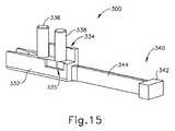
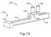
図15〜図16は、作動ビーム(330)の例示的な近位端を示す。作動ビーム(330)は、第1の部分(350)のチャネル(358)内に摺動可能に収容される。作動ビーム(330)及びステープルスレッドアセンブリ(342)は、それぞれ、上述した作動ビーム(202)及びステープルスレッドアセンブリ(160)と実質的に同様であり得、違いは以下で詳述されることを理解されたい。したがって、作動ビーム(330)は、上述の作動ビーム(202)の遠位端(201)と実質的に同様である遠位端(340)に向かって第1の部分(250)のチャネル(358)を通って遠位に延在するビーム部分(344)を含む。したがって、作動ビーム(330)の遠位端(340)は、ステープルスレッドアセンブリ(342)と選択的に連結するように構成されてもよい。あるいは、作動ビーム(330)の遠位端は、ステープルアセンブリ(342)を含み得る。いくつかの図では、明確にするために、ビーム部分(344)及びステープルスレッドアセンブリ(342)は省略されていることを理解されたい。 15-16 show exemplary proximal ends of the working beam (330). The working beam (330) is slidably housed in the channel (358) of the first portion (350). It is understood that the working beam (330) and staple thread assembly (342) can be substantially similar to the working beam (202) and staple thread assembly (160) described above, respectively, and the differences are detailed below. I want to be. Thus, the working beam (330) is directed towards the distal end (340), which is substantially similar to the distal end (201) of the working beam (202) described above, in the channel (358) of the first portion (250). ) Includes a beam portion (344) extending distally through. Therefore, the distal end (340) of the working beam (330) may be configured to selectively connect with the staple thread assembly (342). Alternatively, the distal end of the working beam (330) may include a staple assembly (342). It should be understood that in some figures, the beam portion (344) and the staple thread assembly (342) are omitted for clarity.
図15〜図16に最もよく見られるように、作動ビーム(330)の近位端は、第1及び第2の回転ロックポケット(334、335)を画定する近位本体(332)と、本体(332)から離れるように延在する枢動ポスト(336)と、本体(332)から離れるように延在する把持ポスト(338)と、を含む。第1及び第2の回転ロックポケット(334、335)は、作動ビーム(330)が発射前の近位位置にあるときに、各々上部スロット(360)及び下部スロット(362)の枢動ロック窓(366)と位置合わせするように寸法決めされる(図12〜図13、図20A〜図20D、図23A〜図23B、及び図24A〜図24Bに示すように)。第1及び第2の回転ロックポケット(334、335)は、枢動ポスト(336)と好適に関連付けられたときに互いに垂直にオフセットされたレバー(310、320)のそれぞれの部分を受容するために、互いにまた垂直にオフセットされる。また、以下で更に詳細に説明するように、枢動ロック窓(366)及びロックポケット(334、335)は、レバー(310、320)が側方の、発射前の位置へと枢動するとき、レバー(310、320)の一部をそれぞれ受容するように寸法決めされる。レバー(310、320)のいずれかが側方位置にあり、遠位に作動されると、そのレバー(310、320)は、作動ビーム(330)及び第1の近位フレーム(310)に対して側方に延在する位置に制限される。また、以下で更に詳細に説明するように、枢動ポスト(336)及び把持ポスト(338)は、レバー(310、320)が、上述の説明に従って発射ストロークを通して作動ビーム(330)を駆動することができるように、レバー(310、320)と相互作用するように構成される。 As most often seen in FIGS. 15-16, the proximal ends of the working beam (330) are the proximal body (332) defining the first and second rotary lock pockets (334, 335) and the body. Includes a pivot post (336) extending away from (332) and a gripping post (338) extending away from the body (332). The first and second rotary lock pockets (334, 335) are pivotal lock windows in the upper slot (360) and lower slot (362), respectively, when the working beam (330) is in the proximal position before launch. Dimensioned to align with (366) (as shown in FIGS. 12-13, 20A-20D, 23A-23B, and 24A-24B). The first and second rotary lock pockets (334, 335) are for receiving the respective parts of the levers (310, 320) that are vertically offset from each other when preferably associated with the pivot post (336). Are also offset vertically to each other. Also, as described in more detail below, the pivot lock window (366) and lock pocket (334, 335) are when the levers (310, 320) are pivoted to a lateral, pre-launch position. , Lever (310, 320) are sized to receive, respectively. When any of the levers (310, 320) is in the lateral position and actuated distally, the levers (310, 320) are relative to the actuating beam (330) and the first proximal frame (310). It is limited to a position that extends laterally. Also, as described in more detail below, the pivot post (336) and grip post (338) have levers (310, 320) driving the actuating beam (330) through the firing stroke as described above. It is configured to interact with the levers (310, 320) so that it can.
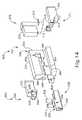
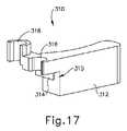
図17〜図18は第1のレバー(310)を示し、対して図19は第2のレバー(320)を示す。第1のレバー(310)は、第1の近位フレーム(351)の第1の面(354)に関連付けられ、一方、第2のレバー(320)は、第1の近位フレーム(351)の第2の面(356)と関連付けられる。第1のレバー(310)は、把持本体(312)と、回転ロック本体(314)と、枢動半体スリーブ(316)と、発射半体スリーブ(318)と、を含む。第1のレバー(310)の把持本体(312)はまた、ロック凹部(311)と開放端部(317)とを部分的に画定する傾斜面(313)を含み、これは、ロック突出部(374)と相互作用してレバー(310)を完全近位位置に選択的にロックするように構成されている。 17 to 18 show the first lever (310), whereas FIG. 19 shows the second lever (320). The first lever (310) is associated with the first surface (354) of the first proximal frame (351), while the second lever (320) is associated with the first proximal frame (351). Is associated with the second surface (356) of. The first lever (310) includes a gripping body (312), a rotary lock body (314), a pivot semifield sleeve (316), and a firing semifield sleeve (318). The gripping body (312) of the first lever (310) also includes an inclined surface (313) that partially defines the locking recess (311) and the open end (317), which is the locking protrusion (31). It is configured to interact with 374) to selectively lock the lever (310) in a fully proximal position.
枢動半体スリーブ(316)は、作動ビーム(330)が近位位置にあるとき、又は第1のレバー(310)が発射ストロークを通して作動ビーム(330)を駆動しているときに、枢動ポスト(336)と枢動可能に連結するように寸法決めされる。発射半体スリーブ(318)は、第1のレバー(310)が側方位置に枢動されるときに、把持ポスト(338)をグリップするように寸法決めされる。第1のレバー(310)の発射半体スリーブ(318)と作動ビーム(330)の把持ポスト(338)との間の相互作用は、例示的な使用中にレバー(310)がスナップするのを防止するのを助けることができる追加的な構造的な支えを提供し得る。枢動半体スリーブ(316)及び発射半体スリーブ(318)は、上部スロット(360)内に挿入されるように寸法決めされる。例示的な使用中に、発射半体スリーブ(318)は上部スロット(360)の内外に枢動するように寸法決めされているが、枢動半体スリーブ(316)は異なる。適切に組み立てられると、停止ブロック(372)は、枢動半体スリーブ(316)が初期連結窓(364)と長手方向に整列されないように、初期連結窓(364)と長手方向に整列される。上部スロット(360)の全ての他の部分は、最初に、初期連結窓(364)が半体スリーブ(316)を通って移動するために枢動するには小さすぎることを予期する。したがって、停止ブロック(372)が適切に組み立てられると、上部スロット(360)及び枢動半体スリーブ(316)により、第1のレバー(310)はチャネル(358)内に拘束される。 The pivotal semifield sleeve (316) is pivotal when the working beam (330) is in the proximal position or when the first lever (310) is driving the working beam (330) through the firing stroke. It is sized to be pivotally connected to the post (336). The firing semifield sleeve (318) is sized to grip the grip post (338) when the first lever (310) is pivoted to the lateral position. The interaction between the firing semifield sleeve (318) of the first lever (310) and the gripping post (338) of the working beam (330) is such that the lever (310) snaps during exemplary use. It may provide additional structural support that can help prevent. The pivot semifield sleeve (316) and the firing semifield sleeve (318) are sized to be inserted into the upper slot (360). During exemplary use, the firing semifield sleeve (318) is sized to pivot in and out of the upper slot (360), but the pivot semifield sleeve (316) is different. When properly assembled, the stop block (372) is longitudinally aligned with the initial connecting window (364) so that the pivotal semifield sleeve (316) is not longitudinally aligned with the initial connecting window (364). .. All other parts of the upper slot (360) are initially expected to be too small for the initial connecting window (364) to pivot to move through the semifield sleeve (316). Therefore, when the stop block (372) is properly assembled, the upper slot (360) and the pivotal semifield sleeve (316) constrain the first lever (310) into the channel (358).
回転ロック本体(314)及び把持本体(312)は、回転ロックチャネル(315)を協働するように画定する。回転ロック本体(314)は、第1のレバー(310)が完全近位位置(図23A及び図24Aに示されるように)から枢動され、側方に延在する発射前の位置(図23B及び図24Bに示されるように)に入るとき、上部スロット(360)の枢動ロック窓(366)を通って第1の回転ロックポケット(334)に挿入されるように寸法決めされる。回転ロック本体(314)は、レバー(310)が側方に延在する位置にあるときにレバー(310)を回転してロックし、遠位に作動させるように構成されている(図23C及び図24Cに示されるように)。具体的には、回転ロック本体(314)は、第1の面(354)の内面と第1の回転ロックポケット(334)との間に限定される。換言すれば、レバー(310)が側方に延在する位置にある間に遠位に作動されると、回転ロックチャネル(315)は、第1の近位フレーム(351)の第1の面(354)を受容し得る。したがって、レバー(310)は、レバー(310)が側方に延在する位置で遠位に作動されるとき、枢動ポスト(336)の周りを枢動しないことがある。加えて、側方に延在する位置にある間にレバー(310)が遠位に作動されると、回転ロック本体(314)はまた、例示的な使用中にレバー(310)がスナップを防止するのを助けるために、構造的支持を与えることができる。 The rotary lock body (314) and grip body (312) define the rotary lock channel (315) to work together. The rotation lock body (314) has a pre-launch position (FIG. 23B) in which the first lever (310) is pivoted from a fully proximal position (as shown in FIGS. 23A and 24A) and extends laterally. And as shown in FIG. 24B), it is sized to be inserted into the first rotary lock pocket (334) through the pivot lock window (366) in the upper slot (360). The rotary lock body (314) is configured to rotate and lock the lever (310) when it is in a laterally extending position to act distally (FIGS. 23C and 23C). (As shown in FIG. 24C). Specifically, the rotary lock body (314) is limited to the inner surface of the first surface (354) and the first rotary lock pocket (334). In other words, when actuated distally while the lever (310) is in a laterally extending position, the rotary lock channel (315) is the first surface of the first proximal frame (351). (354) can be accepted. Therefore, the lever (310) may not pivot around the pivot post (336) when actuated distally in a position where the lever (310) extends laterally. In addition, when the lever (310) is operated distally while in a laterally extending position, the rotary lock body (314) also prevents the lever (310) from snapping during exemplary use. Structural support can be given to help.
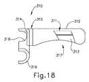
第2のレバー(320)は、第1のレバー(310)と実質的に同様であり、違いは以下に詳述される。したがって、第2のレバー(320)は、把持本体(322)と、回転ロック本体(324)と、枢動半体スリーブ(326)と、発射半体スリーブ(328)と、を含み、これらは上述の把持本体(312)、回転ロック本体(314)、枢動半体スリーブ(316)、及び発射半体スリーブ(318)各々と実質的に同様である。第2のレバー(320)の把持本体(322)はまた、ロック凹部(321)及び開放端部(327)を部分的に画定する傾斜面(323)を含み、これらは各々上記の傾斜面(313)、ロック凹部(311)、及び開放端部(317)と実質的に同様である。加えて、把持本体(322)及び回転ロック本体(314)は、上述の回転ロックチャネル(315)と実質的に同様の回転ロックチャネル(325)を画定する。 The second lever (320) is substantially similar to the first lever (310), the differences being detailed below. Thus, the second lever (320) includes a gripping body (322), a rotary lock body (324), a pivotal semifield sleeve (326), and a firing semifield sleeve (328). It is substantially the same as each of the gripping body (312), the rotary lock body (314), the pivot half body sleeve (316), and the firing half body sleeve (318) described above. The gripping body (322) of the second lever (320) also includes an inclined surface (323) that partially defines the locking recess (321) and the open end (327), each of which is the above-mentioned inclined surface (323). 313), the lock recess (311), and the open end (317) are substantially the same. In addition, the grip body (322) and rotation lock body (314) define a rotation lock channel (325) that is substantially similar to the rotation lock channel (315) described above.
第2のレバー(320)は、回転ロック本体(324)、枢動半体スリーブ(326)、及び発射半体スリーブ(328)が、下部スロット(362)を通って嵌合するために、把持本体(322)の底部に位置し、一方で、回転ロック本体(314)、枢動半体スリーブ(316)、及び発射半体スリーブ(318)は、上部スロット(360)を通って嵌合するために、把持本体(312)の上部に位置する点で、第1のレバー(310)と異なる。この垂直の位置のずれは、作動ビーム(330)が近位の発射前の位置にあるとき、枢動半体スリーブ(316、326)両方が枢動ポスト(336)と連結することを可能にする。加えて、垂直の位置のずれは、所望であれば、第1のレバー(310)及び第2のレバー(320)の両方が、枢動ポスト(336)及び把持ポスト(338)を同時に把持することを可能にする。したがって、所望であれば、操作者は、操作者が発射アセンブリ(300)を駆動するためにレバー(310、320)の両方を作動させることができるように、レバー(310、320)両方を完全近位位置から側方に延在する位置に枢動させることができる。 The second lever (320) grips the rotary lock body (324), the pivot semifield sleeve (326), and the firing semifield sleeve (328) for fitting through the lower slot (362). Located at the bottom of the body (322), while the rotary lock body (314), the pivot semifield sleeve (316), and the firing semifield sleeve (318) fit through the upper slot (360). Therefore, it differs from the first lever (310) in that it is located above the gripping body (312). This vertical misalignment allows both the pivotal semifield sleeves (316, 326) to connect with the pivotal post (336) when the working beam (330) is in the proximal pre-launch position. To do. In addition, the vertical misalignment allows both the first lever (310) and the second lever (320) to simultaneously grip the pivot post (336) and the grip post (338), if desired. Make it possible. Thus, if desired, the operator completes both levers (310, 320) so that the operator can operate both levers (310, 320) to drive the launch assembly (300). It can be pivoted from a proximal position to a laterally extending position.
図20A〜図20Dは、第1のレバー(310)を第1の部分(350)及び作動ビーム(330)に取り付ける例示的な組み立てプロセスを示す。第2のレバー(320)が上部スロット(360)ではなく下部スロット(362)と関連付けられていることを除き、第2のレバー(320)は、実質的に同様の方法で第1の部分(350)と組み立てられてもよいことを理解されたい。図20Aは、第1の近位フレーム(351)から取り外された近位キャップ(370)及び第1のレバー(310)を示す。枢動半体スリーブ(316)は、初期連結窓(364)と好適に整列される。近位キャップ(370)が第1の近位フレーム(351)から取り外されるため、停止ブロック(372)は、初期連結窓(364)からの側方アクセスを現在妨害しない。したがって、図20Bで最も良く見えるように、枢動半体スリーブ(316)は、初期連結窓(364)を介してチャネル(358)に挿入されてもよい。次に、図20Cに示すように、レバー(310)は近位方向に並進することができ、これにより、枢動半体スリーブ(316)は、作動ビーム(330)の枢動ポスト(336)と枢動可能に連結する。次に、図20Dに示すように、係止ブロック(372)が初期連結窓(364)を妨害するように、開放近位端(359)内に停止ブロック(372)を挿入することによって、近位キャップ(370)が第1の近位フレーム(351)と連結され得る。この時点では、第1のレバー(310)は、枢動ポスト(336)と枢動可能に連結され、一方で、上部スロット(360)を介して、第1の近位フレーム(351)と摺動可能に連結されている。 20A-20D show an exemplary assembly process in which the first lever (310) is attached to the first portion (350) and the working beam (330). The second lever (320) is the first part (320) in a substantially similar manner, except that the second lever (320) is associated with the lower slot (362) rather than the upper slot (360). Please understand that it may be assembled with 350). FIG. 20A shows the proximal cap (370) and the first lever (310) removed from the first proximal frame (351). The pivotal semifield sleeve (316) is suitably aligned with the initial connecting window (364). Since the proximal cap (370) is removed from the first proximal frame (351), the stop block (372) does not currently interfere with lateral access from the initial connecting window (364). Therefore, as best visible in FIG. 20B, the pivotal semifield sleeve (316) may be inserted into the channel (358) via the initial connecting window (364). Next, as shown in FIG. 20C, the lever (310) can be translated proximally so that the pivotal semifield sleeve (316) is the pivotal post (336) of the working beam (330). And pivotally connected. Next, as shown in FIG. 20D, the stop block (372) is inserted into the open proximal end (359) so that the locking block (372) interferes with the initial connecting window (364). The position cap (370) may be connected to the first proximal frame (351). At this point, the first lever (310) is pivotally connected to the pivot post (336), while sliding with the first proximal frame (351) via the upper slot (360). It is movably connected.
上述したように、第1のレバー(310)は、ロック凹部(311)及び開放端部(317)を部分的に画定する傾斜面(313)を含み、一方で第2のレバー(320)は、ロック凹部(321)及び開放端部(327)を部分的に画定する傾斜面(323)を含む。ロック凹部(311、321)、開放端部(317、327)、及び傾斜面(313、323)は、ロック突出部(374)と相互作用して、レバー(310、320)が、例示的な使用中にレバー(310、320)が偶発的に枢動するか、完全近位位置から離れるように作動するのを防ぐように、完全近位位置で選択的にロックするよう構成されている。図21〜図22Bは、第1のレバー(310)を完全近位位置に選択的にロックするための、ロック凹部(311)、傾斜面(313)、及び開放端部(317)の例示的な使用を示す。しかし、第2のレバー(320)は、実質的に同様の方法で操作することができることを理解されたい。 As mentioned above, the first lever (310) includes an inclined surface (313) that partially defines the locking recess (311) and the open end (317), while the second lever (320) Includes an inclined surface (323) that partially defines the lock recess (321) and the open end (327). Lock recesses (311 and 321), open ends (317, 327), and inclined surfaces (313, 323) interact with lock protrusions (374), with levers (310, 320) being exemplary. It is configured to selectively lock in the fully proximal position to prevent accidental pivoting of the levers (310, 320) or actuation away from the fully proximal position during use. 21-22B are exemplary of locking recesses (311), inclined surfaces (313), and open ends (317) for selectively locking the first lever (310) in a fully proximal position. Indicates a good use. However, it should be understood that the second lever (320) can be operated in substantially the same manner.
図22Aに示されるように、開放端部(317)は、レバー(310)が完全近位位置に向かって枢動するときに、ロック突出部(374)を受容するように寸法決めされ、これにより、ロック突出部(374)は傾斜面(313)に対してバットすることができる。図21は、ロック突出部(374)が開口部内にないときに第1の部分的に側方に延在する位置まで枢動された第1のレバー(310)を示す。図22Bに最もよく示されるように、操作者は更に、レバー(310)を完全近位位置に向かって枢動させてもよく、そのようなロック突出部(374)は、もはや傾斜面(313)に当接していないが、ロック凹部(311)内に収容され、第1のレバー(310)を効果的に係止する。ロック突出部(374)とロック凹部(311)との間の相互作用は、第1のレバー(310)が偶発的に枢動又は完全近位位置から離れるように作動することを防止するのに役立ち得る。第1のレバー(310)が完全近位位置にロックされると、突出部(374)がロック凹部(311)内に収容されることにより、第1のレバー(310)は遠位に並進せずともよい。しかし、操作者が第1のレバー(310)を側方に延在する位置に枢動させることを望む場合、操作者は、第1のレバー(310)を側方外側に枢動させて、突出部(374)が傾斜面(313)に対して乗り上げて、第1のレバー(310)をロック突出部(374)から「ロック解除」するよう駆り立てることができる。換言すれば、第1のレバー(310)は、図22Bに示される「ロック」位置と、スナップ嵌め又は締まり嵌め機構を介して、図21に示される「ロック解除」位置との間で枢動することができる。本実施例では、ロック凹部(311)及びロック突出部(374)は、ロック位置とロック解除位置との間でレバー(310)を移行させるために使用されているが、本明細書の教示を鑑みる当業者に明らかであるように、任意の他の好適な手段を使用することができる。 As shown in FIG. 22A, the open end (317) is sized to receive the lock protrusion (374) as the lever (310) pivots towards a fully proximal position. As a result, the lock protrusion (374) can butt against the inclined surface (313). FIG. 21 shows a first lever (310) pivoted to a position that partially extends laterally when the lock protrusion (374) is not in the opening. As best shown in FIG. 22B, the operator may further pivot the lever (310) towards a fully proximal position, such a lock protrusion (374) is no longer an inclined surface (313). ), But housed in a locking recess (311) to effectively lock the first lever (310). The interaction between the lock protrusion (374) and the lock recess (311) prevents the first lever (310) from accidentally moving away from the pivot or fully proximal position. Can be useful. When the first lever (310) is locked in a fully proximal position, the protrusion (374) is housed in the locking recess (311) so that the first lever (310) translates distally. It doesn't have to be. However, if the operator wishes to pivot the first lever (310) to a laterally extending position, the operator pivots the first lever (310) laterally outward. The protrusion (374) can ride on the inclined surface (313) to urge the first lever (310) to "unlock" from the lock protrusion (374). In other words, the first lever (310) pivots between the "locking" position shown in FIG. 22B and the "unlocking" position shown in FIG. 21 via a snap-fitting or tightening fitting mechanism. can do. In this embodiment, the lock recess (311) and lock protrusion (374) are used to shift the lever (310) between the lock position and the unlock position. Any other suitable means can be used, as will be apparent to those skilled in the art.
図23A〜図24Cは、発射アセンブリ(300)の例示的な使用を示す。図23A及び図24Aは、近位、発射前の位置の両方の第1及び第2のレバー(310、320)を示す。この時点では、レバー(310、320)の両方が、上記の説明に従って「ロック位置」にあることを理解されたい。次に、エンドエフェクタ(120)が上記の説明に従って組織を適切に把持した後、操作者は、エンドエフェクタ(120)間に捕捉された組織をステープル留め及び切断することを望む場合がある。したがって、図23A〜図23Bと図24A〜図24Bとの間に示されるように、操作者は、レバー(310)を近位の発射前の位置から側方に延在する発射前位置に枢動させて、把持半体スリーブ(318)が上部スロット(360)を介してチャネル(358)内に延在して、把持ポスト(338)に連結されて、回転ロック本体(314)が枢動ロック窓(366)を通って第1の回転ロックポケット(334)に挿入される。第1のレバー(310)は、図23B及び図24Bに示されるように、側方の発射前位置へと枢動され、第2のレバー(320)は、「ロックされた」近位の発射前の位置に留まることができることを理解されたい。本実施例では、操作者は、発射アセンブリ(300)を作動させるために第1のレバー(310)を使用するが、操作者はまた、第2のレバー(320)を使用してもよく、又は更には所望であればレバー(310、320)両方を使用してもよいことを理解されたい。 23A-24C show exemplary use of the launch assembly (300). 23A and 24A show first and second levers (310, 320) both proximal and pre-launch positions. At this point, it should be understood that both levers (310, 320) are in the "locked position" as described above. The operator may then wish to staple and cut the tissue trapped between the end effectors (120) after the end effector (120) has properly gripped the tissue as described above. Thus, as shown between FIGS. 23A-23B and 24A-24B, the operator pivots the lever (310) to a pre-launch position that extends laterally from the proximal pre-launch position. In motion, the gripping semifield sleeve (318) extends into the channel (358) via the upper slot (360) and is connected to the gripping post (338), causing the rotary lock body (314) to pivot. It is inserted into the first rotary lock pocket (334) through the lock window (366). The first lever (310) is pivoted to a lateral pre-launch position, as shown in FIGS. 23B and 24B, and the second lever (320) is a "locked" proximal launch. Please understand that you can stay in the previous position. In this embodiment, the operator uses the first lever (310) to actuate the launch assembly (300), but the operator may also use the second lever (320). It should be understood that both levers (310, 320) may be used, or even if desired.
次に、図23C及び図24Cに示すように、操作者は、上の説明に従ってエンドエフェクタ(120)間に捕捉された組織をステープル留め及び切断するために、レバー(310)及び作動ビーム(330)を遠位に作動させてもよい。第2のレバー(320)は、本実施例における発射プロセス中に、近位の発射前の位置に留まることを理解されたい。したがって、第2のレバー(320)は、例示的な使用中、器具(100)を把持する操作者を妨げられない。また、作動ビーム(330)が遠位に前進している間、第2のレバー(220)の把持半体スリーブ(228)は、もはや把持ポスト(338)と連結されないことも理解されたい。しかし、ひとたび作動ビーム(330)が発射サイクルを完了し、近位位置へと戻るように作動されると、把持ポスト(338)及び把持半体スリーブ(228)は回復し得る。 Next, as shown in FIGS. 23C and 24C, the operator staples and cuts the tissue captured between the end effectors (120) as described above with the lever (310) and actuating beam (330). ) May be actuated distally. It should be understood that the second lever (320) remains in the proximal pre-launch position during the launch process in this embodiment. Therefore, the second lever (320) does not interfere with the operator gripping the instrument (100) during exemplary use. It should also be appreciated that the gripping semifield sleeve (228) of the second lever (220) is no longer connected to the gripping post (338) while the working beam (330) is advancing distally. However, once the actuating beam (330) has completed the firing cycle and is actuated to return to the proximal position, the gripping post (338) and gripping semifield sleeve (228) can be restored.
B.非突出の外形の二面発射レバーを有する例示的な発射アセンブリ
図25は、上述のリニアカッティングステープル(100)の交換に使用され得る、代替の例示的なリニアカッティングステープラ(400)を示す。ステープラ(400)は、第1の部分(402)と、第2の部分(404)と、エンドエフェクタ(420)と、を含み、上述の第1の部分(102)、第2の部分(104)、及びエンドエフェクタ(120)と実質的に同様であり、以下に詳述する相違点を有する。したがって、ステープラ(400)は、上記の第1の面(116)、第2の面(117)、及びスロット(118)と実質的に同様であるスロット(418)を画定する第1の面(416)及び第2の面(417)を有する。更に、器具(400)は、近位端(403)と、アンビル(430)と、ステープルカートリッジチャネル(422)と、ステープルカートリッジアセンブリ(450)と、ステープルデッキ(458)と、ラッチレバー(480)と、アームカバー(486)と、を有し、これらはそれぞれ上述した近位端(103)、アンビル(130)、ステープルカートリッジチャネル(122)、ステープルカートリッジアセンブリ(150)、ステープルデッキ(158)、ラッチレバー(180)、及びアームカバー(186)と実質的に同様である。B. An exemplary launch assembly with a non-protruding two-sided launch lever FIG. 25 shows an alternative exemplary linear cutting stapler (400) that can be used to replace the linear cutting staples (100) described above. The stapler (400) includes a first portion (402), a second portion (404), and an end effector (420), and the first portion (102) and the second portion (104) described above are included. ), And the end effector (120), with the differences detailed below. Therefore, the stapler (400) defines a first surface (116), a second surface (117), and a slot (418) that is substantially similar to the slot (118). It has 416) and a second surface (417). In addition, the appliance (400) includes a proximal end (403), an anvil (430), a staple cartridge channel (422), a staple cartridge assembly (450), a staple deck (458), and a latch lever (480). And an arm cover (486), which have the above-mentioned proximal end (103), anvil (130), staple cartridge channel (122), staple cartridge assembly (150), staple deck (158), respectively. It is substantially the same as the latch lever (180) and the arm cover (186).
本実施例におけるステープラ(400)は、近位本体(503)と、作動ビーム(502)と、ステープルスレッドアセンブリ(501)と、を備える発射アセンブリ(500)を有する。作動ビーム(5020及びステープルスレッドアセンブリ(501)は、上述の作動ビーム(202)及びステープルスレッドアセンブリ(160)と実質的に同様であり得る。しかし、近位本体(503)は、摺動連結アーム(506)を摺動可能に収容する横方向チャネル(505)を画定する。摺動連結アーム(506)は、第1のピン(508)及び第2のピン(509)を含む。第1のピン(508)は、第1の面(416)に位置する第1のレバー(510)と関連付けられ、一方、第2のピン(509)は、第2の面(417)に位置する第2のレバー(514)と関連付けられる。以下でより詳細に説明するように、第1のレバー(510)及び第2のレバー(514)は、両方とも近位本体(503)及び作動ビーム(502)と連結されており、これにより、例示的な使用中に両方のレバー(510、520)が作動ビーム(502)及びステープルスレッドアセンブリ(501)と共に作動する。しかし、以下でまた更に詳細に説明するように、第1のレバー(510)及び第2のレバー(514)は、それぞれピン(508、509)と枢動可能に連結され、1つのレバー(510、514)が側方に延在する位置へと枢動されるときに、他方のレバー(510、514)は、上の説明による発射ストローク中に非突出位置へと内側に枢動され、内側に枢動されたレバー(510、514)が器具(400)を把持する操作者を妨げないようにする。 The stapler (400) in this embodiment has a launch assembly (500) comprising a proximal body (503), an actuating beam (502), and a staple thread assembly (501). The working beam (5020 and staple thread assembly (501) can be substantially similar to the working beam (202) and staple thread assembly (160) described above, but the proximal body (503) is a sliding connecting arm. A lateral channel (505) that slidably accommodates (506) is defined. The sliding connection arm (506) includes a first pin (508) and a second pin (509). A pin (508) is associated with a first lever (510) located on the first surface (416), while a second pin (509) is located on a second surface (417). The first lever (510) and the second lever (514) are both proximal body (503) and actuating beam (502), as will be described in more detail below. Connected with, this allows both levers (510, 520) to operate with the actuating beam (502) and staple thread assembly (501) during exemplary use, but will be described in more detail below. Thus, the first lever (510) and the second lever (514) are pivotally connected to the pins (508, 509), respectively, with one lever (510, 514) extending laterally. When pivoted to position, the other lever (510, 514) was pivoted inward to a non-protruding position during the firing stroke as described above and was pivoted inward (510, 514). ) Does not interfere with the operator holding the instrument (400).
具体的には、各レバー(510、520)は、カムスロット(512、516)を画定し、ピン(508、509)をそれぞれ収容する。カムスロット(512、516)は、それぞれのレバーが側方に延在する位置に枢動されると、ピン(508、509)と接触するように構成される。例えば、図26Aは、近位の発射前の位置にある第1のレバー(510)及び第2のレバー(514)の両者を示す。図26Bに示すように、操作者は、発射アセンブリ(500)を作動させるために第2のレバー(514)を作動させる準備において、第2のレバー(514)を側方に延在する位置に枢動させることができる。第2のレバー(514)が側方に延在する位置へと枢動すると、カムスロット(516)はピン(509)と接触し、それによってピン(509)を近位本体(503)から側方に離れるように押す。結果として、摺動連結アーム(506)は、近位本体(503)の横方向チャネル(505)内で摺動し、それによってピン(508)を近位本体(503)に向かって摺動させる。これにより、ピン(508)は、発射中にレバー(510)を近位本体(503)に向かって非突出の外形に回転させるために、カムスロット(512)と接触する。したがって、使用者が、上記の説明に従って第2のレバー(514)を作動させて発射アセンブリ(500)を作動させると、第1のレバー(510)は器具(400)の把持を妨げない場合がある。 Specifically, each lever (510, 520) defines a cam slot (512, 516) and houses a pin (508, 509), respectively. The cam slots (512, 516) are configured to come into contact with the pins (508, 509) when each lever is pivoted to a laterally extending position. For example, FIG. 26A shows both the first lever (510) and the second lever (514) in the proximal pre-launch position. As shown in FIG. 26B, the operator is in a position where the second lever (514) extends laterally in preparation for activating the second lever (514) to activate the launch assembly (500). Can be pivoted. When the second lever (514) is pivoted to a laterally extending position, the cam slot (516) contacts the pin (509), thereby displacing the pin (509) from the proximal body (503). Push away from it. As a result, the sliding coupling arm (506) slides within the lateral channel (505) of the proximal body (503), thereby sliding the pin (508) towards the proximal body (503). .. This causes the pin (508) to contact the cam slot (512) during firing to rotate the lever (510) towards the proximal body (503) in a non-protruding outer shape. Therefore, when the user activates the second lever (514) to activate the launch assembly (500) according to the above description, the first lever (510) may not interfere with the gripping of the instrument (400). is there.
図26Cに示すように、操作者は、第2のレバー(510)を作動させて発射アセンブリ(500)を作動させる準備において、第1のレバー(510)を側方に延在する位置に枢動させることができる。第1のレバー(510)が側方に延在する位置へと枢動すると、カムスロット(512)はピン(508)と接触し、それによってピン(508)を近位本体(503)から離れるように側方に押す。結果として、摺動連結アーム(506)は、近位本体(503)の横方向チャネル(505)内で摺動し、それによってピン(509)を近位本体(503)に向かって摺動させる。これにより、ピン(509)は、発射中にレバー(514)を近位本体(503)に向かって非突出の外形にレバー(514)を回転させるために、カムスロット(516)と接触する。したがって、使用者が、上記の説明に従って第1のレバー(510)を作動させて発射アセンブリ(500)を作動させると、第2のレバー(514)は器具(400)の把持を妨げられない。 As shown in FIG. 26C, the operator pivots the first lever (510) laterally in preparation for activating the second lever (510) to activate the launch assembly (500). Can be moved. When the first lever (510) pivots to a laterally extending position, the cam slot (512) contacts the pin (508), thereby separating the pin (508) from the proximal body (503). Push it to the side. As a result, the sliding coupling arm (506) slides within the lateral channel (505) of the proximal body (503), thereby sliding the pin (509) towards the proximal body (503). .. This causes the pin (509) to come into contact with the cam slot (516) to rotate the lever (514) into a non-protruding outer shape towards the proximal body (503) during firing. Therefore, when the user activates the first lever (510) to activate the launch assembly (500) according to the above description, the second lever (514) does not interfere with the gripping of the instrument (400).
図27は、上述したレバー(510、514)の代わりに、発射アセンブリ(500)に容易に組み込まれ得る代替レバー(518)を示す。本実施例における代替レバー(518)は、上述のレバー(510、514)と実質的に同様であり得る。ただし、このレバー(518)がカムスロット(520)及びロックスロット(522)を画定し、一方で、摺動連結アーム(506)が代替ピン(507)を有することを除いてのことである。代替レバー(518)は、上記のレバー(510、514)と実質的に同様に動作し得る。それは、側方に延在する位置へと枢動すると、カムスロット(520)がピン(507)と相互作用して、上述の摺動連結アーム(506)を作動させる点においてである。しかし、レバー(518)は、いったん側方に延在する位置へと枢動すると、ピン(507)がロックスロット(522)に入ることができ、それによって例示的な使用中にレバー(518)の角度位置をロックするのを助ける。 FIG. 27 shows an alternative lever (518) that can be easily incorporated into the launch assembly (500) instead of the levers (510, 514) described above. The alternative lever (518) in this embodiment can be substantially similar to the lever (510, 514) described above. Except that this lever (518) defines a cam slot (520) and a lock slot (522), while the sliding connecting arm (506) has an alternative pin (507). The alternative lever (518) can operate substantially the same as the lever (510, 514) described above. It is in that when pivoted to a laterally extending position, the cam slot (520) interacts with the pin (507) to actuate the sliding connection arm (506) described above. However, once the lever (518) is pivoted to a laterally extending position, the pin (507) can enter the lock slot (522), thereby allowing the lever (518) to enter during exemplary use. Helps to lock the angular position of.
図28〜図29は、代替の第1のポーション(562)と共に使用され得る代替の発射アセンブリ(530)を示す。発射アセンブリ(530)及び第1の部分(562)は、それぞれ上述の発射アセンブリ(500)及び第1の部分(402)の代わりに、器具(400)に容易に組み込むことができる。発射アセンブリ(530)は、第1の発射レバー(540)と、第2の発射レバー(550)と、を含み、近位本体(533)と、作動ビーム(532)と、ステープルスレッドアセンブリ(531)と、を含む。作動している近位本体(533)、ビーム(532)、及びステープルスレッドアセンブリ(531)は、各々上述した近位本体(503)、作動ビーム(502)、及びステープルスレッドアセンブリ(501)と実質的に同様であってもよい。 28-29 show an alternative launch assembly (530) that can be used with an alternative first portion (562). The launch assembly (530) and the first portion (562) can be easily incorporated into the instrument (400) in place of the launch assembly (500) and the first portion (402) described above, respectively. The launch assembly (530) includes a first launch lever (540), a second launch lever (550), a proximal body (533), an actuating beam (532), and a staple thread assembly (531). ) And, including. The working proximal body (533), beam (532), and staple thread assembly (531) are substantially the same as the proximal body (503), working beam (502), and staple thread assembly (501) described above, respectively. It may be the same.
近位本体(533)は、摺動連結アーム(536)を摺動可能に収容する横方向チャネル(535)を画定する。摺動連結アーム(536)は、反対側のピン穴(537)を画定し、各々ピン(538)を受容するように構成されている。第1のレバー(540)及び第2のレバー(550)はそれぞれ同様に、ピン(538)を再生するように寸法決めされたピン穴(546、556)を画定する。したがって、ピン(538)はレバー(550、540)を摺動連結アーム(536)と連結する。レバー(540、550)はそれぞれ、それぞれのレバー(540、550)が側方に延在する位置にあるときに摺動連結アーム(536)の一部分を受容するように寸法決めされた受容スロット(542、552)を画定する。加えて、各レバー(540、550)は、それぞれカム本体(544、554)を含む。それぞれのレバー(540、550)が側方に延在する位置へと枢動されると、カム本体(544)は第1の部分(562)の適切な要素に当接でき、それによって、摺動連結アーム(536)を横方向チャネル(535)内で並進させ、レバー(540、550)を引っ張り、側方に延在する位置へ、非突出位置へと枢動しない。図29で最も良く見えるように、第1の部分(562)は、作動ビーム(532)、第1のレバーチャネル(564)、及び第2のレバーチャネル(568)を摺動可能に受容する発射チャネル(562)を画定する。側方に延在する位置へと回転させないレバー(550)は、発射アセンブリ(530)の作動中に、レバーチャネル(568)内に完全に収容され得る。図29で最も良く見えるように、側方に延在する位置にあるレバー(540)は、発射アセンブリ(530)の作動中に発射チャネル(566)内にカム本体(544)のみを有してもよい。 The proximal body (533) defines a lateral channel (535) that slidably accommodates the sliding coupling arm (536). The sliding connection arm (536) is configured to define a pin hole (537) on the opposite side and to receive each pin (538). The first lever (540) and the second lever (550) similarly define pin holes (546, 556) sized to regenerate the pin (538). Therefore, the pin (538) connects the lever (550, 540) to the sliding connecting arm (536). Each of the levers (540, 550) has a receiving slot (540) sized to receive a portion of the sliding connecting arm (536) when each lever (540, 550) is in a laterally extending position. 542, 552) are defined. In addition, each lever (540, 550) includes a cam body (544, 554), respectively. When each lever (540, 550) is pivoted to a laterally extending position, the cam body (544) can contact the appropriate element of the first portion (562), thereby sliding. The dynamic connecting arm (536) is translated within the lateral channel (535), the lever (540, 550) is pulled and does not pivot to a laterally extending position or to a non-protruding position. As best visible in FIG. 29, the first portion (562) is a launch that slidably receives the working beam (532), the first lever channel (564), and the second lever channel (568). The channel (562) is defined. A lever (550) that does not rotate to a laterally extending position can be fully contained within the lever channel (568) during operation of the launch assembly (530). As best visible in FIG. 29, the lever (540) in a laterally extending position has only the cam body (544) in the launch channel (566) during operation of the launch assembly (530). May be good.
図30A〜図30Bは、上記の器具(400)に容易に組み込むことができる、代替的な発射アセンブリ(570)を示す。発射アセンブリ(570)は、近位本体(573)と、作動ビーム(572)と、ステープルスレッドアセンブリ(571)と、第1の発射レバー(580)と、第2の発射レバー(586)と、接続端部(594、592)を介して各発射レバー(580、586)に連結されたリンケージアーム(590)と、を含む。近位本体(573)は、発射レバー(586、582)の連結スリーブ(588、582)と枢動可能に連結された枢動ポスト(574、575)を含む。したがって、レバー(586、582)の作動は、近位本体(573)、作動ビーム(572)、及びステープルスレッドアセンブリ(571)を駆動する。加えて、例示的な使用中、両方のレバー(580、586)は、作動ビーム(572)及びステープルスレッドアセンブリ(571)と共に作動する。しかし、第1のレバー(580)及び第2のレバー(586)は、ポスト(574、575)と枢動可能に連結されて、1つのレバー(580、586)が側方に延在する位置へと枢動されるときに、他方のレバー(580、586)が、上記の説明による発射ストローク中に、内側枢動レバー(580、586)が器具(400)を把持する操作者を妨げないように、非突出位置へと内側に枢動される。図30A〜図30Bに最もよく見られるように、1つのレバー(580、586)が側方に延出する外向きの位置へと枢動するとき、リンケージアーム(590)は、他方のレバー(580、586)を非突出位置へと回転させる。各レバー(580、586)は、レバー(580、586)が図30A〜図30Bに示される位置の間で互いに対して枢動するとき、互いに当接するように寸法決めされた、輪郭形成された接触本体(584、858)を有する。 30A-30B show an alternative launch assembly (570) that can be easily incorporated into the instrument (400) above. The launch assembly (570) includes a proximal body (573), an actuating beam (572), a staple thread assembly (571), a first launch lever (580), and a second launch lever (586). Includes a linkage arm (590) connected to each firing lever (580, 586) via connecting ends (594, 592). The proximal body (573) includes a pivot post (574, 575) that is pivotally coupled to a connecting sleeve (588, 582) of the firing lever (586, 582). Therefore, the actuation of the levers (586, 582) drives the proximal body (573), the actuating beam (572), and the staple thread assembly (571). In addition, during exemplary use, both levers (580, 586) operate with the actuating beam (572) and staple thread assembly (571). However, the first lever (580) and the second lever (586) are pivotally connected to the post (574, 575) so that one lever (580, 586) extends laterally. When pivoted to, the other lever (580, 586) does not interfere with the operator gripping the instrument (400) with the inner pivot lever (580, 586) during the firing stroke as described above. As such, it is pivoted inward to a non-protruding position. As is most often seen in FIGS. 30A-30B, when one lever (580, 586) pivots to an outward position that extends laterally, the linkage arm (590) is the other lever (590). 580, 586) is rotated to the non-protruding position. Each lever (580, 586) was contoured, sized to abut against each other as the levers (580, 586) pivoted relative to each other between the positions shown in FIGS. 30A-30B. It has a contact body (584, 858).
図31A〜図31Cは、上記の器具(400)に容易に組み込むことができる、代替的な発射アセンブリ(600)を示す。発射アセンブリ(600)は、近位適合レバー保持本体(603)と、作動ビーム(602)と、ステープルスレッドアセンブリ(601)と、発射レバー(612)と、を含む。作動ビーム(602)及びステープルスレッドアセンブリ(601)は、上述の作動ビーム(502)及びステープルスレッドアセンブリ(501)と実質的に同様である。以下により詳細に記載されるように、発射レバー(510)は、発射レバー(510)が器具(400)の両面(416、417)からアクセス可能であり得るように、近位適合レバー保持本体(603)内で側方に摺動するように構成される。近位本体(603)は、第1の面適合チャンバと、中間適合チャンバ(609)と、第2の面適合チャンバ(610)とを有する横方向チャネル(606)を画定する。近位本体(603)は、弾性材料から作製される。各適合チャンバ(608、609、610)は、発射レバー(612)の中間突出部(618)を収容するように構成される。 31A-31C show an alternative launch assembly (600) that can be easily incorporated into the instrument (400) above. The firing assembly (600) includes a proximally fitted lever holding body (603), an actuating beam (602), a staple thread assembly (601), and a firing lever (612). The working beam (602) and staple thread assembly (601) are substantially similar to the working beam (502) and staple thread assembly (501) described above. As described in more detail below, the launch lever (510) is a proximally compatible lever holding body (410) so that the launch lever (510) can be accessed from both sides (416, 417) of the appliance (400). It is configured to slide laterally within 603). The proximal body (603) defines a lateral channel (606) having a first surface conforming chamber, an intermediate conforming chamber (609), and a second surface conforming chamber (610). The proximal body (603) is made of elastic material. Each compatible chamber (608, 609, 610) is configured to accommodate an intermediate protrusion (618) of the firing lever (612).
発射レバー(612)は、第1の側面(614)と、第2の側面(616)と、中間突出部と、を含む。図31A〜31Cで最も良く見られるように、発射レバー(612)は、横方向チャネル(606)内で中間位置から(図31A)、第1の側方位置(図31B)、及び第2の側方位置(図31C)の内部で摺動してもよい。以下でより詳細に説明するように、操作者は、発射アセンブリ(600)を作動させるために、第1の側面(614)又は第2の側面(616)にアクセスするために、それぞれの位置の間でレバー(612)を押す及び/又は引くことができる。 The firing lever (612) includes a first side surface (614), a second side surface (616), and an intermediate protrusion. As most often seen in FIGS. 31A-31C, the launch lever (612) is located in the lateral channel (606) from an intermediate position (FIG. 31A), a first lateral position (FIG. 31B), and a second. It may slide inside the lateral position (FIG. 31C). As described in more detail below, the operator is at each position to access the first side surface (614) or the second side surface (616) to activate the launch assembly (600). The lever (612) can be pushed and / or pulled between.
中間位置にある間、中間突出部(618)は、中央適合チャンバ(609)内に位置されてもよい。中間適合チャンバ(609)を画定する近位本体(603)の内面は、レバー(612)が近位本体(603)に対して静止したままであるように、中間突出部(618)と係合するように構成されている。この時点では、第1の側面(614)又は第2の側面(616)は、部分的に横方向チャネル(606)内にあってもよい。しかし、近位本体(603)は、十分に適合性があって弾性であるようにし、操作者が所望する場合に、これらが、発射レバー(612)を近位本体(603)のいずれかの側面に摺動させることができ、中間突出部(618)が第2の面適合チャンバ(610)の第1の面適合チャンバ(608)いずれかの内部で摺動するようにする。そのような例では、横方向チャネル(606)を画定する内部又は近位本体(603)は、中間突出部(618)がチャンバ(608、609、610)内で摺動し得るように拡張することができる。中央の製造(618)がいずれかのチャンバ(608、609、610)の内部にあり、操作者がレバー(612)を押す/引くことを停止すると、適合性及び/又は弾性の性質、又は近位本体(603)は、レバー(612)の中間突出部(614)に再係合する。したがって、操作者は、作動ビーム(602)及びステープルスレッドアセンブリ(601)を把持及び発射するために、第1の側面(614)又は第2の側面(616)のいずれかが露出されるように、レバー(612)を側方に押す/引くことができる。 While in the intermediate position, the intermediate protrusion (618) may be located within the central conformance chamber (609). The inner surface of the proximal body (603) defining the intermediate fit chamber (609) engages the intermediate overhang (618) such that the lever (612) remains stationary with respect to the proximal body (603). It is configured to do. At this point, the first side surface (614) or the second side surface (616) may be partially within the lateral channel (606). However, the proximal body (603) is made to be sufficiently compatible and elastic so that, if the operator so desires, these will cause the firing lever (612) to be one of the proximal bodies (603). It can be slid to the side surface so that the intermediate protrusion (618) slides inside any of the first surface compatible chambers (608) of the second surface compatible chamber (610). In such an example, the internal or proximal body (603) defining the lateral channel (606) extends such that the intermediate protrusion (618) can slide within the chamber (608, 609, 610). be able to. When the central manufacturing (618) is inside one of the chambers (608, 609, 610) and the operator stops pushing / pulling the lever (612), the suitability and / or elastic properties, or near The position body (603) reengages the intermediate protrusion (614) of the lever (612). Thus, the operator may expose either the first side surface (614) or the second side surface (616) to grip and fire the actuating beam (602) and staple thread assembly (601). , The lever (612) can be pushed / pulled sideways.
図32〜図33は、器具(400)に容易に組み込むことができる、別の発射アセンブリ(620)を示す。発射アセンブリ(600)は、カムスロット(624)を画定する近位本体(623)と、近位本体(623)に連結された作動ビーム(622)と、作動ビーム(622)と連結されたステープルスレッドアセンブリ(621)と、発射レバー(630)と、を含む。作動ビーム(622)及びステープルスレッドアセンブリ(621)は、上述の作動ビーム(502)及びステープルスレッドアセンブリ(501)と実質的に同様であり得る。以下により詳細に記載されるように、発射レバー(630)の一部分がカムスロット(624)の領域内で摺動可能に連結され、発射レバー(630)が側方に押されるか引かれると、発射レバー(330)が回転する。 32 to 33 show another launch assembly (620) that can be easily incorporated into the instrument (400). The launch assembly (600) comprises a proximal body (623) defining a cam slot (624), an actuating beam (622) connected to the proximal body (623), and a staple coupled to the actuating beam (622). Includes a thread assembly (621) and a firing lever (630). The working beam (622) and staple thread assembly (621) can be substantially similar to the working beam (502) and staple thread assembly (501) described above. As described in more detail below, when a portion of the launch lever (630) is slidably connected within the area of the cam slot (624) and the launch lever (630) is pushed or pulled laterally The firing lever (330) rotates.
発射レバー(630)は、第1の発射アーム(632)と、第2の発射アーム(634)と、第1の発射アーム(632)と第2の発射アーム(634)との間に位置するねじり部分(636)と、ねじり部分(636)に隣接する第1の発射アーム(632)と第2の発射アーム(634)の一部に沿って位置する側方突出部(635)と、を含む。ねじり部分(636)は、カムスロット(624)の領域内にあり、操作者が発射レバー(630)を押す又は引くことができ、その結果、ねじり部分(636)及びカムスロット(624)は、発射レバー(630)を近位本体(623)に対して回転させて互いに相互作用することができる。具体的には、発射レバー(630)が図33Aに示される位置にあるとき、第2の発射アーム(634)は、発射アセンブリ(620)を作動させるために把持され得る。発射レバー(630)が図33Bに示される位置にあるとき、第1の発射アーム(632)は、発射アセンブリ(620)を作動させるために把持され得る。したがって、操作者は、操作者が発射レバー(630)を把持することを望む面に向かって発射レバー(630)を押す/引くことができる。側方突出部(635)は、発射レバー(630)が近位本体(623)と会合しないように寸法決めされる。 The launch lever (630) is located between the first launch arm (632), the second launch arm (634), and the first launch arm (632) and the second launch arm (634). A twisted portion (636) and a lateral protrusion (635) located along a portion of the first launch arm (632) and the second launch arm (634) adjacent to the twisted portion (636). Including. The twisted portion (636) is within the area of the cam slot (624) and the operator can push or pull the firing lever (630) so that the twisted portion (636) and the cam slot (624) are The firing lever (630) can be rotated relative to the proximal body (623) to interact with each other. Specifically, when the launch lever (630) is in the position shown in FIG. 33A, the second launch arm (634) can be gripped to actuate the launch assembly (620). When the launch lever (630) is in the position shown in FIG. 33B, the first launch arm (632) may be gripped to actuate the launch assembly (620). Thus, the operator can push / pull the launch lever (630) towards the surface on which the operator wishes to grip the launch lever (630). The lateral protrusion (635) is sized so that the firing lever (630) does not meet the proximal body (623).
III.例示的な組み合わせ
以下の実施例は、本明細書の教示を組み合わせるか又は適用することができる、種々の非網羅的な方法に関する。以下の実施例は、本出願における又は本出願後の出願におけるどの時点でも提示され得る、いずれの特許請求の範囲の適用範囲をも限定することを目的としたものではない。一切の棄権を意図するものではない。以下の実施例は、単なる例示の目的で与えられるものに過ぎない。本明細書の種々の教示は、他の多くの方法で構成及び適用が可能であると考えられる。また、いくつかの変形形態では、以下の実施例において言及される特定の特徴を省略してよいことも、考えられる。したがって、本発明者又は本発明者の利益の継承者により、後日、そうである旨が明示的に示されないかぎり、以下に言及される態様又は特徴のいずれも重要なものとしてみなされるべきではない。以下に言及される特徴以外の更なる特徴を含む請求項が本出願において、又は本出願に関連する後の出願において示される場合、それらの更なる特徴は、特許性に関連するいかなる理由によっても追加されたものとして仮定されるべきではない。III. Illustrative Combinations The following examples relate to various non-exhaustive methods to which the teachings herein can be combined or applied. The following examples are not intended to limit the scope of any claim that may be presented at any time in this application or in a subsequent application. It is not intended to abstain at all. The following examples are provided for illustrative purposes only. It is believed that the various teachings herein can be constructed and applied in many other ways. It is also conceivable that in some variants, the specific features mentioned in the following examples may be omitted. Therefore, any of the aspects or features referred to below should not be considered significant unless explicitly indicated at a later date by the inventor or the successor to the interests of the inventor. .. Where a claim containing additional features other than those mentioned below is presented in this application or in a later application related to this application, those additional features may be for any reason relating to patentability. It should not be assumed to have been added.
装置であって、(a)ハンドルアセンブリであって、(i)第1の側面と、(ii)第2の側面と、(iii)第1のアームと、(iv)第2のアームであって、近位枢動ロケーションで第1のアームと枢動可能に連結するように構成されている、第2のアームと、(v)遠位枢動ロケーションで第1のアームと枢動可能に連結されたラッチレバーと、を備える、ハンドルアセンブリ、(b)エンドエフェクタであって、(i)第1のアームから遠位に延在する第1のジョーと、(ii)第2のアームから遠位に延在する第2のジョーであって、第2のジョーが、開放構成と、部分的閉鎖構成と、完全閉鎖構成との間で第1のジョーに対して枢動するように構成され、ラッチレバーが、第2のアーム又は第2のジョーと係合して、第2のジョーを部分的閉鎖構成から完全閉鎖構成に向かって枢動させるように構成されている、第2のジョーと、を備える、エンドエフェクタ、及び(c)完全閉鎖構成において第1のジョーと第2のジョーとの間に捕捉された組織を切断するように構成された発射アセンブリであって、(i)ハンドルアセンブリ及びエンドエフェクタに対して摺動可能な作動ビームと、(ii)作動ビームに連結された近位本体であって、第1のアーム又は第2のアームのいずれかの内部に摺動可能に収容される、近位本体と、(iii)第1の側方に延在する位置と第1の非突出位置との間で移動するように構成された、第1の側面に関連付けられる第1のレバーであって、第1の側方に延在する位置においてハンドルアセンブリに対して作動ビーム及び近位本体を駆動するように構成されている、第1のレバーと、(iv)第2の側方に延在する位置と第2の非突出位置との間で移動するように構成された、第2の側面に関連付けられる第2のレバーであって、第2の側方に延在する位置においてハンドルアセンブリに対して作動ビーム及び近位本体を駆動するように構成されている、第2のレバーと、を備える、発射アセンブリ、を備える、装置。 A device, (a) a handle assembly, (i) a first side surface, (ii) a second side surface, (iii) a first arm, and (iv) a second arm. The second arm, which is configured to be pivotally connected to the first arm at the proximal pivotal location, and (v) pivotally connected to the first arm at the distal pivotal location. From a handle assembly comprising a coupled latch lever, (b) an end effector, (i) a first jaw extending distally from the first arm, and (ii) a second arm. A second jaw that extends distally, with the second jaw pivoting relative to the first jaw between the open configuration, the partially closed configuration, and the fully closed configuration. The latch lever is configured to engage the second arm or second jaw to pivot the second jaw from a partially closed configuration to a fully closed configuration. An end effector comprising a jaw, and (c) a firing assembly configured to cut the tissue trapped between the first jaw and the second jaw in a fully closed configuration (i). ) Sliding actuation beam with respect to the handle assembly and end effector, and (ii) a proximal body connected to the actuating beam, sliding inside either the first arm or the second arm. Associated with a potentially contained proximal body and a first aspect configured to move between (iii) a first laterally extending position and a first non-protruding position. A first lever, the first lever, which is configured to drive the working beam and the proximal body with respect to the handle assembly in a position extending laterally, and (iv) first. A second lever associated with a second side surface, configured to move between a laterally extending position and a second non-protruding position, extending laterally. A device comprising a firing assembly, comprising a second lever, which is configured to drive an actuating beam and a proximal body with respect to the handle assembly at an existing position.
近位本体が、第1のポスト及び第2のポストを備える、実施例1に記載の装置。 The device of Example 1, wherein the proximal body comprises a first post and a second post.
第1のレバーは、枢動コネクタ及び把持コネクタを備え、枢動コネクタは、近位本体が近位位置にある間に、第1のレバーを第1のポストと枢動可能に連結するように構成されている、実施例2に記載の装置。 The first lever comprises a pivot connector and a grip connector so that the pivot connector pivotally connects the first lever to the first post while the proximal body is in the proximal position. The apparatus according to the second embodiment, which is configured.
把持コネクタが、第1の側方に延在する位置において第2のポストと連結するように構成され、把持コネクタが、第1の非突出位置において第2のポストと分離するように構成されている、実施例3に記載の装置。 The grip connector is configured to connect to the second post at a position extending laterally to the first, and the grip connector is configured to separate from the second post at a first non-protruding position. The apparatus according to the third embodiment.
第1のレバーが、第2のレバーとは独立して作動ビームを駆動するように構成されている、実施例4に記載の装置。 The device of Example 4, wherein the first lever is configured to drive the working beam independently of the second lever.
第1のアームが、第1の側面の上部スロットと、第2の側面の下部スロットとを画定し、把持コネクタが、第1の側方位置と第1の非突出位置との間で移動するときに、第1の側面の上部スロットを通るように最初に構成されている、実施例4〜5のいずれか1つ以上に記載の装置。 The first arm defines the upper slot on the first side surface and the lower slot on the second side surface, and the grip connector moves between the first lateral position and the first non-protruding position. The device according to any one or more of Examples 4-5, which is initially configured to pass through an upper slot on a first side surface.
近位本体が、第1の側方位置にある第1のレバーの一部分を受容するように構成された回転ロックポケットを画定する、実施例1〜6のいずれか1つ以上に記載の装置。 The device according to any one or more of Examples 1-6, wherein the proximal body defines a rotary lock pocket configured to receive a portion of a first lever in a first lateral position.
第1のレバーが、スナップ嵌め接続を介して非突出位置に選択的にロックするように構成されている、実施例1〜7のいずれか1つ以上に記載の装置。 The device according to any one or more of Examples 1-7, wherein the first lever is configured to selectively lock to a non-protruding position via a snap fit connection.
第1のレバー及び第2のレバーが、ハンドルアセンブリに対して近位本体と一緒に作動するように構成されている、実施例1〜8のいずれか1つ以上に記載の装置。 The device according to any one or more of Examples 1-8, wherein the first lever and the second lever are configured to act together with a proximal body to the handle assembly.
近位本体が横方向チャネルを画定し、第1のレバー及び第2のレバーが、リンケージアームによって互いに接続されている、実施例9に記載の装置。 9. The device of Example 9, wherein the proximal body defines a lateral channel and the first and second levers are connected to each other by a linkage arm.
近位本体が横方向チャネルを画定し、第1のレバー及び第2のレバーは、摺動連結アームによって互いに接続されている、実施例9〜10のいずれか1つ以上に記載の装置。 The device according to any one or more of Examples 9-10, wherein the proximal body defines a lateral channel and the first lever and the second lever are connected to each other by a sliding connecting arm.
第1のレバーが第1のカムスロットを画定し、第1のレバーは、第1のピン及び第1のカムスロットを介して摺動連結アームと連結される、実施例11に記載の装置。 The device of Example 11, wherein a first lever defines a first cam slot, the first lever being connected to a sliding connecting arm via a first pin and a first cam slot.
第2のレバーが第2のカムスロットを画定し、第2のレバーは、第2のピン及び第2のカムスロットを介して摺動連結アームと連結される、実施例12に記載の装置。 The device according to a twelfth embodiment, wherein the second lever defines the second cam slot, and the second lever is connected to the sliding connecting arm via the second pin and the second cam slot.
第1のレバーはまた、第1のレバーを第1の側方位置に回転でロックするように構成されたロックスロットを画定する、実施例1〜13のいずれか1つ以上に記載の装置。 The device according to any one or more of Examples 1 to 13, wherein the first lever also defines a lock slot configured to rotationally lock the first lever to a first lateral position.
第1のハンドルが、作動ビームを収容する発射チャネルを画定し、第1のハンドルは、第1の非突出位置にある第1のレバーを受容するように構成された第1のレバーチャネルを更に画定する、実施例1〜14のいずれか1つ以上に記載の装置。 A first handle defines a firing channel that houses the working beam, and the first handle further includes a first lever channel configured to receive a first lever in a first non-protruding position. The device according to any one or more of Examples 1 to 14 for defining.
第1のハンドルが、第2の非突出位置にある第2のレバーを受容するように構成された第2のレバーチャネルを更に画定する、実施例15に記載の装置。 The device of Example 15, wherein the first handle further defines a second lever channel configured to receive a second lever in a second non-protruding position.
装置であって、(a)ハンドルアセンブリであって、(i)第1の側面と、(ii)第2の側面と、(iii)第1のアームと、(iv)第2のアームであって、近位枢動ロケーションで第1のアームと枢動可能に連結するように構成されている、第2のアームと、(v)遠位枢動ロケーションで第1のアームと枢動可能に連結されたラッチレバーと、を備える、ハンドルアセンブリ、(b)エンドエフェクタであって、(i)第1のアームから遠位に延在する第1のジョーと、(ii)第2のアームから遠位に延在する第2のジョーであって、第2のジョーが、開放構成と、部分的閉鎖構成と、完全閉鎖構成との間で第1のジョーに対して枢動するように構成され、ラッチレバーが、第2のアーム又は第2のジョーと係合して、第2のジョーを部分的閉鎖構成から完全閉鎖構成に向かって枢動させるように構成されている、第2のジョーと、を備える、エンドエフェクタ、及び(c)完全閉鎖構成において第1のジョーと第2のジョーとの間に捕捉された組織を切断するように構成された発射アセンブリであって、(i)ハンドルアセンブリ及びエンドエフェクタに対して摺動可能な作動ビームと、(ii)第1の側方に延在する位置と第1の非突出位置との間で枢動するように構成された、第1の側面と関連付けられる第1のレバーであって、第1の側方に延在する位置においてハンドルアセンブリに対して作動ビームを駆動するように構成されている、第1のレバーと、(iv)第2の側方に延在する位置と第2の非突出位置との間で枢動するように構成された、第2の側面と関連付けられて構成される第2のレバーであって、第2の側方に延在する位置においてハンドルアセンブリに対して作動ビームを駆動するように構成されている、第2のレバーと、を備える、発射アセンブリ、を備える、装置。 A device, (a) a handle assembly, (i) a first side surface, (ii) a second side surface, (iii) a first arm, and (iv) a second arm. The second arm, which is configured to be pivotally connected to the first arm at the proximal pivot location, and (v) pivotally connect to the first arm at the distal pivot location. A handle assembly comprising a coupled latch lever, (b) an end effector from (i) a first jaw extending distally from the first arm, and (ii) from a second arm. A second jaw that extends distally, with the second jaw pivoting relative to the first jaw between the open configuration, the partially closed configuration, and the fully closed configuration. The latch lever is configured to engage the second arm or second jaw to pivot the second jaw from a partially closed configuration to a fully closed configuration. An end effector comprising a jaw, and (c) a firing assembly configured to cut the tissue trapped between the first jaw and the second jaw in a fully closed configuration (i). ) A working beam slidable with respect to the handle assembly and end effector, and (ii) configured to pivot between a first laterally extending position and a first non-protruding position. A first lever associated with a first aspect, the first lever configured to drive an actuating beam relative to the handle assembly at a position extending laterally, and ( iv) A second lever configured to be pivoted between a second laterally extending position and a second non-protruding position, associated with a second aspect. A device comprising a firing assembly, comprising a second lever, which is configured to drive an actuating beam relative to a handle assembly at a position extending laterally.
第1のアームが、第1の側面に関連付けられた上部スロットを画定し、第1のアームは、第2の側面に関連付けられた下部スロットを画定し、第1のレバーは、上部スロットと摺動可能に連結され、第2のレバーは、下部スロットと摺動可能に連結されている、実施例17に記載の装置。 The first arm defines the upper slot associated with the first side surface, the first arm defines the lower slot associated with the second side surface, and the first lever slides with the upper slot. 13. The device of Example 17, which is movably connected and the second lever is slidably connected to the lower slot.
上部スロットが、第1の側方に延在する位置にある第1のレバーの回転ロック本体を受容するように構成された枢動ロック窓を更に画定する、実施例18に記載の装置。 The device of Example 18, wherein the upper slot further defines a pivot lock window configured to receive a rotation lock body of the first lever located at a position extending laterally to the first.
装置であって、(a)ハンドルアセンブリであって、(i)第1の側面と、(ii)第2の側面と、(iii)第1のアームと、(iv)第2のアームであって、近位枢動ロケーションで第1のアームと枢動可能に連結するように構成されている、第2のアームと、(v)遠位枢動ロケーションで第1のアームと枢動可能に連結されたラッチレバーと、を備える、ハンドルアセンブリ、(b)エンドエフェクタであって、(i)第1のアームから遠位に延在する第1のジョーと、(ii)第2のアームから遠位に延在する第2のジョーであって、第2のジョーが、開放構成と、部分的閉鎖構成と、完全閉鎖構成との間で第1のジョーに対して枢動するように構成され、ラッチレバーが、第2のアーム又は第2のジョーと係合して、第2のジョーを部分的閉鎖構成から完全閉鎖構成に向かって枢動させるように構成されている、第2のジョーと、を備える、エンドエフェクタ、及び(c)完全閉鎖構成において第1のジョーと第2のジョーとの間に捕捉された組織を切断するように構成された発射アセンブリであって、(i)第1の側方に延在する位置と第1の非突出位置との間で移動するように構成された、第1の側面に関連付けられる第1のレバーであって、第1の側方に延在する位置においてハンドルアセンブリに対して発射アセンブリの選択された部分を駆動するように構成されている、第1のレバーと、(ii)第2の側方に延在する位置と第2の非突出位置との間で移動するように構成された、第2の側面と関連付けられて構成される第2のレバーであって、第2の側方に延在する位置においてハンドルアセンブリに対して発射アセンブリの選択された部分を駆動するように構成されている、第2のレバーと、を備える、発射アセンブリ、を備える、装置。 A device, (a) a handle assembly, (i) a first side surface, (ii) a second side surface, (iii) a first arm, and (iv) a second arm. The second arm, which is configured to be pivotally connected to the first arm at the proximal pivot location, and (v) pivotally connect to the first arm at the distal pivot location. A handle assembly comprising a coupled latch lever, (b) an end effector from (i) a first jaw extending distally from the first arm, and (ii) from a second arm. A second jaw that extends distally, with the second jaw pivoting relative to the first jaw between the open configuration, the partially closed configuration, and the fully closed configuration. The latch lever is configured to engage the second arm or second jaw to pivot the second jaw from a partially closed configuration to a fully closed configuration. An end effector comprising a jaw, and (c) a firing assembly configured to cut the tissue trapped between the first jaw and the second jaw in a fully closed configuration (i). ) A first lever associated with a first side surface, configured to move between a first laterally extending position and a first non-protruding position, the first lateral. A first lever configured to drive a selected portion of the launch assembly relative to the handle assembly at a position extending to (ii) a second laterally extending position and a second. A second lever configured in association with a second side surface that is configured to move to and from a non-protruding position of the second lever with respect to the handle assembly at a position extending laterally. A device comprising a launching assembly, comprising a second lever, which is configured to drive a selected portion of the launching assembly.
IV.その他
本明細書に記載の教示、表現、実施形態、実施例などのうちのいずれか1つ又は2つ以上は、本明細書に記載の他の教示、表現、実施形態、実施例などのうちのいずれか1つ又は2つ以上と組み合わされてもよい。したがって、上記の教示、表現、実施形態、実施例など)、互いに対して独立して考慮されるべきではない。本明細書における教示を鑑みると、本明細書の教示を組み合わせることができる種々の好適な方法が、当業者には直ちに明らかとなろう。このような改変及び変形形態は、「特許請求の範囲」内に含まれるものとする。IV. Others Any one or more of the teachings, expressions, embodiments, examples, etc. described in the present specification shall be among the other teachings, expressions, embodiments, examples, etc. described in the present specification. It may be combined with any one or two or more of. Therefore, the above teachings, expressions, embodiments, examples, etc.) should not be considered independently of each other. In view of the teachings herein, various suitable methods in which the teachings herein can be combined will be immediately apparent to those skilled in the art. Such modifications and variations shall be included in the "claims".
更に、本明細書に記載する教示、表現、実施形態、実施例などのうちの任意の1つ以上を、以下で説明する教示、表現、実施形態、実施例などのいずれか1つ以上と組み合わせることができる;本明細書と同日に出願される米国出願[代理人参照番号END7969USNP]、「Release Mechanism for Linear Surgical Stapler」と題する;本明細書と同日に出願される米国出願[代理人参照番号END7970USNP]、「Lockout Assembly for Linear Surgical Stapler」と題する;本明細書と同日に出願される米国出願[代理人参照番号END7971USNP]、「Features to Align and Close Linear Surgical Stapler」と題する;本明細書と同日に出願される米国出願[代理人参照番号END7972USNP]、「Releasable Coupling Features for Proximal Portions of Linear Surgical Stapler」と題する;本明細書と同日に出願される米国出願[代理人参照番号END7973USNP]、「Firing Lever Assembly for Linear Surgical Stapler」と題する;及び、本明細書と同日に出願される米国出願[代理人参照番号END7974USNP]、「Clamping Mechanism for Linear Surgical Stapler」と題する。これらの出願のそれぞれの開示は、参照により本明細書に組み込まれる。 Further, any one or more of the teachings, expressions, embodiments, examples and the like described in the present specification are combined with any one or more of the teachings, expressions, embodiments, examples and the like described below. Can be; a US application filed on the same date as the present specification [agent reference number END7969USNP], entitled "Released Mechanical for Liner Surgical Stapler"; a US application filed on the same date as the present specification [agent reference number]. END7970USNP], entitled "Lockout Assembly for Liner Surgical Stapler"; US application filed on the same day as this specification [agent reference number END7791USNP], "Features to Aligning and Surgery" US application filed on the same day [agent reference number END7792USNP], entitled "Releasable Coupling Features for Proximal Parts of Surgery Stapler"; US application filed on the same day as this specification [agent reference number END79] The US application [Agent reference number END7794USNP] filed on the same day as the present specification; "Clamping Mechanical for Liner Surgical" and "Clamping Mechanical for Liner Surgical". The disclosure of each of these applications is incorporated herein by reference.
参照により本明細書に組み込まれると言及されたいかなる特許、公報、又は他の開示内容も、全体的に又は部分的に、組み込まれた内容が現行の定義、見解、又は本明細書に記載される他の開示内容とあくまで矛盾しない範囲でのみ本明細書に組み込まれる、と理解されなければならない。それ自体、また必要な範囲で、本明細書に明瞭に記載される開示内容は、参照により本明細書に組み込まれるあらゆる矛盾する記載に優先するものとする。現行の定義、見解、又は本明細書に記載されるその他の開示内容と矛盾する任意の内容、又はそれらの部分は本明細書に参考として組み込まれるものとするが、参照内容と現行の開示内容との間に矛盾が生じない範囲においてのみ、参照されるものとする。 Any patent, gazette, or other disclosure that is referred to herein by reference, in whole or in part, is described in the current definition, opinion, or specification. It should be understood that it is incorporated herein only to the extent that it is consistent with other disclosures. As such, and to the extent necessary, the disclosures expressly set forth herein shall supersede any contradictory statements incorporated herein by reference. Any content that conflicts with current definitions, views, or other disclosures contained herein, or parts thereof, shall be incorporated herein by reference, but with reference and current disclosure. It shall be referred to only to the extent that there is no contradiction with.
上記の装置の変形形態は、医療専門家により行われる従来の医療処置及び手術における用途のみではなく、ロボット支援された医療処置及び手術における用途をも有することができる。単なる例として、本明細書の様々な教示は、ロボット外科用システム、例えばIntuitive Surgical,Inc.(Sunnyvale,California)によるDAVINCI(商標)システムなどに容易に組み込むことができる。 The modified form of the device can have applications in robot-assisted medical procedures and surgery as well as in conventional medical procedures and surgery performed by medical professionals. As a mere example, the various teachings herein are described in robotic surgical systems such as Intuitive Surgical, Inc. It can be easily incorporated into a DAVINCI ™ system by (Sunnyvale, California).
上述の変形形態は、1回の使用後に廃棄するように設計することができ、又はそれらは、複数回使用するように設計することができる。変形形態は、一方又はその両方の場合において、少なくとも1回の使用後に再利用のために再調整されてよい。再調整は、装置の分解工程、それに続く特定の部品の洗浄又は交換工程、及びその後の再組み立て工程の、任意の組み合わせを含み得る。特に、装置のいくつかの変形形態は分解することができ、また、装置の任意の数の特定の部分若しくは部品を、任意の組み合わせで選択的に交換又は取り外してもよい。特定の部品の洗浄及び/又は交換の際、装置の一部の変更例は、再調整用の施設で、又は処置の直前にオペレータのいずれかによって、その後の使用のために再組み立てされてもよい。当業者であれば、デバイスの再調整において、分解、洗浄/交換、及び再組み立てのための様々な技術を利用することができることを理解するであろう。このような技術の使用、及び結果として得られる再調整されたデバイスは、全て本出願の範囲内にある。 The variants described above can be designed to be discarded after a single use, or they can be designed to be used multiple times. The variant may be readjusted for reuse after at least one use in one or both cases. The readjustment may include any combination of a disassembly step of the device, followed by a cleaning or replacement step of a particular part, and a subsequent reassembly step. In particular, some variants of the device can be disassembled and any number of specific parts or parts of the device may be selectively replaced or removed in any combination. When cleaning and / or replacing certain parts, some modifications of the device may be reassembled for subsequent use either at the readjustment facility or by the operator shortly before the procedure. Good. Those skilled in the art will appreciate that various techniques for disassembly, cleaning / replacement, and reassembly can be utilized in the readjustment of the device. The use of such techniques, and the resulting readjusted devices, are all within the scope of this application.
単なる例として、本明細書に記載される変形形態は、処置前及び/又は処置後に滅菌されてもよい。1つの滅菌技術では、装置をプラスチック製又はTYVEK製のバックなど、閉鎖及び封止された容器に配置する。次いで、容器及び装置を、γ線、X線、又は高エネルギー電子線などの、容器を透過し得る放射線場に置いてもよい。放射線は、装置上及び容器内の細菌を死滅させ得る。次に、滅菌された装置を、後の使用のために、滅菌容器内に保管してもよい。β線若しくはγ線、エチレンオキシド、又は水蒸気が挙げられるがこれらに限定されない、当該技術分野で周知の他の任意の技術を用いて、デバイスを滅菌してもよい。 As a mere example, the variants described herein may be sterilized before and / or after treatment. In one sterilization technique, the device is placed in a closed and sealed container, such as a plastic or TYVEK bag. The container and device may then be placed in a radiation field that can penetrate the container, such as gamma rays, X-rays, or high energy electron beams. Radiation can kill bacteria on the device and in the container. The sterilized device may then be stored in a sterilized container for later use. The device may be sterilized using any other technique well known in the art, including but not limited to beta or gamma rays, ethylene oxide, or water vapor.
以上、本発明の様々な実施形態を示し、記載したが、当業者による適切な改変により、本発明の範囲から逸脱することなく、本明細書に記載の方法及びシステムの更なる適合化を実現することができる。このような可能な改変のうちのいくつかについて述べたが、他の改変も当業者には明らかとなるであろう。例えば、上記の実施例、実施形態、形状、材料、寸法、比率、工程などは例示的なものであって、必須のものではない。したがって、本発明の範囲は、以下の特許請求の範囲の観点から考慮されるべきものであり、本明細書及び図面において図示され、説明された構造及び動作の細部に限定されないものとして、理解されたい。 Although various embodiments of the present invention have been shown and described above, appropriate modifications by those skilled in the art will realize further adaptation of the methods and systems described in the present specification without departing from the scope of the present invention. can do. Some of these possible modifications have been mentioned, but other modifications will be apparent to those skilled in the art. For example, the above examples, embodiments, shapes, materials, dimensions, ratios, steps, etc. are exemplary and not essential. Therefore, the scope of the present invention should be considered in view of the following claims and is understood to be not limited to the structural and operational details illustrated and described herein and in the drawings. I want to.
〔実施の態様〕
(1) 装置であって、
(a)ハンドルアセンブリであって、
(i)第1の側面と、
(ii)第2の側面と、
(iii)第1のアームと、
(iv)第2のアームであって、近位枢動ロケーションで前記第1のアームと枢動可能に連結するように構成されている、第2のアームと、
(v)遠位枢動ロケーションで前記第1のアームと枢動可能に連結されたラッチレバーと、を備える、ハンドルアセンブリ、
(b)エンドエフェクタであって、
(i)前記第1のアームから遠位に延在する第1のジョーと、
(ii)前記第2のアームから遠位に延在する第2のジョーであって、前記第2のジョーが、開放構成と、部分的閉鎖構成と、完全閉鎖構成との間で前記第1のジョーに対して枢動するように構成され、前記ラッチレバーが、前記第2のアーム又は前記第2のジョーと係合して、前記第2のジョーを前記部分的閉鎖構成から前記完全閉鎖構成に向かって枢動させるように構成されている、第2のジョーと、を備える、エンドエフェクタ、及び
(c)前記完全閉鎖構成において前記第1のジョーと前記第2のジョーとの間に捕捉された組織を切断するように構成された発射アセンブリであって、
(i)前記ハンドルアセンブリ及び前記エンドエフェクタに対して摺動可能な作動ビームと、
(ii)前記作動ビームに連結された近位本体であって、前記第1のアーム又は前記第2のアームのいずれかの内部に摺動可能に収容される、近位本体と、
(iii)第1の側方に延在する位置と第1の非突出位置との間で移動するように構成された、前記第1の側面に関連付けられる第1のレバーであって、前記第1の側方に延在する位置において前記ハンドルアセンブリに対して前記作動ビーム及び前記近位本体を駆動するように構成されている、第1のレバーと、
(iv)第2の側方に延在する位置と第2の非突出位置との間で移動するように構成された、前記第2の側面に関連付けられる第2のレバーであって、前記第2の側方に延在する位置において前記ハンドルアセンブリに対して前記作動ビーム及び前記近位本体を駆動するように構成されている、第2のレバーと、を備える、発射アセンブリ、を備える、装置。
(2) 前記近位本体が、第1のポスト及び第2のポストを備える、実施態様1に記載の装置。
(3) 前記第1のレバーは、枢動コネクタ及び把持コネクタを備え、前記枢動コネクタは、前記近位本体が近位位置にある間に、前記第1のレバーを前記第1のポストと枢動可能に連結するように構成されている、実施態様2に記載の装置。
(4) 前記把持コネクタが、前記第1の側方に延在する位置において前記第2のポストと連結するように構成され、前記把持コネクタが、前記第1の非突出位置において前記第2のポストと分離するように構成されている、実施態様3に記載の装置。
(5) 前記第1のレバーが、前記第2のレバーとは独立して前記作動ビームを駆動するように構成されている、実施態様4に記載の装置。[Implementation mode]
(1) It is a device
(A) Handle assembly
(I) The first aspect and
(Ii) The second aspect and
(Iii) With the first arm
(Iv) A second arm, the second arm, which is configured to be pivotally connected to the first arm at a proximal pivot location.
(V) A handle assembly comprising a latch lever pivotally coupled to the first arm at a distal pivot location.
(B) An end effector
(I) A first jaw extending distally from the first arm,
(Ii) A second jaw extending distally from the second arm, wherein the second jaw is between the open configuration, the partially closed configuration, and the completely closed configuration. The latch lever is configured to pivot with respect to the jaws, and the latch lever engages with the second arm or the second jaw to close the second jaw from the partially closed configuration to the complete closure. An end effector comprising a second jaw configured to pivot towards the configuration, and (c) between the first jaw and the second jaw in the fully closed configuration. A launch assembly configured to cut captured tissue.
(I) An operating beam slidable with respect to the handle assembly and the end effector,
(Ii) A proximal body that is connected to the working beam and is slidably housed inside either the first arm or the second arm.
(Iii) A first lever associated with the first side surface, configured to move between a first laterally extending position and a first non-protruding position, said first. A first lever configured to drive the working beam and the proximal body with respect to the handle assembly in a laterally extending position of 1.
(Iv) A second lever associated with the second side surface, configured to move between a second laterally extending position and a second non-protruding position, said first. A device comprising a firing assembly, comprising a second lever, which is configured to drive the working beam and the proximal body with respect to the handle assembly at a position extending laterally of 2. ..
(2) The apparatus according to the first embodiment, wherein the proximal body includes a first post and a second post.
(3) The first lever includes a pivot connector and a grip connector, and the pivot connector attaches the first lever to the first post while the proximal body is in a proximal position. The device according to embodiment 2, which is configured to be pivotally connected.
(4) The grip connector is configured to be connected to the second post at a position extending laterally, and the grip connector is configured to connect to the second post at the first non-protruding position. The device according to embodiment 3, which is configured to be separated from the post.
(5) The device according to the fourth embodiment, wherein the first lever is configured to drive the operating beam independently of the second lever.
(6) 前記第1のアームが、前記第1の側面の上部スロットと、前記第2の側面の下部スロットとを画定し、前記把持コネクタが、前記第1の側方位置と前記第1の非突出位置との間で移動するときに、前記第1の側面の前記上部スロットを通るように最初に構成されている、実施態様4に記載の装置。
(7) 前記近位本体が、前記第1の側方位置にある前記第1のレバーの一部分を受容するように構成された回転ロックポケットを画定する、実施態様1に記載の装置。
(8) 前記第1のレバーが、スナップ嵌め接続を介して前記非突出位置に選択的にロックするように構成されている、実施態様1に記載の装置。
(9) 前記第1のレバー及び前記第2のレバーが、前記ハンドルアセンブリに対して前記近位本体と一緒に作動するように構成されている、実施態様1に記載の装置。
(10) 前記近位本体が横方向チャネルを画定し、前記第1のレバー及び前記第2のレバーが、リンケージアームによって互いに接続されている、実施態様9に記載の装置。(6) The first arm defines the upper slot of the first side surface and the lower slot of the second side surface, and the gripping connector is the first lateral position and the first side position. The device according to embodiment 4, which is initially configured to pass through the upper slot of the first side surface when moving to and from a non-protruding position.
(7) The device according to embodiment 1, wherein the proximal body defines a rotary lock pocket configured to receive a portion of the first lever at the first lateral position.
(8) The device according to embodiment 1, wherein the first lever is configured to selectively lock to the non-protruding position via a snap fit connection.
(9) The apparatus according to the first embodiment, wherein the first lever and the second lever are configured to operate together with the proximal body with respect to the handle assembly.
(10) The device according to embodiment 9, wherein the proximal body defines a lateral channel, and the first lever and the second lever are connected to each other by a linkage arm.
(11) 前記近位本体が横方向チャネルを画定し、前記第1のレバー及び前記第2のレバーは、摺動連結アームによって互いに接続されている、実施態様9に記載の装置。
(12) 前記第1のレバーが第1のカムスロットを画定し、前記第1のレバーは、第1のピン及び前記第1のカムスロットを介して前記摺動連結アームと連結される、実施態様11に記載の装置。
(13) 前記第2のレバーが第2のカムスロットを画定し、前記第2のレバーは、第2のピン及び前記第2のカムスロットを介して前記摺動連結アームと連結される、実施態様12に記載の装置。
(14) 前記第1のレバーはまた、前記第1のレバーを前記第1の側方位置に回転でロックするように構成されたロックスロットを画定する、実施態様1に記載の装置。
(15) 前記第1のハンドルが、前記作動ビームを収容する発射チャネルを画定し、前記第1のハンドルは、前記第1の非突出位置にある前記第1のレバーを受容するように構成された第1のレバーチャネルを更に画定する、実施態様1に記載の装置。(11) The device according to embodiment 9, wherein the proximal body defines a lateral channel, and the first lever and the second lever are connected to each other by a sliding connecting arm.
(12) The first lever defines the first cam slot, and the first lever is connected to the sliding connecting arm via the first pin and the first cam slot. The device according to aspect 11.
(13) The second lever defines a second cam slot, and the second lever is connected to the sliding connecting arm via a second pin and the second cam slot. The device according to aspect 12.
(14) The device according to embodiment 1, wherein the first lever also defines a lock slot configured to rotationally lock the first lever to the first lateral position.
(15) The first handle defines a firing channel that houses the working beam, and the first handle is configured to receive the first lever in the first non-protruding position. The device according to embodiment 1, further defining the first lever channel.
(16) 前記第1のハンドルが、前記第2の非突出位置にある前記第2のレバーを受容するように構成された第2のレバーチャネルを更に画定する、実施態様15に記載の装置。
(17) 装置であって、
(a)ハンドルアセンブリであって、
(i)第1の側面と、
(ii)第2の側面と、
(iii)第1のアームと、
(iv)第2のアームであって、近位枢動ロケーションで前記第1のアームと枢動可能に連結するように構成されている、第2のアームと、
(v)遠位枢動ロケーションで前記第1のアームと枢動可能に連結されたラッチレバーと、を備える、ハンドルアセンブリ、
(b)エンドエフェクタであって、
(i)前記第1のアームから遠位に延在する第1のジョーと、
(ii)前記第2のアームから遠位に延在する第2のジョーであって、前記第2のジョーが、開放構成と、部分的閉鎖構成と、完全閉鎖構成との間で前記第1のジョーに対して枢動するように構成され、前記ラッチレバーが、前記第2のアーム又は前記第2のジョーと係合して、前記第2のジョーを前記部分的閉鎖構成から前記完全閉鎖構成に向かって枢動させるように構成されている、第2のジョーと、を備える、エンドエフェクタ、及び
(c)前記完全閉鎖構成において前記第1のジョーと前記第2のジョーとの間に捕捉された組織を切断するように構成された発射アセンブリであって、
(i)前記ハンドルアセンブリ及び前記エンドエフェクタに対して摺動可能な作動ビームと、
(ii)第1の側方に延在する位置と第1の非突出位置との間で枢動するように構成された、前記第1の側面と関連付けられる第1のレバーであって、前記第1の側方に延在する位置において前記ハンドルアセンブリに対して前記作動ビームを駆動するように構成されている、第1のレバーと、
(iii)第2の側方に延在する位置と第2の非突出位置との間で枢動するように構成された、前記第2の側面と関連付けられて構成される第2のレバーであって、前記第2の側方に延在する位置において前記ハンドルアセンブリに対して前記作動ビームを駆動するように構成されている、第2のレバーと、を備える、発射アセンブリ、を備える、装置。
(18) 前記第1のアームが、前記第1の側面に関連付けられた上部スロットを画定し、前記第1のアームは、前記第2の側面に関連付けられた下部スロットを画定し、前記第1のレバーは、前記上部スロットと摺動可能に連結され、前記第2のレバーは、前記下部スロットと摺動可能に連結されている、実施態様17に記載の装置。
(19) 前記上部スロットが、前記第1の側方に延在する位置にある前記第1のレバーの回転ロック本体を受容するように構成された枢動ロック窓を更に画定する、実施態様18に記載の装置。
(20) 装置であって、
(a)ハンドルアセンブリであって、
(i)第1の側面と、
(ii)第2の側面と、
(iii)第1のアームと、
(iv)第2のアームであって、近位枢動ロケーションで前記第1のアームと枢動可能に連結するように構成されている、第2のアームと、
(v)遠位枢動ロケーションで前記第1のアームと枢動可能に連結されたラッチレバーと、を備える、ハンドルアセンブリ、
(b)エンドエフェクタであって、
(i)前記第1のアームから遠位に延在する第1のジョーと、
(ii)前記第2のアームから遠位に延在する第2のジョーであって、前記第2のジョーが、開放構成と、部分的閉鎖構成と、完全閉鎖構成との間で前記第1のジョーに対して枢動するように構成され、前記ラッチレバーが、前記第2のアーム又は前記第2のジョーと係合して、前記第2のジョーを前記部分的閉鎖構成から前記完全閉鎖構成に向かって枢動させるように構成されている、第2のジョーと、を備える、エンドエフェクタ、及び
(c)前記完全閉鎖構成において前記第1のジョーと前記第2のジョーとの間に捕捉された組織を切断するように構成された発射アセンブリであって、
(i)第1の側方に延在する位置と第1の非突出位置との間で移動するように構成された、前記第1の側面に関連付けられる第1のレバーであって、前記第1の側方に延在する位置において前記ハンドルアセンブリに対して前記発射アセンブリの選択された部分を駆動するように構成されている、第1のレバーと、
(ii)第2の側方に延在する位置と第2の非突出位置との間で移動するように構成された、前記第2の側面と関連付けられて構成される第2のレバーであって、前記第2の側方に延在する位置において前記ハンドルアセンブリに対して前記発射アセンブリの前記選択された部分を駆動するように構成されている、第2のレバーと、を備える、発射アセンブリ、を備える、装置。(16) The device of embodiment 15, wherein the first handle further defines a second lever channel configured to receive the second lever in the second non-protruding position.
(17) It is a device
(A) Handle assembly
(I) The first aspect and
(Ii) The second aspect and
(Iii) With the first arm
(Iv) A second arm, the second arm, which is configured to be pivotally connected to the first arm at a proximal pivot location.
(V) A handle assembly comprising a latch lever pivotally coupled to the first arm at a distal pivot location.
(B) An end effector
(I) A first jaw extending distally from the first arm,
(Ii) A second jaw extending distally from the second arm, wherein the second jaw is between the open configuration, the partially closed configuration, and the completely closed configuration. The latch lever is configured to pivot with respect to the jaws, and the latch lever engages with the second arm or the second jaw to close the second jaw from the partially closed configuration to the complete closure. An end effector comprising a second jaw configured to pivot towards the configuration, and (c) between the first jaw and the second jaw in the fully closed configuration. A launch assembly configured to cut captured tissue.
(I) An operating beam slidable with respect to the handle assembly and the end effector,
(Ii) A first lever associated with the first side surface, configured to pivot between a first laterally extending position and a first non-protruding position. A first lever configured to drive the actuating beam relative to the handle assembly at a position extending laterally.
(Iii) A second lever configured to be pivoted between a second laterally extending position and a second non-protruding position, associated with said second aspect. A device comprising a firing assembly, comprising a second lever, which is configured to drive the actuating beam relative to the handle assembly at a position extending laterally. ..
(18) The first arm defines an upper slot associated with the first side surface, the first arm defines a lower slot associated with the second side surface, and the first arm. 17. The device according to
(19) Embodiment 18 further defining a pivotal lock window configured such that the upper slot receives a rotational lock body of the first lever located at a position extending laterally to the first lever. The device described in.
(20) It is a device
(A) Handle assembly
(I) The first aspect and
(Ii) The second aspect and
(Iii) With the first arm
(Iv) A second arm, the second arm, which is configured to be pivotally connected to the first arm at a proximal pivot location.
(V) A handle assembly comprising a latch lever pivotally coupled to the first arm at a distal pivot location.
(B) An end effector
(I) A first jaw extending distally from the first arm,
(Ii) A second jaw extending distally from the second arm, wherein the second jaw is between the open configuration, the partially closed configuration, and the completely closed configuration. The latch lever is configured to pivot with respect to the jaws, and the latch lever engages with the second arm or the second jaw to close the second jaw from the partially closed configuration to the complete closure. An end effector comprising a second jaw configured to pivot towards the configuration, and (c) between the first jaw and the second jaw in the fully closed configuration. A launch assembly configured to cut captured tissue.
(I) A first lever associated with the first side surface, configured to move between a first laterally extending position and a first non-protruding position, said first. A first lever configured to drive a selected portion of the launch assembly relative to the handle assembly at a position extending laterally to 1.
(Ii) A second lever configured to move between a second laterally extending position and a second non-protruding position, associated with the second side surface. A launch assembly comprising a second lever configured to drive the selected portion of the launch assembly relative to the handle assembly at a position extending laterally. , A device.
Claims (20)
Translated fromJapanese(a)ハンドルアセンブリであって、
(i)第1の側面と、
(ii)第2の側面と、
(iii)第1のアームと、
(iv)第2のアームであって、近位枢動ロケーションで前記第1のアームと枢動可能に連結するように構成されている、第2のアームと、
(v)遠位枢動ロケーションで前記第1のアームと枢動可能に連結されたラッチレバーと、を備える、ハンドルアセンブリ、
(b)エンドエフェクタであって、
(i)前記第1のアームから遠位に延在する第1のジョーと、
(ii)前記第2のアームから遠位に延在する第2のジョーであって、前記第2のジョーが、開放構成と、部分的閉鎖構成と、完全閉鎖構成との間で前記第1のジョーに対して枢動するように構成され、前記ラッチレバーが、前記第2のアーム又は前記第2のジョーと係合して、前記第2のジョーを前記部分的閉鎖構成から前記完全閉鎖構成に向かって枢動させるように構成されている、第2のジョーと、を備える、エンドエフェクタ、及び
(c)前記完全閉鎖構成において前記第1のジョーと前記第2のジョーとの間に捕捉された組織を切断するように構成された発射アセンブリであって、
(i)前記ハンドルアセンブリ及び前記エンドエフェクタに対して摺動可能な作動ビームと、
(ii)前記作動ビームに連結された近位本体であって、前記第1のアーム又は前記第2のアームのいずれかの内部に摺動可能に収容される、近位本体と、
(iii)第1の側方に延在する位置と第1の非突出位置との間で移動するように構成された、前記第1の側面に関連付けられる第1のレバーであって、前記第1の側方に延在する位置において前記ハンドルアセンブリに対して前記作動ビーム及び前記近位本体を駆動するように構成されている、第1のレバーと、
(iv)第2の側方に延在する位置と第2の非突出位置との間で移動するように構成された、前記第2の側面に関連付けられる第2のレバーであって、前記第2の側方に延在する位置において前記ハンドルアセンブリに対して前記作動ビーム及び前記近位本体を駆動するように構成されている、第2のレバーと、を備える、発射アセンブリ、を備える、装置。It ’s a device,
(A) Handle assembly
(I) The first aspect and
(Ii) The second aspect and
(Iii) With the first arm
(Iv) A second arm, the second arm, which is configured to be pivotally connected to the first arm at a proximal pivot location.
(V) A handle assembly comprising a latch lever pivotally coupled to the first arm at a distal pivot location.
(B) An end effector
(I) A first jaw extending distally from the first arm,
(Ii) A second jaw extending distally from the second arm, wherein the second jaw is between the open configuration, the partially closed configuration, and the completely closed configuration. The latch lever is configured to pivot with respect to the jaws, and the latch lever engages with the second arm or the second jaw to close the second jaw from the partially closed configuration to the complete closure. An end effector comprising a second jaw configured to pivot towards the configuration, and (c) between the first jaw and the second jaw in the fully closed configuration. A launch assembly configured to cut captured tissue.
(I) An operating beam slidable with respect to the handle assembly and the end effector,
(Ii) A proximal body that is connected to the working beam and is slidably housed inside either the first arm or the second arm.
(Iii) A first lever associated with the first side surface, configured to move between a first laterally extending position and a first non-protruding position, said first. A first lever configured to drive the working beam and the proximal body with respect to the handle assembly in a laterally extending position of 1.
(Iv) A second lever associated with the second side surface, configured to move between a second laterally extending position and a second non-protruding position, said first. A device comprising a firing assembly, comprising a second lever, which is configured to drive the working beam and the proximal body with respect to the handle assembly at a position extending laterally of 2. ..
(a)ハンドルアセンブリであって、
(i)第1の側面と、
(ii)第2の側面と、
(iii)第1のアームと、
(iv)第2のアームであって、近位枢動ロケーションで前記第1のアームと枢動可能に連結するように構成されている、第2のアームと、
(v)遠位枢動ロケーションで前記第1のアームと枢動可能に連結されたラッチレバーと、を備える、ハンドルアセンブリ、
(b)エンドエフェクタであって、
(i)前記第1のアームから遠位に延在する第1のジョーと、
(ii)前記第2のアームから遠位に延在する第2のジョーであって、前記第2のジョーが、開放構成と、部分的閉鎖構成と、完全閉鎖構成との間で前記第1のジョーに対して枢動するように構成され、前記ラッチレバーが、前記第2のアーム又は前記第2のジョーと係合して、前記第2のジョーを前記部分的閉鎖構成から前記完全閉鎖構成に向かって枢動させるように構成されている、第2のジョーと、を備える、エンドエフェクタ、及び
(c)前記完全閉鎖構成において前記第1のジョーと前記第2のジョーとの間に捕捉された組織を切断するように構成された発射アセンブリであって、
(i)前記ハンドルアセンブリ及び前記エンドエフェクタに対して摺動可能な作動ビームと、
(ii)第1の側方に延在する位置と第1の非突出位置との間で枢動するように構成された、前記第1の側面と関連付けられる第1のレバーであって、前記第1の側方に延在する位置において前記ハンドルアセンブリに対して前記作動ビームを駆動するように構成されている、第1のレバーと、
(iii)第2の側方に延在する位置と第2の非突出位置との間で枢動するように構成された、前記第2の側面と関連付けられて構成される第2のレバーであって、前記第2の側方に延在する位置において前記ハンドルアセンブリに対して前記作動ビームを駆動するように構成されている、第2のレバーと、を備える、発射アセンブリ、を備える、装置。It ’s a device,
(A) Handle assembly
(I) The first aspect and
(Ii) The second aspect and
(Iii) With the first arm
(Iv) A second arm, the second arm, which is configured to be pivotally connected to the first arm at a proximal pivot location.
(V) A handle assembly comprising a latch lever pivotally coupled to the first arm at a distal pivot location.
(B) An end effector
(I) A first jaw extending distally from the first arm,
(Ii) A second jaw extending distally from the second arm, wherein the second jaw is between the open configuration, the partially closed configuration, and the completely closed configuration. The latch lever is configured to pivot with respect to the jaws, and the latch lever engages with the second arm or the second jaw to close the second jaw from the partially closed configuration to the complete closure. An end effector comprising a second jaw configured to pivot towards the configuration, and (c) between the first jaw and the second jaw in the fully closed configuration. A launch assembly configured to cut captured tissue.
(I) An operating beam slidable with respect to the handle assembly and the end effector,
(Ii) A first lever associated with the first side surface, configured to pivot between a first laterally extending position and a first non-protruding position. A first lever configured to drive the actuating beam relative to the handle assembly at a position extending laterally.
(Iii) A second lever configured to be pivoted between a second laterally extending position and a second non-protruding position, associated with said second aspect. A device comprising a firing assembly, comprising a second lever, which is configured to drive the actuating beam relative to the handle assembly at a position extending laterally. ..
(a)ハンドルアセンブリであって、
(i)第1の側面と、
(ii)第2の側面と、
(iii)第1のアームと、
(iv)第2のアームであって、近位枢動ロケーションで前記第1のアームと枢動可能に連結するように構成されている、第2のアームと、
(v)遠位枢動ロケーションで前記第1のアームと枢動可能に連結されたラッチレバーと、を備える、ハンドルアセンブリ、
(b)エンドエフェクタであって、
(i)前記第1のアームから遠位に延在する第1のジョーと、
(ii)前記第2のアームから遠位に延在する第2のジョーであって、前記第2のジョーが、開放構成と、部分的閉鎖構成と、完全閉鎖構成との間で前記第1のジョーに対して枢動するように構成され、前記ラッチレバーが、前記第2のアーム又は前記第2のジョーと係合して、前記第2のジョーを前記部分的閉鎖構成から前記完全閉鎖構成に向かって枢動させるように構成されている、第2のジョーと、を備える、エンドエフェクタ、及び
(c)前記完全閉鎖構成において前記第1のジョーと前記第2のジョーとの間に捕捉された組織を切断するように構成された発射アセンブリであって、
(i)第1の側方に延在する位置と第1の非突出位置との間で移動するように構成された、前記第1の側面に関連付けられる第1のレバーであって、前記第1の側方に延在する位置において前記ハンドルアセンブリに対して前記発射アセンブリの選択された部分を駆動するように構成されている、第1のレバーと、
(ii)第2の側方に延在する位置と第2の非突出位置との間で移動するように構成された、前記第2の側面と関連付けられて構成される第2のレバーであって、前記第2の側方に延在する位置において前記ハンドルアセンブリに対して前記発射アセンブリの前記選択された部分を駆動するように構成されている、第2のレバーと、を備える、発射アセンブリ、を備える、装置。It ’s a device,
(A) Handle assembly
(I) The first aspect and
(Ii) The second aspect and
(Iii) With the first arm
(Iv) A second arm, the second arm, which is configured to be pivotally connected to the first arm at a proximal pivot location.
(V) A handle assembly comprising a latch lever pivotally coupled to the first arm at a distal pivot location.
(B) An end effector
(I) A first jaw extending distally from the first arm,
(Ii) A second jaw extending distally from the second arm, wherein the second jaw is between the open configuration, the partially closed configuration, and the completely closed configuration. The latch lever is configured to pivot with respect to the jaws, and the latch lever engages with the second arm or the second jaw to close the second jaw from the partially closed configuration to the complete closure. An end effector comprising a second jaw configured to pivot towards the configuration, and (c) between the first jaw and the second jaw in the fully closed configuration. A launch assembly configured to cut captured tissue.
(I) A first lever associated with the first side surface, configured to move between a first laterally extending position and a first non-protruding position, said first. A first lever configured to drive a selected portion of the launch assembly relative to the handle assembly at a position extending laterally to 1.
(Ii) A second lever configured to move between a second laterally extending position and a second non-protruding position, associated with the second side surface. A launch assembly comprising a second lever configured to drive the selected portion of the launch assembly relative to the handle assembly at a position extending laterally. , A device.
Applications Claiming Priority (3)
| Application Number | Priority Date | Filing Date | Title |
|---|---|---|---|
| US15/889,388US10874398B2 (en) | 2018-02-06 | 2018-02-06 | Firing lever assembly for linear surgical stapler |
| US15/889,388 | 2018-02-06 | ||
| PCT/IB2019/050360WO2019155304A1 (en) | 2018-02-06 | 2019-01-16 | Firing lever assembly for linear surgical stapler |
Publications (2)
| Publication Number | Publication Date |
|---|---|
| JP2021512756Atrue JP2021512756A (en) | 2021-05-20 |
| JP7395507B2 JP7395507B2 (en) | 2023-12-11 |
Family
ID=65324208
Family Applications (1)
| Application Number | Title | Priority Date | Filing Date |
|---|---|---|---|
| JP2020563833AActiveJP7395507B2 (en) | 2018-02-06 | 2019-01-16 | Firing lever assembly for surgical linear stapler |
Country Status (6)
| Country | Link |
|---|---|
| US (1) | US10874398B2 (en) |
| EP (1) | EP3520625B1 (en) |
| JP (1) | JP7395507B2 (en) |
| CN (1) | CN111936062B (en) |
| MX (1) | MX2020008288A (en) |
| WO (1) | WO2019155304A1 (en) |
Families Citing this family (24)
| Publication number | Priority date | Publication date | Assignee | Title |
|---|---|---|---|---|
| US10932781B2 (en) | 2018-02-06 | 2021-03-02 | Ethicon Llc | Features to align and close linear surgical stapler |
| US10631866B2 (en) | 2018-02-06 | 2020-04-28 | Ethicon Llc | Release mechanism for linear surgical stapler |
| US10898187B2 (en) | 2018-08-13 | 2021-01-26 | Ethicon Llc | Firing system for linear surgical stapler |
| US11278285B2 (en) | 2018-08-13 | 2022-03-22 | Cilag GbmH International | Clamping assembly for linear surgical stapler |
| US10905419B2 (en) | 2018-10-11 | 2021-02-02 | Ethicon Llc | Closure assembly for linear surgical stapler |
| US11045193B2 (en) | 2018-10-11 | 2021-06-29 | Cilag Gmbh International | Anvil assembly for linear surgical stapler |
| US11166715B2 (en) | 2019-05-13 | 2021-11-09 | Cilag Gmbh International | Actuator support structure for surgical stapler |
| US11464508B2 (en) | 2019-05-13 | 2022-10-11 | Cilag Gmbh International | Actuator retainer for surgical stapler |
| USD956230S1 (en) | 2019-08-09 | 2022-06-28 | Cilag Gmbh International | Staple cartridge assembly for linear surgical stapler |
| USD955575S1 (en) | 2019-08-09 | 2022-06-21 | Cilag Gmbh International | Staple cartridge assembly for linear surgical stapler |
| US11229433B2 (en) | 2019-08-09 | 2022-01-25 | Cilag Gmbh International | Linear surgical stapler |
| US11224425B2 (en) | 2020-05-29 | 2022-01-18 | Cilag Gmbh International | Surgical linear cutter wishbone separation mechanism with detent |
| US11219454B2 (en) | 2020-05-29 | 2022-01-11 | Cilag Gmbh International | Pin trap mechanism for surgical linear cutter |
| US12064116B2 (en) | 2021-09-30 | 2024-08-20 | Cilag Gmbh International | Circular surgical stapler with anastomosis release feature |
| US12059155B2 (en) | 2021-09-30 | 2024-08-13 | Cilag Gmbh International | Staple driver and guide assembly for circular surgical stapler |
| US11937812B2 (en) | 2021-09-30 | 2024-03-26 | Cilag Gmbh International | Lockout feature for linear surgical stapler cartridge |
| WO2023242702A1 (en) | 2022-06-14 | 2023-12-21 | Cilag Gmbh International | Linear surgical stapler |
| US20250143733A1 (en) | 2023-11-02 | 2025-05-08 | Cilag Gmbh International | Strain and compression force measurement features for surgical stapler |
| WO2025094130A1 (en) | 2023-11-02 | 2025-05-08 | Cilag Gmbh International | Linear surgical stapler |
| US20250143696A1 (en) | 2023-11-02 | 2025-05-08 | Cilag Gmbh International | Clamp force sensor for surgical stapler |
| US20250143705A1 (en) | 2023-11-02 | 2025-05-08 | Cilag Gmbh International | Powered firing platform for linear surgical stapler |
| US20250143734A1 (en) | 2023-11-06 | 2025-05-08 | Cilag Gmbh International | Unclamped firing lockout for linear surgical stapler |
| US20250143735A1 (en)* | 2023-11-08 | 2025-05-08 | Cilag Gmbh International | Clamping lockout for linear surgical stapler |
| US20250152170A1 (en)* | 2023-11-15 | 2025-05-15 | Cilag Gmbh International | Firing lockout for linear surgical stapler |
Citations (5)
| Publication number | Priority date | Publication date | Assignee | Title |
|---|---|---|---|---|
| US20050222616A1 (en)* | 2001-10-05 | 2005-10-06 | Rethy Csaba L | Surgical fastener applying apparatus |
| US20110084113A1 (en)* | 2009-10-09 | 2011-04-14 | Ethicon Endo-Surgery, Inc. | Surgical stapler comprising a staple pocket |
| CN103190938A (en)* | 2012-01-05 | 2013-07-10 | 常州市康迪医用吻合器有限公司 | Staple cartridge assembly of surgical linear cutting anastomat |
| JP2014518523A (en)* | 2011-04-20 | 2014-07-31 | 蘇州天臣国際医療科技有限公司 | Straight suture cutting device |
| JP2016534796A (en)* | 2013-11-04 | 2016-11-10 | コヴィディエン リミテッド パートナーシップ | Surgical fastener application device |
Family Cites Families (138)
| Publication number | Priority date | Publication date | Assignee | Title |
|---|---|---|---|---|
| US960300A (en) | 1908-07-16 | 1910-06-07 | Victor Fischer | Wire-stitching instrument. |
| US3078465A (en) | 1959-09-09 | 1963-02-26 | Bobrov Boris Sergueevitch | Instrument for stitching gastric stump |
| GB927936A (en) | 1959-10-02 | 1963-06-06 | Boris Sergeevich Bobrov | An instrument for making anastomoses |
| US3079606A (en) | 1960-01-04 | 1963-03-05 | Bobrov Boris Sergeevich | Instrument for placing lateral gastrointestinal anastomoses |
| US3317105A (en) | 1964-03-25 | 1967-05-02 | Niiex Khirurgicheskoi Apparatu | Instrument for placing lateral intestinal anastomoses |
| US3315863A (en) | 1965-07-06 | 1967-04-25 | United States Surgical Corp | Medical instrument |
| US3490675A (en) | 1966-10-10 | 1970-01-20 | United States Surgical Corp | Instrument for placing lateral gastrointestinal anastomoses |
| SU566574A1 (en) | 1975-05-04 | 1977-07-30 | Всесоюзный научно-исследовательский и испытательный институт медицинской техники | Apparatus for applying linear agraffe suture on organs and tissue |
| SU599799A1 (en) | 1975-12-26 | 1978-04-05 | Всесоюзный научно-исследовательский и испытательный институт медицинской техники | Surgical suturing apparatus |
| US4241861A (en) | 1977-12-20 | 1980-12-30 | Fleischer Harry N | Scissor-type surgical stapler |
| SU886897A1 (en) | 1978-12-25 | 1981-12-07 | Всесоюзный Научно-Исследовательский Институт Медицинской Техники | Surgical apparatus for applying side gastroenterostomy |
| AU534210B2 (en) | 1980-02-05 | 1984-01-12 | United States Surgical Corporation | Surgical staples |
| US4429695A (en) | 1980-02-05 | 1984-02-07 | United States Surgical Corporation | Surgical instruments |
| USD272852S (en) | 1980-12-19 | 1984-02-28 | United States Surgical Corporation | Linear anastomosis stapler |
| USD272851S (en) | 1981-01-09 | 1984-02-28 | United States Surgical Corporation | Linear anastomosis stapler |
| SU1183082A1 (en) | 1983-08-19 | 1985-10-07 | Всесоюзный научно-исследовательский и испытательный институт медицинской техники | Surgical suture apparatus |
| US4610383A (en) | 1983-10-14 | 1986-09-09 | Senmed, Inc. | Disposable linear surgical stapler |
| US4633861A (en) | 1984-10-19 | 1987-01-06 | Senmed, Inc. | Surgical stapling instrument with jaw clamping mechanism |
| US4608981A (en) | 1984-10-19 | 1986-09-02 | Senmed, Inc. | Surgical stapling instrument with staple height adjusting mechanism |
| US4633874A (en) | 1984-10-19 | 1987-01-06 | Senmed, Inc. | Surgical stapling instrument with jaw latching mechanism and disposable staple cartridge |
| US4605001A (en) | 1984-10-19 | 1986-08-12 | Senmed, Inc. | Surgical stapling instrument with dual staple height mechanism |
| USD285836S (en) | 1985-01-07 | 1986-09-23 | Senmed, Inc. | Surgical stapler |
| US4869415A (en) | 1988-09-26 | 1989-09-26 | Ethicon, Inc. | Energy storage means for a surgical stapler |
| JPH02121645A (en) | 1988-10-31 | 1990-05-09 | Matsutani Seisakusho Co Ltd | Medical staples and their manufacturing method |
| US4892244A (en) | 1988-11-07 | 1990-01-09 | Ethicon, Inc. | Surgical stapler cartridge lockout device |
| US4955959A (en) | 1989-05-26 | 1990-09-11 | United States Surgical Corporation | Locking mechanism for a surgical fastening apparatus |
| US5505363A (en) | 1989-05-26 | 1996-04-09 | United States Surgical Corporation | Surgical staples with plated anvils |
| US5156614A (en) | 1990-09-17 | 1992-10-20 | United States Surgical Corporation | Apparatus for applying two-part surgical fasteners |
| US5653373A (en) | 1990-09-17 | 1997-08-05 | United States Surgical Corporation | Arcuate apparatus for applying two-part surgical fasteners |
| US5129570A (en) | 1990-11-30 | 1992-07-14 | Ethicon, Inc. | Surgical stapler |
| BR9107241A (en) | 1990-12-18 | 1994-02-16 | Minnesota Mining & Mfg | CLAMP CARTRIDGE SET ADAPTED FOR USE IN A SURGICAL STAPLER |
| US5141144A (en) | 1990-12-18 | 1992-08-25 | Minnesota Mining And Manufacturing Company | Stapler and firing device |
| US5083695A (en) | 1990-12-18 | 1992-01-28 | Minnesota Mining And Manufacturing Company | Stapler and firing device |
| US5065929A (en) | 1991-04-01 | 1991-11-19 | Ethicon, Inc. | Surgical stapler with locking means |
| US5221036A (en) | 1991-06-11 | 1993-06-22 | Haruo Takase | Surgical stapler |
| US5173133A (en) | 1991-07-23 | 1992-12-22 | United States Surgical Corporation | Method for annealing stapler anvils |
| US5395034A (en) | 1991-11-07 | 1995-03-07 | American Cyanamid Co. | Linear surgical stapling instrument |
| US5364003A (en) | 1993-05-05 | 1994-11-15 | Ethicon Endo-Surgery | Staple cartridge for a surgical stapler |
| US5415334A (en) | 1993-05-05 | 1995-05-16 | Ethicon Endo-Surgery | Surgical stapler and staple cartridge |
| US5542594A (en) | 1993-10-06 | 1996-08-06 | United States Surgical Corporation | Surgical stapling apparatus with biocompatible surgical fabric |
| US5452837A (en) | 1994-01-21 | 1995-09-26 | Ethicon Endo-Surgery, Inc. | Surgical stapler with tissue gripping ridge |
| US5465895A (en) | 1994-02-03 | 1995-11-14 | Ethicon Endo-Surgery, Inc. | Surgical stapler instrument |
| JPH0833642A (en) | 1994-02-25 | 1996-02-06 | Ethicon Endo Surgery Inc | Improved anvil receiving port for surgical stapler |
| US5489058A (en) | 1994-05-02 | 1996-02-06 | Minnesota Mining And Manufacturing Company | Surgical stapler with mechanisms for reducing the firing force |
| US5551622A (en) | 1994-07-13 | 1996-09-03 | Yoon; Inbae | Surgical stapler |
| US5507426A (en) | 1994-08-05 | 1996-04-16 | United States Surgical Corporation | Apparatus for applying surgical fasteners |
| US5636779A (en) | 1994-12-13 | 1997-06-10 | United States Surgical Corporation | Apparatus for applying surgical fasteners |
| US5988479A (en) | 1994-12-13 | 1999-11-23 | United States Surgical Corporation | Apparatus for applying surgical fasteners |
| US5718359A (en) | 1995-08-14 | 1998-02-17 | United States Of America Surgical Corporation | Surgical stapler with lockout mechanism |
| CA2188738A1 (en) | 1995-10-27 | 1997-04-28 | Lisa W. Heaton | Surgical stapler having interchangeable loading units |
| US5651491A (en) | 1995-10-27 | 1997-07-29 | United States Surgical Corporation | Surgical stapler having interchangeable loading units |
| US5673842A (en) | 1996-03-05 | 1997-10-07 | Ethicon Endo-Surgery | Surgical stapler with locking mechanism |
| US5785232A (en) | 1996-04-17 | 1998-07-28 | Vir Engineering | Surgical stapler |
| US5752965A (en) | 1996-10-21 | 1998-05-19 | Bio-Vascular, Inc. | Apparatus and method for producing a reinforced surgical fastener suture line |
| US6099551A (en) | 1998-03-12 | 2000-08-08 | Shelhigh, Inc. | Pericardial strip and stapler assembly for dividing and sealing visceral tissues and method of use thereof |
| US6206903B1 (en) | 1999-10-08 | 2001-03-27 | Intuitive Surgical, Inc. | Surgical tool with mechanical advantage |
| US7055730B2 (en) | 2000-10-13 | 2006-06-06 | Tyco Healthcare Group Lp | Surgical fastener applying apparatus |
| WO2003079909A2 (en) | 2002-03-19 | 2003-10-02 | Tyco Healthcare Group, Lp | Surgical fastener applying apparatus |
| US20040267310A1 (en) | 2000-10-20 | 2004-12-30 | Racenet David C | Directionally biased staple and anvil assembly for forming the staple |
| JP4245480B2 (en) | 2001-10-05 | 2009-03-25 | タイコ ヘルスケア グループ エルピー | Surgical stapling apparatus and method |
| US7070083B2 (en) | 2002-04-11 | 2006-07-04 | Tyco Healthcare Group Lp | Surgical stapling apparatus including an anvil and cartridge each having cooperating mating surfaces |
| JP4316491B2 (en) | 2002-05-10 | 2009-08-19 | タイコ ヘルスケア グループ エルピー | Wound closure material applicator and stapler |
| AU2003230359B2 (en) | 2002-05-10 | 2008-11-13 | Covidien Lp | Electrosurgical stapling apparatus |
| EP2292151B1 (en) | 2002-05-10 | 2014-08-27 | Covidien LP | Surgical stapling apparatus having a wound closure material applicator assembly |
| AU2003234551A1 (en) | 2002-05-13 | 2003-11-11 | Tyco Healthcare Group, Lp | Surgical stapler and disposable loading unit having different size staples |
| EP1507572B1 (en) | 2002-05-17 | 2007-01-10 | Tyco Healthcare Group Lp | Wound closure material applicator |
| ES2730694T3 (en) | 2002-10-04 | 2019-11-12 | Covidien Lp | Surgical stapler with universal joint and prior tissue support |
| US7296722B2 (en) | 2003-10-17 | 2007-11-20 | Tyco Healthcare Group Lp | Surgical fastener applying apparatus with controlled beam deflection |
| US7210609B2 (en) | 2004-07-30 | 2007-05-01 | Tools For Surgery, Llc | Stapling apparatus having a curved anvil and driver |
| US7121446B2 (en) | 2004-12-13 | 2006-10-17 | Niti Medical Technologies Ltd. | Palm-size surgical stapler for single hand operation |
| US20060180633A1 (en) | 2005-02-17 | 2006-08-17 | Tyco Healthcare Group, Lp | Surgical staple |
| US7288098B2 (en) | 2005-04-14 | 2007-10-30 | Ethicon Endo-Surgery, Inc. | Force limiting mechanism for medical instrument |
| CA2549209C (en) | 2005-06-02 | 2014-03-25 | Tyco Healthcare Group Lp | Multiple coil staple and staple applier |
| US7717312B2 (en) | 2005-06-03 | 2010-05-18 | Tyco Healthcare Group Lp | Surgical instruments employing sensors |
| US8679154B2 (en) | 2007-01-12 | 2014-03-25 | Ethicon Endo-Surgery, Inc. | Adjustable compression staple and method for stapling with adjustable compression |
| US8573462B2 (en) | 2006-05-19 | 2013-11-05 | Ethicon Endo-Surgery, Inc. | Electrical surgical instrument with optimized power supply and drive |
| WO2007014354A2 (en) | 2005-07-27 | 2007-02-01 | Power Medical Interventions, Inc. | Staple pocket arrangement for surgical stapler |
| US7407075B2 (en) | 2005-08-15 | 2008-08-05 | Tyco Healthcare Group Lp | Staple cartridge having multiple staple sizes for a surgical stapling instrument |
| US7401721B2 (en) | 2005-08-15 | 2008-07-22 | Tyco Healthcare Group Lp | Surgical stapling instruments including a cartridge having multiple staple sizes |
| US8579178B2 (en) | 2005-08-15 | 2013-11-12 | Covidien Lp | Surgical stapling instruments including a cartridge having multiple staples sizes |
| US7398908B2 (en) | 2005-08-15 | 2008-07-15 | Tyco Healthcare Group Lp | Surgical stapling instruments including a cartridge having multiple staple sizes |
| US7467740B2 (en) | 2005-09-21 | 2008-12-23 | Ethicon Endo-Surgery, Inc. | Surgical stapling instruments having flexible channel and anvil features for adjustable staple heights |
| US7407078B2 (en) | 2005-09-21 | 2008-08-05 | Ehthicon Endo-Surgery, Inc. | Surgical stapling instrument having force controlled spacing end effector |
| US7635074B2 (en) | 2005-10-04 | 2009-12-22 | Tyco Healthcare Group Lp | Staple drive assembly |
| US7641091B2 (en) | 2005-10-04 | 2010-01-05 | Tyco Healthcare Group Lp | Staple drive assembly |
| US7845537B2 (en) | 2006-01-31 | 2010-12-07 | Ethicon Endo-Surgery, Inc. | Surgical instrument having recording capabilities |
| US20110295295A1 (en) | 2006-01-31 | 2011-12-01 | Ethicon Endo-Surgery, Inc. | Robotically-controlled surgical instrument having recording capabilities |
| US7422139B2 (en) | 2006-01-31 | 2008-09-09 | Ethicon Endo-Surgery, Inc. | Motor-driven surgical cutting fastening instrument with tactile position feedback |
| US20100019016A1 (en) | 2006-03-23 | 2010-01-28 | Edoga John K | Vascular Anastomotic Staplers |
| US7278563B1 (en) | 2006-04-25 | 2007-10-09 | Green David T | Surgical instrument for progressively stapling and incising tissue |
| EP2018248B1 (en)* | 2006-05-19 | 2015-11-04 | Applied Medical Resources Corporation | Surgical stapler |
| US8409244B2 (en) | 2007-04-16 | 2013-04-02 | Intuitive Surgical Operations, Inc. | Tool with end effector force limiter |
| US7506791B2 (en) | 2006-09-29 | 2009-03-24 | Ethicon Endo-Surgery, Inc. | Surgical stapling instrument with mechanical mechanism for limiting maximum tissue compression |
| US20100133317A1 (en) | 2006-09-29 | 2010-06-03 | Shelton Iv Frederick E | Motor-Driven Surgical Cutting And Fastening Instrument with Tactile Position Feedback |
| US8708210B2 (en) | 2006-10-05 | 2014-04-29 | Covidien Lp | Method and force-limiting handle mechanism for a surgical instrument |
| US8584921B2 (en) | 2006-10-06 | 2013-11-19 | Covidien Lp | Surgical instrument with articulating tool assembly |
| US8028883B2 (en) | 2006-10-26 | 2011-10-04 | Tyco Healthcare Group Lp | Methods of using shape memory alloys for buttress attachment |
| US7490749B2 (en) | 2007-03-28 | 2009-02-17 | Ethicon Endo-Surgery, Inc. | Surgical stapling and cutting instrument with manually retractable firing member |
| US7810691B2 (en) | 2007-05-16 | 2010-10-12 | The Invention Science Fund I, Llc | Gentle touch surgical stapler |
| US7832611B2 (en) | 2007-05-16 | 2010-11-16 | The Invention Science Fund I, Llc | Steerable surgical stapler |
| US8062330B2 (en) | 2007-06-27 | 2011-11-22 | Tyco Healthcare Group Lp | Buttress and surgical stapling apparatus |
| US8636939B2 (en) | 2007-11-06 | 2014-01-28 | Covidien Lp | Mold for actuation sled |
| US7954685B2 (en) | 2007-11-06 | 2011-06-07 | Tyco Healthcare Group Lp | Articulation and firing force mechanisms |
| US8727199B2 (en)* | 2008-01-03 | 2014-05-20 | Covidien Lp | Surgical stapler |
| US7766209B2 (en) | 2008-02-13 | 2010-08-03 | Ethicon Endo-Surgery, Inc. | Surgical stapling instrument with improved firing trigger arrangement |
| US20090255974A1 (en) | 2008-04-14 | 2009-10-15 | Tyco Healthcare Group Lp | Single loop surgical fastener apparatus for applying variable compression |
| US8231040B2 (en) | 2008-04-14 | 2012-07-31 | Tyco Healthcare Group Lp | Variable compression surgical fastener cartridge |
| US8028884B2 (en) | 2008-04-22 | 2011-10-04 | Tyco Healthcare Group Lp | Cartridge for applying varying amounts of tissue compression |
| US9016541B2 (en) | 2008-05-09 | 2015-04-28 | Covidien Lp | Varying tissue compression with an anvil configuration |
| US8464922B2 (en) | 2008-05-09 | 2013-06-18 | Covidien Lp | Variable compression surgical fastener cartridge |
| US8007513B2 (en)* | 2008-06-12 | 2011-08-30 | Ethicon Endo-Surgery, Inc. | Partially reusable surgical stapler |
| US7954686B2 (en) | 2008-09-19 | 2011-06-07 | Ethicon Endo-Surgery, Inc. | Surgical stapler with apparatus for adjusting staple height |
| US8308043B2 (en)* | 2009-05-19 | 2012-11-13 | Covidien Lp | Recognition of interchangeable component of a device |
| US8257634B2 (en) | 2009-10-06 | 2012-09-04 | Tyco Healthcare Group Lp | Actuation sled having a curved guide member and method |
| US8496154B2 (en) | 2009-10-08 | 2013-07-30 | Covidien Lp | Pair of double staple pusher in triple row stapler |
| US8152041B2 (en) | 2009-10-14 | 2012-04-10 | Tyco Healthcare Group Lp | Varying tissue compression aided by elastic members |
| US8418907B2 (en) | 2009-11-05 | 2013-04-16 | Covidien Lp | Surgical stapler having cartridge with adjustable cam mechanism |
| US8267300B2 (en) | 2009-12-30 | 2012-09-18 | Ethicon Endo-Surgery, Inc. | Dampening device for endoscopic surgical stapler |
| US8789740B2 (en) | 2010-07-30 | 2014-07-29 | Ethicon Endo-Surgery, Inc. | Linear cutting and stapling device with selectively disengageable cutting member |
| US9750502B2 (en) | 2010-10-01 | 2017-09-05 | Covidien Lp | Surgical stapling device for performing circular anastomosis and surgical staples for use therewith |
| US9451959B2 (en)* | 2011-06-09 | 2016-09-27 | Covidien Lp | Surgical fastener applying apparatus |
| US9289209B2 (en)* | 2011-06-09 | 2016-03-22 | Covidien Lp | Surgical fastener applying apparatus |
| US9271728B2 (en)* | 2011-06-09 | 2016-03-01 | Covidien Lp | Surgical fastener applying apparatus |
| WO2012171423A1 (en) | 2011-06-14 | 2012-12-20 | 常州市康迪医用吻合器有限公司 | Kidney-shaped surgical stapler nail and shaping groove therefor |
| US9763891B2 (en) | 2011-07-22 | 2017-09-19 | The General Hospital Corporation | Therapeutic nanoparticles and methods of use thereof |
| US9539007B2 (en)* | 2011-08-08 | 2017-01-10 | Covidien Lp | Surgical fastener applying aparatus |
| US9155537B2 (en)* | 2011-08-08 | 2015-10-13 | Covidien Lp | Surgical fastener applying apparatus |
| US9724095B2 (en)* | 2011-08-08 | 2017-08-08 | Covidien Lp | Surgical fastener applying apparatus |
| CN103845093B (en) | 2012-12-04 | 2016-06-08 | 常州市康迪医用吻合器有限公司 | The firing lock of surgical linear Endo-GIA |
| EP2804541B1 (en) | 2012-01-18 | 2017-10-04 | Covidien LP | Surgical fastener applying apparatus |
| US10299815B2 (en) | 2012-01-19 | 2019-05-28 | Covidien Lp | Surgical instrument with clam releases mechanism |
| US9119617B2 (en) | 2012-03-16 | 2015-09-01 | Ethicon, Inc. | Clamping devices for dispensing surgical fasteners into soft media |
| CN103800041B (en)* | 2012-11-01 | 2016-02-10 | 苏州天臣国际医疗科技有限公司 | Medical stitching cutting device |
| US9566062B2 (en)* | 2012-12-03 | 2017-02-14 | Ethicon Endo-Surgery, Llc | Surgical instrument with secondary jaw closure feature |
| JP2016534794A (en) | 2013-11-04 | 2016-11-10 | コヴィディエン リミテッド パートナーシップ | Surgical fastener application device |
| JP6366708B2 (en) | 2013-11-04 | 2018-08-01 | コヴィディエン リミテッド パートナーシップ | Surgical fastener application device |
| US11083491B2 (en) | 2014-12-09 | 2021-08-10 | Medtronic, Inc. | Extravascular implant tools utilizing a bore-in mechanism and implant techniques using such tools |
| CN110381851A (en)* | 2017-03-09 | 2019-10-25 | 柯惠有限合伙公司 | Operation stitching device with variable height staple propeller |
- 2018
- 2018-02-06USUS15/889,388patent/US10874398B2/enactiveActive
- 2019
- 2019-01-16CNCN201980022824.XApatent/CN111936062B/enactiveActive
- 2019-01-16MXMX2020008288Apatent/MX2020008288A/enunknown
- 2019-01-16JPJP2020563833Apatent/JP7395507B2/enactiveActive
- 2019-01-16WOPCT/IB2019/050360patent/WO2019155304A1/ennot_activeCeased
- 2019-02-05EPEP19155449.2Apatent/EP3520625B1/enactiveActive
Patent Citations (5)
| Publication number | Priority date | Publication date | Assignee | Title |
|---|---|---|---|---|
| US20050222616A1 (en)* | 2001-10-05 | 2005-10-06 | Rethy Csaba L | Surgical fastener applying apparatus |
| US20110084113A1 (en)* | 2009-10-09 | 2011-04-14 | Ethicon Endo-Surgery, Inc. | Surgical stapler comprising a staple pocket |
| JP2014518523A (en)* | 2011-04-20 | 2014-07-31 | 蘇州天臣国際医療科技有限公司 | Straight suture cutting device |
| CN103190938A (en)* | 2012-01-05 | 2013-07-10 | 常州市康迪医用吻合器有限公司 | Staple cartridge assembly of surgical linear cutting anastomat |
| JP2016534796A (en)* | 2013-11-04 | 2016-11-10 | コヴィディエン リミテッド パートナーシップ | Surgical fastener application device |
Also Published As
| Publication number | Publication date |
|---|---|
| WO2019155304A1 (en) | 2019-08-15 |
| US20190239884A1 (en) | 2019-08-08 |
| EP3520625A1 (en) | 2019-08-07 |
| EP3520625B1 (en) | 2022-01-05 |
| CN111936062A (en) | 2020-11-13 |
| US10874398B2 (en) | 2020-12-29 |
| BR112020015980A2 (en) | 2020-12-15 |
| CN111936062B (en) | 2024-06-14 |
| MX2020008288A (en) | 2020-12-10 |
| JP7395507B2 (en) | 2023-12-11 |
Similar Documents
| Publication | Publication Date | Title |
|---|---|---|
| JP2021512756A (en) | Launch lever assembly for surgical linear staplers | |
| JP2021517835A (en) | Release mechanism for linear surgical staplers | |
| JP7707207B2 (en) | Pin trap mechanism for a surgical linear cutter | |
| JP7451509B2 (en) | Closure assembly for linear surgical stapler | |
| CN112074239B (en) | Clamping mechanism for linear surgical stapler | |
| JP7423604B2 (en) | Firing system for linear surgical stapler | |
| JP7367000B2 (en) | Clamp assembly for linear surgical stapler | |
| JP2021512754A (en) | Mechanism for aligning and closing linear surgical staplers | |
| CN106456164B (en) | Lockout engagement features for surgical staplers | |
| JP2021512755A (en) | Releasable coupling mechanism for the proximal part of a linear surgical stapler | |
| US8695865B2 (en) | Surgical stapling and cutting device | |
| JP2022505306A (en) | Separation mechanism for linear surgical staplers | |
| US11399827B2 (en) | Separation mechanism for surgical linear cutter | |
| JP2021512753A (en) | Lockout assembly for linear surgical staplers | |
| JP2022530111A (en) | Cartridge-based lockout mechanism for right-angle surgical staplers | |
| JP2025016756A (en) | Surgical stapler actuator holder | |
| JP2022532364A (en) | Actuator support structure for surgical stapler | |
| BR112020015980B1 (en) | DEVICE WITH TRIGGER LEVER ASSEMBLY |
Legal Events
| Date | Code | Title | Description |
|---|---|---|---|
| A621 | Written request for application examination | Free format text:JAPANESE INTERMEDIATE CODE: A621 Effective date:20220113 | |
| A131 | Notification of reasons for refusal | Free format text:JAPANESE INTERMEDIATE CODE: A131 Effective date:20221115 | |
| A521 | Request for written amendment filed | Free format text:JAPANESE INTERMEDIATE CODE: A523 Effective date:20230215 | |
| A131 | Notification of reasons for refusal | Free format text:JAPANESE INTERMEDIATE CODE: A131 Effective date:20230523 | |
| A521 | Request for written amendment filed | Free format text:JAPANESE INTERMEDIATE CODE: A523 Effective date:20230823 | |
| TRDD | Decision of grant or rejection written | ||
| A01 | Written decision to grant a patent or to grant a registration (utility model) | Free format text:JAPANESE INTERMEDIATE CODE: A01 Effective date:20231107 | |
| A61 | First payment of annual fees (during grant procedure) | Free format text:JAPANESE INTERMEDIATE CODE: A61 Effective date:20231129 | |
| R150 | Certificate of patent or registration of utility model | Ref document number:7395507 Country of ref document:JP Free format text:JAPANESE INTERMEDIATE CODE: R150 |