JP2021512723A - Implantable access chambers and related uses - Google Patents
Implantable access chambers and related usesDownload PDFInfo
- Publication number
- JP2021512723A JP2021512723AJP2020542839AJP2020542839AJP2021512723AJP 2021512723 AJP2021512723 AJP 2021512723AJP 2020542839 AJP2020542839 AJP 2020542839AJP 2020542839 AJP2020542839 AJP 2020542839AJP 2021512723 AJP2021512723 AJP 2021512723A
- Authority
- JP
- Japan
- Prior art keywords
- access chamber
- implantable access
- cavity
- implantable
- layer
- Prior art date
- Legal status (The legal status is an assumption and is not a legal conclusion. Google has not performed a legal analysis and makes no representation as to the accuracy of the status listed.)
- Granted
Links
Images


Classifications
- A—HUMAN NECESSITIES
- A61—MEDICAL OR VETERINARY SCIENCE; HYGIENE
- A61B—DIAGNOSIS; SURGERY; IDENTIFICATION
- A61B5/00—Measuring for diagnostic purposes; Identification of persons
- A61B5/145—Measuring characteristics of blood in vivo, e.g. gas concentration or pH-value ; Measuring characteristics of body fluids or tissues, e.g. interstitial fluid or cerebral tissue
- A61B5/1468—Measuring characteristics of blood in vivo, e.g. gas concentration or pH-value ; Measuring characteristics of body fluids or tissues, e.g. interstitial fluid or cerebral tissue using chemical or electrochemical methods, e.g. by polarographic means
- A61B5/1473—Measuring characteristics of blood in vivo, e.g. gas concentration or pH-value ; Measuring characteristics of body fluids or tissues, e.g. interstitial fluid or cerebral tissue using chemical or electrochemical methods, e.g. by polarographic means invasive, e.g. introduced into the body by a catheter
- A—HUMAN NECESSITIES
- A61—MEDICAL OR VETERINARY SCIENCE; HYGIENE
- A61B—DIAGNOSIS; SURGERY; IDENTIFICATION
- A61B5/00—Measuring for diagnostic purposes; Identification of persons
- A61B5/145—Measuring characteristics of blood in vivo, e.g. gas concentration or pH-value ; Measuring characteristics of body fluids or tissues, e.g. interstitial fluid or cerebral tissue
- A61B5/1468—Measuring characteristics of blood in vivo, e.g. gas concentration or pH-value ; Measuring characteristics of body fluids or tissues, e.g. interstitial fluid or cerebral tissue using chemical or electrochemical methods, e.g. by polarographic means
- A61B5/1486—Measuring characteristics of blood in vivo, e.g. gas concentration or pH-value ; Measuring characteristics of body fluids or tissues, e.g. interstitial fluid or cerebral tissue using chemical or electrochemical methods, e.g. by polarographic means using enzyme electrodes, e.g. with immobilised oxidase
- A61B5/14865—Measuring characteristics of blood in vivo, e.g. gas concentration or pH-value ; Measuring characteristics of body fluids or tissues, e.g. interstitial fluid or cerebral tissue using chemical or electrochemical methods, e.g. by polarographic means using enzyme electrodes, e.g. with immobilised oxidase invasive, e.g. introduced into the body by a catheter or needle or using implanted sensors
- A—HUMAN NECESSITIES
- A61—MEDICAL OR VETERINARY SCIENCE; HYGIENE
- A61B—DIAGNOSIS; SURGERY; IDENTIFICATION
- A61B5/00—Measuring for diagnostic purposes; Identification of persons
- A61B5/48—Other medical applications
- A61B5/4836—Diagnosis combined with treatment in closed-loop systems or methods
- A61B5/4839—Diagnosis combined with treatment in closed-loop systems or methods combined with drug delivery
- A—HUMAN NECESSITIES
- A61—MEDICAL OR VETERINARY SCIENCE; HYGIENE
- A61B—DIAGNOSIS; SURGERY; IDENTIFICATION
- A61B5/00—Measuring for diagnostic purposes; Identification of persons
- A61B5/68—Arrangements of detecting, measuring or recording means, e.g. sensors, in relation to patient
- A61B5/6846—Arrangements of detecting, measuring or recording means, e.g. sensors, in relation to patient specially adapted to be brought in contact with an internal body part, i.e. invasive
- A61B5/6847—Arrangements of detecting, measuring or recording means, e.g. sensors, in relation to patient specially adapted to be brought in contact with an internal body part, i.e. invasive mounted on an invasive device
- A61B5/6861—Capsules, e.g. for swallowing or implanting
- A—HUMAN NECESSITIES
- A61—MEDICAL OR VETERINARY SCIENCE; HYGIENE
- A61B—DIAGNOSIS; SURGERY; IDENTIFICATION
- A61B5/00—Measuring for diagnostic purposes; Identification of persons
- A61B5/68—Arrangements of detecting, measuring or recording means, e.g. sensors, in relation to patient
- A61B5/6846—Arrangements of detecting, measuring or recording means, e.g. sensors, in relation to patient specially adapted to be brought in contact with an internal body part, i.e. invasive
- A61B5/6847—Arrangements of detecting, measuring or recording means, e.g. sensors, in relation to patient specially adapted to be brought in contact with an internal body part, i.e. invasive mounted on an invasive device
- A61B5/6865—Access ports
Landscapes
- Health & Medical Sciences (AREA)
- Life Sciences & Earth Sciences (AREA)
- Physics & Mathematics (AREA)
- Engineering & Computer Science (AREA)
- Medical Informatics (AREA)
- Animal Behavior & Ethology (AREA)
- Veterinary Medicine (AREA)
- Public Health (AREA)
- Biophysics (AREA)
- Pathology (AREA)
- Biomedical Technology (AREA)
- Heart & Thoracic Surgery (AREA)
- General Health & Medical Sciences (AREA)
- Molecular Biology (AREA)
- Surgery (AREA)
- Chemical & Material Sciences (AREA)
- Chemical Kinetics & Catalysis (AREA)
- General Chemical & Material Sciences (AREA)
- Optics & Photonics (AREA)
- Pharmacology & Pharmacy (AREA)
- Bioinformatics & Cheminformatics (AREA)
- Medicinal Chemistry (AREA)
- Prostheses (AREA)
- Measurement Of The Respiration, Hearing Ability, Form, And Blood Characteristics Of Living Organisms (AREA)
- Measuring And Recording Apparatus For Diagnosis (AREA)
Abstract
Translated fromJapaneseDescription
Translated fromJapanese関連出願の相互参照
本出願は、2018年2月9日に出願された仮出願第62/628,679号の利益を主張し、すべての目的のためにその全体を参照により本明細書に取り込む。Cross-references to related applications This application claims the interests of Provisional Application No. 62 / 628,679 filed February 9, 2018, which is incorporated herein by reference in its entirety for all purposes. ..
分野
本開示は、一般に、インプラント可能なデバイスに関し、より具体的には、センサカプセル化デバイス、サンプルリザーバ又はドラッグリザーバアクセスチャンバなどのインプラント可能なアクセスチャンバ及び関連する使用方法に関する。The present disclosure relates generally to implantable devices, and more specifically to implantable access chambers such as sensor encapsulation devices, sample reservoirs or drug reservoir access chambers and related uses.
背景
医療専門家は、間質液から検体をサンプリングして、患者の様々な健康特性を決定している。一般に、医療専門家は、シリンジ又は他の抽出方法を使用して間質液を入手している。Background Health professionals sample samples from interstitial fluid to determine various health characteristics of patients. Health professionals generally use syringes or other extraction methods to obtain interstitial fluid.
概要
本明細書に提供される実施形態は、インプラント可能なアクセスチャンバを使用して対象の間質液をサンプリングし又は取り出すこと及び関連する使用方法に関する。実施形態としては、限定するわけではないが、以下の例が挙げられる。Summary The embodiments provided herein relate to sampling or withdrawing subject interstitial fluid using an implantable access chamber and related uses. Examples of the embodiment include, but are not limited to, the following examples.
例1において、インプラント可能なアクセスチャンバは、対象の組織に挿入され、対象の間質液の少なくとも1つの検体を検知するように構成されたセンサとともに使用するように構成されており、前記インプラント可能なアクセスチャンバは:キャビティを画定し、対象の間質液に対して透過性でかつ細胞に対して閉塞性である材料を含むバリア部分を含み、前記バリア部分はモノリシック構造として形成されている。 In Example 1, an implantable access chamber is configured to be inserted into a subject tissue and used with a sensor configured to detect at least one specimen of the subject's interstitial fluid, said implantable. Access chambers: Contain a barrier moiety that defines a cavity and contains a material that is permeable to the interstitial fluid of interest and occlusive to cells, said barrier moiety being formed as a monolithic structure.
例2において、インプラント可能なアクセスチャンバは、対象の組織に挿入され、対象の間質液の少なくとも1つの検体を検知するように構成されたセンサとともに使用するように構成されており、前記インプラント可能なアクセスチャンバは:キャビティを画定し、第一の層及び第二の層を含む凝集層を含むバリア部分を含み、前記第一の層は対象の細胞に対して閉塞性である材料を含み、前記第二の層は間質液に対して透過性である材料を含み、そして前記第一の層は前記第二の層よりも細胞閉塞性である。 In Example 2, the implantable access chamber is configured to be inserted into the tissue of interest and used with a sensor configured to detect at least one specimen of the subject's interstitial fluid, said implantable. Access chambers: define the cavity and include a barrier portion containing an aggregate layer containing a first layer and a second layer, said first layer containing a material that is obstructive to cells of interest. The second layer contains a material that is permeable to interstitial fluid, and the first layer is more cell-occlusive than the second layer.
例3において、請求項1又は2記載のインプラント可能なアクセスチャンバを使用する治療方法は、組織内に埋め込まれたインプラント可能なアクセスチャンバを位置特定すること、ここで、前記インプラント可能なアクセスチャンバは間質液と流体連通するセンサを含む、前記センサから、前記間質液の少なくとも1つの検体に対応するセンサデータを受信すること、及び、前記センサデータを分析して、前記センサデータに基づいて前記対象の1つ以上の特性を決定することを含む。 In Example 3, the treatment method using the implantable access chamber according to claim 1 or 2 is to locate an implantable access chamber implanted in the tissue, wherein the implantable access chamber Receiving sensor data corresponding to at least one sample of the interstitial fluid from the sensor, including a sensor that communicates fluid with the interstitial fluid, and analyzing the sensor data based on the sensor data. It involves determining one or more properties of the subject.
例4において、例3の方法は、分析されたセンサデータに応答して、治療剤を前記対象に提供することをさらに含む。 In Example 4, the method of Example 3 further comprises providing a therapeutic agent to said subject in response to the analyzed sensor data.
例5において、例4の方法は、前記治療剤が前記インプラント可能なアクセスチャンバの内部に提供されることを含む。 In Example 5, the method of Example 4 comprises providing the therapeutic agent inside the implantable access chamber.
例6において、例1又は2のインプラント可能なアクセスチャンバのキャビティにアクセスする方法は、前記組織内に埋め込まれたインプラント可能なアクセスチャンバを位置特定すること、ここで、前記インプラント可能なアクセスチャンバは、間質液と流体連通しているセンサを含む、前記インプラント可能なアクセスチャンバのアクセス部分に拡張器を挿入して、前記アクセス部分を拡張すること、及び、前記拡張器を介して前記キャビティにアクセスすることを含む。 In Example 6, the method of accessing the cavity of the implantable access chamber of Example 1 or 2 is to locate the implantable access chamber embedded in the tissue, wherein the implantable access chamber The dilator is inserted into the access portion of the implantable access chamber, including a sensor that communicates with interstitial fluid and fluid to expand the access portion, and into the cavity via the dilator. Including access.
例7において、例6の方法は、前記拡張器中の管腔を介して前記キャビティから前記センサを取り除くことをさらに含む。 In Example 7, the method of Example 6 further comprises removing the sensor from the cavity through a lumen in the dilator.
例8において、例6又は7の方法は、前記拡張器中の管腔を介して前記キャビティ内にセンサを挿入することをさらに含む。 In Example 8, the method of Example 6 or 7 further comprises inserting the sensor into the cavity through the lumen in the dilator.
例9において、例6の方法は、前記拡張器を包囲する導入器シースを含み、前記方法は、前記拡張器が前記キャビティにアクセスした後に、前記導入器シースの内部から前記拡張器を取り除くこと、及び、前記導入器シースを通して前記キャビティから前記センサを取り除くことをさらに含む。 In Example 9, the method of Example 6 comprises an introducer sheath that surrounds the dilator, and the method removes the dilator from inside the introducer sheath after the dilator has accessed the cavity. , And removing the sensor from the cavity through the introducer sheath.
例10において、例8の方法は、前記導入器シースを通して前記キャビティ内に前記センサを挿入することをさらに含む。 In Example 10, the method of Example 8 further comprises inserting the sensor into the cavity through the introducer sheath.
例11において、例6〜10のいずれか1つの方法は、前記キャビティ内に治療剤を提供することをさらに含む。 In Example 11, any one of the methods of Examples 6-10 further comprises providing a therapeutic agent within the cavity.
例12において、例1又は2のインプラント可能なアクセスチャンバを使用する治療方法は、前記組織内に埋め込まれたインプラント可能なアクセスチャンバを位置特定すること、及び、前記インプラント可能なアクセスチャンバの内部に治療剤を提供することを含む。 In Example 12, the treatment method using the implantable access chamber of Example 1 or 2 is to locate the implantable access chamber embedded in the tissue and inside the implantable access chamber. Including providing a therapeutic agent.
例13において、例12の方法は、インプラント可能なアクセスチャンバの内部に治療剤を提供して、前記インプラント可能なアクセスチャンバのアクセス部分に拡張器を挿入して前記アクセス部分を拡張すること、及び、前記拡張器を介して前記キャビティにアクセスすることの工程を含む。 In Example 13, the method of Example 12 is to provide a therapeutic agent inside an implantable access chamber and insert a dilator into the access portion of the implantable access chamber to dilate the access portion. Includes the step of accessing the cavity through the dilator.
例14において、例13の方法は、前記拡張器を包囲する導入器シースを含み、前記方法は、前記拡張器が前記キャビティにアクセスした後に、前記導入器シースの内部から前記拡張器を取り除くこと、及び、前記導入器シースを通して前記治療剤を提供することをさらに含む。 In Example 14, the method of Example 13 includes an introducer sheath that surrounds the dilator, and the method removes the dilator from inside the introducer sheath after the dilator has accessed the cavity. And, further comprising providing the therapeutic agent through the introducer sheath.
例15において、例1又は2のインプラント可能なアクセスチャンバを埋め込む方法は、埋め込み部位を位置特定すること、前記埋め込み部位内に針を挿入すること、前記針を通してガイドワイヤを挿入すること、前記針を取り除くこと、拡張器を前記ガイドワイヤ上で前記埋め込み部位中にスライドさせて、前記埋め込み部位を拡張すること、ここで、導入器シースは前記拡張器を包囲している、前記導入器シースの内部から前記拡張器を取り除くこと、及び、前記導入器シースの中へそしてそれを通って前記インプラント可能なアクセスチャンバを提供して、前記インプラント可能なアクセスチャンバを前記埋め込み部位に配置することを含む。 In Example 15, the method of implanting the implantable access chamber of Example 1 or 2 is to locate the implant site, insert a needle into the implant site, insert a guide wire through the needle, the needle. To expand the implant site by sliding the expander onto the guide wire into the implant site, where the introducer sheath surrounds the expander, of the introducer sheath. Includes removing the dilator from the interior and providing the implantable access chamber into and through the introducer sheath to place the implantable access chamber at the implant site. ..
例16において、例1又は2のインプラント可能なアクセスチャンバを埋め込む方法は、埋め込み部位を位置特定すること、トロカールを適合させるように前記埋め込み部位を切開すること、ここで、前記トロカールは前記インプラント可能なアクセスチャンバを含む、切開した埋め込み部位へと前記トロカールを前進させること、前記インプラント可能なアクセスチャンバを前記トロカールから前記埋め込み部位に解放させること、及び、前記トロカールを取り除くことを含む。 In Example 16, the method of implanting the implantable access chamber of Example 1 or 2 is to locate the implant site, to incis the implant site to fit the trocar, where the trocar is implantable. Includes advancing the trocar to an incised implantation site, including an access chamber, releasing the implantable access chamber from the trocar to the implantation site, and removing the trocar.
例17において、例1又は2のインプラント可能なアクセスチャンバは、アクセス部分をさらに備えたインプラント可能なアクセスチャンバを含む。 In Example 17, the implantable access chamber of Example 1 or 2 includes an implantable access chamber further comprising an access portion.
例18において、例2のインプラント可能なアクセスチャンバは、前記凝集層の第一の層として配置される第一の層、ここで、前記第一の層は、前記キャビティを画定する内面及び前記内面の反対側の外面を含む、及び、第二の層として配置される第二の層、ここで、前記第二の層は前記組織と直接相互作用するように構成された外面及び前記外面の反対側の内面を含み、前記内面は前記第一の層の外面上に配置されている、を含む。 In Example 18, the implantable access chamber of Example 2 is a first layer arranged as the first layer of the aggregate layer, where the first layer is the inner surface defining the cavity and the inner surface. A second layer that includes and is arranged as a second layer, wherein the second layer is configured to interact directly with the tissue and the opposite of the outer surface. Includes a side inner surface, the inner surface being located on the outer surface of the first layer.
例19において、例2のインプラント可能なアクセスチャンバは前記第一の層及び第二の層を含み、前記第一の層及び第二の層は、前記組織と直接相互作用するように構成されたそれぞれの外面、前記外面の反対側のそれぞれの内面、ここで、前記内面は集合的にキャビティを画定している、及び、それぞれの側面、ここで、前記第一の層の前記側面は前記第二の層の側面と接触しそして隣接して配置されている、を含む。 In Example 19, the implantable access chamber of Example 2 comprises said first and second layers, the first and second layers configured to interact directly with the tissue. Each outer surface, each inner surface on the opposite side of the outer surface, where the inner surface collectively defines a cavity, and each side surface, where the side surface of the first layer is said to be the first. Includes, which are in contact with and adjacent to the sides of the two layers.
例20において、例1〜19のいずれか1つのインプラント可能なアクセスチャンバは、中に含まれる間質液をサンプリングするためのサンプリング部位を含むバリア部分を含む。 In Example 20, the implantable access chamber of any one of Examples 1-19 includes a barrier portion containing a sampling site for sampling the interstitial fluid contained therein.
例21において、例20のインプラント可能なアクセスチャンバは、前記サンプリング部位を介して経皮的にアクセス可能なキャビティを含む。 In Example 21, the implantable access chamber of Example 20 includes a cavity that is percutaneously accessible through said sampling site.
例22において、例20又は21のインプラント可能なアクセスチャンバは、電磁エネルギーを使用して前記サンプリング部位を介してアクセス可能なキャビティを含む。 In Example 22, the implantable access chamber of Example 20 or 21 comprises a cavity accessible through said sampling site using electromagnetic energy.
例23において、例20〜22のいずれか1つのインプラント可能なアクセスチャンバは、マイクロニードルを使用して前記サンプリング部位を介してアクセス可能なキャビティを含む。 In Example 23, the implantable access chamber of any one of Examples 20-22 comprises a cavity accessible through the sampling site using a microneedle.
例24において、例20〜23のいずれか1つのインプラント可能なアクセスチャンバは、前記キャビティ内に配置され、前記サンプリング部位を介してアクセス可能なサンプリングリザーバをさらに含むインプラント可能なアクセスチャンバを含み、前記サンプリングリザーバは、前記バリア部分を透過する間質液と流体連通されるように構成されている。 In Example 24, the implantable access chamber of any one of Examples 20-23 includes an implantable access chamber that is located within the cavity and further comprises a sampling reservoir accessible through the sampling site. The sampling reservoir is configured to communicate fluidly with the interstitial fluid that permeates the barrier portion.
例25において、例24のインプラント可能なアクセスチャンバは、前記サンプリングリザーバの壁よりも閉塞性であるバリア部分を含む。 In Example 25, the implantable access chamber of Example 24 comprises a barrier portion that is more obstructive than the wall of the sampling reservoir.
例26において、例1〜25のいずれか1つのインプラント可能なアクセスチャンバは、少なくとも部分的に前記キャビティ内に配置されたセンサを含む。 In Example 26, the implantable access chamber of any one of Examples 1-25 comprises a sensor that is at least partially located within the cavity.
例27において、例26のインプラント可能なアクセスチャンバは、前記センサを完全にカプセル化するキャビティを含む。 In Example 27, the implantable access chamber of Example 26 includes a cavity that completely encapsulates the sensor.
例28において、例26又は27のインプラント可能なアクセスチャンバは、前記キャビティで終端となり、前記インプラント可能なアクセスチャンバのアクセス部分を介して前記キャビティから出るリードをさらに備えるインプラント可能なアクセスチャンバを含み、前記リードは前記センサを別のデバイスに接続するように構成されている。 In Example 28, the implantable access chamber of Example 26 or 27 comprises an implantable access chamber that terminates at the cavity and further comprises a lead exiting the cavity through an access portion of the implantable access chamber. The lead is configured to connect the sensor to another device.
例29において、例26〜28のいずれか1つのインプラント可能なアクセスチャンバは、前記キャビティの表面にプリントされているセンサを含む。 In Example 29, the implantable access chamber of any one of Examples 26-28 comprises a sensor printed on the surface of the cavity.
例30において、例1〜29のいずれか1つのインプラント可能なアクセスチャンバは、前記バリア部分から延在している安定化フランジをさらに含むインプラント可能なアクセスチャンバを含み、前記安定化フランジは、前記バリア部分の少なくとも一部よりも、前記安定化フランジにおいて、より大きな組織の内部成長を促進するように構成される材料を含む。 In Example 30, the implantable access chamber of any one of Examples 1-29 includes an implantable access chamber further comprising a stabilizing flange extending from the barrier portion, wherein the stabilizing flange is said to be said. Includes materials configured to promote internal growth of larger structures in the stabilizing flange than at least a portion of the barrier portion.
例31において、例1〜30のいずれか1つのインプラント可能なアクセスチャンバは、強磁性材料を含むインプラント可能なアクセスチャンバを少なくとも一部に含む。 In Example 31, the implantable access chamber of any one of Examples 1-30 comprises at least a portion of the implantable access chamber containing a ferromagnetic material.
例32において、例1〜31のいずれか1つのインプラント可能なアクセスチャンバは、しきい値分子量を超える分子に対して閉塞性である材料を含むバリア部分を含む。 In Example 32, the implantable access chamber of any one of Examples 1-31 comprises a barrier moiety containing a material that is occlusive to molecules above the threshold molecular weight.
例33において、例1〜32のいずれか1つのインプラント可能なアクセスチャンバは、アクセス部分をさらに備えたインプラント可能なアクセスチャンバを含み、前記アクセス部分は、アパチャを形成する環及び前記アパチャ内の自己シール性部材を含む。 In Example 33, the implantable access chamber of any one of Examples 1-32 includes an implantable access chamber further comprising an access portion, wherein the access portion is a ring forming an aperture and a self within the aperture. Includes sealing members.
例34において、例17〜33のいずれか1つのインプラント可能なアクセスチャンバであって、前記バリア部分及び前記アクセス部分からなる群より選ばれる1つ以上の少なくとも一部は生体適合性ポリマーを含む。 In Example 34, any one of the implantable access chambers of Examples 17-33, at least one or more selected from the group consisting of said barrier moiety and said access moiety, comprises a biocompatible polymer.
例35において、例34のインプラント可能なアクセスチャンバであって、前記生体適合性ポリマーはePTFEである。 In Example 35, the implantable access chamber of Example 34, wherein the biocompatible polymer is ePTFE.
例36において、例17〜35のいずれか1つのインプラント可能なアクセスチャンバであって、前記アクセス部分の平均細孔サイズは約0.5ミクロン未満である。 In Example 36, in any one of Examples 17-35, an implantable access chamber, the average pore size of the access portion is less than about 0.5 micron.
例37において、例1〜36のいずれか1つのインプラント可能なアクセスチャンバであって、前記インプラント可能なアクセスチャンバは前記キャビティ内に配置された発光性受容体をさらに含む。 In Example 37, any one of the implantable access chambers of Examples 1-36, the implantable access chamber further comprises a luminescent receptor disposed within the cavity.
例38において、例1〜37のいずれか1つのインプラント可能なアクセスチャンバであって、前記インプラント可能なアクセスチャンバは、前記バリア部分の外面に配置されたコーティングをさらに含み、前記コーティングは、前記バリア部分の外面上での生化学的蓄積を低減するように構成されている。 In Example 38, the implantable access chamber of any one of Examples 1-37, wherein the implantable access chamber further comprises a coating disposed on the outer surface of the barrier portion, wherein the coating comprises the barrier. It is configured to reduce biochemical accumulation on the outer surface of the portion.
例39において、例38のインプラント可能なアクセスチャンバであって、前記コーティングは、固体ポリウレタンコーティング及びCBAS(商標)のうちの少なくとも1つである。 In Example 39, the implantable access chamber of Example 38, wherein the coating is at least one of a solid polyurethane coating and CBAS ™.
例40において、例1〜39のいずれか1つのインプラント可能なアクセスチャンバであって、前記インプラント可能なアクセスチャンバは活性治療剤をさらに含む。 In Example 40, any one of Examples 1-39 is an implantable access chamber, wherein the implantable access chamber further comprises an active therapeutic agent.
例41において、例40のインプラント可能なアクセスチャンバであって、前記活性治療剤は、デキサメタゾン及び血管内皮増殖因子のうちの少なくとも1つを含む。 In Example 41, in the implantable access chamber of Example 40, said active therapeutic agent comprises at least one of dexamethasone and vascular endothelial growth factor.
例42において、例1〜41のいずれか1つのインプラント可能なアクセスチャンバであって、前記バリア部分の少なくとも一部は可撓性材料を含む。 In Example 42, any one of Examples 1-41 is an implantable access chamber, wherein at least a portion of the barrier portion comprises a flexible material.
図面の簡単な説明
添付の図面は、本開示のさらなる理解を提供するために含まれ、本明細書に組み込まれ、本明細書の一部を構成し、実施形態を例示し、記載とともに本開示の原理を説明するのに役立つ。Brief Description of Drawings The accompanying drawings are included to provide a further understanding of the present disclosure, are incorporated herein by reference, constitute a portion of the specification, exemplify embodiments, and the present disclosure with description. Helps explain the principle of.
当業者は、本開示の様々な態様が、意図された機能を発揮するように構成された任意の数の方法及び装置によって実現されうることを容易に理解するであろう。本明細書で参照される添付の図面は必ずしも縮尺通りに描かれているわけではなく、本開示の様々な態様を示すために誇張されていることがあり、その点で、図面は限定として解釈されるべきではないことにも留意されたい。 Those skilled in the art will readily appreciate that various aspects of the present disclosure may be realized by any number of methods and devices configured to perform their intended function. The accompanying drawings referenced herein are not necessarily drawn to scale and may be exaggerated to show various aspects of the disclosure, in which regard the drawings shall be construed as limited. Also note that it should not be done.
詳細な説明
異物が宿主組織に埋め込まれると、異物は、典型的には、炎症を含む宿主組織からの反応を誘発し、続いて細胞のカプセル化が起こる。インプラント可能なデバイス(例えば、診断デバイス又は治療デバイス)の最外層の目標はこの異物反応を最小限に抑えることである。有意な遅延時間のない代表的な間質液との連通が好ましいインプラント可能なデバイスでは、デバイスの近くでの良性の異物反応及び毛細血管の成長の促進は推奨される。適切に設計された外(生体界面)層を備えたインプラント可能なデバイスの場合でも、この反応及び治癒プロセスは時間がかかる場合がある。例として、間質液の信頼性の高い読み取りを実現する前に、インプラント可能なセンサは3〜6週間必要になることがある。この治癒時間中に、インプラント可能なセンサは意図したとおりに機能しないことがよくある。バッテリー寿命、酵素寿命、治療能力、汚れなどのために定期的に交換する必要があるデバイスでは、この頻繁なダウンタイムは、機能に依存している患者に受け入れられない。Detailed Description When a foreign body is implanted in a host tissue, the foreign body typically provokes a reaction from the host tissue, including inflammation, followed by cell encapsulation. The goal of the outermost layer of implantable devices (eg, diagnostic or therapeutic devices) is to minimize this foreign body reaction. For implantable devices where communication with typical interstitial fluid without significant delay is preferred, it is recommended to promote a benign foreign body reaction and capillary growth near the device. This reaction and healing process can be time consuming, even for implantable devices with a well-designed outer (biological interface) layer. As an example, an implantable sensor may be required for 3-6 weeks before achieving a reliable reading of interstitial fluid. During this healing time, implantable sensors often do not function as intended. For devices that need to be replaced regularly due to battery life, enzyme life, therapeutic capacity, dirt, etc., this frequent downtime is unacceptable to patients who are dependent on function.
本明細書に開示される実施形態は、デバイスの交換に関連する必要な治癒に関連する「ダウンタイム」の解決策を提供する。特に、本明細書で提供される実施形態は、中に挿入可能なデバイス(例えば、センサ)から分離できるインプラント可能なアクセスチャンバを開示し、挿入可能なデバイスを取り除き、組織アクセスチャンバの生体界面を周囲組織とともに無傷で残すことができる。次に、新しい挿入可能なデバイス(例えば、新しいセンサ)を、すでに成熟した組織アクセスチャンバに入れることができる。これにより、デバイスの交換時に事実上の新しい「治癒」事象が発生する必要性が減り、関連するダウンタイムを最小限に抑制する。 The embodiments disclosed herein provide a solution for the necessary healing-related "downtime" associated with device replacement. In particular, embodiments provided herein disclose an implantable access chamber that can be separated from an insertable device (eg, a sensor) into it, remove the insertable device, and remove the biointerface of the tissue access chamber. Can be left intact with surrounding tissue. A new insertable device (eg, a new sensor) can then be placed in the already mature tissue access chamber. This reduces the need for virtually new "healing" events to occur during device replacement and minimizes associated downtime.
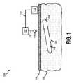
図1は、インプラント可能なアクセスチャンバ102を含むシステム100Aの側面図である。少なくとも1つの実施形態において、インプラント可能なアクセスチャンバ102は、対象の間質液に含まれる1つ以上の検体のサンプリングを促進するために使用されうる。そうするために、インプラント可能なアクセスチャンバ102は、対象の皮膚104の表面の下に埋め込まれることができる。例えば、インプラント可能なアクセスチャンバ102は、対象の皮下組織106内に埋め込まれることができる。追加的に又は代替的に、筋肉、リンパ、器官組織、静脈、眼、動脈などの他のタイプの組織に埋め込まれ、そして動物組織内で使用されることができる。 FIG. 1 is a side view of
少なくとも1つの実施形態において、インプラント可能なアクセスチャンバ102は、1年以上対象に埋め込まれたままであることができる。しかしながら、インプラント可能なアクセスチャンバ102が対象に埋め込まれる期間は、インプラント可能なアクセスチャンバ102の組成、インプラント可能なアクセスチャンバ102が埋め込まれる組織106のタイプ、及び/又は、インプラント可能なアクセスチャンバ102によって発揮される機能に依存しうる。インプラント可能なアクセスチャンバ102が埋め込まれている間に、インプラント可能なアクセスチャンバ102は、以下により詳細に論じられるように、繰り返し再アクセスされうる。これにより、インプラント可能なアクセスチャンバ102が多くの利点を提供することが可能になる。 In at least one embodiment, the
インプラント可能なアクセスチャンバ102のサイズはまた、インプラント可能なアクセスチャンバ102の機能及び/又はインプラント可能なアクセスチャンバ102が埋め込まれる皮下組織106のタイプに応じて変化しうる。一例として、インプラント可能なアクセスチャンバ102の長さは、5mm〜50mmの範囲であることができる。別の例として、インプラント可能なアクセスチャンバ102の高さ及び/又は厚さは、2mm〜20mmの範囲であることができる。しかしながら、これらは単なる例であり、小さい寸法が好ましい場合があることが理解されるように、限定することを意図するものではない。 The size of the
-
皮下組織106内に埋め込まれると、インプラント可能なアクセスチャンバ102のバリア部分108は対象の間質液に接触する。少なくとも1つの実施形態において、バリア部分108はキャビティ110(図5及び6に示される)を画定する。バリア部分108の少なくとも幾つかの部分は、間質液に対して透過性である材料を含む。バリア部分108の少なくとも幾つかの部分は間質液に対して透過性であるので、間質液はバリア部分108を透過し、キャビティ110内に進行する。さらに、バリア部分108の少なくとも幾つかの部分は全体的に又は部分的に細胞(例えば、赤血球、マクロファージなど)閉塞性である。少なくとも1つの例において、細胞は部分的にバリア部分108内に成長することができ、少なくとも1つの他の例において、バリア部分108内への細胞の内部成長は実質的に制限されうる。---
Once implanted within the
間質液に対して透過性であり、及び/又は全体的又は部分的に細胞閉塞性であるために、バリア部分108は、1つ以上の異なる材料を含むことができる。例えば、バリア部分108は、延伸ポリテトラフルオロエチレン(ePTFE)を含むことができる。ePTFE、又は、発泡ポリエチレン(ePE)、エレクトロスピニングされたバイオポリマー又は様々な微孔質ヒドロゲルなどの同様の微孔質材料では、透過性はバリア部分108の細孔サイズによって決定されうる。バリア部分108はポリ乳酸(PLA)、ポリグリコール酸(PGA)、PGA−TMCなどの生体吸収性材料から構築され得ることも理解される。この構成により、サブQアクセスチャンバの機能後に、ホスト再吸収が可能になる。ePTFEにおいて、細孔サイズは材料のフィブリルの長さに関係する。細孔サイズは、ノード間距離又はフィブリル長によって測定されうる。追加的に又は代替的に、フィブリル長は、Goreに付与された米国特許第4,482,516号明細書に記載されているように測定され、参照によりその全体を本明細書に取り込む。単一方向のePTFEのフィブリル長は、伸張方向のフィブリルによって接続されたノード間の10の測定の平均として規定されうる。10の測定は以下の方法で行われる。まず、顕微鏡写真は、サンプル表面の代表的な部分から作られ、顕微鏡写真の長さ内で少なくとも5つの連続するフィブリルを示すのに十分な倍率である。顕微鏡写真の長さを横切って2本の平行な線を引き、写真を3つの等しい領域に分割し、それらの線は、伸張方向に、フィブリルの配向方向に平行に描かれる。左から右に測定して、フィブリルの長さの5つの測定は、写真の一番上の線に沿って、最初のノードから始まり、写真の左端の近くで線と交差し、連続するノードが線と交差するまで続く。写真の右側の線と交差するように、最初のノードから始めて、右から左に向かってもう1つの線に沿ってさらに5つの測定を行う。この方法で得られた10の測定値を平均して、材料のフィブリル長を得る。 The
1つを超える方向に伸張又は延伸されたePTFEでは、フィブリル長は、材料表面の代表的な顕微鏡写真を調べ、フィブリルの様々な方向の向きを表す方法で上記のようにフィブリル長さを比較することによって評価される。 In ePTFE stretched or stretched in more than one direction, the fibril length examines a representative micrograph of the material surface and compares the fibril length as described above in a way that represents the orientation of the fibril in various directions. Be evaluated by.
より厚いフィブリル化材料は、一般に、細孔の一端を細孔の他端に接続する、より蛇行した経路を有する。結果として、より厚いフィブリル化材料は、細孔によって排除されることが求められている実体よりも大きい細孔を有することができるが、より厚い材料内の細孔の経路の蛇行性が増加することにより、細孔を通した実体の通過に耐性を維持する。少なくとも1つの実施形態において、ePTFE材料のフィブリルの長さ及び厚さは、しきい値分子量未満の分子に対して選択的に透過性である一方で、所望の点を超えてバリア部分108の厚さ全体にわたる細胞の内部成長に抵抗する細孔を形成するように選ばれる。追加的に又は代替的に、バリア部分108のePTFE材料のフィブリル長及び厚さは、しきい値分子量未満の分子に対して選択的に透過性でありながら、細胞の内部成長に完全に抵抗する細孔を形成するように選ばれる。一例において、しきい値分子量は250キロダルトン(kDa)であることができる。別の例において、しきい値分子量は200kDaであることができる。さらに別の例において、しきい値分子量は100kDaであることができる。さらに別の例において、しきい値分子量は50kDaであることができる。さらに別の例において、しきい値分子量は25kDaであることができる。 Thicker fibrillated materials generally have a more meandering path connecting one end of the pore to the other end of the pore. As a result, the thicker fibrillated material can have larger pores than the entity that is required to be eliminated by the pores, but the meandering nature of the pore pathways within the thicker material increases. This maintains resistance to the passage of the entity through the pores. In at least one embodiment, the length and thickness of the fibril of the ePTFE material is selectively permeable to molecules below the threshold molecular weight, while the thickness of the
少なくとも幾つかの実施形態において、コーティングをバリア部分108に適用することができる。コーティングは、バリア部分108の外面又は他の所望の物体上の生化学的蓄積を低減することができる。使用できるコーティングの例は、バリア部分の断面の内部に部分的に吸収された固体ポリウレタンコーティングである。ウレタンは細胞不透過性であるが、拡散メカニズムを介して間質液の成分に透過性である。グルコースセンサの場合には、固体ポリウレタンコーティングを含む層は、酸素の迅速な輸送を可能にするが、意図的にグルコースの通過を遅くするので、「抵抗」層と呼ばれることができる。その結果、非酸素枯渇反応はグルコースセンサで発生する。別の例として、CBAS(商標)をコーティングとして使用することができる。同様に、コーティングは、炎症(例えば、デキサメタゾン)又は細胞応答(例えば、血管内皮増殖因子(VEGF))に影響を与えることを意図した1つ以上の生体活性剤を含むことができる。 In at least some embodiments, the coating can be applied to the
バリア部分108の構築及び組成に関する追加の詳細は、下記の図7〜9に関連して説明される。 Additional details regarding the construction and composition of the
上記し、図5〜6に示すように、バリア部分108はキャビティ110を画定する。幾つかの実施形態において、ステント又はコア(図示せず)をキャビティ110に含めて、キャビティ110に構造的一体性を付加することができる。ステントはいかなる形状であることもでき、そして保存中及び/又はインプラント可能なアクセスチャンバ102の埋め込み後に、キャビティ110の全部又は一部を開き又は拡張した形態に保つのに適した任意の生体適合性材料から製造されることができる。ステントに適する材料としては、限定するわけではないが、ステンレス鋼、チタン及び様々なヒドロゲルが挙げられる。キャビティ110の全長を拡張構成に維持するために、キャビティ110の形状及び弾性をシミュレートする不活性コアをキャビティ110内に配置することができる。少なくとも1つの実施形態において、そのような不活性コアの好ましい材料はHYPAN.RTM.構造ヒドロゲル(Hymedix International,Inc.,Dayton,N.J.)である。 As described above, as shown in FIGS. 5 to 6, the
少なくとも1つの実施形態において、キャビティ110はセンサ112を収容する(図5〜6に示される)。幾つかの実施形態において、センサ112は完全にキャビティ110内に配置され、他の実施形態において、センサ112は部分的にのみキャビティ110内に配置される。追加的に又は代替的に、センサ112は、キャビティ110上に印刷され又はその他の方法で堆積され又は形成されうる。センサ112は、バリア部分108に透過した間質液の検体を検知するように構成されている。あるいは、センサ112が生体電気活動を検知できることも理解される。例示的な実施形態において、センサ112は、連続的、間欠的又はほぼ連続的に身体特性を示す検体を検知する。センサ112が検知しうる検体としては、限定するわけではないが、グルコース、カリウム、無機リン、マグネシウム、乳酸デヒドロゲナーゼ(LD)、ラクテート、酸素、インスリン、C−ペプチド、副甲状腺ホルモン(PTH)、オステオカルシン、C−テロペプチド、脳性ナトリウム利尿ペプチド(BNP)、副腎皮質刺激ホルモン(ACTH)、その他のタイプのホルモン、薬理学的薬剤、生物医薬品、タンパク質及びペプチド、バイオマーカー、抗体、治療剤、電解質、ビタミン、病原性成分、抗原、様々な病期、ウイルス量での疾患状態に関連する分子マーカーなどが挙げられる。 In at least one embodiment, the
センサ112は、酵素的及び/又は光学的特性を使用して、間質液中の検体濃度を決定する電気化学的センサであることができる。例えば、グルコースレベルは、電極及びグルコースオキシダーゼを使用してセンサ112によって決定されうる。電気化学的センサの例は、Cheney,IIらの米国特許第5,391,250号、Lordらの米国特許第5,390,671号、Wilsonらの米国特許第5,165,407号及びGoughの米国特許第4,890,620号明細書に記載されており、それらの全体を参照により本明細書に取り込む。追加的に又は代替的に、センサ112は、Lordらの米国特許第5,605,152号明細書に示され、記載されているような光学特性、又は、Van Antwerpらの米国特許第6,011,984号に示され、記載されているような光ファイバ構造、及び/又は、光学/蛍光化合物を利用することができ、それらのすべてをその全体の参照により本明細書に取り込む。 The
センサ112はまた、ナノセンサであることができる。幾つかの実施形態において、ナノセンサは、Farrらの米国特許第7,091,033号及びFarrらの米国特許出願第2003/0219714号明細書に開示されている以下の1つ以上の検出及び同定方法を使用するように構成されることができ、参照によりその全体を本明細書に取り込む。さらに、センサ112は本質的に生物学的であることができ、例えば、局所環境に応答性である細胞を含む。 The
キャビティ110は、センサ112のサイズ及び/又は形状に対応するために、様々なサイズ及び/又は形状であることができる。少なくとも幾つかの実施形態において、キャビティ110のサイズは、キャビティ110内の間質液がキャビティ110内部にあるときに停滞しないように構成されうる。すなわち、キャビティ110のサイズは、センサ112の収容を容易にし、センサ112の周りの限られた空間を閉じ込め、その結果、対象の間質液の現在の検体濃度の読み取りを容易にするのに十分であるように、センサ112と接触する間質液は頻繁に交換される。例えば、キャビティ110の壁とセンサ112の外部部分との間の距離は、0.5〜50.0ミクロンの範囲であることができる。あるいは、センサ112とキャビティ110の壁との間に直接の接触があってもよい。 The
センサ112を含むことに加えて又はその代わりに、キャビティ110は、薬物デリバリーデバイス及び/又は治療剤を含むことができる。少なくとも1つの実施形態において、バリア部分108は、キャビティ110から、バリア部分108を横切って、対象の皮下組織106内への治療剤の交換を可能にする。例示的な治療剤としては、限定するわけではないが、インスリン、エリスロポレチン、G−CSF、トラスツズマブ、パニツムマブ、ゲムツズマブオゾガマイシン、リツキシマブ、オマリズマブ、インフリキシマブ、デキサメタゾン、VEGF、化学療法剤、グルコース、抗増殖剤、抗再鎮痛剤、鎮痛剤、抗炎症剤、正確な計量が必要な薬物(アルツハイマー病、パーキンソン病などの治療剤)、アンジオテンシン変換酵素阻害剤、抗生物質、抗けいれん剤、抗糖尿病剤、ベンゾジアゼビン、ベータ遮断剤、カルシウムチャネル遮断剤、利尿剤、HMG−CoAレダクターゼ阻害剤、NSAID、オピオイド、プロトンポンプ阻害剤、選択的セロトニン再取り込み阻害剤などが挙げられる。 In addition to or instead of including the
少なくとも1つの実施形態において、センサ112、薬物デリバリーデバイス及び/又は治療剤は、バリア部分108に固定されたアクセス部分114を介してキャビティ110内に配置され及び/又はキャビティ110から取り除かれることができる。幾つかの実施形態において、アクセス部分114は、インプラント可能なアクセスチャンバ102の片側に配置され(図示されるように)、他の実施形態において、アクセス部分114は、インプラント可能なアクセスチャンバ102の両側に配置される。アクセス部分114は、キャビティ110内のセンサ112又は治療剤の配置、補充及び交換を容易にするのに適切である任意の形状を有することができる。 In at least one embodiment, the
少なくとも1つの実施形態において、アクセス部分114は、シーリング機構(図11〜14に示される例)で繰り返し開閉することができるポートである。シーリング機構としては、限定するわけではないが、例えば、キャップ、プラグ、フィッティング、クランプ、圧縮リング又はバルブが挙げられる。閉止可能な開口部の例としては、限定するわけではないが、再シール可能なポート又はハウジングが挙げられる。シーリング機構は、例えば、摩擦によって、クランピングによって、又はねじ山及び溝を含むねじ手段によって、アクセス部分114に取り付けることができる。ルアーロックコネクタ(Value Plastics, Inc., Firt Collins, Colo.)などの市販のフィッティングもアクセス部分114として使用できる。 In at least one embodiment, the
少なくとも1つの実施形態において、アクセス部分114は、シーリング機構でシールされて、気密シール、液密シール又は非液密シールを作成する。対象における永久的又は長期的(すなわち、少なくとも約3週間)の埋め込みを意図した装置は、好ましくは、気密シール又は液密シールでシールされる。例えば、アクセス部分114は、熱可塑性フッ素化エチレンプロピレン(FEP)又はエポキシなどの強力な生体適合性接着剤でバリア部分108に取り付けられることができる。FEPを使用してアクセス部分114をバリア部分108に取り付けることを記載している実施形態は、Goreに付与した米国特許第5,843,069号明細書に開示されており、参照によりその全体を本明細書に取り込む。 In at least one embodiment, the
あるいは、アクセス部分114は、インサート成形などの当業者に知られている技術を使用して、バリア部分108の端部にフィッティングを射出成形することによって製造することができる。バリア部分108の端部へのアクセス部分114のインサート射出成形は、最初にキャビティ110の中にツーリングの筒形片を配置し、次いで、キャビティ110及び筒形のツールをモールドキャビティ内に配置することを含む。次に、モールドキャビティを、例えば、ポリジメチルシロキサンなどの熱硬化性樹脂、又は、フッ素化エチレンプロピレン(FEP)、エポキシ、ポリカーボネート、ポリエステル又はポリスルホンなどの溶融熱可塑性物質を、例えば、単独又は組み合わせで含むポリマー物質で充填する。適切な反応条件又は必要に応じて冷却によりポリマー樹脂を硬化させた後に、モールドキャビティを開き、筒状モールドインサートをチューブの管腔から取り外す。 Alternatively, the
アクセス部分114はまた、孔を覆いそして閉じるように配置されたポリマー材料の1つ以上の可撓性片又はフラップを有する微孔質ポリマー材料の孔であることができる。フラップは、装置の部品として形成されてよく、又は、その最初の構築に続いて装置に取り付けられることができる。 The
追加的に又は代替的に、アクセス部分114は、アパチャと、前記アパチャ内に配置された自己シール性膜とを含む(図15〜17に示される例)。自己シール性膜として使用できる材料は、インプラント可能な等級のシリコン、他の適切なポリマー材料、及び/又は、Goreの米国特許第7,985,263号明細書に開示されている材料であり、参照によりその全体を本明細書に取り込む。 Additional or alternative, the
少なくとも幾つかの実施形態において、アクセス部分114を構築するために使用される1つ以上の材料は、アクセス部分114への細胞侵入を低減及び/又は排除するように選択及び/又は形成されうる。アクセス部分114への細胞侵入を低減及び/又は排除するように材料を選択及び/又は形成することにより、センサ112及び/又は治療剤は、細胞がアクセス部分114内で成長した場合よりも容易にアクセス及び/又は交換することができる。すなわち、アクセス部分114を介してセンサ112にアクセスするために、さもなければ皮下組織106からアクセス部分114内へと成長したであろう細胞を破壊(例えば、切断、切除、切開など)する必要がない。 In at least some embodiments, the one or more materials used to construct the
アクセス部分114への細胞侵入を低減及び/又は排除するために、アクセス部分114はePTFE材料から形成されることができ、ここで、前記ePTFE材料のボイド空間は、アクセス部分114の外面に隣接した及び/又は沿ったePTFE材料内の連続バンド内でヒドロゲル材料で含浸される。追加的に又は代替的に、アクセス部分114を形成するために使用される材料の細孔サイズは、ノード間距離又はフィブリル長さ、又は、ヒドロゲル材料で適切に調整された透過率によって測定したときに、平均で約5ミクロン未満、好ましくは平均で約1ミクロン未満、最も好ましくは平均で約0.5ミクロン未満であることができる。実施形態において、細孔サイズは、特定のサイズの検体に合わせて調整及び/又は最適化することができる。例えば、しきい値分子サイズを超える検体は除外されることができ、そしてしきい値分子量未満の検体はバリア部分108Aを透過することができる。一例において、しきい値分子量は250キロダルトン(kDa)であることができる。別の例において、しきい値分子量は200kDaであることができる。さらに別の例において、しきい値分子量は100kDaであることができる。さらに別の例において、しきい値分子量は50kDaであることができる。さらに別の例において、しきい値分子量は25kDaであることができる。 To reduce and / or eliminate cell invasion into the
アクセス部分114を構築するための他の適切な材料としては、限定するわけではないが、金属、セラミック、ガラス、エラストマー又は他のポリマー材料を、単独又は組み合わせのいずれかで挙げられる。金属材料の例としては、限定するわけではないが、タンタル、コバルト−クロム合金、チタン及びその合金、ステンレス鋼又は金が単独又は組み合わせのいずれかで挙げられる。セラミック材料の例としては、限定するわけではないが、アルミナ、シリカ、ジルコニア、硫酸カルシウム、炭酸カルシウム、リン酸カルシウム(ヒドロキシアパタイト及びβ−リン酸三カルシウムを含む)、ホウケイ酸ガラス、元素炭素、ALCAP(アルミニウム、カルシウム及び亜リン酸化物を含むセラミック)及びバイオガラスが単独又は組み合わせのいずれかで挙げられる。エラストマー材料の例としては、限定するわけではないが、シリコーン、ポリウレタン、フルオロポリマーゴム(例えば、Viton)、ポリ(エチレン−コ−プロピレン)ならびにポリブタジエン及びそのコポリマー(例えば、Buna−N)が単独又は組み合わせのいずれかで挙げられる。ポリマー材料の例としては、限定するわけではないが、ポリテトラフルオロエチレン、ポリエチレン、ポリプロピレン、ポリスチレン、ポリ(テトラフルオロエチレン−コ−ペルフルオロプロピレン)、ポリ(エチレンテレフタレート)などのポリエステル、ポリカーボネート、ポリ(メチルメタクリレート)及びポリアミドが単独又は組み合わせのいずれかで挙げられる。アクセス部分114で使用するためのこれらの材料の主要な構造的要件は、それらが強度、生体適合性及びレシピエントにおいて永続的又は長期間(すなわち、少なくとも約3週間)機能する寿命を有することである。 Other suitable materials for constructing the
上述のように、センサ112は、バリア部分108を透過した間質液の1つ以上の検体を検知することができる。少なくとも幾つかの実施形態において、センサ112は、データを処理するためのプロセッサ116及び/又は対象に埋め込まれるか又は対象の外部にあるメディカルデバイス(図示せず)への1つ以上の検知された検体に対応するデータ(例えば、信号値、生データ、操作情報及びパラメータなど)を送信する。少なくとも1つの実施形態において、プロセッサ116は、対象の検知された検体のうちの1つ以上の濃度を決定することができる。濃度に基づいて、プロセッサ116は、濃度が正常であるか又は異常であるかを決定することができる。さらに、プロセッサ116は、異常な濃度レベルに基づいて、提供されるべき対象への療法及び/又は治療のタイプを提供するための医療専門家への通知を提供することもできる。 As described above, the
少なくとも幾つかの実施形態において、データは、無線通信リンク及び/又は有線通信リンク(図示せず)(例えば、電気リンク及び/又は光リンク)を介して送信されうる。無線通信リンクの例としては、限定するわけではないが、ブルートゥース(商標)、ブルートゥース(商標)ローエネルギー、IEEE 802.11、近距離無線通信(NFC)、WiFi、アクティブ又はパッシブRFID、独占権付き無線プロトコールなどの短距離無線リンクが挙げられる。いずれの実施形態においても、有線通信リンクは、ポリエチレン、シリコーンなどの生体適合性材料などから形成されうる。 In at least some embodiments, the data may be transmitted via a wireless communication link and / or a wired communication link (not shown) (eg, an electrical link and / or an optical link). Examples of wireless communications links include, but are not limited to, Bluetooth®, Bluetooth® low energy, IEEE 802.11, Near Field Communication (NFC), WiFi, active or passive RFID, with exclusive rights. Examples include short-range wireless links such as wireless protocols. In any embodiment, the wired communication link can be formed from a biocompatible material such as polyethylene, silicone or the like.
少なくとも幾つかの実施形態において、バリア部分108を構築するために使用される材料は、本質的に電磁的に不透明であることができる。本質的に電磁気的に不透明ではない材料は、例えば、材料にバリウムを含浸させることにより、電磁気的に不透明になるように変性されうる。当業者に知られている材料を電磁的に不透明にする他の適切な方法を使用することもできる。バリア部分108を構築するために使用される材料の電磁的不透明性は、主に、装置の外科的配置を容易にするため、又は、埋め込み後にレシピエント内で装置の位置を特定するために使用される。 In at least some embodiments, the material used to construct the
バリア部分108が電磁的に不透明な材料から構築されるので、センサ112は、検知された1つ以上の検体に対応するデータをキャビティ110からバリア部分108の外部のデバイスに無線で送信できない場合がある。キャビティ110のサンプリングを容易にするために、マイクロニードル118は、キャビティ110内に含まれる間質液をサンプリングすることができる。マイクロニードル118は、対象の皮膚の表面104及びインプラント可能なアクセスチャンバ102のバリア部分108を貫通し、そして間質液のサンプルを抽出することができる。マイクロニードル118が間質液を抽出すると、間質液は、流体経路121を介して、流体分析器120に送られて分析されることができる。少なくとも幾つかの実施形態において、流体分析器120は、さらなる分析のために接続122を介してプロセッサ116に結合されうる。追加的に又は代替的に、流体分析器120は、非有線接続を介して、分析される流体に対応するデータをプロセッサ116に送信することができる。 Since the
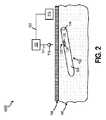
マイクロニードル118によるキャビティ110内の1つ以上の検体のサンプリングを容易にするために、図2に示されるように、インプラント可能なアクセスチャンバ102は、サンプリング部位123を含むことができる。図2は、本開示の別の実施形態による、インプラント可能なアクセスチャンバ102を含むシステム100Bの側面図である。少なくとも1つの実施形態において、サンプリング部位123は膜124を含む。膜124は、バリア部分108よりも透過しやすい材料を含むことができる。追加的に又は代替的に、膜124は、自己シール性である材料を含むことができる。したがって、マイクロニードル118がキャビティ110をサンプリングし、膜124から抽出されると、マイクロニードル118によって作られた孔はシールすることができる。膜124として使用することができる材料は、インプラント可能な等級のシリコン、他の適切なポリマー材料及び/又はGoreの米国特許第7,985,263号明細書に開示されている材料であり、参照によりその全体を本明細書に取り込む。 To facilitate sampling of one or more specimens in the
少なくとも1つの実施形態において、膜124は環126によって包囲されることができる。環126は、ユーザがサンプリング部位123の位置を決定することを可能にする成形触覚隆起を含むことができ、その結果、マイクロニードル118は正確に膜124を突き刺すことができる。追加的に又は代替的に、環126は、サンプリング部位123の位置を決定するために、マイクロニードル118又は別のデバイスによって検知されうるインジケータを含むことができる。例えば、環126は、強磁性材料を含むことができ、強磁性材料を検知することに応答して、マイクロニードル118と環126との間の距離は、例えば、プロセッサ116によって決定することができる。追加的に又は代替的に、強磁性材料は、マイクロニードル118内に配置された磁石と係合して、整列及びサンプリング部位123への耐久性結合を確保することができる。上記の要素は、キャビティ110内で凝集する間質液自体を取り出し又は収集するためだけに同様に使用できることが理解される。 In at least one embodiment, the
別の実施形態において、キャビティ110内の1つ以上の検体のサンプリングを容易にするために、サンプリング部位123は、図3に示すように、電磁波が伝播できる材料を含むことができる。図3は、本開示のさらに別の実施形態によるインプラント可能なアクセスチャンバ102を含むシステム100Cの側面図である。電磁波が伝播できる材料を含むことにより、センサ112は、経皮的に受信デバイス127にデータを送信することができる。少なくとも幾つかの実施形態において、データは、センサ112によって、OCT、TIR、PAS、散乱分光法などを介して受信デバイス127に送信されうる。 In another embodiment, to facilitate sampling of one or more specimens in the
センサ112によって送信される電磁波は受信デバイス127によって受信されうる。電磁波を受信した後に、受信デバイス127は、電気接続128又は非有線接続を介して、電磁波のデータをプロセッサ116に送信することができる。受信デバイス127による電磁波の受信を容易にするために、検知部位123は、膜124を包囲する環126を含むことができる。環126は、サンプリング部位123の位置を決定するために受信デバイス127が検知することができるインジケータを含むことができる。例えば、環126は、強磁性材料を検知することに応答して、受信デバイス127がデバイスと環126との間の距離を決定することができる強磁性材料を含むことができる。 The electromagnetic wave transmitted by the
環126の強磁性材料はまた、インプラント可能なアクセスチャンバ102の位置特定を容易にすることができる。少なくとも1つの例において、受信デバイス127は、環126内に含まれる強磁性材料を引き付ける磁石を含むことができる。磁石と環126の強磁性材料との引力は、受信デバイス127によるセンサ112からの電磁波の受信のために、インプラント可能なアクセスチャンバ102及びサンプリング部位123の有利な位置特定を容易にすることができる。 The ferromagnetic material of
幾つかの実施形態において、データはまた、接続131を介してセンサ112から第二のデバイス130に送信されることもできる。一例において、デバイス130は、経皮的に位置特定されうる。別の例において、デバイス130は、対象の皮膚の表面104の外部に配置されうる。デバイス130は、対象の1つ以上の特性をモニタリングし及び/又は対象に療法をデリバリーするメディカルデバイスであることができる。アクセス部分114は、接続部131の周りでアクセス部分114をシールして、センサ112の読み取りを妨害又は変更する可能性のある、あらゆる材料、細胞又は体液成分がキャビティ110に入るのを防ぐためのシーリング部材132をさらに含むことができる。少なくとも1つの実施形態において、シーリング部材132は、縫合ディスク、スリーブ又はタブである。追加的に又は代替的に、アクセス部分114は、接続部131の縁の周りをシールする自己シール性膜を含むことができる。 In some embodiments, the data can also be transmitted from the
図5及び6に示されるように、インプラント可能なアクセスチャンバ102は、キャビティ110内に延在する壁136を有するサンプリングリザーバ134を含むことができる。少なくとも幾つかの実施形態において、サンプリングリザーバは、サンプリング部位123を介してアクセス可能であることができる。サンプリングリザーバ134はキャビティ110と流体連通していることができる。しかしながら、幾つかの実施形態において、サンプリングリザーバ134の壁136はバリア部分108よりも閉塞性であることができる。そのため、サンプリングリザーバ134中に流入する流体、したがって、キャビティ110内の流体のサブセットは壁136によりろ過されうる。 As shown in FIGS. 5 and 6, the
図3〜5に示されるように、インプラント可能なアクセスチャンバ102は、バリア部分108から延在する安定化フランジ138を含むことができる。安定化フランジ138は、バリア部分108から延在し、部分的にバリア部分108の周囲に延在している隆起であることができる。安定化フランジ138は、皮下組織106内にインプラント可能なアクセスチャンバ102を固定するのを助けることができる。そうするために、安定化フランジ138は、安定化フランジ138内への細胞の内部成長を促進する材料を含むことができる。例示的な材料は、図10に関連して以下で議論される。 As shown in FIGS. 3-5, the
安定化フランジ138は、インプラント可能なアクセスチャンバ102の長さ142の百分率及び/又は幅144の百分率である、バリア部分108からの距離140を延長することができる。例えば、安定化フランジ138は、バリア部分108からのインプラント可能なアクセスチャンバ102の長さ142を10%〜30%延長することができる。別の例として、安定化フランジ138は、バリア部分108からのインプラント可能なアクセスチャンバ102の幅144を10%〜100%延長することができる。追加的に又は代替的に、インプラント可能なアクセスチャンバ102の長さ142は、その幅144よりも大きい可能性が高いため、インプラント可能なアクセスチャンバ102は、y軸148又はz−軸150の周りを回転するよりもx軸146の周りを回転する可能性が高い。x軸146の周りの回転に対抗するために、安定化フランジ138の幅152は、図4及び5に示されるように、その高さ154よりも大きくすることができる。 The stabilizing
図7〜図9は、本開示の異なる実施形態による図5の円Aに含まれる部分の拡大図である。図7は、本開示の1つの実施形態による、バリア部分108Aの組成を示す、インプラント可能なアクセスチャンバ102の断面を描写する。図8は、本開示の別の実施形態による、バリア部分108Bの組成を示す、インプラント可能なアクセスチャンバ102の断面を描写する。図9は、本開示のさらに別の実施形態による、バリア部分108Cの組成を示す、インプラント可能なアクセスチャンバ102の断面を描写する。 7 to 9 are enlarged views of a portion included in the circle A of FIG. 5 according to a different embodiment of the present disclosure. FIG. 7 depicts a cross section of an
図7を参照すると、バリア部分108Aは、バリア部分108Aの外面156からバリア部分108Aの内面158まで延在している。少なくとも幾つかの実施形態において、バリア部分108Aの材料は、外面156から内面158まで実質的に一貫したモノリシック構造であることができる。バリア部分108Aは、微孔質ポリマー材料(例えば、ePTFE又はePE、エレクトロスピニングバイオポリマー又は様々な微孔質ヒドロゲルなどの同様の微孔質材料)を含むことができる。バリア部分108Aが微孔質材料を含むために、蛇行経路は外面156から内面158まで延在することができる。あるいは、バリア部分108Aの材料は、バリア部分108Aの厚さにわたって変化することができる。これらの実施形態において、ポリマー材料の透過性は、バリア部分108Aの厚さにわたって連続的に変化させることができる。 Referring to FIG. 7, the
バリア部分108Aのモノリシック構造の蛇行経路又は可変透過性のために、バリア部分108Aは、バリア部分108Aの外面156からキャビティ110の内面158に隣接する細胞排除領域162まで延在する細胞透過性領域160を含むことができる。細胞透過性領域160は、毛細血管がその中に形成するのに十分な多孔性であることができる。一方、細胞排除領域162は、細胞の内部成長に対して不浸透性であることができる。バリア部分108A内の細胞排除領域162は、侵襲性細胞がキャビティ110に入り、キャビティ110内に含まれる治療剤及び/又はセンサと接触、付着、汚染、内部成長、過剰成長又は他の方法で干渉するのを防ぐ。侵襲性宿主細胞が成長してバリア部分108Aの内面158に至るのを排除するために、細胞排除領域162の細孔サイズは、ノード間距離又はフィブリル長、又は、ヒドロゲル材料で適切に調整された透過性によって測定して、平均して約5ミクロン未満、好ましくは平均して約1ミクロン未満、最も好ましくは平均して約0.5ミクロン未満であることができる。実施形態において、細孔サイズは、特定のサイズの検体に合わせて調整及び最適化することができる。例えば、しきい値分子サイズを超える検体は除外されることができ、しきい値分子サイズを下回る検体はバリア部分108Aを透過することができる。一例において、しきい値分子量は250キロダルトン(kDa)であることができる。別の例において、しきい値分子量は200kDaであることができる。さらに別の例において、しきい値分子量は100kDaであることができる。さらに別の例において、しきい値分子量は50kDaであることができる。さらに別の例において、しきい値分子量は25kDaであることができる。 Due to the meandering path or variable permeability of the monolithic structure of the
細胞透過性領域160は、バリア部分108Aの厚さの大部分に延在するものとして描写されているが、これは、例示の目的のみのためである。他の実施形態において、バリア部分108Aの厚さの大部分は、細胞排除領域162を含むことができ、例えば、バリア部分108Aの厚さ全体が細胞排除領域162を含むことができる。 The cell
図8を参照すると、バリア部分108Bは、バリア部分108Bの外面156からバリア部分108Bの内面158まで延在している。少なくとも幾つかの実施形態において、バリア部分108Bの材料は、第一の層164及び第二の層166を含む凝集層を含むことができる。実施形態において、第一の層164は、キャビティ110を画定する内面158及び前記内面158の反対側の外面168を形成する。第二の層166は第二の層として配置され、前記第二の層は、皮下組織106と直接相互作用するように構成された外面156と、前記外面156の反対側の内面170とを形成し、ここで、前記内面170は、第一の層164の外面168上に配置される。 Referring to FIG. 8, the
少なくとも1つの実施形態において、第一の層164及び/又は第二の層166は、1つ以上の微孔質ポリマー材料(例えば、ePTFE)を含むことができる。第一の層164が微孔質材料を含むために、蛇行経路は外面156から内面170まで延在することができる。追加的に又は代替的に、第一の層164と第二の層166との間に特性の鋭い変動が存在することができる。第一の層164の蛇行経路、又は、第一の層164と第二の層166との間の特性の鋭い変動のために、第一の層164は、外面156から内面170まで延在する細胞透過性領域であることができる。さらに、第二の層166は、外面168からキャビティ110の内面158まで延在する細胞排除領域であることができる。バリア部分108Aにおける第二の層166は、侵襲性細胞がキャビティ110に入り、キャビティ110内に含まれる治療剤及び/又はセンサと接触し、それに付着し、それを汚染し、内部成長し、過剰成長し又はその他の方法で干渉するのを防止する。 In at least one embodiment, the first layer 164 and / or the second layer 166 can include one or more microporous polymer materials (eg, ePTFE). Since the first layer 164 contains a microporous material, the meandering path can extend from the
第一の層164及び/又は第二の層166はそれぞれ、異なる多孔度を有するePTFE材料を含むことができる。少なくとも1つの実施形態において、第二の層166は、実質的にノードがないフィブリルから実質的になる、非常に薄く、非常に強い不織ウェブであるePTFE材料の層である。この第二の層166は、ノード間距離又はフィブリル長によって測定して、約0.05〜約5ミクロンの範囲の平均細孔サイズを有することができる。第二の層166の好ましい細孔サイズは、そのラミネート化形態又は最終形態で約0.4ミクロンである。最終形態の第二の層166の厚さは、約1ミクロン〜約25.4ミクロンである。第二の層166を作製する1つの方法は、Bacinoの米国特許第5,476,589号明細書によって教示された方法の一部を利用し、参照によりその全体を本明細書に取り込む。 The first layer 164 and / or the second layer 166 can each contain an ePTFE material having different porosities. In at least one embodiment, the second layer 166 is a layer of ePTFE material, which is a very thin, very strong non-woven web, substantially consisting of fibril with virtually no nodes. The second layer 166 can have an average pore size in the range of about 0.05 to about 5 microns, measured by internode distance or fibril length. The preferred pore size of the second layer 166 is about 0.4 microns in its laminated or final form. The thickness of the second layer 166 in the final form is from about 1 micron to about 25.4 microns. One method of making the second layer 166 utilizes a portion of the method taught by Bacino, US Pat. No. 5,476,589, which is incorporated herein by reference in its entirety.
Bacino法において、適切なPTFE出発材料を選択し、微粉末PTFEの凝固分散体として調製した後に、凝固分散体粉末を、炭化水素押出助剤、好ましくは無臭ミネラルスピリット、例えばIsopar K(Exxon.Corp.製)で潤滑化する。潤滑化された粉末をシリンダー中に圧縮し、ラム押出機で押し出してテープを形成する。テープの2つ以上の層を重ねて、2つのロール間で圧縮することができる。テープを、ロール間で適切な厚さ、例えば5〜40ミル程度に圧縮する。ウェットテープを横方向に、元の幅の1.5〜5倍に延伸する。押出助剤は熱で追い出される。次に、乾燥したテープを、ロールのバンク間で長手方向に、ポリマーの融点327℃未満の温度に加熱された空間内で延伸又は伸長する。長手方向の延伸は、ロールの第二のバンクの速度/第一のバンクの速度の比が10〜100/1、好ましくは35/1であるようなものである。長手方向の延伸は、1〜1.5/1の比率で繰り返される。次に、長手方向の延伸後に、膜の長手方向の収縮を抑制しながら、327℃未満の温度で元の押出物の導入幅の少なくとも1.5倍、好ましくは6〜15倍までテープを横断方向に延伸する。なおも拘束下にある間に、膜は好ましくはポリマーの融点327℃を超えて加熱され、次いで冷却される。 In the Bacino method, after selecting the appropriate PTFE starting material and preparing it as a coagulation dispersion of fine powder PTFE, the coagulation dispersion powder is prepared with a hydrocarbon extrusion aid, preferably an odorless mineral spirit, such as Isopar K (Exxon. Corp.). Lubricate with (manufactured). The lubricated powder is compressed into a cylinder and extruded with a ram extruder to form a tape. Two or more layers of tape can be stacked and compressed between the two rolls. The tape is compressed between rolls to an appropriate thickness, for example about 5-40 mils. The wet tape is stretched laterally to 1.5 to 5 times its original width. Extrusion aids are expelled by heat. The dried tape is then stretched or stretched longitudinally between banks of rolls in a space heated to a temperature below the melting point of the polymer of 327 ° C. Longitudinal stretching is such that the speed ratio of the second bank of the roll / the speed of the first bank is 10 to 100/1, preferably 35/1. The longitudinal stretching is repeated at a ratio of 1 to 1.5 / 1. Next, after longitudinal stretching, the tape is traversed at a temperature of less than 327 ° C. to at least 1.5 times, preferably 6 to 15 times, the introduction width of the original extrusion, while suppressing longitudinal shrinkage of the membrane. Stretch in the direction. While still under restraint, the membrane is preferably heated above the polymer's melting point of 327 ° C and then cooled.
細胞透過性領域を含む第一の層164は、共にGoreに付与された米国特許第3,953,566号及び第4,187,390号明細書の教示に従って作製されたePTFE材料であり、これらの文献の各々の全体を参照により本明細書に取り込む。第一の層164は、フィブリル長によって測定して、約3.0ミクロンを超える、好ましくは約5.0ミクロンを超える平均細孔サイズを有する。材料の厚さは、約10ミクロン〜約1000ミクロンの範囲であり、好ましくは約40〜60ミクロンである。 The first layer 164 containing the cell permeable region is an ePTFE material both made in accordance with the teachings of US Pat. Nos. 3,935,566 and 4,187,390, both granted to Gore. The entire of each of the literature is incorporated herein by reference. The first layer 164 has an average pore size greater than about 3.0 microns, preferably greater than about 5.0 microns, as measured by fibril length. The thickness of the material ranges from about 10 microns to about 1000 microns, preferably about 40 to 60 microns.
これら2つの層164,166のラミネート化は、上記で参照されたBacino法の工程の幾つかを繰り返すことによって行うことができる。ラミネート化を行うために、上記の両方のePTFE材料を一緒に保持し、ポリマーの融点327℃未満の温度に加熱された空間でロールのバンク間で長手方向に延伸する。長手方向の延伸は、ロールの第二のバンクの第一のバンクに対する速度の比率が、Bacino法により製造された材料に対して、10〜100/1、好ましくは35/1であるようなものである。長手方向の延伸は、第二と第三のセットのロール間で1〜1.5/1の比率で繰り返され、ここで、’566号特許の材料はBacino法の材料と結合される。 Lamination of these two layers 164 and 166 can be performed by repeating some of the steps of the Bacino method referred to above. For laminating, both of the above ePTFE materials are held together and stretched longitudinally between banks of rolls in a space heated to a temperature below the melting point of the polymer of 327 ° C. Longitudinal stretching is such that the ratio of the velocity of the second bank of rolls to the first bank is 10 to 100/1, preferably 35/1, with respect to the material produced by the Bacino method. Is. The longitudinal stretching is repeated at a ratio of 1 to 1.5 / 1 between the second and third sets of rolls, where the '566 patented material is combined with the Bacino method material.
次に、長手方向の延伸後に、ラミネートの長手方向及び横断方向の収縮を抑制しながら、ラミネートを327℃未満の温度で、元のラミネートの導入幅の少なくとも1.5倍、好ましくは6〜15倍まで横断方向に延伸する。なおも拘束下にある間に、ラミネートは好ましくはポリマーの融点327℃を超えて加熱され、次いで、冷却される。 Next, after stretching in the longitudinal direction, the laminate is placed at a temperature of less than 327 ° C., at least 1.5 times the introduction width of the original laminate, preferably 6-15, while suppressing shrinkage in the longitudinal and transverse directions of the laminate. Stretch in the transverse direction up to twice. While still under restraint, the laminate is preferably heated above the polymer's melting point of 327 ° C and then cooled.
第一の層164及び第二の層166はそれぞれ、バリア部分108Bの厚さの約半分を構成するが、これは例示の目的のみのためである。他の実施形態において、バリア部分108Aの厚さのより大きな部分は第一の層164を含むことができ、又は、バリア部分108Aの厚さのより大きな部分は第二の層166を含むことができる。 Each of the first layer 164 and the second layer 166 constitutes about half the thickness of the
2枚の平らなラミネートシートを用いてチューブ状形態を作るために、ラミネートのシートは、最初に、それらのそれぞれの第一の層164及び第二の層166が互いの上に置かれる。次に、ラミネートは、隆起したトラックの所望のパターンを有するダイに配置される。熱的及び化学的に安定したコアは、ダイの上昇したトラックによって輪郭が描かれたチューブ状フォームの周囲内のラミネートの層の間に配置される。ダイに入ると、ラミネート及びコアは、ePTFE材料を緻密化してラミネートの平面シートを接着するのに十分な圧力で、約310℃〜約380℃に約1〜10分間加熱され、ここで、加熱されたトラックはラミネートのシートに接触する。チューブ、コア及び接着された平面材料を、室温まで冷却し、次いで、ダイから取り除く。コアは、例えば、皮下注射器でコアとチューブの壁との間に水を注入することにより、チューブ状フォームの内部から解放される。構築後に装置に取り付けられた平面材料は、付着されたままであっても、トリミングされても、又は、取り外されてもよい。装置に付着されたままの平面材料は、装置を適切な形状に保持するのを助ける。平面材料はまた、外科医に、装置を取り扱う手段及び装置をレシピエントの埋め込み部位にしっかりと取り付ける手段を提供する。 To make a tubular form using two flat laminated sheets, the laminated sheets are first placed on top of each other with their respective first layer 164 and second layer 166. The laminate is then placed on a die with the desired pattern of raised tracks. Thermally and chemically stable cores are placed between layers of laminate within the perimeter of the tubular foam contoured by the raised tracks of the die. Upon entering the die, the laminate and core are heated to about 310 ° C. to about 380 ° C. for about 1-10 minutes with sufficient pressure to densify the ePTFE material and bond the flat sheets of the laminate, where heating. The track is in contact with a sheet of laminate. The tube, core and glued flat material are cooled to room temperature and then removed from the die. The core is released from the inside of the tubular foam, for example, by injecting water between the core and the wall of the tube with a subcutaneous syringe. The planar material attached to the device after construction may remain attached, trimmed, or removed. The flat material that remains attached to the device helps hold the device in proper shape. The planar material also provides the surgeon with a means of handling the device and a means of securely attaching the device to the recipient's implantation site.
幾つかの実施形態において、上記の製造方法は、追加的に又は代替的に、安定化フランジ138を製造するために使用されうる。安定化フランジ138への細胞侵入を容易にするために、マイクロポアを安定化フランジ138にドリル開けすることもできる。 In some embodiments, the above manufacturing method may be used to additionally or alternatively manufacture the stabilizing
バリア部分108Bをチューブ状形状に加工する別の方法は、Bacinoの米国特許第5,476,589号明細書の教示に従って作製された材料をマンドレル上に巻き付け、次いで、ポリマー材料の別の巻き付けを行うことによる。Bacinoの全体を参照により本明細書に取り込む。長手方向及びらせん方向の巻き付けフィルムの配向を使用することができる。次に、この構造を約320℃〜約380℃に約5〜10分間加熱して、それぞれの材料を相互に結合する。材料の1つの層と次の層とのオーバーラップは、約10%未満から約50%までの範囲であることができる。多くの用途において、オーバーラップは、好ましくは約10%である。しかしながら、これらの材料のラップ及びラミネートは、層の間のオーバーラップを有しなくてよいことが理解される。そのような実施形態において、連続する各ラップ材料の縁は、材料の前のラップの縁に当接する。 Another method of processing the
バリア部分108A,108Bとしての使用に適した幾つかの選択的透過性ポリマー材料では、バリア部分108Aの分子量カットオフ又はふるい分け特性は、細胞排除領域162及び/又は第二の層166で始まることができる。その結果、特定の溶質及び/又は細胞は、バリア部分108A,108Bに入らず、それらを通して一方の側から他方の側に通過しない。少なくとも1つの実施形態において、細胞排除領域162及び/又は第二の層166の材料は、細胞が細胞排除領域162及び/又は第二の層166の隣又はその上で成長するのを妨げないことがある。例えば、血管内皮細胞を含む皮下組織106は、細胞排除領域162及び/又は第二の層166と接触するが侵入しないように成長する。血管内皮細胞は、組み合わされて、その上に毛細血管を形成することができる。このような毛細血管形成又は血管新生は、レシピエントの組織とキャビティ110の内容物との間の流体及び溶質流を可能にする。 For some selective permeable polymer materials suitable for use as
別の実施形態において、細胞排除領域162及び/又は第二の層166としての使用に適したポリマー材料の選択的透過性は、ポリマー材料のボイド空間にヒドロゲル材料を含浸させることによって変化する。ヒドロゲル材料は、ポリマー材料の実質的にすべてのボイド空間に、又は、ボイド空間の一部のみに含浸させることができる。例えば、ポリマー材料の内面158に隣接して及び/又はそれに沿って及び/又はその外面168で材料内の連続帯でポリマー材料にヒドロゲル材料を含浸させることにより、材料の選択的透過性は、材料の外面156から内面158まで、材料の内部断面領域まで鋭く変化される。ポリマー材料に含浸されるヒドロゲル材料の量及び組成は、主に、バリア部分108A,108Bを構築するために使用される特定のポリマー材料、所与の用途に必要な透過性の程度、及び、ヒドロゲル材料の生体適合性に依存する。本発明での使用に適したヒドロゲル材料の例としては、限定するわけではないが、ポリビニルアルコール(PVA)、例えば、W.L. Gore&Associatesによって製造されるもの、親水性潤滑コーティング(HLC)(これは温度によって硬化することができる)、HYPAN.RTM,BioA、構造ヒドロゲル(Hymedix International,Inc.,Dayton,N.J.)、DorianによるPCT/US93/05461(参照により本明細書に取り込む)により教示されるとおりの非線維形成性アルギネート、アガロース、アルギン酸、カラギーナン、コラーゲン、ゼラチン、ポリビニルアルコール、ポリ(2−ヒドロキシエチルメタクリレート)、ポリ(N−ビニル−2−ピロリドン)又はジェランガムが単独又は組み合わせのいずれかで挙げられる。HYPAN.RTM.構造ヒドロゲルは好ましい。ePTFE/ヒドロゲル複合材を含むバリア部分108A,108Bの全体の厚さは、約2ミクロン〜約1000ミクロンの範囲であることができる。 In another embodiment, the selective permeability of the polymeric material suitable for use as the
追加的に又は代替的に、微孔質ポリマー材料の透過性は、ポリマー材料の追加の層及びヒドロゲル材料のさらなる層を含む、バリア部分108A,108Bの厚さにわたって鋭く変化されうる。この実施形態の利点は、破損した細胞インプラント可能なアクセスチャンバ102からの細胞による汚染に対してインプラントレシピエントに提供される追加の保護である。さらに、この構成は、強い細胞及び体液性免疫隔離バリアを提供する。 Additional or alternative, the permeability of the microporous polymer material can be sharply varied over the thickness of the
追加的に又は代替的に、様々な細胞タイプは細胞透過性領域160及び/又はバリア部分108A,108Bのポリマー材料の第一の層164内に成長することができる。特定のポリマー材料内に成長する主な細胞タイプは、主に、埋め込み部位、例えば、バリア部分108A,108Bの組成及び透過性、及び、サイトカイン、及び/又は、バリア部分108A,108Bの材料に取り込まれるか又はキャビティ110を通して導入される細胞接着分子などの生物学的要因に依存する。インプラント可能なアクセスチャンバ102での使用に適した生物学的因子としては、限定するわけではないが、タンパク質及びペプチドサイトカイン、例えば、VEGF、血小板由来内皮細胞成長因子(PD−ECGF)、線維芽細胞成長因子(FGF)、gly−his−lysのアミノ酸配列又はそのパリンドロームを含み、塩架橋銅(II)を含む又は含まないペプチド、ヘパリンなどの血管新生活性のある多糖類、オレイン酸などの血管新生刺激脂質、又は銅などの金属が単独又は組み合わせのいずれかで挙げられる。あるいは、デキサメタゾンなどの抗炎症治療剤を使用して、炎症を緩和し及びその後の細胞応答を確かにすることができる。 Additional or alternative, various cell types can grow within the first layer 164 of the polymeric material of the cell
少なくとも1つの実施形態において、血管内皮は、細胞透過性領域160及び/又は第一の層164内に成長する主要な細胞タイプである。毛細血管網の形態の血管内皮細胞のよく確立された集団による細胞透過性領域160及び/又は第一の層164の血管新生は、皮下組織106から細胞透過性領域160及び/又は第一の層164に入りそしてその厚さを横切る血管新生の結果として生じることが奨励される。少なくとも1つの実施形態において、血管新生は、細胞透過性領域160及び/又は、第一の層164を通過することができ、細胞排除領域162及び/又は第二の層166にそれぞれ接近しうるが、細胞排除領域162及び/又は第二の層166を横切らない。 In at least one embodiment, the vascular endothelium is the major cell type that grows within the cell
細胞透過性領域160及び/又は第一の層164の血管新生は、生物学的因子、上述のような血管新生因子の追加なしで起こり得るが、それらは、細胞透過性領域160及び/又は第一の層164の血管新生を増強するために使用されうる。さらに、血管新生は、低酸素症などの状態によって刺激されうる。細胞透過性領域160及び/又は第一の層164のこの血管新生は、キャビティ110と皮下組織106との間の治療剤又は生化学物質の大量輸送を改善し、それにより、キャビティ110と皮下組織106との間の治療剤又は生化学物質の輸送量及び速度を高めることができる。高等動物では、ほぼすべての細胞は毛細血管の約100ミクロン以内にある。したがって、キャビティ110と皮下組織106との間の材料の最大交換を達成するために、内部成長した毛細血管がキャビティ110から取られるべきである最大距離は約100ミクロン未満であることが好ましく、より好ましくは約50ミクロン未満であり、最も好ましくは約25ミクロン未満である。したがって、細胞排除領域162及び/又は第二の層166は、厚さが約100ミクロン未満、好ましくは約50ミクロン未満、最も好ましくは約25ミクロン未満であるべきである。ポリマー材料の血管新生を可能にすることに加えて、ポリマー材料の透過性は、バリア部分108A,108Bの厚さに横切って約5,000,000MWまでの分子量を有する、治療剤を含む生化学物質の通過を選択的に可能にするように選択される。実験動物において、インプラント可能なアクセスチャンバ102への慢性的な炎症反応は観察されていないので、細胞透過性領域160及び/又は第一の層164の血管新生は、埋め込み部位の創傷治癒プロセスとともに進行すると考えられる。 Angiogenesis of the cell
少なくとも1つの実施形態において、細胞透過性領域160及び/又は第一の層164の血管新生はまた、成長してそして対象の循環系に接続された毛細血管へと組み立てられる外面156上の自己又は免疫原性中和血管内皮細胞の集団を培養することによって達成できる。コラーゲン、フィブロネクチン、ラミニン又はそれらの誘導体などの血管内皮マトリックス基質を外面156に適用し、次いで、外面156に細胞を播種すると、細胞が成長し、その上の毛細血管に分化することができるはずである。実験用ラットにおけるこの目的に適していることができる市販の内皮下細胞マトリックスは、「MATRIGEL」(Collaborative Laboratories,Inc.)という商品名で知られている調製物である。あるいは、適切な内皮下マトリックス調製物は、インプラント対象の脈管構造から入手可能であることができる。 In at least one embodiment, the angiogenesis of the cell
細胞透過性領域160及び/又は第一の層164の血管新生及び他の組織の内部成長は、インプラント可能なアクセスチャンバ102を埋め込み部位に固定するのを支援しうる。従来の方法で埋め込まれた治療デバイスの浮遊がしばしば懸念されるため、このことは重要な機能でありうる。チューブ状のインプラント可能なアクセスチャンバ102では、内部成長した宿主組織と埋め込み部位におけるインプラント可能なアクセスチャンバ102の固定は、インプラント可能なアクセスチャンバ102の形状を維持するのを支援する。インプラント可能なアクセスチャンバ102の形状を維持すると、インプラント可能なアクセスチャンバ102に含まれる治療剤及び/又はセンサの配置、交換及び適切な機能を容易にすることができる。 Angiogenesis of the cell
上述したように、図9は、本開示のさらに別の実施形態による、バリア部分108Cの組成を示す、インプラント可能なアクセスチャンバ102の断面を描写している。バリア部分108Cは、互いに隣接して配置された第一の部分172及び第二の部分174を含むことができる。少なくとも1つの実施形態において、第一及び第二の部分172,174のそれぞれの外面は、皮下組織106と相互作用するように構成される外面156を集合的に画定する。さらに、第一及び第二の部分172,174のそれぞれの内面はキャビティ110を形成する内面158を集合的に画定する。少なくとも1つの実施形態において、第一の部分172は、第二の層166と一部又はすべて同じ特徴を有することができ、第二の部分は、バリア部分108Aと一部又はすべて同じ特徴を有することができる。 As mentioned above, FIG. 9 depicts a cross section of an
図10は、本開示の実施形態による、図5の円Bに含まれる部分の拡大図である。少なくとも幾つかの実施形態において、安定化フランジ138は、第一の層164と一部又はすべて同じ特徴を有することができる。例えば、安定化フランジ138は、安定化フランジ138中及びそれを通る細胞の成長を可能にし、インプラント可能なアクセスチャンバ102がその位置を維持する可能性を高めることができる。 FIG. 10 is an enlarged view of a portion included in the circle B of FIG. 5 according to the embodiment of the present disclosure. In at least some embodiments, the stabilizing
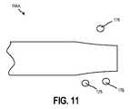
図11〜図12は、本開示の実施形態による、インプラント可能なアクセスチャンバ102のアクセス部分114Aの拡大側面図である。特に、図11は、センサがアクセス部分114Aを介してキャビティ110内に挿入され得る、開放構成のアクセス部分114Aを示し、図12は、クランプ176を使用してシールされた構成のアクセス部分114Aを示す。図示のように、クランプ176は、アクセス部分114Aの気密シール又は液密シールを作成するのに役立つ間欠的な配置を有することができる。 11 to 12 are enlarged side views of the
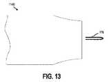
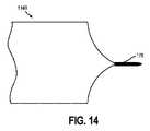
図13〜14は、本開示の別の実施形態による、インプラント可能なアクセスチャンバ102のアクセス部分114Bの拡大側面図である。特に、図13は、センサ112及び/又は治療剤がアクセス部分114Bを介してキャビティ110内に挿入され得る、開放構成のアクセス部分114Bを示し、図14は、ピンチクリップ178を使用してシール構成にあるアクセス部分114Bを示す。図示されるように、ピンチクリップ178は、アクセス部分114Bの開口端を締め付け、それによりアクセス部分114Bの気密シール又は液密シールを作成することができる。 13-14 are enlarged side views of the access portion 114B of the
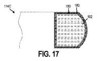
図15は、本開示のさらに別の実施形態による、インプラント可能なアクセスチャンバ102のアクセス部分114Cの拡大側面図である。図16は、図15に描かれたアクセス部分114Cの断面図であり、図17は、図15に描かれたアクセス部分114Cの上面図である。 FIG. 15 is an enlarged side view of the
アクセス部分114Cは、アパチャ181を形成する環180を含む。少なくとも1つの実施形態において、膜182は、アパチャ181内に配置される。環180は、上述の環126と同じ又は同様の特徴を有することができる。例えば、膜182を位置特定するために、環180は、膜182の位置を決定するために受信デバイス127が検知できるインジケータを含むことができる。別の例として、環180は、強磁性材料の検知に応答して、デバイス(例えば、受信デバイス127)が前記デバイスと環180との間の距離を決定することができる強磁性材料を含むことができる。追加的に又は代替的に、環180の強磁性材料はまた、膜182の位置特定を容易にすることができる。少なくとも1つの例において、デバイス(例えば、受信デバイス127)は、環180に含まれる強磁性材料を引き付ける磁石を含むことができる。磁石と環180の強磁性材料との間の引力は、膜182の有利な配置を容易にすることができ、インプラント可能なアクセスチャンバ102が皮下組織106内に配置されるときに、センサ112はキャビティ110から回収されてもよく、及び/又は、センサ112はキャビティ110内に配置されてもよい。膜182の有利な配置により、インプラント可能なアクセスチャンバ102が皮下組織106内に配置されるときに、治療剤をキャビティ110に注入することができる。 The
追加的に又は代替的に、環180は、環180をキャビティ110に固定する成形ハウジング184を含む成形触覚隆起であることができ、これは、ユーザ及び/又は医療専門家が皮膚を通して感じ、それにより、アクセス部分の位置を決定することができる。幾つかの実施形態において、電子機器及び/又は電源は、成形ハウジング184に接続されうる。 Additionally or optionally, the
少なくとも幾つかの実施形態において、膜182は自己シール性である。膜182が自己シール性であることができるために、センサ112及び/又は治療剤は、膜182を通してキャビティ110に挿入されることができ、そしてセンサ112が膜182を通過し及び/又は治療剤をキャビティ110へ挿入するために使用される注射器を引き抜いた後に、膜182はそれ自体で実質的に閉じることができ、それによりアクセス部分114Cの気密又は液密シールを作成する。膜182として使用することができる材料は、Goreの米国特許第7,985,263号明細書に開示されており、参照によりその全体を本明細書に取り込む。 In at least some embodiments, the
図18は、本開示の実施形態による、インプラント可能なアクセスチャンバを使用する治療の方法200のフローダイアグラムである。少なくとも1つの実施形態において、インプラント可能なアクセスチャンバは、上述のインプラント可能なアクセスチャンバ102と一部又はすべて同じ特徴を有することができる。 FIG. 18 is a flow diagram of a
方法200は、皮下組織内に埋め込まれたインプラント可能なアクセスチャンバ102を位置特定することを含み、前記インプラント可能なアクセスチャンバ102は、間質液と流体連通しているセンサを備える(ブロック202)。少なくとも1つの実施形態において、皮下組織は、上述の皮下組織106と一部又はすべて同じ特徴を有することができる。追加的に又は代替的に、センサは、上述のセンサ112と一部又はすべて同じ特徴を有することができる。
インプラント可能なアクセスチャンバ102を位置特定するために、インプラント可能なアクセスチャンバ102は、環(上記の環126と同様)を含むサンプリング部位(上記のサンプリング部位123と同様)を含むことができる。環126は、ユーザが対象の皮膚の下の環126を感じることによって環126の位置を決定することを可能にする成形触覚隆起を含むことができる。追加的に又は代替的に、環126は、強磁性材料を検知することに応答して、デバイス(例えば、受信デバイス127)がデバイスと環との間の距離を決定することができる強磁性材料を含むことができる。デバイスと環との間の決定された距離に基づいて、インプラント可能なアクセスチャンバ102の位置は決定されうる。 To locate the
方法200は、センサ112から、間質液の少なくとも1つの検体に対応するセンサデータを受信することをさらに含む(ブロック204)。実施形態において、センサデータは、上記のセンサデータと同じ又は同様であることができ、そしてセンサデータを受信するデータは、上記の受信デバイス127と同じ又は同様であることもできる。追加的に又は代替的に、少なくとも1つの検体は、上記の検体と同じ又は同様であることができる。センサデータは、センサから放出される電磁波(例えば、可視スペクトルの波)を介して経皮的に受信されうる。追加的に又は代替的に、センサは、1つ以上の検体に応答して発光を変化させることができ、発光の変化はデバイスによって検知されうる。
方法200は、センサデータを分析して、検知されたデータに基づいて対象の1つ以上の特性を決定することをさらに含む(ブロック206)。少なくとも1つの実施形態において、上記のプロセッサ116と同じ又は同様のプロセッサは、センサデータを分析することができる。例えば、プロセッサは、検知されたデータを分析して、検知された検体の1つ以上の濃度を決定することができ、そして、検知された検体に基づいて、プロセッサは、濃度に応答して治療剤を提供するように医療専門家に通知を提供することができる。幾つかの実施形態において、方法200は、治療剤を対象に提供することを含む(ブロック208)。治療剤は、インプラント可能なアクセスチャンバ102の内部に提供されることができ、上述の治療剤と同じ又は同様であることもできる。あるいは、検知されたデータは、別の治療法を示唆するために使用されうる。
図19は、本開示の実施形態による、インプラント可能なアクセスチャンバのキャビティにアクセスする方法300のフローダイアグラムである。図19の議論の間に、図20A〜図20Gを参照し、それらは本開示の実施形態による、キャビティ110へのアクセス及びキャビティ110へのセンサ112の挿入の断面図を描いている。この技術は、あるタイプの局所麻酔下で行われることが理解される。 FIG. 19 is a flow diagram of
少なくとも1つの実施形態において、インプラント可能なアクセスチャンバは、上記のインプラント可能なアクセスチャンバ102と一部又はすべて同じ特徴を有することができる。追加的に又は代替的に、キャビティは、上記のキャビティ110と一部又はすべて同じ特徴を有することができる。 In at least one embodiment, the implantable access chamber can have some or all of the same features as the
方法300は、皮下組織106内に埋め込まれたインプラント可能なアクセスチャンバ102を位置特定することを含む(ブロック302)。少なくとも1つの実施形態において、インプラント可能なアクセスチャンバ102は、間質液106と流体連通しているセンサ112を含む。インプラント可能なアクセスチャンバ102を位置特定するために、インプラント可能なアクセスチャンバ102は、環(上記の環180と同様)を含む、アクセス部分(上記のアクセス部分114と同様)を含むことができる。環180は、図20Aに示されるように、対象の皮膚の下で指185によって感じることができる成形触覚隆起を含むことができる。追加的に又は代替的に、環180は、強磁性材料を検知することに応答して、デバイス(例えば、受信デバイス127)がデバイスと環との間の距離を決定することができる強磁性材料を含むことができる。デバイスと環との間の決定された距離に基づいて、アクセス部分の位置が決定されうる。
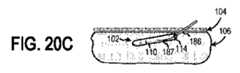
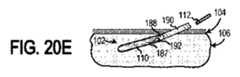
方法300は、図20Bに示されるように、インプラント可能なアクセスチャンバ102のアクセス部位114に経皮的に針186を挿入することをさらに含む(ブロック304)。次に、ガイドワイヤ187は、図20Cに示されるように、アクセス部分114を介して、針186を通してインプラント可能なアクセスチャンバ102のキャビティ110に挿入されうる(ブロック306)。次に、針186を取り除くことができ(ブロック308)、図20D及び図20Eに示されるように、アクセス部分114を拡張するために、拡張器188をガイドワイヤ187上に配置することができる(ブロック310)。後述するように、拡張器188は、拡張器188を包囲する導入器シース190を含み、センサ112をインプラント可能なアクセスチャンバ102に配置することを容易にすることができる。
方法300は、拡張器188を介してキャビティ110にアクセスすることをさらに含むことができる(ブロック312)。少なくとも1つの実施形態において、拡張器188は、内部管腔192を含み、それを通してセンサ112をキャビティ110内に配置することができる。あるいは、拡張器188を導入器シース190から取り除くことができ(ブロック314)、そして、図20Fに示されるように、センサ112を導入器シース190を介してキャビティ110内に配置することができる(ブロック316)。追加的に又は代替的に、キャビティ110内に配置されたセンサ112はキャビティ110から取り除くことができ、及び/又は、新しい又は異なるタイプのセンサ112を、導入シース190及び/又は内部管腔192を介してキャビティ110内に挿入することができる。少なくとも幾つかの実施形態において、センサ112を、流体流を使用して取り出し及び/又はキャビティ110内に挿入することができる。追加的に又は代替的に、治療剤は、拡張器188の内部管腔192を介してキャビティ110内に挿入されうる(ブロック318)。少なくとも1つの実施形態において、治療剤は、上記の治療剤と同じ又は同様であることができる。
追加的に又は代替的に、受信デバイス127と同様の受信デバイスは、キャビティ110に挿入されうる。したがって、キャビティ110は、付属デバイスを使用して、内部管腔を介してアクセスされうる。受信デバイス127は、キャビティ110内に配置されたセンサ112から検知されたデータを受信することができる。 Additional or alternative, a receiving device similar to the receiving
次に、図20Gに示すように、導入器シース190を引き抜くことができ、そして拡張器188が挿入された対象の皮膚の表面104上の点を、縫合及び/又はガーゼ194、バンドエイドなどによってカバーすることができる。 Next, as shown in FIG. 20G, the
センサ112をキャビティ110の内部に容易に配置するために、滑りやすい又は潤滑性の表面はセンサ112の外表面上に存在することができる。そうするために、ヒドロゲルをセンサ112の外面に適用することができ、このことが、センサ112の外面に潤滑性を付加する。追加的に又は代替的に、ヒドロゲルをキャビティ110の表面に適用することができる。さらに、選択的透過性ポリマー材料も潤滑性であり、それは、実施形態において、キャビティ110を構築するために使用されうる。ヒドロゲル材料を含浸させた、又は界面活性剤でコーティングしたこのような膜は、より滑らかである。 A slippery or lubricious surface can be present on the outer surface of the
キャビティ110の表面とセンサ112との間に潤滑面を有することの重要性に加えて、センサ112をキャビティ110内に配置するために流体流が使用されるならば、これらの構成要素間に十分なクリアランスを有することも重要である。この目的のために、透過性微孔質ポリマー材料は半径方向に伸張可能であるので、それを使用してキャビティ110を構築することは有利でありうる。適切な半径方向に伸張可能な材料は、圧力下でわずかに伸び、圧力が解放されると元の寸法に戻ることができる。キャビティ110の表面とセンサ112の外面との間の、センサ112の実質的に全長に沿った非常に近い又は直接の接触は、このタイプの材料で達成することができる。 In addition to the importance of having a lubricating surface between the surface of the
センサ112を取り除くために、加圧流体流はアクセス部分114を介してキャビティ110内に提供されうる。次いで、加圧流体流がキャビティ110の周りに及びキャビティ110を通して確立され、流体流中にセンサ112を同伴する。流体流中に同伴されると、センサ112は、流体流と共にアクセス部分114の1つを通ってチューブから取り出される。流体流は、センサ112をキャビティ110から押し出すか又は引き出すことができる。所望ならば、別のセンサ112をキャビティ110内に配置することができる。キャビティ110内のセンサ112の挿入及び回収の容易さに加えて、方法300は、インプラント可能なアクセスチャンバ102を包囲している皮下組織106の保存を容易にすることができる。 To remove the
様々な実施形態は、センサ112の挿入又は取り出し中にキャビティ110が潰れるのを回避するための特徴及び/又は方法を含む。例えば、内部正圧を約5〜100psiの範囲に維持することは、通常、キャビティ110をセンサ112で装填し、除去しそして再補充する間にキャビティ110の崩潰を防止するのに十分である。様々な用途において、微孔質ポリマー膜の厚さ及び公称直径は、特定のインプラント可能なアクセスチャンバ102が許容する内圧の大きさに大きく依存する。 Various embodiments include features and / or methods for avoiding collapse of the
センサ112の交換及び/又は治療剤のキャビティ110内への導入の後に、アクセス部分114は、アクセス部分114の膜が膜182などの自己シール性膜を含むときに自己シーリングすることができる。あるいは、アクセス部分114は、例えば、クランプ(例えば、クランプ176)及び/又はピンチクリップ(例えば、ピンチクリップ178)を使用してシールされうる。 After replacement of the
少なくとも幾つかの実施形態において、アクセス部分114の近位の皮下組織106は、キャビティ110内のセンサ112の配置及び/又は取り出し、及び/又はキャビティ110内への治療剤の注入時にフラッシュされうる。抗生物質、生理食塩水又は任意の適切な溶液もしくは薬物の組み合わせは、内部管腔192及び/又は導入器シース190を通って、アクセス部分114の近くの皮下組織106中に注入されうる。 In at least some embodiments, the
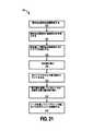
図21は、本開示の実施形態による、インプラント可能なアクセスチャンバを埋め込む方法400のフローダイアグラムである。図21の議論の際に、図22A〜図22Gを参照し、図22A〜22Gは、本開示の実施形態による、インプラント可能なアクセスチャンバを埋め込む側面図を描写している。実施形態において、方法400は局所麻酔下で行うことができる。 FIG. 21 is a flow diagram of a
少なくとも1つの実施形態において、インプラント可能なアクセスチャンバは、上記のインプラント可能なアクセスチャンバ102と一部又はすべて同じ特徴を有することができる。追加的に又は代替的に、キャビティは、上記のキャビティ110と一部又はすべて同じ特徴を有することができる。 In at least one embodiment, the implantable access chamber can have some or all of the same features as the
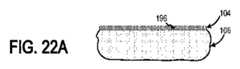
方法400は、図22Aに示されるように、埋め込み部位196を位置特定することを含む(ブロック402)。少なくとも1つの実施形態において、埋め込み部位196は、対象の皮下組織106であることができる。追加的に又は代替的に、埋め込み部位196は、筋肉、リンパ、器官組織、静脈、眼、動脈などの他のタイプの組織であることができ、そして動物組織で使用されうる。埋め込み部位196は、例えば、特定のタイプの検体を検知すること、及び/又は特定のタイプの治療剤をデリバリーすることなど、インプラント可能なアクセスチャンバ102の機能に依存しうる。
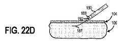
少なくとも1つの実施形態において、方法400は、図20Bに示されるように、針186を経皮的に埋め込み部位196に挿入することをさらに含む(ブロック304)。次に、図22Cに示すように、ガイドワイヤ187を針186を通して埋め込み部位196に挿入することができる(ブロック406)。次に、針186を取り除き(ブロック408)、そして拡張器188をガイドワイヤ187の上をスライドさせることができる(ブロック410)。ガイドワイヤ187は、図22D及び図22Eに示されるように、拡張器188を対象の埋め込み部位196及び皮下組織106内に配置することを容易にすることができる。少なくとも1つの実施形態において、拡張器188は、内部管腔192を含み、それを通してインプラント可能なアクセスチャンバ102を皮下組織106内に提供することができる。あるいは、導入器シース190は、図22Fに示されるように、拡張器188を包囲しそして前記拡張器188を導入器シース190から取り除くことができる(ブロック412)。 In at least one embodiment,
方法400は、図20Gに示されるように、インプラント可能なアクセスチャンバ102を導入器シース190の中及びそれを通して提供して、皮下組織106内にインプラント可能なアクセスチャンバ102を配置することをさらに含む(ブロック414)。インプラント可能なアクセスチャンバ102の配置を容易にするために、滑りやすい、又は潤滑性の表面は、インプラント可能なアクセスチャンバ102の外面上に存在することができる。インプラント可能なアクセスチャンバ102は、潤滑性であるePTFEを含むことができる。追加的に又は代替的に、ヒドロゲルを、インプラント可能なアクセスチャンバ102の外面に適用することができ、このことが外面の潤滑性を付加する。さらに、選択的透過性ポリマー材料も潤滑性である。ヒドロゲル材料を含浸させた、又は界面活性剤でコーティングしたそのような膜は、より滑らかである。
少なくとも幾つかの実施形態において、埋め込み部位196及び/又は埋め込み部位196の近位の皮下組織106は、インプラント可能なアクセスチャンバ102の埋め込み時にフラッシュされうる。抗生物質、生理食塩水又は任意の適切な溶液もしくは薬物の組み合わせを、埋め込み部位196に適用することができ、及び/又は、内部管腔192及び/又は導入器シース190を通して、そして埋め込み部位196の近くの皮下組織106内に注入することができる。 In at least some embodiments, the
図23は、本開示の別の実施形態による、インプラント可能なアクセスチャンバを埋め込む方法500のフローダイアグラムである。図23の議論の際に、図24A〜24Hを参照して、図24A〜24Hは、本開示の別の実施形態による、インプラント可能なアクセスチャンバを埋め込む側面図を描写する。 FIG. 23 is a flow diagram of method 500 for implanting an implantable access chamber according to another embodiment of the present disclosure. In the discussion of FIG. 23, with reference to FIGS. 24A-24H, FIGS. 24A-24H depict side views of implantable access chambers according to another embodiment of the present disclosure.
少なくとも1つの実施形態において、インプラント可能なアクセスチャンバは、上記のインプラント可能なアクセスチャンバ102と一部又はすべて同じ特徴を有することができる。追加的に又は代替的に、キャビティは、上記のキャビティ110と一部又はすべて同じ特徴を有することができる。 In at least one embodiment, the implantable access chamber can have some or all of the same features as the
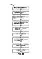
方法500は、図24Aに示されるように、埋め込み部位196を位置特定することを含む(ブロック502)。少なくとも1つの実施形態において、埋め込み部位196は、対象の皮下組織106であることができる。追加的に又は代替的に、埋め込み部位196は、筋肉、リンパ、器官組織、静脈、眼、動脈などの他のタイプの組織であることができ、そして動物組織で使用されうる。埋め込み部位196は、例えば、特定のタイプの検体を検知すること、及び/又は、特定のタイプの治療剤をデリバリーすることなど、インプラント可能なアクセスチャンバ102の機能に依存しうる。 Method 500 comprises locating the
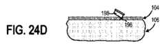
少なくとも1つの実施形態において、方法500は、図24Bに示されるように、例えば、針186を使用して、埋め込み部位196に局所麻酔剤を適用することをさらに含む(ブロック504)。方法500はまた、図24Cに示されるように、例えば、アルコールワイプ197を使用して、埋め込み部位196の表面をクリーニングすることも含みうる(ブロック506)。方法500は、図24Dに示されるように、例えば、かみそり198を使用して、埋め込み部位196でトロカールに適合するサイズの皮膚切開部を作成することをさらに含むことができる(ブロック508)。インプラント可能なアクセスチャンバ102はトロカール199に含まれることもできる。この方法は、図24Eに示されるように、切開部を通してトロカール199の前端を挿入することをさらに含むことができる(ブロック510)。次に、図24Fに示されるように、トロカール199を皮下組織106内に前進させることができ、そこで、インプラント可能なアクセスチャンバ102を配置することができる(ブロック512)。次に、図24Gに示されるように、インプラント可能なアクセスチャンバ102は、皮下組織106内に解放されうる(ブロック514)。 In at least one embodiment, method 500 further comprises applying a local anesthetic to the
次に、トロカール199を引き抜くことができ(ブロック516)、図24Hに示すように、トロカール199が挿入された対象の皮膚の表面104上の点を縫合及び/又はガーゼ194、バンドエイドなどによってカバーすることができる(ブロック518)。 The
インプラント可能なアクセスチャンバ102の配置を容易にするために、滑りやすい、又は潤滑性の表面は、インプラント可能なアクセスチャンバ102の外面上に存在することができる。インプラント可能なアクセスチャンバ102は、潤滑性であるePTFEを含むことができる。追加的に又は代替的に、ヒドロゲルをインプラント可能なアクセスチャンバ102の外面に適用することができ、このことは、外面の潤滑性を付加する。さらに、選択的透過性ポリマー材料も潤滑性である。ヒドロゲル材料を含浸させた、又は界面活性剤でコーティングしたそのような膜は、より滑らかである。 To facilitate the placement of the
少なくとも幾つかの実施形態において、埋め込み部位196及び/又は埋め込み部位196の近位の皮下組織106は、インプラント可能なアクセスチャンバ102の埋め込み時にフラッシュされうる。抗生物質、生理食塩水又は任意の適切な溶液もしくは薬物の組み合わせを埋め込み部位196に適用することができ、及び/又は、トロカール199を通して、埋め込み部位196の近くの皮下組織106内に注入することができる。 In at least some embodiments, the
本出願の発明は、一般的に、そして特定の実施形態の両方に関して上記に記載されてきた。本開示の範囲から逸脱することなく、実施形態において様々な修正及び変更を行うことができることが当業者に明らかであろう。したがって、実施形態は、添付の特許請求の範囲及びそれらの均等形態の範囲内に入る限り、本発明の修正及び変形を網羅することが意図されている。 The inventions of this application have been described above, both in general and with respect to specific embodiments. It will be apparent to those skilled in the art that various modifications and changes can be made in the embodiments without departing from the scope of the present disclosure. Accordingly, embodiments are intended to cover modifications and variations of the invention as long as they fall within the appended claims and their equivalents.
Claims (42)
Translated fromJapaneseキャビティを画定し、そして対象の間質液に対して透過性でかつ細胞に対して閉塞性である材料を含むバリア部分を含み、前記バリア部分はモノリシック構造として形成されている、インプラント可能なアクセスチャンバ。An implantable access chamber that is inserted into a subject's tissue and is configured for use with a sensor configured to detect at least one specimen of the subject's interstitial fluid, said implantable access chamber. Is
Implantable access, comprising a barrier moiety that defines a cavity and contains a material that is permeable to the interstitial fluid of interest and occlusive to cells, said barrier moiety being formed as a monolithic structure. Chamber.
キャビティを画定し、第一の層及び第二の層を含む凝集層を含むバリア部分を含み、前記第一の層は対象の細胞に対して閉塞性である材料を含み、前記第二の層は間質液に対して透過性である材料を含み、そして前記第一の層は前記第二の層よりも細胞閉塞性である、インプラント可能なアクセスチャンバ。An implantable access chamber that is inserted into a subject's tissue and is configured for use with a sensor configured to detect at least one specimen of the subject's interstitial fluid, said implantable access chamber. Is
The first layer comprises a material that defines a cavity and contains an aggregate layer containing a first layer and a second layer, said first layer containing a material that is obstructive to cells of interest, said second layer. An implantable access chamber containing a material that is permeable to interstitial fluid, and the first layer is more cell-occlusive than the second layer.
組織内に埋め込まれたインプラント可能なアクセスチャンバを位置特定することであって、前記インプラント可能なアクセスチャンバは間質液と流体連通しているセンサを含むこと、
前記センサから、前記間質液の少なくとも1つの検体に対応するセンサデータを受信すること、及び、
前記センサデータを分析して、前記センサデータに基づいて前記対象の1つ以上の特性を決定すること、
を含む、方法。A treatment method using the implantable access chamber according to claim 1 or 2.
To locate an implantable access chamber implanted within a tissue, said implantable access chamber containing a sensor that communicates fluid with interstitial fluid.
Receiving sensor data corresponding to at least one sample of the interstitial fluid from the sensor, and
Analyzing the sensor data to determine one or more characteristics of the object based on the sensor data.
Including methods.
組織内に埋め込まれたインプラント可能なアクセスチャンバを位置特定することであって、前記インプラント可能なアクセスチャンバは間質液と流体連通しているセンサを含むこと、
前記インプラント可能なアクセスチャンバのアクセス部分に拡張器を挿入して、前記アクセス部分を拡張すること、及び、
前記拡張器を介して前記キャビティにアクセスすること、
を含む、方法。A method of accessing the cavity of an implantable access chamber according to claim 1 or 2.
To locate an implantable access chamber implanted within a tissue, said implantable access chamber containing a sensor that communicates fluid with interstitial fluid.
Inserting a dilator into the access portion of the implantable access chamber to extend the access portion, and
Accessing the cavity through the dilator,
Including methods.
組織内に埋め込まれたインプラント可能なアクセスチャンバを位置特定すること、及び、
前記インプラント可能なアクセスチャンバの内部に治療剤を提供すること、
を含む、方法。A treatment method using the implantable access chamber according to claim 1 or 2.
Positioning implantable access chambers implanted within tissue and
Providing a therapeutic agent inside the implantable access chamber,
Including methods.
前記インプラント可能なアクセスチャンバのアクセス部分に拡張器を挿入して、前記アクセス部分を拡張すること、及び、
前記拡張器を介して前記キャビティにアクセスすること、
を含む、請求項12記載の方法。Providing a therapeutic agent inside the implantable access chamber
Inserting a dilator into the access portion of the implantable access chamber to extend the access portion, and
Accessing the cavity through the dilator,
12. The method of claim 12.
前記拡張器が前記キャビティにアクセスした後に、前記拡張器を前記導入器シースの内部から取り除くこと、及び、
前記導入器シースを通して治療剤を提供すること、
をさらに含む、請求項13記載の方法。The introducer sheath surrounds the dilator, the method described above.
After the dilator has accessed the cavity, the dilator is removed from the inside of the introducer sheath, and
Providing a therapeutic agent through the introducer sheath,
13. The method of claim 13.
前記埋め込み部位内に針を挿入すること、
前記針を通してガイドワイヤを挿入すること、
前記針を取り除くこと、
拡張器を前記ガイドワイヤ上で前記埋め込み部位中にスライドさせて、前記埋め込み部位を拡張することであって、導入器シースは前記拡張器を包囲していること、
前記導入器シースの内部から前記拡張器を取り除くこと、及び、
前記導入器シース内に前記導入器シースを通してインプラント可能なアクセスチャンバを提供して、前記インプラント可能なアクセスチャンバを前記埋め込み部位に配置すること、
を含む、請求項1又は2記載のインプラント可能なアクセスチャンバを埋め込む方法。Positioning the implantation site,
Inserting a needle into the implantation site,
Inserting the guide wire through the needle,
Removing the needle,
By sliding the dilator onto the guide wire into the embedding site to expand the embedding site, the introducer sheath surrounds the dilator.
Removing the dilator from the inside of the introducer sheath and
Providing an implantable access chamber within the introducer sheath through the introducer sheath and placing the implantable access chamber at the implant site.
The method of implanting an implantable access chamber according to claim 1 or 2, comprising the method.
トロカールを適合させるように前記埋め込み部位を切開することであって、前記トロカールはインプラント可能なアクセスチャンバを含むこと、
切開した埋め込み部位内に前記トロカールを前進させること、
前記インプラント可能なアクセスチャンバを前記トロカールから前記埋め込み部位内に解放すること、及び、
前記トロカールを取り除くこと、
を含む、請求項1又は2記載のインプラント可能なアクセスチャンバを埋め込む方法。Positioning the implantation site,
By making an incision in the implantation site to accommodate the trocar, the trocar includes an implantable access chamber.
Advance the trocar into the incised implantation site,
Releasing the implantable access chamber from the trocar into the implant site, and
Removing the trocar,
The method of implanting an implantable access chamber according to claim 1 or 2, comprising the method.
前記組織と直接相互作用するように構成されたそれぞれの外面、
前記外面の反対側のそれぞれの内面であって、前記内面は集合的にキャビティを画定していること、及び、
それぞれの側面であって、前記第一の層の側面は前記第二の層の側面と接触しそして隣接して配置されていること、
を含む、請求項2記載のインプラント可能なアクセスチャンバ。The first layer and the second layer are
Each outer surface, configured to interact directly with the tissue,
Each inner surface on the opposite side of the outer surface, the inner surface collectively defining the cavity, and
On each side, the side of the first layer is in contact with and adjacent to the side of the second layer.
2. The implantable access chamber according to claim 2.
Priority Applications (1)
| Application Number | Priority Date | Filing Date | Title |
|---|---|---|---|
| JP2022076877AJP2022103268A (en) | 2018-02-09 | 2022-05-09 | Implantable access chamber and associated methods of use |
Applications Claiming Priority (3)
| Application Number | Priority Date | Filing Date | Title |
|---|---|---|---|
| US201862628679P | 2018-02-09 | 2018-02-09 | |
| US62/628,679 | 2018-02-09 | ||
| PCT/US2019/017426WO2019157421A1 (en) | 2018-02-09 | 2019-02-11 | Implantable access chamber and associated methods of use |
Related Child Applications (1)
| Application Number | Title | Priority Date | Filing Date |
|---|---|---|---|
| JP2022076877ADivisionJP2022103268A (en) | 2018-02-09 | 2022-05-09 | Implantable access chamber and associated methods of use |
Publications (2)
| Publication Number | Publication Date |
|---|---|
| JP2021512723Atrue JP2021512723A (en) | 2021-05-20 |
| JP7072072B2 JP7072072B2 (en) | 2022-05-19 |
Family
ID=65767283
Family Applications (2)
| Application Number | Title | Priority Date | Filing Date |
|---|---|---|---|
| JP2020542839AActiveJP7072072B2 (en) | 2018-02-09 | 2019-02-11 | Implantable access chambers and related uses |
| JP2022076877APendingJP2022103268A (en) | 2018-02-09 | 2022-05-09 | Implantable access chamber and associated methods of use |
Family Applications After (1)
| Application Number | Title | Priority Date | Filing Date |
|---|---|---|---|
| JP2022076877APendingJP2022103268A (en) | 2018-02-09 | 2022-05-09 | Implantable access chamber and associated methods of use |
Country Status (7)
| Country | Link |
|---|---|
| US (1) | US20200367792A1 (en) |
| EP (1) | EP3749176A1 (en) |
| JP (2) | JP7072072B2 (en) |
| CN (1) | CN112040839A (en) |
| AU (2) | AU2019218260B2 (en) |
| CA (1) | CA3090541A1 (en) |
| WO (1) | WO2019157421A1 (en) |
Cited By (1)
| Publication number | Priority date | Publication date | Assignee | Title |
|---|---|---|---|---|
| WO2023003093A1 (en)* | 2021-07-19 | 2023-01-26 | 주식회사 에스비솔루션 | Biometric information measurement device and method |
Families Citing this family (3)
| Publication number | Priority date | Publication date | Assignee | Title |
|---|---|---|---|---|
| IT202000021379A1 (en)* | 2020-09-10 | 2020-12-10 | Brain Innovations S R L | Method and adaptive system for personalized daily infusion therapy of Parkinson's disease |
| IT202000021385A1 (en)* | 2020-09-10 | 2020-12-10 | Brain Innovations S R L | Method for the management of oral therapy in Parkinson's disease |
| KR20230013536A (en)* | 2021-07-19 | 2023-01-26 | 주식회사 에스비솔루션 | Device and method for measuring biometric information considering sensor state measurement |
Citations (5)
| Publication number | Priority date | Publication date | Assignee | Title |
|---|---|---|---|---|
| US20030220552A1 (en)* | 1999-07-01 | 2003-11-27 | Medtronic Minimed, Inc. | Reusable analyte sensor site and method of using the same |
| JP2006525853A (en)* | 2003-05-21 | 2006-11-16 | デックスコム・インコーポレーテッド | Biointerface membrane incorporating bioactive agent |
| US20090137899A1 (en)* | 2007-11-27 | 2009-05-28 | Bengtson Bradley P | Devices, systems, and methods for locating magnetic injection fill ports |
| US20130144144A1 (en)* | 2007-04-19 | 2013-06-06 | C.G.M.3 Ltd. | Device system and method for monitoring and controlling blood analyte levels |
| JP2013154002A (en)* | 2012-01-31 | 2013-08-15 | Arkray Inc | Polymer film, sensor, and measuring method |
Family Cites Families (39)
| Publication number | Priority date | Publication date | Assignee | Title |
|---|---|---|---|---|
| CA962021A (en) | 1970-05-21 | 1975-02-04 | Robert W. Gore | Porous products and process therefor |
| US4482516A (en) | 1982-09-10 | 1984-11-13 | W. L. Gore & Associates, Inc. | Process for producing a high strength porous polytetrafluoroethylene product having a coarse microstructure |
| US4588394A (en)* | 1984-03-16 | 1986-05-13 | Pudenz-Schulte Medical Research Corp. | Infusion reservoir and pump system |
| US4890620A (en) | 1985-09-20 | 1990-01-02 | The Regents Of The University Of California | Two-dimensional diffusion glucose substrate sensing electrode |
| DE3933373A1 (en)* | 1989-10-06 | 1991-04-18 | Thomas Hoell | Blood sensor system for analytical in-vivo measurement - has implantable sensor unit with electronics, sensor element positioning holder and penetration seal for element replacement tool |
| US5165407A (en) | 1990-04-19 | 1992-11-24 | The University Of Kansas | Implantable glucose sensor |
| DK0680517T4 (en) | 1993-01-21 | 2005-05-02 | Harvard College | Method and Diagnostic Kits to Determine the Toxicity of a Compound Using Mammalian Stress Promoters |
| US5390671A (en) | 1994-03-15 | 1995-02-21 | Minimed Inc. | Transcutaneous sensor insertion set |
| US5391250A (en) | 1994-03-15 | 1995-02-21 | Minimed Inc. | Method of fabricating thin film sensors |
| US5651767A (en)* | 1994-05-06 | 1997-07-29 | Alfred F. Mann Foundation For Scientific Research | Replaceable catheter system for physiological sensors, stimulating electrodes and/or implantable fluid delivery systems |
| US5605152A (en) | 1994-07-18 | 1997-02-25 | Minimed Inc. | Optical glucose sensor |
| US5476589A (en) | 1995-03-10 | 1995-12-19 | W. L. Gore & Associates, Inc. | Porpous PTFE film and a manufacturing method therefor |
| EP0773753B1 (en) | 1995-06-07 | 2003-10-08 | Gore Hybrid Technologies, Inc. | An implantable containment apparatus for a therapeutical device |
| EP0862648B1 (en) | 1995-11-22 | 2004-10-06 | Medtronic MiniMed, Inc. | Detection of biological molecules using chemical amplification and optical sensors |
| KR100682488B1 (en)* | 1998-08-26 | 2007-02-15 | 센서즈 포 메드슨 앤드 사이언스 인코포레이티드 | Optical system |
| IL134009A (en)* | 2000-01-12 | 2011-07-31 | Bo2 Technologies Ltd | Implantable device |
| US6459917B1 (en)* | 2000-05-22 | 2002-10-01 | Ashok Gowda | Apparatus for access to interstitial fluid, blood, or blood plasma components |
| US7091033B2 (en) | 2000-07-21 | 2006-08-15 | Phase-1 Molecular Toxicology, Inc. | Array of toxicologically relevant canine genes and uses thereof |
| US7641958B2 (en) | 2002-04-25 | 2010-01-05 | Gore Enterprise Holdings, Inc. | Membrane for use in sutured or sutureless surgical procedures |
| US7736309B2 (en)* | 2002-09-27 | 2010-06-15 | Medtronic Minimed, Inc. | Implantable sensor method and system |
| US7727147B1 (en)* | 2004-05-14 | 2010-06-01 | Flint Hills Scientific Llc | Method and system for implantable glucose monitoring and control of a glycemic state of a subject |
| US20060263763A1 (en)* | 2005-04-15 | 2006-11-23 | Simpson Peter C | Analyte sensing biointerface |
| US20160324449A1 (en)* | 2006-03-28 | 2016-11-10 | Glusense Ltd. | Implantable sensors |
| US8221354B2 (en)* | 2006-04-27 | 2012-07-17 | Medtronic, Inc. | Infusion device with positive pressure elastic bladder reservoir |
| US8491547B2 (en)* | 2006-04-28 | 2013-07-23 | Medtronic, Inc. | Septum monitoring system and method for an implantable therapeutic substance delivery device |
| WO2008079997A2 (en)* | 2006-12-22 | 2008-07-03 | Medtronic, Inc. | Implantable device, angiogenesis mechanism and methods |
| US20180116551A1 (en)* | 2007-11-26 | 2018-05-03 | C. R. Bard, Inc. | Needles For Use With System For Guiding A Medical Instrument |
| WO2009097468A2 (en)* | 2008-01-29 | 2009-08-06 | Kliman Gilbert H | Drug delivery devices, kits and methods therefor |
| ES2530450T3 (en)* | 2008-10-02 | 2015-03-03 | Eyesense Ag | Implantable sensor element |
| US8151682B2 (en)* | 2009-01-26 | 2012-04-10 | Boston Scientific Scimed, Inc. | Atraumatic stent and method and apparatus for making the same |
| US10638955B2 (en)* | 2011-06-30 | 2020-05-05 | Endotronix, Inc. | Pressure sensing implant |
| KR20140082642A (en)* | 2011-07-26 | 2014-07-02 | 글리젠스 인코포레이티드 | Tissue implantable sensor with hermetically sealed housing |
| WO2013102161A1 (en)* | 2011-12-29 | 2013-07-04 | Wellsense, Inc. | Analyte sensor |
| US10561353B2 (en)* | 2016-06-01 | 2020-02-18 | Glysens Incorporated | Biocompatible implantable sensor apparatus and methods |
| US20150352229A1 (en)* | 2012-12-28 | 2015-12-10 | Glusense, Ltd. | Apparatus for facilitating cell growth in an implantable sensor |
| US9305461B2 (en) | 2014-04-24 | 2016-04-05 | Ford Global Technologies, Llc | Method and apparatus for vehicle to vehicle communication and information relay |
| SMT202400362T1 (en)* | 2016-02-05 | 2024-11-15 | Hoffmann La Roche | Medical device for detecting at least one analyte in a body fluid |
| CN120753591A (en)* | 2016-02-09 | 2025-10-10 | 制定实验室公司 | Transponder and sensor for implantable medical device and method of use thereof |
| US10638962B2 (en)* | 2016-06-29 | 2020-05-05 | Glysens Incorporated | Bio-adaptable implantable sensor apparatus and methods |
- 2019
- 2019-02-11JPJP2020542839Apatent/JP7072072B2/enactiveActive
- 2019-02-11CACA3090541Apatent/CA3090541A1/enactivePending
- 2019-02-11WOPCT/US2019/017426patent/WO2019157421A1/ennot_activeCeased
- 2019-02-11AUAU2019218260Apatent/AU2019218260B2/enactiveActive
- 2019-02-11EPEP19711179.2Apatent/EP3749176A1/enactivePending
- 2019-02-11CNCN201980024293.8Apatent/CN112040839A/enactivePending
- 2019-02-11USUS16/968,286patent/US20200367792A1/enactivePending
- 2022
- 2022-04-06AUAU2022202304Apatent/AU2022202304A1/ennot_activeAbandoned
- 2022-05-09JPJP2022076877Apatent/JP2022103268A/enactivePending
Patent Citations (5)
| Publication number | Priority date | Publication date | Assignee | Title |
|---|---|---|---|---|
| US20030220552A1 (en)* | 1999-07-01 | 2003-11-27 | Medtronic Minimed, Inc. | Reusable analyte sensor site and method of using the same |
| JP2006525853A (en)* | 2003-05-21 | 2006-11-16 | デックスコム・インコーポレーテッド | Biointerface membrane incorporating bioactive agent |
| US20130144144A1 (en)* | 2007-04-19 | 2013-06-06 | C.G.M.3 Ltd. | Device system and method for monitoring and controlling blood analyte levels |
| US20090137899A1 (en)* | 2007-11-27 | 2009-05-28 | Bengtson Bradley P | Devices, systems, and methods for locating magnetic injection fill ports |
| JP2013154002A (en)* | 2012-01-31 | 2013-08-15 | Arkray Inc | Polymer film, sensor, and measuring method |
Cited By (2)
| Publication number | Priority date | Publication date | Assignee | Title |
|---|---|---|---|---|
| WO2023003093A1 (en)* | 2021-07-19 | 2023-01-26 | 주식회사 에스비솔루션 | Biometric information measurement device and method |
| EP4374786A4 (en)* | 2021-07-19 | 2024-12-04 | SB Solutions Inc. | DEVICE AND METHOD FOR MEASURING BIOMETRIC INFORMATION |
Also Published As
| Publication number | Publication date |
|---|---|
| CA3090541A1 (en) | 2019-08-15 |
| AU2019218260B2 (en) | 2022-01-06 |
| CN112040839A (en) | 2020-12-04 |
| AU2022202304A1 (en) | 2022-04-28 |
| WO2019157421A1 (en) | 2019-08-15 |
| EP3749176A1 (en) | 2020-12-16 |
| JP7072072B2 (en) | 2022-05-19 |
| US20200367792A1 (en) | 2020-11-26 |
| AU2019218260A1 (en) | 2020-09-24 |
| JP2022103268A (en) | 2022-07-07 |
Similar Documents
| Publication | Publication Date | Title |
|---|---|---|
| JP2022103268A (en) | Implantable access chamber and associated methods of use | |
| NL1003300C2 (en) | Implantable therapeutic device. | |
| NL1003302C2 (en) | A method for repeatedly filling and emptying a tubular implantable containment device with a therapeutic device. | |
| US20180125399A1 (en) | Long-term implantable monitoring system & methods of use | |
| Koschwanez et al. | In vitro and in vivo characterization of porous poly‐L‐lactic acid coatings for subcutaneously implanted glucose sensors | |
| AU2020210244B2 (en) | Implantable apparatus for retention of biological moieties | |
| WO2007003431A9 (en) | Device for and method of delivery and removal of substances in and from a tissue or vessel | |
| CN110831637B (en) | Transplantation chamber and transplantation device | |
| EP1731191A1 (en) | Cuff member | |
| JP2024015306A (en) | implantable catheter | |
| CA2484012C (en) | Scaffold for tissue engineering, artificial blood vessel, cuff, and biological implant covering member | |
| WO2024243181A2 (en) | Methods and systems for improved biocompatible membranes for implantable devices | |
| ITMI961171A1 (en) | IMPLANTABLE CONTAINMENT APPARATUS FOR A THERAPEUTIC DEVICE AND METHOD FOR CHARGING AND RECHARGING THE DEVICE ITSELF |
Legal Events
| Date | Code | Title | Description |
|---|---|---|---|
| A621 | Written request for application examination | Free format text:JAPANESE INTERMEDIATE CODE: A621 Effective date:20201005 | |
| A977 | Report on retrieval | Free format text:JAPANESE INTERMEDIATE CODE: A971007 Effective date:20210825 | |
| A131 | Notification of reasons for refusal | Free format text:JAPANESE INTERMEDIATE CODE: A131 Effective date:20210907 | |
| A521 | Request for written amendment filed | Free format text:JAPANESE INTERMEDIATE CODE: A523 Effective date:20211203 | |
| TRDD | Decision of grant or rejection written | ||
| A01 | Written decision to grant a patent or to grant a registration (utility model) | Free format text:JAPANESE INTERMEDIATE CODE: A01 Effective date:20220308 | |
| A601 | Written request for extension of time | Free format text:JAPANESE INTERMEDIATE CODE: A601 Effective date:20220407 | |
| A61 | First payment of annual fees (during grant procedure) | Free format text:JAPANESE INTERMEDIATE CODE: A61 Effective date:20220509 | |
| R150 | Certificate of patent or registration of utility model | Ref document number:7072072 Country of ref document:JP Free format text:JAPANESE INTERMEDIATE CODE: R150 | |
| R250 | Receipt of annual fees | Free format text:JAPANESE INTERMEDIATE CODE: R250 |