JP2021509594A - Electrosurgical ablation instrument - Google Patents
Electrosurgical ablation instrumentDownload PDFInfo
- Publication number
- JP2021509594A JP2021509594AJP2020529212AJP2020529212AJP2021509594AJP 2021509594 AJP2021509594 AJP 2021509594AJP 2020529212 AJP2020529212 AJP 2020529212AJP 2020529212 AJP2020529212 AJP 2020529212AJP 2021509594 AJP2021509594 AJP 2021509594A
- Authority
- JP
- Japan
- Prior art keywords
- distal
- dielectric material
- microwave
- electrosurgical
- transmission line
- Prior art date
- Legal status (The legal status is an assumption and is not a legal conclusion. Google has not performed a legal analysis and makes no representation as to the accuracy of the status listed.)
- Granted
Links
Images


Classifications
- A—HUMAN NECESSITIES
- A61—MEDICAL OR VETERINARY SCIENCE; HYGIENE
- A61B—DIAGNOSIS; SURGERY; IDENTIFICATION
- A61B18/00—Surgical instruments, devices or methods for transferring non-mechanical forms of energy to or from the body
- A61B18/18—Surgical instruments, devices or methods for transferring non-mechanical forms of energy to or from the body by applying electromagnetic radiation, e.g. microwaves
- A61B18/1815—Surgical instruments, devices or methods for transferring non-mechanical forms of energy to or from the body by applying electromagnetic radiation, e.g. microwaves using microwaves
- A—HUMAN NECESSITIES
- A61—MEDICAL OR VETERINARY SCIENCE; HYGIENE
- A61B—DIAGNOSIS; SURGERY; IDENTIFICATION
- A61B18/00—Surgical instruments, devices or methods for transferring non-mechanical forms of energy to or from the body
- A61B18/18—Surgical instruments, devices or methods for transferring non-mechanical forms of energy to or from the body by applying electromagnetic radiation, e.g. microwaves
- A—HUMAN NECESSITIES
- A61—MEDICAL OR VETERINARY SCIENCE; HYGIENE
- A61B—DIAGNOSIS; SURGERY; IDENTIFICATION
- A61B18/00—Surgical instruments, devices or methods for transferring non-mechanical forms of energy to or from the body
- A61B18/04—Surgical instruments, devices or methods for transferring non-mechanical forms of energy to or from the body by heating
- A61B18/12—Surgical instruments, devices or methods for transferring non-mechanical forms of energy to or from the body by heating by passing a current through the tissue to be heated, e.g. high-frequency current
- A61B18/1206—Generators therefor
- A—HUMAN NECESSITIES
- A61—MEDICAL OR VETERINARY SCIENCE; HYGIENE
- A61B—DIAGNOSIS; SURGERY; IDENTIFICATION
- A61B18/00—Surgical instruments, devices or methods for transferring non-mechanical forms of energy to or from the body
- A61B18/04—Surgical instruments, devices or methods for transferring non-mechanical forms of energy to or from the body by heating
- A61B18/12—Surgical instruments, devices or methods for transferring non-mechanical forms of energy to or from the body by heating by passing a current through the tissue to be heated, e.g. high-frequency current
- A61B18/14—Probes or electrodes therefor
- A61B18/1492—Probes or electrodes therefor having a flexible, catheter-like structure, e.g. for heart ablation
- A—HUMAN NECESSITIES
- A61—MEDICAL OR VETERINARY SCIENCE; HYGIENE
- A61B—DIAGNOSIS; SURGERY; IDENTIFICATION
- A61B8/00—Diagnosis using ultrasonic, sonic or infrasonic waves
- A61B8/12—Diagnosis using ultrasonic, sonic or infrasonic waves in body cavities or body tracts, e.g. by using catheters
- A—HUMAN NECESSITIES
- A61—MEDICAL OR VETERINARY SCIENCE; HYGIENE
- A61B—DIAGNOSIS; SURGERY; IDENTIFICATION
- A61B17/00—Surgical instruments, devices or methods
- A61B17/00234—Surgical instruments, devices or methods for minimally invasive surgery
- A61B2017/00292—Surgical instruments, devices or methods for minimally invasive surgery mounted on or guided by flexible, e.g. catheter-like, means
- A61B2017/0034—Surgical instruments, devices or methods for minimally invasive surgery mounted on or guided by flexible, e.g. catheter-like, means adapted to be inserted through a working channel of an endoscope
- A—HUMAN NECESSITIES
- A61—MEDICAL OR VETERINARY SCIENCE; HYGIENE
- A61B—DIAGNOSIS; SURGERY; IDENTIFICATION
- A61B18/00—Surgical instruments, devices or methods for transferring non-mechanical forms of energy to or from the body
- A61B2018/00053—Mechanical features of the instrument of device
- A61B2018/00059—Material properties
- A61B2018/00071—Electrical conductivity
- A—HUMAN NECESSITIES
- A61—MEDICAL OR VETERINARY SCIENCE; HYGIENE
- A61B—DIAGNOSIS; SURGERY; IDENTIFICATION
- A61B18/00—Surgical instruments, devices or methods for transferring non-mechanical forms of energy to or from the body
- A61B2018/00315—Surgical instruments, devices or methods for transferring non-mechanical forms of energy to or from the body for treatment of particular body parts
- A61B2018/00482—Digestive system
- A—HUMAN NECESSITIES
- A61—MEDICAL OR VETERINARY SCIENCE; HYGIENE
- A61B—DIAGNOSIS; SURGERY; IDENTIFICATION
- A61B18/00—Surgical instruments, devices or methods for transferring non-mechanical forms of energy to or from the body
- A61B2018/00571—Surgical instruments, devices or methods for transferring non-mechanical forms of energy to or from the body for achieving a particular surgical effect
- A61B2018/00577—Ablation
- A—HUMAN NECESSITIES
- A61—MEDICAL OR VETERINARY SCIENCE; HYGIENE
- A61B—DIAGNOSIS; SURGERY; IDENTIFICATION
- A61B18/00—Surgical instruments, devices or methods for transferring non-mechanical forms of energy to or from the body
- A61B2018/0091—Handpieces of the surgical instrument or device
- A—HUMAN NECESSITIES
- A61—MEDICAL OR VETERINARY SCIENCE; HYGIENE
- A61B—DIAGNOSIS; SURGERY; IDENTIFICATION
- A61B18/00—Surgical instruments, devices or methods for transferring non-mechanical forms of energy to or from the body
- A61B2018/0091—Handpieces of the surgical instrument or device
- A61B2018/00916—Handpieces of the surgical instrument or device with means for switching or controlling the main function of the instrument or device
- A—HUMAN NECESSITIES
- A61—MEDICAL OR VETERINARY SCIENCE; HYGIENE
- A61B—DIAGNOSIS; SURGERY; IDENTIFICATION
- A61B18/00—Surgical instruments, devices or methods for transferring non-mechanical forms of energy to or from the body
- A61B2018/00982—Surgical instruments, devices or methods for transferring non-mechanical forms of energy to or from the body combined with or comprising means for visual or photographic inspections inside the body, e.g. endoscopes
- A—HUMAN NECESSITIES
- A61—MEDICAL OR VETERINARY SCIENCE; HYGIENE
- A61B—DIAGNOSIS; SURGERY; IDENTIFICATION
- A61B18/00—Surgical instruments, devices or methods for transferring non-mechanical forms of energy to or from the body
- A61B2018/00994—Surgical instruments, devices or methods for transferring non-mechanical forms of energy to or from the body combining two or more different kinds of non-mechanical energy or combining one or more non-mechanical energies with ultrasound
- A—HUMAN NECESSITIES
- A61—MEDICAL OR VETERINARY SCIENCE; HYGIENE
- A61B—DIAGNOSIS; SURGERY; IDENTIFICATION
- A61B18/00—Surgical instruments, devices or methods for transferring non-mechanical forms of energy to or from the body
- A61B18/04—Surgical instruments, devices or methods for transferring non-mechanical forms of energy to or from the body by heating
- A61B18/12—Surgical instruments, devices or methods for transferring non-mechanical forms of energy to or from the body by heating by passing a current through the tissue to be heated, e.g. high-frequency current
- A61B18/1206—Generators therefor
- A61B2018/1246—Generators therefor characterised by the output polarity
- A61B2018/126—Generators therefor characterised by the output polarity bipolar
- A—HUMAN NECESSITIES
- A61—MEDICAL OR VETERINARY SCIENCE; HYGIENE
- A61B—DIAGNOSIS; SURGERY; IDENTIFICATION
- A61B18/00—Surgical instruments, devices or methods for transferring non-mechanical forms of energy to or from the body
- A61B18/18—Surgical instruments, devices or methods for transferring non-mechanical forms of energy to or from the body by applying electromagnetic radiation, e.g. microwaves
- A61B18/1815—Surgical instruments, devices or methods for transferring non-mechanical forms of energy to or from the body by applying electromagnetic radiation, e.g. microwaves using microwaves
- A61B2018/1823—Generators therefor
- A—HUMAN NECESSITIES
- A61—MEDICAL OR VETERINARY SCIENCE; HYGIENE
- A61B—DIAGNOSIS; SURGERY; IDENTIFICATION
- A61B18/00—Surgical instruments, devices or methods for transferring non-mechanical forms of energy to or from the body
- A61B18/18—Surgical instruments, devices or methods for transferring non-mechanical forms of energy to or from the body by applying electromagnetic radiation, e.g. microwaves
- A61B18/1815—Surgical instruments, devices or methods for transferring non-mechanical forms of energy to or from the body by applying electromagnetic radiation, e.g. microwaves using microwaves
- A61B2018/183—Surgical instruments, devices or methods for transferring non-mechanical forms of energy to or from the body by applying electromagnetic radiation, e.g. microwaves using microwaves characterised by the type of antenna
- A61B2018/1853—Monopole antennas
- A—HUMAN NECESSITIES
- A61—MEDICAL OR VETERINARY SCIENCE; HYGIENE
- A61B—DIAGNOSIS; SURGERY; IDENTIFICATION
- A61B18/00—Surgical instruments, devices or methods for transferring non-mechanical forms of energy to or from the body
- A61B18/18—Surgical instruments, devices or methods for transferring non-mechanical forms of energy to or from the body by applying electromagnetic radiation, e.g. microwaves
- A61B18/1815—Surgical instruments, devices or methods for transferring non-mechanical forms of energy to or from the body by applying electromagnetic radiation, e.g. microwaves using microwaves
- A61B2018/1861—Surgical instruments, devices or methods for transferring non-mechanical forms of energy to or from the body by applying electromagnetic radiation, e.g. microwaves using microwaves with an instrument inserted into a body lumen or cavity, e.g. a catheter
- A—HUMAN NECESSITIES
- A61—MEDICAL OR VETERINARY SCIENCE; HYGIENE
- A61B—DIAGNOSIS; SURGERY; IDENTIFICATION
- A61B18/00—Surgical instruments, devices or methods for transferring non-mechanical forms of energy to or from the body
- A61B18/18—Surgical instruments, devices or methods for transferring non-mechanical forms of energy to or from the body by applying electromagnetic radiation, e.g. microwaves
- A61B18/1815—Surgical instruments, devices or methods for transferring non-mechanical forms of energy to or from the body by applying electromagnetic radiation, e.g. microwaves using microwaves
- A61B2018/1869—Surgical instruments, devices or methods for transferring non-mechanical forms of energy to or from the body by applying electromagnetic radiation, e.g. microwaves using microwaves with an instrument interstitially inserted into the body, e.g. needles
- A—HUMAN NECESSITIES
- A61—MEDICAL OR VETERINARY SCIENCE; HYGIENE
- A61B—DIAGNOSIS; SURGERY; IDENTIFICATION
- A61B18/00—Surgical instruments, devices or methods for transferring non-mechanical forms of energy to or from the body
- A61B18/18—Surgical instruments, devices or methods for transferring non-mechanical forms of energy to or from the body by applying electromagnetic radiation, e.g. microwaves
- A61B18/1815—Surgical instruments, devices or methods for transferring non-mechanical forms of energy to or from the body by applying electromagnetic radiation, e.g. microwaves using microwaves
- A61B2018/1892—Details of electrical isolations of the antenna
- A—HUMAN NECESSITIES
- A61—MEDICAL OR VETERINARY SCIENCE; HYGIENE
- A61B—DIAGNOSIS; SURGERY; IDENTIFICATION
- A61B90/00—Instruments, implements or accessories specially adapted for surgery or diagnosis and not covered by any of the groups A61B1/00 - A61B50/00, e.g. for luxation treatment or for protecting wound edges
- A61B90/03—Automatic limiting or abutting means, e.g. for safety
- A61B2090/033—Abutting means, stops, e.g. abutting on tissue or skin
- A61B2090/036—Abutting means, stops, e.g. abutting on tissue or skin abutting on tissue or skin
- A—HUMAN NECESSITIES
- A61—MEDICAL OR VETERINARY SCIENCE; HYGIENE
- A61B—DIAGNOSIS; SURGERY; IDENTIFICATION
- A61B2218/00—Details of surgical instruments, devices or methods for transferring non-mechanical forms of energy to or from the body
- A61B2218/001—Details of surgical instruments, devices or methods for transferring non-mechanical forms of energy to or from the body having means for irrigation and/or aspiration of substances to and/or from the surgical site
- A61B2218/002—Irrigation
- A—HUMAN NECESSITIES
- A61—MEDICAL OR VETERINARY SCIENCE; HYGIENE
- A61B—DIAGNOSIS; SURGERY; IDENTIFICATION
- A61B2218/00—Details of surgical instruments, devices or methods for transferring non-mechanical forms of energy to or from the body
- A61B2218/001—Details of surgical instruments, devices or methods for transferring non-mechanical forms of energy to or from the body having means for irrigation and/or aspiration of substances to and/or from the surgical site
- A61B2218/007—Aspiration
Landscapes
- Health & Medical Sciences (AREA)
- Life Sciences & Earth Sciences (AREA)
- Surgery (AREA)
- Engineering & Computer Science (AREA)
- Heart & Thoracic Surgery (AREA)
- Animal Behavior & Ethology (AREA)
- Veterinary Medicine (AREA)
- Public Health (AREA)
- Physics & Mathematics (AREA)
- Biomedical Technology (AREA)
- General Health & Medical Sciences (AREA)
- Medical Informatics (AREA)
- Molecular Biology (AREA)
- Nuclear Medicine, Radiotherapy & Molecular Imaging (AREA)
- Otolaryngology (AREA)
- Plasma & Fusion (AREA)
- Electromagnetism (AREA)
- Cardiology (AREA)
- Biophysics (AREA)
- Pathology (AREA)
- Radiology & Medical Imaging (AREA)
- Surgical Instruments (AREA)
Abstract
Translated fromJapaneseDescription
Translated fromJapanese本発明は、生体組織に高周波及びマイクロ波エネルギーを送出して標的組織を焼灼するための電気外科器具に関する。詳細には、プローブが、治療部位に非侵襲的な方法で導入可能な外科スコープ装置またはカテーテルのチャネルを通して挿入できるように構成されている。プローブは、腫瘍、嚢胞、または他の損傷部位などの組織を焼灼するように配設される場合がある。プローブは膵臓での処置に特に適している場合がある。 The present invention relates to an electrosurgical instrument for cauterizing a target tissue by delivering high frequency and microwave energy to the living tissue. Specifically, the probe is configured to be inserted through a surgical scope device or catheter channel that can be introduced into the treatment site in a non-invasive manner. The probe may be arranged to cauterize tissue such as a tumor, cyst, or other site of injury. The probe may be particularly suitable for treatment in the pancreas.
細胞を殺す有効な方法として、生体組織に熱エネルギーを加えることが良く知られている。たとえば、高周波またはマイクロ波エネルギーを加えることによって、生体組織を加熱し、したがって焼灼(破壊する)ことができる。この方法は特にがんの処置に用いられる場合がある。 It is well known that heat energy is applied to living tissues as an effective method for killing cells. For example, by applying high frequency or microwave energy, living tissue can be heated and thus cauterized (destroyed). This method may be used specifically for the treatment of cancer.
内視鏡超音波ガイドラジオ波焼灼療法を用いて膵臓の組織を処置する技術が知られている(Pai,M.,et al.:Endoscopic ultrasound guided radiofrequency ablation,for pancreatic cystic neoplasms and neuroendocrine tumors,World J Gastrointest Surg 2015 April 27;7(4):52−59)。この技術では、超音波可能な内視鏡のワーキングチャネルを通して、小直径(たとえば0.33mm)の伝導性ワイヤを挿入する。患者の皮膚に外部の接地リターンパッドを接触させるとともにワイヤにRF電力を印加して、肝臓及び膵臓の組織を凝固させる。損傷部位を焼灼するためには、90〜120秒間、電力を印加する必要があり、場合によってはワイヤを移して位置を変える必要がある。 Techniques for treating pancreatic tissue using endoscopic ultrasound-guided radiofrequency ablation are known (Pai, M., et al .: Endoscopic ultrasond guided radiofrequency ablation, for pancreatic radiofrequency ablation, for pancreatic radiofrequency ablation J Gastrointest Surg 2015 April 27; 7 (4): 52-59). In this technique, a small diameter (eg 0.33 mm) conductive wire is inserted through the working channel of an ultrasonically capable endoscope. An external ground return pad is brought into contact with the patient's skin and RF power is applied to the wire to coagulate liver and pancreatic tissue. In order to cauterize the damaged area, it is necessary to apply electric power for 90 to 120 seconds, and in some cases, it is necessary to move the wire and change the position.
概略的には、本発明によって、外科スコープ装置を介した膵臓内への挿入に適するように寸法取りされたマイクロ波焼灼アンテナを有する電気外科器具が提供され、既知のRF焼灼技術に対する迅速で正確な代替案が得られる。本発明は、膵臓において特定の用途を見出す場合があるが、熟練を要する他の治療部位(たとえば、肺)での使用にも適する場合がある。 In general, the present invention provides an electrosurgical instrument with a microwave ablation antenna sized for insertion into the pancreas via a surgical scope device, providing rapid and accurate for known RF ablation techniques. Alternatives are available. The present invention may find specific applications in the pancreas, but may also be suitable for use in other sensitive therapeutic sites (eg, lungs).
本発明によって、電気外科器具であって、マイクロ波電磁(EM)エネルギーを伝えるための同軸伝送線を含む近位部分と、遠位の放射部分と、同軸伝送線のインピーダンスを遠位の放射部分のインピーダンスに整合するために配設された中間のインピーダンス変成器とを含み、遠位の放射部分は、同軸伝送線が伝えるマイクロ波EMエネルギーを放出するためのマイクロ波アンテナを含み、遠位の放射部分の最大外径は同軸伝送線の外径よりも小さい、電気外科器具が提供される。これらの特徴により、器具は小直径の構造を介してマイクロ波エネルギーを送出することができる。 According to the present invention, an electrosurgical instrument, a proximal portion including a coaxial transmission line for transmitting microwave electromagnetic (EM) energy, a distal radiating portion, and a radiating portion where the impedance of the coaxial transmission line is distal. Includes an intermediate impedance modifier arranged to match the impedance of the coaxial transmission line, and the distal radiating portion contains a microwave antenna for emitting microwave EM energy transmitted by the coaxial transmission line, and is distal. An electrosurgical instrument is provided in which the maximum outer diameter of the radiating part is smaller than the outer diameter of the coaxial transmission line. These features allow the instrument to deliver microwave energy through a small diameter structure.
同軸伝送線には、第1の誘電体材料によって近位の外部導体から分離された内部導体が含まれていてもよい。同軸伝送線は従来の同軸ケーブルであってもよい。優位なことに、同軸ケーブルの内部導体は、近位の外部導体の遠位端を越えて、中間のインピーダンス変成器を通って、遠位の放射部分内に延びていてもよい。言い換えれば、中間のインピーダンス変成器及び遠位の放射部分は共通の同軸ケーブルを有していてもよい。これは、同軸伝送線の外部導体をその遠位部分(中間のインピーダンス変成器及び遠位の放射部分が形成されるべき場所)に沿って剥がすことによって、実現してもよい。後述するように、第1の誘電体材料を中間のインピーダンス変成器及び遠位の放射部分において用いてもよい。たとえば、これらの領域内で第1の誘電体を選択的に取り除いてその直径を減らすことができる。場合によっては、それを全く取り除いて、他の誘電体材料と交換してもよい。代替的に、それを単独でまたは他の材料と組み合わせて用いてもよい。 The coaxial transmission line may include an inner conductor separated from a proximal outer conductor by a first dielectric material. The coaxial transmission line may be a conventional coaxial cable. Advantageously, the inner conductor of the coaxial cable may extend beyond the distal end of the proximal outer conductor, through an intermediate impedance transformer, and into the distal radiating portion. In other words, the intermediate impedance transformer and the distal radiating portion may have a common coaxial cable. This may be achieved by stripping the outer conductor of the coaxial transmission line along its distal portion (where the intermediate impedance transformer and distal radiating portion should be formed). As will be described later, the first dielectric material may be used in the intermediate impedance transformer and the distal radiating portion. For example, within these regions the first dielectric can be selectively removed to reduce its diameter. In some cases, it may be removed altogether and replaced with another dielectric material. Alternatively, it may be used alone or in combination with other materials.
近位の外部導体(すなわち、同軸伝送線の外部導体)の外径は3mm以下であり、好ましくは2.2mm以下であってもよい。遠位の放射部分の最大外径は1mm以下であってもよい。中間のインピーダンス変成器の最大外径は、近位の外部導体のそれと遠位の放射部分のそれとの間であってもよい。 The outer diameter of the proximal outer conductor (that is, the outer conductor of the coaxial transmission line) may be 3 mm or less, preferably 2.2 mm or less. The maximum outer diameter of the distal radiating portion may be 1 mm or less. The maximum outer diameter of the intermediate impedance transformer may be between that of the proximal outer conductor and that of the distal radiating portion.
中間のインピーダンス変成器は4分の1波長の同軸伝送線である。ここで「4分の1波長」は、同軸伝送線によって送出されたマイクロ波エネルギーの波長を指す。器具は、マイクロ波エネルギーの特定の周波数で用いるようにデザインしてもよく、したがってこの長さは任意の所与の器具に対して導き出せる。 The intermediate impedance transformer is a quarter wavelength coaxial transmission line. Here, "quarter wavelength" refers to the wavelength of microwave energy transmitted by the coaxial transmission line. The instrument may be designed for use at a particular frequency of microwave energy, so this length can be derived for any given instrument.
4分の1波長の同軸伝送線において、内部導体は、第1の誘電体材料の外径よりも小さい外径の第2の誘電体材料によって中間の外部導体から分離されていてもよい。一例では、第2の誘電体材料は、近位の外部導体の遠位端を越えて延びる第1の誘電体材料の縮径部分である。その代わりにまたはそれに加えて(中間のインピーダンス変成器に誘電体材料の組み合わせが含まれ得るという点で)、第2の誘電体材料は、第1の誘電体材料よりも比誘電率が高い材料を含んでいてもよいしまたはその材料からなっていてもよい。 In a quarter wavelength coaxial transmission line, the inner conductor may be separated from the intermediate outer conductor by a second dielectric material with an outer diameter smaller than the outer diameter of the first dielectric material. In one example, the second dielectric material is a reduced diameter portion of the first dielectric material that extends beyond the distal end of the proximal outer conductor. Instead or in addition (in that the intermediate impedance transformer may contain a combination of dielectric materials), the second dielectric material is a material with a higher relative permittivity than the first dielectric material. It may contain or consist of its material.
内部導体は遠位の放射部分を通って延びてマイクロ波アンテナの伝導性部分を形成してもよい。この例では、したがって同軸伝送線の内部導体は器具の全長に沿って延びている。 The inner conductor may extend through the distal radiating portion to form the conductive portion of the microwave antenna. In this example, the inner conductor of the coaxial transmission line therefore extends along the overall length of the appliance.
別の例では、遠位の伝導性フィンガーを内部導体の遠位端に取り付けてもよい。遠位の伝導性フィンガーはマイクロ波アンテナの伝導性部分を形成してもよい。この例では、内部導体はマイクロ波アンテナに対するフィードとして働く。遠位の放射部分には、遠位端にマイクロ波アンテナが形成された同軸のフィード部分が含まれていてもよい。 In another example, a distal conductive finger may be attached to the distal end of the inner conductor. The distal conductive fingers may form the conductive portion of the microwave antenna. In this example, the inner conductor acts as a feed for the microwave antenna. The distal radiating portion may include a coaxial feed portion with a microwave antenna formed at the distal end.
マイクロ波アンテナは、マイクロ波アンテナの伝導性部分上に取り付けられた遠位の誘電体材料を有する装荷モノポールアンテナであってもよい。遠位の誘電体材料は、近位の外部導体の遠位端を越えて延びる第1の誘電体材料の縮径部分であってもよい。この例では、第1の誘電体材料は器具の全長に沿って延びていてもよい。その代わりにまたはそれに加えて、遠位の誘電体材料には、第1の誘電体材料よりも比誘電率が高い剛体材料が含まれていてもよい。セラミックまたはポリエーテルエーテルケトン(PEEK)を用いてもよい。遠位の放射部分の同軸のフィード部分は、マイクロ波アンテナを装着するフィード部分と同じかまたは異なる誘電体材料を用いてもよい。 The microwave antenna may be a loaded monopole antenna with a distal dielectric material mounted on the conductive portion of the microwave antenna. The distal dielectric material may be a reduced diameter portion of the first dielectric material that extends beyond the distal end of the proximal outer conductor. In this example, the first dielectric material may extend along the overall length of the appliance. Alternatively or additionally, the distal dielectric material may include a rigid material having a higher relative permittivity than the first dielectric material. Ceramic or polyetheretherketone (PEEK) may be used. The coaxial feed portion of the distal radiating portion may use the same or different dielectric material as the feed portion in which the microwave antenna is mounted.
マイクロ波アンテナの遠位端は組織内への挿入が容易になるように鋭利になっていてもよい。本明細書では「鋭利になっている」は、器具の遠位先端部が先端に向けてテーパ状に(たとえば、針状と同じ様に)なっていることを意味してもよい。鋭利になっている部分には、マイクロ波アンテナを装着する誘電体材料が含まれていてもよいし、またはアンテナが非装着の場合に遠位の伝導性フィンガーの突出部が含まれていてもよい。 The distal end of the microwave antenna may be sharpened for easy insertion into the tissue. As used herein, "sharpened" may mean that the distal tip of the instrument is tapered towards the tip (eg, similar to a needle). The sharpened portion may contain a dielectric material to which the microwave antenna is mounted, or may contain a distal conductive finger protrusion when the antenna is not mounted. Good.
別の例では、マイクロ波アンテナはスロットアンテナであってもよい。たとえば、遠位の放射部分には、遠位の誘電体材料によって遠位の外部導体から分離された遠位の内部導体を有する遠位の同軸伝送線が含まれていてもよい。スロットアンテナを遠位の外部導体の一部を除去することによって形成してもよい。除去部分は、遠位の外部導体内の窓(そこを通って遠位の誘電体材料が露出する)と似ていてもよい。マイクロ波アンテナの長さに沿って1つ以上の窓があってもよい。各窓は、遠位の放射部分の全周の周りに延びていてもよい。窓は、アンテナによって放出されたマイクロ波エネルギーの2分の1波長によって分離されていてもよい。 In another example, the microwave antenna may be a slot antenna. For example, the distal radiating portion may include a distal coaxial transmission line having a distal inner conductor separated from the distal outer conductor by a distal dielectric material. The slot antenna may be formed by removing a portion of the distal outer conductor. The removal portion may resemble a window in the distal outer conductor through which the distal dielectric material is exposed. There may be one or more windows along the length of the microwave antenna. Each window may extend around the entire circumference of the distal radiating portion. The windows may be separated by a half wavelength of the microwave energy emitted by the antenna.
遠位の内部導体を遠位の外部導体に、マイクロ波アンテナの遠位先端部において電気的に接続してもよい。これによって、アンテナによって放出される電磁場の形状を引き延ばしてもよい。 The distal inner conductor may be electrically connected to the distal outer conductor at the distal tip of the microwave antenna. This may stretch the shape of the electromagnetic field emitted by the antenna.
また本明細書では、患者の身体内に挿入できるように構成された器具コードを有する外科スコープ装置であって、器具コードの内部を通って器具チャネルが形成されている、外科スコープ装置と、器具チャネルを通って挿入できるように寸法取りされたいずれかの先行請求項に記載の電気外科器具と、を含む電気外科装置も開示されている。 Further, in the present specification, a surgical scope device having an instrument cord configured to be inserted into the body of a patient, wherein an instrument channel is formed through the inside of the instrument cord, and an instrument. Also disclosed are electrosurgical instruments, including the electrosurgical instrument according to any prior claim, which is sized for insertion through a channel.
本明細書では用語「外科スコープ装置」を、任意の外科装置に、侵襲的手技の間に患者の身体内に導入される剛性または柔軟な(たとえば、配向できる)導管である挿入チューブが設けられたものを意味するために用いてもよい。挿入チューブには器具チャネル及び光チャネルが含まれていてもよい。(これは、たとえば、挿入チューブの遠位端における治療部位を照明し及び/またはその画像を取り込むために光を送信するためである。器具チャネルは、侵襲性の手術ツールを受け取るのに適した直径を有していてもよい。器具チャネルの直径は5mm以下であってもよい。本発明の実施形態では、外科スコープ装置は超音波可能な内視鏡であってもよい。 As used herein, the term "surgical scope device" is provided in any surgical device with an insertion tube that is a rigid or flexible (eg, oriented) conduit that is introduced into the patient's body during an invasive procedure. May be used to mean something else. The insertion tube may include instrument channels and optical channels. (This is, for example, to illuminate the treatment site at the distal end of the insertion tube and / or transmit light to capture the image. The instrument channel is suitable for receiving invasive surgical tools. It may have a diameter. The diameter of the instrument channel may be 5 mm or less. In embodiments of the present invention, the surgical scope device may be an ultrasound capable endoscope.
本明細書では、用語「内部」は、器具チャネル及び/または同軸ケーブルの中心(たとえば軸)に半径方向により近いことを意味する。用語「外部」は、器具チャネル及び/または同軸ケーブルの中心(軸)から半径方向により遠いことを意味する。 As used herein, the term "internal" means closer to the center (eg, axis) of the instrument channel and / or coaxial cable in the radial direction. The term "outside" means more radial away from the center (axis) of the instrument channel and / or coaxial cable.
本明細書では、用語「伝導性」を、文脈からそうでないと示される場合を除いて、電気伝導性を意味するために用いる。 As used herein, the term "conductivity" is used to mean electrical conductivity unless the context indicates otherwise.
本明細書では、用語「近位」及び「遠位」は細長いプローブの端部を指す。使用時、近位端はRF及び/またはマイクロ波エネルギーを与えるために発電機により近く、遠位端は発電機からより遠い。 As used herein, the terms "proximal" and "distal" refer to the end of an elongated probe. In use, the proximal end is closer to the generator to provide RF and / or microwave energy, and the distal end is farther from the generator.
本明細書では、「マイクロ波」を、400MHz〜100GHzの周波数範囲、しかし好ましくは1GHz〜60GHzの範囲を示すために広く用いてもよい。考慮した具体的な周波数は、915MHz、2.45GHz、3.3GHz、5.8GHz、10GHz、14.5GHz、及び24GHzである。デバイスは、これらのマイクロ波周波数の複数においてエネルギーを送出してもよい。対照的に、本明細書では、「高周波」または「RF」を、少なくとも3桁低い周波数範囲、たとえば最大で300MHz、好ましくは10kHz〜1MHzを示すために用いる。 As used herein, "microwave" may be widely used to indicate a frequency range of 400 MHz to 100 GHz, but preferably a range of 1 GHz to 60 GHz. Specific frequencies considered are 915 MHz, 2.45 GHz, 3.3 GHz, 5.8 GHz, 10 GHz, 14.5 GHz, and 24 GHz. The device may deliver energy at multiple of these microwave frequencies. In contrast, "high frequency" or "RF" is used herein to indicate a frequency range that is at least three orders of magnitude lower, such as up to 300 MHz, preferably 10 kHz to 1 MHz.
本発明の実施形態について、添付図面を参照して後述する。 Embodiments of the present invention will be described later with reference to the accompanying drawings.
さらなるオプション及び選好
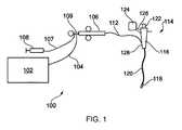
図1は、侵襲性の電気外科器具の遠位端にマイクロ波エネルギー及び流体(たとえば、冷却液)を供給することができる電気外科焼灼装置100の概略図である。システム100には、高周波(RF)及びマイクロ波エネルギーを制御可能に供給するための発電機102が含まれる。この目的にとって好適な発電機は、WO2012/076844に記載されている。この文献は参照により本明細書に組み込まれている。発電機は、器具から戻って受信された反射信号をモニタして、送出にとって適切な電力レベルを決定するために配設してもよい。たとえば、発電機を、器具の遠位端において見られるインピーダンスを計算して、最適な送出電力レベルを決定するために配設してもよい。Further Options and Preference Figure 1 is a schematic representation of an
発電機102は、インターフェースケーブル104によってインターフェースジョイント106に接続されている。またインターフェースジョイント106は、流体流れライン107を介して流体送出装置108(たとえば、注射器)に接続されている。それに加えてまたはその代わりに、いくつかの例では、装置を治療部位からの流体を吸引するために配設してもよい。このシナリオでは、流体流れライン107は、流体をインターフェースジョイント106から離れて好適な収集器(図示せず)まで運んでもよい。吸引メカニズムを流体流れライン107の近位端に接続してもよい。 The
必要に応じて、インターフェースジョイント106は、引き金をスライドさせることによって、たとえば1つ以上の制御ワイヤまたはプッシュロッド(図示せず)の長手方向(前後)の動きを制御するように動作可能である器具制御メカニズムを収容することができる。複数の制御ワイヤがある場合には、完全制御を得るために複数のスライディング引き金がインターフェースジョイント上にあってもよい。インターフェースジョイント106の機能は、発電機102、流体送出装置108、及び器具制御メカニズムからの入力を結合して、単一のフレキシブルシャフト112内に入れることである。フレキシブルシャフト112は、インターフェースジョイント106の遠位端から延びている。 If desired, the interface joint 106 can be operated to control longitudinal (front-back) movement of, for example, one or more control wires or push rods (not shown) by sliding the trigger. It can accommodate a control mechanism. If there are multiple control wires, multiple sliding triggers may be on the interface joint for full control. The function of the
フレキシブルシャフト112は、外科スコープ装置114の器具(ワーキング)チャネルの全長を通して挿入可能である。本発明の実施形態では、外科スコープ装置114には内視鏡超音波デバイスが含まれていてもよい。 The
外科スコープ装置114には、多くの入力ポートと出力ポート(そこから器具コード120が延びている)とを有する本体116が含まれている。器具コード120には、複数の管腔を囲む外部ジャケットが含まれている。複数の管腔によって、本体116から種々の物が器具コード120の遠位端まで運ばれる。複数の管腔のうちの1つは、前述した器具チャネルである。他の管腔には、たとえば遠位端に照明をもたらすかまたは遠位端から画像を収集するために光放射を伝えるためのチャネルが含まれていてもよい。本体116には、遠位端を視認するためのアイピース122が含まれていてもよい。 The surgical scope device 114 includes a
内視鏡超音波デバイスの場合は典型的に、器具チャネルの出口開口部を越えて器具コードの遠位先端部に超音波トランスデューサがある。超音波トランスデューサからの信号を好適なケーブル126によって器具コードに沿ってプロセッサ124まで戻してもよい。プロセッサ124は既知の方法で画像を生成することができる。器具コード内での器具チャネルの形成は、器具を器具チャネルから出して超音波システムの視野を通して送って標的部位における器具の箇所についての情報が得られるように行ってもよい。 In the case of endoscopic ultrasound devices, there is typically an ultrasound transducer at the distal tip of the instrument cord beyond the exit opening of the instrument channel. The signal from the ultrasonic transducer may be returned to the
フレキシブルシャフト112は、外科スコープ装置114の器具チャネルを通り器具コードの遠位端において(たとえば患者の内部に)突出するように成形された遠位のアセンブリ118(図1では一定の比率で描かれてはいない)を有している。 The
後述する遠位のアセンブリ118の構造物は特に、内視鏡超音波(EUS)デバイスとともに用いるようにデザインしてもよく、それによって、遠位端アセンブリ118の最大外径は2.0mm以下、たとえば1.9mm未満(より好ましくは、1.5mm未満)であり、フレキシブルシャフトの長さを1.2m以上とすることができる。 The structure of the
本体116には、フレキシブルシャフト112に接続するための電源入力ポート128が含まれている。後述するように、フレキシブルシャフトの近位部分には、発電機102から遠位のアセンブリ118まで高周波及びマイクロ波エネルギーを伝えることができる従来の同軸ケーブルが含まれていてもよい。EUSデバイスの器具チャネルにフィッティングすることが物理的に可能である同軸ケーブルは、以下の外径のものが入手可能である。1.19mm(0.047”)、1.35mm(0.053”)、1.40mm(0.055”)、1.60mm(0.063”)、1.78mm(0.070”)。カスタムサイズの同軸ケーブル(すなわち、オーダーメード)を用いてもよい。 The
前述したように、少なくとも器具コード120の遠位端の位置を制御できることが望ましい。本体116には、器具コード120の遠位端に1本以上の制御ワイヤ(図示せず)によって機械的に結合された制御アクチュエータが含まれていてもよい。制御ワイヤは器具コード120を通って延びる。制御ワイヤは器具チャネル内を進んでもよいし、または制御ワイヤの独自の専用チャネル内を進んでもよい。制御アクチュエータは、レバーもしくは回転可能なノブ、または任意の他の既知のカテーテル操作デバイスであってもよい。器具コード120の操作は、ソフトウェア支援でもよく、たとえばコンピュータ断層撮影(CT)画像から組み立てられた仮想の3次元マップを用いて行ってもよい。 As mentioned above, it is desirable to be able to control at least the position of the distal end of the
図2は器具コード120の軸の図である。この実施形態では、器具コード120内に4つの管腔がある。最大の管腔は器具チャネル132である。他の管腔には、超音波信号チャネル134、及び照明チャネル136、及びカメラチャネル138が含まれているが、本発明はこの構成に限定されない。たとえば、他の管腔(たとえば、制御ワイヤまたは流体送出もしくは吸引用)があってもよい。 FIG. 2 is a diagram of the axis of the
一実施形態では、本発明によって、EUSシステムカテーテルの遠位端において組織焼灼を行うことができる器具が提供される。副作用を減らして器具の効率を最大にするために、送信アンテナは標的組織のできるだけ近くに配置しなければならない。理想的には、処置中に器具の放射部を腫瘍の内側(たとえば中心)に配置する。 In one embodiment, the invention provides an instrument capable of performing tissue ablation at the distal end of an EUS system catheter. The transmitting antenna should be placed as close as possible to the target tissue to reduce side effects and maximize instrument efficiency. Ideally, the radiating part of the instrument should be placed inside (eg, in the center) of the tumor during the procedure.
本発明は特に、膵臓の処置に適している場合がある。標的部位に到達するためには、器具を、口部、胃、及び十二指腸を通してガイドする必要がある。器具を、十二指腸の壁を通ることによって膵臓にアクセスするように配設する。この手順では、膵臓内を進み得る器具のサイズに著しい制限が課される。従来、外径が1mm以下(たとえば19ゲージ)の器具を用いている。 The present invention may be particularly suitable for the treatment of the pancreas. The device needs to be guided through the mouth, stomach, and duodenum to reach the target site. The device is placed to access the pancreas by passing through the wall of the duodenum. This procedure imposes significant restrictions on the size of the device that can travel within the pancreas. Conventionally, an instrument having an outer diameter of 1 mm or less (for example, 19 gauge) has been used.
以下の説明では、説明した遠位のアセンブリ118で用いるのに適した多くのアンテナ構成を示す。 The following description shows many antenna configurations suitable for use in the
以下の説明では、他に記載がない限り、コンポーネントの長さは同軸ケーブル/器具コードの長手軸と平行な方向でのその寸法を指す。 In the following description, unless otherwise stated, component length refers to its dimensions in a direction parallel to the longitudinal axis of the coaxial cable / appliance cord.
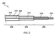
図3は、本発明の実施形態である電気外科器具200の遠位端の断面図である。図3に、3つに区分されている、器具の遠位端部分を示す。第1の区分には、器具の近位端まで、たとえば、前述したように外科スコープ装置の器具チャネルを通って延びる同軸ケーブル202が含まれている。同軸ケーブル202の近位端を電気外科発電機に接続して、周波数が5.8GHzのマイクロ波エネルギー(たとえば、電磁エネルギー)を受け取って伝えるようにしてもよい。第2の区分には中間のインピーダンス変成器204が含まれている。第3の区分には遠位の放射部分206が含まれている。中間のインピーダンス変成器204は、同軸ケーブル202のインピーダンスを遠位の放射部分206のインピーダンスに整合するように配設されている。 FIG. 3 is a cross-sectional view of the distal end of the
遠位の放射部分206は、膵臓内の組織の処置に適するように寸法取りされている。特に、その寸法は、たとえばEUSデバイスを用いて十二指腸の壁を通って膵臓内へと貫通するように使用される既知のプローブと同様である。したがって、遠位の放射部分206の最大外径は1mm以下(たとえば19ゲージ針以下)であってもよい。遠位の放射部分の長さは約40mmであってもよい。 The
同軸ケーブル202は、従来の柔軟な同軸マイクロ波ケーブル(外科スコープ装置の器具チャネルを通ることができるように外径が選択されている)であってもよい。一例では、同軸ケーブル202の外径は2.2mm以下であってもよい。たとえば、Sucoform(登録商標)86ケーブルを用いてもよい。同軸ケーブルには、絶縁性の誘電体材料210によって外部導体212から分離された内部導体208が含まれている。外部導体212の外面の周りに保護ジャケット(図示せず)を設けてもよい。同軸ケーブル202の長さは1.2m以上であってもよい。図3にはその遠位部分のみを示す。 The
この実施形態では、同軸ケーブル202の内部導体208は、外部導体212の遠位端を越えて、中間のインピーダンス変成器204及び遠位の放射部分206の両方を通って延びている。したがって、遠位端アセンブリの3つの区分はすべて、共通の内部導体を共有している。実際には、一例では、中間のインピーダンス変成器204及び遠位の放射部分206の形成は、同軸ケーブルの遠位の区分から外部導体を剥がし、誘電体材料210の一部を選択的に取り除き、各部分に対する所望の誘電体外径を実現し、そして縮径部分上に新しい外部導体を設けることによって行ってもよい。中間のインピーダンス変成器204は、第1の縮径を有する誘電体材料214を有し、遠位の放射部分206は、第2の縮径を有する誘電体材料216を有している。第1の縮径は、同軸ケーブル202内の誘電体材料210の直径よりも小さい。第2の縮径は第1の縮径よりも小さい。直径間の関係については、後でより詳細に説明する。 In this embodiment, the
この実施形態では、遠位の放射部分206には装荷モノポールアンテナ218が含まれている。装荷モノポールアンテナ218は、遠位の放射部分206の最も遠位な長さから外部導体を取り除くことによって設けてもよい。装荷モノポールアンテナ218の長さは、同軸ケーブル202が伝えるマイクロ波エネルギーの4分の1波長の奇数倍に等しくてもよい。 In this embodiment, the
前述したように、遠位の放射部分206の最大外径(膵臓内に挿入されるべき部分)は1mm以下であることが望ましい。一例では、これは、関連するコンポーネントに対する以下の横断寸法によって実現される。 As mentioned above, the maximum outer diameter of the distal radiating portion 206 (the portion to be inserted into the pancreas) is preferably 1 mm or less. In one example, this is achieved by the following cross-sectional dimensions for the relevant components:

この例での外部導体の厚さは0.075mmである。この例で用いる誘電体材料の比誘電率εrは1.85であり、遠位の放射部分に対するインピーダンスZoutは以下のように得られる。The thickness of the outer conductor in this example is 0.075 mm.The relative permittivity ε r of the dielectric material used in this example is 1.85, and the impedance Zout with respect to the distal radiation portion is obtained as follows.
したがって、同軸ケーブル202のインピーダンスZinが50Ωであるならば、中間のインピーダンス変成器204のインピーダンスZtは以下のように計算される。Therefore, if the impedance Zin of the
この例では、中間のインピーダンス変成器204において同じ内部導体及び同じ誘電体材料を用いているので、誘電体材料214の外径d3は、以下の関係を満たすように計算することができる。In this example, since the same inner conductor and the same dielectric material are used in the
これを解くとd3として1.1mmが求まる。これに続いて、中間のインピーダンス変成器204における関連するコンポーネントに対する横断寸法は、以下であってもよい。Solving this 1.1mm is obtained asd 3. Following this, the transverse dimensions for the relevant components in the
中間のインピーダンス変成器204の長さは好ましくは、その中に伝えられるマイクロ波エネルギーの4分の1波長の奇数倍である。εrが1.85mmである場合、5.8GHzにおける4分の1波長は9.5mmである。The length of the
器具の全長に対して同じ誘電体材料を用いる場合、装荷モノポールアンテナ218の長さも9.5mmであってもよい。しかし、至る所で同じ誘電体材料を用いる必要はない。たとえば、装荷モノポールアンテナ218に対して異なる誘電体材料を用いてもよい。たとえば、装荷モノポールアンテナ218の長さを、比誘電率がより高い誘電体材料を用いることによって短くしてもよい。一例では、剛性の誘電体材料たとえばセラミックまたはポリエーテルエーテルケトン(PEEK)を用いることができる。他の例では、遠位の放射部分206には、非装着のアンテナが含まれていてもよい(たとえば、露出した内部導体の一部が含まれていてもよい)。この種の構造物の例について、以下で図5を参照して説明する。 When the same dielectric material is used for the overall length of the instrument, the length of the loaded
前述した器具200によって、これまで用いられている高周波ベースの技術よりも正確で有効な処置を容易にすることができる、膵臓内にマイクロ波エネルギーを導入する手段が得られる。詳細には、マイクロ波アンテナからデバイス内にエネルギーを送出する移送機構は主に放射である。その結果、目標領域は急速に処置されて、不必要な領域にエネルギーが漏れるかまたは集中する危険性は低くなる。これは、移送機構が主に伝導性によるRFベースの技術とは対照的であり得る。RFベースの技術では、外部に位置するリターンパッドを用いることによって、電流経路の位置を制御することが難しくなる可能性がある。 The
本明細書で開示した器具は特に、マイクロ波エネルギーとともに用いることに好適であり得るが、器具はまた、高周波(RF)エネルギーを送出するためのバイポーラ構造ももたらし得る。一例では、マイクロ波エネルギーを放射するためのアンテナを形成する同じ構造物によって、活性電極及びリターン電極(それらの間にRFエネルギーを送出するのに適している)が得られる。活性電極は内部導体であってもよい。リターン電極は外部導体の遠位部分であってもよい。この配置によって、RF電流に対する局部的なリターン経路が得られ、したがって、別個の外部リターンパッドを必要とする従来技術の器具よりも好ましい。他の例では、器具にはRFエネルギーを送出ための別個の構造物が含まれていてもよい。 Although the instruments disclosed herein may be particularly suitable for use with microwave energy, the instruments can also provide bipolar structures for delivering radio frequency (RF) energy. In one example, the same structure forming an antenna for radiating microwave energy provides active and return electrodes (suitable for delivering RF energy between them). The active electrode may be an internal conductor. The return electrode may be the distal portion of the outer conductor. This arrangement provides a local return path for RF currents and is therefore preferred over prior art instruments that require a separate external return pad. In another example, the instrument may include a separate structure for delivering RF energy.
前述したように、器具は、RF及びマイクロ波エネルギーの両方を同軸伝送線に沿って別個または同時に送出することができる発電機に接続可能であってもよい。したがって、器具は複数の処置モードにおいて選択的に動作可能であってもよい。たとえば、(i)マイクロ波のみ、(ii)RFのみ、(iii)RFの後にマイクロ波、(iv)マイクロ波の後にRF、(v)RF及びマイクロ波を同時、のうちのいずれか1つ、2つ、3つ以上を含む。したがって、器具は、従来のRF焼灼デバイスよりも高性能なエネルギー印加方式の下で処置を行うことができる。 As mentioned above, the appliance may be connectable to a generator capable of delivering both RF and microwave energy separately or simultaneously along the coaxial transmission line. Therefore, the device may be selectively operable in multiple treatment modes. For example, any one of (i) microwave only, (ii) RF only, (iii) RF followed by microwave, (iv) microwave followed by RF, (v) RF and microwave simultaneously. Includes two, three or more. Therefore, the instrument can be treated under a higher performance energy application scheme than conventional RF ablation devices.
図4は、本発明の別の実施形態である電気外科器具240の遠位端の断面図である。図3に示す実施形態と共通する特徴物には同じ参照番号を付して、もう一度説明することはしない。図3と同様に、器具240は、同軸ケーブル202から中間のインピーダンス変成器204及び遠位の放射部分206を通る共通の内部導体を利用する。しかし、この実施形態では、同軸ケーブル202の誘電体材料を完全に取り除いて、中間のインピーダンス変成器204及び遠位の放射部分206において代替材料と交換してもよい。 FIG. 4 is a cross-sectional view of the distal end of the
処置すべき腫瘍の内部に器具を押すのを助けるために、器具の遠位部分が剛性であることが望ましい場合がある。したがって、中間のインピーダンス変成器204及び遠位の放射部分206に、剛性の誘電体材料242、244をそれぞれ与えてもよい。この区分における剛性の誘電体材料242、244は同じであってもよいしまたは異なっていてもよい。たとえば、中間のインピーダンス変成器204は、PEEKから形成された誘電体材料242を有していてもよく、遠位の放射部分206はセラミックから形成された誘電体材料244を有していてもよく、逆もまた同様である。前述したように、これらの材料の利点は、同軸ケーブル202の誘電体材料210よりも比誘電率が高いことであり、遠位部分をコンパクトにすることができる。剛性の誘電体材料242、244を、内部導体208の周りに鋳造するかまたは他の場合には内部導体208に取り付けることを、そこから誘電体材料210を剥がした後に行ってもよい。前述したように、剛性の誘電体材料242、244を所定の位置に配置した後で、新しい外部導体を中間のインピーダンス変成器204及び遠位の放射部分206の関連する部品上に適用する。 It may be desirable for the distal portion of the instrument to be rigid to help push the instrument into the tumor to be treated. Therefore, rigid
図4に示す構造物を有する特定の例では、中間の誘電体材料242及び遠位の誘電体材料は両方ともPEEKである。遠位の放射部分206は全長が3cmである。外部のメタライゼーション244は全長のうちの2cmにわたって延びて、最も遠位な1cm部分を露出するPEEKで残す(その中を内部導体が進む)。外部のメタライゼーション244は内径が0.8mmで外径が1.0mmである。 In a particular example with the structure shown in FIG. 4, both the intermediate
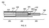
図5は、本発明の別の実施形態である電気外科器具260の遠位端の断面図である。図3に示す実施形態と共通する特徴物には同じ参照番号を付して、もう一度説明することはしない。この例では、内部導体208が同軸ケーブル202から中間のインピーダンス変成器204を通って延びて、遠位の放射部分206の近位端で終了する。剛性の伝導性フィンガー266が、内部導体208の遠位端に取り付けられて電気的に接続されている。この例では、剛性の伝導性フィンガー266は、遠位の放射部分206の内部導体を形成して、非装着のモノポールアンテナ268としてそこから突出している。突出部を鋭利にして(たとえば、針に似させて)、組織内への挿入を容易にする。剛性の伝導性フィンガー266をステンレス鋼などから形成してもよい。 FIG. 5 is a cross-sectional view of the distal end of the
この例では、中間のインピーダンス変成器204及び遠位の放射部分206で用いる誘電体材料262、264は、同軸ケーブル202の誘電体材料210とは異なっている。図4を参照して前述したように、これらの材料は、所望の物理特性(たとえば剛性)を付与するように、または器具の対応する部分の長さを制御するように選択してもよい。図示した例では、剛性の伝導性フィンガー266の外径は内部導体208の外径より大きくてもよく、これは遠位部分のインピーダンスに対して効果がある。 In this example, the
電気外科器具260はさらに、引き込み式シース270が同軸ケーブル202上に取り付けられている。シース270は、挿入の深さを制御するためであり、またアンテナの鋭い先端部に起因する損傷に対して器具チャネルのライニングを保護するためである。シース270は器具の遠位部分にわたって延びていてもよい。目盛尺(たとえば1mm〜30mm)を有していてもよく、シースを引き戻すとアンテナが露出する。シースの遠位端272を十二指腸の壁に対して配置してもよく、アンテナを壁を通して膵臓内に挿入する。その結果、シース端部は停止または基準点として働いてもよい。シースの外径は器具チャネル内に収まるようなサイズであってもよい。たとえば、2.4mmまたは2.7mmであってもよい。図5のみに例示しているが、当然のことながら、シース270は、本明細書で開示した実施形態のいずれかと一緒に用いてもよい。 The
図6は、本発明の別の実施形態である電気外科器具280の遠位端の断面図である。図3に示す実施形態と共通する特徴物には同じ参照番号を付して、もう一度説明することはしない。この例では、遠位の放射部分206はスロットアンテナ構造物286が含まれている。図3と同様に、器具280は、同軸ケーブル202から中間のインピーダンス変成器204及び遠位の放射部分206を通る共通の内部導体を利用する。この実施形態では、同軸ケーブル202の誘電体材料を完全に取り除いて、中間のインピーダンス変成器204及び遠位の放射部分206において代替材料と交換してもよい。中間のインピーダンス変成器204は中間の誘電体材料282を有し、遠位の放射部分206は遠位の誘電体材料284を有している。中間の誘電体材料282及び遠位の誘電体材料284は同じであってもよいしまたは異なっていてもよい。それらは両方とも同軸ケーブルの誘電体材料210とは異なっていてもよい。 FIG. 6 is a cross-sectional view of the distal end of the
コンパクトなスロットアンテナを得るために、遠位の誘電体材料284が、たとえば、誘電定数が20以上、好ましくは40以上であることによって、構造物に対して高負荷を与えることが望ましい場合がある。スロットアンテナ286は、遠位の放射部分206上の外部伝導層内に1つ以上の窓またはスロット288を形成することによって形成する。複数のスロットを形成する場合、それらは遠位の放射部分206の長さに沿って、遠位の放射部分206が伝えるマイクロ波エネルギーの半波長だけ分離されている。細長い(すなわち、前方に向けられた)焼灼場を形成するために、内部導体208の遠位端を、遠位の放射部分206上の外部伝導層に、たとえば伝導性のエンドキャップ290を介して電気的に接続してもよい。遠位の放射部分206上の最も遠位なスロットを好ましくは、遠位端(たとえば、エンドキャップ290)から、遠位の放射部分206が伝えるマイクロ波エネルギーの4分の1波長だけ離間して配置する。一例では、誘電体材料284は比誘電率が49であってもよく、その結果、マイクロ波エネルギーの周波数が5.8GHzである場合の4分の1波長は1.85mmである。この例では、スロットは遠位の放射部分206の長さに沿って3.7mm間隔で離間して配置されている。 In order to obtain a compact slot antenna, it may be desirable for the distal
使用時、前述した例のいずれかによる器具を外科スコープ装置の器具チャネルを通して挿入して、治療部位に(たとえば十二指腸の壁を通して膵臓内部に)到達させてもよい。遠位の放射部分206が組織に侵入して、同軸ケーブル202から送出されたマイクロ波エネルギーが組織内に放射してそれを焼灼してもよい。 At the time of use, an instrument according to any of the above examples may be inserted through the instrument channel of the surgical scope device to reach the treatment site (eg, through the duodenal wall and into the pancreas). The
いくつかの手順では、器具の前に吸引針を治療部位に挿入して、たとえば、嚢胞から流体を取り除く等を行ってもよい。 In some procedures, a suction needle may be inserted into the treatment area in front of the instrument to remove fluid from the cyst, for example.
本発明の器具は、特に器具のサイズが既知のRFプローブと同じオーダーであるために、既知のRF焼灼技術に対する代替物としての特定の用途を見出す場合があり、したがって同じ機器を用いて導入することができる。 The instruments of the present invention may find specific use as an alternative to known RF ablation techniques, especially because the instrument size is on the same order as known RF probes, and are therefore introduced using the same instrument. be able to.
Claims (20)
Translated fromJapaneseマイクロ波電磁(EM)エネルギーを伝えるための同軸伝送線を含む近位部分と、
遠位の放射部分と、
同軸伝送線のインピーダンスを前記遠位の放射部分のインピーダンスに整合するために配設された中間のインピーダンス変成器と、を含み、
前記遠位の放射部分は、前記同軸伝送線が伝える前記マイクロ波EMエネルギーを放出するためのマイクロ波アンテナを含み、
前記遠位の放射部分の最大外径は前記同軸伝送線の外径よりも小さい、電気外科器具。It ’s an electrosurgical instrument,
Proximal part containing coaxial transmission line for transmitting microwave electromagnetic (EM) energy,
With the distal radiant part,
Includes an intermediate impedance transformer, which is arranged to match the impedance of the coaxial transmission line to the impedance of the distal radiating portion.
The distal radiating portion comprises a microwave antenna for emitting the microwave EM energy transmitted by the coaxial transmission line.
An electrosurgical instrument in which the maximum outer diameter of the distal radiating portion is smaller than the outer diameter of the coaxial transmission line.
患者の身体内に挿入できるように構成された器具コードを有する外科スコープ装置であって、前記器具コードの内部を通って器具チャネルが形成されている、前記外科スコープ装置と、
前記器具チャネルを通って挿入できるように寸法取りされたいずれかの先行請求項に記載の電気外科器具と、を含む前記電気外科装置。It ’s an electrosurgical device,
A surgical scope device having an instrument cord configured to be inserted into the patient's body, wherein an instrument channel is formed through the inside of the instrument cord.
The electrosurgical device comprising any of the preclaimed electrosurgical instruments sized for insertion through the instrument channel.
Priority Applications (2)
| Application Number | Priority Date | Filing Date | Title |
|---|---|---|---|
| JP2023075978AJP7539181B2 (en) | 2017-12-27 | 2023-05-02 | Electrosurgical cautery instruments |
| JP2023075979AJP7539182B2 (en) | 2017-12-27 | 2023-05-02 | Electrosurgical cautery instruments |
Applications Claiming Priority (3)
| Application Number | Priority Date | Filing Date | Title |
|---|---|---|---|
| GB1721995.7AGB2569812A (en) | 2017-12-27 | 2017-12-27 | Electrosurgical ablation instrument |
| GB1721995.7 | 2017-12-27 | ||
| PCT/EP2018/086237WO2019129648A1 (en) | 2017-12-27 | 2018-12-20 | Electrosurgical ablation instrument |
Related Child Applications (2)
| Application Number | Title | Priority Date | Filing Date |
|---|---|---|---|
| JP2023075979ADivisionJP7539182B2 (en) | 2017-12-27 | 2023-05-02 | Electrosurgical cautery instruments |
| JP2023075978ADivisionJP7539181B2 (en) | 2017-12-27 | 2023-05-02 | Electrosurgical cautery instruments |
Publications (2)
| Publication Number | Publication Date |
|---|---|
| JP2021509594Atrue JP2021509594A (en) | 2021-04-01 |
| JP7280626B2 JP7280626B2 (en) | 2023-05-24 |
Family
ID=61131530
Family Applications (3)
| Application Number | Title | Priority Date | Filing Date |
|---|---|---|---|
| JP2020529212AActiveJP7280626B2 (en) | 2017-12-27 | 2018-12-20 | electrosurgical cautery instrument |
| JP2023075978AActiveJP7539181B2 (en) | 2017-12-27 | 2023-05-02 | Electrosurgical cautery instruments |
| JP2023075979AActiveJP7539182B2 (en) | 2017-12-27 | 2023-05-02 | Electrosurgical cautery instruments |
Family Applications After (2)
| Application Number | Title | Priority Date | Filing Date |
|---|---|---|---|
| JP2023075978AActiveJP7539181B2 (en) | 2017-12-27 | 2023-05-02 | Electrosurgical cautery instruments |
| JP2023075979AActiveJP7539182B2 (en) | 2017-12-27 | 2023-05-02 | Electrosurgical cautery instruments |
Country Status (15)
| Country | Link |
|---|---|
| US (3) | US12023094B2 (en) |
| EP (3) | EP4000549B1 (en) |
| JP (3) | JP7280626B2 (en) |
| KR (1) | KR20200102989A (en) |
| CN (3) | CN116370064A (en) |
| AU (1) | AU2018394011A1 (en) |
| BR (1) | BR112020010666A2 (en) |
| CA (1) | CA3084509A1 (en) |
| DK (1) | DK3731776T3 (en) |
| ES (3) | ES2910014T3 (en) |
| GB (1) | GB2569812A (en) |
| IL (1) | IL274792A (en) |
| PT (1) | PT3731776T (en) |
| SG (1) | SG11202004756WA (en) |
| WO (1) | WO2019129648A1 (en) |
Families Citing this family (9)
| Publication number | Priority date | Publication date | Assignee | Title |
|---|---|---|---|---|
| GB2569812A (en)* | 2017-12-27 | 2019-07-03 | Creo Medical Ltd | Electrosurgical ablation instrument |
| GB2576481B (en)* | 2018-05-30 | 2022-07-20 | Creo Medical Ltd | Electrosurgical instrument |
| GB2583490A (en)* | 2019-04-30 | 2020-11-04 | Creo Medical Ltd | Electrosurgical system |
| GB2583715A (en) | 2019-04-30 | 2020-11-11 | Creo Medical Ltd | Electrosurgical system |
| JP7147079B2 (en)* | 2019-05-17 | 2022-10-04 | ボストン サイエンティフィック サイムド,インコーポレイテッド | Medical imaging device and system |
| GB2589589A (en)* | 2019-12-03 | 2021-06-09 | Creo Medical Ltd | Electrosurgical instrument |
| GB2594438A (en)* | 2019-12-05 | 2021-11-03 | Creo Medical Ltd | Electrosurgical instrument, generator and apparatus |
| US20220031390A1 (en)* | 2020-07-31 | 2022-02-03 | Medtronic, Inc. | Bipolar tool for separating tissue adhesions or tunneling |
| GB202318579D0 (en)* | 2023-12-05 | 2024-01-17 | Creo Medical Ltd | Electrosurgical instrument |
Citations (7)
| Publication number | Priority date | Publication date | Assignee | Title |
|---|---|---|---|---|
| JP2004518471A (en)* | 2001-01-31 | 2004-06-24 | シーエヌアール・コンシグリオ・ナズィオナレ・デッレ・リセルチェ | Gap microwave with miniaturized choke for treatment of fever in medicine and surgery |
| WO2006084676A1 (en)* | 2005-02-11 | 2006-08-17 | H.S. - Hospital Service - S.P.A. | Microwave device for the ablation of tissues |
| US20110077632A1 (en)* | 2009-09-28 | 2011-03-31 | Vivant Medical, Inc. | Feedpoint Optimization for Microwave Ablation Dipole Antenna With Integrated Tip |
| JP2016514550A (en)* | 2013-03-29 | 2016-05-23 | コビディエン エルピー | Step-down coaxial microwave ablation applicator and method for manufacturing the same |
| WO2017174513A1 (en)* | 2016-04-04 | 2017-10-12 | Creo Medical Limited | Electrosurgical probe for delivering rf and microwave energy |
| JP2017533746A (en)* | 2014-10-17 | 2017-11-16 | クレオ・メディカル・リミテッドCreo Medical Limited | Cable for transmitting high frequency and / or microwave frequency energy to electrosurgical instruments |
| JP2017533740A (en)* | 2014-10-01 | 2017-11-16 | コヴィディエン リミテッド パートナーシップ | Small microwave ablation assembly |
Family Cites Families (19)
| Publication number | Priority date | Publication date | Assignee | Title |
|---|---|---|---|---|
| JPH09140723A (en) | 1995-11-22 | 1997-06-03 | Olympus Optical Co Ltd | High-frequency treatment instrument |
| US5861021A (en)* | 1996-06-17 | 1999-01-19 | Urologix Inc | Microwave thermal therapy of cardiac tissue |
| US5707452A (en)* | 1996-07-08 | 1998-01-13 | Applied Microwave Plasma Concepts, Inc. | Coaxial microwave applicator for an electron cyclotron resonance plasma source |
| US6325796B1 (en)* | 1999-05-04 | 2001-12-04 | Afx, Inc. | Microwave ablation instrument with insertion probe |
| AU2003901390A0 (en)* | 2003-03-26 | 2003-04-10 | University Of Technology, Sydney | Microwave antenna for cardiac ablation |
| US11666377B2 (en)* | 2006-09-29 | 2023-06-06 | Boston Scientific Medical Device Limited | Electrosurgical device |
| US9993294B2 (en)* | 2009-11-17 | 2018-06-12 | Perseon Corporation | Microwave coagulation applicator and system with fluid injection |
| GB201021032D0 (en) | 2010-12-10 | 2011-01-26 | Creo Medical Ltd | Electrosurgical apparatus |
| JP5763263B2 (en)* | 2011-04-08 | 2015-08-12 | コビディエン エルピー | Flexible microwave catheter for natural or artificial lumens |
| US8870860B2 (en)* | 2011-08-09 | 2014-10-28 | Covidien Lp | Microwave antenna having a coaxial cable with an adjustable outer conductor configuration |
| WO2013149245A1 (en)* | 2012-03-31 | 2013-10-03 | Microcube, Llc | Returned power for microwave applications |
| US8906008B2 (en)* | 2012-05-22 | 2014-12-09 | Covidien Lp | Electrosurgical instrument |
| US9144459B2 (en)* | 2012-07-19 | 2015-09-29 | Cook Medical Technologies Llc | Endoscopic ultrasound ablation needle |
| US9993295B2 (en) | 2012-08-07 | 2018-06-12 | Covidien Lp | Microwave ablation catheter and method of utilizing the same |
| GB201308558D0 (en)* | 2013-05-13 | 2013-06-19 | Creo Medical Ltd | Electrosurgical apparatus |
| GB201323171D0 (en)* | 2013-12-31 | 2014-02-12 | Creo Medical Ltd | Electrosurgical apparatus and device |
| GB2545465A (en)* | 2015-12-17 | 2017-06-21 | Creo Medical Ltd | Electrosurgical probe for delivering microwave energy |
| US11058486B2 (en)* | 2016-02-11 | 2021-07-13 | Covidien Lp | Systems and methods for percutaneous microwave ablation |
| GB2569812A (en)* | 2017-12-27 | 2019-07-03 | Creo Medical Ltd | Electrosurgical ablation instrument |
- 2017
- 2017-12-27GBGB1721995.7Apatent/GB2569812A/ennot_activeWithdrawn
- 2018
- 2018-12-20ESES18827087Tpatent/ES2910014T3/enactiveActive
- 2018-12-20WOPCT/EP2018/086237patent/WO2019129648A1/ennot_activeCeased
- 2018-12-20ESES21213905Tpatent/ES2984809T3/enactiveActive
- 2018-12-20CNCN202310381057.XApatent/CN116370064A/enactivePending
- 2018-12-20BRBR112020010666-6Apatent/BR112020010666A2/ennot_activeIP Right Cessation
- 2018-12-20PTPT188270870Tpatent/PT3731776T/enunknown
- 2018-12-20DKDK18827087.0Tpatent/DK3731776T3/enactive
- 2018-12-20EPEP21213905.9Apatent/EP4000549B1/enactiveActive
- 2018-12-20CACA3084509Apatent/CA3084509A1/enactivePending
- 2018-12-20ESES21213841Tpatent/ES2984808T3/enactiveActive
- 2018-12-20JPJP2020529212Apatent/JP7280626B2/enactiveActive
- 2018-12-20SGSG11202004756WApatent/SG11202004756WA/enunknown
- 2018-12-20EPEP18827087.0Apatent/EP3731776B1/enactiveActive
- 2018-12-20CNCN201880076180.8Apatent/CN111565663B/enactiveActive
- 2018-12-20KRKR1020207014371Apatent/KR20200102989A/ennot_activeCeased
- 2018-12-20USUS16/766,422patent/US12023094B2/enactiveActive
- 2018-12-20CNCN202310391035.1Apatent/CN116370065A/enactivePending
- 2018-12-20AUAU2018394011Apatent/AU2018394011A1/ennot_activeAbandoned
- 2018-12-20EPEP21213841.6Apatent/EP3988044B1/enactiveActive
- 2020
- 2020-05-20ILIL274792Apatent/IL274792A/enunknown
- 2023
- 2023-05-02JPJP2023075978Apatent/JP7539181B2/enactiveActive
- 2023-05-02JPJP2023075979Apatent/JP7539182B2/enactiveActive
- 2024
- 2024-04-26USUS18/647,967patent/US20240277408A1/enactivePending
- 2024-04-26USUS18/648,148patent/US20240293178A1/enactivePending
Patent Citations (7)
| Publication number | Priority date | Publication date | Assignee | Title |
|---|---|---|---|---|
| JP2004518471A (en)* | 2001-01-31 | 2004-06-24 | シーエヌアール・コンシグリオ・ナズィオナレ・デッレ・リセルチェ | Gap microwave with miniaturized choke for treatment of fever in medicine and surgery |
| WO2006084676A1 (en)* | 2005-02-11 | 2006-08-17 | H.S. - Hospital Service - S.P.A. | Microwave device for the ablation of tissues |
| US20110077632A1 (en)* | 2009-09-28 | 2011-03-31 | Vivant Medical, Inc. | Feedpoint Optimization for Microwave Ablation Dipole Antenna With Integrated Tip |
| JP2016514550A (en)* | 2013-03-29 | 2016-05-23 | コビディエン エルピー | Step-down coaxial microwave ablation applicator and method for manufacturing the same |
| JP2017533740A (en)* | 2014-10-01 | 2017-11-16 | コヴィディエン リミテッド パートナーシップ | Small microwave ablation assembly |
| JP2017533746A (en)* | 2014-10-17 | 2017-11-16 | クレオ・メディカル・リミテッドCreo Medical Limited | Cable for transmitting high frequency and / or microwave frequency energy to electrosurgical instruments |
| WO2017174513A1 (en)* | 2016-04-04 | 2017-10-12 | Creo Medical Limited | Electrosurgical probe for delivering rf and microwave energy |
Also Published As
Similar Documents
| Publication | Publication Date | Title |
|---|---|---|
| JP7539182B2 (en) | Electrosurgical cautery instruments | |
| US12239368B2 (en) | Electrosurgical instrument | |
| JP2022531099A (en) | Electrosurgical system | |
| EP3796859B1 (en) | Electrosurgical ablation instrument | |
| JP2022530792A (en) | Electrosurgical system | |
| RU2772683C2 (en) | Electrosurgical ablative instrument | |
| RU2777551C2 (en) | Electrosurgical instrument for ablation | |
| HK40034159A (en) | Electrosurgical ablation instrument | |
| HK40054307A (en) | Electrosurgical ablation instrument |
Legal Events
| Date | Code | Title | Description |
|---|---|---|---|
| A529 | Written submission of copy of amendment under article 34 pct | Free format text:JAPANESE INTERMEDIATE CODE: A529 Effective date:20200527 | |
| A521 | Request for written amendment filed | Free format text:JAPANESE INTERMEDIATE CODE: A523 Effective date:20211208 | |
| A621 | Written request for application examination | Free format text:JAPANESE INTERMEDIATE CODE: A621 Effective date:20211208 | |
| A977 | Report on retrieval | Free format text:JAPANESE INTERMEDIATE CODE: A971007 Effective date:20230105 | |
| A131 | Notification of reasons for refusal | Free format text:JAPANESE INTERMEDIATE CODE: A131 Effective date:20230117 | |
| TRDD | Decision of grant or rejection written | ||
| A01 | Written decision to grant a patent or to grant a registration (utility model) | Free format text:JAPANESE INTERMEDIATE CODE: A01 Effective date:20230404 | |
| A61 | First payment of annual fees (during grant procedure) | Free format text:JAPANESE INTERMEDIATE CODE: A61 Effective date:20230502 | |
| R150 | Certificate of patent or registration of utility model | Ref document number:7280626 Country of ref document:JP Free format text:JAPANESE INTERMEDIATE CODE: R150 |