JP2021509081A - Atherosclerosis system - Google Patents
Atherosclerosis systemDownload PDFInfo
- Publication number
- JP2021509081A JP2021509081AJP2020555741AJP2020555741AJP2021509081AJP 2021509081 AJP2021509081 AJP 2021509081AJP 2020555741 AJP2020555741 AJP 2020555741AJP 2020555741 AJP2020555741 AJP 2020555741AJP 2021509081 AJP2021509081 AJP 2021509081A
- Authority
- JP
- Japan
- Prior art keywords
- drive mechanism
- mode
- knob
- actuator
- switch
- Prior art date
- Legal status (The legal status is an assumption and is not a legal conclusion. Google has not performed a legal analysis and makes no representation as to the accuracy of the status listed.)
- Granted
Links
Images


Classifications
- A—HUMAN NECESSITIES
- A61—MEDICAL OR VETERINARY SCIENCE; HYGIENE
- A61B—DIAGNOSIS; SURGERY; IDENTIFICATION
- A61B17/00—Surgical instruments, devices or methods
- A61B17/32—Surgical cutting instruments
- A61B17/3205—Excision instruments
- A61B17/3207—Atherectomy devices working by cutting or abrading; Similar devices specially adapted for non-vascular obstructions
- A61B17/320758—Atherectomy devices working by cutting or abrading; Similar devices specially adapted for non-vascular obstructions with a rotating cutting instrument, e.g. motor driven
- A—HUMAN NECESSITIES
- A61—MEDICAL OR VETERINARY SCIENCE; HYGIENE
- A61B—DIAGNOSIS; SURGERY; IDENTIFICATION
- A61B1/00—Instruments for performing medical examinations of the interior of cavities or tubes of the body by visual or photographical inspection, e.g. endoscopes; Illuminating arrangements therefor
- A61B1/00131—Accessories for endoscopes
- A61B1/00133—Drive units for endoscopic tools inserted through or with the endoscope
- A—HUMAN NECESSITIES
- A61—MEDICAL OR VETERINARY SCIENCE; HYGIENE
- A61B—DIAGNOSIS; SURGERY; IDENTIFICATION
- A61B1/00—Instruments for performing medical examinations of the interior of cavities or tubes of the body by visual or photographical inspection, e.g. endoscopes; Illuminating arrangements therefor
- A61B1/00147—Holding or positioning arrangements
- A61B1/0016—Holding or positioning arrangements using motor drive units
- A—HUMAN NECESSITIES
- A61—MEDICAL OR VETERINARY SCIENCE; HYGIENE
- A61B—DIAGNOSIS; SURGERY; IDENTIFICATION
- A61B17/00—Surgical instruments, devices or methods
- A61B2017/00367—Details of actuation of instruments, e.g. relations between pushing buttons, or the like, and activation of the tool, working tip, or the like
- A61B2017/00389—Button or wheel for performing multiple functions, e.g. rotation of shaft and end effector
- A—HUMAN NECESSITIES
- A61—MEDICAL OR VETERINARY SCIENCE; HYGIENE
- A61B—DIAGNOSIS; SURGERY; IDENTIFICATION
- A61B17/00—Surgical instruments, devices or methods
- A61B2017/00477—Coupling
Landscapes
- Health & Medical Sciences (AREA)
- Life Sciences & Earth Sciences (AREA)
- Surgery (AREA)
- Animal Behavior & Ethology (AREA)
- Public Health (AREA)
- Engineering & Computer Science (AREA)
- Biomedical Technology (AREA)
- Heart & Thoracic Surgery (AREA)
- Medical Informatics (AREA)
- Molecular Biology (AREA)
- Veterinary Medicine (AREA)
- General Health & Medical Sciences (AREA)
- Nuclear Medicine, Radiotherapy & Molecular Imaging (AREA)
- Physics & Mathematics (AREA)
- Biophysics (AREA)
- Optics & Photonics (AREA)
- Pathology (AREA)
- Radiology & Medical Imaging (AREA)
- Vascular Medicine (AREA)
- Surgical Instruments (AREA)
Abstract
Translated fromJapaneseDescription
Translated fromJapanese本発明は、医療デバイス、並びに医療デバイスを製造及び使用するための方法に関する。より具体的には、本発明は、回転医療デバイス、方法、及びシステムに関し、駆動メカニズム及び作動制御を有するものを含む回転医療デバイス、方法、及びシステムに関する。 The present invention relates to medical devices and methods for manufacturing and using medical devices. More specifically, the present invention relates to a rotary medical device, a method, and a system, and the present invention relates to a rotary medical device, a method, and a system including those having a drive mechanism and operation control.
多種多様な医療機器が、例えば、体腔にアクセスし、体腔内の流体及び構造と相互作用する際に使用する等、医療用に開発されてきた。これらのデバイスのいくつかには、ガイドワイヤ、カテーテル、ポンプ、モータ、コントローラ、フィルター、グラインダー、針、バルブ、及びそのようなデバイスを送達するために使用される送達デバイス及び/又はシステムが含まれる。これらのデバイスは、さまざまな異なる製造方法のいずれかによって製造され、さまざまな方法のいずれかに従って使用できる。既知の医療機器及び方法のうち、それぞれに特定の利点と欠点がある。 A wide variety of medical devices have been developed for medical use, for example, for use in accessing body cavities and interacting with fluids and structures within the body cavities. Some of these devices include guide wires, catheters, pumps, motors, controllers, filters, grinders, needles, valves, and delivery devices and / or systems used to deliver such devices. .. These devices are manufactured by one of a variety of different manufacturing methods and can be used according to any of the various methods. Each of the known medical devices and methods has specific advantages and disadvantages.
本発明は、設計、材料、製造方法、及び医療デバイス及びシステムの代替案を提供する。第1の態様では、アテローム切除用デバイスは、ハウジングと、ハウジングに配置されて長尺状部材と結合されるとともに作動によって長尺状部材を回転するように構成された駆動メカニズムと、駆動メカニズムと導通するとともにハウジングの外側から操作可能にアクセス可能なツマミアセンブリとを含み、ツマミアセンブリは、駆動メカニズムの軸方向位置を調整するために長手方向に移動するように構成されるとともに、駆動メカニズムをオンモードとオフモードとの間で選択的に調整するために作動されるよう構成される。 The present invention provides design, materials, manufacturing methods, and alternatives to medical devices and systems. In the first aspect, the atherectomy device comprises a housing, a drive mechanism that is arranged in the housing and is coupled to the elongate member and configured to rotate the elongate member by actuation, and a drive mechanism. Including a knob assembly that is conductive and accessible from the outside of the housing, the knob assembly is configured to move longitudinally to adjust the axial position of the drive mechanism and turns on the drive mechanism. It is configured to be activated to selectively adjust between mode and off mode.
追加又は代替として、第の態様では、ツマミアセンブリは、固定長手方向距離に沿って長手方向に移動するように構成され得るとともに、固定長手方向距離に沿った位置において駆動メカニズムを固定するためにハウジングと解放可能に係合するように構成され得る。 As an addition or alternative, in a first aspect, the knob assembly may be configured to move longitudinally along a fixed longitudinal distance and a housing to secure the drive mechanism at a position along the fixed longitudinal distance. Can be configured to engage releasably with.
追加又は代替として、第3の態様では、ツマミアセンブリは、オンモードとオフモードとの間で駆動メカニズムを選択的に調整するように作動されるアクチュエータを備え得る。 As an addition or alternative, in a third aspect, the knob assembly may include an actuator that is actuated to selectively adjust the drive mechanism between on-mode and off-mode.
追加又は代替として、第4の態様では、ツマミアセンブリは、オンモードとオフモードの間で駆動メカニズムを調整することを容易にするように構成されたスイッチと、作動に応答してスイッチと係合するように構成されたアクチュエータとを含み得るものであり、アクチュエータは、オンモードとオフモードの間で駆動メカニズムを調整するようにスイッチと係合する。 As an addition or alternative, in a fourth aspect, the knob assembly engages with a switch configured to facilitate adjustment of the drive mechanism between on-mode and off-mode, and in response to operation. It may include an actuator configured to do so, the actuator engaging the switch to coordinate the drive mechanism between on-mode and off-mode.
追加又は代替として、第5の態様では、ツマミアセンブリは、駆動メカニズムに結合されたスライドアダプタと、スライドアダプタに結合されるとともに、軸に沿った軸方向位置において駆動メカニズムを固定するためにハウジングに解放可能に係合するように構成されたツマミ本体とを含み得るものであり、かつ、アクチュエータは、オンモードとオフモードとの間で駆動メカニズムを選択的に調整するように作動するように構成される。 As an addition or alternative, in a fifth aspect, the knob assembly is coupled to the slide adapter coupled to the drive mechanism and to the housing to secure the drive mechanism in an axial position along the axis. It may include a knob body configured to engage releasably, and the actuator is configured to act to selectively adjust the drive mechanism between on-mode and off-mode. Will be done.
追加又は代替として、第6の態様では、ツマミアセンブリは、スイッチを備え得るものであり、スイッチは、駆動メカニズムと軸方向に移動し、オンモードとオフモード間の駆動メカニズムの調整を容易にするように構成されており、アクチュエータは、作動したことに応じてスイッチに係合するように構成される。 As an addition or alternative, in a sixth aspect, the knob assembly may include a switch, which moves axially with the drive mechanism, facilitating adjustment of the drive mechanism between on-mode and off-mode. The actuator is configured to engage the switch in response to activation.
追加又は代替として、第7の態様では、ツマミアセンブリは、プリント回路基板を備え得るものであり、該プリント回路基板は、スイッチと電気的に導通し、スライドアダプタに結合される。 As an addition or alternative, in a seventh aspect, the knob assembly may include a printed circuit board, which is electrically conductive with the switch and coupled to the slide adapter.
追加又は代替として、第8の態様では、デバイスは、駆動メカニズムへの電力を制御するように構成された制御アセンブリをさらに備え得るものであり、ツマミアセンブリは、プリント回路基板を備え得るものであり、該プリント回路基板は、スイッチと電気的に導通するとともに駆動メカニズムと軸方向に移動するように構成されており、かつ、プリント回路基板は、制御アセンブリと電気的に導通している。 As an addition or alternative, in an eighth aspect, the device may further include a control assembly configured to control power to the drive mechanism, and the knob assembly may include a printed circuit board. The printed circuit board is configured to be electrically conductive with the switch and move axially with the drive mechanism, and the printed circuit board is electrically conductive with the control assembly.
追加又は代替として、第9の態様では、アクチュエータは、スライドアダプタに結合され得るとともに駆動メカニズムの第1の軸方向位置と駆動メカニズムの第2の軸方向位置との間で駆動メカニズムと移動するように構成され得る。 As an addition or alternative, in a ninth aspect, the actuator may be coupled to the slide adapter and move with the drive mechanism between the first axial position of the drive mechanism and the second axial position of the drive mechanism. Can be configured in.
追加又は代替として、第10の態様では、ツマミ本体は、第1の接続と第2の接続とによってスライドアダプタに結合され得るものであり、ツマミ本体は、ハウジングと選択的に係合し、かつ、ハウジングに沿った軸方向に沿った位置において駆動メカニズムを固定するように第2の接続によって調整されるように構成され得る。 As an addition or alternative, in a tenth aspect, the knob body may be coupled to the slide adapter by a first connection and a second connection, the knob body selectively engaging with the housing and , Can be configured to be adjusted by a second connection to secure the drive mechanism in an axial position along the housing.
追加又は代替として、第11の態様では、制御システムの駆動メカニズムはタービンとすることができる。
追加又は代替として、第12の態様では、アテローム切除システムのアテローム切除用デバイスを作動させる方法は、アテローム切除用デバイスのハウジングに沿う予め設定された経路上の位置において解放可能に固定された位置からツマミアセンブリを解放することと、アテローム切除用デバイスのハウジング内の駆動メカニズムのオンモードを開始するためにツマミアセンブリのアクチュエータを作動させることと、予め設定された経路上にツマミアセンブリを長手方向に移動させることとを備え得る。As an addition or alternative, in the eleventh aspect, the drive mechanism of the control system can be a turbine.
As an addition or alternative, in a twelfth aspect, the method of activating the atherectomy device of the atherectomy system is from a releasably fixed position at a position on a preset path along the housing of the atherectomy device. Releasing the knob assembly, activating the knob assembly actuator to initiate on-mode of the drive mechanism within the housing of the atherectomy device, and longitudinally moving the knob assembly over a preset path. Can be prepared to let.
追加又は代替として、第13の態様では、方法は、駆動メカニズムがオンモードにあるときに、駆動メカニズムのオフモードを開始するためにツマミアセンブリのアクチュエータを作動させることをさらに備え得る。 As an addition or alternative, in a thirteenth aspect, the method may further comprise activating the actuator of the knob assembly to initiate the off mode of the drive mechanism when the drive mechanism is in the on mode.
追加又は代替として、第14の態様では、ツマミアセンブリが予め設定された経路上の位置に固定されている間に、アクチュエータは、作動され得る。
追加又は代替として、第15の態様では、ツマミアセンブリが解放可能に固定された位置から解放されている間に、アクチュエータは、作動され得る。As an addition or alternative, in a fourteenth aspect, the actuator can be actuated while the knob assembly is fixed in a preset path position.
As an addition or alternative, in a fifteenth aspect, the actuator can be actuated while the knob assembly is being released from a releasably fixed position.
追加又は代替として、第16の態様では、方法は、ハウジングに対してツマミアセンブリを解放可能に固定するようにアテローム切除用デバイスのハウジングにツマミ本体が係合するまで、ツマミアセンブリのツマミ本体を回転させることをさらに備え得る。 As an addition or alternative, in the sixteenth aspect, the method rotates the knob body of the knob assembly until the knob body engages the housing of the atherectomy device so that the knob assembly is leasably secured to the housing. Can be further prepared to let.
追加又は代替として、第17の態様では、アテローム切除用デバイスは、駆動メカニズムを備え得るものであり、該駆動メカニズムは、当該駆動メカニズムに固定可能な長尺状部材を回転させるように構成されており、アテローム切除用デバイスは、ツマミアセンブリを備え得るものであり、該ツマミアセンブリは、駆動メカニズムに固定されたスライドアダプタと、スライドアダプタに調整可能に固定されたツマミ本体と、スライドアダプタに調整可能に固定されたアクチュエータとを備えており、かつ、ツマミアセンブリは、駆動メカニズムと長手方向に移動するように構成され得るものであり、アクチュエータの駆動は、駆動メカニズムのモードを開始し得るものである。 As an addition or alternative, in the seventeenth aspect, the atherectomy device may comprise a drive mechanism, which is configured to rotate an elongated member that can be fixed to the drive mechanism. The atherectomy device may include a knob assembly, which is adjustable to a slide adapter fixed to the drive mechanism, a knob body adjustable to the slide adapter, and a slide adapter. The knob assembly can be configured to move longitudinally with the drive mechanism, and the drive of the actuator can initiate the mode of the drive mechanism. ..
追加又は代替として、第18の態様では、ツマミアセンブリは、駆動メカニズムのモードを開始するためにアクチュエータの作動がスイッチを調整するようにアクチュエータと導通するスイッチを備え得る。 As an addition or alternative, in an eighteenth aspect, the knob assembly may include a switch that conducts with the actuator such that the actuation of the actuator adjusts the switch to initiate a mode of drive mechanism.
追加又は代替として、及び第19の態様では、ツマミアセンブリは、スライドアダプタに結合され、スイッチと電気的に導通するプリント回路基板を備え得る。
追加又は代替として、第20の態様では、ツマミ本体は、駆動メカニズムの長手方向の移動を容易にする第1の位置と、長手方向の位置において駆動メカニズムを解放可能に固定する第2の位置との間で調整可能であり得るものであり、かつ、アクチュエータは、ツマミ本体が第1の位置にある場合とツマミ本体が第2の位置にある場合に、駆動メカニズムのモードを開始するように作動可能である。As an addition or alternative, and in a nineteenth aspect, the knob assembly may include a printed circuit board that is coupled to a slide adapter and electrically conductive to the switch.
As an addition or alternative, in a twentieth aspect, the knob body has a first position that facilitates longitudinal movement of the drive mechanism and a second position that releasably secures the drive mechanism in the longitudinal position. It may be adjustable between, and the actuator operates to initiate the mode of the drive mechanism when the knob body is in the first position and when the knob body is in the second position. It is possible.
いくつかの実施形態の上記の要約は、本発明の開示された各実施形態又はすべての実装を説明することを意図していない。以下の図面及び詳細な説明は、これらの実施形態をより具体的に例示する。 The above abstracts of some embodiments are not intended to illustrate each of the disclosed embodiments or all implementations of the present invention. The drawings and detailed description below exemplify these embodiments more specifically.
本発明は、添付の図面に関連して本発明の様々な実施形態を示す以下の詳細な説明を考慮することにより、より完全に理解され得る。 The present invention may be more fully understood by considering the following detailed description showing various embodiments of the present invention in connection with the accompanying drawings.
本開示は、様々な変更及び代替の形態が可能であるが、その詳細は、例として図面に示されており、詳細に説明される。しかしながら、その意図は、記載された特定の実施形態に本発明を限定することではないことを理解されたい。それどころか、その意図は、本開示の精神及び範囲に含まれるすべての修正、同等物、及び代替物を網羅することにある。 Various modifications and alternative forms of the present disclosure are possible, the details of which are shown in the drawings by way of example and are described in detail. However, it should be understood that the intent is not to limit the invention to the particular embodiments described. On the contrary, its intent is to cover all modifications, equivalents, and alternatives contained within the spirit and scope of this disclosure.
以下の定義された用語については、請求項又は本明細書の他の場所で異なる定義が与えられていない限り、これらの定義が適用される。
本明細書では、すべての数値は、明示的に示されているかどうかにかかわらず、「約」という用語で修飾されていると想定されている。「約」という用語は、一般に、当業者が列挙された値と同等であると考える(例えば、同じ機能又は結果を有する)数値の範囲を指す。多くの場合、「約」という用語には、最も近い有効数字に四捨五入された数値が含まれ得る。The following defined terms apply, unless different definitions are given in the claims or elsewhere herein.
As used herein, all numbers are assumed to be modified by the term "about", whether explicitly stated or not. The term "about" generally refers to a range of numbers that one of ordinary skill in the art would consider to be equivalent to the listed values (eg, have the same function or result). In many cases, the term "about" may include a number rounded to the nearest significant digit.
終点による数値範囲の列挙には、その範囲内のすべての数値が含まれる(例えば、1〜5には、1,1.5,2,2.75,3,3.80,4,5が含まれる)。
本明細書及び添付の特許請求の範囲で使用される場合、単数形「a」、「an」、及び「the」は、内容が明らかに他に指示しない限り、複数の指示対象を含む。本明細書及び添付の特許請求の範囲で使用される場合、用語「又は」は、内容が明確に他のことを指示しない限り、一般に「及び/又は」を含む意味で使用される。The enumeration of numerical ranges by endpoints includes all numerical values within that range (eg, 1-5 includes 1,1.5,2,2.75,3,3.80,4,5). included).
As used herein and in the appended claims, the singular forms "a", "an", and "the" include a plurality of referents unless the content clearly dictates otherwise. As used herein and in the appended claims, the term "or" is generally used to include "and / or" unless the content explicitly indicates otherwise.
本明細書における「一実施形態」、「いくつかの実施形態」、「他の実施形態」等への言及は、記載された実施形態が1つ以上の特定の特徴、構造、及び/又は特性を含み得ることを示すことに留意されたい。しかしながら、そのような記載は、すべての実施形態が、その特定の特徴、構造、及び/又は特性を含むことを必ずしも意味しない。さらに、特定の特徴、構造、及び/又は特性が一実施形態に関連して説明される場合、明確に逆のことが記載されない限り、そのような特徴、構造、及び/又は特性は、明示的に記載されているかどうかにかかわらず、他の実施形態に関連して使用されてもよいことを理解されたい。 References to "one embodiment," "some embodiments," "other embodiments," etc. herein include specific features, structures, and / or characteristics in which the described embodiment has one or more specific features, structures, and / or characteristics. Note that it can include. However, such description does not necessarily mean that all embodiments include their particular features, structures, and / or properties. Moreover, where a particular feature, structure, and / or property is described in connection with an embodiment, such feature, structure, and / or property is explicit unless the exact opposite is stated. It should be understood that it may be used in connection with other embodiments, whether or not it is described in.
以下の詳細な説明は、異なる図面を通じて同様の要素に同一の参照番号を付している図面を参照して読まれるべきである。必ずしも縮尺通りではない図面は、実施形態を例示的に示すものであり、本発明の範囲を限定することを意図するものではない。 The following detailed description should be read with reference to drawings with the same reference number for similar elements throughout different drawings. Drawings that are not necessarily on scale are illustrative of embodiments and are not intended to limit the scope of the invention.
心血管疾患及び末梢動脈疾患は、血管内腔の内壁にアテローム性物質が蓄積することにより発生し、アテローム性動脈硬化症として知られる状態を引き起こす。アテローム性及び他の血管沈着物は、血液の流れを制限し、患者の心臓、患者の脚の血管系、患者の頸動脈等に虚血を引き起こす可能性がある。そのような虚血は、痛み、腫れ、治癒しない創傷、切断、脳卒中、及び/又は他の状態を引き起こし得る。 Cardiovascular and peripheral arterial disease result from the accumulation of atherosclerosis on the inner walls of the vascular lumen, causing a condition known as atherosclerosis. Atherosclerosis and other vascular deposits can restrict blood flow and cause ischemia in the patient's heart, the patient's leg vasculature, the patient's carotid arteries, and the like. Such ischemia can cause pain, swelling, irreparable wounds, amputations, strokes, and / or other conditions.
アテローム性沈着物は、広く多様な特性を有し、いくつかの沈着物は比較的柔らかく、他の沈着物は繊維性になり、及び/又は石灰化している。後者の場合、沈着物はプラークと呼ばれることがある。アテローム性動脈硬化症は、加齢の結果として自然に発生するが、食事、高血圧、遺伝、血管損傷等の要因によって悪化することもある。アテローム性動脈硬化症は、薬物、バイパス手術、及び/又は、血管内拡張又はアテローム性血管又は血管を閉塞する他の物質の除去に依存し得る様々なカテーテルベースのアプローチを含む様々な方法で治療され得る。アテローム切除術は、アテローム性動脈硬化症の治療に使用できるカテーテルベースの医療介入である。 Atherosclerotic deposits have a wide variety of properties, some deposits are relatively soft, others are fibrous and / or calcified. In the latter case, the deposit is sometimes called plaque. Atherosclerosis occurs spontaneously as a result of aging, but can be exacerbated by factors such as diet, hypertension, heredity, and vascular damage. Atherosclerosis is treated in a variety of ways, including drugs, bypass surgery, and / or various catheter-based approaches that may rely on intravascular dilation or removal of atherosclerosis or other substances that occlude blood vessels. Can be done. Atherosclerosis is a catheter-based medical intervention that can be used to treat atherosclerosis.
アテローム切除術は、プラーク又は他の物質によって閉塞されている患者の血管系の一部を通る血流を回復するために行われる医療介入処置である。アテローム切除施術では、駆動シャフトの端部にあるデバイスを使用して、患者の血管(動脈や静脈等)からプラークやその他の物質を取り込み、又は、除去(例えば、アブレーション、研削、切断、剃去等)する。場合によっては、駆動シャフトの端部にあるデバイスは、研削を行うことができ、及び/又はそれ以外の方法であっても、デバイスが回転してプラーク又は他の障害物と係合すると、血管壁又は血管内の他の障害物からプラークを取り除くように構成される。 Atherosctomy is a medical intervention performed to restore blood flow through a portion of the patient's vascular system that is obstructed by plaque or other substances. Atherosctomy uses a device at the end of the drive shaft to take or remove plaque and other substances from the patient's blood vessels (arteries, veins, etc.) (eg, ablation, grinding, cutting, shaving). Etc.). In some cases, the device at the end of the drive shaft can be ground and / or otherwise, when the device rotates and engages with plaque or other obstacles, the blood vessels It is configured to remove plaque from other obstacles in the wall or blood vessels.
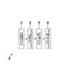
図1は、アテローム切除システム10を示す。アテローム切除システム10は、駆動アセンブリ12(例えば、アテローム切除用デバイス)及び制御ユニット14(例えば、コントローラ又は制御コンソール)を含み得る。駆動アセンブリ12と制御ユニット14とは、アテローム切除システム10の別個の構成要素として図1に示されているが、制御ユニット14の諸機構は、駆動アセンブリ12に組み込まれ得る。
駆動アセンブリ12は、他の要素の他に、前進アセンブリ16と、駆動シャフト18(例えば、可撓性駆動シャフト又は他の駆動シャフト)と、回転デバイス20(例えば、回転チップ又は他の回転部材)と、長尺状部材22であって、第1の端部(例えば、近位端)、第2の端部(例えば、遠位端)、及び第1の端から第2の端まで延び、駆動シャフト18を受け入れるための内腔を有する長尺状部材22とを備え得る。場合によっては、長尺状部材22は長尺状管状部材であってもよい。回転デバイス20は、回転したときに血管壁のプラーク又は血管内の他の障害物を研削、アブレーション、切断、剃去するために、粗い、又は鋭い表面を有してもよい。FIG. 1 shows an
In addition to other elements, the
前進アセンブリ16は、前進ツマミアセンブリ23を含み得るものであり、前進ツマミアセンブリ23と駆動シャフト18と導通する駆動メカニズム(例えば、図5に示す駆動メカニズム50であってもよく、駆動メカニズムは、タービン、電気モータ、空気モータ、及び/又は他の適切な駆動メカニズムであってもよい)を収容し得る。前進ツマミアセンブリ23は、駆動メカニズム、駆動シャフト18、及び/又は回転デバイス20を長手方向に前進及び/又は後退させるべく長手方向経路に沿って移動するように、長手方向経路に沿って軸方向位置において駆動メカニズムを固定するように、及び/又は駆動メカニズムのモードを調整するように構成され得る。 The
駆動メカニズムは、本明細書では前進アセンブリ16に含まれるものとして説明されているが、駆動メカニズムは、前進アセンブリ16とは別個であるが、前進アセンブリ16と導通していてもよいと企図される。そのような場合、駆動メカニズム、駆動シャフト18、及び/又は回転デバイス20を前進させ、そしてツマミアセンブリ23は、駆動メカニズムのモードの作動を開始するために利用され得る。 Although the drive mechanism is described herein as being included in the
駆動メカニズムは、溶接、クランプ接続、接着、ねじ止め、及び/又は高回転速度や回転力に耐えるように構成された他の適切な結合を含むがこれらに限定されない適切な方法で駆動シャフト18に結合されてもよい。駆動シャフト18は、広範囲の速度(例えば、時計回り又は反時計回りにゼロ(0)回/毎分(RPM)〜250,000RPM以上の間の速度)にわたって回転し得るので、駆動メカニズムと駆動シャフト18との間の結合は、そのような回転速度及びそれに関連する力に耐えるように構成され得る。 The drive mechanism includes, but is not limited to, welding, clamping, gluing, screwing, and / or other suitable connections configured to withstand high speeds and rotational forces to the drive shaft 18. It may be combined. The drive shaft 18 can rotate over a wide range of speeds (eg, clockwise or counterclockwise between zero (0) times / minute (RPM) to 250,000 RPM and above), so that the drive mechanism and drive shaft The coupling with 18 may be configured to withstand such rotational speeds and associated forces.
場合によっては、駆動メカニズムは制御ユニット14と導通することができる。制御ユニット14と導通するとき、駆動メカニズムは、制御ユニットと直接に連動し(例えば、配線を介して直接接続される)、又は間接的に連動(例えば、複数の配線接続及び/又は1つ以上のデバイスを介して間接的に接続される)し得る。駆動メカニズムと制御ユニット14との間の間接連動する一例には、圧縮空気によって駆動される駆動メカニズム(例えば、タービン又は空気圧モータ)が含まれ、制御ユニット14がシリンダ25又は他の部品から駆動メカニズムへの圧縮流体の流れを起動することができ(例えば、制御ユニット14の弁を作動させるか、さもなければ圧縮流体流を作動させる)、これは、駆動メカニズム及び駆動シャフト18の回転をもたらし得る。 In some cases, the drive mechanism can be conductive with the control unit 14. When conducting with the control unit 14, the drive mechanism is directly interlocked with the control unit (eg, directly connected via wiring) or indirectly interlocked (eg, multiple wiring connections and / or one or more). Can be indirectly connected via a device). An example of indirect interlocking between a drive mechanism and a control unit 14 includes a drive mechanism driven by compressed air (eg, a turbine or a pneumatic motor) in which the control unit 14 is driven from a
駆動シャフト18は、1つ以上の様々な材料から形成することができる。例えば、駆動シャフト18は、鋼、ステンレス鋼、及び/又は他の適切な材料を含む様々な材料の1つ以上から形成されてもよい。 The drive shaft 18 can be formed from one or more different materials. For example, the drive shaft 18 may be formed from one or more of various materials, including steel, stainless steel, and / or other suitable materials.
駆動シャフト18は、患者の血管系を通過するための適切な直径及び/又は長さを有し得る。場合によっては、駆動シャフト18は、約0.030センチメートル(cm)以下〜約0.150cm以上の範囲の直径、及び約10(cm)〜約300(cm)の範囲の有効長を有することができる。あるいは、駆動シャフト18は、異なる適切な直径及び/又は異なる適切な長さを有し得る。 The drive shaft 18 may have a suitable diameter and / or length for passing through the patient's vascular system. In some cases, the drive shaft 18 has a diameter in the range of about 0.030 cm (cm) or less to about 0.150 cm or more, and an effective length in the range of about 10 (cm) to about 300 (cm). Can be done. Alternatively, the drive shaft 18 may have different suitable diameters and / or different suitable lengths.
回転デバイス20は、駆動シャフト18及び長尺状部材22の遠位直径に等しいか又はそれよりも大きい外周を有し得る。回転デバイス20は、両方の回転方向において等しく十分に貫通するように対称的なデザインを有することができるが、これは必須ではなく、回転デバイス20は、一方向のみに貫通するように構成されてもよい。駆動シャフト18の直径は、長尺状部材22の管腔の寸法及び/又は1つ以上の他の要因に依存し得る。 The rotating device 20 may have an outer circumference equal to or larger than the distal diameter of the drive shaft 18 and the elongated member 22. The rotating device 20 can have a symmetrical design so that it penetrates equally well in both directions of rotation, but this is not required and the rotating device 20 is configured to penetrate in only one direction. May be good. The diameter of the drive shaft 18 may depend on the size of the lumen of the elongated member 22 and / or one or more other factors.
回転デバイス20は、駆動シャフト18に結合され得る。駆動シャフト18が第1の端部(例えば、近位端部分)及び第2の端部(例えば、遠位端部分)を有する場合、回転デバイス20は、第2の端部又はその近傍で駆動シャフト18に結合され得る。場合によっては、回転デバイス20は、駆動シャフト18の第2の端部の末端に、又はそれに隣接して配置されてもよい。 The rotating device 20 may be coupled to the drive shaft 18. If the drive shaft 18 has a first end (eg, a proximal end) and a second end (eg, a distal end), the rotating device 20 is driven at or near the second end. It can be coupled to the shaft 18. In some cases, the rotating device 20 may be located at or adjacent to the end of the second end of the drive shaft 18.
回転デバイス20は、任意の方法で駆動シャフト18に結合され得る。例えば、回転デバイス20は、接着、ねじ止め、溶接、クランプ接続、及び/又は高い回転速度及び力に耐えるように構成された他の適切な接続で駆動シャフト18に結合され得る。駆動シャフト18と駆動メカニズムとの間の接続に関して上記したのと同様に、駆動シャフト18及び/又は回転デバイス20は、時計周り又は反時計回りに、或いは時計回りと反時計回りの双方にゼロ(0)RPM〜250,000RPM以上の速度で回転し得るので、駆動シャフト18及び回転デバイス20は、そのような回転速度及びそれに関連する力に耐えるように構成され得る。 The rotating device 20 can be coupled to the drive shaft 18 in any way. For example, the rotating device 20 may be coupled to the drive shaft 18 by gluing, screwing, welding, clamping connections, and / or other suitable connections configured to withstand high rotational speeds and forces. Similar to the connection between the drive shaft 18 and the drive mechanism, the drive shaft 18 and / or the rotating device 20 is zero (clockwise or counterclockwise, or both clockwise and counterclockwise). 0) Since it can rotate at speeds of RPM to 250,000 RPM and above, the drive shaft 18 and rotating device 20 can be configured to withstand such rotational speeds and associated forces.
駆動アセンブリ12及び制御ユニット14は、導通することが可能であり、同一のハウジングに配置されてもよく、及び/又は別個のハウジング(例えば、前進アセンブリハウジング26及び制御ユニットハウジング28又は他のハウジング)に配置されてもよい。同じハウジング内であろうと別個のハウジング内であろうと、駆動アセンブリ12及び制御ユニット14は、有線接続(例えば、1つ以上の電線24を介して)及び/又は無線接続を介して導通し得る。有線接続は、必要に応じて、USB、イーサネット(登録商標)、SPI、UART、HDMI(登録商標)、及び/又はその他の適切な共通又は専用の有線プロトコルを含むがこれらに限定されない1つ以上の導通プロトコルを介して行うことができる。無線接続は、セルラー導通、ZigBee(商標)、ブルートゥース(登録商標)、WiFi(登録商標)、IrDA(商標)、専用短距離導通(DSRC)、EnOcean(商標)、及び/又はその他の適切な一般的又は独自のワイヤレスプロトコルを含むがこれらに限定されない好適な1つ以上の導通プロトコルを介して行われる。 The
図1には示されていないが、駆動アセンブリ12は、上記に加えて、及び/又は上記の代替として、1つ以上の動作構造物を備え、かつ/又は収容することができる。例えば、様々な部材の中でも駆動アセンブリ12は、制御ボタン、ゴム足、制御電子機器、駆動回路等を含み得る。 Although not shown in FIG. 1, the
制御ユニット14は、(例えば、図1に示されるように)駆動アセンブリ12から分離され得るか、又は駆動アセンブリ12に含まれ得る、いくつかの構造物を含み得る。例えば、図1に示されるように、制御ユニット14は、ディスプレイ30及び制御ツマミ32(例えば、駆動メカニズム速度(例えば、RPM又は他の速度)調整ツマミ又は他の制御ツマミ)を含み得る。追加又は代替として、制御ユニット14は、駆動メカニズム及び/又は駆動アセンブリ12の他の構造物(例えば、駆動メカニズムの1つ以上の状態)を制御するための1つ以上の他の構造物を含み得るものであり、それには、限定はされないが、プロセッサ、メモリ、入出力デバイス、スピーカー、ボリュームコントロールボタン、オン/オフ電源スイッチ、駆動メカニズムモード作動スイッチ、タイマー、時計、及び/又はその他の機構が含まれる。 The control unit 14 may include several structures that may be separated from the drive assembly 12 (eg, as shown in FIG. 1) or may be included in the
ディスプレイ30は、任意の適切なディスプレイパネル技術を使用する任意の適切なタイプのディスプレイパネルであり得るか、又はそれを含み得る。例えば、ディスプレイ30は、以下のタイプのディスプレイパネルのうちの1つ以上を含み得る:アイドホール(商標)、エレクトロルミネセントディスプレイ(ELD)、電子ペーパー(Eインク(商標)、ジリコン)、発光ダイオードディスプレイ(LED)、陰極線管(CRT)(モノスコープ)、液晶ディスプレイ(LCD)(TFT、LED、ブルーフェーズ、IPS)、プラズマディスプレイパネル(PDP)(ALiS)、デジタル光処理(DLP)、液晶オンシリコン(LCoS)、有機発光ダイオード(OLED)(AMOLED)、有機発光トランジスタ(OLET)、表面−伝導電子放出ディスプレイ(SED)、電界放出ディスプレイ(FED)、レーザーTV(量子ドット、液晶)、MEMSディスプレイ(IMoD、TMOS、DMS)、量子ドットディスプレイ(QD−LED)、フェロ液晶ディスプレイ(FLD)、厚膜誘電体エレクトロルミネセンス技術(TDEL)、テレスコピックピクセルディスプレイ(TPD)、レーザー蛍光体ディスプレイ(LPD)、又はその他のタイプのディスプレイパネル。ディスプレイ30は、入力を受信するための接触検知スクリーンを含み得るが、これは必須ではない。 The
制御ツマミ32は、任意の適切なタイプの制御ツマミであり得る。図1に示されるように、制御ツマミ32は、制御機能(例えば、駆動メカニズム又は他の制御構造物の回転速度)を調整する(例えば、回転又は他の方法で移動)ように調整される物理制御ツマミであり得る。代替的又は追加的に、制御ツマミ32は、物理的なボタン、接触感知面と相互作用することによって調整され得る仮想制御ツマミ、及び/又は制御機能を調整するべく調整されるように構成される他の適切な構成要素であり得る。 The
図1に示されるように、制御ユニット14は、光ファイバポート34と、電気ポート36と、流体ポート38と、1つ以上の他のポートとのうちの少なくとも1つを含むがこれらに限定されない、1つ以上のポートを備え得る。光ファイバポート34は、光ファイバライン42の光ファイバコネクタ40を受け入れるように構成されてもよく、光ファイバライン42は、駆動メカニズムの位置を光学的に検知するように構成された位置センサに接続され、及び/又は位置センサの一部であってもよい。追加又は代替として、制御ユニット14への異なるタイプの接続を有する他のタイプの位置センサが利用されてもよい。電気ポート36は、電気ライン24の電気コネクタ44を受容するように構成され得るものであり、電気ライン24は、駆動アセンブリ12の制御電子機器に接続され得るか、及び/又は制御電子機器の一部であり得る。場合によっては、電線ライン24は、駆動アセンブリ12の主PCBに直接接続されてもよく、駆動アセンブリ12の電気アセンブリに電力を供給するために利用されてもよい。流体ポート38は、流体ライン48の流体ラインコネクタ46を受容するように構成され得るものであり、流体ライン48は、駆動メカニズムと接続して駆動メカニズムに動力を供給し得る。駆動メカニズムが電気モータ又は非空気圧駆動メカニズムである場合、流体ポート38、流体ラインコネクタ46、及び/又は流体ライン48は省略されてもよいが、これは必須ではない。 As shown in FIG. 1, the control unit 14 includes, but is not limited to, at least one of, but is not limited to, a
図2は、ツマミアセンブリ23の概略分解斜視図を示している。場合によっては、ツマミアセンブリ23は、スライドアダプタ52、ツマミ本体54、アクチュエータ56及び/又は1つ以上の他の構成要素を含み得る。ツマミアセンブリ23のツマミ本体54は、スライドアダプタ52を受け入れ得るものであり、スライドアダプタ52に固定、又はスライドアダプタ52に対して固定されるように構成することができる。ツマミアセンブリ23の各構成要素(例えば、スライドアダプタ52、ツマミ本体54、アクチュエータ56、及び/又は他の構成要素)は、単一に形成され得るか、又は適切な方法で嵌合される2つ以上の構成要素部品から形成され得る。 FIG. 2 shows a schematic exploded perspective view of the
ツマミ本体54は、適切な方法でスライドアダプタ52に固定又はスライドアダプタ52に対して固定されてもよい。例えば、ツマミ本体54は、スナップ接続、ねじ接続、キー嵌合接続、摩擦嵌合接続、及び/又は他の適切な接続によって、スライドアダプタ52に固定、又はスライドアダプタ52に対して固定され得る。図2に示される例示的なツマミアセンブリ23において、ツマミ本体54は、第1の接続と第2の接続とによってスライドアダプタ52に接続可能であり得るが、単一の接続のみが利用され得るか、又は3つ以上の接続が利用され得る。 The
場合によっては、第1の接続は、ツマミ本体54が軸に沿って軸方向に移動及び/又はスライドアダプタ52に対する軸の周りに回転することを許容しつつ、スライドアダプタ52に対するツマミ本体54の固定を容易にするように構成され得る。場合によっては、第1の接続は、ツマミ本体54とスライドアダプタ52とを接続した後、ツマミ本体54のスライドアダプタ52に対する軸方向の移動及び/又はツマミ本体54の回転を許容する、ツマミ本体54とスライドアダプタ52との間のスナップ接続であり得る。第1の接続がスナップ接続である場合、スライドアダプタ52は、1つ以上の係合要素(例えば、図2に示されるような可撓性及び/又は弾性プロング若しくは他の適切な係合要素等の4つの係合要素58)を含み得るものであり、該1つ以上の係合要素は、ツマミ本体54の1つ以上の肩(例えば、図2に示されるような肩60又は他の適切な肩)と係合し得るように構成され、ツマミ本体54がスライドアダプタ52に対して移動できるように構成される。 In some cases, the first connection secures the
第2の接続は、予め設定された経路(例えば、固定的な又は調整可能な縦方向経路)に沿った位置においてツマミアセンブリを解放可能に固定することを容易にするように構成され得るものであり、該予め設定された経路にわたって、ツマミアセンブリ23は、駆動メカニズム、駆動シャフト18、及び/又は回転デバイス20の軸方向位置を調整するために移動(例えば、長手方向の移動)するように構成され得る。場合によっては、第2の接続は、ツマミ本体54とスライドアダプタ52との間のねじ接続であり、或いは、予め設定された経路に沿う位置においてツマミアセンブリ23が選択的に固定されるために調整するように構成された他の接続である。第2の接続がねじ接続である場合、ツマミ本体54に形成されたねじ(例えば、図5に示す内ねじ62又は別のねじ)は、スライドアダプタ52に形成されたねじ(例えば、図2、図4、図5に示す外ねじ64又は他のねじ)と螺合する。 The second connection may be configured to facilitate the releasably fixing of the knob assembly at a position along a preset path (eg, a fixed or adjustable longitudinal path). Yes, the
アクチュエータ56は、ツマミ本体54並びに/又はスライドアダプタ52の中央開口若しくは他の開口を通して挿入され得る。アクチュエータ56は、適切な方法で、ツマミアセンブリ23内(例えば、ツマミ本体54とスライドアダプタ52とに延びる開口内の少なくとも一部)に固定され得る。場合によっては、アクチュエータ56は、当該アクチュエータ56が当該アクチュエータ56の第1の端部56aと相互作用すること(例えば、第1の端部56aの表面を押し込むこと)により調整され、作動されるように、ツマミアセンブリ23に固定され得る。 The
アクチュエータ56は、ツマミ本体54とスライドアダプタ52の一方又は双方に対して係合することにより、ツマミ本体54及び/又はスライドアダプタ52に対して相対移動可能に固定され得る。図3に示されるように、アクチュエータ56は、突起66を含み得る。該突起66は、スライドアダプタ52の係合要素58と係合(例えば、キャッチ68又は係合要素58の他の機構と係合)するように構成されるとともに、スライドアダプタ52に形成された開口70内(例えば、場合によっては開口70は、係合要素58間の開口)で摺動するように構成される。代替的又は追加的に、アクチュエータ56及びスライドアダプタ52の一方又は双方は、アクチュエータ56及びスライドアダプタ52の相手方の突起と係合するための窪み又は開口を含み得る。 The
ツマミアセンブリ23は、図2に示されるように、駆動メカニズムの動作モードを開始するように構成されたスイッチ72を含み得る。場合によっては、スイッチ72は、スイッチアセンブリを形成するために、機械的に取り付けられ得るとともに、スイッチプリント回路基板(PCB)74と電気的に導通し得る。スイッチ72は、なんらかの適切な方法で、機械的に取り付けられ得るものであり、及び/又はスイッチPCB74と電気的に導通し得る。場合によっては、スイッチ72は、はんだ、接着剤、溶接、ワイヤボンド等を含むがこれらに限定されない1つ以上の接続機構によって、スイッチPCB74に機械的に取り付けられ得るものであり、及び/又は電気的に接続され得るものである。代替的又は追加的に、スイッチアセンブリは、1つ以上の他の構成、1つ以上の追加的な又は代替的な電気的な構成要素、及び/又は1つ以上の追加又は代替の機械的な構成要素をとり得る。 The
図には示されていないが、スイッチ72及び/又はスイッチPCB74は、駆動アセンブリ12のメインPCBと電気的に導通(例えば、電気的に接続する、及び/又は他の適切な電気的な導通を)し得るものであり、該駆動アセンブリ12は、メインPCB及び/又は駆動メカニズムコントローラに電気信号を送るためのものであり、駆動メカニズムコントローラは、駆動メカニズムのモードを調整するように構成される。代替的又は追加的に、スイッチ72は、アクチュエータ56によって作動された、及び/又は、他の適切な方法によって作動されたスイッチ72に応答して駆動メカニズム(例えば、駆動メカニズムが電気モータであるとき、及び/又は他の機構である場合)のモードを調整するために、駆動メカニズムに直接電気的に接続され得る。 Although not shown in the figure, the
スイッチ72は、アクチュエータ56によって作動されることに応答して駆動メカニズムのモードを調整するための適切な構成を有し得る。場合によっては、スイッチ72は、本体76及びボタン78を含み得る。ボタン78は、作動されることに応答して、本体76に対して相対的に動くように構成され得る。例えば、スイッチ72がツマミアセンブリ23内に配置されると、アクチュエータ56の第2の端部56bは、駆動メカニズムのモードの調整を開始するためにスイッチ72のボタン78と相互作用し得る。 The
スイッチ72は、駆動メカニズムのモードを調整するためになんらかの適切な方法で動作し得る。一例では、スイッチ72は、アクチュエータ56がスイッチと相互作用するたびに、駆動メカニズムコントローラ(図示せず)にパルスを送信し得る。駆動メカニズムコントローラはまた、パルスを受信した際に駆動メカニズムがオフモードであったときに駆動メカニズムをオンモードにすることを開始することも、パルスを受信した際に駆動メカニズムがオンモードであったときに駆動メカニズムをオフモードにすることを開始することもなし得る。代替的又は追加的に、スイッチ72は、異なる方法で動作し得るとともに、アクチュエータ56による作動に応答して、駆動メカニズムの1つ以上の他の制御パラメータの調整を容易にするように構成され得る。さらに、スイッチ72は、本明細書では、駆動メカニズムコントローラにパルスを送信するものとして説明されているが、スイッチ72は、アクチュエータ56による作動に応答して、1つ以上の他の適切な動作をとるか、又は1つ以上の他の適切な出力を提供し得る。 The
ツマミアセンブリ23内に配置された場合、スイッチ72は、アクチュエータ56の第2の端部56bがスイッチ72と相互作用し得るように、ツマミアセンブリ23内に位置決めされ得る。一例では、スイッチ72は、スライドアダプタ52の受け入れスロット80に位置決めされ得る。スイッチ72は、限定はされないが、受容スロット80内の摩擦嵌合、キー嵌合接続、ルアーロック接続、受容スロット80内のスナップ嵌合、接着剤、溶接、はんだ付け、永久接続、解放可能な接続、及び/又は適切な他の接続メカニズムを含む1つ以上の接続によって、受容スロット80内に、つまり、スライドアダプタ52に固定され得る。 When placed in the
図3は、スライドアダプタ(例えば、スライドアダプタ52又は他の適切なスライドアダプタ)と、ツマミ本体(例えば、ツマミ本体54又は他の適切なツマミ本体)と、アクチュエータ(例えば、アクチュエータ56又は他の適切なアクチュエータ)と、スイッチ(例えば、スイッチ72又は他の適切なスイッチ)を有するツマミアセンブリ23の組立方法100を示す。方法100は、スライドアダプタにスイッチを位置決めすること102を含み得る。スイッチ72に関して上記で説明したように、スイッチは、スライドアダプタに形成された受容スロット(例えば受容スロット80)又はその他の凹部内に位置決めされ得るものであり、該受容スロット又は他の凹部は、当該スイッチと、関連する構成要素(例えばスイッチPCB74及び/又は他の構成要素)とを受容するように構成される。必ずしも必須ではないが、合体されたスライドアダプタとスイッチとは、スライドアダプタが駆動メカニズム(例えば、図5に示す駆動メカニズム50又は他の適切な駆動メカニズム)から離れるとともにスライドアダプタが前進アセンブリ(例えば、前進アセンブリ16又は他の適切な前進アセンブリ)のハウジング(例えば、ハウジング26又は他の適切なハウジング)内に配置され得る程度に、駆動メカニズムと結合され得る。前進アセンブリのハウジング内に配置されたスライドアダプタは、ハウジングの開口を通って延びるように構成され得るが、これは必須ではない。 FIG. 3 shows a slide adapter (eg,
方法100は、ツマミ本体をスライドアダプタに結合すること(104)をさらに含み得る。一例では、ツマミ本体は、スライドアダプタのねじと螺合するツマミ本体のねじによって、スライドアダプタに結合されてもよい。ツマミ本体をスライドアダプタに対し追加的に又は別の方法で結合するとともにツマミ本体とスライドアダプタとの分離を防止又は制限するために、ツマミ本体をスライドアダプタ上にスナップ留めし、或いは別の接続をするべく、ツマミ本体とスライドアダプタの一方又は双方に力が加えられる。
ツマミアセンブリのアクチュエータは、アクチュエータの作動がスイッチの作動を引き起こすことを確実にするために、スイッチと整合(106)され得る。場合によっては、ツマミ本体及び/又はスライドアダプタを貫通する開口を通してアクチュエータを挿入することにより、アクチュエータをスイッチと整合させることができる。スイッチと整合すると、アクチュエータは、スライドアダプタと結合(108)され得る。場合によっては、ツマミ本体をスライドアダプタにスナップ留めし、或いは別の方法で接続するために、ツマミ本体とスライドアダプタの一方又は両方に力が加えられる。ツマミアセンブリがハウジングに対して配置され、組み付けられると、ユーザは、アクチュエータの作動によって駆動メカニズムのモードの調整を可能にしつつ、駆動メカニズム、駆動メカニズムに結合する駆動シャフト(例えば、駆動シャフト18又は他の適切な駆動シャフト)、及び/又は、駆動シャフトに結合する回転デバイス(例えば、回転デバイス20又は他の適切な回転デバイス)の軸方向位置を長手方向に移動させるために、並びに、駆動メカニズム、駆動シャフト、及び/又は回転デバイスを前進アセンブリのハウジングに対する位置に固定するために、ツマミアセンブリと相互作用し得る。 The actuator of the knob assembly can be aligned (106) with the switch to ensure that the actuator actuation causes the switch actuation. In some cases, the actuator can be aligned with the switch by inserting the actuator through an opening through the knob body and / or slide adapter. When aligned with the switch, the actuator can be coupled (108) with the slide adapter. In some cases, force is applied to one or both of the knob body and the slide adapter to snap the knob body to the slide adapter or otherwise connect it. When the knob assembly is placed and assembled with respect to the housing, the user can adjust the mode of the drive mechanism by actuating the actuator, while the drive mechanism, the drive shaft coupled to the drive mechanism (eg, drive shaft 18 or the like). To move the axial position of the rotating device (eg, rotating device 20 or other suitable rotating device) coupled to the drive shaft in the longitudinal direction, and / or the drive mechanism. The drive shaft and / or rotating device may interact with the knob assembly to secure it in position with respect to the housing of the forward assembly.
図4は、一部がハウジング26内に配置され、ハウジング26を通って延びるツマミアセンブリ23の分解斜視図を含む前進アセンブリ16の概略斜視図を、当該前進アセンブリ16の一部を切除して示す。図4に示すように、スライドアダプタ52は、ハウジング26の開口82を通って延び得る。スライドアダプタ52をハウジング26内に配置するとともにスライドアダプタ52を、開口82を通して延ばした後、本明細書で説明したように(例えば、方法100のステップ104、106、及び108)、或いは1つ以上の他の方法で、ツマミ本体54及び/又はアクチュエータ56は、互いに、及び/又はスライドアダプタ52と結合され得る。本明細書に記載されるスライドアダプタ52は、開口82を通って延びるように構成され得るが、ツマミ本体54及び/又はアクチュエータ56は、開口82から延出するとともにハウジング26内におけるある場所においてスライドアダプタ52と結合し得るものと考えられるのであり、及び/又は、ツマミアセンブリ23は、本明細書で説明されるツマミアセンブリ23の諸機能を実行するように構成された1つ以上の他の構成をとり得る、と考えられる。 FIG. 4 shows a schematic perspective view of a
ハウジング26の開口82は、駆動メカニズム、駆動シャフト18、及び/又は回転デバイス20を長手方向に移動させるための適切な構成を有し得る。図4に示されるように、開口82は細長い形状を有するとともに、ツマミアセンブリ23が予め設定された経路(例えば、予め設定された固定経路又は他の経路)に沿って長手方向に移動できるように構成される。しかしながら、開口82は、必要に応じて、1つ以上の他の適切な構成をとることができる。 The
場合によっては、前進アセンブリ16のハウジング26は、ハウジング26の外面84上に目盛を含み得る。図4に示されるように、目盛は、含まれる場合、開口82に沿う予め設定された及び/又は等間隔の位置に配置され得るものであり、ユーザ(例えば、医師又は他のユーザ)に、駆動メカニズム、駆動シャフト18、及び/又は回転デバイス20の軸位置の測定又は他の表示を提供し得る。目盛は、一般的な目盛、測定(例えば、ミリメートル、センチメートル、インチ等)、並びに/又は、開口82に沿った、ツマミアセンブリ23及び/若しくは駆動メカニズムの相対的な位置の理解を提供することを容易にする他の適切な目盛であり得る。代替的又は追加的に、ハウジング26の外面84に他の目盛を設け得る。 In some cases, the
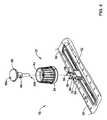
図5は、前進アセンブリ16の一部の概略断面図である。図5は、駆動メカニズム50に結合されたツマミアセンブリ23を示す。図示の駆動メカニズム50は、空気圧タービンであるが、駆動メカニズムは、異なる空気圧モータであり得るものであり、電気モータであり得るものであり、及び/又は1つ以上の他の適切な駆動メカニズムを含み得る。 FIG. 5 is a schematic cross-sectional view of a part of the
ツマミアセンブリ23は、ツマミアセンブリ23の動きに応答して駆動メカニズム50の動きを容易にする適切な方法で駆動メカニズム50に結合され得る。例えば、ツマミアセンブリ23は、摩擦嵌合接続、キー嵌合接続、スナップ嵌合接続、ねじ込み接続、ルアーロック接続、接着接続、溶接接続、はんだ接続、永続的な接続、解放可能な接続、及び/又は1つ以上の他の適切なタイプの接続によって、駆動メカニズム50に結合され得る。図5に示されるように、スライドアダプタ52の延長部53は、ツマミアセンブリ23と駆動メカニズム50との間にキー嵌合接続を形成するために、駆動メカニズム50の凹部51内に延び得るものであり、該キー嵌合接続は、ツマミアセンブリ23の移動(例えば長手方向の動き)に応答した駆動メカニズム50の移動(例えば、中心軸沿いの移動)をもたらし得る。 The
図5から分かるように、ツマミ本体54の内ねじ62は、スライドアダプタ52の外ねじ64と螺合し得る。したがって、矢印88で示すように、前進アセンブリ16のハウジング26における開口82によって少なくとも部分的に画定される予め設定された経路に沿ったツマミアセンブリ23の移動が可能となるために、ツマミ本体54の底面86と外面84との間に隙間を形成するべく、ツマミ本体54は、第1の位置に第1の方向において回転可能に調整し得る。ツマミアセンブリ23及び/又は駆動メカニズム50を開口部82に沿ったある位置に固定したい場合、ツマミ本体54の底面86をハウジング26の外面84と衝合させ、ツマミ本体54とハウジング26との間に摩擦嵌合接続を形成し、ツマミアセンブリ23、駆動メカニズム50、駆動シャフト18、及び/又は回転デバイス20のハウジング26に対する相対的な長手方向の移動を規制若しくは制限するために、ツマミ本体54は第2の方向へ第2の位置に回転され得る。ツマミ本体54は、スライドアダプタ52及び/又はハウジング26の外面84に対するツマミ本体54の軸方向位置を調整するために回転され得るが、スライドアダプタ52の係合要素58は、ツマミ本体54がハウジング26及び/又はスライドアダプタ52から離脱することを規制するために、ツマミ本体54の肩部60と係合するように構成され得る。 As can be seen from FIG. 5, the
図5に示すように、アクチュエータ56は、ツマミ本体54を通り、開口90(例えば、中央開口又は他の開口)を通って延び、少なくとも部分的にスライドアダプタ52を通って延び得るとともに、スイッチ72と整合し得る(例えば、アクチュエータ56の第2の端部56bは、スイッチ72のボタン78と整合し得る)。そのような構成では、アクチュエータ56は、駆動メカニズムの動作モードを調整するための信号を送信するために、ボタン78を軸方向に移動し係合するように構成され得る。一例では、アクチュエータ56の第2の端部56bがスイッチ72を駆動するためにボタン78に係合するように、ユーザがアクチュエータ56の第1の端部56aと相互作用して当該アクチュエータ56を作動(例えば、長手方向に移動)し得るべく、アクチュエータ56の第1の端部56aは、ツマミ本体54の外に延び得るか、或いはツマミ本体54の外側から作動するためにアクセス可能である。 As shown in FIG. 5, the
図5に示すように、アクチュエータ56の突起66は、スライドアダプタ52の開口(単数又は複数)70に受容され得る。スライドアダプタ52の開口(単数又は複数)70及び/又はスライドアダプタ52の突起66は、当該突起66とスライドアダプタ52のキャッチ68との係合により、アクチュエータ56のスライドアダプタ52に対する軸方向の移動を許容し及び/又は規制するように構成され得る。 As shown in FIG. 5, the
図6は、患者の血管系の閉塞部を通過するようにアテローム切除システム10の駆動アセンブリ12を操作する方法200を示す。方法200は、ハウジング(例えば、前進アセンブリのハウジング26又は他のハウジング)に対する第1の位置(例えば、固定位置)からツマミアセンブリ(例えば、ツマミアセンブリ23又は他の適切なツマミアセンブリ)を解放すること(202)を含み得る。ツマミアセンブリは、駆動メカニズム(例えば、駆動メカニズム50又は他の適切な駆動メカニズム)の長手方向の移動を容易にする第2の位置(例えば、解放位置)に、スライドアダプタ(例えば、スライドアダプタ52又は他の適切なスライドアダプタ)に対して相対的にツマミ本体(例えばツマミ本体54又は他の適切なツマミ本体)を回転することによって、固定された位置から解放され得る。代替的又は追加的に、ツマミアセンブリは、1つ以上の他の適切な方法で、ハウジングに対する固定位置から解放され得る。 FIG. 6 shows
(図5の方法200に示されるような)解放位置又は固定位置にあるとき、アクチュエータ(例えば、アクチュエータ56又は他の適切なアクチュエータ)は、駆動メカニズムのオンモード、オフモード、及び/又は他のモードを開始するために作動(204)され得る。上述のように、アクチュエータの作動は、スイッチと係合し得ること、及び/又はスイッチを作動させ得ることとなり、駆動メカニズムコントローラに信号を送信して駆動メカニズムのモードを変更若しくは調整する。一例では、駆動メカニズムがオフモードにある場合、アクチュエータの作動により、駆動メカニズムがオンモードに入ることを開始し得る。同様に、駆動メカニズムがオンモードにある場合、アクチュエータの作動により、駆動メカニズムがオフモードに入ることを開始し得る。 When in the open or fixed position (as shown in
(図5の方法200に示されるように)アクチュエータの作動の結果、駆動メカニズムがオンモードになることに関連して、駆動メカニズムがオフモードにある場合、すなわち、ツマミアセンブリが解放位置にある間にアクチュエータが作動する前である場合に、ツマミアセンブリは、長手方向に調整(例えば、前進又は後退)(206)され得る。場合によっては、駆動シャフト(例えば、駆動シャフト18又は他の適切な駆動シャフト)に結合された回転デバイス(例えば、回転デバイス20又は他の適切な回転デバイス)は、駆動メカニズムがオフモードにある間、患者の血管系を通って閉塞部まで前進し得るとともに、回転デバイスが閉塞部に隣接しているときに、駆動メカニズムはオンモードに作動され得る。駆動メカニズムのオンモードを開始した後、回転デバイスが閉塞部に係合し閉塞部に穿孔し得るように、ツマミアセンブリが前進され得る(206)。閉塞部を通過すると、駆動メカニズムをオフモードにすることを開始するために、アクチュエータを再度作動(208)させ得る。施術が実行されると、ツマミアセンブリは、ハウジングに対するある位置にツマミアセンブリを固定するために回転調整され得るとともに、回転デバイスと駆動シャフトは、オフモードになった駆動メカニズムとともに患者の血管系から取り外され得る。代替的又は追加的に、方法200の1つ以上のステップは、患者の血管系における閉塞部の通過を容易にするために必要に応じて繰り返され得る。 When the drive mechanism is in the off mode, that is, while the knob assembly is in the open position, in connection with the actuation of the actuator (as shown in
必ずしも図には描かれていないが、本明細書に記載の方法(例えば、方法100、200、及び/又は他の方法)は、本明細書に記載の工程以外の1つ以上の工程を備えてもよく、及び/又は記載の工程は、特に明記されていない限り、必要に応じて1つ以上の工程の順番を変えて行うこともできる。さらに、本明細書に記載の方法は必要に応じて、開始時に、アテローム切除システム10の動作中に、継続的に、予め設定された間隔で継続的に、及び/又は他の時間に繰り返されてもよい。 Although not necessarily depicted in the drawings, the methods described herein (eg,
当業者は、本開示が、本明細書で説明及び企図される特定の実施形態以外の様々な形態で明示され得ることを認識するであろう。例えば、本明細書で説明されるように、様々な実施形態は、様々な機能を実行するものとして説明される1つ以上のモジュールを含む。しかしながら、他の実施形態は、説明された機能を本明細書に説明されたものよりも多くのモジュールにわたって分割する追加のモジュールを含み得る。さらに、他の実施形態は、記載された機能をより少ないモジュールに統合することができる。 Those skilled in the art will recognize that the present disclosure may be manifested in various forms other than the particular embodiments described and contemplated herein. For example, as described herein, various embodiments include one or more modules described as performing different functions. However, other embodiments may include additional modules that divide the described functionality across more modules than those described herein. In addition, other embodiments can integrate the described functionality into fewer modules.
すべてではない実施形態に関して様々な特徴を説明してきたが、本開示は、それらの特徴が任意の実施形態に含まれ得ることを企図している。さらに、本明細書に記載の実施形態は、記載された様々な特徴のいくつかの組み合わせを省略しているかもしれないが、この開示は、記載された各特徴の任意の組み合わせを含む実施形態を想定している。したがって、添付の特許請求の範囲に記載されている本開示の範囲及び精神から逸脱することなく、形態及び詳細の変更を行うことができる。 Although various features have been described for, but not all, embodiments, the present disclosure contemplates that those features may be included in any embodiment. Moreover, although the embodiments described herein may omit some combinations of the various features described, this disclosure comprises any combination of the various features described. Is assumed. Therefore, the form and details can be changed without departing from the scope and spirit of the present disclosure described in the appended claims.
Claims (10)
Translated fromJapaneseハウジングを備え、
駆動メカニズムを備え、該駆動メカニズムは、前記ハウジング内に配置され、かつ、長尺状部材に結合するとともに作動時に前記長尺状部材を回転させるように構成されており、
前記駆動メカニズムと導通するとともに前記ハウジングの外部から操作可能にアクセス可能なツマミアセンブリを備え、該ツマミアセンブリは、
前記駆動メカニズムの軸方向位置を調整するために長手方向に移動するように構成されるととともに、
作動されて、オンモードとオフモードの間で前記駆動メカニズムを選択的に調整する
ように構成される、アテローム切除用デバイス。A device for atherectomy
Equipped with a housing
The drive mechanism is provided, and the drive mechanism is arranged in the housing and is configured to be coupled to the elongated member and rotate the elongated member during operation.
A knob assembly that conducts with the drive mechanism and is accessible from the outside of the housing is provided.
In addition to being configured to move longitudinally to adjust the axial position of the drive mechanism,
An atherectomy device that is activated and configured to selectively adjust said drive mechanism between on-mode and off-mode.
固定長手方向距離に沿って長手方向に移動するように構成され、かつ、
前記固定長手方向距離に沿ったある位置に前記駆動メカニズムを固定するために、前記ハウジングと解放可能に係合するように構成される、請求項1に記載のアテローム切除用デバイス。The knob assembly
It is configured to move longitudinally along a fixed longitudinal distance and
The atherectomy device according to claim 1, wherein the drive mechanism is configured to be releasably engaged with the housing in order to fix the drive mechanism at a position along the fixed longitudinal distance.
前記オンモードと前記オフモードとの間での前記駆動メカニズムの調整を容易にするように構成されたスイッチと、
作動されたことに応答して前記スイッチと係合するように構成され、前記スイッチと係合して、前記オンモードと前記オフモードとの間で前記駆動メカニズムを調整するアクチュエータとを備える、請求項1から3のいずれか一項に記載のアテローム切除用デバイス。The knob assembly
A switch configured to facilitate the coordination of the drive mechanism between the on-mode and the off-mode.
A claim comprising an actuator configured to engage the switch in response to being actuated and engaging with the switch to adjust the drive mechanism between the on-mode and the off-mode. The device for atherectomy according to any one of items 1 to 3.
前記駆動メカニズムに結合されたスライドアダプタと、
前記スライドアダプタに結合されるとともに、前記駆動メカニズムを前記ハウジングに沿った軸方向位置に固定するために、前記ハウジングに解放可能に係合するように構成されたツマミ本体と、
前記オンモードと前記オフモードとの間で前記駆動メカニズムを選択的に調整するために作動されるように構成されたアクチュエータとを備える、請求項1から4のいずれか一項に記載のアテローム切除用デバイス。The knob assembly
With the slide adapter coupled to the drive mechanism,
A knob body that is coupled to the slide adapter and is configured to be releasably engaged with the housing in order to secure the drive mechanism in an axial position along the housing.
The atherectomy according to any one of claims 1 to 4, comprising an actuator configured to be actuated to selectively adjust the drive mechanism between the on-mode and the off-mode. For devices.
前記駆動メカニズムとともに軸方向に移動するとともに前記オンモードと前記オフモードとの間で前記駆動メカニズムの調整を容易にするように構成されたスイッチを備え、
前記アクチュエータは、作動されたことに応答して前記スイッチに係合するように構成される、請求項5に記載のアテローム切除用デバイス。The knob assembly
A switch configured to move axially with the drive mechanism and facilitate adjustment of the drive mechanism between the on-mode and the off-mode.
The atherectomy device of claim 5, wherein the actuator is configured to engage the switch in response to being actuated.
前記ツマミアセンブリは、スイッチと電気的に導通するとともに前記駆動メカニズムとともに軸方向に移動するように構成されたプリント回路基板を備え、前記プリント回路基板は、制御アセンブリと電気的に導通する、請求項6又は7に記載のアテローム切除用デバイス。Further comprising a control assembly configured to control power to the drive mechanism.
The knob assembly comprises a printed circuit board configured to be electrically conductive with the switch and axially move with the drive mechanism, wherein the printed circuit board is electrically conductive with the control assembly. The atherosctomy device according to 6 or 7.
Applications Claiming Priority (3)
| Application Number | Priority Date | Filing Date | Title |
|---|---|---|---|
| US201862613023P | 2018-01-02 | 2018-01-02 | |
| US62/613,023 | 2018-01-02 | ||
| PCT/US2018/068029WO2019136009A1 (en) | 2018-01-02 | 2018-12-28 | Atherectomy system |
Publications (2)
| Publication Number | Publication Date |
|---|---|
| JP2021509081Atrue JP2021509081A (en) | 2021-03-18 |
| JP7150873B2 JP7150873B2 (en) | 2022-10-11 |
Family
ID=65041948
Family Applications (1)
| Application Number | Title | Priority Date | Filing Date |
|---|---|---|---|
| JP2020555741AActiveJP7150873B2 (en) | 2018-01-02 | 2018-12-28 | atherectomy system |
Country Status (4)
| Country | Link |
|---|---|
| US (2) | US11065030B2 (en) |
| EP (1) | EP3735191A1 (en) |
| JP (1) | JP7150873B2 (en) |
| WO (1) | WO2019136009A1 (en) |
Families Citing this family (10)
| Publication number | Priority date | Publication date | Assignee | Title |
|---|---|---|---|---|
| EP4018946A1 (en) | 2017-05-03 | 2022-06-29 | Medtronic Vascular, Inc. | Tissue-removing catheter |
| US11690645B2 (en) | 2017-05-03 | 2023-07-04 | Medtronic Vascular, Inc. | Tissue-removing catheter |
| EP3735191A1 (en)* | 2018-01-02 | 2020-11-11 | Boston Scientific Limited | Atherectomy system |
| CN118697424A (en) | 2018-11-16 | 2024-09-27 | 美敦力瓦斯科尔勒公司 | Tissue Removal Catheter |
| US11819236B2 (en) | 2019-05-17 | 2023-11-21 | Medtronic Vascular, Inc. | Tissue-removing catheter |
| USD988511S1 (en) | 2019-11-15 | 2023-06-06 | Medtronic Vascular, Inc | Catheter handle |
| EP4236836A1 (en)* | 2020-10-30 | 2023-09-06 | Boston Scientific Scimed Inc. | Atherectomy system |
| CN115005937A (en)* | 2022-08-03 | 2022-09-06 | 上海鸿脉医疗科技有限公司 | Rotary grinding system and driving handle thereof |
| US11980409B2 (en)* | 2022-08-08 | 2024-05-14 | Crossfire Medical Inc | Segmental vascular ablation |
| US20250134550A1 (en)* | 2023-10-30 | 2025-05-01 | Boston Scientific Scimed, Inc. | Atherectomy system with performance tracking |
Citations (4)
| Publication number | Priority date | Publication date | Assignee | Title |
|---|---|---|---|---|
| JPS63212339A (en)* | 1986-11-14 | 1988-09-05 | ハート・テクノロジー・インコーポレイテッド | Clinical treatment rotary type blood vessel forming system |
| US5217478A (en)* | 1987-02-18 | 1993-06-08 | Linvatec Corporation | Arthroscopic surgical instrument drive system |
| JP2013520280A (en)* | 2010-02-26 | 2013-06-06 | カーディオバスキュラー システムズ, インコーポレイテッド | Rotary atherectomy device with electric motor |
| US20170290603A1 (en)* | 2016-04-06 | 2017-10-12 | Cardio Flow, Inc. | Atherectomy Devices and Methods |
Family Cites Families (10)
| Publication number | Priority date | Publication date | Assignee | Title |
|---|---|---|---|---|
| US5314407A (en)* | 1986-11-14 | 1994-05-24 | Heart Technology, Inc. | Clinically practical rotational angioplasty system |
| US5312427A (en)* | 1992-10-16 | 1994-05-17 | Shturman Cardiology Systems, Inc. | Device and method for directional rotational atherectomy |
| US5893857A (en)* | 1997-01-21 | 1999-04-13 | Shturman Cardiology Systems, Inc. | Handle for atherectomy device |
| US6200311B1 (en)* | 1998-01-20 | 2001-03-13 | Eclipse Surgical Technologies, Inc. | Minimally invasive TMR device |
| US7174240B2 (en) | 2001-10-19 | 2007-02-06 | Cardiovascular Systems, Inc. | Control system for rotational angioplasty device |
| US20080005666A1 (en) | 2006-06-29 | 2008-01-03 | Making Everlasting Memories, Llc | System and method for publishing information and content |
| US20110087254A1 (en) | 2009-10-09 | 2011-04-14 | Cardiovascular Systems, Inc. | Rotational atherectomy device with keyed exchangeable drive shaft |
| US20120046600A1 (en)* | 2010-02-25 | 2012-02-23 | Cardiovascular Systems, Inc. | High-speed rotational atherectomy system, device and method for localized application of therapeutic agents to a biological conduit |
| US9907566B2 (en)* | 2013-07-25 | 2018-03-06 | Cardiovascualar Systems, Inc. | Rotational atherectomy device with exchangeable drive shaft and meshing gears |
| EP3735191A1 (en)* | 2018-01-02 | 2020-11-11 | Boston Scientific Limited | Atherectomy system |
- 2018
- 2018-12-28EPEP18836794.0Apatent/EP3735191A1/enactivePending
- 2018-12-28USUS16/236,173patent/US11065030B2/enactiveActive
- 2018-12-28WOPCT/US2018/068029patent/WO2019136009A1/ennot_activeCeased
- 2018-12-28JPJP2020555741Apatent/JP7150873B2/enactiveActive
- 2021
- 2021-06-24USUS17/356,942patent/US11986206B2/enactiveActive
Patent Citations (4)
| Publication number | Priority date | Publication date | Assignee | Title |
|---|---|---|---|---|
| JPS63212339A (en)* | 1986-11-14 | 1988-09-05 | ハート・テクノロジー・インコーポレイテッド | Clinical treatment rotary type blood vessel forming system |
| US5217478A (en)* | 1987-02-18 | 1993-06-08 | Linvatec Corporation | Arthroscopic surgical instrument drive system |
| JP2013520280A (en)* | 2010-02-26 | 2013-06-06 | カーディオバスキュラー システムズ, インコーポレイテッド | Rotary atherectomy device with electric motor |
| US20170290603A1 (en)* | 2016-04-06 | 2017-10-12 | Cardio Flow, Inc. | Atherectomy Devices and Methods |
Also Published As
| Publication number | Publication date |
|---|---|
| WO2019136009A1 (en) | 2019-07-11 |
| EP3735191A1 (en) | 2020-11-11 |
| US11065030B2 (en) | 2021-07-20 |
| US11986206B2 (en) | 2024-05-21 |
| JP7150873B2 (en) | 2022-10-11 |
| US20190201052A1 (en) | 2019-07-04 |
| US20210322052A1 (en) | 2021-10-21 |
Similar Documents
| Publication | Publication Date | Title |
|---|---|---|
| JP2021509081A (en) | Atherosclerosis system | |
| US11717644B2 (en) | Robotically augmented catheter manipulation handle | |
| US9452014B2 (en) | Integrated blade assembly and identification circuit | |
| US10231742B2 (en) | Surgical drill | |
| JP7366926B2 (en) | rotary medical device | |
| US20090018390A1 (en) | Medical system | |
| JP6588468B2 (en) | Tissue removal catheter including angular displacement sensor | |
| EP4033954B1 (en) | Endoscopic device with usb port and powered accessories | |
| CN115363649B (en) | A kind of flexible surgical instrument and instrument driving device thereof | |
| US20230181240A1 (en) | Device for laparoscopic surgery | |
| CN105208912A (en) | Interventional catheter assemblies and control components | |
| CN107921243A (en) | System and method for operating elongate medical device | |
| US12383117B2 (en) | Powered endoscopic device with haptic feedback |
Legal Events
| Date | Code | Title | Description |
|---|---|---|---|
| A621 | Written request for application examination | Free format text:JAPANESE INTERMEDIATE CODE: A621 Effective date:20200731 | |
| A977 | Report on retrieval | Free format text:JAPANESE INTERMEDIATE CODE: A971007 Effective date:20210624 | |
| A131 | Notification of reasons for refusal | Free format text:JAPANESE INTERMEDIATE CODE: A131 Effective date:20210629 | |
| A521 | Request for written amendment filed | Free format text:JAPANESE INTERMEDIATE CODE: A523 Effective date:20210927 | |
| A02 | Decision of refusal | Free format text:JAPANESE INTERMEDIATE CODE: A02 Effective date:20220301 | |
| A521 | Request for written amendment filed | Free format text:JAPANESE INTERMEDIATE CODE: A523 Effective date:20220701 | |
| C60 | Trial request (containing other claim documents, opposition documents) | Free format text:JAPANESE INTERMEDIATE CODE: C60 Effective date:20220701 | |
| A911 | Transfer to examiner for re-examination before appeal (zenchi) | Free format text:JAPANESE INTERMEDIATE CODE: A911 Effective date:20220711 | |
| C21 | Notice of transfer of a case for reconsideration by examiners before appeal proceedings | Free format text:JAPANESE INTERMEDIATE CODE: C21 Effective date:20220712 | |
| TRDD | Decision of grant or rejection written | ||
| A01 | Written decision to grant a patent or to grant a registration (utility model) | Free format text:JAPANESE INTERMEDIATE CODE: A01 Effective date:20220906 | |
| A61 | First payment of annual fees (during grant procedure) | Free format text:JAPANESE INTERMEDIATE CODE: A61 Effective date:20220928 | |
| R150 | Certificate of patent or registration of utility model | Ref document number:7150873 Country of ref document:JP Free format text:JAPANESE INTERMEDIATE CODE: R150 | |
| S111 | Request for change of ownership or part of ownership | Free format text:JAPANESE INTERMEDIATE CODE: R313113 | |
| S631 | Written request for registration of reclamation of domicile | Free format text:JAPANESE INTERMEDIATE CODE: R313631 | |
| R371 | Transfer withdrawn | Free format text:JAPANESE INTERMEDIATE CODE: R371 | |
| S111 | Request for change of ownership or part of ownership | Free format text:JAPANESE INTERMEDIATE CODE: R313113 | |
| S631 | Written request for registration of reclamation of domicile | Free format text:JAPANESE INTERMEDIATE CODE: R313631 | |
| R350 | Written notification of registration of transfer | Free format text:JAPANESE INTERMEDIATE CODE: R350 |