JP2021508531A - Hemostasis clip - Google Patents
Hemostasis clipDownload PDFInfo
- Publication number
- JP2021508531A JP2021508531AJP2020535561AJP2020535561AJP2021508531AJP 2021508531 AJP2021508531 AJP 2021508531AJP 2020535561 AJP2020535561 AJP 2020535561AJP 2020535561 AJP2020535561 AJP 2020535561AJP 2021508531 AJP2021508531 AJP 2021508531A
- Authority
- JP
- Japan
- Prior art keywords
- distal
- proximal
- clip
- clip arm
- longitudinal slot
- Prior art date
- Legal status (The legal status is an assumption and is not a legal conclusion. Google has not performed a legal analysis and makes no representation as to the accuracy of the status listed.)
- Granted
Links
Images


Classifications
- A—HUMAN NECESSITIES
- A61—MEDICAL OR VETERINARY SCIENCE; HYGIENE
- A61B—DIAGNOSIS; SURGERY; IDENTIFICATION
- A61B17/00—Surgical instruments, devices or methods
- A61B17/12—Surgical instruments, devices or methods for ligaturing or otherwise compressing tubular parts of the body, e.g. blood vessels or umbilical cord
- A61B17/122—Clamps or clips, e.g. for the umbilical cord
- A61B17/1227—Spring clips
- A—HUMAN NECESSITIES
- A61—MEDICAL OR VETERINARY SCIENCE; HYGIENE
- A61B—DIAGNOSIS; SURGERY; IDENTIFICATION
- A61B17/00—Surgical instruments, devices or methods
- A61B17/08—Wound clamps or clips, i.e. not or only partly penetrating the tissue ; Devices for bringing together the edges of a wound
- A61B17/083—Clips, e.g. resilient
- A—HUMAN NECESSITIES
- A61—MEDICAL OR VETERINARY SCIENCE; HYGIENE
- A61B—DIAGNOSIS; SURGERY; IDENTIFICATION
- A61B17/00—Surgical instruments, devices or methods
- A61B17/12—Surgical instruments, devices or methods for ligaturing or otherwise compressing tubular parts of the body, e.g. blood vessels or umbilical cord
- A61B17/128—Surgical instruments, devices or methods for ligaturing or otherwise compressing tubular parts of the body, e.g. blood vessels or umbilical cord for applying or removing clamps or clips
- A61B17/1285—Surgical instruments, devices or methods for ligaturing or otherwise compressing tubular parts of the body, e.g. blood vessels or umbilical cord for applying or removing clamps or clips for minimally invasive surgery
- A—HUMAN NECESSITIES
- A61—MEDICAL OR VETERINARY SCIENCE; HYGIENE
- A61B—DIAGNOSIS; SURGERY; IDENTIFICATION
- A61B17/00—Surgical instruments, devices or methods
- A61B17/10—Surgical instruments, devices or methods for applying or removing wound clamps, e.g. containing only one clamp or staple; Wound clamp magazines
- A—HUMAN NECESSITIES
- A61—MEDICAL OR VETERINARY SCIENCE; HYGIENE
- A61B—DIAGNOSIS; SURGERY; IDENTIFICATION
- A61B17/00—Surgical instruments, devices or methods
- A61B2017/00743—Type of operation; Specification of treatment sites
- A61B2017/00818—Treatment of the gastro-intestinal system
- A—HUMAN NECESSITIES
- A61—MEDICAL OR VETERINARY SCIENCE; HYGIENE
- A61B—DIAGNOSIS; SURGERY; IDENTIFICATION
- A61B17/00—Surgical instruments, devices or methods
- A61B17/12—Surgical instruments, devices or methods for ligaturing or otherwise compressing tubular parts of the body, e.g. blood vessels or umbilical cord
- A61B2017/12004—Surgical instruments, devices or methods for ligaturing or otherwise compressing tubular parts of the body, e.g. blood vessels or umbilical cord for haemostasis, for prevention of bleeding
Landscapes
- Health & Medical Sciences (AREA)
- Surgery (AREA)
- Life Sciences & Earth Sciences (AREA)
- Heart & Thoracic Surgery (AREA)
- Nuclear Medicine, Radiotherapy & Molecular Imaging (AREA)
- Engineering & Computer Science (AREA)
- Biomedical Technology (AREA)
- Medical Informatics (AREA)
- Molecular Biology (AREA)
- Animal Behavior & Ethology (AREA)
- General Health & Medical Sciences (AREA)
- Public Health (AREA)
- Veterinary Medicine (AREA)
- Vascular Medicine (AREA)
- Reproductive Health (AREA)
- Surgical Instruments (AREA)
Abstract
Translated fromJapaneseDescription
Translated fromJapanese本発明は、圧縮クリップに関し、より詳細には、内視鏡内を貫通して標的部位に搬送されて、胃腸管に沿って位置する血管の止血を行う圧縮クリップに関する。 The present invention relates to a compression clip, and more particularly to a compression clip that is transported through the endoscope to a target site to stop bleeding in a blood vessel located along the gastrointestinal tract.
食道、胃、胆管、十二指腸、結腸、及び関連する解剖学的構造などの胃腸(GI)系の疾患は、内視鏡を用いた処置によって治療されることがしばしばあり、多くの場合には、積極的及び/又は予防的な止血を行って内部出血を制御する必要がある。内視鏡を介して止血クリップを配備するカテーテルベースの低侵襲性装置を用いて、傷口または切開の端をまとめて挟持することにより内部出血が阻止されることが多い。止血クリップは、傷口周囲の組織を掴んで傷口の縁部をまとめて保持して自然治癒の過程で傷口を閉鎖可能にする。特殊な内視鏡クリップ装置が用いられ、クリップを体内の所望の位置に搬送して体内の所望する部位に位置決めして配備した後、クリップ搬送装置は体内から撤退され、クリップは体内に留置される。一般的な処置では、大きめの傷口を閉鎖したり複数の出血部位を処置したりする際には1つ以上のクリップが用いられる。 Diseases of the gastrointestinal (GI) system, such as the esophagus, stomach, bile ducts, duodenum, colon, and associated anatomical structures, are often treated by endoscopic procedures and are often treated. Active and / or prophylactic hemostasis should be performed to control internal bleeding. Internal bleeding is often prevented by pinching the ends of the wound or incision together using a catheter-based minimally invasive device that deploys a hemostatic clip through an endoscope. Hemostatic clips grab the tissue around the wound and hold the edges of the wound together, allowing the wound to close during the process of spontaneous healing. A special endoscopic clip device is used to transport the clip to the desired position in the body, position it at the desired site in the body and deploy it, then the clip transport device is withdrawn from the body and the clip is placed in the body. To. In a typical procedure, one or more clips are used to close a large wound or treat multiple bleeding sites.
現在の止血クリップは、一般に配備後に組織を把持するアームの所定の長さの一部を収容するのに十分な長さを備えるカプセルと、アームをカプセルから出し入れしてアームを開閉する展開機構とを備える。さまざまな理由により、現在のクリップはサイズが大きい場合が多く、狭い場所で移動させたり、1つ以上のクリップが既に配備されている傷口部の近くに更なるクリップを配置させたりすることは困難である。 Current hemostatic clips typically include a capsule that is long enough to accommodate a portion of a predetermined length of the arm that grips the tissue after deployment, and a deployment mechanism that moves the arm in and out of the capsule to open and close the arm. To be equipped. For a variety of reasons, current clips are often large in size, making it difficult to move them in tight spaces or place additional clips near a wound where one or more clips have already been deployed. Is.
本発明は、組織を処置する為の装置に関する。装置は、内部を貫通して延びるチャンネルと、遠位部材に着脱可能に連結される近位部材を備える第1のクリップアーム及び第2のクリップアームと、第1,第2のクリップアームそれぞれの遠位部材の少なくとも近位部はカプセルのチャンネル内に摺動可能に受承されて第1,第2のクリップアームが第1,第2のクリップアームの遠位端が互いに離間した組織受け入れ姿勢と、第1,第2のクリップアームの遠位端が互いに接近した組織クリップ姿勢との間で近位方向と遠位方向とに相対移動されることと、第1,第2のクリップアームの近位部材は対応する特定の遠位部材から離脱されて第1,第2のクリップアームの遠位部材をクリップされるべき標的組織の一部にロックすることと、第1,第2のクリップアームの近位部材は体内から除去されることと、を備える。 The present invention relates to a device for treating tissue. The device includes a first clip arm and a second clip arm having a channel extending through the inside and a proximal member detachably connected to a distal member, and the first and second clip arms, respectively. At least the proximal part of the distal member is slidably received within the channel of the capsule, with the first and second clip arms in a tissue receiving position where the distal ends of the first and second clip arms are separated from each other. And the distal ends of the first and second clip arms are moved relative to the proximal and distal directions between the tissue clip postures that are close to each other, and that the first and second clip arms The proximal member is disengaged from the corresponding particular distal member to lock the distal member of the first and second clip arms to a portion of the target tissue to be clipped, and the first and second clips. The proximal member of the arm is to be removed from the body.
一実施形態では、カプセルは、チャンネル内に延びるカムを含み、カムは、近位部材の第1の長手方向スロット内を通過して延びてクリップアームをカプセルに着脱可能に連結する寸法と形状とに形成され、第1の長手方向スロットは、近位部材の遠位端の遠位開口部からスロットの近位端まで延び、第1の長手方向スロットは、互いに向かって付勢された第1の一対の対向部を形成する。 In one embodiment, the capsule comprises a cam that extends into the channel, the cam having a size and shape that extends through the first longitudinal slot of the proximal member to detachably connect the clip arm to the capsule. The first longitudinal slot extends from the distal opening at the distal end of the proximal member to the proximal end of the slot, and the first longitudinal slot is urged toward each other. A pair of facing portions are formed.
一実施形態では、第1の長手方向スロットは、アームが組織受け入れ姿勢にある時、カムを受承する近位部と、遠位開口部と近位部との間に延びる遠位部とを含み、遠位部は、カムの断面積より小さな断面積を有する。 In one embodiment, the first longitudinal slot provides a proximal portion that receives the cam and a distal portion that extends between the distal opening and the proximal portion when the arm is in the tissue receiving position. Including, the distal part has a cross-sectional area smaller than the cross-sectional area of the cam.
一実施形態では、連結機構は、遠位部材の外面から遠位方向に延びるフックを含み、フックは、近位部材のフック受容空間に着脱可能に受承され、フック受容空間は、第1の長手方向スロットの近位部の遠位に配置される。 In one embodiment, the coupling mechanism comprises a hook extending distally from the outer surface of the distal member, the hook is detachably received in the hook receiving space of the proximal member, and the hook receiving space is a first. It is located distal to the proximal part of the longitudinal slot.
一実施形態では、第1の長手方向スロットの近位部は、遠位部に向かって遠位方向に先細りする遠位テーパ部を含み、カムが遠位テーパ部に当接した時、近位部材にかかる近位方向の力は第1の対向部を広げ、カム及びフックが第1の長手方向スロットの外側に遠位方向に進行することを可能にして、近位部材をカプセル及び遠位部材から離脱させる。 In one embodiment, the proximal portion of the first longitudinal slot comprises a distal taper that tapers distally towards the distal portion and is proximal when the cam abuts the distal taper portion. Proximal forces on the member spread the first opposing portion, allowing the cam and hook to travel distally to the outside of the first longitudinal slot, encapsulating and distaling the proximal member. Separate from the member.
一実施形態では、遠位部材は、第2の長手方向スロットを含み、第2の長手方向スロットは遠位部材の近位端の近位開口部からスロットの遠位端まで延び、第2の長手方向スロットは、互いに向かって付勢された一対の対向部を形成し、対向部は広げられて、カムが第2の長手方向スロットの中に遠位方向に進入することを可能にして、遠位部材を組織クリップ姿勢でカプセルにロックする。 In one embodiment, the distal member comprises a second longitudinal slot, the second longitudinal slot extending from the proximal opening of the proximal end of the distal member to the distal end of the slot and the second. The longitudinal slots form a pair of opposing portions that are urged toward each other, and the opposing portions are widened to allow the cam to enter the second longitudinal slot distally. Lock the distal member into the capsule in the tissue clip position.
一実施形態では、第2の長手方向スロットは、近位ネック部と遠位部とを含み、ネック部は、カムの断面積よりも小さな断面積を有する。
一実施形態では、近位開口部は、近位端からネック部に向かって先細りして、カムを第2の長手方向スロットに案内する。In one embodiment, the second longitudinal slot comprises a proximal neck and a distal portion, the neck having a cross-sectional area smaller than the cross-sectional area of the cam.
In one embodiment, the proximal opening tapers from the proximal end towards the neck to guide the cam to the second longitudinal slot.
一実施形態では、カプセルは、第1の対向部がカムの周囲を移動する為に必要とされる空間を形成する一対のウインドウを含む。
本発明は、組織をクリップする為のシステムにも関する。システムは、内部を貫通して延びるルーメンと、挿入部材のルーメン内を貫通して延びる制御部材と、連結部材に連結される制御部材の遠位端と、装置使用者にアクセス可能にアクチュエータに接続される制御部材の近位端とを含み、アクチュエータの駆動により、制御部材及び連結部材は、挿入部材と連結部材とに連結されたクリップに対して遠位方向と近位方向とに移動され、クリップは、挿入部材の遠位端に着脱可能に連結された近位端を含むカプセルであって、内部を貫通して延びるチャンネルを形成するカプセルを備え、第1のクリップアーム及び第2のクリップアームは、遠位部材に着脱可能に連結される近位部材を備え、第1,第2のクリップアームの遠位部材の少なくとも近位部はカプセルのチャンネル内に摺動可能に受承され、アクチュエータの駆動により制御部材及び連結部材が挿入部材に対して近位方向と遠位方向とに移動されると第1,第2のクリップアームは第1,第2のクリップアームの遠位端が互いに離間した組織受け入れ姿勢と、第1,第2のクリップアームの遠位端が互いに接近した組織クリップ姿勢との間で、カプセルに対して近位方向と遠位方向とに移動され、第1,第2のクリップアームの近位部材は、対応する特定の遠位部材から離脱されて第1,第2のクリップアームの遠位部材をクリップされるべき標的組織の一部にロックし、第1,第2のクリップアームの近位部材は体内から除去されることを備えてなる。In one embodiment, the capsule comprises a pair of windows that form the space required for the first facing portion to move around the cam.
The present invention also relates to a system for clipping tissue. The system connects to the actuator with a lumen extending through the interior, a control member extending through the lumen of the insertion member, the distal end of the control member connected to the connecting member, and accessible to the device user. By driving the actuator, the control member and the connecting member are moved distally and proximally to the clip connected to the insertion member and the connecting member, including the proximal end of the control member. The clip is a capsule comprising a proximal end detachably connected to the distal end of the insertion member, comprising a capsule forming a channel extending through the interior, a first clip arm and a second clip. The arm comprises a proximal member that is detachably connected to the distal member, and at least the proximal portion of the distal member of the first and second clip arms is slidably received within the channel of the capsule. When the control member and the connecting member are moved in the proximal direction and the distal direction with respect to the insertion member by the drive of the actuator, the first and second clip arms have the distal ends of the first and second clip arms. Between the tissue receiving postures separated from each other and the tissue clip postures in which the distal ends of the first and second clip arms are close to each other, the first is moved proximally and distally to the capsule. , The proximal member of the second clip arm is disengaged from the corresponding particular distal member and locks the distal member of the first and second clip arms to a portion of the target tissue to be clipped. The proximal member of the first and second clip arms is provided to be removed from the body.
一実施形態では、カプセルはチャンネル内に延びるカムを含み、カムは、近位部材の第1の長手方向スロット内を通過して延びてクリップアームをカプセルに着脱可能に連結する寸法及び形状に形成され、第1の長手方向スロットは、近位部材の遠位端の遠位開口部からスロットの近位端まで延び、互いに向かって付勢された第1の一対の対向部を画定する。 In one embodiment, the capsule comprises a cam that extends into the channel, and the cam is formed in a size and shape that extends through the first longitudinal slot of the proximal member to detachably connect the clip arm to the capsule. The first longitudinal slot extends from the distal opening at the distal end of the proximal member to the proximal end of the slot and defines a first pair of opposing portions urged toward each other.
一実施形態では、第1の長手方向スロットは、アームが組織受け入れ姿勢にある時、カムを受承する近位部と、遠位開口部と近位部との間に延びる遠位部とを含み、遠位部の断面積は、カムの断面積より小さい。 In one embodiment, the first longitudinal slot provides a proximal portion that receives the cam and a distal portion that extends between the distal opening and the proximal portion when the arm is in the tissue receiving position. Including, the cross-sectional area of the distal part is smaller than the cross-sectional area of the cam.
一実施形態では、連結機構は、遠位部材の外面から遠位方向に延びて近位部のフック受容空間内に着脱可能に受承されるフックを含み、フック受容空間は、第1の長手方向スロットの近位部の遠位に配置される。 In one embodiment, the coupling mechanism comprises a hook that extends distally from the outer surface of the distal member and is detachably received within the hook receiving space of the proximal portion, the hook receiving space being the first longitudinal. It is located distal to the proximal part of the directional slot.
一実施形態では、第1の長手方向スロットの近位部は、第1の長手方向スロットの遠位部に向かって遠位方向に先細りする遠位テーパ部を含み、カムが遠位テーパ部に当接した時、近位部材にかかる近位方向の力により第1の対向部は広げられて、カム及びフックが第1の長手方向スロットの外側に遠位方向に進行することを可能にし、近位部材はカプセル及び遠位部材から離脱される。 In one embodiment, the proximal portion of the first longitudinal slot comprises a distal taper that tapers distally towards the distal portion of the first longitudinal slot, with the cam in the distal taper. Upon contact, the proximal force exerted on the proximal member widens the first facing portion, allowing the cam and hook to travel distally to the outside of the first longitudinal slot. The proximal member is detached from the capsule and the distal member.
一実施形態では、遠位部材は、第2の長手方向スロットであって、遠位部材の近位端の近位開口部からスロットの遠位端まで延びる第2の長手方向スロットを含み、第2の長手方向スロットは、互いに向かって付勢された一対の対向部を画定し、対向部は広げられてカムが遠位方向に第2の長手方向スロットの中に進入することを可能にして、遠位部材を組織クリップ姿勢でカプセルにロックする。 In one embodiment, the distal member is a second longitudinal slot that includes a second longitudinal slot that extends from the proximal opening of the proximal end of the distal member to the distal end of the slot. The two longitudinal slots define a pair of opposing portions urged toward each other, which are widened to allow the cam to enter the second longitudinal slot in the distal direction. , Lock the distal member into the capsule in a tissue clip position.
本開示は、組織を処置する方法にも関する。方法は、生体内の標的組織にクリップ装置の遠位部を挿入する工程であって、クリップ装置の遠位部は、近位端から遠位端に長手方向に延びるカプセルであって、内部を貫通するチャンネルを備えて、カプセルの第1の壁からカプセルの第1の壁に対向する壁までカプセルの長手方向軸に直交する方向に延びるカムを備えるカプセルと、近位端から遠位端に延びるクリップアームであって、カプセルのチャンネル内に受承されて、クリップアームの遠位端が互いに離間した組織受け入れ姿勢と、クリップアームの遠位端が互いに接近した組織クリップ姿勢との間で移動されるクリップアームとを備え、クリップアームは、連結機構で互いに連結された近位部材と遠位部材とを含み、近位部材は遠位部材から離脱されて、遠位部材は組織クリップ姿勢で体内に留置され、近位部材は体内から除去されるように構成されていることと、クリップアームを標的組織に接触して配置する工程と、開いた姿勢のクリップアームの間に組織の標的部を配置することにより組織の標的部位をクリップする工程と、クリップアームを閉じた姿勢に向かって引いて組織の標的部分を把持する工程と、を備える。 The present disclosure also relates to methods of treating tissue. The method is the step of inserting the distal part of the clip device into the target tissue in the living body, in which the distal part of the clip device is a capsule extending longitudinally from the proximal end to the distal end and inside. A capsule with a penetrating channel and a cam extending perpendicular to the longitudinal axis of the capsule from the first wall of the capsule to the wall facing the first wall of the capsule, and from the proximal end to the distal end. An extending clip arm that is received within the channel of the capsule and moves between a tissue receiving position in which the distal ends of the clip arm are separated from each other and a tissue clip position in which the distal ends of the clip arm are close to each other. The clip arm comprises a proximal member and a distal member connected to each other by a coupling mechanism, the proximal member being detached from the distal member, and the distal member in a tissue clip posture. It is placed in the body and the proximal member is configured to be removed from the body, the step of placing the clip arm in contact with the target tissue, and the target part of the tissue between the clip arm in the open position. It is provided with a step of clipping the target portion of the tissue by arranging the clip arm and a step of pulling the clip arm toward the closed posture to grasp the target portion of the tissue.
本開示は、以下の説明及び添付図面を参照してさらに理解することができる。図面では、類似の要素は、同一参照番号で参照する。本開示は、組織の穿孔、欠損、及び/又は出血を処置するための内視鏡クリップ装置に関する。本開示の例示的な実施形態は、2部材からなるアームの構成を有する止血クリップについて説明する。具体的には、アームは、近位部材と遠位部材とを含み、クリップを配備する時、近位部材は遠位部材から離脱されるため、体内に留置するクリップの寸法は小さくされる。本願の実施形態は、遠位部材をクリップ姿勢に保持するためのより小さなカプセルの構成も含む。本明細書で使用される「近位」、「遠位」という用語は、装置使用者に向かう方向(近位)及び離間する方向(遠位)を指すことが意図されていることに留意されたい。 The present disclosure can be further understood with reference to the following description and accompanying drawings. In the drawings, similar elements are referred to by the same reference number. The present disclosure relates to an endoscopic clipping device for treating perforation, loss, and / or bleeding of tissue. An exemplary embodiment of the present disclosure describes a hemostatic clip having a two-member arm configuration. Specifically, the arm includes a proximal member and a distal member, and when the clip is deployed, the proximal member is detached from the distal member, so that the size of the clip placed in the body is reduced. Embodiments of the present application also include the construction of smaller capsules for holding the distal member in a clipped position. It should be noted that the terms "proximal" and "distal" as used herein are intended to refer in the direction towards (proximal) and away from the device user (distal). I want to.
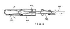
図1に示すように、本開示の例示的な実施形態にかかるクリップ装置100は、内部、例えば、処置されるべき標的組織に内視鏡のワーキングチャンネル内を貫通して生体内に挿入される遠位部102を備える。装置100は、装置が体内の蛇行路を通過する(例えば、生来の身体開口部を介してアクセスされる生来の体管腔内に挿入される内視鏡のワーキングチャンネル内を進行する)ことを許容するのに十分な可撓性を備える。遠位部102は、カプセル108の長手方向チャンネル106内に摺動可能に受承される、第1,第2のクリップアーム104を含む。両クリップアーム104は、これら遠位端110が互いに離間され、両者間に標的組織を受承する開いた姿勢と、両クリップアーム104の遠位端110が互いに接近され、標的組織を把持する閉じた姿勢との間で移動させることができる。遠位部102は、装置100の近位部112に着脱可能に連結され、装置100は搬送システムを含み、搬送システムは制御部材114と、連結部材124と、ハンドル(図示せず)とを備え、ハンドルは、遠位部102が配備された際、装置使用者がアクセス可能なように体外に留まる。クリップアーム104は、カプセル108内に延びる制御部材114を介して、開いた姿勢と閉じた姿勢との間で移動させることができる。制御部材114の近位端は、ハンドルでアクチュエータに接続される。この実施形態では、制御部材の遠位端116は、例えば成形されたコア部材などの連結部材124を用いてクリップアーム104の近位端118に連結され、アーム104の近位部材120が連結部124の面で湾曲された時、アーム104の湾曲は、開いた組織受け入れ姿勢に向かう付勢力を発生させる。 As shown in FIG. 1, the
図1にさらに示すように、装置100は、本開示の例示的な実施形態によれば、クリップアーム104を含み、クリップアーム104はそれぞれ、近位端118から遠位端110に延びる。この実施形態のクリップアーム104は、開いた組織受け入れ姿勢に向かって付勢されているため、カプセル108の外側に遠位方向に移動された時、開いた組織受け入れ姿勢に戻ることは、当業者であれば理解できる。しかしながら、ギア機構、カム接続、追加の付勢部材など、クリップを開くために他の任意の機構を使用できることは、当業者であれば理解できる。組織受け入れ姿勢では、クリップアーム104の遠位端110は、互いに離間する方向に広がり、組織を受承する空間を形成する。しかしながら、装置100は、付勢に加えて又は付勢に代えて、アーム104を互いに離間させるように押圧する別個の部材を含んでもよいことは、当業者であれば理解できる。クリップアーム104がカプセル108内に引き込まれた時、カプセル108はクリップアーム104を拘束し、クリップアームの遠位端118は、ともに引かれて組織クリップ姿勢に保持され、クリップアームは間に捕捉した組織を把持する。この実施形態では、クリップアーム104の近位端118は、連結部材124に連結される。例示的な実施形態では、クリップアーム104の遠位端118は、連結部材124と一体形成される。しかしながら、本発明の範囲から逸脱することなく、クリップアセンブリ(例えば、クリップアームを含むカプセル)を挿入装置に着脱可能に連結するための様々な任意の公知の機構を使用できることは、当業者であれば理解できる。クリップアーム104は、間に組織の把持し易くするように構成された任意の把持要素を含み得る。例えば、クリップアーム104の遠位端110は、互いに向かって横方向内方に延びる先端、及び/又は歯、突起、スパイク、又はクリップアーム104の遠位端110間に組織を把持する別の構造を含んでもよい。 As further shown in FIG. 1, the
図1〜3に示す本開示の例示的な実施形態に係るクリップアーム104は、互いに着脱可能に連結された近位部材120と遠位部材122とを有する。特には、アーム104の近位部材120は、近位端118から遠位端126まで延び、遠位部材122は、遠位部材の近位端128から遠位端110まで延びる。近位部材120及び遠位部材122は、連結された時、任意の公知のクリップアームとほぼ同一形状及び長さを有し得る。近位部材120の遠位湾曲部121は、クリップアーム104の遠位部材122の近位湾曲部123の外面に沿って適合するような寸法と形状とで形成され、湾曲部121は、遠位部材122の湾曲部123にほぼ対応する。 The
近位部材120は、長手方向スロット132を画定する対向部材144を介して遠位部材122のフック130に連結される。長手方向ロット132は、近位部材120の遠位端126の遠位開口部134から近位部材120の長手方向軸に沿ってスロット132の近位部136まで延び、スロット132の近位部136は、カプセル108のカム138を受承する寸法と形状とに形成される。スロット132は、フック130を受承するような寸法及び形状に形成された近位部136の遠位に配置されたフック受容空間140を含む。遠位開口部134とフック受容空間140との間に延びるスロット132の遠位部142の断面積(例えば、直径)は、フック受容空間140の断面積よりも小さい。対向部材144は広げられてフック130を受承することが可能であり、互いに向かって付勢されているため、フック130が近位方向にフック受容空間140内に入ると、対向部材144は跳ね返ってフック144をフック受容空間140にロックし、クリップアーム104の近位部材120と遠位部材122とを互いに連結する。フック受容空間140とスロット132の近位部136との間に延びるスロット132の中間部143の断面積(例えば、直径)は、スロット136の近位部の断面積よりも小さい。図2に示すように、スロット132の近位部136の遠位端135は、スロット132の中間部143に向かって先細りにされ、スロット132の外側にカプセルのカム138を案内する。以下でさらに詳細に説明するが、対向部材144は、カム138がテーパ状の遠位端135内を通過して近位方向に移動させられた際に広げられ、カム138をスロット132及びアーム104の近位部材120から離脱する。カム138がスロット132内を通ってスムーズに移動可能にするために、フック受容空間140の長さは、カム138の直径よりも短い。 The
上記のように、遠位部材122は、遠位部材122の外面から遠位方向に延びるフック130を含む。フック130は、フック受容空間140内に収容され、アーム104の近位部材120と遠位部材122を遠位部材122に連結する。アーム104の遠位部材122は、一対の対向部材148であって、遠位部材122の長手方向軸に沿って遠位部材122の近位端128の近位開口部152からカプセル108のカム138を受承する寸法と形状とに形成されたスロットの遠位部154まで延びる長手方向スロット150を画定する一対の対向部材148を含む。図2に示すように、近位開口部152は、カプセルのカム138をスロット150の中に案内するために、近位端128からスロット150のネック部156まで先細りしている。対向部材148は、カム138の断面積よりも小さな断面積(例えば、直径)を有するスロット150のネック部156を画定する。対向部材148は、以下で詳細に説明するが、広げられてカムを受承することができ、互いに向かって付勢されている為、カム138が遠位方向にスロット150内に入ると、対向部材148は跳ね返ってカム138を長手方向スロット150にロックし、遠位部材122を組織クリップ姿勢でカプセル108にロックする。 As described above, the
この実施形態によれば、遠位部材122のフック130は、近位部材120の遠位開口部134を介して近位部材のスロット132内に挿入される。フック130が所定の閾値よりも大きな力で近位部材120の中に遠位方向に押された時、スロット132の対向部材144は変形して、フック130はその内部を通過してスロットのフック受容空間140に入ることができる。言い換えると、対向部材144は、フック130が遠位開口部134内を近位方向に通過してフック受容空間140内に移動することを可能な程度に十分な距離だけ互いに離間されている。フック130がフック受容空間140内に受承されると、遠位開口部134は元の寸法に戻って、フック130をフック受容空間140にロックする。フック130がフック受容空間140内に受承されると、フック130は、フック受容空間140の遠位壁によりフック受容空間140の外側に遠位方向に移動することが防止される。 According to this embodiment, the
図1に戻る。カプセル108は、近位端から遠位端まで延び、内部を貫通して長手方向に延びるチャンネル106を含む。チャンネル106は、内部にクリップアーム104の一部を摺動可能に受承するような寸法及び形状に形成される。上記のように、カプセル108は、カプセル108の第1の側壁からカプセル108の第2の対向する側壁までチャンネルの長手方向軸に直交して、チャンネル106の中間部を横切って延びるカム138を含む。カム138は略円筒形であり、この実施形態では、クリップアーム104の近位部材120及び遠位部材122の長手方向スロット132、150内に受承されるような寸法及び形状に形成される。しかしながら、カム138は、カム138が対向部材144,148を介してスロット132,150の中に受承される寸法で形成されていれば、任意の断面形状(すなわち、正方形、三角形、楕円形)を有してもよいことは、当業者であれば理解できる。以下でさらに詳細に説明するが、カプセル108は、クリップが離脱する工程で、近位部材120の対向部材144がカム138の周りを通過可能にする一対の直径方向に対向するウインドウ160をさらに含む。クリップアーム104の近位部材120は、クリップ100の配備後に、クリップアーム104の遠位部材122から離脱されて体内から除去されるため、カプセル108は、クリップアーム104の遠位部材122をクリップ姿勢に維持するのに十分な長ささえあればよい。したがって、この実施形態では、カプセル108は、標準的なクリップカプセルよりも長さが実質的に短い。例えば本願のカプセルは、一般には長さが約0.40から0.43である標準的なカプセルと比較して、長さが約0.19から0.22であってよい。 Return to FIG.
体内に挿入する前のクリップ100の初期構成を図1に示す。この構成では、クリップアームの近位部材120及び遠位部材122は、上記のように互いに連結される。さらに、近位部材120は、カプセル108内に配置され、カム138は、長手方向スロット132の長手方向軸に直交する方向に長手方向スロット132内を通過して延びる。近位部材120の近位端118は、カプセル108の外側に近位方向に延びて、装置100の近位部112の連結部材124及び制御部材114に連結される。 The initial configuration of the
使用時には、クリップ100は内視鏡(又は他の挿入装置)のワーキングチャンネル内を貫通して挿入され、体内に(例えば、自然な体腔を通して)クリップされるべき組織の標的部位の隣接する部位まで挿入される。クリップ100は、ワーキングチャンネル内の進行を容易にする為に挿入姿勢で標的組織に挿入される。標的組織部位に到達すると、クリップ100はワーキングチャンネル106の遠位端の外側に進行されて、クリップアーム104はカプセル108の外側に延ばされて、クリップアーム104は組織受け入れ姿勢に移動される。標的組織がクリップアーム104の間に受承されると、クリップ100は、組織クリップ姿勢に向かって移動され、標的組織は、その遠位端110の間に把持される。クリップアーム104は、制御部材114をカプセル108に対して近位方向に引くことにより組織クリップ姿勢に向かって移動される。クリップ100が組織クリップ姿勢になったら、制御部材114をさらに近位に引いて、クリップアーム104をカプセル108にロックすることができる。具体的には、制御部材114を近位方向に引くと、クリップアーム104の近位部材120及び遠位部材122は近位に引かれ、カムは、図4,5に示すようにクリップアーム104の遠位部材122の対向部材148に当接するまで、近位部材120の長手方向スロット132内を通過して遠位方向に移動される。制御部材をさらに近位方向に引くと、対向部材148のテーパ端により、カムは、遠位部材122の近位開口部152内を通過して長手方向スロット150内に移動することができる。カム138が遠位方向にスロット150内に入ると、対向部材148が跳ね返ってカムを長手方向スロット150内にロックし、図5に示すように、遠位部材122を組織クリップ姿勢でカプセル108にロックする。 In use, the
クリップ100を配備するために、制御部材114は、図6に示すように、カム138が長手方向軸スロットの近位部136の遠位テーパ端135に当接するまで、さらに近位方向に引かれる。図7に示すように、スロット132の遠位テーパ端135により、近位部材120はさらに近位方向に移動することが可能となり、フック130がフック受容空間140から離脱されるまで、近位部材120の対向部材144は互いに離間する方向に広げられる。対向部材144が離間する方向に広げられる際、カプセル108のウインドウ160は、対向部材144がカム138の周囲を移動するのに必要な空間を形成する。このようにして、近位部材120及び遠位部材122は、互いに分離され、遠位部材122及びカプセル108は体内に留置され、近位部112(すなわち、連結部材124、制御部材114など)及び取り付けられた近位部材120は、図8に示すように体内から除去される。 To deploy the
本発明の概念から逸脱することなく上記実施形態を変更できることは、当業者であれば理解できる。さらに、実施形態の1つに関連する構造的な特徴及び方法は、他の実施形態に組み込むことができることも理解できる。したがって、本発明は、説明した特定の実施形態に限定されず、変更形態も添付の請求項によって定義される本発明の範囲内に含まれることが理解できる。 Those skilled in the art will understand that the above embodiments can be modified without departing from the concept of the present invention. Further, it can be understood that the structural features and methods associated with one of the embodiments can be incorporated into the other embodiments. Therefore, it can be understood that the present invention is not limited to the specific embodiment described, and the modified form is also included in the scope of the present invention as defined by the appended claims.
Claims (15)
Translated fromJapanese遠位部材に着脱可能に連結される近位部材を含む第1のクリップアーム及び第2のクリップアームと、前記第1のクリップアーム及び前記第2のクリップアームの前記遠位部材の少なくとも近位部は、前記カプセルのチャンネル内に摺動可能に受承されて、前記第1のクリップアーム及び前記第2のクリップアームは、前記第1のクリップアームの遠位端及び前記第2のクリップアームの遠位端が互いに離間した組織受け入れ姿勢と、前記第1のクリップアームの遠位端及び前記第2のクリップアームの遠位端が互いに接近した組織クリップ姿勢との間で前記カプセルに対して近位方向又は遠位方向に移動されることと、前記第1のクリップアーム及び前記第2のクリップアームの近位部材は、対応する特定の前記遠位部材から離脱されて前記第1のクリップアーム及び前記第2のクリップアームの前記遠位部材を挟持されるべき標的組織の一部にロックして、前記第1のクリップアーム及び前記第2のクリップアームの前記近位部材は、体内から除去可能に構成したことと
を備える、組織を処置する為の装置。Capsules that form channels that extend through the interior,
A first clip arm and a second clip arm including a proximal member detachably connected to a distal member, and at least proximal to the distal member of the first clip arm and the second clip arm. The portion is slidably received within the channel of the capsule, the first clip arm and the second clip arm being the distal end of the first clip arm and the second clip arm. With respect to the capsule between the tissue receiving posture in which the distal ends of the first clip arm are separated from each other and the tissue clip posture in which the distal ends of the first clip arm and the distal ends of the second clip arm are close to each other. Being moved proximally or distally, the first clip arm and the proximal member of the second clip arm are detached from the corresponding particular distal member and said first clip. The arm and the distal member of the second clip arm are locked to a portion of the target tissue to be clamped so that the first clip arm and the proximal member of the second clip arm are from within the body. A device for treating tissue, with a removable configuration.
内部を貫通して延びるルーメンを備える挿入部材と、
前記挿入部材のルーメン内を貫通して延びる制御部材であって、連結部材に連結される前記制御部材の遠位端と、装置使用者にアクセス可能にされたアクチュエータに連結される前記制御部材の近位端とを備え、前記アクチュエータの駆動により前記制御部材及び前記連結部材は前記挿入部材に対して遠位又は近位に移動される前記制御部材と、
前記連結部材に連結されるクリップと
を備え、前記クリップは、
前記挿入部材の遠位端に着脱可能に連結される近位端を備えるカプセルであって、内部を貫通して延びるチャンネルを形成する前記カプセルと、
遠位部材に着脱可能に連結される近位部材を含む第1のクリップアーム及び第2のクリップアームと、を備え、前記第1のクリップアーム及び前記第2のクリップアームの前記遠位部材の少なくとも近位部は、前記カプセルのチャンネル内に摺動可能に受承され、前記アクチュエータの駆動により前記制御部材及び前記連結部材が前記挿入部材に対して近位又は遠位に移動された時、前記第1のクリップアーム及び前記第2のクリップアームは、前記第1のクリップアーム及び前記第2のクリップアームの遠位端が互いに離間した組織受け入れ姿勢と、前記第1のクリップアーム及び前記第2のクリップアームの遠位端が互いに接近した組織クリップ姿勢との間で前記カプセルに対して近位又は遠位に移動され、前記第1のクリップアーム及び前記第2のクリップアームの前記近位部材は、対応する特定の前記遠位部材から離脱されて前記第1のクリップアーム及び前記第2のクリップアームの前記遠位部材をクリップされるべき標的組織の一部にロックし、前記第1のクリップアーム及び前記第2のクリップアームの前記近位部材は、体内から除去される、組織をクリップする為のシステム。The system for clipping tissue is
An insertion member with a lumen that extends through the interior,
A control member extending through the lumen of the insertion member, the distal end of the control member connected to the connecting member, and the control member connected to an actuator made accessible to the device user. With the control member having a proximal end, the control member and the connecting member are moved distally or proximally to the insertion member by driving the actuator.
The clip comprises a clip that is connected to the connecting member.
A capsule having a proximal end detachably connected to the distal end of the insertion member, the capsule forming a channel extending through the interior.
A first clip arm and a second clip arm including a proximal member detachably connected to the distal member, the distal member of the first clip arm and the second clip arm. At least the proximal portion is slidably received within the channel of the capsule, and when the control member and the connecting member are moved proximal or distal to the insertion member by the drive of the actuator. The first clip arm and the second clip arm have a tissue receiving posture in which the distal ends of the first clip arm and the second clip arm are separated from each other, and the first clip arm and the first clip arm. The distal ends of the two clip arms are moved proximal or distal to the capsule between the tissue clip postures in close proximity to each other, and the proximal of the first clip arm and the second clip arm. The member disengages from the corresponding particular distal member and locks the distal member of the first clip arm and the second clip arm to a portion of the target tissue to be clipped, said first. The clip arm and the proximal member of the second clip arm are removed from the body, a system for clipping tissue.
Priority Applications (2)
| Application Number | Priority Date | Filing Date | Title |
|---|---|---|---|
| JP2022031384AJP7477548B2 (en) | 2018-01-29 | 2022-03-02 | Hemostatic clip |
| JP2024067385AJP2024083610A (en) | 2018-01-29 | 2024-04-18 | Hemostatic clip |
Applications Claiming Priority (3)
| Application Number | Priority Date | Filing Date | Title |
|---|---|---|---|
| US201862623282P | 2018-01-29 | 2018-01-29 | |
| US62/623,282 | 2018-01-29 | ||
| PCT/US2019/014160WO2019147485A1 (en) | 2018-01-29 | 2019-01-18 | Hemostasis clip |
Related Child Applications (1)
| Application Number | Title | Priority Date | Filing Date |
|---|---|---|---|
| JP2022031384ADivisionJP7477548B2 (en) | 2018-01-29 | 2022-03-02 | Hemostatic clip |
Publications (2)
| Publication Number | Publication Date |
|---|---|
| JP2021508531Atrue JP2021508531A (en) | 2021-03-11 |
| JP7035200B2 JP7035200B2 (en) | 2022-03-14 |
Family
ID=65279785
Family Applications (3)
| Application Number | Title | Priority Date | Filing Date |
|---|---|---|---|
| JP2020535561AActiveJP7035200B2 (en) | 2018-01-29 | 2019-01-18 | Hemostasis clip |
| JP2022031384AActiveJP7477548B2 (en) | 2018-01-29 | 2022-03-02 | Hemostatic clip |
| JP2024067385APendingJP2024083610A (en) | 2018-01-29 | 2024-04-18 | Hemostatic clip |
Family Applications After (2)
| Application Number | Title | Priority Date | Filing Date |
|---|---|---|---|
| JP2022031384AActiveJP7477548B2 (en) | 2018-01-29 | 2022-03-02 | Hemostatic clip |
| JP2024067385APendingJP2024083610A (en) | 2018-01-29 | 2024-04-18 | Hemostatic clip |
Country Status (7)
| Country | Link |
|---|---|
| US (3) | US11071552B2 (en) |
| EP (2) | EP3745966B1 (en) |
| JP (3) | JP7035200B2 (en) |
| CN (2) | CN111655172B (en) |
| AU (1) | AU2019212055B2 (en) |
| CA (1) | CA3084157C (en) |
| WO (1) | WO2019147485A1 (en) |
Families Citing this family (18)
| Publication number | Priority date | Publication date | Assignee | Title |
|---|---|---|---|---|
| EP3745966B1 (en)* | 2018-01-29 | 2025-09-10 | Boston Scientific Scimed, Inc. | Hemostasis clip |
| JP7247218B2 (en)* | 2018-12-11 | 2023-03-28 | オリンパス株式会社 | How to release medical devices and clip units |
| US11234707B2 (en)* | 2019-01-22 | 2022-02-01 | Beijing Donglin Fushi Medical Devices Co., Ltd. | Disposable hemostatic clip system |
| EP4505967A3 (en)* | 2019-05-28 | 2025-05-07 | Boston Scientific Scimed Inc. | Hemostasis clip deployment |
| ES2939069T3 (en)* | 2019-07-24 | 2023-04-18 | Boston Scient Scimed Inc | Two-stage deployment mechanism of hemostat to remove detached parts |
| JP7261897B2 (en)* | 2019-11-01 | 2023-04-20 | オリンパス株式会社 | clip device |
| CA3156881A1 (en) | 2019-11-01 | 2021-05-06 | Doug SJOSTROM | Devices and methods for applying a hemostatic clip assembly |
| CN115103641A (en) | 2019-11-01 | 2022-09-23 | 康美公司 | Apparatus and method for applying a hemostatic clip assembly |
| JP7508490B2 (en)* | 2020-02-04 | 2024-07-01 | オリンパス株式会社 | Ligation Device |
| WO2021210091A1 (en)* | 2020-04-15 | 2021-10-21 | オリンパス株式会社 | Treatment device |
| CN111421752B (en)* | 2020-04-20 | 2025-03-25 | 江苏造裕智能装备有限公司 | Pipe fitting insertion and extraction fixture |
| CN116710000A (en)* | 2021-01-13 | 2023-09-05 | 杭州安杰思医学科技股份有限公司 | Clip device, clip instrument and clip unlocking method |
| CN118119352A (en)* | 2021-09-30 | 2024-05-31 | 杭州安杰思医学科技股份有限公司 | Clip apparatus |
| EP4415631A1 (en)* | 2022-03-07 | 2024-08-21 | Boston Scientific Medical Device Limited | Repositional over the scope clip with frangible link |
| CN115399831B (en)* | 2022-08-31 | 2025-07-22 | 宁波新跃医疗科技股份有限公司 | Insertion type tissue clamping device |
| JP2025517539A (en)* | 2022-09-27 | 2025-06-05 | ボストン サイエンティフィック サイムド,インコーポレイテッド | Locking mechanism for hemostatic clips |
| CN116919512B (en)* | 2023-08-03 | 2024-08-27 | 江苏唯德康医疗科技有限公司 | Tissue clamping device |
| CN117860333A (en)* | 2023-12-06 | 2024-04-12 | 海川医疗供应链(深圳)有限公司 | Detachable titanium clamp assembly and use method |
Citations (4)
| Publication number | Priority date | Publication date | Assignee | Title |
|---|---|---|---|---|
| WO2003053256A1 (en)* | 2001-12-13 | 2003-07-03 | Sumitomo Bakelite Company Limited | Clip device for endoscope and clip for endoscope for use therein |
| JP2005525904A (en)* | 2002-05-20 | 2005-09-02 | アイディー エルエルシー | Surgical clip especially useful for laparoscopic treatment of gastroesophageal reflux disease (GERD) |
| JP2009273677A (en)* | 2008-05-15 | 2009-11-26 | Sumitomo Bakelite Co Ltd | Clip |
| US20150190136A1 (en)* | 2009-08-19 | 2015-07-09 | Boston Scientific Scimed, Inc. | Multifunctional Core for Two-Piece Hemostasis Clip |
Family Cites Families (19)
| Publication number | Priority date | Publication date | Assignee | Title |
|---|---|---|---|---|
| US7727246B2 (en)* | 2000-12-06 | 2010-06-01 | Ethicon Endo-Surgery, Inc. | Methods for endoluminal treatment |
| US7494461B2 (en)* | 2003-09-30 | 2009-02-24 | Boston Scientific Scimed, Inc. | Through the scope tension member release clip |
| EP1670365B1 (en)* | 2003-09-30 | 2018-12-05 | Boston Scientific Scimed, Inc. | Apparatus for deployment of a hemostatic clip |
| JP5246394B2 (en) | 2007-11-28 | 2013-07-24 | 住友ベークライト株式会社 | Clip, clip unit and clip device |
| EP3061413B1 (en)* | 2008-06-19 | 2022-01-19 | Boston Scientific Scimed, Inc. | Tissue clipping apparatus |
| US9005219B2 (en)* | 2009-08-19 | 2015-04-14 | Boston Scientific Scimed, Inc. | Multifunctional core for two-piece hemostasis clip |
| BR112013008763B1 (en) | 2010-10-11 | 2021-02-17 | Cook Medical Technologies LLC. | medical device for engaging a tissue |
| JP5681814B2 (en)* | 2010-12-15 | 2015-03-11 | クック メディカル テクノロジーズ エルエルシーCook Medical Technologies Llc | Medical device with removable pivotable jaws |
| EP2755576B1 (en) | 2011-09-15 | 2019-05-22 | Teleflex Medical Incorporated | Automatic surgical ligation clip applier |
| JP5343113B2 (en) | 2011-09-15 | 2013-11-13 | 富士フイルム株式会社 | Clip unit and ligating apparatus using the same |
| JP5427857B2 (en)* | 2011-09-15 | 2014-02-26 | 富士フイルム株式会社 | Clip unit, ligating apparatus using the same, and manufacturing method of clip unit |
| US9138234B2 (en)* | 2011-11-14 | 2015-09-22 | Anrei Medical (Hz) Co., Ltd. | Clip apparatus for ligature of living tissue |
| CN102626335B (en) | 2012-04-16 | 2014-04-09 | 常州市久虹医疗器械有限公司 | Hemostatic clamp with four-bar structure |
| US9358008B2 (en) | 2012-04-30 | 2016-06-07 | Zsx Medical, Llc | Surgical device |
| JP5480454B1 (en) | 2012-07-20 | 2014-04-23 | オリンパスメディカルシステムズ株式会社 | Hemostatic clip |
| US9877732B2 (en)* | 2014-07-01 | 2018-01-30 | Boston Scientific Scimed, Inc. | Hemostatic clip with needle passer |
| US10470775B2 (en)* | 2015-10-23 | 2019-11-12 | Hangzhou Ags Medtech Co., Ltd. | Ligation device |
| CN206714786U (en) | 2016-10-28 | 2017-12-08 | 上海威尔逊光电仪器有限公司 | A kind of clamping device |
| EP3745966B1 (en)* | 2018-01-29 | 2025-09-10 | Boston Scientific Scimed, Inc. | Hemostasis clip |
- 2019
- 2019-01-18EPEP19703573.6Apatent/EP3745966B1/enactiveActive
- 2019-01-18JPJP2020535561Apatent/JP7035200B2/enactiveActive
- 2019-01-18CNCN201980010473.0Apatent/CN111655172B/enactiveActive
- 2019-01-18WOPCT/US2019/014160patent/WO2019147485A1/ennot_activeCeased
- 2019-01-18EPEP25193630.8Apatent/EP4631444A2/enactivePending
- 2019-01-18CACA3084157Apatent/CA3084157C/enactiveActive
- 2019-01-18AUAU2019212055Apatent/AU2019212055B2/enactiveActive
- 2019-01-18CNCN202410192984.1Apatent/CN118021380A/enactivePending
- 2019-01-18USUS16/251,399patent/US11071552B2/enactiveActive
- 2021
- 2021-06-22USUS17/304,525patent/US12023038B2/enactiveActive
- 2022
- 2022-03-02JPJP2022031384Apatent/JP7477548B2/enactiveActive
- 2024
- 2024-04-18JPJP2024067385Apatent/JP2024083610A/enactivePending
- 2024-05-29USUS18/677,410patent/US20240307068A1/enactivePending
Patent Citations (4)
| Publication number | Priority date | Publication date | Assignee | Title |
|---|---|---|---|---|
| WO2003053256A1 (en)* | 2001-12-13 | 2003-07-03 | Sumitomo Bakelite Company Limited | Clip device for endoscope and clip for endoscope for use therein |
| JP2005525904A (en)* | 2002-05-20 | 2005-09-02 | アイディー エルエルシー | Surgical clip especially useful for laparoscopic treatment of gastroesophageal reflux disease (GERD) |
| JP2009273677A (en)* | 2008-05-15 | 2009-11-26 | Sumitomo Bakelite Co Ltd | Clip |
| US20150190136A1 (en)* | 2009-08-19 | 2015-07-09 | Boston Scientific Scimed, Inc. | Multifunctional Core for Two-Piece Hemostasis Clip |
Also Published As
| Publication number | Publication date |
|---|---|
| JP7477548B2 (en) | 2024-05-01 |
| AU2019212055B2 (en) | 2021-04-29 |
| US20240307068A1 (en) | 2024-09-19 |
| US11071552B2 (en) | 2021-07-27 |
| US12023038B2 (en) | 2024-07-02 |
| CN111655172A (en) | 2020-09-11 |
| JP2024083610A (en) | 2024-06-21 |
| CA3084157A1 (en) | 2019-08-01 |
| US20190231353A1 (en) | 2019-08-01 |
| CN118021380A (en) | 2024-05-14 |
| AU2019212055A1 (en) | 2020-06-18 |
| WO2019147485A1 (en) | 2019-08-01 |
| JP2022066329A (en) | 2022-04-28 |
| JP7035200B2 (en) | 2022-03-14 |
| CA3084157C (en) | 2023-05-09 |
| CN111655172B (en) | 2024-03-12 |
| EP3745966B1 (en) | 2025-09-10 |
| EP4631444A2 (en) | 2025-10-15 |
| EP3745966A1 (en) | 2020-12-09 |
| US20210307755A1 (en) | 2021-10-07 |
Similar Documents
| Publication | Publication Date | Title |
|---|---|---|
| JP7035200B2 (en) | Hemostasis clip | |
| JP7059335B2 (en) | Remountable hemostatic clip device with engagement on sleeve | |
| JP7055842B2 (en) | Multiple means of opening and closing remountable clips | |
| JP7146876B2 (en) | Capsule for reloadable hemostatic clip device having a partial elliptical shape | |
| EP3016598B1 (en) | Suturing devices for suturing an anatomic structure | |
| KR20210020089A (en) | Aggressive clip with improved tissue retention | |
| US11129623B2 (en) | Dual support jaw design | |
| WO2019067149A1 (en) | Reloadable and rotatable clip | |
| US12076015B2 (en) | Hemostasis clip short system | |
| US20250302475A1 (en) | Multiple hemostasis clip system | |
| JP2025530452A (en) | Backside anastomosis closure clip |
Legal Events
| Date | Code | Title | Description |
|---|---|---|---|
| A621 | Written request for application examination | Free format text:JAPANESE INTERMEDIATE CODE: A621 Effective date:20200625 | |
| A977 | Report on retrieval | Free format text:JAPANESE INTERMEDIATE CODE: A971007 Effective date:20210629 | |
| A131 | Notification of reasons for refusal | Free format text:JAPANESE INTERMEDIATE CODE: A131 Effective date:20210713 | |
| A521 | Request for written amendment filed | Free format text:JAPANESE INTERMEDIATE CODE: A523 Effective date:20211012 | |
| TRDD | Decision of grant or rejection written | ||
| A01 | Written decision to grant a patent or to grant a registration (utility model) | Free format text:JAPANESE INTERMEDIATE CODE: A01 Effective date:20220201 | |
| A61 | First payment of annual fees (during grant procedure) | Free format text:JAPANESE INTERMEDIATE CODE: A61 Effective date:20220302 | |
| R150 | Certificate of patent or registration of utility model | Ref document number:7035200 Country of ref document:JP Free format text:JAPANESE INTERMEDIATE CODE: R150 | |
| R250 | Receipt of annual fees | Free format text:JAPANESE INTERMEDIATE CODE: R250 |