JP2021506668A - Marine surface drones and methods for characterizing the underwater environment carried out by such drones - Google Patents
Marine surface drones and methods for characterizing the underwater environment carried out by such dronesDownload PDFInfo
- Publication number
- JP2021506668A JP2021506668AJP2020533672AJP2020533672AJP2021506668AJP 2021506668 AJP2021506668 AJP 2021506668AJP 2020533672 AJP2020533672 AJP 2020533672AJP 2020533672 AJP2020533672 AJP 2020533672AJP 2021506668 AJP2021506668 AJP 2021506668A
- Authority
- JP
- Japan
- Prior art keywords
- drone
- transmission
- marine
- sonar
- fish
- Prior art date
- Legal status (The legal status is an assumption and is not a legal conclusion. Google has not performed a legal analysis and makes no representation as to the accuracy of the status listed.)
- Pending
Links
Images


Classifications
- G—PHYSICS
- G05—CONTROLLING; REGULATING
- G05D—SYSTEMS FOR CONTROLLING OR REGULATING NON-ELECTRIC VARIABLES
- G05D1/00—Control of position, course, altitude or attitude of land, water, air or space vehicles, e.g. using automatic pilots
- G05D1/02—Control of position or course in two dimensions
- G05D1/0206—Control of position or course in two dimensions specially adapted to water vehicles
- G—PHYSICS
- G01—MEASURING; TESTING
- G01S—RADIO DIRECTION-FINDING; RADIO NAVIGATION; DETERMINING DISTANCE OR VELOCITY BY USE OF RADIO WAVES; LOCATING OR PRESENCE-DETECTING BY USE OF THE REFLECTION OR RERADIATION OF RADIO WAVES; ANALOGOUS ARRANGEMENTS USING OTHER WAVES
- G01S15/00—Systems using the reflection or reradiation of acoustic waves, e.g. sonar systems
- G01S15/88—Sonar systems specially adapted for specific applications
- G01S15/96—Sonar systems specially adapted for specific applications for locating fish
- G—PHYSICS
- G01—MEASURING; TESTING
- G01S—RADIO DIRECTION-FINDING; RADIO NAVIGATION; DETERMINING DISTANCE OR VELOCITY BY USE OF RADIO WAVES; LOCATING OR PRESENCE-DETECTING BY USE OF THE REFLECTION OR RERADIATION OF RADIO WAVES; ANALOGOUS ARRANGEMENTS USING OTHER WAVES
- G01S15/00—Systems using the reflection or reradiation of acoustic waves, e.g. sonar systems
- G01S15/88—Sonar systems specially adapted for specific applications
- G01S15/89—Sonar systems specially adapted for specific applications for mapping or imaging
- G—PHYSICS
- G01—MEASURING; TESTING
- G01S—RADIO DIRECTION-FINDING; RADIO NAVIGATION; DETERMINING DISTANCE OR VELOCITY BY USE OF RADIO WAVES; LOCATING OR PRESENCE-DETECTING BY USE OF THE REFLECTION OR RERADIATION OF RADIO WAVES; ANALOGOUS ARRANGEMENTS USING OTHER WAVES
- G01S7/00—Details of systems according to groups G01S13/00, G01S15/00, G01S17/00
- G01S7/52—Details of systems according to groups G01S13/00, G01S15/00, G01S17/00 of systems according to group G01S15/00
- G01S7/523—Details of pulse systems
- G01S7/524—Transmitters
- G—PHYSICS
- G01—MEASURING; TESTING
- G01S—RADIO DIRECTION-FINDING; RADIO NAVIGATION; DETERMINING DISTANCE OR VELOCITY BY USE OF RADIO WAVES; LOCATING OR PRESENCE-DETECTING BY USE OF THE REFLECTION OR RERADIATION OF RADIO WAVES; ANALOGOUS ARRANGEMENTS USING OTHER WAVES
- G01S7/00—Details of systems according to groups G01S13/00, G01S15/00, G01S17/00
- G01S7/52—Details of systems according to groups G01S13/00, G01S15/00, G01S17/00 of systems according to group G01S15/00
- G01S7/523—Details of pulse systems
- G01S7/526—Receivers
- G01S7/527—Extracting wanted echo signals
- G01S7/5273—Extracting wanted echo signals using digital techniques
- G—PHYSICS
- G05—CONTROLLING; REGULATING
- G05D—SYSTEMS FOR CONTROLLING OR REGULATING NON-ELECTRIC VARIABLES
- G05D1/00—Control of position, course, altitude or attitude of land, water, air or space vehicles, e.g. using automatic pilots
- G05D1/0094—Control of position, course, altitude or attitude of land, water, air or space vehicles, e.g. using automatic pilots involving pointing a payload, e.g. camera, weapon, sensor, towards a fixed or moving target
- G—PHYSICS
- G06—COMPUTING OR CALCULATING; COUNTING
- G06T—IMAGE DATA PROCESSING OR GENERATION, IN GENERAL
- G06T7/00—Image analysis
- G06T7/70—Determining position or orientation of objects or cameras
Landscapes
- Engineering & Computer Science (AREA)
- Radar, Positioning & Navigation (AREA)
- Remote Sensing (AREA)
- Physics & Mathematics (AREA)
- General Physics & Mathematics (AREA)
- Computer Networks & Wireless Communication (AREA)
- Acoustics & Sound (AREA)
- Aviation & Aerospace Engineering (AREA)
- Automation & Control Theory (AREA)
- Theoretical Computer Science (AREA)
- Computer Vision & Pattern Recognition (AREA)
- Measurement Of Velocity Or Position Using Acoustic Or Ultrasonic Waves (AREA)
- Control Of Position, Course, Altitude, Or Attitude Of Moving Bodies (AREA)
Abstract
Translated fromJapaneseDescription
Translated fromJapanese本発明は、一般に、自律的に、又は遠隔制御を介して移動するように適合された無人船に関する。 The present invention generally relates to unmanned vessels adapted to move autonomously or via remote control.
本発明はまた、水中環境を探索するための方法に関する。 The present invention also relates to methods for exploring the underwater environment.
現在、「海洋面ドローン」又は「ドローン船」とも呼ばれる、自律的に、又は遠隔制御を介して移動するように適合された無人船が、強力に開発されている。 Currently, unmanned aerial vehicles, also called "marine drones" or "drone vessels," are being strongly developed that are adapted to move autonomously or via remote control.
「無人水面車両」とも呼ばれるそのような海洋ドローンは、パイロットの生命を危険にさらすのを防ぐため、特に軍事用に使用される。 Such marine drones, also known as "unmanned surface vehicles," are used specifically for military purposes to prevent endangering the lives of pilots.
それらはまた、その移動性により、固定観察ブイよりも海洋環境のより完全な特性化を可能にするために、海洋学目的に使用される。更に、そのようなドローンを用いて一連の観察を行うことは、一般に、クルーが操作する従来の探査船を使用するよりも安価である。 They are also used for oceanographic purposes to allow for more complete characterization of the marine environment than fixed observation buoys due to their mobility. Moreover, making a series of observations with such a drone is generally cheaper than using a conventional crew-operated exploration vessel.
そのような海洋面ドローンの下方に位置する水柱の深度を測定したり、又はこの水柱内の魚の存在を検出したりするために、ドローンにシングルビームタイプの、すなわち、単一の、シンプルで軽量の送信機を有するソナーを装備することが知られている。記事「遠洋漁業用の自律水面車両による魚群探知」、R.Haugeら(Oceans 2016 MTS/IEEE Monterey、1〜5頁)には、例えば、帆船のキールの下端に配置されたシングルの低エネルギー消費送信機を装備した、小型の自律型(無人)帆船について記載されている。 To measure the depth of a water column located below such an ocean surface drone, or to detect the presence of fish in this water column, the drone is of a single beam type, ie single, simple and lightweight. It is known to equip a sonar with a transmitter of. Article "Fishfinder by Autonomous Water Vehicle for Deep Sea Fisheries", R.M. Hauge et al. (Oceans 2016 MTS / IEEE Monthly, pp. 1-5) describe, for example, a small autonomous (unmanned) sailing vessel equipped with a single low energy consumer transmitter located at the bottom of the sailboat keel. Has been done.
無人船に(いくつかの送信機及びいくつかの受信機を備える)マルチビームソナーを装備して、船体の長手方向軸に垂直な、したがってこの船の進行方向に垂直な測定線に全て沿って、深度データを取得することもまた知られている。しかしながら、マルチビーム超音波「アンテナ」を設置するためには船体形状を適合させる必要があるため、及びこれによって船のエネルギー消費が大幅に増加するため、マルチビームソナーには、シングルビームソナーを使用するよりもはるかに制約が大きくなる。 The unmanned ship is equipped with a multi-beam sonar (with some transmitters and some receivers), all along the measurement lines perpendicular to the longitudinal axis of the hull and thus perpendicular to the direction of travel of this ship. It is also known to acquire depth data. However, single beam sonar is used for multi-beam sonar because it is necessary to adapt the hull shape in order to install the multi-beam ultrasonic "antenna", and because this significantly increases the energy consumption of the ship. It is much more restrictive than it is.
そのようなマルチビームソナーは、従来、船の長手方向軸に沿って分布した音又は超音波送信機のセットを備える。これらの送信機は、船の長手方向軸に垂直な送信面に含まれる、送信のそれぞれの同一平面上の方向に沿って音波(又は超音波)のセットを送信する。換言すれば、これらの音波は、指向性のある方法で送信され、船の下方、船の真下に延在するシート(「帯」)を一緒に形成する。これらの送信方向は、一般に数十度の開口を有する所与の角度区域をカバーする。ソナーによって送信された音波は、上述の測定ラインに沿って位置する海底の異なるポイントに到達する。海底によって反射した音波を検出するように適合された受信機は、次いで、この測定ラインの異なるポイントに対する深度データを取得することを可能にする。これらの受信機は、船の長手方向軸に垂直なラインに沿ってより正確に配置されており、受信機が受信した信号を組み合わせることによって、測定ラインのどのポイントから所与の後方反射音波が到来するかを判定することを可能にする。 Such multi-beam sonar conventionally comprises a set of sound or ultrasonic transmitters distributed along the longitudinal axis of the ship. These transmitters transmit a set of sound waves (or ultrasonic waves) along their respective coplanar directions of transmission contained in a transmission plane perpendicular to the longitudinal axis of the ship. In other words, these sound waves are transmitted in a directional manner and together form a sheet (“belt”) that extends below the ship, beneath the ship. These transmission directions generally cover a given angular area with an aperture of tens of degrees. Sound waves transmitted by sonar reach different points on the seafloor located along the measurement lines described above. A receiver adapted to detect sound waves reflected by the seafloor then makes it possible to obtain depth data for different points on this measurement line. These receivers are more accurately positioned along a line perpendicular to the longitudinal axis of the ship, and by combining the signals received by the receivers, a given back-reflected sound wave can be obtained from any point on the measurement line. It makes it possible to determine whether it will arrive.
そのような従来のマルチビームソナーは、船が(直線的に)移動するときに、考察される海底の地形を表す2次元画像を、ラインごとに取得することを可能にする。 Such conventional multi-beam sonar makes it possible to obtain line-by-line two-dimensional images representing the seafloor topography considered as the ship moves (linearly).
このコンテキストにおいて、本発明は、オンボードソナーを備える海洋面ドローンであって、ソナーが、第1の軸に沿って配置された複数の音波送信機と、第1の軸と平行ではない第2の軸に沿って配置された複数の音波受信機とを含む、マルチビーム型のソナーである、海洋面ドローンを提案する。 In this context, the present invention is a marine surface drone with on-board sonar in which the sonar is not parallel to the first axis with a plurality of sound wave transmitters located along the first axis. We propose a marine surface drone, which is a multi-beam type sonar, including multiple sound wave receivers arranged along the axis of.
本発明によれば、海洋ドローンは、
−海洋ドローンの所与の位置に対して、複数の連続音波送信を制御するように構成された、ソナーを制御するためのシステムであって、
制御システムが、各送信において、それぞれの複数の送信信号によって異なる送信機を制御し、各送信信号が基準信号に対する振幅及び時間シフトを有し、
制御システムが、所与の送信変動シーケンスに従って、上記複数の送信中に、上記送信信号のそれぞれの振幅又は時間シフトを変化させ、所与の観察ボリュームをカバーする上記複数の送信中に全ての音波が送信される、システムと、
−取得ユニットであって、
−上記各送信に対して、考察される送信に応じて、ソナーの受信機によってキャプチャされたエコー信号を取得し、
−上記複数の送信に応じて取得されたエコー信号から、観察ボリュームの内容を表す3次元画像を判定する、ように構成された取得ユニットと、を更に備える。According to the present invention, the marine drone
-A system for controlling sonar, configured to control multiple continuous sound waves for a given position on a marine drone.
In each transmission, the control system controls different transmitters with each of the plurality of transmission signals, and each transmission signal has an amplitude and time shift with respect to the reference signal.
A control system changes the amplitude or time shift of each of the transmitted signals during the plurality of transmissions according to a given transmission variation sequence, and all sound waves during the plurality of transmissions covering a given observation volume. Is sent, the system and
-Acquisition unit
-For each of the above transmissions, the echo signal captured by the sonar receiver is acquired, depending on the transmission considered.
-It further includes an acquisition unit configured to determine a three-dimensional image representing the contents of the observation volume from the echo signals acquired in response to the plurality of transmissions.
プリアンブルに示されているような従来のマルチビームソナーとは異なり、マルチビームソナーは本発明によるドローンを装備しており、ドローンが移動するという目的を必要とせずに、ドローンの所与の位置から、観察ボリュームの内容を表す3次元画像を取得することが可能である。 Unlike traditional multi-beam sonar as shown in the preamble, the multi-beam sonar is equipped with a drone according to the invention, from a given position on the drone without the purpose of moving the drone. , It is possible to acquire a three-dimensional image showing the contents of the observation volume.
今日、固定された位置から水中環境の3次元画像を判定することを可能にするマルチビームソナーは、その高度レベルの複雑さのために、扱いにくく、重く、エネルギーを消費し、及び時に高価である。したがって、これらの機能により、探査船又は大型漁船に適している。 Today, multi-beam sonar, which makes it possible to determine a three-dimensional image of the underwater environment from a fixed location, is cumbersome, heavy, energy consuming, and sometimes expensive due to its high level of complexity. is there. Therefore, these functions make it suitable for exploration vessels or large fishing vessels.
海洋面ドローンは一般にサイズが小さいが、一方で特に移動性であるため、シングルビームソナー、又は測定ラインに沿って深度データを収集するようにのみ適合された従来のマルチビームソナーを装備する動機となり、プリアンブルで説明されているように、ドローンの移動によって考察される水中環境の画像が次いで取得される。 Marine surface drones are generally small in size, but are particularly mobile, motivating them to equip single-beam sonars, or traditional multi-beam sonars adapted only to collect depth data along the measurement line. An image of the underwater environment considered by the movement of the drone is then acquired, as described in the preamble.
しかし、本出願人は、そのような海洋ドローンに、その水中環境の3次元画像をドローンの固定位置から収集するように構成された、上述のマルチビームソナーを装備することを提案する。 However, Applicants propose to equip such marine drones with the aforementioned multi-beam sonar configured to collect three-dimensional images of their underwater environment from a fixed location on the drone.
この海洋ドローンの作成は、前述の理由により技術的に困難である。しかし、対価として、このドローンは、水中環境の監視と特性化に特に有用であることを明らかにしている。実際に、それによって、
−ドローンのサイズが小さいこと、及び移動のないその3次元ソナー撮像能力のおかげで、個別の方法で、
−且つ、この環境を最適に観察する位置から、特性化を実行することを可能にする。Creating this marine drone is technically difficult for the reasons mentioned above. However, in return, the drone has shown to be particularly useful for monitoring and characterization of the underwater environment. In fact, by that
-Thanks to the small size of the drone and its non-moving 3D sonar imaging capability, in a separate way,
-And it makes it possible to carry out the characterization from the position where this environment is optimally observed.
特に、本発明による海洋面ドローンは、例えば魚群の中心に位置する最適な位置から、魚群を妨害することなく、魚群を検出し、監視し、及び特性化することを可能にする。これは実際には、一般に、遭遇する魚の種類及び魚の集中と挙動が魚群全体のより代表的なものであるような、魚群の中心にある。 In particular, the marine surface drone according to the invention makes it possible to detect, monitor, and characterize a school of fish, for example, from an optimal location in the center of the school of fish, without disturbing the school of fish. This is in fact at the center of the school of fish, where the types of fish encountered and the concentration and behavior of the fish are more representative of the entire school of fish.
本発明はまた、観察された魚群の形態学的及び動的特性の判定などの海洋調査の枠組みにおいて、及び漁業作業前の位置特定のために、特に興味深い用途を見出す。 The present invention also finds particularly interesting applications in the framework of marine research, such as determining the morphological and dynamic characteristics of observed schools of fish, and for pre-fishing localization.
個別に、又は技術的に可能な全ての組み合わせに従って捉えられた、本発明による海洋面ドローンの他の非限定的且つ有利な特徴は、以下のとおりであり、
−ソナーは、観察ボリュームの最小寸法を観察ボリュームの最大寸法で除算した値に等しい観察ボリュームのアスペクト比が0.2よりも大きくなるように構成されており、
−海洋ドローンの最大外形寸法は、2メートル未満であり、
−ソナーの送信機及び受信機は、海洋面ドローンの船体に統合されており、
−ソナーは、海洋面ドローンの船倉に収容された送信機及び受信機の電子制御ユニットを備え、
−制御システムは、上記複数の音波送信に対して前もって、上記所与の位置までの海洋面ドローンの移動を制御するように更に適合されており、
−制御システムは、
−上記3次元画像を処理することによって魚群を検出し、
−魚群の真上に位置する別の位置まで海洋面ドローンの移動を制御し、次いで、
−上記複数の連続音波送信を再び制御し、海洋ドローンが上記他の位置に配置され、取得ユニットが、上記各送信に対して、考察される送信に応じてソナーの受信機によってキャプチャされたエコー信号を取得し、且つ、上記複数の送信に応じて取得されたエコー信号から、観察ボリュームの内容を表す別の3次元画像を判定する、ように更に適合されており、
−制御システムは、上記他の3次元画像の関数として、魚群の中心の位置以外の上記魚群を表すデータ項目を判定するように更に適合されており、
−制御システムは、上記3次元画像の関数として、魚群の中心を位置特定するように更に適合されており、
−上記他の位置が魚群の真上に位置し、
−上記送信信号のそれぞれの時間シフトは、上記送信シーケンスに応じて変化し、それによって、
−上記各音波送信に対して、送信された音波間の干渉によって、送信された音響パワーが送信面に集中し、
−上記各送信と次の送信との間で、送信面は走査軸を中心に旋回し、
−上記複数の音波送信中に、上記旋回動作により、送信面は観察ボリューム全体を走査し、
−ソナーの送信機の数は、Nである。Other non-limiting and advantageous features of the marine surface drone according to the invention, captured individually or according to all technically possible combinations, are:
-Sonar is configured so that the aspect ratio of the observation volume is greater than 0.2, which is equal to the value obtained by dividing the minimum dimension of the observation volume by the maximum dimension of the observation volume.
-The maximum external dimensions of marine drones are less than 2 meters
-Sonar transmitters and receivers are integrated into the hull of the marine drone.
-Sonar is equipped with electronic control units for transmitters and receivers housed in the hold of a marine drone.
-The control system is further adapted to control the movement of the marine surface drone to the given position in advance for the multiple sound transmissions.
-The control system
-Detecting a school of fish by processing the above 3D image,
-Control the movement of the marine drone to another location directly above the school of fish, then
-Recontrol the multiple continuous sound transmissions, the marine drone is placed in the other location, and the acquisition unit is an echo captured by the sonar receiver for each transmission considered. It is further adapted to acquire a signal and determine another three-dimensional image representing the contents of the observation volume from the echo signals acquired in response to the plurality of transmissions.
-The control system is further adapted to determine data items representing the school of fish other than the position of the center of the school of fish as a function of the other 3D image.
-The control system is further adapted to locate the center of the school of fish as a function of the above 3D image.
-The other positions above are located directly above the school of fish,
-Each time shift of the transmission signal changes according to the transmission sequence, thereby.
-For each of the above sound wave transmissions, the transmitted sound power is concentrated on the transmission surface due to the interference between the transmitted sound waves.
-Between each of the above transmissions and the next transmission, the transmission surface revolves around the scanning axis.
-During the transmission of the plurality of sound waves, the transmission surface scans the entire observation volume due to the rotation operation.
-The number of sonar transmitters is N.
次いで、上記複数の音波送信は、制御システムのメモリにおいて、ランクNの行列のそれぞれの複数のラインに関連付けられ、上記音波送信のそれぞれに対して、上記送信信号のそれぞれの振幅は、考察される送信に関連付けられたランクNの行列のラインの係数に比例し得る。 The plurality of sound wave transmissions are then associated with each of the plurality of lines of the rank N matrix in the memory of the control system, and for each of the sound wave transmissions, the respective amplitudes of the transmitted signals are considered. It can be proportional to the coefficient of the line of the rank N matrix associated with the transmission.
この配置は、一般に、観察ボリューム内容の3次元画像を、送信面の走査よりも高いレートで(すなわち、より短い時間内で)収集することを可能にする。 This arrangement generally allows a three-dimensional image of the observed volume content to be collected at a higher rate (ie, within a shorter time) than scanning the transmitting surface.
送信ベース、すなわち、ランクNの考察される行列は、特に、
−ランクNのアダマール行列、又は
−ランクNの対角行列、に対応し得る。The transmission base, that is, the matrix considered of rank N, is particularly
It can correspond to a -rank N Hadamard matrix or-a rank N diagonal matrix.
また、第1の軸及び第2の軸は、60度〜90度に含まれる角度によって分離され得、
−送信機は、第1の軸に沿って、少なくとも20センチメートル超、又は更に少なくとも50センチメートル超の長さにわたって分布しており、
−受信機は、第2の軸に沿って、少なくとも20センチメートル超、又は更に少なくとも50センチメートル超の長さにわたって分布している。Further, the first axis and the second axis can be separated by an angle included in 60 to 90 degrees.
-Transmitters are distributed along the first axis over a length of at least 20 centimeters, or even at least 50 centimeters.
-Receivers are distributed along the second axis over a length of at least 20 centimeters, or even at least 50 centimeters.
本発明はまた、オンボードソナーを備える海洋面ドローンであって、ソナーが、第1の軸に沿って配置された複数の音波送信機と、第1の軸と平行ではない第2の軸に沿って配置された複数の音波受信機とを含む、マルチビーム型のソナーである、海洋面ドローンによって実施される水中環境を特性化するための方法を提供する。 The present invention is also a marine surface drone with onboard sonar in which the sonar is placed on a plurality of sound wave transmitters arranged along a first axis and on a second axis that is not parallel to the first axis. Provided is a method for characterizing the underwater environment carried out by a marine surface drone, which is a multi-beam type sonar, including a plurality of sound wave receivers arranged along the line.
本発明によれば、この方法中に、
−ソナーを制御するためのシステムは、海洋ドローンの所与の位置に対して、複数の連続音波送信を制御し、
制御システムは、各送信において、それぞれの複数の送信信号によって異なる送信機を制御し、各信号が基準信号に対する振幅及び時間シフトを有し、
制御システムは、所与の送信変動シーケンスに従って、上記複数の送信中に、上記送信信号のそれぞれの振幅又は時間シフトを変化させ、所与の観察ボリュームをカバーする上記複数の送信中に全ての音波が送信され、
−取得ユニットは、上記各送信に対して、考察される送信に応じて、ソナーの受信機によってキャプチャされたエコー信号を取得し、
−取得ユニットは、上記複数の送信に応じて取得されたエコー信号から、観察ボリュームの内容を表す3次元画像を判定する。According to the present invention, during this method,
-The system for controlling the sonar controls multiple continuous sound transmissions for a given position of the marine drone.
The control system controls different transmitters with each of the plurality of transmission signals in each transmission, and each signal has an amplitude and time shift with respect to the reference signal.
The control system changes the amplitude or time shift of each of the transmitted signals during the plurality of transmissions according to a given transmission variation sequence, and all sound waves during the plurality of transmissions covering a given observation volume. Is sent,
-For each of the above transmissions, the acquisition unit acquires the echo signal captured by the sonar receiver, depending on the transmission considered.
-The acquisition unit determines a three-dimensional image representing the contents of the observation volume from the echo signals acquired in response to the plurality of transmissions.
この方法の他の非限定的で有利な機能は、次のとおりであり、
−観察ボリュームの最小寸法を観察ボリュームの最大寸法で除算した値に等しい観察ボリュームのアスペクト比が0.2よりも大きく、
−この方法の間、制御システムは、上記複数の音波送信に対して前もって、上記所与の位置までの海洋面ドローンの移動を更に制御し、
−その方法中、制御システムは、
−上記3次元画像を処理することによって魚群を検出し、
−魚群の真上に位置する別の位置まで海洋面ドローンの移動を制御し、次いで、
−上記複数の連続音波送信を再び制御し、海洋ドローンが上記他の位置に配置され、取得ユニットが、上記各送信に対して、考察される送信に応じてソナーの受信機によってキャプチャされたエコー信号を取得し、且つ、上記複数の送信に応じて取得されたエコー信号から、観察ボリュームの内容を表す別の3次元画像を判定し、
−方法は、上記他の3次元画像の関数として、魚群の中心の位置以外の上記魚群を表すデータ項目を、判定するステップを更に含み、
−この方法の間、制御システムは、上記3次元画像の関数として、魚群の中心を位置特定し、
−上記他の位置が魚群の中心の真上に位置し、
−制御ユニットは、上記3次元画像の関数として、魚群の周辺部に位置する複数のポイントのそれぞれの位置を判定し、これらのポイントの位置の関数として、魚群の中心の位置を判定し、
−一連のステップであって、
−上記複数の連続音波送信を制御し、上記各送信に対して、考察される送信に応じてソナーの受信機によってキャプチャされたエコー信号を取得し、次いで、上記複数の送信に応じて取得されたエコー信号から、観察ボリュームの内容を表す3次元画像を判定することと、
−魚群の中心を位置特定することと、
−海洋ドローンが魚群の中心に対してオフセットされている場合に、魚群の中心の真上の位置まで海洋ドローンを移動させることと、
からなる一連のステップを、連続して数回実行し、
−上記送信信号のそれぞれの時間シフトは、上記送信シーケンスに応じて変化し、それによって、
−上記各音波送信に対して、送信された音波間の干渉によって、送信された音響パワーが送信面に集中し、
−上記各送信と次の送信との間で、送信面は走査軸を中心に旋回し、
−上記複数の音波送信中に、上記旋回動作により、送信面は観察ボリューム全体を走査する。Other non-limiting and advantageous features of this method are:
-Equal to the value obtained by dividing the minimum size of the observation volume by the maximum size of the observation volume The aspect ratio of the observation volume is greater than 0.2.
-During this method, the control system further controls the movement of the marine surface drone to the given position in advance for the multiple sound transmissions.
-In that method, the control system
-Detecting a school of fish by processing the above 3D image,
-Control the movement of the marine drone to another location directly above the school of fish, then
-Recontrol the multiple continuous sound transmissions, the marine drone is placed in the other location, and the acquisition unit is an echo captured by the sonar receiver for each transmission considered. A signal is acquired, and another three-dimensional image representing the contents of the observation volume is determined from the echo signals acquired in response to the plurality of transmissions.
-The method further includes, as a function of the other three-dimensional image, a step of determining a data item representing the school of fish other than the position of the center of the school of fish.
-During this method, the control system locates the center of the school of fish as a function of the above 3D image.
-The other positions above are located directly above the center of the school of fish,
-The control unit determines the position of each of the plurality of points located in the peripheral portion of the school of fish as a function of the above three-dimensional image, and determines the position of the center of the school of fish as a function of the positions of these points.
-A series of steps
-Controls the plurality of continuous sound wave transmissions, and for each of the above transmissions, acquires an echo signal captured by the sonar receiver according to the transmission considered, and then acquires according to the plurality of transmissions. Judging the three-dimensional image showing the contents of the observation volume from the echo signal
-Positioning the center of the school of fish and
-Move the marine drone to a position directly above the center of the school when the marine drone is offset with respect to the center of the school.
Perform a series of steps consisting of several times in a row,
-Each time shift of the transmission signal changes according to the transmission sequence, thereby.
-For each of the above sound wave transmissions, the transmitted sound power is concentrated on the transmission surface due to the interference between the transmitted sound waves.
-Between each of the above transmissions and the next transmission, the transmission surface revolves around the scanning axis.
-During the transmission of the plurality of sound waves, the transmission surface scans the entire observation volume by the rotation operation.
また、ソナー送信機の数はNであり、上記複数の音波送信は、制御システムのメモリにおいて、ランクNの行列のそれぞれの複数のラインに関連付けられており、上記音波送信のそれぞれに対して、上記送信信号のそれぞれの振幅は、考察される送信に関連付けられたランクNの行列のラインの係数に比例し得る。 Further, the number of sonar transmitters is N, and the plurality of sound wave transmissions are associated with each of the plurality of lines of the rank N matrix in the memory of the control system, and for each of the sound wave transmissions. Each amplitude of the transmitted signal may be proportional to the coefficient of the line of the rank N matrix associated with the transmitted transmitted considered.
送信モードは、特に、送信面の走査よりも短い時間内に観察ボリュームの内容の3次元画像を収集するように実施される。 The transmission mode is implemented in particular to collect a three-dimensional image of the contents of the observation volume within a shorter time than scanning the transmission surface.
送信ベース、すなわちランクNの考察される行列は、特に、ランクNのアダマール行列に対応し得る。変形例として、それはランクNのアダマール行列ではなく、ランクNの対角行列又はランクNの任意のタイプの行列に対応できる。 The transmission-based, i.e., the matrix considered of rank N, may correspond, in particular, to the Hadamard matrix of rank N. As a variant, it can accommodate a rank N diagonal matrix or any type of rank N matrix, rather than a rank N Hadamard matrix.
非限定的な例として与えられた、添付の図面に関連する以下の説明は、本発明が何から構成され、それがどのように実施され得るかについての十分な理解を可能にするであろう。 The following description in connection with the accompanying drawings, given as a non-limiting example, will allow a full understanding of what the invention consists of and how it can be practiced. ..
図1は、ドローンの水中環境Eを3次元で発音するために特に適合されており、ドローンをその目的で移動させる必要はない、洗練されたマルチビームソナー10を備えた海洋面ドローン1の主要な要素を概略的に示している。 FIG. 1 is the main
海洋ドローン1は、(海洋ドローン1の船尾から船首に向けられた)長手方向軸xに沿った、本明細書では細長い形状の船体2を備える。 The
海洋ドローンが直線的に移動するとき、その移動方向は、ドリフト効果を除いてこの長手方向軸xと一致する。 When the marine drone moves linearly, its direction of movement coincides with this longitudinal axis x, except for the drift effect.
海洋ドローン1は無人であるので、サイズは小さくてもよい。したがって、本明細書ではその船体2の全長Lに対応するその最大外形寸法は、2メートル未満である。本明細書では、より正確には、0.6メートル〜1.5メートルで構成される。 Since the
その小さいサイズにより、海洋ドローンは特に個別的である。したがって、海洋ドローンは、有利にも、水中環境を妨害することなく、監視及び/又は特性化することを可能にする。更に、サイズが小さいため、非常に扱いやすく、水中の種の移動を追随するのに適合できる。 Due to its small size, marine drones are particularly individual. Therefore, marine drones advantageously allow monitoring and / or characterization without disturbing the underwater environment. In addition, due to its small size, it is very easy to handle and can be adapted to follow the movement of species in water.
以下にその動作特性を説明する海洋ドローンのソナー10は、複数の変換器12と、これらの変換器12用の電子制御ユニット11とを備える。 The
変換器12は、海洋ドローン1を取り囲む水中環境において音波を送信し、この環境から反射された音波を受信するように適合されている。したがって、これらの変換器(12)のそれぞれは、本明細書では、送信機として及び受信機としての両方で動作するように適合されている。「音波」という用語は、可聴領域にあるか又は超音波領域にあるかにかかわらず、任意の周波数の音波を表す。 The
それらの制御ユニット11は、デジタル−アナログ変換器(送信中の変換器用)及びアナログ−デジタル変換器(受信中の変換器用)、並びに送信される送信信号、又はこれらの変換器によってキャプチャされたエコー信号を成形するように適合された電子増幅器及びフィルタ、を備え得る。 These
変換器12は、クロスに配置され(図2)、
−いくつかの変換器は、クロスの第1の分岐13に沿って互いに順々に配置されているが、
−他の変換器は、その第1の分岐13に垂直に、クロスの第2の分岐14に沿って互いに順々に配置されている(いわゆる「ミルズクロス」配置)。The
-Several transducers are placed in sequence with each other along the
-The other transducers are arranged in sequence with each other along the
クロスの第1の分岐13は、本明細書では、海洋ドローン1の長手方向軸xに平行であるが、その第2の分岐14は、ドローンの横断方向軸yに平行である。長手方向軸xに垂直であるこの横断方向軸yは、海洋ドローンデッキに平行である。 The
第1及び第2の分岐13、14は、ソナーが高い角度分解能を有するように、20センチメートル超にわたって、本明細書では50センチメートル超にわたって、優先的に延在する。 The first and
通常、マルチビームソナーの変換器及びその制御ユニットは、浸漬することを目的としたソナーの保護シェル内に収容され、この保護シェルは、例えば、船の後ろに引っ張られるか、又は船体に対して収容される。 Usually, the multi-beam sonar transducer and its control unit are housed in a sonar protective shell intended for immersion, which is, for example, pulled behind the ship or against the hull. Be housed.
本明細書では、反対に、変換器12は海洋ドローン1の船体2に統合されているが、それらの制御ユニット11は、海洋環境から隔離されたドローンの船倉3(すなわち、その船体2によって区切られたドローンの内部容積内)に収容されている。換言すれば、海洋ドローンの船体2は、ソナーの保護ケーシングの役割を果たす。 In the present specification, on the contrary, the
この配置により、ソナーに固有の保護カバーにとらわれないで、海洋ドローンを大幅に軽量化できる。したがって、ドローンは本質的に複雑で重い上述のマルチビームソナー10を装備しているが、海洋ドローンの十分な浮力を獲得することができる。 This arrangement allows the marine drone to be significantly lighter, without being bound by the protective cover inherent in sonar. Therefore, although the drone is equipped with the above-mentioned
本明細書で説明する例示的な実施形態では、変換器12は、船体2に配置された浅いハウジング21内に挿入された支持部15自体によって一緒に保持される。この支持部15は、変換器12の取り扱い、及びそれを海洋ドローンの船体2に統合することを容易にする。また、好都合にも、全てのこれらの変換器12からなるソナーアンテナの動作を事前にテストして、このアンテナを海洋ドローン1の船体2に統合することを可能にすることができる。 In an exemplary embodiment described herein, the
変換器12は、それらの制御ユニット11に電気的に接続されている。 The
海洋ドローン1はまた、
−浸漬プロペラを駆動するモーターなどの推進手段5と、
−特にジャイロメーターを含む慣性センサ6と、
−無線送受信機モジュールなどの無線リンクを使用してデータを交換するように適合された通信モジュール7と、
−ソナー10、推進手段5、及び通信モジュール7を制御するように適合されたナビゲーション電子ユニット4と、を備える。
-Propulsion means 5 such as a motor that drives the immersion propeller,
-Inertia sensor 6 including a gyrometer in particular,
-Communication module 7 adapted to exchange data using wireless links such as wireless transmitter / receiver modules, and
-Includes a
ナビゲーション電子ユニット4は、特に、ソナーを制御するためのシステム41と、ソナーからデータを取得するためのユニット42とを備える。ナビゲーション電子ユニット4は、1つ以上のプロセッサ、及び少なくとも1つのメモリによって作成される。それは海洋ドローンの船倉3内に収容されている。 The navigation
特に、ソナー10を制御するためのシステム41は、海洋ドローン1(図12)の所与の位置P1、P2、P3に対して、複数の連続音波送信を制御するように構成され、
制御システム41は、各送信において、それぞれの複数の送信信号S1、S2、S3、S4、…によって異なる送信機12を制御し、各送信信号が、基準信号Srefに対する振幅A1、A2、A3、A4、…及び時間シフトΔt1、Δt2、Δt3、Δt4、…を有し(図3及び図7)、
制御システム41は、所与の送信変動シーケンスに従って、上記複数の送信中に、上記送信信号S1、S2、S3、S4のそれぞれの振幅A1、A2、A3、A4、…又は時間シフトΔt1、Δt2、Δt3、Δt4、…を変化させ、所与の観察ボリュームVをカバーする上記複数の送信中に全ての音波が送信される。In particular, the
The
The
取得ユニット42は、
−上記各送信に対して、考察される送信に応じて、ソナー10の受信機12によってキャプチャされたエコー信号を取得し、
−上記複数の送信に応じて取得されたエコー信号から、観察ボリュームVの内容を表す3次元画像を判定する、ように構成されている。The
-For each of the above transmissions, the echo signal captured by the
-It is configured to determine a three-dimensional image representing the contents of the observation volume V from the echo signals acquired in response to the plurality of transmissions.
この複数の連続送信を制御することにより、これらの送信のうちの1つから次の送信まで変化する送信音波の特性は、海洋ドローン10がその目的のために移動することなしに、この3次元画像を判定することを有利にも可能にする。 By controlling this plurality of continuous transmissions, the characteristics of the transmitted sound waves that change from one of these transmissions to the next are three-dimensional without the
ソナーのいくつかの実施形態は、固有の送信変動シーケンスによってそれぞれ特徴付けられると考えられる。 It is believed that some embodiments of sonar are each characterized by a unique transmission variation sequence.
ここで、ソナー10の第1の実施形態を、図3〜図6を参照して説明する。 Here, the first embodiment of the
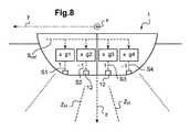
この第1の実施形態では、送信信号S1、S2、S3、S4、…のそれぞれの時間シフトΔt1、Δt2、Δt3、Δt4、…は、上記音波送信のそれぞれに対して、送信される音響パワーが送信された音波間の干渉によって送信面Pに集中するように、送信機12を制御する。 In this first embodiment, the time shifts Δt1, Δt2, Δt3, Δt4, ... Of the transmission signals S1, S2, S3, S4, ... Are the acoustic powers transmitted for each of the sound wave transmissions. The
したがって、各送信において、送信電力は指向的な方法で送信され、送信された音波は、浅い音波シート、又は(本明細書では、図4及び図5に示すように、横断方向軸yに従って浅い)「帯」を一緒に形成する。 Therefore, in each transmission, the transmitted power is transmitted in a directional manner, and the transmitted sound waves are shallow along a shallow sound wave sheet or (in this specification, as shown in FIGS. 4 and 5) along the transverse axis y. ) Form a "belt" together.
上述の3次元画像を収集することを可能にする一連の連続送信中に、上記送信信号のそれぞれの時間シフトΔt1、Δt2、Δt3、Δt4、…は、送信面Pが音波送信のうちの1つから次の送信まで走査軸の周りを旋回するように、変化する。 During a series of continuous transmissions that enable the acquisition of the above-mentioned three-dimensional image, the time shifts Δt1, Δt2, Δt3, Δt4, ... Of the transmission signals are such that the transmission surface P is one of the sound wave transmissions. It changes to swivel around the scan axis from one transmission to the next.
この送信シーケンス中、これらの旋回動作により、送信面Pは、観察ボリュームV全体を走査する。 During this transmission sequence, these swivel movements cause the transmission surface P to scan the entire observation volume V.
この第1の実施形態の特徴を、最初に、上記送信の1つについて説明する。次いで、上述の3次元画像を収集するための送信面Pの走査について説明する。 The features of this first embodiment will first be described with respect to one of the above transmissions. Next, scanning of the transmission surface P for collecting the above-mentioned three-dimensional image will be described.
音波送信は、海洋ドローン1に対して横方向に延在する、変換器12の第2の分岐14によって実行される。 The sound wave transmission is performed by a
各音波送信に対して、送信信号S1、S2、S3、S4、…は同じ基準信号Srefから生成され、それぞれに時間シフトΔt1、Δt2、Δt3、Δt4、…が適用される。 For each sound wave transmission, the transmission signals S1, S2, S3, S4, ... Are generated from the same reference signal Sref, and the time shifts Δt1, Δt2, Δt3, Δt4, ... Are applied to each of them.
これらの時間シフトΔt1、Δt2、Δt3、Δt4、…は、横断方向軸yに沿った送信機12のそれぞれの位置に比例する。したがって、送信された音波が互いに建設的に干渉する送信面Pは、海洋ドローンに対して長手方向に延在する。 These time shifts Δt1, Δt2, Δt3, Δt4, ... Are proportional to the respective positions of the
これらの時間シフトΔt1、Δt2、Δt3、Δt4、…が全て同じ値(例えば、ゼロ)を有する場合、音波は位相で送信され、海洋ドローン1の真下に延在する(x、z)平面で互いに建設的に干渉する。換言すれば、送信面Pは、面(x、z)に対応する。 If these time shifts Δt1, Δt2, Δt3, Δt4, ... All have the same value (eg, zero), the sound waves are transmitted in phase and are transmitted to each other in the (x, z) plane extending beneath the
一方、これらの時間シフトΔt1、Δt2、Δt3、Δt4、…が別個の値を有する場合、特定の音波が他の音波に対して事前に送信され、それによって、これらの音波が互いに建設的に干渉する送信面Pが、図3及び図4に概略的に示されているように、平面(x、z)に対して角度的にオフセットされる。したがって、これらの平面と垂直軸z(降順の垂直軸)との間に形成されるソナーの送信面Pの傾斜角βは、時間シフトΔt1、Δt2、Δt3、Δt4、…の値によって固定される。 On the other hand, when these time shifts Δt1, Δt2, Δt3, Δt4, ... Have different values, a particular sound wave is pre-transmitted to another sound wave, thereby constructively interfering with each other. The transmitting surface P to be used is offset angularly with respect to the plane (x, z), as schematically shown in FIGS. 3 and 4. Therefore, the inclination angle β of the transmission surface P of the sonar formed between these planes and the vertical axis z (vertical axis in descending order) is fixed by the values of the time shifts Δt1, Δt2, Δt3, Δt4, ... ..
送信された全ての音波(すなわち、これらの波の合計)によって形成された音波全体は、この平面の角度区域Sをカバーすることによって、その角度の開口αが60度よりも高く、例えば120度に達し得る、送信面P内を伝播する(図5)。 The entire sound wave formed by all the transmitted sound waves (ie, the sum of these waves) covers the angular region S of this plane so that the aperture α at that angle is higher than 60 degrees, eg 120 degrees. Propagate within the transmission surface P, which can reach (FIG. 5).
この第1の実施形態では、長手方向軸xに平行な第2の分岐13の変換器12は、受信時に動作する。これにより、上述の音波シートが到達する水中環境Eの要素によってエコーとして反射された音波をキャプチャすることを可能にする。 In this first embodiment, the
この反射音波の受信の時点に、反射要素とソナーの間の距離を示す。更に、第1の分岐13の複数の変換器12によってそれぞれ受信されたエコー信号に基づいて、取得ユニット42(又は、変形例として、ソナーの制御ユニット、又は制御システムも)は、角度区域S内のどの方向からそのような反射音波が到来するかを判定する。この方向は、反射要素とソナーを分離する距離と組み合わされて、送信面Pにおける反射要素の位置を完全に判定することを可能にする。 At the time of receiving this reflected sound wave, the distance between the reflecting element and the sonar is shown. Further, based on the echo signals received by the plurality of
したがって、上述の音波送信に応じて、受信機12によってキャプチャされた全てのエコー信号は、送信面P内のドローンの水中環境Eの内容を表す3次元画像を取得することを可能にする。これらのエコー信号は、考察される音波送信と次の音波送信との間に及ぶ時間間隔中に、取得ユニットによって取得される。 Therefore, in response to the above-mentioned sound wave transmission, all the echo signals captured by the
ソナーの角度分解能は、送信される音波シートの角度開口θ1によって、送信面Pに垂直に固定される。すでに示したように、このシートは浅く(変換器12の第2の分岐14の横断方向軸yに沿った延在により、送信には指向性がある)、その角度の開口は、実際には、0.5〜5度である。 The angular resolution of the sonar is fixed perpendicular to the transmission surface P by the angular opening θ1 of the transmitted sound wave sheet. As already shown, this sheet is shallow (transmission is directional due to the extension along the transverse axis y of the
送信面Pにおけるソナーの角度分解能θ2(受信に関するソナーの指向性)もまた、0.5〜5度である。 The sonar angular resolution θ2 (sonar directivity with respect to reception) on the transmitting surface P is also 0.5 to 5 degrees.
したがって、ソナーは、「ビーム」とも呼ばれる、ほぼ円錐形(図6)の異なる基本ゾーンZOの内容を個別に発音し、各角度開口θ1及びθ2(それぞれ、送信面に垂直及び平行である)は、ソナーの送信Sの角度区域に分布する。 Therefore, the sonar individually pronounces the contents of the different basic zones ZO, also called "beams", which are nearly conical (FIG. 6), and each angular aperture θ1 and θ2 (perpendicular and parallel to the transmitting surface, respectively). , Distributed in the angular area of the sonar transmission S.
それゆえ、これらの基本ゾーンのうちの1つに存在する水中要素Eの要素を、海洋ドローンに対して検出及び位置特定できる。検出された要素の等価後方散乱面(一般に、「散乱断面」と呼ばれる)にリンクされたデータ項目もまた、特にこの要素により後方反射された音波のパワーに基づいて、ソナーの制御ユニット11によって判定される。このデータ項目は、この要素に関連付けられたボリューム後方散乱強度、及び/又はこの要素のターゲット後方散乱強度を表し得る。 Therefore, the element of the underwater element E existing in one of these basic zones can be detected and located with respect to the marine drone. Data items linked to the equivalent backscattering surface of the detected element (commonly referred to as the "scattering cross section") are also determined by the
そのようにして内容が発音される個別のビームの数は、20を超える。考察される実施形態では、より正確には64に等しい。 The number of individual beams whose contents are pronounced in this way exceeds 20. In the embodiment considered, it is more precisely equal to 64.
検出された要素は、特に1匹以上の魚、又はドローンの下に位置する海底のプロットに対応し得る。 The detected elements may correspond specifically to one or more fish, or seafloor plots located beneath the drone.
上述のような2次元撮像から3次元撮像への変換を可能にする送信面Pの走査を、ここで説明し得る。 Scanning of the transmitting surface P, which enables the conversion from two-dimensional imaging to three-dimensional imaging as described above, can be described here.
既に示したように、この走査は、走査軸に対するソナー送信面Pの回転によって得られる。この走査軸は、本明細書では海洋ドローン1のデッキに平行である。したがって、ドローンが静止している場合、少なくとも波がないとき、走査軸は水平である。 As already shown, this scan is obtained by rotating the sonar transmission surface P with respect to the scan axis. This scanning axis is parallel to the deck of
この第1の実施形態では、走査軸は、海洋ドローン1の長手方向軸xとより正確に一致する。 In this first embodiment, the scanning axis more accurately coincides with the longitudinal axis x of the
音波送信の1つから次の1つの送信まで、この走査軸を中心に送信面Pを旋回させるために、制御軸41は、基準信号Srefに対する異なる送信信号S1、S2、S3、S4、…のそれぞれの時間シフトΔt1、Δt2、Δt3、Δt4、…を変化させる。 In order to rotate the transmission surface P around this scanning axis from one sound wave transmission to the next transmission, the
したがって、上述の3次元画像の収集を可能にする音波送信シーケンス中、制御システム41は、2つの限界傾斜角+βmax及び−βmax間で送信面Pの傾斜角βを変化させる。実際には、この走査の角度振幅2βmaxは、60度よりも高くなり得る。本明細書では、120度に達する可能性がある。 Therefore, during the sound wave transmission sequence that enables the acquisition of the three-dimensional image described above, the
この音波送信シーケンスに応じて取得されたエコー信号に基づいて、取得ユニット42によって判定された3次元画像は、そのように走査された観察ボリュームVの各基本ゾーンZOの内容を表す。この画像は、特に、(例えば、基準システム(x、y、z)などの3次元基準システムにおける)位置、及びこの観察ボリュームVに含まれる要素の同等の後方散乱面に関する情報を収集する。 The three-dimensional image determined by the
小型で、移動のないその3次元ソナー撮像能力のおかげで、海洋ドローン1は、水中環境を妨害することなく、且つ最適な観察位置から、個別に、水中環境を監視及び特性化することを可能にする。 Thanks to its compact, non-moving 3D sonar imaging capability, the
更に、ソナーのエネルギー消費を最適化することにより、実際には、走査能力のない従来のマルチビームソナーを備えたドローンの(水面での)移動によってそのような画像を取得するのに必要なものよりも低いエネルギー消費量で、この3次元画像を取得することができる。 In addition, by optimizing the energy consumption of the sonar, what is actually needed to obtain such an image by moving the drone (on the surface of the water) with a conventional multi-beam sonar without scanning capability. This three-dimensional image can be acquired with lower energy consumption.
ソナーの送信Sの角度区域の開口α、及び走査振幅2βmaxの両方が特に高いため、たとえドローンの下が浅い深度でも、水平方向に非常に延びた領域に発音することが可能になり、それによって、海洋ドローンの下に延在する水柱内を移動する水生種の検出及び観察に非常に有用である。 Both the aperture α in the angular region of the sonar transmission S and the scanning amplitude 2βmax are particularly high, allowing it to sound in a very horizontally extended region, even at shallow depths under the drone. It is very useful for detecting and observing aquatic species moving in the water column extending under the marine drone.
ソナー10によって送信された音波シートの形状の点から見ると、観察ボリュームVは、本明細書では、概ねピラミッド型の(このピラミッドのベースの両側が、直線か、又は双曲線の弧で形成されているかのいずれかである)形状を有し、その頂点にソナー10を備える。このボリュームは、海底によって垂直方向に制限され、水生環境が非常に深い場合は、(本明細書では500メートルを超える)ソナー範囲によって制限される。 In terms of the shape of the sound wave sheet transmitted by the
送信Sの扇形の角度区域の開口αによって、及び走査振幅2βmaxによって取得できる値を考慮に入れると、観察ボリュームVのアスペクト比は、そのより小さい寸法(例えば、その高さ)をその最大寸法(例えば、その長さ)で除算した値に等しく、本明細書では0.2よりも大きくなり得る。水平面では、観察ボリュームの幅と長さとの比率(横断方向軸yと長手方向軸xのそれぞれに沿ったこのボリュームの寸法)は、0.5を超え得る。その場合、観察ボリュームは、水平面の全ての方向で同等な範囲を有し、所与の観察方向を任意に優先することはない。 Taking into account the values that can be obtained by the opening α of the sector angle region of the transmission S and by the scanning amplitude 2βmax, the aspect ratio of the observation volume V has its smaller dimension (eg, its height) as its maximum dimension (eg, its height). For example, it is equal to the value divided by its length) and can be greater than 0.2 herein. In the horizontal plane, the ratio of the width to the length of the observed volume (the dimension of this volume along each of the transverse axis y and the longitudinal axis x) can exceed 0.5. In that case, the observation volume has an equivalent range in all directions of the horizontal plane and does not arbitrarily prioritize a given observation direction.
観察ボリュームVの上述の基本ゾーンZOは、上記で定義されたように、ほぼ円錐ゾーンに対応し、横断方向軸yを中心に互いに対して角度的にオフセットされるが、それは長手方向軸xを中心とする上述の走査のためでもある。 The above-mentioned basic zone ZO of the observation volume V, as defined above, corresponds to a nearly conical zone and is angularly offset from each other about the transverse axis y, which is the longitudinal axis x. It is also for the above-mentioned scanning centered.
送信面Pの傾斜角βが限界傾斜角±βmaxのうちの1つに近い場合、全ての送信された音波によって形成されたシートの海底のインプリントは、直線ではなく、わずかに湾曲した双曲線形状になり得る。次いで、ソナー送信面Pは、この音波シートによって定義された平均平面に対応する(音波シートは、平面の代わりにわずかに湾曲した表面に沿って伝播し、海底とのその交点は上述の双曲線インプリントである)。 When the tilt angle β of the transmission surface P is close to one of the limit tilt angles ± βmax, the seafloor imprint of the sheet formed by all transmitted sound waves is not a straight line but a slightly curved hyperbolic shape. Can be. The sonar transmission surface P then corresponds to the average plane defined by this sound wave sheet (the sound wave sheet propagates along a slightly curved surface instead of a plane, and its intersection with the seabed is the hyperbolic in above. It is a print).
傾斜角βの走査は非常に細かく行うことができ、この角度は、例えば、限度傾斜角±βmax間に分布する最大64の異なる値を連続して取ってもよく、観察ボリュームVの3次元画像を取得するには、64回の連続音波送信が次いで必要である。 The scan of the tilt angle β can be performed very finely, and this angle may be continuously taken up to 64 different values distributed between the limit tilt angles ± βmax, for example, a three-dimensional image of the observation volume V. 64 continuous sound wave transmissions are then required to obtain.
しかしながら、そのような画像を取得するために必要な時間は、この画像を取得するために実行される送信の数とともに増加する。実際には、そのようなシーケンスの2つの送信は、観察ボリュームの高さ全体に沿った音波の往復伝搬時間にほぼ対応する最小時間によって分離する必要がある。 However, the time required to obtain such an image increases with the number of transmissions performed to obtain this image. In practice, the two transmissions of such a sequence need to be separated by a minimum time approximately corresponding to the round-trip propagation time of the sound wave along the entire height of the observation volume.
したがって、そのような画像を取得するのに必要な時間を低減するために、制御システム41は、観察ボリュームVのより基本的な走査を制御するようにプログラムすることができ、ここで傾斜角βは、限度傾斜角βmax間に分布する最大10(少なくとも2)の異なる値を連続的に取る。そのように取得された観察ボリュームVの画像は、あまり詳細ではない(それでも、特定のアプリケーション、例えば魚群の最初の位置特定には十分である)。見返りに、この単純化された操作により、ソナー10の電力消費量を低減し、したがって海洋ドローン1の自律性を向上させることを可能にする。 Therefore, in order to reduce the time required to acquire such an image, the
制御システム41は、海洋ドローン1の下の浅い深度に位置する要素が検出された場合に、変換器によって送信される音波のこの要素への集束を制御するように更に構成される。 The
この集束により、海洋ドローン1の真下に位置する、いわゆる近視野ゾーン(この領域は、本明細書ではドローンの下に約10メートルを超えて延在する)において、ソナー10の動作を妨害し得る、特に、(例えば、フレネル回折によって引き起こされる)異なるスプリアス効果を補償することを可能にする。この集束により、特に、上述の後方散乱強度測定値を、海洋ドローン1の1メートル下からのたとえ浅い深度でも、信頼性の高い較正された特性で保持することが可能になる。海洋ドローン1は、その小さいサイズにより、種を邪魔することなく、浅い深度で移動する種に近づくように適合されているため、そのような種の正確な観察と特性化が可能である。 This focusing can interfere with the operation of the
上述の集束は、例えば、制御ユニット11の集束モジュール(図示せず)によって実行され得、異なる変換器12にそれぞれ送信される信号、及び/又は異なる変換器12から受信される信号の間に、それぞれの遅延(考察される変換器の位置の関数として2次的に変化する)を導入し、送信された音波を検出された要素に集束させるのに、又はこの要素への近接によって引き起こされる、受信された異なる信号間の位相シフトを補償するのに適している。 The above-mentioned focusing can be performed, for example, by a focusing module (not shown) of the
更に、取得ユニット42(又は変形例として、制御ユニット11)は、慣性センサ6のおかげで、例えば、横揺れ及び縦揺れの動作などの海洋ドローン1の偽の動作を検出し、取得されたデータを処理して、取得された3次元画像に対するそのような動作の影響を補償する、ように構成されている。 Further, the acquisition unit 42 (or, as a modification, the control unit 11) detects false movements of the
ソナー10は、ちょうど説明した第1の実施形態以外の他の実施形態に従って動作するように更に構成されている。この使用における柔軟性は、特に、その変換器12が送信時及び受信時の両方で動作できるという事実によって可能になる。 The
したがって、ソナー10の第2の実施形態では、第1の実施形態と同様に、ミルズクロスの第1の分岐13の変換器12は送信時に動作し、第2の分岐14の変換器12は受信時に動作する。 Therefore, in the second embodiment of the
この第2の実施形態は、以下の点を除いて、あらゆる点で第1の実施形態と同等であり、
−送信された音波シートが、海洋ドローンに対して横断方向に延在し(海洋ドローンに対して長手方向に延在する代わりに)、
−走査軸は、海洋ドローン1の横断方向軸yと一致する。This second embodiment is equivalent to the first embodiment in all respects except for the following points.
-The transmitted sound wave sheet extends transversely to the marine drone (instead of extending longitudinally to the marine drone).
-The scanning axis coincides with the transverse axis y of the
上述したように、その走査軸を中心とする送信面の回転のおかげで観察ボリュームの3次元画像が収集されると、この画像の解像度とその取得に必要な時間との間で妥協点を見出す必要がある。 As mentioned above, when a 3D image of the observation volume is collected thanks to the rotation of the transmitting surface around its scan axis, a compromise is found between the resolution of this image and the time required to obtain it. There is a need.
分解能と取得時間との間とのより良い妥協点は、図7〜図9を参照して以下に説明する第3の実施形態のように、より洗練された送信及び受信スキームに従って変換器12を制御することによって見出され得る。 A better compromise between resolution and acquisition time is to make the
この第3の実施形態は、特に、送信機の数Nが2pに等しい場合に使用されてもよく、ここでpは整数である。受信機の数もまたNである。The third embodiment may, in particular, be used if the number N of the transmitters equals 2p, where p is an integer. The number of receivers is also N.
各音波送信に対して、送信信号S1、S2、S3、S4、…は同じ基準信号Srefから生成され、それぞれの利得g1、g2、g3、g4、…によって乗算される(図7)。したがって、送信信号は、振幅A1、A2、A3、A4、…を有し、それぞれ利得g1、g2、g3、g4に比例する。更に、これらの送信信号は、互いに対して時間シフトを有しない(換言すれば、基準信号Srefに対するこれらの信号の時間シフトΔt1、Δt2、Δt3、Δt4、…が全て同じ値を有する)。 For each sound wave transmission, the transmission signals S1, S2, S3, S4, ... Are generated from the same reference signal Sref and are multiplied by their respective gains g1, g2, g3, g4, ... (FIG. 7). Therefore, the transmitted signal has amplitudes A1, A2, A3, A4, ... And is proportional to the gains g1, g2, g3, g4, respectively. Further, these transmitted signals do not have a time shift with respect to each other (in other words, the time shifts Δt1, Δt2, Δt3, Δt4, ... Of these signals with respect to the reference signal Sref all have the same value).
3次元画像の収集を可能にする各音波送信シーケンスは、M回の送信を含む。これらの送信のそれぞれは、このシーケンス内で、整数インデックス(オーダー番号)Iでマークされ、インデックスiは1〜Mで変化する。 Each sound wave transmission sequence that allows the acquisition of 3D images includes M transmissions. Each of these transmissions is marked with an integer index (order number) I within this sequence, with index i varying from 1 to M.
利得g1(i)、g2(i)、…、gN(i)の値(iは1〜Mで変化)は、送信信号S1、S2、S3、S4を生成するために適用され、この送信シーケンス中に送信機12を制御し、制御システム41のメモリに記憶される。 The values of the gains g1 (i), g2 (i), ..., GN (i) (i varies from 1 to M) are applied to generate the transmission signals S1, S2, S3, S4 and this transmission sequence. The
送信シーケンスは、このメモリ内で、ランクNの行列のそれぞれの複数のラインとより正確に関連付けられる。 The transmission sequence is more accurately associated within this memory with each plurality of lines in the rank N matrix.
したがって、このシーケンスのi番目の送信は、この行列のj番目のラインに関連付けられる。制御システムのメモリに記憶されている利得値g1(i)、g2(i)、…、gN(i)は、ランクNのこの行列のライン番号jの係数に比例する。したがって、この第3の実施形態では、送信変動シーケンスは、各送信シーケンスのM回の送信にそれぞれ関連付けられたランクNの行列のM本のラインのデータによって定義される。 Therefore, the i-th transmission of this sequence is associated with the j-th line of this matrix. The gain values g1 (i), g2 (i), ..., GN (i) stored in the memory of the control system are proportional to the coefficient of the line number j of this matrix of rank N. Therefore, in this third embodiment, the transmission variation sequence is defined by the data of M lines of the rank N matrix associated with each M transmission of each transmission sequence.
この第3の実施形態では、ランクNの異なる行列、すなわち異なる送信ベースが考えられ得る。 In this third embodiment, different matrices of rank N, i.e. different transmission bases, can be considered.
好ましくは、使用される送信ベースは、いわゆるアダマールのものであり、ランクNの上述の行列は、ランクNのアダマール行列である。 Preferably, the transmission base used is of the so-called Hadamard, and the above-mentioned matrix of rank N is a rank N Hadamard matrix.
例えば、送信番号iがこのアダマール行列のライン番号iと関連付けられ、すなわち、j=iであり得る。 For example, the transmission number i can be associated with the line number i of this Hadamard matrix, i.e. j = i.
例では、変形例として、i=1の場合j=1、及びi>1の場合j=2i−1であり得る。 In the example, as a modification, j = 1 when i = 1 and j = 2i-1 when i> 1.
例示として、N=4の送信機及びM=3の送信の場合の、送信シーケンスの簡略化された例が図7〜図9に示され、
−ランク4のアダマール行列のライン1(j=1)に関連付けられた、第1の音波送信(i=1)の場合(図7)、
g1(1)=1、g2(1)=1、g3(1)=1、g4(1)=1であり、
−この行列のライン2(j=2)に関連付けられた、第2の音波送信(i=2)の場合(図8)、
g1(2)=1、g2(2)=−1、g3(2)=1、g4(2)=−1であり、
−この行列のライン2(j=2)に関連付けられた、第3の音波送信(i=3)の場合(図9)、
g1(3)=1、g2(3)=1、g3(3)=−1、g4(3)=−1である。By way of example, a simplified example of the transmission sequence for a transmitter with N = 4 and a transmission with M = 3 is shown in FIGS. 7-9.
-In the case of the first sound wave transmission (i = 1) associated with line 1 (j = 1) of the
g1 (1) = 1, g2 (1) = 1, g3 (1) = 1, g4 (1) = 1.
-In the case of the second sound wave transmission (i = 2) associated with line 2 (j = 2) of this matrix (FIG. 8).
g1 (2) = 1, g2 (2) = -1, g3 (2) = 1, g4 (2) = -1.
-In the case of the third sound wave transmission (i = 3) associated with line 2 (j = 2) of this matrix (FIG. 9),
g1 (3) = 1, g2 (3) = 1, g3 (3) = -1, g4 (3) = -1.
これらの図では、(送信された音波間の干渉のために)送信された音響パワーが最大である観察ボリュームVのゾーンZHが、破線(太線)で概略的に示されている。In these figures, the zone ZH of the observation volume V is transmitted acoustic power (due to interference between the transmitted wave) is maximum, it is schematically illustrated in broken lines (thick line).
そのような送信シーケンス中に、ランクNのアダマール行列の異なるラインの係数に従って送信信号の振幅を変化させることにより、所定の空間解像度で、送信面の回転によって(又は、以下で簡潔に説明される、正準法と呼ばれることもある開口合成法によって)取得され得る時間よりも有利にも短い時間で、観察ボリュームVの3次元画像を収集することを可能にする。 By varying the amplitude of the transmitted signal according to the coefficients of different lines of the rank N Hadamard matrix during such a transmission sequence, at a given spatial resolution, by rotation of the transmitting surface (or briefly described below). It makes it possible to collect a three-dimensional image of the observation volume V in a time that is significantly shorter than the time that can be obtained (by the aperture synthesis method, which is sometimes called the canonical method).
この目的のために、特に、画像(3次元)当たりの送信の数Mはまた、送信機12の数Nよりも少なくてもよい。本出願人は実際に、この送信数の低減が(したがって、これが画像を取得するために必要な時間を低減する)、N回の送信(及び関連する受信)のシーケンスから再構築された画像に対して画像の解像度をごくわずかに劣化させることに気づいた。 For this purpose, in particular, the number M of transmissions per image (three-dimensional) may also be less than the number N of
これにより、ソナー10のエネルギー消費を低減し、したがって海洋ドローン1の自律性を高めることを可能にするため、画像を取得するのに必要な送信の数を低減できることは特に興味深い。 It is of particular interest to be able to reduce the number of transmissions required to acquire an image, as this allows the energy consumption of the
更に、以下に説明する魚群追跡用途の場合、特に画像取得と次の画像取得の間に魚群100が観察ボリュームVから出ていくのを回避するために、そのような画像を迅速に取得できることは興味深い。 Furthermore, in the case of the fish school tracking application described below, it is possible to quickly acquire such an image, especially in order to prevent the school of
すでに示したように、アダマール以外の送信ベースが使用されてもよい。例えば、各送信において、送信機12のうちの1つのみを制御し、送信と次の送信(専門文献では正準法と呼ばれることがある送信方法)との間の送信機の変更するために提供されてもよい。複数の音波送信に関連付けられた、制御システムのメモリ内のランクNの行列は、対角行列(例えば、単位行列)である。 As already shown, transmission bases other than Hadamard may be used. For example, in each transmission, to control only one of the
海洋ドローン1のマルチビームソナー10が提示されたが、このドローンの操作全体をここでより詳細に説明し得る。 The
まず、ナビゲーション電子ユニット4は、
−通信モジュール7を介して受信された、遠隔オペレータによって与えられたコマンドの機能として、及び/又は
−外部からの介入なしに、自律的に、ドローンを制御するようにプログラムされている。First, the navigation
-It is programmed to autonomously control the drone as a function of commands given by a remote operator received via the communication module 7 and / or-without external intervention.
海洋ドローン1がこのオペレータによって遠隔制御されると、ナビゲーションユニット4は、その通信モジュール7のおかげで、ソナー10からのデータに基づいて、特に、ソナーによって収集されたドローンの海洋環境の3次元画像に基づいて、生成された圧縮データを送信する。これらの(圧縮された)データにより、特に、オペレータが、少なくとも部分的に、ドローンの水中環境Eの内容を視覚化し、ドローンのその制御をこの内容に適合させることを可能にする。(例えば、ナビゲーション電子ユニット4によって実行される)ソナー10からのデータの圧縮は、送信されるデータの量を制限し、ここで再びドローンの電力消費を低減することを可能にする。 When the
ここで、ナビゲーション電子ユニット4は、ソナーからのデータをそのメモリに記録するように更にプログラムされている。これらのデータは、データが占有するメモリ空間を制限するために、前もってストレージに圧縮されていてもよい。しかしながら、次いで使用される圧縮率は、送信される圧縮データの生成に使用されるものよりも低くなり、記憶されたデータは、送信されたデータを補完するものであり、リアルタイムで送信されたデータよりも水中環境Eのより詳細な分析を事後的に可能にして、ドローンの制御を可能にする。 Here, the navigation
海洋ドローン1が外部からの介入なしに自律的に航行すると、ナビゲーション電子ユニット4は、上記で説明したように、ソナーからのデータを記録する。任意選択的に、通信モジュール7を介して上述の圧縮データを送信することもできる。 When the
ここで、海洋ドローン1の移動、及び水中環境Eの3次元画像の対応する取得を、この環境の観察及び特性化の操作中に実行することを目的として、図10〜図13を参照して説明する。 Here, with reference to FIGS. 10-10, for the purpose of performing the movement of the
図10は、上述のように海洋面ドローンによって実施される、水中環境Eを特性化するための方法の主要ステップを概略的に示している。 FIG. 10 schematically illustrates the major steps of the method for characterizing the underwater environment E, carried out by the marine surface drone as described above.
この方法は、実装することができ、
−オペレータによる海洋ドローンの遠隔操作により、及び/又は、
−外部からの介入なしに、自律的に、この方法を実行するように、ドローンのナビゲーション電子ユニットがプログラムされている。This method can be implemented,
-By remote control of the marine drone by the operator and / or
-The drone's navigation electronic unit is programmed to perform this method autonomously, without external intervention.
この方法は、第1の観察位置P1までの海洋ドローンの移動である任意選択的なステップE0で開始する。ナビゲーション電子ユニット4によって制御されるこの移動は、上述の移動手段5のおかげで行われる。 This method begins with an optional step E0, which is the movement of the marine drone to the first observation position P1. This movement controlled by the navigation
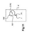
この第1の位置P1(図11及び図12)は、魚又は海洋動物が存在する可能性が高い近くのターゲット位置に対応している。この第1の位置は、例えば、それを中心に浅い深度を移動する海洋動物を集める、一般に、魚集合装置と呼ばれる浮遊装置(フランス語「Dispositif de Concentration de Poisson」から「DCP」)の近くに位置する。この第1のステップにより、例えば、海洋ドローン1は、クルーが操縦するより高いトン数の船舶200の近くで、発射された初期位置P0から、この観察位置P1まで移動することを可能にする。 This first position P1 (FIGS. 11 and 12) corresponds to a nearby target location where fish or marine animals are likely to be present. This first position is located near, for example, a floating device (French "Dispositif de Concentration de Poisson" to "DCP"), commonly referred to as a fish collecting device, which collects marine animals moving at shallow depths around it. To do. This first step allows, for example, the
方法は、水中環境Eの3次元画像を取得するステップa)、すなわち、制御システム41が複数の連続音波送信を制御するステップに続き、取得ユニット42が、上記送信のそれぞれに対して、考察される送信に応じてソナー10の受信機12によってキャプチャされたエコー信号を取得し、上記複数の送信に応じて取得されたエコー信号から、観察ボリュームVの内容を表す3次元画像を判定する。 The method is considered in step a) of acquiring a three-dimensional image of the underwater environment E, i.e., following the step in which the
任意選択的な次のステップT0は、その間にこの観察ボリュームVに魚が存在するかどうかを判定するテストステップである。 The next optional step T0 is a test step for determining whether or not fish are present in the observation volume V in the meantime.
観察ボリュームで魚が検出されない場合、方法は、ステップE0(図10の矢印F2)において再開し、別のターゲット位置に向けて海洋ドローンを移動させる。したがって、海洋個体群の存在がソナーによって検出されるまで、いくつかの別個のターゲット位置を連続的にテストすることができる。任意選択的に、ステップT0において、検出された魚群が例えばこの魚群の魚の密度に関連する所与の基準を満たすかどうかをテストし、この基準が満たされない場合は、ステップE0を再び実行することができる。 If no fish are detected in the observation volume, the method resumes at step E0 (arrow F2 in FIG. 10) and moves the marine drone towards another target position. Therefore, several separate target locations can be continuously tested until the presence of the marine population is detected by sonar. Optionally, in step T0, test whether the detected school of fish meets a given criterion related to, for example, the density of fish in this school of fish, and if this criterion is not met, perform step E0 again. Can be done.
観察ボリュームVで魚を検出した場合、方法は、ステップT0の後に、検出された魚群100をより細かく特性化することを目的とするステップを続行する(図10の矢印F3)。 When fish are detected at the observation volume V, the method continues after step T0 with a step aimed at finely characterizing the detected school of fish 100 (arrow F3 in FIG. 10).
ステップは、
−ステップa)の以前の実行中に取得された3次元画像を処理することによって、魚群100の位置を判定するステップb)と、
−魚群100の上記位置の真上に位置する位置P2、P3、…まで海洋面ドローン1を移動させるステップc)と、
−水中環境Eの3次元画像を取得するステップa)と、を含む。The step is
-Step b) to determine the position of the school of
-Step c) to move the
-Contains step a) for acquiring a three-dimensional image of the underwater environment E.
したがって、ステップa)のこの繰り返しの間、海洋ドローン1は、魚群100の位置の真上、すなわち垂直上方に位置し、この位置は、この魚群100の観察及び特性化に特に適している。 Therefore, during this repetition of step a), the
本明細書のステップb)で判定された魚群100の位置は、この魚群100の中心Cに対応する。海洋ドローン1がこの魚群の中心Cの垂直上方に位置することによって、したがってこの魚群の3次元画像を取得することは非常に興味深いことであるが、なぜなら、これは実際には、一般に、遭遇する魚の種類及び魚の集中と挙動が魚群全体をより代表的なものであるような、魚群の中心にあるからである。これにより、この位置から、魚群の寸法を最高の精度で判定することもできる。 The position of the school of
海洋ドローン1が水生環境の3次元画像を取得する能力は、その目的のために移動させる必要なしに、この方法で非常に有用であると分かっている。 The ability of the
実際に、そのような3次元画像は、走査能力を持たない従来のマルチビームソナーを備えたドローンを水面で移動させることによって取得され得るものよりもはるかに迅速に(且つ慎重に)海洋ドローン1によって取得される。この迅速な取得により、特に、魚群の位置をほぼ瞬時に判定し、魚群が実質的に離れてしまう前に、この位置の真上への海洋ドローンの移動を制御することが可能になる。 In fact, such a 3D image is much faster (and cautiously) than what can be obtained by moving a drone with conventional multi-beam sonar without scanning capability on the surface of the water. Obtained by. This rapid acquisition allows, in particular, to determine the location of the school of fish almost instantly and control the movement of the marine drone directly above this position before the school of fish is substantially separated.
更に、既に示したように、この3次元撮像能力により、海洋ドローン1は、検出された魚群100の真上に留まることによって、検出された魚群100全体を観察することを可能にし、これは魚群観察に関して最も好ましい。 Furthermore, as already shown, this three-dimensional imaging capability allows the
海洋ドローン1の自律ナビゲーションの場合のステップb)及びc)を、ここでより詳細に説明する。 Steps b) and c) in the case of autonomous navigation of the
ステップb)の間、魚群100の中心Cを位置特定するために、制御システム41は、
−以前のステップa)の実行中に取得した3次元画像を処理することによって、魚群100の周辺部101上に位置する複数のポイントのそれぞれの位置を判定し、次いで、
−例えば、これらのポイントの重心の位置を計算することによって(すなわち、これらのポイントにより定義される平均位置を計算することによって)、これらのポイントの位置の関数として、魚群の中心Cの位置を判定する。During step b), the
-By processing the 3D image acquired during the execution of the previous step a), the positions of the plurality of points located on the
-For example, by calculating the position of the center of gravity of these points (ie, by calculating the average position defined by these points), as a function of the position of these points, the position of the center C of the school of fish judge.
魚群の周辺部101のポイントの位置は、輪郭検出アルゴリズムによって判定することができる。 The position of the point at the
変形例として、ステップb)において、魚群の周辺部を前もって検出するのではなく、1匹又は数匹の魚が検出された観察ボリュームVの異なるポイントの重心位置を直接計算することによって、魚群の中心Cを判定することができる。 As a modification, in step b), instead of detecting the peripheral part of the school of fish in advance, the position of the center of gravity of a different point of the observation volume V in which one or several fish are detected is directly calculated. The center C can be determined.
魚群101の一部100’のみが観察ボリュームVに位置する場合(図13に概略的に示されている状況)、これは魚群のこの部分100’の中心Cの位置であり、本明細書では、ステップb)において制御システム41によって判定される。 If only a portion 100'of the school of
ステップb)の後にはテストステップTが続き、ここで制御システム41は、海洋ドローン1が魚群100の中心Cの垂直上方に位置するかどうかを判定する。もしそうであれば、方法は、ステップa)で再開する(図10の矢印F6)。 Step b) is followed by test step T, where the
一方、ステップTが、海洋ドローン1が水平面(x、y)で魚群の中心Cに対してオフセットしていることを示す場合、方法は、ステップc)に継続し、海洋ドローン1を魚群の中心Cの真上まで移動させる(図10の矢印F4)。次いで、方法は、ステップa)で再開する(図10の矢印F5)。 On the other hand, if step T indicates that the
その後、全てのステップa)、b)、T、及び場合によってはc)が、再び連続して数回実行される。 After that, all steps a), b), T, and in some cases c) are performed again several times in succession.
この一連のステップを継続的に繰り返すことにより、海洋ドローン1が魚群の中心Cの上方に留まり、この中心の潜在的な移動を追跡することが可能になる。 By continuously repeating this series of steps, the
図12は、そのような追跡を模式的に示している。初期位置P0において発射された海洋ドローン1は、第1の観察位置P1まで最初に移動される。この第1の位置から、その水生環境の3次元画像を取得する。その画像は、魚群100が観察ボリュームV(図11)に存在し、その中心Cの判定を可能にすることを示している。次いで、海洋ドローンは、この中心の真上に位置する第2の位置P2まで移動される。次いで、魚群が続いて移動した後、海洋ドローンは、(魚群の中心が占有する新しい位置の真上に位置する)第3の位置P3まで移動するなどによって、その位置を調整する。 FIG. 12 schematically illustrates such tracking. The
海洋ドローン1の制御システム41は、本明細書では、ステップa)の後に、ステップa)において取得ユニット42によって取得されるデータの関数として、その中心の位置以外の魚群100を表す少なくとも1つのデータ項目を判定するステップd)を実行するために、更にプログラムされる。 In the present specification, the
上記データ項目は、例えば、(そのような推定が、特に、上述の後方散乱強度の測定値に基づき得る)魚群の寸法(幅、長さ、高さ、ボリューム、…)、その形態、魚群内の魚の密度若しくは数、又はこれらの魚の移動性に関連し得る。 The data items are, for example, the dimensions (width, length, height, volume, ...), morphology, and within the school of fish (such estimates can be obtained, in particular based on the measurements of backscatter intensity described above). It may be related to the density or number of fish, or the mobility of these fish.
ちょうど説明した海洋ドローン1及び特性化方法には、様々な変更を行うことができる。 Various changes can be made to the
まず、ソナー変換器が配置されるクロスは、海洋ドローンに対して異なって整列することができる。このクロスの分岐は、海洋ドローンの軸と整列する代わりに、例えば、海洋ドローンの長手方向軸と横断方向軸の間で45度に配置することができる。変換器はまた、クロスの代わりにグリッド(行列)に従って配置することができる。 First, the cloth on which the sonar transducer is placed can be aligned differently with respect to the marine drone. Instead of aligning with the axis of the marine drone, this cross branch can be placed, for example, at 45 degrees between the longitudinal and transverse axes of the marine drone. The transducers can also be arranged according to a grid instead of a cloth.
他方、制御システム、取得ユニット、及び変換器の制御ユニットの異なる機能は、これらのユニット間で異なって分布できる。例えば、魚群の中心位置は、もちろん、制御システムではなく取得ユニットによって判定できる。そのうえ、制御ユニット及び取得ユニットは、海洋ドローンのナビゲーション電子ユニットの同じ電子モジュールを用いて作成することができる。変換器の制御ユニットは更に、ナビゲーション電子ユニットに統合することもできる。 On the other hand, the different functions of the control system, the acquisition unit, and the control unit of the transducer can be distributed differently among these units. For example, the central position of a school of fish can, of course, be determined by the acquisition unit rather than by the control system. Moreover, the control unit and acquisition unit can be created using the same electronic module of the marine drone navigation electronic unit. The control unit of the transducer can also be integrated into the navigation electronic unit.
更に、魚群の中心を追跡する他のモードも考えられ得る。例えば、魚群の中心のいくつかの以前の位置を考慮に入れて、魚群がおそらく来るであろう将来の位置を判定することができる(次いで、ドローンはこの位置まで制御される)。
In addition, other modes of tracking the center of the school of fish may be considered. For example, some previous positions in the center of the school can be taken into account to determine the future position where the school will probably come (then the drone will be controlled to this position).
Claims (19)
Translated fromJapanese−前記海洋ドローン(1)の所与の位置(P1、P2、P3)に対して、複数の連続音波送信を制御するように構成された、前記ソナー(10)を制御するためのシステム(41)であって、
前記制御システム(41)が、各送信において、それぞれの複数の送信信号(S1、S2、S3、S4)によって前記異なる送信機(12)を制御し、各送信信号(S1、S2、S3、S4)が、基準信号(Sref)に対する振幅及び時間シフト(Δt1、Δt2、Δt3、Δt4)を有し、
前記制御システム(41)が、所定の送信変動シーケンスに従って、前記複数の送信中に、前記送信信号(S1、S2、S3、S4)の前記それぞれの振幅又は時間シフト(Δt1、Δt2、Δt3、Δt4)を変化させ、所与の観察ボリューム(V)をカバーする前記複数の送信中に全ての前記音波が送信される、制御システム(41)と、
−取得ユニット(42)であって、
−前記各送信に対して、前記考察される送信に応じて、前記ソナー(10)の前記受信機(12)によってキャプチャされたエコー信号を取得し、
−前記複数の送信に応じて取得された前記エコー信号から、前記観察ボリューム(V)の内容を表す3次元画像を判定する、ように構成された取得ユニット(42)と、を更に備える、ことを特徴とする、海洋面ドローン(1)。A marine surface drone (1) including an onboard sonar (10), wherein the sonar (10) is arranged along a first axis (x, y) with a plurality of sound wave transmitters (12). In a multi-beam sonar (10) including a plurality of sound wave receivers (12) arranged along a second axis (y, x) that is not parallel to the first axis (x, y). There is a marine drone (1),
-A system (41) for controlling the sonar (10) configured to control a plurality of continuous sound waves for a given position (P1, P2, P3) of the marine drone (1). ) And
The control system (41) controls the different transmitters (12) by the plurality of transmission signals (S1, S2, S3, S4) in each transmission, and each transmission signal (S1, S2, S3, S4). ) Has an amplitude and time shift (Δt1, Δt2, Δt3, Δt4) with respect to the reference signal (Sref).
The control system (41) follows a predetermined transmission variation sequence, and during the plurality of transmissions, the amplitude or time shift (Δt1, Δt2, Δt3, Δt4) of the transmission signals (S1, S2, S3, S4), respectively. A control system (41), wherein all the sound waves are transmitted during the plurality of transmissions covering a given observation volume (V).
-Acquisition unit (42)
-For each of the transmissions, an echo signal captured by the receiver (12) of the sonar (10) is acquired in response to the considered transmission.
-The acquisition unit (42) configured to determine a three-dimensional image representing the contents of the observation volume (V) from the echo signals acquired in response to the plurality of transmissions is further provided. Marine surface drone (1).
−前記3次元画像を処理することによって魚群(100)を検出し、
−前記魚群(100)の真上に位置する別の位置(P2、P3)までの前記海洋面ドローンの移動を制御し、次いで、
−前記複数の連続音波送信を再び制御し、前記海洋ドローン(1)が前記他の位置(P2、P3)に配置され、前記取得ユニット(42)が、前記各送信に対して、前記考察される送信に応じて前記ソナー(10)の前記受信機(12)によってキャプチャされた前記エコー信号を取得し、且つ、前記複数の送信に応じて取得された前記エコー信号から、前記観察ボリューム(V)の前記内容を表す別の3次元画像を判定する、ように更に適合されている、請求項5に記載の海洋面ドローン(1)。The control system (41)
-A school of fish (100) is detected by processing the three-dimensional image,
-Control the movement of the marine drone to another position (P2, P3) located directly above the school of fish (100) and then
-Controlling the plurality of continuous sound wave transmissions again, the marine drone (1) is arranged at the other positions (P2, P3), and the acquisition unit (42) is considered for each transmission. The observation volume (V) is obtained from the echo signal captured by the receiver (12) of the sonar (10) in response to the transmission, and from the echo signal acquired in response to the plurality of transmissions. The marine surface drone (1) according to claim 5, further adapted to determine another three-dimensional image representing the above content of).
−前記各音波送信に対して、前記送信された音波間の干渉によって、前記送信された音響パワーが送信面(P)に集中し、
−前記各送信と次の送信との間で、前記送信面(P)が走査軸(x、y)を中心に旋回し、
−前記複数の音波送信中に、前記旋回動作により、前記送信面(P)が、前記観察ボリューム(V)全体を走査する、請求項1〜8のいずれか一項に記載の海洋面ドローン(1)。The respective time shifts (Δt1, Δt2, Δt3, Δt4) of the transmission signals (S1, S2, S3, S4) change according to the transmission sequence, thereby.
-For each sound wave transmission, the transmitted sound power is concentrated on the transmission surface (P) due to the interference between the transmitted sound waves.
-Between each transmission and the next transmission, the transmission surface (P) swivels around a scanning axis (x, y).
-The marine surface drone according to any one of claims 1 to 8, wherein the transmitting surface (P) scans the entire observation volume (V) by the swivel operation during the plurality of sound wave transmissions. 1).
−前記複数の音波送信が、前記制御システムのメモリにおいて、ランクNのアダマール行列のそれぞれの複数のラインに関連付けられており、
−前記各音波送信に対して、前記送信信号(S1、S2、S3、S4)の前記それぞれの振幅が、前記考察される送信に関連付けられた前記アダマール行列の前記ラインの係数に比例する、請求項1〜8のいずれか一項に記載の海洋面ドローン(1)。-The number of the transmitters (12) of the sonar (10) is N,
-The plurality of sound wave transmissions are associated with each plurality of lines of a rank N Hadamard matrix in the memory of the control system.
-For each sound wave transmission, the respective amplitudes of the transmitted signals (S1, S2, S3, S4) are proportional to the coefficients of the line of the Hadamard matrix associated with the considered transmission. The marine surface drone (1) according to any one of Items 1 to 8.
−前記送信機(12)が、前記第1の軸(x、y)に沿って、少なくとも20センチメートル超の長さにわたって分布しており、
−前記受信機(12)が、前記第2の軸(y、x)に沿って、少なくとも20センチメートル超の長さにわたって分布している、請求項1〜10のいずれか一項に記載の海洋面ドローン(1)。-The first axis (x, y) and the second axis (y, x) are separated by an angle included in 60 to 90 degrees.
-The transmitter (12) is distributed along the first axis (x, y) over a length of at least 20 centimeters or more.
-The one according to any one of claims 1 to 10, wherein the receiver (12) is distributed along the second axis (y, x) over a length of at least 20 centimeters or more. Marine drone (1).
前記方法中に、
−前記ソナー(10)を制御するためのシステム(41)が、前記海洋ドローン(1)の所与の位置(P1、P2、P3)に対して、複数の連続音波送信を制御し、
前記制御システム(41)が、各送信において、それぞれの複数の送信信号(S1、S2、S3、S4)によって前記異なる送信機(12)を制御し、各送信信号(S1、S2、S3、S4)が、基準信号(Sref)に対する振幅及び時間シフト(Δt1、Δt2、Δt3、Δt4)を有し、
前記制御システム(41)が、所定の送信変動シーケンスに従って、前記複数の送信中に、前記送信信号(S1、S2、S3、S4)の前記それぞれの振幅又は時間シフト(Δt1、Δt2、Δt3、Δt4)を変化させ、所与の観察ボリューム(V)をカバーする前記複数の送信中に全ての音波が送信され、
−取得ユニット(42)が、前記各送信に対して、前記考察される送信に応じて、前記ソナー(10)の前記受信機(12)によってキャプチャされたエコー信号を取得し、
−前記取得ユニット(42)が、前記複数の送信に応じて取得された前記エコー信号から、前記観察ボリューム(V)の内容を表す3次元画像を判定する、ことを特徴とする、特性化方法。A marine surface drone (1) including an onboard sonar (10), wherein the sonar (10) is arranged along a first axis (x, y) with a plurality of sound wave transmitters (12). In a multi-beam sonar (10) including a plurality of sound wave receivers (12) arranged along a second axis (y, x) that is not parallel to the first axis (x, y). A method of characterizing the underwater environment (E) implemented by a marine surface drone (1).
During the method,
-A system (41) for controlling the sonar (10) controls a plurality of continuous sound wave transmissions for a given position (P1, P2, P3) of the marine drone (1).
The control system (41) controls the different transmitters (12) by the plurality of transmission signals (S1, S2, S3, S4) in each transmission, and each transmission signal (S1, S2, S3, S4). ) Has an amplitude and time shift (Δt1, Δt2, Δt3, Δt4) with respect to the reference signal (Sref).
The control system (41) follows a predetermined transmission variation sequence, and during the plurality of transmissions, the amplitude or time shift (Δt1, Δt2, Δt3, Δt4) of the transmission signals (S1, S2, S3, S4), respectively. ) Is varied and all sound waves are transmitted during the plurality of transmissions covering a given observation volume (V).
-The acquisition unit (42) acquires the echo signal captured by the receiver (12) of the sonar (10) in response to the considered transmission for each of the transmissions.
-A characterization method, characterized in that the acquisition unit (42) determines a three-dimensional image representing the contents of the observation volume (V) from the echo signals acquired in response to the plurality of transmissions. ..
−前記3次元画像を処理することによって魚群(100)を検出し、
−前記魚群(100)の真上に位置する別の位置(P2、P3)までの前記海洋面ドローン(1)の移動を制御し、次いで、
−前記複数の連続音波送信を再び制御し、前記海洋ドローン(1)が前記他の位置(P2、P3)に配置され、前記取得ユニット(42)が、前記各送信に対して、前記考察される送信に応じて前記ソナー(10)の前記受信機(12)によってキャプチャされた前記エコー信号を取得し、且つ、前記複数の送信に応じて取得された前記エコー信号から、前記観察ボリューム(V)の前記内容を表す別の3次元画像を判定する、請求項14に記載の特性化方法。The control system (41)
-A school of fish (100) is detected by processing the three-dimensional image,
-Control the movement of the marine drone (1) to another position (P2, P3) located directly above the school of fish (100), and then
-Controlling the plurality of continuous sound wave transmissions again, the marine drone (1) is arranged at the other positions (P2, P3), and the acquisition unit (42) is considered for each transmission. The observation volume (V) is obtained from the echo signal captured by the receiver (12) of the sonar (10) in response to the transmission, and from the echo signal acquired in response to the plurality of transmissions. The characterization method according to claim 14, wherein another three-dimensional image representing the content of) is determined.
−前記魚群(100)の前記中心(C)を位置特定することと、
−前記海洋ドローン(1)が前記魚群(100)の前記中心(C)に対してオフセットされている場合に、前記魚群の前記中心(C)の真上の前記位置まで前記海洋ドローンを移動させることと、
からなる一連のステップを、連続して数回実行する、請求項17又は18に記載の特性化方法。
-Controlling the plurality of continuous sound wave transmissions, for each of the transmissions, acquiring an echo signal captured by the receiver (12) of the sonar (10) in response to the considered transmission, and then From the echo signals acquired in response to the plurality of transmissions, a three-dimensional image representing the contents of the observation volume (V) is determined.
-Positioning the center (C) of the school of fish (100) and
-When the marine drone (1) is offset with respect to the center (C) of the school of fish (100), the marine drone is moved to the position directly above the center (C) of the school of fish. That and
The characterization method according to claim 17 or 18, wherein a series of steps comprising is performed several times in succession.
Applications Claiming Priority (3)
| Application Number | Priority Date | Filing Date | Title |
|---|---|---|---|
| FR1763137 | 2017-12-22 | ||
| FR1763137AFR3075974B1 (en) | 2017-12-22 | 2017-12-22 | SURFACE MARINE DRONE AND METHOD FOR THE CHARACTERIZATION OF AN UNDERWATER ENVIRONMENT USED BY SUCH A DRONE |
| PCT/FR2018/053448WO2019122743A1 (en) | 2017-12-22 | 2018-12-20 | Marine surface drone and method for characterising an underwater environment implemented by such a drone |
Publications (1)
| Publication Number | Publication Date |
|---|---|
| JP2021506668Atrue JP2021506668A (en) | 2021-02-22 |
Family
ID=62067634
Family Applications (1)
| Application Number | Title | Priority Date | Filing Date |
|---|---|---|---|
| JP2020533672APendingJP2021506668A (en) | 2017-12-22 | 2018-12-20 | Marine surface drones and methods for characterizing the underwater environment carried out by such drones |
Country Status (7)
| Country | Link |
|---|---|
| US (1) | US20200333787A1 (en) |
| EP (1) | EP3729129A1 (en) |
| JP (1) | JP2021506668A (en) |
| AU (1) | AU2018389732A1 (en) |
| CA (1) | CA3086865A1 (en) |
| FR (1) | FR3075974B1 (en) |
| WO (1) | WO2019122743A1 (en) |
Families Citing this family (6)
| Publication number | Priority date | Publication date | Assignee | Title |
|---|---|---|---|---|
| US11105922B2 (en) | 2018-02-28 | 2021-08-31 | Navico Holding As | Sonar transducer having geometric elements |
| US11047964B2 (en) | 2018-02-28 | 2021-06-29 | Navico Holding As | Sonar transducer having geometric elements |
| US20220380043A1 (en)* | 2021-05-25 | 2022-12-01 | Hydronalix, Inc. | Unmanned aerial vehicle with underwater sonar scanning capability |
| FR3126505B1 (en) | 2021-09-02 | 2024-02-02 | Eca Robotics | Device and method for detecting and locating submerged objects |
| CN115019207A (en)* | 2022-06-13 | 2022-09-06 | 林国义 | A land, sea and air detection and positioning method based on multimodal sensing |
| CN119485484B (en)* | 2025-01-10 | 2025-06-10 | 北京航空航天大学 | UAV swarm measurement and control communication system based on Hardmard block encryption compression |
Citations (7)
| Publication number | Priority date | Publication date | Assignee | Title |
|---|---|---|---|---|
| JPS6280577A (en)* | 1985-10-03 | 1987-04-14 | Hitachi Zosen Corp | Fish detection method |
| JPH11344566A (en)* | 1998-03-31 | 1999-12-14 | Japan Radio Co Ltd | Fish finder |
| JP3129749U (en)* | 2006-10-13 | 2007-03-08 | 古野電気株式会社 | Underwater detector |
| US20160049143A1 (en)* | 2014-07-15 | 2016-02-18 | Garmin Switzerland Gmbh | Marine multibeam sonar device |
| US20170227639A1 (en)* | 2011-10-26 | 2017-08-10 | Flir Systems, Inc. | Pilot display systems and methods |
| JP2017154734A (en)* | 2016-03-01 | 2017-09-07 | ブランスウィック コーポレイションBrunswick Corporation | Improved marine vessel maneuvering methods and systems |
| JP2017528271A (en)* | 2014-09-26 | 2017-09-28 | サントル ナスィオナル ド ラ ルシェルシュ スィアンティフィク(セ.エン.エル.エス.) | Acoustic imaging method and apparatus |
- 2017
- 2017-12-22FRFR1763137Apatent/FR3075974B1/enactiveActive
- 2018
- 2018-12-20CACA3086865Apatent/CA3086865A1/enactivePending
- 2018-12-20USUS16/956,839patent/US20200333787A1/ennot_activeAbandoned
- 2018-12-20WOPCT/FR2018/053448patent/WO2019122743A1/ennot_activeCeased
- 2018-12-20AUAU2018389732Apatent/AU2018389732A1/ennot_activeAbandoned
- 2018-12-20JPJP2020533672Apatent/JP2021506668A/enactivePending
- 2018-12-20EPEP18842537.5Apatent/EP3729129A1/ennot_activeWithdrawn
Patent Citations (7)
| Publication number | Priority date | Publication date | Assignee | Title |
|---|---|---|---|---|
| JPS6280577A (en)* | 1985-10-03 | 1987-04-14 | Hitachi Zosen Corp | Fish detection method |
| JPH11344566A (en)* | 1998-03-31 | 1999-12-14 | Japan Radio Co Ltd | Fish finder |
| JP3129749U (en)* | 2006-10-13 | 2007-03-08 | 古野電気株式会社 | Underwater detector |
| US20170227639A1 (en)* | 2011-10-26 | 2017-08-10 | Flir Systems, Inc. | Pilot display systems and methods |
| US20160049143A1 (en)* | 2014-07-15 | 2016-02-18 | Garmin Switzerland Gmbh | Marine multibeam sonar device |
| JP2017528271A (en)* | 2014-09-26 | 2017-09-28 | サントル ナスィオナル ド ラ ルシェルシュ スィアンティフィク(セ.エン.エル.エス.) | Acoustic imaging method and apparatus |
| JP2017154734A (en)* | 2016-03-01 | 2017-09-07 | ブランスウィック コーポレイションBrunswick Corporation | Improved marine vessel maneuvering methods and systems |
Also Published As
| Publication number | Publication date |
|---|---|
| AU2018389732A1 (en) | 2020-07-09 |
| FR3075974B1 (en) | 2019-12-27 |
| US20200333787A1 (en) | 2020-10-22 |
| CA3086865A1 (en) | 2019-06-27 |
| FR3075974A1 (en) | 2019-06-28 |
| EP3729129A1 (en) | 2020-10-28 |
| WO2019122743A1 (en) | 2019-06-27 |
Similar Documents
| Publication | Publication Date | Title |
|---|---|---|
| JP2021506668A (en) | Marine surface drones and methods for characterizing the underwater environment carried out by such drones | |
| Bingham et al. | Passive and active acoustics using an autonomous wave glider | |
| Stinco et al. | Passive acoustic signal processing at low frequency with a 3-D acoustic vector sensor hosted on a buoyancy glider | |
| US20160069988A1 (en) | Platform-Independent Sonar Calibration Enabling System | |
| JPS60500383A (en) | Device in hydrophone cable for marine seismic exploration | |
| Bjørnø | Developments in sonar and array technologies | |
| US10031216B2 (en) | Synthetic aperture sonar system for inspecting underwater surfaces | |
| WO2020023082A2 (en) | Variable geometry sonar system and method | |
| Mosca et al. | Scientific potential of a new 3D multibeam echosounder in fisheries and ecosystem research | |
| JP6714261B2 (en) | Underwater detection device, underwater detection method, and underwater detection program | |
| KR20190141341A (en) | Method for Inspection Underwater Structures Using Drone and Sonar | |
| LePage et al. | Bistatic synthetic aperture imaging of proud and buried targets from an AUV | |
| Violante | Acoustic remote sensing for seabed archaeology | |
| Pinto et al. | Real-and synthetic-array signal processing of buried targets | |
| Bjørnø | Developments in sonar technologies and their applications | |
| Ødegård et al. | Using synthetic aperture sonar in marine archaeological surveys-Some first experiences | |
| JPH0679065B2 (en) | Seabed search device | |
| RU151204U1 (en) | HYDROACOUSTIC LIGHTING SYSTEM FOR UNDERWATER SPACE | |
| Koyama et al. | Bathymetry by new designed interferometry sonar mounted on AUV | |
| RU2576352C2 (en) | Towed device for measurement of acoustic characteristics of sea ground | |
| Sakellariou et al. | Preliminary report on underwater survey in the Farasan Islands by the R/V Aegaeo, May–June 2013 | |
| AU2020393299A1 (en) | Method for monitoring a maritime area | |
| Nakamura et al. | Acoustic Systems of the AUV" URASHIMA" | |
| RU2558017C1 (en) | Active sonar | |
| US20240353547A1 (en) | Device and method for detecting and locating underwater objects |
Legal Events
| Date | Code | Title | Description |
|---|---|---|---|
| A621 | Written request for application examination | Free format text:JAPANESE INTERMEDIATE CODE: A621 Effective date:20211111 | |
| A977 | Report on retrieval | Free format text:JAPANESE INTERMEDIATE CODE: A971007 Effective date:20220525 | |
| A131 | Notification of reasons for refusal | Free format text:JAPANESE INTERMEDIATE CODE: A131 Effective date:20220712 | |
| A521 | Request for written amendment filed | Free format text:JAPANESE INTERMEDIATE CODE: A523 Effective date:20221007 | |
| A131 | Notification of reasons for refusal | Free format text:JAPANESE INTERMEDIATE CODE: A131 Effective date:20230221 | |
| A02 | Decision of refusal | Free format text:JAPANESE INTERMEDIATE CODE: A02 Effective date:20230926 |