JP2021506553A - Minimally invasive hip arthroplasty technology and equipment - Google Patents
Minimally invasive hip arthroplasty technology and equipmentDownload PDFInfo
- Publication number
- JP2021506553A JP2021506553AJP2020554329AJP2020554329AJP2021506553AJP 2021506553 AJP2021506553 AJP 2021506553AJP 2020554329 AJP2020554329 AJP 2020554329AJP 2020554329 AJP2020554329 AJP 2020554329AJP 2021506553 AJP2021506553 AJP 2021506553A
- Authority
- JP
- Japan
- Prior art keywords
- femoral
- brooch
- femur
- guide wire
- hole
- Prior art date
- Legal status (The legal status is an assumption and is not a legal conclusion. Google has not performed a legal analysis and makes no representation as to the accuracy of the status listed.)
- Pending
Links
Images


Classifications
- A—HUMAN NECESSITIES
- A61—MEDICAL OR VETERINARY SCIENCE; HYGIENE
- A61B—DIAGNOSIS; SURGERY; IDENTIFICATION
- A61B17/00—Surgical instruments, devices or methods
- A61B17/16—Instruments for performing osteoclasis; Drills or chisels for bones; Trepans
- A61B17/17—Guides or aligning means for drills, mills, pins or wires
- A61B17/1739—Guides or aligning means for drills, mills, pins or wires specially adapted for particular parts of the body
- A61B17/1742—Guides or aligning means for drills, mills, pins or wires specially adapted for particular parts of the body for the hip
- A61B17/1746—Guides or aligning means for drills, mills, pins or wires specially adapted for particular parts of the body for the hip for the acetabulum
- A—HUMAN NECESSITIES
- A61—MEDICAL OR VETERINARY SCIENCE; HYGIENE
- A61B—DIAGNOSIS; SURGERY; IDENTIFICATION
- A61B17/00—Surgical instruments, devices or methods
- A61B17/16—Instruments for performing osteoclasis; Drills or chisels for bones; Trepans
- A61B17/1659—Surgical rasps, files, planes, or scrapers
- A—HUMAN NECESSITIES
- A61—MEDICAL OR VETERINARY SCIENCE; HYGIENE
- A61B—DIAGNOSIS; SURGERY; IDENTIFICATION
- A61B17/00—Surgical instruments, devices or methods
- A61B17/16—Instruments for performing osteoclasis; Drills or chisels for bones; Trepans
- A61B17/17—Guides or aligning means for drills, mills, pins or wires
- A61B17/1739—Guides or aligning means for drills, mills, pins or wires specially adapted for particular parts of the body
- A61B17/1742—Guides or aligning means for drills, mills, pins or wires specially adapted for particular parts of the body for the hip
- A—HUMAN NECESSITIES
- A61—MEDICAL OR VETERINARY SCIENCE; HYGIENE
- A61B—DIAGNOSIS; SURGERY; IDENTIFICATION
- A61B17/00—Surgical instruments, devices or methods
- A61B17/16—Instruments for performing osteoclasis; Drills or chisels for bones; Trepans
- A—HUMAN NECESSITIES
- A61—MEDICAL OR VETERINARY SCIENCE; HYGIENE
- A61B—DIAGNOSIS; SURGERY; IDENTIFICATION
- A61B17/00—Surgical instruments, devices or methods
- A61B17/00234—Surgical instruments, devices or methods for minimally invasive surgery
- A—HUMAN NECESSITIES
- A61—MEDICAL OR VETERINARY SCIENCE; HYGIENE
- A61B—DIAGNOSIS; SURGERY; IDENTIFICATION
- A61B17/00—Surgical instruments, devices or methods
- A61B17/02—Surgical instruments, devices or methods for holding wounds open, e.g. retractors; Tractors
- A61B17/025—Joint distractors
- A—HUMAN NECESSITIES
- A61—MEDICAL OR VETERINARY SCIENCE; HYGIENE
- A61B—DIAGNOSIS; SURGERY; IDENTIFICATION
- A61B17/00—Surgical instruments, devices or methods
- A61B17/16—Instruments for performing osteoclasis; Drills or chisels for bones; Trepans
- A61B17/164—Instruments for performing osteoclasis; Drills or chisels for bones; Trepans intramedullary
- A—HUMAN NECESSITIES
- A61—MEDICAL OR VETERINARY SCIENCE; HYGIENE
- A61B—DIAGNOSIS; SURGERY; IDENTIFICATION
- A61B17/00—Surgical instruments, devices or methods
- A61B17/16—Instruments for performing osteoclasis; Drills or chisels for bones; Trepans
- A61B17/1642—Instruments for performing osteoclasis; Drills or chisels for bones; Trepans for producing a curved bore
- A—HUMAN NECESSITIES
- A61—MEDICAL OR VETERINARY SCIENCE; HYGIENE
- A61B—DIAGNOSIS; SURGERY; IDENTIFICATION
- A61B17/00—Surgical instruments, devices or methods
- A61B17/16—Instruments for performing osteoclasis; Drills or chisels for bones; Trepans
- A61B17/1662—Instruments for performing osteoclasis; Drills or chisels for bones; Trepans for particular parts of the body
- A61B17/1664—Instruments for performing osteoclasis; Drills or chisels for bones; Trepans for particular parts of the body for the hip
- A61B17/1666—Instruments for performing osteoclasis; Drills or chisels for bones; Trepans for particular parts of the body for the hip for the acetabulum
- A—HUMAN NECESSITIES
- A61—MEDICAL OR VETERINARY SCIENCE; HYGIENE
- A61B—DIAGNOSIS; SURGERY; IDENTIFICATION
- A61B17/00—Surgical instruments, devices or methods
- A61B17/16—Instruments for performing osteoclasis; Drills or chisels for bones; Trepans
- A61B17/1662—Instruments for performing osteoclasis; Drills or chisels for bones; Trepans for particular parts of the body
- A61B17/1664—Instruments for performing osteoclasis; Drills or chisels for bones; Trepans for particular parts of the body for the hip
- A61B17/1668—Instruments for performing osteoclasis; Drills or chisels for bones; Trepans for particular parts of the body for the hip for the upper femur
- A—HUMAN NECESSITIES
- A61—MEDICAL OR VETERINARY SCIENCE; HYGIENE
- A61B—DIAGNOSIS; SURGERY; IDENTIFICATION
- A61B17/00—Surgical instruments, devices or methods
- A61B17/16—Instruments for performing osteoclasis; Drills or chisels for bones; Trepans
- A61B17/17—Guides or aligning means for drills, mills, pins or wires
- A61B17/1739—Guides or aligning means for drills, mills, pins or wires specially adapted for particular parts of the body
- A61B17/1742—Guides or aligning means for drills, mills, pins or wires specially adapted for particular parts of the body for the hip
- A61B17/175—Guides or aligning means for drills, mills, pins or wires specially adapted for particular parts of the body for the hip for preparing the femur for hip prosthesis insertion
- A—HUMAN NECESSITIES
- A61—MEDICAL OR VETERINARY SCIENCE; HYGIENE
- A61B—DIAGNOSIS; SURGERY; IDENTIFICATION
- A61B17/00—Surgical instruments, devices or methods
- A61B17/56—Surgical instruments or methods for treatment of bones or joints; Devices specially adapted therefor
- A—HUMAN NECESSITIES
- A61—MEDICAL OR VETERINARY SCIENCE; HYGIENE
- A61B—DIAGNOSIS; SURGERY; IDENTIFICATION
- A61B17/00—Surgical instruments, devices or methods
- A61B17/56—Surgical instruments or methods for treatment of bones or joints; Devices specially adapted therefor
- A61B17/58—Surgical instruments or methods for treatment of bones or joints; Devices specially adapted therefor for osteosynthesis, e.g. bone plates, screws or setting implements
- A61B17/88—Osteosynthesis instruments; Methods or means for implanting or extracting internal or external fixation devices
- A61B17/92—Impactors or extractors, e.g. for removing intramedullary devices
- A61B17/921—Impactors or extractors, e.g. for removing intramedullary devices for intramedullary devices
- A—HUMAN NECESSITIES
- A61—MEDICAL OR VETERINARY SCIENCE; HYGIENE
- A61F—FILTERS IMPLANTABLE INTO BLOOD VESSELS; PROSTHESES; DEVICES PROVIDING PATENCY TO, OR PREVENTING COLLAPSING OF, TUBULAR STRUCTURES OF THE BODY, e.g. STENTS; ORTHOPAEDIC, NURSING OR CONTRACEPTIVE DEVICES; FOMENTATION; TREATMENT OR PROTECTION OF EYES OR EARS; BANDAGES, DRESSINGS OR ABSORBENT PADS; FIRST-AID KITS
- A61F2/00—Filters implantable into blood vessels; Prostheses, i.e. artificial substitutes or replacements for parts of the body; Appliances for connecting them with the body; Devices providing patency to, or preventing collapsing of, tubular structures of the body, e.g. stents
- A61F2/02—Prostheses implantable into the body
- A61F2/30—Joints
- A61F2/46—Special tools for implanting artificial joints
- A61F2/4603—Special tools for implanting artificial joints for insertion or extraction of endoprosthetic joints or of accessories thereof
- A61F2/4607—Special tools for implanting artificial joints for insertion or extraction of endoprosthetic joints or of accessories thereof of hip femoral endoprostheses
- A—HUMAN NECESSITIES
- A61—MEDICAL OR VETERINARY SCIENCE; HYGIENE
- A61F—FILTERS IMPLANTABLE INTO BLOOD VESSELS; PROSTHESES; DEVICES PROVIDING PATENCY TO, OR PREVENTING COLLAPSING OF, TUBULAR STRUCTURES OF THE BODY, e.g. STENTS; ORTHOPAEDIC, NURSING OR CONTRACEPTIVE DEVICES; FOMENTATION; TREATMENT OR PROTECTION OF EYES OR EARS; BANDAGES, DRESSINGS OR ABSORBENT PADS; FIRST-AID KITS
- A61F2/00—Filters implantable into blood vessels; Prostheses, i.e. artificial substitutes or replacements for parts of the body; Appliances for connecting them with the body; Devices providing patency to, or preventing collapsing of, tubular structures of the body, e.g. stents
- A61F2/02—Prostheses implantable into the body
- A61F2/30—Joints
- A61F2/46—Special tools for implanting artificial joints
- A61F2/4684—Trial or dummy prostheses
- A—HUMAN NECESSITIES
- A61—MEDICAL OR VETERINARY SCIENCE; HYGIENE
- A61B—DIAGNOSIS; SURGERY; IDENTIFICATION
- A61B17/00—Surgical instruments, devices or methods
- A61B17/16—Instruments for performing osteoclasis; Drills or chisels for bones; Trepans
- A61B17/1613—Component parts
- A61B17/1631—Special drive shafts, e.g. flexible shafts
- A—HUMAN NECESSITIES
- A61—MEDICAL OR VETERINARY SCIENCE; HYGIENE
- A61B—DIAGNOSIS; SURGERY; IDENTIFICATION
- A61B17/00—Surgical instruments, devices or methods
- A61B17/16—Instruments for performing osteoclasis; Drills or chisels for bones; Trepans
- A61B17/17—Guides or aligning means for drills, mills, pins or wires
- A61B17/1735—Guides or aligning means for drills, mills, pins or wires for rasps or chisels
- A—HUMAN NECESSITIES
- A61—MEDICAL OR VETERINARY SCIENCE; HYGIENE
- A61B—DIAGNOSIS; SURGERY; IDENTIFICATION
- A61B17/00—Surgical instruments, devices or methods
- A61B17/56—Surgical instruments or methods for treatment of bones or joints; Devices specially adapted therefor
- A61B17/58—Surgical instruments or methods for treatment of bones or joints; Devices specially adapted therefor for osteosynthesis, e.g. bone plates, screws or setting implements
- A61B17/88—Osteosynthesis instruments; Methods or means for implanting or extracting internal or external fixation devices
- A61B17/8875—Screwdrivers, spanners or wrenches
- A—HUMAN NECESSITIES
- A61—MEDICAL OR VETERINARY SCIENCE; HYGIENE
- A61B—DIAGNOSIS; SURGERY; IDENTIFICATION
- A61B17/00—Surgical instruments, devices or methods
- A61B17/00234—Surgical instruments, devices or methods for minimally invasive surgery
- A61B2017/00353—Surgical instruments, devices or methods for minimally invasive surgery one mechanical instrument performing multiple functions, e.g. cutting and grasping
- A—HUMAN NECESSITIES
- A61—MEDICAL OR VETERINARY SCIENCE; HYGIENE
- A61B—DIAGNOSIS; SURGERY; IDENTIFICATION
- A61B17/00—Surgical instruments, devices or methods
- A61B2017/0046—Surgical instruments, devices or methods with a releasable handle; with handle and operating part separable
- A61B2017/00469—Surgical instruments, devices or methods with a releasable handle; with handle and operating part separable for insertion of instruments, e.g. guide wire, optical fibre
- A—HUMAN NECESSITIES
- A61—MEDICAL OR VETERINARY SCIENCE; HYGIENE
- A61B—DIAGNOSIS; SURGERY; IDENTIFICATION
- A61B17/00—Surgical instruments, devices or methods
- A61B17/02—Surgical instruments, devices or methods for holding wounds open, e.g. retractors; Tractors
- A61B17/025—Joint distractors
- A61B2017/0275—Joint distractors for the hip
- A—HUMAN NECESSITIES
- A61—MEDICAL OR VETERINARY SCIENCE; HYGIENE
- A61B—DIAGNOSIS; SURGERY; IDENTIFICATION
- A61B17/00—Surgical instruments, devices or methods
- A61B17/56—Surgical instruments or methods for treatment of bones or joints; Devices specially adapted therefor
- A61B17/58—Surgical instruments or methods for treatment of bones or joints; Devices specially adapted therefor for osteosynthesis, e.g. bone plates, screws or setting implements
- A61B17/88—Osteosynthesis instruments; Methods or means for implanting or extracting internal or external fixation devices
- A61B17/92—Impactors or extractors, e.g. for removing intramedullary devices
- A61B2017/922—Devices for impaction, impact element
- A—HUMAN NECESSITIES
- A61—MEDICAL OR VETERINARY SCIENCE; HYGIENE
- A61F—FILTERS IMPLANTABLE INTO BLOOD VESSELS; PROSTHESES; DEVICES PROVIDING PATENCY TO, OR PREVENTING COLLAPSING OF, TUBULAR STRUCTURES OF THE BODY, e.g. STENTS; ORTHOPAEDIC, NURSING OR CONTRACEPTIVE DEVICES; FOMENTATION; TREATMENT OR PROTECTION OF EYES OR EARS; BANDAGES, DRESSINGS OR ABSORBENT PADS; FIRST-AID KITS
- A61F2/00—Filters implantable into blood vessels; Prostheses, i.e. artificial substitutes or replacements for parts of the body; Appliances for connecting them with the body; Devices providing patency to, or preventing collapsing of, tubular structures of the body, e.g. stents
- A61F2/02—Prostheses implantable into the body
- A61F2/30—Joints
- A61F2/32—Joints for the hip
- A61F2/34—Acetabular cups
- A—HUMAN NECESSITIES
- A61—MEDICAL OR VETERINARY SCIENCE; HYGIENE
- A61F—FILTERS IMPLANTABLE INTO BLOOD VESSELS; PROSTHESES; DEVICES PROVIDING PATENCY TO, OR PREVENTING COLLAPSING OF, TUBULAR STRUCTURES OF THE BODY, e.g. STENTS; ORTHOPAEDIC, NURSING OR CONTRACEPTIVE DEVICES; FOMENTATION; TREATMENT OR PROTECTION OF EYES OR EARS; BANDAGES, DRESSINGS OR ABSORBENT PADS; FIRST-AID KITS
- A61F2/00—Filters implantable into blood vessels; Prostheses, i.e. artificial substitutes or replacements for parts of the body; Appliances for connecting them with the body; Devices providing patency to, or preventing collapsing of, tubular structures of the body, e.g. stents
- A61F2/02—Prostheses implantable into the body
- A61F2/30—Joints
- A61F2/32—Joints for the hip
- A61F2/36—Femoral heads ; Femoral endoprostheses
- A—HUMAN NECESSITIES
- A61—MEDICAL OR VETERINARY SCIENCE; HYGIENE
- A61F—FILTERS IMPLANTABLE INTO BLOOD VESSELS; PROSTHESES; DEVICES PROVIDING PATENCY TO, OR PREVENTING COLLAPSING OF, TUBULAR STRUCTURES OF THE BODY, e.g. STENTS; ORTHOPAEDIC, NURSING OR CONTRACEPTIVE DEVICES; FOMENTATION; TREATMENT OR PROTECTION OF EYES OR EARS; BANDAGES, DRESSINGS OR ABSORBENT PADS; FIRST-AID KITS
- A61F2/00—Filters implantable into blood vessels; Prostheses, i.e. artificial substitutes or replacements for parts of the body; Appliances for connecting them with the body; Devices providing patency to, or preventing collapsing of, tubular structures of the body, e.g. stents
- A61F2/02—Prostheses implantable into the body
- A61F2/30—Joints
- A61F2/46—Special tools for implanting artificial joints
- A61F2002/4635—Special tools for implanting artificial joints using minimally invasive surgery
Landscapes
- Health & Medical Sciences (AREA)
- Life Sciences & Earth Sciences (AREA)
- Surgery (AREA)
- Orthopedic Medicine & Surgery (AREA)
- Animal Behavior & Ethology (AREA)
- Veterinary Medicine (AREA)
- Public Health (AREA)
- Engineering & Computer Science (AREA)
- Biomedical Technology (AREA)
- Heart & Thoracic Surgery (AREA)
- General Health & Medical Sciences (AREA)
- Nuclear Medicine, Radiotherapy & Molecular Imaging (AREA)
- Medical Informatics (AREA)
- Molecular Biology (AREA)
- Oral & Maxillofacial Surgery (AREA)
- Dentistry (AREA)
- Transplantation (AREA)
- Vascular Medicine (AREA)
- Cardiology (AREA)
- Physical Education & Sports Medicine (AREA)
- Prostheses (AREA)
- Surgical Instruments (AREA)
Abstract
Translated fromJapaneseDescription
Translated fromJapanese本発明は、一般に、最小侵襲股関節形成技術及び装置に関する。より具体的には、本発明は、特定の従来技術の構成に関連する大腿骨の脱臼のための実質的な牽引及び関連する医原性軟組織外傷を最小にする、関節形成術のための技術及び装置に関する。 The present invention generally relates to minimally invasive hip arthroplasty techniques and devices. More specifically, the present invention is a technique for arthroplasty that minimizes substantial traction and associated iatrogenic soft tissue trauma for dislocation of the femur associated with a particular prior art configuration. And equipment.
関節形成術を行う方法は数多く存在するが、それらはすべて、機能不全の関節炎の関節の置換及び関節機能を維持する材料での置換という同じ目的を共有している。股関節形成治療又は手技は、その動きが本来の股関節を再現する、痛みのない荷重関節を提供することを意図している。 There are many ways to perform arthroplasty, but they all share the same purpose of replacing joints with dysfunctional arthritis and replacement with materials that maintain joint function. The hip arthroplasty treatment or procedure is intended to provide a painless load-bearing joint whose movement reproduces the original hip joint.
股関節の関節形成手技は、特に大腿骨頭部(ボール部分)と寛骨臼(ソケット部分)の疾患を対象としている。従来の人工股関節全置換術では、大腿骨頭部と大腿骨頚部の一部を切除し、寛骨臼をリーミング(準備)する。 The hip arthroplasty procedure is specifically targeted at diseases of the femoral head (ball portion) and acetabulum (socket portion). In conventional total hip arthroplasty, the head of the femur and part of the neck of the femur are removed and the acetabulum is reamed (prepared).
関節形成術の目的を達成するための外科的技術は、通常、股関節の直接的な視覚化を必要とする観血的技術であり、したがって、顕著な医原性軟組織外傷をもたらす。関節形成手術で用いられる最小侵襲技術は、通常、1つ又は2つの切開を用いて、腿の前側から行われる。すべての技術は、大腿骨頚部を切断し、寛骨臼のリーミングのために寛骨臼から大腿骨を牽引することを必要とする。 Surgical techniques to achieve the objectives of arthroplasty are invasive techniques that usually require direct visualization of the hip joint, thus resulting in significant iatrogenic soft tissue trauma. The minimally invasive technique used in arthroplasty is usually performed from the anterior side of the thigh, using one or two incisions. All techniques require amputation of the femoral neck and pulling of the femur from the acetabulum for acetabular reaming.
他の優れた最小侵襲手法は、股関節脱臼を回避するために角度付きリーマを用いるが、それでも大腿骨のいくらかの牽引を必要とする。このような牽引は、寛骨臼及び関連するプロテーゼの準備のためにツールを挿入できるようにするのに軟組織の解放を必要とし、関連する医原性損傷をもたらす。 Other good minimally invasive techniques use angled reamers to avoid hip dislocation, but still require some traction of the femur. Such traction requires the release of soft tissue to allow the insertion of tools for the preparation of the acetabulum and associated prostheses, resulting in associated iatrogenic damage.
例えば、McMinnの2003年7月10日に公開された米国特許公開第2003/0130741号は、患者の股関節に行われる第1の切開と、患者の腿の外方側に行われる第2の切開を用いて股関節を表面置換する方法を開示している。特に、McMinnは最初に、ガイドワイヤを第2の切開部から大腿骨頭頚部の中まで入れることを教示している。ガイドワイヤの挿入に続いて、McMinnは次に、寛骨臼から大腿骨頭部を脱臼させることを教示している。次いで、大腿骨頭部が脱臼した状態で、大腿骨頚部を通って大腿骨頭部の天頂に出る管を形成するためにガイドワイヤでオーバードリルする。第2の切開部から大腿骨管まで挿入したドライブロッドを用いて、大腿骨頭部の周囲を、第1の切開部から挿入したスリーブカッターを用いて切除する。 For example, McMinn's US Patent Publication No. 2003/0130741, published July 10, 2003, provides a first incision in the patient's hip joint and a second incision in the lateral side of the patient's thigh. Discloses a method of surface replacement of the hip joint using. In particular, McMinn first teaches that the guide wire is inserted from the second incision into the femoral head and neck. Following the insertion of the guide wire, McMinn then teaches to dislocate the femoral head from the acetabulum. Then, with the femoral head dislocated, overdrill with a guide wire to form a tube that passes through the femoral neck and exits to the zenith of the femoral head. Using a drive rod inserted from the second incision to the femoral canal, the circumference of the femoral head is excised using a sleeve cutter inserted from the first incision.
次いで、第1の切開部から挿入したスリーブ切除ガイドを使用して、大腿骨頭部の天頂を、切断ブレードを用いて適切な量だけ切除する。次いで、第1の切開部から挿入した面取りカッターを使用して、大腿骨頭部を切断し、面取りを行う。大腿骨頭部での準備ができたら、寛骨臼リーマを第1の切開部から挿入し、ドライブロッドに接続する。次いで、寛骨臼リーマを使用して寛骨臼をリーミングすることができる。McMinnはその後、寛骨臼カップの設置と大腿骨コンポーネントの移植を教示している。 Then, using the sleeve excision guide inserted through the first incision, the zenith of the femoral head is excised in an appropriate amount using a cutting blade. Next, the femoral head is cut and chamfered using a chamfering cutter inserted through the first incision. When ready at the femoral head, insert the acetabular reamer through the first incision and connect it to the drive rod. The acetabulum reamer can then be used to ream the acetabulum. McMinn then teaches the placement of an acetabular cup and the transplantation of femoral components.
別の例として、2010年4月13日にCroffordに付与された米国特許第7,695,474号は、大腿骨頚部固定プロテーゼを用いて股関節を表面置換する方法を開示している。Croffordは、固定プロテーゼに人工大腿骨頭部を取り付けることを開示しており、この固定プロテーゼは、大腿骨頚部に形成された大腿骨管を通って大腿骨の中へ同軸に延び、大腿骨の反対側の外側壁に取り付けられる。Croffordはさらに、大腿骨頭部を切除し、大腿骨頚部内の少なくとも1つの通路をリーミングし、寛骨臼をリーミングし、リーミングした通路に大腿骨頚部固定プロテーゼを移植することによって、大腿骨頚固定部プロテーゼの移植が達成されることを教示している。Croffordはさらに、寛骨臼から大腿骨頭部を脱臼させ、患者の脚を回転させて大腿骨頭頚部を露出させることによって、大腿骨頭頚部へのアクセスが達成されることを開示している。 As another example, US Pat. No. 7,695,474, granted to Croford on April 13, 2010, discloses a method of surface replacement of the hip joint using a femoral neck fixation prosthesis. Croford discloses that an artificial femoral head is attached to a fixed prosthesis, which extends coaxially into the femur through the femoral canal formed in the neck of the femur, opposite the femur. Attached to the outer wall on the side. Croford further removes the femoral head, reams at least one passage within the femoral neck, reams the acetabulum, and implants a femoral neck fixation prosthesis into the reamed passage to fix the femoral neck. It teaches that transplantation of a partial prosthesis is achieved. Croford further discloses that access to the femoral head and neck is achieved by dislocating the femoral head from the acetabulum and rotating the patient's leg to expose the femoral head and neck.
McMinn及びCroffordが教示した方法の1つの欠点は、大腿骨頭頚部を露出させるために手技中に股関節を脱臼させるという明示的な要件である。特に、股関節形成手術中の股関節脱臼は大腿骨頭頚部を露出させるのに有益であるが、これは顕著な軟組織損傷を引き起こす場合があり、患者の回復時間を延ばし、術後合併症の確率を高める場合がある。したがって、当該技術分野では、医原性損傷、術後合併症のリスクを低減し、股関節治療及び手技を行うための改善された手段を提供する、最小侵襲技術を用いる関節形成術治療のための改善された方法及び装置が必要とされている。 One drawback of the method taught by McMinn and Croford is the explicit requirement to dislocate the hip joint during the procedure to expose the femoral head and neck. In particular, hip dislocation during hip dysplasia surgery is beneficial for exposing the femoral head and neck, which can cause significant soft tissue damage, prolonging patient recovery time and increasing the probability of postoperative complications. In some cases. Therefore, in the art, for arthroplastic treatment using minimally invasive techniques, which reduces the risk of iatrogenic injuries and postoperative complications and provides improved means for performing hip treatment and procedures. Improved methods and equipment are needed.
Podolskyによる米国特許公開20120226361A1では、大腿骨に長手方向に挿入される大腿骨髄内ロッドを使用する。次いで、ロッドの既存の横孔に人工大腿骨頚部を挿入して人工大腿骨頭部に接合する。しかしながら、Podolskyは、従来の寛骨臼のリーミングを同様に教示している(段落0095参照)。 U.S. Patent Publication 20120226361A1 by Podolsky uses an intrafemoral intramedullary rod that is longitudinally inserted into the femur. The artificial femoral neck is then inserted into the existing lateral hole of the rod and joined to the artificial femoral head. However, Podolsky also teaches conventional acetabular reaming (see paragraph 0905).
Tarabishyの米国特許第6,755,865号は、その内側での組み立てのために外内側方向に大腿骨ドリル孔から挿入される別個の部品を含む、セグメント化されたシェルを開示している。 U.S. Pat. No. 6,755,865 of Tarabyshy discloses a segmented shell that includes a separate part that is inserted laterally medially through a femoral drill hole for internal assembly.
Tarabishyは、寛骨臼の準備のために外内側方向に大腿骨ドリル孔から拡張可能ブレードを有するドリルを挿入することを教示している。 Taraby is teaching to insert a drill with an expandable blade through the femoral drill hole in the lateral medial direction in preparation for the acetabulum.
Walkerの米国特許第9,610,084号は、ガイドワイヤを用いて大腿骨の大腿骨頚部の軸に沿って外内側方向に大腿骨頚部通路を準備することを含む股関節置換方法を開示している。細長いロッド(通常、直径10〜15mm)をガイドワイヤに追従させて寛骨臼リーマを駆動し、関節を脱臼せずに寛骨臼をリーミングする。 Walker's US Pat. No. 9,610,084 discloses a hip replacement method that involves preparing a femoral neck passage in the lateral medial direction along the axis of the femoral neck of the femur using a guide wire. There is. An elongated rod (usually 10-15 mm in diameter) is made to follow the guide wire to drive the acetabular reamer to ream the acetabulum without dislocating the joint.
本発明は、従来技術の欠点の少なくとも一部を克服する又は実質的に改善することになる強化された装置及び方法論を提供する、又は少なくとも代替を提供しようとするものである。 The present invention seeks to provide, or at least replace, enhanced devices and methodologies that will overcome or substantially improve at least some of the shortcomings of prior art.
本明細書で先行技術情報に言及する場合、そのような言及は、情報が当該技術分野の共通の一般的知識の一部をなすことの自認を構成するものではないことを理解されたい。 When referring to prior art information herein, it should be understood that such reference does not constitute a self-confidence that the information forms part of the common general knowledge of the art.
実施形態において外傷を最小にすることができ、さらに、実施形態において構成要素の位置精度を高めることができる、最小侵襲関節形成技術及び装置が明細書で開示される。本明細書で開示される技術及び装置は、股関節形成術に関連して具体的に説明されるが、上記で示唆したように、本明細書で開示される本発明の範囲内で適切な修正を加えて他の関節にも適用することができる。 Minimally invasive arthroplasty techniques and devices that can minimize trauma in embodiments and further enhance the position accuracy of components in embodiments are disclosed herein. The techniques and devices disclosed herein are specifically described in the context of hip arthroplasty, but as suggested above, appropriate modifications within the scope of the invention disclosed herein. Can also be applied to other joints.
股関節置換は、一般に、大腿骨の頭頚部分を除去するために大腿骨頚部を切断し、大腿骨に大腿骨コンポーネントを挿入することを含む。次いで、寛骨臼を準備し(リーミングし)、大腿骨コンポーネントと係合させるためにライナ付きの寛骨臼カップを挿入する。 Hip replacement generally involves cutting the femoral neck to remove the head and neck portion of the femur and inserting a femoral component into the femur. The acetabulum is then prepared (reaming) and a lined acetabular cup is inserted to engage the femoral component.
股関節置換を行うための以前から知られている技術及び装置は、寛骨臼をリーミングするのに適切な露出を得る/維持するために、実質的な軟組織の切開と股関節の脱臼を必要とする。大腿骨の準備は、通常、大腿骨頚部及び頭部を基準として、近位から遠位(頭側から尾側/頭から尾)への方向に行われ、したがって、これらの手技のすべてにおいて大腿骨頚部が直接視覚化される。単なる例として、これらの手技における大腿骨の準備には、大腿骨頚部を露出させるための軟組織の切開及び牽引、次いで、目視下での、のこぎりでの大腿骨頚部の切断、大腿骨管へ近位から遠位の方向にリーマを押すこと又は骨ブローチを打つことが含まれる。寛骨臼の準備は、通常、大腿骨を移動(牽引)して除けた後で、切開部からの直接視下で、切開部から表面をリーミングすることによって行われる。 Previously known techniques and devices for performing hip replacement require substantial soft tissue incisions and hip dislocations to obtain / maintain adequate exposure to ream the acetabulum. .. Femoral preparation is usually done proximal to distal (cranial to caudal / head to caudal) with respect to the femoral neck and head, and therefore the femur in all of these procedures. The neck is directly visualized. As a mere example, the preparation of the femur in these procedures involves incision and traction of soft tissue to expose the femoral neck, followed by visual cutting of the femoral neck with a saw, close to the femoral canal. It involves pushing the reamer or hitting the bone broach in the direction distal to the position. Preparation of the acetabulum is usually performed by moving (pulling) the femur away and then reaming the surface from the incision under direct vision from the incision.
特定の従来技術は、例えば、或る角度でリーミングするために遠位自在ジョイントを備え得る非線形リーマを使用して、大腿骨脱臼を最小にしようとするものである。しかしながら、このような装置で十分な力を提供する又は正しい位置合わせを得るのは難しい。 Certain prior art attempts are to minimize femoral dislocation, for example, using a non-linear reamer that may include a distal free joint for reaming at an angle. However, it is difficult to provide sufficient force or obtain correct alignment with such a device.
したがって、本発明では、大腿骨頚部を外内側方向に(すなわち外側から内側に)通るリーミングロッドを用いて寛骨臼をリーミングする。 Therefore, in the present invention, the acetabulum is reamed using a reaming rod that passes through the femoral neck in the lateral medial direction (ie, lateral to medial).
しかしながら、それに伴う顕著な問題又は欠点として、リーミングロッドが寛骨臼のリーミングに必要な駆動及び回転を与えるのに十分な強度を有するには、通常10〜15mmの直径が必要であることが分かった。 However, as a significant problem or drawback associated with it, it has been found that a diameter of 10 to 15 mm is usually required for the reaming rod to have sufficient strength to provide the drive and rotation required for acetabular reaming. It was.
この特定の直径は、大腿骨を脆弱にする又は不注意で骨折する可能性があることが分かった。さらに、外科医及び/又は患者の体の僅かな動きでさえも、大腿骨の骨にさらに望ましくない応力を生じる可能性がある。 It has been found that this particular diameter can weaken the femur or inadvertently fracture it. Moreover, even the slightest movements of the surgeon and / or the patient's body can cause even more unwanted stress on the femoral bone.
したがって、本発明は、リーミング、打ち込みなどのためにより小直径のロッドを挿入することができる上横孔を備える、髄内ブローチ又は同様の形状の器具の使用を特徴とする。切開部を介して大腿骨と寛骨臼との間に挿入される関節形成術ジグの直角遠位駆動アームを使用して、より小直径のロッドから応力が低減し得る。 Accordingly, the present invention features the use of an intramedullary brooch or similarly shaped instrument with an upper lateral hole into which a smaller diameter rod can be inserted for reaming, driving, etc. Stress can be reduced from smaller diameter rods using the right-angled distal drive arm of the arthroplastic jig that is inserted between the femur and the acetabulum through the incision.
したがって、本方法論及び装置は、直径がおよそ10mm未満のはるかにより小直径のリーミングロッドの使用を可能にする。一実施形態では、リーミングロッドは、およそ4.5〜5.5mmの直径を備え、これにより、大腿骨の骨の完全性をより良好に維持し、骨折のリスクを最小にする。 Therefore, the methodology and equipment allow the use of much smaller diameter reaming rods with a diameter of less than approximately 10 mm. In one embodiment, the reaming rod comprises a diameter of approximately 4.5-5.5 mm, which better maintains the bone integrity of the femur and minimizes the risk of fracture.
さらに、この髄内ブローチは、大腿骨の非変形性の髄内軸とブローチの非変形性の孔軸を基準とすることにより、寛骨臼コンポーネントの位置精度を向上させることができる。 In addition, the intramedullary brooch can improve the positional accuracy of the acetabular component by reference to the non-deformable intramedullary axis of the femur and the non-deformable hole axis of the brooch.
実施形態において、ドリルガイドワイヤが最初に横孔を通して適切な角度で正確に案内され、これには横孔内に配置された角度案内インサートが用いられ得る。直径が10mm未満、好ましくは直径が約5〜6mm未満の(従来技術の構成の直径よりもはるかに小さい)大腿骨頚部通路を作製するために、ドリルガイドワイヤに追従してキャニュレイティッドオーバードリルが使用され得る。 In an embodiment, the drill guide wire is first accurately guided through the transverse hole at an appropriate angle, for which an angle guide insert disposed within the transverse hole can be used. Cannulated over following the drill guide wire to create a femoral neck passage less than 10 mm in diameter, preferably less than about 5-6 mm in diameter (much smaller than the diameter of prior art configurations). A drill can be used.
リーミングに関して、準備した大腿骨頚部通路にリーミングロッドが挿入され、その遠位端に位置する切断ヘッドが寛骨臼をリーミングするべく回転され得る。リーミングロッドは、ガイドワイヤに追従するためにキャニュレイティッドであり得る。 For reaming, a reaming rod is inserted into the prepared femoral neck passage and a cutting head located at its distal end can be rotated to ream the acetabulum. The reaming rod can be cannulated to follow the guide wire.
寛骨臼に切断ヘッドを作動的に押し込み、リーミングロッドが引き受ける駆動力がほとんど又はまったくないように駆動力のほとんどを負担するために、切断ヘッドの後ろに(ベアリングプレート及びアダプタプレートの介在を含む)関節形成術ジグの直角遠位アームを配置することができ、これにより、リーミングロッドの直径を小さくすることができる。 Behind the cutting head (including the intervention of the bearing plate and adapter plate) to operatively push the cutting head into the acetabulum and bear most of the driving force so that the reaming rod takes little or no driving force. ) Arthroplasty A right-angled distal arm of the jig can be placed, which can reduce the diameter of the reaming rod.
インプラントを打ち込むためにブローチを通してインパクタロッドが挿入される、カップ打ち込みが同様に行われてよく、ここでも、関節形成術ジグが打ち込み力のほとんど又はすべてを引き受ける。 An impactor rod is inserted through the brooch to drive the implant, a cup drive may be performed as well, again with the arthroplasty jig taking on most or all of the drive force.
実施形態は、角度調整のためにブローチ孔内に配置される、挿入可能なガイドプラグを含み得る。さらなる実施形態は、トライアル整復のための調整可能な装置を含み得る。 Embodiments may include an insertable guide plug that is placed in the brooch hole for angle adjustment. Further embodiments may include an adjustable device for trial reduction.
延長と駆動との両方のために構成される関節形成術ジグを含み得る、本技術のための装置も本明細書で提供される。具体的には、関節形成術ジグは、スパインと近位直交ハンドルとを有するフレームワークを含み得る。スパインは、遠位直角骨盤延長アームと、スパインに沿って骨盤延長アームに対して移動する、反対側の直角大腿骨延長アームを支持することができる。 Devices for the art, which may include arthroplastic jigs configured for both extension and drive, are also provided herein. Specifically, the arthroplasty jig may include a framework with a spine and a proximal orthogonal handle. The spine can support the distal right-angled pelvic extension arm and the contralateral right-angled femoral extension arm that moves along the spine with respect to the pelvic extension arm.
したがって、大腿骨延長アームは、大腿骨を骨盤から離れる方に延長するために骨盤延長アームから離れる方に移動され、逆に、リーミング及び打ち込み中に、骨盤延長アームに向けて移動され得る。骨盤延長アームは、リーミング及び打ち込み中に、寛骨臼から離れる方に直角方向に係合解除可能であり得る。骨盤延長アームは、骨盤に締結するために寛骨臼リム又は骨盤プレート係合部をさらに備え得る。さらに、大腿骨延長アームは、その遠位端に、それを通してリーミング又は打ち込みシャフトと係合するためのシャフト収容部を備え得る。 Thus, the femoral extension arm can be moved away from the pelvic extension arm to extend the femur away from the pelvis and, conversely, towards the pelvic extension arm during reaming and driving. The pelvic extension arm may be disengaged at right angles away from the acetabulum during reaming and driving. The pelvic extension arm may further comprise an acetabular rim or pelvic plate engagement for fastening to the pelvis. In addition, the femoral extension arm may be provided at its distal end with a shaft housing for engaging with a reaming or driving shaft through it.
関節形成術ジグは、係合位置と係合解除位置との間でさらに直角方向に移行可能であり得る駆動アームをさらに備え得る。関節を延長するとき、駆動アームは、様々なロッドの遠位端に様々なコンポーネントを取り付けるために係合解除されて除けられ、逆に、係合するとき、駆動アームの遠位端は、切断ヘッド又はコンパクタアダプタの後ろに位置し、これを作動可能に圧迫して力を加える。 The arthroplasty jig may further include a drive arm that may be able to move further perpendicularly between the engaging and disengaging positions. When extending the joint, the drive arm is disengaged and disengaged to attach various components to the distal ends of the various rods, and conversely, when engaged, the distal end of the drive arm is cut. It is located behind the head or compactor adapter and presses it operably to apply force.
装置は、準備したライナソケットにインプラントヘッドを案内するための整復器をさらに備え得る。整復器は、ライナの入口を避けてインプラントの上縁又は骨盤孔のいずれかと係合する歯を備えるフォークを備え得る。 The device may further be equipped with a reduction device to guide the implant head to the prepared liner socket. The reducer may be equipped with a fork with teeth that engage either the upper edge of the implant or the pelvic foramen, avoiding the entrance of the liner.
整復器は、インプラントヘッドをソケット開口に向けて押すためにフォークに対してオフセット可能なベアラをさらに備え得る。 The reducer may further include a bearer that can be offset with respect to the fork to push the implant head towards the socket opening.
さらに、特定の本実施形態は、大腿骨頚部を骨折する可能性があるドライブロッドの回転偏心に対処することができる。 In addition, certain embodiments can address the rotational eccentricity of the drive rod that can fracture the femoral neck.
一態様によれば、大腿骨骨幹部、大腿骨頚部、及び大腿骨頭部を有する大腿骨と、寛骨臼が形成された隣接する骨盤とを含む股関節形成術を行うための方法であって、上外内側横孔を備える細長い大腿骨ブローチを骨幹部に髄内挿入することと、リーミングロッドを横孔及び大腿骨頚部に通して配置することと、切開部を介してリーミングロッドの遠位端に切断ヘッドを結合することと、寛骨臼をリーミングするべくリーミングロッドを用いて切断ヘッドを回転させることとを含む方法が提供される。 According to one aspect, it is a method for performing hip arthroplasty including a femoral bone having a femoral shaft, a femoral neck, and a femoral head, and an adjacent pelvis in which a pertussis is formed. Intramedullary insertion of an elongated femoral broach with superior, external and medial lateral holes into the trunk, placement of the reaming rod through the lateral hole and femoral neck, and the distal end of the reaming rod through an incision. A method is provided that includes connecting the cutting head to the bone and rotating the cutting head with a reaming rod to ream the osseous bone.
Border他のUS2006/0200160A1(米国特許出願公開第2006/0200160号)は、長骨用の細長い髄内インプラントを含む内部固定アセンブリ及び関連する方法を教示しており、この髄内インプラントは、入口開口部及び出口開口部と、入口開口部及び出口開口部のうちの少なくとも1つを取り囲む補強リップとを有する横孔を画定する。リップは、連続する傾斜を有する連続する湾曲面を含む。 Border et al. US2006 / 0200160A1 (US Patent Application Publication No. 2006/0200160) teaches internal fixation assemblies including elongated intramedullary implants for long bones and related methods, which are entrance openings. A lateral hole with a portion and an outlet opening and a reinforcing lip surrounding at least one of the inlet and outlet openings is defined. The lip includes a continuous curved surface with a continuous slope.
しかしながら、Borderは、リーミングロッドを大腿骨ブローチの横孔に通して配置することを教示又は示唆しておらず、さらに、駆動シャフトに切断ヘッドを結合するステップ又は関節形成術ジグの駆動アームで切断ヘッドの後ろを圧迫するステップを開示していない。 However, Border does not teach or suggest placing the reaming rod through the lateral hole of the femoral brooch, and further cuts at the step of connecting the cutting head to the drive shaft or at the drive arm of the arthroplasty jig. It does not disclose the steps that squeeze the back of the head.
本方法は、関節形成術ジグの直角駆動アームを挿入して切断ヘッドの後ろに配置し、切断ヘッドを作動的に圧迫することと、駆動アームを用いて切断ヘッドを駆動することをさらに含むことができ、このさらなる特徴についてBorderは言及していない。 The method further comprises inserting a right angle drive arm of the arthroplasty jig and placing it behind the cutting head to operatively compress the cutting head and driving the cutting head with the drive arm. And Border does not mention this additional feature.
リーミングロッドを配置することは、ガイドワイヤを横孔と大腿骨頚部及び頭部に通してドリリングすることと、大腿骨頚部通路を形成するべくキャニュレイティッドオーバードリルをドリルガイドワイヤに追従させることと、キャニュレイティッドオーバードリルを除去することと、リーミングロッドをドリルガイドワイヤに追従させることとを含み得る。 Placing the reaming rod is to drill the guide wire through the lateral hole and the femoral neck and head, and to have the cannulated overdrill follow the drill guide wire to form the femoral neck passage. And removing the cannulated overdrill and allowing the reaming rod to follow the drill guide wire.
大腿骨頚部通路は、10mm未満の直径を備え得る。大腿骨頚部通路は、3と8mmとの間の直径を備え得る。大腿骨頚部通路は、6mm未満の直径を備え得る。大腿骨頚部通路は、4mmと6mmとの間の直径を備え得る。 The femoral neck passage may have a diameter of less than 10 mm. The femoral neck passage may have a diameter between 3 and 8 mm. The femoral neck passage may have a diameter of less than 6 mm. The femoral neck passage may have a diameter between 4 mm and 6 mm.
本方法は、大腿ハンドルを使用して大腿骨ブローチを挿入することをさらに含み得る。 The method may further include inserting a femoral brooch using a femoral handle.
本方法は、大腿ハンドル上の挿入深さ基準器を使用して大腿骨ブローチの挿入深さを制御することをさらに含み得る。 The method may further include controlling the insertion depth of the femoral brooch using an insertion depth reference device on the femoral handle.
挿入深さ基準器は、大腿骨を基準とする深さ基準ピンを備えていてよく、深さ基準ピンは、大腿骨の髄内軸と直角である。 The insertion depth reference device may include a depth reference pin relative to the femur, which is perpendicular to the intramedullary axis of the femur.
深さ基準ピンは、大腿骨の大転子部を基準とし得る。 The depth reference pin can be relative to the greater trochanter of the femur.
本方法は、大腿ハンドルに基準案内ジグを取り付けることをさらに含むことができ、基準案内ジグは、位置調整器を備えていてよく、本方法は、ガイドワイヤを位置調整器の開口に通して孔に向けて外内側方向に案内することを含み得る。 The method can further include attaching a reference guide jig to the thigh handle, which may be equipped with a position adjuster, the method of which a hole is made through the opening of the position adjuster. It may include guiding in the outward-inward direction toward.
位置調整器は、複数の開口を備えていてよく、本方法は、所望の挿入角度に応じて開口のうちの1つを選択することをさらに含み得る。 The position adjuster may include a plurality of openings, and the method may further include selecting one of the openings depending on the desired insertion angle.
本方法は、湾曲した案内チューブを使用してガイドワイヤを孔に通して内外側方向にドリリングすることをさらに含み得る。 The method may further include drilling the guide wire inward and outward through the hole using a curved guide tube.
孔は、ブローチの長軸に平行な断面を有していてよく、断面は、長軸に沿ってより広い。 The hole may have a cross section parallel to the major axis of the brooch, the cross section being wider along the major axis.
孔は、外内側方向にテーパし得る。 The holes can taper outward and medially.
孔は、外側入口及び内側出口を画定することができ、本方法は、ガイド孔を有するガイドワイヤインサートを孔出口に入れ、ドリルガイドワイヤをガイド孔に通して案内することをさらに含み得る。 The hole can define an outer inlet and an inner outlet, and the method may further include inserting a guide wire insert with a guide hole into the hole outlet and guiding the drill guide wire through the guide hole.
本方法は、ガイド孔の角度に応じてガイドワイヤの選択からガイドワイヤインサートを選択することをさらに含み得る。 The method may further include selecting a guide wire insert from the selection of guide wires depending on the angle of the guide holes.
本方法は、切断ヘッドを取り外し、インプラントアダプタを介して孔を通して配置されたインパクタロッドの遠位端にインプラントを取り付け、駆動アームを介してインプラントを寛骨臼に駆動するべく関節形成術ジグの直角近位ハンドルを打つことをさらに含み得る。 In this method, the cutting head is removed, the implant is attached to the distal end of the impactor rod placed through the hole via the implant adapter, and the implant is driven to the acetabulum via the drive arm at right angles to the arthroplastic jig. It may further include hitting the proximal handle.
本方法は、孔を介して挿入したスクリュードライバを使用してインプラントに固定スクリューをねじ込むことをさらに含み得る The method may further include screwing the fixation screw into the implant using a screwdriver inserted through the hole.
スクリュードライバの遠位端は、可撓性であり得る。 The distal end of the screwdriver can be flexible.
本方法は、スクリュードライバの遠位端を位置決めするべく大腿骨を操作することを含み得る。 The method may include manipulating the femur to position the distal end of the screwdriver.
本方法は、インプラント内にライナを挿入することと、ブローチとインプラント内に配置されたトライアルヘッドとの間のトライアル整復ロッドに沿って異なる長さのトライアルインサートを配置することとを含むトライアル整復をさらに含み得る。 The method involves trial reduction, including inserting a liner within the implant and placing trial inserts of different lengths along the trial reduction rod between the brooch and the trial head placed within the implant. Further may be included.
本方法は、インプラント内にライナを挿入することと、ブローチにねじ式に係合される、その遠位端にトライアルヘッドを有するスクリューロッドを挿入することと、ブローチから離れる方へのトライアルヘッドの長さ及びオフセットを調整するべくブローチに対してスクリューロッドを回転させることを含むトライアル整復をさらに含み得る。 The method involves inserting a liner into the implant, inserting a screw rod that is screwed into the brooch and has a trial head at its distal end, and a trial head away from the brooch. It may further include trial repositioning, which involves rotating the screw rod relative to the brooch to adjust the length and offset.
本方法は、ブローチを除去することと、インプラントを髄内挿入することをさらに含み得る。 The method may further include removing the brooch and inserting the implant intramedullally.
本方法は、インプラント内に挿入したライナの入口の付近に整復器のフォークの分岐歯を係合させ、インプラントのヘッドをフォークのステムに接する状態に配置し、ヘッドをライナ入口に向けて押すべく整復器のベアラをフォークに対して調整することをさらに含み得る。 In this method, the branch teeth of the fork of the reducer are engaged near the inlet of the liner inserted into the implant, the head of the implant is placed in contact with the stem of the fork, and the head is pushed toward the inlet of the liner. It may further include adjusting the reducer bearer to the fork.
分岐歯の遠位端は、インプラントの下縁及び骨盤孔のうちの少なくとも1つと係合し得る。 The distal end of the bifurcated tooth may engage at least one of the lower edge of the implant and the pelvic foramen.
関節形成術ジグは、大腿骨延長アーム及び骨盤延長アームをさらに備えていてよく、本方法は、大腿骨延長アームを骨盤延長アームから離れる方にオフセットさせることによって大腿骨を骨盤から離れる方に延長することをさらに含み得る。 The angioplasty jig may further include a femoral extension arm and a pelvic extension arm, the method extending the femur away from the pelvis by offsetting the femur extension arm away from the pelvic extension arm. Can further include doing.
直角駆動アームは、係合解除位置と係合位置との間で直角方向に移行可能であってよく、本方法は、直角駆動アームを切断ヘッドの後ろ及びリーミングロッドの周りに係合させ、大腿骨延長アームを骨盤延長アームに向けて緩めるためにロック機構を係合解除することをさらに含み得る。 The right angle drive arm may be transitionable in the perpendicular direction between the disengagement position and the engagement position, the method engaging the right angle drive arm behind the cutting head and around the reaming rod and thigh. It may further include disengaging the locking mechanism to loosen the femur extension arm towards the pelvis extension arm.
本方法は、リーミングロッドのリーミング角度を調整するために大腿骨骨幹部の配向を調整することをさらに含み得る。 The method may further include adjusting the orientation of the femoral shaft to adjust the reaming angle of the reaming rod.
本方法は、大腿骨骨幹部を地面と平行に配向することをさらに含み得る。 The method may further include orienting the femoral shaft parallel to the ground.
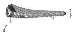
別の態様によれば、髄内挿入のための細長い本体とそれを通る上横孔とを備える大腿骨ブローチを備える大腿骨ブローチ装置が提供される。 According to another aspect, a femoral brooch device comprising a femoral brooch with an elongated body for intramedullary insertion and an superior transverse hole through it is provided.
孔は、使用時に挿入されるリーミングロッドの照準を定めることを可能にするために、細長い本体の長軸に平行な断面を有していてよく、前記断面は、長軸に沿ってより広い。したがって、大腿骨頚部及び大腿骨頭部を通るロッドの照準を調整するために、リーミングロッドの角度が細長い本体に対して調整され得る。 The hole may have a cross section parallel to the long axis of the elongated body to allow aiming of the reaming rod inserted during use, said cross section being wider along the long axis. Therefore, the angle of the reaming rod can be adjusted with respect to the elongated body to adjust the aiming of the rod through the femoral neck and head.
横孔の断面は卵形であり得る。 The cross section of the lateral hole can be oval.
孔は外内側方向にテーパし得る。 The holes can taper outward and medially.
横孔は、入口及び出口を画定することができ、出口内に配置するための少なくとも1つのガイドワイヤインサートをさらに備え、少なくとも1つのガイドワイヤインサートは、ガイド孔を備える。 The lateral holes can define inlets and outlets, further comprising at least one guidewire insert for placement within the outlet, and at least one guidewire insert comprising a guidehole.
少なくとも1つのガイドワイヤインサートは、それぞれ異なる角度の横孔を有する複数のガイドワイヤインサートを含み得る。 The at least one guide wire insert may include a plurality of guide wire inserts, each having a side hole at a different angle.
別の態様によれば、スパイン、直角近位ハンドル、直角骨盤延長アーム、及び直角大腿骨延長アームを備える関節形成術ジグが提供され、大腿骨延長アームは、スパインに沿って骨盤延長アームからオフセット可能である。 According to another aspect, an arthroplastic jig with a spine, a right-angled proximal handle, a right-angled pelvic extension arm, and a right-angled femoral extension arm is provided, with the femoral extension arm offset from the pelvic extension arm along the spine. It is possible.
骨盤延長アームの遠位端の内側面は、寛骨臼リム係合部を備え得る。 The medial aspect of the distal end of the pelvic extension arm may include an acetabular rim engagement.
骨盤延長アームの遠位端は、骨盤固定プレートを備え得る。 The distal end of the pelvic extension arm may include a pelvic fixation plate.
骨盤延長アームは、係合位置と係合解除位置との間で直角方向にオフセット可能であり得る。 The pelvic extension arm may be offset at right angles between the engaging and disengaging positions.
関節形成術ジグは、大腿骨延長アームと骨盤延長アームとの間に位置する直角駆動アームをさらに備え得る。 The arthroplasty jig may further include a right angle drive arm located between the femoral extension arm and the pelvic extension arm.
直角駆動アームは、係合位置と係合解除位置との間で直角方向にオフセット可能であり得る。 The right angle drive arm may be offset perpendicularly between the engaging and disengaging positions.
直角駆動アームの遠位端は、シャフト収容部を備え得る。 The distal end of the right angle drive arm may include a shaft housing.
大腿骨延長アームの遠位端は、シャフト収容部を備え得る。 The distal end of the femoral extension arm may include a shaft containment.
近位ハンドルの遠位端は、シャフト収容部を備え得る。 The distal end of the proximal handle may include a shaft housing.
別の態様によれば、フォークと、相対的にオフセット可能なベアラとを備える整復器が提供され、フォークは、2つの歯に分岐するステムを備える。 According to another aspect, a reduction device comprising a fork and a relatively offset bearer is provided, the fork comprising a stem that branches into two teeth.
ベアラは、フォークにねじ式にオフセット可能に係合され得る。 The bearer can be screwed and offset into the fork.
歯の遠位端は、インプラントリム又は骨盤孔係合部のうちの少なくとも1つのための少なくとも1つのフックを備える。 The distal end of the tooth comprises at least one hook for at least one of the implant rim or pelvic foramen engagement.
本発明の他の態様も開示される。 Other aspects of the invention are also disclosed.
あらゆる他の形態が本発明の範囲内に入る可能性があるにもかかわらず、本開示の好ましい実施形態を、単なる例として添付図を参照しながらここで説明する。 Despite the possibility that any other form falls within the scope of the invention, preferred embodiments of the present disclosure will be described herein by way of reference only by way of illustration.
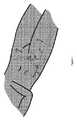
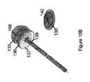
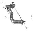
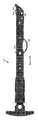
図1〜図25は、股関節100の関節形成技術を例示する。図1から分かるように、股関節100は、大腿骨骨幹部103、大腿骨頚部104、大腿骨頭部105、及び大腿骨大転子部108を有する大腿骨101を備える。大腿骨101は、寛骨臼106が形成された骨盤102に隣接して位置する。 1 to 25 illustrate the articulation technique of the hip joint 100. As can be seen from FIG. 1, the hip joint 100 includes a femur 101 having a
股関節100は、図1に示される概略的な位置にある上切開部107を介してアクセスされ得る。 The hip joint 100 can be accessed through the superior incision 107 at the approximate location shown in FIG.
向きは、「上」が患者の頭に向かい、「下」が足に向かうことに関連して以下で説明される。さらに、「外側」及びその派生語は、背断面において体の側部から離れる側を指し、「内側」及びその派生語は、この平面において体の側面に向かう側を指す。「外内側方向に」は、外側から内側への方向を指し、「内外側方向に」は、その反対方向を指す。 The orientation is explained below in relation to the "upper" towards the patient's head and the "lower" towards the foot. Further, "outside" and its derivatives refer to the side of the dorsal section away from the side of the body, and "inside" and its derivatives refer to the side of the body facing the sides in this plane. "Toward the outside and inside" refers to the direction from the outside to the inside, and "to the inside and outside" refers to the opposite direction.
図2を参照すると、本方法は、細長い大腿骨ブローチ109を髄内軸111に沿って大腿骨101の骨幹部103の髄腔に挿入することを含む。 With reference to FIG. 2, the method comprises inserting an elongated
通常、大腿骨101の上端部は、上切開部107を介してアクセスされることになる。アクセスされると、大腿骨101の梨状陥凹が、ブローチ109のための余地を作るべくドリルされ得る。その適切なサイズを決めるために、サイズが増加する一連のブローチ109が試され得る。 Normally, the upper end of the femur 101 will be accessed via the superior incision 107. Once accessed, the pyriform sinus of the femur 101 can be drilled to make room for the
取り外し可能なブローチハンドル112を、ブローチ109の上端部と選択的に係合させることができる。ブローチハンドル112の上端部は、ブローチ109を髄内管に駆動するために槌で打たれ得る。 The
大腿骨ブローチ109は、大腿骨頚部軸112と概して位置合わせされる上内外側横案内孔110を備える。横孔110は、外側入口と内側出口を有するものとして説明される。案内孔に隣接した大腿骨ブローチ109の外面は、この領域でのブローチのより多くの材料がブローチの強度を最大化することができるように平滑にされ得る。 The
図3は、異なるタイプのインプラントのインプラント角度115の多様性のために(一実施形態では卵形の断面を有することなどにより)孔110をブローチ109の長軸に沿ってより広げることができることを示す。さらに、孔110は、外内側方向にテーパし得る。ブローチ109は、他の実施形態では、角度調整が必要とされない場合に円筒形の孔を有し得る。 FIG. 3 shows that the
実施形態において、装置は、貫通する案内孔190を有する1つ以上の挿入可能なガイドプラグ113を備え得る。挿入可能なガイドプラグ113は、孔出口内に固定される外側挿入部116と、孔110から突出する内側ニブ114を備え得る。 In embodiments, the device may include one or more insertable guide plugs 113 having
さらに、選択されたインプラントコンポーネントの角度を模擬するべく挿入角度115を変えるために異なる案内孔190角度を有する異なるインサートガイド113が使用され得る。実施形態において、ニブ114の延長部は、大腿骨のオフセットを調整するために用いられ得る。 In addition, different insert guides 113 with
具体的には、図3B〜図3Cは、案内孔190の角度が増加する3つのタイプのインサートガイド113を示す。インプラントは、適宜異なる角度及びオフセットを試すための複数のインサートガイド113を備え得る。 Specifically, FIGS. 3B-3C show three types of insert guides 113 in which the angle of the
大腿骨ブローチ109が配置されると、大腿骨頭部105を取り外すために大腿骨頚部104が切断され得る。 Once the
次いで、ガイドワイヤ123がブローチ109を通してドリルされ得る。 The
図4〜図6は、ブローチハンドル112に取り付けることができる案内ジグ117を用いるガイドワイヤ123の外内側ドリリングを示す。 4 to 6 show the outer and inner drilling of the
案内ジグ117は、髄内軸111と並ぶ調整可能な境界線付きの深さ基準ピン118及び/又は直角外側オフセット基準ピン119で大転子部108を基準とし得る。直角基準ピン119は、オフセット調整機構121で制御され得る。 The
案内ジグ117は、オフセット調整可能な位置調整器122及び関連するオフセット境界線120を備え得る。 The
基準ピン118、119を使用してブローチ109の深さが設定されると、調整可能な位置調整器122の位置が、所望の挿入角度に応じて調整される。 When the depth of the
調整可能な位置調整器122は、孔110内のインサート113の方に向けられる異なる角度の複数の開口123を備え得る。図示した実施形態では、調整可能な位置調整器122は、インサート113のそれぞれに対応する3つの開口191を備え得る。 The
図5に示されるように、調整可能な位置調整器122が適正に設定されると、適切な開口123内に配置されたスリーブ124を介してガイドワイヤ123を孔110に通してドリルすることができる。 As shown in FIG. 5, when the
ガイドワイヤ123とぴったりと係合させるために直径を狭めるキャニュレイティッドインサート192をスリーブ124内に配置することができる。 A cannulated
ガイドワイヤ123の遠位端を、孔110及び案内インサート113に通して寛骨臼106に向けて進める。 The distal end of the
その後、ガイドワイヤ123が適正な角度に設定されると、図6から分かるように、キャニュレイティッドオーバードリル125をスリーブ124内のガイドワイヤ123に追従させて孔110に通して、直径およそ5mm(しかし潜在的にはおよそ3mm〜8mm)の大腿骨頚部通路を形成することができる。 After that, when the
手技の実施形態は、困難ではあるがガイドワイヤ123を使用せずに行われてもよい。 Embodiments of the procedure may be difficult but may be performed without the use of the
図7〜図9は、切開部107又は別の切開部を介して大腿骨101と寛骨臼106との間に挿入され得る湾曲したガイドチューブ126を用いるガイドワイヤ123の内外側ドリリングを代替的に示す。 7-9 replace the medial-lateral drilling of the
湾曲したガイドチューブ126は、ドリルガイドワイヤ123を受け入れるために広くされ得る入口128を備える。湾曲したガイドワイヤ126は、インサート113のニブ114と同軸に連結するため及びそれを通るガイドワイヤ123とぴったりと回転可能に係合するために狭くすることができる出口127をさらに備える。 The
図8は、可撓性のガイドワイヤ123が、腿を経由して外側に出るようにインサート113及び孔110に通されてガイドチューブ126の周りに案内されているところを示す。 FIG. 8 shows the
実施形態では、湾曲したガイドチューブ126の使用とは対照的に、直線ドリルが、ガイドワイヤ123と共に又はガイドワイヤ123なしに内外側方向に用いられ得る。 In an embodiment, in contrast to the use of a
図9は、直径およそ5mmの大腿骨頚部通路を形成するべくドリルガイドワイヤ123に追従する可撓性のキャニュレイティッドオーバードリル125を示す。 FIG. 9 shows a flexible cannulated
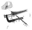
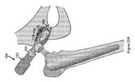
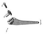
大腿骨頚部通路を形成した後で、図10は、一実施形態における寛骨臼106をリーミングするための関節形成術ジグ129の使用を示す。 After forming the femoral neck passage, FIG. 10 shows the use of an
関節形成術ジグ129は、スパイン133と直角駆動アーム130とを有する剛性のフレームワークを備える。ジグ129は、オフセットアーム131と近位ハンドル132も有することができる。直角駆動アーム130とオフセットアーム131は、切開部107又は別の切開部を介して挿入することができる。 The
リーミングのために、切断ヘッド135がその遠位端に作動可能に結合され得るように、ブローチ109を通るガイドワイヤ123に追従するキャニュレイティッドリーミングロッド141が示されている。実施形態において、リーミングロッド141は、ガイドワイヤ123が既に抜去されているか又は全く使用されない場合などにキャニュレイティッドではなくてもよい。 A cannulated
駆動アーム130及びオフセットアーム131の遠位端は、リーミングロッド141を通すためのノッチ134、開口などを備え得る。 The distal ends of the
近位ハンドル132、大腿骨ブローチ109、及び駆動アーム130は、リーミングロッド141をそれに沿った3点から支持し、精度を高め、ぐらつきを防止/低減するように協働することができる。 The
キャニュレイティッドリーミングロッド141は、アダプタプレート138の対応する内部接続部140と係合する遠位外部接続部139を備え得る。アダプタプレート138は、切断ヘッド135の対応する直角後方クロスバー198(又は他の一致するプロファイル)を着座させる直角チャネルを備え得る。代替的な実施形態では、リーミングロッド141の遠位外部接続部139は、アダプタプレート138を介するのとは対照的に、リーマ135の対応する内部接続部と直接係合し得る。 The cannulated
134からの摩擦を最小にし、メタローシスを回避するために、通常は非金属材料(ポリエチレンなど)で作製される自由に回転するベアリングプレート137を、アダプタプレート138の後ろに配置することができる。 A freely rotating
次いで、切断ヘッド135を使用して寛骨臼106がリーミングされる。リーミングは、直径が増加する一連の切断ヘッド135の使用を含み得る。 The acetabulum 106 is then reamed using the cutting
具体的には、関節形成術ジグ129の駆動アーム130をベアリングプレート137の後ろに作動的に配置して切断ヘッド135を寛骨臼106に押し込む間、切断ヘッド135を対応して回転させるべくリーミングロッド141が回転させられ得る。駆動アーム130を介してベアリングプレート137上に圧力をかけるために近位ハンドル132が押され得る。 Specifically, the
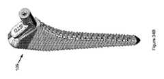
図11に示されるように、オフセットアーム131は、ブローチ109と寛骨臼106との間の距離を測るためにスパイン133に沿って駆動アーム130に対してスライドすることができる。スパイン133は、そこからの距離を読み取るためにそれに沿ってマーク200を備え得る。 As shown in FIG. 11, the offset
逆に、図12に示されるように、オフセットアーム131を駆動アーム130の方へ配置することにより、視覚化のためのアクセス及び/又は切断ヘッド135へのアクセスが可能となり得る。 Conversely, as shown in FIG. 12, by arranging the offset
図11に示されるように、寛骨臼106の底部を基準とするべくガイドワイヤ123は切断ヘッド135の頂点を通り得る。したがって、リーミングロッド141とガイドワイヤ123との間の差動スケール201は、リーミング深さを確認するための基準となり得る。 As shown in FIG. 11, the
実施形態において、リーミングロッド141が、大腿骨103を基準としてブローチ109によって案内され得る。したがって、大腿骨103が数度移動されると、寛骨臼リーマの位置が、同じ度数だけ同様に調整されることになる。さらに、大腿骨が地面に平行であり、且つブローチ109の角度が設定されている場合、寛骨臼の位置を正確に決定することができる。 In an embodiment, the reaming
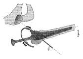
図13に示されるように、寛骨臼106が適切にリーミングされると、切断ヘッド135の取り外し及び寛骨臼インプラント142との置換のための余地を作るべく、オフセットアーム131が駆動アーム130の近くに配置される。 As shown in FIG. 13, when the acetabulum 106 is properly reamed, the offset
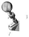
図14に示されるように、円錐形アダプタ143は、適合するねじ切り部144、145又は他の適切な噛み合い/係合を介してインプラント142の内側頂点と接続することができる。 As shown in FIG. 14, the
リーミングロッド141は、取り外され、インパクタロッド172に置換され得る。代替的に、同じリーミングロッド141が使用され得る。円錐形アダプタ143の近位端は、インパクタロッド172の遠位端と係合するための係合ポート146を画定し得る。 The reaming
インパクタロッド172の近位端を保持するために、インパクタロッドアウトリガー147が用いられ得る。アウトリガー147は、ハンドル173と、実施形態では、槌で打つ、手でたたくことなどをすることができるストライクプレート148を備え得る。 An impactor rod outrigger 147 can be used to hold the proximal end of the impactor rod 172. The outriggers 147 may include a
インパクタロッド172は、ガイドワイヤ123をその中に通すために同様にキャニュレイティッドであり得る。さらに、ハンドル173は、ガイドワイヤ123を通す中央孔を備え得る。同様に、ハンドル173とガイドワイヤ123との間の差動オフセットスケールは、インプラント142の打ち込み深さを示すことができる。 The impactor rod 172 can also be cannulated to allow the
インパクタロッド172は、主にインプラント142の適切な配向を維持することができ、打ち込み力の矛先は、関節形成術ジグ129によって保たれ得る。 The impactor rod 172 can mainly maintain the proper orientation of the
インプラント142を着座させた後で、円錐形アダプタ143が、通常はねじを外すことによって、インプラント142から取り外され得る。さらに、リーミングロッド172とリーミングロッドアウトリガー147が取り外され得る。 After seating the
次に、図15は、一実施形態におけるインプラント142の適切な孔の中に固定スクリュー150を締結するのに用いられるスクリュードライバロッド149を有するスクリュードライバ151の使用を示す。スクリュードライバ151の挿入のためにガイドワイヤ123は抜去され得る。 Next, FIG. 15 shows the use of a
実施形態において、スクリュードライバロッド149は、適切な位置に手動で操作できるように可撓性であり得る。実施形態において、スクリュードライバロッド149を適切に配向するべく患者の脚が位置決めされ得る。 In embodiments, the
インプラント142を固定した後で、図16に示されるように実際の又はトライアルのライナ152が挿入され得る。ライナ152を着座させるためにインパクタロッド172をトライアルヘッド153と係合させることができる。図17は、ヘッド153を用いてライナ152をカップ142に押し込むためのインパクタロッド172の打ち込みを示す。 After immobilizing the
ここでトライアル整復が行われ得る。図18は、脚の長さ、オフセット、安定性などを最適化するべく異なるコンポーネント長さを試すための寸法決めトライアルインサート154の使用を例示する。 Trial reduction can be performed here. FIG. 18 illustrates the use of a
寸法決めトライアルインサート154は、インパクタロッド172のシャフトの周りにクリップするために、円筒形で長手方向に開口可能であり得る。さらに、5、10、13mmなどの長さの、異なる長さの複数のトライアルインサート154が提供され得る。 The sizing
図19は、インサートガイド113とカップ142との間のインパクタロッド172に沿った2つのトライアルインサート154の直列挿入を例示する。 FIG. 19 illustrates the series insertion of two trial inserts 154 along the impactor rod 172 between the
図20は、ねじ付きロッド159の対応するねじ山158と回転可能に係合する内ねじ157を備えるオフセット調整可能なインサート155がブローチ109の孔110内に配置される代替的なトライアル整復器を示す。 FIG. 20 shows an alternative trial reducer in which an offset
したがって、インサート155に対するねじ付きロッド159の回転により、トライアルヘッド152の長さ及びオフセットが調整される。 Therefore, the rotation of the threaded
代替的に、ブローチインサート155上に別個のアタッチメントを挿入することができる。 Alternatively, a separate attachment can be inserted on the
図21に示されるように、ねじ付きロッド159は、ミリメートルの長さを示すことができるマーク156を備え得る。したがって、ねじ付きロッド159は、所望の長さ及びオフセットを達成するべく回転させられ、その際にマーク156からの読取値が注目される。 As shown in FIG. 21, the threaded
図19又は図20及び図21に示された装置に従って行われるトライアル整復は、異なるトライアルヘッド及びネック長の挿入のたびに股関節を脱臼させる従来のステップの必要をなくす。 Trial reduction performed according to the device shown in FIG. 19 or FIGS. 20 and 21 eliminates the need for the conventional step of dislocating the hip joint with each insertion of a different trial head and neck length.
図22は、大腿骨ブローチ109の取り外し及び実際のインプラント160との置換を例示する。 FIG. 22 illustrates the removal of the
図22Bは、一実施形態におけるインプラントヘッド161をライナ152に案内するための整復器164の使用を例示する。整復器164は、ライナ152への入口の周りでステムプレート174から分岐する一対の分岐歯175を備え得るフォーク176を備え得る。フォーク176の遠位端は、骨盤孔又はカップ142の下縁と係合する係合部163を備え得る。実施形態において、ライナ(図示せず)内に配置されるボールなどのライナ内に配置される反対牽引機構が、実際のヘッド153が挿入されるときに変位し得る。 FIG. 22B illustrates the use of a
大腿骨コンポーネントヘッド153は、それに沿ってスライドすることができるように、最初にステムプレート174に接する状態で配置され得る。ステムプレート174は、ヘッド153を中央に付勢するように長手方向に凹形であり得る。 The
整復器164は、ねじ、ラチェット機構などの使用によりフォーク176に対してオフセット調整可能なハンドル162をさらに備え得る。したがって、インプラントヘッド161をステムプレート174に接する状態で配置すると、ハンドル162がフォーク176に向けてオフセットされ、これにより、ベアリングヘッド164がインプラントヘッド161に当接し、インプラントヘッド161が図23Bに実質的に示されるように歯175間のライナ152内に配置されるようになるまで、図23Aに実質的に示されるようにインプラントヘッド153がステム174に沿ってライナ152の入口に向けて押される。 The
図24は、完成した表面置換型股関節100を示す。 FIG. 24 shows the completed surface-replacement hip joint 100.
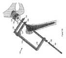
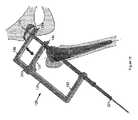
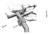
図25は、一実施形態における延長と駆動との両方のために構成された本技術の関節形成術ジグ165を示す。 FIG. 25 shows an
関節形成術ジグ165は、スパイン175と、実施形態において湾曲した移行部を介してスパイン175に隣接することができる直角近位ハンドル170とを備え得る、剛性のフレーム176を備え得る。近位ハンドル170の遠位端は、インサート収容部177を備え得る。 The
スパイン175は、ラチェット及び歯止め機構又は他の機構171によってそれに沿って直角大腿骨延長アーム168を支持することができる。 The
スパイン177は、大腿骨101を寛骨臼106から延長するために大腿骨延長アーム168とは反対側で直角骨盤延長アーム169をさらに支持することができる。 The
延長アーム169は、以下に説明する様態で係合位置と係合解除位置との間で直角に調整可能であり得る。骨盤延長アーム169の遠位端の内側面は、寛骨臼106のリムと係合するための半球形の溝195を備え得る。 The
スパイン177は、延長アーム168、169間に位置する直角駆動アーム167をさらに支持することができる。直角駆動アーム169は、係合解除位置と係合位置との間で同様に直角にオフセット調整可能であり得る。 The
図26は、リーミングのための関節形成術ジグ165の使用を例示する。具体的には、近位ハンドル170のインサート収容部177内のインサート169開口を介する、近位端でのリーミングロッド141の係合が示されている。インサート169は、正確なリーミングのための3つの固定点のうちの1つであることによってロッド141を安定化させる。 FIG. 26 illustrates the use of an
リーミングロッド141の遠位端は、大腿骨延長アーム168及び駆動アーム167の遠位端のノッチ134(又は開口など)内に係合される。駆動アーム167は係合位置に示されている。 The distal end of the reaming
図26Bは、切断ヘッド135、アダプタプレート138、及び近位ベアリングプレート137の係合を示す。 FIG. 26B shows the engagement of the cutting
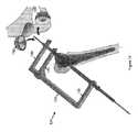
図27は、関節形成術ジグ165の使用をさらに示す。具体的には、図27Aは、大腿骨101を寛骨臼から延長するための、骨盤延長アーム169から離れる方への大腿骨延長アーム168のオフセットを示す。大腿骨延長アーム168を骨盤延長アーム169から離れる方へオフセットさせるために、ラチェット及び歯止め機構171又は他の機構のターンキーが回転され得る。駆動アーム167は係合解除された状態で示されている。 FIG. 27 further illustrates the use of the
骨盤延長アーム169の内側に面する寛骨臼リム係合溝195は、寛骨臼106のリムと係合し得る。 The acetabular
実施形態において、ジグ165は、大腿骨延長アーム168を有さない。この実施形態では、駆動アーム169の外側面は、大腿骨ブローチ109の内側面と当接することができる。 In an embodiment, the
大腿骨が延長されるとき、切断ヘッド135及び関連するコンポーネントが、リーミングロッド144の遠位端に締結され得る。 When the femur is extended, the cutting
その後、ベアリングアーム167が、その遠位端がベアリングプレート137の後ろに位置し、且つリーミングロッド141がノッチ134内に係合されるように、直角下向き移行部によって係合され得る。 The
次いで、骨盤延長アーム169が寛骨臼から係合解除され、図27Bに示された係合解除位置に直角に移動され得るように、ラチェット及び歯止め機構171が解放され得る。 The ratchet and
次いで、係合した駆動アーム167を介して切断ヘッド135を駆動する近位ハンドル171に力をかけることにより、寛骨臼106がリーミングされ得る。切断ヘッド135を回転させるために同時にリーミングロッド141が回転させられる。 The acetabulum 106 can then be reamed by exerting a force on the
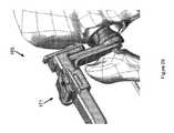
図28は、カップの打ち込みのための関節形成術ジグ165の使用を示し、この場合、ジグ165は、インパクタロッド172、円錐形アダプタ143、及びインプラント142を同様に支持する。 FIG. 28 shows the use of an
図29に示されるように、打ち込み中に、駆動アーム167を介してインプラント142を寛骨臼106に打ち込むために近位ハンドル170の近位面を打つことができるように、骨盤延長アーム169が係合解除され、大腿骨延長アーム168が解放され得る。 As shown in FIG. 29, during driving, the
図30は、骨盤延長アーム169が、前述のように寛骨臼のリムと係合するのとは対照的に、固定スクリュー、ピンなどを使用して骨盤102に締結され得る骨盤取付プレート177を備える一実施形態を例示する。 FIG. 30 shows a
大腿骨ブローチ109の上端部は、大腿骨ハンマー係合入口ポート179と、図32に実質的に例示した様態でブローチハンドル112と係合するための直角ラッチポート178を備え得る。具体的には、図32Aは、入口ポート179内に配置される挿入端181を備えるハンドル112の遠位端を示す。直角ラッチ180は、ピボット182の周りから直角ラッチポート178に選択的に延びる。ラッチ180は、アクセス可能な戻り止めアーム183を押し下げることによって係合解除可能であり、且つ、アーム184を付勢することによってリセットされる。 The upper end of the
図33は、大転子部108を基準とする深さガイド195を備えるハンドル112の一実施形態をさらに示す。深さガイド195は、トラック196に沿ってスケール196から読み取ることができる異なる位置にスライド可能であり得る。オフセットインサート197は、患者の骨の幾何学的形状に応じて深さガイド195を外側に離間させることができる。 FIG. 33 further shows one embodiment of the
図34は、ブローチインサート113が入口ポート179を覆うフランジ183を備える一実施形態を示す。さらに、インサート113は、より小さい内径のガイドワイヤインサート182と選択的に係合し得る。ガイドワイヤインサート182は、ガイドワイヤ123を最初に案内するために使用され、その後、キャニュレイティッドリーミング・ドライブロッド144から取り外され得る。 FIG. 34 shows an embodiment in which the
図35は、トライアル整復のためのトライアルステムロッド184と、締め付けのためにインサート113内に又は上にねじ式に配置されるフィンガグリップバレル185を例示する。ロッド184が回転させられるときにインサート113からのロッド184の長さ及びオフセットが調整されるように185内に雌ねじが存在し得る。これにより、異なる長さのトライアルヘッドを試すたびに股関節を脱臼させる必要がなくなる。 FIG. 35 illustrates a
図36は、遠位クランプ189を使用して手術台(図示せず)にクランプされる支柱186を備える関節形成術ジグ165の固定を例示する。直角支持アームが、ジグ165のスパイン175と係合する遠位ハンド188を備える支柱186とスライド可能に係合する。 FIG. 36 illustrates the fixation of an
上記の説明は、解説する目的で、本発明の十分な理解をもたらすために特定の命名法を用いている。しかしながら、本発明を実施するために具体的な詳細は必要とされないことが当業者には明らかであろう。したがって、本発明の具体的な実施形態の上記の説明は、例示及び説明する目的で提示されている。それらは網羅的であること又は本発明を開示された正確な形態に限定することを意図しておらず、明らかに、上記の教示を考慮して多くの修正及び変形が可能である。本技術及び装置は、主に股関節形成術に関連して説明されているが、実施形態では他の関節に適用されてもよい。本発明の原理及びその実際の用途を最もよく解説するために実施形態が選択され、説明され、それにより、当業者は、考えられる特定の使用に適するように種々の修正を加えて本発明及び種々の実施形態を最良に使用することができる。以下の請求項及びそれらの均等物は本発明の範囲を定めることを意図している。 The above description uses certain nomenclature to provide a good understanding of the present invention for purposes of explanation. However, it will be apparent to those skilled in the art that no specific details are required to practice the present invention. Therefore, the above description of specific embodiments of the present invention is presented for purposes of illustration and explanation. They are not intended to be exhaustive or to limit the invention to the exact forms disclosed, and apparently many modifications and modifications are possible in light of the above teachings. Although the techniques and devices have been described primarily in the context of hip arthroplasty, in embodiments they may be applied to other joints. Embodiments have been selected and described to best illustrate the principles of the invention and its practical use, whereby those skilled in the art will make various modifications to suit the particular use of the invention and its potential. Various embodiments can be best used. The following claims and their equivalents are intended to define the scope of the invention.
Claims (36)
Translated fromJapanese上外内側横孔を備える細長い大腿骨ブローチを骨幹部に髄内挿入することと、
リーミングロッドを前記横孔及び大腿骨頚部に通して配置することと、
切開部を介して前記リーミングロッドの遠位端に切断ヘッドを結合することと、
寛骨臼をリーミングするべく前記リーミングロッドを用いて前記切断ヘッドを回転させることと、
を含む、方法。A method for performing a hip arthroplasty involving a femur having a femoral shaft, a femoral neck, and a femoral head, and an adjacent pelvis in which a scrotum is formed.
Intramedullary insertion of an elongated femoral brooch with superior, lateral, medial lateral holes into the trunk,
Placing the reaming rod through the lateral hole and the neck of the femur
To connect the cutting head to the distal end of the reaming rod through the incision,
Rotating the cutting head with the reaming rod to ream the acetabulum
Including methods.
前記駆動アームを用いて前記切断ヘッドを駆動することと、
をさらに含む、請求項1に記載の方法。The right-angle drive arm of the arthroplasty jig is inserted and placed behind the cutting head to operatively compress the cutting head.
Using the drive arm to drive the cutting head,
The method according to claim 1, further comprising.
ガイドワイヤを前記横孔と大腿骨頚部及び頭部に通してドリリングすることと、
大腿骨頚部通路を形成するべくキャニュレイティッドオーバードリルを前記ドリルガイドワイヤに追従させることと、
前記キャニュレイティッドオーバードリルを除去することと、
前記リーミングロッドを前記ドリルガイドワイヤに追従させることと、
を含む、請求項1に記載の方法。Placing the reaming rod
Drilling through the lateral hole and the femoral neck and head with a guide wire
To make the cannulated overdrill follow the drill guide wire to form the femoral neck passage,
To remove the cannulated overdrill and
To make the reaming rod follow the drill guide wire,
The method according to claim 1, wherein the method comprises.
Applications Claiming Priority (3)
| Application Number | Priority Date | Filing Date | Title |
|---|---|---|---|
| AU2017905106 | 2017-12-21 | ||
| AU2017905106AAU2017905106A0 (en) | 2017-12-21 | Minimally invasive hip arthroplasty techniques and apparatus | |
| PCT/AU2018/051375WO2019119052A1 (en) | 2017-12-21 | 2018-12-21 | Minimally invasive hip arthroplasty techniques and apparatus |
Publications (1)
| Publication Number | Publication Date |
|---|---|
| JP2021506553Atrue JP2021506553A (en) | 2021-02-22 |
Family
ID=66992460
Family Applications (1)
| Application Number | Title | Priority Date | Filing Date |
|---|---|---|---|
| JP2020554329APendingJP2021506553A (en) | 2017-12-21 | 2018-12-21 | Minimally invasive hip arthroplasty technology and equipment |
Country Status (7)
| Country | Link |
|---|---|
| US (1) | US11633196B2 (en) |
| EP (1) | EP3727208B1 (en) |
| JP (1) | JP2021506553A (en) |
| AU (1) | AU2018387124B2 (en) |
| CA (1) | CA3086251A1 (en) |
| GB (1) | GB2583670B (en) |
| WO (1) | WO2019119052A1 (en) |
Cited By (2)
| Publication number | Priority date | Publication date | Assignee | Title |
|---|---|---|---|---|
| JP2025031685A (en)* | 2023-08-23 | 2025-03-07 | グローバス メディカル インコーポレイティッド | Extendable trial femoral neck and related methods of use - Patents.com |
| JP7756211B2 (en) | 2023-08-23 | 2025-10-17 | グローバス メディカル インコーポレイティッド | Extendable trial femoral neck |
Families Citing this family (7)
| Publication number | Priority date | Publication date | Assignee | Title |
|---|---|---|---|---|
| GB201705917D0 (en) | 2017-04-12 | 2017-05-24 | Davidson Craig | Femoral trialling kit and assembly |
| US11369492B2 (en)* | 2017-08-22 | 2022-06-28 | Depuy Ireland Unlimited Company | Trial neck |
| GB201716107D0 (en) | 2017-10-03 | 2017-11-15 | Depuy Ireland Ultd Co | Trial neck apparatus and method |
| CN112137734B (en)* | 2020-09-25 | 2024-03-01 | 林焱斌 | Femoral intertrochanteric fracture body surface incision positioner |
| US12127955B2 (en) | 2021-04-29 | 2024-10-29 | Depuy Ireland Unlimited Company | Trial component and method |
| WO2024035712A1 (en)* | 2022-08-08 | 2024-02-15 | Ohio State Innovation Foundation | Jigs and related methods for guiding a cutting instrument for controlled surgical cutting of a body portion of a patient |
| CH720896A1 (en)* | 2023-06-27 | 2025-01-15 | Beck Martin | Surgical device for abrasive treatment of a natural hip joint |
Citations (1)
| Publication number | Priority date | Publication date | Assignee | Title |
|---|---|---|---|---|
| US20060200160A1 (en)* | 2005-02-18 | 2006-09-07 | Ebi, L.P. | Internal fixation assemblies and associated instruments |
Family Cites Families (26)
| Publication number | Priority date | Publication date | Assignee | Title |
|---|---|---|---|---|
| US3709218A (en)* | 1970-04-24 | 1973-01-09 | W Halloran | Combination intramedullary fixation and external bone compression apparatus |
| US4549319A (en)* | 1982-08-03 | 1985-10-29 | United States Medical Corporation | Artificial joint fixation to bone |
| US4587964A (en)* | 1985-02-05 | 1986-05-13 | Zimmer, Inc. | Rasp tool |
| FR2584915B1 (en)* | 1985-07-19 | 1990-02-09 | France Implant | RAPE FOR THE PREPARATION OF THE MEDULAR CHANNEL OF A BONE FOR RECEIVING A PROSTHESIS |
| US4921493A (en)* | 1986-08-11 | 1990-05-01 | Zimmer, Inc. | Rasp tool |
| US6494913B1 (en) | 1998-03-17 | 2002-12-17 | Acumed, Inc. | Shoulder prosthesis |
| DE10036985A1 (en)* | 2000-07-29 | 2002-02-07 | Klaus Draenert | Femur component of artificial hip joint for cement-free implantation comprises prosthesis whose shaft has no bearing collar and whose constructional axis coincides with the femur channel axis |
| US6755865B2 (en)* | 2001-09-24 | 2004-06-29 | Imad Ed. Tarabishy | Joint prosthesis and method for placement |
| WO2003026518A1 (en)* | 2001-09-27 | 2003-04-03 | Depuy International Limited | Surgical instruments |
| US20030130741A1 (en) | 2002-01-07 | 2003-07-10 | Mcminn Derek James Wallace | Hip prosthesis |
| US6695883B2 (en) | 2002-04-11 | 2004-02-24 | Theodore W. Crofford | Femoral neck fixation prosthesis |
| US7105028B2 (en)* | 2003-10-21 | 2006-09-12 | Wright Medical Technology, Inc. | Tissue preserving and minimally invasive hip replacement surgical procedure |
| US7833228B1 (en)* | 2004-01-05 | 2010-11-16 | Biomet Manufacturing Corp. | Method and instrumentation for performing minimally invasive hip arthroplasty |
| US7582090B2 (en)* | 2004-03-04 | 2009-09-01 | Wright Medical Technology, Inc. | Bone preserving total hip arthroplasty using autograft |
| US8579985B2 (en)* | 2006-12-07 | 2013-11-12 | Ihip Surgical, Llc | Method and apparatus for hip replacement |
| EP2094197B8 (en) | 2006-12-07 | 2016-03-09 | IHip Surgical, LLC | Apparatus for total hip replacement |
| US7918853B2 (en)* | 2007-03-20 | 2011-04-05 | Smith & Nephew, Inc. | Orthopaedic plate and screw assembly |
| US8932301B2 (en)* | 2009-08-26 | 2015-01-13 | Biomet C.V. | Targeting jig for hip fracture nail system |
| US20140031948A1 (en)* | 2012-07-26 | 2014-01-30 | Patrick M. Birmingham | Method and device for joint replacement |
| US9610084B2 (en) | 2012-09-12 | 2017-04-04 | Peter Michael Sutherland Walker | Method and apparatus for hip replacements |
| US9675363B2 (en)* | 2015-11-13 | 2017-06-13 | Advance Research System, Llc | Surgical tools having application for spinal surgical procedures and method of use |
| US10299847B2 (en)* | 2016-09-22 | 2019-05-28 | Globus Medical, Inc. | Systems and methods for intramedullary nail implantation |
| US10751096B2 (en)* | 2016-09-22 | 2020-08-25 | Bala Sundararajan | Systems and methods for intramedullary nail implantation |
| WO2019038203A1 (en)* | 2017-08-21 | 2019-02-28 | Depuy Ireland Unlimited Company | A guide, kit of parts and guide assembly for hip surgery |
| IT201900002543A1 (en)* | 2019-02-21 | 2020-08-21 | Medacta Int Sa | DEVICE FOR POSITIONING A SURGICAL INSTRUMENT FOR HIP ARTHROPLASTIC OPERATIONS |
| US11109982B2 (en)* | 2019-09-07 | 2021-09-07 | Ihip Surgical, Llc | System and method for total hip arthroplasty |
- 2018
- 2018-12-21AUAU2018387124Apatent/AU2018387124B2/enactiveActive
- 2018-12-21JPJP2020554329Apatent/JP2021506553A/enactivePending
- 2018-12-21EPEP18892310.6Apatent/EP3727208B1/enactiveActive
- 2018-12-21CACA3086251Apatent/CA3086251A1/enactivePending
- 2018-12-21USUS15/733,275patent/US11633196B2/enactiveActive
- 2018-12-21WOPCT/AU2018/051375patent/WO2019119052A1/ennot_activeCeased
- 2018-12-21GBGB2011007.8Apatent/GB2583670B/ennot_activeExpired - Fee Related
Patent Citations (1)
| Publication number | Priority date | Publication date | Assignee | Title |
|---|---|---|---|---|
| US20060200160A1 (en)* | 2005-02-18 | 2006-09-07 | Ebi, L.P. | Internal fixation assemblies and associated instruments |
Cited By (2)
| Publication number | Priority date | Publication date | Assignee | Title |
|---|---|---|---|---|
| JP2025031685A (en)* | 2023-08-23 | 2025-03-07 | グローバス メディカル インコーポレイティッド | Extendable trial femoral neck and related methods of use - Patents.com |
| JP7756211B2 (en) | 2023-08-23 | 2025-10-17 | グローバス メディカル インコーポレイティッド | Extendable trial femoral neck |
Also Published As
| Publication number | Publication date |
|---|---|
| AU2018387124A1 (en) | 2020-07-02 |
| EP3727208C0 (en) | 2023-10-11 |
| EP3727208A4 (en) | 2021-09-15 |
| GB2583670B (en) | 2022-02-16 |
| GB2583670A (en) | 2020-11-04 |
| WO2019119052A1 (en) | 2019-06-27 |
| CA3086251A1 (en) | 2019-06-27 |
| US20210093332A1 (en) | 2021-04-01 |
| EP3727208B1 (en) | 2023-10-11 |
| US11633196B2 (en) | 2023-04-25 |
| AU2018387124B2 (en) | 2021-07-29 |
| EP3727208A1 (en) | 2020-10-28 |
| GB202011007D0 (en) | 2020-09-02 |
Similar Documents
| Publication | Publication Date | Title |
|---|---|---|
| JP2021506553A (en) | Minimally invasive hip arthroplasty technology and equipment | |
| JP6591142B2 (en) | Tibial trial instrument for offset setting | |
| US6695850B2 (en) | Minimally invasive total hip replacement | |
| US7935125B2 (en) | Compound offset handle | |
| US6478799B1 (en) | Instruments and methods for use in performing knee surgery | |
| RU2742969C2 (en) | System for tibial preparation of patient in orthopedic operation of replacement arthroplasty | |
| JP5697999B2 (en) | System and method for performing a modular revision hip prosthesis | |
| CN104661619B (en) | Intramedullary Ankle Technology and Systems | |
| US20100137924A1 (en) | Tool | |
| US20070162038A1 (en) | Tool | |
| US9610084B2 (en) | Method and apparatus for hip replacements | |
| US20080033444A1 (en) | Compound offset handle | |
| US10271963B2 (en) | Referencing apparatus and associated methods | |
| US20170056185A1 (en) | Hip replacement systems and methods | |
| US12053189B2 (en) | Orthopaedic broach extraction tool | |
| EP2710968B1 (en) | Apparatus for hip replacements | |
| CN120417861A (en) | Orthopaedic surgical instruments, systems and methods for installing cemented femoral stem components in direct anterior hip replacement surgery |
Legal Events
| Date | Code | Title | Description |
|---|---|---|---|
| A621 | Written request for application examination | Free format text:JAPANESE INTERMEDIATE CODE: A621 Effective date:20211216 | |
| A621 | Written request for application examination | Free format text:JAPANESE INTERMEDIATE CODE: A621 Effective date:20211216 | |
| A977 | Report on retrieval | Free format text:JAPANESE INTERMEDIATE CODE: A971007 Effective date:20221209 | |
| A131 | Notification of reasons for refusal | Free format text:JAPANESE INTERMEDIATE CODE: A131 Effective date:20221213 | |
| A02 | Decision of refusal | Free format text:JAPANESE INTERMEDIATE CODE: A02 Effective date:20230704 |