JP2021506145A - Multi-layer link recovery method and controller with failure - Google Patents
Multi-layer link recovery method and controller with failureDownload PDFInfo
- Publication number
- JP2021506145A JP2021506145AJP2020526119AJP2020526119AJP2021506145AJP 2021506145 AJP2021506145 AJP 2021506145AJP 2020526119 AJP2020526119 AJP 2020526119AJP 2020526119 AJP2020526119 AJP 2020526119AJP 2021506145 AJP2021506145 AJP 2021506145A
- Authority
- JP
- Japan
- Prior art keywords
- link
- network device
- controller
- port
- network
- Prior art date
- Legal status (The legal status is an assumption and is not a legal conclusion. Google has not performed a legal analysis and makes no representation as to the accuracy of the status listed.)
- Granted
Links
Images


Classifications
- H—ELECTRICITY
- H04—ELECTRIC COMMUNICATION TECHNIQUE
- H04L—TRANSMISSION OF DIGITAL INFORMATION, e.g. TELEGRAPHIC COMMUNICATION
- H04L41/00—Arrangements for maintenance, administration or management of data switching networks, e.g. of packet switching networks
- H04L41/06—Management of faults, events, alarms or notifications
- H04L41/0654—Management of faults, events, alarms or notifications using network fault recovery
- H04L41/0668—Management of faults, events, alarms or notifications using network fault recovery by dynamic selection of recovery network elements, e.g. replacement by the most appropriate element after failure
- H—ELECTRICITY
- H04—ELECTRIC COMMUNICATION TECHNIQUE
- H04B—TRANSMISSION
- H04B10/00—Transmission systems employing electromagnetic waves other than radio-waves, e.g. infrared, visible or ultraviolet light, or employing corpuscular radiation, e.g. quantum communication
- H04B10/03—Arrangements for fault recovery
- H—ELECTRICITY
- H04—ELECTRIC COMMUNICATION TECHNIQUE
- H04L—TRANSMISSION OF DIGITAL INFORMATION, e.g. TELEGRAPHIC COMMUNICATION
- H04L41/00—Arrangements for maintenance, administration or management of data switching networks, e.g. of packet switching networks
- H04L41/04—Network management architectures or arrangements
- H04L41/044—Network management architectures or arrangements comprising hierarchical management structures
- H—ELECTRICITY
- H04—ELECTRIC COMMUNICATION TECHNIQUE
- H04L—TRANSMISSION OF DIGITAL INFORMATION, e.g. TELEGRAPHIC COMMUNICATION
- H04L41/00—Arrangements for maintenance, administration or management of data switching networks, e.g. of packet switching networks
- H04L41/06—Management of faults, events, alarms or notifications
- H04L41/0631—Management of faults, events, alarms or notifications using root cause analysis; using analysis of correlation between notifications, alarms or events based on decision criteria, e.g. hierarchy, tree or time analysis
- H—ELECTRICITY
- H04—ELECTRIC COMMUNICATION TECHNIQUE
- H04L—TRANSMISSION OF DIGITAL INFORMATION, e.g. TELEGRAPHIC COMMUNICATION
- H04L41/00—Arrangements for maintenance, administration or management of data switching networks, e.g. of packet switching networks
- H04L41/40—Arrangements for maintenance, administration or management of data switching networks, e.g. of packet switching networks using virtualisation of network functions or resources, e.g. SDN or NFV entities
- H—ELECTRICITY
- H04—ELECTRIC COMMUNICATION TECHNIQUE
- H04L—TRANSMISSION OF DIGITAL INFORMATION, e.g. TELEGRAPHIC COMMUNICATION
- H04L45/00—Routing or path finding of packets in data switching networks
- H04L45/24—Multipath
- H04L45/245—Link aggregation, e.g. trunking
- H—ELECTRICITY
- H04—ELECTRIC COMMUNICATION TECHNIQUE
- H04L—TRANSMISSION OF DIGITAL INFORMATION, e.g. TELEGRAPHIC COMMUNICATION
- H04L45/00—Routing or path finding of packets in data switching networks
- H04L45/28—Routing or path finding of packets in data switching networks using route fault recovery
- H—ELECTRICITY
- H04—ELECTRIC COMMUNICATION TECHNIQUE
- H04L—TRANSMISSION OF DIGITAL INFORMATION, e.g. TELEGRAPHIC COMMUNICATION
- H04L45/00—Routing or path finding of packets in data switching networks
- H04L45/64—Routing or path finding of packets in data switching networks using an overlay routing layer
- H—ELECTRICITY
- H04—ELECTRIC COMMUNICATION TECHNIQUE
- H04L—TRANSMISSION OF DIGITAL INFORMATION, e.g. TELEGRAPHIC COMMUNICATION
- H04L47/00—Traffic control in data switching networks
- H04L47/10—Flow control; Congestion control
- H04L47/41—Flow control; Congestion control by acting on aggregated flows or links
- H—ELECTRICITY
- H04—ELECTRIC COMMUNICATION TECHNIQUE
- H04L—TRANSMISSION OF DIGITAL INFORMATION, e.g. TELEGRAPHIC COMMUNICATION
- H04L49/00—Packet switching elements
- H04L49/55—Prevention, detection or correction of errors
- H04L49/555—Error detection
- H—ELECTRICITY
- H04—ELECTRIC COMMUNICATION TECHNIQUE
- H04L—TRANSMISSION OF DIGITAL INFORMATION, e.g. TELEGRAPHIC COMMUNICATION
- H04L49/00—Packet switching elements
- H04L49/55—Prevention, detection or correction of errors
- H04L49/557—Error correction, e.g. fault recovery or fault tolerance
- H—ELECTRICITY
- H04—ELECTRIC COMMUNICATION TECHNIQUE
- H04L—TRANSMISSION OF DIGITAL INFORMATION, e.g. TELEGRAPHIC COMMUNICATION
- H04L49/00—Packet switching elements
- H04L49/60—Software-defined switches
- H04L49/602—Multilayer or multiprotocol switching, e.g. IP switching
- H—ELECTRICITY
- H04—ELECTRIC COMMUNICATION TECHNIQUE
- H04Q—SELECTING
- H04Q11/00—Selecting arrangements for multiplex systems
- H04Q11/0001—Selecting arrangements for multiplex systems using optical switching
- H04Q11/0062—Network aspects
- H—ELECTRICITY
- H04—ELECTRIC COMMUNICATION TECHNIQUE
- H04Q—SELECTING
- H04Q11/00—Selecting arrangements for multiplex systems
- H04Q11/0001—Selecting arrangements for multiplex systems using optical switching
- H04Q11/0062—Network aspects
- H04Q2011/0079—Operation or maintenance aspects
- H04Q2011/0081—Fault tolerance; Redundancy; Recovery; Reconfigurability
- Y—GENERAL TAGGING OF NEW TECHNOLOGICAL DEVELOPMENTS; GENERAL TAGGING OF CROSS-SECTIONAL TECHNOLOGIES SPANNING OVER SEVERAL SECTIONS OF THE IPC; TECHNICAL SUBJECTS COVERED BY FORMER USPC CROSS-REFERENCE ART COLLECTIONS [XRACs] AND DIGESTS
- Y02—TECHNOLOGIES OR APPLICATIONS FOR MITIGATION OR ADAPTATION AGAINST CLIMATE CHANGE
- Y02D—CLIMATE CHANGE MITIGATION TECHNOLOGIES IN INFORMATION AND COMMUNICATION TECHNOLOGIES [ICT], I.E. INFORMATION AND COMMUNICATION TECHNOLOGIES AIMING AT THE REDUCTION OF THEIR OWN ENERGY USE
- Y02D30/00—Reducing energy consumption in communication networks
- Y02D30/50—Reducing energy consumption in communication networks in wire-line communication networks, e.g. low power modes or reduced link rate
Landscapes
- Engineering & Computer Science (AREA)
- Computer Networks & Wireless Communication (AREA)
- Signal Processing (AREA)
- Physics & Mathematics (AREA)
- Electromagnetism (AREA)
- Data Exchanges In Wide-Area Networks (AREA)
Abstract
Translated fromJapaneseDescription
Translated fromJapanese本願は、2018年8月30日に中国国家知識財産権局へ出願された、「障害がある多層リンク復旧方法およびコントローラ」と題する中国特許出願第CN 201811001018.8号の優先権を主張する。当該出願は、参照により、その全体が本明細書に組み込まれる。 This application claims the priority of Chinese Patent Application No. CN 201811001018.8 entitled "Faulty Multilayer Link Recovery Method and Controller" filed with the National Intellectual Property Office of China on August 30, 2018. The application is incorporated herein by reference in its entirety.
本願は、通信分野、特に、障害がある多層リンク復旧方法およびコントローラに関する。 The present application relates to the field of communications, in particular to faulty multilayer link recovery methods and controllers.
リンクアグリゲーションは、物理インタフェースのグループを論理インタフェースへ共にバンドルする方法であり、この方法により、帯域幅および信頼性を増やすことができる。複数の物理リンクを共にバンドルすることにより形成される論理リンクは、リンクアグリゲーショングループ(Link Aggregation Group、LAG)またはトランク(Trunk)と称される。これらのバンドルされたリンクの全てがイーサネット(登録商標)リンクである場合、当該アグリゲーションは、イーサネット(登録商標)リンクアグリゲーショングループと称され、イーサトランクと略され得る。アグリゲーションのインタフェースが、イーサトランクインタフェースと称され、イーサトランク内の複数のインタフェースが、複数のメンバインタフェースと称される。イーサトランクインタフェースは、共通イーサネット(登録商標)インタフェースとして用いられ得る。イーサトランクインタフェースと共通イーサネット(登録商標)インタフェースとの間の差は、転送中にイーサトランクがメンバインタフェースから1または複数のインタフェースを選択する必要がある、という点のみにある。従って、イーサトランク論理インタフェースは、物理イーサネット(登録商標)インタフェースにのみ構成されなければならないいくつかの特徴を除き、共通イーサネット(登録商標)インタフェースと同じ態様で構成され得る。イーサトランクの物理リンクに障害が生じた場合、障害物理リンクは、復旧される必要がある。そうでなければ、ネットワーク性能が低下するか、またはネットワーク内のデータ伝送が失敗する。 Link aggregation is a method of bundling a group of physical interfaces together with a logical interface, which can increase bandwidth and reliability. A logical link formed by bundling a plurality of physical links together is referred to as a Link Aggregation Group (LAG) or a Trunk. If all of these bundled links are Ethernet® links, the aggregation is referred to as an Ethernet® Link Aggregation Group and may be abbreviated as EtherTrunk. The aggregation interface is referred to as the ether trunk interface, and the plurality of interfaces in the ether trunk are referred to as the plurality of member interfaces. The Ethertrunk interface can be used as a common Ethernet® interface. The only difference between the Ethertrunk interface and the Common Ethernet® interface is that the Ethertrunk must select one or more of the member interfaces during the transfer. Thus, the Ethertrunk logical interface can be configured in the same manner as a common Ethernet® interface, except for some features that must be configured only on the physical Ethernet® interface. If the physical link on the Ether Trunk fails, the failed physical link needs to be restored. Otherwise, network performance will be degraded or data transmission within the network will fail.
本願の実施形態の目的は、リンクトラブルシューティング方法およびコントローラを提供することである。 An object of an embodiment of the present application is to provide a link troubleshooting method and a controller.
本願の態様は、トラブルシューティング方法を提供する。
方法は、
コントローラが、第1のネットワークデバイス上の第1のポートを通過する第1の多層リンクに障害が生じている、と判定する段階であって、第1の多層リンクは、第1のネットワークデバイスと第2のネットワークデバイスとの間のリンクアグリゲーショングループ内のリンクである、判定する段階と、
コントローラが第1の多層リンクの光層リソースを解放する段階と、
コントローラがリンクアグリゲーショングループから第1の多層リンクを削除する段階と、
コントローラが、第1のネットワークデバイス上の第1のアイドルポートとターゲットネットワークデバイス上の第2のアイドルポートとに基づいて、第1の多層リンクの復旧のために用いられる第2の多層リンクを確立する段階と、
コントローラが、第1のネットワークデバイスとターゲットネットワークデバイスとの間のターゲットアグリゲーショングループに第2の多層リンクを追加する段階と
を備える。Aspects of the present application provide a troubleshooting method.
The method is
At the stage where the controller determines that the first multi-layer link passing through the first port on the first network device has failed, the first multi-layer link is with the first network device. The stage of determining that the link is a link within a link aggregation group with a second network device,
When the controller releases the light layer resources of the first multi-layer link,
When the controller removes the first multi-layer link from the link aggregation group,
The controller establishes a second multi-layer link used to restore the first multi-layer link based on the first idle port on the first network device and the second idle port on the target network device. And the stage to do
The controller comprises adding a second multi-layer link to the target aggregation group between the first network device and the target network device.
可能な設計において、ターゲットネットワークデバイスは、第2のネットワークデバイスである。 In a possible design, the target network device is a second network device.
可能な設計において、第1のネットワークデバイス上の第1のポートを通過する第1の多層リンクに障害が生じている、と判定する段階は、
第1のネットワークデバイス上の第1のポートに障害が生じている、と判定する段階と、
第1のポートでの障害に基づいて、第1の多層リンクに障害が生じている、と判定する段階と
を有する。In a possible design, the step of determining that the first multi-layer link through the first port on the first network device has failed is
At the stage of determining that the first port on the first network device has failed,
It has a step of determining that the first multi-layer link has failed based on the failure at the first port.
可能な設計において、ターゲットネットワークデバイスは、第3のネットワークデバイスである。 In a possible design, the target network device is a third network device.
可能な設計において、第1のネットワークデバイス上の第1のポートを通過する第1の多層リンクに障害が生じている、と判定する段階は、
第2のネットワークデバイスにノード障害が生じている、と判定する段階と、
第1の多層リンクは、第1のポートおよび第2のネットワークデバイスを通過している、と判定する段階と、
第1の多層リンクに障害が生じている、と判定する段階と
を有する。In a possible design, the step of determining that the first multi-layer link through the first port on the first network device has failed is
At the stage of determining that the second network device has a node failure,
The stage of determining that the first multi-layer link is passing through the first port and the second network device,
It has a stage of determining that the first multilayer link has a failure.
可能な設計において、第1のアイドルポートは、第1のポートである。 In a possible design, the first idle port is the first port.
可能な設計において、第1のアイドルポートは、第1のポートではない。 In a possible design, the first idle port is not the first port.
可能な設計において、第1の多層リンクおよび第2の多層リンクは、異なるタイプのネットワークを通過するリンクである。 In a possible design, the first multilayer link and the second multilayer link are links that pass through different types of networks.
本願の別の態様は、コントローラを提供する。コントローラは、メモリおよびプロセッサを備える。メモリは、コンピュータ可読命令を格納するように構成される。
プロセッサは、メモリと通信し、コンピュータ可読命令を読み出すことにより、
第1のネットワークデバイス上の第1のポートを通過する第1の多層リンクに障害が生じている、と判定することであって、第1のリンクは、第1のネットワークデバイスと第2のネットワークデバイスとの間のリンクアグリゲーショングループ内のリンクである、判定することと、
第1の多層リンクの光層リソースを解放することと、
リンクアグリゲーショングループから第1の多層リンクを削除することと、
第1のネットワークデバイス上の第1のアイドルポートとターゲットネットワークデバイス上の第2のアイドルポートとに基づいて、第1の多層リンクの復旧のために用いられる第2の多層リンクを確立することと、
第1のネットワークデバイスとターゲットネットワークデバイスとの間のターゲットアグリゲーショングループに第2の多層リンクを追加することと
を行うように構成される。Another aspect of the present application provides a controller. The controller includes memory and a processor. The memory is configured to store computer-readable instructions.
The processor communicates with memory and reads computer-readable instructions.
Determining that the first multi-layer link passing through the first port on the first network device has failed, the first link being the first network device and the second network. To determine that the link is in a link aggregation group with the device,
Releasing the light layer resources of the first multi-layer link,
Removing the first multi-layer link from the link aggregation group and
Establishing a second multi-layer link used to restore the first multi-layer link based on the first idle port on the first network device and the second idle port on the target network device. ,
It is configured to add a second multi-layer link to the target aggregation group between the first network device and the target network device.
可能な設計において、ターゲットネットワークデバイスは、第2のネットワークデバイスである。 In a possible design, the target network device is a second network device.
可能な設計において、プロセッサは、コンピュータ可読命令を読み出すことにより、
第1のネットワークデバイス上の第1のポートに障害が生じている、と判定することと、
第1のポートでの障害に基づいて、第1の多層リンクに障害が生じている、と判定することと
を行うように構成される。In a possible design, the processor reads computer-readable instructions.
Determining that the first port on the first network device has failed
It is configured to determine that the first multi-layer link has failed based on the failure at the first port.
可能な設計において、ターゲットネットワークデバイスは、第3のネットワークデバイスである。 In a possible design, the target network device is a third network device.
可能な設計において、プロセッサは、コンピュータ可読命令を読み出すことにより、
第2のネットワークデバイスにノード障害が生じている、と判定することと、
第1の多層リンクは、第1のポートおよび第2のネットワークデバイスを通過している、と判定することと、
第1の多層リンクに障害が生じている、と判定することと
を行うように構成される。In a possible design, the processor reads computer-readable instructions.
Determining that the second network device has a node failure,
Determining that the first multilayer link is passing through the first port and the second network device,
It is configured to determine that the first multi-layer link has failed.
可能な設計において、第1のアイドルポートは、第1のポートである。 In a possible design, the first idle port is the first port.
可能な設計において、第1のアイドルポートは、第1のポートではない。 In a possible design, the first idle port is not the first port.
可能な設計において、第1の多層リンクおよび第2の多層リンクは、異なるタイプのネットワークを通過するリンクである。 In a possible design, the first multilayer link and the second multilayer link are links that pass through different types of networks.
本願において、コントローラは、リンクアグリゲーショングループ内の障害がある多層リンクを判定した後に、光ネットワークおよびIPネットワークのリソースの協調管理を実行するために、リンクアグリゲーショングループから障害がある多層リンクを削除するだけでなく、多層リンクの光ネットワークリソースを解放し、次に、障害があるリンクの復旧のために用いられる新しい多層リンクをアイドルポートに基づいて確立する必要もあり、これにより障害がある多層リンクの効率的な復旧を実装する。 In the present application, the controller only determines the failed multi-layer link in the link aggregation group and then removes the failed multi-layer link from the link aggregation group in order to perform coordinated management of the resources of the optical network and the IP network. Instead, it is also necessary to free the optical network resources of the multi-layered link and then establish a new multi-layered link based on the idle port that will be used to recover the failed multi-layered link. Implement efficient recovery.
以下では、添付図面および具体的な実施形態を参照して、本発明を詳細に説明する。しかしながら、以下の実施形態は、技術的解決手段を理解しやすくするためにのみ与えられる例であり、本発明を限定することは意図されていないことに留意すべきである。 The present invention will be described in detail below with reference to the accompanying drawings and specific embodiments. However, it should be noted that the following embodiments are given only for the sake of comprehension of the technical solutions and are not intended to limit the invention.
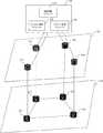
図1は、本発明の実施形態によるネットワークの概略図である。図1に示されるように、ネットワーク100は、コントローラ120、IPネットワーク140および光ネットワーク160を含む。 FIG. 1 is a schematic diagram of a network according to an embodiment of the present invention. As shown in FIG. 1, the network 100 includes a
コントローラ120は、多層管理モジュール122、IPドメイン管理モジュール124および光ドメイン管理モジュール126を含む。これら3つのモジュールは、複数の実装を有する。いくつかの実施形態において、多層管理モジュール122、IPドメイン管理モジュール124および光ドメイン管理モジュール126は、3つの独立のデバイスまたはソフトウェア製品であってよい。この場合、コントローラ120は、複数の独立のデバイスまたはソフトウェア製品を含むシステムとして理解され得る。コントローラ120が、複数の独立のデバイス含むシステムである場合、多層管理モジュール122、IPドメイン管理モジュール124および光ドメイン管理モジュール126は、実際にはそれぞれ、多層管理デバイス122、IPドメイン管理デバイス124および光ドメイン管理デバイス126である。これら3つの管理デバイスは全て、コントローラである。加えて、多層管理モジュール122、IPドメイン管理モジュール124および光ドメイン管理モジュール126は、代替的に、1つの独立のデバイスまたはソフトウェア製品で実装され得る。コントローラ120は、ソフトウェア定義ネットワーク(software defined network、SDN)コントローラ製品であってよい。 The
IPネットワーク140は、複数のネットワークデバイス、例えば、ルータ141から144を含む。これらのルータは、互いに直接または間接的に接続されており、コントローラ120により送信された構成コマンド情報に基づいてこれらのルータの転送挙動を構成して、受信したデータをルーティングする。光ネットワーク160は、複数の光ネットワーク要素(Optical Network Element、ONE)、例えば、ONE161から164を含む。図1に示されるネットワークにおいて、ONE161から164は、ルータ141から144と1対1の対応関係にある。ルータ、例えば、ルータ141が、別のルータ、例えば、ルータ142へデータを送信する必要がある場合、当該データを送信する当該ルータは、転送速度を上げるべく、まず、当該ルータに対応するONE、例えば、ONE161へデータを送信してよく、次に、当該ONEが、光ネットワークを用いることにより、ターゲットルータ、例えば、ルータ142に対応するONE、すなわち、例えば、ONE162へ当該データを送信し、次に、ターゲットルータに対応するONEが、受信した当該データをターゲットルータへ送信する。当該データが通過するリンクは、ルータ141および142が位置するIPネットワーク140と、ONE161およびONE162が位置する光ネットワーク160とにわたる。IPネットワーク140は、IP層ネットワークと称され得る。光ネットワーク160は、光層ネットワークと称され得る。従って、当該リンクは、多層リンクと称され得る。ここで、IPネットワーク140および光ネットワーク160を接続するリンク、例えば、ルータ141およびONE161を接続するリンクが、パッチコード(patch cord)とも称されるクロスリンク(cross link)である。 The
IPドメイン管理モジュール124は、IPネットワーク140内のルータへ制御情報を送信するように構成されており、さらに、IPネットワーク140により報告されるIPネットワークステータス情報を受信し得る。光ドメイン管理モジュール126は、光ネットワーク160内のONEへ制御情報を送信するように構成されており、さらに、光ネットワーク160により報告される光ネットワークステータス情報を受信し得る。 The IP
図2は、本発明の実施形態によるトラブルシューティング方法のフローチャートである。図2に示されるトラブルシューティングは、図3に示されるネットワークに基づいて実行される。図3に示されるネットワーク構造は、図1に示されるネットワークのネットワーク構造と同じである。図3に示されるネットワークにおいて、コントローラ120は、コントローラ120に格納されたIPネットワーク140のネットワークステータス情報に基づいて、ルータ141上にはポートP1、P2およびP3が存在しており、ルータ142上にはポートP4、P5およびP6が存在している、と判定し得る。ポートP1およびP4は、多層リンクを通じて接続され、ポートP2およびP5は、多層リンクを通じて接続され、ポートP3およびP6は、アイドル状態である。これら2つの多層リンクの両方が、1つのリンクアグリゲーショングループに属する。ネットワークステータス情報は、コントローラの多層管理モジュールに格納され得る。加えて、IPドメイン管理モジュール124が、IPネットワーク140についてのネットワークステータス情報の一部分を格納し得て、光ドメイン管理モジュール126が、光ネットワーク160についてのネットワークステータス情報の一部分を格納し得る。 FIG. 2 is a flowchart of a troubleshooting method according to an embodiment of the present invention. The troubleshooting shown in FIG. 2 is performed based on the network shown in FIG. The network structure shown in FIG. 3 is the same as the network structure of the network shown in FIG. In the network shown in FIG. 3, the
図2に示されるトラブルシューティング方法は、以下の内容を含む。 The troubleshooting method shown in FIG. 2 includes the following contents.
205.コントローラ120が、ルータ141上のポートP2に障害が生じている、と判定する。 205. The
ルータ141は、ポートP2に障害が生じていることを検出した後に、コントローラ120へ報告情報を送信して、ポートP2の障害を報告する。報告情報に基づいて、コントローラ120は、ルータ141上のポートP2に障害が生じている、と判定する。例えば、IPドメイン管理モジュール124は、報告情報を受信して多層管理モジュール122へ報告情報を送信し、多層管理モジュール122は、報告情報に基づいて、ポートP2に障害が生じている、と判定する。 After detecting that the failure of the port P2 has occurred, the
210.コントローラ120が、ポートP2およびP5を接続する多層リンクを保持している、ネットワーク160の光層リソースを解放する。 210.
例えば、コントローラ120は、光ネットワーク160へ解放通知を送信することで、光ネットワーク160に、ポートP2およびP5を接続する多層リンクを保持している、光ネットワーク160の光層リソースを解放するよう命令する。コントローラ120の内部で、多層管理モジュール122は、光ドメイン管理モジュール126を駆動することで、ポートP2およびP5を接続する多層リンクを保持している、光ネットワーク160の光層リソースを解放する。これに応じて、光ドメイン管理モジュール126が光ネットワーク160へ解放通知を送信することにより、光ネットワーク160は、ポートP2およびP5を接続する多層リンクを保持している光層リソースを解放する。光ネットワーク160は、解放通知を受信した後に、ポートP2およびP5を接続する多層リンクを伝送するために用いられる光リソースを解放する。解放通知は、ONE161およびONE162へ送信される2つの情報を含み得る。これら2つの情報は、ポートP2およびP5を接続する多層リンクを伝送するために用いられる光リソースを解放するようONE161およびONE162に命令するために別々に用いられる。コントローラ120は、コントローラ120に格納された光ネットワーク160の光ネットワークステータス情報を更新し得る。光ネットワーク160の更新済みの光ネットワークステータス情報は、ポートP2およびP5を接続する多層リンクを伝送するために用いられる光リソースがアイドル状態であることを示す。更新済みの光ネットワークステータス情報は、多層管理モジュール122に格納され得るか、もしくは、光ドメイン管理モジュール126に格納され得るか、または、多層管理モジュール122および光ドメイン管理モジュール126に格納され得る。 For example, the
215.コントローラ120が、ポートP2およびP5を接続する多層リンクをリンクアグリゲーショングループ170から削除する。 215.
例えば、コントローラ120は、IPネットワーク140のルータへ削除通知を送信することで、IPネットワーク140に、多層リンクに属するリンクアグリゲーショングループ170から、ポートP2およびP5を接続する多層リンクを削除するよう命令し得る。削除通知は、ルータ141および142へ別々に送信される2つの情報を含み得る。これら2つの情報は、多層リンクが属するリンクアグリゲーショングループ170から、ポートP2およびP5を接続する多層リンクを削除するよう、ルータ141および142に命令するために別々に用いられる。削除通知は、多層管理モジュール122により駆動されるIPドメイン管理モジュール124により送信され得るか、または、IPドメイン管理モジュール124により単独で送信され得る。 For example, the
220.コントローラ120が、ルータ141および142上のアイドルポートに基づいて、ルータ141および142を接続する多層リンクを確立する。 220.
コントローラ120は、コントローラ120に格納されたIPネットワーク140のステータス情報に基づいて、ポートP3がさらにルータ141上で利用可能である、と判定し得ると共に、アイドルポートP3を用いてルータ142との新しい多層リンクを確立することを決定し得る。具体的には、新しい多層リンクが、ポートP3およびP5を用いることにより確立され得ると共に、新しいIPリンクP3からP6が、ルータ142上のポートP3と別のアイドルポートとを用いることにより確立され得る。ルータ141および142を接続する多層リンクを確立するために、IPネットワーク140および光ネットワーク160の両方が構成され得ることにより、IPドメイン管理モジュール124および光ドメイン管理モジュール126は、多層管理モジュールの制御下で、IPネットワーク140および光ネットワーク160へ制御情報を送信し得る。このようにして、ルータ141および142を接続する多層リンクは確立される。 Based on the status information of the
225.コントローラ120が、確立された多層リンクをリンクアグリゲーショングループ170に追加して、リンクアグリゲーショングループ170内の障害があるリンクを復旧する。例えば、IPドメイン管理モジュール124が、多層管理モジュール122の制御下で、ルータ141および142へ制御情報を送信し得ることにより、ルータ141および142は、220で確立された多層リンクをリンクアグリゲーショングループ170に追加する。 225. The
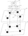
図4は、本発明の実施形態によるトラブルシューティング方法のフローチャートである。図4に示されるトラブルシューティングは、図5に示されるネットワークに基づいて実行される。図5に示されるネットワークのネットワーク構造は、図1に示されるネットワークのネットワーク構造と同じである。図5に示されるネットワークにおいて、コントローラ120は、コントローラ120に格納されたネットワークステータス情報に基づいて、ルータ141上にはポートP1、P2およびP3が存在しており、ルータ142上にはポートP4、P5およびP6が存在しており、ルータ144上にはポートP7およびP8が存在している、と判定し得る。ポートP2およびP5を接続する動作リンクと、ポートP3およびP8を接続する保護リンクとは、コントローラ120用に構成される。動作リンクおよび保護リンクの両方が多層リンクである。保護リンクは、動作リンクを保護するために用いられる。例えば、動作リンクが障害である場合、ルータ141は、トラフィックを動作リンクから保護リンクへ切り替える。ネットワークステータス情報は、コントローラの多層管理モジュール122に格納され得る。加えて、IPドメイン管理モジュール124は、IPネットワーク140についてのネットワークステータス情報の一部分を格納し得て、光ドメイン管理モジュール126は、光ネットワーク160についてのネットワークステータス情報の一部分を格納し得る。 FIG. 4 is a flowchart of a troubleshooting method according to an embodiment of the present invention. The troubleshooting shown in FIG. 4 is performed based on the network shown in FIG. The network structure of the network shown in FIG. 5 is the same as the network structure of the network shown in FIG. In the network shown in FIG. 5, the
図4に示される障害保護方法は、以下の内容を含む。 The fault protection method shown in FIG. 4 includes the following contents.
405.コントローラ120が、ルータ142または光ネットワーク要素162にノード障害が生じている、と判定する。例えば、コントローラ120は、IPドメイン管理モジュール124を用いることにより、ルータ142でのノード障害を感知し得ると共に、光ドメイン管理モジュール126を用いることにより、光デバイス162でのノード障害を感知し得る。ルータ142および光ネットワーク要素162の両方が、データ伝送のために用いられるネットワークデバイスである。光ネットワーク要素162は、ルータ142に対応する光ネットワーク要素である。なぜなら、光ネットワーク要素162は、ルータ142と1または複数のルータ間で相互に通信されるデータを光ネットワーク上で送信および受信するように構成されるからである。 405. The
410.コントローラ120が、ルータ142または光デバイス162での障害に基づいて、ポートP2およびポートP5を接続する多層リンクが障害である、と判定する。ルータ142でノード障害が生じた場合、コントローラ120の多層管理モジュール122は、IPドメイン管理モジュール124により報告される、ルータ142にノード障害が生じていることを通知するために用いられる障害情報に基づいて、ルータ142に障害が生じている、と判定し得る。多層管理モジュール122は、ポートP5がルーティングデバイス142上にあり、ポートP2およびP5を接続する多層リンクが存在することを既に認識しているので、ポートP2およびP5を接続する多層リンクに障害が生じている、と判定し得る。光ネットワーク要素162にノード障害が生じた場合、コントローラ120の多層管理モジュール122は、光ドメイン管理モジュール126により報告される、光ネットワーク要素162にノード障害が生じていることを通知するために用いられる障害情報に基づいて、光ネットワーク要素162に障害が生じている、と判定し得る。多層管理モジュール122は、光ネットワーク要素がルータ142のためにデータを送信および受信するように構成されており、ポートP5がルータ142上にあり、ポートP2およびP5を接続する多層リンクが存在することを既に認識しているので、ポートP2およびP5を接続する多層リンクに障害が生じている、と判定し得る。 410. The
415.コントローラ120が、ポートP2およびP5を接続する多層リンクを保持している、光ネットワーク160の光層リソースを解放する。例えば、コントローラ120は、光トランスポートネットワーク160へ解放通知を送信することで、光ネットワーク160に、ポートP2およびP5を接続する多層リンクを保持している、光ネットワーク160の光層リソースを解放させる。特定の実装中に、解放通知は、ルータ142を通過する各多層リンクを保持している、光ネットワーク160の光層リソースを解放するよう光ネットワーク160に命令するために用いられ得るか、または、ポートP2およびP5を接続する多層リンクのみを保持している、光ネットワーク160の光層リソースを解放するよう光ネットワーク160に命令するために用いられ得る。解放通知を送信するために、多層管理モジュール122は、光ドメイン管理モジュール146を駆動して、解放通知を送信し得るか、または、光ドメイン管理モジュール146は、解放通知の送信を自身で決定し得る。ルータ142に障害が生じていることをノード障害が意味する場合、解放通知は、光ネットワーク要素161または162へ送信される1つの情報であってもよく、光ネットワーク要素161および162を含む複数の光ネットワーク要素へ送信される複数の情報を含んでもよい。光ネットワーク要素162に障害が生じていることをノード障害が意味する場合、解放通知は、光ネットワーク要素161へ送信される1つの情報であってもよく、光ネットワーク要素161を含む複数の光ネットワーク要素へ送信される複数の情報を含んでもよい。光ネットワーク要素162に障害が生じているので、コントローラ120は、ポートP2およびP5を接続する多層リンクを保持している光層リソースを解放するよう光ネットワーク要素162に命令するために用いられる情報を光ネットワーク要素162へ送信しないことがある。しかしながら、光ネットワーク要素162が処理機能を有し得るので、コントローラ120は、代替的に、ポートP2およびP5を接続する多層リンクを保持している光層リソースを解放するよう光ネットワーク要素162に命令するために用いられる情報を光ネットワーク要素162へ送信し得る。 415.
420.コントローラ120が、ルータ141と142との間のリンクアグリゲーショングループ170から、ポートP2およびP5を接続する多層リンクを削除する。例えば、コントローラ120が削除通知をIPネットワーク140へ送信することにより、IPネットワーク140は、ルータ141と142との間のリンクアグリゲーショングループ170から、ポートP2およびP5を接続する多層リンクを削除する。加えて、コントローラ120は、代替的に、コントローラ120に格納されたリンクアグリゲーショングループの構成情報から、ポートP2およびP5を接続する多層リンクを削除し得ることにより、正確なネットワークステータス情報を格納する。ルータ141と142との間のリンクアグリゲーショングループがイーサネット(登録商標)アグリゲーションイーサトランクである場合、ポートP2およびP5を接続する多層リンクは、イーサトランクから削除される必要がある。削除通知を送信するために、多層管理モジュール122は、IPドメイン管理モジュール144を駆動して、削除通知を送信し得るか、または、IPドメイン管理モジュール144は、削除通知の送信を自身で決定し得る。ルータ142に障害が生じていることをノード障害が意味する場合、削除通知は、ルータ141へ送信される1つの情報であってもよく、ルータ141を含む複数のルータへ送信される複数の情報を含んでもよい。ルータ142に障害が生じているので、コントローラ120は、ポートP2およびP5を接続する多層リンクを削除するようルータ142に命令するために用いられる情報をルータ142へ送信しないことがある。しかしながら、ルータ142が処理機能を有し得るので、コントローラ120は、代替的に、ポートP2およびP5を接続する多層リンクを削除するようルータ142に命令するために用いられる情報をルータ142へ送信し得る。 420.
425.コントローラ120が、ルータ141上のアイドルポートとルータ144上のアイドルポートとに基づいて、ルータ141およびルータ144を接続する多層リンクを確立する。ルータ144は、保護リンク上のポートP8が位置するルータであってもよく、ポートP8が位置するルータでなくてもよい。ルータ141およびルータ144を接続する多層リンクは、ルータ141上のアイドルポート、例えば、ポートP1またはポートP1とは異なるアイドルポートと、ルータ144上のアイドルポート、例えば、ポートP7とを接続し得る。コントローラ120は、ルータ141および144および光ネットワーク要素161および164へ構成情報を送信し得ることにより、ルータ141およびルータ144の多層リンクを確立する。 425. The
430.コントローラ120が、保護リンクが属するリンクアグリゲーショングループ180に、ポートP1およびP4を接続する多層リンクを追加する。このようにして、ポートP2およびP5を接続するリンクは、ポートP2およびP7を接続する多層リンクで置換でき、ポートP2およびP5を接続する障害があるリンクは復旧される。ポートP2およびP5を通過する多層リンクに障害が生じた後に、トラフィックが、当該リンクから、ポートP3およびP8を通過する保護リンクへ切り替えられ得る。トラフィックが保護リンクへ切り替えられた場合、コントローラ120は、トラフィックを、段階425において確立された多層リンクへ、切り替えてもよく、切り替えなくてもよい。 430. The
図6は、本発明の実施形態によるトラブルシューティング方法のフローチャートである。トラブルシューティング方法は、以下の内容を含む。 FIG. 6 is a flowchart of a troubleshooting method according to an embodiment of the present invention. Troubleshooting methods include the following:
605.コントローラが、第1のネットワークデバイス上の第1のポートを通過する第1の多層リンクに障害が生じている、と判定する。第1のリンクは、第1のネットワークデバイスと第2のネットワークデバイスとの間のリンクアグリゲーショングループ内のリンクである。 605. The controller determines that the first multilayer link passing through the first port on the first network device has failed. The first link is a link within a link aggregation group between the first network device and the second network device.
コントローラは、第1の多層リンクの2つの端部のいずれかにおけるネットワークデバイスに障害が生じているかどうかを検出することにより、第1の多層リンクに障害が生じているかどうかを判定し得る。コントローラは、第1のポートに障害が生じている、と判定した場合、第1の多層リンクに障害が生じている、と判定し得る。例えば、図3におけるポートP2に障害が生じている場合、ポートP2およびポートP5を接続するリンクに障害が生じている、と判定できる。加えて、コントローラは、第2のネットワークデバイスにノード障害が生じている、と判定した場合、代替的に、第1の多層リンクに障害が生じている、と判定し得る。 The controller may determine if the first multilayer link has failed by detecting if the network device at either of the two ends of the first multilayer link has failed. If the controller determines that the first port has failed, it may determine that the first multilayer link has failed. For example, when the port P2 in FIG. 3 has a failure, it can be determined that the link connecting the port P2 and the port P5 has a failure. In addition, if the controller determines that the second network device has a node failure, it may instead determine that the first multilayer link has failed.
コントローラは、2つの端部におけるネットワークデバイスのいずれかに対応する光ネットワーク要素での障害を用いることにより、代替的に、第1の多層リンクに障害が生じている、と判定し得る。例えば、光ネットワーク要素162にノード障害が生じた場合、コントローラは、光ネットワーク要素162に対応するネットワークデバイス142にノード障害が生じている、と判定し得て、さらに、ネットワークノード142とネットワークノード141との間の全ての多層リンクに障害が生じている、と判定し得る。第1のポートが、ネットワークノード142に接続された、ネットワークノード141のポートである場合、コントローラは、第1のポートを通過する第1の多層リンクに障害が生じている、と判定し得る。 By using the fault at the optical network element corresponding to any of the network devices at the two ends, the controller may instead determine that the first multilayer link is faulty. For example, if a node failure occurs in the
610.コントローラが第1の多層リンクの光層リソースを解放する。 610. The controller frees the optical layer resources of the first multilayer link.
第1の多層リンクがIPネットワークおよび光ネットワークを通過するので、コントローラは、光層リソースの浪費を回避するために、第1の多層リンクの光層リソースを解放する必要がある。第1の多層リンクの光層リソースは、第1の多層リンク上の2つのIP層ネットワークデバイスにそれぞれ対応する2つの光ネットワーク要素間の光リソースであってよい。例えば、図5において、P2およびP5を接続する多層リンクに障害が生じた場合、コントローラ120は、ポートP2およびP5を接続する多層リンクの光層リソースを解放する必要がある、すなわち、ポートP2およびP5を接続する多層リンク上でデータを伝送するために用いられる、光ネットワーク要素161および162の光リソースを解放する必要がある。コントローラは、これら2つの光伝送ノードへの光リソースの解放についての情報を送信するだけでなく、コントローラによりローカルに記録された、ポートP2およびP5を接続する多層リンク上でデータを伝送するために用いられる光リソースの解放もし得る。 Since the first multilayer link passes through the IP network and the optical network, the controller needs to release the optical layer resources of the first multilayer link in order to avoid wasting the optical layer resources. The optical layer resource of the first multilayer link may be an optical resource between two optical network elements corresponding to two IP layer network devices on the first multilayer link, respectively. For example, in FIG. 5, if the multi-layer link connecting P2 and P5 fails, the
615.コントローラがリンクアグリゲーショングループから第1の多層リンクを削除する。 615. The controller removes the first multi-layer link from the link aggregation group.
第1の多層リンクが既に障害なので、第1の多層リンクは、データ損失を回避するために、リンクアグリゲーショングループから削除される必要がある。コントローラが、第1の多層リンクを用いることにより接続された2つのネットワークデバイスへ削除通知を送信し得ることにより、これら2つのネットワークデバイスは、コントローラに格納されたリンクアグリゲーショングループの構成情報から第1の多層リンクを削除する。コントローラは、代替的に、コントローラに格納されたリンクアグリゲーショングループの構成情報から第1の多層リンクを削除し得る。 Since the first multi-layer link is already a failure, the first multi-layer link needs to be removed from the link aggregation group to avoid data loss. Since the controller can send a deletion notification to two network devices connected by using the first multi-layer link, these two network devices can be first from the link aggregation group configuration information stored in the controller. Delete the multi-layer link of. Alternatively, the controller may remove the first multi-layer link from the link aggregation group configuration information stored in the controller.
620.コントローラが、第1のネットワークデバイス上の第1のアイドルポートとターゲットネットワークデバイス上の第2のアイドルポートとに基づいて、第1の多層リンクの復旧のために用いられる第2の多層リンクを確立する。 620. The controller establishes a second multi-layer link used to restore the first multi-layer link based on the first idle port on the first network device and the second idle port on the target network device. To do.
第1のアイドルポートは、第1のネットワークデバイス上の第1のポートであってもよく、第1のネットワークデバイス上の別のアイドルポートであってもよい。 The first idle port may be the first port on the first network device or another idle port on the first network device.
ターゲットネットワークデバイスは、障害タイプに基づいて選択される必要がある。第2のネットワークデバイスにノード障害が生じた場合、ターゲットネットワークデバイスは、第2のネットワークデバイスでなくてもよいが、第1のネットワークデバイスおよび第2のネットワークデバイスとは異なる第3のネットワークデバイスである必要がある。第3のネットワークデバイスは、第2のネットワークデバイスのバックアップデバイスである。第2のネットワークデバイスにノード障害が生じており、第1のリンクでの障害がポートの障害によりもたらされている場合、ターゲットネットワークデバイスは、第2のネットワークデバイスまたは第3のネットワークデバイスのいずれであってもよい。 The target network device should be selected based on the failure type. In the event of a node failure in the second network device, the target network device does not have to be the second network device, but in a third network device that is different from the first network device and the second network device. There must be. The third network device is a backup device for the second network device. If the second network device has a node failure and the failure on the first link is caused by a port failure, the target network device is either the second network device or the third network device. It may be.
625.コントローラが、第1のネットワークデバイスとターゲットネットワークデバイスとの間のターゲットアグリゲーショングループに第2の多層リンクを追加する。 625. The controller adds a second multi-layer link to the target aggregation group between the first network device and the target network device.
このようにして、障害がある第1の多層リンクは、第2の多層リンクにより復旧される。第1の多層リンクでの障害によりもたらされる帯域幅損失が、ターゲットアグリゲーショングループに第2の多層リンクを追加することにより補償され得る。 In this way, the failed first multilayer link is restored by the second multilayer link. Bandwidth loss caused by failure at the first multilayer link can be compensated by adding a second multilayer link to the target aggregation group.
図7は、本発明の実施形態によるコントローラ700の構造のブロック図である。図7に示されるように、コントローラ700は、プロセッサ710と、プロセッサ710と通信するメモリ720と、送受信機730とを含む。図1、図3または図5における多層管理モジュール122、IPドメイン管理モジュール124および光ドメイン管理モジュール126が1つのデバイスにおける3つのモジュールであるが、3つのディスクリートデバイスではない場合、コントローラ700は、図1、図3または図5におけるコントローラ120であってよい。図1、図3または図5における多層管理モジュール122、IPドメイン管理モジュール124および光ドメイン管理モジュール126が3つの独立のデバイスである場合、コントローラ120は、実際には、制御システムである。この場合、コントローラ700は、実際には多層管理デバイス122である多層管理モジュール122であってよい。 FIG. 7 is a block diagram of the structure of the
プロセッサ710は、中央演算処理装置(central processing unit、CPU)、ネットワークプロセッサ(network processor、NP)またはCPUとNPとの組み合わせであってよい。プロセッサは、代替的に、特定用途向け集積回路(application−specific integrated circuit、ASIC)、プログラマブル論理デバイス(programmable logic device、PLD)またはそれらの組み合わせであってよい。PLDは、コンプレックスプログラマブルロジックデバイス(complex programmable logic device、CPLD)、フィールドプログラマブルゲートアレイ(field−programmable gate array、FPGA)、ジェネリックアレイロジック(generic array logic、GAL)またはそれらの任意の組み合わせであってよい。プロセッサ710は、1つのプロセッサであってもよく、複数のプロセッサを含んでもよい。メモリ720は、1つのメモリであってもよく、複数のメモリを含んでもよい。メモリ720は、揮発性メモリ(volatile memory)、例えば、ランダムアクセスメモリ(random−access memory、RAM)を含み得るか、または、当該メモリは、不揮発性メモリ(non−volatile memory)、例えば、リードオンリメモリ(read−only memory、ROM)、フラッシュメモリ(flash(登録商標) memory)、ハードディスクドライブ(hard disk drive、HDD)またはソリッドステートドライブ(solid−state drive、SSD)を含み得る。当該メモリは、前述のタイプのメモリの組み合わせをさらに含み得る。メモリ720は、コンピュータ可読命令を格納する。コンピュータ可読命令は、複数のソフトウェアモジュールを含む。プロセッサ710は、各ソフトウェアモジュールを実行した後に、各ソフトウェアモジュールのインジケーションに従って、対応するオペレーションを実行し得る。プロセッサ710は、メモリ720内のコンピュータ可読命令を実行した後に、コンピュータ可読命令のインジケーションに従って、コントローラ120、または独立のデバイスとして機能する多層管理モジュール122により実行される全てのオペレーションを実行し得る。加えて、図1、図3または図5における多層管理モジュール122、IPドメイン管理モジュール124および光ドメイン管理モジュール126が1つのデバイスにおける3つのモジュールである場合、多層管理モジュール122は、プロセッサ710と、メモリ720と、メモリ720に格納された多層管理ソフトウェアモジュールとに基づいて実装されるものと理解され得る。同様に、IPドメイン管理モジュール124は、プロセッサ710と、メモリ720と、メモリ720に格納されたIPドメイン管理ソフトウェアモジュールとに基づいて実装されるものと理解され得る。光ドメイン管理モジュール126は、プロセッサ710と、メモリ720と、メモリ720に格納された光ドメイン管理ソフトウェアモジュールとに基づいて実装されるものと理解され得る。前述の説明は、本発明の特定の実装方式の例に過ぎず、本発明の保護範囲を限定するよう意図されてはいない。本発明において開示された技術的範囲内で当業者が容易に想到するあらゆる変形例または置換例は、本発明の保護範囲に含まれるものとする。 The
本願は、2018年8月30日に中国国家知識財産権局へ出願された、「障害がある多層リンク復旧方法およびコントローラ」と題する中国特許出願第CN 201811001018.8号の優先権を主張する。当該出願は、参照により、その全体が本明細書に組み込まれる。 This application claims the priority of Chinese Patent Application No. CN 201811001018.8 entitled "Failed Multilayer Link Recovery Method and Controller" filed with the National Intellectual Property Office of China on August 30, 2018. The application is incorporated herein by reference in its entirety.
本願は、通信分野、特に、障害がある多層リンク復旧方法およびコントローラに関する。 The present application relates to the field of communications, in particular to faulty multilayer link recovery methods and controllers.
リンクアグリゲーションは、物理インタフェースのグループを論理インタフェースへ共にバンドルする方法であり、この方法により、帯域幅および信頼性を増やすことができる。複数の物理リンクを共にバンドルすることにより形成される論理リンクは、リンクアグリゲーショングループLAGまたはトランクと称される。これらのバンドルされたリンクの全てがイーサネット(登録商標)リンクである場合、当該アグリゲーションは、イーサネット(登録商標)リンクアグリゲーショングループと称され、イーサトランクと略され得る。アグリゲーションのインタフェースが、イーサトランクインタフェースと称され、イーサトランク内の複数のインタフェースが、複数のメンバインタフェースと称される。イーサトランクインタフェースは、共通イーサネット(登録商標)インタフェースとして用いられ得る。イーサトランクインタフェースと共通イーサネット(登録商標)インタフェースとの間の差は、転送中にイーサトランクがメンバインタフェースから1または複数のインタフェースを選択する必要がある、という点のみにある。従って、イーサトランク論理インタフェースは、物理イーサネット(登録商標)インタフェースにのみ構成されなければならないいくつかの特徴を除き、共通イーサネット(登録商標)インタフェースと同じ態様で構成され得る。イーサトランクの物理リンクに障害が生じた場合、障害物理リンクは、復旧される必要がある。そうでなければ、ネットワーク性能が低下するか、またはネットワーク内のデータ伝送が失敗する。Link aggregation is a method of bundling a group of physical interfaces together with a logical interface, which can increase bandwidth and reliability. Logical link that is formed by both bundling a plurality of physical links is referred to asa link aggregationgroup L A Gor thetrunk. If all of these bundled links are Ethernet® links, the aggregation is referred to as an Ethernet® Link Aggregation Group and may be abbreviated as EtherTrunk. The aggregation interface is referred to as the ether trunk interface, and the plurality of interfaces in the ether trunk are referred to as the plurality of member interfaces. The Ethertrunk interface can be used as a common Ethernet® interface. The only difference between the Ethertrunk interface and the Common Ethernet® interface is that the Ethertrunk must select one or more of the member interfaces during the transfer. Thus, the Ethertrunk logical interface can be configured in the same manner as a common Ethernet® interface, except for some features that must be configured only on the physical Ethernet® interface. If the physical link on the Ether Trunk fails, the failed physical link needs to be restored. Otherwise, network performance will be degraded or data transmission within the network will fail.
本願の実施形態の目的は、リンクトラブルシューティング方法およびコントローラを提供することである。 An object of an embodiment of the present application is to provide a link troubleshooting method and a controller.
本願の態様は、トラブルシューティング方法を提供する。
方法は、
コントローラが、第1のネットワークデバイス上の第1のポートを通過する第1の多層リンクに障害が生じている、と判定する段階であって、第1の多層リンクは、第1のネットワークデバイスと第2のネットワークデバイスとの間のリンクアグリゲーショングループ内のリンクである、判定する段階と、
コントローラが第1の多層リンクの光層リソースを解放する段階と、
コントローラがリンクアグリゲーショングループから第1の多層リンクを削除する段階と、
コントローラが、第1のネットワークデバイス上の第1のアイドルポートとターゲットネットワークデバイス上の第2のアイドルポートとに基づいて、第1の多層リンクの復旧のために用いられる第2の多層リンクを確立する段階と、
コントローラが、第1のネットワークデバイスとターゲットネットワークデバイスとの間のターゲットアグリゲーショングループに第2の多層リンクを追加する段階と
を備える。Aspects of the present application provide a troubleshooting method.
The method is
At the stage where the controller determines that the first multi-layer link passing through the first port on the first network device has failed, the first multi-layer link is with the first network device. The stage of determining that the link is a link within a link aggregation group with a second network device,
When the controller releases the light layer resources of the first multi-layer link,
When the controller removes the first multi-layer link from the link aggregation group,
The controller establishes a second multi-layer link used to restore the first multi-layer link based on the first idle port on the first network device and the second idle port on the target network device. And the stage to do
The controller comprises adding a second multi-layer link to the target aggregation group between the first network device and the target network device.
可能な設計において、ターゲットネットワークデバイスは、第2のネットワークデバイスである。 In a possible design, the target network device is a second network device.
可能な設計において、第1のネットワークデバイス上の第1のポートを通過する第1の多層リンクに障害が生じている、と判定する段階は、
第1のネットワークデバイス上の第1のポートに障害が生じている、と判定する段階と、
第1のポートでの障害に基づいて、第1の多層リンクに障害が生じている、と判定する段階と
を有する。In a possible design, the step of determining that the first multi-layer link through the first port on the first network device has failed is
At the stage of determining that the first port on the first network device has failed,
It has a step of determining that the first multi-layer link has failed based on the failure at the first port.
可能な設計において、ターゲットネットワークデバイスは、第3のネットワークデバイスである。 In a possible design, the target network device is a third network device.
可能な設計において、第1のネットワークデバイス上の第1のポートを通過する第1の多層リンクに障害が生じている、と判定する段階は、
第2のネットワークデバイスにノード障害が生じている、と判定する段階と、
第1の多層リンクは、第1のポートおよび第2のネットワークデバイスを通過している、と判定する段階と、
第1の多層リンクに障害が生じている、と判定する段階と
を有する。In a possible design, the step of determining that the first multi-layer link through the first port on the first network device has failed is
At the stage of determining that the second network device has a node failure,
The stage of determining that the first multi-layer link is passing through the first port and the second network device,
It has a stage of determining that the first multilayer link has a failure.
可能な設計において、第1のアイドルポートは、第1のポートである。 In a possible design, the first idle port is the first port.
可能な設計において、第1のアイドルポートは、第1のポートではない。 In a possible design, the first idle port is not the first port.
可能な設計において、第1の多層リンクおよび第2の多層リンクは、異なるタイプのネットワークを通過するリンクである。 In a possible design, the first multilayer link and the second multilayer link are links that pass through different types of networks.
本願の別の態様は、コントローラを提供する。コントローラは、メモリおよびプロセッサを備える。メモリは、コンピュータ可読命令を格納するように構成される。
プロセッサは、メモリと通信し、コンピュータ可読命令を読み出すことにより、
第1のネットワークデバイス上の第1のポートを通過する第1の多層リンクに障害が生じている、と判定することであって、第1のリンクは、第1のネットワークデバイスと第2のネットワークデバイスとの間のリンクアグリゲーショングループ内のリンクである、判定することと、
第1の多層リンクの光層リソースを解放することと、
リンクアグリゲーショングループから第1の多層リンクを削除することと、
第1のネットワークデバイス上の第1のアイドルポートとターゲットネットワークデバイス上の第2のアイドルポートとに基づいて、第1の多層リンクの復旧のために用いられる第2の多層リンクを確立することと、
第1のネットワークデバイスとターゲットネットワークデバイスとの間のターゲットアグリゲーショングループに第2の多層リンクを追加することと
を行うように構成される。Another aspect of the present application provides a controller. The controller includes memory and a processor. The memory is configured to store computer-readable instructions.
The processor communicates with memory and reads computer-readable instructions.
Determining that the first multilayer link passing through the first port on the first network device is faulty, the first link is the first network device and the second network. To determine that the link is in a link aggregation group with the device,
Releasing the light layer resources of the first multi-layer link,
Removing the first multi-layer link from the link aggregation group and
To establish a second multi-layer link used to restore the first multi-layer link based on the first idle port on the first network device and the second idle port on the target network device. ,
It is configured to add a second multi-layer link to the target aggregation group between the first network device and the target network device.
可能な設計において、ターゲットネットワークデバイスは、第2のネットワークデバイスである。 In a possible design, the target network device is a second network device.
可能な設計において、プロセッサは、コンピュータ可読命令を読み出すことにより、
第1のネットワークデバイス上の第1のポートに障害が生じている、と判定することと、
第1のポートでの障害に基づいて、第1の多層リンクに障害が生じている、と判定することと
を行うように構成される。In a possible design, the processor reads computer-readable instructions.
Determining that the first port on the first network device has failed
It is configured to determine that the first multi-layer link has failed based on the failure at the first port.
可能な設計において、ターゲットネットワークデバイスは、第3のネットワークデバイスである。 In a possible design, the target network device is a third network device.
可能な設計において、プロセッサは、コンピュータ可読命令を読み出すことにより、
第2のネットワークデバイスにノード障害が生じている、と判定することと、
第1の多層リンクは、第1のポートおよび第2のネットワークデバイスを通過している、と判定することと、
第1の多層リンクに障害が生じている、と判定することと
を行うように構成される。In a possible design, the processor reads computer-readable instructions.
Determining that the second network device has a node failure,
Determining that the first multilayer link is passing through the first port and the second network device,
It is configured to determine that the first multi-layer link has failed.
可能な設計において、第1のアイドルポートは、第1のポートである。 In a possible design, the first idle port is the first port.
可能な設計において、第1のアイドルポートは、第1のポートではない。 In a possible design, the first idle port is not the first port.
可能な設計において、第1の多層リンクおよび第2の多層リンクは、異なるタイプのネットワークを通過するリンクである。 In a possible design, the first multilayer link and the second multilayer link are links that pass through different types of networks.
本願において、コントローラは、リンクアグリゲーショングループ内の障害がある多層リンクを判定した後に、光ネットワークおよびIPネットワークのリソースの協調管理を実行するために、リンクアグリゲーショングループから障害がある多層リンクを削除するだけでなく、多層リンクの光ネットワークリソースを解放し、次に、障害があるリンクの復旧のために用いられる新しい多層リンクをアイドルポートに基づいて確立する必要もあり、これにより障害がある多層リンクの効率的な復旧を実装する。 In the present application, the controller only determines the failed multi-layer link in the link aggregation group and then removes the failed multi-layer link from the link aggregation group in order to perform coordinated management of the resources of the optical network and the IP network. Instead, it is also necessary to free the optical network resources of the multi-layered link and then establish a new multi-layered link based on the idle port that will be used to recover the failed multi-layered link. Implement efficient recovery.
以下では、添付図面および具体的な実施形態を参照して、本発明を詳細に説明する。しかしながら、以下の実施形態は、技術的解決手段を理解しやすくするためにのみ与えられる例であり、本発明を限定することは意図されていないことに留意すべきである。 The present invention will be described in detail below with reference to the accompanying drawings and specific embodiments. However, it should be noted that the following embodiments are given only for the sake of comprehension of the technical solutions and are not intended to limit the invention.
図1は、本発明の実施形態によるネットワークの概略図である。図1に示されるように、ネットワーク100は、コントローラ120、IPネットワーク140および光ネットワーク160を含む。 FIG. 1 is a schematic diagram of a network according to an embodiment of the present invention. As shown in FIG. 1, the network 100 includes a
コントローラ120は、多層管理モジュール122、IPドメイン管理モジュール124および光ドメイン管理モジュール126を含む。これら3つのモジュールは、複数の実装を有する。いくつかの実施形態において、多層管理モジュール122、IPドメイン管理モジュール124および光ドメイン管理モジュール126は、3つの独立のデバイスまたはソフトウェア製品であってよい。この場合、コントローラ120は、複数の独立のデバイスまたはソフトウェア製品を含むシステムとして理解され得る。コントローラ120が、複数の独立のデバイス含むシステムである場合、多層管理モジュール122、IPドメイン管理モジュール124および光ドメイン管理モジュール126は、実際にはそれぞれ、多層管理デバイス122、IPドメイン管理デバイス124および光ドメイン管理デバイス126である。これら3つの管理デバイスは全て、コントローラである。加えて、多層管理モジュール122、IPドメイン管理モジュール124および光ドメイン管理モジュール126は、代替的に、1つの独立のデバイスまたはソフトウェア製品で実装され得る。コントローラ120は、ソフトウェア定義ネットワークSDNコントローラ製品であってよい。The
IPネットワーク140は、複数のネットワークデバイス、例えば、ルータ141から144を含む。これらのルータは、互いに直接または間接的に接続されており、コントローラ120により送信された構成コマンド情報に基づいてこれらのルータの転送挙動を構成して、受信したデータをルーティングする。光ネットワーク160は、複数の光ネットワーク要素ONE、例えば、ONE161から164を含む。図1に示されるネットワークにおいて、ONE161から164は、ルータ141から144と1対1の対応関係にある。ルータ、例えば、ルータ141が、別のルータ、例えば、ルータ142へデータを送信する必要がある場合、当該データを送信する当該ルータは、転送速度を上げるべく、まず、当該ルータに対応するONE、例えば、ONE161へデータを送信してよく、次に、当該ONEが、光ネットワークを用いることにより、ターゲットルータ、例えば、ルータ142に対応するONE、すなわち、例えば、ONE162へ当該データを送信し、次に、ターゲットルータに対応するONEが、受信した当該データをターゲットルータへ送信する。当該データが通過するリンクは、ルータ141および142が位置するIPネットワーク140と、ONE161およびONE162が位置する光ネットワーク160とにわたる。IPネットワーク140は、IP層ネットワークと称され得る。光ネットワーク160は、光層ネットワークと称され得る。従って、当該リンクは、多層リンクと称され得る。ここで、IPネットワーク140および光ネットワーク160を接続するリンク、例えば、ルータ141およびONE161を接続するリンクが、パッチコードとも称されるクロスリンクである。The
IPドメイン管理モジュール124は、IPネットワーク140内のルータへ制御情報を送信するように構成されており、さらに、IPネットワーク140により報告されるIPネットワークステータス情報を受信し得る。光ドメイン管理モジュール126は、光ネットワーク160内のONEへ制御情報を送信するように構成されており、さらに、光ネットワーク160により報告される光ネットワークステータス情報を受信し得る。 The IP
図2は、本発明の実施形態によるトラブルシューティング方法のフローチャートである。図2に示されるトラブルシューティングは、図3に示されるネットワークに基づいて実行される。図3に示されるネットワーク構造は、図1に示されるネットワークのネットワーク構造と同じである。図3に示されるネットワークにおいて、コントローラ120は、コントローラ120に格納されたIPネットワーク140のネットワークステータス情報に基づいて、ルータ141上にはポートP1、P2およびP3が存在しており、ルータ142上にはポートP4、P5およびP6が存在している、と判定し得る。ポートP1およびP4は、多層リンクを通じて接続され、ポートP2およびP5は、多層リンクを通じて接続され、ポートP3およびP6は、アイドル状態である。これら2つの多層リンクの両方が、1つのリンクアグリゲーショングループに属する。ネットワークステータス情報は、コントローラの多層管理モジュールに格納され得る。加えて、IPドメイン管理モジュール124が、IPネットワーク140についてのネットワークステータス情報の一部分を格納し得て、光ドメイン管理モジュール126が、光ネットワーク160についてのネットワークステータス情報の一部分を格納し得る。 FIG. 2 is a flowchart of a troubleshooting method according to an embodiment of the present invention. The troubleshooting shown in FIG. 2 is performed based on the network shown in FIG. The network structure shown in FIG. 3 is the same as the network structure of the network shown in FIG. In the network shown in FIG. 3, the
図2に示されるトラブルシューティング方法は、以下の内容を含む。 The troubleshooting method shown in FIG. 2 includes the following contents.
205.コントローラ120が、ルータ141上のポートP2に障害が生じている、と判定する。 205. The
ルータ141は、ポートP2に障害が生じていることを検出した後に、コントローラ120へ報告情報を送信して、ポートP2の障害を報告する。報告情報に基づいて、コントローラ120は、ルータ141上のポートP2に障害が生じている、と判定する。例えば、IPドメイン管理モジュール124は、報告情報を受信して多層管理モジュール122へ報告情報を送信し、多層管理モジュール122は、報告情報に基づいて、ポートP2に障害が生じている、と判定する。 After detecting that the failure of the port P2 has occurred, the
210.コントローラ120が、ポートP2およびP5を接続する多層リンクを保持している、ネットワーク160の光層リソースを解放する。 210.
例えば、コントローラ120は、光ネットワーク160へ解放通知を送信することで、光ネットワーク160に、ポートP2およびP5を接続する多層リンクを保持している、光ネットワーク160の光層リソースを解放するよう命令する。コントローラ120の内部で、多層管理モジュール122は、光ドメイン管理モジュール126を駆動することで、ポートP2およびP5を接続する多層リンクを保持している、光ネットワーク160の光層リソースを解放する。これに応じて、光ドメイン管理モジュール126が光ネットワーク160へ解放通知を送信することにより、光ネットワーク160は、ポートP2およびP5を接続する多層リンクを保持している光層リソースを解放する。光ネットワーク160は、解放通知を受信した後に、ポートP2およびP5を接続する多層リンクを伝送するために用いられる光リソースを解放する。解放通知は、ONE161およびONE162へ送信される2つの情報を含み得る。これら2つの情報は、ポートP2およびP5を接続する多層リンクを伝送するために用いられる光リソースを解放するようONE161およびONE162に命令するために別々に用いられる。コントローラ120は、コントローラ120に格納された光ネットワーク160の光ネットワークステータス情報を更新し得る。光ネットワーク160の更新済みの光ネットワークステータス情報は、ポートP2およびP5を接続する多層リンクを伝送するために用いられる光リソースがアイドル状態であることを示す。更新済みの光ネットワークステータス情報は、多層管理モジュール122に格納され得るか、もしくは、光ドメイン管理モジュール126に格納され得るか、または、多層管理モジュール122および光ドメイン管理モジュール126に格納され得る。 For example, the
215.コントローラ120が、ポートP2およびP5を接続する多層リンクをリンクアグリゲーショングループ170から削除する。 215.
例えば、コントローラ120は、IPネットワーク140のルータへ削除通知を送信することで、IPネットワーク140に、多層リンクに属するリンクアグリゲーショングループ170から、ポートP2およびP5を接続する多層リンクを削除するよう命令し得る。削除通知は、ルータ141および142へ別々に送信される2つの情報を含み得る。これら2つの情報は、多層リンクが属するリンクアグリゲーショングループ170から、ポートP2およびP5を接続する多層リンクを削除するよう、ルータ141および142に命令するために別々に用いられる。削除通知は、多層管理モジュール122により駆動されるIPドメイン管理モジュール124により送信され得るか、または、IPドメイン管理モジュール124により単独で送信され得る。 For example, the
220.コントローラ120が、ルータ141および142上のアイドルポートに基づいて、ルータ141および142を接続する多層リンクを確立する。 220.
コントローラ120は、コントローラ120に格納されたIPネットワーク140のステータス情報に基づいて、ポートP3がさらにルータ141上で利用可能である、と判定し得ると共に、アイドルポートP3を用いてルータ142との新しい多層リンクを確立することを決定し得る。具体的には、新しい多層リンクが、ポートP3およびP5を用いることにより確立され得ると共に、新しいIPリンクP3からP6が、ルータ142上のポートP3と別のアイドルポートとを用いることにより確立され得る。ルータ141および142を接続する多層リンクを確立するために、IPネットワーク140および光ネットワーク160の両方が構成され得ることにより、IPドメイン管理モジュール124および光ドメイン管理モジュール126は、多層管理モジュールの制御下で、IPネットワーク140および光ネットワーク160へ制御情報を送信し得る。このようにして、ルータ141および142を接続する多層リンクは確立される。 Based on the status information of the
225.コントローラ120が、確立された多層リンクをリンクアグリゲーショングループ170に追加して、リンクアグリゲーショングループ170内の障害があるリンクを復旧する。例えば、IPドメイン管理モジュール124が、多層管理モジュール122の制御下で、ルータ141および142へ制御情報を送信し得ることにより、ルータ141および142は、220で確立された多層リンクをリンクアグリゲーショングループ170に追加する。 225. The
図4は、本発明の実施形態によるトラブルシューティング方法のフローチャートである。図4に示されるトラブルシューティングは、図5に示されるネットワークに基づいて実行される。図5に示されるネットワークのネットワーク構造は、図1に示されるネットワークのネットワーク構造と同じである。図5に示されるネットワークにおいて、コントローラ120は、コントローラ120に格納されたネットワークステータス情報に基づいて、ルータ141上にはポートP1、P2およびP3が存在しており、ルータ142上にはポートP4、P5およびP6が存在しており、ルータ144上にはポートP7およびP8が存在している、と判定し得る。ポートP2およびP5を接続する動作リンクと、ポートP3およびP8を接続する保護リンクとは、コントローラ120用に構成される。動作リンクおよび保護リンクの両方が多層リンクである。保護リンクは、動作リンクを保護するために用いられる。例えば、動作リンクが障害である場合、ルータ141は、トラフィックを動作リンクから保護リンクへ切り替える。ネットワークステータス情報は、コントローラの多層管理モジュール122に格納され得る。加えて、IPドメイン管理モジュール124は、IPネットワーク140についてのネットワークステータス情報の一部分を格納し得て、光ドメイン管理モジュール126は、光ネットワーク160についてのネットワークステータス情報の一部分を格納し得る。 FIG. 4 is a flowchart of a troubleshooting method according to an embodiment of the present invention. The troubleshooting shown in FIG. 4 is performed based on the network shown in FIG. The network structure of the network shown in FIG. 5 is the same as the network structure of the network shown in FIG. In the network shown in FIG. 5, the
図4に示される障害保護方法は、以下の内容を含む。 The fault protection method shown in FIG. 4 includes the following contents.
405.コントローラ120が、ルータ142または光ネットワーク要素162にノード障害が生じている、と判定する。例えば、コントローラ120は、IPドメイン管理モジュール124を用いることにより、ルータ142でのノード障害を感知し得ると共に、光ドメイン管理モジュール126を用いることにより、光デバイス162でのノード障害を感知し得る。ルータ142および光ネットワーク要素162の両方が、データ伝送のために用いられるネットワークデバイスである。
光ネットワーク要素162は、ルータ142に対応する光ネットワーク要素である。なぜなら、光ネットワーク要素162は、ルータ142と1または複数のルータ間で相互に通信されるデータを光ネットワーク上で送信および受信するように構成されるからである。405. The
The
410.コントローラ120が、ルータ142または光デバイス162での障害に基づいて、ポートP2およびポートP5を接続する多層リンクが障害である、と判定する。ルータ142でノード障害が生じた場合、コントローラ120の多層管理モジュール122は、IPドメイン管理モジュール124により報告される、ルータ142にノード障害が生じていることを通知するために用いられる障害情報に基づいて、ルータ142に障害が生じている、と判定し得る。多層管理モジュール122は、ポートP5がルータ142上にあり、ポートP2およびP5を接続する多層リンクが存在することを既に認識しているので、ポートP2およびP5を接続する多層リンクに障害が生じている、と判定し得る。光ネットワーク要素162にノード障害が生じた場合、コントローラ120の多層管理モジュール122は、光ドメイン管理モジュール126により報告される、光ネットワーク要素162にノード障害が生じていることを通知するために用いられる障害情報に基づいて、光ネットワーク要素162に障害が生じている、と判定し得る。多層管理モジュール122は、光ネットワーク要素がルータ142のためにデータを送信および受信するように構成されており、ポートP5がルータ142上にあり、ポートP2およびP5を接続する多層リンクが存在することを既に認識しているので、ポートP2およびP5を接続する多層リンクに障害が生じている、と判定し得る。410. The
415.コントローラ120が、ポートP2およびP5を接続する多層リンクを保持している、光ネットワーク160の光層リソースを解放する。例えば、コントローラ120は、光ネットワーク160へ解放通知を送信することで、光ネットワーク160に、ポートP2およびP5を接続する多層リンクを保持している、光ネットワーク160の光層リソースを解放させる。特定の実装中に、解放通知は、ルータ142を通過する各多層リンクを保持している、光ネットワーク160の光層リソースを解放するよう光ネットワーク160に命令するために用いられ得るか、または、ポートP2およびP5を接続する多層リンクのみを保持している、光ネットワーク160の光層リソースを解放するよう光ネットワーク160に命令するために用いられ得る。解放通知を送信するために、多層管理モジュール122は、光ドメイン管理モジュール126を駆動して、解放通知を送信し得るか、または、光ドメイン管理モジュール126は、解放通知の送信を自身で決定し得る。ルータ142に障害が生じていることをノード障害が意味する場合、解放通知は、光ネットワーク要素161または162へ送信される1つの情報であってもよく、光ネットワーク要素161および162を含む複数の光ネットワーク要素へ送信される複数の情報を含んでもよい。光ネットワーク要素162に障害が生じていることをノード障害が意味する場合、解放通知は、光ネットワーク要素161へ送信される1つの情報であってもよく、光ネットワーク要素161を含む複数の光ネットワーク要素へ送信される複数の情報を含んでもよい。光ネットワーク要素162に障害が生じているので、コントローラ120は、ポートP2およびP5を接続する多層リンクを保持している光層リソースを解放するよう光ネットワーク要素162に命令するために用いられる情報を光ネットワーク要素162へ送信しないことがある。しかしながら、光ネットワーク要素162が処理機能を有し得るので、コントローラ120は、代替的に、ポートP2およびP5を接続する多層リンクを保持している光層リソースを解放するよう光ネットワーク要素162に命令するために用いられる情報を光ネットワーク要素162へ送信し得る。415.
420.コントローラ120が、ルータ141と142との間のリンクアグリゲーショングループ170から、ポートP2およびP5を接続する多層リンクを削除する。例えば、コントローラ120が削除通知をIPネットワーク140へ送信することにより、IPネットワーク140は、ルータ141と142との間のリンクアグリゲーショングループ170から、ポートP2およびP5を接続する多層リンクを削除する。加えて、コントローラ120は、代替的に、コントローラ120に格納されたリンクアグリゲーショングループの構成情報から、ポートP2およびP5を接続する多層リンクを削除し得ることにより、正確なネットワークステータス情報を格納する。ルータ141と142との間のリンクアグリゲーショングループがイーサネット(登録商標)アグリゲーションイーサトランクである場合、ポートP2およびP5を接続する多層リンクは、イーサトランクから削除される必要がある。削除通知を送信するために、多層管理モジュール122は、IPドメイン管理モジュール144を駆動して、削除通知を送信し得るか、または、IPドメイン管理モジュール144は、削除通知の送信を自身で決定し得る。ルータ142に障害が生じていることをノード障害が意味する場合、削除通知は、ルータ141へ送信される1つの情報であってもよく、ルータ141を含む複数のルータへ送信される複数の情報を含んでもよい。ルータ142に障害が生じているので、コントローラ120は、ポートP2およびP5を接続する多層リンクを削除するようルータ142に命令するために用いられる情報をルータ142へ送信しないことがある。しかしながら、ルータ142が処理機能を有し得るので、コントローラ120は、代替的に、ポートP2およびP5を接続する多層リンクを削除するようルータ142に命令するために用いられる情報をルータ142へ送信し得る。 420.
425.コントローラ120が、ルータ141上のアイドルポートとルータ144上のアイドルポートとに基づいて、ルータ141およびルータ144を接続する多層リンクを確立する。ルータ144は、保護リンク上のポートP8が位置するルータであってもよく、ポートP8が位置するルータでなくてもよい。ルータ141およびルータ144を接続する多層リンクは、ルータ141上のアイドルポート、例えば、ポートP1またはポートP1とは異なるアイドルポートと、ルータ144上のアイドルポート、例えば、ポートP7とを接続し得る。コントローラ120は、ルータ141および144および光ネットワーク要素161および164へ構成情報を送信し得ることにより、ルータ141およびルータ144の多層リンクを確立する。 425. The
430.コントローラ120が、保護リンクが属するリンクアグリゲーショングループ180に、ポートP1およびP4を接続する多層リンクを追加する。このようにして、ポートP2およびP5を接続するリンクは、ポートP2およびP7を接続する多層リンクで置換でき、ポートP2およびP5を接続する障害があるリンクは復旧される。ポートP2およびP5を通過する多層リンクに障害が生じた後に、トラフィックが、当該リンクから、ポートP3およびP8を通過する保護リンクへ切り替えられ得る。トラフィックが保護リンクへ切り替えられた場合、コントローラ120は、トラフィックを、段階425において確立された多層リンクへ、切り替えてもよく、切り替えなくてもよい。 430. The
図6は、本発明の実施形態によるトラブルシューティング方法のフローチャートである。トラブルシューティング方法は、以下の内容を含む。 FIG. 6 is a flowchart of a troubleshooting method according to an embodiment of the present invention. Troubleshooting methods include the following:
605.コントローラが、第1のネットワークデバイス上の第1のポートを通過する第1の多層リンクに障害が生じている、と判定する。第1のリンクは、第1のネットワークデバイスと第2のネットワークデバイスとの間のリンクアグリゲーショングループ内のリンクである。 605. The controller determines that the first multilayer link passing through the first port on the first network device has failed. The first link is a link within a link aggregation group between the first network device and the second network device.
コントローラは、第1の多層リンクの2つの端部のいずれかにおけるネットワークデバイスに障害が生じているかどうかを検出することにより、第1の多層リンクに障害が生じているかどうかを判定し得る。コントローラは、第1のポートに障害が生じている、と判定した場合、第1の多層リンクに障害が生じている、と判定し得る。例えば、図3におけるポートP2に障害が生じている場合、ポートP2およびポートP5を接続するリンクに障害が生じている、と判定できる。加えて、コントローラは、第2のネットワークデバイスにノード障害が生じている、と判定した場合、代替的に、第1の多層リンクに障害が生じている、と判定し得る。 The controller may determine if the first multilayer link has failed by detecting if the network device at either of the two ends of the first multilayer link has failed. If the controller determines that the first port is faulty, it may determine that the first multilayer link is faulty. For example, when the port P2 in FIG. 3 has a failure, it can be determined that the link connecting the port P2 and the port P5 has a failure. In addition, if the controller determines that the second network device has a node failure, it may instead determine that the first multilayer link has failed.
コントローラは、2つの端部におけるネットワークデバイスのいずれかに対応する光ネットワーク要素での障害を用いることにより、代替的に、第1の多層リンクに障害が生じている、と判定し得る。例えば、光ネットワーク要素162にノード障害が生じた場合、コントローラは、光ネットワーク要素162に対応するネットワークデバイス142にノード障害が生じている、と判定し得て、さらに、ネットワークノード142とネットワークノード141との間の全ての多層リンクに障害が生じている、と判定し得る。第1のポートが、ネットワークノード142に接続された、ネットワークノード141のポートである場合、コントローラは、第1のポートを通過する第1の多層リンクに障害が生じている、と判定し得る。 By using the fault at the optical network element corresponding to any of the network devices at the two ends, the controller may instead determine that the first multilayer link is faulty. For example, if a node failure occurs in the
610.コントローラが第1の多層リンクの光層リソースを解放する。 610. The controller frees the optical layer resources of the first multilayer link.
第1の多層リンクがIPネットワークおよび光ネットワークを通過するので、コントローラは、光層リソースの浪費を回避するために、第1の多層リンクの光層リソースを解放する必要がある。第1の多層リンクの光層リソースは、第1の多層リンク上の2つのIP層ネットワークデバイスにそれぞれ対応する2つの光ネットワーク要素間の光リソースであってよい。例えば、図5において、P2およびP5を接続する多層リンクに障害が生じた場合、コントローラ120は、ポートP2およびP5を接続する多層リンクの光層リソースを解放する必要がある、すなわち、ポートP2およびP5を接続する多層リンク上でデータを伝送するために用いられる、光ネットワーク要素161および162の光リソースを解放する必要がある。コントローラは、これら2つの光伝送ノードへの光リソースの解放についての情報を送信するだけでなく、コントローラによりローカルに記録された、ポートP2およびP5を接続する多層リンク上でデータを伝送するために用いられる光リソースの解放もし得る。 Since the first multilayer link passes through the IP network and the optical network, the controller needs to release the optical layer resources of the first multilayer link in order to avoid wasting the optical layer resources. The optical layer resource of the first multilayer link may be an optical resource between two optical network elements corresponding to two IP layer network devices on the first multilayer link, respectively. For example, in FIG. 5, if the multi-layer link connecting P2 and P5 fails, the
615.コントローラがリンクアグリゲーショングループから第1の多層リンクを削除する。 615. The controller removes the first multi-layer link from the link aggregation group.
第1の多層リンクが既に障害なので、第1の多層リンクは、データ損失を回避するために、リンクアグリゲーショングループから削除される必要がある。コントローラが、第1の多層リンクを用いることにより接続された2つのネットワークデバイスへ削除通知を送信し得ることにより、これら2つのネットワークデバイスは、コントローラに格納されたリンクアグリゲーショングループの構成情報から第1の多層リンクを削除する。コントローラは、代替的に、コントローラに格納されたリンクアグリゲーショングループの構成情報から第1の多層リンクを削除し得る。 Since the first multi-layer link is already a failure, the first multi-layer link needs to be removed from the link aggregation group to avoid data loss. Since the controller can send a deletion notification to two network devices connected by using the first multi-layer link, these two network devices can be first from the link aggregation group configuration information stored in the controller. Delete the multi-layer link of. Alternatively, the controller may remove the first multi-layer link from the link aggregation group configuration information stored in the controller.
620.コントローラが、第1のネットワークデバイス上の第1のアイドルポートとターゲットネットワークデバイス上の第2のアイドルポートとに基づいて、第1の多層リンクの復旧のために用いられる第2の多層リンクを確立する。 620. The controller establishes a second multi-layer link used to restore the first multi-layer link based on the first idle port on the first network device and the second idle port on the target network device. To do.
第1のアイドルポートは、第1のネットワークデバイス上の第1のポートであってもよく、第1のネットワークデバイス上の別のアイドルポートであってもよい。 The first idle port may be the first port on the first network device or another idle port on the first network device.
ターゲットネットワークデバイスは、障害タイプに基づいて選択される必要がある。第2のネットワークデバイスにノード障害が生じた場合、ターゲットネットワークデバイスは、第2のネットワークデバイスでなくてもよいが、第1のネットワークデバイスおよび第2のネットワークデバイスとは異なる第3のネットワークデバイスである必要がある。第3のネットワークデバイスは、第2のネットワークデバイスのバックアップデバイスである。第2のネットワークデバイスにノード障害が生じており、第1のリンクでの障害がポートの障害によりもたらされている場合、ターゲットネットワークデバイスは、第2のネットワークデバイスまたは第3のネットワークデバイスのいずれであってもよい。 The target network device should be selected based on the failure type. In the event of a node failure in the second network device, the target network device does not have to be the second network device, but in a third network device that is different from the first network device and the second network device. There must be. The third network device is a backup device for the second network device. If the second network device has a node failure and the failure on the first link is caused by a port failure, the target network device is either the second network device or the third network device. It may be.
625.コントローラが、第1のネットワークデバイスとターゲットネットワークデバイスとの間のターゲットアグリゲーショングループに第2の多層リンクを追加する。 625. The controller adds a second multi-layer link to the target aggregation group between the first network device and the target network device.
このようにして、障害がある第1の多層リンクは、第2の多層リンクにより復旧される。第1の多層リンクでの障害によりもたらされる帯域幅損失が、ターゲットアグリゲーショングループに第2の多層リンクを追加することにより補償され得る。 In this way, the failed first multilayer link is restored by the second multilayer link. Bandwidth loss caused by failure at the first multilayer link can be compensated by adding a second multilayer link to the target aggregation group.
図7は、本発明の実施形態によるコントローラ700の構造のブロック図である。図7に示されるように、コントローラ700は、プロセッサ710と、プロセッサ710と通信するメモリ720と、送受信機730とを含む。図1、図3または図5における多層管理モジュール122、IPドメイン管理モジュール124および光ドメイン管理モジュール126が1つのデバイスにおける3つのモジュールであるが、3つのディスクリートデバイスではない場合、コントローラ700は、図1、図3または図5におけるコントローラ120であってよい。図1、図3または図5における多層管理モジュール122、IPドメイン管理モジュール124および光ドメイン管理モジュール126が3つの独立のデバイスである場合、コントローラ120は、実際には、制御システムである。この場合、コントローラ700は、実際には多層管理デバイス122である多層管理モジュール122であってよい。 FIG. 7 is a block diagram of the structure of the
プロセッサ710は、中央演算処理装置CPU、ネットワークプロセッサNPまたはCPUとNPとの組み合わせであってよい。プロセッサは、代替的に、特定用途向け集積回路ASIC、プログラマブル論理デバイスPLDまたはそれらの組み合わせであってよい。PLDは、コンプレックスプログラマブルロジックデバイスCPLD、フィールドプログラマブルゲートアレイFPGA、ジェネリックアレイロジックGALまたはそれらの任意の組み合わせであってよい。プロセッサ710は、1つのプロセッサであってもよく、複数のプロセッサを含んでもよい。メモリ720は、1つのメモリであってもよく、複数のメモリを含んでもよい。メモリ720は、揮発性メモリ、例えば、ランダムアクセスメモリRAMを含み得るか、または、当該メモリは、不揮発性メモリ、例えば、リードオンリメモリROM、フラッシュメモリ、ハードディスクドライブHDDまたはソリッドステートドライブSSDを含み得る。当該メモリは、前述のタイプのメモリの組み合わせをさらに含み得る。メモリ720は、コンピュータ可読命令を格納する。コンピュータ可読命令は、複数のソフトウェアモジュールを含む。プロセッサ710は、各ソフトウェアモジュールを実行した後に、各ソフトウェアモジュールのインジケーションに従って、対応するオペレーションを実行し得る。プロセッサ710は、メモリ720内のコンピュータ可読命令を実行した後に、コンピュータ可読命令のインジケーションに従って、コントローラ120、または独立のデバイスとして機能する多層管理モジュール122により実行される全てのオペレーションを実行し得る。加えて、図1、図3または図5における多層管理モジュール122、IPドメイン管理モジュール124および光ドメイン管理モジュール126が1つのデバイスにおける3つのモジュールである場合、多層管理モジュール122は、プロセッサ710と、メモリ720と、メモリ720に格納された多層管理ソフトウェアモジュールとに基づいて実装されるものと理解され得る。同様に、IPドメイン管理モジュール124は、プロセッサ710と、メモリ720と、メモリ720に格納されたIPドメイン管理ソフトウェアモジュールとに基づいて実装されるものと理解され得る。光ドメイン管理モジュール126は、プロセッサ710と、メモリ720と、メモリ720に格納された光ドメイン管理ソフトウェアモジュールとに基づいて実装されるものと理解され得る。前述の説明は、本発明の特定の実装方式の例に過ぎず、本発明の保護範囲を限定するよう意図されてはいない。本発明において開示された技術的範囲内で当業者が容易に想到するあらゆる変形例または置換例は、本発明の保護範囲に含まれるものとする。
[項目1]
コントローラが、第1のネットワークデバイス上の第1のポートを通過する第1の多層リンクに障害が生じている、と判定する段階であって、上記第1の多層リンクは、上記第1のネットワークデバイスと第2のネットワークデバイスとの間のリンクアグリゲーショングループ内のリンクである、判定する段階と、
上記コントローラが上記第1の多層リンクの光層リソースを解放する段階と、
上記コントローラが上記リンクアグリゲーショングループから上記第1の多層リンクを削除する段階と、
上記コントローラが、上記第1のネットワークデバイス上の第1のアイドルポートとターゲットネットワークデバイス上の第2のアイドルポートとに基づいて、上記第1の多層リンクの復旧のために用いられる第2の多層リンクを確立する段階と、
上記コントローラが、上記第1のネットワークデバイスと上記ターゲットネットワークデバイスとの間のターゲットアグリゲーショングループに上記第2の多層リンクを追加する段階と
を備えるトラブルシューティング方法。
[項目2]
上記ターゲットネットワークデバイスは、上記第2のネットワークデバイスである、項目1に記載の方法。
[項目3]
第1のネットワークデバイス上の第1のポートを通過する第1の多層リンクに障害が生じている、と判定する上記段階は、
上記第1のネットワークデバイス上の上記第1のポートに障害が生じている、と判定する段階と、
上記第1のポートでの上記障害に基づいて、上記第1の多層リンクに上記障害が生じている、と判定する段階と
を有する、
項目1または2に記載の方法。
[項目4]
上記ターゲットネットワークデバイスは、第3のネットワークデバイスである、項目1に記載の方法。
[項目5]
第1のネットワークデバイス上の第1のポートを通過する第1の多層リンクに障害が生じている、と判定する上記段階は、
上記第2のネットワークデバイスにノード障害が生じている、と判定する段階と、
上記第1の多層リンクは、上記第1のポートおよび上記第2のネットワークデバイスを通過している、と判定する段階と、
上記第1の多層リンクに上記障害が生じている、と判定する段階と
を有する、
項目1または4に記載の方法。
[項目6]
上記第1のアイドルポートは、上記第1のポートである、項目1から5のいずれか一項に記載の方法。
[項目7]
上記第1のアイドルポートは、上記第1のポートではない、項目1から5のいずれか一項に記載の方法。
[項目8]
上記第1の多層リンクおよび上記第2の多層リンクは、異なるタイプのネットワークを通過するリンクである、項目1から7のいずれか一項に記載の方法。
[項目9]
コンピュータ可読命令を格納するように構成されたメモリと、
上記メモリと通信するプロセッサであって、上記コンピュータ可読命令を読み出すことにより、
第1のネットワークデバイス上の第1のポートを通過する第1の多層リンクに障害が生じている、と判定することであって、上記第1のリンクは、上記第1のネットワークデバイスと第2のネットワークデバイスとの間のリンクアグリゲーショングループ内のリンクである、判定することと、
上記第1の多層リンクの光層リソースを解放することと、
上記リンクアグリゲーショングループから上記第1の多層リンクを削除することと、
上記第1のネットワークデバイス上の第1のアイドルポートとターゲットネットワークデバイス上の第2のアイドルポートとに基づいて、上記第1の多層リンクの復旧のために用いられる第2の多層リンクを確立することと、
上記第1のネットワークデバイスと上記ターゲットネットワークデバイスとの間のターゲットアグリゲーショングループに上記第2の多層リンクを追加することと
を行うように構成される、プロセッサと
を備えるコントローラ。
[項目10]
上記ターゲットネットワークデバイスは、上記第2のネットワークデバイスである、項目9に記載のコントローラ。
[項目11]
上記プロセッサは、上記コンピュータ可読命令を読み出すことにより、
上記第1のネットワークデバイス上の上記第1のポートに障害が生じている、と判定することと、
上記第1のポートでの上記障害に基づいて、上記第1の多層リンクに上記障害が生じている、と判定することと
を行うように構成される、
項目9または10に記載のコントローラ。
[項目12]
上記ターゲットネットワークデバイスは、第3のネットワークデバイスである、項目9に記載のコントローラ。
[項目13]
上記プロセッサは、上記コンピュータ可読命令を読み出すことにより、
上記第2のネットワークデバイスにノード障害が生じている、と判定することと、
上記第1の多層リンクは、上記第1のポートおよび上記第2のネットワークデバイスを通過している、と判定することと、
上記第1の多層リンクに上記障害が生じている、と判定することと
を行うように構成される、
項目9または12に記載のコントローラ。
[項目14]
上記第1のアイドルポートは、上記第1のポートである、項目9から13のいずれか一項に記載のコントローラ。
[項目15]
上記第1のアイドルポートは、上記第1のポートではない、項目9から13のいずれか一項に記載のコントローラ。
[項目16]
上記第1の多層リンクおよび上記第2の多層リンクは、異なるタイプのネットワークを通過するリンクである、項目9から15のいずれか一項に記載のコントローラ。The
[Item 1]
At the stage where the controller determines that the first multilayer link passing through the first port on the first network device has failed, the first multilayer link is the first network. The stage of determining that the link is a link in the link aggregation group between the device and the second network device, and
When the controller releases the optical layer resources of the first multilayer link,
When the controller removes the first multi-layer link from the link aggregation group,
A second multilayer used by the controller to restore the first multilayer link based on a first idle port on the first network device and a second idle port on the target network device. The stage of establishing a link and
When the controller adds the second multilayer link to the target aggregation group between the first network device and the target network device.
How to troubleshoot with.
[Item 2]
The method according to item 1, wherein the target network device is the second network device.
[Item 3]
The above step of determining that the first multilayer link passing through the first port on the first network device has failed is
The stage of determining that the first port on the first network device has failed, and
Based on the failure at the first port, the step of determining that the failure has occurred in the first multilayer link.
Have,
The method according to item 1 or 2.
[Item 4]
The method according to item 1, wherein the target network device is a third network device.
[Item 5]
The above step of determining that the first multilayer link passing through the first port on the first network device has failed is
At the stage of determining that a node failure has occurred in the second network device,
A step of determining that the first multilayer link is passing through the first port and the second network device, and
At the stage of determining that the failure has occurred in the first multilayer link
Have,
The method according to item 1 or 4.
[Item 6]
The method according to any one of items 1 to 5, wherein the first idle port is the first port.
[Item 7]
The method according to any one of items 1 to 5, wherein the first idle port is not the first port.
[Item 8]
The method according to any one of items 1 to 7, wherein the first multilayer link and the second multilayer link are links that pass through different types of networks.
[Item 9]
With memory configured to store computer-readable instructions,
A processor that communicates with the memory and by reading the computer-readable instructions.
It is determined that the first multilayer link passing through the first port on the first network device has failed, and the first link is the first network device and the second. Is a link in a link aggregation group with a network device of
Releasing the optical layer resources of the first multi-layer link above
Removing the first multi-layer link from the link aggregation group and
Based on the first idle port on the first network device and the second idle port on the target network device, a second multilayer link used for recovery of the first multilayer link is established. That and
Adding the second multi-layer link to the target aggregation group between the first network device and the target network device
With a processor that is configured to do
Controller with.
[Item 10]
The controller according to item 9, wherein the target network device is the second network device.
[Item 11]
The processor reads the computer-readable instructions.
Determining that the first port on the first network device has failed,
Based on the failure at the first port, it is determined that the failure has occurred in the first multilayer link.
Is configured to do
The controller according to item 9 or 10.
[Item 12]
The controller according to item 9, wherein the target network device is a third network device.
[Item 13]
The processor reads the computer-readable instructions.
Determining that a node failure has occurred in the second network device,
Determining that the first multilayer link is passing through the first port and the second network device,
Determining that the failure has occurred in the first multilayer link
Is configured to do
The controller according to item 9 or 12.
[Item 14]
The controller according to any one of items 9 to 13, wherein the first idle port is the first port.
[Item 15]
The controller according to any one of items 9 to 13, wherein the first idle port is not the first port.
[Item 16]
The controller according to any one of items 9 to 15, wherein the first multilayer link and the second multilayer link are links that pass through different types of networks.
Claims (16)
Translated fromJapanese前記コントローラが前記第1の多層リンクの光層リソースを解放する段階と、
前記コントローラが前記リンクアグリゲーショングループから前記第1の多層リンクを削除する段階と、
前記コントローラが、前記第1のネットワークデバイス上の第1のアイドルポートとターゲットネットワークデバイス上の第2のアイドルポートとに基づいて、前記第1の多層リンクの復旧のために用いられる第2の多層リンクを確立する段階と、
前記コントローラが、前記第1のネットワークデバイスと前記ターゲットネットワークデバイスとの間のターゲットアグリゲーショングループに前記第2の多層リンクを追加する段階と
を備えるトラブルシューティング方法。At the stage where the controller determines that the first multilayer link passing through the first port on the first network device has failed, the first multilayer link is the first network. The stage of determining that the link is a link in the link aggregation group between the device and the second network device, and
When the controller releases the optical layer resources of the first multilayer link,
When the controller removes the first multilayer link from the link aggregation group,
A second multilayer used by the controller to restore the first multilayer link based on a first idle port on the first network device and a second idle port on the target network device. The stage of establishing a link and
A troubleshooting method in which the controller comprises adding the second multilayer link to a target aggregation group between the first network device and the target network device.
前記第1のネットワークデバイス上の前記第1のポートに障害が生じている、と判定する段階と、
前記第1のポートでの前記障害に基づいて、前記第1の多層リンクに前記障害が生じている、と判定する段階と
を有する、
請求項1または2に記載の方法。The step of determining that the first multilayer link passing through the first port on the first network device has failed is
The stage of determining that the first port on the first network device has failed, and
Based on the failure at the first port, it has a step of determining that the failure has occurred in the first multilayer link.
The method according to claim 1 or 2.
前記第2のネットワークデバイスにノード障害が生じている、と判定する段階と、
前記第1の多層リンクは、前記第1のポートおよび前記第2のネットワークデバイスを通過している、と判定する段階と、
前記第1の多層リンクに前記障害が生じている、と判定する段階と
を有する、
請求項1または4に記載の方法。The step of determining that the first multilayer link passing through the first port on the first network device has failed is
At the stage of determining that the second network device has a node failure,
A step of determining that the first multilayer link is passing through the first port and the second network device, and
It has a step of determining that the failure has occurred in the first multilayer link.
The method according to claim 1 or 4.
前記メモリと通信するプロセッサであって、前記コンピュータ可読命令を読み出すことにより、
第1のネットワークデバイス上の第1のポートを通過する第1の多層リンクに障害が生じている、と判定することであって、前記第1のリンクは、前記第1のネットワークデバイスと第2のネットワークデバイスとの間のリンクアグリゲーショングループ内のリンクである、判定することと、
前記第1の多層リンクの光層リソースを解放することと、
前記リンクアグリゲーショングループから前記第1の多層リンクを削除することと、
前記第1のネットワークデバイス上の第1のアイドルポートとターゲットネットワークデバイス上の第2のアイドルポートとに基づいて、前記第1の多層リンクの復旧のために用いられる第2の多層リンクを確立することと、
前記第1のネットワークデバイスと前記ターゲットネットワークデバイスとの間のターゲットアグリゲーショングループに前記第2の多層リンクを追加することと
を行うように構成される、プロセッサと
を備えるコントローラ。With memory configured to store computer-readable instructions,
A processor that communicates with the memory by reading the computer-readable instructions.
It is determined that the first multilayer link passing through the first port on the first network device has failed, and the first link is the first network device and the second. Is a link in a link aggregation group with a network device of
Releasing the optical layer resources of the first multilayer link
Removing the first multi-layer link from the link aggregation group and
Based on the first idle port on the first network device and the second idle port on the target network device, a second multilayer link used for recovery of the first multilayer link is established. That and
A controller comprising a processor configured to add the second multilayer link to a target aggregation group between the first network device and the target network device.
前記第1のネットワークデバイス上の前記第1のポートに障害が生じている、と判定することと、
前記第1のポートでの前記障害に基づいて、前記第1の多層リンクに前記障害が生じている、と判定することと
を行うように構成される、
請求項9または10に記載のコントローラ。The processor reads the computer-readable instructions.
Determining that the first port on the first network device has failed
Based on the failure at the first port, it is configured to determine that the failure has occurred in the first multilayer link.
The controller according to claim 9 or 10.
前記第2のネットワークデバイスにノード障害が生じている、と判定することと、
前記第1の多層リンクは、前記第1のポートおよび前記第2のネットワークデバイスを通過している、と判定することと、
前記第1の多層リンクに前記障害が生じている、と判定することと
を行うように構成される、
請求項9または12に記載のコントローラ。The processor reads the computer-readable instructions.
Determining that the second network device has a node failure,
Determining that the first multilayer link is passing through the first port and the second network device,
It is configured to determine that the failure has occurred in the first multilayer link.
The controller according to claim 9 or 12.
Priority Applications (1)
| Application Number | Priority Date | Filing Date | Title |
|---|---|---|---|
| JP2022021842AJP7405494B2 (en) | 2018-08-30 | 2022-02-16 | Failed multilayer link recovery method and controller |
Applications Claiming Priority (3)
| Application Number | Priority Date | Filing Date | Title |
|---|---|---|---|
| CN201811001018.8ACN110875824B (en) | 2018-08-30 | 2018-08-30 | Fault multi-layer link recovery method and controller |
| CN201811001018.8 | 2018-08-30 | ||
| PCT/CN2019/102682WO2020043075A1 (en) | 2018-08-30 | 2019-08-27 | Method for recovering faulty multi-layer link and controller |
Related Child Applications (1)
| Application Number | Title | Priority Date | Filing Date |
|---|---|---|---|
| JP2022021842ADivisionJP7405494B2 (en) | 2018-08-30 | 2022-02-16 | Failed multilayer link recovery method and controller |
Publications (2)
| Publication Number | Publication Date |
|---|---|
| JP2021506145Atrue JP2021506145A (en) | 2021-02-18 |
| JP7027542B2 JP7027542B2 (en) | 2022-03-01 |
Family
ID=69644065
Family Applications (2)
| Application Number | Title | Priority Date | Filing Date |
|---|---|---|---|
| JP2020526119AActiveJP7027542B2 (en) | 2018-08-30 | 2019-08-27 | Multi-layer link recovery method and controller with failure |
| JP2022021842AActiveJP7405494B2 (en) | 2018-08-30 | 2022-02-16 | Failed multilayer link recovery method and controller |
Family Applications After (1)
| Application Number | Title | Priority Date | Filing Date |
|---|---|---|---|
| JP2022021842AActiveJP7405494B2 (en) | 2018-08-30 | 2022-02-16 | Failed multilayer link recovery method and controller |
Country Status (7)
| Country | Link |
|---|---|
| US (1) | US11552881B2 (en) |
| EP (1) | EP3694152B1 (en) |
| JP (2) | JP7027542B2 (en) |
| KR (1) | KR102534739B1 (en) |
| CN (2) | CN111130850B (en) |
| BR (1) | BR112020010520A2 (en) |
| WO (1) | WO2020043075A1 (en) |
Families Citing this family (2)
| Publication number | Priority date | Publication date | Assignee | Title |
|---|---|---|---|---|
| CN111786899A (en)* | 2020-07-15 | 2020-10-16 | 深圳市有方科技股份有限公司 | Internet of things communication method and related equipment |
| US11546078B1 (en)* | 2021-03-30 | 2023-01-03 | Amazon Technologies, Inc. | Optimizing routes across an optical network based on traffic stream bandwidth utilization |
Citations (4)
| Publication number | Priority date | Publication date | Assignee | Title |
|---|---|---|---|---|
| JP2008160227A (en)* | 2006-12-21 | 2008-07-10 | Hitachi Communication Technologies Ltd | Network device and communication system |
| JP2009111477A (en)* | 2007-10-26 | 2009-05-21 | Nippon Telegr & Teleph Corp <Ntt> | Node device and communication path control method |
| JP2013085245A (en)* | 2011-10-05 | 2013-05-09 | Fujitsu Ltd | Complex multilayer mesh recovery method and system in communication network |
| WO2013161366A1 (en)* | 2012-04-27 | 2013-10-31 | アライドテレシスホールディングス株式会社 | Switch, transmission method, program, and recording medium |
Family Cites Families (20)
| Publication number | Priority date | Publication date | Assignee | Title |
|---|---|---|---|---|
| US6687758B2 (en)* | 2001-03-07 | 2004-02-03 | Alacritech, Inc. | Port aggregation for network connections that are offloaded to network interface devices |
| US20040107382A1 (en)* | 2002-07-23 | 2004-06-03 | Att Corp. | Method for network layer restoration using spare interfaces connected to a reconfigurable transport network |
| CN101471868A (en)* | 2007-12-27 | 2009-07-01 | 华为技术有限公司 | Route selection method and network system, route calculation module |
| CN101626317A (en)* | 2008-07-07 | 2010-01-13 | 华为技术有限公司 | Method, system and device for link failure recovery |
| CN101715149B (en)* | 2009-07-21 | 2013-01-23 | 北京邮电大学 | Method and device for restoring parallel cross-domain fault of multilayer and multi-domain distributed optical network |
| KR101417195B1 (en)* | 2010-10-18 | 2014-07-09 | 한국전자통신연구원 | Cross layer path provisioning method and system in multi layer transport network |
| US9451598B2 (en)* | 2010-12-02 | 2016-09-20 | Lg Electronics Inc. | Method and apparatus for transmitting channel status information in carrier aggregation system |
| CN102136940B (en)* | 2010-12-31 | 2013-10-09 | 华为技术有限公司 | A network recovery method and device |
| US8861334B2 (en)* | 2011-06-14 | 2014-10-14 | Avaya Inc. | Method and apparatus for lossless link recovery between two devices interconnected via multi link trunk/link aggregation group (MLT/LAG) |
| CN102208999B (en)* | 2011-06-17 | 2017-06-06 | 中兴通讯股份有限公司 | The guard method of ethernet ring network link aggregation group and device |
| US9264302B2 (en)* | 2013-06-17 | 2016-02-16 | Telefonaktiebolaget L M Ericsson (Publ) | Methods and systems with enhanced robustness for multi-chassis link aggregation group |
| US9258238B2 (en)* | 2013-08-30 | 2016-02-09 | Juniper Networks, Inc. | Dynamic end-to-end network path setup across multiple network layers |
| CN103916281B (en)* | 2014-04-29 | 2018-01-30 | 上海斐讯数据通信技术有限公司 | A kind of dynamic LACP aggregated link failures restoration methods |
| CN103973491B (en)* | 2014-05-09 | 2017-11-14 | 北京智谷睿拓技术服务有限公司 | Fault handling method and photosphere control network element, IP layers control network element |
| CN104243015B (en)* | 2014-10-11 | 2018-04-27 | 北京邮电大学 | A kind of optical-fiber network User Network Interface fault recovery method |
| US10015053B2 (en)* | 2015-05-21 | 2018-07-03 | Huawei Technologies Co., Ltd. | Transport software defined networking (SDN)—logical link aggregation (LAG) member signaling |
| CN106330780B (en)* | 2015-06-24 | 2019-08-20 | 联想企业解决方案(新加坡)有限公司 | Switch, apparatus and method for forming aggregated link |
| US10158448B2 (en)* | 2016-01-08 | 2018-12-18 | Ciena Corporation | Multilayer resource management and arbitration in transport networks |
| US10587500B2 (en)* | 2016-04-07 | 2020-03-10 | Infinera Corporation | Intelligent optical restoration in integrated multi-layer networks |
| CN108337043B (en)* | 2017-12-26 | 2020-09-25 | 广东电网有限责任公司电力调度控制中心 | Fault recovery method with area fault tolerance in multilayer SDN optical network |
- 2018
- 2018-08-30CNCN201911202722.4Apatent/CN111130850B/enactiveActive
- 2018-08-30CNCN201811001018.8Apatent/CN110875824B/enactiveActive
- 2019
- 2019-08-27BRBR112020010520-1Apatent/BR112020010520A2/enunknown
- 2019-08-27JPJP2020526119Apatent/JP7027542B2/enactiveActive
- 2019-08-27EPEP19854857.0Apatent/EP3694152B1/enactiveActive
- 2019-08-27KRKR1020207015083Apatent/KR102534739B1/enactiveActive
- 2019-08-27WOPCT/CN2019/102682patent/WO2020043075A1/ennot_activeCeased
- 2020
- 2020-09-04USUS17/012,687patent/US11552881B2/enactiveActive
- 2022
- 2022-02-16JPJP2022021842Apatent/JP7405494B2/enactiveActive
Patent Citations (4)
| Publication number | Priority date | Publication date | Assignee | Title |
|---|---|---|---|---|
| JP2008160227A (en)* | 2006-12-21 | 2008-07-10 | Hitachi Communication Technologies Ltd | Network device and communication system |
| JP2009111477A (en)* | 2007-10-26 | 2009-05-21 | Nippon Telegr & Teleph Corp <Ntt> | Node device and communication path control method |
| JP2013085245A (en)* | 2011-10-05 | 2013-05-09 | Fujitsu Ltd | Complex multilayer mesh recovery method and system in communication network |
| WO2013161366A1 (en)* | 2012-04-27 | 2013-10-31 | アライドテレシスホールディングス株式会社 | Switch, transmission method, program, and recording medium |
Also Published As
| Publication number | Publication date |
|---|---|
| WO2020043075A1 (en) | 2020-03-05 |
| JP7027542B2 (en) | 2022-03-01 |
| KR20200078585A (en) | 2020-07-01 |
| EP3694152A4 (en) | 2021-03-03 |
| CN111130850B (en) | 2022-09-16 |
| CN110875824B (en) | 2023-10-13 |
| JP2022084587A (en) | 2022-06-07 |
| EP3694152B1 (en) | 2023-04-26 |
| CN111130850A (en) | 2020-05-08 |
| US11552881B2 (en) | 2023-01-10 |
| JP7405494B2 (en) | 2023-12-26 |
| CN110875824A (en) | 2020-03-10 |
| EP3694152A1 (en) | 2020-08-12 |
| US20200403907A1 (en) | 2020-12-24 |
| BR112020010520A2 (en) | 2021-03-09 |
| KR102534739B1 (en) | 2023-05-22 |
Similar Documents
| Publication | Publication Date | Title |
|---|---|---|
| JP4008923B2 (en) | Fault tolerant network routing | |
| US9203732B2 (en) | Recovery of traffic in a connection-oriented network | |
| US20080304407A1 (en) | Efficient Protection Mechanisms For Protecting Multicast Traffic in a Ring Topology Network Utilizing Label Switching Protocols | |
| US9154859B2 (en) | Proactive optical restoration system | |
| WO2011027361A2 (en) | A method and system for ring protection switching | |
| CN101227371B (en) | Method and apparatus of backup switch among same level switch equipments | |
| US20140219080A1 (en) | Method and apparatus for interworking protection switching | |
| JP7405494B2 (en) | Failed multilayer link recovery method and controller | |
| WO2017008862A1 (en) | Restoration method for an mpls ring network | |
| CN101783743B (en) | A service protection method and switching node | |
| CN115297051A (en) | Fast reroute using egress port loopback | |
| KR20150002474A (en) | Methods for recovering failure in communication networks | |
| US9866428B2 (en) | Fabric switchover for systems with control plane and fabric plane on same board | |
| WO2019065353A1 (en) | Control device, communication system, communication method | |
| KR102126222B1 (en) | Method and appratus for interworking protection switching | |
| CN101069394B (en) | Fault recovery method and data packet communication device | |
| CN112637054B (en) | Networking optimization method, device, computing equipment and storage medium for IP bearer network | |
| JP3689062B2 (en) | Upper node, network, program and recording medium | |
| KR101982730B1 (en) | Method and apparatus of performing protection switching on networks | |
| CN1983889B (en) | Method and system for transmitting network service | |
| JP2006148761A (en) | Network system | |
| KR20150040743A (en) | Method of linear protection switching for protecting a network segmented into multi-domain and apparatus thereof |
Legal Events
| Date | Code | Title | Description |
|---|---|---|---|
| A521 | Request for written amendment filed | Free format text:JAPANESE INTERMEDIATE CODE: A523 Effective date:20200604 | |
| A621 | Written request for application examination | Free format text:JAPANESE INTERMEDIATE CODE: A621 Effective date:20200604 | |
| A977 | Report on retrieval | Free format text:JAPANESE INTERMEDIATE CODE: A971007 Effective date:20210528 | |
| A131 | Notification of reasons for refusal | Free format text:JAPANESE INTERMEDIATE CODE: A131 Effective date:20210608 | |
| A521 | Request for written amendment filed | Free format text:JAPANESE INTERMEDIATE CODE: A523 Effective date:20210817 | |
| TRDD | Decision of grant or rejection written | ||
| A01 | Written decision to grant a patent or to grant a registration (utility model) | Free format text:JAPANESE INTERMEDIATE CODE: A01 Effective date:20220118 | |
| A61 | First payment of annual fees (during grant procedure) | Free format text:JAPANESE INTERMEDIATE CODE: A61 Effective date:20220216 | |
| R150 | Certificate of patent or registration of utility model | Ref document number:7027542 Country of ref document:JP Free format text:JAPANESE INTERMEDIATE CODE: R150 | |
| R250 | Receipt of annual fees | Free format text:JAPANESE INTERMEDIATE CODE: R250 |