JP2021502587A - Head-mounted augmented reality device with optical bench - Google Patents
Head-mounted augmented reality device with optical benchDownload PDFInfo
- Publication number
- JP2021502587A JP2021502587AJP2020522734AJP2020522734AJP2021502587AJP 2021502587 AJP2021502587 AJP 2021502587AJP 2020522734 AJP2020522734 AJP 2020522734AJP 2020522734 AJP2020522734 AJP 2020522734AJP 2021502587 AJP2021502587 AJP 2021502587A
- Authority
- JP
- Japan
- Prior art keywords
- optical
- optical module
- optical bench
- alignment
- bench
- Prior art date
- Legal status (The legal status is an assumption and is not a legal conclusion. Google has not performed a legal analysis and makes no representation as to the accuracy of the status listed.)
- Granted
Links
Images


Classifications
- G—PHYSICS
- G02—OPTICS
- G02B—OPTICAL ELEMENTS, SYSTEMS OR APPARATUS
- G02B27/00—Optical systems or apparatus not provided for by any of the groups G02B1/00 - G02B26/00, G02B30/00
- G02B27/01—Head-up displays
- G02B27/017—Head mounted
- G02B27/0176—Head mounted characterised by mechanical features
- G—PHYSICS
- G02—OPTICS
- G02B—OPTICAL ELEMENTS, SYSTEMS OR APPARATUS
- G02B27/00—Optical systems or apparatus not provided for by any of the groups G02B1/00 - G02B26/00, G02B30/00
- G—PHYSICS
- G02—OPTICS
- G02B—OPTICAL ELEMENTS, SYSTEMS OR APPARATUS
- G02B27/00—Optical systems or apparatus not provided for by any of the groups G02B1/00 - G02B26/00, G02B30/00
- G02B27/01—Head-up displays
- G—PHYSICS
- G02—OPTICS
- G02B—OPTICAL ELEMENTS, SYSTEMS OR APPARATUS
- G02B27/00—Optical systems or apparatus not provided for by any of the groups G02B1/00 - G02B26/00, G02B30/00
- G02B27/01—Head-up displays
- G02B27/017—Head mounted
- G02B27/0172—Head mounted characterised by optical features
- G—PHYSICS
- G02—OPTICS
- G02B—OPTICAL ELEMENTS, SYSTEMS OR APPARATUS
- G02B27/00—Optical systems or apparatus not provided for by any of the groups G02B1/00 - G02B26/00, G02B30/00
- G02B27/01—Head-up displays
- G02B27/0179—Display position adjusting means not related to the information to be displayed
- G—PHYSICS
- G02—OPTICS
- G02B—OPTICAL ELEMENTS, SYSTEMS OR APPARATUS
- G02B27/00—Optical systems or apparatus not provided for by any of the groups G02B1/00 - G02B26/00, G02B30/00
- G02B27/10—Beam splitting or combining systems
- G—PHYSICS
- G02—OPTICS
- G02B—OPTICAL ELEMENTS, SYSTEMS OR APPARATUS
- G02B27/00—Optical systems or apparatus not provided for by any of the groups G02B1/00 - G02B26/00, G02B30/00
- G02B27/01—Head-up displays
- G02B27/0101—Head-up displays characterised by optical features
- G02B2027/0132—Head-up displays characterised by optical features comprising binocular systems
- G—PHYSICS
- G02—OPTICS
- G02B—OPTICAL ELEMENTS, SYSTEMS OR APPARATUS
- G02B27/00—Optical systems or apparatus not provided for by any of the groups G02B1/00 - G02B26/00, G02B30/00
- G02B27/01—Head-up displays
- G02B27/0101—Head-up displays characterised by optical features
- G02B2027/0138—Head-up displays characterised by optical features comprising image capture systems, e.g. camera
- G—PHYSICS
- G02—OPTICS
- G02B—OPTICAL ELEMENTS, SYSTEMS OR APPARATUS
- G02B27/00—Optical systems or apparatus not provided for by any of the groups G02B1/00 - G02B26/00, G02B30/00
- G02B27/01—Head-up displays
- G02B27/0149—Head-up displays characterised by mechanical features
- G02B2027/0161—Head-up displays characterised by mechanical features characterised by the relative positioning of the constitutive elements
- G02B2027/0163—Electric or electronic control thereof
- G—PHYSICS
- G02—OPTICS
- G02B—OPTICAL ELEMENTS, SYSTEMS OR APPARATUS
- G02B27/00—Optical systems or apparatus not provided for by any of the groups G02B1/00 - G02B26/00, G02B30/00
- G02B27/01—Head-up displays
- G02B27/017—Head mounted
- G02B2027/0178—Eyeglass type
- G—PHYSICS
- G02—OPTICS
- G02B—OPTICAL ELEMENTS, SYSTEMS OR APPARATUS
- G02B27/00—Optical systems or apparatus not provided for by any of the groups G02B1/00 - G02B26/00, G02B30/00
- G02B27/01—Head-up displays
- G02B27/0179—Display position adjusting means not related to the information to be displayed
- G02B2027/0181—Adaptation to the pilot/driver
Landscapes
- Physics & Mathematics (AREA)
- General Physics & Mathematics (AREA)
- Optics & Photonics (AREA)
- Mounting And Adjusting Of Optical Elements (AREA)
Abstract
Translated fromJapaneseDescription
Translated fromJapanese本発明は、拡張現実ディスプレイに関し、特に、光学モジュールのアライメント(alignment)を達成し、維持するために光学ベンチ(optical bench)を用いるヘッドマウント(head-mounted)拡張現実デバイスを提供する。 The present invention relates to an augmented reality display, in particular, provides a head-mounted augmented reality device that uses an optical bench to achieve and maintain alignment of optical modules.
複合現実とも呼ばれる拡張現実は、仮想画像を現実世界のユーザの視界(view)と混合することを可能にする技術である。仮想物体の物理的性質(例えば、形状、色、サイズ、テクスチャ)をディスプレイで現実的にすることに加えて、実際の物体に対する仮想物体の位置と動きを現実的に表示することが望ましい。ヘッドマウントデバイスにおいてこのような機能性を可能にするために、カメラ及び配向センサなどの追加のセンサが、現実の画像と仮想の画像を統合するコンパクトな光学モジュールのそばに取り付けられることができる。このようなコンパクトな光学要素は、結像レンズ及びコンバイナの両方として機能し、これらの中で二次元ディスプレイが、無限大に結像され、観察者の眼内に反射される。このような光学モジュールは、典型的には、コリメート光学系と組み合わされた光変調ディスプレイを照明する光源又はアクティブ照明ディスプレイのいずれであり得るコリメート表示ソースと、コリメート表示ソースからコリメートされた画像を受信し、それを観察者の眼に投射する光ガイドとを含む。 Augmented reality, also known as mixed reality, is a technology that allows virtual images to be mixed with the user's view in the real world. In addition to making the physical properties of the virtual object (eg, shape, color, size, texture) realistic on the display, it is desirable to realistically display the position and movement of the virtual object with respect to the actual object. To enable such functionality in head-mounted devices, additional sensors such as cameras and orientation sensors can be mounted beside compact optical modules that integrate real and virtual images. Such a compact optical element functions as both an imaging lens and a combiner, in which the two-dimensional display is infinitely imaged and reflected in the observer's eye. Such an optical module receives a collimated display source, which can typically be either a light source or an active lighting display that illuminates a light-modulated display combined with collimating optics, and a collimated image from the collimated display source. It includes an optical guide that projects it onto the observer's eyes.
コリメート表示ソース構成要素と光ガイドとの間の機械的アライメント及び配置安定性の要件は、厳密である。さらに、両眼視のための互いに対する光学モジュールのアライメント及び配置、並びに任意の追加のセンサに対する及び観察者に対するアライメントは、厳しい公差の対象である。デバイスに対する機械的応力、振動、衝撃、熱変動及び熱勾配の全てが、光学モジュール及び他の構成要素の急激な又は緩やかなミスアライメント(位置ずれ)、又はモジュールの損傷につながる可能性がある。 The requirements for mechanical alignment and placement stability between the collimated display source component and the optical guide are strict. Moreover, the alignment and placement of the optical modules with respect to each other for binocular vision, and the alignment with respect to any additional sensors and to the observer are subject to tight tolerances. All mechanical stresses, vibrations, shocks, thermal fluctuations and thermal gradients to the device can lead to abrupt or gradual misalignment of the optical module and other components, or damage to the module.
本発明は、ヘッドマウント拡張現実デバイスである。 The present invention is a head-mounted augmented reality device.
本発明の一実施形態の教示によれば、現実のシーン(scene)を見るユーザに拡張現実表示(augmented reality display)を表示するためのヘッドマウント拡張現実デバイスが提供され、該デバイスは:(a)ユーザの右眼のための右光学モジュール及びユーザの左眼のための左光学モジュールを含む光学モジュールのペアであって、光学モジュールの各々は、光ガイドに光学的に結合されたコリメート表示ソース(collimating display source)を含み、光ガイドは、少なくとも部分的に透明であり、前記コリメート表示ソースによって投射された画像照明をカップリングアウト領域(coupling-out region)に誘導し、画像照明の少なくとも一部をカップリングアウト領域からユーザの眼に向けて外へ結合する(couple out)ように構成される、光学モジュールと;(b)ユーザの頭部によって支持されるように、ユーザの頭部と係合するように構成される支持構造と;(c)光学ベンチであって:(i)右光学モジュールを位置合わせし(aligning)且つ固定する(affixing)ためのアライメント機構(alignment features)の第1のセットと;(ii)左光学モジュールを位置合わせし且つ固定するためのアライメント機構の第2のセットと;(iii)支持構造に対して光学ベンチを吊るす(suspending)ためのサスペンション装置と;を有する、光学ベンチと;を有し、光学ベンチは、光学モジュールのペアと支持構造との間に唯一の機械的接続を提供する。 According to the teaching of one embodiment of the present invention, a head-mounted augmented reality device for displaying an augmented reality display is provided to a user viewing a real scene, wherein the device is: (a). A pair of optical modules that include a right optical module for the user's right eye and a left optical module for the user's left eye, each of which is a collimated display source optically coupled to an optical guide. The optical guide, including the collimating display source, is at least partially transparent and guides the image illumination projected by the collimating display source into the coupling-out region, at least one of the image illuminations. With an optical module configured to couple out the portions from the coupling out area towards the user's eye; (b) with the user's head as supported by the user's head. With a support structure configured to engage; (c) an optical bench: (i) a first of the alignment features for aligning and affixing the right optical module. 1 set; (ii) a second set of alignment mechanisms for aligning and fixing the left optical module; (iii) a suspension device for suspending the optical bench against a support structure; With an optical bench; the optical bench provides the only mechanical connection between a pair of optical modules and a support structure.
本発明の一実施形態のさらなる特徴によれば、アライメント機構の第1及び第2のセットの各々は、少なくとも1つの平面アライメント面と、少なくとも1つの平面アライメント面に対して光学モジュールの既知の基準位置を位置付ける(locating)ための少なくとも2つの位置付け機構(locating features)とを含む。 According to a further feature of one embodiment of the invention, each of the first and second sets of alignment mechanisms is a known reference of the optical module with respect to at least one planar alignment surface and at least one planar alignment surface. Includes at least two locating features for locating.
本発明の一実施形態のさらなる特徴によれば、少なくとも2つの位置付け機構は:光学モジュールのアライメント開口に係合するためのピンと、ピンを受けるためのアライメント開口と、からなるグループから選択される。 According to a further feature of one embodiment of the invention, at least two positioning mechanisms are selected from a group consisting of: a pin for engaging the alignment aperture of the optical module and an alignment aperture for receiving the pin.
本発明の一実施形態のさらなる特徴によれば、光学ベンチは、光学モジュールの各々を各対応する平面アライメント面に対して締め付けるためのボルトを受けるためのボルト穴をさらに備える。 According to a further feature of one embodiment of the invention, the optical bench further comprises bolt holes for receiving bolts for tightening each of the optical modules to each corresponding planar alignment surface.
本発明の一実施形態のさらなる特徴によれば、少なくとも2つの位置付け機構は、光学モジュールのカップリングアウト領域間の瞳間距離の調整のための1自由度を提供するように構成される。 According to a further feature of one embodiment of the invention, at least two positioning mechanisms are configured to provide one degree of freedom for adjusting the interpupillary distance between the coupling-out regions of the optical module.
本発明の一実施形態のさらなる特徴によれば、右光学モジュールを位置合わせするための少なくとも1つの平面アライメント面と、左光学モジュールを位置合わせするための少なくとも1つの平面アライメント面は、互いに相対的に傾斜して、両眼輻輳(binocular convergence)の角度を規定する。 According to a further feature of one embodiment of the present invention, at least one planar alignment surface for aligning the right optical module and at least one planar alignment surface for aligning the left optical module are relative to each other. Inclines to define the angle of binocular convergence.
本発明の一実施形態のさらなる特徴によれば、アライメント機構の第1及び第2のセットの各々は、光学モジュールのうちの対応する一方のカップリングアウト領域に対して両側に配置された2つの平面アライメント面を有する。 According to a further feature of one embodiment of the invention, each of the first and second sets of alignment mechanisms is located on either side with respect to one of the corresponding coupling-out regions of the optical module. It has a plane alignment surface.
本発明の一実施形態のさらなる特徴によれば、光学ベンチは、材料の単一ブロックとして形成される。 According to a further feature of one embodiment of the invention, the optical bench is formed as a single block of material.
本発明の一実施形態のさらなる特徴によれば、光学ベンチは、右光学モジュールを強固に支持するための第1の閉ループフレームと、左光学モジュールを強固に支持するための第2の閉ループフレームとを有する。 According to a further feature of one embodiment of the present invention, the optical bench comprises a first closed-loop frame for firmly supporting the right optical module and a second closed-loop frame for firmly supporting the left optical module. Has.
本発明の一実施形態のさらなる特徴によれば、光学ベンチは、光学モジュールのペアに対して少なくとも1つの撮像(imaging)デバイスを位置合わせするためのカメラアライメント機構をさらに有する。 According to a further feature of one embodiment of the invention, the optical bench further comprises a camera alignment mechanism for aligning at least one imaging device with respect to a pair of optical modules.
本発明の一実施形態のさらなる特徴によれば、サスペンション装置は、支持構造から光学ベンチへの振動の通過を防止するように配置された少なくとも1つのエラストマー減衰要素を有する。 According to a further feature of one embodiment of the invention, the suspension device has at least one elastomer damping element arranged to prevent the passage of vibration from the support structure to the optical bench.
本発明の一実施形態のさらなる特徴によれば、光学ベンチ及び光学モジュールのペアは合わせて、全体の幅を有し、サスペンション装置は、幅の中央領域内でのみ光学ベンチに接続する。 According to a further feature of one embodiment of the invention, the optical bench and optical module pair together have an overall width, and the suspension device connects to the optical bench only within the central region of the width.
本発明の一実施形態のさらなる特徴によれば、支持構造は、光学ベンチを少なくとも部分的に囲むケーシングを有し、ケーシングは、通常の動作条件の範囲の下で、ケーシングと光学ベンチ及び光学モジュールのペアの両方との間の接触を回避するように、光学ベンチから及び光学モジュールのペアから離間されている。 According to a further feature of one embodiment of the invention, the support structure has a casing that at least partially surrounds the optical bench, which under normal operating conditions the casing and the optical bench and the optical module. It is separated from the optical bench and from the pair of optics to avoid contact with both of the pairs of optics.
本発明の一実施形態のさらなる特徴によれば、ウェーブガイドの少なくとも一部は、ケーシングから下方に突出する。 According to a further feature of one embodiment of the invention, at least a portion of the wave guide projects downward from the casing.
本発明の一実施形態のさらなる特徴によれば、支持構造は、ユーザの頭部を取り囲むためのヘッドバンドを有する。 According to a further feature of one embodiment of the present invention, the support structure has a headband to surround the user's head.
本発明の一実施形態のさらなる特徴によれば、支持構造は、ユーザの耳に係合するように配置される側部アームのペアを有する。 According to a further feature of one embodiment of the invention, the support structure has a pair of side arms that are arranged to engage the user's ear.
本発明は、添付の図面を参照して、単なる例示として本明細書に記載されている。 The present invention is described herein by way of example only with reference to the accompanying drawings.
本発明は、ヘッドマウント拡張現実デバイスである。 The present invention is a head-mounted augmented reality device.
本発明によるデバイスの原理及び動作は、図面及び添付の説明を参照することにより、よりよく理解され得る。 The principles and operation of the device according to the invention can be better understood by reference to the drawings and the accompanying description.
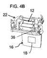
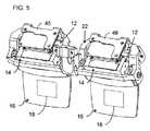
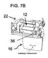
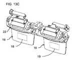
次に、図面を参照すると、図1〜14Cは、実際のシーンを見るユーザに拡張現実表示を表示するための、概して10で示される、ヘッドマウント拡張現実デバイスの種々の実施形態及び種々の構成要素を示している。一般的に言うと、デバイス10は、ユーザの右眼用の右光学モジュールと、ユーザの左眼用の左光学モジュールとを含む、図1に示すような、光学モジュール12のペアを含む。図2に最もよく示されているように、各光学モジュール12は、光ガイド16に光学的に結合されるコリメート表示ソース14を含み、この光ガイドは、少なくとも部分的に透明であり、コリメート表示ソース14によって投射された画像照明をカップリングアウト領域18に案内するように構成され、そこでそれは、カップリングアウト領域からの画像照明の少なくとも一部をユーザの眼に向けて外へ結合する。 Next, with reference to the drawings, FIGS. 1-14C show various embodiments and configurations of the head-mounted augmented reality device, generally shown in FIG. 10, for displaying the augmented reality display to the user viewing the actual scene. Indicates an element. Generally speaking, the
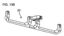
また、デバイスは、ユーザの頭部によって支持されるように、ユーザの頭部の領域に係合するように構成された支持構造20を含む。本発明の一態様の特定の特徴は、デバイス10が、右光学モジュールを位置合わせ及び固定するためのアライメント機構の第1のセット、左光学モジュールを位置合わせ及び固定するためのアライメント機構の第2のセット、及び支持構造に対して光学ベンチを吊るすためのサスペンション装置を提供する光学ベンチ22を含むことである。本発明のこの態様の特に好ましい特徴は、光学ベンチ22が、光学モジュール12のペアと支持構造20との間の唯一の機械的接続を提供することである。 The device also includes a
このような光学ベンチの使用は、身体装着(body-mounted)支持構造への光学モジュールの直接取り付けよりも多くの利点を提供する。具体的には、光学ベンチは、好ましくは、光学モジュール間の比較的剛性のある相互接続を提供し、2つの光学モジュール間の正確なアライメントを規定し、維持する一方で、通常の使用中に身体装着支持構造がさらされ得る応力、振動及び/又は衝撃の大部分から光学モジュールを少なくとも部分的に分離する。光学ベンチはまた、光学モジュールと、カメラ(複数可)及び/又は慣性測定ユニット(IMU)などの追加の構成要素との間のアライメントを規定し、維持するように機能し、同様に、これらの構成要素を、デバイスがさらされ得る機械的及び/又は熱的に誘発される応力の少なくとも一部から保護する。専用の光学ベンチの使用は、典型的には、支持構造に使用されるよりも剛性のある及び/又はより精密に機械加工可能な材料を使用して実装され、他の方法で達成され得るよりも光学モジュールのより精密なアライメントを容易にする。本発明の様々な実施形態のこれら及び他の利点は、以下のさらなる説明を参照してよりよく理解されるであろう。 The use of such an optical bench offers many advantages over the direct attachment of the optical module to a body-mounted support structure. Specifically, the optical bench preferably provides a relatively rigid interconnection between the optical modules, defining and maintaining accurate alignment between the two optical modules, while during normal use. The optics module is at least partially separated from most of the stresses, vibrations and / or shocks that the body-mounted support structure may be exposed to. The optical bench also functions to define and maintain the alignment between the optical module and additional components such as the camera (s) and / or inertial measurement unit (IMU), as well as these. It protects the components from at least some of the mechanical and / or thermally induced stresses that the device may be exposed to. The use of dedicated optical benches is typically implemented using materials that are more rigid and / or more precisely machined than those used for support structures and can be achieved in other ways. Also facilitates more precise alignment of optical modules. These and other advantages of the various embodiments of the invention will be better understood with reference to the further description below.
本明細書で参照する光学モジュール12は、本明細書ではコリメート表示ソース14と称する、コリメート画像プロジェクタと、投影された画像照明を現実世界からの光と組み合わせて、拡張現実表示を提供するための、本明細書では光ガイド16と称する、少なくとも部分的に透明なコンバイナとを含む、任意のタイプの光学モジュールであり得る。コリメート表示ソースは、典型的には、偏光ビームスプリッタ(PBS)に基づいたコンパクトな構成で、コリメート光学系と組み合わされた、OLEDアレイ又は照明付きLCOSアレイなどの画像生成要素に典型的には基づく。最も好ましくは、光学モジュールは、比較的大きい視野角(angular field of view)と、それにわたって表示された画像を見ることができる利用可能な眼の動きの「アイボックス(eyebox)」を達成しながら、小型画像プロジェクタの使用を可能にするための光学開口拡大のための機構を提供する。このような光学的開口拡大を達成するための利用可能な技術には、特に好ましいが非限定的な例として、Lumus Ltd(イスラエル)から市販されている種々の光学モジュールなどの、二次元開口拡大を達成するようにオプションで2段階拡大配置の、光ガイド16内の斜めに角度をつけた部分反射面の使用が含まれる。種々のソースから市販されている別の開口拡大技術は、拡大された領域にわたって光ガイドからの画像照明の外への結合(カップリングアウト)を達成するために、回折光学素子を使用する。上記は単なる例であり、本発明は、拡張現実表示を提供するための表示ソース及びコンバイナを含む任意の利用可能な技術に適用可能であることが留意されるべきである。光学モジュール設計の詳細は、それ自体は本発明の一部を構成しないので、本明細書ではこれ以上論じない。 The
本発明を実装するための光学モジュール12は、多数の異なる構成及びフォームファクタであり得る。図1〜図13Cは、「トップダウン(top-down)」実装に適した構成を示し、そこでは、画像照明は、光ガイドの上端から光ガイド内に向けられる。しかし、本発明は、画像照明が光ガイドの側部又はコーナーから導入される実装にも同様に適用可能であることが留意されるべきである。1つのこのような実施形態が、図14A〜14Cを参照して後述される。 The
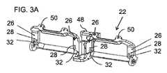
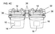
図1に示す例では、光学モジュール12の取り付けは、コリメート表示ソース14の対向する側部に位置する2つの取り付け領域24を介して達成され、したがって、光学モジュールのカップリングアウト領域18に対して両側に配置される。このように取り付け領域を離間することは、構成要素のアライメントの精度を高める傾向がある。 In the example shown in FIG. 1, the mounting of the
各取り付け領域24は、光学ベンチ22上の対応するアライメント機構のセットとのアライメントのための相補的機構(complementary features)を有するように形成される基準位置を規定する。ここに示す好ましい例では、光学ベンチ22のアライメント機構の各セットは、少なくとも1つの、この場合には2つの、平面アライメント面26と、平面アライメント面26に対する光学モジュール12の既知の基準位置を位置付けるための少なくとも2つの位置付け機構とを含む。少なくとも2つの位置付け機構は、ここでは、光学モジュールの取り付け領域24の平面アライメント面から突出するアライメントピン30を受けるためのアライメント開口28として示されている。明らかに、アライメント面26から突出するアライメントピンと領域24の平面内のアライメント開口、又は両方に係合する別個のピンを備えた2つのアライメント開口を提供することによって、同等の効果を達成することができる。光学ベンチ22はまた、典型的にはアライメント面26の領域にも、光学モジュールの各々を各対応する平面アライメント面に対して締め付けるためにボルトを受けるための、ボルト孔32を備える。光学モジュール12は、好ましくは、光学モジュール12の取り付け領域24が、アライメントピン30がアライメント開口28に係合する状態で、光学ベンチ22の平面アライメント面26と共に一緒にされるとき、一対のボルト36が、使用して、図4、5及び7Bに示すように、要素を一緒に締めることができるように、対応するねじ付きボルト穴34を有する。 Each mounting
これまでに説明したアライメント機構は、6自由度(3つの直線/並進及び3つの角度/回転)で正確に定義された配向で各光学モジュール12を光学ベンチ22に固定するのに効果的であることが理解されよう。特に、平面表面に対する平面表面(表面24及び26)の締め付けは、2つの回転配向及び1つの並進自由度(平面に対して垂直)を定義するのに十分である。次いで、第1のアライメントピンとアライメント開口との係合は、2つの面内並進自由度を除外し、軸としてのピンの周りの回転に関する不確実性のみを残す。従って、第1の係合から離間されたアライメント開口との第2のアライメントピンの係合は、6自由度全てにおけるアライメントを完全に規定する。アライメント開口間の高精度の間隔あけの必要性を低減するために、第2のアライメント開口は、有利には、第1のアライメント開口に向かう方向/第1のアライメント開口から離れる方向に伸長された楕円開口部又はスロットとして実施され得、これは依然として、全体の係合の面内回転配向を完全に決定するのに十分である。 The alignment mechanism described so far is effective in fixing each
表面24及び26は、好ましくは、正確なインターフェース表面であり、これは、例えば、機械加工又は研削プロセスを使用して、高精度の平面を達成することによって、これらの要素の他の領域と比較して、より高いレベルの精度を達成するために、製造中に特に加工され得る。各光学モジュールのために2つの離間した場所に平面を設けることにより、高精度のアライメント精度を実現することができる。ここに記載されるアライメント機構の特定の実装は、単に例示であり、アライメント機構の種々の構成が等しく使用され得ることが留意されるべきである。他の例は、光学モジュール取り付け領域24上の対応する機構との当接(abutment)によって光学モジュールを位置合わせする、リッジ、スロット、又はエッジアバットメント機構(abutment features)を有するアライメント面の種々の組み合わせを含む。
各光学モジュール12を位置合わせするための2つの平面アライメント面26は、好ましくは同一平面である。一方の光学モジュールを位置合わせするための表面は、他方の光学モジュールを位置合わせするための表面と同一平面であってもよく、その場合、2つのディスプレイの光軸は平行であってもよく、或いはわずかな収束が、デジタル的に或いは光学コンポーネントのアライメントに導入されてもよい。しかし、いくつかの特に好ましい実装形態では、右光学モジュール12を位置合わせするためのアライメント面26は、両眼輻輳の角度を規定するために左光学モジュールを位置合わせするためのアライメント面に対して傾いている。例えば、1つの特に好ましい実装形態では、各光学モジュールのためのアライメント面は、ユーザから約4メートルの両眼輻輳に対応して、アライメント面間に179.1度の角度を与えるように、基準面に対して0.45度だけ傾斜している。望ましい両眼輻輳の程度は、典型的には、拡張現実表示がスーパーインポーズされることになる現実世界の動作範囲に対応して、意図される用途に応じて変化し得る。例えば、屋外用途は、典型的には6〜10メートルの範囲で、より遠方の輻輳点(point of convergence)を使用し得、一方、AR支援手術用途は、典型的には0.4〜1メートルの範囲で、より短い輻輳ジオメトリ(convergence geometry)を使用し得る。(輻輳距離は、基準面に対する各光学モジュールの傾斜角の正接(tangent)に等しい輻輳長に対する瞳孔間距離(IPD)の半分の比で、簡単な三角測量によって定義されるように、瞳孔間距離(IPD)の関数でもあることに留意されたい。しかし、所望の傾斜角を決定するためには、IPDの平均値が十分な精度を与える。) The two planar alignment surfaces 26 for aligning each
次に、光学ベンチ22の他の特徴に目を向けると、光学ベンチは、有利には、材料の単一ブロックとして形成され得、これは、所与の重さに対してその剛性及び構造強度を高める傾向がある。光学ベンチ22に適した材料は、アルミニウムなどの種々の金属又は金属合金、及び、炭素複合材料などの繊維強化ポリマーを含むが、これらに限定されない。光学ベンチの設計及び寸法、並びに関連する製造プロセスは、当業者にとって明らかなように、選択された材料の特性に応じて調整される。 Next, looking at the other features of the
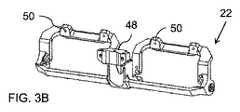
構造及び材料は、光学モジュール12間に実質的に剛体(rigid)の相互接続を提供するために選択される。この文脈において、「実質的に剛体」とは、が移動中に人の頭部及び/又は身体によって行われる線形加速度及び角加速度を含み、且つモジュール自体の重量に留意して、身体装着デバイスが通常さらされる機械的動作条件の範囲にわたって光学モジュールのアライメントを維持する構造を指すために使用される。図12A及び図12Bに最もよく示されるように、光学ベンチ22は、光学モジュールとの正確な位置合わせが重要である及び/又は光学モジュールに近接することが有利である、いくつかの異なる構成要素を支持するために必要とされ得る。図12A〜図12Bの例では、これは、カメラのステレオペア42を含むカメラアセンブリ40と、IMU44と、光学モジュール12のためのドライバ回路46とを含む。これらの要素の各々は、典型的には、カメラアセンブリ40(ここではIMU44と一体化されている)を取り付けるためのカメラアライメント機構を提供するフロントブラケット48及びドライバ回路46を取り付けるためのトップブラケット50などの、光学ベンチの構造における専用の取り付け構成を備える。これらの構成要素の位置及び重量は、光学ベンチ22の設計にさらなる機械的要件を課す。 Structures and materials are selected to provide substantially rigid interconnects between the
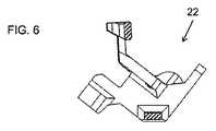
所与の重量及び材料の選択に対して光学ベンチ22の剛性を高めるために、特定の構造的特徴が使用され得る。一つの好ましいオプションによれば、光学ベンチ22は、少なくとも一つの閉ループ構造を、最も好ましくは、図3A〜図5に示すように、右光学モジュールを強固に支持するための第1の閉ループフレームと、左光学モジュールを強固に支持するための第2の閉ループフレームとを用いる。 Certain structural features may be used to increase the stiffness of the
このような閉ループ構造の場合、本発明のある実装形態は、最大剛性の方向が非平行である、非対称剛性を持つクロスビーム(cross-beam)を使用することによって、高められた多軸剛性を達成する。このオプションは、図6に最もよく示されており、ここでは、垂直断面図は、閉ループの一方の2つのクロスビームを切断する(網掛け領域)。各クロスビームは、長軸と短軸とを有する、この場合、長方形断面の長側と短側とを有する、断面を有する。下部クロスビームの長軸は、上部クロスビーム断面の長軸に対して、有意に非平行(45°超)、好ましくはおおよそ垂直(90°±15°)であり、これにより、異なる方向の曲げモーメントに対する抵抗が増大する。 In the case of such a closed loop structure, some implementations of the present invention provide increased multiaxial stiffness by using a cross-beam with asymmetric stiffness in which the directions of maximum stiffness are non-parallel. Achieve. This option is best shown in FIG. 6, where the vertical section cuts one of the two crossbeams in a closed loop (shaded area). Each cross beam has a cross section, having a major axis and a minor axis, in this case having a long side and a short side of a rectangular cross section. The major axis of the lower cross beam is significantly non-parallel (> 45 °), preferably approximately perpendicular (90 ° ± 15 °) to the major axis of the upper cross beam cross section, thereby bending in different directions. Increased resistance to moments.
図示された光学ベンチ22の閉ループ構造は、さまざまな実装形態にとって有利であると考えられているが、本発明は、そのような実装形態に限定されるものではなく、特に、より少ない追加の構成要素がベンチに取り付けられる必要がある場合には、削減された実装形態で十分であることに留意されたい。図13A〜13Cは、本発明の代替実装形態による、光学モジュール12のペアを支持するために使用される光学ベンチ22の削減バージョンを示す。光学ベンチ設計の詳細は、支持されることになる構成要素の特定の組み合わせ、及び、最終的なデバイスの所望のフォームファクタによる利用可能なスペースに応じて、特定の用途ごとに変化し得る。 Although the closed loop structure of the illustrated
次に、図7A〜図7B及び図8を参照すると、本発明のいくつかの好ましい実装形態によれば、光学ベンチ22への光学モジュール12の取り付け位置は、異なる瞳孔間距離(IPD)に適応するように調節可能であり得る。本発明のARディスプレイは、典型的には、ユーザのアイモーションボックス(eye motion box)が、そこから表示画像照明が投影されるカップリングアウト領域18の外側のユーザの視野をとらない限り、IPDの変動に影響されないことに留意されたい。しかし、IPDの調整可能性は、比較的小さなカップリングアウト領域の使用を可能にし、その結果、投影システムの全体的なサイズが小さくなる。 Next, referring to FIGS. 7A-7B and 8, according to some preferred implementations of the present invention, the mounting position of the
IPDを調整するための1つの特に好ましいオプションが図7Aに示されており、そこでは、アライメント開口28及びボルト孔32が、水平方向に細長いスロットとして形成されている。これは、予め定められた可動範囲にわたって、光学モジュールの水平方向の移動のための1自由度を緩和する。光学モジュール12の画像投影は、概して、表示領域の限界に達しない限り、回転無しの面内移動には影響されないので、この調整は、表示に影響を与えない。二つの眼の各々について、いずれかの方向の数ミリメートルの範囲は、典型的には、カップリングアウト領域18の(中心の)間のIPDを調整し、人口の大部分についてのIPDの変動に適応するのに十分であり、カップリングアウト領域18のサイズの対応する縮小を可能にする。オプションで、各光学モジュールの水平位置は、前述のように、摩擦接触によってモジュールを所定の位置にクランプするボルト36の締め付けによって固定され得る。より好ましくは、スプリングワッシャ、又は他の弾性要素が、各光学モジュールの位置の摩擦保持を提供するために設けられ得るが、摩擦保持を克服するために単に穏やかな手動力を加えることによって、ユーザによる光学モジュールの横方向変位を可能にする。光学ベンチのアライメント機構は、光学モジュールの所望のアライメントを、全ての軸周りの角度配向及び2つの線形寸法で、確実に維持し、それによって、複雑な変位機構を必要とせずに、便利なIPD調整を提供する。図8に示すように、光学モジュールの任意の部分に隣接する支持構造20の任意の部分は、光学モジュールの位置に対する利用可能な調整範囲を提供するのに十分なクリアランスで実装される。 One particularly preferred option for adjusting the IPD is shown in FIG. 7A, where the
次に、支持構造20に対して光学ベンチ22を吊るすためのサスペンション装置に目を転じると、これは、特定の用途の詳細及び支持構造のフォームファクタに応じて、多くの異なる形態をとり得る。特に好ましい実装形態の1つのサブセットでは、サスペンション装置は、光学モジュール12を有する光学ベンチ22のアセンブリの全幅の、中央20パーセント以内として定義される、幅の中央領域内でのみ、光学ベンチに接続する。最も好ましくは、接続は、例えば、中央取り付け面52(図12A)を介してのみ光学ベンチ22を支持構造に取り付けることによって達成され得る、全幅の中央10%以内に限定される。取り付け具はリジッド(rigid)であり得るが、支持構造から光学ベンチ22への振動の伝達を抑制(減衰)するように配置された少なくとも1つの弾性減衰要素を介することがより好ましい。中央領域においてのみ光学ベンチ22を支持することによって、支持構造から光学ベンチへの応力の伝達が実質的に排除され、支持構造が、光学アセンブリへの対応する変形又は応力を導入することなく、曲がる、ねじれる、及び/又は熱膨張又は収縮を受けることを可能にする。 Next, turning to the suspension device for suspending the
他の実装形態では、支持構造20に対する光学ベンチ22のアライメントを維持しながら要素間の振動をより効果的に減衰させる、より洗練されたサスペンション装置が提供され得る。そのようなサスペンション装置の一例を、図9A〜11Bを参照して説明する。 In other implementations, more sophisticated suspension devices may be provided that more effectively dampen vibrations between elements while maintaining the alignment of the
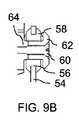
まず、図9Aを参照すると、支持構造(図示せず)は、ここでは、エラストマーグロメット58が内側に配置された開口56で終端する2つの側部ブラケット54を備える。ボルト60及びワッシャ62が、各グロメット58の中央ボアを通過し、光学ベンチ22の各側部のネジ穴64と係合する。組み立てられた接続部は、図9Bの断面図に示されている。側部ブラケット54へのこの両側の取り付けは、光学ベンチ22を、図11Aに示された6自由度のうちの5つ、すなわち、3つの線形変位軸及び2つの回転軸に対して、明確に規定された位置に吊るす。これは、ボルト60の共通軸の周りの回転に対応する、図11Aにおいて「6」とラベル付けされた回転軸のみを残す。この最後の回転自由度は、減衰コネクタ66によって相殺され、この減衰コネクタは、光学ベンチの中心に近いボルト60に対して軸外に取り付けられ、別のブラケット(図示せず)を介して支持構造に接続され、それによって、光学ベンチ22と支持構造との間に減衰接続を形成する。この幾何学的形状は、図11Bに最もよく示されている。ネジ付き開口56は、ネジ付き開口56の間の軸上に実質的に存在する重心をその上に取り付けられた他の構成要素を有する光学ベンチ22のアセンブリが有するように配置されることが、本発明の特定の実装形態の特定の特徴である。これは、この支持構造を介してアセンブリに伝達される衝撃又は振動が、さらなる振動運動を導く可能性がある、正味のモーメント(net moment)を生じないことを確実にする。 First, referring to FIG. 9A, the support structure (not shown) here comprises two
上述のサスペンション装置は、3つの離間した位置での光学ベンチの支持を提供するが、各相互接続は、光学ベンチに重大な応力を伝えることを回避するように、衝撃及び振動を減衰し、(熱膨張係数の差など)応力条件下で変形する能力を有するエラストマー減衰要素を介して生じる。エラストマー要素はまた、光学ベンチ及び関連する光学構成要素の熱絶縁にも寄与する。 The suspension device described above provides support for the optical bench at three separate locations, but each interconnect damps shocks and vibrations to avoid transmitting significant stress to the optical bench. It occurs through an elastomer damping element that has the ability to deform under stress conditions (such as the difference in coefficient of thermal expansion). Elastomer elements also contribute to the thermal insulation of optical benches and related optical components.
本発明のいくつかの特に好ましい実装形態では、支持構造20は、図10に最もよく示されるように、少なくとも部分的に光学ベンチ22を囲むケーシング68を含む。この場合、ケーシング68は、ケーシングと、光学ベンチ及び光学モジュールのペアの両方との間の接触を通常の動作条件の範囲内で回避するために、光学ベンチ22及び光学モジュール12から最小ギャップ70だけ離間されることが好ましい。この文脈における「通常の動作条件の範囲」は、種々の標準によって定義され、かつ当技術分野で知られているような、製品が典型的に動作するために必要とされる振動、機械的応力、及び動作温度の範囲の条件に関する。第一に、ギャップは、デバイスが少なくとも1メートルの高さから硬い表面上に落下した場合、ギャップが閉じられず、衝撃の力積がエラストマー減衰要素を通してのみ光学ベンチに伝達されるように十分であるべきである。 In some particularly preferred embodiments of the present invention, the
本明細書に例示されているように、少なくとも部分的に光学ベンチ及びデバイスの種々の電子及び/又は光学コンポーネントを囲むケーシングのオプションは、有利には、「トップダウン(top-down)」設計で実装されることができ、そこでは、画像照明が光ガイド16の上部に導入され、光ガイド内で下方に伝搬する。この場合、図1及び図8に見られるように、光学モジュール12のウェーブガイド16の少なくとも一部は、好ましくは、ケーシング68から下方に突出する。 As illustrated herein, the casing options that surround the various electronic and / or optical components of the optical bench and device, at least in part, are advantageously in a "top-down" design. It can be implemented, where image illumination is introduced at the top of the
上述したように、光学ベンチ22は、好ましくは、光学モジュール12のペアと支持構造20との間の唯一の機械的接続を提供する。この文脈において、「機械的接続」という句は、荷重を受け、要素間で力を伝達することが意図される2つの要素間の接続を指すために使用される。典型的には、支持構造と光学モジュールとの間を通過する様々な可撓性の電気ケーブルが存在し、電力や映像信号などを供給することに留意されたい。これらの可撓性ケーブルは、要素間に何らかの小さな力を伝達することがあるが、いずれのこのような力も意図されず、意図的に最小化され、構造を支持する機械的接続に比べて無視できるものである。したがって、「唯一の機械的接続」という用語は、耐荷重性であることが意図されないそのような相互接続を排除するものではない。 As mentioned above, the
支持構造20は、デバイスの異なる「フォームファクタ」に対応する広範囲の構成で実装され得る。図1に示すように、1つの非限定的なオプションでは、支持構造20は、ユーザの頭部を取り囲むための、好ましくは調整可能な、ヘッドバンド72を含む。これは、デバイスのための安定したプラットフォームを提供し、特に、デバイスを使用している間にユーザが非常にアクティブである状況での使用に適している。同様の構成は、支持構造20がヘルメットと一体化されたヘルメット装着ディスプレイとして実装されることができる。 The
代替的な「フォームファクタ」は、ガラスフレーム型デバイスを採用し、このデバイスでは、支持構造20は、ユーザの耳(図示せず)に係合するように配置された側部アームのペアを含む。この場合、ユーザの鼻に係合するための第3の支持点は、支持構造20から、或いは、場合によっては、光学ベンチ22から直接、下方に延び得る。本発明のほとんどの実装では、光学ベンチはユーザの身体と直接相互作用(interface with)しないことが好ましいと考えられているが、特に鼻に係合するための弾性ブリッジ又はパッドブリッジとして実装されているとき、中央サポートの1つの領域は、特定の実装において許容され得る。 An alternative "form factor" employs a glass frame type device, in which the
最後に、図14A〜14Cを参照すると、本発明は、トップダウン光学モジュール実装を参照してこれまで図示されてきたが、他の構成を使用しても同様に実施することができ、これは、場合によっては、追加の利点を提供し得る。一例として、図14A及び14Bは、コリメート表示ソース(図示せず)が各光ガイドの横縁部に配置されている側方注入画像実装のために、図14Cに見られるように、2つの光ガイド16の間をリンクするための中央ブロックとして実装される光学ベンチ22を示す。また、この実装形態は、各光学モジュールを位置合わせし、取り付けるためのアライメント機能の代替の実装形態を例示する。この場合、アライメント面26が、光ガイド16の表面に直接当接するように設けられ、横方向当接特徴部(lateral abutment features)74が、ここでは、局部的な突起として実装される。光ガイド16の非直線及び非円形エッジに当接する3つの横方向当接特徴部の使用は、光ガイド唯一の位置及び光学ベンチに対するアライメントを規定するのに十分である。光ガイド16の光学ベンチ22への取り付けは、好ましくは、光ガイドとアライメント面26との間の薄い層において、及び/又は、横方向当接特徴部との間及び/又はその周りの光ガイドと光学ベンチとの間の空間において、接着剤の使用によって、達成される。接着剤の使用は、この実施形態に限定されるものではなく、上記の他の実施形態との関連で実施されてもよい。 Finally, with reference to FIGS. 14A-14C, the present invention has been illustrated with reference to top-down optical module implementations, but other configurations can be implemented as well. , In some cases, may offer additional benefits. As an example, FIGS. 14A and 14B show two lights, as seen in FIG. 14C, for lateral injection image mounting where a collimated display source (not shown) is located at the lateral edge of each optical guide. An
上述の説明は、例としてのみ役立つことを意図するものであり、多くの他の実施形態が、添付の特許請求の範囲において規定される本発明の範囲内で可能であることが理解されるであろう。 The above description is intended to serve as an example only, and it is understood that many other embodiments are possible within the scope of the invention as defined in the appended claims. There will be.
Claims (16)
Translated fromJapanese(a) 前記ユーザの右眼のための右光学モジュール及び前記ユーザの左眼のための左光学モジュールを含む光学モジュールのペアであって、前記光学モジュールの各々は、光ガイドに光学的に結合されたコリメート表示ソースを含み、前記光ガイドは、少なくとも部分的に透明であるとともに、前記コリメート表示ソースによって投射された画像照明をカップリングアウト領域に誘導し、画像照明の少なくとも一部を前記カップリングアウト領域から前記ユーザの眼に向けて外へ結合するように構成される、光学モジュールと;
(b) 前記ユーザの頭部によって支持されるように、前記ユーザの前記頭部と係合するように構成される支持構造と;
(c) 光学ベンチであって:
(i) 前記右光学モジュールを位置合わせし且つ固定するためのアライメント機構の第1のセットと;
(ii) 前記左光学モジュールを位置合わせし且つ固定するためのアライメント機構の第2のセットと;
(iii) 前記支持構造に対して前記光学ベンチを吊るすためのサスペンション装置と;を有する、
光学ベンチと;を有し、
前記光学ベンチは、前記光学モジュールのペアと前記支持構造との間に唯一の機械的接続を提供する、
デバイス。A head-mounted augmented reality device for displaying an augmented reality display to a user viewing a real scene, said device is:
(A) A pair of optical modules including a right optical module for the user's right eye and a left optical module for the user's left eye, each of which is optically coupled to an optical guide. Including a collimated display source, the optical guide is at least partially transparent and guides the image illumination projected by the collimated display source into a coupling-out region, providing at least a portion of the image illumination to the cup. With an optical module configured to couple outward from the ringout area towards the user's eye;
(B) With a support structure configured to engage the user's head so that it is supported by the user's head;
(C) An optical bench:
(I) With the first set of alignment mechanisms for aligning and fixing the right optical module;
(Ii) With a second set of alignment mechanisms for aligning and fixing the left optical module;
(Iii) with a suspension device for suspending the optical bench with respect to the support structure;
With an optical bench;
The optical bench provides the only mechanical connection between the pair of optical modules and the support structure.
device.
請求項1に記載のデバイス。Each of the first and second sets of alignment mechanisms has at least one planar alignment surface and at least two positioning mechanisms for positioning a known reference position of the optical module with respect to the at least one planar alignment surface. Have,
The device according to claim 1.
請求項2に記載のデバイス。The at least two positioning mechanisms are selected from the group consisting of a pin for engaging the alignment aperture of the optical module and the alignment aperture for receiving the pin.
The device according to claim 2.
請求項3に記載のデバイス。The optical bench further comprises bolt holes for receiving bolts for tightening each of the optical modules to each corresponding planar alignment surface.
The device according to claim 3.
請求項2に記載のデバイス。The at least two positioning mechanisms are configured to provide one degree of freedom for adjusting the interpupillary distance between the coupling-out regions of the optical module.
The device according to claim 2.
請求項2に記載のデバイス。The at least one planar alignment surface for aligning the right optical module and the at least one planar alignment surface for aligning the left optical module are inclined relative to each other to cause binocular congestion. Define the angle,
The device according to claim 2.
請求項2に記載のデバイス。Each of the first and second sets of alignment mechanisms has two planar alignment planes located on either side of the corresponding coupling out region of the optical module.
The device according to claim 2.
請求項1に記載のデバイス。The optical bench is formed as a single block of material,
The device according to claim 1.
請求項1に記載のデバイス。The optical bench has a first closed-loop frame for firmly supporting the right optical module and a second closed-loop frame for firmly supporting the left optical module.
The device according to claim 1.
請求項1に記載のデバイス。The optical bench further comprises a camera alignment mechanism for aligning at least one imaging device with respect to the pair of optical modules.
The device according to claim 1.
請求項1に記載のデバイス。The suspension device has at least one elastomer damping element arranged to prevent the passage of vibrations from the support structure to the optical bench.
The device according to claim 1.
請求項1に記載のデバイス。The optical bench and the pair of optical modules together have an overall width, and the suspension device connects to the optical bench only within the central region of the width.
The device according to claim 1.
請求項1に記載のデバイス。The support structure has a casing that at least partially surrounds the optical bench, wherein the casing is provided with both the casing and a pair of the optical bench and the optical module under normal operating conditions. Separated from the optical bench and from the pair of optical modules so as to avoid contact between them.
The device according to claim 1.
請求項13に記載のデバイス。At least a portion of the wave guide projects downward from the casing.
13. The device of claim 13.
請求項1に記載のデバイス。The support structure has a headband for surrounding the user's head.
The device according to claim 1.
請求項1に記載のデバイス。The support structure has a pair of side arms that are arranged to engage the user's ear.
The device according to claim 1.
Applications Claiming Priority (3)
| Application Number | Priority Date | Filing Date | Title |
|---|---|---|---|
| US201762575477P | 2017-10-22 | 2017-10-22 | |
| US62/575,477 | 2017-10-22 | ||
| PCT/IL2018/051127WO2019077614A1 (en) | 2017-10-22 | 2018-10-22 | ENHANCED REALITY DEVICE MOUNTED ON THE HEAD AND USING AN OPTICAL BENCH |
Publications (2)
| Publication Number | Publication Date |
|---|---|
| JP2021502587Atrue JP2021502587A (en) | 2021-01-28 |
| JP7228584B2 JP7228584B2 (en) | 2023-02-24 |
Family
ID=66174356
Family Applications (1)
| Application Number | Title | Priority Date | Filing Date |
|---|---|---|---|
| JP2020522734AActiveJP7228584B2 (en) | 2017-10-22 | 2018-10-22 | Head-mounted augmented reality device with optical bench |
Country Status (8)
| Country | Link |
|---|---|
| US (3) | US11656472B2 (en) |
| EP (1) | EP3701312B1 (en) |
| JP (1) | JP7228584B2 (en) |
| KR (1) | KR102695589B1 (en) |
| CN (1) | CN111133362B (en) |
| IL (1) | IL274104A (en) |
| TW (1) | TWI829656B (en) |
| WO (1) | WO2019077614A1 (en) |
Cited By (1)
| Publication number | Priority date | Publication date | Assignee | Title |
|---|---|---|---|---|
| KR20220125416A (en)* | 2021-03-05 | 2022-09-14 | 신현실 | Underwater AR display device for marine safety education |
Families Citing this family (56)
| Publication number | Priority date | Publication date | Assignee | Title |
|---|---|---|---|---|
| US10261321B2 (en) | 2005-11-08 | 2019-04-16 | Lumus Ltd. | Polarizing optical system |
| IL232197B (en) | 2014-04-23 | 2018-04-30 | Lumus Ltd | Compact head-mounted display system |
| IL237337B (en) | 2015-02-19 | 2020-03-31 | Amitai Yaakov | Compact head-mounted display system having uniform image |
| WO2018065975A1 (en) | 2016-10-09 | 2018-04-12 | Lumus Ltd | Aperture multiplier using a rectangular waveguide |
| KR20240160657A (en) | 2016-11-08 | 2024-11-11 | 루머스 리미티드 | Light-guide device with optical cutoff edge and corresponding production methods |
| CN110431467A (en) | 2017-01-28 | 2019-11-08 | 鲁姆斯有限公司 | Augmented reality imaging system |
| CN109416433B (en) | 2017-03-22 | 2021-06-01 | 鲁姆斯有限公司 | Overlapping Reflector Construction |
| EP4215980A1 (en) | 2017-07-19 | 2023-07-26 | Lumus Ltd. | Lcos illumination via loe |
| US11513352B2 (en) | 2017-09-29 | 2022-11-29 | Lumus Ltd. | Augmented reality display |
| WO2019077614A1 (en) | 2017-10-22 | 2019-04-25 | Lumus Ltd. | ENHANCED REALITY DEVICE MOUNTED ON THE HEAD AND USING AN OPTICAL BENCH |
| WO2019102366A1 (en) | 2017-11-21 | 2019-05-31 | Lumus Ltd. | Optical aperture expansion arrangement for near-eye displays |
| IL275013B (en) | 2017-12-03 | 2022-08-01 | Lumus Ltd | Method and device for testing an optics device |
| CN111417883B (en) | 2017-12-03 | 2022-06-17 | 鲁姆斯有限公司 | Optical equipment alignment method |
| KR20200102408A (en) | 2018-01-02 | 2020-08-31 | 루머스 리미티드 | Augmented Reality Display with Active Alignment and Corresponding Method |
| US10551544B2 (en) | 2018-01-21 | 2020-02-04 | Lumus Ltd. | Light-guide optical element with multiple-axis internal aperture expansion |
| MY203244A (en) | 2018-04-08 | 2024-06-19 | Lumus Ltd | Optical sample characterization |
| KR102752134B1 (en) | 2018-05-14 | 2025-01-08 | 루머스 리미티드 | Projector configuration with sub-optical aperture for near-eye display and corresponding optical system |
| IL278511B2 (en) | 2018-05-17 | 2025-01-01 | Lumus Ltd | Near-eye display having overlapping projector assemblies |
| IL259518B2 (en) | 2018-05-22 | 2023-04-01 | Lumus Ltd | Optical system and method for improvement of light field uniformity |
| MX2020012512A (en) | 2018-05-23 | 2021-02-16 | Lumus Ltd | Optical system including light-guide optical element with partially-reflective internal surfaces. |
| CN119595595A (en) | 2018-06-21 | 2025-03-11 | 鲁姆斯有限公司 | Technique for measuring refractive index non-uniformity between plates of light-guiding optical element (LOE) |
| US11415812B2 (en) | 2018-06-26 | 2022-08-16 | Lumus Ltd. | Compact collimating optical device and system |
| EP3824335B1 (en) | 2018-07-16 | 2023-10-18 | Lumus Ltd. | Light-guide optical element employing polarized internal reflectors |
| CN112601993A (en) | 2018-08-26 | 2021-04-02 | 鲁姆斯有限公司 | Reflection suppression in near-eye displays |
| CN116184666A (en) | 2018-09-09 | 2023-05-30 | 鲁姆斯有限公司 | Optical system comprising a light-guiding optical element with two-dimensional expansion |
| USD908291S1 (en)* | 2018-09-18 | 2021-01-19 | Bae Systems Plc | Helmet module |
| USD927786S1 (en) | 2018-09-18 | 2021-08-10 | Bae Systems Plc | Helmet |
| USD928412S1 (en) | 2018-09-18 | 2021-08-17 | Bae Systems Plc | Helmet |
| USD921990S1 (en) | 2018-09-18 | 2021-06-08 | Bae Systems Plc | Helmet module |
| US11947130B2 (en) | 2018-11-08 | 2024-04-02 | Lumus Ltd. | Optical devices and systems with dichroic beamsplitter color combiner |
| TWM642752U (en) | 2018-11-08 | 2023-06-21 | 以色列商魯姆斯有限公司 | Light-guide display with reflector |
| JP3226277U (en) | 2018-11-11 | 2020-05-14 | ルムス エルティーディー. | Near eye display with intermediate window |
| MX2021008808A (en) | 2019-01-24 | 2021-08-24 | Lumus Ltd | Optical systems including loe with three stage expansion. |
| WO2020174433A1 (en) | 2019-02-28 | 2020-09-03 | Lumus Ltd. | Compact collimated image projector |
| TWI800657B (en) | 2019-03-12 | 2023-05-01 | 以色列商魯姆斯有限公司 | Image projector |
| TWI845670B (en) | 2019-05-06 | 2024-06-21 | 以色列商魯姆斯有限公司 | Transparent lightguide for viewing a scene and a near-eye display |
| CN110262038B (en)* | 2019-06-06 | 2022-06-21 | 歌尔光学科技有限公司 | Optical system and virtual reality device having the same |
| WO2021105982A1 (en) | 2019-11-25 | 2021-06-03 | Lumus Ltd. | Method of polishing a surface of a waveguide |
| IL270991B (en) | 2019-11-27 | 2020-07-30 | Lumus Ltd | Lightguide optical element for polarization scrambling |
| TWI884834B (en) | 2019-12-05 | 2025-05-21 | 以色列商魯姆斯有限公司 | Optical device and method of fabricating optical device |
| CN110895370B (en)* | 2019-12-06 | 2021-11-09 | Oppo广东移动通信有限公司 | Head-mounted device |
| US11523092B2 (en) | 2019-12-08 | 2022-12-06 | Lumus Ltd. | Optical systems with compact image projector |
| CN114787687B (en) | 2019-12-25 | 2024-07-30 | 鲁姆斯有限公司 | Systems and methods for eye tracking based on redirection of light from the eye using an optical arrangement associated with a light guide optical element |
| USD1056835S1 (en)* | 2020-03-04 | 2025-01-07 | Magic Leap, Inc. | Combined charging stand and devices |
| CN218848473U (en) | 2020-05-12 | 2023-04-11 | 鲁姆斯有限公司 | Equipment including projection optics and light guides |
| CN113933991A (en)* | 2020-07-14 | 2022-01-14 | 宁波舜宇光电信息有限公司 | Optical waveguide assembly method in AR device and AR device |
| EP4204890A2 (en)* | 2020-07-27 | 2023-07-05 | Apple Inc. | Electronic devices with biased guide rails |
| AU2021331833A1 (en) | 2020-08-23 | 2023-03-09 | Lumus Ltd. | Optical system for two-dimensional expansion of an image reducing glints and ghosts from the waveguide |
| WO2022044006A1 (en) | 2020-08-26 | 2022-03-03 | Lumus Ltd. | Generation of color images using white light as source |
| DE202021104723U1 (en) | 2020-09-11 | 2021-10-18 | Lumus Ltd. | Image projector coupled to an optical light guide element |
| JP7643055B2 (en) | 2021-01-28 | 2025-03-11 | セイコーエプソン株式会社 | Image display device and manufacturing method thereof |
| KR20230148324A (en) | 2021-03-01 | 2023-10-24 | 루머스 리미티드 | Optical system with compact coupling from projector to waveguide |
| TWI779789B (en)* | 2021-08-20 | 2022-10-01 | 雙瑩科技股份有限公司 | Optical system with augmented reality |
| US20230418070A1 (en)* | 2022-06-27 | 2023-12-28 | Meta Platforms Technologies, Llc | Optical assemblies, head-mounted displays, and related methods |
| WO2024038458A1 (en) | 2022-08-18 | 2024-02-22 | Lumus Ltd. | Image projector with polarizing catadioptric collimator |
| US20240077729A1 (en)* | 2022-09-06 | 2024-03-07 | Meta Platforms Technologies, Llc | Apparatuses, systems, and methods for aligning display projector assemblies included in head-mounted displays |
Citations (6)
| Publication number | Priority date | Publication date | Assignee | Title |
|---|---|---|---|---|
| JPH05196898A (en)* | 1992-01-21 | 1993-08-06 | Sony Corp | Spectacle type video display device |
| JPH09101479A (en)* | 1995-10-04 | 1997-04-15 | Olympus Optical Co Ltd | Video display device |
| WO2007037089A1 (en)* | 2005-09-27 | 2007-04-05 | Konica Minolta Holdings, Inc. | Head-mounted image display unit |
| JP2008035146A (en)* | 2006-07-28 | 2008-02-14 | Canon Inc | Image display device |
| JP2008134471A (en)* | 2006-11-28 | 2008-06-12 | Canon Inc | Display device |
| US20170146802A1 (en)* | 2015-11-19 | 2017-05-25 | Andriy PLETENETSKYY | Low-Stress Waveguide Mounting for Head-Mounted Display Device |
Family Cites Families (147)
| Publication number | Priority date | Publication date | Assignee | Title |
|---|---|---|---|---|
| US3969023A (en) | 1975-03-06 | 1976-07-13 | American Optical Corporation | Method and apparatus for detecting layers of stress in lenses |
| US4720189A (en) | 1986-01-07 | 1988-01-19 | Northern Telecom Limited | Eye-position sensor |
| JP3163786B2 (en)* | 1992-10-09 | 2001-05-08 | ソニー株式会社 | Glasses-type image display device |
| ES2149926T3 (en)* | 1994-04-21 | 2000-11-16 | Sega Enterprises Kk | SCREEN TO MOUNT ON THE HEAD. |
| US6680758B1 (en) | 1997-01-16 | 2004-01-20 | Reveo, Inc. | Flat panel display and a method of fabrication |
| US6268883B1 (en) | 1997-05-30 | 2001-07-31 | California Institute Of Technology | High speed infrared imaging system and method |
| EP1068548B1 (en) | 1998-04-02 | 2003-11-12 | Elop Electro-Optics Industries Ltd. | Holographic optical devices |
| JP3913407B2 (en) | 1999-07-09 | 2007-05-09 | 株式会社リコー | Refractive index distribution measuring apparatus and method |
| ATE473464T1 (en) | 2000-06-05 | 2010-07-15 | Lumus Ltd | OPTICAL BEAM EXPANDER WITH SUBSTRATE LIGHT WAVE GUIDE |
| IL136849A (en) | 2000-06-18 | 2004-09-27 | Beamus Ltd | Optical dynamic devices particularly for beam steering and optical communication |
| IL138895A (en) | 2000-10-05 | 2005-08-31 | Elop Electrooptics Ind Ltd | Optical switching devices |
| US20020186179A1 (en) | 2001-06-07 | 2002-12-12 | Knowles Gary R. | Optical display device |
| IL148804A (en) | 2002-03-21 | 2007-02-11 | Yaacov Amitai | Optical device |
| US20070165192A1 (en) | 2006-01-13 | 2007-07-19 | Silicon Optix Inc. | Reduced field angle projection display system |
| JP4111074B2 (en) | 2002-08-20 | 2008-07-02 | セイコーエプソン株式会社 | projector |
| US7640306B2 (en) | 2002-11-18 | 2009-12-29 | Aol Llc | Reconfiguring an electronic message to effect an enhanced notification |
| CN100416340C (en)* | 2003-04-25 | 2008-09-03 | 微型光学公司 | binocular viewing system |
| US6879443B2 (en)* | 2003-04-25 | 2005-04-12 | The Microoptical Corporation | Binocular viewing system |
| EP1484596A1 (en) | 2003-06-05 | 2004-12-08 | Fraunhofer-Gesellschaft zur Förderung der angewandten Forschung e.V. | Method and device for three-dimensional determination of the refractive index of transparents layers |
| IL157838A (en) | 2003-09-10 | 2013-05-30 | Yaakov Amitai | High brightness optical device |
| IL157836A (en) | 2003-09-10 | 2009-08-03 | Yaakov Amitai | Optical devices particularly for remote viewing applications |
| IL157837A (en) | 2003-09-10 | 2012-12-31 | Yaakov Amitai | Substrate-guided optical device particularly for three-dimensional displays |
| JP2005308717A (en) | 2004-03-23 | 2005-11-04 | Shin Etsu Chem Co Ltd | Method and apparatus for measuring core non-circularity of optical fiber preform |
| US7333199B2 (en) | 2004-05-10 | 2008-02-19 | Finisar Corporation | Aligning optical components with three degrees of translational freedom |
| IL162573A (en) | 2004-06-17 | 2013-05-30 | Lumus Ltd | Substrate-guided optical device with very wide aperture |
| IL163361A (en) | 2004-08-05 | 2011-06-30 | Lumus Ltd | Optical device for light coupling into a guiding substrate |
| JP2006145644A (en) | 2004-11-17 | 2006-06-08 | Hitachi Ltd | Polarization separator and projection display device using the same |
| JP2008533507A (en) | 2005-02-10 | 2008-08-21 | ラマス リミテッド | Substrate guiding optical device especially for vision enhancement optical system |
| IL166799A (en) | 2005-02-10 | 2014-09-30 | Lumus Ltd | Substrate-guided optical device utilizing beam splitters |
| US7724443B2 (en) | 2005-02-10 | 2010-05-25 | Lumus Ltd. | Substrate-guided optical device utilizing thin transparent layer |
| US10073264B2 (en) | 2007-08-03 | 2018-09-11 | Lumus Ltd. | Substrate-guide optical device |
| EP1848966A1 (en) | 2005-02-17 | 2007-10-31 | Lumus Ltd | Personal navigation system |
| CN101203802B (en) | 2005-06-20 | 2010-05-19 | 松下电器产业株式会社 | Two-dimensional image display device, lighting source and exposure lighting device |
| US20070155277A1 (en) | 2005-07-25 | 2007-07-05 | Avi Amitai | Mobile/portable and personal pre-recorded sound effects electronic amplifier device/gadget |
| US10261321B2 (en) | 2005-11-08 | 2019-04-16 | Lumus Ltd. | Polarizing optical system |
| IL171820A (en) | 2005-11-08 | 2014-04-30 | Lumus Ltd | Polarizing optical device for light coupling |
| EP1952189B1 (en) | 2005-11-21 | 2016-06-01 | Microvision, Inc. | Display with image-guiding substrate |
| TWI297817B (en) | 2005-12-30 | 2008-06-11 | Ind Tech Res Inst | System and mehtod for recording and reproducing holographic storage which has tracking servo projection |
| IL173715A0 (en) | 2006-02-14 | 2007-03-08 | Lumus Ltd | Substrate-guided imaging lens |
| IL174170A (en) | 2006-03-08 | 2015-02-26 | Abraham Aharoni | Device and method for binocular alignment |
| IL177618A (en) | 2006-08-22 | 2015-02-26 | Lumus Ltd | Substrate- guided optical device |
| US8643948B2 (en) | 2007-04-22 | 2014-02-04 | Lumus Ltd. | Collimating optical device and system |
| IL183637A (en) | 2007-06-04 | 2013-06-27 | Zvi Lapidot | Distributed head-mounted display |
| JP5140869B2 (en) | 2007-08-06 | 2013-02-13 | 株式会社リコー | Image projection method and image projection apparatus |
| JP2009128565A (en) | 2007-11-22 | 2009-06-11 | Toshiba Corp | Display device, display method, and head-up display |
| US8493662B2 (en) | 2008-09-16 | 2013-07-23 | Bae Systems Plc | Waveguides |
| WO2010062479A1 (en) | 2008-11-02 | 2010-06-03 | David Chaum | System and apparatus for eyeglass appliance platform |
| CN102439509B (en) | 2009-05-05 | 2015-07-22 | 英特尔公司 | Passive alignment method and its application in micro projection devices |
| JP5333067B2 (en) | 2009-08-31 | 2013-11-06 | ソニー株式会社 | Image display device and head-mounted display |
| WO2011106797A1 (en)* | 2010-02-28 | 2011-09-01 | Osterhout Group, Inc. | Projection triggering through an external marker in an augmented reality eyepiece |
| JP5499854B2 (en) | 2010-04-08 | 2014-05-21 | ソニー株式会社 | Optical position adjustment method for head mounted display |
| KR101232036B1 (en) | 2010-10-13 | 2013-02-12 | 한국과학기술원 | Non-contact power transmission device and self-induction power feeding device |
| WO2012062681A1 (en)* | 2010-11-08 | 2012-05-18 | Seereal Technologies S.A. | Display device, in particular a head-mounted display, based on temporal and spatial multiplexing of hologram tiles |
| EP2693027A4 (en) | 2011-03-31 | 2014-10-08 | Toyota Motor Co Ltd | CONTROL DEVICE FOR INTERNAL COMBUSTION ENGINE AND VEHICLE EQUIPPED WITH SAME |
| US20130022220A1 (en)* | 2011-07-20 | 2013-01-24 | Google Inc. | Wearable Computing Device with Indirect Bone-Conduction Speaker |
| US20150051389A1 (en) | 2011-08-11 | 2015-02-19 | Isis Pharmaceuticals, Inc. | Selective antisense compounds and uses thereof |
| US9311883B2 (en) | 2011-11-11 | 2016-04-12 | Microsoft Technology Licensing, Llc | Recalibration of a flexible mixed reality device |
| BR112014012615A2 (en) | 2011-11-23 | 2017-06-13 | Magic Leap Inc | three-dimensional augmented reality and virtual reality display system |
| JP5904665B2 (en) | 2012-04-27 | 2016-04-13 | 株式会社 エフケー光学研究所 | Phase measuring apparatus, phase measuring program and phase measuring method |
| IL219907A (en) | 2012-05-21 | 2017-08-31 | Lumus Ltd | Head-mounted display eyeball tracker integrated system |
| CN202864800U (en) | 2012-07-26 | 2013-04-10 | 诠钧实业有限公司 | Brake mechanism of winch |
| US20150355481A1 (en)* | 2012-12-31 | 2015-12-10 | Esight Corp. | Apparatus and method for fitting head mounted vision augmentation systems |
| US9395543B2 (en) | 2013-01-12 | 2016-07-19 | Microsoft Technology Licensing, Llc | Wearable behavior-based vision system |
| US9638920B2 (en) | 2013-04-15 | 2017-05-02 | Microsoft Technology Licensing, Llc | Torsional support for binocular display |
| US20160020965A1 (en) | 2013-08-07 | 2016-01-21 | Hitachi, Ltd. | Method and apparatus for dynamic monitoring condition control |
| US9596756B2 (en)* | 2013-09-06 | 2017-03-14 | Apple Inc. | Electronic device with printed circuit board noise reduction using elastomeric damming and damping structures |
| US10194860B2 (en)* | 2013-09-11 | 2019-02-05 | Industrial Technology Research Institute | Virtual image display system |
| AU2014337171B2 (en)* | 2013-10-16 | 2018-11-15 | Magic Leap, Inc. | Virtual or augmented reality headsets having adjustable interpupillary distance |
| US20160018651A1 (en) | 2014-01-24 | 2016-01-21 | Osterhout Group, Inc. | See-through computer display systems |
| US9470633B2 (en) | 2014-02-14 | 2016-10-18 | Google Inc. | Method, apparatus and system for transmittance measurement |
| US9395544B2 (en)* | 2014-03-13 | 2016-07-19 | Google Inc. | Eyepiece with switchable reflector for head wearable display |
| IL232197B (en) | 2014-04-23 | 2018-04-30 | Lumus Ltd | Compact head-mounted display system |
| US9509939B2 (en)* | 2014-06-04 | 2016-11-29 | Universal City Studios Llc | Display for immersive window effect |
| EP2958074A1 (en) | 2014-06-17 | 2015-12-23 | Thomson Licensing | A method and a display device with pixel repartition optimization |
| US10198865B2 (en) | 2014-07-10 | 2019-02-05 | Seiko Epson Corporation | HMD calibration with direct geometric modeling |
| US9606354B2 (en) | 2014-07-17 | 2017-03-28 | Google Inc. | Heads-up display with integrated display and imaging system |
| US9529198B2 (en) | 2014-08-29 | 2016-12-27 | Google Inc. | Opto-mechanical system for head-mounted device |
| US9639976B2 (en) | 2014-10-31 | 2017-05-02 | Google Inc. | Efficient computation of shadows for circular light sources |
| IL235642B (en) | 2014-11-11 | 2021-08-31 | Lumus Ltd | Compact head-mounted display system protected by a hyperfine structure |
| JP6464708B2 (en)* | 2014-12-08 | 2019-02-06 | セイコーエプソン株式会社 | Image display device |
| IL236490B (en) | 2014-12-25 | 2021-10-31 | Lumus Ltd | Optical component on a conductive substrate |
| IL236491B (en) | 2014-12-25 | 2020-11-30 | Lumus Ltd | A method for fabricating substrate-guided optical device |
| CN104570353A (en) | 2015-01-08 | 2015-04-29 | 浙江大学 | Color visual display method, optical system and wearable device using holographic waveguide |
| IL237337B (en) | 2015-02-19 | 2020-03-31 | Amitai Yaakov | Compact head-mounted display system having uniform image |
| US11468639B2 (en) | 2015-02-20 | 2022-10-11 | Microsoft Technology Licensing, Llc | Selective occlusion system for augmented reality devices |
| JP2016180871A (en) | 2015-03-24 | 2016-10-13 | 矢崎総業株式会社 | Optical device |
| EP3286599A4 (en) | 2015-04-22 | 2018-12-19 | eSIGHT CORP. | Methods and devices for optical aberration correction |
| US9910276B2 (en) | 2015-06-30 | 2018-03-06 | Microsoft Technology Licensing, Llc | Diffractive optical elements with graded edges |
| US10222619B2 (en) | 2015-07-12 | 2019-03-05 | Steven Sounyoung Yu | Head-worn image display apparatus for stereoscopic microsurgery |
| NZ742518A (en) | 2015-11-04 | 2019-08-30 | Magic Leap Inc | Dynamic display calibration based on eye-tracking |
| US10653567B2 (en) | 2015-11-16 | 2020-05-19 | Hill-Rom Services, Inc. | Incontinence detection pad validation apparatus and method |
| US10198978B2 (en) | 2015-12-15 | 2019-02-05 | Facebook Technologies, Llc | Viewing optics test subsystem for head mounted displays |
| JP6726967B2 (en) | 2016-01-19 | 2020-07-22 | 三菱電機株式会社 | Brightness unevenness measuring device |
| JP2017135605A (en) | 2016-01-28 | 2017-08-03 | コニカミノルタ株式会社 | Image display device |
| AU2017228307B2 (en) | 2016-02-29 | 2021-11-04 | Magic Leap, Inc. | Virtual and augmented reality systems and methods |
| US9958685B2 (en)* | 2016-04-20 | 2018-05-01 | The Boeing Company | Dual-axis tilt platform for head mounted display |
| JP6740366B2 (en) | 2016-05-18 | 2020-08-12 | ルーマス リミテッドLumus Ltd. | Head mount imaging device |
| US20170353714A1 (en) | 2016-06-06 | 2017-12-07 | Navid Poulad | Self-calibrating display system |
| WO2017223042A1 (en)* | 2016-06-20 | 2017-12-28 | PogoTec, Inc. | Image alignment systems and methods |
| CN106054292A (en) | 2016-06-24 | 2016-10-26 | 中国科学院长春光学精密机械与物理研究所 | Thin film structure having selective absorption characteristics and preparation method thereof |
| CN106019602B (en)* | 2016-08-03 | 2018-03-30 | 深圳酷酷科技有限公司 | Head-mounted display apparatus |
| WO2018065975A1 (en) | 2016-10-09 | 2018-04-12 | Lumus Ltd | Aperture multiplier using a rectangular waveguide |
| KR20240160657A (en) | 2016-11-08 | 2024-11-11 | 루머스 리미티드 | Light-guide device with optical cutoff edge and corresponding production methods |
| US10553139B2 (en)* | 2016-11-10 | 2020-02-04 | Microsoft Technology Licensing, Llc | Enhanced imaging system for linear micro-displays |
| DE212017000261U1 (en) | 2016-12-02 | 2019-08-05 | Lumus Ltd. | Optical system with compact collimator image projector |
| KR102296369B1 (en) | 2016-12-31 | 2021-09-01 | 루머스 리미티드 | Retinal Imaging-Based Eye Tracker with Light-Guiding Optics |
| WO2018127913A1 (en) | 2017-01-04 | 2018-07-12 | Lumus Ltd. | Optical system for near-eye displays |
| US10136532B2 (en) | 2017-02-17 | 2018-11-20 | International Business Machines Corporation | Dust guard structure |
| CN108738358B (en) | 2017-02-22 | 2021-03-26 | 鲁姆斯有限公司 | Light guide optics |
| EP3602175A4 (en) | 2017-03-21 | 2021-04-21 | Magic Leap, Inc. | EYE IMAGING DEVICE USING OPTICAL DIFFRACTION ELEMENTS |
| CN109416433B (en) | 2017-03-22 | 2021-06-01 | 鲁姆斯有限公司 | Overlapping Reflector Construction |
| IL251645B (en) | 2017-04-06 | 2018-08-30 | Lumus Ltd | Light-guide optical element and method of its manufacture |
| EP4215980A1 (en) | 2017-07-19 | 2023-07-26 | Lumus Ltd. | Lcos illumination via loe |
| KR101898706B1 (en) | 2017-07-31 | 2018-09-13 | 엘지디스플레이 주식회사 | Mounting apparatus and assembly apparatus for display module and method of same |
| US10798370B2 (en)* | 2017-08-30 | 2020-10-06 | Facebook Technologies, Llc | Apparatus, system, and method for interpupillary-distance-adjustable head-mounted displays |
| EP3685215B1 (en) | 2017-09-21 | 2024-01-03 | Magic Leap, Inc. | Augmented reality display with waveguide configured to capture images of eye and/or environment |
| US11513352B2 (en) | 2017-09-29 | 2022-11-29 | Lumus Ltd. | Augmented reality display |
| CN207216158U (en) | 2017-10-16 | 2018-04-10 | 深圳市闻耀电子科技有限公司 | Interpupillary adjustment mechanism and VR all-in-ones |
| WO2019077614A1 (en) | 2017-10-22 | 2019-04-25 | Lumus Ltd. | ENHANCED REALITY DEVICE MOUNTED ON THE HEAD AND USING AN OPTICAL BENCH |
| WO2019102366A1 (en) | 2017-11-21 | 2019-05-31 | Lumus Ltd. | Optical aperture expansion arrangement for near-eye displays |
| CN207424391U (en) | 2017-11-22 | 2018-05-29 | 深圳创维新世界科技有限公司 | Nearly eye display device |
| CN111417883B (en) | 2017-12-03 | 2022-06-17 | 鲁姆斯有限公司 | Optical equipment alignment method |
| US20190170327A1 (en) | 2017-12-03 | 2019-06-06 | Lumus Ltd. | Optical illuminator device |
| IL275013B (en) | 2017-12-03 | 2022-08-01 | Lumus Ltd | Method and device for testing an optics device |
| KR102704523B1 (en) | 2017-12-10 | 2024-09-06 | 루머스 리미티드 | Image projector |
| US11112613B2 (en) | 2017-12-18 | 2021-09-07 | Facebook Technologies, Llc | Integrated augmented reality head-mounted display for pupil steering |
| US10506220B2 (en) | 2018-01-02 | 2019-12-10 | Lumus Ltd. | Augmented reality displays with active alignment and corresponding methods |
| KR20200102408A (en) | 2018-01-02 | 2020-08-31 | 루머스 리미티드 | Augmented Reality Display with Active Alignment and Corresponding Method |
| IL275824B2 (en) | 2018-01-17 | 2024-08-01 | Magic Leap Inc | Display systems and methods for determining registration between a display and a user's eyes |
| US10551544B2 (en) | 2018-01-21 | 2020-02-04 | Lumus Ltd. | Light-guide optical element with multiple-axis internal aperture expansion |
| MY203244A (en) | 2018-04-08 | 2024-06-19 | Lumus Ltd | Optical sample characterization |
| KR102752134B1 (en) | 2018-05-14 | 2025-01-08 | 루머스 리미티드 | Projector configuration with sub-optical aperture for near-eye display and corresponding optical system |
| IL278511B2 (en) | 2018-05-17 | 2025-01-01 | Lumus Ltd | Near-eye display having overlapping projector assemblies |
| IL259518B2 (en) | 2018-05-22 | 2023-04-01 | Lumus Ltd | Optical system and method for improvement of light field uniformity |
| MX2020012512A (en) | 2018-05-23 | 2021-02-16 | Lumus Ltd | Optical system including light-guide optical element with partially-reflective internal surfaces. |
| TWM587757U (en) | 2018-05-27 | 2019-12-11 | 以色列商魯姆斯有限公司 | Substrate-guide based optical systems with field curvature effect |
| CN119595595A (en) | 2018-06-21 | 2025-03-11 | 鲁姆斯有限公司 | Technique for measuring refractive index non-uniformity between plates of light-guiding optical element (LOE) |
| US11415812B2 (en) | 2018-06-26 | 2022-08-16 | Lumus Ltd. | Compact collimating optical device and system |
| EP3824335B1 (en) | 2018-07-16 | 2023-10-18 | Lumus Ltd. | Light-guide optical element employing polarized internal reflectors |
| KR102592226B1 (en) | 2018-07-17 | 2023-10-23 | 삼성전자주식회사 | Semiconductor package bonding head and bonding method |
| TWI827663B (en) | 2018-09-06 | 2024-01-01 | 以色列商魯姆斯有限公司 | Near-eye display with laser diode illumination |
| CN116184666A (en) | 2018-09-09 | 2023-05-30 | 鲁姆斯有限公司 | Optical system comprising a light-guiding optical element with two-dimensional expansion |
| JP3226277U (en) | 2018-11-11 | 2020-05-14 | ルムス エルティーディー. | Near eye display with intermediate window |
| MX2021008808A (en) | 2019-01-24 | 2021-08-24 | Lumus Ltd | Optical systems including loe with three stage expansion. |
| US11143589B2 (en) | 2019-03-15 | 2021-10-12 | Mls Acq, Inc. | FTIR spectrometer with cut-off filter for hydrogen sulfide detection |
| TWI845670B (en) | 2019-05-06 | 2024-06-21 | 以色列商魯姆斯有限公司 | Transparent lightguide for viewing a scene and a near-eye display |
| US11294838B2 (en) | 2020-07-29 | 2022-04-05 | Micron Technology, Inc. | Signaling mechanism for bus inversion |
- 2018
- 2018-10-22WOPCT/IL2018/051127patent/WO2019077614A1/ennot_activeCeased
- 2018-10-22TWTW107137248Apatent/TWI829656B/enactive
- 2018-10-22JPJP2020522734Apatent/JP7228584B2/enactiveActive
- 2018-10-22KRKR1020207009483Apatent/KR102695589B1/enactiveActive
- 2018-10-22USUS16/758,109patent/US11656472B2/enactiveActive
- 2018-10-22CNCN201880061286.0Apatent/CN111133362B/enactiveActive
- 2018-10-22EPEP18867433.7Apatent/EP3701312B1/enactiveActive
- 2020
- 2020-04-21ILIL274104Apatent/IL274104A/enunknown
- 2023
- 2023-04-30USUS18/141,423patent/US11966062B2/enactiveActive
- 2024
- 2024-04-22USUS18/641,467patent/US12216286B2/enactiveActive
Patent Citations (6)
| Publication number | Priority date | Publication date | Assignee | Title |
|---|---|---|---|---|
| JPH05196898A (en)* | 1992-01-21 | 1993-08-06 | Sony Corp | Spectacle type video display device |
| JPH09101479A (en)* | 1995-10-04 | 1997-04-15 | Olympus Optical Co Ltd | Video display device |
| WO2007037089A1 (en)* | 2005-09-27 | 2007-04-05 | Konica Minolta Holdings, Inc. | Head-mounted image display unit |
| JP2008035146A (en)* | 2006-07-28 | 2008-02-14 | Canon Inc | Image display device |
| JP2008134471A (en)* | 2006-11-28 | 2008-06-12 | Canon Inc | Display device |
| US20170146802A1 (en)* | 2015-11-19 | 2017-05-25 | Andriy PLETENETSKYY | Low-Stress Waveguide Mounting for Head-Mounted Display Device |
Cited By (2)
| Publication number | Priority date | Publication date | Assignee | Title |
|---|---|---|---|---|
| KR20220125416A (en)* | 2021-03-05 | 2022-09-14 | 신현실 | Underwater AR display device for marine safety education |
| KR102549902B1 (en)* | 2021-03-05 | 2023-06-29 | 신현실 | Underwater AR display device for marine safety education |
Also Published As
| Publication number | Publication date |
|---|---|
| KR102695589B1 (en) | 2024-08-14 |
| EP3701312A1 (en) | 2020-09-02 |
| US20200278557A1 (en) | 2020-09-03 |
| EP3701312B1 (en) | 2025-03-12 |
| JP7228584B2 (en) | 2023-02-24 |
| EP3701312A4 (en) | 2020-11-11 |
| CN111133362B (en) | 2021-12-28 |
| IL274104A (en) | 2020-06-30 |
| US12216286B2 (en) | 2025-02-04 |
| US20240264453A1 (en) | 2024-08-08 |
| TWI829656B (en) | 2024-01-21 |
| WO2019077614A1 (en) | 2019-04-25 |
| KR20200077511A (en) | 2020-06-30 |
| TW201923419A (en) | 2019-06-16 |
| US11966062B2 (en) | 2024-04-23 |
| US11656472B2 (en) | 2023-05-23 |
| CN111133362A (en) | 2020-05-08 |
| US20230266597A1 (en) | 2023-08-24 |
Similar Documents
| Publication | Publication Date | Title |
|---|---|---|
| US11966062B2 (en) | Head-mounted augmented reality device employing an optical bench | |
| US10120194B2 (en) | Wide field personal display | |
| CN107272198B (en) | The bending eyepiece with color correction for head-mounted display | |
| JP7566339B2 (en) | Binocular head-mounted display system with adjustable interpupillary distance mechanism | |
| US9733477B2 (en) | Dual axis internal optical beam tilt for eyepiece of an HMD | |
| EP2828703B1 (en) | Optical beam tilt for offset head mounted display | |
| CN111381377B (en) | Near-to-eye display device | |
| US20090153437A1 (en) | Device and method for alignment of binocular personal display | |
| CN109445094B (en) | Light projection engine attachment and alignment | |
| JP2021071603A (en) | Head mount display | |
| CN110088666A (en) | A device for implementing a compact head-mounted display with reflector and eyepiece elements | |
| TW202300991A (en) | Dual-reflector optical component | |
| WO2023245146A1 (en) | Systems and methods for display binocular deformation compensation | |
| JP7604915B2 (en) | Image display device | |
| US20250237877A1 (en) | Optical support system for augmented reality glasses | |
| US20210398953A1 (en) | Display panel and head mounted device | |
| CN114815244A (en) | image display device |
Legal Events
| Date | Code | Title | Description |
|---|---|---|---|
| A621 | Written request for application examination | Free format text:JAPANESE INTERMEDIATE CODE: A621 Effective date:20210823 | |
| A977 | Report on retrieval | Free format text:JAPANESE INTERMEDIATE CODE: A971007 Effective date:20220620 | |
| A131 | Notification of reasons for refusal | Free format text:JAPANESE INTERMEDIATE CODE: A131 Effective date:20220628 | |
| A601 | Written request for extension of time | Free format text:JAPANESE INTERMEDIATE CODE: A601 Effective date:20220928 | |
| A521 | Request for written amendment filed | Free format text:JAPANESE INTERMEDIATE CODE: A523 Effective date:20221122 | |
| TRDD | Decision of grant or rejection written | ||
| A01 | Written decision to grant a patent or to grant a registration (utility model) | Free format text:JAPANESE INTERMEDIATE CODE: A01 Effective date:20230207 | |
| A61 | First payment of annual fees (during grant procedure) | Free format text:JAPANESE INTERMEDIATE CODE: A61 Effective date:20230213 | |
| R150 | Certificate of patent or registration of utility model | Ref document number:7228584 Country of ref document:JP Free format text:JAPANESE INTERMEDIATE CODE: R150 |