JP2021502184A - Thrombectomy device and how to use - Google Patents
Thrombectomy device and how to useDownload PDFInfo
- Publication number
- JP2021502184A JP2021502184AJP2020526058AJP2020526058AJP2021502184AJP 2021502184 AJP2021502184 AJP 2021502184AJP 2020526058 AJP2020526058 AJP 2020526058AJP 2020526058 AJP2020526058 AJP 2020526058AJP 2021502184 AJP2021502184 AJP 2021502184A
- Authority
- JP
- Japan
- Prior art keywords
- braided
- thrombus
- recovery device
- wire
- braided assembly
- Prior art date
- Legal status (The legal status is an assumption and is not a legal conclusion. Google has not performed a legal analysis and makes no representation as to the accuracy of the status listed.)
- Granted
Links
Images


Classifications
- A—HUMAN NECESSITIES
- A61—MEDICAL OR VETERINARY SCIENCE; HYGIENE
- A61B—DIAGNOSIS; SURGERY; IDENTIFICATION
- A61B17/00—Surgical instruments, devices or methods
- A61B17/22—Implements for squeezing-off ulcers or the like on inner organs of the body; Implements for scraping-out cavities of body organs, e.g. bones; for invasive removal or destruction of calculus using mechanical vibrations; for removing obstructions in blood vessels, not otherwise provided for
- A61B17/221—Gripping devices in the form of loops or baskets for gripping calculi or similar types of obstructions
- A—HUMAN NECESSITIES
- A61—MEDICAL OR VETERINARY SCIENCE; HYGIENE
- A61B—DIAGNOSIS; SURGERY; IDENTIFICATION
- A61B17/00—Surgical instruments, devices or methods
- A61B2017/00743—Type of operation; Specification of treatment sites
- A61B2017/00778—Operations on blood vessels
- A—HUMAN NECESSITIES
- A61—MEDICAL OR VETERINARY SCIENCE; HYGIENE
- A61B—DIAGNOSIS; SURGERY; IDENTIFICATION
- A61B17/00—Surgical instruments, devices or methods
- A61B2017/00831—Material properties
- A61B2017/00867—Material properties shape memory effect
- A—HUMAN NECESSITIES
- A61—MEDICAL OR VETERINARY SCIENCE; HYGIENE
- A61B—DIAGNOSIS; SURGERY; IDENTIFICATION
- A61B17/00—Surgical instruments, devices or methods
- A61B17/22—Implements for squeezing-off ulcers or the like on inner organs of the body; Implements for scraping-out cavities of body organs, e.g. bones; for invasive removal or destruction of calculus using mechanical vibrations; for removing obstructions in blood vessels, not otherwise provided for
- A61B2017/22038—Implements for squeezing-off ulcers or the like on inner organs of the body; Implements for scraping-out cavities of body organs, e.g. bones; for invasive removal or destruction of calculus using mechanical vibrations; for removing obstructions in blood vessels, not otherwise provided for with a guide wire
- A—HUMAN NECESSITIES
- A61—MEDICAL OR VETERINARY SCIENCE; HYGIENE
- A61B—DIAGNOSIS; SURGERY; IDENTIFICATION
- A61B17/00—Surgical instruments, devices or methods
- A61B17/22—Implements for squeezing-off ulcers or the like on inner organs of the body; Implements for scraping-out cavities of body organs, e.g. bones; for invasive removal or destruction of calculus using mechanical vibrations; for removing obstructions in blood vessels, not otherwise provided for
- A61B2017/22079—Implements for squeezing-off ulcers or the like on inner organs of the body; Implements for scraping-out cavities of body organs, e.g. bones; for invasive removal or destruction of calculus using mechanical vibrations; for removing obstructions in blood vessels, not otherwise provided for with suction of debris
- A—HUMAN NECESSITIES
- A61—MEDICAL OR VETERINARY SCIENCE; HYGIENE
- A61B—DIAGNOSIS; SURGERY; IDENTIFICATION
- A61B17/00—Surgical instruments, devices or methods
- A61B17/22—Implements for squeezing-off ulcers or the like on inner organs of the body; Implements for scraping-out cavities of body organs, e.g. bones; for invasive removal or destruction of calculus using mechanical vibrations; for removing obstructions in blood vessels, not otherwise provided for
- A61B2017/22081—Treatment of vulnerable plaque
- A—HUMAN NECESSITIES
- A61—MEDICAL OR VETERINARY SCIENCE; HYGIENE
- A61B—DIAGNOSIS; SURGERY; IDENTIFICATION
- A61B17/00—Surgical instruments, devices or methods
- A61B17/22—Implements for squeezing-off ulcers or the like on inner organs of the body; Implements for scraping-out cavities of body organs, e.g. bones; for invasive removal or destruction of calculus using mechanical vibrations; for removing obstructions in blood vessels, not otherwise provided for
- A61B17/221—Gripping devices in the form of loops or baskets for gripping calculi or similar types of obstructions
- A61B2017/2212—Gripping devices in the form of loops or baskets for gripping calculi or similar types of obstructions having a closed distal end, e.g. a loop
- A—HUMAN NECESSITIES
- A61—MEDICAL OR VETERINARY SCIENCE; HYGIENE
- A61B—DIAGNOSIS; SURGERY; IDENTIFICATION
- A61B2217/00—General characteristics of surgical instruments
- A61B2217/002—Auxiliary appliance
- A61B2217/005—Auxiliary appliance with suction drainage system
Landscapes
- Health & Medical Sciences (AREA)
- Surgery (AREA)
- Life Sciences & Earth Sciences (AREA)
- Heart & Thoracic Surgery (AREA)
- Molecular Biology (AREA)
- Vascular Medicine (AREA)
- Engineering & Computer Science (AREA)
- Biomedical Technology (AREA)
- Orthopedic Medicine & Surgery (AREA)
- Medical Informatics (AREA)
- Nuclear Medicine, Radiotherapy & Molecular Imaging (AREA)
- Animal Behavior & Ethology (AREA)
- General Health & Medical Sciences (AREA)
- Public Health (AREA)
- Veterinary Medicine (AREA)
- Surgical Instruments (AREA)
- Media Introduction/Drainage Providing Device (AREA)
Abstract
Translated fromJapaneseDescription
Translated fromJapanese[関連出願との相互参照]
この出願は、2017年11月9日に提出された米国仮出願第62/583613号の利益を主張するものであり、あらゆる目的のためにその全体が参照により組み込まれている。[Cross-reference with related applications]
This application claims the interests of US Provisional Application No. 62/583613 filed on November 9, 2017, which is incorporated by reference in its entirety for all purposes.
本発明は、身体から組織を除去するための医療装置に関する。この装置の特定の用途の1つは、動脈または静脈から血餅(血栓)またはプラークを除去することである。 The present invention relates to a medical device for removing tissue from the body. One particular use of this device is to remove blood clots (thrombus) or plaques from arteries or veins.
他の組織に損傷を与えないように、できるだけ低侵襲的な方法で身体から組織を除去することが望ましい場合がよくある。例えば、血管系からの組織(例えば、血餅)の除去は、患者の状態および生活の質を改善し得る。 It is often desirable to remove tissue from the body in the least invasive way possible so as not to damage other tissues. For example, removal of tissue (eg, blood clots) from the vascular system can improve a patient's condition and quality of life.
血管系の問題の多くは、血管を通る血流が不十分であることから生じる。不十分なまたは不規則な血流の1つの原因は、血餅または血栓と呼ばれる血管内の閉塞である。血栓は、手術などの外傷後や他の原因によるものなど、様々な理由で発生する。例えば、米国における120万件を超える心臓発作の大部分は、冠状動脈内に形成される血餅(血栓)が原因である。 Many vascular problems result from inadequate blood flow through the blood vessels. One cause of inadequate or irregular blood flow is an obstruction in a blood vessel called a clot or blood clot. Blood clots occur for a variety of reasons, including after trauma such as surgery or due to other causes. For example, the majority of over 1.2 million heart attacks in the United States are caused by blood clots (thrombi) that form in the coronary arteries.
血栓が形成されると、形成領域を通る血流を実質的に停止する可能性がある。血栓が動脈の内径を横切って広がる場合、それは動脈を通る血流を遮断する可能性がある。冠状動脈の1つが100%血栓化すると、その動脈での血流が停止し、心臓壁の筋肉(心筋)に供給するなど、赤血球を運ぶ酸素が不足する。そのような血栓症は、血液の損失を防ぐために必要ではないが、アテローム性動脈硬化症による動脈壁への損傷によって、動脈内で望ましくなく引き起こされる可能性がある。したがって、アテローム性動脈硬化症の基礎疾患は急性酸素欠乏症(虚血)を引き起こさないかもしれないが、誘発された血栓症を介して急性虚血を引き起こす可能性がある。同様に、頸動脈の1つの血栓症は、頭蓋内の重要な神経中心への酸素供給が不十分なため、脳卒中を引き起こす可能性がある。酸素欠乏症は、筋肉活動を減少または禁止し、胸痛(狭心症)を引き起こし、心筋を死に至らせ、心臓をある程度永久に機能停止させる可能性がある。心筋細胞死が広範囲に及ぶ場合、心臓は体の生命維持に必要な量を供給するのに十分な血液を送り出すことができなくなる。虚血の程度は、側副血管の存在や必要な酸素を提供できる血流など、多くの要因の影響を受ける。 When a thrombus is formed, it can substantially stop blood flow through the area of formation. If a blood clot spreads across the inner diameter of an artery, it can block blood flow through the artery. When one of the coronary arteries becomes 100% thrombus, blood flow in that artery is stopped, and oxygen that carries red blood cells is insufficient, such as supplying the muscles (myocardium) of the heart wall. Such thrombosis is not necessary to prevent blood loss, but it can be undesirably caused within the artery by damage to the arterial wall due to atherosclerosis. Therefore, the underlying disease of atherosclerosis may not cause acute anoxia (ischemia), but it can cause acute ischemia through induced thrombosis. Similarly, one thrombosis of the carotid artery can cause a stroke due to an inadequate supply of oxygen to important nerve centers within the skull. Anoxia can reduce or abolish muscle activity, cause chest pain (angina), kill the heart muscle, and cause the heart to stop functioning to some extent permanently. When cardiomyocyte death is widespread, the heart is unable to pump enough blood to supply the body's vital needs. The degree of ischemia is affected by many factors, including the presence of collateral vessels and blood flow that can provide the necessary oxygen.
臨床データは、血餅除去が転帰を改善するために有益であるか、または必要でさえあるかもしれないことを示す。例えば、末梢血管系では、発明と手技により、切断の必要性を80%削減できる。動脈系または静脈系のこれらの状態を治療するためのあらゆるモダリティの最終的な目標は、閉塞を除去するか、開存性をすばやく、安全に、そしてコスト効率よく回復することである。このことは、血栓溶解、断片化、血栓吸引、またはこれらの方法の組み合わせによって達成できる。 Clinical data indicate that clot removal may be beneficial or even necessary to improve outcomes. For example, in the peripheral vascular system, inventions and procedures can reduce the need for amputation by 80%. The ultimate goal of any modality for treating these conditions of the arterial or venous system is to eliminate the obstruction or restore patency quickly, safely and cost-effectively. This can be achieved by thrombolysis, fragmentation, thrombus aspiration, or a combination of these methods.
カテーテル指向血栓切除術および血栓溶解療法は、外傷性が低く、従来の外科技術に関連する罹患率および死亡率を低下させる可能性が低いと一般に認識されている。近年、冠状動脈への化学的溶解剤の直接投与は、冠状動脈を血栓化した患者にいくらかの利益があることが示されている。この手技では、閉塞の直前にカテーテルを配置し、血栓の上流側に向けてストレプトキナーゼの滴下を配置する。ストレプトキナーゼは、フィブリン分子を溶解する酵素である。この手技には数時間かかる場合があり、血栓の破壊に常に成功するとは限らない。さらに、下流の血栓の破片(塞栓)を引き起こし、小径の枝の閉塞を引き起こす可能性がある。 It is generally recognized that catheter-directed embolectomy and thrombolytic therapy are less traumatic and less likely to reduce morbidity and mortality associated with conventional surgical techniques. In recent years, direct administration of chemical lysing agents to the coronary arteries has been shown to have some benefit to patients who have thromboized the coronary arteries. In this procedure, a catheter is placed just prior to occlusion and a drop of streptokinase is placed towards the upstream side of the thrombus. Streptokinase is an enzyme that dissolves fibrin molecules. This procedure can take several hours and is not always successful in destroying blood clots. In addition, it can cause downstream thrombus debris (embolus) and blockage of small-diameter branches.
血栓切除術は、動脈または静脈内の血餅を機械的に除去するための技術である。化学的溶解を使用して血餅を溶解するのではなく、血餅を物理的に除去することを指す。血餅とプラークを分解して除去するために複数の装置が導入されたが、それぞれに独自の欠点がある。具体的には、既存のシステムは、その後の吸引のために血餅をより小さな断片に分解するための適切な方法を提供していない。また、それらは、血栓摘出装置をガイドワイヤ上で取り外し、同じ場所に再度挿入して手技を完了するための方法を提供しない。血管系から血栓およびプラークを除去するのにより効果的な改善された血栓摘出装置が必要とされている。 Thrombectomy is a technique for mechanically removing blood clots in arteries or veins. It refers to the physical removal of a clot rather than the use of chemical lysis to dissolve the clot. Several devices have been introduced to break down and remove blood clots and plaque, but each has its own drawbacks. Specifically, existing systems do not provide a suitable method for breaking down blood clots into smaller pieces for subsequent aspiration. Also, they do not provide a way to remove the thrombectomy device on the guide wire and reinsert it in place to complete the procedure. There is a need for an improved thrombectomy device that is more effective in removing thrombi and plaque from the vascular system.
本明細書に開示される装置および方法は、ワイヤを介した機能を備えた改善された動脈内幾何学を介してより効率的な血餅除去の目的を達成する改善された血栓摘出装置を提供する。本明細書に開示されている血栓摘出装置は、施術者が選択した直径に拡張できる編組アセンブリを使用して血栓を除去し、施術者が手技中に装置を特定の血栓にカスタムフィットできるようにする。従来の血栓摘出装置とは異なり、開示された編組アセンブリの直径は、例えば、血栓の除去のために追加のグリップが必要な場合、必要に応じて手技の途中で変更することができる。いくつかの実施形態では、より長い血栓に対処するために、複数の編組アセンブリを使用することができる。各編組アセンブリは、個々のアセンブリが手技中に異なる直径を有するように、個別に拡張できる。 The devices and methods disclosed herein provide an improved thrombectomy device that achieves the purpose of more efficient clot removal through improved intra-arterial geometry with wire-mediated functionality. To do. The thrombectomy device disclosed herein removes a thrombus using a braided assembly that can be expanded to a diameter of the practitioner's choice, allowing the practitioner to custom fit the device to a particular thrombus during the procedure. To do. Unlike conventional thrombectomy devices, the diameter of the disclosed braided assembly can be changed in the middle of the procedure, for example, if additional grip is required to remove the thrombus. In some embodiments, multiple braided assemblies can be used to deal with longer thrombi. Each braided assembly can be individually extended so that the individual assemblies have different diameters during the procedure.
吸引カテーテルは、近位端および遠位端を含む。回収装置は、吸引カテーテルの管腔を通って延び、遠位端で出る。回収装置は、近位領域、遠位領域、および近位領域と遠位領域との間に延在する第1の管腔を含む。少なくとも1つの編組アセンブリは、回収装置の遠位領域にわたって延びる。少なくとも1つの編組アセンブリは、少なくとも1つのスライド可能カラーと、スライド可能カラーに取り付けられた編組とを含む。編組は1層または2層にすることができる。編組は、スライド可能カラーから、編組を回収装置に固定する固定取り付け点に向かって延びる。拡張すると、編組は楕円形または紡錘形を取り、中心付近で最大直径を持ち、近位領域と遠位領域とが編組の縦軸に近づくにつれて狭くなる。 Suction catheters include the proximal and distal ends. The recovery device extends through the lumen of the suction catheter and exits at the distal end. The recovery device includes a proximal region, a distal region, and a first lumen extending between the proximal and distal regions. At least one braided assembly extends over the distal region of the recovery device. The at least one braided assembly includes at least one slidable collar and a braid attached to the slidable collar. The braid can be one or two layers. The braid extends from the slidable collar towards a fixed attachment point that secures the braid to the recovery device. When expanded, the braid takes an elliptical or spindle shape, has a maximum diameter near the center, and narrows as the proximal and distal regions approach the vertical axis of the braid.
少なくとも1つの作動ワイヤは、回収装置の第1の管腔を通り、かつ遠位領域に配置された出口点を通って延びる。作動ワイヤの遠位端は、スライド可能カラーに取り付けられている。いくつかの実施形態では、出口点は、回収装置の側壁における入口である。入口は、例えば、編組アセンブリの編組の下に配置することができる。いくつかの実施形態では、回収装置は、近位に配置された皮下注射管と、近位皮下注射管よりも可撓性が大きい遠位に配置された支持管とを含む。入口は、遠位支持管の側壁に画定することができ、編組アセンブリは、遠位支持管の上に配置することができる。いくつかの実施形態では、遠位支持管は、近位皮下注射管の遠位端に取り付けられる。 At least one actuating wire extends through the first lumen of the recovery device and through an exit point located in the distal region. The distal end of the actuating wire is attached to a slidable collar. In some embodiments, the exit point is the inlet at the side wall of the recovery device. The entrance can be placed below the braid of the braid assembly, for example. In some embodiments, the recovery device comprises a proximally placed subcutaneous injection tube and a distally placed support tube that is more flexible than the proximal subcutaneous injection tube. The entrance can be defined on the side wall of the distal support tube and the braided assembly can be placed on top of the distal support tube. In some embodiments, the distal support tube is attached to the distal end of the proximal subcutaneous injection tube.
作動ワイヤに張力をかけると、編組アセンブリが施術者の選択した直径まで拡張する。したがって、編組アセンブリは、作動ワイヤ上の張力のレベルを変化させることによって、ある範囲の拡張された外径に拡張することができる。例えば、編組アセンブリは、作動ワイヤに第1のレベルの張力をかけることによって第1の拡張外径まで、または作動ワイヤに第2のレベルの張力をかけることによって第2の拡張外径まで展開可能である。施術者は、編組アセンブリを第1の直径に展開するために第1のレベルの張力を作動ワイヤにかけ、その後、異なるレベルの張力をかけることによって直径を後で変更することができる。いくつかの実施形態では、作動ワイヤの第1のレベルの張力は、作動ワイヤの第2のレベルの張力よりも小さいので、第1の拡張外径は、部分的に拡張した構成の編組の最大直径であり、第2の拡張外径は、完全に拡張した構成での編組の最大直径である。拡張された編組アセンブリは、血栓に接触し、吸引カテーテルに向かって近位に引っ張られ、血栓の除去を支援する。編組は、折り畳まれた構成の形状記憶を有するので、作動ワイヤの張力を解放すると、編組は、例えば、除去中に吸引カテーテルに入るときに、緩められて折り畳まれた状態に戻ることができる。 When tension is applied to the working wire, the braided assembly expands to the diameter of the practitioner's choice. Thus, the braided assembly can be extended to a range of extended outer diameters by varying the level of tension on the working wire. For example, the braided assembly can be deployed to a first extended outer diameter by applying a first level of tension to the working wire, or to a second extended outer diameter by applying a second level of tension to the working wire. Is. The practitioner can later change the diameter by applying a first level of tension to the working wire to deploy the braided assembly to a first diameter and then applying different levels of tension. In some embodiments, the first level tension of the working wire is less than the tension of the second level of the working wire, so the first extended outer diameter is the maximum of the braid in the partially expanded configuration. The diameter, the second extended outer diameter is the maximum diameter of the braid in a fully expanded configuration. The expanded braided assembly contacts the thrombus and is pulled proximally towards the suction catheter to assist in removing the thrombus. Since the braid has a shape memory of the folded configuration, releasing the tension of the working wire allows the braid to be loosened and returned to its folded state, for example, when entering the suction catheter during removal.
血栓摘出装置のいくつかの実施形態は、ガイドワイヤ管をさらに含み得る。いくつかの実施形態では、ガイドワイヤ管は、回収装置よりも短くすることができる。回収装置は、ガイドワイヤ管の第1の管腔を通って延在し、ガイドワイヤ管の第2の管腔は、ガイドワイヤの上に延在する。いくつかの実施形態では、編組アセンブリの固定取り付け点は、ガイドワイヤ管上に配置することができる。いくつかの実施形態では、ガイドワイヤ管は、長手方向において、回収装置よりも短くすることができる。 Some embodiments of the thrombectomy device may further include a guidewire tube. In some embodiments, the guidewire tube can be shorter than the recovery device. The recovery device extends through the first cavity of the guidewire tube and the second lumen of the guidewire tube extends over the guidewire. In some embodiments, the fixed attachment points of the braided assembly can be located on the guidewire tubing. In some embodiments, the guidewire tube can be shorter in the longitudinal direction than the recovery device.
血栓摘出装置のいくつかの実施形態は、複数の編組部分および複数のスライドカラーを備えた編組アセンブリを含み得る。これらの実施形態では、各々の追加のスライド可能カラーは、2つの編組部分の間に配置される。作動ワイヤに張力をかけることにより、編組部分のそれぞれが少なくとも部分的に拡張する。複数の編組部分は、1つの連続編組から形成することも、別個の編組から形成することもできる。いくつかの実施形態では、作動ワイヤは、複数のスライド可能カラーの1つに取り付けられる。例えば、作動ワイヤは、最も遠位のスライド可能カラーに取り付けられてもよい。 Some embodiments of the thrombectomy device may include a braided assembly with multiple braided portions and multiple slide collars. In these embodiments, each additional slidable collar is placed between the two braided portions. By applying tension to the working wire, each of the braided portions expands at least partially. The plurality of braided portions can be formed from one continuous braid or from separate braids. In some embodiments, the actuating wire is attached to one of a plurality of slidable collars. For example, the actuating wire may be attached to the most distal slidable collar.
血栓摘出装置のいくつかの実施形態は、少なくとも1つの追加の編組アセンブリと少なくとも1つの追加の作動ワイヤとを含む。各々の追加の作動ワイヤは、追加の編組アセンブリの追加のスライド可能カラーに取り付けられ、各々の編組アセンブリは、取り付けられた作動ワイヤを介して別々に拡張可能である。 Some embodiments of the thrombectomy device include at least one additional braided assembly and at least one additional working wire. Each additional working wire is attached to an additional slidable collar of the additional braided assembly, and each braided assembly is separately expandable via the attached working wire.
血栓摘出装置のいくつかの実施形態は、編組アセンブリを拡張する作動ワイヤを制御するための近位に配置された張力要素を含む。作動ワイヤの近位端は、例えば近位に配置されたハンドルに取り付けられ得る張力要素に取り付けられる。 Some embodiments of the thrombectomy device include a proximally placed tension element for controlling an actuating wire that extends the braided assembly. The proximal end of the actuating wire is attached, for example, to a tension element that can be attached to a locally located handle.
本明細書には血栓切除術の手技を実施する方法も開示されている。この方法は、血管系を通して吸引カテーテルの遠位端を血栓の近位の領域まで前進させること、および少なくとも1つの編組アセンブリを運ぶ回収装置の遠位端を吸引カテーテルの遠位端から血栓の遠位の位置まで前進させることを含む。編組アセンブリに取り付けられている作動ワイヤに第1のレベルの張力をかける。第1のレベルの張力は、回収装置の管腔内で長手方向に作動ワイヤを動かすことにより、編組アセンブリのスライド可能カラーを回収装置の外面上で長手方向に動かし、編組アセンブリを第1の拡張外径に展開する。必要に応じて、第1のレベルの張力よりも大きいまたは小さい第2のレベルの張力を作動ワイヤにかけることができる。第2のレベルの張力は、回収装置の管腔内で長手方向に作動ワイヤを動かすことにより、編組アセンブリのスライド可能カラーを回収装置の外面上で長手方向に動かし、編組アセンブリを第2の拡張外径に展開する。スライド可能カラーが回収装置の外面上で長手方向に移動し、編組アセンブリが最適な直径に拡張されると、回収装置の遠位端は静止位置を維持する。いくつかの実施形態では、第2のレベルの張力は、編組アセンブリをより広い第2の拡張外径に開き、血栓を編組とよりしっかりと接触させる。血栓は吸引カテーテルに向かって引っ張られ、吸引カテーテルの遠位端に吸引される。いくつかの実施形態では、血栓は、外部真空源を使用して吸引カテーテルの遠位端に吸引される。 Also disclosed herein are methods of performing a thrombectomy procedure. This method advances the distal end of the aspiration catheter through the vascular system to the area proximal to the thrombus, and the distal end of the recovery device carrying at least one braided assembly is far from the distal end of the aspiration catheter. Including advancing to the position of the position. A first level of tension is applied to the working wire attached to the braided assembly. The first level of tension moves the slidable collar of the braided assembly longitudinally over the outer surface of the recovery device by moving the actuating wire longitudinally within the cavity of the recovery device, extending the braided assembly to the first. Expand to the outer diameter. If desired, a second level of tension greater than or less than the first level of tension can be applied to the working wire. A second level of tension moves the slidable collar of the braided assembly longitudinally over the outer surface of the recovery device by moving the actuating wire longitudinally within the cavity of the recovery device, extending the braided assembly to the second level. Expand to the outer diameter. The distal end of the recovery device remains stationary as the slidable collar moves longitudinally over the outer surface of the recovery device and the braided assembly is expanded to the optimum diameter. In some embodiments, the second level of tension opens the braided assembly to a wider second dilated outer diameter, bringing the thrombus into tighter contact with the braid. The thrombus is pulled towards the aspiration catheter and aspirated to the distal end of the aspiration catheter. In some embodiments, the thrombus is aspirated to the distal end of the aspiration catheter using an external vacuum source.
方法のいくつかの実施形態では、複数の編組部分または複数の編組アセンブリを使用して、血栓を接触させて引くことができる。例えば、単一のスライド可能カラーの動きは、編組アセンブリの複数の編組部分の拡張を引き起こし得る。別の例では、近位に配置された編組アセンブリは、吸引カテーテルの遠位端に近づくと、第1の拡張外径から狭い第2の外径に折り畳むことができ、一方、遠位に配置された編組アセンブリは、近位に配置された編組アセンブリの第2の外径と同等またはそれよりも広い拡張外径を維持できる。 In some embodiments of the method, multiple braided portions or multiple braided assemblies can be used to bring the thrombus into contact and pull. For example, the movement of a single slidable collar can cause expansion of multiple braided parts of a braided assembly. In another example, the proximally placed braided assembly can be folded from the first dilated outer diameter to the narrower second outer diameter as it approaches the distal end of the suction catheter, while being placed distally. The braided assembly can maintain an extended outer diameter equal to or wider than the second outer diameter of the proximally placed braided assembly.
方法のいくつかの実施形態は、ガイドワイヤの使用を含み得る。これらの方法は、回収装置の遠位端を前進させる前に、ガイドワイヤを血栓の遠位の位置に前進させることを含む。回収装置は、ガイドワイヤ管の第1の管腔を通って少なくとも部分的に延びることができ、方法は、ガイドワイヤを介して回収装置と共にガイドワイヤ管を前進させることを含む。作動ワイヤは、ガイドワイヤ管の第1の管腔内にある回収装置内で長手方向に動く。ガイドワイヤは、ガイドワイヤ管の第2の管腔内を長手方向に動く。 Some embodiments of the method may include the use of guide wires. These methods involve advancing the guide wire to a position distal to the thrombus before advancing the distal end of the recovery device. The recovery device can extend at least partially through the first cavity of the guide wire tube, the method comprising advancing the guide wire tube with the recovery device via the guide wire. The actuating wire moves longitudinally within the recovery device within the first lumen of the guide wire tube. The guide wire moves longitudinally in the second lumen of the guide wire tube.
本発明の概念の特定の例の以下の説明は、特許請求の範囲を限定するために使用されるべきではない。他の例、特徴、態様、実施形態、および利点は、以下の説明から当業者に明らかになるであろう。理解されるように、装置および/または方法は、発明の概念の精神から逸脱することなく、他の異なる明白な態様が可能である。したがって、図面および説明は、本質的に例示と見なされるべきであり、限定と見なされるべきではない。 The following description of a particular example of the concept of the present invention should not be used to limit the scope of the claims. Other examples, features, embodiments, embodiments, and advantages will be apparent to those skilled in the art from the following description. As will be appreciated, the device and / or method is capable of other different and obvious aspects without departing from the spirit of the concept of the invention. Therefore, drawings and descriptions should be considered exemplary in nature and not limitations.
この説明のために、本開示の実施形態の特定の態様、利点、および新規の特徴が本明細書で説明される。説明された方法、システム、および装置は、決して限定的であると解釈されるべきではない。代わりに、本開示は、開示された様々な実施形態のすべての新規かつ非自明な特徴および態様を、単独で、および互いとの様々な組み合わせおよびサブコンビネーションで対象とする。開示された方法、システム、および装置は、特定の態様、特徴、またはそれらの組み合わせに限定されず、開示された方法、システム、および装置は、1つ以上の特定の利点の存在または問題の解決を要求しない。 For this explanation, specific aspects, advantages, and novel features of the embodiments of the present disclosure are described herein. The methods, systems, and devices described should by no means be construed as limiting. Instead, the present disclosure covers all novel and non-trivial features and embodiments of the various disclosed embodiments alone and in various combinations and subcombinations with each other. The disclosed methods, systems, and devices are not limited to specific aspects, features, or combinations thereof, and the disclosed methods, systems, and devices are the existence or problem resolution of one or more specific benefits. Does not require.
本発明の特定の態様、実施形態、または例に関連して説明された特徴、整数、特性、化合物、化学部分、またはグループは、本明細書に記載された他の任意の態様、実施形態、または例に互換性がない限り適用可能であると理解されるべきである。本明細書に開示されているすべての機能(添付の特許請求の範囲、要約、および図面を含む)、および/またはそのように開示されている方法またはプロセスのすべてのステップは、機能や手技が相互に排他的である少なくとも一部の組み合わせを除いて、任意の組み合わせで組み合わせることができる。本発明は、前述の実施形態の詳細に限定されない。本発明は、本明細書に開示された特徴(添付の特許請求の範囲、要約、および図面を含む)の新規なもの、または新規な組み合わせ、またはそのように開示された任意の方法もしくはプロセスのステップの新規なもの、または新規な組み合わせに及ぶ。 The features, integers, properties, compounds, chemical moieties, or groups described in connection with a particular aspect, embodiment, or example of the invention are any other aspects, embodiments, described herein. Or it should be understood that it is applicable unless the examples are compatible. All features disclosed herein (including the appended claims, abstracts, and drawings) and / or all steps of the method or process so disclosed are functional or procedures. Any combination can be combined, except for at least some combinations that are mutually exclusive. The present invention is not limited to the details of the embodiments described above. The present invention is a novel or novel combination of features disclosed herein, including the appended claims, abstracts, and drawings, or of any method or process so disclosed. It extends to new or new combinations of steps.
参照により本明細書に組み込まれると言われる特許、出版物、または他の開示資料の全体または一部は、組み込まれた資料が既存の定義、ステートメントまたはこの開示に記載されている他の開示資料と矛盾しない範囲でのみ本明細書に組み込まれることを理解されたい。したがって、必要な範囲で、本明細書に明示的に記載されている開示は、参照により本明細書に組み込まれている矛盾する資料に優先する。参照により本明細書に組み込まれると言われるが、既存の定義、声明、または本明細書に記載されているその他の開示資料と矛盾する資料またはその一部は、その組み込まれた資料と既存の開示資料との間に矛盾が生じない範囲でのみ組み込まれる。 All or part of a patent, publication, or other disclosure material allegedly incorporated herein by reference, the incorporated material is an existing definition, statement, or other disclosure material described in this disclosure. It should be understood that it is incorporated herein only to the extent that it is consistent with. Accordingly, to the extent necessary, the disclosures expressly described herein supersede the conflicting material incorporated herein by reference. Any material that is said to be incorporated herein by reference, but that is inconsistent with any existing definition, statement, or other disclosure material described herein, or any portion thereof, that is incorporated and existing. It is incorporated only to the extent that there is no contradiction with the disclosed material.
本明細書および添付の特許請求の範囲で使用されているように、単数形「a」、「an」、および「the」は、文脈がそうでないことを明確に示さない限り、複数の指示対象を含む。本明細書では、範囲は、「約」1つの特定の値から、および/または「約」別の特定の値までとして表現され得る。そのような範囲が表現される場合、別の態様は、1つの特定の値からおよび/または他の特定の値までを含む。同様に、先行詞「約」を使用することにより、値が近似値として表される場合、特定の値が別の態様を形成することが理解されよう。さらに、各範囲の端点は、他の端点との関係で、および他の端点とは無関係に重要であることが理解されよう。「約」および「およそ」という用語は、当業者によって理解されるように「近い」と定義される。非限定的な一実施形態では、この用語は、10%以内であると定義される。別の非限定的な実施形態において、これらの用語は、5%以内であると定義される。さらに別の非限定的な実施形態において、これらの用語は、1%以内であると定義される。 As used herein and in the appended claims, the singular forms "a", "an", and "the" are multiple referents unless the context explicitly indicates otherwise. including. As used herein, the range may be expressed as "about" from one particular value and / or "about" another particular value. When such a range is represented, another aspect includes from one particular value to and / or from another particular value. Similarly, by using the antecedent "about", it will be understood that certain values form another aspect when the values are expressed as approximations. Furthermore, it will be appreciated that the endpoints of each range are important in relation to other endpoints and independently of the other endpoints. The terms "about" and "approximately" are defined as "close" as understood by those skilled in the art. In one non-limiting embodiment, the term is defined to be within 10%. In another non-limiting embodiment, these terms are defined to be within 5%. In yet another non-limiting embodiment, these terms are defined to be within 1%.
「任意の」または「必要に応じて」とは、後で説明するイベントまたは状況が発生する場合と発生しない場合とがあり、説明に、上記のイベントまたは状況が発生する場合と発生しない場合とが含まれることを意味する。 "Any" or "as needed" means that the event or situation described below may or may not occur, and the description may or may not cause the above event or situation. Means that is included.
本明細書の説明および特許請求の範囲全体を通して、「備える」という単語、ならびに「備えている」および「備え」などの単語の変形は、「含むがこれらに限定されない」ことを意味し、例えば他の添加剤、構成要素、整数またはステップを排除することを意図しない。「例示的」は「の例」を意味し、好ましいまたは理想的な側面の表示を伝えることを意図していない。「など」は、制限的な意味ではなく、説明の目的で使用される。 Throughout the description and claims herein, the word "prepared" and variants of words such as "prepared" and "prepared" mean "including, but not limited to," eg. It is not intended to exclude other additives, components, integers or steps. "Exemplary" means "example" and is not intended to convey a representation of a preferred or ideal aspect. "Etc." is used for descriptive purposes, not in a restrictive sense.
以下の説明では、特定の用語が便宜的に使用されており、限定的なものではない。「右」、「左」、「下」、および「上」という用語は、参照される図面における方向を示す。「内側」および「外側」という用語は、記載された特徴または装置の幾何学的中心にそれぞれ向かう方向およびそこから離れる方向を指す。「遠位」および「近位」という言葉は、説明されている項目に関連して取られた指示を指し、ここで説明されている器具に関して、通常、そのような器具を使用する施術者の視点に基づいており、「近位」は施術者により近い位置を示し、「遠位」とは、施術者から離れた位置を示す。用語には、上記の単語、その派生語、および同様に重要な単語が含まれる。 In the following description, specific terms are used for convenience and are not limiting. The terms "right", "left", "bottom", and "top" refer to directions in the referenced drawing. The terms "inside" and "outside" refer to the direction towards and away from the geometric center of the described feature or device, respectively. The terms "distal" and "proximal" refer to instructions taken in connection with the items described and are usually of the practitioner using such a device with respect to the device described herein. Based on the viewpoint, "proximal" indicates a position closer to the practitioner, and "distal" indicates a position away from the practitioner. Terminology includes the above words, their derivatives, and similarly important words.
本明細書に開示される血栓摘出装置は、施術者が選択した直径に拡張できる編組アセンブリを使用して血栓を除去し、施術者が装置を特定の血管および血栓に、および手技中にカスタムフィットできるようにする。従来の血栓摘出装置とは異なり、開示される編組アセンブリの直径は、必要に応じて手技の途中で変更することができる。例えば、編組アセンブリをより大きな直径に開いて、血栓に対して外向きの力をかけ、血栓を除去するために追加のグリップが必要になった場合に血栓に力をかけることができる。いくつかの実施形態では、より長い血栓に対処するために、複数の編組アセンブリを使用することができる。各編組アセンブリは、個々のアセンブリが手技中に異なる直径を有するように、個別に拡張できる。 The thrombectomy device disclosed herein removes a thrombus using a braided assembly that can be expanded to a diameter of the practitioner's choice, allowing the practitioner to custom fit the device to specific blood vessels and thrombi and during the procedure. It can be so. Unlike conventional thrombectomy devices, the diameter of the disclosed braided assembly can be changed during the procedure as needed. For example, the braided assembly can be opened to a larger diameter to exert an outward force on the thrombus and force on the thrombus if additional grip is needed to remove the thrombus. In some embodiments, multiple braided assemblies can be used to deal with longer thrombi. Each braided assembly can be individually extended so that the individual assemblies have different diameters during the procedure.
本明細書に開示される装置は、身体の静脈または動脈から血栓、血餅、またはプラークを除去するために使用される。装置は、吸引カテーテルと、吸引カテーテルの管腔を通って延びる回収装置とを含む。拡張可能な編組アセンブリは、回収装置の遠位領域を超えて延び、その結果、回収装置が吸引カテーテルの遠位端を出るとき、編組アセンブリは、吸引カテーテルの外側に配置される。作動ワイヤは、回収装置の管腔を通って延びる。作動ワイヤの遠位端は、出口点で回収装置を出て編組アセンブリに接続し、編組アセンブリの拡張を制御する。近位端では、作動ワイヤが張力要素に取り付けられている。作動ワイヤに張力をかけると、編組アセンブリが施術者の選択した直径まで拡張する。例えば、施術者は、第1のレベルの張力をかけて編組アセンブリを第1の部分的に拡張した構成に展開し、その後、より大きなレベルの張力を作動ワイヤに適用することによって直径を完全に拡張した構成に広げることを決定する。拡張された編組アセンブリは、血栓、血餅、またはプラークと接触し、吸引カテーテルに向かって近位方向に引っ張られて、除去を助ける。以下、装置および方法は、血栓を除去する(または除去するように構成されている)として説明される。しかしながら、装置は、構造を変更することなく(またはわずかな構造的変更のみで)、血管系から血餅またはプラークを除去するためにも使用できることが理解されよう。血栓摘出カテーテルの様々な実施形態は、複数の編組アセンブリを有する回収装置、複数の作動ワイヤ、単一の編組アセンブリの複数の編組部分、および例えばガイドワイヤとの使用を可能にする複数の管腔を有する回収装置を含む。 The devices disclosed herein are used to remove thrombi, clots, or plaques from veins or arteries in the body. The device includes a suction catheter and a recovery device that extends through the lumen of the suction catheter. The expandable braided assembly extends beyond the distal region of the recovery device, so that when the recovery device exits the distal end of the suction catheter, the braided assembly is placed outside the suction catheter. The working wire extends through the lumen of the recovery device. The distal end of the actuating wire exits the recovery device at the exit point and connects to the braided assembly to control the expansion of the braided assembly. At the proximal end, a working wire is attached to the tension element. When tension is applied to the working wire, the braided assembly expands to the diameter of the practitioner's choice. For example, the practitioner applies a first level of tension to deploy the braided assembly into a first partially extended configuration, and then applies a higher level of tension to the working wire to complete the diameter. Decide to expand to an expanded configuration. The expanded braided assembly contacts a thrombus, clot, or plaque and is pulled proximally towards the suction catheter to aid removal. Hereinafter, the device and method are described as removing (or being configured to remove) a thrombus. However, it will be appreciated that the device can also be used to remove blood clots or plaques from the vascular system without structural changes (or with only minor structural changes). Various embodiments of a thrombectomy catheter allow for use with a recovery device having multiple braided assemblies, multiple working wires, multiple braided portions of a single braided assembly, and, for example, guide wires. Includes a recovery device with.
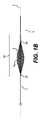
図1A〜1Dは、血栓摘出装置1の実施形態を示す。図1Aは、吸引カテーテル106、回収装置3、折り畳まれた編組アセンブリ102、およびガイドワイヤ先端103を示す。吸引カテーテル106は、強化された構造を備えた細長い管であり、近位端に真空を適用して、潰れることなく血餅および塞栓を動脈または静脈から引き出すことができる。吸引カテーテル106は、ポリマー材料で形成することができる。吸引カテーテル106は、手技中にカテーテルの位置を画像化する際に使用するための画像化マーカ8(蛍光マーカまたは放射線不透過性マーカなど)を含み得る。血栓回収装置3は、吸引カテーテル106を通って延びる。編組アセンブリ102は、回収装置3の遠位領域5を覆って延び、その結果、回収装置3が吸引カテーテル106の遠位端7を出るとき、編組アセンブリ102は、吸引カテーテル106の外側に配置される。折り畳まれた構成では、編組アセンブリ102は、吸引カテーテル106を介して動脈または静脈に挿入するようなサイズおよび構成になっている。ガイドワイヤ先端103は、回収装置3の遠位端107から遠位に延びる。ガイドワイヤ先端103は、可撓性であり、成形可能であり、操縦可能であり得る。 1A-1D show an embodiment of the thrombus removing device 1. FIG. 1A shows a
編組アセンブリ102は、折り畳まれた構成から拡張された構成に移動可能である。拡張された構成の編組アセンブリ102の例が図1Bに示されている。ただし、拡張編組アセンブリ102の最大直径dmaxは、完全に折り畳まれた直径から部分的に拡張された直径、完全に拡張された直径まで、連続的な範囲にわたって任意の値に変更することができる。編組アセンブリの最大直径dmaxは、編組アセンブリ102の中心を通って延びる縦軸aに垂直に測定された最も広い点である。編組アセンブリ102は、1つまたは複数の血餅、プラーク、および/または血栓を破壊および捕捉し、それらを除去できる吸引カテーテル106に向かって引っ張るようなサイズおよび構成にすることができる。編組アセンブリ102は、編組9、スライド可能カラー108、および編組9が回収装置3に固定される固定取り付け点101を含む。編組9は、取り付け点101において回収装置3に直接取り付けられてもよく、または編組9は、取り付け点101において回収装置3に間接的に取り付けられてもよい。いくつかの実施形態では、固定取り付け点101は、回収装置3の周りに延びる固定カラーであり、編組は、固定カラーに溶接、接合、または他の方法で接着される。とにかく、固定取り付け点101では、編組9は、回収装置3に対して長手方向に移動しない。The
編組9の反対側の端部は、スライド可能カラー108に溶接、接合、または他の方法で接着される。図示の実施形態では、スライド可能カラー108は、その環状形状により、回収装置3の周りに円周方向に延在することにより、回収装置3にスライド可能に接続される。スライド可能カラー108は、編組9が拡張および折り畳まれるときに、回収装置3に沿って長手方向にスライドする。スライド可能カラー108は、図1A〜図1Cに示されるように、固定取り付け点101の遠位(遠位位置)に配置され得る。またはスライド可能カラー108は、固定取り付け点101の近位(近位位置)に配置され得る。いくつかの実施形態では、スライド可能カラー108または固定取り付け点101は、手技中に撮像モダリティを使用して見ることができるマーカを含み得る。例えば、スライド可能カラー108または固定取り付け点101は、蛍光または放射線不透過性のラベルを含み得る。 The opposite end of the braid 9 is welded, joined, or otherwise glued to the
編組9は、ワイヤの複数のストランドから構成される。編組9は、拡張時に楕円形または紡錘形を取り、編組9の中心またはその近くで最大直径dmaxを有し、編組が固定取り付け点101およびスライド可能カラー108に近づくにつれて狭くなる。ワイヤは、形状記憶ポリマーまたは形状記憶金属(例えば、ニチノール)などであるがこれらに限定されない形状記憶材料で形成される。編組9は、折り畳まれた構成のベースライン形状記憶を有し、これは、図1Aに示されるように、回収装置3の周りに円筒形構造を形成する。作動され、拡張された構成では、編組9は折り畳まれた構成に向かって弛緩する傾向がある。The braid 9 is composed of a plurality of strands of wire. The braid 9 takes an elliptical or spindle shape upon expansion, has a maximum diameter dmax at or near the center of the braid 9, and narrows as the braid approaches the fixed
施術者が、編組アセンブリ102を使用して、血栓またはプラークを吸引カテーテル106に向かって近位方向に引っ張ると、編組9は、最も広い部分(例えば、隣接する編組の中央領域のdmax)に沿って最も強い遠位方向の抗力に遭遇する。これらの抗力は、施術者によってかけられる近位方向の引張力に抵抗する。スライド可能カラー108での編組9の遠位端は、それが半径方向に隣接する血管系または血栓に及ぼす半径方向の力が小さいか、無視できるか、または存在しないため、近位に引っ張られている間、より小さい抗力に遭遇する。編組が適切に設計されていない場合、スライドカラー108および編組9の遠位端は、編組9のより広い中央領域に反転する。手技中の反転は、pic数(1インチあたりの交差数)、線径、ワイヤの数、編組の層(編組の重なりのセット)などの要素を最適化することで防ぐことができる。pic数が多いほど柔軟性が向上し、pic数が少ないほど長手方向の剛性が高くなる。同様に、2つ以上の層がある編組(相互にネストされた編組の複数のセット)は、単層の編組よりも硬くなる。編組は、1層、2層、3層、またはそれ以上にすることができる。より多くのワイヤを備えた編組は、より少ないワイヤを備えた編組よりも硬く、より広い直径のワイヤを備えた編組は、細い直径のワイヤを備えた編組よりも硬くなる。様々な直径のワイヤを同じ編組9内で使用できる。When the practitioner uses the
本明細書に開示される編組アセンブリ102の設計は、装置1が動脈手技または静脈手技のどちらを対象とするかに基づいて変化し得る。なぜなら、手技部位は静脈設定においてより広いからである。例えば、静脈用途のために設計された編組9は、約0.8インチ、約0.9インチ、約1.0インチ、約1.1インチ、および約1.2インチを含む、約0.8インチ〜1.2インチのdmaxを有し得る。静脈用途では、編組9は、0.005インチ、0.0075インチ、0.01インチ、0.0125インチ、0.015インチ、0.0175インチ、および0.02インチを含む、約0.005インチ〜約0.02インチの線径範囲を有し得る。編組9の異なるワイヤは、異なる直径を有し得るか、またはそれらは同じ直径を有し得る。いくつかの静脈の実施形態では、編組9のワイヤの直径は、0.01インチ、0.0125インチ、および/または0.015インチである。2層編組は、適用できる半径方向の力を犠牲にすることなく、より小さな線径を利用できる。静脈用途では、pic数は2〜6にすることができる。静脈用途で使用されるいくつかの実施形態では、pic数は3、4、または5である。静脈用途の編組あたりのワイヤの数は、8、16、24、32、および40を含め、8〜40のいずれかである。The design of the
静脈用途の編組は、上記の静脈用途パラメータの選択を使用してテストされた。エンドポイントには、拡張力と、編組によって静脈をシミュレートする管(内径が24ミリメートルの管)の内面にかけられる半径方向の外向きの力が含まれる。拡張力は、作動ワイヤに適用される、編組を開くのに必要な力である。データを以下の表1に示す。
動脈用途の場合、編組9は、約0.1インチ、約0.12インチ、約0.14インチ、約0.18インチ、約0.2インチ、約0.22インチ、約0.24インチ、約0.28インチ、約0.3インチ、約0.32インチ、約0.34インチ、約0.36インチ、約0.38インチ、および約0.4インチを含む約0.1インチ〜約0.4のdmaxを有し得る。例えば、編組9は、約0.28インチ、0.3インチ、または0.31インチのdmaxを有し得る。動脈用の編組9のワイヤの直径は、約0.001インチ、約0.002インチ、約0.003インチ、約0.004インチ、約0.005インチ、約0.006インチ、および約0.007インチを含む、約0.001インチ〜約0.007インチの範囲であり得る。編組9の異なるワイヤは、異なる直径を有し得るか、またはそれらは同じ直径を有し得る。いくつかの動脈の実施形態では、編組9のワイヤの直径は、0.003インチ、0.004インチ、および/または0.005インチである。2層編組は、適用できる半径方向の力を犠牲にすることなく、より小さな線径を利用できる。動脈用途のpic数は、5、6、7、8、9、10、11、12、13、14、15、16、117、18、19、20、21、22、23、24、25、26、27、28、29および30のpic数を含む、5〜30にすることができる。動脈用途で使用されるいくつかの実施形態では、pic数は10、12、または15である。動脈用の編組9あたりのワイヤの数は、8、16、24、32、40、48、および54を含む、8〜54のいずれかにすることができる。いくつかの実施形態では、動脈用の編組9あたりのワイヤの数は、26、24、または30である。For arterial applications, the braid 9 is about 0.1 inch, about 0.12 inch, about 0.14 inch, about 0.18 inch, about 0.2 inch, about 0.22 inch, about 0.24 inch. About 0.1 inch, including about 0.28 inch, about 0.3 inch, about 0.32 inch, about 0.34 inch, about 0.36 inch, about 0.38 inch, and about 0.4 inch It can have a dmax of ~ about 0.4. For example, the braid 9 can have a dmax of about 0.28 inches, 0.3 inches, or 0.31 inches. The wire diameters of braid 9 for arteries are about 0.001 inch, about 0.002 inch, about 0.003 inch, about 0.004 inch, about 0.005 inch, about 0.006 inch, and about 0. It can range from about 0.001 inch to about 0.007 inch, including .007 inch. The different wires of braid 9 can have different diameters, or they can have the same diameter. In some arterial embodiments, the wire diameter of braid 9 is 0.003 inch, 0.004 inch, and / or 0.005 inch. Two-layer braids can utilize smaller wire diameters without sacrificing applicable radial forces. The number of pics for arterial use is 5,6,7,8,9,10,11,12,13,14,15,16,117,18,19,20,21,22,23,24,25,26 , 27, 28, 29 and 30 pics, can be 5-30. In some embodiments used in arterial applications, the pic number is 10, 12, or 15. The number of wires per braid 9 for arteries can be any of 8 to 54, including 8, 16, 24, 32, 40, 48, and 54. In some embodiments, the number of wires per braid 9 for the artery is 26, 24, or 30.
動脈用途用の編組は、上記の動脈用途パラメータの選択を使用してテストされた。エンドポイントには、編組によって管(内径6ミリメートルの管)の内径に適用された半径方向の外向きの力と、編組を管の制限部に通すために必要な近位の力(内径制限は4ミリメートルである)とが含まれる。管と制限は、それぞれ動脈と血栓/プラークとをシミュレートする。有利な試作品は、編組を制限部に通すために過度の力を必要とせずに、高い半径方向外向きの力を与える。データを以下の表2に示す。テストされたすべての編組は1層であった。
作動ワイヤ105は、回収装置3の管腔を通って延在し、出口点11で回収装置3を出て、回収装置3の外面に沿って遠位に延在する。作動ワイヤ105の遠位端13は、スライド可能カラー108に取り付けられる。このように、作動ワイヤ105は、スライド可能カラー108を介して編組9の拡張および折り畳みを制御することができる。出口点11とスライド可能カラー108との間の距離は、スライド可能カラーが回収装置3に沿って引っ張られて編組アセンブリ102を開くことができる長さに影響を与える。スライド可能カラーに近すぎると、編組アセンブリ102は完全に開くことができない。したがって、出口点11は、編組アセンブリ102がその最大外径まで開くことができるように、スライド可能カラー108の非拡張位置から十分に近位に配置されるべきである。図1Cは、作動ワイヤ105および作動ワイヤ出口点11を見やすくするべく編組9がない、図1Aおよび図1Bの実施形態を示す。図1Dは、図1Cの線A−Aに沿った、回収装置3内の作動ワイヤ105の断面図である。(回収装置3内の)作動ワイヤ105の近位領域の内部位置決めは、編組アセンブリ102の拡張を制御するシステムによって摩擦または嵩が加えられないという点で有利である。 The
作動ワイヤ105の近位領域(図示せず)に張力をかけ、解放して、スライド可能カラー108の動きを介して編組アセンブリ102の拡張および収縮を制御することができる。張力下で、作動ワイヤ105は、作動ワイヤ105の近位領域から編組アセンブリ102に張力を変換するときに、回収装置3の管腔内で近位に移動する。スライド可能カラー108が遠位位置にある(示されるように)実装では、作動ワイヤの出口点11は、スライド可能カラー108の近位に配置される。出口点11は、例えば、回収装置3の側壁における入口であり得る。編組アセンブリ102を拡張するためのスライド可能カラー108の使用は、回収装置3の遠位領域5が血管系内で一定の位置を維持しながら、編組アセンブリ102の遠位端が移動され得るため、有利である。血管内での遠位領域5の近位/遠位運動のスライドが血管の損傷または穿孔をもたらす可能性があるため、回収装置3の遠位領域5の一定の位置を維持することは有利である。 A proximal region (not shown) of the working
スライド可能カラー108が固定取り付け点(図示せず)に対して近位位置にある実装では、作動ワイヤ105は、回収装置3の内部のスライド可能カラー108を越えて遠位に延在し、出口点11で回収装置3を出る。次に、二重に戻り、回収装置3の外面に沿って延びて、近位に位置するスライド可能カラー108に取り付ける。出口点11は、上記のように、回収装置の側壁における入口であり得るか、または出口点11は、回収装置3の遠位端107であり得る。 In an implementation in which the
回収装置3は、図1Cに示されるように、近位皮下注射管100および遠位支持管104を含み得る。いくつかの実施形態では、皮下注射管100は、支持管104を通って延びる。しかしながら、遠位領域は、遠位支持管104の近位端を近位皮下注射管100の遠位端17に取り付けることによって(例えば、接着剤結合、熱結合、または溶接プロセスによって)より柔軟にすることができる。編組アセンブリ102の固定取り付け点101は、遠位支持管104上に位置することができ、スライド可能カラー108は、遠位支持管104の周りに延在することができ、それにより、編組アセンブリ102は、遠位支持管104の上および周囲に配置される。代替的に、編組アセンブリ102は、遠位支持管の上に部分的にのみ配置することができる(すなわち、固定取り付け点101またはスライド可能カラー108の一方が近位皮下注射管100に取り付けられ、固定取り付け点またはスライド可能カラー108の他方は遠位支持管104に取り付けられる)。いくつかの実施形態では、支持管104は、例えば、より大きな直径の編組を収容し、ガイドワイヤ先端103をカプセル化するために、回収装置3の全体の直径を増大させるように機能する。遠位支持管104はまた、近位皮下注射管100が提供するよりも、スライド可能カラー108の移動のためにより低い摩擦表面を提供することができる。 The recovery device 3 may include a proximal subcutaneous injection tube 100 and a
いくつかの実施形態では、遠位支持管104は、近位皮下注射管100よりも柔軟性が高い。例えば、遠位支持管104は、ポリマー材料で作製することができ、近位皮下注射管100は、より剛性の高い金属材料で作製される。いくつかの実施形態では、近位皮下注射管100は、金属皮下針管から構成される。皮下注射管100は、支持管104よりも最大50倍硬くすることができる。近位皮下注射管100よりも可撓性が高い遠位支持管104を有することにはいくつかの利点がある。支持管104のより大きな可撓性は、皮下注射管100とガイドワイヤ先端103との間の可撓性の段階的な移行を可能にする。いくつかのシナリオでは、遠位支持管104のより大きな可撓性は、曲がりくねった血栓を通る編組アセンブリ102の動きを容易にすることができる。柔軟性が高いほど、耐キンク性が向上する。遠位支持管104のより大きな柔軟性はまた、装置の製造中の入口または出口点11の導入を容易にすることができる。(支持管104と比較して)皮下注射管100のより高い剛性は、回収装置3を血管系を通して押すことを可能にするので重要である。皮下注射管100の剛性はまた、編組アセンブリ102が血栓またはプラークを通って押され得ることを確実にするのに役立つ。 In some embodiments, the
近位端では、作動ワイヤ105は、作動ワイヤ105を回収装置3内で前方に移動させるか、または後方に後退させることができる張力要素(図示せず)に取り付けることができる。作動ワイヤ105に張力をかけることにより、スライド可能カラー108が移動し、編組アセンブリ102が施術者の選択した直径まで拡張する。同様に、作動ワイヤ105の張力を解放することにより、編組アセンブリ102は、折り畳まれたベースライン構成に弛緩することができる。 At the proximal end, the
図2に示されるようないくつかの実施形態では、装置は近位ハンドル128を含む。ハンドル128は、回収装置3の近位端に結合される。張力要素は、ハンドルの内側で作動ワイヤ105の近位端に結合されたノブ129である。ノブ129を一方向に作動させると、作動ワイヤ105が引っ張られ(編組アセンブリを拡張する)、反対方向にノブ129を作動させると、作動ワイヤ105の張力が解放される(編組アセンブリを折り畳む)。他の実施形態では、張力要素は、スライダ、かぎ上げ機構、またはレバーを含み得る。吸引カテーテル106は、吸引カテーテルの管腔を分離して血餅または塞栓を除去するために真空源に接続され、作動ワイヤをハンドル128に接続できるようにするyアダプタ(図示せず)で終端する。 In some embodiments as shown in FIG. 2, the device comprises a
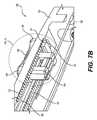
近位ハンドル128の別の実施形態が、図7A〜図7Cに示されている。図7A〜7Cのハンドル128は、施術者が編組アセンブリ102を固定された外径でロックすることを可能にするという点で有利である。これは、例えば、血栓を介して装置を押したり引いたりする場合に役立つ。図7Aに示されるように、近位ハンドル128は、回収装置3の近位端に結合される。作動ワイヤ105は、近位端回収装置3を越えて近位方向に延び、近位ハンドル128内に入る。張力緩和部分139は、ハンドル128のすぐ遠位にある回収装置3のねじれを防止する可撓性材料で形成される。近位ハンドル128は、溝138内で近位および遠位にスライドし、手技中に編組アセンブリ102の外径を固定するために適所にロックすることができる、ロッキングスライダ136の形の張力要素も含む。ロッキングスライダ136および溝138の下側が図7Bに示されており、図7Cには、ロッキングスライダおよび溝138の断面図が示されている。ロッキングスライダ136は、スライド部分146およびロックボタン148を含む。図7Bに見られるように、下向きの歯140は、ハンドル128の外側ケーシング135の内面133から、溝138に隣接する位置から下向きに延びる。ロックボタン148は、テクスチャ加工されたグリップ面を備えた外側部分141を含む。ロックボタン148は、スライド部分146を通って下向きに延び、内側部分137を含む。ロックボタン148の内側部分137は、ロックボタン148の外側部分141から離れて、ロッキングスライダ136の長手方向軸A−Aに垂直な方向に延びる。内部部分137は、ハンドル136の外側ケーシング135の下向きの歯140と係合するように構成された上向きの歯142を含む。スライダ146内でロックボタン148の外面141の下に垂直に配置されたばね150は、ロックボタン148に上向きの力をかけて、上向き歯142を外側ケーシング135の下向き歯140とのロック構成に保持する。ロックボタン148が圧縮されると、ばね150が圧縮され、歯140、142が外れる。ロックボタン148が押されて歯140、142が係合解除された状態で、近位または遠位の力をスライド部分146にかけて、ロッキングスライダ136を溝138内で動かすことができる。スライド部分146の内部144は、作動ワイヤ105を把持する。ロッキングスライダ136が溝138内で移動すると、作動ワイヤ105が近位または遠位に移動して、編組アセンブリ102の拡張に影響を与えるか、または折り畳むことを可能にする。 Another embodiment of the
従来の血栓装置は、ベースライン拡張構成で形状記憶要素を利用する。これらの従来の装置は、不注意による過度の拡張と血管の損傷のリスクがある。さらに、従来の装置は、装置が自己拡張することを可能にするために引き戻される、かさばる上にあるシースによって拘束されることが多い。 Conventional thrombus devices utilize shape memory elements in a baseline extended configuration. These conventional devices carry the risk of inadvertent overdilation and vascular damage. In addition, conventional devices are often constrained by a bulky sheath that is pulled back to allow the device to self-expand.
有利には、折り畳まれた位置の形状記憶を備えた装置を使用することにより、自己拡張中の過度の拡張および損傷のリスクが低減される。自己崩壊はまた、本明細書に記載される薄型の作動ワイヤシステムを使用して、装置が拘束されることを可能にする。さらなる利点は、編組アセンブリを様々な直径に拡張して、容器のサイズに正確にカスタムフィットできることである。これは、容器のサイズが当初の予想と異なる場合に特に役立つ。編組9と周囲の血栓との間のグリップのレベルはまた、作動ワイヤ105に異なるレベルの張力をかけることによって、必要に応じてカスタマイズされ得る。例えば、施術者は、第1のレベルの張力をかけて、編組アセンブリ102を第1の拡張外径に配備して、血栓に接触させることができる。血栓と編組9との間の力が、血栓を吸引カテーテル106の方へ引っ張るのに十分でない場合、施術者は、作動ワイヤ105により大きな第2のレベルの張力をかけることにより、編組9を第2の拡張外径まで広げることができる。この拡大された直径は、血栓が吸引カテーテル106に向かってより容易に引っ張られることができるように、血栓と編組9との間により大きな接触力を提供する。 Advantageously, the use of a device with folded position shape memory reduces the risk of over-expansion and damage during self-expansion. Self-destruction also allows the device to be constrained using the thin actuating wire system described herein. A further advantage is the ability to extend the braided assembly to various diameters for a precise custom fit to the size of the container. This is especially useful if the size of the container is different from what was originally expected. The level of grip between the braid 9 and the surrounding thrombus can also be customized as needed by applying different levels of tension to the
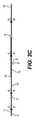
図3A〜図3Dは、複数の編組部分111、112を備えた編組アセンブリ19を有する血栓摘出装置の追加の実施形態を示す。この実施形態の細長い性質は、長い血栓の捕捉および回収を容易にする。図3Aおよび図3Bに示されるように、編組部分111、112のそれぞれは、回収装置21の遠位領域22に取り付けられ、その周りに延びる。編組アセンブリ19は、複数のスライドカラー23、25および固定取り付け点27を含む。近位編組部分111は、固定取り付け点27と近位スライド可能カラー23との間に取り付けられ、それらの間に延在し、中央スライド取り付け点29で溶接、接合、または他の方法で接着される。遠位編組部分112は、近位スライド可能カラー23と遠位スライド可能カラー25に取り付けられ、それらの間に延在する。いくつかの実施形態では、編組部分は、1つのより大きな編組を近位のスライド可能カラー23で拘束することによって形成される。他の実施形態では、各編組部分は別個の編組から形成される(近位編組アセンブリおよび遠位編組アセンブリのそれぞれが近位スライド可能カラー23に別々に固定して取り付けられるように)。いくつかの実施形態では、スライド可能カラー23、25は、図3Aに示されるように、固定取り付け点27の遠位に配置され得る。他の実施形態では、スライド可能カラーは、固定取り付け点(図示せず)の近位に配置することができる。2つの編組部分111、112で示されているが、編組アセンブリ19の他の実施形態は、3つ以上の編組部分および3つ以上のスライド可能カラーを含み得る。 3A-3D show an additional embodiment of a thrombectomy device having a braided
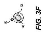
図3Cは、編組アセンブリ19なしの図3Aおよび図3Bの血栓摘出装置を示す。回収装置21は、支持管130に固定して取り付けられた皮下注射管131を有する。単一の作動ワイヤ132は、皮下注射管131および支持管130を通って、支持管130上に配置された出口点134まで延びる。そこから、単一の作動ワイヤ132は、支持管130の外面に沿って移動し、近位スライドカラー23の下を走り、遠位スライドカラー25に取り付けられる。図3D、図3E、図3F、および図3Gに示す断面は、図3Cに示される血栓摘出装置に沿った様々な軸方向位置での皮下注射管131、支持管130、およびガイドワイヤ先端103に対する作動ワイヤ132の半径方向位置を示す。作動ワイヤ132は、遠位スライディングカラー25への接続を介して編組アセンブリの拡張を制御するために利用される。他の実施形態では、作動ワイヤ132は、近位スライドカラー23に取り付けられ得る。近位移動 作動ワイヤによる近位スライド可能カラー23または遠位スライド可能カラー25の回収装置は、2つの編組部分111、112が一致して拡張される(または部分的に拡張される)ように、2つのスライド可能カラーの他方に力を生成する。上述のように、編組は、折り畳まれた構成に向かって付勢された形状記憶材料で形成されているので、作動ワイヤに張力をかけると、複数のレベルの拡張が可能になる。 FIG. 3C shows the thrombectomy apparatus of FIGS. 3A and 3B without braided
図4は、複数の別々に拡張可能な編組アセンブリ37、39を有する追加の実施形態を示す。編組アセンブリ37、39は、回収装置31の遠位領域32に沿って互いに離間している。近位編組アセンブリ37は、固定取り付け点33とスライド可能カラー115との間に延びる編組部分113を含む。遠位編組アセンブリ39は、固定取り付け点35とスライド可能カラー116との間に延びる編組部分114を含む。各編組アセンブリは、各編組アセンブリを個別に制御できるように、個別の作動ワイヤによって制御される。各作動ワイヤは、個々の編組の下の出口点から回収装置31を出て、個々のスライド可能カラー(図示せず)に取り付けられる。複数の作動ワイヤは、回収装置31の同じ管腔を通って移動することができ、または、個々の管腔を有し得る。固定取り付け点に対するスライド可能カラーの配置に応じて、いくつかの実施形態では、各追加の作動ワイヤは、同じ管腔を通って移動し、同じ入口または異なる入口で回収装置を出ることができる。いくつかの実施形態では、1つ以上の作動ワイヤは、回収装置31の遠位端から出ることができる。 FIG. 4 shows an additional embodiment having a plurality of separately expandable braided assemblies 37, 39. The braided assemblies 37, 39 are spaced apart from each other along the distal region 32 of the
前述の実施形態と同様に、図4に示す実施形態の編組は、折り畳まれた構成に向かって付勢された形状記憶材料で形成され、その結果、作動ワイヤに張力をかけることにより、ある範囲の直径への編組の展開が可能になる。各編組アセンブリは、取り付けられた作動ワイヤに第1のレベルの張力をかけることによって部分的に拡張した構成に、または作動ワイヤに第2のより大きいレベルの張力をかけることによって完全に拡張した構成に展開できる。したがって、複数の作動ワイヤおよび編組アセンブリが使用される場合、第2の編組アセンブリが完全に拡張された状態で展開される一方で、第1の編組アセンブリは部分的に拡張された状態に展開され得る。一部のシナリオでは、1つの編組アセンブリが完全に折り畳まれている間に、別の編組アセンブリが部分的または完全に拡張していると有利な場合がある。これは、例えば、より長い血栓を吸引カテーテル106に引き込む場合に有利であり得る。近位編組部分113は、吸引カテーテルに入るときに、未だ吸引カテーテルの外側にある遠位編組部分114に先行して折り畳まれ得る。 Similar to the previous embodiment, the braid of the embodiment shown in FIG. 4 is formed of a shape memory material urged towards a folded configuration, resulting in a range by applying tension to the actuating wire. Allows the deployment of braids to the diameter of. Each braided assembly is either partially extended by applying a first level of tension to the attached working wire, or fully extended by applying a second higher level of tension to the working wire. Can be expanded to. Therefore, when multiple actuating wires and braided assemblies are used, the second braided assembly is unfolded in a fully expanded state, while the first braided assembly is unfolded in a partially extended state. obtain. In some scenarios, it may be advantageous for one braided assembly to be partially or completely expanded while another braided assembly is fully folded. This can be advantageous, for example, when drawing a longer thrombus into the
いくつかの実施形態では、別個の編組部分または別個の編組アセンブリの編組は、異なる最大拡張直径、異なるワイヤサイズ、異なるワイヤ密度、異なる数のワイヤなどの異なる特性を有し得る。これらの特性は、回収装置に沿った編組部分または編組アセンブリの配置に応じて変化し得る。例えば、遠位の編組部分または編組アセンブリは、血栓に対してよりよく引き戻せるように拡張直径が大きくなる可能性があるが、近位の編組部分または編組アセンブリは、血栓の中央にうまく係合するために密度が低く、強くなる可能性がある。 In some embodiments, the braids of separate braided parts or separate braided assemblies may have different properties such as different maximum expansion diameters, different wire sizes, different wire densities, different numbers of wires, and so on. These properties may vary depending on the placement of the braided portion or braided assembly along the recovery device. For example, the distal braid or braid assembly may have a larger dilation diameter so that it can be pulled back better against the thrombus, while the proximal braid or braid assembly engages well in the center of the thrombus. It is less dense and can be stronger.
図5A〜図5Cは、施術者が装置を取り外して同じ解剖学的位置に複数回(例えば、手技中に装置を洗浄するために)再挿入できるように、ガイドワイヤでの使用を可能にする血栓摘出装置の実施形態を示す。図5Aは、吸引カテーテル127、回収装置121、ガイドワイヤ管118、編組アセンブリ123(折り畳まれた構成)、およびガイドワイヤ45を示す。ガイドワイヤ管118は、回収装置121の遠位領域61の周りに配置される。ガイドワイヤ管118は、長手方向において回収装置121よりも短いので、ガイドワイヤ45は、近位ガイドワイヤ出口117でガイドワイヤ管118を離れ、回収装置に沿って近位方向に延びる。図5Bは、編組アセンブリ123が拡張状態にある、図5Aの実施形態を示す。図5Bの線B−Bに沿った、図5Cの断面図に示すように、ガイドワイヤ45は、ガイドワイヤ管118の第1の管腔124を通って延びる。ガイドワイヤ45は、遠位ガイドワイヤ出口47でガイドワイヤ管118を出る。ガイドワイヤ管118は、遠位の非外傷性先端120を含み得る。ガイドワイヤ管118は、例えば、ポリマー材料で形成され得る。作動ワイヤ125を含む回収装置121は、ガイドワイヤ管118の第2の管腔126を通って延びる。上述のように、作動ワイヤ125は、近位端で張力要素に接続され、回収装置121を通って出口点まで延び、出口点(編組の下)で回収装置121を離れ、その遠位端に編組アセンブリ123上のスライド可能な遠位カラー122を取り付ける。出口点は、例えば、回収装置121の側壁およびガイドワイヤ管118を通るトンネル(すなわち、ガイドワイヤ管の側壁118における入口と整列/同軸である、回収装置121の側壁における入口によって形成されるトンネル)であり得る。使用中、ガイドワイヤ管118および回収装置121は、以前に配置された血管ガイドワイヤ45の上に一緒に導入される。ガイドワイヤ45は、ガイドワイヤ管118内に保持されるため、吸引カテーテル127の管腔内の側部に少なくとも部分的に引っ張られ、作動ワイヤ125を妨害することなく移動し得る。ガイドワイヤ管118および回収装置121は、薄型かつ低摩擦の設計を使用して、互いに独立して、作動ワイヤ125およびガイドワイヤ45を軸方向に移動させ続ける。所定の位置になると、編組アセンブリ123が拡張され、吸引カテーテル127の近位端が真空源に接続される。編組アセンブリ123は、拡張され、次いで吸引カテーテル127に向かって後退し、それとともに血餅を引っ張り、それを小さな断片に破壊する。 5A-5C allow the device to be used with a guide wire so that the practitioner can remove the device and reinsert it into the same anatomical position multiple times (eg, to clean the device during the procedure). An embodiment of a thrombus removal device is shown. FIG. 5A shows a
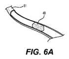
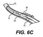
本明細書には血栓切除術の手技を実施する方法も開示されている。図6A〜図6Fに例示的な方法が示されている。図6Aは、血管51を閉塞する血栓49を示す。吸引カテーテル53の遠位端は、図6Bに示されるように、血管系を通って血栓49の近位の領域まで進められる。編組アセンブリ57を運ぶ回収装置55の遠位端は、吸引カテーテル53の遠位端から血栓49を通して前進させられ、それにより、編組アセンブリ57は、図6Cに示されるように、血栓49の遠位にある。次に、施術者は、回収装置55内に収容された作動ワイヤに張力をかけ、それにより、作動ワイヤを回収装置の管腔内において長手方向に動かし、編組アセンブリのスライド可能カラーを長手方向に回収装置の外面上に動かす。作動ワイヤを介したスライド可能カラーの動きにより、編組アセンブリ57は、施術者が選択した直径まで拡張する。施術者が手技中に拡張のレベルを変更したい場合(つまり、編組アセンブリ57の最大直径dを変更したい場合)は、作動ワイヤの張力レベルを変更することで可能になり、これによって、上述したように、回収装置内で作動ワイヤを再び動かし、スライド可能カラーを動かす。有利には、編組アセンブリが最適な直径まで拡張されるとき、回収装置55の遠位端は、静止位置を維持する。血管内での遠位端の近位/遠位運動のスライドは血管の損傷または穿孔をもたらし得るため、回収装置55の遠位端の一定の位置を維持することは有利である。 Also disclosed herein are methods of performing a thrombectomy procedure. An exemplary method is shown in FIGS. 6A-6F. FIG. 6A shows a
図6Dは、血管51に適合するサイズの拡張構成の編組アセンブリ57を示す。次に、施術者は、回収装置55を近位方向に引っ張り、図6Eに示すように、血栓49を編組アセンブリ57と接触させる。血栓49および編組アセンブリ57は、吸引カテーテル53に向かって近位に引っ張られる。吸引カテーテル53は、外部真空源(図示せず)に接続することができ、それにより、吸引カテーテル53の遠位端への血栓49の吸引が可能になる。次に、吸引カテーテル53は、図6Fに示されるように、近位に後退させられ、身体から外される。 FIG. 6D shows the
編組アセンブリを様々な直径の範囲で開く機能は、複数の理由および複数のシナリオにおいて血栓切除術の手技に役立つ。所定のサイズに拡張する編組を導入してから、手技の途中で編組を特定の血管にカスタムフィットする機能は、血栓を掴むには小さすぎるか、または大きすぎて血管を損傷した場合に好ましい。別の例示的な利点として、編組と血栓の間のグリップのレベルは、手技の途中で最適化することができる。例えば、施術者は、第1のレベルの張力を作動ワイヤにかけて、編組アセンブリを第1の拡張外径に展開して、血栓に接触させることができる。血栓と編組との間の力が、血栓を吸引カテーテルに向けて引っ張るのに十分でない場合、施術者は、作動ワイヤにより大きい第2レベルの張力をかけることにより、編組を第2の拡張外径に広げることができる。この拡大された直径は、血栓と編組との間の接触力を増加させるので、血栓が吸引カテーテルに向かってより容易に引っ張られる。 The ability to open braided assemblies over different diameter ranges is useful for thrombolectomy procedures for multiple reasons and in multiple scenarios. The ability to introduce a braid that expands to a given size and then custom-fit the braid to a particular vessel during the procedure is preferred if it is too small or too large to grab a blood clot and damage the vessel. As another exemplary advantage, the level of grip between the braid and the thrombus can be optimized during the procedure. For example, the practitioner can apply a first level of tension to the working wire to deploy the braided assembly to the first extended outer diameter and bring it into contact with the thrombus. If the force between the thrombus and the braid is not sufficient to pull the thrombus towards the suction catheter, the practitioner applies a higher second level of tension to the actuating wire to make the braid a second extended outer diameter. Can be expanded to. This expanded diameter increases the contact force between the thrombus and the braid so that the thrombus is pulled more easily towards the suction catheter.
この方法は、ガイドワイヤを使用して実行することもできる。例えば、ガイドワイヤは、回収装置の遠位端を前進させる前に、血栓の遠位に配置することができる。図5A〜図5Cの実施形態のように、回収装置は、ガイドワイヤ管の管腔を通って少なくとも部分的に延びる。回収装置とガイドワイヤ管とを一緒にして、ガイドワイヤ上を血栓に向かって前進させる。ガイドワイヤは、回収装置および作動ワイヤよりもガイドワイヤ管の別個の管腔を通って延びる。配置されると、作動ワイヤは、回収装置内において長手方向に動かされて編組アセンブリを拡張させる。 This method can also be performed using guide wires. For example, the guide wire can be placed distal to the thrombus before advancing the distal end of the recovery device. As in the embodiments of FIGS. 5A-5C, the recovery device extends at least partially through the lumen of the guidewire tube. The recovery device and the guide wire tube are put together to advance on the guide wire toward the thrombus. The guide wire extends through a separate lumen of the guide wire tube rather than the recovery device and actuation wire. Once in place, the actuating wire is moved longitudinally within the recovery device to extend the braided assembly.
長い血栓は、図3に示される実施形態などの複数の編組部分を有する編組アセンブリを使用して対処することができる。スライド可能カラーの動きにより、複数の編組部分が拡張し、編組アセンブリが比較的長くなる。いくつかの実施形態では、図4に示されるような、複数の別々に拡張可能な編組アセンブリを有する装置が、長い血栓の治療に使用できる。個別に拡張可能な編組アセンブリでは、血栓が吸引カテーテルの遠位端に近接して引き寄せられると、近位に配置された編組アセンブリは、第1の拡張外径から縮小直径(またはより狭い第2の拡張外径)に収縮する。遠位に配置された編組アセンブリは、それも吸引カテーテルに引き込まれるまで、近位に配置された編組アセンブリの外径よりも大きい拡張外径を維持する。 Long thrombi can be addressed using a braided assembly with multiple braided portions, such as the embodiment shown in FIG. The movement of the slidable collar expands the braided parts and makes the braided assembly relatively long. In some embodiments, a device with a plurality of separately expandable braided assemblies, as shown in FIG. 4, can be used to treat long thrombi. In individually expandable braided assemblies, when the thrombus is pulled closer to the distal end of the suction catheter, the proximally placed braided assembly has a reduced diameter (or narrower second) from the first dilated outer diameter. Shrinks to (extended outer diameter). The distally placed braided assembly maintains an expanded outer diameter that is greater than the outer diameter of the proximally placed braided assembly until it is also retracted into the suction catheter.
血栓摘出装置とその対応する構成要素の様々な実装は、コバルトクロム、チタンおよびチタン合金、ステンレス鋼、ニチノール、プラチナ、金、またはその他の金属、およびセラミックやポリマーなどの1つ以上の生体適合性材料から形成される。さらに、いくつかの実施態様では、血栓摘出装置またはその一部は、コーティングされた材料を含む。 Various implementations of the thrombolytic device and its corresponding components are biocompatible with one or more such as cobalt chromium, titanium and titanium alloys, stainless steel, nitinol, platinum, gold, or other metals, and ceramics and polymers. Formed from material. In addition, in some embodiments, the thrombectomy device or a portion thereof comprises a coated material.
1 血栓摘出装置
3 血栓回収装置
5 遠位領域
7 遠位端
8 画像化マーカ
9 編組
11 出口点
13 遠位端
17 遠位端
19 編組アセンブリ
21 回収装置
22 遠位領域
23 近位スライドカラー
25 遠位スライド可能カラー
31 回収装置
32 遠位領域
37 近位編組アセンブリ
39 遠位編組アセンブリ
45 血管ガイドワイヤ
47 遠位ガイドワイヤ出口
49 血栓
51 血管
53 吸引カテーテル
55 回収装置
57 編組アセンブリ
61 遠位領域
100 近位皮下注射管
101 点
102 拡張編組アセンブリ
103 ガイドワイヤ先端
104 遠位支持管
105 作動ワイヤ
106 吸引カテーテル
107 遠位端
108 スライド可能カラー
111 近位編組部分
112 遠位編組部分
113 近位編組部分
114 遠位編組部分
115 スライド可能カラー
116 スライド可能カラー
117 近位ガイドワイヤ出口
118 ガイドワイヤ管
120 非外傷性先端
121 回収装置
122 遠位カラー
123 編組アセンブリ
124 第1の管腔
125 作動ワイヤ
126 第2の管腔
127 吸引カテーテル
128 近位ハンドル
129 ノブ
130 支持管
131 皮下注射管
132 作動ワイヤ
133 内面
134 出口点
135 外側ケーシング
136 ハンドル
137 内部部分
138 溝
139 張力緩和部分
140 歯
141 外側部分
142 歯
144 内部
146 スライド部分
148 ロックボタン1 Clot removal device 3 Clot recovery device 5 Distal region 7 Distal end 8 Imaging marker 9 Braid 11 Exit point 13 Distal end 17
Claims (35)
Translated fromJapanese近位端および遠位端を含む吸引カテーテルと、
前記吸引カテーテルを通って延在し、前記遠位端で出るように構成され、近位領域、遠位領域、および前記近位領域と前記遠位領域との間に延在する第1の管腔を含む回収装置と、
前記回収装置の遠位領域にわたって延在する少なくとも1つの編組アセンブリであって、少なくとも1つのスライド可能カラーと、前記スライド可能カラーに取り付けられた編組であって、前記編組を前記回収装置に固定する固定取り付け点に向かって延びる、編組とを有する、少なくとも1つの編組アセンブリと、
前記回収装置の前記第1の管腔を通り、かつ前記遠位領域に配置された出口点を通って延びる少なくとも1つの作動ワイヤであって、前記作動ワイヤの遠位端は、前記スライド可能カラーに取り付けられる、少なくとも1つの作動ワイヤと、を備え、
前記編組は、折り畳まれた構成の形状記憶を有し、
前記編組アセンブリは、前記作動ワイヤ上の張力のレベルを変化させることによって、ある範囲の拡張さ外径に拡張され得る、血栓摘出装置。A thrombus remover
With a suction catheter that includes the proximal and distal ends,
A first tube that extends through the suction catheter and is configured to exit at the distal end, extending in the proximal region, the distal region, and between the proximal region and the distal region. Recovery device including cavity and
At least one braided assembly extending over the distal region of the recovery device, at least one slidable collar and a braid attached to the slidable collar, fixing the braid to the recovery device. With at least one braided assembly having a braid extending towards a fixed attachment point,
At least one actuating wire extending through the first lumen of the recovery device and through an exit point located in the distal region, the distal end of the actuating wire being the slidable collar. Equipped with at least one working wire, which is attached to
The braid has a shape memory of the folded configuration and
A thrombectomy device, wherein the braided assembly can be expanded to a range of extended outer diameters by varying the level of tension on the actuating wire.
血管系を通して吸引カテーテルの遠位端を血栓の近位の領域に前進させることと、
少なくとも1つの編組アセンブリを運ぶ回収装置の遠位端を、前記吸引カテーテルの前記遠位端から前記血栓の遠位の位置まで前進させることと、
前記編組アセンブリに取り付けられる作動ワイヤに第1のレベルの張力をかけることにより、前記編組アセンブリを第1の拡張外径に展開することと、
前記作動ワイヤに第2のレベルの張力をかけることにより、前記編組アセンブリを第2の拡張外径に展開することと、
前記血栓を前記編組アセンブリに接触させることと、
前記編組アセンブリを使用して、前記血栓を前記吸引カテーテルの前記遠位端に向かって近位方向に引くことと、
前記血栓を前記吸引カテーテルの前記遠位端に吸引することと、を含む方法。A method of performing an embolectomy procedure
To advance the distal end of the suction catheter through the vascular system to the area proximal to the thrombus,
To advance the distal end of the recovery device carrying at least one braided assembly from the distal end of the suction catheter to a position distal to the thrombus.
Deploying the braided assembly to a first extended outer diameter by applying a first level of tension to the actuating wire attached to the braided assembly.
Deploying the braided assembly to a second extended outer diameter by applying a second level of tension to the actuating wire.
Bringing the thrombus into contact with the braided assembly
Using the braided assembly, pulling the thrombus proximally towards the distal end of the suction catheter
A method comprising aspirating the thrombus into the distal end of the suction catheter.
Applications Claiming Priority (3)
| Application Number | Priority Date | Filing Date | Title |
|---|---|---|---|
| US201762583613P | 2017-11-09 | 2017-11-09 | |
| US62/583,613 | 2017-11-09 | ||
| PCT/US2018/060074WO2019094749A1 (en) | 2017-11-09 | 2018-11-09 | Thrombectomy device and methods of use |
Publications (3)
| Publication Number | Publication Date |
|---|---|
| JP2021502184Atrue JP2021502184A (en) | 2021-01-28 |
| JP2021502184A5 JP2021502184A5 (en) | 2021-12-16 |
| JP7315241B2 JP7315241B2 (en) | 2023-07-26 |
Family
ID=66326464
Family Applications (1)
| Application Number | Title | Priority Date | Filing Date |
|---|---|---|---|
| JP2020526058AActiveJP7315241B2 (en) | 2017-11-09 | 2018-11-09 | Thrombectomy device and method of use |
Country Status (5)
| Country | Link |
|---|---|
| US (2) | US11490908B2 (en) |
| EP (1) | EP3706651B1 (en) |
| JP (1) | JP7315241B2 (en) |
| AU (1) | AU2018364666B2 (en) |
| WO (1) | WO2019094749A1 (en) |
Families Citing this family (19)
| Publication number | Priority date | Publication date | Assignee | Title |
|---|---|---|---|---|
| US12114877B2 (en) | 2017-10-16 | 2024-10-15 | Retriever Medical, Inc. | Clot removal methods and devices with multiple independently controllable elements |
| US10258357B1 (en) | 2017-10-16 | 2019-04-16 | Michael Bruce Horowitz | Catheter based retrieval device with proximal body having axial freedom of movement |
| US12201315B2 (en) | 2017-10-16 | 2025-01-21 | Retriever Medical, Inc. | Clot removal methods and devices with multiple independently controllable elements |
| USD924403S1 (en)* | 2019-03-26 | 2021-07-06 | Legacy Ventures LLC | Thrombectomy device |
| CN115916075A (en) | 2020-01-30 | 2023-04-04 | 尤利耶尔医疗股份公司 | Device and method for neurovascular endoluminal intervention |
| CN111528987A (en)* | 2020-06-04 | 2020-08-14 | 上海融脉医疗科技有限公司 | Thrombus taking-out catheter |
| CN112451042B (en)* | 2020-11-20 | 2021-08-03 | 上海心玮医疗科技股份有限公司 | Radial adjustable bolt taking device |
| US11471183B1 (en)* | 2021-02-18 | 2022-10-18 | Boston Scientific Scimed, Inc. | Thrombectomy methods |
| US11504151B2 (en)* | 2021-02-18 | 2022-11-22 | Boston Scientific Scimed, Inc. | Thrombectomy apparatuses |
| US11679195B2 (en) | 2021-04-27 | 2023-06-20 | Contego Medical, Inc. | Thrombus aspiration system and methods for controlling blood loss |
| DE102021133207A1 (en)* | 2021-12-14 | 2023-06-15 | Olympus Winter & Ibe Gmbh | implant |
| CN114391921B (en)* | 2022-01-07 | 2023-12-26 | 东莞天天向上医疗科技有限公司 | Multifunctional thrombus treatment device and application method thereof |
| US11737767B2 (en) | 2022-01-21 | 2023-08-29 | Julier Medical AG | Neurovascular catheter and method of use |
| WO2023147460A1 (en) | 2022-01-27 | 2023-08-03 | Contego Medical, Inc. | Thrombectomy and aspiration system and methods of use |
| WO2023168028A1 (en)* | 2022-03-04 | 2023-09-07 | Surmodics Md, Llc | Thrombectomy manipulation controller and methods for same |
| WO2023173534A1 (en)* | 2022-03-18 | 2023-09-21 | 晨兴(南通)医疗器械有限公司 | Thrombectomy device for transcatheter pulmonary artery thrombectomy system |
| WO2024018460A1 (en)* | 2022-07-19 | 2024-01-25 | EndoWays LTD. | Guidewire and microcatheter |
| CN115429381B (en)* | 2022-08-24 | 2023-04-28 | 玮铭医疗器械(上海)有限公司 | A thrombus suction catheter device |
| WO2024184276A1 (en)* | 2023-03-03 | 2024-09-12 | Vetex Medical Ltd. | Multi-function thrombectomy hub |
Citations (11)
| Publication number | Priority date | Publication date | Assignee | Title |
|---|---|---|---|---|
| US4921484A (en)* | 1988-07-25 | 1990-05-01 | Cordis Corporation | Mesh balloon catheter device |
| JPH0488919U (en)* | 1990-02-14 | 1992-08-03 | ||
| JPH08503154A (en)* | 1992-11-13 | 1996-04-09 | シメッド ライフ システムズ インコーポレイテッド | Device and method for endovascular occlusion removal |
| JP2001523142A (en)* | 1997-05-07 | 2001-11-20 | アプライド メディカル リソーシーズ コーポレイション | Balloon catheter device and method of using the same |
| JP2003505192A (en)* | 1999-08-03 | 2003-02-12 | ボストン サイエンティフィック リミテッド | Induction filter with support wire and method of use |
| US6936025B1 (en)* | 1992-05-19 | 2005-08-30 | Bacchus Vascular, Inc. | Thrombolysis device |
| JP2008023318A (en)* | 2006-06-20 | 2008-02-07 | Terumo Corp | Catheter assembly |
| JP2009517124A (en)* | 2005-11-26 | 2009-04-30 | コンテゴ メディカル エルエルシー | Percutaneous transluminal angioplasty device with integrated embolic filter |
| JP2016501075A (en)* | 2012-11-15 | 2016-01-18 | エンフィニアム バスキュラー テクノロジーズ, エルエルシー | Temporary vascular scaffolding and incision device |
| JP2017077323A (en)* | 2015-10-20 | 2017-04-27 | 朝日インテック株式会社 | catheter |
| JP2017518093A (en)* | 2014-06-09 | 2017-07-06 | インセプタス メディカル リミテッド ライアビリティ カンパニー | Retraction and suction device and related systems and methods for treating embolism |
Family Cites Families (66)
| Publication number | Priority date | Publication date | Assignee | Title |
|---|---|---|---|---|
| US3996938A (en)* | 1975-07-10 | 1976-12-14 | Clark Iii William T | Expanding mesh catheter |
| US5836868A (en)* | 1992-11-13 | 1998-11-17 | Scimed Life Systems, Inc. | Expandable intravascular occlusion material removal devices and methods of use |
| US5827229A (en) | 1995-05-24 | 1998-10-27 | Boston Scientific Corporation Northwest Technology Center, Inc. | Percutaneous aspiration thrombectomy catheter system |
| US6800080B1 (en)* | 1996-05-03 | 2004-10-05 | Scimed Life Systems, Inc. | Medical retrieval device |
| US5972019A (en) | 1996-07-25 | 1999-10-26 | Target Therapeutics, Inc. | Mechanical clot treatment device |
| US6066158A (en) | 1996-07-25 | 2000-05-23 | Target Therapeutics, Inc. | Mechanical clot encasing and removal wire |
| US6066149A (en)* | 1997-09-30 | 2000-05-23 | Target Therapeutics, Inc. | Mechanical clot treatment device with distal filter |
| US9498604B2 (en) | 1997-11-12 | 2016-11-22 | Genesis Technologies Llc | Medical device and method |
| US20100030256A1 (en) | 1997-11-12 | 2010-02-04 | Genesis Technologies Llc | Medical Devices and Methods |
| DE69839888D1 (en) | 1997-11-12 | 2008-09-25 | Genesis Technologies Llc | DEVICE FOR REMOVING OCCLUSIONS IN BIOLOGICAL PASSES |
| WO1999039648A1 (en) | 1998-02-10 | 1999-08-12 | Dubrul William R | Entrapping apparatus and method for use |
| AU746955B2 (en) | 1998-03-27 | 2002-05-09 | Cook Urological Inc. | Minimally-invasive medical retrieval device |
| US6146396A (en) | 1999-03-05 | 2000-11-14 | Board Of Regents, The University Of Texas System | Declotting method and apparatus |
| US6673042B1 (en)* | 1999-11-22 | 2004-01-06 | Wilfred J. Samson | Expandable venous cannula and method of use |
| AU2737001A (en) | 1999-12-23 | 2001-07-03 | Percusurge, Inc. | Vascular filters with radiopaque markings |
| US6656203B2 (en) | 2001-07-18 | 2003-12-02 | Cordis Corporation | Integral vascular filter system |
| US8403976B2 (en) | 2004-04-08 | 2013-03-26 | Contego Medical Llc | Percutaneous transluminal angioplasty device with integral embolic filter |
| US20060058837A1 (en) | 2004-09-10 | 2006-03-16 | Arani Bose | System and method for treating ischemic stroke |
| US9655633B2 (en) | 2004-09-10 | 2017-05-23 | Penumbra, Inc. | System and method for treating ischemic stroke |
| US7931659B2 (en) | 2004-09-10 | 2011-04-26 | Penumbra, Inc. | System and method for treating ischemic stroke |
| US8475487B2 (en)* | 2005-04-07 | 2013-07-02 | Medrad, Inc. | Cross stream thrombectomy catheter with flexible and expandable cage |
| US20110319927A1 (en) | 2005-06-24 | 2011-12-29 | Penumbra, Inc. | Methods and apparatus for removing blood clots from intracranial aneurysms |
| US7717853B2 (en) | 2005-06-24 | 2010-05-18 | Henry Nita | Methods and apparatus for intracranial ultrasound delivery |
| US20120330196A1 (en) | 2005-06-24 | 2012-12-27 | Penumbra Inc. | Methods and Apparatus for Removing Blood Clots and Tissue from the Patient's Head |
| US20110160621A1 (en) | 2005-06-24 | 2011-06-30 | Henry Nita | Methods and apparatus for dissolving intracranial blood clots |
| US20120078140A1 (en) | 2005-06-24 | 2012-03-29 | Penumbra, Inc. | Method and Apparatus for Removing Blood Clots and Tissue from the Patient's Head |
| US20120150147A1 (en) | 2010-12-08 | 2012-06-14 | Penumbra, Inc. | System and method for treating ischemic stroke |
| US20080097401A1 (en)* | 2006-09-22 | 2008-04-24 | Trapp Benjamin M | Cerebral vasculature device |
| US9149609B2 (en) | 2006-10-16 | 2015-10-06 | Embolitech, Llc | Catheter for removal of an organized embolic thrombus |
| US10888354B2 (en)* | 2006-11-21 | 2021-01-12 | Bridgepoint Medical, Inc. | Endovascular devices and methods for exploiting intramural space |
| US9827084B2 (en) | 2007-10-26 | 2017-11-28 | Embolitech, Llc | Intravascular guidewire filter system for pulmonary embolism protection and embolism removal or maceration |
| US8545526B2 (en) | 2007-12-26 | 2013-10-01 | Lazarus Effect, Inc. | Retrieval systems and methods for use thereof |
| EP2268351A4 (en)* | 2008-04-08 | 2011-03-30 | Reverse Medical Corp | Occlusion device and method of use |
| US8070694B2 (en) | 2008-07-14 | 2011-12-06 | Medtronic Vascular, Inc. | Fiber based medical devices and aspiration catheters |
| US8758364B2 (en) | 2008-08-29 | 2014-06-24 | Rapid Medical Ltd. | Device and method for clot engagement and capture |
| US9005237B2 (en) | 2008-08-29 | 2015-04-14 | Rapid Medical Ltd. | Device and method for clot capture |
| US8864792B2 (en) | 2008-08-29 | 2014-10-21 | Rapid Medical, Ltd. | Device and method for clot engagement |
| US9034008B2 (en) | 2008-08-29 | 2015-05-19 | Rapid Medical Ltd. | Device and method involving stabilization during clot removal |
| WO2010046897A1 (en) | 2008-10-24 | 2010-04-29 | Rapid Medical Ltd. | Embolectomy device containing a distal and proximal effecter |
| US20110152920A1 (en) | 2008-12-02 | 2011-06-23 | Rapid Medical Ltd. | Embolectomy device |
| US20100204672A1 (en) | 2009-02-12 | 2010-08-12 | Penumra, Inc. | System and method for treating ischemic stroke |
| US20110054504A1 (en) | 2009-08-31 | 2011-03-03 | Boston Scientific Scimed, Inc. | Recanalization device with expandable cage |
| CA2804254C (en)* | 2010-02-23 | 2016-11-01 | Medina Medical, Inc. | Devices and methods for vascular recanalization |
| EP2558005B1 (en) | 2010-04-13 | 2022-03-30 | MIVI Neuroscience, Inc | Embolectomy devices for treatment of acute ischemic stroke condition |
| CN104168845B (en) | 2012-01-17 | 2017-10-20 | 珀弗娄医疗有限公司 | Method and apparatus for removing blockages |
| WO2014047650A1 (en) | 2012-09-24 | 2014-03-27 | Inceptus Medical LLC | Device and method for treating vascular occlusion |
| US8784434B2 (en) | 2012-11-20 | 2014-07-22 | Inceptus Medical, Inc. | Methods and apparatus for treating embolism |
| US20140214067A1 (en)* | 2012-11-27 | 2014-07-31 | Contego Medical, Llc | Percutaneous transluminal angioplasty device with integral embolic filter |
| US20140188156A1 (en) | 2012-12-27 | 2014-07-03 | Cook Medical Technologies Llc | Venous clot basket |
| US9259237B2 (en) | 2013-07-12 | 2016-02-16 | Inceptus Medical, Llc | Methods and apparatus for treating pulmonary embolism |
| US10238406B2 (en) | 2013-10-21 | 2019-03-26 | Inari Medical, Inc. | Methods and apparatus for treating embolism |
| EP3065668A4 (en)* | 2013-11-08 | 2017-09-27 | Contego Medical, LLC | Percutaneous catheter-based arterial denervation with integral embolic filter |
| JP5869190B2 (en)* | 2013-12-12 | 2016-02-24 | オリンパス株式会社 | Basket-type grasping forceps |
| US9883877B2 (en) | 2014-05-19 | 2018-02-06 | Walk Vascular, Llc | Systems and methods for removal of blood and thrombotic material |
| US9770841B2 (en) | 2014-05-30 | 2017-09-26 | Saint-Gobain Ceramics & Plastics, Inc. | Hot press and method of using |
| US9801643B2 (en) | 2014-09-02 | 2017-10-31 | Cook Medical Technologies Llc | Clot retrieval catheter |
| WO2016072107A1 (en)* | 2014-11-04 | 2016-05-12 | テルモ株式会社 | Medical device |
| EP3017775A1 (en) | 2014-11-07 | 2016-05-11 | National University of Ireland, Galway | A thrombectomy device |
| US20160166265A1 (en) | 2014-12-16 | 2016-06-16 | Penumbra Inc. | Methods and Devices for Removal of Thromboembolic Material |
| US9943321B2 (en) | 2014-12-16 | 2018-04-17 | Penumbra, Inc. | Methods and devices for removal of thromboembolic material |
| JP2018504238A (en) | 2015-02-06 | 2018-02-15 | ラピッド メディカル リミテッド | System and method for removing intravascular obstructions |
| WO2017040681A1 (en) | 2015-09-01 | 2017-03-09 | Mivi Neuroscience, Inc. | Thrombectomy devices and treatment of acute ischemic stroke with thrombus engagement |
| US9700332B2 (en) | 2015-10-23 | 2017-07-11 | Inari Medical, Inc. | Intravascular treatment of vascular occlusion and associated devices, systems, and methods |
| US10342571B2 (en) | 2015-10-23 | 2019-07-09 | Inari Medical, Inc. | Intravascular treatment of vascular occlusion and associated devices, systems, and methods |
| US10492805B2 (en) | 2016-04-06 | 2019-12-03 | Walk Vascular, Llc | Systems and methods for thrombolysis and delivery of an agent |
| FI3528717T3 (en) | 2016-10-24 | 2024-08-09 | Inari Medical Inc | Devices for treating vascular occlusion |
- 2018
- 2018-11-09USUS16/185,319patent/US11490908B2/enactiveActive
- 2018-11-09JPJP2020526058Apatent/JP7315241B2/enactiveActive
- 2018-11-09EPEP18876921.0Apatent/EP3706651B1/enactiveActive
- 2018-11-09AUAU2018364666Apatent/AU2018364666B2/enactiveActive
- 2018-11-09WOPCT/US2018/060074patent/WO2019094749A1/ennot_activeCeased
- 2022
- 2022-11-01USUS17/978,585patent/US20230103258A1/enactivePending
Patent Citations (11)
| Publication number | Priority date | Publication date | Assignee | Title |
|---|---|---|---|---|
| US4921484A (en)* | 1988-07-25 | 1990-05-01 | Cordis Corporation | Mesh balloon catheter device |
| JPH0488919U (en)* | 1990-02-14 | 1992-08-03 | ||
| US6936025B1 (en)* | 1992-05-19 | 2005-08-30 | Bacchus Vascular, Inc. | Thrombolysis device |
| JPH08503154A (en)* | 1992-11-13 | 1996-04-09 | シメッド ライフ システムズ インコーポレイテッド | Device and method for endovascular occlusion removal |
| JP2001523142A (en)* | 1997-05-07 | 2001-11-20 | アプライド メディカル リソーシーズ コーポレイション | Balloon catheter device and method of using the same |
| JP2003505192A (en)* | 1999-08-03 | 2003-02-12 | ボストン サイエンティフィック リミテッド | Induction filter with support wire and method of use |
| JP2009517124A (en)* | 2005-11-26 | 2009-04-30 | コンテゴ メディカル エルエルシー | Percutaneous transluminal angioplasty device with integrated embolic filter |
| JP2008023318A (en)* | 2006-06-20 | 2008-02-07 | Terumo Corp | Catheter assembly |
| JP2016501075A (en)* | 2012-11-15 | 2016-01-18 | エンフィニアム バスキュラー テクノロジーズ, エルエルシー | Temporary vascular scaffolding and incision device |
| JP2017518093A (en)* | 2014-06-09 | 2017-07-06 | インセプタス メディカル リミテッド ライアビリティ カンパニー | Retraction and suction device and related systems and methods for treating embolism |
| JP2017077323A (en)* | 2015-10-20 | 2017-04-27 | 朝日インテック株式会社 | catheter |
Also Published As
| Publication number | Publication date |
|---|---|
| JP7315241B2 (en) | 2023-07-26 |
| EP3706651B1 (en) | 2024-09-25 |
| EP3706651A4 (en) | 2021-07-28 |
| EP3706651A1 (en) | 2020-09-16 |
| AU2018364666B2 (en) | 2023-11-09 |
| US11490908B2 (en) | 2022-11-08 |
| AU2018364666A1 (en) | 2020-05-28 |
| US20190133616A1 (en) | 2019-05-09 |
| AU2018364666A8 (en) | 2020-12-24 |
| US20230103258A1 (en) | 2023-03-30 |
| WO2019094749A1 (en) | 2019-05-16 |
| EP3706651C0 (en) | 2024-09-25 |
Similar Documents
| Publication | Publication Date | Title |
|---|---|---|
| JP7315241B2 (en) | Thrombectomy device and method of use | |
| US20240138866A1 (en) | Retrieval apparatus and methods for use | |
| US20210077134A1 (en) | Devices and methods for removal of acute blockages from blood vessels | |
| CN108113734B (en) | Device and method for removing acute obstructions from blood vessels | |
| EP2319575B1 (en) | Embolectomy catheter | |
| EP2736425B1 (en) | Intravascular thromboembolectomy device | |
| US7063714B2 (en) | Apparatus and methods for treating stroke and controlling cerebral flow characteristics | |
| US6902540B2 (en) | Apparatus and methods for treating stroke and controlling cerebral flow characteristics | |
| AU2009202365B2 (en) | Apparatus and methods for treating stroke and controlling cerebral flow characteristics | |
| US20030040762A1 (en) | Apparatus and methods for treating stroke and controlling cerebral flow characteristics | |
| JP2022000145A (en) | Double channel thrombectomy device | |
| JP7648029B2 (en) | Isolated endovascular procedures with perfusion bypass | |
| US12102782B2 (en) | Thrombectomy and aspiration system and methods of use | |
| AU2012209037B2 (en) | Apparatus and methods for treating stroke and controlling cerebral flow characteristics | |
| AU2007202936A1 (en) | Embolectomy catheters and method for treatment | |
| HK1152261A (en) | Apparatus and methods for treating strokes and controlling cerebral flow characteristics |
Legal Events
| Date | Code | Title | Description |
|---|---|---|---|
| A521 | Request for written amendment filed | Free format text:JAPANESE INTERMEDIATE CODE: A523 Effective date:20211108 | |
| A621 | Written request for application examination | Free format text:JAPANESE INTERMEDIATE CODE: A621 Effective date:20211108 | |
| A977 | Report on retrieval | Free format text:JAPANESE INTERMEDIATE CODE: A971007 Effective date:20221114 | |
| A131 | Notification of reasons for refusal | Free format text:JAPANESE INTERMEDIATE CODE: A131 Effective date:20221128 | |
| A521 | Request for written amendment filed | Free format text:JAPANESE INTERMEDIATE CODE: A523 Effective date:20230215 | |
| TRDD | Decision of grant or rejection written | ||
| A01 | Written decision to grant a patent or to grant a registration (utility model) | Free format text:JAPANESE INTERMEDIATE CODE: A01 Effective date:20230612 | |
| A61 | First payment of annual fees (during grant procedure) | Free format text:JAPANESE INTERMEDIATE CODE: A61 Effective date:20230706 | |
| R150 | Certificate of patent or registration of utility model | Ref document number:7315241 Country of ref document:JP Free format text:JAPANESE INTERMEDIATE CODE: R150 |