JP2021501006A - Clip applier with movable clip magazine - Google Patents
Clip applier with movable clip magazineDownload PDFInfo
- Publication number
- JP2021501006A JP2021501006AJP2020524124AJP2020524124AJP2021501006AJP 2021501006 AJP2021501006 AJP 2021501006AJP 2020524124 AJP2020524124 AJP 2020524124AJP 2020524124 AJP2020524124 AJP 2020524124AJP 2021501006 AJP2021501006 AJP 2021501006A
- Authority
- JP
- Japan
- Prior art keywords
- clip
- shaft
- magazine
- jaw
- applier
- Prior art date
- Legal status (The legal status is an assumption and is not a legal conclusion. Google has not performed a legal analysis and makes no representation as to the accuracy of the status listed.)
- Granted
Links
Images


Classifications
- A—HUMAN NECESSITIES
- A61—MEDICAL OR VETERINARY SCIENCE; HYGIENE
- A61B—DIAGNOSIS; SURGERY; IDENTIFICATION
- A61B17/00—Surgical instruments, devices or methods
- A61B17/10—Surgical instruments, devices or methods for applying or removing wound clamps, e.g. containing only one clamp or staple; Wound clamp magazines
- A61B17/105—Wound clamp magazines
- A—HUMAN NECESSITIES
- A61—MEDICAL OR VETERINARY SCIENCE; HYGIENE
- A61B—DIAGNOSIS; SURGERY; IDENTIFICATION
- A61B17/00—Surgical instruments, devices or methods
- A61B17/08—Wound clamps or clips, i.e. not or only partly penetrating the tissue ; Devices for bringing together the edges of a wound
- A61B17/083—Clips, e.g. resilient
- A—HUMAN NECESSITIES
- A61—MEDICAL OR VETERINARY SCIENCE; HYGIENE
- A61B—DIAGNOSIS; SURGERY; IDENTIFICATION
- A61B17/00—Surgical instruments, devices or methods
- A61B17/10—Surgical instruments, devices or methods for applying or removing wound clamps, e.g. containing only one clamp or staple; Wound clamp magazines
- A—HUMAN NECESSITIES
- A61—MEDICAL OR VETERINARY SCIENCE; HYGIENE
- A61B—DIAGNOSIS; SURGERY; IDENTIFICATION
- A61B17/00—Surgical instruments, devices or methods
- A61B17/12—Surgical instruments, devices or methods for ligaturing or otherwise compressing tubular parts of the body, e.g. blood vessels or umbilical cord
- A61B17/122—Clamps or clips, e.g. for the umbilical cord
- A61B17/1222—Packages or dispensers therefor
- A—HUMAN NECESSITIES
- A61—MEDICAL OR VETERINARY SCIENCE; HYGIENE
- A61B—DIAGNOSIS; SURGERY; IDENTIFICATION
- A61B17/00—Surgical instruments, devices or methods
- A61B17/12—Surgical instruments, devices or methods for ligaturing or otherwise compressing tubular parts of the body, e.g. blood vessels or umbilical cord
- A61B17/122—Clamps or clips, e.g. for the umbilical cord
- A61B17/1227—Spring clips
- A—HUMAN NECESSITIES
- A61—MEDICAL OR VETERINARY SCIENCE; HYGIENE
- A61B—DIAGNOSIS; SURGERY; IDENTIFICATION
- A61B17/00—Surgical instruments, devices or methods
- A61B17/12—Surgical instruments, devices or methods for ligaturing or otherwise compressing tubular parts of the body, e.g. blood vessels or umbilical cord
- A61B17/128—Surgical instruments, devices or methods for ligaturing or otherwise compressing tubular parts of the body, e.g. blood vessels or umbilical cord for applying or removing clamps or clips
- A61B17/1285—Surgical instruments, devices or methods for ligaturing or otherwise compressing tubular parts of the body, e.g. blood vessels or umbilical cord for applying or removing clamps or clips for minimally invasive surgery
- A—HUMAN NECESSITIES
- A61—MEDICAL OR VETERINARY SCIENCE; HYGIENE
- A61B—DIAGNOSIS; SURGERY; IDENTIFICATION
- A61B17/00—Surgical instruments, devices or methods
- A61B17/28—Surgical forceps
- A61B17/29—Forceps for use in minimally invasive surgery
- A61B17/2909—Handles
- A—HUMAN NECESSITIES
- A61—MEDICAL OR VETERINARY SCIENCE; HYGIENE
- A61B—DIAGNOSIS; SURGERY; IDENTIFICATION
- A61B17/00—Surgical instruments, devices or methods
- A61B17/34—Trocars; Puncturing needles
- A61B17/3417—Details of tips or shafts, e.g. grooves, expandable, bendable; Multiple coaxial sliding cannulas, e.g. for dilating
- A61B17/3421—Cannulas
- A—HUMAN NECESSITIES
- A61—MEDICAL OR VETERINARY SCIENCE; HYGIENE
- A61B—DIAGNOSIS; SURGERY; IDENTIFICATION
- A61B34/00—Computer-aided surgery; Manipulators or robots specially adapted for use in surgery
- A61B34/30—Surgical robots
- A—HUMAN NECESSITIES
- A61—MEDICAL OR VETERINARY SCIENCE; HYGIENE
- A61B—DIAGNOSIS; SURGERY; IDENTIFICATION
- A61B90/00—Instruments, implements or accessories specially adapted for surgery or diagnosis and not covered by any of the groups A61B1/00 - A61B50/00, e.g. for luxation treatment or for protecting wound edges
- A61B90/90—Identification means for patients or instruments, e.g. tags
- A61B90/98—Identification means for patients or instruments, e.g. tags using electromagnetic means, e.g. transponders
- G—PHYSICS
- G16—INFORMATION AND COMMUNICATION TECHNOLOGY [ICT] SPECIALLY ADAPTED FOR SPECIFIC APPLICATION FIELDS
- G16H—HEALTHCARE INFORMATICS, i.e. INFORMATION AND COMMUNICATION TECHNOLOGY [ICT] SPECIALLY ADAPTED FOR THE HANDLING OR PROCESSING OF MEDICAL OR HEALTHCARE DATA
- G16H20/00—ICT specially adapted for therapies or health-improving plans, e.g. for handling prescriptions, for steering therapy or for monitoring patient compliance
- G16H20/40—ICT specially adapted for therapies or health-improving plans, e.g. for handling prescriptions, for steering therapy or for monitoring patient compliance relating to mechanical, radiation or invasive therapies, e.g. surgery, laser therapy, dialysis or acupuncture
- G—PHYSICS
- G16—INFORMATION AND COMMUNICATION TECHNOLOGY [ICT] SPECIALLY ADAPTED FOR SPECIFIC APPLICATION FIELDS
- G16H—HEALTHCARE INFORMATICS, i.e. INFORMATION AND COMMUNICATION TECHNOLOGY [ICT] SPECIALLY ADAPTED FOR THE HANDLING OR PROCESSING OF MEDICAL OR HEALTHCARE DATA
- G16H40/00—ICT specially adapted for the management or administration of healthcare resources or facilities; ICT specially adapted for the management or operation of medical equipment or devices
- G16H40/60—ICT specially adapted for the management or administration of healthcare resources or facilities; ICT specially adapted for the management or operation of medical equipment or devices for the operation of medical equipment or devices
- G16H40/63—ICT specially adapted for the management or administration of healthcare resources or facilities; ICT specially adapted for the management or operation of medical equipment or devices for the operation of medical equipment or devices for local operation
- G—PHYSICS
- G16—INFORMATION AND COMMUNICATION TECHNOLOGY [ICT] SPECIALLY ADAPTED FOR SPECIFIC APPLICATION FIELDS
- G16H—HEALTHCARE INFORMATICS, i.e. INFORMATION AND COMMUNICATION TECHNOLOGY [ICT] SPECIALLY ADAPTED FOR THE HANDLING OR PROCESSING OF MEDICAL OR HEALTHCARE DATA
- G16H40/00—ICT specially adapted for the management or administration of healthcare resources or facilities; ICT specially adapted for the management or operation of medical equipment or devices
- G16H40/60—ICT specially adapted for the management or administration of healthcare resources or facilities; ICT specially adapted for the management or operation of medical equipment or devices for the operation of medical equipment or devices
- G16H40/67—ICT specially adapted for the management or administration of healthcare resources or facilities; ICT specially adapted for the management or operation of medical equipment or devices for the operation of medical equipment or devices for remote operation
- A—HUMAN NECESSITIES
- A61—MEDICAL OR VETERINARY SCIENCE; HYGIENE
- A61B—DIAGNOSIS; SURGERY; IDENTIFICATION
- A61B17/00—Surgical instruments, devices or methods
- A61B17/00234—Surgical instruments, devices or methods for minimally invasive surgery
- A—HUMAN NECESSITIES
- A61—MEDICAL OR VETERINARY SCIENCE; HYGIENE
- A61B—DIAGNOSIS; SURGERY; IDENTIFICATION
- A61B17/00—Surgical instruments, devices or methods
- A61B17/068—Surgical staplers, e.g. containing multiple staples or clamps
- A61B17/0682—Surgical staplers, e.g. containing multiple staples or clamps for applying U-shaped staples or clamps, e.g. without a forming anvil
- A—HUMAN NECESSITIES
- A61—MEDICAL OR VETERINARY SCIENCE; HYGIENE
- A61B—DIAGNOSIS; SURGERY; IDENTIFICATION
- A61B17/00—Surgical instruments, devices or methods
- A61B17/068—Surgical staplers, e.g. containing multiple staples or clamps
- A61B17/072—Surgical staplers, e.g. containing multiple staples or clamps for applying a row of staples in a single action, e.g. the staples being applied simultaneously
- A—HUMAN NECESSITIES
- A61—MEDICAL OR VETERINARY SCIENCE; HYGIENE
- A61B—DIAGNOSIS; SURGERY; IDENTIFICATION
- A61B17/00—Surgical instruments, devices or methods
- A61B17/28—Surgical forceps
- A61B17/29—Forceps for use in minimally invasive surgery
- A—HUMAN NECESSITIES
- A61—MEDICAL OR VETERINARY SCIENCE; HYGIENE
- A61B—DIAGNOSIS; SURGERY; IDENTIFICATION
- A61B17/00—Surgical instruments, devices or methods
- A61B2017/00017—Electrical control of surgical instruments
- A—HUMAN NECESSITIES
- A61—MEDICAL OR VETERINARY SCIENCE; HYGIENE
- A61B—DIAGNOSIS; SURGERY; IDENTIFICATION
- A61B17/00—Surgical instruments, devices or methods
- A61B2017/00017—Electrical control of surgical instruments
- A61B2017/00022—Sensing or detecting at the treatment site
- A61B2017/00026—Conductivity or impedance, e.g. of tissue
- A—HUMAN NECESSITIES
- A61—MEDICAL OR VETERINARY SCIENCE; HYGIENE
- A61B—DIAGNOSIS; SURGERY; IDENTIFICATION
- A61B17/00—Surgical instruments, devices or methods
- A61B2017/00017—Electrical control of surgical instruments
- A61B2017/00022—Sensing or detecting at the treatment site
- A61B2017/00039—Electric or electromagnetic phenomena other than conductivity, e.g. capacity, inductivity, Hall effect
- A—HUMAN NECESSITIES
- A61—MEDICAL OR VETERINARY SCIENCE; HYGIENE
- A61B—DIAGNOSIS; SURGERY; IDENTIFICATION
- A61B17/00—Surgical instruments, devices or methods
- A61B2017/00017—Electrical control of surgical instruments
- A61B2017/00115—Electrical control of surgical instruments with audible or visual output
- A61B2017/00119—Electrical control of surgical instruments with audible or visual output alarm; indicating an abnormal situation
- A61B2017/00123—Electrical control of surgical instruments with audible or visual output alarm; indicating an abnormal situation and automatic shutdown
- A—HUMAN NECESSITIES
- A61—MEDICAL OR VETERINARY SCIENCE; HYGIENE
- A61B—DIAGNOSIS; SURGERY; IDENTIFICATION
- A61B17/00—Surgical instruments, devices or methods
- A61B2017/00017—Electrical control of surgical instruments
- A61B2017/00115—Electrical control of surgical instruments with audible or visual output
- A61B2017/00128—Electrical control of surgical instruments with audible or visual output related to intensity or progress of surgical action
- A—HUMAN NECESSITIES
- A61—MEDICAL OR VETERINARY SCIENCE; HYGIENE
- A61B—DIAGNOSIS; SURGERY; IDENTIFICATION
- A61B17/00—Surgical instruments, devices or methods
- A61B2017/00017—Electrical control of surgical instruments
- A61B2017/00221—Electrical control of surgical instruments with wireless transmission of data, e.g. by infrared radiation or radiowaves
- A—HUMAN NECESSITIES
- A61—MEDICAL OR VETERINARY SCIENCE; HYGIENE
- A61B—DIAGNOSIS; SURGERY; IDENTIFICATION
- A61B17/00—Surgical instruments, devices or methods
- A61B17/00234—Surgical instruments, devices or methods for minimally invasive surgery
- A61B2017/00292—Surgical instruments, devices or methods for minimally invasive surgery mounted on or guided by flexible, e.g. catheter-like, means
- A61B2017/003—Steerable
- A61B2017/00318—Steering mechanisms
- A61B2017/00323—Cables or rods
- A61B2017/00327—Cables or rods with actuating members moving in opposite directions
- A—HUMAN NECESSITIES
- A61—MEDICAL OR VETERINARY SCIENCE; HYGIENE
- A61B—DIAGNOSIS; SURGERY; IDENTIFICATION
- A61B17/00—Surgical instruments, devices or methods
- A61B2017/00367—Details of actuation of instruments, e.g. relations between pushing buttons, or the like, and activation of the tool, working tip, or the like
- A61B2017/00389—Button or wheel for performing multiple functions, e.g. rotation of shaft and end effector
- A61B2017/00393—Button or wheel for performing multiple functions, e.g. rotation of shaft and end effector with means for switching between functions
- A—HUMAN NECESSITIES
- A61—MEDICAL OR VETERINARY SCIENCE; HYGIENE
- A61B—DIAGNOSIS; SURGERY; IDENTIFICATION
- A61B17/00—Surgical instruments, devices or methods
- A61B2017/00367—Details of actuation of instruments, e.g. relations between pushing buttons, or the like, and activation of the tool, working tip, or the like
- A61B2017/00398—Details of actuation of instruments, e.g. relations between pushing buttons, or the like, and activation of the tool, working tip, or the like using powered actuators, e.g. stepper motors, solenoids
- A—HUMAN NECESSITIES
- A61—MEDICAL OR VETERINARY SCIENCE; HYGIENE
- A61B—DIAGNOSIS; SURGERY; IDENTIFICATION
- A61B17/00—Surgical instruments, devices or methods
- A61B2017/00367—Details of actuation of instruments, e.g. relations between pushing buttons, or the like, and activation of the tool, working tip, or the like
- A61B2017/00407—Ratchet means
- A—HUMAN NECESSITIES
- A61—MEDICAL OR VETERINARY SCIENCE; HYGIENE
- A61B—DIAGNOSIS; SURGERY; IDENTIFICATION
- A61B17/00—Surgical instruments, devices or methods
- A61B2017/0042—Surgical instruments, devices or methods with special provisions for gripping
- A61B2017/00424—Surgical instruments, devices or methods with special provisions for gripping ergonomic, e.g. fitting in fist
- A—HUMAN NECESSITIES
- A61—MEDICAL OR VETERINARY SCIENCE; HYGIENE
- A61B—DIAGNOSIS; SURGERY; IDENTIFICATION
- A61B17/00—Surgical instruments, devices or methods
- A61B2017/0046—Surgical instruments, devices or methods with a releasable handle; with handle and operating part separable
- A—HUMAN NECESSITIES
- A61—MEDICAL OR VETERINARY SCIENCE; HYGIENE
- A61B—DIAGNOSIS; SURGERY; IDENTIFICATION
- A61B17/00—Surgical instruments, devices or methods
- A61B2017/0046—Surgical instruments, devices or methods with a releasable handle; with handle and operating part separable
- A61B2017/00464—Surgical instruments, devices or methods with a releasable handle; with handle and operating part separable for use with different instruments
- A—HUMAN NECESSITIES
- A61—MEDICAL OR VETERINARY SCIENCE; HYGIENE
- A61B—DIAGNOSIS; SURGERY; IDENTIFICATION
- A61B17/00—Surgical instruments, devices or methods
- A61B2017/0046—Surgical instruments, devices or methods with a releasable handle; with handle and operating part separable
- A61B2017/00473—Distal part, e.g. tip or head
- A—HUMAN NECESSITIES
- A61—MEDICAL OR VETERINARY SCIENCE; HYGIENE
- A61B—DIAGNOSIS; SURGERY; IDENTIFICATION
- A61B17/00—Surgical instruments, devices or methods
- A61B2017/00477—Coupling
- A—HUMAN NECESSITIES
- A61—MEDICAL OR VETERINARY SCIENCE; HYGIENE
- A61B—DIAGNOSIS; SURGERY; IDENTIFICATION
- A61B17/00—Surgical instruments, devices or methods
- A61B2017/00681—Aspects not otherwise provided for
- A61B2017/00734—Aspects not otherwise provided for battery operated
- A—HUMAN NECESSITIES
- A61—MEDICAL OR VETERINARY SCIENCE; HYGIENE
- A61B—DIAGNOSIS; SURGERY; IDENTIFICATION
- A61B17/00—Surgical instruments, devices or methods
- A61B17/28—Surgical forceps
- A61B17/29—Forceps for use in minimally invasive surgery
- A61B2017/2901—Details of shaft
- A61B2017/2902—Details of shaft characterized by features of the actuating rod
- A61B2017/2903—Details of shaft characterized by features of the actuating rod transferring rotary motion
- A—HUMAN NECESSITIES
- A61—MEDICAL OR VETERINARY SCIENCE; HYGIENE
- A61B—DIAGNOSIS; SURGERY; IDENTIFICATION
- A61B17/00—Surgical instruments, devices or methods
- A61B17/28—Surgical forceps
- A61B17/29—Forceps for use in minimally invasive surgery
- A61B17/2909—Handles
- A61B2017/2912—Handles transmission of forces to actuating rod or piston
- A61B2017/2913—Handles transmission of forces to actuating rod or piston cams or guiding means
- A—HUMAN NECESSITIES
- A61—MEDICAL OR VETERINARY SCIENCE; HYGIENE
- A61B—DIAGNOSIS; SURGERY; IDENTIFICATION
- A61B17/00—Surgical instruments, devices or methods
- A61B17/28—Surgical forceps
- A61B17/29—Forceps for use in minimally invasive surgery
- A61B17/2909—Handles
- A61B2017/2912—Handles transmission of forces to actuating rod or piston
- A61B2017/2923—Toothed members, e.g. rack and pinion
- A—HUMAN NECESSITIES
- A61—MEDICAL OR VETERINARY SCIENCE; HYGIENE
- A61B—DIAGNOSIS; SURGERY; IDENTIFICATION
- A61B17/00—Surgical instruments, devices or methods
- A61B17/28—Surgical forceps
- A61B17/29—Forceps for use in minimally invasive surgery
- A61B2017/2926—Details of heads or jaws
- A61B2017/2927—Details of heads or jaws the angular position of the head being adjustable with respect to the shaft
- A61B2017/2929—Details of heads or jaws the angular position of the head being adjustable with respect to the shaft with a head rotatable about the longitudinal axis of the shaft
- A—HUMAN NECESSITIES
- A61—MEDICAL OR VETERINARY SCIENCE; HYGIENE
- A61B—DIAGNOSIS; SURGERY; IDENTIFICATION
- A61B17/00—Surgical instruments, devices or methods
- A61B17/28—Surgical forceps
- A61B17/29—Forceps for use in minimally invasive surgery
- A61B2017/2926—Details of heads or jaws
- A61B2017/2931—Details of heads or jaws with releasable head
- A—HUMAN NECESSITIES
- A61—MEDICAL OR VETERINARY SCIENCE; HYGIENE
- A61B—DIAGNOSIS; SURGERY; IDENTIFICATION
- A61B17/00—Surgical instruments, devices or methods
- A61B17/28—Surgical forceps
- A61B17/29—Forceps for use in minimally invasive surgery
- A61B2017/2926—Details of heads or jaws
- A61B2017/2932—Transmission of forces to jaw members
- A61B2017/2933—Transmission of forces to jaw members camming or guiding means
- A61B2017/2936—Pins in guiding slots
- A—HUMAN NECESSITIES
- A61—MEDICAL OR VETERINARY SCIENCE; HYGIENE
- A61B—DIAGNOSIS; SURGERY; IDENTIFICATION
- A61B17/00—Surgical instruments, devices or methods
- A61B17/28—Surgical forceps
- A61B17/29—Forceps for use in minimally invasive surgery
- A61B2017/2926—Details of heads or jaws
- A61B2017/2932—Transmission of forces to jaw members
- A61B2017/2943—Toothed members, e.g. rack and pinion
- A—HUMAN NECESSITIES
- A61—MEDICAL OR VETERINARY SCIENCE; HYGIENE
- A61B—DIAGNOSIS; SURGERY; IDENTIFICATION
- A61B17/00—Surgical instruments, devices or methods
- A61B17/28—Surgical forceps
- A61B17/29—Forceps for use in minimally invasive surgery
- A61B2017/2926—Details of heads or jaws
- A61B2017/2932—Transmission of forces to jaw members
- A61B2017/2944—Translation of jaw members
- A—HUMAN NECESSITIES
- A61—MEDICAL OR VETERINARY SCIENCE; HYGIENE
- A61B—DIAGNOSIS; SURGERY; IDENTIFICATION
- A61B34/00—Computer-aided surgery; Manipulators or robots specially adapted for use in surgery
- A61B34/30—Surgical robots
- A61B2034/302—Surgical robots specifically adapted for manipulations within body cavities, e.g. within abdominal or thoracic cavities
- A—HUMAN NECESSITIES
- A61—MEDICAL OR VETERINARY SCIENCE; HYGIENE
- A61B—DIAGNOSIS; SURGERY; IDENTIFICATION
- A61B34/00—Computer-aided surgery; Manipulators or robots specially adapted for use in surgery
- A61B34/30—Surgical robots
- A61B2034/305—Details of wrist mechanisms at distal ends of robotic arms
- A—HUMAN NECESSITIES
- A61—MEDICAL OR VETERINARY SCIENCE; HYGIENE
- A61B—DIAGNOSIS; SURGERY; IDENTIFICATION
- A61B90/00—Instruments, implements or accessories specially adapted for surgery or diagnosis and not covered by any of the groups A61B1/00 - A61B50/00, e.g. for luxation treatment or for protecting wound edges
- A61B90/03—Automatic limiting or abutting means, e.g. for safety
- A61B2090/032—Automatic limiting or abutting means, e.g. for safety pressure limiting, e.g. hydrostatic
- A—HUMAN NECESSITIES
- A61—MEDICAL OR VETERINARY SCIENCE; HYGIENE
- A61B—DIAGNOSIS; SURGERY; IDENTIFICATION
- A61B90/00—Instruments, implements or accessories specially adapted for surgery or diagnosis and not covered by any of the groups A61B1/00 - A61B50/00, e.g. for luxation treatment or for protecting wound edges
- A61B90/03—Automatic limiting or abutting means, e.g. for safety
- A61B2090/033—Abutting means, stops, e.g. abutting on tissue or skin
- A61B2090/034—Abutting means, stops, e.g. abutting on tissue or skin abutting on parts of the device itself
- A61B2090/035—Abutting means, stops, e.g. abutting on tissue or skin abutting on parts of the device itself preventing further rotation
- A—HUMAN NECESSITIES
- A61—MEDICAL OR VETERINARY SCIENCE; HYGIENE
- A61B—DIAGNOSIS; SURGERY; IDENTIFICATION
- A61B90/00—Instruments, implements or accessories specially adapted for surgery or diagnosis and not covered by any of the groups A61B1/00 - A61B50/00, e.g. for luxation treatment or for protecting wound edges
- A61B90/06—Measuring instruments not otherwise provided for
- A61B2090/064—Measuring instruments not otherwise provided for for measuring force, pressure or mechanical tension
- A61B2090/065—Measuring instruments not otherwise provided for for measuring force, pressure or mechanical tension for measuring contact or contact pressure
- A—HUMAN NECESSITIES
- A61—MEDICAL OR VETERINARY SCIENCE; HYGIENE
- A61B—DIAGNOSIS; SURGERY; IDENTIFICATION
- A61B90/00—Instruments, implements or accessories specially adapted for surgery or diagnosis and not covered by any of the groups A61B1/00 - A61B50/00, e.g. for luxation treatment or for protecting wound edges
- A61B90/08—Accessories or related features not otherwise provided for
- A61B2090/0807—Indication means
- A61B2090/0808—Indication means for indicating correct assembly of components, e.g. of the surgical apparatus
- A—HUMAN NECESSITIES
- A61—MEDICAL OR VETERINARY SCIENCE; HYGIENE
- A61B—DIAGNOSIS; SURGERY; IDENTIFICATION
- A61B90/00—Instruments, implements or accessories specially adapted for surgery or diagnosis and not covered by any of the groups A61B1/00 - A61B50/00, e.g. for luxation treatment or for protecting wound edges
- A61B90/08—Accessories or related features not otherwise provided for
- A61B2090/0807—Indication means
- A61B2090/0811—Indication means for the position of a particular part of an instrument with respect to the rest of the instrument, e.g. position of the anvil of a stapling instrument
- A—HUMAN NECESSITIES
- A61—MEDICAL OR VETERINARY SCIENCE; HYGIENE
- A61B—DIAGNOSIS; SURGERY; IDENTIFICATION
- A61B90/00—Instruments, implements or accessories specially adapted for surgery or diagnosis and not covered by any of the groups A61B1/00 - A61B50/00, e.g. for luxation treatment or for protecting wound edges
- A61B90/08—Accessories or related features not otherwise provided for
- A61B2090/0814—Preventing re-use
- A—HUMAN NECESSITIES
- A61—MEDICAL OR VETERINARY SCIENCE; HYGIENE
- A61B—DIAGNOSIS; SURGERY; IDENTIFICATION
- A61B90/00—Instruments, implements or accessories specially adapted for surgery or diagnosis and not covered by any of the groups A61B1/00 - A61B50/00, e.g. for luxation treatment or for protecting wound edges
- A61B90/90—Identification means for patients or instruments, e.g. tags
Landscapes
- Health & Medical Sciences (AREA)
- Surgery (AREA)
- Life Sciences & Earth Sciences (AREA)
- Engineering & Computer Science (AREA)
- Biomedical Technology (AREA)
- General Health & Medical Sciences (AREA)
- Medical Informatics (AREA)
- Public Health (AREA)
- Nuclear Medicine, Radiotherapy & Molecular Imaging (AREA)
- Heart & Thoracic Surgery (AREA)
- Molecular Biology (AREA)
- Animal Behavior & Ethology (AREA)
- Veterinary Medicine (AREA)
- Vascular Medicine (AREA)
- Reproductive Health (AREA)
- Pathology (AREA)
- Epidemiology (AREA)
- Primary Health Care (AREA)
- Business, Economics & Management (AREA)
- General Business, Economics & Management (AREA)
- Robotics (AREA)
- Physics & Mathematics (AREA)
- Electromagnetism (AREA)
- Oral & Maxillofacial Surgery (AREA)
- Ophthalmology & Optometry (AREA)
- Urology & Nephrology (AREA)
- Surgical Instruments (AREA)
Abstract
Translated fromJapaneseDescription
Translated fromJapanese (関連出願の相互参照)
本出願は、2018年10月26日出願の米国特許仮出願第16/172,066号、発明の名称「CLIP APPLIER COMPRISING A MOVABLE CLIP MAGAZINE」の利益を主張するものであり、その開示の全内容が参照により本明細書に組み込まれる。本出願は、2018年10月25日出願の米国特許仮出願第62/750,539号、発明の名称「SURGICAL CLIP APPLIER」の利益を主張するものであり、その開示の全内容が参照により本明細書に組み込まれる。本出願は、2018年8月24日出願の米国特許仮出願第16/112,237号、発明の名称「SURGICAL CLIP APPLIER CONFIGURED TO STORE CLIPS IN A STORED STATE」の利益を主張するものであり、その開示の全内容が参照により本明細書に組み込まれる。本出願は、2018年4月19日出願の米国特許仮出願第62/659,900号、発明の名称「METHOD OF HUB COMMUNICATION」の利益を主張するものであり、その開示の全内容が参照により本明細書に組み込まれる。本出願は、2018年5月1日出願の米国特許仮出願第62/665,128号、発明の名称「MODULAR SURGICAL INSTRUMENTS」、2018年5月1日出願の米国特許仮出願第62/665,129号、発明の名称「SURGICAL SUTURING SYSTEMS」、2018年5月1日出願の米国特許仮出願第62/665,134号、発明の名称「SURGICAL CLIP APPLIER」、2018年5月1日出願の米国特許仮出願第62/665,139号、発明の名称「SURGICAL INSTRUMENTS COMPRISING CONTROL SYSTEMS」、2018年5月1日出願の米国特許仮出願第62/665,177号、発明の名称「SURGICAL INSTRUMENTS COMPRISING HANDLE ARRANGEMENTS」、及び2018年5月1日出願の米国特許仮出願第62/665,192号、発明の名称「SURGICAL DISSECTORS」の利益を主張するものであり、その開示の全内容が参照により本明細書に組み込まれる。本出願は、2018年3月28日出願の米国特許仮出願第62/649,291号、発明の名称「USE OF LASER LIGHT AND RED−GREEN−BLUE COLORATION TO DETERMINE PROPERTIES OF BACK SCATTERED LIGHT」、2018年3月28日出願の米国特許仮出願第62/649,294号、発明の名称「DATA STRIPPING METHOD TO INTERROGATE PATIENT RECORDS AND CREATE ANONYMIZED RECORD」、2018年3月28日出願の米国特許仮出願第62/649,296号、発明の名称「ADAPTIVE CONTROL PROGRAM UPDATES FOR SURGICAL DEVICES」、2018年3月28日出願の米国特許仮出願第62/649,300号、発明の名称「SURGICAL HUB SITUATIONAL AWARENESS」、2018年3月28日出願の米国特許仮出願第62/649,302号、発明の名称「INTERACTIVE SURGICAL SYSTEMS WITH ENCRYPTED COMMUNICATION CAPABILITIES」、2018年3月28日出願の米国特許仮出願第62/649,307号、発明の名称「AUTOMATIC TOOL ADJUSTMENTS FOR ROBOT−ASSISTED SURGICAL PLATFORMS」、2018年3月28日出願の米国特許仮出願第62/649,309号、発明の名称「SURGICAL HUB SPATIAL AWARENESS TO DETERMINE DEVICES IN OPERATING THEATER」、2018年3月28日出願の米国特許仮出願第62/649,310号、発明の名称「COMPUTER IMPLEMENTED INTERACTIVE SURGICAL SYSTEMS」、2018年3月28日出願の米国特許仮出願第62/649,313号、発明の名称「CLOUD INTERFACE FOR COUPLED SURGICAL DEVICES」、2018年3月28日出願の米国特許仮出願第62/649,315号、発明の名称「DATA HANDLING AND PRIORITIZATION IN A CLOUD ANALYTICS NETWORK」、2018年3月28日出願の米国特許仮出願第62/649,320号、発明の名称「DRIVE ARRANGEMENTS FOR ROBOT−ASSISTED SURGICAL PLATFORMS」、2018年3月28日出願の米国特許仮出願第62/649,323号、発明の名称「SENSING ARRANGEMENTS FOR ROBOT−ASSISTED SURGICAL PLATFORMS」、2018年3月28日出願の米国特許仮出願第62/649,327号、発明の名称「CLOUD−BASED MEDICAL ANALYTICS FOR SECURITY AND AUTHENTICATION TRENDS AND REACTIVE MEASURES」、及び2018年3月28日出願の米国特許仮出願第62/649,333号、発明の名称「CLOUD−BASED MEDICAL ANALYTICS FOR CUSTOMIZATION AND RECOMMENDATIONS TO A USER」の利益を主張するものであり、その開示の全内容が参照により本明細書に組み込まれる。本出願は、2018年2月28日出願の米国特許非仮出願第15/908,012号、発明の名称「SURGICAL INSTRUMENT HAVING DUAL ROTATABLE MEMBERS TO EFFECT DIFFERENT TYPES OF END EFFECTOR MOVEMENT」、2018年2月28日出願の米国特許非仮出願第15/908,021号、発明の名称「SURGICAL INSTRUMENT WITH REMOTE RELEASE」、2018年2月28日出願の米国特許非仮出願第15/908,040号、発明の名称「SURGICAL INSTRUMENT WITH ROTARY DRIVE SELECTIVELY ACTUATING MULTIPLE END EFFECTOR FUNCTIONS」、2018年2月28日出願の米国特許非仮出願第15/908,057号、発明の名称「SURGICAL INSTRUMENT WITH ROTARY DRIVE SELECTIVELY ACTUATING MULTIPLE END EFFECTOR FUNCTIONS」、2018年2月28日出願の米国特許非仮出願第15/908,058号、発明の名称「SURGICAL INSTRUMENT WITH MODULAR POWER SOURCES」、及び2018年2月28日出願の米国特許非仮出願第15/908,143号、発明の名称「SURGICAL INSTRUMENT WITH SENSOR AND/OR CONTROL SYSTEMS」の利益を主張するものであり、その開示の全内容が参照により本明細書に組み込まれる。本出願は、2017年12月28日出願の米国特許仮出願第62/611,339号、発明の名称「ROBOT ASSISTED SURGICAL PLATFORM」、2017年12月28日出願の米国特許仮出願第62/611,340号、発明の名称「CLOUD−BASED MEDICAL ANALYTICS」、及び2017年12月28日出願の米国特許仮出願第62/611,341号、発明の名称「INTERACTIVE SURGICAL PLATFORM」の利益を主張するものであり、その開示の全内容が参照により本明細書に組み込まれる。本出願は、2017年10月30日出願の米国特許仮出願第62/578,793号、発明の名称「SURGICAL INSTRUMENT WITH REMOTE RELEASE」、2017年10月30日出願の米国特許仮出願第62/578,804号、発明の名称「SURGICAL INSTRUMENT HAVING DUAL ROTATABLE MEMBERS TO EFFECT DIFFERENT TYPES OF END EFFECTOR MOVEMENT」、2017年10月30日出願の米国特許仮出願第62/578,817号、発明の名称「SURGICAL INSTRUMENT WITH ROTARY DRIVE SELECTIVELY ACTUATING MULTIPLE END EFFECTOR FUNCTIONS」、2017年10月30日出願の米国特許仮出願第62/578,835号、発明の名称「SURGICAL INSTRUMENT WITH ROTARY DRIVE SELECTIVELY ACTUATING MULTIPLE END EFFECTOR FUNCTIONS」、2017年10月30日出願の米国特許仮出願第62/578,844号、発明の名称「SURGICAL INSTRUMENT WITH MODULAR POWER SOURCES」、及び2017年10月30日出願の米国特許仮出願第62/578,855号、発明の名称「SURGICAL INSTRUMENT WITH SENSOR AND/OR CONTROL SYSTEMS」の利益を主張するものであり、その開示の全内容が参照により本明細書に組み込まれる。(Cross-reference of related applications)
This application claims the interests of U.S. Patent Provisional Application No. 16 / 172,066 filed on October 26, 2018, the title of the invention "CLIP APPRIER COMPRISING A MOVABLE CLIP MAGAZINE", and the entire content of the disclosure. Is incorporated herein by reference. This application claims the benefits of U.S. Patent Provisional Application No. 62 / 750,539, filed October 25, 2018, and the title of the invention, "SURGICAL CLIP APPRIER," the entire disclosure of which is hereby referred to. Incorporated into the specification. This application claims the benefits of US Patent Provisional Application No. 16 / 112,237 filed on August 24, 2018, the title of the invention "SURGICAL CLIP APPRIER CONFIGURED TO STORE CLIPS IN A STORED STATE". The entire contents of the disclosure are incorporated herein by reference. This application claims the interests of U.S. Patent Provisional Application No. 62 / 659,900 filed April 19, 2018, the title of the invention "METHOD OF HUB COMMUNICATION", the entire contents of which are disclosed by reference. Incorporated herein. This application is the US Patent Provisional Application No. 62 / 665,128 filed on May 1, 2018, the title of the invention "MODULAR SURGICAL INSTRUMENTS", and the US Patent Provisional Application No. 62/665 filed on May 1, 2018. No. 129, the title of the invention "SURGICAL SUTURING SYSTEMS", the US patent provisional application No. 62 / 665,134 filed on May 1, 2018, the title of the invention "SURGICAL CLIP APPLER", the United States filed on May 1, 2018. Patent provisional application No. 62 / 665,139, invention title "SURGICAL INSTRUMENTS COMPRISING CONTROLL SYSTEMS", US patent provisional application No. 62 / 665,177 filed on May 1, 2018, invention title "SURGICAL INSTRUMENTS COMPRIS" ARRANGEMENTS ”, US Patent Provisional Application No. 62 / 665,192 filed May 1, 2018, and the title of the invention“ SURGICAL DISSECTORS ”claim the interests of this specification, the entire contents of which are disclosed by reference. Incorporated into the book. This application is a US patent provisional application No. 62 / 649,291 filed on March 28, 2018, and the title of the invention is "USE OF LASER LIGHT AND RED-GREEN-BLUE COLORATION TO DETERMINE PROPERTIES OF BACK SCATTERED LIGHT", 20 US patent provisional application No. 62 / 649,294 filed on March 28, title of invention "DATA STRIPPING METHOD TO INTERROGATE PATION RECORDS AND CREATE ANONYMIZED RECORD", US patent provisional application filed on March 28, 2018 No. 649,296, title of invention "ADAPTIVE CONTROL PROGRAM UPDATES FOR SURGICAL DEVICES", US patent provisional application No. 62 / 649,300 filed on March 28, 2018, title of invention "SURGICAL HUB SITUATIONAL AWARS" US patent provisional application No. 62 / 649,302 filed on March 28, invention title "INTERACTIVE SURGICAL SYSTEMS WITH ENGRYPTED COMMUNICATION CAPABILITIES", US patent provisional application No. 62 / 649,307 filed on March 28, 2018. , Invention title "AUTOMATIC TOOL ADJUSTMENTS FOR ROBOT-ASSISTED SURGICAL PLATFORMS", US patent provisional application No. 62 / 649,309 filed on March 28, 2018, Invention title "SURGICAL HUB SPECIAL HUB SPECIAL HUB SPECIAL , US patent provisional application No. 62 / 649,310 filed on March 28, 2018, title of invention "COMPUTER IMPLEMENTED INTERACTIVE SURGICAL SYSTEMS", US patent provisional application No. 62/649 filed on March 28, 2018, No. 313, title of invention "CLOUD INTERFACE FOR COUPLED SURGICAL DEVICES", US patent provisional application No. 62 / 649,315 filed on March 28, 2018, title of invention "DATA HANDLING AND PRIORI" TIZATION IN A CLOUD ANALYTICS NETWORK ”, US Patent Provisional Application No. 62 / 649,320 filed March 28, 2018, Invention title“ DRIVE ARRANGEMENTS FOR ROBOT-ASSISTED SURGICAL PLATFORMS ” U.S. Patent Provisional Application No. 62 / 649,323, Invention Title "SENSING ARRANGEMENTS FOR ROBOT-ASSISTED SURGICAL PLATFORMS", U.S. Patent Provisional Application No. 62 / 649,327 filed March 28, 2018, Invention Title " CLOUD-BASED MEDICAL ANALYTICS FOR SECURITY AND AUTHENTICATION TRENDS AND REACTIVE MEASURES ", and US Patent Provisional Application No. 62 / 649,333 filed on March 28, 2018, the title of the invention" CLOUD-BASED It claims the interests of "A USER" and the entire contents of its disclosure are incorporated herein by reference. This application is a US patent non-provisional application No. 15 / 908,012 filed on February 28, 2018, and the title of the invention is "SURGICAL INSTRUMENT HAVING DUAL ROTATABLE MEMBERS TO EFFECT DIFFERENT TYPES OF END EFFECTOR. US patent non-provisional application No. 15 / 908,021 filed in Japan, title of invention "SURGICAL INSTRUMENT WITH REMOTE RELEASE", US patent non-provisional application No. 15 / 908,040 filed on February 28, 2018, invention entitled "SURGICAL INSTRUMENT WITH ROTARY DRIVE SELECTIVELY ACTUATING MULTIPLE END EFFECTOR FUNCTIONS", 2018 February 28, US patent non-provisional application Ser. No. 15 / 908,057, filed, entitled "SURGICAL INSTRUMENT WITH ROTARY DRIVE of the invention SELECTIVELY ACTUATING MULTIPLE END EFFECTOR "FUNCTIONS", US Patent Non-Provisional Application No. 15 / 908,058 filed February 28, 2018, Invention title "SURGICAL INSTRUMENT WITH MODELAR POWER SOURCES", and US Patent Non-Provisional Application filed February 28, 2018. No. 15 / 908,143, the title of the invention "SURGICAL INSTRUMENT WITH SENSOR AND / OR CONTORL SYSTEMS" is claimed and the entire contents of the disclosure are incorporated herein by reference. This application is U.S. Patent Provisional Application No. 62 / 611,339 filed on December 28, 2017, the title of the invention "ROBOT ASSISTED SURGICAL PLATFORM", and U.S. Patent Provisional Application No. 62/611 filed on December 28, 2017. , 340, the title of the invention "CLOUD-BASED MEDICAL ANALYTICS", and the US Patent Provisional Application No. 62 / 611,341 filed on December 28, 2017, claiming the interests of the title of the invention "INTERACTIVE SURGICAL PLATFORM". And the entire content of that disclosure is incorporated herein by reference. This application is a US patent provisional application No. 62 / 578,793 filed on October 30, 2017, the title of the invention "SURGICAL INSTRUMENT WITH REMOTE RELEASE", and a US patent provisional application No. 62 / filed on October 30, 2017. 578,804, title of invention "SURGICAL INSTRUMENT HAVING DUAL ROTATABLE MEMBERS TO EFFECT DIFFERENT TYPES OF END EFFECTOR MOVEMENT", October 30, 2017, U.S. patent provisional application No. 578 INSTRUMENT WITH ROTARY DRIVE SELECTIVELY ACTUATING MULTIPLE END EFFECTOR FUNCTIONS ", US provisional Patent application Serial No. 62 / 578,835, filed Oct. 30, 2017, entitled" SURGICAL INSTRUMENT WITH ROTARY DRIVE SELECTIVELY ACTUATING MULTIPLE END EFFECTOR FUNCTIONS ", 2017 US Patent Provisional Application No. 62 / 578,844 filed on October 30, 2017, invention title "SURGICAL INSTRUMENT WITH MODELAR POWER SOURCES", and US Patent Provisional Application No. 62 / 578,855 filed on October 30, 2017. No., the title of the invention "SURGICAL INSTRUMENT WITH SENSOR AND / OR CONTORL SYSTEMS" is claimed, and the entire contents of the disclosure are incorporated herein by reference.
組織の治療、掴持、締結、固定、及び/又は保持には、種々の締結具を使用することができる。クリップは、患者の手術部位内に位置する組織に対して位置付け、次いで、例えば、組織に掴持力を印加するように変形させることができる。 Various fasteners can be used to treat, grip, fasten, fix, and / or hold the tissue. The clip can be positioned relative to tissue located within the patient's surgical site and then deformed, for example, to apply gripping force to the tissue.
本発明の特徴及び利点、並びにそれらを実現する方法は、本発明の例示の実施形態の以下の説明文を添付の図面と併せて参照することでより明らかとなり、また発明自体のより深い理解が得られるであろう。
複数の図面をとおして、対応する参照符号は対応する部分を示す。本明細書に記載される例示は、本発明の様々な実施形態を1つの形態で例示するものであり、かかる例示は、いかなる方法によっても本発明の範囲を限定するものとして解釈されるべきではない。 Throughout the drawings, the corresponding reference numerals indicate the corresponding parts. The illustrations described herein illustrate various embodiments of the invention in one form, and such illustrations should be construed as limiting the scope of the invention in any way. Absent.
本願の出願人は、2018年10月26日に出願された以下の米国特許出願を所有しており、これらはそれぞれの全ての内容が参照により本明細書に組み込まれる。
−米国特許出願第16/172,130号、発明の名称「CLIP APPLIER COMPRISING INTERCHANGEABLE CLIP RELOADS」、
−米国特許出願第16/172,078号、発明の名称「CLIP APPLIER COMPRISING A ROTATABLE CLIP MAGAZINE」、
−米国特許出願第16/172,087号、発明の名称「CLIP APPLIER COMPRISING CLIP ADVANCING SYSTEMS」、
−米国特許出願第16/172,094号、発明の名称「CLIP APPLIER COMPRISING A CLIP CRIMPING SYSTEM」、
−米国特許出願第16/172,128号、発明の名称「CLIP APPLIER COMPRISING A RECIPROCATING CLIP ADVANCING MEMBER」、
−米国特許出願第16/172,168号、発明の名称「CLIP APPLIER COMPRISING A MOTOR CONTROLLER」、及び
−米国特許出願第16/172,164号、発明の名称「SURGICAL SYSTEM COMPRISING A SURGICAL TOOL AND A SURGICAL HUB」。The applicant of the present application owns the following US patent applications filed on October 26, 2018, the entire contents of which are incorporated herein by reference.
-US Patent Application No. 16 / 172,130, Title of Invention "CLIP APPRIER COMPRISING INTERCHANGE CLIP RELOADS",
-US Patent Application No. 16 / 172,078, Invention Title "CLIP APPRIER COMPRISING A ROTATABLE CLIP MAGAZINE",
-US Patent Application No. 16 / 172,087, Invention Title "CLIP APPRIER COMPRISING CLIP ADVANCEING SYSTEMS",
-US Patent Application No. 16 / 172,094, Invention Title "CLIP APPRIER COMPRISING A CLIP CRIMPING SYSTEM",
-US Patent Application No. 16 / 172,128, Title of Invention "CLIP APPRIER COMPRISING A RECIPROCATING CLIP ADVANCEING MEMBER",
-US Patent Application No. 16 / 172,168, Invention Name "CLIP APPLIER COMPRISING A MOTOR CONTROLLER", and-
本願の出願人は、2018年8月24日に出願された以下の米国特許出願を所有しており、これらはそれぞれの全ての内容が参照により本明細書に組み込まれる。
−米国特許出願第16/112,129号、発明の名称「SURGICAL SUTURING INSTRUMENT CONFIGURED TO MANIPULATE TISSUE USING MECHANICAL AND ELECTRICAL POWER」、
−米国特許出願第16/112,155号、発明の名称「SURGICAL SUTURING INSTRUMENT COMPRISING A CAPTURE WIDTH WHICH IS LARGER THAN TROCAR DIAMETER」、
−米国特許出願第16/112,168号、発明の名称「SURGICAL SUTURING INSTRUMENT COMPRISING A NON−CIRCULAR NEEDLE」、
−米国特許出願第16/112,180号、発明の名称「ELECTRICAL POWER OUTPUT CONTROL BASED ON MECHANICAL FORCES」、
−米国特許出願第16/112,193号、発明の名称「REACTIVE ALGORITHM FOR SURGICAL SYSTEM」、
−米国特許出願第16/112,099号、発明の名称「SURGICAL INSTRUMENT COMPRISING AN ADAPTIVE ELECTRICAL SYSTEM」、
−米国特許出願第16/112,112号、発明の名称「CONTROL SYSTEM ARRANGEMENTS FOR A MODULAR SURGICAL INSTRUMENT」、
−米国特許出願第16/112,119号、発明の名称「ADAPTIVE CONTROL PROGRAMS FOR A SURGICAL SYSTEM COMPRISING MORE THAN ONE TYPE OF CARTRIDGE」、
−米国特許出願第16/112,097号、発明の名称「SURGICAL INSTRUMENT SYSTEMS COMPRISING BATTERY ARRANGEMENTS」、
−米国特許出願第16/112,109号、発明の名称「SURGICAL INSTRUMENT SYSTEMS COMPRISING HANDLE ARRANGEMENTS」、
−米国特許出願第16/112,114号、発明の名称「SURGICAL INSTRUMENT SYSTEMS COMPRISING FEEDBACK MECHANISMS」、
−米国特許出願第16/112,117号、発明の名称「SURGICAL INSTRUMENT SYSTEMS COMPRISING LOCKOUT MECHANISMS」、
−米国特許出願第16/112,095号、発明の名称「SURGICAL INSTRUMENTS COMPRISING A LOCKABLE END EFFECTOR SOCKET」、
−米国特許出願第16/112,121号、発明の名称「SURGICAL INSTRUMENTS COMPRISING A SHIFTING MECHANISM」、
−米国特許出願第16/112,151号、発明の名称「SURGICAL INSTRUMENTS COMPRISING A SYSTEM FOR ARTICULATION AND ROTATION COMPENSATION」、
−米国特許出願第16/112,154号、発明の名称「SURGICAL INSTRUMENTS COMPRISING A BIASED SHIFTING MECHANISM」、
−米国特許出願第16/112,226号、発明の名称「SURGICAL INSTRUMENTS COMPRISING AN ARTICULATION DRIVE THAT PROVIDES FOR HIGH ARTICULATION ANGLES」、
−米国特許出願第16/112,062号、発明の名称「SURGICAL DISSECTORS AND MANUFACTURING TECHNIQUES」、
−米国特許出願第16/112,098号、発明の名称「SURGICAL DISSECTORS CONFIGURED TO APPLY MECHANICAL AND ELECTRICAL ENERGY」、
−米国特許出願第16/112,237号、発明の名称「SURGICAL CLIP APPLIER CONFIGURED TO STORE CLIPS IN A STORED STATE」、
−米国特許出願第16/112,245号、発明の名称「SURGICAL CLIP APPLIER COMPRISING AN EMPTY CLIP CARTRIDGE LOCKOUT」、
−米国特許出願第16/112,249号、発明の名称「SURGICAL CLIP APPLIER COMPRISING AN AUTOMATIC CLIP FEEDING SYSTEM」、
−米国特許出願第16/112,253号、発明の名称「SURGICAL CLIP APPLIER COMPRISING ADAPTIVE FIRING CONTROL」、及び
−米国特許出願第16/112,257号、発明の名称「SURGICAL CLIP APPLIER COMPRISING ADAPTIVE CONTROL IN RESPONSE TO A STRAIN GAUGE CIRCUIT」。The applicant of the present application owns the following US patent applications filed on August 24, 2018, the entire contents of which are incorporated herein by reference.
-US Patent Application No. 16 / 112,129, Title of Invention "SURGICAL SUTURING INSTRUMENT CONFIGURED TO MANIPULATE TISSUE USING MECHANICAL AND ELECTRIC POWER",
-US Patent Application No. 16 / 112,155, Title of Invention "SURGICAL SUTURING INSTRUMENT COMPRISING A CAPTURE WIDTH WHICH IS LARGER THAN TROCAR DIAMETER",
-US Patent Application No. 16 / 112,168, Title of Invention "SURGICAL SUTURING INSTRUMENT COMPRISING ANON-CIRCULAR NEEDLE",
-US Patent Application No. 16 / 112,180, Invention Title "ELECTRIC POWER OUTPUT CONTROL BASED ON MECHANICAL FORCES",
-US Patent Application No. 16 / 112,193, Invention Title "REACIVE ALGORITHM FOR SURGICAL SYSTEM",
-US Patent Application No. 16 / 112,099, Title of Invention "SURGICAL INSTRUMENT COMPRISING AN ADAPTIVE ELECTRICAL SYSTEM",
-US Patent Application No. 16 / 112,112, Title of Invention "CONTROLL SYSTEM ARRANGEMENTS FOR A MODELAR SURGICAL INSTRUMENT",
-US Patent Application No. 16 / 112,119, Title of Invention "ADAPTIVE CONTOROL PROGRAMS FOR A SURGICAL SYSTEM COMPRISING MORE THAN ONE TYPE OF CARTRIGE",
-US Patent Application No. 16 / 112,097, Title of Invention "SURGICAL INSTRUMENT SYSTEMS COMPRISING BATTERY ARRANGEMENTS",
-US Patent Application No. 16 / 112,109, Title of Invention "SURGICAL INSTRUMENT SYSTEMS COMPRISING HANDLE ARRANGEMENTS",
-US Patent Application No. 16 / 112,114, Invention Title "SURGICAL INSTRUMENT SYSTEMS COMPRISING FEEDBACK MECHANIMSS",
-US Patent Application No. 16 / 112,117, Title of Invention "SURGICAL INSTRUMENT SYSTEMS COMPRISING LOCKOUT MECHANIMSS",
-US Patent Application No. 16 / 112,095, Title of Invention "SURGICAL INSTRUMENTS COMPRISING A LOCKABLE END EFFECTOR SOCKET",
-US Patent Application No. 16 / 112,121, Title of Invention "SURGICAL INSTRUMENTS COMPRISING A SHIFTING MECHANISM",
-US Patent Application No. 16 / 112,151, Title of Invention "SURGICAL INSTRUMENTS COMPRISING A SYSTEM FOR ARTICULATION AND ROTATION COMPENSATION",
-US Patent Application No. 16 / 112,154, Title of Invention "SURGICAL INSTRUMENTS COMPRISING A BIASED SHIFTING MEMHANISM",
-US Patent Application No. 16 / 112,226, Title of Invention "SURGICAL INSTRUMENTS COMPRISING AN ARTICULATION DRIVE THAT PROVIDES FOR HIGH ARTICULATION ANGLES",
-US Patent Application No. 16 / 112,062, Invention Title "SURGICAL DISSECTORS AND MANUFACTURING TECHNIQUES",
-US Patent Application No. 16 / 112,098, Title of Invention "SURGICAL DISSECTORS CONFIGURED TO APPLY MECHANICAL AND ELECTRICAL ENERGY",
-US Patent Application No. 16 / 112,237, Title of Invention "SURGICAL CLIP APPLIER CONFIGURED TO STORE CLIPS IN A STORED STATE",
-US Patent Application No. 16 / 112,245, Title of Invention "SURGICAL CLIP APPRIER COMPRISING AN EMPTY CLIP CARTRIDGE LOCKOUT",
-US Patent Application No. 16 / 112,249, Title of Invention "SURGICAL CLIP APPRIER COMPRISING AN AUTOMATIC CLIP FEEDING SYSTEM",
-U.S. Patent Application No. 16 / 112,253, title of invention "SURGICAL CLIPPLEER COMPRISING ADAPTIVE FIRING CONTROLL", and-U.S. Patent Application No. 16 / 112,257, title of invention "SURGICAL CLIPPLENER COMPRIER COMPLIESING COMPRIS TO A STRAIN GAUGE CIRCUIT ".
本願の出願人は、2018年5月1日に出願された以下の米国特許出願を所有しており、これらはそれぞれの全ての内容が参照により本明細書に組み込まれる。
−米国特許仮出願第62/665,129号、発明の名称「SURGICAL SUTURING SYSTEMS」、
−米国特許仮出願第62/665,139号、発明の名称「SURGICAL INSTRUMENTS COMPRISING CONTROL SYSTEMS」、
−米国特許仮出願第62/665,177号、発明の名称「SURGICAL INSTRUMENTS COMPRISING HANDLE ARRANGEMENTS」、
−米国特許仮出願第62/665,128号、発明の名称「MODULAR SURGICAL INSTRUMENTS」、
−米国特許仮出願第62/665,192号、発明の名称「SURGICAL DISSECTORS」、及び
−米国特許仮出願第62/665,134号、発明の名称「SURGICAL CLIP APPLIER」。The applicant of the present application owns the following US patent applications filed on May 1, 2018, the entire contents of which are incorporated herein by reference.
-US Patent Provisional Application No. 62 / 665,129, Title of Invention "SURGICAL SUTURING SYSTEMS",
-US Patent Provisional Application No. 62 / 665,139, Title of Invention "SURGICAL INSTRUMENTS COMPRISING CONTROL SYSTEMS",
-US Patent Provisional Application No. 62 / 665,177, Title of Invention "SURGICAL INSTRUMENTS COMPRISING HANDLE ARRANGEMENTS",
-US Patent Provisional Application No. 62 / 665,128, Invention Title "MODULAR SURGICAL INSTRUMENTS",
-US Patent Provisional Application No. 62 / 665,192, invention name "SURGICAL DISSECTORS", and-US Patent Provisional Application No. 62 / 665,134, invention name "SURGICAL CLIP APPRIER".
本願の出願人は、2018年2月28日に出願された以下の米国特許出願を所有しており、これらはそれぞれの全ての内容が参照により本明細書に組み込まれる。
−米国特許出願第15/908,021号、発明の名称「SURGICAL INSTRUMENT WITH REMOTE RELEASE」、
−米国特許出願第15/908,012号、発明の名称「SURGICAL INSTRUMENT HAVING DUAL ROTATABLE MEMBERS TO EFFECT DIFFERENT TYPES OF END EFFECTOR MOVEMENT」、
−米国特許出願第15/908,040号、発明の名称「SURGICAL INSTRUMENT WITH ROTARY DRIVE SELECTIVELY ACTUATING MULTIPLE END EFFECTOR FUNCTIONS」、
−米国特許出願第15/908,057号、発明の名称「SURGICAL INSTRUMENT WITH ROTARY DRIVE SELECTIVELY ACTUATING MULTIPLE END EFFECTOR FUNCTIONS」、
−米国特許出願第15/908,058号、発明の名称「SURGICAL INSTRUMENT WITH MODULAR POWER SOURCES」、及び
−米国特許出願第15/908,143号、発明の名称「SURGICAL INSTRUMENT WITH SENSOR AND/OR CONTROL SYSTEMS」。The applicant of the present application owns the following US patent applications filed on February 28, 2018, the entire contents of which are incorporated herein by reference.
-US Patent Application No. 15 / 908,021, Title of Invention "SURGICAL INSTRUMENT WITH REMOTE RELEASE",
-US Patent Application No. 15 / 908,012, Title of Invention "SURGICAL INSTRUMENT HAVING DUAL ROTATABLE MEMBERS TO EFFECT DIFFERENT TYPES OF END EFFECTOR MOVEMENT",
-US Patent Application No. 15 / 908,040, Title of Invention "SURGICAL INSTRUMENT WITH ROTARY DRIVE SELECTIVELY ACTION MULTIPLE END EFFECTOR FUNCTIONS",
-US Patent Application No. 15 / 908,057, title of invention "SURGICAL INSTRUMENT WITH ROTARY DRIVE SELECTIVELY ACTION MULTIPLE END EFFECTOR FUNCTIONS",
-US Patent Application No. 15 / 908,058, title of invention "SURGICAL INSTRUMENT WITH MODER POWER SOURCES", and-US Patent Application No. 15 / 908,143, title of invention "SURGICAL INSTRUMENT WITH SENSOR AND / ".
本願の出願人は、2017年10月30日に出願された以下の米国特許出願を所有しており、これらはそれぞれの全ての内容が参照により本明細書に組み込まれる。
−米国特許仮出願第62/578,793号、発明の名称「SURGICAL INSTRUMENT WITH REMOTE RELEASE」、
−米国特許仮出願第62/578,804号、発明の名称「SURGICAL INSTRUMENT HAVING DUAL ROTATABLE MEMBERS TO EFFECT DIFFERENT TYPES OF END EFFECTOR MOVEMENT」、
−米国特許仮出願第62/578,817号、発明の名称「SURGICAL INSTRUMENT WITH ROTARY DRIVE SELECTIVELY ACTUATING MULTIPLE END EFFECTOR FUNCTIONS」、
−米国特許仮出願第62/578,835号、発明の名称「SURGICAL INSTRUMENT WITH ROTARY DRIVE SELECTIVELY ACTUATING MULTIPLE END EFFECTOR FUNCTIONS」、
−米国特許仮出願第62/578,844号、発明の名称「SURGICAL INSTRUMENT WITH MODULAR POWER SOURCES」、及び
−米国特許仮出願第62/578,855号、発明の名称「SURGICAL INSTRUMENT WITH SENSOR AND/OR CONTROL SYSTEMS」。The applicant of the present application owns the following US patent applications filed on October 30, 2017, the entire contents of which are incorporated herein by reference.
-US Patent Provisional Application No. 62 / 578,793, Title of Invention "SURGICAL INSTRUMENT WITH REMOTE RELEASE",
-US Patent Provisional Application No. 62 / 578,804, Title of Invention "SURGICAL INSTRUMENT HAVING DUAL ROTATABLE MEMBERS TO EFFECT DIFFERENT TYPES OF END EFFECTOR MOVEMENT",
-US Patent Provisional Application No. 62 / 578,817, Title of Invention "SURGICAL INSTRUMENT WITH ROTARY DRIVE SELECTIVELY ACTION MULTIPLE END EFFECTOR FUNCTIONS",
-US Patent Provisional Application No. 62 / 578,835, Title of Invention "SURGICAL INSTRUMENT WITH ROTARY DRIVE SELECTIVELY ACTION MULTIPLE END EFFECTOR FUNCTIONS",
-US Patent Provisional Application No. 62 / 578,844, title of invention "SURGICAL INSTRUMENT WITH MODER POWER SOURCES", and-US Patent Provisional Application No. 62 / 578,855, title of invention "SURGICAL INSTRUMENT WITH SENSOR AND "CONTOROL SYSTEMS".
本願の出願人は、2017年12月28日に出願された以下の米国特許仮出願を所有しており、これらはそれぞれの全ての内容が参照により本明細書に組み込まれる。
−米国特許仮出願第62/611,341号、発明の名称「INTERACTIVE SURGICAL PLATFORM」、
−米国特許仮出願第62/611,340号、発明の名称「CLOUD−BASED MEDICAL ANALYTICS」、及び
−米国特許仮出願第62/611,339号、発明の名称「ROBOT ASSISTED SURGICAL PLATFORM」。The applicant of the present application owns the following US patent provisional applications filed on December 28, 2017, the entire contents of which are incorporated herein by reference.
-US Patent Provisional Application No. 62 / 611,341, Invention Title "INTERACTIVE SURGICAL PLATFORM",
-US Patent Provisional Application No. 62 / 611,340, Invention Name "CLOUD-BASED MEDICAL ANALYTICS", and-US Patent Provisional Application No. 62 / 611,339, Invention Name "ROBOT ASSISTED SURGICAL PLATFORM".
本願の出願人は、それぞれの全体が参照により本明細書に組み込まれる、2018年3月28日出願の以下の米国特許仮出願を所有する。
−米国特許仮出願第62/649,302号、発明の名称「INTERACTIVE SURGICAL SYSTEMS WITH ENCRYPTED COMMUNICATION CAPABILITIES」、
−米国特許仮出願第62/649,294号、発明の名称「DATA STRIPPING METHOD TO INTERROGATE PATIENT RECORDS AND CREATE ANONYMIZED RECORD」、
−米国特許仮出願第62/649,300号、発明の名称「SURGICAL HUB SITUATIONAL AWARENESS」、
−米国特許仮出願第62/649,309号、発明の名称「SURGICAL HUB SPATIAL AWARENESS TO DETERMINE DEVICES IN OPERATING THEATER」、
−米国特許仮出願第62/649,310号、発明の名称「COMPUTER IMPLEMENTED INTERACTIVE SURGICAL SYSTEMS」、
−米国特許仮出願第62/649,291号、発明の名称「USE OF LASER LIGHT AND RED−GREEN−BLUE COLORATION TO DETERMINE PROPERTIES OF BACK SCATTERED LIGHT」、
−米国特許仮出願第62/649,296号、発明の名称「ADAPTIVE CONTROL PROGRAM UPDATES FOR SURGICAL DEVICES」、
−米国特許仮出願第62/649,333号、発明の名称「CLOUD−BASED MEDICAL ANALYTICS FOR CUSTOMIZATION AND RECOMMENDATIONS TO A USER」、
−米国特許仮出願第62/649,327号、発明の名称「CLOUD−BASED MEDICAL ANALYTICS FOR SECURITY AND AUTHENTICATION TRENDS AND REACTIVE MEASURES」、
−米国特許仮出願第62/649,315号、発明の名称「DATA HANDLING AND PRIORITIZATION IN A CLOUD ANALYTICS NETWORK」、
−米国特許仮出願第62/649,313号、発明の名称「CLOUD INTERFACE FOR COUPLED SURGICAL DEVICES」、
−米国特許仮出願第62/649,320号、発明の名称「DRIVE ARRANGEMENTS FOR ROBOT−ASSISTED SURGICAL PLATFORMS」、
−米国特許仮出願第62/649,307号、発明の名称「AUTOMATIC TOOL ADJUSTMENTS FOR ROBOT−ASSISTED SURGICAL PLATFORMS」、及び
−米国特許仮出願第62/649,323号、発明の名称「SENSING ARRANGEMENTS FOR ROBOT−ASSISTED SURGICAL PLATFORMS」。The applicant of the present application owns the following US patent provisional application filed March 28, 2018, each of which is incorporated herein by reference in its entirety.
-US Patent Provisional Application No. 62 / 649,302, Title of Invention "INTERACTIVE SURGICAL SYSTEMS WITH ENGRYPTED COMMUNICATION CAPABILITIES",
-US Patent Provisional Application No. 62 / 649,294, Title of Invention "DATA STRIPPING METHOD TO INTERROGATE PATION RECORDS AND CREATE ANONYMIZED RECORD",
-US Patent Provisional Application No. 62 / 649,300, Title of Invention "SURGICAL HUB Situational AWARENSS",
-US Patent Provisional Application No. 62 / 649,309, Title of Invention "SURGICAL HUB SPARATION AWARENESS TO DETERMINE DEVICES IN OPERATING THEATER",
-US Patent Provisional Application No. 62 / 649,310, Title of Invention "COMPUTER IMPLEMENTED INTERACTIVE SURGICAL SYSTEMS",
-US Patent Provisional Application No. 62 / 649,291, Title of Invention "USE OF LASER LIGHT AND RED-GREEN-BLUE COLORATION TO DETERMINE PROPERTIES OF BACK SCATTERED LIGHT",
-US Patent Provisional Application No. 62 / 649,296, Title of Invention "ADAPTIVE CONTROL PROGRAM UPDATES FOR SURGICAL DEVICES",
-US Patent Provisional Application No. 62 / 649,333, title of invention "CLOUD-BASED MEDICAL ANALYTICS FOR CUSTOMIZETION AND RECOMMENDATIONS TO A USER",
-U.S. Patent Provisional Application No. 62 / 649,327, title of invention "CLOUD-BASED MEDICAL ANALYTICS FOR SECURITY AND AUTHENTICATION TRENDS AND REACTIVE MEASURES",
-US Patent Provisional Application No. 62 / 649,315, Title of Invention "DATA HANDLING AND PRIORIZATION IN A CLOUD ANALYTICS NETWORK",
-US Patent Provisional Application No. 62 / 649,313, Invention Title "CLOUD INTERFACE FOR COUPLED SURGICAL DEVICES",
-US Patent Provisional Application No. 62 / 649,320, Title of Invention "DRIVE ARRANGEMENTS FOR ROBOT-ASSISTED SURGICAL PLATFORMS",
-US Patent Provisional Application No. 62 / 649,307, title of invention "AUTOMATIC TOOL ADJUSTMENTS FOR ROBOT-ASSISTED SURGICAL PLATFORMS", and-US Patent Provisional Application No. 62 / 649,323, title of invention "SENSING ARRANGEM -ASSISTED SURGICAL PLATFORMS ".
本願の出願人は、それぞれの全体が参照により本明細書に組み込まれる、2018年3月29日出願の以下の米国特許出願を所有する。
−米国特許出願第15/940,641号、発明の名称「INTERACTIVE SURGICAL SYSTEMS WITH ENCRYPTED COMMUNICATION CAPABILITIES」、
−米国特許出願第15/940,648号、発明の名称「INTERACTIVE SURGICAL SYSTEMS WITH CONDITION HANDLING OF DEVICES AND DATA CAPABILITIES」、
−米国特許出願第15/940,656号、発明の名称「SURGICAL HUB COORDINATION OF CONTROL AND COMMUNICATION OF OPERATING ROOM DEVICES」、
−米国特許出願第15/940,666号、発明の名称「SPATIAL AWARENESS OF SURGICAL HUBS IN OPERATING ROOMS」、
−米国特許出願第15/940,670号、発明の名称「COOPERATIVE UTILIZATION OF DATA DERIVED FROM SECONDARY SOURCES BY INTELLIGENT SURGICAL HUBS」、
−米国特許出願第15/940,677号、発明の名称「SURGICAL HUB CONTROL ARRANGEMENTS」、
−米国特許出願第15/940,632号、発明の名称「DATA STRIPPING METHOD TO INTERROGATE PATIENT RECORDS AND CREATE ANONYMIZED RECORD」、
−米国特許出願第15/940,640号、発明の名称「COMMUNICATION HUB AND STORAGE DEVICE FOR STORING PARAMETERS AND STATUS OF A SURGICAL DEVICE TO BE SHAREd WITH CLOUD BASED ANALYTICS SYSTEMS」、
−米国特許出願第15/940,645号、発明の名称「SELF DESCRIBING DATA PACKETS GENERATED AT AN ISSUING INSTRUMENT」、
−米国特許出願第15/940,649号、発明の名称「DATA PAIRING TO INTERCONNECT A DEVICE MEASURED PARAMETER WITH AN OUTCOME」、
−米国特許出願第15/940,654号、発明の名称「SURGICAL HUB SITUATIONAL AWARENESS」、
−米国特許出願第15/940,663号、発明の名称「SURGICAL SYSTEM DISTRIBUTED PROCESSING」、
−米国特許出願第15/940,668号、発明の名称「AGGREGATION AND REPORTING OF SURGICAL HUB DATA」、
−米国特許出願第15/940,671号、発明の名称「SURGICAL HUB SPATIAL AWARENESS TO DETERMINE DEVICES IN OPERATING THEATER」、
−米国特許出願第15/940,686号、発明の名称「DISPLAY OF ALIGNMENT OF STAPLE CARTRIDGE TO PRIOR LINEAR STAPLE LINE」、
−米国特許出願第15/940,700号、発明の名称「STERILE FIELD INTERACTIVE CONTROL DISPLAYS」、
−米国特許出願第15/940,629号、発明の名称「COMPUTER IMPLEMENTED INTERACTIVE SURGICAL SYSTEMS」、
−米国特許出願第15/940,704号、発明の名称「USE OF LASER LIGHT AND RED−GREEN−BLUE COLORATION TO DETERMINE PROPERTIES OF BACK SCATTERED LIGHT」、
−米国特許出願第15/940,722号、発明の名称「CHARACTERIZATION OF TISSUE IRREGULARITIES THROUGH THE USE OF MONO−CHROMATIC LIGHT REFRACTIVITY」、及び
−米国特許出願第15/940,742号、発明の名称「DUAL CMOS ARRAY IMAGING」。The applicant of the present application owns the following US patent application filed March 29, 2018, each of which is incorporated herein by reference in its entirety.
-US Patent Application No. 15 / 940,641, Title of Invention "INTERACTIVE SURGICAL SYSTEMS WITH ENGRYPTED COMMUNICATION CAPABILITIES",
-US Patent Application No. 15 / 940,648, Title of Invention "INTERACTIVE SURGICAL SYSTEMS WITH CONDITION HANDLING OF DEVICES AND DATA CAPABILITIES",
-US Patent Application No. 15 / 940,656, Title of Invention "SURGICAL HUB COORDINATION OF CONTROL AND COMMUNICATION OF OPERATION ROOM DEVICES",
-US Patent Application No. 15 / 940,666, Title of Invention "SPATIAL AWARENSS OF SURGICAL HUBS IN OPERATING ROOMS",
-US Patent Application No. 15 / 940,670, Title of Invention "COOPERATION UTILIZATION OF DATA DELIVED FROM SECONDARY SOURCES BY INTELLIGENT SURGICAL HUBS",
-US Patent Application No. 15 / 940,677, Title of Invention "SURGICAL HUB CONTROLL ARRANGEMENTS",
-US Patent Application No. 15 / 940,632, title of invention "DATA STRIPPING METHOD TO INTERROGATE PATIENT RECORDS AND CREATE ANONYMIZED RECORD",
-US Pat.
-US Patent Application No. 15 / 940,645, Title of Invention "SELF DESCRIBING DATA PACKETS GENELATED AT AN ISSUING INSTRUMENT",
-US Patent Application No. 15 / 940,649, Title of Invention "DATA PAIRING TO INTERCONNECT A DEVICE MEASURED PARAMETER WITH AN OUTCOME",
-US Patent Application No. 15 / 940,654, Invention Title "SURGICAL HUB Situational AWARENESS",
-US Patent Application No. 15 / 940,663, Invention Title "SURGICAL SYSTEM DISTRIBUTED PROCESSING",
-US Patent Application No. 15 / 940,668, Invention Title "AGGREGATION AND REPORTING OF SURGICAL HUB DATA",
-US Patent Application No. 15 / 940,671, Title of Invention "SURGICAL HUB SPARC AWARENESS TO DETERMINE DEVICES IN OPERATING THEATER",
-US Patent Application No. 15 / 940,686, Title of Invention "DISPLAY OF ALIGNMENT OF STAPLE CARTRIDGE TO PRIOR LINEAR STAPLE LINE",
-US Patent Application No. 15 / 940,700, Invention Title "STERILE FIELD INTERACTIVE CONTROLL DISPLAYS",
-US Patent Application No. 15 / 940,629, Invention Title "COMPUTER IMPLEMENTED INTERACTIVE SURGICAL SYSTEMS",
-US Patent Application No. 15 / 940,704, Title of Invention "USE OF LASER LIGHT AND RED-GREEN-BLUE COLORATION TO DETERMINE PROPERTIES OF BACK SCATTERED LIGHT",
-US Patent Application No. 15 / 940,722, title of invention "CHARACTERIZATION OF TISSUE IRREGULARITIES THROUGH THE USE OF MONO-CHROMATIC LIGHT REFRACTIVITY", and-US Patent Application No. 15/940, 74D ARRAY IMAGING ".
本願の出願人は、それぞれの全体が参照により本明細書に組み込まれる、2018年3月29日出願の以下の米国特許出願を所有する。
−米国特許出願第15/940,636号、発明の名称「ADAPTIVE CONTROL PROGRAM UPDATES FOR SURGICAL DEVICES」、
−米国特許出願第15/940,653号、発明の名称「ADAPTIVE CONTROL PROGRAM UPDATES FOR SURGICAL HUBS」、
−米国特許出願第15/940,660号、発明の名称「CLOUD−BASED MEDICAL ANALYTICS FOR CUSTOMIZATION AND RECOMMENDATIONS TO A USER」、
−米国特許出願第15/940,679号、発明の名称「CLOUD−BASED MEDICAL ANALYTICS FOR LINKING OF LOCAL USAGE TRENDS WITH THE RESOURCE ACQUISITION BEHAVIORS OF LARGER DATA SET」、
−米国特許出願第15/940,694号、発明の名称「CLOUD−BASED MEDICAL ANALYTICS FOR MEDICAL FACILITY SEGMENTED INDIVIDUALIZATION OF INSTRUMENT FUNCTION」、
−米国特許出願第15/940,634号、発明の名称「CLOUD−BASED MEDICAL ANALYTICS FOR SECURITY AND AUTHENTICATION TRENDS AND REACTIVE MEASURES」、
−米国特許出願第15/940,706号、発明の名称「DATA HANDLING AND PRIORITIZATION IN A CLOUD ANALYTICS NETWORK」、及び
−米国特許出願第15/940,675号、発明の名称「CLOUD INTERFACE FOR COUPLED SURGICAL DEVICES」。The applicant of the present application owns the following US patent application filed March 29, 2018, each of which is incorporated herein by reference in its entirety.
-US Patent Application No. 15 / 940,636, Title of Invention "ADAPTIVE CONTROL PROGRAM UPDATES FOR SURGICAL DEVICES",
-US Patent Application No. 15 / 940,653, Title of Invention "ADAPTIVE CONTROL PROGRAM UPDATES FOR SURGICAL HUBS",
-US Patent Application No. 15 / 940,660, Title of Invention "CLOUD-BASED MEDICAL ANALYTICS FOR CUSTOMIZETION AND RECOMMENDATIONS TO A USER",
-US Patent Application No. 15 / 940,679, title of invention "CLOUD-BASED MEDICAL ANALYTICS FOR LINKING OF LOCAL USAGE TRENDS WITH THE RESOURCE ACQUISITION BEHAVIORS OF LARGE"
-US Patent Application No. 15 / 940,694, Title of Invention "CLOUD-BASED MEDICAL ANALYTICS FOR MEDICAL FACILITY SEGMENTED INDIVIDUALIZATION OF INSTRUMENT FUNCTION",
-US Patent Application No. 15 / 940,634, Title of Invention "CLOUD-BASED MEDICAL ANALYTICS FOR SECURITY AND AUTHENTICATION TRENDS AND REACTIVE MEASURES",
-US Patent Application No. 15 / 940,706, Invention Name "DATA HANDLING AND PRIORIZATION IN A CLOUD ANALYTICS NETWORK", and-US Patent Application No. 15 / 940, 675, Invention Name "CLOUD INTERFACE FOR PRODUCT"".
本願の出願人は、それぞれの全体が参照により本明細書に組み込まれる、2018年3月29日出願の以下の米国特許出願を所有する。
−米国特許出願第15/940,627号、発明の名称「DRIVE ARRANGEMENTS FOR ROBOT−ASSISTED SURGICAL PLATFORMs」、
−米国特許出願第15/940,637号、発明の名称「COMMUNICATION ARRANGEMENTS FOR ROBOT−ASSISTED SURGICAL PLATFORMS」、
−米国特許出願第15/940,642号、発明の名称「CONTROLS FOR ROBOT−ASSISTED SURGICAL PLATFORMS」、
−米国特許出願第15/940,676号、発明の名称「AUTOMATIC TOOL ADJUSTMENTS FOR ROBOT−ASSISTED SURGICAL PLATFORMS」、
−米国特許出願第15/940,680号、発明の名称「CONTROLLERS FOR ROBOT−ASSISTED SURGICAL PLATFORMS」、
−米国特許出願第15/940,683号、発明の名称「COOPERATIVE SURGICAL ACTIONS FOR ROBOT−ASSISTED SURGICAL PLATFORMS」、
−米国特許出願第15/940,690号、発明の名称「DISPLAY ARRANGEMENTS FOR ROBOT−ASSISTED SURGICAL PLATFORMS」、及び
−米国特許出願第15/940,711号、発明の名称「SENSING ARRANGEMENTS FOR ROBOT−ASSISTED SURGICAL PLATFORMS」。The applicant of the present application owns the following US patent application filed March 29, 2018, each of which is incorporated herein by reference in its entirety.
-US Patent Application No. 15 / 940,627, Title of Invention "DRIVE ARRANGEMENTS FOR ROBOT-ASSISTED SURGICAL PLATFORMs",
-US Patent Application No. 15 / 940,637, title of invention "COMMUNICATION ARRANGEMENTS FOR ROBOT-ASSISTED SURGICAL PLATFORMS",
-US Patent Application No. 15 / 940,642, Title of Invention "CONTROLS FOR ROBOT-ASSISTED SURGICAL PLATFORMS",
-US Patent Application No. 15 / 940,676, Title of Invention "AUTOMATIC TOOL ADJUSTMENTS FOR ROBOT-ASSISTED SURGICAL PLATFORMS",
-US Patent Application No. 15 / 940,680, Title of Invention "CONTROLLERS FOR ROBOT-ASSISTED SURGICAL PLATFORMS",
-US Patent Application No. 15 / 940,683, title of invention "COOPERATION SURGICAL ACTIONS FOR ROBOT-ASSISTED SURGICAL PLATFORMS",
-US Patent Application No. 15 / 940,690, Invention Name "DISPLAY ARRANGEMENTS FOR ROBOT-ASSISTED SURGICAL PLATFORMS",-US Patent Application No. 15 / 940,711, Invention Name "SENSING ARRANGEMENTS FOR ROBOT- PLATFORMS ".
本願の出願人は、それぞれの全体が参照により本明細書に組み込まれる、2018年3月30日出願の以下の米国特許仮出願を所有する。
−米国特許仮出願第62/650,887号、発明の名称「SURGICAL SYSTEMS WITH OPTIMIZED SENSING CAPABILITIES」、
−米国特許仮出願第62/650,877号、発明の名称「SURGICAL SMOKE EVACUATION SENSING AND CONTROLS」、
−米国特許仮出願第62/650,882号、発明の名称「SMOKE EVACUATION MODULE FOR INTERACTIVE SURGICAL PLATFORM」、及び
−米国特許仮出願第62/650,898号、発明の名称「CAPACITIVE COUPLED RETURN PATH PAD WITH SEPARABLE ARRAY ELEMENTS」。The applicant of the present application owns the following US patent provisional application filed March 30, 2018, each of which is incorporated herein by reference in its entirety.
-US Patent Provisional Application No. 62 / 650,887, Title of Invention "SURGICAL SYSTEMS WITH OPTIMIZED SENSING CAPABILITIES",
-US Patent Provisional Application No. 62 / 650,877, Title of Invention "SURGICAL SMOKE EVACUATION SENSING AND CONTROLLS",
-US Patent Provisional Application No. 62 / 650,882, title of invention "SMOKE EVACUATION MODEL FOR INTERACTIVE SURGICAL PLATFORM", and-US Patent Provisional Application No. 62 / 650,898, title of invention "CAPACTIVE COUPLE COUPLED RETUR" SEPARABLE ARRAY ELEMENTS ".
本願の出願人は、それぞれの全体が参照により本明細書に組み込まれる、2018年4月19日出願の以下の米国特許仮出願を所有する。
−米国特許仮出願第62/659,900号、発明の名称「METHOD OF HUB COMMUNICATION」。The applicant of the present application owns the following US patent provisional application filed April 19, 2018, each of which is incorporated herein by reference in its entirety.
-US Patent Provisional Application No. 62 / 659,900, title of invention "METHOD OF HUB COMMUNICATION".
明細書に記載され、添付の図面に示されるように、実施形態の全体的な構造、機能、製造、及び使用の完全な理解を提供するために、多数の具体的な詳細が説明される。周知の動作、構成要素、及び要素は、本明細書に記載される実施形態を不明瞭にしないようにするため、詳細に記載されていない。読者は、本明細書に記載され図示された実施形態は、非限定的な例であり、したがって本明細書に開示された特定の構造的及び機能的詳細は、代表的及び例示的であり得ることを、理解するであろう。特許請求の範囲から逸脱することなく、それに対する変形及び変更を行うことができる。 A number of specific details are described to provide a complete understanding of the overall structure, function, manufacture, and use of embodiments, as described herein and shown in the accompanying drawings. Well-known behaviors, components, and elements are not described in detail to avoid obscuring the embodiments described herein. To the reader, the embodiments described and illustrated herein are non-limiting examples, and thus the particular structural and functional details disclosed herein may be representative and exemplary. You will understand that. Modifications and changes can be made to it without departing from the claims.
用語「備える(comprise)」(「comprises」及び「comprising」など、compriseの任意の語形)、「有する(have)」(「has」及び「having」など、haveの任意の語形)、「含む(include)」(「includes」及び「including」など、includeの任意の語形)、及び「収容する(contain)」(「contains」及び「containing」など、containの任意の語形)は、オープンエンドの連結動詞である。結果として、1つ以上の要素を「備える」、「有する」、「含む」、若しくは「収容する」外科用システム、デバイス、又は装置は、それらの1つ以上の要素を有するが、それらの1つ以上のみを有することに限定されない。同様に、1つ以上の特徴を「備える」、「有する」、「含む」、若しくは「収容する」、システム、デバイス、又は装置の素子は、それら1つ以上の特徴を有するが、それら1つ以上の特徴のみを有することに限定されない。 The terms "comprise" (any form of comprise, such as "comprises" and "comprising"), "have" (any form of have, such as "has" and "having"), "include ( ”(Any word form of include such as“ includes ”and“ inclusion ”) and“ contain ”(any word form of content such as“ context ”and“ connecting ”) are open-ended concatenations. It is a verb. As a result, a surgical system, device, or device that "equipped", "has", "contains", or "contains" one or more elements has one or more of them, but one of them. Not limited to having only one or more. Similarly, an element of a system, device, or device that "includes", "has", "contains", or "contains" one or more features has one or more of these features, but one of them. It is not limited to having only the above characteristics.
「近位」及び「遠位」という用語は、本明細書では、外科用器具のハンドル部分を操作する臨床医を基準として使用される。「近位」という用語は、臨床医に最も近い部分を指し、「遠位」という用語は、臨床医から離れた位置にある部分を指す。便宜上及び明確性のために、「垂直」、「水平」、「上」、及び「下」などの空間的用語が、本明細書において図面に対して使用され得ることが更に理解されよう。しかしながら、外科用器具は、多くの向き及び位置で使用されるものであり、これらの用語は限定的及び/又は絶対的であることを意図したものではない。 The terms "proximal" and "distal" are used herein with reference to the clinician operating the handle portion of the surgical instrument. The term "proximal" refers to the part closest to the clinician, and the term "distal" refers to the part located away from the clinician. It will be further appreciated that for convenience and clarity, spatial terms such as "vertical", "horizontal", "top", and "bottom" may be used for drawings herein. However, surgical instruments are used in many orientations and positions, and these terms are not intended to be limited and / or absolute.
腹腔鏡下及び低侵襲性の外科手術を行うための、様々な例示的なデバイス及び方法が提供される。しかしながら、本明細書に開示される様々な方法及びデバイスが、例えば開腹外科手術と関連するものを含む、多くの外科手術及び用途で使用され得ることが、読者には容易に理解されよう。本明細書の「発明を実施するための形態」を読み進めることで、読者は、本明細書に開示される様々な器具が、例えば、もとからある開口部を通じて、組織に形成された切開又は穿刺穴を通じてなど、任意の方法で体内に挿入され得ることを更に理解するであろう。これらの器具の作用部分すなわちエンドエフェクタ部分は、患者の体内に直接に挿入することもでき、又は、外科用器具のエンドエフェクタ及び細長いシャフトを前進させることが可能な作用通路を有するアクセスデバイスを通じて挿入することもできる。 Various exemplary devices and methods are provided for performing laparoscopic and minimally invasive surgery. However, it will be readily appreciated by the reader that the various methods and devices disclosed herein can be used in many surgical procedures and applications, including those associated with, for example, open surgery. By reading "Forms for Carrying Out the Invention" herein, the reader will be able to make incisions in which the various instruments disclosed herein are formed into tissue, eg, through an original opening. Or you will further understand that it can be inserted into the body in any way, such as through a puncture hole. The working part or end effector part of these instruments can also be inserted directly into the patient's body or through an access device with a passage of action that allows the end effector and elongated shaft of the surgical instrument to be advanced. You can also do it.
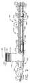
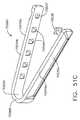
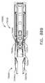
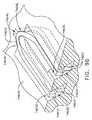
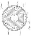
様々な外科手術中に外科医又は他の医師は、様々な効果及び/又は治療結果を得るために患者の組織にクリップを適用することがある。図1を参照すると、例えば、クリップアプライヤー100などの手術器具は、患者の手術部位内に位置する組織に1つ以上のクリップを適用するように構成され得る。概して、ここで図13を参照すると、クリップアプライヤー100は、クリップ140内の組織を圧迫するために組織に対してクリップ140を位置付けるように構成され、配置され得る。クリップアプライヤー100は、例えば図3及び4に図示され、以下で詳述するように、クリップ140を変形させるように構成され得る。各クリップ140は、基部142と、基部142から延在する、対向する脚部144と、を備え得る。基部142及び脚部144は、任意の好適な形状を備えることができ、例えば、実質的にU字形構成及び/又は実質的にV字形構成を備え得る。基部142は、接合部143によって結合される角部141を備え得る。使用する際、クリップ140の脚部144は、組織の両側に位置付けられ得、脚部144を互いに押し付け合って、脚部144の間に位置付けられた組織を圧迫することができる。接合部143は、基部142の角部141及びそこから延在する脚部144が内側に変形できるように構成され得る。様々な状況において、クリップ140は、クリップ140が十分に圧迫されると、ある程度の弾性変形又は跳ね返しが変形したクリップ140内で生じることがあるものの、塑性的に屈曲する、又は変形するように構成され得る。 During various surgeries, the surgeon or other physician may apply clips to the patient's tissue to obtain different effects and / or treatment results. Referring to FIG. 1, a surgical instrument, such as a
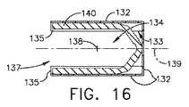
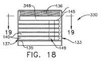
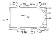
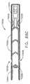
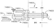
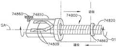
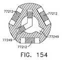
ここで図1及び図2を参照すると、クリップアプライヤー100は、シャフト110と、エンドエフェクタ120と、交換式クリップカートリッジ(すなわち、マガジン)130と、を備え得る。図14〜図16を参照すると、クリップカートリッジ130は、ハウジング132と、ハウジング132内に位置付けられた複数のクリップ140と、を備え得る。ハウジング132は、クリップ140を積み重ねることができる収容チャンバ134を画定する。収容チャンバ134は、クリップ140の外周を囲むように、又は少なくとも実質的に囲むように延在する側壁を備え得る。再び図13を参照すると、各クリップ140は、クリップ140の両側の上面145及び底面146など対向する面を備え得、クリップ140がハウジング132内に積み重ねられると、クリップ140の上面145は、隣接するクリップ140の底面146に接触して位置付けられてよく、クリップ140の底面146は、別の隣接するクリップ140の上面145に接触して位置付けられてよい。様々な状況において、クリップ140の底面146は、ハウジング132内に画定された1つ以上の支持シェルフ(すなわち、プラットフォーム)135に向かって下向きであってよく、クリップ140の上面145は、支持シェルフ135から離れるように上向きであってよい。場合によっては、クリップ140の上面145及び底面146は同一であるか、少なくとも実質的に同一であってよく、他の場合においては、上面145及び底面146は異なってよい。図14〜図16に示されるクリップ140のスタックは、例えば、5つのクリップ140を含むが、クリップ140のスタックが、5つを超えるクリップ140又は5つ未満のクリップ140を含むことができる他の実施形態も想定される。いずれにしても、クリップカートリッジ130は、例えば、ハウジング132とクリップ140の積層体の最上部クリップ140との中間に位置付けられた、付勢部材136など、少なくとも1つの付勢部材を更に備え得る。以下に詳述するように、付勢部材136は、ハウジング132内に画定された支持シェルフ135に対して、クリップ140の積層体の最下部クリップ140、又はより詳細には、最下部クリップ140の底面146を付勢するように構成され得る。付勢部材136は、バネ、及び/又は、例えば、クリップ140に付勢力を印加する、若しくはクリップ140の積層体を通じて下向きに伝達される付勢力を最上部クリップ140に少なくとも印加するように構成され得る任意の好適な圧迫弾性要素を備え得る。 With reference to FIGS. 1 and 2, the
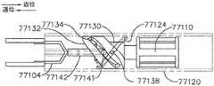
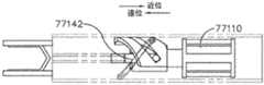
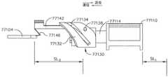
上記のようにクリップ140が支持シェルフ135に接して位置付けられると、クリップ140は、クリップ140が前進してカートリッジ130から排出され得る発射位置で支持されることができる。様々な状況において、支持シェルフ135は、クリップ140が連続して発射位置に位置付けられ得る、発射チャンバ149の少なくとも一部を画定し得る。場合によっては、発射チャンバ149は、カートリッジ130内で完全に画定され得る。他の場合においては、発射チャンバ149は、シャフト110及びカートリッジ130内、並びに/又はそれらの間に画定され得る。いずれにしても、以下に詳述するように、クリップアプライヤー100は、発射部材をカートリッジ130内へと前進させ、支持シェルフ135に接して位置付けられたクリップ140の発射位置からクリップアプライヤー100のエンドエフェクタ120内でクリップが受容される発射済み位置へとクリップを押し出すことができる発射駆動装置を備え得る。主として図14〜図16を参照すると、カートリッジ130のハウジング132は、近位開口部(すなわち、窓)133を備え得る。この近位開口部133は、発射部材が近位開口部133を通ってカートリッジ130に入ることができ、クリップ140を前進させてカートリッジ130から遠位に出すように支持シェルフ135と整列するか、少なくとも実質的に整列し得る。少なくとも1つのかかる実施形態において、ハウジング132は、遠位(すなわち、排出)開口部(すなわち、窓)137を更に備え得る。この遠位開口部137はまた、クリップ140が、例えば、近位開口部133、発射チャンバ149、及び遠位開口部137を通って延在する発射軸139に沿って遠位に前進する(すなわち、発射する)ことができるように支持シェルフ135と整列している。 When the
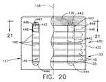
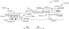
クリップ140を進めてカートリッジ130から出すためには、上記に加えて、カートリッジハウジング132内、及び様々な状況において発射チャンバ149内へと発射駆動装置の発射部材を進めることができる。以下で更に詳細に開示するように、発射部材は、クリップ140をエンドエフェクタ120内のその発射済み位置へと前進させるために、カートリッジ130を完全に通過することができる。発射チャンバ149内に位置付けられたクリップ140が発射部材によって遠位に前進させられると、これまでに概説したように、発射部材は、付勢部材136が別のクリップ140を支持シェルフ135に接触させて位置付けることができるように、十分に後退することができる。様々な状況において、発射部材がハウジング132内に位置付けられている間、付勢部材136は、発射部材に対してクリップ140を付勢することができる。かかるクリップ140は、待機クリップと呼ばれることがある。発射部材が十分に後退し、摺動して待機クリップ140の下から出ると、付勢部材136は、往復発射部材の次のストロークが実行される支持シェルフ135に対してクリップ140を付勢することができる。主として図2及び図14〜図16を参照すると、カートリッジ130は、例えば、供給軸138など所定の経路に沿ってクリップ140を発射チャンバ149に供給するように構成され得る。供給軸138は、発射部材が発射チャンバ149を通過する方向とは異なる方向でクリップ140が発射チャンバ149内へと供給されるように、発射軸139を横断し得る。少なくとも1つのかかる実施形態において、供給軸138は、例えば、発射軸139に対して垂直であるか、少なくとも実質的に垂直であり得る。 In order to advance the
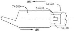
再び図2を参照すると、シャフト110は、例えば、その中でクリップカートリッジ130が受容される寸法であり、そのように構成され得るカートリッジ(すなわち、マガジン)開口部131を備え得る。カートリッジ開口部131は、カートリッジ130のハウジング132がカートリッジ開口部131内で密接に受容される寸法であり、そのように構成され得る。カートリッジ開口部131を画定する側壁は、シャフト110に対するカートリッジ130の横移動を制限し得るか、少なくとも実質的に制限し得る。シャフト110及び/又はカートリッジ130は、カートリッジ開口部131でカートリッジ130を解放可能に保持するように構成され得る1つ以上のロックを更に備え得る。図2に示されるように、カートリッジ130は、少なくとも1つの実施形態において、供給軸138と平行であるか、同一線上にある軸に沿ってカートリッジ開口部131に装填され得る。これもまた図2に示されるように、シャフト110は、シャフト110の側壁111から延在するパッド(すなわち、台座)118を更に備え得、パッド118は、カートリッジ130のハウジング132内に受容される、及び/又はそれと係合されるように構成され得る。パッド118は、パッド118が、シャフト110に対するカートリッジ130の横移動を制限できるか、少なくとも実質的に制限できるように、カートリッジハウジング内に画定される陥凹部148内で密接に受容される寸法であり、そのように構成され得る。パッド118は、シャフト110内でカートリッジ130と整列する、及び/又はカートリッジハウジング132を支持する寸法であり、そのように構成され得る。 Referring again to FIG. 2, the
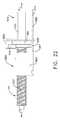
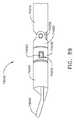
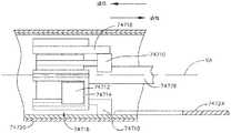
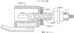
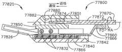
ここで図5及び6を参照すると、クリップカートリッジ130がシャフト開口部131内に位置付けられ、そこに固定されると、クリップアプライヤー100の発射駆動装置160は、作動して、上記のようにクリップカートリッジ130からクリップ140を進めることができる。発射駆動装置160は、例えば、打込ねじ161などの回転駆動入力部と、打込ねじ161と動作可能に係合する、変位可能な発射ナット163と、を備え得る。打込ねじ161は、発射ナット163全体に延在する、ねじ付き開口部とねじ止めにより係合できる少なくとも1つの打込ねじ山162を備え得る。様々な実施形態において、クリップアプライヤー100は、例えば、打込ねじ161と動作可能に連結された電動駆動装置を更に備え得る。様々な場合において、打込ねじ161は、例えば、手持ち式の器具又はロボットアームを備える手術器具システムの駆動装置と動作可能に連結され得る。いずれにしても、シャフト110内での発射ナット163の移動は、打込ねじ161が駆動装置によって長手方向軸164の周りを回転する場合、発射ナット163が長手方向軸164に沿って移動するように制限され得る。例えば、打込ねじ161が駆動装置によって第1の方向に回転する場合、打込ねじ161は、図6に図示されるように、発射ナット163をエンドエフェクタ120に向けて遠位に進めることができる。打込ねじ161が駆動装置によって第1の方向とは反対の方向に回転する場合、打込ねじ161は、発射ナット163をエンドエフェクタ120から離れるように近位に後退することができる。シャフト110は、打込ねじ161を回転可能に支持するように構成され得る、1つ以上の軸受を備え得る。例えば、軸受159は、例えば、図5及び6に図示されるように、打込ねじ161の遠位端を回転可能に支持するように構成され得る。 Here, referring to FIGS. 5 and 6, when the
発射駆動装置160は、以下で詳述するように、発射ナット163を使用して遠位に進められ、近位に後退することができる、発射ナット163から延在する発射部材165を更に備え得る。図5及び6を比較すると、読者は、発射ナット163及び発射部材165が近位の未発射位置(図5に図示される)から遠位の発射済み位置(図6に図示される)へと進められており、発射部材165がクリップカートリッジ130からエンドエフェクタ120へとクリップ140を進めたことを認めるであろう。主として図5を参照すると、クリップカートリッジ130は、その中に収容されている複数のクリップ140を備えるものとして図示されており、上記のように、クリップ140の1つが発射位置に位置付けられている。図5及び6に図示されるように、発射部材165は、発射部材165及び発射ナット163が遠位に進められると、発射軸167に沿ってステープルカートリッジ130内へと進み、発射位置に位置付けられたクリップ140を係合することができる遠位部166を備え得る。場合によっては、発射部材165は、線状部材を含み得るが、他の場合においては、発射部材165の遠位端166は、例えば、発射部材165から上向きに延在し得る。上記に加えて、発射部材165は、発射軸167に沿って遠位にクリップカートリッジ130から出て、エンドエフェクタ120内に画定された受容キャビティ122に入るようにクリップ140を進めることができる。 The
様々な場合において、発射部材165は、発射ナット163に取り付けられ、そこから遠位に延在し得るが、他の場合において、発射部材165及び発射ナット163は、発射アクチュエータ168によって互いに動作可能に接続され得る。発射アクチュエータ168は、ピボット169において発射部材165に枢動可能に取り付けられ得、シャフト110のハウジング112内に画定された長手方向スロット113と係合し得る遠位アーム170a及び近位アーム170bを備え得る。少なくとも1つのかかる実施形態において、アーム170a、170bのそれぞれは、長手方向スロット113内を摺動するように構成され得る、それらから延在するそれぞれ突起部171a及び171bなど突起部を含み得る。上記に加えて、発射ナット163は、そこから延在し、上記のように、アクチュエータ168及び発射部材165を遠位に進めるために、遠位アーム170aと係合するように構成され得る発射ピン172を更に備え得る。使用する際、図5及び6に図示される進行状況を再び参照すると、発射ナット163は、打込ねじ161によって遠位に進められることができ、遠位アーム170aと近位アーム170bとの中間に位置付けられた発射ピン172は、遠位アーム170aと接触し、アクチュエータ168及び発射部材165を遠位に駆動させることができる。アクチュエータ168が遠位に進むと、アクチュエータ168が図6に図示される位置に達するまでは、シャフトスロット113内の突起部171a及び171bの1つ又はその両方が長手方向シャフトスロット113に対して横移動させないようにできるため、アクチュエータ168は、ピボットピン169の周りを回転しないようにされ得る。 In various cases, the
アクチュエータ168が図6に図示される位置に達すると、遠位突起部171aは、アクチュエータ168を下向きに旋回させるか、図9に図示されるようにアクチュエータ168が下向きに旋回できるように構成され得る、長手方向スロット113の遠位スロット部114に入ることができる。少なくとも1つのかかる実施形態において、遠位突起部171aは、アクチュエータ168が発射ナット163によって進められると、遠位突起部171aを下向きに誘導し、アクチュエータ168にピボット169の周りを旋回させることができる遠位スロット部114の側壁と接触するようになり得る。かかる旋回位置において、発射ナット163から延在する発射ピン172は、アクチュエータ168の遠位アーム170aと係合しなくなってよく、続いて、発射ナット163は、アクチュエータ168とは無関係に遠位に移動してよく、したがって、アクチュエータ168及び発射部材165を置き去りにする。換言すると、長手方向シャフトスロット113の遠位端114は、発射部材165の動作を停止させてよく、かかる時点において、発射部材165の位置は、発射部材165の完全発射済み位置、すなわち最遠位位置を示し得る。かかる位置において、クリップ140は、受容キャビティ(すなわち、レシーバー)122内へと十分に進められる。更に、かかる位置において、受容キャビティ122内へと進められる次のクリップ140は、上記に加えて、発射部材165の上面に押し付けられ得る。 When the
クリップ140が受容キャビティ122内に位置付けられると、上記に加えて、クリップ140は、例えば、圧着駆動装置180によって変形させられ得る。ここで図3及び4を参照すると、クリップアプライヤー100のエンドエフェクタ120は、第1のジョー123aと、第2のジョー123bと、を更に備え得、第1のジョー123a及び第2のジョー123bは、少なくとも部分的に受容チャンバ122を画定し得る。図3及び4に図示されるように、第1のジョー123aは第1の溝124aを備えてよく、第2のジョー123bは第2の溝124bを備えてよく、これらは、クリップ140の少なくとも一部を内部に受容し、支持するようにそれぞれ構成され得る。第1のジョー123aは、ピン125aによってシャフト110のフレーム111に枢動可能に連結され得、第2のジョー123bは、ピン125bによってフレーム111に枢動可能に連結され得る。使用する際、圧着駆動装置180は、第1のジョー123aと第2のジョー123bとの間に位置付けられたクリップ140を圧迫するために、第1のジョー123aを第2のジョー123bに向けて回転させる、及び/又は第2のジョー123bを第1のジョー123aに向けて回転させるように構成され得る。少なくとも1つのかかる実施形態において、圧着駆動装置180は、第1のジョー123a及び第2のジョー123bを互いに向けて旋回させるために、第1のジョー123a上に画定された第1のカム面126a及び第2のジョー123b上に画定された第2のカム面126bを係合するように構成され得る、カムアクチュエータ181を備え得る。カムアクチュエータ181は、少なくとも部分的に第1のジョー123a及び第2のジョー123bを囲むカラーを備え得る。少なくとも1つのかかる実施形態において、カラーは、ジョー123aのカム面126a及びジョー123bのカム面126bと接触し、これらを互いに向けて内側に押し込むように輪郭形成され得る、内側カム面182を備え得る。様々な状況において、エンドエフェクタ120に画定された受容チャンバ122内に位置付けられたクリップ140は、圧着駆動装置180の作動前に組織に対して位置付けられることができる。いくつかの状況において、圧着駆動装置180は、少なくとも部分的にクリップ140を圧迫するために、組織に対してクリップ140を位置付ける前に少なくとも部分的に作動され得る。特定の状況において、クリップ140及び受容チャンバ122は、図3に図示されるように、エンドエフェクタ120が非作動状態にあるときに、クリップ140が内側に付勢され得るか、屈曲され得る寸法であり、そのように構成され得る。様々な状況において、圧着する第1のジョー123a及び第2のジョー123bは、これらの間に位置付けられたクリップ140を弾性的に圧着する、及び/又は永続的に圧着するために作動され得る。 Once the
上記に加えて、発射ナット163は、圧着駆動装置180を作動させるように構成され得る。より詳細には、ここで図7を参照すると、圧着駆動装置180は、カムアクチュエータ181と動作可能に連結された圧着アクチュエータ188を備え得、上記のように発射ナット163が遠位に進められると、圧着アクチュエータ188は、発射ナット163によって選択的に係合され得る。少なくとも1つのかかる実施形態において、発射ナット163は、発射ナット163が発射アクチュエータ168を進めると、圧着アクチュエータ188を係合するように構成され得る、例えば、そこから延在する発射ピン184など、第2の発射ピンを更に備え得る。再び図7を参照すると、圧着アクチュエータ188は、非作動位置に位置付けられており、発射ナット163が十分に進められて圧着アクチュエータ188の遠位アーム190aを係合すると、発射ナット163は、図8に図示されるように、圧着アクチュエータ188を上向きに回転させて、作動位置に入れることができる。これもまた図8に図示されるように、遠位アーム190a及び近位アーム190bは、例えば、スロット115など、シャフト110に画定された第2の長手方向スロット内に位置付けられ得、それぞれこれらから延在する突起部191a及び突起部191bなど突起部を備え得る。圧着アクチュエータ188がその非作動位置からピボット189の周りを上向きに回転すると、突起部191a及び191bは、長手方向スロット115の近位湾曲端116から移動して、実質的に線状である、長手方向スロット115の部分に入ることができる。上記と同様に、長手方向スロット115の側壁は、長手方向経路に沿った圧着アクチュエータ188の移動を制限するように構成され得、上記のように、圧着アクチュエータ188が上向きに回転して少なくとも部分的に作動位置に入ると、圧着アクチュエータ188の回転を制限するか、阻止するように構成され得る。読者には理解されるように、発射駆動装置160の発射ピン172及び圧着駆動装置180の発射ピン184は、どちらも発射ナット163から延在する。便器上かつ実証のために、発射ピン172及び184は、発射ナット163の同じ側から延在するように図示されているが、発射ピン172が発射ナット163の第1の外側部から延在でき、一方発射ピン184が発射ナット163の他の外側部から延在できることが想定される。かかる状況において、発射アクチュエータ168は、打込ねじ161の第1の側面と平行して位置付けられ得、圧着アクチュエータ188は、打込ねじ161の反対側面と平行して位置付けられ得る。それに応じて、長手方向スロット113は、シャフトハウジング112の第1の側面に画定され得、一方、長手方向スロット115は、シャフトハウジング112の反対側面に画定され得る。 In addition to the above, the
上記に加えて、カムアクチュエータ181は、図8及び10に図示されるように、圧着アクチュエータ188が発射ナット163によって遠位に進められると、遠位アーム190aから延在する遠位突起部191aが長手方向スロット115の遠位端117に達するまでカムアクチュエータ181が遠位に進められ得るように動作可能に圧着アクチュエータ188と連結され得る。かかる遠位位置において、カムアクチュエータ181は十分に進められた位置にあってよく、受容チャンバ122内に位置付けられたクリップ140は、十分に変形された、又は圧着された構成であり得る。その後、カムアクチュエータ181は後退してよく、エンドエフェクタ120は再開放されてよい。より詳細には、打込ねじ161は、発射ナット163を近位に移動させ、カムアクチュエータ181を後退させるために反対方向に回転することができ、特定の場合において、エンドエフェクタ120は、第1のジョー123及び第2のジョー123bを付勢して、図4に図示される閉鎖(すなわち、発射済み)位置から図3に図示される開放(すなわち、未発射)位置にするように構成され得る、付勢部材を更に備え得る。発射ナット163が、図10に図示されるその位置から後退すると、発射ナット163から延在する発射ピン184は、圧着アクチュエータ188の近位アーム190bを係合でき、図12に図示されるように、圧着アクチュエータ188及びそこから延在するカムアクチュエータ181を近位に移動させることができる。上記と同様に、圧着アクチュエータ188の近位アーム190bから延在する近位突起部191bは、湾曲近位端116の側壁と接触するように構成され得、側壁は、圧着アクチュエータ188を下向きに誘導し、圧着アクチュエータ188にピボット189の周りを回転させ得る。かかる時点において、発射ピン184は、圧着アクチュエータ188と係合しなくなってよく、カムアクチュエータ181は十分に後退してよく、発射ナット163は、圧着アクチュエータ188に対して引き続き引き後退してよい。 In addition to the above, the
上記に加えて、ここで図11を参照すると、発射ナット163は、発射ナット163が近位に後退すると、発射アクチュエータ168を再係合するように構成され得る。上記のように、発射アクチュエータ168は、発射アクチュエータ168が長手方向スロット113の遠位端114に達すると下向きに回転し、その結果、発射アクチュエータ168は、発射ナット163が近位に後退して発射アクチュエータ168を再係合するときに、まだその下向き回転位置にあり得る。図11に図示されるように、発射ナット163から延在する発射ピン172は、発射アクチュエータ168の近位アーム170bを係合することができ、発射ナット163が更に後退すると、発射ナット163は、アーム170aから延在する突起部171a及びアーム170bから延在する突起部171bが長手方向スロット113の長手方向部に再び入ることができるように、発射アクチュエータ168を上向きに回転させることができる。その後、発射ナット163は、図5に図示されるように、発射アクチュエータ168及びそこから延在する発射部材165がそれらの開始(すなわち、未発射)位置に戻るまで後退することができる。かかる状況において、発射部材165は、新しいクリップ140が、付勢部材136によって付勢されてクリップカートリッジ130の発射チャンバ内に入るように発射ナット163によって近位に後退するので、発射部材165は、クリップカートリッジ130から取り出されることができる。発射部材165及び発射アクチュエータ168がそれらの開始位置に後退させられ、次のクリップ140が発射チャンバ内に位置付けられると、発射ナット163及び発射部材165を遠位に移動させて次のクリップ140をエンドエフェクタ120内へと進めるために、発射駆動装置160をもう一度作動させることができる。同様に、発射ナット163は、次のクリップ140を変形させるために発射ナット163をもう一度遠位に移動させると、圧着駆動装置180を再作動させることができる。その後、発射ナット163は、圧着駆動装置180及び発射駆動装置160をもう一度リセットするために後退することができる。このプロセスは、十分な数のクリップ140が標的組織に適用されるまで、及び/又はクリップカートリッジ130内に収容されるクリップ140が使い果たされるまで繰り返すことができる。追加のクリップ140が必要になった場合、シャフト110から使用済みクリップカートリッジ130を取り外すことができ、追加のクリップ140を収容する交換用クリップカートリッジ130をシャフト110に挿入できる。いくつかの状況において、少なくとも部分的に使用されたクリップカートリッジ130を同一又は少なくともほぼ同一の交換用クリップカートリッジ130と交換することができる。一方、他の状況において、クリップカートリッジ130は、例えば、その中に収容される5個超又は5個未満のクリップ140を有するクリップカートリッジ、及び/又はその中に収容されるクリップ140以外のクリップを有するクリップカートリッジと交換することができる。 In addition to the above, with reference to FIG. 11 here, the
再び図6〜図9を参照すると、図示された実施形態の発射ナット163は、発射ナット163が圧着アクチュエータ188と係合すると同時に、発射アクチュエータ168から解放されるように構成され得る。換言すると、発射駆動装置160は、圧着駆動装置180が始動すると同時に、作動を停止し得る。様々な状況において、かかるタイミングは、例えば、長手方向スロット113の遠位端114が第2の長手方向スロット115の近位端116と整列する、又は少なくとも実質的に整列するときに達成され得る。図示される実施形態及び/又は任意の他の実施形態において、発射駆動装置160の作動停止と圧着駆動装置180の始動との間には遅れが存在し得る。いくつかの状況において、発射部材165の発射ストロークの終了時点とカムアクチュエータ181の発射ストロークの開始時点との間のかかる遅れは、クリップ140がカムアクチュエータ181によって変形させられる前に、受容チャンバ122内の完全固定位置にクリップ140を確実に位置付けるために生じ得る。様々な状況において、かかる遅れは、例えば、長手方向スロット113の遠位端114が第2の長手方向スロット115の近位端116に対して近位に位置付けられるときに生じ得る。図示される実施形態及び/又は任意の他の実施形態において、発射駆動装置160の作動停止は、圧着駆動装置180の始動後に生じ得る。発射部材165の発射ストロークの終了時点とカムアクチュエータ181の発射ストロークの開始時点とのかかる重複は、いくつかの状況において、例えば、受容チャンバ122内のクリップ140の完全固定位置への移動時に少なくともある程度の内向き圧力をクリップ140に加えて、クリップ140と受容チャンバ122の側壁との間の相対移動を低減する又は排除するために生じ得る。様々な状況において、かかる重複は、例えば、長手方向スロット113の遠位端114が第2の長手方向スロット115の近位端116に対して遠位に位置付けられたときに生じ得る。 With reference to FIGS. 6-9 again, the
図1の図示される実施形態及び/又は任意の他の好適な実施形態において、ここで図17を参照すると、例えば、クリップカートリッジ230などのクリップカートリッジは、付勢部材136とクリップカートリッジ230内に積み重ねられた最上部クリップ140との中間に位置付けられたプッシャープレート248を備え得る。プッシャープレート248は、剛性又は少なくとも実質的に剛性であってよく、付勢部材136が付勢力を印加できる第1の軸受面を備え得る。プッシャープレート248は、最上部のクリップ140の上面145に付勢力を伝達できる第2の軸受面も備え得る。プッシャープレート248は、任意の好適な形状を備えてよく、任意の好適な材料で構成されてよいが、例えば、プッシャープレート248は、ステンレス鋼材のシートで構成され得る。特定の状況において、プッシャープレート248は、付勢部材136に取り付けられなくてよい。一方、他の状況において、プッシャープレート248は、プッシャープレート248がカートリッジハウジング132から取り外されないように付勢部材136に取り付けられ得る。様々な状況において、プッシャープレート248は、カートリッジハウジング132内に画定された近位開口部133及び/又は遠位開口部137を通過できない寸法であり、そのように構成され得る。 In the illustrated embodiment and / or any other preferred embodiment of FIG. 1, with reference to FIG. 17, for example, a clip cartridge such as a
図1の図示される実施形態及び/又は任意の好適な実施形態において、ここで図18及び19を参照すると、例えば、クリップカートリッジ330などのクリップカートリッジは、クリップカートリッジ330内に収容される全てのクリップ140がカートリッジ330から排出された後で、クリップカートリッジ330の発射チャンバ149内に位置付けられ得るロックアウト部材を備え得る。ロックアウト部材は、付勢部材136とクリップカートリッジ330内に収容された最上部クリップ140の上面145との中間に位置付けられ得るロックアウトプレート348を備え得る。使用する際、上記に加えて、クリップ140は、クリップカートリッジ130の発射チャンバ149内に連続的に位置付けられ、次いで、遠位に進められてクリップハウジング132から出され得る。最後のクリップ140が進められてクリップハウジング132から出され、発射部材165がクリップカートリッジ130から取り出された後で、付勢部材136は、シェルフ135に対してロックアウトプレート348を付勢することができる。かかる位置において、ロックアウトプレート348は、発射部材165がクリップカートリッジ130に入ることができない、又は少なくとも実質的に入ることができないように、近位開口部133及び遠位開口部137と整列し得る。かかる状況において、ロックアウトプレート348は、発射部材165がハウジング132に入り、通過しないようにし、その結果、クリップカートリッジ130がクリップを使い果たした後で、不注意によるクリップアプライヤー100の発射を防止することができる。クリップアプライヤー100の操作者が発射駆動装置160を作動させ、発射部材165を使用済みクリップカートリッジ130へと進めようとする場合、発射部材165はロックアウトプレート348と接触してこれに隣接する。かかる状況においては、発射部材165内に圧迫荷重が生じ得る。クリップアプライヤー100は、発射部材165内で生じた圧迫荷重が特定の量又は所定の量を超えると、駆動装置を摺動させ、打込ねじ161から動作可能に駆動装置の接続を解除するように構成され得るクラッチを更に含み得る。クラッチに加えて、又はその代わりに、駆動装置及び/又はクリップアプライヤー100の駆動装置コントローラ(例えば、発射駆動装置160を動作させる)は、発射部材165内で生じた荷重を検出し、発射部材165内で生じた荷重が特定の量又は所定の量を超えると、駆動装置に供給される電圧及び/又は電流のスイッチを切る、及び/又はこれらを低減するように構成された荷重センサを備え得る。いずれにしても、ロックアウトプレート348は、発射部材165がロックアウトプレート348と接触したときに、ロックアウトプレート348が遠位開口部137及び/又は近位開口部133を通って外れることができない寸法であり、そのように構成され得る。クリップアプライヤー100を再利用するために、クリップアプライヤー100の操作者は、シャフト110から使用済みカートリッジ330を取り外し、例えば、新しいクリップカートリッジ330をシャフト110に挿入することができる。この時点において、クリップ140は、新しいクリップカートリッジ330の発射チャンバ149内に位置付けられてよく、発射部材165は、新しいクリップカートリッジ330内へと遠位に進められて、上記のようにクリップ140を配置することができる。 In the illustrated embodiment and / or any preferred embodiment of FIG. 1, with reference to FIGS. 18 and 19, for example, a clip cartridge such as a
図1の図示される実施形態及び/又は任意の他の好適な実施形態において、ここで図20及び21を参照すると、例えば、クリップカートリッジ430などのクリップカートリッジは、クリップカートリッジ430内でのロックアウト部材の運動を制限するか、限定するように構成され得るガイドを備え得る。上記と同様に、ロックアウト部材は、例えば、付勢部材136とクリップカートリッジ430のハウジング432内に収容された最上部クリップ140の上面145との中間に位置付けられ得る、ロックアウトプレート448を備え得る。使用する際、上記と同様に、クリップ140がクリップカートリッジ430から連続的に排出されるため、ロックアウトプレート448は、次第に下向きに発射チャンバ149に押し込まれ得る。ロックアウトプレート448は、カートリッジハウジング432内で密接に受容され、かつクリップカートリッジ430内でロックアウトプレート448が整列しなくなる可能性を低減するか、阻止するためにロックアウトプレート448とハウジング432との間の相対横移動が制限され得る寸法であり、そのように構成され得る。クリップカートリッジ430内でロックアウトプレート448が整列しなくなった場合、ロックアウトプレート448は、ハウジング432内に留められ、例えば、付勢部材136がクリップ140の積層体に適切な付勢力を印加できないようにしてよい。図20及び21に図示されるように、ロックアウトプレート438は、そこから延在するガイド部材447を更に備え、ガイド部材447は、カートリッジハウジング432内に画定されたガイドスロット446内で受容され得る。ガイド部材447及びガイドスロット446は、ガイド部材447がガイドスロット446内に密接に受容され、かつロックアウトプレート438とカートリッジハウジング432との間の相対横移動が制限され得る寸法であり、そのように構成され得る。各ガイドスロット446は、ガイド部材447が、ガイドスロット446の上部443と底部444との間にある対向する側壁445の間を摺動できるように、その中に位置付けられたガイド部材447の幅と等しいか、やや大きい、その間の距離を画定し得る、対向する側壁445によって画定され得る。したがって、ガイド部材447及びガイドスロット446は、これまでに概説したようにその間の横移動を制限するように構成され得るが、ガイド部材447及びガイドスロット446は、例えば、供給軸138と平行、又はこれと同一線上にある所定の経路に沿って、ロックアウトプレート438とカートリッジハウジング432との間の相対移動を可能にするように構成され得る。ロックアウトプレート438が付勢部材136によって発射チャンバ149に押し込まれると、ロックアウトプレート438は、これまでに概説したように、使用済みクリップカートリッジ430が別の好適なクリップカートリッジと交換されるまで発射部材165の前進及びクリップアプライヤー100の操作を阻止することができる。 In the illustrated embodiment and / or any other preferred embodiment of FIG. 1, with reference to FIGS. 20 and 21, for example, a clip cartridge such as a
図1の図示される実施形態及び/又は任意の他の好適な実施形態において、上記のように、打込ねじ161は、第1の方向に回転して、発射ナット163を遠位に前進させ、第2の(すなわち、反対)方向に回転して、発射ナット163を近位に後退させることができる。打込ねじ161を第1及び第2の方向に回転させるために、動作可能に打込ねじ161と連結された電動駆動装置は、対応する第1及び第2の方向で動作し得る。図1の図示される実施形態及び/又は任意の他の好適な実施形態において、クリップアプライヤーは、第1の方向のみで動作する駆動装置を使用することができ、かかる単方向での駆動装置の回転は、発射ナットを遠位に進め、発射ナットを近位に引き込むために使用することができる。ここで図22〜図26を参照すると、電動駆動装置の出力は、トランスミッションシステム550を介して駆動装置システム560に伝達され得る。トランスミッションシステム550は、単方向で動作する入力シャフト552を備えてよく、トランスミッションシステム550は、トランスミッションシステム550が駆動システム560の打込ねじ561を第1の方向に回転させる第1の状態(すなわち、構成)と、トランスミッションシステム550が打込ねじ561を第2の(すなわち、反対)方向に回転させる第2の状態(すなわち、構成)と、を切り替え可能又は移行可能であり得る。トランスミッションシステム550の第1の状態は図22〜図24に描写されており、トランスミッションシステム550の第2の状態は図25及び図26に描写されている。 In the illustrated embodiment of FIG. 1 and / or any other preferred embodiment, as described above, the driving
再び図22〜図24を参照すると、入力シャフト552は、そこに取り付けられた入力歯車551を備え得、入力歯車551は、入力シャフト552の回転がシフター歯車553に伝達されるようにシフター歯車553と動作可能に連結されるか、噛み合い係合される。本明細書に記載される全ての歯車について、動作可能に連結されるか、互いに噛み合い係合される歯車は、例えば、一方の歯車の回転を他方の歯車に伝達できる任意の好適な歯の配列を備え得る。入力シャフト552が第1の方向に回転すると、シフター歯車553は、第2の(すなわち、反対)方向に回転する。トランスミッションシステムの第1の状態では、シフター歯車553は、シフター歯車553が中間歯車554と動作可能に連結される、第1の位置にあり、上記のように、シフター歯車553が入力歯車551によって第2の方向に回転すると、中間歯車554が第1の方向に回転する。図示されていないが、中間歯車554は、例えば、クリップアプライヤー100のシャフト110内で回転可能に支持され得る。中間歯車554はまた、中間歯車554の回転を出力歯車555に伝達できるように、打込ねじ561に取り付けられた出力歯車555と動作可能に連結され得る。上記のように、中間歯車554がシフター歯車553によって第1の方向に駆動すると、中間歯車554は、出力歯車555及び打込ねじ561を第2の方向に駆動させることができる。上記と同様に、発射ナット563は、打込ねじ561が第2の方向に回転すると、発射ナット563が矢印Dで示されるように遠位に前進するように、打込ねじ561と動作可能に連結され、シャフト110内で好適に拘束され得る。 With reference to FIGS. 22-24 again, the
上記と同様に、発射ナット563は、上記のように、クリップカートリッジ130からエンドエフェクタ120内へとクリップ140を前進させ、クリップ140を圧着するために、図24に図示されるように、その最遠位位置まで前進させることができる。図23及び24に図示されるように、発射ナット563は、トランスミッションシステム550をその第1の状態からその第2の状態に移行させるように構成され得る、そこから延在するカムバー569を更に備え得る。図24及び図25を比較すると、読者は、トランスミッションシステム550がその第1の状態にある第1の位置とトランスミッションシステム550がその第2の状態にある第2の位置との間をシフター歯車553が移動可能であることを認めるであろう。より詳細には、シフター歯車553は、シフター歯車553が入力歯車551及び中間歯車554と動作可能に係合するその第1の位置及びシフター歯車553が中間歯車554から動作可能に解放されるその第2の位置からシフター歯車553が回転できるように、入力シャフト552の周りを回転可能であるシフター556に取り付けられる。シフター歯車553は、シフター歯車553がその第2の位置にあるときに中間歯車554から動作可能に解放されるが、シフター歯車553は、入力シャフト552から打込ねじ561に回転運動を伝達するために、入力歯車551及び出力歯車555と動作可能に連結され得る。図24及び25に図示されるように、シフター556は、入力シャフト552がその中を通って延在できる中央開口部を備え得る。しかしながら、シフター556は、入力シャフト552と動作可能に係合しなくてよく、その結果、入力シャフト552の回転はシフター556を回転させなくてよく、同様に、シフター556の回転は入力シャフト552を回転させなくてよい。いずれにしても、シフター556は、そこから延在するカム従動子558を更に備え得、カム従動子558は、発射ナット563が遠位に進むにつれてカムバー569上に画定されたカム568によって係合され得る。カム568がカム従動子558を係合すると、カム568は、上記のように、その第1の位置とその第2の位置との間でシフター556及びシフター歯車553を回転させることができる。 Similar to the above, the firing
上記のように、シフター歯車553がその第2の位置にあり、トランスミッションシステム550がその第2の状態にある場合、入力シャフト552及び打込ねじ561は、いずれも第1の方向に回転することができる。より詳細には、入力シャフト552は、第1の方向に回転した場合、入力歯車551を第1の方向に回転させることができ、シフター歯車553は入力歯車551と直接係合しているため、シフター歯車553は、第2の方向に回転するであろう。読者は、シフター歯車553が、トランスミッションシステム550がその第1の状態にある場合に第1の(すなわち、反対)方向に回転することと比較して、トランスミッションシステム550がその第2の状態にある場合に第2の方向に回転することを認めるであろう。図24及び図25を比較すると、上記に加えて、読者は、トランスミッションシステム550がその第2の状態にあり、したがって、別の回転方向を示す場合、中間歯車554は、入力歯車551とシフター歯車553との中間に動作可能に位置付けられなくなることを理解するであろう。シフター歯車553がその第2の位置にある場合、シフター歯車553は入力歯車551及び出力歯車555と動作可能に係合するため、シフター歯車553は、出力歯車555、及び出力歯車555に連結された打込ねじ561を第1の方向に回転させることができる。図25及び図26に図示されるように、打込ねじ561が第1の方向に回転すると、発射ナット563は、近位に後退して、エンドエフェクタ120が再開放され、発射部材165を後退させることができるようにし得る。主として図26を参照すると、発射ナット563は、そこから延在する第2のカムバー567を更に備えてよく、第2のカムバー567は、発射ナット563がその完全後退位置へと近位に後退するために、シフター556のカム従動子558と接触するように構成され得るカム566を備える。かかる状況において、カム566は、トランスミッションシステム550がその第1の状態にリセットされることができ、クリップアプライヤー100をもう一度作動できるように、シフター556を押してその第1の位置に戻し、中間歯車554と動作可能に係合させることができる。 As described above, when the
上記のように、クリップアプライヤー100の発射駆動装置は、電動駆動装置を備える手術器具システムによって操作され得る。ロボット手術器具システム20は図27に図示されており、複数の可動アーム30を備え得る。各アーム30は、クリップアプライヤー100のシャフト110に回転運動を供給するように構成された電動駆動装置及び/又は任意の他の好適な手術器具を備えるアクチュエータモジュール32を備え得る。ここで図28を参照すると、エンドエフェクタ620は、選択的にクリップアプライヤーのアクチュエータシャフト610に対して係合可能であり、かつ解放可能であってよく、エンドエフェクタ620は、シャフト610の遠位端611と連結可能な近位端621を備え得る。エンドエフェクタ620の近位端621は、外側ハウジング629と、外側ハウジング629を通って延在するフレームと、フレームを通って延在する外側駆動シャフトと、外側駆動シャフトを通って延在する内側駆動シャフトと、を備え得る。同様に、シャフト610の遠位端611は、外側ハウジング619と、外側ハウジング619を通って延在するフレーム663と、フレーム663を通って延在する外側駆動シャフト662と、外側駆動シャフト662を通って延在する内側駆動シャフト661と、を備え得る。シャフト610の遠位端611に関しては、フレーム663、外側駆動シャフト662、及び内側駆動シャフト661は、そこから延在する舌状コネクタ613の一部と、その中に画定されたコネクタ溝612の一部をそれぞれ備え得る。舌状コネクタ613は、エンドエフェクタ620の近位端621に画定された舌状溝623内で受容されるように構成され得、舌状溝612は、エンドエフェクタ620の近位端621から延在する舌状コネクタ622を受容するように構成され得る。遠位シャフト端611のフレーム663、外側駆動シャフト662、及び内側駆動シャフト661にわたって延在する舌状コネクタ613と同様に、舌状コネクタ622は、エンドエフェクタ620の近位端621のフレーム、外側駆動シャフト、及び内側駆動シャフトにわたって延在し得る。また、遠位シャフト端611のフレーム663、外側駆動シャフト662、及び内側駆動シャフト661にわたって延在する舌状溝612と同様に、舌状溝623は、エンドエフェクタ620の近位端621のフレーム、外側駆動シャフト、及び内側駆動シャフトにわたって延在し得る。図28に図示される構成において、エンドエフェクタ620の舌状コネクタ622は、シャフト610の舌状コネクタ613がエンドエフェクタ620の舌状溝623に横方向に滑り込むのと同時に、シャフト610の舌状溝612に横方向に滑り込み得る。かかるアセンブリのおかげで、エンドエフェクタ620のフレームは、シャフト610のフレーム663にしっかり連結されることができ、エンドエフェクタ620の外側駆動シャフトは、シャフト110の外側駆動シャフト662と動作可能に連結されることができ、エンドエフェクタ620の内側駆動シャフトは、シャフト110の内側駆動シャフト661と動作可能に連結されることができる。読者は、エンドエフェクタ620がシャフト610に組み立てられたときに、舌状コネクタ612の一部が互いに整列し、舌状溝613の一部が互いに整列し、舌状溝622の一部が互いに整列し、舌状コネクタ623の一部が互いに整列することを認めるであろう。組み立てられると、シャフト110の外側駆動シャフト662は、エンドエフェクタ620の外側駆動シャフトを回転させることができ、シャフト610の内側駆動シャフト661は、エンドエフェクタ620の内側駆動シャフトを回転させることができる。外側駆動シャフト662及び/又は内側駆動シャフト661が回転すると、舌状コネクタ612の一部、舌状溝613の一部、舌状溝622の一部、及び舌状コネクタ623の一部は、整列しなくなってよい。シャフト610からエンドエフェクタ620を取り外すために、内側駆動シャフト661及び/又は外側駆動シャフト662は、舌状コネクタ612及び623、並びに舌状溝613及び622が十分に整列する1つ以上の位置へと回転され得る。 As mentioned above, the launch drive of the
再び図28を参照すると、シャフト610の外側ハウジング619は、エンドエフェクタ620がシャフト610の遠位端611の上に横方向に摺動するときにエンドエフェクタ620の横移動を制限するように構成され得る、停止部614を更に備え得る。停止部614は、エンドエフェクタ620の内側駆動シャフト及びシャフト610の内側駆動シャフト661が長手方向軸615に沿って揃えられる、エンドエフェクタ620の外側駆動シャフト及びシャフト610の外側駆動シャフト662が長手方向軸615に沿って整列する、並びに/又はエンドエフェクタ620のフレーム及びシャフト610のフレーム663が長手方向軸615に沿って整列する、基準を提供することができる。上記に加えて、内側駆動シャフト661は、電動駆動装置及び/又は内側駆動シャフト661を回転させるように構成された、内側駆動シャフト661と動作可能に連結された歯車列664を備え得るアクチュエータモジュール632内へと延在し得る。更に、アクチュエータモジュール632は、第2の電動駆動装置と、第2の駆動シャフト662を駆動するように構成された、動作可能に第2の駆動シャフト662に動作可能に係合される歯車列と、を備え得る。以下に詳述するように、第2の電動駆動装置を使用して、エンドエフェクタ620を接合することができる。また、上記に加えて、シャフト610の外側ハウジング619及び/又はフレーム663は、これらに取り付けられた歯車617を更に含み得、歯車617は、電動駆動装置、並びにシャフト610及びエンドエフェクタ620に長手方向軸615の周りを回転させるように構成され得る歯車列618と動作可能に係合する。例えば、電動駆動装置及び歯車列618が第1の方向に動作する場合、シャフト610及びエンドエフェクタ620は軸615の周りを時計回り方向に回転することができる。一方、電動駆動装置及び歯車列618が第2の方向に動作する場合、シャフト610及びエンドエフェクタ620は、エンドエフェクタ620を位置付け、配向するために、軸615の周りを反時計回りの方向に回転することができる。 Referring again to FIG. 28, the
上記のように、エンドエフェクタ620は、選択的にシャフト610に対する取り付け及び取り外しを行うことができる。読者は、エンドエフェクタ620及びシャフト610に関連して記載された原理が、とりわけ図1に開示された実施形態のエンドエフェクタ120及びシャフト110に等しく適用され得ることを認めるであろう。 As described above, the
したがって、再び図27を参照すると、ロボットアーム30の1つは、クリップアプライヤーのエンドエフェクタ120又は、別の方法として、例えば、手術用ステープラーのエンドエフェクタなど任意の他の好適なエンドエフェクタと選択的に係合し得る。かかる状況において、エンドエフェクタ120は、別のエンドエフェクタと選択的に交換可能であり、その結果として、単一のロボットアーム30を使用して1つ以上の機能を実行することができる。換言すると、クリップアプライヤー100は、別のクリップアプライヤー装着装置及び/又は任意の他の好適な交換式装着装置と交換可能である交換式装着装置を備え得る。ここで図29を参照すると、クリップアプライヤー100のエンドエフェクタ120及びシャフト110は、ハンドル700を備える手術器具システムと共に使用することができる。ハンドル700は、上記のように打込ねじ161に回転運動を加えるために、グリップ702に向けて動作する、又は押し込むことができるアクチュエータ701を備え得る。場合によっては、アクチュエータ701の回転は、打込ねじ161に機械的に伝達され得る。一方、他の場合において、アクチュエータ701は、打込ねじ161に動作可能に連結された駆動装置を動作させ得る。 Thus, referring again to FIG. 27, one of the
上記に加えて、クリップアプライヤー100のエンドエフェクタ120及びシャフト110は、クリップアプライヤー100の長手方向軸に沿って整列し得る。ここで図30を参照すると、エンドエフェクタ120及び/又はシャフト110は、エンドエフェクタ120がクリップアプライヤー100の長手方向軸に対して関節接合できるように構成され得る、関節継手101を更に備え得る。シャフト110は、近位端102を備え得、関節継手101の遠位部を備え得る、外側ハウジング(すなわち、フレーム部)119を備え得る。近位端102は、例えば、関節継手部材103に画定された、球状又は少なくとも実質的に球状であるキャビティ104内に受容され得るものなど、球状、又は少なくとも実質的に球状である端部102を備え得る。関節継手部材103はまた、例えば、シャフトフレーム部106に画定された、球状又は少なくとも実質的に球状であるキャビティ107内に受容され得るものなど、球状、又は少なくとも実質的に球状である端部105を備え得る。シャフト110の近位端102は、近位端102がキャビティ104から容易に取り外され得ないように、キャビティ104内で少なくとも部分的に捕捉され得る。したがって、近位端102及びキャビティ104は、近位端102がキャビティ104内で任意の好適な方向に回転できる寸法であり、そのように構成され得る。図30にも図示されるように、クリップアプライヤー100は、例えば、関節継手101を通って延在し得、シャフトハウジング119の近位端102内に画定された、取り付け開口部109a及び109b内にそれぞれ取り付けられる遠位端を含み得る、関節制御部108a及び108bを更に備え得る。使用する際、関節制御部108a及び108bは、キャビティ104内で近位端102を移動させるために、押す、及び/又は引くことができる。上記に加えて、関節継手部材103の端部105は、端部105がキャビティ107から容易に取り外され得ないように、シャフトフレーム部106に画定されたキャビティ107内で少なくとも部分的に捕捉され得る。したがって、端部105及びキャビティ107は、上記のように、シャフト端部102がアクチュエータ108a及び108bによって押される、及び/又は引かれると、端部105がキャビティ107内で任意の好適な方向に回転できる寸法であり、そのように構成され得る。 In addition to the above, the
上記に加えて、再び図30を参照すると、打込ねじ161は、例えば、入力シャフト152など入力シャフトによって回転させられ得る。入力シャフト152は、シャフトフレーム部106、関節継手部材103、及びシャフトハウジング119の近位端102内に画定された開口部156を通って延在し得る。入力シャフト152は、その遠位端に取り付けられた入力歯車151を備え得、入力歯車151は、打込ねじ161の近位端に取り付けられた出力歯車155と動作可能に連結され得る。使用する際、入力シャフト152は、上記のように、電動駆動装置によって回転させられ得、入力シャフト152は打込ねじ161を回転させ得る。これまでに概説したように、関節継手101は、エンドエフェクタ120及びシャフト110の少なくとも一部をクリップアプライヤー100によって画定された長手方向軸に対して関節接合できるように構成され得る。かかる運動に対応するために、関節継手101を通って延在する入力シャフト152の少なくとも一部は、十分に可撓性であり得る。 In addition to the above, with reference to FIG. 30 again, the driving
ここで図31〜図34を参照すると、関節アクチュエータ108a及び108bは、例えば、モジュール832などのアクチュエータモジュールによって操作され得る。主として図31を参照すると、アクチュエータモジュール832は、関節アクチュエータ108a及び108bを押し引きするように構成され得る回転式関節接合駆動体833を備え得る。関節接合駆動体833は、カラー835を回転可能に支持するために、シャフトフレーム106の少なくとも一部をその中に受容するように構成され得る開口部837を含む、円筒形、又は少なくとも実質的に円筒形のカラー835を備え得る。関節接合駆動体833は、電動駆動装置及びモジュール832の歯車列831と動作可能に連結し得る入力歯車部834を更に備え得、電動駆動装置及び歯車列831が作動すると、関節接合駆動体833は、シャフトフレーム106の周りを回転し得る。主として図32及び34を参照すると、読者は、1個のカムスロット835aのみが提供された図に示されていることを認めるであろうが、関節接合駆動体833は、カラー開口部837の側壁に画定された、2個のカムスロットを更に備え得る。カムスロット835aは、関節接合駆動体108aから延在するカム従動子838aを受容するように構成され、カム従動子838aは、カムスロット835a内で摺動するように構成される。関節接合駆動体833が回転すると、例えば、カムスロット835aの螺旋状輪郭は、関節接合駆動体833の回転方向に応じてカム従動子838aを遠位に押す、又はカム従動子838aを近位に引くように構成され得る。カム従動子838aの近位移動又は遠位移動の結果として、カムアクチュエータ108aは、それぞれ近位又は遠位に移動することができる。図示されていないが、関節接合駆動体108bは、カム従動子838aに類似のカム従動子を備え得、このカム従動子は、上記の他のカムスロット内を摺動するように構成され得る。他のカムスロットは、関節接合駆動体833が第1の方向に回転したときに、関節アクチュエータ108aが関節接合駆動体833によって遠位に押されると、関節アクチュエータ108bは、近位に引かれ得るように構成され得る。同様に、他のカムスロットは、関節接合駆動体833が第2の方向に回転したときに、関節アクチュエータ108aが関節接合駆動体833によって近位に引かれると、関節アクチュエータ108bは、遠位に押され得るように構成され得る。主として図32を参照すると、シャフトフレーム部106は、その中に画定された隙間スロット839を備え得、カム従動子はそこを通って延在し得る。上記の特徴はアクチュエータモジュール832に関連して記載してきたが、かかる特徴は、本明細書に記載の他のアクチュエータモジュールに関連して使用することができる。 Here, referring to FIGS. 31 to 34, the
図35A、図35B、及び図35Cは、少なくとも1つの実施形態によるクリップアプライヤー70100を示す。クリップアプライヤー70100は、多くの点でクリップアプライヤー100に類似しており、その大部分は、簡潔にするために、本明細書において再度記載しない。クリップアプライヤー100と同様に、クリップアプライヤー70100は、エンドエフェクタ70120と、シャフトと、クリップカートリッジと、発射部材70165と、を備える。クリップカートリッジは、内部に取り外し可能に格納された複数のクリップ70140を含む。エンドエフェクタ70120は、第1のジョー70123aと、第2のジョー70123bと、を備え、第1のジョー70123a及び第2のジョー70123bは、少なくとも部分的に受容チャンバ70122を画定する。更に、第1のジョー70123a及び第2のジョー70123bは、第1のジョー70123a及び第2のジョー70123bが開放位置(図35B)と閉鎖位置(図35A)との間で互いに対して移動可能であるように、ピン70125によってシャフトに枢動可能に連結される。第1のジョー70123a及び第2のジョー70123bは、圧着駆動装置70180によって開放位置と閉鎖位置との間で移動可能である(図36〜図38参照)。第1のジョー70123a及び第2のジョー70123bが、図1に示される第1のジョー125a及び第2のジョー125bと同様の少なくとも1つのピンを利用してシャフトに枢動可能に連結される、他の実施形態が想定される。第1のジョー70123a及び第2のジョー70123bは、以下で更に詳細に説明される突出部70126a及び70126bなどの予形成特徴部を含む。 35A, 35B, and 35C show the
使用中、発射部材70165は、図35Aに示されるように、クリップカートリッジから突出部70126a及び70126b上へクリップ70140を前進させる。この位置において、クリップ70140は、予形成構成にある。予形成構成におけるクリップ70140の幅は、好ましくは0.080インチであり得る。第1のジョー70123a及び第2のジョー70123bが閉鎖位置から開放位置に移動すると、図35Bに示されるように、突出部70126a及び70126bは、クリップ70140を拡張構成に拡張する。拡張構成におけるクリップ70140の幅は、好ましくは0.210インチであり得る。クリップ70140が予形成構成から拡張構成に移行する間、発射部材70165はクリップ70140の裏側を支持する。より具体的には、発射部材70165は、クリップ70140が拡張する際にクリップ70140の裏側を支持する傾斜表面70165a及び70165bを含む。更に、クリップ70140が拡張されると、発射部材70165を前進させて、クリップ70140が拡張する際に、角度付き表面70165a及び70165bがクリップ70140の裏側との接触を維持し続けることを可能にできる。一旦拡張構成になると、クリップ70140は、発射部材70165によって受容チャンバ70122内に前進する。突出部70126a及び70126bは、クリップ70140が発射部材70165によって前進するときに、クリップ70140が突出部70126a及び70126bの上を摺動することを可能にする角度付き部分を含む。クリップ70140が受容チャンバ70122内に前進した後、発射部材70165が後退し、圧着駆動装置70180が作動して、第1のジョー70123a及び第2のジョー70123bを図35Aに示される閉鎖位置に移行させて、受容チャンバ70122内に位置付けられたクリップ70140を圧着する。クリップ70140が圧着された後、別のクリップ70140を発射部材70165によって突出部70126a及び70126b上に進めることができる。第1のジョー70123a及び第2のジョー70123bが、圧着駆動装置70180によって閉鎖位置から開放位置へと移動するとき、受容チャンバ70122内で圧着されたクリップ70140は、受容チャンバ70122から解放され、突出部70126a及び70126b上に進んだクリップ70140は、第1のジョー70123a及び第2のジョー70123bの突出部70126a及び70126bによって拡張構成へと拡張される。圧着駆動装置70180と第1及び第2のジョー70123a及び70123bとの間の相互作用は、以下で更に詳細に論じられる。 During use, the launching
図36〜図38は、上述のようなクリップアプライヤー70100を示す。加えて、図36〜図38は、圧着駆動装置70180と第1及び第2のジョー70123a及び70123bとの間の相互作用を更に示す。圧着駆動装置70180は、第1の圧着駆動ピン70180aと、そこから突出する第2の圧着駆動ピン70180bとを備える。第1のジョー70123aは、そこから延在する第1のジョーカム70124aを備え、第2のジョー70123bは、そこから延在する第2のジョーカム70124bを備える。使用中、圧着駆動装置70180は、完全後退位置(図38)と、ホーム位置(図37)と、完全発射位置(図36)との間で移動可能である。完全発射位置は、好ましくは、ホーム位置に対して0.300インチ遠位であり得る。完全後退位置は、好ましくは、ホーム位置に対して0.050インチ近位であり得る。他の実施形態は、ホーム位置と、完全後退位置と、完全発射位置との間の異なる距離で想定される。圧着駆動装置70180は、第1のジョー70123a及び第2のジョー70123bの外側表面にカム係合して、上述の圧着駆動装置180と第1のジョー123a及び第2のジョー123bとの相互作用と同様に、圧着駆動装置70180が完全発射位置(図36)に移動するときに、第1のジョー70123a及び第2のジョー70123bを閉鎖位置に移行させる。ホーム位置(図37)では、第1及び第2の圧着駆動ピン70180a及び70180bは、第1のジョー70123a及び第2のジョー70123bが開放位置に向かって移動して、第1及び第2のジョー70123a及び70123bから圧着したクリップ70140を解放するように、第1のジョーカム70124a及び第2のジョーカム70124bにそれぞれ係合する。圧着駆動装置70180がホーム位置にあるとき、別のクリップ70140は、上述のように突出部70126a及び70126b上に前進できる。更に、圧着駆動装置70180がホーム位置(図37)から完全後退位置(図38)へと移動すると、第1の圧着駆動ピン70180a及び第2の圧着駆動ピン70180bは、第1のジョー70123a及び第2のジョー70123bを開放位置に向かって移行させることによって、突出部70126a及び70126bの周囲に位置付けられたクリップ70140は、上述のように、拡張構成に拡張される。圧着したクリップ70140が第1及び第2のジョー70123a及び70123bから解放され、同時に、突出部70126a及び70126b上に位置付けられた別のクリップ70140が、圧着駆動装置が閉鎖位置からホーム位置へと移動するときに少なくとも部分的に拡張される、代替的な実施形態が想定される。 36-38 show the
図39及び図40は、少なくとも1つの実施形態によるクリップアプライヤー70150を示す。クリップアプライヤー70150は、フレーム70155と、発射部材70160と、第1のジョー70170aと、第2のジョー70170bと、を備える。第1のジョー70170a及び第2のジョー70170bは、第1のジョー70170a及び第2のジョー70170bが互いに対して移動可能であるように、フレーム70155に枢動可能に連結される。クリップアプライヤー70150は、例えば、図39に示されるクリップカートリッジ70130などの様々なタイプのクリップカートリッジを受け入れるように構成されている。クリップカートリッジ70130は、互いに対向する第1のカートリッジジョー70132a及び第2のカートリッジジョー70132bを含むカートリッジ本体70132を備える。クリップカートリッジ70130がクリップアプライヤー70150のフレーム70155に取り付けられるとき、第1のカートリッジジョー70132aは、第1のジョー70170aを第2のジョー70170bに向かって付勢し、第2のカートリッジジョー70132bは、第2のジョー70170bを第1のジョー70170aに向かって付勢する。したがって、クリップカートリッジ70130がクリップアプライヤー70150に取り付けられるとき、第1及び第2のジョー70170a及び70170bは、受容チャンバ70175を形成するように近づく。クリップカートリッジ70130は、クリップハウジング70134内に取り外し可能に格納された複数のクリップ70136を更に備える。クリップカートリッジ70130は、クリップ70136をクリップハウジング70134から受容チャンバ70175内に付勢するように構成されている、例えば、ばね70138などの付勢部材を更に含む。受容チャンバ70175内に入ると、クリップ70136は、発射部材70160によって、第1及び第2のジョー70170a及び70170bの遠位端の圧着チャンバ内に前進できる。次に、第1のジョー70170a及び第2のジョー70170bが互いに向かって移動するとき、圧着チャンバ内に位置付けられたクリップ70136を圧着することができる。 39 and 40 show clip appliers 70150 according to at least one embodiment. The
図40は、クリップアプライヤー70150内に位置付けられた異なるクリップカートリッジ70130’を示す。クリップカートリッジ70130’は、以下で論じる相違点を除いて、上述のクリップカートリッジ70130と同様である。クリップカートリッジ70130’は、クリップ70136よりも小さいクリップ70136’を格納するように構成されている。クリップカートリッジ70130’がクリップ70136よりも大きいクリップを格納するように構成される他の実施形態が想定される。いずれにしても、クリップカートリッジ70136’は、クリップ70136’を格納するクリップハウジング70134’を1つと、格納されたクリップ70136’を受容チャンバ70175’に付勢する、例えば、ばね70138’などの付勢部材2つとを備える。更に、クリップカートリッジ70130’は、カートリッジ本体70132’と、第1のカートリッジジョー70132a’と、第1のカートリッジジョー70132a’と反対側の第2のカートリッジジョー70132b’と、を備える。第1のカートリッジジョー70132a’及び第2のカートリッジジョー70132b’は、クリップカートリッジ70130の第1のカートリッジジョー70132a及び第2のカートリッジジョー70132bと比較して、互いに向かって更に内向きに延在する。換言すれば、第1のカートリッジジョー70132a’と第2のカートリッジジョー70132b’との間の間隙は、第1のカートリッジジョー70132aと第2のカートリッジジョー70132bとの間の間隙よりも小さい。クリップカートリッジ70130’がクリップアプライヤー70150に取り付けられるとき、第1のジョー70170aと第2のジョー70170bとの間に画定される受容チャンバ70175’は、受容チャンバ70175よりも小さくなる。クリップカートリッジ70130及び70130’の第1のカートリッジジョーと第2のカートリッジジョーとの間の距離を変更することによって、様々なサイズの受容チャンバを作ることができる。したがって、クリップカートリッジ70130及び70130’は、クリップアプライヤー70150の第1のジョー70170a及び第2のジョー70170bを近づけて、任意の好適なクリップサイズを受容するように変更することができる。 FIG. 40 shows a different clip cartridge 70130'positioned within the
図41は、少なくとも1つの実施形態によるクリップアプライヤー70200を示す。クリップアプライヤーは、ハウジングから延在するシャフト70210と、シャフト70210から延在するエンドエフェクタ70220と、ハウジング内に発生した回転運動に応答してクリップアプライヤー70200を通って移動するように構成されているフィーダ部材70230と、クリップマガジン70240と、を備える。エンドエフェクタは、開放位置と閉鎖位置との間で互いに対して移動するように構成されている一対のジョー70225を含む。クリップマガジン70240は、クリップアプライヤー70200から取り外しできないが、クリップマガジン70240が取り外し可能及び/又は交換可能である他の実施形態が想定される。クリップマガジン70240は、クリップマガジン70240内に格納された、クリップ70244の第1の層70246と、クリップ70244の第2の層70248とを含む。クリップ70244の第1の層70246は、クリップマガジン70240から排出され得る供給位置にある。クリップ70244の第2の層70248は、クリップ70244の第1の層70246の上方に格納され、クリップマガジン70240から排出され得ない格納位置にある。第1の層70246及び第2の層70248のそれぞれは3つのクリップ70244を含むが、他の実施形態は、3つ超又は未満のクリップが想定される。第1の層70246及び第2の層70248は、仕切りプレート70249などの仕切り部材によって分離される。クリップマガジン70240は、上部プレート70243及び付勢部材70242を更に備える。上部プレート70243は、クリップ70244の第2の層70248の上に載置される。付勢部材70242は、クリップ70244の第2の層70248の上部に向かって上部プレート70243を付勢することによって、クリップ70244の第2の層70248を仕切りプレート70249に向かって付勢する。仕切りプレート70249は、クリップ70244の第1の層70246及びフィーダ部材70230の遠位突出部70232の上に載置される。遠位突出部70232は、フィーダ部材70230の上方に延在する。クリップアプライヤー70200の操作については更に詳細に後述する。 FIG. 41 shows a
使用中、フィーダ部材70230は遠位に並進して、クリップ70244の第1の層70246をエンドエフェクタ70220に向かって、クリップマガジン70240の外に押し出す。クリップ70244の第1の層70246がクリップマガジン70240から前進すると、仕切りプレート70249は、フィーダ部材70230の遠位突出部70232、及びクリップマガジン70240から完全に排出されていないクリップ70244のいずれかによって支持される。フィーダ部材70230がクリップマガジン70240の外に第1の層70246内のクリップ70244の全てを前進させると、仕切りプレート70249は付勢部材70242によってフィーダ部材70230の凹部70233内に付勢される。凹部70233は、フィーダ部材70230の遠位突出部70232とフィーダ部材70230の近位突出部70234との間に画定され、フィーダ部材70230の近位端から上方に延在する。仕切りプレート70249が凹部70233内に設置されると、フィーダ部材70230及び仕切りプレート70249は、クリップマガジン70240を出て近位に共に後退できる。フィーダ部材70230及び仕切りプレート70249がクリップマガジン70240を出て完全に後退した後、クリップ70244の第2の層70248は、付勢部材70242によって供給位置(すなわち、クリップ70244の第1の層70246があった位置)へと付勢される。フィーダ部材70230及び仕切りプレート70249は、エンドエフェクタに向かって一緒に前進し、クリップ70244の第2の層70248をクリップマガジン70240から排出できる。第1の層70246及び/又は第2の層70248内のクリップ70244の全てが同時に排出されず、むしろ、1つずつ排出され、各クリップ70244のエンドエフェクタ70220の一対のジョー70255による連続的な圧着が可能になると理解されるであろう。上述のように、2つ以上のクリップ70244が一度に排出され得る他の実施形態が想定される。 During use, the
図42Aは、少なくとも1つの実施形態によるクリップアプライヤー70250を示す。クリップアプライヤー70250は、ハウジングから延在する細長いシャフト70260と、細長いシャフト70260から延在するクリップカートリッジ70270と、クリップカートリッジ70270から延在するエンドエフェクタ70280と、を備える。細長いシャフト70260及びクリップカートリッジ70270は、シャフト軸SAを画定する。細長いシャフト70260は、第1の内向き延在戻り止め70264aと、第1の内向き延在戻り止め70264aと反対側の第2の内向き延在戻り止め70264bとを備える。第1及び第2の内向き延在戻り止め70264a及び70264bは、シャフト軸SAに向かって内向きに延在し、力が加えられると、シャフト軸SAから離れる方向に外向きに屈曲し得る。細長いシャフト70260は、上部ノッチ70262aと、上部ノッチ70262aの反対側の底部ノッチ70262bと、を更に備える。上部ノッチ70262a及び底部ノッチ70262bは、細長いシャフト70260の遠位端に位置する。クリップカートリッジ70270は、以下で更に詳細に論じられるように、細長いシャフト70260の遠位端に解放可能に取り付けできる。 FIG. 42A shows a
クリップカートリッジ70270は、上部突出部70272aと、上部突出部70272aの反対側の底部突出部70272bと、を備える。上部突出部70272a及び底部突出部70272bは、シャフト軸SAから離れる方向にクリップカートリッジ70270から延在する。クリップカートリッジ70270は、クリップカートリッジ70270の近位端に第1のスロット及び第2のスロット70274bを更に備える。第1のスロット及び第2のスロット70274bは互いに対向している。クリップカートリッジ70270は、上部突出部70272aが上部ノッチ70262a内に摺動し、下部突出部70272bが底部ノッチ70262b内に摺動し、第1の内向き延在戻り止め70264aがクリップカートリッジ70270の第1のスロットと係合し、かつ、第2の内向き延在戻り止め70264bがクリップカートリッジ70270の第2のスロット70274bと係合するように、細長いシャフト70260の内径内に摺動し、クリップカートリッジ70220を細長いシャフト70260に取り付けるように構成されている。クリップカートリッジ70270が細長いシャフト70260に取り付けられた後、細長いシャフト70260及びクリップカートリッジ70270は、シャフト軸SAを中心に共に回転できるように、固定的に連結される。更に、臨床医がクリップカートリッジ70270に遠位力を適用して、細長いシャフト70260の第1及び第2の内向き延在戻り止め70264a及び70264bをクリップカートリッジ70270の第1のスロット及び第2のスロット70274bから係合解除するとき、臨床医によってクリップカートリッジ70270を細長いシャフト70260から取り外すことができる。 The
主に図42A及び図42Bを参照すると、エンドエフェクタ70280は、開放位置(図42A)と閉鎖位置(図42B)との間で互いに対して移動するように構成されている、第1のジョー70280a及び第2のジョー70280bを備える。この目的のために、第1のジョー70280a及び第2のジョー70280bは、その近位端に、ピン70290を受容するように構成されている開口部を備える。ピン70290は、クリップカートリッジ70270の開口部70276内に回転可能に捕捉される。ピン70290は、シャフト軸SAに対して直角のピン軸PAを画定する。第1のジョー70280a及び第2のジョー70280bは、ピン軸PAを中心にして互いに対して回転可能である。第1のジョー70280a及び第2のジョー70280bが開放位置(図42A)にあるとき、クリップは、第1のジョー70280aと第2のジョー70280bとの間に位置付けられ得る。第1のジョー70280a及び第2のジョー70280bが閉鎖位置(図42B)に向かって移動すると、クリップは、第1のジョー70280aと第2のジョー70280bとの間に圧着される。第1のジョー70280a及び第2のジョー70280bは、第1のジョー70280a及び第2のジョー70280bの外側表面にカム係合するクロージャ管によって、クロージャ管が遠位に移動するにつれて、開放位置から閉鎖位置へと移動する。クロージャ管が後退すると、第1のジョー70280a及び第2のジョー70280bは、第1のジョー70280a及び第2のジョー70280bを開放位置へと付勢する、付勢部材、つまりばねによって開放位置に戻される。例えば、図36〜図38に示されるジョーカム70124a及び70124bと同様に、クロージャ管と相互作用する第1のジョー70280a及び第2のジョー70280b上のジョーカムによって、第1のジョー70280a及び第2のジョー70280bが閉鎖位置から開放位置へと移動可能である他の実施形態が想定される。 Primarily with reference to FIGS. 42A and 42B, the
図43Aは、少なくとも1つの実施形態によるクリップアプライヤー70300を示す。クリップアプライヤー70300は、シャフト70310と、シャフト70310からエンドエフェクタ70320と、発射駆動装置と、クリップマガジン70306と、を備える。クリップマガジン70306は、図43Aに示されるように、クリップアプライヤー70300のシャフト70310内に組み込まれる。しかしながら、クリップマガジン70306がクリップアプライヤー70300に解放可能に取り付けできる他の実施形態が想定される。シャフト70310は、シャフト70310の両側に開口部70308を備え、クリップアプライヤー70300のユーザがクリップマガジン70306にアクセスできるようにする。他の実施形態は、クリップアプライヤーのシャフト70310内に開口部を1つのみ有することが想定される。クリップアプライヤー70300は、クリップアプライヤー70300のシャフト70310に沿って摺動可能な外側管70302を更に備える。外側管70302は、シャフト70310に沿って摺動し、シャフト70310内の開口部70308を覆うように構成されている。クリップマガジン70306は、クリップ70304などの複数のクリップをその中に格納するように構成されている。クリップ70304は、図43Aに示すように、外側管70302が開口部70308を塞いでいないとき、開口部70308を通ってクリップマガジン70306内に挿入可能である。クリップマガジン70306内に位置付けられると、クリップ70304は、発射部材によってクリップマガジン70306を出てエンドエフェクタ70320内へと前進できる。少なくとも1つの実施形態では、クリップ70304は、クリップマガジン70306を出てエンドエフェクタ70320内へと順次前進できる。外側管70302が開口部70308を覆っているとき、クリップマガジン70306へのアクセスが阻止され、クリップ70304がクリップマガジン70306内に既に挿入されている場合、外側管70302は、クリップ70304が開口部70308を通ってクリップマガジン70306から出ることを阻止する。クリップマガジン70306内のクリップ70304の全てがエンドエフェクタ70320内に前進すると、外側管70302を後退させ、新しいセットのクリップをクリップマガジン70306内に挿入可能にすることができる。上記に加えて、外側管70302は、図43Aに示されるように外側管70302が後退するか、又は少なくとも部分的に後退するとき、発射部材を作動できないように、クリップアプライヤー70300の発射部材と動作可能に係合され得る。 FIG. 43A shows the
図44は、クリップアプライヤー70300’を示す。クリップアプライヤー70300’は、多くの点でクリップアプライヤー70300と類似している。クリップアプライヤー70300’は、ハウジングから延在する細長いシャフト70315と、細長いシャフト70315から延在する関節継手70314と、関節継手70314から延在するシャフトアセンブリ70310’と、シャフトアセンブリ70310’から延在するエンドエフェクタ70320と、シャフトアセンブリ70310’の周りに位置付けられた外側管70302’と、を備える。関節継手70314は、シャフトアセンブリ70310’が細長いシャフト70315に対して関節運動できるように、細長シャフト70315をシャフトアセンブリ70310’に接続する。シャフトアセンブリ70310’は、関節継手70314から延在する近位シャフト部分70311と、近位シャフト部分70311から延在する遠位シャフト部分70312と、ヒンジ70307と、を備える。遠位シャフト部分70312は、クリップマガジン70306’を更に備える。近位シャフト部分70311がクリップマガジン70306’を備える他の実施形態が想定される。ヒンジ70307は、遠位シャフト部分70312が近位シャフト部分70311から離れる方向に回転することを可能にする。外側管70302’は、近位シャフト部分70311及び遠位シャフト部分70312が整列するとき、ロック位置とロック解除位置との間でシャフトアセンブリ70310’に沿って摺動するように構成されている。より具体的には、近位シャフト部分70311及び遠位シャフト部分70312が整列し、外側管70302’がロック位置にあるとき、遠位シャフト部分70312が、ヒンジ70307を中心に近位シャフト部分70311から離れる方向に回転することが阻止される。外側管70302’がロック解除位置にあるとき、遠位シャフト部分70312は、ヒンジ70307を中心に近位シャフト部分70311から離れる方向に回転することができる。上記に加えて、遠位シャフト部分70312が近位シャフト部分70311から離れる方向に回転すると、クリップマガジン70306’内の開口部70308’が露出する。開口部70308’は、クリップ70304’がクリップマガジン70306’内に挿入できるようにする。 FIG. 44 shows the clip applier 70300'. The clip applier 70300'is similar to the
上記に加えて、クリップリローダー70350を利用して、図44に示すようにクリップ70304’をクリップアプライヤー70300’に挿入することができる。クリップリローダーは、ハウジング70352と、ハウジング70352に対して移動可能なトリガ70354と、トリガ70354と動作可能に係合されたフィーダバーと、ハウジング70352から延在する細長いシャフト70356と、細長いシャフト70356から延在するドッキングステーション70360と、を備える。複数のクリップ70304’は、細長いシャフト70356内に取り外し可能に格納される。一実施形態では、細長いシャフト70356は、細長いシャフト70356内6インチにわたって20本のクリップを格納する。他の実施形態は、例えば、異なる数のクリップ及び長さを有するものとして想定される。クリップ70304’は、トリガ70354がハウジング70352に向かって移動すると、細長いシャフト70356からフィーダバーによってドッキングステーション70360内へと前進する。ドッキングステーション70360は、遠位シャフト部分70312が近位シャフト部分70311から離れる方向に回転するときに、クリップアプライヤー70300’のシャフトアセンブリ70310’とドッキングするように構成されている、空洞70358を備える。ドッキングステーション70360がクリップアプライヤー70300’のシャフトアセンブリ70310’とドッキングするとき、クリップ70304’は、細長いシャフト70356からクリップアプライヤーのクリップマガジン70306’内に前進できる。 In addition to the above, the
図45〜図47は、異なるクリップリローダー70400を示す。クリップリローダー70400は、多くの点でクリップリローダー70350に類似している。クリップリローダー70400は、ハウジング70410と、ハウジング70410の内側に格納された複数のクリップ70404と、プランジャ70402と、を備える。プランジャ70402は、ハウジング70410内に延在し、ハウジングに対して移動可能である。クリップ70404は、図45及び図46に示される実施形態において垂直に積み重ねられている。しかしながら、クリップが水平に積み重ねられる他の実施形態が想定される。フィーダブロック70406は、プランジャ70402から延在し、ハウジング70410の内側と摺動可能に係合される。フィーダブロック70406は、図45に示されるように、クリップスタック内の最上部クリップの裏側を支持する角度付き部分を含む。ハウジング70410は、ハウジング70410の底部から延在するボス70408と、ボス70408の底部から延在する可撓性傾斜面70409とを備える。ハンドル70410は、切り欠き領域70411を更に備える。クリップリローダー70400をクリップアプライヤーにドッキングすることは、以下で更に詳細に論じられる。 45-47 show
様々な状況において、クリップリローダー70400は、クリップ70404を、例えばクリップアプライヤー70450などのクリップアプライヤーに挿入するように構成されている。クリップアプライヤー70450は、シャフト70460と、シャフト70460から遠位に延在するエンドエフェクタ70480と、シャフト70460から近位に延在する関節継手70470とを備える。クリップリローダー70400をクリップアプライヤー70450と整列させるために、ボス70408は、クリップアプライヤー70450のシャフト70460内の開口部70464とドッキングし、切り欠き領域70411はシャフト70460の外部と嵌合し、可撓性傾斜面70409は、図47に示されるようにクリップアプライヤー70450のクリップスロット70462内に延在する。開口部70464は、クリップリローダー70400のボス70408及び可撓性傾斜面70409を受容する角度付き部分を含むクリップスロット70462につながる。クリップスロット70462は、クリップアプライヤー70450のエンドエフェクタ70480内へのクリップ70404の前進を容易にする平坦部分を更に備える。クリップアプライヤー70450と併せたクリップリローダー70400の動作については、以下で更に詳細に論じられる。 In various situations, the
使用中、クリップリローダー70400がクリップアプライヤー70450とドッキングした後、プランジャ70402がクリップアプライヤー70450に向かって移動し、クリップ70404をハウジング70410からクリップスロット70462の角度付き部分内へ前進させる。傾斜面70409は、クリップ70404を支持し、クリップスロット70462の角度付き部分からクリップスロット70462の平坦部分まで導く。図47に示されるように、クリップリローダー70400がクリップアプライヤー70450とドッキングするとき、クリップリローダー70400のハウジング70410は、クリップアプライヤー70450の長手方向軸に対してある角度で位置付けられる。ドッキングするとき、ハウジング70410がクリップアプライヤー70450に直角であるか、又は少なくとも実質的に直角である他の実施形態が想定される。主に図47を参照すると、クリップアプライヤー70450は、クリップスロット70462の近位に位置する発射スロット70466内に配置された可撓性発射部材70465を更に備える。クリップリローダー70400がクリップアプライヤー70450とドッキング解除された後、可撓性発射部材70465は、発射スロット70466からクリップスロット70462内へと移動して、クリップ70404をエンドエフェクタ70480内に前進させることができる。クリップ70404の少なくとも1つ、又は全てがエンドエフェクタ70480内に前進すると、可撓性発射部材70465は、クリップスロット70462から発射スロット70466内に後退でき、クリップリローダー70400によってクリップスロット70462内に追加のクリップ70404を装填することができる。 During use, after the
図48〜図50は、クリップアプライヤー70500を示す。クリップアプライヤー70500は、ハウジングから延在する細長いシャフト70570(図50参照)と、細長いシャフト70570に取り付け可能なシャフト70510と、シャフト70510から延在するエンドエフェクタ70520と、クリップマガジン70530と、を備える。取り付け可能なシャフト70510は、上部枢動連結要素70512と、そこから遠位に延在する下部枢動連結要素70514と、を備える。エンドエフェクタ70520は、ピボットピン70511の周りで開放位置と閉鎖位置との間で互いに対して移動可能な第1のジョー70521a及び第2のジョー70521bを備える。ピボットピン70511は、シャフト70510の上部枢動連結要素70512及び下部枢動連結要素70514の開口部内に拘束される。クリップマガジン70530は、取り付け可能なシャフト70510内に取り外し可能に位置付けられ、複数のクリップ70532を備える。クリップアプライヤー70500は、クロージャシステム70540と、発射システム70550とを更に含む。クロージャシステム70540及び発射システム70550については、以下でより詳細に述べる。 48 to 50 show the
クロージャシステム70540は、ねじ付き部分70543を備える近位クロージャ駆動体70542と、クロージャナット70544を備える遠位クロージャ駆動体70566と、上部クロージャヒンジ70545aと、下部クロージャヒンジ70545bと、を備える。近位クロージャ駆動装置70542は、クリップアプライヤーのハウジング内部に発生した回転運動に応答して回転するように構成されている。クロージャ駆動装置70542は、クロージャナット70544内に螺合可能に受容されるねじ付き部分70543に回転運動を伝達する。クロージャ駆動装置70542は、クロージャナット70544への回転運動の伝達を容易にするための可撓性部分を含み得る。クロージャナット70544は、ねじ付き部分70543の第1の方向への回転がナット70544の遠位方向への並進をもたらし、及び第1の方向とは反対の第2の方向へのねじ付き部分70543の回転が、ナット70544の近位方向への並進をもたらすように、シャフト70510内に回転可能に拘束される。遠位クロージャ駆動体70566は、クロージャナット70544から延在し、クロージャピン70547を介して上部クロージャヒンジ70545a及び下部クロージャヒンジ70545bに取り付けられる。クロージャピン70547は、クロージャピン70547を中心として継続して回転可能である間に、上部及び下部クロージャヒンジ70545a及び70545bが遠位クロージャ駆動体70566と共に遠位及び近位に並進することを可能にする。上記に加えて、上部クロージャヒンジ70545aは、第1のジョー70521aの近位部分70523aと回転可能に係合され、下部クロージャヒンジ70545bは、第2のジョー70521bの近位部分70523bと回転可能に係合される。図48に示されるように、第1のジョー70521a及び第2のジョー70521bは、はさみ様の構成でピボットピン70511の周りで互いに交差する。このような構成により、上部及び下部クロージャヒンジ70545a及び70545bがクロージャシステム70540によって遠位に並進されるとき、第1のジョー70521a及び第2のジョー70521bの開放位置に向かう移動を可能にし、上部及び下部クロージャヒンジ70545a及び70545bがクロージャシステム70540によって近位に並進されるとき、第1のジョー70521a及び第2のジョー70521bの閉鎖位置に向かう移動を可能にする。 The
クリップアプライヤー70500は、発射部材70560を含む発射システム70550を更に備える。発射部材70560は、クロージャシステム70540を駆動する回転運動に応答して、未発射位置と発射位置との間でエンドエフェクタを通って並進可能である。クロージャシステム70540及び発射システム70550が、例えば、クリップアプライヤーのハウジング内の2つの別個のモータによって操作される他の実施形態が想定される。発射部材70560は、クリップマガジン70530からクリップアプライヤー70500の第1及び第2のジョー70521a及び70521b内にクリップ70532を前進させるように構成されている。図49に示すように、クリップマガジン70530は、クロージャシステム70540によって少なくとも部分的に支持される。より具体的には、例えば板ばね70546などの付勢部材は、クリップ70532を発射部材70560に向かって付勢し、クリップマガジン70530を定位置に保持する。クロージャシステム70540が、クリップマガジン70530をシャフト70510内の定位置に整列させ、及び/又は導き、及び/又はロックすることができる他の実施形態が想定される。図48及び図49に示される実施形態は、クリップマガジン70530及びクリップ70532のためにシャフト70510内のより大きな空間を可能にする、クリップマガジン70530の周りに配置されたクロージャシステム70540を示しているが、クロージャシステムは、任意の好適な構成を有することができる。クロージャシステム70540については、以下で更に詳細に説明する。 The
クロージャシステム70540のねじ付き部分70543及びクロージャナット70544は、並進クロージャ管又はカム部材を利用するこれまでのクリップアプライヤー構成と比較して、開放位置と閉鎖位置との間で移動するときに、第1及び第2のジョー70521a及び70521bのより正確な作動を可能にする。ロータリーエンコーダ及び/又は他のセンサをクロージャシステム70540と組み合わせて使用し、第1及び第2のジョー70521a及び70521bの位置の決定に更により高い精度をもたらすことができる。 The threaded
ここで図50を参照すると、クリップアプライヤー70500は、シャフト70510の近位端から延在する突出部70513及び70516を更に備える。突出部70513及び70516は、同じ形状又は異なる形状であってもよい。突出部70513及び70516は、クリップアプライヤー70500の細長いシャフト70570内のスロット70572a及び70572bを係止係合して、それらの間にバヨネット接続を形成するように構成されている。スロット70572a及び70572bは、シャフト70510が細長いシャフト70570内に挿入され、次いでそれに対して回転するときに、突出部70513及び70516を定位置にロックするL次型部分を含む。図50は、第1のジョー70521a及び第2のジョー70521b内に位置するクリップ70532を更に示す。クリップアプライヤー70500などのクリップアプライヤーと共に使用するクリップ70532及びクリップの他の実施形態について、以下で更に詳細に論じる。 Referring now to FIG. 50, the
ここで図51A及び図51Bを参照すると、クリップ70532は、ベース部分70534と、ベース部分70534から延在する第1の脚部70534aと、ベース部分70534から延在し、第1の脚部70534aの反対側の第2の脚部70534bとを含む。ベース部分70534は、可撓性材料、例えばプラスチック及び/又は任意の他の好適な可撓性材料を含み、クリップ70532が、不適当な方法で破壊されることなく、又は可塑的に変形されることなく、複数の位置の間で屈曲することを可能にできる。例えば、クリップ70532は、図51Bに示されるように、マガジン格納構成と、発射前構成と、発射後構成との間で移動され得る。第1の脚部70534aは、隆起部70535aを含む補強領域を含み、第2の脚部70534bは、隆起部70535bを含む補強領域を含む。隆起部70535a及び70535bは、それぞれ第1の脚部70534a及び第2の脚部70534bの少なくとも一部に沿って延在する。隆起部70535a及び70535bは、圧着中の第1の脚部70534a及び第2の脚部70534bの変形を阻止するか、又は少なくとも実質的に低減する剛性骨格として作用する。第1の脚部70534a及び第2の脚部70534bのうちの1つのみが隆起部を含む、他の実施形態が想定される。隆起部70535a及び/又は70535bを、繊維ガラス充填及び/又は粒子充填プラスチックなどの剛性材料で構成し、例えば、クリップ70532が圧着されるときに第1の脚部70534a及び/又は第2の脚部70534bのたわみを阻止するか、又は少なくとも低減することができる。クリップ70532は、第1の脚部70534aの一部から延在する、例えば歯部70536などのロック部分を更に備える。歯部70536は、クリップ70532が圧着されるとき、第2の脚部70534bの開口部、つまり窓部70537の縁部に係止係合する(図51Bの発射後構成参照)。そのような構成により、クリップ70532がクリップアプライヤーのジョーから解放された後、クリップ70532が圧着状態に留まることを可能にする。更に、クリップ70532は、第1及び第2の脚部70534a及び70534bの内面から延在する突出部70538などの把持機構を含む。突出部70538は、クリップ70532が圧着されるとき、第1の脚部70534aと第2の脚部70534bとの間にクランプされた組織と係合する。突出部70538は、クリップ70532が組織の周囲に圧着された後のクリップ70532に対する組織の移動を阻止するか、又は少なくとも実質的に低減する。突出部70538は、例えば、角錐形状、円錐形状、円錐台形形状、及び/又は任意の他の好適な形状など、任意の数の形状及びサイズであってもよい。 Here, referring to FIGS. 51A and 51B, the
ここで図51C〜図51Fを参照すると、クリップアプライヤーと共に使用するための異なるクリップ70580が示されている。クリップ70580は、多くの点でクリップ70532に類似している。これにより、クリップ70580のベース部70534は、第1の脚部70534a及び第2の脚部70534bの反対側のベース部70534の側に応力緩和ノッチ70588を備える。使用中、応力緩和ノッチ70588は、第1の脚部70534a及び第2の脚部70534bが、不適切な様式で可塑的に変形されることなく、内向きに、次いで外向きに何度も屈曲することを可能にする。しかしながら、様々な状況において、クリップ70580は、クリップ70580が十分に圧迫されたときに、降伏、つまり塑性的に変形するように構成され得る。そのように設計された、又は制御された降伏は、様々な例において、クリップ70580が所望の形状に折り畳まれるのを助けることができる。 Here, with reference to FIGS. 51C-51F,
図52〜図60は、クリップアプライヤー70600を示す。ここで図53を参照すると、クリップアプライヤー70600は、ハウジングから延在するシャフト70610と、シャフト70610から延在するエンドエフェクタ70605と、回転可能なクリップマガジン70650と、を備える。エンドエフェクタ70605は、上述のクリップアプライヤー70100の第1のジョー70123a及び第2のジョー70123bと同様に、開放位置と閉鎖位置との間で互いに対して移動可能である第1のジョー及び第2のジョーを備える。回転可能なクリップマガジン70650は、クリップアプライヤー70600内で回転可能かつ摺動可能に支持される。より具体的には、回転可能なクリップマガジン70650は、シャフト軸SAを中心として回転可能であり、シャフト軸SAに沿って並進可能である。シャフト軸SAは、シャフト70610によって画定される。クリップマガジン70650がクリップアプライヤー70600内に支持される方法に関する更なる詳細が、以下に提供される。 52 to 60 show the
図52を参照すると、回転可能なクリップマガジン70650は、5つの側部を含む本体部分70652を備え、これらはそれぞれ、その中にクリップ70654を取り外し可能に格納するように構成されているクリップチャネル70656を備える。本体部分70652は、本体部分70652を通って延在する開口部70653を更に備える。図示した実施形態では、本体部分70652は、例えば、五角形形状であるが、開口部70653が異なる形状を備えて、5つ超又は未満のクリップチャネル70656、すなわち、回転可能なクリップマガジン70650内に格納された5つ超又は未満のクリップ70654を可能にする、他の実施形態が想定される。少なくとも1つの実施形態において、クリップ70654は、例えば、クリップ幅0.080インチ、クリップ厚0.03インチ、及びクリップ長0.310インチ(LIGAMAX 5クリップ)又は0.315インチ(ER320クリップ)を含むが、任意の好適なサイズを有するクリップを使用することができる。更に、クリップマガジン70650内に格納されたクリップが、同じ又は少なくとも実質的に同じサイズを有することが想定されるが、異なるサイズを有するクリップが同じクリップマガジン内に格納され得る代替実施形態が想定される。更に、少なくとも1つの実施形態において、回転可能なクリップマガジン70650の全体の直径は、例えば、0.996インチであるが、クリップマガジン70650は、トロカールを通してクリップマガジン70650を挿入することを可能にできる直径など、任意の好適な直径を有することができる。回転可能なクリップマガジン70650は、クリップマガジン70650から近位に延在する、例えば歯部70658などのクロッキング部分を更に含む。クリップアプライヤー70600は、以下に更に詳細に記載されるように、クリップアプライヤー70600の動作及び/又は動作シーケンスを定義するいくつかの駆動装置及び駆動体を備える。 Referring to FIG. 52, the
再び図53を参照すると、クリップアプライヤー70600は、クロージャ管70620と、フィーダ部材70630と、発射部材70640と、を更に備える。クロージャ管70620は、クロージャ管70620から近位に延在するクロージャ駆動装置70625を備える。クロージャ駆動装置70625は、クリップマガジン70650の開口部70653を通って延在し、クリップアプライヤー70600のハウジング内部のアクチュエータと動作可能に係合する。クリップマガジン70650は、クロージャ駆動装置70625の少なくとも一部上に支持される。クロージャ管70620は、シャフト70610内の凹部内に少なくとも部分的に支持され、整列される。クロージャ管70620は、完全後退位置、ホーム位置、及び完全前進位置などの複数の位置の間で移動可能である(図53及び図54A参照)。クリップアプライヤー70100の圧着駆動装置70180と同様に、クロージャ管70620は、エンドエフェクタ70605の第1のジョー及び第2のジョーを互いに向かって、かつ互いから離れるように移動するように構成されている。クロージャ管70620が遠位に移動するとき、クロージャ管70620は、第1及び第2のジョーとカム係合して、第1及び第2のジョーを閉鎖位置に移動させ、クロージャ管70620が近位に移動するとき、クロージャ管70620は、第1及び第2のジョーのそれぞれのジョーカムと係合して、第1及び第2のジョーを開放位置に移動させる。しかし、任意の好適なジョー開閉構成を使用することができる。 Referring again to FIG. 53, the
フィーダ部材70630は、回転可能なクリップカートリッジ70650のクリップチャネル70656のうちの1つと整列し、クリップ70654を、フィーダ部材70630と整列したクリップチャネル70656から出してエンドエフェクタ70605に向かって前進させるように構成されている。フィーダ部材70630は、フィーダギア70638及び、フィーダ部材70630のラック部分と動作可能に係合されるフィーダ駆動装置70635によって、クリップアプライヤー70600を通って直線的に並進可能である。フィーダ駆動装置70635は、フィーダ駆動装置70635が回転するとフィーダ部材70630がクリップアプライヤー70600を通って直線的に並進するように、フィーダギア70638と動作可能に係合したピニオンギア70637をその遠位端に備える。フィーダ駆動装置70635は、クリップアプライヤー70600のハウジング内部の第1のモータと動作可能に係合する。第1のモータは、回転運動をフィーダ駆動装置70635に伝達する。フィーダ部材70630の動作と同様に、発射部材70640は、発射ギア70648及び、発射部材70640のラック部分と動作可能に係合される発射駆動装置70645によって、クリップアプライヤーを通って直線的に並進可能である。発射駆動装置70645は、発射駆動装置70645が回転すると発射部材70640がクリップアプライヤー70600を通って直線的に並進するように、発射ギア70648と動作可能に係合したピニオンギア70647をその遠位端に備える。更に、発射駆動装置70645は、クリップアプライヤー70600のハウジング内部の第2のモータと動作可能に係合する。第2のモータは、回転運動を発射駆動装置70645に伝達する。フィーダ駆動装置70635及び発射駆動装置70645が、伝動装置を利用して同じモータによって回転可能である、他の実施形態が想定される。更に、フィーダ部材70630及び発射部材70640がクリップアプライヤー70600を通って共に並進する他の実施形態が想定され、以下で更に説明される。フィーダ部材70630及び発射部材70640の動作についても、以下でより詳細に説明する。 The
主に図53を参照すると、発射部材70640は、そこから延在する遠位部分70640aを含み、これはクリップ70654をエンドエフェクタ内に前進させるように構成されている。シャフト70610は、シャフト70610に装着され、クリップマガジン70650と整列する接地部分70612を更に含む。接地部分70612は、接地部分70612がシャフト70610に対して移動、並進、及び/又は回転できないように、シャフト70610に装着される。図54Bに示されるように、接地部分70612は、そこから遠位に延在する、例えば歯部70614などのクロッキング部分を含む。接地部分70612の歯部70614は、回転可能なクリップマガジン70650の歯部70658と整列するか、又は少なくとも実質的に整列する。更に、接地部分70612は、その上に、例えばばね70616などの付勢部材を支持する。ばね70616は、図54Aに示すように、クロージャ管70620及びエンドエフェクタ70605に向かって遠位にクリップマガジン70650を付勢する。ばねが板ばねを含み、クリップアプライヤー70600がトラックを更に含み、板ばねがクリップマガジン70650の位置合わせ、及びクリップマガジン70650の反対回転の阻止の両方を行うように構成され得る他の実施形態が想定される。いずれの場合も、シャフト軸SAを中心としたクリップマガジン70650の回転、及びシャフト軸SAに沿ったクリップマガジン70650の並進が、以下で更に詳細に説明される。 Primarily with reference to FIG. 53, the
主に図52を参照すると、クロージャ管70620は、クロージャ駆動装置70625の周りに半径方向に位置するクロッキングチャネル70622を含む。クロージャ駆動装置70625は、上述のようにその上に回転可能なクリップマガジン70650を回転可能かつ摺動可能に支持する。クロッキングチャネル70622は、クロージャ管がホーム位置又は完全前進位置にあるとき、クリップマガジン70650の開口部70653内の突出部と係合し、クリップマガジン70650をクロージャ管70620に対して定位置に回転的にロックする。図53に示されるように、クロージャ管70620が完全後退位置に移動すると、ばね70616はクリップマガジン70650をクロージャ管70620に向かって移動/付勢し、結果として、クロッキングチャネル70622がクリップマガジン70650の開口部70653内の突出部から係合離脱することになる。したがって、クリップマガジン70650は、シャフト軸SAを中心に自由に回転できる。更に、クロージャ管70620が完全後退位置に移動すると、クリップマガジン70650の歯部70658は、接地部分70612の歯部70614と係合し、クリップマガジン70650を回転(すなわち、循環)させる。より具体的には、歯部70658及び歯部70614は、歯部70614に対する歯部70658の間隔及び角度に基づいて、シャフト軸SAを中心にクリップマガジン70650を既定の角度回転させる構造になっている。歯部70614に対する歯部70658の間隔及び角度が、シャフト軸SAを中心としたクリップマガジン70650の好適な回転角度をもたらすように設計され得ることが理解されるであろう。図52〜図54Aに示される実施形態では、歯部70658及び歯部70614は、これらが係合すると、クリップマガジン70650が72度回転して、隣接するクリップ70654をフィーダ部材70630と整列させるような間隔を有し、整列されている。クリップマガジン70650を循環させた後、クロージャ管70620を完全後退位置からホーム位置(図54A)まで遠位に移動でき、その結果、クロッキングチャネル70622がクリップマガジン70650の開口部70653内の突出部と係合し、上述のようにクリップマガジン70650の回転をロックする。クリップ70654を前進、形成、及び発射するためのクリップアプライヤー70600の使用は、以下で更に詳細に説明される。 Primarily with reference to FIG. 52, the
上述したように、フィーダ部材70630及び発射部材70640は、共に並進可能であり得る。簡略化のために、図55〜図60は、フィーダ部材70630及び発射部材70640が共に移動してクリップ70654を回転可能なクリップマガジン70650から供給し、発射するクリップアプライヤー70600の機能を示す。ここで図55及び図56を参照すると、クリップ70654は回転可能なクリップマガジン70650から前進し、フィーダ部材70630によってクロージャ管70620の、例えば板ばね70624などの付勢部材と係合するようになる。板ばね70624は、図56に示されるように、クリップ70654を発射部材70640の上部に付勢し、そこに導く。発射部材70640及びフィーダ部材70630が後退するとき、クリップ70654は、板ばね70624によって更に下方に移動し、例えば、図57に示される突出部70608などの予形成特徴部の周囲に設置される。突出部70608は、上述の突出部70126a及び70126bと同様であってよい(図35A及び図35B参照)。1つの突出部70608は、エンドエフェクタ70605の1つのジョー上に位置し、別の突出部70608は、エンドエフェクタ70605の別のジョー上に位置する。 As mentioned above, both the
図58を参照すると、クロージャ管70620が完全後退位置にあるとき、クリップアプライヤー70600のジョーは開放位置にあり、突出部70608は、図35A及び図35Bに関して上述したクリップ70140の拡張と同様に、クリップ70654を格納構成から発射構成へと拡張する。上述したように、クロージャ管70620が完全後退位置に移動すると、回転可能なクリップマガジン70650は、シャフト軸SAを中心に回転(すなわち、循環)し、別のクリップ70654がフィーダ部材70630と整列する。図59を参照すると、発射部材70640は、エンドエフェクタ70605に向かって移動し、クリップ70654を突出部70608上かつエンドエフェクタ70605内へ前進させることができる。突出部70126a及び70126bに関連して上述したように、突出部70608は、発射部材70640によって遠位に前進するとき、クリップ70654の突出部70608上の摺動を可能にする角度付き部分を含み得る。クリップ70654がエンドエフェクタ70605内に位置付けられると、クロージャ管70620を完全前進位置(図60)に移動させて、ジョーを開放位置から閉鎖位置に移動し、ジョーの間に位置付けられたクリップ70654を圧着することができる。 Referring to FIG. 58, when the
フィーダ部材70630及び発射部材70640は共に並進するため、上記に加えて、発射部材70640がクリップ70654をエンドエフェクタ70605内に前進させるとき、上記に加えて、フィーダ部材70630は別のクリップ70654(すなわち、クロージャ管70620が完全に後退したときに定位置に回転したクリップ)を、板ばね70624の力を借りてクリップカートリッジ70650から発射部材70654上へと下方に前進させる。再び、発射部材70640及びフィーダ部材70630を後退させて、新しいクリップ70654を板ばね70624によって下方に付勢し、突出部70608の周囲に設置することができる。次いで、クリップマガジン70650が循環すると新しいクリップ70654を発射構成に拡張でき、その後、新しいクリップ70654は、上述のように、圧着のためにエンドエフェクタ70605内に前進することができる。上述のプロセスを、クリップマガジン70650が使いつくされるまで繰り返すことができる。クロージャ管70620がホーム位置(図56及び図57)と完全前進位置(図60)との間で移動し、クリップマガジン70650を循環させることなく、エンドエフェクタ70605内のクリップ70654を圧着し、解放できることが理解されるだろう。これにより、エンドエフェクタ70605のジョーは、クリップマガジン70650を循環させることなく、及び/又はクリップマガジン70650から別のクリップを排出することなく、開放位置と閉鎖位置との間で移動することを可能にする。 Since the
図61は、少なくとも1つの実施形態によるクリップアプライヤー70700を示す。クリップアプライヤー70700は、ハウジングから延在するシャフト70710と、シャフト70710から延在するエンドエフェクタ70705と、クリップアプライヤー70700に解放可能に取り付けできるクリップカートリッジ70720と、を備える。エンドエフェクタ70705は、上述の第1及び第2のジョー70123a及び70123bと同様に、互いに対して移動可能な第1のジョー及び第2のジョーを備える。クリップアプライヤー70700は、クリップアプライヤー70700のハウジング内のモータに動作可能に応答する回転可能な駆動装置70732を備える、発射システム70730を更に備える。回転可能な駆動装置70732は、ねじ付き部分を備える。発射システム70730は、発射部材70736及び発射ナット70734を更に含む。発射ナット70734は、回転可能な駆動装置70732のねじ付き部分上に螺合可能に受容される。発射ナット70734は、回転可能な駆動装置70732の回転によって発射ナット70734がクリップアプライヤー70700を通って並進するように、クリップアプライヤー70700内で回転可能に拘束される。発射部材70736は、発射ナット70734と係合し、回転可能な駆動装置70732による発射ナット70734の並進に応答して、エンドエフェクタ70705の第1及び第2のジョーへと並進する。クリップカートリッジ70720のクリップアプライヤー70700への取り付けは、以下でより詳細に説明される。 FIG. 61 shows a
クリップアプライヤー70700は、図61に示すように、クリップアプライヤー70700の遠位端内にドッキング領域又は凹部70714を更に備える。クリップカートリッジ70720は、クリップアプライヤー70700の凹部70714内に摺動可能に受容できる本体部分70722を備える。ロック機構70728は、クリップカートリッジ70720から近位に延在する。ロック機構70728は、その近位端に角度付き表面70728aと、下向きに延在する戻り止め70728bとを含むが、ロック機構70728は、任意の好適な構成を備えることができる。ロック機構70728は、クリップカートリッジ70720が凹部70714内にドッキングされると、シャフト70710の突出部70712と係合する。より具体的には、角度付き表面70728aは突出部70712の上を摺動し、下向きに延在する戻り止め70728bは、突出部70712の近位の定位置にロックされ、したがって、クリップカートリッジ70720をクリップアプライヤー70700にロックする。そのような例では、戻り止め70728bが定位置にロックされるとき、ロック機構70728は角度付き表面70728aが突出部70712の上を摺動するにつれて歪み、その後、歪んでいない構成に弾性的に戻るか、又は少なくともその構成に向かう。十分に遠位に引っ張る動きにより、ロック機構70728を歪ませ、クリップアプライヤー70700からクリップカートリッジ70720を解放することができる。クリップアプライヤー70700の操作については更に詳細に後述する。 The
クリップカートリッジ70720は、傾斜面部分70721と、スタック内に配置された複数のクリップ70724と、例えば、ばね70726などの付勢部材と、を更に備える。クリップ70724は、ばね70726によって傾斜面部分70721に向かって付勢される。実際に、クリップのスタック内の上部クリップ70724は、ばね70726によって傾斜面部分70712内へと付勢される。クリップカートリッジ70720が上述のようにクリップアプライヤー70700とドッキングされると、傾斜面部分70721は、クリップアプライヤー70700のフィーダ駆動装置70740と整列する。フィーダ駆動装置70740は、クリップアプライヤー70700のハウジング内のアクチュエータに動作可能に応答する。フィーダ駆動装置70740は、傾斜面部分70721内へと往復作動するように構成されている。傾斜面部分70721内の角度付き部分を収容するために、フィーダ駆動装置70740は可撓性であり得る。フィーダ駆動装置70740は、傾斜面部分70721を通ってクリップのスタック内の上部クリップ70724をエンドエフェクタ70720内に送り込む。エンドエフェクタ70705内に入ると、クリップ70724は、上述のように発射部材70736の並進によって、エンドエフェクタ70705の第1及び第2のジョー内に更に遠位に前進できる。第1及び第2のジョー内に配置されると、クリップ70724は圧着駆動装置によって圧着され得る。フィーダ駆動装置70740を後退させ、別のクリップ70724を傾斜面部分70721内へと付勢することができる。フィーダ駆動装置70740は、上述のように、傾斜面部分70721を通してエンドエフェクタ70705の第1及び第2のジョー内に新しいクリップ70724を前進させることができる。上述のプロセスは、クリップカートリッジ70720内のクリップ70724の全てが使い果たされるまで、及び/又は好適な数のクリップが組織に適用されるまで繰り返され得る。 The
図62Aは、少なくとも1つの実施形態によるクリップアプライヤーシステム70750を示す。クリップアプライヤーシステム70750は、ハウジングから延在するシャフト70760と、シャフト70760内に少なくとも部分的に位置付けられた図42に示されるクリップアプライヤー70250と、シャフト70760内に位置付けられた図52〜図60に示される回転可能なクリップマガジン70650と、を含む。フィーダ部材は、回転可能なクリップマガジン70650からクリップアプライヤー70250の第1及び第2のジョー70280a及び70280b内にクリップ70654を1つずつ前進させるように構成されている。第1のジョー70280a及び第2のジョー70280b内に配置されると、クリップ70654は、図42A及び42Bに関連して上述したように圧着され得る。クリップ70654が圧着されると、回転可能なクリップマガジン70650を循環(すなわち回転)させ、フィーダ部材によってクリップアプライヤー70250の第1及び第2のジョー70280a及び70280b内に前進させるために、別のクリップ70654を配置することができる。このプロセスは、回転可能なクリップマガジン70650内のクリップ70654の全てが使用されるまで続行することができる。クリップ70654の全てが使用された後、回転可能クリップマガジン70650を、クリップ70650の補充を収容する別の回転可能なクリップマガジン70650と交換することができる。使用済みの回転可能なクリップマガジン70650をクリップアプライヤーシステム70750から取り外し、クリップ70650を再装填した後、更に使用するためにクリップアプライヤーシステム70750に再取り付けすることができる、他の実施形態が想定される。 FIG. 62A shows a
ここで図63A及び図63Bを参照すると、クリップアプライヤーと共に使用するための関節継手70800が示されている。関節継手70800は、クリップカートリッジ70820をクリップアプライヤーのシャフト70810に解放可能に連結する。シャフト70810は、シャフト70810の内側から延在する関節運動枢動点、つまりピボットピン70814を備える。ピボットピン70814は、ベース部分70817と、ベース部分70817から延在する第1の脚部70814aと、ベース部分70817から延在し、第1の脚部70814aの反対側の第2の脚部70814bとを含む。第1及び第2の脚部70814a及び70814bは、互いから離れる方向に延在する。第1の脚部70814aは、第1の脚部70814aから外側に延在する第1の戻り止め、つまり肩部70816aを含み、第2の脚部70814bは、第2の脚部70814bから外側に延在する第2の戻り止め、つまり肩部70816bを含む。クリップカートリッジ70820は、第1の開口部70822と、更に第1の開口部70822に隣接して、かつ横方向に配置された第2の開口部70824と、を備える。第1の開口部70822は、クリップカートリッジ70820の中心にあり、クリップカートリッジ70820がシャフト70810に取り付けられると、ピボットピン70814を回転可能に受容する。第1の脚部70814a及び第2の脚部70814bは、第1の脚部70814a及び第2の脚部70814bのそれぞれの端部の角度付き表面に起因して、第1の開口部70822がピボットピン70814上に摺動するとき、互いに向かって屈曲する(図63B参照)。第1の脚部70814a及び第2の脚部70814bが互いに向かって屈曲すると、図63Bに示されるように、ピボットピン70814は、第1及び第2の戻り止め70816a及び70816bが第1の開口部70822を開放するまで、第1の開口部70822を通って摺動できる。第1及び第2の戻り止め70816a及び70816bが第1の開口部70822を開放すると、第1及び第2の脚部70814a及び70814bは拡張して、クリップカートリッジ70820をピボットピン70814にロックすることができる。より具体的には、第1及び第2の戻り止め70816a及び70816bの底面がクリップカートリッジ70822の外側表面70826上に置かれ、所定の、つまり設計された力閾値を超える十分な力が加えられない限り、クリップカートリッジ70820がピボットピン70814から外れるのを阻止する。力によって、クリップアプライヤーのユーザが、クリップカートリッジ70820をシャフト70810に取り付け、取り外しできることが理解されるであろう。ピボットピン70814の周りのクリップカートリッジの関節運動は、以下に更に詳細に記載される。 Here, with reference to FIGS. 63A and 63B, a joint 70800 for use with clip appliers is shown. The articulated joint 70800 connects the
図63A及び図63Bに示されるクリップアプライヤーは、クリップアプライヤーのハウジング内に位置するモータに動作可能に応答する回転可能な出力部70830を更に備える。回転可能な出力部70830は、関節運動バー70832のねじ付き部分70834と螺合可能に係合される。回転可能な出力部70830の第1の方向への回転は、関節運動バー70832を遠位に並進させ、回転可能な出力部70830を第2の、つまり反対の方向への回転は、関節運動バー70832を近位に並進させる。関節運動バー70832は、シャフト70810内に画定されたスロット70812内に摺動可能に受容される、下向きに延在する突出部70836を備える。突出部70836及びスロット70812は、関節運動バー70832が並進すると関節運動バー70832を導き、関節運動バー70832とシャフト70810との間の相対的な横方向の動きを制限する。関節運動バー70832は、クリップカートリッジ70820がシャフト70810に取り付けられたときに、クリップカートリッジ70820の第2の開口部70824内に受容される上方に延在する突出部70838を更に備える。使用中、関節運動バー70832の遠位並進は、ピボットピン70814を中心として第1の方向にクリップカートリッジ70820を回転させ、関節運動バー70832の近位並進は、ピボットピン70814を中心として第2の、つまり反対の方向にクリップカートリッジ70820を回転させる。関節運動バー70832は可撓性であり、クリップカートリッジ70820がピボットピン70814を中心として関節運動するときに、関節運動バー70832の必要に応じた屈曲を可能にし得る。 The clip appliers shown in FIGS. 63A and 63B further include a
図64は、少なくとも1つの実施形態によるクリップアプライヤー70900を示す。クリップアプライヤー70900は、細長いシャフト70910と、関節継手70920と、遠位ヘッド70930と、を備える。関節継手70920は、細長いシャフト70910から延在し、遠位ヘッド70930は関節継手70920から延在する。遠位ヘッド70930は、関節継手70920に取り付けられた遠位シャフト70932と、第1のジョー70936a及び第2のジョー70936bを含むエンドエフェクタ70936と、クリップカートリッジ70934と、を備える。第1のジョー70936a及び第2のジョー70936bは、例えば、本明細書に開示される駆動システムなどの任意の好適な駆動システムによって、開放位置と閉鎖位置との間で互いに対して移動可能である。クリップカートリッジ70934は、エンドエフェクタ70936内に前進し、第1のジョー70936a及び第2のジョー70936bによって圧着され得る複数のクリップを格納する。クリップカートリッジ70934は、キーイング構成70938を介して遠位シャフト70932に取り外し可能に取り付けできる。クリップカートリッジ70934が遠位シャフト70932に取り外し可能に取り付けられない他の実施形態が想定される。細長いシャフト70910は、第1のロール軸RA1を画定し、遠位ヘッド70930は第2のロール軸RA2を画定する。細長いシャフト70910及び遠位ヘッド70930は、関節継手70920を介して関節運動軸AAを中心にして互いに対して関節運動可能である。図64に示される構成は、細長いシャフト70910を介して、例えば標準ハンドル(すなわちワンド型グリップ)及び/又はピストル型グリップハンドルなどの複数の種類のクリップアプライヤーハンドルに取り付け可能である。細長いシャフト70910に取り付けられるハンドルの種類に応じて、ハンドルの、又はハンドル内の異なる作動により、図64に示される構成の異なる作動を、第1のロール軸RA1、第2のロール軸RA2、及び関節運動軸AAを中心に実行できる。これらの作動は、以下で更に詳細に記載される。FIG. 64 shows a
細長いシャフト70910が標準ハンドル(すなわち、ワンド型ハンドル)に取り付けられている場合、引き続き図64を参照すると、細長いシャフト70910、関節継手70920、及び遠位ヘッド70930は全て、臨床医がワンド型ハンドルを回転させることによって第1のロール軸RA1を中心に回転可能である。更に、回転ノブを手動で回転させると遠位ヘッド70930が第2のロール軸RA2を中心として回転するように、ワンド型ハンドル上の回転ノブは、例えば電動モータ及び/又は制御システムを介して細長いシャフト70910と動作可能に係合される。更に、関節運動軸AAを中心とした細長いシャフト70910に対する遠位ヘッド70930の関節運動は、例えば、ワンド型ハンドル内に収容されたモータと動作可能に係合される関節運動駆動体によって駆動される。細長いシャフト70910が、上述のハンドル700などのピストル型グリップハンドルに取り付けられる場合、細長いシャフト70910、関節継手70920、及び遠位ヘッド70930は全て、例えば、回転ノブによって第1のロール軸RA1を中心に回転可能である。更に、遠位ヘッド70930は、ピストル型グリップハンドル内の専用モータによって第2のロール軸RA2を中心に回転される。なお更に、関節運動軸AAを中心とした細長いシャフト70910に対する遠位ヘッド70930の関節運動は、ピストル型グリップハンドル内に収容されたモータと動作可能に係合される関節運動駆動体によって誘導される。図64に示される構成に取り付けられたハンドルの種類に応じて、第1のロール軸RA1を中心とした細長いシャフト70910の回転は、ハンドル全体を手動で回転させること、細長いシャフトと係合された回転ノブを回転させること、及び/又はハンドル内部の専用モータによって達成され得ることが理解されよう。更に、第2のロール軸RA2を中心とした遠位ヘッド70930の回転は、細長いシャフト70910内に係合された回転ノブの回転、又はハンドル内部の専用モータによって達成され得る。If the
クリップアプライヤージョーアセンブリ70950、又はジョーアセンブリ70950の半分、及びクリップのクリップ脚部70954は、図65に示されている。図65に示されるように、クリップアプライヤージョーアセンブリ70950は、ベース部70952と、ベース部70952から延在する第1の脚部70952aと、ベース部70952から延在する第2の脚部70952bと、を含む第1のジョー70950aを備える。第1の脚部70952a及び第2の脚部70952bは互いに対向し、それらの間に受容領域70953を画定する。クリップ脚部70954は、受容領域70953内に受容されるが、注目すべきことに、クリップ脚部70954の断面の一部は、受容領域70953内に配置されない。したがって、クリップ脚部70954の断面の部分のみが第1のジョー70950aによって支持される。クリップ脚部70954の断面の全て又は少なくとも実質的に全てが受容領域70953内に位置付けられ、第1のジョー70950aによって支持されるように、受容領域70953がクリップのクリップ脚部70954と実質的に同じ深さ及び幅である、他の構成が存在する。 The clip
クリップアプライヤージョーアセンブリ70960は、図66Aに示される。クリップアプライヤージョーアセンブリ70960は、ベース部70962と、第1の脚部70962aと、第2の脚部70962bと、含む第1のジョー70960aと、クリップの第1のクリップ脚部70964を受容する受容領域70963と、を含む。第1のジョー70960aの第1の脚部70962aは、第1のクリップ脚部70964が受容領域70963内に設置されたときに、ベース部分70962から第1のクリップ脚部70964を越えて延在する。第1のジョー70960aの第2の脚部70962bは、ベース部分70962から延在し、第1のクリップ脚部70964の端部の前に終端し、第1のクリップ脚部70964の一部のみが第1のジョー70960aの第2の脚部70962bによって支持されるようになっている。 The clip
クリップアプライヤージョーアセンブリ70960は、第1のジョー70960aと相対して、つまり反対側に位置付けられた第2のジョー70960bを更に備える。第2のジョー70960bは、ベース部70962’と、第1の脚部70962a’と、第2の脚部70962b’と、クリップの第2のクリップ脚部70964’を受容する受容領域70963’と、を含む。第2のジョー70960bは、第1のジョー70960aの第1の脚部70962aが第2のジョー70960bの第1の脚部70962a’と整列し、第1のジョー70960aの第2の脚部70962bが第2のジョー70960bの第2の脚部70962b’と整列するように、第1のジョー70960aと対向する。第2のジョー70960bの第2の脚部70962b’は、第2のクリップ脚部70964’が受容領域70963’内に設置されたときに、ベース部70962’からクリップの第2のクリップ脚部70964’を越えて延在する。更に、第2のジョー70960bの第1の脚部70962a’は、ベース部分70962’から延在し、第2のクリップ脚部70964’の端部の前に終端し、第2のクリップ脚部70964’の一部のみが第2のジョー70960bの第1の脚部70962a’によって支持されるようになっている。 The clip
図66Bに示されるように、クリップアプライヤージョーアセンブリ70960の第1のジョー70962a及び第2のジョー70962bが閉鎖構成にあるとき、第1のジョー70960aの第1の脚部70962aは、クリップの第1のクリップ脚部70964全体と、更にまた、クリップの第2のクリップ脚部70964’の一部を支持する。更に、第2のジョー70960bの第2の脚部70962b’は、クリップの第2のクリップ脚部70964’全体と、更にまた、クリップの第1のクリップ脚部70964の一部を支持する。第1のジョー70960aの第1の脚部70962a及び第2のジョー70960bの第2の脚部70962b’は互いに対向しているため、第1のクリップ脚部70964及び第2のクリップ脚部70964’の断面は、脚部長さの少なくとも一部に沿って、第1のジョー70960a及び第2のジョー70960bの両方によって支持される。そのような構成は、圧着の際にクリップがねじれることを阻止し、又は少なくとも抑制する。 As shown in FIG. 66B, when the
図67を参照すると、クリップ脚部70954は、クリップアプライヤージョーアセンブリ70950の第1のクリップジョー70950a内に設置されるが、クリップアプライヤージョーアセンブリ70950内で長手方向に摺動することは阻止されない。例えば、クリップアプライヤージョーアセンブリ70960などの少なくとも1つの実施形態によれば、第1のジョー70960a及び/又は第2のジョー70960bは、遠位停止部70966などのクリップ排出阻止機構を備える。遠位停止部70966は、クリップ70964が、クリップアプライヤージョーアセンブリ70960の第1のジョー70950a及び/又は第2のジョー70950bの遠位端から滑り出ることを阻止する。クリップの位置を制御し、かつ/又はクリップアプライヤーからクリップの意図しない落下及び/若しくは排出を阻止するように構成されている、他のクリップアプライヤージョーの形状及び誘導機構が、以下でより詳細に論じられる。 Referring to FIG. 67, the
上述のように、クリップアプライヤーのジョー、又は「クリップジョー」は、クリップを変形させるために使用される。理解されるように、クリップジョー自体は応力及び歪みを受け、場合によっては可塑的に変形され得る。使用中の可塑的変形に抵抗するように設計されたクリップジョーは、例えばラップクリップアプライヤー内での剛性を改善するために、クリップジョー長さに沿って厚さ、幅、及び/又はクリップ経路深さが変化するクリップジョーを含んでもよい。更に、クリップアプライヤージョーのうち1つの近位部分は、突出バー(すなわち、舌部)を備えることができ、他のクリップアプライヤージョーの近位部分は、クリップアプライヤージョーが閉じられたときに突出バーが凹部内に設置されるように、凹部(すなわち、溝部)を備えることができる。そのような構成は、クリップの圧着中に、互いに対するクリップアプライヤージョーの垂直方向の歪曲及び/又はねじれに対して、優れたジョー弾性を提供する。改善されたクリップ保持構造が、以下で更に詳細に論じられる。 As mentioned above, clip applier jaws, or "clip jaws," are used to deform clips. As will be appreciated, the clip jaws themselves are subject to stress and strain and can in some cases be plastically deformed. Clip jaws designed to resist plastic deformation during use, such as thickness, width, and / or clip path along the length of the clip jaws, to improve stiffness within the wrap clip applier. Clip jaws of varying depth may be included. In addition, one proximal portion of the clip applier jaws can be provided with a protruding bar (ie, the tongue) and the proximal portion of the other clip applier jaws is when the clip applier jaws are closed. A recess (ie, a groove) can be provided so that the protruding bar is installed in the recess. Such a configuration provides excellent jaw elasticity against vertical distortion and / or twist of the clip applier jaws relative to each other during crimping of the clips. The improved clip retention structure is discussed in more detail below.
少なくとも1つの実施形態において、クリップアプライヤージョーは、クリップ保持チャネル又は凹部を備え、以下のフィーダ部材を介するクリップアプライヤージョー内へのクリップの前進を可能にできる。フィーダ部材は、クリップアプライヤージョーが作動する(すなわち、開放位置から閉鎖位置へと移動する)ときに後退し、クリップアプライヤージョーが作動するまでクリップを遠位位置に保持するためにクリップアプライヤージョーの遠位端内に延出する、可撓性駆動プレートを備える。更に、フィーダ部材は、フィーダ部材が後退して次のクリップを回収及び前進するまで、任意の更なるクリップがクリップアプライヤージョー内に偶発的に前進することを阻止する。遠位保持機構を含むクリップアプライヤージョーは、以下でより詳細に論じられる。 In at least one embodiment, the clip applier jaws are provided with clip holding channels or recesses that allow the clip to advance into the clip applier jaws via the following feeder members. The feeder member retracts when the clip applier jaws are activated (ie, moves from the open position to the closed position) and the clip appliers hold the clip in the distal position until the clip applier jaws are activated. It comprises a flexible drive plate that extends into the distal end of the jaws. Further, the feeder member prevents any further clip from accidentally advancing into the clip applier jaw until the feeder member retracts to retrieve and advance the next clip. Clip applier jaws, including a distal retention mechanism, are discussed in more detail below.
少なくとも1つの実施形態において、クリップアプライヤージョーはそれぞれ、クリップアプライヤージョー内の誘導トラフの上に延在する、例えば、レッジなどの遠位保持特徴部を備える。誘導トラフは、発射部材及び/又はフィーダ部材によって定位置に保持する必要なしに、クリップがクリップアプライヤージョー内の遠位位置に留まることを可能にするために、クリップ上の突出部と嵌合する、例えば凹部などの保持機構をその遠位端上に備えてもよい。特定のクリップアプライヤージョーの構造及び製造については、以下でより詳細に説明する。 In at least one embodiment, each clip applier jaw comprises a distal holding feature that extends over the induction trough within the clip applier jaw, eg, a ledge. The induction trough fits with a protrusion on the clip to allow the clip to stay in a distal position within the clip applier jaws without having to be held in place by the launcher and / or feeder member. A holding mechanism, such as a recess, may be provided on its distal end. The construction and manufacture of specific clip applier jaws will be described in more detail below.
様々な実施形態において、クリップアプライヤージョーは、クリップアプライヤージョーの少なくとも遠位部分が射出成形型内への金属射出成形(MIM)である2部式法を使用して製造される。特定の例では、射出成形型は、分割軸に沿って互いに向かって、かつ互いから離れる方向に平行移動可能な2つの側部を含み、2つの金型半体の間の境界面は、多くの場合、平面状、又は少なくとも実質的に平面状であり、しばしば「分割面」と呼ばれる。少なくとも1つのこのような例において、分割面は、射出成形型内に形成されるクリップアプライヤージョーのクリップトラフの軸に垂直である。そのような構成は、クリップアプライヤージョーの裏側に設計される、例えば、レールなどの補剛機構、クリップトラフ内の摩擦若しくは保持機構、及び/又は、例えば上述の遠位保持機構を可能にする。MIMプロセスを使用することは、多くの場合、射出成形型から取り外された後に、クリップアプライヤージョーを、例えば、機械加工、研削、及び/又は研磨する必要があり得る。次いで、クリップアプライヤージョーは、エンドエフェクタの接続特徴部に枢動可能にピンで固定され、及び/又は、枢動可能に溶接される。MIMを使用してジョーの特定の部分を製造することにより、クリップアプライヤージョー全体の製造にMIMを使用することとは対照的に、安価な製造方法を接続特徴部に利用できるため、ジョーの製造コストを低減できる。更に、クリップアプライヤージョーは、MIMを使用して別々に製造され、次いで、ばね系相互接続クリップに溶接され得る。更に、後に一緒に組み立てられる別々に製造されたクリップアプライヤージョーにより、クリップアプライヤージョーが、クリップアプライヤージョーの横方向内側対向部分に組み込まれる金属クリップ誘導トラックを有することが可能になる。MIMを使用して別々に製造されたクリップアプライヤージョーは、クリップアプライヤージョーの遠位端からのクリップの意図しない排出を阻止する、例えば、レッジなどの遠位クリップ保持機構を更に備えてもよい。このような遠位クリップ保持機構は、これらのMIMプロセスにより、クリップアプライヤージョーの主面の上方に延在することができる。 In various embodiments, clip applier jaws are manufactured using a two-part method in which at least the distal portion of the clip applier jaws is metal injection molding (MIM) into an injection mold. In a particular example, the injection mold comprises two sides that can be translated along the split axis toward and away from each other, with many interface between the two mold halves. , Or at least substantially flat, often referred to as a "split plane". In at least one such example, the split plane is perpendicular to the axis of the clip trough of the clip applier jaws formed in the injection mold. Such configurations allow for stiffening mechanisms such as rails, friction or holding mechanisms within the clip trough, and / or, for example the distal holding mechanisms described above, which are designed behind the clip applier jaws. .. Using the MIM process may require the clip applier jaws to be, for example, machined, ground, and / or polished, for example, after being removed from the injection mold. The clip applier jaws are then pivotally pinned and / or pivotally welded to the connection features of the end effector. By using MIM to manufacture a specific part of the jaw, a cheaper manufacturing method is available for the connection features, as opposed to using MIM to manufacture the entire clip applier jaw. Manufacturing cost can be reduced. In addition, clip applier jaws can be manufactured separately using MIM and then welded to spring-based interconnect clips. In addition, the separately manufactured clip applier jaws that are later assembled together allow the clip applier jaws to have a metal clip guide track that is incorporated into the laterally medially opposed portion of the clip applier jaws. Clip applier jaws manufactured separately using MIM may also be further equipped with a distal clip holding mechanism, such as a ledge, to prevent unintended ejection of clips from the distal end of the clip applier jaws. Good. Such a distal clip holding mechanism can extend above the main surface of the clip applier jaws by these MIM processes.
上述のように、かつ以下により詳細に記載されるように、特定のクリップアプライヤーは、トロカール内に画定された孔を通して患者に挿入されるように構成されている。そのため、多くのクリップアプライヤーのクリップジョーは、それらが開放構成にあるとき、トロカール孔よりも広い。以下では、トロカール孔を通したクリップアプライヤーの挿入を容易にするための、クリップアプライヤー内に組み込みできる様々なシステムが記載される。 As mentioned above and as described in more detail below, certain clip appliers are configured to be inserted into the patient through a hole defined in the trocar. As such, the clip jaws of many clip appliers are wider than the trocar holes when they are in the open configuration. Below are various systems that can be incorporated into the clip applier to facilitate insertion of the clip applier through the trocar holes.
図69を参照すると、グラフ71000は、例えばクリップアプライヤー70100などのクリップアプライヤーのカム部材及びフィーダ/発射部材の移動を示す。カム部材はカム部材70180と同様であり、フィーダシューは、例えば、図35A〜図38に示される発射部材70165と類似している。トロカール挿入構成でクリップアプライヤー70100を構成するために、カム部材を完全前進位置まで移動してクリップアプライヤーのジョーを閉じ、フィーダシューを完全後退位置まで移動する。様々な例において、クリップアプライヤーは、ボタンを含む制御システムを含み、ボタンを押下すると、クリップアプライヤーがトロカール挿入構成になる。少なくとも1つの例において、制御システムは、上述のように駆動システムを構成するようにクリップアプライヤーの1つ以上の電動モータを動作させる。そのような時点で、クリップアプライヤーは、トロカールを通して患者に挿入する準備が整う。一旦患者に挿入されると、ボタンを再び押すことができ、それに応答して、制御システムは、カム部材を完全後退位置に後退させ、クリップアプライヤーのジョーを開く。このボタンを繰り返し押し、必要に応じてクリップアプライヤーの構成をトグル切り替えできる。このような配置はまた、トロカールを介して患者からクリップアプライヤーを取り外すのにも有用である。ボタンを介したジョーの開閉が、クリップを前進させる、クリップを形成する、及び/又はクリップマガジンからクリップを排出するなど、クリップアプライヤーの他の機能に影響を与えないことが理解されるべきである。 Referring to FIG. 69,
クリップアプライヤーがトロカールを通して挿入され、ボタンの2回目の作動が行われると(すなわち、ジョーが開いている)、上記に加えて、発射ボタンを押して、その結果フィーダシューを完全前進位置に前進できる。クリップは、例えば、クリップアプライヤー70100(図35A〜図38)に関連して上述したようにフィーダシューを用いて前進される。次に、フィーダシューを完全後退位置に後退でき、カム部材を完全前進位置まで前進させて、こちらも上述のように、患者の組織の周囲にクリップを形成することができる。次いで、カム部材を完全後退位置に後退させて、クリップ及び組織を解放できる。全てのクリップが適用されると、又は少なくとも十分な数のクリップが適用されると、ボタンを再び作動させてジョーを閉じ、トロカールを通してクリップアプライヤーを取り出すことを可能にできる。このような構成により、クリップアプライヤーのユーザは、緩いクリップを患者内に放出することなくジョーを閉じることが可能になる。 When the clip applier is inserted through the trocar and the button is activated a second time (ie, the jaws are open), in addition to the above, the launch button can be pressed, resulting in the feeder shoe being advanced to the fully forward position. .. The clip is advanced using a feeder shoe as described above in connection with, for example, the clip applier 70100 (FIGS. 35A-38). The feeder shoe can then be retracted to the fully retracted position and the cam member can be advanced to the fully retracted position to form a clip around the patient's tissue, also as described above. The cam member can then be retracted to the fully retracted position to release the clip and tissue. When all clips have been applied, or at least a sufficient number of clips have been applied, the button can be reactivated to close the jaws and allow the clip applier to be removed through the trocar. Such a configuration allows the user of the clip applier to close the jaws without releasing the loose clip into the patient.
上記に加えて、クリップアプライヤーがモータ及びモータコントローラを備える実施形態が想定される。モータコントローラは、プロセッサ及びメモリを介してモータを制御するように構成され得る。モータコントローラは、ジョーを開閉するように、並びにクリップをジョー内に前進させるように、モータ制御アルゴリズムを実装することができる。例えば、ジョーがトロカールを通して挿入された後に、上述のように、ジョーが圧着及び/又は形成位置へクリップを前進させることを可能にするために、モータ制御アルゴリズムを実施することができる。クリップアプライヤーが患者に導入された後まで、ジョーにクリップを供給しないことにより、ジョーは、上述のようにトロカールを通して挿入されるときに、非常にコンパクトな配置に移動され得る。 In addition to the above, an embodiment in which the clip applier includes a motor and a motor controller is assumed. The motor controller may be configured to control the motor via a processor and memory. The motor controller can implement a motor control algorithm to open and close the jaws and to advance the clip into the jaws. For example, after the jaws have been inserted through the trocar, a motor control algorithm can be implemented to allow the jaws to advance the clip to the crimping and / or forming position, as described above. By not feeding the jaws with clips until after the clip applier has been introduced into the patient, the jaws can be moved to a very compact arrangement when inserted through the trocar as described above.
ここで図70を参照すると、グラフ71100は、例えばクリップアプライヤー70600などの回転クリップマガジン(すなわち、バレルマガジン)を備えるクリップアプライヤーのカム部材及びフィーダシューの移動を示す。図70に示されるクリップアプライヤーの動作は、多くの点でクリップアプライヤー70600の動作と類似している。例えば、カム部材は、クロージャ管70620と類似しており、フィーダシューはフィーダ部材70630と類似しており、バレルマガジンは、例えば、図52〜図60に示される回転可能なクリップマガジン70650と類似している。クリップアプライヤーは、閉じられたジョーと、ジョー内に位置付けられたクリップと、バレルマガジンから展開するためにフィーダシューと位置合わせされた別のクリップと共に、トロカールを介して患者に配置される。フィーダシューがホーム位置(すなわち、ゼロ変位)にある状態で、カム部材をホーム位置から完全前進位置まで前進させ、既にジョー内に配置されたクリップを圧着することができる。少なくとも1つの例において、ホーム位置と完全前進位置との間の距離は、例えば、0.3インチである。次いで、カム部材は、完全前進位置のすぐ近位の部分前進位置に後退され、ジョーによってクリップに加えられる力を低減する。カム部材は、再び完全前進位置に前進して、クリップを再び圧着する。力を印加し、その力を低減し、その後、同じ又は異なる力を適用することによって、完全な可塑的変形が生じてクリップを患者組織上に適切に圧着できるように、クリップ内の弾性を低減することができる。部分前進位置は、クリップアプライヤーと共に利用されるクリップのタイプに依存する。例えば、部分前進位置は、好ましくは、クリップ開口部が0.210インチのクリップのホーム位置から0.2インチ遠位であり、クリップ開口部が0.180インチのクリップのホーム位置から0.23インチ遠位である。好適な閾値は、クリップアプライヤーと共に利用されるバレルマガジン内のクリップの種類に応じて、ユーザによって設定することができる。部分後退位置及び完全前進位置に対して、異なるクリップサイズ及び位置構成を有する他の実施形態が想定される。 Here, with reference to FIG. 70,
いずれにしても、クリップが適切に圧着された後、次いで、フィーダシューが、例えばホーム位置から0.08インチ遠位であるときに、フィーダシューがバレルマガジンからクリップを出してクリップアプライヤーのジョーに向かって遠位に、予形成位置に前進させるにつれて、カムメンバーはホーム位置に向かって近位に後退する。クリップが予形成位置にあるとき、ジョーは、ホーム位置をわずかに越えてカム部材を後退させることによって部分的に開くことができ、すなわち、上述したように、カム部材がホーム位置に近位に後退したときに、カム部材はクリップアプライヤーのジョーと相互作用してジョーを開く。このような構成により、上述のように、ジョー(すなわち、突出部70608)のそれぞれにある予形成特徴部によるクリップの拡張が可能になる。次に、フィーダシューは、クリップを、例えば、ホーム位置から0.3インチ遠位にある圧着位置に更に前進させる。フィーダシューがバレルマガジンを越えて前進すると(すなわち、予形成位置まで)、バレルマガジンは循環(すなわち、回転)し、別のクリップをジョー内に前進させるために位置付けることができる。バレルマガジンは、カム部材を、例えばホーム位置から0.05インチ近位にある完全後退位置に後退させることによって循環される。循環クリップは、クリップがバレルマガジンから完全に排出されることを阻止するフィーダシューに対して付勢される。フィーダシューがホーム位置まで後退すると、循環したクリップを表示できる(すなわち、フィーダシューが後退し、そのような移動を阻止しなくなるため、このとき、バレルマガジン内の付勢部材は、循環したクリップをフィーダシューと位置合わせして位置付けることができる)。この時点で、予形成されたクリップがジョー内に位置付けられ、別のクリップは、クリップアプライヤーが最初に患者に挿入されたときと同様に、バレルマガジンから出てクリップアプライヤージョー内に展開するために、フィーダシューと位置合わせされる。上述した同じ動作は、バレルマガジン内のクリップの全てが使用されるまで実行することができる。 In any case, after the clip has been properly crimped, then when the feeder shoe is, for example, 0.08 inch distal from the home position, the feeder shoe pulls the clip out of the barrel magazine and jaws the clip applier. The cam member retracts proximally towards the home position as it advances distally towards the preform position. When the clip is in the preformed position, the jaws can be partially opened by retracting the cam member slightly beyond the home position, i.e., as described above, the cam member is proximal to the home position. When retracted, the cam member interacts with the jaws of the clip applier to open the jaws. Such a configuration allows the clip to be extended by the preformed features on each of the jaws (ie, the protrusions 70608), as described above. The feeder shoe then advances the clip further, for example, to a crimping position 0.3 inches distal to the home position. As the feeder shoe advances past the barrel magazine (ie, to the preform position), the barrel magazine circulates (ie, rotates) and can be positioned to advance another clip into the jaw. The barrel magazine is circulated by retracting the cam member, for example, to a fully retracted position 0.05 inch proximal to the home position. The circulating clip is urged against a feeder shoe that prevents the clip from being completely ejected from the barrel magazine. When the feeder shoe retracts to the home position, a circulating clip can be displayed (ie, the feeder shoe retracts and does not prevent such movement, so the urging member in the barrel magazine then retracts the circulating clip. It can be positioned in alignment with the feeder shoe). At this point, the preformed clip is positioned within the jaw and another clip exits the barrel magazine and unfolds into the clip applier jaw, similar to when the clip applier was first inserted into the patient. Therefore, it is aligned with the feeder shoe. The same operation described above can be performed until all the clips in the barrel magazine have been used.
例えば、本明細書に記載されるクリップアプライヤーのいずれかなどのクリップアプライヤーの発射部材のグラフ71200が、図71に示されている。グラフ71200は、クリップアプライヤー内のクリップを前進させるのに必要な力(すなわち、発射部材を介した)と変位との間の関係を示す。図71を更に参照すると、同じクリップアプライヤーのグラフ71300が図示されており、これは、クリップアプライヤーの発射部材を駆動するモータに印加される電圧と時間との間の関係を示す。クリップアプライヤーのモータコントローラは、モータによって引き込まれている電流、及び/又は、モータによって発射部材に印加されている力を監視し、クリップ供給の詰まり、又はクリップアプライヤー内の不規則な力を検出し、次いで、グラフ71300に見られるように、電動モータに印加される電圧変化を実施することによって、発射部材の更なる前進を阻止することができる。換言すれば、クリップ供給工程中に、監視された力が閾値を超える場合、及び/又は、監視されたモータ電流が閾値を超える場合、モータコントローラは、1)一定期間、モータに印加される電圧電位の大きさを低減でき、2)発射システム内の力を更に評価、及び/又は、モータによって引き込まれる電流を更に評価できる。力及び/又はモータ電流が増加し続け、モータへの電圧の印加が継続される場合、モータ制御システムは、モータを停止させ、及び/又は、モータシャフトの方向を逆転させて、短いストローク距離を通して発射部材を後退させて、詰まったクリップを除くことができる。詰まったクリップが除かれると、クリップアプライヤーは、通常動作に戻ることができ、クリップアプライヤーの通常の動作シーケンスに従って前進する、次のクリップを準備することができる。 For example, a
エンドエフェクタのジョー動作の通常のシーケンスを中断することによって、詰まったクリップの除去が達成される、他の実施形態が想定される。より具体的には、クリップ詰まりが検出されると、クリップアプライヤーの制御システム(すなわち、モータコントローラ、プロセッサ、及びメモリ)は、臨床医に詰まり除去作動の開始を要求できる。詰まり除去作動により、クリップの再前進を改めて試みる前に、クリップアプライヤーのジョーが通常よりも更に開かれる。クリップを再前進させる試みの間、許容可能な負荷閾値、すなわち、電流閾値及び/又は力閾値は、確実にクリップをジョーから排出するために先に論じた通常閾値を上回って上昇し得る。詰まったクリップが除かれると、クリップアプライヤーは、通常動作に戻ることができ、クリップアプライヤーの通常の動作シーケンスに従って前進する、次のクリップを準備することができる。 Other embodiments are envisioned in which the removal of jammed clips is achieved by interrupting the normal sequence of end effector jaw movements. More specifically, when clip clogging is detected, the clip applier control system (ie, motor controller, processor, and memory) can request the clinician to initiate a clogging clearing operation. The declogging operation opens the jaws of the clip applier more than usual before attempting to re-advance the clip. During an attempt to re-advance the clip, the acceptable load threshold, i.e., the current threshold and / or the force threshold, can rise above the normal threshold discussed above to ensure that the clip is ejected from the jaws. Once the jammed clip is removed, the clip applier can return to normal operation and prepare the next clip to move forward according to the normal operation sequence of the clip applier.
上述のように、特定のクリップアプライヤーには、第1のサイズ及び/又は第2のサイズを有するクリップが装填され得る。クリップの相対サイズは、例えば、クリップの脚部間幅などの任意の好適な寸法を使用して測定することができる。第1の幅を有する第1のクリップは、第2の幅を有する第2のクリップよりも幅広であり得る。様々な例において、クリップアプライヤーは、第1のクリップのみ、第2のクリップのみ、又は第1及び第2のクリップの両方を同時に装填することができる。いずれにしても、異なるサイズを有するクリップは、クリップジョーの所与のクロージャストロークに対して異なって変形し得る。したがって、例えば、クリップジョーの第1のクロージャストロークは、第1のクリップに対してより好ましく、クリップジョーの第2のクロージャストロークが、第2のクリップに対してより好ましい場合がある。本明細書に開示されるクリップアプライヤーの多くは、クリップジョーに2つ以上のクロージャストロークを選択的に適用することが可能であるが、正しいクロージャストロークをクリップに適用するために、クリップアプライヤーは、どのサイズのクリップがクリップジョー内に位置付けられるかを評価できる必要がある。特定の例において、このような情報は、臨床医によってクリップアプライヤーの制御システムに手動で入力され得る。そのような構成は、クリップアプライヤー内のクリップが全て同じサイズを有する場合に便利である。様々な例において、クリップアプライヤーに取り付けられたクリップカートリッジは、例えば、制御システム及び/又は制御システムと通信するセンサ回路によって評価され得る、例えば、マイクロチップなどのマーカーを含む。このような構成は、クリップカートリッジ内のクリップが全て同じサイズを有する場合に便利である。 As mentioned above, a particular clip applier may be loaded with clips having a first size and / or a second size. The relative size of the clip can be measured using any suitable dimension, such as the width between the legs of the clip. The first clip having the first width can be wider than the second clip having the second width. In various examples, the clip applier can be loaded with only the first clip, only the second clip, or both the first and second clips at the same time. In any case, clips of different sizes can deform differently with respect to a given closure stroke of the clip jaws. Thus, for example, the first closure stroke of the clip jaws may be more preferred for the first clip and the second closure stroke of the clip jaws may be more preferred for the second clip. Many of the clip appliers disclosed herein are capable of selectively applying more than one closure stroke to a clip jaw, but in order to apply the correct closure stroke to a clip, the clip applier Should be able to evaluate which size of clip is positioned within the clip jaws. In certain examples, such information may be manually entered by the clinician into the clip applier's control system. Such a configuration is useful when all the clips in the clip applier have the same size. In various examples, clip cartridges attached to clip appliers include, for example, markers such as microchips that can be evaluated by a control system and / or a sensor circuit that communicates with the control system. Such a configuration is convenient when all the clips in the clip cartridge have the same size.
様々な例において、上記に加えて、クリップアプライヤーは、クリップアプライヤーのクリップジョー間に位置付けられたクリップを評価して、クリップのサイズを評価するように構成され得る。クリップがクリップジョーの間に装填されると、制御システムは、ジョークロージャ駆動装置を部分的に動作させ、ジョークロージャ駆動装置内の力及び/又はジョークロージャ駆動装置の電動モータによって引き込まれる電流を観察することができる。制御システムは、測定されたデータを、例えば、メモリデバイス内に保存されたデータと比較し、クリップジョー間のクリップが第1のクリップ若しくは第2のクリップ、又は任意の他のクリップであるかどうかを評価するように構成されている。例えば、測定された力及び/又はモータ電流が第1のプロファイルに従う場合、制御システムは、クリップが第1のクリップであると判定し、次いで、第1のクロージャストロークを適用する。同様に、測定された力及び/又はモータ電流が第2のクリップの第2のプロファイルに従う場合、制御システムは第2のクロージャストロークを適用する。そのため、制御システムは、ジョークロージャ駆動装置を使用して、短い評価クロージャストロークを適用してクリップサイズを評価し、次いで、完全なクロージャストロークを適切に完了させることができる。少なくとも1つの例において、制御システムは、短い評価クロージャストロークを実行した後にジョークロージャ駆動装置をリセットし、次いで、完全なクロージャストロークを適切に完了させることができる。様々な例において、短い評価クロージャストロークがクリップを可塑的に変形させないか、又は少なくとも実質的に可塑的に変形しないことが想定される。 In various examples, in addition to the above, the clip applier may be configured to evaluate the clip located between the clip jaws of the clip applier to evaluate the size of the clip. When the clip is loaded between the clip jaws, the control system partially operates the jaw closure drive and observes the force within the jaw closure drive and / or the current drawn by the electric motor of the jaw closure drive. can do. The control system compares the measured data with, for example, the data stored in the memory device and whether the clip between the clip jaws is a first clip or a second clip, or any other clip. Is configured to evaluate. For example, if the measured force and / or motor current follows a first profile, the control system determines that the clip is the first clip and then applies the first closure stroke. Similarly, if the measured force and / or motor current follows the second profile of the second clip, the control system applies a second closure stroke. As such, the control system can use the jaw closure drive to apply a short evaluation closure stroke to evaluate the clip size and then properly complete the full closure stroke. In at least one example, the control system can reset the jaw closure drive after performing a short evaluation closure stroke and then properly complete the full closure stroke. In various examples, it is assumed that a short evaluation closure stroke does not plastically deform the clip, or at least not substantially plastically.
図72を参照すると、時間に対するクリップアプライヤーの一対のジョーに印加された力のグラフ71400が示されている。クリップアプライヤーの制御システムは、圧着駆動装置内の力、及び/又は、モータによって引き込まれた電流を監視し、クリップアプライヤーのジョー内に位置付けられたクリップの圧着に必要な力の量を決定することができる。このフィードバック力は、まず、ジョーのクロージャストロークの第1の部分のジョー内にあるクリップのサイズ及び/又はタイプに依存する。クリップのサイズ/タイプが決定されると、クリップアプライヤーのジョーに加えられる力は、ジョークロージャストロークの残りの部分に対して調節され、適切な量の力でクリップを圧着することができる。そのような配置は、2つ以上のサイズのクリップがクリップアプライヤーに装填されたときに便利である。適応制御プログラムの変更が、クリップアプライヤーへの挿入時に、クリップアプライヤーに対して自身を識別するカートリッジによって開始される、他の実施形態が想定される。これにより、クリップアプライヤーが、クリップアプライヤーに装填されたクリップのサイズ/タイプに対する代替制御プログラム及び閾値(すなわち、ジョーに印加される力)に更新することを可能にする。更に、カートリッジの識別の代替は、クリップアプライヤーの第1のジョブを達成するのに必要な負荷の検出であり得、これは、上述のような、カートリッジからのクリップの前進、又はジョー内でクリップを事前形成することであり得る。クリップアプライヤーの第1のジョブは、動作を完了するために必要とされる顕著に大きい負荷閾値を有する場合があり、閾値を超えるか否かは、その後、後続のクリップアプライヤーの動作及び各動作の閾値制限を決定する。 With reference to FIG. 72, a
本明細書で論じられるクリップアプライヤーの多くは、クリップアプライヤーのクリップジョーが圧力をかけられ、クリップをその適切なサイズに押しつぶされるという文脈において論じられている。クリップが弾性的又は弾力的に伸張され、次いで、標的組織が伸張されたクリップ内に位置付けられた後に解放される、他の実施形態が想定される。このような構成は、例えば、血管をクランプ又はクリップ留めするときに特に有用であり得る。そのような例において、クリップを開放してその未伸張位置に弾性的に戻らせ、又は少なくともその位置に向かわせ、非外傷的、又はほぼ非外傷的な方法で血管をクランプすることができる。本明細書に開示されるクリップアプライヤーの全ては、そのような伸張−解放クリップを適用するように適合され得る。更に、上記に加えて、本明細書に開示されるクリップアプライヤーは、圧潰クリップ及び伸縮クリップの両方を適用するように構成され得る。上記と同様に、クリップアプライヤーは、クリップを患者組織に適切に適用するために、内部に収容されるクリップのタイプを識別することができる必要がある。クリップカートリッジ内の識別チップは、例えば、そのような目的のために使用することができる。 Many of the clip appliers discussed herein are discussed in the context of the clip jaws of the clip applier being pressured and crushing the clip to its proper size. Other embodiments are envisioned in which the clip is elastically or elastically stretched and then released after the target tissue is positioned within the stretched clip. Such a configuration can be particularly useful, for example, when clamping or clipping blood vessels. In such an example, the clip can be opened and elastically returned to its unextended position, or at least directed to that position, to clamp the vessel in a non-traumatic or near-traumatic way. All of the clip appliers disclosed herein may be adapted to apply such stretch-release clips. Further, in addition to the above, the clip appliers disclosed herein may be configured to apply both crushed and stretchable clips. Similar to the above, the clip applier needs to be able to identify the type of clip contained therein in order to properly apply the clip to the patient's tissue. The identification chip in the clip cartridge can be used, for example, for such a purpose.
図75は、少なくとも1つの実施形態によるクリップアプライヤーシステム71500を示す。クリップアプライヤーシステム71500は、上述のクリップアプライヤー70600を含む。クリップアプライヤーシステム71500は、回転可能なクリップマガジン70650のクリップ70654のうちの1つと整列された磁石を更に備える。クリップアプライヤーシステム71500は、クリップアプライヤー70600の接地部分70612内に固定して位置付けられた、例えば、ホール効果センサ71502などのセンサを更に備える。磁石はホール効果センサ71502によって感知することができ、ホール効果センサによって生成された電位に基づいて、クリップアプライヤー71500の制御システムは、磁石の半径方向の位置及び向き、ひいてはクリップマガジン70650の半径方向の位置及び向きを決定することができる。磁石が第1の位置71504にあるとき、図76を参照すると、回転可能なクリップマガジン70650は、クリップ70654が完全に装填されており、クリップ70654のうちの1つが回転可能なクリップマガジン70650を出てエンドエフェクタ70605内に前進できる。回転可能なクリップマガジン70650は、次に、上述のように循環(例えば、回転)し、磁石を第1の位置71504と第2の位置71506との間で移動させることができる。別のクリップ70654を回転可能なクリップマガジン70650から出して前進させることができ、回転可能なクリップマガジン70650を再び循環させて、磁石を第3の位置71508に移動させることができる。別のクリップ70654を回転可能なクリップマガジン70650から出して前進させることができ、回転可能なクリップマガジン70650を再び循環させて、磁石を第4の位置71510に移動させることができる。更に、別のクリップ70654を回転可能なクリップマガジン70650から出して前進させることができ、回転可能なクリップマガジン70650を再び循環させて、磁石を第5の位置71512に移動させることができる。第5の位置71512において、回転可能クリップマガジン70650内の最後のクリップ70654は、回転可能クリップマガジン70650から出て前進できる。したがって、クリップアプライヤーシステム71500は、ホール効果センサ71502に対する磁石の位置に応じて、クリップマガジン70650の状態(すなわち、残りのクリップの数)を決定することができる。上記に加えて、図76は、磁石の位置に応じてホール効果センサ71502によって生成された電位を示す。 FIG. 75 shows a
クリップアプライヤーシステム71500の少なくとも1つの代替実施形態において、クリップマガジン70650は、クリップ70654の全てがクリップマガジン70650から排出されると、クリップマガジン70650から近位に延在する延長部材又はバーを更に備える。延長部材は、ホール効果センサ71502及び/又はクリップアプライヤー70600内の別の電気センサによって感知される。延長部材がクリップアプライヤーシステム71500によって検出されると、クリップアプライヤー70600の機械システム(すなわち、フィーダ部材70630,発射部材70640、及び駆動チューブ70620)をロックアウトして、更なる作動を阻止することができる。 In at least one alternative embodiment of the
図77は、クリップアプライヤー71600を示す。クリップアプライヤー71600は、開放位置と閉鎖位置との間で互いに対して移動可能な第1のジョー71610a及び第2のジョー71610bを備える。クリップアプライヤー71600は、第1のジョー71610a及び第2のジョー71610bが閉鎖位置に向かって移動するときに、第1のジョー71610a及び第2のジョー71610bによって圧着されるクリップ71604を受容するように構成されている。クリップアプライヤー71600は、クリップアプライヤー71600内のクリップ71604の位置を判定するように構成されている、抵抗感知回路を備える。抵抗感知回路は、第1のリード線71620a、第1のジョー71610a、クリップ71604、第2のジョー71610bを通る電流を供給する供給電圧源71602、及び抵抗器71620bを含み、電流を測定できる戻り71606に戻る。クリップ71604が、クリップアプライヤーを通って、例えばクリップ71604’によって示される位置まで遠位に移動されるとき、電流が流れる経路がより大きく(すなわち、クリップ71604の経路よりも大きい)、経路内の抵抗がより大きくなり、結果として、戻り71606で測定された電流はより小さくなる。したがって、戻り71606で測定された電流は、クリップアプライヤー71600内のクリップ71604の位置に正比例する。クリップアプライヤーの制御システムは、この感知回路内の電流の大きさを使用して、ジョー71610a及び71610b内のクリップ71604’の位置を評価するように構成されている。より大きい電流の大きさは、クリップ71604’がより近位にあることを示し、より低い電流の大きさは、クリップ71604’がより遠位にあることを示し、中間の電流の大きさは、クリップ71604’がジョー71610a及び71610bの中央に位置付けられていることを示す。 FIG. 77 shows the
続けて図77を参照すると、クリップアプライヤー71600は、第1のジョー71610a及び第2のジョー71610bがいつ閉鎖位置にあるのかを判定するように構成された、第2の抵抗感知回路を更に備える。より具体的には、供給電圧は、第1のジョー71610aに接続された第1のリード線71630aを通って流れる電流を供給する。第1のリード線71630aは、第1のジョー71610aから絶縁され、すなわち、電流が第1のジョー71610a内に流れることができない。第1のジョー71610a及び第2のジョー71610bが閉鎖位置にあるとき、第1のリード線71630aは第2のジョー71610bに接続された第2のリード線71630bに接触し、これにより、電流が抵抗器71630c内に流れ、電流を測定できる戻り71606へと流れることができる。第2のリード線71630bはまた、第2のジョー71610bから絶縁されている。したがって、第1のジョー71610a及び第2のジョー71610bが閉鎖位置にあるとき、制御システムは、戻りを介して、抵抗器71630cを通る第2の抵抗によって決定される電流を感知し、これは第1及び第2のジョー71610a、71610bが閉鎖位置にあることを示す。制御システムは、同時に、クリップアプライヤー71600内のクリップ71604の位置を示す抵抗器71620bを介して抵抗を感知してもよい。上述の抵抗検知回路のうちの1つのみがクリップアプライヤー71600と共に利用される他の実施形態も想定される。 Subsequently referring to FIG. 77, the
図78A及び図78Bは、クリップジョーの位置及び圧着ストローク中のクリップの形成に関する情報(すなわち、データ)を収集するように構成されている、クリップアプライヤー71650と共に使用するための可変抵抗システムを示す。クリップアプライヤー71650は、多くの点で、例えばクリップアプライヤー71600と類似している。クリップアプライヤー71650は、開放位置(図78A)、部分閉鎖位置(図78B)、及び閉鎖位置の間で互いに対して移動可能な第1のジョー71650a及び第2のジョー71650bを備える。クリップアプライヤー71650は、第1及び第2のジョー71650a、71650bが閉鎖位置に向かって移動するときに、第1及び第2のジョー71650a、71650bによって圧着されるクリップ71654を受容するように構成されている。第1及び第2のジョー71650a、71650b内に位置付けられたクリップ71654の脚部は外向きに延び、第1及び第2のジョー71650a、71650bと係合して、クリップ71654がそれらの間に適切に設置されることを確実にする(すなわち、クリップ71654と第1及び第2のジョー71650a、71650bとの間にスロップ又は遊びがない)。様々な例において、クリップの脚部は、クリップが第1及び第2のジョー71650a、71650b愛に供給されるときに内側にわずかに偏向される。クリップアプライヤー71650の可変抵抗システムは、以下で更に詳細に説明される。 78A and 78B show a variable resistor system for use with the
可変抵抗システムは、第1及び第2のジョー71650a、71650bの互いに対する位置を決定し、クリップ71654の形成を感知するために、電流が流れることができ、クリップアプライヤーの制御システムによって感知され得る3つの戻り経路を備える。第1の戻り経路71660は、第2のジョー71650bを備える。第2の戻り経路71670は、第1のジョー71650a及び第2のジョー71650bの互いに対する位置を決定するように構成されている、可変抵抗器を備える。より具体的には、第1のジョー71650a及び第2のジョー71650bが開放位置(図78A)から閉鎖位置に向かって移動すると、可変抵抗器における抵抗が変化する。第3の戻り経路71680は、第2のジョー71650bから絶縁された第2のジョー71650bの遠位端に別の可変抵抗器を備える。第1のジョー71650a及び第2のジョー71650bが開放位置(図78A)にあるとき、クリップ71654は、第1の戻り経路71660及び第3の戻り経路71680と接触する。第1のジョー71650a及び第2のジョー71650nが部分閉鎖位置にあるとき(図78B)、クリップ71654は、第1の戻り経路71660とのみ接触する。第1のジョー71650a及び第2のジョー71650bが閉鎖位置にあるとき、クリップ71654は完全に圧着され、再び第1の戻り経路71660及び第3の経路71680と接触する。第1のジョー71650a及び第2のジョー71650bの開放位置、部分閉鎖位置、及び閉鎖位置の間の移動全体にわたって、第2の復帰経路71670は、第2のジョー71650bに対する第1のジョー71650aの位置を決定する。したがって、可変抵抗システムは、3つの経路のそれぞれを通る抵抗を決定することによって、クリップ形成プロセス全体にわたってジョー位置を決定し、クリップ形成を感知することができる。 The variable resistance system allows current to flow and can be sensed by the control system of the clip applier to determine the position of the first and
図79は、少なくとも1つの実施形態によるクリップアプライヤージョー71700を示す。クリップアプライヤージョー71700は、別のクリップアプライヤージョーに向かって及びそれから離れる方向に移動するように構成され、本明細書に開示される様々な実施形態に関して上述したようにクリップを圧着するように更に構成されている。クリップアプライヤーは、近位歪みゲージ71720及び遠位歪みゲージ71730、及び/又は任意の数の好適な歪みゲージを備える。近位歪みゲージ71720及び遠位歪みゲージ71730は、クリップアプライヤージョー71700の面71710上に位置付けられる。クリップアプライヤージョー71700の任意の好適な面に沿って離間配置された、及び/又は、クリップアプライヤージョー71710自体の中に構築された、3つ以上の歪みゲージを備える別の実施形態が想定される。近位歪みゲージ71720は近位歪みゲージ回路の一部であり、第1の位置のクリップアプライヤージョー71700内の歪みを示す電圧信号を生成し、遠位歪みゲージ71730は遠位歪みゲージ回路の一部であり、第2の位置のクリップアプライヤージョー71700内の歪みを示す電圧信号を生成する。近位及び遠位歪みゲージ回路は、クリップアプライヤーの制御システムと通信し、クリップアプライヤージョー71700と別のクリップアプライヤージョーとの間にクリップが形成されると、異なるレベルの歪みが、第1の位置及び第2の位置において制御システムによって検出される。 FIG. 79 shows a
図80を参照すると、クリップ形成の様々な段階における近位歪みゲージ71720及び遠位歪みゲージ71730内の歪み(ボルト単位で測定されるが、より好都合にmVで示され得る)のグラフ71800が示されている。クリップアプライヤージョーの間にクリップを最初に配置すると、上述したように、特定のクリップのクリップ脚部は外向きに付勢されてジョーと係合する。そのような例では、遠位歪みゲージ71730と比較して、近位歪みゲージ71720においてより大きい歪みが測定され得る。この段階における歪みゲージ71720、71730内の電圧の差は、図80に示す電圧Aである。クリップアプライヤーのジョーがクリップを形成し始めると、近位歪みゲージ71720の読み取り値は予形成歪み閾値TPFを超え、一方、遠位歪みゲージ71730の読み取り値は、予形成歪み閾値TPFを下回ったままである。これは、クリップが近位歪みゲージ71720又はその付近でのみ形成されていることを示すことができる。この段階における歪みゲージ71720、71730の読み取り値間の電圧の差は、A’と測定される。クリップアプライヤーのジョーがクリップを更に形成すると、遠位歪みゲージ71730の読み取り値は、最終的に、予形成歪み閾値TPFを超え、近位歪みゲージ71720の読み取り値は最終的に、完全形成歪み閾値TFFを超える。これは、クリップが近位歪みゲージ71720又はその付近で完全に形成されており、遠位歪みゲージ71730又はその付近で変形し始めたことを示すことができる。近位歪みゲージ71720及び遠位歪みゲージ71730の読み取り値が両方とも、それぞれ完全形成閾値TFF及び予形成閾値TPFを超えて測定されるとき、歪みゲージの読み取り値の差は、図80に示されるように、Aインチとして測定される。更に、クリップアプライヤーのジョーがクリップを更に形成すると、遠位歪みゲージ71730の読み取り値は最終的に、完全形成歪み閾値TFFを超え、近位歪みゲージ71720の読み取り値は、完全形成歪み閾値TFFを上回って増加し続ける。近位歪みゲージ71720及び遠位歪みゲージ71730の読み取り値が両方とも、完全形成閾値TFFを超えて測定されるとき、歪みゲージの読み取り値の差は、図80に示されるように、A’’’として測定される。Referring to FIG. 80,
上記に加えて、クリップの状態は、クリップの形成全体にわたって、近位歪みゲージ71720と遠位歪みゲージ71730の読み取り値間の差を測定することによって決定することができる。より具体的には、電圧測定値の差Aは、クリップがまだ変形していないことを示す。電圧測定値の差A’は、クリップの近位部分のみが変形されたことを示す。電圧測定値の差Aインチは、クリップの近位部分が完全に形成されており、クリップの遠位部分が変形し始めたことを示す。最後に、電圧測定値の差A’’’は、クリップの近位部分及び遠位部分の両方が完全に形成されていることを示す。 In addition to the above, the state of the clip can be determined by measuring the difference between the readings of the
上述のように、クリップアプライヤーは、トロカールを通して患者に挿入されることが多い。結果として、トロカールを通る通路の直径は、クリップアプライヤー、特に、トロカール孔を通して、かつ/又はその孔内に挿入されるクリップアプライヤーの部分の設計考慮事項の多くに影響する。このことは、他の理由の中でも、患者の切開部の大きさを低減するために、可能な限り細いトロカールを作る動機であることが多い。そのため、細いトロカール及び小さいトロカール孔は、かなりの設計上の制約を与え、使用可能なクリップの幅を制限することが多い。これを念頭に置いて、クリップを小型構成で格納し、次いで、クリップがトロカールの別の側に置かれるとクリップを拡大するように構成されたクリップアプライヤーが本明細書において開示される。そのような配置は、拡大状態では挿入したトロカールの直径を超えるクリップの使用を可能にすることができる。 As mentioned above, clip appliers are often inserted into the patient through the trocar. As a result, the diameter of the passage through the trocar affects many of the design considerations for the clip applier, especially the portion of the clip applier that is inserted through and / or into the trocar hole. This is often the motivation for making the finest trocar possible in order to reduce the size of the patient's incision, among other reasons. As such, narrow trocars and small trocar holes often impose considerable design constraints and limit the width of the clips that can be used. With this in mind, clip appliers configured to store the clip in a small configuration and then expand the clip when placed on the other side of the trocar are disclosed herein. Such an arrangement can allow the use of clips that exceed the diameter of the inserted trocar in the enlarged state.
図81A及び図81Bは、少なくとも1つの実施形態によるクリップアプライヤー71900を示す。クリップアプライヤー71900は、閉鎖位置、ホーム位置(図81A)、及び開放位置(図81B)の間でピボットピン71912を中心にして互いに対して移動可能な第1のジョー71910a及び第2のジョー71910bを備える。クリップアプライヤー71900は、閉鎖位置、ホーム位置、及び開放位置の間で第1のジョー71910a及び第2のジョー71910bを移動するように構成されている、カム部材71920を更に備える。より具体的には、第1のジョー71910a及び第2のジョー71910bは、カム部材71920が第1のジョー71910a上の第1のジョーカム71914aと第2のジョー71910b上の第2のジョーカム71914bとを係合することにより、カム部材71920が完全後退位置(図81B)に移動すると、カム部材71920によって開放位置に移動する。更に、第1のジョー71910a及び第2のジョー71910bは、カム部材71920が図81Aに示されるホーム位置へと遠位に移動すると、カム部材71920によってホーム位置に移動する(すなわち、カム部材71920はもはや第1のジョーカム71914a及び第2のジョーカム71914bを係合しておらず、第1のジョー71910a及び第2のジョー71910bがホーム位置をとることを可能にする)。更に、第1のジョー71910a及び第2のジョー71910bは、カム部材71920が第1のジョー71910a及び第2のジョー71910bの外側表面とカム係合することにより、カム部材71920が完全前進位置まで遠位に移動すると、カム部材71920によって閉鎖位置に移動する。第1のジョー71910a及び第2のジョー71910bは、予形成操作中に拡張され、圧着操作中に圧着されるクリップ71904を、内部に受容するように構成されている。図81Aは、第1のジョー71910a及び第2のジョー71910bがホーム位置にあるときの格納構成のクリップ71904を示す。クリップ71904は、例えば、格納構成の5mmのクリップであってよい。予形成操作中のクリップ71904の拡張、及び圧着操作中のクリップ71904の圧着は、以下に更に詳細に記載される。 81A and 81B show clip appliers 71900 according to at least one embodiment. The
第1のジョー71910a及び第2のジョー71910bは、予形成特徴部、つまり上述の突出部70126a及び70126bと同様の突出部71930a及び71930bを含む。突出部71930a及び71930bは、クリップ71904の内側表面と係合し、第1のジョー71910a及び第2のジョー71910bが開放位置に移動すると、クリップ71904を格納構成(図81A)から発射構成(図81B)に拡張する。例えば、クリップ71904は、クリップ71904が約5mm幅を有する格納構成から、クリップ71904が約10mm幅を有する発射構成まで拡張される。そのため、クリップは、任意の好適な格納幅及び任意の好適な拡張幅を有することができる。クリップ71904が発射構成に拡張された後、発射部材はクリップを、突出部71930a、71930bを越えて第1のジョー71910a及び第2のジョー71910b内の圧着位置に前進させる。突出部71930a及び71930bは、発射部材によって前進するときに、クリップ71904が突出部71930a及び71930bの上を摺動することを可能にする角度付き部分を含む。クリップが圧着位置にあると、カム部材71920は、圧着ストローク中に完全前進位置まで遠位に前進し、第1のジョー71910a及び第2のジョー71910bを閉鎖位置に移動させ、それにより、圧着チャンバ内でクリップ71904を圧着する。 The
上記に加えて、クリップアプライヤー71900は、第1のジョー71910a及び第2のジョー71910bのうちの1つに含まれる磁石71950を検出するセンサアレイ71940を更に備える。センサアレイ71940は、クリップアプライヤー71900の操作中に、第1のジョー71910a及び第2のジョー71910bの互いに対する位置を決定するために、センサアレイ71940に対する磁石71950の位置を検出する。 In addition to the above, the
本明細書で論じられるように、クリップアプライヤーには、様々な様式でクリップが装填される。例えば、クリップは、クリップカートリッジによってクリップアプライヤー内に装填され得る。このようなクリップカートリッジは、例えば、長手方向軸に沿って積み重ねられたクリップを含むことができる。このようなクリップカートリッジはまた、クリップアプライヤーの長手方向軸に対して横断方向である軸に沿って積み重ねられたクリップを含むことができる。特定のカートリッジは、上述のように、円周方向の構成で格納される。つまり、いくつかのクリップアプライヤーは、一度に1つのクリップのみを保持するように構成されてもよい。本明細書で提供される教示は、そのようなクリップアプライヤーに適合可能である。少なくとも1つの例において、例えば、1クリップ用クリップアプライヤーは、内部に格納された複数のクリップを含むドッキングステーションと共に使用することができる。そのような例において、臨床医は、クリップアプライヤーの各使用後に、クリップを1クリップ用クリップアプライヤーに再供給するためにドッキングステーションを使用することができる。特定の例では、クリップアプライヤーを再装填できるように、ドッキングステーションを患者内に位置付け、患者からクリップアプライヤーを取り出す必要性をなくすことができる。少なくとも1つの例において、後述するように、ドッキングステーションは、例えば、患者に挿入されたトロカールに取り付けることができる。上述のように、患者内に配置するドッキングステーションの考えはまた、マルチクリップ用クリップアプライヤーと共に使用することができる。そのような例において、ドッキングステーションからの1つ以上のクリップは、患者からクリップアプライヤーを取り出す必要なく、マルチクリップ用クリップアプライヤーに装填することができる。 As discussed herein, clip appliers are loaded with clips in a variety of ways. For example, the clip may be loaded into the clip applier by a clip cartridge. Such clip cartridges can include, for example, clips stacked along the longitudinal axis. Such clip cartridges can also include clips stacked along an axis that is transverse to the longitudinal axis of the clip applier. The particular cartridge is stored in a circumferential configuration, as described above. That is, some clip appliers may be configured to hold only one clip at a time. The teachings provided herein are adaptable to such clip appliers. In at least one example, for example, a clip applier for one clip can be used with a docking station that includes a plurality of clips stored internally. In such an example, the clinician can use the docking station to resupply the clips to the one-clip clip applier after each use of the clip applier. In certain examples, the docking station can be positioned within the patient so that the clip applier can be reloaded, eliminating the need to remove the clip applier from the patient. In at least one example, the docking station can be attached, for example, to a trocar inserted into the patient, as described below. As mentioned above, the idea of a docking station placed within the patient can also be used with a clip applier for multi-clip. In such an example, one or more clips from the docking station can be loaded into the multi-clip clip applier without the need to remove the clip applier from the patient.
図82及び図83を参照すると、クリップアプライヤーシステム72000が示されている。クリップアプライヤーシステムは、トロカール72010と、クリップマガジン72050と、クリップアプライヤー72020と、を備える。クリップアプライヤー72020は、ハウジングから延在する細長いシャフト72011と、細長いシャフト72011から延在する関節継手72022と、関節継手72022から延在するエンドエフェクタ72024と、を備える。エンドエフェクタ72024は、開放位置と閉鎖位置との間で互いに対して移動可能な第1のジョー72024a及び第2のジョー72024bを備える。エンドエフェクタ72024は、細長いシャフト72011に対して関節運動継手72022の周囲で関節運動可能である。クリップマガジン72050は、クリップマガジン72050を貫通する開口部72051(図82参照)を備える。トロカール72010を通してクリップアプライヤー72020を挿入する前に、クリップマガジン72050は、患者内に配置され、トロカール72010の遠位端に取り付けられる。開口部72051は、図83に示すように、クリップマガジン72050をトロカール72010の遠位端に受容し、取り付けることを可能にする。クリップマガジン72050は、例えば、トロカール72010の遠位端に螺合可能に取り付けられ得る。次いで、クリップアプライヤー72020のエンドエフェクタ72024がクリップマガジン72050の遠位に位置付けられるまで、クリップアプライヤー72020を、トロカール72010及びクリップマガジン72050の開口部72051を通して挿入する。クリップアプライヤー72020がクリップマガジン72050に向かって後退すると、クリップアプライヤー72020がクリップマガジン72050と係合し、以下により詳細に記載されるように、クリップマガジン72050からクリップアプライヤー72020のエンドエフェクタ内にクリップを排出する。 With reference to FIGS. 82 and 83, the
図85A及び図85Bを参照すると、クリップマガジン72050は、板ばね72052と、クリップマガジン72050内に取り外し可能に格納された複数のクリップ72054と、ばね72059と、スレッド72058と、装填アーム72056と、を更に備える。板ばね72052は、クリップ72054がクリップマガジン72050から偶発的に落下することを阻止する。ばね72059は、スレッド72058を遠位に付勢して、クリップ72054を装填アーム72056に向かって付勢する。装填アーム72056は、クリップアプライヤー72020によって作動されるまでクリップ72054を定位置に把持し、保持する。この目的のために、装填アーム72056は、クリップアプライヤー72020がクリップマガジン72050に向かって(すなわち、近位に)後退する際に、クリップアプライヤー72020のジョーウイング72026と係合する。ジョーウイング72026が装填アーム72056によって係合されると、ジョーウイング72026は近位に移動し、装填アーム72056はエンドエフェクタ72024に向かって回転して、クリップ72054をクリップマガジン72050からクリップアプライヤー72020のエンドエフェクタ72024に装填する。図84A〜図84Cは、クリップアプライヤー72020がクリップマガジン72050に向かって後退するときの、ジョーウイング72024及び装填アーム72056の移動を示す。クリップ72054がエンドエフェクタ72024内に装填された後、クリップアプライヤー72024を患者内の所望の位置まで遠位に移動し、患者組織の周囲でクリップ72054を圧着することができる。クリップ72054を圧着し、解放した後、クリップアプライヤー72020は、クリップマガジン72050に向かって(すなわち、近位に)後退し、ジョーウイング72026をクリップマガジン72050の装填アーム72056と係合して、クリップアプライヤー72020内に別のクリップを装填することができる。このプロセスは、クリップ72054の全てがクリップマガジン72050から使い果たされるまで、及び/又は好適な数のクリップが適用されるまで繰り返すことができる。 With reference to FIGS. 85A and 85B, the
ここで図86A及び図86Bを参照すると、ジョーウイング72026と、クリップアプライヤー72020の第1及び第2のジョー72024a及び72024bとの間の関係が示されている。ジョーウイング72026は、第1のジョー72024a及び第2のジョー72024bが閉鎖位置にあるとき(図86B)、ジョーウイング72026が後退するように、第1及び第2のジョー72024a及び72024bと動作可能に係合される。この目的のために、クリップアプライヤー72020は、ジョーウイング72026がクリップマガジン72050の装填アーム72056と係合することなく、クリップマガジン72050を通して挿入され得る。クリップアプライヤー72020がクリップマガジン72050に係合して、クリップアプライヤー72020がクリップマガジン72050の後方の近位位置からクリップマガジン72050を越えて遠位位置に移動するときに、クリップ72054をエンドエフェクタ72024内に装填する他の実施形態が想定される。 Here, with reference to FIGS. 86A and 86B, the relationship between the
クリップアプライヤー73000は、図87A〜図87Dに示されている。クリップアプライヤー73000は、ハウジングから延在する細長いシャフト73010と、細長いシャフト73010から延在する関節継手73020と、関節継手73020から延在するマガジンハウジング73030と、マガジンハウジング73030から延在するエンドエフェクタ73040と、を備える。エンドエフェクタ73040は、開放位置と閉鎖位置との間で互いに対して移動可能な第1のジョー73040a及び第2のジョー73040bを備える。マガジンハウジング73030は、底部ハウジング73030b及び上部ハウジング73030aを備える。上部ハウジング73030aは、関節継手73020に取り付けられたピボットピン73032を中心として、開放位置(図87A)と閉鎖位置(図87C)との間で底部ハウジング73030bに対して移動可能である。マガジンハウジング73030は、内部に格納された複数のクリップ73054を含むクリップマガジン73050を受容することができる。クリップ73054はクリップマガジン73030内に装填され、付勢部材又は板ばね73056によって定位置にロックされる。板ばね73056は、以下でより詳細に説明するように、クリップマガジン73050がマガジンハウジング73030内に設置されるまで、クリップ73054がクリップマガジン73050から排出されるのを阻止する。
クリップマガジン73050は、クリップマガジン73050の両側にノッチ73058を更に備える。クリップマガジン73050をマガジンハウジング73030内に適切に設置させるために、クリップマガジン73050のノッチ73058をマガジンハウジング73030の突出部73034と位置合わせして、図87Bに示されるようにクリップマガジン73050をマガジンハウジング73030内に設置して整列する。クリップマガジン73050がマガジンハウジング73030内に導入されると、上部ハウジング73030aは、図87Cに示されるように閉鎖位置に移動され得る。上部ハウジング73030aは、クリップマガジン73050がマガジンハウジング73030内に導入され、上部ハウジング73030aが図87Dに示されるように閉鎖位置にあるときにクリップマガジン73050の板ばね73056と係合する、ロックアウト解放部、つまり突出部73032を備える。板ばね73056が突出部73032によって押し下げられると、この時点では、クリップ73054はクリップマガジン73050内の位置にロックされておらず、発射部材によってクリップマガジン73050からエンドエフェクタ73040内に排出され得る。 The
ここで図88A〜図88Dを参照すると、クリップ73054の全てがクリップマガジン73050から排出された後、マガジンハウジング73030から取り外すときにクリップマガジン73050をロックアウトでき、少なくとも1つの新しいクリップ73054が再装填されるまで、クリップマガジン73050がマガジンハウジング73030内に再導入されることを阻止できる。より具体的には、クリップマガジン73030は、クリップ73054が排出される際にクリップマガジン73030を通って移動するスレッド73052を備える。スレッド73052は、最後のクリップ73054がクリップマガジン73050から排出されたときにクリップマガジン73050内のノッチ73058と位置合わせされる、ばね仕掛けの戻り止め73059を備える。クリップマガジン73050がマガジンハウジング73030内に取り付けられ、クリップマガジン73050が使用されたとき、ばね仕掛けの戻り止め73059は、図88B及び図88Dに示されるように突出部73034に対して付勢される。クリップマガジン73050がマガジンハウジング73030から取り外された後、ばね仕掛けの戻り止め73059はノッチ73058を通って突出して、図88Aに示すように、スレッド73052を定位置にロックする。少なくとも1つのクリップ73054がクリップマガジン73050内に装填されていない限り、使用済みクリップマガジン73050をマガジンハウジング73030内に再設置することができない。より具体的には、スレッド73052が後退して、ばね仕掛けの戻り止め73059をノッチ73058から係合解除するまで(すなわち、少なくとも1つのクリップ73054が取り付けられている)、ばね仕掛けの戻り止め73059がノッチ73058を占有し、ノッチ73058がマガジンハウジング73030の突出部73034と適切に整列して設置されることが不可能であるため、クリップマガジン73050をマガジンハウジング73030内に取り付けることができない。 Referring here to FIGS. 88A-88D, after all of the
クリップアプライヤーシステムがクリップアプライヤー、トロカール、及び感知システムを備える他の実施形態が想定される。クリップアプライヤーシステムのクリップアプライヤーは、多くの点でクリップアプライヤー72020と類似しており、トロカールは、多くの点でトロカール72010と類似している。トロカールは、トロカールの遠位端、又はその付近に取り付けられた、例えばホール効果センサなどのセンサを含み得る。クリップアプライヤーは、クリップアプライヤーのエンドエフェクタ内に位置付けられた、例えば磁石などの検出可能要素を更に備える。クリップアプライヤーのエンドエフェクタ内の磁石と、トロカールの遠位端上のホール効果センサとが、感知システムに含まれる。感知システムは、トロカール内の無線信号送信機及びクリップアプライヤー内の無線信号受信機を介して、クリップアプライヤーの制御システムと信号通信する。クリップアプライヤーの制御システムは、ホール効果センサに対する磁石の位置に応じて、エンドエフェクタのジョーの開閉を自動的に制御するように構成されている。より具体的には、ジョーがトロカールを通過したことを示す、ジョー内の磁石がトロカールのホール効果センサから遠位に所定の距離に位置付けられるとき、クリップジョーは、クリップアプライヤーの制御システムによって自動的に開放位置に移動される。更に、クリップアプライヤーの制御システムはまた、開いたジョーにクリップを自動的に装填することができる。このような構成は、患者に挿入された後にクリップアプライヤーを装填するのに必要な時間を短縮する。更に、ジョー内の磁石が遠位位置からトロカールのホール効果センサに接近している(すなわち、クリップアプライヤーがトロカールに向かって近位に後退している)とき、制御システムは自動的にジョーを閉鎖位置に移動させて、クリップアプライヤーがトロカールを通って後退することを可能にする。 Other embodiments are envisioned in which the clip applier system comprises a clip applier, a trocar, and a sensing system. The clip applier of the clip applier system is similar to the
図89は、少なくとも1つの実施形態によるクリップアプライヤー74000を示す。クリップアプライヤー74000は、ハウジングから延在する細長いシャフト74010と、複数のクリップを備えるクリップリロード部74020と、ハウジングに対して回転可能な遠位ヘッド74030と、遠位ヘッド74030から延在するエンドエフェクタ74040と、遠位ヘッド74030と細長いシャフト74010とを回転可能に接続する関節継手74050とを備える。遠位ヘッド74030は、クリップアプライヤー74000のハウジング内部のモータに動作可能に応答する関節運動バー74052によって細長いシャフト74010に対して関節運動可能である。更に、クリップリロード部74020は、遠位ヘッド74030内の開口部74032、及びクリップリロード部74020上の突出部74022によって遠位ヘッド74030に解放可能に取り付けできる。突出部74022は外向きに延在し、開口部74032によって捕捉されて、クリップリロード部74020を遠位ヘッド74030に解放可能に取り付ける。クリップリロード部74020は、他のクリップリロード部と互換可能であり、例えば、クリップリロード部74020は、クリップリロード部74020のクリップよりも小さい又は大きいクリップを収容するクリップリロード部と交換され得る。この構成により、異なるサイズのクリップリロード部が、例えば遠位ヘッド74030などの同じ遠位ヘッドに取り付けられることを可能にする。 FIG. 89 shows a
図90A及び図90Bは、少なくとも1つの実施形態による、クリップアプライヤーのシャフト74120に解放可能に取り付けられた遠位ヘッド74100を示す。遠位ヘッド74100は、8ミリメートルの直径を有し、Ethicon Inc.のLIGAMAX 5クリップと共に使用するためのものであり、シャフト74120は、例えば、8ミリメートル径のシャフトを有する。遠位ヘッド74100は、戻り止め74105によってシャフト74120に解放可能に取り付けできる。異なる取り付け機構を有する他の実施形態が想定される。遠位ヘッド74100は、遠位ヘッド74100から近位に延在し、その上に戻り止め74105を備える近位部分74110を備える。近位部分74110は、クリップアプライヤーのシャフト74120の内側に適合して整列し、遠位ヘッド74100のシャフト74120への適切な取り付けを容易にするように構成されている。 90A and 90B show a
図91A及び図91Bは、少なくとも1つの実施形態による、クリップアプライヤーのシャフト74220に解放可能に取り付けられた遠位ヘッド74200を示す。遠位ヘッド74200は、9ミリメートルの直径を有し、Ethicon Inc.のER320クリップと共に使用するためのものであり、シャフト74220は、8ミリメートルのシャフト径を有する。遠位ヘッド74200は、戻り止め74205によってシャフト74220に解放可能に取り付けできる。遠位ヘッド74200は、遠位ヘッド74200から近位に延在し、その上に戻り止め74205を備える近位部分74210を備える。近位部分74210は、クリップアプライヤーのシャフト74220の内側に適合して整列し、遠位ヘッド74200のシャフト74220への適切な取り付けを容易にするように構成されている。 91A and 91B show a
図92A及び図92Bは、少なくとも1つの実施形態による、クリップアプライヤーのシャフト74320に解放可能に取り付けられた遠位ヘッド74300を示す。遠位ヘッド74300は、ER420クリップと共に使用するための11ミリメートルの遠位クリップアプライヤーヘッドであり、シャフト74320は、例えば、8ミリメートルのシャフトである。遠位ヘッド74300は、戻り止め74305によってシャフト74320に解放可能に取り付けできる。遠位ヘッド74300は、遠位ヘッド74300から近位に延在し、その上に戻り止め74305を備える近位部分74310を備える。近位部分74310は、クリップアプライヤーのシャフト74320の内側に適合して整列し、遠位ヘッド74300のシャフト74320への適切な取り付けを容易にするように構成されている。 92A and 92B show a
遠位ヘッド74100、74200、及び74300は、上述のように様々な大きさであるが、遠位ヘッド74100、74200、及び74300は、同じサイズのシャフト(例えば、8ミリメートルのシャフト)に解放可能に取り付けできる。 Distal heads 74100, 74200, and 74300 are of various sizes as described above, while
図93Aは、少なくとも1つの実施形態によるクリップアプライヤーシステム74400を示す。クリップアプライヤーシステム74400は、クリップアプライヤーシステム74400のハウジングから延在するクリップアプライヤーシャフト74410を備える。クリップアプライヤーシャフト74410は、例えば、遠位ヘッド74450、又は代替的な遠位ヘッド74460などの様々な遠位ヘッドを選択的に受容するように構成されている。クリップアプライヤーシャフト74410は、クリップアプライヤーのハウジングから延在する近位シャフト74412と、開口部74422を含む遠位シャフト74420と、近位シャフト74412と遠位シャフト74420とを接続する関節継手74415とを備える。開口部74422は、どの遠位ヘッドがクリップアプライヤーシャフト74410に取り付けられるかに応じて、遠位ヘッド74450及び74460の突出部74452、74462をそれぞれ受容するように構成されている。少なくとも1つの実施形態において、遠位ヘッド74450及び74460は、異なるサイズ(例えば、直径及び/又は長さ)であり、例えば、異なるサイズのクリップを格納するように構成されている。更に、遠位ヘッド74450は、そこから延在するエンドエフェクタ74454を備え、遠位ヘッド74460は、異なるサイズであり、異なるサイズにクリップを形成できる、そこから延在するエンドエフェクタ74464を備える。上記の結果として、クリップアプライヤーシステム74400は、異なるサイズの遠位ヘッドを異なるサイズのエンドエフェクタと共に同じサイズのクリップアプライヤーシャフト74410に互換可能に接続するように構成された、クリップアプライヤーシャフト74410を備える。 FIG. 93A shows a
図93Bは、少なくとも1つの実施形態によるクリップアプライヤーシステム74470を示す。クリップアプライヤーシステム74470は、回転入力部74479を含むシャフト74478に解放可能に取り付けられるように構成された、遠位ヘッド74472を備える。シャフト74478は、クリップアプライヤーシステム74470のハウジングから延在し、ハウジング内のモータによって生成される回転運動に動作可能に応答する。遠位ヘッドは、キャリッジ74474と、キャリッジ74474と螺合可能に係合された打込ねじ74477とを備える。キャリッジ74474は、遠位ヘッド74472がシャフト74478に取り付けられたときに遠位ヘッド74472に対して並進するように構成されている。より具体的には、打込ねじ74477は、キャリッジ74474のカラー74476と螺合可能に係合され、キャリッジ74474は遠位ヘッド74472内で回転可能に拘束され、これにより、打込ねじ74477が回転すると、キャリッジ74474は遠位ヘッド74472を通って並進する。回転入力部74479は、遠位ヘッド74472及びシャフト74478が一緒になったときに、回転入力部74479の遠位端上の迅速切断部74475を介して打込ねじ74477に接続するように構成されている。したがって、回転入力部74479は、それらが取り付けられたと、打込ねじ74477を回転することができる。少なくとも1つの実施形態において、打込ねじ74477の近位端は正方形の形状を備え(図93D参照)、回転入力部74479の遠位端は、回転入力部74479から打込ねじ74477への回転運動の伝達を可能にするよう、打込ねじ74477の正方形の形状を受容するように構成された正方形の開口部を備える。遠位ヘッド74472及びシャフト74478が互いに解放可能に取り付けられ、回転することを可能にする、回転入力部74479と打込ねじ74477との間に異なる機械的接続タイプを有する他の実施形態が想定される。 FIG. 93B shows a
遠位ヘッド74472がシャフト74478に取り付けられると、回転入力部74479を回転させて、キャリッジ74474を遠位ヘッド74472内の近位位置と遠位位置との間で並進させることができる。打込ねじ74477のねじピッチは、所定の長さのストローク全体のキャリッジ74474の並進を達成するように選択することができる。所定の長さは、例えば、遠位ヘッドを通してエンドエフェクタ内にクリップを送ること、又はエンドエフェクタ内のクリップを圧着することなどの、キャリッジ74474の並進を行う遠位ヘッド機能に基づくことができる。更に、所定の長さは、遠位ヘッドのサイズ(例えば、直径若しくは長さ)並びに/又は、前進及び/若しくは形成されるクリップのサイズに基づいて選択することができる。 When the
図93Cは、少なくとも1つの実施形態によるクリップアプライヤーシステム74480を示す。クリップアプライヤーシステム74480は、多くの点においてクリップアプライヤー74470と類似している。遠位ヘッド74482は、遠位ヘッド74482内に回転可能に拘束されたキャリッジ74484を備え、キャリッジ74484は、遠位ヘッド74482の打込ねじ74487を捕捉するように構成されたカラー74486を備える。打込ねじ74487は、上記と同様に、クリップアプライヤーシステム74470のシャフト74478の回転入力部74479に解放可能に取り付けられるように構成されている。図93Cに示すように、遠位ヘッド74482は遠位ヘッド74472よりも大きいが、遠位ヘッド74482のキャリッジ74484は、遠位ヘッド74482がシャフト74478に取り付けられたときに打込ねじ74487及び回転入力部74489が整列するような大きさである。したがって、クリップアプライヤーシステム74470の迅速切断部74475は、クリップアプライヤーシステム74480の打込ねじ74487と適合する。クリップアプライヤーシステム74470の打込ねじ74477と同様に、打込ねじ74487のねじピッチは、所定の長さのストローク全体のキャリッジ74484の並進を達成するように選択することができる。所定の長さは、例えば、遠位ヘッド74482を通してエンドエフェクタ内にクリップを送ること、又はエンドエフェクタ内のクリップを圧着することなどの、キャリッジ74484の並進を行う遠位ヘッド機能に基づくことができる。更に、所定の長さは、遠位ヘッドのサイズ(例えば、直径及び/又は長さ)及び/又は、前進若しくは形成されるクリップのサイズに基づいて選択することができる。 FIG. 93C shows a
図94は、少なくとも1つの実施形態によるクリップアプライヤーのクリップマガジン74500を示す。クリップマガジン74500は、マガジン軸MAを中心に回転可能である。クリップマガジン74500は、例えば、内側クリップ74501、74503、74505及び外側クリップ74502、74504、74506などの複数のクリップを取り外し可能に格納するように構成されている。クリップマガジン74500は、複数のクリップが取り外し可能に格納された外側ハウジング74510を備える。クリップは、マガジン軸MAを中心に半径方向アレイに配置され、約120度離間して配置される。更に、外側クリップ74502、74504、及び74506は外側ハウジング74510に最も近く、内側クリップ74501、74503、74505はマガジン軸MAに最も近い。各外側クリップ74502、74504、及び74506は、それぞれの内側クリップ74501、74503、及び74505から横方向にオフセットされ、それぞれに積み重ねられる。各外側クリップ74502、74504、74506は、クリップ軸CAの中心に置かれ、クリップ軸CAはおよそ120度離れており、各内側クリップ74501、74503、74505は、それぞれのクリップ軸CAからオフセットされる。例えば、外側クリップ74502は、内側クリップ74501に積み重ねられ、外側クリップ74502の縁部は、内側クリップ74501の縁部からオフセットされている(外側クリップ7502はクリップ軸CAの中心に置かれ、内側クリップ74501はそうではない)。図94に示されるように、この配置が各120度の位置でクリップスタックと重複するとき、外側ハウジング74510は、例えば図95Aのようにクリップスタックがオフセットされていないクリップ配置よりも小さい。換言すれば、クリップが、横方向のオフセットがなく互いに積み重ねられる場合、クリップの半径方向取り付け面積は、他の考慮事項がない場合、より大きくなる。クリップマガジン内のクリップ配置の他の実施形態が想定され、以下に記載される。 FIG. 94 shows the
図95Aは、少なくとも1つの実施形態によるクリップマガジン74550を示す。クリップマガジン74550は、クリップアプライヤーシャフト74552に取り付けられ、かつ/又は内側に適合し、クリップアプライヤーシャフト74552に対して回転可能であるように構成されている。クリップマガジン74550は、積み重なって配置され、例えば、半径方向に約120度離間された格納位置74556においてクリップマガジン74550内に格納された複数のクリップ74554を備える。格納位置74556は、クリップ74554の縁部が互いに整列した状態を保つようにサイズ決めされる。クリップマガジン74550内の開口部74558は、内部駆動装置がクリップマガジン74550を通過することを可能にする。内部駆動装置は、クリップ74554をクリップマガジン74550から出してクリップアプライヤーのエンドエフェクタ内に前進させ、及び/又は、クリップアプライヤーのエンドエフェクタ内に位置付けられたクリップ74554を圧着することができる。例えば、2つ以上の内部駆動装置が開口部74558を通って延在する他の実施形態が想定される。クリップ74554は同じサイズであるが、少なくとも1つの代替実施形態では、各格納位置74556に位置付けられたクリップ74554は、例えば、異なるサイズである。更に、少なくとも1つの代替的実施形態において、クリップサイズは、例えば、格納位置74556間で異なり得る。クリップアプライヤーシャフト74552は、格納位置74556のうちの1つが装填スロット74559と整列したときにクリップ74554を受容するように構成された、装填スロット74559を備える。少なくとも1つの実施形態において、付勢部材74557は、クリップ74554をクリップマガジン74550から装填スロット74559内に付勢するように構成されている。 FIG. 95A shows a
図95Bは、少なくとも1つの実施形態によるクリップマガジン74560を示す。クリップマガジン74560は、クリップアプライヤーシャフト74562に取り付けられ、かつ/又は内側に適合し、クリップアプライヤーシャフト74562に対して回転可能であるように構成されている。クリップマガジン74560は、積み重なって配置され、半径方向に約120度離間された格納位置74566においてクリップマガジン74560内に格納された複数のクリップ74564を備える。格納位置74566は、クリップ74564の縁部をオフセットするように角度付けされ、各格納位置74566は複数のクリップ74564を格納する。クリップマガジン74560内の開口部74568は、クリップアプライヤーの内部駆動装置がクリップマガジン74560を通過することを可能にする。内部駆動装置は、クリップ74564をクリップマガジン74560から出してクリップアプライヤーのエンドエフェクタ内に前進させ、及び/又は、エンドエフェクタ内に位置付けられたクリップ74564を圧着することができる。2つ以上の内部駆動装置が開口部74568を通って延在する他の実施形態が想定される。クリップ74564は同じサイズであるが、少なくとも1つの代替実施形態では、各格納位置74566に位置付けられたクリップ74564は異なるサイズである。少なくとも1つの代替的実施形態において、クリップサイズは、例えば、格納位置74566間で異なり得る。クリップアプライヤーシャフト74562は、格納位置74566のうちの1つが装填スロット74569と整列したときにクリップ74564を受容するように構成された、装填スロット74569を備える。付勢部材74567は、クリップ74564をクリップマガジン74560から装填スロット74569内に付勢するように構成されている。 FIG. 95B shows a
図95Cは、少なくとも1つの実施形態によるクリップマガジン74570を示す。クリップマガジン74570は、クリップアプライヤーシャフト74572に取り付けられ、かつ/又は内側に適合し、マガジン軸MAを中心にクリップアプライヤーシャフト74572に対して回転可能であるように構成されている。クリップアプライヤーシャフト74572は、シャフト軸SAを画定する。更に、クリップマガジン74570は、積み重なって配置され、半径方向に約120度離間された格納位置74576においてクリップマガジン74570内に格納された複数のクリップ74574を備える。格納位置74576は、クリップ74574の縁部が整列した状態で維持されるようにサイズ決めされ、各格納位置74576は複数のクリップ74574を格納する。マガジン軸MAは、シャフト軸SAからオフセットされているため、クリップマガジン74570の直径は(クリップマガジン74550と比較して)縮小されて、クリップ74574の十分な格納を提供する。したがって、少なくとも1つの実施形態において、格納位置74576は、クリップマガジン74550の格納位置74556よりも互いに近い。クリップマガジン74570は、クリップ74574をクリップマガジン74570の外へ前進させる、及び/又は、クリップアプライヤーのエンドエフェクタ内に位置付けられたクリップ74574を圧着するように構成されている、外部駆動体と連動して機能する。少なくとも1つの実施形態において、各格納位置74576に位置付けられたクリップ74574は、異なるサイズである。少なくとも1つの代替的実施形態において、クリップサイズは、格納位置74576間で異なり得る。クリップアプライヤーシャフト74572は、格納位置74576のうちの1つが装填スロット74579と整列したときにクリップ74574を受容するように構成された、装填スロット74579を備える。付勢部材74577は、クリップ74574をクリップマガジン74570から装填スロット74579内に付勢するように構成されている。 FIG. 95C shows a
図95Dは、少なくとも1つの実施形態によるクリップマガジン74580を示す。クリップマガジン74580は、クリップアプライヤーシャフト74582に取り付けられ、かつ/又は内側に適合し、マガジン軸MAを中心にクリップアプライヤーシャフト74582に対して回転可能であるように構成されている。クリップアプライヤーシャフト74852は、シャフト軸SAを画定する。クリップマガジン74580は、積み重なって配置され、半径方向に約120度離間された格納位置74586においてクリップマガジン74580内に格納された複数のクリップ74584を備える。格納位置74586は、クリップ74584の縁部が整列した状態で維持されるようにサイズ決めされ、各格納位置74586は複数のクリップ74584を格納する。マガジン軸MAは、シャフト軸SAからオフセットされているため、クリップマガジン74580の直径は(クリップマガジン74550と比較して)縮小されて、クリップ74574の十分な格納を提供する。したがって、少なくとも1つの実施形態において、格納位置74586は、例えば、クリップマガジン74550の格納位置74556よりも互いに近い。クリップマガジン74580は、クリップマガジン74580の外へクリップ74584を前進させるように構成された、外部駆動装置と連動して機能する。更に、クリップマガジン74580は、クリップアプライヤーシャフト74582に対してクリップマガジン74580のための追加の空間を提供する、クリップアプライヤーシャフト74582内の開口部74589を通って突出するように構成されている。少なくとも1つの実施形態において、各格納位置74586に位置付けられたクリップ74584は、異なるサイズである。少なくとも1つの代替的実施形態において、クリップサイズは、格納位置74586間で異なり得る。クリップアプライヤーシャフト74582は、格納位置74586のうちの1つが装填スロット74581と整列したときにクリップ74584を受容するように構成された、装填スロット74581を備える。付勢部材74587は、クリップ74584をクリップマガジン74580から装填スロット74581内に付勢するように構成されている。 FIG. 95D shows a
図95Eは、少なくとも1つの実施形態によるクリップマガジン74590を示す。クリップマガジン74590は、クリップアプライヤーシャフト74592に取り付けられ、かつ/又は内側に適合し、クリップアプライヤーシャフト74592に対して回転可能であるように構成されている。クリップマガジン74590は、積み重なって配置され、半径方向に約90度離間された格納位置74596においてクリップマガジン74590内に格納された複数のクリップ74594を備える。格納位置74596は、クリップ74594の縁部が整列した状態で維持されるようにサイズ決めされ、例えば、各位置に複数のクリップを格納することができる。クリップ74594は同じサイズであるが、少なくとも1つの代替実施形態では、各格納位置74596に位置付けられたクリップ74594は異なるサイズである。少なくとも1つの代替的実施形態において、クリップサイズは、格納位置74596間で異なり得る。クリップマガジン74590は、ギア及び歯部の配置74591を使用して回転される。より具体的には、クリップマガジン74590は、格納位置74596の間に延在する歯部74593の円周方向ラックを更に備える。歯部74593の円周方向ラックは、クリップアプライヤーの回転可能な駆動シャフト74599と動作可能に係合される。回転可能な駆動シャフト74599は、歯部74593の円周方向ラックと係合する、上部に固定されたギア74598を備える。したがって、回転可能な駆動シャフト74599が回転すると、クリップマガジン74590はクリップアプライヤーシャフト74592に対して回転する。クリップアプライヤーシャフト74592は、格納位置74596のうちの1つが装填スロット74595と整列したときにクリップ74594を受容するように構成された、装填スロット74595を備える。付勢部材74597は、クリップ74594をクリップマガジン74590から装填スロット74595内に付勢するように構成されている。 FIG. 95E shows a
図96は、少なくとも1つの実施形態によるクリップマガジン74600を示す。クリップマガジン74600はクリップアプライヤーと共に使用されるように構成され、クリップマガジン74600は複数のクリップ74610を格納するように構成されている。クリップ74610は、クリップスタック内のクリップマガジン74600内に配置され、クリップマガジン74600の半径に対して横方向に角度付けされたクリップチャネル74620によってクリップマガジン74600内に保持される。クリップチャネル74620は、クリップ74610をクリップマガジン74600内に保持するために、クリップスタック内のクリップ74610の形状を部分的に模倣する。より具体的には、クリップチャネル74620は、別個の位置でクリップチャネル74620に対してクリップ74610が摺動する空間を提供し、他の別個の位置において、クリップチャネル74620は、クリップ74610を定位置に解放可能に保持する。例えば、クリップチャネル74620は、クリップ74610を定位置に保持するための別個の保持位置74630及び74640を含むことができる。別個の保持位置74630、74640は、クリップ74610とクリップチャネル74620との間に、クリップチャネル74620の残りの部分と比較してより緊密なフィット性を提供する。角度付きクリップチャネル74620と共に別個の保持位置74630、74640は、クリップ74610が排出されるまでクリップ74610をクリップマガジン74600内に維持する。 FIG. 96 shows a
図97A及び図97Bは、少なくとも1つの実施形態によるクリップマガジン74700を示す。クリップマガジン74700は、例えば、クリップアプライヤーのシャフト74720に取り付けられ、かつ/又は内側に適合するように構成されている。シャフト74720は、シャフト軸SAを画定する。クリップマガジン74700は、複数のクリップ74714を格納するように構成された複数のクリップホルダー74712を備える、キャリッジ74710を備える。クリップホルダー74712は、キャリッジ74710の駆動部分から延在し、複数のクリップ74714がキャリッジ74710の遠位に位置付けられる。クリップマガジン74700は、複数のクリップ発射位置(図97A)と複数のクリップ装填位置(図100)との間でシャフト軸SAを中心にシャフト74720に対して回転するように構成されている。クリップマガジン74700は、クリップアプライヤーのモータに動作可能に応答する回転入力部74726を介して回転可能である。クリップマガジン74700が回転すると、クリップ74714は、図100に示されるように、クリップマガジン74700が装填位置にあるとき、シャフト74720のクリップトラック74716内へと付勢されるように構成されている。クリップトラック74716内に位置付けられたクリップ74714は、図97Aに示されるように、クリップマガジン74700が発射位置にあるときにフィーダシュー74724によってクリップアプライヤーのエンドエフェクタ内に前進するように構成されている。クリップトラック74716がクリップマガジン74700の一部であり、例えば、クリップマガジン74700からクリップ74714を取り外し、前進を容易にするために、シャフト74720内の別のクリップトラックと整列される、別の実施形態が想定される。 97A and 97B show the
上記に加えて、各クリップホルダー74712は、2つのクリップ74714を格納する。各クリップホルダー74712が1つのクリップ又は2つを超えるクリップ74714を格納する他の実施形態が想定される。各クリップホルダー74712は、クリップ74714をシャフト軸SAから離れる方向に付勢するように構成された付勢部材74713(図101参照)を備える。クリップトラック74716は、クリップ74714のうちの1つがクリップトラック74716内へと付勢されるとき(例えば、クリップマガジン74700が装填位置にあるとき)、クリップ74714を受容するように構成されている。更に、クリップマガジン74700が最初にクリップアプライヤーに装填されるときに、クリップ74714のうちの1つが、図97Aに示されるようにクリップトラック74716内に既に装填されてもよい。クリップマガジン74700は、クリップ74714の全てが使用された後にクリップマガジン74700の更なる回転を阻止するように構成されたロックアウト部、つまりロックアウトクリップ74718を更に備える。ロックアウトクリップ74718は、クリップマガジン74700が空であるときに、ロックアウトクリップ74718のキャリッジ74710との干渉を可能にするために、図97Bに示されるようにクリップ74714よりも更に近位に延在する。クリップマガジン74700の操作については更に詳細に後述する。 In addition to the above, each
図97Aに示される向きでは、クリップマガジン74700は発射位置にある。最初にクリップマガジン74700をクリップアプライヤーに装填した後、クリップ74714は、上述のように付勢部材74713によってクリップトラック74716内に既に装填されている。最初に装填されたクリップ74714は、クリップアプライヤーのフィーダシュー74724によってクリップアプライヤーのエンドエフェクタ内に前進できる。フィーダシュー74724は、キャリッジ74710の側面上に延在し、クリップマガジン74700と干渉することなくクリップ74714と係合する。フィーダシュー74724が後退すると、次のクリップ74714は、以下により詳細に記載されるように定位置に回転する。 In the orientation shown in FIG. 97A, the
ここで図98を参照すると、最初のクリップ74714がフィーダシュー74724によって前進し、フィーダシュー74724が後退した後、クリップマガジン74700は装填位置に向かって回転する(図100参照)。クリップマガジン74700が装填位置に向かって回転すると、次のクリップ74714の前縁部は、クリップトラック74716の凹部74719内に落下する(図98参照)。クリップマガジン74700が装填位置に向かって更に回転すると、クリップ74714はクリップトラック74716内に設置され始める(図99参照)。ここで図100を参照すると、クリップ74714及びクリップトラック74716が完全に整列するとき、クリップ74714は、付勢部材74713によってクリップトラック74716内に完全に付勢される。クリップ74714は、ここでは装填位置にある。クリップマガジン74700の更なる操作について、更に詳細に後述する。 Referring here to FIG. 98, the
クリップマガジン74700が図100に示される装填位置から別の発射位置まで回転すると、残りのクリップ74714は、それぞれのクリップホルダー74712内に保持される。より具体的には、図100を参照すると、クリップマガジン74700が装填位置にあるとき、別のクリップ74714がクリップトラック74716内のクリップ74714の上部に置かれる。クリップトラック74716がクリップ74714によって既に占有されているため、クリップ74714がクリップトラック74716に向かって移動する余地がなく、キャリッジ74710が回転されると、このクリップ74714がキャリッジ74710と共に回転し続ける。クリップマガジン74700が発射位置に回転されると、クリップトラック74716内に位置付けられたクリップ74714は、上述のようにフィーダシュー74724によってエンドエフェクタ内に前進する。クリップマガジン74700が別の装填位置に向かって回転すると、上述したように、別のクリップ74714が取り外される(すなわち、クリップトラック74716内へと付勢される)。このシーケンスは、クリップ74714の全てがクリップマガジン74700から取り外され、エンドエフェクタ内に前進するまで継続する。外側クリップ74714(すなわち、クリップ2、3、及び4)は、上述の配置に基づいて最初にクリップマガジン74700から取り外される。外側クリップ74714の全てが外されると、内側クリップ74714(すなわち、クリップ5、6、及びロックアウトクリップ74718)をクリップマガジン74700から取り外すことができる。クリップマガジン74700のロックアウトクリップ74718については更に詳細に後述する。 As the
ここで図101を参照すると、クリップ74714の全てがクリップマガジン74700から取り外された後、クリップマガジン74700が最終装填位置に回転されたときに、ロックアウトクリップ74718はクリップトラック74716内へと付勢される。上述のように、ロックアウトクリップ74718は、クリップ74714よりもキャリッジ74710に向かって更に近位に延在する(図97B参照)。したがって、ロックアウトクリップ74718がクリップトラック74716内に位置付けられると、クリップマガジン74700が装填位置から発射位置へと回転する際に、ロックアウトクリップ74718はキャリッジ74710と干渉する。より具体的には、クリップマガジン74700のキャリッジ74710は、ロックアウトクリップ74718の上部と係合し、クリップマガジン74700の更なる回転を阻止する。付勢部材74713は、ロックアウトクリップ74718をクリップトラック74716内に押し、ロックアウトクリップ74718を定位置に保持する。あるいは、最後のクリップホルダー74712の位置にある付勢部材74713は、クリップトラック74716内に延在して、クリップの全てが使用された後のクリップマガジン74700の更なる回転を阻止するように構成され得る。 Referring now to FIG. 101, the
クリップマガジン74700が回転する際のクリップ74714の回転結合を最小限に抑える手段として、クリップマガジン74700は、例えばクリップマガジン74700の向きに応じて付勢部材74713がクリップ74714に適用される力の量を変えることができる。少なくとも1つの実施形態において、クリップマガジン74700は、クリップマガジン74700が発射位置にあるときに付勢部材74713がクリップ74714に適用する力の量を減少させることができる。あるいは、クリップマガジン74700は、クリップマガジン74700が装填位置にあるときにクリップトラック74716の上のクリップ74714をクリップトラック74716内に促すために、付勢部材74713がクリップ74714に適用する力の量を増加させることができる。クリップ74714がクリップトラック74716と整列する直前(図98及び図99参照)に、クリップマガジン74700が付勢部材74713のばね付勢を解放することができ、クリップ7471がクリップトラック74716と整列する(図100参照)と、ばね付勢を増加させ、クリップ74714及びクリップトラック74716が整列されるときに、クリップ74714がクリップホルダー74712から排出するように促されるのみである、他の実施形態が想定される。非装填位置(すなわち、発射位置)におけるばね付勢を低減するために、クリップマガジン74700の内径74722は、キャリッジ74710の移動経路に対して偏心してよい。そのような例において、クリップマガジン74700の内径74722は、クリップマガジン74700がクリップ74714に対してより大きな力を提供する装填位置にあるときに付勢部材74713が圧縮されるように成形することができる。更に、内径74722は、クリップマガジン74700が発射位置にあるときに、及び/又は発射位置から装填位置まで移動してクリップ74714に与える力が低下したときに、付勢部材74713が延在する空間を提供することができる。 As a means of minimizing the rotational coupling of the
上記に加えて、クリップマガジン74700が回転する際のクリップ74714の回転結合を最小限に抑える別の手段として、クリップマガジン74700の内径74722を研磨して、キャリッジ74710と内径74722との間の摩擦を低減することができる。例えば、キャリッジ74710が特定の半径方向位置を通って回転されるとき、内径74722が特定の領域でのみ研磨されて回転摩擦を低減する他の実施形態が想定される。そのような例において、高摩擦力により、発射時にクリップマガジン74700を定位置に保持することができる。 In addition to the above, as another means of minimizing the rotational coupling of the
図102〜図106は、少なくとも1つの実施形態によるクリップアプライヤー74800を示す。クリップアプライヤー74800は、複数のクリップを備えるクリップマガジン74810と、回転入力部74820と、ハウジングから延在するシャフト74830と、フィーダシュー74840と、圧着駆動装置74850と、を備える。シャフト74830はシャフト軸SAを画定し、クリップマガジン74810は、シャフト軸SAに沿って並進可能であり、シャフト軸SAを中心に回転可能である。複数のクリップは、クリップマガジン74810の第1の側部74812上に格納された第1のクリップセット74806と、クリップマガジン74810の第2の側部74814に格納された第2のクリップセット74807と、クリップマガジン74810の第3の側部74816に格納された第3のクリップセット74808と、を含む。第1の側部74812、第2の側部74814、及び第3の側部74816は、シャフト軸SAを中心に約120度離れて配置される。第1、第2、及び第3のクリップセット74806、74807、74808のそれぞれは、付勢部材74809によってクリップマガジン74810に対して半径方向外側に付勢される(図104参照)。第1、第2、及び第3のクリップセット74806、74807、74808は、クリップマガジン74810のクリップスロット74804内に格納される。回転入力部74820は、クリップアプライヤー74800のハウジング内に位置付けられたモータによって生成された回転運動に応答して回転するように構成されている。回転入力部74820は、クリップマガジン74810と螺合可能に係合される。クリップアプライヤー74800の操作については更に詳細に後述する。 102-106 show the
クリップマガジン74810から第1のクリップセット74806を取り外すために、クリップマガジン74810は、第1のクリップセット74806がクリップアプライヤー74800のシャフト74830の底部にある装填スロット74832と整列するまで、回転入力部74820によって遠位に並進される。第1のクリップセット74806は、第1のクリップ74806a及び第2のクリップ74806bを含む(図106参照)。クリップマガジン74810は、回転入力部74820が方向D1に回転すると、クリップマガジン74810が近位位置(図102)と遠位位置(図103)との間で並進するように、第1のセットのクリップ74806及び付勢部材74809によって、クリップアプライヤー74800のシャフト74830内に回転可能に拘束される。 To remove the first clip set 74806 from the
次いで、クリップマガジン74810を遠位位置(図103)から近位位置(図102)まで後退させて、回転入力部74820を反対方向D2に回転させることによって、第1のクリップ74806aをクリップマガジン74810から取り外すことができる。特に、クリップマガジン74810が遠位位置にあるとき、第1のクリップセット74806の第2のクリップ74806bは、装填スロット74832内の第1のクリップ74806aの上部に位置付けられるため、クリップマガジン74810は、付勢部材74809を介して依然として回転可能に拘束される。したがって、クリップマガジン74810は、回転入力部74820の方向D2への回転に応答して近位に並進する(図102)。クリップマガジン74810が近位位置に後退すると、装填スロット74832内の第1のクリップ74806aは、フィーダシュー74840によってクリップアプライヤー74800のエンドエフェクタ内に前進できる。次いで、クリップマガジン74810を近位位置から遠位位置へと並進させて、第2のクリップ74806bを装填スロット74832内に配置できる。この時点で、クリップマガジン74810は依然として付勢部材74809によって回転可能に拘束されており、装填スロット74832内に位置する第2のクリップ74806bと依然として係合している。したがって、回転入力部74820が第2の方向D2に回転されると、回転入力部74820の回転によりクリップマガジン74810が近位に並進する。更に、付勢部材74809が装填スロット74832を越えて近位に後退すると、付勢部材74809はクリップアプライヤー74800のシャフト74830に力を加え続け、したがって、クリップマガジン74810を回転可能に拘束し続ける。クリップマガジン74810が近位位置にあるとき、装填スロット74832内の第2のクリップ74806bは、フィーダシュー74840によってクリップアプライヤー74800のエンドエフェクタ内に前進できる。この時点で、クリップマガジン74810は、クリップマガジン74810の第1の側部74812に残るクリップを既に有していない。次いで、クリップマガジン74810は、付勢部材74809が上述のようにシャフト74830に対してクリップマガジン74810を回転可能に拘束することにより、近位位置(図102)から遠位位置(図103)に並進することができる。遠位位置(図103)にあるとき、付勢部材74809は装填スロット74832内にクリップを既に有していないので、クリップマガジン74810はこの時点で回転可能に拘束されておらず、したがって付勢部材74809はクリップマガジン74810をこの時点で回転可能に拘束していない。より具体的には、付勢部材74809は、クリップアプライヤー74800のシャフト74830と係合するのに十分に遠くまで下向きに延在するのみであり、装填スロット74832内に延在しない。したがって、クリップが装填スロット74832内に位置付けられていない場合、クリップマガジン74810は、回転入力部74820の回転に応答して回転する。この時点で、回転入力部74820の回転はクリップマガジン74810を回転させる。 Next, the
上記に加えて、装填スロット74832が空であり、回転入力部74820が回転すると、クリップマガジン74810は、第2のクリップセット74807が装填スロット74832と整列し、そこに向かって付勢されるまで回転する。第2のクリップセット74807の第1のクリップは、装填スロット74832を占有し、したがって、クリップマガジン74810は、上述のように再び回転可能に拘束される。クリップマガジン74810は、ここで、遠位位置(図103)と近位位置(図102)との間で並進し、クリップマガジン74810から第2のクリップセット74807の第1のクリップ及び第2のクリップを取り外すことができる。第2のクリップセット74807の第1及び第2のクリップが取り外され、前進すると、クリップマガジン74810を回転し、第3のクリップセット74808を装填スロット74832と整列させることができる。第3のクリップセット74808は、第1のクリップセット74806及び第2のクリップセット74807と同じ排出及び前進シーケンスに従うことができる。クリップマガジン74810が、例えば、クリップを含む3つ超又は未満の側部を含む他の実施形態が想定される。 In addition to the above, when the
クリップマガジン74810が近位位置(図102参照)から遠位位置(図103参照)まで並進すると、上記に加えて、クリップマガジン74810は、クリップアプライヤー74800のシャフト74830から下方に延在する遠位停止部74860と係合する。遠位停止部74860は、クリップマガジン74810の更なる遠位並進を阻止し、クリップマガジン74810を装填スロット74832と適切に整列させる。更に、回転入力部74820は、クリップマガジン74810の更なる近位並進を阻止する近位停止部74862を備える。上述したように、回転入力部74820は、クリップマガジン74810と螺合可能に係合される。以下でより詳細に論じられるように、クリップマガジン接続部への異なる回転入力部を有する他の実施形態が想定される。 As the
図107は、少なくとも1つの実施形態による回転入力部74920及びクリップマガジン74910を示す。回転入力部74920及びクリップマガジン74910は、多くの点で、クリップアプライヤー74800の回転入力部74820及びクリップマガジン74810と同様である(図102〜図106参照)。例えば、回転入力部74920はクリップマガジン74910と螺合可能に係合され、回転入力部74820は、クリップマガジン74910を前進させ、後退させ、回転させるように構成されている。回転入力部74920は、回転入力部74920の遠位端から延在する突出部74922を備える。突出部74922は、クリップマガジン74910の雌ねじ74912と係合される。回転入力部74920が回転し、クリップマガジン74910が回転可能に拘束されると、クリップマガジン74910は並進する。そのような例において、回転入力部74920の突出部74922は、クリップマガジン74910の雌ねじ74912と係合して、クリップマガジン74910を直線的に前進させ、後退させる。回転入力部74920は、第1の方向に回転してクリップマガジン74910を遠位に並進させ、それに対応して、第1の方向とは反対の第2の方向に回転してクリップマガジン74910を近位に並進させるように構成されている。使用中、回転入力部74920は、例えば、クリップマガジン74910を近位位置と遠位位置との間で前後に並進させるなど、クリップマガジン74910の所望の運動範囲を達成するために、時計回り及び反時計回りに回転する。 FIG. 107 shows a
図108及び図109は、少なくとも1つの実施形態による回転入力部74940及びクリップマガジン74930を示す。回転入力部74940及びクリップマガジン74930は、多くの点で、クリップアプライヤー74800の回転入力部74820及びクリップマガジン74810と同様である(図102〜図106参照)。例えば、回転入力部74940はクリップマガジン74930と螺合可能に係合され、回転入力部74940は、クリップマガジン74930を前進させ、後退させ、回転させるように構成されている。クリップマガジン74930は、クリップ74934をクリップマガジン74930から外へ付勢するように作用する、複数のクリップ74934及び付勢部材74936を備える。回転入力部74940は、クリップマガジン74930内のカラー74932と係合される雄ねじ74942を備える。カラー74932は、雄ねじ74942のベース部で雄ねじ74942と係合し、回転入力部74940が回転すると、回転入力部74940の雄ねじ74942に沿って運ばれ、クリップマガジン74930を並進させるように構成されている。回転入力部74940は、クリップマガジン74930を前進及び後退させてクリップマガジン74930からクリップを取り外す、クリップマガジン74930に対する多方向回転駆動体である。回転入力部74940は、第1の方向に回転してクリップマガジン74930を遠位に前進させ、それに対応して、第1の方向とは反対の第2の方向に回転してクリップマガジン74930を近位に前進させるように構成されている。使用中、回転入力部74940は、例えば、クリップマガジン74930を近位位置と遠位位置との間で前後に並進させるなど、クリップマガジン74930の所望の運動範囲を達成するために、時計回り及び反時計回りに回転する。 108 and 109 show a
図110は、少なくとも1つの実施形態による回転入力部74960及びクリップマガジン74950を示す。回転入力部74960及びクリップマガジン74950は、多くの点で、クリップアプライヤー74800の回転入力部74820及びクリップマガジン74810と同様である(図102〜図106参照)。例えば、回転入力部74960はクリップマガジン74950と螺合可能に係合され、クリップマガジン74950を前進し、後退し、回転させるように構成されている。回転入力部74960は、回転入力部から延在する突出部74962を備える。突出部74962は、クリップマガジン74950の雌ねじ74952と係合される。雌ねじ74952は、一方向ねじであるため、回転入力部74960が回転し、クリップマガジン74950が回転可能に拘束されると、クリップマガジン74950は、近位位置と遠位位置との間で並進する。クリップマガジン74950が遠位位置に到達すると、突出部74962は、雌ねじ74952の遠位端74954を通って移動し、回転入力部74960が同じ方向に回転する間、クリップマガジン74950が並進する方向を切り替える。雌ねじ74952は、左ねじ部分及び右ねじ部分が1つの連続ねじ溝を含むように、遠位端で接続されている左ねじ部分及び右ねじ部分を含む。したがって、回転入力部74960は、クリップマガジン74950の所望の運動範囲を達成する、すなわち、クリップマガジン74950を近位位置と遠位位置との間で前後に並進するために、一方向にのみ回転する必要がある。 FIG. 110 shows a
図111は、少なくとも1つの実施形態による回転入力部74980及びクリップマガジン74970を示す。回転入力部74980及びクリップマガジン74970は、多くの点で、回転入力部74820及びクリップマガジン74810と同様である。例えば、回転入力部74980はクリップマガジン74970と螺合可能に係合され、回転入力部74880は、クリップマガジン74970を前進させ、後退させ、回転させるように構成されている。回転入力部74980は、クリップマガジン74970内のカラー74972と係合する回転入力部74980の外側に画定されたねじ溝74982を備える。カラー74972は、ねじ溝74982のベース部でねじ溝74982と係合する。ねじ溝74982は、一方向ねじであるため、回転入力部74980が回転し、クリップマガジン74970が回転可能に拘束されると、クリップマガジン74970は、近位位置と遠位位置との間で前後に並進する。クリップマガジン74970が遠位位置に到達すると、カラー74972は、ねじ溝74982の遠位端74984を通って移動し、回転入力部74980が同じ方向に回転する間、クリップマガジン74970が並進する方向を切り替える。ねじ溝74982は、左ねじ部分及び右ねじ部分が1つの連続ねじ溝を含むように、遠位端で接続されている左ねじ部分及び右ねじ部分を含む。したがって、回転入力部74980は、クリップマガジン74970の所望の運動範囲を達成する、すなわち、クリップマガジン74970を近位位置と遠位位置との間で前後に並進するために、一方向にのみ回転する必要がある。 FIG. 111 shows a
図112は、少なくとも1つの実施形態による回転入力部74990及びクリップマガジン74995を示す。回転入力部74990及びクリップマガジン74995は、多くの点で、クリップアプライヤー74800の回転入力部74820及びクリップマガジン74810と同様である(図102〜図106参照)。例えば、回転入力部74990はクリップマガジン74995と螺合可能に係合され、回転入力部74980及びクリップマガジン74995は、クリップマガジン74995を前進し、後退し、回転させるように構成されている。クリップマガジン74995は、位置合わせピン74999及び連結カラー74997を使用して一緒に組み立てられる上部74995a及び下部74995bを備える。クリップマガジン74995は、上部74995a及び下部74995bが一緒に位置付けられたときに連結カラー74997を受容するように構成された切り欠き領域74996を更に備える。連結カラー74997及び位置合わせピン74999は、上部74995a及び下部74995bを一緒に保持するように構成されている。 FIG. 112 shows a
上記に加えて、クリップマガジン74995は、クリップマガジン74995の内径に成形及び/又は機械加工され得る雌ねじ74991を備える。上部74995a及び下部74995bは、回転入力部74990から延在する突出部74992が雌ねじ74991と係合するように、回転入力部74990の周りに組み立てられ得る。雌ねじ74991は、本明細書に記載される雌ねじのタイプのいずれかに成形及び/又は機械加工され得る。回転入力部74990は、利用される雌ねじに応じて、本明細書に記載されるような、単一方向駆動体及び/又は多方向駆動体であってよい。更に、圧着駆動装置74993は、圧着駆動装置74993と回転入力部74990とが同軸になるように、回転入力部74990の開口部を通って配置され得る。圧着駆動装置74993は、クリップアプライヤーのエンドエフェクタのジョーを作動させて、ジョー間に位置付けられたクリップを圧着するように構成されている。 In addition to the above, the
例えば、クリップアプライヤーのシャフト74994の内側に位置するクリップマガジン74995の断面図を図113に示す。上述のクラムシェル構造を達成する(例えば、クリップマガジン74995の上部74995aと下部74995bをつなぎ合わせる)ために、クリップマガジン74995を、1つのクリップ格納位置74998のみが半分に切断されるように分割することができる。これにより、上部74995a及び下部74995bの容易な組み立て及び位置合わせが可能になる。 For example, FIG. 113 shows a cross-sectional view of the
図114は、少なくとも1つの実施形態によるクリップアプライヤー76000を示す。クリップアプライヤー76000は、回転入力部76022と、回転入力部76022から延在するマガジン駆動体76020と、クリップマガジン76010と、発射駆動装置76030と、付勢部材76040とを備える。回転入力部76022は可撓性回転駆動装置を備え、クリップアプライヤーの関節継手の周りで屈曲する及び/又はたわむ。マガジン駆動体76020は、その遠位端にノッチ76026を備える第1のカム面76024を備える。クリップマガジン76010は、その近位端から延在する突出部76016を備える第2のカム面76014を備える。クリップアプライヤー76000は、付勢部材76040を示すために、クリップマガジン76010がマガジン駆動体76020から分離された状態で、図114の分解図に示されている。 FIG. 114 shows a
上記に加えて、クリップマガジン76010は、マガジン駆動体76020が回転する際に、マガジン駆動体76020に対して近位位置(図115A)と遠位位置(図115B)との間で並進するように構成されている。付勢部材76040は、クリップマガジン76010を近位位置に向かって、かつマガジン駆動体76020に対して付勢するように構成されている。第1のカム面76024及び第2のカム面76014は相補的な形状を含み、クリップマガジン76010が近位位置にあるとき(図115A)、第1のカム面76024及び第2のカム面76014は整列する。第2のカム面76014は、隆起した肩部を備え、クリップマガジン76010及びマガジン駆動体76020が係合したときに、第1のカム面76024はクリップマガジン76010の本体76003によって支持される。クリップマガジン76010は、組織のクリップ留めのためにクリップ76004を格納するように構成された、第1のクリップ格納位置76001と、第2のクリップ格納位置76002と、第3のクリップ格納位置とを更に備える。図114に示される実施形態において、3つのクリップ格納位置があり、クリップ格納位置のそれぞれは、2つのクリップ76004を格納するように構成されている。例えば、各クリップ格納位置が、例えば、2つ超又は未満のクリップ76004を格納する、3つ超又は未満のクリップ格納位置を有する他の実施形態が想定される。回転入力部76022は、以下により詳細に記載されるように、マガジン駆動体76020を回転させ、クリップマガジン76010の並進及び回転の両方を行うように構成されている。 In addition to the above, the
ここで図115Aを参照すると、クリップマガジン76010は、マガジン駆動体76020に対して近位位置にある。回転入力部76022が第1の方向D1に回転すると、マガジン駆動体76020の第1のカム面76024は、クリップマガジン76010の第2のカム面76014と係合して、クリップマガジン76010をその遠位位置に並進させる(図115B)。遠位位置において、第1のクリップ格納位置76001は、例えば、クリップアプライヤー74800に関連して記載される装填スロット74832と同様に、クリップアプライヤーの装填スロットの上に位置する。少なくとも1つの実施形態において、クリップ76004は、第1のクリップ格納位置76001が装填スロットと整列するとき、付勢部材76006によって第1のクリップ格納位置76001から出て装填スロット内に排出される。次いで、回転入力部76022を第2の方向D2に回転させて、マガジン駆動体76020を遠位位置から近位位置へと移動させ、クリップ76004をクリップマガジン76010から取り外す。特に、マガジン駆動体76020が第2の方向D2に回転する際に第2のカム面76014及び第1のカム面76024が連続的に係合するように、付勢部材76040はマガジン駆動体76020に向かってクリップマガジン76010を引っ張る。第1のクリップ格納位置76001内の第1のクリップが取り外された後、クリップマガジン76010は、上述のように、近位位置から遠位位置まで前進し、第1のクリップ格納位置76001内の第2のクリップを装填スロットと整列させることができる。第2のクリップを取り外すために、クリップマガジン76010は回転し、以下でより詳細に論じられるように、第2のクリップ格納位置76002を装填スロットと整列させる。Here, referring to FIG. 115A, the
第1のクリップ格納位置76001の第2のクリップが装填スロット内に位置し、クリップマガジン76010がその遠位位置に位置付けられている状態で、マガジン駆動体76020を第1の方向D1に更に回転させると、クリップマガジン76010が回転し、第2のクリップを第1のクリップ格納位置76001から取り外す。そのような例では、回転入力部76022は、マガジン駆動体76020を回転させて、マガジン駆動体76020のノッチ76026とクリップマガジン76010の突出部76016とを係合させる。ノッチ76026及び突出部76016が係合されると、回転入力部76022が方向D1に回転する際、クリップマガジン76010はマガジン駆動体76020と共に回転する。クリップマガジン76010は、図115Cに示されるように、第2のクリップ格納位置76002を装填スロットと整列させるために、第1の方向D1に120度回転する。第2のクリップ格納位置76002内の第1のクリップ76004は、上述のようにマガジン駆動体76020及び付勢部材76040を介して、クリップマガジン76010をその遠位位置から近位位置に並進させることによって、クリップマガジン76010から取り外される。第2のクリップ格納位置76002内の第1のクリップ76004が取り外された後、第2のクリップ格納位置76002内の第2のクリップを取り外し、第3のクリップ格納位置を装填スロットと整列させるために、マガジン駆動体76020を第1の方向D1に更に120度回転させることによって、クリップマガジン76010が回転され得る。第3のクリップ格納位置の第1のクリップは、上述のように、遠位位置とその近位位置との間のクリップマガジン76010の後退によって取り外され得る。第3のクリップ格納位置の第2のクリップも、上述のように、遠位位置とその近位位置との間のクリップマガジン76010の後退によって取り外され得る。更に、上述のように、クリップマガジンがその遠位位置にあるとき、第3のクリップ格納位置の第2のクリップも、クリップマガジン76010の第1の方向D1への回転によって取り外され得る。With the second clip of the first
上記に加えて、クリップマガジン76010が第2のカム面76014の近位端にノッチを備え、マガジン駆動体76020が第1のカム面76024の遠位端に突出部を備える代替実施形態が想定される。ノッチ及び突出部は、上述のノッチ76026及び突出部76016と同じ機能を実行することができる(すなわち、マガジン駆動体76020をその遠位位置でクリップマガジン76010と係合し、例えばクリップマガジン76010を回転させる)。 In addition to the above, an alternative embodiment is envisioned in which the
図116は、クリップアプライヤー76000のマガジン駆動体76020の回転位置対時間のグラフである。マガジン駆動体76020が位置76110にあるとき、クリップマガジン76010は、図115Aに示す近位位置にある。マガジン駆動体76020がゼロから90度まで回転されるとき、クリップマガジン76010は、図115Bに示されるその遠位位置に移動し、第1のクリップ格納位置76001の第1のクリップ76004は、装填スロット内へと付勢される。次いで、マガジン駆動体76020を位置76120の0度に回転して戻し、上述のように第1のクリップ格納位置76001から第1のクリップ76004を取り外すことができる。次いで、マガジン駆動体76020をゼロから90度回転させて、位置76130において、第2のクリップを第1のクリップ格納位置76001から装填スロット内に配置することができる。次いで、第1のクリップ格納位置76001の第2のクリップは、位置76140において、マガジン駆動体76020がゼロから210度まで回転されると取り外される。第2のクリップ格納位置76002は、ここで装填スロットと整列し、第2のクリップ格納位置76002の第1のクリップは、位置76140において装填スロット内へと付勢される。第2のクリップ格納位置76002の第1のクリップは、位置76150において、マガジン駆動体76020がゼロから90度まで回転して戻されると取り外される。マガジン駆動体76020がゼロから210度まで回転すると、第2のクリップ格納位置76002の第2のクリップは、位置76160において装填スロットと整列し、その中へと付勢される。次いで、マガジン駆動体をゼロから330度まで回転させて、第2のクリップを第2のクリップ格納位置76002から取り外し、第3のクリップ格納位置の第1のクリップを、位置76170において装填スロットと整列させる。第3のクリップ格納位置の第1のクリップは、位置76180において、マガジン駆動体76020がゼロから210度まで回転して戻すと、取り外すことができる。次いで、第3のクリップ格納位置の第2のクリップは、マガジン駆動体76020がゼロから330度に回転されると、装填スロットと整列され、その内部へと付勢される。第3のクリップ格納位置の第2のクリップは、位置76194においてマガジン駆動体76020をゼロから90度から210度まで回転して戻し、クリップマガジン70610を近位位置に後退させるか、又は、位置76192においてマガジン駆動体76020をゼロから90度まで、更に120度回転させて、クリップマガジン70610を回転させてクリップを取り外すかのいずれかによって、クリップマガジン70610から取り外されてもよい。 FIG. 116 is a graph of the rotation position vs. time of the
図117は、少なくとも1つの実施形態によるクリップアプライヤー76200を示す。クリップアプライヤー76200は、細長いシャフトから延在する遠位ヘッド76220と、クリップマガジン76210と、遠位ヘッド76220を通ってそこから延在するエンドエフェクタ76230と、クリップキャリッジ76260と、クリップ形成部76242と、を備える。遠位ヘッド76220は、細長いシャフトに対して関節運動可能である。エンドエフェクタ76230は、本明細書で説明するように、ジョーカム76232によって開放位置と閉鎖位置との間で移動可能な一対の対向するジョーを備える。ジョーカム76232は、ジョーカム駆動体76250と動作可能に係合される。ジョーカム駆動体76250が回転すると、ジョーカム76232は、近位位置と遠位位置との間で並進し、エンドエフェクタ72630のジョーを開放位置と閉鎖位置との間で移動させる。ジョーカム駆動体76250は、クリップアプライヤー76200のハウジング内のモータによって生成される回転運動に応答して回転可能である。 FIG. 117 shows a
上記に加えて、ジョーカム駆動体76250は、クリップマガジン76210内の開口部を通り、クリップマガジン76210から近位に延在するマガジン駆動体76202内の開口部を通過する。マガジン駆動体76202は、クリップアプライヤー76200のハウジング内のモータによって生成される回転運動に応答してクリップマガジン76210を回転するように構成されている。マガジン駆動体76202及びジョーカム駆動体76250は、同じ軸を中心に回転するように構成されている(図121参照)。クリップマガジン76210は、複数のクリップ格納位置に格納された複数のクリップ76204を備える。各クリップ格納位置は、例えば、互いに積み重ねられた一対のクリップ76204を備える。クリップ76204は、以下に更に詳細に記載されるように、例えば、板ばねなどの付勢部材によって、クリップ格納位置を出て、クリップキャリッジ76260の装填スロット76262内に付勢され得る。クリップマガジン76210が、各クリップ格納位置に1つのクリップ又は2つを超えるクリップ76204を格納する他の実施形態が想定される。 In addition to the above, the jaw cam drive 76250 passes through an opening in the
クリップマガジン76210は、複数の格納位置と複数の排出位置との間で回転するように構成されている。クリップマガジン76210の格納位置では、クリップ76204をクリップマガジン76010から排出できない。クリップマガジン76210の排出位置において、クリップ格納位置のうちの1つは、クリップキャリッジ76260の装填スロット76262と整列し、クリップ76204のうちの1つは、クリップマガジン76210から装填スロット76262内へと付勢される。図118Aに示されるように、クリップ76204が装填スロット76262内に位置付けられた後、以下により詳細に記載されるように、クリップキャリッジ76260によって、クリップ76204は、段上位置76224まで遠位に前進するか、又は形成位置76228まで近位に後退することができる。 The
クリップキャリッジ76260は、キャリッジ駆動体76264の回転に応答して近位及び遠位に並進するように構成されている。キャリッジ駆動体76264は、クリップアプライヤー76200のハウジング内のモータによって生成される回転運動に応答して回転するように構成されている。クリップ76204を段上位置76224に前進させるために、キャリッジ駆動体76264は第1の方向に回転する。クリップキャリッジ76260がクリップ76204を段上位置76224に前進させた後(図118B参照)、クリップキャリッジ76260は、付勢部材、つまり板ばね76226がクリップ76204の裏側に係合する際に近位に後退し、クリップ76204を段上位置76224に保持することができる(図118C参照)。キャリッジ駆動体76264が第1の方向とは反対の第2の方向に回転するとき、クリップキャリッジ76260は、キャリッジ駆動体76264を介して後退する。クリップ76204が段上位置76224に置かれ、クリップキャリッジ76260が後退した後、クリップキャリッジ76260を前進させて、クリップキャリッジ72260の遠位端76266をクリップ76204と係合させ、クリップ76204をエンドエフェクタ内へ前進させることができる(図118C及び図118D参照)。 The
上記に加えて、図118Aに示されるようにクリップ76204がクリップマガジン76210から装填スロット76262内に位置付けられた後、キャリッジ駆動体76264を第2の方向に回転させることによって、クリップキャリッジ76260が形成位置76228に後退する。形成位置76228に入ると(図119A及び図119B参照)、クリップ形成部又はアンビル76242は、アンビル駆動体76240によってクリップ76204の対向する脚部76204aと76204bとの間に下げられる(図120A及び図120B参照)。アンビル駆動体76240は、クリップアプライヤー76200のモータ又はクリップアプライヤー76200の別のモータによって生成される回転運動に応答して並進するように構成され、これにより、アンビル駆動体76240が並進すると、アンビル76242は、アンビル駆動体76240の並進方向に応じて、クリップキャリッジ76260の装填スロット76262に近づくように、及び離れるように並進するよう構成されている。 In addition to the above, after the
特に、アンビル駆動体76240は、アンビル76242内の一対の角度付きスロット76246と係合する、一対の横方向に延在するピン76244を備える。アンビル駆動体76240が遠位に並進すると、アンビルは装填スロット76262に向かって移動する。アンビル駆動体76240が近位に並進すると、アンビル76242は装填スロット76262から離れる方向に移動する。装填スロット76262内に位置付けられたクリップ76204の形成は、以下に更に詳細に記載される。 In particular, the
クリップ76204の脚部76204aと76204bとの間にアンビル76242が下げられた後、クリップキャリッジ76260は、上述のように遠位に前進し、クリップ76204の脚部76204a及び76204bがアンビル76242によって互いに離れるように拡張される(図120B参照)。クリップ76204は、クリップキャリッジ76260が前進する際にアンビル76242によって係合されるクリップ76204の脚部76204a及び76204bを連結する角度付き部分76206を備え、これにより、角度付き部分76206は、折り畳まれた向き(図120A参照)から拡張された向き(図120B参照)に変形される。クリップ76204が拡張された後、アンビル76242は、アンビル駆動体76240によって装填スロット76262から離れるように移動でき、これにより、クリップキャリッジ76260は、上述のようにクリップ76204を段上位置76224内に前進させることができる。段上位置76224に入ると、クリップ76204は、上述のようにエンドエフェクタ76230内に前進できる。 After the
上記に加えて、段上位置76224は、単一のクリップ76204を格納するように構成されている。しかしながら、段上位置76224が、例えば、クリップスタック内に複数のクリップ76204を格納するように構成される他の実施形態が想定される。段上位置76224のクリップスタック内の複数のクリップは、上述のように形成されるか、又は形成されなくてもよく、上述の方法でクリップキャリッジ76260によってエンドエフェクタ内に順次前進するまで、段上位置76224に積み重ねられ得る。 In addition to the above, the
上述のように、ジョーカム駆動体76250、マガジン駆動体76202、キャリッジ駆動体76264、及びアンビル駆動体76240は、特定の遠位ヘッド機能を実行するために、クリップアプライヤー76200の同じモータ又はクリップアプライヤー76200の異なるモータによって生成された回転運動に応答して回転するように構成されている。クリップアプライヤー76200のモータは、ジョーカム駆動体76250、マガジン駆動体76202、キャリッジ駆動体76264、及びアンビル駆動体76240を制御するように構成されたモータコントローラを更に備える。ジョーカム駆動体76250、マガジン駆動体76202、キャリッジ駆動体76264、及びアンビル駆動体76240は、専用駆動体が存在するよりも多くの遠位ヘッド機能を実行するために、モータコントローラによって作動され、駆動体を同期できる、及び/又は駆動体の1つ以上を中断できる。 As mentioned above, the
図122は、少なくとも1つの実施形態によるクリップアプライヤー76300を示す。クリップアプライヤー76300は、ハウジングから延在する外側管76305と、外側管76305に取り付け可能なクリップマガジン76307と、エンドエフェクタ76309とを備える。外側管76305は、近位管部分76380と、近位管部分76380から延在する関節屈曲管部分76350と、関節屈曲管部分76350から延在する遠位管部分76340とを備える。エンドエフェクタ76309は、開放位置と閉鎖位置との間で第2のジョー76320に対して移動可能である、第1のジョー76310を備える。第2のジョー76320は、遠位管部分73640から延在し、第1のジョー76310は、ピボットピン76315を中心に第2のジョーに対して回転可能である。第1のジョー76310は、クリップアプライヤー76300のハウジング内で生成された回転運動に応答して外側管76305に対して回転するように構成されたジョー駆動体76360を介して、開放位置と閉鎖位置との間で作動可能である。第1のジョー76310及び第2のジョー76320が、例えば、開放位置と閉鎖位置との間で互いに対して回転可能である、他の実施形態が想定される。 FIG. 122 shows a
上記に加えて、クリップマガジン76307は、その中に取り外し可能に格納された複数のクリップを備える。クリップのそれぞれは、クリップ駆動体76370に動作可能に応答する、クリップアプライヤー76300のクリップ前進装置によってエンドエフェクタ76309内に並進可能である。クリップ駆動体76370は、クリップアプライヤー76300のハウジング内のモータによって生成される回転運動に応答して外側管76305に対して回転するように構成されている。クリップ駆動体76370は、クリップ駆動体76370及びジョー駆動体76360が同軸であるように、ジョー駆動体76360の開口部内に受容される。換言すれば、クリップ駆動体76370及びジョー駆動体76360は、入れ子状の回転駆動列を備える。更に、クリップ駆動体76370及びジョー駆動体76360の両方は、クリップアプライヤー76300のモータを介して互いに独立して動作可能である。関節屈曲管部分76350、ジョー駆動体76360、及びクリップ駆動体76370は、外側管76305が関節運動する際に屈曲する及び/又はたわむように構成されている。ジョー駆動体76360及びクリップ駆動体76370は、例えば、ジョー駆動体76360及びクリップ駆動体76370が回転される方向にかかわらずねじり力を提供する、二重布巻きケーブルで構成されてもよい。様々な例において、ジョー駆動体76360及びクリップ駆動体76370は、例えば、それらが回転する方向にかかわらず、等しいねじり力を提供することができる。 In addition to the above, the
図123は、少なくとも1つの実施形態によるクリップアプライヤー76300を示す。クリップアプライヤー76300’は、多くの態様で、クリップアプライヤー76300と類似している。例えば、クリップアプライヤー76300’は、それぞれジョー駆動体76360’及びクリップ駆動体76370’と同じエンドエフェクタ機能を実行する、ジョー駆動体76360’及びクリップ駆動体76370’を備える。しかしながら、ジョー駆動体76360’及びクリップ駆動体76370’は、例えば、ジョー駆動体76360’及びクリップ駆動体76370’が回転される方向に応じて異なるねじり力を提供するワイヤチューブで構成されてもよい。ジョー駆動体76360及び76360’並びに/又はクリップ駆動体76370及び76370’が、二重布巻きケーブル及び/又はワイヤチューブ及びこれらの組み合わせから構成される他の実施形態が想定される。換言すれば、チューブ又はシャフト(例えば、ジョー駆動体76360、76360’又はクリップ駆動体76370、76370’)の構成は、例えば、クリップを供給する又はクリップを圧着するなど特定のエンドエフェクタ機能を実行するのに必要なトルクの量に基づいて選択することができる。特に、二重布巻きケーブルは、両方向への高負荷に適合性がより高い場合があり、ワイヤチューブ(すなわち、例えば巻かれたばね)は、別の方向よりも1つの方向にねじり荷重を伝達するのにより適している場合がある。より具体的には、ワイヤチューブは、特定の方向に巻かれるため、ワイヤチューブを巻きの反対方向に回転させるときと比較して、ワイヤチューブを巻きの方向に回転させるのに必要な力は小さい。更に、二重布巻きケーブルは、互いに反対方向に巻かれた布を含み得るため、例えば、巻きが釣り合っている場合には、二重布巻きケーブルをいずれかの方向に回転させるのに、同じ量の力を必要とする。 FIG. 123 shows a
図124は、少なくとも1つの実施形態による回転入力部76400を示す。回転入力部76400は、本明細書で論じるクリップアプライヤーのいずれかの遠位ヘッド機能を駆動するために利用されてもよい。回転入力部76400は、外側中空管76410と、一緒に回転する内側中空管76420とを備える。内側中空管76420は、外側中空管76410の内部に収容されている。外側中空管76410は、第1の方向に巻かれた複数のコイルばね76412を備える。内側中空管76420は、第1の方向とは反対の第2の方向に巻かれた複数のコイルばね76422を備える。複数のコイルばね76412は、複数のコイルばね76422とインターロックされている。より具体的には、内側中空管76420内のコイルばね76422のそれぞれは、外側中空管76410の一対のコイルばね76412に隣接しており、内側中空管76420内のコイルばねのそれぞれは、外側中空管76410の一対のコイルばね76412の中間にあり、その結果、トルクがそれらの間で伝達される。 FIG. 124 shows a
少なくとも1つの代替的実施形態において、クリップアプライヤーは、インターロックパターンを作り出すためにレーザー切断された中実壁管を含む回転入力部を含んでもよい。インターロックパターンは、回転入力部に好ましい回転方向を提供する。更に、このような回転入力部は、参照によりその全体が本明細書に組み込まれる2012年6月28日出願の米国特許出願第13/536、232号に更に詳細に記載される、関節継手を中心としたエンドエフェクタの関節運動を容易にするため比較的可撓性である。 In at least one alternative embodiment, the clip applier may include a rotating input that includes a laser-cut solid wall tube to create an interlock pattern. The interlock pattern provides the rotation input section with a preferred direction of rotation. In addition, such rotary inputs are provided in more detail in U.S. Patent Application No. 13/536, 232, filed June 28, 2012, which is incorporated herein by reference in its entirety. It is relatively flexible to facilitate joint movement of the central end effector.
図125は、少なくとも1つの実施形態によるクリップアプライヤー77000を示す。クリップアプライヤー77000は、ハウジングから延在するシャフト77010と、シャフト77010から延在するエンドエフェクタ77050(図141A参照)と、クリップマガジン77020と、クリップ前進装置77030と、を備える。クリップマガジン77020及びクリップ前進装置77030は、シャフト77010内に収容されている。クリップマガジン77020は、ハウジングから伝達される並進運動に応答してシャフト77010に対して並進し、回転するように構成されている。クリップ前進装置77030は、クリップ前進装置77030がクリップマガジン77020に並進可能に連結される際にクリップマガジン77020が並進すると、シャフト77010に対して並進するように構成される。クリップマガジン77020は、クリップマガジン77020の周りに放射状に位置付けられた複数のクリップスロット77022内に複数のクリップ77004を格納するように構成されている。各クリップスロット77022は、クリップ77004をクリップマガジン77020から外へ付勢するように構成されたクリップばね77025を備える。 FIG. 125 shows a
クリップ前進装置77030は、スロット77036と、近位フィーダばね77032と、遠位フィーダばね77034とを備える。以下で論じられるように、近位フィーダばね77032及び遠位フィーダばね77034は、クリップがエンドエフェクタ77050内に前進する際に、クリップを所定の位置に前進させ、保持する。シャフト77010は、シャフト77010の装填スロット77015内に延在する静止ばね77018を備える。装填スロット77015は、クリップがクリップアプライヤー77000のエンドエフェクタ77050内に前進する前に、クリップ77004を一時的に格納するように構成されている。シャフト77010は、並進部分77014及び回転部分77016を含む溝77012を備える。クリップマガジン77020は、以下により詳細に記載されるように、クリップマガジン77020を並進させ、回転させるために、溝77012内で運ばれるように構成されたピン77024を備える。 The clip advance device 70030 includes a
クリップマガジン77020が近位位置にあるとき、再び図125を参照すると、クリップマガジン77020のピン77024は、溝77012の並進部分77014の近位部分に位置する。クリップマガジン77020が遠位位置に遠位に並進すると、図126に示すように、クリップマガジン77020及びクリップ前進装置77030は共に遠位に並進し、ピン77024は溝77012の並進部分77014内に運ばれる。クリップマガジン77020が遠位位置(図126)に並進すると、クリップマガジン77020のクリップスロット77022は、シャフト77010の装填スロット77015と整列し、クリップばね77025は、図126に示されるようにクリップ77004を装填スロット77015内へと付勢する。クリップマガジン77020が遠位位置から近位位置に向かって後退するとき、図127に示されるように、クリップマガジン77020のピン77024は、溝77012の回転部分77016内に運ばれ、クリップマガジン77020をシャフト77010に対して回転させ、クリップマガジン77020を近位位置に後退させるように構成されている。クリップマガジン77020が回転し、近位に並進すると、装填スロット77015内のクリップ77004は、図128に示されるように装填スロット77015内に残される。そのような時点で、クリップ77004をエンドエフェクタ77050内に前進させることができる。 When the
クリップマガジン77020及びクリップ前進装置77030が近位位置から遠位位置に遠位に並進すると、近位フィーダばね77032は、装填スロット77015内のクリップ77004と係合し、図129〜図131に示されるように、クリップ77004をクリップアプライヤー77000のシャフト77010内の段上位置77017内に遠位に並進させる。近位フィーダばね77032がクリップ77004を遠位に押すとき、図132を参照すると、クリップ77004は静止ばね77018と係合し、クリップ77004を装填スロット77015から段上位置77017内へと付勢する。クリップ前進装置77030及びクリップマガジン77020が後退すると、図133に示されるように、クリップ77004は段上位置77017に留まる。段上位置77017は、クリップ77004を保持するスロット、又は任意の好適な手段を含む。 As the
ここで図134〜図136を参照すると、クリップ77004が段上位置77017に位置付けられた後、クリップマガジン77020を再び遠位位置に並進させて、クリップ77004をクリップトラック77052内に前進させることができる(図141A参照)。より具体的には、クリップマガジン77020が遠位位置に向かって移動すると、クリップ前進装置77030の遠位フィーダばね77034は、クリップ77004と係合し、クリップ77004を段上位置77017(図134参照)からクリップトラック77052(図136参照)内へ前進させる。 Here, referring to FIGS. 134 to 136, after the
上述のように、クリップマガジン77020は、複数のクリップ77004を保持するように構成されている。しかしながら、クリップ前進装置77030及びクリップマガジン77020によるクリップ77004の前進様式を示すために、1つのクリップ77004のみが図125〜図136に示されている。主に図137を参照すると、クリップマガジン77020が遠位位置から近位位置へそれぞれ後退すると、上述のように、クリップマガジン77020が回転する。したがって、クリップ77004が装填スロット77015内に前進し、クリップ前進装置77030及びクリップマガジン77020が後退すると、クリップマガジン77020は、クリップ前進装置77030に対して回転して、第2のクリップ77005をクリップ前進装置77030のスロット77036と整列させる。その後、上述のようにクリップ77004が近位フィーダばね77032によって段上位置77017へと前進する間、第2のクリップ77005は、クリップ前進装置77030によって装填スロット77015内に前進する。次いで、クリップ77004を段上位置77017に残し、第2のクリップ77005を装填スロット77015内に残す一方で、クリップ前進装置77030及びクリップマガジン77020を再び後退させることができる。クリップマガジン77020が再び後退すると、再び回転するため、第3のクリップ77006をクリップ前進装置77030のスロット77036と整列させることができる。次いで、クリップマガジン77020が遠位位置に向かって移動するとき、第3のクリップ77006は、クリップ前進装置77030によって装填スロット77015に向かって前進できる。 As described above, the
ここで図138を参照すると、第3のクリップ77006が装填スロット77015内に前進すると、クリップ前進装置77030の近位フィーダばね77032は、第2のクリップ77005を装填スロット77015から段上位置77017に前進させる。更に、段上位置77017に位置付けられたクリップ77004は、遠位フィーダばね77034によってクリップトラック77052内に前進する。ここで図139を参照すると、この後クリップマガジン77020が近位位置に後退すると、回転し、第4のクリップ77007をクリップ前進装置77030のスロット77036と整列させる。次いで、第4のクリップ77007を装填スロット77015内に前進させることができ、一方、装填スロット77015内の第3のクリップ77006は、段上位置77017内に前進する(図140参照)。更に、第4のクリップ77007が装填スロット77015に向かって前進する間、クリップ77004、77005は、遠位フィーダばね77034によって遠位に前進する(図140参照)。より具体的には、遠位フィーダばね77034は第2のクリップ77005と係合し、第2のクリップ77005を段上位置77017からクリップトラック77052内へ前進させる。第2のクリップ77005は、第2のクリップ77005がクリップ77004を前進させるようにクリップ77004の裏側に係合する。 With reference to FIG. 138, as the
上記に加えて、クリップマガジン77020を後退させてクリップマガジンを再度回転させることができ、これにより、第5のクリップ77008(図141A参照)がクリップ前進装置77030のスロット77036と整列する。次いで、第5のクリップ77008を装填スロット77015内に前進させることができ、その一方で、第4のクリップ77007が段上位置77017内に前進し、第3のクリップ77006がクリップトラック77052内に前進する。第3のクリップ77006は、第2のクリップ77005の裏側に係合するため、クリップトラック77052を通して第2のクリップ77005及び第1のクリップ77004を前進させる。クリップ前進装置77030及びクリップマガジン77020のストロークは、一度に1つのクリップがクリップトラック77052を通って前進する長さである。とりわけ、異なるクリップ前進装置77030及びクリップマガジン77020のストロークを有する他の実施形態が想定される。クリップアプライヤー77000の更なる操作について、更に詳細に後述する。 In addition to the above, the
主に図141A〜図141Cを参照すると、クリップアプライヤー77000は、エンドエフェクタ77050を作動させるように構成されたジョーカム77060を更に備える。エンドエフェクタ77050は、第1のジョー77054と第2のジョー77056とを備え、その内部に受容チャンバ77055を少なくとも部分的に画定し、開放位置と閉鎖位置との間で互いに対して移動可能である。エンドエフェクタ77050は、第1のジョー77054及び第2のジョー77056から近位に延在する近位部分77058を更に備える。近位部分77058は、エンドエフェクタ77050がシャフト77010に取り付けられるように、シャフト77010の遠位端内に固定された横方向に延在するピンを介してシャフト77010に取り付けられる。ジョーカム77060は、近位位置(図141A参照)と遠位位置(図141C参照)との間でエンドエフェクタ77050の近位部分77058に沿って並進するように構成されている。ジョーカム77060は、回転入力部の回転がジョーカム77060を並進させるように、回転入力部と螺合可能に係合される。回転入力部は、クリップアプライヤー77000のハウジング内で生成された回転運動に動作可能に応答する。ジョーカム77060は、回転入力部が回転するときにジョーカム77060が並進するように、エンドエフェクタ77050の近位部分77058によって回転可能に拘束される。ジョーカム77060が近位位置と遠位位置との間で移動するとき、第1のジョー77054及び第2のジョー77056は開放位置に留まるが、以下により詳細に記載されるように、ジョーカム77060は、遠位位置を越えて移動し、第1のジョー77054及び第2のジョー77056とカム係合して、第1のジョー77054及び第2のジョー77056を閉鎖位置に向かって移動させることができる。 Primarily with reference to FIGS. 141A-141C, the
ジョーカム77060は、ジョーカム77060から遠位に延在するフィーダシュー77062に摺動可能に連結されている。ジョーカム77060及びフィーダシュー77062は、クリップトラック77052から、クリップがクリップトラック内に存在する場合、クリップをエンドエフェクタ77050の受容チャンバ77055内に前進させるように構成されている。ジョーカム77060は、フィーダシュー77062のスロット77064内に延在するピン77065を備える(図142参照)。フィーダシュー77062は、スロット77064の遠位端から近位に延在する、例えば、ばね77061などの付勢部材を更に備え、これは、フィーダシュー77062がばね77061によって遠位に付勢されるように、ジョーカム77060のピン77065と係合される。換言すれば、ばね77061は、ピン77065がスロット77064の近位端に位置付けられた状態を維持するように作用する。 The
上記に加えて、ジョーカム77060が近位位置から遠位位置に移動すると、フィーダシュー77062は、クリップがクリップトラック77052内に存在する場合、クリップをエンドエフェクタ77050の受容チャンバ77055内に前進させる。より具体的には、ジョーカム77060が遠位に並進すると、フィーダシュー77062の遠位端はクリップトラック77052内のクリップの裏側と係合してクリップを前進させる(図143参照)。ばね77061の付勢力は、クリップをエンドエフェクタ77050内への並進によって克服されないため、ジョーカム77060が遠位位置に並進すると、フィーダシュー77062はジョーカム77060と共に移動する。ジョーカム77060が遠位位置に移動すると、フィーダシュー77062は、クリップトラック77052から突出する遠位停止部77057によって更なる前進が停止する。より具体的には、フィーダシュー77062は、フィーダシュー77062の更なる遠位並進を阻止するために遠位停止部77057と係合するクリップトラック77052に向かって延在する突出部77063を備える。ジョーカム77060は次に、遠位位置を越えて更に並進し、エンドエフェクタ77050の第1のジョー77054及び第2のジョー77056とカム係合して、受容チャンバ77055内に位置付けられたクリップを圧着することができる。換言すれば、ジョーカム77060が遠位位置を越えて並進するとき、フィーダシュー77062はジョーカム77060と共に並進しない。回転入力部がジョーカム77060を遠位側に駆動し続けると、ばね77061の付勢力が克服され、遠位停止部77057によってフィーダシュー77062の遠位並進が阻止されるので、ジョーカム77060のピン77065はフィーダシュー77062のスロット77064を通って遠位に並進する。そのような例では、ばね77061は圧縮されて、フィーダシュー77062を更に前進させることなく、ジョーカム77060が遠位に並進することを可能にする。 In addition to the above, as the
上記に加えて、ジョーカム77060が遠位位置を超えて遠位位置まで後退すると、ばね77061は、ピン77065が再びスロット77064の近位端内に位置付けられるようにフィーダシュー77062を近位に付勢する。また、第1のジョー77054及び第2のジョー77056は、閉鎖位置から開放位置に移動して、圧着したクリップをエンドエフェクタ77050から解放する。上述したようにばね77061の付勢力により、ジョーカム77060が遠位位置から近位位置へと後退する際、ピン77065はスロット77064の近位端内に留まる。したがって、ジョーカム77060及びフィーダシュー77062は、クリップトラック77052内の別のクリップの後方にフィーダシュー77062を位置決めするために一緒に後退可能である。より具体的には、フィーダシュー77062の遠位端は、フィーダシュー77062がクリップトラック77052内に位置決めされた次のクリップ上で摺動することを可能にする、角度付き部分77067を備える。更に、クリップトラック77052は、フィーダシュー77062の更なる近位並進を阻止する、すなわち、フィーダシュー77062上の突出部77063による、近位停止部77053をその近位端に備える。近位停止部77053は、確実に、フィーダシュー77062の遠位端をクリップトラック77052内の次のクリップの裏側と整列させる。 In addition to the above, when the
クリップをエンドエフェクタ77050内に前進させることなく、第1のジョー77054及び第2のジョー77056を開放位置と閉鎖位置との間で移動させるために、クリップ前進装置77030及びジョーカム77060のシーケンスは独立して行われ、すなわち、モータによって断続的に作動され得る。そのような例において、クリップ前進装置77030は、ジョーカム77060が作動されている間の作動が阻止され得る。したがって、ジョーカム77060は、クリップ前進装置77030が作動されるまで、第1のジョー77054と第2のジョー77056との間にクリップが配置されることなく、第1のジョー77054及び第2のジョー77056を開閉することができる。少なくとも1つの例において、クリップ前進装置77030が作動してクリップを供給する前に、ジョーカム77060を利用して、第1のジョー77054及び第2のジョー77056を所定の回数開閉することができる。特定の例において、第1のジョー77054と第2のジョー77056との間での圧着のため、クリップ(又はいくつかのクリップ)をエンドエフェクタ77050内に前進させた後、ジョーカム77060とクリップ前進装置77030との間のシーケンスを中断し、別のクリップをクリップトラック77052内に前進させないようにすることができる。ジョーカム77060及びフィーダシュー77062は、クリップトラック77052が空になるまでクリップトラック77052内に残っているクリップを前進し、圧着することができる。クリップトラック77052が空の状態で、ジョーカム77060は、フィーダシュー77062がクリップに係合することなく、必要に応じて、近位位置と遠位位置との間で移動できる。次いで、クリップ前進装置77030を再び作動し、フィーダシュー77062と係合させるためにクリップトラック77052内により多くのクリップを前進させることができる。換言すれば、クリップが既に前進し圧着された後であっても、クリップが存在する、又は存在しない状態で第1のジョー77054及び第2のジョー77056を作動できるように、クリップアプライヤー77000は、クリップをエンドエフェクタ77050内に断続的に前進させることができる。 In order to move the
図144A〜図144Cは、少なくとも1つの実施形態によるクリップアプライヤー77000を示す。クリップアプライヤー77000’は、多くの態様で、クリップアプライヤー77000と類似している。より具体的には、クリップアプライヤー77000’は、上述のように、開放位置と閉鎖位置との間でエンドエフェクタ77050の第1のジョー77054及び第2のジョー77056を移動させるように構成された、ジョーカム77060’を備える。ジョーカム77060’は、クリップアプライヤー77000’のハウジング内部に生成された回転運動に動作可能に応答する回転入力部77070’に螺合可能に係合するように構成された、本体部分77062’を備える。回転入力部77070’が回転すると、ジョーカム77060’は並進し、第1のジョー77054及び第2のジョー77056を開放位置と閉鎖位置との間で移動させる。 144A-144C show clip appliers 77000 according to at least one embodiment. The clip applier 77000'is similar to the
上記に加えて、本体部分77062’は、そこから横方向に延在する突出部77066’を備える。突出部77066’は、本体部分77062’をクリップ前進装置77064’と解放可能に係合するよう、クリップ前進装置77064’の近位開口部77069’内に延在するように構成されている。クリップ前進装置77064’及び本体部分77062’が、例えば、ばねクリップ、又は任意の他の好適な手段で解放可能に取り付けできる、他の実施形態が想定される。いずれの場合も、クリップ前進装置77064’は、そこから遠位に延在するフィーダシュー77067’を備える。フィーダシュー77067’は、本体部分77062’が近位位置(図144A)から遠位位置(図144B)に移動する際に、クリップトラック77052からエンドエフェクタ77050の受容チャンバ77055内にクリップ(例えば、クリップ77004、77005、77006、77007、77008のうちの1つ)を前進させるように構成されている。本体部分77062’の近位位置と遠位位置との間の並進中に、第1及び第2のジョー77054、77056は接近していない(すなわち、開いたままである)。 In addition to the above, the body portion 77062'includes a protrusion 77066' that extends laterally from it. The protrusion 77066'is configured to extend within the proximal opening 77069' of the clip advance device 77064' so that the body portion 77062'is releasably engaged with the clip advance device 77064'. Other embodiments are envisioned in which the clip advance device 77064'and body portion 77062' can be releasably attached, for example, by a spring clip or any other suitable means. In each case, the clip advance device 77064' includes a feeder shoe 77067' extending distally from it. The feeder shoe 77067'clip (eg, clip) from the
上記に加えて、本体部分77062’は、回転入力部77070’の更なる回転に応じて、遠位位置(図144B)を超えて閉鎖位置(図144C参照)まで前進できる。本体部分77062’が閉鎖位置に向かって移動すると、第1のジョー77054及び第2のジョー77056の外側表面とカム係合して、第1のジョー77054及び第2のジョー77056を閉鎖位置に向かって移動させる。クリップ77004が受容チャンバ77055内に前進すると、クリップ前進装置77064’のフィーダシュー77067’の遠位端がクリップ77004に当接し、クリップ77004が遠位停止部77059に当接して、クリップ前進装置77064’の更なる遠位前進を阻止する。遠位停止部77059は、第1のジョー77054及び第2のジョー77056の両方の遠位端に位置付けられ、クリップ77004がエンドエフェクタ77050から遠位に並進するのを阻止する。したがって、ジョーカム77060’の本体部分77062’が遠位位置(図144B)を越えて閉鎖位置(図144C)まで前進すると、上述したように、クリップ前進装置77064’が既に遠位に並進可能ではないため、本体部分77062’の突出部77066’は、クリップ前進装置77064’の近位開口部77069’からクリップ前進装置77064’の遠位開口部77068’内に移動する。換言すれば、本体部分77062’が遠位位置(図144B)から閉鎖位置(図144C)に向かって前進するとき、近位開口部77069’と突出部77066’との間の保持力は、本体部分77062’によって克服される。したがって、本体部分77062’及びクリップ前進装置77064’は、クリップをエンドエフェクタ77050内に前進させるために一緒に並進可能であり、次いで、本体部分77062’は更に前進して、クリップ前進装置77064’を更に前進させることなく、第1のジョー77054及び第2のジョー77056を閉鎖位置へと移動できる。 In addition to the above, the body portion 77062'can advance beyond the distal position (FIG. 144B) to the closed position (see FIG. 144C) in response to further rotation of the rotation input section 77070'. As the body portion 77062'moves toward the closed position, it cam-engages the outer surfaces of the
図145〜図150は、少なくとも1つの実施形態によるクリップアプライヤー77100を示す。クリップアプライヤー77100は、シャフト77120と、クリップマガジン77110と、クリップ前進装置77130と、フィーダシュー77140と、を備える。シャフト77120は、クリップアプライヤー77100のハウジングから延在し、シャフト軸SAを画定する。クリップマガジン77110は、クリップアプライヤー77100のハウジング内のモータの回転出力に応答して、近位位置(図146及び図150参照)と遠位位置(図148参照)との間でシャフト77120に対して並進するように構成されている。上記と同様に、クリップマガジン77110は、複数のクリップ格納位置77112に複数のクリップ77104を格納するように更に構成されている。クリップマガジン77110は、その遠位端から延在するボス77114を更に備える。クリップ前進装置77130がクリップマガジン77110に対して回転可能であり、クリップマガジン77110と共に並進可能であるように、クリップ前進装置77130は、クリップマガジン77110のボス77114上に回転可能に取り付けられる。クリップ前進装置77130は、以下により詳細に記載されるように、クリップマガジン77110の並進に応答して、クリップトラック77106を通してクリップ77104を並進させるように構成されている。 FIGS. 145-150 show the
クリップアプライヤー77100のシャフト77120は、シャフト77120の内径77122上に環状溝77124を備える。環状溝77124は、クリップ前進装置77130のカム部材77132から延在する突出部77138を摺動可能に受容するように構成されている。環状溝77124は、シャフト77120の内径77122に画定されて、カム部材77132の突出部77138に螺旋状移動経路を提供する。環状溝77124の螺旋状移動経路は、第1の方向にある。カム部材77132は、クリップ前進装置77130の本体部分77131からシャフト軸SAに対して横方向に延在する。カム部材77132は、フィーダシュー77140の近位端から延在する突出部77141を摺動可能に受容するように構成された環状スロット77134を備える。環状スロット77134は、カム部材77132内に形成され、フィーダシュー77140から延在する突出部77141に螺旋状移動経路を提供する。シャフト77120の環状溝77124の螺旋状移動経路と、カム部材77132の環状スロット77134の螺旋状移動経路とは反対方向である。 The
クリップ前進装置は、カム部材77132と本体部分77131との間に凹部77136を更に備える。凹部77136は、フィーダシュー77140がクリップ前進装置77130に対して並進するための隙間を提供する。より具体的には、フィーダシュー77140の突出部77141がカム部材77132の環状スロット77134内に捕捉されるとき、フィーダシュー77140は、凹部77136内に位置付けられる。 The clip advance device further includes a
上記に加えて、フィーダシュー77140は、フィーダシュー77140の遠位端から延在するダブテール部分77144を備える。ダブテール部分77144は、シャフト77120の内径77122に画定された長手方向溝77126内に捕捉される。長手方向溝77123は、ダブテール部分77144が長手方向溝77123内に保持され、それに沿って摺動可能であるように、ダブテール部分77144に対して相補的な形状を備える。フィーダシュー77140は、その近位端から下方に延在するクリップフィーダ77146を更に備える。クリップフィーダ77146は、以下でより詳細に論じられるように、クリップマガジン77110が遠位に並進するときに、クリップアプライヤー77100のクリップトラック77106を通してクリップ77104を供給するように構成されている。 In addition to the above, the
再び図146〜図150を参照する。クリップマガジン77110がその近位位置と遠位位置との間で並進するとき、カム部材77132から延在する突出部77138は、シャフト77120の環状溝77124を通って移動するように構成され、フィーダシュー77140の突出部77141は、カム部材77132の環状スロット77134を通って移動するように構成されている。主に図146を参照すると、クリップマガジン77110は近位位置にあり、クリップ77104はフィーダシュー77140のクリップフィーダ77146に当接する。クリップマガジン77110が遠位に並進すると(図147参照)、クリップ前進装置77130は、突出部77138がシャフト77120の環状溝77124内に拘束されているために回転する。上述のように、フィーダシュー77140は、フィーダシュー77140の長手方向溝77126及びダブテール部分77144によって長手方向の移動に拘束される。したがって、クリップ前進装置77130が回転すると、環状スロット77134が回転する際にフィーダシュー77140の突出部77141に係合する環状スロット77134の側壁によって、クリップ前進装置77130はフィーダシュー77140を遠位に並進させる。フィーダシュー77140が遠位に並進すると、フィーダシュー77140はクリップフィーダ77146を介してクリップ77104を遠位に並進させる。更に、クリップマガジンが近位位置から遠位位置に移動すると、ストローク長SL1を通って移動し、フィーダシュー77140はストローク長SL2を通って移動する(図151A及び図151B参照)。フィーダシュー77140のストローク長SL2は、クリップマガジン77110のストローク長SL1の2倍である。ストローク長SL2が、例えば、ストローク長SL1の2倍超又は未満である他の実施形態が想定される。様々な例において、環状溝77124及び環状スロット77134のピッチは、例えば、ストローク長SL1及びSL2を変更するように構成することができる。See again FIGS. 146-150. When the
上記に加えて、クリップマガジン77110が遠位位置(図148)に並進すると、上述のクリップ前進装置77130の回転は、クリップ前進装置77130の突出部77138が環状溝77124の端部に到達するまで継続し、そのため、クリップ前進装置77130の更なる回転を阻止する。更に、フィーダシュー77140の遠位並進は、突出部77141がクリップ前進装置77130の環状スロット77134の端部に到達するまで継続し、そのため、フィーダシュー77140の更なる遠位並進を阻止する。それに対応して、クリップマガジン77110は近位位置(図149参照)に向かって近位に並進し、フィーダシュー77140を部分的に後退させることができる。クリップマガジン77110の近位位置(図150参照)への更なる近位並進は、フィーダシュー77140を完全に後退させる。 In addition to the above, when the
図152及び図153は、少なくとも1つの実施形態によるクリップアプライヤー77200を示す。クリップアプライヤー77200は、クリップアプライヤー77200のハウジングから延在するシャフト77220と、シャフト77220から延在するクリップマガジン77210と、クリップマガジン77210から延在するクリップ前進装置77230と、発射駆動装置77250と、エンドエフェクタ77240と、を備える。クリップマガジン77210は、マガジン軸MAを画定する。クリップマガジン77210は、マガジン軸MAを中心に回転するように構成されている。発射駆動装置77250はまた、クリップアプライヤー77200のハウジング内のモータによって生成された回転運動に応答して、マガジン軸MAと整列し、それを中心に回転可能である。クリップマガジン77210は、マガジン軸MAを中心に約120度離れて円周方向に配置されたクリップホルダー77212を備える。クリップホルダー77212は、組織をクリップ留めするための複数のクリップを格納するように構成されている。クリップホルダー77212のそれぞれは、クリップマガジン77210が複数の排出位置の間でマガジン軸MAを中心に回転する際に、クリップ前進装置77230のクリップトラック77232と整列するように構成されている。例えば、排出位置のうちの1つが図153に示されており、すなわち、クリップホルダー77212はクリップトラック77232と整列している。クリップマガジン77210が排出位置にあるとき、クリップマガジン77210は、クリップマガジン77210からクリップトラック77232内にクリップを付勢するように構成されている。クリップがクリップトラック77232内に位置付けられると、フィーダシュー77270によってエンドエフェクタ77240内に前進することができる。フィーダシュー77270は、クリップアプライヤー77200のハウジング内で生成された回転運動に応答して、シャフト77220に対してクリップトラック77232を通って並進可能である。 152 and 153 show the
上記に加えて、エンドエフェクタ77240は、クリップ前進装置77230内の第1の開口部77234及びクリップマガジン77210内の第2の開口部77216を通って延在するように構成された近位部分77245を備える。近位部分77245は、クリップ前進装置77230内の第1の開口部77234及びクリップマガジン77210内の第2の開口部77216を通って延在する第1のアーム77246及び第2のアーム77248を備える。エンドエフェクタ77240は、クリップ前進装置77230内の第1の開口部77234を通って、かつクリップマガジン77210のスロット77214を通って延在する近位アンカー77249を更に備える。スロット77214は、マガジン軸MAを中心にクリップマガジン77210内で約120度離れて放射状に配置される。スロット77214は、第2の開口部77216から離れて延在し、エンドエフェクタ77240の近位アンカー77249に隙間を提供する。更に、第1アーム77246及び第2アーム77248は、発射駆動装置77250に隙間を提供するように面取りされている。 In addition to the above, the
上記に加えて、エンドエフェクタ77240は、近位部分77245の第1のアーム77246から遠位に延在する第1のジョー77242と、近位部分77245の第2のアーム77248から遠位に延在する第2のジョー77244とを更に備える。近位部分77245の第1のアーム77246及び第2のアーム77248は、カラー77260を介して一緒に連結される。第1のアーム77246及び第2のアーム77248は、近位アンカー77249を介した接続により、少なくとも部分的に互いに離れて延在する。カラー77260は、近位位置から遠位位置へと前進可能であり、第1のアーム77246及び第2のアーム77248を一緒に、又は互いに向かって移動させる。そのような例では、第1のジョー77242及び第2のジョー77244は、カラー77260の遠位方向の移動に応じて開放位置(図152に示される)と閉鎖位置との間で移動可能である。更に、発射駆動装置77250、近位部分77245の第1のアーム77246及び第2のアーム77248、並びに第1のジョー77242及び第2のジョー77244がクリップアプライヤー77200の異なる平面上に位置付けられるように、第1のジョー77242及び第2のジョー77244は、近位部分77245の中心面CP(図155参照)から下方に延在する。第1のジョー77242及び第2のジョー77244は、クリップマガジン77210からクリップを受容するように構成された受容チャンバ77241を少なくとも部分的に画定する。 In addition to the above, the
上述の構成により、クリップが、マガジン軸MAからオフセットされた平面に沿ってエンドエフェクタ77240のジョー内に送り込まれることを可能にする。エンドエフェクタのジョーは、図152に示されるように、その遠位端においてマガジン軸MAに向かって角度付けされ、クリップが、エンドエフェクタ77240内に供給された平面よりもマガジン軸MAに近い平面内で圧着されるように、内部に位置付けられることを可能にする。これにより、マガジン軸MAと一致する又はほぼ一致する平面上でクリップを圧着しながら、発射駆動装置77250などのフィーダシュー以外の異なる入力部が、クリップマガジン77210を通って延在することを可能にする。 The above configuration allows the clip to be fed into the jaws of the
図156及び図157は、少なくとも1つの実施形態によるクリップアプライヤー77300を示す。クリップアプライヤーは、クリップアプライヤー77300のハウジングから延在する細長い管77320と、細長い管77320内に収容されたクリップマガジン77310と、エンドエフェクタ77340とを備える。クリップマガジン77310は、マガジン軸MAを画定する中央開口部77316を備える。クリップマガジン77310は、マガジン軸MAに沿って並進し、それを中心に回転するように構成されている。クリップマガジン77310は、マガジン軸MAを中心に約120度離れて放射状に配置されたクリップスロット77312を更に備える。クリップスロット77312は、クリップマガジン77310から外に付勢される複数のクリップを格納するように構成されている。クリップは、例えば、本明細書で論じる付勢部材を含む任意の好適な付勢部材によってクリップマガジン77310の外に付勢され得る。細長いチューブ77320は開口部77322を更に備え、クリップスロット77312のうちの1つが開口部77322と整列したときに、クリップマガジン77310からクリップトラック上へと付勢されるクリップマガジン77310のクリップに隙間を提供する。クリップは、本明細書に記載されるように、フィーダシューによってクリップトラックを通ってエンドエフェクタ内に前進できる。 156 and 157 show the
主に図156を参照すると、エンドエフェクタ77340は、第1のジョー77342と、第2のジョー77344と、第1のジョー77342及び第2のジョー77344から近位に延在する近位部分77345と、を備える。第1のジョー77342及び第2のジョー77344は、上述のように、クリップがフィーダシューによって前進するとき、クリップをクリップトラックから受容するように構成されたレシーバー77341を少なくとも部分的に画定する。近位部分77345は、エンドエフェクタ77340を細長い管77320に取り付けるように構成されている。近位部分77345は、第1のジョー77342及び第2のジョー77344から近位に延在する第1の支持部77346を備える。第1の支持部77346は、以下でより詳細に説明されるように、マガジン軸MAの下に位置する。 Primarily with reference to FIG. 156, the
近位部分77345は、マガジン軸MAと第1の支持部77346との間に位置する第2の支持部77348を更に備える。第2の支持部77348が、例えば、マガジン軸MAに、及び/又はその上方に位置する他の実施形態が想定される。いずれにしても、近位部分77345は、第1の支持部77346と第2の支持部77348とを近位端で接続するU字型部分を備える。細長い管77320は、細長い管77320の遠位端に配置され、細長い管77320の内径77326にわたって広がる横方向バー77324を更に備える。U字形部分77347は、横方向バー77324を受容し、エンドエフェクタ77340の近位部分77345を細長い管77320に接続するように構成されている。 The
上記に加え、かつ図158及び図159に関連して、クリップアプライヤー77300は、エンドエフェクタ77340の近位部分77345の第1の支持部77346の周囲に取り付けられたカラー77360を更に備える。カラー77360は、上述のように、エンドエフェクタ77340の近位部分77345が細長い管77320に取り付けられた後、第1の支持部77346の周囲に形成される。より具体的には、カラー77360は、第1の屈曲可能な側部77364及び第2の屈曲可能な側部77365を備える。第1の屈曲可能な側部77364は溝77366を含み、第2の屈曲可能な側部77365は突出部77367を含む。第1及び第2の屈曲可能な側部77364、77365は、第1の支持部77346の周囲で屈曲し、第1の支持部77346の下部に一緒に取り付けられる。より具体的には、突出部77367は溝77366と係合して、カラー77360をエンドエフェクタ77340の近位部分77345に摺動可能に固定する。少なくとも1つの代替実施形態では、組み立てられたカラー77360は、エンドエフェクタ77340を細長い管77320に取り付ける前にエンドエフェクタ77340に取り付けられる。より具体的には、上述の方法で組み立てられた後、第2の支持部77348を第1の支持部77346に対して屈曲させる前に、カラー77360をエンドエフェクタ77340の近位部分77345上に摺動する。カラー77360が近位部分77345に取り付けられると、第2の支持部77348を第1の支持部77346に対して屈曲させ、U字形部分77347を形成することができる。次いで、エンドエフェクタ77340は、上述の方法で細長い管77320に取り付けられる。カラー77360の操作については更に詳細に後述する。 In addition to the above, and in connection with FIGS. 158 and 159, the
カラー77360は、カラー77360が近位位置から遠位位置に移動する際に、第1のジョー77342及び第2のジョー77344にカム係合するように構成されている。そのような例において、第1のジョー77342及び第2のジョー77344は、カラー77360が近位位置から遠位位置に移動する際に、開放位置と閉鎖位置との間で互いに対して移動可能である。カラー77360は、マガジン軸MAに向かって延在する突出部77362を備える。突出部77362は、カラー駆動体と螺合可能に係合されるねじ付き開口77343(図158参照)を備える。カラー駆動体は、クリップアプライヤー77300のハウジング内で生成された回転運動に応答して、カラー77360を近位位置と遠位位置との間で移動させるように構成されている。突出部77362は、第2の支持部77348の開口部77349内に延在する。実際に、開口部77349はU字形部分77347内に延在し、カラー駆動体がクリップマガジン77310の中央開口部77316を通って近位に延在するための隙間を提供する。この構成は、クリップマガジン77310がマガジン軸MAを中心に回転することを可能にし、一方、カラー77360は、マガジン軸MAに平行であるが、そこからオフセットされた軸に沿って並進する。図157に示されるように、エンドエフェクタ77340のジョーは、その遠位端においてマガジン軸MAに向かって角度付けされ、クリップが、エンドエフェクタ77340内に供給された平面よりもマガジン軸MAに近い平面内で圧着されるように、内部に位置付けられることを可能にする。これにより、依然として、クリップがマガジン軸MAと一致する又は実質的に一致する平面上で圧着されることを可能にしながら、カラー駆動体などのフィーダシュー以外の異なる入力部が、クリップマガジン77310を通って延在することを可能にする。 The
ここで図160を参照すると、クリップアプライヤー77300と共に使用するための別のエンドエフェクタ77340’が示されている。エンドエフェクタ77340は、多くの点でエンドエフェクタ77340と類似している。エンドエフェクタ77340’は、第1のジョー77342から延在する第1の突出部77342aと、第2のジョー77344から延在する第2の突出部77344bとを備える。第1の突出部77342a及び第2の突出部77344bは、それらの近位端が遠位端よりも近接するように互いに対して角度をなしている。エンドエフェクタ77340’は、第1の突出部77342aに対して横断方向に配向された第1のスロット77372と、第2の突出部77344bに対して横断方向に配向された第2のスロット77374とを備えるカム部材77370と共に使用するように構成されている。カム部材77370は、クリップアプライヤー77300のハウジング内で生成された回転運動に応答して、カム部材駆動体によって近位位置と遠位位置との間で移動可能である。より具体的には、カム部材駆動体は、カム部材駆動体が回転するとカム部材77370が並進するように、カム部材77370内に画定されたねじ付き開口77376を介してカム部材77370と螺合可能に係合される。カム部材77370が近位位置から遠位位置に移動すると、第1のスロット77372及び第2のスロット77374の側壁は突出部77342a、77344bと係合する。突出部77342a、77344bはスロット77372、77374に対して角度をなしているため、カム部材77370は、カム部材77370が近位位置から遠位位置に移動する際に、第1のジョー77342及び第2のジョー77344を閉鎖位置に向かって付勢する。更に、カム部材77370は、カム部材77370が遠位位置から近位位置に移動する際に、第1のジョー77342及び第2のジョー77344を開放位置に向かって付勢する。 With reference to FIG. 160 here, another end effector 77340'for use with the
図161及び図162は、少なくとも1つの実施形態によるクリップアプライヤー77400を示す。クリップアプライヤー77400は、シャフトから延在するクリップアプライヤーヘッド、つまり例えばエンドエフェクタ77420を備える。エンドエフェクタ77420は、上部77422、底部77424、及び上部77422と底部77424とを接続する中間部77426を備える。上部77422及び底部77424は、2つの異なる平行な、又は少なくとも実質的に平行な平面内にある。底部77424は、そこから遠位に延在する一対の対向するジョー77421を備える。一対の対向するジョー77421は、その内部に受容チャンバ77428を少なくとも部分的に画定する。対向するジョー77421は、エンドエフェクタ77420の底部77424に摺動可能に取り付けられたカム部材77440によって、開放位置と閉鎖位置との間で移動可能である。カム部材77440は、底部77424によって回転可能に拘束され、打込ねじ77430と螺合可能に係合する。打込ねじ77430は、遠位ねじ部分77434と、近位ねじ部分77432と、遠位ねじ部分77434と近位ねじ部分77432とを接続する中間部分77436と、を備える。 161 and 162 show clip appliers 77400 according to at least one embodiment. The
上記に加えて、打込ねじ77430の中間部分77436は、エンドエフェクタ77420の中間部分77426の開口部によって回転可能に支持されるが、螺合可能に係合されない。遠位ねじ山部分77434は、打込ねじ77430の第1の方向への回転がカム部材77440を遠位に並進させるように、カム部材77440と螺合可能に係合される。加えて、近位ねじ山部分77432は、打込ねじ77430の第1の方向への回転がフィーダシュー77450を近位に並進させるように、フィーダシュー77450と螺合可能に係合される。換言すれば、遠位ねじ付き部分77434及び近位ねじ付き部分77432は、反対方向にねじ山を有する。更に、遠位ねじ山部分77434は、近位ねじ山部分77432よりも小さいねじピッチを含む。結果として、打込ねじ77430が所与の分回転すると、カム部材77440は、例えばフィーダシュー77450よりも短い距離を並進する。打込ねじ77430が第1の方向に回転すると、カム部材77440は近位位置(図161参照)から遠位位置(図162参照)へと並進し、フィーダシュー77450は遠位位置(図161参照)から近位位置(図162参照)へと並進する。カム部材77440が遠位位置に向かって移動すると、一対の対向するジョー77421とカム係合し、ジョー77421を閉鎖位置に移動させる。それに対応して、打込ねじ77430が第1の方向とは反対の第2の方向に回転すると、カム部材77440は遠位位置(図162参照)から近位位置(図161参照)へと並進し、フィーダシュー77450は近位位置(図162参照)から遠位位置(図161参照)へと並進する。カム部材77440が近位位置に向かって移動すると、一対の対向するジョー77421は開放位置に移動する。 In addition to the above, the
上記に加えて、クリップアプライヤー77400は、第1のクリップ77404、第2のクリップ77405、及び第3のクリップ77406を格納するように構成されたクリップトラック77410を更に備える。少なくとも1つの実施形態において、第1のクリップ77404、第2のクリップ77405、及び第3のクリップ77406は、クリップマガジンによってクリップトラック77410内に供給され得る。クリップ77404、77405、77406は、フィーダブロック77412及びフィーダばね77413によって遠位に付勢される。フィーダシュー77450は、そこから遠位に延在するフィーダバー77452を更に備える。フィーダバー77452は、その遠位端に位置する第1のクリップノッチ77454と、第1のクリップノッチ77454の近位に位置する第2のクリップノッチ77456とを備える。クリップアプライヤー77400の操作については更に詳細に後述する。 In addition to the above, the
クリップアプライヤー77400がまず、例えばトロカール又はカニューレを介して手術部位に挿入されるとき(主に図161参照)、対向するジョー77421は、その中に位置付けられた第1のクリップ77404を既に有し得る。そのような例において、第2のクリップ77405及び第3のクリップ77406は、クリップトラック77410内に位置し、フィーダばね77413によって遠位に付勢される。第2のクリップ77405及び第3のクリップ77406は、フィーダバー77452の第2のクリップノッチ77456によって定位置に保持される。この位置におけるフィーダばね77413からの付勢力は、ばねが拡張位置にあるため、第2のクリップ77405を第2のクリップノッチ77456から押し出すのに十分ではない。打込ねじ77430が第1の方向に回転すると、対向するジョー77421は閉鎖位置に向かって移動し、フィーダシュー77450は、上述のように近位位置に向かって移動する。フィーダシュー77450が近位位置に向かって移動すると、第1のクリップ77404は圧着され、フィーダシュー77450は、フィーダばね77413を圧縮しながら第2のクリップ77405及び第3のクリップ77406を近位に後退させる。第2及び第3のクリップ77405、77406は、フィーダばね77413からの付勢力が第2のクリップ77405と第2のクリップノッチ77456との間の保持力を克服するまで、近位に後退する。この時点で、第2のクリップ77405は、第2のクリップノッチ77456によって摺動する。しかしながら、第1のクリップノッチ77454が、第2のクリップ77405を捕らえる。更に、第3のクリップ77406は、フィーダばね77413が第3のクリップ77406を介して第2のクリップ77405を押すように、第2のクリップノッチ77456によって第2のクリップ77405に続く。 When the
第1のクリップ77404が圧着された後、打込ねじ77430を第2の方向に回転させることによって、受容チャンバ77428から解放され得る。上述のように、打込ねじ77430が第2の方向に回転されると、エンドエフェクタ77420の対向するジョー77421は開放位置に移動し、フィーダシュー77450は遠位位置に向かって移動する。フィーダシュー77450が遠位位置に向かって移動すると、フィーダバー77452は第2及び第3のクリップ77405、77406を遠位に運ぶ。第2及び第3のクリップ77405、77406は、フィーダシュー77450の遠位端がエンドエフェクタ77420の受容チャンバ77428に近づくまで、フィーダばね77413によって第1のクリップノッチ77454内へと付勢されたままである。フィーダシュー77450の遠位端は、エンドエフェクタ77420の受容チャンバ77428に近づくにつれて、上方に湾曲又は屈曲するように構成され、その結果、第2のクリップ77405は、第1のクリップノッチ77454から解放される。第2のクリップ77405が解放されると、フィーダばね77413は、第2のクリップ77405をエンドエフェクタ77420の受容チャンバ77428内に付勢する。同時に、第3のクリップ77406は、フィーダばね77413によって遠位に付勢されるが、レシーバーが第2のクリップ77405によって占有されているため、受容チャンバ77428に入ることはできない。そのような例において、第3のクリップ77406は、以下に記載されるように、クリップアプライヤーの次の作動のために段上に上げられる。 After the
上記に加えて、ここで打込ねじ77430を第1の方向に回転させて、受容チャンバ77428内に位置付けられた第2のクリップ77405を圧着し、上述のように、フィーダシュー77450を介してフィーダバー77452を後退させることができる。フィーダバー77452が後退すると、第1のクリップノッチ77454は第3のクリップ77406と係合し、第3のクリップ77406を近位に後退させる(図162参照)。この段階で、フィーダシュー77450は再度近位位置にあり、カム部材77440は再度遠位位置にあり、第2のクリップ77405は、対向するジョー77421によって圧着され、第3のクリップ77406は後退している。ここで、打込ねじ77430を第1の方向に回転させて、エンドエフェクタ77420の対向するジョー77421から第2のクリップ77405を解放し、第2のクリップ77405に関連して上述した方法で、第3のクリップ77406をフィーダバー77452によって対向するジョー77421内に前進させることができる。次いで、打込ねじ77430を第2の方向に回転させることによって第3のクリップ77406を圧着でき、次いで、打込ねじ77430を第1の方向に回転させることによって、圧着された第3のクリップ77406を対向するジョー77421から解放することができる。 In addition to the above, the
上述の図161及び図162の実施形態は、第1のクリップが圧着し開放された後に、複数のクリップをエンドエフェクタ内に自動的に装填するためのシステムを備える。次に、エンドエフェクタ内に装填されたクリップは、順次圧着され、解放される。 The embodiments of FIGS. 161 and 162 described above include a system for automatically loading a plurality of clips into the end effector after the first clip has been crimped and released. Next, the clips loaded in the end effector are sequentially crimped and released.
図163及び図164は、少なくとも1つの実施形態によるクリップアプライヤー77500を示す。クリップアプライヤーは、エンドエフェクタ77520と、アクチュエータ77510と、アクチュエータ77510から近位に延在する打込ねじ77530と、を備える。アクチュエータ77510は、駆動バー77511と、駆動バー77511の近位端にあるねじ切りされたナット77514とを備える。駆動バー77511は、打込ねじ77530の雄ねじ77532を受容するように構成された雌ねじ77512を備える。アクチュエータ77510は、ねじ切りされたナット77514によってクリップアプライヤー77500のシャフト内で回転可能に拘束されるため、打込ねじ77530を回転させ、アクチュエータ77510を近位位置(図163)と遠位位置(図164)との間で並進させることができる。打込ねじ77530は、クリップアプライヤー77500のモータによって生成される回転運動に応答して、駆動軸DAを中心に回転可能である。打込ねじ77530は、アクチュエータの駆動バー77511から離れる方向に延在する一対の横方向に延在するピン77516を備える。エンドエフェクタ77520は、開放位置(図163)と閉鎖位置(図164)との間で互いに対して移動可能な第1のジョー77522及び第2のジョー77524を備える。第1のジョー77522及び第2のジョー77524は、第1のジョー77522の内側表面77518と第2のジョー77524の内側表面77519との間に受容チャンバ77521を少なくとも部分的に画定する。第1のジョー77522及び第2のジョー77524は、以下でより詳細に論じられる。 163 and 164 show clip appliers 77500 according to at least one embodiment. The clip applier comprises an
第1のジョー77522は、第1のカム部材77526を備える。第2のジョー77524は、第2のカム部材77528を備える。第1のカム部材77526は、駆動軸DAに対して横断方向に角度付けされた第1の平行スロット対77527を備える。第2のカム部材77528は、駆動軸DAに対して横断方向に角度付けされた第2の平行スロット対77529を備える。第1の平行スロット対77527は、第2の平行スロット対77529に対して横断方向である。アクチュエータ77510の横方向に延在するピン77516は、第1の平行スロット対77527及び第2の平行スロット対77529内に受容される。加えて、第1のカム部材77526は、第1のカム部材77526の近位端に位置する横方向スロット77523を備える。第2のカム部材77528は、第1のカム部材77526の横方向スロット77523内に延在する突出部、つまりピン77525を備える。クリップアプライヤー77500の操作については更に詳細に後述する。 The
上述のように、打込ねじ77530の回転はアクチュエータ77510を並進させる。アクチュエータ77510が近位位置から遠位位置へと並進すると、横方向に延在するピン77516は、第1のスロット対77527及び第2のスロット対77529の側壁と係合して、エンドエフェクタをその開放位置から閉鎖位置へと移動させる。特に、第1のジョー77522及び第2のジョー77524は、平行に閉じている。別の言い方をすれば、第1のジョー77522及び第2のジョー77524は回転して閉鎖するのではなく、並進して閉鎖する。この動きは、横方向に延在するピン77516及びピン77525の配置によって制御される。 As mentioned above, the rotation of the
図165及び図166は、少なくとも1つの実施形態によるクリップアプライヤー77600を示す。クリップアプライヤーは、クリップアプライヤー77600のハウジングから延在するシャフト77640を備える。シャフト77640は、シャフト軸SAを画定する。クリップアプライヤー77600は、エンドエフェクタ77620と、アクチュエータ77650と、アクチュエータ77650から近位に延在する打込ねじ77660と、を更に備える。アクチュエータ77650は、その近位端にボス77658を備える。ボス77658は、打込ねじ77660を受容するように構成された雌ねじを備えるため、打込ねじ77660は、アクチュエータ77650と螺合可能に係合される。アクチュエータ77650は、打込ねじ77660が回転すると、アクチュエータ77650が遠位位置(図165)と近位位置(図166)との間で並進するように、シャフト77640内で回転可能に拘束される。打込ねじ77660は、クリップアプライヤー77600のモータによって生成される回転運動に応答して、シャフト軸SAを中心に回転可能である。 165 and 166 show clip appliers 77600 according to at least one embodiment. The clip applier comprises a
上記に加えて、エンドエフェクタ77620は、開放位置(図165)と閉鎖位置(図166)との間で互いに対して移動可能な第1のジョー77622及び第2のジョー77632を備える。第1のジョー77622及び第2のジョー77632は、第1のジョー77622の内側表面77623と第2のジョー77632の内側表面77633との間に受容チャンバ77621を少なくとも部分的に画定する。第1のジョー77622は、第1のジョー77622から近位に延在する第1のカム部材77624を備える。第2のジョー77632は、第2のジョー77632から近位に延在する第2のカム部材77634を備える。第1のカム部材77624は、シャフト軸SAに対して横断方向に角度付けされた第1のスロット77626を備える。より具体的には、第1のスロット77626は、一方向に延在する遠位部分と、別の方向に延在する近位部分とを備える。第2のカム部材77634は、シャフト軸SAを横断する第2のスロット77636を備える。より具体的には、第2のスロット77636は、一方向に延在する遠位部分と、別の方向に延在する近位部分とを備える。第1のスロット及び第2のスロットは、図165に示されるようにX字形を形成するように重なり合う。 In addition to the above, the
アクチュエータ77650は、遠位スロット77654と、近位スロット77656と、遠位突出部77652とを備える。遠位スロット77654は、第1の方向でシャフト軸SAを横断し、近位スロット77656は、第1の方向とは反対の第2の方向でシャフト軸SAを横断する。アクチュエータ77650の遠位突出部77652は、第1のスロット77626及び第2のスロット77636内に摺動可能に受容されるように構成されている。更に、第1のカム部材77624は、第1のカム部材77624の近位端に位置する第1のカム突出部77628を備える。第2のカム部材77634は、第2のカム部材77634の近位端に位置する第2のカム突出部77638を備える。第1のカム突出部77628は、第2のカム突出部77638の近位に位置する。第1のカム突出部77628は、アクチュエータ77650の近位スロット77656内に摺動可能に受容されるように構成され、第2のカム突出部77638は、アクチュエータ77650の遠位スロット77654内に摺動可能に受容されるように構成されている。クリップアプライヤー77600の操作については更に詳細に後述する。
上述のように、打込ねじ77660の回転はアクチュエータ77650の並進をもたらす。アクチュエータ77650が遠位位置(図165)から近位位置(図166)へと並進すると、アクチュエータ77650の遠位突出部77652は、距離D1を近位に移動する。遠位突出部77652が近位に移動すると、遠位突出部77652は、互いに向かって移動する第1のスロット77626及び第2のスロット77636の側壁と係合する。更に、アクチュエータ77650が近位に移動すると、遠位スロット77654及び近位スロット77656は近位に移動し、結果として、第2のカム突出部77638及び第1のカム突出部77628は、シャフト軸SAに対して反対方向に横断方向に移動する。より具体的には、第1のカム突出部77628は、シャフト軸SAに沿って遠位に、かつシャフト軸SAに対して横断方向に、第1の方向FDに移動する。更に、第2のカム突出部77638は、シャフト軸SAに沿って遠位に、かつシャフト軸SAに対して横断方向に、第2の方向SDに移動する。第1のカム突出部77628が第1の方向FDに移動し、第2のカム突出部77638が第2の方向SDに移動すると、第1のジョー77622及び第2のジョー77632は、図166に示されるように、閉鎖位置に向かって移動する。より具体的には、第1のジョー77622の内側表面77623の遠位端及び第2のジョー77632の内側表面77633の遠位端は、互いに向かって移動する。したがって、第1のジョー77622の内側表面77623及び第2のジョー77632の内側表面77633は、第1のジョー77622及び第2のジョー77632が閉鎖位置にあるときに平行ではない。換言すれば、エンドエフェクタ77620は、ジョーが平行に閉鎖するエンドエフェクタ77520と比較して、ジョーの先端部が最初に閉鎖する。 As mentioned above, the rotation of the
図167A〜図167Dは、少なくとも1つの実施形態によるクリップアプライヤー77700を示す。クリップアプライヤー77700は、エンドエフェクタ77720と、クリップマガジン77710と、クリップ供給システム77730と、ジョーカムアセンブリ77740とを備える。エンドエフェクタ77720は、本明細書に記載されるように、開放位置と閉鎖位置との間で移動するように構成された一対の対向するジョー77721を備える。クリップマガジン77710及びジョーカムアセンブリ77740は、2つの別個の回転入力部によって作動可能である。クリップマガジン77710は、クリップアプライヤー76000のクリップマガジン76010と類似している(図114参照)。クリップマガジン77710は、複数のクリップホルダー77718に格納される複数のクリップ77714を備える。クリップマガジン77710は、第1の回転入力部77712に動作可能に応答するマガジン駆動体77716によって、回転可能かつ並進可能である。第1の回転入力部77712は、クリップアプライヤー77700のハウジング内で生成された回転運動に動作可能に応答する。いずれにしても、クリップマガジン77710は、前進及び後退し、エンドエフェクタ77720の装填スロット77722などの装填スロット内に向けてクリップマガジン77710からクリップ77714を取り外すように構成されている。 167A-167D show clip applier 77700 according to at least one embodiment. The
ジョーカムアセンブリ77740は、第2の回転入力部77744と螺合可能に係合されるジョーカム77742を備える。第2の回転入力部77744は、クリップアプライヤー77700のハウジング内で生成された回転運動に動作可能に応答する。第2の回転入力部77744は、完全前進位置(図167D)、後退位置(図167B)、及び完全後退位置(図167C)の間で、ジョーカム77742を並進させるように構成されている。ジョーカム77742は、エンドエフェクタ77720の対向するジョー77721と相互作用して、対向するジョー77721を開放位置と閉鎖位置との間で移動させるように構成されている。より具体的には、ジョーカム77742は、対向するジョー77721の近位部分77723上に受容されるように構成されたカム窓77743(図168参照)を備える。第1の回転入力部77712及び第2回転入力部77744は、クリップアプライヤー777000のモータ制御システムによって互いに独立して動作可能である。 The
ジョーカム77742が完全前進位置にあるとき(図167D)、エンドエフェクタ77720の対向するジョー77721は、閉鎖位置にある。より具体的には、ジョーカム77742が完全前進位置に向かって移動すると、ジョーカム77742のカム窓77743は、対向するジョー77721の外側にカム係合して、対向するジョー77721を閉鎖位置に移動させる。ジョーカム77742が後退位置(図167B)又は完全後退位置(図167C)にあるとき、対向するジョー77721は、開放位置にある。対向するジョー77721は、それぞれから離れるように付勢され、ジョーカム77742が対向するジョー77721を一緒に保持していないとき、対向するジョー77721が開放位置に移動することを可能にする。対向するジョー77721は、クリップフィード又はクリップマガジン機能を実行することなく、開放位置と閉鎖位置との間で移動することができる。 When the
上記のように、ジョーカム77742はまた、クリップがエンドエフェクタ77720内に送り込まれるように、クリップ供給システム77730を解放するためにも使用される。以下に記載されるように、ジョーカム77742は、後退位置から完全後退位置まで後退して、フィーダばね77734によって遠位側に押されているフィーダシュー77732を解放する。 As mentioned above, the
ここで図168及び図169を参照すると、ジョーカム77742は、その上に配置されたシュー解放ラッチ77746を更に備える。シュー解放ラッチ77746は、付勢部材77748によってジョーカム77742に向かって付勢される。シュー解放ラッチ77746は、ジョーカム77742の上部開口部77745を通って、ジョーカム77742のカム窓77743内へと下方に延在する、遠位端上の突出部77747を備える。突出部77747は、シュー解放ラッチ77746の遠位端上に面取り部分77747aを備える。シュー解放ラッチ77746は、近位端上に面取り部分77749を更に備える。 With reference to FIGS. 168 and 169, the
上記に加えて、クリップ供給システム77730は、フィーダシュー77732と、解放ラッチ77731と、フィーダばね77734と、を備える。その格納位置では、フィーダシュー77732は、フィーダばね77734によってクリップアプライヤー77700の近位停止部77750から離れるように付勢されるが、解放ラッチ77731によって定位置に保持される(図167A参照)。 In addition to the above, the
クリップアプライヤー77700が初期位置にあるとき(例えば、クリップアプライヤー777000が手術部位に配置されるとき)、エンドエフェクタ77720の対向するジョー77721は閉鎖位置にあり得る(図167A参照)。そのような例では、フィーダシュー77732は、上述のように、格納された、つまり発射準備完了位置に保持される。 When the
ジョーカム77742が後退位置(図167B)に後退して対向するジョー77721が開かれると、装填スロット77722はクリップマガジン77710からクリップ77714のうちの1つを受容できる。ジョーカム77742は次に、完全後退位置(図167C)まで後退し、フィーダシュー77732を解放して、クリップ77714をエンドエフェクタ77720の対向するジョー77721内に前進させることができる。より具体的には、ジョーカム77742が完全後退位置(図167C)に後退すると、ジョーカム77742は解放ラッチ77731の前側77738と係合して、解放ラッチ77731をフィーダシュー77732から離れる方向に回転させる。更に、ジョーカム77742が完全後退位置に移動すると、シュー解放ラッチ77746は近位停止部77750と係合し、シュー解放ラッチ77746を上向き方向UD(図169参照)に移動して、エンドエフェクタ77720に向かって前進するフィーダシュー77732のために隙間を提供する。 When the
クリップ77714がエンドエフェクタ77720内に前進した後、ジョーカム77742は完全前進位置(図167D参照)に移動し、エンドエフェクタ77720の対向するジョー77721をそれらの閉鎖位置に移動させて、エンドエフェクタ77720内に位置付けられたクリップ77714を圧着する。特に、ジョーカム77742はシュー解放ラッチ77746を遠位に運び、フィーダシュー77732を再び係合する。より具体的には、ジョーカム77742が完全前進位置に向かって移動すると、シュー解放ラッチ77746の遠位端上の面取り部分77747aは、シュー解放ラッチ77746が上向き方向UDに付勢されるようにフィーダシュー77732の近位端に係合する。ジョーカム77742が完全前進位置にあるとき、シュー解放ラッチ77746は、付勢部材77748によってフィーダシュー77732に向かって下方に移動する。換言すれば、ジョーカム77742が完全前進位置に向かって移動すると、シュー解放ラッチ77746はフィーダシュー77732の上方に移動して、フィーダシュー77732の遠位側に係合できる。 After the
ジョーカム77742は、ここでフィーダシュー77732を後退させるために使用され得る。ジョーカム77742が後退位置(図167B)に達すると、フィーダシュー77732は解放ラッチ77731と再係合する。 The
フィーダシュー77732が解放ラッチ77731と係合すると、ジョーカム77742は、後退位置図167Aと完全前進位置(図167D)との間で自由に並進して、本明細書で論じられるようにエンドエフェクタ77720の対向するジョー77721を作動させることができる。対向するジョー77721は、クリップを供給及び/又は圧着する必要なく開閉することができる。このような開閉は、患者内のクリップアプライヤーのエンドエフェクタを位置付けるために必要とされることが多い。これは、一部には、クリップ供給システムがジョーカムシステムの閉鎖ストローク内で始動されないという事実により、可能である。それよりも、上述したように、クリップ供給システムは、ジョーカムが完全に後退、すなわち、対向するジョーの完全開放位置に関連付けられたジョーカムの位置の後ろに近位に後退したときにのみ作動される。ジョーカム77742が後退位置(図167B)に移動すると、別のクリップ77714を、クリップマガジン77710から装填スロット77722内に位置付けることができ、このクリップ77714は、フィーダシュー77732によってエンドエフェクタ77720内に前進し、上述のように対向するジョー77721によって圧着され得る。このプロセスは、クリップマガジン77710からクリップ77714の全てが使用されるまで続行することができる。 When the
図170〜図175は、少なくとも1つの実施形態によるクリップアプライヤー77800を示す。クリップアプライヤー77800は、エンドエフェクタ77820と、クリップトラック77840と、カム部材77850と、クリップ前進装置77860と、回転入力部77870とを備える。回転入力部77870は回転軸RAを画定し、クリップアプライヤー77800のハウジング内のモータによって生成される回転運動に応答して、回転軸RAを中心に回転可能である。回転入力部77870は、近位ねじ付き部分77872と、近位ねじ付き部分77872から延在する遠位ねじ付き部分77874とを備える。近位ねじ付き部分77872は、遠位ねじ付き部分77874よりも大きいねじピッチを含むが、任意の適切なねじピッチが用いられ得る。 170-175 show clip appliers 77800 according to at least one embodiment. The
エンドエフェクタ77820は、クリップトラック77840から遠位に延在し、装着部材77830を介してクリップトラック77840に装着される。装着部材77830は、クリップトラック77840の上方、及びエンドエフェクタ77820の第1のジョー77822と第2のジョー77824との間に延在する。第1のジョー77822及び第2のジョー77824は、開放位置(図172及び図175)と閉鎖位置(図170及び図173)との間で互いに対して移動可能である。第1のジョー77822及び第2のジョー77824は、その間に受容チャンバ77826を少なくとも部分的に画定する。更に、装着部材77830は、一対の横方向に延在するピン77832を備える。第1のジョー77822及び第2のジョー77824のそれぞれは、装着部材77830の一対の横方向に延在するピン77832を摺動可能に受容するように構成された穴77829を備える。したがって、第1のジョー77822及び第2のジョー77824は、横方向に延在するピン77832に沿って互いに対して横方向に移動可能である。 The
第1のジョー77822は、第1のジョー77822の穴77829の中間に上方に延在する第1のピン77827を備える。更に、第2のジョー77824は、第2のジョー77824の穴77829の中間に上方に延在する第2のピン77828を備える。第1のピン77827は、カム部材77850の第1のスロット77852内に摺動可能に受容され、第2のピン77828はカム部材77850の第2のスロット77854内に摺動可能に受容される。第1のスロット77852は、長手方向部分77856及び横断方向部分77857を含む。長手方向部分77856は、回転入力部77870の回転軸RAに平行であり、横断方向部分77857は、回転入力部77870の回転軸RAに対して横断方向である。同様に、第2のスロット77854は、長手方向部分77858及び横断方向部分77859を含む。長手方向部分77858は、回転入力部77870の回転軸RAに平行であり、横断方向部分77859は、回転入力部77870の回転軸RAに対して横断方向である。横断方向部分77857及び77859は、長手方向部分77856及び77858から回転軸RAに向かって延在する。 The
上記に加えて、カム部材77850は、その近位端から上方に延在する突出部77851を更に備える。突出部77851は、回転入力部77870の遠位ねじ付き部分77874と螺合可能に係合される雌ねじ77853(図175参照)を含む。同様に、クリップ前進装置77860は、その近位端から上方に延在する突出部77862を更に備える。突出部77862は、回転入力部77870の近位ねじ付き部分77872と螺合可能に係合される雌ねじ77864を含む。カム部材77850の突出部77851及びクリップ前進装置77860の突出部77862の両方は、クリップアプライヤー77800の上部ハウジング77880のスロット77882内に回転可能に拘束される。スロット77882は、回転入力部77870が回転軸RAを中心に回転する際に、カム部材77850及びクリップ前進装置77860が回転軸RAに沿って並進することを可能にする。上述したように、回転入力部77870の近位ねじ付き部分77872は、回転入力部77870の遠位ねじ付き部分77874よりも大きいねじピッチを含む。したがって、回転入力部77870の回転は、クリップ前進ストロークを通してクリップ前進装置77860を並進させ、クリップ前進ストロークよりも小さいジョークロージャストロークを通してカム部材77850を並進させる。換言すれば、回転入力部77870の回転は、カム部材77850を並進させるよりも、クリップ前進装置77860をより大きな距離だけ並進させる。クリップ前進装置77860は、クリップ前進装置77860から下方に延在するフィーダシュー77866を更に備える。フィーダシュー77866は、クリップ前進装置77860が回転入力部77870によって並進する際に、クリップトラック77840の装填スロット77842を通って並進するように構成されている。装填スロット77842は、エンドエフェクタ77820の受容チャンバ77826内に順次前進させるために、長手方向列に複数のクリップ77804を格納するように構成されている。クリップアプライヤー77800の更なる操作について、更に詳細に後述する。 In addition to the above, the
初期位置において、第1のジョー77822及び第2のジョー77824は、クリップ77804がそれらの間に置かれることなく閉鎖位置にあり、このような例は、クリップアプライヤー77800がまず手術部位に挿入されるときに生じ得る。また、そのような例において、クリップ前進装置77860及びカム部材77850の両方は、例えばそれらの近位位置にある(図170及び図173参照)。回転入力部77870が第1の方向FDに回転すると、クリップ前進装置77860及びカム部材77850は、中間位置に遠位に並進して、第1のジョー77822及び第2のジョー77824を開放位置へと移動させ、クリップトラック77840を通ってクリップ77804をエンドエフェクタ77820の受容チャンバ77826のすぐ近位の位置まで前進させる。カム部材77850が、その近位位置から中間位置(図171及び図174)へと遠位に並進すると、上述したように、カム部材77850の第1及び第2のスロット77852及び77854の横断方向部分77857及び77859は、第1及び第2のジョー77822、77824の第1及び第2のピン77827及び77828と係合し、第1及び第2のピン77827及び77828が第1及び第2のスロット77852、77854の長手方向部分77856及び77858内に移動するまで、第1及び第2のピン77827及び77828を互いから離れるように移動させる(図171参照)。 In the initial position, the
上述のように、第1及び第2のピン77827及び77828は、第1及び第2のジョー77822及び77824から上方に延在し、第1及び第2のジョー77822及び77824は、装着部材77830の一対の横方向に延在するピン77832に沿って互いに対して摺動可能である。したがって、カム部材77850が近位位置からこの中間位置へと遠位に移動すると、第1のジョー77822及び第2のジョー77824は開放位置に移動する。更に、第1のクリップ77804は、クリップ前進装置77860が近位位置(図173)からこの中間位置(図174)に移動するとき、クリップ前進装置77860のフィーダシュー77866によって受容チャンバ77826のすぐ近位の位置に前進する。換言すれば、回転入力部77870は第1の方向FDに回転し、クリップ77804をエンドエフェクタ77820内に前進させることなく、第1及び第2のジョー77822及び77824を開放位置に移動させることができる。 As described above, the first and
クリップ前進装置77860及びカム部材77850が中間位置にあるとき(図171及び図174)、回転入力部77870を第1の方向FDに更に回転して、クリップ前進装置77860及びカム部材77850を更に遠位に並進させ、第1のクリップ77804をエンドエフェクタ77820の受容チャンバ77826内に前進させることができる。より具体的には、カム部材77850は中間位置(図171)から遠位位置(図172)へと移動でき、クリップ前進装置77860は中間位置(図171)から遠位位置(図172)に移動できる。カム部材77850が遠位位置に向かって移動すると、第1及び第2のジョー77822及び77824の第1及び第2のピン77827及び77828は、カム部材77850の第1及び第2のスロット77852及び77854の長手方向部分77856及び77858を通って移動し、第1及び第2のジョー77822、77824は横方向に駆動されない。クリップ前進装置77860が遠位位置に向かって移動すると、クリップ前進装置77860のフィーダシュー77866は、第1のクリップ77804を、第1のジョー77822と第2のジョー77824との間に画定された受容チャンバ77826内へ前進させる。フィーダシュー77866は、第2のクリップ77804を受容チャンバ77826のすぐ近位の位置まで遠位に前進させるように角度付けされる。 When the
第1のクリップ77804が受容チャンバ77826内に前進すると、回転入力部77870を第2の方向に回転させて、クリップ前進装置77860及びカム部材77850を中間位置に後退させることができる。クリップ前進装置77860及びカム部材77850が中間位置に移動すると、第1及び第2のジョー77822及び77824は開放位置に留まり、クリップ前進装置77860のフィーダシュー77866は、受容チャンバ77826を越えて近位に後退する。したがって、フィーダシュー77866は、受容チャンバ77826内に位置付けられた第1のクリップ77804の圧着に干渉しない。 When the
上記に加えて、回転入力部77870はなお更に第2の方向に回転し、クリップ前進装置77860及びカム部材77850を中間位置から近位位置まで後退させることができる。クリップ前進装置77860及びカム部材77850が近位位置に向かって移動するとき、第1及び第2のジョー77822及び77824は閉鎖位置に移動し、それらの間に位置付けられた第1のクリップ77804を圧着する。更に、フィーダシュー77866が、受容チャンバ77826のすぐ近位のクリップトラック77840内に位置付けられた第2のクリップ77804を越えて近位に移動するように、クリップ前進装置77860を近位に移動する。フィーダシュー77866の遠位端は、フィーダシュー77866が第2のクリップ77804の上方を第2のクリップ77804の後方の位置へと移動できるように、角度をなしている。次いで、第1及び第2のジョー77822及び77824は開放位置に移動し、第1のクリップ77804を第1のジョー77822及び第2のジョー77824から解放でき、その間に第2のクリップ77804が受容チャンバ77826内に前進する。次いで、第2のクリップ77804を圧着して開放し、その間に第3のクリップ77804が受容チャンバ77826内に前進でき、その後も同様である。 In addition to the above, the
図176を参照すると、経時的に様々な設定点におけるクリップアプライヤーシステムの圧着駆動装置の変位対時間のグラフ78000が示されている。圧着駆動装置は、本明細書で説明するように、エンドエフェクタのジョーの間に位置付けられたクリップ78004を圧着するように構成されている。圧着駆動装置は、回転運動を生成するように構成されたクリップアプライヤーシステムのモータに動作可能に応答する。更に、モータは、プロセッサと、プロセッサと信号通信するメモリとを備えるモータコントローラによって制御可能である。モータコントローラは、モータの電流引き込みを検出し、検出された電流をモータコントローラのメモリに記憶された所定の範囲の電流と比較し、次いで検出された電流に基づいて圧着駆動装置の速度及び/又は力を調整するように構成されている。メモリに記憶された所定の範囲の電流は、様々なクリップ構成のためのモータ上の予想される電流引き込み量に基づいてもよい。この情報は、以下により詳細に記載されるように、製造時に、及び/又は外科用ハブからモータコントローラ内にプログラムされ得る。 With reference to FIG. 176, a graph 78000 of displacement vs. time of the crimping drive of the clip applier system at various set points over time is shown. The crimping drive is configured to crimp a clip 7804 located between the jaws of the end effector, as described herein. The crimp drive responds operably to the motor of the clip applier system configured to generate rotational motion. Further, the motor can be controlled by a processor and a motor controller including a memory for signal communication with the processor. The motor controller detects the current draw of the motor, compares the detected current with a current in a predetermined range stored in the memory of the motor controller, and then based on the detected current, the speed of the crimp drive and / or It is configured to adjust the force. A predetermined range of current stored in memory may be based on the expected current draw on the motor for various clip configurations. This information can be programmed into the motor controller at the time of manufacture and / or from the surgical hub, as described in more detail below.
圧着駆動装置が距離δ0から距離δAまで移動すると、更に図176を参照すると、エンドエフェクタ内に位置付けられたクリップ78004は、クリップの脚部の遠位端が設定点78010に達するように、圧着駆動装置によって圧着されるよう構成されている。このような形成タイプを先端部先行型と呼ぶが、他のタイプの形成を使用することができる。圧着駆動装置が距離δAから距離δBまで移動すると、クリップは設定点78020において更に形成される。圧着駆動装置が距離δBから距離δCまで移動すると、クリップは設定点78030において完全に形成される。設定点78010、78020、及び78030におけるクリップ78004の各向きは、モータの電流引き込み及び/又はモータの任意の他の性能特性に基づいて、モータコントローラによって検出され得る。このデータにより、モータコントローラは、所望の結果を達成するためにモータの動作を適応させることができる。例えば、クリップ78004の脚部の端部が(例えば、設定点78010に)達するとき、モータコントローラは、設定点78010で示される形状を越えてクリップを形成するのに必要な力により、モータの電流引き込みの増加を検出する可能性が高い。クリップ78004が設定点78020で示される配向に更に形成されると、クリップ78004を圧着するのに必要な力が、組織の抵抗及びクリップ78004の追加の変形により更に増加するため、電流引き込みが更に増加する可能性が高い。クリップ78004が完全に形成されると(例えば、点78030において)、クリップ78004を更に形成できないため、モータの電流引き込みは著しく増加する。これらの設定点78010、78020、78030のそれぞれにおけるモータの電流引き込みを、モータコントローラのメモリに記憶された所定の電流範囲と比較して、以下でより詳細に説明するように、モータコントローラの進行を決定することができる。As the crimping drive moves from distance δ0 to distance δA , further referring to FIG. 176, the
設定点78010において、上記に加えて、モータコントローラは、圧着駆動装置を距離δAからδB又はδCまで前進を継続させ、クリップを更に形成するように、モータに指示することができる。更に、モータコントローラは、設定点78010において設定時間(例えば、tAからtxまでなど)滞留した後、圧着駆動装置を距離δAから距離δ0まで後退させクリップ78004を開放するか、又は圧着駆動装置を距離δAから距離δB又は距離δCまで前進させクリップ78004を更に形成するかのいずれかを行うように、モータに指示することができる。モータコントローラは、各設定点78010、78020、及び78030において同様の機能を実行するように、モータに指示することができる。例えば、設定点78020において、モータコントローラは、圧着駆動装置を距離δBから距離δcまで前進させクリップを更に形成するように、モータに指示することができる。更に、設定点78020において、モータコントローラは、設定時間(例えば、tbからtDまでなど)滞留した後、例えば、圧着駆動装置を距離δBから距離δ0まで後退させクリップ78004を開放するか、又は圧着駆動装置を距離δBから距離δCまで前進させクリップ78004を完全に形成するかのいずれかを行うように、モータに指示することができる。At
設定点78010、78020、78030のそれぞれで予期される電流引き込みは、モータ上の電流引き込みが設定点78010、78020、78030のうちの1つを示しているときにモータコントローラが自動的にモータを停止するように、モータコントローラのメモリに予めプログラムすることができる。次いで、モータコントローラは、続行するために、クリップアプライヤーシステムのユーザからの手動入力を必要とし得る。したがって、クリップアプライヤーシステムのユーザは、事前にプログラムされた設定点78010、78020、78030に応じてクリップ形成の様々な範囲が可能になるように、クリップ78004の変形の程度やクリップ78004の解放のタイミングを選択的に決定できる。更に、モータコントローラは、ユーザからの手動入力に基づいて各設定点において、モータを減速させ、モータを一時停止させ、又はモータを加速させるように構成され得る。より具体的には、設定点78010、78020、78030に達すると、モータは一時停止及び/又は停止し、ユーザは、その後、クリップアプライヤーの減速ボタン(例えば、一部の形態のアクチュエータなど)を選択して、圧着駆動装置を1つの設定点から別の設定点までゆっくりと前進させるようにモータコントローラに指示でき、又は、ユーザは、高速ボタン、つまりアクチュエータを選択して、より早く圧着駆動装置を前進させるようにモータコントローラに指示できる。 The expected current draw at each of the
以前の装置では、クリップアプライヤーのジョーの開閉により、自動的にクリップが循環され、すなわち、ジョー内に送り込まれた後圧着される。多くの場合、このような構成が好適であるが、クリップを循環させることにより、クリップが患者の中に落ちるか、ないしは別の方法で無駄に消費される多くの例が生じ得る。例えば、トロカールを通してクリップアプライヤーを挿入するためにジョーが閉じられ、その後患者の内部で再び開かれると、クリップが圧着され、続いてジョーが開かれると患者内に落下する。本明細書に記載される多くの実施形態において、クリップアプライヤーのクリップ供給システム及びジョー駆動システムは、別々の異なる駆動システムによって操作される。このような実施形態では、ジョー駆動システムが循環している間に、クリップ供給システムを停止させることができる。そのような構成により、クリップアプライヤーのジョーを必要に応じて何度も開閉し、クリップを循環することなく、クリップアプライヤーを患者内に位置付けることを可能にする。クリップアプライヤーが患者内に適切に位置付けられると、クリップ供給システムを再起動し、クリップ供給システム及びジョー駆動システムを使用して、クリップを患者組織に協働的に適用することができる。様々な実施形態において、クリップアプライヤーは、作動時にクリップ供給システムを停止するクリップアプライヤーの制御システムと通信する、アクチュエータ及び/又は制御装置を含む。特定の実施形態において、アクチュエータを再作動してクリップ供給システムを再起動させるか、又は、クリップアプライヤーは、クリップアプライヤーを再起動するための別個のアクチュエータを備える。 In older devices, opening and closing the jaws of the clip applier automatically circulates the clips, that is, they are fed into the jaws and then crimped. In many cases, such a configuration is preferred, but circulating the clips can result in many cases where the clips fall into the patient or are otherwise wasted. For example, when the jaws are closed to insert the clip applier through the trocar and then reopened inside the patient, the clip is crimped and subsequently falls into the patient when the jaws are opened. In many embodiments described herein, the clip applier clip feeding system and jaw drive system are operated by separate and different drive systems. In such an embodiment, the clip feeding system can be stopped while the jaw drive system is circulating. Such a configuration allows the jaws of the clip applier to be opened and closed as many times as needed to allow the clip applier to be positioned within the patient without circulating the clip. Once the clip applier is properly positioned within the patient, the clip feeding system can be restarted and the clip feeding system and jaw drive system can be used to collaboratively apply the clip to the patient tissue. In various embodiments, the clip applier comprises an actuator and / or a control device that communicates with a control system of the clip applier that stops the clip supply system when activated. In certain embodiments, the actuator is restarted to restart the clip feeding system, or the clip applier comprises a separate actuator for restarting the clip applier.
上記に加えて、クリップアプライヤーのジョーを使用して、患者の組織を把持及び/又は切開することができる。そのような場合、ジョーは繰り返し開閉され得る。上述のように、クリップ供給システムを停止することは、このようにして使用されるエンドエフェクタの手助けになり得る。上記に加えて、又は上記の代わりに、クリップアプライヤーは、把持モード及び/又は切開モードを有することができる。そのようなモードでは、クリップアプライヤーのコントローラは、通常の開閉ストローク外にジョーを移動させることができる。把持モードでは、例えば、ジョーは、完全圧着又は完全発射位置よりも接近して移動することができる。そのような位置では、ジョーを使用して、例えば縫合針などの非常に小さい物体を把持することができる。切開モードでは、例えば、ジョーは、開放又は発射準備完了位置よりも更に離れて移動することができる。そのような位置では、ジョーを使用して、患者組織の切開部を広げることができる。上記と同様に、クリップアプライヤーは、臨床医によってクリップアプライヤーを把持モード及び/又は切開モードにするために使用され得る1つ以上のアクチュエータ及び/又は制御装置を含むことができる。 In addition to the above, clip applier jaws can be used to grip and / or incise the patient's tissue. In such cases, the jaws can be opened and closed repeatedly. As mentioned above, shutting down the clip feeding system can help the end effectors used in this way. In addition to or instead of the above, the clip applier can have a grip mode and / or an incision mode. In such a mode, the clip applier controller can move the jaws out of the normal open / close stroke. In gripping mode, for example, the jaws can move closer than the full crimp or full firing position. In such positions, jaws can be used to grip very small objects such as suture needles. In the incision mode, for example, the jaw can move further away than the open or ready to fire position. In such positions, jaws can be used to widen the incision in the patient's tissue. Similar to the above, the clip applier can include one or more actuators and / or controls that can be used by the clinician to put the clip applier into grip mode and / or incision mode.
特に、上記に加えて、クリップアプライヤーのジョーにかかる負荷、つまり力、及び/又は、クリップアプライヤーのジョーにかかる力のパターンは、例えば、1つ以上の歪みゲージ及び/又はロードセルによって検出できるほど異なる。例えば、クリップがジョーとジョー間に位置付けられておらず、ジョーが把持に使用されるとき、ジョーの閉鎖ストローク全体にわたって、又は少なくとも閉鎖ストロークの終了まで、クリップアプライヤーのジョーにかかる負荷が非常に小さい場合がある。クリップアプライヤーのコントローラは、そのような力パターンを識別し、自動的に把持モードにすることができる。クリップアプライヤーのジョーが組織の切開に使用されているとき、ジョーの解放時に力が急激に増加することを除いて、同様のパターンが生じ得る。クリップアプライヤーのコントローラは、そのような力パターンを識別し、自動的に切開モードにすることができる。クリップアプライヤーは、臨床医によって作動されると、クリップアプライヤーをクリップ発射モードに戻すことができる、オーバーライド機構を有することができる。 In particular, in addition to the above, the load on the jaws of the clip applier, i.e. the force, and / or the pattern of force on the jaws of the clip applier can be detected, for example, by one or more strain gauges and / or load cells. Is different. For example, when the clip is not positioned between the jaws and the jaws are used for gripping, the load on the jaws of the clip applier is very high over the entire closing stroke of the jaws, or at least until the end of the closing strokes. It may be small. The clip applier controller can identify such force patterns and automatically put them into grip mode. When the clip applier jaws are used to make an incision in tissue, a similar pattern can occur, except that the force increases sharply when the jaws are released. The clip applier controller can identify such force patterns and automatically put them into incision mode. The clip applier can have an override mechanism that, when activated by the clinician, can return the clip applier to clip firing mode.
上述のように、クリップアプライヤーの制御システムは、クリップアプライヤーのジョーを所定の位置に移動させるため、予めプログラムされているか、又は使用前に臨床医によってプログラムされる。様々な例において、制御システムは、臨床医がジョーの位置を設定するか、又はプログラムすることを可能にするように構成されたインターフェースを備える。そのようなインターフェースは、例えば、クリップアプライヤー制御システムと通信する制御画面及び/又はアクチュエータを含むことができる。制御システムは、これらの設定を記憶するように構成された、例えば、固体メモリなどのメモリを備え、これによってジョーは臨床医によってそのような位置に向けられたときに自動的にこれらの位置に移動することができる。少なくとも1つの例において、クリップアプライヤーは、第1の位置制御装置及び第2の位置制御装置を含むが、任意の好適な数の位置制御装置を含むことができる。各位置制御装置において、臨床医は、位置制御装置が作動されるときの、ジョーの特定の位置又は構成をプログラムすることができる。そのような位置には、例えば、完全開放未満位置及び完全閉鎖未満位置を含むことができる。 As mentioned above, the clip applier control system is pre-programmed or programmed by the clinician prior to use to move the clip applier jaws into place. In various examples, the control system comprises an interface configured to allow the clinician to position or program the jaws. Such an interface can include, for example, a control screen and / or an actuator that communicates with a clip applier control system. The control system is configured to store these settings, for example, memory such as solid-state memory, which automatically puts Joe in these positions when directed by a clinician to such positions. You can move. In at least one example, the clip applier includes a first position control device and a second position control device, but can include any suitable number of position control devices. In each position control device, the clinician can program the specific position or configuration of the jaws when the position control device is activated. Such positions can include, for example, less than fully open positions and less than completely closed positions.
上記に加えて、製造ラインにおけるクリップアプライヤーの初期試験は、その特定のクリップアプライヤーでクリップの発射に必要とされる予想負荷曲線を生成する。負荷曲線は、例えば、上述した設定点など、デバイスがその範囲で動作することが予期される閾値セットを形成するために使用され得る。モータ電流は、ジョー閉鎖時の負荷の指標として測定され、一方、モータ電圧はモータ速度の指標である。使用中、モータへの負荷が予想閾値を超える場合(例えば、より高い負荷及び/又はより厚い組織を示す)、システムの閉ループ性により、モータコントローラのメモリに記憶された制御アルゴリズムがモータに供給される電流を調節することを可能にする。しかしながら、これらの変更はオンザフライ変更である。その器具での別の発射中、又は他の器具においてかかる負荷を評価しない。すなわち、このようなデータは、クリップアプライヤーの制御プログラムを適応させるために使用することができる。そのような調節は、例えば、モータ電圧を調節して圧着駆動装置の前進速度を減速させること、及び/又は、圧着駆動装置の最終ストローク位置を変化させることを含み得る。 In addition to the above, initial testing of a clip applier on the production line produces the expected load curve required to fire the clip on that particular clip applier. The load curve can be used to form a threshold set in which the device is expected to operate within that range, for example, the set points described above. The motor current is measured as an indicator of the load when the jaws are closed, while the motor voltage is an indicator of the motor speed. During use, if the load on the motor exceeds the expected threshold (eg, indicating higher load and / or thicker tissue), the closed loop property of the system provides the motor with a control algorithm stored in the memory of the motor controller. Allows you to adjust the current. However, these changes are on-the-fly changes. Do not evaluate the load applied during another launch on that device or on another device. That is, such data can be used to adapt the clip applier control program. Such adjustments may include, for example, adjusting the motor voltage to reduce the forward speed of the crimping drive and / or changing the final stroke position of the crimping drive.
状況認識を使用して、クリップアプライヤーの動作を調節することができる。状況認識は、データベース及び/又は器具から受信したデータから外科処置に関連する情報を判定又は推測する外科用システムの能力である。情報は、実行される処置の種類、処置される組織の種類、又は処置の対象である体腔を含むことができる。外科手術に関連する文脈情報により、外科用システムは、例えば、器具を制御し、外科手術の過程で外科医に提案を提供する方法を改善することができる。様々な例において、外科用器具の制御は、外科用器具のユーザからの入力を必要とせずに調節することができる。 Situational awareness can be used to adjust the behavior of the clip applier. Situational awareness is the ability of a surgical system to determine or infer information related to a surgical procedure from data received from databases and / or instruments. The information can include the type of treatment performed, the type of tissue being treated, or the body cavity that is the subject of the treatment. Contextual information related to surgery can improve the way surgical systems control instruments, for example, and provide suggestions to surgeons during the course of surgery. In various examples, the control of the surgical instrument can be adjusted without the need for input from the user of the surgical instrument.
本明細書に記載されるクリップアプライヤーは、本明細書に記載され、かつ/又は参照により本明細書に組み込まれるような、外科用ハブ及び状況認識モジュールと共に使用されるとき、疾患組織を検出し、及び/又は組織の質を検出するために利用できる。例えば、本明細書に開示されるクリップアプライヤーは、アテローム性動脈硬化症(例えば、動脈の硬化)又は動脈瘤(例えば、動脈壁の弱化)を検出し、並びに、クリップアプライヤーのジョー間に捕捉された別のクリップ、ステープル、又は人工物の存在を検出することができる。 The clip appliers described herein detect diseased tissue when used in conjunction with surgical hubs and situational awareness modules as described herein and / or incorporated herein by reference. And / or can be used to detect tissue quality. For example, the clip appliers disclosed herein detect atherosclerosis (eg, arteriosclerosis) or aneurysms (eg, weakening of the arterial wall), and between the jaws of the clip applier. The presence of another captured clip, staple, or artifact can be detected.
より具体的には、外科用ハブ又はシステムは、例えば、高血圧、高コレステロール(特にLDLコレステロール)、及び併存疾患(例えば、肥満及び糖尿病など)のかかる状態を示す、外科用ハブ内に記憶される状況から得られる手掛かり(例えば、処置中に外科用システムによって収集された所定の患者情報及び/又は患者情報など)を監視することによって、潜在的なアテローム性動脈硬化症(動脈の硬化)のリスクを検出することができる。このような条件が検出される場合、外科用ハブは、使用されているクリップアプライヤーが特定の方法で応答するように指示することができる。状況から得られる手掛かりに対する第1のアクションとして、ジョー作動速度の減速、非発射動作(例えば、クリップが存在しないクリップアプライヤーのジョーの開閉など)のための最大トルク及びクランプ負荷閾値の低下、並びに/又は、例えば、クリップ形成に使用されるカム部材若しくは圧着駆動装置の最大ストロークの減少が挙げられる。以下でより詳細に説明するように、外科用システムによって更に状況から得られる手掛かりを監視することができ、監視された手掛かりに応じて、第2のアクションを外科用システムに取らせることができる。 More specifically, the surgical hub or system is stored within the surgical hub, indicating, for example, a condition associated with high blood pressure, high cholesterol (particularly LDL cholesterol), and comorbidities (eg, obesity and diabetes). The risk of potential atherosclerosis (arteriosclerosis) by monitoring clues from the situation (eg, given patient information and / or patient information collected by the surgical system during the procedure). Can be detected. When such a condition is detected, the surgical hub can instruct the clip applier used to respond in a particular way. The first action for clues from the situation is to slow down the jaw actuation speed, lower the maximum torque and clamp load threshold for non-firing movements (eg opening and closing the jaws of clip appliers without clips), and / Or, for example, a reduction in the maximum stroke of the cam member or crimping drive used to form the clip. As will be described in more detail below, the surgical system can further monitor the clues gained from the situation, and depending on the monitored clues, the surgical system can take a second action.
上記に加えて、外科用システムは、クリップの圧着に必要とされる力などの状況から得られる手掛かりを監視することができる。例えば、予想される形成事象及び関連する傾斜から外れる不規則な力ピークを、外科用システムによって検出することができ、外科用システムは、クリップアプライヤーに第2のアクションを実行するように指示することができる。より具体的には、不規則な力ピークが検出されると、モータを停止でき、ジョー上の力を監視して組織の変形を監視することができる。更に、組織が弛緩していない(例えば、組織の変形が異常である)場合、何らかの不規則性がジョー間に生じている場合がある。その後、外科用システムは障害状態を示し、ユーザからのフィードバックを要求して、クリップアプライヤーのジョーを開いて、未知の物体を意図せずクランプすることを阻止することができる。更になお、組織の弛緩(例えば、組織の変形)が検出されるが、既定の予想範囲外である場合、外科用システムは、更なる監視のため追加の設定停止点を用いて圧着/クロージャ駆動装置の前進速度を調節し、より遅い圧着速度でジョーを移動させることができる。換言すれば、外科用システムは、ジョーの閉鎖を中断して組織の変形を監視し、その後、例えば検出された組織の変形に基づいて次の進行を決定することができる。 In addition to the above, the surgical system can monitor clues from situations such as the force required to crimp the clip. For example, an irregular force peak that deviates from the expected formation event and associated tilt can be detected by the surgical system, which directs the clip applier to perform a second action. be able to. More specifically, when an irregular force peak is detected, the motor can be stopped and the force on the jaws can be monitored to monitor tissue deformation. In addition, if the tissue is not relaxed (eg, the tissue is abnormally deformed), some irregularity may occur between the jaws. The surgical system can then indicate a fault condition and request user feedback to open the jaws of the clip applier to prevent unintentional clamping of unknown objects. Furthermore, if tissue loosening (eg, tissue deformation) is detected but outside the prescribed expected range, the surgical system is crimped / closed with additional set stop points for further monitoring. The forward speed of the device can be adjusted to move the jaws at a slower crimping speed. In other words, the surgical system can interrupt the closure of the jaws to monitor tissue deformation and then, for example, determine the next progression based on the detected tissue deformation.
上記に加えて、外科用システムは、例えば、クリップアプライヤーの圧着駆動シャフト上の負荷などの状況から得られる手掛かりを監視することができる。圧着駆動シャフトは、クリップアプライヤーがクリップを圧着するときの圧着駆動シャフト内の力を判定するため、歪みゲージを装備することができる。したがって、歪みゲージを使用して、クリップアプライヤージョーによって組織に印加される力を判定することができる。クリップアプライヤーは、上述のように、例えば、外科用把持具を含む外科用システムと併せて使用することができる。外科用把持具は、標的組織を保持するために使用され、圧着駆動シャフト内で検出された荷重に応じて組織を伸張又は弛緩させることができる。例えば、圧着駆動シャフトの負荷が閾値に近づく場合、把持又はクリップ留めされている組織が、その組織の周りに圧着されるクリップに対して厚すぎることを示し、外科用システムの把持具は、圧着駆動シャフト上の力を解放しようとするために自動的に移動する。より具体的には、例えば、クリップが組織の周囲に適切に圧着できるように、把持具が移動して組織を伸張させ、クリップアプライヤーのジョー間の組織を薄くすることができる。自動救済行動が負荷を緩和しない場合、クリップアプライヤーのジョーの作動(例えば、圧着駆動シャフトによるものなど)を、外科用システムによって減速又は停止できる。 In addition to the above, the surgical system can monitor clues obtained from conditions such as, for example, the load on the crimp drive shaft of the clip applier. The crimp drive shaft can be equipped with a strain gauge to determine the force in the crimp drive shaft when the clip applier crimps the clip. Therefore, a strain gauge can be used to determine the force applied to the tissue by the clip applier jaws. Clip appliers can be used in conjunction with surgical systems, including, for example, surgical grips, as described above. Surgical grips are used to hold the target tissue and can stretch or relax the tissue depending on the load detected within the crimp drive shaft. For example, if the load on the crimp drive shaft approaches a threshold, it indicates that the tissue being gripped or clipped is too thick for the clip to be crimped around the tissue, and the surgical system gripper is crimped. It moves automatically in an attempt to release the force on the drive shaft. More specifically, for example, the gripper can move to stretch the tissue and thin the tissue between the jaws of the clip applier so that the clip can be properly crimped around the tissue. If the automatic rescue action does not relieve the load, the operation of the clip applier jaws (eg, by a crimp drive shaft) can be decelerated or stopped by a surgical system.
上記に加えて、外科用ハブは、かかる状態を示す外科用ハブ内に記憶される状況から得られる手掛かり(例えば、処置中に外科用システムによって収集された所定の患者情報及び/又は患者情報など)を監視することによって、動脈瘤(動脈壁の強度の弱化)を検出することができる。例えば、1つ以上のカメラを含む外科用システムの視覚システムは、隣接する領域に対するクランプ位置における動脈厚の膨らみ又は変化を検出することができる。上記に加えて、又は上記の代わりに、組織のインピーダンスを監視して、動脈壁の弱化の兆候であり得る、動脈壁内の脂肪沈着物の存在を判定することができる。また、クリップアプライヤージョーの負荷を監視して、動脈壁の弱化を示す組織の急激なコンプライアンスの存在を判定することができる。そのような例では、組織の周囲にクリップを圧着するのに必要とされる力は、予想よりも小さい。監視されたパラメータに応じて状況から得られる手掛かりに対するアクションを取ることができ、例えば、ジョー作動速度の減速、非発射動作時の最大トルク及びクランプ負荷閾値の低下、並びに/又は、クリップ形成を駆動するカム部材若しくは圧着駆動装置の最大ストロークの減少を挙げることができる。 In addition to the above, the surgical hub may include clues obtained from the situation stored within the surgical hub indicating such condition (eg, predetermined patient information and / or patient information collected by the surgical system during the procedure, etc. ) Can be detected to detect an aneurysm (weakened arterial wall strength). For example, a visual system of a surgical system that includes one or more cameras can detect a bulge or change in arterial thickness at a clamp position relative to an adjacent area. In addition to or instead of the above, the impedance of the tissue can be monitored to determine the presence of fat deposits within the arterial wall, which may be a sign of weakening of the arterial wall. The load on the clip applier jaws can also be monitored to determine the presence of rapid tissue compliance indicating weakening of the arterial wall. In such an example, the force required to crimp the clip around the tissue is less than expected. Actions can be taken on clues from the situation depending on the monitored parameters, eg, driving jaw actuation speed deceleration, maximal torque and clamp load threshold reduction during non-launch operation, and / or clip formation. It can be mentioned that the maximum stroke of the cam member or the crimping drive device is reduced.
上記に加えて、外科用システムは、外科的処置の前又はその間に患者が呈し得る動脈瘤の既知の要因リストについて、外科用ハブデータベースへの照会を開始することができる。この情報を外科用システムによって使用し、組織クランプ中の不規則性の原因が、より大きい/異なる応答を必要とするかどうかを判定できる。例えば、外科用システムによって照会される既知の要因としては、高血圧、喫煙、肥満、アテローム性動脈硬化症の家族歴、細菌活性、及び/又は結節性多発動脈炎(例えば、小動脈及び中動脈の炎症)を挙げることができ、存在する場合、ハブの制御装置に動脈瘤が存在すると仮定させることができる。 In addition to the above, the surgical system can initiate a query to the surgical hub database for a list of known factors of aneurysms that a patient may present before or during a surgical procedure. This information can be used by the surgical system to determine if the cause of the irregularity in the tissue clamp requires a larger / different response. For example, known factors referred to by surgical systems include hypertension, smoking, obesity, family history of atherosclerosis, bacterial activity, and / or polyarteritis nodosa (eg, arterioles and middle arteries). Inflammation) can be mentioned, and if present, it can be assumed that an aneurysm is present in the hub's control device.
上記に加えて、外科用システムは状況から得られる手掛かりを監視し、例えば、弱化動脈壁などの潜在的な問題を特定することができる。外科医が、検出された弱化がユーザに示された後に手術部位の調査を休止する場合、クリップアプライヤーは、クリップの圧着速度を自動的に遅くすることができる。換言すれば、外科用システムは、外科医の躊躇が、提示された手掛かりにより外科医が注意深くなっていることを示すと仮定するため、外科用システムは、クリップの圧着速度を減速させることによって自動的に応答し、実際に動脈壁の弱化が存在する場合、意図しない組織損傷を阻止する。 In addition to the above, the surgical system can monitor clues from the situation and identify potential problems, such as weakened arterial walls. If the surgeon suspends the investigation of the surgical site after the detected weakening is shown to the user, the clip applier can automatically slow down the crimping rate of the clip. In other words, the surgical system automatically assumes that the surgeon's hesitation indicates that the surgeon is being careful with the clues presented, so the surgical system automatically slows down the crimping speed of the clip. Respond and prevent unintended tissue damage if there is actually weakening of the arterial wall.
上記に加えて、外科用ハブは、かかる状態を示す外科用ハブ内に記憶された状況から得られる手掛かりを監視することによって、クリップアプライヤーのジョー内の別のクリップ、ステープル、又は物体の存在を検出することができる。 In addition to the above, the surgical hub monitors the presence of another clip, staple, or object in the jaws of the clip applier by monitoring the clues obtained from the situation stored in the surgical hub indicating such condition. Can be detected.
例えば、以前の手順が関連する体腔内でクリップを使用した場合、コントローラは、高い応力及び/又は歪みが、エンドエフェクタ内に捕捉されている以前のクリップによるものであると仮定することができる。クランプ時に望ましくない物体がジョー間にあるかどうかを判定するために監視する手掛かりとして、クリップ形成中のクリップ上の力を挙げることができる。クリップ形成中、先端接触後の時点、又は脚部形成中に、力が高い程度かつ非常に急な勾配を有するスパイクを示す場合、クリップアプライヤージョー内の不規則な物体を示すことができる。更に、本明細書に記載される視覚システムからの視覚的手掛かりは、手術部位に既に位置付けられているステープル又はクリップなどの不規則な物体がクリップアプライヤーのジョー間にあり得ることをユーザに示すことができる。この情報は、外科用ハブに、及び/又はクリップアプライヤーに直接フィードバックされ、検出された情報に応答して特定のアクションを実行するようにクリップアプライヤーに指示することができる。例えば、クリップアプライヤージョーを停止でき、視覚的警告を臨床医に提供でき、クリップ形成の最終ストローク距離を短縮して、最終的に圧着されたクリップが完全に圧着されず不規則な物体の剪断を回避するようにでき、及び/又は、ジョーを非常に遅い速度で閉じて不規則な物体及び周囲の組織への損傷を最小限にすることができる。 For example, if the previous procedure used the clip in the relevant body cavity, the controller can assume that the high stress and / or strain is due to the previous clip being trapped in the end effector. A force on the clip during clip formation can be cited as a clue to monitor to determine if there is an unwanted object between the jaws during clamping. Irregular objects within the clip applier jaws can be indicated if the spikes show a high degree of force and a very steep slope during clip formation, after tip contact, or during leg formation. In addition, visual cues from the visual system described herein indicate to the user that irregular objects such as staples or clips already located at the surgical site can be between the jaws of the clip applier. be able to. This information can be fed back directly to the surgical hub and / or to the clip applier, instructing the clip applier to perform a particular action in response to the detected information. For example, clip applier jaws can be stopped, visual warnings can be provided to clinicians, the final stroke distance of clip formation is shortened, and finally crimped clips are not completely crimped and irregular object shearing. And / or the jaws can be closed at a very slow rate to minimize damage to irregular objects and surrounding tissue.
図177は、本明細書に記載される様々なクリップアプライヤーのうちのいずれかと共に使用するための制御システム75000の論理図である。制御システム75000は制御回路を備える。制御回路は、プロセッサ75020及びメモリ75030を備えるマイクロコントローラ75040を含む。センサ75080、センサ75090、センサ71502、及びセンサアレイ71940などの1つ以上のセンサは、例えば、プロセッサ75020にリアルタイムフィードバックを提供する。制御システム75000は、電動モータ75010を制御するように構成されるモータ駆動体75050と、クリップアプライヤー内の1つ以上の長手方向可動構成要素、例えば、発射部材70165(図35A)、圧着駆動装置70180(図36)、フィーダ部材70630(図53)、発射部材70640(図53)、及びクロージャ管70620(図53)などの位置を判定するように構成される追跡システム75060と、を更に備える。追跡システム75060はまた、クリップアプライヤー内の1つ以上の回転構成要素、例えば、回転可能なクリップマガジン70650(図52)などの位置を決定するように構成されている。追跡システム75060は、プロセッサ75020に位置情報を提供し、とりわけ、回転可能なクリップマガジン70650(図52)の位置を決定し、発射部材、フィーダ部材、クロージャ管及び/又は圧着駆動装置の位置を決定し、並びに、クリップアプライヤーのジョーの向きを決定するようにプログラムされ、又は構成され得る。モータ駆動体75050は、例えば、Allegro Microsystems,Incから入手可能なA3941であってもよいが、追跡システム75060で使用するため、他のモータ駆動体で容易に代用できる。絶対位置決めシステムの詳細な説明は、その開示全体が参照により本明細書に組み込まれる「SYSTEMS AND METHODS FOR CONTROLLING A SURGICAL STAPLING AND CUTTING INSTRUMENT」と題する米国特許出願公開第2017/0296213号に記載されている。 FIG. 177 is a logical diagram of a
マイクロコントローラ75040は、例えば、Texas Instruments製のARM Cortexの商品名で知られているものなど、任意のシングルコア又はマルチコアプロセッサであってもよい。少なくとも1つの例では、マイクロコントローラ75040は、例えば、その詳細が製品データシートから入手可能である、例えば、最大40MHzの256KBのシングル循環フラッシュメモリ若しくは他の不揮発性メモリのオンチップメモリ、性能を40MHz超に改善するためのプリフェッチバッファ、32KBのシングル循環シリアルランダムアクセスメモリ(SRAM)、StellarisWare(登録商標)ソフトウェアを搭載した内部読み出し専用メモリ(ROM)、2KBの電気的消去可能プログラマブル読み出し専用メモリ(EEPROM)、1つ以上のパルス幅変調(PWM)モジュール、及び/又は周波数変調(FM)モジュール、1つ以上の直交エンコーダ入力(QEI)アナログ、12個のアナログ入力チャネルを備える1つ以上の12ビットアナログ−デジタル変換器(ADC)を含む、Texas Instrumentsから入手可能なLM4F230H5QR ARM Cortex−M4Fプロセッサコアである。 The
様々な例では、マイクロコントローラ75040は、同じくTexas Instruments製のHercules ARM Cortex R4の商品名で知られるTMS570及びRM4xなどの2つのコントローラ系ファミリーを含む安全コントローラを含む。安全コントローラは、拡張性のある性能、接続性、及びメモリの選択肢を提供しながら、高度な集積型安全機構を提供するために、中でも特に、IEC61508及びISO26262の安全限界用途専用に構成されてもよい。 In various examples, the
マイクロコントローラ75040は、例えば、本明細書に開示されるクリップアプライヤーのうちのいずれかの発射部材、フィーダ部材、圧着駆動装置又はクロージャ管の速度及び/又は位置を正確に制御するなど、様々な機能を実行するようにプログラムされる。マイクロコントローラ75040はまた、クリップアプライヤーのエンドエフェクタの回転速度及び位置、並びにクリップアプライヤーのエンドエフェクタの関節運動速度及び位置を正確に制御するようにプログラムされる。様々な例において、マイクロコントローラ75040は、マイクロコントローラ75040のソフトウェア内で応答を計算する。計算された応答は、実際のシステムの測定された応答と比較されて「観測された」応答が得られ、これが実際のフィードバックの判定に用いられる。観測された応答は、シミュレーションによる応答の滑らかで連続的な性質を、測定による応答と釣り合わせる好適な同調された値であり、これはシステムに及ぼす外部の影響を検出することができる。 The
モータ75010は、モータ駆動体75050によって制御される。種々の形態では、モータ75010は、例えば、約25,000RPMの最大回転数を有するブラシ付きDC駆動モータである。他の構成では、モータ75010は、ブラシレスモータ、コードレスモータ、同期モータ、ステッパモータ、又は任意の他の好適な電気モータを含む。モータ駆動体75050は、例えば、電界効果トランジスタ(FET)を含むHブリッジ駆動器を備えてもよい。モータ駆動体75050は、例えば、Allegro Microsystems,Incから入手可能なA3941であってもよい。A3941モータ駆動体75050は、ブラシ付きDCモータなどの誘導負荷に合わせて特別に設計された外部のNチャネルパワー金属酸化膜半導体電界効果トランジスタ(MOSFET)と共に使用するフルブリッジコントローラである。様々な例では、モータ駆動体75050は、固有の電荷ポンプレギュレータを備え、これは、全(>10V)ゲート駆動を7Vまでの電池電圧に提供し、A3941モータ駆動体75050が5.5Vまでの低減ゲート駆動で動作することを可能にする。ブートストラップコンデンサは、NチャネルのMOSFETに必要な上記の電池供給電圧を提供するために用いられてもよい。ハイサイド駆動用の内部電荷ポンプにより、DC(100%デューティサイクル)動作が可能となる。フルブリッジは、ダイオード又は同期整流を用いて高速又は低速減衰モードで駆動され得る。低速減衰モードにおいて、電流の再循環は、ハイサイドのFETによっても、ローサイドのFETによっても可能である。電力FETは、抵抗器で調節可能なデッドタイムによって、シュートスルーから保護される。統合診断は、低電圧、温度過昇、及びパワーブリッジの異常を指示するものであり、ほとんどの短絡状態下でパワーMOSFETを保護するように構成され得る。他のモータ駆動体を容易に代用できる。 The
追跡システム75060は、例えばセンサ75080、センサ75090、センサ71502、及びセンサアレイ71940などの1つ以上の位置センサを備える制御されたモータ駆動回路構成を備える。絶対位置決めシステム用の位置センサは、変位部材の位置に対応する固有の位置信号を提供する。本明細書で使用するとき、用語「変位部材」は、本明細書に開示されるクリップアプライヤーのいずれかの任意の可動部材を指すために一般的に使用される。様々な例において、変位部材は、直線変位又は回転変位を測定するのに好適な任意の位置センサに連結されてもよい。直線変位センサは、接触式又は非接触式変位センサを含んでよい。変位センサは、線形可変差動変圧器(linear variable differential transformers、LVDT)、差動可変磁気抵抗型変換器(differential variable reluctance transducers、DVRT)、スライドポテンショメータ、図75に記載の配置に類似する移動可能な磁石及び一連の直線上に配置されたホール効果センサを備える磁気感知システム、図81A及び81Bに記載の配置に類似する固定された磁石及び一連の移動可能な直線上に配置されたホール効果センサを備える磁気感知システム、移動可能な光源及び一連の直線上に配置された光ダイオード若しくは光検出器を備える光学検出システム、固定された光源及び一連の移動可能な直線上に配置された光ダイオード若しくは光検出器を備える光学検出システム、又はこれらの任意の組み合わせを含んでもよい。 The
例えば、位置センサ75080、75090、71502、及び71940は、例えば、磁界の全磁界又はベクトル成分を測定するか否かに基づいて分類される磁気センサなどの、任意の数の磁気感知素子を備えてもよい。両タイプの磁気センサを生産するために用いられる技術は、物理学及び電子工学の多数の側面を含んでいる。磁場検出に用いられる技術として、とりわけ、探りコイル、フラックスゲート、光ポンピング、核摂動、SQUID、ホール効果、異方性磁気抵抗、巨大磁気抵抗、磁気トンネル接合、巨大磁気インピーダンス、磁歪/圧電複合材、磁気ダイオード、磁気トランジスタ、光ファイバ、光磁気、及び微小電気機械システム系の磁気センサが挙げられる。 For example, the
様々な例において、追跡システム75060の位置センサのうちの1つ以上は、磁気回転絶対位置決めシステムを備える。このような位置センサは、Austria Microsystems,AGから入手可能なAS5055EQFTシングルチップ磁気回転位置センサとして実装されてもよく、絶対位置決めシステムを提供するためにコントローラ75040とインターフェース接続することができる。特定の例では、位置センサは、低電圧低電力の構成要素であり、磁石の上方に位置する位置センサの領域に、4つのホール効果素子を含む。更に、高解像度ADC及びスマート電力管理コントローラがチップ上に設けられている。加算、減算、ビットシフト、及びテーブル参照演算のみを必要とする、双曲線関数及び三角関数を計算する簡潔かつ効率的なアルゴリズムを実装するために、1桁毎の方法とボルダーアルゴリズム(Volder’s algorithm)でも知られる、CORDIC(座標回転デジタルコンピュータの略)プロセッサが提供されている。角度位置、アラームビット、及び磁界情報は、SPIインターフェースなどの標準的なシリアル通信インターフェースを介してコントローラ75040に伝送される。位置センサは、例えば12ビット又は14ビットの解像度を提供できる。位置センサは、例えば小型のQFN16ピン4x4x0.85mmパッケージで提供されるAS5055チップであってもよい。 In various examples, one or more of the position sensors of the
追跡システム75060は、PID、状態フィードバック、及び適応コントローラなどのフィードバックコントローラを備えてもよく、かつ/又はこれを実装するようにプログラムされてもよい。電源が、フィードバックコントローラからの信号を、システムへの物理的入力、この場合は電圧へと変換する。他の例としては、電圧、電流、及び力のパルス幅変調(PWM)及び/又は周波数変調(FM)が挙げられる。位置に加えて、物理的システムの物理パラメータを測定するために、他のセンサが提供されてもよい。様々な例では、他のセンサとしては、その全体が参照により本明細書に組み込まれる、「STAPLE CARTRIDGE TISSUE THICKNESS SENSOR SYSTEM」と題する米国特許第9,345,481号、その全体が参照により本明細書に組み込まれる、「STAPLE CARTRIDGE TISSUE THICKNESS SENSOR SYSTEM」と題する米国特許出願公開第2014/0263552号、及びその全体が参照により本明細書に組み込まれる、「TECHNIQUES FOR ADAPTIVE CONTROL OF MOTOR VELOCITY OF A SURGICAL STAPLING AND CUTTING INSTRUMENT」と題する米国特許出願第15/628,175号に記載されているものなどのセンサ構成を挙げることができる。デジタル信号処理システムでは、絶対位置決めシステムはデジタルデータ取得システムに連結され、ここで絶対位置決めシステムの出力は有限の解像度及びサンプリング周波数を有する。絶対位置決めシステムは、計算された応答を測定された応答に向けて駆動する加重平均及び理論制御ループなどのアルゴリズムを用いて、計算された応答を測定された応答と組み合わせるために、比較及び組み合わせ回路を備え得る。入力を知ることによって物理的システムの状態及び出力がどうなるかを予測するために、物理的システムの計算された応答は、質量、慣性、粘性摩擦、誘導抵抗などの特性を考慮に入れる。 The
絶対位置決めシステムは、モータ75010が単に前方又は後方に経たステップの数をカウントして装置アクチュエータ、発射部材、フィーダ駆動装置、圧着駆動装置、クロージャ管などの位置を推定する従来のロータリーエンコーダで必要となり得るような、変位部材をリセット(ゼロ又はホーム)位置へ後退又は前進させることなしに、器具の電源投入時に変位部材の絶対位置を提供する。 Absolute positioning systems are required in conventional rotary encoders where the
歪みゲージ又は微小歪みゲージを備えるセンサ75080は、例えば、クリップアプライヤーのエンドエフェクタの1つ以上のパラメータ、例えば、圧着動作中にジョーにかかる歪みなどを測定するように構成されている。一実施形態では、センサ75080は、例えば、先に詳細に述べた歪みゲージ71720及び71730(図79)を備えることができる。測定された歪みは、デジタル信号に変換されて、プロセッサ75020に提供される。センサ75080に加えて、又はその代わりに、例えば、負荷センサを備えるセンサ75090が、クロージャ駆動システムによってクリップアプライヤーのジョーに加えられる閉鎖力を測定することができる。様々な例では、モータ75010による電流引き込みを測定するために、電流センサ75070を用いることができる。クリップを圧着するため第1及び第2のジョーをクランプするのに必要な力は、例えば、モータ75010によって引き込まれる電流に対応することができる。測定された力は、デジタル信号に変換されて、プロセッサ75020に提供される。磁界センサは、捕捉された組織の厚さを測定するために用いることができる。磁界センサの測定値もデジタル信号に変換されて、プロセッサ75020に提供され得る。 The
組織圧縮、組織厚、及び/又はエンドエフェクタを閉鎖し、センサによって測定された組織の周囲にクリップを圧着するために必要な力の測定値を、コントローラ75040が使用し、追跡される可動部材の位置及び/又は速度を特徴付けることができる。少なくとも1つの例では、メモリ75030は、評価においてマイクロコントローラ75040によって用いることができる技術、等式及び/又はルックアップテーブルを記憶することができる。様々な例において、コントローラ75040は、クリップアプライヤーのユーザに、クリップアプライヤーが操作されるべき方法の選択を提供することができる。この目的のため、ディスプレイ75044は、クリップアプライヤーの様々な動作条件を表示でき、データ入力のためのタッチスクリーン機能を含んでもよい。更に、ディスプレイ75044上に表示される情報を、外科手術中に使用される1つ以上の内視鏡の及び/又は1つ以上の追加の外科用器具の撮像モジュールを介して取得された画像と重ね合わせることができる。 Tissue compression, tissue thickness, and / or the force measurements required to close the end effector and crimp the clip around the tissue as measured by the sensor, the
上述のように、本明細書に開示されるクリップアプライヤーは、制御システムを備えることができる。制御システムのそれぞれは、1つ以上のプロセッサ及び/又はメモリデバイスを有する回路基板を備えることができる。とりわけ、制御システムは、例えば、センサデータを記憶するように構成されている。これらはまた、例えば、ハンドル700(図29)などのハンドル又はハウジングに取り付けられたクリップアプライヤーのタイプを識別するデータを記憶するように構成されている。より具体的には、クリップアプライヤーのタイプは、ハンドル又はハウジングに取り付けられたときにセンサによって識別することができ、センサデータを制御システム内に記憶できる。更に、それらはまた、クリップアプライヤーが以前に使用されたかどうか、及び/又は、動作中にクリップアプライヤーのクリップマガジン又はクリップカートリッジから何本のクリップが排出されたかどうかなどのデータを記憶するように構成されている。この情報を制御システムが取得し、例えば、クリップアプライヤーが使用に適しているかどうか、及び/又は所定の回数未満使用されたかどうかを評価することができる。 As mentioned above, the clip appliers disclosed herein may include a control system. Each of the control systems may include a circuit board with one or more processors and / or memory devices. In particular, the control system is configured to store, for example, sensor data. They are also configured to store data that identifies the type of clip applier attached to the handle or housing, such as the handle 700 (FIG. 29). More specifically, the type of clip applier can be identified by the sensor when attached to the handle or housing and the sensor data can be stored within the control system. In addition, they also store data such as whether the clip applier was previously used and / or how many clips were ejected from the clip applier's clip magazine or clip cartridge during operation. It is configured in. This information can be acquired by the control system to evaluate, for example, whether the clip applier is suitable for use and / or has been used less than a predetermined number of times.
本明細書で説明した外科用器具システムは、電気モータにより動作するが、本明細書に記載された外科用器具システムは、任意の好適な方式で動作することができる。ある特定の例において、本明細書に開示されるモータは、ロボット制御システムの部分を備えてもよい。例えば、米国特許出願第13/118,241号、発明の名称「SURGICAL STAPLING INSTRUMENTS WITH ROTATABLE STAPLE DEPLOYMENT ARRANGEMENTS」、現在は米国特許第9,072,535号は、ロボット外科用器具システムのいくつかの例をより詳細に開示しており、その開示全体が参照することにより本明細書に組み込まれる。 While the surgical instrument systems described herein are powered by electric motors, the surgical instrument systems described herein can operate in any suitable manner. In certain embodiments, the motors disclosed herein may include parts of a robotic control system. For example, U.S. Patent Application No. 13 / 118,241, the title of the invention "SURGICAL STAPLING INSTRUMENTS WITH ROTATABLE STAPLE DEPLOYMENT ARRANGEMENTS", now U.S. Pat. No. 9,072,535 is some examples of robotic surgical instrument systems. Is disclosed in more detail and is incorporated herein by reference in its entirety.
本明細書に開示される主題の様々な態様を、以下の実施例セットにおいて説明する。 Various aspects of the subject matter disclosed herein will be described in the following set of examples.
実施例セット1
実施例1−組織をクリップ留めするための外科用装置。外科用装置は、ハウジングと、ハウジングから延在するシャフトと、シャフトに解放可能に取り付けできる第1のリロード部と、を備える。第1のリロード部は、第1のエンドエフェクタと、複数の第1のクリップを含む第1のクリップマガジンと、を備える。外科用装置は、第1のリロード部がシャフトに取り付けられていないときにシャフトに解放可能に取り付けできる第2のリロード部を更に備える。第1のリロード部と第2のリロード部は異なるサイズである。第2のリロード部は、第2のエンドエフェクタと、複数の第2のクリップを含む第2のクリップマガジンと、を備える。Example set 1
Example 1-A surgical device for clipping tissue. The surgical device includes a housing, a shaft extending from the housing, and a first reload portion that can be releasably attached to the shaft. The first reload unit includes a first end effector and a first clip magazine including a plurality of first clips. The surgical device further comprises a second reload portion that can be releasably attached to the shaft when the first reload portion is not attached to the shaft. The first reload section and the second reload section have different sizes. The second reload section includes a second end effector and a second clip magazine containing a plurality of second clips.
実施例2−第1のクリップ及び第2のクリップは異なるサイズである、実施例1に記載の外科用装置。 Example 2-The surgical device according to Example 1, wherein the first clip and the second clip are of different sizes.
実施例3−シャフトが近位部分と遠位部分とを備え、外科用装置が、近位部分と遠位部分とを接続する関節継手を更に備える、実施例1又は2に記載の外科用装置。 Example 3-Surgical apparatus according to Example 1 or 2, wherein the shaft comprises a proximal portion and a distal portion, and the surgical apparatus further comprises a joint joint connecting the proximal portion and the distal portion. ..
実施例4−回転運動を出力するように構成されたモータと、回転運動に動作可能に応答する発射駆動装置であって、発射駆動装置は、第1のリロード部がシャフトに取り付けられたときに、第1のリロード部の第1の駆動体に動作可能に接続され、発射駆動装置は、第2のリロード部がシャフトに取り付けられたときに、第2のリロード部の第2の駆動体に動作可能に接続される、発射駆動装置と、を更に備える、実施例1、2、又3に記載の外科用装置。 Example 4-A motor configured to output rotary motion and a launch drive device that operably responds to rotary motion, wherein the launch drive is when the first reload portion is attached to the shaft. , Operatively connected to the first drive of the first reload, the launch drive to the second drive of the second reload when the second reload is attached to the shaft. The surgical device according to Examples 1, 2 and 3, further comprising a launch drive that is operably connected.
実施例5−第1の駆動体は、第1のリロード部がシャフトに取り付けられたときに、発射駆動装置の回転に応答して第1の駆動体ストロークにわたって並進するように構成されており、第2の駆動体は、第2のリロード部がシャフトに取り付けられたときに、発射駆動装置の回転に応答して第2の駆動体ストロークにわたって並進するように構成されており、第1の駆動体ストローク及び第2の駆動体ストロークが異なる長さである、実施例4に記載の外科用装置。 Example 5-The first drive body is configured to translate over the first drive body stroke in response to rotation of the launch drive when the first reload portion is attached to the shaft. The second drive body is configured to translate over the second drive body stroke in response to the rotation of the launch drive when the second reload portion is attached to the shaft, the first drive. The surgical device according to Example 4, wherein the body stroke and the second drive body stroke have different lengths.
実施例6−第1の駆動体は、第1の駆動体ストローク中に、第1のクリップを第1のクリップマガジンから第1のエンドエフェクタ内に前進させるように構成されており、第2の駆動体は、第2の駆動体ストローク中に、第2のクリップを第2のクリップマガジンから第2のエンドエフェクタ内に前進させるように構成されている、実施例5に記載の外科用装置。 Embodiment 6-The first drive body is configured to advance the first clip from the first clip magazine into the first end effector during the first drive body stroke, and the second The surgical apparatus according to Example 5, wherein the drive body is configured to advance a second clip from a second clip magazine into a second end effector during a second drive body stroke.
実施例7−第1のエンドエフェクタは、開放位置と閉鎖位置との間で互いに対して移動可能な第1のジョー及び第2のジョーを備え、第2のエンドエフェクタは、開放位置と閉鎖位置との間で互いに対して移動可能な第1のジョー及び第2のジョーを備える、実施例5に記載の外科用装置。 Embodiment 7-The first end effector comprises a first jaw and a second jaw that are movable relative to each other between an open position and a closed position, and a second end effector is an open position and a closed position. The surgical device of Example 5, comprising a first jaw and a second jaw that are movable relative to each other.
実施例8−第1の駆動体は、第1の駆動体ストローク中に、第1のエンドエフェクタの第1のジョー及び第2のジョーを閉鎖位置に向かって移動させるように構成されており、第2の駆動体は、第2の駆動体ストローク中に、第2のエンドエフェクタの第1のジョー及び第2のジョーを閉鎖位置に向かって移動させるように構成されている、実施例7に記載の外科用装置。 Example 8-The first drive body is configured to move the first jaw and the second jaw of the first end effector toward the closed position during the first drive body stroke. In Example 7, the second drive body is configured to move the first jaw and the second jaw of the second end effector toward the closed position during the second drive body stroke. The surgical device described.
実施例9−第1のリロード部は、第1の駆動体と螺合可能に係合された第1の打込ねじを備え、第1の打込ねじは、第1のリロード部がシャフトに取り付けられたときに発射駆動装置に動作可能に接続され、第2のリロード部は、第2の駆動体と螺合可能に係合された第2の打込ねじを備え、第2の駆動体は、第2のリロード部がシャフトに取り付けられたときに発射駆動装置に動作可能に接続され、第1の打込ねじは第1のねじピッチを含み、第2の打込ねじは、第1のねじピッチとは異なる第2のねじピッチを含む、実施例5に記載の外科用装置。 Example 9-The first reload portion comprises a first drive screw that is screwably engaged with the first drive body, and the first drive screw has the first reload portion on the shaft. Operatively connected to the launch drive when installed, the second reload section comprises a second drive screw that is screwably engaged with the second drive and is a second drive. Is operably connected to the launch drive when the second reload section is attached to the shaft, the first drive screw includes the first screw pitch and the second drive screw is the first. The surgical apparatus according to Example 5, which comprises a second screw pitch that is different from the screw pitch of.
実施例10−組織をクリップ留めするための外科用装置。外科用装置は、ハウジングと、ハウジングから延在するシャフトと、第1のクリップのマガジンを含む第1のリロード部と、を備える。第1のリロード部は、シャフトに解放可能に取り付けできる。外科用装置は、第2のクリップのマガジンを含む第2のリロード部を更に備える。第2のリロード部は、第1のリロード部がシャフトに取り付けられていないときに、シャフトに解放可能に取り付けできる。第1のクリップのマガジン及び第2のクリップのマガジンは、異なるサイズである。外科用装置は、シャフトから延在するエンドエフェクタを更に備える。エンドエフェクタは、第1のジョーと第2のジョーとを備える。第1のジョー及び第2のジョーは、開放位置と閉鎖位置との間で互いに対して移動可能である。エンドエフェクタは、第1のジョーと第2のジョーとの間に少なくとも部分的に画定された受容部分を更に備える。 Example 10-A surgical device for clipping tissue. The surgical device includes a housing, a shaft extending from the housing, and a first reload section containing a magazine of a first clip. The first reload portion can be releasably attached to the shaft. The surgical device further comprises a second reload section that includes a magazine for the second clip. The second reload portion can be releasably attached to the shaft when the first reload portion is not attached to the shaft. The magazine of the first clip and the magazine of the second clip are different sizes. The surgical device further comprises an end effector extending from the shaft. The end effector includes a first jaw and a second jaw. The first jaw and the second jaw are movable relative to each other between the open position and the closed position. The end effector further comprises a receiving portion defined at least partially between the first jaw and the second jaw.
実施例11−第2のクリップのマガジンが第1のクリップのマガジンよりも大きい、実施例10に記載の外科用装置。 Example 11-The surgical apparatus according to Example 10, wherein the magazine of the second clip is larger than the magazine of the first clip.
実施例12−第1のクリップのマガジンの各第1のクリップ及び第2のクリップのマガジンの各第2のクリップが異なるサイズである、実施例10又は11に記載の外科用装置。 Example 12-The surgical apparatus according to Example 10 or 11, wherein each first clip in the magazine of the first clip and each second clip in the magazine of the second clip are of different sizes.
実施例13−シャフトが近位部分と遠位部分とを備え、エンドエフェクタが遠位部分から延在し、外科用装置が、近位部分と遠位部分とを接続するように構成された関節継手を更に備える、実施例10、11、又は12に記載の外科用装置。 Example 13-A joint configured such that the shaft comprises a proximal portion and a distal portion, an end effector extends from the distal portion, and a surgical device connects the proximal and distal portions. The surgical device according to Example 10, 11, or 12, further comprising a joint.
実施例14−回転運動を出力するように構成されたモータと、回転運動に動作可能に応答する発射駆動装置と、を更に備え、発射駆動装置は、第1のリロード部がシャフトに取り付けられたときに、第1のリロード部の第1の駆動体に動作可能に接続され、発射駆動装置は、第2のリロード部がシャフトに取り付けられたときに、第2のリロード部の第2の駆動体に動作可能に接続されている、実施例10、11、12、又13に記載の外科用装置。 Example 14-The launch drive further comprises a motor configured to output a rotary motion and a launch drive that operably responds to the rotary motion, the launch drive having a first reload mounted on a shaft. Occasionally, it is operably connected to the first drive of the first reload and the launch drive is a second drive of the second reload when the second reload is attached to the shaft. The surgical device according to Examples 10, 11, 12, or 13 that is operably connected to the body.
実施例15−第1の駆動体は、第1のリロード部がシャフトに取り付けられたときに、発射駆動装置の回転に応答して第1の駆動体ストロークにわたって並進するように構成されており、第2の駆動体は、第2のリロード部がシャフトに取り付けられたときに、発射駆動装置の回転に応答して第2の駆動体ストロークにわたって並進するように構成されており、第1の駆動体ストローク及び第2の駆動体ストロークが異なる長さである、実施例14に記載の外科用装置。 Example 15-The first drive is configured to translate over the first drive stroke in response to rotation of the launch drive when the first reload is attached to the shaft. The second drive body is configured to translate over the second drive body stroke in response to the rotation of the launch drive when the second reload portion is attached to the shaft, the first drive. The surgical device according to Example 14, wherein the body stroke and the second drive body stroke are of different lengths.
実施例16−第1のクリップのマガジンからのクリップが、第1の駆動体ストローク中にエンドエフェクタの受容部分内に前進し、第2のクリップのマガジンからのクリップが、第2の駆動体ストローク中にエンドエフェクタの受容部分内に前進する、実施例15に記載の外科用装置。 Example 16-The clip from the magazine of the first clip advances into the receiving portion of the end effector during the first drive body stroke, and the clip from the magazine of the second clip is the second drive body stroke. The surgical device of Example 15, which advances into the receiving portion of the end effector.
実施例17−第1のジョー及び第2のジョーが、第1の駆動体ストローク中に閉鎖位置に向かって移動し、第1のジョー及び第2のジョーが、第2の駆動体ストローク中に閉鎖位置に向かって移動する、実施例15に記載の外科用装置。 Example 17-The first jaw and the second jaw move toward the closed position during the first drive body stroke, and the first jaw and the second jaw move during the second drive body stroke. The surgical device of Example 15, which moves towards a closed position.
実施例18−組織をクリップ留めするための外科用装置。外科用装置は、ハウジングと、ハウジングから延在し、シャフト軸を画定するシャフトと、シャフトから延在するエンドエフェクタと、を備える。エンドエフェクタは、レシーバーを備える。外科用装置は、複数の供給位置間でシャフト軸を中心に回転するように構成された回転クリップマガジンを更に備える。回転クリップマガジンは、複数の供給位置に対応する複数のクリップ格納チャンバを備える。各クリップ格納チャンバは、第1の中心軸を含む第1のクリップと、第2の中心軸を含む第2のクリップとを取り外し可能に格納する。第2のクリップは、第1のクリップに積み重ねられる。第1の中心軸は、第2の中心軸から半径方向かつ円周方向にオフセットされている。 Example 18-A surgical device for clipping tissue. The surgical device comprises a housing, a shaft extending from the housing and defining a shaft axis, and an end effector extending from the shaft. The end effector includes a receiver. The surgical device further comprises a rotating clip magazine configured to rotate about a shaft axis between multiple supply positions. The rotating clip magazine comprises a plurality of clip storage chambers corresponding to a plurality of supply positions. Each clip storage chamber detachably stores a first clip that includes a first central axis and a second clip that includes a second central axis. The second clip is stacked on the first clip. The first central axis is offset in the radial and circumferential directions from the second central axis.
実施例19−各クリップ格納チャンバは、第1のクリップの第1の中心軸が第2のクリップの第2の中心軸から半径方向かつ円周方向にオフセットされるように、回転クリップマガジン内の第1のクリップ及び第2のクリップを保持するように構成された角度付きスロットを備える、実施例18に記載の外科用装置。 Example 19-Each clip storage chamber is in a rotating clip magazine such that the first central axis of the first clip is offset radially and circumferentially from the second central axis of the second clip. The surgical device of Example 18, comprising an angled slot configured to hold a first clip and a second clip.
実施例20−各角度付きスロットが、第1のクリップ及び第2のクリップを保持するように構成された複数の別個の保持位置を備える、実施例19に記載の外科用装置。 Example 20-The surgical device of Example 19, wherein each angled slot comprises a plurality of separate holding positions configured to hold a first clip and a second clip.
実施例21−回転クリップマガジンが、複数のクリップ格納チャンバ間に位置付けられた開口部を更に備え、開口部は、ハウジングから延在する回転入力部を受容するように構成されている、実施例18、19、又は20に記載の外科用装置。 Example 21-The rotary clip magazine further comprises an opening located between a plurality of clip storage chambers, the opening being configured to receive a rotary input extending from the housing. , 19, or 20.
実施例セット2.
実施例1−組織をクリップ留めするための外科用装置。外科用装置は、ハウジングと、ハウジングから延在し、シャフト軸を画定するシャフトと、シャフトから延在するエンドエフェクタと、モータと、モータに応答して回転するように構成された回転入力部と、複数のクリップを含むクリップマガジンと、を備える。クリップマガジンは、回転入力部に動作可能に接続される。クリップマガジンは、回転入力部の回転に応答して、クリップ供給ストロークにわたって第1の方向に移動可能である。クリップマガジンは、回転入力部の回転に応答して、第2の方向に移動可能である。第2の方向は、第1の方向に対して横断方向である。Example set 2.
Example 1-A surgical device for clipping tissue. Surgical devices include a housing, a shaft extending from the housing and defining a shaft axis, an end effector extending from the shaft, a motor, and a rotary input section configured to rotate in response to the motor. , A clip magazine containing a plurality of clips, and the like. The clip magazine is operably connected to the rotary input section. The clip magazine can move in the first direction over the clip feeding stroke in response to the rotation of the rotation input unit. The clip magazine can move in the second direction in response to the rotation of the rotation input unit. The second direction is a transverse direction with respect to the first direction.
実施例2−第1の方向がシャフト軸に沿った並進であり、第2の方向がシャフト軸を中心とする回転である、実施例1に記載の外科用装置。 Example 2-The surgical apparatus according to Example 1, wherein the first direction is translation along the shaft axis and the second direction is rotation about the shaft axis.
実施例3−エンドエフェクタが、クリップマガジンからクリップを受容するように構成された装填部分と、受容部分と、クリップを装填部分から受容部分内に前進させるように構成された発射駆動装置と、を備える、実施例1又は2に記載の外科用装置。 Example 3-A loading portion configured such that an end effector receives a clip from a clip magazine, a receiving portion, and a launch drive device configured to advance the clip from the loading portion into the receiving portion. The surgical device according to Example 1 or 2.
実施例4−複数のクリップがシャフト軸に対して外向きに付勢され、クリップマガジンがシャフト軸を中心に回転すると、クリップ及び装填部分が整列したときにクリップが装填部分内へと付勢される、実施例3に記載の外科用装置。 Example 4-When a plurality of clips are urged outward with respect to the shaft shaft and the clip magazine rotates about the shaft shaft, the clips are urged into the loading portion when the clips and the loading portion are aligned. The surgical device according to Example 3.
実施例5−クリップが装填部分内に位置付けられるとき、クリップマガジンの回転が阻止される、実施例4に記載の外科用装置。 Example 5-The surgical device according to Example 4, wherein the clip magazine is prevented from rotating when the clip is positioned within the loading portion.
実施例6−装填部分内のクリップが受容部分内に前進した後、クリップマガジンが回転入力部によって回転可能であり、別のクリップを装填部分と整列させて、別のクリップを装填部分内に付勢する、実施例5に記載の外科用装置。 Example 6-After the clips in the loading section have advanced into the receiving section, the clip magazine is rotatable by the rotation input section, aligning another clip with the loading section and attaching another clip into the loading section. The surgical device according to the fifth embodiment.
実施例7−クリップマガジンが、複数のクリップのために少なくとも2つの格納位置を含み、各格納位置がクリップスタック内に少なくとも2つのクリップを含む、実施例1、2、3、4、5、又は6に記載の外科用装置。 Example 7-The clip magazine contains at least two storage positions for a plurality of clips, and each storage position contains at least two clips in the clip stack, Examples 1, 2, 3, 4, 5, or. 6. The surgical device according to 6.
実施例8−回転入力部の第1の回転量がクリップマガジンを第1の方向に移動させ、回転入力部の第2の回転量がクリップマガジンを第2の方向に移動させる、実施例1、2、3、4、5、6、又は7に記載の外科用装置。 Example 8-The first rotation amount of the rotation input unit moves the clip magazine in the first direction, and the second rotation amount of the rotation input unit moves the clip magazine in the second direction. 2, 3, 4, 5, 6, or 7 for a surgical device.
実施例9−組織をクリップ留めするための外科用装置。外科用装置は、ハウジングと、ハウジングから延在するシャフトと、を備える。ハウジングは、モータを備える。シャフトはシャフト軸を画定し、装填部分を備える。外科用装置は、シャフトから延在するエンドエフェクタと、回転入力部と、クリップマガジンと、を更に備える。回転入力部は、モータに応答して回転するように構成されている。回転入力部は、第1のカムローブを備える。クリップマガジンは、複数のクリップと、第2のカムローブとを備える。第1のカムローブは、第2のカムローブと係合して、回転入力部の第1の方向への回転に応答して、クリップマガジンを完全後退位置から完全前進位置に並進させるように構成されている。クリップマガジンが完全前進位置にあるとき、クリップマガジンからの第1のクリップはシャフトの装填部分と整列する。 Example 9-A surgical device for clipping tissue. The surgical device comprises a housing and a shaft extending from the housing. The housing comprises a motor. The shaft defines the shaft shaft and comprises a loading portion. The surgical device further comprises an end effector extending from the shaft, a rotary input section, and a clip magazine. The rotation input unit is configured to rotate in response to the motor. The rotation input unit includes a first cam lobe. The clip magazine comprises a plurality of clips and a second cam lobe. The first cam lobe is configured to engage the second cam lobe and translate the clip magazine from a fully retracted position to a fully forward position in response to rotation of the rotation input in the first direction. There is. When the clip magazine is in the fully forward position, the first clip from the clip magazine aligns with the loading portion of the shaft.
実施例10−回転入力部の第1の方向とは反対の第2の方向への回転に応答して、クリップマガジンが完全前進位置から完全後退位置へと後退する際に、第1のクリップがクリップマガジンから取り外されて装填部分内へと入る、実施例9に記載の外科用装置。 Example 10-When the clip magazine retracts from the fully forward position to the fully retracted position in response to rotation of the rotation input section in a second direction opposite to the first direction, the first clip moves. The surgical device according to Example 9, which is removed from the clip magazine and enters the loading portion.
実施例11−クリップマガジンは、付勢部材によって回転入力部に向かって付勢され、回転入力部が第2の方向に回転すると、付勢部材がクリップマガジンを完全後退位置に向かって後退させる、実施例10に記載の外科用装置。 Example 11-The clip magazine is urged by an urging member toward a rotation input section, and when the rotation input section rotates in a second direction, the urging member retracts the clip magazine toward a completely retracted position. The surgical device according to Example 10.
実施例12−回転入力部は、第1のカムローブの遠位端にノッチを更に備え、クリップマガジンは、第2のカムローブから近位に延在する突出部を更に備え、突出部は、クリップマガジンが完全前進位置にあるときにノッチと係合するように構成されている、実施例9、10、又は11に記載の外科用装置。 Example 12-The rotary input section further comprises a notch at the distal end of the first cam lobe, the clip magazine further comprises a protrusion extending proximally from the second cam lobe, and the protrusion is a clip magazine. 9. The surgical device according to Example 9, 10, or 11, which is configured to engage the notch when is in the fully advanced position.
実施例13−クリップマガジンの突出部が回転入力部のノッチと係合し、回転入力部が第1の方向に回転するときに、回転入力部及びクリップマガジンが一緒に回転する、実施例12に記載の外科用装置。 Example 13-In Example 12, when the protruding portion of the clip magazine engages with the notch of the rotation input portion and the rotation input portion rotates in the first direction, the rotation input portion and the clip magazine rotate together. The surgical device described.
実施例14−クリップマガジンの突出部が回転入力部のノッチと係合したときに、クリップマガジンがシャフト軸に対して回転可能であり、別のクリップをエンドエフェクタの装填部分と整列させる、実施例12又は13に記載の外科用装置。 Example 14-When the protrusion of the clip magazine engages the notch of the rotation input, the clip magazine is rotatable with respect to the shaft axis and another clip is aligned with the loading portion of the end effector. 12 or 13 for the surgical device.
実施例15−クリップマガジンが、複数のクリップのために少なくとも2つの格納位置を含み、各格納位置が互いに積み重ねられた少なくとも2つのクリップを含む、実施例9、10、11、12、13、又は14に記載の外科用装置。 Example 15-Examples 9, 10, 11, 12, 13, or example, wherein the clip magazine comprises at least two storage positions for a plurality of clips, and each storage position comprises at least two clips stacked on top of each other. 14. The surgical device according to 14.
実施例16−エンドエフェクタのシャフトに対する関節運動を可能にするように構成された関節継手を更に備える、実施例9、10、11、12、13、14、又は15に記載の外科用装置。 Example 16-The surgical apparatus according to Example 9, 10, 11, 12, 13, 14, or 15, further comprising a joint that is configured to allow joint movement with respect to the shaft of the end effector.
実施例17−組織をクリップ留めするための外科用装置。外科用装置は、ハウジングと、ハウジングから延在するシャフトと、を備える。ハウジングは、回転運動を出力するように構成されたモータを備える。シャフトは、シャフト軸を画定する。外科用装置は、シャフトから延在するエンドエフェクタと、複数のクリップを含むマガジンとを更に備える。マガジンは、回転運動に応答して第1の方向に移動可能である。マガジンは、回転運動に応答して第2の方向に移動可能である。第2の方向は、第1の方向に対して横断方向である。 Example 17-A surgical device for clipping tissue. The surgical device comprises a housing and a shaft extending from the housing. The housing comprises a motor configured to output rotational motion. The shaft defines the shaft axis. The surgical device further comprises an end effector extending from the shaft and a magazine containing a plurality of clips. The magazine can move in the first direction in response to rotational movement. The magazine can move in a second direction in response to rotational movement. The second direction is a transverse direction with respect to the first direction.
実施例18−第1の方向がシャフト軸に沿った並進であり、第2の方向がシャフト軸を中心とする回転である、実施例17に記載の外科用装置。 18-The surgical apparatus according to Example 17, wherein the first direction is translation along the shaft axis and the second direction is rotation about the shaft axis.
実施例19−回転運動に動作可能に応答する回転入力部を更に備え、回転入力部は、回転運動をモータからマガジンに伝達してマガジンを第1の方向及び第2の方向に移動させるように構成されている、実施例17又は18に記載の外科用装置。 Example 19-A rotary input unit that operably responds to a rotary motion is further provided, so that the rotary input section transmits the rotary motion from the motor to the magazine to move the magazine in the first direction and the second direction. The surgical device according to Example 17 or 18, which is configured.
実施例20−回転入力部の第1の回転量がマガジンを第1の方向に移動させ、回転入力部の第2の回転量がマガジンを第2の方向に移動させる、実施例19に記載の外科用装置。 20-The 19th embodiment, wherein the first rotation amount of the rotation input unit moves the magazine in the first direction, and the second rotation amount of the rotation input unit moves the magazine in the second direction. Surgical equipment.
実施例セット3.
実施例1−組織をクリップ留めするための外科用装置。外科用装置は、ハウジングと、ハウジングから延在するシャフトと、シャフトから延在するエンドエフェクタと、フィーダ駆動装置と、クリップマガジンと、を備える。シャフトは、装填チャンバを備え、シャフト軸を画定する。エンドエフェクタは、レシーバーを備える。フィーダ駆動装置は、複数の供給ストロークにわたってシャフトに対して並進するように構成されている。クリップマガジンは、シャフトに取り付け可能である。クリップマガジンは、内部に格納された複数のクリップを含む。クリップマガジンは、複数の位置の間でシャフト軸を中心に回転するように構成されている。複数の位置は、複数の装填位置及び複数の中立位置を含む。クリップは、クリップマガジンが装填位置にあるとき、クリップマガジンから装填チャンバ内へと付勢される。クリップマガジンが中立位置にあるとき、複数のクリップのいずれもクリップマガジンから装填チャンバ内に付勢され得ない。装填チャンバ内に位置付けられたクリップは、供給ストローク中にフィーダ駆動装置によってエンドエフェクタのレシーバー内に前進することができる。供給ストロークは、クリップマガジンが中立位置にあるときにのみ実行され得る。Example set 3.
Example 1-A surgical device for clipping tissue. The surgical device includes a housing, a shaft extending from the housing, an end effector extending from the shaft, a feeder drive device, and a clip magazine. The shaft comprises a loading chamber and defines a shaft shaft. The end effector includes a receiver. The feeder drive is configured to translate with respect to the shaft over multiple supply strokes. The clip magazine can be attached to the shaft. The clip magazine contains a plurality of clips stored inside. The clip magazine is configured to rotate about a shaft axis between a plurality of positions. The plurality of positions include a plurality of loading positions and a plurality of neutral positions. The clip is urged from the clip magazine into the loading chamber when the clip magazine is in the loading position. When the clip magazine is in the neutral position, none of the clips can be urged from the clip magazine into the loading chamber. The clip, located in the loading chamber, can be advanced into the receiver of the end effector by the feeder drive during the feed stroke. The feed stroke can only be performed when the clip magazine is in the neutral position.
実施例2−クリップマガジンが付勢部材を更に備え、クリップマガジン内の各クリップが付勢部材によってシャフト軸から離れる方向に付勢されている、実施例1に記載の外科用装置。 Example 2-The surgical apparatus according to Example 1, wherein the clip magazine further comprises an urging member, and each clip in the clip magazine is urged by the urging member in a direction away from the shaft axis.
実施例3−クリップマガジンが装填位置にあるときに付勢部材によってクリップに加えられる力の量が、クリップマガジンが中立位置にあるときに付勢部材によってクリップに加えられる力の量よりも大きい、実施例2に記載の外科用装置。 Example 3-The amount of force applied to the clip by the urging member when the clip magazine is in the loading position is greater than the amount of force applied to the clip by the urging member when the clip magazine is in the neutral position. The surgical device according to Example 2.
実施例4−付勢部材が、クリップマガジン内のクリップの全てが使用された後に装填チャンバを占有し、クリップマガジンの回転を阻止するように構成されている、実施例2又は3に記載の外科用装置。 Example 4-Surgery according to Example 2 or 3, wherein the urging member is configured to occupy the loading chamber after all of the clips in the clip magazine have been used and prevent the clip magazine from rotating. Equipment.
実施例5−クリップマガジンは、クリップマガジンが中立位置にあるときに供給ストローク中にフィーダ駆動装置を支持するように構成されている、実施例1、2、3、又は4に記載の外科用装置。 Example 5-The surgical apparatus according to Example 1, 2, 3, or 4, wherein the clip magazine is configured to support the feeder drive during the feed stroke when the clip magazine is in the neutral position. ..
実施例6−クリップマガジン内のクリップの全てが使用された後、クリップマガジンの回転を阻止するように構成されたロックアウトを更に備える、実施例1、2、3、4、又は5に記載の外科用装置。 Example 6-described in Example 1, 2, 3, 4, or 5, further comprising a lockout configured to prevent rotation of the clip magazine after all of the clips in the clip magazine have been used. Surgical equipment.
実施例7−ロックアウトが、クリップマガジン内に格納されたロックアウトクリップを備え、ロックアウトクリップが装填チャンバ内へと付勢されたときに、ロックアウトクリップがクリップマガジンの回転を阻止する、実施例6に記載の外科用装置。 Example 7-Implementation, wherein the lockout comprises a lockout clip housed in a clip magazine, the lockout clip blocking rotation of the clip magazine when the lockout clip is urged into the loading chamber. The surgical device according to Example 6.
実施例8−組織をクリップ留めするための外科用装置。外科用装置は、ハウジングと、ハウジングから延在し、かつシャフト軸を画定するシャフトと、シャフトから延在するエンドエフェクタと、フィーダ駆動装置と、シャフトに取り付け可能なクリップマガジンと、を備える。エンドエフェクタは、レシーバーを備える。フィーダ駆動装置は、複数の供給ストロークにわたって外科用装置に対して並進するように構成されている。クリップマガジンは、外側管と、外側管内に収容されたキャリッジと、を備える。外側管は、装填チャンバを備える。キャリッジは、内部に格納された複数のクリップを含む。キャリッジは、複数の位置の間でシャフト軸を中心に外側管に対して回転するように構成されている。複数の位置は、複数の装填位置及び複数の中立位置を含む。クリップは、キャリッジが装填位置にあるとき、キャリッジから装填チャンバ内へと付勢される。キャリッジが中立位置にあるとき、複数のクリップのいずれもキャリッジから装填チャンバ内に付勢され得ない。装填チャンバ内に位置付けられたクリップは、供給ストローク中にフィーダ駆動装置によってエンドエフェクタのレシーバー内に前進することができる。 Example 8-A surgical device for clipping tissue. The surgical device includes a housing, a shaft extending from the housing and defining a shaft axis, an end effector extending from the shaft, a feeder drive device, and a clip magazine that can be attached to the shaft. The end effector includes a receiver. The feeder drive is configured to translate relative to the surgical device over multiple supply strokes. The clip magazine includes an outer tube and a carriage housed in the outer tube. The outer tube comprises a loading chamber. The carriage contains a plurality of clips stored inside. The carriage is configured to rotate about the shaft axis with respect to the outer tube between a plurality of positions. The plurality of positions include a plurality of loading positions and a plurality of neutral positions. The clip is urged from the carriage into the loading chamber when the carriage is in the loading position. When the carriage is in the neutral position, none of the clips can be urged from the carriage into the loading chamber. The clip, located in the loading chamber, can be advanced into the receiver of the end effector by the feeder drive during the feed stroke.
実施例9−供給ストロークが、クリップマガジンが中立位置にあるときにのみ実行され得る、実施例8に記載の外科用装置。 Example 9-The surgical apparatus according to Example 8, wherein the feed stroke can only be performed when the clip magazine is in the neutral position.
実施例10−各装填位置が120度離れて位置し、各中立位置が120度離れて位置し、装填位置及び中立位置が60度離れて位置する、実施例8又は9に記載の外科用装置。 Example 10-The surgical apparatus according to Example 8 or 9, wherein the loading positions are located 120 degrees apart, the neutral positions are located 120 degrees apart, and the loading and neutral positions are located 60 degrees apart. ..
実施例11−キャリッジは、キャリッジが中立位置にあるときに供給ストローク中にフィーダ駆動装置を支持するように構成されている、実施例8、9、又は10に記載の外科用装置。 Example 11-The surgical device of Example 8, 9, or 10, wherein the carriage is configured to support the feeder drive during the feed stroke when the carriage is in the neutral position.
実施例12−クリップマガジンが複数の付勢部材を更に備え、キャリッジ内の各クリップが付勢部材によってシャフト軸から離れる方向に付勢されている、実施例8、9、10、又は11に記載の外科用装置。 Example 12-described in Example 8, 9, 10, or 11, wherein the clip magazine further comprises a plurality of urging members, each clip in the carriage being urged by the urging member in a direction away from the shaft axis. Surgical equipment.
実施例13−キャリッジが装填位置にあるときに付勢部材によってクリップに加えられる力の量が、キャリッジが中立位置にあるときに付勢部材によってクリップに加えられる力の量よりも大きい、実施例12に記載の外科用装置。 Example 13-The amount of force applied to the clip by the urging member when the carriage is in the loading position is greater than the amount of force applied to the clip by the urging member when the carriage is in the neutral position. 12. The surgical device according to 12.
実施例14−付勢部材が、キャリッジ内のクリップの全てが使用された後に装填チャンバを占有し、キャリッジの外側管に対する回転を阻止するように構成されている、実施例12又は13に記載の外科用装置。 Example 14-according to Example 12 or 13, the urging member is configured to occupy the loading chamber after all of the clips in the carriage have been used and prevent rotation of the carriage with respect to the outer tube. Surgical equipment.
実施例15−キャリッジが、キャリッジ内のクリップの全てが使用された後に装填チャンバを占有するように構成されたロックアウトを更に備え、ロックアウトは、ロックアウトが装填チャンバ内に位置付けられたときにキャリッジの外側管に対する回転を阻止する、実施例8、9、10、又は11に記載の外科用装置。 Example 15-The carriage further comprises a lockout configured to occupy the loading chamber after all of the clips in the carriage have been used, the lockout when the lockout is positioned within the loading chamber. The surgical device according to Example 8, 9, 10, or 11, which prevents rotation of the carriage with respect to the outer tube.
実施例16−ロックアウトが、キャリッジ内に格納されたロックアウトクリップを含み、ロックアウトクリップがクリップよりも大きく、ロックアウトクリップが装填チャンバ内に位置付けられたときに、キャリッジの外側管に対する回転を阻止する、実施例15に記載の外科用装置。 Example 16-When the lockout includes a lockout clip housed in the carriage, the lockout clip is larger than the clip, and the lockout clip is positioned in the loading chamber, the rotation of the carriage relative to the outer tube. The surgical device of Example 15 that blocks.
実施例17−組織をクリップ留めするための外科用装置。外科用装置は、ハウジングと、ハウジングから延在するシャフトと、シャフトから延在するエンドエフェクタと、フィーダ駆動装置と、シャフトに取り付け可能である回転可能なクリップマガジンと、を備える。シャフトはシャフト軸を画定し、装填チャンバを備える。フィーダ駆動装置は、外科用装置に対して並進するように構成されている。回転可能なクリップマガジンは、複数の位置の間でシャフト軸を中心に回転するように構成されている。クリップマガジンは、内部に格納された複数のクリップを含む。複数の位置は、クリップマガジンが装填位置にあるとき、クリップがクリップマガジンから装填チャンバ内へと付勢される、装填位置と、クリップマガジンが中立位置にあるとき、クリップのいずれもクリップマガジンから装填チャンバ内に付勢され得ず、装填チャンバ内に位置付けられたクリップがフィーダ駆動装置によってエンドエフェクタ内へ前進できる、中立位置と、を含む。 Example 17-A surgical device for clipping tissue. The surgical device includes a housing, a shaft extending from the housing, an end effector extending from the shaft, a feeder drive, and a rotatable clip magazine that can be attached to the shaft. The shaft defines the shaft shaft and comprises a loading chamber. The feeder drive is configured to translate relative to the surgical device. The rotatable clip magazine is configured to rotate about a shaft axis between a plurality of positions. The clip magazine contains a plurality of clips stored inside. Multiple positions allow the clip to be urged from the clip magazine into the loading chamber when the clip magazine is in the loading position, both in the loading position and when the clip magazine is in the neutral position, loading from the clip magazine. Includes a neutral position, which cannot be urged into the chamber and allows the clip located in the loading chamber to advance into the end effector by the feeder drive.
実施例18−クリップマガジン内の各クリップが付勢部材によってシャフト軸から離れる方向に付勢されている、実施例17に記載の外科用装置。 Example 18-The surgical device of Example 17, wherein each clip in the clip magazine is urged by an urging member in a direction away from the shaft axis.
実施例19−クリップマガジンが装填位置にあるときに付勢部材によってクリップに加えられる力の量が、クリップマガジンが中立位置にあるときに付勢部材によってクリップに加えられる力の量よりも大きい、実施例18に記載の外科用装置。 Example 19-The amount of force applied to the clip by the urging member when the clip magazine is in the loading position is greater than the amount of force applied to the clip by the urging member when the clip magazine is in the neutral position. The surgical device according to Example 18.
実施例20−クリップマガジンが、クリップマガジン内のクリップの全てが使用された後、クリップマガジンのシャフト軸を中心とした回転を阻止するように構成されたロックアウトを更に備える、実施例17、18、又は19に記載の外科用装置。 20-Examples 17, 18 further comprising a lockout in which the clip magazine is configured to prevent rotation about the shaft axis of the clip magazine after all the clips in the clip magazine have been used. , Or the surgical device according to 19.
実施例21−ハウジングと、ハウジングから延在し、かつシャフト軸を画定するシャフトと、シャフトから延在するエンドエフェクタと、フィーダ駆動装置と、回転可能なクリップマガジンと、回転入力部と、を備える、外科用装置。シャフトは、供給チャンバを備える。フィーダ駆動装置は、シャフトに対して近位位置と遠位位置との間で移動するように構成されている。回転可能なクリップマガジンは、シャフト軸を中心に回転するように構成されている。回転入力部は、フィーダ駆動装置及び回転可能なクリップマガジンと選択的に係合可能である。回転入力部は、フィーダ駆動装置及び回転可能なクリップマガジンと係合されて、クリップを供給チャンバから連続的に供給し、そこに送達するように構成されている。 21-Contains a housing, a shaft extending from the housing and defining a shaft axis, an end effector extending from the shaft, a feeder drive, a rotatable clip magazine, and a rotary input section. , Surgical equipment. The shaft comprises a supply chamber. The feeder drive is configured to move between proximal and distal positions with respect to the shaft. The rotatable clip magazine is configured to rotate about a shaft axis. The rotary input section is selectively engageable with the feeder drive and the rotatable clip magazine. The rotary input unit is configured to be engaged with a feeder drive and a rotatable clip magazine to continuously supply and deliver clips from the supply chamber.
実施例セット4.
実施例1−組織をクリップ留めするための外科用装置。外科用装置は、ハウジングと、ハウジングから延在し、シャフト軸を画定するシャフトと、シャフトから延在するエンドエフェクタと、を備える。エンドエフェクタは、第1のジョーと、第2のジョーと、第1のジョーと第2のジョーとの間に少なくとも部分的に画定されたレシーバーと、を備える。第1のジョー及び第2のジョーは、開放位置と閉鎖位置との間で互いに対して移動可能である。外科用装置は、回転可能なクリップマガジンと、第1の前進システムと、第2の前進システムとを更に備える。回転可能なクリップマガジンは、シャフト軸を中心に回転するように構成されている。クリップマガジンは、少なくとも2つのクリップを格納するように構成されている。第2の前進システムは、第1の前進システムと順次動作するように構成されている。第1の前進システム及び第2の前進システムは、クリップをエンドエフェクタのレシーバー内に順次前進させるように構成されている。Example set 4.
Example 1-A surgical device for clipping tissue. The surgical device comprises a housing, a shaft extending from the housing and defining a shaft axis, and an end effector extending from the shaft. The end effector includes a first jaw, a second jaw, and a receiver that is at least partially defined between the first jaw and the second jaw. The first jaw and the second jaw are movable relative to each other between the open position and the closed position. The surgical device further comprises a rotatable clip magazine, a first advancing system, and a second advancing system. The rotatable clip magazine is configured to rotate about a shaft axis. The clip magazine is configured to store at least two clips. The second forward system is configured to operate sequentially with the first forward system. The first forward system and the second forward system are configured to sequentially advance the clip into the receiver of the end effector.
実施例2−第1の前進システムは、回転可能なクリップマガジンに隣接する供給位置から、供給位置の遠位に位置する発射位置へとクリップを前進させるように構成され、第2の前進システムは、発射位置にあるクリップをエンドエフェクタのレシーバー内へと前進させるように構成されている、実施例1に記載の外科用装置。 Example 2-The first forward system is configured to advance the clip from a feed position adjacent to a rotatable clip magazine to a launch position located distal to the feed position, the second forward system. The surgical device of Example 1, wherein the clip in the firing position is configured to advance into the receiver of the end effector.
実施例3−第1の前進システムが第1の入力によって駆動され、第2の前進システムが第2の入力によって駆動される、実施例1又は2に記載の外科用装置。 Example 3-The surgical apparatus according to Example 1 or 2, wherein the first forward system is driven by a first input and the second forward system is driven by a second input.
実施例4−第1のジョー及び第2のジョーが、開放位置に向かって互いから離れる方向に付勢され、第2の前進システムが、第1のジョー及び第2のジョーの周りに位置付けられたカム部材を備え、カム部材は、近位位置と、中間位置と、遠位位置との間でエンドエフェクタに対して並進するように構成されており、中間位置は、近位位置と遠位位置との間に位置する、実施例1、2、又は3に記載の外科用装置。 Embodiment 4-The first jaw and the second jaw are urged away from each other toward the open position, and the second forward system is positioned around the first jaw and the second jaw. The cam member is configured to translate with respect to the end effector between the proximal position, the intermediate position and the distal position, and the intermediate position is the proximal position and the distal position. The surgical device according to Example 1, 2 or 3, which is located between positions.
実施例5−カム部材が近位位置及び中間位置にあるとき、第1のジョー及び第2のジョーは開放位置にあり、カム部材が中間位置から遠位位置に移動するとき、第1のジョー及び第2のジョーは閉鎖位置に向かって移動する、実施例4に記載の外科用装置。 Example 5-When the cam member is in the proximal and intermediate positions, the first jaw and the second jaw are in the open position, and when the cam member moves from the intermediate position to the distal position, the first jaw The surgical device of Example 4, wherein the second jaw and the second jaw move towards a closed position.
実施例6−第2の前進システムが、カム部材から遠位に延在するフィーダバーを更に備え、フィーダバーは、カム部材が近位位置から中間位置に移動するとき、発射位置にあるクリップをエンドエフェクタのレシーバー内に移動させるように構成されている、実施例4又は5に記載の外科用装置。 Example 6-The second forward system further comprises a feeder bar extending distally from the cam member, which provides a clip in the firing position as the cam member moves from the proximal position to the intermediate position. The surgical device according to Example 4 or 5, which is configured to be moved into a receiver of an end effector.
実施例7−カム部材が第2の前進システムによって中間位置から遠位位置に向かって移動するとき、レシーバー内に位置付けられたクリップが、第1のジョー及び第2のジョーによって圧着される、実施例6に記載の外科用装置。 Example 7-When the cam member is moved from the intermediate position to the distal position by the second forward system, the clip positioned in the receiver is crimped by the first jaw and the second jaw. The surgical device according to Example 6.
実施例8−組織をクリップ留めするための外科用装置。外科用装置は、ハウジングと、ハウジングから延在し、シャフト軸を画定するシャフトと、シャフトから延在するエンドエフェクタと、を備える。エンドエフェクタは、第1のジョーと、第2のジョーと、第1のジョーとの間に少なくとも部分的に画定された受容部分と、を備える。第1のジョー及び第2のジョーは、クランプ解除位置とクランプ位置との間で互いに対して移動可能である。外科用装置は、回転可能なクリップマガジンと、第1の供給システムと、第2の供給システムとを更に備える。回転可能なクリップマガジンは、いくつかの排出位置の間でシャフト軸を中心に回転するように構成されている。クリップマガジンは、内部に取り外し可能に格納された複数のクリップと、クリップマガジンがいくつかの排出位置のうちの1つにあるとき、クリップを供給位置に付勢するように構成された1つ以上の付勢部材とを備える。第1の供給システムは、エンドエフェクタに対して並進するように構成された第1のフィーダ部材を備える。第1のフィーダ部材は、供給位置にあるクリップを、供給位置から遠位に位置する発射位置に前進させることができる。第2の供給システムは、エンドエフェクタに対して並進するように構成された第2のフィーダ部材を備える。第2のフィーダ部材は、発射位置にあるクリップを、エンドエフェクタの受容部分内に前進させるように構成されている。 Example 8-A surgical device for clipping tissue. The surgical device comprises a housing, a shaft extending from the housing and defining a shaft axis, and an end effector extending from the shaft. The end effector comprises a first jaw, a second jaw, and a receiving portion defined at least partially between the first jaw. The first jaw and the second jaw are movable relative to each other between the clamp release position and the clamp position. The surgical device further comprises a rotatable clip magazine, a first supply system, and a second supply system. The rotatable clip magazine is configured to rotate about a shaft axis between several ejection positions. A clip magazine is composed of multiple clips that are removable inside and one or more that are configured to urge the clips to the feed position when the clip magazine is in one of several ejection positions. It is equipped with an urging member. The first supply system comprises a first feeder member configured to translate relative to the end effector. The first feeder member can advance the clip in the supply position to the launch position located distal to the supply position. The second supply system comprises a second feeder member configured to translate relative to the end effector. The second feeder member is configured to advance the clip in the firing position into the receiving portion of the end effector.
実施例9−発射位置がエンドエフェクタのクリップトラック内に位置する、実施例8に記載の外科用装置。 Example 9-The surgical device of Example 8, wherein the firing position is located within the clip track of the end effector.
実施例10−第1の供給システムが第1の入力によって駆動され、第2の供給システムが第2の入力によって駆動される、実施例8又は9に記載の外科用装置。 Example 10-The surgical apparatus according to Example 8 or 9, wherein the first supply system is driven by a first input and the second supply system is driven by a second input.
実施例11−第1のジョー及び第2のジョーが、クランプ解除位置に向かって互いから離れる方向に付勢され、第2のフィーダ部材は、カム部材と、カム部材から遠位に延在するフィーダバーと、を備え、カム部材は、第1のジョー及び第2のジョーの周りに位置付けられ、近位位置と、中間位置と、遠位位置との間でエンドエフェクタに対して並進するように構成されており、中間位置は、近位位置と遠位位置との間に位置する、実施例8、9、又は10に記載の外科用装置。 Example 11-The first jaw and the second jaw are urged away from each other toward the unclamped position, and the second feeder member extends distally from the cam member and the cam member. With a feeder bar, the cam member is positioned around the first and second jaws so that it translates relative to the end effector between the proximal, intermediate and distal positions. The surgical device according to Example 8, 9, or 10, wherein the intermediate position is located between the proximal position and the distal position.
実施例12−カム部材が近位位置及び中間位置にあるとき、第1のジョー及び第2のジョーはクランプ解除位置にあり、カム部材が中間位置から遠位位置に移動するとき、第1のジョー及び第2のジョーはクランプ位置に向かって移動する、実施例11に記載の外科用装置。 Example 12-When the cam member is in the proximal and intermediate positions, the first jaw and the second jaw are in the unclamped position, and when the cam member moves from the intermediate position to the distal position, the first The surgical device according to Example 11, wherein the jaw and the second jaw move toward the clamp position.
実施例13−第2のフィーダ部材のフィーダバーは、カム部材が近位位置から中間位置に移動するとき、発射位置にあるクリップをエンドエフェクタの受容部分内に移動させるように構成されている、実施例11又は12に記載の外科用装置。 Example 13-The feeder bar of the second feeder member is configured to move the clip in the firing position into the receiving portion of the end effector as the cam member moves from the proximal position to the intermediate position. The surgical device according to Example 11 or 12.
実施例14−カム部材が中間位置から遠位位置に向かって移動するとき、受容部分内に位置付けられたクリップが、第1のジョー及び第2のジョーによって圧着される、実施例13に記載の外科用装置。 Example 14-The clip according to Example 13, wherein the clip located within the receiving portion is crimped by a first jaw and a second jaw as the cam member moves from an intermediate position to a distal position. Surgical equipment.
実施例15−組織をクリップ留めするための外科用装置。外科用装置は、ハウジングと、ハウジングから延在するシャフトと、シャフトから延在するエンドエフェクタと、を備える。エンドエフェクタは、第1のジョーと、第2のジョーと、第1のジョーと第2のジョーとの間に少なくとも部分的に画定されたレシーバーと、を備える。第1のジョー及び第2のジョーは、開放位置と閉鎖位置との間で互いに対して移動可能である。外科用装置は、クリップトラックと、複数のクリップを格納するように構成されたクリップマガジンと、クリップをクリップマガジンからクリップトラック内に位置する発射位置へと前進させるように構成された第1のクリップ前進装置と、クリップを発射位置からエンドエフェクタのレシーバー内へと前進させるように構成された第2のクリップ前進装置と、を更に備える。第2のクリップ前進装置は、第1のジョー及び第2のジョーを閉鎖位置に向かって移動させるように更に構成されている。 Example 15-A surgical device for clipping tissue. The surgical device includes a housing, a shaft extending from the housing, and an end effector extending from the shaft. The end effector includes a first jaw, a second jaw, and a receiver that is at least partially defined between the first jaw and the second jaw. The first jaw and the second jaw are movable relative to each other between the open position and the closed position. The surgical device includes a clip track, a clip magazine configured to store multiple clips, and a first clip configured to advance the clip from the clip magazine to a firing position located within the clip track. It further comprises a forward device and a second clip forward device configured to advance the clip from the firing position into the receiver of the end effector. The second clip advance device is further configured to move the first jaw and the second jaw toward the closed position.
実施例16−第1のクリップ前進装置が第1の入力によって駆動され、第2のクリップ前進装置が第2の入力によって駆動される、実施例15に記載の外科用装置。 Example 16-The surgical device of Example 15, wherein the first clip advance device is driven by a first input and the second clip advance device is driven by a second input.
実施例17−第2のクリップ前進装置が、近位位置と、中間位置と、遠位位置との間で移動するように構成されたジョーカムを備え、中間位置は、近位位置と遠位位置との間に位置する、実施例15又は16に記載の外科用装置。 Example 17-The second clip advance device comprises a jaw cam configured to move between a proximal position, an intermediate position, and a distal position, the intermediate position being the proximal and distal positions. The surgical device according to Example 15 or 16, located between and.
実施例18−第2のクリップ前進装置が、ジョーカムから延在するフィーダシューを更に備え、フィーダシューは、第2のクリップ前進装置が近位位置から中間位置に移動するとき、クリップを発射位置からエンドエフェクタのレシーバー内へと移動させるように構成されている、実施例17に記載の外科用装置。 Example 18-The second clip advance device further comprises a feeder shoe extending from the jaw cam, the feeder shoe pulling the clip from the firing position as the second clip advance device moves from the proximal position to the intermediate position. The surgical device according to Example 17, which is configured to move into a receiver of an end effector.
実施例19−ジョーカムが中間位置から遠位位置に移動するとき、ジョーカムは、第1のジョー及び第2のジョーを閉鎖位置に向かって移動させ、エンドエフェクタのレシーバー内に位置付けられたクリップを圧着するように構成されている、実施例18に記載の外科用装置。 Example 19-When the jaw cam moves from the intermediate position to the distal position, the jaw cam moves the first jaw and the second jaw toward the closed position and crimps the clip located in the receiver of the end effector. The surgical device according to Example 18, which is configured to do so.
実施例20−ジョーカムが中間位置から遠位位置に移動するとき、フィーダシューは移動しない、実施例18又は19に記載の外科用装置。 Example 20-The surgical device according to Example 18 or 19, wherein the feeder shoe does not move when the jaw cam moves from an intermediate position to a distal position.
実施例セット5.
実施例1−組織をクリップ留めするための外科用装置。外科用装置は、電動モータを備えるハウジングと、ハウジングから延在し、かつ中心シャフト軸を画定するシャフトと、シャフトに取り付け可能なクリップマガジンと、クリップ圧着システムと、を備える。クリップマガジンは、内部に取り外し可能に格納された複数のクリップを含む。クリップ圧着システムは、第1のジョーと、第2のジョーと、遠位部分と、近位接続部分分と、電動モータと動作可能に連結されたクランプとを備える。遠位部分は、第1のジョーと第2のジョーとの間に画定されたクリップ受容チャンバを備える。遠位部分は、中心シャフト軸からオフセットされている。近位接続部分は、第1のジョーと第2のジョーとを接続する。近位接続部分は、中心シャフト軸に沿って位置付けられている。クランプは、電動モータによって遠位に移動可能であり、圧着ストロークを実行し、第1のジョー及び第2のジョーと係合する。Example set 5.
Example 1-A surgical device for clipping tissue. The surgical device comprises a housing with an electric motor, a shaft extending from the housing and defining a central shaft axis, a clip magazine attached to the shaft, and a clip crimping system. The clip magazine contains a plurality of clips that are detachably stored inside. The clip crimping system comprises a first jaw, a second jaw, a distal portion, a proximal connection portion, and a clamp operably connected to an electric motor. The distal portion comprises a clip receiving chamber defined between the first jaw and the second jaw. The distal portion is offset from the central shaft axis. The proximal connection portion connects the first jaw and the second jaw. The proximal connection is positioned along the central shaft axis. The clamp can be moved distally by an electric motor to perform a crimping stroke and engage the first and second jaws.
実施例2−第1のジョーは第1のカンチレバーアームを備え、第2のジョーは第2のカンチレバーアームを備える、実施例1に記載の外科用装置。 Example 2-The surgical apparatus according to Example 1, wherein the first jaw comprises a first cantilever arm and the second jaw comprises a second cantilever arm.
実施例3−近位接続部分が、第1のカンチレバーアームと第2のカンチレバーアームとを一体に接続する、実施例2に記載の外科用装置。 Example 3-The surgical apparatus according to Example 2, wherein the proximal connection portion integrally connects the first cantilever arm and the second cantilever arm.
実施例4−近位接続部分が、クリップマガジンに対して近位に位置付けられている、実施例1、2、又は3に記載の外科用装置。 Example 4-The surgical apparatus according to Example 1, 2 or 3, wherein the proximal connection is located proximal to the clip magazine.
実施例5−第1のカンチレバーアーム及び第2のカンチレバーアームが、クリップマガジンから近位の第1の平面及びクリップマガジンから遠位の第2の平面内に延在し、第2の平面は、第1の平面からオフセットされている、実施例2、3、又は4に記載の外科用装置。 Example 5-A first cantilever arm and a second cantilever arm extend in a first plane proximal to the clip magazine and a second plane distal to the clip magazine, the second plane. The surgical device according to Example 2, 3, or 4, offset from the first plane.
実施例6−近位接続部分の最近位部分が、第2の平面から延出している、実施例5に記載の外科用装置。 Example 6-The surgical device of Example 5, wherein the most recent portion of the proximal connection extends from a second plane.
実施例7−組織をクリップ留めするための外科用装置。外科用装置は、電動モータを備えるハウジングと、ハウジングから延在し、かつ中心シャフト軸を画定するシャフトと、シャフトに取り付け可能なクリップマガジンと、クリップ圧着システムと、を備える。クリップマガジンは、内部に取り外し可能に格納された複数のクリップを含む。クリップ圧着システムは、第1のジョーアームと、第2のジョーアームと、クリップ受容チャンバと、第1のジョーアームと第2のジョーアームとを接続する近位接続部分と、電動モータと動作可能に連結されたクランプ駆動装置と、を備える。クリップ受容チャンバは、第1のジョーアームの遠位端と第2のジョーアームの遠位端との間に画定される。クリップ受容チャンバは、中心シャフト軸からオフセットされている。近位接続部分は、中心シャフト軸に沿って延在する。クランプ駆動装置は、電動モータによって遠位に移動可能であり、圧着ストロークを実行し、第1のジョーアーム及び第2のジョーアームと係合する。 Example 7-A surgical device for clipping tissue. The surgical device includes a housing with an electric motor, a shaft extending from the housing and defining a central shaft axis, a clip magazine attached to the shaft, and a clip crimping system. The clip magazine contains a plurality of clips that are detachably stored inside. The clip crimping system can operate with a first jaw arm, a second jaw arm, a clip receiving chamber, a proximal connection portion connecting the first jaw arm and the second jaw arm, and an electric motor. It is provided with a clamp drive device connected to. The clip receiving chamber is defined between the distal end of the first jaw arm and the distal end of the second jaw arm. The clip receiving chamber is offset from the central shaft axis. The proximal connection extends along the central shaft axis. The clamp drive can be moved distally by an electric motor to perform a crimping stroke and engage the first and second jaw arms.
実施例8−第1のジョーアームは第1のカンチレバーアームを備え、第2のジョーアームは第2のカンチレバーアームを備える、実施例7に記載の外科用装置。 Example 8-The surgical apparatus according to Example 7, wherein the first jaw arm comprises a first cantilever arm and the second jaw arm comprises a second cantilever arm.
実施例9−近位接続部分が、第1のカンチレバーアームと第2のカンチレバーアームとを一体に接続する、実施例8に記載の外科用装置。 Example 9-The surgical device of Example 8, wherein the proximal connection portion integrally connects the first cantilever arm and the second cantilever arm.
実施例10−近位接続部分が、クリップマガジンに対して近位に位置付けられている、実施例7、8、又は9に記載の外科用装置。 Example 10-The surgical device of Example 7, 8 or 9, wherein the proximal connection is located proximal to the clip magazine.
実施例11−第1のカンチレバーアーム及び第2のカンチレバーアームが、クリップマガジンから近位の第1の平面及びクリップマガジンから遠位の第2の平面内に延在し、第2の平面は、第1の平面からオフセットされている、実施例8に記載の外科用装置。 Example 11-The first cantilever arm and the second cantilever arm extend into a first plane proximal to the clip magazine and a second plane distal to the clip magazine, the second plane being The surgical device according to Example 8, offset from the first plane.
実施例12−近位接続部分の最近位部分が、第2の平面から延出している、実施例11に記載の外科用装置。 Example 12-The surgical device of Example 11, wherein the most recent portion of the proximal connection extends from a second plane.
実施例13−組織をクリップ留めするための外科用装置。外科用装置は、長手方向シャフト軸を含むシャフトと、シャフトに取り付けられたクリップマガジンと、クリップ圧着システムと、を備える。クリップマガジンは、内部に取り外し可能に格納された複数のクリップを含む。クリップ圧着システムは、第1のジョーアームと、第2のジョーアームと、第1のジョーアームの遠位端と第2のジョーアームの遠位端との間に画定されたクリップ受容チャンバとを備える。クリップ受容チャンバは、中心シャフト軸からオフセットされている。クリップ圧着システムは、第1のジョーアームと第2のジョーアームとを接続する近位接続部分を更に備える。近位接続部分は、長手方向シャフト軸に沿って延在する。クリップ圧着システムは、第1のジョーアーム及び第2のジョーアームに係合し、第1のジョーアーム及び第2のジョーアームを互いに向かって移動させる、遠位に移動可能な駆動体を備えるクランプ駆動装置を更に備える。 Example 13-A surgical device for clipping tissue. The surgical device comprises a shaft that includes a longitudinal shaft shaft, a clip magazine attached to the shaft, and a clip crimping system. The clip magazine contains a plurality of clips that are detachably stored inside. The clip crimping system comprises a first jaw arm, a second jaw arm, and a clip receiving chamber defined between the distal ends of the first jaw arm and the distal ends of the second jaw arm. Be prepared. The clip receiving chamber is offset from the central shaft axis. The clip crimping system further comprises a proximal connection portion connecting the first jaw arm and the second jaw arm. The proximal connection extends along the longitudinal shaft axis. A clip crimping system is a clamp with a distally movable drive that engages a first jaw arm and a second jaw arm and moves the first jaw arm and the second jaw arm towards each other. Further equipped with a drive device.
実施例14−第1のジョーアームは第1のカンチレバーアームを備え、第2のジョーアームは第2のカンチレバーアームを備える、実施例13に記載の外科用装置。 Example 14-The surgical apparatus according to Example 13, wherein the first jaw arm comprises a first cantilever arm and the second jaw arm comprises a second cantilever arm.
実施例15−近位接続部分が、第1のカンチレバーアームと第2のカンチレバーアームとを一体に接続する、実施例14に記載の外科用装置。 Example 15-The surgical device of Example 14, wherein the proximal connection portion integrally connects the first cantilever arm and the second cantilever arm.
実施例16−近位接続部分が、クリップマガジンに対して近位に位置付けられている、実施例13、14、又は15に記載の外科用装置。 Example 16-The surgical device of Example 13, 14, or 15, wherein the proximal connection is located proximal to the clip magazine.
実施例17−第1のカンチレバーアーム及び第2のカンチレバーアームが、クリップマガジンから近位の第1の平面及びクリップマガジンから遠位の第2の平面内に延在し、第2の平面は、第1の平面からオフセットされている、実施例14に記載の外科用装置。 Example 17-A first cantilever arm and a second cantilever arm extend into a first plane proximal to the clip magazine and a second plane distal to the clip magazine, the second plane being The surgical device according to Example 14, offset from the first plane.
実施例18−近位接続部分の最近位部分が、第2の平面から延出している、実施例17に記載の外科用装置。 Example 18-The surgical device of Example 17, wherein the most recent portion of the proximal connection extends from a second plane.
実施例19−近位接続部分の最近位部分が、第2の平面から外に折り畳まれ、クリップ受容チャンバに向かって戻る、実施例17又は18に記載の外科用装置。 Example 19-The surgical device of Example 17 or 18, wherein the nearest portion of the proximal connection is folded out from the second plane and back towards the clip receiving chamber.
実施例セット6.
実施例1−組織をクリップ留めするための外科用装置。外科用装置は、回転運動を出力するように構成されたモータを備えるハウジングと、ハウジングから延在するシャフトと、シャフトから延在するクリップアプライヤーヘッドと、を備える。クリップアプライヤーヘッドは、クリップマガジンと、エンドエフェクタと、ジョー閉鎖カムと、クリップ前進部材とを備える。クリップマガジンは、複数のクリップを含む。エンドエフェクタは、クランプ解除位置とクランプ位置との間で互いに対して移動可能な、第1のジョーと、第2のジョーとを備える。ジョー閉鎖カムは、第1のジョー及び第2のジョーをクランプ位置に向かって移動させるように構成されている。クリップ前進部材は、ジョー閉鎖カムに動作可能に取り付けできる。クリップ前進部材は、クリップをクリップマガジンから発射位置に移動させるように構成されている。ジョー閉鎖カム及びクリップ前進部材は、同時に反対の方向に移動するように構成されている。Example set 6.
Example 1-A surgical device for clipping tissue. The surgical device includes a housing with a motor configured to output rotational motion, a shaft extending from the housing, and a clip applier head extending from the shaft. The clip applier head includes a clip magazine, an end effector, a jaw closing cam, and a clip advance member. The clip magazine contains a plurality of clips. The end effector includes a first jaw and a second jaw that are movable relative to each other between the clamp release position and the clamp position. The jaw closing cam is configured to move the first jaw and the second jaw toward the clamp position. The clip advance member can be operably attached to the jaw closure cam. The clip advance member is configured to move the clip from the clip magazine to the firing position. The jaw closing cam and the clip advance member are configured to move in opposite directions at the same time.
実施例2−回転駆動装置を更に備え、回転駆動装置がモータの回転運動に動作可能に応答し、ジョー閉鎖カムが回転駆動装置に動作可能に連結されている、実施例1に記載の外科用装置。 Example 2-Surgical operation according to Example 1, further comprising a rotary drive, the rotary drive responding operably to the rotational movement of the motor, and a jaw closing cam operably coupled to the rotary drive. apparatus.
実施例3−第1の方向に回転する回転駆動装置に応答して、ジョー閉鎖カムが遠位方向に並進し、第1のジョー及び第2のジョーをクランプ位置に向かって移動させる、実施例2に記載の外科用装置。 Example 3-In response to a rotational drive rotating in the first direction, the jaw closing cam translates distally, moving the first and second jaws towards the clamp position. 2. The surgical device according to 2.
実施例4−第2の方向に回転する回転駆動装置に応答して、クリップ前進部材が近位方向に並進し、クリップを発射位置に向かって移動させる、実施例3に記載の外科用装置。 Example 4-The surgical apparatus according to Example 3, wherein the clip advancing member translates proximally and moves the clip towards the firing position in response to a rotational drive that rotates in a second direction.
実施例5−第1の方向は第2の方向と反対である、実施例4に記載の外科用装置。 Example 5-The surgical apparatus according to Example 4, wherein the first direction is opposite to the second direction.
実施例6−クリップ前進部材が、クリップ前進部材を遠位方向に付勢するように構成された付勢部材を備える、実施例1、2、3、4、又は5に記載の外科用装置。 Example 6-The surgical apparatus according to Example 1, 2, 3, 4, or 5, wherein the clip advance member comprises an urging member configured to urge the clip advance member in the distal direction.
実施例7−ジョー閉鎖カムに動作可能に取り付けられたラッチを更に備える、実施例1、2、3、4、5、又は6に記載の外科用装置。ラッチは、ジョー閉鎖カムとクリップ前進部材とを動作可能に連結するように構成されている。外科用装置は、クリップ前進部材が発射位置に移動するとき、クリップ前進部材をジョー閉鎖カムから動作可能に分離するように構成されたラッチ解放部を更に備える。 Example 7-The surgical device according to Example 1, 2, 3, 4, 5, or 6, further comprising a latch operably attached to a jaw closure cam. The latch is configured to operably connect the jaw closing cam and the clip forward member. The surgical device further comprises a latch release that is configured to operably separate the clip advance member from the jaw closure cam as the clip advance member moves to the firing position.
実施例8−シャフトがシャフト軸を画定し、クリップマガジンがシャフト軸を中心に回転するように構成されている、実施例1、2、3、4、5、6又は7に記載の外科用装置。 Example 8-The surgical apparatus according to Example 1, 2, 3, 4, 5, 6 or 7, wherein the shaft defines the shaft axis and the clip magazine is configured to rotate about the shaft axis. ..
実施例9−組織をクリップ留めするための外科用装置。外科用装置は、回転運動を出力するように構成されたモータを備えるハウジングと、ハウジングから延在するシャフトと、内部に取り外し可能に格納された複数のクリップを含むクリップトラックと、シャフトから延在するエンドエフェクタと、を備える。エンドエフェクタは、第1のジョーと、第2のジョーと、第1のジョーと第2のジョーとの間に少なくとも部分的に画定された受容部分と、を備える。第1のジョー及び第2のジョーは、クランプ解除位置とクランプ位置との間で互いに対して移動可能である。外科用装置は、打込ねじと、ジョーカム部材と、クリップ前進部材とを更に備える。打込ねじは、回転運動に動作可能に応答する。ジョーカム部材は、打込ねじと動作可能に係合される。ジョーカム部材は、打込ねじの第1の方向への回転に応答して、第1のジョー及び第2のジョーをクランプ解除位置に向かって移動させるように構成されている。クリップ前進部材は、打込ねじと動作可能に係合される。クリップ前進部材は、打込ねじの第1の方向への回転に応答して、クリップをクリップトラックからエンドエフェクタの受容部分内に前進させるように構成されている。 Example 9-A surgical device for clipping tissue. Surgical devices include a housing with a motor configured to output rotational motion, a shaft extending from the housing, a clip track containing multiple clips retractably housed inside, and extending from the shaft. It is equipped with an end effector. The end effector comprises a first jaw, a second jaw, and a receiving portion defined at least partially between the first jaw and the second jaw. The first jaw and the second jaw are movable relative to each other between the clamp release position and the clamp position. The surgical device further comprises a driving screw, a jaw cam member, and a clip advance member. The drive screw responds operably to rotary motion. The jaw cam member is operably engaged with the driving screw. The jaw cam member is configured to move the first jaw and the second jaw toward the clamp release position in response to the rotation of the driving screw in the first direction. The clip advance member is operably engaged with the driving screw. The clip advance member is configured to advance the clip from the clip track into the receiving portion of the end effector in response to the rotation of the driving screw in the first direction.
実施例10−打込ねじが、第1のねじピッチと第1のねじピッチとは異なる第2のねじピッチとを含み、ジョーカム部材が第1のねじピッチと螺合可能に係合されており、クリップ前進部材が第2のねじピッチと螺合可能に係合されている、実施例9に記載の外科用装置。 Example 10-The driven screw comprises a first screw pitch and a second screw pitch that is different from the first screw pitch, and the jaw cam member is screwably engaged with the first screw pitch. The surgical device of Example 9, wherein the clip advance member is screwably engaged with a second screw pitch.
実施例11−打込ねじは、打込ねじの回転に応答してジョーカム部材を第1の速度で並進させるように構成されており、打込ねじは、打込ねじの回転に応答してクリップ前進部材を第2の速度で並進させるように更に構成されており、第2の速度及び第1の速度が異なる、実施例9に記載の外科用装置。 Example 11-The driving screw is configured to translate the jaw cam member at a first speed in response to the rotation of the driving screw, and the driving screw clips in response to the rotation of the driving screw. The surgical device according to Example 9, further configured to translate the advancing member at a second speed, with different second and first speeds.
実施例12−第2の速度が第1の速度より速い、実施例11に記載の外科用装置。 Example 12-The surgical device according to Example 11, wherein the second speed is faster than the first speed.
実施例13−ジョーカム部材は、打込ねじの回転に応答して第1の距離を並進するように構成されており、クリップ前進部材は、打込ねじの回転に応答して第2の距離を並進するように構成されており、第1の距離及び第2の距離が異なる、実施例9、10、11、又は12に記載の外科用装置。 Example 13-The jaw cam member is configured to translate a first distance in response to the rotation of the driving screw, and the clip forward member has a second distance in response to the rotation of the driving screw. The surgical device according to Example 9, 10, 11, or 12, which is configured to translate and has a different first distance and a second distance.
実施例14−第2の距離が第1の距離よりも長い、実施例13に記載の外科用装置。 Example 14-The surgical device of Example 13, wherein the second distance is longer than the first distance.
実施例15−ジョーカム部材は、打込ねじの第2の方向への回転に応答して第1のジョー及び第2のジョーをクランプ位置に向かって移動させ、クリップ前進部材は、打込ねじが第2の方向に回転するときに近位位置に向かって移動し、第2の方向は第1の方向と反対である、実施例9に記載の外科用装置。 Example 15-The jaw cam member moves the first jaw and the second jaw toward the clamp position in response to the rotation of the driving screw in the second direction, and the clip forward member has the driving screw. The surgical device according to Example 9, wherein when rotating in a second direction, it moves towards a proximal position and the second direction is opposite to the first direction.
実施例16−ジョーカム部材は、打込ねじの第2の方向への回転に応答して第1の距離を並進するように構成されており、クリップ前進部材は、打込ねじの第2の方向への回転に応答して第2の距離を並進するように構成されており、第1の距離及び第2の距離が異なる、実施例15に記載の外科用装置。 Example 16-The jaw cam member is configured to translate a first distance in response to rotation of the driving screw in the second direction, and the clip forward member is configured to translate the driving screw in the second direction. The surgical device of Example 15, wherein the surgical device is configured to translate a second distance in response to rotation to, and the first and second distances are different.
実施例17−組織をクリップ留めするための外科用装置。外科用装置は、回転運動を出力するように構成されたモータを備えるハウジングと、ハウジングから延在するシャフトと、複数のクリップを含むクリップマガジンと、シャフトから延在するクリップアプライヤーヘッドと、回転運動に動作可能に応答する打込ねじと、を備える。打込ねじは、打込ねじが第1の方向に回転するときに第1のクリップアプライヤーヘッド動作を実行し、打込ねじが第1の方向とは反対の第2の方向に回転するときに、第2のクリップアプライヤーヘッド動作を実行するように構成されている。 Example 17-A surgical device for clipping tissue. Surgical devices include a housing with a motor configured to output rotational motion, a shaft extending from the housing, a clip magazine containing multiple clips, a clip applier head extending from the shaft, and rotation. It is equipped with a driving screw that responds operably to movement. The drive screw performs a first clip applier head operation when the drive screw rotates in the first direction, and when the drive screw rotates in a second direction opposite to the first direction. It is configured to perform a second clip applier head operation.
実施例18−クリップアプライヤーヘッドが、エンドエフェクタ及びクリップ前進装置を備える、実施例17に記載の外科用装置。エンドエフェクタは、クランプ解除位置とクランプ位置との間で互いに対して移動可能な、第1のジョーと、第2のジョーとを備える。クリップ前進装置は、非付勢位置と付勢位置との間で移動可能である。 Example 18-The surgical device of Example 17, wherein the clip applier head comprises an end effector and a clip advance device. The end effector includes a first jaw and a second jaw that are movable relative to each other between the clamp release position and the clamp position. The clip advance device is movable between the non-urged position and the urged position.
実施例19−第1のクリップアプライヤーヘッド動作が、第1のジョー及び第2のジョーをクランプ位置に向かって移動させることを含む、実施例18に記載の外科用装置。 Example 19-The surgical apparatus according to Example 18, wherein the first clip applier head movement comprises moving the first and second jaws towards the clamp position.
実施例20−第2のクリップアプライヤーヘッド動作が、クリップ前進装置を付勢位置に向かって移動させることを含む、実施例18又は19に記載の外科用装置。 20-The surgical apparatus according to Example 18 or 19, wherein the second clip applier head movement comprises moving the clip advance device towards an urging position.
実施例セット7.
実施例1−組織をクリップ留めするための外科用装置。外科用装置は、モータを備えるハウジングと、ハウジングから延在するシャフトと、モータに動作可能に応答するジョーアクチュエータと、複数のクリップを含むクリップマガジンと、モータに動作可能に応答する往復フィーダ駆動装置と、シャフトから延在するエンドエフェクタと、を備える。エンドエフェクタは、ジョーアクチュエータによって複数の位置間で互いに対して移動可能な第1のジョー及び第2のジョーを備える。複数の位置は、第1のジョー及び第2のジョーが完全開放構成にある発射準備完了位置と、第1のジョー及び第2のジョーが完全閉鎖構成にある完全配置位置と、発射準備完了位置と完全配置位置との中間の操作位置とを含む。外科用装置は、モータコントローラを更に備える。モータコントローラは、ジョーアクチュエータとは独立して往復フィーダ駆動装置を制御し、ジョーアクチュエータを作動させることなく、フィーダ駆動装置によってクリップをクリップマガジンからエンドエフェクタ内へ前進させ、クリップをエンドエフェクタ内に前進させることなくジョーアクチュエータを作動させるように構成されている。Example set 7.
Example 1-A surgical device for clipping tissue. Surgical devices include a housing with a motor, a shaft extending from the housing, a jaw actuator that responds operably to the motor, a clip magazine containing multiple clips, and a reciprocating feeder drive that responds operably to the motor. And an end effector extending from the shaft. The end effector includes a first jaw and a second jaw that can be moved relative to each other between multiple positions by a jaw actuator. The plurality of positions are a launch ready position in which the first jaw and the second jaw are in the fully open configuration, a fully positioned position in which the first jaw and the second jaw are in the fully closed configuration, and a launch ready position. Includes an operating position intermediate between and the fully placed position. The surgical device further comprises a motor controller. The motor controller controls the reciprocating feeder drive device independently of the jaw actuator, and the feeder drive device advances the clip from the clip magazine into the end effector and advances the clip into the end effector without activating the jaw actuator. It is configured to operate the jaw actuator without causing it to operate.
実施例2−モータコントローラが、外科用装置のユーザによってモータコントローラに供給されるユーザ入力部に基づいてモータを制御するように更に構成されている、実施例1に記載の外科用装置。 Example 2-The surgical apparatus according to Example 1, wherein the motor controller is further configured to control the motor based on a user input provided to the motor controller by a user of the surgical apparatus.
実施例3−ユーザ入力部は、作動されると、クリップをエンドエフェクタ内に前進させることなく、第1のジョー及び第2のジョーを完全閉鎖構成に移動させるアクチュエータを含む、実施例2に記載の外科用装置。 Example 3-The user input unit comprises an actuator that, when activated, moves a first jaw and a second jaw into a fully closed configuration without advancing the clip into the end effector, according to Example 2. Surgical equipment.
実施例4−ユーザ入力部は、作動されると、クリップをエンドエフェクタ内に前進させることなく、第1のジョー及び第2のジョーを複数の位置のうち1つに移動させるアクチュエータを含む、実施例2に記載の外科用装置。 Embodiment 4-A user input unit comprises an actuator that, when actuated, moves a first jaw and a second jaw to one of a plurality of positions without advancing the clip into the end effector. The surgical device according to Example 2.
実施例5−プロセッサ及びメモリを更に備え、モータコントローラは、プロセッサ及びメモリを介してモータを制御するように構成されている、実施例1、2、3、又は4に記載の外科用装置。 Example 5-The surgical apparatus according to Example 1, 2, 3, or 4, further comprising a processor and memory, wherein the motor controller is configured to control the motor via the processor and memory.
実施例6−プロセッサが、メモリに記憶されたモータ制御アルゴリズムを実行してジョーアクチュエータを作動させ、第1のジョー及び第2のジョーを複数の位置間で移動させるように構成されている、実施例5に記載の外科用装置。 Example 6-A processor is configured to execute a motor control algorithm stored in memory to activate a jaw actuator to move a first jaw and a second jaw between multiple positions. The surgical device according to Example 5.
実施例7−プロセッサが、メモリに記憶されたモータ制御アルゴリズムを実行し、ジョーアクチュエータとは独立して往復フィーダ駆動装置を作動させるように構成されている、実施例5又は6に記載の外科用装置。 Example 7-Surgical operation according to Example 5 or 6, wherein the processor executes a memory-stored motor control algorithm to operate a reciprocating feeder drive device independently of the jaw actuator. apparatus.
実施例8−クリップマガジンが交換可能である、実施例1、2、3、4、5、6、又は7に記載の外科用装置。 Example 8-The surgical apparatus according to Example 1, 2, 3, 4, 5, 6, or 7, wherein the clip magazine is replaceable.
実施例9−組織をクリップ留めするための外科用装置。外科用装置は、モータを備えるハウジングと、ハウジングから延在するシャフトと、モータに動作可能に応答するジョーアクチュエータと、を備える。ジョーアクチュエータは、近位位置と遠位位置との間で並進するように構成されている。外科用装置は、複数のクリップを含むクリップマガジンと、モータに動作可能に応答する往復フィーダ駆動装置と、シャフトから延在するエンドエフェクタと、を更に備える。エンドエフェクタは、ジョーアクチュエータが近位位置と遠位位置との間で移動するとき、開放構成と閉鎖構成との間で互いに対して移動可能な第1のジョー及び第2のジョーを備える。外科用装置は、モータコントローラを更に備える。モータコントローラは、発射動作モードでの第1のユーザ入力部に応答して、ジョーアクチュエータを作動させて第1のジョー及び第2のジョーを開放構成に向かって移動させる間、フィーダ駆動装置によってクリップをクリップマガジンからエンドエフェクタ内へと前進させるように構成されている。モータコントローラは、操作動作モードでの第2のユーザ入力部に応答して、クリップをエンドエフェクタ内に前進させることなく、ジョーアクチュエータを作動させて第1のジョー及び第2のジョーを閉鎖構成に向かって移動させるように更に構成されている。 Example 9-A surgical device for clipping tissue. The surgical device includes a housing with a motor, a shaft extending from the housing, and a jaw actuator that responds operably to the motor. The jaw actuator is configured to translate between the proximal and distal positions. The surgical device further comprises a clip magazine containing a plurality of clips, a reciprocating feeder drive device operably responding to the motor, and an end effector extending from the shaft. The end effector comprises a first jaw and a second jaw that are movable relative to each other between the open and closed configurations when the jaw actuator moves between the proximal and distal positions. The surgical device further comprises a motor controller. The motor controller is clipped by the feeder drive while the jaw actuator is actuated to move the first and second jaws towards the open configuration in response to the first user input in firing mode. Is configured to advance from the clip magazine into the end effector. The motor controller responds to a second user input in operational mode by activating a jaw actuator to close the first and second jaws without advancing the clip into the end effector. It is further configured to move towards.
実施例10−第1のユーザ入力部と第2のユーザ入力部が異なる、実施例9に記載の外科用装置。 Example 10-The surgical apparatus according to Example 9, wherein the first user input unit and the second user input unit are different.
実施例11−第1のユーザ入力部は、外科用装置のユーザによって作動されると、クリップをエンドエフェクタ内に前進させることなく、第1のジョー及び第2のジョーを開放構成に移動させるアクチュエータを含む、実施例9又は10に記載の外科用装置。 Example 11-The first user input unit is an actuator that, when activated by a user of a surgical device, moves a first jaw and a second jaw into an open configuration without advancing the clip into the end effector. 9. The surgical device according to Example 9 or 10.
実施例12−第2のユーザ入力部は、外科用装置のユーザによって作動されると、クリップをエンドエフェクタ内に前進させることなく、第1のジョー及び第2のジョーを閉鎖構成に移動させるアクチュエータを含む、実施例9、10、又は11に記載の外科用装置。 Example 12-The second user input unit is an actuator that, when activated by a user of a surgical device, moves the first and second jaws into a closed configuration without advancing the clip into the end effector. 9. The surgical device according to Example 9, 10, or 11.
実施例13−プロセッサ及びメモリを更に備え、モータコントローラは、プロセッサ及びメモリを介してモータを制御するように構成されている、実施例9、10、11、又は12に記載の外科用装置。 Example 13-The surgical apparatus according to Example 9, 10, 11, or 12, further comprising a processor and memory, wherein the motor controller is configured to control the motor via the processor and memory.
実施例14−プロセッサが、メモリに記憶されたモータ制御アルゴリズムを実行してジョーアクチュエータを作動させ、第1のジョー及び第2のジョーを開放構成と閉鎖構成との間で移動させるように構成されている、実施例13に記載の外科用装置。 Example 14-A processor is configured to execute a motor control algorithm stored in memory to activate a jaw actuator and move a first jaw and a second jaw between an open configuration and a closed configuration. The surgical device according to Example 13.
実施例15−プロセッサが、メモリに記憶されたモータ制御アルゴリズムを実行し、ジョーアクチュエータとは独立して往復フィーダ駆動装置を作動させるように構成されている、実施例13又は14に記載の外科用装置。 Example 15-The surgical operation according to Example 13 or 14, wherein the processor executes a memory-stored motor control algorithm to operate the reciprocating feeder drive device independently of the jaw actuator. apparatus.
実施例16−クリップマガジンが交換可能である、実施例9、10、11、12、13、14、又は15に記載の外科用装置。 Example 16-The surgical apparatus according to Example 9, 10, 11, 12, 13, 14, or 15, wherein the clip magazine is replaceable.
実施例17−組織をクリップ留めするための外科用装置。外科用装置は、複数のクリップを含むクリップマガジンと、開放位置と閉鎖位置との間で移動可能なエンドエフェクタと、第1の回転可能入力部に動作可能に応答するジョーアクチュエータと、を備える。ジョーアクチュエータは、開放位置と閉鎖位置との間でエンドエフェクタを移動するように構成されている。外科用装置は、往復フィーダ駆動装置とコントローラとを更に備える。往復フィーダ駆動装置は、第2の回転可能入力部に動作可能に応答する。コントローラは、エンドエフェクタが開放位置にあるときに、フィーダ駆動装置によってクリップをクリップマガジンからエンドエフェクタ内に前進させるように構成されている。コントローラは、クリップをエンドエフェクタ内に前進させることなく、ジョーアクチュエータを作動させてエンドエフェクタを閉鎖位置に向かって移動させるように更に構成されている。 Example 17-A surgical device for clipping tissue. The surgical device includes a clip magazine containing a plurality of clips, an end effector that can move between open and closed positions, and a jaw actuator that operably responds to a first rotatable input. The jaw actuator is configured to move the end effector between the open and closed positions. The surgical device further comprises a reciprocating feeder drive and a controller. The reciprocating feeder drive responds operably to the second rotatable input unit. The controller is configured to advance the clip from the clip magazine into the end effector by the feeder drive when the end effector is in the open position. The controller is further configured to actuate the jaw actuator to move the end effector towards the closed position without advancing the clip into the end effector.
実施例18−コントローラが、外科用装置のユーザによってコントローラに供給されるユーザ入力部に基づいて、第1の回転可能入力部及び第2の回転可能入力部を制御するように更に構成されている、実施例17に記載の外科用装置。 Example 18-The controller is further configured to control a first rotatable input and a second rotatable input based on a user input supplied to the controller by the user of the surgical device. , The surgical apparatus according to Example 17.
実施例19−クリップマガジンが交換可能である、実施例17又は18に記載の外科用装置。 Example 19-The surgical device according to Example 17 or 18, wherein the clip magazine is replaceable.
実施例セット8.
実施例1−手術室で使用するための外科用システム。外科用システムは、外科用ツールと外科用ハブとを備える。外科用ツールは、モータと、モータと信号通信するモータコントローラと、エンドエフェクタ機能を実行するように構成されているエンドエフェクタと、を備える。エンドエフェクタは、モータに動作可能に応答する。外科用ハブは、モータコントローラと信号通信する。外科用ハブは、手術室内の状況から得られる手掛かりを検出するように構成されている。モータコントローラは、外科用ハブによって検出された状況から得られる手掛かりに基づいてモータの作動パラメータを調節するように構成されている。Example set 8.
Example 1-A surgical system for use in an operating room. The surgical system comprises a surgical tool and a surgical hub. Surgical tools include a motor, a motor controller that signals the motor, and an end effector that is configured to perform end effector functions. The end effector responds operably to the motor. The surgical hub signals and communicates with the motor controller. Surgical hubs are configured to detect clues from conditions in the operating room. The motor controller is configured to adjust the operating parameters of the motor based on clues obtained from the situation detected by the surgical hub.
実施例2−状況から得られる手掛かりが患者の組織特性を含む、実施例1に記載の外科用システム。 Example 2-The surgical system according to Example 1, wherein the clues obtained from the situation include the tissue characteristics of the patient.
実施例3−状況から得られる手掛かりが患者の所定の生体データを含む、実施例1又は2に記載の外科用システム。 Example 3-The surgical system according to Example 1 or 2, wherein the clues obtained from the situation include predetermined biometric data of the patient.
実施例4−外科用ツールが、モータの少なくとも1つの作動パラメータを測定するように構成されたセンサを更に備え、センサは、外科用ハブと信号通信する、実施例1、2、又は3に記載の外科用システム。 Example 4-The surgical tool further comprises a sensor configured to measure at least one operating parameter of the motor, wherein the sensor signals and communicates with a surgical hub, according to Example 1, 2, or 3. Surgical system.
実施例5−状況から得られる手掛かりが、センサによって測定された少なくとも1つの作動パラメータを含む、実施例1、2、3、又は4に記載の外科用システム。 Example 5-The surgical system according to Example 1, 2, 3, or 4, wherein the clues obtained from the situation include at least one operating parameter measured by a sensor.
実施例6−少なくとも1つの作動パラメータが、モータの速度を含む、実施例3、4、又は5に記載の外科用システム。 Example 6-The surgical system according to Example 3, 4, or 5, wherein at least one operating parameter comprises the speed of the motor.
実施例7−少なくとも1つの作動パラメータが、モータの電流引き込みを含む、実施例3、4、又は5に記載の外科用システム。 Example 7-The surgical system according to Example 3, 4, or 5, wherein at least one operating parameter comprises drawing a motor current.
実施例8−少なくとも1つの作動パラメータが、モータのトルク出力を含む、実施例3、4、又は5に記載の外科用システム。 Example 8-The surgical system according to Example 3, 4, or 5, wherein at least one operating parameter comprises the torque output of the motor.
実施例9−外科用システムが、外科用ハブのデータベースへの照会を開始するように更に構成され、状況から得られる手掛かりは、データベースへの照会からもたらされる、実施例1、2、3、4、5、6、7、又は8に記載の外科用システム。 Example 9-The surgical system is further configured to initiate a query to the database of the surgical hub, and the clues obtained from the situation come from the query to the database, Examples 1, 2, 3, 4 5, 6, 7, or 8 of the surgical system.
実施例10−エンドエフェクタ機能が、エンドエフェクタの第1のジョーと第2のジョーとの間に組織を把持することを含み、モータコントローラは、第1のジョー及び第2のジョーが異常な組織を把持しているときに、モータ内の電流スパイクを検出するように構成されており、外科用ハブによって検出された状況から得られる手掛かりは、モータコントローラによって検出された電流スパイクを含む、実施例1、2、3、4、5、6、7、8、又は9に記載の外科用システム。 Example 10-The end effector function comprises gripping tissue between the first and second jaws of the end effector, and the motor controller has an abnormal structure of the first and second jaws. The clues obtained from the situation detected by the surgical hub are configured to detect current spikes in the motor while gripping the motor controller, including the current spikes detected by the motor controller. 1, 2, 3, 4, 5, 6, 7, 8 or 9 for a surgical system.
実施例11−外科用ツールがクリップアプライヤーを含み、エンドエフェクタ機能が、クリップアプライヤーの第1のジョーと第2のジョーとの間でクリップを圧着することを含み、モータコントローラが、不適切に圧着されたクリップを示すモータ内の電流スパイクを検出するように構成されており、外科用ハブによって検出された状況から得られる手掛かりは、モータコントローラによって検出された電流スパイクを含む、実施例1、2、3、4、5、6、7、8、又は9に記載の外科用システム。 Example 11-The surgical tool comprises a clip applier, the end effector function comprises crimping the clip between the first and second jaws of the clip applier, and the motor controller is inappropriate. The clues obtained from the situation detected by the surgical hub are configured to detect current spikes in the motor indicating a clip crimped to, including the current spikes detected by the motor controller, Example 1. 2, 3, 4, 5, 6, 7, 8, or 9 for a surgical system.
実施例12−手術室で使用するための外科用システム。外科用システムは、クリップアプライヤーと外科用ハブとを備える。クリップアプライヤーは、モータと、モータと信号通信するモータコントローラと、モータに動作可能に応答する圧着駆動装置と、エンドエフェクタと、を備える。エンドエフェクタは、圧着ストローク中の圧着駆動装置の並進に応答して、開放位置から閉鎖位置に向かって互いに対して移動可能な第1のジョー及び第2のジョーを備える。外科用ハブは、モータコントローラと信号通信する。外科用ハブは、手術室内の状況から得られる手掛かりを検出するように構成されている。モータコントローラは、外科用ハブによって検出された状況から得られる手掛かりに基づいて、圧着駆動装置の圧着ストロークを調節するように構成されている。 Example 12-A surgical system for use in the operating room. The surgical system includes a clip applier and a surgical hub. The clip applier includes a motor, a motor controller that signals and communicates with the motor, a crimping drive that responds operably to the motor, and an end effector. The end effector comprises a first jaw and a second jaw that are movable relative to each other from the open position to the closed position in response to the translation of the crimp drive during the crimp stroke. The surgical hub signals and communicates with the motor controller. Surgical hubs are configured to detect clues from conditions in the operating room. The motor controller is configured to adjust the crimp stroke of the crimp drive based on clues obtained from the situation detected by the surgical hub.
実施例13−状況から得られる手掛かりが患者の組織特性を含む、実施例12に記載の外科用システム。 Example 13-The surgical system according to Example 12, wherein the clues obtained from the situation include the tissue characteristics of the patient.
実施例14−状況から得られる手掛かりが患者の所定の生体データを含む、実施例12又は13に記載の外科用システム。 Example 14-The surgical system according to Example 12 or 13, wherein the clues obtained from the situation include predetermined biometric data of the patient.
実施例15−クリップアプライヤーが、モータの少なくとも1つの作動パラメータを測定するように構成されたセンサを更に備え、センサは、外科用ハブと信号通信する、実施例12、13、又は14に記載の外科用システム。 Example 15-As described in Example 12, 13, or 14, a clip applier further comprises a sensor configured to measure at least one operating parameter of the motor, the sensor communicating with a surgical hub. Surgical system.
実施例16−状況から得られる手掛かりが、センサによって測定された少なくとも1つの作動パラメータを含む、実施例15に記載の外科用システム。 Example 16-The surgical system according to Example 15, wherein the clues obtained from the situation include at least one operating parameter measured by a sensor.
実施例17−少なくとも1つの作動パラメータが、モータの速度を含む、実施例15又は16に記載の外科用システム。 Example 17-The surgical system according to Example 15 or 16, wherein at least one operating parameter comprises the speed of the motor.
実施例18−少なくとも1つの作動パラメータが、モータの電流引き込みを含む、実施例15又は16に記載の外科用システム。 Example 18-The surgical system according to Example 15 or 16, wherein at least one operating parameter comprises drawing a motor current.
実施例19−外科用システムが、外科用ハブのデータベースへの照会を開始するように更に構成され、状況から得られる手掛かりは照会の結果である、実施例12、13、14、15、16、17、又は18に記載の外科用システム。 Example 19-The surgical system is further configured to initiate a query to the database of surgical hubs, and the clues obtained from the situation are the result of the query, Examples 12, 13, 14, 15, 16, 17 or 18 for the surgical system.
実施例20−手術室で使用するための外科用システム。外科用システムは、外科用ツールと外科用ハブとを備える。外科用ツールは、回転運動を出力するように構成されたモータと、モータを制御するように構成されたモータコントローラと、遠位ヘッド機能を実行するように構成された遠位ヘッドと、を備える。遠位ヘッド機能は、モータの回転運動に応答して実行される。外科用ハブは、モータコントローラと信号通信する。外科用ハブは、手術室内の状況から得られる手掛かりを検出するように構成されている。モータコントローラは、検出された状況から得られる手掛かりに基づいてモータの回転運動を調節するように構成されている。 Example 20-A surgical system for use in the operating room. The surgical system comprises a surgical tool and a surgical hub. Surgical tools include a motor configured to output rotational motion, a motor controller configured to control the motor, and a distal head configured to perform distal head functions. .. The distal head function is performed in response to the rotational movement of the motor. The surgical hub signals and communicates with the motor controller. Surgical hubs are configured to detect clues from conditions in the operating room. The motor controller is configured to adjust the rotational motion of the motor based on clues obtained from the detected situation.
対象の出願に開示されているデバイス、システム、及び方法は、以下に開示されているデバイス、システム、及び方法と共に使用することができる:2018年4月19日出願の米国特許仮出願第62/659,900号、発明の名称「METHOD OF HUB COMMUNICATION」、2017年12月28日出願の米国特許仮出願第62/611,341号、発明の名称「INTERACTIVE SURGICAL PLATFORM」、2017年12月28日出願の米国特許仮出願第62/611,340号、発明の名称「CLOUD−BASED MEDICAL ANALYTICS」、及び2017年12月28日出願の米国特許仮出願第62/611,339号、発明の名称「ROBOT ASSISTED SURGICAL PLATFORM」。 The devices, systems, and methods disclosed in the applicable application may be used in conjunction with the devices, systems, and methods disclosed below: US Patent Provisional Application No. 62 /, filed April 19, 2018. No. 659,900, Invention Title "METHOD OF HUB COMMUNICATION", US Patent Provisional Application No. 62 / 611,341 filed December 28, 2017, Invention Title "INTERACTIVE SURGICAL PLATFORM", December 28, 2017 US Patent Provisional Application No. 62 / 611,340, title of invention "CLOUD-BASED MEDICAL ANALYTICS", and US Patent Provisional Application No. 62 / 611,339 filed December 28, 2017, title of invention " ROBOT ASSISTED SURGICAL PLATFORM ".
対象の出願に開示されているデバイス、システム、及び方法は、以下に開示されているデバイス、システム、及び方法とも共に使用することができる:2018年2月28日出願の米国特許出願第15/908,021号、発明の名称「SURGICAL INSTRUMENT WITH REMOTE RELEASE」、2018年2月28日出願の米国特許出願第15/908,012号、発明の名称「SURGICAL INSTRUMENT HAVING DUAL ROTATABLE MEMBERS TO EFFECT DIFFERENT TYPES OF END EFFECTOR MOVEMENT」、2018年2月28日出願の米国特許出願第15/908,040号、発明の名称「SURGICAL INSTRUMENT WITH ROTARY DRIVE SELECTIVELY ACTUATING MULTIPLE END EFFECTOR FUNCTIONS」、2018年2月28日出願の米国特許出願第15/908,057号、発明の名称「SURGICAL INSTRUMENT WITH ROTARY DRIVE SELECTIVELY ACTUATING MULTIPLE END EFFECTOR FUNCTIONS」、2018年2月28日出願の米国特許出願第15/908,058号、発明の名称「SURGICAL INSTRUMENT WITH MODULAR POWER SOURCES」、及び2018年2月28日出願の米国特許出願第15/908,143号、発明の名称「SURGICAL INSTRUMENT WITH SENSOR AND/OR CONTROL SYSTEMS」。 The devices, systems, and methods disclosed in the applicable application can also be used with the devices, systems, and methods disclosed below: US Patent Application No. 15 /, filed February 28, 2018. 908,021, the title of the invention "SURGICAL INSTRUMENT WITH REMOTE RELEASE", the US patent application No. 15 / 908,012 filed on February 28, 2018, the title of the invention "SURGICAL INSTRUMENT HAVING DUAL ROTABLE TEMBER END EFFECTOR MOVEMENT ”, US patent application No. 15 / 908,040 filed on February 28, 2018, title of invention“ SURGICAL INSTRUMENT WITH ROTARY DRIVE SELECTIVELY ACTUATING MULTIPLE END Patent Application No. 15 / 908,057, Title of Invention "SURGICAL INSTRUMENT WITH ROTARY DRIVE SELECTIVELY ACTION MULTIPLE END EFFECTOR FUNCTIONS", Patent No. 15/28, 2018, US Patent No. SURGICAL INSTRUMENT WITH MODELAR POWER SOURCES ”, and US Patent Application Nos. 15 / 908,143 filed on February 28, 2018, the title of the invention“ SURGICAL INSTRUMENT WITH SENSOR AND / OR CONTORSTY.
本明細書に記載される外科用器具システムは、ステープルの展開及び変形に関連して使用できる。例えば、クランプ又はタックなど、ステープル以外の締結要素を展開する様々な実施形態が想定される。更に、組織を封止するための任意の好適な手段を利用する、様々な実施形態も想到される。例えば、様々な実施形態によるエンドエフェクタは、組織を加熱して封止するように構成された電極を備え得る。また例えば、特定の実施形態によるエンドエフェクタは、組織を封止するために振動エネルギーを加えることができる。加えて、組織を切断するために好適な切断手段を利用する様々な実施形態が想定される。 The surgical instrument system described herein can be used in connection with the deployment and deformation of staples. Various embodiments are envisioned that deploy fastening elements other than staples, such as clamps or tacks. In addition, various embodiments have been conceived that utilize any suitable means for sealing the tissue. For example, end effectors according to various embodiments may include electrodes configured to heat and seal the tissue. Also, for example, end effectors according to certain embodiments can apply vibrational energy to seal the tissue. In addition, various embodiments are envisioned that utilize suitable cutting means for cutting tissue.
以下の開示内容全体が参照により本明細書に組み込まれる。
−2011年12月13日発行の米国特許第8,075,571号、発明の名称「SURGICAL CLIP APPLIER METHODS」、
−2011年10月18日発行の米国特許第8,038,686号、発明の名称「CLIP APPLIER CONFIGURED TO PREVENT CLIP FALLOUT」、
−2010年4月20日発行の米国特許第7,699,860号、発明の名称「SURGICAL CLIP」、
−米国特許出願第11/013,924号、発明の名称「TROCAR SEAL ASSEMBLY」、現在は米国特許第7,371,227号、
−米国特許出願第11/162,991号、発明の名称「ELECTROACTIVE POLYMER−BASED ARTICULATION MECHANISM FOR GRASPER」、現在は米国特許第7,862,579号、
−米国特許出願第12/364,256号、発明の名称「SURGICAL DISSECTOR」、現在は米国特許出願公開第2010/0198248号、
−米国特許出願第13/536,386号、発明の名称「EMPTY CLIP CARTRIDGE LOCKOUT」、現在は米国特許第9,282,974号、
−米国特許出願第13/832,786号、発明の名称「CIRCULAR NEEDLE APPLIER WITH OFFSET NEEDLE AND CARRIER TRACKS」、現在は米国特許第9,398,905号、
−米国特許出願第12/592,174号、発明の名称「APPARATUS AND METHOD FOR MINIMALLY INVASIVE SUTURING」、現在は米国特許第8,123,764号、
−米国特許出願第12/482,049号、発明の名称「ENDOSCOPIC STITCHING DEVICES」、現在は米国特許第8,628,545号、
−米国特許出願第13/118,241号、発明の名称「SURGICAL STAPLING INSTRUMENTS WITH ROTATABLE STAPLE DEPLOYMENT ARRANGEMENTS」、現在は米国特許第9,072,535号、
−米国特許出願第11/343,803号、発明の名称「SURGICAL INSTRUMENT HAVING RECORDING CAPABILITIES」、現在は米国特許第7,845,537号、
−米国特許出願第14/200,111号、発明の名称「CONTROL SYSTEMS FOR SURGICAL INSTRUMENTS」、現在は米国特許第9,629,629号、
−米国特許出願第14/248,590号、発明の名称「MOTOR DRIVEN SURGICAL INSTRUMENTS WITH LOCKABLE DUAL DRIVE SHAFTS」、現在は米国特許第9,826,976号、
−米国特許出願第14/813,242号、発明の名称「SURGICAL INSTRUMENT COMPRISING SYSTEMS FOR ASSURING THE PROPER SEQUENTIAL OPERATION OF THE SURGICAL INSTRUMENT」、現在は米国特許出願公開第2017/0027571号、
−米国特許出願第14/248,587号、発明の名称「POWERED SURGICAL STAPLER」、現在は米国特許第9,867,612号、
−米国特許出願第12/945,748号、発明の名称「SURGICAL TOOL WITH A TWO DEGREE OF FREEDOM WRIST」、現在は米国特許第8,852,174号、
−米国特許出願第13/297,158号、発明の名称「METHOD FOR PASSIVELY DECOUPLING TORQUE APPLIED BY A REMOTE ACTUATOR INTO AN INDEPENDENTLY ROTATING MEMBER」、現在は米国特許第9,095,362号、
−国際出願PCT/US2015/023636号、発明の名称「SURGICAL INSTRUMENT WITH SHIFTABLE TRANSMISSION」、現在は国際公開第2015/153642(A1)号、
−国際出願PCT/US2015/051837号、発明の名称「HANDHELD ELECTROMECHANICAL SURGICAL SYSTEM」、現在は国際公開第2016/057225(A1)号、
−米国特許出願第14/657,876号、発明の名称「SURGICAL GENERATOR FOR ULTRASONIC AND ELECTROSURGICAL DEVICES、米国特許出願公開第2015/0182277号、
−米国特許出願第15/382,515号、発明の名称「MODULAR BATTERY POWERED HANDHELD SURGICAL INSTRUMENT AND METHODS THEREFOR」、米国特許出願公開第2017/0202605号、
−米国特許出願第14/683,358号、発明の名称「SURGICAL GENERATOR SYSTEMS AND RELATED METHODS」、米国特許出願公開第2016/0296271号、
−米国特許出願第14/149,294号、発明の名称「HARVESTING ENERGY FROM A SURGICAL GENERATOR」、米国特許第9,795,436号、
−米国特許出願第15/265,293号、発明の名称「TECHNIQUES FOR CIRCUIT TOPOLOGIES FOR COMBINED GENERATOR」、米国特許出願公開第2017/0086910号、及び
−米国特許出願第15/265,279号、発明の名称「TECHNIQUES FOR OPERATING GENERATOR FOR DIGITALLY GENERATING ELECTRICAL SIGNAL WAVEFORMS AND SURGICAL INSTRUMENTS」、米国特許出願公開第2017/0086914号。The entire disclosure below is incorporated herein by reference.
-US Pat. No. 8,075,571 issued December 13, 2011, title of invention "SURGICAL CLIP APPRIER METHODS",
-US Pat. No. 8,038,686, issued October 18, 2011, title of invention "CLIP APPRIER CONFIGURED TO PREVENT CLIP FALLOUT",
-US Pat. No. 7,699,860 issued on April 20, 2010, title of invention "SURGICAL CLIP",
-US Patent Application No. 11 / 013,924, Invention Title "TROCAR SEAL ASSEMBLY", Currently US Pat. No. 7,371,227,
-US Patent Application No. 11 / 162,991, Invention Title "ELECTROACTIVE POLYMER-BASED ARTICULATION MECHANISM FOR GRASSPER", now US Pat. No. 7,862,579,
-US Patent Application No. 12 / 364,256, Invention Title "SURGICAL DISSECTOR", Currently US Patent Application Publication No. 2010/0198248,
-US Patent Application No. 13 / 536,386, Invention Title "EMPTY CLIP CARTRIDGE LOCKOUT", Currently US Pat. No. 9,282,974,
-US Patent Application No. 13 / 832,786, Invention Title "CIRCULAR NEEDLE APPLIER WITH OFFSET NEEDLE AND CARRIER TRACKS", now US Pat. No. 9,398,905,
-US Patent Application No. 12 / 592,174, Invention Title "APPARATUS AND METHOD FOR MINIMALLY INVASIVE SUTURING", now US Pat. No. 8,123,764,
-US Patent Application No. 12 / 482,049, Invention Title "ENDOSCOPIC STITCHING DEVICES", Currently US Pat. No. 8,628,545,
-US Patent Application No. 13 / 118,241, Title of Invention "SURGICAL STAPLING INSTRUMENTS WITH ROTATABLE STAPLE DEVLOYMENT ARRANGEMENTS", now US Pat. No. 9,072,535,
-US Patent Application No. 11 / 343,803, Invention Title "SURGICAL INSTRUMENT HAVING RECORDING CAPABILITIES", Currently US Pat. No. 7,845,537,
-US Patent Application No. 14 / 200,111, Invention Title "CONTROLL SYSTEMS FOR SURGICAL INSTRUMENTS", Currently US Pat. No. 9,629,629,
-US Patent Application No. 14 / 248,590, Invention Title "MOTOR DRIVEN SURGICAL INSTRUMENTS WITH LOCKABLE DUAL DRIVE SHAFTS", now US Pat. No. 9,286,976,
-US Patent Application No. 14 / 833,242, Title of Invention "SURGICAL INSTRUMENT COMPRISING SYSTEMS FOR ASSURING THE PROPER SEQUENTIAL OPERATION OF THE SURGICAL INSTRUMENT No. 57, US Patent No. 1
-US Patent Application No. 14 / 248,587, Invention Name "POWERED SURGICAL STAPLER", Currently US Patent No. 9,867,612,
-US Patent Application No. 12 / 945,748, Invention Title "SURGICAL TOOL WITH ATWO DEGREE OF FREEDOM WRIST", now US Pat. No. 8,852,174,
-US Pat.
-International application PCT / US2015 / 023636, title of invention "SURGICAL INSTRUMENT WITH SHIFTABLE TRANSMISSION", now International Publication No. 2015/153642 (A1),
-International application PCT / US2015 / 051837, title of invention "HANDHELD ELECTROMECHANICAL SURGICAL SYSTEM", now International Publication No. 2016/0572225 (A1),
-US Patent Application No. 14 / 657,876, Invention Title "SURGICAL GENERALTOR FOR ULTRASONIC AND ELECTROSURGICAL DEVICES, US Patent Application Publication No. 2015/0182277,
-US Patent Application No. 15 / 382,515, Invention Title "MODULAR BATTERY POWERED HANDHELD SURGICAL INSTRUMENT AND METHODS THE REFOR", US Patent Application Publication No. 2017/2020605,
-US Patent Application No. 14 / 683,358, Invention Title "SURGICAL GENERATOR SYSTEMS AND RELATED METHODS", US Patent Application Publication No. 2016/0296271
-US Patent Application No. 14 / 149,294, Invention Title "Harvesting ENERGY FROM A SURGICAL GENERATION", US Patent No. 9,795,436,
-US Patent Application No. 15 / 265,293, Title of Invention "TECHNIQUES FOR CIRCUIT TOPOLOGIES FOR COMBINED GENERATION", US Patent Application Publication No. 2017/0086910, and-US Patent Application No. 15 / 265,279, Invention Name "TECHNIQUES FOR OPERATING GENERATOR FOR DIGITALLY GENERATING ELECTRICAL SIGNAL WAVEFORMS AND SURGICAL INSTRUMENTS", US Patent Application Publication No. 2017/00086914.
特定の実施形態と共に本明細書で様々なデバイスについて説明したが、それらの実施形態に対して修正及び変更が実施されてもよい。特定の特徴、構造又は特性を、1つ以上の実施形態で、任意の適切な様式で組み合わせてもよい。したがって、一実施形態に関して図示又は説明される特定の特徴、構造、又は特性は、無制限に、1つ以上のその他の実施形態の特徴、構造、又は特性と全て、あるいは、部分的に組み合わされてよい。また、材料が特定の構成要素に関して開示されているが、他の材料が使用されてもよい。更に、様々な実施形態に従って、所与の機能(複数可)を実行するために、単一の構成要素を複数の構成要素に置き換えてもよく、また複数の構成要素を単一の構成要素に置き換えてもよい。以上の説明及び以下の特許請求の範囲は、そのような修正及び変形形態を全て包含することが意図される。 Although various devices have been described herein with specific embodiments, modifications and modifications may be made to those embodiments. Specific features, structures or properties may be combined in any suitable manner in one or more embodiments. Thus, a particular feature, structure, or property illustrated or described with respect to an embodiment may, indefinitely, be combined in whole or in part with the feature, structure, or property of one or more other embodiments. Good. Also, although the material is disclosed for a particular component, other materials may be used. Further, according to various embodiments, a single component may be replaced with multiple components to perform a given function (s), and multiple components may be combined into a single component. It may be replaced. The above description and the following claims are intended to include all such modifications and variations.
本明細書に開示される装置は、1回の使用後に廃棄されるように設計することができ、又は複数回使用されるように設計することができる。しかしながら、いずれの場合も、デバイスは少なくとも1回の使用後に再利用のために再調整され得る。再調整には、デバイスの分解工程、それに続くデバイスの特定の部品の洗浄工程又は交換工程、及びその後のデバイスの再組み立て工程の任意の組み合わせを含むことができるが、これらに限定されない。具体的には、再調整の施設及び/又は外科チームは、デバイスを分解することができ、デバイスの特定の部品を洗浄及び/又は交換した後、デバイスをその後の使用のために再組み立てすることができる。当業者であれば、装置の再調整が、分解、洗浄/交換、及び再組み立てのための様々な技術を利用できることを理解するであろう。このような技術の使用、及び結果として得られる再調整された装置は、全て本出願の範囲内にある。 The devices disclosed herein can be designed to be discarded after a single use, or can be designed to be used multiple times. However, in either case, the device can be readjusted for reuse after at least one use. The readjustment can include, but is not limited to, any combination of a device disassembly step, a subsequent cleaning or replacement step of a particular part of the device, and a subsequent device reassembly step. Specifically, the readjustment facility and / or surgical team may disassemble the device, clean and / or replace certain parts of the device, and then reassemble the device for subsequent use. Can be done. Those skilled in the art will appreciate that readjustment of the equipment can utilize a variety of techniques for disassembly, cleaning / replacement, and reassembly. The use of such techniques and the resulting readjustment device are all within the scope of this application.
本明細書に開示のデバイスは、手術前に処理され得る。最初に、新品又は使用済みの器具が入手され、必要に応じて洗浄されてもよい。次いで器具を滅菌することができる。1つの滅菌技術では、器具は、プラスチックバッグ又はTYVEKバッグなど、閉鎖され密封された容器に入れられる。次いで、容器及び器具を、γ線、X線、及び/又は高エネルギー電子などの、容器を透過し得る放射線野に置くことができる。放射線は、器具上及び容器内の細菌を死滅させることができる。この後、滅菌済みの器具を滅菌容器内で保管することができる。密封容器は、医療施設で開けられるまで、器具を滅菌状態に保つことができる。デバイスはまた、β線、γ線、エチレンオキシド、過酸化水素プラズマ、及び/又は水蒸気が挙げられるが、これらに限定されない、当該技術分野で既知の任意の他の技術を用いて滅菌され得る。 The devices disclosed herein can be processed prior to surgery. First, new or used utensils may be obtained and cleaned as needed. The instrument can then be sterilized. In one sterilization technique, the instrument is placed in a closed and sealed container, such as a plastic bag or TYVEK bag. The vessel and instrument can then be placed in a radiation field that can penetrate the vessel, such as gamma rays, X-rays, and / or high energy electrons. Radiation can kill bacteria on instruments and in containers. After this, the sterilized instrument can be stored in a sterilized container. The sealed container can keep the instrument sterile until it is opened in a medical facility. The device can also be sterilized using any other technique known in the art, including but not limited to β-rays, gamma-rays, ethylene oxide, hydrogen peroxide plasma, and / or water vapor.
代表的な設計を有するものとして本発明について記載してきたが、本発明は、本開示の趣旨及び範囲内で更に修正されてもよい。したがって、本出願は、その一般的原理を使用する本発明のあらゆる変形、使用、又は適合を包含するものとする。 Although the present invention has been described as having a representative design, the present invention may be further modified within the spirit and scope of the present disclosure. Accordingly, this application shall include any modification, use, or adaptation of the invention that uses its general principles.
その全体又は部分において本明細書に参照によって組み込まれるものとする全ての特許、刊行物、又はその他の開示文献は、組み込まれる資料が本開示に記載される既存の定義、記述、又はその他の開示内容と矛盾しない範囲においてのみ本明細書に組み込まれるものとする。そのようなものであるから、また必要な範囲で、本明細書に明瞭に記載される開示内容は、参考として本明細書に組み込まれているあらゆる矛盾する記載に優先するものとする。現行の定義、見解、又は本明細書に記載されるその他の開示内容と矛盾する任意の内容、又はそれらの部分は本明細書に参考として組み込まれるものとするが、参照内容と現行の開示内容との間に矛盾が生じない範囲においてのみ、参照されるものとする。 All patents, publications, or other disclosed documents, in whole or in part thereof, which are incorporated herein by reference, are existing definitions, descriptions, or other disclosures in which the incorporated material is described in this disclosure. It is incorporated herein only to the extent that it is consistent with the content. As such, and to the extent necessary, the disclosures expressly stated herein shall supersede any contradictory statements incorporated herein by reference. Any content that conflicts with current definitions, views, or other disclosures contained herein, or parts thereof, shall be incorporated herein by reference, but with reference and current disclosure. It shall be referred to only to the extent that there is no contradiction with.
〔実施の態様〕
(1) 組織をクリップ留めするための外科用装置であって、
ハウジングと、
前記ハウジングから延在するシャフトであって、前記シャフトがシャフト軸を画定する、シャフトと、
前記シャフトから延在するエンドエフェクタと、
モータと、
前記モータに応答して回転するように構成された回転入力部と、
複数のクリップを含むクリップマガジンであって、前記クリップマガジンは、前記回転入力部に動作可能に接続されており、前記クリップマガジンは、前記回転入力部の回転に応答してクリップ供給ストロークにわたって第1の方向に移動可能であり、前記クリップマガジンは、前記回転入力部の回転に応答して第2の方向に移動可能であり、前記第2の方向は前記第1の方向に対して横断方向である、クリップマガジンと、を備える、外科用装置。
(2) 前記第1の方向が前記シャフト軸に沿った並進であり、前記第2の方向が前記シャフト軸を中心とする回転である、実施態様1に記載の外科用装置。
(3) 前記エンドエフェクタが、
前記クリップマガジンからクリップを受容するように構成された装填部分と、
受容部分と、
前記クリップを前記装填部分から前記受容部分内に前進させるように構成された発射駆動装置と、を備える、実施態様2に記載の外科用装置。
(4) 前記複数のクリップが前記シャフト軸に対して外向きに付勢され、前記クリップマガジンが前記シャフト軸を中心に回転すると、前記クリップ及び前記装填部分が整列したときに前記クリップが前記装填部分内へと付勢される、実施態様3に記載の外科用装置。
(5) 前記クリップが前記装填部分内に位置付けられるとき、前記クリップマガジンの回転が阻止される、実施態様4に記載の外科用装置。[Implementation]
(1) A surgical device for clipping tissue.
With the housing
A shaft that extends from the housing, wherein the shaft defines a shaft axis.
The end effector extending from the shaft and
With the motor
A rotation input unit configured to rotate in response to the motor,
A clip magazine containing a plurality of clips, the clip magazine is operably connected to the rotation input unit, and the clip magazine is the first over a clip supply stroke in response to rotation of the rotation input unit. The clip magazine can move in the second direction in response to the rotation of the rotation input unit, and the second direction is a transverse direction with respect to the first direction. There is a clip magazine, and a surgical device.
(2) The surgical apparatus according to
(3) The end effector
A loading portion configured to receive clips from the clip magazine,
Receptive part and
The surgical device according to
(4) When the plurality of clips are urged outward with respect to the shaft shaft and the clip magazine rotates about the shaft shaft, the clips are loaded when the clips and the loading portion are aligned. The surgical device according to
(5) The surgical device according to
(6) 前記装填部分内の前記クリップが前記受容部分内に前進した後、前記クリップマガジンが前記回転入力部によって回転可能であり、別の前記クリップを前記装填部分と整列させて、前記別のクリップを前記装填部分内へと付勢する、実施態様5に記載の外科用装置。
(7) 前記クリップマガジンが、前記複数のクリップのために少なくとも2つの格納位置を含み、各格納位置がクリップスタック内に少なくとも2つのクリップを含む、実施態様1に記載の外科用装置。
(8) 前記回転入力部の第1の回転量が前記クリップマガジンを前記第1の方向に移動させ、前記回転入力部の第2の回転量が前記クリップマガジンを前記第2の方向に移動させる、実施態様1に記載の外科用装置。
(9) 組織をクリップ留めするための外科用装置であって、
モータを備えるハウジングと、
前記ハウジングから延在するシャフトであって、前記シャフトはシャフト軸を画定し、装填部分を備える、シャフトと、
前記シャフトから延在するエンドエフェクタと、
前記モータに応答して回転するように構成された回転入力部であって、前記回転入力部は第1のカムローブを備える、回転入力部と、
複数のクリップ及び第2のカムローブを備えるクリップマガジンであって、前記第1のカムローブは、前記第2のカムローブと係合して、前記回転入力部の第1の方向への回転に応答して、前記クリップマガジンを完全後退位置から完全前進位置に並進させるように構成されており、前記クリップマガジンが前記完全前進位置にあるとき、前記クリップマガジンからの第1の前記クリップは前記シャフトの前記装填部分と整列する、クリップマガジンと、を備える、外科用装置。
(10) 前記回転入力部の前記第1の方向とは反対の第2の方向への回転に応答して、前記クリップマガジンが前記完全前進位置から前記完全後退位置へと後退する際に、前記第1のクリップが前記クリップマガジンから取り外されて前記装填部分内へと入る、実施態様9に記載の外科用装置。(6) After the clip in the loading portion has advanced into the receiving portion, the clip magazine is rotatable by the rotation input portion, and another clip is aligned with the loading portion to align the other clip with the loading portion. The surgical device of
(7) The surgical apparatus according to
(8) The first rotation amount of the rotation input unit moves the clip magazine in the first direction, and the second rotation amount of the rotation input unit moves the clip magazine in the second direction. , The surgical apparatus according to the first embodiment.
(9) A surgical device for clipping tissue.
A housing with a motor and
A shaft extending from the housing, wherein the shaft defines a shaft shaft and comprises a loading portion.
The end effector extending from the shaft and
A rotation input unit configured to rotate in response to the motor, wherein the rotation input unit includes a first cam lobe and a rotation input unit.
A clip magazine comprising a plurality of clips and a second cam lobe, wherein the first cam lobe engages with the second cam lobe and responds to rotation of the rotation input portion in the first direction. The clip magazine is configured to translate from a fully retracted position to a fully advanced position, and when the clip magazine is in the fully advanced position, the first clip from the clip magazine is the loading of the shaft. A surgical device with a clip magazine, which aligns with parts.
(10) When the clip magazine retracts from the completely advanced position to the completely retracted position in response to the rotation of the rotation input unit in the second direction opposite to the first direction, the said 9. The surgical apparatus according to embodiment 9, wherein the first clip is removed from the clip magazine and into the loading portion.
(11) 前記クリップマガジンが、付勢部材によって前記回転入力部に向かって付勢され、前記回転入力部が前記第2の方向に回転すると、前記付勢部材は前記クリップマガジンを前記完全後退位置に向かって後退させる、実施態様10に記載の外科用装置。
(12) 前記回転入力部が、前記第1のカムローブの遠位端にノッチを更に備え、前記クリップマガジンが、前記第2のカムローブから近位に延在する突出部を更に備え、前記突出部は、前記クリップマガジンが前記完全前進位置にあるときに前記ノッチと係合するように構成されている、実施態様9に記載の外科用装置。
(13) 前記クリップマガジンの前記突出部が前記回転入力部の前記ノッチと係合し、前記回転入力部が前記第1の方向に回転するとき、前記回転入力部及び前記クリップマガジンが一緒に回転する、実施態様12に記載の外科用装置。
(14) 前記クリップマガジンの前記突出部が前記回転入力部の前記ノッチと係合したときに、前記クリップマガジンが前記シャフト軸に対して回転可能であり、別の前記クリップを前記エンドエフェクタの前記装填部分と整列させる、実施態様13に記載の外科用装置。
(15) 前記クリップマガジンが、前記複数のクリップのために少なくとも2つの格納位置を含み、各格納位置が互いに積み重ねられた少なくとも2つのクリップを含む、実施態様9に記載の外科用装置。(11) When the clip magazine is urged toward the rotation input portion by the urging member and the rotation input portion rotates in the second direction, the urging member moves the clip magazine to the completely retracted position. 10. The surgical device according to
(12) The rotation input portion further includes a notch at the distal end of the first cam lobe, and the clip magazine further includes a protrusion extending proximally from the second cam lobe, said protrusion. 9 is a surgical device according to embodiment 9, wherein the clip magazine is configured to engage the notch when in the fully advanced position.
(13) When the protruding portion of the clip magazine engages with the notch of the rotation input portion and the rotation input portion rotates in the first direction, the rotation input portion and the clip magazine rotate together. The surgical device according to
(14) When the protruding portion of the clip magazine engages with the notch of the rotation input portion, the clip magazine is rotatable with respect to the shaft shaft, and another clip is attached to the end effector. 13. The surgical device of
(15) The surgical apparatus according to embodiment 9, wherein the clip magazine comprises at least two storage positions for the plurality of clips, and each storage position comprises at least two clips stacked on top of each other.
(16) 前記エンドエフェクタの前記シャフトに対する関節運動を可能にするように構成された関節継手を更に備える、実施態様9に記載の外科用装置。
(17) 組織をクリップ留めするための外科用装置であって、
回転運動を出力するように構成されたモータを備えるハウジングと、
前記ハウジングから延在するシャフトであって、前記シャフトはシャフト軸を画定する、シャフトと、
前記シャフトから延在するエンドエフェクタと、
複数のクリップを含むマガジンであって、前記マガジンは、前記回転運動に応答して第1の方向に移動可能であり、前記マガジンは、前記回転運動に応答して第2の方向に移動可能であり、前記第2の方向は前記第1の方向に対して横断方向である、マガジンと、を備える、外科用装置。
(18) 前記第1の方向が前記シャフト軸に沿った並進であり、前記第2の方向が前記シャフト軸を中心とする回転である、実施態様17に記載の外科用装置。
(19) 前記回転運動に動作可能に応答する回転入力部を更に備え、前記回転入力部は、前記回転運動を前記モータから前記マガジンに伝達して前記マガジンを前記第1の方向及び前記第2の方向に移動させるように構成されている、実施態様18に記載の外科用装置。
(20) 前記回転入力部の第1の回転量が前記マガジンを前記第1の方向に移動させ、前記回転入力部の第2の回転量が前記マガジンを前記第2の方向に移動させる、実施態様19に記載の外科用装置。(16) The surgical apparatus according to embodiment 9, further comprising a joint joint configured to allow joint movement of the end effector with respect to the shaft.
(17) A surgical device for clipping tissue.
A housing with a motor configured to output rotary motion,
A shaft extending from the housing, wherein the shaft defines a shaft shaft.
The end effector extending from the shaft and
A magazine containing a plurality of clips, wherein the magazine can move in a first direction in response to the rotational movement, and the magazine can move in a second direction in response to the rotational movement. A surgical device comprising a magazine, wherein the second direction is transverse to the first direction.
(18) The surgical apparatus according to
(19) A rotary input unit that operably responds to the rotary motion is further provided, and the rotary input section transmits the rotary motion from the motor to the magazine to transmit the magazine to the first direction and the second. 18. The surgical device according to
(20) The first rotation amount of the rotation input unit moves the magazine in the first direction, and the second rotation amount of the rotation input unit moves the magazine in the second direction. The surgical device according to
Claims (20)
Translated fromJapaneseハウジングと、
前記ハウジングから延在するシャフトであって、前記シャフトがシャフト軸を画定する、シャフトと、
前記シャフトから延在するエンドエフェクタと、
モータと、
前記モータに応答して回転するように構成された回転入力部と、
複数のクリップを含むクリップマガジンであって、前記クリップマガジンは、前記回転入力部に動作可能に接続されており、前記クリップマガジンは、前記回転入力部の回転に応答してクリップ供給ストロークにわたって第1の方向に移動可能であり、前記クリップマガジンは、前記回転入力部の回転に応答して第2の方向に移動可能であり、前記第2の方向は前記第1の方向に対して横断方向である、クリップマガジンと、を備える、外科用装置。A surgical device for clipping tissue
With the housing
A shaft that extends from the housing, wherein the shaft defines a shaft axis.
The end effector extending from the shaft and
With the motor
A rotation input unit configured to rotate in response to the motor,
A clip magazine containing a plurality of clips, the clip magazine is operably connected to the rotation input unit, and the clip magazine is the first over a clip supply stroke in response to rotation of the rotation input unit. The clip magazine can move in the second direction in response to the rotation of the rotation input unit, and the second direction is a transverse direction with respect to the first direction. There is a clip magazine, and a surgical device.
前記クリップマガジンからクリップを受容するように構成された装填部分と、
受容部分と、
前記クリップを前記装填部分から前記受容部分内に前進させるように構成された発射駆動装置と、を備える、請求項2に記載の外科用装置。The end effector
A loading portion configured to receive clips from the clip magazine,
Receptive part and
The surgical device according to claim 2, comprising a launch drive device configured to advance the clip from the loading portion into the receiving portion.
モータを備えるハウジングと、
前記ハウジングから延在するシャフトであって、前記シャフトはシャフト軸を画定し、装填部分を備える、シャフトと、
前記シャフトから延在するエンドエフェクタと、
前記モータに応答して回転するように構成された回転入力部であって、前記回転入力部は第1のカムローブを備える、回転入力部と、
複数のクリップ及び第2のカムローブを備えるクリップマガジンであって、前記第1のカムローブは、前記第2のカムローブと係合して、前記回転入力部の第1の方向への回転に応答して、前記クリップマガジンを完全後退位置から完全前進位置に並進させるように構成されており、前記クリップマガジンが前記完全前進位置にあるとき、前記クリップマガジンからの第1の前記クリップは前記シャフトの前記装填部分と整列する、クリップマガジンと、を備える、外科用装置。A surgical device for clipping tissue
A housing with a motor and
A shaft extending from the housing, wherein the shaft defines a shaft shaft and comprises a loading portion.
The end effector extending from the shaft and
A rotation input unit configured to rotate in response to the motor, wherein the rotation input unit includes a first cam lobe and a rotation input unit.
A clip magazine comprising a plurality of clips and a second cam lobe, wherein the first cam lobe engages with the second cam lobe and responds to rotation of the rotation input portion in the first direction. The clip magazine is configured to translate from a fully retracted position to a fully advanced position, and when the clip magazine is in the fully advanced position, the first clip from the clip magazine is the loading of the shaft. A surgical device with a clip magazine, which aligns with parts.
回転運動を出力するように構成されたモータを備えるハウジングと、
前記ハウジングから延在するシャフトであって、前記シャフトはシャフト軸を画定する、シャフトと、
前記シャフトから延在するエンドエフェクタと、
複数のクリップを含むマガジンであって、前記マガジンは、前記回転運動に応答して第1の方向に移動可能であり、前記マガジンは、前記回転運動に応答して第2の方向に移動可能であり、前記第2の方向は前記第1の方向に対して横断方向である、マガジンと、を備える、外科用装置。A surgical device for clipping tissue
A housing with a motor configured to output rotary motion,
A shaft extending from the housing, wherein the shaft defines a shaft shaft.
The end effector extending from the shaft and
A magazine containing a plurality of clips, wherein the magazine can move in a first direction in response to the rotational movement, and the magazine can move in a second direction in response to the rotational movement. A surgical device comprising a magazine, wherein the second direction is transverse to the first direction.
Applications Claiming Priority (82)
| Application Number | Priority Date | Filing Date | Title |
|---|---|---|---|
| US201762578817P | 2017-10-30 | 2017-10-30 | |
| US201762578793P | 2017-10-30 | 2017-10-30 | |
| US201762578844P | 2017-10-30 | 2017-10-30 | |
| US201762578835P | 2017-10-30 | 2017-10-30 | |
| US201762578855P | 2017-10-30 | 2017-10-30 | |
| US201762578804P | 2017-10-30 | 2017-10-30 | |
| US62/578,844 | 2017-10-30 | ||
| US62/578,835 | 2017-10-30 | ||
| US62/578,817 | 2017-10-30 | ||
| US62/578,855 | 2017-10-30 | ||
| US62/578,804 | 2017-10-30 | ||
| US62/578,793 | 2017-10-30 | ||
| US201762611339P | 2017-12-28 | 2017-12-28 | |
| US201762611340P | 2017-12-28 | 2017-12-28 | |
| US201762611341P | 2017-12-28 | 2017-12-28 | |
| US62/611,339 | 2017-12-28 | ||
| US62/611,340 | 2017-12-28 | ||
| US62/611,341 | 2017-12-28 | ||
| US15/908,012 | 2018-02-28 | ||
| US15/908,040US10952708B2 (en) | 2017-10-30 | 2018-02-28 | Surgical instrument with rotary drive selectively actuating multiple end effector functions |
| US15/908,143US10932804B2 (en) | 2017-10-30 | 2018-02-28 | Surgical instrument with sensor and/or control systems |
| US15/908,040 | 2018-02-28 | ||
| US15/908,012US10842473B2 (en) | 2017-10-30 | 2018-02-28 | Surgical instrument having dual rotatable members to effect different types of end effector movement |
| US15/908,143 | 2018-02-28 | ||
| US15/908,021 | 2018-02-28 | ||
| US15/908,058 | 2018-02-28 | ||
| US15/908,058US11116485B2 (en) | 2017-10-30 | 2018-02-28 | Surgical instrument with modular power sources |
| US15/908,057US11129634B2 (en) | 2017-10-30 | 2018-02-28 | Surgical instrument with rotary drive selectively actuating multiple end effector functions |
| US15/908,057 | 2018-02-28 | ||
| US15/908,021US10736616B2 (en) | 2017-10-30 | 2018-02-28 | Surgical instrument with remote release |
| US201862649294P | 2018-03-28 | 2018-03-28 | |
| US201862649309P | 2018-03-28 | 2018-03-28 | |
| US201862649323P | 2018-03-28 | 2018-03-28 | |
| US201862649291P | 2018-03-28 | 2018-03-28 | |
| US201862649320P | 2018-03-28 | 2018-03-28 | |
| US201862649315P | 2018-03-28 | 2018-03-28 | |
| US201862649296P | 2018-03-28 | 2018-03-28 | |
| US201862649300P | 2018-03-28 | 2018-03-28 | |
| US201862649313P | 2018-03-28 | 2018-03-28 | |
| US201862649310P | 2018-03-28 | 2018-03-28 | |
| US201862649327P | 2018-03-28 | 2018-03-28 | |
| US201862649307P | 2018-03-28 | 2018-03-28 | |
| US201862649333P | 2018-03-28 | 2018-03-28 | |
| US201862649302P | 2018-03-28 | 2018-03-28 | |
| US62/649,309 | 2018-03-28 | ||
| US62/649,291 | 2018-03-28 | ||
| US62/649,327 | 2018-03-28 | ||
| US62/649,307 | 2018-03-28 | ||
| US62/649,333 | 2018-03-28 | ||
| US62/649,310 | 2018-03-28 | ||
| US62/649,302 | 2018-03-28 | ||
| US62/649,323 | 2018-03-28 | ||
| US62/649,320 | 2018-03-28 | ||
| US62/649,300 | 2018-03-28 | ||
| US62/649,294 | 2018-03-28 | ||
| US62/649,296 | 2018-03-28 | ||
| US62/649,315 | 2018-03-28 | ||
| US62/649,313 | 2018-03-28 | ||
| US201862659300P | 2018-04-18 | 2018-04-18 | |
| US201862659900P | 2018-04-19 | 2018-04-19 | |
| US62/659,900 | 2018-04-19 | ||
| US201862665134P | 2018-05-01 | 2018-05-01 | |
| US201862665177P | 2018-05-01 | 2018-05-01 | |
| US201862665192P | 2018-05-01 | 2018-05-01 | |
| US201862665139P | 2018-05-01 | 2018-05-01 | |
| US201862665129P | 2018-05-01 | 2018-05-01 | |
| US201862665128P | 2018-05-01 | 2018-05-01 | |
| US62/665,128 | 2018-05-01 | ||
| US62/665,139 | 2018-05-01 | ||
| US62/665,177 | 2018-05-01 | ||
| US62/665,134 | 2018-05-01 | ||
| US62/665,192 | 2018-05-01 | ||
| US62/665,129 | 2018-05-01 | ||
| US16/112,237US11026713B2 (en) | 2017-10-30 | 2018-08-24 | Surgical clip applier configured to store clips in a stored state |
| US16/112,237 | 2018-08-24 | ||
| US201862750539P | 2018-10-25 | 2018-10-25 | |
| US201862750555P | 2018-10-25 | 2018-10-25 | |
| US62/750,539 | 2018-10-25 | ||
| US16/172,066US11045197B2 (en) | 2017-10-30 | 2018-10-26 | Clip applier comprising a movable clip magazine |
| US16/172,128US11413042B2 (en) | 2017-10-30 | 2018-10-26 | Clip applier comprising a reciprocating clip advancing member |
| US16/172,066 | 2018-10-26 | ||
| PCT/US2018/057939WO2019089423A1 (en) | 2017-10-30 | 2018-10-29 | Clip applier comprising a movable clip magazine |
Publications (2)
| Publication Number | Publication Date |
|---|---|
| JP2021501006Atrue JP2021501006A (en) | 2021-01-14 |
| JP7297744B2 JP7297744B2 (en) | 2023-06-26 |
Family
ID=75523552
Family Applications (8)
| Application Number | Title | Priority Date | Filing Date |
|---|---|---|---|
| JP2020524243AActiveJP7341995B2 (en) | 2017-10-30 | 2018-10-29 | Clip applier with reciprocating clip advancement member |
| JP2020524078AActiveJP7317820B2 (en) | 2017-10-30 | 2018-10-29 | Clip applier with clip crimping system |
| JP2020524077APendingJP2021500990A (en) | 2017-10-30 | 2018-10-29 | Clip applier with motor controller |
| JP2020524017AActiveJP7275126B2 (en) | 2017-10-30 | 2018-10-29 | Clip applier with replaceable clip reload |
| JP2020524076AActiveJP7293216B2 (en) | 2017-10-30 | 2018-10-29 | Clip applier with clip advancement system |
| JP2020524003AActiveJP7309704B2 (en) | 2017-10-30 | 2018-10-29 | Clip applier with rotatable clip magazine |
| JP2020524119AActiveJP7301828B2 (en) | 2017-10-30 | 2018-10-29 | Surgical system with surgical tool and surgical hub |
| JP2020524124AActiveJP7297744B2 (en) | 2017-10-30 | 2018-10-29 | Clip applier with removable clip magazine |
Family Applications Before (7)
| Application Number | Title | Priority Date | Filing Date |
|---|---|---|---|
| JP2020524243AActiveJP7341995B2 (en) | 2017-10-30 | 2018-10-29 | Clip applier with reciprocating clip advancement member |
| JP2020524078AActiveJP7317820B2 (en) | 2017-10-30 | 2018-10-29 | Clip applier with clip crimping system |
| JP2020524077APendingJP2021500990A (en) | 2017-10-30 | 2018-10-29 | Clip applier with motor controller |
| JP2020524017AActiveJP7275126B2 (en) | 2017-10-30 | 2018-10-29 | Clip applier with replaceable clip reload |
| JP2020524076AActiveJP7293216B2 (en) | 2017-10-30 | 2018-10-29 | Clip applier with clip advancement system |
| JP2020524003AActiveJP7309704B2 (en) | 2017-10-30 | 2018-10-29 | Clip applier with rotatable clip magazine |
| JP2020524119AActiveJP7301828B2 (en) | 2017-10-30 | 2018-10-29 | Surgical system with surgical tool and surgical hub |
Country Status (5)
| Country | Link |
|---|---|
| US (6) | US11026687B2 (en) |
| EP (7) | EP3703575A1 (en) |
| JP (8) | JP7341995B2 (en) |
| CN (8) | CN111565650B (en) |
| WO (8) | WO2019089423A1 (en) |
Families Citing this family (505)
| Publication number | Priority date | Publication date | Assignee | Title |
|---|---|---|---|---|
| US9060770B2 (en) | 2003-05-20 | 2015-06-23 | Ethicon Endo-Surgery, Inc. | Robotically-driven surgical instrument with E-beam driver |
| US20070084897A1 (en) | 2003-05-20 | 2007-04-19 | Shelton Frederick E Iv | Articulating surgical stapling instrument incorporating a two-piece e-beam firing mechanism |
| US11890012B2 (en) | 2004-07-28 | 2024-02-06 | Cilag Gmbh International | Staple cartridge comprising cartridge body and attached support |
| US9072535B2 (en) | 2011-05-27 | 2015-07-07 | Ethicon Endo-Surgery, Inc. | Surgical stapling instruments with rotatable staple deployment arrangements |
| US11998198B2 (en) | 2004-07-28 | 2024-06-04 | Cilag Gmbh International | Surgical stapling instrument incorporating a two-piece E-beam firing mechanism |
| US8215531B2 (en) | 2004-07-28 | 2012-07-10 | Ethicon Endo-Surgery, Inc. | Surgical stapling instrument having a medical substance dispenser |
| US7934630B2 (en) | 2005-08-31 | 2011-05-03 | Ethicon Endo-Surgery, Inc. | Staple cartridges for forming staples having differing formed staple heights |
| US9237891B2 (en) | 2005-08-31 | 2016-01-19 | Ethicon Endo-Surgery, Inc. | Robotically-controlled surgical stapling devices that produce formed staples having different lengths |
| US7669746B2 (en) | 2005-08-31 | 2010-03-02 | Ethicon Endo-Surgery, Inc. | Staple cartridges for forming staples having differing formed staple heights |
| US11484312B2 (en) | 2005-08-31 | 2022-11-01 | Cilag Gmbh International | Staple cartridge comprising a staple driver arrangement |
| US10159482B2 (en) | 2005-08-31 | 2018-12-25 | Ethicon Llc | Fastener cartridge assembly comprising a fixed anvil and different staple heights |
| US11246590B2 (en) | 2005-08-31 | 2022-02-15 | Cilag Gmbh International | Staple cartridge including staple drivers having different unfired heights |
| US20070106317A1 (en) | 2005-11-09 | 2007-05-10 | Shelton Frederick E Iv | Hydraulically and electrically actuated articulation joints for surgical instruments |
| US7845537B2 (en) | 2006-01-31 | 2010-12-07 | Ethicon Endo-Surgery, Inc. | Surgical instrument having recording capabilities |
| US11278279B2 (en) | 2006-01-31 | 2022-03-22 | Cilag Gmbh International | Surgical instrument assembly |
| US11224427B2 (en) | 2006-01-31 | 2022-01-18 | Cilag Gmbh International | Surgical stapling system including a console and retraction assembly |
| US20110024477A1 (en) | 2009-02-06 | 2011-02-03 | Hall Steven G | Driven Surgical Stapler Improvements |
| US8186555B2 (en) | 2006-01-31 | 2012-05-29 | Ethicon Endo-Surgery, Inc. | Motor-driven surgical cutting and fastening instrument with mechanical closure system |
| US8820603B2 (en) | 2006-01-31 | 2014-09-02 | Ethicon Endo-Surgery, Inc. | Accessing data stored in a memory of a surgical instrument |
| US20120292367A1 (en) | 2006-01-31 | 2012-11-22 | Ethicon Endo-Surgery, Inc. | Robotically-controlled end effector |
| US11793518B2 (en) | 2006-01-31 | 2023-10-24 | Cilag Gmbh International | Powered surgical instruments with firing system lockout arrangements |
| US20110295295A1 (en) | 2006-01-31 | 2011-12-01 | Ethicon Endo-Surgery, Inc. | Robotically-controlled surgical instrument having recording capabilities |
| US8708213B2 (en) | 2006-01-31 | 2014-04-29 | Ethicon Endo-Surgery, Inc. | Surgical instrument having a feedback system |
| US7753904B2 (en) | 2006-01-31 | 2010-07-13 | Ethicon Endo-Surgery, Inc. | Endoscopic surgical instrument with a handle that can articulate with respect to the shaft |
| US8992422B2 (en) | 2006-03-23 | 2015-03-31 | Ethicon Endo-Surgery, Inc. | Robotically-controlled endoscopic accessory channel |
| US8322455B2 (en) | 2006-06-27 | 2012-12-04 | Ethicon Endo-Surgery, Inc. | Manually driven surgical cutting and fastening instrument |
| US10568652B2 (en) | 2006-09-29 | 2020-02-25 | Ethicon Llc | Surgical staples having attached drivers of different heights and stapling instruments for deploying the same |
| US11980366B2 (en) | 2006-10-03 | 2024-05-14 | Cilag Gmbh International | Surgical instrument |
| US11291441B2 (en) | 2007-01-10 | 2022-04-05 | Cilag Gmbh International | Surgical instrument with wireless communication between control unit and remote sensor |
| US8632535B2 (en) | 2007-01-10 | 2014-01-21 | Ethicon Endo-Surgery, Inc. | Interlock and surgical instrument including same |
| US8684253B2 (en) | 2007-01-10 | 2014-04-01 | Ethicon Endo-Surgery, Inc. | Surgical instrument with wireless communication between a control unit of a robotic system and remote sensor |
| US20080169333A1 (en) | 2007-01-11 | 2008-07-17 | Shelton Frederick E | Surgical stapler end effector with tapered distal end |
| US11039836B2 (en) | 2007-01-11 | 2021-06-22 | Cilag Gmbh International | Staple cartridge for use with a surgical stapling instrument |
| US7673782B2 (en) | 2007-03-15 | 2010-03-09 | Ethicon Endo-Surgery, Inc. | Surgical stapling instrument having a releasable buttress material |
| US8931682B2 (en) | 2007-06-04 | 2015-01-13 | Ethicon Endo-Surgery, Inc. | Robotically-controlled shaft based rotary drive systems for surgical instruments |
| US11564682B2 (en) | 2007-06-04 | 2023-01-31 | Cilag Gmbh International | Surgical stapler device |
| US7753245B2 (en) | 2007-06-22 | 2010-07-13 | Ethicon Endo-Surgery, Inc. | Surgical stapling instruments |
| US11849941B2 (en) | 2007-06-29 | 2023-12-26 | Cilag Gmbh International | Staple cartridge having staple cavities extending at a transverse angle relative to a longitudinal cartridge axis |
| US7819298B2 (en) | 2008-02-14 | 2010-10-26 | Ethicon Endo-Surgery, Inc. | Surgical stapling apparatus with control features operable with one hand |
| US9179912B2 (en) | 2008-02-14 | 2015-11-10 | Ethicon Endo-Surgery, Inc. | Robotically-controlled motorized surgical cutting and fastening instrument |
| US11986183B2 (en) | 2008-02-14 | 2024-05-21 | Cilag Gmbh International | Surgical cutting and fastening instrument comprising a plurality of sensors to measure an electrical parameter |
| US8573465B2 (en) | 2008-02-14 | 2013-11-05 | Ethicon Endo-Surgery, Inc. | Robotically-controlled surgical end effector system with rotary actuated closure systems |
| US7866527B2 (en) | 2008-02-14 | 2011-01-11 | Ethicon Endo-Surgery, Inc. | Surgical stapling apparatus with interlockable firing system |
| JP5410110B2 (en) | 2008-02-14 | 2014-02-05 | エシコン・エンド−サージェリィ・インコーポレイテッド | Surgical cutting / fixing instrument with RF electrode |
| US8636736B2 (en) | 2008-02-14 | 2014-01-28 | Ethicon Endo-Surgery, Inc. | Motorized surgical cutting and fastening instrument |
| US9585657B2 (en) | 2008-02-15 | 2017-03-07 | Ethicon Endo-Surgery, Llc | Actuator for releasing a layer of material from a surgical end effector |
| US11648005B2 (en) | 2008-09-23 | 2023-05-16 | Cilag Gmbh International | Robotically-controlled motorized surgical instrument with an end effector |
| US9386983B2 (en) | 2008-09-23 | 2016-07-12 | Ethicon Endo-Surgery, Llc | Robotically-controlled motorized surgical instrument |
| US9005230B2 (en) | 2008-09-23 | 2015-04-14 | Ethicon Endo-Surgery, Inc. | Motorized surgical instrument |
| US8210411B2 (en) | 2008-09-23 | 2012-07-03 | Ethicon Endo-Surgery, Inc. | Motor-driven surgical cutting instrument |
| US8608045B2 (en) | 2008-10-10 | 2013-12-17 | Ethicon Endo-Sugery, Inc. | Powered surgical cutting and stapling apparatus with manually retractable firing system |
| US8517239B2 (en) | 2009-02-05 | 2013-08-27 | Ethicon Endo-Surgery, Inc. | Surgical stapling instrument comprising a magnetic element driver |
| RU2525225C2 (en) | 2009-02-06 | 2014-08-10 | Этикон Эндо-Серджери, Инк. | Improvement of drive surgical suturing instrument |
| US8220688B2 (en) | 2009-12-24 | 2012-07-17 | Ethicon Endo-Surgery, Inc. | Motor-driven surgical cutting instrument with electric actuator directional control assembly |
| US8851354B2 (en) | 2009-12-24 | 2014-10-07 | Ethicon Endo-Surgery, Inc. | Surgical cutting instrument that analyzes tissue thickness |
| US8783543B2 (en) | 2010-07-30 | 2014-07-22 | Ethicon Endo-Surgery, Inc. | Tissue acquisition arrangements and methods for surgical stapling devices |
| US9788834B2 (en) | 2010-09-30 | 2017-10-17 | Ethicon Llc | Layer comprising deployable attachment members |
| US9386988B2 (en) | 2010-09-30 | 2016-07-12 | Ethicon End-Surgery, LLC | Retainer assembly including a tissue thickness compensator |
| US11298125B2 (en) | 2010-09-30 | 2022-04-12 | Cilag Gmbh International | Tissue stapler having a thickness compensator |
| US11812965B2 (en) | 2010-09-30 | 2023-11-14 | Cilag Gmbh International | Layer of material for a surgical end effector |
| US10945731B2 (en) | 2010-09-30 | 2021-03-16 | Ethicon Llc | Tissue thickness compensator comprising controlled release and expansion |
| US9629814B2 (en) | 2010-09-30 | 2017-04-25 | Ethicon Endo-Surgery, Llc | Tissue thickness compensator configured to redistribute compressive forces |
| US9016542B2 (en) | 2010-09-30 | 2015-04-28 | Ethicon Endo-Surgery, Inc. | Staple cartridge comprising compressible distortion resistant components |
| US11925354B2 (en) | 2010-09-30 | 2024-03-12 | Cilag Gmbh International | Staple cartridge comprising staples positioned within a compressible portion thereof |
| US12213666B2 (en) | 2010-09-30 | 2025-02-04 | Cilag Gmbh International | Tissue thickness compensator comprising layers |
| US9351730B2 (en) | 2011-04-29 | 2016-05-31 | Ethicon Endo-Surgery, Llc | Tissue thickness compensator comprising channels |
| US8695866B2 (en) | 2010-10-01 | 2014-04-15 | Ethicon Endo-Surgery, Inc. | Surgical instrument having a power control circuit |
| AU2012250197B2 (en) | 2011-04-29 | 2017-08-10 | Ethicon Endo-Surgery, Inc. | Staple cartridge comprising staples positioned within a compressible portion thereof |
| US11207064B2 (en) | 2011-05-27 | 2021-12-28 | Cilag Gmbh International | Automated end effector component reloading system for use with a robotic system |
| BR112014024098B1 (en) | 2012-03-28 | 2021-05-25 | Ethicon Endo-Surgery, Inc. | staple cartridge |
| MX358135B (en) | 2012-03-28 | 2018-08-06 | Ethicon Endo Surgery Inc | Tissue thickness compensator comprising a plurality of layers. |
| JP6224070B2 (en) | 2012-03-28 | 2017-11-01 | エシコン・エンド−サージェリィ・インコーポレイテッドEthicon Endo−Surgery,Inc. | Retainer assembly including tissue thickness compensator |
| US12226070B2 (en) | 2012-05-20 | 2025-02-18 | Cilag Gmbh International | System comprising control circuit to determine a property of a fluid at a surgical site |
| US11871901B2 (en) | 2012-05-20 | 2024-01-16 | Cilag Gmbh International | Method for situational awareness for surgical network or surgical network connected device capable of adjusting function based on a sensed situation or usage |
| US9101358B2 (en) | 2012-06-15 | 2015-08-11 | Ethicon Endo-Surgery, Inc. | Articulatable surgical instrument comprising a firing drive |
| US9289256B2 (en) | 2012-06-28 | 2016-03-22 | Ethicon Endo-Surgery, Llc | Surgical end effectors having angled tissue-contacting surfaces |
| US9408606B2 (en) | 2012-06-28 | 2016-08-09 | Ethicon Endo-Surgery, Llc | Robotically powered surgical device with manually-actuatable reversing system |
| US12383267B2 (en) | 2012-06-28 | 2025-08-12 | Cilag Gmbh International | Robotically powered surgical device with manually-actuatable reversing system |
| JP6290201B2 (en) | 2012-06-28 | 2018-03-07 | エシコン・エンド−サージェリィ・インコーポレイテッドEthicon Endo−Surgery,Inc. | Lockout for empty clip cartridge |
| US9282974B2 (en) | 2012-06-28 | 2016-03-15 | Ethicon Endo-Surgery, Llc | Empty clip cartridge lockout |
| US11278284B2 (en) | 2012-06-28 | 2022-03-22 | Cilag Gmbh International | Rotary drive arrangements for surgical instruments |
| US20140001231A1 (en) | 2012-06-28 | 2014-01-02 | Ethicon Endo-Surgery, Inc. | Firing system lockout arrangements for surgical instruments |
| BR112014032776B1 (en) | 2012-06-28 | 2021-09-08 | Ethicon Endo-Surgery, Inc | SURGICAL INSTRUMENT SYSTEM AND SURGICAL KIT FOR USE WITH A SURGICAL INSTRUMENT SYSTEM |
| BR112015021082B1 (en) | 2013-03-01 | 2022-05-10 | Ethicon Endo-Surgery, Inc | surgical instrument |
| RU2672520C2 (en) | 2013-03-01 | 2018-11-15 | Этикон Эндо-Серджери, Инк. | Hingedly turnable surgical instruments with conducting ways for signal transfer |
| US9629629B2 (en) | 2013-03-14 | 2017-04-25 | Ethicon Endo-Surgey, LLC | Control systems for surgical instruments |
| BR112015026109B1 (en) | 2013-04-16 | 2022-02-22 | Ethicon Endo-Surgery, Inc | surgical instrument |
| US9826976B2 (en) | 2013-04-16 | 2017-11-28 | Ethicon Llc | Motor driven surgical instruments with lockable dual drive shafts |
| US9775609B2 (en) | 2013-08-23 | 2017-10-03 | Ethicon Llc | Tamper proof circuit for surgical instrument battery pack |
| MX369362B (en) | 2013-08-23 | 2019-11-06 | Ethicon Endo Surgery Llc | Firing member retraction devices for powered surgical instruments. |
| BR112016021943B1 (en) | 2014-03-26 | 2022-06-14 | Ethicon Endo-Surgery, Llc | SURGICAL INSTRUMENT FOR USE BY AN OPERATOR IN A SURGICAL PROCEDURE |
| US20150272580A1 (en) | 2014-03-26 | 2015-10-01 | Ethicon Endo-Surgery, Inc. | Verification of number of battery exchanges/procedure count |
| US10013049B2 (en) | 2014-03-26 | 2018-07-03 | Ethicon Llc | Power management through sleep options of segmented circuit and wake up control |
| US12232723B2 (en) | 2014-03-26 | 2025-02-25 | Cilag Gmbh International | Systems and methods for controlling a segmented circuit |
| BR112016023825B1 (en) | 2014-04-16 | 2022-08-02 | Ethicon Endo-Surgery, Llc | STAPLE CARTRIDGE FOR USE WITH A SURGICAL STAPLER AND STAPLE CARTRIDGE FOR USE WITH A SURGICAL INSTRUMENT |
| CN106456176B (en) | 2014-04-16 | 2019-06-28 | 伊西康内外科有限责任公司 | Fastener Cartridge Including Extensions With Different Configurations |
| CN106456159B (en) | 2014-04-16 | 2019-03-08 | 伊西康内外科有限责任公司 | Fastener Cartridge Assembly and Nail Retainer Cover Arrangement |
| US10327764B2 (en) | 2014-09-26 | 2019-06-25 | Ethicon Llc | Method for creating a flexible staple line |
| US20150297225A1 (en) | 2014-04-16 | 2015-10-22 | Ethicon Endo-Surgery, Inc. | Fastener cartridges including extensions having different configurations |
| US11311294B2 (en) | 2014-09-05 | 2022-04-26 | Cilag Gmbh International | Powered medical device including measurement of closure state of jaws |
| BR112017004361B1 (en) | 2014-09-05 | 2023-04-11 | Ethicon Llc | ELECTRONIC SYSTEM FOR A SURGICAL INSTRUMENT |
| US10135242B2 (en) | 2014-09-05 | 2018-11-20 | Ethicon Llc | Smart cartridge wake up operation and data retention |
| US10105142B2 (en) | 2014-09-18 | 2018-10-23 | Ethicon Llc | Surgical stapler with plurality of cutting elements |
| US11523821B2 (en) | 2014-09-26 | 2022-12-13 | Cilag Gmbh International | Method for creating a flexible staple line |
| CN107427300B (en) | 2014-09-26 | 2020-12-04 | 伊西康有限责任公司 | Surgical suture buttresses and auxiliary materials |
| US9924944B2 (en) | 2014-10-16 | 2018-03-27 | Ethicon Llc | Staple cartridge comprising an adjunct material |
| US10517594B2 (en) | 2014-10-29 | 2019-12-31 | Ethicon Llc | Cartridge assemblies for surgical staplers |
| US11141153B2 (en) | 2014-10-29 | 2021-10-12 | Cilag Gmbh International | Staple cartridges comprising driver arrangements |
| US11504192B2 (en) | 2014-10-30 | 2022-11-22 | Cilag Gmbh International | Method of hub communication with surgical instrument systems |
| US9844376B2 (en) | 2014-11-06 | 2017-12-19 | Ethicon Llc | Staple cartridge comprising a releasable adjunct material |
| US10736636B2 (en) | 2014-12-10 | 2020-08-11 | Ethicon Llc | Articulatable surgical instrument system |
| US9844375B2 (en) | 2014-12-18 | 2017-12-19 | Ethicon Llc | Drive arrangements for articulatable surgical instruments |
| MX389118B (en) | 2014-12-18 | 2025-03-20 | Ethicon Llc | SURGICAL INSTRUMENT WITH AN ANVIL THAT CAN BE SELECTIVELY MOVED ON A DISCRETE, NON-MOBILE AXIS RELATIVE TO A STAPLE CARTRIDGE. |
| US9844374B2 (en) | 2014-12-18 | 2017-12-19 | Ethicon Llc | Surgical instrument systems comprising an articulatable end effector and means for adjusting the firing stroke of a firing member |
| US9987000B2 (en) | 2014-12-18 | 2018-06-05 | Ethicon Llc | Surgical instrument assembly comprising a flexible articulation system |
| US9943309B2 (en) | 2014-12-18 | 2018-04-17 | Ethicon Llc | Surgical instruments with articulatable end effectors and movable firing beam support arrangements |
| US10085748B2 (en) | 2014-12-18 | 2018-10-02 | Ethicon Llc | Locking arrangements for detachable shaft assemblies with articulatable surgical end effectors |
| US11154301B2 (en) | 2015-02-27 | 2021-10-26 | Cilag Gmbh International | Modular stapling assembly |
| US10245033B2 (en) | 2015-03-06 | 2019-04-02 | Ethicon Llc | Surgical instrument comprising a lockable battery housing |
| US10441279B2 (en) | 2015-03-06 | 2019-10-15 | Ethicon Llc | Multiple level thresholds to modify operation of powered surgical instruments |
| US9993248B2 (en) | 2015-03-06 | 2018-06-12 | Ethicon Endo-Surgery, Llc | Smart sensors with local signal processing |
| JP2020121162A (en) | 2015-03-06 | 2020-08-13 | エシコン エルエルシーEthicon LLC | Time dependent evaluation of sensor data to determine stability element, creep element and viscoelastic element of measurement |
| US10548504B2 (en) | 2015-03-06 | 2020-02-04 | Ethicon Llc | Overlaid multi sensor radio frequency (RF) electrode system to measure tissue compression |
| US10433844B2 (en) | 2015-03-31 | 2019-10-08 | Ethicon Llc | Surgical instrument with selectively disengageable threaded drive systems |
| US10105139B2 (en) | 2015-09-23 | 2018-10-23 | Ethicon Llc | Surgical stapler having downstream current-based motor control |
| US10238386B2 (en) | 2015-09-23 | 2019-03-26 | Ethicon Llc | Surgical stapler having motor control based on an electrical parameter related to a motor current |
| US10299878B2 (en) | 2015-09-25 | 2019-05-28 | Ethicon Llc | Implantable adjunct systems for determining adjunct skew |
| US11890015B2 (en) | 2015-09-30 | 2024-02-06 | Cilag Gmbh International | Compressible adjunct with crossing spacer fibers |
| US10433846B2 (en) | 2015-09-30 | 2019-10-08 | Ethicon Llc | Compressible adjunct with crossing spacer fibers |
| US10478188B2 (en) | 2015-09-30 | 2019-11-19 | Ethicon Llc | Implantable layer comprising a constricted configuration |
| US10980539B2 (en) | 2015-09-30 | 2021-04-20 | Ethicon Llc | Implantable adjunct comprising bonded layers |
| US10265068B2 (en) | 2015-12-30 | 2019-04-23 | Ethicon Llc | Surgical instruments with separable motors and motor control circuits |
| US10368865B2 (en) | 2015-12-30 | 2019-08-06 | Ethicon Llc | Mechanisms for compensating for drivetrain failure in powered surgical instruments |
| US10292704B2 (en) | 2015-12-30 | 2019-05-21 | Ethicon Llc | Mechanisms for compensating for battery pack failure in powered surgical instruments |
| US11213293B2 (en) | 2016-02-09 | 2022-01-04 | Cilag Gmbh International | Articulatable surgical instruments with single articulation link arrangements |
| BR112018016098B1 (en) | 2016-02-09 | 2023-02-23 | Ethicon Llc | SURGICAL INSTRUMENT |
| US10448948B2 (en) | 2016-02-12 | 2019-10-22 | Ethicon Llc | Mechanisms for compensating for drivetrain failure in powered surgical instruments |
| US11224426B2 (en) | 2016-02-12 | 2022-01-18 | Cilag Gmbh International | Mechanisms for compensating for drivetrain failure in powered surgical instruments |
| US11607239B2 (en) | 2016-04-15 | 2023-03-21 | Cilag Gmbh International | Systems and methods for controlling a surgical stapling and cutting instrument |
| US10426467B2 (en) | 2016-04-15 | 2019-10-01 | Ethicon Llc | Surgical instrument with detection sensors |
| US10492783B2 (en) | 2016-04-15 | 2019-12-03 | Ethicon, Llc | Surgical instrument with improved stop/start control during a firing motion |
| US10456137B2 (en) | 2016-04-15 | 2019-10-29 | Ethicon Llc | Staple formation detection mechanisms |
| US10335145B2 (en) | 2016-04-15 | 2019-07-02 | Ethicon Llc | Modular surgical instrument with configurable operating mode |
| US11179150B2 (en) | 2016-04-15 | 2021-11-23 | Cilag Gmbh International | Systems and methods for controlling a surgical stapling and cutting instrument |
| US10828028B2 (en) | 2016-04-15 | 2020-11-10 | Ethicon Llc | Surgical instrument with multiple program responses during a firing motion |
| US10357247B2 (en) | 2016-04-15 | 2019-07-23 | Ethicon Llc | Surgical instrument with multiple program responses during a firing motion |
| US11317917B2 (en) | 2016-04-18 | 2022-05-03 | Cilag Gmbh International | Surgical stapling system comprising a lockable firing assembly |
| US10363037B2 (en) | 2016-04-18 | 2019-07-30 | Ethicon Llc | Surgical instrument system comprising a magnetic lockout |
| US20170296173A1 (en) | 2016-04-18 | 2017-10-19 | Ethicon Endo-Surgery, Llc | Method for operating a surgical instrument |
| US10500000B2 (en) | 2016-08-16 | 2019-12-10 | Ethicon Llc | Surgical tool with manual control of end effector jaws |
| JP7010957B2 (en) | 2016-12-21 | 2022-01-26 | エシコン エルエルシー | Shaft assembly with lockout |
| US11134942B2 (en) | 2016-12-21 | 2021-10-05 | Cilag Gmbh International | Surgical stapling instruments and staple-forming anvils |
| US10813638B2 (en) | 2016-12-21 | 2020-10-27 | Ethicon Llc | Surgical end effectors with expandable tissue stop arrangements |
| US10582928B2 (en) | 2016-12-21 | 2020-03-10 | Ethicon Llc | Articulation lock arrangements for locking an end effector in an articulated position in response to actuation of a jaw closure system |
| JP6983893B2 (en) | 2016-12-21 | 2021-12-17 | エシコン エルエルシーEthicon LLC | Lockout configuration for surgical end effectors and replaceable tool assemblies |
| US10542982B2 (en) | 2016-12-21 | 2020-01-28 | Ethicon Llc | Shaft assembly comprising first and second articulation lockouts |
| US11090048B2 (en) | 2016-12-21 | 2021-08-17 | Cilag Gmbh International | Method for resetting a fuse of a surgical instrument shaft |
| US10973516B2 (en) | 2016-12-21 | 2021-04-13 | Ethicon Llc | Surgical end effectors and adaptable firing members therefor |
| US20180168615A1 (en) | 2016-12-21 | 2018-06-21 | Ethicon Endo-Surgery, Llc | Method of deforming staples from two different types of staple cartridges with the same surgical stapling instrument |
| MX2019007295A (en) | 2016-12-21 | 2019-10-15 | Ethicon Llc | Surgical instrument system comprising an end effector lockout and a firing assembly lockout. |
| US20180168625A1 (en) | 2016-12-21 | 2018-06-21 | Ethicon Endo-Surgery, Llc | Surgical stapling instruments with smart staple cartridges |
| US10980536B2 (en) | 2016-12-21 | 2021-04-20 | Ethicon Llc | No-cartridge and spent cartridge lockout arrangements for surgical staplers |
| CN110087565A (en) | 2016-12-21 | 2019-08-02 | 爱惜康有限责任公司 | Surgical stapling system |
| US11419606B2 (en) | 2016-12-21 | 2022-08-23 | Cilag Gmbh International | Shaft assembly comprising a clutch configured to adapt the output of a rotary firing member to two different systems |
| JP7010956B2 (en) | 2016-12-21 | 2022-01-26 | エシコン エルエルシー | How to staple tissue |
| JP2020501815A (en) | 2016-12-21 | 2020-01-23 | エシコン エルエルシーEthicon LLC | Surgical stapling system |
| US11071554B2 (en) | 2017-06-20 | 2021-07-27 | Cilag Gmbh International | Closed loop feedback control of motor velocity of a surgical stapling and cutting instrument based on magnitude of velocity error measurements |
| US11653914B2 (en) | 2017-06-20 | 2023-05-23 | Cilag Gmbh International | Systems and methods for controlling motor velocity of a surgical stapling and cutting instrument according to articulation angle of end effector |
| US11090046B2 (en) | 2017-06-20 | 2021-08-17 | Cilag Gmbh International | Systems and methods for controlling displacement member motion of a surgical stapling and cutting instrument |
| US10779820B2 (en) | 2017-06-20 | 2020-09-22 | Ethicon Llc | Systems and methods for controlling motor speed according to user input for a surgical instrument |
| US10881399B2 (en) | 2017-06-20 | 2021-01-05 | Ethicon Llc | Techniques for adaptive control of motor velocity of a surgical stapling and cutting instrument |
| US11517325B2 (en) | 2017-06-20 | 2022-12-06 | Cilag Gmbh International | Closed loop feedback control of motor velocity of a surgical stapling and cutting instrument based on measured displacement distance traveled over a specified time interval |
| US11382638B2 (en) | 2017-06-20 | 2022-07-12 | Cilag Gmbh International | Closed loop feedback control of motor velocity of a surgical stapling and cutting instrument based on measured time over a specified displacement distance |
| US10307170B2 (en) | 2017-06-20 | 2019-06-04 | Ethicon Llc | Method for closed loop control of motor velocity of a surgical stapling and cutting instrument |
| US11090049B2 (en) | 2017-06-27 | 2021-08-17 | Cilag Gmbh International | Staple forming pocket arrangements |
| US11266405B2 (en) | 2017-06-27 | 2022-03-08 | Cilag Gmbh International | Surgical anvil manufacturing methods |
| US10993716B2 (en) | 2017-06-27 | 2021-05-04 | Ethicon Llc | Surgical anvil arrangements |
| US11324503B2 (en) | 2017-06-27 | 2022-05-10 | Cilag Gmbh International | Surgical firing member arrangements |
| US11484310B2 (en) | 2017-06-28 | 2022-11-01 | Cilag Gmbh International | Surgical instrument comprising a shaft including a closure tube profile |
| US11564686B2 (en) | 2017-06-28 | 2023-01-31 | Cilag Gmbh International | Surgical shaft assemblies with flexible interfaces |
| US10765427B2 (en) | 2017-06-28 | 2020-09-08 | Ethicon Llc | Method for articulating a surgical instrument |
| USD906355S1 (en) | 2017-06-28 | 2020-12-29 | Ethicon Llc | Display screen or portion thereof with a graphical user interface for a surgical instrument |
| EP3420947B1 (en) | 2017-06-28 | 2022-05-25 | Cilag GmbH International | Surgical instrument comprising selectively actuatable rotatable couplers |
| US11246592B2 (en) | 2017-06-28 | 2022-02-15 | Cilag Gmbh International | Surgical instrument comprising an articulation system lockable to a frame |
| US10758232B2 (en) | 2017-06-28 | 2020-09-01 | Ethicon Llc | Surgical instrument with positive jaw opening features |
| US11259805B2 (en) | 2017-06-28 | 2022-03-01 | Cilag Gmbh International | Surgical instrument comprising firing member supports |
| US10932772B2 (en) | 2017-06-29 | 2021-03-02 | Ethicon Llc | Methods for closed loop velocity control for robotic surgical instrument |
| US11974742B2 (en) | 2017-08-03 | 2024-05-07 | Cilag Gmbh International | Surgical system comprising an articulation bailout |
| US11944300B2 (en) | 2017-08-03 | 2024-04-02 | Cilag Gmbh International | Method for operating a surgical system bailout |
| US11304695B2 (en) | 2017-08-03 | 2022-04-19 | Cilag Gmbh International | Surgical system shaft interconnection |
| US11471155B2 (en) | 2017-08-03 | 2022-10-18 | Cilag Gmbh International | Surgical system bailout |
| US10743872B2 (en) | 2017-09-29 | 2020-08-18 | Ethicon Llc | System and methods for controlling a display of a surgical instrument |
| US11399829B2 (en) | 2017-09-29 | 2022-08-02 | Cilag Gmbh International | Systems and methods of initiating a power shutdown mode for a surgical instrument |
| US11317919B2 (en) | 2017-10-30 | 2022-05-03 | Cilag Gmbh International | Clip applier comprising a clip crimping system |
| US11510741B2 (en) | 2017-10-30 | 2022-11-29 | Cilag Gmbh International | Method for producing a surgical instrument comprising a smart electrical system |
| US11564756B2 (en) | 2017-10-30 | 2023-01-31 | Cilag Gmbh International | Method of hub communication with surgical instrument systems |
| US11925373B2 (en) | 2017-10-30 | 2024-03-12 | Cilag Gmbh International | Surgical suturing instrument comprising a non-circular needle |
| US11026687B2 (en) | 2017-10-30 | 2021-06-08 | Cilag Gmbh International | Clip applier comprising clip advancing systems |
| US11090075B2 (en) | 2017-10-30 | 2021-08-17 | Cilag Gmbh International | Articulation features for surgical end effector |
| US11134944B2 (en) | 2017-10-30 | 2021-10-05 | Cilag Gmbh International | Surgical stapler knife motion controls |
| US11801098B2 (en) | 2017-10-30 | 2023-10-31 | Cilag Gmbh International | Method of hub communication with surgical instrument systems |
| US11911045B2 (en) | 2017-10-30 | 2024-02-27 | Cllag GmbH International | Method for operating a powered articulating multi-clip applier |
| US11291510B2 (en) | 2017-10-30 | 2022-04-05 | Cilag Gmbh International | Method of hub communication with surgical instrument systems |
| US11311342B2 (en) | 2017-10-30 | 2022-04-26 | Cilag Gmbh International | Method for communicating with surgical instrument systems |
| US11229436B2 (en) | 2017-10-30 | 2022-01-25 | Cilag Gmbh International | Surgical system comprising a surgical tool and a surgical hub |
| US10842490B2 (en) | 2017-10-31 | 2020-11-24 | Ethicon Llc | Cartridge body design with force reduction based on firing completion |
| US10779826B2 (en) | 2017-12-15 | 2020-09-22 | Ethicon Llc | Methods of operating surgical end effectors |
| US11197670B2 (en) | 2017-12-15 | 2021-12-14 | Cilag Gmbh International | Surgical end effectors with pivotal jaws configured to touch at their respective distal ends when fully closed |
| US11071543B2 (en) | 2017-12-15 | 2021-07-27 | Cilag Gmbh International | Surgical end effectors with clamping assemblies configured to increase jaw aperture ranges |
| US10835330B2 (en) | 2017-12-19 | 2020-11-17 | Ethicon Llc | Method for determining the position of a rotatable jaw of a surgical instrument attachment assembly |
| US11311290B2 (en) | 2017-12-21 | 2022-04-26 | Cilag Gmbh International | Surgical instrument comprising an end effector dampener |
| US11129680B2 (en) | 2017-12-21 | 2021-09-28 | Cilag Gmbh International | Surgical instrument comprising a projector |
| US12336705B2 (en) | 2017-12-21 | 2025-06-24 | Cilag Gmbh International | Continuous use self-propelled stapling instrument |
| US11179151B2 (en) | 2017-12-21 | 2021-11-23 | Cilag Gmbh International | Surgical instrument comprising a display |
| US11076853B2 (en) | 2017-12-21 | 2021-08-03 | Cilag Gmbh International | Systems and methods of displaying a knife position during transection for a surgical instrument |
| US11540855B2 (en) | 2017-12-28 | 2023-01-03 | Cilag Gmbh International | Controlling activation of an ultrasonic surgical instrument according to the presence of tissue |
| US11612444B2 (en) | 2017-12-28 | 2023-03-28 | Cilag Gmbh International | Adjustment of a surgical device function based on situational awareness |
| US11304763B2 (en) | 2017-12-28 | 2022-04-19 | Cilag Gmbh International | Image capturing of the areas outside the abdomen to improve placement and control of a surgical device in use |
| US11786245B2 (en) | 2017-12-28 | 2023-10-17 | Cilag Gmbh International | Surgical systems with prioritized data transmission capabilities |
| US20190201142A1 (en) | 2017-12-28 | 2019-07-04 | Ethicon Llc | Automatic tool adjustments for robot-assisted surgical platforms |
| US10892995B2 (en) | 2017-12-28 | 2021-01-12 | Ethicon Llc | Surgical network determination of prioritization of communication, interaction, or processing based on system or device needs |
| US11602393B2 (en) | 2017-12-28 | 2023-03-14 | Cilag Gmbh International | Surgical evacuation sensing and generator control |
| US11304745B2 (en) | 2017-12-28 | 2022-04-19 | Cilag Gmbh International | Surgical evacuation sensing and display |
| US12127729B2 (en) | 2017-12-28 | 2024-10-29 | Cilag Gmbh International | Method for smoke evacuation for surgical hub |
| US11903601B2 (en) | 2017-12-28 | 2024-02-20 | Cilag Gmbh International | Surgical instrument comprising a plurality of drive systems |
| US11832899B2 (en) | 2017-12-28 | 2023-12-05 | Cilag Gmbh International | Surgical systems with autonomously adjustable control programs |
| US11069012B2 (en) | 2017-12-28 | 2021-07-20 | Cilag Gmbh International | Interactive surgical systems with condition handling of devices and data capabilities |
| US10943454B2 (en) | 2017-12-28 | 2021-03-09 | Ethicon Llc | Detection and escalation of security responses of surgical instruments to increasing severity threats |
| US11304699B2 (en) | 2017-12-28 | 2022-04-19 | Cilag Gmbh International | Method for adaptive control schemes for surgical network control and interaction |
| US11464535B2 (en) | 2017-12-28 | 2022-10-11 | Cilag Gmbh International | Detection of end effector emersion in liquid |
| US11284936B2 (en) | 2017-12-28 | 2022-03-29 | Cilag Gmbh International | Surgical instrument having a flexible electrode |
| US11376002B2 (en) | 2017-12-28 | 2022-07-05 | Cilag Gmbh International | Surgical instrument cartridge sensor assemblies |
| US11273001B2 (en) | 2017-12-28 | 2022-03-15 | Cilag Gmbh International | Surgical hub and modular device response adjustment based on situational awareness |
| US11324557B2 (en) | 2017-12-28 | 2022-05-10 | Cilag Gmbh International | Surgical instrument with a sensing array |
| US20190206569A1 (en) | 2017-12-28 | 2019-07-04 | Ethicon Llc | Method of cloud based data analytics for use with the hub |
| US11234756B2 (en) | 2017-12-28 | 2022-02-01 | Cilag Gmbh International | Powered surgical tool with predefined adjustable control algorithm for controlling end effector parameter |
| US11464559B2 (en) | 2017-12-28 | 2022-10-11 | Cilag Gmbh International | Estimating state of ultrasonic end effector and control system therefor |
| US11308075B2 (en) | 2017-12-28 | 2022-04-19 | Cilag Gmbh International | Surgical network, instrument, and cloud responses based on validation of received dataset and authentication of its source and integrity |
| US11253315B2 (en) | 2017-12-28 | 2022-02-22 | Cilag Gmbh International | Increasing radio frequency to create pad-less monopolar loop |
| US12396806B2 (en) | 2017-12-28 | 2025-08-26 | Cilag Gmbh International | Adjustment of a surgical device function based on situational awareness |
| US11013563B2 (en) | 2017-12-28 | 2021-05-25 | Ethicon Llc | Drive arrangements for robot-assisted surgical platforms |
| US11051876B2 (en) | 2017-12-28 | 2021-07-06 | Cilag Gmbh International | Surgical evacuation flow paths |
| WO2019133144A1 (en) | 2017-12-28 | 2019-07-04 | Ethicon Llc | Detection and escalation of security responses of surgical instruments to increasing severity threats |
| US11832840B2 (en) | 2017-12-28 | 2023-12-05 | Cilag Gmbh International | Surgical instrument having a flexible circuit |
| US10849697B2 (en) | 2017-12-28 | 2020-12-01 | Ethicon Llc | Cloud interface for coupled surgical devices |
| US10944728B2 (en) | 2017-12-28 | 2021-03-09 | Ethicon Llc | Interactive surgical systems with encrypted communication capabilities |
| US11160605B2 (en) | 2017-12-28 | 2021-11-02 | Cilag Gmbh International | Surgical evacuation sensing and motor control |
| US11166772B2 (en) | 2017-12-28 | 2021-11-09 | Cilag Gmbh International | Surgical hub coordination of control and communication of operating room devices |
| US20190201039A1 (en) | 2017-12-28 | 2019-07-04 | Ethicon Llc | Situational awareness of electrosurgical systems |
| US11179175B2 (en) | 2017-12-28 | 2021-11-23 | Cilag Gmbh International | Controlling an ultrasonic surgical instrument according to tissue location |
| US11317937B2 (en) | 2018-03-08 | 2022-05-03 | Cilag Gmbh International | Determining the state of an ultrasonic end effector |
| US11026751B2 (en) | 2017-12-28 | 2021-06-08 | Cilag Gmbh International | Display of alignment of staple cartridge to prior linear staple line |
| US11786251B2 (en) | 2017-12-28 | 2023-10-17 | Cilag Gmbh International | Method for adaptive control schemes for surgical network control and interaction |
| US11666331B2 (en) | 2017-12-28 | 2023-06-06 | Cilag Gmbh International | Systems for detecting proximity of surgical end effector to cancerous tissue |
| US11857152B2 (en) | 2017-12-28 | 2024-01-02 | Cilag Gmbh International | Surgical hub spatial awareness to determine devices in operating theater |
| US11419667B2 (en) | 2017-12-28 | 2022-08-23 | Cilag Gmbh International | Ultrasonic energy device which varies pressure applied by clamp arm to provide threshold control pressure at a cut progression location |
| US12376855B2 (en) | 2017-12-28 | 2025-08-05 | Cilag Gmbh International | Safety systems for smart powered surgical stapling |
| US11559308B2 (en) | 2017-12-28 | 2023-01-24 | Cilag Gmbh International | Method for smart energy device infrastructure |
| US11202570B2 (en) | 2017-12-28 | 2021-12-21 | Cilag Gmbh International | Communication hub and storage device for storing parameters and status of a surgical device to be shared with cloud based analytics systems |
| US11389164B2 (en) | 2017-12-28 | 2022-07-19 | Cilag Gmbh International | Method of using reinforced flexible circuits with multiple sensors to optimize performance of radio frequency devices |
| US10892899B2 (en) | 2017-12-28 | 2021-01-12 | Ethicon Llc | Self describing data packets generated at an issuing instrument |
| US11896322B2 (en) | 2017-12-28 | 2024-02-13 | Cilag Gmbh International | Sensing the patient position and contact utilizing the mono-polar return pad electrode to provide situational awareness to the hub |
| US11410259B2 (en) | 2017-12-28 | 2022-08-09 | Cilag Gmbh International | Adaptive control program updates for surgical devices |
| US11132462B2 (en) | 2017-12-28 | 2021-09-28 | Cilag Gmbh International | Data stripping method to interrogate patient records and create anonymized record |
| US11179208B2 (en) | 2017-12-28 | 2021-11-23 | Cilag Gmbh International | Cloud-based medical analytics for security and authentication trends and reactive measures |
| US12062442B2 (en) | 2017-12-28 | 2024-08-13 | Cilag Gmbh International | Method for operating surgical instrument systems |
| US11056244B2 (en) | 2017-12-28 | 2021-07-06 | Cilag Gmbh International | Automated data scaling, alignment, and organizing based on predefined parameters within surgical networks |
| US11076921B2 (en) | 2017-12-28 | 2021-08-03 | Cilag Gmbh International | Adaptive control program updates for surgical hubs |
| US11864728B2 (en) | 2017-12-28 | 2024-01-09 | Cilag Gmbh International | Characterization of tissue irregularities through the use of mono-chromatic light refractivity |
| US10966791B2 (en) | 2017-12-28 | 2021-04-06 | Ethicon Llc | Cloud-based medical analytics for medical facility segmented individualization of instrument function |
| US10758310B2 (en) | 2017-12-28 | 2020-09-01 | Ethicon Llc | Wireless pairing of a surgical device with another device within a sterile surgical field based on the usage and situational awareness of devices |
| US11419630B2 (en) | 2017-12-28 | 2022-08-23 | Cilag Gmbh International | Surgical system distributed processing |
| US11969216B2 (en) | 2017-12-28 | 2024-04-30 | Cilag Gmbh International | Surgical network recommendations from real time analysis of procedure variables against a baseline highlighting differences from the optimal solution |
| US12290231B2 (en) | 2017-12-28 | 2025-05-06 | Cilag Gmbh International | Method of hub communication, processing, storage and display |
| US11311306B2 (en) | 2017-12-28 | 2022-04-26 | Cilag Gmbh International | Surgical systems for detecting end effector tissue distribution irregularities |
| US11266468B2 (en) | 2017-12-28 | 2022-03-08 | Cilag Gmbh International | Cooperative utilization of data derived from secondary sources by intelligent surgical hubs |
| US11432885B2 (en) | 2017-12-28 | 2022-09-06 | Cilag Gmbh International | Sensing arrangements for robot-assisted surgical platforms |
| US11291495B2 (en) | 2017-12-28 | 2022-04-05 | Cilag Gmbh International | Interruption of energy due to inadvertent capacitive coupling |
| US11969142B2 (en) | 2017-12-28 | 2024-04-30 | Cilag Gmbh International | Method of compressing tissue within a stapling device and simultaneously displaying the location of the tissue within the jaws |
| US11109866B2 (en) | 2017-12-28 | 2021-09-07 | Cilag Gmbh International | Method for circular stapler control algorithm adjustment based on situational awareness |
| US11304720B2 (en) | 2017-12-28 | 2022-04-19 | Cilag Gmbh International | Activation of energy devices |
| US11257589B2 (en) | 2017-12-28 | 2022-02-22 | Cilag Gmbh International | Real-time analysis of comprehensive cost of all instrumentation used in surgery utilizing data fluidity to track instruments through stocking and in-house processes |
| US11744604B2 (en) | 2017-12-28 | 2023-09-05 | Cilag Gmbh International | Surgical instrument with a hardware-only control circuit |
| US11446052B2 (en) | 2017-12-28 | 2022-09-20 | Cilag Gmbh International | Variation of radio frequency and ultrasonic power level in cooperation with varying clamp arm pressure to achieve predefined heat flux or power applied to tissue |
| US11659023B2 (en) | 2017-12-28 | 2023-05-23 | Cilag Gmbh International | Method of hub communication |
| US20190201112A1 (en) | 2017-12-28 | 2019-07-04 | Ethicon Llc | Computer implemented interactive surgical systems |
| US10898622B2 (en) | 2017-12-28 | 2021-01-26 | Ethicon Llc | Surgical evacuation system with a communication circuit for communication between a filter and a smoke evacuation device |
| US11364075B2 (en) | 2017-12-28 | 2022-06-21 | Cilag Gmbh International | Radio frequency energy device for delivering combined electrical signals |
| US12096916B2 (en) | 2017-12-28 | 2024-09-24 | Cilag Gmbh International | Method of sensing particulate from smoke evacuated from a patient, adjusting the pump speed based on the sensed information, and communicating the functional parameters of the system to the hub |
| US11424027B2 (en) | 2017-12-28 | 2022-08-23 | Cilag Gmbh International | Method for operating surgical instrument systems |
| US10987178B2 (en) | 2017-12-28 | 2021-04-27 | Ethicon Llc | Surgical hub control arrangements |
| US11937769B2 (en) | 2017-12-28 | 2024-03-26 | Cilag Gmbh International | Method of hub communication, processing, storage and display |
| US11529187B2 (en) | 2017-12-28 | 2022-12-20 | Cilag Gmbh International | Surgical evacuation sensor arrangements |
| US11278281B2 (en) | 2017-12-28 | 2022-03-22 | Cilag Gmbh International | Interactive surgical system |
| US10755813B2 (en) | 2017-12-28 | 2020-08-25 | Ethicon Llc | Communication of smoke evacuation system parameters to hub or cloud in smoke evacuation module for interactive surgical platform |
| US11678881B2 (en) | 2017-12-28 | 2023-06-20 | Cilag Gmbh International | Spatial awareness of surgical hubs in operating rooms |
| US11571234B2 (en) | 2017-12-28 | 2023-02-07 | Cilag Gmbh International | Temperature control of ultrasonic end effector and control system therefor |
| US11589888B2 (en) | 2017-12-28 | 2023-02-28 | Cilag Gmbh International | Method for controlling smart energy devices |
| US11696760B2 (en) | 2017-12-28 | 2023-07-11 | Cilag Gmbh International | Safety systems for smart powered surgical stapling |
| US11423007B2 (en) | 2017-12-28 | 2022-08-23 | Cilag Gmbh International | Adjustment of device control programs based on stratified contextual data in addition to the data |
| US11896443B2 (en) | 2017-12-28 | 2024-02-13 | Cilag Gmbh International | Control of a surgical system through a surgical barrier |
| US11100631B2 (en) | 2017-12-28 | 2021-08-24 | Cilag Gmbh International | Use of laser light and red-green-blue coloration to determine properties of back scattered light |
| US20190201090A1 (en) | 2017-12-28 | 2019-07-04 | Ethicon Llc | Capacitive coupled return path pad with separable array elements |
| US11998193B2 (en) | 2017-12-28 | 2024-06-04 | Cilag Gmbh International | Method for usage of the shroud as an aspect of sensing or controlling a powered surgical device, and a control algorithm to adjust its default operation |
| US11096693B2 (en) | 2017-12-28 | 2021-08-24 | Cilag Gmbh International | Adjustment of staple height of at least one row of staples based on the sensed tissue thickness or force in closing |
| US11818052B2 (en) | 2017-12-28 | 2023-11-14 | Cilag Gmbh International | Surgical network determination of prioritization of communication, interaction, or processing based on system or device needs |
| US11576677B2 (en) | 2017-12-28 | 2023-02-14 | Cilag Gmbh International | Method of hub communication, processing, display, and cloud analytics |
| US10932872B2 (en) | 2017-12-28 | 2021-03-02 | Ethicon Llc | Cloud-based medical analytics for linking of local usage trends with the resource acquisition behaviors of larger data set |
| US10918310B2 (en) | 2018-01-03 | 2021-02-16 | Biosense Webster (Israel) Ltd. | Fast anatomical mapping (FAM) using volume filling |
| US11633237B2 (en) | 2017-12-28 | 2023-04-25 | Cilag Gmbh International | Usage and technique analysis of surgeon / staff performance against a baseline to optimize device utilization and performance for both current and future procedures |
| US11147607B2 (en) | 2017-12-28 | 2021-10-19 | Cilag Gmbh International | Bipolar combination device that automatically adjusts pressure based on energy modality |
| US11559307B2 (en) | 2017-12-28 | 2023-01-24 | Cilag Gmbh International | Method of robotic hub communication, detection, and control |
| US10695081B2 (en) | 2017-12-28 | 2020-06-30 | Ethicon Llc | Controlling a surgical instrument according to sensed closure parameters |
| US11986233B2 (en) | 2018-03-08 | 2024-05-21 | Cilag Gmbh International | Adjustment of complex impedance to compensate for lost power in an articulating ultrasonic device |
| US11534196B2 (en) | 2018-03-08 | 2022-12-27 | Cilag Gmbh International | Using spectroscopy to determine device use state in combo instrument |
| US12303159B2 (en) | 2018-03-08 | 2025-05-20 | Cilag Gmbh International | Methods for estimating and controlling state of ultrasonic end effector |
| US11259830B2 (en) | 2018-03-08 | 2022-03-01 | Cilag Gmbh International | Methods for controlling temperature in ultrasonic device |
| US11219453B2 (en) | 2018-03-28 | 2022-01-11 | Cilag Gmbh International | Surgical stapling devices with cartridge compatible closure and firing lockout arrangements |
| US11096688B2 (en) | 2018-03-28 | 2021-08-24 | Cilag Gmbh International | Rotary driven firing members with different anvil and channel engagement features |
| US10973520B2 (en) | 2018-03-28 | 2021-04-13 | Ethicon Llc | Surgical staple cartridge with firing member driven camming assembly that has an onboard tissue cutting feature |
| US11207067B2 (en) | 2018-03-28 | 2021-12-28 | Cilag Gmbh International | Surgical stapling device with separate rotary driven closure and firing systems and firing member that engages both jaws while firing |
| US11278280B2 (en) | 2018-03-28 | 2022-03-22 | Cilag Gmbh International | Surgical instrument comprising a jaw closure lockout |
| US11471156B2 (en) | 2018-03-28 | 2022-10-18 | Cilag Gmbh International | Surgical stapling devices with improved rotary driven closure systems |
| US11589865B2 (en) | 2018-03-28 | 2023-02-28 | Cilag Gmbh International | Methods for controlling a powered surgical stapler that has separate rotary closure and firing systems |
| US11090047B2 (en) | 2018-03-28 | 2021-08-17 | Cilag Gmbh International | Surgical instrument comprising an adaptive control system |
| US11213294B2 (en) | 2018-03-28 | 2022-01-04 | Cilag Gmbh International | Surgical instrument comprising co-operating lockout features |
| US11335449B2 (en)* | 2018-05-31 | 2022-05-17 | Vimocity LLC | Movement station for interactive health therapy |
| US11083458B2 (en) | 2018-08-20 | 2021-08-10 | Cilag Gmbh International | Powered surgical instruments with clutching arrangements to convert linear drive motions to rotary drive motions |
| US11253256B2 (en) | 2018-08-20 | 2022-02-22 | Cilag Gmbh International | Articulatable motor powered surgical instruments with dedicated articulation motor arrangements |
| USD914878S1 (en) | 2018-08-20 | 2021-03-30 | Ethicon Llc | Surgical instrument anvil |
| US11207065B2 (en) | 2018-08-20 | 2021-12-28 | Cilag Gmbh International | Method for fabricating surgical stapler anvils |
| US11039834B2 (en) | 2018-08-20 | 2021-06-22 | Cilag Gmbh International | Surgical stapler anvils with staple directing protrusions and tissue stability features |
| US11324501B2 (en) | 2018-08-20 | 2022-05-10 | Cilag Gmbh International | Surgical stapling devices with improved closure members |
| US20200054321A1 (en) | 2018-08-20 | 2020-02-20 | Ethicon Llc | Surgical instruments with progressive jaw closure arrangements |
| US11045192B2 (en) | 2018-08-20 | 2021-06-29 | Cilag Gmbh International | Fabricating techniques for surgical stapler anvils |
| US11291440B2 (en) | 2018-08-20 | 2022-04-05 | Cilag Gmbh International | Method for operating a powered articulatable surgical instrument |
| US11304704B2 (en) | 2018-08-22 | 2022-04-19 | Covidien Lp | Surgical clip applier and ligation clips |
| US11141777B2 (en)* | 2018-12-31 | 2021-10-12 | Cilag Gmbh International | Multi-piece jaw assembly for surgical clip applier |
| US11369377B2 (en) | 2019-02-19 | 2022-06-28 | Cilag Gmbh International | Surgical stapling assembly with cartridge based retainer configured to unlock a firing lockout |
| US11317915B2 (en) | 2019-02-19 | 2022-05-03 | Cilag Gmbh International | Universal cartridge based key feature that unlocks multiple lockout arrangements in different surgical staplers |
| US11357503B2 (en) | 2019-02-19 | 2022-06-14 | Cilag Gmbh International | Staple cartridge retainers with frangible retention features and methods of using same |
| US11331100B2 (en) | 2019-02-19 | 2022-05-17 | Cilag Gmbh International | Staple cartridge retainer system with authentication keys |
| US11464511B2 (en) | 2019-02-19 | 2022-10-11 | Cilag Gmbh International | Surgical staple cartridges with movable authentication key arrangements |
| US11147551B2 (en) | 2019-03-25 | 2021-10-19 | Cilag Gmbh International | Firing drive arrangements for surgical systems |
| US11147553B2 (en) | 2019-03-25 | 2021-10-19 | Cilag Gmbh International | Firing drive arrangements for surgical systems |
| US11172929B2 (en) | 2019-03-25 | 2021-11-16 | Cilag Gmbh International | Articulation drive arrangements for surgical systems |
| US11696761B2 (en) | 2019-03-25 | 2023-07-11 | Cilag Gmbh International | Firing drive arrangements for surgical systems |
| US11369378B2 (en)* | 2019-04-18 | 2022-06-28 | Covidien Lp | Surgical instrument including an adapter assembly and an articulating surgical loading unit |
| US11452528B2 (en) | 2019-04-30 | 2022-09-27 | Cilag Gmbh International | Articulation actuators for a surgical instrument |
| US11426251B2 (en) | 2019-04-30 | 2022-08-30 | Cilag Gmbh International | Articulation directional lights on a surgical instrument |
| US11471157B2 (en) | 2019-04-30 | 2022-10-18 | Cilag Gmbh International | Articulation control mapping for a surgical instrument |
| US11648009B2 (en) | 2019-04-30 | 2023-05-16 | Cilag Gmbh International | Rotatable jaw tip for a surgical instrument |
| US11432816B2 (en) | 2019-04-30 | 2022-09-06 | Cilag Gmbh International | Articulation pin for a surgical instrument |
| US11253254B2 (en) | 2019-04-30 | 2022-02-22 | Cilag Gmbh International | Shaft rotation actuator on a surgical instrument |
| US11903581B2 (en) | 2019-04-30 | 2024-02-20 | Cilag Gmbh International | Methods for stapling tissue using a surgical instrument |
| CN112089470A (en)* | 2019-06-18 | 2020-12-18 | 迈斯科生化科技有限公司 | Clip nail pushing structure of clip applier |
| USD952144S1 (en) | 2019-06-25 | 2022-05-17 | Cilag Gmbh International | Surgical staple cartridge retainer with firing system authentication key |
| USD950728S1 (en) | 2019-06-25 | 2022-05-03 | Cilag Gmbh International | Surgical staple cartridge |
| USD964564S1 (en) | 2019-06-25 | 2022-09-20 | Cilag Gmbh International | Surgical staple cartridge retainer with a closure system authentication key |
| US11051807B2 (en) | 2019-06-28 | 2021-07-06 | Cilag Gmbh International | Packaging assembly including a particulate trap |
| US11627959B2 (en) | 2019-06-28 | 2023-04-18 | Cilag Gmbh International | Surgical instruments including manual and powered system lockouts |
| US11553971B2 (en) | 2019-06-28 | 2023-01-17 | Cilag Gmbh International | Surgical RFID assemblies for display and communication |
| US11246678B2 (en) | 2019-06-28 | 2022-02-15 | Cilag Gmbh International | Surgical stapling system having a frangible RFID tag |
| US11684434B2 (en) | 2019-06-28 | 2023-06-27 | Cilag Gmbh International | Surgical RFID assemblies for instrument operational setting control |
| US11497492B2 (en) | 2019-06-28 | 2022-11-15 | Cilag Gmbh International | Surgical instrument including an articulation lock |
| US11224497B2 (en) | 2019-06-28 | 2022-01-18 | Cilag Gmbh International | Surgical systems with multiple RFID tags |
| US11399837B2 (en) | 2019-06-28 | 2022-08-02 | Cilag Gmbh International | Mechanisms for motor control adjustments of a motorized surgical instrument |
| US11853835B2 (en) | 2019-06-28 | 2023-12-26 | Cilag Gmbh International | RFID identification systems for surgical instruments |
| US11241235B2 (en) | 2019-06-28 | 2022-02-08 | Cilag Gmbh International | Method of using multiple RFID chips with a surgical assembly |
| US11259803B2 (en) | 2019-06-28 | 2022-03-01 | Cilag Gmbh International | Surgical stapling system having an information encryption protocol |
| US11298132B2 (en) | 2019-06-28 | 2022-04-12 | Cilag GmbH Inlernational | Staple cartridge including a honeycomb extension |
| US11638587B2 (en)* | 2019-06-28 | 2023-05-02 | Cilag Gmbh International | RFID identification systems for surgical instruments |
| US11219455B2 (en) | 2019-06-28 | 2022-01-11 | Cilag Gmbh International | Surgical instrument including a lockout key |
| US11771419B2 (en) | 2019-06-28 | 2023-10-03 | Cilag Gmbh International | Packaging for a replaceable component of a surgical stapling system |
| US11291451B2 (en) | 2019-06-28 | 2022-04-05 | Cilag Gmbh International | Surgical instrument with battery compatibility verification functionality |
| US11298127B2 (en) | 2019-06-28 | 2022-04-12 | Cilag GmbH Interational | Surgical stapling system having a lockout mechanism for an incompatible cartridge |
| US11464601B2 (en) | 2019-06-28 | 2022-10-11 | Cilag Gmbh International | Surgical instrument comprising an RFID system for tracking a movable component |
| US11426167B2 (en) | 2019-06-28 | 2022-08-30 | Cilag Gmbh International | Mechanisms for proper anvil attachment surgical stapling head assembly |
| US11478241B2 (en) | 2019-06-28 | 2022-10-25 | Cilag Gmbh International | Staple cartridge including projections |
| US11376098B2 (en) | 2019-06-28 | 2022-07-05 | Cilag Gmbh International | Surgical instrument system comprising an RFID system |
| US11523822B2 (en) | 2019-06-28 | 2022-12-13 | Cilag Gmbh International | Battery pack including a circuit interrupter |
| US11660163B2 (en) | 2019-06-28 | 2023-05-30 | Cilag Gmbh International | Surgical system with RFID tags for updating motor assembly parameters |
| US12004740B2 (en) | 2019-06-28 | 2024-06-11 | Cilag Gmbh International | Surgical stapling system having an information decryption protocol |
| EP4034017A4 (en)* | 2019-09-24 | 2022-10-05 | Intuitive Surgical Operations, Inc. | METHOD AND SYSTEM FOR CONTROLLING THE GRIP BEHAVIOR OF AN INSTRUMENT |
| US20240122597A1 (en)* | 2019-10-23 | 2024-04-18 | Intocare Medical Technology (Suzhou) Co., Ltd. | Surgical apparatus and automatic clip-delivery method thereof |
| US20210128155A1 (en)* | 2019-11-05 | 2021-05-06 | Covidien Lp | Surgical clip applier with partial clamping |
| US11291446B2 (en) | 2019-12-18 | 2022-04-05 | Covidien Lp | Surgical instrument including an adapter assembly and an articulating surgical loading unit |
| US11446029B2 (en) | 2019-12-19 | 2022-09-20 | Cilag Gmbh International | Staple cartridge comprising projections extending from a curved deck surface |
| US11607219B2 (en) | 2019-12-19 | 2023-03-21 | Cilag Gmbh International | Staple cartridge comprising a detachable tissue cutting knife |
| US11529137B2 (en) | 2019-12-19 | 2022-12-20 | Cilag Gmbh International | Staple cartridge comprising driver retention members |
| US11234698B2 (en) | 2019-12-19 | 2022-02-01 | Cilag Gmbh International | Stapling system comprising a clamp lockout and a firing lockout |
| US12035913B2 (en) | 2019-12-19 | 2024-07-16 | Cilag Gmbh International | Staple cartridge comprising a deployable knife |
| US11304696B2 (en) | 2019-12-19 | 2022-04-19 | Cilag Gmbh International | Surgical instrument comprising a powered articulation system |
| US11291447B2 (en) | 2019-12-19 | 2022-04-05 | Cilag Gmbh International | Stapling instrument comprising independent jaw closing and staple firing systems |
| US11559304B2 (en) | 2019-12-19 | 2023-01-24 | Cilag Gmbh International | Surgical instrument comprising a rapid closure mechanism |
| US11576672B2 (en) | 2019-12-19 | 2023-02-14 | Cilag Gmbh International | Surgical instrument comprising a closure system including a closure member and an opening member driven by a drive screw |
| US11701111B2 (en) | 2019-12-19 | 2023-07-18 | Cilag Gmbh International | Method for operating a surgical stapling instrument |
| US11529139B2 (en) | 2019-12-19 | 2022-12-20 | Cilag Gmbh International | Motor driven surgical instrument |
| US11844520B2 (en) | 2019-12-19 | 2023-12-19 | Cilag Gmbh International | Staple cartridge comprising driver retention members |
| US11464512B2 (en) | 2019-12-19 | 2022-10-11 | Cilag Gmbh International | Staple cartridge comprising a curved deck surface |
| US11911032B2 (en) | 2019-12-19 | 2024-02-27 | Cilag Gmbh International | Staple cartridge comprising a seating cam |
| US11504122B2 (en) | 2019-12-19 | 2022-11-22 | Cilag Gmbh International | Surgical instrument comprising a nested firing member |
| US11931033B2 (en) | 2019-12-19 | 2024-03-19 | Cilag Gmbh International | Staple cartridge comprising a latch lockout |
| USD975851S1 (en) | 2020-06-02 | 2023-01-17 | Cilag Gmbh International | Staple cartridge |
| USD974560S1 (en) | 2020-06-02 | 2023-01-03 | Cilag Gmbh International | Staple cartridge |
| USD966512S1 (en) | 2020-06-02 | 2022-10-11 | Cilag Gmbh International | Staple cartridge |
| USD975850S1 (en) | 2020-06-02 | 2023-01-17 | Cilag Gmbh International | Staple cartridge |
| USD976401S1 (en) | 2020-06-02 | 2023-01-24 | Cilag Gmbh International | Staple cartridge |
| USD967421S1 (en) | 2020-06-02 | 2022-10-18 | Cilag Gmbh International | Staple cartridge |
| USD975278S1 (en) | 2020-06-02 | 2023-01-10 | Cilag Gmbh International | Staple cartridge |
| US10934318B1 (en) | 2020-06-05 | 2021-03-02 | The Florida International University Board Of Trustees | Synthesis of the organoarsenical antibiotic arsinothricin and derivatives thereof |
| WO2021252817A1 (en)* | 2020-06-10 | 2021-12-16 | The Regents Of The University Of California | Endoscopic stapler and staple remover |
| CN113925559B (en)* | 2020-06-29 | 2025-07-22 | 苏州英途康医疗科技有限公司 | Jaw assembly and clip applier |
| US11871925B2 (en) | 2020-07-28 | 2024-01-16 | Cilag Gmbh International | Surgical instruments with dual spherical articulation joint arrangements |
| GB2599101B (en)* | 2020-09-23 | 2025-02-12 | Cmr Surgical Ltd | Arrangement of end effector elements |
| US20220104826A1 (en)* | 2020-10-06 | 2022-04-07 | Transenterix Surgical, Inc. | Multi-fire clip applier |
| WO2022082250A1 (en)* | 2020-10-20 | 2022-04-28 | Chien, Chih-Yung | A surgical actuator with interchangeable applier |
| US11931059B2 (en) | 2020-10-22 | 2024-03-19 | Cilag Gmbh International | Surgical instrument with a carrier kart and various communication cable arrangements |
| US11998228B2 (en) | 2020-10-22 | 2024-06-04 | Cilag Gmbh International | Ultrasonic surgical instrument with a carrier kart and reusable stage |
| US12016587B2 (en)* | 2020-10-22 | 2024-06-25 | Cilag Gmbh International | Carrier kart and jaw closure of an ultrasonic surgical instrument |
| US12035935B2 (en) | 2020-10-22 | 2024-07-16 | Cilag Gmbh International | Surgical instrument and carrier kart supporting ultrasonic transducer |
| US11896217B2 (en) | 2020-10-29 | 2024-02-13 | Cilag Gmbh International | Surgical instrument comprising an articulation lock |
| US11844518B2 (en) | 2020-10-29 | 2023-12-19 | Cilag Gmbh International | Method for operating a surgical instrument |
| US11517390B2 (en) | 2020-10-29 | 2022-12-06 | Cilag Gmbh International | Surgical instrument comprising a limited travel switch |
| US12053175B2 (en) | 2020-10-29 | 2024-08-06 | Cilag Gmbh International | Surgical instrument comprising a stowed closure actuator stop |
| USD1013170S1 (en) | 2020-10-29 | 2024-01-30 | Cilag Gmbh International | Surgical instrument assembly |
| US11779330B2 (en) | 2020-10-29 | 2023-10-10 | Cilag Gmbh International | Surgical instrument comprising a jaw alignment system |
| US11931025B2 (en) | 2020-10-29 | 2024-03-19 | Cilag Gmbh International | Surgical instrument comprising a releasable closure drive lock |
| US11617577B2 (en) | 2020-10-29 | 2023-04-04 | Cilag Gmbh International | Surgical instrument comprising a sensor configured to sense whether an articulation drive of the surgical instrument is actuatable |
| US11534259B2 (en) | 2020-10-29 | 2022-12-27 | Cilag Gmbh International | Surgical instrument comprising an articulation indicator |
| US11717289B2 (en) | 2020-10-29 | 2023-08-08 | Cilag Gmbh International | Surgical instrument comprising an indicator which indicates that an articulation drive is actuatable |
| US11452526B2 (en) | 2020-10-29 | 2022-09-27 | Cilag Gmbh International | Surgical instrument comprising a staged voltage regulation start-up system |
| USD980425S1 (en) | 2020-10-29 | 2023-03-07 | Cilag Gmbh International | Surgical instrument assembly |
| US11653920B2 (en) | 2020-12-02 | 2023-05-23 | Cilag Gmbh International | Powered surgical instruments with communication interfaces through sterile barrier |
| US11744581B2 (en) | 2020-12-02 | 2023-09-05 | Cilag Gmbh International | Powered surgical instruments with multi-phase tissue treatment |
| US11627960B2 (en) | 2020-12-02 | 2023-04-18 | Cilag Gmbh International | Powered surgical instruments with smart reload with separately attachable exteriorly mounted wiring connections |
| US11849943B2 (en) | 2020-12-02 | 2023-12-26 | Cilag Gmbh International | Surgical instrument with cartridge release mechanisms |
| US11890010B2 (en) | 2020-12-02 | 2024-02-06 | Cllag GmbH International | Dual-sided reinforced reload for surgical instruments |
| US11678882B2 (en) | 2020-12-02 | 2023-06-20 | Cilag Gmbh International | Surgical instruments with interactive features to remedy incidental sled movements |
| US11944296B2 (en) | 2020-12-02 | 2024-04-02 | Cilag Gmbh International | Powered surgical instruments with external connectors |
| US11653915B2 (en) | 2020-12-02 | 2023-05-23 | Cilag Gmbh International | Surgical instruments with sled location detection and adjustment features |
| US11737751B2 (en) | 2020-12-02 | 2023-08-29 | Cilag Gmbh International | Devices and methods of managing energy dissipated within sterile barriers of surgical instrument housings |
| CN114680995B (en)* | 2020-12-31 | 2025-08-29 | 江苏风和医疗器材股份有限公司 | A clip applier |
| CN113100102A (en)* | 2021-02-23 | 2021-07-13 | 邓洋 | Livestock self-service water drinking device capable of automatically adding water and uniformly mixing additives |
| US11696757B2 (en) | 2021-02-26 | 2023-07-11 | Cilag Gmbh International | Monitoring of internal systems to detect and track cartridge motion status |
| CN113019958B (en)* | 2021-02-26 | 2022-08-12 | 贵州省建材产品质量检验检测院 | Steel bar diameter device calibration device for building engineering detection |
| US11730473B2 (en) | 2021-02-26 | 2023-08-22 | Cilag Gmbh International | Monitoring of manufacturing life-cycle |
| US11950777B2 (en) | 2021-02-26 | 2024-04-09 | Cilag Gmbh International | Staple cartridge comprising an information access control system |
| US11793514B2 (en) | 2021-02-26 | 2023-10-24 | Cilag Gmbh International | Staple cartridge comprising sensor array which may be embedded in cartridge body |
| US11925349B2 (en) | 2021-02-26 | 2024-03-12 | Cilag Gmbh International | Adjustment to transfer parameters to improve available power |
| US11812964B2 (en) | 2021-02-26 | 2023-11-14 | Cilag Gmbh International | Staple cartridge comprising a power management circuit |
| US11701113B2 (en) | 2021-02-26 | 2023-07-18 | Cilag Gmbh International | Stapling instrument comprising a separate power antenna and a data transfer antenna |
| US12108951B2 (en) | 2021-02-26 | 2024-10-08 | Cilag Gmbh International | Staple cartridge comprising a sensing array and a temperature control system |
| US12324580B2 (en) | 2021-02-26 | 2025-06-10 | Cilag Gmbh International | Method of powering and communicating with a staple cartridge |
| US11950779B2 (en) | 2021-02-26 | 2024-04-09 | Cilag Gmbh International | Method of powering and communicating with a staple cartridge |
| US11980362B2 (en) | 2021-02-26 | 2024-05-14 | Cilag Gmbh International | Surgical instrument system comprising a power transfer coil |
| US11723657B2 (en) | 2021-02-26 | 2023-08-15 | Cilag Gmbh International | Adjustable communication based on available bandwidth and power capacity |
| US11751869B2 (en) | 2021-02-26 | 2023-09-12 | Cilag Gmbh International | Monitoring of multiple sensors over time to detect moving characteristics of tissue |
| US11749877B2 (en) | 2021-02-26 | 2023-09-05 | Cilag Gmbh International | Stapling instrument comprising a signal antenna |
| US11744583B2 (en) | 2021-02-26 | 2023-09-05 | Cilag Gmbh International | Distal communication array to tune frequency of RF systems |
| US11723658B2 (en) | 2021-03-22 | 2023-08-15 | Cilag Gmbh International | Staple cartridge comprising a firing lockout |
| US11717291B2 (en) | 2021-03-22 | 2023-08-08 | Cilag Gmbh International | Staple cartridge comprising staples configured to apply different tissue compression |
| US11737749B2 (en) | 2021-03-22 | 2023-08-29 | Cilag Gmbh International | Surgical stapling instrument comprising a retraction system |
| US11826042B2 (en) | 2021-03-22 | 2023-11-28 | Cilag Gmbh International | Surgical instrument comprising a firing drive including a selectable leverage mechanism |
| US11826012B2 (en) | 2021-03-22 | 2023-11-28 | Cilag Gmbh International | Stapling instrument comprising a pulsed motor-driven firing rack |
| US11759202B2 (en) | 2021-03-22 | 2023-09-19 | Cilag Gmbh International | Staple cartridge comprising an implantable layer |
| US11806011B2 (en) | 2021-03-22 | 2023-11-07 | Cilag Gmbh International | Stapling instrument comprising tissue compression systems |
| US11744603B2 (en) | 2021-03-24 | 2023-09-05 | Cilag Gmbh International | Multi-axis pivot joints for surgical instruments and methods for manufacturing same |
| US11793516B2 (en) | 2021-03-24 | 2023-10-24 | Cilag Gmbh International | Surgical staple cartridge comprising longitudinal support beam |
| US11896219B2 (en) | 2021-03-24 | 2024-02-13 | Cilag Gmbh International | Mating features between drivers and underside of a cartridge deck |
| US11944336B2 (en) | 2021-03-24 | 2024-04-02 | Cilag Gmbh International | Joint arrangements for multi-planar alignment and support of operational drive shafts in articulatable surgical instruments |
| US11786239B2 (en) | 2021-03-24 | 2023-10-17 | Cilag Gmbh International | Surgical instrument articulation joint arrangements comprising multiple moving linkage features |
| US12102323B2 (en) | 2021-03-24 | 2024-10-01 | Cilag Gmbh International | Rotary-driven surgical stapling assembly comprising a floatable component |
| US11857183B2 (en) | 2021-03-24 | 2024-01-02 | Cilag Gmbh International | Stapling assembly components having metal substrates and plastic bodies |
| US11832816B2 (en) | 2021-03-24 | 2023-12-05 | Cilag Gmbh International | Surgical stapling assembly comprising nonplanar staples and planar staples |
| US11849945B2 (en) | 2021-03-24 | 2023-12-26 | Cilag Gmbh International | Rotary-driven surgical stapling assembly comprising eccentrically driven firing member |
| US11896218B2 (en) | 2021-03-24 | 2024-02-13 | Cilag Gmbh International | Method of using a powered stapling device |
| US11849944B2 (en) | 2021-03-24 | 2023-12-26 | Cilag Gmbh International | Drivers for fastener cartridge assemblies having rotary drive screws |
| US11786243B2 (en) | 2021-03-24 | 2023-10-17 | Cilag Gmbh International | Firing members having flexible portions for adapting to a load during a surgical firing stroke |
| US11903582B2 (en) | 2021-03-24 | 2024-02-20 | Cilag Gmbh International | Leveraging surfaces for cartridge installation |
| CN113331880B (en)* | 2021-05-25 | 2023-01-20 | 上海交通大学 | Miniature full alimentary canal multi-position clamp type biopsy sampling device |
| CN113320976B (en)* | 2021-05-27 | 2023-05-12 | 珠海格力智能装备有限公司 | Clamp, transporting device and production method using clamp |
| US11826047B2 (en) | 2021-05-28 | 2023-11-28 | Cilag Gmbh International | Stapling instrument comprising jaw mounts |
| US11957337B2 (en) | 2021-10-18 | 2024-04-16 | Cilag Gmbh International | Surgical stapling assembly with offset ramped drive surfaces |
| US12239317B2 (en) | 2021-10-18 | 2025-03-04 | Cilag Gmbh International | Anvil comprising an arrangement of forming pockets proximal to tissue stop |
| US11980363B2 (en) | 2021-10-18 | 2024-05-14 | Cilag Gmbh International | Row-to-row staple array variations |
| US11877745B2 (en) | 2021-10-18 | 2024-01-23 | Cilag Gmbh International | Surgical stapling assembly having longitudinally-repeating staple leg clusters |
| US12089841B2 (en) | 2021-10-28 | 2024-09-17 | Cilag CmbH International | Staple cartridge identification systems |
| US12432790B2 (en) | 2021-10-28 | 2025-09-30 | Cilag Gmbh International | Method and device for transmitting UART communications over a security short range wireless communication |
| US11937816B2 (en) | 2021-10-28 | 2024-03-26 | Cilag Gmbh International | Electrical lead arrangements for surgical instruments |
| EP4432933A1 (en)* | 2021-11-15 | 2024-09-25 | Boston Scientific Scimed Inc. | Devices, systems, and methods for positioning a leaflet clip |
| CN114111746B (en)* | 2021-11-23 | 2023-11-21 | 山东省地质测绘院 | Positioning robot for remote sensing mapping and method for keeping identification rod stable |
| CN114221188B (en)* | 2022-01-13 | 2024-02-20 | 北京三一智造科技有限公司 | Swivel joint and operation machinery |
| US12127773B2 (en)* | 2022-06-15 | 2024-10-29 | DePuy Synthes Products, Inc. | Orthopedic fixation system and methods of use thereof |
| CN115153687B (en)* | 2022-06-27 | 2024-08-27 | 星奇点(武汉)医疗科技有限公司 | Endoluminal surgical instrument |
| CN115337066B (en) | 2022-10-18 | 2023-01-10 | 苏州英途康医疗科技有限公司 | Clamping mechanism and clamping device thereof |
| CN115337069B (en)* | 2022-10-18 | 2023-01-10 | 苏州英途康医疗科技有限公司 | Clamping mechanism and clamping device thereof |
| US12254977B2 (en)* | 2022-12-30 | 2025-03-18 | Cilag Gmbh International | Detection of knock-off or counterfeit surgical devices |
| CN115924137B (en)* | 2023-01-09 | 2025-07-04 | 中山大学 | A high-aspect-ratio snail-like space satellite selfie device |
| CN116616904B (en)* | 2023-06-19 | 2025-09-02 | 苏州视通医疗科技有限公司 | A control mechanism for a flexible robotic arm and a medical device |
| WO2025054512A1 (en)* | 2023-09-08 | 2025-03-13 | Arizona Board Of Regents On Behalf Of Arizona State University | Magnetic surgical clip, and associated system and method for manipulation of tissue |
| WO2025054514A1 (en)* | 2023-09-08 | 2025-03-13 | Arizona Board Of Regents On Behalf Of Arizona State University | Surgical clip with tethered magnetic element, and associated system and method for manipulation of tissue |
| CN118766532B (en)* | 2024-07-17 | 2025-01-03 | 江苏风和医疗器材股份有限公司 | Clip applier |
| CN118500285B (en)* | 2024-07-22 | 2024-09-20 | 福智星(福州)智能科技有限公司 | Laser device applied to 3D depth information detection and detection method thereof |
| CN119184781B (en)* | 2024-09-20 | 2025-05-09 | 江苏风和医疗器材股份有限公司 | Clip Applier |
Citations (3)
| Publication number | Priority date | Publication date | Assignee | Title |
|---|---|---|---|---|
| JPS58157456A (en)* | 1982-02-26 | 1983-09-19 | エチコン・インコ−ポレ−テツド | Surgical clip adaptor having circular clip magazine |
| JP2012030069A (en)* | 2010-07-28 | 2012-02-16 | Tyco Healthcare Group Lp | Articulating clip applier cartridge |
| JP2015521908A (en)* | 2012-06-28 | 2015-08-03 | エシコン・エンド−サージェリィ・インコーポレイテッドEthicon Endo−Surgery,Inc. | Replaceable clip cartridge for clip applier |
Family Cites Families (1978)
| Publication number | Priority date | Publication date | Assignee | Title |
|---|---|---|---|---|
| US1392408A (en) | 1919-09-22 | 1921-10-04 | Remington Typewriter Co | Typewriting-machine |
| US1853416A (en) | 1931-01-24 | 1932-04-12 | Ada P Hall | Tattoo marker |
| US2222125A (en)* | 1940-03-19 | 1940-11-19 | Rudolph J Stehlik | Nail driver |
| US2321212A (en) | 1940-07-23 | 1943-06-08 | H A Douglas Mfg Co | Electric switch means |
| US3082426A (en) | 1960-06-17 | 1963-03-26 | George Oliver Halsted | Surgical stapling device |
| US3503396A (en) | 1967-09-21 | 1970-03-31 | American Hospital Supply Corp | Atraumatic surgical clamp |
| US3584628A (en) | 1968-10-11 | 1971-06-15 | United States Surgical Corp | Wire suture wrapping instrument |
| US3633584A (en) | 1969-06-10 | 1972-01-11 | Research Corp | Method and means for marking animals for identification |
| US4041362A (en) | 1970-01-23 | 1977-08-09 | Canon Kabushiki Kaisha | Motor control system |
| US3626457A (en) | 1970-03-05 | 1971-12-07 | Koppers Co Inc | Sentinel control for cutoff apparatus |
| DE2037167A1 (en) | 1970-07-27 | 1972-02-03 | Kretschmer H | |
| US3759017A (en) | 1971-10-22 | 1973-09-18 | American Air Filter Co | Latch for a filter apparatus |
| US3863118A (en) | 1973-01-26 | 1975-01-28 | Warner Electric Brake & Clutch | Closed-loop speed control for step motors |
| US3898545A (en) | 1973-05-25 | 1975-08-05 | Mohawk Data Sciences Corp | Motor control circuit |
| US3932812A (en) | 1974-03-20 | 1976-01-13 | Peripheral Equipment Corporation | Motor speed indicator |
| US3912121A (en) | 1974-08-14 | 1975-10-14 | Dickey John Corp | Controlled population monitor |
| US3915271A (en) | 1974-09-25 | 1975-10-28 | Koppers Co Inc | Method and apparatus for electronically controlling the engagement of coacting propulsion systems |
| US4052649A (en) | 1975-06-18 | 1977-10-04 | Lear Motors Corporation | Hand held variable speed drill motor and control system therefor |
| AT340039B (en) | 1975-09-18 | 1977-11-25 | Viennatone Gmbh | MYOELECTRIC CONTROL CIRCUIT |
| US4096006A (en) | 1976-09-22 | 1978-06-20 | Spectra-Strip Corporation | Method and apparatus for making twisted pair multi-conductor ribbon cable with intermittent straight sections |
| US4412539A (en) | 1976-10-08 | 1983-11-01 | United States Surgical Corporation | Repeating hemostatic clip applying instruments and multi-clip cartridges therefor |
| US4171700A (en) | 1976-10-13 | 1979-10-23 | Erbe Elektromedizin Gmbh & Co. Kg | High-frequency surgical apparatus |
| JPS6056394B2 (en) | 1976-12-10 | 1985-12-10 | ソニー株式会社 | Motor control device |
| US4157859A (en) | 1977-05-26 | 1979-06-12 | Clifford Terry | Surgical microscope system |
| CA1124605A (en) | 1977-08-05 | 1982-06-01 | Charles H. Klieman | Surgical stapler |
| DE2944730A1 (en) | 1978-11-16 | 1980-05-29 | Corning Glass Works | SURGICAL INSTRUMENT |
| DE3016131A1 (en) | 1980-04-23 | 1981-10-29 | Siemens AG, 1000 Berlin und 8000 München | Telecommunications cable with humidity detector - comprising one bare conductor and one conductor insulated with water-soluble material |
| DE3204522A1 (en) | 1982-02-10 | 1983-08-25 | B. Braun Melsungen Ag, 3508 Melsungen | SURGICAL SKIN CLIP DEVICE |
| US5385544A (en) | 1992-08-12 | 1995-01-31 | Vidamed, Inc. | BPH ablation method and apparatus |
| US4614366A (en) | 1983-11-18 | 1986-09-30 | Exactident, Inc. | Nail identification wafer |
| US4633874A (en) | 1984-10-19 | 1987-01-06 | Senmed, Inc. | Surgical stapling instrument with jaw latching mechanism and disposable staple cartridge |
| US4608160A (en) | 1984-11-05 | 1986-08-26 | Nelson Industries, Inc. | System for separating liquids |
| DE3523871C3 (en) | 1985-07-04 | 1994-07-28 | Erbe Elektromedizin | High frequency surgical device |
| US4701193A (en) | 1985-09-11 | 1987-10-20 | Xanar, Inc. | Smoke evacuator system for use in laser surgery |
| GB2180972A (en) | 1985-09-27 | 1987-04-08 | Philips Electronic Associated | Generating addresses for circuit units |
| US5047043A (en) | 1986-03-11 | 1991-09-10 | Olympus Optical Co., Ltd. | Resecting device for living organism tissue utilizing ultrasonic vibrations |
| US4735603A (en) | 1986-09-10 | 1988-04-05 | James H. Goodson | Laser smoke evacuation system and method |
| USD303787S (en) | 1986-10-31 | 1989-10-03 | Messenger Ronald L | Connector strain relieving back shell |
| GB8704265D0 (en) | 1987-02-24 | 1987-04-01 | Yang T H | Manual electric tools(1) |
| US5084057A (en)* | 1989-07-18 | 1992-01-28 | United States Surgical Corporation | Apparatus and method for applying surgical clips in laparoscopic or endoscopic procedures |
| US5158585A (en) | 1988-04-13 | 1992-10-27 | Hitachi, Ltd. | Compressor unit and separator therefor |
| DE3824913A1 (en) | 1988-07-22 | 1990-02-01 | Thomas Hill | Device for monitoring high-frequency (radio-frequency) electric leakage currents |
| JPH071130Y2 (en) | 1988-10-25 | 1995-01-18 | オリンパス光学工業株式会社 | Ultrasonic treatment device |
| US4892244A (en) | 1988-11-07 | 1990-01-09 | Ethicon, Inc. | Surgical stapler cartridge lockout device |
| US4955959A (en) | 1989-05-26 | 1990-09-11 | United States Surgical Corporation | Locking mechanism for a surgical fastening apparatus |
| FR2647683B1 (en) | 1989-05-31 | 1993-02-12 | Kyocera Corp | BLOOD WATERPROOFING / COAGULATION DEVICE OUTSIDE BLOOD VESSELS |
| JPH0341943A (en) | 1989-07-10 | 1991-02-22 | Topcon Corp | Laser surgical operation device |
| US5010341A (en) | 1989-10-04 | 1991-04-23 | The United States Of America As Represented By The Secretary Of The Navy | High pulse repetition frequency radar early warning receiver |
| DE4002843C1 (en) | 1990-02-01 | 1991-04-18 | Gesellschaft Fuer Geraetebau Mbh, 4600 Dortmund, De | Protective breathing mask with filter - having gas sensors in-front and behind with difference in their signals providing signal for change of filter |
| US5035692A (en) | 1990-02-13 | 1991-07-30 | Nicholas Herbert | Hemostasis clip applicator |
| US5026387A (en) | 1990-03-12 | 1991-06-25 | Ultracision Inc. | Method and apparatus for ultrasonic surgical cutting and hemostatis |
| US5318516A (en) | 1990-05-23 | 1994-06-07 | Ioan Cosmescu | Radio frequency sensor for automatic smoke evacuator system for a surgical laser and/or electrical apparatus and method therefor |
| DE4026452C2 (en) | 1990-08-21 | 1993-12-02 | Schott Glaswerke | Device for recognizing and distinguishing medical disposable applicators that can be connected to a laser under a plug connection |
| US5204669A (en) | 1990-08-30 | 1993-04-20 | Datacard Corporation | Automatic station identification where function modules automatically initialize |
| US5156315A (en) | 1990-09-17 | 1992-10-20 | United States Surgical Corporation | Arcuate apparatus for applying two-part surgical fasteners |
| US5253793A (en) | 1990-09-17 | 1993-10-19 | United States Surgical Corporation | Apparatus for applying two-part surgical fasteners |
| US5100402A (en) | 1990-10-05 | 1992-03-31 | Megadyne Medical Products, Inc. | Electrosurgical laparoscopic cauterization electrode |
| US5129570A (en) | 1990-11-30 | 1992-07-14 | Ethicon, Inc. | Surgical stapler |
| US5366458A (en)* | 1990-12-13 | 1994-11-22 | United States Surgical Corporation | Latchless surgical clip |
| BR9107241A (en) | 1990-12-18 | 1994-02-16 | Minnesota Mining & Mfg | CLAMP CARTRIDGE SET ADAPTED FOR USE IN A SURGICAL STAPLER |
| USD399561S (en) | 1991-01-24 | 1998-10-13 | Megadyne Medical Products, Inc. | Electrical surgical forceps handle |
| US5423192A (en) | 1993-08-18 | 1995-06-13 | General Electric Company | Electronically commutated motor for driving a compressor |
| US5171247A (en) | 1991-04-04 | 1992-12-15 | Ethicon, Inc. | Endoscopic multiple ligating clip applier with rotating shaft |
| US5396900A (en) | 1991-04-04 | 1995-03-14 | Symbiosis Corporation | Endoscopic end effectors constructed from a combination of conductive and non-conductive materials and useful for selective endoscopic cautery |
| US5189277A (en) | 1991-04-08 | 1993-02-23 | Thermal Dynamics Corporation | Modular, stackable plasma cutting apparatus |
| US5413267A (en) | 1991-05-14 | 1995-05-09 | United States Surgical Corporation | Surgical stapler with spent cartridge sensing and lockout means |
| US5197962A (en) | 1991-06-05 | 1993-03-30 | Megadyne Medical Products, Inc. | Composite electrosurgical medical instrument |
| US5417210A (en) | 1992-05-27 | 1995-05-23 | International Business Machines Corporation | System and method for augmentation of endoscopic surgery |
| USD327061S (en) | 1991-07-29 | 1992-06-16 | Motorola, Inc. | Radio telephone controller or similar article |
| FR2679763B1 (en)* | 1991-07-31 | 1994-02-04 | Vitacorp | SURGICAL PLIERS FOR POSITIONING SUTURE CLIPS. |
| US5397046A (en) | 1991-10-18 | 1995-03-14 | United States Surgical Corporation | Lockout mechanism for surgical apparatus |
| US5307976A (en) | 1991-10-18 | 1994-05-03 | Ethicon, Inc. | Linear stapling mechanism with cutting means |
| US6250532B1 (en) | 1991-10-18 | 2001-06-26 | United States Surgical Corporation | Surgical stapling apparatus |
| EP0642376A4 (en) | 1991-11-01 | 1995-04-12 | Sorenson Laboratories, Inc. | Dual mode laser smoke evacuation system with sequential filter monitor and vacuum compensation. |
| US5383880A (en) | 1992-01-17 | 1995-01-24 | Ethicon, Inc. | Endoscopic surgical system with sensing means |
| US5271543A (en) | 1992-02-07 | 1993-12-21 | Ethicon, Inc. | Surgical anastomosis stapling instrument with flexible support shaft and anvil adjusting mechanism |
| US5318563A (en) | 1992-06-04 | 1994-06-07 | Valley Forge Scientific Corporation | Bipolar RF generator |
| US5906625A (en) | 1992-06-04 | 1999-05-25 | Olympus Optical Co., Ltd. | Tissue-fixing surgical instrument, tissue-fixing device, and method of fixing tissue |
| US5762458A (en) | 1996-02-20 | 1998-06-09 | Computer Motion, Inc. | Method and apparatus for performing minimally invasive cardiac procedures |
| US5772597A (en) | 1992-09-14 | 1998-06-30 | Sextant Medical Corporation | Surgical tool end effector |
| FR2696089B1 (en) | 1992-09-25 | 1994-11-25 | Gen Electric Cgr | Device for handling a radiology device. |
| US5626587A (en) | 1992-10-09 | 1997-05-06 | Ethicon Endo-Surgery, Inc. | Method for operating a surgical instrument |
| US5431323A (en)* | 1992-10-09 | 1995-07-11 | Ethicon, Inc. | Endoscopic surgical instrument with pivotable and rotatable staple cartridge |
| DE4304353A1 (en) | 1992-10-24 | 1994-04-28 | Helmut Dipl Ing Wurster | Suturing device used in endoscopic surgical operations - has helical needle with fixed non-traumatic thread held and rotated by rollers attached to instrument head extended into patients body. |
| US5610811A (en) | 1992-11-09 | 1997-03-11 | Niti-On Medical Supply Co., Ltd. | Surgical instrument file system |
| US5417699A (en) | 1992-12-10 | 1995-05-23 | Perclose Incorporated | Device and method for the percutaneous suturing of a vascular puncture site |
| US5697926A (en) | 1992-12-17 | 1997-12-16 | Megadyne Medical Products, Inc. | Cautery medical instrument |
| US5403312A (en) | 1993-07-22 | 1995-04-04 | Ethicon, Inc. | Electrosurgical hemostatic device |
| US5403327A (en) | 1992-12-31 | 1995-04-04 | Pilling Weck Incorporated | Surgical clip applier |
| US5322055B1 (en) | 1993-01-27 | 1997-10-14 | Ultracision Inc | Clamp coagulator/cutting system for ultrasonic surgical instruments |
| US5987346A (en) | 1993-02-26 | 1999-11-16 | Benaron; David A. | Device and method for classification of tissue |
| US5467911A (en) | 1993-04-27 | 1995-11-21 | Olympus Optical Co., Ltd. | Surgical device for stapling and fastening body tissues |
| JPH06304176A (en)* | 1993-04-27 | 1994-11-01 | Olympus Optical Co Ltd | Suturing and ligating device |
| ES2122282T3 (en) | 1993-04-30 | 1998-12-16 | United States Surgical Corp | SURGICAL INSTRUMENT THAT HAS AN ARTICULATED JAW STRUCTURE. |
| GB9309142D0 (en) | 1993-05-04 | 1993-06-16 | Gyrus Medical Ltd | Laparoscopic instrument |
| US5364003A (en) | 1993-05-05 | 1994-11-15 | Ethicon Endo-Surgery | Staple cartridge for a surgical stapler |
| US5439468A (en) | 1993-05-07 | 1995-08-08 | Ethicon Endo-Surgery | Surgical clip applier |
| GR940100335A (en) | 1993-07-22 | 1996-05-22 | Ethicon Inc. | Electrosurgical device for placing staples. |
| US5817093A (en) | 1993-07-22 | 1998-10-06 | Ethicon Endo-Surgery, Inc. | Impedance feedback monitor with query electrode for electrosurgical instrument |
| US5342349A (en) | 1993-08-18 | 1994-08-30 | Sorenson Laboratories, Inc. | Apparatus and system for coordinating a surgical plume evacuator and power generator |
| US5503320A (en) | 1993-08-19 | 1996-04-02 | United States Surgical Corporation | Surgical apparatus with indicator |
| ZA948393B (en) | 1993-11-01 | 1995-06-26 | Polartechnics Ltd | Method and apparatus for tissue type recognition |
| US5462545A (en) | 1994-01-31 | 1995-10-31 | New England Medical Center Hospitals, Inc. | Catheter electrodes |
| US5560372A (en) | 1994-02-02 | 1996-10-01 | Cory; Philip C. | Non-invasive, peripheral nerve mapping device and method of use |
| US5465895A (en) | 1994-02-03 | 1995-11-14 | Ethicon Endo-Surgery, Inc. | Surgical stapler instrument |
| US5415335A (en) | 1994-04-07 | 1995-05-16 | Ethicon Endo-Surgery | Surgical stapler cartridge containing lockout mechanism |
| US5529235A (en) | 1994-04-28 | 1996-06-25 | Ethicon Endo-Surgery, Inc. | Identification device for surgical instrument |
| US5474566A (en)* | 1994-05-05 | 1995-12-12 | United States Surgical Corporation | Self-contained powered surgical apparatus |
| DE69530642T2 (en) | 1994-07-29 | 2004-04-01 | Olympus Optical Co., Ltd. | Medical instrument for use in combination with endoscopes |
| US5496315A (en) | 1994-08-26 | 1996-03-05 | Megadyne Medical Products, Inc. | Medical electrode insulating system |
| US7053752B2 (en) | 1996-08-06 | 2006-05-30 | Intuitive Surgical | General purpose distributed operating room control system |
| US6646541B1 (en) | 1996-06-24 | 2003-11-11 | Computer Motion, Inc. | General purpose distributed operating room control system |
| DE4434864C2 (en) | 1994-09-29 | 1997-06-19 | United States Surgical Corp | Surgical staple applicator with interchangeable staple magazine |
| US6678552B2 (en) | 1994-10-24 | 2004-01-13 | Transscan Medical Ltd. | Tissue characterization based on impedance images and on impedance measurements |
| US5531743A (en) | 1994-11-18 | 1996-07-02 | Megadyne Medical Products, Inc. | Resposable electrode |
| US5846237A (en) | 1994-11-18 | 1998-12-08 | Megadyne Medical Products, Inc. | Insulated implement |
| JPH08164148A (en) | 1994-12-13 | 1996-06-25 | Olympus Optical Co Ltd | Surgical operation device under endoscope |
| US5836869A (en) | 1994-12-13 | 1998-11-17 | Olympus Optical Co., Ltd. | Image tracking endoscope system |
| US5632432A (en) | 1994-12-19 | 1997-05-27 | Ethicon Endo-Surgery, Inc. | Surgical instrument |
| US5613966A (en) | 1994-12-21 | 1997-03-25 | Valleylab Inc | System and method for accessory rate control |
| DE19503702B4 (en) | 1995-02-04 | 2005-10-27 | Nicolay Verwaltungs-Gmbh | Liquid and gas-tight encapsulated switch, in particular for electrosurgical instruments |
| US5654750A (en) | 1995-02-23 | 1997-08-05 | Videorec Technologies, Inc. | Automatic recording system |
| US5735445A (en) | 1995-03-07 | 1998-04-07 | United States Surgical Corporation | Surgical stapler |
| US5695505A (en) | 1995-03-09 | 1997-12-09 | Yoon; Inbae | Multifunctional spring clips and cartridges and applicators therefor |
| US5942333A (en) | 1995-03-27 | 1999-08-24 | Texas Research Institute | Non-conductive coatings for underwater connector backshells |
| US5624452A (en) | 1995-04-07 | 1997-04-29 | Ethicon Endo-Surgery, Inc. | Hemostatic surgical cutting or stapling instrument |
| US5775331A (en) | 1995-06-07 | 1998-07-07 | Uromed Corporation | Apparatus and method for locating a nerve |
| US5752644A (en) | 1995-07-11 | 1998-05-19 | United States Surgical Corporation | Disposable loading unit for surgical stapler |
| US5706998A (en) | 1995-07-17 | 1998-01-13 | United States Surgical Corporation | Surgical stapler with alignment pin locking mechanism |
| US5718359A (en) | 1995-08-14 | 1998-02-17 | United States Of America Surgical Corporation | Surgical stapler with lockout mechanism |
| US5693052A (en) | 1995-09-01 | 1997-12-02 | Megadyne Medical Products, Inc. | Coated bipolar electrocautery |
| USD379346S (en) | 1995-09-05 | 1997-05-20 | International Business Machines Corporation | Battery charger |
| GB9521772D0 (en) | 1995-10-24 | 1996-01-03 | Gyrus Medical Ltd | An electrosurgical instrument |
| US6283960B1 (en) | 1995-10-24 | 2001-09-04 | Oratec Interventions, Inc. | Apparatus for delivery of energy to a surgical site |
| DE19546707A1 (en) | 1995-12-14 | 1997-06-19 | Bayerische Motoren Werke Ag | Drive device for a motor vehicle |
| US5746209A (en) | 1996-01-26 | 1998-05-05 | The United States Of America As Represented By The Administrator Of The National Aeronautics And Space Administration | Method of and apparatus for histological human tissue characterizationusing ultrasound |
| US6010054A (en) | 1996-02-20 | 2000-01-04 | Imagyn Medical Technologies | Linear stapling instrument with improved staple cartridge |
| US5820009A (en) | 1996-02-20 | 1998-10-13 | Richard-Allan Medical Industries, Inc. | Articulated surgical instrument with improved jaw closure mechanism |
| US5725536A (en) | 1996-02-20 | 1998-03-10 | Richard-Allen Medical Industries, Inc. | Articulated surgical instrument with improved articulation control mechanism |
| US5762255A (en) | 1996-02-20 | 1998-06-09 | Richard-Allan Medical Industries, Inc. | Surgical instrument with improvement safety lockout mechanisms |
| US5797537A (en) | 1996-02-20 | 1998-08-25 | Richard-Allan Medical Industries, Inc. | Articulated surgical instrument with improved firing mechanism |
| US6099537A (en) | 1996-02-26 | 2000-08-08 | Olympus Optical Co., Ltd. | Medical treatment instrument |
| JPH09224948A (en)* | 1996-02-26 | 1997-09-02 | Olympus Optical Co Ltd | Treatment tool |
| US5673842A (en) | 1996-03-05 | 1997-10-07 | Ethicon Endo-Surgery | Surgical stapler with locking mechanism |
| IL117607A0 (en) | 1996-03-21 | 1996-07-23 | Dev Of Advanced Medical Produc | Surgical stapler and method of surgical fastening |
| WO1997038634A1 (en) | 1996-04-18 | 1997-10-23 | Applied Medical Resources Corporation | Malleable clip applier and method |
| US6911916B1 (en) | 1996-06-24 | 2005-06-28 | The Cleveland Clinic Foundation | Method and apparatus for accessing medical data over a network |
| US6017354A (en) | 1996-08-15 | 2000-01-25 | Stryker Corporation | Integrated system for powered surgical tools |
| US5997528A (en) | 1996-08-29 | 1999-12-07 | Bausch & Lomb Surgical, Inc. | Surgical system providing automatic reconfiguration |
| DE69728793T2 (en) | 1996-08-29 | 2004-09-23 | Bausch & Lomb Surgical, Inc. | FREQUENCY AND POWER CONTROL ARRANGEMENT WITH DOUBLE CIRCLE |
| US5724468A (en) | 1996-09-09 | 1998-03-03 | Lucent Technologies Inc. | Electronic backplane device for a fiber distribution shelf in an optical fiber administration system |
| US7030146B2 (en) | 1996-09-10 | 2006-04-18 | University Of South Carolina | Methods for treating diabetic neuropathy |
| US5836909A (en) | 1996-09-13 | 1998-11-17 | Cosmescu; Ioan | Automatic fluid control system for use in open and laparoscopic laser surgery and electrosurgery and method therefor |
| US6109500A (en) | 1996-10-04 | 2000-08-29 | United States Surgical Corporation | Lockout mechanism for a surgical stapler |
| US5843080A (en) | 1996-10-16 | 1998-12-01 | Megadyne Medical Products, Inc. | Bipolar instrument with multi-coated electrodes |
| US6582424B2 (en) | 1996-10-30 | 2003-06-24 | Megadyne Medical Products, Inc. | Capacitive reusable electrosurgical return electrode |
| US6053910A (en) | 1996-10-30 | 2000-04-25 | Megadyne Medical Products, Inc. | Capacitive reusable electrosurgical return electrode |
| US5766186A (en) | 1996-12-03 | 1998-06-16 | Simon Fraser University | Suturing device |
| US6331181B1 (en) | 1998-12-08 | 2001-12-18 | Intuitive Surgical, Inc. | Surgical robotic tools, data architecture, and use |
| US9050119B2 (en) | 2005-12-20 | 2015-06-09 | Intuitive Surgical Operations, Inc. | Cable tensioning in a robotic surgical system |
| US8183998B2 (en) | 1996-12-16 | 2012-05-22 | Ip Holdings, Inc. | System for seamless and secure networking of implantable medical devices, electronic patch devices and wearable devices |
| EP0864348A1 (en) | 1997-03-11 | 1998-09-16 | Philips Electronics N.V. | Gas purifier |
| US6699187B2 (en) | 1997-03-27 | 2004-03-02 | Medtronic, Inc. | System and method for providing remote expert communications and video capabilities for use during a medical procedure |
| US7041941B2 (en) | 1997-04-07 | 2006-05-09 | Patented Medical Solutions, Llc | Medical item thermal treatment systems and method of monitoring medical items for compliance with prescribed requirements |
| US5947996A (en) | 1997-06-23 | 1999-09-07 | Medicor Corporation | Yoke for surgical instrument |
| DE19731894C1 (en) | 1997-07-24 | 1999-05-12 | Storz Karl Gmbh & Co | Endoscopic instrument for performing endoscopic interventions or examinations and endoscopic instruments containing such an endoscopic instrument |
| US5878938A (en) | 1997-08-11 | 1999-03-09 | Ethicon Endo-Surgery, Inc. | Surgical stapler with improved locking mechanism |
| US6102907A (en) | 1997-08-15 | 2000-08-15 | Somnus Medical Technologies, Inc. | Apparatus and device for use therein and method for ablation of tissue |
| US5865361A (en) | 1997-09-23 | 1999-02-02 | United States Surgical Corporation | Surgical stapling apparatus |
| US6039735A (en) | 1997-10-03 | 2000-03-21 | Megadyne Medical Products, Inc. | Electric field concentrated electrosurgical electrode |
| US5873873A (en) | 1997-10-10 | 1999-02-23 | Ethicon Endo-Surgery, Inc. | Ultrasonic clamp coagulator apparatus having improved clamp mechanism |
| US5980510A (en) | 1997-10-10 | 1999-11-09 | Ethicon Endo-Surgery, Inc. | Ultrasonic clamp coagulator apparatus having improved clamp arm pivot mount |
| US6068627A (en) | 1997-12-10 | 2000-05-30 | Valleylab, Inc. | Smart recognition apparatus and method |
| US6273887B1 (en) | 1998-01-23 | 2001-08-14 | Olympus Optical Co., Ltd. | High-frequency treatment tool |
| US6457625B1 (en) | 1998-02-17 | 2002-10-01 | Bionx Implants, Oy | Device for installing a tissue fastener |
| AU2769399A (en) | 1998-02-17 | 1999-08-30 | James A. Baker Jr. | Radiofrequency medical instrument for vessel welding |
| US6126658A (en) | 1998-02-19 | 2000-10-03 | Baker; James A. | Radiofrequency medical instrument and methods for vessel welding |
| JPH11267133A (en) | 1998-03-25 | 1999-10-05 | Olympus Optical Co Ltd | Therapeutic apparatus |
| US5968032A (en) | 1998-03-30 | 1999-10-19 | Sleister; Dennis R. | Smoke evacuator for a surgical laser or cautery plume |
| US8688188B2 (en) | 1998-04-30 | 2014-04-01 | Abbott Diabetes Care Inc. | Analyte monitoring device and methods of use |
| US6059799A (en) | 1998-06-25 | 2000-05-09 | United States Surgical Corporation | Apparatus for applying surgical clips |
| US6341164B1 (en) | 1998-07-22 | 2002-01-22 | Entrust Technologies Limited | Method and apparatus for correcting improper encryption and/or for reducing memory storage |
| US6126592A (en) | 1998-09-12 | 2000-10-03 | Smith & Nephew, Inc. | Endoscope cleaning and irrigation sheath |
| US6090107A (en) | 1998-10-20 | 2000-07-18 | Megadyne Medical Products, Inc. | Resposable electrosurgical instrument |
| US20100042093A9 (en) | 1998-10-23 | 2010-02-18 | Wham Robert H | System and method for terminating treatment in impedance feedback algorithm |
| US7137980B2 (en) | 1998-10-23 | 2006-11-21 | Sherwood Services Ag | Method and system for controlling output of RF medical generator |
| US7901400B2 (en) | 1998-10-23 | 2011-03-08 | Covidien Ag | Method and system for controlling output of RF medical generator |
| WO2000024322A1 (en) | 1998-10-23 | 2000-05-04 | Applied Medical Resources Corporation | Surgical grasper with inserts and method of using same |
| JP4101951B2 (en) | 1998-11-10 | 2008-06-18 | オリンパス株式会社 | Surgical microscope |
| US6451015B1 (en) | 1998-11-18 | 2002-09-17 | Sherwood Services Ag | Method and system for menu-driven two-dimensional display lesion generator |
| US6659939B2 (en) | 1998-11-20 | 2003-12-09 | Intuitive Surgical, Inc. | Cooperative minimally invasive telesurgical system |
| US6325808B1 (en) | 1998-12-08 | 2001-12-04 | Advanced Realtime Control Systems, Inc. | Robotic system, docking station, and surgical tool for collaborative control in minimally invasive surgery |
| DE19860689C2 (en) | 1998-12-29 | 2001-07-05 | Erbe Elektromedizin | Method for controlling a device for removing smoke and device for carrying out the method |
| CA2358387C (en)* | 1998-12-31 | 2007-11-13 | Jeffrey E. Yeung | Tissue fastening devices and delivery means |
| GB2351884B (en) | 1999-04-10 | 2002-07-31 | Peter Strong | Data transmission method |
| US6308089B1 (en) | 1999-04-14 | 2001-10-23 | O.B. Scientific, Inc. | Limited use medical probe |
| US6301495B1 (en) | 1999-04-27 | 2001-10-09 | International Business Machines Corporation | System and method for intra-operative, image-based, interactive verification of a pre-operative surgical plan |
| US6461352B2 (en) | 1999-05-11 | 2002-10-08 | Stryker Corporation | Surgical handpiece with self-sealing switch assembly |
| US6454781B1 (en) | 1999-05-26 | 2002-09-24 | Ethicon Endo-Surgery, Inc. | Feedback control in an ultrasonic surgical instrument for improved tissue effects |
| US8229549B2 (en) | 2004-07-09 | 2012-07-24 | Tyco Healthcare Group Lp | Surgical imaging device |
| US6716233B1 (en) | 1999-06-02 | 2004-04-06 | Power Medical Interventions, Inc. | Electromechanical driver and remote surgical instrument attachment having computer assisted control capabilities |
| US8025199B2 (en) | 2004-02-23 | 2011-09-27 | Tyco Healthcare Group Lp | Surgical cutting and stapling device |
| US7032798B2 (en) | 1999-06-02 | 2006-04-25 | Power Medical Interventions, Inc. | Electro-mechanical surgical device |
| US8241322B2 (en) | 2005-07-27 | 2012-08-14 | Tyco Healthcare Group Lp | Surgical device |
| US6264087B1 (en) | 1999-07-12 | 2001-07-24 | Powermed, Inc. | Expanding parallel jaw device for use with an electromechanical driver device |
| US6793652B1 (en) | 1999-06-02 | 2004-09-21 | Power Medical Interventions, Inc. | Electro-mechanical surgical device |
| US6443973B1 (en) | 1999-06-02 | 2002-09-03 | Power Medical Interventions, Inc. | Electromechanical driver device for use with anastomosing, stapling, and resecting instruments |
| US6619406B1 (en) | 1999-07-14 | 2003-09-16 | Cyra Technologies, Inc. | Advanced applications for 3-D autoscanning LIDAR system |
| JP2001029353A (en) | 1999-07-21 | 2001-02-06 | Olympus Optical Co Ltd | Ultrasonic treating device |
| DE19935904C1 (en) | 1999-07-30 | 2001-07-12 | Karlsruhe Forschzent | Applicator tip of a surgical applicator for placing clips / clips for the connection of tissue |
| WO2001008578A1 (en) | 1999-07-30 | 2001-02-08 | Vivant Medical, Inc. | Device and method for safe location and marking of a cavity and sentinel lymph nodes |
| AU7880600A (en) | 1999-08-12 | 2001-03-13 | Somnus Medical Technologies, Inc. | Nerve stimulation and tissue ablation apparatus and method |
| US6269411B1 (en) | 1999-08-12 | 2001-07-31 | Hewlett-Packard Company | System for enabling stacking of autochanger modules |
| US6611793B1 (en) | 1999-09-07 | 2003-08-26 | Scimed Life Systems, Inc. | Systems and methods to identify and disable re-use single use devices based on detecting environmental changes |
| WO2001020892A2 (en) | 1999-09-13 | 2001-03-22 | Fernway Limited | A method for transmitting data between respective first and second modems in a telecommunications system, and a telecommunications system |
| US8004229B2 (en) | 2005-05-19 | 2011-08-23 | Intuitive Surgical Operations, Inc. | Software center and highly configurable robotic systems for surgery and other uses |
| US6325811B1 (en) | 1999-10-05 | 2001-12-04 | Ethicon Endo-Surgery, Inc. | Blades with functional balance asymmetries for use with ultrasonic surgical instruments |
| US20040078236A1 (en) | 1999-10-30 | 2004-04-22 | Medtamic Holdings | Storage and access of aggregate patient data for analysis |
| US6466817B1 (en) | 1999-11-24 | 2002-10-15 | Nuvasive, Inc. | Nerve proximity and status detection system and method |
| DK1246665T3 (en) | 2000-01-07 | 2006-01-09 | Biowave Corp | Electromagnetic Therapy Device |
| US6569109B2 (en) | 2000-02-04 | 2003-05-27 | Olympus Optical Co., Ltd. | Ultrasonic operation apparatus for performing follow-up control of resonance frequency drive of ultrasonic oscillator by digital PLL system using DDS (direct digital synthesizer) |
| US6911033B2 (en) | 2001-08-21 | 2005-06-28 | Microline Pentax Inc. | Medical clip applying device |
| US8016855B2 (en) | 2002-01-08 | 2011-09-13 | Tyco Healthcare Group Lp | Surgical device |
| US7770773B2 (en) | 2005-07-27 | 2010-08-10 | Power Medical Interventions, Llc | Surgical device |
| AUPQ600100A0 (en) | 2000-03-03 | 2000-03-23 | Macropace Products Pty. Ltd. | Animation technology |
| US6689131B2 (en) | 2001-03-08 | 2004-02-10 | Tissuelink Medical, Inc. | Electrosurgical device having a tissue reduction sensor |
| US6391102B1 (en) | 2000-03-21 | 2002-05-21 | Stackhouse, Inc. | Air filtration system with filter efficiency management |
| US6778846B1 (en) | 2000-03-30 | 2004-08-17 | Medtronic, Inc. | Method of guiding a medical device and system regarding same |
| JP4723156B2 (en) | 2000-03-31 | 2011-07-13 | アンジオ ダイナミクス インコーポレイテッド | Tissue biopsy and treatment equipment |
| US6905498B2 (en) | 2000-04-27 | 2005-06-14 | Atricure Inc. | Transmural ablation device with EKG sensor and pacing electrode |
| US7252664B2 (en) | 2000-05-12 | 2007-08-07 | Cardima, Inc. | System and method for multi-channel RF energy delivery with coagulum reduction |
| EP1289415A4 (en) | 2000-05-18 | 2008-12-03 | Nuvasive Inc | Tissue discrimination and applications in medical procedures |
| US6742895B2 (en) | 2000-07-06 | 2004-06-01 | Alan L. Robin | Internet-based glaucoma diagnostic system |
| JP2004520865A (en) | 2000-07-25 | 2004-07-15 | リタ メディカル システムズ インコーポレイテッド | Apparatus for tumor detection and treatment using localized impedance measurements |
| ATE369800T1 (en) | 2000-09-24 | 2007-09-15 | Medtronic Inc | MOTOR CONTROL SYSTEM FOR A SURGICAL HANDPIECE |
| WO2003079909A2 (en) | 2002-03-19 | 2003-10-02 | Tyco Healthcare Group, Lp | Surgical fastener applying apparatus |
| US7334717B2 (en) | 2001-10-05 | 2008-02-26 | Tyco Healthcare Group Lp | Surgical fastener applying apparatus |
| US7055730B2 (en) | 2000-10-13 | 2006-06-06 | Tyco Healthcare Group Lp | Surgical fastener applying apparatus |
| CA2702198C (en) | 2000-10-20 | 2013-12-17 | Ethicon Endo-Surgery, Inc. | Detection circuitry for surgical handpiece system |
| US7077853B2 (en) | 2000-10-20 | 2006-07-18 | Ethicon Endo-Surgery, Inc. | Method for calculating transducer capacitance to determine transducer temperature |
| US6633234B2 (en) | 2000-10-20 | 2003-10-14 | Ethicon Endo-Surgery, Inc. | Method for detecting blade breakage using rate and/or impedance information |
| US6945981B2 (en) | 2000-10-20 | 2005-09-20 | Ethicon-Endo Surgery, Inc. | Finger operated switch for controlling a surgical handpiece |
| US6679899B2 (en) | 2000-10-20 | 2004-01-20 | Ethicon Endo-Surgery, Inc. | Method for detecting transverse vibrations in an ultrasonic hand piece |
| US6480796B2 (en) | 2000-10-20 | 2002-11-12 | Ethicon Endo-Surgery, Inc. | Method for improving the start up of an ultrasonic system under zero load conditions |
| US20020049551A1 (en) | 2000-10-20 | 2002-04-25 | Ethicon Endo-Surgery, Inc. | Method for differentiating between burdened and cracked ultrasonically tuned blades |
| ATE326802T1 (en) | 2000-11-28 | 2006-06-15 | Flash Networks Ltd | SYSTEM AND METHOD FOR TRANSMISSION RATE CONTROL |
| US7232445B2 (en) | 2000-12-06 | 2007-06-19 | Id, Llc | Apparatus for the endoluminal treatment of gastroesophageal reflux disease (GERD) |
| US6558380B2 (en) | 2000-12-08 | 2003-05-06 | Gfd Gesellschaft Fur Diamantprodukte Mbh | Instrument for surgical purposes and method of cleaning same |
| EP1216651A1 (en) | 2000-12-21 | 2002-06-26 | BrainLAB AG | Wireless medical acquisition and treatment system |
| US20050004559A1 (en) | 2003-06-03 | 2005-01-06 | Senorx, Inc. | Universal medical device control console |
| US6618626B2 (en) | 2001-01-16 | 2003-09-09 | Hs West Investments, Llc | Apparatus and methods for protecting the axillary nerve during thermal capsullorhaphy |
| US6551243B2 (en) | 2001-01-24 | 2003-04-22 | Siemens Medical Solutions Health Services Corporation | System and user interface for use in providing medical information and health care delivery support |
| WO2002067798A1 (en) | 2001-02-26 | 2002-09-06 | Ntero Surgical, Inc. | System and method for reducing post-surgical complications |
| EP1235471A1 (en) | 2001-02-27 | 2002-08-28 | STMicroelectronics Limited | A stackable module |
| DE60232315D1 (en) | 2001-02-27 | 2009-06-25 | Smith & Nephew Inc | SURGICAL NAVIGATION SYSTEM FOR PARTIAL KNEE JOINT CONSTRUCTION |
| EP1367958B1 (en) | 2001-03-14 | 2007-11-07 | Braun GmbH | Device for cleaning teeth |
| JP2002288105A (en) | 2001-03-26 | 2002-10-04 | Hitachi Ltd | Storage area network system, operation method thereof, storage, data transfer amount monitoring device |
| US6783524B2 (en) | 2001-04-19 | 2004-08-31 | Intuitive Surgical, Inc. | Robotic surgical tool with ultrasound cauterizing and cutting instrument |
| ATE551955T1 (en) | 2001-04-20 | 2012-04-15 | Tyco Healthcare | SURGICAL DEVICE HAVING BIPOLAR OR ULTRASONIC FEATURES |
| JP4617059B2 (en) | 2001-04-20 | 2011-01-19 | パワー メディカル インターベンションズ, エルエルシー | Imaging device |
| US11229472B2 (en) | 2001-06-12 | 2022-01-25 | Cilag Gmbh International | Modular battery powered handheld surgical instrument with multiple magnetic position sensors |
| WO2002100247A2 (en) | 2001-06-13 | 2002-12-19 | Ckm Diagnostics, Inc. | Non-invasive method and apparatus for tissue detection |
| US7044911B2 (en) | 2001-06-29 | 2006-05-16 | Philometron, Inc. | Gateway platform for biological monitoring and delivery of therapeutic compounds |
| WO2003013374A1 (en) | 2001-08-06 | 2003-02-20 | Penn State Research Foundation | Multifunctional tool and method for minimally invasive surgery |
| EP2314233B1 (en) | 2001-08-08 | 2013-06-12 | Stryker Corporation | A surgical tool system with an intermediate attachment located between the handpiece and an accessory or an implant, the attachment able to transmit energy from the handpiece to the accessory or the implant and the transmission of data signals from the accessory or implant to the handpiece |
| US7344532B2 (en) | 2001-08-27 | 2008-03-18 | Gyrus Medical Limited | Electrosurgical generator and system |
| US7104949B2 (en) | 2001-08-31 | 2006-09-12 | Ams Research Corporation | Surgical articles for placing an implant about a tubular tissue structure and methods |
| US20030093503A1 (en) | 2001-09-05 | 2003-05-15 | Olympus Optical Co., Ltd. | System for controling medical instruments |
| CN1561244A (en) | 2001-09-28 | 2005-01-05 | 密根医药公司 | Method and apparatus for securing and/or identifying a link to a percutaneous probe |
| JP4450622B2 (en) | 2001-09-28 | 2010-04-14 | アンジオ ダイナミクス インコーポレイテッド | Impedance-controlled tissue peeling device and method |
| US6524307B1 (en) | 2001-10-05 | 2003-02-25 | Medtek Devices, Inc. | Smoke evacuation apparatus |
| US6635056B2 (en) | 2001-10-09 | 2003-10-21 | Cardiac Pacemakers, Inc. | RF ablation apparatus and method using amplitude control |
| DE10151269B4 (en) | 2001-10-17 | 2005-08-25 | Sartorius Ag | Method for monitoring the integrity of filtration plants |
| US7464847B2 (en) | 2005-06-03 | 2008-12-16 | Tyco Healthcare Group Lp | Surgical stapler with timer and feedback display |
| US10285694B2 (en) | 2001-10-20 | 2019-05-14 | Covidien Lp | Surgical stapler with timer and feedback display |
| US6770072B1 (en) | 2001-10-22 | 2004-08-03 | Surgrx, Inc. | Electrosurgical jaw structure for controlled energy delivery |
| WO2003038566A2 (en) | 2001-11-01 | 2003-05-08 | Scott Laboratories, Inc. | User interface for sedation and analgesia delivery systems and methods |
| US7383088B2 (en) | 2001-11-07 | 2008-06-03 | Cardiac Pacemakers, Inc. | Centralized management system for programmable medical devices |
| US7409354B2 (en) | 2001-11-29 | 2008-08-05 | Medison Online Inc. | Method and apparatus for operative event documentation and related data management |
| EP1453432B1 (en) | 2001-12-04 | 2012-08-01 | Tyco Healthcare Group LP | System and method for calibrating a surgical instrument |
| US6783525B2 (en) | 2001-12-12 | 2004-08-31 | Megadyne Medical Products, Inc. | Application and utilization of a water-soluble polymer on a surface |
| US20030114851A1 (en) | 2001-12-13 | 2003-06-19 | Csaba Truckai | Electrosurgical jaws for controlled application of clamping pressure |
| US6869435B2 (en) | 2002-01-17 | 2005-03-22 | Blake, Iii John W | Repeating multi-clip applier |
| US6585791B1 (en) | 2002-01-29 | 2003-07-01 | Jon C. Garito | Smoke plume evacuation filtration system |
| US8775196B2 (en) | 2002-01-29 | 2014-07-08 | Baxter International Inc. | System and method for notification and escalation of medical data |
| EP1334699A1 (en) | 2002-02-11 | 2003-08-13 | Led S.p.A. | Apparatus for electrosurgery |
| US20030210812A1 (en) | 2002-02-26 | 2003-11-13 | Ali Khamene | Apparatus and method for surgical navigation |
| US6685704B2 (en) | 2002-02-26 | 2004-02-03 | Megadyne Medical Products, Inc. | Utilization of an active catalyst in a surface coating of an electrosurgical instrument |
| US8010180B2 (en) | 2002-03-06 | 2011-08-30 | Mako Surgical Corp. | Haptic guidance system and method |
| US7527590B2 (en) | 2002-03-19 | 2009-05-05 | Olympus Corporation | Anastomosis system |
| US7343565B2 (en) | 2002-03-20 | 2008-03-11 | Mercurymd, Inc. | Handheld device graphical user interfaces for displaying patient medical records |
| US6641039B2 (en) | 2002-03-21 | 2003-11-04 | Alcon, Inc. | Surgical procedure identification system |
| FR2838234A1 (en) | 2002-04-03 | 2003-10-10 | Sylea | Flat electric cable, uses two layers with alternating wave layout for flattened conductors to provide electromagnetic cancellation |
| US7258688B1 (en) | 2002-04-16 | 2007-08-21 | Baylis Medical Company Inc. | Computerized electrical signal generator |
| WO2003090630A2 (en) | 2002-04-25 | 2003-11-06 | Tyco Healthcare Group, Lp | Surgical instruments including micro-electromechanical systems (mems) |
| US7457804B2 (en) | 2002-05-10 | 2008-11-25 | Medrad, Inc. | System and method for automated benchmarking for the recognition of best medical practices and products and for establishing standards for medical procedures |
| EP2292151B1 (en) | 2002-05-10 | 2014-08-27 | Covidien LP | Surgical stapling apparatus having a wound closure material applicator assembly |
| US20030223877A1 (en) | 2002-06-04 | 2003-12-04 | Ametek, Inc. | Blower assembly with closed-loop feedback |
| US7442198B2 (en) | 2002-06-12 | 2008-10-28 | Boston Scientific Scimed, Inc. | Suturing instrument with multi-load cartridge |
| CA2489727C (en) | 2002-06-14 | 2011-04-26 | Power Medical Interventions, Inc. | Surgical device |
| US6849074B2 (en) | 2002-06-17 | 2005-02-01 | Medconx, Inc. | Disposable surgical devices |
| US6951559B1 (en) | 2002-06-21 | 2005-10-04 | Megadyne Medical Products, Inc. | Utilization of a hybrid material in a surface coating of an electrosurgical instrument |
| WO2004001569A2 (en) | 2002-06-21 | 2003-12-31 | Cedara Software Corp. | Computer assisted system and method for minimal invasive hip, uni knee and total knee replacement |
| US7121460B1 (en) | 2002-07-16 | 2006-10-17 | Diebold Self-Service Systems Division Of Diebold, Incorporated | Automated banking machine component authentication system and method |
| US6852219B2 (en) | 2002-07-22 | 2005-02-08 | John M. Hammond | Fluid separation and delivery apparatus and method |
| US20060116908A1 (en) | 2002-07-30 | 2006-06-01 | Dew Douglas K | Web-based data entry system and method for generating medical records |
| US6824539B2 (en) | 2002-08-02 | 2004-11-30 | Storz Endoskop Produktions Gmbh | Touchscreen controlling medical equipment from multiple manufacturers |
| US9271753B2 (en) | 2002-08-08 | 2016-03-01 | Atropos Limited | Surgical device |
| AU2003257309A1 (en) | 2002-08-13 | 2004-02-25 | Microbotics Corporation | Microsurgical robot system |
| JP4217215B2 (en) | 2002-10-02 | 2009-01-28 | オリンパス株式会社 | Surgery system |
| ES2730694T3 (en) | 2002-10-04 | 2019-11-12 | Covidien Lp | Surgical stapler with universal joint and prior tissue support |
| EP1561299B1 (en) | 2002-10-28 | 2009-09-16 | Nokia Corporation | Device keys |
| US6913471B2 (en) | 2002-11-12 | 2005-07-05 | Gateway Inc. | Offset stackable pass-through signal connector |
| US7073765B2 (en) | 2002-11-13 | 2006-07-11 | Hill-Rom Services, Inc. | Apparatus for carrying medical equipment |
| US7009511B2 (en) | 2002-12-17 | 2006-03-07 | Cardiac Pacemakers, Inc. | Repeater device for communications with an implantable medical device |
| JP3769752B2 (en) | 2002-12-24 | 2006-04-26 | ソニー株式会社 | Information processing apparatus and information processing method, data communication system, and program |
| US7081096B2 (en) | 2003-01-24 | 2006-07-25 | Medtronic Vascular, Inc. | Temperature mapping balloon |
| US7230529B2 (en) | 2003-02-07 | 2007-06-12 | Theradoc, Inc. | System, method, and computer program for interfacing an expert system to a clinical information system |
| US7182775B2 (en) | 2003-02-27 | 2007-02-27 | Microline Pentax, Inc. | Super atraumatic grasper apparatus |
| US20080114212A1 (en) | 2006-10-10 | 2008-05-15 | General Electric Company | Detecting surgical phases and/or interventions |
| US8882657B2 (en) | 2003-03-07 | 2014-11-11 | Intuitive Surgical Operations, Inc. | Instrument having radio frequency identification systems and methods for use |
| US20040206365A1 (en) | 2003-03-31 | 2004-10-21 | Knowlton Edward Wells | Method for treatment of tissue |
| US9149322B2 (en) | 2003-03-31 | 2015-10-06 | Edward Wells Knowlton | Method for treatment of tissue |
| US20040199180A1 (en) | 2003-04-02 | 2004-10-07 | Knodel Bryan D. | Method of using surgical device for anastomosis |
| WO2004091419A2 (en) | 2003-04-08 | 2004-10-28 | Wasielewski Ray C | Use of micro-and miniature position sensing devices for use in tka and tha |
| CA2523675C (en) | 2003-05-01 | 2016-04-26 | Sherwood Services Ag | Electrosurgical instrument which reduces thermal damage to adjacent tissue |
| JP5137230B2 (en) | 2003-05-15 | 2013-02-06 | コヴィディエン・アクチェンゲゼルシャフト | Tissue sealer with non-conductive variable stop member and method for sealing tissue |
| US7140528B2 (en) | 2003-05-20 | 2006-11-28 | Ethicon Endo-Surgery, Inc. | Surgical stapling instrument having an electroactive polymer actuated single lockout mechanism for prevention of firing |
| US7143923B2 (en) | 2003-05-20 | 2006-12-05 | Ethicon Endo-Surgery, Inc. | Surgical stapling instrument having a firing lockout for an unclosed anvil |
| US20070010838A1 (en) | 2003-05-20 | 2007-01-11 | Shelton Frederick E Iv | Surgical stapling instrument having a firing lockout for an unclosed anvil |
| US6978921B2 (en) | 2003-05-20 | 2005-12-27 | Ethicon Endo-Surgery, Inc. | Surgical stapling instrument incorporating an E-beam firing mechanism |
| US7044352B2 (en) | 2003-05-20 | 2006-05-16 | Ethicon Endo-Surgery, Inc. | Surgical stapling instrument having a single lockout mechanism for prevention of firing |
| US9060770B2 (en) | 2003-05-20 | 2015-06-23 | Ethicon Endo-Surgery, Inc. | Robotically-driven surgical instrument with E-beam driver |
| US7380695B2 (en) | 2003-05-20 | 2008-06-03 | Ethicon Endo-Surgery, Inc. | Surgical stapling instrument having a single lockout mechanism for prevention of firing |
| US6988649B2 (en) | 2003-05-20 | 2006-01-24 | Ethicon Endo-Surgery, Inc. | Surgical stapling instrument having a spent cartridge lockout |
| US20070084897A1 (en) | 2003-05-20 | 2007-04-19 | Shelton Frederick E Iv | Articulating surgical stapling instrument incorporating a two-piece e-beam firing mechanism |
| US20040243435A1 (en) | 2003-05-29 | 2004-12-02 | Med-Sched, Inc. | Medical information management system |
| US9035741B2 (en) | 2003-06-27 | 2015-05-19 | Stryker Corporation | Foot-operated control console for wirelessly controlling medical devices |
| US9002518B2 (en) | 2003-06-30 | 2015-04-07 | Intuitive Surgical Operations, Inc. | Maximum torque driving of robotic surgical tools in robotic surgical systems |
| US20050020909A1 (en) | 2003-07-10 | 2005-01-27 | Moctezuma De La Barrera Jose Luis | Display device for surgery and method for using the same |
| US8200775B2 (en) | 2005-02-01 | 2012-06-12 | Newsilike Media Group, Inc | Enhanced syndication |
| JP2005058616A (en) | 2003-08-19 | 2005-03-10 | Olympus Corp | Control device for medical system and method of control for medical system |
| KR100724837B1 (en) | 2003-08-25 | 2007-06-04 | 엘지전자 주식회사 | How to manage audio level information recording and adjust audio output level in digital audio equipment |
| US20050065438A1 (en) | 2003-09-08 | 2005-03-24 | Miller Landon C.G. | System and method of capturing and managing information during a medical diagnostic imaging procedure |
| AU2004273890A1 (en) | 2003-09-15 | 2005-03-31 | Robert O. Dean | Operating room smoke evacuator with integrated vacuum motor and filter |
| EP1517117A1 (en) | 2003-09-22 | 2005-03-23 | Leica Geosystems AG | Method and system for the determination of the actual position of a positioning apparatus |
| US8147486B2 (en) | 2003-09-22 | 2012-04-03 | St. Jude Medical, Atrial Fibrillation Division, Inc. | Medical device with flexible printed circuit |
| US20050063575A1 (en) | 2003-09-22 | 2005-03-24 | Ge Medical Systems Global Technology, Llc | System and method for enabling a software developer to introduce informational attributes for selective inclusion within image headers for medical imaging apparatus applications |
| JP2005111085A (en) | 2003-10-09 | 2005-04-28 | Olympus Corp | Operation supporting system |
| US10041822B2 (en)* | 2007-10-05 | 2018-08-07 | Covidien Lp | Methods to shorten calibration times for powered devices |
| US20090090763A1 (en) | 2007-10-05 | 2009-04-09 | Tyco Healthcare Group Lp | Powered surgical stapling device |
| US8968276B2 (en) | 2007-09-21 | 2015-03-03 | Covidien Lp | Hand held surgical handle assembly, surgical adapters for use between surgical handle assembly and surgical end effectors, and methods of use |
| US10588629B2 (en) | 2009-11-20 | 2020-03-17 | Covidien Lp | Surgical console and hand-held surgical device |
| US9113880B2 (en) | 2007-10-05 | 2015-08-25 | Covidien Lp | Internal backbone structural chassis for a surgical device |
| US9055943B2 (en) | 2007-09-21 | 2015-06-16 | Covidien Lp | Hand held surgical handle assembly, surgical adapters for use between surgical handle assembly and surgical end effectors, and methods of use |
| US10105140B2 (en) | 2009-11-20 | 2018-10-23 | Covidien Lp | Surgical console and hand-held surgical device |
| CA2543613A1 (en) | 2003-10-28 | 2005-05-12 | Uab Research Foundation | Electrosurgical control system |
| US7169145B2 (en) | 2003-11-21 | 2007-01-30 | Megadyne Medical Products, Inc. | Tuned return electrode with matching inductor |
| US7118564B2 (en) | 2003-11-26 | 2006-10-10 | Ethicon Endo-Surgery, Inc. | Medical treatment system with energy delivery device for limiting reuse |
| US7317955B2 (en) | 2003-12-12 | 2008-01-08 | Conmed Corporation | Virtual operating room integration |
| US20050143759A1 (en) | 2003-12-30 | 2005-06-30 | Kelly William D. | Curved cutter stapler shaped for male pelvis |
| US7766207B2 (en) | 2003-12-30 | 2010-08-03 | Ethicon Endo-Surgery, Inc. | Articulating curved cutter stapler |
| US7207472B2 (en) | 2003-12-30 | 2007-04-24 | Ethicon Endo-Surgery, Inc. | Cartridge with locking knife for a curved cutter stapler |
| US7147139B2 (en) | 2003-12-30 | 2006-12-12 | Ethicon Endo-Surgery, Inc | Closure plate lockout for a curved cutter stapler |
| US20050149356A1 (en) | 2004-01-02 | 2005-07-07 | Cyr Keneth K. | System and method for management of clinical supply operations |
| CN100490750C (en) | 2004-01-23 | 2009-05-27 | Ams研究公司 | Tissue Binding and Cutting Tools |
| US7766905B2 (en) | 2004-02-12 | 2010-08-03 | Covidien Ag | Method and system for continuity testing of medical electrodes |
| ES2285586T3 (en) | 2004-02-17 | 2007-11-16 | Tyco Healthcare Group Lp | SURGICAL ENGRAVING DEVICE WITH LOCKING MECHANISM. |
| US20050192610A1 (en) | 2004-02-27 | 2005-09-01 | Houser Kevin L. | Ultrasonic surgical shears and tissue pad for same |
| US7625388B2 (en) | 2004-03-22 | 2009-12-01 | Alcon, Inc. | Method of controlling a surgical system based on a load on the cutting tip of a handpiece |
| JP2007531124A (en) | 2004-03-26 | 2007-11-01 | コンヴァージェンス シーティー | System and method for controlling access and use of patient medical data records |
| US20050222631A1 (en) | 2004-04-06 | 2005-10-06 | Nirav Dalal | Hierarchical data storage and analysis system for implantable medical devices |
| US7379790B2 (en) | 2004-05-04 | 2008-05-27 | Intuitive Surgical, Inc. | Tool memory-based software upgrades for robotic surgery |
| US20050251233A1 (en) | 2004-05-07 | 2005-11-10 | John Kanzius | System and method for RF-induced hyperthermia |
| US20070179482A1 (en) | 2004-05-07 | 2007-08-02 | Anderson Robert S | Apparatuses and methods to treat biological external tissue |
| US7945065B2 (en) | 2004-05-07 | 2011-05-17 | Phonak Ag | Method for deploying hearing instrument fitting software, and hearing instrument adapted therefor |
| EP1753357B1 (en) | 2004-05-11 | 2014-11-26 | Wisconsin Alumni Research Foundation | Radiofrequency ablation with independently controllable ground pad conductors |
| US20050277913A1 (en) | 2004-06-09 | 2005-12-15 | Mccary Brian D | Heads-up display for displaying surgical parameters in a surgical microscope |
| US20050283148A1 (en) | 2004-06-17 | 2005-12-22 | Janssen William M | Ablation apparatus and system to limit nerve conduction |
| KR20070039065A (en) | 2004-06-24 | 2007-04-11 | 필립 엘. 길덴버그 | Anti-robot sealing device |
| US7818041B2 (en) | 2004-07-07 | 2010-10-19 | Young Kim | System and method for efficient diagnostic analysis of ophthalmic examinations |
| CA2513202C (en) | 2004-07-23 | 2015-03-31 | Mehran Anvari | Multi-purpose robotic operating system and method |
| US7143925B2 (en) | 2004-07-28 | 2006-12-05 | Ethicon Endo-Surgery, Inc. | Surgical instrument incorporating EAP blocking lockout mechanism |
| US8905977B2 (en) | 2004-07-28 | 2014-12-09 | Ethicon Endo-Surgery, Inc. | Surgical stapling instrument having an electroactive polymer actuated medical substance dispenser |
| US7879070B2 (en) | 2004-07-28 | 2011-02-01 | Ethicon Endo-Surgery, Inc. | Electroactive polymer-based actuation mechanism for grasper |
| US9072535B2 (en) | 2011-05-27 | 2015-07-07 | Ethicon Endo-Surgery, Inc. | Surgical stapling instruments with rotatable staple deployment arrangements |
| US7407074B2 (en) | 2004-07-28 | 2008-08-05 | Ethicon Endo-Surgery, Inc. | Electroactive polymer-based actuation mechanism for multi-fire surgical fastening instrument |
| US7147138B2 (en) | 2004-07-28 | 2006-12-12 | Ethicon Endo-Surgery, Inc. | Surgical stapling instrument having an electroactive polymer actuated buttress deployment mechanism |
| US7128254B2 (en)* | 2004-09-07 | 2006-10-31 | Ethicon Endo-Surgery, Inc. | Surgical stapling instrument incorporating a multistroke firing mechanism having a rotary slip-clutch transmission |
| JP4873384B2 (en) | 2004-09-16 | 2012-02-08 | オリンパス株式会社 | Medical practice management method, management server and medical practice management system using the same |
| US8123764B2 (en) | 2004-09-20 | 2012-02-28 | Endoevolution, Llc | Apparatus and method for minimally invasive suturing |
| WO2008147555A2 (en) | 2007-05-24 | 2008-12-04 | Suturtek Incorporated | Apparatus and method for minimally invasive suturing |
| US7782789B2 (en) | 2004-09-23 | 2010-08-24 | Harris Corporation | Adaptive bandwidth utilization for telemetered data |
| US20080015664A1 (en) | 2004-10-06 | 2008-01-17 | Podhajsky Ronald J | Systems and methods for thermally profiling radiofrequency electrodes |
| US8409222B2 (en)* | 2004-10-08 | 2013-04-02 | Covidien Lp | Endoscopic surgical clip applier |
| US20060079872A1 (en) | 2004-10-08 | 2006-04-13 | Eggleston Jeffrey L | Devices for detecting heating under a patient return electrode |
| US20060079879A1 (en) | 2004-10-08 | 2006-04-13 | Faller Craig N | Actuation mechanism for use with an ultrasonic surgical instrument |
| US7865236B2 (en) | 2004-10-20 | 2011-01-04 | Nervonix, Inc. | Active electrode, bio-impedance based, tissue discrimination system and methods of use |
| US8641738B1 (en) | 2004-10-28 | 2014-02-04 | James W. Ogilvie | Method of treating scoliosis using a biological implant |
| JP2006158525A (en) | 2004-12-03 | 2006-06-22 | Olympus Medical Systems Corp | Ultrasonic surgical apparatus and driving method of ultrasonic treatment instrument |
| US7371227B2 (en) | 2004-12-17 | 2008-05-13 | Ethicon Endo-Surgery, Inc. | Trocar seal assembly |
| US20060136622A1 (en) | 2004-12-21 | 2006-06-22 | Spx Corporation | Modular controller apparatus and method |
| US7294116B1 (en) | 2005-01-03 | 2007-11-13 | Ellman Alan G | Surgical smoke plume evacuation system |
| USD521936S1 (en) | 2005-01-07 | 2006-05-30 | Apple Computer, Inc. | Connector system |
| US8027710B1 (en) | 2005-01-28 | 2011-09-27 | Patrick Dannan | Imaging system for endoscopic surgery |
| US20080040151A1 (en) | 2005-02-01 | 2008-02-14 | Moore James F | Uses of managed health care data |
| US20070168461A1 (en) | 2005-02-01 | 2007-07-19 | Moore James F | Syndicating surgical data in a healthcare environment |
| EP1848332A4 (en) | 2005-02-03 | 2011-11-02 | Christopher Sakezles | Models and methods of using same for testing medical devices |
| US20060241399A1 (en) | 2005-02-10 | 2006-10-26 | Fabian Carl E | Multiplex system for the detection of surgical implements within the wound cavity |
| US7884735B2 (en) | 2005-02-11 | 2011-02-08 | Hill-Rom Services, Inc. | Transferable patient care equipment support |
| JP4681908B2 (en) | 2005-02-14 | 2011-05-11 | オリンパス株式会社 | Surgical device controller and surgical system using the same |
| JP2006223375A (en) | 2005-02-15 | 2006-08-31 | Olympus Corp | Surgery data recorder, surgery data display device and surgery data recording and displaying method |
| WO2006093807A2 (en) | 2005-02-28 | 2006-09-08 | Michael Rothman | A system and method for improving hospital patient care by providing a continual measurement of health |
| US8206345B2 (en) | 2005-03-07 | 2012-06-26 | Medtronic Cryocath Lp | Fluid control system for a medical device |
| US7784663B2 (en) | 2005-03-17 | 2010-08-31 | Ethicon Endo-Surgery, Inc. | Surgical stapling instrument having load sensing control circuitry |
| US8945095B2 (en) | 2005-03-30 | 2015-02-03 | Intuitive Surgical Operations, Inc. | Force and torque sensing for surgical instruments |
| US7699860B2 (en) | 2005-04-14 | 2010-04-20 | Ethicon Endo-Surgery, Inc. | Surgical clip |
| US7297149B2 (en) | 2005-04-14 | 2007-11-20 | Ethicon Endo-Surgery, Inc. | Surgical clip applier methods |
| US8038686B2 (en)* | 2005-04-14 | 2011-10-18 | Ethicon Endo-Surgery, Inc. | Clip applier configured to prevent clip fallout |
| US9204830B2 (en) | 2005-04-15 | 2015-12-08 | Surgisense Corporation | Surgical instruments with sensors for detecting tissue properties, and system using such instruments |
| US7362228B2 (en) | 2005-04-28 | 2008-04-22 | Warsaw Orthepedic, Inc. | Smart instrument tray RFID reader |
| US7515961B2 (en) | 2005-04-29 | 2009-04-07 | Medtronic, Inc. | Method and apparatus for dynamically monitoring, detecting and diagnosing lead conditions |
| US9526587B2 (en) | 2008-12-31 | 2016-12-27 | Intuitive Surgical Operations, Inc. | Fiducial marker design and detection for locating surgical instrument in images |
| US7717312B2 (en) | 2005-06-03 | 2010-05-18 | Tyco Healthcare Group Lp | Surgical instruments employing sensors |
| US8398541B2 (en) | 2006-06-06 | 2013-03-19 | Intuitive Surgical Operations, Inc. | Interactive user interfaces for robotic minimally invasive surgical systems |
| US20060282097A1 (en) | 2005-06-13 | 2006-12-14 | Ortiz Mark S | Surgical suturing apparatus with a non-visible spectrum sensing member |
| US8468030B2 (en) | 2005-06-27 | 2013-06-18 | Children's Mercy Hospital | System and method for collecting, organizing, and presenting date-oriented medical information |
| US8603083B2 (en) | 2005-07-15 | 2013-12-10 | Atricure, Inc. | Matrix router for surgical ablation |
| US20160374747A9 (en) | 2005-07-15 | 2016-12-29 | Atricure, Inc. | Ablation Device with Sensor |
| US9662116B2 (en) | 2006-05-19 | 2017-05-30 | Ethicon, Llc | Electrically self-powered surgical instrument with cryptographic identification of interchangeable part |
| US8627993B2 (en) | 2007-02-12 | 2014-01-14 | Ethicon Endo-Surgery, Inc. | Active braking electrical surgical instrument and method for braking such an instrument |
| US8627995B2 (en) | 2006-05-19 | 2014-01-14 | Ethicon Endo-Sugery, Inc. | Electrically self-powered surgical instrument with cryptographic identification of interchangeable part |
| US8573462B2 (en) | 2006-05-19 | 2013-11-05 | Ethicon Endo-Surgery, Inc. | Electrical surgical instrument with optimized power supply and drive |
| CN101495046B (en) | 2005-07-27 | 2012-12-12 | Tyco医疗健康集团 | e.g. shafts for electromechanical surgical equipment |
| US7621192B2 (en) | 2005-07-29 | 2009-11-24 | Dynatek Laboratories, Inc. | Medical device durability test apparatus having an integrated particle counter and method of use |
| KR20080045165A (en) | 2005-07-29 | 2008-05-22 | 알콘, 인코퍼레이티드 | Method and system for configuring a surgical device and entering data |
| US7641092B2 (en) | 2005-08-05 | 2010-01-05 | Ethicon Endo - Surgery, Inc. | Swing gate for device lockout in a curved cutter stapler |
| US7407075B2 (en) | 2005-08-15 | 2008-08-05 | Tyco Healthcare Group Lp | Staple cartridge having multiple staple sizes for a surgical stapling instrument |
| US20070049947A1 (en) | 2005-08-25 | 2007-03-01 | Microline Pentax Inc. | Cinch control device |
| US7720306B2 (en) | 2005-08-29 | 2010-05-18 | Photomed Technologies, Inc. | Systems and methods for displaying changes in biological responses to therapy |
| US8800838B2 (en) | 2005-08-31 | 2014-08-12 | Ethicon Endo-Surgery, Inc. | Robotically-controlled cable-based surgical end effectors |
| US9237891B2 (en) | 2005-08-31 | 2016-01-19 | Ethicon Endo-Surgery, Inc. | Robotically-controlled surgical stapling devices that produce formed staples having different lengths |
| US20070078678A1 (en) | 2005-09-30 | 2007-04-05 | Disilvestro Mark R | System and method for performing a computer assisted orthopaedic surgical procedure |
| US8096459B2 (en) | 2005-10-11 | 2012-01-17 | Ethicon Endo-Surgery, Inc. | Surgical stapler with an end effector support |
| CA2625359A1 (en) | 2005-10-11 | 2007-04-19 | Blake Podaima | Smart medical compliance method and system |
| US20070191713A1 (en) | 2005-10-14 | 2007-08-16 | Eichmann Stephen E | Ultrasonic device for cutting and coagulating |
| US7966269B2 (en) | 2005-10-20 | 2011-06-21 | Bauer James D | Intelligent human-machine interface |
| DE202005021068U1 (en) | 2005-10-25 | 2007-02-15 | Olympus Winter & Ibe Gmbh | Surgical gripping or cutting tool, comprises gripping or cutting elements and joint area separately made of different material |
| JP4676864B2 (en) | 2005-10-26 | 2011-04-27 | 株式会社フジクラ | Circuit structure using flexible wiring board |
| US7328828B2 (en) | 2005-11-04 | 2008-02-12 | Ethicon Endo-Surgery, Inc, | Lockout mechanisms and surgical instruments including same |
| CN1964187B (en) | 2005-11-11 | 2011-09-28 | 鸿富锦精密工业(深圳)有限公司 | A system, device and method to manage sound volume |
| US8411034B2 (en) | 2009-03-12 | 2013-04-02 | Marc Boillot | Sterile networked interface for medical systems |
| US7761164B2 (en) | 2005-11-30 | 2010-07-20 | Medtronic, Inc. | Communication system for medical devices |
| US7246734B2 (en) | 2005-12-05 | 2007-07-24 | Ethicon Endo-Surgery, Inc. | Rotary hydraulic pump actuated multi-stroke surgical instrument |
| JP2009519104A (en) | 2005-12-12 | 2009-05-14 | クック クリティカル ケア インコーポレーテッド | High intensity echo stimulation block needle |
| CA2867838C (en) | 2005-12-14 | 2016-08-02 | Stryker Corporation | Medical surgical waste collection and disposal system including a rover and a docker, the docker having features facilitating the alignment of the docker with the rover |
| US8054752B2 (en) | 2005-12-22 | 2011-11-08 | Intuitive Surgical Operations, Inc. | Synchronous data communication |
| US7757028B2 (en) | 2005-12-22 | 2010-07-13 | Intuitive Surgical Operations, Inc. | Multi-priority messaging |
| JP2007175231A (en) | 2005-12-27 | 2007-07-12 | Olympus Medical Systems Corp | Medical system |
| WO2007075091A2 (en) | 2005-12-29 | 2007-07-05 | Rikshospitalet - Radiumhospitalet Hf | Method and apparatus for determining local tissue impedance for positioning of a needle |
| US8628518B2 (en) | 2005-12-30 | 2014-01-14 | Intuitive Surgical Operations, Inc. | Wireless force sensor on a distal portion of a surgical instrument and method |
| US20070167702A1 (en) | 2005-12-30 | 2007-07-19 | Intuitive Surgical Inc. | Medical robotic system providing three-dimensional telestration |
| US7907166B2 (en) | 2005-12-30 | 2011-03-15 | Intuitive Surgical Operations, Inc. | Stereo telestration for robotic surgery |
| US7670334B2 (en) | 2006-01-10 | 2010-03-02 | Ethicon Endo-Surgery, Inc. | Surgical instrument having an articulating end effector |
| CA2574935A1 (en) | 2006-01-24 | 2007-07-24 | Sherwood Services Ag | A method and system for controlling an output of a radio-frequency medical generator having an impedance based control algorithm |
| CA2854625C (en) | 2006-01-27 | 2017-01-24 | Suturtek Incorporated | Apparatus and method for tissue closure |
| US7644848B2 (en) | 2006-01-31 | 2010-01-12 | Ethicon Endo-Surgery, Inc. | Electronic lockouts and surgical instrument including same |
| US7568603B2 (en) | 2006-01-31 | 2009-08-04 | Ethicon Endo-Surgery, Inc. | Motor-driven surgical cutting and fastening instrument with articulatable end effector |
| US20120292367A1 (en) | 2006-01-31 | 2012-11-22 | Ethicon Endo-Surgery, Inc. | Robotically-controlled end effector |
| US20070175955A1 (en) | 2006-01-31 | 2007-08-02 | Shelton Frederick E Iv | Surgical cutting and fastening instrument with closure trigger locking mechanism |
| US8763879B2 (en) | 2006-01-31 | 2014-07-01 | Ethicon Endo-Surgery, Inc. | Accessing data stored in a memory of surgical instrument |
| US7575144B2 (en) | 2006-01-31 | 2009-08-18 | Ethicon Endo-Surgery, Inc. | Surgical fastener and cutter with single cable actuator |
| US7422139B2 (en) | 2006-01-31 | 2008-09-09 | Ethicon Endo-Surgery, Inc. | Motor-driven surgical cutting fastening instrument with tactile position feedback |
| US7845537B2 (en) | 2006-01-31 | 2010-12-07 | Ethicon Endo-Surgery, Inc. | Surgical instrument having recording capabilities |
| US7464849B2 (en) | 2006-01-31 | 2008-12-16 | Ethicon Endo-Surgery, Inc. | Electro-mechanical surgical instrument with closure system and anvil alignment components |
| US8161977B2 (en) | 2006-01-31 | 2012-04-24 | Ethicon Endo-Surgery, Inc. | Accessing data stored in a memory of a surgical instrument |
| US8820603B2 (en) | 2006-01-31 | 2014-09-02 | Ethicon Endo-Surgery, Inc. | Accessing data stored in a memory of a surgical instrument |
| US10357184B2 (en) | 2012-06-21 | 2019-07-23 | Globus Medical, Inc. | Surgical tool systems and method |
| US20070203744A1 (en) | 2006-02-28 | 2007-08-30 | Stefan Scholl | Clinical workflow simulation tool and method |
| CA2644983C (en) | 2006-03-16 | 2015-09-29 | Boston Scientific Limited | System and method for treating tissue wall prolapse |
| US20070225556A1 (en) | 2006-03-23 | 2007-09-27 | Ethicon Endo-Surgery, Inc. | Disposable endoscope devices |
| US8992422B2 (en) | 2006-03-23 | 2015-03-31 | Ethicon Endo-Surgery, Inc. | Robotically-controlled endoscopic accessory channel |
| US9636188B2 (en) | 2006-03-24 | 2017-05-02 | Stryker Corporation | System and method for 3-D tracking of surgical instrument in relation to patient body |
| US20070270660A1 (en) | 2006-03-29 | 2007-11-22 | Caylor Edward J Iii | System and method for determining a location of an orthopaedic medical device |
| US9675375B2 (en) | 2006-03-29 | 2017-06-13 | Ethicon Llc | Ultrasonic surgical system and method |
| US20080015912A1 (en) | 2006-03-30 | 2008-01-17 | Meryl Rosenthal | Systems and methods for workforce management |
| US7667839B2 (en) | 2006-03-30 | 2010-02-23 | Particle Measuring Systems, Inc. | Aerosol particle sensor with axial fan |
| FR2899932A1 (en) | 2006-04-14 | 2007-10-19 | Renault Sas | METHOD AND DEVICE FOR CONTROLLING THE REGENERATION OF A DEPOLLUTION SYSTEM |
| US20070244478A1 (en) | 2006-04-18 | 2007-10-18 | Sherwood Services Ag | System and method for reducing patient return electrode current concentrations |
| US20070249990A1 (en) | 2006-04-20 | 2007-10-25 | Ioan Cosmescu | Automatic smoke evacuator and insufflation system for surgical procedures |
| CN101060315B (en) | 2006-04-21 | 2010-09-29 | 鸿富锦精密工业(深圳)有限公司 | Volume management system and method |
| US7278563B1 (en) | 2006-04-25 | 2007-10-09 | Green David T | Surgical instrument for progressively stapling and incising tissue |
| US8007494B1 (en) | 2006-04-27 | 2011-08-30 | Encision, Inc. | Device and method to prevent surgical burns |
| US8574229B2 (en) | 2006-05-02 | 2013-11-05 | Aesculap Ag | Surgical tool |
| US7841980B2 (en) | 2006-05-11 | 2010-11-30 | Olympus Medical Systems Corp. | Treatment system, trocar, treatment method and calibration method |
| US7920162B2 (en) | 2006-05-16 | 2011-04-05 | Stryker Leibinger Gmbh & Co. Kg | Display method and system for surgical procedures |
| WO2007136769A2 (en) | 2006-05-19 | 2007-11-29 | Mako Surgical Corp. | Method and apparatus for controlling a haptic device |
| EP2486862B1 (en) | 2006-05-19 | 2019-03-27 | Ethicon Endo-Surgery, Inc. | Electrical surgical instrument |
| US20070293218A1 (en) | 2006-05-22 | 2007-12-20 | Qualcomm Incorporated | Collision avoidance for traffic in a wireless network |
| US8366727B2 (en) | 2006-06-01 | 2013-02-05 | Ethicon Endo-Surgery, Inc. | Tissue pad ultrasonic surgical instrument |
| JP4504332B2 (en) | 2006-06-12 | 2010-07-14 | オリンパスメディカルシステムズ株式会社 | Surgical system and system operation information notification method |
| US9561045B2 (en) | 2006-06-13 | 2017-02-07 | Intuitive Surgical Operations, Inc. | Tool with rotation lock |
| US8560047B2 (en) | 2006-06-16 | 2013-10-15 | Board Of Regents Of The University Of Nebraska | Method and apparatus for computer aided surgery |
| WO2007149559A2 (en) | 2006-06-22 | 2007-12-27 | Board Of Regents Of The University Of Nebraska | Magnetically coupleable robotic devices and related methods |
| CN103222894B (en) | 2006-06-28 | 2015-07-01 | 美敦力Af卢森堡公司 | Methods and systems for thermally-induced renal neuromodulation |
| US10258425B2 (en) | 2008-06-27 | 2019-04-16 | Intuitive Surgical Operations, Inc. | Medical robotic system providing an auxiliary view of articulatable instruments extending out of a distal end of an entry guide |
| US20080059658A1 (en) | 2006-06-29 | 2008-03-06 | Nokia Corporation | Controlling the feeding of data from a feed buffer |
| US7391173B2 (en) | 2006-06-30 | 2008-06-24 | Intuitive Surgical, Inc | Mechanically decoupled capstan drive |
| JP2009543299A (en) | 2006-06-30 | 2009-12-03 | モレックス インコーポレイテド | Compliant pin control module and manufacturing method thereof |
| CA2692368C (en) | 2006-07-03 | 2016-09-20 | Beth Israel Deaconess Medical Center | Multi-channel medical imaging systems |
| US7776037B2 (en) | 2006-07-07 | 2010-08-17 | Covidien Ag | System and method for controlling electrode gap during tissue sealing |
| US20080013460A1 (en) | 2006-07-17 | 2008-01-17 | Geoffrey Benjamin Allen | Coordinated upload of content from multimedia capture devices based on a transmission rule |
| JP2008026051A (en) | 2006-07-19 | 2008-02-07 | Furuno Electric Co Ltd | Biochemical autoanalyzer |
| US7740159B2 (en) | 2006-08-02 | 2010-06-22 | Ethicon Endo-Surgery, Inc. | Pneumatically powered surgical cutting and fastening instrument with a variable control of the actuating rate of firing with mechanical power assist |
| US20080033404A1 (en) | 2006-08-03 | 2008-02-07 | Romoda Laszlo O | Surgical machine with removable display |
| US9757142B2 (en) | 2006-08-09 | 2017-09-12 | Olympus Corporation | Relay device and ultrasonic-surgical and electrosurgical system |
| US7771429B2 (en) | 2006-08-25 | 2010-08-10 | Warsaw Orthopedic, Inc. | Surgical tool for holding and inserting fasteners |
| US8652086B2 (en) | 2006-09-08 | 2014-02-18 | Abbott Medical Optics Inc. | Systems and methods for power and flow rate control |
| US7637907B2 (en) | 2006-09-19 | 2009-12-29 | Covidien Ag | System and method for return electrode monitoring |
| USD584688S1 (en) | 2006-09-26 | 2009-01-13 | Hosiden Corporation | Photoelectric-transfer connector for optical fiber |
| US7506791B2 (en) | 2006-09-29 | 2009-03-24 | Ethicon Endo-Surgery, Inc. | Surgical stapling instrument with mechanical mechanism for limiting maximum tissue compression |
| US10130359B2 (en) | 2006-09-29 | 2018-11-20 | Ethicon Llc | Method for forming a staple |
| US8733614B2 (en) | 2006-10-06 | 2014-05-27 | Covidien Lp | End effector identification by mechanical features |
| US8584921B2 (en) | 2006-10-06 | 2013-11-19 | Covidien Lp | Surgical instrument with articulating tool assembly |
| CA2605135C (en) | 2006-10-17 | 2014-12-30 | Tyco Healthcare Group Lp | Apparatus for applying surgical clips |
| EP2455036B1 (en) | 2006-10-18 | 2015-07-15 | Vessix Vascular, Inc. | Tuned RF energy and electrical tissue characterization for selective treatment of target tissues |
| US8229767B2 (en) | 2006-10-18 | 2012-07-24 | Hartford Fire Insurance Company | System and method for salvage calculation, fraud prevention and insurance adjustment |
| US8126728B2 (en) | 2006-10-24 | 2012-02-28 | Medapps, Inc. | Systems and methods for processing and transmittal of medical data through an intermediary device |
| JP5085996B2 (en) | 2006-10-25 | 2012-11-28 | テルモ株式会社 | Manipulator system |
| US8214007B2 (en) | 2006-11-01 | 2012-07-03 | Welch Allyn, Inc. | Body worn physiological sensor device having a disposable electrode module |
| IL179051A0 (en) | 2006-11-05 | 2007-03-08 | Gyrus Group Plc | Modular surgical workstation |
| WO2008056618A2 (en) | 2006-11-06 | 2008-05-15 | Johnson & Johnson Kabushiki Kaisha | Stapling instrument |
| WO2008069816A1 (en) | 2006-12-06 | 2008-06-12 | Ryan Timothy J | Apparatus and methods for delivering sutures |
| US8062306B2 (en) | 2006-12-14 | 2011-11-22 | Ethicon Endo-Surgery, Inc. | Manually articulating devices |
| US8571598B2 (en) | 2006-12-18 | 2013-10-29 | Intel Corporation | Method and apparatus for location-based wireless connection and pairing |
| WO2008097407A2 (en) | 2006-12-18 | 2008-08-14 | Trillium Precision Surgical, Inc. | Intraoperative tissue mapping and dissection systems, devices, methods, and kits |
| US7617137B2 (en) | 2006-12-19 | 2009-11-10 | At&T Intellectual Property I, L.P. | Surgical suite radio frequency identification methods and systems |
| US7721936B2 (en) | 2007-01-10 | 2010-05-25 | Ethicon Endo-Surgery, Inc. | Interlock and surgical instrument including same |
| US8684253B2 (en) | 2007-01-10 | 2014-04-01 | Ethicon Endo-Surgery, Inc. | Surgical instrument with wireless communication between a control unit of a robotic system and remote sensor |
| US11291441B2 (en) | 2007-01-10 | 2022-04-05 | Cilag Gmbh International | Surgical instrument with wireless communication between control unit and remote sensor |
| US7954682B2 (en) | 2007-01-10 | 2011-06-07 | Ethicon Endo-Surgery, Inc. | Surgical instrument with elements to communicate between control unit and end effector |
| JP5165696B2 (en) | 2007-01-16 | 2013-03-21 | エシコン・エンド−サージェリィ・インコーポレイテッド | Ultrasonic device for cutting and coagulation |
| US20080177258A1 (en) | 2007-01-18 | 2008-07-24 | Assaf Govari | Catheter with microphone |
| US20080177362A1 (en) | 2007-01-18 | 2008-07-24 | Medtronic, Inc. | Screening device and lead delivery system |
| US20090017910A1 (en) | 2007-06-22 | 2009-01-15 | Broadcom Corporation | Position and motion tracking of an object |
| US7836085B2 (en) | 2007-02-05 | 2010-11-16 | Google Inc. | Searching structured geographical data |
| US20110125149A1 (en) | 2007-02-06 | 2011-05-26 | Rizk El-Galley | Universal surgical function control system |
| US20080306759A1 (en) | 2007-02-09 | 2008-12-11 | Hakan Mehmel Ilkin | Patient workflow process messaging notification apparatus, system, and method |
| US8930203B2 (en) | 2007-02-18 | 2015-01-06 | Abbott Diabetes Care Inc. | Multi-function analyte test device and methods therefor |
| US8986197B2 (en)* | 2007-02-20 | 2015-03-24 | Olympus Medical Systems Corp. | Medical system and endoscope system |
| DK2117621T3 (en) | 2007-03-01 | 2013-12-09 | Buffalo Filter Llc | Weights and relief valve for laparoscopic disposable smoke evacuation system |
| EP3087929B1 (en) | 2007-03-06 | 2020-04-29 | Covidien LP | Surgical stapling apparatus |
| US8690864B2 (en) | 2007-03-09 | 2014-04-08 | Covidien Lp | System and method for controlling tissue treatment |
| US7673782B2 (en) | 2007-03-15 | 2010-03-09 | Ethicon Endo-Surgery, Inc. | Surgical stapling instrument having a releasable buttress material |
| US7422136B1 (en) | 2007-03-15 | 2008-09-09 | Tyco Healthcare Group Lp | Powered surgical stapling device |
| US8057498B2 (en) | 2007-11-30 | 2011-11-15 | Ethicon Endo-Surgery, Inc. | Ultrasonic surgical instrument blades |
| US8142461B2 (en) | 2007-03-22 | 2012-03-27 | Ethicon Endo-Surgery, Inc. | Surgical instruments |
| US7862560B2 (en) | 2007-03-23 | 2011-01-04 | Arthrocare Corporation | Ablation apparatus having reduced nerve stimulation and related methods |
| EP2156718B1 (en) | 2007-04-03 | 2015-06-03 | Optis Wireless Technology, LLC | Backplane to mate boards with different widths |
| WO2008124079A1 (en) | 2007-04-03 | 2008-10-16 | Nuvasive, Inc. | Neurophysiologic monitoring system |
| CN102327136B (en) | 2007-04-11 | 2014-04-23 | 柯惠Lp公司 | Surgical clip applier |
| US7950560B2 (en) | 2007-04-13 | 2011-05-31 | Tyco Healthcare Group Lp | Powered surgical instrument |
| US20080255413A1 (en) | 2007-04-13 | 2008-10-16 | Michael Zemlok | Powered surgical instrument |
| US7995045B2 (en) | 2007-04-13 | 2011-08-09 | Ethicon Endo-Surgery, Inc. | Combined SBI and conventional image processor |
| US8170396B2 (en) | 2007-04-16 | 2012-05-01 | Adobe Systems Incorporated | Changing video playback rate |
| WO2009040677A2 (en) | 2007-04-16 | 2009-04-02 | The Governors Of The University Of Calgary | Methods, devices, and systems useful in registration |
| US20080281301A1 (en) | 2007-04-20 | 2008-11-13 | Deboer Charles | Personal Surgical Center |
| US7823760B2 (en) | 2007-05-01 | 2010-11-02 | Tyco Healthcare Group Lp | Powered surgical stapling device platform |
| DE102007021185B4 (en) | 2007-05-05 | 2012-09-20 | Ziehm Imaging Gmbh | X-ray diagnostic device with a plurality of coded marks and a method for determining the position of device parts of the X-ray diagnostic device |
| US8083685B2 (en) | 2007-05-08 | 2011-12-27 | Propep, Llc | System and method for laparoscopic nerve detection |
| US20080281678A1 (en) | 2007-05-09 | 2008-11-13 | Mclagan Partners, Inc. | Practice management analysis tool for financial advisors |
| US9042978B2 (en) | 2007-05-11 | 2015-05-26 | Neurometrix, Inc. | Method and apparatus for quantitative nerve localization |
| US8768251B2 (en) | 2007-05-17 | 2014-07-01 | Abbott Medical Optics Inc. | Exclusive pairing technique for Bluetooth compliant medical devices |
| US7518502B2 (en) | 2007-05-24 | 2009-04-14 | Smith & Nephew, Inc. | System and method for tracking surgical assets |
| WO2008147567A1 (en) | 2007-05-25 | 2008-12-04 | The Charles Stark Draper Laboratory, Inc. | Integration and control of medical devices in a clinical environment |
| US20080296346A1 (en) | 2007-05-31 | 2008-12-04 | Shelton Iv Frederick E | Pneumatically powered surgical cutting and fastening instrument with electrical control and recording mechanisms |
| US8157145B2 (en) | 2007-05-31 | 2012-04-17 | Ethicon Endo-Surgery, Inc. | Pneumatically powered surgical cutting and fastening instrument with electrical feedback |
| US8931682B2 (en) | 2007-06-04 | 2015-01-13 | Ethicon Endo-Surgery, Inc. | Robotically-controlled shaft based rotary drive systems for surgical instruments |
| US8620473B2 (en) | 2007-06-13 | 2013-12-31 | Intuitive Surgical Operations, Inc. | Medical robotic system with coupled control modes |
| US9138129B2 (en) | 2007-06-13 | 2015-09-22 | Intuitive Surgical Operations, Inc. | Method and system for moving a plurality of articulated instruments in tandem back towards an entry guide |
| US8160690B2 (en) | 2007-06-14 | 2012-04-17 | Hansen Medical, Inc. | System and method for determining electrode-tissue contact based on amplitude modulation of sensed signal |
| US20080312953A1 (en) | 2007-06-14 | 2008-12-18 | Advanced Medical Optics, Inc. | Database design for collection of medical instrument parameters |
| US8408439B2 (en) | 2007-06-22 | 2013-04-02 | Ethicon Endo-Surgery, Inc. | Surgical stapling instrument with an articulatable end effector |
| US7753245B2 (en) | 2007-06-22 | 2010-07-13 | Ethicon Endo-Surgery, Inc. | Surgical stapling instruments |
| US8062330B2 (en) | 2007-06-27 | 2011-11-22 | Tyco Healthcare Group Lp | Buttress and surgical stapling apparatus |
| GB0715211D0 (en) | 2007-08-06 | 2007-09-12 | Smith & Nephew | Apparatus |
| US9861354B2 (en) | 2011-05-06 | 2018-01-09 | Ceterix Orthopaedics, Inc. | Meniscus repair |
| US20160184054A1 (en) | 2007-07-05 | 2016-06-30 | Orthoaccel Technologies, Inc. | Pulsatile orthodontic device and methods |
| US7982776B2 (en) | 2007-07-13 | 2011-07-19 | Ethicon Endo-Surgery, Inc. | SBI motion artifact removal apparatus and method |
| US8808319B2 (en) | 2007-07-27 | 2014-08-19 | Ethicon Endo-Surgery, Inc. | Surgical instruments |
| US8035685B2 (en) | 2007-07-30 | 2011-10-11 | General Electric Company | Systems and methods for communicating video data between a mobile imaging system and a fixed monitor system |
| US8512365B2 (en) | 2007-07-31 | 2013-08-20 | Ethicon Endo-Surgery, Inc. | Surgical instruments |
| US8604709B2 (en) | 2007-07-31 | 2013-12-10 | Lsi Industries, Inc. | Methods and systems for controlling electrical power to DC loads |
| US9044261B2 (en) | 2007-07-31 | 2015-06-02 | Ethicon Endo-Surgery, Inc. | Temperature controlled ultrasonic surgical instruments |
| US8801703B2 (en) | 2007-08-01 | 2014-08-12 | Covidien Lp | System and method for return electrode monitoring |
| WO2009023634A2 (en) | 2007-08-10 | 2009-02-19 | Smiths Medical Md, Inc. | System for controlling medical devices |
| US9020240B2 (en) | 2007-08-10 | 2015-04-28 | Leica Geosystems Ag | Method and surveying system for noncontact coordinate measurement on an object surface |
| US20090046146A1 (en) | 2007-08-13 | 2009-02-19 | Jonathan Hoyt | Surgical communication and control system |
| US20090048589A1 (en) | 2007-08-14 | 2009-02-19 | Tomoyuki Takashino | Treatment device and treatment method for living tissue |
| FR2920086A1 (en) | 2007-08-24 | 2009-02-27 | Univ Grenoble 1 | ANALYSIS SYSTEM AND METHOD FOR ENDOSCOPY SURGICAL OPERATION |
| US9848058B2 (en) | 2007-08-31 | 2017-12-19 | Cardiac Pacemakers, Inc. | Medical data transport over wireless life critical network employing dynamic communication link mapping |
| GB0718291D0 (en) | 2007-09-19 | 2007-10-31 | King S College London | Imaging apparatus and method |
| CN102793571B (en) | 2007-09-21 | 2014-12-17 | 柯惠Lp公司 | Surgical device |
| AU2008302043B2 (en) | 2007-09-21 | 2013-06-27 | Covidien Lp | Surgical device |
| US9050120B2 (en) | 2007-09-30 | 2015-06-09 | Intuitive Surgical Operations, Inc. | Apparatus and method of user interface with alternate tool mode for robotic surgical tools |
| US20090112618A1 (en) | 2007-10-01 | 2009-04-30 | Johnson Christopher D | Systems and methods for viewing biometrical information and dynamically adapting schedule and process interdependencies with clinical process decisioning |
| US8960520B2 (en) | 2007-10-05 | 2015-02-24 | Covidien Lp | Method and apparatus for determining parameters of linear motion in a surgical instrument |
| US10271844B2 (en) | 2009-04-27 | 2019-04-30 | Covidien Lp | Surgical stapling apparatus employing a predictive stapling algorithm |
| US10779818B2 (en) | 2007-10-05 | 2020-09-22 | Covidien Lp | Powered surgical stapling device |
| US20130214025A1 (en) | 2007-10-05 | 2013-08-22 | Covidien Lp | Powered surgical stapling device |
| US8967443B2 (en) | 2007-10-05 | 2015-03-03 | Covidien Lp | Method and apparatus for determining parameters of linear motion in a surgical instrument |
| US20110022032A1 (en) | 2007-10-05 | 2011-01-27 | Tyco Healthcare Group Lp | Battery ejection design for a surgical device |
| EP2217157A2 (en) | 2007-10-05 | 2010-08-18 | Ethicon Endo-Surgery, Inc. | Ergonomic surgical instruments |
| US8012170B2 (en) | 2009-04-27 | 2011-09-06 | Tyco Healthcare Group Lp | Device and method for controlling compression of tissue |
| US10498269B2 (en) | 2007-10-05 | 2019-12-03 | Covidien Lp | Powered surgical stapling device |
| US8343065B2 (en) | 2007-10-18 | 2013-01-01 | Innovative Surgical Solutions, Llc | Neural event detection |
| US8321581B2 (en) | 2007-10-19 | 2012-11-27 | Voxer Ip Llc | Telecommunication and multimedia management method and apparatus |
| DE102007050232B4 (en) | 2007-10-20 | 2024-05-02 | Deutsches Zentrum für Luft- und Raumfahrt e.V. | Handling robot and method for controlling a handling robot |
| EP2053353A1 (en) | 2007-10-26 | 2009-04-29 | Leica Geosystems AG | Distance measuring method and corresponding device |
| US7954685B2 (en)* | 2007-11-06 | 2011-06-07 | Tyco Healthcare Group Lp | Articulation and firing force mechanisms |
| EP2060986B1 (en) | 2007-11-13 | 2019-01-02 | Karl Storz SE & Co. KG | System and method for management of processes in a hospital and/or in an operating room |
| DE102007057033A1 (en) | 2007-11-27 | 2009-05-28 | Robert Bosch Gmbh | Electrically drivable hand tool machine |
| JP5278854B2 (en) | 2007-12-10 | 2013-09-04 | 富士フイルム株式会社 | Image processing system and program |
| DE102008061418A1 (en) | 2007-12-12 | 2009-06-18 | Erbe Elektromedizin Gmbh | Apparatus for contactless communication and use of a memory device |
| FR2924917B1 (en) | 2007-12-13 | 2011-02-11 | Microval | APPARATUS FOR INSTALLING SUTURE SPIERS RESULTING FROM A SHAPE MEMORY METAL WIRE. |
| EP2075096A1 (en) | 2007-12-27 | 2009-07-01 | Leica Geosystems AG | Method and system for extremely precise positioning of at least one object in the end position of a space |
| US20110264000A1 (en) | 2007-12-28 | 2011-10-27 | Saurav Paul | System and method for determining tissue type and mapping tissue morphology |
| US20090182577A1 (en) | 2008-01-15 | 2009-07-16 | Carestream Health, Inc. | Automated information management process |
| US8740840B2 (en) | 2008-01-16 | 2014-06-03 | Catheter Robotics Inc. | Remotely controlled catheter insertion system |
| JP5154961B2 (en) | 2008-01-29 | 2013-02-27 | テルモ株式会社 | Surgery system |
| US9336385B1 (en) | 2008-02-11 | 2016-05-10 | Adaptive Cyber Security Instruments, Inc. | System for real-time threat detection and management |
| US8561870B2 (en) | 2008-02-13 | 2013-10-22 | Ethicon Endo-Surgery, Inc. | Surgical stapling instrument |
| US7810692B2 (en) | 2008-02-14 | 2010-10-12 | Ethicon Endo-Surgery, Inc. | Disposable loading unit with firing indicator |
| US8758391B2 (en)* | 2008-02-14 | 2014-06-24 | Ethicon Endo-Surgery, Inc. | Interchangeable tools for surgical instruments |
| US9179912B2 (en) | 2008-02-14 | 2015-11-10 | Ethicon Endo-Surgery, Inc. | Robotically-controlled motorized surgical cutting and fastening instrument |
| US8752749B2 (en) | 2008-02-14 | 2014-06-17 | Ethicon Endo-Surgery, Inc. | Robotically-controlled disposable motor-driven loading unit |
| US8573465B2 (en) | 2008-02-14 | 2013-11-05 | Ethicon Endo-Surgery, Inc. | Robotically-controlled surgical end effector system with rotary actuated closure systems |
| US7857185B2 (en) | 2008-02-14 | 2010-12-28 | Ethicon Endo-Surgery, Inc. | Disposable loading unit for surgical stapling apparatus |
| US8636736B2 (en) | 2008-02-14 | 2014-01-28 | Ethicon Endo-Surgery, Inc. | Motorized surgical cutting and fastening instrument |
| US7819298B2 (en) | 2008-02-14 | 2010-10-26 | Ethicon Endo-Surgery, Inc. | Surgical stapling apparatus with control features operable with one hand |
| US7913891B2 (en) | 2008-02-14 | 2011-03-29 | Ethicon Endo-Surgery, Inc. | Disposable loading unit with user feedback features and surgical instrument for use therewith |
| US8608044B2 (en) | 2008-02-15 | 2013-12-17 | Ethicon Endo-Surgery, Inc. | Feedback and lockout mechanism for surgical instrument |
| US20090206131A1 (en) | 2008-02-15 | 2009-08-20 | Ethicon Endo-Surgery, Inc. | End effector coupling arrangements for a surgical cutting and stapling instrument |
| US9585657B2 (en) | 2008-02-15 | 2017-03-07 | Ethicon Endo-Surgery, Llc | Actuator for releasing a layer of material from a surgical end effector |
| US7980443B2 (en) | 2008-02-15 | 2011-07-19 | Ethicon Endo-Surgery, Inc. | End effectors for a surgical cutting and stapling instrument |
| US20090217932A1 (en) | 2008-03-03 | 2009-09-03 | Ethicon Endo-Surgery, Inc. | Intraluminal tissue markers |
| US8118206B2 (en) | 2008-03-15 | 2012-02-21 | Surgisense Corporation | Sensing adjunct for surgical staplers |
| US20090234352A1 (en) | 2008-03-17 | 2009-09-17 | Tyco Healthcare Group Lp | Variable Capacitive Electrode Pad |
| US9987072B2 (en) | 2008-03-17 | 2018-06-05 | Covidien Lp | System and method for detecting a fault in a capacitive return electrode for use in electrosurgery |
| US8343096B2 (en) | 2008-03-27 | 2013-01-01 | St. Jude Medical, Atrial Fibrillation Division, Inc. | Robotic catheter system |
| US8155479B2 (en) | 2008-03-28 | 2012-04-10 | Intuitive Surgical Operations Inc. | Automated panning and digital zooming for robotic surgical systems |
| ES2442241T3 (en) | 2008-03-31 | 2014-02-10 | Applied Medical Resources Corporation | Electrosurgical system with a switching mechanism |
| USD583328S1 (en) | 2008-04-01 | 2008-12-23 | Cheng Uei Precision Industry Co., Ltd. | Receptacle connector |
| WO2009126553A2 (en) | 2008-04-08 | 2009-10-15 | The Quantum Group, Inc. | Dynamic integration of disparate health-related processes and data |
| US20090259149A1 (en) | 2008-04-15 | 2009-10-15 | Naoko Tahara | Power supply apparatus for operation |
| US20090259221A1 (en) | 2008-04-15 | 2009-10-15 | Naoko Tahara | Power supply apparatus for operation |
| US9526407B2 (en) | 2008-04-25 | 2016-12-27 | Karl Storz Imaging, Inc. | Wirelessly powered medical devices and instruments |
| WO2009140092A1 (en) | 2008-05-13 | 2009-11-19 | The Medicines Company | Maintenance of platelet inhibition during antiplatelet therapy |
| EP2793154B1 (en) | 2008-05-27 | 2021-03-31 | Stryker Corporation | Wireless medical room control arrangement for control of a plurality of medical devices |
| DE602009001103D1 (en) | 2008-06-04 | 2011-06-01 | Fujifilm Corp | Lighting device for use in endoscopes |
| EP2304555A2 (en) | 2008-06-05 | 2011-04-06 | Alcon Research, Ltd. | Wireless network and methods of wireless communication for ophthalmic surgical consoles |
| US7789283B2 (en) | 2008-06-06 | 2010-09-07 | Tyco Healthcare Group Lp | Knife/firing rod connection for surgical instrument |
| US7942303B2 (en) | 2008-06-06 | 2011-05-17 | Tyco Healthcare Group Lp | Knife lockout mechanisms for surgical instrument |
| US7932826B2 (en) | 2008-06-12 | 2011-04-26 | Abbott Laboratories Inc. | System for tracking the location of components, assemblies, and subassemblies in an automated diagnostic analyzer |
| US8007513B2 (en) | 2008-06-12 | 2011-08-30 | Ethicon Endo-Surgery, Inc. | Partially reusable surgical stapler |
| US8628545B2 (en) | 2008-06-13 | 2014-01-14 | Covidien Lp | Endoscopic stitching devices |
| JP5216429B2 (en) | 2008-06-13 | 2013-06-19 | 富士フイルム株式会社 | Light source device and endoscope device |
| US20090326321A1 (en) | 2008-06-18 | 2009-12-31 | Jacobsen Stephen C | Miniaturized Imaging Device Including Multiple GRIN Lenses Optically Coupled to Multiple SSIDs |
| US9168104B2 (en) | 2008-06-23 | 2015-10-27 | John Richard Dein | Intra-operative system for identifying and tracking surgical sharp objects, instruments, and sponges |
| US20090326336A1 (en) | 2008-06-25 | 2009-12-31 | Heinz Ulrich Lemke | Process for comprehensive surgical assist system by means of a therapy imaging and model management system (TIMMS) |
| CN101617950A (en) | 2008-07-01 | 2010-01-06 | 王爱娣 | Repeating titanium clamp pincers |
| US8771270B2 (en) | 2008-07-16 | 2014-07-08 | Intuitive Surgical Operations, Inc. | Bipolar cautery instrument |
| US8054184B2 (en) | 2008-07-31 | 2011-11-08 | Intuitive Surgical Operations, Inc. | Identification of surgical instrument attached to surgical robot |
| US8058771B2 (en) | 2008-08-06 | 2011-11-15 | Ethicon Endo-Surgery, Inc. | Ultrasonic device for cutting and coagulating with stepped output |
| US9089360B2 (en) | 2008-08-06 | 2015-07-28 | Ethicon Endo-Surgery, Inc. | Devices and techniques for cutting and coagulating tissue |
| US8406859B2 (en) | 2008-08-10 | 2013-03-26 | Board Of Regents, The University Of Texas System | Digital light processing hyperspectral imaging apparatus |
| US8172836B2 (en) | 2008-08-11 | 2012-05-08 | Tyco Healthcare Group Lp | Electrosurgical system having a sensor for monitoring smoke or aerosols |
| US20100217991A1 (en) | 2008-08-14 | 2010-08-26 | Seung Wook Choi | Surgery robot system of server and client type |
| US8257387B2 (en) | 2008-08-15 | 2012-09-04 | Tyco Healthcare Group Lp | Method of transferring pressure in an articulating surgical instrument |
| US8500728B2 (en) | 2008-08-18 | 2013-08-06 | Encision, Inc. | Enhanced control systems including flexible shielding and support systems for electrosurgical applications |
| US8409223B2 (en) | 2008-08-29 | 2013-04-02 | Covidien Lp | Endoscopic surgical clip applier with clip retention |
| JP5231902B2 (en) | 2008-09-02 | 2013-07-10 | 株式会社ニデック | Vitreous surgery device |
| US8208707B2 (en) | 2008-09-02 | 2012-06-26 | General Electric Company | Tissue classification in medical images |
| WO2010030850A2 (en) | 2008-09-12 | 2010-03-18 | Ethicon Endo-Surgery, Inc. | Ultrasonic device for fingertip control |
| US9107688B2 (en) | 2008-09-12 | 2015-08-18 | Ethicon Endo-Surgery, Inc. | Activation feature for surgical instrument with pencil grip |
| US20100070417A1 (en) | 2008-09-12 | 2010-03-18 | At&T Mobility Ii Llc | Network registration for content transactions |
| CN101672648A (en) | 2008-09-12 | 2010-03-17 | 富士通天株式会社 | Information processing device and image processing device |
| US20100069939A1 (en) | 2008-09-15 | 2010-03-18 | Olympus Medical Systems Corp. | Operation system |
| EP2163209A1 (en) | 2008-09-15 | 2010-03-17 | Zhiqiang Weng | Lockout mechanism for a surgical stapler |
| US20100069942A1 (en) | 2008-09-18 | 2010-03-18 | Ethicon Endo-Surgery, Inc. | Surgical instrument with apparatus for measuring elapsed time between actions |
| US7954686B2 (en) | 2008-09-19 | 2011-06-07 | Ethicon Endo-Surgery, Inc. | Surgical stapler with apparatus for adjusting staple height |
| US8005947B2 (en) | 2008-09-22 | 2011-08-23 | Abbott Medical Optics Inc. | Systems and methods for providing remote diagnostics and support for surgical systems |
| US9386983B2 (en) | 2008-09-23 | 2016-07-12 | Ethicon Endo-Surgery, Llc | Robotically-controlled motorized surgical instrument |
| US8210411B2 (en) | 2008-09-23 | 2012-07-03 | Ethicon Endo-Surgery, Inc. | Motor-driven surgical cutting instrument |
| US9050083B2 (en) | 2008-09-23 | 2015-06-09 | Ethicon Endo-Surgery, Inc. | Motorized surgical instrument |
| US7988028B2 (en) | 2008-09-23 | 2011-08-02 | Tyco Healthcare Group Lp | Surgical instrument having an asymmetric dynamic clamping member |
| CN102216430B (en) | 2008-10-01 | 2014-07-09 | 雪佛龙美国公司 | A process to manufacture a base stock and a base oil manufacturing plant |
| US8608045B2 (en) | 2008-10-10 | 2013-12-17 | Ethicon Endo-Sugery, Inc. | Powered surgical cutting and stapling apparatus with manually retractable firing system |
| US7918377B2 (en) | 2008-10-16 | 2011-04-05 | Ethicon Endo-Surgery, Inc. | Surgical stapling instrument with apparatus for providing anvil position feedback |
| US8239066B2 (en) | 2008-10-27 | 2012-08-07 | Lennox Industries Inc. | System and method of use for a user interface dashboard of a heating, ventilation and air conditioning network |
| US8021890B2 (en) | 2008-11-03 | 2011-09-20 | Petty Jon A | Colorimetric test for brake system corrosion |
| US8231042B2 (en) | 2008-11-06 | 2012-07-31 | Tyco Healthcare Group Lp | Surgical stapler |
| US8295902B2 (en) | 2008-11-11 | 2012-10-23 | Shifamed Holdings, Llc | Low profile electrode assembly |
| US20100137845A1 (en) | 2008-12-03 | 2010-06-03 | Immersion Corporation | Tool Having Multiple Feedback Devices |
| US8515520B2 (en) | 2008-12-08 | 2013-08-20 | Medtronic Xomed, Inc. | Nerve electrode |
| US10080578B2 (en) | 2008-12-16 | 2018-09-25 | Nico Corporation | Tissue removal device with adjustable delivery sleeve for neurosurgical and spinal surgery applications |
| US8627483B2 (en) | 2008-12-18 | 2014-01-07 | Accenture Global Services Limited | Data anonymization based on guessing anonymity |
| US8335590B2 (en) | 2008-12-23 | 2012-12-18 | Intuitive Surgical Operations, Inc. | System and method for adjusting an image capturing device attribute using an unused degree-of-freedom of a master control device |
| US8160098B1 (en) | 2009-01-14 | 2012-04-17 | Cisco Technology, Inc. | Dynamically allocating channel bandwidth between interfaces |
| US11075754B2 (en) | 2009-01-15 | 2021-07-27 | International Business Machines Corporation | Universal personal medical database access control |
| US20100191100A1 (en) | 2009-01-23 | 2010-07-29 | Warsaw Orthopedic, Inc. | Methods and systems for diagnosing, treating, or tracking spinal disorders |
| US20110278343A1 (en) | 2009-01-29 | 2011-11-17 | Cardica, Inc. | Clamping of Hybrid Surgical Instrument |
| BRPI1007522A2 (en) | 2009-01-30 | 2016-02-16 | Univ Columbia | controllable magnetic source for intracorporeal device fixation |
| US20100198200A1 (en) | 2009-01-30 | 2010-08-05 | Christopher Horvath | Smart Illumination for Surgical Devices |
| CN102300516B (en) | 2009-01-30 | 2014-07-23 | 皇家飞利浦电子股份有限公司 | Check device |
| US8799009B2 (en) | 2009-02-02 | 2014-08-05 | Mckesson Financial Holdings | Systems, methods and apparatuses for predicting capacity of resources in an institution |
| US20100198248A1 (en) | 2009-02-02 | 2010-08-05 | Ethicon Endo-Surgery, Inc. | Surgical dissector |
| EP2215980B1 (en) | 2009-02-04 | 2012-12-19 | Stryker Leibinger GmbH & Co. KG | Surgical electric tool and actuation components for same |
| US8517239B2 (en) | 2009-02-05 | 2013-08-27 | Ethicon Endo-Surgery, Inc. | Surgical stapling instrument comprising a magnetic element driver |
| US8641621B2 (en) | 2009-02-17 | 2014-02-04 | Inneroptic Technology, Inc. | Systems, methods, apparatuses, and computer-readable media for image management in image-guided medical procedures |
| US8858547B2 (en) | 2009-03-05 | 2014-10-14 | Intuitive Surgical Operations, Inc. | Cut and seal instrument |
| US9848904B2 (en) | 2009-03-06 | 2017-12-26 | Procept Biorobotics Corporation | Tissue resection and treatment with shedding pulses |
| TW201129129A (en) | 2009-03-06 | 2011-08-16 | Interdigital Patent Holdings | Platform validation and management of wireless devices |
| US8892191B2 (en) | 2009-03-08 | 2014-11-18 | Oprobe, Llc | Methods of determining motion and distance during medical and veterinary procedures |
| US8423182B2 (en) | 2009-03-09 | 2013-04-16 | Intuitive Surgical Operations, Inc. | Adaptable integrated energy control system for electrosurgical tools in robotic surgical systems |
| US8418073B2 (en) | 2009-03-09 | 2013-04-09 | Intuitive Surgical Operations, Inc. | User interfaces for electrosurgical tools in robotic surgical systems |
| US8918207B2 (en) | 2009-03-09 | 2014-12-23 | Intuitive Surgical Operations, Inc. | Operator input device for a robotic surgical system |
| US8120301B2 (en) | 2009-03-09 | 2012-02-21 | Intuitive Surgical Operations, Inc. | Ergonomic surgeon control console in robotic surgical systems |
| US9226689B2 (en) | 2009-03-10 | 2016-01-05 | Medtronic Xomed, Inc. | Flexible circuit sheet |
| US20100235689A1 (en) | 2009-03-16 | 2010-09-16 | Qualcomm Incorporated | Apparatus and method for employing codes for telecommunications |
| US20100250276A1 (en) | 2009-03-26 | 2010-09-30 | Jay Pierce | System and method for an orthopedic dynamic data repository and registry for clinical |
| US8945163B2 (en) | 2009-04-01 | 2015-02-03 | Ethicon Endo-Surgery, Inc. | Methods and devices for cutting and fastening tissue |
| US9277969B2 (en) | 2009-04-01 | 2016-03-08 | Covidien Lp | Microwave ablation system with user-controlled ablation size and method of use |
| DE102009018818A1 (en)* | 2009-04-24 | 2010-10-28 | Aesculap Ag | Surgical instrument for applying ligature clips |
| US8277446B2 (en) | 2009-04-24 | 2012-10-02 | Tyco Healthcare Group Lp | Electrosurgical tissue sealer and cutter |
| US8365975B1 (en) | 2009-05-05 | 2013-02-05 | Cardica, Inc. | Cam-controlled knife for surgical instrument |
| AU2010245667B2 (en) | 2009-05-08 | 2015-03-12 | Johnson & Johnson Surgical Vision, Inc. | Self-learning engine for the refinement and optimization of surgical settings |
| GB2470189B (en) | 2009-05-11 | 2013-10-16 | Gyrus Medical Ltd | Electrosurgical generator |
| US9656092B2 (en) | 2009-05-12 | 2017-05-23 | Chronicmobile, Inc. | Methods and systems for managing, controlling and monitoring medical devices via one or more software applications functioning in a secure environment |
| GB0908368D0 (en) | 2009-05-15 | 2009-06-24 | Univ Leuven Kath | Adjustable remote center of motion positioner |
| US20100292684A1 (en) | 2009-05-15 | 2010-11-18 | Cybulski James S | Tissue modification devices and methods of the same |
| US20100292535A1 (en) | 2009-05-18 | 2010-11-18 | Larry Paskar | Endoscope with multiple fields of view |
| WO2010141922A1 (en) | 2009-06-04 | 2010-12-09 | Abbott Diabetes Care Inc. | Method and system for updating a medical device |
| US9277961B2 (en) | 2009-06-12 | 2016-03-08 | Advanced Cardiac Therapeutics, Inc. | Systems and methods of radiometrically determining a hot-spot temperature of tissue being treated |
| US9226791B2 (en) | 2012-03-12 | 2016-01-05 | Advanced Cardiac Therapeutics, Inc. | Systems for temperature-controlled ablation using radiometric feedback |
| US20110077512A1 (en) | 2009-06-16 | 2011-03-31 | Dept. Of Veterans Affairs | Biopsy marker composition and method of use |
| US9532827B2 (en) | 2009-06-17 | 2017-01-03 | Nuortho Surgical Inc. | Connection of a bipolar electrosurgical hand piece to a monopolar output of an electrosurgical generator |
| US9872609B2 (en) | 2009-06-18 | 2018-01-23 | Endochoice Innovation Center Ltd. | Multi-camera endoscope |
| WO2010146587A1 (en) | 2009-06-18 | 2010-12-23 | Peer Medical Ltd. | Multi-camera endoscope |
| US8827134B2 (en) | 2009-06-19 | 2014-09-09 | Covidien Lp | Flexible surgical stapler with motor in the head |
| US9017326B2 (en) | 2009-07-15 | 2015-04-28 | Ethicon Endo-Surgery, Inc. | Impedance monitoring apparatus, system, and method for ultrasonic surgical instruments |
| US8461744B2 (en) | 2009-07-15 | 2013-06-11 | Ethicon Endo-Surgery, Inc. | Rotating transducer mount for ultrasonic surgical instruments |
| WO2011007271A1 (en) | 2009-07-15 | 2011-01-20 | Koninklijke Philips Electronics N.V. | Method for automatic setting time varying parameter alert and alarm limits |
| US8663220B2 (en) | 2009-07-15 | 2014-03-04 | Ethicon Endo-Surgery, Inc. | Ultrasonic surgical instruments |
| US9439736B2 (en) | 2009-07-22 | 2016-09-13 | St. Jude Medical, Atrial Fibrillation Division, Inc. | System and method for controlling a remote medical device guidance system in three-dimensions using gestures |
| FR2948594B1 (en) | 2009-07-31 | 2012-07-20 | Dexterite Surgical | ERGONOMIC AND SEMI-AUTOMATIC MANIPULATOR AND INSTRUMENT APPLICATIONS FOR MINI-INVASIVE SURGERY |
| US8968358B2 (en) | 2009-08-05 | 2015-03-03 | Covidien Lp | Blunt tissue dissection surgical instrument jaw designs |
| GB0913930D0 (en) | 2009-08-07 | 2009-09-16 | Ucl Business Plc | Apparatus and method for registering two medical images |
| US8360299B2 (en) | 2009-08-11 | 2013-01-29 | Covidien Lp | Surgical stapling apparatus |
| US8955732B2 (en) | 2009-08-11 | 2015-02-17 | Covidien Lp | Surgical stapling apparatus |
| US7956620B2 (en) | 2009-08-12 | 2011-06-07 | Tyco Healthcare Group Lp | System and method for augmented impedance sensing |
| US20140148729A1 (en) | 2012-11-29 | 2014-05-29 | Gregory P. Schmitz | Micro-mechanical devices and methods for brain tumor removal |
| US8886790B2 (en) | 2009-08-19 | 2014-11-11 | Opanga Networks, Inc. | Systems and methods for optimizing channel resources by coordinating data transfers based on data type and traffic |
| US9636239B2 (en) | 2009-08-20 | 2017-05-02 | Case Western Reserve University | System and method for mapping activity in peripheral nerves |
| US20110166883A1 (en) | 2009-09-01 | 2011-07-07 | Palmer Robert D | Systems and Methods for Modeling Healthcare Costs, Predicting Same, and Targeting Improved Healthcare Quality and Profitability |
| SE0901166A1 (en) | 2009-09-10 | 2011-03-11 | Cathprint Ab | Flexible catheter lead carrier provided with such lead carrier |
| US9265429B2 (en) | 2009-09-18 | 2016-02-23 | Welch Allyn, Inc. | Physiological parameter measuring platform device supporting multiple workflows |
| US10386990B2 (en) | 2009-09-22 | 2019-08-20 | Mederi Rf, Llc | Systems and methods for treating tissue with radiofrequency energy |
| US9474565B2 (en) | 2009-09-22 | 2016-10-25 | Mederi Therapeutics, Inc. | Systems and methods for treating tissue with radiofrequency energy |
| US9750563B2 (en) | 2009-09-22 | 2017-09-05 | Mederi Therapeutics, Inc. | Systems and methods for treating tissue with radiofrequency energy |
| WO2011035816A1 (en) | 2009-09-28 | 2011-03-31 | Johnson & Johnson Medical S.P.A. | Method and system for monitoring the flow and usage of medical devices |
| WO2011035817A1 (en) | 2009-09-28 | 2011-03-31 | Johnson & Johnson Medical S.P.A. | Method and system for monitoring the flow and usage of medical devices |
| EP2329786A2 (en) | 2009-10-01 | 2011-06-08 | Navotek Medical Ltd. | Guided surgery |
| US20110125519A1 (en) | 2009-10-02 | 2011-05-26 | Rabin Chandra Kemp Dhoble | Apparatuses, methods and systems for a mobile healthcare manager-based patient feedback driven prescription optimizer |
| US9050093B2 (en) | 2009-10-09 | 2015-06-09 | Ethicon Endo-Surgery, Inc. | Surgical generator for ultrasonic and electrosurgical devices |
| US9168054B2 (en) | 2009-10-09 | 2015-10-27 | Ethicon Endo-Surgery, Inc. | Surgical generator for ultrasonic and electrosurgical devices |
| US8267945B2 (en)* | 2009-10-09 | 2012-09-18 | Ethicon Endo-Surgery, Inc. | Clip advancer with lockout mechanism |
| US10441345B2 (en) | 2009-10-09 | 2019-10-15 | Ethicon Llc | Surgical generator for ultrasonic and electrosurgical devices |
| US20140074076A1 (en) | 2009-10-12 | 2014-03-13 | Kona Medical, Inc. | Non-invasive autonomic nervous system modulation |
| US8157151B2 (en) | 2009-10-15 | 2012-04-17 | Tyco Healthcare Group Lp | Staple line reinforcement for anvil and cartridge |
| AU2010306622A1 (en) | 2009-10-16 | 2012-05-24 | Nanomedapps Llc | Item and user tracking |
| US8038693B2 (en) | 2009-10-21 | 2011-10-18 | Tyco Healthcare Group Ip | Methods for ultrasonic tissue sensing and feedback |
| WO2011052390A1 (en) | 2009-10-28 | 2011-05-05 | オリンパスメディカルシステムズ株式会社 | Medical device |
| US8322590B2 (en) | 2009-10-28 | 2012-12-04 | Covidien Lp | Surgical stapling instrument |
| US8398633B2 (en) | 2009-10-30 | 2013-03-19 | Covidien Lp | Jaw roll joint |
| US8225979B2 (en) | 2009-10-30 | 2012-07-24 | Tyco Healthcare Group Lp | Locking shipping wedge |
| DK2320621T3 (en) | 2009-11-06 | 2016-12-19 | Hoffmann La Roche | A method of establishing a cryptographic communication between a remote device and a medical device and system for carrying out this method |
| US20110118708A1 (en) | 2009-11-13 | 2011-05-19 | Intuitive Surgical Operations, Inc. | Double universal joint |
| US8521331B2 (en) | 2009-11-13 | 2013-08-27 | Intuitive Surgical Operations, Inc. | Patient-side surgeon interface for a minimally invasive, teleoperated surgical instrument |
| KR102152042B1 (en) | 2009-11-13 | 2020-09-04 | 인튜어티브 서지컬 오퍼레이션즈 인코포레이티드 | Surgical tool with a compact wrist |
| US8682489B2 (en) | 2009-11-13 | 2014-03-25 | Intuitive Sugical Operations, Inc. | Method and system for hand control of a teleoperated minimally invasive slave surgical instrument |
| EP2467065B1 (en) | 2009-11-13 | 2020-01-08 | Intuitive Surgical Operations, Inc. | End effector with redundant closing mechanisms |
| US9241730B2 (en) | 2009-11-25 | 2016-01-26 | Eliaz Babaev | Ultrasound surgical saw |
| US8540709B2 (en) | 2009-12-07 | 2013-09-24 | Covidien Lp | Removable ink for surgical instrument |
| US8136712B2 (en) | 2009-12-10 | 2012-03-20 | Ethicon Endo-Surgery, Inc. | Surgical stapler with discrete staple height adjustment and tactile feedback |
| US20110152712A1 (en) | 2009-12-21 | 2011-06-23 | Hong Cao | Impedance Measurement Tissue Identification in Blood Vessels |
| US8851354B2 (en) | 2009-12-24 | 2014-10-07 | Ethicon Endo-Surgery, Inc. | Surgical cutting instrument that analyzes tissue thickness |
| US8220688B2 (en) | 2009-12-24 | 2012-07-17 | Ethicon Endo-Surgery, Inc. | Motor-driven surgical cutting instrument with electric actuator directional control assembly |
| US20110162048A1 (en) | 2009-12-31 | 2011-06-30 | Apple Inc. | Local device awareness |
| USD657368S1 (en) | 2009-12-31 | 2012-04-10 | Welch Allyn, Inc. | Patient monitoring device with graphical user interface |
| US8608046B2 (en) | 2010-01-07 | 2013-12-17 | Ethicon Endo-Surgery, Inc. | Test device for a surgical tool |
| WO2011089606A1 (en) | 2010-01-20 | 2011-07-28 | Creative Team Instruments Ltd. | Orientation dector for use with a hand-held surgical or dental tool |
| US8439910B2 (en) | 2010-01-22 | 2013-05-14 | Megadyne Medical Products Inc. | Electrosurgical electrode with electric field concentrating flash edge |
| US11881307B2 (en) | 2012-05-24 | 2024-01-23 | Deka Products Limited Partnership | System, method, and apparatus for electronic patient care |
| US8476227B2 (en) | 2010-01-22 | 2013-07-02 | Ethicon Endo-Surgery, Inc. | Methods of activating a melanocortin-4 receptor pathway in obese subjects |
| US8556929B2 (en) | 2010-01-29 | 2013-10-15 | Covidien Lp | Surgical forceps capable of adjusting seal plate width based on vessel size |
| GB2477515B (en) | 2010-02-03 | 2012-09-26 | Orbital Multi Media Holdings Corp | Data flow control method and apparatus |
| ES2436516T3 (en) | 2010-02-04 | 2014-01-02 | Aesculap Ag | Laparoscopic radiofrequency surgical device |
| US8486096B2 (en) | 2010-02-11 | 2013-07-16 | Ethicon Endo-Surgery, Inc. | Dual purpose surgical instrument for cutting and coagulating tissue |
| US8951272B2 (en) | 2010-02-11 | 2015-02-10 | Ethicon Endo-Surgery, Inc. | Seal arrangements for ultrasonically powered surgical instruments |
| US8403945B2 (en) | 2010-02-25 | 2013-03-26 | Covidien Lp | Articulating endoscopic surgical clip applier |
| US8512325B2 (en) | 2010-02-26 | 2013-08-20 | Covidien Lp | Frequency shifting multi mode ultrasonic dissector |
| US9610412B2 (en) | 2010-03-02 | 2017-04-04 | Covidien Lp | Internally pressurized medical devices |
| US9107684B2 (en) | 2010-03-05 | 2015-08-18 | Covidien Lp | System and method for transferring power to intrabody instruments |
| USD673117S1 (en) | 2010-03-09 | 2012-12-25 | Wago Verwaltungsgesellschaft Mbh | Electrical connectors |
| WO2011112931A1 (en) | 2010-03-12 | 2011-09-15 | The Board Of Trustees Of The University Of Illinois | Waterproof stretchable optoelectronics |
| US9888864B2 (en) | 2010-03-12 | 2018-02-13 | Inspire Medical Systems, Inc. | Method and system for identifying a location for nerve stimulation |
| US9023032B2 (en) | 2010-03-25 | 2015-05-05 | Covidien Lp | Shaped circuit boards suitable for use in electrosurgical devices and rotatable assemblies including same |
| WO2011119840A1 (en) | 2010-03-25 | 2011-09-29 | The Research Foundation Of State University Of New York | Method and system for guided, efficient treatment |
| JP5405373B2 (en) | 2010-03-26 | 2014-02-05 | 富士フイルム株式会社 | Electronic endoscope system |
| JP5606120B2 (en) | 2010-03-29 | 2014-10-15 | 富士フイルム株式会社 | Endoscope device |
| USD678304S1 (en) | 2010-03-31 | 2013-03-19 | Spintso International Ab | Display screen or portion thereof with graphical user interface |
| US8834518B2 (en) | 2010-04-12 | 2014-09-16 | Ethicon Endo-Surgery, Inc. | Electrosurgical cutting and sealing instruments with cam-actuated jaws |
| WO2011128766A2 (en) | 2010-04-13 | 2011-10-20 | Picard Frederic | Methods and systems for object tracking |
| WO2011128796A1 (en) | 2010-04-13 | 2011-10-20 | Koninklijke Philips Electronics N.V. | Medical body area network (mban) with key-based control of spectrum usage |
| US10631912B2 (en) | 2010-04-30 | 2020-04-28 | Medtronic Xomed, Inc. | Interface module for use with nerve monitoring and electrosurgery |
| USD631252S1 (en) | 2010-05-26 | 2011-01-25 | Leslie Henry E | Glove holder for engaging a garment |
| US9052809B2 (en) | 2010-05-26 | 2015-06-09 | General Electric Company | Systems and methods for situational application development and deployment with patient event monitoring |
| US9091588B2 (en) | 2010-05-28 | 2015-07-28 | Prognost Systems Gmbh | System and method of mechanical fault detection based on signature detection |
| AU2015201140B2 (en) | 2010-06-11 | 2017-02-09 | Ethicon, Llc | Suture delivery tools for endoscopic and robot-assisted surgery and methods |
| US20120130217A1 (en) | 2010-11-23 | 2012-05-24 | Kauphusman James V | Medical devices having electrodes mounted thereon and methods of manufacturing therefor |
| US8596515B2 (en) | 2010-06-18 | 2013-12-03 | Covidien Lp | Staple position sensor system |
| RU2579737C2 (en) | 2010-06-24 | 2016-04-10 | Конинклейке Филипс Электроникс Н.В. | Real-time hifu therapy monitoring and control in set of measurements |
| US8429153B2 (en) | 2010-06-25 | 2013-04-23 | The United States Of America As Represented By The Secretary Of The Army | Method and apparatus for classifying known specimens and media using spectral properties and identifying unknown specimens and media |
| US20120022519A1 (en) | 2010-07-22 | 2012-01-26 | Ethicon Endo-Surgery, Inc. | Surgical cutting and sealing instrument with controlled energy delivery |
| US8968337B2 (en)* | 2010-07-28 | 2015-03-03 | Covidien Lp | Articulating clip applier |
| US10137245B2 (en) | 2010-08-17 | 2018-11-27 | University Of Florida Research Foundation, Inc. | Central site photoplethysmography, medication administration, and safety |
| US8814864B2 (en) | 2010-08-23 | 2014-08-26 | Covidien Lp | Method of manufacturing tissue sealing electrodes |
| US20120059684A1 (en) | 2010-09-02 | 2012-03-08 | International Business Machines Corporation | Spatial-Temporal Optimization of Physical Asset Maintenance |
| US8360296B2 (en) | 2010-09-09 | 2013-01-29 | Ethicon Endo-Surgery, Inc. | Surgical stapling head assembly with firing lockout for a surgical stapler |
| US9289212B2 (en) | 2010-09-17 | 2016-03-22 | Ethicon Endo-Surgery, Inc. | Surgical instruments and batteries for surgical instruments |
| US8632525B2 (en) | 2010-09-17 | 2014-01-21 | Ethicon Endo-Surgery, Inc. | Power control arrangements for surgical instruments and batteries |
| WO2012044410A2 (en) | 2010-09-20 | 2012-04-05 | Surgiquest, Inc. | Multi-flow filtration system |
| US9220559B2 (en) | 2010-09-24 | 2015-12-29 | Ethicon Endo-Surgery, Inc. | Articulation joint features for articulating surgical device |
| US8733613B2 (en) | 2010-09-29 | 2014-05-27 | Ethicon Endo-Surgery, Inc. | Staple cartridge |
| US9301753B2 (en) | 2010-09-30 | 2016-04-05 | Ethicon Endo-Surgery, Llc | Expandable tissue thickness compensator |
| EP3120781B1 (en) | 2010-09-30 | 2018-03-21 | Ethicon LLC | Surgical stapling instrument with interchangeable staple cartridge arrangements |
| US9351730B2 (en) | 2011-04-29 | 2016-05-31 | Ethicon Endo-Surgery, Llc | Tissue thickness compensator comprising channels |
| US9788834B2 (en) | 2010-09-30 | 2017-10-17 | Ethicon Llc | Layer comprising deployable attachment members |
| US8893949B2 (en) | 2010-09-30 | 2014-11-25 | Ethicon Endo-Surgery, Inc. | Surgical stapler with floating anvil |
| RU2013119928A (en) | 2010-09-30 | 2014-11-10 | Этикон Эндо-Серджери, Инк. | A STAPLING SYSTEM CONTAINING A RETAINING MATRIX AND A LEVELING MATRIX |
| US9113862B2 (en) | 2010-09-30 | 2015-08-25 | Ethicon Endo-Surgery, Inc. | Surgical stapling instrument with a variable staple forming system |
| US9016542B2 (en) | 2010-09-30 | 2015-04-28 | Ethicon Endo-Surgery, Inc. | Staple cartridge comprising compressible distortion resistant components |
| US9386988B2 (en) | 2010-09-30 | 2016-07-12 | Ethicon End-Surgery, LLC | Retainer assembly including a tissue thickness compensator |
| US9314246B2 (en) | 2010-09-30 | 2016-04-19 | Ethicon Endo-Surgery, Llc | Tissue stapler having a thickness compensator incorporating an anti-inflammatory agent |
| US8979890B2 (en) | 2010-10-01 | 2015-03-17 | Ethicon Endo-Surgery, Inc. | Surgical instrument with jaw member |
| AU2011308509B8 (en) | 2010-10-01 | 2015-04-02 | Applied Medical Resources Corporation | Electrosurgical instrument |
| US9655672B2 (en) | 2010-10-04 | 2017-05-23 | Covidien Lp | Vessel sealing instrument |
| BR112013008763B1 (en) | 2010-10-11 | 2021-02-17 | Cook Medical Technologies LLC. | medical device for engaging a tissue |
| US9155503B2 (en) | 2010-10-27 | 2015-10-13 | Cadwell Labs | Apparatus, system, and method for mapping the location of a nerve |
| US9381058B2 (en) | 2010-11-05 | 2016-07-05 | Ethicon Endo-Surgery, Llc | Recharge system for medical devices |
| US20120116265A1 (en) | 2010-11-05 | 2012-05-10 | Houser Kevin L | Surgical instrument with charging devices |
| US9782214B2 (en) | 2010-11-05 | 2017-10-10 | Ethicon Llc | Surgical instrument with sensor and powered control |
| US10959769B2 (en) | 2010-11-05 | 2021-03-30 | Ethicon Llc | Surgical instrument with slip ring assembly to power ultrasonic transducer |
| US9072523B2 (en) | 2010-11-05 | 2015-07-07 | Ethicon Endo-Surgery, Inc. | Medical device with feature for sterile acceptance of non-sterile reusable component |
| US9011471B2 (en) | 2010-11-05 | 2015-04-21 | Ethicon Endo-Surgery, Inc. | Surgical instrument with pivoting coupling to modular shaft and end effector |
| US20120116381A1 (en) | 2010-11-05 | 2012-05-10 | Houser Kevin L | Surgical instrument with charging station and wireless communication |
| US9161803B2 (en) | 2010-11-05 | 2015-10-20 | Ethicon Endo-Surgery, Inc. | Motor driven electrosurgical device with mechanical and electrical feedback |
| CA140107S (en) | 2010-11-11 | 2011-11-30 | Hosiden Corp | Electrical connector |
| EP2640301B1 (en) | 2010-11-15 | 2016-03-30 | Intuitive Surgical Operations, Inc. | Decoupling instrument shaft roll and end effector actuation in a surgical instrument |
| EP2458328B1 (en) | 2010-11-24 | 2016-01-27 | Leica Geosystems AG | Construction measuring device with an automatic plumbing point finding function |
| US8814996B2 (en) | 2010-12-01 | 2014-08-26 | University Of South Carolina | Methods and sensors for the detection of active carbon filters degradation with EMIS-ECIS PWAS |
| US8523043B2 (en) | 2010-12-07 | 2013-09-03 | Immersion Corporation | Surgical stapler having haptic feedback |
| US8714352B2 (en) | 2010-12-10 | 2014-05-06 | Covidien Lp | Cartridge shipping aid |
| US9044244B2 (en) | 2010-12-10 | 2015-06-02 | Biosense Webster (Israel), Ltd. | System and method for detection of metal disturbance based on mutual inductance measurement |
| US9364171B2 (en) | 2010-12-22 | 2016-06-14 | Veebot Systems, Inc. | Systems and methods for autonomous intravenous needle insertion |
| DE112011104539T5 (en) | 2010-12-22 | 2013-09-26 | Cooper Technologies Company | Pre-filtering and maintenance detection for explosion-proof enclosures |
| US9119655B2 (en) | 2012-08-03 | 2015-09-01 | Stryker Corporation | Surgical manipulator capable of controlling a surgical instrument in multiple modes |
| US8936614B2 (en) | 2010-12-30 | 2015-01-20 | Covidien Lp | Combined unilateral/bilateral jaws on a surgical instrument |
| USD678196S1 (en) | 2011-01-07 | 2013-03-19 | Seiko Epson Corporation | Input signal selector for projector |
| EP3113692B1 (en) | 2011-01-11 | 2025-09-10 | Amsel Medical Corporation | Apparatus for occluding a blood vessel and/or other tubular structures |
| US8818556B2 (en) | 2011-01-13 | 2014-08-26 | Microsoft Corporation | Multi-state model for robot and user interaction |
| US8798527B2 (en) | 2011-01-14 | 2014-08-05 | Covidien Lp | Wireless relay module for remote monitoring systems |
| US20120191162A1 (en) | 2011-01-20 | 2012-07-26 | Cristiano Villa | System of Remote Controlling a Medical Laser Generator Unit with a Portable Computing Device |
| US20120191091A1 (en) | 2011-01-24 | 2012-07-26 | Tyco Healthcare Group Lp | Reusable Medical Device with Advanced Counting Capability |
| US9875339B2 (en) | 2011-01-27 | 2018-01-23 | Simbionix Ltd. | System and method for generating a patient-specific digital image-based model of an anatomical structure |
| US9990856B2 (en) | 2011-02-08 | 2018-06-05 | The Trustees Of The University Of Pennsylvania | Systems and methods for providing vibration feedback in robotic systems |
| CA2827044A1 (en) | 2011-02-10 | 2012-08-16 | Actuated Medical, Inc. | Medical tool with electromechanical control and feedback |
| KR102359695B1 (en) | 2011-02-15 | 2022-02-09 | 인튜어티브 서지컬 오퍼레이션즈 인코포레이티드 | Systems for detecting clamping or firing failure |
| US9216062B2 (en) | 2011-02-15 | 2015-12-22 | Intuitive Surgical Operations, Inc. | Seals and sealing methods for a surgical instrument having an articulated end effector actuated by a drive shaft |
| US9393017B2 (en) | 2011-02-15 | 2016-07-19 | Intuitive Surgical Operations, Inc. | Methods and systems for detecting staple cartridge misfire or failure |
| WO2012112251A1 (en) | 2011-02-15 | 2012-08-23 | Intuitive Surgical Operations, Inc. | Systems for indicating a clamping prediction |
| US20120211542A1 (en) | 2011-02-23 | 2012-08-23 | Tyco Healthcare Group I.P | Controlled tissue compression systems and methods |
| USD687146S1 (en) | 2011-03-02 | 2013-07-30 | Baylis Medical Company Inc. | Electrosurgical generator |
| AU2012225668A1 (en) | 2011-03-07 | 2013-10-10 | Passer Stitch, Llc | Suture passing devices and methods |
| US8397972B2 (en) | 2011-03-18 | 2013-03-19 | Covidien Lp | Shipping wedge with lockout |
| US20120245958A1 (en) | 2011-03-25 | 2012-09-27 | Surgichart, Llc | Case-Centric Medical Records System with Social Networking |
| US10729458B2 (en) | 2011-03-30 | 2020-08-04 | Covidien Lp | Ultrasonic surgical instruments |
| EP2509276B1 (en) | 2011-04-05 | 2013-11-20 | F. Hoffmann-La Roche AG | Method for secure transmission of electronic data over a data communication connection between one device and another |
| BR112013026603A8 (en) | 2011-04-15 | 2018-03-06 | Infobionic Inc | multi-layer analysis remote data collection and monitoring system |
| US20150051452A1 (en) | 2011-04-26 | 2015-02-19 | The Trustees Of Columbia University In The City Of New York | Apparatus, method and computer-accessible medium for transform analysis of biomedical data |
| US9649113B2 (en) | 2011-04-27 | 2017-05-16 | Covidien Lp | Device for monitoring physiological parameters in vivo |
| AU2012250197B2 (en) | 2011-04-29 | 2017-08-10 | Ethicon Endo-Surgery, Inc. | Staple cartridge comprising staples positioned within a compressible portion thereof |
| US9561316B2 (en) | 2011-04-29 | 2017-02-07 | Medtronic, Inc. | Intersession monitoring for blood fluid removal therapy |
| JP5816457B2 (en) | 2011-05-12 | 2015-11-18 | オリンパス株式会社 | Surgical device |
| US9820741B2 (en) | 2011-05-12 | 2017-11-21 | Covidien Lp | Replaceable staple cartridge |
| JP5865606B2 (en) | 2011-05-27 | 2016-02-17 | オリンパス株式会社 | Endoscope apparatus and method for operating endoscope apparatus |
| US9202078B2 (en) | 2011-05-27 | 2015-12-01 | International Business Machines Corporation | Data perturbation and anonymization using one way hash |
| US10542978B2 (en) | 2011-05-27 | 2020-01-28 | Covidien Lp | Method of internally potting or sealing a handheld medical device |
| KR102109615B1 (en) | 2011-05-31 | 2020-05-12 | 인튜어티브 서지컬 오퍼레이션즈 인코포레이티드 | Positive control of robotic surgical instrument end effector |
| WO2012174539A1 (en) | 2011-06-17 | 2012-12-20 | Parallax Enterprises | Consolidated healthcare and resource management system |
| US9498231B2 (en) | 2011-06-27 | 2016-11-22 | Board Of Regents Of The University Of Nebraska | On-board tool tracking system and methods of computer assisted surgery |
| US20130008677A1 (en) | 2011-07-08 | 2013-01-10 | Chen Huifu | Multi-head power tool |
| US9652655B2 (en) | 2011-07-09 | 2017-05-16 | Gauss Surgical, Inc. | System and method for estimating extracorporeal blood volume in a physical sample |
| JP5936914B2 (en) | 2011-08-04 | 2016-06-22 | オリンパス株式会社 | Operation input device and manipulator system including the same |
| JP6021353B2 (en) | 2011-08-04 | 2016-11-09 | オリンパス株式会社 | Surgery support device |
| US9539007B2 (en) | 2011-08-08 | 2017-01-10 | Covidien Lp | Surgical fastener applying aparatus |
| US9724095B2 (en) | 2011-08-08 | 2017-08-08 | Covidien Lp | Surgical fastener applying apparatus |
| US20130112618A1 (en) | 2011-08-08 | 2013-05-09 | Mamadou S. Diallo | Filtration membranes, related nano and/or micro fibers, composites methods and systems |
| US9312618B2 (en) | 2011-08-08 | 2016-04-12 | Molex, Llc | Connector with tuned channel |
| US9123155B2 (en) | 2011-08-09 | 2015-09-01 | Covidien Lp | Apparatus and method for using augmented reality vision system in surgical procedures |
| US9125644B2 (en) | 2011-08-14 | 2015-09-08 | SafePath Medical, Inc. | Apparatus and method for suturing tissue |
| US20130046182A1 (en) | 2011-08-16 | 2013-02-21 | Elwha LLC, a limited liability company of the State of Delaware | Devices and Methods for Recording Information on a Subject's Body |
| US20130046279A1 (en) | 2011-08-16 | 2013-02-21 | Paul J. Niklewski | User interface feature for drug delivery system |
| US8685056B2 (en) | 2011-08-18 | 2014-04-01 | Covidien Lp | Surgical forceps |
| WO2013036496A1 (en) | 2011-09-09 | 2013-03-14 | Depuy Spine, Inc. | Systems and methods for surgical support and management |
| US9099863B2 (en) | 2011-09-09 | 2015-08-04 | Covidien Lp | Surgical generator and related method for mitigating overcurrent conditions |
| US9101359B2 (en) | 2011-09-13 | 2015-08-11 | Ethicon Endo-Surgery, Inc. | Surgical staple cartridge with self-dispensing staple buttress |
| US9414940B2 (en) | 2011-09-23 | 2016-08-16 | Orthosensor Inc. | Sensored head for a measurement tool for the muscular-skeletal system |
| WO2013049386A1 (en) | 2011-09-27 | 2013-04-04 | Allied Minds Devices Llc | Instruct-or |
| US11154559B2 (en) | 2011-09-29 | 2021-10-26 | Ethicon Endo-Surgery, Inc. | Methods and compositions of bile acids |
| US9579503B2 (en) | 2011-10-05 | 2017-02-28 | Medtronic Xomed, Inc. | Interface module allowing delivery of tissue stimulation and electrosurgery through a common surgical instrument |
| US9463646B2 (en) | 2011-10-07 | 2016-10-11 | Transact Technologies Incorporated | Tilting touch screen for printer and printer with tilting touch screen |
| US8856936B2 (en) | 2011-10-14 | 2014-10-07 | Albeado Inc. | Pervasive, domain and situational-aware, adaptive, automated, and coordinated analysis and control of enterprise-wide computers, networks, and applications for mitigation of business and operational risks and enhancement of cyber security |
| US8931679B2 (en) | 2011-10-17 | 2015-01-13 | Covidien Lp | Surgical stapling apparatus |
| US8585631B2 (en) | 2011-10-18 | 2013-11-19 | Alcon Research, Ltd. | Active bimodal valve system for real-time IOP control |
| EP2768418B1 (en) | 2011-10-19 | 2017-07-19 | Ethicon Endo-Surgery, Inc. | Clip applier adapted for use with a surgical robot |
| US9492146B2 (en) | 2011-10-25 | 2016-11-15 | Covidien Lp | Apparatus for endoscopic procedures |
| US9016539B2 (en) | 2011-10-25 | 2015-04-28 | Covidien Lp | Multi-use loading unit |
| US8657177B2 (en) | 2011-10-25 | 2014-02-25 | Covidien Lp | Surgical apparatus and method for endoscopic surgery |
| US9480492B2 (en) | 2011-10-25 | 2016-11-01 | Covidien Lp | Apparatus for endoscopic procedures |
| US8912746B2 (en) | 2011-10-26 | 2014-12-16 | Intuitive Surgical Operations, Inc. | Surgical instrument motor pack latch |
| KR102019754B1 (en) | 2011-10-26 | 2019-09-10 | 인튜어티브 서지컬 오퍼레이션즈 인코포레이티드 | Surgical instrument with integral knife blade |
| EP2770937B1 (en) | 2011-10-26 | 2016-10-05 | Intuitive Surgical Operations, Inc. | Cartridge status and presence detection |
| US9364231B2 (en) | 2011-10-27 | 2016-06-14 | Covidien Lp | System and method of using simulation reload to optimize staple formation |
| US10404801B2 (en) | 2011-11-08 | 2019-09-03 | DISH Technologies L.L.C. | Reconfiguring remote controls for different devices in a network |
| US9277956B2 (en) | 2011-11-09 | 2016-03-08 | Siemens Medical Solutions Usa, Inc. | System for automatic medical ablation control |
| US8968309B2 (en) | 2011-11-10 | 2015-03-03 | Covidien Lp | Surgical forceps |
| CN111281457B (en) | 2011-11-15 | 2023-10-20 | 直观外科手术操作公司 | Surgical instrument with retracting blade |
| EP2781195B1 (en) | 2011-11-16 | 2016-10-26 | Olympus Corporation | Medical instrument |
| US8968312B2 (en) | 2011-11-16 | 2015-03-03 | Covidien Lp | Surgical device with powered articulation wrist rotation |
| WO2013076714A1 (en) | 2011-11-24 | 2013-05-30 | Synerom Medical Ltd | A safe skin treatment apparatus for personal use and method for its use |
| WO2013086036A1 (en) | 2011-12-05 | 2013-06-13 | Qualcomm Incorporated | Telehealth wireless communication hub device and service platform system |
| US9259268B2 (en) | 2011-12-06 | 2016-02-16 | Covidien Lp | Vessel sealing using microwave energy |
| US8968336B2 (en) | 2011-12-07 | 2015-03-03 | Edwards Lifesciences Corporation | Self-cinching surgical clips and delivery system |
| US20130165776A1 (en) | 2011-12-22 | 2013-06-27 | Andreas Blomqvist | Contraction status assessment |
| US9220502B2 (en) | 2011-12-28 | 2015-12-29 | Covidien Lp | Staple formation recognition for a surgical device |
| JP5859849B2 (en) | 2011-12-28 | 2016-02-16 | タイコエレクトロニクスジャパン合同会社 | Electrical connector |
| US20130178853A1 (en) | 2012-01-05 | 2013-07-11 | International Business Machines Corporation | Surgical tool management |
| US9867914B2 (en) | 2012-01-10 | 2018-01-16 | Buffalo Filter Llc | Fluid filtration device and system |
| US8962062B2 (en) | 2012-01-10 | 2015-02-24 | Covidien Lp | Methods of manufacturing end effectors for energy-based surgical instruments |
| CN103841910B (en) | 2012-01-19 | 2017-02-15 | 奥林巴斯株式会社 | Medical system |
| US20130191154A1 (en) | 2012-01-22 | 2013-07-25 | Dobkin William R. | Medical data system generating automated surgical reports |
| JP5815426B2 (en) | 2012-01-25 | 2015-11-17 | 富士フイルム株式会社 | Endoscope system, processor device for endoscope system, and image processing method |
| WO2013111244A1 (en) | 2012-01-25 | 2013-08-01 | パナソニック株式会社 | Consumer electronic appliance information management device, consumer electronic appliance information sharing method and consumer electronic appliance information sharing system |
| US9649064B2 (en) | 2012-01-26 | 2017-05-16 | Autonomix Medical, Inc. | Controlled sympathectomy and micro-ablation systems and methods |
| US9183723B2 (en) | 2012-01-31 | 2015-11-10 | Cleanalert, Llc | Filter clog detection and notification system |
| US9710644B2 (en) | 2012-02-01 | 2017-07-18 | Servicenow, Inc. | Techniques for sharing network security event information |
| US9038882B2 (en) | 2012-02-03 | 2015-05-26 | Covidien Lp | Circular stapling instrument |
| US20140066700A1 (en) | 2012-02-06 | 2014-03-06 | Vantage Surgical Systems Inc. | Stereoscopic System for Minimally Invasive Surgery Visualization |
| US20130206813A1 (en) | 2012-02-14 | 2013-08-15 | Ethicon Endo-Surgery, Inc. | Linear stapler |
| US8682049B2 (en) | 2012-02-14 | 2014-03-25 | Terarecon, Inc. | Cloud-based medical image processing system with access control |
| US9192375B2 (en) | 2012-02-29 | 2015-11-24 | Marker Medical, Llc | Surgical apparatus and method |
| US9486271B2 (en) | 2012-03-05 | 2016-11-08 | Covidien Lp | Method and apparatus for identification using capacitive elements |
| US20150066000A1 (en) | 2012-03-06 | 2015-03-05 | Briteseed Llc | Surgical Tool With Integrated Sensor |
| US11399898B2 (en) | 2012-03-06 | 2022-08-02 | Briteseed, Llc | User interface for a system used to determine tissue or artifact characteristics |
| US9864839B2 (en) | 2012-03-14 | 2018-01-09 | El Wha Llc. | Systems, devices, and method for determining treatment compliance including tracking, registering, etc. of medical staff, patients, instrumentation, events, etc. according to a treatment staging plan |
| US9119617B2 (en) | 2012-03-16 | 2015-09-01 | Ethicon, Inc. | Clamping devices for dispensing surgical fasteners into soft media |
| US9364249B2 (en) | 2012-03-22 | 2016-06-14 | Ethicon Endo-Surgery, Llc | Method and apparatus for programming modular surgical instrument |
| US9198711B2 (en) | 2012-03-22 | 2015-12-01 | Covidien Lp | Electrosurgical system for communicating information embedded in an audio tone |
| US20130253480A1 (en) | 2012-03-22 | 2013-09-26 | Cory G. Kimball | Surgical instrument usage data management |
| US9381003B2 (en) | 2012-03-23 | 2016-07-05 | Integrated Medical Systems International, Inc. | Digital controller for surgical handpiece |
| US9375282B2 (en) | 2012-03-26 | 2016-06-28 | Covidien Lp | Light energy sealing, cutting and sensing surgical device |
| WO2013143573A1 (en) | 2012-03-26 | 2013-10-03 | Brainlab Ag | Pairing medical devices within a working environment |
| US9078653B2 (en) | 2012-03-26 | 2015-07-14 | Ethicon Endo-Surgery, Inc. | Surgical stapling device with lockout system for preventing actuation in the absence of an installed staple cartridge |
| US20130256373A1 (en) | 2012-03-28 | 2013-10-03 | Ethicon Endo-Surgery, Inc. | Devices and methods for attaching tissue thickness compensating materials to surgical stapling instruments |
| MX358135B (en) | 2012-03-28 | 2018-08-06 | Ethicon Endo Surgery Inc | Tissue thickness compensator comprising a plurality of layers. |
| JP2013202313A (en) | 2012-03-29 | 2013-10-07 | Panasonic Corp | Surgery support device and surgery support program |
| US9050063B2 (en) | 2012-03-30 | 2015-06-09 | Sandance Technology Llc | Systems and methods for determining suitability of a mechanical implant for a medical procedure |
| KR101365357B1 (en) | 2012-04-02 | 2014-02-20 | 주식회사 모바수 | Instrument for Minimally Invasive Surgery Having Articulation Fixing Structure |
| US20130268283A1 (en) | 2012-04-05 | 2013-10-10 | Welch Allyn, Inc. | Process to Streamline Workflow for Continuous Monitoring of a Patient |
| US9055870B2 (en) | 2012-04-05 | 2015-06-16 | Welch Allyn, Inc. | Physiological parameter measuring platform device supporting multiple workflows |
| USD772252S1 (en) | 2012-04-05 | 2016-11-22 | Welch Allyn, Inc. | Patient monitoring device with a graphical user interface |
| US9439668B2 (en) | 2012-04-09 | 2016-09-13 | Ethicon Endo-Surgery, Llc | Switch arrangements for ultrasonic surgical instruments |
| US9241731B2 (en) | 2012-04-09 | 2016-01-26 | Ethicon Endo-Surgery, Inc. | Rotatable electrical connection for ultrasonic surgical instruments |
| US9237921B2 (en) | 2012-04-09 | 2016-01-19 | Ethicon Endo-Surgery, Inc. | Devices and techniques for cutting and coagulating tissue |
| US9724118B2 (en) | 2012-04-09 | 2017-08-08 | Ethicon Endo-Surgery, Llc | Techniques for cutting and coagulating tissue for ultrasonic surgical instruments |
| US9226766B2 (en) | 2012-04-09 | 2016-01-05 | Ethicon Endo-Surgery, Inc. | Serial communication protocol for medical device |
| US20130267874A1 (en) | 2012-04-09 | 2013-10-10 | Amy L. Marcotte | Surgical instrument with nerve detection feature |
| US9814457B2 (en) | 2012-04-10 | 2017-11-14 | Ethicon Llc | Control interface for laparoscopic suturing instrument |
| US9186141B2 (en) | 2012-04-12 | 2015-11-17 | Covidien Lp | Circular anastomosis stapling apparatus utilizing a two stroke firing sequence |
| JP5940864B2 (en) | 2012-04-12 | 2016-06-29 | カール シュトルツ ゲゼルシャフト ミット ベシュレンクテル ハフツング ウント コンパニー コマンディートゲゼルシャフト | Medical manipulator |
| US10357304B2 (en) | 2012-04-18 | 2019-07-23 | CardioSonic Ltd. | Tissue treatment |
| US9788851B2 (en) | 2012-04-18 | 2017-10-17 | Ethicon Llc | Surgical instrument with tissue density sensing |
| JP5997365B2 (en) | 2012-04-18 | 2016-09-28 | カーディカ インコーポレイテッド | Safety lockout for surgical staplers |
| US20150133945A1 (en) | 2012-05-02 | 2015-05-14 | Stryker Global Technology Center | Handheld tracking system and devices for aligning implant systems during surgery |
| US11871901B2 (en) | 2012-05-20 | 2024-01-16 | Cilag Gmbh International | Method for situational awareness for surgical network or surgical network connected device capable of adjusting function based on a sensed situation or usage |
| US9439622B2 (en) | 2012-05-22 | 2016-09-13 | Covidien Lp | Surgical navigation system |
| US9498182B2 (en) | 2012-05-22 | 2016-11-22 | Covidien Lp | Systems and methods for planning and navigation |
| US9493807B2 (en) | 2012-05-25 | 2016-11-15 | Medtronic Minimed, Inc. | Foldover sensors and methods for making and using them |
| US9572592B2 (en) | 2012-05-31 | 2017-02-21 | Ethicon Endo-Surgery, Llc | Surgical instrument with orientation sensing |
| US9084606B2 (en) | 2012-06-01 | 2015-07-21 | Megadyne Medical Products, Inc. | Electrosurgical scissors |
| KR20130136184A (en) | 2012-06-04 | 2013-12-12 | 삼성전자주식회사 | Method for contents backup and an electronic device thereof |
| US10453573B2 (en) | 2012-06-05 | 2019-10-22 | Dexcom, Inc. | Dynamic report building |
| US20130331875A1 (en) | 2012-06-11 | 2013-12-12 | Covidien Lp | Temperature estimation and tissue detection of an ultrasonic dissector from frequency response monitoring |
| US11076880B2 (en) | 2012-06-11 | 2021-08-03 | Covidien Lp | Temperature estimation and tissue detection of an ultrasonic dissector from frequency response monitoring |
| US10677764B2 (en) | 2012-06-11 | 2020-06-09 | Covidien Lp | Temperature estimation and tissue detection of an ultrasonic dissector from frequency response monitoring |
| US9101358B2 (en) | 2012-06-15 | 2015-08-11 | Ethicon Endo-Surgery, Inc. | Articulatable surgical instrument comprising a firing drive |
| US10136954B2 (en) | 2012-06-21 | 2018-11-27 | Globus Medical, Inc. | Surgical tool systems and method |
| US20190000569A1 (en) | 2012-06-21 | 2019-01-03 | Globus Medical, Inc. | Controlling a surgical robot to avoid robotic arm collision |
| US10799298B2 (en) | 2012-06-21 | 2020-10-13 | Globus Medical Inc. | Robotic fluoroscopic navigation |
| US20140107697A1 (en) | 2012-06-25 | 2014-04-17 | Castle Surgical, Inc. | Clamping Forceps and Associated Methods |
| US8968296B2 (en) | 2012-06-26 | 2015-03-03 | Covidien Lp | Energy-harvesting system, apparatus and methods |
| US9642606B2 (en) | 2012-06-27 | 2017-05-09 | Camplex, Inc. | Surgical visualization system |
| US9615728B2 (en) | 2012-06-27 | 2017-04-11 | Camplex, Inc. | Surgical visualization system with camera tracking |
| US20140005718A1 (en) | 2012-06-28 | 2014-01-02 | Ethicon Endo-Surgery, Inc. | Multi-functional powered surgical device with external dissection features |
| US9561038B2 (en)* | 2012-06-28 | 2017-02-07 | Ethicon Endo-Surgery, Llc | Interchangeable clip applier |
| US9408606B2 (en) | 2012-06-28 | 2016-08-09 | Ethicon Endo-Surgery, Llc | Robotically powered surgical device with manually-actuatable reversing system |
| US20140001231A1 (en) | 2012-06-28 | 2014-01-02 | Ethicon Endo-Surgery, Inc. | Firing system lockout arrangements for surgical instruments |
| US9282974B2 (en) | 2012-06-28 | 2016-03-15 | Ethicon Endo-Surgery, Llc | Empty clip cartridge lockout |
| BR112014032776B1 (en) | 2012-06-28 | 2021-09-08 | Ethicon Endo-Surgery, Inc | SURGICAL INSTRUMENT SYSTEM AND SURGICAL KIT FOR USE WITH A SURGICAL INSTRUMENT SYSTEM |
| US9119657B2 (en) | 2012-06-28 | 2015-09-01 | Ethicon Endo-Surgery, Inc. | Rotary actuatable closure arrangement for surgical end effector |
| US20140006132A1 (en) | 2012-06-28 | 2014-01-02 | Jason W. Barker | Systems and methods for managing promotional offers |
| JP6290201B2 (en)* | 2012-06-28 | 2018-03-07 | エシコン・エンド−サージェリィ・インコーポレイテッドEthicon Endo−Surgery,Inc. | Lockout for empty clip cartridge |
| US8747238B2 (en) | 2012-06-28 | 2014-06-10 | Ethicon Endo-Surgery, Inc. | Rotary drive shaft assemblies for surgical instruments with articulatable end effectors |
| US10930400B2 (en) | 2012-06-28 | 2021-02-23 | LiveData, Inc. | Operating room checklist system |
| US9028494B2 (en) | 2012-06-28 | 2015-05-12 | Ethicon Endo-Surgery, Inc. | Interchangeable end effector coupling arrangement |
| US9072536B2 (en) | 2012-06-28 | 2015-07-07 | Ethicon Endo-Surgery, Inc. | Differential locking arrangements for rotary powered surgical instruments |
| US20140005640A1 (en) | 2012-06-28 | 2014-01-02 | Ethicon Endo-Surgery, Inc. | Surgical end effector jaw and electrode configurations |
| US9226767B2 (en) | 2012-06-29 | 2016-01-05 | Ethicon Endo-Surgery, Inc. | Closed feedback control for electrosurgical device |
| US9283045B2 (en) | 2012-06-29 | 2016-03-15 | Ethicon Endo-Surgery, Llc | Surgical instruments with fluid management system |
| US9393037B2 (en) | 2012-06-29 | 2016-07-19 | Ethicon Endo-Surgery, Llc | Surgical instruments with articulating shafts |
| TWM444669U (en) | 2012-07-03 | 2013-01-01 | Sercomm Corp | Multi-module combination communication device |
| US9955965B2 (en)* | 2012-07-09 | 2018-05-01 | Covidien Lp | Switch block control assembly of a medical device |
| US20140013565A1 (en) | 2012-07-10 | 2014-01-16 | Eileen B. MacDonald | Customized process for facilitating successful total knee arthroplasty with outcomes analysis |
| US10194907B2 (en) | 2012-07-18 | 2019-02-05 | Covidien Lp | Multi-fire stapler with electronic counter, lockout, and visual indicator |
| MX346174B (en) | 2012-07-26 | 2017-03-10 | Depuy Synthes Products Inc | YCBCR PULSED LIGHTING SCHEME IN A DEFICIENT LIGHT ENVIRONMENT. |
| US20140029411A1 (en) | 2012-07-27 | 2014-01-30 | Samsung Electronics Co., Ltd. | Method and system to provide seamless data transmission |
| US8917513B1 (en) | 2012-07-30 | 2014-12-23 | Methode Electronics, Inc. | Data center equipment cabinet information center and updateable asset tracking system |
| CA2880277A1 (en) | 2012-08-03 | 2014-02-06 | Applied Medical Resources Corporation | Simulated stapling and energy based ligation for surgical training |
| US20140033926A1 (en) | 2012-08-03 | 2014-02-06 | Robert Scott Fassel | Filtration System |
| US8761717B1 (en) | 2012-08-07 | 2014-06-24 | Brian K. Buchheit | Safety feature to disable an electronic device when a wireless implantable medical device (IMD) is proximate |
| JP6257930B2 (en) | 2012-08-07 | 2018-01-10 | 東芝メディカルシステムズ株式会社 | Ultrasonic diagnostic apparatus and ultrasonic probe |
| US9101374B1 (en) | 2012-08-07 | 2015-08-11 | David Harris Hoch | Method for guiding an ablation catheter based on real time intracardiac electrical signals and apparatus for performing the method |
| EP2883510B1 (en) | 2012-08-07 | 2017-09-27 | Olympus Corporation | Medical control system |
| EP4218647A1 (en) | 2012-08-08 | 2023-08-02 | Ortoma AB | System for computer assisted surgery |
| US8795001B1 (en) | 2012-08-10 | 2014-08-05 | Cisco Technology, Inc. | Connector for providing pass-through power |
| EP2698602A1 (en) | 2012-08-16 | 2014-02-19 | Leica Geosystems AG | Hand-held distance measuring device with angle calculation unit |
| WO2014031800A1 (en) | 2012-08-22 | 2014-02-27 | Energize Medical Llc | Therapeutic energy systems |
| AU2012388657B2 (en) | 2012-08-28 | 2017-09-07 | Covidien Lp | Adjustable electrosurgical pencil |
| USD729267S1 (en) | 2012-08-28 | 2015-05-12 | Samsung Electronics Co., Ltd. | Oven display screen with a graphical user interface |
| US20140073893A1 (en) | 2012-09-12 | 2014-03-13 | Boston Scientific Scimed Inc. | Open irrigated-mapping linear ablation catheter |
| US10496788B2 (en) | 2012-09-13 | 2019-12-03 | Parkland Center For Clinical Innovation | Holistic hospital patient care and management system and method for automated patient monitoring |
| CN202875416U (en) | 2012-09-14 | 2013-04-17 | 苏州天臣国际医疗科技有限公司 | Staple chamber of linear stitching and cutting device |
| US20140081659A1 (en) | 2012-09-17 | 2014-03-20 | Depuy Orthopaedics, Inc. | Systems and methods for surgical and interventional planning, support, post-operative follow-up, and functional recovery tracking |
| US9250172B2 (en) | 2012-09-21 | 2016-02-02 | Ethicon Endo-Surgery, Inc. | Systems and methods for predicting metabolic and bariatric surgery outcomes |
| US20140087999A1 (en) | 2012-09-21 | 2014-03-27 | The General Hospital Corporation D/B/A Massachusetts General Hospital | Clinical predictors of weight loss |
| US20140084949A1 (en) | 2012-09-24 | 2014-03-27 | Access Business Group International Llc | Surface impedance systems and methods |
| JP5719819B2 (en) | 2012-09-28 | 2015-05-20 | 日本光電工業株式会社 | Surgery support system |
| US9106270B2 (en) | 2012-10-02 | 2015-08-11 | Covidien Lp | Transmitting data across a patient isolation barrier using an electric-field capacitive coupler module |
| DE102012109459A1 (en) | 2012-10-04 | 2014-04-10 | Aesculap Ag | Adjustable blade for transapical aortic valve resection |
| US20140108035A1 (en) | 2012-10-11 | 2014-04-17 | Kunter Seref Akbay | System and method to automatically assign resources in a network of healthcare enterprises |
| US9107573B2 (en) | 2012-10-17 | 2015-08-18 | Karl Storz Endovision, Inc. | Detachable shaft flexible endoscope |
| US9421014B2 (en) | 2012-10-18 | 2016-08-23 | Covidien Lp | Loading unit velocity and position feedback |
| US10201365B2 (en) | 2012-10-22 | 2019-02-12 | Ethicon Llc | Surgeon feedback sensing and display methods |
| US9095367B2 (en) | 2012-10-22 | 2015-08-04 | Ethicon Endo-Surgery, Inc. | Flexible harmonic waveguides/blades for surgical instruments |
| US9265585B2 (en) | 2012-10-23 | 2016-02-23 | Covidien Lp | Surgical instrument with rapid post event detection |
| EP4257159A3 (en) | 2012-10-24 | 2023-10-25 | Stryker Corporation | Mobile cart of a waste collection system |
| US9572529B2 (en) | 2012-10-31 | 2017-02-21 | Covidien Lp | Surgical devices and methods utilizing optical coherence tomography (OCT) to monitor and control tissue sealing |
| US9918788B2 (en) | 2012-10-31 | 2018-03-20 | St. Jude Medical, Atrial Fibrillation Division, Inc. | Electrogram-based ablation control |
| US10631939B2 (en) | 2012-11-02 | 2020-04-28 | Intuitive Surgical Operations, Inc. | Systems and methods for mapping flux supply paths |
| KR102359702B1 (en) | 2012-11-02 | 2022-02-09 | 인튜어티브 서지컬 오퍼레이션즈 인코포레이티드 | Flux transmission connectors and systems, flux disambiguation, and systems and methods for mapping flux supply paths |
| US9686306B2 (en) | 2012-11-02 | 2017-06-20 | University Of Washington Through Its Center For Commercialization | Using supplemental encrypted signals to mitigate man-in-the-middle attacks on teleoperated systems |
| CN104902836B (en) | 2012-11-05 | 2017-08-08 | 毕达哥拉斯医疗有限公司 | controlled tissue ablation |
| CA2795323C (en) | 2012-11-09 | 2019-09-24 | Covidien Lp | Multi-use loading unit |
| ES2736004T3 (en) | 2012-11-14 | 2019-12-23 | Covidien Lp | Multipurpose Charging Unit |
| US9546662B2 (en) | 2012-11-20 | 2017-01-17 | Smith & Nephew, Inc. | Medical pump |
| WO2014081783A1 (en) | 2012-11-20 | 2014-05-30 | Surgiquest, Inc. | Systems and methods for conducting smoke evacuation during laparoscopic surgical procedures |
| US9724100B2 (en) | 2012-12-04 | 2017-08-08 | Ethicon Llc | Circular anvil introduction system with alignment feature |
| US9743016B2 (en) | 2012-12-10 | 2017-08-22 | Intel Corporation | Techniques for improved focusing of camera arrays |
| US9320534B2 (en) | 2012-12-13 | 2016-04-26 | Alcon Research, Ltd. | Fine membrane forceps with integral scraping feature |
| US9398905B2 (en) | 2012-12-13 | 2016-07-26 | Ethicon Endo-Surgery, Llc | Circular needle applier with offset needle and carrier tracks |
| FR2999757A1 (en) | 2012-12-13 | 2014-06-20 | Patrick Coudert | METHOD FOR SECURE ACCESS TO CONFIDENTIAL MEDICAL DATA, AND STORAGE MEDIUM FOR SAID METHOD |
| US10722222B2 (en) | 2012-12-14 | 2020-07-28 | Covidien Lp | Surgical system including a plurality of handle assemblies |
| CN202953237U (en) | 2012-12-14 | 2013-05-29 | 纬创资通股份有限公司 | carton structure |
| US9597081B2 (en) | 2012-12-17 | 2017-03-21 | Ethicon Endo-Surgery, Llc | Motor driven rotary input circular stapler with modular end effector |
| US9463022B2 (en) | 2012-12-17 | 2016-10-11 | Ethicon Endo-Surgery, Llc | Motor driven rotary input circular stapler with lockable flexible shaft |
| DE102012025102A1 (en) | 2012-12-20 | 2014-06-26 | avateramedical GmBH | Endoscope with a multi-camera system for minimally invasive surgery |
| MX365363B (en) | 2012-12-21 | 2019-05-30 | Deka Products Lp | System, method, and apparatus for communicating data. |
| JP6297060B2 (en) | 2012-12-31 | 2018-03-20 | インテュイティブ サージカル オペレーションズ, インコーポレイテッド | Surgical staple cartridge with enhanced knife clearance |
| US20140187856A1 (en) | 2012-12-31 | 2014-07-03 | Lee D. Holoien | Control System For Modular Imaging Device |
| US10588597B2 (en) | 2012-12-31 | 2020-03-17 | Intuitive Surgical Operations, Inc. | Systems and methods for interventional procedure planning |
| US10028788B2 (en) | 2012-12-31 | 2018-07-24 | Mako Surgical Corp. | System for image-based robotic surgery |
| US9717141B1 (en) | 2013-01-03 | 2017-07-25 | St. Jude Medical, Atrial Fibrillation Division, Inc. | Flexible printed circuit with removable testing portion |
| GB2509523A (en) | 2013-01-07 | 2014-07-09 | Anish Kumar Mampetta | Surgical instrument with flexible members and a motor |
| US9522003B2 (en) | 2013-01-14 | 2016-12-20 | Intuitive Surgical Operations, Inc. | Clamping instrument |
| US9675354B2 (en) | 2013-01-14 | 2017-06-13 | Intuitive Surgical Operations, Inc. | Torque compensation |
| US10265090B2 (en) | 2013-01-16 | 2019-04-23 | Covidien Lp | Hand held electromechanical surgical system including battery compartment diagnostic display |
| US9750500B2 (en) | 2013-01-18 | 2017-09-05 | Covidien Lp | Surgical clip applier |
| USD716333S1 (en) | 2013-01-24 | 2014-10-28 | Broadbandtv, Corp. | Display screen or portion thereof with a graphical user interface |
| US9610114B2 (en) | 2013-01-29 | 2017-04-04 | Ethicon Endo-Surgery, Llc | Bipolar electrosurgical hand shears |
| US9370248B2 (en) | 2013-01-31 | 2016-06-21 | Enrique Ramirez Magaña | Theater seating system with reclining seats and comfort divider |
| US9386984B2 (en) | 2013-02-08 | 2016-07-12 | Ethicon Endo-Surgery, Llc | Staple cartridge comprising a releasable cover |
| CN105358070B (en) | 2013-02-08 | 2018-03-23 | 阿库图森医疗有限公司 | Expandable catheter assembly with flexible printed circuit board |
| US20140226572A1 (en) | 2013-02-13 | 2014-08-14 | Qualcomm Incorporated | Smart WiFi Access Point That Selects The Best Channel For WiFi Clients Having Multi-Radio Co-Existence Problems |
| KR101451970B1 (en) | 2013-02-19 | 2014-10-23 | 주식회사 루트로닉 | An ophthalmic surgical apparatus and an method for controlling that |
| US20140243809A1 (en) | 2013-02-22 | 2014-08-28 | Mark Gelfand | Endovascular catheters for trans-superficial temporal artery transmural carotid body modulation |
| WO2014134196A1 (en) | 2013-02-26 | 2014-09-04 | Eastern Virginia Medical School | Augmented shared situational awareness system |
| US10098527B2 (en) | 2013-02-27 | 2018-10-16 | Ethidcon Endo-Surgery, Inc. | System for performing a minimally invasive surgical procedure |
| US20140243799A1 (en) | 2013-02-27 | 2014-08-28 | Ethicon Endo-Surgery, Inc. | Percutaneous Instrument with Tapered Shaft |
| US9808248B2 (en) | 2013-02-28 | 2017-11-07 | Ethicon Llc | Installation features for surgical instrument end effector cartridge |
| US9717497B2 (en) | 2013-02-28 | 2017-08-01 | Ethicon Llc | Lockout feature for movable cutting member of surgical instrument |
| US9468438B2 (en) | 2013-03-01 | 2016-10-18 | Eticon Endo-Surgery, LLC | Sensor straightened end effector during removal through trocar |
| RU2672520C2 (en) | 2013-03-01 | 2018-11-15 | Этикон Эндо-Серджери, Инк. | Hingedly turnable surgical instruments with conducting ways for signal transfer |
| BR112015021082B1 (en)* | 2013-03-01 | 2022-05-10 | Ethicon Endo-Surgery, Inc | surgical instrument |
| US20140252064A1 (en) | 2013-03-05 | 2014-09-11 | Covidien Lp | Surgical stapling device including adjustable fastener crimping |
| US9414776B2 (en) | 2013-03-06 | 2016-08-16 | Navigated Technologies, LLC | Patient permission-based mobile health-linked information collection and exchange systems and methods |
| KR102117270B1 (en) | 2013-03-06 | 2020-06-01 | 삼성전자주식회사 | Surgical robot system and method for controlling the same |
| US9706993B2 (en) | 2013-03-08 | 2017-07-18 | Covidien Lp | Staple cartridge with shipping wedge |
| US9204995B2 (en) | 2013-03-12 | 2015-12-08 | Katalyst Surgical, Llc | Membrane removing forceps |
| US9717498B2 (en) | 2013-03-13 | 2017-08-01 | Covidien Lp | Surgical stapling apparatus |
| US9629628B2 (en) | 2013-03-13 | 2017-04-25 | Covidien Lp | Surgical stapling apparatus |
| US9345481B2 (en) | 2013-03-13 | 2016-05-24 | Ethicon Endo-Surgery, Llc | Staple cartridge tissue thickness sensor system |
| EP3135225B1 (en) | 2013-03-13 | 2019-08-14 | Covidien LP | Surgical stapling apparatus |
| US9668729B2 (en) | 2013-03-13 | 2017-06-06 | Covidien Lp | Surgical stapling apparatus |
| US9814463B2 (en) | 2013-03-13 | 2017-11-14 | Covidien Lp | Surgical stapling apparatus |
| US9314308B2 (en) | 2013-03-13 | 2016-04-19 | Ethicon Endo-Surgery, Llc | Robotic ultrasonic surgical device with articulating end effector |
| US9114494B1 (en) | 2013-03-14 | 2015-08-25 | Kenneth Jack Mah | Electronic drill guide |
| US9629629B2 (en) | 2013-03-14 | 2017-04-25 | Ethicon Endo-Surgey, LLC | Control systems for surgical instruments |
| WO2014142926A1 (en) | 2013-03-14 | 2014-09-18 | Empire Technology Development Llc | Identification of surgical smoke |
| EP2967564B1 (en) | 2013-03-14 | 2018-09-12 | Applied Medical Resources Corporation | Surgical stapler with partial pockets |
| US9808244B2 (en) | 2013-03-14 | 2017-11-07 | Ethicon Llc | Sensor arrangements for absolute positioning system for surgical instruments |
| WO2014142925A1 (en) | 2013-03-14 | 2014-09-18 | Empire Technology Development Llc | Identification of surgical smoke |
| US9241728B2 (en) | 2013-03-15 | 2016-01-26 | Ethicon Endo-Surgery, Inc. | Surgical instrument with multiple clamping mechanisms |
| WO2014144947A1 (en) | 2013-03-15 | 2014-09-18 | Olive Medical Corporation | Super resolution and color motion artifact correction in a pulsed color imaging system |
| JP6396987B2 (en) | 2013-03-15 | 2018-09-26 | エスアールアイ インターナショナルSRI International | Super elaborate surgical system |
| WO2014145249A1 (en) | 2013-03-15 | 2014-09-18 | Olive Medical Corporation | Controlling the integral light energy of a laser pulse |
| US9283028B2 (en) | 2013-03-15 | 2016-03-15 | Covidien Lp | Crest-factor control of phase-shifted inverter |
| MY177299A (en) | 2013-03-15 | 2020-09-11 | Synaptive Medical Inc | Surgical imaging systems |
| US9485475B2 (en) | 2013-03-15 | 2016-11-01 | Arthrex, Inc. | Surgical imaging system and method for processing surgical images |
| US11278353B2 (en) | 2016-03-16 | 2022-03-22 | Synaptive Medical Inc. | Trajectory alignment system and methods |
| WO2014145695A1 (en) | 2013-03-15 | 2014-09-18 | Peerbridge Health, Inc. | System and method for monitoring and diagnosing patient condition based on wireless sensor monitoring data |
| WO2014145661A1 (en) | 2013-03-15 | 2014-09-18 | Pentair Water Pool And Spa, Inc. | Dissolved oxygen control system for aquaculture |
| US20160038253A1 (en) | 2013-03-15 | 2016-02-11 | Cameron Anthony Piron | Method, system and apparatus for controlling a surgical navigation system |
| US9116597B1 (en) | 2013-03-15 | 2015-08-25 | Ca, Inc. | Information management software |
| CN105050527B (en) | 2013-03-15 | 2018-03-27 | 圣纳普医疗(巴巴多斯)公司 | Intelligent positioning system and method therefor |
| WO2014144946A2 (en) | 2013-03-15 | 2014-09-18 | John Alberti | Force responsive power tool |
| US9788906B2 (en) | 2013-03-15 | 2017-10-17 | Synaptive Medical (Barbados) Inc. | Context aware surgical systems for intraoperatively configuring imaging devices |
| KR102526549B1 (en) | 2013-03-15 | 2023-04-27 | 어플라이드 메디컬 리소시스 코포레이션 | Surgical stapler having actuation mechanism with rotatable shaft |
| US9668765B2 (en) | 2013-03-15 | 2017-06-06 | The Spectranetics Corporation | Retractable blade for lead removal device |
| US9600138B2 (en) | 2013-03-15 | 2017-03-21 | Synaptive Medical (Barbados) Inc. | Planning, navigation and simulation systems and methods for minimally invasive therapy |
| EP2967347B1 (en) | 2013-03-15 | 2023-09-06 | Synaptive Medical Inc. | Intramodal synchronization of surgical data |
| US9420967B2 (en) | 2013-03-19 | 2016-08-23 | Surgisense Corporation | Apparatus, systems and methods for determining tissue oxygenation |
| US9433422B2 (en)* | 2013-03-26 | 2016-09-06 | Design Standards Corporation | Surgical clip applicator |
| US20140364691A1 (en) | 2013-03-28 | 2014-12-11 | Endochoice, Inc. | Circuit Board Assembly of A Multiple Viewing Elements Endoscope |
| US20140303660A1 (en) | 2013-04-04 | 2014-10-09 | Elwha Llc | Active tremor control in surgical instruments |
| US20140303990A1 (en) | 2013-04-05 | 2014-10-09 | Biomet Manufacturing Corp. | Integrated orthopedic planning and management process |
| US10349824B2 (en) | 2013-04-08 | 2019-07-16 | Apama Medical, Inc. | Tissue mapping and visualization systems |
| US9826976B2 (en)* | 2013-04-16 | 2017-11-28 | Ethicon Llc | Motor driven surgical instruments with lockable dual drive shafts |
| US9561982B2 (en) | 2013-04-30 | 2017-02-07 | Corning Incorporated | Method of cleaning glass substrates |
| US9629648B2 (en)* | 2013-05-10 | 2017-04-25 | Ethicon Endo-Surgery, Llc | Surgical instrument with translating compliant jaw closure feature |
| US9592095B2 (en) | 2013-05-16 | 2017-03-14 | Intuitive Surgical Operations, Inc. | Systems and methods for robotic medical system integration with external imaging |
| US9111548B2 (en) | 2013-05-23 | 2015-08-18 | Knowles Electronics, Llc | Synchronization of buffered data in multiple microphones |
| US10722292B2 (en) | 2013-05-31 | 2020-07-28 | Covidien Lp | Surgical device with an end-effector assembly and system for monitoring of tissue during a surgical procedure |
| JP6599317B2 (en) | 2013-06-05 | 2019-10-30 | ザ アリゾナ ボード オブ リージェンツ オン ビハーフ オブ ザ ユニバーシティー オブ アリゾナ | Imaging probe |
| AU2014288938B2 (en) | 2013-06-17 | 2019-03-14 | Nyxoah SA | Dynamic modification of modulation throughout a therapy period |
| US9820699B2 (en) | 2013-06-18 | 2017-11-21 | Koninklijke Philips N.V. | Processing status information of a medical device |
| EP2639580B1 (en) | 2013-06-20 | 2017-08-16 | Siemens Schweiz AG | Monitoring the function of an electrolytic gas sensor with three electrodes and a hazard warning device and gas measuring device |
| US9797486B2 (en) | 2013-06-20 | 2017-10-24 | Covidien Lp | Adapter direct drive with manual retraction, lockout and connection mechanisms |
| WO2014205254A2 (en) | 2013-06-21 | 2014-12-24 | Virtual Radiologic Corporation | Radiology data processing and standardization techniques |
| US11195598B2 (en) | 2013-06-28 | 2021-12-07 | Carefusion 303, Inc. | System for providing aggregated patient data |
| EP2827099A1 (en) | 2013-07-16 | 2015-01-21 | Leica Geosystems AG | Laser tracker with target searching functionality |
| US10097578B2 (en) | 2013-07-23 | 2018-10-09 | Oasis Technology, Inc. | Anti-cyber hacking defense system |
| CN105431093B (en) | 2013-08-06 | 2019-03-29 | 奥林巴斯株式会社 | Pneumoperitoneum device |
| WO2015021333A1 (en) | 2013-08-07 | 2015-02-12 | Cornell Universty | Semiconductor tweezers and instrumentation for tissue detection and characterization |
| US9439717B2 (en) | 2013-08-13 | 2016-09-13 | Covidien Lp | Surgical forceps including thermal spread control |
| US9750522B2 (en) | 2013-08-15 | 2017-09-05 | Ethicon Llc | Surgical instrument with clips having transecting blades |
| US9636112B2 (en) | 2013-08-16 | 2017-05-02 | Covidien Lp | Chip assembly for reusable surgical instruments |
| KR102299245B1 (en) | 2013-08-16 | 2021-09-08 | 인튜어티브 서지컬 오퍼레이션즈 인코포레이티드 | System and method for coordinated motion among heterogeneous devices |
| GB201314774D0 (en) | 2013-08-19 | 2013-10-02 | Fish Engineering Ltd | Distributor apparatus |
| US9675419B2 (en) | 2013-08-21 | 2017-06-13 | Brachium, Inc. | System and method for automating medical procedures |
| US9775609B2 (en) | 2013-08-23 | 2017-10-03 | Ethicon Llc | Tamper proof circuit for surgical instrument battery pack |
| US9539006B2 (en) | 2013-08-27 | 2017-01-10 | Covidien Lp | Hand held electromechanical surgical handle assembly for use with surgical end effectors, and methods of use |
| US9295514B2 (en) | 2013-08-30 | 2016-03-29 | Ethicon Endo-Surgery, Llc | Surgical devices with close quarter articulation features |
| EP3041427B1 (en) | 2013-09-06 | 2024-11-06 | Brigham and Women's Hospital, Inc. | System for a tissue resection margin measurement device |
| US9916942B2 (en) | 2013-09-10 | 2018-03-13 | Apple Inc. | Sealed button for an electronic device |
| US9861428B2 (en) | 2013-09-16 | 2018-01-09 | Ethicon Llc | Integrated systems for electrosurgical steam or smoke control |
| US9962157B2 (en) | 2013-09-18 | 2018-05-08 | Covidien Lp | Apparatus and method for differentiating between tissue and mechanical obstruction in a surgical instrument |
| US9830424B2 (en) | 2013-09-18 | 2017-11-28 | Hill-Rom Services, Inc. | Bed/room/patient association systems and methods |
| US9622684B2 (en) | 2013-09-20 | 2017-04-18 | Innovative Surgical Solutions, Llc | Neural locating system |
| US10478189B2 (en) | 2015-06-26 | 2019-11-19 | Ethicon Llc | Method of applying an annular array of staples to tissue |
| US9717548B2 (en) | 2013-09-24 | 2017-08-01 | Covidien Lp | Electrode for use in a bipolar electrosurgical instrument |
| US9513861B2 (en) | 2013-09-24 | 2016-12-06 | Intel Corporation | Systems and methods for discovering wireless display devices using inaudible audio signals |
| US9867651B2 (en) | 2013-09-26 | 2018-01-16 | Covidien Lp | Systems and methods for estimating tissue parameters using surgical devices |
| US9936942B2 (en) | 2013-09-26 | 2018-04-10 | Surgimatix, Inc. | Laparoscopic suture device with release mechanism |
| DE102013016063A1 (en) | 2013-09-27 | 2015-04-02 | W. O. M. World of Medicine GmbH | Pressure-retaining smoke evacuation in an insufflator |
| US20140035762A1 (en) | 2013-10-01 | 2014-02-06 | Ethicon Endo-Surgery, Inc. | Providing Near Real Time Feedback To A User Of A Surgical Instrument |
| US20160235303A1 (en) | 2013-10-11 | 2016-08-18 | The Trustees Of Columbia University In The City Of New York | System, method and computer-accessible medium for characterization of tissue |
| US10037715B2 (en) | 2013-10-16 | 2018-07-31 | Simulab Corporation | Detecting insertion of needle into simulated vessel using a conductive fluid |
| US10463365B2 (en) | 2013-10-17 | 2019-11-05 | Covidien Lp | Chip assembly for surgical instruments |
| US20150108198A1 (en) | 2013-10-17 | 2015-04-23 | Covidien Lp | Surgical instrument, loading unit and fasteners for use therewith |
| US10022090B2 (en) | 2013-10-18 | 2018-07-17 | Atlantic Health System, Inc. | Nerve protecting dissection device |
| EP3060157B1 (en) | 2013-10-24 | 2019-12-11 | Auris Health, Inc. | System for robotic-assisted endolumenal surgery |
| EP3065824A4 (en) | 2013-11-04 | 2017-07-05 | Guided Interventions, Inc. | Method and apparatus for performance of thermal bronchiplasty with unfocused ultrasound |
| US9922304B2 (en) | 2013-11-05 | 2018-03-20 | Deroyal Industries, Inc. | System for sensing and recording consumption of medical items during medical procedure |
| US9544744B2 (en) | 2013-11-15 | 2017-01-10 | Richard Postrel | Method and system for pre and post processing of beacon ID signals |
| USD783675S1 (en) | 2013-11-18 | 2017-04-11 | Mitsubishi Electric Corporation | Information display for an automotive vehicle with a computer generated icon |
| US9949785B2 (en) | 2013-11-21 | 2018-04-24 | Ethicon Llc | Ultrasonic surgical instrument with electrosurgical feature |
| EP2876885A1 (en) | 2013-11-21 | 2015-05-27 | Axis AB | Method and apparatus in a motion video capturing system |
| US10368892B2 (en) | 2013-11-22 | 2019-08-06 | Ethicon Llc | Features for coupling surgical instrument shaft assembly with instrument body |
| US10552574B2 (en) | 2013-11-22 | 2020-02-04 | Spinal Generations, Llc | System and method for identifying a medical device |
| US9105174B2 (en) | 2013-11-25 | 2015-08-11 | Mark Matthew Harris | System and methods for nonverbally communicating patient comfort data |
| WO2015081038A1 (en) | 2013-11-26 | 2015-06-04 | Ethicon Endo-Surgery, Inc. | Features to apply fluid to an ultrasonic blade of a surgical instrument |
| US9943325B2 (en) | 2013-11-26 | 2018-04-17 | Ethicon Llc | Handpiece and blade configurations for ultrasonic surgical instrument |
| WO2015081086A1 (en) | 2013-11-27 | 2015-06-04 | The Johns Hopkins University | System and method for medical data analysis and sharing |
| US9713503B2 (en) | 2013-12-04 | 2017-07-25 | Novartis Ag | Surgical utility connector |
| FR3014636A1 (en) | 2013-12-05 | 2015-06-12 | Sagemcom Broadband Sas | ELECTRIC MODULE |
| US10159044B2 (en) | 2013-12-09 | 2018-12-18 | GM Global Technology Operations LLC | Method and apparatus for controlling operating states of bluetooth interfaces of a bluetooth module |
| KR101527176B1 (en) | 2013-12-09 | 2015-06-09 | (주)미래컴퍼니 | Surgical Robot Apparatus and Method for Controlling Surgical Robot Apparatus |
| CN105813582B (en) | 2013-12-11 | 2019-05-28 | 柯惠Lp公司 | Wrist and jaw assemblies for robotic surgical systems |
| CN110448377A (en) | 2013-12-12 | 2019-11-15 | 柯惠Lp公司 | Gear train for robotic surgical system |
| US9808245B2 (en) | 2013-12-13 | 2017-11-07 | Covidien Lp | Coupling assembly for interconnecting an adapter assembly and a surgical device, and surgical systems thereof |
| GB2521228A (en) | 2013-12-16 | 2015-06-17 | Ethicon Endo Surgery Inc | Medical device |
| US9743946B2 (en) | 2013-12-17 | 2017-08-29 | Ethicon Llc | Rotation features for ultrasonic surgical instrument |
| US9681870B2 (en) | 2013-12-23 | 2017-06-20 | Ethicon Llc | Articulatable surgical instruments with separate and distinct closing and firing systems |
| US20150297311A1 (en) | 2013-12-23 | 2015-10-22 | Camplex, Inc. | Surgical visualization systems |
| US10039546B2 (en) | 2013-12-23 | 2018-08-07 | Covidien Lp | Loading unit including shipping member |
| US20150173756A1 (en) | 2013-12-23 | 2015-06-25 | Ethicon Endo-Surgery, Inc. | Surgical cutting and stapling methods |
| US9642620B2 (en) | 2013-12-23 | 2017-05-09 | Ethicon Endo-Surgery, Llc | Surgical cutting and stapling instruments with articulatable end effectors |
| US9839428B2 (en) | 2013-12-23 | 2017-12-12 | Ethicon Llc | Surgical cutting and stapling instruments with independent jaw control features |
| US9539020B2 (en) | 2013-12-27 | 2017-01-10 | Ethicon Endo-Surgery, Llc | Coupling features for ultrasonic surgical instrument |
| TWI548388B (en) | 2013-12-30 | 2016-09-11 | 國立臺灣大學 | A handheld robot for orthopedic surgery and a control method thereof |
| US9795436B2 (en) | 2014-01-07 | 2017-10-24 | Ethicon Llc | Harvesting energy from a surgical generator |
| KR20150085251A (en) | 2014-01-15 | 2015-07-23 | 엘지전자 주식회사 | Display device and method for controlling the same |
| US9839424B2 (en) | 2014-01-17 | 2017-12-12 | Covidien Lp | Electromechanical surgical assembly |
| US9655616B2 (en) | 2014-01-22 | 2017-05-23 | Covidien Lp | Apparatus for endoscopic procedures |
| US20150208934A1 (en) | 2014-01-24 | 2015-07-30 | Genevieve Sztrubel | Method And Apparatus For The Detection Of Neural Tissue |
| US9907550B2 (en) | 2014-01-27 | 2018-03-06 | Covidien Lp | Stitching device with long needle delivery |
| WO2015116687A1 (en) | 2014-01-28 | 2015-08-06 | St. Jude Medical, Cardiology Division, Inc. | Elongate medical devices incorporating a flexible substrate, a sensor, and electrically-conductive traces |
| US9700312B2 (en) | 2014-01-28 | 2017-07-11 | Covidien Lp | Surgical apparatus |
| US9468454B2 (en) | 2014-01-28 | 2016-10-18 | Ethicon Endo-Surgery, Inc. | Motor control and feedback in powered surgical devices |
| US9802033B2 (en) | 2014-01-28 | 2017-10-31 | Ethicon Llc | Surgical devices having controlled tissue cutting and sealing |
| US9801679B2 (en) | 2014-01-28 | 2017-10-31 | Ethicon Llc | Methods and devices for controlling motorized surgical devices |
| US9358685B2 (en) | 2014-02-03 | 2016-06-07 | Brain Corporation | Apparatus and methods for control of robot actions based on corrective user inputs |
| US9706674B2 (en) | 2014-02-04 | 2017-07-11 | Covidien Lp | Authentication system for reusable surgical instruments |
| US10213266B2 (en) | 2014-02-07 | 2019-02-26 | Covidien Lp | Robotic surgical assemblies and adapter assemblies thereof |
| US11090109B2 (en) | 2014-02-11 | 2021-08-17 | Covidien Lp | Temperature-sensing electrically-conductive tissue-contacting plate configured for use in an electrosurgical jaw member, electrosurgical system including same, and methods of controlling vessel sealing using same |
| JP5942045B2 (en) | 2014-02-17 | 2016-06-29 | オリンパス株式会社 | Ultrasonic treatment device |
| US9301691B2 (en) | 2014-02-21 | 2016-04-05 | Covidien Lp | Instrument for optically detecting tissue attributes |
| US20140166724A1 (en) | 2014-02-24 | 2014-06-19 | Ethicon Endo-Surgery, Inc. | Staple cartridge including a barbed staple |
| JP6462004B2 (en) | 2014-02-24 | 2019-01-30 | エシコン エルエルシー | Fastening system with launcher lockout |
| US10973682B2 (en) | 2014-02-24 | 2021-04-13 | Alcon Inc. | Surgical instrument with adhesion optimized edge condition |
| US10499994B2 (en) | 2014-02-27 | 2019-12-10 | University Surgical Associates, Inc. | Interactive display for surgery with mother and daughter video feeds |
| JP2015163172A (en) | 2014-02-28 | 2015-09-10 | オリンパス株式会社 | Exclusion device and robot system |
| US9603277B2 (en) | 2014-03-06 | 2017-03-21 | Adtran, Inc. | Field-reconfigurable backplane system |
| WO2015134749A2 (en) | 2014-03-06 | 2015-09-11 | Stryker Corporation | Medical/surgical waste collection unit with a light assembly separate from the primary display, the light assembly presenting informatin about the operation of the system by selectively outputting light |
| GB2523831B (en) | 2014-03-07 | 2020-09-30 | Cmr Surgical Ltd | Surgical arm |
| US10342623B2 (en) | 2014-03-12 | 2019-07-09 | Proximed, Llc | Surgical guidance systems, devices, and methods |
| KR20170035831A (en) | 2014-03-14 | 2017-03-31 | 시냅티브 메디컬 (바베이도스) 아이엔씨. | Intelligent positioning system and methods therefore |
| US10166061B2 (en) | 2014-03-17 | 2019-01-01 | Intuitive Surgical Operations, Inc. | Teleoperated surgical system equipment with user interface |
| KR102536576B1 (en) | 2014-03-17 | 2023-05-26 | 인튜어티브 서지컬 오퍼레이션즈 인코포레이티드 | Surgical cannulas and related systems and methods of identifying surgical cannulas |
| KR102360482B1 (en) | 2014-03-17 | 2022-02-10 | 인튜어티브 서지컬 오퍼레이션즈 인코포레이티드 | Methods and devices for tele-surgical table registration |
| KR102395425B1 (en) | 2014-03-17 | 2022-05-09 | 인튜어티브 서지컬 오퍼레이션즈 인코포레이티드 | Alignment and engagement for teleoperated actuated surgical instruments |
| KR102553082B1 (en) | 2014-03-17 | 2023-07-10 | 인튜어티브 서지컬 오퍼레이션즈 인코포레이티드 | Surgical cannula mounts and related systems and methods |
| WO2015142953A1 (en) | 2014-03-17 | 2015-09-24 | Intuitive Surgical Operations, Inc. | System and method for recentering imaging devices and input controls |
| US9554854B2 (en) | 2014-03-18 | 2017-01-31 | Ethicon Endo-Surgery, Llc | Detecting short circuits in electrosurgical medical devices |
| US9913642B2 (en) | 2014-03-26 | 2018-03-13 | Ethicon Llc | Surgical instrument comprising a sensor system |
| US10004497B2 (en) | 2014-03-26 | 2018-06-26 | Ethicon Llc | Interface systems for use with surgical instruments |
| US10013049B2 (en) | 2014-03-26 | 2018-07-03 | Ethicon Llc | Power management through sleep options of segmented circuit and wake up control |
| US20150272580A1 (en) | 2014-03-26 | 2015-10-01 | Ethicon Endo-Surgery, Inc. | Verification of number of battery exchanges/procedure count |
| US10159140B2 (en) | 2014-03-27 | 2018-12-18 | Fagerhults Belysning Ab | Lighting system for providing light in a room |
| US10197803B2 (en) | 2014-03-28 | 2019-02-05 | Alma Mater Studiorum—Universita' di Bologna | Augmented reality glasses for medical applications and corresponding augmented reality system |
| US9737355B2 (en) | 2014-03-31 | 2017-08-22 | Ethicon Llc | Controlling impedance rise in electrosurgical medical devices |
| CN106163445B (en) | 2014-03-31 | 2019-11-29 | 直观外科手术操作公司 | Surgical instruments with switchable drives |
| US9757126B2 (en) | 2014-03-31 | 2017-09-12 | Covidien Lp | Surgical stapling apparatus with firing lockout mechanism |
| CN106163444B (en) | 2014-04-01 | 2019-06-28 | 直观外科手术操作公司 | Control Input Accuracy of Teleoperated Surgical Instruments |
| US9974595B2 (en) | 2014-04-04 | 2018-05-22 | Covidien Lp | Systems and methods for optimizing emissions from simultaneous activation of electrosurgery generators |
| US9987068B2 (en) | 2014-04-04 | 2018-06-05 | Covidien Lp | Systems and methods for optimizing emissions from simultaneous activation of electrosurgery generators |
| US9980769B2 (en) | 2014-04-08 | 2018-05-29 | Ethicon Llc | Methods and devices for controlling motorized surgical devices |
| US9918730B2 (en) | 2014-04-08 | 2018-03-20 | Ethicon Llc | Methods and devices for controlling motorized surgical devices |
| US20170027603A1 (en) | 2014-04-08 | 2017-02-02 | Ams Research Corporation | Flexible devices for blunt dissection and related methods |
| EP3128941B1 (en) | 2014-04-09 | 2020-11-18 | Gyrus ACMI, Inc. (D.B.A. Olympus Surgical Technologies America) | Enforcement device for limited usage product |
| US10765376B2 (en) | 2014-04-09 | 2020-09-08 | University Of Rochester | Method and apparatus to diagnose the metastatic or progressive potential of cancer, fibrosis and other diseases |
| US20150297225A1 (en) | 2014-04-16 | 2015-10-22 | Ethicon Endo-Surgery, Inc. | Fastener cartridges including extensions having different configurations |
| US10327764B2 (en) | 2014-09-26 | 2019-06-25 | Ethicon Llc | Method for creating a flexible staple line |
| BR112016023825B1 (en) | 2014-04-16 | 2022-08-02 | Ethicon Endo-Surgery, Llc | STAPLE CARTRIDGE FOR USE WITH A SURGICAL STAPLER AND STAPLE CARTRIDGE FOR USE WITH A SURGICAL INSTRUMENT |
| US10470768B2 (en) | 2014-04-16 | 2019-11-12 | Ethicon Llc | Fastener cartridge including a layer attached thereto |
| US20150297200A1 (en) | 2014-04-17 | 2015-10-22 | Covidien Lp | End of life transmission system for surgical instruments |
| US20150302157A1 (en) | 2014-04-17 | 2015-10-22 | Ryan Mitchell Collar | Apparatus, Method, and System for Counting Packaged, Consumable, Medical Items Such as Surgical Suture Cartridges |
| US10164466B2 (en) | 2014-04-17 | 2018-12-25 | Covidien Lp | Non-contact surgical adapter electrical interface |
| US10258363B2 (en) | 2014-04-22 | 2019-04-16 | Ethicon Llc | Method of operating an articulating ultrasonic surgical instrument |
| AU2015249277B2 (en) | 2014-04-25 | 2020-01-30 | Sharp Fluidics Inc. | Systems and methods for increased operating room efficiency |
| EP3134038A4 (en) | 2014-04-25 | 2017-11-29 | The Trustees of Columbia University in the City of New York | Spinal treatment devices, methods, and systems |
| US10133248B2 (en) | 2014-04-28 | 2018-11-20 | Covidien Lp | Systems and methods for determining an end of life state for surgical devices |
| US20150317899A1 (en) | 2014-05-01 | 2015-11-05 | Covidien Lp | System and method for using rfid tags to determine sterilization of devices |
| US10175127B2 (en) | 2014-05-05 | 2019-01-08 | Covidien Lp | End-effector force measurement drive circuit |
| US10342606B2 (en) | 2014-05-06 | 2019-07-09 | Cosman Instruments, Llc | Electrosurgical generator |
| US9861366B2 (en)* | 2014-05-06 | 2018-01-09 | Covidien Lp | Ejecting assembly for a surgical stapler |
| US20150324114A1 (en) | 2014-05-06 | 2015-11-12 | Conceptualiz Inc. | System and method for interactive 3d surgical planning and modelling of surgical implants |
| WO2015175570A1 (en) | 2014-05-12 | 2015-11-19 | Virginia Tech Intellectual Properties, Inc. | Selective modulation of intracellular effects of cells using pulsed electric fields |
| CN106456257B (en) | 2014-05-13 | 2019-11-05 | 柯惠Lp公司 | Robot arm for operation support system and application method |
| US9770541B2 (en) | 2014-05-15 | 2017-09-26 | Thermedx, Llc | Fluid management system with pass-through fluid volume measurement |
| EP3142569B1 (en) | 2014-05-15 | 2023-12-27 | Covidien LP | Surgical fastener applying apparatus |
| US11977998B2 (en) | 2014-05-15 | 2024-05-07 | Storz Endoskop Produktions Gmbh | Surgical workflow support system |
| US9753568B2 (en) | 2014-05-15 | 2017-09-05 | Bebop Sensors, Inc. | Flexible sensors and applications |
| US9901341B2 (en)* | 2014-05-16 | 2018-02-27 | Covidien Lp | Surgical instrument |
| US9943918B2 (en) | 2014-05-16 | 2018-04-17 | Powdermet, Inc. | Heterogeneous composite bodies with isolated cermet regions formed by high temperature, rapid consolidation |
| US20150332003A1 (en) | 2014-05-19 | 2015-11-19 | Unitedhealth Group Incorporated | Computer readable storage media for utilizing derived medical records and methods and systems for same |
| SG10201912585TA (en) | 2014-05-30 | 2020-02-27 | Semiconductor Energy Lab | Semiconductor device and method for manufacturing the same |
| WO2015184146A1 (en) | 2014-05-30 | 2015-12-03 | Sameh Mesallum | Systems for automated biomechanical computerized surgery |
| US9549781B2 (en) | 2014-05-30 | 2017-01-24 | The Johns Hopkins University | Multi-force sensing surgical instrument and method of use for robotic surgical systems |
| JP6735272B2 (en) | 2014-05-30 | 2020-08-05 | アプライド メディカル リソーシーズ コーポレイション | Electrosurgical sealing and incision system |
| US9325732B1 (en) | 2014-06-02 | 2016-04-26 | Amazon Technologies, Inc. | Computer security threat sharing |
| US10251725B2 (en) | 2014-06-09 | 2019-04-09 | Covidien Lp | Authentication and information system for reusable surgical instruments |
| WO2015191562A1 (en) | 2014-06-09 | 2015-12-17 | Revon Systems, Llc | Systems and methods for health tracking and management |
| US9331422B2 (en) | 2014-06-09 | 2016-05-03 | Apple Inc. | Electronic device with hidden connector |
| ES2861258T3 (en) | 2014-06-11 | 2021-10-06 | Applied Med Resources | Circumferential Shot Surgical Stapler |
| US10045781B2 (en) | 2014-06-13 | 2018-08-14 | Ethicon Llc | Closure lockout systems for surgical instruments |
| KR101587721B1 (en) | 2014-06-17 | 2016-01-22 | 에스엔유 프리시젼 주식회사 | Apparatus and method for controlling surgical burr cutter |
| US10314577B2 (en) | 2014-06-25 | 2019-06-11 | Ethicon Llc | Lockout engagement features for surgical stapler |
| US10335147B2 (en) | 2014-06-25 | 2019-07-02 | Ethicon Llc | Method of using lockout features for surgical stapler cartridge |
| US9636825B2 (en) | 2014-06-26 | 2017-05-02 | Robotex Inc. | Robotic logistics system |
| CN112862775A (en) | 2014-07-25 | 2021-05-28 | 柯惠Lp公司 | Augmenting surgical reality environment |
| US20160034648A1 (en) | 2014-07-30 | 2016-02-04 | Verras Healthcare International, LLC | System and method for reducing clinical variation |
| US10748115B2 (en) | 2014-08-01 | 2020-08-18 | Smith & Nephew, Inc. | Providing implants for surgical procedures |
| US10422727B2 (en) | 2014-08-10 | 2019-09-24 | Harry Leon Pliskin | Contaminant monitoring and air filtration system |
| EP3179952B1 (en) | 2014-08-13 | 2019-03-20 | Covidien LP | Robotically controlled mechanical advantage gripper |
| US10194972B2 (en) | 2014-08-26 | 2019-02-05 | Ethicon Llc | Managing tissue treatment |
| CN105449719B (en) | 2014-08-26 | 2019-01-04 | 珠海格力电器股份有限公司 | distributed energy power supply control method, device and system |
| KR20170045286A (en) | 2014-08-26 | 2017-04-26 | 아벤트, 인크. | Method and system for identification of source of chronic pain and treatment |
| US9636103B2 (en)* | 2014-08-28 | 2017-05-02 | Covidien Lp | Surgical suturing instrument |
| US9700320B2 (en) | 2014-09-02 | 2017-07-11 | Ethicon Llc | Devices and methods for removably coupling a cartridge to an end effector of a surgical device |
| US9943312B2 (en) | 2014-09-02 | 2018-04-17 | Ethicon Llc | Methods and devices for locking a surgical device based on loading of a fastener cartridge in the surgical device |
| US9848877B2 (en) | 2014-09-02 | 2017-12-26 | Ethicon Llc | Methods and devices for adjusting a tissue gap of an end effector of a surgical device |
| US10004500B2 (en) | 2014-09-02 | 2018-06-26 | Ethicon Llc | Devices and methods for manually retracting a drive shaft, drive beam, and associated components of a surgical fastening device |
| US9788835B2 (en) | 2014-09-02 | 2017-10-17 | Ethicon Llc | Devices and methods for facilitating ejection of surgical fasteners from cartridges |
| US9280884B1 (en) | 2014-09-03 | 2016-03-08 | Oberon, Inc. | Environmental sensor device with alarms |
| US10135242B2 (en) | 2014-09-05 | 2018-11-20 | Ethicon Llc | Smart cartridge wake up operation and data retention |
| EP3193767B1 (en) | 2014-09-15 | 2022-04-20 | Covidien LP | Robotically controlling surgical assemblies |
| CA2957091C (en) | 2014-09-15 | 2021-08-10 | Synaptive Medical (Barbados) Inc. | System and method for collection, storage and management of medical data |
| KR102773368B1 (en) | 2014-09-15 | 2025-02-27 | 어플라이드 메디컬 리소시스 코포레이션 | Surgical stapler with self-adjusting staple height |
| US10105142B2 (en) | 2014-09-18 | 2018-10-23 | Ethicon Llc | Surgical stapler with plurality of cutting elements |
| WO2016044920A1 (en) | 2014-09-23 | 2016-03-31 | Surgical Safety Technologies Inc. | Operating room black-box device, system, method and computer readable medium |
| WO2016149794A1 (en) | 2015-03-26 | 2016-09-29 | Surgical Safety Technologies Inc. | Operating room black-box device, system, method and computer readable medium |
| EP3626279A1 (en) | 2014-09-25 | 2020-03-25 | NxStage Medical Inc. | Medicament preparation and treatment devices, methods, and systems |
| US9936961B2 (en) | 2014-09-26 | 2018-04-10 | DePuy Synthes Products, Inc. | Surgical tool with feedback |
| CN106714722A (en) | 2014-09-29 | 2017-05-24 | 柯惠Lp公司 | Dynamic Input Scaling for Controlling Robotic Surgical Systems |
| US10039564B2 (en) | 2014-09-30 | 2018-08-07 | Ethicon Llc | Surgical devices having power-assisted jaw closure and methods for compressing and sensing tissue |
| US9630318B2 (en) | 2014-10-02 | 2017-04-25 | Brain Corporation | Feature detection apparatus and methods for training of robotic navigation |
| US9901406B2 (en) | 2014-10-02 | 2018-02-27 | Inneroptic Technology, Inc. | Affected region display associated with a medical device |
| US9833254B1 (en) | 2014-10-03 | 2017-12-05 | Verily Life Sciences Llc | Controlled dissection of biological tissue |
| US10603128B2 (en) | 2014-10-07 | 2020-03-31 | Covidien Lp | Handheld electromechanical surgical system |
| GB201417963D0 (en) | 2014-10-10 | 2014-11-26 | Univ Oslo Hf | Measurement of impedance of body tissue |
| US10010309B2 (en)* | 2014-10-10 | 2018-07-03 | Ethicon Llc | Surgical device with overload mechanism |
| US10292758B2 (en) | 2014-10-10 | 2019-05-21 | Ethicon Llc | Methods and devices for articulating laparoscopic energy device |
| US10102926B1 (en) | 2014-10-14 | 2018-10-16 | Sentry Data Systems, Inc. | Detecting, analyzing and impacting improvement opportunities related to total cost of care, clinical quality and revenue integrity |
| US9924944B2 (en) | 2014-10-16 | 2018-03-27 | Ethicon Llc | Staple cartridge comprising an adjunct material |
| CN110236853B (en) | 2014-10-27 | 2021-06-04 | 直观外科手术操作公司 | System and method for registration to an operating table |
| US11504192B2 (en) | 2014-10-30 | 2022-11-22 | Cilag Gmbh International | Method of hub communication with surgical instrument systems |
| DE112014006992T5 (en) | 2014-10-31 | 2017-06-14 | Olympus Corporation | Medical treatment device |
| CN104436911A (en) | 2014-11-03 | 2015-03-25 | 佛山市顺德区阿波罗环保器材有限公司 | Air purifier capable of preventing faking based on filter element recognition |
| US9844376B2 (en) | 2014-11-06 | 2017-12-19 | Ethicon Llc | Staple cartridge comprising a releasable adjunct material |
| US10792422B2 (en) | 2014-11-10 | 2020-10-06 | White Bear Medical LLC | Dynamically controlled treatment protocols for autonomous treatment systems |
| JP6614456B2 (en) | 2014-11-19 | 2019-12-04 | 国立大学法人九州大学 | High frequency forceps |
| US10092355B1 (en) | 2014-11-21 | 2018-10-09 | Verily Life Sciences Llc | Biophotonic surgical probe |
| US9782212B2 (en) | 2014-12-02 | 2017-10-10 | Covidien Lp | High level algorithms |
| CA2969129A1 (en) | 2014-12-03 | 2016-06-09 | Metavention, Inc. | Systems and methods for modulating nerves or other tissue |
| US10736636B2 (en) | 2014-12-10 | 2020-08-11 | Ethicon Llc | Articulatable surgical instrument system |
| US9247996B1 (en) | 2014-12-10 | 2016-02-02 | F21, Llc | System, method, and apparatus for refurbishment of robotic surgical arms |
| US10095942B2 (en) | 2014-12-15 | 2018-10-09 | Reflex Robotics, Inc | Vision based real-time object tracking system for robotic gimbal control |
| WO2016100214A1 (en) | 2014-12-16 | 2016-06-23 | Intuitive Surgical Operations, Inc. | Ureter detection using waveband-selective imaging |
| CN104490448B (en) | 2014-12-17 | 2017-03-15 | 徐保利 | Surgical ligation clip applier |
| US9160853B1 (en) | 2014-12-17 | 2015-10-13 | Noble Systems Corporation | Dynamic display of real time speech analytics agent alert indications in a contact center |
| WO2016100719A1 (en) | 2014-12-17 | 2016-06-23 | Maquet Cardiovascular Llc | Surgical device |
| US10085748B2 (en) | 2014-12-18 | 2018-10-02 | Ethicon Llc | Locking arrangements for detachable shaft assemblies with articulatable surgical end effectors |
| US9987000B2 (en) | 2014-12-18 | 2018-06-05 | Ethicon Llc | Surgical instrument assembly comprising a flexible articulation system |
| US10117649B2 (en) | 2014-12-18 | 2018-11-06 | Ethicon Llc | Surgical instrument assembly comprising a lockable articulation system |
| US9844374B2 (en) | 2014-12-18 | 2017-12-19 | Ethicon Llc | Surgical instrument systems comprising an articulatable end effector and means for adjusting the firing stroke of a firing member |
| US9844375B2 (en) | 2014-12-18 | 2017-12-19 | Ethicon Llc | Drive arrangements for articulatable surgical instruments |
| US9943309B2 (en) | 2014-12-18 | 2018-04-17 | Ethicon Llc | Surgical instruments with articulatable end effectors and movable firing beam support arrangements |
| US10188385B2 (en) | 2014-12-18 | 2019-01-29 | Ethicon Llc | Surgical instrument system comprising lockable systems |
| US20160180045A1 (en) | 2014-12-19 | 2016-06-23 | Ebay Inc. | Wireless beacon devices used to track medical information at a hospital |
| US20160224760A1 (en) | 2014-12-24 | 2016-08-04 | Oncompass Gmbh | System and method for adaptive medical decision support |
| ES2971142T3 (en) | 2014-12-30 | 2024-06-03 | Touchstone International Medical Science Co Ltd | Stapling head and suturing and cutting apparatus set for endoscopic surgery |
| EP3241166A4 (en) | 2014-12-31 | 2018-10-03 | Vector Medical, LLC | Process and apparatus for managing medical device selection and implantation |
| US9775611B2 (en) | 2015-01-06 | 2017-10-03 | Covidien Lp | Clam shell surgical stapling loading unit |
| US9931124B2 (en)* | 2015-01-07 | 2018-04-03 | Covidien Lp | Reposable clip applier |
| US10362179B2 (en) | 2015-01-09 | 2019-07-23 | Tracfone Wireless, Inc. | Peel and stick activation code for activating service for a wireless device |
| US9931040B2 (en) | 2015-01-14 | 2018-04-03 | Verily Life Sciences Llc | Applications of hyperspectral laser speckle imaging |
| WO2016115409A1 (en) | 2015-01-14 | 2016-07-21 | Datto, Inc. | Remotely configurable routers with failover features, and methods and apparatus for reliable web-based administration of same |
| GB2535627B (en) | 2015-01-14 | 2017-06-28 | Gyrus Medical Ltd | Electrosurgical system |
| CN107205747B (en) | 2015-01-15 | 2020-09-08 | 柯惠有限合伙公司 | Reusable endoscopic surgical clip applier |
| US10656720B1 (en) | 2015-01-16 | 2020-05-19 | Ultrahaptics IP Two Limited | Mode switching for integrated gestural interaction and multi-user collaboration in immersive virtual reality environments |
| AU2016200084B2 (en) | 2015-01-16 | 2020-01-16 | Covidien Lp | Powered surgical stapling device |
| EP3247298A4 (en) | 2015-01-21 | 2018-12-26 | Serene Medical, Inc. | Systems and devices to identify and limit nerve conduction |
| GB2534558B (en) | 2015-01-21 | 2020-12-30 | Cmr Surgical Ltd | Robot tool retraction |
| US9387295B1 (en) | 2015-01-30 | 2016-07-12 | SurgiQues, Inc. | Filter cartridge with internal gaseous seal for multimodal surgical gas delivery system having a smoke evacuation mode |
| US10159809B2 (en) | 2015-01-30 | 2018-12-25 | Surgiquest, Inc. | Multipath filter assembly with integrated gaseous seal for multimodal surgical gas delivery system |
| CN107209805A (en) | 2015-02-02 | 2017-09-26 | 思想外科有限公司 | Method and system for managed care data |
| EP3254640A4 (en) | 2015-02-05 | 2018-08-08 | Olympus Corporation | Manipulator |
| US9713424B2 (en) | 2015-02-06 | 2017-07-25 | Richard F. Spaide | Volume analysis and display of information in optical coherence tomography angiography |
| JP6389774B2 (en) | 2015-02-10 | 2018-09-12 | 東芝テック株式会社 | Product sales data processing device |
| US10111658B2 (en) | 2015-02-12 | 2018-10-30 | Covidien Lp | Display screens for medical devices |
| EP3872525A1 (en) | 2015-02-13 | 2021-09-01 | Zoller & Fröhlich GmbH | Scanning assembly and method for scanning an object |
| US9805472B2 (en) | 2015-02-18 | 2017-10-31 | Sony Corporation | System and method for smoke detection during anatomical surgery |
| US9905000B2 (en) | 2015-02-19 | 2018-02-27 | Sony Corporation | Method and system for surgical tool localization during anatomical surgery |
| US10111665B2 (en) | 2015-02-19 | 2018-10-30 | Covidien Lp | Electromechanical surgical systems |
| US20160242836A1 (en) | 2015-02-23 | 2016-08-25 | Hemostatix Medical Technologies, LLC | Apparatus, System and Method for Excision of Soft Tissue |
| US10085749B2 (en) | 2015-02-26 | 2018-10-02 | Covidien Lp | Surgical apparatus with conductor strain relief |
| US10285698B2 (en) | 2015-02-26 | 2019-05-14 | Covidien Lp | Surgical apparatus |
| US9993258B2 (en) | 2015-02-27 | 2018-06-12 | Ethicon Llc | Adaptable surgical instrument handle |
| US10180463B2 (en) | 2015-02-27 | 2019-01-15 | Ethicon Llc | Surgical apparatus configured to assess whether a performance parameter of the surgical apparatus is within an acceptable performance band |
| US10159483B2 (en) | 2015-02-27 | 2018-12-25 | Ethicon Llc | Surgical apparatus configured to track an end-of-life parameter |
| US10733267B2 (en) | 2015-02-27 | 2020-08-04 | Surgical Black Box Llc | Surgical data control system |
| JP6440816B2 (en) | 2015-02-27 | 2018-12-19 | オリンパス株式会社 | MEDICAL TREATMENT DEVICE AND METHOD OF OPERATING MEDICAL TREATMENT DEVICE |
| US9924961B2 (en) | 2015-03-06 | 2018-03-27 | Ethicon Endo-Surgery, Llc | Interactive feedback system for powered surgical instruments |
| US10045776B2 (en) | 2015-03-06 | 2018-08-14 | Ethicon Llc | Control techniques and sub-processor contained within modular shaft with select control processing from handle |
| US10548504B2 (en) | 2015-03-06 | 2020-02-04 | Ethicon Llc | Overlaid multi sensor radio frequency (RF) electrode system to measure tissue compression |
| US10245033B2 (en) | 2015-03-06 | 2019-04-02 | Ethicon Llc | Surgical instrument comprising a lockable battery housing |
| US10441279B2 (en) | 2015-03-06 | 2019-10-15 | Ethicon Llc | Multiple level thresholds to modify operation of powered surgical instruments |
| US9901342B2 (en) | 2015-03-06 | 2018-02-27 | Ethicon Endo-Surgery, Llc | Signal and power communication system positioned on a rotatable shaft |
| US9808246B2 (en) | 2015-03-06 | 2017-11-07 | Ethicon Endo-Surgery, Llc | Method of operating a powered surgical instrument |
| US10617412B2 (en) | 2015-03-06 | 2020-04-14 | Ethicon Llc | System for detecting the mis-insertion of a staple cartridge into a surgical stapler |
| US10687806B2 (en)* | 2015-03-06 | 2020-06-23 | Ethicon Llc | Adaptive tissue compression techniques to adjust closure rates for multiple tissue types |
| US9993248B2 (en) | 2015-03-06 | 2018-06-12 | Ethicon Endo-Surgery, Llc | Smart sensors with local signal processing |
| US9895148B2 (en) | 2015-03-06 | 2018-02-20 | Ethicon Endo-Surgery, Llc | Monitoring speed control and precision incrementing of motor for powered surgical instruments |
| JP6360803B2 (en) | 2015-03-10 | 2018-07-18 | 富士フイルム株式会社 | Medical data management apparatus, its operating method and operating program |
| ES2779523T3 (en) | 2015-03-10 | 2020-08-18 | Covidien Lp | Robotic Surgical Systems, Instrument Drive Units, and Drive Assemblies |
| WO2016144937A1 (en) | 2015-03-10 | 2016-09-15 | Covidien Lp | Measuring health of a connector member of a robotic surgical system |
| US10190888B2 (en) | 2015-03-11 | 2019-01-29 | Covidien Lp | Surgical stapling instruments with linear position assembly |
| US10653476B2 (en) | 2015-03-12 | 2020-05-19 | Covidien Lp | Mapping vessels for resecting body tissue |
| US9717525B2 (en) | 2015-03-17 | 2017-08-01 | Prabhat Kumar Ahluwalia | Uterine manipulator |
| US10342602B2 (en) | 2015-03-17 | 2019-07-09 | Ethicon Llc | Managing tissue treatment |
| US10390718B2 (en) | 2015-03-20 | 2019-08-27 | East Carolina University | Multi-spectral physiologic visualization (MSPV) using laser imaging methods and systems for blood flow and perfusion imaging and quantification in an endoscopic design |
| US10136891B2 (en) | 2015-03-25 | 2018-11-27 | Ethicon Llc | Naturally derived bioabsorbable polymer gel adhesive for releasably attaching a staple buttress to a surgical stapler |
| US10172618B2 (en) | 2015-03-25 | 2019-01-08 | Ethicon Llc | Low glass transition temperature bioabsorbable polymer adhesive for releasably attaching a staple buttress to a surgical stapler |
| US9636164B2 (en) | 2015-03-25 | 2017-05-02 | Advanced Cardiac Therapeutics, Inc. | Contact sensing systems and methods |
| US10349939B2 (en) | 2015-03-25 | 2019-07-16 | Ethicon Llc | Method of applying a buttress to a surgical stapler |
| US10863984B2 (en) | 2015-03-25 | 2020-12-15 | Ethicon Llc | Low inherent viscosity bioabsorbable polymer adhesive for releasably attaching a staple buttress to a surgical stapler |
| US10568621B2 (en) | 2015-03-25 | 2020-02-25 | Ethicon Llc | Surgical staple buttress with integral adhesive for releasably attaching to a surgical stapler |
| US10813684B2 (en) | 2015-03-30 | 2020-10-27 | Ethicon Llc | Control of cutting and sealing based on tissue mapped by segmented electrode |
| EP3278256A4 (en) | 2015-03-30 | 2018-11-21 | Zoll Medical Corporation | Clinical data handoff in device management and data sharing |
| US10383518B2 (en) | 2015-03-31 | 2019-08-20 | Midmark Corporation | Electronic ecosystem for medical examination room |
| EP3777745B1 (en) | 2015-03-31 | 2024-06-05 | St. Jude Medical, Cardiology Division, Inc. | Device for delivering pulsed rf energy during catheter ablation |
| US10433844B2 (en) | 2015-03-31 | 2019-10-08 | Ethicon Llc | Surgical instrument with selectively disengageable threaded drive systems |
| EP3280315B1 (en) | 2015-04-06 | 2020-11-18 | Thomas Jefferson University | Implantable vital sign sensor |
| EP3280345B1 (en) | 2015-04-10 | 2024-08-07 | MAKO Surgical Corp. | System of controlling a surgical tool during autonomous movement of the surgical tool |
| US10117702B2 (en) | 2015-04-10 | 2018-11-06 | Ethicon Llc | Surgical generator systems and related methods |
| US20160299213A1 (en) | 2015-04-10 | 2016-10-13 | Enovate Medical, Llc | Asset tags |
| US20160296246A1 (en) | 2015-04-13 | 2016-10-13 | Novartis Ag | Forceps with metal and polymeric arms |
| JP2018512967A (en) | 2015-04-20 | 2018-05-24 | メドロボティクス コーポレイション | Articulated robotic probe, system and method for incorporating a probe, and method for performing a surgical procedure |
| US10806506B2 (en) | 2015-04-21 | 2020-10-20 | Smith & Nephew, Inc. | Vessel sealing algorithm and modes |
| EP3741309A1 (en) | 2015-04-22 | 2020-11-25 | Covidien LP | Handheld electromechanical surgical system |
| CN107708595B (en) | 2015-04-23 | 2020-08-04 | Sri国际公司 | Ultra-dexterous surgical system user interface device |
| US20160342753A1 (en) | 2015-04-24 | 2016-11-24 | Starslide | Method and apparatus for healthcare predictive decision technology platform |
| US20160314717A1 (en) | 2015-04-27 | 2016-10-27 | KindHeart, Inc. | Telerobotic surgery system for remote surgeon training using robotic surgery station coupled to remote surgeon trainee and instructor stations and associated methods |
| US20160314712A1 (en) | 2015-04-27 | 2016-10-27 | KindHeart, Inc. | Telerobotic surgery system for remote surgeon training using robotic surgery station and remote surgeon station and associated methods |
| US20160323283A1 (en) | 2015-04-30 | 2016-11-03 | Samsung Electronics Co., Ltd. | Semiconductor device for controlling access right to resource based on pairing technique and method thereof |
| JP6501915B2 (en) | 2015-05-07 | 2019-04-17 | ノバダック テクノロジーズ ユーエルシー | Method and system for laser speckle imaging of tissue using color image sensor |
| US10235737B2 (en) | 2015-05-11 | 2019-03-19 | Elwha Llc | Interactive surgical drape, system, and related methods |
| CN107735044B (en) | 2015-05-11 | 2021-02-05 | 柯惠Lp公司 | Coupling instrument drive unit and robotic surgical instrument |
| JP6930062B2 (en) | 2015-05-12 | 2021-09-01 | レビー、エイブラハム | Dynamic field endoscope |
| GB2538497B (en) | 2015-05-14 | 2020-10-28 | Cmr Surgical Ltd | Torque sensing in a surgical robotic wrist |
| US9566708B2 (en) | 2015-05-14 | 2017-02-14 | Daniel Kurnianto | Control mechanism for end-effector maneuver |
| EP4434690A3 (en) | 2015-05-15 | 2024-12-18 | Mako Surgical Corp. | Systems for providing guidance for a robotic medical procedure |
| US10555675B2 (en) | 2015-05-15 | 2020-02-11 | Gauss Surgical, Inc. | Method for projecting blood loss of a patient during a surgery |
| US20160342916A1 (en) | 2015-05-20 | 2016-11-24 | Schlumberger Technology Corporation | Downhole tool management system |
| CA3029355A1 (en) | 2015-05-22 | 2016-11-22 | Covidien Lp | Surgical instruments and methods for performing tonsillectomy, adenoidectomy, and other surgical procedures |
| US9999721B2 (en)* | 2015-05-26 | 2018-06-19 | Medtronic Minimed, Inc. | Error handling in infusion devices with distributed motor control and related operating methods |
| US10022120B2 (en) | 2015-05-26 | 2018-07-17 | Ethicon Llc | Surgical needle with recessed features |
| US9519753B1 (en) | 2015-05-26 | 2016-12-13 | Virtual Radiologic Corporation | Radiology workflow coordination techniques |
| US9918326B2 (en) | 2015-05-27 | 2018-03-13 | Comcast Cable Communications, Llc | Optimizing resources in data transmission |
| US10349941B2 (en) | 2015-05-27 | 2019-07-16 | Covidien Lp | Multi-fire lead screw stapling device |
| US10959788B2 (en) | 2015-06-03 | 2021-03-30 | Covidien Lp | Offset instrument drive unit |
| EP4179997A3 (en) | 2015-06-08 | 2023-08-30 | Covidien LP | Mounting device for surgical systems and method of use |
| US10118119B2 (en) | 2015-06-08 | 2018-11-06 | Cts Corporation | Radio frequency process sensing, control, and diagnostics network and system |
| CN114376733B (en) | 2015-06-09 | 2025-01-10 | 直观外科手术操作公司 | Configuring surgical systems using surgical procedure atlases |
| US20160361070A1 (en) | 2015-06-10 | 2016-12-15 | OrthoDrill Medical Ltd. | Sensor technologies with alignment to body movements |
| EP3307197B1 (en) | 2015-06-10 | 2024-06-26 | Intuitive Surgical Operations, Inc. | System for patient-side instrument control |
| US10004491B2 (en) | 2015-06-15 | 2018-06-26 | Ethicon Llc | Suturing instrument with needle motion indicator |
| CN107921618B (en) | 2015-06-15 | 2022-10-28 | 米沃奇电动工具公司 | Electric tool communication system |
| CA2987637C (en) | 2015-06-16 | 2023-10-03 | Covidien Lp | Robotic surgical system torque transduction sensing |
| US9782164B2 (en) | 2015-06-16 | 2017-10-10 | Ethicon Endo-Surgery, Llc | Suturing instrument with multi-mode cartridges |
| US9888914B2 (en) | 2015-06-16 | 2018-02-13 | Ethicon Endo-Surgery, Llc | Suturing instrument with motorized needle drive |
| US9839419B2 (en) | 2015-06-16 | 2017-12-12 | Ethicon Endo-Surgery, Llc | Suturing instrument with jaw having integral cartridge component |
| US9861422B2 (en) | 2015-06-17 | 2018-01-09 | Medtronic, Inc. | Catheter breach loop feedback fault detection with active and inactive driver system |
| US10154841B2 (en) | 2015-06-18 | 2018-12-18 | Ethicon Llc | Surgical stapling instruments with lockout arrangements for preventing firing system actuation when a cartridge is spent or missing |
| US10512499B2 (en) | 2015-06-19 | 2019-12-24 | Covidien Lp | Systems and methods for detecting opening of the jaws of a vessel sealer mid-seal |
| JP6771494B2 (en) | 2015-06-19 | 2020-10-21 | コヴィディエン リミテッド パートナーシップ | Control method for robotic surgical instruments with bidirectional connections |
| JP6697487B2 (en) | 2015-06-19 | 2020-05-20 | コヴィディエン リミテッド パートナーシップ | Robotic surgery assembly |
| US10792118B2 (en) | 2015-06-23 | 2020-10-06 | Matrix It Medical Tracking Systems, Inc. | Sterile implant tracking device, system and method of use |
| EP3313315B1 (en) | 2015-06-23 | 2024-04-10 | Covidien LP | Robotic surgical assemblies |
| US10528840B2 (en) | 2015-06-24 | 2020-01-07 | Stryker Corporation | Method and system for surgical instrumentation setup and user preferences |
| WO2016206015A1 (en) | 2015-06-24 | 2016-12-29 | Covidien Lp | Surgical clip applier with multiple clip feeding mechanism |
| US10905415B2 (en) | 2015-06-26 | 2021-02-02 | Ethicon Llc | Surgical stapler with electromechanical lockout |
| US11141213B2 (en) | 2015-06-30 | 2021-10-12 | Cilag Gmbh International | Surgical instrument with user adaptable techniques |
| US9839470B2 (en) | 2015-06-30 | 2017-12-12 | Covidien Lp | Electrosurgical generator for minimizing neuromuscular stimulation |
| US10898256B2 (en) | 2015-06-30 | 2021-01-26 | Ethicon Llc | Surgical system with user adaptable techniques based on tissue impedance |
| US11129669B2 (en) | 2015-06-30 | 2021-09-28 | Cilag Gmbh International | Surgical system with user adaptable techniques based on tissue type |
| US11051873B2 (en) | 2015-06-30 | 2021-07-06 | Cilag Gmbh International | Surgical system with user adaptable techniques employing multiple energy modalities based on tissue parameters |
| US10034704B2 (en) | 2015-06-30 | 2018-07-31 | Ethicon Llc | Surgical instrument with user adaptable algorithms |
| KR101726054B1 (en) | 2015-07-08 | 2017-04-12 | 성균관대학교산학협력단 | Apparatus and method for discriminating biological tissue, surgical apparatus using the apparatus |
| WO2017011382A1 (en) | 2015-07-13 | 2017-01-19 | Surgimatix, Inc. | Laparoscopic suture device with release mechanism |
| WO2017011576A2 (en) | 2015-07-13 | 2017-01-19 | Mako Surgical Corp. | Lower extremities leg length calculation method |
| WO2017011646A1 (en) | 2015-07-14 | 2017-01-19 | Smith & Nephew, Inc. | Instrumentation identification and re-ordering system |
| GB2541369B (en) | 2015-07-22 | 2021-03-31 | Cmr Surgical Ltd | Drive mechanisms for robot arms |
| GB2540756B (en) | 2015-07-22 | 2021-03-31 | Cmr Surgical Ltd | Gear packaging for robot arms |
| US10194913B2 (en) | 2015-07-30 | 2019-02-05 | Ethicon Llc | Surgical instrument comprising systems for assuring the proper sequential operation of the surgical instrument |
| US10045782B2 (en) | 2015-07-30 | 2018-08-14 | Covidien Lp | Surgical stapling loading unit with stroke counter and lockout |
| US10679758B2 (en) | 2015-08-07 | 2020-06-09 | Abbott Cardiovascular Systems Inc. | System and method for supporting decisions during a catheterization procedure |
| US9532845B1 (en) | 2015-08-11 | 2017-01-03 | ITKR Software LLC | Methods for facilitating individualized kinematically aligned total knee replacements and devices thereof |
| EP3334510B1 (en) | 2015-08-14 | 2020-02-12 | 3M Innovative Properties Company | Identification of filter media within a filtration system |
| US10136949B2 (en) | 2015-08-17 | 2018-11-27 | Ethicon Llc | Gathering and analyzing data for robotic surgical systems |
| US11351001B2 (en) | 2015-08-17 | 2022-06-07 | Intuitive Surgical Operations, Inc. | Ungrounded master control devices and methods of use |
| US10205708B1 (en) | 2015-08-21 | 2019-02-12 | Teletracking Technologies, Inc. | Systems and methods for digital content protection and security in multi-computer networks |
| US10639039B2 (en) | 2015-08-24 | 2020-05-05 | Ethicon Llc | Surgical stapler buttress applicator with multi-zone platform for pressure focused release |
| US10980538B2 (en) | 2015-08-26 | 2021-04-20 | Ethicon Llc | Surgical stapling configurations for curved and circular stapling instruments |
| WO2017037705A1 (en) | 2015-08-30 | 2017-03-09 | M.S.T. Medical Surgery Technologies Ltd | An intelligent surgical tool control system for laparoscopic surgeries |
| JP6894431B2 (en) | 2015-08-31 | 2021-06-30 | ケービー メディカル エスアー | Robotic surgical system and method |
| US20170068792A1 (en) | 2015-09-03 | 2017-03-09 | Bruce Reiner | System and method for medical device security, data tracking and outcomes analysis |
| EP3141181B1 (en) | 2015-09-11 | 2018-06-20 | Bernard Boon Chye Lim | Ablation catheter apparatus with a basket comprising electrodes, an optical emitting element and an optical receiving element |
| EP3346940B1 (en) | 2015-09-11 | 2021-08-18 | Covidien LP | Robotic surgical system control scheme for manipulating robotic end effctors |
| DE102015115559A1 (en) | 2015-09-15 | 2017-03-16 | Karl Storz Gmbh & Co. Kg | Manipulation system and handling device for surgical instruments |
| US10076326B2 (en) | 2015-09-23 | 2018-09-18 | Ethicon Llc | Surgical stapler having current mirror-based motor control |
| CN108024834A (en) | 2015-09-25 | 2018-05-11 | 柯惠Lp公司 | Elastic Surgical Interfaces for Robotic Surgical Systems |
| CN108289713B (en) | 2015-09-25 | 2021-07-27 | 柯惠Lp公司 | Robotic surgical components and their electromechanical instruments |
| US10639111B2 (en) | 2015-09-25 | 2020-05-05 | Covidien Lp | Surgical robotic assemblies and instrument adapters thereof |
| US11076909B2 (en) | 2015-09-25 | 2021-08-03 | Gyrus Acmi, Inc. | Multifunctional medical device |
| AU2016326371B2 (en) | 2015-09-25 | 2020-07-23 | Covidien Lp | Robotic surgical assemblies and instrument drive connectors thereof |
| JP7123791B2 (en) | 2015-09-30 | 2022-08-23 | エシコン エルエルシー | Circuit topology for compound generator |
| EP3355816B1 (en) | 2015-09-30 | 2022-06-15 | Ethicon LLC | Generator for digitally generating combined electrical signal waveforms for ultrasonic surgical instruments |
| US10433846B2 (en) | 2015-09-30 | 2019-10-08 | Ethicon Llc | Compressible adjunct with crossing spacer fibers |
| US10194973B2 (en) | 2015-09-30 | 2019-02-05 | Ethicon Llc | Generator for digitally generating electrical signal waveforms for electrosurgical and ultrasonic surgical instruments |
| US9900787B2 (en) | 2015-09-30 | 2018-02-20 | George Ou | Multicomputer data transferring system with a base station |
| CN107613897B (en) | 2015-10-14 | 2021-12-17 | 外科手术室公司 | Augmented reality surgical navigation |
| US10595930B2 (en) | 2015-10-16 | 2020-03-24 | Ethicon Llc | Electrode wiping surgical device |
| US11020200B2 (en) | 2015-10-19 | 2021-06-01 | Ethicon Llc | Surgical instrument with dual mode end effector and compound lever with detents |
| US10058393B2 (en) | 2015-10-21 | 2018-08-28 | P Tech, Llc | Systems and methods for navigation and visualization |
| EP3364904A4 (en) | 2015-10-22 | 2019-06-19 | Covidien LP | VARIABLE SCAN FOR INPUT DEVICES |
| US20170116873A1 (en) | 2015-10-26 | 2017-04-27 | C-SATS, Inc. | Crowd-sourced assessment of performance of an activity |
| US10639027B2 (en) | 2015-10-27 | 2020-05-05 | Ethicon Llc | Suturing instrument cartridge with torque limiting features |
| WO2017075541A1 (en) | 2015-10-29 | 2017-05-04 | Sharp Fluidics Llc | Systems and methods for data capture in an operating room |
| EP3367948B1 (en) | 2015-10-30 | 2024-04-24 | Covidien LP | Haptic fedback controls for a robotic surgical system interface |
| CN108348303B (en) | 2015-10-30 | 2021-03-05 | 柯惠Lp公司 | Input handle for robotic surgical system with visual feedback |
| US10818383B2 (en) | 2015-10-30 | 2020-10-27 | Koninklijke Philips N.V. | Hospital matching of de-identified healthcare databases without obvious quasi-identifiers |
| WO2017075176A1 (en) | 2015-10-30 | 2017-05-04 | Cedars-Sinai Medical Center | Methods and systems for performing tissue classification using multi-channel tr-lifs and multivariate analysis |
| US20170132785A1 (en) | 2015-11-09 | 2017-05-11 | Xerox Corporation | Method and system for evaluating the quality of a surgical procedure from in-vivo video |
| US10084833B2 (en) | 2015-11-09 | 2018-09-25 | Cisco Technology, Inc. | Initiating a collaboration session between devices using an audible message |
| US10390831B2 (en) | 2015-11-10 | 2019-08-27 | Covidien Lp | Endoscopic reposable surgical clip applier |
| EP3373811A4 (en) | 2015-11-10 | 2019-09-04 | Novanta Inc. | Cordless and wireless surgical display system |
| US20170132374A1 (en) | 2015-11-11 | 2017-05-11 | Zyno Medical, Llc | System for Collecting Medical Data Using Proxy Inputs |
| EP3373834A4 (en) | 2015-11-12 | 2019-07-31 | Intuitive Surgical Operations Inc. | Surgical system with training or assist functions |
| US10973517B2 (en) | 2015-11-13 | 2021-04-13 | Intuitive Surgical Operations, Inc. | Stapler with composite cardan and screw drive |
| US10772630B2 (en) | 2015-11-13 | 2020-09-15 | Intuitive Surgical Operations, Inc. | Staple pusher with lost motion between ramps |
| EP3373831B1 (en) | 2015-11-13 | 2024-01-03 | Intuitive Surgical Operations, Inc. | Push-pull stapler with two degree of freedom wrist |
| WO2017091704A1 (en) | 2015-11-25 | 2017-06-01 | Camplex, Inc. | Surgical visualization systems and displays |
| US20170143284A1 (en) | 2015-11-25 | 2017-05-25 | Carestream Health, Inc. | Method to detect a retained surgical object |
| KR102374677B1 (en) | 2015-11-27 | 2022-03-15 | 삼성전자 주식회사 | Method and apparatus for managing terminal using wireless communication |
| US10143526B2 (en) | 2015-11-30 | 2018-12-04 | Auris Health, Inc. | Robot-assisted driving systems and methods |
| US9888975B2 (en) | 2015-12-04 | 2018-02-13 | Ethicon Endo-Surgery, Llc | Methods, systems, and devices for control of surgical tools in a robotic surgical system |
| US10311036B1 (en) | 2015-12-09 | 2019-06-04 | Universal Research Solutions, Llc | Database management for a logical registry |
| KR102535081B1 (en) | 2015-12-09 | 2023-05-22 | 삼성전자주식회사 | Watch-type wearable device |
| GB201521804D0 (en) | 2015-12-10 | 2016-01-27 | Cambridge Medical Robotics Ltd | Pulley arrangement for articulating a surgical instrument |
| US20170164997A1 (en) | 2015-12-10 | 2017-06-15 | Ethicon Endo-Surgery, Llc | Method of treating tissue using end effector with ultrasonic and electrosurgical features |
| GB201521805D0 (en) | 2015-12-10 | 2016-01-27 | Cambridge Medical Robotics Ltd | Guiding engagement of a robot arm and surgical instrument |
| AU2016367922B2 (en) | 2015-12-11 | 2019-08-08 | Servicenow, Inc. | Computer network threat assessment |
| US10265130B2 (en) | 2015-12-11 | 2019-04-23 | Ethicon Llc | Systems, devices, and methods for coupling end effectors to surgical devices and loading devices |
| US11045223B2 (en) | 2015-12-11 | 2021-06-29 | Reach Surgical, Inc. | Modular signal interface system and powered trocar |
| CA3005094C (en) | 2015-12-14 | 2021-05-25 | Buffalo Filter Llc | Method and apparatus for attachment and evacuation |
| US10238413B2 (en) | 2015-12-16 | 2019-03-26 | Ethicon Llc | Surgical instrument with multi-function button |
| US20170172614A1 (en) | 2015-12-17 | 2017-06-22 | Ethicon Endo-Surgery, Llc | Surgical instrument with multi-functioning trigger |
| US10624616B2 (en) | 2015-12-18 | 2020-04-21 | Covidien Lp | Surgical instruments including sensors |
| US20170177806A1 (en) | 2015-12-21 | 2017-06-22 | Gavin Fabian | System and method for optimizing surgical team composition and surgical team procedure resource management |
| US10368894B2 (en) | 2015-12-21 | 2019-08-06 | Ethicon Llc | Surgical instrument with variable clamping force |
| WO2017111890A1 (en) | 2015-12-21 | 2017-06-29 | GYRUS ACMI, INC. (d/b/a OLYMPUS SURGICAL TECHNOLOGIES AMERICA) | High surface energy portion on a medical instrument |
| JP6657933B2 (en) | 2015-12-25 | 2020-03-04 | ソニー株式会社 | Medical imaging device and surgical navigation system |
| US10779900B2 (en) | 2015-12-29 | 2020-09-22 | Covidien Lp | Robotic surgical systems and instrument drive assemblies |
| US10470791B2 (en) | 2015-12-30 | 2019-11-12 | Ethicon Llc | Surgical instrument with staged application of electrosurgical and ultrasonic energy |
| US10368865B2 (en) | 2015-12-30 | 2019-08-06 | Ethicon Llc | Mechanisms for compensating for drivetrain failure in powered surgical instruments |
| US10265068B2 (en) | 2015-12-30 | 2019-04-23 | Ethicon Llc | Surgical instruments with separable motors and motor control circuits |
| US10292704B2 (en) | 2015-12-30 | 2019-05-21 | Ethicon Llc | Mechanisms for compensating for battery pack failure in powered surgical instruments |
| US10716615B2 (en) | 2016-01-15 | 2020-07-21 | Ethicon Llc | Modular battery powered handheld surgical instrument with curved end effectors having asymmetric engagement between jaw and blade |
| US11129670B2 (en) | 2016-01-15 | 2021-09-28 | Cilag Gmbh International | Modular battery powered handheld surgical instrument with selective application of energy based on button displacement, intensity, or local tissue characterization |
| US11051840B2 (en) | 2016-01-15 | 2021-07-06 | Ethicon Llc | Modular battery powered handheld surgical instrument with reusable asymmetric handle housing |
| US11229471B2 (en) | 2016-01-15 | 2022-01-25 | Cilag Gmbh International | Modular battery powered handheld surgical instrument with selective application of energy based on tissue characterization |
| US20170202595A1 (en) | 2016-01-15 | 2017-07-20 | Ethicon Endo-Surgery, Llc | Modular battery powered handheld surgical instrument with a plurality of control programs |
| US11022421B2 (en) | 2016-01-20 | 2021-06-01 | Lucent Medical Systems, Inc. | Low-frequency electromagnetic tracking |
| US11273006B2 (en) | 2016-01-29 | 2022-03-15 | Millennium Healthcare Technologies, Inc. | Laser-assisted periodontics |
| KR102760033B1 (en) | 2016-01-29 | 2025-02-03 | 인튜어티브 서지컬 오퍼레이션즈 인코포레이티드 | Systems and methods for variable speed surgical devices |
| CN108601623B (en) | 2016-01-29 | 2021-11-02 | 波士顿科学医学有限公司 | Medical User Interface |
| JP6864011B2 (en) | 2016-02-02 | 2021-04-21 | インテュイティブ サージカル オペレーションズ, インコーポレイテッド | Instrument force sensor using strain gauge on Faraday cage |
| USD784270S1 (en) | 2016-02-08 | 2017-04-18 | Vivint, Inc. | Control panel |
| US10413291B2 (en) | 2016-02-09 | 2019-09-17 | Ethicon Llc | Surgical instrument articulation mechanism with slotted secondary constraint |
| US11213293B2 (en) | 2016-02-09 | 2022-01-04 | Cilag Gmbh International | Articulatable surgical instruments with single articulation link arrangements |
| US10420559B2 (en) | 2016-02-11 | 2019-09-24 | Covidien Lp | Surgical stapler with small diameter endoscopic portion |
| US9980140B1 (en) | 2016-02-11 | 2018-05-22 | Bigfoot Biomedical, Inc. | Secure communication architecture for medical devices |
| US10258331B2 (en) | 2016-02-12 | 2019-04-16 | Ethicon Llc | Mechanisms for compensating for drivetrain failure in powered surgical instruments |
| US20170231628A1 (en) | 2016-02-12 | 2017-08-17 | Ethicon Endo-Surgery, Llc | Mechanisms for compensating for drivetrain failure in powered surgical instruments |
| US11224426B2 (en) | 2016-02-12 | 2022-01-18 | Cilag Gmbh International | Mechanisms for compensating for drivetrain failure in powered surgical instruments |
| US10448948B2 (en) | 2016-02-12 | 2019-10-22 | Ethicon Llc | Mechanisms for compensating for drivetrain failure in powered surgical instruments |
| US20170231827A1 (en) | 2016-02-14 | 2017-08-17 | Christina Goree | Hand or Foot Compression Wound Bandage System |
| US10555769B2 (en) | 2016-02-22 | 2020-02-11 | Ethicon Llc | Flexible circuits for electrosurgical instrument |
| CA2958160A1 (en) | 2016-02-24 | 2017-08-24 | Covidien Lp | Endoscopic reposable surgical clip applier |
| CN108697468B (en) | 2016-02-26 | 2021-06-08 | 柯惠Lp公司 | Robotic surgical system and its robotic arm |
| US10717194B2 (en) | 2016-02-26 | 2020-07-21 | Intuitive Surgical Operations, Inc. | System and method for collision avoidance using virtual boundaries |
| AU2017224228B2 (en) | 2016-02-26 | 2022-03-24 | Think Surgical, Inc. | Method and system for guiding user positioning of a robot |
| US10786298B2 (en) | 2016-03-01 | 2020-09-29 | Covidien Lp | Surgical instruments and systems incorporating machine learning based tissue identification and methods thereof |
| US10561753B2 (en) | 2016-03-02 | 2020-02-18 | Asp Global Manufacturing Gmbh | Method of sterilizing medical devices, analyzing biological indicators, and linking medical device sterilization equipment |
| AU2017225996B2 (en) | 2016-03-04 | 2021-05-20 | Covidien Lp | Electromechanical surgical systems and robotic surgical instruments thereof |
| EP3422990A4 (en) | 2016-03-04 | 2019-11-13 | Covidien LP | REVERSE KINEMATIC CONTROL SYSTEMS FOR SURGICAL ROBOTIC SYSTEM |
| EP3422983B1 (en) | 2016-03-04 | 2021-09-22 | Covidien LP | Ultrasonic instruments for robotic surgical systems |
| WO2017155999A1 (en) | 2016-03-07 | 2017-09-14 | Hansa Medical Products, Inc. | Apparatus and method for forming an opening in patient's tissue |
| JP6488249B2 (en) | 2016-03-08 | 2019-03-20 | 富士フイルム株式会社 | Blood vessel information acquisition apparatus, endoscope system, and blood vessel information acquisition method |
| CA2960535C (en) | 2016-03-11 | 2019-08-20 | The Toronto-Dominion Bank | Application platform security enforcement in cross device and ownership structures |
| WO2017160808A1 (en) | 2016-03-15 | 2017-09-21 | Advanced Cardiac Therapeutics, Inc. | Improved devices, systems and methods for irrigated ablation |
| US10631858B2 (en) | 2016-03-17 | 2020-04-28 | Intuitive Surgical Operations, Inc. | Stapler with cable-driven advanceable clamping element and distal pulley |
| US10350016B2 (en) | 2016-03-17 | 2019-07-16 | Intuitive Surgical Operations, Inc. | Stapler with cable-driven advanceable clamping element and dual distal pulleys |
| CN108601670B (en) | 2016-03-30 | 2021-03-23 | 索尼公司 | Image processing device and method, surgical system, and surgical member |
| US10420552B2 (en) | 2016-04-01 | 2019-09-24 | Ethicon Llc | Surgical stapling system configured to provide selective cutting of tissue |
| US11284890B2 (en) | 2016-04-01 | 2022-03-29 | Cilag Gmbh International | Circular stapling system comprising an incisable tissue support |
| US10413297B2 (en) | 2016-04-01 | 2019-09-17 | Ethicon Llc | Surgical stapling system configured to apply annular rows of staples having different heights |
| US10531874B2 (en) | 2016-04-01 | 2020-01-14 | Ethicon Llc | Surgical cutting and stapling end effector with anvil concentric drive member |
| US10175096B2 (en) | 2016-04-01 | 2019-01-08 | Ethicon Llc | System and method to enable re-use of surgical instrument |
| US10722233B2 (en) | 2016-04-07 | 2020-07-28 | Intuitive Surgical Operations, Inc. | Stapling cartridge |
| KR102388183B1 (en) | 2016-04-12 | 2022-04-19 | 어플라이드 메디컬 리소시스 코포레이션 | Reload Shaft Assembly for Surgical Stapler |
| US10492783B2 (en) | 2016-04-15 | 2019-12-03 | Ethicon, Llc | Surgical instrument with improved stop/start control during a firing motion |
| US11607239B2 (en) | 2016-04-15 | 2023-03-21 | Cilag Gmbh International | Systems and methods for controlling a surgical stapling and cutting instrument |
| US11179150B2 (en) | 2016-04-15 | 2021-11-23 | Cilag Gmbh International | Systems and methods for controlling a surgical stapling and cutting instrument |
| US10456137B2 (en) | 2016-04-15 | 2019-10-29 | Ethicon Llc | Staple formation detection mechanisms |
| US10357247B2 (en) | 2016-04-15 | 2019-07-23 | Ethicon Llc | Surgical instrument with multiple program responses during a firing motion |
| US10828028B2 (en) | 2016-04-15 | 2020-11-10 | Ethicon Llc | Surgical instrument with multiple program responses during a firing motion |
| US10426467B2 (en) | 2016-04-15 | 2019-10-01 | Ethicon Llc | Surgical instrument with detection sensors |
| US20170296173A1 (en) | 2016-04-18 | 2017-10-19 | Ethicon Endo-Surgery, Llc | Method for operating a surgical instrument |
| US10363037B2 (en) | 2016-04-18 | 2019-07-30 | Ethicon Llc | Surgical instrument system comprising a magnetic lockout |
| EP3445978B1 (en) | 2016-04-19 | 2021-03-10 | Clearmotion, Inc. | Active hydraulec ripple cancellation methods and systems |
| US10285700B2 (en) | 2016-04-20 | 2019-05-14 | Ethicon Llc | Surgical staple cartridge with hydraulic staple deployment |
| US20170304020A1 (en) | 2016-04-20 | 2017-10-26 | Samson Ng | Navigation arm system and methods |
| US10363032B2 (en) | 2016-04-20 | 2019-07-30 | Ethicon Llc | Surgical stapler with hydraulic deck control |
| WO2017189317A1 (en) | 2016-04-26 | 2017-11-02 | KindHeart, Inc. | Telerobotic surgery system for remote surgeon training using robotic surgery station and remote surgeon station and an animating device |
| US20170312456A1 (en) | 2016-04-27 | 2017-11-02 | David Bruce PHILLIPS | Skin Desensitizing Device |
| US10772673B2 (en) | 2016-05-02 | 2020-09-15 | Covidien Lp | Surgical energy system with universal connection features |
| US10456193B2 (en) | 2016-05-03 | 2019-10-29 | Ethicon Llc | Medical device with a bilateral jaw configuration for nerve stimulation |
| DE102016207666B4 (en) | 2016-05-03 | 2023-03-02 | Olympus Winter & Ibe Gmbh | Medical smoke evacuation apparatus and method of operating the same |
| CN105785611A (en) | 2016-05-04 | 2016-07-20 | 深圳市华星光电技术有限公司 | Backboard and mould used for manufacturing backboard brackets |
| US20170325878A1 (en) | 2016-05-11 | 2017-11-16 | Ethicon Llc | Suction and irrigation sealing grasper |
| CA3024623A1 (en) | 2016-05-18 | 2017-11-23 | Virtual Incision Corporation | Robotic surgical devices, systems and related methods |
| US10624667B2 (en) | 2016-05-20 | 2020-04-21 | Ethicon Llc | System and method to track usage of surgical instrument |
| US10555748B2 (en) | 2016-05-25 | 2020-02-11 | Ethicon Llc | Features and methods to control delivery of cooling fluid to end effector of ultrasonic surgical instrument |
| WO2017205481A1 (en) | 2016-05-26 | 2017-11-30 | Covidien Lp | Robotic surgical assemblies and instrument drive units thereof |
| EP3463159B1 (en) | 2016-05-26 | 2024-01-03 | Covidien LP | Instrument drive units |
| EP3463158B1 (en) | 2016-05-26 | 2023-08-30 | Covidien LP | Cannula assemblies for use with robotic surgical systems |
| EP3463143A4 (en) | 2016-05-26 | 2020-01-22 | Covidien LP | ROBOTIC SURGICAL ARRANGEMENTS |
| GB201609467D0 (en) | 2016-05-30 | 2016-07-13 | Givaudan Sa | Improvements in or relating to organic compounds |
| DE102016209576B4 (en) | 2016-06-01 | 2024-06-13 | Siemens Healthineers Ag | Motion control for a mobile medical device |
| US11090125B2 (en) | 2016-06-03 | 2021-08-17 | Covidien Lp | Passive axis system for robotic surgical systems |
| CN107735040B (en) | 2016-06-03 | 2021-06-18 | 柯惠Lp公司 | Control Arms for Robotic Surgical Systems |
| CA3023266A1 (en) | 2016-06-03 | 2017-12-07 | Covidien Lp | Systems, methods, and computer-readable storage media for controlling aspects of a robotic surgical device and viewer adaptive stereoscopic display |
| US11272992B2 (en) | 2016-06-03 | 2022-03-15 | Covidien Lp | Robotic surgical assemblies and instrument drive units thereof |
| CN107708594B (en) | 2016-06-03 | 2021-03-05 | 柯惠Lp公司 | Control arm assembly for robotic surgical system |
| US11617611B2 (en) | 2016-06-17 | 2023-04-04 | Megadayne Medical Products, Inc. | Hand-held instrument with dual zone fluid removal |
| US11515030B2 (en) | 2016-06-23 | 2022-11-29 | Siemens Healthcare Gmbh | System and method for artificial agent based cognitive operating rooms |
| US11125553B2 (en) | 2016-06-24 | 2021-09-21 | Syracuse University | Motion sensor assisted room shape reconstruction and self-localization using first-order acoustic echoes |
| USD847989S1 (en) | 2016-06-24 | 2019-05-07 | Ethicon Llc | Surgical fastener cartridge |
| US10893863B2 (en) | 2016-06-24 | 2021-01-19 | Ethicon Llc | Staple cartridge comprising offset longitudinal staple rows |
| USD850617S1 (en) | 2016-06-24 | 2019-06-04 | Ethicon Llc | Surgical fastener cartridge |
| USD822206S1 (en) | 2016-06-24 | 2018-07-03 | Ethicon Llc | Surgical fastener |
| USD826405S1 (en) | 2016-06-24 | 2018-08-21 | Ethicon Llc | Surgical fastener |
| CN113425344A (en) | 2016-06-30 | 2021-09-24 | 直观外科手术操作公司 | System and method for fault reaction mechanism for medical robotic system |
| US10313137B2 (en) | 2016-07-05 | 2019-06-04 | General Electric Company | Method for authenticating devices in a medical network |
| CN206097107U (en) | 2016-07-08 | 2017-04-12 | 山东威瑞外科医用制品有限公司 | Ultrasonic knife frequency tracking device |
| US10258362B2 (en) | 2016-07-12 | 2019-04-16 | Ethicon Llc | Ultrasonic surgical instrument with AD HOC formed blade |
| US10842522B2 (en) | 2016-07-15 | 2020-11-24 | Ethicon Llc | Ultrasonic surgical instruments having offset blades |
| WO2018020553A1 (en) | 2016-07-25 | 2018-02-01 | オリンパス株式会社 | Energy control device and treatment system |
| JP6665299B2 (en) | 2016-07-26 | 2020-03-13 | オリンパス株式会社 | Energy control device, treatment system, and method of operating energy control device |
| US10378893B2 (en) | 2016-07-29 | 2019-08-13 | Ca, Inc. | Location detection sensors for physical devices |
| US9844321B1 (en) | 2016-08-04 | 2017-12-19 | Novartis Ag | Enhanced ophthalmic surgical experience using a virtual reality head-mounted display |
| US10376305B2 (en) | 2016-08-05 | 2019-08-13 | Ethicon Llc | Methods and systems for advanced harmonic energy |
| US11006997B2 (en) | 2016-08-09 | 2021-05-18 | Covidien Lp | Ultrasonic and radiofrequency energy production and control from a single power converter |
| US10037641B2 (en) | 2016-08-10 | 2018-07-31 | Elwha Llc | Systems and methods for individual identification and authorization utilizing conformable electronics |
| EP3497544B1 (en) | 2016-08-12 | 2021-09-22 | Boston Scientific Scimed, Inc. | Distributed interactive medical visualization system with primary/secondary interaction features |
| US9943377B2 (en) | 2016-08-16 | 2018-04-17 | Ethicon Endo-Surgery, Llc | Methods, systems, and devices for causing end effector motion with a robotic surgical system |
| US10398517B2 (en) | 2016-08-16 | 2019-09-03 | Ethicon Llc | Surgical tool positioning based on sensed parameters |
| US10531929B2 (en) | 2016-08-16 | 2020-01-14 | Ethicon Llc | Control of robotic arm motion based on sensed load on cutting tool |
| US10390895B2 (en) | 2016-08-16 | 2019-08-27 | Ethicon Llc | Control of advancement rate and application force based on measured forces |
| US10813703B2 (en) | 2016-08-16 | 2020-10-27 | Ethicon Llc | Robotic surgical system with energy application controls |
| US10500000B2 (en) | 2016-08-16 | 2019-12-10 | Ethicon Llc | Surgical tool with manual control of end effector jaws |
| US10231775B2 (en) | 2016-08-16 | 2019-03-19 | Ethicon Llc | Robotic surgical system with tool lift control |
| US11285314B2 (en) | 2016-08-19 | 2022-03-29 | Cochlear Limited | Advanced electrode array insertion |
| US10555750B2 (en) | 2016-08-25 | 2020-02-11 | Ethicon Llc | Ultrasonic surgical instrument with replaceable blade having identification feature |
| US10736649B2 (en) | 2016-08-25 | 2020-08-11 | Ethicon Llc | Electrical and thermal connections for ultrasonic transducer |
| US10695134B2 (en) | 2016-08-25 | 2020-06-30 | Verily Life Sciences Llc | Motion execution of a robotic system |
| KR102299132B1 (en) | 2016-08-30 | 2021-09-08 | 마코 서지컬 코포레이션 | Intraoperative pelvic registration systems and methods |
| US11370113B2 (en) | 2016-09-06 | 2022-06-28 | Verily Life Sciences Llc | Systems and methods for prevention of surgical mistakes |
| US10568703B2 (en) | 2016-09-21 | 2020-02-25 | Verb Surgical Inc. | User arm support for use in a robotic surgical system |
| US10069633B2 (en) | 2016-09-30 | 2018-09-04 | Data I/O Corporation | Unified programming environment for programmable devices |
| KR102265060B1 (en) | 2016-10-03 | 2021-06-16 | 버브 서지컬 인크. | Immersive 3D display for robotic surgery |
| US20180098816A1 (en) | 2016-10-06 | 2018-04-12 | Biosense Webster (Israel) Ltd. | Pre-Operative Registration of Anatomical Images with a Position-Tracking System Using Ultrasound |
| US10278778B2 (en) | 2016-10-27 | 2019-05-07 | Inneroptic Technology, Inc. | Medical device navigation using a virtual 3D space |
| EP3534817A4 (en) | 2016-11-04 | 2020-07-29 | Intuitive Surgical Operations Inc. | RECONFIGURABLE DISPLAY IN COMPUTER-BASED REMOTE-CONTROLLED SURGERY |
| US10492784B2 (en) | 2016-11-08 | 2019-12-03 | Covidien Lp | Surgical tool assembly with compact firing assembly |
| WO2018089812A1 (en) | 2016-11-11 | 2018-05-17 | Intuitive Surgical Operations, Inc. | Teleoperated surgical system with patient health records based instrument control |
| WO2018089986A2 (en) | 2016-11-14 | 2018-05-17 | Conmed Corporation | Multimodal surgical gas delivery system having continuous pressure monitoring of a continuous flow of gas to a body cavity |
| US11147935B2 (en) | 2016-11-14 | 2021-10-19 | Conmed Corporation | Smoke evacuation system for continuously removing gas from a body cavity |
| US11003988B2 (en) | 2016-11-23 | 2021-05-11 | General Electric Company | Hardware system design improvement using deep learning algorithms |
| US10463371B2 (en) | 2016-11-29 | 2019-11-05 | Covidien Lp | Reload assembly with spent reload indicator |
| DE112017006128T5 (en) | 2016-12-01 | 2019-08-14 | Kinze Manufacturing, Inc. | A system, method and / or apparatus for providing a display unit and an interface for use with an agricultural implement |
| WO2018106809A2 (en) | 2016-12-06 | 2018-06-14 | Fellowes, Inc. | Air purifier with intelligent sensors and airflow |
| US10881446B2 (en) | 2016-12-19 | 2021-01-05 | Ethicon Llc | Visual displays of electrical pathways |
| US10318763B2 (en) | 2016-12-20 | 2019-06-11 | Privacy Analytics Inc. | Smart de-identification using date jittering |
| BR112019010623B1 (en) | 2016-12-20 | 2023-01-24 | Verb Surgical Inc | SYSTEM FOR USE IN A ROBOTIC SURGICAL SYSTEM AND METHOD OF OPERATING A ROBOTIC SURGICAL SYSTEM |
| US10993715B2 (en) | 2016-12-21 | 2021-05-04 | Ethicon Llc | Staple cartridge comprising staples with different clamping breadths |
| US10582928B2 (en) | 2016-12-21 | 2020-03-10 | Ethicon Llc | Articulation lock arrangements for locking an end effector in an articulated position in response to actuation of a jaw closure system |
| US10485543B2 (en) | 2016-12-21 | 2019-11-26 | Ethicon Llc | Anvil having a knife slot width |
| US10426471B2 (en) | 2016-12-21 | 2019-10-01 | Ethicon Llc | Surgical instrument with multiple failure response modes |
| US20180168648A1 (en) | 2016-12-21 | 2018-06-21 | Ethicon Endo-Surgery, Llc | Durability features for end effectors and firing assemblies of surgical stapling instruments |
| US10568625B2 (en) | 2016-12-21 | 2020-02-25 | Ethicon Llc | Staple cartridges and arrangements of staples and staple cavities therein |
| US10758229B2 (en) | 2016-12-21 | 2020-09-01 | Ethicon Llc | Surgical instrument comprising improved jaw control |
| US10687810B2 (en) | 2016-12-21 | 2020-06-23 | Ethicon Llc | Stepped staple cartridge with tissue retention and gap setting features |
| US10973516B2 (en) | 2016-12-21 | 2021-04-13 | Ethicon Llc | Surgical end effectors and adaptable firing members therefor |
| US10813638B2 (en) | 2016-12-21 | 2020-10-27 | Ethicon Llc | Surgical end effectors with expandable tissue stop arrangements |
| US11090048B2 (en) | 2016-12-21 | 2021-08-17 | Cilag Gmbh International | Method for resetting a fuse of a surgical instrument shaft |
| US10980536B2 (en) | 2016-12-21 | 2021-04-20 | Ethicon Llc | No-cartridge and spent cartridge lockout arrangements for surgical staplers |
| US20180168625A1 (en) | 2016-12-21 | 2018-06-21 | Ethicon Endo-Surgery, Llc | Surgical stapling instruments with smart staple cartridges |
| US11419606B2 (en) | 2016-12-21 | 2022-08-23 | Cilag Gmbh International | Shaft assembly comprising a clutch configured to adapt the output of a rotary firing member to two different systems |
| US10542982B2 (en) | 2016-12-21 | 2020-01-28 | Ethicon Llc | Shaft assembly comprising first and second articulation lockouts |
| US10898186B2 (en) | 2016-12-21 | 2021-01-26 | Ethicon Llc | Staple forming pocket arrangements comprising primary sidewalls and pocket sidewalls |
| US10695055B2 (en) | 2016-12-21 | 2020-06-30 | Ethicon Llc | Firing assembly comprising a lockout |
| US10945727B2 (en) | 2016-12-21 | 2021-03-16 | Ethicon Llc | Staple cartridge with deformable driver retention features |
| US11134942B2 (en) | 2016-12-21 | 2021-10-05 | Cilag Gmbh International | Surgical stapling instruments and staple-forming anvils |
| US20180168615A1 (en) | 2016-12-21 | 2018-06-21 | Ethicon Endo-Surgery, Llc | Method of deforming staples from two different types of staple cartridges with the same surgical stapling instrument |
| US11523857B2 (en) | 2016-12-22 | 2022-12-13 | Medtronic, Inc. | Multiplexing algorithm with power allocation |
| US10244926B2 (en) | 2016-12-28 | 2019-04-02 | Auris Health, Inc. | Detecting endolumenal buckling of flexible instruments |
| US10610654B2 (en) | 2017-01-10 | 2020-04-07 | General Electric Company | Lung protective ventilation control |
| US10842897B2 (en) | 2017-01-20 | 2020-11-24 | Éclair Medical Systems, Inc. | Disinfecting articles with ozone |
| CN110139619A (en) | 2017-02-15 | 2019-08-16 | 柯惠Lp公司 | Anti-Crush Systems and Devices for Medical Robotics Applications |
| US11158415B2 (en) | 2017-02-16 | 2021-10-26 | Mako Surgical Corporation | Surgical procedure planning system with multiple feedback loops |
| KR102471422B1 (en) | 2017-02-17 | 2022-11-30 | 엔제트 테크놀러지스 인크. | Method and system for non-contact control in surgical environment |
| US20180242967A1 (en) | 2017-02-26 | 2018-08-30 | Endoevolution, Llc | Apparatus and method for minimally invasive suturing |
| US9922172B1 (en) | 2017-02-28 | 2018-03-20 | Digital Surgery Limited | Surgical guidance system based on a pre-coded surgical procedural map |
| US10675100B2 (en) | 2017-03-06 | 2020-06-09 | Covidien Lp | Systems and methods for improving medical instruments and devices |
| US10497472B1 (en) | 2017-03-08 | 2019-12-03 | Deborah T. Bullington | Directional signal fencing for medical appointment progress tracking |
| WO2018167878A1 (en) | 2017-03-15 | 2018-09-20 | オリンパス株式会社 | Energy source device |
| CN110402111A (en) | 2017-03-17 | 2019-11-01 | 柯惠有限合伙公司 | Cutting boards for surgical stapling instruments |
| US11017906B2 (en) | 2017-03-20 | 2021-05-25 | Amino, Inc. | Machine learning models in location based episode prediction |
| US10028402B1 (en) | 2017-03-22 | 2018-07-17 | Seagate Technology Llc | Planar expansion card assembly |
| CN108652695B (en) | 2017-03-31 | 2020-02-14 | 江苏风和医疗器材股份有限公司 | Surgical instrument |
| WO2018176414A1 (en) | 2017-03-31 | 2018-10-04 | Fengh Medical Co., Ltd. | Staple cartridge assembly and surgical instrument with the same |
| EP3609424A1 (en) | 2017-04-14 | 2020-02-19 | Stryker Corporation | Surgical systems and methods for facilitating ad-hoc intraoperative planning of surgical procedures |
| JP2018176387A (en) | 2017-04-19 | 2018-11-15 | 富士ゼロックス株式会社 | Robot device and program |
| EP3612122B1 (en) | 2017-04-21 | 2023-12-20 | Medicrea International | A system for developing one or more patient-specific spinal implants |
| US20180315492A1 (en) | 2017-04-26 | 2018-11-01 | Darroch Medical Solutions, Inc. | Communication devices and systems and methods of analyzing, authenticating, and transmitting medical information |
| CN117373636A (en) | 2017-05-08 | 2024-01-09 | 梅西莫股份有限公司 | System for pairing a medical system with a network controller using an adapter |
| USD834541S1 (en) | 2017-05-19 | 2018-11-27 | Universal Remote Control, Inc. | Remote control |
| CN110650675B (en) | 2017-05-22 | 2022-12-06 | 贝克顿·迪金森公司 | System, apparatus and method for secure wireless pairing between two devices using embedded out-of-band key generation |
| US10806532B2 (en) | 2017-05-24 | 2020-10-20 | KindHeart, Inc. | Surgical simulation system using force sensing and optical tracking and robotic surgery system |
| US10478185B2 (en) | 2017-06-02 | 2019-11-19 | Covidien Lp | Tool assembly with minimal dead space |
| US10992698B2 (en) | 2017-06-05 | 2021-04-27 | Meditechsafe, Inc. | Device vulnerability management |
| US10932784B2 (en) | 2017-06-09 | 2021-03-02 | Covidien Lp | Handheld electromechanical surgical system |
| US20180360456A1 (en) | 2017-06-20 | 2018-12-20 | Ethicon Llc | Surgical instrument having controllable articulation velocity |
| US10881399B2 (en) | 2017-06-20 | 2021-01-05 | Ethicon Llc | Techniques for adaptive control of motor velocity of a surgical stapling and cutting instrument |
| US10980537B2 (en) | 2017-06-20 | 2021-04-20 | Ethicon Llc | Closed loop feedback control of motor velocity of a surgical stapling and cutting instrument based on measured time over a specified number of shaft rotations |
| US10888321B2 (en) | 2017-06-20 | 2021-01-12 | Ethicon Llc | Systems and methods for controlling velocity of a displacement member of a surgical stapling and cutting instrument |
| US10307170B2 (en) | 2017-06-20 | 2019-06-04 | Ethicon Llc | Method for closed loop control of motor velocity of a surgical stapling and cutting instrument |
| US11229496B2 (en) | 2017-06-22 | 2022-01-25 | Navlab Holdings Ii, Llc | Systems and methods of providing assistance to a surgeon for minimizing errors during a surgical procedure |
| US10903685B2 (en) | 2017-06-28 | 2021-01-26 | Ethicon Llc | Surgical shaft assemblies with slip ring assemblies forming capacitive channels |
| US10299870B2 (en) | 2017-06-28 | 2019-05-28 | Auris Health, Inc. | Instrument insertion compensation |
| US10765427B2 (en) | 2017-06-28 | 2020-09-08 | Ethicon Llc | Method for articulating a surgical instrument |
| USD893717S1 (en) | 2017-06-28 | 2020-08-18 | Ethicon Llc | Staple cartridge for surgical instrument |
| US11298128B2 (en) | 2017-06-28 | 2022-04-12 | Cilag Gmbh International | Surgical system couplable with staple cartridge and radio frequency cartridge, and method of using same |
| US10758232B2 (en) | 2017-06-28 | 2020-09-01 | Ethicon Llc | Surgical instrument with positive jaw opening features |
| US10898183B2 (en) | 2017-06-29 | 2021-01-26 | Ethicon Llc | Robotic surgical instrument with closed loop feedback techniques for advancement of closure member during firing |
| US10932772B2 (en) | 2017-06-29 | 2021-03-02 | Ethicon Llc | Methods for closed loop velocity control for robotic surgical instrument |
| US10258418B2 (en) | 2017-06-29 | 2019-04-16 | Ethicon Llc | System for controlling articulation forces |
| US11007022B2 (en) | 2017-06-29 | 2021-05-18 | Ethicon Llc | Closed loop velocity control techniques based on sensed tissue parameters for robotic surgical instrument |
| US10398434B2 (en) | 2017-06-29 | 2019-09-03 | Ethicon Llc | Closed loop velocity control of closure member for robotic surgical instrument |
| US11153076B2 (en) | 2017-07-17 | 2021-10-19 | Thirdwayv, Inc. | Secure communication for medical devices |
| JP6901342B2 (en) | 2017-07-21 | 2021-07-14 | 東芝テック株式会社 | Information processing device |
| US10959732B2 (en)* | 2017-08-10 | 2021-03-30 | Ethicon Llc | Jaw for clip applier |
| US10751052B2 (en)* | 2017-08-10 | 2020-08-25 | Ethicon Llc | Surgical device with overload mechanism |
| EP3662810A4 (en) | 2017-08-31 | 2020-07-08 | Sony Corporation | DEVICE FOR PROCESSING MEDICAL IMAGES, SYSTEM FOR PROCESSING MEDICAL IMAGES AND CONTROL METHOD OF A DEVICE FOR PROCESSING MEDICAL IMAGES |
| US11027432B2 (en) | 2017-09-06 | 2021-06-08 | Stryker Corporation | Techniques for controlling position of an end effector of a robotic device relative to a virtual constraint |
| USD831209S1 (en) | 2017-09-14 | 2018-10-16 | Ethicon Llc | Surgical stapler cartridge |
| US10624707B2 (en) | 2017-09-18 | 2020-04-21 | Verb Surgical Inc. | Robotic surgical system and method for communicating synchronous and asynchronous information to and from nodes of a robotic arm |
| US20190087544A1 (en) | 2017-09-21 | 2019-03-21 | General Electric Company | Surgery Digital Twin |
| US10743872B2 (en) | 2017-09-29 | 2020-08-18 | Ethicon Llc | System and methods for controlling a display of a surgical instrument |
| WO2019074722A2 (en) | 2017-10-10 | 2019-04-18 | Miki Roberto Augusto | Universal orthopedic clamp |
| WO2019079179A1 (en) | 2017-10-16 | 2019-04-25 | Cryterion Medical, Inc. | Fluid detection assembly for a medical device |
| EP3697356B1 (en) | 2017-10-17 | 2023-02-15 | Alcon Inc. | Customized ophthalmic surgical profiles |
| WO2019079126A1 (en) | 2017-10-17 | 2019-04-25 | Verily Life Sciences Llc | Display of preoperative and intraoperative images |
| US10398348B2 (en) | 2017-10-19 | 2019-09-03 | Biosense Webster (Israel) Ltd. | Baseline impedance maps for tissue proximity indications |
| US10736616B2 (en) | 2017-10-30 | 2020-08-11 | Ethicon Llc | Surgical instrument with remote release |
| US11229436B2 (en) | 2017-10-30 | 2022-01-25 | Cilag Gmbh International | Surgical system comprising a surgical tool and a surgical hub |
| US11925373B2 (en) | 2017-10-30 | 2024-03-12 | Cilag Gmbh International | Surgical suturing instrument comprising a non-circular needle |
| US10932804B2 (en) | 2017-10-30 | 2021-03-02 | Ethicon Llc | Surgical instrument with sensor and/or control systems |
| US11510741B2 (en) | 2017-10-30 | 2022-11-29 | Cilag Gmbh International | Method for producing a surgical instrument comprising a smart electrical system |
| US11026687B2 (en) | 2017-10-30 | 2021-06-08 | Cilag Gmbh International | Clip applier comprising clip advancing systems |
| US11317919B2 (en) | 2017-10-30 | 2022-05-03 | Cilag Gmbh International | Clip applier comprising a clip crimping system |
| US11801098B2 (en) | 2017-10-30 | 2023-10-31 | Cilag Gmbh International | Method of hub communication with surgical instrument systems |
| US11911045B2 (en) | 2017-10-30 | 2024-02-27 | Cllag GmbH International | Method for operating a powered articulating multi-clip applier |
| US11291510B2 (en) | 2017-10-30 | 2022-04-05 | Cilag Gmbh International | Method of hub communication with surgical instrument systems |
| US11090075B2 (en) | 2017-10-30 | 2021-08-17 | Cilag Gmbh International | Articulation features for surgical end effector |
| US11311342B2 (en) | 2017-10-30 | 2022-04-26 | Cilag Gmbh International | Method for communicating with surgical instrument systems |
| US11129634B2 (en) | 2017-10-30 | 2021-09-28 | Cilag Gmbh International | Surgical instrument with rotary drive selectively actuating multiple end effector functions |
| US11564756B2 (en) | 2017-10-30 | 2023-01-31 | Cilag Gmbh International | Method of hub communication with surgical instrument systems |
| US10842490B2 (en) | 2017-10-31 | 2020-11-24 | Ethicon Llc | Cartridge body design with force reduction based on firing completion |
| US10783634B2 (en) | 2017-11-22 | 2020-09-22 | General Electric Company | Systems and methods to deliver point of care alerts for radiological findings |
| US10631916B2 (en) | 2017-11-29 | 2020-04-28 | Megadyne Medical Products, Inc. | Filter connection for a smoke evacuation device |
| US10786317B2 (en) | 2017-12-11 | 2020-09-29 | Verb Surgical Inc. | Active backdriving for a robotic arm |
| US10729509B2 (en) | 2017-12-19 | 2020-08-04 | Ethicon Llc | Surgical instrument comprising closure and firing locking mechanism |
| US11179151B2 (en) | 2017-12-21 | 2021-11-23 | Cilag Gmbh International | Surgical instrument comprising a display |
| US11026751B2 (en) | 2017-12-28 | 2021-06-08 | Cilag Gmbh International | Display of alignment of staple cartridge to prior linear staple line |
| US11109866B2 (en) | 2017-12-28 | 2021-09-07 | Cilag Gmbh International | Method for circular stapler control algorithm adjustment based on situational awareness |
| US10758310B2 (en) | 2017-12-28 | 2020-09-01 | Ethicon Llc | Wireless pairing of a surgical device with another device within a sterile surgical field based on the usage and situational awareness of devices |
| US11132462B2 (en) | 2017-12-28 | 2021-09-28 | Cilag Gmbh International | Data stripping method to interrogate patient records and create anonymized record |
| US20190201090A1 (en) | 2017-12-28 | 2019-07-04 | Ethicon Llc | Capacitive coupled return path pad with separable array elements |
| US11571234B2 (en) | 2017-12-28 | 2023-02-07 | Cilag Gmbh International | Temperature control of ultrasonic end effector and control system therefor |
| US20190206569A1 (en) | 2017-12-28 | 2019-07-04 | Ethicon Llc | Method of cloud based data analytics for use with the hub |
| US11464559B2 (en) | 2017-12-28 | 2022-10-11 | Cilag Gmbh International | Estimating state of ultrasonic end effector and control system therefor |
| US11896322B2 (en) | 2017-12-28 | 2024-02-13 | Cilag Gmbh International | Sensing the patient position and contact utilizing the mono-polar return pad electrode to provide situational awareness to the hub |
| US20190201130A1 (en) | 2017-12-28 | 2019-07-04 | Ethicon Llc | Communication of data where a surgical network is using context of the data and requirements of a receiving system / user to influence inclusion or linkage of data and metadata to establish continuity |
| US20190201034A1 (en) | 2017-12-28 | 2019-07-04 | Ethicon Llc | Powered stapling device configured to adjust force, advancement speed, and overall stroke of cutting member based on sensed parameter of firing or clamping |
| US11678881B2 (en) | 2017-12-28 | 2023-06-20 | Cilag Gmbh International | Spatial awareness of surgical hubs in operating rooms |
| US11903601B2 (en) | 2017-12-28 | 2024-02-20 | Cilag Gmbh International | Surgical instrument comprising a plurality of drive systems |
| US11147607B2 (en) | 2017-12-28 | 2021-10-19 | Cilag Gmbh International | Bipolar combination device that automatically adjusts pressure based on energy modality |
| US11304699B2 (en) | 2017-12-28 | 2022-04-19 | Cilag Gmbh International | Method for adaptive control schemes for surgical network control and interaction |
| US11179208B2 (en) | 2017-12-28 | 2021-11-23 | Cilag Gmbh International | Cloud-based medical analytics for security and authentication trends and reactive measures |
| US20190200906A1 (en) | 2017-12-28 | 2019-07-04 | Ethicon Llc | Dual cmos array imaging |
| US11696760B2 (en) | 2017-12-28 | 2023-07-11 | Cilag Gmbh International | Safety systems for smart powered surgical stapling |
| US11419630B2 (en) | 2017-12-28 | 2022-08-23 | Cilag Gmbh International | Surgical system distributed processing |
| US10695081B2 (en) | 2017-12-28 | 2020-06-30 | Ethicon Llc | Controlling a surgical instrument according to sensed closure parameters |
| US11324557B2 (en) | 2017-12-28 | 2022-05-10 | Cilag Gmbh International | Surgical instrument with a sensing array |
| US11419667B2 (en) | 2017-12-28 | 2022-08-23 | Cilag Gmbh International | Ultrasonic energy device which varies pressure applied by clamp arm to provide threshold control pressure at a cut progression location |
| US20190200980A1 (en) | 2017-12-28 | 2019-07-04 | Ethicon Llc | Surgical system for presenting information interpreted from external data |
| US20190206555A1 (en) | 2017-12-28 | 2019-07-04 | Ethicon Llc | Cloud-based medical analytics for customization and recommendations to a user |
| US11364075B2 (en) | 2017-12-28 | 2022-06-21 | Cilag Gmbh International | Radio frequency energy device for delivering combined electrical signals |
| US11051876B2 (en) | 2017-12-28 | 2021-07-06 | Cilag Gmbh International | Surgical evacuation flow paths |
| US20190200987A1 (en) | 2017-12-28 | 2019-07-04 | Ethicon Llc | Variable output cartridge sensor assembly |
| US11633237B2 (en) | 2017-12-28 | 2023-04-25 | Cilag Gmbh International | Usage and technique analysis of surgeon / staff performance against a baseline to optimize device utilization and performance for both current and future procedures |
| US11056244B2 (en) | 2017-12-28 | 2021-07-06 | Cilag Gmbh International | Automated data scaling, alignment, and organizing based on predefined parameters within surgical networks |
| US11278281B2 (en) | 2017-12-28 | 2022-03-22 | Cilag Gmbh International | Interactive surgical system |
| US11559307B2 (en) | 2017-12-28 | 2023-01-24 | Cilag Gmbh International | Method of robotic hub communication, detection, and control |
| US11266468B2 (en) | 2017-12-28 | 2022-03-08 | Cilag Gmbh International | Cooperative utilization of data derived from secondary sources by intelligent surgical hubs |
| US11612444B2 (en) | 2017-12-28 | 2023-03-28 | Cilag Gmbh International | Adjustment of a surgical device function based on situational awareness |
| US11202570B2 (en) | 2017-12-28 | 2021-12-21 | Cilag Gmbh International | Communication hub and storage device for storing parameters and status of a surgical device to be shared with cloud based analytics systems |
| US11311306B2 (en) | 2017-12-28 | 2022-04-26 | Cilag Gmbh International | Surgical systems for detecting end effector tissue distribution irregularities |
| US20190201112A1 (en) | 2017-12-28 | 2019-07-04 | Ethicon Llc | Computer implemented interactive surgical systems |
| US20190200997A1 (en) | 2017-12-28 | 2019-07-04 | Ethicon Llc | Stapling device with both compulsory and discretionary lockouts based on sensed parameters |
| US11076921B2 (en) | 2017-12-28 | 2021-08-03 | Cilag Gmbh International | Adaptive control program updates for surgical hubs |
| US11666331B2 (en) | 2017-12-28 | 2023-06-06 | Cilag Gmbh International | Systems for detecting proximity of surgical end effector to cancerous tissue |
| US11529187B2 (en) | 2017-12-28 | 2022-12-20 | Cilag Gmbh International | Surgical evacuation sensor arrangements |
| US11589888B2 (en) | 2017-12-28 | 2023-02-28 | Cilag Gmbh International | Method for controlling smart energy devices |
| WO2019133144A1 (en) | 2017-12-28 | 2019-07-04 | Ethicon Llc | Detection and escalation of security responses of surgical instruments to increasing severity threats |
| US11304763B2 (en) | 2017-12-28 | 2022-04-19 | Cilag Gmbh International | Image capturing of the areas outside the abdomen to improve placement and control of a surgical device in use |
| US11786245B2 (en) | 2017-12-28 | 2023-10-17 | Cilag Gmbh International | Surgical systems with prioritized data transmission capabilities |
| US12127729B2 (en) | 2017-12-28 | 2024-10-29 | Cilag Gmbh International | Method for smoke evacuation for surgical hub |
| US20190201142A1 (en) | 2017-12-28 | 2019-07-04 | Ethicon Llc | Automatic tool adjustments for robot-assisted surgical platforms |
| US11423007B2 (en) | 2017-12-28 | 2022-08-23 | Cilag Gmbh International | Adjustment of device control programs based on stratified contextual data in addition to the data |
| US10966791B2 (en) | 2017-12-28 | 2021-04-06 | Ethicon Llc | Cloud-based medical analytics for medical facility segmented individualization of instrument function |
| US11432885B2 (en) | 2017-12-28 | 2022-09-06 | Cilag Gmbh International | Sensing arrangements for robot-assisted surgical platforms |
| US12096916B2 (en) | 2017-12-28 | 2024-09-24 | Cilag Gmbh International | Method of sensing particulate from smoke evacuated from a patient, adjusting the pump speed based on the sensed information, and communicating the functional parameters of the system to the hub |
| US11896443B2 (en) | 2017-12-28 | 2024-02-13 | Cilag Gmbh International | Control of a surgical system through a surgical barrier |
| US11998193B2 (en) | 2017-12-28 | 2024-06-04 | Cilag Gmbh International | Method for usage of the shroud as an aspect of sensing or controlling a powered surgical device, and a control algorithm to adjust its default operation |
| US11969216B2 (en) | 2017-12-28 | 2024-04-30 | Cilag Gmbh International | Surgical network recommendations from real time analysis of procedure variables against a baseline highlighting differences from the optimal solution |
| US11864728B2 (en) | 2017-12-28 | 2024-01-09 | Cilag Gmbh International | Characterization of tissue irregularities through the use of mono-chromatic light refractivity |
| US10943454B2 (en) | 2017-12-28 | 2021-03-09 | Ethicon Llc | Detection and escalation of security responses of surgical instruments to increasing severity threats |
| US11424027B2 (en) | 2017-12-28 | 2022-08-23 | Cilag Gmbh International | Method for operating surgical instrument systems |
| US11069012B2 (en) | 2017-12-28 | 2021-07-20 | Cilag Gmbh International | Interactive surgical systems with condition handling of devices and data capabilities |
| US10987178B2 (en) | 2017-12-28 | 2021-04-27 | Ethicon Llc | Surgical hub control arrangements |
| US11602393B2 (en) | 2017-12-28 | 2023-03-14 | Cilag Gmbh International | Surgical evacuation sensing and generator control |
| US10849697B2 (en) | 2017-12-28 | 2020-12-01 | Ethicon Llc | Cloud interface for coupled surgical devices |
| US11832840B2 (en) | 2017-12-28 | 2023-12-05 | Cilag Gmbh International | Surgical instrument having a flexible circuit |
| US11464535B2 (en) | 2017-12-28 | 2022-10-11 | Cilag Gmbh International | Detection of end effector emersion in liquid |
| US11100631B2 (en) | 2017-12-28 | 2021-08-24 | Cilag Gmbh International | Use of laser light and red-green-blue coloration to determine properties of back scattered light |
| US11744604B2 (en) | 2017-12-28 | 2023-09-05 | Cilag Gmbh International | Surgical instrument with a hardware-only control circuit |
| US11969142B2 (en) | 2017-12-28 | 2024-04-30 | Cilag Gmbh International | Method of compressing tissue within a stapling device and simultaneously displaying the location of the tissue within the jaws |
| US11937769B2 (en) | 2017-12-28 | 2024-03-26 | Cilag Gmbh International | Method of hub communication, processing, storage and display |
| US11389164B2 (en) | 2017-12-28 | 2022-07-19 | Cilag Gmbh International | Method of using reinforced flexible circuits with multiple sensors to optimize performance of radio frequency devices |
| US11284936B2 (en) | 2017-12-28 | 2022-03-29 | Cilag Gmbh International | Surgical instrument having a flexible electrode |
| US11559308B2 (en) | 2017-12-28 | 2023-01-24 | Cilag Gmbh International | Method for smart energy device infrastructure |
| US11410259B2 (en) | 2017-12-28 | 2022-08-09 | Cilag Gmbh International | Adaptive control program updates for surgical devices |
| US10898622B2 (en) | 2017-12-28 | 2021-01-26 | Ethicon Llc | Surgical evacuation system with a communication circuit for communication between a filter and a smoke evacuation device |
| US20190201115A1 (en) | 2017-12-28 | 2019-07-04 | Ethicon Llc | Aggregation and reporting of surgical hub data |
| US11291495B2 (en) | 2017-12-28 | 2022-04-05 | Cilag Gmbh International | Interruption of energy due to inadvertent capacitive coupling |
| US10755813B2 (en) | 2017-12-28 | 2020-08-25 | Ethicon Llc | Communication of smoke evacuation system parameters to hub or cloud in smoke evacuation module for interactive surgical platform |
| US11832899B2 (en) | 2017-12-28 | 2023-12-05 | Cilag Gmbh International | Surgical systems with autonomously adjustable control programs |
| US10892899B2 (en) | 2017-12-28 | 2021-01-12 | Ethicon Llc | Self describing data packets generated at an issuing instrument |
| US20190205567A1 (en) | 2017-12-28 | 2019-07-04 | Ethicon Llc | Data pairing to interconnect a device measured parameter with an outcome |
| US11013563B2 (en) | 2017-12-28 | 2021-05-25 | Ethicon Llc | Drive arrangements for robot-assisted surgical platforms |
| US11857152B2 (en) | 2017-12-28 | 2024-01-02 | Cilag Gmbh International | Surgical hub spatial awareness to determine devices in operating theater |
| US20190206564A1 (en) | 2017-12-28 | 2019-07-04 | Ethicon Llc | Method for facility data collection and interpretation |
| US10944728B2 (en) | 2017-12-28 | 2021-03-09 | Ethicon Llc | Interactive surgical systems with encrypted communication capabilities |
| US11308075B2 (en) | 2017-12-28 | 2022-04-19 | Cilag Gmbh International | Surgical network, instrument, and cloud responses based on validation of received dataset and authentication of its source and integrity |
| US11096693B2 (en) | 2017-12-28 | 2021-08-24 | Cilag Gmbh International | Adjustment of staple height of at least one row of staples based on the sensed tissue thickness or force in closing |
| US11376002B2 (en) | 2017-12-28 | 2022-07-05 | Cilag Gmbh International | Surgical instrument cartridge sensor assemblies |
| US11576677B2 (en) | 2017-12-28 | 2023-02-14 | Cilag Gmbh International | Method of hub communication, processing, display, and cloud analytics |
| US20190201140A1 (en) | 2017-12-28 | 2019-07-04 | Ethicon Llc | Surgical hub situational awareness |
| US11160605B2 (en) | 2017-12-28 | 2021-11-02 | Cilag Gmbh International | Surgical evacuation sensing and motor control |
| US11304720B2 (en) | 2017-12-28 | 2022-04-19 | Cilag Gmbh International | Activation of energy devices |
| US10932872B2 (en) | 2017-12-28 | 2021-03-02 | Ethicon Llc | Cloud-based medical analytics for linking of local usage trends with the resource acquisition behaviors of larger data set |
| US11273001B2 (en) | 2017-12-28 | 2022-03-15 | Cilag Gmbh International | Surgical hub and modular device response adjustment based on situational awareness |
| US11253315B2 (en) | 2017-12-28 | 2022-02-22 | Cilag Gmbh International | Increasing radio frequency to create pad-less monopolar loop |
| US11166772B2 (en) | 2017-12-28 | 2021-11-09 | Cilag Gmbh International | Surgical hub coordination of control and communication of operating room devices |
| US11257589B2 (en) | 2017-12-28 | 2022-02-22 | Cilag Gmbh International | Real-time analysis of comprehensive cost of all instrumentation used in surgery utilizing data fluidity to track instruments through stocking and in-house processes |
| US10892995B2 (en) | 2017-12-28 | 2021-01-12 | Ethicon Llc | Surgical network determination of prioritization of communication, interaction, or processing based on system or device needs |
| US11659023B2 (en) | 2017-12-28 | 2023-05-23 | Cilag Gmbh International | Method of hub communication |
| US11304745B2 (en) | 2017-12-28 | 2022-04-19 | Cilag Gmbh International | Surgical evacuation sensing and display |
| US20190201039A1 (en) | 2017-12-28 | 2019-07-04 | Ethicon Llc | Situational awareness of electrosurgical systems |
| US11234756B2 (en) | 2017-12-28 | 2022-02-01 | Cilag Gmbh International | Powered surgical tool with predefined adjustable control algorithm for controlling end effector parameter |
| US20190201027A1 (en) | 2017-12-28 | 2019-07-04 | Ethicon Llc | Surgical instrument with acoustic-based motor control |
| US11540855B2 (en) | 2017-12-28 | 2023-01-03 | Cilag Gmbh International | Controlling activation of an ultrasonic surgical instrument according to the presence of tissue |
| US11179175B2 (en) | 2017-12-28 | 2021-11-23 | Cilag Gmbh International | Controlling an ultrasonic surgical instrument according to tissue location |
| US11446052B2 (en) | 2017-12-28 | 2022-09-20 | Cilag Gmbh International | Variation of radio frequency and ultrasonic power level in cooperation with varying clamp arm pressure to achieve predefined heat flux or power applied to tissue |
| US11317937B2 (en) | 2018-03-08 | 2022-05-03 | Cilag Gmbh International | Determining the state of an ultrasonic end effector |
| US20190206561A1 (en) | 2017-12-28 | 2019-07-04 | Ethicon Llc | Data handling and prioritization in a cloud analytics network |
| WO2019143856A2 (en) | 2018-01-17 | 2019-07-25 | Zoll Medical Corporation | Systems and methods for assisting patient airway management |
| US10856768B2 (en) | 2018-01-25 | 2020-12-08 | Biosense Webster (Israel) Ltd. | Intra-cardiac scar tissue identification using impedance sensing and contact measurement |
| WO2019152898A1 (en) | 2018-02-03 | 2019-08-08 | Caze Technologies | Surgical systems with sensing and machine learning capabilities and methods thereof |
| US10682139B2 (en) | 2018-02-11 | 2020-06-16 | Chul Hi Park | Device and method for assisting selection of surgical staple height |
| KR20250038836A (en) | 2018-02-27 | 2025-03-19 | 어플라이드 메디컬 리소시스 코포레이션 | Surgical stapler having a powered handle |
| US11967422B2 (en) | 2018-03-05 | 2024-04-23 | Medtech S.A. | Robotically-assisted surgical procedure feedback techniques |
| US11986233B2 (en) | 2018-03-08 | 2024-05-21 | Cilag Gmbh International | Adjustment of complex impedance to compensate for lost power in an articulating ultrasonic device |
| US11534196B2 (en) | 2018-03-08 | 2022-12-27 | Cilag Gmbh International | Using spectroscopy to determine device use state in combo instrument |
| US11259830B2 (en) | 2018-03-08 | 2022-03-01 | Cilag Gmbh International | Methods for controlling temperature in ultrasonic device |
| US11219453B2 (en) | 2018-03-28 | 2022-01-11 | Cilag Gmbh International | Surgical stapling devices with cartridge compatible closure and firing lockout arrangements |
| US11471156B2 (en) | 2018-03-28 | 2022-10-18 | Cilag Gmbh International | Surgical stapling devices with improved rotary driven closure systems |
| US11589865B2 (en) | 2018-03-28 | 2023-02-28 | Cilag Gmbh International | Methods for controlling a powered surgical stapler that has separate rotary closure and firing systems |
| US11090047B2 (en) | 2018-03-28 | 2021-08-17 | Cilag Gmbh International | Surgical instrument comprising an adaptive control system |
| US10973520B2 (en) | 2018-03-28 | 2021-04-13 | Ethicon Llc | Surgical staple cartridge with firing member driven camming assembly that has an onboard tissue cutting feature |
| US11096688B2 (en) | 2018-03-28 | 2021-08-24 | Cilag Gmbh International | Rotary driven firing members with different anvil and channel engagement features |
| US11213294B2 (en) | 2018-03-28 | 2022-01-04 | Cilag Gmbh International | Surgical instrument comprising co-operating lockout features |
| US20190298353A1 (en) | 2018-03-28 | 2019-10-03 | Ethicon Llc | Surgical stapling devices with asymmetric closure features |
| US11278280B2 (en) | 2018-03-28 | 2022-03-22 | Cilag Gmbh International | Surgical instrument comprising a jaw closure lockout |
| US11207067B2 (en) | 2018-03-28 | 2021-12-28 | Cilag Gmbh International | Surgical stapling device with separate rotary driven closure and firing systems and firing member that engages both jaws while firing |
| US11141232B2 (en) | 2018-03-29 | 2021-10-12 | Intuitive Surgical Operations, Inc. | Teleoperated surgical instruments |
| USD876466S1 (en) | 2018-03-29 | 2020-02-25 | Mitsubishi Electric Corporation | Display screen with graphical user interface |
| JP7108449B2 (en) | 2018-04-10 | 2022-07-28 | Dgshape株式会社 | Surgical instrument management system |
| US11278274B2 (en) | 2018-05-04 | 2022-03-22 | Arch Day Design, Llc | Suture passing device |
| WO2019236847A1 (en) | 2018-06-08 | 2019-12-12 | East Carolina University | Determining peripheral oxygen saturation (spo2) and hemoglobin concentration using multi-spectral laser imaging (msli) methods and systems |
| USD904612S1 (en) | 2018-08-13 | 2020-12-08 | Ethicon Llc | Cartridge for linear surgical stapler |
| US11278285B2 (en) | 2018-08-13 | 2022-03-22 | Cilag GbmH International | Clamping assembly for linear surgical stapler |
| US11253256B2 (en) | 2018-08-20 | 2022-02-22 | Cilag Gmbh International | Articulatable motor powered surgical instruments with dedicated articulation motor arrangements |
| US11039834B2 (en) | 2018-08-20 | 2021-06-22 | Cilag Gmbh International | Surgical stapler anvils with staple directing protrusions and tissue stability features |
| US11045192B2 (en) | 2018-08-20 | 2021-06-29 | Cilag Gmbh International | Fabricating techniques for surgical stapler anvils |
| US10856870B2 (en) | 2018-08-20 | 2020-12-08 | Ethicon Llc | Switching arrangements for motor powered articulatable surgical instruments |
| US11291440B2 (en) | 2018-08-20 | 2022-04-05 | Cilag Gmbh International | Method for operating a powered articulatable surgical instrument |
| US10779821B2 (en) | 2018-08-20 | 2020-09-22 | Ethicon Llc | Surgical stapler anvils with tissue stop features configured to avoid tissue pinch |
| US20200054321A1 (en) | 2018-08-20 | 2020-02-20 | Ethicon Llc | Surgical instruments with progressive jaw closure arrangements |
| USD914878S1 (en) | 2018-08-20 | 2021-03-30 | Ethicon Llc | Surgical instrument anvil |
| US11083458B2 (en) | 2018-08-20 | 2021-08-10 | Cilag Gmbh International | Powered surgical instruments with clutching arrangements to convert linear drive motions to rotary drive motions |
| US10912559B2 (en) | 2018-08-20 | 2021-02-09 | Ethicon Llc | Reinforced deformable anvil tip for surgical stapler anvil |
| US11207065B2 (en) | 2018-08-20 | 2021-12-28 | Cilag Gmbh International | Method for fabricating surgical stapler anvils |
| US10842492B2 (en) | 2018-08-20 | 2020-11-24 | Ethicon Llc | Powered articulatable surgical instruments with clutching and locking arrangements for linking an articulation drive system to a firing drive system |
| US11804679B2 (en) | 2018-09-07 | 2023-10-31 | Cilag Gmbh International | Flexible hand-switch circuit |
| US11510720B2 (en) | 2018-09-07 | 2022-11-29 | Cilag Gmbh International | Managing simultaneous monopolar outputs using duty cycle and synchronization |
| US12144136B2 (en) | 2018-09-07 | 2024-11-12 | Cilag Gmbh International | Modular surgical energy system with module positional awareness with digital logic |
| US11923084B2 (en) | 2018-09-07 | 2024-03-05 | Cilag Gmbh International | First and second communication protocol arrangement for driving primary and secondary devices through a single port |
| US20200078113A1 (en) | 2018-09-07 | 2020-03-12 | Ethicon Llc | Port presence detection system for modular energy system |
| US11357503B2 (en) | 2019-02-19 | 2022-06-14 | Cilag Gmbh International | Staple cartridge retainers with frangible retention features and methods of using same |
| US11317915B2 (en) | 2019-02-19 | 2022-05-03 | Cilag Gmbh International | Universal cartridge based key feature that unlocks multiple lockout arrangements in different surgical staplers |
| US11464511B2 (en) | 2019-02-19 | 2022-10-11 | Cilag Gmbh International | Surgical staple cartridges with movable authentication key arrangements |
| US11331100B2 (en) | 2019-02-19 | 2022-05-17 | Cilag Gmbh International | Staple cartridge retainer system with authentication keys |
| US11369377B2 (en) | 2019-02-19 | 2022-06-28 | Cilag Gmbh International | Surgical stapling assembly with cartridge based retainer configured to unlock a firing lockout |
| US11218822B2 (en) | 2019-03-29 | 2022-01-04 | Cilag Gmbh International | Audio tone construction for an energy module of a modular energy system |
| US20200305924A1 (en) | 2019-03-29 | 2020-10-01 | Ethicon Llc | Automatic ultrasonic energy activation circuit design for modular surgical systems |
| US11547468B2 (en) | 2019-06-27 | 2023-01-10 | Cilag Gmbh International | Robotic surgical system with safety and cooperative sensing control |
| US11253255B2 (en) | 2019-07-26 | 2022-02-22 | Covidien Lp | Knife lockout wedge |
| US20210128149A1 (en) | 2019-11-01 | 2021-05-06 | Covidien Lp | Surgical staple cartridge |
| US10902944B1 (en) | 2020-01-06 | 2021-01-26 | Carlsmed, Inc. | Patient-specific medical procedures and devices, and associated systems and methods |
- 2018
- 2018-10-26USUS16/172,087patent/US11026687B2/ennot_activeExpired - Fee Related
- 2018-10-26USUS16/172,128patent/US11413042B2/enactiveActive
- 2018-10-26USUS16/172,130patent/US11406390B2/enactiveActive
- 2018-10-26USUS16/172,168patent/US11141160B2/enactiveActive
- 2018-10-26USUS16/172,066patent/US11045197B2/ennot_activeExpired - Fee Related
- 2018-10-26USUS16/172,078patent/US11123070B2/enactiveActive
- 2018-10-29EPEP18807768.9Apatent/EP3703575A1/ennot_activeWithdrawn
- 2018-10-29EPEP18807480.1Apatent/EP3704710B1/enactiveActive
- 2018-10-29CNCN201880084891.XApatent/CN111565650B/enactiveActive
- 2018-10-29WOPCT/US2018/057939patent/WO2019089423A1/ennot_activeCeased
- 2018-10-29EPEP18815052.8Apatent/EP3703585A2/ennot_activeWithdrawn
- 2018-10-29JPJP2020524243Apatent/JP7341995B2/enactiveActive
- 2018-10-29EPEP18807766.3Apatent/EP3703591A2/ennot_activeWithdrawn
- 2018-10-29WOPCT/US2018/057943patent/WO2019089426A2/ennot_activeCeased
- 2018-10-29EPEP18808151.7Apatent/EP3703584B1/enactiveActive
- 2018-10-29JPJP2020524078Apatent/JP7317820B2/enactiveActive
- 2018-10-29CNCN201880084822.9Apatent/CN111566752B/enactiveActive
- 2018-10-29JPJP2020524077Apatent/JP2021500990A/enactivePending
- 2018-10-29CNCN201880084810.6Apatent/CN111542277B/enactiveActive
- 2018-10-29JPJP2020524017Apatent/JP7275126B2/enactiveActive
- 2018-10-29JPJP2020524076Apatent/JP7293216B2/enactiveActive
- 2018-10-29EPEP18807767.1Apatent/EP3703596A1/ennot_activeWithdrawn
- 2018-10-29CNCN201880084809.3Apatent/CN111587091B/enactiveActive
- 2018-10-29JPJP2020524003Apatent/JP7309704B2/enactiveActive
- 2018-10-29WOPCT/US2018/057954patent/WO2019089433A2/ennot_activeCeased
- 2018-10-29CNCN201880084044.3Apatent/CN111526809B/enactiveActive
- 2018-10-29WOPCT/US2018/057945patent/WO2019089427A1/ennot_activeCeased
- 2018-10-29JPJP2020524119Apatent/JP7301828B2/enactiveActive
- 2018-10-29JPJP2020524124Apatent/JP7297744B2/enactiveActive
- 2018-10-29CNCN201880083651.8Apatent/CN111601559B/enactiveActive
- 2018-10-29CNCN201880084777.7Apatent/CN111526805B/enactiveActive
- 2018-10-29EPEP18807479.3Apatent/EP3703590B1/enactiveActive
- 2018-10-29WOPCT/US2018/057941patent/WO2019089424A2/ennot_activeCeased
- 2018-10-29WOPCT/US2018/057947patent/WO2019089428A1/ennot_activeCeased
- 2018-10-29WOPCT/US2018/057950patent/WO2019089431A1/ennot_activeCeased
- 2018-10-29CNCN201880084823.3Apatent/CN111542272B/enactiveActive
- 2018-10-29WOPCT/US2018/057942patent/WO2019089425A1/ennot_activeCeased
Patent Citations (3)
| Publication number | Priority date | Publication date | Assignee | Title |
|---|---|---|---|---|
| JPS58157456A (en)* | 1982-02-26 | 1983-09-19 | エチコン・インコ−ポレ−テツド | Surgical clip adaptor having circular clip magazine |
| JP2012030069A (en)* | 2010-07-28 | 2012-02-16 | Tyco Healthcare Group Lp | Articulating clip applier cartridge |
| JP2015521908A (en)* | 2012-06-28 | 2015-08-03 | エシコン・エンド−サージェリィ・インコーポレイテッドEthicon Endo−Surgery,Inc. | Replaceable clip cartridge for clip applier |
Also Published As
Similar Documents
| Publication | Publication Date | Title |
|---|---|---|
| JP7317820B2 (en) | Clip applier with clip crimping system | |
| US11317919B2 (en) | Clip applier comprising a clip crimping system | |
| US11229436B2 (en) | Surgical system comprising a surgical tool and a surgical hub | |
| JP2021500987A (en) | Surgical clip applier with automatic clip feeding system | |
| EP3703589A1 (en) | Clip applier comprising a movable clip magazine |
Legal Events
| Date | Code | Title | Description |
|---|---|---|---|
| A621 | Written request for application examination | Free format text:JAPANESE INTERMEDIATE CODE: A621 Effective date:20210929 | |
| A977 | Report on retrieval | Free format text:JAPANESE INTERMEDIATE CODE: A971007 Effective date:20220921 | |
| A131 | Notification of reasons for refusal | Free format text:JAPANESE INTERMEDIATE CODE: A131 Effective date:20221018 | |
| A601 | Written request for extension of time | Free format text:JAPANESE INTERMEDIATE CODE: A601 Effective date:20230118 | |
| A521 | Request for written amendment filed | Free format text:JAPANESE INTERMEDIATE CODE: A523 Effective date:20230314 | |
| TRDD | Decision of grant or rejection written | ||
| A01 | Written decision to grant a patent or to grant a registration (utility model) | Free format text:JAPANESE INTERMEDIATE CODE: A01 Effective date:20230516 | |
| A61 | First payment of annual fees (during grant procedure) | Free format text:JAPANESE INTERMEDIATE CODE: A61 Effective date:20230614 | |
| R150 | Certificate of patent or registration of utility model | Ref document number:7297744 Country of ref document:JP Free format text:JAPANESE INTERMEDIATE CODE: R150 |