JP2021500978A - Modular surgical instrument control system configuration - Google Patents
Modular surgical instrument control system configurationDownload PDFInfo
- Publication number
- JP2021500978A JP2021500978AJP2020524024AJP2020524024AJP2021500978AJP 2021500978 AJP2021500978 AJP 2021500978AJP 2020524024 AJP2020524024 AJP 2020524024AJP 2020524024 AJP2020524024 AJP 2020524024AJP 2021500978 AJP2021500978 AJP 2021500978A
- Authority
- JP
- Japan
- Prior art keywords
- shaft
- drive
- clutch
- end effector
- control system
- Prior art date
- Legal status (The legal status is an assumption and is not a legal conclusion. Google has not performed a legal analysis and makes no representation as to the accuracy of the status listed.)
- Granted
Links
- IIEWJVIFRVWJOD-UHFFFAOYSA-NCCC1CCCCC1Chemical compoundCCC1CCCCC1IIEWJVIFRVWJOD-UHFFFAOYSA-N0.000description1
Images


Classifications
- A—HUMAN NECESSITIES
- A61—MEDICAL OR VETERINARY SCIENCE; HYGIENE
- A61B—DIAGNOSIS; SURGERY; IDENTIFICATION
- A61B17/00—Surgical instruments, devices or methods
- A61B17/12—Surgical instruments, devices or methods for ligaturing or otherwise compressing tubular parts of the body, e.g. blood vessels or umbilical cord
- A61B17/128—Surgical instruments, devices or methods for ligaturing or otherwise compressing tubular parts of the body, e.g. blood vessels or umbilical cord for applying or removing clamps or clips
- A61B17/1285—Surgical instruments, devices or methods for ligaturing or otherwise compressing tubular parts of the body, e.g. blood vessels or umbilical cord for applying or removing clamps or clips for minimally invasive surgery
- A—HUMAN NECESSITIES
- A61—MEDICAL OR VETERINARY SCIENCE; HYGIENE
- A61B—DIAGNOSIS; SURGERY; IDENTIFICATION
- A61B17/00—Surgical instruments, devices or methods
- A61B17/04—Surgical instruments, devices or methods for suturing wounds; Holders or packages for needles or suture materials
- A61B17/0469—Suturing instruments for use in minimally invasive surgery, e.g. endoscopic surgery
- A—HUMAN NECESSITIES
- A61—MEDICAL OR VETERINARY SCIENCE; HYGIENE
- A61B—DIAGNOSIS; SURGERY; IDENTIFICATION
- A61B17/00—Surgical instruments, devices or methods
- A61B17/04—Surgical instruments, devices or methods for suturing wounds; Holders or packages for needles or suture materials
- A61B17/0482—Needle or suture guides
- A—HUMAN NECESSITIES
- A61—MEDICAL OR VETERINARY SCIENCE; HYGIENE
- A61B—DIAGNOSIS; SURGERY; IDENTIFICATION
- A61B17/00—Surgical instruments, devices or methods
- A61B17/04—Surgical instruments, devices or methods for suturing wounds; Holders or packages for needles or suture materials
- A61B17/06—Needles ; Sutures; Needle-suture combinations; Holders or packages for needles or suture materials
- A61B17/06114—Packages or dispensers for needles or sutures
- A—HUMAN NECESSITIES
- A61—MEDICAL OR VETERINARY SCIENCE; HYGIENE
- A61B—DIAGNOSIS; SURGERY; IDENTIFICATION
- A61B17/00—Surgical instruments, devices or methods
- A61B17/04—Surgical instruments, devices or methods for suturing wounds; Holders or packages for needles or suture materials
- A61B17/06—Needles ; Sutures; Needle-suture combinations; Holders or packages for needles or suture materials
- A61B17/062—Needle manipulators
- A—HUMAN NECESSITIES
- A61—MEDICAL OR VETERINARY SCIENCE; HYGIENE
- A61B—DIAGNOSIS; SURGERY; IDENTIFICATION
- A61B17/00—Surgical instruments, devices or methods
- A61B17/12—Surgical instruments, devices or methods for ligaturing or otherwise compressing tubular parts of the body, e.g. blood vessels or umbilical cord
- A61B17/122—Clamps or clips, e.g. for the umbilical cord
- A61B17/1222—Packages or dispensers therefor
- A—HUMAN NECESSITIES
- A61—MEDICAL OR VETERINARY SCIENCE; HYGIENE
- A61B—DIAGNOSIS; SURGERY; IDENTIFICATION
- A61B17/00—Surgical instruments, devices or methods
- A61B17/12—Surgical instruments, devices or methods for ligaturing or otherwise compressing tubular parts of the body, e.g. blood vessels or umbilical cord
- A61B17/122—Clamps or clips, e.g. for the umbilical cord
- A61B17/1227—Spring clips
- A—HUMAN NECESSITIES
- A61—MEDICAL OR VETERINARY SCIENCE; HYGIENE
- A61B—DIAGNOSIS; SURGERY; IDENTIFICATION
- A61B17/00—Surgical instruments, devices or methods
- A61B17/28—Surgical forceps
- A61B17/285—Surgical forceps combined with cutting implements
- A—HUMAN NECESSITIES
- A61—MEDICAL OR VETERINARY SCIENCE; HYGIENE
- A61B—DIAGNOSIS; SURGERY; IDENTIFICATION
- A61B17/00—Surgical instruments, devices or methods
- A61B17/28—Surgical forceps
- A61B17/29—Forceps for use in minimally invasive surgery
- A—HUMAN NECESSITIES
- A61—MEDICAL OR VETERINARY SCIENCE; HYGIENE
- A61B—DIAGNOSIS; SURGERY; IDENTIFICATION
- A61B17/00—Surgical instruments, devices or methods
- A61B17/28—Surgical forceps
- A61B17/29—Forceps for use in minimally invasive surgery
- A61B17/2909—Handles
- A—HUMAN NECESSITIES
- A61—MEDICAL OR VETERINARY SCIENCE; HYGIENE
- A61B—DIAGNOSIS; SURGERY; IDENTIFICATION
- A61B17/00—Surgical instruments, devices or methods
- A61B17/28—Surgical forceps
- A61B17/29—Forceps for use in minimally invasive surgery
- A61B17/295—Forceps for use in minimally invasive surgery combined with cutting implements
- A—HUMAN NECESSITIES
- A61—MEDICAL OR VETERINARY SCIENCE; HYGIENE
- A61B—DIAGNOSIS; SURGERY; IDENTIFICATION
- A61B17/00—Surgical instruments, devices or methods
- A61B17/32—Surgical cutting instruments
- A61B17/320068—Surgical cutting instruments using mechanical vibrations, e.g. ultrasonic
- A—HUMAN NECESSITIES
- A61—MEDICAL OR VETERINARY SCIENCE; HYGIENE
- A61B—DIAGNOSIS; SURGERY; IDENTIFICATION
- A61B17/00—Surgical instruments, devices or methods
- A61B17/34—Trocars; Puncturing needles
- A61B17/3417—Details of tips or shafts, e.g. grooves, expandable, bendable; Multiple coaxial sliding cannulas, e.g. for dilating
- A61B17/3421—Cannulas
- A—HUMAN NECESSITIES
- A61—MEDICAL OR VETERINARY SCIENCE; HYGIENE
- A61B—DIAGNOSIS; SURGERY; IDENTIFICATION
- A61B18/00—Surgical instruments, devices or methods for transferring non-mechanical forms of energy to or from the body
- A61B18/04—Surgical instruments, devices or methods for transferring non-mechanical forms of energy to or from the body by heating
- A61B18/12—Surgical instruments, devices or methods for transferring non-mechanical forms of energy to or from the body by heating by passing a current through the tissue to be heated, e.g. high-frequency current
- A61B18/14—Probes or electrodes therefor
- A61B18/1442—Probes having pivoting end effectors, e.g. forceps
- A61B18/1445—Probes having pivoting end effectors, e.g. forceps at the distal end of a shaft, e.g. forceps or scissors at the end of a rigid rod
- A—HUMAN NECESSITIES
- A61—MEDICAL OR VETERINARY SCIENCE; HYGIENE
- A61B—DIAGNOSIS; SURGERY; IDENTIFICATION
- A61B34/00—Computer-aided surgery; Manipulators or robots specially adapted for use in surgery
- A61B34/30—Surgical robots
- A—HUMAN NECESSITIES
- A61—MEDICAL OR VETERINARY SCIENCE; HYGIENE
- A61B—DIAGNOSIS; SURGERY; IDENTIFICATION
- A61B34/00—Computer-aided surgery; Manipulators or robots specially adapted for use in surgery
- A61B34/70—Manipulators specially adapted for use in surgery
- A61B34/76—Manipulators having means for providing feel, e.g. force or tactile feedback
- A—HUMAN NECESSITIES
- A61—MEDICAL OR VETERINARY SCIENCE; HYGIENE
- A61B—DIAGNOSIS; SURGERY; IDENTIFICATION
- A61B90/00—Instruments, implements or accessories specially adapted for surgery or diagnosis and not covered by any of the groups A61B1/00 - A61B50/00, e.g. for luxation treatment or for protecting wound edges
- A61B90/03—Automatic limiting or abutting means, e.g. for safety
- A—HUMAN NECESSITIES
- A61—MEDICAL OR VETERINARY SCIENCE; HYGIENE
- A61B—DIAGNOSIS; SURGERY; IDENTIFICATION
- A61B90/00—Instruments, implements or accessories specially adapted for surgery or diagnosis and not covered by any of the groups A61B1/00 - A61B50/00, e.g. for luxation treatment or for protecting wound edges
- A61B90/90—Identification means for patients or instruments, e.g. tags
- A61B90/98—Identification means for patients or instruments, e.g. tags using electromagnetic means, e.g. transponders
- G—PHYSICS
- G16—INFORMATION AND COMMUNICATION TECHNOLOGY [ICT] SPECIALLY ADAPTED FOR SPECIFIC APPLICATION FIELDS
- G16H—HEALTHCARE INFORMATICS, i.e. INFORMATION AND COMMUNICATION TECHNOLOGY [ICT] SPECIALLY ADAPTED FOR THE HANDLING OR PROCESSING OF MEDICAL OR HEALTHCARE DATA
- G16H40/00—ICT specially adapted for the management or administration of healthcare resources or facilities; ICT specially adapted for the management or operation of medical equipment or devices
- G16H40/20—ICT specially adapted for the management or administration of healthcare resources or facilities; ICT specially adapted for the management or operation of medical equipment or devices for the management or administration of healthcare resources or facilities, e.g. managing hospital staff or surgery rooms
- G—PHYSICS
- G16—INFORMATION AND COMMUNICATION TECHNOLOGY [ICT] SPECIALLY ADAPTED FOR SPECIFIC APPLICATION FIELDS
- G16H—HEALTHCARE INFORMATICS, i.e. INFORMATION AND COMMUNICATION TECHNOLOGY [ICT] SPECIALLY ADAPTED FOR THE HANDLING OR PROCESSING OF MEDICAL OR HEALTHCARE DATA
- G16H40/00—ICT specially adapted for the management or administration of healthcare resources or facilities; ICT specially adapted for the management or operation of medical equipment or devices
- G16H40/60—ICT specially adapted for the management or administration of healthcare resources or facilities; ICT specially adapted for the management or operation of medical equipment or devices for the operation of medical equipment or devices
- G16H40/63—ICT specially adapted for the management or administration of healthcare resources or facilities; ICT specially adapted for the management or operation of medical equipment or devices for the operation of medical equipment or devices for local operation
- G—PHYSICS
- G16—INFORMATION AND COMMUNICATION TECHNOLOGY [ICT] SPECIALLY ADAPTED FOR SPECIFIC APPLICATION FIELDS
- G16H—HEALTHCARE INFORMATICS, i.e. INFORMATION AND COMMUNICATION TECHNOLOGY [ICT] SPECIALLY ADAPTED FOR THE HANDLING OR PROCESSING OF MEDICAL OR HEALTHCARE DATA
- G16H40/00—ICT specially adapted for the management or administration of healthcare resources or facilities; ICT specially adapted for the management or operation of medical equipment or devices
- G16H40/60—ICT specially adapted for the management or administration of healthcare resources or facilities; ICT specially adapted for the management or operation of medical equipment or devices for the operation of medical equipment or devices
- G16H40/67—ICT specially adapted for the management or administration of healthcare resources or facilities; ICT specially adapted for the management or operation of medical equipment or devices for the operation of medical equipment or devices for remote operation
- G—PHYSICS
- G16—INFORMATION AND COMMUNICATION TECHNOLOGY [ICT] SPECIALLY ADAPTED FOR SPECIFIC APPLICATION FIELDS
- G16H—HEALTHCARE INFORMATICS, i.e. INFORMATION AND COMMUNICATION TECHNOLOGY [ICT] SPECIALLY ADAPTED FOR THE HANDLING OR PROCESSING OF MEDICAL OR HEALTHCARE DATA
- G16H50/00—ICT specially adapted for medical diagnosis, medical simulation or medical data mining; ICT specially adapted for detecting, monitoring or modelling epidemics or pandemics
- G16H50/70—ICT specially adapted for medical diagnosis, medical simulation or medical data mining; ICT specially adapted for detecting, monitoring or modelling epidemics or pandemics for mining of medical data, e.g. analysing previous cases of other patients
- A—HUMAN NECESSITIES
- A61—MEDICAL OR VETERINARY SCIENCE; HYGIENE
- A61B—DIAGNOSIS; SURGERY; IDENTIFICATION
- A61B17/00—Surgical instruments, devices or methods
- A61B17/04—Surgical instruments, devices or methods for suturing wounds; Holders or packages for needles or suture materials
- A61B17/06—Needles ; Sutures; Needle-suture combinations; Holders or packages for needles or suture materials
- A—HUMAN NECESSITIES
- A61—MEDICAL OR VETERINARY SCIENCE; HYGIENE
- A61B—DIAGNOSIS; SURGERY; IDENTIFICATION
- A61B17/00—Surgical instruments, devices or methods
- A61B17/068—Surgical staplers, e.g. containing multiple staples or clamps
- A—HUMAN NECESSITIES
- A61—MEDICAL OR VETERINARY SCIENCE; HYGIENE
- A61B—DIAGNOSIS; SURGERY; IDENTIFICATION
- A61B17/00—Surgical instruments, devices or methods
- A61B17/32—Surgical cutting instruments
- A61B17/3201—Scissors
- A—HUMAN NECESSITIES
- A61—MEDICAL OR VETERINARY SCIENCE; HYGIENE
- A61B—DIAGNOSIS; SURGERY; IDENTIFICATION
- A61B17/00—Surgical instruments, devices or methods
- A61B17/34—Trocars; Puncturing needles
- A61B17/3417—Details of tips or shafts, e.g. grooves, expandable, bendable; Multiple coaxial sliding cannulas, e.g. for dilating
- A—HUMAN NECESSITIES
- A61—MEDICAL OR VETERINARY SCIENCE; HYGIENE
- A61B—DIAGNOSIS; SURGERY; IDENTIFICATION
- A61B17/00—Surgical instruments, devices or methods
- A61B2017/00017—Electrical control of surgical instruments
- A—HUMAN NECESSITIES
- A61—MEDICAL OR VETERINARY SCIENCE; HYGIENE
- A61B—DIAGNOSIS; SURGERY; IDENTIFICATION
- A61B17/00—Surgical instruments, devices or methods
- A61B2017/00017—Electrical control of surgical instruments
- A61B2017/00022—Sensing or detecting at the treatment site
- A61B2017/00039—Electric or electromagnetic phenomena other than conductivity, e.g. capacity, inductivity, Hall effect
- A—HUMAN NECESSITIES
- A61—MEDICAL OR VETERINARY SCIENCE; HYGIENE
- A61B—DIAGNOSIS; SURGERY; IDENTIFICATION
- A61B17/00—Surgical instruments, devices or methods
- A61B2017/00017—Electrical control of surgical instruments
- A61B2017/00115—Electrical control of surgical instruments with audible or visual output
- A61B2017/00119—Electrical control of surgical instruments with audible or visual output alarm; indicating an abnormal situation
- A61B2017/00123—Electrical control of surgical instruments with audible or visual output alarm; indicating an abnormal situation and automatic shutdown
- A—HUMAN NECESSITIES
- A61—MEDICAL OR VETERINARY SCIENCE; HYGIENE
- A61B—DIAGNOSIS; SURGERY; IDENTIFICATION
- A61B17/00—Surgical instruments, devices or methods
- A61B2017/00017—Electrical control of surgical instruments
- A61B2017/00115—Electrical control of surgical instruments with audible or visual output
- A61B2017/00128—Electrical control of surgical instruments with audible or visual output related to intensity or progress of surgical action
- A—HUMAN NECESSITIES
- A61—MEDICAL OR VETERINARY SCIENCE; HYGIENE
- A61B—DIAGNOSIS; SURGERY; IDENTIFICATION
- A61B17/00—Surgical instruments, devices or methods
- A61B2017/00017—Electrical control of surgical instruments
- A61B2017/00137—Details of operation mode
- A61B2017/00154—Details of operation mode pulsed
- A61B2017/00172—Pulse trains, bursts, intermittent continuous operation
- A—HUMAN NECESSITIES
- A61—MEDICAL OR VETERINARY SCIENCE; HYGIENE
- A61B—DIAGNOSIS; SURGERY; IDENTIFICATION
- A61B17/00—Surgical instruments, devices or methods
- A61B2017/00017—Electrical control of surgical instruments
- A61B2017/00221—Electrical control of surgical instruments with wireless transmission of data, e.g. by infrared radiation or radiowaves
- A—HUMAN NECESSITIES
- A61—MEDICAL OR VETERINARY SCIENCE; HYGIENE
- A61B—DIAGNOSIS; SURGERY; IDENTIFICATION
- A61B17/00—Surgical instruments, devices or methods
- A61B2017/0023—Surgical instruments, devices or methods disposable
- A—HUMAN NECESSITIES
- A61—MEDICAL OR VETERINARY SCIENCE; HYGIENE
- A61B—DIAGNOSIS; SURGERY; IDENTIFICATION
- A61B17/00—Surgical instruments, devices or methods
- A61B17/00234—Surgical instruments, devices or methods for minimally invasive surgery
- A61B2017/00292—Surgical instruments, devices or methods for minimally invasive surgery mounted on or guided by flexible, e.g. catheter-like, means
- A61B2017/003—Steerable
- A61B2017/00305—Constructional details of the flexible means
- A61B2017/00309—Cut-outs or slits
- A—HUMAN NECESSITIES
- A61—MEDICAL OR VETERINARY SCIENCE; HYGIENE
- A61B—DIAGNOSIS; SURGERY; IDENTIFICATION
- A61B17/00—Surgical instruments, devices or methods
- A61B17/00234—Surgical instruments, devices or methods for minimally invasive surgery
- A61B2017/00292—Surgical instruments, devices or methods for minimally invasive surgery mounted on or guided by flexible, e.g. catheter-like, means
- A61B2017/003—Steerable
- A61B2017/00318—Steering mechanisms
- A61B2017/00323—Cables or rods
- A61B2017/00327—Cables or rods with actuating members moving in opposite directions
- A—HUMAN NECESSITIES
- A61—MEDICAL OR VETERINARY SCIENCE; HYGIENE
- A61B—DIAGNOSIS; SURGERY; IDENTIFICATION
- A61B17/00—Surgical instruments, devices or methods
- A61B17/00234—Surgical instruments, devices or methods for minimally invasive surgery
- A61B2017/00353—Surgical instruments, devices or methods for minimally invasive surgery one mechanical instrument performing multiple functions, e.g. cutting and grasping
- A—HUMAN NECESSITIES
- A61—MEDICAL OR VETERINARY SCIENCE; HYGIENE
- A61B—DIAGNOSIS; SURGERY; IDENTIFICATION
- A61B17/00—Surgical instruments, devices or methods
- A61B2017/00367—Details of actuation of instruments, e.g. relations between pushing buttons, or the like, and activation of the tool, working tip, or the like
- A61B2017/00389—Button or wheel for performing multiple functions, e.g. rotation of shaft and end effector
- A61B2017/00393—Button or wheel for performing multiple functions, e.g. rotation of shaft and end effector with means for switching between functions
- A—HUMAN NECESSITIES
- A61—MEDICAL OR VETERINARY SCIENCE; HYGIENE
- A61B—DIAGNOSIS; SURGERY; IDENTIFICATION
- A61B17/00—Surgical instruments, devices or methods
- A61B2017/00367—Details of actuation of instruments, e.g. relations between pushing buttons, or the like, and activation of the tool, working tip, or the like
- A61B2017/00398—Details of actuation of instruments, e.g. relations between pushing buttons, or the like, and activation of the tool, working tip, or the like using powered actuators, e.g. stepper motors, solenoids
- A—HUMAN NECESSITIES
- A61—MEDICAL OR VETERINARY SCIENCE; HYGIENE
- A61B—DIAGNOSIS; SURGERY; IDENTIFICATION
- A61B17/00—Surgical instruments, devices or methods
- A61B2017/00367—Details of actuation of instruments, e.g. relations between pushing buttons, or the like, and activation of the tool, working tip, or the like
- A61B2017/00407—Ratchet means
- A—HUMAN NECESSITIES
- A61—MEDICAL OR VETERINARY SCIENCE; HYGIENE
- A61B—DIAGNOSIS; SURGERY; IDENTIFICATION
- A61B17/00—Surgical instruments, devices or methods
- A61B2017/0042—Surgical instruments, devices or methods with special provisions for gripping
- A61B2017/00424—Surgical instruments, devices or methods with special provisions for gripping ergonomic, e.g. fitting in fist
- A—HUMAN NECESSITIES
- A61—MEDICAL OR VETERINARY SCIENCE; HYGIENE
- A61B—DIAGNOSIS; SURGERY; IDENTIFICATION
- A61B17/00—Surgical instruments, devices or methods
- A61B2017/0046—Surgical instruments, devices or methods with a releasable handle; with handle and operating part separable
- A—HUMAN NECESSITIES
- A61—MEDICAL OR VETERINARY SCIENCE; HYGIENE
- A61B—DIAGNOSIS; SURGERY; IDENTIFICATION
- A61B17/00—Surgical instruments, devices or methods
- A61B2017/0046—Surgical instruments, devices or methods with a releasable handle; with handle and operating part separable
- A61B2017/00464—Surgical instruments, devices or methods with a releasable handle; with handle and operating part separable for use with different instruments
- A—HUMAN NECESSITIES
- A61—MEDICAL OR VETERINARY SCIENCE; HYGIENE
- A61B—DIAGNOSIS; SURGERY; IDENTIFICATION
- A61B17/00—Surgical instruments, devices or methods
- A61B2017/0046—Surgical instruments, devices or methods with a releasable handle; with handle and operating part separable
- A61B2017/00473—Distal part, e.g. tip or head
- A—HUMAN NECESSITIES
- A61—MEDICAL OR VETERINARY SCIENCE; HYGIENE
- A61B—DIAGNOSIS; SURGERY; IDENTIFICATION
- A61B17/00—Surgical instruments, devices or methods
- A61B2017/00477—Coupling
- A—HUMAN NECESSITIES
- A61—MEDICAL OR VETERINARY SCIENCE; HYGIENE
- A61B—DIAGNOSIS; SURGERY; IDENTIFICATION
- A61B17/00—Surgical instruments, devices or methods
- A61B2017/00477—Coupling
- A61B2017/00482—Coupling with a code
- A—HUMAN NECESSITIES
- A61—MEDICAL OR VETERINARY SCIENCE; HYGIENE
- A61B—DIAGNOSIS; SURGERY; IDENTIFICATION
- A61B17/00—Surgical instruments, devices or methods
- A61B2017/00526—Methods of manufacturing
- A—HUMAN NECESSITIES
- A61—MEDICAL OR VETERINARY SCIENCE; HYGIENE
- A61B—DIAGNOSIS; SURGERY; IDENTIFICATION
- A61B17/00—Surgical instruments, devices or methods
- A61B2017/00681—Aspects not otherwise provided for
- A61B2017/00734—Aspects not otherwise provided for battery operated
- A—HUMAN NECESSITIES
- A61—MEDICAL OR VETERINARY SCIENCE; HYGIENE
- A61B—DIAGNOSIS; SURGERY; IDENTIFICATION
- A61B17/00—Surgical instruments, devices or methods
- A61B2017/00831—Material properties
- A61B2017/00876—Material properties magnetic
- A—HUMAN NECESSITIES
- A61—MEDICAL OR VETERINARY SCIENCE; HYGIENE
- A61B—DIAGNOSIS; SURGERY; IDENTIFICATION
- A61B17/00—Surgical instruments, devices or methods
- A61B17/04—Surgical instruments, devices or methods for suturing wounds; Holders or packages for needles or suture materials
- A61B17/06—Needles ; Sutures; Needle-suture combinations; Holders or packages for needles or suture materials
- A61B17/06066—Needles, e.g. needle tip configurations
- A61B2017/06076—Needles, e.g. needle tip configurations helically or spirally coiled
- A—HUMAN NECESSITIES
- A61—MEDICAL OR VETERINARY SCIENCE; HYGIENE
- A61B—DIAGNOSIS; SURGERY; IDENTIFICATION
- A61B17/00—Surgical instruments, devices or methods
- A61B17/04—Surgical instruments, devices or methods for suturing wounds; Holders or packages for needles or suture materials
- A61B17/06—Needles ; Sutures; Needle-suture combinations; Holders or packages for needles or suture materials
- A61B17/06066—Needles, e.g. needle tip configurations
- A61B2017/0608—J-shaped
- A—HUMAN NECESSITIES
- A61—MEDICAL OR VETERINARY SCIENCE; HYGIENE
- A61B—DIAGNOSIS; SURGERY; IDENTIFICATION
- A61B17/00—Surgical instruments, devices or methods
- A61B17/28—Surgical forceps
- A61B17/2812—Surgical forceps with a single pivotal connection
- A61B17/282—Jaws
- A61B2017/2825—Inserts of different material in jaws
- A—HUMAN NECESSITIES
- A61—MEDICAL OR VETERINARY SCIENCE; HYGIENE
- A61B—DIAGNOSIS; SURGERY; IDENTIFICATION
- A61B17/00—Surgical instruments, devices or methods
- A61B17/28—Surgical forceps
- A61B17/29—Forceps for use in minimally invasive surgery
- A61B2017/2901—Details of shaft
- A61B2017/2902—Details of shaft characterized by features of the actuating rod
- A61B2017/2903—Details of shaft characterized by features of the actuating rod transferring rotary motion
- A—HUMAN NECESSITIES
- A61—MEDICAL OR VETERINARY SCIENCE; HYGIENE
- A61B—DIAGNOSIS; SURGERY; IDENTIFICATION
- A61B17/00—Surgical instruments, devices or methods
- A61B17/28—Surgical forceps
- A61B17/29—Forceps for use in minimally invasive surgery
- A61B17/2909—Handles
- A61B2017/291—Handles the position of the handle being adjustable with respect to the shaft
- A—HUMAN NECESSITIES
- A61—MEDICAL OR VETERINARY SCIENCE; HYGIENE
- A61B—DIAGNOSIS; SURGERY; IDENTIFICATION
- A61B17/00—Surgical instruments, devices or methods
- A61B17/28—Surgical forceps
- A61B17/29—Forceps for use in minimally invasive surgery
- A61B2017/2926—Details of heads or jaws
- A—HUMAN NECESSITIES
- A61—MEDICAL OR VETERINARY SCIENCE; HYGIENE
- A61B—DIAGNOSIS; SURGERY; IDENTIFICATION
- A61B17/00—Surgical instruments, devices or methods
- A61B17/28—Surgical forceps
- A61B17/29—Forceps for use in minimally invasive surgery
- A61B2017/2926—Details of heads or jaws
- A61B2017/2927—Details of heads or jaws the angular position of the head being adjustable with respect to the shaft
- A61B2017/2929—Details of heads or jaws the angular position of the head being adjustable with respect to the shaft with a head rotatable about the longitudinal axis of the shaft
- A—HUMAN NECESSITIES
- A61—MEDICAL OR VETERINARY SCIENCE; HYGIENE
- A61B—DIAGNOSIS; SURGERY; IDENTIFICATION
- A61B17/00—Surgical instruments, devices or methods
- A61B17/28—Surgical forceps
- A61B17/29—Forceps for use in minimally invasive surgery
- A61B2017/2926—Details of heads or jaws
- A61B2017/2931—Details of heads or jaws with releasable head
- A—HUMAN NECESSITIES
- A61—MEDICAL OR VETERINARY SCIENCE; HYGIENE
- A61B—DIAGNOSIS; SURGERY; IDENTIFICATION
- A61B17/00—Surgical instruments, devices or methods
- A61B17/28—Surgical forceps
- A61B17/29—Forceps for use in minimally invasive surgery
- A61B2017/2926—Details of heads or jaws
- A61B2017/2932—Transmission of forces to jaw members
- A61B2017/2933—Transmission of forces to jaw members camming or guiding means
- A—HUMAN NECESSITIES
- A61—MEDICAL OR VETERINARY SCIENCE; HYGIENE
- A61B—DIAGNOSIS; SURGERY; IDENTIFICATION
- A61B17/00—Surgical instruments, devices or methods
- A61B17/28—Surgical forceps
- A61B17/29—Forceps for use in minimally invasive surgery
- A61B2017/2926—Details of heads or jaws
- A61B2017/2932—Transmission of forces to jaw members
- A61B2017/2943—Toothed members, e.g. rack and pinion
- A—HUMAN NECESSITIES
- A61—MEDICAL OR VETERINARY SCIENCE; HYGIENE
- A61B—DIAGNOSIS; SURGERY; IDENTIFICATION
- A61B17/00—Surgical instruments, devices or methods
- A61B17/28—Surgical forceps
- A61B17/29—Forceps for use in minimally invasive surgery
- A61B2017/2926—Details of heads or jaws
- A61B2017/2945—Curved jaws
- A—HUMAN NECESSITIES
- A61—MEDICAL OR VETERINARY SCIENCE; HYGIENE
- A61B—DIAGNOSIS; SURGERY; IDENTIFICATION
- A61B17/00—Surgical instruments, devices or methods
- A61B17/32—Surgical cutting instruments
- A61B2017/320044—Blunt dissectors
- A—HUMAN NECESSITIES
- A61—MEDICAL OR VETERINARY SCIENCE; HYGIENE
- A61B—DIAGNOSIS; SURGERY; IDENTIFICATION
- A61B18/00—Surgical instruments, devices or methods for transferring non-mechanical forms of energy to or from the body
- A61B2018/00053—Mechanical features of the instrument of device
- A61B2018/00059—Material properties
- A61B2018/00071—Electrical conductivity
- A61B2018/00083—Electrical conductivity low, i.e. electrically insulating
- A—HUMAN NECESSITIES
- A61—MEDICAL OR VETERINARY SCIENCE; HYGIENE
- A61B—DIAGNOSIS; SURGERY; IDENTIFICATION
- A61B18/00—Surgical instruments, devices or methods for transferring non-mechanical forms of energy to or from the body
- A61B2018/00053—Mechanical features of the instrument of device
- A61B2018/00107—Coatings on the energy applicator
- A61B2018/00136—Coatings on the energy applicator with polymer
- A—HUMAN NECESSITIES
- A61—MEDICAL OR VETERINARY SCIENCE; HYGIENE
- A61B—DIAGNOSIS; SURGERY; IDENTIFICATION
- A61B18/00—Surgical instruments, devices or methods for transferring non-mechanical forms of energy to or from the body
- A61B2018/00053—Mechanical features of the instrument of device
- A61B2018/00172—Connectors and adapters therefor
- A61B2018/00178—Electrical connectors
- A—HUMAN NECESSITIES
- A61—MEDICAL OR VETERINARY SCIENCE; HYGIENE
- A61B—DIAGNOSIS; SURGERY; IDENTIFICATION
- A61B18/00—Surgical instruments, devices or methods for transferring non-mechanical forms of energy to or from the body
- A61B2018/00315—Surgical instruments, devices or methods for transferring non-mechanical forms of energy to or from the body for treatment of particular body parts
- A61B2018/00345—Vascular system
- A61B2018/00404—Blood vessels other than those in or around the heart
- A—HUMAN NECESSITIES
- A61—MEDICAL OR VETERINARY SCIENCE; HYGIENE
- A61B—DIAGNOSIS; SURGERY; IDENTIFICATION
- A61B18/00—Surgical instruments, devices or methods for transferring non-mechanical forms of energy to or from the body
- A61B2018/00571—Surgical instruments, devices or methods for transferring non-mechanical forms of energy to or from the body for achieving a particular surgical effect
- A61B2018/00577—Ablation
- A—HUMAN NECESSITIES
- A61—MEDICAL OR VETERINARY SCIENCE; HYGIENE
- A61B—DIAGNOSIS; SURGERY; IDENTIFICATION
- A61B18/00—Surgical instruments, devices or methods for transferring non-mechanical forms of energy to or from the body
- A61B2018/00571—Surgical instruments, devices or methods for transferring non-mechanical forms of energy to or from the body for achieving a particular surgical effect
- A61B2018/00601—Cutting
- A—HUMAN NECESSITIES
- A61—MEDICAL OR VETERINARY SCIENCE; HYGIENE
- A61B—DIAGNOSIS; SURGERY; IDENTIFICATION
- A61B18/00—Surgical instruments, devices or methods for transferring non-mechanical forms of energy to or from the body
- A61B2018/00571—Surgical instruments, devices or methods for transferring non-mechanical forms of energy to or from the body for achieving a particular surgical effect
- A61B2018/0063—Sealing
- A—HUMAN NECESSITIES
- A61—MEDICAL OR VETERINARY SCIENCE; HYGIENE
- A61B—DIAGNOSIS; SURGERY; IDENTIFICATION
- A61B18/00—Surgical instruments, devices or methods for transferring non-mechanical forms of energy to or from the body
- A61B2018/00636—Sensing and controlling the application of energy
- A61B2018/00642—Sensing and controlling the application of energy with feedback, i.e. closed loop control
- A—HUMAN NECESSITIES
- A61—MEDICAL OR VETERINARY SCIENCE; HYGIENE
- A61B—DIAGNOSIS; SURGERY; IDENTIFICATION
- A61B18/00—Surgical instruments, devices or methods for transferring non-mechanical forms of energy to or from the body
- A61B2018/00636—Sensing and controlling the application of energy
- A61B2018/00666—Sensing and controlling the application of energy using a threshold value
- A61B2018/00672—Sensing and controlling the application of energy using a threshold value lower
- A—HUMAN NECESSITIES
- A61—MEDICAL OR VETERINARY SCIENCE; HYGIENE
- A61B—DIAGNOSIS; SURGERY; IDENTIFICATION
- A61B18/00—Surgical instruments, devices or methods for transferring non-mechanical forms of energy to or from the body
- A61B2018/00636—Sensing and controlling the application of energy
- A61B2018/00666—Sensing and controlling the application of energy using a threshold value
- A61B2018/00678—Sensing and controlling the application of energy using a threshold value upper
- A—HUMAN NECESSITIES
- A61—MEDICAL OR VETERINARY SCIENCE; HYGIENE
- A61B—DIAGNOSIS; SURGERY; IDENTIFICATION
- A61B18/00—Surgical instruments, devices or methods for transferring non-mechanical forms of energy to or from the body
- A61B2018/00636—Sensing and controlling the application of energy
- A61B2018/00696—Controlled or regulated parameters
- A61B2018/00702—Power or energy
- A—HUMAN NECESSITIES
- A61—MEDICAL OR VETERINARY SCIENCE; HYGIENE
- A61B—DIAGNOSIS; SURGERY; IDENTIFICATION
- A61B18/00—Surgical instruments, devices or methods for transferring non-mechanical forms of energy to or from the body
- A61B2018/00636—Sensing and controlling the application of energy
- A61B2018/00696—Controlled or regulated parameters
- A61B2018/0072—Current
- A—HUMAN NECESSITIES
- A61—MEDICAL OR VETERINARY SCIENCE; HYGIENE
- A61B—DIAGNOSIS; SURGERY; IDENTIFICATION
- A61B18/00—Surgical instruments, devices or methods for transferring non-mechanical forms of energy to or from the body
- A61B2018/00636—Sensing and controlling the application of energy
- A61B2018/00773—Sensed parameters
- A61B2018/00827—Current
- A—HUMAN NECESSITIES
- A61—MEDICAL OR VETERINARY SCIENCE; HYGIENE
- A61B—DIAGNOSIS; SURGERY; IDENTIFICATION
- A61B18/00—Surgical instruments, devices or methods for transferring non-mechanical forms of energy to or from the body
- A61B2018/00636—Sensing and controlling the application of energy
- A61B2018/00773—Sensed parameters
- A61B2018/00875—Resistance or impedance
- A—HUMAN NECESSITIES
- A61—MEDICAL OR VETERINARY SCIENCE; HYGIENE
- A61B—DIAGNOSIS; SURGERY; IDENTIFICATION
- A61B18/00—Surgical instruments, devices or methods for transferring non-mechanical forms of energy to or from the body
- A61B2018/00636—Sensing and controlling the application of energy
- A61B2018/00773—Sensed parameters
- A61B2018/00892—Voltage
- A—HUMAN NECESSITIES
- A61—MEDICAL OR VETERINARY SCIENCE; HYGIENE
- A61B—DIAGNOSIS; SURGERY; IDENTIFICATION
- A61B18/00—Surgical instruments, devices or methods for transferring non-mechanical forms of energy to or from the body
- A61B18/04—Surgical instruments, devices or methods for transferring non-mechanical forms of energy to or from the body by heating
- A61B18/12—Surgical instruments, devices or methods for transferring non-mechanical forms of energy to or from the body by heating by passing a current through the tissue to be heated, e.g. high-frequency current
- A61B18/14—Probes or electrodes therefor
- A61B18/1442—Probes having pivoting end effectors, e.g. forceps
- A61B2018/1452—Probes having pivoting end effectors, e.g. forceps including means for cutting
- A61B2018/1457—Probes having pivoting end effectors, e.g. forceps including means for cutting having opposing blades cutting tissue grasped by the jaws, i.e. combined scissors and pliers
- A—HUMAN NECESSITIES
- A61—MEDICAL OR VETERINARY SCIENCE; HYGIENE
- A61B—DIAGNOSIS; SURGERY; IDENTIFICATION
- A61B18/00—Surgical instruments, devices or methods for transferring non-mechanical forms of energy to or from the body
- A61B18/04—Surgical instruments, devices or methods for transferring non-mechanical forms of energy to or from the body by heating
- A61B18/12—Surgical instruments, devices or methods for transferring non-mechanical forms of energy to or from the body by heating by passing a current through the tissue to be heated, e.g. high-frequency current
- A61B18/14—Probes or electrodes therefor
- A61B18/1442—Probes having pivoting end effectors, e.g. forceps
- A61B2018/146—Scissors
- A—HUMAN NECESSITIES
- A61—MEDICAL OR VETERINARY SCIENCE; HYGIENE
- A61B—DIAGNOSIS; SURGERY; IDENTIFICATION
- A61B34/00—Computer-aided surgery; Manipulators or robots specially adapted for use in surgery
- A61B34/30—Surgical robots
- A61B2034/305—Details of wrist mechanisms at distal ends of robotic arms
- A—HUMAN NECESSITIES
- A61—MEDICAL OR VETERINARY SCIENCE; HYGIENE
- A61B—DIAGNOSIS; SURGERY; IDENTIFICATION
- A61B90/00—Instruments, implements or accessories specially adapted for surgery or diagnosis and not covered by any of the groups A61B1/00 - A61B50/00, e.g. for luxation treatment or for protecting wound edges
- A61B90/03—Automatic limiting or abutting means, e.g. for safety
- A61B2090/031—Automatic limiting or abutting means, e.g. for safety torque limiting
- A—HUMAN NECESSITIES
- A61—MEDICAL OR VETERINARY SCIENCE; HYGIENE
- A61B—DIAGNOSIS; SURGERY; IDENTIFICATION
- A61B90/00—Instruments, implements or accessories specially adapted for surgery or diagnosis and not covered by any of the groups A61B1/00 - A61B50/00, e.g. for luxation treatment or for protecting wound edges
- A61B90/03—Automatic limiting or abutting means, e.g. for safety
- A61B2090/032—Automatic limiting or abutting means, e.g. for safety pressure limiting, e.g. hydrostatic
- A—HUMAN NECESSITIES
- A61—MEDICAL OR VETERINARY SCIENCE; HYGIENE
- A61B—DIAGNOSIS; SURGERY; IDENTIFICATION
- A61B90/00—Instruments, implements or accessories specially adapted for surgery or diagnosis and not covered by any of the groups A61B1/00 - A61B50/00, e.g. for luxation treatment or for protecting wound edges
- A61B90/03—Automatic limiting or abutting means, e.g. for safety
- A61B2090/033—Abutting means, stops, e.g. abutting on tissue or skin
- A61B2090/034—Abutting means, stops, e.g. abutting on tissue or skin abutting on parts of the device itself
- A61B2090/035—Abutting means, stops, e.g. abutting on tissue or skin abutting on parts of the device itself preventing further rotation
- A—HUMAN NECESSITIES
- A61—MEDICAL OR VETERINARY SCIENCE; HYGIENE
- A61B—DIAGNOSIS; SURGERY; IDENTIFICATION
- A61B90/00—Instruments, implements or accessories specially adapted for surgery or diagnosis and not covered by any of the groups A61B1/00 - A61B50/00, e.g. for luxation treatment or for protecting wound edges
- A61B90/06—Measuring instruments not otherwise provided for
- A61B2090/061—Measuring instruments not otherwise provided for for measuring dimensions, e.g. length
- A—HUMAN NECESSITIES
- A61—MEDICAL OR VETERINARY SCIENCE; HYGIENE
- A61B—DIAGNOSIS; SURGERY; IDENTIFICATION
- A61B90/00—Instruments, implements or accessories specially adapted for surgery or diagnosis and not covered by any of the groups A61B1/00 - A61B50/00, e.g. for luxation treatment or for protecting wound edges
- A61B90/06—Measuring instruments not otherwise provided for
- A61B2090/064—Measuring instruments not otherwise provided for for measuring force, pressure or mechanical tension
- A61B2090/065—Measuring instruments not otherwise provided for for measuring force, pressure or mechanical tension for measuring contact or contact pressure
- A—HUMAN NECESSITIES
- A61—MEDICAL OR VETERINARY SCIENCE; HYGIENE
- A61B—DIAGNOSIS; SURGERY; IDENTIFICATION
- A61B90/00—Instruments, implements or accessories specially adapted for surgery or diagnosis and not covered by any of the groups A61B1/00 - A61B50/00, e.g. for luxation treatment or for protecting wound edges
- A61B90/08—Accessories or related features not otherwise provided for
- A61B2090/0803—Counting the number of times an instrument is used
- A—HUMAN NECESSITIES
- A61—MEDICAL OR VETERINARY SCIENCE; HYGIENE
- A61B—DIAGNOSIS; SURGERY; IDENTIFICATION
- A61B90/00—Instruments, implements or accessories specially adapted for surgery or diagnosis and not covered by any of the groups A61B1/00 - A61B50/00, e.g. for luxation treatment or for protecting wound edges
- A61B90/08—Accessories or related features not otherwise provided for
- A61B2090/0807—Indication means
- A61B2090/0808—Indication means for indicating correct assembly of components, e.g. of the surgical apparatus
- A—HUMAN NECESSITIES
- A61—MEDICAL OR VETERINARY SCIENCE; HYGIENE
- A61B—DIAGNOSIS; SURGERY; IDENTIFICATION
- A61B90/00—Instruments, implements or accessories specially adapted for surgery or diagnosis and not covered by any of the groups A61B1/00 - A61B50/00, e.g. for luxation treatment or for protecting wound edges
- A61B90/08—Accessories or related features not otherwise provided for
- A61B2090/0807—Indication means
- A61B2090/0811—Indication means for the position of a particular part of an instrument with respect to the rest of the instrument, e.g. position of the anvil of a stapling instrument
- A—HUMAN NECESSITIES
- A61—MEDICAL OR VETERINARY SCIENCE; HYGIENE
- A61B—DIAGNOSIS; SURGERY; IDENTIFICATION
- A61B90/00—Instruments, implements or accessories specially adapted for surgery or diagnosis and not covered by any of the groups A61B1/00 - A61B50/00, e.g. for luxation treatment or for protecting wound edges
- A61B90/08—Accessories or related features not otherwise provided for
- A61B2090/0814—Preventing re-use
- A—HUMAN NECESSITIES
- A61—MEDICAL OR VETERINARY SCIENCE; HYGIENE
- A61B—DIAGNOSIS; SURGERY; IDENTIFICATION
- A61B2562/00—Details of sensors; Constructional details of sensor housings or probes; Accessories for sensors
- A61B2562/02—Details of sensors specially adapted for in-vivo measurements
- A61B2562/0261—Strain gauges
- A—HUMAN NECESSITIES
- A61—MEDICAL OR VETERINARY SCIENCE; HYGIENE
- A61B—DIAGNOSIS; SURGERY; IDENTIFICATION
- A61B2562/00—Details of sensors; Constructional details of sensor housings or probes; Accessories for sensors
- A61B2562/04—Arrangements of multiple sensors of the same type
- A61B2562/043—Arrangements of multiple sensors of the same type in a linear array
- B—PERFORMING OPERATIONS; TRANSPORTING
- B33—ADDITIVE MANUFACTURING TECHNOLOGY
- B33Y—ADDITIVE MANUFACTURING, i.e. MANUFACTURING OF THREE-DIMENSIONAL [3-D] OBJECTS BY ADDITIVE DEPOSITION, ADDITIVE AGGLOMERATION OR ADDITIVE LAYERING, e.g. BY 3-D PRINTING, STEREOLITHOGRAPHY OR SELECTIVE LASER SINTERING
- B33Y80/00—Products made by additive manufacturing
- G—PHYSICS
- G01—MEASURING; TESTING
- G01L—MEASURING FORCE, STRESS, TORQUE, WORK, MECHANICAL POWER, MECHANICAL EFFICIENCY, OR FLUID PRESSURE
- G01L1/00—Measuring force or stress, in general
- G01L1/20—Measuring force or stress, in general by measuring variations in ohmic resistance of solid materials or of electrically-conductive fluids; by making use of electrokinetic cells, i.e. liquid-containing cells wherein an electrical potential is produced or varied upon the application of stress
- G01L1/22—Measuring force or stress, in general by measuring variations in ohmic resistance of solid materials or of electrically-conductive fluids; by making use of electrokinetic cells, i.e. liquid-containing cells wherein an electrical potential is produced or varied upon the application of stress using resistance strain gauges
- Y—GENERAL TAGGING OF NEW TECHNOLOGICAL DEVELOPMENTS; GENERAL TAGGING OF CROSS-SECTIONAL TECHNOLOGIES SPANNING OVER SEVERAL SECTIONS OF THE IPC; TECHNICAL SUBJECTS COVERED BY FORMER USPC CROSS-REFERENCE ART COLLECTIONS [XRACs] AND DIGESTS
- Y02—TECHNOLOGIES OR APPLICATIONS FOR MITIGATION OR ADAPTATION AGAINST CLIMATE CHANGE
- Y02E—REDUCTION OF GREENHOUSE GAS [GHG] EMISSIONS, RELATED TO ENERGY GENERATION, TRANSMISSION OR DISTRIBUTION
- Y02E60/00—Enabling technologies; Technologies with a potential or indirect contribution to GHG emissions mitigation
- Y02E60/10—Energy storage using batteries
Landscapes
- Health & Medical Sciences (AREA)
- Life Sciences & Earth Sciences (AREA)
- Surgery (AREA)
- Engineering & Computer Science (AREA)
- Biomedical Technology (AREA)
- Public Health (AREA)
- Medical Informatics (AREA)
- General Health & Medical Sciences (AREA)
- Veterinary Medicine (AREA)
- Animal Behavior & Ethology (AREA)
- Molecular Biology (AREA)
- Heart & Thoracic Surgery (AREA)
- Nuclear Medicine, Radiotherapy & Molecular Imaging (AREA)
- Reproductive Health (AREA)
- Vascular Medicine (AREA)
- Epidemiology (AREA)
- Ophthalmology & Optometry (AREA)
- General Business, Economics & Management (AREA)
- Business, Economics & Management (AREA)
- Primary Health Care (AREA)
- Pathology (AREA)
- Oral & Maxillofacial Surgery (AREA)
- Data Mining & Analysis (AREA)
- Robotics (AREA)
- Dentistry (AREA)
- Physics & Mathematics (AREA)
- Databases & Information Systems (AREA)
- Mechanical Engineering (AREA)
- Plasma & Fusion (AREA)
- Otolaryngology (AREA)
- Electromagnetism (AREA)
- Surgical Instruments (AREA)
Abstract
Translated fromJapaneseDescription
Translated fromJapanese (関連出願の相互参照)
本出願は、2018年8月24日出願の米国非暫定的特許出願第16/112,112号、発明の名称「CONTROL SYSTEM ARRANGEMENTS FOR A MODULAR SURGICAL INSTRUMENT」の利益を主張するものであり、その開示の全内容が参照により本明細書に組み込まれる。本出願は、2018年4月19日出願の米国仮特許出願第62/659,900号、発明の名称「METHOD OF HUB COMMUNICATION」の利益を主張するものであり、その開示の全内容が参照により本明細書に組み込まれる。本出願は、2018年5月1日出願の米国仮特許出願第62/665,128号、発明の名称「MODULAR SURGICAL INSTRUMENTS」、2018年5月1日出願の米国仮特許出願第62/665,129号、発明の名称「SURGICAL SUTURING SYSTEMS」、2018年5月1日出願の米国仮特許出願第62/665,134号、発明の名称「SURGICAL CLIP APPLIER」、2018年5月1日出願の米国仮特許出願第62/665,139号、発明の名称「SURGICAL INSTRUMENTS COMPRISING CONTROL SYSTEMS」、2018年5月1日出願の米国仮特許出願第62/665,177号、発明の名称「SURGICAL INSTRUMENTS COMPRISING HANDLE ARRANGEMENTS」、及び2018年5月1日出願の米国仮特許出願第62/665,192号、発明の名称「SURGICAL DISSECTORS」の利益を主張するものであり、これらの開示の全内容が参照により本明細書に組み込まれる。本出願は、2018年3月28日出願の米国仮特許出願第62/649,291号、発明の名称「USE OF LASER LIGHT AND RED−GREEN−BLUE COLORATION TO DETERMINE PROPERTIES OF BACK SCATTERED LIGHT」、2018年3月28日出願の米国仮特許出願第62/649,294号、発明の名称「DATA STRIPPING METHOD TO INTERROGATE PATIENT RECORDS AND CREATE ANONYMIZED RECORD」、2018年3月28日出願の米国仮特許出願第62/649,296号、発明の名称「ADAPTIVE CONTROL PROGRAM UPDATES FOR SURGICAL DEVICES」、2018年3月28日出願の米国仮特許出願第62/649,300号、発明の名称「SURGICAL HUB SITUATIONAL AWARENESS」、2018年3月28日出願の米国仮特許出願第62/649,302号、発明の名称「INTERACTIVE SURGICAL SYSTEMS WITH ENCRYPTED COMMUNICATION CAPABILITIES」、2018年3月28日出願の米国仮特許出願第62/649,307号、発明の名称「AUTOMATIC TOOL ADJUSTMENTS FOR ROBOT−ASSISTED SURGICAL PLATFORMS」、2018年3月28日出願の米国仮特許出願第62/649,309号、発明の名称「SURGICAL HUB SPATIAL AWARENESS TO DETERMINE DEVICES IN OPERATING THEATER」、2018年3月28日出願の米国仮特許出願第62/649,310号、発明の名称「COMPUTER IMPLEMENTED INTERACTIVE SURGICAL SYSTEMS」、2018年3月28日出願の米国仮特許出願第62/649,313号、発明の名称「CLOUD INTERFACE FOR COUPLED SURGICAL DEVICES」、2018年3月28日出願の米国仮特許出願第62/649,315号、発明の名称「DATA HANDLING AND PRIORITIZATION IN A CLOUD ANALYTICS NETWORK」、2018年3月28日出願の米国仮特許出願第62/649,320号、発明の名称「DRIVE ARRANGEMENTS FOR ROBOT−ASSISTED SURGICAL PLATFORMS」、2018年3月28日出願の米国仮特許出願第62/649,323号、発明の名称「SENSING ARRANGEMENTS FOR ROBOT−ASSISTED SURGICAL PLATFORMS」、2018年3月28日出願の米国仮特許出願第62/649,327号、発明の名称「CLOUD−BASED MEDICAL ANALYTICS FOR SECURITY AND AUTHENTICATION TRENDS AND REACTIVE MEASURES」、及び2018年3月28日出願の米国仮特許出願第62/649,333号、発明の名称「CLOUD−BASED MEDICAL ANALYTICS FOR CUSTOMIZATION AND RECOMMENDATIONS TO A USER」の利益を主張するものであり、これらの開示の全内容が参照により本明細書に組み込まれる。本出願は、2018年2月28日出願の米国非暫定的特許出願第15/908,012号、発明の名称「SURGICAL INSTRUMENT HAVING DUAL ROTATABLE MEMBERS TO EFFECT DIFFERENT TYPES OF END EFFECTOR MOVEMENT」、2018年2月28日出願の米国非暫定的特許出願第15/908,021号、発明の名称「SURGICAL INSTRUMENT WITH REMOTE RELEASE」、2018年2月28日出願の米国非暫定的特許出願第15/908,040号、発明の名称「SURGICAL INSTRUMENT WITH ROTARY DRIVE SELECTIVELY ACTUATING MULTIPLE END EFFECTOR FUNCTIONS」、2018年2月28日出願の米国非暫定的特許出願第15/908,057号、発明の名称「SURGICAL INSTRUMENT WITH ROTARY DRIVE SELECTIVELY ACTUATING MULTIPLE END EFFECTOR FUNCTIONS」、2018年2月28日出願の米国非暫定的特許出願第15/908,058号、発明の名称「SURGICAL INSTRUMENT WITH MODULAR POWER SOURCES」、及び2018年2月28日出願の米国非暫定的特許出願第15/908,143号、発明の名称「SURGICAL INSTRUMENT WITH SENSOR AND/OR CONTROL SYSTEMS」の利益を主張するものであり、これらの開示の全内容が参照により本明細書に組み込まれる。本出願は、2017年12月28日出願の米国仮特許出願第62/611,339号、発明の名称「ROBOT ASSISTED SURGICAL PLATFORM」、2017年12月28日出願の米国仮特許出願第62/611,340号、発明の名称「CLOUD−BASED MEDICAL ANALYTICS」、及び2017年12月28日出願の米国仮特許出願第62/611,341号、発明の名称「INTERACTIVE SURGICAL PLATFORM」の利益を主張するものであり、これらの開示の全内容が参照により本明細書に組み込まれる。本出願は、2017年10月30日出願の米国仮特許出願第62/578,793号、発明の名称「SURGICAL INSTRUMENT WITH REMOTE RELEASE」、2017年10月30日出願の米国仮特許出願第62/578,804号、発明の名称「SURGICAL INSTRUMENT HAVING DUAL ROTATABLE MEMBERS TO EFFECT DIFFERENT TYPES OF END EFFECTOR MOVEMENT」、2017年10月30日出願の米国仮特許出願第62/578,817号、発明の名称「SURGICAL INSTRUMENT WITH ROTARY DRIVE SELECTIVELY ACTUATING MULTIPLE END EFFECTOR FUNCTIONS」、2017年10月30日出願の米国仮特許出願第62/578,835号、発明の名称「SURGICAL INSTRUMENT WITH ROTARY DRIVE SELECTIVELY ACTUATING MULTIPLE END EFFECTOR FUNCTIONS」、2017年10月30日出願の米国仮特許出願第62/578,844号、発明の名称「SURGICAL INSTRUMENT WITH MODULAR POWER SOURCES」、及び2017年10月30日出願の米国仮特許出願第62/578,855号、発明の名称「SURGICAL INSTRUMENT WITH SENSOR AND/OR CONTROL SYSTEMS」の利益を主張するものであり、これらの開示の全内容が参照により本明細書に組み込まれる。(Cross-reference of related applications)
This application claims the interests of US non-provisional patent application No. 16 / 112,112 filed on August 24, 2018, the title of the invention "CONTOR SYSTEM ARRANGEMENTS FOR A MODELAR SURGICAL INSTRUMENT", and disclosure thereof. The entire contents of are incorporated herein by reference. This application claims the interests of US Provisional Patent Application No. 62 / 659,900 filed April 19, 2018, the title of the invention "METHOD OF HUB COMMUNICATION", the entire contents of which are disclosed by reference. Incorporated herein. This application is the US provisional patent application No. 62 / 665,128 filed on May 1, 2018, the title of the invention "MODULAR SURGICAL INSTRUMENTS", and the US provisional patent application No. 62/665 filed on May 1, 2018. No. 129, the title of the invention "SURGICAL SUTURING SYSTEMS", the US provisional patent application No. 62 / 665,134 filed on May 1, 2018, the title of the invention "SURGICAL CLIP APPRIER", the United States filed on May 1, 2018. Provisional Patent Application No. 62 / 665,139, Invention Title "SURGICAL INSTRUMENTS COMPRISING CONTROLL SYSTEMS", US Provisional Patent Application No. 62 / 665,177 filed May 1, 2018, Invention Title "SURGICAL INSTRUMENTS COMPRIS" ARRANGEMENTS, and US Provisional Patent Application No. 62 / 665,192 filed May 1, 2018, claiming the interests of the title of the invention, "SURGICAL DISSECTORS", all of which are disclosed by reference. Incorporated into the specification. This application is a US provisional patent application No. 62 / 649,291 filed on March 28, 2018, and the title of the invention is "USE OF LASER LIGHT AND RED-GREEN-BLUE COLORATION TO DETERMINE PROPERTIES OF BACK SCATTERED LIGHT", 20 US provisional patent application No. 62 / 649,294 filed on March 28, title of invention "DATA STRIPPING METHOD TO INTERROGATE PATION RECORDS AND CREATE ANONYMIZED RECORD", US provisional patent application filed on March 28, 2018. 649,296, title of invention "ADAPTIVE CONTROL PROGRAM UPDATES FOR SURGICAL DEVICES", US provisional patent application No. 62 / 649,300 filed on March 28, 2018, title of invention "SURGICAL HUB SITUATIONAL AWARS" US provisional patent application No. 62 / 649,302 filed on March 28, title of invention "INTERACTIVE SURGICAL SYSTEMS WITH ENGRYPTED COMMUNICATION CAPABILITIES", US provisional patent application No. 62 / 649,307 filed on March 28, 2018. , The title of the invention "AUTOMATIC TOOL ADJUSTMENTS FOR ROBOT-ASSISTED SURGICAL PLATFORMS", US provisional patent application No. 62 / 649,309 filed on March 28, 2018, the title of the invention "SURGICAL HUB SPECIAL HUB SPECIAL HUB SPECIAL , US Provisional Patent Application No. 62 / 649,310 filed on March 28, 2018, title of invention "COMPUTER IMPLEMENTED INTERACTIVE SURGICAL SYSTEMS", US Provisional Patent Application No. 62/649 filed on March 28, 2018, 313, title of invention "CLOUD INTERFACE FOR COUPLED SURGICAL DEVICES", US provisional patent application No. 62 / 649,315 filed on March 28, 2018, title of invention "DATA HANDLING AND PRIORI" TIZATION IN A CLOUD ANALYTICS NETWORK ”, US Provisional Patent Application No. 62 / 649,320 filed March 28, 2018, Invention title“ DRIVE ARRANGEMENTS FOR ROBOT-ASSISTED SURGICAL PLATFORMS ” US Provisional Patent Application No. 62 / 649,323, Invention Title "SENSING ARRANGEMENTS FOR ROBOT-ASSISTED SURGICAL PLATFORMS", US Provisional Patent Application No. 62 / 649,327 filed March 28, 2018, Invention Title " CLOUD-BASED MEDICAL ANALYTICS FOR SECURITY AND AUTHENTICATION TRENDS AND REACTIVE MEASURES ", and US provisional patent application No. 62 / 649,333 filed on March 28, 2018, the title of the invention" CLOUD-BASE It claims the interests of "A USER" and the entire contents of these disclosures are incorporated herein by reference. This application is the US non-provisional patent application No. 15 / 908,012 filed on February 28, 2018, and the title of the invention is "SURGICAL INSTRUMENT HAVING DUAL ROTATABLE MEMBERS TO EFFECT DIFFERENT TYPES OF END EFENTOR". US non-provisional patent application No. 15 / 908,021 filed on 28th, title of invention "SURGICAL INSTRUMENT WITH REMOTE RELEASE", US non-provisional patent application 15 / 908,040 filed on February 28, 2018 , Invention title "SURGICAL INSTRUMENT WITH ROTARY DRIVE SELECTIVELY ACTION MULTIPLE END EFFECTOR FUNCTIONS", US non-provisional patent application No. 15/908, filed on February 28, 2018, US non-provisional patent application ACTUATING MULTIPLE END EFFECTOR FUNCTIONS ”, US non-provisional patent application No. 15 / 908,058 filed on February 28, 2018, title of invention“ SURGICAL INSTRUMENT WITH MODEL AR POWER US non-provisional patent application Nos. 15 / 908,143, claiming the interests of the title of the invention "SURGICAL INSTRUMENT WITH SENSOR AND / OR CONTORL SYSTEMS", the entire contents of these disclosures are hereby incorporated by reference. Be incorporated. This application is a US provisional patent application No. 62 / 611,339 filed on December 28, 2017, the title of the invention "ROBOT ASSISTED SURGICAL PLATFORM", and a US provisional patent application on December 28, 2017, No. 62/611. , 340, the title of the invention "CLOUD-BASED MEDICAL ANALYTICS", and the US Provisional Patent Application No. 62 / 611,341 filed on December 28, 2017, claiming the interests of the title of the invention "INTERACTIVE SURGICAL PLATFORM". The entire contents of these disclosures are incorporated herein by reference. This application is the US provisional patent application No. 62 / 578,793 filed on October 30, 2017, the title of the invention "SURGICAL INSTRUMENT WITH REMOTE RELEEASE", and the US provisional patent application No. 62 / filed on October 30, 2017. 578,804, title of invention "SURGICAL INSTRUMENT HAVING DUAL ROTATABLE MEMBERS TO EFFECT DIFFERENT TYPES OF END EFFECTOR MOVEMENT", US provisional patent application No. 62 of October 30, 2017 INSTRUMENT WITH ROTARY DRIVE SELECTIVELY ACTUATING MULTIPLE END EFFECTOR FUNCTIONS ", US provisional Patent application Serial No. 62 / 578,835, filed Oct. 30, 2017, entitled" SURGICAL INSTRUMENT WITH ROTARY DRIVE SELECTIVELY ACTUATING MULTIPLE END EFFECTOR FUNCTIONS ", 2017 US provisional patent application No. 62 / 578,844 filed on October 30, 2017, title of invention "SURGICAL INSTRUMENT WITH MODELAR POWER SOURCES", and US provisional patent application No. 62 / 578,855 filed on October 30, 2017. No., the title of the invention "SURGICAL INSTRUMENT WITH SENSOR AND / OR CONTORL SYSTEMS" is claimed, and the entire contents of these disclosures are incorporated herein by reference.
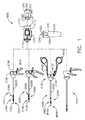
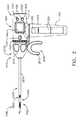
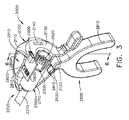
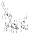
本開示は、外科用システムに関し、並びに、とりわけ、様々な構成において、患者の組織を把持するように設計された把持器具、患者の組織を操作するように構成された切開器具、患者の組織をクリップ留めするように構成されたクリップアプライヤ、及び患者の組織を縫合するように構成された縫合器具に関する。 The present disclosure relates to surgical systems and, among other things, in various configurations, gripping instruments designed to grip patient tissue, incision instruments configured to manipulate patient tissue, patient tissue. It relates to a clip applier configured to clip and a suturing device configured to suture the patient's tissue.
本明細書に記載する実施形態の様々な特徴は、それらの利点と共に、以下の添付図面と併せて以下の説明によって理解することができる。
複数の図面をとおして、対応する参照符号は対応する部分を示す。本明細書に記載される例示は、本発明の様々な実施形態を1つの形態で例示するものであり、このような例示は、いかようにも本発明の範囲を限定するものとして解釈されるべきではない。 Throughout the drawings, the corresponding reference numerals indicate the corresponding parts. The illustrations described herein illustrate various embodiments of the invention in one form, and such illustrations are construed as limiting the scope of the invention in any way. Should not be.
本願の出願人は、2018年8月24日に出願された以下の米国特許出願を所有しており、これらはそれぞれの全内容が参照により本明細書に組み込まれる。
−米国特許出願第16/112,129号、発明の名称「SURGICAL SUTURING INSTRUMENT CONFIGURED TO MANIPULATE TISSUE USING MECHANICAL AND ELECTRICAL POWER」、
−米国特許出願第16/112,155号、発明の名称「SURGICAL SUTURING INSTRUMENT COMPRISING A CAPTURE WIDTH WHICH IS LARGER THAN TROCAR DIAMETER」、
−米国特許出願第16/112,168号、発明の名称「SURGICAL SUTURING INSTRUMENT COMPRISING A NON−CIRCULAR NEEDLE」、
−米国特許出願第16/112,180号、発明の名称「ELECTRICAL POWER OUTPUT CONTROL BASED ON MECHANICAL FORCES」、
−米国特許出願第16/112,193号、発明の名称「REACTIVE ALGORITHM FOR SURGICAL SYSTEM」、
−米国特許出願第16/112,099号、発明の名称「SURGICAL INSTRUMENT COMPRISING AN ADAPTIVE ELECTRICAL SYSTEM」、
−米国特許出願第16/112,119号、発明の名称「ADAPTIVE CONTROL PROGRAMS FOR A SURGICAL SYSTEM COMPRISING MORE THAN ONE TYPE OF CARTRIDGE」、
−米国特許出願第16/112,097号、発明の名称「SURGICAL INSTRUMENT SYSTEMS COMPRISING BATTERY ARRANGEMENTS」、
−米国特許出願第16/112,109号、発明の名称「SURGICAL INSTRUMENT SYSTEMS COMPRISING HANDLE ARRANGEMENTS」、
−米国特許出願第16/112,114号、発明の名称「SURGICAL INSTRUMENT SYSTEMS COMPRISING FEEDBACK MECHANISMS」、
−米国特許出願第16/112,117号、発明の名称「SURGICAL INSTRUMENT SYSTEMS COMPRISING LOCKOUT MECHANISMS」、
−米国特許出願第16/112,095号、発明の名称「SURGICAL INSTRUMENTS COMPRISING A LOCKABLE END EFFECTOR SOCKET」、
−米国特許出願第16/112,121号、発明の名称「SURGICAL INSTRUMENTS COMPRISING A SHIFTING MECHANISM」、
−米国特許出願第16/112,151号、発明の名称「SURGICAL INSTRUMENTS COMPRISING A SYSTEM FOR ARTICULATION AND ROTATION COMPENSATION」、
−米国特許出願第16/112,154号、発明の名称「SURGICAL INSTRUMENTS COMPRISING A BIASED SHIFTING MECHANISM」、
−米国特許出願第16/112,226号、発明の名称「SURGICAL INSTRUMENTS COMPRISING AN ARTICULATION DRIVE THAT PROVIDES FOR HIGH ARTICULATION ANGLES」、
−米国特許出願第16/112,062号、発明の名称「SURGICAL DISSECTORS AND MANUFACTURING TECHNIQUES」、
−米国特許出願第16/112,098号、発明の名称「SURGICAL DISSECTORS CONFIGURED TO APPLY MECHANICAL AND ELECTRICAL ENERGY」、
−米国特許出願第16/112,237号、発明の名称「SURGICAL CLIP APPLIER CONFIGURED TO STORE CLIPS IN A STORED STATE」、
−米国特許出願第16/112,245号、発明の名称「SURGICAL CLIP APPLIER COMPRISING AN EMPTY CLIP CARTRIDGE LOCKOUT」、
−米国特許出願第16/112,249号、発明の名称「SURGICAL CLIP APPLIER COMPRISING AN AUTOMATIC CLIP FEEDING SYSTEM」、
−米国特許出願第16/112,253号、発明の名称「SURGICAL CLIP APPLIER COMPRISING ADAPTIVE FIRING CONTROL」、及び
−米国特許出願第16/112,257号、発明の名称「SURGICAL CLIP APPLIER COMPRISING ADAPTIVE CONTROL IN RESPONSE TO A STRAIN GAUGE CIRCUIT」。The applicant of the present application owns the following US patent applications filed on August 24, 2018, the entire contents of which are incorporated herein by reference.
-US Patent Application No. 16 / 112,129, Title of Invention "SURGICAL SUTURING INSTRUMENT CONFIGURED TO MANIPULATE TISSUE USING MECHANICAL AND ELECTRIC POWER",
-US Patent Application No. 16 / 112,155, Title of Invention "SURGICAL SUTURING INSTRUMENT COMPRISING A CAPTURE WIDTH WHICH IS LARGER THAN TROCAR DIAMETER",
-US Patent Application No. 16 / 112,168, Title of Invention "SURGICAL SUTURING INSTRUMENT COMPRISING ANON-CIRCULAR NEEDLE",
-US Patent Application No. 16 / 112,180, Invention Title "ELECTRIC POWER OUTPUT CONTROL BASED ON MECHANICAL FORCES",
-US Patent Application No. 16 / 112,193, Invention Title "REACIVE ALGORITHM FOR SURGICAL SYSTEM",
-US Patent Application No. 16 / 112,099, Title of Invention "SURGICAL INSTRUMENT COMPRISING AN ADAPTIVE ELECTRICAL SYSTEM",
-US Patent Application No. 16 / 112,119, Title of Invention "ADAPTIVE CONTOROL PROGRAMS FOR A SURGICAL SYSTEM COMPRISING MORE THAN ONE TYPE OF CARTRIGE",
-US Patent Application No. 16 / 112,097, Title of Invention "SURGICAL INSTRUMENT SYSTEMS COMPRISING BATTERY ARRANGEMENTS",
-US Patent Application No. 16 / 112,109, Title of Invention "SURGICAL INSTRUMENT SYSTEMS COMPRISING HANDLE ARRANGEMENTS",
-US Patent Application No. 16 / 112,114, Invention Title "SURGICAL INSTRUMENT SYSTEMS COMPRISING FEEDBACK MECHANIMSS",
-US Patent Application No. 16 / 112,117, Title of Invention "SURGICAL INSTRUMENT SYSTEMS COMPRISING LOCKOUT MECHANIMSS",
-US Patent Application No. 16 / 112,095, Title of Invention "SURGICAL INSTRUMENTS COMPRISING A LOCKABLE END EFFECTOR SOCKET",
-US Patent Application No. 16 / 112,121, Title of Invention "SURGICAL INSTRUMENTS COMPRISING A SHIFTING MECHANISM",
-US Patent Application No. 16 / 112,151, Title of Invention "SURGICAL INSTRUMENTS COMPRISING A SYSTEM FOR ARTICULATION AND ROTATION COMPENSATION",
-US Patent Application No. 16 / 112,154, Title of Invention "SURGICAL INSTRUMENTS COMPRISING A BIASED SHIFTING MEMHANISM",
-US Patent Application No. 16 / 112,226, Title of Invention "SURGICAL INSTRUMENTS COMPRISING AN ARTICULATION DRIVE THAT PROVIDES FOR HIGH ARTICULATION ANGLES",
-US Patent Application No. 16 / 112,062, Invention Title "SURGICAL DISSECTORS AND MANUFACTURING TECHNIQUES",
-US Patent Application No. 16 / 112,098, Title of Invention "SURGICAL DISSECTORS CONFIGURED TO APPLY MECHANICAL AND ELECTRICAL ENERGY",
-US Patent Application No. 16 / 112,237, Title of Invention "SURGICAL CLIP APPLIER CONFIGURED TO STORE CLIPS IN A STORED STATE",
-US Patent Application No. 16 / 112,245, Title of Invention "SURGICAL CLIP APPRIER COMPRISING AN EMPTY CLIP CARTRIDGE LOCKOUT",
-US Patent Application No. 16 / 112,249, Title of Invention "SURGICAL CLIP APPRIER COMPRISING AN AUTOMATIC CLIP FEEDING SYSTEM",
-U.S. Patent Application No. 16 / 112,253, title of invention "SURGICAL CLIPPLEER COMPRISING ADAPTIVE FIRING CONTROLL", and-U.S. Patent Application No. 16 / 112,257, title of invention "SURGICAL CLIPPLENER COMPRIER COMPLIESING COMPRIS TO A STRAIN GAUGE CIRCUIT ".
本願の出願人は、2018年5月1日に出願された以下の米国特許出願を所有しており、これらはそれぞれの全内容が参照により本明細書に組み込まれる。
−米国特許出願第62/665,129号、発明の名称「SURGICAL SUTURING SYSTEMS」、
−米国仮特許出願第62/665,139号、発明の名称「SURGICAL INSTRUMENTS COMPRISING CONTROL SYSTEMS」、
−米国特許出願第62/665,177号、発明の名称「SURGICAL INSTRUMENTS COMPRISING HANDLE ARRANGEMENTS」、
−米国特許出願第62/665,128号、発明の名称「MODULAR SURGICAL INSTRUMENTS」、
−米国特許出願第62/665,192号、発明の名称「SURGICAL DISSECTORS」、及び
−米国特許出願第62/665,134号、発明の名称「SURGICAL CLIP APPLIER」。The applicant of the present application owns the following US patent applications filed on May 1, 2018, the entire contents of which are incorporated herein by reference.
-US Patent Application No. 62 / 665,129, Invention Title "SURGICAL SUTURING SYSTEMS",
-US Provisional Patent Application No. 62 / 665,139, Title of Invention "SURGICAL INSTRUMENTS COMPRISING CONTROLL SYSTEMS",
-US Patent Application No. 62 / 665,177, Invention Title "SURGICAL INSTRUMENTS COMPRISING HANDLE ARRANGEMENTS",
-US Patent Application No. 62 / 665,128, Invention Title "MODULAR SURGICAL INSTRUMENTS",
-US Patent Application No. 62 / 665,192, title of invention "SURGICAL DISSECTORS",-US Patent Application No. 62 / 665,134, title of invention "SURGICAL CLIP APPRIER".
本願の出願人は、2018年2月28日に出願された以下の米国特許出願を所有しており、これらはそれぞれの全内容が参照により本明細書に組み込まれる。
−米国特許出願第15/908,021号、発明の名称「SURGICAL INSTRUMENT WITH REMOTE RELEASE」、
−米国特許出願第15/908,012号、発明の名称「SURGICAL INSTRUMENT HAVING DUAL ROTATABLE MEMBERS TO EFFECT DIFFERENT TYPES OF END EFFECTOR MOVEMENT」、
−米国特許出願第15/908,040号、発明の名称「SURGICAL INSTRUMENT WITH ROTARY DRIVE SELECTIVELY ACTUATING MULTIPLE END EFFECTOR FUNCTIONS」、
−米国特許出願第15/908,057号、発明の名称「SURGICAL INSTRUMENT WITH ROTARY DRIVE SELECTIVELY ACTUATING MULTIPLE END EFFECTOR FUNCTIONS」、
−米国特許出願第15/908,058号、発明の名称「SURGICAL INSTRUMENT WITH MODULAR POWER SOURCES」、及び
−米国特許出願第15/908,143号、発明の名称「SURGICAL INSTRUMENT WITH SENSOR AND/OR CONTROL SYSTEMS」。The applicant of the present application owns the following US patent applications filed on February 28, 2018, the entire contents of which are incorporated herein by reference.
-US Patent Application No. 15 / 908,021, Title of Invention "SURGICAL INSTRUMENT WITH REMOTE RELEASE",
-US Patent Application No. 15 / 908,012, Title of Invention "SURGICAL INSTRUMENT HAVING DUAL ROTATABLE MEMBERS TO EFFECT DIFFERENT TYPES OF END EFFECTOR MOVEMENT",
-US Patent Application No. 15 / 908,040, Title of Invention "SURGICAL INSTRUMENT WITH ROTARY DRIVE SELECTIVELY ACTION MULTIPLE END EFFECTOR FUNCTIONS",
-US Patent Application No. 15 / 908,057, title of invention "SURGICAL INSTRUMENT WITH ROTARY DRIVE SELECTIVELY ACTION MULTIPLE END EFFECTOR FUNCTIONS",
-US Patent Application No. 15 / 908,058, title of invention "SURGICAL INSTRUMENT WITH MODER POWER SOURCES", and-US Patent Application No. 15 / 908,143, title of invention "SURGICAL INSTRUMENT WITH SENSOR AND / ".
本願の出願人は、2017年10月30日に出願された以下の米国特許出願を所有しており、これらはそれぞれの全内容が参照により本明細書に組み込まれる。
−米国仮特許出願第62/578,793号、発明の名称「SURGICAL INSTRUMENT WITH REMOTE RELEASE」、
−米国仮特許出願第62/578,804号、発明の名称「SURGICAL INSTRUMENT HAVING DUAL ROTATABLE MEMBERS TO EFFECT DIFFERENT TYPES OF END EFFECTOR MOVEMENT」、
−米国仮特許出願第62/578,817号、発明の名称「SURGICAL INSTRUMENT WITH ROTARY DRIVE SELECTIVELY ACTUATING MULTIPLE END EFFECTOR FUNCTIONS」、
−米国仮特許出願第62/578,835号、発明の名称「SURGICAL INSTRUMENT WITH ROTARY DRIVE SELECTIVELY ACTUATING MULTIPLE END EFFECTOR FUNCTIONS」、
−米国仮特許出願第62/578,844号、発明の名称「SURGICAL INSTRUMENT WITH MODULAR POWER SOURCES」、及び
−米国仮特許出願第62/578,855号、発明の名称「SURGICAL INSTRUMENT WITH SENSOR AND/OR CONTROL SYSTEMS」。The applicant of the present application owns the following US patent applications filed on October 30, 2017, the entire contents of which are incorporated herein by reference.
-US Provisional Patent Application No. 62 / 578,793, Title of Invention "SURGICAL INSTRUMENT WITH REMOTE RELEASE",
-US Provisional Patent Application No. 62 / 578,804, Title of Invention "SURGICAL INSTRUMENT HAVING DUAL ROTATABLE MEMBERS TO EFFECT DIFFERENT TYPES OF END EFFECTOR MOVEMENT",
-US Provisional Patent Application No. 62 / 578,817, Title of Invention "SURGICAL INSTRUMENT WITH ROTARY DRIVE SELECTIVELY ACTION MULTIPLE END EFFECTOR FUNCTIONS",
-US Provisional Patent Application No. 62 / 578,835, Title of Invention "SURGICAL INSTRUMENT WITH ROTARY DRIVE SELECTIVELY ACTION MULTIPLE END EFFETOR FUNCTIONS",
-US provisional patent application No. 62 / 578,844, title of invention "SURGICAL INSTRUMENT WITH MODER POWER SOURCES", and-US provisional patent application No. 62 / 578,855, title of invention "SURGICAL INSTRUMENT WITH SENSOR AND "CONTOROL SYSTEMS".
本願の出願人は、各開示の全体が参照により本明細書に組み込まれる、2017年12月28日出願の以下の米国仮特許出願を所有する。
−米国仮特許出願第62/611,341号、発明の名称「INTERACTIVE SURGICAL PLATFORM」、
−米国仮特許出願第62/611,340号、発明の名称「CLOUD−BASED MEDICAL ANALYTICS」、及び
−米国仮特許出願第62/611,339号、発明の名称「ROBOT ASSISTED SURGICAL PLATFORM」。The applicant of the present application owns the following US provisional patent application filed December 28, 2017, of which the entire disclosure is incorporated herein by reference.
-US Provisional Patent Application No. 62 / 611,341, Invention Name "INTERACTIVE SURGICAL PLATFORM",
-US Provisional Patent Application No. 62 / 611,340, title of invention "CLOUD-BASED MEDICAL ANALYTICS",-US Provisional Patent Application No. 62 / 611,339, title of invention "ROBOT ASSISTED SURGICAL PLATFORM".
本願の出願人は、その全体が各々参照により本明細書に組み込まれる、2018年3月28日出願の以下の米国仮特許出願を所有する。
−米国仮特許出願第62/649,302号、発明の名称「INTERACTIVE SURGICAL SYSTEMS WITH ENCRYPTED COMMUNICATION CAPABILITIES」、
−米国仮特許出願第62/649,294号、発明の名称「DATA STRIPPING METHOD TO INTERROGATE PATIENT RECORDS AND CREATE ANONYMIZED RECORD」、
−米国仮特許出願第62/649,300号、発明の名称「SURGICAL HUB SITUATIONAL AWARENESS」、
−米国仮特許出願第62/649,309号、発明の名称「SURGICAL HUB SPATIAL AWARENESS TO DETERMINE DEVICES IN OPERATING THEATER」、
−米国仮特許出願第62/649,310号、発明の名称「COMPUTER IMPLEMENTED INTERACTIVE SURGICAL SYSTEMS」、
−米国仮特許出願第62/649,291号、発明の名称「USE OF LASER LIGHT AND RED−GREEN−BLUE COLORATION TO DETERMINE PROPERTIES OF BACK SCATTERED LIGHT」、
−米国仮特許出願第62/649,296号、発明の名称「ADAPTIVE CONTROL PROGRAM UPDATES FOR SURGICAL DEVICES」、
−米国仮特許出願第62/649,333号、発明の名称「CLOUD−BASED MEDICAL ANALYTICS FOR CUSTOMIZATION AND RECOMMENDATIONS TO A USER」、
−米国仮特許出願第62/649,327号、発明の名称「CLOUD−BASED MEDICAL ANALYTICS FOR SECURITY AND AUTHENTICATION TRENDS AND REACTIVE MEASURES」、
−米国仮特許出願第62/649,315号、発明の名称「DATA HANDLING AND PRIORITIZATION IN A CLOUD ANALYTICS NETWORK」、
−米国仮特許出願第62/649,313号、発明の名称「CLOUD INTERFACE FOR COUPLED SURGICAL DEVICES」、
−米国仮特許出願第62/649,320号、発明の名称「DRIVE ARRANGEMENTS FOR ROBOT−ASSISTED SURGICAL PLATFORMS」、
−米国仮特許出願第62/649,307号、発明の名称「AUTOMATIC TOOL ADJUSTMENTS FOR ROBOT−ASSISTED SURGICAL PLATFORMS」、及び
−米国仮特許出願第62/649,323号、発明の名称「SENSING ARRANGEMENTS FOR ROBOT−ASSISTED SURGICAL PLATFORMS」。The applicant of the present application owns the following US provisional patent application filed on March 28, 2018, which is incorporated herein by reference in its entirety.
-US Provisional Patent Application No. 62 / 649,302, Title of Invention "INTERACTIVE SURGICAL SYSTEMS WITH ENGRYPTED COMMUNICATION CAPABILITIES",
-US Provisional Patent Application No. 62 / 649,294, Title of Invention "DATA STRIPPING METHOD TO INTERROGATE PATION RECORDS AND CREATE ANONYMIZED RECORD",
-US Provisional Patent Application No. 62 / 649,300, Title of Invention "SURGICAL HUB Situational AWARENESS",
-US Provisional Patent Application No. 62 / 649,309, Title of Invention "SURGICAL HUB SPARC AWARENESS TO DETERMINE DEVICES IN OPERATING THEATER",
-US Provisional Patent Application No. 62 / 649,310, Title of Invention "COMPUTER IMPLEMENTED INTERACTIVE SURGICAL SYSTEMS",
-US Provisional Patent Application No. 62 / 649,291, Title of Invention "USE OF LASER LIGHT AND RED-GREEN-BLUE COLORATION TO DETERMINE PROPERTIES OF BACK SCATTERED LIGHT",
-US Provisional Patent Application No. 62 / 649,296, Title of Invention "ADAPTIVE CONTROL PROGRAM UPDATES FOR SURGICAL DEVICES",
-US Provisional Patent Application No. 62 / 649,333, Title of Invention "CLOUD-BASED MEDICAL ANALYTICS FOR CUSTOMIZETION AND RECOMMENDATIONS TO A USER",
-US Provisional Patent Application No. 62 / 649,327, Title of Invention "CLOUD-BASED MEDICAL ANALYTICS FOR SECURITY AND AUTHENTICATION TRENDS AND REACTIVE MEASURES",
-US Provisional Patent Application No. 62 / 649,315, Title of Invention "DATA HANDLING AND PRIORIZATION IN A CLOUD ANALYTICS NETWORK",
-US Provisional Patent Application No. 62 / 649,313, Title of Invention "CLOUD INTERFACE FOR COUPLED SURGICAL DEVICES",
-US Provisional Patent Application No. 62 / 649,320, Title of Invention "DRIVE ARRANGEMENTS FOR ROBOT-ASSISTED SURGICAL PLATFORMS",
-US provisional patent application No. 62 / 649,307, title of invention "AUTOMATIC TOOL ADJUSTMENTS FOR ROBOT-ASSISTED SURGICAL PLATFORMS", and-US provisional patent application No. 62 / 649,323, title of invention "SENSING ARRANGEM -ASSISTED SURGICAL PLATFORMS ".
本願の出願人は、その全体が各々参照により本明細書に組み込まれる、2018年3月29日出願の以下の米国特許出願を所有する。
−米国特許出願第15/940,641号、発明の名称「INTERACTIVE SURGICAL SYSTEMS WITH ENCRYPTED COMMUNICATION CAPABILITIES」、
−米国特許出願第15/940,648号、発明の名称「INTERACTIVE SURGICAL SYSTEMS WITH CONDITION HANDLING OF DEVICES AND DATA CAPABILITIES」、
−米国特許出願第15/940,656号、発明の名称「SURGICAL HUB COORDINATION OF CONTROL AND COMMUNICATION OF OPERATING ROOM DEVICES」、
−米国特許出願第15/940,666号、発明の名称「SPATIAL AWARENESS OF SURGICAL HUBS IN OPERATING ROOMS」、
−米国特許出願第15/940,670号、発明の名称「COOPERATIVE UTILIZATION OF DATA DERIVED FROM SECONDARY SOURCES BY INTELLIGENT SURGICAL HUBS」、
−米国特許出願第15/940,677号、発明の名称「SURGICAL HUB CONTROL ARRANGEMENTS」、
−米国特許出願第15/940,632号、発明の名称「DATA STRIPPING METHOD TO INTERROGATE PATIENT RECORDS AND CREATE ANONYMIZED RECORD」、
−米国特許出願第15/940,640号、発明の名称「COMMUNICATION HUB AND STORAGE DEVICE FOR STORING PARAMETERS AND STATUS OF A SURGICAL DEVICE TO BE SHARED WITH CLOUD BASED ANALYTICS SYSTEMS」、
−米国特許出願第15/940,645号、発明の名称「SELF DESCRIBING DATA PACKETS GENERATED AT AN ISSUING INSTRUMENT」、
−米国特許出願第15/940,649号、発明の名称「DATA PAIRING TO INTERCONNECT A DEVICE MEASURED PARAMETER WITH AN OUTCOME」、
−米国特許出願第15/940,654号、発明の名称「SURGICAL HUB SITUATIONAL AWARENESS」、
−米国特許出願第15/940,663号、発明の名称「SURGICAL SYSTEM DISTRIBUTED PROCESSING」、
−米国特許出願第15/940,668号、発明の名称「AGGREGATION AND REPORTING OF SURGICAL HUB DATA」、
−米国特許出願第15/940,671号、発明の名称「SURGICAL HUB SPATIAL AWARENESS TO DETERMINE DEVICES IN OPERATING THEATER」、
−米国特許出願第15/940,686号、発明の名称「DISPLAY OF ALIGNMENT OF STAPLE CARTRIDGE TO PRIOR LINEAR STAPLE LINE」、
−米国特許出願第15/940,700号、発明の名称「STERILE FIELD INTERACTIVE CONTROL DISPLAYS」、
−米国特許出願第15/940,629号、発明の名称「COMPUTER IMPLEMENTED INTERACTIVE SURGICAL SYSTEMS」、
−米国特許出願第15/940,704号、発明の名称「USE OF LASER LIGHT AND RED−GREEN−BLUE COLORATION TO DETERMINE PROPERTIES OF BACK SCATTERED LIGHT」、
−米国特許出願第15/940,722号、発明の名称「CHARACTERIZATION OF TISSUE IRREGULARITIES THROUGH THE USE OF MONO−CHROMATIC LIGHT REFRACTIVITY」、及び
−米国特許出願第15/940,742号、発明の名称「DUAL CMOS ARRAY IMAGING」。The applicant of the present application owns the following US patent application filed March 29, 2018, which is incorporated herein by reference in its entirety.
-US Patent Application No. 15 / 940,641, Title of Invention "INTERACTIVE SURGICAL SYSTEMS WITH ENGRYPTED COMMUNICATION CAPABILITIES",
-US Patent Application No. 15 / 940,648, Title of Invention "INTERACTIVE SURGICAL SYSTEMS WITH CONDITION HANDLING OF DEVICES AND DATA CAPABILITIES",
-US Patent Application No. 15 / 940,656, Title of Invention "SURGICAL HUB COORDINATION OF CONTROL AND COMMUNICATION OF OPERATION ROOM DEVICES",
-US Patent Application No. 15 / 940,666, Title of Invention "SPATIAL AWARENSS OF SURGICAL HUBS IN OPERATING ROOMS",
-US Patent Application No. 15 / 940,670, Title of Invention "COOPERATION UTILIZATION OF DATA DELIVED FROM SECONDARY SOURCES BY INTELLIGENT SURGICAL HUBS",
-US Patent Application No. 15 / 940,677, Title of Invention "SURGICAL HUB CONTROLL ARRANGEMENTS",
-US Patent Application No. 15 / 940,632, title of invention "DATA STRIPPING METHOD TO INTERROGATE PATIENT RECORDS AND CREATE ANONYMIZED RECORD",
-US Patent Application No. 15 / 940,640, title of invention "COMMUNICATION HUB AND STORAGE DEVICE FOR STORING PARAMETERS AND STARTUS OF A SURGICAL DEVICE TO BE SHARED WITH CLOUD BA"
-US Patent Application No. 15 / 940,645, Title of Invention "SELF DESCRIBING DATA PACKETS GENELATED AT AN ISSUING INSTRUMENT",
-US Patent Application No. 15 / 940,649, Title of Invention "DATA PAIRING TO INTERCONNECT A DEVICE MEASURED PARAMETER WITH AN OUTCOME",
-US Patent Application No. 15 / 940,654, Invention Title "SURGICAL HUB Situational AWARENESS",
-US Patent Application No. 15 / 940,663, Invention Title "SURGICAL SYSTEM DISTRIBUTED PROCESSING",
-US Patent Application No. 15 / 940,668, Invention Title "AGGREGATION AND REPORTING OF SURGICAL HUB DATA",
-US Patent Application No. 15 / 940,671, Title of Invention "SURGICAL HUB SPARC AWARENESS TO DETERMINE DEVICES IN OPERATING THEATER",
-US Patent Application No. 15 / 940,686, Title of Invention "DISPLAY OF ALIGNMENT OF STAPLE CARTRIDGE TO PRIOR LINEAR STAPLE LINE",
-US Patent Application No. 15 / 940,700, Invention Title "STERILE FIELD INTERACTIVE CONTROLL DISPLAYS",
-US Patent Application No. 15 / 940,629, Invention Title "COMPUTER IMPLEMENTED INTERACTIVE SURGICAL SYSTEMS",
-US Patent Application No. 15 / 940,704, Title of Invention "USE OF LASER LIGHT AND RED-GREEN-BLUE COLORATION TO DETERMINE PROPERTIES OF BACK SCATTERED LIGHT",
-US Patent Application No. 15 / 940,722, title of invention "CHARACTERIZATION OF TISSUE IRREGULARITIES THROUGH THE USE OF MONO-CHROMATIC LIGHT REFRACTIVITY", and-US Patent Application No. 15/940, 74D ARRAY IMAGING ".
本願の出願人は、その全体が各々参照により本明細書に組み込まれる、2018年3月29日出願の以下の米国特許出願を所有する。
−米国特許出願第15/940,636号、発明の名称「ADAPTIVE CONTROL PROGRAM UPDATES FOR SURGICAL DEVICES」、
−米国特許出願第15/940,653号、発明の名称「ADAPTIVE CONTROL PROGRAM UPDATES FOR SURGICAL HUBS」、
−米国特許出願第15/940,660号、発明の名称「CLOUD−BASED MEDICAL ANALYTICS FOR CUSTOMIZATION AND RECOMMENDATIONS TO A USER」、
−米国特許出願第15/940,679号、発明の名称「CLOUD−BASED MEDICAL ANALYTICS FOR LINKING OF LOCAL USAGE TRENDS WITH THE RESOURCE ACQUISITION BEHAVIORS OF LARGER DATA SET」、
−米国特許出願第15/940,694号、発明の名称「CLOUD−BASED MEDICAL ANALYTICS FOR MEDICAL FACILITY SEGMENTED INDIVIDUALIZATION OF INSTRUMENT FUNCTION」、
−米国特許出願第15/940,634号、発明の名称「CLOUD−BASED MEDICAL ANALYTICS FOR SECURITY AND AUTHENTICATION TRENDS AND REACTIVE MEASURES」、
−米国特許出願第15/940,706号、発明の名称「DATA HANDLING AND PRIORITIZATION IN A CLOUD ANALYTICS NETWORK」、及び
−米国特許出願第15/940,675号、発明の名称「CLOUD INTERFACE FOR COUPLED SURGICAL DEVICES」。The applicant of the present application owns the following US patent application filed March 29, 2018, which is incorporated herein by reference in its entirety.
-US Patent Application No. 15 / 940,636, Title of Invention "ADAPTIVE CONTROL PROGRAM UPDATES FOR SURGICAL DEVICES",
-US Patent Application No. 15 / 940,653, Title of Invention "ADAPTIVE CONTROL PROGRAM UPDATES FOR SURGICAL HUBS",
-US Patent Application No. 15 / 940,660, Title of Invention "CLOUD-BASED MEDICAL ANALYTICS FOR CUSTOMIZETION AND RECOMMENDATIONS TO A USER",
-US Patent Application No. 15 / 940,679, title of invention "CLOUD-BASED MEDICAL ANALYTICS FOR LINKING OF LOCAL USAGE TRENDS WITH THE RESOURCE ACQUISITION BEHAVIORS OF LARGE"
-US Patent Application No. 15 / 940,694, Title of Invention "CLOUD-BASED MEDICAL ANALYTICS FOR MEDICAL FACILITY SEGMENTED INDIVIDUALIZATION OF INSTRUMENT FUNCTION",
-US Patent Application No. 15 / 940,634, Title of Invention "CLOUD-BASED MEDICAL ANALYTICS FOR SECURITY AND AUTHENTICATION TRENDS AND REACTIVE MEASURES",
-US Patent Application No. 15 / 940,706, Invention Name "DATA HANDLING AND PRIORIZATION IN A CLOUD ANALYTICS NETWORK", and-US Patent Application No. 15 / 940, 675, Invention Name "CLOUD INTERFACE FOR PRODUCT"".
本願の出願人は、その全体が各々参照により本明細書に組み込まれる、2018年3月29日出願の以下の米国特許出願を所有する。
−米国特許出願第15/940,627号、発明の名称「DRIVE ARRANGEMENTS FOR ROBOT−ASSISTED SURGICAL PLATFORMS」、
−米国特許出願第15/940,637号、発明の名称「COMMUNICATION ARRANGEMENTS FOR ROBOT−ASSISTED SURGICAL PLATFORMS」、
−米国特許出願第15/940,642号、発明の名称「CONTROLS FOR ROBOT−ASSISTED SURGICAL PLATFORMS」、
−米国特許出願第15/940,676号、発明の名称「AUTOMATIC TOOL ADJUSTMENTS FOR ROBOT−ASSISTED SURGICAL PLATFORMS」、
−米国特許出願第15/940,680号、発明の名称「CONTROLLERS FOR ROBOT−ASSISTED SURGICAL PLATFORMS」、
−米国特許出願第15/940,683号、発明の名称「COOPERATIVE SURGICAL ACTIONS FOR ROBOT−ASSISTED SURGICAL PLATFORMS」、
−米国特許出願第15/940,690号、発明の名称「DISPLAY ARRANGEMENTS FOR ROBOT−ASSISTED SURGICAL PLATFORMS」、及び
−米国特許出願第15/940,711号、発明の名称「SENSING ARRANGEMENTS FOR ROBOT−ASSISTED SURGICAL PLATFORMS」。The applicant of the present application owns the following US patent application filed March 29, 2018, which is incorporated herein by reference in its entirety.
-US Patent Application No. 15 / 940,627, Title of Invention "DRIVE ARRANGEMENTS FOR ROBOT-ASSISTED SURGICAL PLATFORMS",
-US Patent Application No. 15 / 940,637, title of invention "COMMUNICATION ARRANGEMENTS FOR ROBOT-ASSISTED SURGICAL PLATFORMS",
-US Patent Application No. 15 / 940,642, Title of Invention "CONTROLS FOR ROBOT-ASSISTED SURGICAL PLATFORMS",
-US Patent Application No. 15 / 940,676, Title of Invention "AUTOMATIC TOOL ADJUSTMENTS FOR ROBOT-ASSISTED SURGICAL PLATFORMS",
-US Patent Application No. 15 / 940,680, Title of Invention "CONTROLLERS FOR ROBOT-ASSISTED SURGICAL PLATFORMS",
-US Patent Application No. 15 / 940,683, title of invention "COOPERATION SURGICAL ACTIONS FOR ROBOT-ASSISTED SURGICAL PLATFORMS",
-US Patent Application No. 15 / 940,690, Invention Name "DISPLAY ARRANGEMENTS FOR ROBOT-ASSISTED SURGICAL PLATFORMS",-US Patent Application No. 15 / 940,711, Invention Name "SENSING ARRANGEMENTS FOR ROBOT- PLATFORMS ".
本願の出願人は、その全体が各々参照により本明細書に組み込まれる、2018年3月30日出願の以下の米国仮特許出願を所有する。
−米国仮特許出願第62/650,887号、発明の名称「SURGICAL SYSTEMS WITH OPTIMIZED SENSING CAPABILITIES」、
−米国仮特許出願第62/650,877号、発明の名称「SURGICAL SMOKE EVACUATION SENSING AND CONTROLS」、
−米国仮特許出願第62/650,882号、発明の名称「SMOKE EVACUATION MODULE FOR INTERACTIVE SURGICAL PLATFORM」、及び
−米国仮特許出願第62/650,898号、発明の名称「CAPACITIVE COUPLED RETURN PATH PAD WITH SEPARABLE ARRAY ELEMENTS」。The applicant of the present application owns the following US provisional patent application filed on March 30, 2018, which is incorporated herein by reference in its entirety.
-US Provisional Patent Application No. 62 / 650,887, Title of Invention "SURGICAL SYSTEMS WITH OPTIMIZED SENSING CAPABILITIES",
-US Provisional Patent Application No. 62 / 650,877, Title of Invention "SURGICAL SMOKE EVACUATION SENSING AND CONTROLS",
-US provisional patent application No. 62 / 650,882, title of invention "SMOKE EVACUATION MODEL FOR INTERACTIVE SURGICAL PLATFORM", and-US provisional patent application No. 62 / 650,898, title of invention "CAPACTIVE COUPPAR" SEPARABLE ARRAY ELEMENTS ".
本願の出願人は、その全体が各々参照により本明細書に組み込まれる、2018年4月19日出願の以下の米国仮特許出願を所有する。
−米国仮特許出願第62/659,900号、発明の名称「METHOD OF HUB COMMUNICATION」。The applicant of the present application owns the following US provisional patent application filed on April 19, 2018, which is incorporated herein by reference in its entirety.
-US Provisional Patent Application No. 62 / 659,900, title of invention "METHOD OF HUB COMMUNICATION".
明細書に記載され、添付の図面に示されるように、実施形態の全体的な構造、機能、製造、及び使用の完全な理解を提供するために、多数の具体的な詳細が説明される。周知の動作、構成要素、及び要素は、本明細書に記載される実施形態を不明瞭にしないようにするため、詳細に記載されていない。読者は、本明細書に記載され図示された実施形態は、非限定的な例であり、したがって本明細書に開示された特定の構造的及び機能的詳細は、代表的及び例示的であり得ることを、理解するであろう。特許請求の範囲から逸脱することなく、それに対する変形及び変更を行うことができる。 A number of specific details are described to provide a complete understanding of the overall structure, function, manufacture, and use of embodiments, as described herein and shown in the accompanying drawings. Well-known behaviors, components, and elements are not described in detail to avoid obscuring the embodiments described herein. To the reader, the embodiments described and illustrated herein are non-limiting examples, and thus the particular structural and functional details disclosed herein may be representative and exemplary. You will understand that. Modifications and changes can be made to it without departing from the claims.
「備える(comprise)」(「comprises」及び「comprising」など、compriseの任意の語形)、「有する(have)」(「has」及び「having」など、haveの任意の語形)、「含む(include)」(「includes」及び「including」など、includeの任意の語形)、及び「含有する(contain)」(「contains」及び「containing」など、containの任意の語形)という用語は、オープンエンドの連結動詞である。結果として、1つ又は2つ以上の要素を「備える」、「有する」、「含む」、若しくは「含有する」外科用システム、デバイス、又は装置は、それらの1つ又は2つ以上の要素を有するが、それらの1つ又は2つ以上のみを有することに限定されない。同様に、1つ又は2つ以上の特徴を「備える」、「有する」、「含む」、若しくは「含有する」、システム、デバイス、又は装置の要素は、それら1つ又は2つ以上の特徴を有するが、それら1つ又は2つ以上の特徴のみを有することに限定されない。 "Comprise" (any word form of comprise, such as "comprises" and "comprising"), "have" (any word form of have, such as "has" and "having"), "include" ) ”(Any word form of include, such as“ includes ”and“ inclusion ”), and“ contain ”(any word form of content, such as“ context ”and“ connecting ”) are open-ended. It is a concatenated verb. As a result, a surgical system, device, or device that "equipped", "has", "contains", or "contains" one or more elements comprises one or more of them. Have, but are not limited to having only one or more of them. Similarly, an element of a system, device, or device that "includes", "has", "contains", or "contains" one or more features has one or more of these features. Have, but are not limited to having only one or more of them.
「近位」及び「遠位」という用語は、本明細書では、外科用器具のハンドル部分を操作する臨床医を基準として使用される。「近位」という用語は、臨床医に最も近い部分を指し、「遠位」という用語は、臨床医から離れた位置にある部分を指す。便宜上及び明確性のために、「垂直」、「水平」、「上」、及び「下」などの空間的用語が、本明細書において図面に対して使用され得ることが更に理解されよう。しかしながら、外科用器具は、多くの向き及び位置で使用されるものであり、これらの用語は限定的及び/又は絶対的であることを意図したものではない。 The terms "proximal" and "distal" are used herein with reference to the clinician operating the handle portion of the surgical instrument. The term "proximal" refers to the part closest to the clinician, and the term "distal" refers to the part located away from the clinician. It will be further appreciated that for convenience and clarity, spatial terms such as "vertical", "horizontal", "top", and "bottom" may be used for drawings herein. However, surgical instruments are used in many orientations and positions, and these terms are not intended to be limited and / or absolute.
腹腔鏡下及び低侵襲性の外科手術を行うための、様々な例示的なデバイス及び方法が提供される。しかしながら、本明細書に開示される様々な方法及びデバイスが、例えば開腹外科手術と関連するものを含む、多くの外科手術及び用途で使用され得ることが、読者には容易に理解されよう。本明細書の「発明を実施するための形態」を読み進めることで、読者は、本明細書に開示される様々な器具が、例えば、もとからある開口部を通じて、組織に形成された切開又は穿刺穴を通じてなど、任意の方法で体内に挿入され得ることを更に理解するであろう。これらの器具の作用部分すなわちエンドエフェクタ部分は、患者の体内に直接に挿入することもでき、又は、外科用器具のエンドエフェクタ及び細長いシャフトを進めることが可能な作用通路を有するアクセスデバイスを通じて挿入することもできる。 Various exemplary devices and methods are provided for performing laparoscopic and minimally invasive surgery. However, it will be readily appreciated by the reader that the various methods and devices disclosed herein can be used in many surgical procedures and applications, including those associated with, for example, open surgery. By reading "Forms for Carrying Out the Invention" herein, the reader will be able to make incisions in which the various instruments disclosed herein are formed into tissue, eg, through an original opening. Or you will further understand that it can be inserted into the body in any way, such as through a puncture hole. The working part or end effector part of these instruments can also be inserted directly into the patient's body, or through an access device with a passage of action capable of advancing the end effector and elongated shaft of the surgical instrument. You can also do it.
例えば、把持具などの外科用器具は、ハンドル、ハンドルから延在するシャフト、及びシャフトから延在するエンドエフェクタを備えることができる。様々な例において、エンドエフェクタは、第1のジョー及び第2のジョーを備え、ジョーの一方又は両方は、患者の組織を把持するように、他方に対して移動可能である。これにより、外科用器具のエンドエフェクタは、任意の好適な構成を備えることができ、任意の好適な機能を実行することができる。例えば、エンドエフェクタは、患者の組織を切開又は分離するように構成された第1及び第2のジョーを備えることができる。また、例えば、エンドエフェクタは、患者の組織を縫合及び/又はクリップ留めするように構成され得る。様々な例において、外科用器具のエンドエフェクタ及び/又はシャフトは、トロカール又はカニューレを通して患者に挿入されるように構成されており、例えば、およそ5mm、8mm、及び/又は12mmなどの任意の好適な直径を有することができる。米国特許出願第11/013,924号、発明の名称「TROCAR SEAL ASSEMBLY」、現在の米国特許第7,371,227号は、参照によりその全体が本明細書に組み込まれる。シャフトは、長手方向軸を画定することができ、エンドエフェクタの少なくとも一部分は、長手方向軸を中心に回転可能であり得る。更に、外科用器具は、エンドエフェクタの少なくとも一部分がシャフトに対して関節運動することを可能にし得る関節運動継手を更に備えることができる。使用中、臨床医は、エンドエフェクタを患者内で操作するためにエンドエフェクタを回転及び/又は関節運動させることができる。 For example, a surgical instrument such as a grip may include a handle, a shaft extending from the handle, and an end effector extending from the shaft. In various examples, the end effector comprises a first jaw and a second jaw, one or both of which are movable relative to the other so as to grip the patient's tissue. Thereby, the end effector of the surgical instrument can be provided with any suitable configuration and can perform any suitable function. For example, the end effector can include first and second jaws configured to incise or separate the patient's tissue. Also, for example, the end effector may be configured to suture and / or clip the patient's tissue. In various examples, the end effector and / or shaft of the surgical instrument is configured to be inserted into the patient through a trocar or cannula, and any suitable, such as approximately 5 mm, 8 mm, and / or 12 mm. Can have a diameter. U.S. Patent Application No. 11 / 013,924, the title of the invention "TROCAR SEAL ASSEMBLY", and current U.S. Pat. No. 7,371,227 are incorporated herein by reference in their entirety. The shaft can define a longitudinal axis and at least a portion of the end effector may be rotatable about the longitudinal axis. In addition, surgical instruments can further comprise articulated joints that can allow at least a portion of the end effector to articulate with respect to the shaft. During use, the clinician can rotate and / or jointly move the end effector to operate it within the patient.
外科用器具システムが、図1に描写されている。外科用器具システムは、ハンドルアセンブリ1000を備え、ハンドルアセンブリ1000は、シャフトアセンブリ2000、シャフトアセンブリ3000、シャフトアセンブリ4000、シャフトアセンブリ5000、及び/又は任意の他の好適なシャフトアセンブリと共に選択的に使用可能である。シャフトアセンブリ2000は、図2のハンドルアセンブリ1000に取り付けられ、シャフトアセンブリ4000は、図45のハンドルアセンブリ1000に取り付けられる。シャフトアセンブリ2000は、近位部分2100と、近位部分2100から延在する細長いシャフト2200と、遠位取り付け部分2400と、遠位取り付け部分2400を細長いシャフト2200に回転可能に接続する関節運動継手2300と、を備える。シャフトアセンブリ2000は、遠位取り付け部分2400に取り付けられた交換可能なエンドエフェクタアセンブリ7000を更に備える。交換可能なエンドエフェクタアセンブリ7000は、患者の組織をクランプ及び/又は操作するために開閉されるように構成されたジョーアセンブリ7100を備える。使用時には、以下で更に詳細に説明するように、エンドエフェクタアセンブリ7000は、関節運動継手2300を中心に関節運動することができ、かつ/又は長手方向軸を中心に遠位取り付け部分2400に対して回転されて、患者内のジョーアセンブリ7100をより良好に位置付けることができる。 The surgical instrument system is depicted in FIG. The surgical instrument system comprises a
再び図1を参照すると、ハンドルアセンブリ1000は、とりわけ、駆動モジュール1100を備える。以下でより詳細に説明するように、駆動モジュール1100は、臨床医がシャフトアセンブリ2000、3000、4000及び5000のうちの1つを例えば駆動モジュール1100に選択的に取り付けることを可能にする遠位装着インターフェースを備える。したがって、シャフトアセンブリ2000、3000、4000及び5000の各々は、駆動モジュール1100の遠位装着インターフェースと係合するように構成された同一の又は少なくとも同様の近位装着インターフェースを備える。以下でより詳細に説明するように、駆動モジュール1100の装着インターフェースは、選択されたシャフトアセンブリを駆動モジュール1100に機械的に固設及び電気的に結合する。駆動モジュール1100は、少なくとも1つの電動モータと、1つ若しくは2つ以上の制御部及び/又はディスプレイと、電気モータを動作させるように構成されたコントローラと、を更に備え、その回転出力は、駆動モジュール1100に取り付けられたシャフトアセンブリの駆動システムに伝達される。更に、駆動モジュール1100は、例えば、電源モジュール1200及び1300などの1つ又は2つ以上の電源モジュールと共に使用可能であり、これは、駆動モジュール1100に動作可能に取り付け可能であり、それに電力を供給する。 With reference to FIG. 1 again, the
上記に加えて、図1及び図2を再び参照すると、ハンドル駆動モジュール1100は、ハウジング1110と、第1のモジュールコネクタ1120と、第2のモジュールコネクタ1120’と、を備える。電源モジュール1200は、ハウジング1210と、コネクタ1220と、1つ又は2つ以上の解放ラッチ1250と、1つ又は2つ以上の電池1230と、を備える。コネクタ1220は、電源モジュール1200を駆動モジュール1100に取り付けるために、駆動モジュール1100の第1のモジュールコネクタ1120と係合するように構成されている。コネクタ1220は、電源モジュール1200のハウジング1210を駆動モジュール1100のハウジング1110に機械的に連結及び固定して固設する1つ又は2つ以上のラッチ1240を備える。ラッチ1240は、電源モジュール1200が駆動モジュール1100から取り外され得るように解放ラッチ1250が押下されると、係合解除位置へと移動可能である。コネクタ1220はまた、電池1230及び/又は電池1230を含む電気回路を駆動モジュール1100内の電気回路と電気通信するように配置する1つ又は2つ以上の電気接点を備える。 In addition to the above, with reference to FIGS. 1 and 2 again, the
上記に加えて、図1及び図2を再び参照すると、電源モジュール1300は、ハウジング1310と、コネクタ1320と、1つ又は2つ以上の解放ラッチ1350と、1つ又は2つ以上の電池1330と、を備える(図47)。コネクタ1320は、電源モジュール1300を駆動モジュール1100に取り付けるために、駆動モジュール1100の第2のモジュールコネクタ1120’と係合するように構成されている。コネクタ1320は、電源モジュール1300のハウジング1310を駆動モジュール1100のハウジング1110に機械的に連結及び固定して固設する1つ又は2つ以上のラッチ1340を備える。ラッチ1340は、電源モジュール1300が駆動モジュール1100から取り外され得るように解放ラッチ1350が押下されると、係合解除位置へと移動可能である。コネクタ1320はまた、電源モジュール1300の電池1330及び/又は電池1330を含む電力回路を駆動モジュール1100内の電力回路と電気通信するように配置する1つ又は2つ以上の電気接点を備える。 In addition to the above, with reference to FIGS. 1 and 2, the
上記に加えて、駆動モジュール1100に取り付けられたときの電源モジュール1200は、臨床医が駆動モジュール1100を臨床医の手の上に配置するようにハンドル1000を保持することを可能にし得るピストルグリップを備える。駆動モジュール1100に取り付けられたときの電源モジュール1300は、臨床医がハンドル1000をワンドのように保持することを可能にする端部グリップを備える。電源モジュール1200及び1300は任意の好適な長さを備えることができるが、電源モジュール1200は電源モジュール1300よりも長い。電源モジュール1200は、電源モジュール1300よりも多くの電池セルを有し、その長さにより、これらの追加の電池セルを好適に収容することができる。様々な例において、電源モジュール1200は、電源モジュール1300よりもより多くの電力を駆動モジュール1100に提供することができ、一方、いくつかの例では、電源モジュール1200は、より長い期間電力を提供することができる。いくつかの例では、駆動モジュール1100のハウジング1110は、キー、及び/又は任意の他の好適な機構を備え、これは、電源モジュール1200が第2のモジュールコネクタ1120’に接続されることを防止し、同様に、電源モジュール1300が第1のモジュールコネクタ1120に接続されることを防止する。このような構成は、より長い電源モジュール1200がピストルグリップ構成で使用され、より短い電源モジュール1300がワンドグリップ構成で使用されることを確実にすることができる。代替的な実施形態では、電源モジュール1200及び電源モジュール1300は、第1のモジュールコネクタ1120又は第2のモジュールコネクタ1120’のいずれかで駆動モジュール1100に選択的に連結され得る。このような実施形態は、ハンドル1000をそれらに好適な様式でカスタマイズするためのより多くの選択肢を臨床医に提供する。 In addition to the above, the
様々な例において、上記に加えて、電源モジュール1200及び1300のうちの1つのみが、一度に駆動モジュール1100に連結される。特定の例では、電源モジュール1200は、例えばシャフトアセンブリ4000が駆動モジュール1100に取り付けられたときに妨げとなり得る。代替的に、電源モジュール1200及び1300の両方は、同時に駆動モジュール1100に動作可能に連結され得る。このような例では、駆動モジュール1100は、電源モジュール1200及び1300の両方によって提供される電力へのアクセスを有することができる。更に、臨床医は、電源モジュール1200及び1300の両方が駆動モジュール1100に取り付けられたときに、ピストルグリップとワンドグリップとの間で切り替えることができる。更に、このような構成により、電源モジュール1300は、例えば、駆動モジュール1100に取り付けられたシャフトアセンブリ2000、3000、4000、又は5000などのシャフトアセンブリへの釣り合いとして機能することができる。 In various examples, in addition to the above, only one of the
図7及び図8を参照すると、ハンドル駆動モジュール1100は、フレーム1500と、モータアセンブリ1600と、モータアセンブリ1600と動作可能に係合された駆動システム1700と、制御システム1800と、を更に備える。フレーム1500は、モータアセンブリ1600を通って延在する細長いシャフトを備える。細長いシャフトは、遠位端1510と、遠位端1510に画定された電気接点又はソケット1520と、を備える。電気接点1520は、1つ又は2つ以上の電気回路を介して駆動モジュール1100の制御システム1800と電気通信し、制御システム1800と、例えば、駆動モジュール1100に取り付けられたシャフトアセンブリ2000、3000、4000又は5000などのシャフトアセンブリとの間で信号及び/又は電力を伝達するように構成されている。制御システム1800は、プリント回路基板(printed circuit board、PCB)1810、少なくとも1つのマイクロプロセッサ1820、及び少なくとも1つのメモリデバイス1830を備える。基板1810は、剛性及び/又は可撓性であり得、任意の好適な数の層を備えることができる。マイクロプロセッサ1820及びメモリデバイス1830は、以下でより詳細に説明するように、モータアセンブリ1600の動作を制御する基板1810上に画定された制御回路の一部である。 With reference to FIGS. 7 and 8, the
図12及び13を参照すると、モータアセンブリ1600は、ハウジング1620と、駆動シャフト1630と、歯車減速システムと、を含む電気モータ1610を備える。電気モータ1610は、巻線1640を含む固定子と、磁気素子1650を含む回転子と、を更に備える。固定子巻線1640はハウジング1620内に支持され、回転子磁気素子1650は駆動シャフト1630に装着される。固定子巻線1640が制御システム1800によって制御された電流で通電されると、駆動シャフト1630は長手方向軸を中心に回転する。駆動シャフト1630は、中央太陽歯車と、太陽歯車に動作可能に噛み合ったいくつかの遊星歯車と、を含む第1の遊星歯車システム1660と動作可能に噛み合っている。第1の遊星歯車システム1660の太陽歯車は、駆動シャフト1630と共に回転するように駆動シャフト1630に固定的に装着される。第1の遊星歯車システム1660の遊星歯車は、第2の遊星歯車システム1670の太陽歯車に回転可能に装着され、また、モータハウジング1620の歯車付き又はスプライン付き内側表面1625と噛み合っている。上記の結果、第1の太陽歯車の回転は、第2の太陽歯車を回転させる第1の遊星歯車を回転させる。上記と同様に、第2の遊星歯車システム1670は、遊星歯車1665(図13)を更に備え、遊星歯車1665は、第3の遊星歯車システム、最終的には駆動シャフト1710を駆動する。遊星歯車システム1660、1670及び1680は、モータシャフト1620によって駆動シャフト1710に適用される速度を減速させるように協働する。減速システムを伴わずに、様々な代替的な実施形態が想定される。このような実施形態は、エンドエフェクタ機能を迅速に駆動することが望ましい場合に好適である。特に、駆動シャフト1630は、それを貫通して延在する開口部又は中空コアを備え、それを通してワイヤ及び/又は電気回路が延在することができる。 With reference to FIGS. 12 and 13,
制御システム1800は、モータアセンブリ1600及び駆動モジュール1100の電力回路と通信する。制御システム1800は、モータアセンブリ1600に供給される電力を電力回路から制御するように構成されている。電力回路は、一定の、又は少なくともほぼ一定の直流(direct current、DC)電圧を供給するように構成される。少なくとも1つの例では、電力回路は、制御システム1800に3VDCを供給する。制御システム1800は、電圧パルスをモータアセンブリ1600に供給するように構成されたパルス幅変調(pulse width modulation、PWM)回路を備える。電圧パルスの持続時間若しくは幅、及び/又はPWM回路によって供給される電圧パルス間の持続時間若しくは幅は、モータアセンブリ1600に印加される電力を制御するために制御され得る。モータアセンブリ1600に印加される電力を制御することによって、PWM回路は、モータアセンブリ1600の出力シャフトの速度を制御することができる。PWM回路に加えて、又はその代わりに、制御システム1800は、周波数変調(frequency modulation、FM)回路を含むことができる。以下でより詳細に考察されるように、制御システム1800は、2つ以上の動作モードで動作可能であり、使用される動作モードに応じて、制御システム1800は、その動作モードに適切であると判定される速度又は速度の範囲でモータアセンブリ1600を動作させることができる。 The
上記に加えて、図7及び図8を再び参照すると、駆動システム1700は、スプライン付き遠位端1720と、内部に画定された長手方向開口部1730と、を含む回転可能シャフト1710を備える。回転可能シャフト1710は、回転可能シャフト1710がモータ出力シャフトと共に回転するように、モータアセンブリ1600の出力シャフトに動作可能に装着される。ハンドルフレーム1510は、長手方向開口部1730を通って延在し、回転可能シャフト1710を回転可能に支持する。結果として、ハンドルフレーム1510は、回転可能シャフト1710の軸受として機能する。ハンドルフレーム1510及び回転可能シャフト1710は、駆動モジュール1110の装着インターフェース1130から遠位に延在し、シャフトアセンブリ2000が駆動モジュール1100に組み付けられたときに、シャフトアセンブリ2000上の対応する構成要素と連結される。主に図3〜図6を参照すると、シャフトアセンブリ2000は、フレーム2500及び駆動システム2700を更に備える。フレーム2500は、シャフトアセンブリ2000を通って延在する長手方向シャフト2510と、シャフト2510から近位に延在する複数の電気接点又はピン2520と、を備える。シャフトアセンブリ2000が駆動モジュール1100に取り付けられると、シャフトフレーム2510上の電気接点2520は、ハンドルフレーム1510上の電気接点1520と係合し、それらの間に電気経路を形成する。 In addition to the above, with reference to FIGS. 7 and 8 again, the
上記と同様に、駆動システム2700は、回転可能な駆動シャフト2710を備え、これは、シャフトアセンブリ2000が駆動モジュール1100に組み付けられ、駆動シャフト2710が駆動シャフト1710と共に回転するときに、ハンドル1000の回転可能な駆動シャフト1710に動作可能に連結される。この目的のため、駆動シャフト2710はスプライン付き近位端2720を備え、これは、駆動シャフト1710がモータアセンブリ1600によって回転されるときに駆動シャフト1710及び2710が一緒に回転するように、駆動シャフト1710のスプライン付き遠位端1720と嵌合する。駆動シャフト1710と2710との間のスプライン相互接続の性質、並びにフレーム1510と2510との間の電気的相互接続の性質を考慮すると、シャフトアセンブリ2000は、長手方向軸に沿ってハンドル1000に組み付けられる。しかしながら、駆動シャフト1710と2710との間の動作可能な相互接続、並びにフレーム1510と2510との間の電気的相互接続は、シャフトアセンブリが任意の好適な方法でハンドル1000に組み付けられ得る任意の好適な構成を備えることができる。 Similar to the above, the
上で考察されるように、図3〜図8を参照すると、駆動モジュール1110の装着インターフェース1130は、例えば、シャフトアセンブリ2000、3000、4000、及び5000上の対応する装着インターフェースに連結されるように構成されている。例えば、シャフトアセンブリ2000は、駆動モジュール1100の装着インターフェース1130に連結されるように構成された装着インターフェース2130を備える。より具体的には、シャフトアセンブリ2000の近位部分2100は、装着インターフェース2130を画定するハウジング2110を備える。主に図8を参照すると、駆動モジュール1100は、シャフトアセンブリ2000の装着インターフェース2130を駆動モジュール1100の装着インターフェース1130に対して解放可能に保持するように構成されたラッチ1140を備える。駆動モジュール1100及びシャフトアセンブリ2000が、上で説明されるように長手方向軸に沿って一緒になったとき、ラッチ1140は、装着インターフェース2130に接触し、ロック解除位置へと外向きに回転する。主に図8、図10、及び図11を参照すると、各ラッチ1140は、ロック端部1142及び枢動部分1144を備える。各ラッチ1140の枢動部分1144は、駆動モジュール1100のハウジング1110に回転可能に連結され、ラッチ1140が外向きに回転されると、ラッチ1140は枢動部分1144を中心に回転する。特に、各ラッチ1140は、ラッチ1140をロック位置に内向きに付勢するように構成された付勢ばね1146を更に備える。各付勢ばね1146は、付勢ばね1146がラッチ1140に付勢力を印加するように、駆動モジュール1100のラッチ1140とハウジング1110との間で圧縮される。しかしながら、このような付勢力は、ラッチ1140がシャフトアセンブリ2000によってそれらのロック解除位置へと外向きに回転されるときに打ち消される。これにより、ラッチ1140が装着インターフェース2130に接触した後に外向きに回転すると、ラッチ1140のロック端部1142は、装着インターフェース2130内に画定されたラッチ窓2140内に入ることができる。ロック端部1142がラッチ窓2140を通過すると、ばね1146はラッチ1140を自身のロック位置に戻すことができる。各ロック端部1142は、シャフトアセンブリ2000を駆動モジュール1100にしっかりと保持するロック肩部又は表面を備える。 As discussed above, with reference to FIGS. 3-8, the mounting
上記に加えて、付勢ばね1146はラッチ1140をそのロック位置に保持する。遠位端1142は、ラッチ1140がそれらのロック位置にあるときに、シャフトアセンブリ2000と駆動モジュール1100との間の相対的な長手方向の移動、すなわち長手方向軸に沿った並進を防止するか、又は少なくとも抑制するようにサイズ決め及び構成される。更に、ラッチ1140及びラッチ窓1240は、シャフトアセンブリ2000と駆動モジュール1100との間の相対的な横方向の移動、すなわち長手方向軸に対して横方向の並進を防止するようにサイズ決め及び構成される。加えて、ラッチ1140及びラッチ窓2140は、シャフトアセンブリ2000が駆動モジュール1100に対して回転することを防止するようにサイズ決め及び構成される。駆動モジュール1100は、臨床医によって押下されるとラッチ1140をそれらのロック位置からそれらのロック解除位置へと移動させる解放アクチュエータ1150を更に備える。駆動モジュール1100は、ハンドルハウジング1110の第1の側に画定された開口部内に摺動可能に装着された第1の解放アクチュエータ1150と、ハンドルハウジング1110の第2の側、又は反対側に画定された開口部内に摺動可能に装着された第2の解放アクチュエータ1150と、を備える。解放アクチュエータ1150は別々に作動可能であるが、通常、シャフトアセンブリ2000を駆動モジュール1100から完全にロック解除し、シャフトアセンブリ2000を駆動モジュール1100から取り外すことを可能にするために、解放アクチュエータ1150の両方を押下する必要がある。これにより、シャフトアセンブリ2000は、1つの解放アクチュエータ1150のみを押下することによって、駆動モジュール1100から取り外すことが可能となる。 In addition to the above, the urging
シャフトアセンブリ2000がハンドル1000に固設され、例えば、エンドエフェクタ7000がシャフト2000に組み付けられると、臨床医は、ハンドル1000を操作してエンドエフェクタ7000を患者に挿入することができる。少なくとも1つの例では、エンドエフェクタ7000は、トロカールを通して患者に挿入され、次いで、患者の組織に対してエンドエフェクタアセンブリ7000のジョーアセンブリ7100を位置付けるために操作される。しばしば、ジョーアセンブリ7100は、トロカールを通して嵌合するために、その閉鎖構成又はクランプ構成とする必要がある。トロカールを貫通すると、ジョーアセンブリ7100は、患者組織がジョーアセンブリ7100のジョーの間に嵌合するように開放することができる。このような時点で、ジョーアセンブリ7100は、ジョーの間の患者組織をクランプするために、その閉鎖構成に戻ることができる。ジョーアセンブリ7100によって患者組織に印加されるクランプ力は、外科手術中に組織を移動させるか、又は別の方法で操作するのに十分である。その後、ジョーアセンブリ7100を再び開放して、患者組織をエンドエフェクタ7000から解放することができる。このプロセスは、患者からエンドエフェクタ7000を取り除くことが望ましくなるまで、繰り返され得る。このような時点で、ジョーアセンブリ7100は、その閉鎖構成に戻され、トロカールを通して後退させることができる。エンドエフェクタ7000が、開放切開部を通して、又はトロカールを使用せずに患者に挿入される、他の外科的技術が想定される。いずれにしても、ジョーアセンブリ7100は、外科的技術を通じて数回開閉されなければならない場合があることが想定される。 When the
再び図3〜6を参照すると、シャフトアセンブリ2000は、クランプトリガシステム2600及び制御システム2800を更に備える。クランプトリガシステム2600は、シャフトアセンブリ2000の近位ハウジング2110に回転可能に接続されたクランプトリガ2610を備える。以下で考察されるように、クランプトリガ2610が作動されると、クランプトリガ2610は、モータ1610を作動させてエンドエフェクタ7000のジョー駆動部を動作させる。クランプトリガ2610は、ハンドル1000を保持しながら臨床医によって把持可能な細長い部分を備える。クランプトリガ2610は、クランプトリガ2610が固定された軸、又は少なくとも実質的に固定された軸を中心に回転可能であるように、近位ハウジング2110の装着部分2120に枢動可能に接続される装着部分2620を更に備える。閉鎖トリガ2610は、遠位位置と近位位置との間で回転可能であり、閉鎖トリガ2610の近位位置は、遠位位置よりもハンドル1000のピストルグリップに近い。閉鎖トリガ2610は、近位ハウジング2110内で回転する、そこから延在するタブ2615を更に備える。閉鎖トリガ2610がその遠位位置にあるとき、タブ2615は、近位ハウジング2110上に装着されたスイッチ2115の上方に位置付けられるが、接触はしていない。スイッチ2115は、その開放状態にある閉鎖トリガ2610の作動を検出するように構成された電気回路の一部であり、閉鎖トリガ2610は開放位置にある。閉鎖トリガ2610がその近位位置に移動されると、タブ2615はスイッチ2115と接触し、電気回路を閉鎖する。様々な例において、スイッチ2115は、例えば、閉鎖トリガ2610のタブ2615によって接触されたときに開放状態と閉鎖状態との間で機械的に切り替えられるトグルスイッチを備え得る。特定の例では、スイッチ2115は、例えば、近接センサ、及び/又は任意の好適なタイプのセンサを備え得る。少なくとも1つの例では、スイッチ2115は、閉鎖トリガ2610が回転された量を検出し、その回転量に基づいてモータ1610が動作される速度を制御し得るホール効果センサを備える。このような例では、閉鎖トリガ2610のより大きな回転により、モータ1610の速度が速くなり、その一方で、より小さい回転は、例えば、より遅い速度をもたらす。いずれにしても、電気回路は、シャフトアセンブリ2000の制御システム2800と通信し、これは、以下でより詳細に考察される。 With reference to FIGS. 3-6 again, the
上記に加えて、シャフトアセンブリ2000の制御システム2800は、プリント回路基板(PCB)2810、少なくとも1つのマイクロプロセッサ2820、及び少なくとも1つのメモリデバイス2830を備える。基板2810は、剛性及び/又は可撓性であり得、任意の好適な数の層を備えることができる。マイクロプロセッサ2820及びメモリデバイス2830は、ハンドル1000の制御システム1800と通信する基板2810上に画定された制御回路の一部である。シャフトアセンブリ2000は、信号通信システム2900を更に備え、ハンドル1000は、シャフト制御システム2800とハンドル制御システム1800との間でデータを伝送するように構成された信号通信システム1900を更に備える。信号通信システム2900は、任意の好適なアナログ及び/又はデジタル構成要素を利用して、信号通信システム1900にデータを伝送するように構成される。様々な例において、通信システム2900及び1900は、マイクロプロセッサ1820の入力ゲートがマイクロプロセッサ2820の出力ゲートによって少なくとも部分的に直接制御されることを可能にする、複数の離散したチャネルを使用して通信することができる。いくつかの例では、通信システム2900及び1900は、多重化を利用することができる。少なくとも1つのこのような例において、制御システム2900は、単一の複合信号の形態で、同時にキャリアチャネル上で複数の信号を、複合信号から分離信号を復元する制御システム1900の多重化デバイスに同時に送信する、多重化デバイスを含む。 In addition to the above, the
通信システム2900は、回路基板2810に装着された電気コネクタ2910を備える。電気コネクタ2910は、コネクタ本体と、コネクタ本体に装着された複数の導電性コンタクトとを備える。導電性コンタクトは、例えば、回路基板2810内に画定された電気トレースにはんだ付けされる、雄型ピンを備える。他の例では、雄型ピンは、例えば、ゼロ挿入力(zero-insertion-force、ZIF)ソケットを介して回路基板トレースと通信することができる。通信システム1900は、回路基板1810に装着された電気コネクタ1910を備える。電気コネクタ1910は、コネクタ本体と、コネクタ本体に装着された複数の導電性コンタクトと、を備える。導電性コンタクトは、例えば、回路基板1810内に画定された電気トレースにはんだ付けされる、雌型ピンを備える。他の例では、雌型ピンは、例えば、ゼロ挿入力(ZIF)ソケットを介して回路基板トレースと通信することができる。シャフトアセンブリ2000が駆動モジュール1100に組み付けられると、電気コネクタ2910は、電気接点が電気的経路をそれらの間に形成するように、電気コネクタ1910に動作可能に連結される。上述したように、コネクタ1910及び2910は、任意の好適な電気接点を備えることができる。更に、通信システム1900及び2900は、任意の好適な方法で互いに通信することができる。様々な例において、通信システム1900及び2900は無線で通信する。少なくとも1つのこのような例では、通信システム2900は無線信号送信機を備え、通信システム1900は、シャフトアセンブリ2000がハンドル1000にデータを無線通信することができるように無線信号受信機を備える。同様に、通信システム1900は無線信号送信機を備えることができ、通信システム2900は、ハンドル1000がシャフトアセンブリ2000にデータを無線通信できるように、無線信号受信機を備えることができる。 The
上で考察されるように、ハンドル1000の制御システム1800は、ハンドル1000の電力回路と通信し、ハンドル1000の電力回路を制御するように構成されている。ハンドル制御システム1800はまた、ハンドル1000の電力回路によって電力供給される。ハンドル通信システム1900は、ハンドル制御システム1800と信号通信し、ハンドル1000の電力回路によっても電力供給される。ハンドル通信システム1900は、ハンドル制御システム1800を介してハンドル電力回路によって電力供給されるが、電力回路によって直接電力供給され得る。上でも考察されるように、ハンドル通信システム1900は、シャフト通信システム2900と信号通信する。これにより、シャフト通信システム2900はまた、ハンドル通信システム1900を介してハンドル電力回路によって電力供給される。この目的のため、電気コネクタ1910及び2010は、ハンドル1000とシャフトアセンブリ2000との間の1つ又は2つ以上の信号回路及び1つ又は2つ以上の電力回路の両方を接続する。更に、シャフト通信システム2900は、上で考察されるようにシャフト制御システム2800と信号通信し、また、シャフト制御システム2800に電力を供給するように構成されている。したがって、制御システム1800及び2800並びに通信システム1900及び2900は全て、ハンドル1000の電力回路によって電力供給される。しかしながら、代替的な実施形態では、シャフトアセンブリ2000が、1つ又は2つ以上の電池などのそれ自体の電源、並びに電池からハンドルシステム2800及び2900に電力を供給するように構成された電力回路を備えることが想定される。少なくとも1つのこのような実施形態において、ハンドル制御システム1800及びハンドル通信システム1900は、ハンドル電力システム及びシャフト制御システム2800によって電力供給され、ハンドル通信システム2900は、シャフト電力システムによって電力供給される。 As discussed above, the
上記に加えて、クランプトリガ2610の作動は、シャフト制御システム2800によって検出され、通信システム2900及び1900を介してハンドル制御システム1800に通信される。クランプトリガ2610が作動されたという信号を受信すると、ハンドル制御システム1800は、モータアセンブリ1600の電動モータ1610に電力を供給して、ハンドル駆動システム1700の駆動シャフト1710及びシャフト駆動システム2700の駆動シャフト2710を、エンドエフェクタ7000のジョーアセンブリ7100を閉鎖する方向に回転させる。駆動シャフト2710の回転をジョーアセンブリ7100の閉鎖運動に変換するための機構は、以下でより詳細に考察される。クランプトリガ2610がその作動位置に保持される限り、電気モータ1610は、ジョーアセンブリ7100がその完全にクランプされた位置に達するまで駆動シャフト1710を回転させる。ジョーアセンブリ7100がその完全にクランプされた位置に達すると、ハンドル制御システム1800は、電気モータ1610への電力を切断する。ハンドル制御システム1800は、ジョーアセンブリ7100が任意の好適な方法でその完全にクランプされた位置に達したときを判定することができる。例えば、ハンドル制御システム1800は、電動モータ1610の出力シャフトの回転を監視し、その回転をカウントするエンコーダシステムを備えることができ、回転数が所定の閾値に達すると、ハンドル制御システム1800は、電動モータ1610への電力の供給を停止することができる。少なくとも1つの例では、エンドエフェクタアセンブリ7000は、ジョーアセンブリ7100がその完全にクランプされた位置に達したときを検出するように構成された1つ又は2つ以上のセンサを備えることができる。少なくとも1つのこのような例において、エンドエフェクタ7000内のセンサは、例えば電気接点1520及び2520を含み得るシャフトアセンブリ2000を通って延在する電気回路を介してハンドル制御システム1800と信号通信する。 In addition to the above, the operation of the
クランプトリガ2610がその近位位置から遠位に回転されると、スイッチ2115は開放され、これはシャフト制御システム2800によって検出され、通信システム2900及び1900を介してハンドル制御システム1800に通信される。クランプトリガ2610がその作動位置から移動されたという信号を受信すると、ハンドル制御システム1800は、モータアセンブリ1600の電気モータ1610に印加される電圧差の極性を逆転させて、ハンドル駆動システム1700の駆動シャフト1710及びシャフト駆動システム2700の駆動シャフト2710を反対方向に回転させる。結果として、エンドエフェクタ7000のジョーアセンブリ7100が開放することになる。ジョーアセンブリ7100がその完全開放位置に達すると、ハンドル制御システム1800は電気モータ1610への電力を切断する。ハンドル制御システム1800は、ジョーアセンブリ7100が任意の好適な方法でその完全開放位置に達したときを判定することができる。例えば、ハンドル制御システム1800は、エンコーダシステム及び/又は上で説明される1つ若しくは2つ以上のセンサを利用して、ジョーアセンブリ7100の構成を判定することができる。上記を考慮すると、臨床医は、ジョーアセンブリ7100をそのクランプ構成に維持するために、クランプトリガ2610をその作動位置に保持することに関して注意する必要があり、そうでなければ、制御システム1800はジョーアセンブリ7100を開放することになる。これを念頭に置いて、シャフトアセンブリ2000は、ジョーアセンブリ7100の偶発的な開放を防止するために、クランプトリガ2610をその作動位置に解放可能に保持するように構成されたアクチュエータラッチ2630を更に備える。アクチュエータラッチ2630は、臨床医によって手動で解放されるか、ないしは別の方法で無効にされて、クランプトリガ2610を遠位に回転させ、ジョーアセンブリ7100を開放することができる。 When the
クランプトリガシステム2600は、例えば、クランプトリガシステム2600の閉鎖に抵抗するように構成された、ねじりばねなどの弾性付勢部材を更に備える。ねじりばねはまた、クランプトリガ2610の突然の移動及び/又はジッタを低減及び/又は軽減するのを支援することができる。このようなねじりばねはまた、クランプトリガ2610が解放されると、クランプトリガ2610をその非作動位置に自動的に戻すことができる。上で考察されるアクチュエータラッチ2630は、クランプトリガ2610をその作動位置に、ねじりばねの付勢力に対して好適に保持することができる。 The
上で考察されるように、制御システム1800は、電気モータ1610を動作させてジョーアセンブリ7100を開閉する。制御システム1800は、ジョーアセンブリ7100を同じ速度で開閉するように構成されている。このような例では、制御システム1800は、ジョーアセンブリ7100を開閉する際に、異なる電圧極性を有する電気モータ1610に同じ電圧パルスを印加する。これにより、制御システム1800は、ジョーアセンブリ7100を異なる速度で開閉するように構成され得る。例えば、ジョーアセンブリ7100は、第1の速度で閉鎖し、第1の速度よりも速い第2の速度で開放することができる。このような例では、より遅い閉鎖速度は、臨床医に、組織をクランプしながら、ジョーアセンブリ7100をより良好に位置付ける機会を与える。代替的に、制御システム1800は、より遅い速度でジョーアセンブリ7100を開放することができる。このような例では、開放速度が低減するほど、開放ジョーが隣接する組織と衝突する可能性が低くなる。いずれの場合も、制御システム1800は、電圧パルスの持続時間を減少させることができ、かつ/又は電圧パルス間の持続時間を増加させて、ジョーアセンブリ7100の運動を減速かつ/又は加速させることができる。 As discussed above, the
上で考察されるように、制御システム1800は、ジョーアセンブリ7100を特定の構成に位置決めするコマンドとしてクランプトリガ2610の位置を解釈するように構成されている。例えば、制御システム1800は、ジョーアセンブリ7100を閉鎖するコマンドとしてクランプトリガ2610の最近位位置と、ジョーアセンブリ7100を開放するためのコマンドとしてクランプトリガの任意の他の位置を解釈するように構成されている。これにより、制御システム1800は、ジョーアセンブリ7100を閉鎖するコマンドとして、単一の位置の代わりに、位置の近位範囲におけるクランプトリガ2610の位置を解釈するように構成され得る。このような構成は、ジョーアセンブリ7000が臨床医の入力に応じてより良好になることを可能にし得る。このような例では、クランプトリガ2610の運動範囲は、ジョーアセンブリ7100を閉鎖するコマンドとして解釈される近位範囲と、ジョーアセンブリ7100を開放するためのコマンドとして解釈される遠位範囲と、に分割される。少なくとも1つの例では、クランプトリガ2610の運動範囲は、近位範囲と遠位範囲との間の中間範囲を有し得る。クランプトリガ2610が中間範囲にあるとき、制御システム1800は、ジョーアセンブリ7100を開閉しないコマンドとしてクランプトリガ2610の位置を解釈することができる。このような中間範囲は、開放範囲と閉鎖範囲との間のジッタの可能性を防止又は低減することができる。上で説明される例では、制御システム1800は、ジョーアセンブリ7100を開閉する累積コマンドを無視するように構成され得る。例えば、閉鎖トリガ2610が既に最近位位置へと完全に後退している場合、制御アセンブリ1800は、クランプトリガ2610が遠位又は開放範囲に入るまで、近位又はクランプ範囲におけるクランプトリガ2610の運動を無視することができ、このような時点で、制御システム1800は、次いで、電気モータ1610を作動させて、ジョーアセンブリ7100を開放することができる。 As discussed above, the
特定の例では、上記に加えて、クランプトリガ範囲内のクランプトリガ2610の位置、又はクランプトリガ範囲の少なくとも一部分は、臨床医が電動モータ1610の速度(したがって、ジョーアセンブリ7100が制御アセンブリ1800によって開閉される速度)を制御することができる。少なくとも1つの例では、センサ2115は、ホール効果センサ、及び/又は、その遠位の非作動位置とその近位の完全作動位置との間のクランプトリガ2610の位置を検出するように構成された任意の他の好適なセンサを備える。ホール効果センサは、ハンドル制御システム1800がクランプトリガ2610の位置に応じて電気モータ1610の速度を制御できるように、シャフト制御システム2800を介してハンドル制御システム1800に信号を伝送するように構成されている。少なくとも1つの例では、ハンドル制御システム1800は、電気モータ1610の速度を、クランプトリガ2610の位置に比例して、又は直線的に制御する。例えば、クランプトリガ2610がその範囲を通って半分に移動される場合、ハンドル制御システム1800は、クランプトリガ2610が完全に後退したときに電気モータ1610が動作する速度の半分で電気モータ1610を動作させる。同様に、クランプトリガ2610がその範囲を通って4分の1に移動される場合、ハンドル制御システム1800は、クランプトリガ2610が完全に後退したときに電気モータ1610が動作する速度の4分の1で電気モータ1610を動作させる。ハンドル制御システム1800が、クランプトリガ2610の位置に対して非線形に電気モータ1610の速度を制御する他の実施形態が想定される。少なくとも1つの例では、制御システム1800は、クランプトリガ範囲の遠位部分において電気モータ1610をゆっくりと動作させる一方で、クランプトリガ範囲の近位部分内の電気モータ1610の速度を素早く加速させる。 In certain examples, in addition to the above, the position of the
上で説明されるように、クランプトリガ2610は、電気モータ1610を動作させてエンドエフェクタ7000のジョーアセンブリ7100を開閉するように移動可能である。電気モータ1610はまた、エンドエフェクタ7000を長手方向軸を中心に回転させ、エンドエフェクタ7000をシャフトアセンブリ2000の関節運動継手2300を中心に細長いシャフト2200に対して関節運動させるように動作可能である。主に図7〜図8を参照すると、駆動モジュール1100は、回転アクチュエータ1420及び関節運動アクチュエータ1430を含む入力システム1400を備える。入力システム1400は、制御システム1800のプリント回路基板(PCB)1810と信号通信するプリント回路基板(PCB)1410を更に備える。駆動モジュール1100は、例えば可撓性の配線ハーネス又はリボンなどの電気回路を備え、これは入力システム1400が制御システム1800と通信することを可能にする。回転アクチュエータ1420は、ハウジング1110上に回転可能に支持され、以下でより詳細に説明するように、入力基板1410及び/又は制御基板1810と信号通信する。関節運動アクチュエータ1430は、以下でより詳細に説明するように、入力基板1410及び/又は制御基板1810によって支持され、かつそれらと信号通信する。 As described above, the
主に図8、図10及び図11を参照すると、ハンドルハウジング1110は、上記に加えて、遠位装着インターフェース1130に隣接して内部に画定された環状溝又はスロットを備える。回転アクチュエータ1420は、環状溝内に回転可能に支持された環状リング1422を備え、環状溝の側壁の構成により、環状リング1422は、ハンドルハウジング1110に対して長手方向及び/又は横方向に並進しないように拘束される。環状リング1422は、駆動モジュール1100のフレーム1500を通って延在する長手方向軸を中心に、第1又は時計回りの方向及び第2又は反時計回りの方向に回転可能である。回転アクチュエータ1420は、環状リング1422の回転を検出するように構成された1つ又は2つ以上のセンサを備える。少なくとも1つの例では、回転アクチュエータ1420は、駆動モジュール1100の第1の側に位置付けられた第1のセンサと、駆動モジュール1100の第2の側、又は反対側に位置付けられた第2のセンサと、を備え、環状リング1422は、第1及び第2のセンサによって検出可能な検出可能要素を備える。第1のセンサは、環状リング1422が第1の方向に回転されたときを検出するように構成されており、第2のセンサは、環状リング1422が第2の方向に回転されたときを検出するように構成されている。第1のセンサが、環状リング1422が第1の方向に回転されたことを検出すると、ハンドル制御システム1800は、以下でより詳細に記載されるように、ハンドル駆動シャフト1710、駆動シャフト2710及びエンドエフェクタ7000を第1の方向に回転させる。同様に、ハンドル制御システム1800は、第2のセンサが、環状リング1422が第2の方向に回転したことを検出すると、ハンドル駆動シャフト1710、駆動シャフト2710及びエンドエフェクタ7000を第2の方向に回転させる。上記を考慮して、読者は、クランプトリガ2610及び回転アクチュエータ1420は両方とも駆動シャフト2710を回転させるように動作可能であることを理解すべきである。 Primarily with reference to FIGS. 8, 10 and 11, in addition to the above, the
様々な実施形態において、上記に加えて、第1及び第2のセンサは、環状リング1422の検出可能要素によって機械的に閉鎖可能であるスイッチを備える。環状リング1422が中心位置から第1の方向に回転されると、検出可能要素は、第1のセンサのスイッチを閉鎖する。第1のセンサのスイッチが閉鎖されると、制御システム1800は、電気モータ1610を動作させて、エンドエフェクタ7000を第1の方向に回転させる。環状リング1422が第2の方向に中心位置に向かって回転されると、検出可能要素は第1のスイッチから係合解除され、第1のスイッチは再び開放される。第1のスイッチが再び開放されると、制御システム1800は電気モータ1610への電力に切断して、エンドエフェクタ7000の回転を停止する。同様に、検出可能要素は、環状リング1422が中心位置から第2の方向に回転されるときに、第2のセンサのスイッチを閉鎖する。第2のセンサのスイッチが閉鎖されると、制御システム1800は、電気モータ1610を動作させて、エンドエフェクタ7000を第2の方向に回転させる。環状リング1422が第1の方向に中心位置に向かって回転されるとき、検出可能要素は、第2のスイッチから係合解除され、第2のスイッチは再び開放される。第2のスイッチが再び開放されると、制御システム1800は電気モータ1610への電力を切断して、エンドエフェクタ7000の回転を停止する。 In various embodiments, in addition to the above, the first and second sensors include a switch that can be mechanically closed by the detectable element of the
様々な実施形態において、上記に加えて、回転アクチュエータ1420の第1及び第2のセンサは、例えば、近接センサを備える。特定の実施形態では、回転アクチュエータ1420の第1及び第2のセンサは、ホール効果センサ、並びに/又は環状リング1422の検出可能要素と第1及び第2のセンサとの間の距離を検出するように構成された任意の好適なセンサを備える。第1のホール効果センサが、環状リング1422が第1の方向に回転したことを検出した場合、次いで、上で考察されるように、制御システム1800は、エンドエフェクタ7000を第1の方向に回転させる。加えて、制御システム1800は、検出可能要素が第1のホール効果センサに近接しているときに、検出可能要素が第1のホール効果センサから更に離れているときよりも高速でエンドエフェクタ7000を回転させることができる。第2のホール効果センサが、環状リング1422が第2の方向に回転したことを検出した場合、上で考察されるように、制御システム1800は、エンドエフェクタ7000を第2の方向に回転させる。加えて、制御システム1800は、検出可能要素が第2のホール効果センサに近接しているときに、検出可能要素が第2のホール効果センサから更に離れているときよりも高速でエンドエフェクタ7000を回転させることができる。結果として、エンドエフェクタ7000が回転する速度は、環状リング1422が回転する量又は程度の関数である。制御システム1800は、エンドエフェクタ7000を回転させる方向及び速度を判定するとき、第1のホール効果センサ及び第2のホール効果センサの両方からの入力を評価するように更に構成されている。様々な例において、制御システム1800は、データの主要ソースとして、環状リング1422の検出可能要素に最も近いホール効果センサを、データの主要ソースによって提供されたデータを二重検査するためのデータの確認ソースとして、検出可能要素から最も遠いホール効果センサを使用することができる。制御システム1800は、制御システム1800が競合するデータを提供する状況を解決するためのデータ完全性プロトコルを更に備えることができる。いずれにせよ、ホール効果センサが、検出可能要素がその中心位置、又は第1のホール効果センサと第2のホール効果センサとの間の等距離の位置にあることを検出したとき、ハンドル制御システム1800は、ハンドル制御システム1800がエンドエフェクタ7000を回転させない中立状態に入ることができる。少なくとも1つのこのような例において、制御システム1800は、検出可能要素が位置の中央範囲にあるとき、その中立状態に入ることができる。このような構成は、臨床医がエンドエフェクタ7000を回転させることを意図していないときに回転ジッタの可能性を防止するか、又は少なくとも低減する。 In various embodiments, in addition to the above, the first and second sensors of the
上記に加えて、回転アクチュエータ1420は、臨床医によって解放されるとき、回転アクチュエータ1420を中心に、又は少なくとも実質的に中心になるように構成された1つ又は2つ以上のばねを備えることができる。このような例では、ばねは、電気モータ1610を遮断し、エンドエフェクタ7000の回転を停止するように作用することができる。少なくとも1つの例では、回転アクチュエータ1420は、回転アクチュエータ1420を第1の方向に回転させるように構成された第1のねじりばねと、回転アクチュエータ1420を第2の方向に回転させるように構成された第2のねじりばねと、を備える。第1及び第2のねじりばねは、第1及び第2のねじりばねのバランスによって印加される力及び/又はトルクが、その中心位置で回転アクチュエータ1420を少なくとも実質的に均衡させるように、同じ又は少なくとも実質的に同じばね定数を有し得る。 In addition to the above, the
上記を考慮して、読者は、クランプトリガ2610及び回転アクチュエータ1420は両方とも駆動シャフト2710を回転させるように動作可能であり、それぞれ、ジョーアセンブリ7100を動作させるか、又はエンドエフェクタ7000を回転させるように動作可能であることを理解すべきである。これらの機能を選択的に実行するために駆動シャフト2710の回転を使用するシステムは、以下により詳細に記載される。 With the above in mind, the reader can operate both the
主に図7及び8を参照すると、関節運動アクチュエータ1430は、第1の押しボタン1432及び第2の押しボタン1434を備える。第1の押しボタン1432は第1の関節運動制御回路の一部であり、第2の押しボタン1434は入力システム1400の第2の関節運動回路の一部である。第1の押しボタン1432は、第1の押しボタン1432が押下されたときに閉鎖される第1のスイッチを備える。ハンドル制御システム1800は、第1のスイッチの閉鎖、更には第1の関節運動制御回路の閉鎖を感知するように構成されている。ハンドル制御システム1800が第1の関節運動制御回路が閉鎖されたことを検出すると、ハンドル制御システム1800は、電気モータ1610を動作させて、関節運動継手2300を中心に第1の関節運動方向にエンドエフェクタ7000を関節運動させる。第1の押しボタン1432が臨床医によって解放されると、第1の関節運動制御回路が開放され、制御システム1800によって検出されると、制御システム1800は、電気モータ1610への電力を切断してエンドエフェクタ7000の関節運動を停止する。 Primarily with reference to FIGS. 7 and 8, the
様々な例において、上記に加えて、エンドエフェクタ7000の関節運動範囲は制限されており、制御システム1800は、例えば、エンドエフェクタ7000が第1の方向に回転される量又は程度を監視するように電気モータ1610の回転出力を監視するために、上で考察されるエンコーダシステムを利用することができる。エンコーダシステムに加えて、又はエンコーダシステムの代わりに、シャフトアセンブリ2000は、エンドエフェクタ7000が第1の方向のその関節運動の限度に達したときを検出するように構成された第1のセンサを備えることができる。いずれにしても、制御システム1800が、エンドエフェクタ7000が第1の方向の関節運動の限度に達したと判定すると、制御システム1800は、電気モータ1610への電力を切断して、エンドエフェクタ7000の関節運動を停止することができる。 In various examples, in addition to the above, the range of joint motion of the
上記と同様に、第2の押しボタン1434は、第2の押しボタン1434が押下されたときに閉鎖される第2のスイッチを備える。ハンドル制御システム1800は、第2のスイッチの閉鎖、更には第2の関節運動制御回路の閉鎖を感知するように構成されている。ハンドル制御システム1800が第2の関節運動制御回路が閉鎖されたことを検出すると、ハンドル制御システム1800は、電気モータ1610を動作させて、関節運動継手2300を中心に第2の方向にエンドエフェクタ7000を関節運動させる。第2の押しボタン1434が臨床医によって解放されると、第2の関節運動制御回路が開放され、制御システム1800によって検出されると、制御システム1800は、電気モータ1610への電力を切断してエンドエフェクタ7000の関節運動を停止する。 Similar to the above, the
様々な例において、エンドエフェクタ7000の関節運動範囲は制限されており、制御システム1800は、例えば、エンドエフェクタ7000が第2の方向に回転される量又は程度を監視するように電気モータ1610の回転出力を監視するために、上で考察されるエンコーダシステムを利用することができる。エンコーダシステムに加えて、又はエンコーダシステムの代わりに、シャフトアセンブリ2000は、エンドエフェクタ7000が第2の方向のその関節運動の限度に達したときを検出するように構成された第2のセンサを備えることができる。いずれにしても、制御システム1800が、エンドエフェクタ7000が第2の方向の関節運動の限度に達したと判定すると、制御システム1800は、電気モータ1610への電力を切断して、エンドエフェクタ7000の関節運動を停止することができる。 In various examples, the range of joint motion of the
上で説明されるように、エンドエフェクタ7000は、中心又は非関節運動位置(図15)から第1の方向(図16)及び/又は第2の方向(図17)で関節運動可能である。エンドエフェクタ7000が関節運動されると、臨床医は、第1及び第2の関節運動押しボタン1432及び1434を使用することによってエンドエフェクタ7000を再センタリングすることを試み得る。読者が理解することができるように、臨床医は、例えば、エンドエフェクタ7000が患者内に位置付けられると、完全に見えない場合があるため、エンドエフェクタ7000を再センタリングするのに難儀する可能性がある。いくつかの例では、エンドエフェクタ7000が再センタリングされていない、又は少なくとも実質的に再センタリングされていない場合、エンドエフェクタ7000はトロカールを通って戻ることができない。これを念頭に置いて、制御システム1800は、エンドエフェクタ7000がその非関節運動位置又は中心位置に移動されるときに、臨床医にフィードバックを提供するように構成されている。少なくとも1つの例では、フィードバックは、音声フィードバックを備え、ハンドル制御システム1800は、例えば、エンドエフェクタ7000がセンタリングされたときにビープなどの音を発するスピーカを備えることができる。特定の例では、フィードバックは、視覚フィードバックを備え、ハンドル制御システム1800は、例えば、エンドエフェクタ7000がセンタリングされたときに点滅するハンドルハウジング1110上に位置付けられた発光ダイオード(LED)を備えることができる。様々な例において、フィードバックは、触覚フィードバックを備え、ハンドル制御システム1800は、エンドエフェクタ7000がセンタリングされたときにハンドル1000を振動させる偏心要素を備える電動モータを備えることができる。このようにエンドエフェクタ7000を手動で再センタリングすることは、エンドエフェクタ7000がその中心位置に近づいているときにモータ1610を減速させる制御システム1800によって、促進され得る。少なくとも1つの例では、制御システム1800は、例えば、エンドエフェクタ7000がいずれかの方向においておよそ5度の中心内にあるとき、エンドエフェクタ7000の関節運動を減速させる。 As described above, the
上記に加えて、又は上記の代わりに、ハンドル制御システム1800は、エンドエフェクタ7000を再センタリングするように構成され得る。少なくとも1つのこのような例において、ハンドル制御システム1800は、関節運動アクチュエータ1430の関節運動ボタン1432及び1434の両方が同時に押下されると、エンドエフェクタ7000を再センタリングすることができる。ハンドル制御システム1800が、電気モータ1610の回転出力を監視するように構成されたエンコーダシステムを備えるとき、ハンドル制御システム1800は、例えば、エンドエフェクタ7000を再センタリング又は少なくとも実質的に再センタリングするために必要な関節運動の量及び方向を判定することができる。様々な例において、入力システム1400は、例えば、押下されたときにエンドエフェクタ7000を自動的にセンタリングするホームボタンを備えることができる。 In addition to or instead of the above, the
主に図5及び図6を参照すると、シャフトアセンブリ2000の細長いシャフト2200は、近位部分2100の近位ハウジング2110に装着された外側ハウジング又はチューブ2210を備える。外側ハウジング2210は、それを通って延在する長手方向開口部2230と、外側ハウジング2210を近位ハウジング2110に固設する近位フランジ2220と、を備える。シャフトアセンブリ2000のフレーム2500は、細長いシャフト2200の長手方向開口部2230を通って延在する。より具体的には、シャフトフレーム2500のシャフト2510は、長手方向開口部2230を通って延在するより小さいシャフト2530にネックダウンする。これにより、シャフトフレーム2500は、任意の好適な構成を備えることができる。シャフトアセンブリ2000の駆動システム2700はまた、細長いシャフト2200の長手方向開口部2230を通って延在する。より具体的には、シャフト駆動システム2700の駆動シャフト2710は、長手方向開口部2230を通って延在するより小さい駆動シャフト2730にネックダウンする。これにより、シャフト駆動システム2700は、任意の好適な構成を備えることができる。 Primarily with reference to FIGS. 5 and 6, the
主に図20、図23及び24を参照すると、細長いシャフト2200の外側ハウジング2210は、関節運動継手2300に延在する。関節運動継手2300は、近位フレーム2310と外側ハウジング2210との間の相対並進及び/又は回転がほとんどないように外側ハウジング2210に装着された近位フレーム2310を備える。主に図22を参照すると、近位フレーム2310は、外側ハウジング2210の側壁に装着された環状部分2312と、環状部分2312から遠位に延在するタブ2314と、を備える。関節運動継手2300は、フレーム2310に回転可能に装着され、遠位取り付け部分2400の外側ハウジング2410に装着されたリンク2320及び2340を更に備える。リンク2320は、外側ハウジング2410に装着された遠位端2322を備える。より具体的には、リンク2320の遠位端2322は、外側ハウジング2410内に画定された装着スロット2412内に受容され、固定的に固設される。同様に、リンク2340は、外側ハウジング2410に装着された遠位端2342を備える。より具体的には、リンク2340の遠位端2342は、外側ハウジング2410内に画定された装着スロット内に受容され、固定的に固設される。リンク2320は、近位関節フレーム2310のタブ2314に回転可能に連結された近位端2324を備える。図22には示されていないが、ピンは、近位端2324及びタブ2314に画定された開口部を通って延在して、それらの間に枢動軸を画定する。同様に、リンク2340は、近位関節フレーム2310のタブ2314に回転可能に連結された近位端2344を備える。図22には示されていないが、ピンは、近位端2344及びタブ2314に画定された開口部を通って延在して、それらの間に枢動軸を画定する。これらの枢動軸は、同一直線上、又は少なくとも実質的に同一直線上であり、関節運動継手2300の関節運動軸Aを画定する。 Primarily with reference to FIGS. 20, 23 and 24, the
主に図20、図23及び24を参照すると、遠位取り付け部分2400の外側ハウジング2410は、それを通って延在する長手方向開口部2430を備える。長手方向開口部2430は、エンドエフェクタ7000の近位取り付け部分7400を受容するように構成されている。エンドエフェクタ7000は、遠位取り付け部分2400の長手方向開口部2430内に緊密に受容される外側ハウジング6230を備え、これにより、エンドエフェクタ7000の近位取り付け部分7400とシャフトアセンブリ2000の遠位取り付け部分2400との間に相対的な半径方向移動がほとんどなくなる。近位取り付け部分7400は、シャフトアセンブリ2000の遠位取り付け部分2400内のエンドエフェクタロック6400によって解放可能に係合される外側ハウジング6230上に画定されたロックノッチ7410の環状アレイを更に備える。エンドエフェクタロック6400がロックノッチ7410のアレイと係合されると、エンドエフェクタロック6400は、エンドエフェクタ7000の近位取り付け部分7400とシャフトアセンブリ2000の遠位取り付け部分2400との間の相対的な長手方向の移動を防止するか、又は少なくとも抑制する。上記の結果として、エンドエフェクタ7000の近位取り付け部分7400とシャフトアセンブリ2000の遠位取り付け部分2400との間の相対回転のみが可能となる。この目的のため、エンドエフェクタ7000の外側ハウジング6230は、シャフトアセンブリ2000の遠位取り付け部分2400内に画定された長手方向開口部2430内に緊密に受容される。 Primarily with reference to FIGS. 20, 23 and 24, the
上記に加えて、図21を参照すると、外側ハウジング6230は、内部にOリング6275を受容するように構成された、内部に画定された環状スロット又は陥凹6270を更に備える。Oリング6275は、エンドエフェクタ7000が遠位取り付け部分2400に挿入されるときに、外側ハウジング6230と長手方向開口部2430の側壁との間で圧縮される。Oリング6275は、Oリング6275がエンドエフェクタ7000と遠位取り付け部分2400との間の意図しない相対回転を防止又は低減することができるように、エンドエフェクタ7000と遠位取り付け部分2400との間の相対回転に抵抗するがこれを可能とするように構成されている。様々な例において、Oリング6275は、エンドエフェクタ7000と遠位取り付け部分2400との間に封止物を提供して、例えば、シャフトアセンブリ2000内への流体侵入の可能性を防止するか、又は少なくとも低減することができる。 In addition to the above, with reference to FIG. 21, the
図14〜図21を参照すると、エンドエフェクタ7000のジョーアセンブリ7100は、第1のジョー7110及び第2のジョー7120を備える。各ジョー7110、7120は、臨床医がエンドエフェクタ7000で組織を切開するのを支援するように構成された遠位端を備える。各ジョー7110、7120は、臨床医がエンドエフェクタ7000を用いて組織を把持して保持するのを支援するように構成された複数の歯を更に備える。更に、主に図21を参照すると、各ジョー7110、7120は、ジョー7110、7120を一緒に回転可能に接続する近位端(すなわち、近位端7115、7125)を備える。各近位端7115、7125は、ピン7130をその内部に緊密に受容するように構成された、その内部を通って延在する開口部を備える。ピン7130は、ジョー7110、7120の近位端7115、7125に画定された開口部内に緊密に受容される中央本体7135を備え、これにより、ジョー7110、7120とピン7130との間に相対的な並進がほとんどなくなる。ピン7130は、ジョー7110、7120を回転させ得るジョー軸Jを画定し、また、ジョー7110、7120をエンドエフェクタ7000の外側ハウジング6230に回転可能に装着する。より具体的には、外側ハウジング6230は、内部に画定された開口部を有する遠位延在タブ6235を備え、これはまた、ジョーアセンブリ7100がエンドエフェクタ7000のシャフト部分7200に対して並進しないように、ピン7130を緊密に受容するように構成されている。ピン7130は、ジョー7110、7120がピン7130から外れることを防止し、またジョーアセンブリ7100がシャフト部分7200から外れることを防止する拡大端部を更に備える。この構成は、回転継手7300を画定する。 With reference to FIGS. 14-21, the
主に図21及び23を参照すると、ジョー7110及び7120は、駆動リンク7140、駆動ナット7150、及び駆動ねじ6130を含むジョーアセンブリ駆動部によって、それらの開放位置と閉鎖位置との間で回転可能である。以下でより詳細に説明するように、駆動ねじ6130は、シャフト駆動システム2700の駆動シャフト2730によって選択的に回転可能である。駆動ねじ6130は、エンドエフェクタ7000の外側ハウジング6230内に画定されたスロット又は溝6232(図25)内に緊密に受容される環状フランジ6132を備える。スロット6232の側壁は、駆動ねじ6130と外側ハウジング6230との間の長手方向及び/又は半径方向の並進を防止又は少なくとも抑制するが、駆動ねじ6130と外側ハウジング6230との間の相対的な回転運動を可能にするように構成されている。駆動ねじ6130は、駆動ナット7150に画定されたねじ山開口部7160とねじ式に係合するねじ山端部6160を更に備える。駆動ナット7150は、駆動ねじ6130と共に回転することを抑制され、結果として、駆動ねじ6130が回転されると駆動ナット7150が並進する。使用中、駆動ねじ6130は、第1の方向に回転して駆動ナット7150を近位に変位させ、第2の側、又は反対側の方向に回転して、駆動ナット7150を遠位に変位させる。駆動ナット7150は、駆動リンク7140から延在するピン7145を緊密に受容するように構成された、内部に画定された開口部を含む遠位端7155を更に備える。主に図21を参照すると、第1の駆動リンク7140が遠位端7155の一方の側に取り付けられ、第2の駆動リンク7140が遠位端7155の反対側に取り付けられている。第1の駆動リンク7140は、そこから延在する別のピン7145を備え、これは、第1のジョー7110の近位端7115に画定された開口部内に緊密に受容され、同様に、第2の駆動リンク7140は、そこから延在する別のピンを備え、これは、第2のジョー7120の近位端7125に画定された開口部内に緊密に受容される。上記の結果として、駆動リンク7140は、ジョー7110及び7120を駆動ナット7150に動作可能に接続する。駆動ナット7150が上記のように駆動ねじ6130によって近位に駆動されるとき、ジョー7110、7120は、閉鎖構成又はクランプ構成に回転される。それに対応して、駆動ナット7150が駆動ねじ6130によって遠位に駆動されるとき、ジョー7110、7120はそれらの開放構成に回転される。 Primarily with reference to FIGS. 21 and 23, the
上で考察されるように、制御システム1800は、電気モータ1610を作動させて、3つの異なるエンドエフェクタ機能(ジョーアセンブリ7100をクランプ/開放すること(図14及び図15)、エンドエフェクタ7000を長手方向軸を中心に回転させること(図18及び19)、並びにエンドエフェクタ7000を関節運動軸を中心に関節運動させること(図16及び図17))を実行するように構成される。主に図26及び図27を参照すると、制御システム1800は、これらの3つのエンドエフェクタ機能を選択的に実行するためにトランスミッション6000を動作させるように構成されている。トランスミッション6000は、駆動シャフト2730が回転される方向に応じて、駆動シャフト2730の回転をエンドエフェクタ7000の駆動ねじ6130に選択的に伝達してジョーアセンブリ7100を開閉するように構成された第1のクラッチシステム6100を備える。トランスミッション6000は、駆動シャフト2730の回転をエンドエフェクタ7000の外側ハウジング6230に選択的に伝達してエンドエフェクタ7000を長手方向軸Lを中心に回転させるように構成された第2のクラッチシステム6200を更に備える。トランスミッション6000はまた、駆動シャフト2730の回転を関節運動継手2300に選択的に伝達して、関節運動軸Aを中心に遠位取り付け部分2400及びエンドエフェクタ7000を関節運動させるように構成された第3のクラッチシステム6300を備える。クラッチシステム6100、6200及び6300は、例えば、シャフト2510、コネクタピン2520、コネクタピン1520及びシャフト1510を通って延在する電気回路を介して制御システム1800と電気通信する。少なくとも1つの例では、これらのクラッチ制御回路の各々は、例えば、2つのコネクタピン2520及び2つのコネクタピン1520を備える。 As discussed above, the
様々な例において、上記に加えて、シャフト2510及び/又はシャフト1510は、クラッチ制御回路の一部を形成する電気トレースを含むフレックス回路を備える。フレックス回路は、その中及び/又はその上に画定された導電経路を有するリボン又は基板を備えることができる。フレックス回路はまた、センサ及び/又は、例えば、それに装着された信号平滑化コンデンサなどの任意の固体構成要素を備えることができる。少なくとも1つの例では、導電経路の各々は、とりわけ、導電経路を介して伝送される信号の変動を均一にし得る1つ又は2つ以上の信号平滑化コンデンサを備えることができる。様々な例において、フレックス回路は、例えばエラストマーなどの少なくとも1つの材料でコーティングすることができ、この材料は、流体侵入に対してフレックス回路を封止することができる。 In various examples, in addition to the above, the
主に図28を参照すると、第1のクラッチシステム6100は、第1のクラッチ6110、拡張可能な第1の駆動リング6120及び第1の電磁アクチュエータ6140を備える。第1のクラッチ6110は環状リングを備え、駆動シャフト2730上に摺動可能に配設されている。第1のクラッチ6110は、磁性材料で構成されており、係合解除位置又は非作動位置(図28)と、第1の電磁アクチュエータ6140によって生成された電磁場EFによる係合位置又は作動位置(図29)との間で移動可能である。様々な例において、第1のクラッチ6110は、例えば、鉄及び/又はニッケルから少なくとも部分的に構成される。少なくとも1つの例では、第1のクラッチ6110は永久磁石を備える。図22Aに示されるように、駆動シャフト2730は、駆動シャフト2730に対するクラッチ6110の長手方向の移動を拘束するように構成された、内部に画定された1つ又は2つ以上の長手方向キースロット6115を備える。より具体的には、クラッチ6110は、キースロット6115内に延在する1つ又は2つ以上のキーを備え、それによりキースロット6115の遠位端がクラッチ6110の遠位移動を停止し、キースロット6115の近位端がクラッチ6110の近位移動を停止する。 Primarily with reference to FIG. 28, the first
第1のクラッチ6110がその係合解除位置にあるとき(図28)、第1のクラッチ6110は駆動シャフト2130と共に回転するが、第1の駆動リング6120に回転運動を伝達しない。図28に見られるように、第1のクラッチ6110は、第1の駆動リング6120から分離されるか、又は接触していない。結果として、駆動シャフト2730及び第1のクラッチ6110の回転は、第1のクラッチアセンブリ6100がその係合解除状態にあるとき、駆動ねじ6130に伝達されない。第1のクラッチ6110がその係合位置にあるとき(図29)、第1のクラッチ6110は、第1の駆動リング6120が半径方向外側に拡張又は伸張されて駆動ねじ6130と接触するように、第1の駆動リング6120と係合される。少なくとも1つの例では、第1の駆動リング6120は、例えば、エラストマーバンドを備える。図29に見られるように、第1の駆動リング6120は、駆動ねじ6130の環状内側側壁6135に対して圧縮される。結果として、駆動シャフト2730及び第1のクラッチ6110の回転は、第1のクラッチアセンブリ6100がその係合状態にあるときに駆動ねじ6130に伝達される。駆動シャフト2730が回転される方向に応じて、第1のクラッチアセンブリ6100は、第1のクラッチアセンブリ6100がその係合状態にあるときに、ジョーアセンブリ7100をその開放構成及び閉鎖構成に移動させることができる。 When the first clutch 6110 is in its disengaged position (FIG. 28), the first clutch 6110 rotates with the
上で説明されるように、第1の電磁アクチュエータ6140は、第1のクラッチ6110をその係合解除(図28)と係合(図29)との間で移動させる磁場を生成するように構成されている。例えば、図28を参照すると、第1の電磁アクチュエータ6140は、第1のクラッチアセンブリ6100がその係合解除状態にあるときに、第1のクラッチ6110を第1の駆動リング6120から離れるように反発又は駆動する磁場EFLを放出するように構成されている。第1の電磁アクチュエータ6140は、巻回コイルを含む第1の電気クラッチ回路を通って第1の方向に流れるときに磁場EFLを生成する、シャフトフレーム2530内に画定された空洞内に1つ又は2つ以上の巻回コイルを備える。制御システム1800は、第1の電圧極性を第1の電気クラッチ回路に印加して、第1の方向に流れる電流を生成するように構成されている。制御システム1800は、第1の電圧極性を第1の電気シャフト回路に連続的に印加して、第1のクラッチ6110をその係合解除位置に連続的に保持することができる。このような構成は、第1のクラッチ6110が、第1の駆動リング6120に意図せず係合することを防止し得るが、このような構成はまた、多くの電力を消費する場合がある。代替的に、制御システム1800は、第1の電圧極性を第1の電気クラッチ回路に十分な時間印加して、第1のクラッチ6110をその係合解除位置に位置付け、次いで、第1の電圧極性を第1の電気クラッチ回路に印加することを停止し、それによって電力の消費を低減することができる。つまり、第1のクラッチアセンブリ6100は、第1のクラッチ6110をその係合解除位置に解放可能に保持するように構成された、駆動ねじ6130に装着された第1のクラッチロック6150を更に備える。第1のクラッチロック6150は、第1のクラッチ6110が第1の駆動リング6120と意図せず係合されるのを防止するか、又は少なくとも低減するように構成されている。図28に示されるように、第1のクラッチ6110がその係合解除位置にあるとき、第1のクラッチロック6150は、第1のクラッチ6110の自由移動と干渉し、それらの間の摩擦力及び/又は干渉力を介して第1のクラッチ6110を定位置に保持する。少なくとも1つの例では、第1のクラッチロック6150は、例えばゴムから構成されるエラストマープラグ、シート、又は戻り止めを備える。特定の例では、第1のクラッチロック6150は、電磁力によって第1のクラッチ6110をその係合解除位置に保持する永久磁石を備える。いずれにしても、以下でより詳細に説明するように、第1の電磁アクチュエータ6140は、これらの力を打ち消す電磁引力を第1のクラッチ6110に印加することができる。As described above, the first
上記に加えて、図29を参照すると、第1の電磁アクチュエータ6140は、第1のクラッチアセンブリ6100がその係合状態にあるときに、第1のクラッチ6110を第1の駆動リング6120に向かって引くか、又は駆動する磁場EFDを放出するように構成されている。第1の電磁アクチュエータ6140のコイルは、電流が第1の電気クラッチ回路を通って第2の、又は反対の方向に流れるとき、磁場EFDを生成する。制御システム1800は、反対の電圧極性を第1の電気クラッチ回路に印加して、反対方向に流れる電流を生成するように構成されている。制御システム1800は、反対の電圧極性を第1の電気クラッチ回路に連続的に印加して、第1のクラッチ6110をその係合位置に連続的に保持し、第1の駆動リング6120と駆動ねじ6130との間の動作可能な係合を維持することができる。代替的に、第1のクラッチ6110は、第1のクラッチ6110がその係合位置にあるときに、第1の駆動リング6120内にくさび留めされるように構成されてもよく、このような例では、制御システム1800は、第1のクラッチアセンブリ6100をその係合状態に保持するために、第1の電気クラッチ回路に電圧極性を連続的に印加する必要がない場合がある。このような例では、制御システム1800は、第1のクラッチ6110が第1の駆動リング6120内に十分にくさび留めされると、電圧極性の印加を停止することができる。In addition to the above, with reference to FIG. 29, the first
特に、上記に加えて、第1のクラッチロック6150はまた、第1のクラッチ6110がその係合解除位置にあるときにジョーアセンブリ駆動部をロックアウトするように構成されている。より具体的には、再び図28を参照すると、第1のクラッチ6110がその係合解除位置にあるとき、駆動ねじ6130が外側ハウジング6230に対して回転しないか、又は少なくとも実質的に回転しないように、第1のクラッチ6110は、駆動ねじ6130内の第1のクラッチロック6150をエンドエフェクタ7000の外側ハウジング6230と係合させる。外側ハウジング6230は、第1のクラッチロック6150を受容するように構成された、内部に画定されたスロット6235を備える。第1のクラッチ6110がその係合位置に移動されると、図29を参照すると、第1のクラッチ6110はもはや第1のクラッチロック6150と係合されず、結果として、第1のクラッチロック6150はもはや外側ハウジング6230と係合するように付勢されず、駆動ねじ6130は外側ハウジング6230に対して自由に回転することができる。上記の結果として、第1のクラッチ6110は、少なくとも2つのことを行うことができる。すなわち、第1のクラッチ6110がその係合位置にあるときにジョー駆動部を動作させ、第1のクラッチ6110がその係合解除位置にあるときにジョー駆動部をロックアウトすることができる。 In particular, in addition to the above, the first
更に、上記に加えて、ねじ山付き部分6160及び7160のねじ山は、ジョー駆動部の逆駆動を防止するか、又は少なくともそれに抵抗するように構成することができる。少なくとも1つの例では、ねじ山付き部分6160及び7160のねじ山ピッチ及び/又は角度は、ジョーアセンブリ7100の逆駆動又は意図しない開口部を防止するように選択することができる。上記の結果、ジョーアセンブリ7100が意図せず開放又は閉鎖する可能性が防止されるか、又は少なくとも低減される。 Further, in addition to the above, the threads of the threaded
主に図30を参照すると、第2のクラッチシステム6200は、第2のクラッチ6210、拡張可能な第2の駆動リング6220及び第2の電磁アクチュエータ6240を備える。第2のクラッチ6210は環状リングを備え、駆動シャフト2730上に摺動可能に配設されている。第2のクラッチ6210は、磁性材料で構成されており、係合解除位置又は非作動位置(図30)と、第2の電磁アクチュエータ6240によって生成された電磁場EFによる係合位置又は作動位置(図31)との間で移動可能である。様々な例において、第2のクラッチ6210は、例えば、鉄及び/又はニッケルから少なくとも部分的に構成される。少なくとも1つの例では、第2のクラッチ6210は永久磁石を備える。図22Aに示されるように、駆動シャフト2730は、駆動シャフト2730に対する第2のクラッチ6210の長手方向の移動を拘束するように構成された、内部に画定された1つ又は2つ以上の長手方向キースロット6215を備える。より具体的には、第2のクラッチ6210は、キースロット6215内に延在する1つ又は2つ以上のキーを備え、それによりキースロット6215の遠位端が第2のクラッチ6210の遠位移動を停止し、キースロット6215の近位端が第2のクラッチ6210の近位移動を停止する。 Primarily with reference to FIG. 30, the second
第2のクラッチ6210がその係合解除位置にあるとき、図30を参照すると、第2のクラッチ6210は駆動シャフト2730と共に回転するが、第2の駆動リング6220に回転運動を伝達しない。図30に見られるように、第2のクラッチ6210は、第2の駆動リング6220から分離されるか、又は接触していない。結果として、駆動シャフト2730及び第2のクラッチ6210の回転は、第2のクラッチアセンブリ6200がその係合解除状態にあるとき、エンドエフェクタ7000の外側ハウジング6230に伝達されない。第2のクラッチ6210がその係合位置にあるとき(図31)、第2のクラッチ6210は、第2の駆動リング6220が半径方向外側に拡張又は伸張されて外側ハウジング6230と接触するように、第2の駆動リング6220と係合される。少なくとも1つの例では、第2の駆動リング6220は、例えば、エラストマーバンドを備える。図31に見られるように、第2の駆動リング6220は、外側ハウジング6230の環状内側側壁7415に対して圧縮される。結果として、駆動シャフト2730及び第2のクラッチ6210の回転は、第2のクラッチアセンブリ6200がその係合状態にあるときに、外側ハウジング6230に伝達される。駆動シャフト2730が回転される方向に応じて、第2のクラッチアセンブリ6200は、第2のクラッチアセンブリ6200がその係合状態にあるときに、長手方向軸Lを中心にエンドエフェクタ7000を第1の方向又は第2の方向に回転させることができる。 When the second clutch 6210 is in its disengaged position, referring to FIG. 30, the second clutch 6210 rotates with the
上で説明されるように、第2の電磁アクチュエータ6240は、第2のクラッチ6210をその係合解除(図30)と係合(図31)との間で移動させる磁場を生成するように構成されている。例えば、第2の電磁アクチュエータ6240は、第2のクラッチアセンブリ6200がその係合解除状態にあるときに、第2のクラッチ6210を第2の駆動リング6220から離れるように反発又は駆動する磁場EFLを放出するように構成されている。第2の電磁アクチュエータ6240は、巻回コイルを含む第2の電気クラッチ回路を通って第1の方向に流れるときに磁場EFLを生成する、シャフトフレーム2530内に画定された空洞内に1つ又は2つ以上の巻回コイルを備える。制御システム1800は、第1の電圧極性を第2の電気クラッチ回路に印加して、第1の方向に流れる電流を生成するように構成されている。制御システム1800は、第1の電圧極性を第2の電気クラッチ回路に連続的に印加して、第2のクラッチ6120をその係合解除位置に連続的に保持することができる。このような構成は、第2のクラッチ6210が、第2の駆動リング6220に意図せず係合することを防止し得るが、このような構成はまた、多くの電力を消費する場合がある。代替的に、制御システム1800は、第1の電圧極性を第2の電気クラッチ回路に十分な時間印加して、第2のクラッチ6210をその係合解除位置に位置付け、次いで、第1の電圧極性を第2の電気クラッチ回路に印加することを停止し、それによって電力の消費を低減することができる。つまり、第2のクラッチアセンブリ6200は、第2のクラッチ6210をその係合解除位置に解放可能に保持するように構成された、外側ハウジング6230に装着された第2のクラッチロック6250を更に備える。上記と同様に、第2のクラッチロック6250は、第2のクラッチ6210が第2の駆動リング6220と意図せず係合されるのを防止するか、又は少なくとも低減することができる。図30に示されるように、第2のクラッチ6210がその係合解除位置にあるとき、第2のクラッチロック6250は、第2のクラッチ6210の自由移動と干渉し、それらの間の摩擦力及び/又は干渉力を介して第2のクラッチ6210を定位置に保持する。少なくとも1つの例では、第2のクラッチロック6250は、例えばゴムから構成されるエラストマープラグ、シート、又は戻り止めを備える。特定の例では、第2のクラッチロック6250は、電磁力によって第2のクラッチ6210をその係合解除位置に保持する永久磁石を備える。これにより、以下でより詳細に説明するように、第2の電磁アクチュエータ6240は、これらの力を打ち消す電磁引力を第2のクラッチ6210に印加することができる。As described above, the second
上記に加えて、図31を参照すると、第2の電磁アクチュエータ6240は、第2のクラッチアセンブリ6200がその係合状態にあるときに、第2のクラッチ6210を第2の駆動リング6220に向かって引くか、又は駆動する磁場EFDを放出するように構成されている。第2の電磁アクチュエータ6240のコイルは、電流が第2の電気シャフト回路を通って第2の、又は反対の方向に流れるとき、磁場EFDを生成する。制御システム1800は、反対の電圧極性を第2の電気シャフト回路に印加して、反対方向に流れる電流を生成するように構成されている。制御システム1800は、反対の電圧極性を第2の電気シャフト回路に連続的に印加して、第2のクラッチ6210をその係合位置に連続的に保持し、第2の駆動リング6220と外側ハウジング6230との間の動作可能な係合を維持することができる。代替的に、第2のクラッチ6210は、第2のクラッチ6210がその係合位置にあるときに、第2の駆動リング6220内にくさび留めされるように構成されてもよく、このような例では、制御システム1800は、第2のクラッチアセンブリ6200をその係合状態に保持するために、第2のシャフト電気回路に電圧極性を連続的に印加する必要がない場合がある。このような例では、制御システム1800は、第2のクラッチ6210が第2の駆動リング6220内に十分にくさび留めされると、電圧極性を印加し続けることができる。In addition to the above, with reference to FIG. 31, the second
特に、上記に加えて、第2のクラッチロック6250はまた、第2のクラッチ6210がその係合解除位置にあるときにエンドエフェクタ7000の回転をロックアウトするように構成されている。より具体的には、再び図30を参照すると、第2のクラッチ6210がその係合解除位置にあるとき、エンドエフェクタ7000がシャフトアセンブリ2000の遠位取り付け部分2400に対して回転しないか、又は少なくとも実質的に回転しないように、第2のクラッチ6210は、外側シャフト6230内の第2のクラッチロック6250を押して、関節リンク2340と係合させる。図27に示されるように、第2のクラッチロック6250は、第2のクラッチ6210がその係合解除位置にあるときに、関節リンク2340内に画定されたスロット又はチャネル2345内に位置付けられるか、又はくさび留めされる。上記の結果、エンドエフェクタ7000が意図せず回転する可能性が防止されるか、又は少なくとも低減される。更に、上記の結果として、第2のクラッチ6210は、少なくとも2つのことを行うことができる。すなわち、第2のクラッチ6210がその係合位置にあるときにエンドエフェクタ回転駆動部を動作させ、第2のクラッチ6210がその係合解除位置にあるときにエンドエフェクタ回転駆動部をロックアウトすることができる。 In particular, in addition to the above, the second
主に図22、図24、図25を参照すると、シャフトアセンブリ2000は、関節運動継手2300を中心に遠位取り付け部分2400及びエンドエフェクタ7000を関節運動させるように構成された関節運動駆動システムを更に備える。関節運動駆動システムは、遠位取り付け部分2400内に回転可能に支持される関節運動駆動部6330を備える。これにより、関節運動駆動部6330は、遠位取り付け部分2400内に緊密に受容され、それにより、関節運動駆動部6330は、遠位取り付け部分2400に対して並進しないか、又は少なくとも実質的に並進しない。シャフトアセンブリ2000の関節運動駆動システムは、関節フレーム2310に固定的に装着された固定歯車2330を更に備える。より具体的には、固定歯車2330は、固定歯車2330が関節フレーム2310に対して回転しないように、関節フレーム2310のタブ2314と関節リンク2340とを接続するピンに固定的に装着される。固定歯車2330は、中央本体2335と、中央本体2335の外周の周りに延在する固定歯2332の環状アレイとを備える。関節運動駆動部6330は、固定歯2332と噛み合って係合された駆動歯6332の環状アレイを備える。関節運動駆動部6330が回転されると、関節運動駆動部6330は、固定歯車2330を押し、シャフトアセンブリ2000の遠位取り付け部分2400及び関節運動継手2300を中心とするエンドエフェクタ7000を関節運動させる。 Primarily with reference to FIGS. 22, 24 and 25, the
主に図32を参照すると、第3のクラッチシステム6300は、第3のクラッチ6310、拡張可能な第3の駆動リング6320及び第3の電磁アクチュエータ6340を備える。第3のクラッチ6310は環状リングを備え、駆動シャフト2730上に摺動可能に配設されている。第3のクラッチ6310は、磁性材料で構成されており、係合解除位置又は非作動位置(図32)と、第3の電磁アクチュエータ6340によって生成された電磁場EFによる係合位置又は作動位置(図33)との間で移動可能である。様々な例において、第3のクラッチ6310は、例えば、鉄及び/又はニッケルから少なくとも部分的に構成される。少なくとも1つの例では、第3のクラッチ6310は永久磁石を備える。図22Aに示されるように、駆動シャフト2730は、駆動シャフト2730に対する第3のクラッチ6310の長手方向の移動を拘束するように構成された、内部に画定された1つ又は2つ以上の長手方向キースロット6315を備える。より具体的には、第3のクラッチ6310は、キースロット6315内に延在する1つ又は2つ以上のキーを備え、それによりキースロット6315の遠位端が第3のクラッチ6310の遠位移動を停止し、キースロット6315の近位端が第3のクラッチ6310の近位移動を停止する。 Primarily with reference to FIG. 32, the third
第3のクラッチ6310がその係合解除位置にあるとき、図32を参照すると、第3のクラッチ6310は駆動シャフト2730と共に回転するが、第3の駆動リング6320に回転運動を伝達しない。図32に見られるように、第3のクラッチ6310は、第3の駆動リング6320から分離されるか、又は接触していない。結果として、駆動シャフト2730及び第3のクラッチ6310の回転は、第3のクラッチアセンブリ6300がその係合解除状態にあるとき、関節運動駆動部6330に伝達されない。第3のクラッチ6310がその係合位置にあるとき、図33を参照すると、第3のクラッチ6310は、第3の駆動リング6320が半径方向外側に拡張又は伸張されて関節運動駆動部6330と接触するように、第3の駆動リング6320と係合される。少なくとも1つの例では、第3の駆動リング6320は、例えば、エラストマーバンドを備える。図33に見られるように、第3の駆動リング6320は、関節運動駆動部6330の環状内側側壁6335に対して圧縮される。結果として、駆動シャフト2730及び第3のクラッチ6310の回転は、第3のクラッチアセンブリ6300がその係合状態にあるときに関節運動駆動部6330に伝達される。駆動シャフト2730が回転される方向に応じて、第3のクラッチアセンブリ6300は、シャフトアセンブリ2000の遠位取り付け部分2400及びエンドエフェクタ7000を関節運動継手2300を中心に第1又は第2の方向に関節運動させることができる。 When the third clutch 6310 is in its disengaged position, referring to FIG. 32, the third clutch 6310 rotates with the
上で説明されるように、第3の電磁アクチュエータ6340は、第3のクラッチ6310をその係合解除(図32)と係合(図33)との間で移動させる磁場を生成するように構成されている。例えば、図32を参照すると、第3の電磁アクチュエータ6340は、第3のクラッチアセンブリ6300がその係合解除状態にあるときに、第3のクラッチ6310を第3の駆動リング6320から離れるように反発又は駆動する磁場EFLを放出するように構成されている。第3の電磁アクチュエータ6340は、巻回コイルを含む第3の電気クラッチ回路を通って第1の方向に流れるときに磁場EFLを生成する、シャフトフレーム2530内に画定された空洞内に1つ又は2つ以上の巻回コイルを備える。制御システム1800は、第1の電圧極性を第3の電気クラッチ回路に印加して、第1の方向に流れる電流を生成するように構成されている。制御システム1800は、第1の電圧極性を第3の電気クラッチ回路に連続的に印加して、第3のクラッチ6310をその係合解除位置に連続的に保持することができる。このような構成は、第3のクラッチ6310が、第3の駆動リング6320に意図せず係合することを防止し得るが、このような構成はまた、多くの電力を消費する場合がある。代替的に、制御システム1800は、第1の電圧極性を第3の電気クラッチ回路に十分な時間印加して、第3のクラッチ6310をその係合解除位置に位置付け、次いで、第1の電圧極性を第3の電気クラッチ回路に印加することを停止し、それによって電力の消費を低減することができる。As described above, the third
上記に加えて、第3の電磁アクチュエータ6340は、第3のクラッチアセンブリ6300がその係合状態にあるときに、第3のクラッチ6310を第3の駆動リング6320に向かって引くか、又は駆動する磁場EFDを放出するように構成されている。第3の電磁アクチュエータ6340のコイルは、電流が第3の電気クラッチ回路を通って第2の、又は反対の方向に流れるとき、磁場EFDを生成する。制御システム1800は、反対の電圧極性を第3の電気シャフト回路に印加して、反対方向に流れる電流を生成するように構成されている。制御システム1800は、反対の電圧極性を第3の電気シャフト回路に連続的に印加して、第3のクラッチ6310をその係合位置に連続的に保持し、第3の駆動リング6320と関節運動駆動部6330との間の動作可能な係合を維持することができる。代替的に、第3のクラッチ6210は、第3のクラッチ6310がその係合位置にあるときに、第3の駆動リング6320内にくさび留めされるように構成されてもよく、このような例では、制御システム1800は、第3のクラッチアセンブリ6300をその係合状態に保持するために、第3のシャフト電気回路に電圧極性を連続的に印加する必要がない場合がある。このような例では、制御システム1800は、第3のクラッチ6310が第3の駆動リング6320内に十分にくさび留めされると、電圧極性を印加し続けることができる。いずれにしても、エンドエフェクタ7000は、第3のクラッチアセンブリ6300がその係合状態にあるとき、駆動シャフト2730が回転される方向に応じて、第1の方向又は第2の方向に関節運動可能である。In addition to the above, the third
上記に加えて、図22、図32、及び図33を参照すると、関節運動駆動システムは、第3のクラッチ6310がその係合解除位置にあるとき(図32)、シャフトアセンブリ2000の遠位取り付け部分2400及び関節運動継手2300を中心とするエンドエフェクタ7000の関節運動を防止するか、又は少なくとも抑制するロックアウト6350を更に備える。主に図22を参照すると、関節リンク2340は、内部に画定されたスロット又は溝2350を備え、ロックアウト6350はスロット2350内に摺動可能に位置付けられ、静止関節歯車2330の下に少なくとも部分的に延在する。ロックアウト6350は、第3のクラッチ6310と係合された取り付けフック6352を備える。より具体的には、第3のクラッチ6310は、内部に画定された環状スロット又は溝6312を備え、取り付けフック6352は、ロックアウト6350が第3のクラッチ6310と並進するように環状スロット6312内に位置付けられる。しかしながら、特に、ロックアウト6350は、第3のクラッチ6310と共に回転しないか、又は少なくとも実質的に回転しない。代わりに、第3のクラッチ6310内の環状溝6312は、第3のクラッチ6310がロックアウト6350に対して回転することを可能にする。ロックアウト6350は、固定歯車2330の底部に画定された半径方向に延在するロックアウトスロット2334内に摺動可能に位置付けられるロックアウトフック6354を更に備える。図32に示されるように、第3のクラッチ6310がその係合解除位置にあるとき、ロックアウト6350は、ロックアウトフック6354がエンドエフェクタ7000が関節運動継手2300を中心に回転することを防止するロック位置にある。図33に示されるように、第3のクラッチ6310がその係合位置にあるとき、ロックアウト6350は、ロックアウトフック6354がロックアウトスロット2334内にもはや位置付けられていないロック解除位置にある。代わりに、ロックアウトフック6354は、固定歯車2330の中央又は本体2335内に画定されたクリアランススロット内に位置付けられる。このような例では、ロックアウトフック6354は、エンドエフェクタ7000が関節運動継手2300を中心に回転するときに、クリアランススロット内で回転することができる。 In addition to the above, with reference to FIGS. 22, 32, and 33, the joint motion drive system is a distal attachment of the
上記に加えて、図32及び33に示される半径方向に延在するロックアウトスロット2334は、長手方向に、すなわち、細長いシャフト2200の長手方向軸に平行な軸に沿って延在する。しかしながら、エンドエフェクタ7000が関節運動されると、ロックアウトフック6354は、もはや長手方向ロックアウトスロット2334と整列しない。これを念頭に置いて、固定歯車2330は、固定歯車2330の底部に画定された、複数の又はアレイ状の半径方向に延在するロックアウトスロット2334を備え、それにより、第3のクラッチ6310が非作動にされ、エンドエフェクタ7000が関節運動した後にロックアウト6350が遠位に引かれると、ロックアウトフック6354は、ロックアウトスロット2334の1つに入り、エンドエフェクタ7000をその関節運動位置にロックすることができる。したがって、結果として、エンドエフェクタ7000は、非関節運動位置及び関節運動位置にロックされ得る。様々な例において、ロックアウトスロット2334は、エンドエフェクタ7000の別個の関節運動位置を画定することができる。例えば、ロックアウトスロット2334は、例えば、10度の間隔で画定することができ、これにより、10度の間隔でエンドエフェクタ7000に対する別個の関節運動配向を画定することができる。他の例では、これらの配向は、例えば、5度の間隔であり得る。代替的な実施形態では、ロックアウト6350は、第3のクラッチ6310が第3の駆動リング6320から係合解除されたときに、固定歯車2330内に画定された円周方向肩部と係合するブレーキを備える。このような実施形態では、エンドエフェクタ7000は、任意の好適な配向でロックされ得る。いずれにせよ、ロックアウト6350は、エンドエフェクタ7000が意図せずに関節運動する可能性を防止するか、又は少なくとも低減する。上記の結果として、第3のクラッチ6310は、それがその係合位置にあるときに関節運動駆動部を動作させ、それがその係合解除位置にあるときに関節運動駆動部をロックアウトすることができる。 In addition to the above, the radially extending
主に図24及び図25を参照すると、シャフトフレーム2530及び駆動シャフト2730は、関節運動継手2300を通って遠位取り付け部分2400へと延在する。図16及び17に示されるように、エンドエフェクタ7000が関節運動しているとき、シャフトフレーム2530及び駆動シャフト2730は、エンドエフェクタ7000の関節運動に適応するように屈曲する。したがって、シャフトフレーム2530及び駆動シャフト2730は、エンドエフェクタ7000の関節運動に適応する任意の好適な材料で構成される。更に、上で考察されるように、シャフトフレーム2530は、第1、第2、及び第3の電磁アクチュエータ6140、6240及び6340を収容する。様々な例において、第1、第2、及び第3の電磁アクチュエータ6140、6240及び6340はそれぞれ、例えば銅線コイルなどの巻線コイルを備え、シャフトフレーム2530は、第1、第2、及び第3の電磁アクチュエータ6140、6240及び6340の間の短絡を防止するか、又は少なくとも低減する絶縁材料で構成される。様々な例において、シャフトフレーム2530を通って延在する第1、第2、及び第3の電気クラッチ回路は、例えば絶縁電線から構成される。上記に加えて、第1、第2、及び第3の電気クラッチ回路は、電磁アクチュエータ6140、6240及び6340を駆動モジュール1100内の制御システム1800と通信させる。 Primarily with reference to FIGS. 24 and 25, the
上で説明されるように、クラッチ6110、6210及び/又は6310は、それらの係合位置へと意図せず移動しないように、それらの係合解除位置に保持され得る。様々な構成において、クラッチシステム6000は、例えば、第1のクラッチ6110をその係合解除位置に付勢するように構成されたばねなどの第1の付勢部材、例えば、第2のクラッチ6210をその係合解除位置に付勢するように構成されたばねなどの第2の付勢部材、及び/又は、例えば、第3のクラッチ6110をその係合解除位置に付勢するように構成されたばねなどの第3の付勢部材を備える。このような構成では、ばねの付勢力は、電流によって通電されたときに電磁アクチュエータによって生成される電磁力によって選択的に打ち消すことができる。上記に加えて、クラッチ6110、6210及び/又は6310は、それぞれ駆動リング6120、6220及び/又は6320によってそれらの係合位置に保持され得る。より具体的には、少なくとも1つの例では、駆動リング6120、6220及び/又は6320は、それらの係合位置において、クラッチ6110、6210及び/又は6310をそれぞれ把捉又は摩擦保持する弾性材料で構成される。様々な代替的な実施形態では、クラッチシステム6000は、例えば、第1のクラッチ6110をその係合位置に付勢するように構成されたばねなどの第1の付勢部材、例えば、第2のクラッチ6210をその係合位置に付勢するように構成されたばねなどの第2の付勢部材、及び/又は、例えば、第3のクラッチ6110をその係合位置に付勢するように構成されたばねなどの第3の付勢部材を備える。このような構成では、ばねの付勢力は、クラッチ6110、6210及び6310をそれらの係合解除位置に選択的に保持するために必要に応じて、電磁アクチュエータ6140、6240及び/又は6340によってそれぞれ印加される電磁力によって打ち消され得る。外科用システムの任意の1つの動作モードでは、制御アセンブリ1800は、他の2つの電磁アクチュエータを通電して他の2つのクラッチを係合解除する間に、電磁アクチュエータのうちの1つに通電して、クラッチのうちの1つを係合することができる。 As described above, the
クラッチシステム6000は、外科用システムの3つの駆動システムを制御するための3つのクラッチを備えるが、クラッチシステムは、任意の好適な数のシステムを制御するための任意の好適な数のクラッチを備え得る。更に、クラッチシステム6000のクラッチは、それらの係合位置と係合解除位置との間で近位及び遠位に摺動するが、クラッチシステムのクラッチは、任意の好適な方法で移動することができる。加えて、クラッチシステム6000のクラッチは、一度に1つの駆動運動を制御するために1つずつ係合されているが、様々な例において、2つ以上のクラッチが、一度に2つ以上の駆動運動を制御するように係合され得ることが想定される。 The
上記を考慮すると、読者は、制御システム1800は、第1に、モータシステム1600を動作させて駆動シャフトシステム2700を適切な方向に回転させ、第2に、クラッチシステム6000を動作させて、駆動シャフトシステム2700の回転をエンドエフェクタ7000の適切な機能に伝達するように構成されていることを理解すべきである。更に、上で考察されるように、制御システム1800は、シャフトアセンブリ2000のクランプトリガシステム2600及びハンドル1000の入力システム1400からの入力に応答する。上で考察されるように、クランプトリガシステム2600が作動されると、制御システム1800は、第1のクラッチアセンブリ6100を起動させ、第2のクラッチアセンブリ6200及び第3のクラッチアセンブリ6300を停止する。このような例では、制御システム1800はまた、モータシステム1600に電力を供給して、駆動シャフトシステム2700を第1の方向に回転させて、エンドエフェクタ7000のジョーアセンブリ7100をクランプする。制御システム1800が、ジョーアセンブリ7100がそのクランプ構成にあることを検出すると、制御システム1800は、モータアセンブリ1600を停止し、第1のクラッチアセンブリ6100を停止する。制御システム1800が、クランプトリガシステム2600がその非作動位置に移動されたか、又は移動されていることを検出すると、制御システム1800は、第1のクラッチアセンブリ6100を起動するか、又は起動維持し、第2のクラッチアセンブリ6200及び第3のクラッチアセンブリ6300を停止するか、又は停止維持する。このような例では、制御システム1800はまた、モータシステム1600に電力を供給して、駆動シャフトシステム2700を第2の方向に回転させて、エンドエフェクタ7000のジョーアセンブリ7100を開放する。 Considering the above, the reader may read that the
回転アクチュエータ1420が第1の方向に作動されると、上記に加えて、制御システム1800は、第2のクラッチアセンブリ6200を起動させ、第1のクラッチアセンブリ6100及び第3のクラッチアセンブリ6300を停止する。このような例では、制御システム1800はまた、モータシステム1600に電力を供給して、駆動シャフトシステム2700を第1の方向に回転させて、エンドエフェクタ7000を第1の方向に回転させる。制御システム1800が、回転アクチュエータ1420が第2の方向に作動されたことを検出すると、制御システム1800は、第2のクラッチアセンブリ6200を起動するか、又は起動維持し、第1のクラッチアセンブリ6100及び第3のクラッチアセンブリ6300を停止するか、又は停止維持する。このような例では、制御システム1800はまた、モータシステム1600に電力を供給して、駆動シャフトシステム2700を第2の方向に回転させて、駆動シャフトシステム2700を第2の方向に回転させて、エンドエフェクタ7000を第2の方向に回転させる。制御システム1800が、回転アクチュエータ1420が作動していないことを検出すると、制御システム1800は、第2のクラッチアセンブリ6200を停止する。 When the
上記に加えて、第1の関節運動アクチュエータ1432が押下されると、制御システム1800は、第3のクラッチアセンブリ6300を起動させ、第1のクラッチアセンブリ6100及び第2のクラッチアセンブリ6200を停止する。このような例では、制御システム1800はまた、モータシステム1600に電力を供給して、駆動シャフトシステム2700を第1の方向に回転させて、エンドエフェクタ7000を第1の方向に関節運動させる。制御システム1800が、第2の関節運動アクチュエータ1434が押下されたことを検出すると、制御システム1800は、第3のクラッチアセンブリ6200を起動するか、又は起動維持し、第1のクラッチアセンブリ6100及び第2のクラッチアセンブリ6200を停止するか、又は停止維持する。このような例では、制御システム1800はまた、モータシステム1600に電力を供給して、駆動シャフトシステム2700を第2の方向に回転させて、エンドエフェクタ7000を第2の方向に関節運動させる。制御システム1800が、第1の関節運動アクチュエータ1432も第2の関節運動アクチュエータ1434も作動されていないことを検出すると、制御システム1800は、第3のクラッチアセンブリ6200を停止する。 In addition to the above, when the first
上記に加えて、制御システム1800は、シャフトアセンブリ2000のクランプトリガシステム2600及びハンドル1000の入力システム1400から受信する入力に基づいて、ステープリングシステムの動作モードを変更するように構成される。制御システム1800は、シャフト駆動システム2700を回転させる前にクラッチシステム6000をシフトさせて、対応するエンドエフェクタ機能を実行するように構成される。更に、制御システム1800は、クラッチシステム6000をシフトする前にシャフト駆動システム2700の回転を停止するように構成されている。このような構成は、エンドエフェクタ7000の突然の移動を防止することができる。代替的に、制御システム1800は、シャフト駆動システム2700が回転している間にクラッチシステム600をシフトさせることができる。このような構成は、制御システム1800が動作モード間で迅速にシフトすることを可能にし得る。 In addition to the above, the
上で考察されるように、図34を参照すると、シャフトアセンブリ2000の遠位取り付け部分2400は、エンドエフェクタ7000がシャフトアセンブリ2000から意図せずに分離されることを防止するように構成されたエンドエフェクタロック6400を備える。エンドエフェクタロック6400は、エンドエフェクタ7000の近位取り付け部分7400上に画定されたロックノッチ7410の環状アレイと選択的に係合可能なロック端部6410と、近位端6420と、エンドエフェクタロック6400を関節リンク2320に回転可能に接続する枢動部6430と、を備える。図34に示されるように、第3のクラッチアセンブリ6300の第3のクラッチ6310がその係合解除位置にあるとき、第3のクラッチ6310は、エンドエフェクタロック6400の近位端6420と接触し、それにより、エンドエフェクタロック6400のロック端部6410は、ロックノッチのアレイ7410と係合される。このような例では、エンドエフェクタ7000は、エンドエフェクタロック6400に対して回転することができるが、遠位取り付け部分2400に対して並進することはできない。図35に示されるように、第3のクラッチ6310がその係合位置に移動されると、第3のクラッチ6310は、エンドエフェクタロック6400の近位端6420ともはや係合していない。このような例では、エンドエフェクタロック6400は、上向きに自由に枢動し、エンドエフェクタ7000がシャフトアセンブリ2000から取り外されることを可能にする。 As discussed above, with reference to FIG. 34, the
上述したように、再び図34を参照すると、臨床医がシャフトアセンブリ2000からエンドエフェクタ7000を取り外すか、又は取り外そうとするとき、第2のクラッチアセンブリ6200の第2のクラッチ6210は、その係合解除位置にあることが可能である。上で考察されるように、第2のクラッチ6210は、第2のクラッチ6210がその係合解除位置にあるときに第2のクラッチロック6250と係合され、このような例では、第2のクラッチロック6250は、関節リンク2340と係合するように押される。より具体的には、第2のクラッチ6210が第2のクラッチロック6250と係合しているときに、第2のクラッチロック6250は、関節運動2340内に画定されたチャネル2345内に位置付けられ、これにより、エンドエフェクタ7000がシャフトアセンブリ2000から取り外されることを防止するか、又は少なくとも妨げることができる。シャフトアセンブリ2000からエンドエフェクタ7000を解放するのを容易にするために、制御システム1800は、第3のクラッチ6310をその係合位置に移動させることに加えて、第2のクラッチ6210をその係合位置へと移動させることができる。このような例では、エンドエフェクタ7000は、エンドエフェクタ7000が取り除かれると、エンドエフェクタロック6400及び第2のクラッチロック6250の両方をクリアすることができる。 As mentioned above, referring again to FIG. 34, when the clinician removes or attempts to remove the
少なくとも1つの例では、上記に加えて、駆動モジュール1100は、入力システム1400及び/又は制御システム1800を直接的に介して制御システム1800と通信する入力スイッチ及び/又はセンサを備え、これは、作動されると、制御システム1800にエンドエフェクタ7000をロック解除させる。様々な例において、駆動モジュール1100は、臨床医からのロック解除入力を受信するように構成された入力システム1400の基板1410と通信する入力スクリーン1440を備える。ロック解除入力に応答して、制御システム1800は、モータシステム1600が動作している場合にモータシステム1600を停止し、上で説明されるようにエンドエフェクタ7000をロック解除することができる。入力スクリーン1440はまた、入力システム1800が第2のクラッチアセンブリ6200及び/又は第3のクラッチアセンブリ6300をそれらの非作動状態に移動させて、エンドエフェクタ7000をシャフトアセンブリ2000にロックするという臨床医からのロック入力を受信するように構成される。 In at least one example, in addition to the above, the
図37は、少なくとも1つの代替的な実施形態によるシャフトアセンブリ2000’を描写する。シャフトアセンブリ2000’は、多数の点でシャフトアセンブリ2000と同様であり、これらの大部分は、本明細書において簡潔にするため、繰り返されない。シャフトアセンブリ2000と同様に、シャフトアセンブリ2000’は、シャフトフレーム、すなわちシャフトフレーム2530’を備える。シャフトフレーム2530’は、長手方向通路2535’、及びそれに加えて、複数のクラッチ位置センサ、すなわち、第1のセンサ6180’、第2のセンサ6280’、及びシャフトフレーム2530’内に位置付けられた第3のセンサ6380’を備える。第1のセンサ6180’は、第1の感知回路の一部として制御システム1800と信号通信する。第1の感知回路は、長手方向通路2535’を通って延在する信号ワイヤを備える。しかしながら、第1の感知回路は、制御システム1800と信号通信するように第1のセンサ6180’を配置するための無線信号送信機及び受信機を備えることができる。第1のセンサ6180’は、第1のクラッチアセンブリ6100の第1のクラッチ6110の位置を検出するように位置付け及び配置される。制御システム1800は、第1のセンサ6180’から受信したデータに基づいて、第1のクラッチ6110がその係合位置、その係合解除位置、又はその間の何らかの場所にあるかどうかを判定することができる。この情報により、制御システム1800は、外科用器具の動作状態を考慮して、第1のクラッチ6110が正しい位置にあるか否かを評価することができる。例えば、外科用器具がそのジョークランプ/開放動作状態にある場合、制御システム1800は、第1のクラッチ6110がその係合位置に適切に位置付けられているかどうかを検証することができる。このような例では、以下に加えて、制御システム1800はまた、第2のクラッチ6210が第2のセンサ6280’を介してその係合解除位置にあり、第3のクラッチ6310が第3のセンサ6380’を介してその係合解除位置にあることを検証することができる。それに対応して、制御システム1800は、外科用器具がそのジョークランプ/開放状態にない場合、第1のクラッチ6110がその係合解除位置に適切に位置付けられているかどうかを検証することができる。第1のクラッチ6110がその適切な位置にない限り、制御システム1800は、第1のクラッチ6110を適切に位置付ける試みにおいて、第1の電磁アクチュエータ6140を作動させることができる。同様に、制御システム1800は、必要に応じてクラッチ6210及び/又は6310を適切に位置付けるために、電磁アクチュエータ6240及び/又は6340を作動させることができる。 FIG. 37 depicts a shaft assembly 2000'according to at least one alternative embodiment. Shaft assembly 2000'is similar to
第2のセンサ6280’は、第2の感知回路の一部として制御システム1800と信号通信する。第2の感知回路は、長手方向通路2535’を通って延在する信号ワイヤを備える。しかしながら、第2の感知回路は、制御システム1800と信号通信するように第2のセンサ6280’を配置するための無線信号送信機及び受信機を備えることができる。第2のセンサ6280’は、第1のクラッチアセンブリ6200の第2のクラッチ6210の位置を検出するように位置付け及び配置される。制御システム1800は、第2のセンサ6280’から受信したデータに基づいて、第2のクラッチ6210がその係合位置、その係合解除位置、又はその間の何らかの場所にあるかどうかを判定することができる。この情報により、制御システム1800は、外科用器具の動作状態を考慮して、第2のクラッチ6210が正しい位置にあるか否かを評価することができる。例えば、外科用器具がそのエンドエフェクタ回転動作状態にある場合、制御システム1800は、第2のクラッチ6210がその係合位置に適切に位置付けられているかどうかを検証することができる。このような例では、制御システム1800はまた、第1のクラッチ6110が第1のセンサ6180’を介してその係合解除位置にあることを検証することができ、以下に加えて、制御システム1800はまた、第3のクラッチ6310が第3のセンサ6380’を介してその係合解除位置にあることを検証することができる。それに対応して、制御システム1800は、外科用器具がそのエンドエフェクタ回転状態にない場合、第2のクラッチ6110がその係合解除位置に適切に位置付けられているかどうかを検証することができる。第2のクラッチ6210がその適切な位置にない限り、制御システム1800は、第2のクラッチ6210を適切に位置付ける試みにおいて、第2の電磁アクチュエータ6240を作動させることができる。同様に、制御システム1800は、必要に応じてクラッチ6110及び/又は6310を適切に位置付けるために、電磁アクチュエータ6140及び/又は6340を作動させることができる。 The
第3のセンサ6380’は、第3の感知回路の一部として制御システム1800と信号通信する。第3の感知回路は、長手方向通路2535’を通って延在する信号ワイヤを備える。しかしながら、第3の感知回路は、制御システム1800と信号通信するように第3のセンサ6380’を配置するための無線信号送信機及び受信機を備えることができる。第3のセンサ6380’は、第3のクラッチアセンブリ6300の第3のクラッチ6310の位置を検出するように位置付け及び配置される。制御システム1800は、第3のセンサ6380’から受信したデータに基づいて、第3のクラッチ6310がその係合位置、その係合解除位置、又はその間の何らかの場所にあるかどうかを判定することができる。この情報により、制御システム1800は、外科用器具の動作状態を考慮して、第3のクラッチ6310が正しい位置にあるか否かを評価することができる。例えば、外科用器具がそのエンドエフェクタの関節運動動作状態にある場合、制御システム1800は、第3のクラッチ6310がその係合位置に適切に位置付けられているかどうかを検証することができる。このような例では、制御システム1800はまた、第1のセンサ6180’を介して、第1のクラッチ6110がその係合解除位置にあること、及び第2のセンサ6280’を介して、第2のクラッチ6210がその係合解除位置にあることを検証することができる。それに対応して、制御システム1800は、外科用器具がそのエンドエフェクタの関節運動状態にない場合、第3のクラッチ6310がその係合解除位置に適切に位置付けられているかどうかを検証することができる。第3のクラッチ6310がその適切な位置にない限り、制御システム1800は、第3のクラッチ6310を適切に位置付ける試みにおいて、第3の電磁アクチュエータ6340を作動させることができる。同様に、制御システム1800は、必要に応じてクラッチ6110及び/又は6210を適切に位置付けるために、電磁アクチュエータ6140及び/又は6240を作動させることができる。 The
上記に加えて、クラッチ位置センサ、すなわち、第1のセンサ6180’、第2のセンサ6280’、及び第3のセンサ6380’は、任意の好適なタイプのセンサを備えることができる。様々な例において、第1のセンサ6180’、第2のセンサ6280’、及び第3のセンサ6380’はそれぞれ、近接センサを備える。このような構成では、センサ6180’、6280’及び6380’は、クラッチ6110、6210及び6310がそれぞれそれらの係合位置にあるか否かを検出するように構成される。様々な例において、第1のセンサ6180’、第2のセンサ6280’、及び第3のセンサ6380’はそれぞれ、例えばホール効果センサを備える。このような構成では、センサ6180’、6280’及び6380’は、クラッチ6110、6210及び6310がそれぞれそれらの係合位置にあるか否かを検出するだけでなく、センサ6180’、6280’及び6380’はまた、クラッチ6110、6210及び6310がそれらの係合位置又は係合解除位置に対してどれだけ近いかを検出することができる。 In addition to the above, the clutch position sensor, i.e., the first sensor 6180', the second sensor 6280', and the third sensor 6380' can include any suitable type of sensor. In various examples, the first sensor 6180', the second sensor 6280', and the third sensor 6380' each include a proximity sensor. In such a configuration, the sensors 6180', 6280' and 6380'are configured to detect whether the
図38は、少なくとも1つの代替的な実施形態によるシャフトアセンブリ2000’及びエンドエフェクタ7000’’を描写する。エンドエフェクタ7000’’は、多数の点でエンドエフェクタ7000と同様であり、これらの大部分は、本明細書において簡潔にするため、繰り返されない。エンドエフェクタ7000と同様に、シャフトアセンブリ7000’’は、ジョーアセンブリ7100と、ジョーアセンブリ7100をその開放構成と閉鎖構成との間で移動させるように構成されたジョーアセンブリ駆動部と、を備える。ジョーアセンブリ駆動部は、駆動リンク7140、駆動ナット7150’’、及び駆動ねじ6130’’を備える。駆動ナット7150’’は、内部に位置付けられたセンサ7190’’を備え、これは、駆動ねじ6130’’内に位置付けられた磁気素子6190’’の位置を検出するように構成される。磁気素子6190’’は、駆動ねじ6130’’内に画定された細長い開口部6134’’内に位置付けられ、永久磁石を備えることができ、並びに/又は鉄、ニッケル、及び/若しくは任意の好適な金属から構成されてもよい。様々な例において、センサ7190’’は、例えば、制御システム1800と信号通信する近接センサを備える。特定の例では、センサ7190’’は、例えば、制御システム1800と信号通信するホール効果センサを備える。特定の例では、センサ7190’’は、例えば光学センサを備え、検出可能要素6190’’は、例えば、反射素子などの光学的検出可能要素を備える。いずれの場合も、センサ7190’’は、無線信号送信機及び受信機を介して、及び/又はシャフトフレーム通路2532’を通って延在する有線接続を介して、制御システム1800と無線通信するように構成される。 FIG. 38 depicts a shaft assembly 2000'and an end effector 7000' by at least one alternative embodiment. The
上記に加えて、センサ7190’’は、磁気素子6190’’がセンサ7190’’に隣接しているときを検出するように構成されており、制御システム1800は、このデータを使用して、ジョーアセンブリ7100がそのクランプストロークの端部に達したと判定することができる。このような時点で、制御システム1800はモータアセンブリ1600を停止することができる。センサ7190’’及び制御システム1800はまた、ジョーアセンブリ7100を閉鎖するために依然として必要とされる駆動ねじ6130’’の閉鎖ストローク量を計算するために、駆動ねじ6130’’が現在位置付けられている場所と、駆動ねじ6130’’をその閉鎖ストロークの端部に位置付けるべき場所との間の距離を判定するように構成される。更に、このような情報は、ジョーアセンブリ7100の現在の構成、すなわち、ジョーアセンブリ7100がその開放構成、その閉鎖構成、又は部分的に閉鎖構成にあるかどうかを評価するために、制御システム1800によって使用することができる。センサシステムは、ジョーアセンブリ7100がその完全開放位置に達したときを判定し、その時点でモータアセンブリ1600を停止することができる。様々な例において、制御システム1800は、モータアセンブリ1600が旋回している間にジョーアセンブリ7100が移動していることを確認することによって、このセンサシステムを使用して第1のクラッチアセンブリ6100がその作動状態にあることを確認することができる。同様に、制御システム1800は、モータアセンブリ1600が旋回している間にジョーアセンブリ7100が移動していないことを確認することによって、このセンサシステムを使用して第1のクラッチアセンブリ6100がその非作動状態にあることを確認することができる。 In addition to the above, the sensor 7190'' is configured to detect when the magnetic element 6190'' is adjacent to the sensor 7190'', and the
図39は、少なくとも1つの代替的な実施形態によるシャフトアセンブリ2000’’’及びエンドエフェクタ7000’’’を描写する。シャフトアセンブリ2000’’’は、多数の点でシャフトアセンブリ2000及び2000’と同様であり、これらの大部分は、本明細書において簡潔にするため、繰り返されない。エンドエフェクタ7000’’’は、多数の点でエンドエフェクタ7000及び7000’’と同様であり、これらの大部分は、本明細書において簡潔にするため、繰り返されない。エンドエフェクタ7000と同様に、エンドエフェクタ7000’’’は、ジョーアセンブリ7100と、ジョーアセンブリ7100をその開放構成と閉鎖構成との間で移動させるように構成されたジョーアセンブリ駆動部と、加えて、シャフトアセンブリ2000’の遠位取り付け部分2400に対してエンドエフェクタ7000’’’を回転させるエンドエフェクタ回転駆動部と、を備える。エンドエフェクタ回転駆動部は、第2のクラッチアセンブリ6200によってエンドエフェクタ7000’’’のシャフトフレーム2530’’’に対して回転される外側ハウジング6230’’’を備える。シャフトフレーム2530’’’は、内部に位置付けられたセンサ6290’’’を備え、これは、外側ハウジング6230’’’内及び/又は外側ハウジング6230’’’上に位置付けられた磁気素子6190’’’の位置を検出するように構成されている。磁気素子6190’’’は、永久磁石を備えることができ、並びに/又は鉄、ニッケル、及び/若しくは任意の好適な金属から構成されてもよい。様々な例において、センサ6290’’’は、例えば、制御システム1800と信号通信する近接センサを備える。特定の例では、センサ6290’’’は、例えば、制御システム1800と信号通信するホール効果センサを備える。いずれの場合も、センサ6290’’’は、無線信号送信機及び受信機を介して、及び/又はシャフトフレーム通路2532’を通って延在する有線接続を介して、制御システム1800と無線通信するように構成される。様々な例において、制御システム1800は、センサ6290’’’を使用して、磁気素子6190’’’が回転しているかどうかを確認することができ、したがって、第2のクラッチアセンブリ6200がその作動状態にあることを確認することができる。同様に、制御システム1800は、センサ6290’’’を使用して、磁気素子6190’’’が回転していないかどうかを確認することができ、したがって、第2のクラッチアセンブリ6200がその非作動状態にあることを確認することができる。制御システム1800はまた、センサ6290’’’を使用して、第2のクラッチ6210がセンサ6290’’’に隣接して位置付けられていることを確認することによって、第2のクラッチアセンブリ6200がその非作動状態にあることを確認することができる。 FIG. 39 depicts a
図40は、少なくとも1つの代替的な実施形態によるシャフトアセンブリ2000’’’’を描写する。シャフトアセンブリ2000’’’’は、多数の点でシャフトアセンブリ2000、2000’及び2000’’’と同様であり、これらの大部分は、本明細書において簡潔にするため、繰り返されない。シャフトアセンブリ2000と同様に、シャフトアセンブリ2000’’’’は、とりわけ、細長いシャフト2200と、関節運動継手2300と、例えばエンドエフェクタ7000’などのエンドエフェクタを受容するように構成された遠位取り付け部分2400と、を備える。シャフトアセンブリ2000と同様に、シャフトアセンブリ2000’’’’は、関節運動駆動部、すなわち、関節運動継手2300を中心に遠位取り付け部分2400及びエンドエフェクタ7000’を回転させるように構成された関節運動駆動部6330’’’’を備える。上記と同様に、シャフトフレーム2530’’’’は、内部に位置付けられたセンサを備え、これは、関節運動駆動部6330’’’’内及び/又は関節運動駆動部6330’’’’上に位置付けられた磁気素子6390’’’’の位置及び/又は回転を検出するように構成される。磁気素子6390’’’’は、永久磁石を備えることができ、並びに/又は鉄、ニッケル、及び/若しくは任意の好適な金属から構成されてもよい。様々な例において、センサは、例えば、制御システム1800と信号通信する近接センサを備える。特定の例では、センサは、例えば、制御システム1800と信号通信するホール効果センサを備える。いずれの場合も、センサは、無線信号送信機及び受信機を介して、及び/又はシャフトフレーム通路2532’を通って延在する有線接続を介して、制御システム1800と無線通信するように構成される。様々な例において、制御システム1800は、センサを使用して、磁気素子6390’’’が回転しているかどうかを確認することができ、したがって、第3のクラッチアセンブリ6300がその作動状態にあることを確認することができる。同様に、制御システム1800は、センサを使用して、磁気素子6390’’’’が回転していないかどうかを確認することができ、したがって、第3のクラッチアセンブリ6300がその非作動状態にあることを確認することができる。特定の例では、制御システム1800は、センサを使用して、第3のクラッチ6310がセンサに隣接して位置付けられていることを確認することによって、第3のクラッチアセンブリ6300がその非作動状態にあることを確認することができる。 FIG. 40 depicts a
図40を再び参照すると、シャフトアセンブリ2000’’’’は、エンドエフェクタ7000’を例えばシャフトアセンブリ2000’’’’に解放可能にロックするように構成されたエンドエフェクタロック6400’を備える。エンドエフェクタロック6400’は、多数の点でエンドエフェクタロック6400と同様であり、これらの大部分は、本明細書において簡潔にするため、考察されない。しかしながら、特に、ロック6400’の近位端6420’は、第3のクラッチ6310の環状スロット6312と係合し、第3のクラッチ6310をその係合解除位置に解放可能に保持するように構成された歯6422’を備える。これにより、第3の電磁アセンブリ6340の作動は、第3のクラッチ6310をエンドエフェクタロック6400’から係合解除することができる。更に、このような例では、第3のクラッチ6310の係合位置への近位移動は、エンドエフェクタロック6400’をロック位置へと回転させ、ロックノッチ7410と係合させて、エンドエフェクタ7000’をシャフトアセンブリ2000’’’’にロックする。それに対応して、第3のクラッチ6310のその係合解除位置への遠位移動は、エンドエフェクタ7000’をロック解除し、エンドエフェクタ7000’がシャフトアセンブリ2000’’’’から分解されることを可能にする。 With reference to FIG. 40 again, the
上記に加えて、ハンドル及びそれに取り付けられたシャフトアセンブリを含む器具システムは、クラッチアセンブリ6100、6200及び6300の状態を評価するための診断チェックを実行するように構成され得る。少なくとも1つの例では、制御システム1800は、電磁アクチュエータ6140、6240及び/又は6340を任意の好適な順序で順次作動させて、クラッチ6110、6210及び/若しくは6310の位置をそれぞれ検証し、かつ/又はクラッチが電磁アクチュエータに応答し、したがって、スタックしていないことを検証する。制御システム1800は、本明細書に開示されるセンサのいずれかを含むセンサを使用して、電磁アクチュエータ6140、6240及び/又は6340によって生成された電磁場に応答してクラッチ6110、6120及び6130の移動を検証することができる。加えて、診断チェックはまた、駆動システムの運動を検証することも含み得る。少なくとも1つの例では、制御システム1800は、任意の好適な順序で電磁アクチュエータ6140、6240及び/又は6340を順次作動させて、ジョー駆動部がジョーアセンブリ7100を開閉すること、回転駆動部がエンドエフェクタ7000を回転させること、及び/又は関節運動駆動部がエンドエフェクタ7000を関節運動させることを検証する。制御システム1800は、ジョーアセンブリ7100及びエンドエフェクタ7000の運動を検証するためのセンサを使用することができる。 In addition to the above, the instrument system, including the handle and the shaft assembly attached to it, may be configured to perform diagnostic checks to assess the condition of the
制御システム1800は、例えば、シャフトアセンブリがハンドルに取り付けられたとき、及び/又はハンドルが電源オンされているときなど、任意の好適な時間で診断試験を実行することができる。制御システム1800が、器具システムが診断試験を合格したと判定した場合、制御システム1800は、器具システムの通常の動作を可能にし得る。少なくとも1つの例では、ハンドルは、例えば、診断チェックが合格したことを示す、緑色LEDなどのインジケータを備え得る。制御システム1800が、器具システムが診断試験に不合格になったと判定した場合、制御システム1800は、器具システムの動作を防止及び/又は修正することができる。少なくとも1つの例では、制御システム1800は、例えば、エンドエフェクタ7000を真っ直ぐにする、及び/又はジョーアセンブリ7100を開閉するなど、器具システムの機能を、患者から器具システムを取り除くのに必要な機能のみに制限することができる。少なくとも1つの点において、制御システム1800は、リンプモードに入る。制御システム1800のリンプモードは、例えば、モータ1610の現在の回転速度を、約75%〜約25%の範囲から選択される任意の割合だけ低減させ得る。一実施例では、リンプモードは、モータ1610の現在の回転速度を50%低減させ得る。一実施例では、リンプモードは、モータ1610の現在の回転速度を75%低減させ得る。リンプモードは、例えば、モータ1610の現在トルクを約75%〜約25%の範囲から選択される任意の割合だけ低減させ得る。一実施例では、リンプモードは、モータ1610の現在のトルクを50%低減させ得る。ハンドルは、例えば赤色LEDなどのインジケータを備えることができ、これは、器具システムが診断チェックに不合格になったこと、及び/又は器具システムがリンプモードに入ったことを示す。上記したように、例えば、可聴警告及び/又は触覚若しくは振動警告など、器具システムが適切に動作していないことを臨床医に警告するために、任意の好適なフィードバックを使用することができる。 The
図41〜図43は、少なくとも1つの代替的な実施形態によるクラッチシステム6000’を描写する。クラッチシステム6000’は、多数の点でクラッチシステム6000と同様であり、これらの大部分は、本明細書において簡潔にするため、繰り返されない。クラッチシステム6000と同様に、クラッチシステム6000’は、回転可能な駆動入力部6030’を回転可能な駆動出力部6130’と選択的に連結するように作動可能であるクラッチアセンブリ6100’を備える。クラッチアセンブリ6100’は、クラッチプレート6110’及び駆動リング6120’を備える。クラッチプレート6110’は、例えば鉄及び/又はニッケルなどの磁性材料から構成されており、永久磁石を備えることができる。以下でより詳細に説明するように、クラッチプレート6110’は、駆動出力部6130’内の非作動位置(図42)と作動位置(図43)との間で移動可能である。クラッチプレート6110’は、クラッチプレート6110’が非作動位置又は作動位置にあるかどうかにかかわらず、クラッチプレート6110’が駆動出力部6130’と共に回転するように、駆動出力部6130’に画定された開口部内に摺動可能に位置付けられる。 41-43 depict a clutch system 6000'according to at least one alternative embodiment. The clutch system 6000'is similar to the
クラッチプレート6110’が非作動位置にあるとき、図42に示されるように、駆動入力部6030’の回転は駆動出力部6130’に伝達されない。より具体的には、駆動入力部6030’が回転されると、このような例では、駆動入力部6030’は、駆動リング6120’を越えて摺動し、駆動リング6120’に対して回転し、結果として、駆動リング6120’は、クラッチプレート6110’及び駆動出力部6130’を駆動しない。クラッチプレート6110’が作動位置にあるとき、図43に示されるように、クラッチプレート6110’は、駆動リング6120’を駆動入力部6030’に対して弾性的に圧縮する。駆動リング6120’は、例えば、ゴムなどの任意の好適な圧縮性材料で構成される。いずれの場合も、このような例では、駆動入力部6030’の回転は、駆動リング6120’及びクラッチプレート6110’を介して駆動出力部6130’に伝達される。クラッチシステム6000’は、クラッチプレート6110’をそれらの作動位置に移動させるように構成されたクラッチアクチュエータ6140’を備える。クラッチアクチュエータ6140’は、例えば鉄及び/又はニッケルなどの磁性材料から構成されており、永久磁石を備えることができる。クラッチアクチュエータ6140’は、駆動入力部6030’を通って延在する長手方向シャフトフレーム6050’内に摺動可能に位置付けられ、クラッチシャフト6060’によって非作動位置(図42)と作動位置(図43)との間で移動することができる。少なくとも1つの例では、可撓性駆動シャフト6060’は、例えば、ケーブルを備える。クラッチアクチュエータ6140’がその作動位置にあるとき、図43に示されるように、クラッチアクチュエータ6140’はクラッチプレート6110’を内向きに引いて、上で考察されるように駆動リング6120’を圧縮する。クラッチアクチュエータ6140’がその非作動位置に移動されると、図42に示されるように、駆動リング6120’は弾性的に拡張し、クラッチプレート6110’を駆動入力部6030’から離れるように押す。様々な代替的な実施形態では、クラッチアクチュエータ6140’は電磁石を備えてもよい。このような構成では、クラッチアクチュエータ6140’は、例えば、クラッチシャフト6060’内に画定された長手方向開口部を通って延在する電気回路によって作動され得る。様々な例において、クラッチシステム6000’は、例えば、長手方向開口部を通って延在する、電気ワイヤ6040’を更に備える。 When the clutch plate 6110'is in the non-operating position, as shown in FIG. 42, the rotation of the drive input unit 6030'is not transmitted to the drive output unit 6130'. More specifically, when the drive input unit 6030'is rotated, in such an example, the drive input unit 6030' slides over the drive ring 6120'and rotates with respect to the drive ring 6120'. As a result, the drive ring 6120'does not drive the clutch plate 6110' and the drive output unit 6130'. When the clutch plate 6110'is in the working position, the clutch plate 6110' elastically compresses the drive ring 6120'with respect to the drive input unit 6030', as shown in FIG. The drive ring 6120'is constructed of any suitable compressible material such as rubber. In any case, in such an example, the rotation of the drive input unit 6030'is transmitted to the drive output unit 6130' via the drive ring 6120'and the clutch plate 6110'. The clutch system 6000' includes a clutch actuator 6140' configured to move the clutch plates 6110'to their operating positions. The clutch actuator 6140'is made of a magnetic material such as iron and / or nickel and may include a permanent magnet. The clutch actuator 6140'is slidably positioned within the longitudinal shaft frame 6050'extending through the drive input 6030', and is slidably positioned by the clutch shaft 6060' in the non-actuated position (FIG. 42) and the actuated position (FIG. 43). ) Can be moved to and from. In at least one example, the flexible drive shaft 6060'provides, for example, a cable. When the clutch actuator 6140'is in its operating position, as shown in FIG. 43, the clutch actuator 6140'pulls the clutch plate 6110'inward and compresses the drive ring 6120' as discussed above. .. When the clutch actuator 6140'is moved to its non-operating position, the drive ring 6120'elastically expands and pushes the clutch plate 6110' away from the drive input 6030', as shown in FIG. In various alternative embodiments, the clutch actuator 6140'may include an electromagnet. In such a configuration, the clutch actuator 6140'can be actuated by, for example, an electrical circuit extending through a longitudinal opening defined within the clutch shaft 6060'. In various examples, the clutch system 6000' further comprises, for example, an electrical wire 6040' extending through a longitudinal opening.
図44は、ジョーアセンブリ7100aと、ジョーアセンブリ駆動部と、少なくとも1つの別の実施形態によるクラッチシステム6000aと、を含むエンドエフェクタ7000aを描写する。ジョーアセンブリ7100aは、枢動部7130aを中心に選択的に回転可能である第1のジョー7110a及び第2のジョー7120aを備える。ジョーアセンブリ駆動部は、枢動部7150aを中心にアクチュエータロッド7160aに枢動可能に連結された並進可能なアクチュエータロッド7160a及び駆動リンク7140aを備える。駆動リンク7140aはまた、ジョー7110a及び7120aに枢動可能に連結され、それによりジョー7110a及び7120aは、アクチュエータロッド7160aが近位に引かれると回転して閉鎖され、アクチュエータロッド7160aが遠位に押されると回転して開放される。クラッチシステム6000aは、多数の点でクラッチシステム6000及び6000’と同様であり、これらの大部分は、本明細書において簡潔にするため、繰り返されない。クラッチシステム6000aは、以下でより詳細に説明するように、駆動入力部6030aの回転を選択的に伝達してジョーアセンブリ7100aを長手方向軸を中心に回転させ、ジョーアセンブリ7100aを関節運動継手7300aを中心に関節運動させるように構成された第1のクラッチアセンブリ6100a及び第2のクラッチアセンブリ6200aを備える。 FIG. 44 depicts an
第1のクラッチアセンブリ6100aは、クラッチプレート6110a及び駆動リング6120aを備え、上で考察されるクラッチプレート6110’及び駆動リング6120’と同様の方法で動作する。クラッチプレート6110aが電磁アクチュエータ6140aによって作動されると、駆動入力部6030aの回転は外側シャフトハウジング7200aに伝達される。より具体的には、外側シャフトハウジング7200aは、近位外側ハウジング7210aと、近位外側ハウジング7210aによって回転可能に支持され、クラッチプレート6110aがそれらの作動位置にあるとき、駆動入力部6030aによって近位外側ハウジング7210aに対して回転される遠位外側ハウジング7220aと、を備える。遠位外側ハウジング7220aの回転は、ジョーアセンブリ7100aの枢動部7130aが遠位外側ハウジング7220aに装着されているという事実により、ジョーアセンブリ7100aを長手方向軸を中心に回転させる。結果として、外側シャフトハウジング7200aは、外側シャフトハウジング7200aが駆動入力部6030aによって第1の方向に回転されるときに、ジョーアセンブリ7100aを第1の方向に回転させる。同様に、外側シャフトハウジング7200aは、外側シャフトハウジング7200aが駆動入力部6030aによって第2の方向に回転されるときに、ジョーアセンブリ7100aを第2の方向に回転させる。電磁アクチュエータ6140aが通電解除されると、駆動リング6120aが拡張し、クラッチプレート6110aがそれらの非作動位置に移動され、それによって、エンドエフェクタ回転駆動部を駆動入力部6030aから分離する。 The first clutch assembly 6100a comprises a
第2のクラッチアセンブリ6200aは、クラッチプレート6210a及び駆動リング6220aを備え、上で考察されるクラッチプレート6110’及び駆動リング6120’と同様の方法で動作する。クラッチプレート6210aが電磁アクチュエータ6240aによって作動されると、駆動入力部6030aの回転は、関節運動駆動部6230aに伝達される。関節運動駆動部6230aは、エンドエフェクタ取り付け部分7400aの外側シャフトハウジング7410a内に回転可能に支持され、外側シャフトハウジング7410aを通って延在するシャフトフレーム6050aによって回転可能に支持される。関節運動駆動部6230aは、その上に画定された歯車面を備え、この歯車面は、外側シャフトハウジング7200aの近位外側ハウジング7210a上に画定された固定歯車面7230aと動作可能に噛み合う。結果として、関節運動駆動部6230aは、関節運動駆動部6230aが駆動入力部6030aによって第1の方向に回転されるときに、外側シャフトハウジング7200a及びジョーアセンブリ7100aを第1の方向に関節運動させる。同様に、関節運動駆動部6230aは、関節運動駆動部6230aが駆動入力部6030aによって第2の方向に回転されるときに、外側シャフトハウジング7200a及びジョーアセンブリ7100aを第2の方向に関節運動させる。電磁アクチュエータ6240aが通電解除されると、駆動リング6220aが拡張し、クラッチプレート6210aがそれらの非作動位置に移動され、それによって、エンドエフェクタ関節運動駆動部を駆動入力部6030aから分離する。 The second clutch assembly 6200a comprises a
上記に加えて、シャフトアセンブリ4000が、図45〜49に示されている。シャフトアセンブリ4000は、多数の点でシャフトアセンブリ2000、2000’、2000’’’、及び2000’’’’と同様であり、これらの大部分は、本明細書において簡潔にするため、繰り返されない。シャフトアセンブリ4000は、近位部分4100と、細長いシャフト4200と、遠位取り付け部分2400と、遠位取り付け部分2040を細長いシャフト4200に回転可能に接続する関節運動継手2300と、を備える。近位部分4100は、近位部分2100と同様に、ハンドル1000の駆動モジュール1100に動作可能に取り付け可能である。近位部分4100は、シャフトアセンブリ4000をハンドル1000の取り付けインターフェース1130に装着するように構成された取り付けインターフェース4130を含むハウジング4110を備える。シャフトアセンブリ4000は、シャフトアセンブリ4000がハンドル1000に取り付けられたときにハンドルフレーム1500のシャフト1510に連結されるように構成されたシャフト4510を含むフレーム4500を更に備える。シャフトアセンブリ4000はまた、シャフトアセンブリ4000がハンドル1000に取り付けられたときにハンドル駆動システム1700の駆動シャフト1710に動作可能に連結されるように構成された回転可能な駆動シャフト4710を含む駆動システム4700を備える。遠位取り付け部分2400は、例えばエンドエフェクタ8000などのエンドエフェクタを受容するように構成されている。エンドエフェクタ8000は、多数の点でエンドエフェクタ7000と同様であり、これらの大部分は、本明細書において簡潔にするため、繰り返されない。これにより、エンドエフェクタ8000は、とりわけ組織を把持するように構成されたジョーアセンブリ8100を備える。 In addition to the above,
上で考察されるように、主に図47〜図49を参照すると、シャフトアセンブリ4000のフレーム4500は、フレームシャフト4510を備える。フレームシャフト4510は、内部に画定されたノッチ又は切り欠き部4530を備える。以下でより詳細に考察されるように、切り欠き部4530は、ジョー閉鎖作動システム4600のためのクリアランスを提供するように構成されている。フレーム4500は、遠位部分4550と、遠位部分4550をフレームシャフト4510に接続するブリッジ4540と、を更に備える。フレーム4500は、細長いシャフト4200を通って遠位取り付け部分2400まで延在する長手方向部分4560を更に備える。上記と同様に、フレームシャフト4510は、その上及び/又は内部に画定された1つ又は2つ以上の電気トレースを備える。電気トレースは、長手方向部分4560、遠位部分4550、ブリッジ4540、及び/又はフレームシャフト4510の任意の好適な部分を通って電気接点2520まで延在する。主に図48を参照すると、遠位部分4550及び長手方向部分4560は、内部に画定された長手方向開口部を備え、これは、以下でより詳細に説明するように、ジョー閉鎖作動システム4600のロッド4660を受容するように構成される。 As discussed above, mainly with reference to FIGS. 47-49, the
上でも考察されるように、主に図48及び49を参照すると、シャフトアセンブリ4000の駆動システム4700は、駆動シャフト4710を備える。駆動シャフト4710は、フレームシャフト4510によって近位シャフトハウジング4110内に回転可能に支持され、フレームシャフト4510を通って延在する長手方向軸を中心に回転可能である。駆動システム4700は、伝達シャフト4750及び出力シャフト4780を更に備える。伝達シャフト4750はまた、近位シャフトハウジング4110内で回転可能に支持され、フレームシャフト4510に平行に、又は少なくとも実質的に平行に延在する長手方向軸及びそれを通って画定される長手方向軸を中心に回転可能である。伝達シャフト4750は、それに固定的に装着された近位平歯車4740を備え、それにより、近位平歯車4740は伝達シャフト4750と共に回転する。近位平歯車4740は、駆動シャフト4710の回転が伝達シャフト4750に伝達されるように、駆動シャフト4710の外周の周りに画定された環状歯車面4730と動作可能に噛み合っている。伝達シャフト4750は、それに固定的に装着された遠位平歯車4760を更に備え、それにより、遠位平歯車4760は伝達シャフト4750と共に回転する。遠位平歯車4760は、伝達シャフト4750の回転が出力シャフト4780に伝達されるように、出力シャフト4780の外周の周りに画定された環状歯車4770と動作可能に噛み合っている。上記と同様に、出力シャフト4780は、出力シャフト4780が長手方向シャフト軸を中心に回転するように、シャフトフレーム4500の遠位部分4550によって近位シャフトハウジング4110内に回転可能に支持される。特に、出力シャフト4780は、入力シャフト4710に直接連結されない。むしろ、出力シャフト4780は、伝達シャフト4750によって入力シャフト4710に動作可能に連結される。このような構成は、以下で考察される手動作動式ジョー閉鎖作動システム4600のための余地を提供する。 As also discussed above,
上記に加えて、主に図47及び図48を参照すると、ジョー閉鎖作動システム4600は、枢動部4620を中心に近位シャフトハウジング4110に回転可能に連結された作動又ははさみトリガ4610を備える。作動トリガ4610は、細長い部分4612と、近位端4614と、臨床医によって把捉されるように構成された近位端4614に画定されたグリップリング開口部4616と、を備える。シャフトアセンブリ4000は、近位ハウジング4110から延在する固定グリップ4160を更に備える。固定グリップ4160は、細長い部分4162と、近位端4164と、臨床医によって把捉されるように構成された近位端4164に画定されたグリップリング開口部4166と、を備える。使用中、以下でより詳細に説明するように、作動トリガ4610は、非作動位置と作動位置(図48)との間、すなわち、固定グリップ4160に向かって回転可能であり、エンドエフェクタ8000のジョーアセンブリ8100を閉鎖する。 In addition to the above, primarily with reference to FIGS. 47 and 48, the jaw
主に図48を参照すると、ジョー閉鎖作動システム4600は、枢動部4650を中心に近位シャフトハウジング4110に回転可能に連結された駆動リンク4640と、加えて、駆動リンク4640に動作可能に連結された作動ロッド4660と、を更に備える。作動ロッド4660は、長手方向フレーム部分4560内に画定された開口部を通って延在し、シャフトフレーム4500の長手方向軸に沿って並進可能である。作動ロッド4660は、ジョーアセンブリ8100に動作可能に連結された遠位端と、駆動リンク4640内に画定された駆動スロット4645内に位置付けられた近位端4665とを備え、それにより、作動ロッド4660は、駆動リンク4640が枢動部4650を中心に回転されるときに、長手方向に並進される。特に、近位端4665は、作動ロッド4660がエンドエフェクタ8000と共に回転することができるように、駆動スロット4645内で回転可能に支持される。 Primarily with reference to FIG. 48, the jaw
上記に加えて、作動トリガ4610は、作動トリガ4610が作動されるとき、すなわち近位シャフトハウジング4110に近接して移動されるとき、駆動リンク4640を近位に係合かつ回転させ、作動ロッド4660を近位に並進させるように構成された駆動アーム4615を更に備える。このような例では、駆動リンク4640の近位回転は、例えば、駆動リンク4640とフレームシャフト4510との中間に位置付けられたコイルばね4670などの付勢部材を弾性的に圧縮する。作動トリガ4610が解放されると、圧縮コイルばね4670は再び拡張し、駆動リンク4640及び作動ロッド4660を遠位に押して、エンドエフェクタ8000のジョーアセンブリ8100を開放する。更に、駆動リンク4640の遠位回転は、作動トリガ4610がその非作動位置に戻るように駆動及び自動的に回転する。つまり、臨床医は、作動トリガ4610を手動でその非作動位置に戻すことができる。このような例では、作動トリガ4610は、ゆっくりと開放することができる。いずれの場合も、シャフトアセンブリ4000は、作動トリガ4610をその作動位置に解放可能に保持するように構成されたロックを更に備え、これにより、臨床医は、ジョーアセンブリ8100が意図せずに開放することなく、自分の手を使用して別のタスクを実行することができる。 In addition to the above, the
様々な代替的な実施形態では、上記に加えて、作動ロッド4660は、ジョーアセンブリ8100を閉鎖するために遠位に押され得る。少なくとも1つのこのような例において、作動ロッド4660は、作動トリガ4610に直接装着され、それにより、作動トリガ4610が作動されると、作動トリガ4610が作動ロッド4660を遠位に駆動する。上記と同様に、作動トリガ4610は、作動トリガ4610が閉鎖されたときにばねを圧縮することができ、これにより、作動トリガ4610が解放されると、作動ロッド4660が近位に押される。 In various alternative embodiments, in addition to the above, the
上記に加えて、シャフトアセンブリ4000は、3つの機能(エンドエフェクタのジョーアセンブリを開閉すること、エンドエフェクタを長手方向軸を中心に回転させること、及びエンドエフェクタを関節運動軸を中心に関節運動させること)を有する。シャフトアセンブリ4000のエンドエフェクタの回転及び関節運動機能は、ジョー作動機能がジョー閉鎖作動システム4600によって手動で駆動される間、駆動モジュール1100のモータアセンブリ1600及び制御システム1800によって駆動される。ジョー閉鎖作動システム4600は、モータ駆動システムであってもよいが、その代わりに、ジョー閉鎖作動システム4600は、臨床医がエンドエフェクタ内でクランプされている組織に対してより良好な感触を有することができるように、手動駆動システムに維持されている。エンドエフェクタの回転及び作動システムを電動化することは、エンドエフェクタの位置を制御するための特定の利点を提供するが、ジョー閉鎖作動システム4600を電動化することは、臨床医に組織に印加されている力の触覚的感覚を喪失させ、力が不十分か過剰であるかどうかを評価することができない場合がある。したがって、エンドエフェクタの回転及び関節運動システムがモータ駆動されたとしても、ジョー閉鎖作動システム4600は、手動で駆動される。 In addition to the above, the
図50は、少なくとも1つの実施形態による、図1に示される外科用システムの制御システム1800の論理図である。制御システム1800は制御回路を備える。制御回路は、プロセッサ1820及びメモリ1830を備えるマイクロコントローラ1840を含む。例えば、センサ1880、1890、6180’、6280’、6380’、7190’’及び/又は6290’’’などの1つ又は2つ以上のセンサは、プロセッサ1820にリアルタイムフィードバックを提供する。制御システム1800は、電気モータ1610を制御するように構成されたモータドライバ1850と、例えば、クラッチ6110、6120及び6130などの外科用器具内の1つ若しくは2つ以上の長手方向可動構成要素、及び/又はジョーアセンブリ駆動部の長手方向可動駆動ナット7150の位置を判定するように構成された追跡システム1860と、を更に備える。追跡システム1860はまた、例えば、駆動シャフト2530、外側シャフト6230及び/又は関節運動駆動部6330など、外科用器具内の1つ又は2つ以上の回転構成要素の位置を判定するように構成されている。追跡システム1860は、とりわけ、クラッチ6110、6120及び6130及び駆動ナット7150の位置、並びにジョー7110及び7120の配向を判定するようにプログラム又は構成され得るプロセッサ1820に、位置情報を提供する。モータドライバ1850は、Allegro Microsystems,Incから入手可能なA3941であってもよい。しかしながら、追跡システム1860で使用するために、他のモータドライバが容易に代用され得る。絶対位置決めシステムの詳細な説明は、その開示全体が参照により本明細書に組み込まれる、米国特許出願公開第2017/0296213号、発明の名称「SYSTEMS AND METHODS FOR CONTROLLING A SURGICAL STAPLING AND CUTTING INSTRUMENT」に記載されている。 FIG. 50 is a logical diagram of the
マイクロコントローラ1840は、例えば、Texas Instruments製のARM Cortexの商品名で知られているものなど、任意のシングルコア又はマルチコアプロセッサであってもよい。少なくとも1つの例では、マイクロコントローラ1840は、例えば、その詳細が製品データシートから入手可能である、最大40MHzの256KBのシングルサイクルフラッシュメモリ若しくは他の不揮発性メモリのオンチップメモリ、性能を40MHz超に改善するためのプリフェッチバッファ、32KBのシングルサイクルシリアルランダムアクセスメモリ(single-cycle serial random access memory、SRAM)、StellarisWare(登録商標)ソフトウェアを搭載した内部読み出し専用メモリ(read-only memory、ROM)、2KBの電気的消去可能プログラマブル読み出し専用メモリ(electrically erasable programmable read-only memory、EEPROM)、1つ又は2つ以上のパルス幅変調モジュール、及び/又は周波数変調(FM)モジュール、1つ又は2つ以上の直交エンコーダ入力(quadrature encoder input、QEI)アナログ、12個のアナログ入力チャネルを備える1つ又は2つ以上の12ビットアナログ−デジタル変換器(Analog-to-Digital Converter、ADC)を含む、Texas Instrumentsから入手可能なLM4F230H5QR ARM Cortex−M4Fプロセッサコアであってもよい。 The
様々な例において、マイクロコントローラ1840は、同じくTexas Instruments製のHercules ARM Cortex R4の商品名で知られるTMS570及びRM4xなどの2つのコントローラ系ファミリーを含む安全コントローラを備える。安全コントローラは、拡張性のある性能、接続性、及びメモリの選択肢を提供しながら、高度な集積型安全機構を提供するために、中でも特に、IEC61508及びISO26262の安全限界用途専用に構成されてもよい。 In various examples, the
マイクロコントローラ1840は、例えば、ジョー閉鎖アセンブリの駆動ナット7150の速度及び/又は位置を正確に制御するなど、様々な機能を実行するようにプログラムされる。マイクロコントローラ1840はまた、エンドエフェクタ7000の回転速度及び位置、並びにエンドエフェクタ7000の関節運動速度及び位置を正確に制御するようにプログラムされる。様々な例において、マイクロコントローラ1840は、マイクロコントローラ1840のソフトウェアにおける応答を計算する。計算された応答は、実際のシステムの測定された応答と比較されて「観測された」応答が得られ、これが実際のフィードバックの判定に用いられる。観測された応答は、シミュレーションによる応答の滑らかで連続的な性質を、測定による応答と釣り合わせる好適な同調された値であり、これはシステムに及ぼす外部の影響を検出することができる。 The
モータ1610は、モータドライバ1850によって制御される。様々な形態では、モータ1610は、例えば、およそ25,000RPMの最大回転速度を有するブラシ付きDC駆動モータである。他の構成では、モータ1610は、ブラシレスモータ、コードレスモータ、同期モータ、ステッパモータ、又は任意の他の好適な電気モータを含んでよい。モータドライバ1850は、例えば、電界効果トランジスタ(field-effect transistor、FET)を含むHブリッジドライバを備えてもよい。モータドライバ1850は、Allegro Microsystems,Incから入手可能なA3941であってもよい。A3941ドライバ1850は、ブラシ付きDCモータなどの誘導負荷に合わせて特別に設計された外部のNチャネルパワー金属酸化膜半導体電界効果トランジスタ(metal oxide semiconductor field effect transistor、MOSFET)と共に使用するフルブリッジコントローラである。様々な例において、ドライバ1850は、固有の電荷ポンプレギュレータを備え、これは、全(>10V)ゲート駆動を7Vまでの電池電圧に提供し、A3941が5.5Vまでの低減ゲート駆動で動作することを可能にする。ブートストラップコンデンサは、NチャネルのMOSFETに必要な上記の電池供給電圧を提供するために用いられてもよい。ハイサイド駆動用の内部電荷ポンプにより、DC(100%デューティサイクル)動作が可能となる。フルブリッジは、ダイオード又は同期整流を用いて高速又は低速減衰モードで駆動され得る。低速減衰モードにおいて、電流の再循環は、ハイサイドのFETによっても、ローサイドのFETによっても可能である。電力FETは、抵抗器で調節可能なデッドタイムによって、シュートスルーから保護される。統合診断は、低電圧、温度過昇、及びパワーブリッジの異常を指示するものであり、ほとんどの短絡状態下でパワーMOSFETを保護するように構成され得る。他のモータドライバは、容易に代用され得る。 The
追跡システム1860は、例えば、センサ1880、1890、6180’、6280’、6380’、7190’’、及び/又は6290’’’などの1つ又は2つ以上の位置センサを含む、制御されたモータ駆動回路構成を備える。絶対位置決めシステム用の位置センサは、変位部材の位置に対応する固有の位置信号を提供する。本明細書で使用するとき、「変位部材」という用語は、一般的に、外科用システムの任意の可動部材を指すために使用される。様々な例において、変位部材は、直線変位を測定するのに好適な任意の位置センサに連結されてもよい。直線変位センサは、接触式又は非接触式変位センサを含んでよい。直線変位センサは、線形可変差動変圧器(linear variable differential transformers、LVDT)、差動可変磁気抵抗型変換器(differential variable reluctance transducers、DVRT)、スライドポテンショメータ、移動可能な磁石及び一連の直線上に配置されたホール効果センサを含む磁気感知システム、固定された磁石及び一連の移動可能な直線上に配置されたホール効果センサを含む磁気感知システム、移動可能な光源及び一連の直線上に配置された光ダイオード若しくは光検出器を含む光学検出システム、又は固定された光源及び一連の移動可能な直線上に配置された光ダイオード若しくは光検出器を含む光学検出システム、あるいはこれらの任意の組み合わせを備えてもよい。 The
位置センサ1880、1890、6180’、6280’、6380’、7190’’、及び/又は6290’’’は、例えば、磁界の全磁界又はベクトル成分を測定するかどうかに基づいて分類される磁気センサなどの、任意の数の磁気感知素子を備えてもよい。両タイプの磁気センサを生産するために用いられる技術は、物理学及び電子工学の多数の側面を含んでいる。磁場検出に用いられる技術として、とりわけ、探りコイル、フラックスゲート、光ポンピング、核摂動、SQUID、ホール効果、異方性磁気抵抗、巨大磁気抵抗、磁気トンネル接合、巨大磁気インピーダンス、磁歪/圧電複合材、磁気ダイオード、磁気トランジスタ、光ファイバ、光磁気、及び微小電気機械システム系の磁気センサが挙げられる。
様々な例において、追跡システム1860の位置センサのうちの1つ又は2つ以上は、磁気回転絶対位置決めシステムを備える。このような位置センサは、Austria Microsystems,AGから入手可能なAS5055EQFTシングルチップ磁気回転位置センサとして実装されてもよく、絶対位置決めシステムを提供するためにコントローラ1840とインターフェース接続することができる。特定の例では、位置センサは、低電圧及び低電力構成要素を備え、磁石に隣接して位置する位置センサの領域に4つのホール効果素子を含む。更に、高解像度ADC及びスマート電力管理コントローラがチップ上に設けられている。加算、減算、ビットシフト、及びテーブル参照演算のみを必要とする、双曲線関数及び三角関数を計算する簡潔かつ効率的なアルゴリズムを実装するために、1桁毎の方法とボルダーアルゴリズム(Volder's algorithm)でも知られる、CORDIC(座標回転デジタルコンピュータ(Coordinate Rotation Digital Computer)の略)プロセッサが提供されている。角度位置、アラームビット、及び磁界情報は、SPIインターフェースなどの標準的なシリアル通信インターフェースを介してコントローラ1840に伝送される。位置センサは、例えば、12ビット又は14ビットの解像度を提供することができる。位置センサは、例えば、小型のQFN16ピン4×4×0.85mmパッケージで提供されるAS5055チップであってもよい。 In various examples, one or more of the position sensors of the
追跡システム1860は、PID、状態フィードバック、及び適応コントローラなどのフィードバックコントローラを備えてもよく、かつ/又はこれを実装するようにプログラムされてもよい。電源が、フィードバックコントローラからの信号を、システムへの物理的入力、この場合は電圧へと変換する。他の例としては、電圧、電流、及び力のパルス幅変調(PWM)及び/又は周波数変調(FM)が挙げられる。位置に加えて、物理的システムの物理パラメータを測定するために、他のセンサ(複数可)が提供されてもよい。様々な例において、他のセンサ(複数可)としては、その全体が参照により本明細書に組み込まれる、米国特許第9,345,481号、発明の名称「STAPLE CARTRIDGE TISSUE THICKNESS SENSOR SYSTEM」、その全体が参照により本明細書に組み込まれる、米国特許出願公開第2014/0263552号、発明の名称「STAPLE CARTRIDGE TISSUE THICKNESS SENSOR SYSTEM」、及びその全体が参照により本明細書に組み込まれる、米国特許出願第15/628,175号、発明の名称「TECHNIQUES FOR ADAPTIVE CONTROL OF MOTOR VELOCITY OF A SURGICAL STAPLING AND CUTTING INSTRUMENT」に記載されているものなどのセンサ構成を挙げることができる。デジタル信号処理システムでは、絶対位置決めシステムはデジタルデータ取得システムに連結され、ここで絶対位置決めシステムの出力は有限の解像度及びサンプリング周波数を有する。絶対位置決めシステムは、計算された応答を測定された応答に向けて駆動する加重平均及び理論制御ループなどのアルゴリズムを用いて、計算された応答を測定された応答と組み合わせるために、比較及び組み合わせ回路を備え得る。入力を知ることによって物理的システムの状態及び出力がどうなるかを予測するために、物理的システムの計算された応答は、質量、慣性、粘性摩擦、誘導抵抗などの特性を考慮に入れる。 The
絶対位置決めシステムは、モータ1610が単に前方又は後方に経たステップの数をカウントして装置アクチュエータ、駆動バー、ナイフなどの位置を推定する従来の回転エンコーダで必要となり得るような、変位部材をリセット(ゼロ又はホーム)位置へ後退又は前進させることなく、器具の電源投入時に変位部材の絶対位置を提供する。 The absolute positioning system resets the displacement members, which may be required in conventional rotary encoders where the
歪みゲージ又は微小歪みゲージを備えるセンサ1880は、例えば、クランプ動作中にジョー7110及び7120が受ける歪みなど、エンドエフェクタの1つ又は2つ以上のパラメータを測定するように構成されている。測定された歪みは、デジタル信号に変換されて、プロセッサ1820に提供される。センサ1880に加えて、又はセンサ1880の代わりに、例えば、負荷センサを備えるセンサ1890は、閉鎖駆動システムによってジョー7110及び7120に印加される閉鎖力を測定することができる。様々な例において、モータ1610による電流引き込みを測定するために、電流センサ1870を用いることができる。ジョーアセンブリ7100をクランプするために要する力は、例えば、電気モータ1610によって引き出される電流に対応することができる。測定された力は、デジタル信号に変換されて、プロセッサ1820に提供される。磁界センサは、捕捉された組織の厚さを測定するために用いることができる。磁界センサの測定値もデジタル信号に変換されて、プロセッサ1820に提供され得る。 A
センサによって測定される、組織の圧縮、組織の厚さ、及び/又はエンドエフェクタを組織上で閉鎖するのに必要な力の測定値は、追跡されている可動部材の位置及び/又は速度を特性決定するために、コントローラ1840によって使用され得る。少なくとも1つの例では、メモリ1830は、評価においてコントローラ1840によって用いることができる技術、等式及び/又はルックアップテーブルを記憶することができる。様々な例において、コントローラ1840は、外科用器具を動作させるべき方法の選択を、外科用器具のユーザに提供することができる。この目的のため、ディスプレイ1440は、器具の様々な動作条件を表示し、データ入力のためのタッチスクリーン機能を含んでもよい。更に、ディスプレイ1440上に表示される情報は、1つ若しくは2つ以上の内視鏡の撮像モジュール、及び/又は外科手術中に使用される1つ若しくは2つ以上の追加の外科用器具の撮像モジュールを介して取得された画像と重ね合わせることができる。 Measures of tissue compression, tissue thickness, and / or force required to close the end effector on the tissue, as measured by the sensor, characterize the position and / or velocity of the moving member being tracked. It can be used by the
上で考察されるように、ハンドル1000並びに/又はシャフトアセンブリ2000、3000、4000及び/若しくは5000の駆動モジュール1100は、例えば、それに取り付け可能な制御システムを備える。制御システムの各々は、1つ若しくは2つ以上のプロセッサ及び/又はメモリデバイスを有する回路基板を備えることができる。とりわけ、制御システムは、例えば、センサデータを記憶するように構成される。これらはまた、シャフトアセンブリをハンドル1000に識別するデータを記憶するように構成されている。更に、これらはまた、シャフトアセンブリが以前に使用されているか否か、及び/又はシャフトアセンブリが何回使用されたかを含むデータを記憶するように構成されている。この情報は、例えば、シャフトアセンブリが使用に好適であるか否か、及び/又は所定の回数未満で使用されたかどうかを評価するために、ハンドル1000によって得ることができる。 As discussed above, the
上記に加えて、駆動モジュール1100の第1のモジュールコネクタ1120は、駆動モジュール1100の側に画定された側部電池ポートを備える。同様に、第2のモジュールコネクタ1120’は、駆動モジュール1100の近位端に画定された近位電池ポートを備える。このことは、駆動モジュールは、任意の好適な位置に電池ポートを備えることができる。いずれにしても、電源モジュール1200は、図54〜図58に示されるように、側部電池ポート1120で、又は図67及び図68に示されるように近位電池ポート1120’で駆動モジュール1100に動作可能に取り付け可能である。これは、モジュール1200のコネクタ1220が側部電池ポート1120及び近位電池ポート1120’と互換性があるため、可能となる。とりわけ、コネクタ1220は、電池ポート1120及び1120’の実質的に円形又は実質的に円筒形の構成と一致する、又は少なくとも実質的に一致する、実質的に円形又は実質的に円筒形の構成を備える。様々な例において、コネクタ1220は、頂部よりも大きい底部と、それらの間に延在する角度付き又はテーパ状の側面とを有する円錐台形、又は少なくとも実質的に円錐台形の形状を備える。上述したように、電源モジュール1200のコネクタ1220は、そこから延在するキー又は突起部を備えておらず、これらは、電源モジュール1200の電池ポート1120及び1120’への組み付けを妨げる。 In addition to the above, the
主に図55及び図56を参照すると、コネクタ1220は、そこから延在する2つのラッチ1240を備える。ラッチ1240は、電源モジュール1200をハンドルモジュール1100に解放可能に保持する対向するラッチ肩部を備えるように、コネクタ1220の両側に位置付けられる。側部電池ポート1120は、電源モジュール1200のラッチ1240を受容するように構成されたハウジング1100内に画定されたラッチ開口部1125を備え、同様に、近位電池ポート1120’は、ハウジング1100内に画定されたラッチ開口部1125’を備え、これはまた、電源モジュール1200のラッチ1240を受容するように構成されている。側部電池ポート1120内のラッチ開口部1125及び近位電池ポート1120’内のラッチ開口部1125’は、電源モジュール1200が各電池ポート1120及び1120’に組み付けられ得る配向、すなわち、各電池ポートに対する2つの配向を制限するが、電源モジュール1200は、それでもなお、電池ポート1120及び1120’の両方に動作可能に取り付け可能である。 Primarily with reference to FIGS. 55 and 56, the
上記に加えて、電源モジュール1200のラッチ1240は、駆動モジュール1100とスナップ嵌め方式で係合するように構成されている。様々な例において、電源モジュール1200が駆動モジュール1100に組み付けられたときに、ラッチ1240は半径方向外向きに弾性的に屈曲し、次いで、電源モジュール1200がポート1120及び1120’のうちの1つの内部に完全に据え付けられ、電源モジュール1200を駆動モジュール1100にロックすると、半径方向内向きに弾性的に移動又はスナップ嵌めされる。様々な例において、ラッチ1240は、上で説明されるように半径方向内向き及び外向きに偏向する可撓性アームを備え、いくつかの例では、ラッチ1240は、ラッチ1240を内側又はロック位置に弾性的に押し込むように構成されたばねなどの1つ又は2つ以上の付勢部材を備える。様々な実施形態において、電源モジュール1200は、電源モジュール1200を駆動モジュール1100に保持するために、ポート1120及び1120’内に画定された開口部に圧入される部材を備えることができる。 In addition to the above, the
上記に加えて、電源モジュール1200の電気接点は、コネクタ1220の上部分又は面上に画定される。上で考察されるように、電源モジュール1200の電気接点は、電源モジュール1200が駆動モジュール1100に取り付けられたときにポート1120及び1120’内に画定された対応する電気接点に係合して、電源モジュール1200を駆動モジュール1100と電気通信させる。様々な例において、電源モジュール1200の電気接点は、電源モジュール1200が駆動モジュール1100に取り付けられたときに、駆動モジュール1100の電気接点に対して圧縮される。少なくとも1つのこのような例では、電源モジュール接点及び/又は駆動モジュール接点は、電源モジュール1200が駆動モジュール1100に取り付けられたときに弾性的に偏向するように構成された弾性部材を備える。このような弾性部材は、ラッチ1240と共に、電源モジュール1200と駆動モジュール1100との間に適切な電気的インターフェースが存在することを確実にすることができる。代替的な実施形態では、電源モジュール1200は、ポート1120及び1120’の側面上の電気接点と係合する、その周辺部の周りに延在する環状電気接点を備えることができる。このような構成は、電源モジュール1200と駆動モジュール1100との間の相対回転を可能にし得る。 In addition to the above, the electrical contacts of the
上記に加えて、電源モジュール1300は、図59〜図66に示されるように、近位電池ポート1120’で駆動モジュール1100に動作可能に取り付け可能であるが、図69及び図70に示されるように、側部電池ポート1120では取り付け可能ではない。これは、電源モジュール1300のコネクタ1320が近位電池ポート1120’と互換性があるが、側部電池ポート1120とは互換性がないためである。コネクタ1320は、電池ポート1120及び1120’の実質的に円形又は実質的に円筒形の構成と一致する、又は少なくとも実質的に一致する、実質的に円形又は実質的に円筒形の構成を備え、電源モジュール1300のコネクタ1320は、そこから延在するキー又は突起部1315を備え、これらは、電源モジュール1300の側部電池ポート1120への組み付けを妨げるが、近位電池ポート1120’は妨げない。臨床医が電源モジュール1300を側部電池ポート1120’に組み付けしようと試みると、突起部1315はハウジング1110に接触し、電源モジュール1300のラッチ1340が電源モジュール1300を駆動モジュール1100にロックすることを防止し、電源モジュール1300が駆動モジュール1100に電気的に結合されることを防止する。つまり、主に図63及び図64を参照すると、近位電池ポート1120’は、内部に画定されたクリアランス開口部1115’を備え、これは、電源モジュール1300の突起部1315を受容し、電源モジュール1300が近位電池ポート1120’に組み付けられることを可能にするように構成される。上記と同様に、近位電池ポート1120’のラッチ開口部1125’及びクリアランス開口部1115’は、電源モジュール1300が近位電池ポート1120’に2つの配向に組み付けられ得る配向を制限する。 In addition to the above, the
上記に加えて、他の状況では、電源モジュールが電池ポート1120及び1120’のうちの1つに取り付けられることを防止し得る。例えば、電池ポートのうちの1つは、電源モジュールのうちの1つのみの相補的形状を受容するように構成された非対称形状を有することができる。少なくとも1つのこのような例において、側部電池ポート1120は半円形空洞を備えることができ、近位電池ポート1120’は円形空洞を備えることができ、電源モジュール1200のコネクタ1220は、電池ポート1120及び1120’の両方に受容され得る半円形形状を備え、一方で、電源モジュール1300のコネクタ1320は、近位電池ポート1120’に受容され得るが、側部電池ポート1120には受容されない円形形状を備える。いくつかの例では、駆動モジュール1100に取り付けられたシャフトアセンブリの構成は、電源モジュールのうちの1つの駆動モジュール1100への組み付けを防止することができる。例えば、図59を参照すると、シャフトアセンブリ4000は、作動トリガ4610がそのアセンブリと干渉する際に、電源モジュール1300の側部電池ポート1120への組み付けを防止することができる。特に、このような構成はまた、電源モジュール1200が側部電池ポート1120に組み付けられることを防止する。結果として、臨床医は、シャフトアセンブリ4000を使用するときに、電源モジュールを駆動モジュール1100に連結するために、近位電池ポート1120’を使用する必要がある。図71及び図72を参照すると、特定のシャフトアセンブリの構成は、電源モジュール1200及び1300の両方が同時に駆動モジュール1100に組み付けられることを可能にする。例えば、図51を参照すると、図1のシャフトアセンブリ3000は、電源モジュール1200及び1300の両方が、同時に駆動モジュール1100に電力を供給するために使用されることを可能にする。 In addition to the above, in other situations it may be possible to prevent the power supply module from being attached to one of the
電源モジュール1200及び1300は、同じ又は少なくとも実質的に同じ電圧で駆動モジュール1100に電力を供給するように構成されている。例えば、各電源モジュール1200及び1300は、例えば、3VDCで駆動モジュール1100に電力を供給するように構成される。駆動モジュール1100の制御システム1800は、例えば、AC電流が必要とされる程度までDC電流をAC電流に変換するように構成された1つ又は2つ以上の電力インバータを備える。これにより、電源モジュール1200及び1300は、任意の好適な電圧で駆動モジュール1100に電力を供給するように構成され得る。少なくとも1つの例では、電源モジュール1200及び/又は1300は、駆動モジュールにAC電力を供給するように構成される。少なくとも1つのこのような例では、電源モジュール1200及び/又は1300はそれぞれ、1つ又は2つ以上の電力インバータを備える。代替的な実施形態では、電源モジュール1200及び1300は、異なる電圧で駆動モジュール1100に電力を供給するように構成される。このような実施形態では、上で考察されるポート1120及び1120’の構成は、より高い電圧を有する電源モジュールがより低い電圧ポートに取り付けられることを防止し得る。同様に、ポート1120及び1120’の構成は、所望であれば、より低い電圧を有する電源モジュールがより高い電圧ポートに取り付けられることを防止し得る。 The
様々な例において、電源モジュール1200及び1300は、駆動モジュールに同じ又は少なくとも実質的に同じ電流を提供するように構成される。少なくとも1つの例では、電源モジュール1200及び1300は、駆動モジュール1100に同じ又は少なくとも実質的に同じ電流を供給する。代替的な実施形態では、電源モジュール1200及び1300は、駆動モジュール1100に異なる電流を提供するように構成される。少なくとも1つの例では、電源モジュール1200は、例えば、電源モジュール1300によって提供される電流の2倍の大きさを有する電流を駆動モジュール1100に提供する。少なくとも1つのこのような例では、電源モジュール1200の電池セルは、電源モジュール1300と同じ電圧を提供するが、電流の2倍であるように並列に配置される。上記と同様に、上で考察されるポート1120及び1120’の構成は、より高い電流を有する電源モジュールがより低い電流ポートに取り付けられることを防止し得る。同様に、ポート1120及び1120’の構成は、所望であれば、より低い電流を有する電源モジュールがより高い電流ポートに取り付けられることを防止し得る。 In various examples, the
上記に加えて、制御システム1800は、電源モジュール1200及び1300によって提供される電力を適応的に管理するように構成されている。様々な例において、制御システム1800は、電源モジュールによってそれに提供される電圧を逓増及び/又は下降させるように構成された1つ又は2つ以上の変圧器回路を備える。例えば、より高い電圧電源モジュールが低電圧ポートに取り付けられている場合、制御システム1800は、より高い電圧電源モジュールから電圧を下降させるために、変圧器回路を起動又はスイッチオンすることができる。同様に、より低い電圧電源モジュールが高電圧ポートに取り付けられている場合、制御システム1800は、より低い電圧電源モジュールから電圧を逓増させるために、変圧器回路を起動又はスイッチオンすることができる。様々な実施形態において、制御システム1800は、不適切な電圧を有する電源モジュールが駆動モジュール1100内のポートに取り付けられた場合に、電源モジュールをスイッチオフするように構成される。少なくとも1つの例では、制御システム1800は、駆動モジュールに取り付けられた電源モジュールの電圧を評価するように構成された1つ又は2つ以上の電圧計回路を備え、電源モジュールの電圧が不適切であるか、又は適切な電圧範囲外である場合、制御システム1800は、電源モジュールが駆動モジュール1100に電力を供給しないように電源モジュールをスイッチオフすることができる。少なくとも1つのこのような例において、駆動モジュール1100は、各ポート1120及び1120’の電圧計回路を有する。少なくとも1つの例では、制御システム1800は、駆動モジュールに取り付けられた電源モジュールの電流を評価するように構成された1つ又は2つ以上の電流計回路を備え、電源モジュールの電流が不適切であるか、又は適切な電流範囲外である場合、制御システム1800は、電源モジュールが駆動モジュール1100に電力を供給しないように電源モジュールをスイッチオフすることができる。少なくとも1つのこのような例において、駆動モジュール1100は、各ポート1120及び1120’の電流計回路を有する。少なくとも1つの例では、各電源モジュール1200及び1300は、制御システム1800によって開放されると、電力が駆動モジュール1100に供給されることを防止するスイッチ回路を備える。電源モジュールが、正確な電圧又は電源モジュールが取り付けられているポートの適切な電圧範囲内の電圧を備える場合、スイッチ回路は、閉鎖されたままであり、かつ/又は制御システム1800によって閉鎖される。少なくとも1つのこのような例において、駆動モジュール1100は、各ポート1120及び1120’のスイッチ回路を有する。 In addition to the above, the
様々な例において、電源モジュールは、電源モジュールが駆動モジュール1100に電力を供給することを防止するために臨床医によって選択的に作動可能なスイッチを備えることができる。少なくとも1つの例では、スイッチは、例えば、電源モジュールの電源回路内の機械的スイッチを備える。しかしながら、スイッチオフされた電源モジュールは、依然として他の利益を提供し得る。例えば、スイッチオフ電源モジュール1200は、ピストルグリップを依然として提供することができ、スイッチオフ電源モジュール1300は、ワンドグリップを依然として提供することができる。更に、いくつかの例では、スイッチオフ電源モジュールは、臨床医によって選択的に作動され得るパワーリザーブを提供することができる。 In various examples, the power supply module may include a switch that can be selectively actuated by the clinician to prevent the power supply module from supplying power to the
上記に加えて、又は上記の代わりに、電源モジュール1200及び1300の各々は、識別メモリデバイスを備える。識別メモリデバイスは、例えば、例えば、その上に記憶されたデータを有する固体チップを備えることができ、このデータは、電源モジュールが駆動モジュール1100に組み付けられたときに制御システム1800によってアクセスされ、かつ/又は制御システム1800に伝送され得る。少なくとも1つの例では、識別メモリデバイス上に記憶されたデータは、例えば、電源モジュールが駆動モジュール1100に供給するように構成されている電圧に関するデータを備え得る。 In addition to or instead of the above, each of the
上記に加えて、シャフトアセンブリ2000、3000、4000及び/又は5000の各々は、例えば、メモリデバイス2830などの識別メモリデバイスを備える。シャフトアセンブリの識別メモリデバイスは、例えば、その上に記憶されたデータを有する固体チップを備えることができ、このデータは、シャフトアセンブリが駆動モジュール1100に組み付けられたときに制御システム1800によってアクセスされ、かつ/又は制御システム1800に伝送され得る。少なくとも1つの例では、識別メモリデバイス上に記憶されたデータは、シャフトアセンブリの駆動システムを動作させるのに必要な電力に関するデータを備え得る。シャフトアセンブリ2000は、駆動モジュール1100によって駆動される3つのシステム(エンドエフェクタ関節運動駆動システム、エンドエフェクタ回転駆動システム、及びジョー駆動システム)を備え、これらはそれぞれ独自の電力要件を有する。ジョー駆動システムは、例えば、エンドエフェクタの関節運動及び回転駆動システムよりも多くの電力を必要とし得る。この目的のため、制御システム1800は、駆動モジュール1100に取り付けられた1つの電源モジュール又は複数の電源モジュールによって提供される電力が、駆動モジュール1100に組み付けられたシャフトアセンブリ2000の全ての駆動システム(ジョー駆動システムを含む)に電力を供給するのに十分であることを検証するように構成されている。したがって、制御システム1800は、駆動モジュール1100に取り付けられた電源モジュール構成が、駆動モジュール1100に取り付けられたシャフトアセンブリと適切にペアリングされることを確実にするように構成されている。電源モジュール構成によって提供される電力が不十分であるか、又は必要な電力閾値を下回る場合、制御システム1800は、異なる及び/又は追加の電源モジュールが必要とされることを臨床医に通知することができる。少なくとも1つの例では、駆動モジュール1100は、例えば、ハウジング1110上及び/又はディスプレイスクリーン1440上に低電力インジケータを備える。特に、シャフトアセンブリ4000のジョー駆動システムは、駆動モジュール1100によって駆動されない。むしろ、臨床医によって手動で電力供給される。したがって、シャフトアセンブリ4000を動作させるのに必要な電力は、例えば、シャフトアセンブリ2000を動作させるのに必要な電力よりも小さくすることができ、制御システム1800は、電源モジュール構成を評価する際に、シャフトアセンブリ4000に必要な電力閾値を低下させることができる。 In addition to the above, each of the
上記に加えて、組織を把持及び/又は切開するように構成されたエンドエフェクタは、患者の組織をクリップ留めするように構成されたエンドエフェクタよりも少ない電力を必要とし得る。結果として、クリップアプライヤを備えるエンドエフェクタ及び/又はシャフトアセンブリは、ジョーを把持及び/又は切開することを含むエンドエフェクタ及び/又はシャフトアセンブリよりも大きな電力要件を有し得る。このような例では、駆動モジュール1100の制御システム1800は、駆動モジュール1100に取り付けられた1つの電源モジュール又は複数の電源モジュールが駆動モジュール1100に十分な電力を提供することができることを検証するように構成されている。制御システム1800は、駆動モジュール1100に取り付けられた電源モジュール上の識別チップに問い合わせ、並びに/又は、電源モジュール内の電源を評価して、電源モジュールが、クリップアプライヤを動作させるために駆動モジュール1100に適切に電力を供給するのに十分に利用可能な電圧及び/若しくは電流を備えるかどうかを評価するように構成され得る。 In addition to the above, end effectors configured to grip and / or incise tissue may require less power than end effectors configured to clip patient tissue. As a result, end effector and / or shaft assemblies with clip appliers may have greater power requirements than end effector and / or shaft assemblies, including gripping and / or incising jaws. In such an example, the
上記に加えて、組織を把持及び/又は切開するように構成されたエンドエフェクタは、例えば、患者の組織を縫合するように構成されたエンドエフェクタよりも少ない電力を必要とし得る。結果として、縫合デバイスを備えるエンドエフェクタ及び/又はシャフトアセンブリは、ジョーを把持及び/又は切開することを含むエンドエフェクタ及び/又はシャフトアセンブリよりも大きな電力要件を有し得る。このような例では、駆動モジュール1100の制御システム1800は、駆動モジュール1100に取り付けられた1つの電源モジュール又は複数の電源モジュールが、駆動モジュール1100に取り付けられたシャフトアセンブリに基づいて駆動モジュール1100に十分な電力を提供することができることを検証するように構成される。制御システム1800は、駆動モジュール1100に取り付けられた電源モジュール上の識別チップに問い合わせ、並びに/又は、電源モジュール内の電源を評価して、電源モジュールが、縫合デバイスを動作させるために駆動モジュール1100に適切に電力を供給するのに十分に利用可能な電圧及び/若しくは電流を備えるかどうかを評価するように構成され得る。 In addition to the above, an end effector configured to grip and / or incise tissue may require less power than, for example, an end effector configured to suture the patient's tissue. As a result, end effector and / or shaft assemblies with suturing devices may have greater power requirements than end effector and / or shaft assemblies, including gripping and / or incising jaws. In such an example, in the
上記に加えて、又は上記の代わりに、エンドエフェクタ7000などのエンドエフェクタは、識別メモリデバイスを備える。エンドエフェクタの識別メモリデバイスは、例えば、その上に記憶されたデータを有する固体チップを備えることができ、このデータは、エンドエフェクタがシャフトアセンブリを介して駆動モジュール1100に組み付けられたときに制御システム1800によってアクセスされ、かつ/又は制御システム1800に伝送され得る。少なくとも1つの例では、識別メモリデバイス上に記憶されたデータは、エンドエフェクタの駆動システムを動作させるのに必要な電力に関するデータを備え得る。エンドエフェクタは、シャフトアセンブリを通って延在する電気経路又は回路を介して駆動モジュール1100と通信することができる。上記と同様に、エンドエフェクタはそれ自体を駆動モジュール1100に識別させることができ、この情報により、駆動モジュール1100は、その動作を適合させてエンドエフェクタを適切に動作させることができる。 In addition to or instead of the above, end effectors such as the
上で説明されるように、電源モジュール1200及び1300はそれぞれ、1つ又は2つ以上の電池セルを備える。そのため、電源モジュール1200及び1300は、電力を蓄積及び供給するための任意の好適な手段を備えることができる。少なくとも1つの例では、電源モジュール1200及び1300は、エネルギーを蓄積し、エネルギーを駆動モジュール1100に供給するように構成されたコンデンサ及び/又はスーパーコンデンサを備える。コンデンサ及び/又はスーパーコンデンサは、電池セルと同じ電気回路又は異なる電気回路の一部であり得る。スーパーコンデンサは、静電二重層容量及び/又は電気化学擬似容量を備えることができ、これらの両方がスーパーコンデンサの総容量に寄与し得る。様々な例において、静電二重層コンデンサは、電気化学擬似容量よりもはるかに高い静電二重層容量を有する炭素電極又は誘導体を使用し、導電性電極の表面と電解質との間の界面におけるヘルムホルツ二重層の電荷の分離を達成する。電荷の分離は、多くの場合、従来のコンデンサよりもはるかに小さい数オングストローム(0.3〜0.8nm)のオーダーである。電気化学擬似コンデンサは、金属酸化物又は導電性ポリマー電極を使用し、二重層容量に加えて電気化学的擬似容量を有する。擬似容量は、レドックス反応、インターカレーション、及び/又は電着を伴うファラデー電子電荷移動によって達成される。例えば、リチウムイオンコンデンサなどのハイブリッドコンデンサもまた、異なる特性を有する電極を備え、一方は主に静電容量を示し、他方は主に電気化学容量を示す。 As described above, the
電源モジュール1200及び1300は、充電式であっても非充電式であってもよい。電源モジュール1200及び1300が充電式でない場合、それらは、1回の使用後に廃棄される。このような例では、電源モジュール1200及び1300は、それらが廃棄されたときに、完全に排出されるか、又は少なくとも実質的に排出されることが望ましい。この目的のため、各電源モジュールは、電源モジュールが駆動モジュール1100に組み付けられたときに係合されるか、又は作動されるドレインを備える。様々な例において、ドレインは、電池セルを含む電源モジュール内部の抵抗回路を備える。作動されると、ドレインは、電源モジュールの電池セルをゆっくりと放電させるが、電源モジュールが外科手術中に駆動モジュール1100に十分な電力を提供することを依然として可能にするレートで放電する。しかしながら、外科手術が完了した後、電源モジュールが駆動モジュール1100にもはや組み付けられなくても、ドレインは電池セルを放電し続ける。したがって、ドレインは、電源モジュールが駆動モジュール1100に電力を供給するか、又はそれに取り付けられているか否かに関わらず、電池セルを放電する。2014年1月21日出願の米国特許第8,632,525号、発明の名称「POWER CONTROL ARRANGEMENTS FOR SURGICAL INSTRUMENTS AND BATTERIES」、及び2016年3月22日出願の米国特許第9,289,212号、発明の名称「SURGICAL INSTRUMENTS AND BATTERIES FOR SURGICAL INSTRUMENTS」は、参照により本明細書に組み込まれる。 The
様々なハンドヘルド器具を含む複数の外科用器具は、異なる機能を実行するために、特定の外科手術中に臨床医によって使用される。各外科用器具は、異なるユーザ制御機構に加えて、異なるハンドル及び/又は把捉構成を備えてもよい。様々なハンドヘルド器具間の切り替えは、臨床医が外科用器具を制御し、ユーザ制御機構を作動させる際に、遅延及び/又は不快感を引き起こし得る。電源は変動し得、かつ/又は電源は全ての電動外科用器具とは互換性がない場合があるため、多くの電動外科用器具の使用では、全ての外科手術の開始前に、多数の電源が充電され、及び/又は機能していることをユーザが確実する必要があり得る。 Multiple surgical instruments, including various handheld instruments, are used by clinicians during a particular surgical procedure to perform different functions. Each surgical instrument may have different handles and / or grip configurations in addition to different user control mechanisms. Switching between various handheld instruments can cause delays and / or discomfort when the clinician controls the surgical instrument and activates the user control mechanism. With the use of many electrosurgical instruments, a large number of power sources prior to the start of all surgical procedures, as power sources can vary and / or power sources may not be compatible with all electrosurgical instruments It may be necessary for the user to ensure that is charged and / or functioning.
汎用ハンドル及び電源を備えるモジュール式外科用器具は、汎用ハンドル構成の使用に慣れ親しんでいる感覚を臨床医に提供することができる。モジュール式外科用器具は、多数の外科用ツールアタッチメントと共に使用するように構成される。複数の異なる電源を充電する必要性の代わりに、モジュール式外科用器具は、各外科手術後に廃棄することができる交換可能な電源と共に使用するように構成される。更に、複数の外科用ツールアタッチメントを有する1つの汎用ハンドルの使用は、外科領域内の外科用器具の乱雑さ及び/又は容積を低減することができる。 Modular surgical instruments with general purpose handles and power supplies can provide clinicians with a sensation of familiarity with the use of general purpose handle configurations. Modular surgical instruments are configured for use with a number of surgical tool attachments. Instead of the need to charge multiple different power sources, modular surgical instruments are configured to be used with a replaceable power source that can be discarded after each surgical operation. In addition, the use of one general purpose handle with multiple surgical tool attachments can reduce the clutter and / or volume of surgical instruments within the surgical area.
図73は、モジュール式外科用器具80000の一部分を示し、図74は、モジュール式外科用器具80000の電気アーキテクチャを示す。モジュール式外科用器具80000の構成は、上で考察される図1の外科用器具1000と多数の点で同様である。モジュール式外科用器具80000は、例えば、駆動モジュール80010、シャフト80020、エンドエフェクタ80030、及び電源80040を含む、複数のモジュール式構成要素を備える。様々な例において、駆動モジュール80010はハンドルを備える。駆動モジュール80010は、1つ又は2つ以上の制御スイッチ80012及びモータ80015を備える。 FIG. 73 shows a portion of the modular
シャフト80020は、外科用器具80000のモジュール式構成要素80010、80020、80030、80040間の通信を容易にするように構成された制御回路80022を備える。外科用器具80000のモジュール式構成要素80010、80020、80030、80040の動作及び機能は、他の外科用器具と関連して、上でより詳細に説明される。 The shaft 8002 includes a
様々な例において、1つ又は2つ以上の制御スイッチ80012は、図7及び図8に関連してより詳細に説明されるように、入力システム1400の回転アクチュエータ1420及び関節運動アクチュエータ1430に対応する。図7及び図8に示されるように、関節運動アクチュエータ1430は、第1の押しボタン1432及び第2の押しボタン1434を備える。第1の押しボタン1432は、第1の押しボタン1434が押下されたときに閉鎖される第1のスイッチを備える。多くの態様において、図7及び図8に示される関節運動アクチュエータ1430及び回転アクチュエータ1420と同様に、1つ又は2つ以上の制御スイッチ80012は、押しボタンを備えてもよい。ユーザ入力が押しボタンを押下すると、スイッチが閉鎖され、ユーザコマンドを示す信号を制御回路80022に送信する。様々な例において、第1の押しボタンは、第1の方向への関節運動又は回転を開始することができ、第2の押しボタンは、第2の方向への関節運動又は回転を開始することができる。これらの制御スイッチ80012の動作及び機能は、上でより詳細に説明される。 In various examples, one or
様々な例において、シャフト80020は、患者を治療するために使用された後に廃棄可能であるように構成される。このような例では、シャフト80020は、同じ患者に対して1回を超えて使用可能である。以下でより詳細に考察されるように、シャフト80020は、プロセッサ80024と、1つ又は2つ以上の制御プログラムに関する命令を記憶するメモリと、を備える。廃棄可能シャフト80020は、モジュール式外科用器具80000が完全に構成されているか、又は組み付けられたときに、エンドエフェクタ80030、電源80040及び/又は駆動モジュール80010とインターフェース接続するために必要な任意の信号処理回路を備える。エンドエフェクタ80030は、エンドエフェクタ80030のパラメータを監視するように構成されたセンサアレイ80035を備える。このようなセンサアレイ80035は、例えば、エンドエフェクタ80030の識別情報、エンドエフェクタ80030の動作状態、及び/又は、例えば組織特性などの手術部位の環境に関する情報を検出することができる。様々な例において、電源80040は、外科用器具80000に電力を供給するために駆動モジュール80010に直接取り付けられるように構成された交換可能な電池パックを備える。電源80040は、電池80042及びディスプレイ80044を備える。様々な例において、ディスプレイ80044は、例えば、ユーザ入力がプロセッサ80024に送信される、タッチ感知ディスプレイを備える。 In various examples, the
様々な例において、駆動モジュール80010は、モジュール式電源80040をそれに取り付けるための電源インターフェースを備える。電源80040と駆動モジュール80010との交換可能な接続により、ユーザは、駆動モジュール80010のハウジングを分解する必要なく、電源80040を容易に交換することができる。モジュール式電源80040内の電池80042は、一次セルを備えるが、二次セルも含み得る。一次セル電池80042は、一度に完全に充電されるように構成されている。換言すれば、一次セル電池80042は、各外科手術後に廃棄されるように構成される。廃棄可能電源の使用は、とりわけ、電池80042が各外科手術の開始時に完全に充電されているという保証を臨床医に提供し得る。 In various examples, the drive module 80010 comprises a power interface for attaching a
電源インターフェースは、電源80040の駆動モジュール80010への取り付け時に、電池80042とディスプレイ80044の接続との間の相互接続を供給する。換言すれば、電源80040が駆動モジュール80010上の電源インターフェースに交換可能に取り付けられるまで、電源80040内に連続回路は存在しない。したがって、電源80040は、非連結状態で分散させ、かつ滅菌することができる。非連結状態にできることにより、各電源80040を容易に滅菌することができる。例えば、モジュール式電源80040は、非取り付け電源80040内に連続回路が存在しないので、エチレンオキシド及びガンマ線滅菌の両方と適合する。 The power interface provides interconnection between the
電源80040と同様に、駆動モジュール80010は、シャフト80020及び電源80040に取り付けられていない間、任意の連続回路を有さない。少なくともこの理由により、駆動モジュール80010は、各使用後に任意の所望の滅菌プロトコルを使用して滅菌することができる。その非取り付け構成では、駆動モジュール80010は、洗浄プロセス中に完全浸漬に耐性を有するように構成される。 Like the
上記に加えて、シャフト80020の制御回路80022は、駆動モジュール80010上の1つ又は2つ以上の制御スイッチ80012からユーザ入力を受け取るように構成されたプロセッサ80024を備える。シャフト80020は、シャフト80020が駆動モジュール80010に組み付けられたときに駆動モジュール80010内のモータ80015を制御するように構成されたモータコントローラ80028を更に備える。様々な例において、制御回路80022は、例えば、Texas Instruments製のHercules ARM Cortex R4の商品名で知られるTMS570及びRM4xなどの2つのコントローラ系ファミリーを含む安全プロセッサ80024を更に備える。安全プロセッサ80026は、拡張性がある性能、接続性及びメモリの選択肢を提供しながら、高度な集積型安全特性を提供するために、中でも特に、IEC61508及びISO26262の安全限界用途向けに特異的に構成されてもよい。安全プロセッサ80026は、プロセッサ80024及びモータコントローラ80028と信号通信するように構成されている。モータコントローラ80028は、ハンドル80010内のエンドエフェクタ80030及びモータ80015のセンサアレイ80035と信号通信するように構成されている。モータコントローラ80028は、例えば、モータ80015に供給される電圧(又は電力)を示す電圧信号などの電気信号を送信するように構成されている。電気信号は、例えば、1つ若しくは2つ以上の制御スイッチ80012からのユーザ入力、センサアレイ80035から受信した入力、ディスプレイ80044からのユーザ入力、及び/又はモータ80015からのフィードバックに基づいて判定することができる。様々な例において、モータコントローラ80028は、モータ80015を制御するためにPWM制御信号をモータ80015に出力してもよい。 In addition to the above, the
シャフト80020は、制御プログラムを記憶するように構成されたメモリを更に備え、制御プログラムは、実行されると、プロセッサに、とりわけ、モータ80015を所定のレベルで起動させるようにモータコントローラ80028に命令するように指示する。各シャフト80020の制御回路80022内のメモリは、1つ又は2つ以上の制御プログラムを記憶して、モジュール式外科用器具80000が完全に構成されたときに所望の機能を実行することを可能にするように構成される。様々な例において、シャフト80020は、取り付けられたシャフト80020が制御プログラムを備えない場合、及び/又は記憶された制御プログラムが読み取ることも検出することもできない場合、デフォルトの制御プログラムを備えてもよい。このようなデフォルトの制御プログラムは、モータ80015が最小レベルで実行されることを可能にし、臨床医がモジュール式外科用器具80000の基本的機能を実行することを可能にする。様々な例において、モジュール式外科用器具80000の基本的機能のみがデフォルト制御プログラムで利用可能であり、手術部位内及び/又はその周囲の組織に対する害を最小限に抑える方法で実施される。各交換可能なシャフト80020内の意図された機能に特有の制御プログラムを記憶することで、記憶される必要のある情報の量が最小化され、これにより、駆動モジュール80010の多くが未使用となる可能性のある全ての制御プログラムを記憶する負担を軽減する。様々な例において、外科用器具80000のモジュール式構成要素80010、80020、80030、80040は、異なる時間にかつ/又は異なるソフトウェア及び/若しくはファームウェアの改訂及び更新に従って、設計、製造、プログラミング、及び/又は更新され得る。更に、個々の制御プログラムは、多数の制御プログラムの集合よりも迅速に更新することができる。更新時間が速いほど、臨床医及び/又は補助者が制御プログラムを更新して、各外科手術で最新のプログラムを利用する可能性が高くなる。様々な例において、駆動モジュール80010は、任意の制御プログラムを備えない場合がある。他の例では、駆動モジュール80010は、上で考察されるようなデフォルトの制御プログラムを備え得る。換言すれば、臨床医が第1の機能を実行することを意図する場合、臨床医は、記憶された第1の制御プログラムを備える第1のシャフトをモジュール式外科用器具に取り付けることができる。臨床医が第1の機能とは異なる第2の機能を実行することを意図する場合、臨床医は、汎用駆動モジュールから第1のシャフトを取り除き、記憶された第2の制御プログラムを備える第2のシャフトをモジュール式外科用器具に取り付けることができる。様々な例において、臨床医が検出可能及び/又は機能的に記憶された制御プログラムを伴わずにシャフトを取り付ける場合、駆動モジュール80010は、モジュール式外科用器具80000を最小レベル及び/又は任意の好適なレベルの機能で動作させるためのデフォルト制御プログラムを記憶するメモリを備え得る。記憶された制御プログラムの動作及び機能は、その全体が参照により本明細書に組み込まれる、米国特許出願第14/226、133号、現在は米国特許出願公開第2015/0272557号、発明の名称「MODULAR SURGICAL INSTRUMENT SYSTEM」に詳細に記載されている。 The shaft 8002 further comprises a memory configured to store the control program, which, when executed, commands the processor, in particular the motor controller 8002, to start the
図75は、取り付けられたシャフト内の対応する駆動部と相互作用して、例えば、エンドエフェクタの回転及び/又は関節運動などの所望の機能を生成するように構成された複数の駆動部を備える駆動モジュール80110を描写する。例えば、駆動モジュール80110は、作動時にエンドエフェクタを回転させるように構成された回転駆動部80120を備える。図75の駆動モジュール80110は、モジュール式シャフトに取り付けられたハンドルのタイプに基づいて動作するように構成されている。複数の駆動部のうちの1つ又は2つ以上は、例えば、はさみグリップハンドルなどの低機能ハンドルがモジュール式シャフトに取り付けられるときに分離される。例えば、低機能ハンドルのモジュール式シャフトへの取り付けの間、低機能ハンドル上の延在ラグは、回転駆動部80120を遠位に前進させて低機能ハンドルとの係合から外すことができる。このような遠位前進は、回転駆動部80120をハンドルから分離し、回転駆動部80120の機能を効果的にロックアウトする。はさみグリップハンドルをモジュール式シャフトから取り外すと、例えば、ばねなどの弾性部材80125は、回転駆動部80120をそのもとの位置に近位に付勢する。様々な例において、全ての駆動部は、低機能ハンドルのモジュール式シャフトへの取り付け時に分離される。他の例では、例えば、回転駆動部80120などの第1の駆動部は、低機能ハンドルのモジュール式シャフトへの取り付け時に分離されてもよく、一方で、第2の駆動部80130は、低機能ハンドルと共に使用するために係合したままである。 FIG. 75 comprises a plurality of drives configured to interact with the corresponding drive within the mounted shaft to produce the desired function, for example, end effector rotation and / or joint movement. The
様々な例において、回転駆動部80120は、図8、図10及び図11に関連して上でより詳細に説明される回転アクチュエータ1420などの手動回転アクチュエータと連通している。臨床医が回転アクチュエータを回転させると、回転アクチュエータの位置を監視することができる。例えば、外科用器具は、回転アクチュエータの位置を監視するように構成されたエンコーダシステムを備えることができる。エンコーダシステムに加えて、又はエンコーダシステムの代わりに、駆動モジュール80110は、回転アクチュエータの回転度を検出するように構成されたセンサシステムを備えることができる。いずれにしても、回転アクチュエータの検出された位置は、プロセッサ及びモータコントローラ、例えばプロセッサ80024及びモータコントローラ80028にシャフト80020内で通信される。様々な例において、駆動モジュール80110はハンドルを備える。 In various examples, the rotary drive unit 80120 communicates with a manual rotary actuator such as the
プロセッサ80024及びモータコントローラ80028は、回転駆動部80120の移動に応じて回転駆動部80120によって手動で駆動されるシステム以外のシャフト80020のシステムを駆動するように構成されている。少なくとも1つの例では、外科用器具は、第1の回転継手及び第2の回転継手を有し、第1の回転継手を中心とした外科用器具の回転が手動で駆動され、第2の回転継手を中心とした外科用器具の回転が電動モータによって駆動される。このような例では、プロセッサ80024は、例えば、外科用器具の回転可能な構成要素を整列した状態に保つために、エンコーダを使用して第1の回転継手を中心とした外科用器具の回転を監視し、モータコントローラ80028を使用して第2の回転継手を中心とした外科用器具を回転させることができる。 The
図76は、交換可能なシャフト80220と係合する前のハンドル80210を描写する。ハンドル80210は、いくつかの交換可能なシャフトと共に使用可能であり、汎用ハンドルと呼ぶことができる。シャフト80220は、ハンドル80210の遠位ナット80255と機械的に係合するように構成された駆動ロッド80250を備える。駆動ロッド80250の近位端80251は、遠位ナット80255の遠位端に画定された陥凹80256内に嵌合するように構成された特定の形状を備える。遠位ナット80255内の陥凹80256は、駆動ロッド80250の近位端80251の形状に相補的な形状を備える。換言すれば、臨床医及び/又は助手が、駆動ロッド80250がハンドル80210の遠位ナット80255上の陥凹内に嵌合することを可能にするようにシャフト80220を配向すると、交換可能なシャフト80220は、遠位ナット80255と駆動ロッド80250との間に相対的な横方向の動きがほとんどないように、汎用ハンドル80210と正常に整列される。 FIG. 76 depicts the
様々な例において、駆動ナット80255の遠位端80211及び駆動ロッド80250の近位端80223は、上で説明される機械的整列システムに加えて、又はその代わりに、ハンドル80210とシャフト80220との整列を容易にするように構成された複数の磁気素子80260、80265、80270を備える。磁気素子80260、80265、80270のシステムは、シャフト80220とハンドル80210との自己整列を可能にする。様々な例において、複数の磁気素子80260、80265、80270は永久磁石である。図75に見られるように、シャフト80220の近位端80223は、非対称に配向された複数の磁気素子80260、80265を備えるが、磁気素子80260、80265は任意の好適な様式で配置されてもよい。磁気素子80260、80265は、シャフト80220の近位端80223から外側に向く対向する極で位置付けられる。より具体的には、シャフト80220の第1の部分上に位置付けられた磁気素子80260は、それらの正極が近位端80223から外側に向いて位置付けられ、一方、シャフト80220の第2の、又は反対の部分上に位置付けられた磁気素子80265は、それらの負極が近位端80223から外側に向いて位置付けられる。駆動ナット80255の遠位端80211は、それらの負極がハンドル80210の遠位端80211から外側に向くように位置付けられた複数の磁気素子80270を備える。以下でより詳細に説明するように、シャフト80220上の磁気素子80260、80265のこのような非対称パターンにより、シャフト80220及びハンドル80210を1つ又は2つ以上の所定の位置で整列させることができる。磁気素子80260、80265、80270の使用により、ハンドル80210及びシャフト80220を所定の位置へとシフトさせるばね機構の必要性が排除される。 In various examples, the
上記に加えて、ハンドル80210上に位置付けられた磁気素子80270がシャフト80220の第1の部分上に位置付けられた磁気素子80260の近傍にあるように、臨床医がハンドル80210をシャフト80220と整列させようと試みる場合、磁気素子80260、80270は、吸引磁力を生成し、それによってモジュール式構成要素80210、80220を整列させる。しかしながら、ハンドル80210上に位置付けられた磁気素子80270がシャフト80220の第2の部分上に位置付けられた磁気素子80265の近傍にあるように、臨床医がハンドル80210をシャフト80220と整列させようと試みる場合、反発磁力により、モジュール式構成要素80210、80220が離れ、それによってハンドル80210とシャフト80220との間の不適切な接続を防止する。 In addition to the above, the clinician will align the
特定の例では、上記に加えて、モジュール式構成要素の間には1つの安定した位置のみが存在する。様々な例において、複数の磁気素子は、それらの極が、ハンドル80210の遠位端の外周及びシャフト80220の近位端に沿って反復パターンで交互になるように位置付けられる。このようなパターンは、複数の安定した整列位置を提供するために作成することができる。磁気素子の反復パターンにより、吸引磁力がモジュール式構成要素80210、80220を多数の位置で引き寄せるため、シャフトとハンドルとの間の一連の安定した整列が可能になる。様々な例において、複数の磁気素子は、双安定性磁気ネットワークを生成する方法で配向される。このような双安定性ネットワークは、モジュール式構成要素80210、80220が最初に整列していないときでも、モジュール式構成要素80210、80220が安定して整列することを確実にする。換言すれば、ハンドル80210とシャフト80220とが整列していないとき、複数の磁気素子によって生成された磁場は互いに相互作用して、整列していない位置から次の最も近い安定した整列への回転を開始する。したがって、整列していないモジュール式構成要素80210、80220が受ける反発磁力は、モジュール式構成要素80210、80220を整列に移行させるのを支援する。モジュール式構成要素80210、80220が反発磁力によって押し離されると、それらは吸引性磁場に回転し、それによってハンドル80210とシャフト80220とを整列させる。様々な例において、反発磁力は、シャフトに対するハンドルの回転を開始し、逆もまた同様である。磁気素子の配向のパターンは、モジュール式構成要素80210、80220を互いに対して特定の方向に回転させることができ、反対方向の回転も防止することができる。例えば、様々な例において、磁気素子は、反発磁力を受けたときに、シャフト80220及びハンドル80210が時計回り方向にのみ互いに対して回転することによって整列を達成することを可能にするパターンで配向される。他の例では、磁気素子は、反発磁力を受けたときに、シャフト80220及びハンドル80210が反時計回り方向にのみ互いに対して回転することによって整列することを可能にするパターンで配向される。様々な例において、磁気素子は、モジュール式構成要素が整列される速度に影響を及ぼし得る。例えば、磁場の強度に基づいて磁気素子を配置することができ、これにより、加速又は減速を整列の内外に引き起こすことができる。複数の磁気素子80260、80265、80270は、永久磁石であるとして上で説明されているが、特定の例では、複数の磁気素子80260、80265、80270は、電磁石である。このような例では、磁気反発力及び吸引力は、複数の磁気素子80260、80265、80270に選択的に通電することによって生成され得る。 In a particular example, in addition to the above, there is only one stable position between the modular components. In various examples, the plurality of magnetic elements are positioned so that their poles alternate in a repeating pattern along the outer circumference of the distal end of the
様々な例において、ハンドル80210及びシャフト80220は、初期吸引磁力を提供する主磁気素子を備え、主磁気素子は、モジュール式構成要素80210、80220を互いに近づけるように構成されている。モジュール式構成要素80210、80220が主磁気素子によって一緒に引き出された後、複数の磁気素子80260、80265、80270は、ハンドル80210及びシャフト80220の配向を微調節するように構成される。 In various examples, the
図77は、シャフト80320と整列され、シャフト80320に取り付けられる前の汎用ハンドル80310を描写する。シャフト80320の近位端80323は、ハンドル80310の遠位端80311に切断されたL字形、又はバヨネット状のスロット80312に係合するように構成されたピン80322を備える。様々な例において、複数のL字形スロット80312は、遠位端80311の周りに切断されて、追加のピン80322のための追加の取り付け支持体を提供してもよい。シャフト80320の近位端80323は、フレームと、その正極は外側に向くようにフレーム内に位置付けられたシャフト磁気素子80324と、を更に備える。ハンドル80310の遠位端80311は、第1の磁気素子80314及び第2の磁気素子80316を更に備える。第1の磁気素子80314は、その正極が外側に向いて配向され、第2の磁気素子80316は、その負極が外側に向くように配向される。臨床医がシャフト80320のピン80322をハンドル80310内のその対応するL字形スロット80312と整列させ始めると、第1の磁気素子80314及びシャフト磁気素子80324は相互作用して反発磁力を生成する。臨床医は、ピン80322をL字形スロット80312と係合するためにこの力を打ち消す必要がある。ピン80322がL字形スロット80312内にあると、かつ/又はシャフト磁気素子80324が第1の磁気素子及び第2の磁気素子80314及び80324に対して閾値距離を超えて移動すると、臨床医はモジュール式構成要素80310、80320を互いに対して手動で回転させ始めることができる。加えて、図78に示されるように、臨床医が反発磁力を打ち消して、L字形スロット80312内にピン80322を位置付けると、磁気素子80324、80316は反応して、一旦シャフト磁気素子80324が閾値を超えた後に吸引磁力を生成することができる。吸引磁力は、ハンドル80310に対するシャフト80320の回転、及びピン80322のL字形スロット80312への完全な係合をもたらす。このような例では、シャフト磁気素子80324及びハンドル80310上の第2の磁気素子80316の磁場間の相互作用は、モジュール式構成要素80310、80320を一緒に引く、及び/又は保持するのに十分な強さである。様々な例において、このような相互作用は、シャフト磁気素子80324と第2の磁気素子80316との間の吸引磁力をもたらし、モジュール式構成要素80310、80320の整列、及びL字形スロット80312内のピン80322の完全な係合をもたらす。磁気素子の配向が具体的に説明されているが、磁気素子は、任意の好適な様式で配向され得ることが想定される。複数の磁気素子80314、80316、80324は、永久磁石であるとして上で説明されているが、特定の例では、複数の磁気素子80314、80316、80324は、電磁石である。このような例では、磁気反発力及び吸引力は、複数の磁気素子80314、80316、80324に選択的に通電することによって生成され得る。 FIG. 77 depicts a general purpose handle 80310 aligned with
上記の磁気素子は、電磁石、永久磁石、又はこれらの組み合わせを備え得る。上記のような実例において、永久磁気素子のシステムは、シャフト及びハンドルを複数の位置で整列させることができる。このような例では、電磁石を永久磁気素子のシステムに追加することができる。起動されると、電磁石は、永久磁気素子のシステム内の磁場よりも強い磁場を及ぼすように構成される。換言すれば、電磁石は、永久磁石のシステム間の協働を遮断、阻止、及び/又は変化させるために、電磁石が組み込まれてもよい。このような中断は、外科用器具のモジュール式構成要素の整列の選択的制御を発揮する能力をもたらす。例えば、図76の磁気素子80260、80265、82070などの磁気素子のシステムが、シャフト80220及びハンドル80210を好適に整列された位置で一緒に引き出されたとき、臨床医は、電磁石を選択的に起動して、永久磁石の吸引磁力を打ち消し、シャフトをハンドルから離れるように反発させるのに十分な強さの磁場を生成することができる。様々な例において、電磁石の起動は、ハンドルをシャフトから離れるように反発して、ハンドルからシャフトを解放又はロック解除する。様々な例において、電磁石の起動は、永久磁石によって生成された引力を妨害するだけでなく、モジュール式構成要素80210、80220を分離するように構成される。 The above magnetic element may include an electromagnet, a permanent magnet, or a combination thereof. In an example as described above, the system of permanent magnet elements can align the shaft and handle in multiple positions. In such an example, an electromagnet can be added to the system of permanent magnet elements. When activated, the electromagnet is configured to exert a stronger magnetic field than the magnetic field in the system of permanent magnetic elements. In other words, the electromagnet may incorporate an electromagnet to block, block, and / or alter the coordination of permanent magnets between systems. Such interruptions provide the ability to exert selective control of the alignment of modular components of surgical instruments. For example, when a system of magnetic elements, such as the
例えば、図73に示される外科用器具80000などのモジュール式外科用器具は、外科用器具の意図される機能を実行するために互いに通信するように構成された複数の構成要素を備える。モジュール式外科用器具の構成要素間の通信経路は、上で詳細に説明される。このような通信経路は、本質的に無線であり得るが、有線接続もまた好適である。様々な例において、外科用器具のエンドエフェクタ及び/又はシャフトは、トロカール又はカニューレを通して患者に挿入されるように構成されており、例えば、およそ5mm、8mm、及び/又は12mmなどの任意の好適な直径を有することができる。サイズ制約に加えて、例えば、クリップアプライヤなどの様々なモジュール式外科用器具は、例えば、回転及び/又は関節運動するように構成されたエンドエフェクタ及び/又はシャフトを備える。したがって、エンドエフェクタ及び/又はシャフトが回転及び/又は関節運動される際に機能を維持するために、有線通信経路はいずれもコンパクトであり、可撓性を有する必要がある。外科用器具のシャフト及び/又はエンドエフェクタ内の動作要素のサイズを低減するために、様々な微小電気機械機能要素を利用することができる。例えば、外科用器具内に圧電性インチワーム(inchworm)アクチュエータ又は波状モータなどのマイクロエレクトロニクスを組み込むことは、例えば、動作要素に必要な空間の低減に役立ち、例えば、波状モータは、歯車又はカムを伴わずに直線運動を供給するように構成される。 For example, modular surgical instruments, such as the
様々な例において、可撓性の基板上に様々な電気トレースを装着することによって、有線通信経路に可撓性が組み込まれる。様々な例において、電気トレースは、任意の好適な方法で可撓性の基板上に支持される。図79は、例えば、外科用器具1000などのモジュール式外科用器具で使用するためのフレックス回路80400を描写する。フレックス回路80400は、図73のシャフト80020などのシャフトのハウジング内に延在するように構成されている。フレックス回路80400の遠位端80401は、エンドエフェクタ内の導電性電気トレースと電気的に結合されるように構成される。少なくとも1つの例では、電気トレースは、例えば、銅及び/又は銀で構成される。遠位端80401は、第1のリング80402へと巻かれ、電気トレース80405は、第1のリング80402の周りに延在する。フレックス回路80400の近位端80403は、ハンドル内の電気トレースと電気的に結合されるように構成されている。近位端80403は、第2のリング80404へと巻かれ、電気トレース80405は、第2のリング80404の周りに延在する。 In various examples, flexibility is incorporated into the wired communication path by mounting various electrical traces on a flexible substrate. In various examples, the electrical trace is supported on a flexible substrate in any suitable manner. FIG. 79 depicts a
可撓性の基板上の様々な電気トレースを支持することにより可撓性が提供されるが、とりわけ、フレックス回路80400の寿命を延ばし、及び/又はフレックス回路80400の完全性を保護するために、追加の特徴を追加することができる。図79及び図79Aに描写されるように、一次歪み緩和領域80410は、関節運動継手に対して近位に位置付けられるように構成されている。フレックス回路80400の一次歪み緩和領域80410は、外科用器具の関節運動に応答して、最も変位及び/又はねじれを受ける。例えば、外科用器具が関節運動している間にフレックス回路80400上の歪みを解放するために、かつ/又は一次歪み緩和領域80410内のフレックス回路80400の部分が、外科用器具がその非関節運動後にもとの配向に戻るのを支援するために、1つ又は2つ以上の付勢及び/又は弾性部材80412は、弾性及び/又は可撓性のために存在する。1つ又は2つ以上の付勢部材80412は、外科用器具が関節運動及び/又は回転される際に、屈曲状態と非屈曲状態との間で移行するように構成される。様々な例において、付勢部材80412はばねを備える。付勢部材80412は、例えば、周囲部分の運動に適応するために、フレックス回路80400の基板内に組み込まれる。一次歪み緩和領域80410内のフレックス回路80400の部分は、第1のレッグ80414と、基部80416と、第2のレッグ80418と、を含むパターンを備える。基部80416は、第1のレッグ80414と第2のレッグ80418との間に延在する。付勢部材80412は、第1のレッグ80414と第2のレッグ80418との間に延在し、これらを接続する。付勢部材80412はとりわけ、第1のレッグ80414が第2のレッグ80418に対して偏向され、次いで弾性的にその非屈曲状態に戻ることを可能にする。付勢部材80412は、エンドエフェクタが関節運動しているときに屈曲状態へと屈曲するように構成されており、付勢部材80412は、エンドエフェクタがもはや関節運動していないときに、非屈曲状態に弾性的に戻るように構成されている。 Flexibility is provided by supporting various electrical traces on a flexible substrate, but above all to extend the life of the
図79及び図79Bに見られるように、フレックス回路80400は、その導電性要素80405が分離され、相互接続されていない、二次歪み緩和領域80420を用いて製造される。導電性要素80405のこのような配向により、フレックス回路80400が折り畳まれることが可能になる。フレックス回路80400の非疲労部分及び可撓性部分は、一次歪み緩和領域80410内のフレックス回路80400に垂直に位置付けられる。二次歪み緩和領域80420は、上記でより詳細に説明される付勢部材80412と同様の1つ又は2つ以上の付勢部材80422を備える。一次歪み緩和領域80410内の付勢部材80412及び二次歪み緩和部分80320内の付勢部材80422の存在は、フレックス回路80400が、例えば図73のシャフト80020などのシャフトの長手方向軸に対して少なくとも2つの別個の平面に伸張性部分を有することを可能にする。第1の平面内の一次歪み緩和部分80410及び第2の平面内の二次歪み緩和部分80320の存在は、エンドエフェクタと、シャフトアセンブリと、エンドエフェクタを関節運動させ、エンドエフェクタを回転させ、シャフトアセンブリを回転させるように構成された外科用器具のハンドルとの間の通信を可能にする。別の例では、フレックス回路80400は、平坦に製造され、続いて、外科用器具の関節運動又は作動部分に相関する一次歪み緩和領域80410などの部分で捻られてもよい。このような設計は、一般にフレックス回路80400の応力緩和の必要性を軽減することができる。 As seen in FIGS. 79 and 79B, the
図79Cは、フレックス回路80400の可撓性の基板80430と一体的に形成されたプリント回路基板(printed circuit board、PCB)によって特性決定される、図79のフレックス回路80400の一部分を描写する。図79Cに示されるように、可撓性プラスチックは、導電要素80405上にオーバーモールドされ、様々な制御回路構成要素80432、80434、80436は、フレックス回路80400の可撓性の基板80430と一体的に形成される。 FIG. 79C depicts a portion of the
図80は、エンドエフェクタ内に延在するように構成された、エンドエフェクタフレックス回路80500を描写する。エンドエフェクタフレックス回路80500は、例えば、図79〜図79Cに示されるフレックス回路80400などの、シャフトフレックス回路と共に使用されるように構成される。エンドエフェクタフレックス回路80500は、可撓性の基板上に支持された電気トレース80505を備える。エンドエフェクタフレックス回路80500の遠位端80503は、リング80504へと巻かれる。電気トレース80505は、リング80504の周りに延在する。図81A及び図81Bに示されるように、リング80504は、例えば、フレックス回路80400の遠位端80401上の第1のリング80402を介して、シャフトフレックス回路と電気的に結合されるように構成されている。フレックス回路80400及び80500の一方又は両方は、フレックス回路80400、80500間の境界面におけるトレース間の電気的接触を維持するための付勢部材を備える。様々な例において、エンドエフェクタフレックス回路80500は、例えば、クリップ供給センサ80510及び/又はクリップカム形態センサ80520などの1つ又は2つ以上のセンサを備える。このようなセンサは、エンドエフェクタのパラメータを検出し、検出されたパラメータを、シャフトフレックス回路80400上の制御回路構成要素80432、80434、80436に通信することができる。様々な例において、制御回路は、外科用器具のハンドル内に位置付けられる。 FIG. 80 depicts an end
図82は、患者の組織を縫合するように構成された外科用縫合器具94000を描写する。外科用縫合器具94000は、ハンドル94100と、ハンドル94100から遠位に延在するシャフト94200と、関節運動継手94210を介してシャフト94200に取り付けられたエンドエフェクタ94300と、を備える。ハンドル94100は、外科用縫合器具94000の発射駆動部を作動させるように構成された発射トリガ94110と、関節運動継手94210によって画定される関節運動軸AAを中心にエンドエフェクタ94300を関節運動させるように構成された第1の回転アクチュエータ94120と、エンドエフェクタ94300によって画定された長手方向軸LAを中心にエンドエフェクタ94300を回転させるように構成された第2の回転アクチュエータ94130と、を備える。外科用縫合器具94000は、フラッシュポート94140を更に備える。外科用縫合装置、システム、及び方法の例は、その全体が参照により本明細書に組み込まれる、米国特許出願第13/832,786号、現在は米国特許第9,398,905号、発明の名称「CIRCULAR NEEDLE APPLIER WITH OFFSET NEEDLE AND CARRIER TRACKS」、米国特許出願第14/721,244号、現在は米国特許第10,022,120号、発明の名称「SURGICAL NEEDLE WITH RECESSED FEATURES」、及び米国特許出願第14/740,724号、現在は米国特許第9,888,914号、発明の名称「SUTURING INSTRUMENT WITH MOTORIZED NEEDLE DRIVE」に開示されている。 FIG. 82 depicts a
様々な実施形態において、外科用縫合器具は、異なる縫合手術のための異なるニードル及び縫合糸サイズに適応することができる。このような器具は、器具に装填されたニードル及び/又は縫合糸のサイズを検出するための手段を備え得る。この情報は、器具が制御プログラムを適宜調節できるように、器具に通信することができる。より大きい直径のニードルは、より小さい直径のニードルよりも遅い速度で角度をなして回転されてもよい。異なる長さを有するニードルは、単一の器具で使用することもできる。このような例では、外科用器具は、ニードルの長さを検出するための手段を備え得る。この情報は、例えば、ニードルドライバの経路を修正するために外科用器具に通信され得る。同じニードルトラック内のその発射ストロークを通して短いニードルを十分に前進させるために、ニードルドライバからのより長いストローク経路を必要とし得る小さいニードルとは対照的に、長いニードルは、その発射ストロークを通して長いニードルを十分に前進させるために、ニードルドライバからのより小さいストローク経路を必要とし得る。 In various embodiments, surgical suture instruments can be adapted to different needle and suture sizes for different suture operations. Such an instrument may include means for detecting the size of the needle and / or suture loaded in the instrument. This information can be communicated to the instrument so that the instrument can adjust the control program accordingly. Larger diameter needles may be rotated at an angle at a slower rate than smaller diameter needles. Needles with different lengths can also be used in a single instrument. In such an example, the surgical instrument may be provided with a means for detecting the length of the needle. This information can be communicated to surgical instruments, for example, to correct the path of the needle driver. Long needles have long needles through their firing stroke, as opposed to small needles, which may require a longer stroke path from the needle driver to advance the short needle sufficiently through its firing stroke within the same needle track. A smaller stroke path from the needle driver may be required to advance sufficiently.
図83は、外科用器具を制御するための制御プログラムを示すプロセス94100の論理図を描写する。プロセス94100は、外科用縫合器具内に設置された縫合糸カートリッジのタイプを検出すること94101を含む。様々な例において、異なる縫合糸カートリッジは、例えば、異なる縫合糸長さ、ニードルの長さ、ニードルの直径、及び/又は縫合糸材料を有し得る。縫合糸カートリッジのタイプ及び/又はその特性は、カートリッジ内に位置付けられた識別チップによって制御回路に通信され得、それにより、縫合糸カートリッジが外科用器具内に設置されたとき、制御回路は、どのタイプのカートリッジが設置されているかを識別し、縫合糸カートリッジの特性を評価することができる。異なるカートリッジタイプに適応するために、制御回路は、縫合糸カートリッジに適用される制御運動を調節してもよい。例えば、発射速度は、異なるサイズのニードルに関して異なってもよい。別の例として、異なるニードルの長さ又は大きさに基づいて角度ニードルの回転範囲を調節することを含んでもよい。このような違いに適応するために、例えば、プロセスによって実施されるプロセス94100は、どのタイプの縫合糸カートリッジが設置されているかに基づいて、器具のモータ制御プログラムを調節すること94103を含む。 FIG. 83 depicts a logical diagram of
少なくとも1つの実施形態において、外科用器具は、ロックアウトシステムを含む患者の組織に縫合糸を適用するように構成されている。ロックアウトシステムは、ロック構成及びロック解除構成を備える。外科用器具は、制御回路を更に備え、カートリッジが外科用器具のエンドエフェクタ内に設置されているか設置されていないかを識別するように構成されている。制御回路は、カートリッジがエンドエフェクタ内に設置されていないときにロックアウトシステムをロック状態に配置し、カートリッジがエンドエフェクタに設置されたときにロックアウトシステムをロック解除状態にするように構成されている。このようなロックアウトシステムは、設置時にカートリッジが設置されたことを示す、カートリッジが完成することができる電気感知回路を含むことができる。少なくとも1つの例では、アクチュエータは電気モータを備え、ロックアウトシステムは、電動モータに電力が供給されることを防止し得る。少なくとも1つの例では、アクチュエータは機械的トリガを備え、ロックアウトシステムは、機械的トリガが引かれて縫合ニードルを作動させることを阻止する。ロックアウトシステムがロック構成にあるとき、ロックアウトシステムは、アクチュエータが作動されることを防止する。ロックアウトシステムがロック解除構成にあるとき、ロックアウトシステムは、アクチュエータがカートリッジ内に位置付けられた縫合糸を展開することを可能にする。一実施形態では、制御回路は、電気感知回路が外科用器具をロック構成に配置するときに、外科用器具のユーザに触覚フィードバックを提供する。一実施形態において、電気感知回路が、ロックアウトシステムがロック構成にあると判定すると、制御回路は、アクチュエータを作動させるように構成された電気モータの作動を防止する。一実施形態において、ロックアウトシステムは、カートリッジがエンドエフェクタ内に位置付けられ、カートリッジが完全に排出されていないとき、ロック解除構成にある。 In at least one embodiment, the surgical instrument is configured to apply sutures to the patient's tissue, including the lockout system. The lockout system includes a lock configuration and an unlock configuration. The surgical instrument further comprises a control circuit and is configured to identify whether the cartridge is installed within the end effector of the surgical instrument or not. The control circuit is configured to place the lockout system in the locked state when the cartridge is not installed in the end effector and unlock the lockout system when the cartridge is installed in the end effector. There is. Such a lockout system can include an electrical sensing circuit that can complete the cartridge to indicate that the cartridge was installed at the time of installation. In at least one example, the actuator comprises an electric motor and the lockout system can prevent the electric motor from being powered. In at least one example, the actuator comprises a mechanical trigger and the lockout system prevents the mechanical trigger from being pulled to activate the suture needle. When the lockout system is in the lock configuration, the lockout system prevents the actuator from being activated. When the lockout system is in the unlock configuration, the lockout system allows the actuator to deploy the suture located within the cartridge. In one embodiment, the control circuit provides tactile feedback to the user of the surgical instrument as the electrical sensing circuit places the surgical instrument in a locked configuration. In one embodiment, when the electrical sensing circuit determines that the lockout system is in a locked configuration, the control circuit prevents the actuation of an electric motor configured to actuate the actuator. In one embodiment, the lockout system is in an unlocked configuration when the cartridge is positioned within the end effector and the cartridge is not fully ejected.
図84及び85は、外科用縫合器具を使用するように動作可能なハンドルアセンブリ95200を描写する。ハンドルアセンブリ95200は、シャフトの近位端に接続されている。ハンドルアセンブリ95200は、モータ95202及びトランスミッションアセンブリ95210を含む。モータ95202は、ニードルドライバを介して外科用縫合端エンドエフェクタのニードルを作動させ、エンドエフェクタを関節運動させ、トランスミッションアセンブリ95210を介して、エンドエフェクタを回転させるように構成されている。トランスミッションアセンブリ95210は、二重作用型ソレノイドによって3つの状態の間でシフトされ、例えば、モータ95202を使用して外科用縫合エンドエフェクタのニードルを作動させ、エンドエフェクタを関節運動させ、及び/又はエンドエフェクタを回転させる。少なくとも1つの実施形態において、ハンドルアセンブリ95200は、例えば、ロボットインターフェース又は歯車、プーリ、及び/又はサーボ機構を備えるハウジングの形態を採ることができる。このような構成は、ロボット外科用システムと共に使用することができる。 Figures 84 and 85 depict a
図86は、下側本体93581、上側本体93582、及びニードルカバー93583を備える縫合糸カートリッジ93590を描写する。カートリッジ93590は、ニードルドライバ93586と、回転入力93594と、ニードルドライバ93586及び回転入力93594を接続するリンク93585と、を含む駆動システムを更に備える。ニードルドライバ93586、回転入力93594、及びリンク93585は、下部本体93581と上部本体93582との間に捕捉されている。ニードルドライバ93586、リンク93585及び回転入力93594は、例えば、モータ駆動システム、手動駆動ハンドヘルドシステム、及び/又はロボットシステムによってニードル発射ストロークを通してニードル93570を駆動するように作動されるように構成されている。下部本体93581及び上部本体93582は、カートリッジ本体を形成するために、例えば、溶接、ピン、接着剤などの任意の好適な適切な技術を使用して互いに取り付けられる。ニードル93570は、組織を穿刺するように構成された前端部93571と、後端部93572と、後端部93572から延在して後端部93572に取り付けられた長さの縫合糸93573とを備える。ニードル93570は、ニードルトラック93584によって画定される円形経路内で回転するように構成されている。ニードルトラック93584は、カートリッジ本体内に画定される。ニードル93570は、ニードル発射ストローク中に、カートリッジ本体の第1のアーム95393A及び第2のアーム95393Bのうちの一方を出て、第1のアーム95393A及び第2のアーム95393Bのうちの他方に入るように構成されている。陥凹特徴部93574は、ニードルドライバ93586が、ラチェット様運動でニードル発射ストロークを通してニードル93570と係合し、それを駆動することができるように提供される。ニードル93570は、ニードルトラック93584とニードルカバー93583との間に位置付けられる。縫合糸カートリッジ953590は、ニードルカバー93583を下部本体93581に取り付けるためにカートリッジ本体の上を摺動するように構成されたケージ93587を更に備える。 FIG. 86 depicts a suture cartridge 93590 with a lower body 93581, an upper body 93582, and a needle cover 93583. The cartridge 93590 further comprises a drive system including a needle driver 93586, a rotation input 93594, and a link 93585 connecting the needle driver 93586 and the rotation input 93594. The needle driver 93586, rotary input 93594, and link 93585 are captured between the lower body 93581 and the upper body 93582. The needle driver 93586, link 93585 and rotary input 93594 are configured to be actuated to drive the needle 93570 through a needle firing stroke by, for example, a motor drive system, a manually driven handheld system, and / or a robot system. The lower body 93581 and the upper body 93582 are attached to each other using any suitable suitable technique such as welding, pins, adhesives, etc. to form the cartridge body. The needle 93570 comprises a front end 93571 configured to puncture the tissue, a rear end 93572, and a suture thread 93573 of a length extending from the rear end 93572 and attached to the rear end 93572. .. The needle 93570 is configured to rotate within a circular path defined by the needle track 93584. The needle track 93584 is defined within the cartridge body. The needle 93570 exits one of the
主題の出願に開示されているデバイス、システム、及び方法は、その全内容が参照により本明細書に組み込まれる、米国特許出願第13/832,786号、現在は米国特許第9,398,905号、発明の名称「CIRCULAR NEEDLE APPLIER WITH OFFSET NEEDLE AND CARRIER TRACKS」、米国特許出願第14/721,244号、現在は米国特許第10,022,120号、発明の名称「SURGICAL NEEDLE WITH RECESSED FEATURES」、及び米国特許出願第14/740,724号、現在は米国特許第9,888,914号、発明の名称「SUTURING INSTRUMENT WITH MOTORIZED NEEDLE DRIVE」に開示されているデバイス、システム、及び方法と共に使用することができる。 The devices, systems, and methods disclosed in the subject application are incorporated herein by reference in their entirety, U.S. Patent Application No. 13 / 832,786, now U.S. Pat. No. 9,398,905. No., title of invention "CIRCULAR NEEDLE APPLIER WITH OFFSET NEEDLE AND CARRIER TRACKS", US patent application No. 14 / 721,244, now US patent No. 10,022,120, title of invention "SURGICAL NEEDLE WITES" , And US Patent Application No. 14 / 740,724, now US Pat. No. 9,888,914, for use with the devices, systems, and methods disclosed in the title of the invention "SUTURING INSTRUMENT WITH MOTORIZED NEEDLE DRIVE". be able to.
主題の出願に開示されているデバイス、システム、及び方法は、その全内容が本明細書に組み込まれる、2018年4月19日出願の米国仮特許出願第62/659,900号、発明の名称「METHOD OF HUB COMMUNICATION」、2017年12月28日出願の米国仮特許出願第62/611,341号、発明の名称「INTERACTIVE SURGICAL PLATFORM」、2017年12月28日出願の米国仮特許出願第62/611,340号、発明の名称「CLOUD−BASED MEDICAL ANALYTICS」、及び2017年12月28日出願の米国仮特許出願第62/611,339号、発明の名称「ROBOT ASSISTED SURGICAL PLATFORM」に開示されているデバイス、システム、及び方法と共に使用することができる。主題の出願に開示されているデバイス、システム、及び方法はまた、その全内容が本明細書に組み込まれる、2018年2月28日出願の米国特許出願第15/908,021号、発明の名称「SURGICAL INSTRUMENT WITH REMOTE RELEASE」、2018年2月28日出願の米国特許出願第15/908,012号、発明の名称「SURGICAL INSTRUMENT HAVING DUAL ROTATABLE MEMBERS TO EFFECT DIFFERENT TYPES OF END EFFECTOR MOVEMENT」、2018年2月28日出願の米国特許出願第15/908,040号、発明の名称「SURGICAL INSTRUMENT WITH ROTARY DRIVE SELECTIVELY ACTUATING MULTIPLE END EFFECTOR FUNCTIONS」、2018年2月28日出願の米国特許出願第15/908,057号、発明の名称「SURGICAL INSTRUMENT WITH ROTARY DRIVE SELECTIVELY ACTUATING MULTIPLE END EFFECTOR FUNCTIONS」、2018年2月28日出願の米国特許出願第15/908,058号、発明の名称「SURGICAL INSTRUMENT WITH MODULAR POWER SOURCES」、及び2018年2月28日出願の米国特許出願第15/908,143号、発明の名称「SURGICAL INSTRUMENT WITH SENSOR AND/OR CONTROL SYSTEMS」に開示されているデバイス、システム、及び方法と共に使用することができる。主題の出願に開示されている装置、システム、及び方法はまた、その全体が本明細書に組み込まれる、2014年3月26日出願の米国特許出願第14/226,133号、現在は、米国特許出願公開第2015/0272557号、発明の名称「MODULAR SURGICAL INSTRUMENT SYSTEM」に開示されているデバイス、システム、及び方法と共に使用することができる。 The devices, systems, and methods disclosed in the subject application are all incorporated herein by US Provisional Patent Application No. 62 / 659,900, filed April 19, 2018, title of the invention. "METHOD OF HUB COMMUNICATION", US provisional patent application No. 62 / 611,341 filed on December 28, 2017, title of invention "INTERACTIVE SURGICAL PLATFORM", US provisional patent application No. 62 filed on December 28, 2017. / 611,340, the title of the invention "CLOUD-BASED MEDICAL ANALYTICS", and the US provisional patent application No. 62 / 611,339 filed on December 28, 2017, the title of the invention "ROBOT ASSISTED SURGICAL PLATFORM". Can be used with devices, systems, and methods. The devices, systems, and methods disclosed in the subject application are also incorporated herein by reference in US Patent Application No. 15 / 908,021, filed February 28, 2018, title of the invention. "SURGICAL INSTRUMENT WITH REMOTE RELEEASE", US patent application No. 15 / 908,012 filed on February 28, 2018, title of invention "SURGICAL INSTRUMENT HAVING DUAL ROTTABLE MEMBERS TO EFFTENT US Patent Application No. 15 / 908,040 filed on May 28, 2018, title of invention "SURGICAL INSTRUMENT WITH ROTARY DRIVE SELECTIVELY ACTUATING MULTIPLE END EFFECTOR FUNCTIONS", filed February 28, 2018 No., title of invention "SURGICAL INSTRUMENT WITH ROTARY DRIVE SELECTIVELY ACTION MULTIPLE END EFFECTOR FUNCTIONS", US patent application No. 15/908, 058 of the US patent application No. 15/908, 058, filed on February 28, 2018. And the devices, systems, and methods disclosed in US Patent Application No. 15 / 908,143, filed February 28, 2018, title of the invention "SURGICAL INSTRUMENT WITH SENSOR AND / OR CONTROL SYSTEMS". it can. The devices, systems, and methods disclosed in the subject application are also incorporated herein by reference in their entirety, U.S. Pat. It can be used with the devices, systems, and methods disclosed in Patent Application Publication No. 2015/0272557, the title of the invention, "MODULAR SURGICAL INSTRUMENT SYSTEM".
実施例1−モジュール式外科用器具が開示される。モジュール式外科用器具は、ハンドルと、ハンドルから遠位に延在する細長いシャフトと、細長いシャフトから遠位に延在するエンドエフェクタと、電源と、を備える。細長いシャフトは、プロセッサと、プロセッサに結合されたメモリと、を備える。メモリは、実行されると、プロセッサに所望の機能を開始させる命令を記憶する。電源は、電池及びディスプレイを備える。 Example 1-Modular surgical instruments are disclosed. Modular surgical instruments include a handle, an elongated shaft extending distally from the handle, an end effector extending distally from the elongated shaft, and a power source. The elongated shaft comprises a processor and a memory coupled to the processor. The memory stores instructions that, when executed, cause the processor to initiate the desired function. The power supply includes a battery and a display.
実施例2−電源が、ハンドルに交換可能に取り付けられるように構成されている、実施例1に記載のモジュール式外科用器具。 Example 2-The modular surgical instrument according to Example 1, wherein the power supply is configured to be interchangeably attached to a handle.
実施例3−ハンドルが、細長いシャフト内の制御システムによって動作可能な駆動モータを備える、実施例1及び2のいずれか1つに記載のモジュール式外科用器具。 Example 3-The modular surgical instrument according to any one of Examples 1 and 2, wherein the handle comprises a drive motor that can be operated by a control system within an elongated shaft.
実施例4−外科用器具が開示される。外科用器具は、モータと、ハンドルに交換可能に取り付けられた電池パックと、ハンドルから遠位に延在する細長いシャフトと、細長いシャフトから遠位に延在するエンドエフェクタと、ハンドルを備える。電池パックは、モータ及びディスプレイに連結可能な電源を備える。細長いシャフトは、プロセッサと、プロセッサに結合されたメモリと、を備える。メモリは、実行されると、プロセッサに所望の機能を開始させる制御プログラムを備える。エンドエフェクタは、エンドエフェクタの状態を検出するように構成された感知回路を備え、感知回路はプロセッサと信号通信する。 Example 4-Surgical instruments are disclosed. Surgical instruments include a motor, a battery pack interchangeably attached to the handle, an elongated shaft extending distally from the handle, an end effector extending distally from the elongated shaft, and the handle. The battery pack comprises a power source that can be connected to a motor and a display. The elongated shaft comprises a processor and a memory coupled to the processor. The memory comprises a control program that causes the processor to initiate the desired function when executed. The end effector includes a sensing circuit configured to detect the state of the end effector, which signals and communicates with the processor.
実施例5−外科用器具が開示される。外科用器具は、ハンドルと、ハンドルから遠位に延在するシャフトと、シャフトから遠位に延在するエンドエフェクタと、関節運動継手と、シャフト内に延在するフレックス回路と、を備える。エンドエフェクタは、関節運動継手を中心に関節運動するように構成される。フレックス回路は、第1の歪み緩和領域及び第2の歪み緩和領域を備える。第1の歪み緩和領域は、フレックス回路の拡張を可能にし、第2の歪み緩和領域は、フレックス回路の拡張を可能にする。第2の歪み緩和領域は、第1の歪み緩和領域に対して実質的に垂直である。 Example 5-Surgical instruments are disclosed. Surgical instruments include a handle, a shaft extending distally from the handle, an end effector extending distally from the shaft, a arthroplasty joint, and a flex circuit extending within the shaft. The end effector is configured to move the joint around the joint movement joint. The flex circuit includes a first distortion relaxation region and a second distortion relaxation region. The first distortion relaxation region allows expansion of the flex circuit, and the second distortion relaxation region allows expansion of the flex circuit. The second strain relaxation region is substantially perpendicular to the first strain relaxation region.
実施例6−シャフトが、10ミリメートル未満の直径を含む、実施例5に記載の外科用器具。 Example 6-The surgical instrument according to Example 5, wherein the shaft comprises a diameter of less than 10 millimeters.
実施例7−フレックス回路が、可撓性の基板及び回路基板を更に含み、回路基板が、可撓性の基板と一体的に形成されている、実施例5及び6のいずれか1つに記載の外科用器具。 Example 7-described in any one of Examples 5 and 6, wherein the flex circuit further comprises a flexible substrate and a circuit board, and the circuit board is integrally formed with the flexible substrate. Surgical instruments.
実施例8−フレックス回路が、可撓性の基板と、可撓性の基板によって支持される電気トレースと、第1のリングへと巻かれた第1の端部と、を更に備え、電気トレースが第1のリングの周りに延在する、実施例5及び6のいずれか1つに記載の外科用器具。 Example 8-A flex circuit further comprises a flexible substrate, an electrical trace supported by the flexible substrate, and a first end wound around a first ring. The surgical instrument according to any one of Examples 5 and 6, wherein the surgical instrument extends around the first ring.
実施例9−フレックス回路が、第2のリングへと巻かれた第2の端部を更に備え、電気トレースが第2のリングの周りに延在する、実施例8に記載の外科用器具。 Example 9-The surgical instrument of Example 8, wherein the flex circuit further comprises a second end wound around a second ring, and an electrical trace extends around the second ring.
実施例10−フレックス回路が、第1のレッグ、第2のレッグ、第1のレッグと第2のレッグとの間に延在する基部、及び第1のレッグと第2のレッグとの間に延在する付勢部材を更に備える、実施例5〜9のいずれか1つに記載の外科用器具。 Example 10-The flex circuit extends between the first leg, the second leg, the first leg and the second leg, and between the first leg and the second leg. The surgical instrument according to any one of Examples 5-9, further comprising an extending urging member.
実施例11−付勢部材が、屈曲状態と非屈曲状態との間で移行するように構成されており、付勢部材は、エンドエフェクタが関節運動しているときに屈曲状態へと屈曲するように構成されている、実施例10に記載の外科用器具。 Example 11-The urging member is configured to transition between a flexed and non-flexed state, and the urging member flexes into a flexed state when the end effector is articulating. The surgical instrument according to Example 10, which is configured in.
実施例12−付勢部材が、ばねを備える、実施例10及び11のいずれか1つに記載の外科用器具。 Example 12-The surgical instrument according to any one of Examples 10 and 11, wherein the urging member comprises a spring.
実施例13−外科用器具が開示される。外科用器具は、ハウジングと、ハウジング’から遠位に延在するシャフトと、シャフトから遠位に延在するエンドエフェクタと、を備える。外科用器具は、関節運動継手を更に備え、エンドエフェクタは、関節運動継手及びシャフト内に延在するフレックス回路を中心に関節運動するように構成される。フレックス回路は、可撓性の基板と、電気トレースと、第1の歪み緩和領域であって、第1の歪み緩和領域が、フレックス回路の拡張を可能にする、第1の歪み緩和領域と、第2の歪み緩和領域であって、第2の歪み緩和領域が、フレックス回路の拡張を可能にする、第2の歪み緩和領域と、を備え、第2の歪み緩和領域は、第1の歪み緩和領域に対して実質的に垂直である。 Example 13-Surgical instruments are disclosed. Surgical instruments include a housing, a shaft extending distally from the housing', and an end effector extending distally from the shaft. The surgical instrument further comprises a joint motion joint, and the end effector is configured to perform joint motion around the joint motion joint and a flex circuit extending within the shaft. The flex circuit includes a flexible substrate, an electrical trace, and a first strain relaxation region, wherein the first strain relaxation region allows expansion of the flex circuit. A second strain relaxation region, the second strain relaxation region includes a second strain relaxation region that allows expansion of the flex circuit, and the second strain relaxation region is the first strain. It is substantially perpendicular to the relaxation area.
実施例14−フレックス回路が、可撓性の基板と一体的に形成された回路基板を更に備える、実施例13に記載の外科用器具。 Example 14-The surgical instrument according to Example 13, wherein the flex circuit further comprises a circuit board integrally formed with a flexible substrate.
実施例15−シャフトが、10ミリメートル未満の直径を含む、実施例13及び14のいずれか1つに記載の外科用器具。 Example 15-The surgical instrument according to any one of Examples 13 and 14, wherein the shaft comprises a diameter of less than 10 millimeters.
実施例16−フレックス回路が、第1のレッグ、第2のレッグ、第1のレッグと第2のレッグとの間に延在する基部、及び第1のレッグと第2のレッグとの間に延在する付勢部材を更に備える、実施例13〜15のいずれか1つに記載の外科用器具。 Example 16-The flex circuit extends between the first leg, the second leg, the first leg and the second leg, and between the first leg and the second leg. The surgical instrument according to any one of Examples 13 to 15, further comprising an extending urging member.
実施例17−付勢部材が、屈曲状態と非屈曲状態との間で移行するように構成されており、付勢部材は、エンドエフェクタが関節運動しているときに屈曲状態へと屈曲するように構成されている、実施例16に記載の外科用器具。 Example 17-The urging member is configured to transition between a flexed and non-flexed state, and the urging member flexes into a flexed state when the end effector is articulating. The surgical instrument according to Example 16, which is configured in.
実施例18−付勢部材が、ばねを備える、実施例16及び17のいずれか1つに記載の外科用器具。 Example 18-The surgical instrument according to any one of Examples 16 and 17, wherein the urging member comprises a spring.
実施例19−外科用器具が開示される。外科用器具は、遠位端を含むハンドルと、近位端を含むシャフトと、を備える。ハンドルの遠位端は、インターフェース表面と、第1の組の磁気素子と、を備える。シャフトの近位端は、ハンドルインターフェース表面と、第2の組の磁気素子と、第3の組の磁気素子と、を備え、シャフトインターフェース表面は、ハンドルインターフェース表面でシャフトと係合するように構成されており、第1の組の磁気素子が第2の磁気素子と相互作用すると、吸引磁力がハンドルをシャフトに向かって引くように構成される。反発磁力は、第1の組の磁気素子が第3の組の磁気素子と相互作用すると、ハンドルをシャフトから反発させるように構成される。 Example 19-Surgical instruments are disclosed. Surgical instruments include a handle that includes a distal end and a shaft that includes a proximal end. The distal end of the handle comprises an interface surface and a first set of magnetic elements. The proximal end of the shaft comprises a handle interface surface, a second set of magnetic elements, and a third set of magnetic elements, the shaft interface surface configured to engage the shaft at the handle interface surface. When the first set of magnetic elements interacts with the second magnetic element, the attractive magnetic force is configured to pull the handle towards the shaft. The repulsive magnetic force is configured to repel the handle from the shaft when the first set of magnetic elements interacts with the third set of magnetic elements.
実施例20−第1の組の磁気素子、第2の組の磁気素子、及び第3の組の磁気素子が、永久磁石を備える、実施例19に記載の外科用器具。 20-The surgical instrument according to Example 19, wherein the first set of magnetic elements, the second set of magnetic elements, and the third set of magnetic elements comprises permanent magnets.
実施例21−第1の組の磁気素子、第2の組の磁気素子、及び第3の組の磁気素子が、電磁石を備える、実施例19に記載の外科用器具。 21-The surgical instrument according to Example 19, wherein the first set of magnetic elements, the second set of magnetic elements, and the third set of magnetic elements comprises an electromagnet.
実施例22−第1の組の磁気素子、第2の組の磁気素子、及び第3の組の磁気素子が、永久磁石及び電磁石を備える、実施例19に記載の外科用器具。 Example 22-The surgical instrument according to Example 19, wherein the first set of magnetic elements, the second set of magnetic elements, and the third set of magnetic elements comprises permanent magnets and electromagnets.
実施例23−外科用器具が開示される。外科用器具は、ハンドルと、ハンドルから遠位に延在するシャフトと、シャフトから遠位に延在するエンドエフェクタと、フレックス回路と、を備える。フレックス回路は、可撓性の基板と、電気トレースと、当該可撓性の基板と一体的に形成された回路基板と、を備える。 Example 23-Surgical instruments are disclosed. Surgical instruments include a handle, a shaft extending distally from the handle, an end effector extending distally from the shaft, and a flex circuit. The flex circuit includes a flexible substrate, an electric trace, and a circuit board integrally formed with the flexible substrate.
実施例24−外科用器具が開示される。外科用器具は、ハンドルと、ハンドルから長手方向シャフト軸に沿って遠位に延在するシャフトと、シャフトから遠位に延在するエンドエフェクタと、を備え、エンドエフェクタは、エンドエフェクタのパラメータを検出するように構成されたセンサを備える。外科用器具は、シャフトを長手方向シャフト軸を中心に回転させるように構成されたシャフト回転システムと、関節運動継手であって、エンドエフェクタが、関節運動継手を中心に関節運動するように構成されている、関節運動継手と、エンドエフェクタ長手方向軸を中心にシャフトに対してエンドエフェクタを回転させるように構成されたエンドエフェクタ回転システムと、を更に備える。外科用器具は、可撓性の基板と、電気トレースと、第1のリングへと巻かれた近位端と、第2のリングへと巻かれた遠位端と、を含む、フレックス回路を更に備える。電気トレースは、第1のリングの周りに延在し、電気トレースは第2のリングの周りに延在する。第2のリングは、遠位端を介してエンドエフェクタのセンサと信号通信するように構成される。 Example 24-Surgical instruments are disclosed. The surgical instrument comprises a handle, a shaft extending distally along the longitudinal shaft axis from the handle, and an end effector extending distally from the shaft, the end effector providing the parameters of the end effector. It comprises a sensor configured to detect. The surgical instrument is a shaft rotation system configured to rotate the shaft around the longitudinal shaft axis and a joint motion joint, and the end effector is configured to joint motion around the joint motion joint. It further comprises a joint motion joint and an end effector rotation system configured to rotate the end effector with respect to the shaft about the longitudinal axis of the end effector. Surgical instruments include a flexible substrate, an electrical trace, a proximal end wound around a first ring, and a distal end wound around a second ring. Further prepare. The electrical traces extend around the first ring and the electrical traces extend around the second ring. The second ring is configured to signal and communicate with the end effector sensor via the distal end.
実施例25−外科用器具が開示される。外科用器具は、ハンドルと、ハンドルから長手方向軸に沿って遠位に延在するシャフトと、シャフトから遠位に延在するエンドエフェクタと、を備える。エンドエフェクタは、エンドエフェクタのパラメータを検出するように構成されたセンサを備える。外科用器具は、シャフトを長手方向軸を中心に回転させるように構成されたシャフト回転システムと、関節運動継手と、を更に備え、エンドエフェクタは、関節運動継手を中心に関節運動するように構成されており、エンドエフェクタ回転システムは、長手方向軸を中心にシャフトに対してエンドエフェクタを回転させるように構成される。外科用器具はフレックス回路を更に備え、フレックス回路は、可撓性の基板と、電気トレースと、近位端と、遠位端と、を備え、遠位端は、エンドエフェクタのセンサと通信するように構成される。 Example 25-Surgical instruments are disclosed. Surgical instruments include a handle, a shaft extending distally along the longitudinal axis from the handle, and an end effector extending distally from the shaft. The end effector comprises a sensor configured to detect the parameters of the end effector. The surgical instrument further comprises a shaft rotation system configured to rotate the shaft around the longitudinal axis and a joint motion joint, and the end effector is configured to joint motion around the joint motion joint. The end effector rotation system is configured to rotate the end effector with respect to the shaft about a longitudinal axis. The surgical instrument further comprises a flex circuit, which comprises a flexible substrate, an electrical trace, a proximal end, a distal end, and the distal end communicates with the end effector sensor. It is configured as follows.
実施例26−外科用器具が開示される。外科用器具は、ハンドルと、ハンドルから遠位に延在するシャフトと、シャフトから遠位に延在するエンドエフェクタと、を備える。外科用器具は、関節運動継手及びフレックス回路を更に備える。エンドエフェクタは、関節運動継手を中心に関節運動するように構成される。フレックス回路は、第1のレッグ、第2のレッグ、第1のレッグと第2のレッグとの間に延在する基部、可撓性の基板、可撓性の基板によって支持される電気トレース、及び第1のレッグと第2のレッグとの間に延在する付勢部材を備える。付勢部材は、第1のレッグが第2のレッグに対して偏向することを可能にし、付勢部材は、屈曲状態と非屈曲状態との間で移行するように構成される。付勢部材は、エンドエフェクタが関節運動しているときに屈曲状態へと屈曲するように構成されており、付勢部材は、エンドエフェクタがもはや関節運動していないときに非屈曲状態に弾性的に戻るように構成される。 Example 26-Surgical instruments are disclosed. Surgical instruments include a handle, a shaft extending distally from the handle, and an end effector extending distally from the shaft. Surgical instruments further include articulation joints and flex circuits. The end effector is configured to move the joint around the joint movement joint. The flex circuit is a first leg, a second leg, a base extending between the first leg and the second leg, a flexible substrate, an electrical trace supported by the flexible substrate, And an urging member extending between the first leg and the second leg. The urging member allows the first leg to deflect with respect to the second leg, and the urging member is configured to transition between a bent and non-bent state. The urging member is configured to bend into a flexed state when the end effector is articulating, and the urging member is elastic to a non-flexing state when the end effector is no longer articulating. It is configured to return to.
実施例27−付勢部材が、ばねを備える、実施例26に記載の外科用器具。 Example 27-The surgical instrument of Example 26, wherein the urging member comprises a spring.
実施例28−外科用器具が開示される。外科用器具は、遠位端を含むハンドルと、近位端を含むシャフトと、を備える。遠位端は、シャフトインターフェース表面と、第1の組の磁気素子と、を備える。近位端は、ハンドルインターフェース表面と、第2の組の磁気素子と、を備える。シャフトインターフェース表面は、ハンドルインターフェース表面でシャフトと係合するように構成されており、第1の組の磁気素子が第2の組の磁気素子と相互作用すると、吸引磁力がハンドルをシャフトに向かって引くように構成される。 Example 28-Surgical instruments are disclosed. Surgical instruments include a handle that includes a distal end and a shaft that includes a proximal end. The distal end comprises a shaft interface surface and a first set of magnetic elements. The proximal end comprises a handle interface surface and a second set of magnetic elements. The shaft interface surface is configured to engage the shaft at the handle interface surface, and when the first set of magnetic elements interacts with the second set of magnetic elements, the attractive magnetic force moves the handle towards the shaft. It is configured to pull.
実施例29−外科用器具が開示される。外科用器具は、遠位端を含むハンドルと、近位端を含むシャフトと、を備える。ハンドルの遠位端は、フレームと、シャフトインターフェース表面と、フレームに固定的に装着された第1の組の磁気素子と、を備える。シャフトの近位端は、ハンドルインターフェース表面と、第2の組の磁気素子と、を備える。シャフトインターフェース表面は、ハンドルインターフェース表面でシャフトと係合するように構成されており、吸引磁力は、第1の組の磁気素子を第2の磁気素子に向かって回転させることによって、ハンドルとシャフトとを整列させるように構成される。 Example 29-Surgical instruments are disclosed. Surgical instruments include a handle that includes a distal end and a shaft that includes a proximal end. The distal end of the handle comprises a frame, a shaft interface surface, and a first set of magnetic elements fixedly mounted on the frame. The proximal end of the shaft comprises a handle interface surface and a second set of magnetic elements. The shaft interface surface is configured to engage the shaft at the handle interface surface, and the attractive magnetic force is applied to the handle and shaft by rotating the first set of magnetic elements towards the second magnetic element. Is configured to align.
実施例30−外科用器具が開示される。外科用器具は、遠位端を含むハンドルと、近位端を含むシャフトと、を備える。ハンドルの遠位端は、シャフトインターフェース表面と、第1の磁気アレイと、を備える。シャフトの近位端は、ハンドルインターフェース表面と、第2の磁気アレイと、を備える。シャフトインターフェース表面は、ハンドルインターフェース表面でシャフトと係合するように構成されており、第1の磁気アレイ及び第2の磁気アレイは、ハンドル及びシャフトが整列していないときに反発磁力を生成するように協働する。第1の磁気アレイ及び第2の磁気アレイは、ハンドル及びシャフトが整列されたときに吸引磁力を生成するように協働する。吸引磁力は反発磁力よりも強く、吸引磁力は、ハンドル及びシャフトを回転させて整列させるように構成される。 Example 30-Surgical instruments are disclosed. Surgical instruments include a handle that includes a distal end and a shaft that includes a proximal end. The distal end of the handle comprises a shaft interface surface and a first magnetic array. The proximal end of the shaft comprises a handle interface surface and a second magnetic array. The shaft interface surface is configured to engage the shaft at the handle interface surface so that the first magnetic array and the second magnetic array generate repulsive forces when the handle and shaft are not aligned. Collaborate with. The first magnetic array and the second magnetic array work together to generate an attractive magnetic force when the handles and shafts are aligned. The attractive magnetic force is stronger than the repulsive magnetic force, and the attractive magnetic force is configured to rotate and align the handle and shaft.
実施例31−外科用器具が開示される。外科用器具は、遠位端と、複数の整列位置においてハンドルに取り付けられるように構成されたシャフトと、を含むハンドルを備える。ハンドルの遠位端は、第1の磁気アレイを備える。複数の整列位置は、第1の整列位置と、第2の整列位置と、不整列位置と、を備える。不整列位置は、第1の整列位置と第2の整列位置との間にある。シャフトの近位端は第2の磁気アレイを備え、第1の磁気アレイ及び第2の磁気アレイは、ハンドル及びシャフトが不整列位置にあるときに反発磁力を生成する。第1の磁気アレイ及び第2の磁気アレイは、ハンドル及びシャフトが第1の整列位置及び第2の整列位置にあるときに吸引磁力を生成する。吸引磁力は、ハンドル及びシャフトを不整列位置から、第1の整列位置及び第2の整列位置のうちの1つへと回転するように構成される。 Example 31-Surgical instruments are disclosed. Surgical instruments include a handle that includes a distal end and a shaft that is configured to be attached to the handle in multiple alignment positions. The distal end of the handle comprises a first magnetic array. The plurality of aligned positions include a first aligned position, a second aligned position, and a non-aligned position. The misaligned position is between the first aligned position and the second aligned position. The proximal end of the shaft comprises a second magnetic array, the first magnetic array and the second magnetic array generating a repulsive force when the handle and shaft are in misaligned positions. The first magnetic array and the second magnetic array generate attractive magnetic forces when the handles and shafts are in the first and second alignment positions. The attractive magnetic force is configured to rotate the handle and shaft from a misaligned position to one of a first aligned position and a second aligned position.
実施例32−外科用器具が開示される。外科用器具は、第1の磁気素子のアレイと、取り付けインターフェースと、を含むハンドルを備える。外科用器具は、取り付けインターフェースに動作可能に取り付け可能なシャフトアセンブリを更に備える。シャフトアセンブリは、第2の磁気素子のアレイを備え、第1の磁気素子のアレイ及び第2の磁気素子のアレイは協働して、シャフトアセンブリが磁界閾値の第1の側に位置付けられたときに、シャフトアセンブリを取り付けインターフェースから反発させる反発磁力を生成する。第1の磁気素子のアレイ及び第2の磁気素子のアレイは協働して、シャフトアセンブリが磁界閾値の第2の側に位置付けられたときに、シャフトアセンブリを取り付けインターフェースに向かって引く吸引磁力を生成する。 Example 32-Surgical instruments are disclosed. Surgical instruments include a handle that includes an array of first magnetic elements and a mounting interface. Surgical instruments further include a shaft assembly that can be operably attached to the attachment interface. The shaft assembly comprises an array of second magnetic elements, when the array of first magnetic elements and the array of second magnetic elements work together to position the shaft assembly on the first side of the magnetic field threshold. Generates a repulsive magnetic force that repels the shaft assembly from the mounting interface. The array of first magnetic elements and the array of second magnetic elements work together to create an attractive magnetic force that pulls the shaft assembly toward the mounting interface when the shaft assembly is positioned on the second side of the magnetic field threshold. Generate.
実施例33−シャフトアセンブリが開示される。シャフトアセンブリは、シャフトフレックス回路と、シャフトアセンブリに取り付け可能なエンドエフェクタと、エンドエフェクタフレックス回路と、を備える。シャフトフレックス回路は、可撓性の基板と、電気トレースと、第1のリングへと巻かれた遠位端と、を備え、電気トレースは、第1のリングの周りに延在する。エンドエフェクタフレックス回路は、可撓性の基板と、電気トレースと、第2のリングへと巻かれた近位端と、を備え、電気トレースは、第2のリングの周りに延在し、第2のリングは、第1のリングに電気的に結合されるように構成される。 Example 33-Shaft assembly is disclosed. The shaft assembly includes a shaft flex circuit, an end effector that can be attached to the shaft assembly, and an end effector flex circuit. The shaft flex circuit comprises a flexible substrate, an electrical trace, and a distal end wound around a first ring, with the electrical trace extending around the first ring. The end effector flex circuit comprises a flexible substrate, an electrical trace, and a proximal end wound around a second ring, the electrical trace extending around the second ring and the second. The second ring is configured to be electrically coupled to the first ring.
実施例34−外科用器具が開示される。外科用器具は、ハンドルと、ハンドルから遠位に延在するシャフトと、シャフトから遠位に延在するエンドエフェクタと、シャフト内に延在する第1のフレックス回路と、エンドエフェクタ内に延在する第2のフレックス回路と、を備える。第1のフレックス回路は、第1のリング、可撓性の基板、及び電気トレースへと巻かれた遠位端を含み、電気トレースは、第1のリングの周りに延在する。第2のフレックス回路は、第2のリング、可撓性の基板、及び電気トレースへと巻かれた近位端を含み、電気トレースは、第2のリングの周りに延在し、第2のフレックス回路の第2のリングは、第1のフレックス回路の第1のリングと電気的に結合されるように構成される。 Example 34-Surgical instruments are disclosed. Surgical instruments extend within the handle, the shaft extending distally from the handle, the end effector extending distally from the shaft, the first flex circuit extending within the shaft, and the end effector. A second flex circuit to be provided. The first flex circuit includes a first ring, a flexible substrate, and a distal end wound around an electrical trace, which extends around the first ring. The second flex circuit includes a second ring, a flexible substrate, and a proximal end wound around an electrical trace, the electrical trace extending around the second ring and a second. The second ring of the flex circuit is configured to be electrically coupled to the first ring of the first flex circuit.
実施例35−外科用器具が開示される。外科用器具は、ハンドルと、ハンドルから長手方向シャフト軸に沿って遠位に延在するシャフトと、シャフトから遠位に延在するエンドエフェクタと、シャフトを長手方向シャフト軸を中心に回転させるように構成されたシャフト回転システムと、関節運動継手であって、エンドエフェクタは、関節運動継手を中心に関節運動するように構成されている、関節運動継手と、エンドエフェクタ長手方向軸を中心にシャフトに対してエンドエフェクタを回転させるように構成されたエンドエフェクタ回転システムと、フレックス回路と、を備える。フレックス回路は、可撓性の基板と、電気トレースと、第1の歪み緩和領域であって、第1の歪み緩和領域が、フレックス回路の拡張を可能にする、第1の歪み緩和領域と、第2の歪み緩和領域であって、第2の歪み緩和領域が、フレックス回路の拡張を可能にする、第2の歪み緩和領域と、を備え、第2の歪み緩和領域は、第1の歪み緩和領域に対して実質的に垂直である。 Example 35-Surgical instruments are disclosed. Surgical instruments include a handle, a shaft extending distally from the handle along the longitudinal shaft axis, an end effector extending distally from the shaft, and rotating the shaft about the longitudinal shaft axis. The shaft rotation system and the end effector are the joint movement joints configured in the above, and the end effectors are configured to move the joints around the joint movement joints. It includes an end effector rotation system configured to rotate the end effector and a flex circuit. The flex circuit includes a flexible substrate, an electrical trace, and a first strain relaxation region, wherein the first strain relaxation region allows expansion of the flex circuit. A second strain relaxation region, the second strain relaxation region includes a second strain relaxation region that allows expansion of the flex circuit, and the second strain relaxation region is the first strain. It is substantially perpendicular to the relaxation area.
実施例36−フレックス回路が、可撓性の基板と一体的に形成された回路基板を更に備える、実施例35に記載の外科用器具。 Example 36-The surgical instrument of Example 35, wherein the flex circuit further comprises a circuit board formed integrally with a flexible substrate.
実施例37−シャフトが、10ミリメートル未満の直径を含む、実施例34及び35のいずれか1つに記載の外科用器具。 Example 37-The surgical instrument according to any one of Examples 34 and 35, wherein the shaft comprises a diameter of less than 10 millimeters.
実施例38−フレックス回路が、第1のレッグ、第2のレッグ、第1のレッグと第2のレッグとの間に延在する基部、及び第1のレッグと第2のレッグとの間に延在する付勢部材を備える、実施例34〜36のいずれか1つに記載の外科用器具。 Example 38-The flex circuit extends between the first leg, the second leg, the first leg and the second leg, and between the first leg and the second leg. The surgical instrument according to any one of Examples 34 to 36, comprising an extending urging member.
実施例39−付勢部材が、屈曲状態と非屈曲状態との間で移行するように構成されており、付勢部材は、エンドエフェクタが関節運動しているときに屈曲状態へと屈曲するように構成されている、実施例38に記載の外科用器具。 Example 39-The urging member is configured to transition between a flexed and non-flexed state, and the urging member flexes into a flexed state when the end effector is articulating 38. The surgical instrument according to Example 38.
実施例40−付勢部材が、ばねを備える、実施例38及び39のいずれか1つに記載の外科用器具。 Example 40-The surgical instrument according to any one of Examples 38 and 39, wherein the urging member comprises a spring.
実施例41−外科用器具が開示される。外科用器具は、ハウジングと、当該ハウジングに取り付け可能な第1のシャフトと、ハウジングに取り付け可能な第2のシャフトと、電池を含む電源と、を備える。第1のシャフトは、第1のプロセッサと、第1のプロセッサに結合された第1のメモリと、を備え、第1のメモリは、実行されると、第1のプロセッサに所望の機能を開始させる第1の組の命令を記憶する。第2のシャフトは、第2のプロセッサと、第2のプロセッサに結合された第2のメモリと、を備え、第2のメモリは、実行されると、第2のプロセッサに所望の機能を開始させる第2の組の命令を記憶する。 Example 41-Surgical instruments are disclosed. The surgical instrument includes a housing, a first shaft that can be attached to the housing, a second shaft that can be attached to the housing, and a power source that includes a battery. The first shaft comprises a first processor and a first memory coupled to the first processor, which, when executed, initiates the desired function on the first processor. Memorize the first set of instructions to cause. The second shaft comprises a second processor and a second memory coupled to the second processor, which, when executed, initiates the desired function on the second processor. Memorize the second set of commands to cause.
実施例42−電源が、ハウジングに直接取り付けられるように構成されている、実施例41に記載の外科用器具。 Example 42-The surgical instrument according to Example 41, wherein the power supply is configured to be attached directly to the housing.
実施例43−ハウジングが、第1のシャフト内の制御システムによって動作可能な駆動モータを備える、実施例41及び42のいずれか1つに記載の外科用器具。 Example 43-The surgical instrument according to any one of Examples 41 and 42, wherein the housing comprises a drive motor that can be operated by a control system within a first shaft.
実施例44−第1のシャフトが、10ミリメートル未満の直径を含む、実施例41〜43のいずれか1つに記載の外科用器具。 Example 44-The surgical instrument according to any one of Examples 41-43, wherein the first shaft comprises a diameter of less than 10 millimeters.
実施例45−第1のメモリによって記憶された第1の組の命令が、第1のシャフトに固有である、実施例41〜44のいずれか1つに記載の外科用器具。 Example 45-The surgical instrument according to any one of Examples 41-44, wherein the first set of instructions stored in the first memory is specific to the first shaft.
実施例46−第2のメモリによって記憶された第2の組の命令が、第2のシャフトに固有である、実施例41〜45のいずれか1つに記載の外科用器具。 Example 46-The surgical instrument according to any one of Examples 41-45, wherein the second set of instructions stored by the second memory is specific to the second shaft.
実施例47−第1の組の命令が、第2の組の命令とは異なる、実施例41〜46のいずれか1つに記載の外科用器具。 Example 47-The surgical instrument according to any one of Examples 41-46, wherein the first set of instructions is different from the second set of instructions.
実施例48−電源がディスプレイを更に備える、実施例41〜47のいずれか1つに記載の外科用器具。 Example 48-The surgical instrument according to any one of Examples 41-47, wherein the power supply further comprises a display.
実施例49−ハウジングが第1のシャフト及び電源に取り付けられていない間、ハウジング内に連続回路が存在しない、実施例41〜48のいずれか1つに記載の外科用器具。 Example 49-The surgical instrument according to any one of Examples 41-48, wherein there is no continuous circuit in the housing while the housing is not attached to the first shaft and power supply.
実施例50−モジュール式外科用器具が開示される。モジュール式外科用器具は、ハンドルと、ハンドルから遠位に延在する細長いシャフトと、細長いシャフトから遠位に延在するエンドエフェクタと、電池を含む電源と、を備える。細長いシャフトは、プロセッサと、プロセッサに結合されたメモリと、を備える。メモリは、実行されると、プロセッサに所望の機能を開始させる命令を記憶する。 Example 50-Modular surgical instruments are disclosed. Modular surgical instruments include a handle, an elongated shaft extending distally from the handle, an end effector extending distally from the elongated shaft, and a power source including a battery. The elongated shaft comprises a processor and a memory coupled to the processor. The memory stores instructions that, when executed, cause the processor to initiate the desired function.
実施例51−電源が、ハンドルに交換可能に取り付けられるように構成されている、実施例50に記載のモジュール式外科用器具。 Example 51-The modular surgical instrument according to Example 50, wherein the power supply is configured to be interchangeably attached to a handle.
実施例52−ハンドルが、細長いシャフト内の制御システムによって動作可能な駆動モータを備える、実施例50及び51のいずれか1つに記載のモジュール式外科用器具。 Example 52-The modular surgical instrument according to any one of Examples 50 and 51, wherein the handle comprises a drive motor that can be operated by a control system within an elongated shaft.
実施例53−細長いシャフトが、10ミリメートル未満の直径を含む、実施例50〜52のいずれか1つに記載のモジュール式外科用器具。 Example 53-The modular surgical instrument according to any one of Examples 50-52, wherein the elongated shaft comprises a diameter of less than 10 millimeters.
実施例54−メモリによって記憶された命令が、細長いシャフトに固有である、実施例50〜53のいずれか1つに記載のモジュール式外科用器具。 Example 54-The modular surgical instrument according to any one of Examples 50-53, wherein the instructions stored in memory are specific to an elongated shaft.
実施例55−電源が、ディスプレイを更に備える、実施例50〜54のいずれか1つに記載のモジュール式外科用器具。 Example 55-The modular surgical instrument according to any one of Examples 50-54, wherein the power supply further comprises a display.
実施例56−ハンドルが細長いシャフト及び電源に取り付けられていない間、ハンドル内に連続回路が存在しない、実施例50〜55のいずれか1つに記載のモジュール式外科用器具。 Example 56-The modular surgical instrument according to any one of Examples 50-55, wherein there is no continuous circuit in the handle while the handle is not attached to the elongated shaft and power supply.
実施例57−電源がハンドルに取り付けられていない間、電源内に連続回路が存在しない、実施例50〜56のいずれか1つに記載のモジュール式外科用器具。 Example 57-The modular surgical instrument according to any one of Examples 50-56, wherein there is no continuous circuit in the power supply while the power supply is not attached to the handle.
実施例58−モジュール式外科用器具が開示される。モジュール式外科用器具は、ハンドルと、ハンドルに取り付け可能な第1のシャフトアセンブリと、ハンドルに取り付け可能な第2のシャフトアセンブリと、電池を含む電源と、を備える。第1のシャフトアセンブリは、第1のプロセッサと、第1のプロセッサに結合された第1のメモリと、を備え、第1のメモリは、実行されると、第1のプロセッサに所望の機能を開始させる第1の組の命令を記憶する。第2のシャフトアセンブリは、第2のプロセッサと、第2のプロセッサに結合された第2のメモリと、を備え、第2のメモリは、実行されると、第2のプロセッサに所望の機能を開始させる第2の組の命令を記憶する。 Example 58-Modular surgical instruments are disclosed. Modular surgical instruments include a handle, a first shaft assembly that can be attached to the handle, a second shaft assembly that can be attached to the handle, and a power supply that includes a battery. The first shaft assembly comprises a first processor and a first memory coupled to the first processor, which, when executed, provides the first processor with the desired functionality. Memorize the first set of instructions to start. The second shaft assembly comprises a second processor and a second memory coupled to the second processor, which, when executed, provides the second processor with the desired functionality. Memorize the second set of instructions to start.
実施例59−電源が、ハンドルに交換可能に直接取り付けられるように構成されている、実施例58に記載のモジュール式外科用器具。 Example 59-The modular surgical instrument according to Example 58, wherein the power supply is configured to be interchangeably directly attached to the handle.
実施例60−ハンドルが、第1のシャフトアセンブリ内の制御システムによって動作可能な駆動モータを備える、実施例58及び59のいずれか1つに記載のモジュール式外科用器具。 Example 60-The modular surgical instrument according to any one of Examples 58 and 59, wherein the handle comprises a drive motor that can be operated by a control system within a first shaft assembly.
実施例61−外科用システムが開示される。外科用システムは、外科用器具と、外科用器具と動作可能に係合可能な第1の縫合糸カートリッジと、第1の縫合糸カートリッジの代わりに外科用器具と動作可能に係合可能な第2の縫合糸カートリッジと、第1の縫合糸カートリッジ又は第2の縫合糸カートリッジが外科用器具に取り付けられているかどうかを検出するように構成されたセンサシステムと、を備える。外科用器具は、電気モータと、第1の制御プログラム及び第2の制御プログラムを使用して電気モータを動作させるように構成された制御システムと、を含む駆動システムを備える。第1の制御プログラムは、第2の制御プログラムとは異なる。第1の縫合糸カートリッジは、第1のカートリッジ本体と、第1のカートリッジ本体内に回転可能に装着された第1のニードルと、第1のニードルに取り付けられた第1の縫合糸と、を備える。第1のニードルは第1の直径を備え、第1のニードルは、第1の縫合糸カートリッジが外科用器具と動作可能に係合されたときに、駆動システムに動作可能に連結されている。第2の縫合糸カートリッジは、第2のカートリッジ本体と、第2のカートリッジ本体内に回転可能に装着された第2のニードルと、第2のニードルに取り付けられた第2の縫合糸と、を備える。第2のニードルは、第1の直径とは異なる第2の直径を備え、第2のニードルは、第2の縫合糸カートリッジが外科用器具と動作可能に係合されたときに駆動システムに動作可能に連結されている。センサシステムは制御システムと通信しており、制御システムは、第1の縫合糸カートリッジが外科用器具と動作可能に係合しているとき、第2の制御プログラムではなく第1の制御プログラムを使用し、制御システムは、第2の縫合糸カートリッジが外科用器具と動作可能に係合しているとき、第1の制御プログラムではなく第2の制御プログラムを使用する。 Example 61-The surgical system is disclosed. The surgical system comprises a surgical instrument, a first suture cartridge operably engageable with the surgical instrument, and a first suture cartridge operably engageable with the surgical instrument in place of the first suture cartridge. It comprises two suture cartridges and a sensor system configured to detect whether a first suture cartridge or a second suture cartridge is attached to a surgical instrument. Surgical instruments include a drive system that includes an electric motor and a control system configured to operate the electric motor using a first control program and a second control program. The first control program is different from the second control program. The first suture cartridge includes a first cartridge body, a first needle rotatably mounted in the first cartridge body, and a first suture thread attached to the first needle. Be prepared. The first needle has a first diameter and the first needle is operably connected to the drive system when the first suture cartridge is operably engaged with the surgical instrument. The second suture cartridge includes a second cartridge body, a second needle rotatably mounted in the second cartridge body, and a second suture thread attached to the second needle. Be prepared. The second needle has a second diameter that is different from the first diameter, and the second needle acts on the drive system when the second suture cartridge is operably engaged with the surgical instrument. It is connected as possible. The sensor system is communicating with the control system, which uses the first control program instead of the second control program when the first suture cartridge is operably engaged with the surgical instrument. However, the control system uses a second control program rather than a first control program when the second suture cartridge is operably engaged with the surgical instrument.
実施例62−電気モータが出力シャフトを備え、第1の制御プログラムが、第1の駆動ストローク中に第1の回転数で出力シャフトを回転させ、第2の制御プログラムが、第2の駆動ストローク中に第2の回転数で出力シャフトを回転させ、第1の回転数が第2の回転数とは異なる、実施例61に記載の外科用システム。 Example 62-The electric motor comprises an output shaft, a first control program rotates the output shaft at a first rotation speed during a first drive stroke, and a second control program is a second drive stroke. The surgical system according to Example 61, wherein the output shaft is rotated at a second rotation speed inside, and the first rotation speed is different from the second rotation speed.
実施例63−第1の駆動ストロークが第1のストローク長を有し、第2の駆動ストロークが第2のストローク長を有し、第1のストローク長が第2のストローク長とは異なる、実施例62に記載の外科用システム。 Example 63-The first drive stroke has a first stroke length, the second drive stroke has a second stroke length, and the first stroke length is different from the second stroke length. The surgical system according to Example 62.
実施例64−電気モータが出力シャフトを備え、第1の制御プログラムが、駆動ストローク中に出力シャフトを第1の最大速度で回転させ、第2の制御プログラムが、駆動ストローク中に出力シャフトを第2の最大速度で回転させ、第1の最大速度が第2の最大速度とは異なる、実施例61に記載の外科用システム。 Example 64-The electric motor comprises an output shaft, a first control program rotates the output shaft at a first maximum speed during the drive stroke, and a second control program rotates the output shaft during the drive stroke. The surgical system according to Example 61, which is rotated at a maximum speed of 2 and the first maximum speed is different from the second maximum speed.
実施例65−制御システムが、電気モータの速度を制御するためのパルス幅変調モータ制御回路を備える、実施例64に記載の外科用システム。 Example 65-The surgical system of Example 64, wherein the control system comprises a pulse width modulation motor control circuit for controlling the speed of an electric motor.
実施例66−制御システムが、電気モータの速度を制御するための周波数変調モータ制御回路を備える、実施例64及び65のいずれか1つに記載の外科用システム。 Example 66-The surgical system according to any one of Examples 64 and 65, wherein the control system comprises a frequency modulation motor control circuit for controlling the speed of an electric motor.
実施例67−第1のニードルが第1の円周を有し、第2のニードルが第2の円周を有し、第1の円周が第2の円周とは異なる、実施例61〜66のいずれか1つに記載の外科用システム。 Example 67-Example 61, where the first needle has a first circumference, the second needle has a second circumference, and the first circumference is different from the second circumference. The surgical system according to any one of ~ 66.
実施例68−第1のニードルが平面であり、第2のニードルが平面ではない、実施例61〜67のいずれか1つに記載の外科用システム。 Example 68-The surgical system according to any one of Examples 61-67, wherein the first needle is flat and the second needle is not.
実施例69−センサシステムが、第1の縫合糸カートリッジも第2の縫合糸カートリッジも外科用器具に動作可能に連結されていないときを検出するように構成されており、制御システムが、第1の縫合糸カートリッジも第2の縫合糸カートリッジも外科用器具に動作可能に連結されていないときに、電力が電気モータに供給されることを防止するように構成されたロックアウト回路を更に備える、実施例61〜68のいずれか1つに記載の外科用システム。 Example 69-The sensor system is configured to detect when neither the first suture cartridge nor the second suture cartridge is operably connected to the surgical instrument, and the control system is the first. It further comprises a lockout circuit configured to prevent power from being delivered to the electric motor when neither the suture cartridge nor the second suture cartridge is operably connected to the surgical instrument. The surgical system according to any one of Examples 61 to 68.
実施例70−外科用システムが開示される。外科用システムは、外科用器具と、外科用器具と動作可能に係合可能な第1の縫合糸カートリッジと、第1の縫合糸カートリッジの代わりに外科用器具と動作可能に係合可能な第2の縫合糸カートリッジと、第1の縫合糸カートリッジ及び第2の縫合糸カートリッジのうちの1つが外科用器具に取り付けられているかどうかを検出するように構成されたセンサシステムと、を備える。外科用器具は、電気モータと、第1の制御プログラム及び第2の制御プログラムを使用して電気モータを動作させるように構成された制御システムと、を含む駆動システムを備え、第1の制御プログラムは第2の制御プログラムとは異なる。第1の縫合糸カートリッジは、第1のカートリッジ本体と、第1のカートリッジ本体内に回転可能に装着された第1のニードルと、第1のニードルに取り付けられた第1の縫合糸と、を備える。第1のニードルは、第1の円周経路を画定し、第1のニードルは、第1の縫合糸が外科用器具と動作可能に係合されたときに、駆動システムに動作可能に連結されている。第2の縫合糸カートリッジは、第2のカートリッジ本体と、第2のカートリッジ本体内に回転可能に装着された第2のニードルと、第2のニードルに取り付けられた第2の縫合糸と、を備える。第2のニードルは、第1の円周経路とは異なる第2の円周経路を画定し、第2のニードルは、第2の縫合糸カートリッジが外科用器具と動作可能に係合されたときに、駆動システムに動作可能に連結されている。センサシステムは制御システムと通信しており、制御システムは、第1の縫合糸カートリッジが外科用器具と動作可能に係合しているとき、第2の制御プログラムではなく第1の制御プログラムを使用し、制御システムは、第2の縫合糸カートリッジが外科用器具と動作可能に係合しているとき、第1の制御プログラムではなく第2の制御プログラムを使用する。 Example 70-Surgical system is disclosed. The surgical system comprises a surgical instrument, a first suture cartridge operably engageable with the surgical instrument, and a first suture cartridge operably engageable with the surgical instrument in place of the first suture cartridge. It comprises two suture cartridges and a sensor system configured to detect whether one of a first suture cartridge and a second suture cartridge is attached to a surgical instrument. The surgical instrument comprises a drive system comprising an electric motor and a control system configured to operate the electric motor using a first control program and a second control program, the first control program. Is different from the second control program. The first suture cartridge includes a first cartridge body, a first needle rotatably mounted in the first cartridge body, and a first suture thread attached to the first needle. Be prepared. The first needle defines the first circumferential path and the first needle is operably connected to the drive system when the first suture is operably engaged with the surgical instrument. ing. The second suture cartridge includes a second cartridge body, a second needle rotatably mounted in the second cartridge body, and a second suture thread attached to the second needle. Be prepared. The second needle defines a second circumferential path that is different from the first circumferential path, and the second needle is when the second suture cartridge is operably engaged with the surgical instrument. It is operably connected to the drive system. The sensor system is communicating with the control system, which uses the first control program instead of the second control program when the first suture cartridge is operably engaged with the surgical instrument. However, the control system uses a second control program rather than a first control program when the second suture cartridge is operably engaged with the surgical instrument.
実施例71−電気モータが出力シャフトを備え、第1の制御プログラムが、第1の駆動ストローク中に第1の回転数で出力シャフトを回転させ、第2の制御プログラムが、第2の駆動ストローク中に第2の回転数で出力シャフトを回転させ、第1の回転数が第2の回転数とは異なる、実施例70に記載の外科用システム。 Example 71-The electric motor comprises an output shaft, a first control program rotates the output shaft at a first rotation speed during a first drive stroke, and a second control program is a second drive stroke. The surgical system according to Example 70, wherein the output shaft is rotated at a second rotation speed inside, and the first rotation speed is different from the second rotation speed.
実施例72−第1の駆動ストロークが第1のストローク長を有し、第2の駆動ストロークが第2のストローク長を有し、第1のストローク長が第2のストローク長とは異なる、実施例71に記載の外科用システム。 Example 72-The first drive stroke has a first stroke length, the second drive stroke has a second stroke length, and the first stroke length is different from the second stroke length. The surgical system according to Example 71.
実施例73−電気モータが出力シャフトを備え、第1の制御プログラムが、駆動ストローク中に出力シャフトを第1の最大速度で回転させ、第2の制御プログラムが、駆動ストローク中に出力シャフトを第2の最大速度で回転させ、第1の最大速度が第2の最大速度とは異なる、実施例70に記載の外科用システム。 Example 73-The electric motor comprises an output shaft, a first control program rotates the output shaft at a first maximum speed during the drive stroke, and a second control program rotates the output shaft during the drive stroke. The surgical system according to Example 70, which is rotated at a maximum speed of 2 and the first maximum speed is different from the second maximum speed.
実施例74−制御システムが、電気モータの速度を制御するためのパルス幅変調モータ制御回路を備える、実施例73に記載の外科用システム。 Example 74-The surgical system of Example 73, wherein the control system comprises a pulse width modulation motor control circuit for controlling the speed of an electric motor.
実施例75−制御システムが、電気モータの速度を制御するための周波数変調モータ制御回路を備える、実施例73及び74のいずれか1つに記載の外科用システム。 Example 75-The surgical system according to any one of Examples 73 and 74, wherein the control system comprises a frequency modulation motor control circuit for controlling the speed of an electric motor.
実施例76−第1のニードルが第1の直径を有し、第2のニードルが第2の直径を有し、第1の直径が第2の直径とは異なる、実施例70〜75のいずれか1つに記載の外科用システム。 Example 76-Any of Examples 70-75, where the first needle has a first diameter, the second needle has a second diameter, and the first diameter is different from the second diameter. The surgical system described in one.
実施例77−第1のニードルが平面であり、第2のニードルが平面ではない、実施例70〜76のいずれか1つに記載の外科用システム。 Example 77-The surgical system according to any one of Examples 70-76, wherein the first needle is flat and the second needle is not.
実施例78−センサシステムが、第1の縫合糸カートリッジも第2の縫合糸カートリッジも外科用器具に動作可能に連結されていないときを検出するように構成されており、制御システムが、第1の縫合糸カートリッジも第2の縫合糸カートリッジも外科用器具に動作可能に連結されていないときに、電力が電気モータに供給されることを防止するように構成されたロックアウト回路を更に備える、実施例70〜77のいずれか1つに記載の外科用システム。 Example 78-The sensor system is configured to detect when neither the first suture cartridge nor the second suture cartridge is operably connected to the surgical instrument, and the control system is the first. It further comprises a lockout circuit configured to prevent power from being delivered to the electric motor when neither the suture cartridge nor the second suture cartridge is operably connected to the surgical instrument. The surgical system according to any one of Examples 70 to 77.
実施例79−外科用システムが開示される。外科用システムは、外科用器具と、外科用器具と動作可能に係合可能な第1の排出可能なカートリッジと、第1の排出可能なカートリッジの代わりに外科用器具と動作可能に係合可能な第2の排出可能なカートリッジと、第1の排出可能なカートリッジ及び第2の排出可能なカートリッジのうちのどれが外科用器具に取り付けられているかを検出するように構成されたセンサシステムと、を備える。外科用器具は、電気モータと、制御プログラムを使用して電気モータを動作させるように構成された制御システムと、を含む駆動システムを備える。第1の排出可能なカートリッジは、第1のカートリッジ本体と、第1のカートリッジが外科用器具と動作可能に係合されたときに駆動システムと動作可能に係合可能な第1の駆動部材と、を備える。第2の排出可能なカートリッジは、第2のカートリッジ本体と、第2の排出可能なカートリッジが外科用器具と動作可能に係合されたときに駆動システムと動作可能に係合可能な第2の駆動部材と、を備える。センサシステムは制御システムと通信しており、制御システムは、第1の排出可能なカートリッジが外科用器具と動作可能に係合しているとき、制御プログラムを使用し、制御プログラムは、第2の排出可能なカートリッジが外科用器具と動作可能に係合されたときに修正される。 Example 79-Surgical system is disclosed. The surgical system is operably engageable with a surgical instrument, a first ejectable cartridge operably engaged with the surgical instrument, and a surgical instrument in place of the first ejectable cartridge. A second ejectable cartridge and a sensor system configured to detect which of the first ejectable cartridge and the second ejectable cartridge is attached to the surgical instrument. To be equipped. Surgical instruments include a drive system that includes an electric motor and a control system that is configured to operate the electric motor using a control program. The first ejectable cartridge includes a first cartridge body and a first drive member that is operably engaged with a drive system when the first cartridge is operably engaged with a surgical instrument. , Equipped with. The second ejectable cartridge is a second ejectable cartridge that is operable with the drive system when the second ejectable cartridge is operably engaged with the surgical instrument. It includes a driving member. The sensor system is communicating with the control system, which uses the control program when the first ejectable cartridge is operably engaged with the surgical instrument, and the control program is the second. Corrected when the ejectable cartridge is operably engaged with the surgical instrument.
実施例80−第1の排出可能なカートリッジが第1の縫合糸カートリッジであり、第2の排出可能なカートリッジが第2の縫合糸カートリッジである、実施例79に記載の外科用システム。 Example 80-The surgical system according to Example 79, wherein the first ejectable cartridge is the first suture cartridge and the second ejectable cartridge is the second suture cartridge.
実施例81−外科用縫合システムが開示される。外科用縫合システムは、シャフトと、発射駆動部と、シャフトから遠位に延在するエンドエフェクタと、制御回路と、を備える。発射駆動部は、モータを備える。エンドエフェクタは、モータによって作動されるように構成されたニードルドライバを備え、ニードルドライバは、エンドエフェクタ内に設置されたニードルを駆動するように構成される。エンドエフェクタは、ニードル発射ストロークを通してエンドエフェクタ内に設置されたニードルをガイドするように構成されたニードルトラックを更に備え、エンドエフェクタは、異なるサイズを有する縫合ニードルに適応するように構成される。制御回路は、エンドエフェクタ内に設置された縫合ニードルのサイズを感知し、エンドエフェクタ内に設置された縫合ニードルのサイズに適応するようにモータの作動ストロークを調節するように構成される。 Example 81-A surgical suture system is disclosed. The surgical suture system includes a shaft, a firing drive, an end effector extending distally from the shaft, and a control circuit. The launch drive unit includes a motor. The end effector comprises a needle driver configured to be driven by a motor, which is configured to drive a needle installed within the end effector. The end effector further comprises a needle track configured to guide a needle placed within the end effector through a needle firing stroke, the end effector being configured to adapt to suture needles of different sizes. The control circuit is configured to sense the size of the suture needle installed in the end effector and adjust the operating stroke of the motor to adapt to the size of the suture needle installed in the end effector.
実施例82−制御回路が、エンドエフェクタ内に設置されたニードルのサイズをユーザに示すように更に構成されている、実施例81に記載の外科用縫合システム。 Example 82-The surgical suture system according to Example 81, wherein the control circuit is further configured to indicate to the user the size of a needle placed within the end effector.
実施例83−エンドエフェクタが、異なる直径を有する縫合ニードルに適応するように構成されている、実施例81及び82のうちの少なくとも1つに記載の外科用縫合システム。 Example 83-The surgical suture system according to at least one of Examples 81 and 82, wherein the end effector is configured to adapt to suture needles of different diameters.
実施例84−エンドエフェクタが、異なる円周長を有する縫合ニードルに適応するように構成されている、実施例81〜83のうちの少なくとも1つに記載の外科用縫合システム。 Example 84-The surgical suture system according to at least one of Examples 81-83, wherein the end effector is configured to adapt to suture needles with different circumferences.
実施例85−制御回路が、モータ速度を変更することによって作動ストロークを調節するように構成されている、実施例81〜84のうちの少なくとも1つに記載の外科用縫合システム。 Example 85-The surgical suturing system according to at least one of Examples 81-84, wherein the control circuit is configured to adjust the working stroke by varying the motor speed.
実施例86−制御回路が、ニードル発射ストローク中にモータが回転する回転量を変更することによって、作動ストロークを調節するように構成されている、実施例81〜85の少なくとも1つに記載の外科用縫合システム。 Example 86-The surgery according to at least one of Examples 81-85, wherein the control circuit is configured to adjust the actuation stroke by changing the amount of rotation the motor rotates during the needle firing stroke. For suturing system.
実施例87−外科用縫合システムが開示される。外科用縫合システムは、シャフトと、発射駆動部と、シャフトから遠位に延在するエンドエフェクタと、を備える。エンドエフェクタは、発射駆動部によって作動されるように構成されたニードルドライバを備え、ニードルドライバは、エンドエフェクタ内に設置されたニードルを駆動するように構成される。エンドエフェクタは、ニードル発射ストロークを通してエンドエフェクタ内に設置されたニードルをガイドするように構成されたニードルトラックを更に備える。エンドエフェクタは、異なる円周長を有する縫合ニードルを受容するように構成される。外科用縫合システムは、エンドエフェクタ内に設置された縫合ニードルの円周長を感知し、エンドエフェクタ内に設置された縫合ニードルの円周長に適応するようにニードルドライバの作動ストロークを調節するように構成された制御回路を更に備える。 Example 87-A surgical suture system is disclosed. The surgical suture system includes a shaft, a firing drive, and an end effector extending distally from the shaft. The end effector comprises a needle driver configured to be actuated by a launch drive, and the needle driver is configured to drive a needle installed within the end effector. The end effector further comprises a needle track configured to guide the needle placed within the end effector through the needle firing stroke. The end effector is configured to receive suture needles with different perimeters. The surgical suture system senses the circumference of the suture needle placed inside the end effector and adjusts the operating stroke of the needle driver to adapt to the circumference of the suture needle placed inside the end effector. It is further provided with a control circuit configured in.
実施例88−制御回路が、エンドエフェクタ内に設置されたニードルの円周長をユーザに示すように更に構成されている、実施例87に記載の外科用縫合システム。 Example 88-The surgical suturing system according to Example 87, wherein the control circuit is further configured to indicate to the user the circumference of the needle placed in the end effector.
実施例89−制御回路が、モータ速度を変更することによって作動ストロークを調節するように構成されている、実施例87及び88のいずれか1つに記載の外科用縫合システム。 Example 89-The surgical suturing system according to any one of Examples 87 and 88, wherein the control circuit is configured to adjust the working stroke by varying the motor speed.
実施例90−制御回路が、ニードル発射ストローク中にモータが回転する回転量を変更することによって、作動ストロークを調節するように構成されている、実施例87〜89のいずれか1つに記載の外科用縫合システム。 Example 90-described in any one of Examples 87-89, wherein the control circuit is configured to adjust the actuation stroke by changing the amount of rotation the motor rotates during the needle firing stroke. Surgical suture system.
実施例91−患者の組織に縫合糸を適用するように構成された外科用器具が開示される。外科用器具は、その内部に除去可能に格納された縫合糸と、縫合糸を展開するように構成されたアクチュエータと、を含む、交換可能な縫合糸カートリッジを含むエンドエフェクタを備える。外科用器具は、ロック構成及びロック解除構成で構成可能なロックアウトを更に備える。ロックアウトは、交換可能な縫合糸カートリッジがエンドエフェクタ内にないときに、ロック構成にあり、ロックアウトは、ロックアウトがロック構成にあるときに、アクチュエータが作動するのを防止し、ロックアウトは、交換可能な縫合糸カートリッジがエンドエフェクタ内に位置付けられているときに、ロック解除構成にあり、ロックアウトは、ロックアウトがロック解除構成にあるときに、アクチュエータが縫合糸を展開することを可能にする。外科用器具は、ハンドルと、アクチュエータを駆動するように構成された電気モータと、電気モータを駆動するように構成された制御回路と、ロックアウトがロック構成にあるときを判定するように構成された感知システムと、を更に備え、感知システムは、制御回路と通信している。 Example 91-A surgical instrument configured to apply a suture to a patient's tissue is disclosed. Surgical instruments include an end effector that includes a replaceable suture cartridge, including a suture that is removably stored therein and an actuator that is configured to deploy the suture. Surgical instruments further include lockouts that can be configured in lock and unlock configurations. The lockout is in the lock configuration when the replaceable suture cartridge is not in the end effector, the lockout prevents the actuator from operating when the lockout is in the lock configuration, and the lockout is The lockout is in the unlock configuration when the replaceable suture cartridge is located in the end effector, and the lockout allows the actuator to deploy the suture when the lockout is in the unlock configuration. To. Surgical instruments are configured to determine when a handle, an electric motor configured to drive an actuator, a control circuit configured to drive an electric motor, and a lockout are in a locked configuration. It further comprises a sensing system, which communicates with a control circuit.
実施例92−制御回路は、ロックアウトがロック構成にあると感知システムが判定したときに、電気モータの作動を防止する、実施例91に記載の外科用器具。 Example 92-The surgical instrument of Example 91, wherein the control circuit prevents the operation of an electric motor when the sensing system determines that the lockout is in a locked configuration.
実施例93−制御回路は、ロックアウトがロック構成にあると感知システムが判定したときに、外科用器具のユーザに触覚フィードバックを提供する、実施例91及び92のいずれか1つに記載の外科用器具。 Example 93-The surgery according to any one of Examples 91 and 92, wherein the control circuit provides haptic feedback to the user of the surgical instrument when the sensing system determines that the lockout is in a locked configuration. Equipment.
実施例94−交換可能な縫合糸カートリッジがエンドエフェクタ内に位置付けられ、交換可能な縫合糸カートリッジが完全に排出されていないときに、ロックアウトがロック解除構成にある、実施例91〜93のいずれか1つに記載の外科用器具。 Example 94-Any of Examples 91-93, wherein the lockout is in an unlock configuration when the replaceable suture cartridge is positioned within the end effector and the replaceable suture cartridge is not fully ejected. The surgical instrument described in one.
本明細書で説明した外科用器具システムは、電気モータにより動作するが、本明細書に記載された外科用器具システムは、任意の好適な方式で動作することができる。ある特定の例において、本明細書に開示されるモータは、ロボット制御システムの部分を備えてもよい。例えば、米国特許出願第13/118,241号、発明の名称「SURGICAL STAPLING INSTRUMENTS WITH ROTATABLE STAPLE DEPLOYMENT ARRANGEMENTS」、現在は米国特許第9,072,535号は、ロボット外科用器具システムのいくつかの例をより詳細に開示しており、その開示の全内容が参照により本明細書に組み込まれる。 While the surgical instrument systems described herein are powered by electric motors, the surgical instrument systems described herein can operate in any suitable manner. In certain embodiments, the motors disclosed herein may include parts of a robotic control system. For example, U.S. Patent Application No. 13 / 118,241, the title of the invention "SURGICAL STAPLING INSTRUMENTS WITH ROTATABLE STAPLE DEPLOYMENT ARRANGEMENTS", now U.S. Pat. No. 9,072,535 is some examples of robotic surgical instrument systems. Is disclosed in more detail, the entire contents of which disclosure is incorporated herein by reference.
本明細書に記載される外科用器具システムは、ステープルの展開及び変形に接続して使用することができる。例えば、クランプ又はタックなど、ステープル以外の締結要素を展開する様々な実施形態が想定される。更に、組織を封止するための任意の好適な手段を利用する、様々な実施形態も想到される。例えば、様々な実施形態によるエンドエフェクタは、組織を加熱して封止するように構成された電極を備え得る。また、例えば、特定の実施形態によるエンドエフェクタは、組織を封止するために振動エネルギーを印加することができる。加えて、組織を切断するために好適な切断手段を利用する様々な実施形態が想定される。 The surgical instrument system described herein can be used in connection with the deployment and deformation of staples. Various embodiments are envisioned that deploy fastening elements other than staples, such as clamps or tacks. In addition, various embodiments have been conceived that utilize any suitable means for sealing the tissue. For example, end effectors according to various embodiments may include electrodes configured to heat and seal the tissue. Also, for example, the end effector according to a particular embodiment can apply vibrational energy to seal the tissue. In addition, various embodiments are envisioned that utilize suitable cutting means for cutting tissue.
以下の開示内容全体が参照により本明細書に組み込まれる。
−米国特許出願第11/013,924号、発明の名称「TROCAR SEAL ASSEMBLY」、現在は米国特許第7371227号、
−米国特許出願第11/162,991号、発明の名称「ELECTROACTIVE POLYMER−BASED ARTICULATION MECHANISM FOR GRASPER」、現在は米国特許第7862579号、
−米国特許出願第12/364,256号、発明の名称「SURGICAL DISSECTOR」、現在は米国特許出願公開第2010/0198248号、
−米国特許出願第13/536,386号、発明の名称「EMPTY CLIP CARTRIDGE LOCKOUT」、現在は米国特許第9282974号、
−米国特許出願第13/832,786号、発明の名称「CIRCULAR NEEDLE APPLIER WITH OFFSET NEEDLE AND CARRIER TRACKS」、現在は米国特許第9398905号、
−米国特許出願第12/592,174号、発明の名称「APPARATUS AND METHOD FOR MINIMALLY INVASIVE SUTURING」、現在は米国特許第8123764号、
−米国特許出願第12/482,049号、発明の名称「ENDOSCOPIC STITCHING DEVICES」、現在は米国特許第8628545号、
−米国特許出願第13/118,241号、発明の名称「SURGICAL STAPLING INSTRUMENTS WITH ROTATABLE STAPLE DEPLOYMENT ARRANGEMENTS」、現在は米国特許第9,072,535号、
−米国特許出願第11/343,803号、発明の名称「SURGICAL INSTRUMENT HAVING RECORDING CAPABILITIES」、現在は米国特許第7845537号、
−米国特許出願第14/200,111号、発明の名称「CONTROL SYSTEMS FOR SURGICAL INSTRUMENTS」、現在は米国特許第9629629号、
−米国特許出願第14/248,590号、発明の名称「MOTOR DRIVEN SURGICAL INSTRUMENTS WITH LOCKABLE DUAL DRIVE SHAFTS」、現在は米国特許第9826976号、
−米国特許出願第14/813,242号、発明の名称「SURGICAL INSTRUMENT COMPRISING SYSTEMS FOR ASSURING THE PROPER SEQUENTIAL OPERATION OF THE SURGICAL INSTRUMENT」、現在は米国特許出願公開第2017/0027571号、
−米国特許出願第14/248,587号、発明の名称「POWERED SURGICAL STAPLER」、現在は米国特許第9867612号、
−米国特許出願第12/945,748号、発明の名称「SURGICAL TOOL WITH A TWO DEGREE OF FREEDOM WRIST」、現在は米国特許第8852174号、
−米国特許出願第13/297,158号、発明の名称「METHOD FOR PASSIVELY DECOUPLING TORQUE APPLIED BY A REMOTE ACTUATOR INTO AN INDEPENDENTLY ROTATING MEMBER」、現在は米国特許第9095362号、
−国際出願PCT/US2015/023636号、発明の名称「SURGICAL INSTRUMENT WITH SHIFTABLE TRANSMISSION」、現在は国際公開第2015/153642(A1)号、
−国際出願PCT/US2015/051837号、発明の名称「HANDHELD ELECTROMECHANICAL SURGICAL SYSTEM」、現在は国際公開第2016/057225(A1)号、
−米国特許出願第14/657,876号、発明の名称「SURGICAL GENERATOR FOR ULTRASONIC AND ELECTROSURGICAL DEVICES」、現在は米国特許出願公開第2015/0182277号、
−米国特許出願第15/382,515号、発明の名称「MODULAR BATTERY POWERED HANDHELD SURGICAL INSTRUMENT AND METHODS THEREFOR」、現在は米国特許出願公開第2017/0202605号、
−米国特許出願第14/683,358号、発明の名称「SURGICAL GENERATOR SYSTEMS AND RELATED METHODS」、現在は米国特許出願公開第2016/0296271号、
−米国特許出願第14/149,294号、発明の名称「HARVESTING ENERGY FROM A SURGICAL GENERATOR」、現在は米国特許第9795436号、
−米国特許出願第15/265,293号、発明の名称「TECHNIQUES FOR CIRCUIT TOPOLOGIES FOR COMBINED GENERATOR」、現在は米国特許出願公開第2017/0086910号、及び
−米国特許出願第15/265,279号、発明の名称「TECHNIQUES FOR OPERATING GENERATOR FOR DIGITALLY GENERATING ELECTRICAL SIGNAL WAVEFORMS AND SURGICAL INSTRUMENTS」、現在は米国特許出願公開第2017/0086914号は、参照により本明細書に組み込まれる。The entire disclosure below is incorporated herein by reference.
-US Patent Application No. 11 / 013,924, Invention Title "TROCAR SEAL ASSEMBLY", now US Pat. No. 7371227,
-US Patent Application No. 11 / 162,991, Invention Title "ELECTROACTIVE POLYMER-BASED ARTICULATION MECHANISM FOR GRASSPER", now US Patent No. 7862579,
-US Patent Application No. 12 / 364,256, Invention Title "SURGICAL DISSECTOR", Currently US Patent Application Publication No. 2010/0198248,
-US Patent Application No. 13 / 536,386, Invention Title "EMPTY CLIP CARTRIDGE LOCKOUT", Currently US Pat. No. 9282974,
-US Patent Application No. 13 / 832,786, Invention Title "CIRCULAR NEEDLE APPLIER WITH OFFSET NEEDLE AND CARRIER TRACKS", now US Patent No. 9398905,
-US Patent Application No. 12 / 592,174, Invention Title "APPARATUS AND METHOD FOR MINIMALLY INVASIVE SUTURING", now US Pat. No. 8123764,
-US Patent Application No. 12 / 482,049, Invention Title "ENDOSCOPIC STITCHING DEVICES", Currently US Patent No. 8628545,
-US Patent Application No. 13 / 118,241, Title of Invention "SURGICAL STAPLING INSTRUMENTS WITH ROTATABLE STAPLE DEVLOYMENT ARRANGEMENTS", now US Pat. No. 9,072,535,
-US Patent Application No. 11 / 343,803, Invention Title "SURGICAL INSTRUMENT HAVING RECORDING CAPABILITIES", now U.S. Patent No. 7845537,
-US Patent Application No. 14 / 200,111, Invention Title "CONTROLL SYSTEMS FOR SURGICAL INSTRUMENTS", Currently US Patent No. 9629629,
-US Patent Application No. 14 / 248,590, Invention Title "MOTOR DRIVEN SURGICAL INSTRUMENTS WITH LOCKABLE DUAL DRIVE SHAFTS", now US Pat. No. 9826976,
-US Patent Application No. 14 / 833,242, Title of Invention "SURGICAL INSTRUMENT COMPRISING SYSTEMS FOR ASSURING THE PROPER SEQUENTIAL OPERATION OF THE SURGICAL INSTRUMENT No. 57, US Patent No. 1
-US Patent Application No. 14 / 248,587, Invention Title "POWERED SURGICAL STAPLER", Currently US Patent No. 9867612,
-US Patent Application No. 12 / 945,748, Invention Title "SURGICAL TOOL WITH ATWO DEGREE OF FREEDOM WRIST", now US Pat. No. 8852174,
-US Patent Application No. 13 / 297,158, Invention Title "METHOD FOR PASSIVELY DECOUPLING TORQUE APPLIED BY A REMOTE ACTUATOR INTO AN INDEPENDENTLY ROTATING MEMBER", now US Patent No. 9026
-International application PCT / US2015 / 023636, title of invention "SURGICAL INSTRUMENT WITH SHIFTABLE TRANSMISSION", now International Publication No. 2015/153642 (A1),
-International application PCT / US2015 / 051837, title of invention "HANDHELD ELECTROMECHANICAL SURGICAL SYSTEM", now International Publication No. 2016/0572225 (A1),
-US Patent Application No. 14 / 657,876, Invention Title "SURGICAL GENERALTOR FOR ULTRASONIC AND ELECTROSURGICAL DEVICES", now US Patent Application Publication No. 2015/0182277,
-US Patent Application No. 15 / 382,515, Invention Title "MODULAR BATTERY POWERED HANDHELD SURGICAL INSTRUMENT AND METHODS THE REFOR", now US Patent Application Publication No. 2017/2020605,
-US Patent Application No. 14 / 683,358, Invention Title "SURGICAL GENERATOR SYSTEMS AND RELATED METHODS", Currently US Patent Application Publication No. 2016/0296271,
-US Patent Application No. 14 / 149,294, Invention Title "Harvesting ENERGY FROM A SURGICAL GENERATION", Currently US Patent No. 9795436,
-US Patent Application No. 15 / 265,293, title of invention "TECHNIQUES FOR CIRCUIT TOPOLOGIES FOR COMBINED GENERATION", now US Patent Application Publication No. 2017/0086910, and-US Patent Application No. 15/265,279 The title of the invention, "TECHNIQUES FOR OPERATING GENERATOR FOR FOR DIGITALLY GENERATING ELECTRIC SIGNAL WAVEFORMS AND SURGICAL INSTRUMENTS", is now incorporated in US Patent Application Publication No. 2017/00086914.
特定の実施形態と共に本明細書で様々なデバイスについて説明したが、それらの実施形態に対して修正及び変更が実施されてもよい。特定の特徴、構造又は特性を、1つ以上の実施形態で、任意の適切な様式で組み合わせてもよい。したがって、一実施形態に関して図示又は説明される特定の特徴、構造、又は特性は、無制限に、1つ以上の他の実施形態の特徴、構造、又は特性と全て、あるいは、部分的に組み合わされてよい。また、材料が特定の構成要素に関して開示されているが、他の材料が使用されてもよい。更に、様々な実施形態に従って、所与の機能(複数可)を実行するために、単一の構成要素を複数の構成要素に置き換えてもよく、また複数の構成要素を単一の構成要素に置き換えてもよい。以上の説明及び以下の特許請求の範囲は、このような修正及び変形形態を全て包含することが意図される。 Although various devices have been described herein with specific embodiments, modifications and modifications may be made to those embodiments. Specific features, structures or properties may be combined in any suitable manner in one or more embodiments. Thus, a particular feature, structure, or property illustrated or described with respect to one embodiment may, indefinitely, be combined in whole or in part with the feature, structure, or property of one or more other embodiments. Good. Also, although the material is disclosed for a particular component, other materials may be used. Further, according to various embodiments, a single component may be replaced with multiple components to perform a given function (s), and multiple components may be combined into a single component. It may be replaced. The above description and the following claims are intended to include all such modifications and modifications.
本明細書に開示される装置は、1回の使用後に廃棄されるように設計することができ、又は複数回使用されるように設計することができる。しかしながら、いずれの場合も、デバイスは少なくとも1回の使用後に再利用のために再調整され得る。再調整には、デバイスの分解工程、それに続くデバイスの特定の部品の洗浄工程又は交換工程、及びその後のデバイスの再組み立て工程の任意の組み合わせを含むことができるが、これらに限定されない。具体的には、再調整の施設及び/又は外科チームは、デバイスを分解することができ、デバイスの特定の部品を洗浄及び/又は交換した後、デバイスをその後の使用のために再組み立てすることができる。当業者であれば、装置の再調整が、分解、洗浄/交換、及び再組み立てのための様々な技術を利用することができることを理解するであろう。このような技術の使用、及び結果として得られる再調整された装置は、全て本出願の範囲内にある。 The devices disclosed herein can be designed to be discarded after a single use, or can be designed to be used multiple times. However, in either case, the device can be readjusted for reuse after at least one use. The readjustment can include, but is not limited to, any combination of a device disassembly step, a subsequent cleaning or replacement step of a particular part of the device, and a subsequent device reassembly step. Specifically, the readjustment facility and / or surgical team may disassemble the device, clean and / or replace certain parts of the device, and then reassemble the device for subsequent use. Can be done. Those skilled in the art will appreciate that readjustment of the equipment can utilize a variety of techniques for disassembly, cleaning / replacement, and reassembly. The use of such techniques and the resulting readjustment device are all within the scope of this application.
本明細書に開示のデバイスは、手術前に処理され得る。最初に、新品又は使用済みの器具が入手され、必要に応じて洗浄されてもよい。次いで器具を滅菌することができる。1つの滅菌技術では、器具は、プラスチックバッグ又はTYVEKバッグなど、閉鎖され密封された容器に入れられる。次いで、容器及び器具を、γ線、X線、及び/又は高エネルギー電子などの、容器を透過し得る放射線野に置くことができる。放射線は、器具上及び容器内の細菌を死滅させることができる。この後、滅菌済みの器具を滅菌容器内で保管することができる。密封容器は、医療施設で開けられるまで、器具を滅菌状態に保つことができる。デバイスはまた、β線、γ線、エチレンオキシド、過酸化水素プラズマ、及び/又は水蒸気が挙げられるが、これらに限定されない、当該技術分野で既知の任意の他の技術を用いて滅菌され得る。 The devices disclosed herein can be processed prior to surgery. First, new or used utensils may be obtained and cleaned as needed. The instrument can then be sterilized. In one sterilization technique, the instrument is placed in a closed and sealed container, such as a plastic bag or TYVEK bag. The vessel and instrument can then be placed in a radiation field that can penetrate the vessel, such as gamma rays, X-rays, and / or high energy electrons. Radiation can kill bacteria on instruments and in containers. After this, the sterilized instrument can be stored in a sterilized container. The sealed container can keep the instrument sterile until it is opened in a medical facility. The device can also be sterilized using any other technique known in the art, including but not limited to β-rays, gamma-rays, ethylene oxide, hydrogen peroxide plasma, and / or water vapor.
例示的な設計を有するものとして本発明について記載してきたが、本発明は、本開示の趣旨及び範囲内で更に修正されてもよい。したがって、本出願は、その一般的原理を使用する本発明のあらゆる変形、使用、又は適合を包含するものとする。 Although the present invention has been described as having an exemplary design, the present invention may be further modified within the spirit and scope of the present disclosure. Accordingly, this application shall include any modification, use, or adaptation of the invention that uses its general principles.
その全体又は部分において本明細書に参照によって組み込まれるものとする全ての特許、刊行物、又は他の開示文献は、組み込まれる資料が本開示に記載される既存の定義、記述、又は他の開示内容と矛盾しない範囲においてのみ本明細書に組み込まれるものとする。したがって、また必要な範囲で、本明細書に明瞭に記載される開示内容は、参考として本明細書に組み込まれているあらゆる矛盾する記載に優先するものとする。現行の定義、見解、又は本明細書に記載される他の開示内容と矛盾する任意の内容、又はそれらの部分は本明細書に参考として組み込まれるものとするが、参照内容と現行の開示内容との間に矛盾が生じない範囲においてのみ、組み込まれるものとする。 All patents, publications, or other disclosed documents, in whole or in part thereof, which are incorporated herein by reference, are existing definitions, descriptions, or other disclosures in which the incorporated material is described in this disclosure. It is incorporated herein only to the extent that it is consistent with the content. Accordingly, and to the extent necessary, the disclosures expressly stated herein shall supersede any contradictory statements incorporated herein by reference. Any content that conflicts with current definitions, views, or other disclosures contained herein, or parts thereof, shall be incorporated herein by reference, but with reference and current disclosure. It shall be incorporated only to the extent that there is no contradiction with.
〔実施の態様〕
(1) 外科用器具であって、
ハウジングと、
前記ハウジングに取り付け可能な第1のシャフトであって、前記第1のシャフトが、
第1のプロセッサと、
前記第1のプロセッサに連結された第1のメモリであって、前記第1のメモリが、実行されると、前記第1のプロセッサに所望の機能を開始させる第1の組の命令を記憶する、第1のメモリと、を含む、第1のシャフトと、
前記ハウジングに取り付け可能な第2のシャフトであって、前記第2のシャフトが、
第2のプロセッサと、
前記第2のプロセッサに連結された第2のメモリであって、前記第2のメモリが、実行されると、前記第2のプロセッサに所望の機能を開始させる第2の組の命令を記憶する、第2のメモリと、を含む、第2のシャフトと、
電池を含む電源と、を備える、外科用器具。
(2) 前記電源が、前記ハウジングに直接取り付けられるように構成されている、実施態様1に記載の外科用器具。
(3) 前記ハウジングが、前記第1のシャフト内の制御システムによって動作可能な駆動モータを含む、実施態様1に記載の外科用器具。
(4) 前記第1のシャフトが、10ミリメートル未満の直径を含む、実施態様1に記載の外科用器具。
(5) 前記第1のメモリによって記憶された前記第1の組の命令が、前記第1のシャフトに固有である、実施態様1に記載の外科用器具。[Implementation]
(1) Surgical instruments
With the housing
A first shaft that can be attached to the housing, wherein the first shaft
With the first processor
A first memory attached to the first processor, which stores a first set of instructions that, when executed, causes the first processor to initiate a desired function. The first shaft, including, the first memory,
A second shaft that can be attached to the housing, wherein the second shaft
With the second processor
A second set of instructions attached to the second processor that, when executed, stores a second set of instructions that causes the second processor to initiate a desired function. A second shaft, including, a second memory,
A surgical instrument, including a power source, including a battery.
(2) The surgical instrument according to
(3) The surgical instrument according to
(4) The surgical instrument according to
(5) The surgical instrument according to
(6) 前記第2のメモリによって記憶された前記第2の組の命令が、前記第2のシャフトに固有である、実施態様1に記載の外科用器具。
(7) 前記第1の組の命令が、前記第2の組の命令とは異なる、実施態様1に記載の外科用器具。
(8) 前記電源が、ディスプレイを更に含む、実施態様1に記載の外科用器具。
(9) 前記ハウジングが前記第1のシャフト及び前記電源に取り付けられていない間、前記ハウジング内に連続回路が存在しない、実施態様1に記載の外科用器具。
(10) モジュール式外科用器具であって、
ハンドルと、
前記ハンドルから遠位に延在する細長いシャフトであって、前記細長いシャフトが、
プロセッサと、
前記プロセッサに連結されたメモリであって、前記メモリが、実行されると、前記プロセッサに所望の機能を開始させる命令を記憶する、メモリと、を含む、細長いシャフトと、
前記細長いシャフトから遠位に延在するエンドエフェクタと、
電池を含む電源と、を備える、モジュール式外科用器具。(6) The surgical instrument according to
(7) The surgical instrument according to
(8) The surgical instrument according to
(9) The surgical instrument according to
(10) Modular surgical instrument
With the handle
An elongated shaft extending distally from the handle, wherein the elongated shaft
With the processor
An elongated shaft comprising a memory attached to the processor, which, when executed, stores an instruction that causes the processor to initiate a desired function.
An end effector extending distally from the elongated shaft,
A modular surgical instrument, including a power source, including a battery.
(11) 前記電源が、前記ハンドルに交換可能に取り付けられるように構成されている、実施態様10に記載のモジュール式外科用器具。
(12) 前記ハンドルが、前記細長いシャフト内の制御システムによって動作可能な駆動モータを含む、実施態様10に記載のモジュール式外科用器具。
(13) 前記細長いシャフトが、10ミリメートル未満の直径を含む、実施態様10に記載のモジュール式外科用器具。
(14) 前記メモリによって記憶された前記命令が、前記細長いシャフトに固有である、実施態様10に記載のモジュール式外科用器具。
(15) 前記電源が、ディスプレイを更に含む、実施態様10に記載のモジュール式外科用器具。(11) The modular surgical instrument according to embodiment 10, wherein the power supply is configured to be replaceably attached to the handle.
(12) The modular surgical instrument according to embodiment 10, wherein the handle comprises a drive motor that can be operated by a control system within the elongated shaft.
(13) The modular surgical instrument according to embodiment 10, wherein the elongated shaft comprises a diameter of less than 10 millimeters.
(14) The modular surgical instrument according to embodiment 10, wherein the instructions stored in the memory are specific to the elongated shaft.
(15) The modular surgical instrument according to embodiment 10, wherein the power source further comprises a display.
(16) 前記ハンドルが前記細長いシャフト及び前記電源に取り付けられていない間、前記ハンドル内に連続回路が存在しない、実施態様10に記載のモジュール式外科用器具。
(17) 前記電源が前記ハンドルに取り付けられていない間、前記電源内に連続回路が存在しない、実施態様10に記載のモジュール式外科用器具。
(18) モジュール式外科用器具であって、
ハンドルと、
前記ハンドルに取り付け可能な第1のシャフトアセンブリであって、前記第1のシャフトアセンブリが、
第1のプロセッサと、
前記第1のプロセッサに連結された第1のメモリであって、前記第1のメモリが、実行されると、前記第1のプロセッサに所望の機能を開始させる第1の組の命令を記憶する、第1のメモリと、を含む、第1のシャフトアセンブリと、
前記ハンドルに取り付け可能な第2のシャフトアセンブリであって、前記第2のシャフトアセンブリが、
第2のプロセッサと、
前記第2のプロセッサに連結された第2のメモリであって、前記第2のメモリが、実行されると、前記第2のプロセッサに所望の機能を開始させる第2の組の命令を記憶する、第2のメモリと、を含む、第2のシャフトアセンブリと、
電池を含む電源と、を備える、モジュール式外科用器具。
(19) 前記電源が、前記ハンドルに直接交換可能に取り付けられるように構成されている、実施態様18に記載のモジュール式外科用器具。
(20) 前記ハンドルが、前記第1のシャフトアセンブリ内の制御システムによって動作可能な駆動モータを含む、実施態様18に記載のモジュール式外科用器具。(16) The modular surgical instrument of embodiment 10, wherein there is no continuous circuit within the handle while the handle is not attached to the elongated shaft and power source.
(17) The modular surgical instrument according to embodiment 10, wherein there is no continuous circuit in the power supply while the power supply is not attached to the handle.
(18) Modular surgical instrument
With the handle
A first shaft assembly that can be attached to the handle, wherein the first shaft assembly
With the first processor
A first memory attached to the first processor, which stores a first set of instructions that, when executed, causes the first processor to initiate a desired function. A first shaft assembly, including, a first memory,
A second shaft assembly that can be attached to the handle, wherein the second shaft assembly
With the second processor
A second set of instructions attached to the second processor that, when executed, stores a second set of instructions that causes the second processor to initiate a desired function. A second shaft assembly, including, a second memory,
A modular surgical instrument, including a power source, including a battery.
(19) The modular surgical instrument according to embodiment 18, wherein the power supply is configured to be directly replaceably attached to the handle.
(20) The modular surgical instrument according to embodiment 18, wherein the handle comprises a drive motor that can be operated by a control system within the first shaft assembly.
Claims (20)
Translated fromJapaneseハウジングと、
前記ハウジングに取り付け可能な第1のシャフトであって、前記第1のシャフトが、
第1のプロセッサと、
前記第1のプロセッサに連結された第1のメモリであって、前記第1のメモリが、実行されると、前記第1のプロセッサに所望の機能を開始させる第1の組の命令を記憶する、第1のメモリと、を含む、第1のシャフトと、
前記ハウジングに取り付け可能な第2のシャフトであって、前記第2のシャフトが、
第2のプロセッサと、
前記第2のプロセッサに連結された第2のメモリであって、前記第2のメモリが、実行されると、前記第2のプロセッサに所望の機能を開始させる第2の組の命令を記憶する、第2のメモリと、を含む、第2のシャフトと、
電池を含む電源と、を備える、外科用器具。It ’s a surgical instrument,
With the housing
A first shaft that can be attached to the housing, wherein the first shaft
With the first processor
A first memory attached to the first processor, which stores a first set of instructions that, when executed, causes the first processor to initiate a desired function. The first shaft, including, the first memory,
A second shaft that can be attached to the housing, wherein the second shaft
With the second processor
A second set of instructions attached to the second processor that, when executed, stores a second set of instructions that causes the second processor to initiate a desired function. A second shaft, including, a second memory,
A surgical instrument, including a power source, including a battery.
ハンドルと、
前記ハンドルから遠位に延在する細長いシャフトであって、前記細長いシャフトが、
プロセッサと、
前記プロセッサに連結されたメモリであって、前記メモリが、実行されると、前記プロセッサに所望の機能を開始させる命令を記憶する、メモリと、を含む、細長いシャフトと、
前記細長いシャフトから遠位に延在するエンドエフェクタと、
電池を含む電源と、を備える、モジュール式外科用器具。Modular surgical instrument
With the handle
An elongated shaft extending distally from the handle, wherein the elongated shaft
With the processor
An elongated shaft comprising a memory attached to the processor, which, when executed, stores an instruction that causes the processor to initiate a desired function.
An end effector extending distally from the elongated shaft,
A modular surgical instrument, including a power source, including a battery.
ハンドルと、
前記ハンドルに取り付け可能な第1のシャフトアセンブリであって、前記第1のシャフトアセンブリが、
第1のプロセッサと、
前記第1のプロセッサに連結された第1のメモリであって、前記第1のメモリが、実行されると、前記第1のプロセッサに所望の機能を開始させる第1の組の命令を記憶する、第1のメモリと、を含む、第1のシャフトアセンブリと、
前記ハンドルに取り付け可能な第2のシャフトアセンブリであって、前記第2のシャフトアセンブリが、
第2のプロセッサと、
前記第2のプロセッサに連結された第2のメモリであって、前記第2のメモリが、実行されると、前記第2のプロセッサに所望の機能を開始させる第2の組の命令を記憶する、第2のメモリと、を含む、第2のシャフトアセンブリと、
電池を含む電源と、を備える、モジュール式外科用器具。Modular surgical instrument
With the handle
A first shaft assembly that can be attached to the handle, wherein the first shaft assembly
With the first processor
A first memory attached to the first processor, which stores a first set of instructions that, when executed, causes the first processor to initiate a desired function. A first shaft assembly, including, a first memory,
A second shaft assembly that can be attached to the handle, wherein the second shaft assembly
With the second processor
A second set of instructions attached to the second processor that, when executed, stores a second set of instructions that causes the second processor to initiate a desired function. A second shaft assembly, including, a second memory,
A modular surgical instrument, including a power source, including a battery.
Applications Claiming Priority (75)
| Application Number | Priority Date | Filing Date | Title |
|---|---|---|---|
| US201762578793P | 2017-10-30 | 2017-10-30 | |
| US201762578817P | 2017-10-30 | 2017-10-30 | |
| US201762578844P | 2017-10-30 | 2017-10-30 | |
| US201762578835P | 2017-10-30 | 2017-10-30 | |
| US201762578855P | 2017-10-30 | 2017-10-30 | |
| US201762578804P | 2017-10-30 | 2017-10-30 | |
| US62/578,835 | 2017-10-30 | ||
| US62/578,817 | 2017-10-30 | ||
| US62/578,855 | 2017-10-30 | ||
| US62/578,804 | 2017-10-30 | ||
| US62/578,793 | 2017-10-30 | ||
| US62/578,844 | 2017-10-30 | ||
| US201762611339P | 2017-12-28 | 2017-12-28 | |
| US201762611340P | 2017-12-28 | 2017-12-28 | |
| US201762611341P | 2017-12-28 | 2017-12-28 | |
| US62/611,341 | 2017-12-28 | ||
| US62/611,339 | 2017-12-28 | ||
| US62/611,340 | 2017-12-28 | ||
| US15/908,012 | 2018-02-28 | ||
| US15/908,040US10952708B2 (en) | 2017-10-30 | 2018-02-28 | Surgical instrument with rotary drive selectively actuating multiple end effector functions |
| US15/908,143 | 2018-02-28 | ||
| US15/908,058 | 2018-02-28 | ||
| US15/908,143US10932804B2 (en) | 2017-10-30 | 2018-02-28 | Surgical instrument with sensor and/or control systems |
| US15/908,040 | 2018-02-28 | ||
| US15/908,012US10842473B2 (en) | 2017-10-30 | 2018-02-28 | Surgical instrument having dual rotatable members to effect different types of end effector movement |
| US15/908,021 | 2018-02-28 | ||
| US15/908,057 | 2018-02-28 | ||
| US15/908,057US11129634B2 (en) | 2017-10-30 | 2018-02-28 | Surgical instrument with rotary drive selectively actuating multiple end effector functions |
| US15/908,021US10736616B2 (en) | 2017-10-30 | 2018-02-28 | Surgical instrument with remote release |
| US15/908,058US11116485B2 (en) | 2017-10-30 | 2018-02-28 | Surgical instrument with modular power sources |
| US201862649294P | 2018-03-28 | 2018-03-28 | |
| US201862649309P | 2018-03-28 | 2018-03-28 | |
| US201862649296P | 2018-03-28 | 2018-03-28 | |
| US201862649320P | 2018-03-28 | 2018-03-28 | |
| US201862649315P | 2018-03-28 | 2018-03-28 | |
| US201862649300P | 2018-03-28 | 2018-03-28 | |
| US201862649313P | 2018-03-28 | 2018-03-28 | |
| US201862649307P | 2018-03-28 | 2018-03-28 | |
| US201862649291P | 2018-03-28 | 2018-03-28 | |
| US201862649302P | 2018-03-28 | 2018-03-28 | |
| US201862649310P | 2018-03-28 | 2018-03-28 | |
| US201862649327P | 2018-03-28 | 2018-03-28 | |
| US201862649323P | 2018-03-28 | 2018-03-28 | |
| US201862649333P | 2018-03-28 | 2018-03-28 | |
| US62/649,323 | 2018-03-28 | ||
| US62/649,307 | 2018-03-28 | ||
| US62/649,296 | 2018-03-28 | ||
| US62/649,313 | 2018-03-28 | ||
| US62/649,302 | 2018-03-28 | ||
| US62/649,327 | 2018-03-28 | ||
| US62/649,300 | 2018-03-28 | ||
| US62/649,333 | 2018-03-28 | ||
| US62/649,309 | 2018-03-28 | ||
| US62/649,310 | 2018-03-28 | ||
| US62/649,315 | 2018-03-28 | ||
| US62/649,291 | 2018-03-28 | ||
| US62/649,294 | 2018-03-28 | ||
| US62/649,320 | 2018-03-28 | ||
| US201862659900P | 2018-04-19 | 2018-04-19 | |
| US62/659,900 | 2018-04-19 | ||
| US201862665129P | 2018-05-01 | 2018-05-01 | |
| US201862665192P | 2018-05-01 | 2018-05-01 | |
| US201862665177P | 2018-05-01 | 2018-05-01 | |
| US201862665139P | 2018-05-01 | 2018-05-01 | |
| US201862665128P | 2018-05-01 | 2018-05-01 | |
| US201862665134P | 2018-05-01 | 2018-05-01 | |
| US62/665,128 | 2018-05-01 | ||
| US62/665,129 | 2018-05-01 | ||
| US62/665,192 | 2018-05-01 | ||
| US62/665,139 | 2018-05-01 | ||
| US62/665,134 | 2018-05-01 | ||
| US62/665,177 | 2018-05-01 | ||
| US16/112,112 | 2018-08-24 | ||
| US16/112,112US20190125320A1 (en) | 2017-10-30 | 2018-08-24 | Control system arrangements for a modular surgical instrument |
| PCT/US2018/057272WO2019089317A1 (en) | 2017-10-30 | 2018-10-24 | Control system arrangements for a modular surgical instrument |
Publications (2)
| Publication Number | Publication Date |
|---|---|
| JP2021500978Atrue JP2021500978A (en) | 2021-01-14 |
| JP7289834B2 JP7289834B2 (en) | 2023-06-12 |
Family
ID=66331429
Family Applications (25)
| Application Number | Title | Priority Date | Filing Date |
|---|---|---|---|
| JP2020524118AActiveJP7225228B2 (en) | 2017-10-30 | 2018-10-24 | Power output control based on mechanical force |
| JP2020524133AActiveJP7326266B2 (en) | 2017-10-30 | 2018-10-24 | Surgical instrument system with battery configuration |
| JP2020524092AActiveJP7286638B2 (en) | 2017-10-30 | 2018-10-24 | Reaction Algorithms for Surgical Systems |
| JP2020524094AActiveJP7326265B2 (en) | 2017-10-30 | 2018-10-24 | Surgical cutting instruments and manufacturing techniques |
| JP2020524033AActiveJP7317819B2 (en) | 2017-10-30 | 2018-10-24 | Surgical instrument with lockable end effector socket |
| JP2020524054AActiveJP7282764B2 (en) | 2017-10-30 | 2018-10-24 | Surgical clip applier with automatic clip feeding system |
| JP2020524123AActiveJP7279035B2 (en) | 2017-10-30 | 2018-10-24 | Surgical instrument with an articulation drive that provides high articulation angles |
| JP2020523992APendingJP2021500970A (en) | 2017-10-30 | 2018-10-24 | Surgical instrument system with lockout mechanism |
| JP2020524053AActiveJP7322012B2 (en) | 2017-10-30 | 2018-10-24 | A surgical clip applier configured to store a clip in a retracted state |
| JP2020524024AActiveJP7289834B2 (en) | 2017-10-30 | 2018-10-24 | Modular Surgical Instrument Control System Configuration |
| JP2020524237APendingJP2021501023A (en) | 2017-10-30 | 2018-10-24 | Surgical suture device configured to manipulate tissue using mechanical force and power |
| JP2020524181AActiveJP7322014B2 (en) | 2017-10-30 | 2018-10-24 | Surgical clip applier with adaptive firing control |
| JP2020524121AActiveJP7354102B2 (en) | 2017-10-30 | 2018-10-24 | Surgical instrument with biased shifting mechanism |
| JP2020524109AActiveJP7330959B2 (en) | 2017-10-30 | 2018-10-24 | Surgical instrument system with handle configuration |
| JP2020524117AActiveJP7423516B2 (en) | 2017-10-30 | 2018-10-24 | Surgical cutting instrument configured to apply mechanical and electrical energy |
| JP2020524027AActiveJP7279034B2 (en) | 2017-10-30 | 2018-10-24 | Surgical instrument with system for compensating articulation and rotation |
| JP2020524037AActiveJP7301827B2 (en) | 2017-10-30 | 2018-10-24 | Surgical clip applier with empty clip cartridge lockout |
| JP2020524218AActiveJP7334151B2 (en) | 2017-10-30 | 2018-10-24 | Surgical clip applier with adaptive control responsive to strain gauge circuitry |
| JP2020524090APendingJP2021500996A (en) | 2017-10-30 | 2018-10-24 | Surgical instrument with shift mechanism |
| JP2020524173AActiveJP7242665B2 (en) | 2017-10-30 | 2018-10-24 | Surgical instrument with adaptive electrical system |
| JP2023017552AActiveJP7476374B2 (en) | 2017-10-30 | 2023-02-08 | A surgical suturing instrument configured to manipulate tissue using mechanical and electrical forces - Patents.com |
| JP2023062679AActiveJP7508636B2 (en) | 2017-10-30 | 2023-04-07 | Surgical Instrument System with Battery Configuration |
| JP2023062695AActiveJP7508637B2 (en) | 2017-10-30 | 2023-04-07 | Surgical Instrument System with Battery Configuration - Patent application |
| JP2023065545AActiveJP7500815B2 (en) | 2017-10-30 | 2023-04-13 | Surgical instrument system with lockout mechanism |
| JP2023072187AActiveJP7490855B2 (en) | 2017-10-30 | 2023-04-26 | Surgical instrument with shift mechanism |
Family Applications Before (9)
| Application Number | Title | Priority Date | Filing Date |
|---|---|---|---|
| JP2020524118AActiveJP7225228B2 (en) | 2017-10-30 | 2018-10-24 | Power output control based on mechanical force |
| JP2020524133AActiveJP7326266B2 (en) | 2017-10-30 | 2018-10-24 | Surgical instrument system with battery configuration |
| JP2020524092AActiveJP7286638B2 (en) | 2017-10-30 | 2018-10-24 | Reaction Algorithms for Surgical Systems |
| JP2020524094AActiveJP7326265B2 (en) | 2017-10-30 | 2018-10-24 | Surgical cutting instruments and manufacturing techniques |
| JP2020524033AActiveJP7317819B2 (en) | 2017-10-30 | 2018-10-24 | Surgical instrument with lockable end effector socket |
| JP2020524054AActiveJP7282764B2 (en) | 2017-10-30 | 2018-10-24 | Surgical clip applier with automatic clip feeding system |
| JP2020524123AActiveJP7279035B2 (en) | 2017-10-30 | 2018-10-24 | Surgical instrument with an articulation drive that provides high articulation angles |
| JP2020523992APendingJP2021500970A (en) | 2017-10-30 | 2018-10-24 | Surgical instrument system with lockout mechanism |
| JP2020524053AActiveJP7322012B2 (en) | 2017-10-30 | 2018-10-24 | A surgical clip applier configured to store a clip in a retracted state |
Family Applications After (15)
| Application Number | Title | Priority Date | Filing Date |
|---|---|---|---|
| JP2020524237APendingJP2021501023A (en) | 2017-10-30 | 2018-10-24 | Surgical suture device configured to manipulate tissue using mechanical force and power |
| JP2020524181AActiveJP7322014B2 (en) | 2017-10-30 | 2018-10-24 | Surgical clip applier with adaptive firing control |
| JP2020524121AActiveJP7354102B2 (en) | 2017-10-30 | 2018-10-24 | Surgical instrument with biased shifting mechanism |
| JP2020524109AActiveJP7330959B2 (en) | 2017-10-30 | 2018-10-24 | Surgical instrument system with handle configuration |
| JP2020524117AActiveJP7423516B2 (en) | 2017-10-30 | 2018-10-24 | Surgical cutting instrument configured to apply mechanical and electrical energy |
| JP2020524027AActiveJP7279034B2 (en) | 2017-10-30 | 2018-10-24 | Surgical instrument with system for compensating articulation and rotation |
| JP2020524037AActiveJP7301827B2 (en) | 2017-10-30 | 2018-10-24 | Surgical clip applier with empty clip cartridge lockout |
| JP2020524218AActiveJP7334151B2 (en) | 2017-10-30 | 2018-10-24 | Surgical clip applier with adaptive control responsive to strain gauge circuitry |
| JP2020524090APendingJP2021500996A (en) | 2017-10-30 | 2018-10-24 | Surgical instrument with shift mechanism |
| JP2020524173AActiveJP7242665B2 (en) | 2017-10-30 | 2018-10-24 | Surgical instrument with adaptive electrical system |
| JP2023017552AActiveJP7476374B2 (en) | 2017-10-30 | 2023-02-08 | A surgical suturing instrument configured to manipulate tissue using mechanical and electrical forces - Patents.com |
| JP2023062679AActiveJP7508636B2 (en) | 2017-10-30 | 2023-04-07 | Surgical Instrument System with Battery Configuration |
| JP2023062695AActiveJP7508637B2 (en) | 2017-10-30 | 2023-04-07 | Surgical Instrument System with Battery Configuration - Patent application |
| JP2023065545AActiveJP7500815B2 (en) | 2017-10-30 | 2023-04-13 | Surgical instrument system with lockout mechanism |
| JP2023072187AActiveJP7490855B2 (en) | 2017-10-30 | 2023-04-26 | Surgical instrument with shift mechanism |
Country Status (4)
| Country | Link |
|---|---|
| EP (8) | EP4529865A3 (en) |
| JP (25) | JP7225228B2 (en) |
| CN (21) | CN111587093B (en) |
| WO (23) | WO2019089305A1 (en) |
Families Citing this family (33)
| Publication number | Priority date | Publication date | Assignee | Title |
|---|---|---|---|---|
| BR112015021082B1 (en) | 2013-03-01 | 2022-05-10 | Ethicon Endo-Surgery, Inc | surgical instrument |
| WO2019089305A1 (en)* | 2017-10-30 | 2019-05-09 | Ethicon Llc | Surgical suturing instrument configured to manipulate tissue using mechanical and electrical power |
| CN111278497B (en) | 2017-11-28 | 2024-01-12 | 圣犹达医疗用品心脏病学部门有限公司 | Lumen control catheter |
| EP3768185B1 (en) | 2018-05-21 | 2023-06-14 | St. Jude Medical, Cardiology Division, Inc. | Radio-frequency ablation and direct current electroporation catheters |
| US12156979B2 (en) | 2018-05-21 | 2024-12-03 | St. Jude Medical, Cardiology Division, Inc. | Deflectable catheter shaft with pullwire anchor feature |
| WO2020039392A2 (en) | 2018-08-23 | 2020-02-27 | St. Jude Medical, Cardiology Division, Inc. | Curved high density electrode mapping catheter |
| US12082936B2 (en) | 2018-09-27 | 2024-09-10 | St. Jude Medical, Cardiology Division, Inc. | Uniform mapping balloon |
| US11918762B2 (en) | 2018-10-03 | 2024-03-05 | St. Jude Medical, Cardiology Division, Inc. | Reduced actuation force electrophysiology catheter handle |
| CN112690861B (en)* | 2019-10-23 | 2023-01-20 | 苏州英途康医疗科技有限公司 | Medical instrument, working head and clip feeding position identification method |
| US11872026B2 (en) | 2019-12-04 | 2024-01-16 | Biosense Webster (Israel) Ltd. | Catheter contact force sensor |
| CN111616777B (en)* | 2020-05-28 | 2021-04-13 | 胡均 | Minimally invasive scalpel system |
| US12383352B2 (en)* | 2020-08-13 | 2025-08-12 | Covidien Lp | Endoluminal robotic (ELR) systems and methods |
| WO2022038546A1 (en) | 2020-08-18 | 2022-02-24 | St. Jude Medical, Cardiology Division, Inc. | High-density electrode catheters with magnetic position tracking |
| US12064121B2 (en) | 2020-11-20 | 2024-08-20 | Covidien Lp | Surgical clip packs coupleable to surgical access devices |
| US20220192733A1 (en)* | 2020-12-10 | 2022-06-23 | Atricure, Inc. | Minimally invasive surgery ablation clamp with cam mechanism |
| CN112472153B (en)* | 2020-12-14 | 2024-05-07 | 浙江工业大学 | Disposable living body sampling forceps with multi-angle adjustment function |
| AU2022210582A1 (en)* | 2021-01-20 | 2023-08-03 | Mako Surgical Corp. | Robotic hand-held surgical instrument systems and methods |
| US20230046473A1 (en)* | 2021-08-16 | 2023-02-16 | Covidien Lp | End effector drive mechanisms for surgical instruments such as for use in robotic surgical systems |
| CN113749720B (en)* | 2021-09-18 | 2024-12-03 | 海泽临床成果转化医学研究院(无锡)有限公司 | An improved hemostatic clip magazine |
| CN114129233A (en)* | 2021-11-16 | 2022-03-04 | 浙江申达斯奥医疗器械有限公司 | A random and dead-end spotting laparoscopic surgical instrument |
| TWI812033B (en)* | 2022-01-06 | 2023-08-11 | 臺北醫學大學 | Endoscopic suture device and operation method thereof |
| US20230346378A1 (en)* | 2022-05-02 | 2023-11-02 | Covidien Lp | Surgical robotic systems and reloading modules thereof |
| EP4525749A1 (en)* | 2022-05-18 | 2025-03-26 | Covidien LP | Surgical system including a cordless surgical instrument, communication hub, and one or more connected devices |
| EP4598436A1 (en)* | 2022-10-05 | 2025-08-13 | Vald Pty Ltd | Multi-use dynamometer |
| CN115337067B (en) | 2022-10-18 | 2022-12-20 | 苏州英途康医疗科技有限公司 | Clamping mechanism and clamping device thereof |
| CN115337066B (en)* | 2022-10-18 | 2023-01-10 | 苏州英途康医疗科技有限公司 | Clamping mechanism and clamping device thereof |
| CN115644975B (en)* | 2022-11-21 | 2023-03-10 | 苏州英途康医疗科技有限公司 | A self-locking clip applier |
| WO2024194721A1 (en)* | 2023-03-17 | 2024-09-26 | Covidien Lp | Surgical robotic system and method for detecting detachment of instruments |
| CN116269606A (en)* | 2023-03-21 | 2023-06-23 | 苏州英途康医疗科技有限公司 | Clip Applier |
| CN116821745B (en)* | 2023-04-10 | 2024-04-09 | 浙江万能弹簧机械有限公司 | Control method and system of intelligent linear cutting slow wire-moving equipment |
| CN116613560B (en)* | 2023-07-14 | 2023-09-15 | 湖南省华芯医疗器械有限公司 | An electrical connection component and an endoscope |
| TWI847917B (en)* | 2023-11-17 | 2024-07-01 | 財團法人金屬工業研究發展中心 | Device, system and method for sensing surgical suture thread |
| WO2025154067A1 (en)* | 2024-01-16 | 2025-07-24 | Mazor Robotics Ltd. | Systems and methods for attaching a tool changer to a robotic arm |
Citations (1)
| Publication number | Priority date | Publication date | Assignee | Title |
|---|---|---|---|---|
| WO2017123842A1 (en)* | 2016-01-15 | 2017-07-20 | Ethicon Llc | Modular battery powered handheld surgical instrument with a plurality of control programs |
Family Cites Families (246)
| Publication number | Priority date | Publication date | Assignee | Title |
|---|---|---|---|---|
| US1392408A (en) | 1919-09-22 | 1921-10-04 | Remington Typewriter Co | Typewriting-machine |
| US1392404A (en) | 1921-02-15 | 1921-10-04 | Lagar R Culver | Keyhole-guard |
| US3082426A (en)* | 1960-06-17 | 1963-03-26 | George Oliver Halsted | Surgical stapling device |
| US4412539A (en)* | 1976-10-08 | 1983-11-01 | United States Surgical Corporation | Repeating hemostatic clip applying instruments and multi-clip cartridges therefor |
| CA1124605A (en)* | 1977-08-05 | 1982-06-01 | Charles H. Klieman | Surgical stapler |
| JPS59107888A (en)* | 1982-12-11 | 1984-06-22 | メドマン株式会社 | Gripper with sensor |
| JP2604833B2 (en)* | 1987-10-26 | 1997-04-30 | ピリング・ウェック・インコーポレイテッド | Plastic ligating clip |
| FR2647683B1 (en)* | 1989-05-31 | 1993-02-12 | Kyocera Corp | BLOOD WATERPROOFING / COAGULATION DEVICE OUTSIDE BLOOD VESSELS |
| US5658307A (en)* | 1990-11-07 | 1997-08-19 | Exconde; Primo D. | Method of using a surgical dissector instrument |
| US5396900A (en)* | 1991-04-04 | 1995-03-14 | Symbiosis Corporation | Endoscopic end effectors constructed from a combination of conductive and non-conductive materials and useful for selective endoscopic cautery |
| RU2020860C1 (en)* | 1991-04-11 | 1994-10-15 | Линник Леонид Феодосьевич | Blepharostat |
| US5383880A (en)* | 1992-01-17 | 1995-01-24 | Ethicon, Inc. | Endoscopic surgical system with sensing means |
| US5906625A (en)* | 1992-06-04 | 1999-05-25 | Olympus Optical Co., Ltd. | Tissue-fixing surgical instrument, tissue-fixing device, and method of fixing tissue |
| US5417699A (en)* | 1992-12-10 | 1995-05-23 | Perclose Incorporated | Device and method for the percutaneous suturing of a vascular puncture site |
| US6030162A (en)* | 1998-12-18 | 2000-02-29 | Acumed, Inc. | Axial tension screw |
| JPH06343639A (en)* | 1993-06-08 | 1994-12-20 | Olympus Optical Co Ltd | Surgical treatment tool |
| US5439468A (en)* | 1993-05-07 | 1995-08-08 | Ethicon Endo-Surgery | Surgical clip applier |
| US5619881A (en)* | 1993-07-16 | 1997-04-15 | Ohyodo Diesel Co., Ltd. | Double-scissors cutter |
| US5607436A (en)* | 1993-10-08 | 1997-03-04 | United States Surgical Corporation | Apparatus for applying surgical clips |
| US5456685A (en)* | 1994-02-14 | 1995-10-10 | Smith & Nephew Dyonics, Inc. | Interference screw having a tapered back root |
| DE4434864C2 (en)* | 1994-09-29 | 1997-06-19 | United States Surgical Corp | Surgical staple applicator with interchangeable staple magazine |
| US6179837B1 (en)* | 1995-03-07 | 2001-01-30 | Enable Medical Corporation | Bipolar electrosurgical scissors |
| US5695505A (en)* | 1995-03-09 | 1997-12-09 | Yoon; Inbae | Multifunctional spring clips and cartridges and applicators therefor |
| WO1997038634A1 (en)* | 1996-04-18 | 1997-10-23 | Applied Medical Resources Corporation | Malleable clip applier and method |
| US5947996A (en)* | 1997-06-23 | 1999-09-07 | Medicor Corporation | Yoke for surgical instrument |
| US6273887B1 (en)* | 1998-01-23 | 2001-08-14 | Olympus Optical Co., Ltd. | High-frequency treatment tool |
| JPH11245191A (en)* | 1998-02-27 | 1999-09-14 | Nachi Fujikoshi Corp | Method and device for controlling driving shaft of industrial robot |
| US6059799A (en)* | 1998-06-25 | 2000-05-09 | United States Surgical Corporation | Apparatus for applying surgical clips |
| JP2000058355A (en)* | 1998-08-17 | 2000-02-25 | Ooita Ken | Transformer for power supply to rotating body |
| WO2000024322A1 (en)* | 1998-10-23 | 2000-05-04 | Applied Medical Resources Corporation | Surgical grasper with inserts and method of using same |
| DE19935904C1 (en)* | 1999-07-30 | 2001-07-12 | Karlsruhe Forschzent | Applicator tip of a surgical applicator for placing clips / clips for the connection of tissue |
| US6406485B1 (en)* | 1999-10-08 | 2002-06-18 | Pilling Weck Incorporated | Surgical grasping device and components thereof |
| JP3459973B2 (en) | 1999-10-22 | 2003-10-27 | 川崎重工業株式会社 | Drive control method and drive control device |
| DE10007919C2 (en)* | 2000-02-21 | 2003-07-17 | Wolf Gmbh Richard | Forceps for free preparation of tissue in a body cavity |
| US6953461B2 (en)* | 2002-05-16 | 2005-10-11 | Tissuelink Medical, Inc. | Fluid-assisted medical devices, systems and methods |
| US7101371B2 (en)* | 2001-04-06 | 2006-09-05 | Dycus Sean T | Vessel sealer and divider |
| US7090673B2 (en)* | 2001-04-06 | 2006-08-15 | Sherwood Services Ag | Vessel sealer and divider |
| US20090292282A9 (en)* | 2001-04-06 | 2009-11-26 | Dycus Sean T | Movable handle for vessel sealer |
| EP2314233B1 (en) | 2001-08-08 | 2013-06-12 | Stryker Corporation | A surgical tool system with an intermediate attachment located between the handpiece and an accessory or an implant, the attachment able to transmit energy from the handpiece to the accessory or the implant and the transmission of data signals from the accessory or implant to the handpiece |
| US7104949B2 (en)* | 2001-08-31 | 2006-09-12 | Ams Research Corporation | Surgical articles for placing an implant about a tubular tissue structure and methods |
| US6869435B2 (en)* | 2002-01-17 | 2005-03-22 | Blake, Iii John W | Repeating multi-clip applier |
| CA2489727C (en)* | 2002-06-14 | 2011-04-26 | Power Medical Interventions, Inc. | Surgical device |
| US7081096B2 (en)* | 2003-01-24 | 2006-07-25 | Medtronic Vascular, Inc. | Temperature mapping balloon |
| US7182775B2 (en)* | 2003-02-27 | 2007-02-27 | Microline Pentax, Inc. | Super atraumatic grasper apparatus |
| US10041822B2 (en)* | 2007-10-05 | 2018-08-07 | Covidien Lp | Methods to shorten calibration times for powered devices |
| US7367976B2 (en)* | 2003-11-17 | 2008-05-06 | Sherwood Services Ag | Bipolar forceps having monopolar extension |
| JP2005160236A (en)* | 2003-11-27 | 2005-06-16 | Alpine Electronics Inc | Stepping motor control device |
| CN100490750C (en)* | 2004-01-23 | 2009-05-27 | Ams研究公司 | Tissue Binding and Cutting Tools |
| JP2005230333A (en)* | 2004-02-20 | 2005-09-02 | Olympus Corp | Instrument for endoscope |
| US7379790B2 (en)* | 2004-05-04 | 2008-05-27 | Intuitive Surgical, Inc. | Tool memory-based software upgrades for robotic surgery |
| KR20070039065A (en)* | 2004-06-24 | 2007-04-11 | 필립 엘. 길덴버그 | Anti-robot sealing device |
| US9072535B2 (en) | 2011-05-27 | 2015-07-07 | Ethicon Endo-Surgery, Inc. | Surgical stapling instruments with rotatable staple deployment arrangements |
| US7879070B2 (en) | 2004-07-28 | 2011-02-01 | Ethicon Endo-Surgery, Inc. | Electroactive polymer-based actuation mechanism for grasper |
| US7407074B2 (en)* | 2004-07-28 | 2008-08-05 | Ethicon Endo-Surgery, Inc. | Electroactive polymer-based actuation mechanism for multi-fire surgical fastening instrument |
| US8123764B2 (en) | 2004-09-20 | 2012-02-28 | Endoevolution, Llc | Apparatus and method for minimally invasive suturing |
| US7371227B2 (en) | 2004-12-17 | 2008-05-13 | Ethicon Endo-Surgery, Inc. | Trocar seal assembly |
| US7784662B2 (en)* | 2005-02-18 | 2010-08-31 | Ethicon Endo-Surgery, Inc. | Surgical instrument with articulating shaft with single pivot closure and double pivot frame ground |
| US8038686B2 (en) | 2005-04-14 | 2011-10-18 | Ethicon Endo-Surgery, Inc. | Clip applier configured to prevent clip fallout |
| US7297149B2 (en) | 2005-04-14 | 2007-11-20 | Ethicon Endo-Surgery, Inc. | Surgical clip applier methods |
| US7699860B2 (en) | 2005-04-14 | 2010-04-20 | Ethicon Endo-Surgery, Inc. | Surgical clip |
| US20060282097A1 (en)* | 2005-06-13 | 2006-12-14 | Ortiz Mark S | Surgical suturing apparatus with a non-visible spectrum sensing member |
| US20070049950A1 (en)* | 2005-08-25 | 2007-03-01 | Microline Pentax Inc. | Medical clip applying device |
| KR20070024128A (en)* | 2005-08-26 | 2007-03-02 | 삼성전자주식회사 | How to use electronic products and their replacement modules |
| US7451904B2 (en)* | 2005-09-26 | 2008-11-18 | Ethicon Endo-Surgery, Inc. | Surgical stapling instrument having end effector gripping surfaces |
| DE202005021068U1 (en)* | 2005-10-25 | 2007-02-15 | Olympus Winter & Ibe Gmbh | Surgical gripping or cutting tool, comprises gripping or cutting elements and joint area separately made of different material |
| CA2854625C (en)* | 2006-01-27 | 2017-01-24 | Suturtek Incorporated | Apparatus and method for tissue closure |
| US8820603B2 (en)* | 2006-01-31 | 2014-09-02 | Ethicon Endo-Surgery, Inc. | Accessing data stored in a memory of a surgical instrument |
| US7845537B2 (en) | 2006-01-31 | 2010-12-07 | Ethicon Endo-Surgery, Inc. | Surgical instrument having recording capabilities |
| US7575144B2 (en)* | 2006-01-31 | 2009-08-18 | Ethicon Endo-Surgery, Inc. | Surgical fastener and cutter with single cable actuator |
| WO2007136769A2 (en)* | 2006-05-19 | 2007-11-29 | Mako Surgical Corp. | Method and apparatus for controlling a haptic device |
| WO2007136739A2 (en) | 2006-05-19 | 2007-11-29 | Mako Surgical Corp. | A method and apparatus for controlling a haptic device |
| WO2007149559A2 (en)* | 2006-06-22 | 2007-12-27 | Board Of Regents Of The University Of Nebraska | Magnetically coupleable robotic devices and related methods |
| JP5085996B2 (en)* | 2006-10-25 | 2012-11-28 | テルモ株式会社 | Manipulator system |
| WO2008069816A1 (en)* | 2006-12-06 | 2008-06-12 | Ryan Timothy J | Apparatus and methods for delivering sutures |
| US8062306B2 (en)* | 2006-12-14 | 2011-11-22 | Ethicon Endo-Surgery, Inc. | Manually articulating devices |
| US20080255413A1 (en)* | 2007-04-13 | 2008-10-16 | Michael Zemlok | Powered surgical instrument |
| US8534528B2 (en)* | 2007-06-04 | 2013-09-17 | Ethicon Endo-Surgery, Inc. | Surgical instrument having a multiple rate directional switching mechanism |
| US7753245B2 (en)* | 2007-06-22 | 2010-07-13 | Ethicon Endo-Surgery, Inc. | Surgical stapling instruments |
| US9861354B2 (en)* | 2011-05-06 | 2018-01-09 | Ceterix Orthopaedics, Inc. | Meniscus repair |
| US8262655B2 (en)* | 2007-11-21 | 2012-09-11 | Ethicon Endo-Surgery, Inc. | Bipolar forceps |
| US10498269B2 (en)* | 2007-10-05 | 2019-12-03 | Covidien Lp | Powered surgical stapling device |
| US10779818B2 (en)* | 2007-10-05 | 2020-09-22 | Covidien Lp | Powered surgical stapling device |
| US8252021B2 (en)* | 2007-11-16 | 2012-08-28 | Microline Surgical, Inc. | Fenestrated super atraumatic grasper apparatus |
| US8740840B2 (en)* | 2008-01-16 | 2014-06-03 | Catheter Robotics Inc. | Remotely controlled catheter insertion system |
| US8752749B2 (en)* | 2008-02-14 | 2014-06-17 | Ethicon Endo-Surgery, Inc. | Robotically-controlled disposable motor-driven loading unit |
| US8070759B2 (en)* | 2008-05-30 | 2011-12-06 | Ethicon Endo-Surgery, Inc. | Surgical fastening device |
| US8628545B2 (en) | 2008-06-13 | 2014-01-14 | Covidien Lp | Endoscopic stitching devices |
| KR101240530B1 (en)* | 2008-07-31 | 2013-03-08 | 삼성전자주식회사 | CRUM unit, replaceble unit and image forming device comprising the CRUM unit, and, method for driving unit thereof |
| GB0815515D0 (en)* | 2008-08-26 | 2008-10-01 | Gyrus Medical Ltd | Electrosurgical instrument and system |
| US9545216B2 (en)* | 2011-08-05 | 2017-01-17 | Mc10, Inc. | Catheter balloon methods and apparatus employing sensing elements |
| US20100198248A1 (en) | 2009-02-02 | 2010-08-05 | Ethicon Endo-Surgery, Inc. | Surgical dissector |
| FR2948594B1 (en)* | 2009-07-31 | 2012-07-20 | Dexterite Surgical | ERGONOMIC AND SEMI-AUTOMATIC MANIPULATOR AND INSTRUMENT APPLICATIONS FOR MINI-INVASIVE SURGERY |
| US8968358B2 (en)* | 2009-08-05 | 2015-03-03 | Covidien Lp | Blunt tissue dissection surgical instrument jaw designs |
| US9050093B2 (en) | 2009-10-09 | 2015-06-09 | Ethicon Endo-Surgery, Inc. | Surgical generator for ultrasonic and electrosurgical devices |
| US8398633B2 (en)* | 2009-10-30 | 2013-03-19 | Covidien Lp | Jaw roll joint |
| KR102152042B1 (en) | 2009-11-13 | 2020-09-04 | 인튜어티브 서지컬 오퍼레이션즈 인코포레이티드 | Surgical tool with a compact wrist |
| ES2436516T3 (en)* | 2010-02-04 | 2014-01-02 | Aesculap Ag | Laparoscopic radiofrequency surgical device |
| US20110224700A1 (en)* | 2010-03-09 | 2011-09-15 | Teleflex Medical Incorporated | Narrow Profile Surgical Ligation Clip |
| US8597295B2 (en) | 2010-04-12 | 2013-12-03 | Covidien Lp | Surgical instrument with non-contact electrical coupling |
| AU2015201140B2 (en)* | 2010-06-11 | 2017-02-09 | Ethicon, Llc | Suture delivery tools for endoscopic and robot-assisted surgery and methods |
| US20120130217A1 (en)* | 2010-11-23 | 2012-05-24 | Kauphusman James V | Medical devices having electrodes mounted thereon and methods of manufacturing therefor |
| US8512336B2 (en) | 2010-07-08 | 2013-08-20 | Covidien Lp | Optimal geometries for creating current densities in a bipolar electrode configuration |
| US8968337B2 (en)* | 2010-07-28 | 2015-03-03 | Covidien Lp | Articulating clip applier |
| US8632525B2 (en) | 2010-09-17 | 2014-01-21 | Ethicon Endo-Surgery, Inc. | Power control arrangements for surgical instruments and batteries |
| US9289212B2 (en) | 2010-09-17 | 2016-03-22 | Ethicon Endo-Surgery, Inc. | Surgical instruments and batteries for surgical instruments |
| US9055941B2 (en)* | 2011-09-23 | 2015-06-16 | Ethicon Endo-Surgery, Inc. | Staple cartridge including collapsible deck |
| BR112013007624B1 (en)* | 2010-09-30 | 2020-09-08 | Ethicon Endo-Surgery, Inc. | CUTTING AND FIXING SURGICAL INSTRUMENTS WITH SEPARATE SYSTEMS AND DIFFERENT CUTTING AND TISSUE CUTTING SYSTEMS |
| AU2011308509B8 (en)* | 2010-10-01 | 2015-04-02 | Applied Medical Resources Corporation | Electrosurgical instrument |
| BR112013008763B1 (en)* | 2010-10-11 | 2021-02-17 | Cook Medical Technologies LLC. | medical device for engaging a tissue |
| US9161803B2 (en)* | 2010-11-05 | 2015-10-20 | Ethicon Endo-Surgery, Inc. | Motor driven electrosurgical device with mechanical and electrical feedback |
| EP2640301B1 (en) | 2010-11-15 | 2016-03-30 | Intuitive Surgical Operations, Inc. | Decoupling instrument shaft roll and end effector actuation in a surgical instrument |
| KR102359695B1 (en)* | 2011-02-15 | 2022-02-09 | 인튜어티브 서지컬 오퍼레이션즈 인코포레이티드 | Systems for detecting clamping or firing failure |
| US20120211542A1 (en)* | 2011-02-23 | 2012-08-23 | Tyco Healthcare Group I.P | Controlled tissue compression systems and methods |
| US9775623B2 (en)* | 2011-04-29 | 2017-10-03 | Covidien Lp | Surgical clip applier including clip relief feature |
| JP2012248031A (en)* | 2011-05-27 | 2012-12-13 | Fujifilm Corp | Electronic apparatus, endoscopic device, and program module update method of electronic apparatus |
| US9358065B2 (en)* | 2011-06-23 | 2016-06-07 | Covidien Lp | Shaped electrode bipolar resection apparatus, system and methods of use |
| JP6174017B2 (en)* | 2011-06-10 | 2017-08-02 | ボード オブ リージェンツ オブ ザ ユニバーシティ オブ ネブラスカ | In vivo vascular seal end effector and in vivo robotic device |
| DE102011079494A1 (en)* | 2011-07-20 | 2013-01-24 | Celon Ag Medical Instruments | Electrosurgical gripping instrument |
| US8685056B2 (en)* | 2011-08-18 | 2014-04-01 | Covidien Lp | Surgical forceps |
| EP2755576B1 (en)* | 2011-09-15 | 2019-05-22 | Teleflex Medical Incorporated | Automatic surgical ligation clip applier |
| US9050084B2 (en)* | 2011-09-23 | 2015-06-09 | Ethicon Endo-Surgery, Inc. | Staple cartridge including collapsible deck arrangement |
| US9364231B2 (en)* | 2011-10-27 | 2016-06-14 | Covidien Lp | System and method of using simulation reload to optimize staple formation |
| US8968309B2 (en)* | 2011-11-10 | 2015-03-03 | Covidien Lp | Surgical forceps |
| US8962062B2 (en)* | 2012-01-10 | 2015-02-24 | Covidien Lp | Methods of manufacturing end effectors for energy-based surgical instruments |
| WO2013129635A1 (en)* | 2012-02-28 | 2013-09-06 | ハリキ精工株式会社 | Minimally invasive surgical system |
| US9144456B2 (en)* | 2012-04-09 | 2015-09-29 | Intuitive Surgical Operations, Inc. | Surgical instrument control |
| JP5940864B2 (en)* | 2012-04-12 | 2016-06-29 | カール シュトルツ ゲゼルシャフト ミット ベシュレンクテル ハフツング ウント コンパニー コマンディートゲゼルシャフト | Medical manipulator |
| TW201347723A (en)* | 2012-05-30 | 2013-12-01 | Univ Nat Central | Replaceable micro-surgical instrument |
| AU2013203675B2 (en)* | 2012-05-31 | 2014-11-27 | Covidien Lp | Hand held surgical handle assembly, surgical adapters for use between surgical handle assembly and surgical end effectors, and methods of use |
| US20140107697A1 (en)* | 2012-06-25 | 2014-04-17 | Castle Surgical, Inc. | Clamping Forceps and Associated Methods |
| US9028494B2 (en)* | 2012-06-28 | 2015-05-12 | Ethicon Endo-Surgery, Inc. | Interchangeable end effector coupling arrangement |
| US9282974B2 (en) | 2012-06-28 | 2016-03-15 | Ethicon Endo-Surgery, Llc | Empty clip cartridge lockout |
| US9561038B2 (en)* | 2012-06-28 | 2017-02-07 | Ethicon Endo-Surgery, Llc | Interchangeable clip applier |
| JP6290201B2 (en)* | 2012-06-28 | 2018-03-07 | エシコン・エンド−サージェリィ・インコーポレイテッドEthicon Endo−Surgery,Inc. | Lockout for empty clip cartridge |
| US9119657B2 (en)* | 2012-06-28 | 2015-09-01 | Ethicon Endo-Surgery, Inc. | Rotary actuatable closure arrangement for surgical end effector |
| US9226767B2 (en)* | 2012-06-29 | 2016-01-05 | Ethicon Endo-Surgery, Inc. | Closed feedback control for electrosurgical device |
| US20140005702A1 (en) | 2012-06-29 | 2014-01-02 | Ethicon Endo-Surgery, Inc. | Ultrasonic surgical instruments with distally positioned transducers |
| US9101374B1 (en)* | 2012-08-07 | 2015-08-11 | David Harris Hoch | Method for guiding an ablation catheter based on real time intracardiac electrical signals and apparatus for performing the method |
| US9198835B2 (en)* | 2012-09-07 | 2015-12-01 | Covidien Lp | Catheter with imaging assembly with placement aid and related methods therefor |
| US9131957B2 (en) | 2012-09-12 | 2015-09-15 | Gyrus Acmi, Inc. | Automatic tool marking |
| JP6336451B2 (en)* | 2012-09-26 | 2018-06-06 | アエスキュラップ アーゲー | Tissue cutting and sealing device |
| US20140088637A1 (en)* | 2012-09-26 | 2014-03-27 | Ethicon Endo-Surgery, Inc. | Magnetic Collet for Attaching End Effector |
| US9107573B2 (en)* | 2012-10-17 | 2015-08-18 | Karl Storz Endovision, Inc. | Detachable shaft flexible endoscope |
| US9421014B2 (en)* | 2012-10-18 | 2016-08-23 | Covidien Lp | Loading unit velocity and position feedback |
| US9918788B2 (en)* | 2012-10-31 | 2018-03-20 | St. Jude Medical, Atrial Fibrillation Division, Inc. | Electrogram-based ablation control |
| US9398905B2 (en) | 2012-12-13 | 2016-07-26 | Ethicon Endo-Surgery, Llc | Circular needle applier with offset needle and carrier tracks |
| US10722222B2 (en)* | 2012-12-14 | 2020-07-28 | Covidien Lp | Surgical system including a plurality of handle assemblies |
| GB2509523A (en)* | 2013-01-07 | 2014-07-09 | Anish Kumar Mampetta | Surgical instrument with flexible members and a motor |
| US10265090B2 (en)* | 2013-01-16 | 2019-04-23 | Covidien Lp | Hand held electromechanical surgical system including battery compartment diagnostic display |
| US9216013B2 (en)* | 2013-02-18 | 2015-12-22 | Covidien Lp | Apparatus for endoscopic procedures |
| US9468438B2 (en)* | 2013-03-01 | 2016-10-18 | Eticon Endo-Surgery, LLC | Sensor straightened end effector during removal through trocar |
| RU2663487C2 (en)* | 2013-03-01 | 2018-08-06 | Этикон Эндо-Серджери, Инк. | Multiple processor motor control for modular surgical instruments |
| MX373144B (en)* | 2013-03-01 | 2020-05-26 | Ethicon Endo Surgery Inc | ROTATIONALLY FED SURGICAL INSTRUMENTS WITH MULTIPLE DEGREES OF FREEDOM. |
| BR112015021082B1 (en)* | 2013-03-01 | 2022-05-10 | Ethicon Endo-Surgery, Inc | surgical instrument |
| AU2014200501B2 (en)* | 2013-03-07 | 2017-08-24 | Covidien Lp | Powered surgical stapling device |
| US9655673B2 (en)* | 2013-03-11 | 2017-05-23 | Covidien Lp | Surgical instrument |
| US9345481B2 (en) | 2013-03-13 | 2016-05-24 | Ethicon Endo-Surgery, Llc | Staple cartridge tissue thickness sensor system |
| US9629629B2 (en) | 2013-03-14 | 2017-04-25 | Ethicon Endo-Surgey, LLC | Control systems for surgical instruments |
| US9808244B2 (en)* | 2013-03-14 | 2017-11-07 | Ethicon Llc | Sensor arrangements for absolute positioning system for surgical instruments |
| MX383548B (en)* | 2013-04-16 | 2025-03-14 | Ethicon Endo Surgery Inc | MODULAR MOTOR DRIVEN SURGICAL INSTRUMENTS WITH STATUS INDICATION ARRANGEMENTS. |
| US9826976B2 (en) | 2013-04-16 | 2017-11-28 | Ethicon Llc | Motor driven surgical instruments with lockable dual drive shafts |
| MX377739B (en)* | 2013-04-16 | 2025-03-11 | Ethicon Endo Surgery Inc | SURGICAL INSTRUMENT COMPRISING A CLOSING DRIVE MECHANISM AND A FIRING DRIVE MECHANISM OPERATED FROM THE SAME ROTATING OUTLET. |
| US9750522B2 (en)* | 2013-08-15 | 2017-09-05 | Ethicon Llc | Surgical instrument with clips having transecting blades |
| BR112016003537B1 (en)* | 2013-08-23 | 2023-01-17 | Ethicon Endo-Surgery, Llc | SURGICAL INSTRUMENT, EQUIPPED WITH A MOTOR, WITH SECONDARY BATTERY PROVISIONS |
| US9539006B2 (en)* | 2013-08-27 | 2017-01-10 | Covidien Lp | Hand held electromechanical surgical handle assembly for use with surgical end effectors, and methods of use |
| US9717548B2 (en)* | 2013-09-24 | 2017-08-01 | Covidien Lp | Electrode for use in a bipolar electrosurgical instrument |
| JP2015085454A (en)* | 2013-10-31 | 2015-05-07 | セイコーエプソン株式会社 | Robot |
| JP6366708B2 (en)* | 2013-11-04 | 2018-08-01 | コヴィディエン リミテッド パートナーシップ | Surgical fastener application device |
| US9795436B2 (en) | 2014-01-07 | 2017-10-24 | Ethicon Llc | Harvesting energy from a surgical generator |
| US9655616B2 (en)* | 2014-01-22 | 2017-05-23 | Covidien Lp | Apparatus for endoscopic procedures |
| US9907550B2 (en)* | 2014-01-27 | 2018-03-06 | Covidien Lp | Stitching device with long needle delivery |
| US9801679B2 (en)* | 2014-01-28 | 2017-10-31 | Ethicon Llc | Methods and devices for controlling motorized surgical devices |
| CN106068175B (en)* | 2014-03-14 | 2020-04-28 | 索尼公司 | Robot arm device, robot arm control method, and program |
| CN106413578B (en)* | 2014-03-26 | 2019-09-06 | 伊西康内外科有限责任公司 | Surgery suturing appliance system |
| US20150272580A1 (en)* | 2014-03-26 | 2015-10-01 | Ethicon Endo-Surgery, Inc. | Verification of number of battery exchanges/procedure count |
| US10004497B2 (en)* | 2014-03-26 | 2018-06-26 | Ethicon Llc | Interface systems for use with surgical instruments |
| JP6532886B2 (en)* | 2014-03-26 | 2019-06-19 | エシコン エルエルシーEthicon LLC | Interface system for use with a surgical instrument |
| CN106163445B (en) | 2014-03-31 | 2019-11-29 | 直观外科手术操作公司 | Surgical instruments with switchable drives |
| US20150302157A1 (en)* | 2014-04-17 | 2015-10-22 | Ryan Mitchell Collar | Apparatus, Method, and System for Counting Packaged, Consumable, Medical Items Such as Surgical Suture Cartridges |
| WO2015195487A1 (en)* | 2014-06-19 | 2015-12-23 | Bayer Healthcare Llc | Sensor clip for stacked sensor dispensing system, and system using the same |
| DE102015211119A1 (en)* | 2014-06-20 | 2015-12-24 | Robert Bosch Gmbh | Method for controlling an electric motor of a power tool |
| WO2016028835A1 (en)* | 2014-08-20 | 2016-02-25 | GYRUS ACMI, INC. (d/b/a OLYMPUS SURGICAL TECHNOLOGIES AMERICA) | Surgical forceps and latching system |
| US10603128B2 (en) | 2014-10-07 | 2020-03-31 | Covidien Lp | Handheld electromechanical surgical system |
| US10292758B2 (en)* | 2014-10-10 | 2019-05-21 | Ethicon Llc | Methods and devices for articulating laparoscopic energy device |
| US10779880B2 (en)* | 2014-10-22 | 2020-09-22 | Covidien Lp | Surgical forceps for grasping, treating, and/or cutting tissue |
| CN104490448B (en)* | 2014-12-17 | 2017-03-15 | 徐保利 | Surgical ligation clip applier |
| US10117649B2 (en)* | 2014-12-18 | 2018-11-06 | Ethicon Llc | Surgical instrument assembly comprising a lockable articulation system |
| US10188385B2 (en)* | 2014-12-18 | 2019-01-29 | Ethicon Llc | Surgical instrument system comprising lockable systems |
| US9844375B2 (en)* | 2014-12-18 | 2017-12-19 | Ethicon Llc | Drive arrangements for articulatable surgical instruments |
| US9943309B2 (en)* | 2014-12-18 | 2018-04-17 | Ethicon Llc | Surgical instruments with articulatable end effectors and movable firing beam support arrangements |
| US10085748B2 (en)* | 2014-12-18 | 2018-10-02 | Ethicon Llc | Locking arrangements for detachable shaft assemblies with articulatable surgical end effectors |
| US9844374B2 (en)* | 2014-12-18 | 2017-12-19 | Ethicon Llc | Surgical instrument systems comprising an articulatable end effector and means for adjusting the firing stroke of a firing member |
| US9987000B2 (en)* | 2014-12-18 | 2018-06-05 | Ethicon Llc | Surgical instrument assembly comprising a flexible articulation system |
| CN107205747B (en)* | 2015-01-15 | 2020-09-08 | 柯惠有限合伙公司 | Reusable endoscopic surgical clip applier |
| AU2016200084B2 (en)* | 2015-01-16 | 2020-01-16 | Covidien Lp | Powered surgical stapling device |
| US10537667B2 (en)* | 2015-01-28 | 2020-01-21 | Ethicon Llc | High temperature material for use in medical devices |
| EP3254640A4 (en)* | 2015-02-05 | 2018-08-08 | Olympus Corporation | Manipulator |
| US10285698B2 (en)* | 2015-02-26 | 2019-05-14 | Covidien Lp | Surgical apparatus |
| US10180463B2 (en)* | 2015-02-27 | 2019-01-15 | Ethicon Llc | Surgical apparatus configured to assess whether a performance parameter of the surgical apparatus is within an acceptable performance band |
| US9993258B2 (en)* | 2015-02-27 | 2018-06-12 | Ethicon Llc | Adaptable surgical instrument handle |
| US10159483B2 (en)* | 2015-02-27 | 2018-12-25 | Ethicon Llc | Surgical apparatus configured to track an end-of-life parameter |
| US10548504B2 (en)* | 2015-03-06 | 2020-02-04 | Ethicon Llc | Overlaid multi sensor radio frequency (RF) electrode system to measure tissue compression |
| US10045776B2 (en)* | 2015-03-06 | 2018-08-14 | Ethicon Llc | Control techniques and sub-processor contained within modular shaft with select control processing from handle |
| US9808246B2 (en)* | 2015-03-06 | 2017-11-07 | Ethicon Endo-Surgery, Llc | Method of operating a powered surgical instrument |
| US10433844B2 (en)* | 2015-03-31 | 2019-10-08 | Ethicon Llc | Surgical instrument with selectively disengageable threaded drive systems |
| US10117702B2 (en) | 2015-04-10 | 2018-11-06 | Ethicon Llc | Surgical generator systems and related methods |
| US10327779B2 (en)* | 2015-04-10 | 2019-06-25 | Covidien Lp | Adapter, extension, and connector assemblies for surgical devices |
| US20160296246A1 (en)* | 2015-04-13 | 2016-10-13 | Novartis Ag | Forceps with metal and polymeric arms |
| CA3029355A1 (en)* | 2015-05-22 | 2016-11-22 | Covidien Lp | Surgical instruments and methods for performing tonsillectomy, adenoidectomy, and other surgical procedures |
| US10022120B2 (en) | 2015-05-26 | 2018-07-17 | Ethicon Llc | Surgical needle with recessed features |
| US10004491B2 (en)* | 2015-06-15 | 2018-06-26 | Ethicon Llc | Suturing instrument with needle motion indicator |
| US9782164B2 (en)* | 2015-06-16 | 2017-10-10 | Ethicon Endo-Surgery, Llc | Suturing instrument with multi-mode cartridges |
| US9888914B2 (en) | 2015-06-16 | 2018-02-13 | Ethicon Endo-Surgery, Llc | Suturing instrument with motorized needle drive |
| US10154841B2 (en)* | 2015-06-18 | 2018-12-18 | Ethicon Llc | Surgical stapling instruments with lockout arrangements for preventing firing system actuation when a cartridge is spent or missing |
| WO2016206015A1 (en)* | 2015-06-24 | 2016-12-29 | Covidien Lp | Surgical clip applier with multiple clip feeding mechanism |
| WO2017011382A1 (en)* | 2015-07-13 | 2017-01-19 | Surgimatix, Inc. | Laparoscopic suture device with release mechanism |
| GB2541369B (en) | 2015-07-22 | 2021-03-31 | Cmr Surgical Ltd | Drive mechanisms for robot arms |
| US10194913B2 (en) | 2015-07-30 | 2019-02-05 | Ethicon Llc | Surgical instrument comprising systems for assuring the proper sequential operation of the surgical instrument |
| US20170056038A1 (en)* | 2015-08-26 | 2017-03-02 | Ethicon Endo-Surgery, Llc | Dissecting surgical jaws |
| JP6894431B2 (en)* | 2015-08-31 | 2021-06-30 | ケービー メディカル エスアー | Robotic surgical system and method |
| CN204951933U (en)* | 2015-09-21 | 2016-01-13 | 哈尔滨理工大学 | Device is implanted to electronic radioactivity treatment particle |
| US10076326B2 (en)* | 2015-09-23 | 2018-09-18 | Ethicon Llc | Surgical stapler having current mirror-based motor control |
| US10194973B2 (en) | 2015-09-30 | 2019-02-05 | Ethicon Llc | Generator for digitally generating electrical signal waveforms for electrosurgical and ultrasonic surgical instruments |
| US11020200B2 (en)* | 2015-10-19 | 2021-06-01 | Ethicon Llc | Surgical instrument with dual mode end effector and compound lever with detents |
| US10639027B2 (en)* | 2015-10-27 | 2020-05-05 | Ethicon Llc | Suturing instrument cartridge with torque limiting features |
| US10390831B2 (en)* | 2015-11-10 | 2019-08-27 | Covidien Lp | Endoscopic reposable surgical clip applier |
| US20170164997A1 (en)* | 2015-12-10 | 2017-06-15 | Ethicon Endo-Surgery, Llc | Method of treating tissue using end effector with ultrasonic and electrosurgical features |
| US20170164972A1 (en)* | 2015-12-10 | 2017-06-15 | Ethicon Endo-Surgery, Llc | End effector for instrument with ultrasonic and electrosurgical features |
| US10265130B2 (en)* | 2015-12-11 | 2019-04-23 | Ethicon Llc | Systems, devices, and methods for coupling end effectors to surgical devices and loading devices |
| WO2017111890A1 (en)* | 2015-12-21 | 2017-06-29 | GYRUS ACMI, INC. (d/b/a OLYMPUS SURGICAL TECHNOLOGIES AMERICA) | High surface energy portion on a medical instrument |
| GB201600546D0 (en)* | 2016-01-12 | 2016-02-24 | Gyrus Medical Ltd | Electrosurgical device |
| US11051840B2 (en)* | 2016-01-15 | 2021-07-06 | Ethicon Llc | Modular battery powered handheld surgical instrument with reusable asymmetric handle housing |
| US11129670B2 (en)* | 2016-01-15 | 2021-09-28 | Cilag Gmbh International | Modular battery powered handheld surgical instrument with selective application of energy based on button displacement, intensity, or local tissue characterization |
| US11229471B2 (en)* | 2016-01-15 | 2022-01-25 | Cilag Gmbh International | Modular battery powered handheld surgical instrument with selective application of energy based on tissue characterization |
| US10716615B2 (en)* | 2016-01-15 | 2020-07-21 | Ethicon Llc | Modular battery powered handheld surgical instrument with curved end effectors having asymmetric engagement between jaw and blade |
| US10420552B2 (en)* | 2016-04-01 | 2019-09-24 | Ethicon Llc | Surgical stapling system configured to provide selective cutting of tissue |
| US10531874B2 (en)* | 2016-04-01 | 2020-01-14 | Ethicon Llc | Surgical cutting and stapling end effector with anvil concentric drive member |
| US10413297B2 (en)* | 2016-04-01 | 2019-09-17 | Ethicon Llc | Surgical stapling system configured to apply annular rows of staples having different heights |
| US10828028B2 (en)* | 2016-04-15 | 2020-11-10 | Ethicon Llc | Surgical instrument with multiple program responses during a firing motion |
| US10357247B2 (en)* | 2016-04-15 | 2019-07-23 | Ethicon Llc | Surgical instrument with multiple program responses during a firing motion |
| US11607239B2 (en)* | 2016-04-15 | 2023-03-21 | Cilag Gmbh International | Systems and methods for controlling a surgical stapling and cutting instrument |
| US10363037B2 (en)* | 2016-04-18 | 2019-07-30 | Ethicon Llc | Surgical instrument system comprising a magnetic lockout |
| US10258362B2 (en) | 2016-07-12 | 2019-04-16 | Ethicon Llc | Ultrasonic surgical instrument with AD HOC formed blade |
| CN106236175B (en)* | 2016-08-25 | 2018-09-11 | 苏州英途康医疗科技有限公司 | Intelligent stapler |
| CN109788977B (en) | 2016-09-13 | 2022-05-03 | 奥林巴斯株式会社 | Energy disposal system and output control method thereof |
| WO2019089305A1 (en)* | 2017-10-30 | 2019-05-09 | Ethicon Llc | Surgical suturing instrument configured to manipulate tissue using mechanical and electrical power |
- 2018
- 2018-10-24WOPCT/US2018/057254patent/WO2019089305A1/ennot_activeCeased
- 2018-10-24JPJP2020524118Apatent/JP7225228B2/enactiveActive
- 2018-10-24WOPCT/US2018/057270patent/WO2019089315A1/ennot_activeCeased
- 2018-10-24JPJP2020524133Apatent/JP7326266B2/enactiveActive
- 2018-10-24CNCN201880084764.XApatent/CN111587093B/enactiveActive
- 2018-10-24CNCN201880077632.4Apatent/CN111432738B/enactiveActive
- 2018-10-24JPJP2020524092Apatent/JP7286638B2/enactiveActive
- 2018-10-24JPJP2020524094Apatent/JP7326265B2/enactiveActive
- 2018-10-24CNCN201880082995.7Apatent/CN111511295B/enactiveActive
- 2018-10-24CNCN201880084778.1Apatent/CN111565662B/enactiveActive
- 2018-10-24CNCN201880084768.8Apatent/CN111565655B/enactiveActive
- 2018-10-24WOPCT/US2018/057268patent/WO2019089313A1/ennot_activeCeased
- 2018-10-24WOPCT/US2018/057257patent/WO2019089308A1/ennot_activeCeased
- 2018-10-24JPJP2020524033Apatent/JP7317819B2/enactiveActive
- 2018-10-24JPJP2020524054Apatent/JP7282764B2/enactiveActive
- 2018-10-24JPJP2020524123Apatent/JP7279035B2/enactiveActive
- 2018-10-24CNCN201880084480.0Apatent/CN111542280B/enactiveActive
- 2018-10-24CNCN201880071061.3Apatent/CN111295718B/enactiveActive
- 2018-10-24JPJP2020523992Apatent/JP2021500970A/enactivePending
- 2018-10-24JPJP2020524053Apatent/JP7322012B2/enactiveActive
- 2018-10-24JPJP2020524024Apatent/JP7289834B2/enactiveActive
- 2018-10-24WOPCT/US2018/057258patent/WO2019089309A1/ennot_activeCeased
- 2018-10-24WOPCT/US2018/057276patent/WO2019089318A2/ennot_activeCeased
- 2018-10-24CNCN201880081054.1Apatent/CN111542273B/enactiveActive
- 2018-10-24CNCN201880084884.XApatent/CN111542274B/enactiveActive
- 2018-10-24WOPCT/US2018/057246patent/WO2019089300A2/ennot_activeCeased
- 2018-10-24CNCN201880078215.1Apatent/CN111432739B/enactiveActive
- 2018-10-24CNCN201880071018.7Apatent/CN111295146B/enactiveActive
- 2018-10-24WOPCT/US2018/057248patent/WO2019089302A1/ennot_activeCeased
- 2018-10-24WOPCT/US2018/057239patent/WO2019089294A2/ennot_activeCeased
- 2018-10-24JPJP2020524237Apatent/JP2021501023A/enactivePending
- 2018-10-24JPJP2020524181Apatent/JP7322014B2/enactiveActive
- 2018-10-24CNCN201880071007.9Apatent/CN111315303B/enactiveActive
- 2018-10-24WOPCT/US2018/057238patent/WO2019089293A1/ennot_activeCeased
- 2018-10-24WOPCT/US2018/057259patent/WO2019089310A1/ennot_activeCeased
- 2018-10-24WOPCT/US2018/057252patent/WO2019089304A1/ennot_activeCeased
- 2018-10-24WOPCT/US2018/057271patent/WO2019089316A1/ennot_activeCeased
- 2018-10-24WOPCT/US2018/057272patent/WO2019089317A1/ennot_activeCeased
- 2018-10-24WOPCT/US2018/057260patent/WO2019089311A1/ennot_activeCeased
- 2018-10-24CNCN201880084853.4Apatent/CN111556730B/enactiveActive
- 2018-10-24CNCN201880084224.1Apatent/CN111526811B/enactiveActive
- 2018-10-24JPJP2020524121Apatent/JP7354102B2/enactiveActive
- 2018-10-24WOPCT/US2018/057247patent/WO2019089301A2/ennot_activeCeased
- 2018-10-24JPJP2020524109Apatent/JP7330959B2/enactiveActive
- 2018-10-24WOPCT/US2018/057244patent/WO2019089298A1/ennot_activeCeased
- 2018-10-24JPJP2020524117Apatent/JP7423516B2/enactiveActive
- 2018-10-24CNCN201880084326.3Apatent/CN111565654B/enactiveActive
- 2018-10-24CNCN201880084236.4Apatent/CN111526812B/enactiveActive
- 2018-10-24JPJP2020524027Apatent/JP7279034B2/enactiveActive
- 2018-10-24WOPCT/US2018/057269patent/WO2019089314A2/ennot_activeCeased
- 2018-10-24WOPCT/US2018/057265patent/WO2019089312A1/ennot_activeCeased
- 2018-10-24JPJP2020524037Apatent/JP7301827B2/enactiveActive
- 2018-10-24WOPCT/US2018/057243patent/WO2019089297A1/ennot_activeCeased
- 2018-10-24CNCN202410625696.0Apatent/CN118319417A/enactivePending
- 2018-10-24JPJP2020524218Apatent/JP7334151B2/enactiveActive
- 2018-10-24CNCN201880084776.2Apatent/CN111526814B/enactiveActive
- 2018-10-24JPJP2020524090Apatent/JP2021500996A/enactivePending
- 2018-10-24CNCN201880084808.9Apatent/CN111556729B/enactiveActive
- 2018-10-24CNCN201880084725.XApatent/CN111526826A/enactivePending
- 2018-10-24WOPCT/US2018/057256patent/WO2019089307A1/ennot_activeCeased
- 2018-10-24WOPCT/US2018/057250patent/WO2019089303A2/ennot_activeCeased
- 2018-10-24WOPCT/US2018/057245patent/WO2019089299A1/ennot_activeCeased
- 2018-10-24CNCN201880084125.3Apatent/CN111526810A/enactivePending
- 2018-10-24JPJP2020524173Apatent/JP7242665B2/enactiveActive
- 2018-10-30EPEP24212521.9Apatent/EP4529865A3/enactivePending
- 2018-10-30EPEP22180200.2Apatent/EP4137072B1/enactiveActive
- 2018-10-30EPEP23202778.9Apatent/EP4311508A1/enactivePending
- 2018-10-30EPEP21211485.4Apatent/EP3981344B1/enactiveActive
- 2018-10-30EPEP24217276.5Apatent/EP4555969A3/enactivePending
- 2018-10-30EPEP18203458.7Apatent/EP3508145B1/enactiveActive
- 2018-10-30EPEP24223664.4Apatent/EP4509086A3/enactivePending
- 2018-10-30EPEP25184992.3Apatent/EP4599783A2/enactivePending
- 2023
- 2023-02-08JPJP2023017552Apatent/JP7476374B2/enactiveActive
- 2023-04-07JPJP2023062679Apatent/JP7508636B2/enactiveActive
- 2023-04-07JPJP2023062695Apatent/JP7508637B2/enactiveActive
- 2023-04-13JPJP2023065545Apatent/JP7500815B2/enactiveActive
- 2023-04-26JPJP2023072187Apatent/JP7490855B2/enactiveActive
Patent Citations (1)
| Publication number | Priority date | Publication date | Assignee | Title |
|---|---|---|---|---|
| WO2017123842A1 (en)* | 2016-01-15 | 2017-07-20 | Ethicon Llc | Modular battery powered handheld surgical instrument with a plurality of control programs |
Also Published As
Similar Documents
| Publication | Publication Date | Title |
|---|---|---|
| JP7242665B2 (en) | Surgical instrument with adaptive electrical system | |
| US11793537B2 (en) | Surgical instrument comprising an adaptive electrical system | |
| EP3932343A1 (en) | Surgical instrument comprising an adaptive electrical system | |
| JP7604554B2 (en) | Surgical Instrument with Acoustic-Based Motor Control | |
| US11116485B2 (en) | Surgical instrument with modular power sources | |
| JP7438952B2 (en) | Surgical instruments with hardware-only control circuits | |
| JP7447000B2 (en) | Surgical instruments with environmental sensing | |
| JP7608578B2 (en) | Surgical Instrument with Control Circuit | |
| JP2021517834A (en) | Surgical instruments with sensors and / or control systems | |
| EP3476305A2 (en) | Adaptive control programs for a surgical system comprising more than one type of cartridge | |
| JP2023169358A (en) | Surgical instrument systems comprising feedback mechanisms | |
| EP3476326A1 (en) | Control system arrangements for a modular surgical instrument |
Legal Events
| Date | Code | Title | Description |
|---|---|---|---|
| A621 | Written request for application examination | Free format text:JAPANESE INTERMEDIATE CODE: A621 Effective date:20211014 | |
| A977 | Report on retrieval | Free format text:JAPANESE INTERMEDIATE CODE: A971007 Effective date:20221020 | |
| A131 | Notification of reasons for refusal | Free format text:JAPANESE INTERMEDIATE CODE: A131 Effective date:20221108 | |
| A601 | Written request for extension of time | Free format text:JAPANESE INTERMEDIATE CODE: A601 Effective date:20230208 | |
| A521 | Request for written amendment filed | Free format text:JAPANESE INTERMEDIATE CODE: A523 Effective date:20230314 | |
| TRDD | Decision of grant or rejection written | ||
| A01 | Written decision to grant a patent or to grant a registration (utility model) | Free format text:JAPANESE INTERMEDIATE CODE: A01 Effective date:20230502 | |
| A61 | First payment of annual fees (during grant procedure) | Free format text:JAPANESE INTERMEDIATE CODE: A61 Effective date:20230531 | |
| R150 | Certificate of patent or registration of utility model | Ref document number:7289834 Country of ref document:JP Free format text:JAPANESE INTERMEDIATE CODE: R150 |