JP2021196941A - Driver monitoring system - Google Patents
Driver monitoring systemDownload PDFInfo
- Publication number
- JP2021196941A JP2021196941AJP2020103729AJP2020103729AJP2021196941AJP 2021196941 AJP2021196941 AJP 2021196941AJP 2020103729 AJP2020103729 AJP 2020103729AJP 2020103729 AJP2020103729 AJP 2020103729AJP 2021196941 AJP2021196941 AJP 2021196941A
- Authority
- JP
- Japan
- Prior art keywords
- driver
- indicator
- vehicle
- face
- angle
- Prior art date
- Legal status (The legal status is an assumption and is not a legal conclusion. Google has not performed a legal analysis and makes no representation as to the accuracy of the status listed.)
- Pending
Links
Images


Classifications
- G—PHYSICS
- G06—COMPUTING OR CALCULATING; COUNTING
- G06V—IMAGE OR VIDEO RECOGNITION OR UNDERSTANDING
- G06V20/00—Scenes; Scene-specific elements
- G06V20/50—Context or environment of the image
- G06V20/59—Context or environment of the image inside of a vehicle, e.g. relating to seat occupancy, driver state or inner lighting conditions
- G06V20/597—Recognising the driver's state or behaviour, e.g. attention or drowsiness
- B—PERFORMING OPERATIONS; TRANSPORTING
- B60—VEHICLES IN GENERAL
- B60W—CONJOINT CONTROL OF VEHICLE SUB-UNITS OF DIFFERENT TYPE OR DIFFERENT FUNCTION; CONTROL SYSTEMS SPECIALLY ADAPTED FOR HYBRID VEHICLES; ROAD VEHICLE DRIVE CONTROL SYSTEMS FOR PURPOSES NOT RELATED TO THE CONTROL OF A PARTICULAR SUB-UNIT
- B60W40/00—Estimation or calculation of non-directly measurable driving parameters for road vehicle drive control systems not related to the control of a particular sub unit, e.g. by using mathematical models
- B60W40/08—Estimation or calculation of non-directly measurable driving parameters for road vehicle drive control systems not related to the control of a particular sub unit, e.g. by using mathematical models related to drivers or passengers
- G—PHYSICS
- G06—COMPUTING OR CALCULATING; COUNTING
- G06V—IMAGE OR VIDEO RECOGNITION OR UNDERSTANDING
- G06V40/00—Recognition of biometric, human-related or animal-related patterns in image or video data
- G06V40/10—Human or animal bodies, e.g. vehicle occupants or pedestrians; Body parts, e.g. hands
- G06V40/16—Human faces, e.g. facial parts, sketches or expressions
- G06V40/161—Detection; Localisation; Normalisation
- G06V40/165—Detection; Localisation; Normalisation using facial parts and geometric relationships
- B—PERFORMING OPERATIONS; TRANSPORTING
- B60—VEHICLES IN GENERAL
- B60W—CONJOINT CONTROL OF VEHICLE SUB-UNITS OF DIFFERENT TYPE OR DIFFERENT FUNCTION; CONTROL SYSTEMS SPECIALLY ADAPTED FOR HYBRID VEHICLES; ROAD VEHICLE DRIVE CONTROL SYSTEMS FOR PURPOSES NOT RELATED TO THE CONTROL OF A PARTICULAR SUB-UNIT
- B60W2540/00—Input parameters relating to occupants
- B60W2540/225—Direction of gaze
Landscapes
- Engineering & Computer Science (AREA)
- Physics & Mathematics (AREA)
- General Physics & Mathematics (AREA)
- Multimedia (AREA)
- Theoretical Computer Science (AREA)
- Oral & Maxillofacial Surgery (AREA)
- Health & Medical Sciences (AREA)
- General Health & Medical Sciences (AREA)
- Geometry (AREA)
- Human Computer Interaction (AREA)
- Automation & Control Theory (AREA)
- Mathematical Physics (AREA)
- Transportation (AREA)
- Mechanical Engineering (AREA)
- Traffic Control Systems (AREA)
- Fittings On The Vehicle Exterior For Carrying Loads, And Devices For Holding Or Mounting Articles (AREA)
- Instrument Panels (AREA)
- Image Analysis (AREA)
Abstract
Description
Translated fromJapanese本発明はドライバ監視システムに関する。 The present invention relates to a driver monitoring system.
従来、車両に設けられた撮像手段を用いてドライバの状態を監視することが知られている。これに関して、特許文献1には、脇見検出時からの経過時間が警告待機時間に達したときに警告が出力され、自車両の後方又は側方を走行する他車両が検出されたときには、上記警告待機時間が長くされることが記載されている。 Conventionally, it is known to monitor the state of a driver by using an image pickup means provided in a vehicle. In this regard, Patent Document 1 outputs a warning when the elapsed time from the time of inattentive detection reaches the warning standby time, and when another vehicle traveling behind or beside the own vehicle is detected, the above warning is given. It is stated that the waiting time will be increased.
しかしながら、ドライバは、車両の周囲の状況確認のためだけでなく、車両に設けられた運転支援装置(例えばブラインドスポットモニタ)の表示を確認するために正面以外を注視する場合がある。このときにドライバが脇見をしていると判定してドライバに警告が与えられると、ドライバの適切な行為に対して警告が与えられることとなり、ドライバに不快感をもたらす。 However, the driver may look outside the front not only to check the situation around the vehicle but also to check the display of the driving support device (for example, the blind spot monitor) provided in the vehicle. At this time, if it is determined that the driver is looking aside and a warning is given to the driver, a warning is given for the proper action of the driver, which causes discomfort to the driver.
そこで、本発明の目的は、ドライバの脇見を適切に検出することができるドライバ監視システムを提供することにある。 Therefore, an object of the present invention is to provide a driver monitoring system capable of appropriately detecting a driver's inattentiveness.
本開示の要旨は以下のとおりである。 The gist of this disclosure is as follows.
(1)車両のドライバの顔を撮影して該ドライバの顔画像を生成する撮像装置と、前記顔画像に基づいて前記ドライバの顔向き又は視線の角度を検出する視点検出部と、前記角度に基づいて前記ドライバの脇見を判定する脇見判定部とを備え、前記車両には、該車両の後側方エリアに他車両が存在していることを示すインジケータが設けられ、前記脇見判定部は、前記インジケータが点灯しているときには、前記ドライバが前記インジケータを見るときの所定角度範囲について脇見判定条件を緩和する、ドライバ監視システム。 (1) An image pickup device that photographs the driver's face of a vehicle and generates a face image of the driver, a viewpoint detection unit that detects the driver's face orientation or line-of-sight angle based on the face image, and the angle. The driver is provided with an inattentive determination unit for determining the inattentiveness of the driver based on the above, and the vehicle is provided with an indicator indicating that another vehicle is present in the rear side area of the vehicle. A driver monitoring system that relaxes the inattentiveness determination condition for a predetermined angle range when the driver looks at the indicator when the indicator is lit.
(2)前記脇見判定部は、前記角度が閾値時間以上閾値範囲外である場合に前記ドライバが脇見をしていると判定し、前記インジケータが点灯しているときには、前記所定角度範囲が前記閾値範囲に含まれるように該閾値範囲を広くする、上記(1)に記載のドライバ監視システム。 (2) The inattentive determination unit determines that the driver is inattentive when the angle is out of the threshold range for the threshold time or more, and when the indicator is lit, the predetermined angle range is the threshold. The driver monitoring system according to (1) above, which widens the threshold range so as to be included in the range.
(3)前記脇見判定部は、前記インジケータが点灯していないときには、前記角度が第1閾値時間以上前記所定角度範囲内に維持された場合に前記ドライバが脇見をしていると判定し、前記インジケータが点灯しているときには、前記角度が第2閾値時間以上前記所定角度範囲内に維持された場合に前記ドライバが脇見をしていると判定し、前記第2閾値時間は前記第1閾値時間よりも長い、上記(1)に記載のドライバ監視システム。 (3) The inattentive determination unit determines that the driver is inattentive when the angle is maintained within the predetermined angle range for the first threshold time or more when the indicator is not lit. When the indicator is lit, it is determined that the driver is looking aside when the angle is maintained within the predetermined angle range for the second threshold time or more, and the second threshold time is the first threshold time. The driver monitoring system according to (1) above, which is longer than the above.
本発明によれば、ドライバの脇見を適切に検出することができるドライバ監視システムが提供される。 INDUSTRIAL APPLICABILITY According to the present invention, a driver monitoring system capable of appropriately detecting a driver's inattentiveness is provided.
以下、図面を参照して本発明の実施形態について詳細に説明する。なお、以下の説明では、同様な構成要素には同一の参照番号を付す。 Hereinafter, embodiments of the present invention will be described in detail with reference to the drawings. In the following description, similar components are given the same reference numbers.
<第一実施形態>
以下、図1〜図6を参照して、本発明の第一実施形態について説明する。図1は、本発明の第一実施形態に係るドライバ監視システム1の構成を概略的に示すブロック図である。ドライバ監視システム1は、車両に搭載され、車両のドライバを監視する。ドライバ監視システム1は撮像装置10及び電子制御ユニット(ECU)20を備える。<First Embodiment>
Hereinafter, the first embodiment of the present invention will be described with reference to FIGS. 1 to 6. FIG. 1 is a block diagram schematically showing the configuration of the driver monitoring system 1 according to the first embodiment of the present invention. The driver monitoring system 1 is mounted on the vehicle and monitors the driver of the vehicle. The driver monitoring system 1 includes an
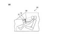
図2は、ドライバ監視システム1を搭載した車両80の内部を概略的に示す図である。撮像装置10は車両80のドライバの顔を撮影してドライバの顔画像を生成する。撮像装置10はいわゆるドライバモニタカメラである。 FIG. 2 is a diagram schematically showing the inside of the
撮像装置10は車両80の内部に設けられる。具体的には、図2に示すように、撮像装置10は車両80のステアリングコラム81の上部に設けられる。図2には、撮像装置10の投影範囲が破線で示されている。なお、撮像装置10は、車両80のステアリング82、ルームミラー、メータパネル、メータフード等に設けられてもよい。また、ドライバ監視システム1は複数の撮像装置10を備えていてもよい。 The
撮像装置10はカメラ及び投光器を含む。カメラは、レンズ及び撮像素子から構成され、例えばCMOS(相補型金属酸化膜半導体)カメラ又はCCD(電荷結合素子)カメラである。投光器は、LED(発光ダイオード)であり、例えばカメラの両側に配置された二個の近赤外LEDである。ドライバに近赤外光を照射することによって、夜間等の低照度時においてもドライバに不快感を与えることなくドライバの顔を撮影することができる。また、近赤外以外の波長成分の光を除去するバンドパスフィルタがカメラの内部に設けられ、近赤外LEDから照射される赤色波長成分の光を除去する可視光カットフィルタが投光器の前面に設けられる。 The
図1に示されるように、ECU20は、通信インターフェース21、メモリ22及びプロセッサ23を含み、車両80の各種制御を実行する。なお、本実施形態では、一つのECU20が設けられているが、機能毎に複数のECUが設けられていてもよい。 As shown in FIG. 1, the ECU 20 includes a
通信インターフェース21は、CAN(Controller Area Network)等の規格に準拠した車内ネットワークにECU20を接続するためのインターフェース回路を有する。ECU20は通信インターフェース21及び車内ネットワークを介して撮像装置10のような車載機器と通信する。 The
メモリ22は、例えば、揮発性の半導体メモリ(例えば、RAM)及び不揮発性の半導体メモリ(例えば、ROM)を有する。メモリ22は、プロセッサ23によって実行されるプログラム、プロセッサ23によって各種処理が実行されるときに使用される各種データ等を記憶する。メモリ22は記憶装置の一例である。 The
通信インターフェース21及びメモリ22は信号線を介してプロセッサ23に接続されている。プロセッサ23は、一つ又は複数のCPU(Central Processing Unit)及びその周辺回路を有し、各種処理を実行する。なお、プロセッサ23は、論理演算ユニット又は数値演算ユニットのような演算回路を更に有していてもよい。 The
例えば、撮像装置10は、車両80のイグニッションスイッチがオンであるときに、所定間隔で繰り返しドライバの顔を撮影してドライバの顔画像を生成する。撮像装置10によって生成されたドライバの顔画像は車内ネットワークを介して撮像装置10からECU20に送信される。 For example, the
図3は、ドライバ監視システム1を搭載した車両80の背部を概略的に示す図である。図3に示されるように、車両80には、物体検出装置83及びインジケータ84が設けられる。 FIG. 3 is a diagram schematically showing the back portion of the
物体検出装置83は車両80の周囲の物体を検出する。物体検出装置83は例えばレーダセンサである。レーダセンサは、車両80の周囲に電波(例えばミリ波)を発信し、電波の反射波を受信する。このことによって、レーダセンサは車両80の周囲の物体の有無及び車両80から物体までの距離を検出する。本実施形態では、物体検出装置83は、車両の後部(例えばリアバンパー)に設けられ、車両80の後側方エリアに存在する他車両を検出する。 The
インジケータ84は、例えばLEDであり、本実施形態ではドライバによって視認されるように左右のドアミラー85に内蔵される。インジケータ84は、表示灯であり、物体検出装置83の出力に応じて点灯する。具体的には、インジケータ84は、物体検出装置83によって他車両が検出されたときに点灯する。車両80の右側の車線を走行する他車両が検出されたときには右側のインジケータ84が点灯し、車両80の左側の車線を走行する他車両が検出されたときには左側のインジケータ84が点灯する。 The
すなわち、インジケータ84は、いわゆるブラインドスポットモニタとして機能し、車両80の後側方エリアに他車両が存在していることを示す。このことによって、ドライバは、車両80後側方エリアに存在する他車両、特にドアミラー85の死角に存在する他車両を容易に認識することができる。インジケータ84の出力、すなわちインジケータ84の点灯状態は車内ネットワークを介してECU20に送信される。 That is, the
図4は、ECU20のプロセッサ23の機能ブロック図である。本実施形態では、プロセッサ23は視点検出部24及び脇見判定部25を有する。視点検出部24及び脇見判定部25は、ECU20のメモリ22に記憶されたプログラムをECU20のプロセッサ23が実行することによって実現される機能ブロックである。 FIG. 4 is a functional block diagram of the
視点検出部24は、撮像装置10によって生成されたドライバの顔画像に基づいてドライバの顔向き又は視線の角度を検出する。脇見判定部25は、視点検出部24によって検出された顔向き又は視線の角度に基づいてドライバの脇見を判定する。 The
視点検出部24は、例えば、撮像装置10によって生成されたドライバの顔画像と、ドライバが正面を向いているときの顔形状データとのマッチングを行うことによってドライバの顔向きの角度を検出する。具体的には、視点検出部24は、両者の一致率が最大となるようにドライバの顔画像を回転させ、一致率が最大となるときの回転角度をドライバの顔向きの角度として検出する。顔形状データはECU20のメモリ22又は他の記憶装置に予め記憶されている。顔形状データは、一般的な人間の顔のデータであっても、ドライバ毎に取得されてもよい。 The
なお、視点検出部24は、撮像装置10によって生成されたドライバの顔画像と、ドライバの顔向きが異なる複数の顔形状データとのマッチングを行うことによってドライバの顔向きの角度を検出してもよい。この場合、視点検出部24は、両者の一致率が最大となる顔形状データの顔向きをドライバの顔向きの角度として検出する。複数の顔形状データはECU20のメモリ22又は他の記憶装置に予め記憶されている。複数の顔形状データは、一般的な人間の顔のデータであっても、ドライバ毎に取得されてもよい。 Even if the
また、視点検出部24は、例えば、以下の方法によってドライバの視線の角度を検出する。まず、視点検出部24は、撮像装置10によって生成されたドライバの顔画像から顔領域を特定し、眼、鼻、口等の顔部品の特徴点を抽出することによって顔部品を検出する。次いで、視点検出部24は、プルキニエ像(角膜反射像)の位置と瞳孔中心の位置とを検出し、プルキニエ像と瞳孔中心との位置関係に基づいてドライバの視線の角度を検出する。なお、視点検出部24は、プルキニエ像と瞳孔中心との位置関係と、検出されたドライバの顔向きの角度とに基づいてドライバの視線の角度を検出してもよい。 Further, the
また、視点検出部24は他の公知の手法によってドライバの顔向き又は視線の角度を検出してもよい。 Further, the
上述したように、車両80では、物体検出装置83によって他車両が検出されたときにインジケータ84が点灯する。このとき、ドライバはインジケータ84の表示を確認するためにインジケータ84を目視する。すなわち、ドライバは顔向き及び視線を正面からインジケータ84の方に移動させる。このときにドライバが脇見をしていると判定してドライバに警告が与えられると、ドライバの適切な行為に対して警告が与えられることとなり、ドライバに不快感をもたらす。 As described above, in the
このため、本実施形態では、脇見判定部25は、インジケータ84が点灯しているときには、ドライバがインジケータ84を見るときの所定角度範囲について脇見判定条件を緩和する。このことによって、ドライバがインジケータ84を見る行為を脇見と判定することを抑制することができ、ひいてはドライバの脇見を適切に検出することができる。 Therefore, in the present embodiment, when the
本実施形態では、脇見判定部25は、ドライバの顔向き又は視線の角度が閾値時間以上閾値範囲外であるときにドライバが脇見を判定していると判定し、インジケータ84が点灯しているときには、所定角度範囲が閾値範囲に含まれるように閾値範囲を広くする。所定角度範囲はインジケータ84の位置に基づいて予め定められる。 In the present embodiment, the
<閾値範囲設定処理>
以下、図5及び図6のフローチャートを参照して、ドライバ監視システム1を用いてドライバの脇見を検出するための制御について詳細に説明する。図5は、第一実施形態における閾値範囲設定処理の制御ルーチンを示すフローチャートである。本制御ルーチンはECU20によって所定の時間間隔で繰り返し実行される。本制御ルーチンでは、脇見判定に用いられる閾値範囲が設定される。<Threshold range setting process>
Hereinafter, the control for detecting the inattentiveness of the driver by using the driver monitoring system 1 will be described in detail with reference to the flowcharts of FIGS. 5 and 6. FIG. 5 is a flowchart showing a control routine of the threshold range setting process in the first embodiment. This control routine is repeatedly executed by the
最初に、ステップS101において、脇見判定部25は、右側のインジケータ84が点灯しているか否かを判定する。右側のインジケータ84が点灯していると判定された場合、本制御ルーチンはステップS102に進む。 First, in step S101, the
ステップS102では、脇見判定部25は、ドライバが右側のインジケータ84を見るときの所定角度範囲が閾値範囲に含まれるように右方向の閾値範囲を広くする。例えば、脇見判定部25は左右方向の閾値範囲の上限値を+15°から+45°に変更する。ステップS102の後、本制御ルーチンは終了する。 In step S102, the
一方、ステップS101において右側のインジケータ84が点灯していないと判定された場合、本制御ルーチンはステップS103に進む。ステップS103では、脇見判定部25は、左側のインジケータ84が点灯しているか否かを判定する。左側のインジケータ84が点灯していると判定された場合、本制御ルーチンはステップS104に進む。 On the other hand, if it is determined in step S101 that the
ステップS104では、脇見判定部25は、ドライバが左側のインジケータ84を見るときの所定角度範囲が閾値範囲に含まれるように左方向の閾値範囲を広くする。例えば、脇見判定部25は左右方向の閾値範囲の下限値を−15°から−45°に変更する。ステップS104の後、本制御ルーチンは終了する。 In step S104, the
一方、ステップS103において左側のインジケータ84が点灯していないと判定された場合、本制御ルーチンはステップS105に進む。ステップS105では、脇見判定部25は閾値範囲を初期化する。すなわち、閾値範囲が変更前の初期値に戻される。閾値範囲の初期値は、予め定められ、例えば0°(正面)を中心とした所定範囲(例えば左右方向±15°)に設定される。ステップS105の後、本制御ルーチンは終了する。 On the other hand, if it is determined in step S103 that the
なお、インジケータ84が消灯してから数秒後に閾値範囲が初期化されてもよい。すなわち、インジケータ84が消灯してから数秒後まで閾値範囲が変更後の値に維持されてもよい。 The threshold range may be initialized several seconds after the
<脇見判定処理>
図6は、第一実施形態における脇見判定処理の制御ルーチンを示すフローチャートである。本制御ルーチンはECU20によって繰り返し実行される。本制御ルーチンでは、ドライバが脇見をしているか否かが判定される。<Inattentive judgment processing>
FIG. 6 is a flowchart showing a control routine of the inattentive determination process in the first embodiment. This control routine is repeatedly executed by the
最初に、ステップS201において、視点検出部24は、撮像装置10によって生成されたドライバの顔画像を取得する。 First, in step S201, the
次いで、ステップS202において、脇見判定部25は、ドライバの顔画像に基づいて、上述したいずれかの方法によってドライバの顔向き又は視線の角度を検出する。 Next, in step S202, the
次いで、ステップS203において、脇見判定部25は、ドライバの顔向き又は視線の角度が閾値範囲内であるか否かを判定する。閾値範囲は、図5の制御ルーチンによって設定された値が用いられる。ドライバの顔向き又は視線の角度が閾値範囲内であると判定された場合、本制御ルーチンは終了する。 Next, in step S203, the
一方、ステップS203においてドライバの顔向き又は視線の角度が閾値範囲外であると判定された場合、本制御ルーチンはステップS204に進む。ステップS204では、脇見判定部25は経過時間が閾値時間に達したか否かを判定する。すなわち、脇見判定部25は、ドライバの顔向き又は視線の角度が閾値範囲外に閾値時間維持されたか否かを判定する。閾値時間は予め定められる。経過時間が閾値時間に達しなかったと判定された場合、本制御ルーチンは終了する。 On the other hand, if it is determined in step S203 that the driver's face orientation or line-of-sight angle is out of the threshold range, the control routine proceeds to step S204. In step S204, the
一方、ステップS204において経過時間が閾値時間に達したと判定された場合、本制御ルーチンはステップS205に進む。ステップS205では、脇見判定部25は、ドライバが脇見をしていると判定する。 On the other hand, if it is determined in step S204 that the elapsed time has reached the threshold time, the control routine proceeds to step S205. In step S205, the
次いで、ステップS206では、脇見判定部25はドライバに警報を与える。例えば、脇見判定部25は、車両80の内部に設けられたヒューマン・マシン・インターフェース(Human Machine Interface(HMI))を介して視覚的又は聴覚的にドライバに警報を与える。ステップS206の後、本制御ルーチンは終了する。 Next, in step S206, the
<第二実施形態>
第二実施形態に係るドライバ監視システムの構成及び制御は、以下に説明する点を除いて、基本的に第一実施形態に係るドライバ監視システムの構成及び制御と同様である。このため、以下、本発明の第二実施形態について、第一実施形態と異なる部分を中心に説明する。<Second embodiment>
The configuration and control of the driver monitoring system according to the second embodiment are basically the same as the configuration and control of the driver monitoring system according to the first embodiment, except for the points described below. Therefore, hereinafter, the second embodiment of the present invention will be described focusing on the parts different from the first embodiment.
インジケータ84が点灯しているときにドライバがインジケータ84を目視する行為は適切な行為であるが、ドライバがインジケータ84のみを見続けることは安全上好ましくない。このため、第二実施形態では、ドライバがインジケータ84を見るときの所定角度範囲について、以下のように脇見判定条件が緩和される。 Although it is appropriate for the driver to visually check the
脇見判定部25は、インジケータ84が点灯していないときには、ドライバの顔向き又は視線の角度が第1閾値時間以上所定角度範囲内に維持された場合にドライバが脇見をしていると判定し、インジケータ84が点灯しているときには、上記角度が第2閾値時間以上所定角度範囲内に維持された場合にドライバが脇見をしていると判定する。第2閾値時間は第1閾値時間よりも長く、インジケータ84が点灯しているときには、脇見判定されるまでの時間が長くされる。このことによって、ドライバの脇見をより適切に検出することができる。 When the
<脇見判定処理>
図7は、第二実施形態における脇見判定処理の制御ルーチンを示すフローチャートである。本制御ルーチンはECU20によって繰り返し実行される。本制御ルーチンでは、ドライバが脇見をしているか否かが判定される。<Inattentive judgment processing>
FIG. 7 is a flowchart showing a control routine of the inattentive determination process in the second embodiment. This control routine is repeatedly executed by the
最初に、ステップS301において、視点検出部24は、撮像装置10によって生成されたドライバの顔画像を取得する。 First, in step S301, the
次いで、ステップS302において、脇見判定部25は、ドライバの顔画像に基づいて、上述したいずれかの方法によってドライバの顔向き又は視線の角度を検出する。 Next, in step S302, the
次いで、ステップS303において、脇見判定部25は、ドライバの顔向き又は視線の角度が閾値範囲内であるか否かを判定する。閾値範囲は、予め定められ、例えば0°(正面)を中心とした所定範囲(例えば左右方向±15°)に設定される。ドライバの顔向き又は視線の角度が閾値範囲内であると判定された場合、本制御ルーチンは終了する。 Next, in step S303, the
一方、ステップS303においてドライバの顔向き又は視線の角度が閾値範囲外であると判定された場合、本制御ルーチンはステップS304に進む。ステップS304では、脇見判定部25はインジケータ84が点灯しているか否かを判定する。インジケータが点灯していると判定された場合、本制御ルーチンはステップS308に進む。 On the other hand, if it is determined in step S303 that the driver's face orientation or line-of-sight angle is out of the threshold range, the control routine proceeds to step S304. In step S304, the
ステップS308では、脇見判定部25は、ドライバの顔向き又は視線の角度が所定角度範囲内であるか否かを判定する。所定角度範囲は、ドライバがインジケータ84を見るときの角度範囲であり、インジケータ84の位置に基づいて予め定められる。なお、所定角度範囲は閾値範囲外の角度である。右側のインジケータ84が点灯している場合には右側のインジケータ84についての所定角度が用いられ、左側のインジケータ84が点灯している場合には左側のインジケータ84についての所定角度が用いられる。 In step S308, the
ステップS304においてインジケータ84が点灯していないと判定された場合、又はステップS308においてドライバの顔向き又は視線の角度が所定角度範囲外であると判定された場合、本制御ルーチンはステップS305に進む。ステップS305では、脇見判定部25は経過時間が第1閾値時間に達したか否かを判定する。すなわち、脇見判定部25は、ドライバの顔向き又は視線の角度が閾値範囲外に第1閾値時間維持されたか否かを判定する。第1閾値時間は予め定められる。経過時間が第1閾値時間に達しなかったと判定された場合、本制御ルーチンは終了する。 If it is determined in step S304 that the
一方、ステップS305において経過時間が第1閾値時間に達したと判定された場合、本制御ルーチンはステップS306に進む。ステップS306では、脇見判定部25は、ドライバが脇見をしていると判定する。 On the other hand, if it is determined in step S305 that the elapsed time has reached the first threshold time, the control routine proceeds to step S306. In step S306, the
次いで、ステップS307では、脇見判定部25はドライバに警報を与える。例えば、脇見判定部25は、車両80の内部に設けられたHMIを介して視覚的又は聴覚的にドライバに警報を与える。ステップS307の後、本制御ルーチンは終了する。 Next, in step S307, the
また、ステップS308においてドライバの顔向き又は視線の角度が所定角度範囲内であると判定された場合、本制御ルーチンはステップS309に進む。ステップS309では、経過時間が第2閾値時間に達したか否かを判定する。すなわち、脇見判定部25は、ドライバの顔向き又は視線の角度が所定角度範囲内に第2閾値時間維持されたか否かを判定する。第2閾値時間は、予め定められ、第1閾値時間よりも長い時間に設定される。 If it is determined in step S308 that the angle of the driver's face or line of sight is within a predetermined angle range, the control routine proceeds to step S309. In step S309, it is determined whether or not the elapsed time has reached the second threshold time. That is, the
ステップS309において、インジケータ84が消灯及び再点灯したとしても、ドライバの顔向き又は視線の角度が所定角度範囲内に維持されている限り、経過時間はカウントされ続ける。なお、インジケータ84の再点灯時に経過時間がゼロにリセットされてもよい。 Even if the
ステップS309において経過時間が第2閾値時間に達しなかったと判定された場合、本制御ルーチンは終了する。一方、ステップS309において経過時間が第2閾値時間に達したと判定された場合、本制御ルーチンはステップS306に進む。脇見判定部25は、ステップS306においてドライバが脇見をしていると判定し、ステップS307においてドライバに警報を与える。ステップS307の後、本制御ルーチンは終了する。 If it is determined in step S309 that the elapsed time has not reached the second threshold time, this control routine ends. On the other hand, if it is determined in step S309 that the elapsed time has reached the second threshold time, the control routine proceeds to step S306. The
以上、本発明に係る好適な実施形態を説明したが、本発明はこれら実施形態に限定されるものではなく、特許請求の範囲の記載内で様々な修正及び変更を施すことができる。例えば、インジケータ84は車両80の内部(左右のAピラー、ルームミラー、ナビゲーションシステム等)に設けられてもよい。 Although the preferred embodiments of the present invention have been described above, the present invention is not limited to these embodiments, and various modifications and modifications can be made within the scope of the claims. For example, the
1 ドライバ監視システム
10 撮像装置
20 電子制御ユニット(ECU)
23 プロセッサ
24 視点検出部
25 脇見判定部
80 車両
84 インジケータ1
23
Claims (3)
Translated fromJapanese前記顔画像に基づいて前記ドライバの顔向き又は視線の角度を検出する視点検出部と、
前記角度に基づいて前記ドライバの脇見を判定する脇見判定部と
を備え、
前記車両には、該車両の後側方エリアに他車両が存在していることを示すインジケータが設けられ、
前記脇見判定部は、前記インジケータが点灯しているときには、前記ドライバが前記インジケータを見るときの所定角度範囲について脇見判定条件を緩和する、ドライバ監視システム。An image pickup device that captures the face of the driver of the vehicle and generates a face image of the driver.
A viewpoint detection unit that detects the face orientation or line-of-sight angle of the driver based on the face image, and
It is provided with an inattentive determination unit that determines inattentiveness of the driver based on the angle.
The vehicle is provided with an indicator indicating that another vehicle is present in the rear side area of the vehicle.
The inattentive determination unit is a driver monitoring system that relaxes the inattentive determination condition for a predetermined angle range when the driver looks at the indicator when the indicator is lit.
Priority Applications (3)
| Application Number | Priority Date | Filing Date | Title |
|---|---|---|---|
| JP2020103729AJP2021196941A (en) | 2020-06-16 | 2020-06-16 | Driver monitoring system |
| CN202110652799.2ACN113799784B (en) | 2020-06-16 | 2021-06-11 | driver monitoring system |
| US17/347,839US11741727B2 (en) | 2020-06-16 | 2021-06-15 | Driver monitoring system for judging distracted driving |
Applications Claiming Priority (1)
| Application Number | Priority Date | Filing Date | Title |
|---|---|---|---|
| JP2020103729AJP2021196941A (en) | 2020-06-16 | 2020-06-16 | Driver monitoring system |
Publications (1)
| Publication Number | Publication Date |
|---|---|
| JP2021196941Atrue JP2021196941A (en) | 2021-12-27 |
Family
ID=78825611
Family Applications (1)
| Application Number | Title | Priority Date | Filing Date |
|---|---|---|---|
| JP2020103729APendingJP2021196941A (en) | 2020-06-16 | 2020-06-16 | Driver monitoring system |
Country Status (3)
| Country | Link |
|---|---|
| US (1) | US11741727B2 (en) |
| JP (1) | JP2021196941A (en) |
| CN (1) | CN113799784B (en) |
Families Citing this family (2)
| Publication number | Priority date | Publication date | Assignee | Title |
|---|---|---|---|---|
| JP6973298B2 (en)* | 2018-05-31 | 2021-11-24 | トヨタ自動車株式会社 | Object monitoring device |
| JP7624790B2 (en)* | 2021-03-31 | 2025-01-31 | 株式会社Subaru | Vehicle distraction monitoring device |
Citations (5)
| Publication number | Priority date | Publication date | Assignee | Title |
|---|---|---|---|---|
| JPH10166974A (en)* | 1996-12-09 | 1998-06-23 | Mitsubishi Motors Corp | Rear side alarm system for vehicles |
| JP2003118523A (en)* | 2001-10-17 | 2003-04-23 | Nissan Motor Co Ltd | Vehicle approach notification device |
| JP2007226666A (en)* | 2006-02-24 | 2007-09-06 | Aisin Aw Co Ltd | Driving support method and driving support device |
| JP2019191788A (en)* | 2018-04-23 | 2019-10-31 | クラリオン株式会社 | Information processing device and information processing method |
| JP2020024532A (en)* | 2018-08-07 | 2020-02-13 | オムロン株式会社 | Inattentive driving detection device |
Family Cites Families (15)
| Publication number | Priority date | Publication date | Assignee | Title |
|---|---|---|---|---|
| WO2007005942A2 (en)* | 2005-07-06 | 2007-01-11 | Donnelly Corporation | Vehicle exterior mirror assembly with blind spot indicator |
| US9751534B2 (en)* | 2013-03-15 | 2017-09-05 | Honda Motor Co., Ltd. | System and method for responding to driver state |
| US20150232028A1 (en)* | 2014-02-14 | 2015-08-20 | Magnadyne Corporation | Exterior Mirror Blind Spot Warning Display and Video Camera |
| KR101916993B1 (en)* | 2015-12-24 | 2018-11-08 | 엘지전자 주식회사 | Display apparatus for vehicle and control method thereof |
| US10126422B1 (en)* | 2016-07-12 | 2018-11-13 | Leonard Obodo | Vehicle blind spot sensor |
| JP2018108784A (en) | 2017-01-04 | 2018-07-12 | 株式会社デンソーテン | Inattention determination system and method |
| JP6962141B2 (en)* | 2017-11-07 | 2021-11-05 | トヨタ自動車株式会社 | Driver status detector |
| JP6915503B2 (en)* | 2017-11-09 | 2021-08-04 | トヨタ自動車株式会社 | Driver monitor system |
| JP6705437B2 (en)* | 2017-11-15 | 2020-06-03 | オムロン株式会社 | Inattentive judgment device, inattentive judgment method, and program for inattentive judgment |
| JP6777060B2 (en)* | 2017-11-15 | 2020-10-28 | オムロン株式会社 | Inattentive judgment device, driving support system, inattentive judgment method and program for inattentive judgment |
| EP3493178B1 (en)* | 2017-12-01 | 2024-03-06 | Veoneer Sweden AB | Driver attentiveness detection method and device |
| US10836403B2 (en)* | 2017-12-04 | 2020-11-17 | Lear Corporation | Distractedness sensing system |
| WO2020055992A1 (en)* | 2018-09-11 | 2020-03-19 | NetraDyne, Inc. | Inward/outward vehicle monitoring for remote reporting and in-cab warning enhancements |
| KR102740742B1 (en)* | 2019-10-29 | 2024-12-12 | 엘지전자 주식회사 | Artificial intelligence apparatus and method for determining inattention of driver |
| US11345298B2 (en)* | 2019-12-26 | 2022-05-31 | Panasonic Intellectual Property Management Co., Ltd. | Driver monitoring device and driver monitoring method |
- 2020
- 2020-06-16JPJP2020103729Apatent/JP2021196941A/enactivePending
- 2021
- 2021-06-11CNCN202110652799.2Apatent/CN113799784B/enactiveActive
- 2021-06-15USUS17/347,839patent/US11741727B2/enactiveActive
Patent Citations (5)
| Publication number | Priority date | Publication date | Assignee | Title |
|---|---|---|---|---|
| JPH10166974A (en)* | 1996-12-09 | 1998-06-23 | Mitsubishi Motors Corp | Rear side alarm system for vehicles |
| JP2003118523A (en)* | 2001-10-17 | 2003-04-23 | Nissan Motor Co Ltd | Vehicle approach notification device |
| JP2007226666A (en)* | 2006-02-24 | 2007-09-06 | Aisin Aw Co Ltd | Driving support method and driving support device |
| JP2019191788A (en)* | 2018-04-23 | 2019-10-31 | クラリオン株式会社 | Information processing device and information processing method |
| JP2020024532A (en)* | 2018-08-07 | 2020-02-13 | オムロン株式会社 | Inattentive driving detection device |
Also Published As
| Publication number | Publication date |
|---|---|
| CN113799784B (en) | 2023-09-22 |
| CN113799784A (en) | 2021-12-17 |
| US20210390322A1 (en) | 2021-12-16 |
| US11741727B2 (en) | 2023-08-29 |
Similar Documents
| Publication | Publication Date | Title |
|---|---|---|
| CN109758167B (en) | Driver state detection device | |
| US10604160B2 (en) | Driver condition detection system | |
| WO2018092265A1 (en) | Driving assistance device and driving assistance method | |
| JP6870660B2 (en) | Driver monitoring device | |
| WO2013115241A1 (en) | Device for alerting vehicle driver and method for same | |
| US11834073B2 (en) | Autonomous driving system | |
| JP2017151606A (en) | Inattentiveness/overlooking reminding system and computer program | |
| CN113799784B (en) | driver monitoring system | |
| JP4337130B2 (en) | Control device for driving device | |
| JP2019087029A (en) | Driver status detection device | |
| JP2007082594A (en) | Fatigue detection device | |
| JP2014136513A (en) | Entity approach alarm system | |
| KR101993189B1 (en) | Apparatus for preventing driver from driving while drowsy using image processing, and method thereof | |
| JP6962141B2 (en) | Driver status detector | |
| KR102331937B1 (en) | Apparatus for vehicle emergency rescue based on the analysis of the driving state risk and the driver state and method thereof | |
| JP2014048885A (en) | Diminished attentiveness detection system | |
| KR102791251B1 (en) | Apparatus and method for preventing drowsiness of vehicle driver | |
| JP7014680B2 (en) | Gaze object detection device, gaze object detection method, and program | |
| US20250229798A1 (en) | Notification device, notification method, and notification program | |
| JP2022014294A (en) | Driver monitoring system | |
| JP7697482B2 (en) | Driver monitoring device, driver monitoring method, and computer program for driver monitoring | |
| US12157487B2 (en) | Monitoring device, storage medium storing computer program for monitoring, and monitoring method | |
| JP2024130994A (en) | Warning control device, warning control method and program | |
| CN118470914A (en) | Driver monitoring device, driver monitoring method, and driver monitoring computer program | |
| JP2018116428A (en) | Driver status detection device |
Legal Events
| Date | Code | Title | Description |
|---|---|---|---|
| A621 | Written request for application examination | Free format text:JAPANESE INTERMEDIATE CODE: A621 Effective date:20211007 | |
| A131 | Notification of reasons for refusal | Free format text:JAPANESE INTERMEDIATE CODE: A131 Effective date:20220726 | |
| A02 | Decision of refusal | Free format text:JAPANESE INTERMEDIATE CODE: A02 Effective date:20230117 |