JP2021196345A - Vehicle radar device - Google Patents
Vehicle radar deviceDownload PDFInfo
- Publication number
- JP2021196345A JP2021196345AJP2021076494AJP2021076494AJP2021196345AJP 2021196345 AJP2021196345 AJP 2021196345AJP 2021076494 AJP2021076494 AJP 2021076494AJP 2021076494 AJP2021076494 AJP 2021076494AJP 2021196345 AJP2021196345 AJP 2021196345A
- Authority
- JP
- Japan
- Prior art keywords
- antenna
- radar device
- vehicle radar
- vehicle
- lamp
- Prior art date
- Legal status (The legal status is an assumption and is not a legal conclusion. Google has not performed a legal analysis and makes no representation as to the accuracy of the status listed.)
- Granted
Links
Images


Classifications
- G—PHYSICS
- G01—MEASURING; TESTING
- G01S—RADIO DIRECTION-FINDING; RADIO NAVIGATION; DETERMINING DISTANCE OR VELOCITY BY USE OF RADIO WAVES; LOCATING OR PRESENCE-DETECTING BY USE OF THE REFLECTION OR RERADIATION OF RADIO WAVES; ANALOGOUS ARRANGEMENTS USING OTHER WAVES
- G01S13/00—Systems using the reflection or reradiation of radio waves, e.g. radar systems; Analogous systems using reflection or reradiation of waves whose nature or wavelength is irrelevant or unspecified
- G01S13/88—Radar or analogous systems specially adapted for specific applications
- G01S13/93—Radar or analogous systems specially adapted for specific applications for anti-collision purposes
- G01S13/931—Radar or analogous systems specially adapted for specific applications for anti-collision purposes of land vehicles
- G—PHYSICS
- G01—MEASURING; TESTING
- G01S—RADIO DIRECTION-FINDING; RADIO NAVIGATION; DETERMINING DISTANCE OR VELOCITY BY USE OF RADIO WAVES; LOCATING OR PRESENCE-DETECTING BY USE OF THE REFLECTION OR RERADIATION OF RADIO WAVES; ANALOGOUS ARRANGEMENTS USING OTHER WAVES
- G01S13/00—Systems using the reflection or reradiation of radio waves, e.g. radar systems; Analogous systems using reflection or reradiation of waves whose nature or wavelength is irrelevant or unspecified
- G01S13/02—Systems using reflection of radio waves, e.g. primary radar systems; Analogous systems
- G01S13/06—Systems determining position data of a target
- B—PERFORMING OPERATIONS; TRANSPORTING
- B60—VEHICLES IN GENERAL
- B60Q—ARRANGEMENT OF SIGNALLING OR LIGHTING DEVICES, THE MOUNTING OR SUPPORTING THEREOF OR CIRCUITS THEREFOR, FOR VEHICLES IN GENERAL
- B60Q1/00—Arrangement of optical signalling or lighting devices, the mounting or supporting thereof or circuits therefor
- B60Q1/0017—Devices integrating an element dedicated to another function
- B—PERFORMING OPERATIONS; TRANSPORTING
- B60—VEHICLES IN GENERAL
- B60R—VEHICLES, VEHICLE FITTINGS, OR VEHICLE PARTS, NOT OTHERWISE PROVIDED FOR
- B60R11/00—Arrangements for holding or mounting articles, not otherwise provided for
- F—MECHANICAL ENGINEERING; LIGHTING; HEATING; WEAPONS; BLASTING
- F21—LIGHTING
- F21S—NON-PORTABLE LIGHTING DEVICES; SYSTEMS THEREOF; VEHICLE LIGHTING DEVICES SPECIALLY ADAPTED FOR VEHICLE EXTERIORS
- F21S41/00—Illuminating devices specially adapted for vehicle exteriors, e.g. headlamps
- G—PHYSICS
- G01—MEASURING; TESTING
- G01S—RADIO DIRECTION-FINDING; RADIO NAVIGATION; DETERMINING DISTANCE OR VELOCITY BY USE OF RADIO WAVES; LOCATING OR PRESENCE-DETECTING BY USE OF THE REFLECTION OR RERADIATION OF RADIO WAVES; ANALOGOUS ARRANGEMENTS USING OTHER WAVES
- G01S7/00—Details of systems according to groups G01S13/00, G01S15/00, G01S17/00
- G01S7/02—Details of systems according to groups G01S13/00, G01S15/00, G01S17/00 of systems according to group G01S13/00
- G01S7/027—Constructional details of housings, e.g. form, type, material or ruggedness
- G—PHYSICS
- G01—MEASURING; TESTING
- G01S—RADIO DIRECTION-FINDING; RADIO NAVIGATION; DETERMINING DISTANCE OR VELOCITY BY USE OF RADIO WAVES; LOCATING OR PRESENCE-DETECTING BY USE OF THE REFLECTION OR RERADIATION OF RADIO WAVES; ANALOGOUS ARRANGEMENTS USING OTHER WAVES
- G01S7/00—Details of systems according to groups G01S13/00, G01S15/00, G01S17/00
- G01S7/02—Details of systems according to groups G01S13/00, G01S15/00, G01S17/00 of systems according to group G01S13/00
- G01S7/03—Details of HF subsystems specially adapted therefor, e.g. common to transmitter and receiver
- G—PHYSICS
- G01—MEASURING; TESTING
- G01S—RADIO DIRECTION-FINDING; RADIO NAVIGATION; DETERMINING DISTANCE OR VELOCITY BY USE OF RADIO WAVES; LOCATING OR PRESENCE-DETECTING BY USE OF THE REFLECTION OR RERADIATION OF RADIO WAVES; ANALOGOUS ARRANGEMENTS USING OTHER WAVES
- G01S7/00—Details of systems according to groups G01S13/00, G01S15/00, G01S17/00
- G01S7/02—Details of systems according to groups G01S13/00, G01S15/00, G01S17/00 of systems according to group G01S13/00
- G01S7/28—Details of pulse systems
- G01S7/285—Receivers
- G01S7/288—Coherent receivers
- G01S7/2883—Coherent receivers using FFT processing
- G—PHYSICS
- G01—MEASURING; TESTING
- G01S—RADIO DIRECTION-FINDING; RADIO NAVIGATION; DETERMINING DISTANCE OR VELOCITY BY USE OF RADIO WAVES; LOCATING OR PRESENCE-DETECTING BY USE OF THE REFLECTION OR RERADIATION OF RADIO WAVES; ANALOGOUS ARRANGEMENTS USING OTHER WAVES
- G01S7/00—Details of systems according to groups G01S13/00, G01S15/00, G01S17/00
- G01S7/02—Details of systems according to groups G01S13/00, G01S15/00, G01S17/00 of systems according to group G01S13/00
- G01S7/40—Means for monitoring or calibrating
- G01S7/4004—Means for monitoring or calibrating of parts of a radar system
- G01S7/4026—Antenna boresight
- H—ELECTRICITY
- H01—ELECTRIC ELEMENTS
- H01Q—ANTENNAS, i.e. RADIO AERIALS
- H01Q1/00—Details of, or arrangements associated with, antennas
- H01Q1/27—Adaptation for use in or on movable bodies
- H01Q1/32—Adaptation for use in or on road or rail vehicles
- H01Q1/3208—Adaptation for use in or on road or rail vehicles characterised by the application wherein the antenna is used
- H01Q1/3233—Adaptation for use in or on road or rail vehicles characterised by the application wherein the antenna is used particular used as part of a sensor or in a security system, e.g. for automotive radar, navigation systems
- H—ELECTRICITY
- H01—ELECTRIC ELEMENTS
- H01Q—ANTENNAS, i.e. RADIO AERIALS
- H01Q1/00—Details of, or arrangements associated with, antennas
- H01Q1/27—Adaptation for use in or on movable bodies
- H01Q1/32—Adaptation for use in or on road or rail vehicles
- H01Q1/325—Adaptation for use in or on road or rail vehicles characterised by the location of the antenna on the vehicle
- H—ELECTRICITY
- H01—ELECTRIC ELEMENTS
- H01Q—ANTENNAS, i.e. RADIO AERIALS
- H01Q1/00—Details of, or arrangements associated with, antennas
- H01Q1/40—Radiating elements coated with or embedded in protective material
- B—PERFORMING OPERATIONS; TRANSPORTING
- B60—VEHICLES IN GENERAL
- B60R—VEHICLES, VEHICLE FITTINGS, OR VEHICLE PARTS, NOT OTHERWISE PROVIDED FOR
- B60R11/00—Arrangements for holding or mounting articles, not otherwise provided for
- B60R2011/0001—Arrangements for holding or mounting articles, not otherwise provided for characterised by position
- B60R2011/004—Arrangements for holding or mounting articles, not otherwise provided for characterised by position outside the vehicle
- G—PHYSICS
- G01—MEASURING; TESTING
- G01S—RADIO DIRECTION-FINDING; RADIO NAVIGATION; DETERMINING DISTANCE OR VELOCITY BY USE OF RADIO WAVES; LOCATING OR PRESENCE-DETECTING BY USE OF THE REFLECTION OR RERADIATION OF RADIO WAVES; ANALOGOUS ARRANGEMENTS USING OTHER WAVES
- G01S13/00—Systems using the reflection or reradiation of radio waves, e.g. radar systems; Analogous systems using reflection or reradiation of waves whose nature or wavelength is irrelevant or unspecified
- G01S13/88—Radar or analogous systems specially adapted for specific applications
- G01S13/93—Radar or analogous systems specially adapted for specific applications for anti-collision purposes
- G01S13/931—Radar or analogous systems specially adapted for specific applications for anti-collision purposes of land vehicles
- G01S2013/9327—Sensor installation details
- G01S2013/93277—Sensor installation details in the lights
Landscapes
- Engineering & Computer Science (AREA)
- Remote Sensing (AREA)
- Radar, Positioning & Navigation (AREA)
- Physics & Mathematics (AREA)
- Computer Networks & Wireless Communication (AREA)
- General Physics & Mathematics (AREA)
- Electromagnetism (AREA)
- Mechanical Engineering (AREA)
- General Engineering & Computer Science (AREA)
- Computer Security & Cryptography (AREA)
- Radar Systems Or Details Thereof (AREA)
- Arrangement Of Elements, Cooling, Sealing, Or The Like Of Lighting Devices (AREA)
- Lighting Device Outwards From Vehicle And Optical Signal (AREA)
- Details Of Aerials (AREA)
- Non-Portable Lighting Devices Or Systems Thereof (AREA)
Abstract
Translated fromJapaneseDescription
Translated fromJapanese本発明は、車両レーダ装置に関し、より具体的には、構造を簡素化することができ、設計自由度および空間活用性を向上させることができる車両レーダ装置に関する。 The present invention relates to a vehicle radar device, and more specifically, to a vehicle radar device capable of simplifying a structure and improving design freedom and space utilization.
レーダ(RADAR:Radio Detection And Ranging)は、電磁波を発生させて周辺物体に送信し、また戻ってくる電磁波を通じて、距離、方向、高度などを検出し、物体の位置を把握することができる。 Radar (Radio Detection And Ringing) can generate electromagnetic waves and transmit them to surrounding objects, detect distances, directions, altitudes, etc. through the returning electromagnetic waves, and grasp the position of the objects.
レーダは、電波形態によって、連続波レーダ(Continuous Wave Radar)とパルス波レーダ(Pulse Wave Radar)とに大別することができる。 The radar can be roughly classified into a continuous wave radar (Continuous Wave Radar) and a pulse wave radar (Pulse Wave Radar) according to the radio wave form.
連続波レーダとしては、ドップラーレーダ(Doppler Radar)とFMCW(Frequency Modulated Continuous Wave)、およびHFMCW(High speed ramping FMCW)レーダがあり、パルス波レーダとしては、パルスドップラーレーダ(Pulse Doppler Radar)とパルス圧縮レーダ(Pulse Compression Radar)がある。 Continuous wave radars include Doppler Radar and FMCW (Frequency Modulated Continuous Wave), and HFMCW (High speed speed ramping FMCW) radars, and pulse wave radars include pulsed puller radar (Pulse pulse radar) and pulse radar (Pulse pulse radar). There is a radar (Pulse Compression Radar).
最近、ミリ波帯域やサブミリ波帯域を用いて、数十メートル以内の物体を探知する高解像度レーダに対する需要が増大するに伴い、これに関する研究が行われ続いている。 Recently, as the demand for high-resolution radar that detects objects within several tens of meters using the millimeter-wave band and submillimeter-wave band has increased, research on this has continued.
近距離物体間の距離を判別または分解することができる高解像度レーダは、産業用、軍事用として多様に活用されており、実生活では車両用としても使用されている。 High-resolution radars that can determine or decompose the distance between short-range objects are widely used for industrial and military purposes, and are also used for vehicles in real life.
車両用レーダは、知能型交通システムを具現するための必須技術であり、動いていたり停止している他の車両や物体の動きを感知することで、劣悪な気象条件または運転者の不注意によって発生し得る事故を予め防止するために開発されており、自律走行車に適用可能な代表的なシステム(レーダシステム)である。 Vehicle radar is an essential technology for embodying intelligent transportation systems, by sensing the movement of other vehicles and objects that are moving or stopped, due to poor weather conditions or driver's carelessness. It is a typical system (radar system) that has been developed in advance to prevent possible accidents and can be applied to autonomous vehicles.
しかし、従来、レーダを構成するアンテナモジュールを別に作製した後、車両に装着しなければならないため、構造が複雑で、設計自由度および空間活用性が低下するという問題がある。 However, conventionally, since the antenna module constituting the radar must be separately manufactured and then mounted on the vehicle, there is a problem that the structure is complicated and the degree of freedom in design and the space utilization are reduced.
また、従来、レーダの前方に金属性部品または金属性塗料層が存在することによるセンシング正確度の低下を防止するために、レーダを外部に露出して装着しなければならないため、レーダの装着位置に制約が伴うという問題があり、外部に露出するレーダによって車両のデザイン特性が低下するという問題がある。さらに、従来、車両のバンパーまたはフロントグリルにレーダを装着しなければならないため、追突事故の発生時にレーダが破損しやすくなる恐れがある。 In addition, conventionally, in order to prevent a decrease in sensing accuracy due to the presence of a metallic part or a metallic paint layer in front of the radar, the radar must be exposed to the outside and mounted, so that the radar mounting position There is a problem that the design characteristics of the vehicle are deteriorated by the radar exposed to the outside. Further, conventionally, since the radar must be mounted on the bumper or the front grill of the vehicle, the radar may be easily damaged in the event of a rear-end collision.
そのため、最近、レーダの構造を簡素化し、設計自由度および空間活用性を向上させるための様々な研究が行われているが、まだ十分でなく、これに関する開発が求められている。 Therefore, recently, various studies have been conducted to simplify the structure of the radar and improve the degree of freedom in design and the space utilization, but it is still insufficient and development on this is required.
本発明の実施形態は、構造を簡素化し、設計自由度および空間活用性を向上させることができる車両レーダ装置に関する。 An embodiment of the present invention relates to a vehicle radar device capable of simplifying a structure and improving design freedom and space utilization.
特に、本発明の実施形態は、車両用ランプの内部にレーダを装着可能にすることを目的とする。 In particular, an embodiment of the present invention makes it possible to mount a radar inside a vehicle lamp.
また、本発明の実施形態は、車両用ランプのデザイン特性の低下を防止することができ、商品性を向上させ、消費者の満足度を高めることができるようにすることを目的とする。 Further, it is an object of the present invention to be able to prevent deterioration of the design characteristics of the vehicle lamp, improve the commercial value, and increase the satisfaction of the consumer.
実施形態において解決しようとする課題は、これに限定されるものではなく、以下で説明する課題の解決手段や実施形態から把握できる目的や効果も含まれると言える。 It can be said that the problem to be solved in the embodiment is not limited to this, and includes the means for solving the problem described below and the purpose and effect that can be grasped from the embodiment.
上述の本発明の目的を達成するための本発明の好ましい実施形態によると、車両レーダ装置は、車両用ランプの内面に設けられ、電磁波を送受信するアンテナと、車両用ランプの内部に設けられ、アンテナに受信した信号を処理する信号処理モジュールとを含む。 According to the preferred embodiment of the present invention for achieving the above-mentioned object of the present invention, the vehicle radar device is provided on the inner surface of the vehicle lamp, the antenna for transmitting and receiving electromagnetic waves, and the inside of the vehicle lamp. It includes a signal processing module that processes the signal received by the antenna.
これは、車両レーダ装置の構造を簡素化し、設計自由度および空間活用性を向上させるためである。 This is to simplify the structure of the vehicle radar device and improve the degree of freedom in design and space utilization.
すなわち、従来、レーダを構成するアンテナモジュールを別に作製した後、車両に装着しなければならなかったため、構造が複雑で、設計自由度および空間活用性が低下するという問題がある。さらに、従来、レーダの前方に金属性部品または金属性塗料層が存在することによるセンシング正確度の低下を防止するために、レーダが外部に露出するように装着しなければならなかったため、レーダの装着位置に制約が伴うという問題があり、外部に露出するレーダによって車両のデザイン特性が低下するという問題がある。 That is, conventionally, since the antenna module constituting the radar had to be separately manufactured and then mounted on the vehicle, there is a problem that the structure is complicated and the degree of freedom in design and the space utilization are lowered. Furthermore, in the past, in order to prevent a decrease in sensing accuracy due to the presence of metallic parts or metallic paint layers in front of the radar, the radar had to be mounted so as to be exposed to the outside. There is a problem that the mounting position is restricted, and there is a problem that the design characteristics of the vehicle are deteriorated by the radar exposed to the outside.
しかし、本発明の実施形態は、車両用ランプの内面にアンテナを設けることによって、レーダ装着に必要な空間を最小化し、設計自由度および空間活用性を向上させる有利な効果を得ることができる。 However, in the embodiment of the present invention, by providing the antenna on the inner surface of the vehicle lamp, it is possible to obtain an advantageous effect of minimizing the space required for mounting the radar and improving the degree of freedom in design and the space utilization.
本発明の好ましい実施形態によると、ランプは、光を発生する光源と、光源の前方に設けられ、外観を形成するアウターレンズとを含み、アンテナは、アウターレンズの内面に設けられる。 According to a preferred embodiment of the present invention, the lamp includes a light source that generates light and an outer lens that is provided in front of the light source and forms an appearance, and the antenna is provided on the inner surface of the outer lens.
本発明の好ましい実施形態によると、アンテナは、アウターレンズの内面に形成されるアンテナパターンを含むことができる。 According to a preferred embodiment of the invention, the antenna can include an antenna pattern formed on the inner surface of the outer lens.
好ましくは、アンテナパターンは、透明電極で形成される。 Preferably, the antenna pattern is formed of transparent electrodes.
これは、アンテナパターンの性能(電磁波送受信性能)を保障し、且つアウターレンズの内面にアンテナパターンを適用することによるランプの配光性能の低下およびデザイン特性の低下を最小化するためである。 This is to guarantee the performance of the antenna pattern (electromagnetic wave transmission / reception performance) and to minimize the deterioration of the light distribution performance and the design characteristics of the lamp due to the application of the antenna pattern to the inner surface of the outer lens.
すなわち、アウターレンズの内面にアンテナパターンを形成することによって、金属性部品または金属性塗料層などによる信号干渉なしに電磁波を送受信することができ、空間活用性を確保することができるが、アンテナパターンによってランプから照射される光が遮られ、ランプの配光性能が低下し、外部に露出するアンテナパターンによってランプのデザイン特性が低下するという問題がある。 That is, by forming an antenna pattern on the inner surface of the outer lens, electromagnetic waves can be transmitted and received without signal interference due to metal parts or a metal paint layer, and space utilization can be ensured. There is a problem that the light emitted from the lamp is blocked by the antenna, the light distribution performance of the lamp is deteriorated, and the design characteristics of the lamp are deteriorated by the antenna pattern exposed to the outside.
しかし、本発明は、アンテナパターンを透明電極で形成することによって、アンテナパターンの性能を保障し、且つランプの配光性能の低下およびデザイン特性の低下を最小化する有利な効果を得ることができる。 However, according to the present invention, by forming the antenna pattern with transparent electrodes, it is possible to obtain an advantageous effect of guaranteeing the performance of the antenna pattern and minimizing the deterioration of the light distribution performance and the design characteristics of the lamp. ..
透明電極は、求められる条件および設計仕様に応じて様々な材質で形成され得る。一例として、透明電極は、ITO、IZO、AZO、金属ナノファイバ(metal nano fiber)の少なくともいずれか一つで形成され得る。 The transparent electrode can be made of various materials depending on the required conditions and design specifications. As an example, the transparent electrode may be formed of at least one of ITO, IZO, AZO, and metal nanofiber.
アンテナパターンは、求められる条件および設計仕様に応じて様々な方式で形成され得る。 The antenna pattern can be formed in various ways depending on the required conditions and design specifications.
一例として、アンテナパターンは、アウターレンズの内面に導電性薄膜を形成するステップと、導電性薄膜の表面にマスクパターンを形成するステップと、マスクパターンを用いて、導電性薄膜を部分的に除去するステップとによって設けられ得る。 As an example, the antenna pattern partially removes the conductive thin film by using a step of forming a conductive thin film on the inner surface of the outer lens, a step of forming a mask pattern on the surface of the conductive thin film, and a mask pattern. Can be provided by steps and.
好ましくは、アンテナパターンは、地面に垂直にアウターレンズの内面に形成される。このように、地面に垂直にアンテナパターンを形成することによって、アンテナパターンによる電磁波の送受信特性を極大化する有利な効果を得ることができる。 Preferably, the antenna pattern is formed on the inner surface of the outer lens perpendicular to the ground. By forming the antenna pattern perpendicular to the ground in this way, it is possible to obtain an advantageous effect of maximizing the transmission / reception characteristics of the electromagnetic wave by the antenna pattern.
本発明の好ましい実施形態によると、信号処理モジュールは、アンテナの下部(ランプ内部の底部)に配置される。このように、アンテナの下部に信号処理モジュールを配置することによって、信号処理モジュールによるアンテナの性能低下を防止し、信号処理モジュールの外部露出を最小化する有利な効果を得ることができる。 According to a preferred embodiment of the invention, the signal processing module is located at the bottom of the antenna (bottom inside the lamp). By arranging the signal processing module below the antenna in this way, it is possible to prevent the performance of the antenna from being deteriorated by the signal processing module and obtain an advantageous effect of minimizing the external exposure of the signal processing module.
より好ましくは、信号処理モジュールは、光源の下部に配置される。 More preferably, the signal processing module is located below the light source.
これは、密閉構造を有するランプの内部空間で、光源の下部空間の温度が他の空間(例えば、光源とインナーレンズとの間の空間)の温度より相対的に低く形成されることによるものであり、ランプの内部で相対的に最も温度が低い光源の下部空間に信号処理モジュールを配置することによって、信号処理モジュールの過熱現象を最小化し、安定性および信頼性を向上させる有利な効果を得ることができる。 This is because the temperature of the lower space of the light source is formed relatively lower than the temperature of other spaces (for example, the space between the light source and the inner lens) in the internal space of the lamp having a closed structure. By arranging the signal processing module in the lower space of the light source, which has the relatively lowest temperature inside the lamp, the overheating phenomenon of the signal processing module is minimized, and the advantageous effect of improving the stability and reliability is obtained. be able to.
本発明の好ましい実施形態によると、アンテナと信号処理モジュールは連結部材によって電気的に連結され得る。 According to a preferred embodiment of the present invention, the antenna and the signal processing module may be electrically connected by a connecting member.
好ましくは、連結部材としては、ケーブル、フレキシブル基板(FPCB)の少なくともいずれか一つが使用され得る。 Preferably, at least one of a cable and a flexible substrate (FPCB) can be used as the connecting member.
以下、添付の図面を参照して、本発明の好ましい実施形態について詳細に説明する。 Hereinafter, preferred embodiments of the present invention will be described in detail with reference to the accompanying drawings.
ただし、本発明の技術思想は、説明している一部の実施形態に限定されるものではなく、互いに異なる様々な形態に具現されてもよく、本発明の技術思想の範囲内であれば、実施形態間のその構成要素のうち一つ以上を選択的に結合、置換して使用してもよい。 However, the technical idea of the present invention is not limited to some of the embodiments described, and may be embodied in various forms different from each other, as long as it is within the scope of the technical idea of the present invention. One or more of its components between embodiments may be selectively combined, replaced and used.
また、本発明の実施形態で使用される用語(技術および科学的用語を含む)は、明らかに特別に定義して記述されない限り、本発明が属する技術分野において通常の知識を有する者が一般的に理解し得る意味に解釈され得、辞書に定義された用語のように一般的に使用される用語は、関連技術の文脈上の意味を考慮して、その意味を解釈することができる。 In addition, the terms (including technical and scientific terms) used in the embodiments of the present invention are generally those who have ordinary knowledge in the technical field to which the present invention belongs, unless they are clearly specifically defined and described. Commonly used terms, such as those defined in dictionaries, can be interpreted in a way that can be understood in the context of the relevant technology.
また、本発明の実施形態で使用された用語は、実施形態を説明するためのものであって、本発明を制限するためのものではない。 In addition, the terms used in the embodiments of the present invention are for explaining the embodiments and not for limiting the present invention.
本明細書において、単数型は、文章で特に言及しない限り、複数型も含むことができ、「Aおよび(と)B、Cのうち少なくとも一つ(または一つ以上)」と記載する場合、A、B、Cで組み合わせることができるすべての組み合わせのうち一つ以上を含むことができる。 In the present specification, the singular type may also include multiple types unless otherwise specified in the text, and when described as "at least one (or one or more) of A and (and) B, C", It can include one or more of all combinations that can be combined in A, B, C.
また、本発明の実施形態の構成要素を説明するにあたって、第1、第2、A、B、(a)、(b)などの用語を使用することができる。 In addition, terms such as first, second, A, B, (a), and (b) can be used in explaining the components of the embodiment of the present invention.
かかる用語は、その構成要素を他の構成要素と区別するためのものであって、その用語によって当該構成要素の本質や順番または順序などが限定されない。 Such a term is for distinguishing a component from other components, and the term does not limit the essence, order or order of the component.
また、ある構成要素が他の構成要素に「連結」、「結合」または「接続」すると記載された場合、その構成要素は、その他の構成要素に直接連結、結合または接続する場合だけでなく、その構成要素とその他の構成要素との間にあるさらに他の構成要素によって「連結」、「結合」または「接続」する場合も含むことができる。 Also, when one component is described as "bound," "joined," or "connected" to another component, that component is not only directly linked, joined, or connected to another component. It may also include the case of "linking", "joining" or "connecting" by yet another component between that component and the other components.
また、各構成要素の「上(の上)または下(の下)」に形成または配置されるものと記載する場合、上(の上)または下(の下)は、二つの構成要素が互いに直接接触する場合だけでなく、一つ以上のさらに他の構成要素が二つの構成要素の間に形成または配置される場合も含む。また、「上(の上)または下(の下)」と表現される場合、一つの構成要素を基準に上側方向だけでなく下側方向の意味も含むことができる。 Also, when it is described that each component is formed or arranged "above (above) or below (below)", the above (above) or below (below) means that the two components are formed or arranged on each other. Not only in direct contact, but also in the case where one or more other components are formed or placed between the two components. Further, when expressed as "upper (upper) or lower (lower)", the meaning of not only the upper direction but also the lower direction can be included with respect to one component.
図1〜図8を参照すると、本発明による車両レーダ装置100は、車両用ランプ10の内面に設けられ、電磁波を送受信するアンテナ110と、車両用ランプ10の内部に設けられ、アンテナ110に受信した信号を処理する信号処理モジュール120とを含む。 Referring to FIGS. 1 to 8, the
参考までに、本発明の実施形態による車両レーダ装置100は、求められる条件および設計仕様に応じて、様々な車両(例えば、乗用車、乗合車)のランプ10に適用されてもよく、車両レーダ装置100が適用される車両の種類によって本発明が制限または限定されるものではない。 For reference, the
また、本発明の実施形態による車両レーダ装置100が装着される車両用ランプ10は、主に照明機能(例えば、ヘッドランプ、フォグランプ)を目的として使用されるか、信号機能(例えば、ターンシグナルランプ、テールランプ、ブレーキランプ、サイドマーカ)を目的として使用され得、車両用ランプ10の用途および構造によって本発明が制限または限定されるものではない。 Further, the
一例として、本発明の実施形態による車両レーダ装置100は、車両の前方左側および前方右側に設けられる車両のヘッドランプ10に装着され得る。 As an example, the
車両用ランプ10の構造は、求められる条件および設計仕様に応じて様々に変更され得る。 The structure of the
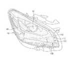
一例として、図1および図2を参照すると、車両用ランプ10は、光源20と、光源20から発生した光を前方に反射するリフレクタ30と、リフレクタ30から反射した光を前方に投射するインナーレンズ40と、インナーレンズ40の前方に設けられ、外観を形成するアウターレンズ50とを含むことができる。 As an example, referring to FIGS. 1 and 2, the
光源20としては、半導体発光素子であるLED(Light Emitting Diode)が使用され得、求められる条件および設計仕様に応じて同一または相違する色相の光を発生させる複数個のLEDが使用されることも可能である。本発明の他の実施形態によると、光源として、蛍光灯、白熱灯、ハロゲンなどを使用することも可能である。 As the
リフレクタ30は、光源20から発生した光を前方に反射させることができる様々な構造に形成され得、リフレクタ30の形態および構造によって本発明が制限または限定されるものではない。 The
一例として、リフレクタ30は、光源20から発生した光を車両用ランプ10の前方に反射させることができるように、内面に反射層(反射面)が形成された楕円曲面形態や自由曲面形態をなすように形成され得、単焦点または多焦点を有する構造で提供され得る。好ましくは、光源20は、リフレクタ30の焦点または焦点近所に配置され得る。 As an example, the
参考までに、本発明の実施形態において、光源20から発生した光を前方に反射させることとは、車両用ランプ10から光が照射される方向に光を反射させることと理解され得、車両用ランプ10の設置位置および方向に応じて前方が意味する方向は変わり得る。 For reference, in the embodiment of the present invention, reflecting the light generated from the
インナーレンズ40は、リフレクタ30によって反射した光を前方に透過させるように設けられる。 The
インナーレンズ40としては、光源20から発生した光を外部に投射可能な様々なレンズが使用可能であり、インナーレンズ40の種類および構造によって本発明が制限または限定されるものではない。一例として、インナーレンズ40としては、通常の非球面レンズが使用され得る。 As the
アウターレンズ50は、水分、ダストおよび外部衝撃などから光源20および周辺部品を保護し、外観を形成するために、インナーレンズ40の前方に設けられる。 The
アウターレンズ50は、光が透過され得る透明または半透明の光透過性材質で形成され得、アウターレンズ50の材質および構造によって本発明が制限または限定されるものではない。 The
アンテナ110は、電磁波を送受信することができるように車両用ランプ10の内面に設けられる。 The
アンテナ110は、電磁波を送受信することができる様々な構造に形成され得、アンテナ110の構造およびアンテナ110に送受信する電磁波の特性によって本発明が制限または限定されるものではない。 The
一例として、アンテナ110は、略10cm〜100cmの波長を有する極超短波(例えば、マイクロ波)を周辺物体に送受信するように設けられ得る。 As an example, the
好ましくは、アンテナ110は、インナーレンズ40に対向するアウターレンズ50の内面に設けられる。 Preferably, the
このように、アウターレンズ50の内面にアンテナ110を設けることによって、アンテナ110を装着するための別の空間を設けなくても良いため、構造を簡素化し、設計自由度および空間活用性を向上させる有利な効果を得ることができる。 In this way, by providing the
一例として、アンテナ110は、アウターレンズ50の内面に形成されるアンテナパターン112を含むことができる。 As an example, the
アンテナパターン112は、求められる条件および設計仕様に応じて、電磁波を送受信可能な様々なパターンに形成され得、アンテナパターン112の構造および配列によって本発明が制限または限定されるものではない。 The
一例として、グループ化した平行ライン(grouped parallel lines)形態で提供され得る。場合によっては、アンテナパターン112を単一ライン(single line)または、その他、他の形態に形成することも可能である。 As an example, it can be provided in the form of grouped parallel lines. In some cases, the
好ましくは、アンテナパターン112は、透明電極で形成される。 Preferably, the
これは、アンテナパターン112の性能(電磁波送受信性能)を保障し、且つアウターレンズ50の内面にアンテナパターン112を適用することによるランプ10の配光性能の低下およびデザイン特性の低下を最小化するためである。 This is to guarantee the performance of the antenna pattern 112 (electromagnetic wave transmission / reception performance) and to minimize the deterioration of the light distribution performance and the design characteristics of the
すなわち、アウターレンズ50の内面にアンテナパターン112を形成することにより、金属性部品または金属性塗料層などによる信号干渉なしに電磁波を送受信することができ、空間活用性を確保することができるが、アンテナパターン112によってランプ10から照射される光が遮られ、ランプ10の配光性能が低下し、外部に露出するアンテナパターン112によってランプ10のデザイン特性が低下するという問題がある。 That is, by forming the
しかし、本発明は、アンテナパターン112を微細な幅(例えば、10μm以下の幅または数十μmの幅)を有する透明電極で形成することによって、アンテナパターン112の性能を保障し、且つランプ10の配光性能の低下およびデザイン特性の低下を最小化する有利な効果を得ることができる。 However, the present invention guarantees the performance of the
透明電極は、求められる条件および設計仕様に応じて様々な材質で形成され得、透明電極の材質によって本発明が制限または限定されるものではない。一例として、透明電極は、ITO(Indium Tin Oxide)、IZO(indium zinc oxide)、ATO(Antimony doped Tin oxide)、AZO(Al‐doped Zinc Oxide)、金属ナノファイバ(metal nano fiber)(例えば、シルバーナノファイバ)の少なくともいずれか一つで形成され得る。 The transparent electrode may be made of various materials according to the required conditions and design specifications, and the material of the transparent electrode does not limit or limit the present invention. As an example, the transparent electrode is ITO (Indium Tin Oxide), IZO (indium zinc oxide), ATO (Antimony bonded Tin oxide), AZO (Al-topped Zinc Oxide), metal nanofiber (metal nano), for example, metal nanofiber (metal nano). It can be formed of at least one of nanofibers).
アンテナパターン112は、求められる条件および設計仕様に応じて様々な方式で形成され得る。 The
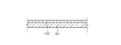
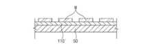
一例として、図3〜図7を参照すると、アンテナパターン112は、アウターレンズ50の内面に導電性薄膜110´を形成するステップ(S10)と、導電性薄膜110´の表面にマスクパターンMを形成するステップ(S20)と、マスクパターンMを用いて、導電性薄膜110´を部分的に除去するステップ(S30)とによって設けられ得る。 As an example, referring to FIGS. 3 to 7, the
先ず、図4のように、アウターレンズ50の内面に導電性薄膜110´(例えば、銀、銅、ITO材質の金属薄膜)を形成する。次に、図5のように、導電性薄膜110´の表面(図5を基準に上面)にマスクパターンMを形成する。次に、図6のように、マスクパターンMを用いて、導電性薄膜110´を部分的に除去(例えば、マスクパターンMが形成されていない箇所をエッチング)することで、アンテナパターン112を形成することができる。最後に、図7のように、アンテナパターン112を形成してからはマスクパターンMが除去され得る。 First, as shown in FIG. 4, a conductive thin film 110'(for example, a metal thin film made of silver, copper, or ITO material) is formed on the inner surface of the
上述および図示している本発明の実施形態では、エッチングによってアンテナパターン112を形成する例を挙げて説明しているが、本発明の他の実施形態によると、印刷または、その他の異なる方式でアウターレンズ50の内面にアンテナパターン112をパターニングすることも可能である。 In the embodiments of the present invention described above and illustrated, examples of forming the
好ましくは、アンテナパターン112は、地面に垂直にアウターレンズ50の内面に形成される。 Preferably, the
このように、地面に垂直にアンテナパターン112を形成することにより、アンテナパターン112による電磁波の送受信特性を極大化する有利な効果を得ることができる。 By forming the
図1および図2を参照すると、信号処理モジュール120は、アンテナ110に送受信する信号を分析および処理し、アンテナ110を制御するために車両用ランプ10の内部に設けられる。 Referring to FIGS. 1 and 2, the
信号処理モジュール120は、中央処理装置(CPU)またはメモリおよび/またはストレージに保存された命令語に対する処理を行う半導体装置を含むことができる。メモリおよびストレージは、各種の揮発性または不揮発性保存媒体を含むことができる。例えば、メモリは、ROM(Read Only Memory)およびRAM(Random Access Memory)を含むことができる。 The
好ましくは、信号処理モジュール120は、アンテナ110の下部(ランプ10内部の底部)に配置される。このように、アンテナ110の下部に信号処理モジュール120を配置することによって、信号処理モジュール120によるアンテナ110の性能の低下を防止し、信号処理モジュール120の外部露出を最小化する有利な効果を得ることができる。 Preferably, the
より好ましくは、信号処理モジュール120は、光源20の下部に配置される。 More preferably, the
これは、密閉構造を有するランプ10の内部空間で、光源20の下部空間の温度が他の空間(例えば、光源20とインナーレンズ40との間の空間)の温度より相対的に低く形成されることによるものであり、ランプ10の内部で相対的に最も温度が低い光源20の下部空間に信号処理モジュール120を配置することにより、信号処理モジュール120の過熱現象を最小化し、安定性および信頼性を向上させる有利な効果を得ることができる。 This is an internal space of the
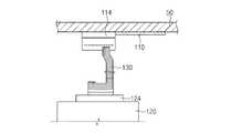
一方、図2および図8を参照すると、アンテナ110と信号処理モジュール120は、連結部材130によって電気的に連結され得る。 On the other hand, referring to FIGS. 2 and 8, the
好ましくは、連結部材130としては、柔軟に反ることができるケーブル、フレキシブル基板(FPCB)の少なくともいずれか一つが使用され得、連結部材130の種類および構造によって本発明が制限または限定されるものではない。 Preferably, as the connecting
一例として、図8を参照すると、連結部材130としては、フレキシブル基板が使用され得、連結部材130の一端は、アンテナパターン112に電気的に連結され、連結部材130の他の一端は、信号処理モジュール120に電気的に連結され得る。 As an example, referring to FIG. 8, a flexible substrate can be used as the connecting
連結部材130とアンテナパターン112(または信号処理モジュール)は、コネクタ、導電性接着体、半田付け、導電性フックなどを介して電気的に接続され得、連結部材130とアンテナパターン112(または信号処理モジュール)との電気的接続構造によって本発明が制限または限定されるものではない。 The connecting
一例として、連結部材130の一端および他端には、それぞれコネクタ114、124が連結され得、コネクタ114、124をアンテナ110および信号処理モジュール120に連結された端子部(図示せず)に結合することで、電気的に接続され得る。 As an example,
上述のように、本発明の実施形態によると、構造を簡素化し、設計自由度および空間活用性を向上させる有利な効果を得ることができる。 As described above, according to the embodiment of the present invention, it is possible to obtain an advantageous effect of simplifying the structure and improving the degree of freedom in design and the space utilization.
特に、本発明の実施形態によると、車両用ランプの内部にレーダを装着することによって、レーダ装着に必要な空間を最小化し、設計自由度および空間活用性を向上させる有利な効果を得ることができる。 In particular, according to the embodiment of the present invention, by mounting the radar inside the vehicle lamp, it is possible to obtain an advantageous effect of minimizing the space required for mounting the radar and improving the degree of freedom in design and the space utilization. can.
また、本発明の実施形態によると、車両用ランプのデザイン特性の低下を防止することができ、商品性を向上させ、消費者の満足度を高める有利な効果を得ることができる。 Further, according to the embodiment of the present invention, it is possible to prevent deterioration of the design characteristics of the vehicle lamp, improve commerciality, and obtain an advantageous effect of increasing consumer satisfaction.
以上、実施形態を中心に説明しているが、これは単に例示であって、本発明を限定するものではなく、本発明が属する分野において通常の知識を有する者であれば、本実施形態の本質的な特性から逸脱しない範囲で、以上に例示されていない様々の変形と応用が可能であることを知ることができる。例えば、実施形態に具体的に示された各構成要素は、変形して実施可能なものである。また、かかる変形と応用に関する差異は、添付の請求の範囲で規定する本発明の範囲に含まれるものと解釈すべきである。 Although the above description mainly describes the embodiment, this is merely an example and does not limit the present invention, and any person who has ordinary knowledge in the field to which the present invention belongs can use the present embodiment. It can be seen that various modifications and applications not illustrated above are possible without departing from the essential properties. For example, each component specifically shown in the embodiment can be modified and implemented. In addition, such variations and differences in application should be construed as included in the scope of the invention as defined in the appended claims.
10 ランプ
20 光源
30 リフレクタ
40 インナーレンズ
50 アウターレンズ
100 車両レーダ装置
110 アンテナ
112 アンテナパターン
120 信号処理モジュール
130 連結部材10
Claims (11)
Translated fromJapanese車両用ランプの内部に設けられ、前記アンテナに受信した信号を処理する信号処理モジュールとを含む、車両レーダ装置。An antenna installed on the inner surface of the vehicle lamp to transmit and receive electromagnetic waves,
A vehicle radar device provided inside a vehicle lamp and including a signal processing module for processing a signal received by the antenna.
光を発生する光源と、
前記光源の前方に設けられ、外観を形成するアウターレンズとを含み、
前記アンテナは、前記アウターレンズの内面に設けられる、請求項1に記載の車両レーダ装置。The lamp is
A light source that generates light and
Including an outer lens provided in front of the light source and forming an appearance.
The vehicle radar device according to claim 1, wherein the antenna is provided on the inner surface of the outer lens.
前記アウターレンズの内面に導電性薄膜を形成するステップと、
前記導電性薄膜の表面にマスクパターンを形成するステップと、
前記マスクパターンを用いて、前記導電性薄膜を部分的に除去するステップとにより設けられる、請求項4に記載の車両レーダ装置。The antenna pattern is
The step of forming a conductive thin film on the inner surface of the outer lens,
The step of forming a mask pattern on the surface of the conductive thin film,
The vehicle radar device according to claim 4, further provided by a step of partially removing the conductive thin film using the mask pattern.
Applications Claiming Priority (2)
| Application Number | Priority Date | Filing Date | Title |
|---|---|---|---|
| KR1020200069655AKR20210152764A (en) | 2020-06-09 | 2020-06-09 | Vehicle radar device |
| KR10-2020-0069655 | 2020-06-09 |
Publications (2)
| Publication Number | Publication Date |
|---|---|
| JP2021196345Atrue JP2021196345A (en) | 2021-12-27 |
| JP7126746B2 JP7126746B2 (en) | 2022-08-29 |
Family
ID=75588043
Family Applications (1)
| Application Number | Title | Priority Date | Filing Date |
|---|---|---|---|
| JP2021076494AActiveJP7126746B2 (en) | 2020-06-09 | 2021-04-28 | vehicle radar device |
Country Status (5)
| Country | Link |
|---|---|
| US (1) | US11808845B2 (en) |
| EP (1) | EP3923018A1 (en) |
| JP (1) | JP7126746B2 (en) |
| KR (1) | KR20210152764A (en) |
| CN (1) | CN113777597A (en) |
Families Citing this family (2)
| Publication number | Priority date | Publication date | Assignee | Title |
|---|---|---|---|---|
| DE102021132798A1 (en)* | 2021-12-13 | 2023-06-15 | Valeo Schalter Und Sensoren Gmbh | Vehicle radar device assembly and method of manufacturing a vehicle radar device assembly |
| WO2024206423A1 (en)* | 2023-03-31 | 2024-10-03 | Indian Motorcycle International, LLC | Vehicle front radar integration |
Citations (10)
| Publication number | Priority date | Publication date | Assignee | Title |
|---|---|---|---|---|
| JPH0669708A (en)* | 1992-05-19 | 1994-03-11 | Thomson Csf | Microwave antenna |
| JP2007174390A (en)* | 2005-12-22 | 2007-07-05 | Tdk Corp | Radar system |
| JP2008186741A (en)* | 2007-01-31 | 2008-08-14 | Koito Mfg Co Ltd | Vehicle lighting |
| JP2010154182A (en)* | 2008-12-25 | 2010-07-08 | Koito Mfg Co Ltd | On-vehicle radar apparatus |
| JP2017517993A (en)* | 2014-05-06 | 2017-06-29 | ローベルト ボッシュ ゲゼルシャフト ミット ベシュレンクテル ハフツング | Antenna device for vehicle |
| JP2017147487A (en)* | 2016-02-15 | 2017-08-24 | マツダ株式会社 | Vehicle including radar device |
| JP2018182734A (en)* | 2017-04-04 | 2018-11-15 | 株式会社Soken | Optical transmission type antenna, window pasted type communication module, and peripheral monitoring unit |
| JP2020051975A (en)* | 2018-09-28 | 2020-04-02 | パナソニックIpマネジメント株式会社 | In-vehicle light device |
| JP2020056788A (en)* | 2018-09-28 | 2020-04-09 | ツェットカーベー グループ | Vehicle lamp |
| WO2020179447A1 (en)* | 2019-03-06 | 2020-09-10 | 株式会社小糸製作所 | Vehicular lamp and vehicle |
Family Cites Families (19)
| Publication number | Priority date | Publication date | Assignee | Title |
|---|---|---|---|---|
| US5008678A (en)* | 1990-03-02 | 1991-04-16 | Hughes Aircraft Company | Electronically scanning vehicle radar sensor |
| DE4201214C1 (en)* | 1992-01-18 | 1993-02-04 | Mercedes-Benz Aktiengesellschaft, 7000 Stuttgart, De | |
| US5467072A (en)* | 1994-03-11 | 1995-11-14 | Piccard Enterprises, Inc. | Phased array based radar system for vehicular collision avoidance |
| DE19607653A1 (en)* | 1996-02-29 | 1997-09-04 | Bosch Gmbh Robert | Headlamp with integrated microwave antenna |
| US6380883B1 (en)* | 1998-02-23 | 2002-04-30 | Amerigon | High performance vehicle radar system |
| DE10024666A1 (en)* | 2000-05-18 | 2001-11-29 | Bosch Gmbh Robert | Vehicle antenna arrangement |
| US6552690B2 (en)* | 2001-08-14 | 2003-04-22 | Guardian Industries Corp. | Vehicle windshield with fractal antenna(s) |
| US7126541B2 (en)* | 2002-11-19 | 2006-10-24 | Farrokh Mohamadi | Beam forming phased array system in a transparent substrate |
| JP2008162391A (en)* | 2006-12-27 | 2008-07-17 | Koito Mfg Co Ltd | Vehicular lamp |
| CN101743573B (en)* | 2007-07-17 | 2014-05-14 | 住友电气工业株式会社 | Lamp device, antenna unit for a lamp device, communication system, and traffic signal controller |
| US8922435B2 (en)* | 2009-04-27 | 2014-12-30 | Drexel University | Transparent conformal polymer antennas for RFID and other wireless communications applications |
| JP4919179B2 (en)* | 2010-05-11 | 2012-04-18 | 独立行政法人電子航法研究所 | Millimeter wave radar built-in headlamp |
| DE102011115829A1 (en)* | 2011-10-13 | 2013-04-18 | Conti Temic Microelectronic Gmbh | Radar apparatus for vehicle e.g. motor car, has transmitting-receiving units for emitting radar beam as transmission signal, and receiving signal of target object within radiation area such that the radar beam is reflected |
| US9647325B2 (en)* | 2014-08-29 | 2017-05-09 | GM Global Technology Operations LLC | Flexible artificial impedance surface antennas for automotive radar sensors |
| US20170098888A1 (en)* | 2015-10-06 | 2017-04-06 | GM Global Technology Operations LLC | Flexible conformable antenna array applique |
| DE102019126122A1 (en)* | 2018-09-28 | 2020-04-02 | Panasonic Intellectual Property Management Co., Ltd. | Vehicle lighting device |
| DE102018217774A1 (en) | 2018-10-17 | 2020-04-23 | Fraunhofer-Gesellschaft zur Förderung der angewandten Forschung e.V. | Radar and light emitting device for vehicles for emitting light and radar radiation as well as method and use |
| JP7132887B2 (en)* | 2019-05-29 | 2022-09-07 | 本田技研工業株式会社 | vehicle light body |
| WO2021133408A1 (en)* | 2019-12-27 | 2021-07-01 | Intel Corporation | Embedded antennas structures for wireless communications and radar |
- 2020
- 2020-06-09KRKR1020200069655Apatent/KR20210152764A/enactivePending
- 2021
- 2021-04-14USUS17/230,931patent/US11808845B2/enactiveActive
- 2021-04-19EPEP21169185.2Apatent/EP3923018A1/enactivePending
- 2021-04-28JPJP2021076494Apatent/JP7126746B2/enactiveActive
- 2021-05-11CNCN202110513189.4Apatent/CN113777597A/enactivePending
Patent Citations (10)
| Publication number | Priority date | Publication date | Assignee | Title |
|---|---|---|---|---|
| JPH0669708A (en)* | 1992-05-19 | 1994-03-11 | Thomson Csf | Microwave antenna |
| JP2007174390A (en)* | 2005-12-22 | 2007-07-05 | Tdk Corp | Radar system |
| JP2008186741A (en)* | 2007-01-31 | 2008-08-14 | Koito Mfg Co Ltd | Vehicle lighting |
| JP2010154182A (en)* | 2008-12-25 | 2010-07-08 | Koito Mfg Co Ltd | On-vehicle radar apparatus |
| JP2017517993A (en)* | 2014-05-06 | 2017-06-29 | ローベルト ボッシュ ゲゼルシャフト ミット ベシュレンクテル ハフツング | Antenna device for vehicle |
| JP2017147487A (en)* | 2016-02-15 | 2017-08-24 | マツダ株式会社 | Vehicle including radar device |
| JP2018182734A (en)* | 2017-04-04 | 2018-11-15 | 株式会社Soken | Optical transmission type antenna, window pasted type communication module, and peripheral monitoring unit |
| JP2020051975A (en)* | 2018-09-28 | 2020-04-02 | パナソニックIpマネジメント株式会社 | In-vehicle light device |
| JP2020056788A (en)* | 2018-09-28 | 2020-04-09 | ツェットカーベー グループ | Vehicle lamp |
| WO2020179447A1 (en)* | 2019-03-06 | 2020-09-10 | 株式会社小糸製作所 | Vehicular lamp and vehicle |
Also Published As
| Publication number | Publication date |
|---|---|
| CN113777597A (en) | 2021-12-10 |
| KR20210152764A (en) | 2021-12-16 |
| JP7126746B2 (en) | 2022-08-29 |
| EP3923018A1 (en) | 2021-12-15 |
| US11808845B2 (en) | 2023-11-07 |
| US20210382168A1 (en) | 2021-12-09 |
Similar Documents
| Publication | Publication Date | Title |
|---|---|---|
| US12269391B2 (en) | Vehicle light fitting, radar module, radar, and vehicle | |
| US11845376B2 (en) | Radar and light emission assembly for vehicles for emitting light and radar radiation, and method and use | |
| JP4658605B2 (en) | Retroreflective display | |
| CN105531151B (en) | Lighting system, automotive vehicle lighting device and automotive vehicle | |
| JP2021196345A (en) | Vehicle radar device | |
| US12422122B2 (en) | Deicing system for an automotive lamp | |
| US9347652B2 (en) | Lighting device and lighting device set | |
| CN106104145A (en) | Lighting unit for vehicle | |
| JP2014135158A (en) | Vehicular lighting tool | |
| CN114729988A (en) | Vehicle lamps, radars and vehicles | |
| US20230220968A1 (en) | Lighting device and lamp comprising same | |
| KR101673655B1 (en) | Lamp unit for vehicle | |
| JP2020051975A (en) | In-vehicle light device | |
| CN120363824A (en) | Retro-reflector and lamp device with the same | |
| WO2025215722A1 (en) | Vehicular lamp and vehicle | |
| CN113039389A (en) | Vehicle lamp | |
| JP7745441B2 (en) | Lamp unit | |
| CN116893417A (en) | Exterior member for vehicle and electromagnetic wave radar system | |
| CN119895658A (en) | Electronic system comprising a radar antenna and transmitting device | |
| JP5262340B2 (en) | Lamp and method of manufacturing lamp | |
| CN114174115A (en) | Lighting equipment for cars | |
| KR20180037491A (en) | The light source module and vehicle lamp including the same |
Legal Events
| Date | Code | Title | Description |
|---|---|---|---|
| A621 | Written request for application examination | Free format text:JAPANESE INTERMEDIATE CODE: A621 Effective date:20210428 | |
| A131 | Notification of reasons for refusal | Free format text:JAPANESE INTERMEDIATE CODE: A131 Effective date:20220329 | |
| A521 | Request for written amendment filed | Free format text:JAPANESE INTERMEDIATE CODE: A523 Effective date:20220610 | |
| TRDD | Decision of grant or rejection written | ||
| A01 | Written decision to grant a patent or to grant a registration (utility model) | Free format text:JAPANESE INTERMEDIATE CODE: A01 Effective date:20220802 | |
| A61 | First payment of annual fees (during grant procedure) | Free format text:JAPANESE INTERMEDIATE CODE: A61 Effective date:20220815 | |
| R150 | Certificate of patent or registration of utility model | Ref document number:7126746 Country of ref document:JP Free format text:JAPANESE INTERMEDIATE CODE: R150 | |
| R250 | Receipt of annual fees | Free format text:JAPANESE INTERMEDIATE CODE: R250 |