JP2021195580A - Film deposition apparatus and film deposition method - Google Patents
Film deposition apparatus and film deposition methodDownload PDFInfo
- Publication number
- JP2021195580A JP2021195580AJP2020101193AJP2020101193AJP2021195580AJP 2021195580 AJP2021195580 AJP 2021195580AJP 2020101193 AJP2020101193 AJP 2020101193AJP 2020101193 AJP2020101193 AJP 2020101193AJP 2021195580 AJP2021195580 AJP 2021195580A
- Authority
- JP
- Japan
- Prior art keywords
- film
- gas
- raw material
- substrate
- filter
- Prior art date
- Legal status (The legal status is an assumption and is not a legal conclusion. Google has not performed a legal analysis and makes no representation as to the accuracy of the status listed.)
- Granted
Links
- 238000000151depositionMethods0.000titleabstract10
- 230000008021depositionEffects0.000titleabstract8
- 239000002994raw materialSubstances0.000claimsabstractdescription79
- 239000000758substrateSubstances0.000claimsabstractdescription51
- 239000002245particleSubstances0.000claimsabstractdescription34
- 238000007599dischargingMethods0.000claimsabstractdescription4
- 230000015572biosynthetic processEffects0.000claimsdescription14
- 238000010438heat treatmentMethods0.000claimsdescription9
- 238000000034methodMethods0.000claimsdescription9
- 238000009792diffusion processMethods0.000claimsdescription8
- 239000007787solidSubstances0.000claimsdescription8
- 229910052751metalInorganic materials0.000claimsdescription6
- 239000002184metalSubstances0.000claimsdescription6
- 239000000835fiberSubstances0.000claimsdescription3
- 239000007789gasSubstances0.000description76
- 239000012159carrier gasSubstances0.000description11
- 235000012431wafersNutrition0.000description11
- 230000002093peripheral effectEffects0.000description5
- 239000004065semiconductorSubstances0.000description5
- 238000005229chemical vapour depositionMethods0.000description3
- 239000011261inert gasSubstances0.000description3
- 238000005979thermal decomposition reactionMethods0.000description3
- 238000006243chemical reactionMethods0.000description2
- 230000003028elevating effectEffects0.000description2
- 239000012495reaction gasSubstances0.000description2
- 238000000859sublimationMethods0.000description2
- 230000008022sublimationEffects0.000description2
- NQZFAUXPNWSLBI-UHFFFAOYSA-Ncarbon monoxide;rutheniumChemical group[Ru].[Ru].[Ru].[O+]#[C-].[O+]#[C-].[O+]#[C-].[O+]#[C-].[O+]#[C-].[O+]#[C-].[O+]#[C-].[O+]#[C-].[O+]#[C-].[O+]#[C-].[O+]#[C-].[O+]#[C-]NQZFAUXPNWSLBI-UHFFFAOYSA-N0.000description1
- 125000002915carbonyl groupChemical group[*:2]C([*:1])=O0.000description1
- 238000000354decomposition reactionMethods0.000description1
- 238000001514detection methodMethods0.000description1
- 230000000694effectsEffects0.000description1
- 238000010030laminatingMethods0.000description1
- 239000000463materialSubstances0.000description1
- 239000012528membraneSubstances0.000description1
- 239000004745nonwoven fabricSubstances0.000description1
- 238000005245sinteringMethods0.000description1
- 230000008016vaporizationEffects0.000description1
Images

Classifications
- C—CHEMISTRY; METALLURGY
- C23—COATING METALLIC MATERIAL; COATING MATERIAL WITH METALLIC MATERIAL; CHEMICAL SURFACE TREATMENT; DIFFUSION TREATMENT OF METALLIC MATERIAL; COATING BY VACUUM EVAPORATION, BY SPUTTERING, BY ION IMPLANTATION OR BY CHEMICAL VAPOUR DEPOSITION, IN GENERAL; INHIBITING CORROSION OF METALLIC MATERIAL OR INCRUSTATION IN GENERAL
- C23C—COATING METALLIC MATERIAL; COATING MATERIAL WITH METALLIC MATERIAL; SURFACE TREATMENT OF METALLIC MATERIAL BY DIFFUSION INTO THE SURFACE, BY CHEMICAL CONVERSION OR SUBSTITUTION; COATING BY VACUUM EVAPORATION, BY SPUTTERING, BY ION IMPLANTATION OR BY CHEMICAL VAPOUR DEPOSITION, IN GENERAL
- C23C16/00—Chemical coating by decomposition of gaseous compounds, without leaving reaction products of surface material in the coating, i.e. chemical vapour deposition [CVD] processes
- C23C16/44—Chemical coating by decomposition of gaseous compounds, without leaving reaction products of surface material in the coating, i.e. chemical vapour deposition [CVD] processes characterised by the method of coating
- C23C16/4401—Means for minimising impurities, e.g. dust, moisture or residual gas, in the reaction chamber
- C—CHEMISTRY; METALLURGY
- C23—COATING METALLIC MATERIAL; COATING MATERIAL WITH METALLIC MATERIAL; CHEMICAL SURFACE TREATMENT; DIFFUSION TREATMENT OF METALLIC MATERIAL; COATING BY VACUUM EVAPORATION, BY SPUTTERING, BY ION IMPLANTATION OR BY CHEMICAL VAPOUR DEPOSITION, IN GENERAL; INHIBITING CORROSION OF METALLIC MATERIAL OR INCRUSTATION IN GENERAL
- C23C—COATING METALLIC MATERIAL; COATING MATERIAL WITH METALLIC MATERIAL; SURFACE TREATMENT OF METALLIC MATERIAL BY DIFFUSION INTO THE SURFACE, BY CHEMICAL CONVERSION OR SUBSTITUTION; COATING BY VACUUM EVAPORATION, BY SPUTTERING, BY ION IMPLANTATION OR BY CHEMICAL VAPOUR DEPOSITION, IN GENERAL
- C23C16/00—Chemical coating by decomposition of gaseous compounds, without leaving reaction products of surface material in the coating, i.e. chemical vapour deposition [CVD] processes
- C23C16/06—Chemical coating by decomposition of gaseous compounds, without leaving reaction products of surface material in the coating, i.e. chemical vapour deposition [CVD] processes characterised by the deposition of metallic material
- C23C16/16—Chemical coating by decomposition of gaseous compounds, without leaving reaction products of surface material in the coating, i.e. chemical vapour deposition [CVD] processes characterised by the deposition of metallic material from metal carbonyl compounds
- C—CHEMISTRY; METALLURGY
- C23—COATING METALLIC MATERIAL; COATING MATERIAL WITH METALLIC MATERIAL; CHEMICAL SURFACE TREATMENT; DIFFUSION TREATMENT OF METALLIC MATERIAL; COATING BY VACUUM EVAPORATION, BY SPUTTERING, BY ION IMPLANTATION OR BY CHEMICAL VAPOUR DEPOSITION, IN GENERAL; INHIBITING CORROSION OF METALLIC MATERIAL OR INCRUSTATION IN GENERAL
- C23C—COATING METALLIC MATERIAL; COATING MATERIAL WITH METALLIC MATERIAL; SURFACE TREATMENT OF METALLIC MATERIAL BY DIFFUSION INTO THE SURFACE, BY CHEMICAL CONVERSION OR SUBSTITUTION; COATING BY VACUUM EVAPORATION, BY SPUTTERING, BY ION IMPLANTATION OR BY CHEMICAL VAPOUR DEPOSITION, IN GENERAL
- C23C16/00—Chemical coating by decomposition of gaseous compounds, without leaving reaction products of surface material in the coating, i.e. chemical vapour deposition [CVD] processes
- C23C16/44—Chemical coating by decomposition of gaseous compounds, without leaving reaction products of surface material in the coating, i.e. chemical vapour deposition [CVD] processes characterised by the method of coating
- C23C16/4401—Means for minimising impurities, e.g. dust, moisture or residual gas, in the reaction chamber
- C23C16/4402—Reduction of impurities in the source gas
- C—CHEMISTRY; METALLURGY
- C23—COATING METALLIC MATERIAL; COATING MATERIAL WITH METALLIC MATERIAL; CHEMICAL SURFACE TREATMENT; DIFFUSION TREATMENT OF METALLIC MATERIAL; COATING BY VACUUM EVAPORATION, BY SPUTTERING, BY ION IMPLANTATION OR BY CHEMICAL VAPOUR DEPOSITION, IN GENERAL; INHIBITING CORROSION OF METALLIC MATERIAL OR INCRUSTATION IN GENERAL
- C23C—COATING METALLIC MATERIAL; COATING MATERIAL WITH METALLIC MATERIAL; SURFACE TREATMENT OF METALLIC MATERIAL BY DIFFUSION INTO THE SURFACE, BY CHEMICAL CONVERSION OR SUBSTITUTION; COATING BY VACUUM EVAPORATION, BY SPUTTERING, BY ION IMPLANTATION OR BY CHEMICAL VAPOUR DEPOSITION, IN GENERAL
- C23C16/00—Chemical coating by decomposition of gaseous compounds, without leaving reaction products of surface material in the coating, i.e. chemical vapour deposition [CVD] processes
- C23C16/44—Chemical coating by decomposition of gaseous compounds, without leaving reaction products of surface material in the coating, i.e. chemical vapour deposition [CVD] processes characterised by the method of coating
- C23C16/455—Chemical coating by decomposition of gaseous compounds, without leaving reaction products of surface material in the coating, i.e. chemical vapour deposition [CVD] processes characterised by the method of coating characterised by the method used for introducing gases into reaction chamber or for modifying gas flows in reaction chamber
- C23C16/45517—Confinement of gases to vicinity of substrate
- C—CHEMISTRY; METALLURGY
- C23—COATING METALLIC MATERIAL; COATING MATERIAL WITH METALLIC MATERIAL; CHEMICAL SURFACE TREATMENT; DIFFUSION TREATMENT OF METALLIC MATERIAL; COATING BY VACUUM EVAPORATION, BY SPUTTERING, BY ION IMPLANTATION OR BY CHEMICAL VAPOUR DEPOSITION, IN GENERAL; INHIBITING CORROSION OF METALLIC MATERIAL OR INCRUSTATION IN GENERAL
- C23C—COATING METALLIC MATERIAL; COATING MATERIAL WITH METALLIC MATERIAL; SURFACE TREATMENT OF METALLIC MATERIAL BY DIFFUSION INTO THE SURFACE, BY CHEMICAL CONVERSION OR SUBSTITUTION; COATING BY VACUUM EVAPORATION, BY SPUTTERING, BY ION IMPLANTATION OR BY CHEMICAL VAPOUR DEPOSITION, IN GENERAL
- C23C16/00—Chemical coating by decomposition of gaseous compounds, without leaving reaction products of surface material in the coating, i.e. chemical vapour deposition [CVD] processes
- C23C16/44—Chemical coating by decomposition of gaseous compounds, without leaving reaction products of surface material in the coating, i.e. chemical vapour deposition [CVD] processes characterised by the method of coating
- C23C16/455—Chemical coating by decomposition of gaseous compounds, without leaving reaction products of surface material in the coating, i.e. chemical vapour deposition [CVD] processes characterised by the method of coating characterised by the method used for introducing gases into reaction chamber or for modifying gas flows in reaction chamber
- C23C16/45559—Diffusion of reactive gas to substrate
- C—CHEMISTRY; METALLURGY
- C23—COATING METALLIC MATERIAL; COATING MATERIAL WITH METALLIC MATERIAL; CHEMICAL SURFACE TREATMENT; DIFFUSION TREATMENT OF METALLIC MATERIAL; COATING BY VACUUM EVAPORATION, BY SPUTTERING, BY ION IMPLANTATION OR BY CHEMICAL VAPOUR DEPOSITION, IN GENERAL; INHIBITING CORROSION OF METALLIC MATERIAL OR INCRUSTATION IN GENERAL
- C23C—COATING METALLIC MATERIAL; COATING MATERIAL WITH METALLIC MATERIAL; SURFACE TREATMENT OF METALLIC MATERIAL BY DIFFUSION INTO THE SURFACE, BY CHEMICAL CONVERSION OR SUBSTITUTION; COATING BY VACUUM EVAPORATION, BY SPUTTERING, BY ION IMPLANTATION OR BY CHEMICAL VAPOUR DEPOSITION, IN GENERAL
- C23C16/00—Chemical coating by decomposition of gaseous compounds, without leaving reaction products of surface material in the coating, i.e. chemical vapour deposition [CVD] processes
- C23C16/44—Chemical coating by decomposition of gaseous compounds, without leaving reaction products of surface material in the coating, i.e. chemical vapour deposition [CVD] processes characterised by the method of coating
- C23C16/455—Chemical coating by decomposition of gaseous compounds, without leaving reaction products of surface material in the coating, i.e. chemical vapour deposition [CVD] processes characterised by the method of coating characterised by the method used for introducing gases into reaction chamber or for modifying gas flows in reaction chamber
- C23C16/45563—Gas nozzles
- C23C16/4557—Heated nozzles
- C—CHEMISTRY; METALLURGY
- C23—COATING METALLIC MATERIAL; COATING MATERIAL WITH METALLIC MATERIAL; CHEMICAL SURFACE TREATMENT; DIFFUSION TREATMENT OF METALLIC MATERIAL; COATING BY VACUUM EVAPORATION, BY SPUTTERING, BY ION IMPLANTATION OR BY CHEMICAL VAPOUR DEPOSITION, IN GENERAL; INHIBITING CORROSION OF METALLIC MATERIAL OR INCRUSTATION IN GENERAL
- C23C—COATING METALLIC MATERIAL; COATING MATERIAL WITH METALLIC MATERIAL; SURFACE TREATMENT OF METALLIC MATERIAL BY DIFFUSION INTO THE SURFACE, BY CHEMICAL CONVERSION OR SUBSTITUTION; COATING BY VACUUM EVAPORATION, BY SPUTTERING, BY ION IMPLANTATION OR BY CHEMICAL VAPOUR DEPOSITION, IN GENERAL
- C23C16/00—Chemical coating by decomposition of gaseous compounds, without leaving reaction products of surface material in the coating, i.e. chemical vapour deposition [CVD] processes
- C23C16/44—Chemical coating by decomposition of gaseous compounds, without leaving reaction products of surface material in the coating, i.e. chemical vapour deposition [CVD] processes characterised by the method of coating
- C23C16/46—Chemical coating by decomposition of gaseous compounds, without leaving reaction products of surface material in the coating, i.e. chemical vapour deposition [CVD] processes characterised by the method of coating characterised by the method used for heating the substrate
- C—CHEMISTRY; METALLURGY
- C23—COATING METALLIC MATERIAL; COATING MATERIAL WITH METALLIC MATERIAL; CHEMICAL SURFACE TREATMENT; DIFFUSION TREATMENT OF METALLIC MATERIAL; COATING BY VACUUM EVAPORATION, BY SPUTTERING, BY ION IMPLANTATION OR BY CHEMICAL VAPOUR DEPOSITION, IN GENERAL; INHIBITING CORROSION OF METALLIC MATERIAL OR INCRUSTATION IN GENERAL
- C23C—COATING METALLIC MATERIAL; COATING MATERIAL WITH METALLIC MATERIAL; SURFACE TREATMENT OF METALLIC MATERIAL BY DIFFUSION INTO THE SURFACE, BY CHEMICAL CONVERSION OR SUBSTITUTION; COATING BY VACUUM EVAPORATION, BY SPUTTERING, BY ION IMPLANTATION OR BY CHEMICAL VAPOUR DEPOSITION, IN GENERAL
- C23C16/00—Chemical coating by decomposition of gaseous compounds, without leaving reaction products of surface material in the coating, i.e. chemical vapour deposition [CVD] processes
- C23C16/44—Chemical coating by decomposition of gaseous compounds, without leaving reaction products of surface material in the coating, i.e. chemical vapour deposition [CVD] processes characterised by the method of coating
- C23C16/54—Apparatus specially adapted for continuous coating
- C—CHEMISTRY; METALLURGY
- C23—COATING METALLIC MATERIAL; COATING MATERIAL WITH METALLIC MATERIAL; CHEMICAL SURFACE TREATMENT; DIFFUSION TREATMENT OF METALLIC MATERIAL; COATING BY VACUUM EVAPORATION, BY SPUTTERING, BY ION IMPLANTATION OR BY CHEMICAL VAPOUR DEPOSITION, IN GENERAL; INHIBITING CORROSION OF METALLIC MATERIAL OR INCRUSTATION IN GENERAL
- C23C—COATING METALLIC MATERIAL; COATING MATERIAL WITH METALLIC MATERIAL; SURFACE TREATMENT OF METALLIC MATERIAL BY DIFFUSION INTO THE SURFACE, BY CHEMICAL CONVERSION OR SUBSTITUTION; COATING BY VACUUM EVAPORATION, BY SPUTTERING, BY ION IMPLANTATION OR BY CHEMICAL VAPOUR DEPOSITION, IN GENERAL
- C23C16/00—Chemical coating by decomposition of gaseous compounds, without leaving reaction products of surface material in the coating, i.e. chemical vapour deposition [CVD] processes
- C23C16/44—Chemical coating by decomposition of gaseous compounds, without leaving reaction products of surface material in the coating, i.e. chemical vapour deposition [CVD] processes characterised by the method of coating
- C23C16/455—Chemical coating by decomposition of gaseous compounds, without leaving reaction products of surface material in the coating, i.e. chemical vapour deposition [CVD] processes characterised by the method of coating characterised by the method used for introducing gases into reaction chamber or for modifying gas flows in reaction chamber
- C23C16/45563—Gas nozzles
- C23C16/45565—Shower nozzles
- C—CHEMISTRY; METALLURGY
- C23—COATING METALLIC MATERIAL; COATING MATERIAL WITH METALLIC MATERIAL; CHEMICAL SURFACE TREATMENT; DIFFUSION TREATMENT OF METALLIC MATERIAL; COATING BY VACUUM EVAPORATION, BY SPUTTERING, BY ION IMPLANTATION OR BY CHEMICAL VAPOUR DEPOSITION, IN GENERAL; INHIBITING CORROSION OF METALLIC MATERIAL OR INCRUSTATION IN GENERAL
- C23C—COATING METALLIC MATERIAL; COATING MATERIAL WITH METALLIC MATERIAL; SURFACE TREATMENT OF METALLIC MATERIAL BY DIFFUSION INTO THE SURFACE, BY CHEMICAL CONVERSION OR SUBSTITUTION; COATING BY VACUUM EVAPORATION, BY SPUTTERING, BY ION IMPLANTATION OR BY CHEMICAL VAPOUR DEPOSITION, IN GENERAL
- C23C16/00—Chemical coating by decomposition of gaseous compounds, without leaving reaction products of surface material in the coating, i.e. chemical vapour deposition [CVD] processes
- C23C16/44—Chemical coating by decomposition of gaseous compounds, without leaving reaction products of surface material in the coating, i.e. chemical vapour deposition [CVD] processes characterised by the method of coating
- C23C16/455—Chemical coating by decomposition of gaseous compounds, without leaving reaction products of surface material in the coating, i.e. chemical vapour deposition [CVD] processes characterised by the method of coating characterised by the method used for introducing gases into reaction chamber or for modifying gas flows in reaction chamber
- C23C16/45587—Mechanical means for changing the gas flow
- C23C16/45591—Fixed means, e.g. wings, baffles
Landscapes
- Chemical & Material Sciences (AREA)
- General Chemical & Material Sciences (AREA)
- Chemical Kinetics & Catalysis (AREA)
- Engineering & Computer Science (AREA)
- Materials Engineering (AREA)
- Mechanical Engineering (AREA)
- Metallurgy (AREA)
- Organic Chemistry (AREA)
- Chemical Vapour Deposition (AREA)
- Electrodes Of Semiconductors (AREA)
Abstract
Description
Translated fromJapanese本開示は、成膜装置および成膜方法に関する。 The present disclosure relates to a film forming apparatus and a film forming method.
基板上に膜を形成する技術として、基板上に原料ガスを供給して熱分解または反応ガスとの反応により膜形成を行う化学蒸着(CVD)法が存在する。常温で固体の原料を用いてCVD法による成膜を行う場合は、原料を気化させて生成した原料ガスを供給して成膜する。例えば特許文献1には、常温で固体のRu3(CO)12を容器内で気化させ、気体状のRu3(CO)12をチャンバー内に供給し、基板上で熱分解させてRu膜を成膜する技術が記載されている。As a technique for forming a film on a substrate, there is a chemical vapor deposition (CVD) method in which a raw material gas is supplied onto the substrate and the film is formed by thermal decomposition or reaction with the reaction gas. When a film is formed by the CVD method using a solid raw material at room temperature, the raw material gas generated by vaporizing the raw material is supplied to form the film. For example, in Patent Document 1, a Ru3 (CO)12 solid at room temperature is vaporized in a container, a gaseous Ru3 (CO)12 is supplied into a chamber, and the Ru film is thermally decomposed on a substrate to form a Ru film. The technique for forming a film is described.
本開示は、パーティクルの影響を抑制した成膜を行うことができる成膜装置および成膜方法を提供する。 The present disclosure provides a film forming apparatus and a film forming method capable of performing film formation in which the influence of particles is suppressed.
本開示の一態様に係る成膜装置は、基板に膜を形成する成膜装置であって、チャンバーと、チャンバー内に設けられ、基板を載置するとともに基板を成膜温度に保持する基板載置台と、成膜原料ガスを含むガスを供給するガス供給部と、前記基板載置台に対向して設けられ、前記ガス供給部から供給された前記成膜原料ガスを含むガスを吐出するガス吐出エリアを有するガス吐出部材と、前記ガス吐出部材の前記基板載置台との対向面と反対側の面の少なくともガス吐出エリアを覆うように設けられ、前記成膜原料ガスを含むガスを通過させてその中のパーティクルをトラップするフィルターと、を有する、 The film forming apparatus according to one aspect of the present disclosure is a film forming apparatus for forming a film on a substrate, and is mounted on a chamber and a substrate provided in the chamber on which the substrate is placed and the substrate is held at the film forming temperature. A table, a gas supply unit for supplying a gas containing a film-forming raw material gas, and a gas discharge unit provided facing the substrate mounting table and discharging a gas containing the film-forming raw material gas supplied from the gas supply unit. It is provided so as to cover at least the gas discharge area on the surface of the gas discharge member opposite to the surface facing the substrate mounting table of the gas discharge member having an area, and allows the gas containing the film-forming raw material gas to pass therethrough. It has a filter that traps the particles in it,
本開示によれば、パーティクルの影響を抑制した成膜を行うことができる成膜装置および成膜方法が提供される。 According to the present disclosure, there is provided a film forming apparatus and a film forming method capable of performing film formation in which the influence of particles is suppressed.
以下、添付図面を参照して実施形態について具体的に説明する。
図1は一実施形態に係る成膜装置を示す断面図である。Hereinafter, embodiments will be specifically described with reference to the accompanying drawings.
FIG. 1 is a cross-sectional view showing a film forming apparatus according to an embodiment.
成膜装置100は、気密に構成された略円筒状のチャンバー1を有しており、その中には半導体ウエハ等の基板Wを水平に載置する基板載置台としてのサセプタ2が、チャンバー1の底壁中央に設けられた円筒状の支持部材3により支持されて配置されている。サセプタ2にはヒーター5が埋め込まれており、このヒーター5はヒーター電源6から給電されることにより発熱し、サセプタ2が加熱される。そして、サセプタ2により基板Wが所望の温度に加熱される。このときのサセプタ2の加熱温度は、熱電対等の温度センサ(図示せず)の検出値に基づいて後述する制御部50で制御される。すなわち、サセプタ2は基板Wを成膜温度に保持する機能を有する。なお、サセプタ2には、ウエハWを支持して昇降させるための複数のウエハ昇降ピン(図示せず)がサセプタ2の表面に対して突没可能に設けられている。 The
チャンバー1の天壁(LID)には、成膜のための処理ガスをチャンバー1内にシャワー状に導入するためのシャワーヘッド10がサセプタ2と対向するように設けられている。シャワーヘッド10の詳細は後述する。 A
チャンバー1の底壁には、下方に向けて突出する排気室21が設けられている。排気室21の側面には排気配管22が接続されており、この排気配管22には真空ポンプや自動圧力制御バルブ等を有する排気装置23が接続されている。そして、この排気装置23を作動させることによりチャンバー1内を予め定められた真空圧力に制御することが可能となっている。 The bottom wall of the chamber 1 is provided with an
チャンバー1の側壁には、真空搬送室(図示せず)との間でウエハWを搬入出するための搬入出口27が設けられており、搬入出口27はゲートバルブ28により開閉されるようになっている。 A carry-in
また、成膜装置100は、成膜原料ガスを含むガスをシャワーヘッド10へ供給するガス供給部30を有する。ガス供給部30は、常温で固体状の成膜原料Sを収容する成膜原料容器31を有している。常温で固体状の成膜原料としては、例えばルテニウムカルボニル(Ru3(CO)12)を用いることができるが、Ru3(CO)12に限らず、80℃における蒸気圧が0.1〜100Paであれば別の成膜原料であってもよい。このような原料としては、例えばヘキサカルボニルタングステン(W(CO)6)を挙げることができる。Further, the
成膜原料容器31の周囲にはヒーター32が設けられており、成膜原料容器31内の固体状の成膜原料Sを昇華させるように構成される。成膜原料SがRu3(CO)12の場合は、Ru3(CO)12は昇華可能な80℃程度(例えば、60〜100℃)に加熱される。成膜原料容器31には、上方からキャリアガスを供給するキャリアガス供給配管33が挿入されている。キャリアガス供給配管33にはキャリアガスを供給するキャリアガス供給源34が接続されている。キャリアガスとしては、ArガスやN2ガス等の不活性ガスを用いることができる。また、固体原料がRu3(CO)12のようなカルボニルの場合は、分解抑制のためにCOガスを用いてもよい。A
また、成膜原料容器31には、成膜原料ガス供給配管35が挿入されている。この成膜原料ガス供給配管35は、シャワーヘッド10に接続されている。したがって、キャリアガス供給配管33を介して成膜原料容器31内にキャリアガスが吹き込まれることにより、成膜原料容器31内で固体状の成膜原料Sが昇華して生成された原料ガスが成膜原料ガス供給配管35へ搬送される。そして、成膜原料ガス供給配管35へ搬送された原料ガスは、シャワーヘッド10を介してチャンバー1内に供給される。 Further, a film-forming raw material
キャリアガス供給配管33には、流量制御用のマスフローコントローラ36とその前後のバルブ37a、37bが設けられている。また、成膜原料ガス供給配管35には、バルブ39a,39bが設けられている。 The carrier
成膜装置100は、さらに制御部50を有している。制御部50は、成膜装置100の各構成部、例えば、排気装置23、ガス供給部30のバルブ、マスフローコントローラを制御する。 The
次に、シャワーヘッド10について詳細に説明する。
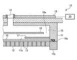
図2は成膜装置100のシャワーヘッド10の部分を拡大して示す断面図である。図2に示すように、シャワーヘッド10は、有天井で下部が開放された円筒状をなす本体11と、本体11の下部開口を塞ぐように設けられ、複数のガス吐出孔13を有するシャワープレート12とを有する。なお、ガス吐出孔13はガスを吐出する機能を有すれば形状に限定はなく、円形の孔やスリット状に形成された孔を含み得る。シャワープレート12は、ガス供給部30からの成膜原料ガスを含むガスを吐出するガス吐出部材を構成する。また、本体11の上部中央にはガス導入口14が設けられ、本体11とシャワープレート12の間の空間はガス拡散空間15となっている。Next, the
FIG. 2 is an enlarged cross-sectional view showing a portion of the
ガス拡散空間15には、外周部にリング状の貫通孔16aを有する第1バッフル板16と、中央部に円形の貫通口17aを有する第2バッフル板17とが上から順に水平に設けられている。 In the
第2バッフル板17の直下には、フィルター18が水平に設けられている。フィルター18は円板状をなし、シャワープレート12のサセプタ2の対向面と反対側の面に、少なくともガス吐出孔13が形成されたガス吐出エリアを覆うように設けられている。フィルター18の端部は本体11の側壁に嵌め込まれている。フィルター18の外周には外周枠体18aが設けられており、外周枠体18aはその下のシャワープレート12の枠体12aに支持されている。フィルター18は、ガス導入口14から導入されたガス中のパーティクル成分を除去する機能を有する。 A
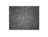
フィルター18は、例えば、図3の写真に示すような、金属繊維を用いた金属メッシュで構成されている。金属メッシュとしては、金属繊維の不織布を積層し焼結したものを挙げることができる。 The
また、フィルター18としては、原料ガスの基板Wへの供給量が不足しない程度のコンダクタンスを有するものが好ましく、適切なコンダクタンスが得られるように圧損や空隙率等の他のパラメータが適切に調整されたものが用いられる。 Further, the
さらに、フィルター18としては、適切に原料ガスを供給できる程度の厚さのものが用いられ、例えば、0.3〜0.5mmの範囲の厚さのものを用いることができる。 Further, as the
さらにまた、フィルター18は、シャワーヘッド10内で生成されたパーティクルを確実にトラップできるように、シャワープレート12に極力近接していることが好ましく、接していてもよい。ただし、フィルター18がシャワープレート12に接している場合は、フィルター18のガス吐出孔13に接している部分以外はほとんどフィルターとして機能しない。このため、フィルター18は、その全面がフィルターとして機能できるように、シャワープレート12から3〜6mm離間していることが好ましい。 Furthermore, the
チャンバー1の天壁(LID)の上にはLIDヒーター19が設けられており、LIDヒーター19はヒーター電源20から給電されることにより発熱し、シャワーヘッド10が加熱されるように構成されている。このときの加熱温度は制御部50で制御される。LIDヒーター19の熱はシャワープレート12の枠体12aおよび外周枠体18aを介してフィルター18に伝熱され、フィルター18も加熱されるように構成されている。これにより、フィルター18にトラップされたパーティクルを昇華させることができる。このときの温度は、成膜原料を昇華できる温度であればよく、成膜原料がRu3(CO)12の場合は、加熱温度は80℃程度に設定される。ヒーターとしてはフィルター18の加熱専用のものであってもよい。An
このように構成される成膜装置100においては、ゲートバルブ28を開にして搬入出口27から基板Wをチャンバー1内に搬入し、サセプタ2上に載置する。サセプタ2はヒーター5により所望の成膜温度に加熱されている。チャンバー1内は排気装置23により真空引きされた状態で、不活性ガスが導入され、不活性ガスを介して基板Wが加熱される。そして、自動圧力制御バルブによりチャンバー1内が所望の圧力に調圧される。この時のチャンバー内の圧力は、成膜原料によって適宜調整されるが、例えば、0.013〜133.3Pa(0.1mTorr〜1Torr)の範囲が用いられる。 In the
次いで、ヒーター32により成膜原料容器31を成膜原料Sの昇華温度以上の温度で加熱した状態とし、バルブ37a,37bを開にしてキャリアガス供給配管33を介して成膜原料容器31にキャリアガスを吹き込む。 Next, the film-forming
これにより、成膜原料容器31内でヒーター32の加熱により固体状の成膜原料Sが昇華して生成された成膜原料ガス、例えばRu3(CO)12ガスが、キャリアガスにより成膜原料ガス供給配管35へ搬送される。そして、成膜原料ガスは、成膜原料ガス供給配管35を経てシャワーヘッド10へ供給され、シャワーヘッド10のガス吐出孔13からチャンバー1内へ吐出される。チャンバー1に吐出された原料ガスは、サセプタ2に載置された基板W上で熱分解され、基板W上に所望の膜が成膜される。成膜原料ガスとしてRu3(CO)12ガスを用いた場合は、基板W上でRu3(CO)12ガスが熱分解してRu膜が成膜される。As a result, the film-forming raw material gas produced by sublimating the solid film-forming raw material S by heating the
成膜の際のサセプタ2の温度(基板温度)は、用いる成膜原料や成膜しようとする膜に応じて適宜設定される。本実施形態では、成膜原料ガスが基板上で熱分解することにより成膜されるため、少なくとも成膜原料ガスが熱分解可能な温度に設定される。成膜原料ガスとしてRu3(CO)12ガスを用いた場合には、成膜温度は100〜300℃とすることができる。The temperature of the susceptor 2 (substrate temperature) at the time of film formation is appropriately set according to the film forming raw material to be used and the film to be filmed. In the present embodiment, since the film-forming raw material gas is thermally decomposed on the substrate to form a film, at least the film-forming raw material gas is set to a temperature at which thermal decomposition is possible.When Ru 3 (CO)12 gas is used as the film forming raw material gas, the film forming temperature can be 100 to 300 ° C.
ところで、プロセスの都合により低温成膜が要求される場合があるが、その場合には基板W上のパーティクルが多くなる傾向があることが判明した。Ru3(CO)12を用いてRu膜を成膜する場合を例にとると、サセプタ2の温度が175℃では、パーティクルが少ないのに対し、サセプタ2の温度を155℃以下の低温にするとパーティクルが増加する。そして、特に、サセプタ2の温度の低温化にともない、Ru3(CO)12が固化して生成されたものと考えられるファイバー状のパーティクルが増加することが判明した。By the way, it has been found that low-temperature film formation may be required due to the convenience of the process, but in that case, the number of particles on the substrate W tends to increase. Taking the case of forming a Ru film using Ru3 (CO)12 as an example, when the temperature of the susceptor 2 is 175 ° C., the number of particles is small, whereas when the temperature of the susceptor 2 is lowered to 155 ° C. or lower, the number of particles is small. Particles increase. In particular, it was found that as the temperature of the susceptor 2 was lowered, the number of fiber-like particles thought to be produced by solidifyingRu 3 (CO)12 increased.
すなわち、原料ガスは、基板W上で加熱されて熱分解されるまでの間、気体状態に保持される必要があるが、低温成膜の場合は、原料ガスが基板Wに到達するまでの間に温度が低下して固化し、それがパーティクルの主成分となると考えられる。 That is, the raw material gas needs to be kept in a gaseous state until it is heated on the substrate W and thermally decomposed, but in the case of low temperature film formation, it is until the raw material gas reaches the substrate W. It is thought that the temperature drops and solidifies, which becomes the main component of the particles.
そこで、本実施形態では、シャワーヘッド10のガス拡散空間15に、シャワープレート12のガス吐出エリアを覆うようにフィルター18を設ける。これにより、ガス拡散空間15内で第1および第2のバッフルプレート16,17を経た成膜原料を含むガスがフィルター18を通過し、パーティクルがフィルター18にトラップされる。このため、基板Wに付着するパーティクルを抑制することができる。フィルター18は、特に、成膜原料ガスが固化して生成されたパーティクルが多い低温成膜の場合に有効である。成膜原料がRu3(CO)12の場合には、成膜温度が100〜155℃と低温の場合に有効である。Therefore, in the present embodiment, the
上述したように、フィルター18は、シャワーヘッド10内で生成されたパーティクルを確実にトラップでき、フィルターの機能を有効に発揮させる観点から、ガス拡散空間15内のシャワープレート12から3〜6mm程度離間していることが好ましい。シャワープレート12の基板W側の領域では、サセプタ2から十分に熱が供給され、原料ガスが再固化するおそれはないため、フィルター18はシャワープレート12の基板W側へ設ける必要はない。 As described above, the
また、フィルター18はLIDヒーター19により加熱されるようになっており、LIDヒーター19によりフィルター18をパーティクルの昇華温度より高い温度に加熱することにより、トラップされたパーティクルを昇華させることができる。これにより、パーティクルが基板Wに到達することをより確実に防止することができるとともに、フィルター18にパーティクルが残存しないので、フィルター18の目詰まりが生じない。 Further, the
次に、フィルター18を設けた効果を実証する実験結果について説明する。ここでは、図1の概略構成を有する成膜装置を用い、成膜原料としてRu3(CO)12を用いて、サセプタ温度を155℃とし、フィルターの加熱温度を80℃として基板である半導体ウエハ上にRu膜の成膜を行った。また、比較として、図1の成膜装置からフィルターを除いた装置を用いて、同様に成膜原料としてRu3(CO)12を用いて、同じくサセプタ温度を155℃としてRu膜の成膜を行った。半導体ウエハとしては表面がTaNのものおよびSiのものを2枚ずつ合計4枚用いた。Next, the experimental results demonstrating the effect of providing the
フィルターを用いない場合、4枚の半導体ウエハに対し、合計のパーティクル個数は179個であり、その中で気体状のRu3(CO)12が固化して形成されたファイバー状のパーティクルは147個であった。これに対し、フィルターを用いた場合、4枚の半導体ウエハに対し、合計のパーティクル個数は44個であり、その中でファイバー状のパーティクルは40個であった。When no filter is used, the total number of particles is 179 for four semiconductor wafers, of which 147 are fibrous particles formed by solidifyinggaseous Ru 3 (CO)12. Met. On the other hand, when the filter was used, the total number of particles was 44 for 4 semiconductor wafers, and 40 of them were fiber-like particles.
この結果から、フィルターを用いることにより、トータルのパーティクルの個数および気体状のRu3(CO)12が固化して形成されたファイバー状のパーティクルの個数を大幅に低減できることが確認された。パーティクルの主体であるファイバー状パーティクルについては、フィルターを用いることにより73%低減された。From this result, it was confirmed that the total number of particles and the number of fibrous particlesformed by solidifying the gaseous Ru 3 (CO)12 can be significantly reduced by using the filter. The fibrous particles, which are the main particles, were reduced by 73% by using a filter.
以上、実施形態について説明したが、今回開示された実施形態は、全ての点で例示であって制限的なものではないと考えられるべきである。上記の実施形態は、添付の特許請求の範囲およびその主旨を逸脱することなく、様々な形態で省略、置換、変更されてもよい。 Although the embodiments have been described above, the embodiments disclosed this time should be considered to be exemplary in all respects and not restrictive. The above embodiments may be omitted, replaced or modified in various forms without departing from the scope of the appended claims and their gist.
例えば、上記実施形態では、成膜原料として、Ru3(CO)12のような熱分解により成膜可能なものを用いた例を示したが、反応ガスとの反応により膜形成を行うものであってもよい。For example, in the above embodiment, an example in which a film-forming material such as Ru3 (CO)12 that can be formed by thermal decomposition is used as a film-forming raw material is shown, but a film is formed by reaction with a reaction gas. There may be.
また、成膜装置として図1のものを例示したが、シャワーヘッドからサセプタ上の基板に成膜原料ガスを供給して成膜するものであればよく、またシャワーヘッドも供給された成膜原料ガスがフィルターを通過する構造を有していればよく、図1の成膜装置に限定されるものではない。 Further, although the film forming apparatus of FIG. 1 is illustrated as the film forming apparatus, any film-forming raw material gas may be supplied from the shower head to the substrate on the susceptor to form a film, and the shower head is also supplied as the film-forming raw material. It suffices as long as it has a structure in which the gas passes through the filter, and is not limited to the film forming apparatus of FIG.
1;チャンバー
2;サセプタ(基板載置台)
5;ヒーター
10;シャワーヘッド
15;ガス拡散空間
18;フィルター
19;LIDヒーター
23;排気装置
30;ガス供給部
31;成膜原料容器
35;成膜原料ガス供給配管
50;制御部
100;成膜装置
W;基板1; Chamber 2; Suceptor (board mount)
5;
Claims (10)
Translated fromJapaneseチャンバーと、
チャンバー内に設けられ、基板を載置するとともに基板を成膜温度に保持する基板載置台と、
成膜原料ガスを含むガスを供給するガス供給部と、
前記基板載置台に対向して設けられ、前記ガス供給部から供給された前記成膜原料ガスを含むガスを吐出するガス吐出エリアを有するガス吐出部材と、
前記ガス吐出部材の前記基板載置台との対向面と反対側の面の少なくともガス吐出エリアを覆うように設けられ、前記成膜原料ガスを含むガスを通過させてその中のパーティクルをトラップするフィルターと、
を有する、成膜装置。A film forming device that forms a film on a substrate.
With the chamber
A substrate mounting table provided in the chamber for mounting the substrate and holding the substrate at the film formation temperature.
A gas supply unit that supplies gas including the film-forming raw material gas,
A gas discharge member provided facing the substrate mounting table and having a gas discharge area for discharging a gas containing the film-forming raw material gas supplied from the gas supply unit.
A filter provided so as to cover at least the gas discharge area on the surface of the gas discharge member opposite to the surface facing the substrate mounting table, and allowing the gas containing the film-forming raw material gas to pass through and trap the particles in the filter. When,
A film forming apparatus.
請求項1から請求項9のいずれか一項に記載の成膜装置を準備することと、
前記基板載置台に基板を載置することと、
前記ガス供給部から前記成膜原料ガスを含むガスを前記基板載置台上の基板に向けて供給することと、
前記成膜原料ガスを含むガスが、前記基板載置台上の基板に至る前に、前記フィルターを通過するようにして、前記成膜原料ガスを含むガスの中のパーティクルをトラップすることと、
前記フィルターを通過した前記成膜原料ガスを含むガスを用いて基板上に膜を形成することと、
を含む成膜方法。It is a film forming method for forming a film on a substrate.
The film forming apparatus according to any one of claims 1 to 9 is prepared.
Placing the board on the board mounting table and
The gas containing the film-forming raw material gas is supplied from the gas supply unit toward the substrate on the substrate mounting table.
By allowing the gas containing the film-forming raw material gas to pass through the filter before reaching the substrate on the substrate mounting table, the particles in the gas containing the film-forming raw material gas are trapped.
Forming a film on a substrate using a gas containing the film-forming raw material gas that has passed through the filter,
Film formation method including.
Priority Applications (5)
| Application Number | Priority Date | Filing Date | Title |
|---|---|---|---|
| JP2020101193AJP7493389B2 (en) | 2020-06-10 | 2020-06-10 | Film forming apparatus and film forming method |
| TW110119362ATWI881130B (en) | 2020-06-10 | 2021-05-28 | Film forming device and film forming method |
| KR1020210070144AKR102699338B1 (en) | 2020-06-10 | 2021-05-31 | Film forming apparatus and film forming method |
| CN202110614529.2ACN113774355A (en) | 2020-06-10 | 2021-06-02 | Film forming apparatus and film forming method |
| US17/338,128US20210388493A1 (en) | 2020-06-10 | 2021-06-03 | Film forming apparatus and film forming method |
Applications Claiming Priority (1)
| Application Number | Priority Date | Filing Date | Title |
|---|---|---|---|
| JP2020101193AJP7493389B2 (en) | 2020-06-10 | 2020-06-10 | Film forming apparatus and film forming method |
Publications (2)
| Publication Number | Publication Date |
|---|---|
| JP2021195580Atrue JP2021195580A (en) | 2021-12-27 |
| JP7493389B2 JP7493389B2 (en) | 2024-05-31 |
Family
ID=78824529
Family Applications (1)
| Application Number | Title | Priority Date | Filing Date |
|---|---|---|---|
| JP2020101193AActiveJP7493389B2 (en) | 2020-06-10 | 2020-06-10 | Film forming apparatus and film forming method |
Country Status (5)
| Country | Link |
|---|---|
| US (1) | US20210388493A1 (en) |
| JP (1) | JP7493389B2 (en) |
| KR (1) | KR102699338B1 (en) |
| CN (1) | CN113774355A (en) |
| TW (1) | TWI881130B (en) |
Families Citing this family (1)
| Publication number | Priority date | Publication date | Assignee | Title |
|---|---|---|---|---|
| WO2019131394A1 (en)* | 2017-12-26 | 2019-07-04 | アルプスアルパイン株式会社 | Tunnel magnetoresistive effect film and magnetic device using same |
Citations (2)
| Publication number | Priority date | Publication date | Assignee | Title |
|---|---|---|---|---|
| JP2004273692A (en)* | 2003-03-07 | 2004-09-30 | Ulvac Japan Ltd | System and process for producing thin film |
| JP2020013966A (en)* | 2018-07-20 | 2020-01-23 | 東京エレクトロン株式会社 | Film deposition apparatus, starting material supply apparatus and film deposition method |
Family Cites Families (18)
| Publication number | Priority date | Publication date | Assignee | Title |
|---|---|---|---|---|
| JPH0517872A (en)* | 1991-07-01 | 1993-01-26 | Sharp Corp | Thin film forming equipment |
| JP3147325B2 (en)* | 1994-08-17 | 2001-03-19 | 東京エレクトロン株式会社 | Semiconductor wafer processing equipment |
| JP3809391B2 (en) | 2002-04-19 | 2006-08-16 | 株式会社アルバック | Thin film forming equipment |
| US8580076B2 (en)* | 2003-05-22 | 2013-11-12 | Lam Research Corporation | Plasma apparatus, gas distribution assembly for a plasma apparatus and processes therewith |
| US20060130757A1 (en)* | 2004-12-22 | 2006-06-22 | Yicheng Li | Apparatus for active dispersion of precursors |
| US7763311B2 (en)* | 2007-03-28 | 2010-07-27 | Tokyo Electron Limited | Method for heating a substrate prior to a vapor deposition process |
| WO2008129977A1 (en)* | 2007-04-17 | 2008-10-30 | Ulvac, Inc. | Film forming apparatus |
| JP2009084625A (en)* | 2007-09-28 | 2009-04-23 | Tokyo Electron Ltd | Raw material gas supply system and film deposition apparatus |
| KR101173645B1 (en)* | 2007-12-31 | 2012-08-20 | (주)에이디에스 | Gas injection unit and apparatus for depositing thin film having the same |
| JP5408819B2 (en)* | 2008-01-29 | 2014-02-05 | 国立大学法人長岡技術科学大学 | Deposition apparatus and deposition method |
| JP4972657B2 (en) | 2009-02-02 | 2012-07-11 | 東京エレクトロン株式会社 | Vaporizer and film forming apparatus |
| KR101420709B1 (en)* | 2013-03-11 | 2014-07-22 | 참엔지니어링(주) | Substrate supporting apparatus and substrate processing apparatus having the same |
| JP2015160963A (en) | 2014-02-26 | 2015-09-07 | 東京エレクトロン株式会社 | Method and apparatus for depositing ruthenium film, and method for manufacturing semiconductor device |
| US20150348755A1 (en)* | 2014-05-29 | 2015-12-03 | Charm Engineering Co., Ltd. | Gas distribution apparatus and substrate processing apparatus including same |
| JP2016004834A (en)* | 2014-06-13 | 2016-01-12 | 東京エレクトロン株式会社 | Vacuum processing device |
| JP7224175B2 (en)* | 2018-12-26 | 2023-02-17 | 東京エレクトロン株式会社 | Deposition apparatus and method |
| WO2020165990A1 (en)* | 2019-02-14 | 2020-08-20 | 株式会社日立ハイテクノロジーズ | Semiconductor manufacturing device |
| FI129565B (en)* | 2019-04-24 | 2022-04-29 | Canatu Oy | Equipment and procedure for oriented deposition |
- 2020
- 2020-06-10JPJP2020101193Apatent/JP7493389B2/enactiveActive
- 2021
- 2021-05-28TWTW110119362Apatent/TWI881130B/enactive
- 2021-05-31KRKR1020210070144Apatent/KR102699338B1/enactiveActive
- 2021-06-02CNCN202110614529.2Apatent/CN113774355A/enactivePending
- 2021-06-03USUS17/338,128patent/US20210388493A1/ennot_activeAbandoned
Patent Citations (2)
| Publication number | Priority date | Publication date | Assignee | Title |
|---|---|---|---|---|
| JP2004273692A (en)* | 2003-03-07 | 2004-09-30 | Ulvac Japan Ltd | System and process for producing thin film |
| JP2020013966A (en)* | 2018-07-20 | 2020-01-23 | 東京エレクトロン株式会社 | Film deposition apparatus, starting material supply apparatus and film deposition method |
Also Published As
| Publication number | Publication date |
|---|---|
| TWI881130B (en) | 2025-04-21 |
| KR102699338B1 (en) | 2024-08-26 |
| CN113774355A (en) | 2021-12-10 |
| US20210388493A1 (en) | 2021-12-16 |
| KR20210153536A (en) | 2021-12-17 |
| JP7493389B2 (en) | 2024-05-31 |
| TW202209420A (en) | 2022-03-01 |
Similar Documents
| Publication | Publication Date | Title |
|---|---|---|
| JP5247528B2 (en) | Substrate processing apparatus, semiconductor device manufacturing method, substrate processing method, and gas introducing means | |
| TWI666338B (en) | Gas supply mechanism and gas supply method, and film forming apparatus and film forming method using the same | |
| KR101677973B1 (en) | Source container and method for using source container | |
| WO2007034623A1 (en) | Raw material feeding device and film formation system | |
| JP2009530494A (en) | Method and apparatus for suppressing particle contamination in a film forming system | |
| JP2020191427A (en) | Hard mask, substrate processing method, and substrate processing device | |
| JP4260404B2 (en) | Deposition equipment | |
| JPWO2017057623A1 (en) | Substrate processing apparatus and substrate processing method | |
| WO2011033918A1 (en) | Film forming device, film forming method and storage medium | |
| JP5344663B2 (en) | Substrate processing apparatus, semiconductor device manufacturing method, and substrate processing method | |
| JP2021195580A (en) | Film deposition apparatus and film deposition method | |
| WO2020179575A1 (en) | Film-forming apparatus and material gas feeding method | |
| JP2002222805A (en) | Substrate processing equipment | |
| JP2004095701A (en) | Substrate treatment device, method of treating substrate, and method of cleaning substrate treatment device | |
| WO2022004520A1 (en) | Film forming method and film forming device | |
| JP5021688B2 (en) | Atomic layer growth equipment | |
| JP2007227471A (en) | Substrate processing equipment | |
| JP2004079682A (en) | Substrate processing apparatus | |
| JP2020147772A (en) | Film deposition device and film deposition method | |
| JP2005054253A (en) | Thin film production apparatus and production method | |
| JP5659041B2 (en) | Film formation method and storage medium | |
| JP2011021264A (en) | Film deposition system | |
| JPH08167577A (en) | Semiconductor film forming equipment | |
| JP2007073879A (en) | Substrate processing equipment | |
| JP2012172250A (en) | Film forming method and storage medium |
Legal Events
| Date | Code | Title | Description |
|---|---|---|---|
| A621 | Written request for application examination | Free format text:JAPANESE INTERMEDIATE CODE: A621 Effective date:20230119 | |
| A977 | Report on retrieval | Free format text:JAPANESE INTERMEDIATE CODE: A971007 Effective date:20230816 | |
| A131 | Notification of reasons for refusal | Free format text:JAPANESE INTERMEDIATE CODE: A131 Effective date:20230829 | |
| A521 | Request for written amendment filed | Free format text:JAPANESE INTERMEDIATE CODE: A523 Effective date:20231005 | |
| A131 | Notification of reasons for refusal | Free format text:JAPANESE INTERMEDIATE CODE: A131 Effective date:20231226 | |
| A521 | Request for written amendment filed | Free format text:JAPANESE INTERMEDIATE CODE: A523 Effective date:20240126 | |
| TRDD | Decision of grant or rejection written | ||
| A01 | Written decision to grant a patent or to grant a registration (utility model) | Free format text:JAPANESE INTERMEDIATE CODE: A01 Effective date:20240423 | |
| A61 | First payment of annual fees (during grant procedure) | Free format text:JAPANESE INTERMEDIATE CODE: A61 Effective date:20240521 | |
| R150 | Certificate of patent or registration of utility model | Ref document number:7493389 Country of ref document:JP Free format text:JAPANESE INTERMEDIATE CODE: R150 |