JP2021193394A - Fish body length measuring system, fish body length measuring method, and fish body length measuring program - Google Patents
Fish body length measuring system, fish body length measuring method, and fish body length measuring programDownload PDFInfo
- Publication number
- JP2021193394A JP2021193394AJP2021157490AJP2021157490AJP2021193394AJP 2021193394 AJP2021193394 AJP 2021193394AJP 2021157490 AJP2021157490 AJP 2021157490AJP 2021157490 AJP2021157490 AJP 2021157490AJP 2021193394 AJP2021193394 AJP 2021193394A
- Authority
- JP
- Japan
- Prior art keywords
- fish
- length
- measured
- information processing
- image
- Prior art date
- Legal status (The legal status is an assumption and is not a legal conclusion. Google has not performed a legal analysis and makes no representation as to the accuracy of the status listed.)
- Granted
Links
Images


Classifications
- G—PHYSICS
- G01—MEASURING; TESTING
- G01B—MEASURING LENGTH, THICKNESS OR SIMILAR LINEAR DIMENSIONS; MEASURING ANGLES; MEASURING AREAS; MEASURING IRREGULARITIES OF SURFACES OR CONTOURS
- G01B11/00—Measuring arrangements characterised by the use of optical techniques
- G01B11/02—Measuring arrangements characterised by the use of optical techniques for measuring length, width or thickness
- G01B11/04—Measuring arrangements characterised by the use of optical techniques for measuring length, width or thickness specially adapted for measuring length or width of objects while moving
- G01B11/043—Measuring arrangements characterised by the use of optical techniques for measuring length, width or thickness specially adapted for measuring length or width of objects while moving for measuring length
- G—PHYSICS
- G06—COMPUTING OR CALCULATING; COUNTING
- G06T—IMAGE DATA PROCESSING OR GENERATION, IN GENERAL
- G06T7/00—Image analysis
- G06T7/60—Analysis of geometric attributes
- G06T7/62—Analysis of geometric attributes of area, perimeter, diameter or volume
- A—HUMAN NECESSITIES
- A01—AGRICULTURE; FORESTRY; ANIMAL HUSBANDRY; HUNTING; TRAPPING; FISHING
- A01K—ANIMAL HUSBANDRY; AVICULTURE; APICULTURE; PISCICULTURE; FISHING; REARING OR BREEDING ANIMALS, NOT OTHERWISE PROVIDED FOR; NEW BREEDS OF ANIMALS
- A01K61/00—Culture of aquatic animals
- A01K61/90—Sorting, grading, counting or marking live aquatic animals, e.g. sex determination
- A01K61/95—Sorting, grading, counting or marking live aquatic animals, e.g. sex determination specially adapted for fish
- G—PHYSICS
- G01—MEASURING; TESTING
- G01B—MEASURING LENGTH, THICKNESS OR SIMILAR LINEAR DIMENSIONS; MEASURING ANGLES; MEASURING AREAS; MEASURING IRREGULARITIES OF SURFACES OR CONTOURS
- G01B11/00—Measuring arrangements characterised by the use of optical techniques
- G01B11/02—Measuring arrangements characterised by the use of optical techniques for measuring length, width or thickness
- G01B11/022—Measuring arrangements characterised by the use of optical techniques for measuring length, width or thickness by means of tv-camera scanning
- G—PHYSICS
- G01—MEASURING; TESTING
- G01B—MEASURING LENGTH, THICKNESS OR SIMILAR LINEAR DIMENSIONS; MEASURING ANGLES; MEASURING AREAS; MEASURING IRREGULARITIES OF SURFACES OR CONTOURS
- G01B11/00—Measuring arrangements characterised by the use of optical techniques
- G01B11/02—Measuring arrangements characterised by the use of optical techniques for measuring length, width or thickness
- G01B11/03—Measuring arrangements characterised by the use of optical techniques for measuring length, width or thickness by measuring coordinates of points
- G—PHYSICS
- G06—COMPUTING OR CALCULATING; COUNTING
- G06T—IMAGE DATA PROCESSING OR GENERATION, IN GENERAL
- G06T7/00—Image analysis
- G—PHYSICS
- G06—COMPUTING OR CALCULATING; COUNTING
- G06T—IMAGE DATA PROCESSING OR GENERATION, IN GENERAL
- G06T7/00—Image analysis
- G06T7/60—Analysis of geometric attributes
- G—PHYSICS
- G06—COMPUTING OR CALCULATING; COUNTING
- G06T—IMAGE DATA PROCESSING OR GENERATION, IN GENERAL
- G06T7/00—Image analysis
- G06T7/70—Determining position or orientation of objects or cameras
- G06T7/73—Determining position or orientation of objects or cameras using feature-based methods
- G—PHYSICS
- G06—COMPUTING OR CALCULATING; COUNTING
- G06T—IMAGE DATA PROCESSING OR GENERATION, IN GENERAL
- G06T2207/00—Indexing scheme for image analysis or image enhancement
- G06T2207/10—Image acquisition modality
- G06T2207/10016—Video; Image sequence
- G06T2207/10021—Stereoscopic video; Stereoscopic image sequence
Landscapes
- Physics & Mathematics (AREA)
- General Physics & Mathematics (AREA)
- Engineering & Computer Science (AREA)
- Theoretical Computer Science (AREA)
- Computer Vision & Pattern Recognition (AREA)
- Life Sciences & Earth Sciences (AREA)
- Zoology (AREA)
- Environmental Sciences (AREA)
- Geometry (AREA)
- Biodiversity & Conservation Biology (AREA)
- Animal Husbandry (AREA)
- Marine Sciences & Fisheries (AREA)
- Length Measuring Devices By Optical Means (AREA)
- Image Analysis (AREA)
Abstract
Description
Translated fromJapanese本発明は、測定対象の物体を撮影した撮影画像から物体の長さを測定する技術に関する。 The present invention relates to a technique for measuring the length of an object from a photographed image of the object to be measured.
魚の養殖技術の向上のために、養殖している魚の成長を観測することが行われている。特許文献1には、魚の観測に関わる技術が開示されている。この特許文献1における技術では、水槽の上方側(あるいは底側)と横側から撮影された魚の背側(あるいは腹側)の撮影画像と、頭側の正面の撮影画像とに基づいて、魚の頭、胴体、尾ひれ等の部位の形状や大きさが部位毎に推定される。その魚の部位毎の形状や大きさの推定は、各部位毎に与えられている複数のテンプレート画像を利用して行われる。すなわち、各部位毎の撮影画像がそれぞれ各部位毎のテンプレート画像に照合され、撮影画像に合うテンプレート画像中の魚の部位における大きさ等の既知の情報に基づいて、魚の各部位毎の大きさ等が推定される。 In order to improve fish farming techniques, the growth of farmed fish is being observed. Patent Document 1 discloses a technique related to fish observation. In the technique of Patent Document 1, the image of the dorsal side (or ventral side) of the fish taken from the upper side (or the bottom side) and the side of the water tank and the image of the front side of the head side of the fish are taken. The shape and size of parts such as the head, torso, and tail fins are estimated for each part. The shape and size of each part of the fish are estimated by using a plurality of template images given for each part. That is, the captured image of each part is collated with the template image of each part, and the size of each part of the fish etc. is based on the known information such as the size of the fish part in the template image matching the photographed image. Is estimated.
特許文献2には、水中の魚を動画カメラと静止画カメラによって撮影し、撮影された動画および静止画に基づいて、魚影を検知する技術が開示されている。また、特許文献2には、画像サイズ(画素数)によって、魚のサイズを推定する構成が示されている。
特許文献1に記載されている技術では、テンプレート画像中の魚の部位における既知の大きさの情報に基づいて魚の部位の大きさが推定されている。つまり、特許文献1における技術では、テンプレート画像中の魚の部位の大きさが測定対象の魚の部位の大きさとして検知されているにすぎず、測定対象の魚の部位の大きさを測定していないので、大きさの検知精度を高めにくいという問題が生じる。 In the technique described in Patent Document 1, the size of the fish part is estimated based on the information of the known size of the fish part in the template image. That is, in the technique in Patent Document 1, the size of the fish part in the template image is only detected as the size of the fish part to be measured, and the size of the fish part to be measured is not measured. However, there is a problem that it is difficult to improve the size detection accuracy.
特許文献2には、魚影サイズとして画像サイズ(画素数)を検知する構成は示されているものの、魚の実際の大きさを検知する構成は開示されていない。
本発明は上記課題を解決するために考え出された。すなわち、本発明の主な目的は、撮影画像に基づいて測定対象の物体の長さを容易に、かつ、精度良く検知できる技術を提供することにある。 The present invention has been devised to solve the above problems. That is, a main object of the present invention is to provide a technique capable of easily and accurately detecting the length of an object to be measured based on a photographed image.
本発明の魚体長さ測定システムは、
水中を泳ぐ魚体が撮影されている撮影画像から、測定対象の魚体における特徴部位である頭及び尾を検知する検知手段と、
検知した測定対象の魚体における頭と尾の間の長さを算出する算出手段と、
撮影画像上に、測定対象の魚体を囲む枠と、長さの両端に対応する頭及び尾とを示す表示と、を表示させる表示制御手段と、を備える。The fish body length measuring system of the present invention is
A detection means for detecting the head and tail, which are characteristic parts of the fish to be measured, from the captured image of the fish swimming in the water.
A calculation method for calculating the length between the head and tail of the detected fish to be measured, and
On the photographed image, a frame surrounding the fish to be measured, a display indicating the head and the tail corresponding to both ends of the length, and a display control means for displaying the display are provided.
本発明の魚体長さ測定方法は、
コンピュータが、
魚体が撮影されている撮影画像から、測定対象の前記魚体における特徴部位である頭及び尾を検知し、
前記測定対象の魚体における前記頭と前記尾の間の長さを算出し、
検知した前記特徴部位と前記測定対象の魚体を囲む枠とを示した前記撮影画像を表示装置に表示させる。The fish body length measuring method of the present invention is
The computer
From the captured image of the fish body, the head and tail, which are the characteristic parts of the fish body to be measured, are detected.
The length between the head and the tail of the fish to be measured was calculated.
The photographed image showing the detected feature portion and the frame surrounding the fish body to be measured is displayed on the display device.
本発明の魚体長さ測定プログラムは、
コンピュータに、
魚体が撮影されている撮影画像から、測定対象の前記魚体における特徴部位である頭及び尾を検知する処理と、
前記測定対象の魚体における前記頭と前記尾の間の長さを算出する処理と、
検知した前記特徴部位と前記測定対象の魚体を囲む枠とを示した前記撮影画像を表示装置に表示させる処理と、を実行させる。The fish length measurement program of the present invention is
On the computer
Processing to detect the head and tail, which are the characteristic parts of the fish to be measured, from the captured image of the fish.
The process of calculating the length between the head and the tail of the fish to be measured, and
The process of displaying the photographed image showing the detected feature portion and the frame surrounding the fish body to be measured on the display device is executed.
なお、本発明の主な目的は、本発明の魚体長さ測定方法によっても達成される。 The main object of the present invention is also achieved by the fish body length measuring method of the present invention.
また、本発明の主な目的は、本発明のコンピュータプログラムおよび当該コンピュータプログラムを記憶するプログラム記憶媒体によっても達成される。 The main object of the present invention is also achieved by the computer program of the present invention and a program storage medium for storing the computer program.
本発明によれば、撮影画像に基づいて測定対象の物体の長さを容易に、かつ、精度良く検知できる。 According to the present invention, the length of the object to be measured can be easily and accurately detected based on the captured image.
以下に、本発明に係る実施形態を図面を参照しながら説明する。 Hereinafter, embodiments according to the present invention will be described with reference to the drawings.
<第1実施形態>
図1は、本発明に係る第1実施形態の情報処理装置の構成を簡略化して表すブロック図である。この情報処理装置1は、図2に表されるような長さ測定システム10に組み込まれ、測定対象の物体の長さを算出する機能を備えている。長さ測定システム10は、情報処理装置1に加えて、複数の撮影装置11A,11Bを備えている。撮影装置11A,11Bは、間隔を介して並設され、測定対象の物体を共通に撮影する装置である。撮影装置11A,11Bにより撮影された撮影画像は、有線通信あるいは無線通信によって情報処理装置1に提供される。又は、撮影装置11A,11Bにより撮影された撮影画像は、撮影装置11A,11Bにおいて可搬型記憶媒体(例えば、SD(Secure Digital)カード)に記憶され、当該可搬型記憶媒体から情報処理装置1に読み込まれてもよい。<First Embodiment>
FIG. 1 is a block diagram showing a simplified configuration of the information processing apparatus according to the first embodiment of the present invention. The information processing device 1 is incorporated in a
情報処理装置1は、図1に表されるように、検知部2と、特定部3と、算出部4とを備えている。検知部2は、測定対象の物体が撮影されている撮影画像から、測定対象の物体における対を成す部位であって予め定められた特徴をそれぞれ持つ特徴部位を検知する機能を備えている。 As shown in FIG. 1, the information processing apparatus 1 includes a
特定部3は、その検知された特徴部位の位置を表す座標空間における座標を特定する機能を備えている。その座標を特定する処理では、特定部3は、測定対象の物体を互いに異なる位置から撮影した複数の撮影画像における特徴部位が表示されている表示位置情報を利用する。また、特定部3は、物体が撮影されている複数の撮影画像をそれぞれ撮影した撮影位置間の間隔を表す間隔情報をも利用する。 The
算出部4は、特定された特徴部位の位置の座標に基づいて、対を成す特徴部位間の長さを算出する機能を備えている。 The
第1実施形態の情報処理装置1は、測定対象の物体を互いに異なる位置から撮影した複数の撮影画像から、測定対象の物体における対を成す部位であって予め定められた特徴をそれぞれ持つ特徴部位を検知する。そして、情報処理装置1は、それら検知した特徴部位の位置を表す座標空間における座標を特定し、当該特定した特徴部位の位置の座標に基づいて、対を成す特徴部位間の長さを算出する。情報処理装置1は、そのような処理によって、測定対象の物体における対を成す特徴部位間の長さを測定することができる。 The information processing apparatus 1 of the first embodiment is a feature portion that is a paired portion of the object to be measured and has predetermined features from a plurality of captured images obtained by capturing the object to be measured from different positions. Is detected. Then, the information processing apparatus 1 specifies the coordinates in the coordinate space representing the positions of the detected feature parts, and calculates the length between the paired feature parts based on the coordinates of the positions of the specified feature parts. .. The information processing apparatus 1 can measure the length between paired feature portions in the object to be measured by such processing.
すなわち、情報処理装置1は、測定対象の物体が撮影されている撮影画像から、長さの測定に利用する対を成す特徴部位を検知する機能を備えている。このため、測定対象の物体の長さを測定する測定者は、測定対象の物体が撮影されている撮影画像から、長さの測定に利用する対を成す特徴部位を見つけ出すという作業を行う必要がない。また、測定者は、見つけ出した特徴部位の位置の情報を情報処理装置1に入力するという作業を行う必要もない。このように、第1実施形態の情報処理装置1は、測定対象の物体の長さを測定する測定者の手間を軽減することができる。 That is, the information processing apparatus 1 has a function of detecting a pair of characteristic portions used for length measurement from a captured image in which an object to be measured is captured. For this reason, the measurer who measures the length of the object to be measured needs to perform the work of finding a pair of characteristic parts used for measuring the length from the photographed image in which the object to be measured is photographed. No. Further, the measurer does not need to perform the work of inputting the information on the position of the found feature portion into the information processing apparatus 1. As described above, the information processing apparatus 1 of the first embodiment can reduce the time and effort of the measurer to measure the length of the object to be measured.
その上、情報処理装置1は、画像から検知した特徴部位における座標空間における位置の座標を特定し、当該座標を利用して測定対象の物体の長さを算出する。このように、情報処理装置1は、座標空間における位置の座標に基づいて、測定対象の物体の長さを算出するので、長さの測定の精度を高めることができる。すなわち、第1実施形態の情報処理装置1は、撮影画像に基づいて測定対象の物体の長さを容易に、かつ、精度良く検知できるという効果を得ることができる。なお、図2の例では、長さ測定システム10は、複数の撮影装置11A,11Bを備えているが、長さ測定システム10を構成する撮影装置は、1台であってもよい。 Further, the information processing apparatus 1 specifies the coordinates of the position in the coordinate space of the feature portion detected from the image, and calculates the length of the object to be measured by using the coordinates. As described above, the information processing apparatus 1 calculates the length of the object to be measured based on the coordinates of the position in the coordinate space, so that the accuracy of the length measurement can be improved. That is, the information processing apparatus 1 of the first embodiment can obtain the effect that the length of the object to be measured can be easily and accurately detected based on the captured image. In the example of FIG. 2, the
<第2実施形態>
以下に、本発明に係る第2実施形態を説明する。<Second Embodiment>
The second embodiment according to the present invention will be described below.
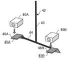
図3は、本発明に係る第2実施形態の情報処理装置の構成を簡略化して表すブロック図である。第2実施形態では、情報処理装置20は、図4Aに表されるような複数(2台)のカメラ40A,40Bによって撮影された測定対象の物体である魚の撮影画像から、魚の長さを算出する機能を備えている。この情報処理装置20は、カメラ40A,40Bと共に、長さ測定システムを構成する。 FIG. 3 is a block diagram showing a simplified configuration of the information processing apparatus according to the second embodiment of the present invention. In the second embodiment, the
第2実施形態では、カメラ40A,40Bは、動画を撮影する機能を備えている撮影装置であるが、動画撮影機能を持たずに例えば静止画を設定の時間間隔毎に断続的に撮影する撮影装置をカメラ40A,40Bとして採用してもよい。 In the second embodiment, the
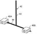
ここでは、カメラ40A,40Bは、図4Aに表されるような支持部材42に支持固定されることにより、図4Bに表されるように間隔を介して並設されている状態で、魚を撮影する。支持部材42は、伸縮棒43と、取り付け棒44と、取り付け具45A,45Bとを有して構成されている。この例では、伸縮棒43は、伸縮自在な棒部材であり、さらに、伸縮可能な長さ範囲内における使用に適切な長さで長さを固定できる構成を備えている。取り付け棒44は、例えばアルミニウム等の金属材料により構成されており、伸縮棒43に直交するように接合されている。取り付け棒44には、伸縮棒43との接合部分を中心にして対称となる部位にそれぞれ取り付け具45A,45Bが固定されている。取り付け具45A,45Bは、カメラ40A,40Bを搭載する搭載面46A,46Bを備え、当該搭載面46A,46Bに搭載されたカメラ40A,40Bを例えば螺子等により搭載面46A,46Bにがたつきなく固定する構成が設けられている。 Here, the
カメラ40A,40Bは、上述したような構成を持つ支持部材42に固定されることにより、予め設定された間隔を介して並設されている状態を維持することができる。また、第2実施形態では、カメラ40A,40Bに設けられているレンズが同じ方向を向き、かつ、レンズの光軸が平行となるように、カメラ40A,40Bは支持部材42に固定される。なお、カメラ40A,40Bを支持固定する支持部材は、図4A等に表される支持部材42に限定されない。例えば、カメラ40A,40Bを支持固定する支持部材は、支持部材42における伸縮棒43に代えて、1本あるいは複数本のロープを利用し、当該ロープによって取り付け棒44や取り付け具45A,45Bを吊下げる構成であってもよい。 By fixing the
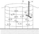
カメラ40A,40Bは、支持部材42に固定されている状態で、例えば図5に表されるように魚が養殖されている生簀48に進入し、魚の観測(換言すれば、測定対象の物体である魚の撮影)に適切と判断された水深およびレンズの向きで配設される。なお、生簀48に進入させた支持部材42(カメラ40A,40B)を適宜な水深およびレンズの向きで配設固定する手法には様々な手法が考えられ、ここでは、何れの手法を採用してもよく、その説明は省略する。また、カメラ40A,40Bのキャリブレーションは、生簀48の環境や測定対象の魚の種類等を考慮した適宜なキャリブレーション手法によって行われる。ここでは、そのキャリブレーション手法の説明は省略する。 The
さらに、カメラ40A,40Bによる撮影を開始する手法および撮影を停止する手法は、カメラ40A,40Bの性能や生簀48の環境などを考慮した適宜な手法が採用される。例えば、魚の観測者(測定者)が、カメラ40A,40Bを生簀48に進入させる前に手動により撮影を開始させ、また、カメラ40A,40Bを生簀48から退出させた後に手動により撮影を停止させる。また、カメラ40A,40Bが無線通信あるいは有線通信の機能を備えている場合には、撮影開始と撮影停止を制御する情報を送信できる操作装置と、カメラ40A,40Bとを接続する。そして、観測者による操作装置の操作により、水中のカメラ40A,40Bの撮影開始と撮影停止が制御されてもよい。 Further, as a method of starting shooting with the
また、カメラ40Aとカメラ40Bの一方又は両方の撮影中の画像をカメラ40A,40Bから有線通信あるいは無線通信により受信可能なモニタ装置が用いられてもよい。この場合には、観測者は、モニタ装置により撮影中の画像を見ることが可能となる。これにより、例えば、観測者は、撮影中の画像を見ながら、カメラ40A,40Bの撮影方向や水深を変更することが可能となる。なお、モニタ機能を備えた携帯端末がモニタ装置として用いられてもよい。 Further, a monitoring device capable of receiving an image being photographed by one or both of the
ところで、情報処理装置20は、魚の長さを算出する処理において、同時間に撮影されたカメラ40Aの撮影画像とカメラ40Bの撮影画像とを用いる。このことを考慮し、同時間に撮影されたカメラ40Aによる撮影画像とカメラ40Bによる撮影画像とを得やすくするために、撮影中に、時間合わせに用いる目印となる変化をもカメラ40A,40Bに撮影させることが好ましい。例えば、時間合わせに用いる目印として、自動制御あるいは観測者の手動によって短時間発光する光を利用することとし、カメラ40A,40Bがその光を撮影するようにしてもよい。これにより、カメラ40A,40Bによる撮影画像に撮影されたその光に基づき、カメラ40Aによる撮影画像と、カメラ40Bによる撮影画像との時間合わせ(同期)を行うことが容易となる。 By the way, in the process of calculating the length of the fish, the
上述したようなカメラ40A,40Bにより撮影された撮影画像は、有線通信あるいは無線通信によって情報処理装置20に取り込まれてもよいし、可搬型記憶媒体に格納された後に当該可搬型記憶媒体から情報処理装置20に取り込まれてもよい。 The captured images taken by the
情報処理装置20は、図3に表されるように、概略すると、制御装置22と、記憶装置23とを備えている。また、情報処理装置20は、例えば観測者の操作により情報を情報処理装置20に入力する入力装置(例えば、キーボードやマウス)25と、情報を表示する表示装置26に接続されている。さらに、情報処理装置20は、当該情報処理装置20とは別体の外付けの記憶装置24に接続されていてもよい。 As shown in FIG. 3, the
記憶装置23は、各種データやコンピュータプログラム(以下、プログラムとも記す)を記憶する機能を有し、例えば、ハードディスク装置や半導体メモリ等の記憶媒体により実現される。情報処理装置20に備えられる記憶装置23は一つには限定されず、複数種の記憶装置が情報処理装置20に備えられていてもよく、この場合には、複数の記憶装置を総称して記憶装置23と記す。また、記憶装置24も、記憶装置23と同様に、各種データやコンピュータプログラムを記憶する機能を有し、例えば、ハードディスク装置や半導体メモリ等の記憶媒体により実現される。なお、情報処理装置20が記憶装置24に接続されている場合には、記憶装置24には適宜な情報が格納される。また、この場合には、情報処理装置20は、適宜、記憶装置24に情報を書き込む処理および読み出す処理を実行するが、以下の説明では、記憶装置24に関する説明を省略する。 The
第2実施形態では、記憶装置23には、カメラ40A,40Bによる撮影画像が、撮影したカメラを表す情報や、撮影時間の情報などの撮影状況に関わる情報と関連付けられた状態で格納される。 In the second embodiment, the
制御装置22は、例えば、CPU(Central Processing Unit)により構成される。制御装置22は、例えばCPUが記憶装置23に格納されているコンピュータプログラムを実行することにより、次のような機能を有することができる。すなわち、制御装置22は、機能部として、検知部30と、特定部31と、算出部32と、分析部33と、表示制御部34とを備えている。 The
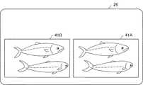
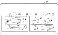
表示制御部34は、表示装置26の表示動作を制御する機能を備えている。例えば、表示制御部34は、入力装置25から、カメラ40A,40Bの撮影画像を再生する要求を受け取った場合に、記憶装置23から要求に応じたカメラ40A,40Bの撮影画像を読み出し当該撮影画像を表示装置26に表示する。図6は、表示装置26におけるカメラ40A,40Bの撮影画像の表示例を表す図である。図6の例では、二画面表示により、カメラ40Aによる撮影画像41Aとカメラ40Bによる撮影画像41Bが並んで表示される。 The
なお、表示制御部34は、表示装置26に同時に表示される撮影画像41A,41Bの撮影時刻が同じとなるように、撮影画像41A,41Bの同期が可能な機能を備える。例えば、表示制御部34は、カメラ40A,40Bに同時撮影された前述したような時間合わせの目印を利用して、観測者が撮影画像41A,41Bの再生コマを調整可能な機能を備える。 The
検知部30は、表示装置26に表示(再生)されている撮影画像41A,41Bにおいて、測定対象の魚を指定する情報の入力を観測者に促す機能を備えている。例えば、検知部30は、表示制御部34を利用して、図6のように撮影画像41A,41Bが表示されている表示装置26に、「測定対象の魚を指定(選択)して下さい」旨のメッセージを表示させる。第2実施形態では、観測者が入力装置25を操作することにより、図7に表されるような枠50で測定対象の魚が囲まれることにより、測定対象の魚が指定されるように設定されている。その枠50は、例えば長方形状(正方形を含む)と成し、その大きさおよび縦横比が観測者により可変可能となっている。この枠50は、検知部30が撮影画像に行う検知処理の対象となる調査範囲である。なお、観測者が枠50によって測定対象の魚を指定する作業を実行している場合には、撮影画像41A,41Bは一時停止状態で静止している状態となっている。 The
第2実施形態では、撮影画像41A,41Bのうちの一方側を表示する画面領域(例えば図6、図7における左側の画面領域)が操作画面として設定され、他方側を表示する画面領域(例えば図6、図7における右側の画面領域)が参照画面として設定されている。検知部30は、カメラ40A,40B間の間隔を表す間隔情報に基づき、撮影画像41Bにおいて枠50により指定されている領域と同じ領域を表す参照画面の撮影画像41Aでの枠51の表示位置を算出する機能を備えている。なお、検知部30は、撮影画像41Bにおいて枠50の位置や大きさが調整されている最中に、その位置や大きさに追従して撮影画像41Aにおける枠51の位置や大きさを可変する機能を備える。あるいは、検知部30は、撮影画像41Bにおいて枠50の位置および大きさが確定した後に、枠51を撮影画像41Aに表示させる機能を備えていてもよい。さらにまた、検知部30は、枠50の位置や大きさの調整に追従して枠51の位置や大きさを可変する機能と、枠50の位置および大きさが確定した後に枠51を表示させる機能とを共に備え、例えば観測者により択一的に選択された側の機能を実行してもよい。また、上記のような撮影画像41Bにおいて指定された枠50に基づいて撮影画像41Aにおける枠51を設定する機能は、検知部30に代えて、図3の点線に表されるような範囲追従部35が実行してもよい。 In the second embodiment, a screen area for displaying one side of the captured
検知部30は、さらに、撮影画像41A,41Bにおいて調査範囲として指定された枠50,51内で、測定対象の魚における予め定められた特徴を持つ対を成す特徴部位を検知する機能を備えている。第2実施形態では、魚の頭と尾が対を成す特徴部位として設定されている。撮影画像41A,41Bから特徴部位である魚の頭と尾を検知する手法には様々な手法があり、ここでは、情報処理装置20の処理能力等を考慮した適宜な手法が採用されるが、その一例を挙げると、次のような手法がある。 The
例えば、測定対象となる種類の魚の頭と尾について、魚の向きや形が異なる図8に表されるような複数の参考データ(参考部位画像)が記憶装置23に格納されている。これら参考データは、特徴部位である魚の頭と尾のサンプル画像が表されている参考部位画像である。当該参考データは、測定対象となる種類の魚が撮影されている多数の撮影画像から、頭と尾のそれぞれの特徴部位が撮影されている領域の画像が教師データ(教師画像)として抽出され、当該教師データを利用した機械学習により作成される。 For example, with respect to the head and tail of the type of fish to be measured, a plurality of reference data (reference site images) shown in FIG. 8 having different directions and shapes of the fish are stored in the
第2実施形態の情報処理装置20は、魚の頭と尾との間の長さを魚の長さとして測定する。このことから、魚の頭と尾は、魚の長さを測定する際に測定部分の両端となる部位である。このことを考慮し、ここでは、魚の長さを測定する際に魚の測定部分の両端となる頭と尾のそれぞれの測定ポイントが中心となるように抽出された教師データを利用した機械学習により参考データが作成される。これにより、図8に表されるように、参考データの中心は、魚の頭あるいは尾の測定ポイントPを表すという意味を持つ。 The
これに対し、測定ポイントPを考慮せずに、図9に表されるように単に頭と尾が撮影されている領域が教師データとして抽出され、当該教師データに基づいて参考データが作成された場合には、参考データの中心は測定ポイントPを表すとは限らない。つまり、この場合には、参考データの中心位置は、測定ポイントPを表すという意味を持たない。 On the other hand, without considering the measurement point P, the area where the head and tail are simply photographed was extracted as teacher data as shown in FIG. 9, and reference data was created based on the teacher data. In some cases, the center of the reference data does not necessarily represent the measurement point P. That is, in this case, the center position of the reference data does not mean that it represents the measurement point P.
上述したような参考データと、撮影画像41A,41Bにおいて指定された調査範囲(枠50,51)内の画像とが照合されることにより、枠50,51において参考データに合う画像領域が検知される。 By collating the reference data as described above with the images within the survey range (frames 50 and 51) specified in the captured
検知部30は、さらに、表示制御部34を利用して、検知した特徴部位である魚の頭と尾の位置を表示装置26に明示させる機能を備えている。図10には、表示装置26において、検知された魚の頭と尾のそれぞれの部位が枠52,53により明示されている表示例が表されている。 The
特定部31は、検知部30により検知された測定対象の魚における対を成す特徴部位(つまり、頭と尾)の座標空間における位置を表す座標を特定する機能を備えている。例えば、特定部31は、検知部30により検知された測定対象の魚の頭と尾が撮影画像41A,41Bにおいて表示されている表示位置を表す表示位置情報を検知部30から受け取る。また、特定部31は、記憶装置23から、カメラ40A,40B(つまり、撮影位置)間の間隔を表す間隔情報を読み出す。そして、特定部31は、それら情報を利用して、三角測量法によって測定対象の魚の頭と尾の座標空間における座標を特定(算出)する。この際、中心が測定ポイントPとなっている参考データを利用して、検知部30が特徴部位を検知している場合には、特定部31は、検知部30により検知された特徴部位の中心が表示されている撮影画像41A,41Bの表示位置情報を利用する。 The
算出部32は、特定部31により特定された測定対象の魚の特徴部位(頭と尾)の空間座標を利用して、対を成す特徴部位(頭と尾)間の図11に表されるような間隔Lを測定対象の魚の長さとして算出する機能を備えている。このように算出部32により算出された魚の長さLは、例えば観測日時等の予め定められた情報に関連付けられた状態で記憶装置23に格納される。 The
分析部33は、記憶装置23に格納されている魚の長さLの複数の情報と当該情報に関連付けられている情報を利用して、予め定められた分析を実行する機能を備えている。例えば、分析部33は、観測日における生簀48内の複数の魚の長さLの平均値あるいは検知対象とした魚の長さLの平均値を算出する。なお、検知対象とした魚の長さLの平均値を算出する場合の一例としては、1秒間というような短時間に撮影された動画の複数フレームにおける検知対象の魚の画像により算出された検知対象の魚の複数の長さLが利用される。また、生簀48内の複数の魚の長さLの平均値を算出する場合であって魚の個体識別をしていない場合には、平均値の算出に利用する魚の長さLの値として同じ魚の値が重複利用されることが懸念される。ただ、千尾以上というような多数の魚の長さLの平均値を算出する場合には、値を重複利用することに因る平均値の算出精度への悪影響は小さくなる。 The
また、分析部33は、生簀48内における魚の長さLとその魚の数との関係 (魚の長さにおける魚体数分布)を算出してもよい。さらに、分析部33は、魚の成長を表す魚の長さLの時間的な推移を算出してもよい。 Further, the
次に、情報処理装置20における魚の長さLの算出(測定)動作の一例を図12を参照しつつ説明する。なお、図12は、情報処理装置20が実行する魚の長さLの算出(測定)に関わる処理手順を表すフローチャートである。 Next, an example of the calculation (measurement) operation of the fish length L in the
例えば、情報処理装置20の検知部30は、操作画面における撮影画像41Bにおいての調査範囲(枠50)を指定する情報を受け付けると(ステップS101)、参照画面における撮影画像41Aの調査範囲(枠51)の位置を算出する。そして、検知部30は、撮影画像41A,41Bの枠50,51内において、予め定められた特徴部位(頭と尾)を例えば参考データを利用して検知する(ステップS102)。 For example, when the
その後、特定部31が、検知された特徴部位である頭と尾について、例えば、カメラ40A,40B(撮影位置)間についての間隔情報等を利用し、三角測量法によって座標空間における座標を特定する(ステップS103)。 After that, the
そして、算出部32が、特定された座標に基づき、対を成す特徴部位(頭と尾)間の間隔Lを魚の長さとして算出する(ステップS104)。その後、算出部32は、算出結果を予め定められた情報(例えば、撮影日時)に関連付けた状態で記憶装置23に格納する(ステップS105)。 Then, the
その後、情報処理装置20の制御装置22は、例えば観測者による入力装置25の操作により魚の長さLの測定を終了する旨の指示が入力されたか否かを判断する(ステップS106)。そして、制御装置22は、終了の指示が入力されていない場合には、次の魚の長さLの測定に備えて待機する。また、制御装置22は、終了の指示が入力された場合には、魚の長さLを測定する動作を終了する。 After that, the
第2実施形態の情報処理装置20は、検知部30によって、カメラ40A,40Bの撮影画像41A,41Bにおいて、魚の長さLの測定に必要な魚の頭と尾の部位を検知する機能を備えている。さらに、情報処理装置20は、特定部31によって、検知された魚の頭と尾の位置を表す座標空間における座標を特定する機能を備えている。さらにまた、情報処理装置20は、算出部32によって、特定された座標に基づき魚の頭と尾の間隔Lを魚の長さとして算出する機能を備えている。このため、撮影画像41A,41Bにおける調査対象の範囲(枠50)の情報を観測者が入力装置25を利用して入力することにより、情報処理装置20は、魚の長さLを算出し、当該魚の長さLの情報を観測者に提供できる。換言すれば、観測者は、撮影画像41A,41Bにおける調査対象の範囲(枠50)の情報を情報処理装置20に入力することで、手間無く簡単に魚の長さLの情報を得ることができる。 The
また、情報処理装置20は、三角測量法により、魚の対を成す特徴部位(頭と尾)の空間座標を特定(算出)し、当該空間座標を利用して、特徴部位間の長さLを魚の長さとして算出するので、長さの測定精度を高めることができる。 Further, the
さらに、情報処理装置20が特徴部位を検知する処理にて利用する参考データ(参考部位画像)の中心が、魚の長さを測定する部分の端部となっている場合には、測定する魚によって測定部分の端部位置がばらつくことを抑制できる。これにより、情報処理装置20は、魚の長さLの測定に対する信頼性をより高めることができる。 Further, when the center of the reference data (reference part image) used by the
さらに、情報処理装置20は、指定された調査範囲(枠50,51)内において特徴部位を検知する機能を備えている。このため、情報処理装置20は、撮影画像全体に亘って特徴部位を検知する場合に比べて、処理の負荷を軽減できる。 Further, the
さらに、情報処理装置20は、複数の撮影画像のうちの一つの画像において、調査範囲(枠50)が指定されることにより、他の撮影画像の調査範囲(枠51)を決定する機能を備えている。情報処理装置20は、複数の撮影画像において観測者が調査範囲を指定しなければならない場合に比べて、観測者の手間を軽減できる。 Further, the
なお、第2実施形態では、検知部30は、撮影画像41A,41Bのうちの一方において測定対象の魚を指定する調査範囲(枠50)が観測者等により指定された場合に、他方における調査範囲(枠51)の位置を設定(算出)する機能を備えている。これに代えて、検知部30は、撮影画像41A,41Bのそれぞれにおいて、測定対象の魚を指定する調査範囲の情報を入力することを観測者等に促し、さらに、入力された情報に基づいて調査範囲(枠50,51)の位置を設定する機能を備えていてもよい。つまり、撮影画像41A,41Bの両方において、調査範囲(枠50,51)の位置が観測者等により指定され、検知部30は、その指定された位置の情報に基づいて、撮影画像41A,41Bのそれぞれにおける調査範囲(枠50,51)の位置を設定してもよい。 In the second embodiment, the
<第3実施形態>
以下に、本発明に係る第3実施形態を説明する。なお、第3実施形態の説明において、第2実施形態の情報処理装置および長さ測定システムを構成する構成部分と同一名称部分には同一符号を付し、その共通部分の重複説明は省略する。<Third Embodiment>
The third embodiment according to the present invention will be described below. In the description of the third embodiment, the same reference numerals are given to the components having the same names as the components constituting the information processing apparatus and the length measurement system of the second embodiment, and the overlapping description of the common sections will be omitted.
第3実施形態の情報処理装置20は、第2実施形態の構成に加えて、図13に表されるような設定部55を備えている。なお、情報処理装置20は、第2実施形態の構成を備えているが、図13では、特定部31と算出部32と分析部33と表示制御部34の図示が省略されている。また、図13において、記憶装置24と入力装置25と表示装置26の図示も省略されている。 The
設定部55は、撮影画像41A,41Bにおいて検知部30が特徴部位(頭と尾)の位置を調べる調査範囲を設定する機能を備えている。その調査範囲は、第2実施形態では、観測者により入力される情報であるのに対し、第3実施形態では、設定部55が調査範囲を設定するので、観測者は調査範囲の情報を入力しなくて済む。このことにより、第3実施形態の情報処理装置20は、利便性をより高めることができる。 The setting
第3実施形態では、記憶装置23には、設定部55が調査範囲を設定するために利用する情報として、調査範囲の形状および大きさを決定する情報が格納されている。例えば、調査範囲の形状および大きさが図14の実線に示されるような形状および大きさを持つ枠50である場合には、その形状を表す情報と、枠50の縦と横の長さの情報とが記憶装置23に格納される。なお、枠50は、例えば観測者が測定に適切であると考えた撮影画像における魚1尾の大きさに応じた大きさを持つ範囲であり、その縦と横のそれぞれの長さは、観測者等による入力装置25の操作により可変可能となっている。 In the third embodiment, the
さらに、記憶装置23には、測定対象の物体全体(つまり、ここでは魚体)の撮影画像がサンプル画像として格納されている。ここでは、図15および図16に表されるように、撮影条件が互いに異なる複数のサンプル画像が格納されている。これら測定対象の物体全体(魚体)のサンプル画像も、特徴部位(頭と尾)のサンプル画像と同様に、多数の測定対象の物体を撮影した撮影画像を教師データ(教師画像)とした機械学習により得ることができる。 Further, the
設定部55は、次のようにして調査範囲を設定する。例えば、設定部55は、観測者により、長さの測定を要求する情報が入力装置25の操作により入力されると、記憶装置23から枠50に関する情報を読み出す。なお、長さの測定を要求する情報は、例えば、撮影画像41A,41Bの再生中に画像の一時停止を指示する情報であってもよいし、撮影画像41A,41Bの停止中に動画の再生を指示する情報であってよい。また、長さの測定を要求する情報は、表示装置26に表示されている『測定開始』のマークが観測者の入力装置25の操作により指示されたことを表す情報であってもよい。さらに、長さの測定を要求する情報は、測定開始を意味する予め定められた入力装置25の操作(例えばキーボード操作)が行われたことを表す情報であってもよい。 The setting
設定部55は、枠50に関する情報を読み出した後に、撮影画像において、読み出した情報に表されている形状および大きさの枠50を図14に表される枠A1→枠A2→枠A3→・・・→枠A9→・・・のように、枠50を所定の間隔で順次移動させる。なお、枠50の移動の間隔は、例えば、観測者により適宜可変可能な構成を備えていてもよい。 After reading the information about the
また、設定部55は、枠50を移動させながら、当該枠50における撮影画像部分と、図15および図16のような測定対象の物体のサンプル画像とのマッチ度(類似度)を例えばテンプレートマッチング手法で利用される手法により判定する。そして、設定部55は、マッチ度が閾値(例えば、90%)以上となる枠50を調査範囲として確定する。例えば、図17に表される撮影画像の例では、設定部55により、1つの撮影画像において、2つの枠50が確定されている。この場合には、2つの枠50のそれぞれについて、第2実施形態で述べたように、検知部30は、特徴部位を検知する処理を実行し、特定部31は、座標空間における特徴部位の空間座標を特定する。そして、算出部32は、2つの枠50のそれぞれについて、対を成す特徴部位間の間隔(ここでは、魚の長さL)を算出する。なお、例えば、長さの測定を要求する情報として画像の一時停止を指示する情報が入力された場合、設定部55は、一時停止中の撮影画像において調査範囲を設定する。このように調査範囲が設定されることにより、前記の如く、対を成す特徴部位間の間隔が算出される。また、例えば、長さの測定を要求する情報として動画の再生を指示する情報が入力された場合、設定部55は、再生中の動画に対して、連続的に、調査範囲を設定する。このように調査範囲が設定されることにより、前記の如く、対を成す特徴部位間の間隔が算出される。 Further, while moving the
なお、設定部55は、撮影画像4A,4Bの一方において調査範囲(枠50)の位置を上記の如く設定すると、他方における調査範囲(枠51)の位置を枠50の位置に応じて設定するが、これに代えて、設定部55は、次のような機能を備えていてもよい。つまり、設定部55は、撮影画像4A,4Bのそれぞれにおいて、枠50,51を上記同様に移動(スキャン)させることにより、調査範囲(枠50,51)を設定してもよい。 When the position of the investigation range (frame 50) is set in one of the captured images 4A and 4B as described above, the setting
また、設定部55は、上記のように設定した調査範囲の位置を仮決定とし、仮決定の調査範囲(枠50,51)の位置を撮影画像4A,4Bに明記すると共に、調査範囲の確認を観測者等に促すメッセージを表示制御部34によって表示装置26に表示させる機能を備えていてもよい。そして、設定部55は、観測者等による入力装置25の操作によって調査範囲(枠50,51)の位置(例えば、枠50,51が同じ魚を囲んでいること等)を確認した旨の情報が入力された場合に、調査範囲の位置を確定してもよい。また、設定部55は、観測者等による入力装置25の操作により調査範囲(枠50,51)の位置を変更したい旨の情報が入力された場合には、調査範囲(枠50,51)の位置を調整可能とし、変更された枠50,51の位置を調査範囲として確定してもよい。 Further, the setting
第3実施形態の情報処理装置20および長さ測定システムにおける上記以外の構成は、第2実施形態の情報処理装置20と同様である。 The configuration other than the above in the
第3実施形態の情報処理装置20および長さ測定システムは、第2実施形態と同様の構成を備えているので、第2実施形態と同様の効果を得ることができる。その上、第3実施形態の情報処理装置20および長さ測定システムは、設定部55を備えているので、観測者が調査範囲を確定する情報を入力しなくて済むこととなり、観測者の手間を軽減できる。これにより、第3実施形態の情報処理装置20および長さ測定システムは、物体の長さ測定に関する利便性をより高めることができる。例えば、情報処理装置20は、撮影画像41A,41Bの同期を取り、その後、撮影画像41A,41Bを再生しながら設定部55と検知部30と特定部31と算出部32により魚の長さLを算出していく処理を再生終了まで連続して行うことが可能となる。なお、情報処理装置20が上記のような画像の同期から撮影画像の再生および魚の長さの算出を連続して行う一連の処理を開始する手法には様々な手法が考えられる。例えば、入力装置25の操作により処理の開始が指示された場合に、情報処理装置20は、上記一連の処理を開始してもよい。また、撮影画像41A,41Bが情報処理装置20の記憶装置23に格納(登録)される際に、情報処理装置20は、その登録を検知することにより、上記一連の処理を開始してもよい。さらに、再生する撮影画像41A,41Bが選択された際に、情報処理装置20は、その選択情報に基づいて上記一連の処理を開始してもよい。ここでは、そのような様々な手法の中から、適宜な手法が採用されてよいものとする。 Since the
<その他の実施形態>
なお、本発明は第1〜第3の実施形態に限定されることなく、様々な実施の形態を採り得る。例えば、第2と第3の実施形態では、情報処理装置20に分析部33が備えられているが、魚の長さLの観測により得られた情報の分析は、情報処理装置20と別の情報処理装置により実行されてもよく、この場合には、分析部33は省略されてもよい。<Other embodiments>
The present invention is not limited to the first to third embodiments, and various embodiments can be adopted. For example, in the second and third embodiments, the
また、第2と第3の実施形態では、対を成す特徴部位が魚の頭と尾である例を示したが、例えば、対を成す特徴部位として、さらに、背びれと腹びれの組をも検知する構成とし、頭と尾の間の長さだけでなく、背びれと腹びれとの間の長さをも算出してもよい。それら特徴部位としての背びれと腹びれを撮影画像から検知する手法は、頭と尾の検知と同様の検知手法を用いることができる。 Further, in the second and third embodiments, an example is shown in which the paired characteristic sites are the head and tail of the fish. For example, as the paired feature sites, a pair of dorsal fin and abdominal fin is also detected. As a configuration, not only the length between the head and the tail but also the length between the dorsal fin and the abdominal fin may be calculated. As a method for detecting the dorsal fin and the abdominal fin as these characteristic parts from the captured image, a detection method similar to the detection of the head and the tail can be used.
さらに、例えば、頭と尾の間の長さと、背びれと腹びれとの間の長さとを算出する場合であって、それら長さに基づいて魚の重さを推定できる長さと重さの関係が得られる場合には、分析部33が、それら算出された長さに基づき魚の重さを推定してもよい。 Further, for example, in the case of calculating the length between the head and the tail and the length between the dorsal fin and the abdominal fin, the relationship between the length and the weight that can estimate the weight of the fish based on these lengths is obtained. If so, the
さらに、第2実施形態の説明では、特徴部位の参考データとして図8の例が挙げられているが、特徴部位の参考データの種類は、図19〜図22に表されているように、より多くてもよい。なお、図19および図20は、魚の頭に関する参考データの例であり、図21および図22は、魚の尾に関する参考データの例である。また、例えば、魚の尾の参考データとして、さらに、くねりが入っている魚の尾の画像が含まれていてもよい。また、魚の頭や尾の一部が撮影画像に映っていない見切りのデータが検知対象外の参考データとして与えられていてもよい。このように、参考データの種類や数は限定されない。 Further, in the description of the second embodiment, the example of FIG. 8 is given as the reference data of the characteristic portion, but the types of the reference data of the characteristic portion are more as shown in FIGS. 19 to 22. There may be many. Note that FIGS. 19 and 20 are examples of reference data regarding the fish head, and FIGS. 21 and 22 are examples of reference data regarding the fish tail. Further, for example, as reference data of the fish tail, an image of the fish tail containing a bend may be further included. Further, the parting data in which a part of the head or the tail of the fish is not reflected in the captured image may be given as reference data not to be detected. In this way, the type and number of reference data is not limited.
さらに、第2と第3の各実施形態において、教師データを利用した機械学習によって特徴部位(頭と尾)や測定対象の物体全体(魚体)のサンプル画像を作成する場合に、次のようにして教師データの削減が図られてもよい。例えば、教師データとして図18に表されるような左向きの魚の撮影画像が取得された場合に、その左向きの魚の像を左右反転する処理を行って右向きの魚の教師データが得られるようにしてもよい。 Further, in each of the second and third embodiments, when creating a sample image of a characteristic part (head and tail) or the entire object to be measured (fish body) by machine learning using teacher data, the following is performed. The teacher data may be reduced. For example, when a photographed image of a left-facing fish as shown in FIG. 18 is acquired as teacher data, the image of the left-facing fish may be flipped horizontally so that the teacher data of the right-facing fish can be obtained. good.
さらに、第2実施形態において、情報処理装置20が、特徴部位を検知する処理を開始する前などの適宜なタイミングで、撮影画像における水の濁りを軽減する画像処理や、水の揺らぎに因る魚体の歪みを補正する画像処理を行ってもよい。また、情報処理装置20は、撮影画像を物体の水深や明るさ等の撮影条件を考慮して補正する画像処理を行ってもよい。さらに、第3実施形態において、情報処理装置20が、調査範囲を確定する処理を開始する前などの適宜なタイミングで、上記同様の画像処理を実行してもよい。このように、情報処理装置20が、撮影環境を考慮して撮影画像を画像処理(画像補正)することにより、測定対象の物体の長さ測定の精度をより高めることができる。また、情報処理装置20は、そのように画像補正された撮影画像を利用することにより、参考データの数を少なくできるという効果を得ることができる。 Further, in the second embodiment, the image processing for reducing the turbidity of water in the captured image and the fluctuation of water are caused at an appropriate timing such as before the
さらに、第2と第3の実施形態では、測定対象の物体として魚を例にして説明しているが、第2と第3の実施形態で説明した構成を持つ情報処理装置20は、他の物体にも適用可能である。すなわち、第2と第3の実施形態における情報処理装置20は、魚でなくとも、長さを測定する部分の両端部分が他の部分と区別可能な特徴を持つ物体であれば、その物体の長さ測定に適用することもできる。 Further, in the second and third embodiments, a fish is described as an example of an object to be measured, but the
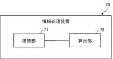
さらに、図23には、本発明に係るその他の実施形態の情報処理装置の構成が簡略化して表されている。図23における情報処理装置70は、機能部として、検知部71と、算出部72とを備えている。検知部71は、測定対象の物体が撮影されている撮影画像から、測定対象の物体における対を成す部位であって予め定められた特徴をそれぞれ持つ特徴部位を検知する機能を備えている。算出部72は、検知部71の検知結果に基づいた対を成す特徴部位間の長さを算出する機能を備えている。情報処理装置70は、上記のような構成を備えることにより、撮影画像に基づいて測定対象の物体の長さを容易に、かつ、精度良く検知できるという効果を得ることができる。 Further, FIG. 23 shows a simplified configuration of the information processing apparatus according to another embodiment of the present invention. The
以上、上述した実施形態を模範的な例として本発明を説明した。しかしながら、本発明は、上述した実施形態には限定されない。即ち、本発明は、本発明のスコープ内において、当業者が理解し得る様々な態様を適用することができる。 The present invention has been described above by using the above-described embodiment as a model example. However, the invention is not limited to the embodiments described above. That is, the present invention can apply various aspects that can be understood by those skilled in the art within the scope of the present invention.
この出願は、2016年9月30日に出願された日本出願特願2016−194268を基礎とする優先権を主張し、その開示の全てをここに取り込む。 This application claims priority on the basis of Japanese application Japanese Patent Application No. 2016-194268 filed on September 30, 2016 and incorporates all of its disclosures herein.
上記の実施形態の一部又は全部は、以下の付記のようにも記載されうるが、以下には限られない。 Some or all of the above embodiments may also be described, but not limited to:
(付記1)
測定対象の物体が撮影されている撮影画像から、前記物体における対を成す部位であって予め定められた特徴をそれぞれ持つ特徴部位を検知する検知部と、
前記検知部の検知結果に基づいた対を成す前記特徴部位間の長さを算出する算出部と
を備える情報処理装置。(Appendix 1)
From the captured image in which the object to be measured is photographed, a detection unit that detects a paired portion of the object and a characteristic portion having predetermined characteristics, and a detection unit.
An information processing device including a calculation unit for calculating the length between the featured portions forming a pair based on the detection result of the detection unit.
(付記2)
前記物体を互いに異なる位置から撮影した複数の撮影画像における前記検知された特徴部位が表示されている表示位置情報と、前記複数の撮影画像をそれぞれ撮影した撮影位置間の間隔を表す間隔情報とに基づいて、座標空間における前記特徴部位の位置を表す座標を特定する特定部をさらに備え、
前記算出部は、前記特定された前記特徴部位の位置の座標に基づいて、対を成す前記特徴部位間の長さを算出する付記1に記載の情報処理装置。(Appendix 2)
The display position information in which the detected feature portions are displayed in a plurality of captured images obtained by photographing the object from different positions, and the interval information indicating the interval between the captured positions in which the plurality of captured images are captured are provided. Based on this, a specific part for specifying the coordinates representing the position of the feature portion in the coordinate space is further provided.
The information processing apparatus according to Appendix 1, wherein the calculation unit calculates the length between the paired feature portions based on the coordinates of the positions of the specified feature portions.
(付記3)
前記検知部は、前記撮影画像における指定された調査範囲内において前記特徴部位を検知する付記1又は付記2に記載の情報処理装置。(Appendix 3)
The information processing device according to Appendix 1 or
(付記4)
複数の前記撮影画像の中の一つにおいて前記検知部により前記特徴部位を検知する調査範囲が指定された場合に、前記調査範囲が指定された前記撮影画像における前記調査範囲の位置を表す情報と、前記撮影位置間の間隔情報とに基づいて、前記調査範囲が指定されていない前記撮影画像における前記調査範囲の位置を決定する範囲追従部をさらに備える付記2に記載の情報処理装置。(Appendix 4)
Information indicating the position of the survey range in the captured image to which the survey range is designated when the survey range for detecting the feature portion is designated by the detection unit in one of the plurality of captured images. The information processing apparatus according to
(付記5)
前記撮影画像において前記検知部が検知処理を実行する調査範囲を設定する設定部をさらに備える付記1又は付記2に記載の情報処理装置。(Appendix 5)
The information processing apparatus according to
(付記6)
前記検知部は、前記特徴部位のサンプル画像が表されている参考部位画像に基づいて、前記撮影画像から前記特徴部位を検知する付記1乃至付記5の何れか一つに記載の情報処理装置。(Appendix 6)
The information processing device according to any one of Supplementary note 1 to Supplementary note 5, wherein the detection unit detects the featured portion from the captured image based on a reference site image showing a sample image of the featured portion.
(付記7)
前記検知部は、前記特徴部位のサンプル画像であって且つ画像中心が前記物体の長さを測定する測定部分の端部を表している参考部位画像に基づき、前記物体における前記測定部分の端部を中心にした部位を前記特徴部位として検知し、
前記特定部は、検知された前記特徴部位の中心位置を表す座標を特定し、
前記算出部は、対を成す前記特徴部位の中心間の長さを算出する付記2に記載の情報処理装置。(Appendix 7)
The detection unit is a sample image of the characteristic portion, and the end portion of the measurement portion in the object is based on a reference portion image in which the center of the image represents the end portion of the measurement portion for measuring the length of the object. The part centered on is detected as the characteristic part,
The specific unit specifies the coordinates representing the detected center position of the characteristic portion, and the specific unit determines the coordinates.
The information processing device according to
(付記8)
前記特定部は、三角測量法を用いて、座標空間における前記特徴部位の位置を表す座標を特定する付記1乃至付記7の何れか一つに記載の情報処理装置。(Appendix 8)
The information processing apparatus according to any one of Supplementary note 1 to Supplementary note 7, wherein the specific unit specifies coordinates representing the position of the characteristic portion in a coordinate space by using a triangulation method.
(付記9)
測定対象の物体を撮影する撮影装置と、
前記撮影装置により撮影された撮影画像を利用して、前記物体における対を成す部位であって予め定められた特徴をそれぞれ持つ特徴部位間の長さを算出する情報処理装置と
を備え、
前記情報処理装置は、
測定対象の物体が撮影されている撮影画像から、前記物体における対を成す部位であって予め定められた特徴をそれぞれ持つ特徴部位を検知する検知部と、
前記検知部の検知結果に基づいた対を成す前記特徴部位間の長さを算出する算出部と
を備える長さ測定システム。(Appendix 9)
An imaging device that photographs the object to be measured, and
It is equipped with an information processing device that calculates the length between feature parts that are paired parts in the object and have predetermined features by using the shot image taken by the shooting device.
The information processing device is
From the captured image in which the object to be measured is photographed, a detection unit that detects a paired portion of the object and a characteristic portion having predetermined characteristics, and a detection unit.
A length measuring system including a calculation unit for calculating the length between the featured portions forming a pair based on the detection result of the detection unit.
(付記10)
測定対象の物体が撮影されている撮影画像から、前記物体における対を成す部位であって予め定められた特徴をそれぞれ持つ特徴部位を検知し、
前記検知された結果に基づいた対を成す前記特徴部位間の長さを算出する長さ測定方法。(Appendix 10)
From the photographed image in which the object to be measured is photographed, the characteristic parts that form a pair in the object and have predetermined characteristics are detected.
A length measuring method for calculating the length between the featured parts forming a pair based on the detected result.
(付記11)
測定対象の物体が撮影されている撮影画像から、前記物体における対を成す部位であって予め定められた特徴をそれぞれ持つ特徴部位を検知する処理と、
前記検知された結果に基づいた対を成す前記特徴部位間の長さを算出する処理と
をコンピュータに実行させるコンピュータプログラムを記憶するプログラム記憶媒体。(Appendix 11)
Processing to detect featured parts that are paired parts of the object and have predetermined features from the captured image of the object to be measured.
A program storage medium for storing a computer program that causes a computer to execute a process of calculating the length between the featured parts forming a pair based on the detected result.
1,20 情報処理装置
2,30 検知部
3,31 特定部
4,32 算出部
10 長さ測定システム
11A,11B 撮影装置
50,51 枠
55 設定部1,20
本発明の魚体長さ測定システムは、
水中を泳ぐ魚体が撮影されている撮影画像から、測定対象の魚体における特徴部位である頭及び尾を、参考部位画像を用いて検知する検知手段と 、
検知した測定対象の魚体における頭と尾の間の長さを算出する算出手段と、
撮影画像上に、測定対象の魚体を囲む枠と、長さの両端に対応する頭と尾を示す表示と、を表示させる表示制御手段と 、を備え、
参考部位画像は、くねりが入っている特徴部位の画像または異なる水深における特徴部位の画像を含む。The fish body length measuring system of the present invention is
A detection means for detecting the head and tail, which are characteristic parts of the fish to be measured, using the reference part image from the photographed image of the fish swimming in the water.
A calculation method for calculating the length between the head and tail of the detected fish to be measured, and
On the captured image, a frame surrounding the fish to be measured, a display showing the head and tail corresponding to both ends of the length, and a display control means for displaying the display are provided.
Reference site images include images of feature sites with waviness or images of feature sites at different water depths .
本発明の魚体長さ測定方法は、
コンピュータが、
魚体が撮影されている撮影画像から、測定対象の魚体における特徴部位である頭及び尾を、くねりが入っている特徴部位の画像または異なる水深における特徴部位の画像を含む参考部位画像を用いて検知し、
測定対象の魚体における頭と尾の間の長さを算出し、
撮影画像上に、測定対象の魚体を囲む枠と、長さの両端に対応する頭と尾を示す表示と、を表示させる。The fish body length measuring method of the present invention
The computer
From the captured image that fish are photographed, the head and tail are characteristic portions ofthe fish body to bemeasured, and using Reference region image that bend including an image characteristic portions of a picture or a different depth of the characteristic portions containing the Detect and
To calculate the length betweenthe head and tail ofthat put on themeasurement object of the fish,
A frame surrounding the fish to be measured and a display showing the head and tail corresponding to both ends of the length are displayed on the captured image.
本発明の魚体長さ測定プログラムは、
コンピュータに、
魚体が撮影されている撮影画像から、測定対象の魚体における特徴部位である頭及び尾を、くねりが入っている特徴部位の画像または異なる水深における特徴部位の画像を含む参考部位画像を用いて検知する処理と、
測定対象の魚体における頭と尾の間の長さを算出する処理と、
撮影画像上に、測定対象の魚体を囲む枠と、長さの両端に対応する頭と尾を示す表示と、を表示させる処理と、を実行させる。
The fish length measurement program of the present invention is
On the computer
From the captured image that fish are photographed, the head and tail are characteristic portions ofthe fish bodyto bemeasured, and using Reference region image that bend including an image characteristic portions of a picture or a different depth of the characteristic portions containing the Processing to detect and
A process of calculating the distance betweenhead and tail that put themeasurement target fish,
A processof displaying a frame surrounding the fish to be measured and a display showing the head and tail corresponding to both ends of the length is executed on the captured image.
Claims (1)
Translated fromJapanese前記検知した前記測定対象の魚体における前記頭と前記尾の間の長さを算出する算出手段と、
前記撮影画像上に、前記測定対象の魚体を囲む枠と、前記長さの両端に対応する前記頭及び前記尾とを示す表示と、を表示させる表示制御手段と、
を備える魚体長さ測定システム。A detection means for detecting the head and tail, which are characteristic parts of the fish to be measured, from a photographed image of a fish swimming in water.
A calculation means for calculating the length between the head and the tail of the detected fish to be measured, and
A display control means for displaying a frame surrounding the fish body to be measured and a display indicating the head and the tail corresponding to both ends of the length on the captured image.
A fish length measurement system equipped with.
Applications Claiming Priority (3)
| Application Number | Priority Date | Filing Date | Title |
|---|---|---|---|
| JP2016194268 | 2016-09-30 | ||
| JP2016194268 | 2016-09-30 | ||
| JP2021000654AJP7004094B2 (en) | 2016-09-30 | 2021-01-06 | Fish length measurement system, fish length measurement method and fish length measurement program |
Related Parent Applications (1)
| Application Number | Title | Priority Date | Filing Date |
|---|---|---|---|
| JP2021000654ADivisionJP7004094B2 (en) | 2016-09-30 | 2021-01-06 | Fish length measurement system, fish length measurement method and fish length measurement program |
Publications (2)
| Publication Number | Publication Date |
|---|---|
| JP2021193394Atrue JP2021193394A (en) | 2021-12-23 |
| JP7188527B2 JP7188527B2 (en) | 2022-12-13 |
Family
ID=61760710
Family Applications (3)
| Application Number | Title | Priority Date | Filing Date |
|---|---|---|---|
| JP2018542455APendingJPWO2018061925A1 (en) | 2016-09-30 | 2017-09-20 | INFORMATION PROCESSING APPARATUS, LENGTH MEASUREMENT SYSTEM, LENGTH MEASUREMENT METHOD, AND PROGRAM STORAGE MEDIUM |
| JP2021000654AActiveJP7004094B2 (en) | 2016-09-30 | 2021-01-06 | Fish length measurement system, fish length measurement method and fish length measurement program |
| JP2021157490AActiveJP7188527B2 (en) | 2016-09-30 | 2021-09-28 | Fish length measurement system, fish length measurement method and fish length measurement program |
Family Applications Before (2)
| Application Number | Title | Priority Date | Filing Date |
|---|---|---|---|
| JP2018542455APendingJPWO2018061925A1 (en) | 2016-09-30 | 2017-09-20 | INFORMATION PROCESSING APPARATUS, LENGTH MEASUREMENT SYSTEM, LENGTH MEASUREMENT METHOD, AND PROGRAM STORAGE MEDIUM |
| JP2021000654AActiveJP7004094B2 (en) | 2016-09-30 | 2021-01-06 | Fish length measurement system, fish length measurement method and fish length measurement program |
Country Status (3)
| Country | Link |
|---|---|
| US (1) | US20190277624A1 (en) |
| JP (3) | JPWO2018061925A1 (en) |
| WO (1) | WO2018061925A1 (en) |
Families Citing this family (22)
| Publication number | Priority date | Publication date | Assignee | Title |
|---|---|---|---|---|
| WO2019045089A1 (en)* | 2017-09-04 | 2019-03-07 | 日本電気株式会社 | Information processing device, length measurement system, length measurement method, and program storage medium |
| WO2019121851A1 (en) | 2017-12-20 | 2019-06-27 | Intervet International B.V. | System for external fish parasite monitoring in aquaculture |
| CN116034917A (en)* | 2017-12-20 | 2023-05-02 | 英特维特国际股份有限公司 | Method and system for fish ectoparasite monitoring in aquaculture |
| AU2018390171B2 (en)* | 2017-12-20 | 2024-12-05 | Intervet International B.V. | System for external fish parasite monitoring in aquaculture |
| US10599922B2 (en)* | 2018-01-25 | 2020-03-24 | X Development Llc | Fish biomass, shape, and size determination |
| WO2019216297A1 (en)* | 2018-05-09 | 2019-11-14 | 日本電気株式会社 | Calibration device and calibration method |
| JP6702370B2 (en)* | 2018-07-24 | 2020-06-03 | 日本電気株式会社 | Measuring device, measuring system, measuring method and computer program |
| JP6694039B1 (en)* | 2018-11-22 | 2020-05-13 | 株式会社アイエンター | Fish size calculator |
| US20200296925A1 (en)* | 2018-11-30 | 2020-09-24 | Andrew Bennett | Device for, system for, method of identifying and capturing information about items (fish tagging) |
| JP7233688B2 (en)* | 2019-02-12 | 2023-03-07 | 広和株式会社 | Method and system for measuring substances in liquid |
| ES2791551A1 (en)* | 2019-05-03 | 2020-11-04 | Inst Espanol De Oceanografia Ieo | PROCEDURE FOR THE IDENTIFICATION AND CHARACTERIZATION OF FISH AND AUTOMATIC FEED SUPPLY SYSTEM THAT MAKES USE OF THE SAME (Machine-translation by Google Translate, not legally binding) |
| WO2021065265A1 (en)* | 2019-09-30 | 2021-04-08 | 日本電気株式会社 | Size estimation device, size estimation method, and recording medium |
| WO2021096856A1 (en)* | 2019-11-12 | 2021-05-20 | X Development Llc | Entity identification using machine learning |
| US20230023743A1 (en)* | 2019-12-25 | 2023-01-26 | Nec Corporation | Device, movement speed estimation system, feeding control system, movement speed estimation method, and recording medium in which movement speed estimation program is stored |
| CN111862189B (en)* | 2020-07-07 | 2023-12-05 | 京东科技信息技术有限公司 | Body size information determining method, body size information determining device, electronic equipment and computer readable medium |
| JPWO2022209435A1 (en) | 2021-03-31 | 2022-10-06 | ||
| CN117222686B (en) | 2021-03-31 | 2024-04-12 | 住友电木株式会社 | Sealing resin composition and electronic device using same |
| US12051222B2 (en)* | 2021-07-13 | 2024-07-30 | X Development Llc | Camera calibration for feeding behavior monitoring |
| KR102576926B1 (en)* | 2021-07-14 | 2023-09-08 | 부경대학교 산학협력단 | Fish growth measurement system using deep neural network |
| JP7608411B2 (en)* | 2022-11-01 | 2025-01-06 | ソフトバンク株式会社 | Information processing program, information processing device, and information processing method |
| JP7556926B2 (en)* | 2022-11-17 | 2024-09-26 | ソフトバンク株式会社 | Shooting System |
| WO2024166355A1 (en)* | 2023-02-10 | 2024-08-15 | 日本電気株式会社 | Image analysis device, imaging system, image analysis method, and recording medium |
Citations (5)
| Publication number | Priority date | Publication date | Assignee | Title |
|---|---|---|---|---|
| WO2009008733A1 (en)* | 2007-07-09 | 2009-01-15 | Feed Control Norway As | Means and method for average weight determination and appetite feeding |
| JP2011205387A (en)* | 2010-03-25 | 2011-10-13 | Sony Corp | Image processing apparatus and method, and program |
| US20120086802A1 (en)* | 2008-04-09 | 2012-04-12 | Agency For Science, Technology And Research | System and method for monitoring water quality |
| KR101278630B1 (en)* | 2013-04-26 | 2013-06-25 | 대한민국 | Automatic injection method of a vaccine for a fish using a process of shape image |
| JP2013217662A (en)* | 2012-04-04 | 2013-10-24 | Sharp Corp | Length measuring device, length measuring method, and program |
Family Cites Families (10)
| Publication number | Priority date | Publication date | Assignee | Title |
|---|---|---|---|---|
| JP2002277409A (en)* | 2001-03-15 | 2002-09-25 | Olympus Optical Co Ltd | Inspection device for pattern of printed board |
| EP1650711B1 (en)* | 2003-07-18 | 2015-03-04 | Canon Kabushiki Kaisha | Image processing device, imaging device, image processing method |
| JP5231173B2 (en)* | 2007-12-27 | 2013-07-10 | オリンパス株式会社 | Endoscope device for measurement and program |
| JP5349622B2 (en)* | 2010-02-10 | 2013-11-20 | 株式会社東芝 | Pattern identification device |
| JP2012057974A (en)* | 2010-09-06 | 2012-03-22 | Ntt Comware Corp | Photographing object size estimation device, photographic object size estimation method and program therefor |
| EP2469222A1 (en)* | 2010-12-23 | 2012-06-27 | Geoservices Equipements | Method for analyzing at least a cutting emerging from a well, and associated apparatus. |
| WO2013146269A1 (en)* | 2012-03-29 | 2013-10-03 | シャープ株式会社 | Image capturing device, image processing method, and program |
| KR101657039B1 (en)* | 2013-08-28 | 2016-09-12 | 가부시키가이샤 리코 | Image processing apparatus, image processing method, and imaging system |
| JP2016075658A (en)* | 2014-10-03 | 2016-05-12 | 株式会社リコー | Information processing system and information processing method |
| JP6428144B2 (en)* | 2014-10-17 | 2018-11-28 | オムロン株式会社 | Area information estimation device, area information estimation method, and air conditioner |
- 2017
- 2017-09-20JPJP2018542455Apatent/JPWO2018061925A1/enactivePending
- 2017-09-20USUS16/338,161patent/US20190277624A1/ennot_activeAbandoned
- 2017-09-20WOPCT/JP2017/033881patent/WO2018061925A1/ennot_activeCeased
- 2021
- 2021-01-06JPJP2021000654Apatent/JP7004094B2/enactiveActive
- 2021-09-28JPJP2021157490Apatent/JP7188527B2/enactiveActive
Patent Citations (5)
| Publication number | Priority date | Publication date | Assignee | Title |
|---|---|---|---|---|
| WO2009008733A1 (en)* | 2007-07-09 | 2009-01-15 | Feed Control Norway As | Means and method for average weight determination and appetite feeding |
| US20120086802A1 (en)* | 2008-04-09 | 2012-04-12 | Agency For Science, Technology And Research | System and method for monitoring water quality |
| JP2011205387A (en)* | 2010-03-25 | 2011-10-13 | Sony Corp | Image processing apparatus and method, and program |
| JP2013217662A (en)* | 2012-04-04 | 2013-10-24 | Sharp Corp | Length measuring device, length measuring method, and program |
| KR101278630B1 (en)* | 2013-04-26 | 2013-06-25 | 대한민국 | Automatic injection method of a vaccine for a fish using a process of shape image |
Also Published As
| Publication number | Publication date |
|---|---|
| US20190277624A1 (en) | 2019-09-12 |
| JPWO2018061925A1 (en) | 2019-06-24 |
| JP7004094B2 (en) | 2022-01-21 |
| JP7188527B2 (en) | 2022-12-13 |
| JP2021060421A (en) | 2021-04-15 |
| WO2018061925A1 (en) | 2018-04-05 |
Similar Documents
| Publication | Publication Date | Title |
|---|---|---|
| JP7004094B2 (en) | Fish length measurement system, fish length measurement method and fish length measurement program | |
| JP6816773B2 (en) | Information processing equipment, information processing methods and computer programs | |
| JP7001145B2 (en) | Information processing equipment, object measurement system, object measurement method and computer program | |
| JP6981531B2 (en) | Object identification device, object identification system, object identification method and computer program | |
| CN111345029B (en) | A target tracking method, device, movable platform and storage medium | |
| JP6849081B2 (en) | Information processing equipment, counting system, counting method and computer program | |
| JP6879375B2 (en) | Information processing equipment, length measurement system, length measurement method and computer program | |
| JP4764959B1 (en) | Imaging apparatus and control method thereof | |
| JP2005215750A (en) | Face detection device and face detection method | |
| US20230045358A1 (en) | Underwater organism imaging aid system, underwater organism imaging aid method, and storage medium | |
| CN107295252A (en) | Focusing area display methods, device and terminal device | |
| CN115244360A (en) | Calculation method | |
| JP4198536B2 (en) | Object photographing apparatus, object photographing method and object photographing program | |
| CN115135973A (en) | Weight estimation device and program | |
| JP6583565B2 (en) | Counting system and counting method | |
| JP7007280B2 (en) | Information processing equipment, counting system, counting method and computer program | |
| JP2009299241A (en) | Body size measuring device | |
| JP7343237B2 (en) | Tracking method | |
| JP7323234B2 (en) | Guide method | |
| CN116506594B (en) | Camera accuracy testing method, system and host computer | |
| JP2008157780A (en) | Three-dimensional data creating apparatus, image acquiring device, three-dimensional data creating method, image acquisition method and program | |
| JP2012165212A (en) | Imaging device and control method therefor | |
| JP2015197429A (en) | Image processing apparatus, imaging apparatus, image processing method, and program | |
| JP2007096480A (en) | Object tracking apparatus and object tracking method | |
| JP2021139672A (en) | Area measuring device, area measuring method, and program |
Legal Events
| Date | Code | Title | Description |
|---|---|---|---|
| A521 | Request for written amendment filed | Free format text:JAPANESE INTERMEDIATE CODE: A523 Effective date:20211027 | |
| A621 | Written request for application examination | Free format text:JAPANESE INTERMEDIATE CODE: A621 Effective date:20211027 | |
| TRDD | Decision of grant or rejection written | ||
| A01 | Written decision to grant a patent or to grant a registration (utility model) | Free format text:JAPANESE INTERMEDIATE CODE: A01 Effective date:20221101 | |
| A61 | First payment of annual fees (during grant procedure) | Free format text:JAPANESE INTERMEDIATE CODE: A61 Effective date:20221114 | |
| R151 | Written notification of patent or utility model registration | Ref document number:7188527 Country of ref document:JP Free format text:JAPANESE INTERMEDIATE CODE: R151 |