JP2021190977A - Wireless charging headphone - Google Patents
Wireless charging headphoneDownload PDFInfo
- Publication number
- JP2021190977A JP2021190977AJP2020131685AJP2020131685AJP2021190977AJP 2021190977 AJP2021190977 AJP 2021190977AJP 2020131685 AJP2020131685 AJP 2020131685AJP 2020131685 AJP2020131685 AJP 2020131685AJP 2021190977 AJP2021190977 AJP 2021190977A
- Authority
- JP
- Japan
- Prior art keywords
- wireless charging
- annular
- circuit board
- module
- headphone
- Prior art date
- Legal status (The legal status is an assumption and is not a legal conclusion. Google has not performed a legal analysis and makes no representation as to the accuracy of the status listed.)
- Granted
Links
Images


Classifications
- H—ELECTRICITY
- H04—ELECTRIC COMMUNICATION TECHNIQUE
- H04R—LOUDSPEAKERS, MICROPHONES, GRAMOPHONE PICK-UPS OR LIKE ACOUSTIC ELECTROMECHANICAL TRANSDUCERS; DEAF-AID SETS; PUBLIC ADDRESS SYSTEMS
- H04R1/00—Details of transducers, loudspeakers or microphones
- H04R1/10—Earpieces; Attachments therefor ; Earphones; Monophonic headphones
- H04R1/1025—Accumulators or arrangements for charging
- H—ELECTRICITY
- H02—GENERATION; CONVERSION OR DISTRIBUTION OF ELECTRIC POWER
- H02J—CIRCUIT ARRANGEMENTS OR SYSTEMS FOR SUPPLYING OR DISTRIBUTING ELECTRIC POWER; SYSTEMS FOR STORING ELECTRIC ENERGY
- H02J50/00—Circuit arrangements or systems for wireless supply or distribution of electric power
- H02J50/10—Circuit arrangements or systems for wireless supply or distribution of electric power using inductive coupling
- H02J50/12—Circuit arrangements or systems for wireless supply or distribution of electric power using inductive coupling of the resonant type
- H—ELECTRICITY
- H02—GENERATION; CONVERSION OR DISTRIBUTION OF ELECTRIC POWER
- H02J—CIRCUIT ARRANGEMENTS OR SYSTEMS FOR SUPPLYING OR DISTRIBUTING ELECTRIC POWER; SYSTEMS FOR STORING ELECTRIC ENERGY
- H02J7/00—Circuit arrangements for charging or depolarising batteries or for supplying loads from batteries
- H02J7/0042—Circuit arrangements for charging or depolarising batteries or for supplying loads from batteries characterised by the mechanical construction
- H—ELECTRICITY
- H02—GENERATION; CONVERSION OR DISTRIBUTION OF ELECTRIC POWER
- H02J—CIRCUIT ARRANGEMENTS OR SYSTEMS FOR SUPPLYING OR DISTRIBUTING ELECTRIC POWER; SYSTEMS FOR STORING ELECTRIC ENERGY
- H02J7/00—Circuit arrangements for charging or depolarising batteries or for supplying loads from batteries
- H02J7/02—Circuit arrangements for charging or depolarising batteries or for supplying loads from batteries for charging batteries from AC mains by converters
- H—ELECTRICITY
- H04—ELECTRIC COMMUNICATION TECHNIQUE
- H04R—LOUDSPEAKERS, MICROPHONES, GRAMOPHONE PICK-UPS OR LIKE ACOUSTIC ELECTROMECHANICAL TRANSDUCERS; DEAF-AID SETS; PUBLIC ADDRESS SYSTEMS
- H04R1/00—Details of transducers, loudspeakers or microphones
- H04R1/10—Earpieces; Attachments therefor ; Earphones; Monophonic headphones
- H04R1/1041—Mechanical or electronic switches, or control elements
- H—ELECTRICITY
- H04—ELECTRIC COMMUNICATION TECHNIQUE
- H04R—LOUDSPEAKERS, MICROPHONES, GRAMOPHONE PICK-UPS OR LIKE ACOUSTIC ELECTROMECHANICAL TRANSDUCERS; DEAF-AID SETS; PUBLIC ADDRESS SYSTEMS
- H04R1/00—Details of transducers, loudspeakers or microphones
- H04R1/10—Earpieces; Attachments therefor ; Earphones; Monophonic headphones
- H04R1/1058—Manufacture or assembly
- H04R1/1075—Mountings of transducers in earphones or headphones
- H—ELECTRICITY
- H04—ELECTRIC COMMUNICATION TECHNIQUE
- H04R—LOUDSPEAKERS, MICROPHONES, GRAMOPHONE PICK-UPS OR LIKE ACOUSTIC ELECTROMECHANICAL TRANSDUCERS; DEAF-AID SETS; PUBLIC ADDRESS SYSTEMS
- H04R1/00—Details of transducers, loudspeakers or microphones
- H04R1/10—Earpieces; Attachments therefor ; Earphones; Monophonic headphones
- H04R1/1008—Earpieces of the supra-aural or circum-aural type
- H—ELECTRICITY
- H04—ELECTRIC COMMUNICATION TECHNIQUE
- H04R—LOUDSPEAKERS, MICROPHONES, GRAMOPHONE PICK-UPS OR LIKE ACOUSTIC ELECTROMECHANICAL TRANSDUCERS; DEAF-AID SETS; PUBLIC ADDRESS SYSTEMS
- H04R2420/00—Details of connection covered by H04R, not provided for in its groups
- H04R2420/07—Applications of wireless loudspeakers or wireless microphones
- H—ELECTRICITY
- H04—ELECTRIC COMMUNICATION TECHNIQUE
- H04R—LOUDSPEAKERS, MICROPHONES, GRAMOPHONE PICK-UPS OR LIKE ACOUSTIC ELECTROMECHANICAL TRANSDUCERS; DEAF-AID SETS; PUBLIC ADDRESS SYSTEMS
- H04R5/00—Stereophonic arrangements
- H04R5/033—Headphones for stereophonic communication
Landscapes
- Engineering & Computer Science (AREA)
- Physics & Mathematics (AREA)
- Acoustics & Sound (AREA)
- Signal Processing (AREA)
- Power Engineering (AREA)
- Computer Networks & Wireless Communication (AREA)
- Manufacturing & Machinery (AREA)
- Charge And Discharge Circuits For Batteries Or The Like (AREA)
- Headphones And Earphones (AREA)
Abstract
Translated fromJapaneseDescription
Translated fromJapanese本発明はヘッドホンの構造に関し、特に、ワイヤレス充電ヘッドホンに関する。 The present invention relates to the structure of headphones, and more particularly to wireless charging headphones.
ワイヤによる行動制限やワイヤの収納に要する時間、回路の破損といった状況をなくすために、従来の有線ヘッドホンに代わって、ワイヤレスヘッドホンが次第に音楽鑑賞や通話、映画鑑賞、ゲームに用いられるようになっている。また、近頃ではワイヤレスヘッドホンの内部に誘導コイルを設けることで、ワイヤレスヘッドホンにワイヤレス充電機能を持たせている。上記のワイヤレスヘッドホンは、一方の側(内側)に耳に配置される前方ハウジングを有し、他方の側(外側)に外部に露出する背部ハウジングを有している。 Wireless headphones are increasingly being used for listening to music, calling, watching movies, and playing games, replacing traditional wired headphones in order to eliminate wire behavior restrictions, wire storage time, and circuit breakage. There is. Recently, by providing an induction coil inside the wireless headphones, the wireless headphones have a wireless charging function. The wireless headphones described above have a front housing located on one side (inside) of the ear and a back housing exposed to the outside on the other side (outside).
ここで、誘導コイルは、主に背部ハウジングの内側中央部に固定されている。誘導コイルによる安定的な電磁誘導を可能とするためには、充電パッドに対し均一且つ平らに密着させたり、その他の電子部品からの干渉をなくしたりする必要がある。そのため、背部ハウジングを曲面や斜面等に設計したり、その他の電子部品(例えば、インジケータやボタン等)を設けたりすることは困難である。 Here, the induction coil is mainly fixed to the inner center portion of the back housing. In order to enable stable electromagnetic induction by the induction coil, it is necessary to make the charging pad adhere uniformly and evenly, and to eliminate interference from other electronic components. Therefore, it is difficult to design the back housing on a curved surface, a slope, or the like, or to provide other electronic components (for example, an indicator, a button, or the like).
上記に鑑みて、本発明の発明者は、上述の従来技術を対象に研究に専心するとともに、学術理論を駆使し、上記の課題解決に努めることを開発の目標とした。 In view of the above, the inventor of the present invention has set the goal of development to devote himself to research on the above-mentioned prior art and to make full use of academic theory to solve the above-mentioned problems.
本発明の目的は、デザイン、組み立ての利便性及び動作の安定性の向上を図ることが可能なワイヤレス充電ヘッドホンを提供することである。 An object of the present invention is to provide wireless charging headphones capable of improving the convenience of design, assembly and operational stability.
本発明によるワイヤレス充電ヘッドホンは、前方ハウジング及び収容空間を有し、当該前方ハウジングに複数の放音孔が設けられるヘッドホンハウジング、当該収容空間に収容されるとともに、当該複数の放音孔に対応して配置されるスピーカモジュール、及び、当該収容空間に収容され、当該前方ハウジングと当該スピーカモジュールとの間に設置される環状のワイヤレス充電モジュールを含む。 The wireless charging headphone according to the present invention has a front housing and a storage space, and is housed in a headphone housing in which a plurality of sound emitting holes are provided in the front housing, and is housed in the housing space, and corresponds to the plurality of sound emitting holes. It includes a speaker module arranged in a row and an annular wireless charging module housed in the accommodation space and installed between the front housing and the speaker module.
このように構成することによって、環状のワイヤレス充電モジュールが前方ハウジングとスピーカモジュールの間に設置されることにより、前方ハウジングの位置付近にはその他の電子部品が設けられていないため、環状のワイヤレス充電モジュールはスピーカモジュールやその他の電子部品から影響を受けることなく動作する。且つ、後方ハウジングの外観デザインや電子部品(例えば、インジケータやボタン等)の配置を、環状のワイヤレス充電モジュールに規制されて変更する必要もない。 With this configuration, the annular wireless charging module is installed between the front housing and the speaker module, and no other electronic components are provided near the position of the front housing, so that the annular wireless charging is performed. The module operates unaffected by speaker modules and other electronic components. Moreover, it is not necessary to change the appearance design of the rear housing and the arrangement of electronic parts (for example, indicators, buttons, etc.) by being restricted by the annular wireless charging module.
本発明のワイヤレス充電ヘッドホンによれば、デザイン、組み立ての利便性及び動作の安定性の向上を図ることができる。 According to the wireless charging headphone of the present invention, the convenience of design and assembly and the stability of operation can be improved.
以下、本発明の一実施形態を説明する。 Hereinafter, an embodiment of the present invention will be described.
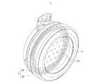
図1〜図5を参照して、本発明の一実施形態によるワイヤレス充電ヘッドホン10は、主に、1又は複数のヘッドホンハウジング1、1又は複数のスピーカモジュール2、及び、1又は複数の環状のワイヤレス充電モジュール3を含む。 With reference to FIGS. 1 to 5, the
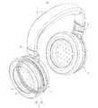
図3に示すように、ヘッドホンハウジング1は、対向配置される前方ハウジング11及び後方ハウジング12を有する。前方ハウジング11には複数の放音孔111が設けられている。また、ヘッドホンハウジング1の内部には収容空間sが備わっている。前方ハウジング11は、使用者の耳に配置される側である。 As shown in FIG. 3, the
スピーカモジュール2は、収容空間sに収容されるとともに、複数の放音孔111に対応して配置されている。これにより、スピーカモジュール2から発生した音を放音孔111を通じて前方ハウジング11の外部に伝達可能となる。 The
環状のワイヤレス充電モジュール3は収容空間sに配置されている。環状のワイヤレス充電モジュール3は、前方ハウジング11とスピーカモジュール2との間に設置されるとともに、スピーカモジュール2から発生する音を遮らないよう、スピーカモジュール2の外周を取り囲むように設けられている。 The annular
詳細に説明すると、環状のワイヤレス充電モジュール3は、前方ハウジング11に固定されるとともに、複数の放音孔111を取り囲むように設けられている。これにより、環状のワイヤレス充電モジュール3が複数の放音孔111を遮ることがないため、スピーカモジュール2から発生した音声を複数の放音孔111から出すことが可能である。 More specifically, the annular
また、環状のワイヤレス充電モジュール3は、環状の回路基板31と、環状の回路基板31に装着される環状の磁気共鳴コイル32とを含む。環状の磁気共鳴コイル32は環状の回路基板31のうち前方ハウジング11と隣接する側の表面に固定接続されている。 Further, the annular
また、当該環状の磁気共鳴コイル32はリング状をなす磁気共鳴コイルである。磁気共鳴コイルは「磁気共鳴」によりワイヤレス充電を行う。「電磁誘導」と比較して、「磁気共鳴」方式の場合には充電距離が数メートルにも達し、充電効率を向上することも可能である。 Further, the annular
ワイヤレス充電ヘッドホン10は、更に、1又は複数の制御モジュール4を含む。制御モジュール4は、収容空間sに収容され、制御回路基板41とバッテリ42とを含む。制御回路基板41は、スピーカモジュール2、環状の回路基板31及びバッテリ42にそれぞれ電気的に接続されている。図1、図4〜図5に示すように、ワイヤレス充電ヘッドホン10は、フレーム5を更に含む。本実施形態のワイヤレス充電ヘッドホン10では、ヘッドホンハウジング1、スピーカモジュール2、環状のワイヤレス充電モジュール3及び制御モジュール4の数はいずれも2つとし、各スピーカモジュール2、環状のワイヤレス充電モジュール3及び制御モジュール4は、それぞれ各ヘッドホンハウジング1の収容空間sに収容されている。且つ、2つのヘッドホンハウジング1は、それぞれフレーム5の両端に接続されている。フレーム5の形状はU字型をなしている。また、フレーム5は人体の頭頂部、後頭部又は後頸部への装着に適合させるが、これに限らない。ワイヤレス充電ヘッドホン10は、2つの回転軸6を更に含む。2つの回転軸6はフレーム5の両端と2つのヘッドホンハウジング1との間に組み付けられ、各ヘッドホンハウジング1は各回転軸6によってフレーム5に対し回動可能である。 The
ワイヤレス充電ヘッドホン10が充電される場合には、図4に示すように、前方ハウジング11が外側を向くように、ヘッドホンハウジング1が回転軸6によって回動される。そして、外側を向いた前方ハウジング11が充電パッド100上に載置される。充電パッド100内の送電側誘導コイル101は、「磁気共鳴」理論によってワイヤレス充電ヘッドホン10の磁気共鳴コイル32に対してワイヤレスで電力を伝送可能に構成されている。送電側誘導コイル101が共振周波数で振動し、交互に変動する磁場を周囲に発信すると、環状のワイヤレス充電モジュール3における環状の磁気共鳴コイル32が交互に変動する磁場を感知して交流電流に変換する。そして、交流電流が環状の回路基板31、制御回路基板41を通じてバッテリ42に蓄積される。 When the
なお、ワイヤレス充電ヘッドホン10が音声を出力する場合等には、制御回路基板41によってバッテリ42に蓄積された電力がスピーカモジュール2等のその他の電子部品に供給される。 When the
ここで、従来のワイヤレスヘッドホンでは、誘導コイルが主に背部ハウジングの内側中央部に固定されるため、背部ハウジングを曲面や斜面等に設計したり、その他の電子部品(例えば、インジケータやボタン等)を設けたりすることは困難であった。これに対し、本実施形態のワイヤレス充電ヘッドホン10では、環状のワイヤレス充電モジュール3が、前方ハウジング11とスピーカモジュール2の間に設置されるとともに、スピーカモジュール2の外周を取り囲むように設けられている。また、前方ハウジング11の位置付近にはその他の電子部品が設けられていないため、環状のワイヤレス充電モジュール3はスピーカモジュール2やその他の電子部品から影響を受けることなく動作する。且つ、後方ハウジング12の外観デザインや電子部品(例えば、インジケータやボタン等)の配置を、環状のワイヤレス充電モジュール3に規制されて変更する必要もない。よって、ワイヤレス充電ヘッドホン10のデザイン、組み立ての利便性及び動作の安定性の向上を図ることができる。 Here, in the conventional wireless headphones, since the induction coil is mainly fixed to the inner center of the back housing, the back housing may be designed on a curved surface or a slope, or other electronic components (for example, indicators, buttons, etc.). It was difficult to set up. On the other hand, in the
なお、今回開示した実施形態は、すべての点で例示であって、限定的な解釈の根拠となるものではない。したがって、本発明の技術的範囲は、上記した実施形態のみによって解釈されるものではなく、特許請求の範囲の記載に基づいて画定される。また、本発明の技術的範囲には、特許請求の範囲と均等の意味及び範囲内でのすべての変更が含まれる。 It should be noted that the embodiments disclosed this time are examples in all respects and do not serve as a basis for a limited interpretation. Therefore, the technical scope of the present invention is not construed solely by the embodiments described above, but is defined based on the description of the scope of claims. In addition, the technical scope of the present invention includes all modifications within the meaning and scope equivalent to the scope of claims.
たとえば、上記実施形態では、環状の回路基板31が環状の磁気共鳴コイル32を介して前方ハウジング11に固定される例を示したが、これに限らず、環状の回路基板31が前方ハウジング11に直接固定されていてもよい。 For example, in the above embodiment, the example in which the
具体的には、図6に示す第1変形例のように、環状の回路基板31のうち前方ハウジング11と隣接する側の表面には凹溝311が設けられており、環状の磁気共鳴コイル32が凹溝311に嵌め込まれていてもよい。これにより、環状の磁気共鳴コイル32がより安定的に環状の回路基板31に固定される。 Specifically, as in the first modification shown in FIG. 6, a
また、図7に示す第2変形例のように、環状の回路基板31の外周縁には凹溝311’が設けられており、環状の磁気共鳴コイル32が凹溝311’に嵌め込まれていてもよい。これにより、環状の磁気共鳴コイル32がより安定的に環状の回路基板31に固定される。 Further, as in the second modification shown in FIG. 7, a concave groove 311'is provided on the outer peripheral edge of the
また、上記実施形態では、ワイヤレス充電モジュール3が環状の回路基板31及び磁気共鳴コイル32を含む例を示したが、これに限らず、図8に示す第3変形例のように、ワイヤレス充電モジュール3が、環状の磁気共鳴コイル32’を含み、環状の回路基板を含まないようにしてもよい。すなわち、環状のワイヤレス充電モジュール3では環状の回路基板31(図3参照)が省略されていてもよい。環状の磁気共鳴コイル32’は、前方ハウジング11に固定接続され、制御回路基板41に電気的に接続される。これにより、環状のワイヤレス充電モジュール3は、部材の削減、コスト節約との利点を有する。 Further, in the above embodiment, the example in which the
10 ワイヤレス充電ヘッドホン
1 ヘッドホンハウジング
11 前方ハウジング
111 放音孔
12 後方ハウジング
2 スピーカモジュール
3 環状のワイヤレス充電モジュール
31 環状の回路基板
311、311’ 凹溝
32、32’ 環状の磁気共鳴コイル
4 制御モジュール
41 制御回路基板
42 バッテリ
5 フレーム
6 回転軸
s 収容空間
100 充電パッド
101 送電側誘導コイル10
本発明によるワイヤレス充電ヘッドホンは、前方ハウジング及び収容空間を有し、当該前方ハウジングに複数の放音孔が設けられるヘッドホンハウジング、当該収容空間に収容されるとともに、当該複数の放音孔に対応して配置されるスピーカモジュール、及び、当該収容空間に収容され、当該前方ハウジングと当該スピーカモジュールとの間に設置される環状のワイヤレス充電モジュールを含む。当該環状のワイヤレス充電モジュールは、当該スピーカモジュールの外周を取り囲むように設けられている。The wireless charging headphone according to the present invention has a front housing and an accommodation space, and is accommodated in a headphone housing in which a plurality of sound emitting holes are provided in the front housing and the accommodation space, and corresponds to the plurality of sound emitting holes. It includes a speaker module arranged in a row and an annular wireless charging module housed in the accommodation space and installed between the front housing and the speaker module.The annular wireless charging module is provided so as to surround the outer periphery of the speaker module.
Claims (10)
Translated fromJapanese当該収容空間に収容されるとともに、当該複数の放音孔に対応して配置されるスピーカモジュール、及び、
当該収容空間に収容され、当該前方ハウジングと当該スピーカモジュールとの間に設置される環状のワイヤレス充電モジュールを含むワイヤレス充電ヘッドホン。A headphone housing that has a front housing and accommodation space and is provided with a plurality of sound emitting holes in the front housing.
A speaker module that is accommodated in the accommodation space and is arranged corresponding to the plurality of sound emitting holes, and
Wireless charging headphones that include an annular wireless charging module that is housed in the storage space and installed between the front housing and the speaker module.
当該制御モジュールは、当該収容空間に収容され、制御回路基板とバッテリとを含み、
当該制御回路基板は、当該スピーカモジュール、当該環状の回路基板及び当該バッテリにそれぞれ電気的に接続されている請求項4〜7のいずれか1つに記載のワイヤレス充電ヘッドホン。Including more control modules,
The control module is housed in the accommodation space and includes a control circuit board and a battery.
The wireless charging headphone according to any one of claims 4 to 7, wherein the control circuit board is electrically connected to the speaker module, the annular circuit board, and the battery, respectively.
当該制御モジュールは、当該収容空間に収容され、制御回路基板とバッテリとを含み、
当該制御回路基板は、当該スピーカモジュール、当該環状の磁気共鳴コイル及び当該バッテリにそれぞれ電気的に接続されている請求項9に記載のワイヤレス充電ヘッドホン。Including more control modules,
The control module is housed in the accommodation space and includes a control circuit board and a battery.
The wireless charging headphone according to claim 9, wherein the control circuit board is electrically connected to the speaker module, the annular magnetic resonance coil, and the battery, respectively.
Applications Claiming Priority (2)
| Application Number | Priority Date | Filing Date | Title |
|---|---|---|---|
| CN202010499517.5 | 2020-06-04 | ||
| CN202010499517.5ACN113766375B (en) | 2020-06-04 | 2020-06-04 | Wireless charging earphones |
Publications (2)
| Publication Number | Publication Date |
|---|---|
| JP2021190977Atrue JP2021190977A (en) | 2021-12-13 |
| JP7099741B2 JP7099741B2 (en) | 2022-07-12 |
Family
ID=78605260
Family Applications (1)
| Application Number | Title | Priority Date | Filing Date |
|---|---|---|---|
| JP2020131685AActiveJP7099741B2 (en) | 2020-06-04 | 2020-08-03 | Wireless charging headphones |
Country Status (4)
| Country | Link |
|---|---|
| US (1) | US11425483B2 (en) |
| JP (1) | JP7099741B2 (en) |
| CN (1) | CN113766375B (en) |
| DE (1) | DE102020121840B4 (en) |
Families Citing this family (1)
| Publication number | Priority date | Publication date | Assignee | Title |
|---|---|---|---|---|
| CN222802982U (en)* | 2024-03-22 | 2025-04-25 | 安克创新科技股份有限公司 | Headset earphone |
Citations (5)
| Publication number | Priority date | Publication date | Assignee | Title |
|---|---|---|---|---|
| US20130223640A1 (en)* | 2011-09-28 | 2013-08-29 | Tdk Corporation | Headphone, headphone stand and headphone system |
| JP2016072978A (en)* | 2014-09-29 | 2016-05-09 | パロット | Contactless rechargeable audio headset |
| JP2017139523A (en)* | 2016-02-01 | 2017-08-10 | エレコム株式会社 | headphone |
| US20180206023A1 (en)* | 2015-07-07 | 2018-07-19 | Amogreentech Co., Ltd. | Wireless headphone having built-in flexible battery |
| US20200007971A1 (en)* | 2016-12-21 | 2020-01-02 | AMOSENSE Co.,Ltd | Headset capable of wireless charging, and headset charging system using wireless power transmission comprising same |
Family Cites Families (9)
| Publication number | Priority date | Publication date | Assignee | Title |
|---|---|---|---|---|
| DE2656431A1 (en) | 1976-12-14 | 1978-06-22 | Demolux | DEVICE FOR WIRELESS TRANSMISSION OF A TEACHING PROGRAM IN CLASSROOMS |
| JP3794363B2 (en)* | 2002-09-13 | 2006-07-05 | ソニー株式会社 | Charging apparatus and charging method |
| US7680267B2 (en)* | 2005-07-01 | 2010-03-16 | Plantronics, Inc. | Headset with a retractable speaker portion |
| CN103928991B (en)* | 2014-04-23 | 2017-03-29 | 慈溪市源顺光电科技有限公司 | Magnetic resonance wireless electric energy transmission device based on PCB resonance coupling coil structures |
| KR101620628B1 (en) | 2015-03-16 | 2016-05-12 | 고려대학교 산학협력단 | Headset wireless charging system |
| CN105207621A (en)* | 2015-09-24 | 2015-12-30 | 王巍 | Nested capacitor-loaded coil resonator |
| CN205961375U (en) | 2016-07-08 | 2017-02-15 | 北京金锐德路科技有限公司 | Headphone |
| US11405713B2 (en) | 2019-06-19 | 2022-08-02 | Hewlett-Packard Development Company, L.P. | Free-standing wireless-charging headsets |
| CN212278429U (en)* | 2020-06-04 | 2021-01-01 | 宝德科技股份有限公司 | wireless charging headset |
- 2020
- 2020-06-04CNCN202010499517.5Apatent/CN113766375B/enactiveActive
- 2020-07-30USUS16/942,802patent/US11425483B2/enactiveActive
- 2020-08-03JPJP2020131685Apatent/JP7099741B2/enactiveActive
- 2020-08-20DEDE102020121840.0Apatent/DE102020121840B4/enactiveActive
Patent Citations (5)
| Publication number | Priority date | Publication date | Assignee | Title |
|---|---|---|---|---|
| US20130223640A1 (en)* | 2011-09-28 | 2013-08-29 | Tdk Corporation | Headphone, headphone stand and headphone system |
| JP2016072978A (en)* | 2014-09-29 | 2016-05-09 | パロット | Contactless rechargeable audio headset |
| US20180206023A1 (en)* | 2015-07-07 | 2018-07-19 | Amogreentech Co., Ltd. | Wireless headphone having built-in flexible battery |
| JP2017139523A (en)* | 2016-02-01 | 2017-08-10 | エレコム株式会社 | headphone |
| US20200007971A1 (en)* | 2016-12-21 | 2020-01-02 | AMOSENSE Co.,Ltd | Headset capable of wireless charging, and headset charging system using wireless power transmission comprising same |
Also Published As
| Publication number | Publication date |
|---|---|
| CN113766375B (en) | 2025-04-25 |
| US20210385566A1 (en) | 2021-12-09 |
| JP7099741B2 (en) | 2022-07-12 |
| CN113766375A (en) | 2021-12-07 |
| US11425483B2 (en) | 2022-08-23 |
| DE102020121840B4 (en) | 2023-09-14 |
| DE102020121840A1 (en) | 2021-12-09 |
Similar Documents
| Publication | Publication Date | Title |
|---|---|---|
| KR102625817B1 (en) | Audio input/output device | |
| JP2023515451A (en) | earphone | |
| US20180139529A1 (en) | Portable acoustic device | |
| CN111083612A (en) | Shrapnel, bone conduction speaker and bone conduction ear-worn device | |
| CN214481253U (en) | Double-moving-coil micro loudspeaker | |
| WO2021063111A1 (en) | Headset | |
| JP7099741B2 (en) | Wireless charging headphones | |
| CN211860530U (en) | Elastic sheet, bone conduction loudspeaker and bone conduction ear-wearing type equipment | |
| WO2009008570A1 (en) | Small sized body-sonic vibration receiver | |
| KR20160020921A (en) | Mixed sound receiver with vibration effect | |
| CN212278429U (en) | wireless charging headset | |
| JP7663971B2 (en) | In-ear wearable device and panel assembly thereof | |
| CN220023021U (en) | Earphone and combination of earphone and charging bin | |
| WO2021253737A1 (en) | Wireless charging earphone and wireless charging earphone system | |
| CN218243813U (en) | Bone conduction speaker oscillator and bone conduction earphone | |
| US20250097617A1 (en) | Wearable speaker | |
| CN113363762B (en) | A split intelligent voice socket | |
| CN214174842U (en) | Intelligent watch | |
| CN209882056U (en) | Wireless active audio amplifier that charges | |
| KR101092900B1 (en) | Speakers and electronics | |
| CN222655302U (en) | A sound cavity structure and earphone | |
| CN221575579U (en) | Wireless earphone and earphone device | |
| CN111526448A (en) | Environment sound receiving controllable electromagnetic type music earphone | |
| CN220732983U (en) | Wireless bluetooth headset of ear-hanging and bluetooth headset suit | |
| CN218772379U (en) | Sound box |
Legal Events
| Date | Code | Title | Description |
|---|---|---|---|
| A621 | Written request for application examination | Free format text:JAPANESE INTERMEDIATE CODE: A621 Effective date:20200803 | |
| A131 | Notification of reasons for refusal | Free format text:JAPANESE INTERMEDIATE CODE: A131 Effective date:20210615 | |
| A521 | Request for written amendment filed | Free format text:JAPANESE INTERMEDIATE CODE: A523 Effective date:20210805 | |
| A131 | Notification of reasons for refusal | Free format text:JAPANESE INTERMEDIATE CODE: A131 Effective date:20211221 | |
| A521 | Request for written amendment filed | Free format text:JAPANESE INTERMEDIATE CODE: A523 Effective date:20220309 | |
| TRDD | Decision of grant or rejection written | ||
| A01 | Written decision to grant a patent or to grant a registration (utility model) | Free format text:JAPANESE INTERMEDIATE CODE: A01 Effective date:20220614 | |
| A61 | First payment of annual fees (during grant procedure) | Free format text:JAPANESE INTERMEDIATE CODE: A61 Effective date:20220623 | |
| R150 | Certificate of patent or registration of utility model | Ref document number:7099741 Country of ref document:JP Free format text:JAPANESE INTERMEDIATE CODE: R150 | |
| R250 | Receipt of annual fees | Free format text:JAPANESE INTERMEDIATE CODE: R250 |