JP2021186251A - Cannula for percutaneous minimally invasive cannulation of vena cava - Google Patents
Cannula for percutaneous minimally invasive cannulation of vena cavaDownload PDFInfo
- Publication number
- JP2021186251A JP2021186251AJP2020094602AJP2020094602AJP2021186251AJP 2021186251 AJP2021186251 AJP 2021186251AJP 2020094602 AJP2020094602 AJP 2020094602AJP 2020094602 AJP2020094602 AJP 2020094602AJP 2021186251 AJP2021186251 AJP 2021186251A
- Authority
- JP
- Japan
- Prior art keywords
- cannula
- tube
- balloon
- cone
- chamber
- Prior art date
- Legal status (The legal status is an assumption and is not a legal conclusion. Google has not performed a legal analysis and makes no representation as to the accuracy of the status listed.)
- Granted
Links
Images


Classifications
- A—HUMAN NECESSITIES
- A61—MEDICAL OR VETERINARY SCIENCE; HYGIENE
- A61B—DIAGNOSIS; SURGERY; IDENTIFICATION
- A61B17/00—Surgical instruments, devices or methods
- A61B17/34—Trocars; Puncturing needles
- A61B17/3417—Details of tips or shafts, e.g. grooves, expandable, bendable; Multiple coaxial sliding cannulas, e.g. for dilating
- A61B17/3421—Cannulas
- A—HUMAN NECESSITIES
- A61—MEDICAL OR VETERINARY SCIENCE; HYGIENE
- A61M—DEVICES FOR INTRODUCING MEDIA INTO, OR ONTO, THE BODY; DEVICES FOR TRANSDUCING BODY MEDIA OR FOR TAKING MEDIA FROM THE BODY; DEVICES FOR PRODUCING OR ENDING SLEEP OR STUPOR
- A61M1/00—Suction or pumping devices for medical purposes; Devices for carrying-off, for treatment of, or for carrying-over, body-liquids; Drainage systems
- A61M1/36—Other treatment of blood in a by-pass of the natural circulatory system, e.g. temperature adaptation, irradiation ; Extra-corporeal blood circuits
- A61M1/3621—Extra-corporeal blood circuits
- A61M1/3653—Interfaces between patient blood circulation and extra-corporal blood circuit
- A61M1/3659—Cannulae pertaining to extracorporeal circulation
- A—HUMAN NECESSITIES
- A61—MEDICAL OR VETERINARY SCIENCE; HYGIENE
- A61M—DEVICES FOR INTRODUCING MEDIA INTO, OR ONTO, THE BODY; DEVICES FOR TRANSDUCING BODY MEDIA OR FOR TAKING MEDIA FROM THE BODY; DEVICES FOR PRODUCING OR ENDING SLEEP OR STUPOR
- A61M25/00—Catheters; Hollow probes
- A61M25/0021—Catheters; Hollow probes characterised by the form of the tubing
- A61M25/0023—Catheters; Hollow probes characterised by the form of the tubing by the form of the lumen, e.g. cross-section, variable diameter
- A—HUMAN NECESSITIES
- A61—MEDICAL OR VETERINARY SCIENCE; HYGIENE
- A61B—DIAGNOSIS; SURGERY; IDENTIFICATION
- A61B17/00—Surgical instruments, devices or methods
- A61B17/34—Trocars; Puncturing needles
- A61B17/3417—Details of tips or shafts, e.g. grooves, expandable, bendable; Multiple coaxial sliding cannulas, e.g. for dilating
- A61B17/3421—Cannulas
- A61B17/3423—Access ports, e.g. toroid shape introducers for instruments or hands
- A—HUMAN NECESSITIES
- A61—MEDICAL OR VETERINARY SCIENCE; HYGIENE
- A61B—DIAGNOSIS; SURGERY; IDENTIFICATION
- A61B17/00—Surgical instruments, devices or methods
- A61B17/00234—Surgical instruments, devices or methods for minimally invasive surgery
- A—HUMAN NECESSITIES
- A61—MEDICAL OR VETERINARY SCIENCE; HYGIENE
- A61B—DIAGNOSIS; SURGERY; IDENTIFICATION
- A61B17/00—Surgical instruments, devices or methods
- A61B17/34—Trocars; Puncturing needles
- A61B17/3478—Endoscopic needles, e.g. for infusion
- A—HUMAN NECESSITIES
- A61—MEDICAL OR VETERINARY SCIENCE; HYGIENE
- A61M—DEVICES FOR INTRODUCING MEDIA INTO, OR ONTO, THE BODY; DEVICES FOR TRANSDUCING BODY MEDIA OR FOR TAKING MEDIA FROM THE BODY; DEVICES FOR PRODUCING OR ENDING SLEEP OR STUPOR
- A61M1/00—Suction or pumping devices for medical purposes; Devices for carrying-off, for treatment of, or for carrying-over, body-liquids; Drainage systems
- A61M1/36—Other treatment of blood in a by-pass of the natural circulatory system, e.g. temperature adaptation, irradiation ; Extra-corporeal blood circuits
- A61M1/3621—Extra-corporeal blood circuits
- A61M1/3666—Cardiac or cardiopulmonary bypass, e.g. heart-lung machines
- A—HUMAN NECESSITIES
- A61—MEDICAL OR VETERINARY SCIENCE; HYGIENE
- A61M—DEVICES FOR INTRODUCING MEDIA INTO, OR ONTO, THE BODY; DEVICES FOR TRANSDUCING BODY MEDIA OR FOR TAKING MEDIA FROM THE BODY; DEVICES FOR PRODUCING OR ENDING SLEEP OR STUPOR
- A61M25/00—Catheters; Hollow probes
- A61M25/0021—Catheters; Hollow probes characterised by the form of the tubing
- A61M25/0041—Catheters; Hollow probes characterised by the form of the tubing pre-formed, e.g. specially adapted to fit with the anatomy of body channels
- A—HUMAN NECESSITIES
- A61—MEDICAL OR VETERINARY SCIENCE; HYGIENE
- A61M—DEVICES FOR INTRODUCING MEDIA INTO, OR ONTO, THE BODY; DEVICES FOR TRANSDUCING BODY MEDIA OR FOR TAKING MEDIA FROM THE BODY; DEVICES FOR PRODUCING OR ENDING SLEEP OR STUPOR
- A61M25/00—Catheters; Hollow probes
- A61M25/0043—Catheters; Hollow probes characterised by structural features
- A61M25/005—Catheters; Hollow probes characterised by structural features with embedded materials for reinforcement, e.g. wires, coils, braids
- A61M25/0052—Localized reinforcement, e.g. where only a specific part of the catheter is reinforced, for rapid exchange guidewire port
- A—HUMAN NECESSITIES
- A61—MEDICAL OR VETERINARY SCIENCE; HYGIENE
- A61M—DEVICES FOR INTRODUCING MEDIA INTO, OR ONTO, THE BODY; DEVICES FOR TRANSDUCING BODY MEDIA OR FOR TAKING MEDIA FROM THE BODY; DEVICES FOR PRODUCING OR ENDING SLEEP OR STUPOR
- A61M25/00—Catheters; Hollow probes
- A61M25/0067—Catheters; Hollow probes characterised by the distal end, e.g. tips
- A61M25/0068—Static characteristics of the catheter tip, e.g. shape, atraumatic tip, curved tip or tip structure
- A—HUMAN NECESSITIES
- A61—MEDICAL OR VETERINARY SCIENCE; HYGIENE
- A61M—DEVICES FOR INTRODUCING MEDIA INTO, OR ONTO, THE BODY; DEVICES FOR TRANSDUCING BODY MEDIA OR FOR TAKING MEDIA FROM THE BODY; DEVICES FOR PRODUCING OR ENDING SLEEP OR STUPOR
- A61M25/00—Catheters; Hollow probes
- A61M25/10—Balloon catheters
- A61M25/1002—Balloon catheters characterised by balloon shape
- A—HUMAN NECESSITIES
- A61—MEDICAL OR VETERINARY SCIENCE; HYGIENE
- A61B—DIAGNOSIS; SURGERY; IDENTIFICATION
- A61B17/00—Surgical instruments, devices or methods
- A61B17/12—Surgical instruments, devices or methods for ligaturing or otherwise compressing tubular parts of the body, e.g. blood vessels or umbilical cord
- A61B17/12022—Occluding by internal devices, e.g. balloons or releasable wires
- A61B17/12099—Occluding by internal devices, e.g. balloons or releasable wires characterised by the location of the occluder
- A61B17/12109—Occluding by internal devices, e.g. balloons or releasable wires characterised by the location of the occluder in a blood vessel
- A—HUMAN NECESSITIES
- A61—MEDICAL OR VETERINARY SCIENCE; HYGIENE
- A61B—DIAGNOSIS; SURGERY; IDENTIFICATION
- A61B17/00—Surgical instruments, devices or methods
- A61B17/12—Surgical instruments, devices or methods for ligaturing or otherwise compressing tubular parts of the body, e.g. blood vessels or umbilical cord
- A61B17/12022—Occluding by internal devices, e.g. balloons or releasable wires
- A61B17/12131—Occluding by internal devices, e.g. balloons or releasable wires characterised by the type of occluding device
- A61B17/12136—Balloons
- A—HUMAN NECESSITIES
- A61—MEDICAL OR VETERINARY SCIENCE; HYGIENE
- A61B—DIAGNOSIS; SURGERY; IDENTIFICATION
- A61B17/00—Surgical instruments, devices or methods
- A61B17/34—Trocars; Puncturing needles
- A61B17/3494—Trocars; Puncturing needles with safety means for protection against accidental cutting or pricking, e.g. limiting insertion depth, pressure sensors
- A61B17/3496—Protecting sleeves or inner probes; Retractable tips
- A—HUMAN NECESSITIES
- A61—MEDICAL OR VETERINARY SCIENCE; HYGIENE
- A61B—DIAGNOSIS; SURGERY; IDENTIFICATION
- A61B17/00—Surgical instruments, devices or methods
- A61B17/00234—Surgical instruments, devices or methods for minimally invasive surgery
- A61B2017/00238—Type of minimally invasive operation
- A61B2017/00243—Type of minimally invasive operation cardiac
- A—HUMAN NECESSITIES
- A61—MEDICAL OR VETERINARY SCIENCE; HYGIENE
- A61B—DIAGNOSIS; SURGERY; IDENTIFICATION
- A61B17/00—Surgical instruments, devices or methods
- A61B17/00234—Surgical instruments, devices or methods for minimally invasive surgery
- A61B2017/00292—Surgical instruments, devices or methods for minimally invasive surgery mounted on or guided by flexible, e.g. catheter-like, means
- A61B2017/003—Steerable
- A61B2017/00318—Steering mechanisms
- A61B2017/00331—Steering mechanisms with preformed bends
- A—HUMAN NECESSITIES
- A61—MEDICAL OR VETERINARY SCIENCE; HYGIENE
- A61B—DIAGNOSIS; SURGERY; IDENTIFICATION
- A61B17/00—Surgical instruments, devices or methods
- A61B17/22—Implements for squeezing-off ulcers or the like on inner organs of the body; Implements for scraping-out cavities of body organs, e.g. bones; for invasive removal or destruction of calculus using mechanical vibrations; for removing obstructions in blood vessels, not otherwise provided for
- A61B2017/22051—Implements for squeezing-off ulcers or the like on inner organs of the body; Implements for scraping-out cavities of body organs, e.g. bones; for invasive removal or destruction of calculus using mechanical vibrations; for removing obstructions in blood vessels, not otherwise provided for with an inflatable part, e.g. balloon, for positioning, blocking, or immobilisation
- A—HUMAN NECESSITIES
- A61—MEDICAL OR VETERINARY SCIENCE; HYGIENE
- A61B—DIAGNOSIS; SURGERY; IDENTIFICATION
- A61B17/00—Surgical instruments, devices or methods
- A61B17/34—Trocars; Puncturing needles
- A61B17/3417—Details of tips or shafts, e.g. grooves, expandable, bendable; Multiple coaxial sliding cannulas, e.g. for dilating
- A61B17/3421—Cannulas
- A61B17/3423—Access ports, e.g. toroid shape introducers for instruments or hands
- A61B2017/3425—Access ports, e.g. toroid shape introducers for instruments or hands for internal organs, e.g. heart ports
- A—HUMAN NECESSITIES
- A61—MEDICAL OR VETERINARY SCIENCE; HYGIENE
- A61B—DIAGNOSIS; SURGERY; IDENTIFICATION
- A61B17/00—Surgical instruments, devices or methods
- A61B17/34—Trocars; Puncturing needles
- A61B17/3417—Details of tips or shafts, e.g. grooves, expandable, bendable; Multiple coaxial sliding cannulas, e.g. for dilating
- A61B17/3421—Cannulas
- A61B2017/3445—Cannulas used as instrument channel for multiple instruments
- A61B2017/3447—Linked multiple cannulas
- A—HUMAN NECESSITIES
- A61—MEDICAL OR VETERINARY SCIENCE; HYGIENE
- A61B—DIAGNOSIS; SURGERY; IDENTIFICATION
- A61B17/00—Surgical instruments, devices or methods
- A61B17/34—Trocars; Puncturing needles
- A61B2017/348—Means for supporting the trocar against the body or retaining the trocar inside the body
- A61B2017/3482—Means for supporting the trocar against the body or retaining the trocar inside the body inside
- A61B2017/3484—Anchoring means, e.g. spreading-out umbrella-like structure
- A61B2017/3486—Balloon
- A—HUMAN NECESSITIES
- A61—MEDICAL OR VETERINARY SCIENCE; HYGIENE
- A61M—DEVICES FOR INTRODUCING MEDIA INTO, OR ONTO, THE BODY; DEVICES FOR TRANSDUCING BODY MEDIA OR FOR TAKING MEDIA FROM THE BODY; DEVICES FOR PRODUCING OR ENDING SLEEP OR STUPOR
- A61M2205/00—General characteristics of the apparatus
- A61M2205/58—Means for facilitating use, e.g. by people with impaired vision
- A61M2205/586—Ergonomic details therefor, e.g. specific ergonomics for left or right-handed users
- A—HUMAN NECESSITIES
- A61—MEDICAL OR VETERINARY SCIENCE; HYGIENE
- A61M—DEVICES FOR INTRODUCING MEDIA INTO, OR ONTO, THE BODY; DEVICES FOR TRANSDUCING BODY MEDIA OR FOR TAKING MEDIA FROM THE BODY; DEVICES FOR PRODUCING OR ENDING SLEEP OR STUPOR
- A61M25/00—Catheters; Hollow probes
- A61M25/0067—Catheters; Hollow probes characterised by the distal end, e.g. tips
- A61M25/0068—Static characteristics of the catheter tip, e.g. shape, atraumatic tip, curved tip or tip structure
- A61M25/007—Side holes, e.g. their profiles or arrangements; Provisions to keep side holes unblocked
- A—HUMAN NECESSITIES
- A61—MEDICAL OR VETERINARY SCIENCE; HYGIENE
- A61M—DEVICES FOR INTRODUCING MEDIA INTO, OR ONTO, THE BODY; DEVICES FOR TRANSDUCING BODY MEDIA OR FOR TAKING MEDIA FROM THE BODY; DEVICES FOR PRODUCING OR ENDING SLEEP OR STUPOR
- A61M25/00—Catheters; Hollow probes
- A61M25/01—Introducing, guiding, advancing, emplacing or holding catheters
- A61M25/02—Holding devices, e.g. on the body
- A61M25/04—Holding devices, e.g. on the body in the body, e.g. expansible
Landscapes
- Health & Medical Sciences (AREA)
- Life Sciences & Earth Sciences (AREA)
- Heart & Thoracic Surgery (AREA)
- Public Health (AREA)
- Engineering & Computer Science (AREA)
- Biomedical Technology (AREA)
- Animal Behavior & Ethology (AREA)
- General Health & Medical Sciences (AREA)
- Veterinary Medicine (AREA)
- Surgery (AREA)
- Anesthesiology (AREA)
- Hematology (AREA)
- Nuclear Medicine, Radiotherapy & Molecular Imaging (AREA)
- Medical Informatics (AREA)
- Molecular Biology (AREA)
- Vascular Medicine (AREA)
- Pulmonology (AREA)
- Biophysics (AREA)
- Pathology (AREA)
- Cardiology (AREA)
- Reproductive Health (AREA)
- Child & Adolescent Psychology (AREA)
- Media Introduction/Drainage Providing Device (AREA)
- Surgical Instruments (AREA)
- Acyclic And Carbocyclic Compounds In Medicinal Compositions (AREA)
- Materials For Medical Uses (AREA)
Abstract
Description
Translated fromJapanese本発明は、大静脈の経皮的低侵襲カニュレーション用のカニューレに関する。 The present invention relates to a cannula for percutaneous minimally invasive cannulation of the vena cava.
心臓外科手術では、血液を送り出す作業から心臓を解放し、それに伴い患者の血流を体外循環システムの人工心肺装置に接続する必要がある。この装置は、圧力を発生させて機械的作業を行い、末梢血管を通して血液を送り、静脈血に酸素を送り込む。体外循環システムは、心臓の主要な血管に接続されたカニューレを有する装置である。 Cardiac surgery requires the heart to be released from the task of pumping blood and the patient's blood flow to be connected to the heart-lung machine of the extracorporeal circulation system. The device creates pressure to perform mechanical work, pumping blood through peripheral blood vessels and pumping oxygen into venous blood. The extracorporeal circulation system is a device with a cannula connected to the major blood vessels of the heart.
近年では、肋間腔の皮膚の小さな切開部を通して手術全体を行う低侵襲法がより頻繁に選択されている。
単離法はカニュレーションに不可欠である。すなわち、カニューレの周りの主静脈を閉じて、血液がカニューレ内部のみに流れ、血管の内腔を通らないようにすることである。いわゆる止血帯による外側からの閉鎖は、標準的な手術、つまり胸骨切開による典型的なものである。しかしながら、この方法は、特殊な長い器具を使用して内視鏡カメラの制御下で心臓と弁にアクセスする必要がある低侵襲手術では、非常に困難であり不可能ですらある。そのような手術は、体外循環装置を接続する別の方法や、別のカニュレーション部位(鼠径部の静脈と大腿動脈)を必要とし、したがって、全く異なるカニューレが必要となる。先端部にバルーンまたは特別なフランジを備えた低侵襲手術用の静脈カニューレは、外側から締め付けるのと同じくらい有効に静脈を閉鎖できることが知られている。通常、カニューレは2つあり、1つは大腿静脈から下大静脈に挿入され、もう1つは下大静脈から頸静脈に挿入されるものである。In recent years, minimally invasive procedures have been selected more often, in which the entire operation is performed through a small incision in the skin of the intercostal space.
Isolation methods are essential for cannulation. That is, the main vein around the cannula is closed to prevent blood from flowing only inside the cannula and through the lumen of blood vessels. External closure with a so-called tourniquet is typical of standard surgery, a sternotomy. However, this method is very difficult and even impossible in minimally invasive surgery, which requires access to the heart and valves under the control of an endoscopic camera using a special long instrument. Such surgery requires different methods of connecting extracorporeal circulation devices and different cannulation sites (inguinal veins and femoral arteries) and therefore requires a completely different cannula. Venous cannulas for minimally invasive surgery with a balloon or special flange at the tip are known to be able to close veins as effectively as tightening from the outside. There are usually two cannulas, one inserted from the femoral vein into the inferior vena cava and the other from the inferior vena cava into the jugular vein.
(特許文献1)の明細書からは、湾曲した先端部分、弾性の中心部分および基端部分からなるカニューレが知られている。膨張したバルーンが先端部分に取り付けられ、血管内でのカニューレの固定を容易にする。中央部分には、第2のほぼ円筒形のバルーンが周囲に配置されており、ポンピングによりカニューレの管腔の直径が増加する。両方のバルーンを膨らませる2つのポートが基端部分に設けられている。好ましくは、カニューレの先端部分の曲率は約90度である。 From the specification of (Patent Document 1), a cannula composed of a curved tip portion, an elastic central portion and a proximal end portion is known. An inflated balloon is attached to the tip to facilitate fixation of the cannula in the blood vessel. In the central part, a second nearly cylindrical balloon is placed around it, and pumping increases the diameter of the lumen of the cannula. Two ports are provided at the base to inflate both balloons. Preferably, the curvature of the tip of the cannula is about 90 degrees.
心臓麻痺の結果として一時的な心停止が発生する手技で使用されるカニューレは、(特許文献2)から知られている。カニューレは、その先端部に位置する伸長可能な切断刃を使用して患者の大動脈に配置される。切開を行った後、切断刃はカニューレ内に後退し、カニューレの管腔から取り外される。同時に、カニューレの出口開口部の近くにある封止バルーンがポンピングされる。元の状態のカニューレは、前にとった湾曲した形状を利用して、引き出された後で、縦フランジに配置される。物質を大動脈に投与するため、または大動脈の内腔から閉塞物を取り除くために使用されるポートは、基端部に設けられる。 A cannula used in a procedure in which temporary cardiac arrest occurs as a result of a heart attack is known from (Patent Document 2). The cannula is placed in the patient's aorta using an extendable cutting blade located at its tip. After making the incision, the cutting blade retracts into the cannula and is removed from the lumen of the cannula. At the same time, a sealing balloon near the exit opening of the cannula is pumped. The original state of the cannula is pulled out and then placed on the vertical flange, taking advantage of the previously curved shape. A port used to administer a substance to the aorta or to remove an obstruction from the lumen of the aorta is provided at the proximal end.
カニューレを血管内に配置するための案内として剛性のトロカールを外部に備えたカニューレは、(特許文献3)から知られている。トロカールの先端部には、血管壁を切除するための刃と、刃側に保護カバーを備えた膨張可能な封止バルーンが配置されている。トロカールを選択した場所に配置した後で、カニューレを引き出すと、以前に設定された形状になる。 A cannula provided with a rigid trocar externally as a guide for arranging the cannula in a blood vessel is known from (Patent Document 3). At the tip of the trocar, a blade for excising the blood vessel wall and an inflatable sealing balloon with a protective cover on the blade side are arranged. After placing the trocar in the selected location, pulling out the cannula will give it the previously set shape.
現在使用されている解決手段において、カニューレと静脈を結び付けて、固定された機械的接続を確保する必要がある。 In the solutions currently in use, it is necessary to connect the cannula to the vein to ensure a fixed mechanical connection.
大静脈の経皮的低侵襲カニュレーション用のカニューレは、少なくとも1つの円錐形または丸形の端部を有し、血液が内部に入るのを可能にする少なくとも1つの流入開口部を備えたプラスチック製の管である。本発明の本質は、主チャンバ、第1の側方チャンバおよび第2の側方チャンバを含む3つの長手方向のチャンバと、一定の内径を確保する少なくとも1つの補強部分とを有する管が、先端側に丸形の端部を備えていることであり、丸形の端部は端に向かって狭くなる。管には、静脈血の自由な流入を可能にする大きさの長手方向の穴と、バルーンとが設けられている。バルーンの下には管の補強部分があり、その一部は約90度の角度αで曲げられている。管は柔軟な円錐体を有する基端側で終端し、カニューレを容易にしっかりと密閉する(light tightly)。管の内部には、主チャンバを閉じる弁と、第1の側方チャンバに接続されたバルーンを膨張させるポートがある。第2の側方チャンバの内側には、取り外し可能な補強材が配置されており、その先端が最も離れた位置でバルーンの基部に達する一方で、円錐体を通過する補強材の基端部が引き出される。補強部分では、カニューレの管が形状記憶を保持する。 The cannula for percutaneous minimally invasive cannulation of the vena cava is a plastic with at least one conical or rounded end and at least one inflow opening that allows blood to enter inside. It is a tube made of. The essence of the present invention is a tube having three longitudinal chambers including a main chamber, a first lateral chamber and a second lateral chamber, and at least one reinforcing portion to ensure a constant inner diameter. It is provided with a rounded end on the side, which narrows towards the end. The tube is provided with a longitudinal hole sized to allow free inflow of venous blood and a balloon. Below the balloon is a reinforced portion of the tube, a portion of which is bent at an angle α of about 90 degrees. The tube is terminated on the proximal side with a flexible cone and the cannula is easily and tightly sealed (light tightly). Inside the tube is a valve that closes the main chamber and a port that inflates the balloon connected to the first side chamber. Inside the second lateral chamber is a removable reinforcement, the tip of which reaches the base of the balloon at the furthest position, while the base end of the reinforcement passing through the cone. Pulled out. At the reinforced portion, the cannula tube retains shape memory.
好ましくは、丸形の端部の穴の長いほうの端(edge)はカニューレの軸線と一致する。
好ましい実施形態では、穴は、丸形の端部の周囲に均一に配置している。Preferably, the longer end (edge) of the hole at the round end coincides with the axis of the cannula.
In a preferred embodiment, the holes are evenly distributed around the edges of the round shape.
好ましくは、穴は、丸形の端部の周囲で均等に2つの列状に配置され、列と列との間で位置がずれている。
好ましい実施形態では、カニューレの管は、金属線ソレノイドで補強される。Preferably, the holes are evenly arranged in two rows around the end of the round shape and are misaligned between the rows.
In a preferred embodiment, the tube of the cannula is reinforced with a metal wire solenoid.
好ましい実施形態では、カニューレの管は、金属バンドソレノイドで補強されている。
好ましくは、カニューレの管は、任意の織りの金属ワイヤメッシュで補強されている。
好ましくは、二部品一体型の針は、カニューレの丸形の端部の内側に取り付けられる。針は、チャネル形状の鋭利な部分と、鋭利な部分の内側にある丸い部分で構成されている。丸い部分には複数の入口開口部があり、両方の部分は個別のバネを備えているとともに、トリガーボタンに連結されてる。In a preferred embodiment, the tube of the cannula is reinforced with a metal band solenoid.
Preferably, the tube of the cannula is reinforced with a metal wire mesh of any weave.
Preferably, the two-part integrated needle is mounted inside the rounded end of the cannula. The needle is composed of a sharp part of the channel shape and a round part inside the sharp part. The round part has multiple entrance openings, both of which have separate springs and are connected to the trigger button.
好ましくは、カニューレは、カニューレの管を中心に延在するスタイレットを有し、スタイレットの先端は、丸形の端部の出口に達し、基端は、円錐体を通って外側に延び、蝶の形状を有する人間工学的ハンドルを備える。 Preferably, the cannula has a stylet that extends around the tube of the cannula, the tip of the stylet reaching the exit of the rounded end, and the proximal end extending outward through a cone. It has an ergonomic handle with the shape of a butterfly.
好ましい実施形態では、円錐体はカニューレの管に取り外し可能に接続される。
本発明による解決手段の主な利点は、低侵襲性心臓手術中に十分な保護を提供することである。カニューレは、さまざまな操作技術において使用できる。操作者にとって便利であり、手術のために手術部位を準備する時間を大幅に短縮する。さらに、カニューレを使用すると、切開部の必要がまったくなくなるか、切開部を最小限にし、カニューレの直径よりもさらに小さくする。In a preferred embodiment, the cone is removably connected to the tube of the cannula.
The main advantage of the solution according to the invention is to provide adequate protection during minimally invasive heart surgery. Cannula can be used in a variety of operating techniques. It is convenient for the operator and greatly reduces the time required to prepare the surgical site for surgery. In addition, the use of a cannula eliminates the need for an incision altogether, or minimizes the incision and makes it even smaller than the diameter of the cannula.
ニューレの円錐形の端部により、血管内にカニューレを容易に配置でき、次の切開部に容易に挿入できる。円錐体を取り外すと、バルーン膨張ポートが拡張され、このポートには短い注水管(hose)が備わっている。 The conical end of the cannula allows the cannula to be easily placed within the vessel and easily inserted into the next incision. When the cone is removed, the balloon expansion port is expanded, which is equipped with a short water pipe (hose).
カニューレは、操作者が選択する操作技術に応じて、最も単純で安価なタイプから最も要求が高い場合での使用を目的とした最も装備されたタイプまで、さまざまなニーズに適合したいくつかのタイプを設計することができる。 Cannulas are available in several types to suit different needs, from the simplest and cheapest type to the most equipped type for use in the most demanding cases, depending on the operating technique selected by the operator. Can be designed.
カニューレの重要な要素は、カニューレが血管に入るときに直線形状を可能にする補強材である。補強材を除去することにより、カニューレは、バルーンの下にある補強部分の一部が約90度の角度で湾曲した状態に戻る。 An important element of the cannula is a stiffener that allows for a linear shape as the cannula enters the blood vessel. By removing the stiffener, the cannula returns to a state in which a portion of the stiffener under the balloon is curved at an angle of about 90 degrees.
本発明の主題は、図面によって示される実施形態において提示される。 The subject matter of the present invention is presented in embodiments shown in the drawings.
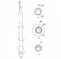
図1に示す第1の実施形態では、カニューレは、3つの長手方向のチャンバ、すなわち、主チャンバ1a、第1の側方チャンバ1a1および第2の側方チャンバ1a2と、先端側に丸形の端部2とを有しており、丸形の端部2には、静脈血がカニューレの管1の内部を自由に流れることを可能にする長手方向の穴4がある。穴4は、丸形の端部2の周囲に均等に配置されている。これに代えて、穴4は、丸形の端部2の円周上に2つの列状に均一に配置され、列と列との間で位置をずらしてもよい。 In the first embodiment shown in FIG. 1, the cannula has three longitudinal chambers, namely a main chamber 1a, a first lateral chamber 1a1 and a second lateral chamber 1a2, and a round tip side. It has an
丸形の端部2の後(behind)には、基端側から境界付けられた軟質部分m1が位置しており、バルーン6を有している。バルーン6の後には補強部分が続き、その一部は約90度の角度で曲げられている。補強部分は、軟質部分m2を通り、円錐体3を有する基端側で終端し、カニューレを容易にしっかりと密閉する。円錐体3の内部には、バルーン6を膨張させるためのポート5と、主チャンバ1を閉鎖する弁12とがある。膨張ポート5は第1の側方チャンバ1a1に接続されており、第1の側方チャンバ1a1を通って充填流体がバルーン6に到達する。カニューレは金属線ソレノイドで補強されており、補強部分において形状記憶を保持する。金属線はテープやメッシュに置き換えることができる。カニューレを血管内に配置する前に、人間工学的ハンドル13を備えた補強材8が円錐体3を介して第2の側方チャンバ1a2に導入され、補強材8により管1が真っ直ぐな形状になる。補強材8を取り除いた後で、カニューレは解剖学的構造および胸部への進入角度の比率と一致する形状になる。 Behind the
円錐体3はカニューレの管1に取り外し可能に接続されているため、適切な時期に取り外してポート5にアクセスできる。
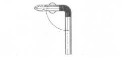
図2に示される第2の実施形態では、管1の補強部分は、クランプが適用される軟質部分m2によって分割される。一方、円錐体3は補強部分の基端に位置する。Since the
In the second embodiment shown in FIG. 2, the reinforcing portion of the
カニューレの第1の使用法は、外科医が肋間腔の切開部を通して大静脈の領域にアクセスし、丸形の端部2を静脈の切開部から内腔に挿入して、外科的方法を用いて取り付けることである。次のステップでは、補強材8を第2の側方チャンバ1a2から取り外す。次に、胸壁に別の切開部を形成し、手術用器具を胸部の手術部位の近くに挿入する。その後、円錐体3を手術用器具で把持して、胸壁の経皮的切開部へ導き、その切開部を介して円錐体3を体外に押し出すと、外科医が患者の体の外側で円錐形の端部を有する柔らかいカニューレを使用できる。次に、円錐体3が取り除かれるとポート5が解放され、次いで、シリンジを使用してバルーン6が液体で満たされる。カニューレの軟質部分m2に対して、クランプが挿入され、体外循環装置がカニューレの端部に接続される。次に、クランプが取り外されると、血液はすでに閉じた体外循環装置を循環している。処置の最後に、カニューレの軟質部分にクランプが適用され、体外循環装置が分離され、流体がバルーン6から除去されて、すべての操作が実行された後で、カニューレが除去される。 The first use of the cannula is to use a surgical method in which the surgeon accesses the area of the large vein through the incision in the intercostal space and inserts the
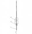
古典的なセルディンガー法を使用したカニューレの使用では、長いセルディンガー針が大静脈に挿入され、ガイドワイヤが挿入される。次に、可撓性ワイヤの形態のガイド11は、カニューレの丸形の端部2からピン7に通され、カニューレがガイド11に沿って静脈に挿入されることを可能にする。丸形の端部2が正常に静脈に配置されると、カニューレに血液が流れる。カニューレの適切な部分が挿入された後で、スタイレット7とガイドワイヤ11が円錐体3から取り外される。スタイレット7を取り外した後、血液はカニューレ内にある。この段階の後の次のステップは、第1の方法と同じである。 In the use of a cannula using the classical Seldinger method, a long Seldinger needle is inserted into the vena cava and a guide wire is inserted. The
カニューレを使用する別の方法は、ガイドまたは外科的切開を必要とせずに、カニューレを血管の内腔に挿入することである。この目的のために、図6に示されるように、丸形の端部2の内側に取り付けられた一体型の針10を備えたカニューレが使用される。この針は、丸い部分15が配置されるチャネル形状の鋭利な部分14からなり、これら両方の部分は別個のバネ16、17からなり、トリガーボタン18に結合される。丸い部分には複数の入口開口部があり、血液をカニューレにすばやく流すことができる。一体型の針10を用いて適切な角度で静脈に穴を開ける。十分な力を作用させて、圧力をかけて針の丸い針部分15を血管壁に突き刺す。血管壁を突き刺した後、バネ17の作用により丸い針部分15が延びて、鋭利な部分14の刃を固定する。正しい迎角では、針10は静脈の内腔にあり、両方の壁に穴を開けない。血液がカニューレに流れ込み、次にトリガーボタン18が丸形の端部2において押されると、針10が丸形の端部2の内側に移動し、カニューレを適切な深さまでさらに安全に挿入しながら、補強材8を第2の側方チャンバ1a2から外へスライドさせて、解剖学的構造に従ってカニューレを曲げる。ピンを取り外した後の手順は、第1の方法および第2の方法と同じである。 Another method of using a cannula is to insert the cannula into the lumen of a blood vessel without the need for a guide or surgical incision. For this purpose, as shown in FIG. 6, a cannula with an
Claims (10)
Translated fromJapanese前記管(1)は、主チャンバ(1a)、第1の側方チャンバ(1a1)および第2の側方チャンバ(1a2)を含む3つの長手方向のチャンバと、一定の内径を確保する少なくとも1つの補強部分とを有し、先端側に丸形の端部(2)を備えており、丸形の端部(2)は端に向かって狭くなっており、
丸形の端部(2)には、静脈血の自由な流入を可能にする大きさの長手方向の穴(4)と、バルーン(6)とが配置されており、バルーン(6)の下方には前記管の補強部分の一部が約90度の角度(α)で曲げられており、
前記管は、柔軟な円錐体(3)を有する基端側で終端し、カニューレをしっかりと密閉し、前記管の内部には、主チャンバ(1a)を閉じる弁(12)と、第1の側方チャンバ(1a1)に接続されたバルーン(6)を膨張させるためのポート(5)とが配置されており、
さらに、第2の側方チャンバ(1a2)の内側には、取り外し可能な補強材(8)が配置されており、前記補強材の先端が最も離れた位置でバルーン(6)の基部に達する一方で、前記補強材の基端が円錐体(3)を通過して引き出され、前記補強材では、カニューレの管(1)が形状記憶を保持する、カニューレ。A cannula for percutaneous minimally invasive cannulation of the vena cava, having at least one cone (3) or rounded end (2), allowing blood to enter at least one. In a cannula, which is a plastic tube (1) with two inflow openings (4).
The tube (1) has three longitudinal chambers including a main chamber (1a), a first lateral chamber (1a1) and a second lateral chamber (1a2), and at least one that ensures a constant inner diameter. It has two reinforcing portions and has a rounded end (2) on the tip side, the rounded end (2) narrowing towards the end.
At the round end (2), a longitudinal hole (4) sized to allow free inflow of venous blood and a balloon (6) are arranged below the balloon (6). A part of the reinforcing part of the pipe is bent at an angle (α) of about 90 degrees.
The tube is terminated at the proximal end with a flexible cone (3), the cannula is tightly sealed, and inside the tube is a valve (12) that closes the main chamber (1a) and a first. A port (5) for inflating a balloon (6) connected to the side chamber (1a1) is arranged.
Further, inside the second lateral chamber (1a2), a removable reinforcing material (8) is arranged, while the tip of the reinforcing material reaches the base of the balloon (6) at the farthest position. A cannula in which the base end of the reinforcing material is pulled out through the cone (3), and in the reinforcing material, the tube (1) of the cannula retains shape memory.
Applications Claiming Priority (2)
| Application Number | Priority Date | Filing Date | Title |
|---|---|---|---|
| EP20177271 | 2020-05-28 | ||
| EP20177271.2AEP3861946B1 (en) | 2020-05-28 | 2020-05-28 | Cannula for percutaneous minimally invasive cannulation of the vena cava |
Publications (2)
| Publication Number | Publication Date |
|---|---|
| JP2021186251Atrue JP2021186251A (en) | 2021-12-13 |
| JP7177516B2 JP7177516B2 (en) | 2022-11-24 |
Family
ID=71948410
Family Applications (1)
| Application Number | Title | Priority Date | Filing Date |
|---|---|---|---|
| JP2020094602AActiveJP7177516B2 (en) | 2020-05-28 | 2020-05-29 | Cannula for percutaneous minimally invasive cannulation of the vena cava |
Country Status (9)
| Country | Link |
|---|---|
| US (1) | US12121260B2 (en) |
| EP (1) | EP3861946B1 (en) |
| JP (1) | JP7177516B2 (en) |
| KR (1) | KR102461525B1 (en) |
| CN (1) | CN113786549B (en) |
| CA (1) | CA3081942C (en) |
| ES (1) | ES2926596T3 (en) |
| IL (1) | IL275000B2 (en) |
| PL (1) | PL3861946T3 (en) |
Families Citing this family (2)
| Publication number | Priority date | Publication date | Assignee | Title |
|---|---|---|---|---|
| KR20250032680A (en) | 2023-08-31 | 2025-03-07 | (재)예수병원유지재단 | Arterial cannula with one hand release |
| KR20250032679A (en) | 2023-08-31 | 2025-03-07 | (재)예수병원유지재단 | One-hand arterial cannula |
Citations (3)
| Publication number | Priority date | Publication date | Assignee | Title |
|---|---|---|---|---|
| JPH05161715A (en)* | 1991-12-13 | 1993-06-29 | Nissho Corp | Aorta blocking balloon catheter |
| US20010023332A1 (en)* | 1998-08-07 | 2001-09-20 | Kevin Hahnen | Inflatable cannula and method of using same |
| JP2007105240A (en)* | 2005-10-13 | 2007-04-26 | Kaneka Corp | Extracorporeal circulation catheter |
Family Cites Families (18)
| Publication number | Priority date | Publication date | Assignee | Title |
|---|---|---|---|---|
| US4140119A (en)* | 1977-05-12 | 1979-02-20 | Pollack Charles N | Balloon-tipped extracorporeal cannula apparatus and method for insertion of same |
| US5584803A (en)* | 1991-07-16 | 1996-12-17 | Heartport, Inc. | System for cardiac procedures |
| US6866650B2 (en)* | 1991-07-16 | 2005-03-15 | Heartport, Inc. | System for cardiac procedures |
| US6048331A (en) | 1996-05-14 | 2000-04-11 | Embol-X, Inc. | Cardioplegia occluder |
| US6129713A (en) | 1998-08-11 | 2000-10-10 | Embol-X, Inc. | Slidable cannula and method of use |
| US6440120B1 (en)* | 1998-09-02 | 2002-08-27 | Embol-X, Inc. | Bendable shape-retaining cannula |
| US20060247575A1 (en)* | 2001-12-21 | 2006-11-02 | Richard Cartledge | Balloon cannulae |
| GB0405426D0 (en)* | 2004-03-11 | 2004-04-21 | Jones Trevor | Device and method for aorta occlusion during surgery on the heart or surrounding tissues |
| US9375217B2 (en)* | 2006-07-18 | 2016-06-28 | Boston Scientific Scimed, Inc. | Catheterizing body lumens |
| US20090131867A1 (en)* | 2007-11-16 | 2009-05-21 | Liu Y King | Steerable vertebroplasty system with cavity creation element |
| US20100249491A1 (en)* | 2009-03-27 | 2010-09-30 | Circulite, Inc. | Two-piece transseptal cannula, delivery system, and method of delivery |
| US8795253B2 (en)* | 2011-04-05 | 2014-08-05 | Sorin Group Italia S.R.L. | Bi-directional perfusion cannula |
| WO2015048545A1 (en)* | 2013-09-27 | 2015-04-02 | Release Medical, Inc. | Tissue incision device |
| CN204092788U (en)* | 2014-09-11 | 2015-01-14 | 南京大学医学院附属鼓楼医院 | For the cannulation of venae cava that heart is performed the operation again |
| EP3193746A4 (en)* | 2014-09-17 | 2018-10-31 | Metactive Medical, Inc. | Expandable body device and method of use |
| US20160361088A1 (en)* | 2015-06-12 | 2016-12-15 | Covidien Lp | Catheter with pre-formed geometry for body lumen access |
| US10737008B2 (en)* | 2015-08-17 | 2020-08-11 | Abiomed, Inc. | Dual lumen sheath for arterial access |
| CN208448389U (en)* | 2018-02-28 | 2019-02-01 | 昆明市延安医院 | A kind of Cardiac operation with mini-trauma modified form superior vena cava intubation |
- 2020
- 2020-05-28ESES20177271Tpatent/ES2926596T3/enactiveActive
- 2020-05-28EPEP20177271.2Apatent/EP3861946B1/enactiveActive
- 2020-05-28PLPL20177271.2Tpatent/PL3861946T3/enunknown
- 2020-05-29JPJP2020094602Apatent/JP7177516B2/enactiveActive
- 2020-05-29CNCN202010474339.0Apatent/CN113786549B/enactiveActive
- 2020-05-29CACA3081942Apatent/CA3081942C/enactiveActive
- 2020-05-29KRKR1020200065055Apatent/KR102461525B1/enactiveActive
- 2020-05-30USUS16/888,715patent/US12121260B2/enactiveActive
- 2020-05-31ILIL275000Apatent/IL275000B2/enunknown
Patent Citations (3)
| Publication number | Priority date | Publication date | Assignee | Title |
|---|---|---|---|---|
| JPH05161715A (en)* | 1991-12-13 | 1993-06-29 | Nissho Corp | Aorta blocking balloon catheter |
| US20010023332A1 (en)* | 1998-08-07 | 2001-09-20 | Kevin Hahnen | Inflatable cannula and method of using same |
| JP2007105240A (en)* | 2005-10-13 | 2007-04-26 | Kaneka Corp | Extracorporeal circulation catheter |
Also Published As
| Publication number | Publication date |
|---|---|
| CN113786549B (en) | 2024-04-12 |
| KR102461525B1 (en) | 2022-11-01 |
| US12121260B2 (en) | 2024-10-22 |
| KR20210148540A (en) | 2021-12-08 |
| CA3081942A1 (en) | 2021-11-28 |
| IL275000B2 (en) | 2024-02-01 |
| ES2926596T3 (en) | 2022-10-27 |
| CA3081942C (en) | 2023-09-26 |
| JP7177516B2 (en) | 2022-11-24 |
| EP3861946B1 (en) | 2022-06-08 |
| US20210369301A1 (en) | 2021-12-02 |
| CN113786549A (en) | 2021-12-14 |
| IL275000B1 (en) | 2023-10-01 |
| EP3861946A1 (en) | 2021-08-11 |
| PL3861946T3 (en) | 2023-09-04 |
| IL275000A (en) | 2021-12-01 |
Similar Documents
| Publication | Publication Date | Title |
|---|---|---|
| US6537290B2 (en) | Sealing access cannula system | |
| CN105473107B (en) | Mitral valve spacer and implantation system and method thereof | |
| US20190015232A1 (en) | Transcatheter insertion system | |
| US5980503A (en) | Endoscopic cardioplegia infusion cannula and method of use | |
| US6042563A (en) | Methods and apparatus for occluding a blood vessel | |
| US12263320B2 (en) | Percutaneous access pathway system and method | |
| JP2009542375A (en) | Surgical instrument for LVAD transplantation | |
| EP1049510A1 (en) | Cannula placement system | |
| US10893847B2 (en) | Transcatheter insertion system | |
| JP2010537726A (en) | Devices, methods, and systems for establishing assistance in blood circulation | |
| JP7177516B2 (en) | Cannula for percutaneous minimally invasive cannulation of the vena cava | |
| US20170189063A1 (en) | Transcatheter insertion method | |
| CN110652616B (en) | Cannula for minimally invasive surgical tricuspid valve repair | |
| US11849968B2 (en) | Free scar cardiovascular cannula and method | |
| US20070088253A1 (en) | Cannula with extendable distal tip | |
| GB2411842A (en) | Balloon obturator for the aorta | |
| JP2005341987A (en) | Trocar catheter |
Legal Events
| Date | Code | Title | Description |
|---|---|---|---|
| A621 | Written request for application examination | Free format text:JAPANESE INTERMEDIATE CODE: A621 Effective date:20200624 | |
| A131 | Notification of reasons for refusal | Free format text:JAPANESE INTERMEDIATE CODE: A131 Effective date:20210518 | |
| A601 | Written request for extension of time | Free format text:JAPANESE INTERMEDIATE CODE: A601 Effective date:20210818 | |
| A521 | Request for written amendment filed | Free format text:JAPANESE INTERMEDIATE CODE: A523 Effective date:20211118 | |
| A131 | Notification of reasons for refusal | Free format text:JAPANESE INTERMEDIATE CODE: A131 Effective date:20220118 | |
| A601 | Written request for extension of time | Free format text:JAPANESE INTERMEDIATE CODE: A601 Effective date:20220418 | |
| A601 | Written request for extension of time | Free format text:JAPANESE INTERMEDIATE CODE: A601 Effective date:20220620 | |
| A521 | Request for written amendment filed | Free format text:JAPANESE INTERMEDIATE CODE: A523 Effective date:20220715 | |
| TRDD | Decision of grant or rejection written | ||
| A01 | Written decision to grant a patent or to grant a registration (utility model) | Free format text:JAPANESE INTERMEDIATE CODE: A01 Effective date:20221004 | |
| A61 | First payment of annual fees (during grant procedure) | Free format text:JAPANESE INTERMEDIATE CODE: A61 Effective date:20221104 | |
| R150 | Certificate of patent or registration of utility model | Ref document number:7177516 Country of ref document:JP Free format text:JAPANESE INTERMEDIATE CODE: R150 |