JP2021182949A - Medical device, medical device component and master-slave system - Google Patents
Medical device, medical device component and master-slave systemDownload PDFInfo
- Publication number
- JP2021182949A JP2021182949AJP2018152505AJP2018152505AJP2021182949AJP 2021182949 AJP2021182949 AJP 2021182949AJP 2018152505 AJP2018152505 AJP 2018152505AJP 2018152505 AJP2018152505 AJP 2018152505AJP 2021182949 AJP2021182949 AJP 2021182949A
- Authority
- JP
- Japan
- Prior art keywords
- medical device
- structural member
- vibration
- sensor unit
- pipe
- Prior art date
- Legal status (The legal status is an assumption and is not a legal conclusion. Google has not performed a legal analysis and makes no representation as to the accuracy of the status listed.)
- Pending
Links
Images


Classifications
- A—HUMAN NECESSITIES
- A61—MEDICAL OR VETERINARY SCIENCE; HYGIENE
- A61B—DIAGNOSIS; SURGERY; IDENTIFICATION
- A61B34/00—Computer-aided surgery; Manipulators or robots specially adapted for use in surgery
- A61B34/70—Manipulators specially adapted for use in surgery
- A61B34/76—Manipulators having means for providing feel, e.g. force or tactile feedback
- A—HUMAN NECESSITIES
- A61—MEDICAL OR VETERINARY SCIENCE; HYGIENE
- A61B—DIAGNOSIS; SURGERY; IDENTIFICATION
- A61B34/00—Computer-aided surgery; Manipulators or robots specially adapted for use in surgery
- A61B34/30—Surgical robots
- A61B34/37—Leader-follower robots
- A—HUMAN NECESSITIES
- A61—MEDICAL OR VETERINARY SCIENCE; HYGIENE
- A61B—DIAGNOSIS; SURGERY; IDENTIFICATION
- A61B90/00—Instruments, implements or accessories specially adapted for surgery or diagnosis and not covered by any of the groups A61B1/00 - A61B50/00, e.g. for luxation treatment or for protecting wound edges
- A61B90/06—Measuring instruments not otherwise provided for
- G—PHYSICS
- G01—MEASURING; TESTING
- G01H—MEASUREMENT OF MECHANICAL VIBRATIONS OR ULTRASONIC, SONIC OR INFRASONIC WAVES
- G01H3/00—Measuring characteristics of vibrations by using a detector in a fluid
- A—HUMAN NECESSITIES
- A61—MEDICAL OR VETERINARY SCIENCE; HYGIENE
- A61B—DIAGNOSIS; SURGERY; IDENTIFICATION
- A61B90/00—Instruments, implements or accessories specially adapted for surgery or diagnosis and not covered by any of the groups A61B1/00 - A61B50/00, e.g. for luxation treatment or for protecting wound edges
- A61B90/06—Measuring instruments not otherwise provided for
- A61B2090/064—Measuring instruments not otherwise provided for for measuring force, pressure or mechanical tension
- A61B2090/065—Measuring instruments not otherwise provided for for measuring force, pressure or mechanical tension for measuring contact or contact pressure
- A—HUMAN NECESSITIES
- A61—MEDICAL OR VETERINARY SCIENCE; HYGIENE
- A61B—DIAGNOSIS; SURGERY; IDENTIFICATION
- A61B90/00—Instruments, implements or accessories specially adapted for surgery or diagnosis and not covered by any of the groups A61B1/00 - A61B50/00, e.g. for luxation treatment or for protecting wound edges
- A61B90/50—Supports for surgical instruments, e.g. articulated arms
- A61B2090/502—Headgear, e.g. helmet, spectacles
Landscapes
- Health & Medical Sciences (AREA)
- Engineering & Computer Science (AREA)
- Surgery (AREA)
- Life Sciences & Earth Sciences (AREA)
- Robotics (AREA)
- Biomedical Technology (AREA)
- Animal Behavior & Ethology (AREA)
- Veterinary Medicine (AREA)
- Public Health (AREA)
- Heart & Thoracic Surgery (AREA)
- Medical Informatics (AREA)
- Molecular Biology (AREA)
- Nuclear Medicine, Radiotherapy & Molecular Imaging (AREA)
- General Health & Medical Sciences (AREA)
- Physics & Mathematics (AREA)
- General Physics & Mathematics (AREA)
- Oral & Maxillofacial Surgery (AREA)
- Pathology (AREA)
- Manipulator (AREA)
Abstract
Translated fromJapaneseDescription
Translated fromJapanese本開示は、医療用装置、医療用装置部品、及びマスタースレーブシステムに関する。 The present disclosure relates to medical devices, medical device components, and master-slave systems.
近年、内視鏡外科手術を施す際に用いられる外科手術システムとして、患者の体を大きく切開することなく患部へのアプローチを可能とするマスタースレーブ方式のシステム(以下では、マスタースレーブシステムとも称される)が知られている。かかるマスタースレーブシステムでは、医師等の術者(ユーザ)が入力インタフェースを備えたマスター装置を操作し、術者によるマスター装置の操作に応じて、鉗子又は攝子等の医療用装置を備えたスレーブ装置が遠隔操作される。スレーブ装置は、例えば、先端に医療用装置が保持されるアーム装置として構成され、腹腔内において医療用装置の位置又は姿勢を変化させることができる。 In recent years, as a surgical operation system used when performing endoscopic surgery, a master-slave system that enables an approach to the affected area without making a large incision in the patient's body (hereinafter also referred to as a master-slave system). Is known. In such a master-slave system, a surgeon (user) such as a doctor operates a master device provided with an input interface, and a slave device provided with a medical device such as forceps or a sword according to the operation of the master device by the surgeon. Is remotely controlled. The slave device is configured as, for example, an arm device in which the medical device is held at the tip, and the position or posture of the medical device can be changed in the abdominal cavity.
かかるマスタースレーブシステムでは、患者と医療用装置との接触状態が検出されない場合、術者は、医療用装置が患者に接触していることに気付かず、患者の生体組織に損傷を与える恐れがある。そこで、スレーブ装置側で患者と医療用装置との接触状態を検出し、マスター装置側で接触状態を術者にフィードバックする技術が開発されている。当該技術には、例えば、スレーブ装置に患者と医療用装置の接触状態に関する情報を計測するセンサを設け、当該センサが計測した接触状態に関する情報をマスター装置へ送信し、マスター装置側で振動等により術者へ触覚を提示する手法がある。当該手法に関連し、例えば、下記特許文献1には、患者と医療用装置の接触状態をより高感度で検出し、術者に触覚を提示する技術が開示されている。 In such a master-slave system, if the contact between the patient and the medical device is not detected, the operator is unaware that the medical device is in contact with the patient and may damage the patient's tissue. .. Therefore, a technique has been developed in which the contact state between the patient and the medical device is detected on the slave device side and the contact state is fed back to the operator on the master device side. In this technology, for example, a sensor for measuring information on the contact state between a patient and a medical device is provided in a slave device, information on the contact state measured by the sensor is transmitted to the master device, and the master device side vibrates or the like. There is a method of presenting a tactile sensation to the surgeon. In relation to this technique, for example, Patent Document 1 below discloses a technique of detecting a contact state between a patient and a medical device with higher sensitivity and presenting a tactile sensation to an operator.
しかしながら、上記の技術では、患者と医療用装置の接触状態に関する情報以外に、スレーブ装置のモータの振動と駆動音、設置場所の振動、周囲の雑音等の接触とは無関係な振動(以下では、振動ノイズとも称される)がクロストークしてセンサに計測されてしまう。かかる振動ノイズは、マスター装置が術者に触覚として提示する振動に含まれるため、術者によるマスター装置の操作に悪影響を及ぼす可能性がある。 However, in the above technique, in addition to the information on the contact state between the patient and the medical device, the vibration and driving sound of the motor of the slave device, the vibration of the installation location, the vibration unrelated to the contact such as the ambient noise (hereinafter, the following, (Also called vibration noise) cross-talks and is measured by the sensor. Since such vibration noise is included in the vibration presented to the operator as a tactile sensation by the master device, there is a possibility that the operation of the master device by the operator may be adversely affected.
そこで、本開示では、センサに伝達する振動ノイズを低減することが可能な、新規かつ改良された医療用装置、医療用装置部品、及びマスタースレーブシステムを提案する。 Therefore, the present disclosure proposes new and improved medical devices, medical device components, and master-slave systems capable of reducing vibration noise transmitted to the sensor.
本開示によれば、動力伝達機構を介して駆動部に接続され、前記駆動部により駆動される医療用器具と、第1の中空部分を有し、前記第1の中空部分に前記動力伝達機構が挿通される第1の構造部材と、第2の中空部分を有し、前記第2の中空部分に前記第1の構造部材が挿通される第2の構造部材と、前記第1の構造部材と前記第2の構造部材とを連結する第3の構造部材と、前記医療用器具側の前記第1の構造部材の外壁と前記第2の構造部材の内壁と前記第3の構造部材との間の空間に関する振動を計測するセンサ部と、を備える、医療用装置が提供される。 According to the present disclosure, it has a medical device connected to a drive unit via a power transmission mechanism and driven by the drive unit, and a first hollow portion, and the power transmission mechanism is provided in the first hollow portion. A first structural member through which the first structural member is inserted, a second structural member having a second hollow portion through which the first structural member is inserted, and the first structural member. And the third structural member connecting the second structural member, the outer wall of the first structural member on the medical device side, the inner wall of the second structural member, and the third structural member. A medical device is provided that includes a sensor unit that measures vibrations related to the space between them.
また、本開示によれば、動力伝達機構を介して駆動部に接続され、前記駆動部により駆動される医療用器具と、第1の中空部分を有し、前記第1の中空部分に前記動力伝達機構が挿通される第1の構造部材と、を備える医療用装置の前記第1の構造部材が、第2の中空部分に挿通される第2の構造部材と、前記第1の構造部材と前記第2の構造部材とを連結する第3の構造部材と、前記医療用器具側の前記第1の構造部材の外壁と前記第2の構造部材の内壁と前記第3の構造部材との間の空間に関する振動を計測するセンサ部と、を備える、医療用装置部品が提供される。 Further, according to the present disclosure, a medical device connected to a drive unit via a power transmission mechanism and driven by the drive unit, and a first hollow portion are provided, and the power is provided in the first hollow portion. The first structural member of the medical device including the first structural member through which the transmission mechanism is inserted is the second structural member inserted into the second hollow portion, and the first structural member. Between the third structural member connecting the second structural member, the outer wall of the first structural member on the medical device side, the inner wall of the second structural member, and the third structural member. A medical device component comprising a sensor unit for measuring vibrations related to the space of the above is provided.
また、本開示によれば、動力伝達機構を介して駆動部に接続され、前記駆動部により駆動される医療用器具と、第1の中空部分を有し、前記第1の中空部分に前記動力伝達機構が挿通される第1の構造部材と、第2の中空部分を有し、前記第2の中空部分に前記第1の構造部材が挿通される第2の構造部材と、前記第1の構造部材と前記第2の構造部材とを連結する第3の構造部材と、前記医療用器具側の前記第1の構造部材の外壁と前記第2の構造部材の内壁と前記第3の構造部材との間の空間に関する振動を計測するセンサ部と、を備える、医療用装置と、前記医療用装置が設けられるスレーブ装置と、前記スレーブ装置の操作に用いられるマスター装置と、を含む、マスタースレーブシステムが提供される。 Further, according to the present disclosure, a medical device connected to a drive unit via a power transmission mechanism and driven by the drive unit, and a first hollow portion are provided, and the power is provided in the first hollow portion. A first structural member through which a transmission mechanism is inserted, a second structural member having a second hollow portion through which the first structural member is inserted, and the first structural member. A third structural member connecting the structural member and the second structural member, an outer wall of the first structural member on the medical device side, an inner wall of the second structural member, and the third structural member. A master-slave including a medical device including a sensor unit for measuring vibration with respect to a space between the two, a slave device provided with the medical device, and a master device used for operating the slave device. The system is provided.
以上説明したように本開示によれば、センサに伝達する振動ノイズを低減することが可能である。なお、上記の効果は必ずしも限定的なものではなく、上記の効果とともに、または上記の効果に代えて、本明細書に示されたいずれかの効果、または本明細書から把握され得る他の効果が奏されてもよい。 As described above, according to the present disclosure, it is possible to reduce the vibration noise transmitted to the sensor. It should be noted that the above effects are not necessarily limited, and either along with or in place of the above effects, any of the effects shown herein, or any other effect that can be ascertained from this specification. May be played.
以下に添付図面を参照しながら、本開示の好適な実施の形態について詳細に説明する。なお、本明細書及び図面において、実質的に同一の機能構成を有する構成要素については、同一の符号を付することにより重複説明を省略する。 Preferred embodiments of the present disclosure will be described in detail below with reference to the accompanying drawings. In the present specification and the drawings, components having substantially the same functional configuration are designated by the same reference numerals, and duplicate description will be omitted.
なお、説明は以下の順序で行うものとする。
1.概要
2.本開示の実施形態
2−1.マスタースレーブシステムの構成
2−2.医療用装置の構成
2−3.振動の計測
2−4.制御装置の構成
3.変形例
3−1.第1の変形例
3−2.第2の変形例
3−3.第3の変形例
4.ハードウェア構成例
5.まとめThe explanations will be given in the following order.
1. 1. Overview 2. Embodiments of the present disclosure 2-1. Master-slave system configuration 2-2. Configuration of medical equipment 2-3. Vibration measurement 2-4. Control device configuration 3. Modification example 3-1. First modification 3-2. Second modification 3-3. Third modification 4. Hardware configuration example 5. summary
<<1.概要>>
近年、内視鏡外科手術を施す際に用いられる外科手術システムとして、患者の体を大きく切開することなく患部へのアプローチを可能とするマスタースレーブ方式のシステム(以下では、マスタースレーブシステムとも称される)が知られている。かかるマスタースレーブシステムでは、医師等の術者(ユーザ)が入力インタフェースを備えたマスター装置を操作し、術者によるマスター装置の操作に応じて、鉗子又は攝子等の医療用器具を備えたスレーブ装置が遠隔操作される。スレーブ装置は、例えば、先端に医療用装置が保持されるアーム装置として構成され、腹腔内において医療用装置の位置又は姿勢を変化させることができる。<< 1. Overview >>
In recent years, as a surgical operation system used when performing endoscopic surgery, a master-slave system that enables an approach to the affected area without making a large incision in the patient's body (hereinafter also referred to as a master-slave system). Is known. In such a master-slave system, an operator (user) such as a doctor operates a master device provided with an input interface, and a slave device provided with medical instruments such as forceps or a sword according to the operation of the master device by the operator. Is remotely controlled. The slave device is configured as, for example, an arm device in which the medical device is held at the tip, and the position or posture of the medical device can be changed in the abdominal cavity.
かかるマスタースレーブシステムでは、患者と医療用装置との接触状態が検出されない場合、術者は、医療用装置が患者に接触していることに気付かず、患者の生体組織に損傷を与える恐れがある。そこで、医療用装置を挿入する穴とは別に開けられた穴から術者が手を入れて、術者が手で組織に直接触れながら手術を行うHALS(Hand−Assisted Laparoscopic Surgery)という方法が用いられる場合もある。当該方法では、術者が触覚を感じながら手術を行うことができるが、HALSを用いない通常の内視鏡外科手術に比べて、腹腔内における侵襲性が高くなってしまう。そこで、スレーブ装置側で患者と医療用装置との接触状態を検出し、マスター装置側で接触状態を術者にフィードバックする技術が開発されている。当該技術には、例えば、スレーブ装置に患者と医療用装置の接触状態に関する情報を計測するセンサを設け、当該センサが計測した接触状態に関する情報をマスター装置へ送信し、マスター装置側で振動等により術者へ触覚を提示する手法がある。 In such a master-slave system, if the contact between the patient and the medical device is not detected, the operator is unaware that the medical device is in contact with the patient and may damage the patient's tissue. .. Therefore, a method called HALS (Hand-Assisted Laparoscopy Surgery) is used, in which the surgeon puts his / her hand through a hole made separately from the hole into which the medical device is inserted, and the surgeon performs the surgery while directly touching the tissue with his / her hand. In some cases. In this method, the surgeon can perform the operation while feeling the tactile sensation, but the invasiveness in the abdominal cavity is higher than that of the usual endoscopic surgery without HALS. Therefore, a technique has been developed in which the contact state between the patient and the medical device is detected on the slave device side and the contact state is fed back to the operator on the master device side. In this technology, for example, a sensor for measuring information on the contact state between a patient and a medical device is provided in a slave device, information on the contact state measured by the sensor is transmitted to the master device, and the master device side vibrates or the like. There is a method of presenting a tactile sensation to the surgeon.
しかしながら、上記の手法では、患者と医療用装置の接触状態に関する情報以外に、スレーブ装置のモータの振動と駆動音、設置場所の振動、周囲の雑音等の接触とは無関係な振動(以下では、振動ノイズとも称される)がクロストークしてセンサに計測されてしまう。かかる振動ノイズは、マスター装置が術者に触覚として提示する振動に含まれるため、術者によるマスター装置の操作に悪影響を及ぼす可能性がある。 However, in the above method, in addition to the information on the contact state between the patient and the medical device, the vibration and driving sound of the motor of the slave device, the vibration of the installation location, the vibration unrelated to the contact such as the ambient noise (hereinafter, the following, (Also called vibration noise) cross-talks and is measured by the sensor. Since such vibration noise is included in the vibration presented to the operator as a tactile sensation by the master device, there is a possibility that the operation of the master device by the operator may be adversely affected.
本開示に実施形態に係るマスタースレーブシステムは、上記の点に着目して発想されたものであり、スレーブ装置が有するセンサに伝達する振動ノイズを低減することができる。以下、このような効果を有する本開示の各実施形態について、順次詳細に説明する。 The master-slave system according to the embodiment of the present disclosure is conceived by paying attention to the above points, and can reduce the vibration noise transmitted to the sensor of the slave device. Hereinafter, each embodiment of the present disclosure having such an effect will be described in detail in sequence.
<<2.本開示の実施形態>>
<2−1.マスタースレーブシステムの構成>
以下では、図1〜図3を参照しながら、本開示の実施形態に係るマスタースレーブシステムの構成について説明する。図1は、本開示の実施形態に係るマスタースレーブシステムの概略構成を示す説明図である。図1に示すように、本開示の実施形態に係るマスタースレーブシステム1000は、スレーブ装置10、マスター装置20、出力装置30、及び制御装置40を備えるマスタースレーブ方式の手術システムである。<< 2. Embodiments of the present disclosure >>
<2-1. Master-slave system configuration>
Hereinafter, the configuration of the master-slave system according to the embodiment of the present disclosure will be described with reference to FIGS. 1 to 3. FIG. 1 is an explanatory diagram showing a schematic configuration of a master-slave system according to an embodiment of the present disclosure. As shown in FIG. 1, the master-
(1)スレーブ装置10
スレーブ装置10は、マスタースレーブシステム1000におけるスレーブ側の装置である。例えば、スレーブ装置10は、マスター装置20への入力操作に対応して動くための、1または2以上の能動関節と、能動関節に接続されるリンクとを有するロボット(能動関節を含むリンク機構を有するロボット)であってよい。なお、能動関節は、モータやアクチュエータなどにより駆動する関節である。(1)
The
また、スレーブ装置10は、例えば、能動関節の動きを計測するための動きセンサを、能動関節それぞれに対応する位置に備える。上記動きセンサとしては、例えば、エンコーダなどが挙げられる。また、スレーブ装置10は、例えば、能動関節を駆動させるための駆動機構を、能動関節それぞれに対応する位置に備える。上記駆動機構としては、例えば、モータとドライバとが挙げられる。かかる駆動機構は、後述する制御装置40により制御され得る。 Further, the
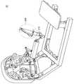
図2は、本開示の実施形態に係るスレーブ装置の一例を示す説明図である。図2に示す例では、スレーブ装置10のアームの先端部分である先端部12には、本実施形態に係る医療用装置100が設けられる。医療用装置100の先端部分には、患者と接触する医療用器具110がさらに設けられる。ユーザは、マスター装置20を操作することにより、医療用器具110の位置を遠隔操作する。 FIG. 2 is an explanatory diagram showing an example of a slave device according to the embodiment of the present disclosure. In the example shown in FIG. 2, the
また、スレーブ装置10は、医療用装置100に各種センサ(例えば、力センサ、振動センサ、原点センサ、Limitセンサ、エンコーダ、マイクロフォン、及び加速度センサなど)を有してもよい。例えば、スレーブ装置10は、医療用装置100に振動センサを有する。当該振動センサは、医療用器具110が患者と接触した際に、医療用器具110を伝播する振動を計測する。また、スレーブ装置10は、医療用装置100にマイクロフォンを有する。当該マイクロフォンは、医療用器具110が患者と接触した際に、空気を伝播する振動を計測する。なお、上述した各種センサが備えられる場所は特に限定されず、各種センサは、医療用装置100の任意の場所に備えられてもよい。 Further, the
なお、図2に示すスレーブ装置10は一例であり、本実施形態にかかるスレーブ装置10の構成は図2の例に限定されるものではない。 The
(2)マスター装置20
マスター装置20は、マスタースレーブシステム1000におけるマスター側の装置である。例えば、マスター装置20は、受動関節を含む1または2以上の関節と、関節に接続されるリンクとを有するロボット(受動関節を含むリンク機構を有するロボット)であってよい。なお、受動関節は、モータやアクチュエータなどにより駆動しない関節である。(2)
The
図3は、本開示の実施形態に係るマスター装置の一例を示す説明図である。図3に示す例では、マスター装置20は、受動関節に接続されるリンクに設けられる操作体200と、操作体200に印加される力を計測する力センサ210とを含む。ここで、本実施形態にかかる力センサ210としては、例えば、“歪ゲージを用いる方式等の任意の方式の力覚センサ”や、“圧電素子やマイクロフォン等で振動を計測することにより触覚を得る方式等の任意の方式の触覚センサ”等の、操作体200に印加される力を計測することが可能な任意のセンサが、挙げられる。また、マスター装置20は、例えば、関節の動きを計測するための動きセンサを、関節それぞれに対応する位置に備える。 FIG. 3 is an explanatory diagram showing an example of the master device according to the embodiment of the present disclosure. In the example shown in FIG. 3, the
本実施形態において、マスター装置20は、スレーブ装置10の操作に用いられる。例えば、マスター装置20は、マスター装置20の入力インタフェースである操作体200を備える。ユーザは、操作体200の位置を移動させる操作により、上述したスレーブ装置10の医療用器具110の位置を移動させる(遠隔操作する)ことが可能である。 In this embodiment, the
なお、図3では、マスター装置20に設けられる操作体200が、スタイラス型の操作デバイスである例を示しているが、本実施形態にかかる操作体200は、図3に示す例に限定されない。本実施形態にかかる操作体200としては、例えば、グローブ型の操作デバイスなどの、任意の形状の操作デバイスが挙げられる。また、本実施形態に係る操作体200は、ハプティックデバイスに適用することが可能な、任意の操作デバイスであってもよい。また、マスター装置20は、操作体200を交換することが可能な構造を有していてもよい。なお、本実施形態にかかるマスター装置20の構成は、図3に示す例に限定されず、任意の構成であってよい。 Although FIG. 3 shows an example in which the
また、操作体200は、スレーブ装置10の医療用装置100と患者が接触した際に生じる振動を、ユーザに触覚として提示するための振動装置を有する。振動装置には、例えば、ボイスコイルモータ(VCM:Voice Coil Motor)式の振動アクチュエータが用いられる。また、振動装置には、LRA(Linear Resonant Actuator)又は圧電素子が用いられてもよい。 Further, the operating
(3)出力装置30
出力装置30は、後述する制御装置40から入力される出力情報を出力する。例えば、出力装置30は、設置型のディスプレイ及びユーザの頭部に装着されるHMD(Head Mounted Display)等の表示装置であってもよい。出力装置30は、制御装置40から出力情報として画像情報を入力された場合、当該表示装置に画像を表示する。また、出力装置30は、スピーカ及びヘッドホン等の音声出力装置であってもよい。出力装置30は、制御装置40から出力情報として音声情報を入力された場合、当該音声出力装置から音声を出力する。(3) Output device 30
The output device 30 outputs output information input from the
なお、出力装置30として用いられる装置は、上述の例に限定されず、任意の装置が用いてられてもよい。 The device used as the output device 30 is not limited to the above example, and any device may be used.
(4)制御装置40
制御装置40は、マスタースレーブシステム1000に含まれる他の各装置を制御する。例えば、制御装置40は、スレーブ装置10の駆動を制御する。具体的に、制御装置40は、スレーブ装置10のアームを駆動するための指示を示す情報をマスター装置20から受信し、受信した情報に基づき、スレーブ装置10のアームの駆動を制御する。アームを駆動するための指示を示す情報は、ユーザがマスター装置20の操作体200を操作することで入力される。(4)
The
また、制御装置40は、マスター装置20の駆動を制御する。具体的に、制御装置40は、スレーブ装置10から受信する医療用装置100と患者との接触に関する情報に基づき、マスター装置20の操作体200が有する振動装置の駆動を制御する。 Further, the
また、制御装置40は、出力装置30における出力を制御する。具体的に、制御装置40は、スレーブ装置10のアームの医療用器具110に設けられたカメラにより撮像された画像(静止画像/動画像)をスレーブ装置10から受信し、当該画像を出力装置30へ送信し、出力装置30に当該画像を出力させる。 Further, the
制御装置40は、マスタースレーブシステム1000に含まれる他の各装置と任意の通信方式で接続されており、通信を介して、他の各装置と制御に関する情報を送受信する。 The
<2−2.医療用装置の構成>
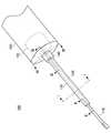
以下では、図4〜図10を参照しながら、本実施形態に係る医療用装置の構成例について説明する。図4は、本実施形態に係る医療用装置の外観構成を示す斜視図である。図5は、本実施形態に係る医療用装置の切断線I−Iにおける断面図である。図6は、本実施形態に係る医療用装置の切断線II−IIにおける断面図である。図7は、本実施形態に係る医療用装置の切断線III−IIIにおける断面図である。図8は、本実施形態に係る医療用装置の切断線IV−IVにおける断面図である。<2-2. Configuration of medical equipment>
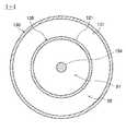
Hereinafter, a configuration example of the medical device according to the present embodiment will be described with reference to FIGS. 4 to 10. FIG. 4 is a perspective view showing an external configuration of the medical device according to the present embodiment. FIG. 5 is a cross-sectional view taken along the cutting line I-I of the medical device according to the present embodiment. FIG. 6 is a cross-sectional view taken along the cutting line II-II of the medical device according to the present embodiment. FIG. 7 is a cross-sectional view taken along the cutting line III-III of the medical device according to the present embodiment. FIG. 8 is a cross-sectional view taken along the cutting line IV-IV of the medical device according to the present embodiment.
図4に示すように、医療用装置100は、医療用器具110、パイプ120(第1の構造部材)、パイプ130(第2の構造部材)、連結部140(第3の構造部材)、及び駆動部150で構成されている。また、図5に示すように、パイプ120はパイプ130の中空部分92に挿通されている。また、図6に示すように、医療用器具110は、パイプ120と連結されている。また、図7に示すように、駆動部150は、連結部140により、パイプ120及びパイプ130と連結されている。 As shown in FIG. 4, the
さらに、医療用装置100は、駆動部150の駆動により生じる動力を医療用器具110に伝達する動力伝達機構を有する。動力伝達機構は、例えば、プーリ摺動部152及びワイヤ154を含む構成である。プーリ摺動部152は、例えば、駆動部150の内部設けられ、駆動部150及びワイヤ154と互いに連結されている。プーリ摺動部152は、駆動部150の駆動に伴い駆動することで、駆動部150の動力をワイヤ154へ伝達する機能を有する。ワイヤ154は、プーリ摺動部152に加え、医療用器具110とも連結されている。ワイヤ154は、プーリ摺動部152の駆動に伴い駆動することで、プーリ摺動部152の動力を医療用器具110へ伝達する機能を有する。そして、医療用器具110は、プーリ摺動部152から伝達された動力により駆動する。なお、図5〜図8に示すワイヤ154は、説明の便宜上で1本しか示されていないが、動力伝達機構の構成に応じて複数のワイヤ154が設けられてもよい。 Further, the
上述の構成を有することにより、医療用装置100は、駆動部150の駆動を医療用器具110へ伝達することができる。なお、動力伝達機構は、リンク機構により実現されてもよい。 By having the above-mentioned configuration, the
医療用器具110は、例えば、鉗子型の器具である。医療用器具110は、動力伝達機構を介して駆動部150に接続され、駆動部150により駆動される。パイプ120は、中空部分91を有し、両端に開口部を有する構造部材である。パイプ120の表面は、以下では、パイプ120の外壁121とも称される。パイプ120は、例えば、断面の形状が円形の構造部材である。なお、パイプ120の断面の形状は、円形に限定されず、任意の形状であってよい。また、パイプ120の長さは、特に限定されず、任意の長さであってよい。また、パイプ120の形状は、特に限定されず、任意の形状であってよい。例えば、パイプ120の形状は、直線な形状であってもよいし、湾曲した形状であってもよい。 The
パイプ130は、中空部分92を有し、両端に開口部を有する構造部材である。パイプ130の中空部分92における面は、以下では、パイプ130の内壁131とも称される。パイプ130は、例えば、断面の形状が円形の構造部材である。なお、パイプ130の断面の形状は、円形に限定されず、任意の形状であってよい。また、パイプ130の長さは、特に限定されず、任意の長さであってよいが、パイプ120と同等程度の長さであることが望ましい。また、パイプ120の形状は、特に限定されず、任意の形状であってよい。例えば、パイプ120の形状は、直線な形状であってもよいし、湾曲した形状であってもよい。連結部140は、内部に中空部分94を有し、パイプ120、パイプ130、及び駆動部150を連結する構造部材である。 The
パイプ120の一方の開口部には、例えば、医療用器具110が設けられる。具体的に、図6に示すように、医療用器具110は、パイプ120の一方の開口部に挿通され、パイプ130の外側から締結部材170により固定される。なお、医療用器具110の固定に用いられる締結部材170の数は、特に限定されず、任意の数であってもよい。例えば、図6に示すように、パイプ120は、締結部材170aと締結部材170bの2つの締結部材170により固定される。また、パイプ120は、締結部材170により必ずしも固定される必要はない。 For example, a
また、パイプ120の他方の開口部には、例えば、連結部140が設けられる。具体的に、図7に示すように、パイプ120は、連結部140が有する中空部分94に挿通される。なお、連結部140のパイプ120が連結される側の反対側には、駆動部150が連結される。即ち、パイプ120の一方の開口部側には医療用器具110が位置し、パイプ120の他方の開口部側には駆動部150が位置する。なお、パイプ120は、上述のように連結部140の中空部分94に挿通されてもよいし、パイプ120の端部と連結部140が密着するように固定されることで連結部140と連結されてもよい。 Further, for example, a connecting
また、パイプ120の中空部分91には、動力伝達機構が挿通される。図6及び図7に示すように、例えば、パイプ120の中空部分91には、プーリ摺動部152と連結されたワイヤ154が挿通される。この時、ワイヤ154は、パイプ120の一方の開口部側に医療用器具110が位置し、パイプ120の他方の開口部側に駆動部150が位置するように医療用器具110と駆動部150とを連結する。なお、パイプ120の中空部分91は、駆動部150の中空部分95とつながっている。以下では、パイプの120の一方の開口部は、パイプ120の医療用器具110側の開口部とも称される。また、以下では、パイプ120の他方の開口部は、パイプ120の駆動部150側の開口部とも称される。 Further, a power transmission mechanism is inserted through the
パイプ130の中空部分92には、例えば、図4〜図7に示すように、パイプ120が挿通される。この時、パイプ120は、パイプ130の一方の開口部側には医療用器具110が位置し、パイプ130の他方の開口部側には駆動部150が位置するようにパイプ130の中空部分92に挿通される。以下では、パイプの130の一方の開口部は、パイプ130の医療用器具110側の開口部とも称される。また、以下では、パイプ130の他方の開口部は、パイプ130の駆動部150側の開口部とも称される。 A
パイプ130の中空部分92にパイプ120が挿通されることから、パイプ130の断面の径の大きさは、パイプ120の断面の径の大きさよりも大きいことが望ましい。さらに、パイプ120は、パイプ120の外壁121とパイプ130の内壁131との間に空間的な余裕を持って、パイプ130の中空部分92に挿通されることが望ましい。また、パイプ120には動力伝達機構が挿通される。そのため、パイプ120の断面の径の大きさは、パイプ130の断面の径の大きさよりも小さく、中空部分91に動力伝達機構を挿通可能な程度の大きさ以上の範囲内の大きさであることが望ましい。なお、当該範囲内であれば、パイプ120の断面の径の大きさは特に限定されない。 Since the
パイプ130の医療用器具110側の開口部の近傍には、上述のように、医療用器具110を固定する締結部材170が設けられる。一方、パイプ130の駆動部150側の開口部には、例えば、連結部140が設けられる。具体的に、図7に示すように、パイプ130は、連結部140に連結される。なお、パイプ130が連結部140に連結される方法は、特に限定されない。例えば、パイプ130は、パイプ120と同様に、連結部140の中空部分94に挿通されることにより連結部140と連結されてもよい。 As described above, a fastening member 170 for fixing the
連結部140は、パイプ120の外壁121とパイプ130の内壁131とを連結する。例えば、連結部140は、図7を参照すると、パイプ120とパイプ130との間の駆動部150側の開口部を塞ぐように、パイプ120及びパイプ130と連結される。具体的に、図8が示すように、連結部140は、パイプ120の外壁121とパイプ130の内壁131と連結部140との間の空間93の駆動部150側を塞ぎ、ワイヤ154が通るパイプ120の中空部分91は塞がないように設けられる。 The connecting
上述したように、医療用装置100は、パイプ130の中空部分92にパイプ120を挿通し、連結部140によりパイプ120とパイプ130の駆動部150側の開口部を塞ぐ構成を有する。これにより、医療用装置100は、駆動部150側におけるパイプ120の中空部分91及び駆動部150の中空部分95を、パイプ120の外壁121とパイプ130の内壁131の間の空間93と分離することができる。このように、中空部分91及び中空部分95を空間93と分離することは、以下では、空間分離とも称される。 As described above, the
医療用装置100は、医療用器具110側のパイプ120の外壁121とパイプ130の内壁131と連結部140との間の空間93振動を計測するセンサ部160をさらに有する。センサ部160が計測する振動には、少なくとも2種類の振動が存在する。1つ目の振動は、例えば、空気を伝播する振動(以下では、空気振動又は音とも称される)である。2つ目の振動は、例えば、医療用装置100を伝播する振動(以下では、筐体振動とも称される)。また、本実施形態に係る振動が生じる要因は、少なくとも3種類の要因がある。1つ目の要因は、例えば、医療用器具110と患者との接触である。2つ目の要因は、例えば、駆動部150の駆動である。3つ目の要因は、例えば、外的要因である。3種類の各々の要因により生じる振動には、上述の2種類の振動がそれぞれ含まれる。即ち、本実施形態に係る振動は、少なくとも6種類の振動が存在する。 The
より具体的に説明すると、1つ目及び2つ目の振動は、それぞれ医療用器具110と患者との接触により生じる音(以下では、接触音とも称される)と筐体振動(以下では、接触振動とも称される)である。3つ目及び4つ目の振動は、それぞれ駆動部150の駆動により生じる音(以下では、駆動音とも称される)と筐体振動(以下では、駆動振動とも称される)である。5つ目及び6つ目の振動は、それぞれ外的要因により生じる音(以下では、外界音とも称される)と筐体振動(以下では、外界振動とも称される)である。なお、本実施形態では、センサ部160は、少なくとも接触音を計測し、接触振動も計測することが望ましい。接触音及び接触振動以外の振動は、ノイズの要因となる。そのため、センサ部160は、接触音及び接触振動以外の振動を計測しないことが望ましい。接触音及び接触振動以外の振動は、以下では、振動ノイズとも称される。 More specifically, the first and second vibrations are the sound generated by the contact between the
本実施形態では、センサ部160が接触音のみを計測することが望ましいが、センサ部160の設置場所によっては、接触音以外の振動も計測してしまう。そこで、センサ部160は、接触音以外の振動がより低減されて計測される位置に設けられることが望ましい。例えば、本実施形態に係るセンサ部160は、図7に示す位置に設けられる。図7に示すセンサ部160の位置は、医療用器具110側のパイプ120の外壁121とパイプ130の内壁131と連結部140との間の空間93の駆動部150側の位置である。まず、センサ部160は、空間93に設けられることで、パイプ120の中空部分91の空気を伝播する駆動音を計測しにくくなる、又は計測することができない。よって、センサ部160は、計測される振動ノイズを低減することができる。さらに、センサ部160は、医療用装置100の医療用器具110側である遠位端よりも、駆動部150側である近位端に設置されることで、医療用器具110をより清潔に保つことができる。 In the present embodiment, it is desirable that the
また、センサ部160は、パイプ130又は連結部140に設けられる。図7に示す例では、センサ部160は、連結部140に設けられている。さらに、図7に示すセンサ部160は、医療用器具110側のパイプ120の外壁121とパイプ130の内壁131と連結部140との間の空間93の連結部140の中空部分94の位置に設けられている。センサ部160は、パイプ130に設けられてもよいが、パイプ130よりも駆動部150側にある連結部140に設けられることで、より近位端側に設けることができる。 Further, the
また、パイプ130の外壁132などの医療用装置100の外側に、空間93に設けられたセンサ部160とは異なるセンサ部が設けられてもよい。異なるセンサ部は、医療用装置100の外側にあるため、振動ノイズである外界音及び外界振動を検出することができる。もし、センサ部160が計測した振動に、外界音又は外界振動の少なくともいずれか一方が含まれている場合、異なる振動部が計測した外界音又は外界振動に基づき、医療用装置100はセンサ部160が計測した振動から振動ノイズを除去することができる。 Further, a sensor unit different from the
また、駆動部150は、中空部分95の内部又は外部にモータ(図示しない)を有する。モータが駆動部150の中空部分95の内部にある場合、例えば、モータの駆動音は、中空部分91及び中空部分95を伝播するが、空間分離により空間93には伝播せず、センサ部160に計測もされない。一方、モータが駆動部150の中空部分95の外部にある場合、モータの駆動音は、パイプ120とパイプ130との間の医療用器具110側の開口部から回り込んで、空間93を伝播する可能性はある。しかし、モータの駆動音は、パイプ120とパイプ130との間の医療用器具110側の開口部へ回り込むことで、センサ部160に伝達するまでに減衰する。よって、モータの駆動音は、センサ部160に計測されにくい。 Further, the
上述した空間分離された構成を有することにより、医療用装置100は、センサ部160に伝達する振動ノイズを低減することができる。これにより、医療用装置100は、特別な信号処理を用いることなく、SN比(Signal−Noise Ratio:信号雑音比)を向上することもできる。 By having the above-mentioned spatially separated configuration, the
また、ノイズ源となる駆動部150を構成する部品には、駆動部150を伝播する振動を低減する材料が用いられてもよい。駆動部150を伝播する振動を低減する材料は、例えば、カーボン及び多孔質構造を有する発泡剤等が挙げられる。これらの材料が駆動部150を構成する部品に用いられることで、センサ部160は、計測する振動ノイズをより低減することができる。 Further, a material that reduces vibration propagating in the
<2−3.振動の計測>
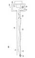
以下では、図9〜図11を参照しながら、本実施形態に係る振動の計測例について説明する。図9は、比較例に係る医療用装置を示す簡易図である。図10は、本実施形態に係る医療用装置を示す簡易図である。図11は、本実施形態に係る医療用装置の切断線V−Vにおける断面図である。なお、医療用装置の簡易図では、説明の便宜上、パイプ120の一方の開口部に設けられる医療用器具110、及びワイヤ154の記載を省略している。また、駆動部150の外側にモータ156が設けられ、当該モータ156は駆動部150の内部に設けられるプーリ摺動部152と連結されているものとする。<2-3. Vibration measurement>
Hereinafter, an example of vibration measurement according to the present embodiment will be described with reference to FIGS. 9 to 11. FIG. 9 is a simplified diagram showing a medical device according to a comparative example. FIG. 10 is a simplified diagram showing a medical device according to the present embodiment. FIG. 11 is a cross-sectional view taken along the cutting line VV of the medical device according to the present embodiment. In the simplified drawing of the medical device, the description of the
図9に示す比較例に係る医療用装置300は、パイプ130を備えていない点、及びセンサ部160がパイプ120に設けられている点が本実施形態に係る医療用装置100と異なる。これにより、医療用器具110と対象物との接触により位置50で生じ、パイプ120の中空部分91の空気を伝播する振動52(接触音)と、パイプ120を伝播する振動54(接触振動)は、センサ部160により計測される。また、駆動部150の駆動により位置60で生じる振動62(駆動音)も、センサ部160により計測される。そのため、医療用装置300は、センサ部160に伝達する振動ノイズを低減することができない。これは、比較例に係る医療用装置300は、空間分離がされていないためである。具体的に、医療用装置300がパイプ130及び連結部140を備えていないことで、振動52(接触音)と振動62(駆動音)が伝播する空気が分けられていないためである。また、センサ部160が振動52(接触音)と振動62(駆動音)の両方の振動を計測する位置に設けられているためでもある。 The
一方、図10に示す本実施形態に係る医療用装置100は、パイプ120の外側にパイプ130が設けられ、パイプ130にセンサ部160が設けられている。また、駆動部150側のパイプ120の外壁とパイプ130の外壁との間のパイプ130の開口部は、連結部140により塞がれている。これにより、医療用器具110と対象物との接触により位置50で生じ、医療用器具110側のパイプ120の外壁121とパイプ130の内壁131と連結部140との間の空間93の空気を伝播する振動52(接触音)は、センサ部160により計測される。また、パイプ120、締結部材170、及びパイプ130を伝播する振動54(接触振動)も、センサ部160によりを計測される。一方、駆動部150の駆動により位置60で生じる振動62(駆動音)は、センサ部160が設けられていないパイプ120内の空気を伝播するため、センサ部160により計測されにくい、若しくは計測されない。これは、医療用装置100が空間分離されているためである。なお、モータが中空部分95の外側に設けられている場合、モータの駆動音は医療用器具110側へ回り込み、医療用器具110側のすき間から空間93へ入り込み、振動ノイズとしてセンサ部160に計測され得る。しかしながら、モータの駆動音は、医療用器具110側へ回り込むことにより、センサ部160に計測されるまでに減衰する。よって、医療用装置100は、センサ部160に伝達する振動ノイズを低減することができる。 On the other hand, in the
なお、図11に示す締結部材170の位置における断面図のように、空間93は、締結部材170aと締結部材170bとの間が塞がれていない。そのため、振動52は、空間93の空気を伝播することができる。 As shown in the cross-sectional view at the position of the fastening member 170 shown in FIG. 11, the
以上説明したように、本実施形態に係る医療用装置100は、医療用装置100の他の構成要素と上述した関係にあるパイプ130、連結部140、及びセンサ部160で構成される医療用装置部品を備えることで、上述の本願に特有の効果を奏することができる。 As described above, the
<2−4.制御装置の機能構成>
以下では、図12を参照しながら、本開示の実施形態に係る制御装置40の機能構成例について説明する。図12は、本開示の実施形態に係る制御装置の機能構成例を示すブロック図である。図12に示すように、制御装置40は、通信部400及び制御部410を備える。<2-4. Function configuration of control device>
Hereinafter, an example of the functional configuration of the
(1)通信部400
通信部400は、他の装置と通信を行う機能を有する。例えば、通信部400は、他の装置との通信において、他の装置から受信する情報を制御部410へ出力する。具体的に、通信部400は、スレーブ装置10から受信するセンシング情報を制御部410へ出力する。また、通信部400は、マスター装置20から受信する制御情報を制御部410へ出力する。(1)
The
通信部400は、他の装置との通信において、制御部410から入力される情報を他の装置へ送信する。具体的に、通信部400は、制御部410から入力される駆動処理に関する情報をスレーブ装置10へ送信する。また、通信部400は、制御部410から入力される検出情報の提示に関する情報をマスター装置20へ送信する。また、通信部400は、制御部410から入力された出力処理に関する情報を出力装置30へ送信する。 The
(2)制御部410
制御部410は、マスタースレーブシステム1000の動作全体を制御する機能を有する。当該機能を実現するために、本実施形態に係る制御部410は、図12に示すように、取得部412、信号処理部414、駆動制御部416、及び出力制御部418を備える。(2)
The
(2−1)取得部412
取得部412は、センシング情報を取得する機能を有する。例えば、取得部412は、通信部400を介して、スレーブ装置10の医療用装置100が備えるセンサ部160が計測したセンシング情報を信号として取得する。そして、取得部412は、取得したセンシング情報に関する信号を信号処理部414へ出力する。(2-1)
The
また、取得部412は、通信部400を介して、マスター装置20が備える力センサ210が計測したセンシング情報を信号として取得する。そして、取得部412は、取得したセンシング情報に関する信号を駆動制御部416へ出力する。 Further, the
(2−2)信号処理部414
信号処理部414は、取得部412から入力される信号に基づき、スレーブ装置10及びマスター装置20の動作に関する信号の処理を行う機能を有する。例えば、信号処理部414は、マスター装置20の力センサ210が計測したユーザの入力操作に関する情報の信号に基づき、スレーブ装置10のアームの駆動に関する信号を生成する。そして、信号処理部414は、生成した信号を駆動制御部416へ出力する。(2-2)
The
また、信号処理部414は、スレーブ装置10のセンサ部160が計測した医療用装置100と患者との接触に関する情報の信号に基づき、マスター装置20の振動装置の駆動に関する信号を生成する。具体的に、信号処理部414は、センサ部160が計測した情報の信号のみを入力された場合、センサ部160が計測した情報の信号に基づく信号を生成する。そして、信号処理部414は、生成した信号を駆動制御部416へ出力する。 Further, the
(2−3)駆動制御部416
駆動制御部416は、信号処理部414から入力される信号に基づき、スレーブ装置10及びマスター装置20の駆動の制御を行う機能を有する。例えば、駆動制御部416は、マスター装置20の力センサ210が計測した情報に関する信号を信号処理部414から受信し、受信した情報に基づき、スレーブ装置10のアームの駆動を制御する。また、駆動制御部416は、スレーブ装置10のセンサ部160が計測した情報に関する信号を信号処理部414から受信し、受信した情報に基づき、マスター装置20の振動装置の駆動を制御する。(2-3) Drive
The
(2−4)出力制御部418
出力制御部418は、出力装置30に出力する情報の制御を行う。例えば、出力制御部418は、スレーブ装置10のアームの医療用器具110に設けられたカメラにより撮像された画像(静止画像/動画像)を、通信部400を介して受信し、受信した画像を出力装置30へ送信し、出力装置30に当該画像を出力させる。(2-4)
The
<<3.変形例>>
以下では、本開示の実施形態の変形例を説明する。なお、以下に説明する変形例は、単独で本開示の実施形態に適用されてもよいし、組み合わせで本開示の実施形態に適用されてもよい。また、変形例は、本開示の実施形態で説明した構成に代えて適用されてもよいし、本開示の実施形態で説明した構成に対して追加的に適用されてもよい。<< 3. Modification example >>
Hereinafter, a modified example of the embodiment of the present disclosure will be described. The modifications described below may be applied alone to the embodiments of the present disclosure, or may be applied in combination to the embodiments of the present disclosure. Further, the modification may be applied in place of the configuration described in the embodiment of the present disclosure, or may be additionally applied to the configuration described in the embodiment of the present disclosure.
<3−1.第1の変形例>
以下では、図13を参照しながら、本開示の実施形態に係る第1の変形例について説明する。図13は、本開示の実施形態に係る第1の変形例を示す説明図である。<3-1. First variant>
Hereinafter, the first modification according to the embodiment of the present disclosure will be described with reference to FIG. FIG. 13 is an explanatory diagram showing a first modification according to the embodiment of the present disclosure.
上述の実施形態では、医療用装置100がセンサ部160を1つのみ有する例について説明した。変形例1では、医療用装置100がセンサ部160と異なるセンサ部をさらに備える例について説明する。 In the above-described embodiment, an example in which the
例えば、図13に示すように、医療用装置100は、センサ部160aとセンサ部160bとを有する。センサ部160aは、上述の実施形態におけるセンサ部160と同じ位置に設けられ、センサ部160bは、センサ部160aとは異なる位置に設けられる。なお、センサ部160bが計測する振動は、センサ部160aが計測する振動に含まれる振動ノイズの除去に用いられる。そのため、センサ部160bは、センサ部160aが計測する振動から除去したい振動ノイズを計測可能な位置に設けられることが望ましい。例えば、図13に示す例では、モータ156の駆動により位置70で生じる振動72aが、医療用装置100の筐体を伝播してセンサ部160aに伝達する。これにより、センサ部160aが計測する振動には、振動ノイズとなる駆動振動が含まれる。そこで、当該駆動振動を除去したい場合、センサ部160bは、当該駆動振動を計測可能な位置に設けられるとよい。例えば、図13に示すように、センサ部160bは、内壁131側の空気に触れないように、パイプ130の外壁側と接するように設けるとよい。これにより、センサ部160bは、空間93に関する振動を計測しないため、センサ部160aで計測される振動に含まれる振動ノイズにより近い振動を計測することができる。 For example, as shown in FIG. 13, the
なお、センサ部160bは、センサ部160aが設けられている構造部材と同一の構造部材に設けられるとよい。例えば、図13に示す例では、センサ部160aは、パイプ130に設けられている。振動72aは、センサ部160aに計測される前に、パイプ130を伝達することで減衰する。そこで、振動72bもパイプ130を伝達させてからセンサ部160bに計測させることで、センサ部160bは、センサ部160aで計測される振動に含まれる振動ノイズにより近い振動を計測することができる。さらに、振動72aと72bが、位置70から各センサ部に伝達するまでの間に伝達する構造部材及び伝達する距離も同一となる位置に各センサ部を設けてもよい。これにより、センサ部160bは、センサ部160aで計測される振動に含まれる振動ノイズにさらに近い振動を計測することができる。また、センサ部160bで計測された振動ノイズをセンサ部160aで計測された振動から除去することで、医療用装置100は、振動ノイズをより低減することができる。 The
なお、振動ノイズの除去は、信号処理部414により行われる。例えば、信号処理部414は、センサ部160aが計測した情報の信号に加え、他のセンサ部160bが計測した振動ノイズに関する情報の信号を入力された場合、センサ部160aが計測した情報の信号から振動ノイズに関する情報の信号を除去する処理を行う。そして、信号処理部414は、処理後の信号を駆動制御部416へ出力する。 The vibration noise is removed by the
<3−2.第2の変形例>
以下では、図14及び図15を参照しながら、本開示の実施形態に係る第2の変形例について説明する。図14は、本開示の実施形態に係る第2の変形例を示す説明図である。図15は、本開示の実施形態に係る医療用装置の切断線VI−VIにおける断面図である。<3-2. Second variant>
Hereinafter, a second modification according to the embodiment of the present disclosure will be described with reference to FIGS. 14 and 15. FIG. 14 is an explanatory diagram showing a second modification according to the embodiment of the present disclosure. FIG. 15 is a cross-sectional view taken along the cutting line VI-VI of the medical device according to the embodiment of the present disclosure.
上述の実施形態では、空間93の医療用器具110側のパイプ120とパイプ130との開口部が塞がれていない例について説明した。第2の変形例では、当該開口部を塞ぐ例について説明する。 In the above-described embodiment, an example in which the openings between the
例えば、医療用装置100は、Oリング180(第4の構造部材)をさらに備える。当該Oリング180は、図14に示すように、パイプ120とパイプ130とを空間93のセンサ部160より医療用器具110側で連結する。パイプ120とパイプ130がOリング180により連結されることで、図15に示すように、医療用器具110側のパイプ120とパイプ130との開口部が塞がれる。これにより、空間93と外界音である振動82aが伝播する空間とが空間分離され、振動82aは、センサ部160aまで伝達しない。よって、医療用装置100は、センサ部160aにて計測される振動ノイズを低減することができる。また、医療用装置100は、Oリング180により空間分離を行うことで、特別な信号処理を行うことなく、振動ノイズを低減することができる。 For example, the
<3−3.第3の変形例>
以下では、図16を参照しながら、本開示の実施形態に係る第3の変形例について説明する。図16は、本開示の実施形態に係る第3の変形例を示す説明図である。<3-3. Third variant>
Hereinafter, a third modification according to the embodiment of the present disclosure will be described with reference to FIG. FIG. 16 is an explanatory diagram showing a third modification according to the embodiment of the present disclosure.
上述の第1の変形例では、医療用装置100がセンサ部160と異なるセンサ部をさらに備える例について説明した。第3の変形例では、センサ部160と異なるセンサ部が医療用装置100の外部に設けられる例について説明する。 In the first modification described above, an example in which the
例えば、センサ部160aとは異なるセンサ部160cが医療用装置100の外部にさらに設けられ、センサ部160cは、医療用装置100の外部で生じる振動を計測する。医療用装置100の外部で生じる振動は、例えば、外界音又は外界振動の少なくともいずれか一方である。具体的に、図16に示すように、外界の要因により、位置80で振動82a及び82b(例えば外界音)が生じたとする。振動82aは、締結部材170aと170bとの間から空間93を伝播し、センサ部160aで計測される。一方、振動82bは、医療用装置100の外部の空気を伝播し、医療用装置100の外部に設けられたセンサ部160cにより計測される。そして、医療用装置100は、センサ部160cで計測された振動ノイズをセンサ部160aで計測された振動から除去することで、振動ノイズをより低減することができる。なお、振動ノイズの除去処理は、第1の変形例と同様に、信号処理部414により行われる。 For example, a
<<4.ハードウェア構成例>>
以上、本開示の実施形態を説明した。最後に、図17を参照しながら、本開示の実施形態に係るハードウェア構成について説明する。図17は、本開示の実施形態に係る制御装置のハードウェア構成の一例を示すブロック図である。なお、図17に示す制御装置40は、図12に示した制御装置40の機能を実現し得る。本実施形態に係る制御装置40による情報処理は、ソフトウェアと、以下に説明するハードウェアとの協働により実現される。<< 4. Hardware configuration example >>
The embodiments of the present disclosure have been described above. Finally, the hardware configuration according to the embodiment of the present disclosure will be described with reference to FIG. FIG. 17 is a block diagram showing an example of the hardware configuration of the control device according to the embodiment of the present disclosure. The
図17に示すように、制御装置40は、CPU(Central Processing Unit)901、ROM(Read Only Memory)902、及びRAM(Random Access Memory)903を備える。また、制御装置40は、ホストバス904a、ブリッジ904、外部バス904b、インタフェース905、入力装置906、出力装置907、ストレージ装置908、ドライブ909、接続ポート911、及び通信装置913を備える。なお、ここで示すハードウェア構成は一例であり、構成要素の一部が省略されてもよい。また、ハードウェア構成は、ここで示される構成要素以外の構成要素をさらに含んでもよい。 As shown in FIG. 17, the
(CPU901、ROM902、RAM903)
CPU901は、例えば、演算処理装置又は制御装置として機能し、ROM902、RAM903、又はストレージ装置908に記録された各種プログラムに基づいて各構成要素の動作全般又はその一部を制御する。ROM902は、CPU901に読み込まれるプログラムや演算に用いるデータ等を格納する手段である。RAM903には、例えば、CPU901に読み込まれるプログラムや、そのプログラムを実行する際に適宜変化する各種パラメータ等が一時的又は永続的に格納される。これらはCPUバスなどから構成されるホストバス904aにより相互に接続されている。CPU901、ROM902、及びRAM903は、例えば、ソフトウェアとの協働により、図12を参照して説明した制御部410の機能を実現し得る。(CPU901, ROM902, RAM903)
The
(ホストバス904a、ブリッジ904、外部バス904b、インタフェース905)
CPU901、ROM902、及びRAM903は、例えば、高速なデータ伝送が可能なホストバス904aを介して相互に接続される。一方、ホストバス904aは、例えば、ブリッジ904を介して比較的データ伝送速度が低速な外部バス904bに接続される。また、外部バス904bは、インタフェース905を介して種々の構成要素と接続される。(
The
(入力装置906)
入力装置906は、例えば、マウス、キーボード、タッチパネル、ボタン、マイクロフォン、スイッチ及びレバー等、ユーザによって情報が入力される装置によって実現される。また、入力装置906は、例えば、赤外線やその他の電波を利用したリモートコントロール装置であってもよいし、制御装置40の操作に対応した携帯電話やPDA等の外部接続機器であってもよい。さらに、入力装置906は、例えば、上記の入力手段を用いてユーザにより入力された情報に基づいて入力信号を生成し、CPU901に出力する入力制御回路などを含んでいてもよい。制御装置40のユーザは、この入力装置906を操作することにより、制御装置40に対して各種のデータを入力したり処理動作を指示したりすることができる。(Input device 906)
The
他にも、入力装置906は、ユーザに関する情報を検知する装置により形成され得る。例えば、入力装置906は、画像センサ(例えば、カメラ)、深度センサ(例えば、ステレオカメラ)、加速度センサ、ジャイロセンサ、地磁気センサ、光センサ、音センサ、測距センサ(例えば、ToF(Time of Flight)センサ)、力センサ等の各種のセンサを含み得る。また、入力装置906は、制御装置40の姿勢、移動速度等、制御装置40自身の状態に関する情報や、制御装置40の周辺の明るさや騒音等、制御装置40の周辺環境に関する情報を取得してもよい。また、入力装置906は、GNSS(Global Navigation Satellite System)衛星からのGNSS信号(例えば、GPS(Global Positioning System)衛星からのGPS信号)を受信して装置の緯度、経度及び高度を含む位置情報を測定するGNSSモジュールを含んでもよい。また、位置情報に関しては、入力装置906は、Wi−Fi(登録商標)、携帯電話・PHS・スマートフォン等との送受信、または近距離通信等により位置を検知するものであってもよい。 In addition, the
(出力装置907)
出力装置907は、取得した情報をユーザに対して視覚的又は聴覚的に通知することが可能な装置で形成される。このような装置として、CRTディスプレイ装置、液晶ディスプレイ装置、プラズマディスプレイ装置、ELディスプレイ装置、レーザープロジェクタ、LEDプロジェクタ及びランプ等の表示装置や、スピーカ及びヘッドホン等の音声出力装置や、プリンタ装置等がある。出力装置907は、例えば、制御装置40が行った各種処理により得られた結果を出力する。具体的には、表示装置は、制御装置40が行った各種処理により得られた結果を、テキスト、イメージ、表、グラフ等、様々な形式で視覚的に表示する。他方、音声出力装置は、再生された音声データや音響データ等からなるオーディオ信号をアナログ信号に変換して聴覚的に出力する。(Output device 907)
The
(ストレージ装置908)
ストレージ装置908は、制御装置40の記憶部の一例として形成されたデータ格納用の装置である。ストレージ装置908は、例えば、HDD等の磁気記憶部デバイス、半導体記憶デバイス、光記憶デバイス又は光磁気記憶デバイス等により実現される。ストレージ装置908は、記憶媒体、記憶媒体にデータを記録する記録装置、記憶媒体からデータを読み出す読出し装置および記憶媒体に記録されたデータを削除する削除装置などを含んでもよい。このストレージ装置908は、CPU901が実行するプログラムや各種データ及び外部から取得した各種のデータ等を格納する。(Storage device 908)
The
(ドライブ909)
ドライブ909は、記憶媒体用リーダライタであり、制御装置40に内蔵、あるいは外付けされる。ドライブ909は、装着されている磁気ディスク、光ディスク、光磁気ディスク、または半導体メモリ等のリムーバブル記憶媒体に記録されている情報を読み出して、RAM903に出力する。また、ドライブ909は、リムーバブル記憶媒体に情報を書き込むこともできる。(Drive 909)
The
(接続ポート911)
接続ポート911は、例えば、USB(Universal Serial Bus)ポート、IEEE1394ポート、SCSI(Small Computer System Interface)、RS−232Cポート、又は光オーディオ端子等のような外部接続機器を接続するためのポートである。(Connection port 911)
The
(通信装置913)
通信装置913は、例えば、ネットワーク920に接続するための通信デバイス等で形成された通信インタフェースである。通信装置913は、例えば、有線若しくは無線LAN(Local Area Network)、LTE(Long Term Evolution)、Bluetooth(登録商標)又はWUSB(Wireless USB)用の通信カード等である。また、通信装置913は、光通信用のルータ、ADSL(Asymmetric Digital Subscriber Line)用のルータ又は各種通信用のモデム等であってもよい。この通信装置913は、例えば、インターネットや他の通信機器との間で、例えばTCP/IP等の所定のプロトコルに則して信号等を送受信することができる。(Communication device 913)
The
なお、ネットワーク920は、ネットワーク920に接続されている装置から送信される情報の有線、または無線の伝送路である。例えば、ネットワーク920は、インターネット、電話回線網、衛星通信網などの公衆回線網や、Ethernet(登録商標)を含む各種のLAN(Local Area Network)、WAN(Wide Area Network)などを含んでもよい。また、ネットワーク920は、IP−VPN(Internet Protocol−Virtual Private Network)などの専用回線網を含んでもよい。 The
以上、図17を参照しながら、本実施形態に係る制御装置40のハードウェア構成例について説明した。上記の各構成要素は、汎用的な部材を用いて実現されていてもよいし、各構成要素の機能に特化したハードウェアにより実現されていてもよい。従って、本実施形態を実施する時々の技術レベルに応じて、適宜、利用するハードウェア構成を変更することが可能である。 As described above, the hardware configuration example of the
<<5.まとめ>>
以上説明したように、本開示の実施形態に係る医療用装置100は、動力伝達機構を介して駆動部150に接続され、駆動部150により駆動される医療用器具110を備える。また、中空部分91を有し、中空部分91に動力伝達機構が挿通されるパイプ120を、医療用装置100は備える。また、中空部分92を有し、中空部分92にパイプ120が挿通されるパイプ130を、医療用装置100は備える。また、医療用装置100は、パイプ120とパイプ130とを連結する連結部140を備える。また、医療用装置100は、医療用器具110側のパイプ120の外壁121とパイプ130の内壁131と連結部140との間の空間93に関する振動を計測するセンサ部160とを備える。<< 5. Summary >>
As described above, the
医療用装置100は、上述の構成を有することにより、駆動部150の駆動により生じる駆動音を、センサ部160へ伝達させにくくすることができる。これにより、センサ部160では、振動ノイズである駆動音が計測されにくくなる。 By having the above-mentioned configuration, the
よって、センサに伝達する振動ノイズを低減することが可能な、新規かつ改良された医療用装置、医療用装置部品、及びマスタースレーブシステムを提供することが可能である。 Therefore, it is possible to provide new and improved medical devices, medical device components, and master-slave systems capable of reducing vibration noise transmitted to the sensor.
以上、添付図面を参照しながら本開示の好適な実施形態について詳細に説明したが、本開示の技術的範囲はかかる例に限定されない。本開示の技術分野における通常の知識を有する者であれば、特許請求の範囲に記載された技術的思想の範疇内において、各種の変更例または修正例に想到し得ることは明らかであり、これらについても、当然に本開示の技術的範囲に属するものと了解される。 Although the preferred embodiments of the present disclosure have been described in detail with reference to the accompanying drawings, the technical scope of the present disclosure is not limited to such examples. It is clear that anyone with ordinary knowledge in the art of the present disclosure may come up with various modifications or amendments within the scope of the technical ideas set forth in the claims. Is, of course, understood to belong to the technical scope of the present disclosure.
例えば、本明細書において説明した各装置は、単独の装置として実現されてもよく、一部または全部が別々の装置として実現されても良い。例えば、図1に示したスレーブ装置10、マスター装置20、出力装置30、及び制御装置40は、単独の装置として実現されてもよい。また、図1に示した制御装置40が、スレーブ装置10、マスター装置20、及び出力装置30とネットワーク等で接続されたサーバ装置として実現されてもよい。なお、制御装置40は、スレーブ装置10又はマスター装置20の少なくともいずれか一方に備えられてもよい。 For example, each device described herein may be realized as a single device, or partly or wholly as separate devices. For example, the
また、本明細書において説明した各装置による一連の処理は、ソフトウェア、ハードウェア、及びソフトウェアとハードウェアとの組合せのいずれを用いて実現されてもよい。ソフトウェアを構成するプログラムは、例えば、各装置の内部又は外部に設けられる記録媒体(非一時的な媒体:non−transitory media)に予め格納される。そして、各プログラムは、例えば、コンピュータによる実行時にRAMに読み込まれ、CPUなどのプロセッサにより実行される。 Further, the series of processes by each device described in the present specification may be realized by using any software, hardware, and a combination of software and hardware. The programs constituting the software are stored in advance in, for example, a recording medium (non-transitory medium: non-transitory media) provided inside or outside each device. Then, each program is read into RAM at the time of execution by a computer and executed by a processor such as a CPU.
また、本明細書に記載された効果は、あくまで説明的または例示的なものであって限定的ではない。つまり、本開示に係る技術は、上記の効果とともに、または上記の効果に代えて、本明細書の記載から当業者には明らかな他の効果を奏しうる。 In addition, the effects described herein are merely explanatory or exemplary and are not limited. That is, the technique according to the present disclosure may exert other effects apparent to those skilled in the art from the description of the present specification, in addition to or in place of the above effects.
なお、以下のような構成も本開示の技術的範囲に属する。
(1)
動力伝達機構を介して駆動部に接続され、前記駆動部により駆動される医療用器具と、
第1の中空部分を有し、前記第1の中空部分に前記動力伝達機構が挿通される第1の構造部材と、
第2の中空部分を有し、前記第2の中空部分に前記第1の構造部材が挿通される第2の構造部材と、
前記第1の構造部材と前記第2の構造部材とを連結する第3の構造部材と、
前記医療用器具側の前記第1の構造部材の外壁と前記第2の構造部材の内壁と前記第3の構造部材との間の空間に関する振動を計測するセンサ部と、
を備える、医療用装置。
(2)
前記センサ部は、前記空間内の前記駆動部側に位置する、前記(1)に記載の医療用装置。
(3)
前記センサ部は、前記空間内の前記第2の構造部材又は前記第3の構造部材に設けられる、前記(2)に記載の医療用装置。
(4)
前記医療用装置は、前記センサ部とは異なるセンサ部をさらに備え、
前記異なるセンサ部は、前記駆動部の駆動により生じる振動を計測する、前記(1)〜(3)のいずれか一項に記載の医療用装置。
(5)
前記センサ部とは異なるセンサ部が前記医療用装置の外部にさらに設けられ、
前記異なるセンサ部は、前記医療用装置の外部で生じる振動を計測する、前記(1)〜(3)のいずれか一項に記載の医療用装置。
(6)
前記異なるセンサが計測する振動は、前記センサが計測する振動に含まれるノイズの除去に用いられる、前記(4)または(5)に記載の医療用装置。
(7)
前記異なるセンサ部は、前記センサ部が設けられている構造部材と同一の前記構造部材に設けられる、前記(4)に記載の医療用装置。
(8)
前記医療用装置は、第4の構造部材をさらに備え、
前記第4の構造部材は、前記第1の構造部材と前記第2の構造部材とを前記空間の前記センサ部より前記医療用器具側で連結する、前記(1)〜(7)のいずれか一項に記載の医療用装置。
(9)
前記振動は、空気を伝播する振動を含む、前記(1)〜(8)のいずれか一項に記載の医療用装置。
(10)
前記振動は、前記医療用装置を伝播する振動を含む、前記(1)〜(9)のいずれか一項に記載の医療用装置。
(11)
前記医療用器具は、前記動力伝達機構の駆動に伴い駆動し、
前記動力伝達機構は、前記駆動部の駆動に伴い駆動する、前記(1)〜(10)のいずれか一項に記載の医療用装置。
(12)
前記動力伝達機構は、ワイヤを含む、前記(1)〜(11)のいずれか一項に記載の医療用装置。
(13)
動力伝達機構を介して駆動部に接続され、前記駆動部により駆動される医療用器具と、第1の中空部分を有し、前記第1の中空部分に前記動力伝達機構が挿通される第1の構造部材と、を備える医療用装置の前記第1の構造部材が、第2の中空部分に挿通される第2の構造部材と、
前記第1の構造部材と前記第2の構造部材とを連結する第3の構造部材と、
前記医療用器具側の前記第1の構造部材の外壁と前記第2の構造部材の内壁と前記第3の構造部材との間の空間に関する振動を計測するセンサ部と、
を備える、医療用装置部品。
(14)
動力伝達機構を介して駆動部に接続され、前記駆動部により駆動される医療用器具と、第1の中空部分を有し、前記第1の中空部分に前記動力伝達機構が挿通される第1の構造部材と、第2の中空部分を有し、前記第2の中空部分に前記第1の構造部材が挿通される第2の構造部材と、前記第1の構造部材と前記第2の構造部材とを連結する第3の構造部材と、前記医療用器具側の前記第1の構造部材の外壁と前記第2の構造部材の内壁と前記第3の構造部材との間の空間に関する振動を計測するセンサ部と、を備える、医療用装置と、
前記医療用装置が設けられるスレーブ装置と、
前記スレーブ装置の操作に用いられるマスター装置と、
を含む、マスタースレーブシステム。The following configurations also belong to the technical scope of the present disclosure.
(1)
A medical device connected to a drive unit via a power transmission mechanism and driven by the drive unit,
A first structural member having a first hollow portion and having the power transmission mechanism inserted through the first hollow portion.
A second structural member having a second hollow portion and having the first structural member inserted through the second hollow portion.
A third structural member connecting the first structural member and the second structural member,
A sensor unit that measures vibrations related to the space between the outer wall of the first structural member on the medical device side, the inner wall of the second structural member, and the third structural member.
A medical device.
(2)
The medical device according to (1), wherein the sensor unit is located on the drive unit side in the space.
(3)
The medical device according to (2), wherein the sensor unit is provided on the second structural member or the third structural member in the space.
(4)
The medical device further includes a sensor unit different from the sensor unit.
The medical device according to any one of (1) to (3) above, wherein the different sensor unit measures vibration generated by driving the drive unit.
(5)
A sensor unit different from the sensor unit is further provided outside the medical device.
The medical device according to any one of (1) to (3) above, wherein the different sensor unit measures vibration generated outside the medical device.
(6)
The medical device according to (4) or (5) above, wherein the vibration measured by the different sensor is used for removing noise included in the vibration measured by the sensor.
(7)
The medical device according to (4) above, wherein the different sensor unit is provided in the same structural member as the structural member in which the sensor unit is provided.
(8)
The medical device further comprises a fourth structural member.
The fourth structural member is any one of the above (1) to (7), wherein the first structural member and the second structural member are connected to each other on the medical device side from the sensor portion of the space. The medical device according to paragraph 1.
(9)
The medical device according to any one of (1) to (8) above, wherein the vibration includes vibration propagating through air.
(10)
The medical device according to any one of (1) to (9) above, wherein the vibration includes vibration propagating through the medical device.
(11)
The medical device is driven by driving the power transmission mechanism.
The medical device according to any one of (1) to (10) above, wherein the power transmission mechanism is driven by driving the drive unit.
(12)
The medical device according to any one of (1) to (11) above, wherein the power transmission mechanism includes a wire.
(13)
A medical device connected to a drive unit via a power transmission mechanism and driven by the drive unit, and a first hollow portion through which the power transmission mechanism is inserted. The first structural member of the medical device comprising the structural member of the above is the second structural member inserted into the second hollow portion.
A third structural member connecting the first structural member and the second structural member,
A sensor unit that measures vibrations related to the space between the outer wall of the first structural member on the medical device side, the inner wall of the second structural member, and the third structural member.
Medical device parts.
(14)
A first structure having a medical device connected to a drive unit via a power transmission mechanism and driven by the drive unit, a first hollow portion, and the power transmission mechanism being inserted through the first hollow portion. A second structural member having a second hollow portion and the first structural member being inserted into the second hollow portion, the first structural member and the second structure. Vibrations related to the space between the third structural member connecting the members, the outer wall of the first structural member on the medical device side, the inner wall of the second structural member, and the third structural member. A medical device equipped with a sensor unit for measuring,
A slave device provided with the medical device and
The master device used to operate the slave device and
Including master-slave system.
10 スレーブ装置
12 先端部
20 マスター装置
30 出力装置
40 制御装置
100 医療用装置
110 医療用器具
120 パイプ
130 パイプ
140 連結部
150 駆動部
152 プーリ摺動部
154 ワイヤ
156 モータ
160 センサ部
170 締結部材
180 Oリング
200 操作体
210 力センサ
400 通信部
410 制御部
412 取得部
414 信号処理部
416 駆動制御部
418 出力制御部
1000 マスタースレーブシステム
10
Claims (14)
Translated fromJapanese第1の中空部分を有し、前記第1の中空部分に前記動力伝達機構が挿通される第1の構造部材と、
第2の中空部分を有し、前記第2の中空部分に前記第1の構造部材が挿通される第2の構造部材と、
前記第1の構造部材と前記第2の構造部材とを連結する第3の構造部材と、
前記医療用器具側の前記第1の構造部材の外壁と前記第2の構造部材の内壁と前記第3の構造部材との間の空間に関する振動を計測するセンサ部と、
を備える、医療用装置。A medical device connected to a drive unit via a power transmission mechanism and driven by the drive unit,
A first structural member having a first hollow portion and having the power transmission mechanism inserted through the first hollow portion.
A second structural member having a second hollow portion and having the first structural member inserted through the second hollow portion.
A third structural member connecting the first structural member and the second structural member,
A sensor unit that measures vibrations related to the space between the outer wall of the first structural member on the medical device side, the inner wall of the second structural member, and the third structural member.
A medical device.
前記異なるセンサ部は、前記駆動部の駆動により生じる振動を計測する、請求項1に記載の医療用装置。The medical device further includes a sensor unit different from the sensor unit.
The medical device according to claim 1, wherein the different sensor units measure vibrations generated by driving the drive unit.
前記異なるセンサ部は、前記医療用装置の外部で生じる振動を計測する、請求項1に記載の医療用装置。A sensor unit different from the sensor unit is further provided outside the medical device.
The medical device according to claim 1, wherein the different sensor unit measures vibration generated outside the medical device.
前記第4の構造部材は、前記第1の構造部材と前記第2の構造部材とを前記空間の前記センサ部より前記医療用器具側で連結する、請求項1に記載の医療用装置。The medical device further comprises a fourth structural member.
The medical device according to claim 1, wherein the fourth structural member connects the first structural member and the second structural member from the sensor portion of the space on the medical device side.
前記動力伝達機構は、前記駆動部の駆動に伴い駆動する、請求項1に記載の医療用装置。The medical device is driven by driving the power transmission mechanism.
The medical device according to claim 1, wherein the power transmission mechanism is driven by driving the drive unit.
前記第1の構造部材と前記第2の構造部材とを連結する第3の構造部材と、
前記医療用器具側の前記第1の構造部材の外壁と前記第2の構造部材の内壁と前記第3の構造部材との間の空間に関する振動を計測するセンサ部と、
を備える、医療用装置部品。A medical device connected to a drive unit via a power transmission mechanism and driven by the drive unit, and a first hollow portion through which the power transmission mechanism is inserted. The first structural member of the medical device comprising the structural member of the above is the second structural member inserted into the second hollow portion.
A third structural member connecting the first structural member and the second structural member,
A sensor unit that measures vibrations related to the space between the outer wall of the first structural member on the medical device side, the inner wall of the second structural member, and the third structural member.
With medical equipment parts.
前記医療用装置が設けられるスレーブ装置と、
前記スレーブ装置の操作に用いられるマスター装置と、
を含む、マスタースレーブシステム。
A first structure having a medical device connected to a drive unit via a power transmission mechanism and driven by the drive unit, a first hollow portion, and the power transmission mechanism being inserted through the first hollow portion. A second structural member having a second hollow portion and the first structural member being inserted into the second hollow portion, the first structural member and the second structure. Vibrations related to the space between the third structural member connecting the members, the outer wall of the first structural member on the medical device side, the inner wall of the second structural member, and the third structural member. A medical device equipped with a sensor unit for measuring,
A slave device provided with the medical device and
The master device used to operate the slave device and
Including master-slave system.
Priority Applications (3)
| Application Number | Priority Date | Filing Date | Title |
|---|---|---|---|
| JP2018152505AJP2021182949A (en) | 2018-08-13 | 2018-08-13 | Medical device, medical device component and master-slave system |
| PCT/JP2019/030089WO2020036066A1 (en) | 2018-08-13 | 2019-07-31 | Medical device, medical device component, and master-slave system |
| US17/250,570US20210290325A1 (en) | 2018-08-13 | 2019-07-31 | Medical device, medical device component and master-slave system |
Applications Claiming Priority (1)
| Application Number | Priority Date | Filing Date | Title |
|---|---|---|---|
| JP2018152505AJP2021182949A (en) | 2018-08-13 | 2018-08-13 | Medical device, medical device component and master-slave system |
Publications (1)
| Publication Number | Publication Date |
|---|---|
| JP2021182949Atrue JP2021182949A (en) | 2021-12-02 |
Family
ID=69525487
Family Applications (1)
| Application Number | Title | Priority Date | Filing Date |
|---|---|---|---|
| JP2018152505APendingJP2021182949A (en) | 2018-08-13 | 2018-08-13 | Medical device, medical device component and master-slave system |
Country Status (3)
| Country | Link |
|---|---|
| US (1) | US20210290325A1 (en) |
| JP (1) | JP2021182949A (en) |
| WO (1) | WO2020036066A1 (en) |
Family Cites Families (7)
| Publication number | Priority date | Publication date | Assignee | Title |
|---|---|---|---|---|
| US6949106B2 (en)* | 1998-02-24 | 2005-09-27 | Endovia Medical, Inc. | Surgical instrument |
| US7752920B2 (en)* | 2005-12-30 | 2010-07-13 | Intuitive Surgical Operations, Inc. | Modular force sensor |
| JP2009500086A (en)* | 2005-07-01 | 2009-01-08 | ハンセン メディカル,インク. | Robotic guide catheter system |
| US8465476B2 (en)* | 2009-09-23 | 2013-06-18 | Intuitive Surgical Operations, Inc. | Cannula mounting fixture |
| WO2011100220A1 (en)* | 2010-02-09 | 2011-08-18 | The Trustees Of The University Of Pennsylvania | Systems and methods for providing vibration feedback in robotic systems |
| US10369045B2 (en)* | 2014-07-29 | 2019-08-06 | The Johns Hopkins University | Micromanipulation systems and methods |
| JP6582549B2 (en)* | 2015-05-25 | 2019-10-02 | ソニー株式会社 | Vibration detection module, vibration detection device, vibration detection method, and surgical system |
- 2018
- 2018-08-13JPJP2018152505Apatent/JP2021182949A/enactivePending
- 2019
- 2019-07-31USUS17/250,570patent/US20210290325A1/ennot_activeAbandoned
- 2019-07-31WOPCT/JP2019/030089patent/WO2020036066A1/ennot_activeCeased
Also Published As
| Publication number | Publication date |
|---|---|
| US20210290325A1 (en) | 2021-09-23 |
| WO2020036066A1 (en) | 2020-02-20 |
Similar Documents
| Publication | Publication Date | Title |
|---|---|---|
| US9333039B2 (en) | Systems and methods for providing vibration feedback in robotic systems | |
| US11632614B2 (en) | Different head detection in headphones | |
| JP6322830B2 (en) | Information processing apparatus, information processing program, information processing system, and information processing method | |
| KR102192361B1 (en) | Method and apparatus for user interface by sensing head movement | |
| JP2016214715A (en) | Vibration detection module, vibration detection method and surgery system | |
| EP3950231B1 (en) | Control device and master-slave system | |
| JP6631528B2 (en) | Information processing apparatus, information processing method and program | |
| CN111372228A (en) | Audio control method and electronic device | |
| CN107749306B (en) | Vibration optimization method and mobile terminal | |
| US20200405426A1 (en) | Tactile presentation apparatus and tactile presentation system | |
| US11538315B2 (en) | Tactile sensation presenting device and tactile sensation presenting system | |
| WO2021255415A1 (en) | Wear detection | |
| US11975448B2 (en) | Control device and master-slave system | |
| JP2021182949A (en) | Medical device, medical device component and master-slave system | |
| KR102834692B1 (en) | Acoustic device and method for determining its transfer function | |
| CN113519167A (en) | Head mounted information processing device | |
| CN111176606B (en) | Electronic equipment and volume adjusting method thereof | |
| EP4550101A1 (en) | Sound signal reproduction device, method for controlling sound signal reproduction device, and program for controlling sound signal reproduction device | |
| JP2021023363A (en) | Audiometry device | |
| JP2007082914A (en) | Conversation system and magnetic resonance imaging system | |
| EP4414873A1 (en) | Detection of ultrasonic signals | |
| CN120769211A (en) | Microphone position determination method, earphones, and storage medium |
Legal Events
| Date | Code | Title | Description |
|---|---|---|---|
| RD04 | Notification of resignation of power of attorney | Free format text:JAPANESE INTERMEDIATE CODE: A7424 Effective date:20190208 | |
| RD03 | Notification of appointment of power of attorney | Free format text:JAPANESE INTERMEDIATE CODE: A7423 Effective date:20190214 | |
| RD04 | Notification of resignation of power of attorney | Free format text:JAPANESE INTERMEDIATE CODE: A7424 Effective date:20190222 |