JP2021182426A - User interface for operating user interface object - Google Patents
User interface for operating user interface objectDownload PDFInfo
- Publication number
- JP2021182426A JP2021182426AJP2021126843AJP2021126843AJP2021182426AJP 2021182426 AJP2021182426 AJP 2021182426AJP 2021126843 AJP2021126843 AJP 2021126843AJP 2021126843 AJP2021126843 AJP 2021126843AJP 2021182426 AJP2021182426 AJP 2021182426A
- Authority
- JP
- Japan
- Prior art keywords
- icons
- icon
- touch
- displayed
- crown
- Prior art date
- Legal status (The legal status is an assumption and is not a legal conclusion. Google has not performed a legal analysis and makes no representation as to the accuracy of the status listed.)
- Granted
Links
Images


Classifications
- G—PHYSICS
- G06—COMPUTING OR CALCULATING; COUNTING
- G06F—ELECTRIC DIGITAL DATA PROCESSING
- G06F3/00—Input arrangements for transferring data to be processed into a form capable of being handled by the computer; Output arrangements for transferring data from processing unit to output unit, e.g. interface arrangements
- G06F3/01—Input arrangements or combined input and output arrangements for interaction between user and computer
- G06F3/03—Arrangements for converting the position or the displacement of a member into a coded form
- G06F3/033—Pointing devices displaced or positioned by the user, e.g. mice, trackballs, pens or joysticks; Accessories therefor
- G06F3/0362—Pointing devices displaced or positioned by the user, e.g. mice, trackballs, pens or joysticks; Accessories therefor with detection of 1D translations or rotations of an operating part of the device, e.g. scroll wheels, sliders, knobs, rollers or belts
- G—PHYSICS
- G04—HOROLOGY
- G04G—ELECTRONIC TIME-PIECES
- G04G21/00—Input or output devices integrated in time-pieces
- G—PHYSICS
- G06—COMPUTING OR CALCULATING; COUNTING
- G06F—ELECTRIC DIGITAL DATA PROCESSING
- G06F3/00—Input arrangements for transferring data to be processed into a form capable of being handled by the computer; Output arrangements for transferring data from processing unit to output unit, e.g. interface arrangements
- G06F3/01—Input arrangements or combined input and output arrangements for interaction between user and computer
- G06F3/048—Interaction techniques based on graphical user interfaces [GUI]
- G06F3/0481—Interaction techniques based on graphical user interfaces [GUI] based on specific properties of the displayed interaction object or a metaphor-based environment, e.g. interaction with desktop elements like windows or icons, or assisted by a cursor's changing behaviour or appearance
- G06F3/04817—Interaction techniques based on graphical user interfaces [GUI] based on specific properties of the displayed interaction object or a metaphor-based environment, e.g. interaction with desktop elements like windows or icons, or assisted by a cursor's changing behaviour or appearance using icons
- G—PHYSICS
- G06—COMPUTING OR CALCULATING; COUNTING
- G06F—ELECTRIC DIGITAL DATA PROCESSING
- G06F3/00—Input arrangements for transferring data to be processed into a form capable of being handled by the computer; Output arrangements for transferring data from processing unit to output unit, e.g. interface arrangements
- G06F3/01—Input arrangements or combined input and output arrangements for interaction between user and computer
- G06F3/048—Interaction techniques based on graphical user interfaces [GUI]
- G06F3/0481—Interaction techniques based on graphical user interfaces [GUI] based on specific properties of the displayed interaction object or a metaphor-based environment, e.g. interaction with desktop elements like windows or icons, or assisted by a cursor's changing behaviour or appearance
- G06F3/0482—Interaction with lists of selectable items, e.g. menus
- G—PHYSICS
- G06—COMPUTING OR CALCULATING; COUNTING
- G06F—ELECTRIC DIGITAL DATA PROCESSING
- G06F3/00—Input arrangements for transferring data to be processed into a form capable of being handled by the computer; Output arrangements for transferring data from processing unit to output unit, e.g. interface arrangements
- G06F3/01—Input arrangements or combined input and output arrangements for interaction between user and computer
- G06F3/048—Interaction techniques based on graphical user interfaces [GUI]
- G06F3/0484—Interaction techniques based on graphical user interfaces [GUI] for the control of specific functions or operations, e.g. selecting or manipulating an object, an image or a displayed text element, setting a parameter value or selecting a range
- G06F3/0485—Scrolling or panning
- G—PHYSICS
- G06—COMPUTING OR CALCULATING; COUNTING
- G06F—ELECTRIC DIGITAL DATA PROCESSING
- G06F3/00—Input arrangements for transferring data to be processed into a form capable of being handled by the computer; Output arrangements for transferring data from processing unit to output unit, e.g. interface arrangements
- G06F3/01—Input arrangements or combined input and output arrangements for interaction between user and computer
- G06F3/048—Interaction techniques based on graphical user interfaces [GUI]
- G06F3/0487—Interaction techniques based on graphical user interfaces [GUI] using specific features provided by the input device, e.g. functions controlled by the rotation of a mouse with dual sensing arrangements, or of the nature of the input device, e.g. tap gestures based on pressure sensed by a digitiser
- G06F3/0488—Interaction techniques based on graphical user interfaces [GUI] using specific features provided by the input device, e.g. functions controlled by the rotation of a mouse with dual sensing arrangements, or of the nature of the input device, e.g. tap gestures based on pressure sensed by a digitiser using a touch-screen or digitiser, e.g. input of commands through traced gestures
- G—PHYSICS
- G06—COMPUTING OR CALCULATING; COUNTING
- G06F—ELECTRIC DIGITAL DATA PROCESSING
- G06F2203/00—Indexing scheme relating to G06F3/00 - G06F3/048
- G06F2203/048—Indexing scheme relating to G06F3/048
- G06F2203/04806—Zoom, i.e. interaction techniques or interactors for controlling the zooming operation
Landscapes
- Engineering & Computer Science (AREA)
- General Engineering & Computer Science (AREA)
- Theoretical Computer Science (AREA)
- Physics & Mathematics (AREA)
- General Physics & Mathematics (AREA)
- Human Computer Interaction (AREA)
- User Interface Of Digital Computer (AREA)
- Position Input By Displaying (AREA)
- Electric Clocks (AREA)
- Electromechanical Clocks (AREA)
- Controls And Circuits For Display Device (AREA)
- Measuring Pulse, Heart Rate, Blood Pressure Or Blood Flow (AREA)
- Ultra Sonic Daignosis Equipment (AREA)
Abstract
Description
Translated fromJapanese [関連出願の相互参照]
この出願は、「CROWN INPUT FOR A WEARABLE ELECTRONIC DEVICE」と題する2013年9月3日出願の米国特許仮出願第61/873,356号、「USER INTERFACE OBJECT MANIPULATIONS IN A USER INTERFACE」と題する2013年9月3日出願の米国特許仮出願第61/873,359号、「USER INTERFACE FOR MANIPULATING USER INTERFACE OBJECTS」と題する2013年9月3日出願の米国特許仮出願第61/959,851号、「USER INTERFACE FOR MANIPULATING USER INTERFACE OBJECTS WITH MAGNETIC PROPERTIES」と題する2013年9月3日出願の米国特許仮出願第61/873,360号、及び「USER INTERFACE FOR MANIPULATING USER INTERFACE OBJECTS WITH MAGNETIC PROPERTIES」と題する2014年9月3日出願の米国特許非仮出願第14/476,657号の優先権を主張する。これらの出願の内容は、全ての目的でその全体の参照により本明細書に組み込まれる。[Cross-reference of related applications]
This application is entitled "CROWN INPUT FOR A UILABLE ELECTRONIC DEVICE", US Patent Provisional Application No. 61 / 873,356 filed on September 3, 2013, "USER INTERFACE OBJECT MANIPULATIONS IN AUSER" 20. US Patent Provisional Application No. 61 / 873,359 filed on March 3, 2013, US Patent Provisional Application No. 61 / 959,851, filed September 3, 2013, entitled "USER INTERFACE FOR MANIPULATING USER INTERFACE OBJECTS", "USER" INTERFACE FOR MANIPULATING USER INTERFACE OBJECTS WITH MAGNETIC PROPERTIES, US patent provisional application No. 61 / 873,360 filed on September 3, 2013, and "USER INTERFACE FOR MANIPUTES Claims the priority of US Patent Non-Provisional Application No. 14 / 476,657 filed on March 3rd. The contents of these applications are incorporated herein by reference in their entirety for all purposes.
この出願は、Nicholas Zambetti等を発明者とし、本出願と同時に2014年9月3日に出願された、「CROWN INPUT FOR A WEARABLE ELECTRONIC DEVICE」と題する同時係属出願である米国特許非仮出願、Nicholas Zambetti等を発明者とし、本出願と同時に2014年9月3日に出願された、「USER INTERFACE OBJECT MANIPULATIONS IN A USER INTERFACE」と題する米国特許非仮出願、及び、「Device,Method,and Graphical User Interface for Manipulating User Interface Objects with Visual and/or Haptic Feedback」と題する2012年12月29日出願の米国特許仮出願第61/747,278号に関係付けられる。これらの出願の内容は、全ての目的でその全体の参照により本明細書に組み込まれる。 This application is a co-pending application entitled "CROWN INPUT FOR A UILABLE ELECTRONIC DEVICE", which was filed on September 3, 2014 at the same time as this application, with Nicholas Zambetti et al. As the inventor. A US patent non-provisional application entitled "USER INTERFACE OBJECT MANIPULATIONS IN A USER INTERFACE" filed on September 3, 2014 at the same time as this application, with Zambetti et al. It is related to US Patent Application No. 61 / 747,278, filed December 29, 2012, entitled "Interface for Manipulating User Interface Invests with Graphical and / or Haptic Feedback". The contents of these applications are incorporated herein by reference in their entirety for all purposes.
[技術分野]
開示される実施形態は、概して、非限定的に電子腕時計用のユーザインターフェースを含む、電子デバイスのユーザインターフェースに関する。[Technical field]
The disclosed embodiments generally relate to user interfaces of electronic devices, including, but not limited to, user interfaces for electronic wristwatches.
最新のパーソナル電子デバイスは小型形状を有することができる。例示的なパーソナル電子デバイスは、非限定的にタブレット及びスマートフォンを含む。このようなパーソナル電子デバイスの使用は、パーソナル電子デバイスのデザインを補完する小型形状を有する、ディスプレイ画面上のユーザインターフェースオブジェクトの操作を伴う。 Modern personal electronic devices can have a small shape. Exemplary personal electronic devices include, but are not limited to, tablets and smartphones. The use of such a personal electronic device involves the manipulation of a user interface object on the display screen, which has a small shape that complements the design of the personal electronic device.
ユーザがパーソナル電子デバイス上で実行できる例示的な操作は、階層のナビゲート、ユーザインターフェースオブジェクトの選択、ユーザインターフェースオブジェクトの位置、サイズ、及びズームの調節、或いはユーザインターフェースの操作を含む。例示的なユーザインターフェースオブジェクトは、デジタル画像、映像、テキスト、アイコン、ボタン等の制御要素、及び他のグラフィックを含む。 Illustrative operations that a user can perform on a personal electronic device include navigating a hierarchy, selecting user interface objects, adjusting the position, size, and zoom of user interface objects, or manipulating user interfaces. Exemplary user interface objects include control elements such as digital images, videos, text, icons, buttons, and other graphics.
小型化されたパーソナル電子デバイス上のユーザインターフェースオブジェクトを操作する既存の方法は、非効率である場合がある。更に、既存の方法は、概して、好ましいよりも低い精度を提供する。 Existing methods of manipulating user interface objects on miniaturized personal electronic devices can be inefficient. Moreover, existing methods generally provide lower accuracy than preferred.
一部の実施形態において、パーソナル電子デバイス上のユーザインターフェースをクラウンの動作に基づいてナビゲートする技術が開示される。上述されたプロセスを実行するシステム及びコンピュータ可読記憶媒体も開示される。 In some embodiments, techniques for navigating a user interface on a personal electronic device based on the movement of the crown are disclosed. Systems and computer-readable storage media that perform the processes described above are also disclosed.
本開示及び例の以下の説明において、実践できる特定の例を例示として示す添付図面が参照される。他の例を実践できること、及び、本開示の範囲から逸脱せずに構造を変更できることが理解されるべきである。 In the present disclosure and the following description of the examples, reference is made to the accompanying drawings illustrating specific examples that can be practiced. It should be understood that other examples can be practiced and that the structure can be modified without departing from the scope of this disclosure.
図1は、例示的なパーソナル電子デバイス100を図示する。図示された例において、デバイス100は、本体102と、デバイス100をユーザの身体に着けるストラップ104とを一般に含む腕時計である。すなわち、デバイス100はウェアラブルである。本体102をストラップ104と結び付けられるようにデザインすることができる。デバイス100は、タッチ感知ディスプレイ画面(以下タッチスクリーン)106及びクラウン108を有することができる。一部の実施形態において、デバイス100は、1つ以上のボタン110、112、及び114を有することができる。一部の実施形態において、デバイス100は、ボタン110、112、及び114を有しない。 FIG. 1 illustrates an exemplary personal
通常、腕時計のコンテキストにおける用語「クラウン」は、腕時計を巻く軸の頂部のキャップを指す。パーソナル電子デバイスのコンテキストにおいて、クラウンは、タッチ感知ディスプレイ上の仮想的なクラウンよりもむしろ電子デバイスの物理的部品であることができる。クラウン108を機械式にできることは、それをクラウンの物理的動作を電気信号に変換するセンサに接続できることを意味する。クラウン108は、2つの回転方向(例えば前後)に回転することができる。クラウン108をデバイス100の本体に押し込むこと及び/又はデバイス100から引き出すこともできる。クラウン108は、例えば、ユーザがクラウンにタッチしているかを検出できる静電容量式タッチ技術を用いる、タッチ感知式であることができる。また、クラウン108を更に1つ以上の方向に揺動させること又は本体102の縁部若しくは周縁の少なくとも一部に沿う通路に沿って平行移動させることができる。一部の例において、1つよりも多いクラウン108を用いることができる。クラウン108の外見は、必要ではないが、通常の腕時計のクラウンに似せることができる。本明細書に記述される例は、クラウンの回転、押込み、引出し、及び/又はタッチを参照し、それらのそれぞれは、クラウンの物理的状態を構成する。 Usually, the term "crown" in the context of a wristwatch refers to the cap on the top of the shaft around which the wristwatch is wound. In the context of a personal electronic device, the crown can be a physical component of the electronic device rather than a virtual crown on a touch-sensitive display. The ability of the
ボタン110、112、及び114は、含まれる場合、それぞれ物理的ボタン又はタッチ感知式ボタンであることができる。すなわち、ボタンは、例えば、物理的ボタン又は静電容量式ボタンであり得る。更に、ベゼルを含むことができる本体102は、ボタンとして働く、ベゼル上の所定の領域を有し得る。
タッチスクリーン106は、相互容量式タッチ感知、自己容量式タッチ感知、抵抗式タッチ感知、投影走査式タッチ感知等の任意の所望のタッチ感知技術を用いて実施されるタッチセンサパネルの背面又は前面に部分的に又は完全に配置された、液晶ディスプレイ(LCD)、発光ダイオード(LED)ディスプレイ、有機発光ダイオード(OLED)ディスプレイ等のディスプレイデバイスを含むことができる。タッチスクリーン106は、1つ以上の指又は他の物体を用いてタッチセンサパネルにタッチすること又はタッチセンサパネルの近くでホバリングすることよって、ユーザが各種の機能を実行することを可能にすることができる。 The
一部の例において、デバイス100は、ディスプレイに加えられた力又は圧力を検出する1つ以上の圧力センサ(不図示)を更に含むことができる。タッチスクリーン106に加えられた力又は圧力をデバイス100に対する入力として用いて、選択を行う、メニューに入る若しくはメニューから出る、追加オプション/アクション等を表示させる等の任意の所望の操作を実行することができる。一部の例において、タッチスクリーン106に加えられている力又は圧力の量に基づいて異なる操作を実行することができる。1つ以上の圧力センサを更に用いて、タッチスクリーン106に力が加えられている位置を決定することができる。
1.クラウンに基づくユーザインターフェース制御In some examples, the
1. 1. Crown-based user interface control
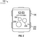
図2〜図7は、クラウン108(図1)の動作に応答する例示的なユーザインターフェースを図示する。図2は、デバイス100により表示できる例示的な画面200を示す。画面200は、例えば、デバイス100の電源が入るときに現れる又はデバイス100のタッチスクリーンディスプレイの電源が入るとき(スリープ状態からのスリープ解除を含む)に最初に現れる、ホーム画面であることができる。アイコン204、206、及び208を画面200に表示することができる。一部の実施形態において、アイコンは、デバイス100上で動作可能なアプリケーションに対応することができ、このことは、アプリケーションをデバイス100上にインストールできること及び/又はアプリケーションがデバイス100上のサービスとして実行できることを意味する。アイコン上のタッチ(例えば指タップ)は、対応するアプリケーションを起動させ、このことは、アプリケーションが、デバイス100のフォアグラウンドで動作し、タッチスクリーン106上に現れることを意味する。一部の実施形態において、アイコンは、テキスト文書、メディアアイテム、ウェブページ、電子メールメッセージ等に対応することができる。 2 to 7 illustrate an exemplary user interface in response to the operation of crown 108 (FIG. 1). FIG. 2 shows an
デバイス100は、アイコン204、206、及び208を、利用可能なアイコンの大きな集合からディスプレイ画面200上の表示のために選択することができ、これは、これらのアイコンが現時点のユーザ関連情報を有しているためである。例えば、アイコン204は、ユーザが着信メッセージを受信したばかりのメッセージングアプリケーションに対応することができ、アイコン206は、ユーザが近日中のカレンダアポイントメント項目を有するカレンダアプリケーションに対応することができる。 The
図3は、画面200(図2)が表示されている間にクラウン108の方向302の回転に応答してデバイス100により表示できる例示的な画面300を示す。画面300は、例えば、利用可能なアイコンの大きな集合からユーザにより前に選択されたユーザの好みのアイコンを示すことができる。また、画面300は、利用可能なアイコンの大きな集合からユーザのアイコンアクセス頻度に基づいてデバイス100により選択されたアイコンを含むことができる。画面300に表示された例示的なアイコン304、306、308、310、及び312は、デバイス100上で動作可能なアプリケーションにそれぞれ対応することができる。アイコン上のタッチ(例えば指タップ)は、対応するアプリケーションを起動させる。 FIG. 3 shows an
図4は、画面300(図3)が表示されている間にクラウン108の方向402の回転に応答してデバイス100により表示できる例示的な画面400を示す。画面400は、例えば、デバイス100上で動作可能なアプリケーションの全てに対応するアイコンを示すことができる。多数のアプリケーションがデバイス100上で動作可能であることができるため、画面400は、多数のアイコンを含むことができる。多くのアイコンが表示されるとき、タッチスクリーン106内に適合できるようにアイコンを適宜にサイズ決定することができ、又は、アイコンのうちの少なくとも代表的なもの若しくは所定の割合をタッチスクリーン106内に視認可能に適合できるようにサイズ決定することができる。 FIG. 4 shows an exemplary screen 400 that can be displayed by the
図5は、画面400(図4)が表示されている間にクラウン108の方向502の回転に応答してデバイス100により表示できる例示的な画面500を示す。画面500は、例えば、デバイス100上で動作可能なアプリケーションの部分集合に対応するアイコンを示すことができる。画面400と比べて少ないアイコンが画面500に表示されるため、画面500に表示されるアイコン、例えばアイコン504は、画面400上のアイコンの表示と比べて大きくなることができ、追加の忠実性を有することができる。例えば、画面500上のアイコンは、テキスト及び/又はイメージの形での印を有し、その対応するアプリケーションを特定することができる。示されるように、アイコン504は、文字「c」を用いて、対応するアプリケーションの名称が時計(clock)の「c」で始まることを助言する。一部の実施形態において、アイコン上のタッチ(例えば指タップ)は、対応するアプリケーションを起動させる。 FIG. 5 shows an
図6は、クラウン108の方向602の回転に応答してデバイス100により表示できる例示的な画面600を示す。画面600は、例えば、デバイス100上で動作可能なアプリケーションに対応し、画面500と比べて更に選び出された、アイコンの部分集合を示すことができる。
画面500(図5)と比べてもより少ないアイコンが画面600に表示されるため、表示されるアイコン(例えばアイコン604)は、画面200、300、400、及び500上のアイコンの表示と比べて更に拡大し、追加の忠実性を有することができる。例えば、アイコン604は、現在時刻を表示する時計の画像を有することができる。一部の実施形態において、アイコン上のタッチ(例えば指タップ)は、対応するアプリケーションを起動させる。FIG. 6 shows an
Since fewer icons are displayed on
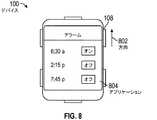
図7及び図8は、画面600(図6)が表示されている間にクラウン108の方向702の回転に応答してデバイス100により表示できる例示的な画面700及び800をそれぞれに示す。 7 and 8 respectively show
図7を参照すると、一部の実施形態において、画面600(図6)が表示されているときに方向702のクラウン回転に応答して画面700を表示することができる。単一のアイコン704が画面700に表示されるため、アイコン704は、前の画面と比べて追加の忠実性を有することができる。例えば、アイコン704は、現在時刻と共に日付情報を表示する時計の画像を有することができる。アイコン704上のタッチ(例えば指タップ)は、対応するアプリケーションを起動させる。 Referring to FIG. 7, in some embodiments, the
図8に転ずると、一部の実施形態において、画面600(図6)が表示されているときに方向802のクラウン回転に応答して画面800を表示することができる。画面800は、アイコン704(図7)に対応し、デバイス100のフォアグラウンドで動作する、アプリケーション804を示す。すなわち、アプリケーション804は、方向802のクラウン回転に応答して起動した。例示的なアプリケーション804は、アラーム機能を提供する時計アプリケーションであることができる。また、一部の実施形態において、画面800は、画面700(図7)が表示されているときに方向802のクラウン回転に応答して表示された状態となる。 Turning to FIG. 8, in some embodiments, the screen 800 can be displayed in response to the crown rotation in
上述された画面200〜700(図2〜図7)を軸に沿う情報平面として論理的に体系付けることができる。この体系付けの下では、所与のアイコン画面を、2つの軸(例えばx軸及びy軸)により定義され、その上に空間的に配置されたアイコンを有する、平面とみなすことができる。複数の平面をx軸又はy軸のうちの少なくとも一方に直交するz軸と呼ばれる第3の軸に沿って体系付けることができる。(z軸をx及びy軸により形成された平面に垂直とすることができる。) The
この論理的体系付けは、x軸902及びy軸904がデバイス100のタッチスクリーンの画面表面(図1)と同一平面の平面を形成し、z軸906が軸902及び904により形成されたx/y平面に垂直である、図9により図示される。平面908は、画面200(図2)に対応することができる。平面910は、画面300(図3)に対応することができる。平面912は、パーソナル電子デバイスの動作可能なアプリケーションを表すアイコンの集りを表すことができる。よって、平面912の異なる視点は、画面400〜700(図4〜図7)に対応することができる。平面908及び910を平面912に関係付けることができ、平面908及び910は、平面912上で利用可能なアイコンの部分集合をそれぞれ含むことができる。パーソナル電子デバイス上に表示されるべき特定の情報平面(すなわちアイコン画面)を、クラウンの回転等のクラウンの動作により選択することができる。すなわち、クラウンの動作を用いて、z軸906に交差する情報平面を横断することができ、又は所与の平面(例えば平面912)の代替的な視認を提供することができる。 In this logical systematization, the x-axis 902 and the y-
一部の実施形態において、クラウンの動作によりz軸の端(例えば、最上又は最下の平面)に到達すると、表示された情報(例えばアイコン画面)は、ラバーバンド効果を生じさせて端に到達したことを示す。ユーザがクラウンの入力により最下の情報平面に到達した状況を考慮されたい。ユーザが追加のクラウンの入力を同一方向に提供すると、表示されたアイコンの集りは、動作が止まるまでクラウンの動作に従って(可能な範囲で)縮む。クラウンの動作が止まると、表示されたアイコンは、画面上のアニメーションによりそれらの縮んだサイズからそれらの普通のサイズに戻り、それによりラバーバンディングの視覚効果を生じさせる。 In some embodiments, when the movement of the crown reaches the end of the z-axis (eg, the top or bottom plane), the displayed information (eg, the icon screen) creates a rubber band effect and reaches the end. Show that you did. Consider the situation where the user has reached the bottom information plane by entering the crown. When the user provides additional crown input in the same direction, the displayed collection of icons shrinks (to the extent possible) according to the crown's movement until it stops. When the crown stops moving, the displayed icons will revert from their shrunken size to their normal size with on-screen animations, thereby creating the visual effect of rubber banding.
この論理的体系付けの特筆すべき1つの利益は、異なる情報平面が互いにズームされた部分集合である必要がない(ズームされた部分集合であることはできるが)ことである。すなわち、例えば、平面908及び910は、パーソナル電子デバイス上で利用可能なアイコンのうちの全く異なるアイコンを収容できるが、異なる情報平面は、ユーザにより効率的にアクセスすることができる。 One notable benefit of this logical systematization is that different information planes do not have to be subsets zoomed to each other (although they can be zoomed subsets). That is, for example, the
代わりに、画面200〜700(図2〜図7)をパーソナル電子デバイスの異なるモード状態に属する情報の部分集合として論理的に体系付けることができる。この体系付けの下では、画面200及び300は、デバイスの第1及び第2のモード状態に対応することができ、画面400〜700は、例えば第3のモード状態に対応することができる。パーソナル電子デバイスは、クラウンの押込みに応答してモード状態を循環し、画面200又は300を第1及び第2のモード状態でそれぞれ表示することができる。代替的な実施形態において、モード状態は、ボタン110、112、又は114を用いて循環され得る。複数の画面が特定のモード状態(例えば第3のモード状態)内で利用可能であるとき、デバイスは、ある画面(例えば300)の表示から別の画面(例えば400)にクラウンの回転に基づいて切り替わることができる。ページングドット等の、画面上のユーザインターフェース要素を用いて、特定のモード状態内の表示のための追加画面の利用可能性を示すことができる。 Instead, screens 200-700 (FIGS. 2-7) can be logically organized as subsets of information belonging to different mode states of the personal electronic device. Under this systematization, the
この論理的配置は、図41により図示される。示されるように、平面4102と4104は、画面200(図2)と300(図3)にそれぞれ対応する。平面4106は、パーソナル電子デバイスの動作可能なアプリケーションを表すアイコンの集りを表すことができる。よって、平面4106の異なる視点は、画面400〜700(図4〜図7)に対応することができる。パーソナル電子デバイス上に表示されるべき特定の情報平面(すなわちアイコン画面)を、クラウンの押込み等のクラウンの動作により選択することができる。
2.速度に基づくクラウン制御This logical arrangement is illustrated by FIG. As shown,
2. 2. Speed-based crown control
デバイス100(図1)は、あるアイコン画面が別のアイコン画面と置き換えられるべきかを判定する際にクラウン108(図1)の回転角速度を考慮することができる。具体的には、デバイス100は、あるアイコン画面の表示を別のアイコン画面に変化させる前に、クラウン108に所定の角速度を上回る回転を要求することができる。このようにして、ユーザにより意図されないクラウン108の緩慢な回転がデバイス100に角度変位を示すクラウンの入力を受信させる一方、変位は、ユーザインターフェースの意図されない更新を生じさせるために十分な速度を有すると解釈される必要がない。この目的のための所定の角速度の選択は、現在表示されているアイコンの密度、現在表示されているアイコンの視覚的配置等の多数の要因に依存することができる。 The device 100 (FIG. 1) can take into account the rotational angular velocity of the crown 108 (FIG. 1) when determining whether one icon screen should be replaced by another icon screen. Specifically, the
一部の実施形態において、アイコン画面の間を切り替えるために必要となるクラウンの最小回転角速度は、クラウン108(図1)の瞬間角速度に直接対応し、このことは、デバイス100のユーザインターフェースが、本質的に、クラウン108が十分な角速度に到達したときに応答することを意味する。一部の実施形態において、アイコン画面の間の切替えに必要となるクラウン回転の最小角速度は、クラウン108の瞬間的な(「現在の」)角速度に基づくが、該角速度に直接等しくはない計算された速度である。これらの実施形態において、デバイス100は、数式1に従って時間T内の別々の瞬間に、計算されたクラウン(角)速度Vを維持することができる。
数式1において、VTは、時間Tでの計算されたクラウン速度(スピード及び方向)を表し、V(T−1)は、時間T−1での前の速度(スピード及び方向)を表し、ΔVCROWNは、時間Tでのクラウンの回転により加えられる力により生じた速度変化を表し、ΔVDRAGは、抗力による速度変化を表す。加えられる力は、ΔVCROWNにより反映され、クラウンの現在の回転角速度に依存することができる。よって、ΔVCROWNも、クラウンの現在角速度に依存することができる。このようにして、デバイス100は、クラウンの瞬間速度のみならず、複数の時間インターバルに亘るクラウンの動作の形でのユーザ入力に基づいて、それらのインターバルが細かく区分される場合でも、ユーザインターフェース相互作用を提供することができる。典型的に、ΔVCROWNの形でのユーザ入力がない場合、VTは、数式1に従ってΔVDRAGに基づいてゼロに近づく(ゼロになる)が、VTの符号は、クラウンの回転(ΔVCROWN)の形でのユーザ入力なしに変化しないことに留意されたい。In Equation 1, VT represents the calculated crown velocity at time T (speed and direction), V(T-1) represents the velocity (speed and direction) of the previous time T-1, ΔVCROWN represents the velocity change caused by the force applied by the rotation of the crown at timeT, and ΔV DRAG represents the velocity change due to the resistance force. The force applied isreflected by the ΔV CROWN and can depend on the current angular velocity of the crown. Therefore, the ΔVCROWN can also depend on the current angular velocity of the crown. In this way, the
典型的に、クラウンの回転角速度が大きいほど、ΔVCROWNの値が大きくなる。しかし、クラウンの回転角速度とΔVCROWNとの間の実際のマッピングは、所望のユーザインターフェース効果に応じて変動する場合がある。例えば、クラウンの回転角速度とΔVCROWNとの間で各種の線形又は非線形マッピングを用いることができる。別の例において、マッピングは、現在表示されているアイコンの数及び/又はアイコンの配置に依存することができる。Typically, the higher the angular velocity of the crown, the higher the value ofΔV CROWN. However, the actual mapping between the angular velocity of the crown and the ΔVCROWN may vary depending on the desired user interface effect. For example, various linear or non-linear mappings can be used between the angular velocity of the crown and the ΔVCROWN. In another example, the mapping can depend on the number of icons currently displayed and / or the placement of the icons.
また、ΔVDRAGは、各種の値を取ることができる。例えば、ΔVDRAGは、より大きな速度では、より大きな反対の速度変化(ΔVDRAG)を生じさせることができるように、クラウンの回転速度に依存することができる。別の例において、ΔVDRAGは定数値を有することができる。更に別の例において、ΔVDRAGは、現在表示されているアイコンの数及び/又は現在表示されているアイコンの配置に基づくことができる。ΔVCROWN及びΔVDRAGの上述された要件を望ましいユーザインターフェース効果を生じさせるように変化させることができることが理解されるべきである。Further, ΔVDRAG can take various values. For example, ΔVDRAG can depend on the rotational speed of the crown so that at higher velocities, a larger opposite velocity change (ΔVDRAG) can occur. In another example, ΔVDRAG can have a constant value. In yet another example, the ΔVDRAG can be based on the number of currently displayed icons and / or the arrangement of currently displayed icons. It should be understood that the above-mentioned requirements for ΔVCROWN and ΔVDRAG can be varied to produce the desired user interface effect.
数式1から分かるように、維持された速度(VT)は、ΔVCROWNがΔVDRAGよりも大きい限り増加し続けることができる。加えて、VTは、ΔVCROWNの入力が受信されないときでも非ゼロ値を有することができ、このことは、ユーザがクラウンを回転させなくてもユーザインターフェース画面が変化し続けることができることを意味する。このことが起きると、画面は、ユーザがクラウンの回転を止めたときの維持された速度及びΔVDRAG成分に基づいて変化を止めることができる。As can be seen from Equation 1, the rate maintained(V T) may be [Delta] VCROWN continue to increase as long as greater than [Delta] VDRAG. In addition, VT can have a non-zero value even when the input of the [Delta] VCROWN is not received, this means that the user can continue to change the user interface screen may not rotate the crown do. When this happens, the screen can stop the change based onthe maintained speed and the ΔV DRAG component when the user stops the rotation of the crown.
一部の実施形態において、クラウンが現在のユーザインターフェースの変化とは反対の回転方向に対応する方向に回転されるとき、V(T−1)成分をゼロ値にリセットすることができ、ユーザが、VTをオフセットするために十分な力を提供する必要なしに画面変化の方向を素早く変化させることを可能にする。In some embodiments, the V (T-1) component can be reset to a zero value when the crown is rotated in a direction corresponding to the direction of rotation opposite the current user interface change, allowing the user to do so. , it makes it possible to quickly change the direction of the screen changes without the need to provide sufficient force to offset the VT.
他の実施形態において、表示されたアイコンをナビゲートするためにクラウンの回転以外の物理的なクラウンの異なる状態が用いられる。
3.ユーザインターフェースの外観In other embodiments, different states of the physical crown other than the rotation of the crown are used to navigate the displayed icon.
3. 3. Appearance of user interface
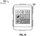
アイコンは、各種の外見を取ることができる。例えば、アイコンは、図10に示されるように矩形形状であることができる。別の例として、アイコンは、図2〜図7に示されるように円形であることができる。更に、アイコンは、各種の空間配置スキームを取ることができ、このことは、アイコンを視認不能なグリッドの行及び列に沿って配置できることを意味する。グリッドを対称又は非対称とすることができる。図10において、例えば対称グリッドが用いられる。図5において、例えば、第1の行に配置されたxアイコンと第2の行に沿って配置されたyアイコンとを有する非対称グリッドが用いられる。 The icons can have different appearances. For example, the icon can have a rectangular shape as shown in FIG. As another example, the icon can be circular as shown in FIGS. 2-7. In addition, the icons can take various spatial arrangement schemes, which means that the icons can be arranged along rows and columns of an invisible grid. The grid can be symmetrical or asymmetric. In FIG. 10, for example, a symmetric grid is used. In FIG. 5, for example, an asymmetric grid having an x icon arranged in the first row and a y icon arranged along the second row is used.
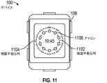
図11は、異なる直径の視認不能な円1102及び1104の周囲に沿って円形アイコンが位置合わせされる放射状のアイコン配置スキームを図示する。視認不能な円1102及び1104は、必要ではないが、同心状である。異なる視認不能な円に沿って配置された、アイコン1106等のアイコンは、異なるサイズを有することができる。示されるように、視認不能な円1102に沿って配置されたアイコンは、視認不能な円1104に沿って配置されたアイコンよりも、デバイス100の中心により近くにあり、かつ大きい。また、図11に図示されていないが、放射状配置のアイコンを2つよりも多い視認不能な円に沿って配置することができる。 FIG. 11 illustrates a radial icon placement scheme in which circular icons are aligned around
特定のアイコンが放射状のアイコン配置の中心から配置される距離は、異なる要因に依存することができる。例えば、距離をアイコンの使用頻度に比例させることができ、頻繁に使用されるアイコンは、より中心の近くにある。別の例として、距離は、アイコン(に対応するアプリケーション)のために着信通知が受信されたかに依存することができる。別の例として、距離をユーザにより定義することができ、或いは、デバイス100により決定(すなわち精選)することができる。 The distance at which a particular icon is placed from the center of the radial icon placement can depend on different factors. For example, the distance can be proportional to the frequency of use of the icon, and the frequently used icons are closer to the center. As another example, the distance can depend on whether an incoming call notification was received for the icon (corresponding application). As another example, the distance can be defined by the user or determined (ie, selected) by the
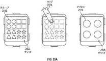
図25Aは、アイコングループ内へのアイコンの配置を図示する。グリッド2502上に、アイコングループ2512を含むアイコンの4つのグループが表示される。グループ2512上のタッチスクリーン位置2514での、指タップ等のタッチ入力に応答して、グループ2512内のアイコンを拡大形式で表示することができる。グリッド2506において、アイコン2516を含むグループ2512内のアイコンは、拡大形式で表示される。図25Bは、グループ内へのアプリケーション機能性の配置を図示する。グリッド2508上において、上で議論されたように、アイコングループ2512の4つのアイコンがグリッド2506上に表示される。(例えば指タップ2518による)アイコン2516の選択は、(アイコン2508に対応する)アプリケーション2510により提供される機能2520のグループを表示させることができる。 FIG. 25A illustrates the placement of icons within an icon group. Four groups of icons, including icon group 2512, are displayed on the
アイコングループのサイズ及び形状を系統的とすることができ、又は定義することができる。グリッド2502内のアイコングループ2512(図25A)等の定義されるアイコングループは、予め定義されたグループサイズ及びグループ形状を共有する。図42に示される系統的なアイコングループは、ユーザ定義されたグループサイズ及び/又はグループ形状であることができる。例えば、グリッド4202内のアイコングループ4204及び4206は、ユーザ定義された異なる形状及びサイズである。一部の実施形態において、系統的なアイコングループは、パーソナル電子デバイスの外部のコンピュータ上で動作し、パーソナル電子デバイス上にダウンロードされる、ソフトウェアを用いて定義される。 The size and shape of the icon group can be systematic or can be defined. Defined icon groups such as icon group 2512 (FIG. 25A) in
図30は、ローロデックスのページに類似してアイコンが配置されるアイコン配置スキームを図示する。例示的なローロデックス3002のページは、クラウンの回転に応答してフリップすることができる。例えば、ページ(アイコン)3004は、クラウンの回転に応答してページ(アイコン)3006上に下側へフリップすることができる。 FIG. 30 illustrates an icon placement scheme in which icons are placed similar to a Rolodex page. An exemplary Rolodex 3002 page can flip in response to a crown rotation. For example, the page (icon) 3004 can flip down onto the page (icon) 3006 in response to the rotation of the crown.
図31は、アイコンが旋回ダイヤルの外周に配置されるアイコン配置スキームを図示する。例示的な旋回ダイヤル3102は、クラウンの回転に応答して旋回することができる。例えば、方向3104のクラウンの回転は、ダイヤル3102を同一方向(3106)に旋回させる。また、クラウンの押込み(又は引出し)は、3102の列の数を変化させ、残り列のアイコンを拡大させること及び/又は忠実性を高めることを可能にすることができる。 FIG. 31 illustrates an icon placement scheme in which the icon is placed on the outer circumference of the swivel dial. The
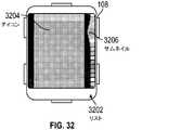
図32は、サムネイルリスト202の形でのアイコン配置スキームを図示する。例示的なサムネイルリスト3202内のアイコン3204は、対応するサムネイル3206を有することができる。サムネイルリスト3202のアイコンをクラウンの回転により横断することができる。アイコン3204等の特定のアイコンを対応するサムネイル3206にタッチすることにより表示のために直接選択することができる。 FIG. 32 illustrates an icon placement scheme in the form of thumbnail list 202.
図33は、アイコンが視認不能な球体又は多面体の表面と位置合わせされる配置スキームを図示する。視認不能な球体のフォアグラウンド表面の、アイコン3302等のアイコンを表示することができる。視認不能な球体の表面の反対側にあるアイコンは表示されない。視認不能な球体は、クラウンの回転及び/又はタッチスクリーンの入力に応答して回転することができ、それにより、表示される特定のアイコンを変化させる。 FIG. 33 illustrates an arrangement scheme in which the icon is aligned with the surface of an invisible sphere or polyhedron. It is possible to display an icon such as the
操作中、デバイス100(図1)は、上述されたアイコン配置スキームのうちの1つ以上を用いることができる。デバイス10により用いられる(単数又は複数)特定の配置をユーザにより選択することができ及び/又はシステムにより選択することができる。すなわち、ユーザは、表示のための1つ以上の好しい配置を特定することを許可され得る。また、デバイス上にインストールされたアプリケーションの合計数、頻繁にアクセスされたアイコンの数等の判定基準に基づいて、配置をデバイス100により選択することができる。 During operation, device 100 (FIG. 1) can use one or more of the icon placement schemes described above. The specific arrangement (s) used by the device 10 can be selected by the user and / or by the system. That is, the user may be allowed to identify one or more preferred arrangements for display. Further, the arrangement can be selected by the
更に、特定のアイコン配置スキームにおけるアイコンの特定の順序及び配置をユーザにより選択することができ、及び/又はシステムにより選択することができる。例えば、ユーザは、所与の画面におけるアイコンの位置を指定することを許可され得る。また、特定のアイコンの使用頻度、計算された関係性等の判定基準に基づいて、アイコン配置をデバイス100により決定(すなわち精選)することができる。
4.ユーザ入力に対する応答In addition, a particular order and arrangement of icons in a particular icon placement scheme can be selected by the user and / or by the system. For example, the user may be allowed to specify the position of the icon on a given screen. Further, the icon arrangement can be determined (that is, carefully selected) by the
4. Response to user input
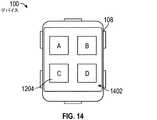
表示されたアイコンは、ユーザ入力に応答することができる。図12〜図14は、クラウンの回転に応答した表示されたアイコンの再配置を図示する。図12において、9つのアイコンは、3×3の対称グリッド1202に沿って表示される。アイコン1204は、グリッド1202の右上位置に表示される。図4〜図7に関して上で議論されたように、クラウン108の回転は、表示されたアイコンの数をデバイス100に低減させることができる。例えば、クラウン108の回転は、デバイス100に2×2グリッドを表示させることができ、それにより、表示されたアイコンの数が低減する。図13は、方向1302のクラウンの回転に応答した2×2グリッドへの例示的な遷移を図示する。示されるように、クラウンの回転1302に応答して、アイコン1204は、図12の3×3グリッドのその右上位置から、表示されるべき2×2グリッド内のその新しい位置に画面上で視認可能に平行移動される。具体的には、図14に示されるように、アイコン1204は、2×2グリッド1402の左下コーナに平行移動される。更に、グリッド1202からの遷移の後に2×2グリッド内に表示されたままに留まるべきアイコンは、拡大され2×2グリッド1402内に配置される。 The displayed icon can respond to user input. 12-14 illustrate the rearrangement of the displayed icons in response to the rotation of the crown. In FIG. 12, the nine icons are displayed along a 3x3
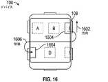
図15〜図17は、クラウンの回転に応答したアイコンの別の再配置を図示する。図15において、9つのアイコンは、3×3の対称グリッド1502に沿って表示される。アイコン1504は、グリッド1502の右上位置に表示される。図16に示されるように、クラウンの回転1602に応答して、アイコン1504は、2×2グリッド内の表示されるべきその新しい位置に平行移動される間に、グリッド1502(図15)内のその位置から画面外で平行移動される。言い換えれば、図16により図示される遷移中に、アイコン1504をデバイス100のタッチスクリーンの2つの離れた非接触位置に表示される2つの部分に分割することができる。より具体的には、アイコン1504が画面外で平行移動されるときにアイコン1504の一部分が右上コーナに部分的に表示されたままに留まる一方、1504の残り部分は、画面上で平行移動されるときに左下コーナに部分的に表示される。図17に示されるように、アイコン1504は、2×2グリッド1702の左下コーナに平行移動される。更に、グリッド1502からの遷移の後に2×2グリッド内に表示されたままに留まるべきアイコンは、拡大され2×2グリッド1702内に配置される。 FIGS. 15-17 illustrate another rearrangement of the icons in response to rotation of the crown. In FIG. 15, the nine icons are displayed along a 3x3
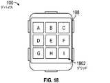
図18〜図20は、クラウンの回転に応答したアイコンの別の再配置を図示する。図18において、9つのアイコンは、3×3の対称グリッド1802に沿って表示される。図19に示されるように、クラウンの回転1902に応答して、グリッド1802(図18)の右及び下の境界に沿うアイコンは、残りのアイコンが拡大されている間に表示から除去される。残りのアイコンは、図20のグリッド2002内に示されるように拡大されて表示される。 18-20 illustrate another rearrangement of the icon in response to rotation of the crown. In FIG. 18, the nine icons are displayed along a 3x3
図12〜図20に示される例示的な画面において、左上コーナに表示された(すなわち「A」と印付けられた)アイコンが固定され、このことは、上述された遷移がアイコンを左上コーナから離れさせないことを意味することが留意されるべきである。しかし、以下で議論されるように、このようなアイコンをユーザ入力により固定解除することが可能である。 In the exemplary screens shown in FIGS. 12-20, the icon displayed in the upper left corner (ie marked "A") is fixed, which means that the transition described above causes the icon to move from the upper left corner. It should be noted that it means not to separate. However, as discussed below, such icons can be unpinned by user input.
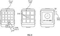
図21は、タッチスクリーン入力に応答したアイコンの再配置を図示する。示されるように、アイコン2106は、4×4グリッド2012の下端行に表示される。アイコン2106上の指タップ2104に応答して、3×3グリッド2108は、アイコン2106が中心に拡大された状態で表示される。特筆すべきは、「A」と印付けられたアイコンは、グリッド2012内に表示され、グリッド2108内にはもはや表示されない。図21は、クラウンの回転に応答した表示されたアイコンの更新も図示する。具体的には、クラウンの回転2110に応答して、アイコン2106は、更に拡大され、画面上に表示された唯一のアイコンになる。 FIG. 21 illustrates the rearrangement of icons in response to touch screen input. As shown, the
図22は、デバイス100の動作に応答したアイコンの再配置を図示する。デバイスの動作を1つ以上のセンサ、例えばジャイロスコープを用いて検出することができる。示されるように、各種のアイコンは、グリッド2202内に表示される。デバイス100の方向2204の傾動に応答して、表示されたアイコンは、方向2206に平行移動され、グリッド2208内に異なるアイコンの表示をもたらす。具体的には、デバイス100の左側方向2204の傾動に応答して、グリッド2202のアイコンは、左方向2206に平行移動する。一部の実施形態において、平行移動は、単一の行又は列が外に遷移し、単一の行又は列がディスプレイ上に遷移するように増加し得る。代わりに、完全に新しいセットのアイコンがディスプレイ上に遷移するときに、アイコンの全画面が外に遷移してもよい。 FIG. 22 illustrates the rearrangement of icons in response to the operation of
図23は、タッチスクリーン入力に応答したアイコンの外観の変化を図示する。示されるように、位置2304でのタッチに応答して、アイコン2306は拡大状態となる。特筆すべきは、アイコン2306は、位置2304に位置しておらず、むしろ、アイコン2306は、(その拡大されていない状態で)行2312に沿うタッチ位置2304の上方の行2310にある。このようにして、アイコンが拡大されるため、及びデバイス100にタッチしている場合によっては不透明な物体によりアイコンの視認が邪魔されないための両方で、アイコン2306のユーザ視認性が向上する。近くのタッチに応答して1つよりも多いアイコンを拡大することができることが留意されるべきである。複数のアイコンを、拡大されている各アイコンとタッチ位置との間の距離に反比例する異なる倍率レベルで拡大することができる。 FIG. 23 illustrates a change in the appearance of the icon in response to touch screen input. As shown, the icon 2306 is in the magnified state in response to the touch at position 2304. Notably, the icon 2306 is not located at position 2304, rather the icon 2306 is at
図40は、近くのアイコンの間の物理的な相互作用を説明するアイコン動作を図示する。示されるように、グリッド4002は、放射状配置に配置された多数のアイコンを含む。位置4010でのタッチ入力に応答して、多数のアイコンは、異なる倍率レベルで拡大される。特筆すべきは、アイコン4004の拡大は、アイコンが互いに視認を邪魔しないように、隣接するアイコン4006及び4008をアイコン4004から離れさせることができる。 FIG. 40 illustrates icon behavior that illustrates the physical interaction between nearby icons. As shown, the
図24は、アイコンとグリッド境界の間の相互作用を説明するアイコン動作を図示する。示されるように、多数のアイコンは、非対称グリッド2402に従って表示される。表示されたアイコンは、圧縮されていないアイコン2408を含む。右側方向2404のジェスチャの形でのタッチ入力に応答して、グリッド2402の左側のアイコンが拡大形式又は非拡大形式のいずれかでより優位に表示されるように、グリッド2402の右境界上のアイコンを圧縮されたアイコン2406に圧縮することができる。また、左側方向2406のタッチジェスチャに応答して、グリッド2402の右側のアイコンがより優位に表示されるように、グリッド2402の左境界上のアイコンを圧縮されたアイコン2412に圧縮することができる。上述された相互作用は、ユーザがアイコンを容易に視認及び選択することを可能にしながら、全て又は実質的に全てのアイコンが同時に表示されることを可能にする。この圧縮は、図示されないが対称グリッドで起き得ることに留意されたい。 FIG. 24 illustrates icon behavior that illustrates the interaction between the icon and the grid boundaries. As shown, a large number of icons are displayed according to the
図34は、グリッド境界と近くのアイコンとの間の相互作用を説明するアイコン動作を図示する。図34の放射状配置において、アイコンは、視認不能な内側円3402と視認不能な外側境界円3400との間に表示される。外側円3400をデバイス100のタッチスクリーンの物理的なサイズに基づいてサイズ決定することができる。内側円3402をデザイン及び/又はユーザの好みに基づいてサイズ決定することができる。内側円3402もクラウンの回転等のユーザ入力に基づいてサイズ決定することができる。内側円3402は、その面範囲内のタッチスクリーン入力に応答することができる。例えば、内側円3402の面範囲内で起きるタッチダウン及び次のタッチ動作を内側円3402のパンと解釈することができる。内側円3402がパンされるとき、アイコン3404及び3408等、内側円3402と外側円3400の間に配置されるアイコンを、内側円3402と外側円3400の間の利用可能な空間、表示されているアイコンの数、及び隣接するアイコンのサイズに基づいて、再びサイズ決定することができる。例えば、円3402の右側へのパンに応答して、アイコン3404は、サイズを大きくすることができ、アイコン3404の拡大は、アイコン3408のサイズを小さくさせることができる。 FIG. 34 illustrates icon behavior that illustrates the interaction between grid boundaries and nearby icons. In the radial arrangement of FIG. 34, the icon is displayed between the invisible
ユーザ入力がない場合、表示されたアイコンを、画面の焼付きを防ぐために画面上で移動するように、プログラムできることに留意されたい。また、アイコン配置は、マルチタッチジェスチャに応答することができる。例えば、デバイス100(図1)のタッチスクリーン上での2本指の下側へのジェスチャは、ステータスバー等のシステム情報の表示を生じさせることができる。別の例として、2本の指が反対方向に移動する2本指のジェスチャは、左利き又は右利きの使用のためにデバイス100(図1)を設定することができる。
5.追加機能Note that in the absence of user input, the displayed icon can be programmed to move on the screen to prevent screen burns. Also, the icon placement can respond to multi-touch gestures. For example, a gesture to the underside of two fingers on the touch screen of device 100 (FIG. 1) can result in the display of system information such as a status bar. As another example, a two-finger gesture in which the two fingers move in opposite directions can set the device 100 (FIG. 1) for left-handed or right-handed use.
5. Additional features
図2に戻ると、ホーム画面200は、アラート等のシステム生成情報を表示することができる。例えば、ホーム画面200は、ユーザが長時間座っており、運動が要求されることの注意を表示することができる。また、画面200は、ユーザが翌朝多忙なカレンダを有するため、休息の助言を表示することができる。また図3に戻ると、デバイス100がドックに結合されるときに画面300を表示することができる。 Returning to FIG. 2, the
図26は、グリッド内でのアイコンのユーザナビゲーションを助ける壁紙2602の使用を図示する。示されるように、グリッド2600は、比較的多数のアイコンを有する。クラウンの回転2604に応答して、グリッド2600のアイコンの部分集合は、拡大されグリッド2606内に表示される。加えて、部分集合の背景に表示された壁紙2602の対応する部分も表示され、このことは、例えば、グリッド2600の左上象限のアイコンがグリッド2606内に表示されるようになる場合、次いで壁紙2602の左上象限もグリッド2606で表示されることを意味する。また示されるように、左側方向2608のタッチジェスチャに応答して、デバイス100は、グリッド2600のアイコンの別の部分集合を表示することができる。例えば、グリッド2610において、グリッド2600の右上象限のアイコンは、壁紙2600の右上象限と一緒に表示される。このようにして、ユーザは、現在表示されているアイコンの集合とデバイス100上の表示のために利用可能なアイコンの全体との間の関係を決定することができる。 FIG. 26 illustrates the use of
図27は、配置が情報、例えば現在時刻情報をユーザに提供する、アイコンの例示的な配置を図示する。配置をクラウンの動作に応答して表示することができる。また、所定のユーザ入力非活動期間の後に配置を表示することができる。例えば、小さなサイズのアイコンを用いて現在時刻を示す画面2702を、所定のユーザ入力非活動期間の後に表示することができる。更に、クラウンの回転に応答して、画面2702は、画面2704及び2706を通じて、アイコンのグリッドを示す画面2708に遷移することができる。 FIG. 27 illustrates an exemplary arrangement of icons, the arrangement providing information, eg, current time information, to the user. The placement can be displayed in response to the movement of the crown. Also, the placement can be displayed after a predetermined user input inactivity period. For example, a
図28は、表示されたアイコンの色及び/又は強度が着信情報に応答して変化できる、アイコン(グリッド2802)の例示的な配置を図示する。例えば、メッセージングアプリケーションに対応するアイコン2804は、新しいメッセージが到着するときに点滅又は発光することができる。一部の実施形態において、点滅又は発光は、アプリケーションストアにおけるアプリケーションの人気、又はユーザのより大きなエコシステムにおけるアプリケーションの使用頻度に対応することができる。更に、グリッド2802のアイコンは、インストールされているそれらのアプリケーションを越えて、アプリケーションストアにおいて利用可能なアプリケーションのより大きな集合を表すアイコンを示すことができる。 FIG. 28 illustrates an exemplary arrangement of icons (grid 2802) in which the color and / or intensity of the displayed icon can change in response to incoming information. For example, the
図29は、コンテキスト依存メッセージの例示的な表示を図示する。ユーザによるクラウン108のタッチの検出に応答してコンテキスト依存メッセージを表示することができる。コンテキスト依存メッセージは、デバイス100のフォアグラウンドにおいて現在動作しているアプリケーションに応じて異なる機能を取ることができる、クラウン108の現在の機能性を示す。例えば、音楽アプリケーションがデバイス100のフォアグラウンドにおいて動作しているとき、クラウン108上のタッチは、クラウン108の現在の機能性が音量制御であることをユーザに示すことができる音量インジケータの形でのコンテキスト依存メッセージ2902の表示をもたらすことができる。 FIG. 29 illustrates an exemplary display of context-dependent messages. A context-dependent message can be displayed in response to the user's detection of a touch on the
図35は、上述されたユーザインターフェース技術を提供する例示的なプロセス3500を描写する。ブロック3510において、クラウンの動作及び/又はクラウンのタッチに基づく入力が受信される。クラウンの動作は、回転、押込み、及び/又は引出しであることができる。ブロック3520において、受信された入力により表されるクラウンの動作の種類に基づいて決定が行われる。受信された入力がクラウンの回転を表す場合、処理はブロック3530に進む。受信された入力がクラウンの押込み又は引出しを表す場合、処理はブロック3550に進む。受信された入力が、(回転又は押込み/引出しを伴わない)クラウンのタッチを表すとき、処理はブロック3560に進む。ブロック3530において、現在表示されている画面及びz軸906(図9)に沿うその対応する位置を決定することができる。加えて、z軸906に沿う隣接する情報レベルを決定することができる。隣接するレベルを、受信された入力により表されるクラウンの回転方向に基づいて決定することができる。図4〜図7のそれぞれにより図示されるアイコン等のアイコンの対応するグリッドを表示することができる。ブロック3550において、図2の例示的な画面200等のホーム画面を表示することができる。代替案において、図3の例示的な画面300等のユーザの好みの画面を表示することができる。ブロック3560において、図29の例示的なコンテキスト依存メッセージ2902等のコンテキスト依存メッセージを表示することができる。 FIG. 35 illustrates an
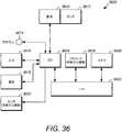
図36は、上述されたユーザインターフェース技術を提供する例示的なコンピューティングシステム3600を描写する。一部の実施形態において、コンピューティングシステム3600は、デバイス100を形成することができる。示されるように、コンピューティングシステム3600は、I/Oセクション3604と、1つ以上のコンピュータプロセッサ3606と、メモリセクション3608とを1つに接続するバス3602を有することができる。メモリセクション3608は、プロセス3500(図35)を含む上述された技術を実施するコンピュータ実行可能命令及び/又はデータを収容することができる。I/Oセクション3604をタッチ感知部品3612を有することができるディスプレイ3610に接続することができる。I/Oセクション3604をクラウン3614に接続することができる。I/Oセクション3604をボタンを含み得る入力デバイス3616に接続することができる。I/Oセクション3604を、例えば、Wi−Fi(登録商標)、Bluetooth(登録商標)、及び/又はセルラー機能を提供できる通信ユニット3618に接続することができる。I/Oセクション3604を、ジャイロスコープ、GPSセンサ、光センサ、ジャイロスコープ、加速度計、及び/又はそれらの組合せを有することができる、センサパック3620に接続することができる。上述された部品の1つ以上がオンチップシステムの部分であり得ることに留意されたい。 FIG. 36 illustrates an
コンピューティングシステム3600のメモリセクション3608は、1つ以上のコンピュータプロセッサ3606により実行されると、例えば、コンピュータプロセッサにプロセス3500(図35)を含む上述されたユーザインターフェース技術を実行させることができる、コンピュータ実行可能命令を記憶する非一時的なコンピュータ可読記憶媒体であることができる。コンピュータベースシステム、プロセッサを含むシステム、又は、命令実行システム、装置、若しくはデバイスから命令をフェッチし、命令を実行することができる他のシステム等の、命令実行システム、装置、若しくはデバイスによる使用又は関連して、コンピュータ実行可能命令を任意の非一時的なコンピュータ可読記憶媒体内で記憶及び/又は転送することもできる。この文書の目的のために、「非一時的なコンピュータ可読記憶媒体」は、命令実行システム、装置、若しくはデバイスによる使用又は関連してコンピュータ実行可能命令を収容又は記憶できる任意の媒体であることができる。非一時的なコンピュータ可読記憶媒体としては、非限定的に、磁気、光、及び/又は半導体ストレージを挙げることができる。このようなストレージの例としては、磁気ディスク、CD、DVD、若しくはBlu−ray技術に基づく光ディスク、並びにRAM、ROM、EPROM、フラッシュメモリ、及びソリッドステートメモリを挙げることができる。 The
コンピューティングシステム3600は、図36の部品及び構成に限定されないが、複数の構成において他の又は追加の部品を含むことができる。一部の実施形態において、システム3600は、図37に示されるようなタブレットであるパーソナル電子デバイス3700を形成することができる。一部の実施形態において、コンピューティングシステム3600は、図38に示されるような移動電話であるパーソナル電子デバイス3800を形成することができる。一部の実施形態において、コンピューティングシステム3600は、図39に示されるような携帯式音楽デバイスであるパーソナル電子デバイス3900を形成することができる。 The
本開示及び例が添付図面を参照して完全に記述されてきたが、各種の変更及び修正が当業者には明らかとなることが留意されるべきである。このような変更及び修正は、添付の特許請求の範囲により定義されるように本開示及び例の範囲内に含まれることが理解されるべきである。 Although the present disclosure and examples have been fully described with reference to the accompanying drawings, it should be noted that various changes and amendments will be apparent to those skilled in the art. It should be understood that such changes and amendments are included within the scope of the present disclosure and examples as defined by the appended claims.
Claims (67)
Translated fromJapanese第1の複数のアイコンをウェアラブル電子デバイスのタッチ感知ディスプレイに表示することと、
前記ウェアラブル電子デバイスの物理的なクラウンの動作に基づく入力を受信することと、
前記受信された入力に応答して、前記タッチ感知ディスプレイにおいて前記第1の複数のアイコンを第2の複数のアイコンと置き換えることと、
を含み、前記第2の複数のアイコンが前記第1の複数のアイコンの部分集合である、方法。The method performed by the computer
Displaying the first multiple icons on the touch-sensitive display of a wearable electronic device,
Receiving input based on the movement of the physical crown of the wearable electronic device,
Replacing the first plurality of icons with the second plurality of icons in the touch-sensitive display in response to the received input.
The method, wherein the second plurality of icons is a subset of the first plurality of icons.
前記第2の複数のアイコンが表示されるときに、前記アプリケーションに関する情報と共に前記第2のアイコンを表示することと、
前記第1の複数のアイコンが表示されるときに、前記アプリケーションに関する異なる情報と共に前記第1のアイコンを表示することと、
を更に含む、請求項1に記載の方法。The first icon of the first plurality of icons is associated with the application, the second icon of the second plurality of icons is associated with the same application, and the method.
Displaying the second icon along with information about the application when the second plurality of icons are displayed.
Displaying the first icon with different information about the application when the first plurality of icons are displayed.
The method according to claim 1, further comprising.
前記物理的なクラウンの第2の動作に基づく第2の入力を受信することと、
前記第2の受信された入力に応答して、前記タッチ感知ディスプレイにおいて前記第2の複数のアイコンを前記第1の複数のアイコンと置き換えることと、
を更に含む、請求項1に記載の方法。The received input is the first received input, and the method is:
Receiving a second input based on the second movement of the physical crown,
Replacing the second plurality of icons with the first plurality of icons on the touch-sensitive display in response to the second received input.
The method according to claim 1, further comprising.
前記物理的なクラウンの第2の動作に基づく第2の入力を受信することであって、前記第2の動作は前記第1の回転方向の回転である、ことと、
前記第2の受信された入力に応答して、前記第2の複数のアイコンの前記表示を第3の複数のアイコンと置き換えることと、
を更に含み、前記第3の複数のアイコンが前記第2の複数のアイコンの部分集合である、請求項1に記載の方法。The received input is the first received input, and the method is:
Receiving a second input based on the second movement of the physical crown, the second movement being rotation in the first rotation direction.
Replacing the display of the second plurality of icons with the third plurality of icons in response to the second received input.
The method according to claim 1, wherein the third plurality of icons is a subset of the second plurality of icons.
前記物理的なクラウンの第2の動作に基づく第2の入力を受信することであって、前記第2の動作は前記第1の方向の回転である、ことと、
前記第2の受信された入力に応答して、前記第2の複数のアイコンのうちのアイコンと関連付けられたアプリケーションを起動することと、
を更に含む、請求項1に記載の方法。The received input is the first received input, and the method is:
Receiving a second input based on the second movement of the physical crown, the second movement being rotation in the first direction.
In response to the second received input, launching the application associated with the icon of the second plurality of icons.
The method according to claim 1, further comprising.
表示されたアイコンに対応するアプリケーションの活動状態を表す情報を受信することと、
前記受信された情報に応答して、前記表示されたアイコンの外観を変更することと、
を更に含む、請求項1に記載の方法。The above method
Receiving information that indicates the activity status of the application corresponding to the displayed icon,
To change the appearance of the displayed icon in response to the received information,
The method according to claim 1, further comprising.
前記第1の複数のアイコンのうちのアイコンを、前記タッチ感知ディスプレイの第1の位置から、前記タッチ感知ディスプレイの第2の位置に平行移動させることを含み、
前記アイコンの全体が、前記平行移動させている間に前記タッチ感知ディスプレイに表示される、請求項18に記載の方法。The replacement of the first plurality of icons with the second plurality of icons in the display
The inclusion of translating the icon of the first plurality of icons from the first position of the touch-sensitive display to the second position of the touch-sensitive display.
18. The method of claim 18, wherein the entire icon is displayed on the touch-sensitive display while being translated.
前記タッチ感知ディスプレイの第1の位置に、前記第1の複数のアイコンのうちのアイコンの一部分のみを表示することと、
前記アイコンの残り部分を前記タッチ感知ディスプレイの第2の位置に表示することと、
を含み、前記第1の位置と前記第2の位置が離れている、請求項18に記載の方法。The replacement of the first plurality of icons with the second plurality of icons in the display
Displaying only a part of the icon among the first plurality of icons at the first position of the touch-sensitive display.
Displaying the rest of the icon in a second position on the touch-sensitive display
18. The method of claim 18, wherein the first position and the second position are separated from each other.
前記検出された力に基づいて前記第1の表示を置き換えることと、
を更に含む、請求項1に記載の方法。Detecting the force applied to the touch-sensitive display and
Replacing the first indication based on the detected force,
The method according to claim 1, further comprising.
第1の複数のアイコンをウェアラブル電子デバイスのタッチ感知ディスプレイに表示させ、
前記ウェアラブル電子デバイスの物理的なクラウンの動作に基づく入力を受信させ、
前記受信された入力に応答して、前記タッチ感知ディスプレイにおいて前記第1の複数のアイコンを第2の複数のアイコンと置き換えさせ、
前記第2の複数のアイコンが前記第1の複数のアイコンの部分集合である、非一時的なコンピュータ可読記憶媒体。A non-temporary computer-readable storage medium with computer-executable instructions that, when executed by one or more computer processors, to the one or more computer processors.
The first plurality of icons are displayed on the touch-sensitive display of the wearable electronic device.
An input based on the movement of the physical crown of the wearable electronic device is received, and the input is received.
In response to the received input, the first plurality of icons are replaced with the second plurality of icons on the touch-sensitive display.
A non-temporary computer-readable storage medium in which the second plurality of icons is a subset of the first plurality of icons.
前記第2の複数のアイコンが表示されるときに、前記アプリケーションに関する情報と共に前記第2のアイコンを表示し、
前記第1の複数のアイコンが表示されるときに、前記アプリケーションに関する異なる情報と共に前記第1のアイコンを表示する、
コンピュータ実行可能命令を更に備える、請求項23に記載の非一時的なコンピュータ可読記憶媒体。The first icon of the first plurality of icons is associated with the application, the second icon of the second plurality of icons is associated with the same application, and non-temporary computer readable storage. The medium is
When the second plurality of icons are displayed, the second icon is displayed together with information about the application.
When the first plurality of icons are displayed, the first icon is displayed with different information about the application.
23. The non-transitory computer-readable storage medium of claim 23, further comprising computer executable instructions.
前記物理的なクラウンの第2の動作に基づく第2の入力を受信し、
前記第2の受信された入力に応答して、前記タッチ感知ディスプレイにおいて前記第2の複数のアイコンを前記第1の複数のアイコンと置き換える、
命令を更に備える、請求項23に記載の非一時的なコンピュータ可読記憶媒体。The received input is the first received input and the computer executable instruction is:
Receives a second input based on the second movement of the physical crown,
In response to the second received input, the touch-sensitive display replaces the second plurality of icons with the first plurality of icons.
23. The non-temporary computer-readable storage medium of claim 23, further comprising instructions.
前記第1の回転方向の回転である、前記物理的なクラウンの第2の動作に基づく第2の入力を受信し、
前記第2の受信された入力に応答して、前記第2の複数のアイコンの前記表示を第3の複数のアイコンと置き換える、
コンピュータ実行可能命令を更に備え、前記第3の複数のアイコンが前記第2の複数のアイコンの部分集合である、請求項23に記載の非一時的なコンピュータ可読記憶媒体。The received input is the first received input, and the non-temporary computer-readable storage medium is the non-temporary computer-readable storage medium.
Receives a second input based on the second movement of the physical crown, which is the rotation in the first rotation direction.
In response to the second received input, the display of the second plurality of icons is replaced with the third plurality of icons.
23. The non-temporary computer-readable storage medium of claim 23, further comprising computer executable instructions, wherein the third icon is a subset of the second icon.
前記第1の方向の回転である、前記物理的なクラウンの第2の動作に基づく第2の入力を受信し、
前記第2の受信された入力に応答して、前記第2の複数のアイコンのうちの1つのアイコンと関連付けられたアプリケーションを起動する、
コンピュータ実行可能命令を更に備える、請求項23に記載の非一時的なコンピュータ可読記憶媒体。The received input is the first received input, and the non-temporary computer-readable storage medium is the non-temporary computer-readable storage medium.
Receives a second input based on the second movement of the physical crown, which is the rotation in the first direction.
In response to the second received input, launching an application associated with one of the second plurality of icons.
23. The non-transitory computer-readable storage medium of claim 23, further comprising computer executable instructions.
前記受信された情報に応答して、前記表示されたアイコンの外観を変更する、
コンピュータ実行可能命令を更に備える、請求項23に記載の非一時的なコンピュータ可読記憶媒体。Receives information that indicates the activity status of the application corresponding to the displayed icon,
Changing the appearance of the displayed icon in response to the received information,
23. The non-transitory computer-readable storage medium of claim 23, further comprising computer executable instructions.
前記第1の複数のアイコンのうちの1つのアイコンを、前記タッチ感知ディスプレイの第1の位置から、前記タッチ感知ディスプレイの第2の位置に平行移動させることを含み、
前記1つのアイコンの全体が、前記平行移動させている間に前記タッチ感知ディスプレイに表示される、請求項40に記載の非一時的なコンピュータ可読記憶媒体。Replacing the display of the first plurality of icons with the second plurality of icons can be used.
The inclusion of translating one of the first plurality of icons from a first position on the touch-sensitive display to a second position on the touch-sensitive display.
The non-temporary computer-readable storage medium of claim 40, wherein the entire icon is displayed on the touch-sensitive display while it is being translated.
前記タッチ感知ディスプレイの第1の位置に、前記第1の複数のアイコンのうちの1つのアイコンの一部分のみを表示することと、
前記1つのアイコンの残り部分を前記タッチ感知ディスプレイの第2の位置に表示することと、
を含み、前記第1の位置と前記第2の位置が離れている、請求項40に記載の非一時的なコンピュータ可読記憶媒体。Replacing the display of the first plurality of icons with the second plurality of icons can be used.
Displaying only a part of one of the first plurality of icons at the first position of the touch-sensitive display.
Displaying the rest of the one icon in a second position on the touch-sensitive display
40. The non-temporary computer-readable storage medium according to claim 40, wherein the first position and the second position are separated from each other.
前記第1の表示を前記検出された力に基づいて置き換える、コンピュータ実行可能命令を更に備える、請求項23に記載の非一時的なコンピュータ可読記憶媒体。Detects the force applied to the touch-sensitive display and
23. The non-transitory computer-readable storage medium of claim 23, further comprising computer-executable instructions that replace the first indication based on the detected force.
1つ以上のプロセッサと、
前記1つ以上のプロセッサに動作可能に結合された物理的なクラウンと、
前記1つ以上のプロセッサに動作可能に結合されたタッチ感知ディスプレイと、
を備え、前記1つ以上のプロセッサが、
第1の複数のアイコンをウェアラブル電子デバイスのタッチ感知ディスプレイに表示し、
前記ウェアラブル電子デバイスの物理的なクラウンの動作に基づく入力を受信し、
前記受信された入力に応答して、前記タッチ感知ディスプレイにおいて前記第1の複数のアイコンを第2の複数のアイコンと置き換える、
ように構成され、前記第2の複数のアイコンが前記第1の複数のアイコンの部分集合である、電子デバイス。It ’s an electronic device,
With one or more processors
With a physical crown operably coupled to the one or more processors,
A touch-sensitive display operably coupled to the one or more processors,
The one or more processors mentioned above
The first multiple icons are displayed on the touch-sensitive display of the wearable electronic device.
Receives an input based on the movement of the physical crown of the wearable electronic device and
In response to the received input, the first plurality of icons are replaced with the second plurality of icons on the touch-sensitive display.
An electronic device configured as such, wherein the second plurality of icons is a subset of the first plurality of icons.
前記第2の複数のアイコンが表示されるときに、前記アプリケーションに関する情報と共に前記第2のアイコンを表示し、
前記第1の複数のアイコンが表示されるときに、前記アプリケーションに関する異なる情報と共に前記第1のアイコンを表示する、
ように更に構成される、請求項45に記載のデバイス。The first icon of the first plurality of icons is associated with the application, the second icon of the second plurality of icons is associated with the same application, and the one or more processors. ,
When the second plurality of icons are displayed, the second icon is displayed together with information about the application.
When the first plurality of icons are displayed, the first icon is displayed with different information about the application.
45. The device of claim 45, further configured as such.
前記物理的なクラウンの第2の動作に基づく第2の入力を受信し、
前記第2の受信された入力に応答して、前記タッチ感知ディスプレイにおいて前記第2の複数のアイコンを前記第1の複数のアイコンと置き換える、
ように更に構成される、請求項45に記載のデバイス。The received input is the first received input, and the one or more processors.
Receives a second input based on the second movement of the physical crown,
In response to the second received input, the touch-sensitive display replaces the second plurality of icons with the first plurality of icons.
45. The device of claim 45, further configured as such.
前記第1の回転方向の回転である、前記物理的なクラウンの第2の動作に基づく第2の入力を受信し、
前記第2の受信された入力に応答して、前記第2の複数のアイコンの前記表示を第3の複数のアイコンと置き換える、
ように更に構成され、前記第3の複数のアイコンが前記第2の複数のアイコンの部分集合である、請求項45に記載のデバイス。The received input is the first received input, and the one or more processors.
Receives a second input based on the second movement of the physical crown, which is the rotation in the first rotation direction.
In response to the second received input, the display of the second plurality of icons is replaced with the third plurality of icons.
45. The device of claim 45, wherein the third plurality of icons is a subset of the second plurality of icons.
前記第1の方向の回転である、前記物理的なクラウンの第2の動作に基づく第2の入力を受信し、
前記第2の受信された入力に応答して、前記第2の複数のアイコンのうちの1つのアイコンと関連付けられたアプリケーションを起動する、
ように更に構成される、請求項45に記載のデバイス。The received input is the first received input, and the one or more processors.
Receives a second input based on the second movement of the physical crown, which is the rotation in the first direction.
In response to the second received input, launching an application associated with one of the second plurality of icons.
45. The device of claim 45, further configured as such.
表示されたアイコンに対応するアプリケーションの活動状態を表す情報を受信し、
前記受信された情報に応答して、前記表示されたアイコンの外観を変更する、
ように更に構成される、請求項45に記載のデバイス。The one or more processors mentioned above
Receives information that indicates the activity status of the application corresponding to the displayed icon,
Changing the appearance of the displayed icon in response to the received information,
45. The device of claim 45, further configured as such.
前記第1の複数のアイコンのうちの1つのアイコンを、前記タッチ感知ディスプレイの第1の位置から、前記タッチ感知ディスプレイの第2の位置に平行移動させることを含み、
前記1つのアイコンの全体が、前記平行移動させている間に前記タッチ感知ディスプレイに表示される、請求項62に記載のデバイス。Replacing the display of the first plurality of icons with the second plurality of icons can be used.
The inclusion of translating one of the first plurality of icons from a first position on the touch-sensitive display to a second position on the touch-sensitive display.
62. The device of claim 62, wherein the entire icon is displayed on the touch-sensitive display while being translated.
前記タッチ感知ディスプレイの第1の位置に、前記第1の複数のアイコンのうちの1つのアイコンの一部分のみを表示することと、
前記1つのアイコンの残り部分を前記タッチ感知ディスプレイの第2の位置に表示することと、
を含み、前記第1の位置と前記第2の位置が離れている、請求項62に記載のデバイス。Replacing the display of the first plurality of icons with the second plurality of icons can be used.
Displaying only a part of one of the first plurality of icons at the first position of the touch-sensitive display.
Displaying the rest of the one icon in a second position on the touch-sensitive display
62. The device of claim 62, wherein the first position and the second position are separated from each other.
Priority Applications (2)
| Application Number | Priority Date | Filing Date | Title |
|---|---|---|---|
| JP2023015606AJP7532568B2 (en) | 2013-09-03 | 2023-02-03 | User interface for manipulating user interface objects |
| JP2024124777AJP2024156818A (en) | 2013-09-03 | 2024-07-31 | User interface for manipulating user interface objects |
Applications Claiming Priority (11)
| Application Number | Priority Date | Filing Date | Title |
|---|---|---|---|
| US201361959851P | 2013-09-03 | 2013-09-03 | |
| US201361873359P | 2013-09-03 | 2013-09-03 | |
| US201361873360P | 2013-09-03 | 2013-09-03 | |
| US201361873356P | 2013-09-03 | 2013-09-03 | |
| US61/873,356 | 2013-09-03 | ||
| US61/959,851 | 2013-09-03 | ||
| US61/873,360 | 2013-09-03 | ||
| US61/873,359 | 2013-09-03 | ||
| US201414476657A | 2014-09-03 | 2014-09-03 | |
| US14/476,657 | 2014-09-03 | ||
| JP2019138053AJP6924802B2 (en) | 2013-09-03 | 2019-07-26 | User interface User interface for manipulating objects |
Related Parent Applications (1)
| Application Number | Title | Priority Date | Filing Date |
|---|---|---|---|
| JP2019138053ADivisionJP6924802B2 (en) | 2013-09-03 | 2019-07-26 | User interface User interface for manipulating objects |
Related Child Applications (1)
| Application Number | Title | Priority Date | Filing Date |
|---|---|---|---|
| JP2023015606ADivisionJP7532568B2 (en) | 2013-09-03 | 2023-02-03 | User interface for manipulating user interface objects |
Publications (2)
| Publication Number | Publication Date |
|---|---|
| JP2021182426Atrue JP2021182426A (en) | 2021-11-25 |
| JP7223081B2 JP7223081B2 (en) | 2023-02-15 |
Family
ID=51589515
Family Applications (12)
| Application Number | Title | Priority Date | Filing Date |
|---|---|---|---|
| JP2016537947AActiveJP6170250B2 (en) | 2013-09-03 | 2014-09-03 | Manipulating user interface objects in the user interface |
| JP2016537946AActiveJP6333387B2 (en) | 2013-09-03 | 2014-09-03 | User interface for manipulating user interface objects |
| JP2016537945AActiveJP6397918B2 (en) | 2013-09-03 | 2014-09-03 | Crown input for wearable electronics |
| JP2018083313AActiveJP6564493B2 (en) | 2013-09-03 | 2018-04-24 | User interface for manipulating user interface objects |
| JP2018090084AActiveJP6547039B2 (en) | 2013-09-03 | 2018-05-08 | Crown input for wearable electronics |
| JP2019116590AActiveJP7128153B2 (en) | 2013-09-03 | 2019-06-24 | Crown input for wearable electronics |
| JP2019138053AActiveJP6924802B2 (en) | 2013-09-03 | 2019-07-26 | User interface User interface for manipulating objects |
| JP2021111630AActiveJP7471262B2 (en) | 2013-09-03 | 2021-07-05 | Crown Input for Wearable Electronics |
| JP2021126843AActiveJP7223081B2 (en) | 2013-09-03 | 2021-08-02 | User interface for manipulating user interface objects |
| JP2023015606AActiveJP7532568B2 (en) | 2013-09-03 | 2023-02-03 | User interface for manipulating user interface objects |
| JP2023095734AActiveJP7595114B2 (en) | 2013-09-03 | 2023-06-09 | Crown Input for Wearable Electronics |
| JP2024124777APendingJP2024156818A (en) | 2013-09-03 | 2024-07-31 | User interface for manipulating user interface objects |
Family Applications Before (8)
| Application Number | Title | Priority Date | Filing Date |
|---|---|---|---|
| JP2016537947AActiveJP6170250B2 (en) | 2013-09-03 | 2014-09-03 | Manipulating user interface objects in the user interface |
| JP2016537946AActiveJP6333387B2 (en) | 2013-09-03 | 2014-09-03 | User interface for manipulating user interface objects |
| JP2016537945AActiveJP6397918B2 (en) | 2013-09-03 | 2014-09-03 | Crown input for wearable electronics |
| JP2018083313AActiveJP6564493B2 (en) | 2013-09-03 | 2018-04-24 | User interface for manipulating user interface objects |
| JP2018090084AActiveJP6547039B2 (en) | 2013-09-03 | 2018-05-08 | Crown input for wearable electronics |
| JP2019116590AActiveJP7128153B2 (en) | 2013-09-03 | 2019-06-24 | Crown input for wearable electronics |
| JP2019138053AActiveJP6924802B2 (en) | 2013-09-03 | 2019-07-26 | User interface User interface for manipulating objects |
| JP2021111630AActiveJP7471262B2 (en) | 2013-09-03 | 2021-07-05 | Crown Input for Wearable Electronics |
Family Applications After (3)
| Application Number | Title | Priority Date | Filing Date |
|---|---|---|---|
| JP2023015606AActiveJP7532568B2 (en) | 2013-09-03 | 2023-02-03 | User interface for manipulating user interface objects |
| JP2023095734AActiveJP7595114B2 (en) | 2013-09-03 | 2023-06-09 | Crown Input for Wearable Electronics |
| JP2024124777APendingJP2024156818A (en) | 2013-09-03 | 2024-07-31 | User interface for manipulating user interface objects |
Country Status (5)
| Country | Link |
|---|---|
| JP (12) | JP6170250B2 (en) |
| KR (12) | KR102111452B1 (en) |
| AU (12) | AU2014315319B2 (en) |
| DK (1) | DK179231B1 (en) |
| WO (3) | WO2015034960A1 (en) |
Families Citing this family (107)
| Publication number | Priority date | Publication date | Assignee | Title |
|---|---|---|---|---|
| US9100493B1 (en)* | 2011-07-18 | 2015-08-04 | Andrew H B Zhou | Wearable personal digital device for facilitating mobile device payments and personal use |
| TWI439960B (en) | 2010-04-07 | 2014-06-01 | Apple Inc | Avatar editing environment |
| US9753436B2 (en) | 2013-06-11 | 2017-09-05 | Apple Inc. | Rotary input mechanism for an electronic device |
| EP3014400B1 (en) | 2013-08-09 | 2020-06-03 | Apple Inc. | Tactile switch for an electronic device |
| WO2015088492A1 (en) | 2013-12-10 | 2015-06-18 | Apple Inc. | Input friction mechanism for rotary inputs of electronic devices |
| US10048802B2 (en) | 2014-02-12 | 2018-08-14 | Apple Inc. | Rejection of false turns of rotary inputs for electronic devices |
| KR102511376B1 (en) | 2014-08-02 | 2023-03-17 | 애플 인크. | Context-specific user interfaces |
| US10452253B2 (en) | 2014-08-15 | 2019-10-22 | Apple Inc. | Weather user interface |
| KR20250021617A (en) | 2014-09-02 | 2025-02-13 | 애플 인크. | Wearable electronic device |
| US10145712B2 (en) | 2014-09-09 | 2018-12-04 | Apple Inc. | Optical encoder including diffuser members |
| US9829350B2 (en) | 2014-09-09 | 2017-11-28 | Apple Inc. | Magnetically coupled optical encoder |
| US9651405B1 (en) | 2015-03-06 | 2017-05-16 | Apple Inc. | Dynamic adjustment of a sampling rate for an optical encoder |
| WO2016144385A1 (en) | 2015-03-08 | 2016-09-15 | Apple Inc. | Sharing user-configurable graphical constructs |
| EP3251139B1 (en) | 2015-03-08 | 2021-04-28 | Apple Inc. | Compressible seal for rotatable and translatable input mechanisms |
| US12117775B2 (en)* | 2015-03-27 | 2024-10-15 | Saronikos Trading And Services, Unipessoal Lda | Electronic wrist or pocket watch comprising a rotary crown |
| WO2016171467A1 (en) | 2015-04-23 | 2016-10-27 | Samsung Electronics Co., Ltd. | Electronic device including rotary member and display method thereof |
| KR102406102B1 (en) | 2015-04-24 | 2022-06-10 | 삼성전자주식회사 | Electronic apparatus and method for displaying object thereof |
| KR20160131275A (en)* | 2015-05-06 | 2016-11-16 | 엘지전자 주식회사 | Watch type terminal |
| KR102356449B1 (en)* | 2015-05-13 | 2022-01-27 | 삼성전자주식회사 | Apparatus and method for providing additional information according to rotary input |
| CN105141755A (en)* | 2015-07-28 | 2015-12-09 | 广东欧珀移动通信有限公司 | Information reply method, smart watch, terminal equipment and system |
| CN113154645B (en)* | 2015-07-28 | 2022-07-26 | Oppo广东移动通信有限公司 | A kind of air conditioning control method and smart watch |
| CN105116998B (en)* | 2015-07-28 | 2019-05-21 | Oppo广东移动通信有限公司 | A kind of method and smartwatch of fastopen |
| CN105025629B (en)* | 2015-07-28 | 2019-11-29 | Oppo广东移动通信有限公司 | A kind of control method and smartwatch of smartwatch |
| CN105117118B (en)* | 2015-07-28 | 2019-02-01 | Oppo广东移动通信有限公司 | A kind of method and smartwatch controlling video playing |
| CN105022947B (en)* | 2015-07-28 | 2019-02-22 | Oppo广东移动通信有限公司 | Fingerprint recognition method for smart watch and smart watch |
| CN105117143B (en)* | 2015-07-28 | 2020-07-03 | Oppo广东移动通信有限公司 | An information display method, smart watch, server and system |
| CN105117002B (en)* | 2015-07-28 | 2017-07-11 | 广东欧珀移动通信有限公司 | The table hat and the operating method of intelligent watch of a kind of intelligent watch |
| CN105013175A (en)* | 2015-07-28 | 2015-11-04 | 广东欧珀移动通信有限公司 | A game motion control method and smart watch |
| CN105116996A (en)* | 2015-07-28 | 2015-12-02 | 广东欧珀移动通信有限公司 | Smart watch control method and smart watch |
| CN105005479B (en)* | 2015-07-28 | 2018-06-29 | 广东欧珀移动通信有限公司 | A kind of alarm clock method for closing and smartwatch |
| CN105137746B (en)* | 2015-07-28 | 2018-03-27 | 广东欧珀移动通信有限公司 | A kind of receives frequency adjusting method and intelligent watch |
| CN105117121B (en)* | 2015-07-28 | 2019-04-02 | Oppo广东移动通信有限公司 | A kind of method that smartwatch is sought help and smartwatch |
| CN106708379B (en)* | 2015-07-28 | 2020-01-10 | Oppo广东移动通信有限公司 | Interface operation method and device and smart watch |
| CN105025630A (en)* | 2015-07-28 | 2015-11-04 | 广东欧珀移动通信有限公司 | Brightness adjustment method and smart watch |
| CN105068738A (en)* | 2015-07-28 | 2015-11-18 | 广东欧珀移动通信有限公司 | Smart watch control method and smart watch |
| CN105117001B (en)* | 2015-07-28 | 2017-07-11 | 广东欧珀移动通信有限公司 | The table hat and the operating method of intelligent watch of a kind of intelligent watch |
| CN105117119B (en)* | 2015-07-28 | 2018-12-11 | 广东欧珀移动通信有限公司 | A kind of method and smartwatch of rotation of screen picture |
| CN105137819B (en)* | 2015-07-28 | 2019-07-02 | Oppo广东移动通信有限公司 | A method for playing music and a smart watch |
| CN105117120B (en)* | 2015-07-28 | 2017-07-11 | 广东欧珀移动通信有限公司 | The table hat and the operating method of intelligent watch of a kind of intelligent watch |
| CN105138116B (en)* | 2015-07-28 | 2018-07-06 | 广东欧珀移动通信有限公司 | A kind of information displaying method, smartwatch, terminal device and system |
| CN105389074A (en)* | 2015-07-28 | 2016-03-09 | 广东欧珀移动通信有限公司 | Smart watch control method and smart watch |
| CN105116997B (en)* | 2015-07-28 | 2018-05-29 | 广东欧珀移动通信有限公司 | A kind of data encryption, the method for decryption and smartwatch |
| CN107921317B (en) | 2015-08-20 | 2021-07-06 | 苹果公司 | Movement-based watch faces and complications |
| CN105204893B (en)* | 2015-08-26 | 2018-07-06 | 广东欧珀移动通信有限公司 | A kind of application control method and smartwatch |
| CN105117013B (en)* | 2015-08-26 | 2018-03-27 | 广东欧珀移动通信有限公司 | The unlocking method and intelligent watch of a kind of intelligent watch |
| CN105117129A (en)* | 2015-08-26 | 2015-12-02 | 广东欧珀移动通信有限公司 | Interface operation method and device and smart watch |
| CN105224193B (en)* | 2015-08-26 | 2018-05-29 | 广东欧珀移动通信有限公司 | The control method and smartwatch of a kind of smartwatch |
| CN105068847B (en)* | 2015-08-26 | 2016-12-28 | 广东欧珀移动通信有限公司 | A kind of application program launching method and intelligent watch |
| CN105068412B (en)* | 2015-08-26 | 2017-10-17 | 广东欧珀移动通信有限公司 | A kind of intelligent watch and operating method |
| CN105224208B (en)* | 2015-08-26 | 2018-07-06 | 广东欧珀移动通信有限公司 | The method and smartwatch that a kind of page is shown |
| CN105208675B (en)* | 2015-08-26 | 2018-09-04 | 广东欧珀移动通信有限公司 | A kind of wireless connection method and smartwatch based on smartwatch |
| CN105227201B (en)* | 2015-08-26 | 2018-03-27 | 广东欧珀移动通信有限公司 | A kind of communication information answering method and intelligent watch |
| CN105117010B (en)* | 2015-08-26 | 2018-12-11 | 广东欧珀移动通信有限公司 | A kind of method and smartwatch starting application program |
| CN105117014B (en)* | 2015-08-26 | 2018-03-27 | 广东欧珀移动通信有限公司 | A kind of friend-making management method and intelligent watch |
| CN105117012B (en)* | 2015-08-26 | 2018-06-29 | 广东欧珀移动通信有限公司 | A kind of display interface method of adjustment and smartwatch |
| CN105068742B (en)* | 2015-08-26 | 2018-03-27 | 广东欧珀移动通信有限公司 | The control method and intelligent watch of a kind of intelligent watch |
| CN105117011B (en)* | 2015-08-26 | 2017-08-29 | 广东欧珀移动通信有限公司 | A kind of method for operating application program, device and intelligent watch |
| CN105224072B (en)* | 2015-08-26 | 2018-07-06 | 广东欧珀移动通信有限公司 | The control method and smartwatch of a kind of music |
| US9983029B2 (en) | 2015-09-30 | 2018-05-29 | Apple Inc. | Integrated optical encoder for tilt able rotatable shaft |
| US10503271B2 (en) | 2015-09-30 | 2019-12-10 | Apple Inc. | Proximity detection for an input mechanism of an electronic device |
| EP3394685A1 (en) | 2016-01-14 | 2018-10-31 | Huawei Technologies Co., Ltd. | An electronic device and a method of operating such an electronic device |
| WO2017126727A1 (en)* | 2016-01-22 | 2017-07-27 | 엘지전자 주식회사 | Watch-type mobile terminal and method of operation thereof |
| US10048837B2 (en)* | 2016-02-16 | 2018-08-14 | Google Llc | Target selection on a small form factor display |
| WO2017152139A1 (en)* | 2016-03-04 | 2017-09-08 | Apple Inc. | Input with haptic feedback |
| CN107203261B (en)* | 2016-03-16 | 2022-05-24 | Lg电子株式会社 | Watch type mobile terminal and control method thereof |
| US10025399B2 (en)* | 2016-03-16 | 2018-07-17 | Lg Electronics Inc. | Watch type mobile terminal and method for controlling the same |
| US10551798B1 (en) | 2016-05-17 | 2020-02-04 | Apple Inc. | Rotatable crown for an electronic device |
| JP6927670B2 (en)* | 2016-05-26 | 2021-09-01 | 株式会社アイ・オー・データ機器 | Operation reception device, program, and operation reception method |
| US12175065B2 (en) | 2016-06-10 | 2024-12-24 | Apple Inc. | Context-specific user interfaces for relocating one or more complications in a watch or clock interface |
| US10061399B2 (en) | 2016-07-15 | 2018-08-28 | Apple Inc. | Capacitive gap sensor ring for an input device |
| US10019097B2 (en)* | 2016-07-25 | 2018-07-10 | Apple Inc. | Force-detecting input structure |
| KR102607562B1 (en)* | 2016-08-30 | 2023-11-30 | 삼성전자주식회사 | Method for providing visual effects according to interaction based on bezel and electronic device for the same |
| US10324620B2 (en) | 2016-09-06 | 2019-06-18 | Apple Inc. | Processing capacitive touch gestures implemented on an electronic device |
| KR102208257B1 (en)* | 2016-09-23 | 2021-01-27 | 애플 인크. | Watch theater mode |
| WO2018057272A1 (en) | 2016-09-23 | 2018-03-29 | Apple Inc. | Avatar creation and editing |
| DK179412B1 (en) | 2017-05-12 | 2018-06-06 | Apple Inc | Context-Specific User Interfaces |
| DK179555B1 (en) | 2017-05-16 | 2019-02-13 | Apple Inc. | User interface for a flashlight mode on an electronic device |
| US10962935B1 (en) | 2017-07-18 | 2021-03-30 | Apple Inc. | Tri-axis force sensor |
| US10203662B1 (en) | 2017-09-25 | 2019-02-12 | Apple Inc. | Optical position sensor for a crown |
| DK179874B1 (en) | 2018-05-07 | 2019-08-13 | Apple Inc. | USER INTERFACE FOR AVATAR CREATION |
| US11722764B2 (en) | 2018-05-07 | 2023-08-08 | Apple Inc. | Creative camera |
| US11327650B2 (en) | 2018-05-07 | 2022-05-10 | Apple Inc. | User interfaces having a collection of complications |
| US12033296B2 (en) | 2018-05-07 | 2024-07-09 | Apple Inc. | Avatar creation user interface |
| US11360440B2 (en) | 2018-06-25 | 2022-06-14 | Apple Inc. | Crown for an electronic watch |
| US11561515B2 (en) | 2018-08-02 | 2023-01-24 | Apple Inc. | Crown for an electronic watch |
| US11181863B2 (en) | 2018-08-24 | 2021-11-23 | Apple Inc. | Conductive cap for watch crown |
| US12259690B2 (en) | 2018-08-24 | 2025-03-25 | Apple Inc. | Watch crown having a conductive surface |
| CN211293787U (en) | 2018-08-24 | 2020-08-18 | 苹果公司 | Electronic watch |
| CN209625187U (en) | 2018-08-30 | 2019-11-12 | 苹果公司 | Electronic Watches and Electronic Devices |
| US11194299B1 (en) | 2019-02-12 | 2021-12-07 | Apple Inc. | Variable frictional feedback device for a digital crown of an electronic watch |
| JP6921338B2 (en) | 2019-05-06 | 2021-08-18 | アップル インコーポレイテッドApple Inc. | Limited operation of electronic devices |
| US11960701B2 (en) | 2019-05-06 | 2024-04-16 | Apple Inc. | Using an illustration to show the passing of time |
| US10852905B1 (en) | 2019-09-09 | 2020-12-01 | Apple Inc. | Techniques for managing display usage |
| US11526256B2 (en) | 2020-05-11 | 2022-12-13 | Apple Inc. | User interfaces for managing user interface sharing |
| DK202070624A1 (en) | 2020-05-11 | 2022-01-04 | Apple Inc | User interfaces related to time |
| US11921998B2 (en) | 2020-05-11 | 2024-03-05 | Apple Inc. | Editing features of an avatar |
| KR102541891B1 (en)* | 2020-05-11 | 2023-06-12 | 애플 인크. | User interfaces related to time |
| US11550268B2 (en) | 2020-06-02 | 2023-01-10 | Apple Inc. | Switch module for electronic crown assembly |
| US11694590B2 (en) | 2020-12-21 | 2023-07-04 | Apple Inc. | Dynamic user interface with time indicator |
| US11720239B2 (en) | 2021-01-07 | 2023-08-08 | Apple Inc. | Techniques for user interfaces related to an event |
| US12182373B2 (en) | 2021-04-27 | 2024-12-31 | Apple Inc. | Techniques for managing display usage |
| US11921992B2 (en) | 2021-05-14 | 2024-03-05 | Apple Inc. | User interfaces related to time |
| US11776190B2 (en) | 2021-06-04 | 2023-10-03 | Apple Inc. | Techniques for managing an avatar on a lock screen |
| US12092996B2 (en) | 2021-07-16 | 2024-09-17 | Apple Inc. | Laser-based rotation sensor for a crown of an electronic watch |
| US20230236547A1 (en) | 2022-01-24 | 2023-07-27 | Apple Inc. | User interfaces for indicating time |
| US12189347B2 (en) | 2022-06-14 | 2025-01-07 | Apple Inc. | Rotation sensor for a crown of an electronic watch |
| US12287913B2 (en) | 2022-09-06 | 2025-04-29 | Apple Inc. | Devices, methods, and graphical user interfaces for controlling avatars within three-dimensional environments |
Citations (1)
| Publication number | Priority date | Publication date | Assignee | Title |
|---|---|---|---|---|
| JP2001202170A (en)* | 2000-01-18 | 2001-07-27 | Seiko Epson Corp | Display device, portable information processing device, information recording medium, and electronic device |
Family Cites Families (84)
| Publication number | Priority date | Publication date | Assignee | Title |
|---|---|---|---|---|
| JPH0795261B2 (en)* | 1988-10-25 | 1995-10-11 | 日本電気株式会社 | Menu display method |
| US5530455A (en)* | 1994-08-10 | 1996-06-25 | Mouse Systems Corporation | Roller mouse for implementing scrolling in windows applications |
| US6047301A (en)* | 1996-05-24 | 2000-04-04 | International Business Machines Corporation | Wearable computer |
| US6266098B1 (en)* | 1997-10-22 | 2001-07-24 | Matsushita Electric Corporation Of America | Function presentation and selection using a rotatable function menu |
| JP3673425B2 (en)* | 1999-04-16 | 2005-07-20 | 松下電器産業株式会社 | Program selection execution device and data selection execution device |
| US7469381B2 (en)* | 2007-01-07 | 2008-12-23 | Apple Inc. | List scrolling and document translation, scaling, and rotation on a touch-screen display |
| EP1052566A1 (en)* | 1999-05-14 | 2000-11-15 | Alcatel | Graphical user interface |
| US6809724B1 (en)* | 2000-01-18 | 2004-10-26 | Seiko Epson Corporation | Display apparatus and portable information processing apparatus |
| US6661438B1 (en)* | 2000-01-18 | 2003-12-09 | Seiko Epson Corporation | Display apparatus and portable information processing apparatus |
| US7081905B1 (en)* | 2000-06-30 | 2006-07-25 | International Business Machines Corporation | Method and apparatus for dynamically controlling scroller speed employed for a user interface of a wearable appliance |
| US6556222B1 (en)* | 2000-06-30 | 2003-04-29 | International Business Machines Corporation | Bezel based input mechanism and user interface for a smart watch |
| JP2002175139A (en) | 2000-12-07 | 2002-06-21 | Sony Corp | Information processor, menu display method and program storage medium |
| JP3762243B2 (en)* | 2001-03-26 | 2006-04-05 | 陣山 俊一 | Information processing method, information processing program, and portable information terminal device |
| JP2003122713A (en)* | 2001-10-11 | 2003-04-25 | Sony Corp | Information processor and program |
| US7312785B2 (en)* | 2001-10-22 | 2007-12-25 | Apple Inc. | Method and apparatus for accelerated scrolling |
| US8004496B2 (en)* | 2002-01-08 | 2011-08-23 | Koninklijke Philips Electronics N.V. | User interface for electronic devices for controlling the displaying of long sorted lists |
| JP2003248544A (en)* | 2002-02-25 | 2003-09-05 | Sony Corp | Graphical user interface, method for operating information processor, the information processor, and program |
| US7751650B2 (en)* | 2002-03-05 | 2010-07-06 | Sony Corporation | Image processing device image processing program and image processing method |
| JP3761165B2 (en)* | 2002-05-13 | 2006-03-29 | 株式会社モバイルコンピューティングテクノロジーズ | Display control device, portable information terminal device, program, and display control method |
| JP2004021522A (en)* | 2002-06-14 | 2004-01-22 | Sony Corp | Apparatus, method, and program for information processing |
| JP2004070654A (en)* | 2002-08-06 | 2004-03-04 | Matsushita Electric Ind Co Ltd | Portable electronic devices |
| JP2004184396A (en)* | 2002-10-09 | 2004-07-02 | Seiko Epson Corp | Display device, clock, control method of display device, control program, and recording medium |
| JP2004178584A (en) | 2002-11-26 | 2004-06-24 | Asulab Sa | Input method of security code by touch screen for accessing function, device or specific place, and device for executing the method |
| US20040130581A1 (en)* | 2003-01-03 | 2004-07-08 | Microsoft Corporation | Interaction model |
| JP2004259063A (en)* | 2003-02-26 | 2004-09-16 | Sony Corp | Device and method for display processing for three dimensional object and computer program |
| JP2004326193A (en)* | 2003-04-21 | 2004-11-18 | Sony Corp | Image management system, image management method, and computer program |
| US8046705B2 (en)* | 2003-05-08 | 2011-10-25 | Hillcrest Laboratories, Inc. | Systems and methods for resolution consistent semantic zooming |
| US20040264301A1 (en)* | 2003-06-30 | 2004-12-30 | Microsoft Corporation | Calendar user interface |
| DE202004021926U1 (en)* | 2003-12-01 | 2012-11-06 | Research In Motion Limited | Provide notification of new events on a small screen device |
| US7454713B2 (en)* | 2003-12-01 | 2008-11-18 | Sony Ericsson Mobile Communications Ab | Apparatus, methods and computer program products providing menu expansion and organization functions |
| US8082382B2 (en)* | 2004-06-04 | 2011-12-20 | Micron Technology, Inc. | Memory device with user configurable density/performance |
| JP2006004260A (en)* | 2004-06-18 | 2006-01-05 | Daikin Ind Ltd | Information processing apparatus and method, program, and recording medium |
| JP2006074320A (en)* | 2004-09-01 | 2006-03-16 | Sony Corp | Information processing device and method, program recording medium, program, and display controller |
| US7778671B2 (en)* | 2004-10-08 | 2010-08-17 | Nokia Corporation | Mobile communications terminal having an improved user interface and method therefor |
| JP2006140990A (en)* | 2004-10-13 | 2006-06-01 | Olympus Corp | Image display apparatus, camera, display methods of image display apparatus and camera |
| US7847792B2 (en)* | 2005-08-15 | 2010-12-07 | Tektronix, Inc. | Simple integrated control for zoom/pan functions |
| KR100630154B1 (en)* | 2005-08-31 | 2006-10-02 | 삼성전자주식회사 | Method of controlling the display according to the degree of inclination using geomagnetic sensor and mobile terminal thereof |
| US20070063995A1 (en)* | 2005-09-22 | 2007-03-22 | Bailey Eric A | Graphical user interface for use with a multi-media system |
| JP2007170995A (en)* | 2005-12-22 | 2007-07-05 | Casio Comput Co Ltd | Electronic equipment and electronic timepiece |
| KR100678963B1 (en)* | 2005-12-28 | 2007-02-06 | 삼성전자주식회사 | Portable device having a rotatable input button and its operation method |
| KR100754674B1 (en)* | 2006-03-10 | 2007-09-03 | 삼성전자주식회사 | Method and device for selecting menu in mobile terminal |
| KR100896055B1 (en)* | 2007-01-15 | 2009-05-07 | 엘지전자 주식회사 | Mobile terminal with rotary input device and display method thereof |
| KR20080073868A (en)* | 2007-02-07 | 2008-08-12 | 엘지전자 주식회사 | Terminal and Menu Display Method |
| TW200734916A (en)* | 2007-05-03 | 2007-09-16 | Ying-Chu Lee | Method of using mouse wheel to operate picture |
| CN101821702A (en)* | 2007-10-12 | 2010-09-01 | 法国电信公司 | Device for displaying plurality of multimedia documents |
| JP4462338B2 (en)* | 2007-11-27 | 2010-05-12 | セイコーエプソン株式会社 | Electronic clock, electronic clock time correction method, electronic clock control program |
| JP5356713B2 (en)* | 2008-03-28 | 2013-12-04 | 京セラ株式会社 | Mobile phone |
| JP2009265793A (en) | 2008-04-23 | 2009-11-12 | Sony Ericsson Mobilecommunications Japan Inc | Display and operation device, operation device and program |
| KR101512041B1 (en)* | 2008-07-01 | 2015-04-14 | 엘지전자 주식회사 | Mobile terminal and control method thereof |
| KR101546774B1 (en)* | 2008-07-29 | 2015-08-24 | 엘지전자 주식회사 | Mobile terminal and operation control method thereof |
| KR101555055B1 (en)* | 2008-10-10 | 2015-09-22 | 엘지전자 주식회사 | Mobile terminal and display method thereof |
| US20110055752A1 (en)* | 2009-06-04 | 2011-03-03 | Rubinstein Jonathan J | Method and Apparatus for Displaying and Auto-Correcting an Over-Scroll State on a Computing Device |
| JP5513071B2 (en)* | 2009-10-26 | 2014-06-04 | 株式会社プロフィールド | Information processing apparatus, information processing method, and program |
| CH701440A2 (en) | 2009-07-03 | 2011-01-14 | Comme Le Temps Sa | Wrist touch screen and method for displaying on a watch with touch screen. |
| KR101608764B1 (en)* | 2009-07-14 | 2016-04-04 | 엘지전자 주식회사 | Mobile terminal and method for controlling display thereof |
| KR101595384B1 (en)* | 2009-07-20 | 2016-02-18 | 엘지전자 주식회사 | Watch type mobile terminal |
| JP5333068B2 (en) | 2009-08-31 | 2013-11-06 | ソニー株式会社 | Information processing apparatus, display method, and display program |
| JP5751607B2 (en)* | 2009-10-27 | 2015-07-22 | Necカシオモバイルコミュニケーションズ株式会社 | Terminal device and program |
| KR101649646B1 (en)* | 2010-02-11 | 2016-08-19 | 엘지전자 주식회사 | Portable terminal |
| US8930841B2 (en)* | 2010-02-15 | 2015-01-06 | Motorola Mobility Llc | Methods and apparatus for a user interface configured to display event information |
| CH702862B1 (en)* | 2010-03-30 | 2024-06-14 | Smart Communications Sa | Wristwatch with electronic display. |
| US9052926B2 (en) | 2010-04-07 | 2015-06-09 | Apple Inc. | Device, method, and graphical user interface for managing concurrently open software applications |
| US20110316888A1 (en)* | 2010-06-28 | 2011-12-29 | Invensense, Inc. | Mobile device user interface combining input from motion sensors and other controls |
| JP5676952B2 (en)* | 2010-07-26 | 2015-02-25 | キヤノン株式会社 | Display control apparatus, display control method, program, and storage medium |
| JP5745241B2 (en)* | 2010-09-08 | 2015-07-08 | 任天堂株式会社 | Information processing program, information processing apparatus, information processing system, and information processing method |
| US9104211B2 (en)* | 2010-11-19 | 2015-08-11 | Google Inc. | Temperature controller with model-based time to target calculation and display |
| JP5762718B2 (en) | 2010-10-20 | 2015-08-12 | シャープ株式会社 | Image forming apparatus |
| US9244606B2 (en)* | 2010-12-20 | 2016-01-26 | Apple Inc. | Device, method, and graphical user interface for navigation of concurrently open software applications |
| KR101740439B1 (en) | 2010-12-23 | 2017-05-26 | 엘지전자 주식회사 | Mobile terminal and method for controlling thereof |
| US20120169776A1 (en)* | 2010-12-29 | 2012-07-05 | Nokia Corporation | Method and apparatus for controlling a zoom function |
| US9423951B2 (en)* | 2010-12-31 | 2016-08-23 | Microsoft Technology Licensing, Llc | Content-based snap point |
| KR101785323B1 (en)* | 2011-01-05 | 2017-10-17 | 삼성전자주식회사 | Method and apparatus for providing a user interface in a portable terminal |
| TWI441051B (en)* | 2011-01-25 | 2014-06-11 | Compal Electronics Inc | Electronic device and information display method thereof |
| US20120246678A1 (en)* | 2011-03-24 | 2012-09-27 | Tobe Barksdale | Distance Dependent Scalable User Interface |
| JP2012252384A (en) | 2011-05-31 | 2012-12-20 | Camelot:Kk | Screen control system, screen control method, and screen control program |
| JP2013003718A (en)* | 2011-06-14 | 2013-01-07 | Mitsubishi Electric Information Systems Corp | Information processing device, scroll display method of information processing device, and scroll display program |
| EP2551784A1 (en)* | 2011-07-28 | 2013-01-30 | Roche Diagnostics GmbH | Method of controlling the display of a dataset |
| US20130097566A1 (en)* | 2011-10-17 | 2013-04-18 | Carl Fredrik Alexander BERGLUND | System and method for displaying items on electronic devices |
| US20130117698A1 (en) | 2011-10-31 | 2013-05-09 | Samsung Electronics Co., Ltd. | Display apparatus and method thereof |
| JP6159078B2 (en)* | 2011-11-28 | 2017-07-05 | 京セラ株式会社 | Apparatus, method, and program |
| JP2013152693A (en)* | 2011-12-27 | 2013-08-08 | Nintendo Co Ltd | Information processing program, information processing device, image display method, and image display system |
| CN103460164B (en)* | 2012-02-03 | 2017-02-08 | 松下知识产权经营株式会社 | Tactile sense presentation device and method for driving tactile sense presentation device |
| JP2013164700A (en)* | 2012-02-10 | 2013-08-22 | Samsung Electronics Co Ltd | Scroll method and scroll device for portable terminal |
| KR20130094054A (en)* | 2012-02-15 | 2013-08-23 | 삼성전자주식회사 | Apparatus and method for managing object in portable electronic device |
- 2014
- 2014-09-03KRKR1020187010872Apatent/KR102111452B1/enactiveActive
- 2014-09-03KRKR1020207019035Apatent/KR102305362B1/enactiveActive
- 2014-09-03JPJP2016537947Apatent/JP6170250B2/enactiveActive
- 2014-09-03KRKR1020217017259Apatent/KR20210070395A/ennot_activeCeased
- 2014-09-03KRKR1020167008449Apatent/KR102045111B1/enactiveActive
- 2014-09-03WOPCT/US2014/053951patent/WO2015034960A1/enactiveApplication Filing
- 2014-09-03KRKR1020187032106Apatent/KR102029303B1/enactiveActive
- 2014-09-03KRKR1020167008474Apatent/KR20160048967A/ennot_activeCeased
- 2014-09-03KRKR1020197028736Apatent/KR20190114034A/ennot_activeCeased
- 2014-09-03KRKR1020197007748Apatent/KR102143895B1/enactiveActive
- 2014-09-03WOPCT/US2014/053958patent/WO2015034966A1/enactiveIP Right Grant
- 2014-09-03KRKR1020217001918Apatent/KR20210010661A/ennot_activeCeased
- 2014-09-03AUAU2014315319Apatent/AU2014315319B2/enactiveActive
- 2014-09-03JPJP2016537946Apatent/JP6333387B2/enactiveActive
- 2014-09-03AUAU2014315325Apatent/AU2014315325B2/enactiveActive
- 2014-09-03AUAU2014315324Apatent/AU2014315324B2/enactiveActive
- 2014-09-03KRKR1020207022802Apatent/KR102263620B1/enactiveActive
- 2014-09-03KRKR1020187013265Apatent/KR102131228B1/enactiveActive
- 2014-09-03KRKR1020167008488Apatent/KR102072614B1/enactiveActive
- 2014-09-03WOPCT/US2014/053957patent/WO2015034965A1/enactiveIP Right Grant
- 2014-09-03JPJP2016537945Apatent/JP6397918B2/enactiveActive
- 2016
- 2016-02-29DKDKPA201670117Apatent/DK179231B1/ennot_activeIP Right Cessation
- 2017
- 2017-12-14AUAU2017276285Apatent/AU2017276285B2/enactiveActive
- 2018
- 2018-01-12AUAU2018200289Apatent/AU2018200289B2/enactiveActive
- 2018-04-24JPJP2018083313Apatent/JP6564493B2/enactiveActive
- 2018-05-08JPJP2018090084Apatent/JP6547039B2/enactiveActive
- 2019
- 2019-06-24JPJP2019116590Apatent/JP7128153B2/enactiveActive
- 2019-07-18AUAU2019206101Apatent/AU2019206101B2/enactiveActive
- 2019-07-26JPJP2019138053Apatent/JP6924802B2/enactiveActive
- 2019-11-01AUAU2019257521Apatent/AU2019257521A1/ennot_activeAbandoned
- 2021
- 2021-03-19AUAU2021201748Apatent/AU2021201748C1/enactiveActive
- 2021-07-05JPJP2021111630Apatent/JP7471262B2/enactiveActive
- 2021-08-02JPJP2021126843Apatent/JP7223081B2/enactiveActive
- 2021-08-06AUAU2021212114Apatent/AU2021212114B9/enactiveActive
- 2022
- 2022-09-21AUAU2022235585Apatent/AU2022235585A1/ennot_activeAbandoned
- 2023
- 2023-02-03JPJP2023015606Apatent/JP7532568B2/enactiveActive
- 2023-06-09JPJP2023095734Apatent/JP7595114B2/enactiveActive
- 2023-09-28AUAU2023237127Apatent/AU2023237127B2/enactiveActive
- 2024
- 2024-07-26AUAU2024205135Apatent/AU2024205135A1/enactivePending
- 2024-07-31JPJP2024124777Apatent/JP2024156818A/enactivePending
Patent Citations (1)
| Publication number | Priority date | Publication date | Assignee | Title |
|---|---|---|---|---|
| JP2001202170A (en)* | 2000-01-18 | 2001-07-27 | Seiko Epson Corp | Display device, portable information processing device, information recording medium, and electronic device |
Also Published As
Similar Documents
| Publication | Publication Date | Title |
|---|---|---|
| JP6924802B2 (en) | User interface User interface for manipulating objects | |
| US10921976B2 (en) | User interface for manipulating user interface objects | |
| DK180032B8 (en) | User Interface for manipulating user interface objects | |
| US11513675B2 (en) | User interface for manipulating user interface objects | |
| US20250156059A1 (en) | User interface for manipulating user interface objects |
Legal Events
| Date | Code | Title | Description |
|---|---|---|---|
| A521 | Request for written amendment filed | Free format text:JAPANESE INTERMEDIATE CODE: A523 Effective date:20210816 | |
| A621 | Written request for application examination | Free format text:JAPANESE INTERMEDIATE CODE: A621 Effective date:20210816 | |
| A977 | Report on retrieval | Free format text:JAPANESE INTERMEDIATE CODE: A971007 Effective date:20220711 | |
| A131 | Notification of reasons for refusal | Free format text:JAPANESE INTERMEDIATE CODE: A131 Effective date:20220829 | |
| A521 | Request for written amendment filed | Free format text:JAPANESE INTERMEDIATE CODE: A523 Effective date:20221004 | |
| TRDD | Decision of grant or rejection written | ||
| A01 | Written decision to grant a patent or to grant a registration (utility model) | Free format text:JAPANESE INTERMEDIATE CODE: A01 Effective date:20230106 | |
| A61 | First payment of annual fees (during grant procedure) | Free format text:JAPANESE INTERMEDIATE CODE: A61 Effective date:20230203 | |
| R150 | Certificate of patent or registration of utility model | Ref document number:7223081 Country of ref document:JP Free format text:JAPANESE INTERMEDIATE CODE: R150 |