JP2021180912A - Delivering and/or receiving fluids - Google Patents
Delivering and/or receiving fluidsDownload PDFInfo
- Publication number
- JP2021180912A JP2021180912AJP2021131886AJP2021131886AJP2021180912AJP 2021180912 AJP2021180912 AJP 2021180912AJP 2021131886 AJP2021131886 AJP 2021131886AJP 2021131886 AJP2021131886 AJP 2021131886AJP 2021180912 AJP2021180912 AJP 2021180912A
- Authority
- JP
- Japan
- Prior art keywords
- actuator
- fluid
- item
- deploying
- effector
- Prior art date
- Legal status (The legal status is an assumption and is not a legal conclusion. Google has not performed a legal analysis and makes no representation as to the accuracy of the status listed.)
- Granted
Links
Images


Classifications
- A—HUMAN NECESSITIES
- A61—MEDICAL OR VETERINARY SCIENCE; HYGIENE
- A61B—DIAGNOSIS; SURGERY; IDENTIFICATION
- A61B5/00—Measuring for diagnostic purposes; Identification of persons
- A61B5/145—Measuring characteristics of blood in vivo, e.g. gas concentration or pH-value ; Measuring characteristics of body fluids or tissues, e.g. interstitial fluid or cerebral tissue
- A61B5/14546—Measuring characteristics of blood in vivo, e.g. gas concentration or pH-value ; Measuring characteristics of body fluids or tissues, e.g. interstitial fluid or cerebral tissue for measuring analytes not otherwise provided for, e.g. ions, cytochromes
- A—HUMAN NECESSITIES
- A61—MEDICAL OR VETERINARY SCIENCE; HYGIENE
- A61B—DIAGNOSIS; SURGERY; IDENTIFICATION
- A61B5/00—Measuring for diagnostic purposes; Identification of persons
- A61B5/15—Devices for taking samples of blood
- A61B5/150007—Details
- A61B5/150374—Details of piercing elements or protective means for preventing accidental injuries by such piercing elements
- A—HUMAN NECESSITIES
- A61—MEDICAL OR VETERINARY SCIENCE; HYGIENE
- A61B—DIAGNOSIS; SURGERY; IDENTIFICATION
- A61B10/00—Instruments for taking body samples for diagnostic purposes; Other methods or instruments for diagnosis, e.g. for vaccination diagnosis, sex determination or ovulation-period determination; Throat striking implements
- A61B10/0045—Devices for taking samples of body liquids
- A—HUMAN NECESSITIES
- A61—MEDICAL OR VETERINARY SCIENCE; HYGIENE
- A61B—DIAGNOSIS; SURGERY; IDENTIFICATION
- A61B5/00—Measuring for diagnostic purposes; Identification of persons
- A61B5/14—Devices for taking samples of blood ; Measuring characteristics of blood in vivo, e.g. gas concentration within the blood, pH-value of blood
- A61B5/1405—Devices for taking blood samples
- A61B5/1411—Devices for taking blood samples by percutaneous method, e.g. by lancet
- A—HUMAN NECESSITIES
- A61—MEDICAL OR VETERINARY SCIENCE; HYGIENE
- A61B—DIAGNOSIS; SURGERY; IDENTIFICATION
- A61B5/00—Measuring for diagnostic purposes; Identification of persons
- A61B5/145—Measuring characteristics of blood in vivo, e.g. gas concentration or pH-value ; Measuring characteristics of body fluids or tissues, e.g. interstitial fluid or cerebral tissue
- A61B5/1468—Measuring characteristics of blood in vivo, e.g. gas concentration or pH-value ; Measuring characteristics of body fluids or tissues, e.g. interstitial fluid or cerebral tissue using chemical or electrochemical methods, e.g. by polarographic means
- A61B5/1486—Measuring characteristics of blood in vivo, e.g. gas concentration or pH-value ; Measuring characteristics of body fluids or tissues, e.g. interstitial fluid or cerebral tissue using chemical or electrochemical methods, e.g. by polarographic means using enzyme electrodes, e.g. with immobilised oxidase
- A61B5/14865—Measuring characteristics of blood in vivo, e.g. gas concentration or pH-value ; Measuring characteristics of body fluids or tissues, e.g. interstitial fluid or cerebral tissue using chemical or electrochemical methods, e.g. by polarographic means using enzyme electrodes, e.g. with immobilised oxidase invasive, e.g. introduced into the body by a catheter or needle or using implanted sensors
- A—HUMAN NECESSITIES
- A61—MEDICAL OR VETERINARY SCIENCE; HYGIENE
- A61B—DIAGNOSIS; SURGERY; IDENTIFICATION
- A61B5/00—Measuring for diagnostic purposes; Identification of persons
- A61B5/15—Devices for taking samples of blood
- A61B5/150007—Details
- A61B5/150015—Source of blood
- A61B5/150022—Source of blood for capillary blood or interstitial fluid
- A—HUMAN NECESSITIES
- A61—MEDICAL OR VETERINARY SCIENCE; HYGIENE
- A61B—DIAGNOSIS; SURGERY; IDENTIFICATION
- A61B5/00—Measuring for diagnostic purposes; Identification of persons
- A61B5/15—Devices for taking samples of blood
- A61B5/150007—Details
- A61B5/150053—Details for enhanced collection of blood or interstitial fluid at the sample site, e.g. by applying compression, heat, vibration, ultrasound, suction or vacuum to tissue; for reduction of pain or discomfort; Skin piercing elements, e.g. blades, needles, lancets or canulas, with adjustable piercing speed
- A61B5/150061—Means for enhancing collection
- A61B5/150099—Means for enhancing collection by negative pressure, other than vacuum extraction into a syringe by pulling on the piston rod or into pre-evacuated tubes
- A—HUMAN NECESSITIES
- A61—MEDICAL OR VETERINARY SCIENCE; HYGIENE
- A61B—DIAGNOSIS; SURGERY; IDENTIFICATION
- A61B5/00—Measuring for diagnostic purposes; Identification of persons
- A61B5/15—Devices for taking samples of blood
- A61B5/150007—Details
- A61B5/150358—Strips for collecting blood, e.g. absorbent
- A—HUMAN NECESSITIES
- A61—MEDICAL OR VETERINARY SCIENCE; HYGIENE
- A61B—DIAGNOSIS; SURGERY; IDENTIFICATION
- A61B5/00—Measuring for diagnostic purposes; Identification of persons
- A61B5/15—Devices for taking samples of blood
- A61B5/150007—Details
- A61B5/150374—Details of piercing elements or protective means for preventing accidental injuries by such piercing elements
- A61B5/150381—Design of piercing elements
- A61B5/150412—Pointed piercing elements, e.g. needles, lancets for piercing the skin
- A—HUMAN NECESSITIES
- A61—MEDICAL OR VETERINARY SCIENCE; HYGIENE
- A61B—DIAGNOSIS; SURGERY; IDENTIFICATION
- A61B5/00—Measuring for diagnostic purposes; Identification of persons
- A61B5/15—Devices for taking samples of blood
- A61B5/150007—Details
- A61B5/150374—Details of piercing elements or protective means for preventing accidental injuries by such piercing elements
- A61B5/150381—Design of piercing elements
- A61B5/150503—Single-ended needles
- A—HUMAN NECESSITIES
- A61—MEDICAL OR VETERINARY SCIENCE; HYGIENE
- A61B—DIAGNOSIS; SURGERY; IDENTIFICATION
- A61B5/00—Measuring for diagnostic purposes; Identification of persons
- A61B5/15—Devices for taking samples of blood
- A61B5/150969—Low-profile devices which resemble patches or plasters, e.g. also allowing collection of blood samples for testing
- A—HUMAN NECESSITIES
- A61—MEDICAL OR VETERINARY SCIENCE; HYGIENE
- A61B—DIAGNOSIS; SURGERY; IDENTIFICATION
- A61B5/00—Measuring for diagnostic purposes; Identification of persons
- A61B5/15—Devices for taking samples of blood
- A61B5/150977—Arrays of piercing elements for simultaneous piercing
- A—HUMAN NECESSITIES
- A61—MEDICAL OR VETERINARY SCIENCE; HYGIENE
- A61B—DIAGNOSIS; SURGERY; IDENTIFICATION
- A61B5/00—Measuring for diagnostic purposes; Identification of persons
- A61B5/15—Devices for taking samples of blood
- A61B5/150977—Arrays of piercing elements for simultaneous piercing
- A61B5/150984—Microneedles or microblades
- A—HUMAN NECESSITIES
- A61—MEDICAL OR VETERINARY SCIENCE; HYGIENE
- A61B—DIAGNOSIS; SURGERY; IDENTIFICATION
- A61B5/00—Measuring for diagnostic purposes; Identification of persons
- A61B5/15—Devices for taking samples of blood
- A61B5/151—Devices specially adapted for taking samples of capillary blood, e.g. by lancets, needles or blades
- A61B5/15101—Details
- A61B5/15103—Piercing procedure
- A61B5/15107—Piercing being assisted by a triggering mechanism
- A61B5/15113—Manually triggered, i.e. the triggering requires a deliberate action by the user such as pressing a drive button
- A—HUMAN NECESSITIES
- A61—MEDICAL OR VETERINARY SCIENCE; HYGIENE
- A61B—DIAGNOSIS; SURGERY; IDENTIFICATION
- A61B5/00—Measuring for diagnostic purposes; Identification of persons
- A61B5/15—Devices for taking samples of blood
- A61B5/151—Devices specially adapted for taking samples of capillary blood, e.g. by lancets, needles or blades
- A61B5/15101—Details
- A61B5/15115—Driving means for propelling the piercing element to pierce the skin, e.g. comprising mechanisms based on shape memory alloys, magnetism, solenoids, piezoelectric effect, biased elements, resilient elements, vacuum or compressed fluids
- A61B5/15117—Driving means for propelling the piercing element to pierce the skin, e.g. comprising mechanisms based on shape memory alloys, magnetism, solenoids, piezoelectric effect, biased elements, resilient elements, vacuum or compressed fluids comprising biased elements, resilient elements or a spring, e.g. a helical spring, leaf spring, or elastic strap
- A—HUMAN NECESSITIES
- A61—MEDICAL OR VETERINARY SCIENCE; HYGIENE
- A61B—DIAGNOSIS; SURGERY; IDENTIFICATION
- A61B5/00—Measuring for diagnostic purposes; Identification of persons
- A61B5/15—Devices for taking samples of blood
- A61B5/151—Devices specially adapted for taking samples of capillary blood, e.g. by lancets, needles or blades
- A61B5/15142—Devices intended for single use, i.e. disposable
- A61B5/15144—Devices intended for single use, i.e. disposable comprising driving means, e.g. a spring, for retracting the piercing unit into the housing
- A—HUMAN NECESSITIES
- A61—MEDICAL OR VETERINARY SCIENCE; HYGIENE
- A61B—DIAGNOSIS; SURGERY; IDENTIFICATION
- A61B5/00—Measuring for diagnostic purposes; Identification of persons
- A61B5/15—Devices for taking samples of blood
- A61B5/151—Devices specially adapted for taking samples of capillary blood, e.g. by lancets, needles or blades
- A61B5/15186—Devices loaded with a single lancet, i.e. a single lancet with or without a casing is loaded into a reusable drive device and then discarded after use; drive devices reloadable for multiple use
- A61B5/15188—Constructional features of reusable driving devices
- A—HUMAN NECESSITIES
- A61—MEDICAL OR VETERINARY SCIENCE; HYGIENE
- A61B—DIAGNOSIS; SURGERY; IDENTIFICATION
- A61B5/00—Measuring for diagnostic purposes; Identification of persons
- A61B5/15—Devices for taking samples of blood
- A61B5/153—Devices specially adapted for taking samples of venous or arterial blood, e.g. with syringes
- A61B5/154—Devices using pre-evacuated means
- A—HUMAN NECESSITIES
- A61—MEDICAL OR VETERINARY SCIENCE; HYGIENE
- A61B—DIAGNOSIS; SURGERY; IDENTIFICATION
- A61B5/00—Measuring for diagnostic purposes; Identification of persons
- A61B5/41—Detecting, measuring or recording for evaluating the immune or lymphatic systems
- A61B5/411—Detecting or monitoring allergy or intolerance reactions to an allergenic agent or substance
- A—HUMAN NECESSITIES
- A61—MEDICAL OR VETERINARY SCIENCE; HYGIENE
- A61B—DIAGNOSIS; SURGERY; IDENTIFICATION
- A61B5/00—Measuring for diagnostic purposes; Identification of persons
- A61B5/68—Arrangements of detecting, measuring or recording means, e.g. sensors, in relation to patient
- A61B5/6846—Arrangements of detecting, measuring or recording means, e.g. sensors, in relation to patient specially adapted to be brought in contact with an internal body part, i.e. invasive
- A61B5/6847—Arrangements of detecting, measuring or recording means, e.g. sensors, in relation to patient specially adapted to be brought in contact with an internal body part, i.e. invasive mounted on an invasive device
- A61B5/685—Microneedles
- A—HUMAN NECESSITIES
- A61—MEDICAL OR VETERINARY SCIENCE; HYGIENE
- A61M—DEVICES FOR INTRODUCING MEDIA INTO, OR ONTO, THE BODY; DEVICES FOR TRANSDUCING BODY MEDIA OR FOR TAKING MEDIA FROM THE BODY; DEVICES FOR PRODUCING OR ENDING SLEEP OR STUPOR
- A61M1/00—Suction or pumping devices for medical purposes; Devices for carrying-off, for treatment of, or for carrying-over, body-liquids; Drainage systems
- A61M1/36—Other treatment of blood in a by-pass of the natural circulatory system, e.g. temperature adaptation, irradiation ; Extra-corporeal blood circuits
- A61M1/38—Removing constituents from donor blood and storing or returning remainder to body, e.g. for transfusion
- A—HUMAN NECESSITIES
- A61—MEDICAL OR VETERINARY SCIENCE; HYGIENE
- A61M—DEVICES FOR INTRODUCING MEDIA INTO, OR ONTO, THE BODY; DEVICES FOR TRANSDUCING BODY MEDIA OR FOR TAKING MEDIA FROM THE BODY; DEVICES FOR PRODUCING OR ENDING SLEEP OR STUPOR
- A61M37/00—Other apparatus for introducing media into the body; Percutany, i.e. introducing medicines into the body by diffusion through the skin
- A61M37/0015—Other apparatus for introducing media into the body; Percutany, i.e. introducing medicines into the body by diffusion through the skin by using microneedles
- A—HUMAN NECESSITIES
- A61—MEDICAL OR VETERINARY SCIENCE; HYGIENE
- A61M—DEVICES FOR INTRODUCING MEDIA INTO, OR ONTO, THE BODY; DEVICES FOR TRANSDUCING BODY MEDIA OR FOR TAKING MEDIA FROM THE BODY; DEVICES FOR PRODUCING OR ENDING SLEEP OR STUPOR
- A61M5/00—Devices for bringing media into the body in a subcutaneous, intra-vascular or intramuscular way; Accessories therefor, e.g. filling or cleaning devices, arm-rests
- G—PHYSICS
- G16—INFORMATION AND COMMUNICATION TECHNOLOGY [ICT] SPECIALLY ADAPTED FOR SPECIFIC APPLICATION FIELDS
- G16H—HEALTHCARE INFORMATICS, i.e. INFORMATION AND COMMUNICATION TECHNOLOGY [ICT] SPECIALLY ADAPTED FOR THE HANDLING OR PROCESSING OF MEDICAL OR HEALTHCARE DATA
- G16H10/00—ICT specially adapted for the handling or processing of patient-related medical or healthcare data
- G16H10/40—ICT specially adapted for the handling or processing of patient-related medical or healthcare data for data related to laboratory analysis, e.g. patient specimen analysis
- G—PHYSICS
- G16—INFORMATION AND COMMUNICATION TECHNOLOGY [ICT] SPECIALLY ADAPTED FOR SPECIFIC APPLICATION FIELDS
- G16Z—INFORMATION AND COMMUNICATION TECHNOLOGY [ICT] SPECIALLY ADAPTED FOR SPECIFIC APPLICATION FIELDS, NOT OTHERWISE PROVIDED FOR
- G16Z99/00—Subject matter not provided for in other main groups of this subclass
- A—HUMAN NECESSITIES
- A61—MEDICAL OR VETERINARY SCIENCE; HYGIENE
- A61B—DIAGNOSIS; SURGERY; IDENTIFICATION
- A61B10/00—Instruments for taking body samples for diagnostic purposes; Other methods or instruments for diagnosis, e.g. for vaccination diagnosis, sex determination or ovulation-period determination; Throat striking implements
- A61B10/0045—Devices for taking samples of body liquids
- A61B10/0051—Devices for taking samples of body liquids for taking saliva or sputum samples
- A—HUMAN NECESSITIES
- A61—MEDICAL OR VETERINARY SCIENCE; HYGIENE
- A61B—DIAGNOSIS; SURGERY; IDENTIFICATION
- A61B10/00—Instruments for taking body samples for diagnostic purposes; Other methods or instruments for diagnosis, e.g. for vaccination diagnosis, sex determination or ovulation-period determination; Throat striking implements
- A61B10/0045—Devices for taking samples of body liquids
- A61B10/007—Devices for taking samples of body liquids for taking urine samples
- A—HUMAN NECESSITIES
- A61—MEDICAL OR VETERINARY SCIENCE; HYGIENE
- A61B—DIAGNOSIS; SURGERY; IDENTIFICATION
- A61B10/00—Instruments for taking body samples for diagnostic purposes; Other methods or instruments for diagnosis, e.g. for vaccination diagnosis, sex determination or ovulation-period determination; Throat striking implements
- A61B10/0045—Devices for taking samples of body liquids
- A61B2010/008—Interstitial fluid
- A—HUMAN NECESSITIES
- A61—MEDICAL OR VETERINARY SCIENCE; HYGIENE
- A61B—DIAGNOSIS; SURGERY; IDENTIFICATION
- A61B5/00—Measuring for diagnostic purposes; Identification of persons
- A61B5/145—Measuring characteristics of blood in vivo, e.g. gas concentration or pH-value ; Measuring characteristics of body fluids or tissues, e.g. interstitial fluid or cerebral tissue
- A61B5/14532—Measuring characteristics of blood in vivo, e.g. gas concentration or pH-value ; Measuring characteristics of body fluids or tissues, e.g. interstitial fluid or cerebral tissue for measuring glucose, e.g. by tissue impedance measurement
- A—HUMAN NECESSITIES
- A61—MEDICAL OR VETERINARY SCIENCE; HYGIENE
- A61B—DIAGNOSIS; SURGERY; IDENTIFICATION
- A61B5/00—Measuring for diagnostic purposes; Identification of persons
- A61B5/145—Measuring characteristics of blood in vivo, e.g. gas concentration or pH-value ; Measuring characteristics of body fluids or tissues, e.g. interstitial fluid or cerebral tissue
- A61B5/14539—Measuring characteristics of blood in vivo, e.g. gas concentration or pH-value ; Measuring characteristics of body fluids or tissues, e.g. interstitial fluid or cerebral tissue for measuring pH
- A—HUMAN NECESSITIES
- A61—MEDICAL OR VETERINARY SCIENCE; HYGIENE
- A61B—DIAGNOSIS; SURGERY; IDENTIFICATION
- A61B5/00—Measuring for diagnostic purposes; Identification of persons
- A61B5/145—Measuring characteristics of blood in vivo, e.g. gas concentration or pH-value ; Measuring characteristics of body fluids or tissues, e.g. interstitial fluid or cerebral tissue
- A61B5/1455—Measuring characteristics of blood in vivo, e.g. gas concentration or pH-value ; Measuring characteristics of body fluids or tissues, e.g. interstitial fluid or cerebral tissue using optical sensors, e.g. spectral photometrical oximeters
- A61B5/1459—Measuring characteristics of blood in vivo, e.g. gas concentration or pH-value ; Measuring characteristics of body fluids or tissues, e.g. interstitial fluid or cerebral tissue using optical sensors, e.g. spectral photometrical oximeters invasive, e.g. introduced into the body by a catheter
- A—HUMAN NECESSITIES
- A61—MEDICAL OR VETERINARY SCIENCE; HYGIENE
- A61B—DIAGNOSIS; SURGERY; IDENTIFICATION
- A61B5/00—Measuring for diagnostic purposes; Identification of persons
- A61B5/15—Devices for taking samples of blood
- A61B5/150007—Details
- A61B5/150206—Construction or design features not otherwise provided for; manufacturing or production; packages; sterilisation of piercing element, piercing device or sampling device
- A61B5/150221—Valves
- A—HUMAN NECESSITIES
- A61—MEDICAL OR VETERINARY SCIENCE; HYGIENE
- A61B—DIAGNOSIS; SURGERY; IDENTIFICATION
- A61B5/00—Measuring for diagnostic purposes; Identification of persons
- A61B5/15—Devices for taking samples of blood
- A61B5/150007—Details
- A61B5/150755—Blood sample preparation for further analysis, e.g. by separating blood components or by mixing
- A—HUMAN NECESSITIES
- A61—MEDICAL OR VETERINARY SCIENCE; HYGIENE
- A61M—DEVICES FOR INTRODUCING MEDIA INTO, OR ONTO, THE BODY; DEVICES FOR TRANSDUCING BODY MEDIA OR FOR TAKING MEDIA FROM THE BODY; DEVICES FOR PRODUCING OR ENDING SLEEP OR STUPOR
- A61M37/00—Other apparatus for introducing media into the body; Percutany, i.e. introducing medicines into the body by diffusion through the skin
- A61M37/0015—Other apparatus for introducing media into the body; Percutany, i.e. introducing medicines into the body by diffusion through the skin by using microneedles
- A61M2037/0023—Drug applicators using microneedles
Landscapes
- Health & Medical Sciences (AREA)
- Life Sciences & Earth Sciences (AREA)
- Engineering & Computer Science (AREA)
- General Health & Medical Sciences (AREA)
- Public Health (AREA)
- Heart & Thoracic Surgery (AREA)
- Medical Informatics (AREA)
- Veterinary Medicine (AREA)
- Biomedical Technology (AREA)
- Animal Behavior & Ethology (AREA)
- Physics & Mathematics (AREA)
- Pathology (AREA)
- Molecular Biology (AREA)
- Surgery (AREA)
- Biophysics (AREA)
- Hematology (AREA)
- Dermatology (AREA)
- Optics & Photonics (AREA)
- Vascular Medicine (AREA)
- Anesthesiology (AREA)
- Pain & Pain Management (AREA)
- Immunology (AREA)
- Primary Health Care (AREA)
- Epidemiology (AREA)
- Emergency Medicine (AREA)
- Manufacturing & Machinery (AREA)
- General Chemical & Material Sciences (AREA)
- Chemical Kinetics & Catalysis (AREA)
- Chemical & Material Sciences (AREA)
- Cardiology (AREA)
- Measurement Of The Respiration, Hearing Ability, Form, And Blood Characteristics Of Living Organisms (AREA)
- Infusion, Injection, And Reservoir Apparatuses (AREA)
- Surgical Instruments (AREA)
- Prostheses (AREA)
Abstract
Translated fromJapaneseDescription
Translated fromJapanese本発明は、概して、例えば、皮膚および/または皮膚下へ、またはそこから、被検体からの血液または間質液等の流体または他の物質を運搬および/または受け取るためのシステムおよび方法に関する。 The invention generally relates to systems and methods for transporting and / or receiving fluids or other substances such as blood or interstitial fluid from a subject, eg, under or under the skin and / or under the skin.
静脈切開術または静脈穿刺は、静脈内療法の目的のために、静脈内アクセスを得るプロセス、または静脈血液の試料を得るプロセスである。このプロセスは、典型的には、救急救命士、瀉血専門医、医師、看護士等を含む、医療施術者によって実践される。大体の機器は、例えば、VacutainerTM(Becton, Dickinson and compamy)およびVacuetteTM(Greiner Bio−One GmBH)システム等、真空排気された(真空)管の使用を含め、被検体から血液を得ることが必要とされる。他の機器は、皮下注射針、注射器等を含む。しかしながら、そのような手技は、複雑であり、施術者の高度な訓練を要求し、多くの場合、非医療環境において行うことができない。故に、皮膚から、または皮膚を通して血液または他の流体を得る方法の改良が、依然として、必要とされる。Venipuncture or venipuncture is the process of obtaining intravenous access or obtaining a sample of venous blood for the purpose of intravenous therapy. This process is typically practiced by medical practitioners, including paramedics, phlebotomists, doctors, nurses, and the like. Roughly equipment,e.g., Vacutainer TM (Becton, Dickinson and compamy) andVacuette TM (Greiner Bio-One GmBH ) system or the like, including the use of an evacuated (vacuum) tube, to obtain blood from a subject Needed. Other devices include subcutaneous needles, syringes and the like. However, such procedures are complex, require a high degree of training of the practitioner, and are often not possible in non-medical environments. Therefore, improvements in the method of obtaining blood or other fluids from or through the skin are still needed.
いくつかの実施形態では、本発明は、概して、血漿または血清を形成するための血液の受け取りおよび分離等の、被検体から流体を受け取るためのデバイスおよび方法に関する。本発明の主題は、場合によっては、相関生成物、特定の問題の代替的解決法、および/または1つ以上のシステムおよび/または部品の複数の異なる用途を伴う。 In some embodiments, the invention generally relates to devices and methods for receiving fluid from a subject, such as receiving and separating blood for forming plasma or serum. The subject matter of the present invention, in some cases, involves correlation products, alternative solutions to specific problems, and / or multiple different uses of one or more systems and / or components.
本発明の一側面では、デバイスは、被検体から流体が放出されるようにするために配列されている、流体輸送体を含む。流動活性化体は、展開アクチュエータによって展開方向に移動させられ得る。流動活性化体はまた、後退アクチュエータによって後退方向に移動させられ得る。一側面では、流動活性化体は、後退後の開口部からのその距離とは異なる、展開前位の開口部からの距離にあり得る。 In one aspect of the invention, the device comprises a fluid transporter, which is arranged to allow fluid to be released from the subject. The flow activator can be moved in the deployment direction by the deployment actuator. The flow activator can also be moved in the retracting direction by the retracting actuator. On one side, the flow activator can be at a distance from the pre-deployment opening that is different from its distance from the post-retraction opening.
本発明の別の側面では、機械構成要素のみを含むエフェクタが、展開および後退のために流動活性化体を移動させる。展開移動は、後退移動よりも実質的に高速で起こり得る。 In another aspect of the invention, effectors containing only mechanical components move fluid activators for deployment and retreat. Deployment movements can occur substantially faster than backward movements.
本発明の別の側面では、デバイスは、開口部および流動活性化体であって、被検体から流体が放出されるようにするために配列されている流動活性化体を含む流体輸送体、ならびに周囲圧力より低い圧力を提供する真空源を含み得る。デバイスはまた、開口部と真空源との間で流体的に連結される、チャネルを含み得る。本発明の一側面では、流動活性化体は、チャネルに沿った開口部と真空源との間の流体連通が可能になった後、作動させられる。本発明の一側面では、チャネルに沿った開口部と真空源との間の流体連通は、流動活性化体が後退方向に移動させられる前に可能にされる。別の側面では、流動活性化体を作動させるデバイスアクチュエータもまた、チャネルに沿った開口部と真空源との間の流体連通を可能にする。 In another aspect of the invention, the device is a fluid transporter, including an opening and a fluid activator, which is arranged to allow fluid to be released from the subject, as well as a fluid transporter. It may include a vacuum source that provides a pressure lower than the ambient pressure. The device may also include a channel that is fluidly coupled between the opening and the vacuum source. In one aspect of the invention, the flow activator is activated after allowing fluid communication between the opening along the channel and the vacuum source. In one aspect of the invention, fluid communication between the opening along the channel and the vacuum source is enabled before the flow activator is moved backward. On another side, the device actuator that actuates the flow activator also allows fluid communication between the opening along the channel and the vacuum source.
本発明の別の側面では、エフェクタは、流動活性化体の任意の展開移動前に、最初の貯蔵されたポテンシャルエネルギーを有し得る。エフェクタは、貯蔵されたポテンシャルエネルギーを放出して流動活性化体を後退させるように配列され得る。 In another aspect of the invention, the effector may have the initial stored potential energy prior to any deployment transfer of the flow activator. Effectors can be arranged to retreat the flow activator by releasing stored potential energy.
本発明の別の側面では、流動活性化体、後退アクチュエータ、および展開アクチュエータは、互に同心円状に整列させられ得る。加えて、デバイスは、同様に流動活性化体、後退アクチュエータ、および展開アクチュエータと同心円状に整列させられる、スペーサ要素を含み得る。 In another aspect of the invention, the flow activator, retracting actuator, and deploying actuator can be concentrically aligned with each other. In addition, the device may include spacer elements that are also concentrically aligned with the flow activator, retracting actuator, and deploying actuator.
別の側面では、本発明は、本明細書で説明される実施形態のうちの1つ以上、例えば、流体を受け取るためのデバイスを作製する方法を包含する。なおも別の側面では、本発明は、本明細書で説明される実施形態のうちの1つ以上、例えば、流体を受け取るためのデバイスを使用する方法を包含する。 In another aspect, the invention includes one or more of the embodiments described herein, eg, a method of making a device for receiving a fluid. Yet another aspect, the invention includes a method of using one or more of the embodiments described herein, eg, a device for receiving a fluid.
本発明の他の利点および新規の特徴は、添付図面と併せて考慮されることによって、本発明の種々の非限定的実施形態の以下の詳細な説明から明白となるであろう。本明細書および参照することにより組み込まれる文書が、相反する、および/または矛盾する開示を含む場合、本明細書が優先するものとする。参照することにより組み込まれる2つ以上の文書が、互に対して相反する、および/または矛盾する開示を含む場合には、より最近の発効日を有する文書が優先するものとする。 Other advantages and novel features of the invention will be apparent from the following detailed description of the various non-limiting embodiments of the invention, which are taken into account in conjunction with the accompanying drawings. If the specification and the documents incorporated by reference contain conflicting and / or contradictory disclosures, the specification shall prevail. If two or more documents incorporated by reference contain conflicting and / or contradictory disclosures to each other, the document with the most recent effective date shall prevail.
概略的であり、必ずしも一定の縮尺で描かれることを目的としていない、添付図面を参照して、本発明の1つ以上の側面を組み込む、非限定的実施形態を一例として説明する。図中、図示されるそれぞれの同一またはほぼ同一の構成要素は、典型的には、単一の数字によって表される。明確にするために、全ての構成要素が全ての図で標識されるわけでも、当業者が本発明を理解することを可能にするために図示が必要ではない、示される本発明の各実施形態の全ての構成要素が標識されるわけでもない。
例えば、本発明は、以下を提供する。
(項目1)
被検体から流体を受け取るためのデバイスであって、上記デバイスは、
開口部および流動活性化体を含む流体輸送体であって、上記流動活性化体は、上記被検体から流体が放出されるようにするために配列されている、流体輸送体と、
展開方向に上記流動活性化体を移動させるために構築および配列されている展開アクチュエータと、
後退方向に上記流動活性化体を移動させるために構築および配列されている後退アクチュエータと
を備えている、デバイス。
(項目2)
上記展開アクチュエータは、上記後退アクチュエータに取り付けられている、項目1に記載のデバイス。
(項目3)
上記展開アクチュエータおよび後退アクチュエータは、エフェクタ本体を介して接続されている、項目2に記載のデバイス。
(項目4)
上記展開アクチュエータは、展開および後退方向に可逆的に移動可能である、項目1に記載のデバイス。
(項目5)
上記展開アクチュエータは、上記展開方向への移動前、上記開口部に対面する凹状部分を有し、上記展開方向への移動後、上記開口部に対面する凸状部分を有する、項目1に記載のデバイス。
(項目6)
上記展開アクチュエータは、スナップドームを備えている、項目1に記載のデバイス。
(項目7)
上記展開アクチュエータは、複数のローブを備えている、項目1に記載のデバイス。
(項目8)
上記展開アクチュエータは、作動させられると、上記展開アクチュエータへの少なくとも0.1Nまたは少なくとも0.3Nの力の適用に応じて、展開方向に移動する、項目1に記載のデバイス。
(項目9)
上記展開アクチュエータは、ポリマーまたは金属を含む、項目1に記載のデバイス。
(項目10)
上記展開アクチュエータは、4cm以下の最大直径を有する、項目1に記載のデバイス。
(項目11)
上記展開アクチュエータは、作動させられると、少なくとも1cm/秒または少なくとも10cm/秒の平均速度で展開方向に移動する、項目1に記載のデバイス。
(項目12)
上記展開アクチュエータは、作動させられると、約0.002秒未満の期間で展開前位置から展開後位置まで移動する、項目1に記載のデバイス。
(項目13)
上記展開アクチュエータは、作動させられると、少なくとも100,000メートル/秒2のピーク加速度で展開前位置から展開後位置まで移動する、項目1に記載のデバイス。
(項目14)
上記展開アクチュエータは、作動させられると、展開方向に移動するとき、上記展開アクチュエータのいずれの部分も約5mmより大きく移動しない、項目1に記載のデバイス。
(項目15)
上記流動活性化体は、1本以上の針または極微針を備えている、項目1に記載のデバイス。
(項目16)
上記針または極微針のうちの少なくともいくつかは、中実または中空である、項目15に記載のデバイス。
(項目17)
上記針または極微針のうちの少なくともいくつかは、約5ミリメートル未満の長さを有する、項目15に記載のデバイス。
(項目18)
上記針または極微針のうちの少なくともいくつかは、約1mm以下の上記被検体の皮膚への最大穿通を有する、項目15に記載のデバイス。
(項目19)
上記針または極微針のうちの少なくともいくつかは、少なくとも約500マイクロメートルの上記被検体の皮膚への最小穿通を有する、項目15に記載のデバイス。
(項目20)
上記流動活性化体は、上記展開アクチュエータに固定されている、項目1に記載のデバイス。
(項目21)
上記流動活性化体は、変換構造または膜を介して上記展開アクチュエータに固定されている、項目20に記載のデバイス。
(項目22)
上記展開アクチュエータを展開方向に移動させることが可能なデバイスアクチュエータをさらに備えている、項目1に記載のデバイス。
(項目23)
上記デバイスアクチュエータは、ボタンまたはスライダを備えている、項目22に記載のデバイス。
(項目24)
上記デバイスアクチュエータは、少なくとも、ユーザによって操作可能な第1の部分と、展開方向に上記展開アクチュエータを移動させるために配列されている第2の部分とを備えている、項目22に記載のデバイス。
(項目25)
上記デバイスアクチュエータの少なくとも一部分は、展開方向に上記展開アクチュエータを移動させるために、上記展開アクチュエータの上で横方向に摺動することが可能である、項目22に記載のデバイス。
(項目26)
上記デバイスアクチュエータの少なくとも一部分は、展開方向に上記展開アクチュエータを移動させるために、上記展開アクチュエータの中へ下向きに押し進められることが可能である、項目22に記載のデバイス。
(項目27)
上記後退アクチュエータを後退方向に移動させることが可能なデバイスアクチュエータをさらに備えている、項目1に記載のデバイス。
(項目28)
上記後退アクチュエータは、バネを備えている、項目1に記載のデバイス。
(項目29)
上記バネは、展開前、比較的高いエネルギー状態にあり、展開後、比較的低いエネルギー状態にある、項目28に記載のデバイス。
(項目30)
上記後退アクチュエータは、コイルバネまたは板バネを備えている、項目1に記載のデバイス。
(項目31)
上記後退アクチュエータは、多足板バネを備えている、項目1に記載のデバイス。
(項目32)
上記後退アクチュエータは、弾性部材を備えている、項目1に記載のデバイス。
(項目33)
上記後退アクチュエータは、後退方向に上記開口部から離れるほうに上記展開アクチュエータを移動させる、項目1に記載のデバイス。
(項目34)
上記展開アクチュエータのいずれの部分も、上記後退アクチュエータが後退方向に移動するときに、10mmより大きく移動しない、項目1に記載のデバイス。
(項目35)
上記後退アクチュエータは、後退後に定位置で係止される、項目1に記載のデバイス。
(項目36)
上記展開アクチュエータは、後退方向に上記後退アクチュエータを移動させることによって作動させられる、項目1に記載のデバイス。
(項目37)
基部およびカバーを含む筐体をさらに備え、上記基部およびカバーは、上記展開および後退アクチュエータを封入し、上記筐体の一部分は、上記開口部を画定する、項目1に記載のデバイス。
(項目38)
上記筐体は、上記開口部から上記筐体の中への流体の流動を引き起こすために配列されている真空源を画定する、項目37に記載のデバイス。
(項目39)
上記真空源と上記開口部との間に流体連結を作成するチャネルをさらに備え、上記真空源によって引き起こされる流動は、少なくとも部分的に上記チャネルを通る、項目38に記載のデバイス。
(項目40)
上記チャネルへの流体連結を有する貯蔵チャンバをさらに備え、上記チャネルの中の流体は、上記貯蔵チャンバに進入する、項目39に記載のデバイス。
(項目41)
上記真空源と上記開口部との間の流動を制御するために配列されているシールをさらに備えている、項目38に記載のデバイス。
(項目42)
デバイスアクチュエータが、上記シールに作用して上記真空源と上記開口部との間の流動を可能にするために配列されている、項目41に記載のデバイス。
(項目43)
上記デバイスは、流体の受け取りを示す指標を含む、項目1に記載のデバイス。
(項目44)
被検体から流体を受け取るためのデバイスであって、上記デバイスは、
流体を受け取るように配列されている開口部と、
展開前、上記開口部から第1の距離にあり、展開後、上記開口部から第2の距離にある流動活性化体であって、上記第1の距離は、上記第2の距離とは異なる、流動活性化体と
を備えている、デバイス。
(項目45)
上記第1の距離は、上記第2の距離よりも小さい、項目44に記載のデバイス。
(項目46)
上記流動活性化体は、1本以上の針を含む、項目44に記載のデバイス。
(項目47)
展開方向および後退方向に上記流動活性化体を移動させるために配列されているエフェクタをさらに備えている、項目44に記載のデバイス。
(項目48)
上記エフェクタは、一緒に取り付けられている展開アクチュエータおよび後退アクチュエータを含み、上記展開アクチュエータは、上記展開方向に上記流動活性化体を少なくとも上記第1の距離移動させるために配列され、上記後退アクチュエータは、上記後退方向に上記流動活性化体を少なくとも上記第2の距離移動させるために配列されている、項目47に記載のデバイス。
(項目49)
上記展開アクチュエータは、上記後退アクチュエータが上記後退方向に上記流動活性化体を移動させるよりも高い速度で、上記展開方向に上記流動活性化体を移動させる、項目48に記載のデバイス。
(項目50)
基部およびカバーを含む筐体をさらに備え、上記基部およびカバーは、上記流動活性化体を封入し、上記筐体の一部分は、上記開口部を画定する、項目44に記載のデバイス。
(項目51)
上記筐体は、上記開口部から上記筐体の中への流体の流動を引き起こすために配列されている真空源を画定する、項目50に記載のデバイス。
(項目52)
上記真空源と上記開口部との間に流体連結を有するチャネルをさらに備え、上記真空源によって引き起こされる流動は、少なくとも部分的に上記チャネルを通る、項目51に記載のデバイス。
(項目53)
上記チャネルへの流体連結を有する貯蔵チャンバをさらに備え、上記チャネルの中の流体は、上記貯蔵チャンバに進入する、項目52に記載のデバイス。
(項目54)
上記真空源と上記開口部との間の流動を制御するために配列されているシールをさらに備えている、項目51に記載のデバイス。
(項目55)
展開方向および後退方向に上記流動活性化体を移動させるために配列されているエフェクタをさらに備え、上記エフェクタは、上記真空源と上記開口部との間の流動を可能にするように配列されている、項目50に記載のデバイス。
(項目56)
上記展開方向に上記流動活性化体を少なくとも上記第1の距離移動させるために配列されているバネ要素を含む展開アクチュエータと、上記後退方向に上記流動活性化体を少なくとも上記第2の距離移動させるために配列されているバネ要素を含む後退アクチュエータとをさらに備えている、項目44に記載のデバイス。
(項目57)
上記デバイスは、流体の受け取りを示す指標を含む、項目44に記載のデバイス。
(項目58)
被検体から流体を受け取るためのデバイスであって、上記デバイスは、
開口部および流動活性化体を含む流体輸送体であって、上記流動活性化体は、上記被検体から流体が放出されるようにするための展開のために移動可能であり、上記被検体から離れるほうへの後退のために移動可能である、流体輸送体と、
機械構成要素のみを含み、電子制御がないエフェクタであって、上記エフェクタは、展開および後退のために上記流動活性化体を移動させ、上記流動活性化体の展開移動は、上記流動活性化体の後退移動よりも実質的に高速で起きる、エフェクタと
を備えている、デバイス。
(項目59)
上記エフェクタは、展開アクチュエータと後退アクチュエータとを含み、上記展開アクチュエータは、展開方向に上記流動活性化体を移動させるために配列され、後退アクチュエータは、後退方向に上記流動活性化体を移動させるために配列されている、項目58に記載のデバイス。
(項目60)
上記展開アクチュエータは、上記展開方向に上記流動活性化体を移動させるために配列されているバネ要素を含み、後退アクチュエータは、上記後退方向に上記流動活性化体を移動させるために配列されているバネ要素を含む、項目59に記載のデバイス。
(項目61)
上記展開アクチュエータおよび上記後退アクチュエータは、一緒に取り付けられている、項目59に記載のデバイス。
(項目62)
上記流動活性化体は、1本以上の針を含む、項目58に記載のデバイス。
(項目63)
基部およびカバーを含む筐体をさらに備え、上記基部およびカバーは、上記流動活性化体および上記エフェクタを封入し、上記筐体の一部分は、上記開口部を画定する、項目58に記載のデバイス。
(項目64)
上記筐体は、上記開口部から上記筐体の中への流体の流動を引き起こすために配列されている真空源を画定する、項目63に記載のデバイス。
(項目65)
上記真空源と上記開口部との間に流体連結を有するチャネルをさらに備え、上記真空源によって引き起こされる流動は、少なくとも部分的に上記チャネルを通る、項目64に記載のデバイス。
(項目66)
上記チャネルへの流体連結を有する貯蔵チャンバをさらに備え、上記チャネルの中の流体は、上記貯蔵チャンバに進入する、項目65に記載のデバイス。
(項目67)
上記真空源と上記開口部との間の流動を制御するために配列されているシールをさらに備えている、項目64に記載のデバイス。
(項目68)
デバイスアクチュエータが、上記真空源と上記開口部との間の流動を可能にするために配列されている、項目67に記載のデバイス。
(項目69)
上記デバイスアクチュエータは、穿刺部材を含み、上記穿刺部材は、上記シールを穿刺して上記真空源と上記開口部との間の流動を可能にするように配列されている、項目68に記載のデバイス。
(項目70)
上記デバイスは、流体の受け取りを示す指標を含む、項目58に記載のデバイス。
(項目71)
被検体から流体を受け取るためのデバイスであって、上記デバイスは、
開口部および流動活性化体を含む流体輸送体であって、上記流動活性化体は、上記被検体から流体が放出されるようにするために配列されている、流体輸送体と、
周囲圧力より低い圧力を提供する真空源と、
上記開口部と上記真空源との間に流体連結を作成するチャネルと
を備え、
上記流動活性化体は、上記チャネルに沿った上記開口部と上記真空源との間の流体連通が可能になった後、作動させられる、デバイス。
(項目72)
上記流動活性化体は、上記流体連通が可能になった後、後退させられる、項目71に記載のデバイス。
(項目73)
上記流動活性化体は、上記流体連通が可能になった後、展開される、項目71に記載のデバイス。
(項目74)
上記真空源は、上記被検体からの体液の導入前、大気圧より約300mmHg以上低い圧力を有する、項目71に記載のデバイス。
(項目75)
上記真空源は、約10mlより小さい容積を有する、項目71に記載のデバイス。
(項目76)
展開方向および後退方向に上記流動活性化体を移動させるために配列されているエフェクタをさらに備えている、項目71に記載のデバイス。
(項目77)
上記エフェクタは、一緒に取り付けられている展開アクチュエータおよび後退アクチュエータを含み、上記展開アクチュエータは、上記展開方向に上記流動活性化体を移動させるために配列され、上記後退アクチュエータは、上記後退方向に上記流動活性化体を移動させるために配列されている、項目76に記載のデバイス。
(項目78)
上記展開アクチュエータは、上記後退アクチュエータが上記後退方向に上記流動活性化体を移動させるよりも高い速度で、上記展開方向に上記流動活性化体を移動させる、項目77に記載のデバイス。
(項目79)
基部およびカバーを含む筐体をさらに備え、上記基部およびカバーは、上記流動活性化体および上記エフェクタを封入し、上記筐体の一部分は、上記開口部を画定する、項目76に記載のデバイス。
(項目80)
上記真空源は、上記筐体によって画定され、上記開口部から上記筐体の中への流体の流動を引き起こすように配列されている、項目79に記載のデバイス。
(項目81)
上記デバイスの表面上に位置付けられた接着剤をさらに備え、上記デバイスの表面は、上記被検体の皮膚に適用される、項目71に記載のデバイス。
(項目82)
上記チャネルへの流体連結を有する上記貯蔵チャンバをさらに備え、上記チャネルの中の流体は、貯蔵チャンバに進入する、項目71に記載のデバイス。
(項目83)
上記真空源と上記開口部との間の流動を制御するために配列されているシールをさらに備えている、項目71に記載のデバイス。
(項目84)
展開方向および後退方向に上記流動活性化体を移動させるために配列されているエフェクタをさらに備えている、項目83に記載のデバイス。
(項目85)
デバイスアクチュエータをさらに備え、デバイスアクチュエータの作動は、流体連通が可能になること、および上記流動活性化体の作動が起きるようにする、項目71に記載のデバイス。
(項目86)
上記チャネルに沿った上記開口部と上記真空源との間の流体連通は、上記穿刺部材によって可能にされ、上記穿刺部材は、上記デバイスアクチュエータが作動させられたときに上記穿刺部材が移動することができるように、上記デバイスアクチュエータに機械的に連結されている、項目85に記載のデバイス。
(項目87)
上記デバイスアクチュエータの作動後、流体連通が可能になることおよび上記流動活性化体の作動は、上記デバイスアクチュエータに適用される任意の後続の力とは無関係である、項目85に記載のデバイス。
(項目88)
後退方向に上記流動活性化体を移動させる後退アクチュエータをさらに備えている、項目87に記載のデバイス。
(項目89)
上記後退アクチュエータは、ねじりバネを備えている、項目88に記載のデバイス。
(項目90)
上記流動活性化体は、圧力差によって作動させられる、項目71に記載のデバイス。
(項目91)
上記デバイスは、流体の受け取りを示す指標を含む、項目71に記載のデバイス。
(項目92)
被検体から流体を受け取るためのデバイスであって、上記デバイスは、
周囲圧力より低い圧力を提供する真空源と、
開口部、および上記被検体から流体が放出されるようにするために配列されている流動活性化体を含む流体輸送体であって、上記流動活性化体は、展開方向および後退方向に移動可能である、流体輸送体と、
上記開口部と上記真空源との間に流体連結を作成するチャネルと
を備え、
上記チャネルを通る上記開口部と上記真空源との間の流体連通は、上記流動活性化体が上記後退方向に移動させられる前に可能にされる、デバイス。
(項目93)
上記チャネルを通る上記開口部と上記真空源との間の流体連通は、上記流動活性化体が上記展開方向に移動させられる前に可能にされる、項目92に記載のデバイス。
(項目94)
被検体から流体を受け取るためのデバイスであって、上記デバイスは、
開口部および流動活性化体を含む流体輸送体であって、上記流動活性化体は、上記被検体から流体が放出されるようにするために配列されている、流体輸送体と、
周囲圧力より低い圧力を提供する真空源と、
上記開口部と上記真空源との間に流体連結を作成するチャネルと、
上記流動活性化体を作動させ、上記チャネルを通る上記開口部と上記真空源との間の流体連通を可能にするデバイスアクチュエータと
を備えている、デバイス。
(項目95)
被検体から流体を受け取るためのデバイスであって、上記デバイスは、
流動活性化体を含む流体輸送体であって、上記流動活性化体は、上記被検体から流体が放出されるようにするために配列されている、流体輸送体と、
上記流動活性化体の任意の展開移動前に、最初の貯蔵されたポテンシャルエネルギーを有するエフェクタであって、上記エフェクタは、上記貯蔵されたポテンシャルエネルギーを放出して上記流動活性化体を後退させるように配列されている、エフェクタと
を備えている、デバイス。
(項目96)
被検体から流体を受け取るためのデバイスであって、上記デバイスは、
流動活性化体を含む筐体であって、上記流動活性化体は、上記被検体から流体が放出されるようにするために配列され、上記筐体に対して移動可能である、筐体と、
展開方向に上記流動活性化体を移動させるために配列されている展開アクチュエータと、
後退方向に上記流動活性化体を移動させるために配列されている後退アクチュエータと、
を備え
上記流動活性化体、上記展開アクチュエータ、および上記後退アクチュエータは、実質的に同心円状に整列させられている、デバイス。
(項目97)
上記展開アクチュエータと上記後退アクチュエータとの間に位置するスペーサ要素をさらに備え、上記スペーサ要素は、上記展開アクチュエータと同心円状に整列させられている、項目96に記載のデバイス。
(項目98)
上記展開アクチュエータは、上記流動活性化体に連結されている、項目96に記載のデバイス。A non-limiting embodiment that incorporates one or more aspects of the invention is described as an example with reference to the accompanying drawings, which are schematic and not necessarily intended to be drawn to a constant scale. In the figure, each identical or nearly identical component illustrated is typically represented by a single number. Each embodiment of the invention shown, wherein for clarity, all components are labeled in all figures, but illustration is not required to allow one of ordinary skill in the art to understand the invention. Not all components of are labeled.
For example, the present invention provides:
(Item 1)
A device for receiving a fluid from a subject, and the above device is
A fluid transporter comprising an opening and a fluid activator, wherein the fluid activator is arranged to allow fluid to be released from the subject.
With the deployment actuators constructed and arranged to move the flow activator in the deployment direction,
A device comprising a retreat actuator constructed and arranged to move the flow activator in the retreat direction.
(Item 2)
The device according to item 1, wherein the deploying actuator is attached to the retracting actuator.
(Item 3)
The device according to item 2, wherein the deploying actuator and the retracting actuator are connected via an effector main body.
(Item 4)
The device according to item 1, wherein the deploying actuator is reversibly movable in the deploying and retracting directions.
(Item 5)
Item 2. The item 1 wherein the deploying actuator has a concave portion facing the opening before moving in the deploying direction and a convex portion facing the opening after moving in the deploying direction. device.
(Item 6)
The device according to item 1, wherein the deployable actuator comprises a snap dome.
(Item 7)
The device of item 1, wherein the unfolding actuator comprises a plurality of lobes.
(Item 8)
The device of item 1, wherein the deploying actuator, when activated, moves in the deploying direction in response to the application of a force of at least 0.1N or at least 0.3N to the deploying actuator.
(Item 9)
The device of item 1, wherein the deployable actuator comprises a polymer or metal.
(Item 10)
The device according to item 1, wherein the deployable actuator has a maximum diameter of 4 cm or less.
(Item 11)
The device of item 1, wherein the deploying actuator, when activated, moves in the deploying direction at an average speed of at least 1 cm / sec or at least 10 cm / sec.
(Item 12)
The device according to item 1, wherein the deploying actuator, when activated, moves from a pre-deployment position to a post-deployment position in a period of less than about 0.002 seconds.
(Item 13)
The device according to item 1, wherein the deploying actuator, when activated, moves from a pre-deployment position to a post-deployment position at a peak acceleration of at least 100,000 m / s2.
(Item 14)
The device according to item 1, wherein when the deployable actuator is activated, when it moves in the deployable direction, none of the deployable actuators moves more than about 5 mm.
(Item 15)
The device of item 1, wherein the flow activator comprises one or more needles or microneedle.
(Item 16)
15. The device of item 15, wherein at least some of the needles or microneedles are solid or hollow.
(Item 17)
The device of item 15, wherein at least some of the needles or microneedles have a length of less than about 5 millimeters.
(Item 18)
The device of item 15, wherein at least some of the needles or microneedles have maximum penetration of the subject into the skin of about 1 mm or less.
(Item 19)
15. The device of item 15, wherein at least some of the needles or microneedles have a minimum penetration of at least about 500 micrometers into the skin of the subject.
(Item 20)
The device according to item 1, wherein the flow activator is fixed to the deploying actuator.
(Item 21)
20. The device of
(Item 22)
The device according to item 1, further comprising a device actuator capable of moving the deployment actuator in the deployment direction.
(Item 23)
22. The device of item 22, wherein the device actuator comprises a button or slider.
(Item 24)
22. The device of item 22, wherein the device actuator comprises at least a first portion operable by the user and a second portion arranged to move the deployment actuator in a deployment direction.
(Item 25)
22. The device of item 22, wherein at least a portion of the device actuator is capable of laterally sliding on the deployable actuator in order to move the deployable actuator in the deployable direction.
(Item 26)
22. The device of item 22, wherein at least a portion of the device actuator can be pushed downward into the deployment actuator in order to move the deployment actuator in the deployment direction.
(Item 27)
The device according to item 1, further comprising a device actuator capable of moving the retracting actuator in the retracting direction.
(Item 28)
The device according to item 1, wherein the retracting actuator comprises a spring.
(Item 29)
28. The device of item 28, wherein the spring is in a relatively high energy state before deployment and in a relatively low energy state after deployment.
(Item 30)
The device of item 1, wherein the retracting actuator comprises a coil spring or a leaf spring.
(Item 31)
The device according to item 1, wherein the retracting actuator comprises a multi-legged leaf spring.
(Item 32)
The device according to item 1, wherein the retracting actuator includes an elastic member.
(Item 33)
The device according to item 1, wherein the retracting actuator moves the deploying actuator away from the opening in the retracting direction.
(Item 34)
The device according to item 1, wherein none of the parts of the deploying actuator moves more than 10 mm when the retracting actuator moves in the retracting direction.
(Item 35)
The device according to item 1, wherein the retracting actuator is locked in place after retracting.
(Item 36)
The device according to item 1, wherein the deploying actuator is actuated by moving the retracting actuator in a retracting direction.
(Item 37)
The device of item 1, further comprising a housing including a base and a cover, wherein the base and cover encapsulate the deployable and retractable actuators, and a portion of the housing defines the opening.
(Item 38)
37. The device of item 37, wherein the enclosure defines a vacuum source arranged to cause fluid flow from the opening into the enclosure.
(Item 39)
38. The device of item 38, further comprising a channel for creating a fluid connection between the vacuum source and the opening, wherein the flow caused by the vacuum source is at least partially through the channel.
(Item 40)
39. The device of item 39, further comprising a storage chamber having a fluid connection to the channel, wherein the fluid in the channel enters the storage chamber.
(Item 41)
38. The device of item 38, further comprising a seal arranged to control the flow between the vacuum source and the opening.
(Item 42)
41. The device of
(Item 43)
The device according to item 1, wherein the device includes an index indicating the receipt of a fluid.
(Item 44)
A device for receiving a fluid from a subject, and the above device is
With openings arranged to receive fluid,
A flow activator that is at a first distance from the opening before deployment and at a second distance from the opening after deployment, the first distance being different from the second distance. , A device equipped with a flow activator.
(Item 45)
44. The device of
(Item 46)
44. The device of
(Item 47)
44. The device of
(Item 48)
The effector includes a deploying actuator and a retracting actuator mounted together, the deploying actuator being arranged to move the flow activator at least the first distance in the deploying direction, the retracting actuator. 47. The device of item 47, wherein the flow actuator is arranged to move at least the second distance in the receding direction.
(Item 49)
The device according to
(Item 50)
44. The device of
(Item 51)
50. The device of
(Item 52)
51. The device of item 51, further comprising a channel having a fluid connection between the vacuum source and the opening, wherein the flow caused by the vacuum source is at least partially through the channel.
(Item 53)
52. The device of
(Item 54)
51. The device of item 51, further comprising a seal arranged to control the flow between the vacuum source and the opening.
(Item 55)
Further provided with effectors arranged to move the flow activator in the unfolding and retreating directions, the effectors are arranged to allow flow between the vacuum source and the opening. The device according to
(Item 56)
A deployment actuator including a spring element arranged to move the flow activator at least the first distance in the deployment direction and the flow activator are moved at least the second distance in the receding direction. 44. The device of
(Item 57)
44. The device of
(Item 58)
A device for receiving a fluid from a subject, and the above device is
A fluid transporter comprising an opening and a fluid activator, wherein the fluid activator is mobile for deployment to allow fluid to be released from the subject and from the subject. A fluid transporter, which is mobile for retreat away,
An effector containing only mechanical components and no electronic control, the effector moving the flow activator for expansion and retreat, and the expansion movement of the flow activator is the flow activator. A device equipped with an effector that occurs substantially faster than the backward movement of the device.
(Item 59)
The effector includes a deploying actuator and a retracting actuator, the deploying actuators are arranged to move the flow activator in the deploying direction, and the retracting actuators move the flow activator in the retracting direction. 58. The device of item 58, arranged in.
(Item 60)
The deploying actuator includes a spring element arranged to move the flow activator in the unfolding direction, and the retracting actuator is arranged to move the flow activator in the retracting direction. 59. The device of item 59, comprising a spring element.
(Item 61)
The device of item 59, wherein the deploying actuator and the retracting actuator are mounted together.
(Item 62)
58. The device of item 58, wherein the flow activator comprises one or more needles.
(Item 63)
58. The device of item 58, further comprising a housing including a base and a cover, wherein the base and cover encapsulate the flow activator and the effector, and a portion of the housing defines the opening.
(Item 64)
63. The device of
(Item 65)
64. The device of
(Item 66)
65. The device of item 65, further comprising a storage chamber having a fluid connection to the channel, wherein the fluid in the channel enters the storage chamber.
(Item 67)
64. The device of
(Item 68)
67. The device of item 67, wherein the device actuators are arranged to allow flow between the vacuum source and the opening.
(Item 69)
28. The device of item 68, wherein the device actuator includes a puncture member, wherein the puncture member is arranged to puncture the seal and allow flow between the vacuum source and the opening. ..
(Item 70)
58. The device of item 58, wherein the device comprises an indicator of fluid receipt.
(Item 71)
A device for receiving a fluid from a subject, and the above device is
A fluid transporter comprising an opening and a fluid activator, wherein the fluid activator is arranged to allow fluid to be released from the subject.
With a vacuum source that provides a pressure lower than the ambient pressure,
It is equipped with a channel that creates a fluid connection between the opening and the vacuum source.
The flow activator is a device that is activated after fluid communication between the opening along the channel and the vacuum source is possible.
(Item 72)
The device of item 71, wherein the flow activator is retracted after the fluid communication is enabled.
(Item 73)
Item 7. The device according to item 71, wherein the flow activator is developed after the fluid communication becomes possible.
(Item 74)
The device according to item 71, wherein the vacuum source has a pressure lower than the atmospheric pressure by about 300 mmHg or more before the introduction of the body fluid from the subject.
(Item 75)
The device of item 71, wherein the vacuum source has a volume smaller than about 10 ml.
(Item 76)
Item 7. The device of item 71, further comprising an effector that is arranged to move the flow activator in the unfolding and retreating directions.
(Item 77)
The effector includes a deployable actuator and a retracting actuator mounted together, the deployable actuator is arranged to move the flow activator in the deployable direction, and the retractable actuator is the retractable actuator in the retractable direction. Item 7. The device of
(Item 78)
The device according to item 77, wherein the deploying actuator moves the flow activator in the deploying direction at a higher speed than the retracting actuator moves the flow activator in the retracting direction.
(Item 79)
7. The device of
(Item 80)
79. The device of item 79, wherein the vacuum source is defined by the housing and is arranged to cause fluid flow from the opening into the housing.
(Item 81)
The device of item 71, further comprising an adhesive located on the surface of the device, wherein the surface of the device is applied to the skin of the subject.
(Item 82)
The device of item 71, further comprising the storage chamber having a fluid connection to the channel, wherein the fluid in the channel enters the storage chamber.
(Item 83)
71. The device of item 71, further comprising a seal arranged to control the flow between the vacuum source and the opening.
(Item 84)
83. The device of item 83, further comprising an effector that is arranged to move the flow activator in the unfolding and retracting directions.
(Item 85)
The device according to item 71, further comprising a device actuator, wherein the operation of the device actuator enables fluid communication and the operation of the flow activator occurs.
(Item 86)
Fluid communication between the opening and the vacuum source along the channel is enabled by the puncture member, which is such that the puncture member moves when the device actuator is activated. 85. The device of item 85, which is mechanically coupled to the device actuator so that it can be.
(Item 87)
58. The device of item 85, wherein after activation of the device actuator, fluid communication is possible and the actuation of the flow activator is independent of any subsequent force applied to the device actuator.
(Item 88)
87. The device of item 87, further comprising a retreat actuator that moves the flow activator in a retreat direction.
(Item 89)
88. The device of item 88, wherein the retracting actuator comprises a torsion spring.
(Item 90)
The device of item 71, wherein the flow activator is actuated by a pressure difference.
(Item 91)
The device of item 71, wherein the device comprises an indicator of fluid receipt.
(Item 92)
A device for receiving a fluid from a subject, and the above device is
With a vacuum source that provides a pressure lower than the ambient pressure,
A fluid transporter comprising an opening and a fluid activator arranged to allow fluid to be released from the subject, wherein the fluid activator is mobile in the deployment and receding directions. Is a fluid transporter,
It is equipped with a channel that creates a fluid connection between the opening and the vacuum source.
A device in which fluid communication between the opening through the channel and the vacuum source is enabled before the flow activator is moved in the receding direction.
(Item 93)
28. The device of item 92, wherein fluid communication between the opening through the channel and the vacuum source is enabled before the flow activator is moved in the unfolding direction.
(Item 94)
A device for receiving a fluid from a subject, and the above device is
A fluid transporter comprising an opening and a fluid activator, wherein the fluid activator is arranged to allow fluid to be released from the subject.
With a vacuum source that provides a pressure lower than the ambient pressure,
A channel that creates a fluid connection between the opening and the vacuum source,
A device comprising a device actuator that activates the flow activator and allows fluid communication between the opening through the channel and the vacuum source.
(Item 95)
A device for receiving a fluid from a subject, and the above device is
A fluid transporter comprising a fluid transporter, wherein the fluid activator is a fluid transporter that is arranged to allow fluid to be released from the subject.
An effector having the initial stored potential energy prior to any deployment movement of the flow activator, such that the effector releases the stored potential energy to retract the flow activator. A device that has an effector and is arranged in.
(Item 96)
A device for receiving a fluid from a subject, and the above device is
A housing containing a flow activator, wherein the flow activator is arranged to allow fluid to be released from the subject and is movable with respect to the housing. ,
The deployment actuators arranged to move the flow activator in the deployment direction,
A retreat actuator arranged to move the flow activator in the retreat direction,
The device, wherein the flow activator, the deploying actuator, and the retracting actuator are substantially concentrically aligned.
(Item 97)
9. The device of item 96, further comprising a spacer element located between the deploying actuator and the retracting actuator, wherein the spacer element is concentrically aligned with the deploying actuator.
(Item 98)
The device of item 96, wherein the deploying actuator is coupled to the flow activator.
本発明の側面は、用途において、以下の説明で記載される、または図面で図示される、構造および構成要素の配列の詳細に限定されない。例えば、皮膚を穿刺し、穿刺された皮膚から放出される血液を受け取ることに関する例証的実施形態が、以下で論議されるが、本発明の側面は、皮膚を穿刺する、および/または血液を受け取るデバイスを用いた使用に限定されない。穿刺することなく他の体液を受け取るデバイス等の、他の実施形態が採用され得、本発明の側面は、種々の方法で実践または実行され得る。また、本明細書で使用される表現および用語は、説明の目的のためであり、限定的と見なされるべきではない。 Aspects of the invention are not limited in use to the details of the arrangement of structures and components described in the following description or illustrated in the drawings. Illustrative embodiments of puncturing the skin and receiving blood released from the punctured skin, for example, are discussed below, but aspects of the invention puncture the skin and / or receive blood. It is not limited to use with a device. Other embodiments may be employed, such as devices that receive other body fluids without puncturing, and aspects of the invention may be practiced or practiced in various ways. Also, the expressions and terms used herein are for illustration purposes only and should not be considered limiting.
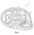
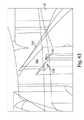
図1は、本発明の種々の側面を組み込む、流体受け取りデバイス1を示す。図1は、本発明の側面の多くを組み込むが、本発明の任意の好適な数の側面が、流体受け取りデバイスに組み込まれ得る。したがって、本発明の側面は、単独で、または互の任意の好適な組み合わせで使用され得る。この例証的実施形態は、カバー20および基部100を含み、それらは、一緒に接合され、デバイス1の種々の部品を封入し、デバイス1に被検体から流体を受け取らせるために使用されるデバイスアクチュエータ10等の1つ以上の外部特徴を支持するように協働し得る。基部100およびカバー20は、ポリエステル(PCTAまたはPETG)または低いガス透過率を伴う他のポリマーから形成され得、または別様にそれらを含み得る。この実施形態におけるデバイスアクチュエータ10は、ユーザによって(例えば、指で押すことによって)作動させられるように配列されるが、デバイスアクチュエータ10は、他の方法で、例えば、流体受け取りデバイス1に被検体から流体を受け取らせるように、機械、電気信号、または他の好適な配列による作動のために配列され得る。デバイスアクチュエータ10の作動は、自動的に、例えば、経過タイマまたは他の刺激あるいは条件に応答して、または手動で起こり得る。いくつかの実施形態では、デバイスアクチュエータ10は、示されるような押しボタン、以下でさらに論議される摺動ボタン、タッチスクリーンインターフェース、スイッチ、または他のユーザ作動可能配列等を含み得る。場合によっては、デバイスアクチュエータ10は、デバイス1の作動を1回だけ可能にし、例えば、デバイスアクチュエータ10は、さらなる作動を防止する位置に係止され得、またはデバイス1が複数回作動させられることを可能にし得る。 FIG. 1 shows a fluid receiving device 1 incorporating various aspects of the invention. Although FIG. 1 incorporates many of the aspects of the invention, any suitable number of aspects of the invention may be incorporated into the fluid receiving device. Therefore, aspects of the invention can be used alone or in any suitable combination of each other. This exemplary embodiment includes a
本発明の一側面によれば、デバイス1は、被検体から流体を受け取る流体輸送体を含み得る。流体輸送体は、身体からの体液が蓄積し得るアプリケータ領域を含み得る。いくつかの実施形態では、アプリケータ領域は、皮膚の表面から流体を受け取ることができる、デバイスの基部内の陥凹またはへこみであり得る。アプリケータ領域は、任意の好適な形状を有し得る。例えば、アプリケータ領域は、略半球形、半卵形、長方形、不整形等であり得る。アプリケータ領域に関するさらなる詳細は、その全体で参照することにより本明細書に組み込まれる、本明細書と同日付に出願された、それぞれ「Systems and Methods for Collecting a Fluid from a Subject」と題された、米国および国際特許出願で見出すことができる。また、2011年4月29日に出願された、Haghgooieらによる「Systems and Methods for Collecting a Fluid from a Subject」と題された米国仮特許出願第61/480,960号も、その全体で参照することにより本明細書に組み込まれる。 According to one aspect of the invention, device 1 may include a fluid transporter that receives fluid from a subject. The fluid transporter may include an applicator area where fluid from the body can accumulate. In some embodiments, the applicator area can be a depression or dent within the base of the device that can receive fluid from the surface of the skin. The applicator region can have any suitable shape. For example, the applicator region can be substantially hemispherical, hemi-oval, rectangular, irregular, etc. Further details regarding the applicator domain are incorporated herein by reference in their entirety, entitled "Systems and Methods for Collecting a Fluid from a Subject," respectively, filed on the same date as this specification. , US and international patent applications. Also referred to in its entirety is US Provisional Patent Application No. 61 / 480,960, entitled "Systems and Methods for Collecting a Fluid from Subject", filed April 29, 2011 by Haghgooe et al. Thereby incorporated herein.
流体輸送体は、デバイス内に流体を受け取るように構成される、任意のサイズおよび/または幾何学形状の開口部を含み得る。例えば、開口部は、2次元平面にあり得、または開口部は、3次元空洞、孔、溝、細隙等を含み得る。いくつかの実施形態では、流体輸送体はまた、例えば、被検体の皮膚を穿刺することによって、被検体から流体が放出されるようにするために配列されている、1つ以上の極微針等の流動活性化体を含み得る。いくつかの実施形態では、流体が、流動活性化体を包囲するエンクロージャを部分的または完全に充填し得る場合には、エンクロージャは、流体輸送体の少なくとも一部を画定することができる。 The fluid transporter may include openings of any size and / or geometry that are configured to receive the fluid within the device. For example, the openings can be in a two-dimensional plane, or the openings can include three-dimensional cavities, holes, grooves, gaps, and the like. In some embodiments, the fluid transporter is also arranged to allow fluid to be released from the subject, for example by puncturing the skin of the subject, such as one or more microneedles. May include a fluid activator of. In some embodiments, the enclosure can define at least a portion of the fluid transporter if the fluid can partially or completely fill the enclosure surrounding the flow activator.
デバイスは、必ずしも被検体から流体放出を引き起こすための機構を採用しないことがあるので、流動活性化体が、全ての実施形態で含まれる必要はないことに留意されたい。例えば、デバイスは、切断または摩耗等の別の原因、別個のランセット等の別個かつ独立したデバイスによる流体放出、外科手術中等の開放流体アクセス等により、すでに放出されている流体を受け取り得る。加えて、流体は、排尿、吐出、デバイスに流体を注ぐこと等を介して、デバイスに導入され得る。含まれる場合、流動活性化体は、物理的に貫通し、穿刺し、および/または摩耗させ、化学的に剥離し、腐食し、および/または刺激し、電磁、音響、または他の波を放出および/または産生し、被検体から流体を放出させるように別様に動作し得る。流動活性化体は、例えば、針を移動させる可動機構を含んでもよく、または機能するために移動を要求しなくてもよい。例えば、流動活性化体は、圧力を受けて流体を被検体に運搬するジェット式注射器または「ハイポスプレー」、流体を運搬および/または受け取る空気圧システム、流体を吸着または吸収する吸湿剤、逆イオンフォトレシスシステム、超音波、あるいは熱、無線周波数、および/またはレーザエネルギーを放出する変換器等を含み得、それらのうちのいずれも、必ずしも被検体から流体を放出させるために流動活性化体の移動を要求する必要がない。 It should be noted that the fluid activator need not be included in all embodiments, as the device may not necessarily employ a mechanism to cause fluid release from the subject. For example, the device may receive fluid that has already been released due to another cause such as cutting or wear, fluid release by a separate and independent device such as a separate lancet, open fluid access during surgery, etc. In addition, the fluid can be introduced into the device through urination, discharge, pouring the fluid into the device, and the like. When included, the fluid activator physically penetrates, punctures, and / or wears, chemically peels, corrodes, and / or irritates, and emits electromagnetic, acoustic, or other waves. And / or can produce and act differently to release fluid from the subject. The flow activator may include, for example, a movable mechanism for moving the needle, or may not require movement to function. For example, a flow activator may be a jet injector or "hyposspray" that receives pressure to transport the fluid to the subject, a pneumatic system that transports and / or receives the fluid, a hygroscopic agent that adsorbs or absorbs the fluid, a reverse ion photo. It may include a recis system, ultrasonic waves, or a converter that emits heat, radio frequency, and / or laser energy, any of which is necessarily a transfer of a fluid activator to expel a fluid from the subject. There is no need to request.
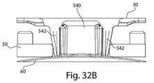
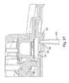
図2は、開口部130、アプリケータ領域131、および流動活性化体90を含む流体輸送体120を伴う図1の流体受け取りデバイス1の裏面を示す。この実施形態では、流動活性化体90は、1本以上の針を含む。以下でさらに詳細に説明されるように、針は、被検体の皮膚を穿刺するように開口部130から拡張され、次いで、血液または他の流体が開口部130に進入することを可能にするように、開口部の中へ後退させられ得る。つまり、被検体から血液を受け取るようにデバイス1を使用するために、開口部130が皮膚に隣接するように、基部100が皮膚上に配置され得る。その後、デバイスアクチュエータ10は、針を展開させるように押下され得、皮膚を穿刺し、血液を放出させる。血液は、開口部に進入し、貯蔵チャンバ140において収集され得る。一実施形態では、血液は、開口部130から貯蔵チャンバ140の中へ血液を引き込む、デバイス1における比較的低い圧力(真空)の結果として、貯蔵チャンバ140に流入する(図4参照)。 FIG. 2 shows the back surface of the fluid receiving device 1 of FIG. 1 with a
針は、任意の好適な幅、長さ、および/または他のサイズであり得、針は各々、中実または中空であり得る。針は、円形、正方形、卵形、楕円形、長方形、丸みを帯びた長方形、三角形、多角形、六角形、不整形等の(例えば、貫通の方向と垂直である)任意の好適な断面を有し得る。いくつかの実施形態では、針は、約5mm以下の長さを有し得る。代替的な針配列に関する追加の情報が、以下で提供される。 The needle can be of any suitable width, length, and / or other size, and the needle can be solid or hollow, respectively. The needle has any suitable cross section (eg, perpendicular to the direction of penetration) such as circular, square, oval, oval, rectangular, rounded rectangle, triangle, polygon, hexagon, irregular, etc. Can have. In some embodiments, the needle can have a length of about 5 mm or less. Additional information on alternative needle arrangements is provided below.
この実施形態(図4)では、デバイスアクチュエータ10の起動が、流動活性化体90に被検体から血液または他の流体を放出させ、それは次いで、開口部130で受け取られる。次いで、血液または他の流体は、1つ以上のチャンバ140において収集され得る。血液または他の流体の収集は、吸収、毛細管作用、吸引、または他の手段によって等、任意の好適な方法で行われ得る。この例証的実施形態では、デバイスアクチュエータ10の起動は、血液または他の流体が、開口部130から、チャネル(図4参照、要素110)を通ってチャンバ140まで流れ得るように、シール76を開かせる。以下でさらに説明されるように、デバイス1は、シール76が開くと、開口部130からチャンバ140の中へ血液または他の流体を引き込む、真空源を含み得る。つまり、シール76の開放は、開口部130からチャンバ140の中へ血液または他の流体を引き込ませる、比較的低い圧力をチャンバ140に導入し得る。 In this embodiment (FIG. 4), activation of the
本発明の一側面では、流動活性化体は、展開アクチュエータおよび後退アクチュエータによって作動させられ得る。例えば、流動活性化体は、移動可能であり得、流動活性化体の移動は、展開アクチュエータおよび後退アクチュエータによって引き起こされ得る。展開アクチュエータは、被検体の皮膚および/または他の表面に向かって、流動活性化体を展開方向に移動させ得、後退アクチュエータは、被検体の皮膚および/または身体から離して、流動活性化体を後退方向に移動させ得る。以下でさらに詳細に論議されるように、展開および後退移動のために別個のアクチュエータを提供することは、場合によっては、流動活性化体が展開および後退のために異なる速度で移動させることを可能にすること、アクチュエータが血液または他の流体のための流体流路を開くこと等の他の追加の機能を果たすことを可能にすること、展開前および展開後、流動活性化体がデバイス内の異なる位置で始動または終了することを可能にすること等の利点を提供し得る。展開アクチュエータおよび後退アクチュエータは各々、ボタン、スイッチ、レバー、スライダ、ダイヤル、圧縮バネ、ベルビルバネ、サーボ、回転または線形電気モータ、および/または空気圧装置、あるいは他の好適なデバイス等の任意の数の好適な構成要素を含み得る。また、展開アクチュエータおよび後退アクチュエータは、同一の種類であり得、または異なる種類のデバイスであり得る。各アクチュエータは、手動で、機械的に、電気的に、空気圧で、電磁的に、または他の好適な動作モードで動作し得、起動のためにユーザ入力を必要としても、しなくてもよい。 In one aspect of the invention, the flow activator can be actuated by a deploying actuator and a retracting actuator. For example, the flow activator may be mobile and the movement of the flow activator may be triggered by a deploying actuator and a retracting actuator. The deployable actuator may move the flow activator in the unfolding direction towards the skin and / or other surface of the subject, and the retracting actuator may move away from the skin and / or body of the subject and the flow activator. Can be moved in the backward direction. As discussed in more detail below, providing separate actuators for deployment and retreat allows fluid activators to move at different speeds for deployment and retreat in some cases. Allowing the actuator to perform other additional functions such as opening a fluid flow path for blood or other fluids, pre-deployment and post-deployment flow activators within the device. It may provide advantages such as being able to start or end at different positions. The deployable and retractable actuators are each suitable for any number of buttons, switches, levers, sliders, dials, compression springs, bellville springs, servos, rotary or linear electric motors, and / or pneumatic devices, or other suitable devices. Can contain various components. Also, the deploying actuator and the retracting actuator can be of the same type or different types of devices. Each actuator may or may not require user input for activation, manually, mechanically, electrically, pneumatically, electromagnetically, or in other suitable modes of operation. ..
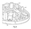
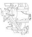
本発明の側面によれば、エフェクタが、流動活性化体の展開および/または後退移動を引き起こすように配列され得る。例えば、エフェクタは、展開アクチュエータおよび後退アクチュエータの両方を含み得る。エフェクタは、ポリエステル(PETGまたはPCTA)、アセタール樹脂、アクリロニトリルブタジエンスチレン(ABS)等から形成され得、または別様にそれらを含み得る。図3、4、および5は、それぞれ、カバー20が基部100から除去された、図1のデバイス1の斜視図、デバイス1の部分断面図、およびデバイス1の分解図を図示する。この実施形態では、デバイス1は、後退アクチュエータ40および展開アクチュエータ60を含み、エフェクタガイド104に沿って基部100に対して上下方向に移動可能であるエフェクタ50を含む。展開アクチュエータ60の下向きの移動が、流動活性化体90を開口部130から少なくとも部分的に拡張させ得るように、展開アクチュエータ60が、膜72(図4参照)を介して流動活性化体90に取り付けられる。(以下でさらに論議されるように、貯蔵チャンバ140の中への流動を引き起こすように制御可能に開かれるまで、比較的低い圧力が真空源156で維持されるように、膜72は、開口部130からデバイス1の中の真空源156を分離し得る。真空源156は、密閉真空チャンバの形態であり得る)。この実施形態では、展開アクチュエータ60は、展開アクチュエータ60を流動活性化体90に取り付ける膜72の一部を受け取る中心孔を有する略ドーム形状を有する(たとえば、ベルビルバネの場合のように)。(この実施形態では、流動活性化体90は、膜72を介して展開アクチュエータ60に取り付けられるが、流動活性化体90は、例えば、流動活性化体90から展開アクチュエータ60まで延在する垂直柱または他の構造を介して、展開アクチュエータ60に直接接続され得る。)展開アクチュエータ60は、最初に、図4に示される下向き凹状構成に配列され、例えば、解放要素30に展開アクチュエータ60の中心部分を下向きに押させるように、デバイスアクチュエータ10をユーザが押すことによって、上向き凹状構成に移動させられ得る。展開アクチュエータ60は、開口部130から流動活性化体90を急速に拡張し、被検体の皮膚または他の表面を穿刺するよう、下向き凹状構成から上向き凹状構成まで急速に移動する好適な材料および構成で作製され得る。この実施形態における展開アクチュエータ60は、ドーム形状を伴う可撓性バネとして配列されるが、展開アクチュエータ60は、任意の好適な形状および/またはサイズであり得る。例えば、展開アクチュエータ60は、円形(図5に示される4本の脚部と違って「脚部」を持たない)、長円形、三角形(3本の脚部を有する)、正方形(各脚部の間に真っ直ぐな側面を伴う4本の脚部)、五角形(5本の脚部)、六角形(6本の脚部)、クモ脚型、星状、クローバ形状(例えば、2、3、4、5等の任意の数のローブを伴う)、鋸歯状円盤または波形等であり得る。展開アクチュエータ60は、いくつかの実施形態では、中央または他の場所に、示されるよう中心孔、あるいはくぼみまたはボタン等の別の特徴を有し得る。展開アクチュエータ60は、任意の好適な材料、例えば、ステンレス鋼(例えば、301、301LN、304、304L、304LN、304H、305、312、321、321H、316、316L、316LN、316Ti、317L、409、410、430、440A、440B、440C、440F、904L)、炭素鋼、バネ鋼、バネ黄銅、リン青銅、ベリリウム銅、チタン、チタン合金鋼、クロムバナジウム、ニッケル合金鋼(例えば、Monel 400、Monel K 500、Inconel 600、Inconel 718、Inconel x 750等)等の金属、ポリマー(例えば、ポリ塩化ビニル、ポリプロピレン、ポリカーボネート等)、複合物または積層(例えば、繊維ガラス、炭素繊維、竹、Kevlar等を含む)等から形成され得、または別様にそれらを含み得る。 According to aspects of the invention, the effectors can be arranged to cause the expansion and / or retreat of the flow activator. For example, effectors can include both deploying and retracting actuators. The effector can be made of polyester (PETG or PCTA), acetal resin, acrylonitrile butadiene styrene (ABS), etc., or can optionally include them. FIGS. 3, 4, and 5 show a perspective view of the device 1 of FIG. 1, a partial cross-sectional view of the device 1, and an exploded view of the device 1 with the
いくつかの実施形態では、展開アクチュエータの全ての部分は、展開アクチュエータが開口部130に向かって展開方向に移動するときに、ある距離未満を移動し得る。いくつかの実施形態では、展開アクチュエータの全ての部分は、約10mm未満、約5mm未満、約3mm未満、約2mm未満、または約1mm未満を移動し得る。 In some embodiments, all parts of the deployable actuator may travel less than a certain distance as the deployable actuator moves in the deployable direction towards the
この実施形態における後退アクチュエータ40は、板バネの形態の可逆的に変形可能な構造を含むが、展開アクチュエータ60のように、コイルバネ、発泡体、弾性ブラダ等の他の配列が可能である。後退アクチュエータは、任意の好適な材料、例えば、1095バネ鋼または301ステンレス鋼、あるいは1074/1075、5160、9255バネ鋼等の他のバネ材料から形成され得、または別様にそれらを含み得る。後退アクチュエータ40がデバイスアクチュエータ10の作動に応じて解放されたとき、後退アクチュエータ40(およびエフェクタ50の他の部分)がエフェクタガイド104に沿って開口部130から離れて移動することができるように、後退アクチュエータ40は、エフェクタ本体50を介して展開アクチュエータ60に取り付けられる。この後退運動は、開口部から流動活性化体90および展開アクチュエータ60も引き離す。具体的には、少なくとも部分的に図4および5で示されるように、デバイス1の作動前、後退アクチュエータ40は、ポテンシャルエネルギーを貯蔵する圧縮状態にある。つまり、後退アクチュエータ40の中心は、後退アクチュエータ40の4本アームが弾性的に変形させられるように、組立中に下向きに押される。後退アクチュエータ40は、デバイス1が作動させられるまで基部100と係合している後退アクチュエータ40の耳部分103(図8および9参照)によって、この押下状態で保持される。しかしながら、デバイスアクチュエータ10がデバイス作動中に押し下げられたとき、解放要素30のアーム31が、基部100から耳部分103を解放するようにタブ41と係合し、後退アクチュエータ40の中心部分が開口部130から離れて後退方向に移動することを可能にする。展開アクチュエータ60および流動活性化体90が後退アクチュエータ40に取り付けられているので、開口部13から離れた上向きの後退アクチュエータ40の移動が、開口部130から流動活性化体90を後退させる。加えて、開口部130から離れた上向きの後退アクチュエータ40の移動はまた、開口部130から離して後退方向に展開アクチュエータ60を移動させ得る。いくつかの実施形態では、展開アクチュエータ60の全ての部分は、展開アクチュエータ60が開口部130から離れて後退方向に移動するときに、ある距離未満を移動し得る。いくつかの実施形態では、展開アクチュエータの全ての部分は、約10mm未満、約5mm未満、約3mm未満、約2mm未満、または約1mm未満を移動し得る。 The retracting
いくつかの実施形態では、図4に示されるように、スペーサ要素32が、展開アクチュエータ60と後退アクチュエータ40との間に位置する。スペーサ要素32は、展開アクチュエータ60と解放要素30との間の間隙を排除するのに役立ち得る。デバイスアクチュエータ10の作動は、解放要素30にスペーサ要素32を押し下げさせ得、それがひいては、展開アクチュエータ60を押し進め、展開アクチュエータ60に流動活性化体90を展開方向に移動させ得る。いくつかの実施形態では、流動活性化体90、展開アクチュエータ60、後退アクチュエータ40、およびスペーサ要素32は、実質的に同心円状に整列させられる。 In some embodiments, the
流動活性化体90のために展開アクチュエータ60および後退アクチュエータ40の両方を提供することによって、流動活性化体90は、展開および後退の両方のために任意の好適な移動を有するように制御され得る。例えば、流動活性化体90は、後退方向よりも展開方向に急速に移動させられ得、それは、血液を放出するように皮膚を穿刺するときに疼痛を潜在的に低減させることが分かっている。つまり、展開アクチュエータ60は、下向き凹状から上向き凹状構成まで比較的急速に移動し、流動活性化体90を皮膚または別の表面に迅速に挿入するように配列され得る。その後、流動活性化体90は、例えば、後退アクチュエータ40の減衰運動または他の好適な配列によって、展開アクチュエータ60よりも後退アクチュエータ40によって流動活性化体90に及ぼされる比較的低い力によって制御されるように、後退アクチュエータ40によって、よりゆっくりと皮膚から引き出され得る。他の実施形態では、別個の展開および後退アクチュエータを有することにより、後退方向等の別の方向よりも展開方向等の1つの方向で、より短い可動域を可能にし得る。例えば、展開のために比較的短い距離を流動活性化体90に移動させることによって、展開アクチュエータ60は、比較的小型に作製され得るが、流動活性化体90を皮膚に挿入するように好適に高い力を生成し得る。対照的に、後退中に流動活性化体90によって移動される比較的長い距離は、血液のプールまたは他の集まりが、デバイス1による受け取りのための空洞または他の空間に進入することを可能にするように、好適に活性化体90を引き出し得る。加えて、短い展開距離が、長い移動距離に固有の整列誤差を最小限化し得る。 By providing both the deploy
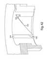
故に、本発明の一側面では、流動活性化体は、流動活性化体と皮膚または他の表面との間の最終的な後退後距離とは異なる、皮膚または別の表面からの最初の展開前距離に位置し得る。この側面は、エフェクタの一部としてのモータ、サーボ、または自動デバイスによって等、多くの異なる方法で提供することができるが、図1−5の実施形態のエフェクタ50は、流動活性化体90が展開前に開口部130に比較的近く、展開後に開口部130から比較的遠く離れて位置する、配列を提供し得る。図6A−6Cは、それぞれ、流動活性化体90の展開前の初期状態、標的皮膚または他の表面から流体の放出を引き起こすように、流動活性化体が開口部130から拡張されているか、または別様に位置付けられている中間状態、および流動活性化体90が後退させられている最終状態を含む、図1−5のデバイス1の3つの状態の一連の概略図を示す。 Therefore, in one aspect of the invention, the fluid activator is different from the final post-regression distance between the fluid activator and the skin or other surface, before the first deployment from the skin or another surface. Can be located at a distance. This aspect can be provided in many different ways, such as by a motor, servo, or automatic device as part of the effector, although the
図6Aで見ることができるように、開口部130と流動活性化体90との間の展開前距離181は、1mm以下等、比較的小さい。この状態で、後退アクチュエータ40は、圧縮され、展開アクチュエータ60は、下向き凹状配列にある。図6Bに示されるように、展開アクチュエータ60は、流動活性化体90が展開されるように、上向き凹状構成に反転される。後退アクチュエータ40はまた、例えば、ユーザが解放要素30を押し下げることによって、さらに圧縮され得るが、他の実施形態では、後退アクチュエータ40は、さらに圧縮、または変形させられる必要はない。図6Cに示されるように、開口部130と流動活性化体90との間の後退後距離183は、展開前距離181よりも大きく、場合によっては有意に大きくあり得る。例えば、流動活性化体90が開口部130から完全に後退させられる後退後距離183は、2〜3mm以上であり得る。開口部130からの流動活性化体90の後退は、被検体から放出された血液または他の流体が集合し、および/またはデバイス1によって受け取られ得る空間を提供し得る。しかしながら、後退後距離が、展開前距離よりも小さい、または展開前距離と同一である、他の配列が可能であり、本発明の全ての側面は、この点に関して必ずしも限定されない。 As can be seen in FIG. 6A, the
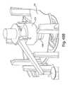
図7Aおよび7Bは、図1−5の実施形態のエフェクタ50の上面斜視図および底面斜視図を示し、エフェクタ50の運動が制御される方法をより良く図示するのに役立つ。図7Aに示されるように、後退アクチュエータ40は、中心孔を有する中心本体から放射状に広がる、8本の脚部を有する。より短い脚部のうちの2本が、後退アクチュエータ40の孔46を通って延在する2本の柱52を介して、後退アクチュエータ40をエフェクタ本体50に取り付ける。柱頭部52の直径は、孔46よりも大きく作製され、したがって、後退アクチュエータ40をエフェクタ本体50に固定し得る。後退アクチュエータ40は、代替として、接着剤(例えば、テープ、液体)、機械的締結(例えば、締り嵌め、スロット/溝、ネジ)、または熱的方法(例えば、熱かしめ)によって、エフェクタ本体50に取り付けられ得、この点に関して限定されない。後退アクチュエータ40の他の脚部48は、例えば、エフェクタ50の後退移動を提供するように、エフェクタ本体50に対して屈曲するように自由なままであり得る。脚部48のうちの2本は、基部100と係合し、流動活性化体90の展開前に圧縮された初期位置で後退アクチュエータ40を保持する働きをする、耳部分103を含む。耳部分103が基部100と係合するために本体に向かって移動することを可能にするように、空間または間隙43が、耳部分103とエフェクタ本体50との間に提供される。上記で説明され、図7Bに示されるように、展開アクチュエータ60は、中心孔66と、エフェクタ本体50の溝56内で保持されるローブ62とを含む。展開アクチュエータ60は、エフェクタ本体50に取り付けられるが、展開アクチュエータ60の中心部分64は、展開アクチュエータ60が移動して流動活性化体90を展開し得るように、エフェクタ本体50に対して変位可能なままである。 7A and 7B show top and bottom perspectives of the
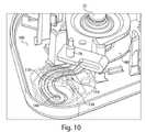
上記で論議されるように、エフェクタ50は、基部100に載置され、基部100から突出するエフェクタガイド104を介して、運動を誘導され得る。図8は、後退アクチュエータ40が圧縮された初期状態で基部100と係合する方法を図示する、後退アクチュエータ40の接近図を示す一方で、図9は、圧縮された初期状態で後退アクチュエータ40を保持するように基部100と係合する、後退アクチュエータ40の脚部48のうちの2本の脚部上の耳部分103の接近図を示す。エフェクタ50がエフェクタガイド104によって好適に保持されると、基部100上の対応する突出101の下にタブ41の耳部分103を位置付けることができるように、エフェクタ50が下向きに押される。耳部分103が突出101と係合されると、脚部48のバネ力がエフェクタ50を付勢して後退方向に上向きに移動させるように、エフェクタ50が解放され得る。しかしながら、耳部分103が突出101と係合されることにより、エフェクタ50は、圧縮状態で保持される。この展開前配列では、流動活性化体90は、開口部130からの初期展開前距離181(図6参照)にあり得る。いくつかの実施形態では、この展開前距離181は、展開アクチュエータ60の作動が、流動活性化体90を被検体の皮膚に到達させ、流動活性化体90が皮膚を貫通および/または穿刺して流体流動を引き起こすことを可能にするように、配列され得る。したがって、初期半圧縮状態で後退アクチュエータ40を事前装填させることにより、デバイスアクチュエータ10の作動時に流動活性化体90が展開の準備ができた状態になることを可能にする、展開前距離181で流動活性化体90を保持し得る。 As discussed above, the
図8はまた、後退アクチュエータ40が流動活性化体90を後退させるように解放され得る方法も図示する。デバイスアクチュエータ10および解放要素30が下向きに移動させられたときに、アーム31の傾斜部分が、タブ41を外向きに、かつエフェクタ本体50から離して押すように、解放要素30のアーム31が、タブ41と係合し得る。これは、突出101から耳部分103を解放し、後退アクチュエータ40の変形した脚部の付勢を受けて、エフェクタ50が上向きに移動することを可能にする。解放要素30は、ポリエステル(PETGまたはPCTA)、アセタール樹脂、アクリロニトリルブタジエンスチレン(ABS)等から形成され得、または別様にそれらを含み得る。この実施形態では、後退アクチュエータ40は、耳部分103および突出101を含む解放可能なラッチ配列を介して、基部100と係合することが示されているが、本発明は、この点に関して限定されないので、解放可能なレバー、摺動解放、戻り止め、楔を使用して、または極性を反転させることによって分離可能である磁石等の他の配列が可能である。 FIG. 8 also illustrates how the retracting
本発明の別の側面では、エフェクタは、流動活性化体の任意の展開移動前、最初の貯蔵されたポテンシャルエネルギーを有し得る。つまり、エフェクタは、流動活性化体を展開および/または後退させ、あるいは流体受け取りデバイスの他の部品の他の運動を引き起こすために使用される、貯蔵されたバネエネルギー、または例えば、弾性的に変形させられた要素に貯蔵された他の機械エネルギー、貯蔵された化学エネルギー、貯蔵された電気エネルギー等を有し得る。上記で説明されるように、流動活性化体90の展開前、後退アクチュエータ40は、基部100上の突出要素101との脚部48の耳部分103の係合によって、圧縮状態で保持され得る。後退アクチュエータ40の圧縮は、流動活性化体90を後退させること等の異なる動作に使用することができるポテンシャルエネルギーを後退アクチュエータ40に貯蔵する。したがって、初期圧縮状態で後退アクチュエータ40を有することにより、デバイスの作動時にエネルギーがシステムに入力されることを要求することなく、後退アクチュエータ40がポテンシャルエネルギーを貯蔵し、作動の準備ができた状態になることを可能にする。 In another aspect of the invention, the effector may have the initial stored potential energy prior to any deployment transfer of the flow activator. That is, the effector is stored spring energy, or, for example, elastically deformed, which is used to deploy and / or retract the flow activator or to cause other movements of other parts of the fluid receiving device. It may have other mechanical energy stored, chemical energy stored, electrical energy stored, etc. in the stored element. As described above, prior to deployment of the
本発明の別の側面では、流動活性化体は、後退方向よりも展開方向に速く移動し得る。上記で論議される実施形態では、展開アクチュエータ60は、急速に、例えば、双安定的に、初期展開前位置から展開位置に移動するように配列され得る。対照的に、後退アクチュエータ40は、例えば、比較的低いバネ定数または他の特性を有し、後退運動の少なくとも一部の間に、より遅い速度で流動活性化体90を移動させるように配列され得る。一組の実施形態では、流動活性化体90は、流動活性化体90が最初に皮膚に接触する点で、少なくとも約0.1cm/秒、少なくとも約0.3cm/秒、約1cm/秒、少なくとも約3cm/秒、少なくとも約10cm/秒、少なくとも約30cm/秒、少なくとも約1m/秒、少なくとも約2m/秒、少なくとも約3m/秒、少なくとも約4m/秒、少なくとも約5m/秒、少なくとも約6m/秒、少なくとも約7m/秒、少なくとも約8m/秒、少なくとも約9m/秒、少なくとも約10m/秒、少なくとも約12m/秒等の速度で、展開することができる。いずれの理論によっても拘束されるわけではないが、比較的速い展開速度は、(皮膚を変形させること、または応答して皮膚を移動させることなく)皮膚を貫通する流動活性化体の能力を増加させ、および/または皮膚への流動活性化体の適用によって感じられる疼痛の量を減少させ得ることが考えられる。本明細書で説明されるものを含む、皮膚への貫通速度を制御する任意の好適な方法が使用され得る。 In another aspect of the invention, the flow activator may move faster in the unfolding direction than in the receding direction. In the embodiments discussed above, the
流動活性化体90の後退は、例えば、流動活性化体90の引き出しと関連付けられる任意の疼痛を低減させるのに役立つように、展開よりも遅い速度で起こり得る。後退アクチュエータ40が、例えば、バネ、弾性部材、折り畳み式発泡体等の場合のように、電気的に制御されない機械要素のみを含む場合、バネまたは他の要素は、所望の後退速度を提供するように設計され、または別様に配列され得る。代替として、1つ以上のダンパ等の他の機械要素が、引き出し速度を制御するように提供され得る。いくつかのサーボ、空気圧システム等の他の電気的に制御されたシステムは、所望の後退速度を提供するように、開または閉ループ制御を組み込み得る。手動操作型後退アクチュエータの場合、ユーザは、後退の速度を制御することが可能であり得る。例えば、バネの形態の後退アクチュエータは、力がデバイスアクチュエータから徐々に排除された場合、よりゆっくりと後退し得る。しかしながら、力が急激に除去された(例えば、ユーザがデバイスアクチュエータを突然解放した)場合、後退は、より迅速に起こり得るが、可能な限り速い後退速度は、展開速度よりも依然として遅くあり得る。 Retreat of the
いくつかの側面では、流体受け取りデバイスは、被検体から受け取られた流体を保持するための1つ以上のチャンバまたは容器140を含み得る。場合によっては、チャンバは、1つ以上の流体輸送体および/または1つ以上の流体チャネルと流体連通し得る。例えば、流体受け取りデバイスは、(例えば、貯蔵および/または以降の分析のために)被検体から引き出された流体を収集するためのチャンバ、被検体に運搬するための流体(例えば、血液、生理食塩水、薬剤、ホルモン、ビタミン、医薬品等を随意的に含む)を含むためのチャンバ等を含み得る。 In some aspects, the fluid receiving device may include one or more chambers or
本発明の一側面では、デバイスは、真空源を含み得る。真空(周囲以下の圧力)は、デバイスの開口部130の中への流体流動を促進するのに役立ち得、および/または流動活性化体90と接触するために開口部130の中へ皮膚を引き込むのに役立ち得、および/または開口部130からチャンバ140までの流体流動を促進するのに役立ち得る。場合によっては、真空源は、デバイス内で内蔵型であるものであり得、すなわち、デバイスは、皮膚から、および/または皮膚下から、血液または間質液を引き出すために、デバイスの使用中に外部真空源(例えば、家庭用真空)に接続される必要がない。例えば、図4に示されるように、一組の実施形態では、真空源は、血液(または他の流体)がデバイスの中へ引き込まれる前に周囲圧力より低い圧力を有する、真空源156を含み得、すなわち、真空源156は、「陰圧」(つまり、周囲圧力に対して負である)または「減圧」(または単に「真空」を有する)にあり得る。例えば、周囲圧力が大気圧にある場合、真空源の中の真空は、少なくとも約50mmHg、少なくとも約100mmHg、少なくとも約150mmHg、少なくとも約200mmHg、少なくとも約250mmHg、少なくとも約300mmHg、少なくとも約350mmHg、少なくとも約400mmHg、少なくとも約450mmHg、少なくとも約500mmHg、少なくとも550mmHg、少なくとも600mmHg、少なくとも650mmHg、少なくとも約700mmHg、または少なくとも約750mmHgであり得、すなわち、周囲大気圧より低い。しかしながら、他の実施形態では、他の圧力が使用され得ること、および/または異なる方法が(大気圧より大きい、または大気圧未満の)他の圧力を産生するために使用され得ることを理解されたい。非限定的実施例として、外部真空または機械デバイスが、真空源として使用され得る。例えば、デバイスは、内部真空源を備え得、および/または真空ポンプあるいは外部(ライン)真空源等のデバイスの外部にある真空源に接続可能であり得る。場合によっては、真空は、手動で、例えば、シリンジポンプ、プランジャ等を操作することによって作成され得、または低い圧力は、機械的または自動的に、例えば、ピストンポンプ、シリンジ、バルブ、ベンチュリ管、手動(口)吸引等を使用して作成され得る。 In one aspect of the invention, the device may include a vacuum source. Vacuum (below ambient pressure) can help facilitate fluid flow into the
したがって、場合によっては、デバイスは、好適な真空源(例えば、事前に真空排気された真空源156)とともに「事前包装」され得、例えば、一実施形態では、デバイスは、皮膚に適用され、真空源を作成し、および/またはそれにアクセスするように、何らかの様式で起動され得る。いくつかの実施形態では、内蔵型真空源が、デバイス内で真空を作成するように、何らかの様式で作動させられ得る。例えば、内蔵型真空源は、ピストン、シリンジ、デバイス内で真空を作成することが可能な真空ポンプ等の機械デバイス、および/または、反応によって駆動される機械または他の手段の助けを借りて、圧力調節器と関連付けられる圧力差を形成することができる、圧力を上昇または低下させるように反応することができる化学物質あるいは他の反応物質を含み得る。化学反応はまた、化学反応自体に基づく圧力の変化を伴って、または伴わずに、機械的作動を駆動することもできる。内蔵型真空源はまた、膨張性発泡体、形状記憶材料等を含むこともできる。 Thus, in some cases, the device may be "pre-packaged" with a suitable vacuum source (eg, pre-evacuated vacuum source 156), eg, in one embodiment, the device is applied to the skin and evacuated. It can be invoked in some way to create and / or access the source. In some embodiments, the built-in vacuum source can be actuated in some way to create a vacuum within the device. For example, a built-in vacuum source can be used with the help of mechanical devices such as pistons, syringes, vacuum pumps capable of creating a vacuum within the device, and / or reaction-driven machines or other means. It may include a chemical or other reactant that can react to increase or decrease the pressure, which can form a pressure difference associated with the pressure regulator. The chemical reaction can also drive mechanical action with or without a change in pressure based on the chemical reaction itself. Built-in vacuum sources can also include inflatable foams, shape memory materials and the like.
場合によっては、デバイスは、デバイスが皮膚および/または開口部130に真空を印加するのに役立つことができる界面105(図2、4、および5参照)を含む。界面105は、例えば、吸引カップ、Katecho 10Gまたは他の好適なヒドロゲル等のヒドロゲル材料の層、あるいは皮膚の表面上に配置される円形のボウルであり得、真空は、界面105によってデバイス1にさらされる皮膚の部分に印加され得る。一組の実施形態では、界面は、支持構造、例えば、基部100の一部である。界面105は、任意の好適な材料、例えば、ガラス、ゴム、シリコーン、ポリウレタン、ニトリルゴム、EPDMゴム、ネオプレン等のポリマーから形成され得る。場合によっては、界面105と皮膚との間のシールは、例えば、真空グリース、ワセリン、ゲル、接着剤等を使用して、強化され得る(例えば、漏出を低減させる)。場合によっては、界面105は、比較的小さく、例えば、約5cm未満、約4cm未満、約3cm未満、約2cm未満、約1cm未満、約5mm未満、約4mm未満、約3mm未満、約2mm未満、または約1mm未満の直径を有し得る。界面105は、円形であり得るが、他の形状、例えば、正方形、星形(5、6、7、8、9、10、11個等の先端を有する)、涙滴状、卵形、長方形等も可能である。 In some cases, the device includes an interface 105 (see FIGS. 2, 4, and 5) where the device can help apply a vacuum to the skin and / or the
いくつかの実施形態では、真空源からの真空は、流体輸送体の開口部から貯蔵容器までの血液または他の流体の移動を促進し得る。図1−5の実施形態では、真空が、真空源156(例えば、デバイスカバー20、基部100、および膜72の間に封入される空間)の大部分に貯蔵され得る。真空源156の中の真空は、開口部130における流体をチャネル110の中に、およびチャンバ140へ引き込ませるよう、貯蔵チャンバ140に選択的に連結され得る。例えば、図5で見ることができるように、1つ以上のチャネル110が、基部100の中に形成され、または別様に開口部130と貯蔵チャンバ140との間に提供され得る。チャネル110は、チャネル板80の下面によって上側で覆われ得る。いくつかの実施形態では、チャネル板80、膜72、およびシール76は、単一の部品を形成することができる。(チャネル110に対する追加の構成オプションが以下で論議される。)チャネル板80は、チャネル110を画定するのに役立つだけでなく、流体輸送体120における空洞の少なくとも一部分、貯蔵チャンバ140の一部、真空源156と貯蔵チャンバ140との間の流動の制御に使用される真空入口154および流路150、ならびにチャネル110と貯蔵チャンバ140との間の流路を画定し得る。つまり、図4および10に示されるように、チャネル板80は、開口部130からの流動が、チャネル110および貯蔵チャンバ140を接続するチャネル板80内の開口部144までチャネル110を通過し得るように、開口部130と真空源156との間の流路を画定するのに役立つ。開口部144は、フィルタ、(例えば、貯蔵チャンバ140の中の水性流体が後にチャンバ140から退出することを防止するのに役立つ)疎水性要素、一方向弁を含み得、または完全に遮るものがなくてもよい。図10で見ることができるように、流動はまた、貯蔵チャンバ140から、チャネル板80の中の通路150を通って、真空入口154まで起こり得る。真空入口154は、通常、開口部130および真空源156の中の低い圧力に対する他の潜在的出口から真空源156を隔離するのにも役立つ、膜72の一部であり得る、シール76によって閉鎖される。図4で見ることができるように、後退アクチュエータ40が圧縮された初期状態にあるとき、通路150を閉鎖し、真空源156と貯蔵チャンバ140との間の連通を防止するよう、シール脚部49がシール76を押して真空入口154と接触させるように、シール76は、後退アクチュエータ40の脚部48のうちの1本(シール脚部49)と係合される。しかしながら、いったん後退アクチュエータ40が解放されると、シール脚部49は、上向きに移動し得、および/またはシール76へのシール脚部49の力は、貯蔵チャンバ140から真空源156までの流動のために真空入口154が開く点まで、低減させられ得る。したがって、いったんシール76が真空入口154を開くと、真空源156は、チャネル110の中の流体が貯蔵チャンバ140の中に引き込まれるように、貯蔵チャンバ140から流体(例えば、空気および/または液体)を引き込み得る。示されていないが、液体が貯蔵チャンバ140から真空源156の中へ流れることを防止するように、疎水性膜または他の好適な要素が、真空入口154または他の好適な場所(通路150の中等)で提供され得る。 In some embodiments, the vacuum from the vacuum source may facilitate the transfer of blood or other fluid from the opening of the fluid transporter to the storage vessel. In the embodiment of FIG. 1-5, the vacuum can be stored in most of the vacuum source 156 (eg, the space enclosed between the
本発明の一側面によれば、流体輸送体の開口部と真空源との間の流体連通は、流動活性化体の作動に応答して、または流動活性化体の作動の前に、可能にされ得る。例えば、デバイスアクチュエータ10の押下が、真空源156と貯蔵チャンバ140/開口部130との間の連通を可能にし得る。他の配列が可能であるが、図1−10の例証的実施形態では、いったん流動活性化体90が作動させられると(例えば、展開および後退が開始されると)、真空源156と貯蔵チャンバ140との間の流体連通を可能にするよう、シール76が真空入口154から解放され得るように、シール76は、後退アクチュエータ40のシール脚部49に連結され得る。この実施形態では、流動活性化体90が後退させられるにつれて、後退アクチュエータ40のシール脚部49が、真空入口154から離れて移動する(または少なくともシール76への圧力を低減させる)が、流動活性化体90の展開時に、または流動活性化体90の移動における任意の他の時点で、ならびに移動が始まる前、または移動が完了した後に、シール76の開放を配列することが可能である。例えば、真空源156と貯蔵チャンバ140との間の流動は、例えば、流動活性化体90の展開に伴って、または流動活性化体90の完全後退時に、膜または箔を穿刺することによって可能にされ得る。一実施形態では、膜シールが、開口部130に位置することができ、流動活性化体90自体は、膜を穿孔する働きをし、開口部130から真空源156までの流動を可能にすることができる。したがって、この穿孔は、貯蔵チャンバ140の中へ流体を引き込むように、開口部130における流体を真空にさらす働きをすることができる。当然ながら、膜シールは、真空入口154等の開口部130以外の場所に位置し得、膜を穿孔するために、解放要素30上のスパイク等の別個の穿刺要素を使用することができる。流動活性化体の作動に応答して、(化学真空源または真空ポンプ等の)真空源を作動させること等の他の配列も可能である。例えば、後退アクチュエータ40が後退方向に移動するにつれて、貯蔵チャンバ140において吸引を生成するようピストンが移動させられるように、後退アクチュエータ40は、シリンジに連結され得る。 According to one aspect of the invention, fluid communication between the opening of the fluid transporter and the vacuum source is possible in response to or prior to the actuation of the flow activator. Can be done. For example, pressing the
上記の説明から理解されるように、本発明の別の側面では、流動活性化体は、流動活性化体を展開するように展開方向に移動させられ、流動活性化体を後退させるとともに、真空源と流体輸送体の開口部との間の流体連通を可能にするように後退方向に移動させられ得る。上記で説明される例証的実施形態では、流動活性化体90が後退させられるにつれて、シール76は、真空入口154から解放され得る。シール76における流路の開放は、後退の開始時に、後退中に、および/または後退が完了した後に起こり得る。いくつかの実施形態では、シール76および流動活性化体90は、両方とも、後退アクチュエータによって同じ後退方向に移動させられ得る。つまり、後退中、チャネル110を通る真空源156とデバイス開口部130との間の流体連通を可能にするように、流動活性化体90は、後退させられ得、シール76は、持ち上げられ得る。シール76は、ラテックス、または熱可塑性エラストマー(TPE)あるいはポリウレタン等の他の可撓性材料から形成され得、または別様にそれらを含み得る。他の実施形態では、シール76への力は、真空源156の中の比較的低い圧力に貯蔵チャンバ140から真空源156までの流動を発生させるように、十分に解放され得る。したがって、シール76は、必ずしも真空入口154から持ち上げられる必要はないが、代わりに、好適な圧力差がシール76をわたって存在し、貯蔵チャンバ140から真空源156までの流動を可能にするが、入口154を通る流動を別様に阻止する、所望のクラック圧を有する一種の逆止め弁の役割を果たし得る。流体連通を開くように膜を穿刺する後退アクチュエータ40上のスパイク等の、流動活性化体の後退中に流体連通を開くための他の配列が可能である。別の実施形態では、電気スイッチが、後退アクチュエータによって開かれ、または閉じられ得、(ポンプ等の)真空源を起動させる。別の実施形態では、後退アクチュエータの移動は、ラッチまたは他のデバイスを解放し得、それは、バネ荷重シリンジピストンまたは他のデバイスが移動することを可能にし、所望の真空を作成する。別の実施形態では、後退アクチュエータ40自体の後退移動が、所望の真空を提供するようにシリンジピストンまたは他のデバイスを移動させ得る。したがって、真空源と流体輸送体の開口部との間の流体連通を可能にすることは、流動を遮断する弁または他のデバイスの開放を必ずしも伴う必要はないが、代わりに、流動を引き起こすための好適な真空の作成を伴い得る。他の配列も、可能である。 As can be seen from the above description, in another aspect of the invention, the fluid activator is moved in the unfolding direction to deploy the fluid activator, retracting the fluid activator and vacuuming. It can be moved backwards to allow fluid communication between the source and the opening of the fluid carrier. In the exemplary embodiment described above, the
本発明の別の側面では、流動活性化体を展開および/または後退させるエフェクタもまた、流体輸送体の開口部と真空源との間の流体連通を可能にし得る。流動活性化体を展開および/または後退させるとともに、流体輸送体と真空源との間の流体連通を開くための単一の構成要素またはアセンブリを提供することにより、いくつかの実施形態では、動作または構造がより単純である流体受け取りデバイスを提供し得る。例えば、図1−10の実施形態における後退アクチュエータ40等の単一のデバイスは、後退させるとともに、流路を開く働きをし得る。これは、流体受け取りデバイスの構築に必要とされる部品を低減させ、費用および/または組立の複雑性を低減させ得る。当然ながら、エフェクタは、必ずしも展開および後退機能の両方を果たす必要はないが、代わりに、流体連通を可能にするとともに、展開のみまたは後退のみを提供し得る。例えば、流動活性化体が、展開後に後退させられず、代わりに、真空が流動活性化体に印加されるとき、流体を引き出すために皮膚に埋め込まれたままとなることが許される実施形態において、例えば、エフェクタは、流動活性化体を展開し、流体輸送体の開口部と真空源との間の流体連通を可能にすることのみの働きをし得る。上記で論議されるように、流体輸送体の開口部と真空源との間の流体連通を可能にすることは、弁または類似構造(シール76等)を開くこと、膜を穿刺すること、真空源を作動させること(シリンジプランジャまたは類似要素を移動させること等)、化学操作型真空源を起動すること等によるなど、異なる方法で提供され得る。 In another aspect of the invention, effectors that deploy and / or retract the flow activator may also allow fluid communication between the opening of the fluid transporter and the vacuum source. In some embodiments, it operates by deploying and / or retracting the flow activator and providing a single component or assembly for opening fluid communication between the fluid transporter and the vacuum source. Alternatively, it may provide a fluid receiving device having a simpler structure. For example, a single device, such as the retracting
本発明の別の側面では、流動活性化体および真空シールは、例えば、単一の一体構造または構成要素の一部として、一緒に取り付けられ得る。例えば、図4および5に示されるように、流動活性化体90が、例えば、流動活性化体90を膜と共同成形すること、流動活性化体90を膜に接着すること等によって、膜72に取り付けられ得る一方で、シール76は、膜72自体の一部から形成される。そのような配列は、組立を容易にし、流体受け取りデバイス1の中の構成要素の数を削減し得る。 In another aspect of the invention, the flow activator and vacuum seal can be attached together, for example, as part of a single integral structure or component. For example, as shown in FIGS. 4 and 5, the
上記で論議されるように、シール76の移動によって可能にされる流動は、チャネル110に沿って貯蔵チャンバ140への流動を引き起こし得る。チャネル110は、少なくとも部分的に、単一の構成要素、例えば、基部100等のエッチングされた基材または成形ユニットによって、形成され得る。チャネルは、任意の断面形状、例えば、円形、卵形、三角形、不整形、正方形、または長方形(任意の縦横比を有する)等を有することができ、かつ覆うこと、または覆いを取ることができる(すなわち、チャネルを包囲する外部環境に開いている)。チャネル110は、任意の長さであり得る。場合によっては、チャネル110は、開口部130と真空源または貯蔵容器等の別の容器との間に流体連結を作成する、単純な2次元開口部であり得る。これらの場合において、チャネルは、(例えば、2次元開口部の場合のように)いかなる長さも全く持たなくてもよい。チャネルが完全に覆われる実施形態では、チャネルの少なくとも一部分が、完全に封入される断面を有することができ、および/またはチャネル全体が、その入口および出口を除いて、その全長に沿って完全に封入され得る。 As discussed above, the flow allowed by the movement of the
チャネルは、任意の縦横比(長さ対平均断面寸法)、例えば、少なくとも約2:1、より典型的には、少なくとも約3:1、少なくとも約5:1、少なくとも約10:1等の縦横比を有し得る。本明細書で使用される場合、流体またはマイクロ流体チャネルを参照した、「断面寸法」は、チャネル内の流体流動に対して略垂直な方向で測定される。チャネルは、概して、流体輸送に対する制御を促進する特性、例えば、構造的特性および/または物理的あるいは化学的特性(疎水性対親水性)、および/または流体に力(例えば、抑制力)を及ぼすことができる他の特性を含むであろう。チャネル内の流体は、部分的または完全にチャネルを充填し得る。場合によっては、流体は、例えば、表面張力を使用して(例えば、流体が、凹状または凸状メニスカス等のメニスカス内のチャネル内で保持されるように)、何らかの様式でチャネルまたはチャネルの一部分内に保持または拘束され得る。部品または基材では、チャネルのいくらか(または全体)が、特定のサイズ以下であり得、例えば、場合によっては、約5mm未満、約2mm未満、約1mm未満、約500ミクロン未満、約200ミクロン未満、約100ミクロン未満、約60ミクロン未満、約50ミクロン未満、約40ミクロン未満、約30ミクロン未満、約25ミクロン未満、約10ミクロン未満、約3ミクロン未満、約1ミクロン未満、約300nm未満、約100nm未満、約30nm未満、または約10nm未満、あるいはそれ以下の流体流動に対して垂直な最大寸法を有する。一実施形態では、チャネルは、毛細管である。 The channels have any aspect ratio (length vs. average cross-sectional dimension), eg, at least about 2: 1, more typically at least about 3: 1, at least about 5: 1, at least about 10: 1, and so on. Can have a ratio. As used herein, a "cross-sectional dimension" with reference to a fluid or microfluidic channel is measured in a direction approximately perpendicular to the fluid flow in the channel. Channels generally exert forces on fluids (eg, inhibitory forces) that facilitate control over fluid transport, such as structural and / or physical or chemical properties (hydrophobic vs. hydrophilic), and / or fluids. Will include other properties that can be. The fluid in the channel can partially or completely fill the channel. In some cases, the fluid may somehow be within the channel or part of the channel, eg, using surface tension (eg, such that the fluid is held within the channel within the meniscus, such as a concave or convex meniscus). Can be held or constrained to. For parts or substrates, some (or whole) of the channels can be less than or equal to a particular size, for example, in some cases less than about 5 mm, less than about 2 mm, less than about 1 mm, less than about 500 microns, less than about 200 microns. Less than about 100 microns, less than about 60 microns, less than about 50 microns, less than about 40 microns, less than about 30 microns, less than about 25 microns, less than about 10 microns, less than about 3 microns, less than about 1 micron, less than about 300 nm, It has a maximum dimension perpendicular to fluid flow below about 100 nm, less than about 30 nm, less than about 10 nm, or less. In one embodiment, the channel is a capillary.
一組の実施形態では、デバイスは、マイクロ流体チャネルを含み得る。本明細書で使用される場合、「マイクロ流体」、「顕微鏡的」、「マイクロスケール」、「マイクロ」という接頭辞(例えば、「マイクロチャネル」の場合のような)等は、概して、約1mm未満、場合によっては約100ミクロン(マイクロメートル)未満の幅または直径を有する要素または部品を指す。いくつかの実施形態では、より大きいチャネルが、本明細書で論議される実施形態のうちのいずれかのためのマイクロ流体チャネルの代わりに、またはそれと併せて使用され得る。例えば、約10mm未満、約9mm未満、約8mm未満、約7mm未満、約6mm未満、約5mm未満、約4mm未満、約3mm未満、または約2mm未満の幅または直径を有するチャネルが、ある場合において使用され得る。場合によっては、要素または部品は、それを通って流体が流れることができる、チャネルを含む。全ての実施形態では、特定された幅は、最小幅(すなわち、その場所で、部品が異なる寸法においてより大きい幅を有することができる場合に特定されるような幅)、または最大幅(その場所で、部品が、特定されるものより広くない幅を有するが、より大きい長さを有することができる場合)であり得る。したがって、例えば、マイクロ流体チャネルは、約1mm未満、約500ミクロン未満、約300ミクロン未満、または約100ミクロン未満の平均断面寸法(例えば、マイクロ流体チャネルの中の流体の流動方向に対して垂直である)を有し得る。場合によっては、マイクロ流体チャネルは、約60ミクロン未満、約50ミクロン未満、約40ミクロン未満、約30ミクロン未満、約25ミクロン未満、約10ミクロン未満、約5ミクロン未満、約3ミクロン未満、または約1ミクロン未満の平均直径を有し得る。 In one set of embodiments, the device may include microfluidic channels. As used herein, the prefixes "microfluidic", "microscopic", "microscale", "micro" (eg, as in the case of "microchannel"), etc. are generally about 1 mm. Refers to an element or component having a width or diameter less than, and in some cases less than about 100 microns (micrometers). In some embodiments, larger channels may be used in place of or in conjunction with the microfluidic channels for any of the embodiments discussed herein. For example, where there are channels with a width or diameter of less than about 10 mm, less than about 9 mm, less than about 8 mm, less than about 7 mm, less than about 6 mm, less than about 5 mm, less than about 4 mm, less than about 3 mm, or less than about 2 mm. Can be used. In some cases, the element or component comprises a channel through which the fluid can flow. In all embodiments, the specified width is the minimum width (ie, the width specified if the part can have a larger width in different dimensions at that location), or the maximum width (that location). (If the part has a width that is not wider than specified, but can have a larger length). Thus, for example, a microfluidic channel has an average cross-sectional dimension of less than about 1 mm, less than about 500 microns, less than about 300 microns, or less than about 100 microns (eg, perpendicular to the flow direction of the fluid in the microfluidic channel). Can have). In some cases, microfluidic channels are less than about 60 microns, less than about 50 microns, less than about 40 microns, less than about 30 microns, less than about 25 microns, less than about 10 microns, less than about 5 microns, less than about 3 microns, or It can have an average diameter of less than about 1 micron.
被検体の皮膚から、および/または皮膚下から受け取られる流体は、しばしば、診断目的で重要である、体内の種々の被分析物、例えば、(例えば、糖尿病に対する)グルコース等の種々の病状に対するマーカーを含むであろう。他の被分析物例は、(例えば、脱水症を決定するための)ナトリウム、カリウム、塩化物、カルシウム、マグネシウム、および/または重炭酸塩等のイオン、二酸化炭素または酸素等のガス、H+(すなわち、pH)、尿素、血中尿素窒素、またはクレアチニン等の代謝産物、(例えば、妊娠、違法薬物使用等を決定するための)エストラジオール、エストロン、プロゲステロン、プロゲスチン、テストステロン、アンドロステンジオン等のホルモン、またはコレステロールを含む。他の例は、インスリン、またはホルモンレベルを含む。なおも他の被分析物は、(例えば、肝機能検査のための)高密度リポタンパク質(「HDL」)、低密度リポタンパク質(「LDL」)、アルブミン、アラニンアミノ基転移酵素(「ALT」)、アスパラギン酸アミノ基転移酵素(「AST」)、アルカリホスファターゼ(「ALP」)、ビリルビン、乳酸脱水素酵素等、(例えば、受胎能検査のための)黄体形成ホルモンまたはベータヒト絨毛性ゴナドトロピン(hCG)、(例えば、凝固検査のための)プロトロンビン、(例えば、心臓マーカーとしての)トロポニン、BNT、またはB型ナトリウム利尿ペプチド等、インフルエンザ、呼吸器合胞体ウイルス、またはRSV等に対する感染症マーカー等を含むが、それらに限定されない。The fluid received from and / or under the skin of the subject is often a marker for various medical conditions in the body, such as glucose (eg, for diabetes), which are important for diagnostic purposes. Will include. Other examples of objects to be analyzed include ions such as sodium, potassium, chloride, calcium, magnesium, and / or progesterone (eg, for determining dehydration), gases such as carbon dioxide or oxygen, H+. Metabolites such as (ie, pH), urea, blood urea nitrogen, or creatinine, such as estradiol, estrone, progesterone, progestin, testosterone, androstenedione (eg, for determining pregnancy, illicit drug use, etc.) Contains hormones, or cholesterol. Other examples include insulin, or hormone levels. Still other subjects to be analyzed are high density lipoproteins (“HDL”), low density lipoproteins (“LDL”), albumins, alanine aminotransferase (“ALT”) (eg, for liver function testing). ), Aspartate aminotransferase (“AST”), alkaline phosphatase (“ALP”), birylbin, lactate dehydrogenase, etc., luteinizing hormone (eg, for fertility testing) or beta-human chorionic gonadotropin (hCG) ), Prothrombin (eg for coagulation testing), troponin (eg, as a cardiac marker), BNT, or type B sodium diuretic peptide, etc., infectious disease markers against influenza, respiratory symptom virus, RSV, etc. Including, but not limited to them.
流体受け取りデバイス1は、被検体から受け取られる流体の1つ以上の特性を検出するための1つ以上のセンサを含み得る。センサは、貯蔵チャンバ140において、チャネル110において、カバー20の上等で、デバイスに対して任意の好適な方法または場所で位置し得る。例えば、デバイス1は、pHセンサ、光センサ、酸素センサ、物質の濃度を検出することが可能なセンサ等を含み得る。本発明で有用であるセンサの非限定的例は、染料ベースの検出システム、親和性ベースの検出システム、微細加工重量分析器、CCDカメラ、光検出器、光学顕微鏡システム、電気システム、熱電対およびサーミスタ、圧力センサ等を含む。当業者であれば、他の好適なセンサを識別することができるであろう。センサは、場合によっては、デバイスの外部にあり得る、またはある場合においてはデバイスに微細加工され得る、比色検出システムを含むことができる。比色検出システムの例として、染料または蛍光実体が(例えば、粒子で)使用される場合、比色検出システムは、染料または蛍光実体の周波数および/または強度の変化または偏移を検出することが可能であり得る。 The fluid receiving device 1 may include one or more sensors for detecting one or more properties of the fluid received from the subject. The sensor may be located in the
一組の実施形態では、センサは、試験紙片、例えば、商業的に入手することができる試験紙片であり得る。試験紙片の例は、グルコース試験紙片、尿試験紙片、妊娠試験紙片等を含むが、それらに限定されない。試験紙片は、典型的には、紙または他の材料の帯、断片、または細片を含み、例えば、被分析物と相互作用および/または関連することが可能な診断薬または反応実体への被分析物の結合を介して、被分析物を決定することが可能な1つ以上の領域を含むであろう。例えば、試験紙片は、種々の酵素または抗体、ブドウ糖酸化酵素、および/またはヘキサシアノ鉄酸塩等を含み得る。試験紙片は、試験紙片の種類に応じて、例えば、グルコース、コレステロール、クレアチニン、ケトン、血液、タンパク質、亜硝酸塩、pH、ウロビリノーゲン、ビリルビン、白血球、黄体形成ホルモン等を決定することが可能であり得る。試験紙片は、任意の数の異なる方法で使用され得る。場合によっては、試験紙片は、商業的に入手され、例えば、被検体から血液、間質液、または他の流体を受け取る前または後に、デバイスに挿入され得る。例えば、デバイス自体が被分析物を決定するように、デバイスがセンサとして試験紙片を使用する実施形態では、血液または他の流体の少なくとも一部分が、被分析物を決定するように試験紙片に暴露され得る。場合によっては、デバイスは、事前装填された試験紙片とともに販売され得、またはユーザが、試験紙片をデバイスに挿入する(および随意で、使用間に試験紙片を交換する)必要があり得る。ある場合において、試験紙片は、ユーザによって除去可能ではないデバイスの一体部分を形成し得る。いくつかの実施形態では、被検体から引き出された血液または他の流体への暴露後、試験紙片は、デバイスから除去され、例えば、試験紙片を決定することが可能な他の装置、例えば、市販の試験紙片読取機を使用して、外部で決定され得る。 In one set of embodiments, the sensor can be a piece of test strip, eg, a piece of test strip that is commercially available. Examples of test strips include, but are not limited to, glucose test strips, urine test strips, pregnancy test strips and the like. The strip of test paper typically comprises strips, fragments, or strips of paper or other material, such as a substrate on a diagnostic agent or reaction entity capable of interacting with and / or being associated with the object to be analyzed. It will contain one or more regions from which the subject to be analyzed can be determined through the binding of the analyte. For example, the test strip may contain various enzymes or antibodies, glucose oxidase, and / or hexacyanoferrate and the like. The test strip may be capable of determining, for example, glucose, cholesterol, creatinine, ketone, blood, protein, nitrite, pH, urobilinogen, bilirubin, leukocytes, luteinizing hormone, etc., depending on the type of test strip. .. The test strips can be used in any number of different ways. In some cases, test strips are commercially available and can be inserted into the device, for example, before or after receiving blood, interstitial fluid, or other fluid from the subject. For example, in embodiments where the device uses a piece of test strip as a sensor, as the device itself determines the test strip, at least a portion of blood or other fluid is exposed to the strip of test strip to determine the subject to be analyzed. obtain. In some cases, the device may be sold with a preloaded test strip, or the user may need to insert the test strip into the device (and optionally replace the test strip during use). In some cases, the test strip may form an integral part of the device that is not removable by the user. In some embodiments, after exposure to blood or other fluid drawn from the subject, the test strip is removed from the device, eg, another device capable of determining the test strip, eg, commercially available. Can be determined externally using a test strip reader.
いくつかの実施形態では、デバイスは、血球および他の物質に対して不透過性である分離膜を含み得る。被検体から受け取られる流体は、分離膜を通って流れ、受け取られた流体は、種々のサイズの成分を含み得る。例えば、デバイスは、いくつかある成分の中でも、血球、凝固因子、タンパク質、および血漿を含む、血液を受け取り得る。血球等のより大きい成分および他のより大きい物質が、分離膜を通過することができない場合がある一方で、血漿は、自由に通過することができる。いくつかの実施形態では、この血漿は、貯蔵チャンバの中へ収集される。抗凝固剤が血漿に導入されない場合、フィブリノゲン等の凝固因子を含む血漿は、凝固し、それにより、固体血栓成分および液体成分をもたらし得る。この液体成分は、フィブリノゲンまたは他の凝固因子がない血漿である、血清として知られている。この血清は、貯蔵チャンバの中に血栓を残して、貯蔵チャンバからの分離または他の好適な方法を介して収集することができる。抗凝固剤が血漿に導入された場合、血漿は凝固せず、代わりに、血漿を貯蔵チャンバから収集することができる。したがって、本明細書の全体を通して説明される実施形態は、血漿または血清を産生するために使用され得る。血漿および血清の産生に関するさらなる詳細は、その全体で参照することにより本明細書に組み込まれる、本明細書と同日付に出願された、それぞれ「Plasma or Serum Production and Removal of Fluids Under Reduced Pressure」と題された米国および国際特許出願で見出すことができる。また、2011年4月29日に出願された、Haghgooieらによる「Plasma or Serum Production and Removal of Fluids Under Reduced Pressure」と題された米国仮特許出願第61/480,941号も、その全体で参照することにより本明細書に組み込まれる。 In some embodiments, the device may include a separation membrane that is impermeable to blood cells and other substances. The fluid received from the subject flows through the separation membrane and the received fluid may contain components of various sizes. For example, the device may receive blood, including blood cells, coagulation factors, proteins, and plasma, among other components. Plasma is free to pass, while larger components such as blood cells and other larger substances may not be able to cross the separation membrane. In some embodiments, this plasma is collected into a storage chamber. If the anticoagulant is not introduced into the plasma, the plasma containing a coagulation factor such as fibrinogen will coagulate, thereby resulting in solid thrombotic and liquid components. This liquid component is known as serum, which is plasma free of fibrinogen or other coagulation factors. This serum can be collected via separation from the storage chamber or other suitable method, leaving a thrombus in the storage chamber. When the anticoagulant is introduced into the plasma, the plasma does not coagulate and instead the plasma can be collected from the storage chamber. Accordingly, embodiments described throughout this specification can be used to produce plasma or serum. Further details regarding plasma and serum production are incorporated herein by reference in their entirety, with "Plasma or Serum Production and Removal of Fluids Under Recommended Pressure," respectively, filed at the same date as this specification. It can be found in the title US and international patent applications. See also US Provisional Patent Application No. 61 / 480, 941 filed April 29, 2011, entitled "Plasma or Serum Production and Removal of Fluids Under Reducated Pressure" by Haghgooe et al. Incorporated herein by.
いくつかの実施形態では、デバイスは、デバイスの少なくとも一部分、デバイスから除去される流体、流体内に存在する疑いがある被分析物等を決定するための外部装置に接続され得る。例えば、デバイスは、外部分析装置に接続され得、流体は、後に分析するためにデバイスから除去され得るか、または流体は、例えば、1つ以上の反応実体を、デバイスに、例えば、貯蔵チャンバに、またはデバイス内の分析チャンバに追加することによって、原位置においてデバイス内で分析され得る。いくつかの実施形態では、検定ディスク200または膜が、図4に示されるように、貯蔵チャンバ140に含まれ得る。一実施形態では、外部装置は、デバイス上のポートまたは他の好適な表面と嵌合するためのポートまたは他の好適な表面を有し得、任意の好適な技法を使用して、例えば、真空または圧力等を使用して、血液、間質液、または他の流体を、デバイスから除去することができる。血液または他の流体は、外部装置によって除去され、随意で、何らかの様式で貯蔵および/または分析され得る。例えば、一組の実施形態では、デバイスは、デバイスから流体(例えば、血液)を除去するための出口ポートを含み得る。いくつかの実施形態では、デバイスの中の貯蔵チャンバ内に含まれる流体は、デバイスから除去され、後に使用するために貯蔵され、またはデバイスの外側で分析され得る。場合によっては、出口ポートは、流体輸送体から分離し得る。場合によっては、出口ポートは、場合によっては流体貯留部としての機能も果たすことができる、真空源と流体連通することができる。デバイスから血液、間質液、または他の流体を除去するための他の方法は、真空ラインを使用した除去、ピペット、出口ポートの代わりに隔壁を通した抽出等を含むが、それらに限定されない。場合によっては、デバイスはまた、例えば、デバイス内の流体内の細胞または他の物質の分離を発生させるように、遠心分離機の中に位置付けられ、種々の重力(例えば、少なくとも50gの求心力)を受け得る。 In some embodiments, the device may be connected to at least a portion of the device, a fluid removed from the device, an external device for determining objects to be analyzed that are suspected to be present in the fluid, and the like. For example, the device may be connected to an external analyzer and the fluid may be removed from the device for later analysis, or the fluid may, for example, transfer one or more reaction entities to the device, eg, a storage chamber. , Or by adding to the analysis chamber within the device, can be analyzed within the device in situ. In some embodiments, the
デバイスは、抗凝固剤、あるいは、皮膚から、および/または皮膚下から引き出された流体を安定させるための安定剤を含み得る。具体的な非限定的実施例として、抗凝固剤は、皮膚から引き出された血液に使用され得る。抗凝固剤の例は、ヘパリン、クエン酸塩、トロンビン、シュウ酸塩、エチレンジアミン四酢酸(EDTA)、ポリアネトールスルホン酸ナトリウム、クエン酸デキストロースを含むが、それらに限定されない。例えば、溶剤、希釈材、緩衝剤、キレート剤、酵素阻害薬(例えば、プロテアーゼまたはヌクレアーゼ阻害薬)、酸化防止剤、結合剤、防腐剤、抗菌剤等の安定剤といった、他の薬剤が、抗凝固剤と併せて、またはその代わりに使用され得る。防腐剤の例は、例えば、塩化ベンザルコニウム、クロロブタノール、パラベン、またはチメロサールを含む。酸化防止剤の非限定的例は、アスコルビン酸、グルタチオン、リポ酸、尿酸、カロチン、アルファ・トコフェロール、ユビキノール、またはカタラーゼ、スーパーオキシドジスムターゼ、あるいはペルオキシダーゼ等の酵素を含む。抗菌剤の例は、エタノールまたはイソプロピルアルコール、アジド等を含むが、それらに限定されない。キレート剤の例は、エチレングリコール四酢酸またはエチレンジアミン四酢酸を含むが、それらに限定されない。緩衝剤の例は、当業者に公知であるもの等のリン酸緩衝剤を含む。 The device may include an anticoagulant or a stabilizer to stabilize the fluid drawn from and / or under the skin. As a specific non-limiting example, the anticoagulant can be used for blood drawn from the skin. Examples of anticoagulants include, but are not limited to, heparin, citrate, trombine, oxalate, ethylenediamine tetraacetic acid (EDTA), sodium polyanetol sulfonate, dextrose citrate. Other agents such as solvents, diluents, buffers, chelating agents, enzyme inhibitors (eg, protease or nuclease inhibitors), antioxidants, binders, preservatives, stabilizers such as antibacterial agents, etc. It can be used in conjunction with or in place of coagulants. Examples of preservatives include, for example, benzalkonium chloride, chlorobutanol, parabens, or thimerosal. Non-limiting examples of antioxidants include ascorbic acid, glutathione, lipoic acid, uric acid, carotene, alpha tocopherol, ubiquinol, or enzymes such as catalase, superoxide dismutase, or peroxidase. Examples of antibacterial agents include, but are not limited to, ethanol or isopropyl alcohol, azides and the like. Examples of chelating agents include, but are not limited to, ethylene glycol tetraacetic acid or ethylenediaminetetraacetic acid. Examples of buffering agents include phosphate buffering agents such as those known to those of skill in the art.
一組の実施形態では、デバイスの少なくとも一部分が、デバイス内に含まれる抗凝固剤を示すように着色され得る。場合によっては、使用される色は、VacutainersTM、VacuettesTM、または他の市販の静脈切開機器のために商業的に使用されるものと同一または同等であり得る。例えば、薄紫および/または紫色が、エチレンジアミン四酢酸を示し得、明るい青色が、クエン酸塩を示し得、紺青色が、エチレンジアミン四酢酸を示し得、緑色が、ヘパリンを示し得、灰色が、フッ化物および/またはシュウ酸塩を示し得、橙色が、トロンビンを示し得、黄色が、ポリアネトールスルホン酸ナトリウムおよび/またはクエン酸デキストロースを示し得、黒色が、クエン酸塩を示し得、茶色が、ヘパリンを示し得る等である。しかしながら、他の実施形態では、他の着色システムが使用され得る。In one set of embodiments, at least a portion of the device can be colored to indicate the anticoagulant contained within the device. In some cases, the colors used may be the same as or equivalent to those commercially used forVacutainers TM , VacuettesTM, or other commercial venous incision equipment. For example, light purple and / or purple may indicate ethylenediamine tetraacetic acid, bright blue may indicate citrate, dark blue may indicate ethylenediamine tetraacetic acid, green may indicate heparin, and gray may indicate huh. Compounds and / or oxalates can be indicated, orange can indicate thrombin, yellow can indicate sodium polyanthol sulfonate and / or dextrose citrate, black can indicate citrate, brown can indicate. It can show heparin, etc. However, in other embodiments, other coloring systems may be used.
必ずしも抗凝固剤を示すわけではない、他の着色システムが、本発明の他の実施形態で使用され得る。例えば、一組の実施形態では、デバイスは、デバイスの推奨身体使用部位を示す色、例えば、背部上の配置のために好適なデバイスを示す第1の色、脚の上の配置のために好適なデバイスを示す第2の色、腕の上の配置のために好適なデバイスを示す第3の色等を付けている。 Other coloring systems that do not necessarily indicate anticoagulants may be used in other embodiments of the invention. For example, in one set of embodiments, the device is a color that indicates a recommended body use site for the device, eg, a first color that indicates a suitable device for placement on the back, suitable for placement on the legs. A second color is used to indicate a suitable device, a third color is used to indicate a suitable device for placement on the arm, and the like.
既述のように、一組の実施形態では、本明細書で論議されるような本発明のデバイスは、分析のために別の場所に発送され得る。場合によっては、デバイスは、デバイス内、例えば、流体のための貯蔵チャンバ内に含まれる抗凝固剤または安定剤を含み得る。したがって、例えば、皮膚および/または皮膚下から引き出された血液または間質液等の流体が、デバイス内のチャンバ(例えば、貯蔵チャンバ)に運搬され得、次いで、デバイスまたはデバイスの一部分(例えば、モジュール)が、分析のために別の場所に発送され得る。例えば、郵便を介した、任意の形態の発送が使用され得る。 As mentioned above, in one set of embodiments, the devices of the invention as discussed herein may be shipped elsewhere for analysis. In some cases, the device may include an anticoagulant or stabilizer contained within the device, eg, in a storage chamber for a fluid. Thus, for example, fluids such as blood or interstitial fluid drawn from the skin and / or subskin can be transported to a chamber within the device (eg, a storage chamber) and then to the device or a portion of the device (eg, a module). ) May be shipped to another location for analysis. For example, any form of shipping via mail may be used.
(代替的実施形態)
本発明の1つ以上の側面を組み込み得る代替的実施形態が、以下でさらに論議される。(Alternative Embodiment)
Alternative embodiments that may incorporate one or more aspects of the invention are further discussed below.
流体受け取りデバイスの種々の構成要素が、異なる方法で修正され得、図1−10に関して論議される実施形態は、本発明の側面を限定するために使用されるべきではないことを理解されたい。例えば、1つの代替的実施形態では、デバイス1の後退アクチュエータ40は、2つの別個の要素を含み得る。図11−14は、後退アクチュエータ40が、リトラクタ部分42と、シールアクチュエータ部分44とを含む実施形態を示す。図11および12に示されるように、リトラクタ部分42およびシールアクチュエータ部分44は、積み重ねられ、5本の柱52を介してエフェクタ本体50に連結される。任意の数の柱が、使用され得る。柱52は、ポリエステル(PETGまたはPCTA)またはABS、アセタール樹脂、ポリスチレン等の他のポリマーから形成され得、または別様にそれらを含み得る。代替として、リトラクタ部分42およびシールアクチュエータ部分44は、単一の柱、糊、テープ、または他の接着剤等を介して、エフェクタ本体50に連結され得る。図12は、リトラクタ部分42がエフェクタ50に対して自由に屈曲することができる脚部48を含むことを示す。シールアクチュエータ部分44は、タブ41と、シール76に連結されるシール脚部49とを含む。リトラクタ部分42およびシールアクチュエータ部分44の両方は、別様に、上記で説明される後退アクチュエータ40と本質的に同一の特徴を有する。後退アクチュエータ40を2つの部分に分離することによって、各々は、所望の特徴を有するように設計および構築され得る。例えば、いくつかの実施形態では、高度に弾性の材料でできた脚部48を有することが望ましくあり得る一方で、タブ41およびシール脚部49は、例えば、後退アクチュエータ40が上向きに移動するにつれてシール76を解放するのに役立つように、あまり弾性ではない材料で作製され得る。加えて、図13に示されるように、膜72は、シール76から独立して作製され得、例えば、シール76は、アクチュエータ40のシール脚部49の一部として形成され得る。いくつかの実施形態では、流動活性化体90は、柱、ロッド、またはその他等の伝達構造94を介して、展開アクチュエータ60に機械的に連結され得る。図13に示されるように、柱94は、膜72、流動活性化体90、および展開アクチュエータ60に連結され、例えば、損失をほとんど伴わずに、展開アクチュエータ60から流動活性化体90まで移動を伝達するのに役立つように、比較的剛にまたは非柔軟に作製され得る。図15−18は、図1−10の実施形態に非常に類似するが、初期圧縮状態で後退アクチュエータ40を保持するために使用されるラッチ配列が修正されるさらに別の実施形態を示す。この例証的実施形態では、デバイス1は、デバイスの動作中に基部100に対して回転する、回転可能な解放要素170を含む。(回転可能な解放要素170および基部100の対応する部分は、図1−10の実施形態の解放要素30および後退アクチュエータ40のタブ41に取って代わる。)解放要素170のスピナランプ174は、最初に、エフェクタガイド104のロックアウトランプ161と係合し、デバイス1の作動前、回転可能な解放要素170を定位置で保持する。図16は、デバイス1の作動前の初期係合の接近図を示す。しかしながら、回転可能な解放要素170がデバイス作動(例えば、デバイスアクチュエータ10の押下)中に基部100に向かって移動させられるとき、解放要素170が基部100に向かって移動するにつれて、スピナランプ174が摺動し、ロックアウトランプ161を通過するように、解放要素170は、わずかに回転する。(デバイスアクチュエータ10の作動時の解放要素170の下向き移動が、所望の回転を引き起こすように、解放要素170のわずかな回転が、基部100の対応する傾斜または他の表面に接触する、要素170上の傾斜または他の角度付き表面によって引き起こされ得る。)その後、解放要素170への圧力がユーザによって解放されると、スピナ解放ランプ175が基礎解放ランプ160を通過するように回転可能な解放要素170が回転するように、解放要素170が上向きに移動するにつれて、スピナ解放ランプ175は、基礎解放ランプ160に係合する。これは、後退アクチュエータ40が後退すること、例えば、流動活性化体90を後退させることを可能にし得る。さらに他の実施形態では、流体受け取りデバイス10は、上記で提案されるように、他の方法で配列され得る。例えば、図19−25に示される一実施形態では、流体受け取りデバイス1は、ユーザによって、または別様に指で押下することによって、作動させることができる、水平摺動トリガ304を含む。上記で説明され、図19および20に示されるような実施形態と同様に、デバイス1は、カバー20と、基部100とを含み、流体輸送体120の開口部130で受け取られる流体は、チャネル110によって貯蔵チャンバ140に伝導され得る(図示せず)。図21および22は、デバイス1の内部構成要素を示す。Oリングシール340が、トリガ304のトリガシャフト306上に位置し得る。別の実施形態では、変形可能な膜が、シールを形成することができる。使用中、基部100の後縁102に向かって後方にトリガ304を摺動させることは、トリガシャフト306にトリガピンカバー334とともにトリガピン332を押させる(図22参照)。この運動は、基部100の後縁102に向かって、基部100上のガイド360(図21参照)に沿って後方にキャリッジ330を摺動させる。ガイド360は、基部100にエッチングされ得、基部100から突出され得、または任意の他の好適な配列を有する。 It should be understood that the various components of the fluid receiving device can be modified in different ways and that the embodiments discussed with respect to FIGS. 1-10 should not be used to limit aspects of the invention. For example, in one alternative embodiment, the retracting
キャリッジ330が後方に移動するにつれて、キャリッジ330に接続されたトリガブリッジ336が、エフェクタ本体50に対して後方に移動する。トリガブリッジ336の裏面は、図23Aおよび23Bで見ることができるように、トリガタブ338を含む。トリガブリッジ336が後方に移動するにつれて、トリガタブ338が、上記で説明される実施形態におけるもののような構成を有する展開アクチュエータ60を作動させるのに十分な量で、エフェクタ本体50を下向きに移動させるように、トリガタブ338は、エフェクタ本体50の上の突出339(図24参照)と係合する。これは、例えば、開口部130から針を拡張するように、展開アクチュエータ60に流動活性化体90を展開させる。後方方向でのキャリッジ330の継続的移動は、(楔350の形態の)トリガの後退アクチュエータを、エフェクタ本体50上の持上支柱370の下で摺動させる。楔350が持上支柱370の下で摺動するにつれて、エフェクタ50は、基部100から離して上向きに持ち上げられ、それにより、上記の実施形態に類似する方法で、展開アクチュエータ60を介してエフェクタ本体50に取り付けられる流動活性化体90、および膜72を後退させる。トリガタブ338は、エフェクタ本体50内の開口部380の中で受け取られ得、エフェクタ本体50の中心部分が上向きに屈曲することを可能にし、かつ流動活性化体90のさらなる後退を可能にする。 As the
一側面によれば、展開アクチュエータへの流動アクチュエータの接続は、上記で提案されるように、種々の異なる方法で行われ得る。例えば、図26Aは、流動活性化体(図示せず)を膜72および/または展開アクチュエータ60に接続するために使用される柱94が、接着剤400によって作製され得る、概略的配列を示す。図26Bに示される別の実施形態では、柱94は、膜72内の空洞(または孔)ならびに展開アクチュエータ60内の孔の中へ受け取られ得る。それぞれの孔または空洞との柱94の係合は、締り嵌めまたは摩擦嵌合、接着剤、リベット打ち等によって等、任意の好適な方法で行われ得る。この実施形態では、柱94は、接着剤400によって膜72の空洞と係合され、展開アクチュエータ60内の孔と係合するリベット型頭部を有する。柱94のリベット頭は、柱94の塑性的に変形する部分によって形成され得るか、または柱94は、リベット頭の上部分が弾力的に変形させられ、アクチュエータ60の孔を通して押し進められ得るように配列される可撓性材料を含み得る。図26Cは、アクチュエータ60内の開口部を通して膜72の一部分を拡張し、開口部を通って延在する膜72の部分を縮らすか、または別様に変形させることによって、膜72が展開アクチュエータに接合される、さらに別の実施形態を示す。代替として、クリップ、バンド、または他の要素が、膜およびアクチュエータ60の係合を維持するように膜部分上に締め付けられ得る。柱94は、同一プロセスの一部として、膜およびアクチュエータの両方に取り付けられ得、例えば、柱の一部が、クリップまたはバンドとして機能し得る。図26Dは、膜72が柱の2つの部分の間で捕われる、2部品柱94を伴う実施形態を示す。柱の最上部は、展開アクチュエータ60内の孔を通って延在し、または柱と展開アクチュエータ60との間に締り嵌めを作成するように熱かしめされる。柱94の一部分が、接続点において開口部を通して押し進められ、それにより、展開アクチュエータ60と係合させられ得る。 According to one aspect, the connection of the flow actuator to the deployable actuator can be made in a variety of different ways, as proposed above. For example, FIG. 26A shows a schematic arrangement in which the
一側面によれば、流動活性化体の展開および後退、真空放出、および流体の受け取りに関する動作の順番は、種々の順序で配列され得る。いくつかの実施形態では、流動活性化体の展開前の真空放出が、展開アクチュエータをまたぐ圧力差を減少させ、それにより、流動活性化体の挿入深度を増加させるのに役立ち得る。例えば、いくつかの実施形態では、動作の順番は、以下のように配列され得、真空が最初に発生し、次いで、流動活性化体の展開、最終的に、流動活性化体の後退である。場合によっては、流体受け取りは、この側面がこの点に関して限定されないので、後退の前または後に起こり得る。場合によっては、流体受け取りは、後退前に始まり得るが、後退中または後退後まで完了しないであろう。場合によっては、流体受け取りは、後退中または後退後まで始まらないであろう。真空放出は、以前の実施形態で説明されるように、種々の異なる方法で達成され得る。例えば、一実施形態では、図27−30に示されるように、スパイク510が、解放要素30のアーム33の端部に取り付けられる。真空は、真空源156、例えば、カバー20、基部100、および膜72によって封入される空間の大部分に貯蔵され得る。最初に、シール512が、真空源156と開口部130との間の連通を防止し得る。デバイスアクチュエータ10の下向き移動時に、スパイク510も、下向き方向に移動し、シール512を穿刺し、死容積514に進入する。スパイク510は、部分的に中空であり得、真空源156と死容積514との間で流動を確保するのに役立ち得る真空入口チャネル511を含み得る。結果として、スパイク510でシール512を穿孔することにより、真空源156と開口部130との間の連通を効果的に開く。開口部130付近の領域における真空または他の比較的低い圧力のこの最初の印加は、開口部の中へ、または開口部のより付近に皮膚を引き込ませ得る。後に、デバイスアクチュエータ10のさらなる下向き移動が、作動リング540を展開アクチュエータ60に接触させ、それを作動させる。以前の実施形態で説明されるように、展開アクチュエータ60の作動は、被検体の皮膚を穿刺するように、流動活性化体90を開口部130から少なくとも部分的に拡張させ、または別様に移動させて、流体を放出させ得る。流体は、開口部130に進入し得、真空源156から放出される真空は、貯蔵チャンバ140に向かって、および/または貯蔵チャンバ140の中へ流体を引き込み得る。空気の通過を可能にするが、液体(水を含む液体等)の通過を防止する疎水性停止膜516が、貯蔵チャンバ140と死容積514との間に位置付けられ得る。結果として、疎水性停止膜516は、貯蔵チャンバ140の中の液体が死容積514および真空源156に進入することを防止し得る。貯蔵チャンバ140が液体で充填されたとき、疎水性停止膜516は、真空源156と開口部130との間の連通を密封するように、充填された貯蔵チャンバ140と効果的に協働し得る。流動活性化体90の展開後、エフェクタ50および後退アクチュエータ(ここでは係止部分45およびリトラクタ42から成る、図28参照)は、以前の実施形態で説明されるように、流動活性化体90を後退させるように協働し得る。以前に論議された図12の実施形態と同様に、ここでは、後退アクチュエータは、係止部分45およびリトラクタ42といった、2つの分離された構成要素を備え得る。しかしながら、この実施形態では、係止部分45が、真空源156と開口部130との間の連通を閉じるために使用される追加のシール脚部49を持たないため、係止部分45は、図12のシールアクチュエータ部分44とは異なる。一側面によれば、流動活性化体の展開前、展開アクチュエータをまたぐ圧力平衡を可能にするために、真空放出と流動活性化体の展開との間に時間遅延があり得る。一実施形態では、解放要素が、下向きの垂直移動に対する増加した抵抗を示し、それにより、真空放出と流動活性化体の展開との間に時間遅延を生成するように配列され得る。例えば、図29に示されるように、解放要素30は、解放アーム31に加えて、抵抗アーム33を含み得る。抵抗アーム33は、脚部34を含み得る。図30に示されるように、解放要素30が下向きの展開方向に移動するにつれて、脚部34が基部100に接触し得、ラッチ解放30を半径方向外向きに屈曲させ、それにより、真空放出のためにシール512を引き裂くことを促進するようにスパイク510の側方移動を生成し得る。真空放出後、脚部34と基部100との間の接触はまた、作動リング540と展開アクチュエータ60との間の接触を遅延させることによって、流動活性化体90の展開を遅延させ得る、下向きの垂直移動に対する増加した抵抗を提供し得る。 According to one aspect, the sequence of actions relating to the deployment and retreat of the flow activator, the evacuation, and the receipt of the fluid can be arranged in various orders. In some embodiments, pre-deployment vacuum release of the flow activator can help reduce the pressure difference across the deployable actuator, thereby increasing the insertion depth of the flow activator. For example, in some embodiments, the order of operation can be arranged as follows: vacuum first occurs, then expansion of the flow activator, and finally retreat of the flow activator. .. In some cases, fluid reception can occur before or after retreat, as this aspect is not limited in this regard. In some cases, fluid receipt may begin before retreat, but will not complete during or after retreat. In some cases, fluid receipt will not begin during or after retreat. Vacuum release can be achieved in a variety of different ways, as described in previous embodiments. For example, in one embodiment, the
一側面によれば、デバイスの基部にデバイスエフェクタを堅く保持することは、展開アクチュエータが作動させられたときにエネルギー損失を低減させるのに役立ち得る。場合によっては、エフェクタへの応力または構成要素間の不良な嵌合が、基部に対してしっかりと押し下げられる代わりに、エフェクタを不正確に位置付けさせ得る。ある状況では、エフェクタの不正確な位置付けが、デバイスの作動中に展開アクチュエータおよび流動活性化体へのエネルギーの移動を低減させ得る。一実施形態では、解放要素とエフェクタとの間の締り嵌めは、デバイスの基部に対して同一平面にエフェクタを押し下げ、それにより、エフェクタの適正な位置付けを確保する働きをし得る。一実施例では、図30に示されるように、デバイスアクチュエータ10は、解放要素30に直接取り付けられ、または別様に連結され得る。作動リング540が、解放要素30の基部に存在し得る。解放要素30の基部は、作動リング540とエフェクタ50との間の締り嵌めを用いて、エフェクタ50に係合し得る。図31に示されるように、作動リング540は、増加した側方可撓性のために先細にされている脚部542を含み得る。図32Aは、作動リング540が展開アクチュエータ60にまだ接触していない、流動活性化体の展開前の解放要素30とエフェクタ50との間の初期接触を描写する。解放要素30がさらに下向きに移動するにつれて、解放要素30は、図32Bに示されるように、エフェクタ50と締り嵌めで係合される。図32Bは、作動リング540が展開アクチュエータ60との初期接触を達成した、流動活性化体の展開の直前の解放要素30およびエフェクタ50を描写する。締り嵌めは、エフェクタが基部に対してしっかりと保持されることを確実にするために、展開アクチュエータ60の作動前に、エフェクタ50への圧力の直接印加を可能にする。そのような配列は、エフェクタの正しい位置付けを確保するのに役立ち、エネルギーがデバイスアクチュエータ10および解放要素30から展開アクチュエータ60へ直接平行移動することを可能にし得る。当然ながら、この側面がこの点に関して限定されないため、他の配列が可能である。例えば、エフェクタは、解放要素の下に位置する波形バネまたはコイルバネによって、板バネ、コイルバネ、発泡体、弾性ブラダ、または解放要素の裏面上で成形される他の好適な特徴によって、デバイス基部に対してしっかりと保持され得る。 According to one aspect, holding the device effector tightly at the base of the device can help reduce energy loss when the deploying actuator is activated. In some cases, stress on the effector or poor fit between the components can cause the effector to be misaligned at the cost of being pressed firmly against the base. In some situations, improper positioning of effectors can reduce the transfer of energy to deploying actuators and flow activators during device operation. In one embodiment, the tight fit between the release element and the effector may serve to push the effector down in a plane with respect to the base of the device, thereby ensuring proper positioning of the effector. In one embodiment, as shown in FIG. 30, the
一側面によれば、デバイスは、流体の受け取りが完了したときに指示を有効にし得る。そのような指示は、デバイスを皮膚から除去できることをユーザに通知し得る。一実施形態では、図27、33、および34に示されるように、視覚的指示が、指標520によって提供され得る。指標520は、流体の受け取りが完了したときに色を変化させ得る。一実施例では、指標520は、透明から受け取られた流体の色に変化し得る。図27および34に示されるように、指標520は、流体を受け取って保持することができる、空間の平坦な円盤を含み得る。指標520は、貯蔵チャンバ140と開放連通し得る。流体の受け取り中、流体が貯蔵チャンバ140の最上部に到達したとき、流体は、貯蔵チャンバ140を指標520に接続する通路522に進入し得る。流体は、毛細管作用、吸い上げ、圧力差により、または任意の他の好適な力を介して、通路522に進入し、それを通って指標520の中へ進行し得る。場合によっては、指標520は、受け取られた流体と接触すると色を変化させる、固体または液体物質を含み得る。このようにして、ユーザは、受け取られた流体を実際に見ることなく、流体の受け取りが完了したという指示を受信し得る。例えば、指標520は、実際の収集された流体とは異なる色に変わってもよい。いくつかの実施形態では、デバイスは、ユーザが指標520を視認することを可能にするように透明または半透明であり得る、指標カバー521を含み得る。いくつかの実施形態では、指標カバー521は、流体の色の外観を変化させる色を付けられ得る。場合によっては、指標カバー521は、除去可能であり得る。当然ながら、この側面がこの点に関して限定されないので、指示は、視覚的、可聴、または触覚であり得ることを理解されたい。例えば、貯蔵チャンバ140の充填は、流体の受け取りが完了したことを示す可聴音を発するようにデバイスをトリガし得る。場合によっては、可聴音は、デバイスアクチュエータ、解放要素、エフェクタ、後退アクチュエータ、展開アクチュエータ、および/または流動活性化体の間の相互作用による、機械的クリック音であり得る。場合によっては、可聴音は、流体が貯蔵チャンバ140の最上部に到達することによりトリガされる、アラームであり得る。代替として、または加えて、ユーザは、流体の受け取りが完了したことを示す触覚フィードバックを受信し得る。例えば、ユーザ作動デバイスアクチュエータが、デバイスアクチュエータからの物理抵抗の突然の増加または減少を被るように、デバイスアクチュエータ、解放要素、エフェクタ、後退アクチュエータ、展開アクチュエータ、および/または流動活性化体は、相互作用するように配列され得る。別の実施例として、デバイスの構成要素は、触覚フィードバックをユーザに提供する、戻り止め型相互作用を含み得る。さらに、指示が流体の受け取りの完了に限定されないので、指示、フィードバック、および/またはアラームは、デバイス作動プロセスにおける任意の点で生じ得る。例えば、デバイスは、真空が放出されたとき、流動活性化体が展開および/または後退させられたとき、流体の受け取りが開始したとき等に指示を有効にし得る。デバイスはまた、不十分な量の流体が受け取られたとき、または受け取られた流体の種類が不適切である場合に、指示またはアラームを有効にし得る。 According to one aspect, the device may activate the instructions when the receipt of fluid is complete. Such instructions may inform the user that the device can be removed from the skin. In one embodiment, visual instructions may be provided by
一側面によれば、デバイスは、ユーザがデバイスの貯蔵チャンバの中で受け取られる流体にアクセスすることを可能にし得る。いくつかの実施形態では、貯蔵チャンバに接続されたアクセスポートは、ユーザが貯蔵チャンバの中の流体に直接アクセスすることを可能にし得る。一実施形態では、図35に示されるように、アクセスポート530が、デバイスの基部に位置し得る。当然ながら、この側面がこの点に関して限定されないので、アクセスポート530は、デバイスの任意の場所に位置し得ることを理解されたい。いくつかの実施形態では、ユーザは、ピペット、毛細管、または他の好適なツール等の種々のツールを使用して流体を除去し得る。いくつかの実施形態では、ユーザは、チャンバから流体を除去することなく、貯蔵チャンバの中の流体にアクセスし得る。例えば、ユーザは、pH紙片を流体と接触させることによって、流体のpHを測定し得る。別の実施例では、ユーザは、流体が貯蔵チャンバの中で保持されている間に、物質または化学物質を流体に添加するために、収集された流体へのアクセスを要求し得る。いくつかの実施形態では、アクセスポート530は、細片ならびにピペットまたは毛細管等の異なる形状の物体の挿入を可能にするように成形され得る。一実施例では、図36A−Bに示されるように、アクセスポート530は、ピペットおよび毛細管等の円筒形物体を受け取るように孔532を含み得、細片等の長方形または幅が広い物体を受け取るようにスロット534を含み得る。当然ながら、この側面がこの点に関して限定されないので、単純な孔、スロット、角孔、または複数の孔等のアクセスポートの他の形状および幾何学形状が可能である。いくつかの実施形態では、アクセスポートは、貯蔵チャンバからの流体除去の容易性を増加させるように位置付けられ得る。一実施例では、図37に示されるように、アクセスポート530は、貯蔵チャンバ140の側壁531付近に位置付けられ得る。貯蔵チャンバ140の中心から離してアクセスポート530を位置付けることにより、流体を貯蔵チャンバからの除去に抵抗させ得る毛細管作用等の力を減少させるのに役立ち得る。代替として、または加えて、貯蔵チャンバの底部は、流体がアクセスポートに向かって下向きに傾斜させられるように、傾斜して配列され得る。貯蔵チャンバ140はさらに、貯蔵チャンバの底部が側壁531に接触する、貯蔵チャンバの底部周囲535の周辺に及ぶ、円形溝を含み得る。そのような溝は、吸い上げ、毛細管作用、または他の好適な力を介して、アクセスポート530に向かって流体を押勢し得る。いくつかの実施形態では、シールは、流体がアクセスポートを通って流れることを防止し得る。一実施例では、シールは、貯蔵チャンバの内側に位置し得、その場合、ユーザが、ピペットまたは他の好適なツールでシールを穿孔する。別の実施例では、図38に示されるように、シール536は、基部100上の貯蔵チャンバの外側に位置し得、その場合、ユーザは、貯蔵チャンバの中の流体にアクセスするように、シールを剥離または穿孔し得る。当然ながら、この側面がこの点に関して限定されないため、アクセスポートを密閉する他の方法が可能であることを理解されたい。 According to one aspect, the device may allow the user to access the fluid received within the storage chamber of the device. In some embodiments, an access port connected to the storage chamber may allow the user to directly access the fluid in the storage chamber. In one embodiment,
1つの代替的実施形態では、回転可能な解放要素が、流動活性化体の展開の前に真空放出を可能にするように配列され得る。図39−43は、回転可能な解放要素を伴うデバイスの一実施例を示す。これらの図では、デバイスは、展開後の後退状態で描写される。デバイスは、デバイスアクチュエータ10に対して自由に回転することができる、回転可能な解放要素170を含む(図40A−B参照)。デバイスアクチュエータ10は、デバイスアクチュエータ10の下向きの移動がスパイク510の下向きの移動を引き起こし、それが次いで、真空放出のためにシール512を穿刺するように、スパイク510に取り付けられる。以前に論議されたように、シール512を穿刺することにより、真空源とデバイス開口部との間の連通を開き、真空がデバイス開口部に印加されることを可能にする。デバイスアクチュエータ10はまた、デバイスアクチュエータ10の移動を垂直方向に制約するように、デバイスカバー20上に形成される摺動溝554と相互作用するタブ566(図41および42参照)も含む。回転可能な解放要素170は、展開前ロックアウト556およびカバー20上に形成されるカバーランプ552(図41および42参照)と相互作用する、スピナランプ562を含む。図40Bに示されるように、後退アクチュエータ40およびエフェクタ50は、図から隠され、回転可能な解放要素170がまた、展開アクチュエータ60の頂面との接触時に展開アクチュエータ60を作動させる、作動リング540も含むことを示す。(図40Bでは、展開アクチュエータ60は、その展開後状態で示され、したがって、作動リング540から離れて下向きに凹状に配列される。)展開前に、スピナランプ562は、解放要素170上の作動リング540が展開アクチュエータ60の頂面に近い距離で保持されるように、展開前ロックアウト556内で保持される。スピナランプ562と展開前ロックアウト556との間の係合はまた、圧縮された高エネルギー状態で後退アクチュエータ40を係止する。下向き方向でのデバイスアクチュエータ10の押下は、最初に、真空放出のために、スパイク510にシール512を穿刺させ、次いで、解放要素170上の作動リング540を展開アクチュエータ60に接触させて、それを作動させ、それにより、以前の実施形態で論議されるように流動活性化体を展開し得る。同時に、下向き方向でのデバイスアクチュエータ10の押下はまた、スピナランプ562に展開前ロックアウト556を通過させ、その圧縮された高エネルギー状態から後退アクチュエータ40を開放する。後退アクチュエータ40は、上向きの後退方向に移動することによって減圧するにつれて、その貯蔵されたポテンシャルエネルギーを放出する。上向き方向でカバーランプ552に対してスピナランプ562を摺動させる。結果として、回転可能な要素170全体が、同様に後退方向に上向きに移動するにつれて、時計回りに回転する。後退アクチュエータ40の上向き移動は、以前の実施形態で説明されるように、流動活性化体を後退させる。最終的に、図43に示されるように、スピナランプ562がカバーランプ552の端部に到達するとき、スピナランプ562の係合縁560は、後退状態でデバイスを係止するように、展開後ロックアウト550と係合する。 In one alternative embodiment, the rotatable release element may be arranged to allow vacuum release prior to deployment of the flow activator. FIG. 39-43 shows an embodiment of a device with a rotatable release element. In these figures, the device is depicted in a retracted state after deployment. The device includes a
一側面によれば、流動活性化体の作動は、追加の外部作動を要求することなく、真空放出に直接応答して起こり得る。一実施形態では、展開アクチュエータをまたぐ圧力差が、展開アクチュエータに流動活性化体を展開させ得る。図1−5の実施形態等で、以前に論議された実施形態では、真空が、真空源156、例えば、デバイスカバー20、基部100、および膜シール72によって封入される空間の大部分に貯蔵され得る。しかしながら、本側面によれば、一実施例では、大気圧または周囲圧力が、真空源よりもむしろ、カバー、基部、および膜シールによって封入される空間に貯蔵される。真空源は、展開アクチュエータの上側よりもむしろ、デバイス内またはデバイスの外部のいずれかで、別の場所に貯蔵される。結果として、デバイスの作動前に、展開アクチュエータの頂面における圧力は、真空圧の代わりに大気圧または周囲圧力にある。真空源とデバイス開口部との間の連通を開くことにより、展開アクチュエータの底面を真空圧に暴露し、それにより、展開アクチュエータより上側で大気圧または周囲圧力、および下側で真空圧といった、圧力差を展開アクチュエータをまたいで生成し得る。展開アクチュエータをまたぐ圧力差は、展開アクチュエータを作動させ、後に、流動活性化体の展開を引き起こし得る。そのような配列は、流動活性化体の展開の前に真空がデバイス開口部に到達することを可能にし得る。 According to one aspect, the actuation of the flow activator can occur in direct response to vacuum release without requiring additional external actuation. In one embodiment, a pressure difference across the deployable actuator can deploy the flow activator to the deployable actuator. In the previously discussed embodiments, such as those of FIGS. 1-5, the vacuum is stored in most of the space enclosed by the
一側面によれば、デバイスの初期作動から開始して流体の受け取りの終了までの一連の事象は、ユーザ独立型であり得、初期トリガ後、トリガ後にデバイスアクチュエータに印加される後続の圧力、トルク、速度、衝撃、または他の力の大きさにかかわらず、一連の事象全体が自動的に起こることを意味する。一実施形態では、デバイスは、ユーザ独立型の一連の作動事象を可能にする、ねじりバネを含み得る。例えば、図44に示されるように、デバイス1は、後退アクチュエータとしての機能を果たし得る、ねじりバネ570を含む。図44では、デバイス1は、カム571に取り付けられたコイルねじりバネ570を伴って、その展開前の高エネルギー状態で描写される。ポテンシャルエネルギーが、コイルねじりバネ570に貯蔵され得、バネが反時計回り方向にカム571を回転させるよう付勢されるように、バネは、カム571に取り付けられ得る。アクチュエータアーム574の端部とカム571に取り付けられたロックアウト突出572との間の係合は、カム571の回転を防止し、それにより、ねじりバネ570が解れることを防止する。デバイスアクチュエータ10は、下向きの力によって作動させられ得、アクチュエータアーム574の端部を、ロックアウト突出572に対して垂直に下向きに摺動させる。いったんアクチュエータアーム574の端部が下に摺動し、ロックアウト突出572の下面を通過すると、カム571は自由に回転することができ、ねじりバネ570が解れ、その貯蔵されたポテンシャルエネルギーを放出することを可能にする。ねじりバネ570の解放は、全ての後続のユーザ独立型事象が従う、トリガとしての機能を果たし得る。ねじりバネ57が解れることは、反時計回り方向にカム571を回転させる。カム571は、死容積514を覆うシール(図示せず)を引き裂くスパイク510に取り付けられ得、真空源とデバイスの開口部との間の連通を開く。図45に示されるように、エフェクタ50は、ホルダ580および溝56を介して展開アクチュエータ60に取り付けられ得る。加えて、エフェクタ50は、エフェクタタブ578を含み得る。図46A−Bに示されるように、解放要素30は、作動リング540と、解放要素タブ576とを含み得る。図44に示されるように、エフェクタタブ578は、下進路588と協働し得る。反時計回り方向でのカム571の回転中、タブ578は、下進路588の外形と相互作用する。下進路588が、その外形の端部で上向きに傾斜しているので、タブ578は、下進路588によって上向きに押される。結果として、エフェクタ50が、垂直に上向きの後退方向に上昇させられる。同様に、解放要素30の解放要素タブ576は、上進路586と協働する。カム571の反時計回りの回転中に、タブ576は、上進路586の外形と相互作用する。上進路586の外形が下向きに落ちているので、タブ576は、上進路586によって下向きに押される。結果として、解放要素30は、展開方向へ垂直に下向きに降下され、解放要素30の作動リング540を展開アクチュエータ60に接触させ、それを作動させ(図46A−B参照)、それにより、以前の実施形態で説明される方式で流動活性化体(図示せず)を作動させる。進路586が外形の端部で上向きに傾斜しているので、解放要素30は、垂直に上向きの後退方向に上昇させられる。展開アクチュエータ60の作動後、解放要素30およびエフェクタ50の両方が、上進路586および下進路588の両方の上向き傾斜により、後退方向に持ち上げられ、それにより、展開アクチュエータ60およびエフェクタ50に接続される流動活性化体(図示せず)の後退を引き起こす。当然ながら、この側面がこの点に関して限定されないので、ユーザ独立型の一連の事象を達成するための他の好適な配列が可能であることを理解されたい。 According to one aspect, the sequence of events from the initial operation of the device to the end of fluid receipt can be user-independent, with subsequent pressure, torque applied to the device actuator after the initial trigger and after the trigger. , Velocity, impact, or other force, meaning that the entire sequence of events occurs automatically. In one embodiment, the device may include a torsion spring that allows a user-independent series of actuation events. For example, as shown in FIG. 44, device 1 includes a
一側面によれば、デバイスは、不慮または時期尚早の作動を回避するために使用される保護特徴または機構を含み得る。一実施形態では、保護特徴は、デバイスアクチュエータの作動を防止する物理的障壁または覆いを含み得る。例えば、図47に示されるように、デバイスは、デバイスアクチュエータ10の圧縮を防止するスペーサリング602を有するキャップ600を含み得る。キャップ600は、デバイスが作動される準備ができているときに、ユーザによって除去され得る。一実施形態では、保護特徴は、デバイスアクチュエータまたはデバイスの他の構成要素に組み込まれ得る。例えば、デバイスアクチュエータは、展開アクチュエータの展開がトリガされる前に、デバイスアクチュエータが所定の距離を移動しなければならない、ロストモーション型配列を含み得る。別の実施例では、デバイスアクチュエータは、作動が起こる前に、最小圧力またはトルクの印加を要求し得る。さらに別の実施例では、デバイスアクチュエータは、ユーザがデバイスアクチュエータを押し下げる前に、最初にそれをねじらなければならない、安全ロック型配列を含み得る。当然ながら、この側面がこの点に関して限定されないため、不慮の作動を回避する他の方法が可能であることを理解されたい。加えて、上述の安全特徴を、単一のデバイス内で任意の方式で組み合わせることができる。 According to one aspect, the device may include protective features or mechanisms used to avoid accidental or premature operation. In one embodiment, the protective feature may include a physical barrier or covering that prevents the device actuator from operating. For example, as shown in FIG. 47, the device may include a
以前に説明された実施形態のうちのいくつかは、真空源とデバイス開口部との間の連通を開くために、シールを穿刺するために使用されるスパイクを含む。一側面によれば、多種多様のスパイク幾何学形状が可能である。例えば、図48A−Gは、端部にポインタを伴う円筒(図48A)、傾斜端部を伴う円筒(図48B)、分岐配列(図48C)、勾配付き先端を伴う中空円筒(図48D)、中実または中空であり得る単純な円筒(図48E)、圧入部分を伴う尖ったスパイク(図48F)、および縦溝を伴うV字形スパイク溝(図48G)等の種々の可能なスパイク幾何学形状を描写する。当然ながら、この側面がこの点に関して限定されないので、シール穿刺または引裂に好適な任意の幾何学形状が、スパイク幾何学形状に使用され得ることを理解されたい。 Some of the previously described embodiments include spikes used to puncture the seal to open communication between the vacuum source and the device opening. According to one aspect, a wide variety of spike geometries are possible. For example, FIGS. 48A-G show a cylinder with a pointer at the end (FIG. 48A), a cylinder with an inclined end (FIG. 48B), a bifurcated array (FIG. 48C), a hollow cylinder with a sloped tip (FIG. 48D). Various possible spike geometries such as a simple cylinder that can be solid or hollow (FIG. 48E), a pointed spike with a press-fit portion (FIG. 48F), and a V-shaped spike groove with a flute (FIG. 48G). To describe. Of course, it should be understood that any geometry suitable for seal puncture or tearing can be used for spike geometry, as this aspect is not limited in this regard.
流動活性化体の一部として含まれ得る、針の随意的な配列に関するさらなる詳細が、以下で提供される。 Further details regarding the optional arrangement of needles that may be included as part of the flow activator are provided below.
上述のように、流動活性化体で含まれる針は、意図された用途に応じて、種々の異なる方法で配列され得る。例えば、針は、約5mm未満、約4mm未満、約3mm未満、約2mm未満、約1mm未満、約800マイクロメートル未満、600マイクロメートル未満、500マイクロメートル未満、400マイクロメートル未満、約300マイクロメートル未満、約200マイクロメートル未満、約175マイクロメートル未満、約150マイクロメートル未満、約125マイクロメートル未満、約100マイクロメートル未満、約75マイクロメートル未満、約50マイクロメートル未満、約10マイクロメートル未満等の長さを有し得る。針はまた、約5mm未満、約4mm未満、約3mm未満、約2mm未満、約1mm未満、約800マイクロメートル未満、600マイクロメートル未満、500マイクロメートル未満、400マイクロメートル未満、約300マイクロメートル未満、約200マイクロメートル未満、約175マイクロメートル未満、約150マイクロメートル未満、約125マイクロメートル未満、約100マイクロメートル未満、約75マイクロメートル未満、約50マイクロメートル未満、約10マイクロメートル未満等の最大断面寸法を有し得る。例えば、一実施形態では、針は、175マイクロメートル×50マイクロメートルの寸法を有する長方形断面を有し得る。一組の実施形態では、針は、少なくとも約2:1、少なくとも約3:1、少なくとも約4:1、少なくとも5:1、少なくとも約7:1、少なくとも約10:1、少なくとも約15:1、少なくとも約20:1、少なくとも約25:1、少なくとも約30:1等の長さ対最大断面寸法の縦横比を有し得る。 As mentioned above, the needles contained in the flow activator can be arranged in a variety of different ways, depending on the intended use. For example, needles are less than about 5 mm, less than about 4 mm, less than about 3 mm, less than about 2 mm, less than about 1 mm, less than about 800 micrometers, less than 600 micrometers, less than 500 micrometers, less than 400 micrometers, about 300 micrometers. Less than, less than about 200 micrometers, less than about 175 micrometers, less than about 150 micrometers, less than about 125 micrometers, less than about 100 micrometers, less than about 75 micrometers, less than about 50 micrometers, less than about 10 micrometers, etc. Can have a length of. Needles are also less than about 5 mm, less than about 4 mm, less than about 3 mm, less than about 2 mm, less than about 1 mm, less than about 800 micrometers, less than 600 micrometers, less than 500 micrometers, less than 400 micrometers, less than about 300 micrometers. , Less than about 200 micrometers, less than about 175 micrometers, less than about 150 micrometers, less than about 125 micrometers, less than about 100 micrometers, less than about 75 micrometers, less than about 50 micrometers, less than about 10 micrometers, etc. Can have maximum cross-sectional dimensions. For example, in one embodiment, the needle may have a rectangular cross section with dimensions of 175 micrometers x 50 micrometers. In one set of embodiments, the needles are at least about 2: 1, at least about 3: 1, at least about 4: 1, at least 5: 1, at least about 7: 1, at least about 10: 1, and at least about 15: 1. , At least about 20: 1, at least about 25: 1, at least about 30: 1, etc. May have an aspect ratio of length to maximum cross-sectional dimension.
一実施形態では、針は、極微針である。典型的には、極微針は、約1ミリメートル未満の平均断面寸法(例えば、直径)を有するであろう。本明細書で論議されるような「針」または「極微針」という言及は、一例として、提示を容易にするのみであり、他の実施形態では、1本よりも多くの針および/または極微針が、本明細書の説明のうちのいずれかで存在し得ることを理解されたい。実施例として、Allenらによる、2002年1月1日発行の米国特許第6,334,856号「Microneedle Devices and Methods of Manufacture and Use Thereof」で開示されているもの等の極微針は、流体(または他の物質)を被検体に運搬し、および/または被検体から引き出すために使用され得る。極微針は、中空または中実であり得、任意の好適な物質、例えば、金属、セラミック、半導体、有機物、ポリマーおよび/または複合物から形成され得る。実施例は、医療グレードステンレス鋼、チタン、ニッケル、鉄、金、スズ、クロム、銅、これらの金属または他の金属の合金、シリコン、二酸化ケイ素、ならびに、乳酸およびグリコール酸等のヒドロキシ酸のポリマー、ポリラクチド、ポリグリコリド、ポリラクチド−コ−グリコリドを含むポリマー、およびポリエチレングリコール、ポリ無水物、ポリオルトエステル、ポリウレタン、ポリ酪酸、ポリ吉草酸、ポリラクチド−コ−カプロラクトン、ポリカーボネート、ポリメタクリル酸、ポリエチレン酢酸ビニル、ポリテトラフルオロエチレン、ポリメタクリル酸メチル、ポリアクリル酸、またはポリエステルを伴う共重合体を含むが、それらに限定されない。 In one embodiment, the needle is a microneedle. Typically, the microneedle will have an average cross-sectional dimension (eg, diameter) of less than about 1 millimeter. The reference to "needle" or "microneedle" as discussed herein is, by way of example, only facilitating presentation, and in other embodiments more than one needle and / or micro. It should be understood that the needle may be present in any of the descriptions herein. As an example, the microneedle, such as that disclosed in US Pat. No. 6,334,856, "Micronedle Devices and Methods of Manufacture and Use Thereof," issued January 1, 2002 by Allen et al., Is a fluid. Or other substances) can be used to transport to and / or withdraw from the subject. The microneedles can be hollow or solid and can be formed from any suitable material, such as metals, ceramics, semiconductors, organics, polymers and / or composites. Examples include medical grade stainless steel, titanium, nickel, iron, gold, tin, chromium, copper, alloys of these metals or other metals, silicon, silicon dioxide, and polymers of hydroxy acids such as lactic acid and glycolic acid. , Polylactide, polyglycolide, polymers containing polylactide-co-glycolide, and polyethylene glycol, polyanhydrides, polyorthoesters, polyurethanes, polybutyric acid, polyvaleric acid, polylactide-co-caprolactone, polycarbonate, polymethacrylic acid, polyethylene acetate. It includes, but is not limited to, polymers with vinyl, polytetrafluoroethylene, polymethyl methacrylate, polyacrylic acid, or polyester.
場合によっては、2本以上の針または極微針が使用され得る。例えば、針または極微針のアレイが使用され得、針または極微針は、任意の好適な構成、例えば、周期的、ランダム構成等において、アレイに配列され得る。場合によっては、アレイは、3本以上、4本以上、5本以上、6本以上、10本以上、15本以上、20本以上、35本以上、50本以上、100本以上、または任意の他の好適な数の針または極微針を有し得る。典型的には、極微針は、約1ミクロン未満の平均断面寸法(例えば、直径)を有するであろう。 In some cases, two or more needles or microneedles may be used. For example, an array of needles or microneedles may be used, and the needles or microneedle may be arranged in an array in any suitable configuration, such as periodic, random configurations and the like. In some cases, the array may be 3 or more, 4 or more, 5 or more, 6 or more, 10 or more, 15 or more, 20 or more, 35 or more, 50 or more, 100 or more, or any. It may have other suitable number of needles or microneedles. Typically, the microneedle will have an average cross-sectional dimension (eg, diameter) of less than about 1 micron.
当業者であれば、一実施形態では、皮膚の表面に対して90°以外の角度で皮膚に針を導入すること、すなわち、穿通の深度を制限するよう、傾斜して皮膚に1本または複数の針を導入することを含んで、これらの目的で皮膚または他の表面に対して針を配列することができる。しかしながら、別の実施形態では、針は、約90°で皮膚または他の表面に進入し得る。 One of ordinary skill in the art would, in one embodiment, introduce the needle into the skin at an angle other than 90 ° to the surface of the skin, i.e. tilt one or more to the skin to limit the depth of penetration. Needles can be arranged against the skin or other surfaces for these purposes, including the introduction of needles in the skin. However, in another embodiment, the needle can penetrate the skin or other surface at about 90 °.
場合によっては、針(または極微針)は、アレイ内の針の密度が、約0.5本/mm2から10本/mm2の間であり、場合によっては、密度が、約0.6本/mm2から約5本/mm2の間、約0.8本/mm2から約3本/mm2の間、約1本/mm2から約2.5本/mm2の間等であるように選択される、アレイに存在し得る。場合によっては、針は、2本の針が、約1mm、約0.9mm、約0.8mm、約0.7mm、約0.6mm、約0.5mm、約0.4mm、約0.3mm、約0.2mm、約0.1mm、約0.05mm、約0.03mm、約0.01mm等よりも近くないように、アレイ内に位置付けられ得る。In some cases, the needle (or microneedle) has a needle density in the arraybetween about 0.5 / mm 2 and 10 / mm2 , and in some cases, a density of about 0.6. Between books / mm2 and about 5 lines / mm2 , between about 0.8 lines / mm2 and about 3 lines / mm2 , between about 1 line / mm2 and about 2.5 lines / mm2 , etc. May be present in the array, selected to be. In some cases, the two needles are about 1 mm, about 0.9 mm, about 0.8 mm, about 0.7 mm, about 0.6 mm, about 0.5 mm, about 0.4 mm, about 0.3 mm. , About 0.2 mm, about 0.1 mm, about 0.05 mm, about 0.03 mm, about 0.01 mm, etc., can be positioned within the array.
別の一組の実施形態では、針(または極微針)は、針の面積(針による被検体の皮膚の表面上の穿通または穿孔の面積を決定することによって決定される)が、被検体の皮膚および/または皮膚下を往復する流体の十分な流量を可能にするように選択され得る。針は、皮膚への針の接触面積が、被検体の皮膚からデバイスへの十分な血流を可能にする限り、より小さいまたは大きい面積(あるいは、より小さいまたは大きい直径)を有するように選択され得る。例えば、ある実施形態では、針は、用途に応じて、少なくとも約500nm2、少なくとも約1,000nm2、少なくとも約3,000nm2、少なくとも約10,000nm2、少なくとも約30,000nm2、少なくとも約100,000nm2、少なくとも約300,000nm2、少なくとも約1ミクロン2、少なくとも約3ミクロン2、少なくとも約10ミクロン2、少なくとも約30ミクロン2、少なくとも約100ミクロン2、少なくとも約300ミクロン2、少なくとも約500ミクロン2、少なくとも約1,000ミクロン2、少なくとも約2,000ミクロン2、少なくとも約2,500ミクロン2、少なくとも約3,000ミクロン2、少なくとも約5,000ミクロン2、少なくとも約8,000ミクロン2、少なくとも約10,000ミクロン2、少なくとも約35,000ミクロン2、少なくとも約100,000ミクロン2少なくとも約300,000ミクロン2、少なくとも約500,000ミクロン2、少なくとも約800,000ミクロン2、少なくとも約8,000,000ミクロン2等の複合皮膚穿通面積を有するように選択され得る。In another set of embodiments, the needle (or microneedle) is determined by the area of the needle, which is determined by determining the area of penetration or perforation of the subject's skin by the needle. It may be selected to allow sufficient flow of fluid to and from the skin and / or under the skin. The needle is selected to have a smaller or larger area (or smaller or larger diameter) as long as the contact area of the needle with the skin allows sufficient blood flow from the subject's skin to the device. obtain. For example, in some embodiments, the needle, depending on the application, at least about 500 nm2, at least about 1,000 nm2, at least about 3,000 nm2, at least about 10,000nm2, at least about 30,0002, at least about 100,0002, at least about 300,000Nm2, at least about 1 micron2, at least about 3 microns2, at least about 10 microns2, at least about 30 microns2, at least about 100 microns2, at least about 300 microns2, at least about 500 micron2 , at least about 1,000 micron2 , at least about 2,000 micron2 , at least about 2,500 micron2 , at least about 3,000 micron2 , at least about 5,000 micron2 , at least about 8,000 micron2 , at least about 10,000 microns2 , at least about 35,000 microns2 , at least about 100,000 microns2, at least about 300,000 microns2 , at least about 500,000 microns2 , at least about 800,000 microns2 , at least It can be selected to have a complex skin penetration area such as about 8,000,000 microns2.
針または極微針は、任意の好適な長さを有し得、長さは、場合によっては、用途に依存し得る。例えば、表皮のみを穿通するように設計されている針は、真皮も穿通するように、あるいは真皮または皮膚下に延在するように設計されている針より短くてもよい。ある実施形態では、針または極微針は、約3mm以下、約2mm以下、約1.75mm以下、約1.5mm以下、約1.25mm以下、約1mm以下、約900ミクロン以下、約800ミクロン以下、約750ミクロン以下、約600ミクロン以下、約500ミクロン以下、約400ミクロン以下、約300ミクロン以下、約200ミクロン以下、約175マイクロメートル以下、約150マイクロメートル以下、約125マイクロメートル以下、約100マイクロメートル以下、約75マイクロメートル以下、約50マイクロメートル以下等の皮膚への最大穿通度を有し得る。ある実施形態では、針または極微針は、少なくとも約50マイクロメートル、少なくとも約100マイクロメートル、少なくとも約300マイクロメートル、少なくとも約500マイクロメートル、少なくとも約1mm、少なくとも約2mm、少なくとも約3mm等の皮膚への最大穿通度を有するよう選択され得る。 The needle or microneedle can have any suitable length, which in some cases may depend on the application. For example, a needle designed to penetrate only the epidermis may be shorter than a needle designed to penetrate the dermis or extend beneath the dermis or skin. In certain embodiments, the needle or microneedle is about 3 mm or less, about 2 mm or less, about 1.75 mm or less, about 1.5 mm or less, about 1.25 mm or less, about 1 mm or less, about 900 microns or less, about 800 microns or less. , About 750 microns or less, about 600 microns or less, about 500 microns or less, about 400 microns or less, about 300 microns or less, about 200 microns or less, about 175 micrometers or less, about 150 micrometers or less, about 125 micrometers or less, about It may have a maximum penetration into the skin such as 100 micrometers or less, about 75 micrometers or less, about 50 micrometers or less. In certain embodiments, the needle or microneedle is applied to the skin at least about 50 micrometers, at least about 100 micrometers, at least about 300 micrometers, at least about 500 micrometers, at least about 1 mm, at least about 2 mm, at least about 3 mm, and the like. Can be selected to have maximum penetration of.
一組の実施形態では、針(または極微針)は、被覆され得る。例えば、針は、針が皮膚に挿入されたときに運搬される物質で被覆され得る。例えば、被覆は、被検体の皮膚からの血流を支援するように、ヘパリン、抗凝固剤、抗炎症化合物、鎮痛剤、高ヒスタミン化合物等を含み得、または被覆は、本明細書で説明されるもの等の薬剤または他の治療薬を含み得る。薬剤または他の治療薬は、(例えば、被覆された針または極微針が適用される領域の、またはそれに近接した)局所的運搬に使用されるものであり得、および/または薬剤または他の治療薬は、被検体内の全身運搬のために意図されたものであり得る。 In one set of embodiments, the needle (or microneedle) can be coated. For example, the needle can be covered with a substance that is carried when the needle is inserted into the skin. For example, the coating may comprise heparin, an anticoagulant, an anti-inflammatory compound, an analgesic, a high histamine compound, etc. to support blood flow from the subject's skin, or the coating is described herein. It may include drugs such as those or other therapeutic agents. The agent or other therapeutic agent may be used for topical transport (eg, in or near the area to which the coated or microneedle is applied) and / or the agent or other treatment. The drug may be intended for systemic transport within the subject.
本発明の側面が、種々の例証的実施形態を参照して説明されているが、そのような側面は、説明される実施形態に限定されない。したがって、説明される実施形態の多くの代替案、修正、および変形例が、当業者に明白となるであろうことが明確である。故に、本明細書に記載されるような実施形態は、限定的ではなく例証的となることを目的としている。本発明の側面の精神から逸脱することなく、種々の変更が行われ得る。 Aspects of the invention are described with reference to various exemplary embodiments, but such aspects are not limited to the embodiments described. Therefore, it is clear that many alternatives, modifications, and variations of the embodiments described will be apparent to those of skill in the art. Accordingly, embodiments as described herein are intended to be exemplary rather than limiting. Various changes can be made without departing from the spirit of aspects of the invention.
Claims (18)
Translated fromJapaneseデバイスアクチュエータと、 With device actuators
ハウジングであって、前記ハウジングは、前記ハウジングの中に流体を受け取るための開口部を含む、ハウジングと、 A housing, wherein the housing comprises an opening for receiving a fluid in the housing.
少なくとも1つの針を含む流動活性化体と、 With a flow activator containing at least one needle,
真空源と、 With a vacuum source,
前記デバイスアクチュエータの作動に応答して展開方向に前記流動活性化体を移動させるように構成されている展開アクチュエータと、 A deployment actuator configured to move the flow activator in the deployment direction in response to the activation of the device actuator.
エフェクタおよびエフェクタガイドであって、前記エフェクタは、前記展開方向および後退方向において前記エフェクタガイドを介して運動を誘導され、前記展開アクチュエータは、前記エフェクタによって保持される、エフェクタおよびエフェクタガイドと、 The effector and the effector guide, wherein the effector is guided to move through the effector guide in the deploying direction and the retracting direction, and the deploying actuator is held by the effector.
前記エフェクタを前記後退方向に移動させるように構成されている後退アクチュエータと With a retracting actuator configured to move the effector in the retracting direction
を含む、デバイス。 Including devices.
展開アクチュエータと、 With the deployable actuator,
ガイドと、 With a guide
流動活性化体と、 With the flow activator,
デバイスアクチュエータと With device actuator
を含み、 Including
前記デバイスアクチュエータは、前記展開アクチュエータを展開方向および後退方向に移動させるように構成されており、前記展開アクチュエータの移動は、前記ガイドを介して運動を誘導され、 The device actuator is configured to move the deploying actuator in a deploying direction and a retracting direction, and the movement of the deploying actuator is guided by the guide.
前記展開アクチュエータは、前記展開方向に前記流動活性化体を移動させるように構成されており、前記流動活性化体は、少なくとも1つの針を含む、デバイス。 The unfolding actuator is configured to move the flow activator in the unfolding direction, wherein the flow activator comprises at least one needle.
前記展開アクチュエータは、前記エフェクタが前記ガイドに沿って前記展開方向および前記後退方向において移動するにつれて前記エフェクタととともに移動する、請求項12に記載のデバイス。 12. The device of claim 12, wherein the deploying actuator moves with the effector as it moves along the guide in the deploying direction and the retracting direction.
Priority Applications (2)
| Application Number | Priority Date | Filing Date | Title |
|---|---|---|---|
| JP2023074632AJP7660157B2 (en) | 2011-04-29 | 2023-04-28 | Fluid Delivery and/or Receipt |
| JP2025058245AJP2025106344A (en) | 2011-04-29 | 2025-03-31 | Fluid Delivery and/or Receipt |
Applications Claiming Priority (3)
| Application Number | Priority Date | Filing Date | Title |
|---|---|---|---|
| US201161480977P | 2011-04-29 | 2011-04-29 | |
| US61/480,977 | 2011-04-29 | ||
| JP2019113623AJP6931373B2 (en) | 2011-04-29 | 2019-06-19 | A device for receiving fluid from a subject |
Related Parent Applications (1)
| Application Number | Title | Priority Date | Filing Date |
|---|---|---|---|
| JP2019113623ADivisionJP6931373B2 (en) | 2011-04-29 | 2019-06-19 | A device for receiving fluid from a subject |
Related Child Applications (1)
| Application Number | Title | Priority Date | Filing Date |
|---|---|---|---|
| JP2023074632ADivisionJP7660157B2 (en) | 2011-04-29 | 2023-04-28 | Fluid Delivery and/or Receipt |
Publications (2)
| Publication Number | Publication Date |
|---|---|
| JP2021180912Atrue JP2021180912A (en) | 2021-11-25 |
| JP7273906B2 JP7273906B2 (en) | 2023-05-15 |
Family
ID=46085182
Family Applications (6)
| Application Number | Title | Priority Date | Filing Date |
|---|---|---|---|
| JP2014508548AActiveJP6121400B2 (en) | 2011-04-29 | 2012-04-26 | Delivery and / or receipt of fluid |
| JP2017065121AWithdrawnJP2017131697A (en) | 2011-04-29 | 2017-03-29 | Delivering and/or receiving fluids |
| JP2019113623AExpired - Fee RelatedJP6931373B2 (en) | 2011-04-29 | 2019-06-19 | A device for receiving fluid from a subject |
| JP2021131886AActiveJP7273906B2 (en) | 2011-04-29 | 2021-08-13 | Fluid delivery and/or receipt |
| JP2023074632AActiveJP7660157B2 (en) | 2011-04-29 | 2023-04-28 | Fluid Delivery and/or Receipt |
| JP2025058245APendingJP2025106344A (en) | 2011-04-29 | 2025-03-31 | Fluid Delivery and/or Receipt |
Family Applications Before (3)
| Application Number | Title | Priority Date | Filing Date |
|---|---|---|---|
| JP2014508548AActiveJP6121400B2 (en) | 2011-04-29 | 2012-04-26 | Delivery and / or receipt of fluid |
| JP2017065121AWithdrawnJP2017131697A (en) | 2011-04-29 | 2017-03-29 | Delivering and/or receiving fluids |
| JP2019113623AExpired - Fee RelatedJP6931373B2 (en) | 2011-04-29 | 2019-06-19 | A device for receiving fluid from a subject |
Family Applications After (2)
| Application Number | Title | Priority Date | Filing Date |
|---|---|---|---|
| JP2023074632AActiveJP7660157B2 (en) | 2011-04-29 | 2023-04-28 | Fluid Delivery and/or Receipt |
| JP2025058245APendingJP2025106344A (en) | 2011-04-29 | 2025-03-31 | Fluid Delivery and/or Receipt |
Country Status (10)
| Country | Link |
|---|---|
| US (5) | US8827971B2 (en) |
| EP (2) | EP3087919B2 (en) |
| JP (6) | JP6121400B2 (en) |
| KR (2) | KR102013466B1 (en) |
| CN (1) | CN103874460B (en) |
| AU (6) | AU2012249692A1 (en) |
| BR (1) | BR112013027351B1 (en) |
| CA (1) | CA2833275C (en) |
| ES (1) | ES2597081T3 (en) |
| WO (1) | WO2012149143A1 (en) |
Families Citing this family (104)
| Publication number | Priority date | Publication date | Assignee | Title |
|---|---|---|---|---|
| GB0402131D0 (en) | 2004-01-30 | 2004-03-03 | Isis Innovation | Delivery method |
| ES2687258T3 (en) | 2008-05-21 | 2018-10-24 | Theraject, Inc. | Manufacturing procedure of microneedle assemblies |
| US20100256524A1 (en)* | 2009-03-02 | 2010-10-07 | Seventh Sense Biosystems, Inc. | Techniques and devices associated with blood sampling |
| US20110105952A1 (en)* | 2009-10-30 | 2011-05-05 | Seventh Sense Biosystems, Inc. | Relatively small devices applied to the skin, modular systems, and methods of use thereof |
| WO2011053796A2 (en)* | 2009-10-30 | 2011-05-05 | Seventh Sense Biosystems, Inc. | Systems and methods for treating, sanitizing, and/or shielding the skin or devices applied to the skin |
| WO2011094573A1 (en) | 2010-01-28 | 2011-08-04 | Seventh Sense Biosystems, Inc. | Monitoring or feedback systems and methods |
| WO2011163347A2 (en) | 2010-06-23 | 2011-12-29 | Seventh Sense Biosystems, Inc. | Sampling devices and methods involving relatively little pain |
| US20120016308A1 (en) | 2010-07-16 | 2012-01-19 | Seventh Sense Biosystems, Inc. | Low-pressure packaging for fluid devices |
| US20130158482A1 (en) | 2010-07-26 | 2013-06-20 | Seventh Sense Biosystems, Inc. | Rapid delivery and/or receiving of fluids |
| WO2012021801A2 (en) | 2010-08-13 | 2012-02-16 | Seventh Sense Biosystems, Inc. | Systems and techniques for monitoring subjects |
| WO2012064802A1 (en) | 2010-11-09 | 2012-05-18 | Seventh Sense Biosystems, Inc. | Systems and interfaces for blood sampling |
| WO2012149155A1 (en) | 2011-04-29 | 2012-11-01 | Seventh Sense Biosystems, Inc. | Systems and methods for collecting fluid from a subject |
| KR102013466B1 (en) | 2011-04-29 | 2019-08-22 | 세븐쓰 센스 바이오시스템즈, 인크. | Delivering and/or receiving fluids |
| CN103874461B (en) | 2011-04-29 | 2017-05-10 | 第七感生物系统有限公司 | Devices for collecting and/or manipulating blood spots or other bodily fluids |
| US20130158468A1 (en) | 2011-12-19 | 2013-06-20 | Seventh Sense Biosystems, Inc. | Delivering and/or receiving material with respect to a subject surface |
| EP2765927B1 (en) | 2011-10-12 | 2021-02-24 | Vaxxas Pty Limited | Delivery device |
| US20130211289A1 (en) | 2012-01-25 | 2013-08-15 | Tasso, Inc. | Handheld Device for Drawing, Collecting, and Analyzing Bodily Fluid |
| US11360076B2 (en) | 2012-03-30 | 2022-06-14 | Weavr Health Corp. | Methods and systems to collect a biological sample |
| US9861978B2 (en) | 2012-12-05 | 2018-01-09 | Boston Microfluidics, Inc. | Mechanically actuated vacuum controlled fluid collection |
| AU2014209951A1 (en)* | 2013-01-25 | 2015-08-27 | Youmedical Brands B.V. | Device for non-surgical cold treatment of disorders |
| WO2014160804A2 (en) | 2013-03-26 | 2014-10-02 | The Trustees Of Columbia University In The City Of New York | Fluid extraction and drug delivery system and methods using microneedles |
| ES2832756T3 (en)* | 2013-04-15 | 2021-06-11 | Becton Dickinson Co | Biological fluid sampling device |
| JP6240308B2 (en)* | 2013-04-15 | 2017-11-29 | ベクトン・ディキンソン・アンド・カンパニーBecton, Dickinson And Company | Biological fluid separation device and biological fluid separation and inspection system |
| JP6247380B2 (en) | 2013-04-15 | 2017-12-13 | ベクトン・ディキンソン・アンド・カンパニーBecton, Dickinson And Company | Blood collection and transportation device |
| US10194851B2 (en) | 2013-04-15 | 2019-02-05 | Becton, Dickinson And Company | Blood sampling transfer device and blood separation and testing system |
| BR112015026222B1 (en) | 2013-04-15 | 2022-05-17 | Becton, Dickinson And Company | Biological fluid sample collection device and biological fluid examination system |
| EP2986381B1 (en)* | 2013-04-15 | 2018-08-01 | Becton, Dickinson and Company | Biological fluid collection device and biological fluid separation and testing system |
| WO2014172235A1 (en)* | 2013-04-15 | 2014-10-23 | Becton, Dickinson And Company | Biological fluid collection device and biological fluid separation system |
| CA2909263C (en) | 2013-04-15 | 2020-01-28 | Becton, Dickinson And Company | Biological fluid sampling transfer device and biological fluid separation and testing system |
| ES2828508T3 (en) | 2013-04-15 | 2021-05-26 | Becton Dickinson Co | Biological fluid separation device and biological fluid separation and testing system |
| US9380972B2 (en) | 2013-04-15 | 2016-07-05 | Becton, Dickinson And Company | Biological fluid collection device and biological fluid collection and testing system |
| EP2986218B1 (en) | 2013-04-15 | 2017-12-20 | Becton, Dickinson and Company | Biological fluid collection device and biological fluid separation and testing system |
| WO2014172233A1 (en)* | 2013-04-15 | 2014-10-23 | Becton, Dickinson And Company | Biological fluid transfer device and biological fluid sampling system |
| US10080516B2 (en) | 2013-04-15 | 2018-09-25 | Becton, Dickinson And Company | Biological fluid collection device and biological fluid separation and testing system |
| JP6568843B2 (en) | 2013-04-15 | 2019-08-28 | ベクトン・ディキンソン・アンド・カンパニーBecton, Dickinson And Company | Body fluid sampling device and body fluid sampling and collection assembly |
| JP6193474B2 (en) | 2013-04-15 | 2017-09-06 | ベクトン・ディキンソン・アンド・カンパニーBecton, Dickinson And Company | Biological fluid collection and transfer device and biological fluid separation and inspection system |
| WO2015009970A1 (en) | 2013-07-18 | 2015-01-22 | Erythron Llc | Spectroscopic measurements with parallel array detector |
| US11358138B2 (en) | 2013-07-19 | 2022-06-14 | Boston Microfluidics Inc. | Fluid sample collection device |
| WO2015112575A1 (en)* | 2014-01-22 | 2015-07-30 | The Board Of Regents Of The University Of Nebraska | Gastrointestinal sensor implantation system |
| GB201401133D0 (en)* | 2014-01-23 | 2014-03-12 | Renephra Ltd | Fluid extraction device, applicator device and associated methods |
| US20170007215A1 (en)* | 2014-01-30 | 2017-01-12 | SALVME, Inc. | System for saliva collection |
| US20150338338A1 (en) | 2014-02-28 | 2015-11-26 | Erythron, Llc | Method and Apparatus for Determining Markers of Health by Analysis of Blood |
| CN106999120B (en)* | 2014-08-01 | 2021-05-14 | 塔索公司 | Devices, systems, and methods for gravity-enhanced microfluidic collection, handling, and delivery of liquids |
| US11147954B2 (en)* | 2015-02-02 | 2021-10-19 | Vaxxas Pty Limited | Microprojection array applicator and method |
| EP3282937A4 (en) | 2015-04-14 | 2018-11-21 | Nueon Inc. | Method and apparatus for determining markers of health by analysis of blood |
| CN113181477B (en) | 2015-06-04 | 2023-07-14 | 麦迪麦珀医疗工程有限公司 | Cartridge insertion for drug delivery device |
| US10371606B2 (en) | 2015-07-21 | 2019-08-06 | Theraos IP Company, LLC | Bodily fluid sample collection and transport |
| CN107771057B (en) | 2015-08-06 | 2021-03-09 | 贝克顿·迪金森公司 | Biological fluid collection device and biological fluid collection system |
| US11278225B2 (en)* | 2015-08-12 | 2022-03-22 | University Of Tasmania | Liquid collection device |
| JP7142569B2 (en) | 2015-09-09 | 2022-09-27 | ドローブリッジ ヘルス,インコーポレイテッド | Systems, methods and devices for sample collection, stabilization and storage |
| WO2017045031A1 (en) | 2015-09-18 | 2017-03-23 | Vaxxas Pty Limited | Microprojection arrays with microprojections having large surface area profiles |
| EP3355981A4 (en) | 2015-09-28 | 2019-05-22 | Vaxxas Pty Limited | MICROAILLY NETWORK HAVING IMPROVED SKIN PENETRATION PROPERTIES AND ASSOCIATED METHODS |
| CA3009328C (en)* | 2015-12-21 | 2024-03-05 | Tasso, Inc. | Devices, systems and methods for actuation and retraction in fluid collection |
| WO2017165403A1 (en) | 2016-03-21 | 2017-09-28 | Nueon Inc. | Porous mesh spectrometry methods and apparatus |
| US10765369B2 (en) | 2016-04-08 | 2020-09-08 | Medtronic Minimed, Inc. | Analyte sensor |
| US20170290535A1 (en)* | 2016-04-08 | 2017-10-12 | Medtronic Minimed, Inc. | Analyte sensor with indicators |
| US10765348B2 (en)* | 2016-04-08 | 2020-09-08 | Medtronic Minimed, Inc. | Sensor and transmitter product |
| US10631787B2 (en) | 2016-04-08 | 2020-04-28 | Medtronic Minimed, Inc. | Sensor and transmitter product |
| US12419547B2 (en) | 2016-04-08 | 2025-09-23 | Medtronic Minimed, Inc. | Sensor and transmitter product |
| EP3711670B1 (en)* | 2016-05-04 | 2022-03-16 | midge medical GmbH | Body fluid extraction device |
| WO2018022535A1 (en)* | 2016-07-29 | 2018-02-01 | Seventh Sense Biosystems, Inc. | Device for receiving bodily fluid from a subject |
| US10585021B2 (en) | 2016-08-11 | 2020-03-10 | Instrumentation Laboratory Company | Dual chamber reagent mixing container |
| US10456787B2 (en)* | 2016-08-11 | 2019-10-29 | Instrumentation Laboratory Company | Reagent component dispensing caps for reagent containers used in automated clinical analyzers |
| CN109069077B (en)* | 2016-08-26 | 2021-03-02 | 泰尔茂株式会社 | Medical instrument and fixture |
| WO2018085699A1 (en) | 2016-11-04 | 2018-05-11 | Nueon Inc. | Combination blood lancet and analyzer |
| GB2590813B (en) | 2017-01-10 | 2021-10-27 | Drawbridge Health Inc | Devices, systems, and methods for sample collection |
| US20180256086A1 (en)* | 2017-03-08 | 2018-09-13 | National Technology & Engineering Solutions Of Sandia, Llc | Microneedle Device for Interstitial Fluid Extraction |
| WO2018176102A1 (en) | 2017-03-31 | 2018-10-04 | Vaxxas Pty Limited | Device and method for coating surfaces |
| WO2018227246A1 (en) | 2017-06-13 | 2018-12-20 | Vaxxas Pty Limited | Quality control of substrate coatings |
| CA3071680A1 (en)* | 2017-08-04 | 2019-02-07 | Vaxxas Pty Limited | Compact high mechanical energy storage and low trigger force actuator for the delivery of microprojection array patches (map) |
| CN111163817B (en)* | 2017-09-21 | 2022-04-01 | 西部制药服务有限公司(以色列) | Needle insertion mechanism for syringe |
| WO2019083825A1 (en) | 2017-10-27 | 2019-05-02 | Boston Microfluidics, Inc. | Fluid sample collection device |
| CN107934896B (en)* | 2017-11-01 | 2020-09-04 | 九牧厨卫股份有限公司 | Urine conveying device |
| TWI653968B (en)* | 2017-11-20 | 2019-03-21 | 研能科技股份有限公司 | Blood glucose detecting device |
| JP7402799B2 (en) | 2017-12-22 | 2023-12-21 | ウェスト ファーマ サービシーズ イスラエル リミテッド | Syringes available with different cartridge sizes |
| CN108175421B (en)* | 2017-12-30 | 2019-07-23 | 枣庄市妇幼保健院 | High-efficiency and energy-saving blood collection and storage test tubes |
| IT201800004247A1 (en)* | 2018-04-05 | 2019-10-05 | OPTICAL SENSOR DEVICE FOR FLUID SUBSTANCES | |
| CA3098664A1 (en)* | 2018-05-01 | 2019-11-07 | Becton, Dickinson And Company | Biological fluid micro-sample management device |
| US11484877B2 (en) | 2018-05-29 | 2022-11-01 | Weavr Health Corp. | Blood metering device with desiccant and support for storage media and inlay with flange |
| JP7460607B2 (en) | 2018-09-14 | 2024-04-02 | タッソ インコーポレイテッド | Body fluid collection devices and related methods |
| US11772097B2 (en) | 2018-10-19 | 2023-10-03 | Renegadexbio, Pbc | Simultaneous spot test and storage of blood samples |
| GB2595060B (en) | 2018-10-23 | 2022-11-02 | Weavr Health Corp | Funnel with extension tube to augment blood collection device |
| JP2020161569A (en)* | 2019-03-25 | 2020-10-01 | 株式会社東芝 | Housing, electronic device, method for manufacturing housing, and method for manufacturing electronic device |
| AU2020265824B2 (en)* | 2019-05-02 | 2025-08-14 | Yourbio Health, Inc. | Devices and methods for receiving fluids |
| ES2940212T3 (en)* | 2019-11-13 | 2023-05-04 | Loop Medical Sa | Sample collection device for extracting and collecting a sample of a fluid from a user |
| EP4142589A1 (en) | 2020-05-01 | 2023-03-08 | YourBio Health, Inc. | Vacuum generation devices and methods |
| RU2737998C1 (en)* | 2020-06-19 | 2020-12-07 | Никита Сергеевич Комов | Blood sampling device |
| RU201119U1 (en)* | 2020-06-19 | 2020-11-27 | Никита Сергеевич Комов | Blood collection device |
| EP4253953A4 (en)* | 2020-11-25 | 2024-09-25 | Provigate Inc. | MEDIUM FOR SEPARATION AND STORAGE OF BLOOD PLASMA OR SERUM, METHOD FOR PRODUCING SAME, DEVICE, KIT AND METHOD FOR MEASURING GLYCOSYLATED PROTEIN |
| EP4277527A1 (en)* | 2021-01-12 | 2023-11-22 | Anvajo GmbH | Sample-receiving device |
| AU2022227019A1 (en)* | 2021-02-26 | 2023-08-31 | Tasso, Inc. | Bodily fluid collection devices and related methods |
| US12178979B2 (en) | 2021-10-13 | 2024-12-31 | Satio, Inc. | Dermal patch for delivering a pharmaceutical |
| US12214346B2 (en) | 2021-10-13 | 2025-02-04 | Satio, Inc. | Dermal patch with a diagnostic test strip |
| US12048543B2 (en) | 2021-11-08 | 2024-07-30 | Satio, Inc. | Dermal patch for collecting a physiological sample with removable vial |
| US12029562B2 (en) | 2021-04-14 | 2024-07-09 | Satio, Inc. | Dermal patch system |
| US12053284B2 (en) | 2021-11-08 | 2024-08-06 | Satio, Inc. | Dermal patch for collecting a physiological sample |
| US11877848B2 (en) | 2021-11-08 | 2024-01-23 | Satio, Inc. | Dermal patch for collecting a physiological sample |
| US12023156B2 (en) | 2021-10-13 | 2024-07-02 | Satio, Inc. | Dermal patch for collecting a physiological sample |
| US11964121B2 (en) | 2021-10-13 | 2024-04-23 | Satio, Inc. | Mono dose dermal patch for pharmaceutical delivery |
| CA3219530A1 (en)* | 2021-05-19 | 2022-11-24 | Namal NAWANA | Self-contained dermal patch for blood analysis |
| US11478175B1 (en) | 2021-10-20 | 2022-10-25 | Paulus Holdings Limited | Devices for collecting capillary blood and methods for same |
| US11957465B2 (en) | 2022-08-23 | 2024-04-16 | Reddrop Dx, Inc. | Accelerated ergonomic collection of capillary blood |
| CN117653102A (en)* | 2022-08-31 | 2024-03-08 | 深圳华大智造科技股份有限公司 | Sample collection device and method |
| CN116509458B (en)* | 2023-03-13 | 2024-07-12 | 深圳大学 | Device for rapidly extracting and storing tissue fluid under negative pressure based on microneedle array |
Citations (5)
| Publication number | Priority date | Publication date | Assignee | Title |
|---|---|---|---|---|
| JPH08317918A (en)* | 1995-05-25 | 1996-12-03 | Advance Co Ltd | Blood drawing device |
| JP2001314394A (en)* | 2000-05-10 | 2001-11-13 | Terumo Corp | Tip |
| US6322574B1 (en)* | 1999-10-29 | 2001-11-27 | Medical Plastic Devices M.P.D. Inc. | Disposable lancet |
| WO2007088905A1 (en)* | 2006-01-31 | 2007-08-09 | Matsushita Electric Industrial Co., Ltd. | Blood test method and blood test apparatus |
| US20100256465A1 (en)* | 2009-03-02 | 2010-10-07 | Seventh Sense Biosystems, Inc. | Devices and techniques associated with diagnostics, therapies, and other applications, including skin-associated applications |
Family Cites Families (613)
| Publication number | Priority date | Publication date | Assignee | Title |
|---|---|---|---|---|
| US2735671A (en) | 1956-02-21 | Time delay mechanism | ||
| BE577784A (en) | 1958-05-16 | |||
| US2976735A (en) | 1958-09-12 | 1961-03-28 | Gen Motors Corp | Mechanical time delay mechanism |
| US3072122A (en) | 1959-01-15 | 1963-01-08 | Rosenthal Sol Roy | Package for transcutaneous injection |
| US2961233A (en) | 1959-07-29 | 1960-11-22 | Honeywell Regulator Co | Time delay mechanism |
| US3339546A (en) | 1963-12-13 | 1967-09-05 | Squibb & Sons Inc | Bandage for adhering to moist surfaces |
| US3740421A (en) | 1966-09-19 | 1973-06-19 | Basf Wyandotte Corp | Polyoxyethylene-polyoxypropylene aqueous gels |
| US3519171A (en) | 1968-04-26 | 1970-07-07 | Continental Can Co | Dispensing container with metering and time delay valve mechanism |
| US3551554A (en) | 1968-08-16 | 1970-12-29 | Crown Zellerbach Corp | Enhancing tissue penetration of physiologically active agents with dmso |
| NL6816121A (en) | 1968-11-12 | 1970-05-14 | ||
| US3711606A (en) | 1970-09-02 | 1973-01-16 | Crown Zellerbach Corp | Enhancing tissue penetration of physiologically active steroidal agents with dmso |
| US3711602A (en) | 1970-10-30 | 1973-01-16 | Crown Zellerbach Corp | Compositions for topical application for enhancing tissue penetration of physiologically active agents with dmso |
| US3964482A (en) | 1971-05-17 | 1976-06-22 | Alza Corporation | Drug delivery device |
| US3908657A (en) | 1973-01-15 | 1975-09-30 | Univ Johns Hopkins | System for continuous withdrawal of blood |
| US4150744A (en) | 1976-02-27 | 1979-04-24 | Smith & Nephew Pharmaceuticals Ltd. | Packaging |
| US4103684A (en) | 1976-12-30 | 1978-08-01 | Aaron Ismach | Hydraulically powered hypodermic injector with adapters for reducing and increasing fluid injection force |
| DE2750454C3 (en) | 1977-11-11 | 1981-01-08 | Walter Sorstedt Kunststoff-Spritzgusswerk, 5223 Nuembrecht | Device for taking blood |
| US4253460A (en) | 1979-07-27 | 1981-03-03 | E. R. Squibb & Sons, Inc. | Ostomy adhesive |
| US4329999A (en) | 1980-03-03 | 1982-05-18 | Michael Phillips | Patient attached patch and method of making |
| US4340067A (en)* | 1980-03-31 | 1982-07-20 | Rattenborg Christen C | Blood collection syringe |
| CA1165240A (en) | 1980-07-09 | 1984-04-10 | The Procter & Gamble Company | Penetrating topical pharmaceutical compositions |
| US4572210A (en)* | 1981-07-01 | 1986-02-25 | Marquest Medical Products, Inc. | Syringe with means for allowing passage of air while preventing the passage of blood to obtain a gas-free blood sample |
| US4517978A (en) | 1983-01-13 | 1985-05-21 | Levin Paul D | Blood sampling instrument |
| JPS59183731A (en) | 1983-03-31 | 1984-10-18 | 三洋電機株式会社 | Pulse meter |
| DE3313074C2 (en) | 1983-04-12 | 1985-10-31 | Stephan, Eberhart, Prof. Dr., 3000 Hannover | Portable sampling device for blood and other body fluids |
| US4537776A (en) | 1983-06-21 | 1985-08-27 | The Procter & Gamble Company | Penetrating topical pharmaceutical compositions containing N-(2-hydroxyethyl) pyrrolidone |
| US4557943A (en) | 1983-10-31 | 1985-12-10 | Advanced Semiconductor Materials America, Inc. | Metal-silicide deposition using plasma-enhanced chemical vapor deposition |
| EP0163696B1 (en) | 1983-11-14 | 1992-11-25 | Columbia Laboratories, Inc. | Use of a bioadhesive |
| US4605670A (en) | 1984-02-01 | 1986-08-12 | Nitto Electric Industrial Co., Ltd. | Method for percutaneously administering metoclopramide |
| GB8403304D0 (en) | 1984-02-08 | 1984-03-14 | Willett Int Ltd | Fluid application |
| US4553552A (en) | 1984-02-21 | 1985-11-19 | Valdespino Joseph M | Hemodialysis meter |
| US4740365A (en) | 1984-04-09 | 1988-04-26 | Toyo Boseki Kabushiki Kaisha | Sustained-release preparation applicable to mucous membrane in oral cavity |
| CA1300996C (en) | 1985-01-29 | 1992-05-19 | Hideo Anraku | Vacuum blood-collection tube |
| JPS61198061A (en) | 1985-02-28 | 1986-09-02 | Sekisui Chem Co Ltd | Gas barrier type packaging body |
| US4706676A (en) | 1985-02-11 | 1987-11-17 | The United States Of America As Represented By The Secretary Of The Army | Dermal substance collection device |
| US5279294A (en) | 1985-04-08 | 1994-01-18 | Cascade Medical, Inc. | Medical diagnostic system |
| US4627445A (en) | 1985-04-08 | 1986-12-09 | Garid, Inc. | Glucose medical monitoring system |
| EP0200508B1 (en) | 1985-04-27 | 1991-10-02 | Nitto Denko Corporation | Adhesive oral bandages and oral pharmaceutical preparations |
| DE3524824A1 (en) | 1985-07-11 | 1987-01-15 | Fresenius Ag | DEVICE FOR SAMPLING AND INFUSION |
| CA1264275A (en) | 1985-09-04 | 1990-01-09 | Wadley Technologies, Inc. | Stabilization of specimens for microbial analysis |
| US4756314A (en) | 1985-10-28 | 1988-07-12 | Alza Corporation | Sweat collection patch |
| US4764378A (en) | 1986-02-10 | 1988-08-16 | Zetachron, Inc. | Buccal drug dosage form |
| JPS6323670A (en) | 1986-04-25 | 1988-01-30 | バイオ−ポリマ−ズ インコ−ポレ−テツド | Adhesive coating composition and its production |
| DE3685024D1 (en) | 1986-06-20 | 1992-05-27 | Menarini Sas | PORTABLE DEVICE FOR IMMEDIATE BLOOD COLLECTION. |
| US4863970A (en) | 1986-11-14 | 1989-09-05 | Theratech, Inc. | Penetration enhancement with binary system of oleic acid, oleins, and oleyl alcohol with lower alcohols |
| JPS63132889A (en) | 1986-11-21 | 1988-06-04 | Tanabe Seiyaku Co Ltd | Quinazolinone derivative |
| US5006342A (en) | 1986-12-22 | 1991-04-09 | Cygnus Corporation | Resilient transdermal drug delivery device |
| US4821733A (en) | 1987-08-18 | 1989-04-18 | Dermal Systems International | Transdermal detection system |
| US4820720A (en) | 1987-08-24 | 1989-04-11 | Alza Corporation | Transdermal drug composition with dual permeation enhancers |
| NL8702370A (en) | 1987-10-05 | 1989-05-01 | Groningen Science Park | METHOD AND SYSTEM FOR GLUCOSE DETERMINATION AND USEABLE MEASURING CELL ASSEMBLY. |
| US5014718A (en) | 1988-01-22 | 1991-05-14 | Safety Diagnostics, Inc. | Blood collection and testing method |
| US4908404A (en) | 1988-08-22 | 1990-03-13 | Biopolymers, Inc. | Synthetic amino acid-and/or peptide-containing graft copolymers |
| US5817012A (en) | 1988-09-08 | 1998-10-06 | Sudormed, Inc. | Method of determining an analyte |
| US5441048A (en) | 1988-09-08 | 1995-08-15 | Sudor Partners | Method and apparatus for determination of chemical species in perspiration |
| US5465713A (en) | 1988-09-08 | 1995-11-14 | Sudor Partners | Energy-assisted transdermal collection patch for accelerated analyte collection and method of use |
| US5438984A (en) | 1988-09-08 | 1995-08-08 | Sudor Partners | Apparatus and method for the collection of analytes on a dermal patch |
| US5076273A (en) | 1988-09-08 | 1991-12-31 | Sudor Partners | Method and apparatus for determination of chemical species in body fluid |
| US4957108A (en) | 1988-09-08 | 1990-09-18 | Sudor Partners | Method and apparatus for determination of chemical species in body fluid |
| US5972386A (en) | 1995-12-19 | 1999-10-26 | Flinders Technologies Pty, Ltd. | Dry solid medium for storage and analysis of genetic material |
| US5108889A (en) | 1988-10-12 | 1992-04-28 | Thorne, Smith, Astill Technologies, Inc. | Assay for determining analyte using mercury release followed by detection via interaction with aluminum |
| US4973468A (en) | 1989-03-22 | 1990-11-27 | Cygnus Research Corporation | Skin permeation enhancer compositions |
| US5054499A (en) | 1989-03-27 | 1991-10-08 | Swierczek Remi D | Disposable skin perforator and blood testing device |
| US5145565A (en) | 1989-05-01 | 1992-09-08 | Spacelabs, Inc. | Contamination-free method and apparatus for measuring body fluid chemical parameters |
| US4971068A (en) | 1989-07-07 | 1990-11-20 | Bio-Plexus, Inc. | Blood vessel locating needle assembly with thermochromic indicator |
| US5574134A (en) | 1989-07-11 | 1996-11-12 | University Of Delaware | Polypeptide monomers, linearly extended and/or crosslinked forms thereof, and applications thereof |
| JPH0360645A (en)* | 1989-07-28 | 1991-03-15 | Safety Diagnostics Inc | Method and device for taking blood component from human or animal body, in safety and in painlell state that penetration is minimum |
| US5036861A (en) | 1990-01-11 | 1991-08-06 | Sembrowich Walter L | Method and apparatus for non-invasively monitoring plasma glucose levels |
| CN2065878U (en) | 1990-01-15 | 1990-11-21 | 韩建礼 | Glass subatmospheric pressure test tube |
| US5858188A (en) | 1990-02-28 | 1999-01-12 | Aclara Biosciences, Inc. | Acrylic microchannels and their use in electrophoretic applications |
| US5213568A (en) | 1990-03-30 | 1993-05-25 | Medtronic Inc. | Activity controlled electrotransport drug delivery device |
| US5161532A (en) | 1990-04-19 | 1992-11-10 | Teknekron Sensor Development Corporation | Integral interstitial fluid sensor |
| JP2567500B2 (en) | 1990-06-21 | 1996-12-25 | 株式会社ニッショー | Vacuum blood collection tube |
| US5110557A (en) | 1990-07-09 | 1992-05-05 | Brown Bradley V | Blood sample collection apparatus |
| SE467442B (en) | 1990-09-17 | 1992-07-20 | Anders Trell C O Apoteket | SINGLE SHOP PRESENTS VENOES SAMPLING ACCORDING TO THE VACUUM STREAM METHOD |
| SE9101022D0 (en) | 1991-01-09 | 1991-04-08 | Paal Svedman | MEDICAL SUSPENSION DEVICE |
| DK120991D0 (en) | 1991-06-21 | 1991-06-21 | Novo Nordisk As | BLOOD SAMPLES |
| JPH053536A (en) | 1991-06-25 | 1993-01-08 | Murata Mach Ltd | Facsimile equipment |
| US5402798A (en) | 1991-07-18 | 1995-04-04 | Swierczek; Remi | Disposable skin perforator and blood testing device |
| JPH0563506A (en) | 1991-08-30 | 1993-03-12 | Sony Corp | Balanced/unbalanced conversion circuit |
| CA2123400A1 (en) | 1991-11-12 | 1993-05-27 | Urs A. Ramel | Lancet device |
| US5231993A (en) | 1991-11-20 | 1993-08-03 | Habley Medical Technology Corporation | Blood sampler and component tester with guide member |
| US6436078B1 (en) | 1994-12-06 | 2002-08-20 | Pal Svedman | Transdermal perfusion of fluids |
| US6048337A (en) | 1992-01-07 | 2000-04-11 | Principal Ab | Transdermal perfusion of fluids |
| JP2572823Y2 (en) | 1992-02-13 | 1998-05-25 | 株式会社アドバンス | Simple blood sampler |
| US6235313B1 (en) | 1992-04-24 | 2001-05-22 | Brown University Research Foundation | Bioadhesive microspheres and their use as drug delivery and imaging systems |
| US5345070A (en) | 1992-09-25 | 1994-09-06 | Cobe Laboratories, Inc. | Radio frequency tubing sealer |
| CA2151144A1 (en) | 1992-12-07 | 1994-06-23 | Masaru Saita | Diagnostic patch and method for diagnosis using the same |
| US5415177A (en) | 1992-12-31 | 1995-05-16 | Zadini; Filiberto P. | Automatic guide wire placement device for intravascular catheters |
| JP3494183B2 (en) | 1993-08-10 | 2004-02-03 | 株式会社アドバンス | Simple blood collection device |
| US5520727A (en) | 1993-08-16 | 1996-05-28 | The Regents Of University Of California | Aqueous algal-based phenolic type adhesives and glues |
| WO1995006240A1 (en) | 1993-08-24 | 1995-03-02 | Metrika Laboratories, Inc. | Novel disposable electronic assay device |
| US5582184A (en) | 1993-10-13 | 1996-12-10 | Integ Incorporated | Interstitial fluid collection and constituent measurement |
| US5458140A (en) | 1993-11-15 | 1995-10-17 | Non-Invasive Monitoring Company (Nimco) | Enhancement of transdermal monitoring applications with ultrasound and chemical enhancers |
| US5445611A (en) | 1993-12-08 | 1995-08-29 | Non-Invasive Monitoring Company (Nimco) | Enhancement of transdermal delivery with ultrasound and chemical enhancers |
| US20020169394A1 (en) | 1993-11-15 | 2002-11-14 | Eppstein Jonathan A. | Integrated tissue poration, fluid harvesting and analysis device, and method therefor |
| US5885211A (en) | 1993-11-15 | 1999-03-23 | Spectrix, Inc. | Microporation of human skin for monitoring the concentration of an analyte |
| ES2120931T3 (en) | 1993-12-07 | 2002-10-01 | Svedman Paul | DEVICE FOR TRANSDERMAL PERFUSION PROCEDURES. |
| AT400802B (en) | 1993-12-16 | 1996-03-25 | Greiner & Soehne C A | HOLDING DEVICE FOR A BLOOD SAMPLING TUBE OF A BLOOD SAMPLING DEVICE |
| US5443080A (en) | 1993-12-22 | 1995-08-22 | Americate Transtech, Inc. | Integrated system for biological fluid constituent analysis |
| JP3593553B2 (en) | 1994-03-22 | 2004-11-24 | 株式会社アドバンス | Simple blood collection device |
| GB9406255D0 (en) | 1994-03-29 | 1994-05-18 | Electrosols Ltd | Dispensing device |
| DE4415896A1 (en) | 1994-05-05 | 1995-11-09 | Boehringer Mannheim Gmbh | Analysis system for monitoring the concentration of an analyte in the blood of a patient |
| US5529581A (en)* | 1994-05-17 | 1996-06-25 | International Technidyne Corporation | Lancet device for creating a skin incision |
| US5516487A (en) | 1994-06-22 | 1996-05-14 | Isolab, Inc. | Absorbent paper for liquid sampling and impregnated paper calibrators and controls |
| US6007845A (en) | 1994-07-22 | 1999-12-28 | Massachusetts Institute Of Technology | Nanoparticles and microparticles of non-linear hydrophilic-hydrophobic multiblock copolymers |
| US5552118A (en) | 1994-07-22 | 1996-09-03 | Critical Device Corporation | Needleless vacuum container port system |
| JPH0880291A (en) | 1994-09-13 | 1996-03-26 | Koki Eng:Kk | Isobaric pack structure of blood collection tube |
| US5560543A (en) | 1994-09-19 | 1996-10-01 | Board Of Regents, The University Of Texas System | Heat-resistant broad-bandwidth liquid droplet generators |
| US5504011A (en) | 1994-10-21 | 1996-04-02 | International Technidyne Corporation | Portable test apparatus and associated method of performing a blood coagulation test |
| IE72524B1 (en) | 1994-11-04 | 1997-04-23 | Elan Med Tech | Analyte-controlled liquid delivery device and analyte monitor |
| US5636640A (en)* | 1995-02-06 | 1997-06-10 | Volunteers For Medical Engineering | Liquid sampling and test apparatus |
| JP2000515771A (en)† | 1995-04-13 | 2000-11-28 | アドヴァンスド サイトメトリックス インコーポレイテッド | Vacuum pressure self-contained suction needle device, method and adapter for use therewith |
| US6107102A (en) | 1995-06-07 | 2000-08-22 | Regents Of The University Of California | Therapeutic microdevices and methods of making and using same |
| US5811108A (en) | 1995-06-26 | 1998-09-22 | Goeringer; Leslie A. | Sun blocking tattoo sticker |
| US5998588A (en) | 1995-09-01 | 1999-12-07 | University Of Washington | Interactive molecular conjugates |
| US6614522B1 (en) | 1995-09-08 | 2003-09-02 | Integ, Inc. | Body fluid sampler |
| US5682233A (en) | 1995-09-08 | 1997-10-28 | Integ, Inc. | Interstitial fluid sampler |
| US6624882B2 (en) | 1995-09-08 | 2003-09-23 | Integ, Inc. | Methods of sampling body fluid |
| WO1997010745A1 (en) | 1995-09-08 | 1997-03-27 | Integ, Inc. | Body fluid sampler |
| US5879367A (en) | 1995-09-08 | 1999-03-09 | Integ, Inc. | Enhanced interstitial fluid collection |
| US6044303A (en) | 1995-09-13 | 2000-03-28 | Empi Corp. | TENS device with electronic pain intensity scale |
| US5653739A (en) | 1995-09-13 | 1997-08-05 | Empi, Inc. | Electronic pain feedback system and method |
| US20020068357A1 (en) | 1995-09-28 | 2002-06-06 | Mathies Richard A. | Miniaturized integrated nucleic acid processing and analysis device and method |
| US6133318A (en) | 1995-11-15 | 2000-10-17 | Hart; Francis J. | Oxalic acid or oxalate compositions and methods for bacterial, viral, and other diseases or conditions |
| US5662127A (en)† | 1996-01-17 | 1997-09-02 | Bio-Plas, Inc. | Self-contained blood withdrawal apparatus and method |
| US5985312A (en) | 1996-01-26 | 1999-11-16 | Brown University Research Foundation | Methods and compositions for enhancing the bioadhesive properties of polymers |
| GB9605867D0 (en) | 1996-03-20 | 1996-05-22 | Svedman Paul | Transdermal device |
| US6461644B1 (en) | 1996-03-25 | 2002-10-08 | Richard R. Jackson | Anesthetizing plastics, drug delivery plastics, and related medical products, systems and methods |
| JP4912517B2 (en) | 1996-04-03 | 2012-04-11 | アプライド バイオシステムズ リミテッド ライアビリティー カンパニー | Devices and methods for detection of multiple analytes |
| US6001307A (en) | 1996-04-26 | 1999-12-14 | Kyoto Daiichi Kagaku Co., Ltd. | Device for analyzing a sample |
| AU2693397A (en) | 1996-05-09 | 1997-12-05 | Novo Nordisk A/S | Antimicrobial peroxidase compositions |
| US5951493A (en) | 1997-05-16 | 1999-09-14 | Mercury Diagnostics, Inc. | Methods and apparatus for expressing body fluid from an incision |
| EP1579814A3 (en) | 1996-05-17 | 2006-06-14 | Roche Diagnostics Operations, Inc. | Methods and apparatus for sampling and analyzing body fluid |
| US7235056B2 (en) | 1996-05-17 | 2007-06-26 | Amira Medical | Body fluid sampling device and methods of use |
| US6340354B1 (en) | 1996-05-17 | 2002-01-22 | Christopher L Rambin | Automated compulsory blood extraction system |
| US6015392A (en) | 1996-05-17 | 2000-01-18 | Mercury Diagnostics, Inc. | Apparatus for sampling body fluid |
| US6332871B1 (en) | 1996-05-17 | 2001-12-25 | Amira Medical | Blood and interstitial fluid sampling device |
| US5879311A (en) | 1996-05-17 | 1999-03-09 | Mercury Diagnostics, Inc. | Body fluid sampling device and methods of use |
| EP1862116A3 (en) | 1996-05-17 | 2009-02-25 | Roche Diagnostics Operations, Inc. | Disposable element for use in a body fluid sampling device |
| US5857983A (en) | 1996-05-17 | 1999-01-12 | Mercury Diagnostics, Inc. | Methods and apparatus for sampling body fluid |
| US5951492A (en) | 1996-05-17 | 1999-09-14 | Mercury Diagnostics, Inc. | Methods and apparatus for sampling and analyzing body fluid |
| FR2749169B1 (en) | 1996-06-04 | 1998-08-21 | Delab | PROCESS FOR CONSTITUTING AN INJECTABLE PREPARATION AND DEVICE FOR CARRYING OUT SAID METHOD |
| US6230051B1 (en) | 1996-06-18 | 2001-05-08 | Alza Corporation | Device for enhancing transdermal agent delivery or sampling |
| US5955096A (en) | 1996-06-25 | 1999-09-21 | Brown University Research Foundation | Methods and compositions for enhancing the bioadhesive properties of polymers using organic excipients |
| EP0925088A2 (en) | 1996-06-28 | 1999-06-30 | Sontra Medical, L.P. | Ultrasound enhancement of transdermal transport |
| US6252129B1 (en) | 1996-07-23 | 2001-06-26 | Electrosols, Ltd. | Dispensing device and method for forming material |
| US6361944B1 (en) | 1996-07-29 | 2002-03-26 | Nanosphere, Inc. | Nanoparticles having oligonucleotides attached thereto and uses therefor |
| US5741138A (en) | 1996-08-12 | 1998-04-21 | The Procter & Gamble Company | Oral compositions |
| US5714390A (en) | 1996-10-15 | 1998-02-03 | Bio-Tech Imaging, Inc. | Cartridge test system for the collection and testing of blood in a single step |
| US6063039A (en) | 1996-12-06 | 2000-05-16 | Abbott Laboratories | Method and apparatus for obtaining blood for diagnostic tests |
| US6027459A (en) | 1996-12-06 | 2000-02-22 | Abbott Laboratories | Method and apparatus for obtaining blood for diagnostic tests |
| US7584108B2 (en) | 1996-12-23 | 2009-09-01 | Health Hero Network, Inc. | Network media access control system for encouraging patient compliance with a treatment plan |
| US6527716B1 (en) | 1997-12-30 | 2003-03-04 | Altea Technologies, Inc. | Microporation of tissue for delivery of bioactive agents |
| US6540962B1 (en) | 1997-03-03 | 2003-04-01 | Kyoto Daiichi Kagaku Co., Ltd. | Testing instrument for analyzing liquid sample |
| US6741877B1 (en) | 1997-03-04 | 2004-05-25 | Dexcom, Inc. | Device and method for determining analyte levels |
| US7041941B2 (en) | 1997-04-07 | 2006-05-09 | Patented Medical Solutions, Llc | Medical item thermal treatment systems and method of monitoring medical items for compliance with prescribed requirements |
| US6225123B1 (en) | 1997-04-30 | 2001-05-01 | Becton Dickinson And Company | Additive preparation and method of use thereof |
| ATE251913T1 (en) | 1997-05-21 | 2003-11-15 | Univ Leland Stanford Junior | COMPOSITION AND METHOD FOR DELAYING TRANSPORT THROUGH BIOLOGICAL MEMBRANES |
| DE19833868A1 (en) | 1997-05-23 | 2000-05-04 | Wagner Wolfgang | Instrument to puncture skin to draw drop of blood for medical analysis has a suction cup with a suction pump to lie on the skin with a test strip which immediately absorbs the blood from the prick |
| AU8238998A (en) | 1997-07-07 | 1999-02-08 | Loctite (R&D) Limited | A container for anaerobic products |
| US5876675A (en) | 1997-08-05 | 1999-03-02 | Caliper Technologies Corp. | Microfluidic devices and systems |
| US20020013538A1 (en) | 1997-09-30 | 2002-01-31 | David Teller | Method and apparatus for health signs monitoring |
| US6706000B2 (en) | 1997-11-21 | 2004-03-16 | Amira Medical | Methods and apparatus for expressing body fluid from an incision |
| US5964718A (en) | 1997-11-21 | 1999-10-12 | Mercury Diagnostics, Inc. | Body fluid sampling device |
| DE19824036A1 (en) | 1997-11-28 | 1999-06-02 | Roche Diagnostics Gmbh | Analytical measuring device with lancing device |
| US6155992A (en) | 1997-12-02 | 2000-12-05 | Abbott Laboratories | Method and apparatus for obtaining interstitial fluid for diagnostic tests |
| US6918901B1 (en) | 1997-12-10 | 2005-07-19 | Felix Theeuwes | Device and method for enhancing transdermal agent flux |
| CA2313458C (en) | 1997-12-11 | 2007-04-17 | Alza Corporation | Device for enhancing transdermal agent flux |
| ATE302041T1 (en) | 1997-12-11 | 2005-09-15 | Alza Corp | DEVICE FOR INCREASE THE TRANSDERMAL FLOW OF ACTIVE INGREDIENTS |
| JP2001527216A (en) | 1997-12-19 | 2001-12-25 | アミラ メディカル | Embossed test strip system |
| US8071384B2 (en) | 1997-12-22 | 2011-12-06 | Roche Diagnostics Operations, Inc. | Control and calibration solutions and methods for their use |
| CN1222334A (en) | 1998-01-04 | 1999-07-14 | 山东龙冠医疗用品有限公司 | Automatic hemostix |
| JP2002500075A (en) | 1998-01-08 | 2002-01-08 | ソントラ メディカル, インコーポレイテッド | Transdermal transport enhanced by ultrasound transmission |
| US7066884B2 (en) | 1998-01-08 | 2006-06-27 | Sontra Medical, Inc. | System, method, and device for non-invasive body fluid sampling and analysis |
| JP2000014662A (en) | 1998-01-22 | 2000-01-18 | Terumo Corp | Humor examination device |
| US6309887B1 (en) | 1998-01-27 | 2001-10-30 | Flexsite Diagnostics, Inc. | Filter paper treatment for improved diagnostic assays |
| DE69928229T2 (en) | 1998-02-17 | 2006-08-03 | Abbott Laboratories, Abbott Park | DEVICE FOR REMOVING AND ANALYZING INTERSTITUTIONAL LIQUID |
| US6059736A (en) | 1998-02-24 | 2000-05-09 | Tapper; Robert | Sensor controlled analysis and therapeutic delivery system |
| US6132702A (en) | 1998-02-27 | 2000-10-17 | The Procter & Gamble Company | Oral care compositions comprising chlorite and methods |
| CN2331315Y (en) | 1998-03-03 | 1999-08-04 | 黄鹏 | Disposable hemospast |
| US6040135A (en) | 1998-03-06 | 2000-03-21 | Biosafe Laboratories, Inc. | Method for correcting for blood volume in a serum analyte determination |
| US6192890B1 (en) | 1998-03-31 | 2001-02-27 | David H Levy | Changeable tattoos |
| US6091975A (en) | 1998-04-01 | 2000-07-18 | Alza Corporation | Minimally invasive detecting device |
| JP3382853B2 (en) | 1998-04-09 | 2003-03-04 | 松下電器産業株式会社 | Body fluid testing device |
| US6086545A (en) | 1998-04-28 | 2000-07-11 | Amira Medical | Methods and apparatus for suctioning and pumping body fluid from an incision |
| US8465425B2 (en) | 1998-04-30 | 2013-06-18 | Abbott Diabetes Care Inc. | Analyte monitoring device and methods of use |
| DE69910003T2 (en) | 1998-05-13 | 2004-04-22 | Cygnus, Inc., Redwood City | MONITORING PHYSIOLOGICAL ANALYSIS |
| US6302855B1 (en) | 1998-05-20 | 2001-10-16 | Novo Nordisk A/S | Medical apparatus for use by a patient for medical self treatment of diabetes |
| JP2002517300A (en) | 1998-06-10 | 2002-06-18 | ジョージア テック リサーチ コーポレイション | Microneedle devices and methods of manufacture and uses thereof |
| US6503231B1 (en) | 1998-06-10 | 2003-01-07 | Georgia Tech Research Corporation | Microneedle device for transport of molecules across tissue |
| US7344499B1 (en) | 1998-06-10 | 2008-03-18 | Georgia Tech Research Corporation | Microneedle device for extraction and sensing of bodily fluids |
| US5963136A (en) | 1998-07-15 | 1999-10-05 | O'brien; Charles Terrence | Interactive prescription compliance and life safety system |
| US7037277B1 (en) | 1998-07-21 | 2006-05-02 | Spectrx, Inc. | System and method for fluid management in a continuous fluid collection and sensor device |
| US6267724B1 (en) | 1998-07-30 | 2001-07-31 | Microfab Technologies, Inc. | Implantable diagnostic sensor |
| US6485703B1 (en) | 1998-07-31 | 2002-11-26 | The Texas A&M University System | Compositions and methods for analyte detection |
| DE69921489T2 (en) | 1998-08-31 | 2005-10-27 | Johnson & Johnson Consumer Companies, Inc. | ELECTRIC TRANSPORT DEVICE WITH BLADE |
| US6063365A (en) | 1998-09-10 | 2000-05-16 | International Flavors & Fragrances Inc. | Application of film forming technology to fragrance control release systems; and resultant fragrance control release systems |
| JP2000116629A (en) | 1998-10-15 | 2000-04-25 | Kdk Corp | Wearing body |
| US6468229B1 (en) | 1998-10-20 | 2002-10-22 | Abbott Laboratories | Apparatus and method for the collection of interstitial fluids |
| AUPP676898A0 (en) | 1998-10-26 | 1998-11-19 | Noble House Group Pty Ltd | Sampling first in blood collection |
| WO2000030592A1 (en) | 1998-11-20 | 2000-06-02 | The General Hospital Corporation | Permanent, removable tissue markings |
| CA2355184A1 (en) | 1998-12-18 | 2000-06-22 | Sontra Medical, Inc. | Methods and apparatus for enhancement of transdermal transport |
| US20040171980A1 (en) | 1998-12-18 | 2004-09-02 | Sontra Medical, Inc. | Method and apparatus for enhancement of transdermal transport |
| CA2352974A1 (en) | 1998-12-18 | 2000-06-22 | John H. Livingston | Insertion sets with micro-piercing members for use with medical devices and methods of using the same |
| US6620123B1 (en) | 1999-12-17 | 2003-09-16 | Sontra Medical, Inc. | Method and apparatus for producing homogenous cavitation to enhance transdermal transport |
| SE9900378D0 (en) | 1999-02-05 | 1999-02-05 | Forskarpatent I Syd Ab | Gels with shape memory |
| ITMS990002A1 (en) | 1999-02-12 | 2000-08-12 | Dino Cagetti | VALVE, FOR STERILE DOUBLE POINTED NEEDLES, FOR THE BLOOD COLLECTION TO BE SENT TO THE BIOCHEMICAL ANALYSIS LABORATORIES, WHICH ALLOWS |
| US6132449A (en) | 1999-03-08 | 2000-10-17 | Agilent Technologies, Inc. | Extraction and transportation of blood for analysis |
| US6368563B1 (en) | 1999-03-12 | 2002-04-09 | Integ, Inc. | Collection well for body fluid tester |
| JP4043135B2 (en) | 1999-03-29 | 2008-02-06 | 株式会社東芝 | Functional element and multi-component multi-phase polymer molding |
| CA2370349C (en) | 1999-04-16 | 2013-01-29 | Johnson & Johnson Consumer Companies, Inc. | Electrotransport delivery system comprising internal sensors |
| US6611707B1 (en) | 1999-06-04 | 2003-08-26 | Georgia Tech Research Corporation | Microneedle drug delivery device |
| US6743211B1 (en)† | 1999-11-23 | 2004-06-01 | Georgia Tech Research Corporation | Devices and methods for enhanced microneedle penetration of biological barriers |
| ATE462468T1 (en) | 1999-06-04 | 2010-04-15 | Georgia Tech Res Inst | DEVICES FOR ENLARGED MICRONEEDLES PENETRATION IN BIOLOGICAL SKIN LAYERS |
| US6256533B1 (en) | 1999-06-09 | 2001-07-03 | The Procter & Gamble Company | Apparatus and method for using an intracutaneous microneedle array |
| US6379324B1 (en) | 1999-06-09 | 2002-04-30 | The Procter & Gamble Company | Intracutaneous microneedle array apparatus |
| US6925317B1 (en) | 1999-06-11 | 2005-08-02 | Spectrx, Inc. | Integrated alignment devices, system, and methods for efficient fluid extraction, substance delivery and other applications |
| US6152942A (en) | 1999-06-14 | 2000-11-28 | Bayer Corporation | Vacuum assisted lancing device |
| US6607495B1 (en) | 1999-06-18 | 2003-08-19 | University Of Virginia Patent Foundation | Apparatus for fluid transport and related method thereof |
| WO2001006260A1 (en) | 1999-07-19 | 2001-01-25 | California Institute Of Technology | Detection of biomolecules by sensitizer-linked substrates |
| JP4191330B2 (en) | 1999-08-03 | 2008-12-03 | 浜松ホトニクス株式会社 | Microdroplet forming method and microdroplet forming apparatus |
| US7133717B2 (en) | 1999-08-25 | 2006-11-07 | Johnson & Johnson Consumer Companies, Inc. | Tissue electroperforation for enhanced drug delivery and diagnostic sampling |
| US6228100B1 (en) | 1999-10-25 | 2001-05-08 | Steven Schraga | Multi-use lancet device |
| US6629057B2 (en) | 1999-11-05 | 2003-09-30 | Beckman Coulter, Inc. | Comprehensive verification systems and methods for analyzer-read clinical assays |
| DE60018796T2 (en) | 1999-12-16 | 2006-04-13 | Alza Corp., Mountain View | DEVICE FOR INCREASING THE TRANSDERMAL FLOW OF SAMPLE MATERIALS |
| US6406919B1 (en) | 1999-12-16 | 2002-06-18 | Biosafe Laboratories, Inc. | Whole blood collection device and method |
| JP2001249996A (en) | 1999-12-28 | 2001-09-14 | Sony Corp | Home doctor system, capsule for storing blood and injection device |
| DE10003507B4 (en) | 2000-01-27 | 2004-06-03 | Knoll, Meinhard, Prof. Dr. | Device and method for the removal of liquids from the body's own tissue and determination of substance concentrations in this liquid |
| US6706159B2 (en) | 2000-03-02 | 2004-03-16 | Diabetes Diagnostics | Combined lancet and electrochemical analyte-testing apparatus |
| US6558361B1 (en) | 2000-03-09 | 2003-05-06 | Nanopass Ltd. | Systems and methods for the transport of fluids through a biological barrier and production techniques for such systems |
| US6465002B1 (en) | 2000-03-13 | 2002-10-15 | Brown University Research Foundation | Liquid crystalline polymers |
| US6612111B1 (en) | 2000-03-27 | 2003-09-02 | Lifescan, Inc. | Method and device for sampling and analyzing interstitial fluid and whole blood samples |
| US6798920B1 (en) | 2000-03-29 | 2004-09-28 | Xerox Corporation | Method for half tone phase matching at run boundaries |
| US7585412B2 (en) | 2000-04-13 | 2009-09-08 | Transvivo, Inc. | Specialized hollow fiber membranes for plasmapheresis and ultrafiltration |
| WO2003026506A1 (en) | 2001-09-19 | 2003-04-03 | Terumo Kabushiki Kaisha | Apparatus for measuring component and chip |
| US6548264B1 (en) | 2000-05-17 | 2003-04-15 | University Of Florida | Coated nanoparticles |
| US6506168B1 (en) | 2000-05-26 | 2003-01-14 | Abbott Laboratories | Apparatus and method for obtaining blood for diagnostic tests |
| DE10026172A1 (en) | 2000-05-26 | 2001-11-29 | Roche Diagnostics Gmbh | Body fluid withdrawal system |
| JP2001344352A (en) | 2000-05-31 | 2001-12-14 | Toshiba Corp | Life support apparatus, life support method, and advertisement information providing method |
| CA2688795C (en) | 2000-06-01 | 2014-07-08 | Science Application International Corporation | Systems and methods for monitoring health and delivering drugs transdermally |
| US6607513B1 (en) | 2000-06-08 | 2003-08-19 | Becton, Dickinson And Company | Device for withdrawing or administering a substance and method of manufacturing a device |
| US6409679B2 (en) | 2000-06-13 | 2002-06-25 | Pacific Paragon Investment Fund Ltd. | Apparatus and method for collecting bodily fluid |
| US20020076443A1 (en) | 2000-06-19 | 2002-06-20 | Stanley Stein | Multiple phase cross-linked compositions and uses thereof |
| US6540675B2 (en) | 2000-06-27 | 2003-04-01 | Rosedale Medical, Inc. | Analyte monitor |
| US6757558B2 (en) | 2000-07-06 | 2004-06-29 | Algodyne, Ltd. | Objective pain measurement system and method |
| US6603987B2 (en) | 2000-07-11 | 2003-08-05 | Bayer Corporation | Hollow microneedle patch |
| US6440096B1 (en) | 2000-07-14 | 2002-08-27 | Becton, Dickinson And Co. | Microdevice and method of manufacturing a microdevice |
| US6656147B1 (en)* | 2000-07-17 | 2003-12-02 | Becton, Dickinson And Company | Method and delivery device for the transdermal administration of a substance |
| DE60140625D1 (en) | 2000-08-15 | 2010-01-07 | Univ Illinois | PROCESS FOR PRODUCING MICROPARTICLES |
| US6553244B2 (en) | 2000-08-18 | 2003-04-22 | Cygnus, Inc. | Analyte monitoring device alarm augmentation system |
| US6749575B2 (en) | 2001-08-20 | 2004-06-15 | Alza Corporation | Method for transdermal nucleic acid sampling |
| US8048386B2 (en) | 2002-02-25 | 2011-11-01 | Cepheid | Fluid processing and control |
| JP4536890B2 (en) | 2000-09-12 | 2010-09-01 | テルモ株式会社 | Component measuring device chip and component measuring system |
| US6537243B1 (en) | 2000-10-12 | 2003-03-25 | Abbott Laboratories | Device and method for obtaining interstitial fluid from a patient for diagnostic tests |
| WO2002030506A2 (en) | 2000-10-12 | 2002-04-18 | Ink Jet Technology Ltd. | Transdermal method |
| BR0114629A (en)* | 2000-10-13 | 2004-01-20 | Alza Corp | Apparatus and method for skin piercing with microprojections |
| US7198603B2 (en) | 2003-04-14 | 2007-04-03 | Remon Medical Technologies, Inc. | Apparatus and methods using acoustic telemetry for intrabody communications |
| US7131987B2 (en) | 2000-10-16 | 2006-11-07 | Corium International, Inc. | Microstructures and method for treating and conditioning skin which cause less irritation during exfoliation |
| US6589562B1 (en) | 2000-10-25 | 2003-07-08 | Salvona L.L.C. | Multicomponent biodegradable bioadhesive controlled release system for oral care products |
| US6685921B2 (en) | 2000-10-25 | 2004-02-03 | The Procter & Gamble Company | Dental care compositions |
| EP1339348A2 (en) | 2000-10-31 | 2003-09-03 | Smith & Nephew, Inc. | Packaging and delivery system for bone graft particles |
| US20050282774A1 (en) | 2000-10-31 | 2005-12-22 | Eek Bjorn C | Method and pharmaceutical to treat spinal discs |
| WO2002045771A2 (en) | 2000-11-09 | 2002-06-13 | Biovalve Technologies, Inc. | Microneedle adapter |
| US9302903B2 (en) | 2000-12-14 | 2016-04-05 | Georgia Tech Research Corporation | Microneedle devices and production thereof |
| GB0030929D0 (en) | 2000-12-19 | 2001-01-31 | Inverness Medical Ltd | Analyte measurement |
| CN2462854Y (en) | 2001-01-19 | 2001-12-05 | 陈晖紘 | Ergonomic Safety Vacuum Syringe |
| US20020099356A1 (en) | 2001-01-19 | 2002-07-25 | Unger Evan C. | Transmembrane transport apparatus and method |
| US6491902B2 (en) | 2001-01-29 | 2002-12-10 | Salvona Llc | Controlled delivery system for hair care products |
| US6890338B1 (en) | 2001-02-27 | 2005-05-10 | Origin Medsystems, Inc. | Method and apparatus for performing anastomosis using ring having tines with weak sections |
| US6854599B2 (en) | 2001-03-06 | 2005-02-15 | Musculoskeletal Transplant Foundation | Packaging system for frozen allograft tissue forms |
| EP1328192B1 (en) | 2001-03-29 | 2011-01-05 | Lifescan Scotland Ltd | Integrated sample testing meter |
| US6861954B2 (en) | 2001-03-30 | 2005-03-01 | Bruce H. Levin | Tracking medical products with integrated circuits |
| US7867756B2 (en) | 2001-04-12 | 2011-01-11 | Arkray, Inc. | Specimen analyzing implement |
| US6783502B2 (en) | 2001-04-26 | 2004-08-31 | Phoenix Bioscience | Integrated lancing and analytic device |
| US6712792B2 (en) | 2001-05-02 | 2004-03-30 | Becton, Dickinson And Company | Flashback blood collection needle |
| US6591124B2 (en) | 2001-05-11 | 2003-07-08 | The Procter & Gamble Company | Portable interstitial fluid monitoring system |
| US6503209B2 (en) | 2001-05-18 | 2003-01-07 | Said I. Hakky | Non-invasive focused energy blood withdrawal and analysis system |
| US20020188223A1 (en) | 2001-06-08 | 2002-12-12 | Edward Perez | Devices and methods for the expression of bodily fluids from an incision |
| US7041068B2 (en) | 2001-06-12 | 2006-05-09 | Pelikan Technologies, Inc. | Sampling module device and method |
| US6721586B2 (en) | 2001-06-12 | 2004-04-13 | Lifescan, Inc. | Percutaneous biological fluid sampling and analyte measurement devices and methods |
| WO2002101359A2 (en) | 2001-06-12 | 2002-12-19 | Pelikan Technologies, Inc. | Integrated blood sampling analysis system with multi-use sampling module |
| US7344507B2 (en) | 2002-04-19 | 2008-03-18 | Pelikan Technologies, Inc. | Method and apparatus for lancet actuation |
| US7749174B2 (en) | 2001-06-12 | 2010-07-06 | Pelikan Technologies, Inc. | Method and apparatus for lancet launching device intergrated onto a blood-sampling cartridge |
| US7001344B2 (en) | 2001-06-12 | 2006-02-21 | Pelikan Technologies, Inc. | Blood sampling device with diaphragm actuated lancet |
| EP1395185B1 (en)* | 2001-06-12 | 2010-10-27 | Pelikan Technologies Inc. | Electric lancet actuator |
| WO2003088851A1 (en) | 2001-06-12 | 2003-10-30 | Pelikan Technologies, Inc. | Tissue penetration device |
| US6875613B2 (en) | 2001-06-12 | 2005-04-05 | Lifescan, Inc. | Biological fluid constituent sampling and measurement devices and methods |
| US6501976B1 (en) | 2001-06-12 | 2002-12-31 | Lifescan, Inc. | Percutaneous biological fluid sampling and analyte measurement devices and methods |
| US6793632B2 (en) | 2001-06-12 | 2004-09-21 | Lifescan, Inc. | Percutaneous biological fluid constituent sampling and measurement devices and methods |
| AU2002312526A1 (en) | 2001-06-14 | 2003-01-02 | Killer App, Inc. | Viewer interactive event system |
| US6814707B2 (en) | 2001-06-20 | 2004-11-09 | Margie M. Collins | Blood collection safety device |
| US6749792B2 (en) | 2001-07-09 | 2004-06-15 | Lifescan, Inc. | Micro-needles and methods of manufacture and use thereof |
| US6766817B2 (en) | 2001-07-25 | 2004-07-27 | Tubarc Technologies, Llc | Fluid conduction utilizing a reversible unsaturated siphon with tubarc porosity action |
| GB2378753A (en) | 2001-08-17 | 2003-02-19 | Acaris Healthcare Solutions Pl | Collection and analysis of entrained components |
| US6908448B2 (en) | 2001-08-24 | 2005-06-21 | Dermisonics, Inc. | Substance delivery device |
| US7264627B2 (en) | 2001-08-29 | 2007-09-04 | Roche Diagnostics Operations, Inc. | Wicking methods and structures for use in sampling bodily fluids |
| US6881203B2 (en) | 2001-09-05 | 2005-04-19 | 3M Innovative Properties Company | Microneedle arrays and methods of manufacturing the same |
| CN100349629C (en) | 2001-09-12 | 2007-11-21 | 贝克顿迪肯森公司 | Microneedle-based pen device for drug delivery and method of using same |
| US8361037B2 (en) | 2001-09-19 | 2013-01-29 | Valeritas, Inc. | Microneedles, microneedle arrays, and systems and methods relating to same |
| CA2499838C (en) | 2001-09-21 | 2012-12-18 | Biovalve Technologies, Inc. | Gas pressure actuated microneedle arrays, and systems and methods relating to same |
| JP2005504090A (en) | 2001-09-26 | 2005-02-10 | バクスター・インターナショナル・インコーポレイテッド | Preparation of submicron size-nanoparticles by removal of dispersion and solvent or liquid phase |
| CA2500453A1 (en) | 2001-09-28 | 2003-04-03 | Biovalve Technologies, Inc. | Microneedle with membrane |
| US6689100B2 (en) | 2001-10-05 | 2004-02-10 | Becton, Dickinson And Company | Microdevice and method of delivering or withdrawing a substance through the skin of an animal |
| US6939310B2 (en) | 2001-10-10 | 2005-09-06 | Lifescan, Inc. | Devices for physiological fluid sampling and methods of using the same |
| US7429258B2 (en) | 2001-10-26 | 2008-09-30 | Massachusetts Institute Of Technology | Microneedle transport device |
| AU2002348148B2 (en) | 2001-11-02 | 2008-07-10 | Meridian Medical Technologies, Inc. | A medicament container, a medicament dispensing kit for administering medication and a method for packaging the same |
| US7645253B2 (en) | 2001-11-16 | 2010-01-12 | National Quality Care, Inc. | Wearable ultrafiltration device |
| IL146776A (en) | 2001-11-27 | 2010-11-30 | Yoram Alroy | Device for blood sampling under vacuum conditions |
| WO2003049610A1 (en) | 2001-12-06 | 2003-06-19 | University Of Virginia Patent Foundation | An apparatus for fluid transport and related method thereof |
| WO2003052413A1 (en) | 2001-12-17 | 2003-06-26 | Powderject Research Limited | Diagnostic sensing apparatus |
| TWI288758B (en) | 2001-12-19 | 2007-10-21 | Ind Tech Res Inst | Thermal responsive, water-soluble polymers |
| US6952604B2 (en) | 2001-12-21 | 2005-10-04 | Becton, Dickinson And Company | Minimally-invasive system and method for monitoring analyte levels |
| US20030143746A1 (en) | 2002-01-31 | 2003-07-31 | Sage Burton H. | Self-calibrating body anayte monitoring system |
| US7004928B2 (en) | 2002-02-08 | 2006-02-28 | Rosedale Medical, Inc. | Autonomous, ambulatory analyte monitor or drug delivery device |
| DE20213607U1 (en)* | 2002-02-21 | 2003-07-03 | Paul Hartmann AG, 89522 Heidenheim | Blood analyzer for the determination of an analyte |
| US6660527B2 (en) | 2002-03-28 | 2003-12-09 | David Karl Stroup | Fluid-transfer collection assembly and method of using the same |
| US7115108B2 (en) | 2002-04-02 | 2006-10-03 | Becton, Dickinson And Company | Method and device for intradermally delivering a substance |
| US7047070B2 (en) | 2002-04-02 | 2006-05-16 | Becton, Dickinson And Company | Valved intradermal delivery device and method of intradermally delivering a substance to a patient |
| US6780171B2 (en) | 2002-04-02 | 2004-08-24 | Becton, Dickinson And Company | Intradermal delivery device |
| GB2388898B (en) | 2002-04-02 | 2005-10-05 | Inverness Medical Ltd | Integrated sample testing meter |
| GB0207944D0 (en) | 2002-04-05 | 2002-05-15 | Univ Cambridge Tech | Method of detection |
| US20040058458A1 (en) | 2002-04-18 | 2004-03-25 | The Regents Of The University Of Michigan | Modulated chemical sensors |
| US8372016B2 (en) | 2002-04-19 | 2013-02-12 | Sanofi-Aventis Deutschland Gmbh | Method and apparatus for body fluid sampling and analyte sensing |
| US7892183B2 (en) | 2002-04-19 | 2011-02-22 | Pelikan Technologies, Inc. | Method and apparatus for body fluid sampling and analyte sensing |
| US9795334B2 (en) | 2002-04-19 | 2017-10-24 | Sanofi-Aventis Deutschland Gmbh | Method and apparatus for penetrating tissue |
| US8267870B2 (en)† | 2002-04-19 | 2012-09-18 | Sanofi-Aventis Deutschland Gmbh | Method and apparatus for body fluid sampling with hybrid actuation |
| US6825161B2 (en) | 2002-04-26 | 2004-11-30 | Salvona Llc | Multi component controlled delivery system for soap bars |
| US7343188B2 (en) | 2002-05-09 | 2008-03-11 | Lifescan, Inc. | Devices and methods for accessing and analyzing physiological fluid |
| US20030143113A2 (en) | 2002-05-09 | 2003-07-31 | Lifescan, Inc. | Physiological sample collection devices and methods of using the same |
| US20030212344A1 (en) | 2002-05-09 | 2003-11-13 | Vadim Yuzhakov | Physiological sample collection devices and methods of using the same |
| US7303726B2 (en) | 2002-05-09 | 2007-12-04 | Lifescan, Inc. | Minimal procedure analyte test system |
| US20030212423A1 (en) | 2002-05-09 | 2003-11-13 | Pugh Jerry T. | Analyte test element with molded lancing blade |
| EP1513448A1 (en) | 2002-05-22 | 2005-03-16 | SPECTRX, Inc. | System and method for the extraction and monitoring of a biological fluid |
| JP2004008413A (en) | 2002-06-05 | 2004-01-15 | Advance Co Ltd | Simple blood collecting utensil, and blood collecting method |
| GB0213437D0 (en) | 2002-06-12 | 2002-07-24 | Univ Cranfield | Temporary tattoos: A novel vehicle for skin testing |
| US7185764B2 (en) | 2002-06-24 | 2007-03-06 | Macronix International Co., Ltd. | Wafer shipping device and storage method for preventing fluoridation in bonding pads |
| US6945952B2 (en) | 2002-06-25 | 2005-09-20 | Theraject, Inc. | Solid solution perforator for drug delivery and other applications |
| CA2393720C (en) | 2002-07-12 | 2010-09-14 | Eli Lilly And Company | Crystalline 2,5-dione-3-(1-methyl-1h-indol-3-yl)-4-[1-(pyridin-2-ylmethyl)piperidin-4-yl]-1h-indol-3-yl]-1h-pyrrole mono-hydrochloride |
| US20040010207A1 (en) | 2002-07-15 | 2004-01-15 | Flaherty J. Christopher | Self-contained, automatic transcutaneous physiologic sensing system |
| JP4257943B2 (en) | 2002-07-29 | 2009-04-30 | アークレイ株式会社 | Puncture unit and puncture member removal tool |
| US20070100666A1 (en) | 2002-08-22 | 2007-05-03 | Stivoric John M | Devices and systems for contextual and physiological-based detection, monitoring, reporting, entertainment, and control of other devices |
| WO2004020015A2 (en) | 2002-08-29 | 2004-03-11 | Becton Dickinson And Company | Microprotrusion arrays and methods for using same to deliver substances into tissue |
| US7163515B2 (en) | 2002-09-03 | 2007-01-16 | Mcnenny James H | Projectile blood collection device |
| US7148211B2 (en) | 2002-09-18 | 2006-12-12 | Genzyme Corporation | Formulation for lipophilic agents |
| EP1556103A1 (en) | 2002-10-07 | 2005-07-27 | Novo Nordisk A/S | Needle device comprising a plurality of needles |
| WO2004033021A1 (en) | 2002-10-07 | 2004-04-22 | Biovalve Technologies, Inc. | Microneedle array patch |
| CN1703163A (en) | 2002-10-09 | 2005-11-30 | Csp技术公司 | Lancet system including test strips and cassettes |
| US7964390B2 (en) | 2002-10-11 | 2011-06-21 | Case Western Reserve University | Sensor system |
| US7572237B2 (en) | 2002-11-06 | 2009-08-11 | Abbott Diabetes Care Inc. | Automatic biological analyte testing meter with integrated lancing device and methods of use |
| US6896666B2 (en) | 2002-11-08 | 2005-05-24 | Kochamba Family Trust | Cutaneous injection delivery under suction |
| US20040102717A1 (en) | 2002-11-26 | 2004-05-27 | Yan Qi | Disposable automatic safety assembly means for test and/or delivery |
| JP2004191336A (en) | 2002-12-13 | 2004-07-08 | Advance Co Ltd | Chip for inspection |
| EP1570783A4 (en)† | 2002-12-13 | 2009-09-09 | Arkray Inc | Needle-insertion device |
| KR101410692B1 (en) | 2002-12-24 | 2014-06-24 | 리나트 뉴로사이언스 코프. | Anti-ngf antibodies and methods using same |
| US7231258B2 (en) | 2002-12-26 | 2007-06-12 | Medtronic Physio-Control Corp. | Communicating medical event information |
| US7481777B2 (en) | 2006-01-05 | 2009-01-27 | Roche Diagnostics Operations, Inc. | Lancet integrated test element tape dispenser |
| US7419638B2 (en) | 2003-01-14 | 2008-09-02 | Micronics, Inc. | Microfluidic devices for fluid manipulation and analysis |
| CN2600055Y (en) | 2003-02-14 | 2004-01-21 | 高炳源 | Rubber-plastic composite film packaged type negative blood sampling tube |
| CA2877504C (en) | 2003-02-25 | 2017-07-25 | Bennie Thompson | Biopsy device with variable speed cutter advance |
| US20050070819A1 (en) | 2003-03-31 | 2005-03-31 | Rosedale Medical, Inc. | Body fluid sampling constructions and techniques |
| EP1470781A3 (en) | 2003-04-23 | 2005-01-05 | Matsushita Electric Industrial Co., Ltd. | Lancet device and case therefor |
| US20050038669A1 (en) | 2003-05-02 | 2005-02-17 | Orametrix, Inc. | Interactive unified workstation for benchmarking and care planning |
| US7374949B2 (en) | 2003-05-29 | 2008-05-20 | Bayer Healthcare Llc | Diagnostic test strip for collecting and detecting an analyte in a fluid sample |
| US20040253281A1 (en) | 2003-06-12 | 2004-12-16 | Atrium Medical Corp. | Therapeutic markings applied to tissue |
| US8058077B2 (en) | 2003-06-20 | 2011-11-15 | Roche Diagnostics Operations, Inc. | Method for coding information on a biosensor test strip |
| DE10345663A1 (en) | 2003-06-27 | 2005-01-20 | Senslab-Gesellschaft Zur Entwicklung Und Herstellung Bioelektrochemischer Sensoren Mbh | Diagnostic or analytical disposable with integrated lancet |
| EP1621132B1 (en) | 2003-06-27 | 2007-03-07 | Ehrfeld Mikrotechnik AG in Insolvenz | Device and method for sampling and analysing body fluids |
| EP1522260A1 (en) | 2003-06-27 | 2005-04-13 | Ehrfeld Mikrotechnik AG | Device for blood sampling and simultaneous quantitative determination of blood analytes |
| US7393345B2 (en) | 2003-07-18 | 2008-07-01 | Chang-Ming Yang | Sterilized safety syringe |
| WO2005017571A2 (en) | 2003-07-31 | 2005-02-24 | Skymoon Research & Development | Optical in vivo analyte probe using embedded intradermal particles |
| US7172071B2 (en) | 2003-08-05 | 2007-02-06 | Biomet Manufacturing Corp. | Method and apparatus for use of a vacuum package for allograft material |
| WO2005046576A2 (en) | 2003-08-06 | 2005-05-26 | The General Hospital Corporation | Magnetic ink tissue markings |
| WO2005018443A1 (en) | 2003-08-15 | 2005-03-03 | Animas Technologies Llc | Microprocessors, devices, and methods for use in monitoring of physiological analytes |
| CA2537796C (en) | 2003-09-03 | 2013-12-03 | Life Patch International, Inc. | Personal diagnostic devices and related methods |
| US20050054907A1 (en) | 2003-09-08 | 2005-03-10 | Joseph Page | Highly portable and wearable blood analyte measurement system |
| KR20140134338A (en) | 2003-09-11 | 2014-11-21 | 테라노스, 인코포레이티드 | Medical device for analyte monitoring and drug delivery |
| US7617932B2 (en) | 2003-09-19 | 2009-11-17 | Diabetes Diagnostics, Inc. | Medical device package, kit and associated methods |
| ES2377647T3 (en) | 2003-10-31 | 2012-03-29 | Alza Corporation | Self-acting applicator for microprojection ordering |
| US7413868B2 (en) | 2003-11-05 | 2008-08-19 | Trellis Bioscience, Inc. | Use of particulate labels in bioanalyte detection methods |
| US7497980B2 (en) | 2003-11-10 | 2009-03-03 | Agency For Science, Technology And Research | Microneedles and microneedle fabrication |
| JP2007516238A (en) | 2003-11-12 | 2007-06-21 | ザ ジェネラル ホスピタル コーポレーション | Variable appearance tissue marking |
| US20050228313A1 (en) | 2003-12-04 | 2005-10-13 | University Technologies International Inc. | Fluid sampling, analysis and delivery system |
| US8364230B2 (en) | 2006-10-04 | 2013-01-29 | Dexcom, Inc. | Analyte sensor |
| AU2004296404A1 (en) | 2003-12-09 | 2005-06-23 | Spherics, Inc. | Bioadhesive polymers with catechol functionality |
| EP2301428B1 (en) | 2003-12-09 | 2016-11-30 | Dexcom, Inc. | Signal processing for continuous analyte sensor |
| GB0329288D0 (en) | 2003-12-18 | 2004-01-21 | Inverness Medical Switzerland | Monitoring method and apparatus |
| US7361182B2 (en) | 2003-12-19 | 2008-04-22 | Lightnix, Inc. | Medical lancet |
| US8394328B2 (en) | 2003-12-31 | 2013-03-12 | Nipro Diagnostics, Inc. | Test strip container with integrated meter having strip coding capability |
| WO2005084191A2 (en) | 2004-02-13 | 2005-09-15 | The University Of North Carolina At Chapel Hill | Functional materials and novel methods for the fabrication of microfluidic devices |
| JP2005245705A (en) | 2004-03-03 | 2005-09-15 | Sekisui Chem Co Ltd | Dispenser |
| US20080020409A1 (en) | 2004-03-03 | 2008-01-24 | Michael Pawlak | Analytical Platform and Method for Generating Protein Expression Profiles of Cell Populations |
| ATE385572T1 (en) | 2004-03-05 | 2008-02-15 | Egomedical Swiss Ag | ANALYTE TEST SYSTEM FOR DETERMINING THE CONCENTRATION OF AN ANALYTE IN A PHYSIOLOGICAL LIQUID |
| US20050215923A1 (en) | 2004-03-26 | 2005-09-29 | Wiegel Christopher D | Fingertip conforming fluid expression cap |
| KR101637908B1 (en) | 2004-04-07 | 2016-07-11 | 리나트 뉴로사이언스 코프. | Methods for treating bone cancer pain by administering a nerve growth factor antagonist |
| ZA200609269B (en) | 2004-04-09 | 2008-06-25 | Res Think Tank Inc | Devices and methods for collection, storage and transportation of biological specimens |
| US9101302B2 (en) | 2004-05-03 | 2015-08-11 | Abbott Diabetes Care Inc. | Analyte test device |
| US20050261639A1 (en) | 2004-05-05 | 2005-11-24 | Atrium Medical Corp. | Medicated ink marker |
| US20050251152A1 (en) | 2004-05-05 | 2005-11-10 | Atrium Medical Corp. | Illuminated medicated ink marker |
| ES2874950T3 (en) | 2004-05-05 | 2021-11-05 | Becton Dickinson Co | Squeeze-activated medical lancing device |
| US7591806B2 (en) | 2004-05-18 | 2009-09-22 | Bai Xu | High-aspect-ratio microdevices and methods for transdermal delivery and sampling of active substances |
| US20050267422A1 (en) | 2004-05-26 | 2005-12-01 | Kriesel Marshall S | Fluid delivery apparatus |
| US20090318846A1 (en) | 2004-05-28 | 2009-12-24 | Georgia Tech Research Corporation | Methods and apparatus for surface ablation |
| EP1773444B1 (en) | 2004-06-10 | 2017-09-20 | 3M Innovative Properties Company | Patch application device and kit |
| US7299081B2 (en) | 2004-06-15 | 2007-11-20 | Abbott Laboratories | Analyte test device |
| DE102004030318B4 (en) | 2004-06-23 | 2009-04-02 | Henkel Ag & Co. Kgaa | Multi-compartment pouch |
| WO2006004664A1 (en) | 2004-06-25 | 2006-01-12 | Facet Technologies, Llc | Low cost safety lancet |
| JP2006014789A (en) | 2004-06-30 | 2006-01-19 | Terumo Corp | Body fluid sampler and body fluid sampling method |
| US20060036187A1 (en) | 2004-06-30 | 2006-02-16 | Hester Vos | Devices, systems and methods for extracting bodily fluid and monitoring an analyte therein |
| US20060001551A1 (en) | 2004-06-30 | 2006-01-05 | Ulrich Kraft | Analyte monitoring system with wireless alarm |
| US8343074B2 (en) | 2004-06-30 | 2013-01-01 | Lifescan Scotland Limited | Fluid handling devices |
| JP2008504881A (en) | 2004-07-01 | 2008-02-21 | ヴィヴォメディカル, インコーポレイテッド | Noninvasive glucose measurement |
| US7951849B2 (en) | 2004-07-02 | 2011-05-31 | The University Court Of The University Of Edinburgh | Fluid-bicontinuos particle-stabilised gels |
| JP3982522B2 (en) | 2004-07-07 | 2007-09-26 | 三菱電機株式会社 | Commerce method |
| US8565848B2 (en) | 2004-07-13 | 2013-10-22 | Dexcom, Inc. | Transcutaneous analyte sensor |
| US8886272B2 (en) | 2004-07-13 | 2014-11-11 | Dexcom, Inc. | Analyte sensor |
| JP2008506701A (en) | 2004-07-15 | 2008-03-06 | フリーダム−2・エル・エル・シー | Modified tissue marking pigment and method for modifying tissue marking pigment |
| US7537590B2 (en) | 2004-07-30 | 2009-05-26 | Microchips, Inc. | Multi-reservoir device for transdermal drug delivery and sensing |
| US20060030790A1 (en) | 2004-08-06 | 2006-02-09 | Braig James R | Sample element with barrier material and vacuum |
| US8696619B2 (en) | 2004-08-10 | 2014-04-15 | Robert P. Schnall | Drug delivery devices |
| GB0427762D0 (en) | 2004-12-17 | 2005-01-19 | Functional Microstructures Ltd | Device and method for transport across barrier |
| US20060058602A1 (en) | 2004-08-17 | 2006-03-16 | Kwiatkowski Krzysztof C | Interstitial fluid analyzer |
| CA2578078A1 (en) | 2004-09-08 | 2006-03-16 | Alertis Medical As | Sensor |
| GB0420256D0 (en) | 2004-09-13 | 2004-10-13 | Cassells John M | Method and apparatus for sampling and analysis of fluids |
| JP2006109894A (en) | 2004-10-12 | 2006-04-27 | Casio Comput Co Ltd | Blood component measuring device |
| US7775990B2 (en) | 2004-10-27 | 2010-08-17 | Abbott Laboratories | Blood expression device |
| JP5502279B2 (en) | 2004-10-28 | 2014-05-28 | エコー セラピューティクス, インコーポレイテッド | System and method for analyte sampling and analysis using hydrogels |
| AU2005302584B2 (en) | 2004-10-28 | 2011-08-11 | Echo Therapeutics, Inc. | System and method for analyte sampling and analysis with hydrogel |
| US8043480B2 (en) | 2004-11-10 | 2011-10-25 | The Regents Of The University Of Michigan | Methods for forming biodegradable nanocomponents with controlled shapes and sizes via electrified jetting |
| US8187708B2 (en) | 2004-11-10 | 2012-05-29 | The Regents Of The University Of Michigan | Microphasic micro-components and methods for controlling morphology via electrified jetting |
| EP1809719B1 (en) | 2004-11-10 | 2013-01-16 | The Regents of The University of Michigan | Multi-phasic nanoparticles |
| US7947772B2 (en) | 2004-11-10 | 2011-05-24 | The Regents Of The University Of Michigan | Multiphasic nano-components comprising colorants |
| US8934955B2 (en) | 2005-01-18 | 2015-01-13 | Stat Medical Devices, Inc. | Cartridge with lancets and test strips and testing device using the cartridge |
| DE102005003789A1 (en) | 2005-01-19 | 2006-07-27 | Roche Diagnostics Gmbh | Test unit for one-time examinations of a body fluid |
| US20070054119A1 (en) | 2005-03-04 | 2007-03-08 | Piotr Garstecki | Systems and methods of forming particles |
| EP2412306B1 (en) | 2005-03-09 | 2017-08-30 | DELTA, Dansk Elektronik, Lys & Akustik | A three-dimensional adhesive device having a microelectronic system embedded therein |
| JP2006280912A (en) | 2005-03-10 | 2006-10-19 | Fuji Photo Film Co Ltd | Puncture needle for blood sampling |
| EP1709906A1 (en)* | 2005-04-07 | 2006-10-11 | F. Hoffmann-La Roche Ag | Method and device for blood sampling |
| EP1867298A4 (en) | 2005-04-07 | 2014-10-29 | Terumo Corp | Drug-eluting stent system and method of producing drug-eluting stent system |
| US8206650B2 (en) | 2005-04-12 | 2012-06-26 | Chromedx Inc. | Joint-diagnostic spectroscopic and biosensor meter |
| GB0507838D0 (en) | 2005-04-18 | 2005-05-25 | Epsom & St Helier University H | A method of measuring the glomerular filtration rate of an human or animal patient, a self-use kit for providing blood samples for use in measuring glomerular |
| DE102005019306B4 (en) | 2005-04-26 | 2011-09-01 | Disetronic Licensing Ag | Energy-optimized data transmission of a medical device |
| NZ603604A (en) | 2005-05-09 | 2014-02-28 | Theranos Inc | Point-of-care fluidic systems and uses thereof |
| US20060257883A1 (en) | 2005-05-10 | 2006-11-16 | Bjoraker David G | Detection and measurement of hematological parameters characterizing cellular blood components |
| WO2006128034A1 (en) | 2005-05-25 | 2006-11-30 | Georgia Tech Research Corporation | Microneedles and methods for microinfusion |
| US20070036686A1 (en) | 2005-05-31 | 2007-02-15 | Mehdi Hatamian | Systems for tracking and testing of medical specimens and data |
| KR100716015B1 (en)* | 2005-06-08 | 2007-05-08 | 유재천 | Lancet device and blood collection and injection method using the same |
| US20070129618A1 (en) | 2005-06-20 | 2007-06-07 | Daniel Goldberger | Blood parameter testing system |
| WO2007002579A2 (en) | 2005-06-23 | 2007-01-04 | Bioveris Corporation | Assay cartridges and methods for point of care instruments |
| EP1901799B1 (en) | 2005-06-27 | 2012-06-13 | 3M Innovative Properties Company | Microneedle array applicator device |
| EP1896115B2 (en) | 2005-06-27 | 2020-01-22 | 3M Innovative Properties Company | Microneedle cartridge assembly |
| US20070004989A1 (en) | 2005-06-29 | 2007-01-04 | Parvinder Dhillon | Device for transdermal sampling |
| US7942827B2 (en) | 2005-07-11 | 2011-05-17 | Infotonics Technology Center, Inc. | Minimally invasive allergy testing system |
| US20070031293A1 (en) | 2005-08-04 | 2007-02-08 | Beatty Christopher C | Method and apparatus for collecting and diluting a liquid sample |
| US20070078414A1 (en) | 2005-08-05 | 2007-04-05 | Mcallister Devin V | Methods and devices for delivering agents across biological barriers |
| AR057500A1 (en) | 2005-08-12 | 2007-12-05 | Bayer Healthcare Llc | INTEGRATED ANALYSIS SYSTEM TO MONITOR BODY FLUIDS |
| JP2007050100A (en) | 2005-08-18 | 2007-03-01 | Rohm Co Ltd | Chip for sampling specimen |
| US7609155B2 (en) | 2005-08-25 | 2009-10-27 | Hinkamp Thomas J | System providing medical personnel with immediate critical data for emergency treatments |
| EP1928537B1 (en)† | 2005-09-02 | 2015-01-21 | Intercell USA, Inc. | Devices for transcutaneous delivery of vaccines and transdermal delivery of drugs |
| GB0518843D0 (en) | 2005-09-15 | 2005-10-26 | Plastic Logic Ltd | A method of forming interconnects using a process of lower ablation |
| US20070185432A1 (en) | 2005-09-19 | 2007-08-09 | Transport Pharmaceuticals, Inc. | Electrokinetic system and method for delivering methotrexate |
| US20070066934A1 (en) | 2005-09-19 | 2007-03-22 | Transport Pharmaceuticals, Inc. | Electrokinetic delivery system and methods therefor |
| US20090036795A1 (en) | 2005-09-26 | 2009-02-05 | Koninklijke Philips Electronics, N.V. | Substance sampling and/or substance delivery via skin |
| US7704704B2 (en) | 2005-09-28 | 2010-04-27 | The Texas A&M University System | Implantable system for glucose monitoring using fluorescence quenching |
| EP1928302B1 (en) | 2005-09-30 | 2012-08-01 | Intuity Medical, Inc. | Fully integrated wearable or handheld monitor |
| GB2430880A (en) | 2005-10-04 | 2007-04-11 | Cambridge Biostability Ltd | Pharmaceutical compositions stabilized in glassy particles |
| EP1776925A1 (en) | 2005-10-20 | 2007-04-25 | Roche Diagnostics GmbH | Analyzing means with lancet and test element |
| US7499739B2 (en) | 2005-10-27 | 2009-03-03 | Smiths Medical Pm, Inc. | Single use pulse oximeter |
| US8900180B2 (en) | 2005-11-18 | 2014-12-02 | 3M Innovative Properties Company | Coatable compositions, coatings derived therefrom and microarrays having such coatings |
| US20070123801A1 (en) | 2005-11-28 | 2007-05-31 | Daniel Goldberger | Wearable, programmable automated blood testing system |
| US20080200838A1 (en) | 2005-11-28 | 2008-08-21 | Daniel Goldberger | Wearable, programmable automated blood testing system |
| US20080014627A1 (en) | 2005-12-02 | 2008-01-17 | Cabochon Aesthetics, Inc. | Devices and methods for selectively lysing cells |
| EP1797822A1 (en)* | 2005-12-15 | 2007-06-20 | Roche Diagnostics GmbH | Lancing system for sampling of bodily fluid |
| DK1962926T3 (en) | 2005-12-23 | 2009-09-28 | Unomedical As | injection device |
| US7658728B2 (en) | 2006-01-10 | 2010-02-09 | Yuzhakov Vadim V | Microneedle array, patch, and applicator for transdermal drug delivery |
| AU2007204589B2 (en) | 2006-01-12 | 2012-11-01 | Mycrolab Diagnostics Pty Ltd | New instrumentation systems and methods |
| US20070231355A1 (en) | 2006-01-23 | 2007-10-04 | L'oreal | Cosmetic composition comprising multiphasic particles |
| US20090215159A1 (en) | 2006-01-23 | 2009-08-27 | Quidel Corporation | Device for handling and analysis of a biological sample |
| US20070169411A1 (en) | 2006-01-25 | 2007-07-26 | Thiessen Randall J | Rotating bed gasifier |
| EP1986927B1 (en) | 2006-02-08 | 2015-07-22 | Becton Dickinson and Company | Improved label processor and method relating thereto |
| JP2007209549A (en) | 2006-02-09 | 2007-08-23 | Advance Co Ltd | Blood collecting apparatus |
| JP4944803B2 (en) | 2006-02-09 | 2012-06-06 | パナソニック株式会社 | Blood test equipment |
| US8133191B2 (en) | 2006-02-16 | 2012-03-13 | Syneron Medical Ltd. | Method and apparatus for treatment of adipose tissue |
| ES2871822T3 (en) | 2006-02-22 | 2021-11-02 | Dexcom Inc | Analyte sensor |
| US9119577B2 (en) | 2006-03-01 | 2015-09-01 | Home Access Health Corporation | Specimen collection device |
| JP2007236686A (en) | 2006-03-09 | 2007-09-20 | Terumo Corp | Package |
| JP4963849B2 (en) | 2006-03-13 | 2012-06-27 | シスメックス株式会社 | Micropore formation system |
| GB0605003D0 (en) | 2006-03-13 | 2006-04-19 | Microsample Ltd | Method and apparatus for piercing the skin and delivery or collection of liquids |
| US8114064B2 (en) | 2006-03-16 | 2012-02-14 | Calibra Medical, Inc. | Infusion device with piston pump |
| JP4909987B2 (en) | 2006-03-22 | 2012-04-04 | パナソニック株式会社 | Blood test equipment |
| KR20080103503A (en) | 2006-03-22 | 2008-11-27 | 파나소닉 주식회사 | Bio sensor and component concentration measuring device |
| CA2646279C (en) | 2006-03-23 | 2015-12-08 | Becton, Dickinson And Company | System and methods for improved diabetes data management and use employing wireless connectivity between patients and healthcare providers and repository of diabetes management information |
| US20080154107A1 (en) | 2006-12-20 | 2008-06-26 | Jina Arvind N | Device, systems, methods and tools for continuous glucose monitoring |
| WO2007115291A2 (en) | 2006-04-04 | 2007-10-11 | Freedom-2, Inc. | Tissue markings with discrete absorption particles |
| WO2007115568A1 (en) | 2006-04-07 | 2007-10-18 | Radiometer Medical Aps | Mounting device for an electrochemical sensor unit |
| DK1844710T3 (en) | 2006-04-13 | 2009-02-16 | Haemedic Ab | Lancet for puncturing the skin |
| US9119945B2 (en) | 2006-04-20 | 2015-09-01 | 3M Innovative Properties Company | Device for applying a microneedle array |
| US7558622B2 (en) | 2006-05-24 | 2009-07-07 | Bao Tran | Mesh network stroke monitoring appliance |
| TW200744534A (en) | 2006-06-09 | 2007-12-16 | Univ Nat Chiao Tung | Microprobe array structure and manufacturing method thereof |
| WO2007149310A2 (en) | 2006-06-16 | 2007-12-27 | The Regents Of The University Of Michigan | Multiphasic biofunctional nano-components and methods for use thereof |
| US8167847B2 (en) | 2006-06-22 | 2012-05-01 | Excelsior Medical Corporation | Antiseptic cap and antiseptic cap equipped plunger and syringe barrel assembly |
| KR101396797B1 (en) | 2006-06-30 | 2014-05-26 | 애브비 바이오테크놀로지 리미티드 | Automatic injection device |
| JP2008022988A (en) | 2006-07-19 | 2008-02-07 | Ritsumeikan | Blood collection device |
| KR100793615B1 (en) | 2006-07-21 | 2008-01-10 | 연세대학교 산학협력단 | Biodegradable solid microneedle and manufacturing method thereof |
| US20090182306A1 (en) | 2006-07-21 | 2009-07-16 | Georgia Tech Research Corporation | Microneedle Devices and Methods of Drug Delivery or Fluid Withdrawal |
| WO2008016646A2 (en) | 2006-07-31 | 2008-02-07 | The Charles Stark Draper Laboratory, Inc. | Quantum dot based fluorescent ion-sensor |
| US7846110B2 (en) | 2006-08-03 | 2010-12-07 | Advanced Medical Products Gmbh | Self-contained test unit for testing body fluids |
| JP2008054884A (en) | 2006-08-30 | 2008-03-13 | Setsunan Univ | Liquid collection measuring apparatus and liquid collection measurement method |
| EP2061434A2 (en) | 2006-09-08 | 2009-05-27 | The Regent of the University of California | Engineering shape of polymeric micro-and nanoparticles |
| EP2063989B1 (en) | 2006-09-08 | 2017-01-25 | Becton, Dickinson and Company | Sample container with physical fill-line indicator |
| US8221336B2 (en) | 2006-09-19 | 2012-07-17 | Panasonic Corporation | Blood sensor and blood examining instrument including same |
| US20080086051A1 (en) | 2006-09-20 | 2008-04-10 | Ethicon Endo-Surgery, Inc. | System, storage medium for a computer program, and method for displaying medical images |
| US20080077430A1 (en) | 2006-09-25 | 2008-03-27 | Singer Michael S | Systems and methods for improving medication adherence |
| JP4871083B2 (en) | 2006-09-27 | 2012-02-08 | テルモ株式会社 | Body fluid collection unit |
| US8968272B2 (en) | 2006-10-06 | 2015-03-03 | Lipocosm Llc | Closed system and method for atraumatic, low pressure, continuous harvesting, processing, and grafting of lipoaspirate |
| EP2077757A4 (en) | 2006-10-13 | 2010-02-17 | Noble House Group Pty Ltd | Means for sampling animal blood |
| JP2008099992A (en) | 2006-10-20 | 2008-05-01 | Olympus Corp | Blood collection device |
| JP2008099988A (en) | 2006-10-20 | 2008-05-01 | Olympus Corp | Blood collection device |
| WO2008051939A2 (en) | 2006-10-24 | 2008-05-02 | Medapps, Inc. | Systems and methods for medical data transmission |
| DE102006050909A1 (en) | 2006-10-28 | 2008-04-30 | Sulzer Chemtech Ag | Multicomponent cartridge |
| US7785301B2 (en) | 2006-11-28 | 2010-08-31 | Vadim V Yuzhakov | Tissue conforming microneedle array and patch for transdermal drug delivery or biological fluid collection |
| EP2125572A2 (en) | 2006-11-29 | 2009-12-02 | West Pharmaceutical Services, Inc. | Syringe cartridge system |
| IL185737A0 (en) | 2007-09-05 | 2008-01-06 | Sindolor Medical Ltd | A device and method for piercing a patient's skin with an injector whilst reducing pain caused by the piercing |
| PL216241B1 (en) | 2007-01-10 | 2014-03-31 | Htl Strefa Społka Akcyjna | Device for puncture of patient's skin |
| CA2676221C (en) | 2007-01-22 | 2016-12-20 | Corium International, Inc. | Applicators for microneedles |
| EP2144695A4 (en) | 2007-01-24 | 2011-06-08 | Whatman Inc | Modified porous membranes, methods of membrane pore modification, and methods of use thereof |
| WO2008096552A1 (en) | 2007-02-09 | 2008-08-14 | Panasonic Corporation | Blood testing apparatus |
| EP3108812B1 (en) | 2007-03-07 | 2020-04-29 | Becton, Dickinson and Company | Safety blood collection assembly with indicator |
| US9068977B2 (en) | 2007-03-09 | 2015-06-30 | The Regents Of The University Of Michigan | Non-linear rotation rates of remotely driven particles and uses thereof |
| US7713196B2 (en) | 2007-03-09 | 2010-05-11 | Nellcor Puritan Bennett Llc | Method for evaluating skin hydration and fluid compartmentalization |
| GB2448493B (en) | 2007-04-16 | 2009-10-14 | Dewan Fazlul Hoque Chowdhury | Microneedle transdermal delivery device |
| JP5102350B2 (en) | 2007-04-30 | 2012-12-19 | メドトロニック ミニメド インコーポレイテッド | Reservoir filling / bubble management / infusion medium delivery system and method using the system |
| US8150505B2 (en) | 2007-05-03 | 2012-04-03 | Path Scientific, Llc | Method and apparatus for the formation of multiple microconduits |
| WO2009056981A2 (en) | 2007-05-07 | 2009-05-07 | Medingo Ltd. | Reciprocating delivery of fluids to the body with analyte concentration monitoring |
| US20080300508A1 (en) | 2007-05-30 | 2008-12-04 | Inverness Medical Switzerland Gmbh | Diagnostic patch |
| AU2008262388A1 (en) | 2007-06-08 | 2008-12-18 | The Charles Stark Draper Laboratory, Inc. | Sensors for the detection of diols and carbohydrates using boronic acid chelators for glucose |
| US7591791B2 (en) | 2007-06-21 | 2009-09-22 | Inverness Medical Switzerland Gmbh | Diagnostic thimble |
| US9173991B2 (en) | 2007-07-02 | 2015-11-03 | Roche Diabetes Care, Inc. | Device for drug delivery |
| WO2009008267A1 (en) | 2007-07-11 | 2009-01-15 | Konica Minolta Opto, Inc. | Bodily fluid collection device and bodily fluid collection method |
| US20100210970A1 (en) | 2007-07-18 | 2010-08-19 | Panasonic Corporation | Piercing device, blood inspection device, and piercing method |
| JP5546243B2 (en) | 2007-07-18 | 2014-07-09 | パナソニックヘルスケア株式会社 | Blood test equipment |
| CN101778599B (en) | 2007-07-21 | 2013-03-13 | 斯坦利·金 | Lancet system |
| GB0716427D0 (en) | 2007-08-23 | 2007-10-03 | Smartsensor Telemed Ltd | Glucose tolerance test device |
| JP4891276B2 (en) | 2007-08-23 | 2012-03-07 | テルモ株式会社 | Puncture device |
| WO2009027950A2 (en) | 2007-08-29 | 2009-03-05 | Brighter Ab | A portable medical apparatus comprising sampling means, determining means and injecting means |
| US20090099427A1 (en) | 2007-10-12 | 2009-04-16 | Arkal Medical, Inc. | Microneedle array with diverse needle configurations |
| WO2009055693A2 (en) | 2007-10-24 | 2009-04-30 | The Regents Of The University Of Michigan | Methods for forming biodegradable nanocomponents with controlled shapes and sizes via electrified jetting |
| EP2052678A1 (en) | 2007-10-24 | 2009-04-29 | F. Hoffmann-Roche AG | Medical system with monitoring of consumables |
| FR2923151B1 (en) | 2007-11-02 | 2010-09-03 | Commissariat Energie Atomique | BLOOD SAMPLING DEVICE COMPRISING AT LEAST ONE FILTER. |
| US7592740B2 (en) | 2007-11-08 | 2009-09-22 | Roche Diagnostics Operations, Inc. | Miniature drug delivery pump with a piezoelectric drive system |
| KR101515062B1 (en) | 2007-12-17 | 2015-04-24 | 뉴 월드 파마슈티컬스, 엘엘시 | Integrated intra-dermal delivery, diagnostic and communication system |
| EP2072523A1 (en) | 2007-12-20 | 2009-06-24 | Cognis IP Management GmbH | Alkylene oxide adducts of oligosaccharides |
| WO2009081405A2 (en) | 2007-12-25 | 2009-07-02 | Rapidx Ltd. | Devices and methods for reduced-pain blood sampling |
| US7631760B2 (en) | 2008-02-07 | 2009-12-15 | Amcor Flexibles Healthcare, Inc. | Dual compartment pouch |
| EP2087840A1 (en)* | 2008-02-11 | 2009-08-12 | F.Hoffmann-La Roche Ag | Device and method for removing bodily fluids |
| WO2009105564A2 (en) | 2008-02-19 | 2009-08-27 | Xvasive, Inc. | Acupuncture and acupressure therapies |
| EP2243427B1 (en) | 2008-02-21 | 2013-04-24 | Terumo Kabushiki Kaisha | Puncture tool with mechanism for relieving needle puncture pain and tool for relieving needle puncture pain |
| US20090216629A1 (en) | 2008-02-21 | 2009-08-27 | James Terry L | System and Method for Incentivizing a Healthcare Individual Through Music Distribution |
| AU2009219678A1 (en) | 2008-02-27 | 2009-09-03 | Mon4D Ltd. | Device, system and method for modular analyte monitoring |
| CN101248998B (en) | 2008-03-31 | 2010-12-08 | 天津超然生物技术有限公司 | Vacuum hemostix |
| FR2929135A1 (en) | 2008-03-31 | 2009-10-02 | Commissariat Energie Atomique | DEVICE FOR ALIQUOTAGE AND EXEMPTION OF A LIQUID |
| US20090259176A1 (en) | 2008-04-09 | 2009-10-15 | Los Gatos Research, Inc. | Transdermal patch system |
| US20090264720A1 (en) | 2008-04-17 | 2009-10-22 | The Cooper Health System | Wearable Automated Blood Sampling and Monitoring System |
| US9833183B2 (en) | 2008-05-30 | 2017-12-05 | Intuity Medical, Inc. | Body fluid sampling device—sampling site interface |
| JP2011522616A (en) | 2008-06-04 | 2011-08-04 | セブンス センス バイオシステムズ,インコーポレーテッド | Compositions and methods for single-step diagnosis |
| JP5386673B2 (en) | 2008-06-05 | 2014-01-15 | 株式会社ライトニックス | Puncture needle cartridge and puncture device |
| WO2009148624A1 (en) | 2008-06-06 | 2009-12-10 | Intuity Medical, Inc. | Detection meter and mode of operation |
| US8202240B2 (en) | 2008-08-12 | 2012-06-19 | Caridianbct, Inc. | System and method for collecting plasma protein fractions from separated blood components |
| DE202008010918U1 (en) | 2008-08-15 | 2008-12-24 | Dienst, Michael | Blister-based disposable syringe system for taking a blood sample |
| CN101347384A (en) | 2008-08-29 | 2009-01-21 | 苏建强 | Inner sticky pad type film sealed vacuum hemostix |
| US20110105952A1 (en) | 2009-10-30 | 2011-05-05 | Seventh Sense Biosystems, Inc. | Relatively small devices applied to the skin, modular systems, and methods of use thereof |
| WO2010101625A2 (en) | 2009-03-02 | 2010-09-10 | Seventh Sense Biosystems, Inc. | Oxygen sensor |
| US20110125058A1 (en) | 2009-11-24 | 2011-05-26 | Seven Sense Biosystems, Inc. | Patient-enacted sampling technique |
| WO2010110916A2 (en) | 2009-03-26 | 2010-09-30 | Seventh Sense Biosystems, Inc. | Determination of tracers within subjects |
| EP2411067A1 (en) | 2009-03-26 | 2012-02-01 | Seventh Sense Biosystems, Inc. | Monitoring of implants and other devices |
| JP2010233803A (en) | 2009-03-31 | 2010-10-21 | Sysmex Corp | Puncture instrument for forming micropore |
| AU2009344276B2 (en) | 2009-04-15 | 2014-06-05 | C.R. Bard, Inc. | Biopsy apparatus having integrated fluid management |
| EP2419401A2 (en) | 2009-04-17 | 2012-02-22 | XenoPort, Inc. | GAMMA-AMINO-BUTYRIC ACID DERIVATIVES AS GABAb RECEPTOR LIGANDS |
| US8383044B2 (en) | 2009-07-09 | 2013-02-26 | Becton, Dickinson And Company | Blood sampling device |
| US8317812B2 (en)* | 2009-07-29 | 2012-11-27 | Wah Leong Lum | Lancet device with lance retraction |
| AU2010280361B2 (en) | 2009-08-04 | 2015-10-08 | Pollogen Ltd. | Cosmetic skin rejuvination |
| US20110040208A1 (en) | 2009-08-11 | 2011-02-17 | Abbott Diabetes Care Inc. | Integrated lancet and test strip and methods of making and using same |
| KR20110017063A (en) | 2009-08-13 | 2011-02-21 | (주)마이티시스템 | Lancet block and lancet actuator |
| US20130018279A1 (en) | 2009-09-01 | 2013-01-17 | Pathway Genomics | "blood sample collection apparatus and kits" |
| WO2011053796A2 (en) | 2009-10-30 | 2011-05-05 | Seventh Sense Biosystems, Inc. | Systems and methods for treating, sanitizing, and/or shielding the skin or devices applied to the skin |
| US20110105828A1 (en) | 2009-10-30 | 2011-05-05 | Magnetic Acupuncture, LLC | Methods of treating a body part |
| WO2011053787A2 (en) | 2009-10-30 | 2011-05-05 | Seventh Sense Biosystems, Inc. | Systems and methods for application to skin and control of actuation, delivery and/or perception thereof |
| WO2011088211A2 (en) | 2010-01-13 | 2011-07-21 | Seventh Sense Biosystems, Inc. | Sampling device interfaces |
| CN107115115B (en) | 2010-01-13 | 2021-03-30 | 第七感生物系统有限公司 | Device for conveying and/or extracting fluid |
| CN102811754B (en) | 2010-01-13 | 2017-05-17 | 第七感生物系统有限公司 | Rapid delivery and/or withdrawal of fluids |
| WO2011094573A1 (en) | 2010-01-28 | 2011-08-04 | Seventh Sense Biosystems, Inc. | Monitoring or feedback systems and methods |
| WO2011116388A1 (en)* | 2010-03-19 | 2011-09-22 | Nanostar Health Corporation | Body fluid sampling/fluid delivery device |
| WO2011126894A2 (en) | 2010-03-30 | 2011-10-13 | The Children's Research Institute | Apparatus and method for human algometry |
| US9687640B2 (en)* | 2010-05-04 | 2017-06-27 | Corium International, Inc. | Applicators for microneedles |
| WO2011163347A2 (en) | 2010-06-23 | 2011-12-29 | Seventh Sense Biosystems, Inc. | Sampling devices and methods involving relatively little pain |
| US20120016308A1 (en) | 2010-07-16 | 2012-01-19 | Seventh Sense Biosystems, Inc. | Low-pressure packaging for fluid devices |
| US20130158482A1 (en) | 2010-07-26 | 2013-06-20 | Seventh Sense Biosystems, Inc. | Rapid delivery and/or receiving of fluids |
| ES2550668T3 (en) | 2010-08-13 | 2015-11-11 | Seventh Sense Biosystems, Inc. | Clinical and / or consumer techniques and devices |
| WO2012021801A2 (en) | 2010-08-13 | 2012-02-16 | Seventh Sense Biosystems, Inc. | Systems and techniques for monitoring subjects |
| US9241631B2 (en) | 2010-10-27 | 2016-01-26 | Dexcom, Inc. | Continuous analyte monitor data recording device operable in a blinded mode |
| WO2012064802A1 (en) | 2010-11-09 | 2012-05-18 | Seventh Sense Biosystems, Inc. | Systems and interfaces for blood sampling |
| US20120271125A1 (en) | 2011-04-11 | 2012-10-25 | Seventh Sense Biosystems, Inc. | Devices and methods for delivery and/or withdrawal of fluids and preservation of withdrawn fluids |
| CN103874461B (en) | 2011-04-29 | 2017-05-10 | 第七感生物系统有限公司 | Devices for collecting and/or manipulating blood spots or other bodily fluids |
| WO2012149155A1 (en) | 2011-04-29 | 2012-11-01 | Seventh Sense Biosystems, Inc. | Systems and methods for collecting fluid from a subject |
| KR102013466B1 (en) | 2011-04-29 | 2019-08-22 | 세븐쓰 센스 바이오시스템즈, 인크. | Delivering and/or receiving fluids |
| US20130158468A1 (en) | 2011-12-19 | 2013-06-20 | Seventh Sense Biosystems, Inc. | Delivering and/or receiving material with respect to a subject surface |
| KR20140113655A (en) | 2011-11-21 | 2014-09-24 | 바이오미메디카, 인코포레이티드 | Systems, devices, and methods for anchoring orthopaedic implants to bone |
| US9033989B2 (en)* | 2012-06-04 | 2015-05-19 | Depuy (Ireland) | Surgical cutting guide |
| US20140364711A1 (en) | 2013-03-27 | 2014-12-11 | AkibaH Health Corporation | All-in-one analyte sensor in a detachable external mobile device case |
| US9737251B2 (en) | 2014-05-28 | 2017-08-22 | Verily Life Sciences Llc | Needle-free blood draw |
| US20180008183A1 (en) | 2015-01-28 | 2018-01-11 | Seventh Sense Biosystems, Inc. | Devices and methods for delivering and/or receiving fluid |
| JP7142569B2 (en) | 2015-09-09 | 2022-09-27 | ドローブリッジ ヘルス,インコーポレイテッド | Systems, methods and devices for sample collection, stabilization and storage |
| CA3009328C (en) | 2015-12-21 | 2024-03-05 | Tasso, Inc. | Devices, systems and methods for actuation and retraction in fluid collection |
| WO2018022535A1 (en) | 2016-07-29 | 2018-02-01 | Seventh Sense Biosystems, Inc. | Device for receiving bodily fluid from a subject |
- 2012
- 2012-04-26KRKR1020137031309Apatent/KR102013466B1/enactiveActive
- 2012-04-26CNCN201280021297.9Apatent/CN103874460B/enactiveActive
- 2012-04-26EPEP16162360.8Apatent/EP3087919B2/enactiveActive
- 2012-04-26WOPCT/US2012/035191patent/WO2012149143A1/enactiveApplication Filing
- 2012-04-26JPJP2014508548Apatent/JP6121400B2/enactiveActive
- 2012-04-26AUAU2012249692Apatent/AU2012249692A1/ennot_activeAbandoned
- 2012-04-26USUS13/456,570patent/US8827971B2/enactiveActive
- 2012-04-26BRBR112013027351-8Apatent/BR112013027351B1/enactiveIP Right Grant
- 2012-04-26CACA2833275Apatent/CA2833275C/enactiveActive
- 2012-04-26EPEP12721066.4Apatent/EP2701600B1/enactiveActive
- 2012-04-26KRKR1020197023871Apatent/KR102237667B1/enactiveActive
- 2012-04-26ESES12721066.4Tpatent/ES2597081T3/enactiveActive
- 2012-11-19USUS13/680,351patent/US8821412B2/enactiveActive
- 2014
- 2014-07-11USUS14/328,892patent/US9730624B2/enactiveActive
- 2016
- 2016-12-03AUAU2016266112Apatent/AU2016266112A1/ennot_activeAbandoned
- 2017
- 2017-03-29JPJP2017065121Apatent/JP2017131697A/ennot_activeWithdrawn
- 2017-06-27USUS15/634,354patent/US10799166B2/enactiveActive
- 2018
- 2018-08-31AUAU2018223046Apatent/AU2018223046B2/enactiveActive
- 2019
- 2019-06-19JPJP2019113623Apatent/JP6931373B2/ennot_activeExpired - Fee Related
- 2020
- 2020-04-29AUAU2020202814Apatent/AU2020202814B2/enactiveActive
- 2021
- 2021-08-13JPJP2021131886Apatent/JP7273906B2/enactiveActive
- 2021-09-17AUAU2021232809Apatent/AU2021232809B2/enactiveActive
- 2023
- 2023-04-28JPJP2023074632Apatent/JP7660157B2/enactiveActive
- 2023-06-13USUS18/333,656patent/US20230338639A1/enactivePending
- 2023-11-29AUAU2023274147Apatent/AU2023274147B2/enactiveActive
- 2025
- 2025-03-31JPJP2025058245Apatent/JP2025106344A/enactivePending
Patent Citations (5)
| Publication number | Priority date | Publication date | Assignee | Title |
|---|---|---|---|---|
| JPH08317918A (en)* | 1995-05-25 | 1996-12-03 | Advance Co Ltd | Blood drawing device |
| US6322574B1 (en)* | 1999-10-29 | 2001-11-27 | Medical Plastic Devices M.P.D. Inc. | Disposable lancet |
| JP2001314394A (en)* | 2000-05-10 | 2001-11-13 | Terumo Corp | Tip |
| WO2007088905A1 (en)* | 2006-01-31 | 2007-08-09 | Matsushita Electric Industrial Co., Ltd. | Blood test method and blood test apparatus |
| US20100256465A1 (en)* | 2009-03-02 | 2010-10-07 | Seventh Sense Biosystems, Inc. | Devices and techniques associated with diagnostics, therapies, and other applications, including skin-associated applications |
Also Published As
Similar Documents
| Publication | Publication Date | Title |
|---|---|---|
| JP6931373B2 (en) | A device for receiving fluid from a subject | |
| US20210228124A1 (en) | Delivering and/or receiving fluids | |
| US10543310B2 (en) | Delivering and/or receiving material with respect to a subject surface |
Legal Events
| Date | Code | Title | Description |
|---|---|---|---|
| A621 | Written request for application examination | Free format text:JAPANESE INTERMEDIATE CODE: A621 Effective date:20210813 | |
| A977 | Report on retrieval | Free format text:JAPANESE INTERMEDIATE CODE: A971007 Effective date:20220729 | |
| A131 | Notification of reasons for refusal | Free format text:JAPANESE INTERMEDIATE CODE: A131 Effective date:20220802 | |
| A601 | Written request for extension of time | Free format text:JAPANESE INTERMEDIATE CODE: A601 Effective date:20221031 | |
| A601 | Written request for extension of time | Free format text:JAPANESE INTERMEDIATE CODE: A601 Effective date:20221221 | |
| A521 | Request for written amendment filed | Free format text:JAPANESE INTERMEDIATE CODE: A523 Effective date:20230202 | |
| TRDD | Decision of grant or rejection written | ||
| A01 | Written decision to grant a patent or to grant a registration (utility model) | Free format text:JAPANESE INTERMEDIATE CODE: A01 Effective date:20230329 | |
| A61 | First payment of annual fees (during grant procedure) | Free format text:JAPANESE INTERMEDIATE CODE: A61 Effective date:20230428 | |
| R150 | Certificate of patent or registration of utility model | Ref document number:7273906 Country of ref document:JP Free format text:JAPANESE INTERMEDIATE CODE: R150 |