JP2021179833A - Information processing equipment, information processing methods and programs - Google Patents
Information processing equipment, information processing methods and programsDownload PDFInfo
- Publication number
- JP2021179833A JP2021179833AJP2020085177AJP2020085177AJP2021179833AJP 2021179833 AJP2021179833 AJP 2021179833AJP 2020085177 AJP2020085177 AJP 2020085177AJP 2020085177 AJP2020085177 AJP 2020085177AJP 2021179833 AJP2021179833 AJP 2021179833A
- Authority
- JP
- Japan
- Prior art keywords
- image
- noise
- information processing
- learning
- noisy
- Prior art date
- Legal status (The legal status is an assumption and is not a legal conclusion. Google has not performed a legal analysis and makes no representation as to the accuracy of the status listed.)
- Granted
Links
Images


Classifications
- G—PHYSICS
- G06—COMPUTING OR CALCULATING; COUNTING
- G06T—IMAGE DATA PROCESSING OR GENERATION, IN GENERAL
- G06T3/00—Geometric image transformations in the plane of the image
- G06T3/40—Scaling of whole images or parts thereof, e.g. expanding or contracting
- G06T3/4015—Image demosaicing, e.g. colour filter arrays [CFA] or Bayer patterns
- G—PHYSICS
- G06—COMPUTING OR CALCULATING; COUNTING
- G06F—ELECTRIC DIGITAL DATA PROCESSING
- G06F18/00—Pattern recognition
- G06F18/20—Analysing
- G06F18/21—Design or setup of recognition systems or techniques; Extraction of features in feature space; Blind source separation
- G06F18/214—Generating training patterns; Bootstrap methods, e.g. bagging or boosting
- G—PHYSICS
- G06—COMPUTING OR CALCULATING; COUNTING
- G06N—COMPUTING ARRANGEMENTS BASED ON SPECIFIC COMPUTATIONAL MODELS
- G06N3/00—Computing arrangements based on biological models
- G06N3/02—Neural networks
- G06N3/04—Architecture, e.g. interconnection topology
- G—PHYSICS
- G06—COMPUTING OR CALCULATING; COUNTING
- G06N—COMPUTING ARRANGEMENTS BASED ON SPECIFIC COMPUTATIONAL MODELS
- G06N3/00—Computing arrangements based on biological models
- G06N3/02—Neural networks
- G06N3/04—Architecture, e.g. interconnection topology
- G06N3/045—Combinations of networks
- G—PHYSICS
- G06—COMPUTING OR CALCULATING; COUNTING
- G06N—COMPUTING ARRANGEMENTS BASED ON SPECIFIC COMPUTATIONAL MODELS
- G06N3/00—Computing arrangements based on biological models
- G06N3/02—Neural networks
- G06N3/04—Architecture, e.g. interconnection topology
- G06N3/0464—Convolutional networks [CNN, ConvNet]
- G—PHYSICS
- G06—COMPUTING OR CALCULATING; COUNTING
- G06N—COMPUTING ARRANGEMENTS BASED ON SPECIFIC COMPUTATIONAL MODELS
- G06N3/00—Computing arrangements based on biological models
- G06N3/02—Neural networks
- G06N3/08—Learning methods
- G—PHYSICS
- G06—COMPUTING OR CALCULATING; COUNTING
- G06N—COMPUTING ARRANGEMENTS BASED ON SPECIFIC COMPUTATIONAL MODELS
- G06N3/00—Computing arrangements based on biological models
- G06N3/02—Neural networks
- G06N3/08—Learning methods
- G06N3/084—Backpropagation, e.g. using gradient descent
- G—PHYSICS
- G06—COMPUTING OR CALCULATING; COUNTING
- G06N—COMPUTING ARRANGEMENTS BASED ON SPECIFIC COMPUTATIONAL MODELS
- G06N3/00—Computing arrangements based on biological models
- G06N3/02—Neural networks
- G06N3/08—Learning methods
- G06N3/09—Supervised learning
- G—PHYSICS
- G06—COMPUTING OR CALCULATING; COUNTING
- G06N—COMPUTING ARRANGEMENTS BASED ON SPECIFIC COMPUTATIONAL MODELS
- G06N3/00—Computing arrangements based on biological models
- G06N3/02—Neural networks
- G06N3/08—Learning methods
- G06N3/096—Transfer learning
- G—PHYSICS
- G06—COMPUTING OR CALCULATING; COUNTING
- G06T—IMAGE DATA PROCESSING OR GENERATION, IN GENERAL
- G06T3/00—Geometric image transformations in the plane of the image
- G06T3/40—Scaling of whole images or parts thereof, e.g. expanding or contracting
- G06T3/4046—Scaling of whole images or parts thereof, e.g. expanding or contracting using neural networks
- G—PHYSICS
- G06—COMPUTING OR CALCULATING; COUNTING
- G06T—IMAGE DATA PROCESSING OR GENERATION, IN GENERAL
- G06T5/00—Image enhancement or restoration
- G06T5/70—Denoising; Smoothing
- G—PHYSICS
- G06—COMPUTING OR CALCULATING; COUNTING
- G06V—IMAGE OR VIDEO RECOGNITION OR UNDERSTANDING
- G06V10/00—Arrangements for image or video recognition or understanding
- G06V10/70—Arrangements for image or video recognition or understanding using pattern recognition or machine learning
- G06V10/764—Arrangements for image or video recognition or understanding using pattern recognition or machine learning using classification, e.g. of video objects
- G—PHYSICS
- G06—COMPUTING OR CALCULATING; COUNTING
- G06V—IMAGE OR VIDEO RECOGNITION OR UNDERSTANDING
- G06V10/00—Arrangements for image or video recognition or understanding
- G06V10/70—Arrangements for image or video recognition or understanding using pattern recognition or machine learning
- G06V10/82—Arrangements for image or video recognition or understanding using pattern recognition or machine learning using neural networks
- G—PHYSICS
- G06—COMPUTING OR CALCULATING; COUNTING
- G06T—IMAGE DATA PROCESSING OR GENERATION, IN GENERAL
- G06T2207/00—Indexing scheme for image analysis or image enhancement
- G06T2207/10—Image acquisition modality
- G06T2207/10024—Color image
- G—PHYSICS
- G06—COMPUTING OR CALCULATING; COUNTING
- G06T—IMAGE DATA PROCESSING OR GENERATION, IN GENERAL
- G06T2207/00—Indexing scheme for image analysis or image enhancement
- G06T2207/20—Special algorithmic details
- G06T2207/20081—Training; Learning
- G—PHYSICS
- G06—COMPUTING OR CALCULATING; COUNTING
- G06T—IMAGE DATA PROCESSING OR GENERATION, IN GENERAL
- G06T2207/00—Indexing scheme for image analysis or image enhancement
- G06T2207/20—Special algorithmic details
- G06T2207/20084—Artificial neural networks [ANN]
Landscapes
- Engineering & Computer Science (AREA)
- Theoretical Computer Science (AREA)
- Physics & Mathematics (AREA)
- General Physics & Mathematics (AREA)
- Evolutionary Computation (AREA)
- Artificial Intelligence (AREA)
- Health & Medical Sciences (AREA)
- Computing Systems (AREA)
- General Health & Medical Sciences (AREA)
- Software Systems (AREA)
- Data Mining & Analysis (AREA)
- General Engineering & Computer Science (AREA)
- Life Sciences & Earth Sciences (AREA)
- Mathematical Physics (AREA)
- Biomedical Technology (AREA)
- Biophysics (AREA)
- Computational Linguistics (AREA)
- Molecular Biology (AREA)
- Computer Vision & Pattern Recognition (AREA)
- Databases & Information Systems (AREA)
- Medical Informatics (AREA)
- Multimedia (AREA)
- Evolutionary Biology (AREA)
- Bioinformatics & Computational Biology (AREA)
- Bioinformatics & Cheminformatics (AREA)
- Image Analysis (AREA)
- Image Processing (AREA)
- Color Television Image Signal Generators (AREA)
Abstract
Description
Translated fromJapanese本発明は、機械学習用の学習データの生成及び学習方法に関する。 The present invention relates to a method of generating and learning learning data for machine learning.
デジタルカメラなどの撮像装置に利用される撮像素子にはカラーフィルタが装着され、各画素に特定の波長光を入射する構成となっている。そして、カラーフィルタは、ベイヤ(Bayer)配列を持つカラーフィルタが多く利用されている。このベイヤ配列のカラーフィルタを採用したデジタルカメラで撮像して得られる画像(RAW画像)は、その撮像素子の各画素にRGBいずれかの色に対応する画素値のみが設定されたいわゆるモザイク画像となる。そして、一般的なデジタルカメラでは、RAW画像に対し、各画素が有していない残り二色の画素値を補間するデモザイク処理などの様々な信号処理を施し、各画素がRGBそれぞれの画素値を持つカラー画像(RGB画像)を生成して出力する。 A color filter is attached to an image pickup device used in an image pickup device such as a digital camera, and a specific wavelength light is incident on each pixel. As the color filter, a color filter having a Bayer array is often used. The image (RAW image) obtained by imaging with a digital camera that employs the color filter of this bayer arrangement is a so-called mosaic image in which only the pixel values corresponding to any of the RGB colors are set for each pixel of the imaging element. Become. Then, in a general digital camera, various signal processes such as demosaic processing for interpolating the pixel values of the remaining two colors that each pixel does not have are applied to the RAW image, and each pixel obtains the pixel value of each RGB. Generates and outputs a color image (RGB image) to have.
上記デモザイク処理においては偽色やアーティファクトの発生が課題となるところ、従来の線形フィルタや非線形フィルタを適用する手法に加え、近年では、深層学習を応用したデータ駆動型の補間手法が提案されている。以下の特許文献1及び非特許文献1には、ノイズの少ない教師画像を用いて畳み込みニューラルネットワーク(CNN)ベースのデモザイクネットワークを学習する手法が開示されている。 In the above demosaic processing, the generation of false colors and artifacts becomes a problem. In recent years, in addition to the conventional method of applying a linear filter or a non-linear filter, a data-driven interpolation method applying deep learning has been proposed. .. The following Patent Document 1 and Non-Patent Document 1 disclose a method for learning a convolutional neural network (CNN) -based demosaic network using a teacher image with less noise.
上記特許文献1及び非特許文献1に開示の技術では、学習によって得られたデモザイクネットワーク(学習済みモデル)を用いて推論を行うことで、RAW画像に含まれるノイズが少ない場合には、良好なRGB画像を得ることができる。しかしながら、RAW画像に含まれるノイズが多い場合には、出力されるRGB画像にアーティファクトが発生するなど、ノイズに対するロバスト性が低いという課題があった。 The techniques disclosed in Patent Document 1 and Non-Patent Document 1 are good when the noise contained in the RAW image is small by performing inference using the demosaic network (learned model) obtained by learning. An RGB image can be obtained. However, when there is a lot of noise contained in the RAW image, there is a problem that the robustness to the noise is low, such as an artifact occurring in the output RGB image.
そこで本開示の技術では、RAW画像にノイズが含まれていてもアーティファクトが抑制された良好なRGB画像を得ることが可能なデモザイクネットワークを得ることを目的とする。 Therefore, the technique of the present disclosure aims to obtain a demosaic network capable of obtaining a good RGB image in which artifacts are suppressed even if the RAW image contains noise.
本開示に係る情報処理装置は、デモザイクネットワークの学習データを生成する情報処理装置であって、RGBの3チャネルから成る教師画像を取得する取得手段と、取得した前記教師画像に基づき、ノイズ有り教師画像とノイズ有り生徒画像との組で構成されるデータセットを生成する生成手段と、を備え、前記ノイズ有り教師画像は、前記教師画像にノイズを付与した画像であり、前記ノイズ有り生徒画像は、前記教師画像からカラーフィルタ配列に基づき所定の画素を間引いたモザイク画像にノイズを付与した画像である、ことを特徴とする。 The information processing device according to the present disclosure is an information processing device that generates learning data of a demosaic network, and is a teacher with noise based on an acquisition means for acquiring a teacher image consisting of three channels of RGB and the acquired teacher image. The noisy teacher image is an image in which noise is added to the teacher image, and the noisy student image is provided with a generation means for generating a data set composed of a set of an image and a noisy student image. It is an image in which noise is added to a mosaic image in which predetermined pixels are thinned out from the teacher image based on a color filter arrangement.
本開示の技術によれば、ノイズに対してロバスト性の高いデモザイクネットワークを得ることができる。 According to the technique of the present disclosure, it is possible to obtain a demosaic network having high robustness against noise.
以下、本発明の実施形態について、図面を参照して説明する。なお、以下の実施形態は本発明を限定するものではなく、また、本実施形態で説明されている特徴の組み合わせの全てが本発明の解決手段に必須のものとは限らない。なお、同一の構成については、同じ符号を付して説明する。 Hereinafter, embodiments of the present invention will be described with reference to the drawings. It should be noted that the following embodiments do not limit the present invention, and not all combinations of features described in the present embodiment are essential for the means for solving the present invention. The same configuration will be described with the same reference numerals.
<CNNについて>
まず、以下の各実施形態において登場する、深層学習を応用した画像処理技術全般で用いられている畳み込みニューラルネットワーク(Convolutional Neural Network:CNN)について説明する。CNNは、学習(“training”または“learning”)により生成したフィルタを画像データに対して畳み込んだ(convolution)後、非線形演算することを繰り返す技術である。フィルタは、局所受容野(Local Receptive Field:LPF)とも呼ばれる。画像データに対してフィルタを畳み込んだ後、非線形演算して得られる画像データは、特徴マップ(feature map)と呼ばれる。また、学習は入力画像データと出力画像データのペアからなる学習データ(“training images”または“data sets”)を用いて行われる。簡単には、入力画像データから対応する出力画像データへ高精度に変換可能なフィルタの値を、学習データから生成することが学習である。この詳細については後述する。<About CNN>
First, a convolutional neural network (CNN) used in all image processing techniques to which deep learning is applied, which appears in each of the following embodiments, will be described. CNN is a technique in which a filter generated by learning (“training” or “learning”) is convolutioned with respect to image data, and then a non-linear operation is repeated. The filter is also called a Local Receptive Field (LPF). The image data obtained by performing a non-linear operation after convolving the filter with respect to the image data is called a feature map. Further, training is performed using training data (“training images” or “data sets”) consisting of a pair of input image data and output image data. Simply, learning is to generate a filter value that can be converted from the input image data to the corresponding output image data with high accuracy from the training data. The details will be described later.
画像データがRGBの3つのチャネルを有する場合や、特徴マップが複数枚の画像データから構成されている場合、畳み込みに用いるフィルタも、それに応じて複数のチャネルを有する。すなわち、畳み込みフィルタは、縦横サイズと枚数の他に、チャネル数を加えた、4次元配列で表現される。画像データ(または特徴マップ)にフィルタを畳み込んだ後、非線形演算する処理は、層(layer)という単位で表され、例えば、n層目の特徴マップやn層目のフィルタなどと表現される。また、例えばフィルタの畳み込みと非線形演算を3回繰り返すようなCNNは、3層のネットワーク構造を有する。このような非線形演算処理は、以下の式(1)のように定式化することができる。 When the image data has three channels of RGB, or when the feature map is composed of a plurality of image data, the filter used for convolution also has a plurality of channels accordingly. That is, the convolution filter is represented by a four-dimensional array in which the number of channels is added in addition to the vertical and horizontal sizes and the number of sheets. After convolving a filter into image data (or feature map), the process of performing non-linear operations is expressed in units called layers, for example, the nth layer feature map and the nth layer filter. .. Further, for example, a CNN in which a filter convolution and a non-linear operation are repeated three times has a three-layer network structure. Such non-linear arithmetic processing can be formulated as the following equation (1).

上記式(1)において、Wnはn層目のフィルタ、bnはn層目のバイアス、fは非線形演算子、Xnはn層目の特徴マップ、*は畳み込み演算子である。なお、右肩の(l)はl番目のフィルタまたは特徴マップであることを表している。フィルタおよびバイアスは、後述する学習により生成され、まとめて「ネットワークパラメータ」とも呼ばれる。非線形演算としては、例えばシグモイド関数(sigmoid function)やReLU(Rectified Linear Unit)が用いられる。ReLUの場合は、以下の式(2)で与えられる。In the above equation (1), Wn is the filter of the nth layer, bn is the bias of the nth layer, f is the nonlinear operator, Xn is the feature map of the nth layer, and * is the convolution operator. Note that (l) on the right shoulder indicates that it is the lth filter or feature map. Filters and biases are generated by learning described below and are collectively referred to as "network parameters". As the nonlinear operation, for example, a sigmoid function or a ReLU (Rectified Linear Unit) is used. In the case of ReLU, it is given by the following equation (2).
上記式(2)が示すように、入力したベクトルXの要素のうち負のものはゼロ、正のものはそのままとなる。 As shown in the above equation (2), the negative elements of the input vector X are zero, and the positive ones are left as they are.
CNNを用いたネットワークとしては、画像認識分野のResNetや超解像分野におけるその応用RED−Netが有名である。いずれもCNNを多層にして、フィルタの畳み込みを何度も行うことで、処理の高精度化を図っている。例えば、ResNetは畳み込み層をショートカットする経路を設けたネットワーク構造を特徴とし、これにより152層もの多層ネットワークを実現し、人間の認識率に迫る高精度な認識を実現している。なお、多層CNNにより処理が高精度化する理由は、簡単には非線形演算を何度も繰り返すことで、入出力間の非線形な関係を表現できるためである。 As a network using CNN, ResNet in the field of image recognition and its application RED-Net in the field of super-resolution are famous. In each case, the CNN is multi-layered and the filter is folded many times to improve the processing accuracy. For example, ResNet features a network structure provided with a path for shortcutting the convolution layer, thereby realizing a multi-layer network of 152 layers and realizing highly accurate recognition approaching the human recognition rate. The reason why the processing is made more accurate by the multi-layer CNN is that the non-linear relationship between the input and output can be expressed simply by repeating the non-linear operation many times.
<CNNの学習>
次に、CNNの学習について説明する。CNNの学習は、入力学習画像(観測画像)データと対応する出力学習画像(正解画像)データの組からなる学習データに対して、一般に以下の式(3)で表される目的関数を最小化することで行われる。<CNN learning>
Next, learning of CNN will be described. CNN learning generally minimizes the objective function represented by the following equation (3) for the training data consisting of a set of input learning image (observation image) data and corresponding output learning image (correct image) data. It is done by doing.
上記式(3)において、Lは正解とその推定との誤差を測る損失関数(Loss function)である。また、Yiはi番目の出力学習画像データ、Xiはi番目の入力学習画像データである。また、FはCNNの各層で行う演算(式1)を、まとめて表した関数である。また、θはネットワークパラメータ(フィルタおよびバイアス)である。また、||Z||2はL2ノルムであり、簡単にはベクトルZの要素の2乗和の平方根である。また、nは学習に用いる学習データの全枚数である。一般に学習データの全枚数は多いため、確率的勾配降下法(Stochastic Gradient Descent:SGD)では、学習画像データの一部をランダムに選び学習に用いている。これにより、多くの学習データを用いた学習における、計算負荷が低減できる。また、目的関数の最小化(=最適化)法として、モーメンタム(momentum)法やAdaGrad法、AdaDelta法、Adam法など、様々な方法が知られている。Adam法は、以下の式(4)で与えられる。In the above equation (3), L is a loss function for measuring the error between the correct answer and its estimation. Further, Yi is the i-th output learning image data, and Xi is the i-th input learning image data. Further, F is a function that collectively expresses the operations (Equation 1) performed in each layer of the CNN. Also, θ is a network parameter (filter and bias). Further, || Z ||2 is an L2 norm, which is simply the square root of the sum of squares of the elements of the vector Z. Further, n is the total number of learning data used for learning. In general, since the total number of training data is large, in the stochastic gradient descent method (SGD), a part of the training image data is randomly selected and used for training. As a result, the calculation load in learning using a large amount of learning data can be reduced. Further, as a method for minimizing (= optimizing) the objective function, various methods such as a momentum method, an AdaGrad method, an AdaDelta method, and an Adam method are known. The Adam method is given by the following equation (4).
上記式(4)において、θitは反復t回目におけるi番目のネットワークパラメータ、gはθitに関する損失関数Lの勾配である。また、m、vはモーメントベクトル、αは基本学習率(base learning rate)、β1、β2はハイパーパラメータ、εは小さい定数である。なお、学習における最適化法の選択指針は存在しないため、基本的に何を用いても良いが、方法ごとの収束性には違いがあるため、学習時間の違いが生じることが知られている。In the above equation (4), θit is the i-th network parameter in the t-th iteration, and g is the gradient of the loss function L with respect toθ it. Further, m and v are moment vectors, α is a base learning rate, β1 and β2 are hyperparameters, and ε is a small constant. Since there is no guideline for selecting an optimization method in learning, basically anything can be used, but it is known that there is a difference in learning time due to the difference in convergence between methods. ..
[実施形態1]
本実施形態では、学習データとしての教師画像と生徒画像それぞれに対し人工的にノイズを付与することにより、ロバスト性(頑健性)の高い学習済みモデルを生成する態様を説明する。[Embodiment 1]
In the present embodiment, a mode in which a trained model with high robustness (robustness) is generated by artificially adding noise to each of the teacher image and the student image as training data will be described.
<システム構成>
図1は、本実施形態に係る情報処理システムの構成の一例を示す図である。図1に示す情報処理システムでは、学習データの生成及びデモザイク学習を担うクラウドサーバ200とデモザイク推論を担うクライアントPC100とがインターネットを介して接続されている。<System configuration>
FIG. 1 is a diagram showing an example of a configuration of an information processing system according to the present embodiment. In the information processing system shown in FIG. 1, a
<クライアントPCのハードウェア構成>
本実施形態のクライアントPC100は、撮像装置から入力されるRAW画像(モザイク画像)に対し、クラウドサーバ200から提供される学習済みネットワークパラメータを適用してデモザイク推論を行う画像処理装置である。ユーザは、クライアントPC100にインストールされた画像処理アプリケーションを利用して、RAW画像を現像する。クライアントPC100は、CPU101、RAM102、ROM103、大容量記憶装置104、汎用インタフェース(I/F)105、ネットワークI/F106を有し、各構成要素がシステムバス107によって相互に接続されている。また、クライアントPC100は、汎用I/F105を介して、デジタルカメラ10、入力装置20、外部記憶装置30及び表示装置40にも接続されている。<Hardware configuration of client PC>
The client PC 100 of the present embodiment is an image processing device that performs demographic inference by applying learned network parameters provided by the
CPU101は、RAM102をワークメモリとして、ROM103に格納されたプログラムを実行し、システムバス107を介してクライアントPC100の各構成要素を統括的に制御する。また、大容量記憶装置104は、例えばHDDやSSDであり、クライアントPC100で取り扱われる種々のデータを記憶する。CPU101は、システムバス107を介して大容量記憶装置104へのデータの書き込み及び大容量記憶装置104に記憶されたデータの読出しを行う。汎用I/F105は、例えばUSB、IEEE1394、HDMI(登録商標)等のシリアルバスインターフェースである。クライアントPC100は、汎用I/F105を介して、外部記憶装置30(例えば、メモリカード、CFカード、SDカード、USBメモリなどの各種記憶媒体)からデータを取得する。また、クライアントPC100は、汎用I/F105を介して、マウスやキーボードなどの入力装置20からのユーザ指示を受け付ける。また、クライアントPC100は、汎用I/F105を介して、表示装置40(例えば液晶ディスプレイなどの各種画像表示デバイス)に、CPU101によって処理された画像データ等を出力する。また、クライアントPC100は、汎用I/F105を介して、撮像装置であるデジタルカメラ10から現像処理の対象となる撮像画像(RAW画像)のデータを取得する。ネットワークI/F106は、インターネットに接続するためのインタフェースである。クライアントPC100は、インストールされたウェブブラウザによってクラウドサーバ200にアクセスして、デモザイク推論のためのネットワークパラメータを取得する。 The
<クラウドサーバのハードウェア構成>
本実施形態のクラウドサーバ200は、インターネット上でクラウドサービスを提供するサーバ装置である。より詳細には、学習データの生成及びデモザイク学習を行って、学習結果(学習済みモデル)としてのネットワークパラメータを、クライアントPC100からのリクエストに応じて提供する。クラウドサーバ200は、CPU201、ROM202、RAM203、大容量記憶装置204及びネットワークI/F205を有し、各構成要素がシステムバス206によって相互に接続されている。CPU201は、ROM202に記憶された制御プログラムを読み出して各種処理を実行することで、全体の動作を制御する。RAM203は、CPU201の主メモリ、ワークエリア等の一時記憶領域として用いられる。大容量記憶装置204は、画像データや各種プログラムを記憶するHDDやSSD等の大容量の二次記憶装置である。ネットワークI/F205は、インターネットに接続するためのインタフェースであり、クライアントPC100のウェブブラウザからのリクエストに応じて上述のネットワークパラメータを提供する。<Hardware configuration of cloud server>
The
なお、クライアントPC100及びクラウドサーバ200の構成要素は上記以外にも存在するが、本発明の主眼ではないため、説明を省略する。また、本実施形態では、クラウドサーバ200にて学習データの生成・デモザイク学習を行い、学習結果であるネットワークパラメータをクライアントPC100にダウンロードして、現像対象となるRAW画像のデモザイク推論を行うことを想定している。しかしながら、上記システム構成は一例であって、これに限定されない。例えば、クラウドサーバ200が担う機能を細分化し、学習データの生成とデモザイク学習とを別々の装置で実行するような構成でもよい。さらには、クライアントPC100の機能とクラウドサーバ200の機能とを兼ね備えたデジタルカメラ10において、学習データの生成・デモザイク学習・デモザイク推論のすべてを行うような構成であってもよい。 Although the components of the client PC 100 and the
<システム全体の処理の流れ>
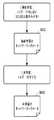
次に、本実施形態の情報処理システムで行われる各種処理について説明する。図2は情報処理システム全体の機能ブロック図、図3は情報処理システムにおける処理の流れを示すフローチャートである。図2に示す通り、クライアントPC100は、デモザイク推論部111とノイズ低減部112を有する。また、クラウドサーバ200は、教師画像生成部211、データセット生成部212及びデモザイク学習部213を有する。図2に示す各機能部は、それぞれの機能部に対応するコンピュータプログラムをCPU101/201が実行することで実現される。ただし、図2に示す機能部の全部あるいは一部をハードウェアで実装してもよい。以下、図3のフローに沿って説明する。なお、以下の説明において記号「S」はステップを意味する。<Process flow of the entire system>
Next, various processes performed by the information processing system of the present embodiment will be described. FIG. 2 is a functional block diagram of the entire information processing system, and FIG. 3 is a flowchart showing a processing flow in the information processing system. As shown in FIG. 2, the client PC 100 has a
S301では、教師画像の元になるサンプル画像がクラウドサーバ200に入力される。サンプル画像は、デジタルカメラで撮像することで得られたRAW画像(モザイク画像)であり、被写体や撮像条件のバリエーションが豊富であることが望ましい。サンプル画像の具体例としては、風景や動物といった自然写真、ポートレートやスポーツシーンといった人物写真、建築や商品といった人工物写真などが挙げられる。また、デジタルカメラ10で撮像したものをそのままアップロードしてもよいし、撮り溜めたものをHDD等に記憶しておきそれをアップロードしてもよい。クラウドサーバ200に入力されたサンプル画像のデータは、教師画像生成部211に送られる。 In S301, a sample image that is the source of the teacher image is input to the
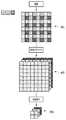
S302では、教師画像生成部211が、受け取ったサンプル画像に基づいて教師画像を生成する。図4は、教師画像の生成を説明する図である。以下、図4を参照しつつ説明する。 In S302, the teacher
まず、受け取ったサンプル画像401は、R(赤)画素、G(緑)画素、B(青)画素の各画素が図示された配置で規則的に並んだベイヤ形式のモザイク画像となっている。そこで、サンプル画像401に対して簡易的なデモザイク手法(例えば、特許文献1の手法)を適用し、RGBの3チャネルから成るRGB画像402を得る。その後、RGB画像402に対して、例えばbilinear補間やbicubic補間の手法により縦横の画素数が4分の1になるよう画像縮小を行う。RGB画像には、簡易デモザイクにより発生したモアレや偽色等のアーティファクトが含まれているが、このアーティファクトは画像縮小によって低減されることになる。なお、画像の縮小率は4分の1以外としても構わない。こうした処理が入力されたすべてのサンプル画像について行われ、サンプル画像それぞれに対応する教師画像403が得られる。また、デジタルカメラ10において簡易的なデモザイクまでを済ませ、RGB画像のデータ形式でクラウドサーバ200に入力されてもよい。このようにして生成・取得された教師画像403のデータは、データセット生成部212に送られる。 First, the received
S303では、データセット生成部212が、入力された教師画像群に基づいて、学習に用いるデータセットを生成する。図5は、データセット生成部212の詳細を示すブロック図である。データセット生成部212は、チャネル分解部501、R画像ノイズ付与部502、G画像ノイズ付与部503、B画像ノイズ付与部504、モザイク画像生成部505、チャネル連結部506及び画像ペア生成部507で構成される。以下、図5を参照しつつ、学習用データセットの生成について説明する。なお、以下に説明する内容は、入力された教師画像群に含まれる各教師画像の単位で実行される。 In S303, the data set
≪学習用データセットの生成≫
まず、チャネル分解部501が、RGBの3チャネルから成る教師画像を、RGBそれぞれのチャネル単位の画像(以下、「チャネル画像」と呼ぶ。)に分解する。各々のチャネル画像は、教師画像と同じ画像サイズ・同じビット深度を有する。なお、RGBそれぞれに対応するチャネル画像を、「R画像」、「G画像」、「B画像」と表記する場合がある。≪Generation of learning data set≫
First, the
続いて、R画像ノイズ付与部502、G画像ノイズ付与部503、B画像ノイズ付与部504それぞれが、自身が担当するチャネル画像に対して、以下の式(5)を用いてノイズの付与を行う。 Subsequently, each of the R image
上記式(5)において、s(x、y)はチャネル画像中の座標(x、y)における信号値(画素値)を示し、r(x、y)は平均が“0”かつ分散が“1”の標準正規分布に従う乱数を示し、σ(x、y)はノイズの標準偏差を示す。また、n(x、y)はノイズ付与後のチャネル画像中の座標(x、y)における画素値を示す。ここで、標準偏差σ(x、y)は、下記式(6)に示すように、ノイズ付与前のチャネル画像における信号値に基づいて決定する。 In the above equation (5), s (x, y) indicates a signal value (pixel value) at coordinates (x, y) in the channel image, and r (x, y) has an average of "0" and a variance of "0". A random number following a standard normal distribution of 1 ”is shown, and σ (x, y) is the standard deviation of noise. Further, n (x, y) indicates a pixel value at the coordinates (x, y) in the channel image after adding noise. Here, the standard deviation σ (x, y) is determined based on the signal value in the channel image before noise is applied, as shown in the following equation (6).
上記式(6)において、k、Iは所与の定数である。各定数は、入力RAW画像の撮像に使用する撮像装置の特性に応じて決定する。具体的には、事前にテスト用チャートを撮像して、得られた撮像画像から信号値sと標準偏差σを実測し、両者の関係からk、Iを求める。なお、ここでは、付与するノイズを、上記式(6)の標準偏差に基づく正規分布に従う加法性ノイズとしたが、他の分布や付与方式を持つノイズでもよい。例えば、輝度に依存しない一定の分散に従ったノイズでもよい。また、例えば全画素のうち1%の画素に対して強制的に欠陥画素(画素値を8ビットで表す場合において、画素値を“0”または“255”に意図的に設定した画素)とすることでノイズとしてもよい。或いはまた、チャネル画像中の縦(列)方向に並ぶ画素のみ又は横(行)方向に並ぶ画素にのみを対象としてノイズを付与してもよい。こうして得られたノイズ付与後のチャネル画像(ノイズ有りR像、ノイズ有りG画像、ノイズ有りB画像)は、各ノイズ付与部502〜504から、モザイク画像生成部505とチャネル連結部506にそれぞれ送られる。 In the above equation (6), k and I are given constants. Each constant is determined according to the characteristics of the image pickup apparatus used for capturing the input RAW image. Specifically, a test chart is imaged in advance, the signal value s and the standard deviation σ are actually measured from the obtained image, and k and I are obtained from the relationship between the two. Here, the noise to be applied is additive noise that follows a normal distribution based on the standard deviation of the above equation (6), but noise having another distribution or addition method may be used. For example, noise according to a constant dispersion that does not depend on brightness may be used. Further, for example, 1% of all pixels are forcibly set as defective pixels (pixels whose pixel value is intentionally set to "0" or "255" when the pixel value is represented by 8 bits). This may be noise. Alternatively, noise may be added only to the pixels arranged in the vertical (column) direction or only the pixels arranged in the horizontal (row) direction in the channel image. The noise-added channel images (R image with noise, G image with noise, B image with noise) thus obtained are sent from the noise-adding
続いて、モザイク画像生成部505がノイズ有り生徒画像を、チャネル連結部506がノイズ有り教師画像をそれぞれ生成する。以下、順に説明する。 Subsequently, the mosaic
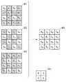
まず、ノイズ有り生徒画像の生成について説明する。ノイズ有り生徒画像は、教師画像からカラーフィルタ配列に基づき所定の画素を間引くことで得られるモザイク画像に、ノイズが加えられた画像である。図6はノイズ有り生徒画像の生成を説明する図である。図6において、縦に並ぶ3つの画像601〜603は、それぞれノイズ有りR画像、ノイズ有りG画像、ノイズ有りB画像であり、ここでは模式的に4×4画素の画像サイズで示している。いま、ノイズ有りR画像601には、画素R00、R01、R02、・・・、R31、R32、R33の計16個の画素が存在する。モザイク画像生成部505は、これら16個の画素の中からカラーフィルタ配列605に従って、画素R00、R02、R20、R22の画素値をサンプリングし、バッファ604の対応する位置に代入する。同様に、ノイズ有りG画像602からもカラーフィルタ配列605に従って、G01、G03、G10、G12、G21、G23、G30、G32の8つの画素の画素値をサンプリングし、バッファ604の対応する位置に代入する。さらに、ノイズ有りB画像603からもカラーフィルタ配列605に従って、B11、B13、B31、B33の4つの画素の画素値をサンプリングし、バッファ604の対応する位置に代入する。これにより、代入後のバッファ604が示す画像は、ノイズを含んだモザイク画像となる。こうして得られたモザイク画像は、ノイズ有り生徒画像として、画像ペア生成部507に送られる。なお、ここではカラーフィルタ配列としてベイヤ配列を使用したが、入力RAW画像の画像形式に合わせて決定すればよく、例えばX−Transなど他のカラーフィルタ配列を用いても構わない。First, the generation of a student image with noise will be described. The noisy student image is an image in which noise is added to a mosaic image obtained by thinning out predetermined pixels based on a color filter array from the teacher image. FIG. 6 is a diagram illustrating the generation of a noisy student image. In FIG. 6, the three
続いて、ノイズ有り教師画像の生成について説明する。チャネル連結部506は、各ノイズ付与部502〜504から受け取った3つのチャネル画像(ノイズ有りR画像、ノイズ有りG画像、ノイズ有りB画像)をチャネル方向に連結する。こうして得られる、ノイズを含んだRGBの3チャネルから成る画像が、ノイズ有り教師画像となる。このノイズ有り教師画像は、教師画像生成部211が生成した教師画像と同じサイズ・同じビット深度・同じチャネル数を有することになる。また、上述のようにして生成されたノイズ有り教師画像とノイズ有り生徒画像とで共通する画素においては、付与されているノイズの値が略一致することになる。 Next, the generation of the teacher image with noise will be described. The
続いて、画像ペア生成部507は、モザイク画像生成部505から受け取ったノイズ有り生徒画像と、チャネル連結部506から受け取った対応するノイズ有り教師画像との画像ペアを生成する。生成した画像ペア(データセット)は、デモザイク学習部213に送られる。 Subsequently, the image
図3のフローの説明に戻る。 Returning to the explanation of the flow of FIG.
S304では、デモザイク学習に用いるCNNに適用する上述のネットワークパラメータがクラウドサーバ200に入力される。ここでのネットワークパラメータは、CNNを構成する各フィルタの係数である。ネットワークパラメータは、「Heの正規分布」に従う乱数として設定する。Heの正規分布とは、平均が“0”で分散がσhとなるような正規分布である。“σh”は以下の式(7)で表される。In S304, the above-mentioned network parameters applied to the CNN used for demosaic learning are input to the
上記式(7)において、mはCNN中の各フィルタのニューロン数である。なお、上述の内容は一例であって、他の方法でネットワークパラメータを決定しても構わない。入力されたネットワークパラメータは、デモザイク学習部213に送られる。 In equation (7) above, m is the number of neurons in each filter in the CNN. The above content is an example, and network parameters may be determined by other methods. The input network parameters are sent to the demosaic learning unit 213.
S305では、デモザイク学習部213が、受け取ったネットワークパラメータを用いてCNNの重みを初期化した後、S303で生成されたデータセットを用いてCNNを学習する。学習には、例えば非特許文献1に開示されているCNNを用いる。図7は、CNNの構造と学習の流れを説明する図である。以下、図7を参照して、本ステップに係るデモザイク学習について詳しく説明する。 In S305, the demosaic learning unit 213 initializes the CNN weights using the received network parameters, and then learns the CNN using the data set generated in S303. For learning, for example, CNN disclosed in Non-Patent Document 1 is used. FIG. 7 is a diagram illustrating the structure of CNN and the flow of learning. Hereinafter, the demosaic learning according to this step will be described in detail with reference to FIG. 7.
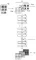
CNNは、前述の式(1)の演算を行う複数のフィルタ702で構成されている。このCNNに対して、前述の画像ペアに含まれるノイズ有り生徒画像700を入力する。この際、図7に示すような3チャネルの欠損画像701に変換して入力する。欠損画像701におけるRチャネル701aには、ノイズ有り生徒画像700のR成分の画素のみが含まれており、他の画素には欠損値(0)が設定されている。Gチャネル、Bチャネルについても同様である。すなわち、Gチャネル701bには、ノイズ有り生徒画像700のG成分の画素のみが含まれており、他の画素には欠損値(0)が設定されている。また、Bチャネル701cには、ノイズ有り生徒画像700のB成分の画素のみが含まれており、他の画素には欠損値(0)が設定されている。なお、欠損値については、bilinear補間等の手法により補間して設定しても構わない。次に、この欠損画像701に対してフィルタ702を順次適用し、特徴マップを算出する。続いて、連結層703によって、算出した特徴マップと欠損画像701とをチャネル方向に連結する。特徴マップと欠損画像のチャネル数がそれぞれn1とn2であった場合、連結結果のチャネル数は(n1+n2)となる。続けて、この連結結果に対してフィルタ702を適用し、最終フィルタではRGB3チャネルの出力を行う。これにより、RGBの3チャネルから成る画像が推論結果704として得られる。そして、得られた推論結果704と、画像ペアに含まれていたノイズ有り教師画像との差分を求め、画像全体についてその平均を取ることにより、損失関数値を得る。そして、得られた損失関数値を用いて、誤差逆伝播法(Back propagation)などによってネットワークパラメータの更新を行う。The CNN is composed of a plurality of
S306では、デモザイク学習が完了したか否かが判定される。学習の完了は、学習(ネットワークパラメータの更新)の反復回数が規定値に達したか否かにより判定する。なお、学習完了の判定基準は反復回数に限定されない。例えば、更新時のネットワークパラメータの変化量が規定値より小さいかどうかや、推論結果とノイズ有り教師画像との差分が規定値より小さいかどうかを用いてもよい。学習が完了していない場合は、S301に戻って、次の画像ペアを生成して学習を続行する。なお、次の画像ペアを生成する際には、過去の学習で用いたサンプル画像や教師画像を再利用してもよい。その場合、データセット生成部212内の各ノイズ付与部502〜504は、毎回新たな乱数に従ってノイズを付与することになる。従って、同じ教師画像に対して、学習の度に異なるノイズが付与され得る。こうすることにより、同一画像からであっても中身の異なる(付与されたノイズが異なる)ノイズ有り教師画像を得て学習することができ、ノイズに対するロバスト性が高められる。なお、一度付与したノイズを記憶しておくことにより、同一画像に対しては必ず同じノイズが付与されるようにしてもよい。こうして得られた学習結果(更新後のネットワークパラメータ)が、ネットワークパラメータの取得リクエストに応じる等してクライアントPC100に提供される。クライアントPC100では、受け取ったネットワークパラメータをRAM102又は大容量記憶装置104に保持する。ここまでが、クラウドサーバ200における学習フェーズである。次に、クライアントPC100における推論フェーズについて説明する。 In S306, it is determined whether or not the demosaic learning is completed. The completion of learning is determined by whether or not the number of repetitions of learning (update of network parameters) has reached a specified value. The criterion for determining the completion of learning is not limited to the number of iterations. For example, it may be used whether or not the amount of change in the network parameter at the time of update is smaller than the specified value, and whether or not the difference between the inference result and the teacher image with noise is smaller than the specified value. If the learning is not completed, the process returns to S301 to generate the next image pair and continue the learning. When generating the next image pair, the sample image or the teacher image used in the past learning may be reused. In that case, each
S307では、デモザイクを含む現像処理の対象となるモザイク画像(RAW画像)が入力される。このRAW画像は、例えばデジタルカメラ10で撮像したものを直接入力してもよいし、事前に撮像して大容量記憶装置104に記憶しておいたものを読み出してもよい。また、入力RAW画像を撮像した際のISO感度といった撮像パラメータも併せて入力される。入力RAW画像のデータはデモザイク推論部111に送られ、入力撮像パラメータはノイズ低減部112に送られる。 In S307, a mosaic image (RAW image) to be developed, including demosaic, is input. As the RAW image, for example, an image captured by the
S308では、デモザイク推論部111が、デモザイク学習部213での学習で用いられたのと同じCNNを構築して、入力RAW画像のデモザイクを行う。この際、既存のネットワークパラメータが、クラウドサーバ200から受け取った更新後のネットワークパラメータで初期化される。こうして、更新後のネットワークパラメータを適用したCNN(学習済みデモザイクネットワーク)に対して、入力RAW画像を入力し、デモザイク学習部213で行ったのと同じ方法でデモザイク推論を行なってRGB画像を得る。デモザイク推論によって得られたRGB画像は、ノイズ低減部112に送られる。 In S308, the
S309では、ノイズ低減部112が、推論結果としてのRGB画像に対し、ノイズ低減処理を行う。ノイズ低減処理には、例えばバイラテラルフィルタ(Bilateral filter)などの公知の手法を適用すればよい。また、ノイズ低減をどれだけ強く掛けるか(ノイズ強度)に関するパラメータは、入力された撮像パラメータに基づいて決定すればよい。 In S309, the
以上が、本実施形態の情報処理システムで行われる処理の流れである。なお、各ノイズ付与部502〜504が付与するノイズの標準偏差σは、下記の式(6’)で表す右辺をα(<1)倍したものでもよい。 The above is the flow of processing performed by the information processing system of the present embodiment. The standard deviation σ of the noise applied by each
上記式(6’)を採用する場合、最初はα=1で学習を行い、その学習結果を用いたデモザイク推論を行って、その結果画像におけるアーティファクトを確認する。アーティファクトの強度が規定値以下である場合、αの値を所定の割合(例えば10%)だけ削減して再度学習を行い、その学習結果を用いたデモザイク推論を行って、その結果画像におけるアーティファクトを確認する。これを繰り返し、アーティファクトが規定値以下で最小となるようなαを探索し、見つかったαの値で学習を行った結果を、最終的な学習結果としてデモザイク推論部111に提供する。なお、最適なαの値が見つかればよいので、探索方法は任意である。この場合、ノイズ有り教師画像に付与するノイズ量を低減でき、過学習を抑制することができる。 When the above equation (6') is adopted, learning is first performed with α = 1, demomosaic inference using the learning result is performed, and the artifact in the resulting image is confirmed. When the intensity of the artifact is less than or equal to the specified value, the value of α is reduced by a predetermined ratio (for example, 10%), learning is performed again, demosaic inference is performed using the learning result, and the artifact in the resulting image is obtained. Check. This is repeated, α is searched so that the artifact becomes the minimum below the specified value, and the result of learning with the found α value is provided to the
<変形例>
本実施形態では、ノイズ付与をクラウドサーバ200内のデータセット生成部212において行っているが、これに限定されない。例えば、デジタルカメラ10で撮像してサンプル画像を得る際に、撮像画像中にノイズが多くなるような条件(高感度、低照度、速いシャッター速度、小さい開口幅など)を設定するなどして撮像装置側でノイズ付与を行ってもよい。<Modification example>
In the present embodiment, noise is added by the data set
また、ノイズの付与は段階的に行ってもよい。例えば、ノイズを付与しない状態で事前学習を行い、その後にノイズを付与して本学習を行ってもよい。図8は、本変形例の考え方を説明する図である。まず、事前学習では、データセット生成部212における画像ペアの生成時、各ノイズ付与部502〜504において付与するノイズ量を“0(或いはそれに準じた少ないノイズ量)”に設定する。そして、前述した手法による学習を行う。これにより、ノイズの無いRAW画像に適合したネットワークパラメータ801が得られる。続いて、本学習では、データセット生成部212における画像ペアの生成時、各ノイズ付与部502〜504において一定レベルのノイズを付与する。そして、上述の実施形態と同様の学習を行う。この際、デモザイク学習部213に入力されるネットワークパラメータは、事前学習にて得られたネットワークパラメータであり、デモザイク学習部213はこれを初期値として学習を行うことになる。これにより、ノイズの有るRAW画像に適合したネットワークパラメータ803が得られる。なお、メモリから読み出した或いはweb上から取得した学習済みのネットワークパラメータを事前学習の結果と見做し、これを初期値として本学習を行ってもよい。このように2段階で学習を行って得られたネットワークパラメータを用いてデモザイク推論を行うことにより、ノイズの有り/無し両方のRAW画像に対して、よりアーティファクトの少ないデモザイク画像が得られるようになる。さらには、学習の容易なノイズ無し教師画像で事前学習を行い、その後に学習の困難なノイズ有り教師画像で本学習を行うことにより、カリキュラム学習の考え方に基づいて、少ない計算コストで高いアーティファクト抑制効果が得られる。なお、学習の段階数は2段階だけには限らず、ノイズ量を増やしながら3段階以上の複数段階にて学習を行っても構わない。また、1段階の学習の中で、付与するノイズ量を動的に上昇、すなわち、学習の進みに応じて付与するノイズの強度が強くなるよう段階的に変更してもよい。 Further, the noise may be added step by step. For example, pre-learning may be performed without adding noise, and then noise may be added to perform the main learning. FIG. 8 is a diagram illustrating the concept of this modification. First, in the pre-learning, when the image pair is generated by the data set
また、本実施形態の現像処理では、デモザイク後にノイズ低減を行っているが、これとは逆に、ノイズ低減後にデモザイクを行っても構わない。ノイズ低減後にデモザイクを行う構成において、ノイズ低減処理によって現像対象の入力RAW画像中のノイズを除去しきれなかった場合、ノイズを多く含むモザイク画像がデモザイク推論の対象となる。この場合でも、ロバスト性の高いデモザイクネットワークを使用したデモザイク推論によって同様の推論結果を得ることができる。 Further, in the development process of the present embodiment, noise reduction is performed after noise reduction, but conversely, noise reduction may be performed after noise reduction. In a configuration in which demosaic is performed after noise reduction, if the noise in the input RAW image to be developed cannot be completely removed by the noise reduction processing, the mosaic image containing a large amount of noise becomes the target of demosaic inference. Even in this case, similar inference results can be obtained by demosaic inference using a highly robust demosaic network.
以上のとおり本実施形態によれば、教師画像と生徒画像の双方にノイズを付与して学習することでノイズに対するロバスト性の高いデモザイクネットワークを得る。これにより、現像対象のRAW画像に多くのノイズが含まれていても、デモザイク推論においてアーティファクトの少ない推論結果を得ることができる。 As described above, according to the present embodiment, a demosaic network having high robustness against noise is obtained by learning by adding noise to both the teacher image and the student image. As a result, even if the RAW image to be developed contains a lot of noise, it is possible to obtain an inference result with few artifacts in demosaic inference.
(その他の実施例)
本発明は、上述の実施形態の1以上の機能を実現するプログラムを、ネットワーク又は記憶媒体を介してシステム又は装置に供給し、そのシステム又は装置のコンピュータにおける1つ以上のプロセッサーがプログラムを読出し実行する処理でも実現可能である。また、1以上の機能を実現する回路(例えば、ASIC)によっても実現可能である。(Other examples)
The present invention supplies a program that realizes one or more functions of the above-described embodiment to a system or device via a network or storage medium, and one or more processors in the computer of the system or device reads and executes the program. It can also be realized by the processing to be performed. It can also be realized by a circuit (for example, ASIC) that realizes one or more functions.
Claims (18)
Translated fromJapaneseRGBの3チャネルから成る教師画像を取得する取得手段と、
取得した前記教師画像に基づき、ノイズ有り教師画像とノイズ有り生徒画像との組で構成されるデータセットを生成する生成手段と、
を備え、
前記ノイズ有り教師画像は、前記教師画像にノイズを付与した画像であり、
前記ノイズ有り生徒画像は、前記教師画像からカラーフィルタ配列に基づき所定の画素を間引いたモザイク画像にノイズを付与した画像である、
ことを特徴とする情報処理装置。An information processing device that generates learning data for demosaic networks.
An acquisition means for acquiring a teacher image consisting of three channels of RGB,
A generation means for generating a data set composed of a set of a noisy teacher image and a noisy student image based on the acquired teacher image, and
Equipped with
The noisy teacher image is an image in which noise is added to the teacher image.
The noisy student image is an image in which noise is added to a mosaic image in which predetermined pixels are thinned out from the teacher image based on a color filter array.
An information processing device characterized by this.
前記教師画像をRGBの各チャネルに対応するチャネル画像に分解する分解手段と、
前記チャネル画像のそれぞれにノイズを付与する付与手段と、
前記付与手段にてノイズが付与された各チャネル画像における所定の画素をカラーフィルタ配列に従ってサンプリングして、前記ノイズが付与されたモザイク画像を生成するモザイク画像生成手段と、
前記付与手段にてノイズが付与された各チャネル画像を連結して、前記ノイズが付与されたRGBの3チャネルから成る画像を生成する連結手段と、
前記ノイズが付与されたモザイク画像を前記ノイズ有り生徒画像として、前記ノイズが付与されたRGBの3チャネルから成る画像を前記ノイズ有り教師画像として、前記データセットを得る画像ペア生成手段と、
を有することを特徴とする、請求項1乃至3のいずれか1項に記載の情報処理装置。The generation means is
Decomposition means for decomposing the teacher image into channel images corresponding to each RGB channel, and
An imparting means for imparting noise to each of the channel images, and
A mosaic image generation means for generating a mosaic image to which noise is added by sampling predetermined pixels in each channel image to which noise is added by the addition means according to a color filter array.
A connecting means for connecting each channel image to which noise is added by the adding means to generate an image consisting of three channels of RGB to which the noise is added, and a connecting means.
An image pair generation means for obtaining the data set, wherein the noisy mosaic image is used as the noisy student image, and the noisy RGB three-channel image is used as the noisy teacher image.
The information processing apparatus according to any one of claims 1 to 3, wherein the information processing apparatus has.
ことを特徴とする、請求項6に記載の情報処理装置。The standard deviation is expressed by the following equation.
The information processing apparatus according to claim 6, wherein the information processing apparatus is characterized in that.
前記付与手段は、前記学習の進みに応じて、付与するノイズの強度を変更する、
ことを特徴とする請求項4乃至7のいずれか1項に記載の情報処理装置。A learning means for learning the demosaic network using the data set generated by the generation means is further provided.
The imparting means changes the intensity of the noise to be imparted according to the progress of the learning.
The information processing apparatus according to any one of claims 4 to 7.
前記RAW画像に対して、前記学習によって得られた学習済みネットワークパラメータを用いた推論によるデモザイク処理を行う推論手段と、
前記推論手段における前記デモザイク処理によって得られた、RGBの3チャネルから成るRGB画像に対し、ノイズ低減処理を行うノイズ低減手段と、
をさらに備えたことを特徴とする、請求項10乃至14のいずれか1項に記載の情報処理装置。An acquisition method for acquiring a RAW image to be developed,
An inference means that performs inference processing on the RAW image by inference using the learned network parameters obtained by the learning.
A noise reducing means for performing noise reducing processing on an RGB image composed of three RGB channels obtained by the demosaic processing in the inference means.
The information processing apparatus according to any one of claims 10 to 14, further comprising.
RGBの3チャネルから成る教師画像を取得する取得ステップと、
取得した前記教師画像に基づき、ノイズ有り教師画像とノイズ有り生徒画像との組で構成されるデータセットを生成する生成ステップと、
を含み、
前記ノイズ有り教師画像は、前記教師画像にノイズを付与した画像であり、
前記ノイズ有り生徒画像は、前記教師画像からカラーフィルタ配列に基づき所定の画素を間引いたモザイク画像にノイズを付与した画像である、
ことを特徴とする情報処理方法。An information processing method that generates learning data for demosaic networks.
An acquisition step to acquire a teacher image consisting of 3 channels of RGB,
Based on the acquired teacher image, a generation step to generate a data set composed of a set of a noisy teacher image and a noisy student image, and
Including
The noisy teacher image is an image in which noise is added to the teacher image.
The noisy student image is an image in which noise is added to a mosaic image in which predetermined pixels are thinned out from the teacher image based on a color filter array.
An information processing method characterized by that.
Priority Applications (2)
| Application Number | Priority Date | Filing Date | Title |
|---|---|---|---|
| JP2020085177AJP7508265B2 (en) | 2020-05-14 | 2020-05-14 | Information processing device, information processing method, and program |
| US17/245,364US11967040B2 (en) | 2020-05-14 | 2021-04-30 | Information processing apparatus, control method thereof, imaging device, and storage medium |
Applications Claiming Priority (1)
| Application Number | Priority Date | Filing Date | Title |
|---|---|---|---|
| JP2020085177AJP7508265B2 (en) | 2020-05-14 | 2020-05-14 | Information processing device, information processing method, and program |
Publications (3)
| Publication Number | Publication Date |
|---|---|
| JP2021179833Atrue JP2021179833A (en) | 2021-11-18 |
| JP2021179833A5 JP2021179833A5 (en) | 2023-05-09 |
| JP7508265B2 JP7508265B2 (en) | 2024-07-01 |
Family
ID=78511525
Family Applications (1)
| Application Number | Title | Priority Date | Filing Date |
|---|---|---|---|
| JP2020085177AActiveJP7508265B2 (en) | 2020-05-14 | 2020-05-14 | Information processing device, information processing method, and program |
Country Status (2)
| Country | Link |
|---|---|
| US (1) | US11967040B2 (en) |
| JP (1) | JP7508265B2 (en) |
Families Citing this family (7)
| Publication number | Priority date | Publication date | Assignee | Title |
|---|---|---|---|---|
| JP7508265B2 (en)* | 2020-05-14 | 2024-07-01 | キヤノン株式会社 | Information processing device, information processing method, and program |
| JP2022002376A (en) | 2020-06-22 | 2022-01-06 | キヤノン株式会社 | Image processing apparatus, image processing method, and program |
| US11417125B2 (en)* | 2020-11-30 | 2022-08-16 | Sony Group Corporation | Recognition of license plate numbers from Bayer-domain image data |
| KR20220094561A (en)* | 2020-12-29 | 2022-07-06 | 에스케이하이닉스 주식회사 | Image sensing device and method of operating the same |
| JP7709289B2 (en) | 2021-03-01 | 2025-07-16 | キヤノン株式会社 | Image processing device and image processing method |
| JP2022137916A (en) | 2021-03-09 | 2022-09-22 | キヤノン株式会社 | IMAGE PROCESSING APPARATUS, IMAGE FORMING SYSTEM, IMAGE PROCESSING METHOD AND PROGRAM |
| CN116452416A (en)* | 2022-01-10 | 2023-07-18 | 北京三星通信技术研究有限公司 | Image processing method, device, electronic equipment and computer readable storage medium |
Citations (2)
| Publication number | Priority date | Publication date | Assignee | Title |
|---|---|---|---|---|
| US20150215590A1 (en)* | 2014-01-24 | 2015-07-30 | Microsoft Corporation | Image demosaicing |
| JP2019121252A (en)* | 2018-01-10 | 2019-07-22 | キヤノン株式会社 | Image processing method, image processing apparatus, image processing program and storage medium |
Family Cites Families (10)
| Publication number | Priority date | Publication date | Assignee | Title |
|---|---|---|---|---|
| WO2012097336A1 (en)* | 2011-01-13 | 2012-07-19 | Rutgers, The State University Of New Jersey | Enhanced multi-protocol analysis via intelligent supervised embedding (empravise) for multimodal data fusion |
| JP2012095351A (en) | 2012-01-12 | 2012-05-17 | Olympus Corp | Imaging system |
| US9613396B2 (en)* | 2013-12-09 | 2017-04-04 | Marvell World Trade Ltd. | Method and apparatus for demosaicing of color filter array image |
| JP7124404B2 (en)* | 2018-04-12 | 2022-08-24 | 富士通株式会社 | Machine learning program, machine learning method and machine learning apparatus |
| US11030487B2 (en)* | 2018-09-05 | 2021-06-08 | Vanderbilt University | Noise-robust neural networks and methods thereof |
| JP7278766B2 (en) | 2018-12-21 | 2023-05-22 | キヤノン株式会社 | Image processing device, image processing method and program |
| JP2020129276A (en) | 2019-02-08 | 2020-08-27 | キヤノン株式会社 | Image processing apparatus, image processing method, and program |
| JP7508265B2 (en)* | 2020-05-14 | 2024-07-01 | キヤノン株式会社 | Information processing device, information processing method, and program |
| EP4044110A4 (en)* | 2020-10-27 | 2023-02-22 | Samsung Electronics Co., Ltd. | Method for generating image data with reduced noise, and electronic device for performing same |
| JP2022150562A (en)* | 2021-03-26 | 2022-10-07 | キヤノン株式会社 | Image processing device, image processing method and program |
- 2020
- 2020-05-14JPJP2020085177Apatent/JP7508265B2/enactiveActive
- 2021
- 2021-04-30USUS17/245,364patent/US11967040B2/enactiveActive
Patent Citations (2)
| Publication number | Priority date | Publication date | Assignee | Title |
|---|---|---|---|---|
| US20150215590A1 (en)* | 2014-01-24 | 2015-07-30 | Microsoft Corporation | Image demosaicing |
| JP2019121252A (en)* | 2018-01-10 | 2019-07-22 | キヤノン株式会社 | Image processing method, image processing apparatus, image processing program and storage medium |
Non-Patent Citations (1)
| Title |
|---|
| KAI CUI ET AL.: "Color Image Demosaicking Using a 3-Stage Convolutional Neural Network Structure", 2018 25TH IEEE INTERNATIONAL CONFERENCE ON IMAGE PROCESSING (ICIP), JPN6024018290, 10 October 2018 (2018-10-10), US, ISSN: 0005326909* |
Also Published As
| Publication number | Publication date |
|---|---|
| US11967040B2 (en) | 2024-04-23 |
| US20210358081A1 (en) | 2021-11-18 |
| JP7508265B2 (en) | 2024-07-01 |
Similar Documents
| Publication | Publication Date | Title |
|---|---|---|
| JP7508265B2 (en) | Information processing device, information processing method, and program | |
| CN110770784B (en) | Image processing device, imaging device, image processing method, program, and storage medium | |
| JP7512150B2 (en) | Information processing device, information processing method, and program | |
| WO2021164234A1 (en) | Image processing method and image processing device | |
| Saleh et al. | Adaptive uncertainty distribution in deep learning for unsupervised underwater image enhancement | |
| CN108364270B (en) | Color restoration method and device for color cast image | |
| JP7463186B2 (en) | Information processing device, information processing method, and program | |
| US12380534B2 (en) | Training apparatus, training method, and medium | |
| CN114240794B (en) | Image processing method, system, device and storage medium | |
| CN118096529B (en) | Datamation fusion algorithm for improving spatial resolution of hyperspectral image | |
| Peng et al. | Raune-Net: a residual and attention-driven underwater image enhancement method | |
| CN113205507A (en) | Visual question answering method, system and server | |
| WO2023005818A1 (en) | Noise image generation method and apparatus, electronic device, and storage medium | |
| Wang et al. | Single underwater image enhancement using an analysis-synthesis network | |
| CN117611455A (en) | Underwater image enhancement method and system based on generation countermeasure network | |
| US12333675B2 (en) | Image processing apparatus, image processing method, and storage medium | |
| JP2023047600A (en) | Information processing device, information processing method and program | |
| CN115965555B (en) | Noise estimation image enhancement method based on transducer network | |
| US20230088317A1 (en) | Information processing apparatus, information processing method, and storage medium | |
| CN116740399A (en) | Training methods, matching methods and media for heterogeneous image matching models | |
| JP7598272B2 (en) | Image processing device and learning method | |
| CN116095256B (en) | Deep learning image conversion model training method, device, equipment and medium | |
| JP7724643B2 (en) | Image processing device, image processing method, and program | |
| US12380532B2 (en) | Image processing apparatus, image processing method, and non-transitory computer-readable storage medium | |
| US20240193732A1 (en) | Image processing apparatus, image processing method, and non-transitory computer-readable storage medium |
Legal Events
| Date | Code | Title | Description |
|---|---|---|---|
| A521 | Request for written amendment filed | Free format text:JAPANESE INTERMEDIATE CODE: A523 Effective date:20230424 | |
| A621 | Written request for application examination | Free format text:JAPANESE INTERMEDIATE CODE: A621 Effective date:20230424 | |
| A977 | Report on retrieval | Free format text:JAPANESE INTERMEDIATE CODE: A971007 Effective date:20240205 | |
| A131 | Notification of reasons for refusal | Free format text:JAPANESE INTERMEDIATE CODE: A131 Effective date:20240213 | |
| A521 | Request for written amendment filed | Free format text:JAPANESE INTERMEDIATE CODE: A523 Effective date:20240409 | |
| TRDD | Decision of grant or rejection written | ||
| A01 | Written decision to grant a patent or to grant a registration (utility model) | Free format text:JAPANESE INTERMEDIATE CODE: A01 Effective date:20240521 | |
| A61 | First payment of annual fees (during grant procedure) | Free format text:JAPANESE INTERMEDIATE CODE: A61 Effective date:20240619 | |
| R150 | Certificate of patent or registration of utility model | Ref document number:7508265 Country of ref document:JP Free format text:JAPANESE INTERMEDIATE CODE: R150 |