Movatterモバイル変換


[0]ホーム

URL:


JP2021177450A - Connector assembly - Google Patents

Connector assembly
Download PDF

Info

Publication number
JP2021177450A
JP2021177450AJP2020081861AJP2020081861AJP2021177450AJP 2021177450 AJP2021177450 AJP 2021177450AJP 2020081861 AJP2020081861 AJP 2020081861AJP 2020081861 AJP2020081861 AJP 2020081861AJP 2021177450 AJP2021177450 AJP 2021177450A
Authority
JP
Japan
Prior art keywords
housing
terminal
connector
mating
additional
Prior art date
Legal status (The legal status is an assumption and is not a legal conclusion. Google has not performed a legal analysis and makes no representation as to the accuracy of the status listed.)
Granted
Application number
JP2020081861A
Other languages
Japanese (ja)
Other versions
JP2021177450A5 (en
JP7414635B2 (en
Inventor
真生 山本
Masanari Yamamoto
ツァイク ミカエル
Zayc Michael
シュナイダー デイビッド
Schneider David
キングズウェル ステュアート
Kingswell Stuart
Current Assignee (The listed assignees may be inaccurate. Google has not performed a legal analysis and makes no representation or warranty as to the accuracy of the list.)
Japan Aviation Electronics Industry Ltd
Original Assignee
Japan Aviation Electronics Industry Ltd
Priority date (The priority date is an assumption and is not a legal conclusion. Google has not performed a legal analysis and makes no representation as to the accuracy of the date listed.)
Filing date
Publication date
Application filed by Japan Aviation Electronics Industry LtdfiledCriticalJapan Aviation Electronics Industry Ltd
Priority to JP2020081861ApriorityCriticalpatent/JP7414635B2/en
Priority to CN202110438857.1Aprioritypatent/CN113629449B/en
Priority to US17/237,220prioritypatent/US11495906B2/en
Priority to EP21170899.5Aprioritypatent/EP3907833B1/en
Priority to RS20221115Aprioritypatent/RS63792B1/en
Publication of JP2021177450ApublicationCriticalpatent/JP2021177450A/en
Publication of JP2021177450A5publicationCriticalpatent/JP2021177450A5/ja
Application grantedgrantedCritical
Publication of JP7414635B2publicationCriticalpatent/JP7414635B2/en
Activelegal-statusCriticalCurrent
Anticipated expirationlegal-statusCritical

Links

Images

Classifications

Landscapes

Abstract

Translated fromJapanese

【課題】従来品よりも小型で部品点数が少なく、コネクタの嵌合・離脱時の操作もより簡便な新規のコネクタ組立体を提供する。【解決手段】コネクタ組立体10は、コネクタ20と、相手側コネクタ60とを備えている。相手側コネクタ60は、相手側第1端子82と、相手側第2端子84と、相手側ハウジング70とを備えている。相手側ハウジング70には、解除突起722と、相手側ロック部725とが形成されている。コネクタ20は、第1端子と、第1ハウジング30と、第2端子54と、第2ハウジング40とを備えている。第1ハウジング30には、第1支持部362とロック部365とを有する第1構造体36と、ストッパ部350とが設けられている。第2ハウジング40には、被ストップ部464と、規制部442とが設けられている。第1ハウジング30及び第2ハウジング40の一方には、第2支持部46が設けられている。【選択図】図18PROBLEM TO BE SOLVED: To provide a new connector assembly which is smaller than a conventional product, has a small number of parts, and is easier to operate when fitting and detaching a connector. A connector assembly 10 includes a connector 20 and a mating connector 60. The mating side connector 60 includes a mating side first terminal 82, a mating side second terminal 84, and a mating side housing 70. The mating side housing 70 is formed with a release protrusion 722 and a mating side lock portion 725. The connector 20 includes a first terminal, a first housing 30, a second terminal 54, and a second housing 40. The first housing 30 is provided with a first structure 36 having a first support portion 362 and a lock portion 365, and a stopper portion 350. The second housing 40 is provided with a stopped portion 464 and a regulation portion 442. A second support portion 46 is provided on one of the first housing 30 and the second housing 40. [Selection diagram] FIG. 18

Description

Translated fromJapanese

本発明は、コネクタと、相手側コネクタとを備えるコネクタ組立体に関する。 The present invention relates to a connector assembly comprising a connector and a mating connector.

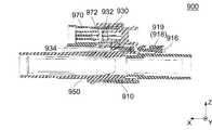
図45から図47までに示されるように、特許文献1のコネクタ組立体900は、雌高圧コネクタ910と、雌HVILコネクタ930と、雄高圧コネクタ950と、雄HVILコネクタ970とを備えている。雌高圧コネクタ910は、X方向に沿って雄高圧コネクタ950と嵌合可能となっている。雌高圧コネクタ910は、X方向にスライド移動可能なスライド部材916と、ラッチデバイス918とを有している。ラッチデバイス918は、ラッチハンドル919と、係止ラッチ(図示せず)とを有している。係止ラッチは、ラッチハンドル919によりZ方向に移動可能となっている。雌HVILコネクタ930は、雌高圧コネクタ910から取り外し可能となっている。雌HVILコネクタ930は、X方向に沿って雄HVILコネクタ970と嵌合可能となっている。雌HVILコネクタ930は、低圧端子932と、当接肩部934とを有している。雄高圧コネクタ950は、相補的凹所954を有している。雄HVILコネクタ970は、雄高圧コネクタ950に取り付けられている。雄HVILコネクタ970は、低圧端子972と、ストッパ肩部976とを有している。雌HVILコネクタ930と雄HVILコネクタ970とが嵌合して低圧端子932と低圧端子972とが接続されると、高電圧インターロック(HVIL:High Voltage Interlock Loop)回路が閉じて雌高圧コネクタ910と雄高圧コネクタ950との間に電力が供給される。雌HVILコネクタ930が雄HVILコネクタ970から外されて低圧端子932と低圧端子972との接続が解除されると、HVIL回路が開いて雌高圧コネクタ910と雄高圧コネクタ950との間の電力供給が遮断される。 As shown in FIGS. 45 to 47, theconnector assembly 900 of Patent Document 1 includes a female high-pressure connector 910, afemale HVIL connector 930, a male high-pressure connector 950, and amale HVIL connector 970. The female high-voltage connector 910 can be fitted with the male high-voltage connector 950 along the X direction. The female high-voltage connector 910 has aslide member 916 that can slide and move in the X direction, and alatch device 918. Thelatch device 918 has alatch handle 919 and a locking latch (not shown). The locking latch is movable in the Z direction by thelatch handle 919. Thefemale HVIL connector 930 is removable from the femalehigh voltage connector 910. Thefemale HVIL connector 930 can be fitted with themale HVIL connector 970 along the X direction. Thefemale HVIL connector 930 has alow pressure terminal 932 and acontact shoulder portion 934. The malehigh voltage connector 950 has acomplementary recess 954. Themale HVIL connector 970 is attached to the malehigh voltage connector 950. Themale HVIL connector 970 has alow voltage terminal 972 and astopper shoulder 976. When thefemale HVIL connector 930 and themale HVIL connector 970 are fitted and thelow voltage terminal 932 and thelow voltage terminal 972 are connected, the high voltage interlock (HVIL) circuit is closed and the femalehigh voltage connector 910 is connected. Power is supplied to and from the malehigh voltage connector 950. When thefemale HVIL connector 930 is disconnected from themale HVIL connector 970 and the connection between thelow voltage terminal 932 and thelow voltage terminal 972 is disconnected, the HVIL circuit is opened to supply power between the femalehigh voltage connector 910 and the malehigh voltage connector 950. It is blocked.

コネクタ組立体900においては、雌高圧コネクタ910と雄高圧コネクタ950との間に電力を供給するためには、以下の操作を行う必要がある。まず、図47に示されるように、雌高圧コネクタ910と雄高圧コネクタ950とをX方向に沿って互いに嵌合させる。このとき、ラッチデバイス918の係止ラッチは、図46に示される相補的凹所954と係合し、雌高圧コネクタ910と雄高圧コネクタ950との嵌合をロックする。次に、スライド部材916を図46に示す位置まで+X方向に押し込む。このとき、ラッチハンドル919の−Z側にスライド部材916が位置することにより、ラッチハンドル919を−Z方向に押圧しても係止ラッチが+Z方向に移動して上記ロックが解除されないようになっている。この状態で、雌HVILコネクタ930を雄HVILコネクタ970に向かってスライドさせて低圧端子932と低圧端子972とを接触させ、図45の状態とする。これにより、HVIL回路が閉じて、雌高圧コネクタ910と雄高圧コネクタ950との間に電力が供給される。なお、スライド部材916を図46に示す位置まで押し込むことなく雌HVILコネクタ930を雄HVILコネクタ970に向かってスライドさせた場合、図45に示される当接肩部934が図46に示されるストッパ肩部976に突き当たり、雌HVILコネクタ930と雄HVILコネクタ970とを嵌合させることができないようになっている。また、雌高圧コネクタ910と雄高圧コネクタ950との嵌合を解除するためには、上記操作と逆の操作を行う必要がある。 In theconnector assembly 900, in order to supply electric power between the female high-voltage connector 910 and the male high-voltage connector 950, it is necessary to perform the following operations. First, as shown in FIG. 47, the female high-voltage connector 910 and the male high-voltage connector 950 are fitted to each other along the X direction. At this time, the locking latch of thelatch device 918 engages with thecomplementary recess 954 shown in FIG. 46 to lock the fit between the femalehigh voltage connector 910 and the malehigh voltage connector 950. Next, theslide member 916 is pushed in the + X direction to the position shown in FIG. At this time, since theslide member 916 is located on the −Z side of thelatch handle 919, the locking latch moves in the + Z direction even if thelatch handle 919 is pressed in the −Z direction, and the lock is not released. ing. In this state, thefemale HVIL connector 930 is slid toward themale HVIL connector 970 to bring the low-voltage terminal 932 and the low-voltage terminal 972 into contact with each other, and the state shown in FIG. 45 is obtained. As a result, the HVIL circuit is closed and power is supplied between the femalehigh voltage connector 910 and the malehigh voltage connector 950. When thefemale HVIL connector 930 is slid toward themale HVIL connector 970 without pushing theslide member 916 to the position shown in FIG. 46, thecontact shoulder portion 934 shown in FIG. 45 becomes the stopper shoulder shown in FIG. Thefemale HVIL connector 930 and themale HVIL connector 970 cannot be fitted by hitting theportion 976. Further, in order to release the fitting between the female high-voltage connector 910 and the male high-voltage connector 950, it is necessary to perform an operation opposite to the above operation.

特開2010−56088号公報JP-A-2010-56088

特許文献1のコネクタ組立体900は、部品点数が多いことから、製造工程が煩雑化し、製造コストが増大するという問題がある。 Since theconnector assembly 900 of Patent Document 1 has a large number of parts, there is a problem that the manufacturing process becomes complicated and the manufacturing cost increases.

よって本発明は、従来品よりも小型で部品点数が少なく、コネクタの嵌合・離脱時の操作もより簡便な新規のコネクタ組立体を提供することを目的とする。 Therefore, an object of the present invention is to provide a new connector assembly which is smaller in size than a conventional product, has a smaller number of parts, and is easier to operate when fitting and detaching a connector.

即ち、本発明は、第1のコネクタ組立体として、
コネクタと、相手側コネクタとを備えるコネクタ組立体であって、
前記相手側コネクタは、相手側第1端子と、相手側第2端子と、相手側ハウジングとを備えており、
前記相手側ハウジングは、前記相手側第1端子と、前記相手側第2端子とを保持しており、
前記相手側ハウジングは、受容部を構成しており、
前記相手側ハウジングには、解除突起と、相手側ロック部とが形成されており、
前記解除突起は、前記受容部内に突出しており、
前記相手側ロック部は、前記受容部内に面しており、
前記コネクタは、嵌合方向に沿って前記相手側コネクタに対して嵌合可能であり、
前記コネクタは、第1端子と、第1ハウジングと、第2端子と、第2ハウジングとを備えており、
前記第1ハウジングは、前記嵌合方向に沿って前記受容部に受容されるものであり、
前記第1ハウジングは、前記第1端子を保持しており、
前記第1端子は、前記第1ハウジングが前記受容部に受容されたとき、前記相手側第1端子に接続されるものであり、
前記第1ハウジングには、第1支持部とロック部とを有する第1構造体と、ストッパ部とが設けられており、
前記第1支持部は、復元力を有しており、前記ロック部を支持しており、
前記ロック部は、前記第1支持部の前記復元力を利用して前記嵌合方向と直交する直交方向に移動可能であり、
前記ロック部と前記相手側ロック部は、前記第1端子が前記相手側第1端子に接続されたとき、前記第1ハウジングが前記受容部に受容された状態をロックするものであり、
前記第2ハウジングは、前記第2端子を保持しており、
前記第2ハウジングには、被ストップ部と、規制部とが設けられており、
前記第1ハウジング及び前記第2ハウジングの一方には、第2支持部が設けられており、
前記第2支持部は、復元力を有しており、前記ストッパ部及び前記被ストップ部の一方を被支持部として支持しており、
前記被支持部は、前記第2支持部の前記復元力を利用して前記直交方向に移動可能であり、
前記第2ハウジングを前記第1ハウジングに対して前記嵌合方向に沿って組み込むと、前記被ストップ部が前記ストッパ部に突き当り、前記第2ハウジングは前記ストッパ部により前記嵌合方向への移動を規制された規制状態となり、
前記規制状態の前記第2ハウジングを前記第1ハウジングと共に前記嵌合方向に沿って前記受容部に受容させると、前記相手側第1端子に前記第1端子が接続された後、前記第2支持部又は前記被支持部が前記解除突起に当たって前記嵌合方向への前記第2ハウジングの移動規制が解除され、
前記移動規制が解除された後、前記第2ハウジングを前記嵌合方向に更に移動させると、前記第2端子が前記相手側第2端子に接続されると共に、前記規制部が前記第1構造体の少なくとも一部の前記直交方向における内側に位置して前記ロック部の前記直交方向における移動を規制する
コネクタ組立体を提供する。
That is, the present invention comprises the first connector assembly.
A connector assembly comprising a connector and a mating connector.
The mating connector includes a mating first terminal, a mating second terminal, and a mating housing.
The mating housing holds the mating first terminal and the mating second terminal.
The mating housing constitutes a receiving portion and
The mating side housing is formed with a release protrusion and a mating side lock portion.
The release protrusion protrudes into the receiving portion and
The other side lock portion faces the inside of the receiving portion.
The connector can be fitted to the mating connector along the fitting direction.
The connector includes a first terminal, a first housing, a second terminal, and a second housing.
The first housing is received by the receiving portion along the fitting direction, and is received by the receiving portion.
The first housing holds the first terminal and
The first terminal is connected to the other side first terminal when the first housing is received by the receiving portion.
The first housing is provided with a first structure having a first support portion and a lock portion, and a stopper portion.
The first support portion has a restoring force and supports the lock portion.
The lock portion can move in a direction orthogonal to the fitting direction by utilizing the restoring force of the first support portion.
The lock portion and the mating lock portion lock the state in which the first housing is received by the receiving portion when the first terminal is connected to the mating first terminal.
The second housing holds the second terminal and
The second housing is provided with a stopped portion and a regulating portion.
A second support portion is provided on one of the first housing and the second housing.
The second support portion has a restoring force, and one of the stopper portion and the stopped portion is supported as a supported portion.
The supported portion can move in the orthogonal direction by utilizing the restoring force of the second supporting portion.
When the second housing is incorporated into the first housing along the fitting direction, the stopped portion abuts on the stopper portion, and the second housing moves in the fitting direction by the stopper portion. It becomes a regulated state,
When the second housing in the regulated state is received by the receiving portion together with the first housing along the fitting direction, the second support is supported after the first terminal is connected to the mating first terminal. When the portion or the supported portion hits the release protrusion, the movement restriction of the second housing in the fitting direction is released.
When the second housing is further moved in the fitting direction after the movement restriction is released, the second terminal is connected to the mating second terminal, and the restricting portion is connected to the first structure. Provided is a connector assembly that is located inside at least a part of the lock portion in the orthogonal direction and restricts the movement of the lock portion in the orthogonal direction.

また、本発明は、第2のコネクタ組立体として、第1のコネクタ組立体であって、
前記第2ハウジングは、前記第1ハウジングに相対移動可能となるように保持されている
コネクタ組立体を提供する。
Further, the present invention is a first connector assembly as a second connector assembly.
The second housing provides a connector assembly that is held relative to the first housing so that it can move relative to it.

また、本発明は、第3のコネクタ組立体として、第1又は第2のコネクタ組立体であって、
前記第2支持部は、前記第2ハウジングに設けられており、
前記第2支持部は、前記被ストップ部を前記被支持部として支持している
コネクタ組立体を提供する。
Further, the present invention is a first or second connector assembly as a third connector assembly.
The second support portion is provided in the second housing.
The second support portion provides a connector assembly that supports the stopped portion as the supported portion.

また、本発明は、第4のコネクタ組立体として、第1から第3までのいずれかのコネクタ組立体であって、
前記第1構造体は、操作部を更に有しており、
前記移動規制が解除された後、前記第2ハウジングを前記嵌合方向に更に移動させると、前記第2端子が前記相手側第2端子に接続されると共に、前記規制部が前記操作部の前記直交方向における内側に位置して前記ロック部の前記直交方向における移動を規制する
コネクタ組立体を提供する。
Further, the present invention is any of the first to third connector assemblies as the fourth connector assembly.
The first structure further has an operation unit, and has an operation unit.
When the second housing is further moved in the fitting direction after the movement restriction is released, the second terminal is connected to the mating second terminal, and the restricting portion is connected to the operating portion. Provided is a connector assembly that is located inside in the orthogonal direction and restricts the movement of the lock portion in the orthogonal direction.

また、本発明は、第5のコネクタ組立体として、第1から第4までのいずれかのコネクタ組立体であって、
前記第2ハウジングには、付加的ロック部と、付加的支持部とが設けられており、
前記付加的支持部は、復元力を有しており、前記付加的ロック部を支持しており、
前記第1ハウジングは、付加的被ロック部を有しており、
前記付加的ロック部と前記付加的被ロック部とは、前記第2端子が前記相手側第2端子に接続されたとき、前記第2ハウジングが前記第1ハウジングに組み込まれた状態をロックする
コネクタ組立体を提供する。
Further, the present invention is any of the first to fourth connector assemblies as the fifth connector assembly.
The second housing is provided with an additional lock portion and an additional support portion.
The additional support portion has a restoring force and supports the additional lock portion.
The first housing has an additional locked portion and has an additional locked portion.
The additional locking portion and the additional locked portion are connectors that lock the state in which the second housing is incorporated in the first housing when the second terminal is connected to the mating second terminal. Provide an assembly.

また、本発明は、第6のコネクタ組立体として、第2のコネクタ組立体であって、
前記第1ハウジングには、カバー部が設けられており、
前記第2ハウジングには、機械式読み取り可能なマークが設けられており、
前記第2ハウジングは、カバー位置及び露出位置の夫々に位置できるように、前記第1ハウジングに保持されており、
前記規制状態における前記第2ハウジングは、前記カバー位置にあり、
前記移動規制が解除された後、前記第2ハウジングを前記嵌合方向に更に移動させると、前記第2端子が前記相手側第2端子に接続されると共に、前記第2ハウジングは、前記露出位置まで移動し、
前記第2ハウジングが前記カバー位置にあるとき、前記マークは、前記カバー部により少なくとも部分的に覆い隠されており、
前記第2ハウジングが前記露出位置にあるとき、前記マーク全体が前記カバー部から露出している
コネクタ組立体を提供する。
Further, the present invention is a second connector assembly as a sixth connector assembly.
The first housing is provided with a cover portion.
The second housing is provided with a mechanically readable mark.
The second housing is held in the first housing so that it can be located at each of the cover position and the exposed position.
The second housing in the regulated state is in the cover position.
When the second housing is further moved in the fitting direction after the movement restriction is released, the second terminal is connected to the mating second terminal, and the second housing is placed in the exposed position. Move to
When the second housing is in the cover position, the mark is at least partially obscured by the cover portion.
Provided is a connector assembly in which the entire mark is exposed from the cover portion when the second housing is in the exposed position.

また、本発明は、第7のコネクタ組立体として、第6のコネクタ組立体であって、
前記第2支持部は、前記第2ハウジングに設けられており、
前記第2支持部は、前記被ストップ部を前記被支持部として支持している
コネクタ組立体を提供する。
Further, the present invention is a sixth connector assembly as the seventh connector assembly.
The second support portion is provided in the second housing.
The second support portion provides a connector assembly that supports the stopped portion as the supported portion.

また、本発明は、第8のコネクタ組立体として、第6又は第7のコネクタ組立体であって、
前記カバー部は、前記第1構造体の一部であり、
前記移動規制が解除された後、前記第2ハウジングを前記嵌合方向に沿って前記露出位置まで移動させると、前記規制部は、前記カバー部の前記直交方向における内側に位置して前記ロック部の前記直交方向における移動を規制する
コネクタ組立体を提供する。
Further, the present invention is a sixth or seventh connector assembly as the eighth connector assembly.
The cover portion is a part of the first structure and
After the movement restriction is released, when the second housing is moved to the exposed position along the fitting direction, the restriction portion is located inside the cover portion in the orthogonal direction and the lock portion. Provided is a connector assembly that regulates the movement of the above in the orthogonal direction.

また、本発明は、第9のコネクタ組立体として、第6から第8までのいずれかのコネクタ組立体であって、
前記第2ハウジングには、付加的ロック部と、付加的支持部とが設けられており、
前記付加的支持部は、復元力を有しており、前記付加的ロック部を支持しており、
前記第1ハウジングは、付加的被ロック部を有しており、
前記付加的ロック部と前記付加的被ロック部とは、前記第2ハウジングが前記露出位置にあるとき、前記第2ハウジングを前記露出位置にロックする
コネクタ組立体を提供する。
Further, the present invention is any of the sixth to eighth connector assemblies as the ninth connector assembly.
The second housing is provided with an additional lock portion and an additional support portion.
The additional support portion has a restoring force and supports the additional lock portion.
The first housing has an additional locked portion and has an additional locked portion.
The additional locking portion and the additional locked portion provide a connector assembly that locks the second housing to the exposed position when the second housing is in the exposed position.

また、本発明は、第10のコネクタ組立体として、第6から第9までのいずれかのコネクタ組立体であって、
前記マークは、2次元コードである
コネクタ組立体を提供する。
Further, the present invention is any of the sixth to ninth connector assemblies as the tenth connector assembly.
The mark provides a connector assembly that is a two-dimensional code.

また、本発明は、第11のコネクタ組立体として、第1から第10までのいずれかのコネクタ組立体であって、
前記第1ハウジングには、付加的ストッパ部が設けられており、
前記第2ハウジングには、付加的被ストップ部が設けられており、
前記第2ハウジングが前記規制状態にあるとき、前記付加的ストッパ部は、前記第2ハウジングが前記第1ハウジングから抜去できないように、前記嵌合方向の逆方向である抜去方向における前記付加的被ストップ部の移動を規制している
コネクタ組立体を提供する。
Further, the present invention is any of the first to tenth connector assemblies as the eleventh connector assembly.
The first housing is provided with an additional stopper portion.
The second housing is provided with an additional stop portion.
When the second housing is in the restricted state, the additional stopper portion is provided with the additional cover in the removal direction, which is the opposite direction of the fitting direction, so that the second housing cannot be removed from the first housing. Provided is a connector assembly that regulates the movement of the stop portion.

また、本発明は、第12のコネクタ組立体として、第1から第11までのいずれかのコネクタ組立体であって、
前記第2端子は、ケーブルに接続されている
コネクタ組立体を提供する。
Further, the present invention is any of the first to eleventh connector assemblies as the twelfth connector assembly.
The second terminal provides a connector assembly connected to the cable.

また、本発明は、第13のコネクタ組立体として、第1から第12までのいずれかのコネクタ組立体であって、
前記第2端子は、2つあり、互いに接続されている
コネクタ組立体を提供する。
Further, the present invention is any of the first to twelfth connector assemblies as the thirteenth connector assembly.
The second terminal provides a connector assembly having two and connected to each other.

本発明のコネクタ組立体においては、相手側コネクタの相手側ハウジングには解除突起が形成されており、コネクタの第1ハウジングにはストッパ部が設けられており、コネクタの第2ハウジングには、被ストップ部と、規制部とが設けられており、第1ハウジング及び第2ハウジングの一方には、ストッパ部及び被ストップ部の一方を被支持部として支持する第2支持部が設けられている。これにより、本発明のコネクタ組立体においては、特許文献1のスライド部材916、雌HVILコネクタ930及び雄HVILコネクタ970に含まれる機能を相手側コネクタ及びコネクタに割り当てることにより、特許文献1のコネクタ組立体900と比較して、小型化と部品点数の削減が図られている。 In the connector assembly of the present invention, a release protrusion is formed on the mating housing of the mating connector, a stopper portion is provided on the first housing of the connector, and the second housing of the connector is covered. A stop portion and a regulation portion are provided, and one of the first housing and the second housing is provided with a second support portion that supports one of the stopper portion and the stopped portion as a supported portion. As a result, in the connector assembly of the present invention, the functions included in theslide member 916, thefemale HVIL connector 930, and themale HVIL connector 970 of Patent Document 1 are assigned to the mating connector and the connector, whereby the connector assembly of Patent Document 1 is performed. Compared to the three-dimensional 900, the size and the number of parts have been reduced.

本発明のコネクタ組立体において、第2ハウジングを第1ハウジングに対して嵌合方向に沿って組み込むと、被ストップ部がストッパ部に突き当り、第2ハウジングはストッパ部により嵌合方向への移動を規制された規制状態となる。また、上記規制状態の第2ハウジングを第1ハウジングと共に嵌合方向に沿って相手側コネクタの受容部に受容させると、相手側コネクタの相手側第1端子にコネクタの第1端子が接続された後、第2支持部又は被支持部が解除突起に当たって上記規制が解除される。加えて、上記規制が解除された後、第2ハウジングを嵌合方向に更に移動させると、第2端子が相手側第2端子に接続されると共に、規制部が第1構造体の少なくとも一部の直交方向における内側に位置してロック部の直交方向における移動を規制する。これにより、本発明のコネクタ組立体においては、第2ハウジングを第1ハウジングに組み込んだ状態のコネクタを相手側コネクタに嵌合させ、更に第2ハウジングを第1ハウジングに押し込むことによりコネクタと相手側コネクタとの接続が完了するように構成されており、特許文献1のコネクタ組立体900と比較してコネクタの嵌合・離脱時の操作がより簡便となっている。 In the connector assembly of the present invention, when the second housing is assembled with respect to the first housing along the fitting direction, the stopped portion abuts on the stopper portion, and the second housing moves in the fitting direction by the stopper portion. It will be in a regulated state. Further, when the second housing in the restricted state is received by the receiving portion of the mating connector along the fitting direction together with the first housing, the first terminal of the connector is connected to the mating first terminal of the mating connector. After that, the second support portion or the supported portion hits the release protrusion, and the above restriction is released. In addition, when the second housing is further moved in the mating direction after the above restriction is lifted, the second terminal is connected to the second terminal on the mating side, and the regulation portion is at least a part of the first structure. It is located inside in the orthogonal direction of the lock portion and regulates the movement of the lock portion in the orthogonal direction. As a result, in the connector assembly of the present invention, the connector in which the second housing is incorporated in the first housing is fitted to the mating connector, and the second housing is further pushed into the first housing to connect the connector to the mating side. It is configured so that the connection with the connector is completed, and the operation at the time of fitting / detaching the connector is simpler than that of theconnector assembly 900 of Patent Document 1.

本発明の第1の実施の形態によるコネクタ組立体を示す斜視図である。コネクタ組立体のコネクタ及び相手側コネクタは、互いに離れた未嵌合状態にある。コネクタの第2ハウジングは、規制状態にある。It is a perspective view which shows the connector assembly by 1st Embodiment of this invention. The connector of the connector assembly and the mating connector are in an unfitted state separated from each other. The second housing of the connector is in a regulated state.図1のコネクタ組立体のコネクタを示す斜視図である。It is a perspective view which shows the connector of the connector assembly of FIG.図2のコネクタを示す上面図である。It is a top view which shows the connector of FIG.図3のコネクタをIV−IV線に沿って示す断面図である。第2端子及びケーブルは、断面ではなく側面を描画している。It is sectional drawing which shows the connector of FIG. 3 along the IV-IV line. The second terminal and the cable are drawn on the side surface, not on the cross section.図3のコネクタをV−V線に沿って示す断面図である。It is sectional drawing which shows the connector of FIG. 3 along the VV line.図2のコネクタを示す別の斜視図である。コネクタの規制部は、ロック部の直交方向における移動を規制している。It is another perspective view which shows the connector of FIG. The regulation part of the connector regulates the movement of the lock part in the orthogonal direction.図6のコネクタを示す上面図である。コネクタの一部(破線で囲んだ部分)を拡大して描画している。It is a top view which shows the connector of FIG. A part of the connector (the part surrounded by the broken line) is enlarged and drawn.図6のコネクタを示す正面図である。It is a front view which shows the connector of FIG.図2のコネクタを示す分解斜視図である。破線円内にコネクタのケーブルの変形例を描画している。It is an exploded perspective view which shows the connector of FIG. A modified example of the connector cable is drawn in the broken line circle.図9のコネクタの第1ハウジングを示す上面図である。It is a top view which shows the 1st housing of the connector of FIG.図10の第1ハウジングをXI−XI線に沿って示す断面図である。It is sectional drawing which shows the 1st housing of FIG. 10 along the line XI-XI.図10の第1ハウジングをXII−XII線に沿って示す断面図である。It is sectional drawing which shows the 1st housing of FIG. 10 along the line XII-XII.図9のコネクタの第2ハウジングを示す斜視図である。It is a perspective view which shows the 2nd housing of the connector of FIG.図1のコネクタ組立体の相手側コネクタを示す斜視図である。It is a perspective view which shows the mating side connector of the connector assembly of FIG.図14の相手側コネクタを示す別の斜視図である。It is another perspective view which shows the other side connector of FIG.図14の相手側コネクタを示す背面図である。It is a rear view which shows the other side connector of FIG.図1のコネクタ組立体におけるコネクタと相手側コネクタとの嵌合手順を説明するための上面図である。コネクタと相手側コネクタとは未嵌合状態にあり、第2ハウジングは規制状態にある。It is a top view for demonstrating the fitting procedure of the connector and the mating side connector in the connector assembly of FIG. The connector and the mating connector are in an unfitted state, and the second housing is in a regulated state.図17のコネクタ組立体をXVIII−XVIII線に沿って示す断面図である。第2端子及びケーブルは、断面ではなく側面を描画している。It is sectional drawing which shows the connector assembly of FIG. 17 along the line XVIII-XVIII. The second terminal and the cable are drawn on the side surface, not on the cross section.図17のコネクタ組立体をXIX−XIX線に沿って示す断面図である。It is sectional drawing which shows the connector assembly of FIG. 17 along the XIX-XIX line.図1のコネクタ組立体におけるコネクタと相手側コネクタとの嵌合手順を説明するための別の上面図である。第1ハウジングは受容部に受容されており、第2ハウジングは規制状態にある。It is another top view for demonstrating the fitting procedure of the connector and the mating side connector in the connector assembly of FIG. The first housing is received by the receiving part and the second housing is in a regulated state.図20のコネクタ組立体をXXI−XXI線に沿って示す断面図である。第2端子及びケーブルは、断面ではなく側面を描画している。It is sectional drawing which shows the connector assembly of FIG. 20 along the line XXI-XXI. The second terminal and the cable are drawn on the side surface, not on the cross section.図20のコネクタ組立体をXXII−XXII線に沿って示す断面図である。It is sectional drawing which shows the connector assembly of FIG. 20 along the line XXII-XXII.図1のコネクタ組立体におけるコネクタと相手側コネクタとの嵌合手順を説明するための更に別の上面図である。コネクタ組立体の一部(破線で囲んだ部分)を拡大して描画している。コネクタと相手側コネクタとは、互いに嵌合した嵌合状態にあり、規制部はロック部の直交方向における移動を規制している。It is still another top view for demonstrating the mating procedure of the connector and the mating connector in the connector assembly of FIG. A part of the connector assembly (the part surrounded by the broken line) is enlarged and drawn. The connector and the mating connector are in a fitted state in which they are fitted to each other, and the regulating portion regulates the movement of the locking portion in the orthogonal direction.図23のコネクタ組立体をXXIV−XXIV線に沿って示す断面図である。第2端子及びケーブルは、断面ではなく側面を描画している。It is sectional drawing which shows the connector assembly of FIG. 23 along the line XXIV-XXIV. The second terminal and the cable are drawn on the side surface, not on the cross section.図23のコネクタ組立体をXXV−XXV線に沿って示す断面図である。It is sectional drawing which shows the connector assembly of FIG. 23 along the line XXV-XXV.本発明の第2の実施の形態によるコネクタ組立体を示す斜視図である。コネクタ組立体のコネクタ及び相手側コネクタは、互いに離れた未嵌合状態にある。相手側コネクタの一部(破線で囲んだ部分)を拡大して描画している。It is a perspective view which shows the connector assembly by the 2nd Embodiment of this invention. The connector of the connector assembly and the mating connector are in an unfitted state separated from each other. A part of the connector on the other side (the part surrounded by the broken line) is enlarged and drawn.図26のコネクタ組立体の相手側コネクタを示す斜視図である。It is a perspective view which shows the mating side connector of the connector assembly of FIG.図27の相手側コネクタを示す上面図である。It is a top view which shows the mating side connector of FIG. 27.図28の相手側コネクタをXXIX−XXIX線に沿って示す断面図である。隠れた相手側ロック部の輪郭を破線で描画している。FIG. 28 is a cross-sectional view showing the mating connector of FIG. 28 along the XXIX-XXIX line. The outline of the hidden other side lock part is drawn with a broken line.図26のコネクタ組立体のコネクタを示す斜視図である。It is a perspective view which shows the connector of the connector assembly of FIG.図30のコネクタを示す別の斜視図である。It is another perspective view which shows the connector of FIG.図30のコネクタを示す分解斜視図である。コネクタの一部(破線で囲んだ部分)を拡大して描画している。It is an exploded perspective view which shows the connector of FIG. A part of the connector (the part surrounded by the broken line) is enlarged and drawn.図32のコネクタの第1ハウジングを示す斜視図である。It is a perspective view which shows the 1st housing of the connector of FIG.図32のコネクタの第2ハウジングを示す斜視図である。第2ハウジングの一部(破線で囲んだ部分)を拡大して描画している。It is a perspective view which shows the 2nd housing of the connector of FIG. A part of the second housing (the part surrounded by the broken line) is enlarged and drawn.図30のコネクタを示す上面図である。It is a top view which shows the connector of FIG.図35のコネクタをXXXVI−XXXVI線に沿って示す断面図である。It is sectional drawing which shows the connector of FIG. 35 along the line XXXVI-XXXVI.図35のコネクタをXXXVII−XXXVII線に沿って示す断面図である。第2端子及びケーブルは、断面ではなく側面を描画している。It is sectional drawing which shows the connector of FIG. 35 along the line XXXVII-XXXVII. The second terminal and the cable are drawn on the side surface, not on the cross section.図35のコネクタと図28の相手側コネクタとからなるコネクタ組立体を示す上面図である。相手側コネクタは、輪郭の一部のみを破線で描画している。コネクタと相手側コネクタとは、互いに嵌合した嵌合状態にある。コネクタの第2ハウジングは、カバー位置にある。FIG. 3 is a top view showing a connector assembly including the connector of FIG. 35 and the mating connector of FIG. 28. The mating connector draws only a part of the outline with a broken line. The connector and the mating connector are in a fitted state in which they are fitted to each other. The second housing of the connector is in the cover position.図38のコネクタ組立体をXXXIX−XXXIX線に沿って示す断面図である。隠れたロック部及び相手側ロック部の輪郭を破線で描画している。It is sectional drawing which shows the connector assembly of FIG. 38 along the XXXIX-XXXIX line. The outline of the hidden lock part and the lock part on the other side is drawn by a broken line.図38のコネクタ組立体をXL−XL線に沿って示す断面図である。隠れたロック部、相手側ロック部、端子の一部及び相手側端子の輪郭を破線で描画している。第2端子及びケーブルは、断面ではなく側面を描画している。It is sectional drawing which shows the connector assembly of FIG. 38 along the XL-XL line. The hidden lock part, the other side lock part, a part of the terminal, and the outline of the other side terminal are drawn by broken lines. The second terminal and the cable are drawn on the side surface, not on the cross section.図38のコネクタ組立体を示す上面図である。相手側コネクタは、輪郭の一部のみを破線で描画している。コネクタの第2ハウジングは、露出位置にある。It is a top view which shows the connector assembly of FIG. 38. The mating connector draws only a part of the outline with a broken line. The second housing of the connector is in the exposed position.図41のコネクタ組立体をXLII−XLII線に沿って示す断面図である。隠れたロック部及び相手側ロック部の輪郭を破線で描画している。It is sectional drawing which shows the connector assembly of FIG. 41 along the line XLII-XLII. The outline of the hidden lock part and the lock part on the other side is drawn by a broken line.図41のコネクタ組立体をXLIII−XLIII線に沿って示す断面図である。隠れたロック部及び相手側ロック部の輪郭を破線で描画している。第2端子及びケーブルは、断面ではなく側面を描画している。It is sectional drawing which shows the connector assembly of FIG. 41 along the line XLIII-XLIII. The outline of the hidden lock part and the lock part on the other side is drawn by a broken line. The second terminal and the cable are drawn on the side surface, not on the cross section.図41のコネクタ組立体を示す正面図である。相手側コネクタは、輪郭の一部のみを破線で描画している。It is a front view which shows the connector assembly of FIG. 41. The mating connector draws only a part of the outline with a broken line.特許文献1のコネクタ組立体を示す断面図である。雌高圧コネクタと雄高圧コネクタとは互いに嵌合しており、雌HVILコネクタと雄HVILコネクタとは互いに嵌合している。It is sectional drawing which shows the connector assembly of Patent Document 1. FIG. The female high-pressure connector and the male high-pressure connector are fitted to each other, and the female HVIL connector and the male HVIL connector are fitted to each other.図45のコネクタ組立体を示す別の断面図である。雌高圧コネクタと雄高圧コネクタとは互いに嵌合しているが、雌HVILコネクタと雄HVILコネクタとは未嵌合状態にある。It is another cross-sectional view which shows the connector assembly of FIG. 45. The female high-voltage connector and the male high-voltage connector are fitted to each other, but the female HVIL connector and the male HVIL connector are not fitted to each other.図45のコネクタ組立体を示す更に別の断面図である。雌高圧コネクタと雄高圧コネクタとは互いに嵌合しているが、雌HVILコネクタは雌高圧コネクタから取り外されている。It is still another cross-sectional view which shows the connector assembly of FIG. 45. The female high-voltage connector and the male high-voltage connector are fitted to each other, but the female HVIL connector is removed from the female high-voltage connector.

(第1の実施の形態)
図1に示されるように、本発明の第1の実施の形態によるコネクタ組立体10は、相手側コネクタ60と、コネクタ20とを備えている。コネクタ20及び相手側コネクタ60は、互いに嵌合可能である。コネクタ組立体10は、コネクタ20と相手側コネクタ60とが互いに嵌合した嵌合状態をロックするコネクタ位置保証(CPA:Connector Position Assurance)機構と、高圧電力による感電を防止するための高電圧インターロック(HVIL)機構とを有している。
(First Embodiment)
As shown in FIG. 1, theconnector assembly 10 according to the first embodiment of the present invention includes amating connector 60 and aconnector 20. Theconnector 20 and themating connector 60 can be fitted to each other. Theconnector assembly 10 includes a connector position assurance (CPA) mechanism that locks the mated state in which theconnector 20 and themating connector 60 are fitted to each other, and a high-voltage inter to prevent electric shock due to high-voltage power. It has a lock (HVIL) mechanism.

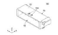
図16を参照して、本実施の形態の相手側コネクタ60は、回路基板(図示せず)上に搭載されるものである。相手側コネクタ60は、相手側ハウジング70と、相手側第1端子82と、相手側第2端子84とを備えている。 With reference to FIG. 16, themating connector 60 of this embodiment is mounted on a circuit board (not shown). Themating side connector 60 includes amating side housing 70, a mating sidefirst terminal 82, and a mating sidesecond terminal 84.

図16に示されるように、本実施の形態の相手側ハウジング70は、相手側第1端子82と、相手側第2端子84とを保持している。図14に示されるように、相手側ハウジング70は、受容部62を構成している。 As shown in FIG. 16, themating side housing 70 of the present embodiment holds the mating sidefirst terminal 82 and the mating sidesecond terminal 84. As shown in FIG. 14, themating housing 70 constitutes a receivingportion 62.

図18及び図19に示されるように、本実施の形態の受容部62は、前後方向に延びる空間である。本実施の形態において、前後方向はX方向である。後述する嵌合方向は+X方向である。ここで、前方を+X方向とし、後方を−X方向とする。 As shown in FIGS. 18 and 19, the receivingportion 62 of the present embodiment is a space extending in the front-rear direction. In the present embodiment, the front-rear direction is the X direction. The fitting direction described later is the + X direction. Here, the front is in the + X direction and the rear is in the −X direction.

図19に示されるように、相手側ハウジング70は、上板72と、背板78とを有している。 As shown in FIG. 19, themating housing 70 has anupper plate 72 and aback plate 78.

図19に示されるように、本実施の形態の上板72は、嵌合方向と直交する直交方向において相手側ハウジング70の一端を規定している。本実施の形態において、直交方向はZ方向である。また、直交方向は上下方向でもある。ここで、上方を+Z方向とし、下方を−Z方向とする。即ち、上板72は、上下方向において相手側ハウジング70の上端を規定している。 As shown in FIG. 19, theupper plate 72 of the present embodiment defines one end of themating housing 70 in a direction orthogonal to the fitting direction. In the present embodiment, the orthogonal direction is the Z direction. The orthogonal direction is also the vertical direction. Here, the upper side is the + Z direction and the lower side is the −Z direction. That is, theupper plate 72 defines the upper end of themating housing 70 in the vertical direction.

図19に示されるように、本実施の形態の背板78は、前後方向において相手側ハウジング70の前端を規定している。受容部62は、前後方向において背板78の後方に位置している。 As shown in FIG. 19, theback plate 78 of the present embodiment defines the front end of themating housing 70 in the front-rear direction. The receivingportion 62 is located behind theback plate 78 in the front-rear direction.

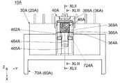
図15及び図18に示されるように、相手側ハウジング70には、解除突起722と、延長部728と、2つのロック孔724と、2つの相手側ロック部725とが形成されている。なお、本発明はこれに限定されず、ロック孔724及び相手側ロック部725は、夫々一つであってもよい。 As shown in FIGS. 15 and 18, themating side housing 70 is formed with arelease protrusion 722, anextension portion 728, twolock holes 724, and two matingside lock portions 725. The present invention is not limited to this, and thelock hole 724 and thecounterpart lock portion 725 may be one each.

図16に示されるように、本実施の形態の解除突起722は、受容部62内に突出している。解除突起722は、上板72から下方に突出している。 As shown in FIG. 16, therelease projection 722 of the present embodiment projects into the receivingportion 62. Therelease protrusion 722 projects downward from theupper plate 72.

図19に示されるように、解除突起722は、前面7222と、後面7224とを有している。 As shown in FIG. 19, therelease projection 722 has afront surface 7222 and arear surface 7224.

図19に示されるように、本実施の形態の前面7222は、前後方向と交差している。前面7222は、前方且つ下方に向いている。前面7222は、後方且つ下方に傾斜している。 As shown in FIG. 19, thefront surface 7222 of the present embodiment intersects the front-rear direction. Thefront surface 7222 faces forward and downward. Thefront surface 7222 is inclined rearward and downward.

図19に示されるように、本実施の形態の後面7224は、前後方向と交差している。後面7224は、後方且つ下方に向いている。後面7224は、後方且つ上方に傾斜している。後面7224は、前後方向において前面7222の後方に位置している。 As shown in FIG. 19, therear surface 7224 of the present embodiment intersects the front-rear direction. Therear surface 7224 faces rearward and downward. Therear surface 7224 is inclined rearward and upward. Therear surface 7224 is located behind thefront surface 7222 in the front-rear direction.

図19に示されるように、本実施の形態の延長部728は、前後方向において背板78の後方に位置している。延長部728は、前後方向において解除突起722の前方に位置している。延長部728は、前後方向において背板78と解除突起722とを連結している。延長部728の下端は、解除突起722の下端よりも上方に位置している。 As shown in FIG. 19, theextension portion 728 of the present embodiment is located behind theback plate 78 in the front-rear direction. Theextension portion 728 is located in front of therelease protrusion 722 in the front-rear direction. Theextension portion 728 connects theback plate 78 and therelease protrusion 722 in the front-rear direction. The lower end of theextension portion 728 is located above the lower end of therelease protrusion 722.

図18に示されるように、本実施の形態のロック孔724は、上板72を上下方向に貫通している。ロック孔724は、前後方向において前方を向いた内面を有している。ロック孔724の上記内面は、相手側ロック部725として機能する。 As shown in FIG. 18, thelock hole 724 of the present embodiment penetrates theupper plate 72 in the vertical direction. Thelock hole 724 has an inner surface facing forward in the front-rear direction. The inner surface of thelock hole 724 functions as amating lock portion 725.

図18に示されるように、本実施の形態の相手側ロック部725は、受容部62内に面している。相手側ロック部725は、前後方向において前方を向いた平面である。 As shown in FIG. 18, thecounterpart lock portion 725 of the present embodiment faces the inside of the receivingportion 62. Themating lock portion 725 is a flat surface facing forward in the front-rear direction.

図18を参照して、本実施の形態の相手側第1端子82は、金属製であり、略L字形状を有している。相手側第1端子82は、所謂ピンコンタクトである。相手側第1端子82の下端は、回路基板上のパッド(図示せず)に半田付け等によって接続固定される。 With reference to FIG. 18, thecounterpart 1st terminal 82 of the present embodiment is made of metal and has a substantially L-shape. Thefirst terminal 82 on the other side is a so-called pin contact. The lower end of thefirst terminal 82 on the other side is connected and fixed to a pad (not shown) on the circuit board by soldering or the like.

図18を参照して、本実施の形態の相手側第2端子84は、金属製であり、略L字形状を有している。相手側第2端子84は、所謂ピンコンタクトである。相手側第2端子84の下端は、回路基板上のパッド(図示せず)に半田付け等によって接続固定される。 With reference to FIG. 18, the counterpartsecond terminal 84 of the present embodiment is made of metal and has a substantially L-shape. Thesecond terminal 84 on the other side is a so-called pin contact. The lower end of thesecond terminal 84 on the other side is connected and fixed to a pad (not shown) on the circuit board by soldering or the like.

図17、図20及び図23を参照して、本実施の形態のコネクタ20は、嵌合方向に沿って相手側コネクタ60に対して嵌合可能である。相手側コネクタ60と嵌合したコネクタ20は、嵌合方向(+X方向)の逆方向である抜去方向(−X方向)に沿って相手側コネクタ60から抜去可能である。 With reference to FIGS. 17, 20, and 23, theconnector 20 of this embodiment can be fitted to themating connector 60 along the fitting direction. Theconnector 20 fitted with themating connector 60 can be pulled out from themating connector 60 along the pulling direction (−X direction) which is the opposite direction of the fitting direction (+ X direction).

図8に示されるように、本実施の形態のコネクタ20は、第1ハウジング30と、複数の第1端子52と、第2ハウジング40と、2つの第2端子54とを備えている。 As shown in FIG. 8, theconnector 20 of the present embodiment includes afirst housing 30, a plurality offirst terminals 52, asecond housing 40, and twosecond terminals 54.

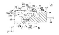
図18及び図21から理解されるように、本実施の形態の第1ハウジング30は、嵌合方向に沿って受容部62に受容されるものである。図8に示されるように、第1ハウジング30は、第1端子52を保持している。図8及び図10を参照して、第1ハウジング30は、横方向と直交する平面であって第1ハウジング30の横方向における中心を通る平面に対して、鏡対称な形状を有している。本実施の形態において、横方向はY方向である。図10及び図11に示されるように、第1ハウジング30には、上部305と、ストッパ部350と、第1構造体36と、収容部33と、付加的ストッパ部34と、仕切壁320と、第2支持部収容部325とが設けられている。 As can be seen from FIGS. 18 and 21, thefirst housing 30 of this embodiment is received by the receivingportion 62 along the fitting direction. As shown in FIG. 8, thefirst housing 30 holds thefirst terminal 52. With reference to FIGS. 8 and 10, thefirst housing 30 has a shape that is orthogonal to the lateral direction and is mirror-symmetrical with respect to a plane that passes through the center of thefirst housing 30 in the lateral direction. .. In the present embodiment, the lateral direction is the Y direction. As shown in FIGS. 10 and 11, thefirst housing 30 includes anupper portion 305, astopper portion 350, afirst structure 36, anaccommodating portion 33, anadditional stopper portion 34, and apartition wall 320. , A second supportportion accommodating portion 325 is provided.

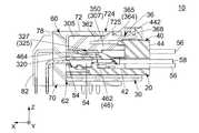
図11に示されるように、本実施の形態の上部305は、前後方向に延びている。上部305は、下面306と、突部307とを有している。下面306は、上下方向において下方に向いた平面である。突部307は、下面306から下方に突出している。突部307は、前後方向において第1ハウジング30の中間部に位置している。突部307は、前後方向において後方を向いた後面を有している。突部307の後面は、ストッパ部350として機能する。 As shown in FIG. 11, theupper portion 305 of this embodiment extends in the front-rear direction. Theupper portion 305 has alower surface 306 and aprotrusion 307. Thelower surface 306 is a plane facing downward in the vertical direction. Theprotrusion 307 projects downward from thelower surface 306. Theprotrusion 307 is located in the middle of thefirst housing 30 in the front-rear direction. Theprotrusion 307 has a rear surface facing rearward in the front-rear direction. The rear surface of theprotrusion 307 functions as astopper portion 350.

図11に示されるように、本実施の形態のストッパ部350は、前後方向と交差している。ストッパ部350は、前後方向において後方を向いた平面である。 As shown in FIG. 11, thestopper portion 350 of the present embodiment intersects the front-rear direction. Thestopper portion 350 is a flat surface facing rearward in the front-rear direction.

図10及び図11に示されるように、本実施の形態の第1構造体36は、2つの第1支持部362と、2つのロック部365と、第1操作部(操作部)368とを有している。即ち、第1ハウジング30には、第1支持部362とロック部365とを有する第1構造体36と、ストッパ部350とが設けられている。なお、本発明はこれに限定されず、相手側ロック部725が一つの場合、第1構造体36は、第1支持部362及びロック部365を夫々一つ有していればよい。 As shown in FIGS. 10 and 11, thefirst structure 36 of the present embodiment includes twofirst support portions 362, twolock portions 365, and a first operation portion (operation unit) 368. Have. That is, thefirst housing 30 is provided with afirst structure 36 having afirst support portion 362 and alock portion 365, and astopper portion 350. The present invention is not limited to this, and when there is onecounterpart lock portion 725, thefirst structure 36 may have onefirst support portion 362 and onelock portion 365, respectively.

図11に示されるように、本実施の形態の第1支持部362は、上部305から前後方向における後方に延びている。第1支持部362は、復元力を有しており、ロック部365を支持している。第1支持部362は、直交方向、即ち上下方向に弾性変形可能となっている。第1支持部362は、ロック突起364を有している。 As shown in FIG. 11, thefirst support portion 362 of the present embodiment extends rearward from theupper portion 305 in the front-rear direction. Thefirst support portion 362 has a restoring force and supports thelock portion 365. Thefirst support portion 362 can be elastically deformed in the orthogonal direction, that is, in the vertical direction. Thefirst support portion 362 has alock protrusion 364.

上述のように、本実施の形態の第1支持部362の夫々は、弾性力である復元力を有している。但し、本発明における第1支持部362の復元力は、第1支持部362自身の弾性力に限定されない。例えば、第1支持部362は、第1ハウジング30と別体のバネ(図示せず)によって、前端を支点として回転移動可能に支持されていてもよい。即ち、第1支持部362の夫々は、他の部材に起因する復元力を有していてもよい。上述のような変形は、本実施の形態及び後述する第2の実施の形態における復元力を有する部位や部材の夫々に対して適用可能である。 As described above, each of thefirst support portions 362 of the present embodiment has a restoring force which is an elastic force. However, the restoring force of thefirst support portion 362 in the present invention is not limited to the elastic force of thefirst support portion 362 itself. For example, thefirst support portion 362 may be rotatably supported with the front end as a fulcrum by a spring (not shown) separate from thefirst housing 30. That is, each of thefirst support portions 362 may have a restoring force caused by other members. The above-mentioned deformation can be applied to each of the parts and members having a restoring force in the present embodiment and the second embodiment described later.

図11に示されるように、本実施の形態のロック突起364は、前後方向において第1構造体36の中間部に位置している。ロック突起364は、上下方向において上方に突出している。ロック突起364は、前後方向において後方を向いた後面を有している。ロック突起364の後面は、ロック部365として機能する。 As shown in FIG. 11, thelock projection 364 of the present embodiment is located in the middle portion of thefirst structure 36 in the front-rear direction. Thelock protrusion 364 projects upward in the vertical direction. Thelock projection 364 has a rear surface facing rearward in the front-rear direction. The rear surface of thelock protrusion 364 functions as alock portion 365.

図11に示されるように、本実施の形態のロック部365は、前後方向と交差している。ロック部365は、前後方向において後方を向いた平面である。ロック部365は、第1支持部362に設けられている。上述のように、第1支持部362は、復元力を有していることから、ロック部365は、第1支持部362の復元力を利用して嵌合方向と直交する直交方向に移動可能となっている。即ち、ロック部365は、第1支持部362の復元力を利用して上下方向に移動可能となっている。図21を参照して、ロック部365と相手側ロック部725とは、図8に示される第1端子52が相手側第1端子82に接続されたとき、第1ハウジング30が受容部62に受容された状態をロックするものである。 As shown in FIG. 11, thelock portion 365 of the present embodiment intersects the front-rear direction. Thelock portion 365 is a flat surface facing rearward in the front-rear direction. Thelock portion 365 is provided on thefirst support portion 362. As described above, since thefirst support portion 362 has a restoring force, thelock portion 365 can move in the orthogonal direction orthogonal to the fitting direction by utilizing the restoring force of thefirst support portion 362. It has become. That is, thelock portion 365 can move in the vertical direction by utilizing the restoring force of thefirst support portion 362. With reference to FIG. 21, thelock portion 365 and themating lock portion 725 have thefirst housing 30 attached to the receivingportion 62 when thefirst terminal 52 shown in FIG. 8 is connected to the matingfirst terminal 82. It locks the accepted state.

図10に示されるように、本実施の形態の第1操作部368は、第1構造体36の前後方向における後端に位置している。第1操作部368は、第1ハウジング30の前後方向における後端付近に位置している。第1操作部368は、前後方向において第1支持部362の後方に位置している。第1操作部368は、前後方向においてロック部365の後方に位置している。図11を参照して、第1操作部368を直交方向内側に押圧することにより、第1支持部362を弾性変形させて、ロック部365を直交方向内側に移動させることができる。また、上述のように、第1支持部362は復元力を有していることから、第1操作部368への上記押圧を止めると、第1支持部362は元の形状に復帰し、ロック部365は直交方向外側へ移動することとなる。即ち、第1操作部368を下方に押圧することにより、第1支持部362を弾性変形させて、ロック部365を下方に移動させることができ、第1操作部368への上記押圧を止めると、第1支持部362は元の形状に復帰し、ロック部365は上方へ移動することとなる。 As shown in FIG. 10, thefirst operation unit 368 of the present embodiment is located at the rear end of thefirst structure 36 in the front-rear direction. Thefirst operation unit 368 is located near the rear end of thefirst housing 30 in the front-rear direction. Thefirst operation unit 368 is located behind thefirst support unit 362 in the front-rear direction. Thefirst operation unit 368 is located behind thelock unit 365 in the front-rear direction. By pressing thefirst operating portion 368 inward in the orthogonal direction with reference to FIG. 11, the first supportingportion 362 can be elastically deformed and thelock portion 365 can be moved inward in the orthogonal direction. Further, as described above, since thefirst support portion 362 has a restoring force, when the pressing on thefirst operation portion 368 is stopped, thefirst support portion 362 returns to the original shape and locks. Theportion 365 will move outward in the orthogonal direction. That is, by pressing thefirst operating portion 368 downward, the first supportingportion 362 can be elastically deformed and thelock portion 365 can be moved downward, and when the pressing on thefirst operating portion 368 is stopped. , Thefirst support portion 362 returns to the original shape, and thelock portion 365 moves upward.

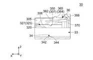
図11に示されるように、本実施の形態の収容部33は、前後方向において第1ハウジング30を貫通する孔である。収容部33は、上下方向において上部305の下面306の下方に位置している。収容部33は、上下方向において第1支持部362の下方に位置している。収容部33は、上下方向においてロック部365の下方に位置している。収容部33は、上下方向において第1操作部368の下方に位置している。図9に示されるように、収容部33は、横方向において第1ハウジング30の中間部に位置している。 As shown in FIG. 11, theaccommodating portion 33 of the present embodiment is a hole that penetrates thefirst housing 30 in the front-rear direction. Theaccommodating portion 33 is located below thelower surface 306 of theupper portion 305 in the vertical direction. Theaccommodating portion 33 is located below thefirst support portion 362 in the vertical direction. Theaccommodating portion 33 is located below thelock portion 365 in the vertical direction. Theaccommodating portion 33 is located below thefirst operating portion 368 in the vertical direction. As shown in FIG. 9, theaccommodating portion 33 is located in the intermediate portion of thefirst housing 30 in the lateral direction.

図12に示されるように、本実施の形態の付加的ストッパ部34は、第1ハウジング30の前後方向における中間部に位置している。付加的ストッパ部34は、第1ハウジング30の下端付近に位置している。付加的ストッパ部34は、収容部33内において上下方向における上方に突出している。付加的ストッパ部34は、前面342と、後面344とを有している。前面342及び後面344の夫々は、前後方向と交差している。前面342は、前後方向において前方を向いている。後面344は、後方且つ上方を向いている。後面344は、後方且つ下方に傾斜している。後面344は、前後方向において前面342の後方に位置している。 As shown in FIG. 12, theadditional stopper portion 34 of the present embodiment is located at an intermediate portion in the front-rear direction of thefirst housing 30. Theadditional stopper portion 34 is located near the lower end of thefirst housing 30. Theadditional stopper portion 34 projects upward in the vertical direction in theaccommodating portion 33. Theadditional stopper portion 34 has afront surface 342 and arear surface 344. Each of thefront surface 342 and therear surface 344 intersects the front-rear direction. Thefront surface 342 faces forward in the front-rear direction. Therear surface 344 faces rearward and upward. Therear surface 344 is inclined rearward and downward. Therear surface 344 is located behind thefront surface 342 in the front-rear direction.

図11及び図12に示されるように、本実施の形態の仕切壁320は、第1ハウジング30の前端から後方に延びている。仕切壁320は、上部305の下面306の下方に位置している。仕切壁320は、前後方向において第1支持部362の前方に位置している。仕切壁320は、前後方向においてロック部365の前方に位置している。仕切壁320は、前後方向において第1操作部368の前方に位置している。図8に示されるように、仕切壁320は、横方向において第1ハウジング30の中間部に位置している。 As shown in FIGS. 11 and 12, thepartition wall 320 of the present embodiment extends rearward from the front end of thefirst housing 30. Thepartition wall 320 is located below thelower surface 306 of the upper 305. Thepartition wall 320 is located in front of thefirst support portion 362 in the front-rear direction. Thepartition wall 320 is located in front of thelock portion 365 in the front-rear direction. Thepartition wall 320 is located in front of thefirst operation unit 368 in the front-rear direction. As shown in FIG. 8, thepartition wall 320 is located in the middle portion of thefirst housing 30 in the lateral direction.

図10に示されるように、本実施の形態の第2支持部収容部325は、前後方向に延びる空間である。第2支持部収容部325は、横方向において第1ハウジング30の中間部に位置している。第2支持部収容部325は、横方向において2つの第1支持部362の間に位置している。第2支持部収容部325は、横方向において2つのロック部365の間に位置している。第2支持部収容部325は、前後方向において第1操作部368の前方に位置している。図11及び図12に示されるように、第2支持部収容部325は、上下方向において仕切壁320の上方に位置している。 As shown in FIG. 10, the second supportportion accommodating portion 325 of the present embodiment is a space extending in the front-rear direction. The second supportportion accommodating portion 325 is located in the middle portion of thefirst housing 30 in the lateral direction. The second supportportion accommodating portion 325 is located between the twofirst support portions 362 in the lateral direction. The second supportportion accommodating portion 325 is located between the twolock portions 365 in the lateral direction. The second supportportion accommodating portion 325 is located in front of thefirst operation portion 368 in the front-rear direction. As shown in FIGS. 11 and 12, the second supportportion accommodating portion 325 is located above thepartition wall 320 in the vertical direction.

図11及び図12を参照して、第2支持部収容部325は、主収容部326と、2つの付加的収容部327とを有している。 With reference to FIGS. 11 and 12, the secondsupport accommodating portion 325 has a mainaccommodating portion 326 and two additionalaccommodating portions 327.

図10に示されるように、本実施の形態の主収容部326は、前後方向に延びる溝である。主収容部326は、横方向において第1ハウジング30の中間部に位置している。主収容部326は、横方向において2つの第1支持部362の間に位置している。主収容部326は、横方向において2つのロック部365の間に位置している。図12に示されるように、主収容部326は、上下方向において第1ハウジング30の外部と連通している。主収容部326は、前後方向において第1ハウジング30の外部と連通している。主収容部326は、前後方向において第1操作部368の前方に位置している。図11及び図12を参照して、主収容部326は、横方向において2つの付加的収容部327の間に位置している。主収容部326は、横方向において付加的収容部327の夫々と連通している。 As shown in FIG. 10, the mainaccommodating portion 326 of the present embodiment is a groove extending in the front-rear direction. The mainaccommodating portion 326 is located in the middle portion of thefirst housing 30 in the lateral direction. The mainaccommodating portion 326 is located between the twofirst support portions 362 in the lateral direction. The mainaccommodating portion 326 is laterally located between the two lockingportions 365. As shown in FIG. 12, the mainaccommodating portion 326 communicates with the outside of thefirst housing 30 in the vertical direction. The mainaccommodating portion 326 communicates with the outside of thefirst housing 30 in the front-rear direction. The mainaccommodating portion 326 is located in front of thefirst operating portion 368 in the front-rear direction. With reference to FIGS. 11 and 12, themain containment section 326 is located laterally between the twoadditional containment sections 327. Themain containment section 326 communicates laterally with each of theadditional containment sections 327.

図11に示されるように、本実施の形態の付加的収容部327は、前後方向に延びる空間である。付加的収容部327は、前後方向において第1ハウジング30の外部と連通している。付加的収容部327は、上下方向においてロック部365の下方に位置している。付加的収容部327は、上下方向において、上部305の下面306の下方に位置している。 As shown in FIG. 11, the additionalaccommodating portion 327 of the present embodiment is a space extending in the front-rear direction. The additionalaccommodating portion 327 communicates with the outside of thefirst housing 30 in the front-rear direction. The additionalaccommodating portion 327 is located below the lockingportion 365 in the vertical direction. The additionalaccommodating portion 327 is located below thelower surface 306 of theupper portion 305 in the vertical direction.

図10に示されるように、第1ハウジング30は、付加的被ロック部370を更に有している。 As shown in FIG. 10, thefirst housing 30 further has an additional lockedportion 370.

図10に示されるように、本実施の形態の付加的被ロック部370は、前後方向において第1ハウジング30の後端付近に位置している。付加的被ロック部370は、前後方向と交差している。より詳しくは、付加的被ロック部370は、前後方向において前方を向いた平面である。付加的被ロック部370は、前後方向において第1操作部368の後方に位置している。 As shown in FIG. 10, the additional lockedportion 370 of the present embodiment is located near the rear end of thefirst housing 30 in the front-rear direction. The additional lockedportion 370 intersects the front-rear direction. More specifically, the additional lockedportion 370 is a plane facing forward in the front-rear direction. The additional lockedportion 370 is located behind thefirst operating portion 368 in the front-rear direction.

図9を参照して、本実施の形態の第1端子52は、金属製である。第1端子52は、所謂ソケットコンタクトであり、ケーブル56に接続されている。図8、図16及び図21を参照して、第1端子52は、第1ハウジング30が受容部62に受容されたとき、相手側第1端子82に接続されるものである。ここで、第1端子52と相手側第1端子82とは互いに接続されて高電圧の電流を伝送するものである。 With reference to FIG. 9, thefirst terminal 52 of this embodiment is made of metal. Thefirst terminal 52 is a so-called socket contact and is connected to thecable 56. With reference to FIGS. 8, 16 and 21, thefirst terminal 52 is connected to the other sidefirst terminal 82 when thefirst housing 30 is received by the receivingportion 62. Here, thefirst terminal 52 and the other-sidefirst terminal 82 are connected to each other to transmit a high-voltage current.

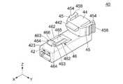
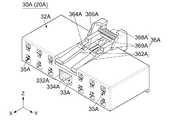
図5に示されるように、本実施の形態の第2ハウジング40は、第1ハウジング30に相対移動可能となるように保持されている。図4に示されるように、第2ハウジング40は、第2端子54を保持している。図4及び図13に示されるように、第2ハウジング40には、本体部42と、頭部44と、規制部442と、第2支持部46と、2つの被ストップ部464と、2つの付加的支持部45と、2つの付加的ロック部454と、2つの第2操作部458と、付加的被ストップ部424とが設けられている。即ち、第2支持部46は、第2ハウジング40に設けられている。なお、本発明はこれに限定されず、第2支持部46は、第1ハウジング30に設けられていてもよい。換言すれば、第2支持部46は、第1ハウジング30及び第2ハウジング40の一方に設けられていればよい。但し、第2支持部46が第2ハウジング40に設けられているほうがコネクタ20の設計の自由度が高くなるため、より好ましい。 As shown in FIG. 5, thesecond housing 40 of the present embodiment is held so as to be relatively movable to thefirst housing 30. As shown in FIG. 4, thesecond housing 40 holds thesecond terminal 54. As shown in FIGS. 4 and 13, thesecond housing 40 includes amain body 42, ahead 44, aregulation 442, asecond support 46, two stoppedportions 464, and two. Anadditional support portion 45, twoadditional lock portions 454, twosecond operation portions 458, and anadditional stop portion 424 are provided. That is, thesecond support portion 46 is provided in thesecond housing 40. The present invention is not limited to this, and thesecond support portion 46 may be provided in thefirst housing 30. In other words, thesecond support portion 46 may be provided on one of thefirst housing 30 and thesecond housing 40. However, it is more preferable that thesecond support portion 46 is provided in thesecond housing 40 because the degree of freedom in designing theconnector 20 is increased.

図13に示されるように、本実施の形態の本体部42は、前後方向に延びる略角筒形状を有している。本体部42は、上方を向いた上面423を有している。 As shown in FIG. 13, themain body portion 42 of the present embodiment has a substantially square tubular shape extending in the front-rear direction. Themain body 42 has anupper surface 423 facing upward.

図13に示されるように、本実施の形態の頭部44は、上下方向において本体部42の上方に位置している。頭部44は、本体部42の上面423上に設けられている。頭部44は、上下方向における第2ハウジング40の上端を規定している。 As shown in FIG. 13, thehead 44 of the present embodiment is located above themain body 42 in the vertical direction. Thehead 44 is provided on theupper surface 423 of themain body 42. Thehead 44 defines the upper end of thesecond housing 40 in the vertical direction.

図13に示されるように、本実施の形態の規制部442は、板状である。図5に示されるように、規制部442は、頭部44から前後方向において前方に延びている。規制部442は、頭部44の上端近傍に位置している。規制部442は、上下方向において本体部42から離れて上方に位置している。規制部442は、上下方向において第2支持部46から離れて上方に位置している。 As shown in FIG. 13, theregulation unit 442 of the present embodiment has a plate shape. As shown in FIG. 5, the regulatingportion 442 extends forward from thehead 44 in the front-rear direction. Theregulation unit 442 is located near the upper end of thehead 44. The regulatingportion 442 is located above themain body portion 42 in the vertical direction. Theregulation unit 442 is located above thesecond support unit 46 in the vertical direction.

図4を参照して、本実施の形態の第2支持部46は、復元力を有しており、被ストップ部464を被支持部464として支持している。第2支持部46は、直交方向、即ち上下方向に弾性変形可能となっている。なお、本発明はこれに限定されず、第2支持部46が第1ハウジング30に設けられている場合、第2支持部46は、第1ハウジング30のストッパ部350を被支持部として支持していてもよい。即ち、第2支持部46は、復元力を有しており、ストッパ部350及び被ストップ部464の一方を被支持部として支持していればよい。 With reference to FIG. 4, thesecond support portion 46 of the present embodiment has a restoring force, and the stoppedportion 464 is supported as the supportedportion 464. Thesecond support portion 46 is elastically deformable in the orthogonal direction, that is, in the vertical direction. The present invention is not limited to this, and when thesecond support portion 46 is provided in thefirst housing 30, thesecond support portion 46 supports thestopper portion 350 of thefirst housing 30 as a supported portion. You may be. That is, thesecond support portion 46 has a restoring force, and it is sufficient that one of thestopper portion 350 and the stoppedportion 464 is supported as the supported portion.

図13に示されるように、第2支持部46は、凸部支持部465と、凸部466と、2つの被ストップ部支持部462とを有している。 As shown in FIG. 13, thesecond support portion 46 has a convexportion support portion 465, aconvex portion 466, and two stoppedportion support portions 462.

図13を参照して、本実施の形態の凸部支持部465は、復元力を有しており、本体部42の上面423の前後方向における中間部から前方に延びている。凸部支持部465は、横方向における第2支持部46の中間部に位置している。凸部支持部465は、横方向において2つの被ストップ部支持部462に挟まれている。凸部支持部465は、横方向において被ストップ部支持部462と連結されている。 With reference to FIG. 13, the convexportion support portion 465 of the present embodiment has a restoring force and extends forward from the intermediate portion in the front-rear direction of theupper surface 423 of themain body portion 42. The convexportion support portion 465 is located in the middle portion of thesecond support portion 46 in the lateral direction. The convexportion support portion 465 is sandwiched between two stoppedportion support portions 462 in the lateral direction. The convexportion support portion 465 is connected to the stoppedportion support portion 462 in the lateral direction.

図13を参照して、本実施の形態の凸部466は、第2支持部46の復元力を利用して、直交方向、即ち上下方向に移動可能となっている。凸部466は、前後方向において本体部42の前端の後方に位置している。凸部466は、前後方向において被ストップ部464の前方に位置している。凸部466は、前後方向において第2支持部46の前端に位置している。凸部466は、前後方向において凸部支持部465の前端に位置している。凸部466は、横方向において2つの被ストップ部464に挟まれている。凸部466は、横方向において被ストップ部464と連結されている。図5に示されるように、凸部466は、上下方向において上方に突出している。凸部466は、上下方向において規制部442の下方に位置している。 With reference to FIG. 13, theconvex portion 466 of the present embodiment can be moved in the orthogonal direction, that is, in the vertical direction by utilizing the restoring force of thesecond support portion 46. Theconvex portion 466 is located behind the front end of themain body portion 42 in the front-rear direction. Theconvex portion 466 is located in front of the stoppedportion 464 in the front-rear direction. Theconvex portion 466 is located at the front end of thesecond support portion 46 in the front-rear direction. Theconvex portion 466 is located at the front end of the convexportion support portion 465 in the front-rear direction. Theconvex portion 466 is sandwiched between two stoppedportions 464 in the lateral direction. Theconvex portion 466 is connected to the stoppedportion 464 in the lateral direction. As shown in FIG. 5, theconvex portion 466 projects upward in the vertical direction. Theconvex portion 466 is located below the regulatingportion 442 in the vertical direction.

図5に示されるように、本実施の形態の凸部466は、前面467と、後面468とを有している。 As shown in FIG. 5, theconvex portion 466 of the present embodiment has afront surface 467 and arear surface 468.

図5に示されるように、本実施の形態の前面467は、前後方向と交差している。前面467は、前方且つ上方に向いている。前面467は、後方且つ上方に傾斜している。 As shown in FIG. 5, thefront surface 467 of the present embodiment intersects the front-rear direction. Thefront surface 467 faces forward and upward. Thefront surface 467 is inclined rearward and upward.

図5に示されるように、本実施の形態の後面468は、前後方向と交差している。後面468は、後方且つ上方に向いている。後面468は、後方且つ下方に傾斜している。後面468は、前後方向において前面467の後方に位置している。 As shown in FIG. 5, therear surface 468 of the present embodiment intersects the front-rear direction. Therear surface 468 faces rearward and upward. Therear surface 468 is inclined rearward and downward. Therear surface 468 is located behind thefront surface 467 in the front-rear direction.

図13を参照して、本実施の形態の被ストップ部支持部462は、復元力を有しており、本体部42の上面423の前後方向における中間部から前方に延びている。被ストップ部支持部462は、横方向における第2支持部46の両側に夫々位置している。被ストップ部支持部462は、上下方向において上端463を有している。 With reference to FIG. 13, the stoppedportion support portion 462 of the present embodiment has a restoring force and extends forward from the intermediate portion in the front-rear direction of theupper surface 423 of themain body portion 42. The stoppedportion support portion 462 is located on both sides of thesecond support portion 46 in the lateral direction, respectively. The stoppedportion support portion 462 has anupper end 463 in the vertical direction.

図13に示されるように、本実施の形態の被ストップ部464は、第2支持部46に設けられている。上述のように、第2支持部46は、復元力を有していることから、被ストップ部464は、第2支持部46の復元力を利用して、直交方向、即ち上下方向に移動可能となっている。即ち、被支持部464は、第2支持部46の復元力を利用して、直交方向、即ち上下方向に移動可能となっている。被ストップ部464は、前後方向と交差している。被ストップ部464は、前後方向において前方を向いた平面である。被ストップ部464は、前後方向において前方を向いている。被ストップ部464は、前後方向において本体部42の前端の後方に位置している。被ストップ部464は、前後方向において被ストップ部支持部462の前端に位置している。被ストップ部464は、前後方向において凸部466の後方に位置している。2つの被ストップ部464は、横方向において凸部466を挟んでいる。 As shown in FIG. 13, the stoppedportion 464 of the present embodiment is provided in thesecond support portion 46. As described above, since thesecond support portion 46 has a restoring force, the stoppedportion 464 can move in the orthogonal direction, that is, in the vertical direction by using the restoring force of thesecond support portion 46. It has become. That is, the supportedportion 464 can move in the orthogonal direction, that is, in the vertical direction by utilizing the restoring force of the second supportedportion 46. The stoppedportion 464 intersects the front-rear direction. The stoppedportion 464 is a flat surface facing forward in the front-rear direction. The stoppedportion 464 faces forward in the front-rear direction. The stoppedportion 464 is located behind the front end of themain body portion 42 in the front-rear direction. The stoppedportion 464 is located at the front end of the stoppedportion supporting portion 462 in the front-rear direction. The stoppedportion 464 is located behind theconvex portion 466 in the front-rear direction. The two stoppedportions 464 sandwich theconvex portion 466 in the lateral direction.

図13を参照して、本実施の形態の付加的支持部45は、復元力を有している。付加的支持部45は、横方向に弾性変形可能となっている。付加的支持部45は、上下方向において本体部42の上方に位置している。図3に示されるように、付加的支持部45は第2ハウジング40の横方向両端付近に夫々位置している。付加的支持部45は、頭部44の横方向外端から横方向外側に延びている。付加的支持部45は、頭部44の前端から後方に延びている。付加的支持部45は、付加的ロック部454を支持している。 With reference to FIG. 13, theadditional support portion 45 of the present embodiment has a restoring force. Theadditional support portion 45 is elastically deformable in the lateral direction. Theadditional support portion 45 is located above themain body portion 42 in the vertical direction. As shown in FIG. 3, theadditional support portion 45 is located near both ends in the lateral direction of thesecond housing 40, respectively. Theadditional support portion 45 extends laterally outward from the lateral outer end of thehead 44. Theadditional support 45 extends posteriorly from the anterior end of thehead 44. Theadditional support portion 45 supports theadditional lock portion 454.

図3に示されるように、本実施の形態の付加的ロック部454は、第2ハウジング40の横方向両端付近に位置している。付加的ロック部454は、付加的支持部45から横方向外側に延びている。付加的ロック部454は、前後方向と交差している。付加的ロック部454は、前後方向において後方を向いた平面である。図23及び図24から理解されるように、付加的ロック部454と付加的被ロック部370とは、第2端子54が相手側第2端子84に接続されたとき、第2ハウジング40が第1ハウジング30に組み込まれた状態をロックするものである。 As shown in FIG. 3, theadditional lock portion 454 of the present embodiment is located near both ends in the lateral direction of thesecond housing 40. Theadditional locking portion 454 extends laterally outward from theadditional support portion 45. Theadditional lock portion 454 intersects the front-rear direction. Theadditional lock portion 454 is a plane facing rearward in the front-rear direction. As can be seen from FIGS. 23 and 24, theadditional locking portion 454 and the additional lockedportion 370 have asecond housing 40 when thesecond terminal 54 is connected to the other sidesecond terminal 84. 1 It locks the state of being incorporated in thehousing 30.

図3に示されるように、本実施の形態の第2操作部458は、横方向における第2ハウジング40の両端に夫々位置している。第2操作部458は、前後方向における第2ハウジング40の後端に位置している。第2操作部458は、前後方向における付加的支持部45の後方に位置している。第2操作部458は、前後方向において付加的ロック部454の後方に位置している。第2操作部458を横方向内側に押圧することにより、付加的支持部45を弾性変形させて、付加的ロック部454を横方向内側に移動させることができる。また、上述のように、付加的支持部45は復元力を有していることから、第2操作部458への上記押圧を止めると、付加的支持部45は元の形状に復帰し、付加的ロック部454は横方向外側へ移動することとなる。 As shown in FIG. 3, thesecond operation unit 458 of the present embodiment is located at both ends of thesecond housing 40 in the lateral direction, respectively. Thesecond operation unit 458 is located at the rear end of thesecond housing 40 in the front-rear direction. Thesecond operating portion 458 is located behind the additional supportingportion 45 in the front-rear direction. Thesecond operating unit 458 is located behind theadditional locking unit 454 in the front-rear direction. By pressing thesecond operation portion 458 inward in the lateral direction, theadditional support portion 45 can be elastically deformed and theadditional lock portion 454 can be moved inward in the lateral direction. Further, as described above, since theadditional support portion 45 has a restoring force, when the pressing on thesecond operation portion 458 is stopped, theadditional support portion 45 returns to the original shape and is added. Thetarget lock portion 454 moves outward in the lateral direction.

図4に示されるように、本実施の形態の付加的被ストップ部424は、本体部42の下端であって前端から下方に突出している。付加的被ストップ部424は、前面425と、後面426とを有している。前面425及び後面426の夫々は、前後方向と交差している。前面425は、前方且つ下方を向いている。前面425は、後方且つ下方に傾斜している。後面426は、前後方向において後方を向いている。後面426は、前後方向において前面425の後方に位置している。 As shown in FIG. 4, the additional stoppedportion 424 of the present embodiment is the lower end of themain body portion 42 and projects downward from the front end. The additional stoppedportion 424 has a front surface 425 and arear surface 426. The front surface 425 and therear surface 426 each intersect the front-rear direction. The front 425 faces forward and downward. The front surface 425 is inclined rearward and downward. Therear surface 426 faces rearward in the front-rear direction. Therear surface 426 is located behind the front surface 425 in the front-rear direction.

図9を参照して、本実施の形態の第2端子54は、金属製である。第2端子54は、所謂ソケットコンタクトであり、ケーブル58に夫々接続されている。本実施の形態において、2つの第2端子54同士は短絡されていない。なお、本発明はこれに限定されず、図9の破線内に示されるように、2つの第2端子54がケーブル59により短絡されていてもよい。換言すれば、第2端子54は、2つあってもよく、2つの第2端子54は、互いに接続されていてもよい。図4に示されるように、第2端子54は、本体部42内に収容されている。 With reference to FIG. 9, thesecond terminal 54 of this embodiment is made of metal. Thesecond terminal 54 is a so-called socket contact, and is connected to thecable 58, respectively. In the present embodiment, the twosecond terminals 54 are not short-circuited with each other. The present invention is not limited to this, and as shown in the broken line in FIG. 9, the twosecond terminals 54 may be short-circuited by thecable 59. In other words, there may be twosecond terminals 54, and the twosecond terminals 54 may be connected to each other. As shown in FIG. 4, thesecond terminal 54 is housed in themain body 42.

図24を参照して、第2端子54と相手側第2端子84とは、HVIL回路(図示せず)に接続して同回路の開閉をコントロールするものである。具体的には、第2端子54と相手側第2端子84とが接続されると、HVIL回路が閉じられて図8に示される第1端子52と図18に示される相手側第1端子82との間が通電され、第2端子54と相手側第2端子84との接続が解除されると、HVIL回路が開いて図8に示される第1端子52と図18に示される相手側第1端子82との間の電力供給が遮断される。即ち、コネクタ組立体10は、第2端子54、相手側第2端子84及びHVIL回路を含むHVIL機構を有している。 With reference to FIG. 24, thesecond terminal 54 and the other sidesecond terminal 84 are connected to an HVIL circuit (not shown) to control the opening and closing of the circuit. Specifically, when thesecond terminal 54 and thesecond terminal 84 on the other side are connected, the HVIL circuit is closed and thefirst terminal 52 shown in FIG. 8 and thefirst terminal 82 on the other side shown in FIG. 18 are closed. When the power is supplied between the twoterminals 54 and the connection between thesecond terminal 54 and thesecond terminal 84 on the other side is released, the HVIL circuit is opened and thefirst terminal 52 shown in FIG. 8 and the other side second terminal shown in FIG. 18 are opened. The power supply to and from the 1terminal 82 is cut off. That is, theconnector assembly 10 has an HVIL mechanism including asecond terminal 54, asecond terminal 84 on the other side, and an HVIL circuit.

コネクタ20と相手側コネクタ60との嵌合操作について、以下に詳述する。 The fitting operation between theconnector 20 and themating connector 60 will be described in detail below.

図4及び図13を参照して、まず初めに、第2ハウジング40を第1ハウジング30に対して嵌合方向に沿って組み込む。具体的には、第1ハウジング30の収容部33の後方に第2ハウジング40の本体部42が位置するように第1ハウジング30及び第2ハウジング40を配置する。次に、第1ハウジング30に対して第2ハウジング40を前方に移動し、第1ハウジング30の収容部33に第2ハウジング40の本体部42を収容する。このとき、第2ハウジング40の付加的被ストップ部424の前面425は、第1ハウジング30の収容部33内の付加的ストッパ部34の後面344と接触する。 With reference to FIGS. 4 and 13, first, thesecond housing 40 is assembled with respect to thefirst housing 30 along the fitting direction. Specifically, thefirst housing 30 and thesecond housing 40 are arranged so that themain body 42 of thesecond housing 40 is located behind theaccommodating portion 33 of thefirst housing 30. Next, thesecond housing 40 is moved forward with respect to thefirst housing 30, and themain body 42 of thesecond housing 40 is accommodated in theaccommodating portion 33 of thefirst housing 30. At this time, the front surface 425 of the additional stoppedportion 424 of thesecond housing 40 comes into contact with therear surface 344 of theadditional stopper portion 34 in theaccommodating portion 33 of thefirst housing 30.

第2ハウジング40を第1ハウジング30に対して更に前方に相対移動させると、第2ハウジング40の付加的被ストップ部424は第1ハウジング30の付加的ストッパ部34を乗り越えて、付加的被ストップ部424の後面426と付加的ストッパ部34の前面342とが前後方向において対向する。その後、第2ハウジング40の被ストップ部464は、第1ハウジング30のストッパ部350に突き当たり、コネクタ20は、図4に示される規制状態となる。 When thesecond housing 40 is further moved forward relative to thefirst housing 30, the additional stoppedportion 424 of thesecond housing 40 gets over theadditional stopper portion 34 of thefirst housing 30 and is additionally stopped. Therear surface 426 of theportion 424 and thefront surface 342 of theadditional stopper portion 34 face each other in the front-rear direction. After that, the stoppedportion 464 of thesecond housing 40 abuts on thestopper portion 350 of thefirst housing 30, and theconnector 20 is in the regulated state shown in FIG.

図4に示される規制状態において、被ストップ部464がストッパ部350に突き当り、第2ハウジング40はストッパ部350により嵌合方向への移動を規制されている。より詳しくは、被ストップ部464がストッパ部350に対して後方から突き当り、第2ハウジング40はストッパ部350により前後方向における前方への移動を規制されている。また、この規制状態において、付加的被ストップ部424の後面426と付加的ストッパ部34の前面342とは前後方向において対向していることから、第2ハウジング40は前後方向における後方への移動も規制されている。即ち、第2ハウジング40が規制状態にあるとき、付加的ストッパ部34は、第2ハウジング40が第1ハウジング30から抜去できないように、抜去方向における付加的被ストップ部424の移動を規制している。 In the regulated state shown in FIG. 4, the stoppedportion 464 abuts on thestopper portion 350, and thesecond housing 40 is restricted from moving in the fitting direction by thestopper portion 350. More specifically, the stoppedportion 464 abuts against thestopper portion 350 from the rear, and thesecond housing 40 is restricted from moving forward in the front-rear direction by thestopper portion 350. Further, in this regulated state, since therear surface 426 of the additional stoppedportion 424 and thefront surface 342 of theadditional stopper portion 34 face each other in the front-rear direction, thesecond housing 40 can also move backward in the front-rear direction. It is regulated. That is, when thesecond housing 40 is in the regulated state, theadditional stopper portion 34 regulates the movement of the additional stoppedportion 424 in the removing direction so that thesecond housing 40 cannot be removed from thefirst housing 30. There is.

上述した構造により、この規制状態においては、第2ハウジング40は、第1ハウジング30に対して、前後方向における前方及び後方の双方への移動が規制されている。即ち、第2ハウジング40を第1ハウジング30に対して嵌合方向に沿って組み込むと、被ストップ部464がストッパ部350に突き当り、第2ハウジング40はストッパ部350により嵌合方向への移動を規制された規制状態となる。 Due to the structure described above, in this restricted state, thesecond housing 40 is restricted from moving both forward and backward in the front-rear direction with respect to thefirst housing 30. That is, when thesecond housing 40 is incorporated with respect to thefirst housing 30 along the fitting direction, the stoppedportion 464 abuts on thestopper portion 350, and thesecond housing 40 moves in the fitting direction by thestopper portion 350. It will be in a regulated state.

図17から図19までを参照して、第2ハウジング40が規制状態にあるコネクタ20を、嵌合方向に沿って相手側コネクタ60に対して対向配置する。その後、コネクタ20と相手側コネクタ60とを嵌合方向において互いに近づけて、第1ハウジング30を受容部62に受容させると、相手側第1端子82に図8に示される第1端子52が接続された後、コネクタ20の第2ハウジング40の凸部466の前面467が、相手側コネクタ60の解除突起722の後面7224と接触する。 With reference to FIGS. 17 to 19, theconnector 20 in which thesecond housing 40 is in the regulated state is arranged so as to face themating connector 60 along the fitting direction. After that, when theconnector 20 and themating side connector 60 are brought close to each other in the fitting direction and thefirst housing 30 is received by the receivingportion 62, thefirst terminal 52 shown in FIG. 8 is connected to the mating sidefirst terminal 82. After that, thefront surface 467 of theconvex portion 466 of thesecond housing 40 of theconnector 20 comes into contact with therear surface 7224 of therelease projection 722 of themating connector 60.

凸部466の前面467が解除突起722の後面7224と接触した状態から、コネクタ20と相手側コネクタ60とを嵌合方向において更に互いに近づけると、第2支持部46が弾性変形して凸部466が解除突起722により押し下げられて、図20から図22に示される状態となる。 When theconnector 20 and themating connector 60 are brought closer to each other in the mating direction from the state where thefront surface 467 of theconvex portion 466 is in contact with therear surface 7224 of therelease protrusion 722, thesecond support portion 46 is elastically deformed and theconvex portion 466 is formed. Is pushed down by therelease protrusion 722 to be in the state shown in FIGS. 20 to 22.

図22に示されるように、この状態において、コネクタ20の第2支持部46の凸部466は相手側コネクタ60の解除突起722に当たっており、第2支持部46は下方に弾性変形している。また、図21に示されるように、この状態において、第2ハウジング40の被ストップ部464は、上下方向において第1ハウジング30のストッパ部350の下方に位置しており、上記規制(移動規制)は解除されている。 As shown in FIG. 22, in this state, theconvex portion 466 of thesecond support portion 46 of theconnector 20 hits therelease projection 722 of themating connector 60, and thesecond support portion 46 is elastically deformed downward. Further, as shown in FIG. 21, in this state, the stoppedportion 464 of thesecond housing 40 is located below thestopper portion 350 of thefirst housing 30 in the vertical direction, and the above-mentioned regulation (movement regulation) Has been released.

即ち、上記規制状態の第2ハウジング40を第1ハウジング30と共に嵌合方向に沿って受容部62に受容させると、相手側第1端子82に第1端子52が接続された後、第2支持部46が解除突起722に当たって嵌合方向への第2ハウジング40の移動規制が解除される。 That is, when thesecond housing 40 in the regulated state is received by the receivingportion 62 together with thefirst housing 30 along the fitting direction, thefirst terminal 52 is connected to the matingfirst terminal 82 and then the second support is provided. Theportion 46 hits therelease protrusion 722, and the movement restriction of thesecond housing 40 in the fitting direction is released.

更に、図21に示されるように、この状態において、コネクタ20のロック突起364は、相手側コネクタ60のロック孔724に収容されており、ロック部365は、前後方向において相手側ロック部725と対向している。即ち、この状態において、ロック部365と相手側ロック部725は、第1ハウジング30が受容部62に受容された状態をロックしている。 Further, as shown in FIG. 21, in this state, thelock protrusion 364 of theconnector 20 is housed in thelock hole 724 of themating connector 60, and thelock portion 365 is housed with themating lock portion 725 in the front-rear direction. Opposing. That is, in this state, thelock portion 365 and thecounterpart lock portion 725 lock the state in which thefirst housing 30 is received by the receivingportion 62.

なお、図21に示されるように、この状態において、第2端子54は相手側第2端子84と接続されていないため、HVIL回路は開いており、図8に示される第1端子52と図18に示される相手側第1端子82との間の電力供給は遮断されている。 As shown in FIG. 21, in this state, since thesecond terminal 54 is not connected to thesecond terminal 84 on the other side, the HVIL circuit is open, and thefirst terminal 52 shown in FIG. 8 and FIG. The power supply to and from the other party's first terminal 82 shown in 18 is cut off.

上記規制が解除された後、第2ハウジング40を嵌合方向に更に移動させると、コネクタ組立体10は、図23から図25に示される状態となる。 When thesecond housing 40 is further moved in the fitting direction after the above restriction is lifted, theconnector assembly 10 is in the state shown in FIGS. 23 to 25.

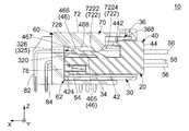
図24及び図25に示されるように、この状態において、第2支持部46は、第2支持部収容部325に収容されており、元の形状に復帰している。より詳しくは、この状態において、被ストップ部464及び被ストップ部支持部462は、付加的収容部327に収容されており、凸部466及び凸部支持部465は、主収容部326に収容されている。また、この状態において、凸部466の上端は、延長部728の下端と接触しておらず、凸部466の下端も、仕切壁320と接触していない。加えて、この状態において、凸部支持部465は解除突起722と接触していない。 As shown in FIGS. 24 and 25, in this state, thesecond support portion 46 is housed in the second supportportion accommodating portion 325 and has returned to its original shape. More specifically, in this state, the stoppedportion 464 and the stoppedportion supporting portion 462 are accommodated in the additionalaccommodating portion 327, and theconvex portion 466 and the convexportion supporting portion 465 are accommodated in the mainaccommodating portion 326. ing. Further, in this state, the upper end of theconvex portion 466 is not in contact with the lower end of theextension portion 728, and the lower end of theconvex portion 466 is also not in contact with thepartition wall 320. In addition, in this state, theconvex support portion 465 is not in contact with therelease protrusion 722.

図24に示されるように、この状態において、コネクタ20の第2端子54は相手側コネクタ60の相手側第2端子84に接続されており、HVIL回路が閉じられて図8に示される第1端子52と図18に示される相手側第1端子82との間が通電される。また、この状態において、規制部442は、第1操作部368の直交方向における内側に位置してロック部365の直交方向における移動を規制している。より詳しくは、この状態において、規制部442は、第1操作部368の上下方向における下方に位置してロック部365の下方への移動を規制している。 As shown in FIG. 24, in this state, thesecond terminal 54 of theconnector 20 is connected to the matingsecond terminal 84 of themating connector 60, the HVIL circuit is closed, and the first terminal shown in FIG. 8 is closed. A power is supplied between the terminal 52 and thefirst terminal 82 on the other side shown in FIG. Further, in this state, the regulatingunit 442 is located inside thefirst operating unit 368 in the orthogonal direction and restricts the movement of thelocking unit 365 in the orthogonal direction. More specifically, in this state, the regulatingunit 442 is located below thefirst operating unit 368 in the vertical direction and restricts the downward movement of thelocking unit 365.

即ち、上記規制(移動規制)が解除された後、第2ハウジング40を嵌合方向に更に移動させると、第2端子54が相手側第2端子84に接続されると共に、規制部442が第1操作部368の直交方向における内側に位置してロック部365の直交方向における移動を規制する。なお、本発明はこれに限定されず、規制部442は、第1構造体36の少なくとも一部の直交方向における内側に位置することにより、ロック部365の直交方向における移動を規制してもよい。換言すれば、移動規制が解除された後、第2ハウジング40を嵌合方向に更に移動させると、第2端子54が相手側第2端子84に接続されると共に、規制部442が第1構造体36の少なくとも一部の直交方向における内側に位置してロック部365の直交方向における移動を規制すればよい。 That is, when thesecond housing 40 is further moved in the fitting direction after the above restriction (movement restriction) is released, thesecond terminal 54 is connected to the other sidesecond terminal 84, and theregulation unit 442 becomes the second. 1 It is located inside theoperation unit 368 in the orthogonal direction and regulates the movement of thelock unit 365 in the orthogonal direction. The present invention is not limited to this, and the regulatingunit 442 may restrict the movement of thelocking unit 365 in the orthogonal direction by being located inside at least a part of thefirst structure 36 in the orthogonal direction. .. In other words, when thesecond housing 40 is further moved in the fitting direction after the movement restriction is lifted, thesecond terminal 54 is connected to the matingsecond terminal 84 and theregulation unit 442 has the first structure. At least a part of thebody 36 may be located inside in the orthogonal direction to restrict the movement of thelock portion 365 in the orthogonal direction.

図24から理解されるように、この状態において、第1操作部368を直交方向内側に押圧しても、第1操作部368が規制部442に突き当たるため、ロック部365及び相手側ロック部725による第1ハウジング30が受容部62に受容された状態のロックを解除することができない。これにより、図8に示される第1端子52と図18に示される相手側第1端子82との間が通電されたこの状態において、ユーザーが誤って第1操作部368を押圧してコネクタ20と相手側コネクタ60との嵌合を解除しようとしても、コネクタ20と相手側コネクタ60との嵌合が解除されないようになっている。即ち、コネクタ組立体10は、コネクタ20と相手側コネクタ60との嵌合状態をロックするCPA機構を有している。 As can be seen from FIG. 24, in this state, even if thefirst operation unit 368 is pressed inward in the orthogonal direction, thefirst operation unit 368 abuts on theregulation unit 442, so that thelock unit 365 and the otherside lock unit 725 Thefirst housing 30 cannot be unlocked in a state of being received by the receivingportion 62. As a result, in this state in which thefirst terminal 52 shown in FIG. 8 and the other sidefirst terminal 82 shown in FIG. 18 are energized, the user mistakenly presses thefirst operation unit 368 to press theconnector 20. Even if an attempt is made to release the mating between theconnector 20 and themating connector 60, the mating between theconnector 20 and themating connector 60 is not released. That is, theconnector assembly 10 has a CPA mechanism that locks the mated state of theconnector 20 and themating connector 60.

加えて、図23に示されるように、この状態において、付加的ロック部454は、前後方向において付加的被ロック部370と対向している。即ち、この状態において、付加的ロック部454と付加的被ロック部370とは、第2ハウジング40が第1ハウジング30に組み込まれた状態をロックしている。 In addition, as shown in FIG. 23, in this state, theadditional locking portion 454 faces the additional lockedportion 370 in the front-rear direction. That is, in this state, theadditional locking portion 454 and the additional lockedportion 370 lock the state in which thesecond housing 40 is incorporated in thefirst housing 30.

コネクタ20と相手側コネクタ60との嵌合を解除する操作について、以下に詳述する。 The operation of releasing the mating between theconnector 20 and themating connector 60 will be described in detail below.

図23の状態のコネクタ組立体10において、コネクタ20の第2操作部458を横方向内側に押圧する。これにより、付加的ロック部454は、付加的被ロック部370に対して横方向内側に移動するため、第2ハウジング40が第1ハウジング30に組み込まれた状態のロックが解除される。 In theconnector assembly 10 in the state of FIG. 23, thesecond operation portion 458 of theconnector 20 is pressed inward in the lateral direction. As a result, theadditional locking portion 454 moves laterally inward with respect to the additional lockedportion 370, so that the lock in the state where thesecond housing 40 is incorporated in thefirst housing 30 is released.

第2操作部458の上記押圧状態を維持しつつ、第2ハウジング40を第1ハウジング30から後方に引き離すように移動させると、コネクタ20の第2ハウジング40の凸部466の後面468が相手側コネクタ60の解除突起722の前面7222に接触する。 When thesecond housing 40 is moved so as to be pulled backward from thefirst housing 30 while maintaining the pressed state of thesecond operating portion 458, therear surface 468 of theconvex portion 466 of thesecond housing 40 of theconnector 20 is on the other side. It contacts thefront surface 7222 of therelease protrusion 722 of theconnector 60.

凸部466の後面468が解除突起722の前面7222と接触した状態から、第2ハウジング40を第1ハウジング30から更に後方に引き離すように移動させると、第2支持部46が弾性変形して凸部466が解除突起722により押し下げられて、図20から図22に示される状態となる。 When therear surface 468 of theconvex portion 466 is in contact with thefront surface 7222 of therelease protrusion 722 and thesecond housing 40 is moved so as to be further rearwardly separated from thefirst housing 30, thesecond support portion 46 is elastically deformed and convex. Theportion 466 is pushed down by therelease protrusion 722 to be in the state shown in FIGS. 20 to 22.

図21に示されるように、この状態において、第2端子54と相手側第2端子84との接続は解除されているので、HVIL回路は開いており、図8に示される第1端子52と図18に示される相手側第1端子82との間の電力供給は遮断されている。また、この状態において、規制部442は、前後方向において第1操作部368の後方に位置していることから、第1操作部368を直交方向内側に押圧しても規制部442に突き当たらないようになっている。 As shown in FIG. 21, in this state, the connection between thesecond terminal 54 and thesecond terminal 84 on the other side is disconnected, so that the HVIL circuit is open and thefirst terminal 52 shown in FIG. The power supply to and from thefirst terminal 82 on the other side shown in FIG. 18 is cut off. Further, in this state, since the regulatingunit 442 is located behind thefirst operating unit 368 in the front-rear direction, it does not hit the regulatingunit 442 even if thefirst operating unit 368 is pressed inward in the orthogonal direction. It has become like.

この状態において、第1操作部368を、直交方向内側、即ち下方に押圧する。これにより、ロック部365は相手側ロック部725に対して下方に移動するため、第1ハウジング30が受容部62に受容された状態のロックが解除される。 In this state, thefirst operation unit 368 is pressed inward in the orthogonal direction, that is, downward. As a result, thelock portion 365 moves downward with respect to thecounterpart lock portion 725, so that the lock in the state where thefirst housing 30 is received by the receivingportion 62 is released.

第1操作部368の上記押圧状態を維持しつつ、コネクタ20を相手側コネクタ60から後方に引き離すように移動させると、コネクタ20を相手側コネクタ60から引き抜くことができ、コネクタ20と相手側コネクタ60との嵌合を解除することができる。 By moving theconnector 20 so as to pull it backward from themating connector 60 while maintaining the above-mentioned pressing state of thefirst operation unit 368, theconnector 20 can be pulled out from themating connector 60, and theconnector 20 and the mating connector can be pulled out. The mating with 60 can be released.

以上、本発明について、実施の形態を掲げて具体的に説明してきたが、本発明はこれに限定されるわけではなく、種々の変形が可能である。 Although the present invention has been specifically described with reference to embodiments, the present invention is not limited to this, and various modifications are possible.

本実施の形態の相手側コネクタ60は、回路基板上のパッドに接続される相手側第1端子82及び相手側第2端子84を備えていたが、本発明はこれに限定されず、相手側コネクタ60は、相手側第1端子82及び相手側第2端子84の代わりに、ケーブルに接続されるケーブル用端子を備えていてもよい。即ち、コネクタ組立体10は、コネクタ20と相手側コネクタ60の双方をケーブルハーネスに使用することにより、中継コネクタとして使用してもよい。 Themating side connector 60 of the present embodiment includes a mating sidefirst terminal 82 and a mating sidesecond terminal 84 connected to a pad on the circuit board, but the present invention is not limited to this, and the mating side is not limited to this. Theconnector 60 may include a cable terminal connected to a cable instead of the mating sidefirst terminal 82 and the mating sidesecond terminal 84. That is, theconnector assembly 10 may be used as a relay connector by using both theconnector 20 and themating connector 60 for the cable harness.

本実施の形態のコネクタ組立体10において、相手側ロック部725は、ロック孔724の上記内面であり、ロック部365はロック突起364の後面であったが、本発明はこれに限定されない。即ち、相手側ロック部725は、上板72から下方に突出した突起の後面であり、ロック部365は、第1支持部362を上下方向に貫通する孔の内面であって前方を向いた内面であってもよい。 In theconnector assembly 10 of the present embodiment, themating lock portion 725 is the inner surface of thelock hole 724, and thelock portion 365 is the rear surface of thelock protrusion 364, but the present invention is not limited thereto. That is, themating lock portion 725 is the rear surface of the protrusion protruding downward from theupper plate 72, and thelock portion 365 is the inner surface of the hole that penetrates thefirst support portion 362 in the vertical direction and faces forward. It may be.

本実施の形態のコネクタ組立体10において、上記規制状態の第2ハウジング40を第1ハウジング30と共に嵌合方向に沿って相手側コネクタ60の受容部62に受容させると、第2支持部46の凸部466が解除突起722に当たって上記規制(移動規制)が解除されるよう構成されていたが、本発明はこれに限定されない。具体的には、上記規制状態の第2ハウジング40を第1ハウジング30と共に嵌合方向に沿って相手側コネクタ60の受容部62に受容させると、被支持部464が解除突起722に当たって移動規制が解除されるように構成されていてもよい。即ち、上記規制状態の第2ハウジング40を第1ハウジング30と共に嵌合方向に沿って受容部62に受容させると、相手側第1端子82に第1端子52が接続された後、第2支持部46又は被支持部464が解除突起722に当たって移動規制が解除されればよい。 In theconnector assembly 10 of the present embodiment, when thesecond housing 40 in the regulated state is received by the receivingportion 62 of themating connector 60 along the fitting direction together with thefirst housing 30, the second supportingportion 46 Theconvex portion 466 is configured to hit therelease protrusion 722 to release the above restriction (movement restriction), but the present invention is not limited to this. Specifically, when thesecond housing 40 in the restricted state is received by the receivingportion 62 of themating connector 60 along the fitting direction together with thefirst housing 30, the supportedportion 464 hits therelease projection 722 and movement restriction is imposed. It may be configured to be released. That is, when thesecond housing 40 in the regulated state is received by the receivingportion 62 together with thefirst housing 30 along the fitting direction, thefirst terminal 52 is connected to the matingfirst terminal 82, and then the second support is provided. The movement restriction may be released when theportion 46 or the supportedportion 464 hits therelease protrusion 722.

(第2の実施の形態)
本発明は、上述した第1の実施の形態に限られず、様々に適用可能である。以下、本発明の第2の実施の形態について、第1の実施の形態において特に触れなかった構造及び変形例を含めて詳細に説明する。
(Second Embodiment)
The present invention is not limited to the first embodiment described above, and can be applied in various ways. Hereinafter, the second embodiment of the present invention will be described in detail including a structure and modifications not particularly mentioned in the first embodiment.

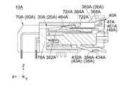
図26に示されるように、本発明の第2の実施の形態によるコネクタ組立体10Aは、コネクタ20Aと、相手側コネクタ60Aとを備えている。コネクタ20Aは、嵌合方向(+X方向)に沿って相手側コネクタ60Aと嵌合可能である。相手側コネクタ60Aと嵌合したコネクタ20Aは、嵌合方向(+X方向)の逆方向である抜去方向(−X方向)に沿って相手側コネクタ60Aから抜去可能である。即ち、本実施の形態において、嵌合方向は、前後方向(X方向)において前方に向かう+X方向であり、抜去方向は、前後方向(X方向)において後方に向かう−X方向である。 As shown in FIG. 26, theconnector assembly 10A according to the second embodiment of the present invention includes aconnector 20A and amating connector 60A. Theconnector 20A can be fitted with themating connector 60A along the fitting direction (+ X direction). Theconnector 20A fitted with themating connector 60A can be pulled out from themating connector 60A along the pulling direction (−X direction) which is the opposite direction of the fitting direction (+ X direction). That is, in the present embodiment, the fitting direction is the + X direction toward the front in the front-rear direction (X direction), and the removal direction is the -X direction toward the rear in the front-rear direction (X direction).

本実施の形態のコネクタ20Aは、ケーブル56A,58Aに接続されたケーブルコネクタである。コネクタ20Aは、ケーブル56A,58Aと共にケーブルハーネスを形成している。一方、本実施の形態の相手側コネクタ60Aは、回路基板(図示せず)に搭載されたオンボードコネクタである。但し、本発明は、これに限られず、様々なコネクタ及び相手側コネクタを備えたコネクタ組立体に適用可能である。例えば、相手側コネクタ60Aは、コネクタ20Aと同様に、ケーブルに接続されてケーブルハーネスを形成していてもよい。 Theconnector 20A of the present embodiment is a cable connector connected to thecables 56A and 58A. Theconnector 20A forms a cable harness together with thecables 56A and 58A. On the other hand, themating connector 60A of the present embodiment is an on-board connector mounted on a circuit board (not shown). However, the present invention is not limited to this, and is applicable to a connector assembly provided with various connectors and a mating connector. For example, themating connector 60A may be connected to a cable to form a cable harness in the same manner as theconnector 20A.

本実施の形態において、ケーブル56A,58Aは、電源装置(図示せず)に接続されている。一方、相手側コネクタ60Aを搭載した回路基板(図示せず)は、相手側電子機器(図示せず)に組み込まれている。コネクタ20Aと相手側コネクタ60Aとが互いに嵌合した嵌合状態において、相手側電子機器は、電源装置と電気的に接続され、電源装置から相手側電子機器に高圧電力が供給される。後述するように、コネクタ組立体10Aは、嵌合状態をロックするコネクタ位置保証機構(CPA機構)と、高圧電力による感電を防止するための高電圧インターロック機構(HVIL機構)とを有している。 In this embodiment, thecables 56A and 58A are connected to a power supply device (not shown). On the other hand, the circuit board (not shown) on which themating connector 60A is mounted is incorporated in the mating electronic device (not shown). In the fitted state in which theconnector 20A and themating connector 60A are fitted to each other, the mating electronic device is electrically connected to the power supply device, and high-voltage power is supplied from the power supply device to the mating electronic device. As will be described later, theconnector assembly 10A has a connector position guarantee mechanism (CPA mechanism) for locking the mating state and a high voltage interlock mechanism (HVIL mechanism) for preventing electric shock due to high voltage power. There is.

以下、相手側コネクタ60Aの構造について説明する。 Hereinafter, the structure of themating connector 60A will be described.

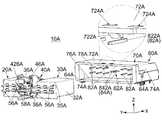
図26を参照すると、本実施の形態の相手側コネクタ60Aは、絶縁体からなる相手側ハウジング70Aと、金属製の2つの付加的部材64Aと、導電体からなる複数の相手側第1端子82Aと、導電体からなる複数の相手側第2端子84Aとを備えている。 Referring to FIG. 26, themating connector 60A of the present embodiment includes amating housing 70A made of an insulator, twoadditional metal members 64A, and a plurality of matingfirst terminals 82A made of a conductor. And a plurality of counterpartysecond terminals 84A made of a conductor.

本実施の形態において、相手側第1端子82Aは、電力供給用の端子であり、相手側第2端子84Aは、HVIL機構の一部である。本実施の形態の相手側コネクタ60Aには、12(6対)の相手側第1端子82Aと、2つ(1対)の相手側第2端子84Aとが設けられている。但し、本発明は、これに限られない。例えば、相手側第1端子82Aの数は、用途に応じていればよい。相手側第2端子84Aの数は、必要なHVIL機構に応じていればよい。HVIL機構を設けない場合、相手側第2端子84Aを設ける必要がない。また、相手側第2端子84Aと異なる部材を使用してHVIL機構を形成してもよい。加えて、付加的部材64Aは、必要に応じて設ければよい。即ち、本発明の相手側コネクタ60Aは、相手側ハウジング70Aと、1以上の相手側第1端子82Aとを備えていればよい。一方、相手側コネクタ60Aは、上述した部材に加えて、更に別の部材を備えていてもよい。 In the present embodiment, the other side first terminal 82A is a terminal for power supply, and the other sidesecond terminal 84A is a part of the HVIL mechanism. Themating side connector 60A of the present embodiment is provided with 12 (6 pairs) mating sidefirst terminals 82A and two (1 pair) mating sidesecond terminals 84A. However, the present invention is not limited to this. For example, the number of thefirst terminal 82A on the other side may be set according to the intended use. The number of thesecond terminal 84A on the other side may depend on the required HVIL mechanism. When the HVIL mechanism is not provided, it is not necessary to provide thesecond terminal 84A on the other side. Further, the HVIL mechanism may be formed by using a member different from thesecond terminal 84A on the other side. In addition, theadditional member 64A may be provided as needed. That is, themating side connector 60A of the present invention may include amating side housing 70A and one or more mating sidefirst terminals 82A. On the other hand, themating connector 60A may include yet another member in addition to the above-mentioned member.

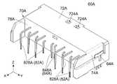
図26及び図27を参照すると、本実施の形態の相手側ハウジング70Aは、上板72Aと、2つの側板74Aと、底板76Aと、背板78Aとを有している。上板72A、側板74A、底板76A及び背板78Aの夫々は、矩形の平板形状を有している。上板72A、側板74A、底板76A及び背板78Aは、互いに繋がっており、後方に開口した略直方体形状の箱を形成している。 Referring to FIGS. 26 and 27, themating housing 70A of the present embodiment has anupper plate 72A, twoside plates 74A, abottom plate 76A, and aback plate 78A. Each of theupper plate 72A, theside plate 74A, thebottom plate 76A, and theback plate 78A has a rectangular flat plate shape. Theupper plate 72A, theside plate 74A, thebottom plate 76A, and theback plate 78A are connected to each other to form a substantially rectangular parallelepiped box that opens rearward.

上板72Aは、X方向と直交する直交方向(上下方向:Z方向)における相手側ハウジング70Aの上端に位置しており、Z方向と直交する水平面(XY平面)に沿って延びている。底板76Aは、相手側ハウジング70Aの下端に位置しており、XY平面に沿って上板72Aと平行に延びている。2つの側板74Aは、X方向及びZ方向の双方と直交する横方向(Y方向)における相手側ハウジング70Aの両側に夫々位置しており、所定平面(XZ平面)に沿って互いに平行に延びている。背板78Aは、直交平面(YZ平面)に沿って延びており、上板72A、側板74A及び底板76Aの前端(+X側の端)に繋がっている。 Theupper plate 72A is located at the upper end of themating housing 70A in the orthogonal direction (vertical direction: Z direction) orthogonal to the X direction, and extends along a horizontal plane (XY plane) orthogonal to the Z direction. Thebottom plate 76A is located at the lower end of themating housing 70A and extends parallel to theupper plate 72A along the XY plane. The twoside plates 74A are located on both sides of themating housing 70A in the lateral direction (Y direction) orthogonal to both the X direction and the Z direction, and extend parallel to each other along a predetermined plane (XZ plane). There is. Theback plate 78A extends along an orthogonal plane (YZ plane) and is connected to the front ends (+ X side ends) of theupper plate 72A, theside plates 74A, and thebottom plate 76A.

図26を参照すると、上述のように形成された相手側ハウジング70Aは、コネクタ20Aを受容可能な受容部62Aを有している。即ち、相手側ハウジング70Aは、相手側コネクタ60Aの受容部62Aを構成している。本実施の形態の受容部62Aは、上板72A、側板74A、底板76A及び背板78Aによって囲まれた概ね直方体形状の空間であり、後方に開口している。背板78Aは、受容部62Aの前端を規定している。 Referring to FIG. 26, themating housing 70A formed as described above has a receivingportion 62A capable of receiving theconnector 20A. That is, themating side housing 70A constitutes the receivingportion 62A of themating side connector 60A. The receivingportion 62A of the present embodiment is a substantially rectangular parallelepiped space surrounded by anupper plate 72A, aside plate 74A, abottom plate 76A, and aback plate 78A, and is open to the rear. Theback plate 78A defines the front end of the receivingportion 62A.

本実施の形態の相手側ハウジング70Aは、全体として上述の構造を有している。但し、相手側コネクタ60Aに受容部62Aが設けられている限り、相手側ハウジング70Aの構造は、本実施の形態に限定されない。 Themating housing 70A of the present embodiment has the above-mentioned structure as a whole. However, as long as the receivingportion 62A is provided on themating side connector 60A, the structure of themating side housing 70A is not limited to the present embodiment.

図26に示されるように、相手側ハウジング70Aには、解除突起722Aと、2つの相手側ロック部(ロック孔)724Aとが形成されている。解除突起722A及び相手側ロック部724Aは、コネクタ組立体10AのCPA機構の一部である。本実施の形態において、解除突起722Aの数は1であり、相手側ロック部724Aの数は2である。2つの相手側ロック部724Aは、Y方向において解除突起722Aを間に置いて並んでいる。但し、解除突起722Aの数及び相手側ロック部724Aの数は、必要なCPA機構に応じていればよい。また、解除突起722A及び相手側ロック部724Aは、必要なCPA機構に応じて配置すればよい。 As shown in FIG. 26, themating side housing 70A is formed with arelease protrusion 722A and two mating side lock portions (lock holes) 724A. Therelease protrusion 722A and themating lock portion 724A are part of the CPA mechanism of theconnector assembly 10A. In the present embodiment, the number ofrelease protrusions 722A is 1, and the number ofcounterpart lock portions 724A is 2. The twomating lock portions 724A are lined up with arelease protrusion 722A in between in the Y direction. However, the number of therelease protrusions 722A and the number of the otherside lock portions 724A may be determined according to the required CPA mechanism. Further, therelease protrusion 722A and themating lock portion 724A may be arranged according to the required CPA mechanism.

図26及び図29に示されるように、本実施の形態の解除突起722Aは、上板72Aに設けられている。解除突起722Aは、X方向において上板72Aの後端(−X側の端)に位置しており、Y方向において上板72Aの中間部に位置している。解除突起722Aは、上板72Aの下面(−Z側の面)から下方(−Z方向)に突出している。即ち、解除突起722Aは、受容部62A内に突出している。本実施の形態において、解除突起722Aの後端には、前方及び下方に向かって比較的緩やかに傾斜する緩斜面(ガイド面)が形成されており、解除突起722Aの前端には、前方及び下方に向かって急激に傾斜する急斜面(受止面)が形成されている。但し、解除突起722Aが少なくとも部分的に受容部62A内に位置している限り、解除突起722Aの構造は、本実施の形態に限定されず、必要に応じて変形可能である。 As shown in FIGS. 26 and 29, therelease protrusion 722A of the present embodiment is provided on theupper plate 72A. Therelease protrusion 722A is located at the rear end (-X side end) of theupper plate 72A in the X direction, and is located at the intermediate portion of theupper plate 72A in the Y direction. Therelease protrusion 722A projects downward (in the −Z direction) from the lower surface (the surface on the −Z side) of theupper plate 72A. That is, therelease protrusion 722A protrudes into the receivingportion 62A. In the present embodiment, gentle slopes (guide surfaces) that incline relatively gently toward the front and downward are formed at the rear ends of therelease protrusion 722A, and front and downward at the front ends of therelease protrusion 722A. A steep slope (reception surface) that slopes sharply toward the surface is formed. However, as long as therelease protrusion 722A is at least partially located in the receivingportion 62A, the structure of therelease protrusion 722A is not limited to the present embodiment and can be deformed as needed.

図26から図29までに示されるように、本実施の形態の相手側ロック部724Aは、上板72Aに形成されている。相手側ロック部724Aの夫々は、上板72Aに形成された孔であり、XY平面において矩形形状を有している。相手側ロック部724Aの夫々は、上板72AをZ方向に貫通しており、受容部62Aと連通している。即ち、相手側ロック部724Aの夫々は、受容部62A内に面している。本実施の形態の相手側ロック部724Aは、上述の構造を有している。但し、相手側ロック部724Aの構造は、相手側ロック部724Aが受容部62Aの内部空間に面している限り、様々に変形可能である。例えば、相手側ロック部724Aは、孔ではなく、突出部であってもよい。相手側ロック部724Aが突出部である場合、相手側ロック部724Aは、受容部62A内に突出していてもよい。 As shown in FIGS. 26 to 29, thecounterpart lock portion 724A of the present embodiment is formed on theupper plate 72A. Each of themating lock portions 724A is a hole formed in theupper plate 72A and has a rectangular shape in the XY plane. Each of themating lock portions 724A penetrates theupper plate 72A in the Z direction and communicates with the receivingportion 62A. That is, each of the otherside lock portions 724A faces the inside of the receivingportion 62A. Thecounterpart lock portion 724A of the present embodiment has the above-mentioned structure. However, the structure of themating lock portion 724A can be variously modified as long as themating locking portion 724A faces the internal space of the receivingportion 62A. For example, themating lock portion 724A may be a protruding portion instead of a hole. When thecounterpart lock portion 724A is a protruding portion, thecounterpart lock portion 724A may project into the receivingportion 62A.

図26、図27及び図29を参照すると、相手側ハウジング70Aは、相手側第1端子82Aと、相手側第2端子84Aとを保持している。本実施の形態の相手側第1端子82A及び相手側第2端子84Aは、相手側ハウジング70Aの背板78Aにインサート成型されて保持されている。但し、本発明は、これに限られず、相手側第1端子82A及び相手側第2端子84Aは、相手側ハウジング70Aにどのように保持されていてもよい。 With reference to FIGS. 26, 27 and 29, themating side housing 70A holds the mating side first terminal 82A and the mating sidesecond terminal 84A. The mating side first terminal 82A and the mating side second terminal 84A of the present embodiment are inserted and held in theback plate 78A of themating side housing 70A. However, the present invention is not limited to this, and the mating side first terminal 82A and the mating sidesecond terminal 84A may be held in themating side housing 70A in any way.

図26及び図27を参照すると、相手側第2端子84Aは、背板78AのY方向における中間部に位置しており、Y方向に並んでいる。相手側第1端子82Aは、Z方向において2列に分けられている。各列の相手側第1端子82Aは、Y方向において相手側第2端子84Aを間に置いて並んでいる。本実施の形態の相手側第1端子82A及び相手側第2端子84Aは、上述のように配置されている。但し、相手側第1端子82A及び相手側第2端子84Aの配置は、本実施の形態に限定されない。 With reference to FIGS. 26 and 27, the matingsecond terminal 84A is located in the middle portion of theback plate 78A in the Y direction and is arranged in the Y direction. Thefirst terminal 82A on the other side is divided into two rows in the Z direction. The mating side first terminal 82A of each row is lined up with the mating side second terminal 84A in between in the Y direction. The mating side first terminal 82A and the mating side second terminal 84A of the present embodiment are arranged as described above. However, the arrangement of the mating side first terminal 82A and the mating sidesecond terminal 84A is not limited to this embodiment.

図29を参照すると、相手側第1端子82Aの夫々は、棒状の金属を曲げて形成した所謂ピンコンタクトである。相手側第1端子82Aの夫々は、相手側接触部822Aと、被固定部828Aとを有している。相手側接触部822Aの夫々は、受容部62Aの内部に位置している。詳しくは、相手側接触部822Aは、背板78Aから受容部62Aの開口に向かって−X方向に沿って同じ位置まで夫々延びている。被固定部828Aの夫々は、背板78Aから相手側ハウジング70Aの外部に突出しており、全体として下方に向かって延びている。被固定部828Aの夫々は、相手側コネクタ60Aの使用時に、回路基板(図示せず)に半田付け等によって固定され接続される。 Referring to FIG. 29, each of the matingfirst terminals 82A is a so-called pin contact formed by bending a rod-shaped metal. Each of thefirst terminal 82A on the other side has acontact portion 822A on the other side and a fixedportion 828A. Each of themating contact portions 822A is located inside the receivingportion 62A. Specifically, themating contact portion 822A extends from theback plate 78A toward the opening of the receivingportion 62A to the same position along the −X direction. Each of the fixedportions 828A projects from theback plate 78A to the outside of themating housing 70A, and extends downward as a whole. Each of the fixedportions 828A is fixed and connected to a circuit board (not shown) by soldering or the like when themating connector 60A is used.

相手側第2端子84Aの夫々は、棒状の金属を曲げて形成した所謂ピンコンタクトである。相手側第2端子84Aの夫々は、相手側接触部842Aと、被固定部848Aとを有している。相手側接触部842Aの夫々は、受容部62Aの内部に位置している。詳しくは、相手側接触部842Aは、背板78Aから受容部62Aの開口に向かって−X方向に沿って同じ位置まで夫々延びている。被固定部848Aの夫々は、背板78Aから相手側ハウジング70Aの外部に突出しており、全体として下方に向かって延びている。被固定部848Aの夫々は、相手側コネクタ60Aの使用時に、回路基板(図示せず)に半田付け等によって固定され接続される。 Each of the matingsecond terminals 84A is a so-called pin contact formed by bending a rod-shaped metal. Each of thesecond terminal 84A on the other side has acontact portion 842A on the other side and a fixedportion 848A. Each of themating contact portions 842A is located inside the receivingportion 62A. Specifically, themating contact portion 842A extends from theback plate 78A toward the opening of the receivingportion 62A to the same position along the −X direction. Each of the fixedportions 848A protrudes from theback plate 78A to the outside of themating housing 70A, and extends downward as a whole. Each of the fixedportions 848A is fixed and connected to a circuit board (not shown) by soldering or the like when themating connector 60A is used.

相手側第2端子84Aの相手側接触部842Aは、−X方向に沿って相手側第1端子82Aの相手側接触部822Aと同じ位置まで延びている。換言すれば、相手側接触部822Aの後端のX方向における位置は、相手側接触部842Aの後端のX方向における位置と同じである。本実施の形態の相手側第1端子82A及び相手側第2端子84Aは、上述の構造を有している。但し、相手側第1端子82A及び相手側第2端子84Aの構造は、本実施の形態に限定されない。 The matingside contact portion 842A of the mating sidesecond terminal 84A extends along the −X direction to the same position as the matingside contact portion 822A of the mating side first terminal 82A. In other words, the position of the rear end of themating contact portion 822A in the X direction is the same as the position of the rear end of themating contact portion 842A in the X direction. The mating side first terminal 82A and the mating side second terminal 84A of the present embodiment have the above-mentioned structure. However, the structure of the mating side first terminal 82A and the mating sidesecond terminal 84A is not limited to this embodiment.

以下、コネクタ20A(図26参照)の構造について説明する。 Hereinafter, the structure of theconnector 20A (see FIG. 26) will be described.

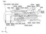
図26及び図32を参照すると、本実施の形態のコネクタ20Aは、絶縁体からなる第1ハウジング30Aと、絶縁体からなる第2ハウジング40Aと、導電体からなる複数の第1端子52Aと、導電体からなる複数の第2端子54Aとを備えている。 With reference to FIGS. 26 and 32, theconnector 20A of the present embodiment includes afirst housing 30A made of an insulator, asecond housing 40A made of an insulator, and a plurality offirst terminals 52A made of a conductor. It is provided with a plurality ofsecond terminals 54A made of a conductor.

本実施の形態の第1端子52Aは、電力供給用の端子であり、電力供給用のケーブル56Aに夫々接続して使用される。第2端子54Aは、HVIL機構の一部であり、信号伝送用のケーブル58Aに夫々接続して使用される。本実施の形態において、第1端子52Aは、相手側第1端子82A(図26参照)に夫々対応しており、第2端子54Aは、相手側第2端子84Aに夫々対応している。即ち、本実施の形態のコネクタ20Aには、12(6対)の第1端子52Aと、2つ(1対)の第2端子54Aとが設けられている。 Thefirst terminal 52A of the present embodiment is a terminal for power supply, and is used by being connected to each of thepower supply cables 56A. Thesecond terminal 54A is a part of the HVIL mechanism and is used by being connected to each of thesignal transmission cables 58A. In the present embodiment, thefirst terminal 52A corresponds to the other side first terminal 82A (see FIG. 26), and thesecond terminal 54A corresponds to the other sidesecond terminal 84A, respectively. That is, theconnector 20A of the present embodiment is provided with 12 (6 pairs) of thefirst terminal 52A and two (1 pair) of thesecond terminals 54A.

本実施の形態のコネクタ20Aは、上述の部材を有している。但し、本発明は、これに限られない。例えば、第1端子52Aの数は、用途に応じていればよい。第2端子54Aの数は、必要なHVIL機構に応じていればよい。HVIL機構を設けない場合、第2端子54Aを設ける必要がない。また、第2端子54Aと異なる部材を使用してHVIL機構を形成してもよい。即ち、本発明のコネクタ20Aは、第1ハウジング30Aと、第2ハウジング40Aと、1以上の第1端子52Aとを備えていればよい。一方、コネクタ20Aは、上述した部材に加えて、更に別の部材を備えていてもよい。 Theconnector 20A of the present embodiment has the above-mentioned member. However, the present invention is not limited to this. For example, the number of thefirst terminals 52A may be adjusted according to the intended use. The number of thesecond terminals 54A may depend on the required HVIL mechanism. When the HVIL mechanism is not provided, it is not necessary to provide thesecond terminal 54A. Further, the HVIL mechanism may be formed by using a member different from thesecond terminal 54A. That is, theconnector 20A of the present invention may include afirst housing 30A, asecond housing 40A, and one or morefirst terminals 52A. On the other hand, theconnector 20A may include yet another member in addition to the above-mentioned member.

図26を参照すると、第1ハウジング30Aは、相手側コネクタ60Aの受容部62Aに部分的に挿入可能である。コネクタ20Aを相手側コネクタ60Aと嵌合する際、第1ハウジング30Aは、+X方向に沿って受容部62Aに挿入され受容される。即ち、第1ハウジング30Aは、+X方向に沿って受容部62Aに受容されるものである。 Referring to FIG. 26, thefirst housing 30A can be partially inserted into the receivingportion 62A of themating connector 60A. When theconnector 20A is fitted with themating connector 60A, thefirst housing 30A is inserted into the receivingportion 62A along the + X direction and received. That is, thefirst housing 30A is received by the receivingportion 62A along the + X direction.

図26、図30及び図31を参照すると、本実施の形態の第1ハウジング30Aは、基部32Aと、第1構造体36Aと、付加的構造体38Aとを有している。基部32Aは、相手側コネクタ60Aの受容部62Aに対応した形状を有している。第1構造体36Aは、コネクタ組立体10AのCPA機構の一部である。本実施の形態の第1構造体36Aは、基部32Aの上側(+Z側)の部位に繋がっている。付加的構造体38Aは、基部32Aの下側(−Z側)の部位に繋がっている。本実施の形態の第1ハウジング30Aは、全体として上述の構造を有している。但し、第1ハウジング30Aの構造は、必要に応じて変形可能である。 With reference to FIGS. 26, 30 and 31, thefirst housing 30A of this embodiment has abase 32A, afirst structure 36A and anadditional structure 38A. Thebase portion 32A has a shape corresponding to the receivingportion 62A of themating connector 60A. Thefirst structure 36A is a part of the CPA mechanism of theconnector assembly 10A. Thefirst structure 36A of the present embodiment is connected to a portion on the upper side (+ Z side) of thebase portion 32A. Theadditional structure 38A is connected to a lower (−Z side) portion of thebase 32A. Thefirst housing 30A of the present embodiment has the above-mentioned structure as a whole. However, the structure of thefirst housing 30A can be deformed as needed.

図30及び図31を参照すると、基部32Aには、収容部33Aと、複数の第1端子収容部35Aとが形成されている。収容部33Aは、基部32AをX方向に貫通する孔であり、前方及び後方に開口している。収容部33Aは、略直方体形状を有している。第1端子収容部35Aの夫々は、基部32AをX方向に貫通する孔であり、前方及び後方に開口している。 With reference to FIGS. 30 and 31, thebase portion 32A is formed with anaccommodating portion 33A and a plurality of first terminalaccommodating portions 35A. Theaccommodating portion 33A is a hole penetrating thebase portion 32A in the X direction, and is open forward and rearward. Theaccommodating portion 33A has a substantially rectangular parallelepiped shape. Each of the firstterminal accommodating portions 35A is a hole penetrating thebase portion 32A in the X direction, and is open forward and rearward.

図32及び図36を参照すると、収容部33Aは、第2ハウジング40Aの一部を移動可能に収容するための空間である。図33を参照すると、収容部33Aは、Y方向における基部32Aの中間部に位置している。収容部33Aには、上壁部332Aと、底壁部334Aとが設けられている。上壁部332Aは、収容部33Aの上側の内壁である。底壁部334Aは、収容部33Aの下側の内壁である。 With reference to FIGS. 32 and 36, theaccommodating portion 33A is a space for accommodating a part of thesecond housing 40A so as to be movable. Referring to FIG. 33, theaccommodating portion 33A is located in the middle portion of thebase portion 32A in the Y direction. Theaccommodating portion 33A is provided with anupper wall portion 332A and abottom wall portion 334A. Theupper wall portion 332A is an inner wall on the upper side of theaccommodating portion 33A. Thebottom wall portion 334A is an inner wall on the lower side of theaccommodating portion 33A.

図36を参照すると、底壁部334Aには、付加的ストッパ部34Aが形成されている。即ち、第1ハウジング30Aには、付加的ストッパ部34Aが設けられている。付加的ストッパ部34Aは、第2ハウジング40Aの一部を収容部33Aの内部に保持するための部位である。付加的ストッパ部34Aは、底壁部334Aから上方(+Z方向)に突出している。即ち、付加的ストッパ部34Aは、収容部33A内に突出している。本実施の形態において、付加的ストッパ部34Aの後端には、前方及び上方に向かって比較的緩やかに傾斜する緩斜面(ガイド面)が形成されており、付加的ストッパ部34Aの前端には、前方及び上方に向かって急激に傾斜する急斜面(受止面)が形成されている。本実施の形態の収容部33Aは、上述の構造を有している。但し、収容部33Aの構造は、本実施の形態に限られない。 Referring to FIG. 36, anadditional stopper portion 34A is formed on thebottom wall portion 334A. That is, thefirst housing 30A is provided with anadditional stopper portion 34A. Theadditional stopper portion 34A is a portion for holding a part of thesecond housing 40A inside theaccommodating portion 33A. Theadditional stopper portion 34A projects upward (+ Z direction) from thebottom wall portion 334A. That is, theadditional stopper portion 34A projects into theaccommodating portion 33A. In the present embodiment, a gentle slope (guide surface) that inclines relatively gently forward and upward is formed at the rear end of theadditional stopper portion 34A, and at the front end of theadditional stopper portion 34A. , A steep slope (reception surface) that slopes sharply forward and upward is formed. Theaccommodating portion 33A of the present embodiment has the above-mentioned structure. However, the structure of theaccommodating portion 33A is not limited to the present embodiment.

図32を参照すると、第1端子収容部35Aは、第1端子52Aに夫々対応して設けられている。第1端子収容部35Aの夫々は、対応する第1端子52Aを収容するための空間である。図26を参照すると、第1端子収容部35AのYZ平面における位置は、相手側コネクタ60Aの相手側第1端子82Aの相手側接触部822AのYZ平面における位置と夫々対応している。即ち、第1端子収容部35Aは、相手側接触部822Aを夫々受容可能に配置されている。 With reference to FIG. 32, the firstterminal accommodating portion 35A is provided corresponding to thefirst terminal 52A, respectively. Each of the firstterminal accommodating portions 35A is a space for accommodating the correspondingfirst terminal 52A. Referring to FIG. 26, the position of the firstterminal accommodating portion 35A in the YZ plane corresponds to the position of the matingside contact portion 822A of the mating side first terminal 82A of themating side connector 60A in the YZ plane, respectively. That is, the firstterminal accommodating portion 35A is arranged so as to be able to accept themating contact portion 822A, respectively.

図32を参照すると、第1端子52Aの夫々は、1枚の金属板を曲げて形成した所謂ソケットコンタクトである。即ち、第1端子52Aの夫々は、曲げを有する1枚の金属板である。本実施の形態の第1端子52Aは、互いに同じ形状を有している。第1端子52Aの夫々は、接触部522Aと、被接続部528Aとを有している。 Referring to FIG. 32, each of thefirst terminals 52A is a so-called socket contact formed by bending one metal plate. That is, each of thefirst terminals 52A is a single metal plate having a bend. Thefirst terminal 52A of the present embodiment has the same shape as each other. Each of thefirst terminals 52A has acontact portion 522A and aconnected portion 528A.

図32を図26と併せて参照すると、接触部522Aの夫々は、対応する相手側第1端子82Aの相手側接触部822Aを部分的に受容可能であり、これにより、相手側接触部822Aと接触可能である。即ち、第1端子52Aは、第1ハウジング30Aが相手側コネクタ60Aの受容部62Aに受容されたとき、相手側第1端子82Aに夫々接続されるものである。一方、被接続部528Aの夫々は、対応するケーブル56Aに接続されている。本実施の形態の第1端子52Aは、上述の構造を有している。但し、第1端子52Aの構造は、本実施の形態に限定されない。 Referring to FIG. 32 together with FIG. 26, each of thecontact portions 522A can partially accept the matingside contact portion 822A of the corresponding mating side first terminal 82A, thereby forming the matingside contact portion 822A. Can be contacted. That is, thefirst terminal 52A is connected to the mating first terminal 82A, respectively, when thefirst housing 30A is received by the receivingportion 62A of themating connector 60A. On the other hand, each of theconnected portions 528A is connected to thecorresponding cable 56A. Thefirst terminal 52A of the present embodiment has the above-mentioned structure. However, the structure of thefirst terminal 52A is not limited to this embodiment.

図32を参照すると、第1端子52Aの夫々は、ケーブル56Aの端部と共に、対応する第1端子収容部35Aに挿入され、基部32Aに対して移動しないように保持されている。即ち、第1ハウジング30Aは、第1端子52Aを保持している。第1端子52Aが第1ハウジング30Aに保持されたとき、第1端子52Aの接触部522Aの夫々は、基部32Aの前端近傍に位置している。 With reference to FIG. 32, each of thefirst terminals 52A, along with the end of thecable 56A, is inserted into the corresponding firstterminal accommodating portion 35A and held so as not to move relative to thebase 32A. That is, thefirst housing 30A holds thefirst terminal 52A. When thefirst terminal 52A is held by thefirst housing 30A, each of thecontact portions 522A of thefirst terminal 52A is located near the front end of thebase portion 32A.

図31及び図32を参照すると、第2ハウジング40Aは、第1ハウジング30Aの収容部33Aに部分的に挿入可能である。第2ハウジング40Aは、収容部33Aに後方から挿入されて収容されており、これにより、コネクタ20Aが組み立てられている。 With reference to FIGS. 31 and 32, thesecond housing 40A can be partially inserted into theaccommodating portion 33A of thefirst housing 30A. Thesecond housing 40A is inserted into and accommodated in theaccommodating portion 33A from the rear, whereby theconnector 20A is assembled.

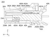
図34を参照すると、本実施の形態の第2ハウジング40Aは、本体部42Aと、付加的構造体43Aと、連結部44Aと、第2構造体46Aとを有している。本体部42Aは、第1ハウジング30A(図32参照)の収容部33A(図32参照)に対応した形状を有している。付加的構造体43Aは、本体部42Aの下面に繋がっており、本体部42Aの後端を越えて後方に延びている。連結部44Aは、本体部42Aの上面(+Z側の面)の後端に繋がっており、本体部42Aの上面から上方に延びている。第2構造体46Aは、コネクタ組立体10A(図26参照)のCPA機構の一部である。本実施の形態の第2構造体46Aは、連結部44Aの上端に繋がっており、連結部44Aの後方に張り出しつつ、全体として前方に延びている。即ち、連結部44Aは、第2構造体46Aを、本体部42Aに連結している。 Referring to FIG. 34, thesecond housing 40A of the present embodiment has amain body portion 42A, anadditional structure 43A, a connectingportion 44A, and asecond structure 46A. Themain body portion 42A has a shape corresponding to theaccommodating portion 33A (see FIG. 32) of thefirst housing 30A (see FIG. 32). Theadditional structure 43A is connected to the lower surface of themain body portion 42A and extends rearward beyond the rear end of themain body portion 42A. The connectingportion 44A is connected to the rear end of the upper surface (+ Z side surface) of themain body portion 42A, and extends upward from the upper surface of themain body portion 42A. Thesecond structure 46A is a part of the CPA mechanism of theconnector assembly 10A (see FIG. 26). Thesecond structure 46A of the present embodiment is connected to the upper end of the connectingportion 44A, and extends forward as a whole while projecting to the rear of the connectingportion 44A. That is, the connectingportion 44A connects thesecond structure 46A to themain body portion 42A.

本実施の形態の第2ハウジング40Aは、全体として上述の構造を有している。但し、第2ハウジング40Aの構造は、必要に応じて変形可能である。 Thesecond housing 40A of the present embodiment has the above-mentioned structure as a whole. However, the structure of thesecond housing 40A can be deformed as needed.

本実施の形態の本体部42Aには、2つの第2端子収容部428Aと、付加的被ストップ部424Aを有する底板部422Aとが形成されている。即ち、本実施の形態の第2ハウジング40Aには、第2端子収容部428Aと、付加的被ストップ部424Aとが設けられている。 Themain body portion 42A of the present embodiment is formed with two secondterminal accommodating portions 428A and abottom plate portion 422A having an additional stoppedportion 424A. That is, thesecond housing 40A of the present embodiment is provided with a secondterminal accommodating portion 428A and an additional stoppedportion 424A.

図32を参照すると、第2端子収容部428Aの夫々は、本体部42AをX方向に貫通する孔であり、前方及び後方に開口している。第2端子収容部428Aは、第2端子54Aに夫々対応して設けられている。第2端子収容部428Aの夫々は、対応する第2端子54Aを収容するための空間である。図26を参照すると、第2端子収容部428AのYZ平面における位置は、相手側コネクタ60Aの相手側第2端子84Aの相手側接触部842AのYZ平面における位置と夫々対応している。即ち、第2端子収容部428Aは、相手側接触部842Aを夫々受容可能に配置されている。 Referring to FIG. 32, each of the secondterminal accommodating portions 428A is a hole penetrating themain body portion 42A in the X direction, and is open forward and rearward. The secondterminal accommodating portion 428A is provided corresponding to thesecond terminal 54A, respectively. Each of the secondterminal accommodating portions 428A is a space for accommodating the correspondingsecond terminal 54A. Referring to FIG. 26, the position of the secondterminal accommodating portion 428A in the YZ plane corresponds to the position of the matingside contact portion 842A of the mating side second terminal 84A of themating side connector 60A in the YZ plane, respectively. That is, the secondterminal accommodating portion 428A is arranged so as to be able to accept themating contact portion 842A, respectively.

図34を参照すると、本体部42Aには、後方に凹んだ凹み421Aが形成されている。底板部422Aは、凹み421Aの下側の内壁である。底板部422AのZ方向におけるサイズ(厚さ)は小さく、これにより、底板部422Aは撓み易い。付加的被ストップ部424Aは、底板部422Aの前端に位置しており、底板部422Aの下面から下方に突出している。図36及び図37を参照すると、本実施の形態において、付加的被ストップ部424Aの前端には、後方及び下方に向かって比較的緩やかに傾斜する緩斜面(被ガイド面)が形成されており、付加的被ストップ部424Aの後端には、後方及び下方に向かって急激に傾斜する急斜面(被受止面)が形成されている。 Referring to FIG. 34, themain body portion 42A is formed with a recessed 421A recessed rearward. Thebottom plate portion 422A is an inner wall on the lower side of therecess 421A. The size (thickness) of thebottom plate portion 422A in the Z direction is small, so that thebottom plate portion 422A is easily bent. The additional stoppedportion 424A is located at the front end of thebottom plate portion 422A and projects downward from the lower surface of thebottom plate portion 422A. Referring to FIGS. 36 and 37, in the present embodiment, a gentle slope (guided surface) that slopes relatively gently rearward and downward is formed at the front end of the additional stoppedportion 424A. At the rear end of the additional stoppedportion 424A, a steep slope (received surface) that is steeply inclined rearward and downward is formed.

本実施の形態の本体部42Aは、上述の構造を有している。但し、本体部42Aの構造は、本実施の形態に限られない。 Themain body portion 42A of the present embodiment has the above-mentioned structure. However, the structure of themain body portion 42A is not limited to the present embodiment.

図32を参照すると、第2端子54Aの夫々は、1枚の金属板を曲げて形成した所謂ソケットコンタクトである。即ち、第2端子54Aの夫々は、曲げを有する1枚の金属板である。本実施の形態の第2端子54Aは、互いに同じ形状を有している。第2端子54Aの夫々は、接触部542Aと、被接続部548Aとを有している。図32を図26と併せて参照すると、接触部542Aの夫々は、対応する相手側第2端子84Aの相手側接触部842Aを部分的に受容可能であり、これにより、相手側接触部842Aと接触可能である。一方、被接続部548Aの夫々は、対応するケーブル58Aに接続されている。即ち、第2端子54Aは、ケーブル58Aに夫々接続されている。本実施の形態の第2端子54Aは、上述の構造を有している。但し、第2端子54Aの構造は、本実施の形態に限定されない。 Referring to FIG. 32, each of thesecond terminals 54A is a so-called socket contact formed by bending one metal plate. That is, each of thesecond terminals 54A is a single metal plate having a bend. Thesecond terminal 54A of the present embodiment has the same shape as each other. Each of thesecond terminals 54A has acontact portion 542A and aconnected portion 548A. Referring to FIG. 32 together with FIG. 26, each of thecontact portions 542A can partially accept the matingside contact portion 842A of the corresponding mating sidesecond terminal 84A, thereby forming the matingside contact portion 842A. Can be contacted. On the other hand, each of theconnected portions 548A is connected to thecorresponding cable 58A. That is, thesecond terminal 54A is connected to thecable 58A, respectively. Thesecond terminal 54A of the present embodiment has the above-mentioned structure. However, the structure of thesecond terminal 54A is not limited to this embodiment.

図32及び図37を参照すると、第2端子54Aの夫々は、ケーブル58Aの端部と共に、対応する第2端子収容部428Aに挿入され、本体部42Aに対して移動しないように保持されている。即ち、第2ハウジング40Aは、第2端子54Aを保持している。第2端子54Aが第2ハウジング40Aに保持されたとき、第2端子54Aの接触部542Aの夫々は、本体部42Aの前端近傍に位置している。 With reference to FIGS. 32 and 37, each of thesecond terminal 54A is inserted into the corresponding secondterminal accommodating portion 428A together with the end of thecable 58A and is held so as not to move with respect to themain body portion 42A. .. That is, thesecond housing 40A holds thesecond terminal 54A. When thesecond terminal 54A is held by thesecond housing 40A, each of thecontact portions 542A of thesecond terminal 54A is located near the front end of themain body portion 42A.

図36及び図37を参照すると、第2ハウジング40Aの本体部42Aは、第1ハウジング30Aの収容部33Aに後方から挿入されている。本体部42Aを収容部33Aに挿入する際、付加的被ストップ部424Aの前端の被ガイド面は、付加的ストッパ部34Aの後端のガイド面にガイドされ、これにより、付加的被ストップ部424Aは、底板部422Aを撓ませながら、付加的ストッパ部34Aを越えて前方に移動する。即ち、コネクタ20Aにおいて、付加的被ストップ部424Aは、付加的ストッパ部34Aの前方に位置しており、X方向において付加的ストッパ部34Aと対向している。第2ハウジング40Aを収容部33Aから引き抜こうとすると、付加的被ストップ部424Aの後端の被受止面が付加的ストッパ部34Aの前端の受止面に受け止められ、これにより、第2ハウジング40Aの後方への移動が停止する。 With reference to FIGS. 36 and 37, themain body portion 42A of thesecond housing 40A is inserted into theaccommodating portion 33A of thefirst housing 30A from the rear. When themain body portion 42A is inserted into theaccommodating portion 33A, the guided surface at the front end of the additional stoppedportion 424A is guided by the guide surface at the rear end of theadditional stopper portion 34A, whereby the additional stoppedportion 424A Moves forward beyond theadditional stopper portion 34A while bending thebottom plate portion 422A. That is, in theconnector 20A, the additional stoppedportion 424A is located in front of theadditional stopper portion 34A and faces theadditional stopper portion 34A in the X direction. When thesecond housing 40A is to be pulled out from theaccommodating portion 33A, the receiving surface at the rear end of the additional stoppedportion 424A is received by the receiving surface at the front end of theadditional stopper portion 34A, whereby thesecond housing 40A Stops moving backwards.

上述のように、付加的ストッパ部34A及び付加的被ストップ部424Aは、互いに係合しており、これにより、第2ハウジング40Aの本体部42Aが第1ハウジング30Aの収容部33Aから抜け出ることを防止している。即ち、第2ハウジング40Aは、第1ハウジング30Aから抜け出ないように確実に保持されている。 As described above, theadditional stopper portion 34A and the additional stoppedportion 424A are engaged with each other, whereby themain body portion 42A of thesecond housing 40A can escape from theaccommodating portion 33A of thefirst housing 30A. It is preventing. That is, thesecond housing 40A is securely held so as not to come out of thefirst housing 30A.

図32及び図37を参照すると、第2ハウジング40Aの本体部42Aが第1ハウジング30Aの収容部33Aに収容されてコネクタ20Aが組み立てられたとき、第2端子54Aの接触部542Aは、第1端子52Aの接触部522Aの後方に位置している。 With reference to FIGS. 32 and 37, when themain body 42A of thesecond housing 40A is housed in thehousing 33A of thefirst housing 30A and theconnector 20A is assembled, thecontact portion 542A of thesecond terminal 54A becomes the first. It is located behind thecontact portion 522A of the terminal 52A.

図26を参照すると、本実施の形態によれば、第1ハウジング30Aの第1構造体36A及び第2ハウジング40Aの第2構造体46Aは、相手側コネクタ60Aの解除突起722A及び相手側ロック部724Aと共に、コネクタ組立体10AのCPA機構を形成している。以下、第1構造体36A及び第2構造体46Aの構造について説明する。 Referring to FIG. 26, according to the present embodiment, thefirst structure 36A of thefirst housing 30A and thesecond structure 46A of thesecond housing 40A have arelease protrusion 722A of themating connector 60A and a mating locking portion. Together with the 724A, it forms the CPA mechanism of theconnector assembly 10A. Hereinafter, the structures of thefirst structure 36A and thesecond structure 46A will be described.

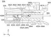
図33を参照すると、本実施の形態の第1ハウジング30Aの第1構造体36Aは、2つの第1支持部362Aと、2つのロック部(ロック突起)364Aと、2つのストッパ部366Aと、カバー部(操作部)368Aと、2つの連結アーム369Aとを有している。即ち、第1ハウジング30Aには、第1支持部362Aと、ロック部364Aと、ストッパ部366Aと、カバー部368Aと、連結アーム369Aとが設けられている。 Referring to FIG. 33, thefirst structure 36A of thefirst housing 30A of the present embodiment includes twofirst support portions 362A, two lock portions (lock protrusions) 364A, and twostopper portions 366A. It has a cover portion (operation portion) 368A and two connectingarms 369A. That is, thefirst housing 30A is provided with afirst support portion 362A, alock portion 364A, astopper portion 366A, acover portion 368A, and a connectingarm 369A.

第1支持部362Aは、Y方向において互いに離れて並んでいる。第1支持部362Aの夫々の前端は、基部32Aの前端に固定された固定端である。第1支持部362Aは、この固定端から後方に向かって、基部32Aの上面から離れつつ、互いに平行に延びている。連結アーム369Aは、第1支持部362Aに夫々対応して設けられている。連結アーム369Aの夫々は、対応する第1支持部362Aの後端に繋がっており、基部32Aの上方を後方に向かって延びている。カバー部368Aは、Y方向に沿って延びており、2つの連結アーム369Aの後端を互いに連結している。換言すれば、連結アーム369Aの夫々は、カバー部368Aと、対応する第1支持部362Aとを互いに連結している。 Thefirst support portions 362A are arranged apart from each other in the Y direction. Each front end of thefirst support portion 362A is a fixed end fixed to the front end of thebase portion 32A. Thefirst support portion 362A extends rearward from the fixed end in parallel with each other while being separated from the upper surface of thebase portion 32A. The connectingarm 369A is provided corresponding to thefirst support portion 362A, respectively. Each of the connectingarms 369A is connected to the rear end of the correspondingfirst support portion 362A and extends rearward above thebase portion 32A. Thecover portion 368A extends along the Y direction and connects the rear ends of the two connectingarms 369A to each other. In other words, each of the connectingarms 369A connects thecover portion 368A and the correspondingfirst support portion 362A to each other.

上述の構造から理解されるように、第1支持部362Aの夫々は、片持ち梁状に支持されたバネであり、弾性変形可能である。特に、第1支持部362Aの夫々は、Z方向におけるサイズ(厚さ)が小さく、弾性変形し易い。一方、連結アーム369Aの夫々は、Z方向におけるサイズ(厚さ)が大きく、弾性変形し難い。例えば、カバー部368Aを下方に向かって押すと、主として第1支持部362Aが弾性変形する。即ち、本実施の形態の第1支持部362Aの夫々は、弾性力である復元力を有している。 As can be understood from the above structure, each of thefirst support portions 362A is a spring supported in a cantilever shape and is elastically deformable. In particular, each of thefirst support portions 362A has a small size (thickness) in the Z direction and is easily elastically deformed. On the other hand, each of the connectingarms 369A has a large size (thickness) in the Z direction and is not easily elastically deformed. For example, when thecover portion 368A is pushed downward, thefirst support portion 362A is mainly elastically deformed. That is, each of thefirst support portions 362A of the present embodiment has a restoring force which is an elastic force.

2つのロック部364Aは、第1支持部362Aに夫々対応して設けられている。ロック部364Aの夫々は、対応する第1支持部362Aの後端近傍に位置しており、第1支持部362Aから上方に突出している。即ち、第1支持部362Aの夫々は、対応するロック部364Aを支持している。ロック部364Aの夫々は、対応する第1支持部362Aの復元力を利用してZ方向に移動可能である。例えば、カバー部368Aを下方に向かって押すと、第1支持部362Aが弾性変形し、ロック部364Aが下方に移動する。カバー部368Aを押すのを止めると、第1支持部362Aが初期状態に復元し、ロック部364Aが上方に移動する。 The twolock portions 364A are provided corresponding to thefirst support portion 362A, respectively. Each of thelock portions 364A is located near the rear end of the correspondingfirst support portion 362A and projects upward from thefirst support portion 362A. That is, each of thefirst support portions 362A supports thecorresponding lock portion 364A. Each of thelock portions 364A can move in the Z direction by utilizing the restoring force of the correspondingfirst support portion 362A. For example, when thecover portion 368A is pushed downward, thefirst support portion 362A is elastically deformed and thelock portion 364A moves downward. When thecover portion 368A is stopped to be pushed, thefirst support portion 362A is restored to the initial state, and thelock portion 364A moves upward.

本実施の形態において、ロック部364Aの前端には、後方及び上方に向かって比較的緩やかに傾斜する緩斜面(被ガイド面)が形成されており、ロック部364Aの後端には、YZ平面に沿って延びる垂直面(被受止面)が形成されている。 In the present embodiment, a gentle slope (guided surface) that inclines relatively gently rearward and upward is formed at the front end of thelock portion 364A, and a YZ plane is formed at the rear end of thelock portion 364A. A vertical plane (received plane) extending along the above is formed.

図39を参照すると、上述のように形成されたロック部364Aは、第1ハウジング30Aが相手側コネクタ60Aの受容部62Aに受容された嵌合状態において、相手側ロック部724Aと夫々係合して、第1ハウジング30Aが受容部62Aから抜け出ることを防止する。また、図40を参照すると、嵌合状態において、コネクタ20Aの第1端子52Aは、相手側コネクタ60Aの相手側第1端子82Aに夫々接続される。即ち、ロック部364Aと相手側ロック部724Aとは、第1端子52Aが相手側第1端子82Aに接続されたとき、第1ハウジング30Aが受容部62Aに受容された状態をロックするものである。 Referring to FIG. 39, thelock portion 364A formed as described above engages with themating lock portion 724A, respectively, in a fitted state in which thefirst housing 30A is received by the receivingportion 62A of themating connector 60A. This prevents thefirst housing 30A from coming out of the receivingportion 62A. Further, referring to FIG. 40, in the mated state, thefirst terminal 52A of theconnector 20A is connected to the mating first terminal 82A of themating connector 60A, respectively. That is, thelock portion 364A and themating lock portion 724A lock the state in which thefirst housing 30A is received by the receivingportion 62A when thefirst terminal 52A is connected to the mating first terminal 82A. ..

図39を参照すると、本実施の形態のロック部364Aは、上述の構造を有している。但し、ロック部364Aが相手側ロック部724Aと夫々対応するように設けられている限り、ロック部364Aの構造は、本実施の形態に限られない。例えば、相手側ロック部724Aが突出部である場合、ロック部364Aは、第1支持部362Aに設けられた孔であってもよい。また、ロック部364Aは、1つのみ設けられていてもよい。この場合、第1支持部362Aは、1つのみ設ければよい。 Referring to FIG. 39, thelock portion 364A of the present embodiment has the above-mentioned structure. However, as long as thelock portion 364A is provided so as to correspond to the otherside lock portion 724A, the structure of thelock portion 364A is not limited to the present embodiment. For example, when the matingside lock portion 724A is a protruding portion, thelock portion 364A may be a hole provided in thefirst support portion 362A. Further, only onelock portion 364A may be provided. In this case, only onefirst support portion 362A needs to be provided.

図33を参照すると、本実施の形態の2つのストッパ部366Aは、第1支持部362Aに夫々対応して設けられている。ストッパ部366Aの夫々は、X方向においてロック部364Aと同じ位置にあり、対応する第1支持部362AからY方向内側に張り出している。即ち、第1支持部362Aの夫々は、対応するストッパ部366Aを支持している。ストッパ部366Aの夫々は、対応する第1支持部362Aの復元力を利用してZ方向に移動可能である。本実施の形態において、ストッパ部366Aの後端には、YZ平面に沿って延びる垂直面(受止面)が形成されている。 Referring to FIG. 33, the twostopper portions 366A of the present embodiment are provided corresponding to thefirst support portion 362A, respectively. Each of thestopper portions 366A is located at the same position as thelock portion 364A in the X direction, and projects inward in the Y direction from the correspondingfirst support portion 362A. That is, each of thefirst support portions 362A supports thecorresponding stopper portion 366A. Each of thestopper portions 366A can be moved in the Z direction by utilizing the restoring force of the correspondingfirst support portion 362A. In the present embodiment, a vertical surface (reception surface) extending along the YZ plane is formed at the rear end of thestopper portion 366A.

図34を参照すると、本実施の形態の第2ハウジング40Aの第2構造体46Aは、規制部461Aと、第2支持部462Aと、被ストップ部(被支持部)464Aと、先端部468Aと、被受止部47Aとを有している。即ち、第2ハウジング40Aには、規制部461Aと、第2支持部462Aと、被ストップ部464Aと、先端部468Aと、被受止部47Aとが設けられている。 Referring to FIG. 34, thesecond structure 46A of thesecond housing 40A of the present embodiment includes a regulatingportion 461A, a second supportingportion 462A, a stopped portion (supported portion) 464A, and atip portion 468A. , Has a receivingportion 47A. That is, thesecond housing 40A is provided with a regulatingportion 461A, a second supportingportion 462A, a stoppedportion 464A, atip portion 468A, and a receivingportion 47A.

本実施の形態の規制部461Aは、XY平面と平行な平面であり、第2支持部462Aの後方かつ上方に位置している。被受止部47Aは、規制部461Aの後端に設けられており、規制部461Aから上方に突出している。但し、本発明はこれに限られない。例えば、規制部461Aの形状は、平面形状に限定されない。また、被受止部47Aは、必要に応じて設ければよい。 Theregulation portion 461A of the present embodiment is a plane parallel to the XY plane, and is located behind and above thesecond support portion 462A. The receivingportion 47A is provided at the rear end of the regulatingportion 461A, and projects upward from the regulatingportion 461A. However, the present invention is not limited to this. For example, the shape of the regulatingportion 461A is not limited to the planar shape. Further, the receivingportion 47A may be provided as needed.

本実施の形態の第2支持部462Aは、XY平面と平行な平板形状を有している。第2支持部462Aは、連結部44Aから本体部42Aの上方を前方に延びている。即ち、第2支持部462Aは、連結部44Aによって片持ち梁状に支持されており、弾性変形可能である。換言すれば、第2支持部462Aは、復元力を有している。第2支持部462Aの後端部の上面には、機械式読み取り可能なマーク48Aが設けられている。即ち、第2ハウジング40Aには、マーク48Aが設けられている。 Thesecond support portion 462A of the present embodiment has a flat plate shape parallel to the XY plane. Thesecond support portion 462A extends forward from the connectingportion 44A above themain body portion 42A. That is, thesecond support portion 462A is supported in a cantilever shape by the connectingportion 44A and is elastically deformable. In other words, thesecond support portion 462A has a restoring force. A mechanicallyreadable mark 48A is provided on the upper surface of the rear end portion of thesecond support portion 462A. That is, themark 48A is provided on thesecond housing 40A.

本実施の形態のマーク48Aは、DMC(DataMatrix Code)等の2次元コードである。但し、本発明は、これに限られず、マーク48Aは、読み取り装置(図示せず)によって読み取り可能な限り、どのように設けられていてもよい。例えば、マーク48Aは、第2支持部462Aに刻まれた数字であってもよく、第2支持部462Aに形成された複数の突起のパターンであってもよい。 Themark 48A of the present embodiment is a two-dimensional code such as DMC (DataMatrix Code). However, the present invention is not limited to this, and themark 48A may be provided in any way as long as it can be read by a reading device (not shown). For example, themark 48A may be a number engraved on thesecond support portion 462A, or may be a pattern of a plurality of protrusions formed on thesecond support portion 462A.

本実施の形態の被ストップ部464Aは、概ねXY平面と平行な平板形状を有している。被ストップ部464Aは、第2支持部462Aの前端から前方に延びている。被ストップ部464Aには、2つの被ストップ面465Aと、傾斜面466Aとが形成されている。被ストップ面465Aの夫々は、YZ平面と平行な垂直面である。被ストップ面465Aは、被ストップ部464Aの前端に位置しており、Y方向において傾斜面466Aを挟んでいる。傾斜面466Aは、被ストップ部464Aの前端から、上方及び後方に向かって傾斜している。本実施の形態の先端部468Aは、被ストップ部464Aの前端から前方に突出している。先端部468Aは、被ストップ面465A及び傾斜面466Aの下方に位置している。 The stoppedportion 464A of the present embodiment has a flat plate shape substantially parallel to the XY plane. The stoppedportion 464A extends forward from the front end of thesecond support portion 462A. Two stoppedsurfaces 465A and aninclined surface 466A are formed on the stoppedportion 464A. Each of the stoppedsurfaces 465A is a vertical surface parallel to the YZ plane. The stoppedsurface 465A is located at the front end of the stoppedportion 464A and sandwiches theinclined surface 466A in the Y direction. Theinclined surface 466A is inclined upward and backward from the front end of the stoppedportion 464A. Thetip portion 468A of the present embodiment projects forward from the front end of the stoppedportion 464A. Thetip portion 468A is located below the stoppedsurface 465A and theinclined surface 466A.

図33及び図34を参照すると、本実施の形態の第1構造体36A及び第2構造体46Aは、上述の構造を有している。但し、本発明は、これに限られず、第1構造体36A及び第2構造体46Aの構造は、必要に応じて変形可能である。 With reference to FIGS. 33 and 34, thefirst structure 36A and thesecond structure 46A of the present embodiment have the above-mentioned structures. However, the present invention is not limited to this, and the structures of thefirst structure 36A and thesecond structure 46A can be deformed as necessary.

以下、相手側コネクタ60A(図26参照)と嵌合する前のコネクタ20Aにおける第1ハウジング30Aと第2ハウジング40Aとの間の位置的関係について説明する。 Hereinafter, the positional relationship between thefirst housing 30A and thesecond housing 40A in theconnector 20A before fitting with themating side connector 60A (see FIG. 26) will be described.

図37を参照すると、第2ハウジング40Aの本体部42Aが第1ハウジング30Aの収容部33Aに挿入され、付加的被ストップ部424Aが付加的ストッパ部34Aの前方に位置したとき、ストッパ部366Aの後端の受止面は、被ストップ部464Aの被ストップ面465Aと夫々接触するか、又は、X方向において被ストップ面465Aと夫々対向している。第2ハウジング40Aを前方に向かって押すと、被ストップ面465Aがストッパ部366Aの受止面に受け止められ、これにより、第2ハウジング40Aの前方への移動が停止する。即ち、ストッパ部366A及び被ストップ部464Aは、第2ハウジング40Aが第1ハウジング30Aに対して相対的に前方に移動することを防止している。このときの第2ハウジング40Aの第1ハウジング30Aに対する位置(図35から図37までに示した位置)を「カバー位置」という。 Referring to FIG. 37, when themain body portion 42A of thesecond housing 40A is inserted into theaccommodating portion 33A of thefirst housing 30A and the additional stoppedportion 424A is located in front of theadditional stopper portion 34A, thestopper portion 366A The receiving surface at the rear end is in contact with the stoppedsurface 465A of the stoppedportion 464A, or is opposed to the stoppedsurface 465A in the X direction, respectively. When thesecond housing 40A is pushed forward, the stoppedsurface 465A is received by the receiving surface of thestopper portion 366A, whereby the forward movement of thesecond housing 40A is stopped. That is, thestopper portion 366A and the stoppedportion 464A prevent thesecond housing 40A from moving forward relative to thefirst housing 30A. The position of thesecond housing 40A with respect to thefirst housing 30A at this time (the position shown in FIGS. 35 to 37) is referred to as a “cover position”.

上述のように、第2ハウジング40Aを第1ハウジング30Aに対して+X方向に沿って組み込むと、被ストップ部464Aがストッパ部366Aに突き当り、第2ハウジング40Aは、ストッパ部366Aにより+X方向への移動を規制された規制状態となる。即ち、第2ハウジング40Aは、カバー位置にあるとき、規制状態にある。換言すれば、規制状態における第2ハウジング40Aは、カバー位置にある。 As described above, when thesecond housing 40A is incorporated with respect to thefirst housing 30A along the + X direction, the stoppedportion 464A abuts on thestopper portion 366A, and thesecond housing 40A is moved in the + X direction by thestopper portion 366A. It will be in a regulated state where movement is restricted. That is, thesecond housing 40A is in a regulated state when it is in the cover position. In other words, thesecond housing 40A in the regulated state is in the cover position.

図36及び図37を参照すると、第2ハウジング40Aがカバー位置にあるとき(即ち、第2ハウジング40Aが規制状態にあるとき)、付加的ストッパ部34Aは、第2ハウジング40Aが第1ハウジング30Aから抜去できないように、−X方向における付加的被ストップ部424Aの移動を規制している。従って、カバー位置にある第2ハウジング40Aは、第1ハウジング30Aから引き抜くことができず、且つ、第1ハウジング30Aに更に挿入することができない。例えば、カバー部368Aを下方に向かって押してストッパ部366Aを下方に移動させると、先端部468Aがストッパ部366Aに押されて下方に移動する。この結果、被ストップ部464Aがストッパ部366Aと共に下方に移動し、X方向においてストッパ部366Aと接触又は対向し続ける。 With reference to FIGS. 36 and 37, when thesecond housing 40A is in the cover position (ie, when thesecond housing 40A is in the regulated state), theadditional stopper 34A is such that thesecond housing 40A is thefirst housing 30A. The movement of the additional stoppedportion 424A in the −X direction is restricted so that it cannot be removed from the. Therefore, thesecond housing 40A at the cover position cannot be pulled out from thefirst housing 30A and cannot be further inserted into thefirst housing 30A. For example, when thecover portion 368A is pushed downward to move thestopper portion 366A downward, thetip portion 468A is pushed by thestopper portion 366A and moves downward. As a result, the stoppedportion 464A moves downward together with thestopper portion 366A, and continues to come into contact with or face thestopper portion 366A in the X direction.

図35を図34と併せて参照すると、第2ハウジング40Aがカバー位置にあるとき、マーク48Aの前端部は、カバー部368Aの真下に位置しており、カバー部368Aによって覆い隠されている。読み取り装置(図示せず)は、このように隠されたマーク48Aを正確に読み取ることができず、これにより、第2ハウジング40Aがカバー位置にあることが分かる。本実施の形態によれば、第2ハウジング40Aがカバー位置にあるとき、マーク48Aは、カバー部368Aにより部分的に覆い隠されている。但し、本発明は、これに限られない。例えば、第2ハウジング40Aがカバー位置にあるとき、マーク48A全体が、カバー部368Aにより覆い隠されていてもよい。即ち、第2ハウジング40Aがカバー位置にあるとき、マーク48Aは、カバー部368Aにより少なくとも部分的に覆い隠されていればよい。 Referring to FIG. 35 together with FIG. 34, when thesecond housing 40A is in the cover position, the front end portion of themark 48A is located directly below thecover portion 368A and is covered by thecover portion 368A. The reading device (not shown) cannot accurately read themark 48A hidden in this way, which indicates that thesecond housing 40A is in the cover position. According to this embodiment, when thesecond housing 40A is in the cover position, themark 48A is partially covered by thecover portion 368A. However, the present invention is not limited to this. For example, when thesecond housing 40A is in the cover position, theentire mark 48A may be covered by thecover portion 368A. That is, when thesecond housing 40A is in the cover position, themark 48A may be at least partially covered by thecover portion 368A.

以下、コネクタ20Aを相手側コネクタ60Aと嵌合する際の嵌合操作及びコネクタ組立体10AのCPA機構について説明する。 Hereinafter, the fitting operation when fitting theconnector 20A with themating connector 60A and the CPA mechanism of theconnector assembly 10A will be described.

図39及び図40を参照すると、コネクタ20Aを相手側コネクタ60Aと嵌合させる際、コネクタ20Aを相手側コネクタ60Aに挿入する。詳しくは、カバー位置にある第2ハウジング40Aを、第1ハウジング30Aと共に+X方向に沿って相手側コネクタ60Aの受容部62Aに挿入する。コネクタ20Aを相手側コネクタ60Aに挿入すると、相手側第1端子82Aの相手側接触部822Aは、第1端子52Aの接触部522Aと夫々接触する。 With reference to FIGS. 39 and 40, when fitting theconnector 20A with themating connector 60A, theconnector 20A is inserted into themating connector 60A. Specifically, thesecond housing 40A at the cover position is inserted into the receivingportion 62A of themating connector 60A along the + X direction together with thefirst housing 30A. When theconnector 20A is inserted into themating connector 60A, themating contact portion 822A of the mating first terminal 82A comes into contact with thecontact portion 522A of thefirst terminal 52A, respectively.

コネクタ20Aを相手側コネクタ60Aに更に挿入すると、コネクタ20Aのロック部364Aの前端の被ガイド面は、相手側ハウジング70Aの上板72Aの後端に当たる。コネクタ20Aを相手側コネクタ60Aに更に挿入すると、第1支持部362Aが弾性変形し、ロック部364Aは、ストッパ部366Aと共に上板72Aの下に移動して受容部62Aに受容される。 When theconnector 20A is further inserted into themating connector 60A, the guided surface of the front end of thelock portion 364A of theconnector 20A hits the rear end of theupper plate 72A of themating housing 70A. When theconnector 20A is further inserted into themating connector 60A, thefirst support portion 362A is elastically deformed, and thelock portion 364A moves under theupper plate 72A together with thestopper portion 366A and is received by the receivingportion 62A.

コネクタ20Aを相手側コネクタ60Aに更に挿入すると、ロック部364Aは、相手側コネクタ60Aの相手側ロック部724Aまで移動する。このとき、ロック部364Aは、第1支持部362Aの復元力によって、ストッパ部366Aと共に上方に移動し、相手側ロック部724Aの内部に夫々受容される。このとき、コネクタ20Aと相手側コネクタ60Aとは、互いに嵌合した嵌合状態(図38から図40までに示した状態)にあり、第2ハウジング40Aは、カバー位置に維持されている。このときの嵌合状態を「半嵌合状態」という。 When theconnector 20A is further inserted into themating connector 60A, thelock portion 364A moves to themating locking portion 724A of themating connector 60A. At this time, thelock portion 364A moves upward together with thestopper portion 366A due to the restoring force of thefirst support portion 362A, and is received inside themating lock portion 724A, respectively. At this time, theconnector 20A and themating connector 60A are in a fitted state (states shown in FIGS. 38 to 40) fitted to each other, and thesecond housing 40A is maintained at the cover position. The mating state at this time is called a "semi-fitting state".

コネクタ20Aが半嵌合状態にあるとき、第1ハウジング30Aを後方に引くと、ロック部364Aの後端の被受止面が相手側ロック部724Aの内壁面に受け止められる。従って、第1ハウジング30Aは、後方に引いても受容部62Aから抜去できない。一方、カバー部368Aを下方に向かって押してロック部364Aを相手側ロック部724Aの下方に移動することで、第1ハウジング30Aを受容部62Aから抜去できる。 When thefirst housing 30A is pulled backward when theconnector 20A is in the semi-fitted state, the receiving surface at the rear end of the lockingportion 364A is received by the inner wall surface of themating locking portion 724A. Therefore, thefirst housing 30A cannot be removed from the receivingportion 62A even if it is pulled backward. On the other hand, thefirst housing 30A can be removed from the receivingportion 62A by pushing thecover portion 368A downward and moving the lockingportion 364A below themating locking portion 724A.

本実施の形態において、コネクタ20Aが嵌合状態(半嵌合状態を含む)にあるとき、第1ハウジング30Aの前端は、相手側ハウジング70Aの背板78Aと接触している。従って、第1ハウジング30Aは、受容部62Aに更に挿入できない。即ち、本実施の形態によれば、コネクタ20Aが嵌合状態にあるとき、背板78Aは、第1ハウジング30Aの前方への更なる移動を規制している。但し、本発明は、これに限らず、相手側ハウジング70Aの背板78A以外の部位が、第1ハウジング30Aの前方への更なる移動を規制してもよい。 In the present embodiment, when theconnector 20A is in the fitted state (including the semi-fitted state), the front end of thefirst housing 30A is in contact with theback plate 78A of themating housing 70A. Therefore, thefirst housing 30A cannot be further inserted into the receivingportion 62A. That is, according to the present embodiment, when theconnector 20A is in the fitted state, theback plate 78A restricts further movement of thefirst housing 30A forward. However, the present invention is not limited to this, and a portion of themating housing 70A other than theback plate 78A may restrict further movement of thefirst housing 30A forward.

図39を参照すると、上述のようにコネクタ20Aを相手側コネクタ60Aに挿入する際、ロック部364Aがストッパ部366Aと共に上板72Aの下に移動するのに伴って、第2支持部462Aは、弾性変形し、被ストップ部464Aは、下方に移動する。被ストップ部464Aの傾斜面466Aは、解除突起722Aの後端のガイド面にガイドされ、これにより、被ストップ部464Aは、解除突起722Aの下に移動する。ロック部364Aが相手側ロック部724Aに受容されたとき、被ストップ部464Aは、第2支持部462Aの復元力によって、上方に位置する解除突起722Aと当たっている。この結果、コネクタ20Aが半嵌合状態にあるとき、被ストップ部464Aは、ストッパ部366Aの下方に位置しており、これにより、第2ハウジング40Aは、第1ハウジング30Aに対して相対的に、カバー位置から前方に移動できる。 Referring to FIG. 39, when theconnector 20A is inserted into themating connector 60A as described above, thesecond support portion 462A is moved as thelock portion 364A moves under theupper plate 72A together with thestopper portion 366A. It is elastically deformed and the stoppedportion 464A moves downward. Theinclined surface 466A of the stoppedportion 464A is guided by the guide surface at the rear end of therelease protrusion 722A, whereby the stoppedportion 464A moves under therelease protrusion 722A. When thelock portion 364A is received by thecounterpart lock portion 724A, the stoppedportion 464A hits therelease protrusion 722A located above by the restoring force of thesecond support portion 462A. As a result, when theconnector 20A is in the semi-fitted state, the stoppedportion 464A is located below thestopper portion 366A, whereby thesecond housing 40A is relative to thefirst housing 30A. , Can be moved forward from the cover position.

図38から図43までを参照すると、第2ハウジング40Aをカバー位置(図38から図40までに示した状態)から前方に移動すると、第2ハウジング40Aの規制部461Aは、第1ハウジング30Aのカバー部368Aの下に移動する。このときの第2ハウジング40Aの第1ハウジング30Aに対する位置を「露出位置」(図41から図43までに示した位置)という。また、このときの嵌合状態を「完全嵌合状態」という。 With reference to FIGS. 38 to 43, when thesecond housing 40A is moved forward from the cover position (the state shown in FIGS. 38 to 40), the regulatingportion 461A of thesecond housing 40A becomes thefirst housing 30A. It moves under thecover portion 368A. The position of thesecond housing 40A with respect to thefirst housing 30A at this time is referred to as an "exposed position" (position shown in FIGS. 41 to 43). Further, the fitting state at this time is referred to as a "complete fitting state".

図42及び図43を参照すると、本実施の形態において、第2ハウジング40Aが露出位置にあるとき、第2ハウジング40Aの前端は、相手側ハウジング70Aの背板78Aと接触している。加えて、第2ハウジング40Aの被受止部47Aは、第1ハウジング30Aのカバー部368Aと接触している。従って、第2ハウジング40Aは、前方に向かって更に移動できない。即ち、本実施の形態によれば、第2ハウジング40Aが露出位置にあるとき、背板78A及びカバー部368Aは、第2ハウジング40Aの前方への更なる移動を規制している。但し、本発明は、これに限られない。例えば、カバー部368Aのみが、第1ハウジング30Aの前方への更なる移動を規制してもよい。 With reference to FIGS. 42 and 43, in the present embodiment, when thesecond housing 40A is in the exposed position, the front end of thesecond housing 40A is in contact with theback plate 78A of themating housing 70A. In addition, the receivingportion 47A of thesecond housing 40A is in contact with thecover portion 368A of thefirst housing 30A. Therefore, thesecond housing 40A cannot move further forward. That is, according to the present embodiment, when thesecond housing 40A is in the exposed position, theback plate 78A and thecover portion 368A restrict the further movement of thesecond housing 40A forward. However, the present invention is not limited to this. For example, only thecover portion 368A may restrict further forward movement of thefirst housing 30A.

第2ハウジング40Aが露出位置にあるとき、カバー部368A又は連結アーム369Aを下方に向かって押すと、カバー部368Aが第2ハウジング40Aの規制部461Aに受け止められ、第1支持部362Aは、弾性変形しない。加えて、第1支持部362Aは、相手側コネクタ60Aの受容部62A(図26参照)に略完全に受容されており、直接的に操作し難い。従って、第2ハウジング40Aが露出位置にあるとき、ロック部364Aを下方に移動するのは難しい。即ち、第2ハウジング40Aが露出位置にあるとき、嵌合状態が確実にロックされている。 When thecover portion 368A or the connectingarm 369A is pushed downward when thesecond housing 40A is in the exposed position, thecover portion 368A is received by theregulation portion 461A of thesecond housing 40A, and thefirst support portion 362A is elastic. Does not deform. In addition, thefirst support portion 362A is substantially completely received by the receivingportion 62A (see FIG. 26) of themating connector 60A, and is difficult to operate directly. Therefore, it is difficult to move thelock portion 364A downward when thesecond housing 40A is in the exposed position. That is, when thesecond housing 40A is in the exposed position, the fitted state is securely locked.

図41を図34と併せて参照すると、第2ハウジング40Aが露出位置にあるとき、マーク48Aは、カバー部368Aの前方に位置しており、カバー部368Aから完全に露出している。読み取り装置(図示せず)は、このように完全に露出したマーク48Aを正確に読み取ることができ、これにより、第2ハウジング40Aが露出位置にあること、即ち、嵌合状態がロックされていることが分かる。 Referring to FIG. 41 together with FIG. 34, when thesecond housing 40A is in the exposed position, themark 48A is located in front of thecover portion 368A and is completely exposed from thecover portion 368A. The reader (not shown) can accurately read the fully exposedmark 48A in this way so that thesecond housing 40A is in the exposed position, i.e. the mating state is locked. You can see that.

図38から図43までを参照しつつ以上の説明を纏めると、本実施の形態において、第2ハウジング40Aは、カバー位置(図38から図40までに示した位置)及び露出位置(図41から図43までに示した位置)の夫々に位置できるように、第1ハウジング30Aに保持されている。換言すれば、第2ハウジング40Aは、第1ハウジング30Aに相対移動可能となるように保持されている。但し、第2ハウジング40Aがカバー位置にあるとき、ストッパ部366Aは、第2ハウジング40Aが+X方向に沿って露出位置に移動できないように、被ストップ部464Aの+X方向における移動を規制している。 Summarizing the above description with reference to FIGS. 38 to 43, in the present embodiment, thesecond housing 40A has a cover position (position shown in FIGS. 38 to 40) and an exposed position (from FIG. 41). It is held in thefirst housing 30A so that it can be located at each of the positions shown up to FIG. 43). In other words, thesecond housing 40A is held so as to be relatively movable to thefirst housing 30A. However, when thesecond housing 40A is in the cover position, thestopper portion 366A regulates the movement of the stoppedportion 464A in the + X direction so that thesecond housing 40A cannot move to the exposed position along the + X direction. ..

カバー位置にある第2ハウジング40A(即ち、規制状態の第2ハウジング40A)を第1ハウジング30Aと共に+X方向に沿って受容部62Aに受容させると、相手側第1端子82Aに第1端子52Aが接続された後、被ストップ部(被支持部)464が解除突起722Aに当たり、ストッパ部366Aによる被ストップ部464Aの移動規制(即ち、+X方向への第2ハウジング40Aの移動規制)が解除される。 When thesecond housing 40A in the cover position (that is, the regulatedsecond housing 40A) is received by the receivingportion 62A along the + X direction together with thefirst housing 30A, thefirst terminal 52A becomes the mating first terminal 82A. After being connected, the stopped portion (supported portion) 464 hits therelease protrusion 722A, and the movement restriction of the stoppedportion 464A by thestopper portion 366A (that is, the movement restriction of thesecond housing 40A in the + X direction) is released. ..

移動規制が解除された後、第2ハウジング40Aを+X方向に沿って露出位置まで移動させると、規制部461Aは、カバー部368AのZ方向における内側に位置してロック部364AのZ方向における移動を規制する。この結果、第1ハウジング30Aが受容部62Aに受容された嵌合状態をロック解除できない。即ち、本実施の形態のコネクタ組立体10Aは、コネクタ20Aと相手側コネクタ60Aとの嵌合状態をロックするCPA機構を有している。 After the movement restriction is released, when thesecond housing 40A is moved to the exposed position along the + X direction, theregulation portion 461A is located inside thecover portion 368A in the Z direction and thelock portion 364A moves in the Z direction. To regulate. As a result, the fitted state in which thefirst housing 30A is received by the receivingportion 62A cannot be unlocked. That is, theconnector assembly 10A of the present embodiment has a CPA mechanism that locks the mated state of theconnector 20A and themating connector 60A.

図38を参照すると、第2ハウジング40Aがカバー位置にあるとき、第2ハウジング40Aの機械式読み取り可能なマーク48Aは、覆い隠されており機械的に読み取ることができない。一方、図41を参照すると、第2ハウジング40Aが露出位置にあるとき、マーク48A全体がカバー部368Aから露出しており、読み取り装置(図示せず)によって機械的に読み取ることができる。マーク48Aを機械的に読み取ることで、コネクタ20Aの嵌合状態がロックされているか否かを、目視に頼ることなく正確に把握及び管理できる。即ち、本実施の形態によれば、嵌合状態がロックされているか否かを従来に比べて確実に確認可能なコネクタ組立体10Aを提供できる。 Referring to FIG. 38, when thesecond housing 40A is in the cover position, the mechanicallyreadable mark 48A of thesecond housing 40A is obscured and cannot be mechanically read. On the other hand, referring to FIG. 41, when thesecond housing 40A is in the exposed position, theentire mark 48A is exposed from thecover portion 368A and can be mechanically read by a reading device (not shown). By mechanically reading themark 48A, it is possible to accurately grasp and manage whether or not the mating state of theconnector 20A is locked without relying on visual inspection. That is, according to the present embodiment, it is possible to provide theconnector assembly 10A which can surely confirm whether or not the mating state is locked as compared with the conventional case.

図42及び図43を参照すると、本実施の形態によれば、第1ハウジング30Aの第1構造体36A及び第2ハウジング40Aの第2構造体46Aが、相手側コネクタ60Aの解除突起722A及び相手側ロック部724Aと共に、CPA機構として機能する。但し、本発明は、これに限られず、本発明のCPA機構は、以下に説明するように、様々に変形可能である。 With reference to FIGS. 42 and 43, according to the present embodiment, thefirst structure 36A of thefirst housing 30A and thesecond structure 46A of thesecond housing 40A are therelease projection 722A of themating connector 60A and the mating. Together with theside lock portion 724A, it functions as a CPA mechanism. However, the present invention is not limited to this, and the CPA mechanism of the present invention can be variously modified as described below.

図36及び図37を参照すると、本実施の形態の第1ハウジング30Aのストッパ部366Aは、第1支持部362Aによって移動可能に支持されている。但し、本発明は、これに限られず、ストッパ部366Aは、第1ハウジング30Aに対して移動しないように設けてもよい。 With reference to FIGS. 36 and 37, thestopper portion 366A of thefirst housing 30A of the present embodiment is movably supported by thefirst support portion 362A. However, the present invention is not limited to this, and thestopper portion 366A may be provided so as not to move with respect to thefirst housing 30A.

本実施の形態の第2支持部462Aは、第2ハウジング40Aに設けられている。第2支持部462Aは、被ストップ部464Aを被支持部として支持している。この構造によれば、設計上の自由度が高くなる。但し、本発明は、これに限られない。例えば、第1ハウジング30Aに、第1支持部362Aに加えて、ストッパ部366Aを移動可能に支持する第2支持部を設けてもよい。この場合、被ストップ部464Aは、第2ハウジング40Aに対して移動しないように設けてもよい。即ち、第1ハウジング30A及び第2ハウジング40Aの一方に、復元力を有する第2支持部が設けられていればよい。この第2支持部は、ストッパ部366A及び被ストップ部464Aの一方を被支持部として支持していればよい。被支持部は、第2支持部の復元力を利用してZ方向に移動可能であればよい。 Thesecond support portion 462A of the present embodiment is provided in thesecond housing 40A. Thesecond support portion 462A supports the stoppedportion 464A as a supported portion. According to this structure, the degree of freedom in design is increased. However, the present invention is not limited to this. For example, thefirst housing 30A may be provided with a second support portion that movably supports thestopper portion 366A in addition to thefirst support portion 362A. In this case, the stoppedportion 464A may be provided so as not to move with respect to thesecond housing 40A. That is, it is sufficient that one of thefirst housing 30A and thesecond housing 40A is provided with a second support portion having a restoring force. The second support portion may support one of thestopper portion 366A and the stoppedportion 464A as the supported portion. The supported portion may be movable in the Z direction by utilizing the restoring force of the second supporting portion.

図38から図43までを参照すると、第2ハウジング40Aを第1ハウジング30Aと共に+X方向に沿って受容部62Aに受容させたとき、相手側第1端子82Aに第1端子52Aが接続された後、被ストップ部(被支持部)464Aではなく、第2支持部462Aが解除突起722Aに当たり、ストッパ部366Aによる被ストップ部464Aの移動規制が解除されてもよい。即ち、第2支持部462A又は被支持部464Aが解除突起722Aに当たり、これにより、ストッパ部366Aによる被ストップ部464Aの移動規制(即ち、+X方向への第2ハウジング40Aの移動規制)が解除されればよい。 Referring to FIGS. 38 to 43, when thesecond housing 40A is received by the receivingportion 62A together with thefirst housing 30A along the + X direction, after thefirst terminal 52A is connected to the mating first terminal 82A. Thesecond support portion 462A may hit therelease protrusion 722A instead of the stopped portion (supported portion) 464A, and the movement restriction of the stoppedportion 464A by thestopper portion 366A may be released. That is, thesecond support portion 462A or the supportedportion 464A hits therelease projection 722A, whereby the movement restriction of the stoppedportion 464A by thestopper portion 366A (that is, the movement restriction of thesecond housing 40A in the + X direction) is released. Just do it.

図33を参照すると、本実施の形態によれば、カバー部368Aは、第1構造体36Aの一部である。但し、本発明は、これに限られない。例えば、カバー部368Aは、第1構造体36Aと別の部位であってもよい。図41から図43を参照すると、この場合、第2ハウジング40Aを露出位置まで移動させたとき、第2ハウジング40Aのいずれかの部位が第1支持部362A又はロック部364Aの下に位置して規制部として機能すればよい。 Referring to FIG. 33, according to the present embodiment, thecover portion 368A is a part of thefirst structure 36A. However, the present invention is not limited to this. For example, thecover portion 368A may be a portion different from thefirst structure 36A. Referring to FIGS. 41 to 43, in this case, when thesecond housing 40A is moved to the exposed position, any part of thesecond housing 40A is located below thefirst support portion 362A or thelock portion 364A. It suffices to function as a regulatory department.

上述のように、カバー部368Aは、第1構造体36Aと一体の部位であってもよく、第1構造体36Aと別体の部位であってもよい。即ち、第1ハウジング30Aには、第1支持部362Aとロック部364Aとを有する第1構造体36Aと、カバー部368Aとが設けられていればよい。本実施の形態及び変形例によれば、ストッパ部366Aによる被ストップ部464Aの移動規制が解除された後、第2ハウジング40Aを+X方向に沿って露出位置まで移動させると、規制部461Aは、第1構造体36Aの少なくとも一部のZ方向における内側に位置してロック部364AのZ方向における移動を規制する。 As described above, thecover portion 368A may be a portion integrated with thefirst structure 36A or a portion separate from thefirst structure 36A. That is, thefirst housing 30A may be provided with afirst structure 36A having afirst support portion 362A and alock portion 364A, and acover portion 368A. According to the present embodiment and the modification, when thesecond housing 40A is moved to the exposed position along the + X direction after the movement restriction of the stoppedportion 464A by thestopper portion 366A is released, the restrictingportion 461A is moved. It is located inside at least a part of thefirst structure 36A in the Z direction to restrict the movement of thelock portion 364A in the Z direction.

以下、コネクタ組立体10AのHVIL機構について説明する。 Hereinafter, the HVIL mechanism of theconnector assembly 10A will be described.

図40を参照すると、前述したように、第1端子52Aは、コネクタ20Aが半嵌合状態になったときに相手側第1端子82Aに接続されている。一方、第2端子54Aの接触部542Aは、コネクタ20Aが半嵌合状態になったときに、相手側第2端子84Aの相手側接触部842Aと接触していない。即ち、第2端子54Aは、相手側第2端子84Aに接続されていない。本実施の形態によれば、第2端子54Aが相手側第2端子84Aに接続されるまで、相手側コネクタ60Aに高圧電力が供給されない。 Referring to FIG. 40, as described above, thefirst terminal 52A is connected to the mating first terminal 82A when theconnector 20A is in the half-fitted state. On the other hand, thecontact portion 542A of thesecond terminal 54A is not in contact with themating contact portion 842A of the matingsecond terminal 84A when theconnector 20A is in the half-fitted state. That is, thesecond terminal 54A is not connected to the other sidesecond terminal 84A. According to this embodiment, high voltage power is not supplied to themating connector 60A until thesecond terminal 54A is connected to the matingsecond terminal 84A.

図43を参照すると、第2ハウジング40Aをカバー位置から露出位置まで移動する際に、相手側第2端子84Aの相手側接触部842Aは、第2端子54Aの接触部542Aと夫々接触する。即ち、ストッパ部366Aによる被ストップ部464Aの移動規制が解除された後、第2ハウジング40Aを+X方向に更に移動させると、第2端子54Aが相手側第2端子84Aに接続されると共に、第2ハウジング40Aは、露出位置まで移動する。本実施の形態によれば、移動規制が解除された後、第2ハウジング40Aを+X方向に沿って露出位置まで移動させると、相手側第2端子84Aに第2端子54Aが接続される。この結果、相手側コネクタ60Aへの高圧電力の供給が始まる。 Referring to FIG. 43, when thesecond housing 40A is moved from the cover position to the exposed position, the matingside contact portion 842A of the mating sidesecond terminal 84A comes into contact with thecontact portion 542A of thesecond terminal 54A, respectively. That is, when the movement restriction of the stoppedportion 464A by thestopper portion 366A is released and then thesecond housing 40A is further moved in the + X direction, thesecond terminal 54A is connected to the other side second terminal 84A and thesecond housing 40A is connected to the second terminal 84A. 2 Thehousing 40A moves to the exposed position. According to the present embodiment, when thesecond housing 40A is moved to the exposed position along the + X direction after the movement restriction is lifted, thesecond terminal 54A is connected to thesecond terminal 84A on the other side. As a result, the supply of high-voltage power to themating connector 60A starts.

相手側コネクタ60Aへの高圧電力の供給が始まったとき、規制部461Aは、上述したように、ロック部364AのZ方向における移動を規制する。即ち、移動規制が解除された後、第2ハウジング40Aを+X方向に更に移動させると、第2端子54Aが相手側第2端子84Aに夫々接続されると共に、規制部461Aが第1構造体36Aの少なくとも一部のZ方向における内側に位置してロック部364AのZ方向における移動を規制する。 When the supply of high-voltage power to themating connector 60A starts, theregulation unit 461A restricts the movement of thelock unit 364A in the Z direction as described above. That is, when thesecond housing 40A is further moved in the + X direction after the movement restriction is released, thesecond terminal 54A is connected to the other sidesecond terminal 84A, and theregulation unit 461A is connected to thefirst structure 36A. It is located inside at least a part of thelock portion 364A in the Z direction to restrict the movement of thelock portion 364A in the Z direction.

本実施の形態のコネクタ組立体10Aは、上述のHVIL機構を有しており、これにより、高圧電力による感電が防止されている。但し、本発明は、これに限られず、HVIL機構の構造は、必要に応じて変形可能である。例えば、第2端子54Aは、第1の実施の形態の変形例(図9の破線内参照)のように、2つあってもよく、2つの第2端子54Aは、互いに接続されていてもよい。 Theconnector assembly 10A of the present embodiment has the above-mentioned HVIL mechanism, whereby electric shock due to high voltage power is prevented. However, the present invention is not limited to this, and the structure of the HVIL mechanism can be modified as necessary. For example, there may be twosecond terminals 54A as in the modified example of the first embodiment (see the inside of the broken line in FIG. 9), and the twosecond terminals 54A may be connected to each other. good.

図42を参照すると、本実施の形態のコネクタ20Aは、露出位置にある第2ハウジング40Aを、露出位置に確実に維持する機構を有している。この機構は、第1ハウジング30Aの付加的構造体38Aと第2ハウジング40Aの付加的構造体43Aとから形成されている。以下、付加的構造体38A及び付加的構造体43Aの構造について説明する。 Referring to FIG. 42, theconnector 20A of the present embodiment has a mechanism for reliably maintaining thesecond housing 40A in the exposed position in the exposed position. This mechanism is formed of anadditional structure 38A of thefirst housing 30A and anadditional structure 43A of thesecond housing 40A. Hereinafter, the structures of theadditional structure 38A and theadditional structure 43A will be described.

図31及び図44を参照すると、本実施の形態の付加的構造体38Aは、2つの支持板382Aと、付加的被ロック部384Aとを有している。即ち、第1ハウジング30Aには、支持板382Aと、付加的被ロック部384Aとが設けられている。支持板382Aは、Y方向に並んでおり、基部32Aから下方に延びている。付加的被ロック部384Aは、Y方向に沿って延びており、2つの支持板382Aの下端に繋がっている。即ち、本実施の形態の第1ハウジング30Aは、支持板382Aによって支持された付加的被ロック部384Aを有している。本実施の形態において、付加的被ロック部384Aの後端には、後方及び下方に向かって比較的緩やかに傾斜する緩斜面(ガイド面)が形成されており、付加的被ロック部384Aの前端には、YZ平面に沿って延びる垂直面(受止面)が形成されている。 Referring to FIGS. 31 and 44, theadditional structure 38A of this embodiment has twosupport plates 382A and an additional lockedportion 384A. That is, thefirst housing 30A is provided with asupport plate 382A and an additional lockedportion 384A. Thesupport plates 382A are aligned in the Y direction and extend downward from thebase 32A. The additional lockedportion 384A extends along the Y direction and is connected to the lower ends of the twosupport plates 382A. That is, thefirst housing 30A of the present embodiment has an additional lockedportion 384A supported by thesupport plate 382A. In the present embodiment, a gentle slope (guide surface) that inclines relatively gently rearward and downward is formed at the rear end of the additional lockedportion 384A, and the front end of the additional lockedportion 384A. Is formed with a vertical plane (reception plane) extending along the YZ plane.

図31及び図34を参照すると、本実施の形態の付加的構造体43Aは、付加的支持部432Aと、付加的ロック部434Aとを有している。即ち、第2ハウジング40Aには、付加的支持部432Aと、付加的ロック部434Aとが設けられている。付加的支持部432Aは、本体部42Aの下面に繋がっており、本体部42Aの下面から離れつつ後方に向かって延びている。即ち、付加的支持部432Aは、片持ち梁状のバネであり、弾性変形可能である。換言すれば、本実施の形態の付加的支持部432Aは、弾性力である復元力を有している。 With reference to FIGS. 31 and 34, theadditional structure 43A of this embodiment has anadditional support portion 432A and anadditional locking portion 434A. That is, thesecond housing 40A is provided with anadditional support portion 432A and anadditional lock portion 434A. Theadditional support portion 432A is connected to the lower surface of themain body portion 42A and extends rearward while being separated from the lower surface of themain body portion 42A. That is, theadditional support portion 432A is a cantilever-shaped spring and is elastically deformable. In other words, theadditional support portion 432A of the present embodiment has a restoring force which is an elastic force.

図36を参照すると、付加的ロック部434Aは、付加的支持部432Aから下方に突出している。即ち、付加的支持部432Aは、付加的ロック部434Aを支持している。付加的ロック部434Aは、付加的支持部432Aの復元力を利用してZ方向に移動可能である。本実施の形態において、付加的ロック部434Aの前端には、後方及び下方に向かって比較的緩やかに傾斜する緩斜面(被ガイド面)が形成されており、付加的ロック部434Aの後端には、YZ平面に沿って延びる垂直面(被受止面)が形成されている。 Referring to FIG. 36, theadditional locking portion 434A projects downward from theadditional support portion 432A. That is, theadditional support portion 432A supports theadditional lock portion 434A. Theadditional locking portion 434A can be moved in the Z direction by utilizing the restoring force of the additional supportingportion 432A. In the present embodiment, a gentle slope (guided surface) that inclines relatively gently rearward and downward is formed at the front end of theadditional lock portion 434A, and is formed at the rear end of theadditional lock portion 434A. Is formed with a vertical plane (received plane) extending along the YZ plane.

図39及び図40を参照すると、第2ハウジング40Aがカバー位置にあるとき、付加的ロック部434Aは、付加的被ロック部384Aの後方に位置している。図42及び図43を参照すると、第2ハウジング40Aをカバー位置から露出位置まで移動する際に、付加的ロック部434Aの前端の被ガイド面は、付加的被ロック部384Aの後端のガイド面にガイドされ、付加的ロック部434Aは、付加的被ロック部384Aを越えて移動する。 Referring to FIGS. 39 and 40, theadditional locking portion 434A is located behind the additional lockedportion 384A when thesecond housing 40A is in the cover position. With reference to FIGS. 42 and 43, when thesecond housing 40A is moved from the cover position to the exposed position, the guided surface at the front end of theadditional lock portion 434A is the guide surface at the rear end of theadditional lock portion 384A. Guided by, theadditional locking portion 434A moves over the additional lockedportion 384A.

第2ハウジング40Aが露出位置まで移動したとき、付加的ロック部434Aは、付加的被ロック部384Aの前方に位置する。第2ハウジング40Aを後方に引くと、付加的ロック部434Aの後端の被受止面が付加的被ロック部384Aの前端の受止面に受け止められ、これにより、第2ハウジング40Aのカバー位置に向かう移動が防止される。即ち、付加的ロック部434Aと付加的被ロック部384Aとは、第2ハウジング40Aが露出位置にあるとき、第2ハウジング40Aを露出位置にロックする。 When thesecond housing 40A moves to the exposed position, theadditional locking portion 434A is located in front of the additional lockedportion 384A. When thesecond housing 40A is pulled backward, the receiving surface at the rear end of theadditional locking portion 434A is received by the receiving surface at the front end of the additional lockedportion 384A, whereby the cover position of thesecond housing 40A Movement towards is prevented. That is, theadditional locking portion 434A and the additional lockedportion 384A lock thesecond housing 40A to the exposed position when thesecond housing 40A is in the exposed position.

本実施の形態の付加的構造体38A及び付加的構造体43Aは、上述の構造を有している。但し、付加的構造体38A及び付加的構造体43Aの構造は、本実施の形態に限られず、必要に応じて変形可能である。また、付加的構造体38A及び付加的構造体43Aは、必要に応じて設ければよい。 Theadditional structure 38A and theadditional structure 43A of the present embodiment have the above-mentioned structure. However, the structures of theadditional structure 38A and theadditional structure 43A are not limited to the present embodiment, and can be modified as needed. Further, theadditional structure 38A and theadditional structure 43A may be provided as needed.

図42及び図43を参照すると、付加的ロック部434A及び付加的被ロック部384Aによるロックは、付加的支持部432Aを上方に持ち上げることで解除できる。上述のようにロックを解除した後、第2ハウジング40Aを後方に引くと、第2ハウジング40Aは、カバー位置に移動する。図39及び図40を参照すると、第2ハウジング40Aがカバー位置に移動したとき、ロック部364Aを相手側ロック部724Aの下方に移動することで、第1ハウジング30Aを第2ハウジング40Aと共に受容部62Aから抜去できる。 With reference to FIGS. 42 and 43, the lock by theadditional locking portion 434A and the additional lockedportion 384A can be released by lifting the additional supportingportion 432A upward. After releasing the lock as described above, when thesecond housing 40A is pulled backward, thesecond housing 40A moves to the cover position. With reference to FIGS. 39 and 40, when thesecond housing 40A moves to the cover position, thelock portion 364A moves below themating lock portion 724A to move thefirst housing 30A together with thesecond housing 40A to the receiving portion. It can be removed from 62A.

10,10A コネクタ組立体
20,20A コネクタ
30,30A 第1ハウジング
305 上部
306 下面
307 突部
32A 基部
320 仕切壁
325 第2支持部収容部
326 主収容部
327 付加的収容部
33,33A 収容部
332A 上壁部
334A 底壁部
34,34A 付加的ストッパ部
342 前面
344 後面
35A 第1端子収容部
350 ストッパ部
36,36A 第1構造体
362,362A 第1支持部
364 ロック突起
364A ロック部(ロック突起)
365 ロック部
366A ストッパ部
368 第1操作部(操作部)
368A カバー部(操作部)
369A 連結アーム
370 付加的被ロック部
38A 付加的構造体
382A 支持板
384A 付加的被ロック部
40,40A 第2ハウジング
42,42A 本体部
421A 凹み
422A 底板部
423 上面
424,424A 付加的被ストップ部
425 前面
426 後面
428A 第2端子収容部
43A 付加的構造体
432A 付加的支持部
434A 付加的ロック部
44 頭部
44A 連結部
442 規制部
45 付加的支持部
454 付加的ロック部
458 第2操作部
46 第2支持部
462 被ストップ部支持部
463 上端
464 被ストップ部(被支持部)
465 凸部支持部
466 凸部
467 前面
468 後面
46A 第2構造体
461A 規制部
462A 第2支持部
464A 被ストップ部(被支持部)
465A 被ストップ面
466A 傾斜面
468A 先端部
47A 被受止部
48A マーク
52,52A 第1端子
522A 接触部
528A 被接続部
54,54A 第2端子
542A 接触部
548A 被接続部
56,56A ケーブル
58,58A ケーブル
59 ケーブル
60,60A 相手側コネクタ
62,62A 受容部
64A 付加的部材
70,70A 相手側ハウジング
72,72A 上板
722,722A 解除突起
7222 前面
7224 後面
724 ロック孔
724A 相手側ロック部(ロック孔)
725 相手側ロック部
728 延長部
74A 側板
76A 底板
78,78A 背板
82,82A 相手側第1端子
822A 相手側接触部
828A 被固定部
84,84A 相手側第2端子
842A 相手側接触部
848A 被固定部
10,10A Connector assembly 20,20A Connector 30,30A First housing 305Top 306Bottom surface 307Protrusion 32A Base 320Partition wall 325Second support housing 326Main housing 327Additional housing 33,33A Storage 332ATop wall part 334ABottom wall part 34,34AAdditional stopper part 342Front surface 344Rear surface 35A Firstterminal accommodating part 350Stopper part 36, 36A First structure 362,362AFirst support part 364Lock protrusion 364A Lock part (Lock protrusion) )
365Lock part366A Stopper part 368 First operation part (operation part)
368A Cover (operation)
369AConnecting arm 370 Additional lockedpart 38AAdditional structure382A Support plate 384A Additional lockedpart 40,40A Second housing 42,42A Main body 421A Recess422A Bottom plate 423Top surface 424, 424A Additional stop 425Front surface 426Rear surface 428A Secondterminal accommodating part 43AAdditional structure 432AAdditional support part 434AAdditional lock part 44Head44A Connecting part 442Restriction part 45Additional support part 454Additional lock part 458Second operation part 46 2Support part 462 Stoppedpart Support part 463Upper end 464 Stopped part (supported part)
465Convex support part 466Convex part 467Front 468Rear surface46A Second structure461A Restriction part 462ASecond support part 464A Stopped part (supported part)
465A Stoppedsurface 466AInclinedsurface 468A Tip 47A Receivedpart 48A Mark 52,52A First terminal522A Contact part 528AConnected part 54,54A Second terminal542A Contact part 548AConnected part 56,56A Cable 58,58A Cable 59Cable 60,60A Mating connector 62,62A Receptor 64AAdditional member 70,70A Mating housing 72,72A Top plate 722,722ARelease protrusion 7222Front 7224Rear 724Lock hole 724A Mating lock (lock hole)
725 Oppositeside lock part 728Extension part74A Side plate76A Bottom plate 78,78A Back plate 82,82A Opposite side first terminal 822A Oppositeside contact part 828A Fixedpart 84,84A Opposite side second terminal 842A Opposite side contact part 884A Fixed Department

Claims (13)

Translated fromJapanese
コネクタと、相手側コネクタとを備えるコネクタ組立体であって、
前記相手側コネクタは、相手側第1端子と、相手側第2端子と、相手側ハウジングとを備えており、
前記相手側ハウジングは、前記相手側第1端子と、前記相手側第2端子とを保持しており、
前記相手側ハウジングは、受容部を構成しており、
前記相手側ハウジングには、解除突起と、相手側ロック部とが形成されており、
前記解除突起は、前記受容部内に突出しており、
前記相手側ロック部は、前記受容部内に面しており、
前記コネクタは、嵌合方向に沿って前記相手側コネクタに対して嵌合可能であり、
前記コネクタは、第1端子と、第1ハウジングと、第2端子と、第2ハウジングとを備えており、
前記第1ハウジングは、前記嵌合方向に沿って前記受容部に受容されるものであり、
前記第1ハウジングは、前記第1端子を保持しており、
前記第1端子は、前記第1ハウジングが前記受容部に受容されたとき、前記相手側第1端子に接続されるものであり、
前記第1ハウジングには、第1支持部とロック部とを有する第1構造体と、ストッパ部とが設けられており、
前記第1支持部は、復元力を有しており、前記ロック部を支持しており、
前記ロック部は、前記第1支持部の前記復元力を利用して前記嵌合方向と直交する直交方向に移動可能であり、
前記ロック部と前記相手側ロック部とは、前記第1端子が前記相手側第1端子に接続されたとき、前記第1ハウジングが前記受容部に受容された状態をロックするものであり、
前記第2ハウジングは、前記第2端子を保持しており、
前記第2ハウジングには、被ストップ部と、規制部とが設けられており、
前記第1ハウジング及び前記第2ハウジングの一方には、第2支持部が設けられており、
前記第2支持部は、復元力を有しており、前記ストッパ部及び前記被ストップ部の一方を被支持部として支持しており、
前記被支持部は、前記第2支持部の前記復元力を利用して前記直交方向に移動可能であり、
前記第2ハウジングを前記第1ハウジングに対して前記嵌合方向に沿って組み込むと、前記被ストップ部が前記ストッパ部に突き当り、前記第2ハウジングは前記ストッパ部により前記嵌合方向への移動を規制された規制状態となり、
前記規制状態の前記第2ハウジングを前記第1ハウジングと共に前記嵌合方向に沿って前記受容部に受容させると、前記相手側第1端子に前記第1端子が接続された後、前記第2支持部又は前記被支持部が前記解除突起に当たって前記嵌合方向への前記第2ハウジングの移動規制が解除され、
前記移動規制が解除された後、前記第2ハウジングを前記嵌合方向に更に移動させると、前記第2端子が前記相手側第2端子に接続されると共に、前記規制部が前記第1構造体の少なくとも一部の前記直交方向における内側に位置して前記ロック部の前記直交方向における移動を規制する
コネクタ組立体。
A connector assembly comprising a connector and a mating connector.
The mating connector includes a mating first terminal, a mating second terminal, and a mating housing.
The mating housing holds the mating first terminal and the mating second terminal.
The mating housing constitutes a receiving portion and
The mating side housing is formed with a release protrusion and a mating side lock portion.
The release protrusion protrudes into the receiving portion and
The other side lock portion faces the inside of the receiving portion.
The connector can be fitted to the mating connector along the fitting direction.
The connector includes a first terminal, a first housing, a second terminal, and a second housing.
The first housing is received by the receiving portion along the fitting direction, and is received by the receiving portion.
The first housing holds the first terminal and
The first terminal is connected to the other side first terminal when the first housing is received by the receiving portion.
The first housing is provided with a first structure having a first support portion and a lock portion, and a stopper portion.
The first support portion has a restoring force and supports the lock portion.
The lock portion can move in a direction orthogonal to the fitting direction by utilizing the restoring force of the first support portion.
The lock portion and the mating lock portion lock the state in which the first housing is received by the receiving portion when the first terminal is connected to the mating first terminal.
The second housing holds the second terminal and
The second housing is provided with a stopped portion and a regulating portion.
A second support portion is provided on one of the first housing and the second housing.
The second support portion has a restoring force, and one of the stopper portion and the stopped portion is supported as a supported portion.
The supported portion can move in the orthogonal direction by utilizing the restoring force of the second supporting portion.
When the second housing is incorporated into the first housing along the fitting direction, the stopped portion abuts on the stopper portion, and the second housing moves in the fitting direction by the stopper portion. It becomes a regulated state,
When the second housing in the regulated state is received by the receiving portion together with the first housing along the fitting direction, the second support is supported after the first terminal is connected to the mating first terminal. When the portion or the supported portion hits the release protrusion, the movement restriction of the second housing in the fitting direction is released.
When the second housing is further moved in the fitting direction after the movement restriction is released, the second terminal is connected to the mating second terminal, and the restricting portion is connected to the first structure. A connector assembly that is located inside at least a part of the lock portion in the orthogonal direction and restricts the movement of the lock portion in the orthogonal direction.
請求項1記載のコネクタ組立体であって、
前記第2ハウジングは、前記第1ハウジングに相対移動可能となるように保持されている
コネクタ組立体。
The connector assembly according to claim 1.
The second housing is a connector assembly held so as to be relatively movable with respect to the first housing.
請求項1又は請求項2記載のコネクタ組立体であって、
前記第2支持部は、前記第2ハウジングに設けられており、
前記第2支持部は、前記被ストップ部を前記被支持部として支持している
コネクタ組立体。
The connector assembly according to claim 1 or 2.
The second support portion is provided in the second housing.
The second support portion is a connector assembly that supports the stopped portion as the supported portion.
請求項1から請求項3までのいずれかに記載のコネクタ組立体であって、
前記第1構造体は、操作部を更に有しており、
前記移動規制が解除された後、前記第2ハウジングを前記嵌合方向に更に移動させると、前記第2端子が前記相手側第2端子に接続されると共に、前記規制部が前記操作部の前記直交方向における内側に位置して前記ロック部の前記直交方向における移動を規制する
コネクタ組立体。
The connector assembly according to any one of claims 1 to 3.
The first structure further has an operation unit, and has an operation unit.
When the second housing is further moved in the fitting direction after the movement restriction is released, the second terminal is connected to the mating second terminal, and the restricting portion is connected to the operating portion. A connector assembly that is located inside in the orthogonal direction and restricts the movement of the lock portion in the orthogonal direction.
請求項1から請求項4までのいずれかに記載のコネクタ組立体であって、
前記第2ハウジングには、付加的ロック部と、付加的支持部とが設けられており、
前記付加的支持部は、復元力を有しており、前記付加的ロック部を支持しており、
前記第1ハウジングは、付加的被ロック部を有しており、
前記付加的ロック部と前記付加的被ロック部とは、前記第2端子が前記相手側第2端子に接続されたとき、前記第2ハウジングが前記第1ハウジングに組み込まれた状態をロックする
コネクタ組立体。
The connector assembly according to any one of claims 1 to 4.
The second housing is provided with an additional lock portion and an additional support portion.
The additional support portion has a restoring force and supports the additional lock portion.
The first housing has an additional locked portion and has an additional locked portion.
The additional locking portion and the additional locked portion are connectors that lock the state in which the second housing is incorporated in the first housing when the second terminal is connected to the mating second terminal. Assembly.
請求項2記載のコネクタ組立体であって、
前記第1ハウジングには、カバー部が設けられており、
前記第2ハウジングには、機械式読み取り可能なマークが設けられており、
前記第2ハウジングは、カバー位置及び露出位置の夫々に位置できるように、前記第1ハウジングに保持されており、
前記規制状態における前記第2ハウジングは、前記カバー位置にあり、
前記移動規制が解除された後、前記第2ハウジングを前記嵌合方向に更に移動させると、前記第2端子が前記相手側第2端子に接続されると共に、前記第2ハウジングは、前記露出位置まで移動し、
前記第2ハウジングが前記カバー位置にあるとき、前記マークは、前記カバー部により少なくとも部分的に覆い隠されており、
前記第2ハウジングが前記露出位置にあるとき、前記マーク全体が前記カバー部から露出している
コネクタ組立体。
The connector assembly according to claim 2.
The first housing is provided with a cover portion.
The second housing is provided with a mechanically readable mark.
The second housing is held in the first housing so that it can be located at each of the cover position and the exposed position.
The second housing in the regulated state is in the cover position.
When the second housing is further moved in the fitting direction after the movement restriction is released, the second terminal is connected to the mating second terminal, and the second housing is placed in the exposed position. Move to
When the second housing is in the cover position, the mark is at least partially obscured by the cover portion.
A connector assembly in which the entire mark is exposed from the cover portion when the second housing is in the exposed position.
請求項6記載のコネクタ組立体であって、
前記第2支持部は、前記第2ハウジングに設けられており、
前記第2支持部は、前記被ストップ部を前記被支持部として支持している
コネクタ組立体。
The connector assembly according to claim 6.
The second support portion is provided in the second housing.
The second support portion is a connector assembly that supports the stopped portion as the supported portion.
請求項6又は請求項7記載のコネクタ組立体であって、
前記カバー部は、前記第1構造体の一部であり、
前記移動規制が解除された後、前記第2ハウジングを前記嵌合方向に沿って前記露出位置まで移動させると、前記規制部は、前記カバー部の前記直交方向における内側に位置して前記ロック部の前記直交方向における移動を規制する
コネクタ組立体。
The connector assembly according to claim 6 or 7.
The cover portion is a part of the first structure and
After the movement restriction is released, when the second housing is moved to the exposed position along the fitting direction, the restriction portion is located inside the cover portion in the orthogonal direction and the lock portion. A connector assembly that regulates the movement of the above in the orthogonal direction.
請求項6から請求項8までのいずれかに記載のコネクタ組立体であって、
前記第2ハウジングには、付加的ロック部と、付加的支持部とが設けられており、
前記付加的支持部は、復元力を有しており、前記付加的ロック部を支持しており、
前記第1ハウジングは、付加的被ロック部を有しており、
前記付加的ロック部と前記付加的被ロック部とは、前記第2ハウジングが前記露出位置にあるとき、前記第2ハウジングを前記露出位置にロックする
コネクタ組立体。
The connector assembly according to any one of claims 6 to 8.
The second housing is provided with an additional lock portion and an additional support portion.
The additional support portion has a restoring force and supports the additional lock portion.
The first housing has an additional locked portion and has an additional locked portion.
The additional locking portion and the additional locked portion are connector assemblies that lock the second housing to the exposed position when the second housing is in the exposed position.
請求項6から請求項9までのいずれかに記載のコネクタ組立体であって、
前記マークは、2次元コードである
コネクタ組立体。
The connector assembly according to any one of claims 6 to 9.
The mark is a connector assembly that is a two-dimensional code.
請求項1から請求項10までのいずれかに記載のコネクタ組立体であって、
前記第1ハウジングには、付加的ストッパ部が設けられており、
前記第2ハウジングには、付加的被ストップ部が設けられており、
前記第2ハウジングが前記規制状態にあるとき、前記付加的ストッパ部は、前記第2ハウジングが前記第1ハウジングから抜去できないように、前記嵌合方向の逆方向である抜去方向における前記付加的被ストップ部の移動を規制している
コネクタ組立体。
The connector assembly according to any one of claims 1 to 10.
The first housing is provided with an additional stopper portion.
The second housing is provided with an additional stop portion.
When the second housing is in the restricted state, the additional stopper portion is provided with the additional cover in the removal direction, which is the opposite direction of the fitting direction, so that the second housing cannot be removed from the first housing. A connector assembly that regulates the movement of the stop.
請求項1から請求項11までのいずれかに記載のコネクタ組立体であって、
前記第2端子は、ケーブルに接続されている
コネクタ組立体。
The connector assembly according to any one of claims 1 to 11.
The second terminal is a connector assembly connected to a cable.
請求項1から請求項12までのいずれかに記載のコネクタ組立体であって、
前記第2端子は、2つあり、互いに接続されている
コネクタ組立体。
The connector assembly according to any one of claims 1 to 12.
The second terminal is a connector assembly having two and connected to each other.
JP2020081861A2020-05-072020-05-07 connector assemblyActiveJP7414635B2 (en)

Priority Applications (5)

Application NumberPriority DateFiling DateTitle
JP2020081861AJP7414635B2 (en)2020-05-072020-05-07 connector assembly
CN202110438857.1ACN113629449B (en)2020-05-072021-04-22 Connector components
US17/237,220US11495906B2 (en)2020-05-072021-04-22Connector assembly including a connector and a mating connector lockably engageable with each other
EP21170899.5AEP3907833B1 (en)2020-05-072021-04-28Connector assembly
RS20221115ARS63792B1 (en)2020-05-072021-04-28Connector assembly

Applications Claiming Priority (1)

Application NumberPriority DateFiling DateTitle
JP2020081861AJP7414635B2 (en)2020-05-072020-05-07 connector assembly

Publications (3)

Publication NumberPublication Date
JP2021177450Atrue JP2021177450A (en)2021-11-11
JP2021177450A5 JP2021177450A5 (en)2023-04-17
JP7414635B2 JP7414635B2 (en)2024-01-16

Family

ID=75728686

Family Applications (1)

Application NumberTitlePriority DateFiling Date
JP2020081861AActiveJP7414635B2 (en)2020-05-072020-05-07 connector assembly

Country Status (5)

CountryLink
US (1)US11495906B2 (en)
EP (1)EP3907833B1 (en)
JP (1)JP7414635B2 (en)
CN (1)CN113629449B (en)
RS (1)RS63792B1 (en)

Cited By (1)

* Cited by examiner, † Cited by third party
Publication numberPriority datePublication dateAssigneeTitle
KR20230068678A (en)*2021-11-112023-05-18코리아알프스(주)Electric Connecting Connector for MCC

Families Citing this family (12)

* Cited by examiner, † Cited by third party
Publication numberPriority datePublication dateAssigneeTitle
CN210137029U (en)*2019-08-132020-03-10纽陲客股份公司Embedded plug connector
CN211743556U (en)*2020-03-062020-10-23东莞富强电子有限公司Plug electric connector
DE102020210760A1 (en)*2020-08-252022-03-03Te Connectivity Germany Gmbh Connector with a position securing element with a contact
DE102020122660A1 (en)*2020-08-312022-03-03Md Elektronik Gmbh Connection device with a connector and a mating connector
JP1703927S (en)*2021-06-232022-01-04
JP2024075244A (en)*2022-11-222024-06-03日本航空電子工業株式会社connector
DE102023114792B3 (en)*2023-06-062024-10-02Lisa Dräxlmaier GmbH SAFETY DEVICE WITH DISPLAY ELEMENT AND CONTRAST ELEMENT
DE102023114791B3 (en)2023-06-062024-10-02Lisa Dräxlmaier GmbH SECURITY DEVICE WITH IDENTIFICATION FEATURE AS PART OF A SECOND IDENTIFICATION FEATURE
DE102023114793B3 (en)2023-06-062024-12-12Lisa Dräxlmaier GmbH SAFETY DEVICE WITH DISPLAY ELEMENT AND ORIENTATION ELEMENTS
DE102023114789B3 (en)2023-06-062024-10-02Lisa Dräxlmaier GmbH SECURITY DEVICE WITH IDENTIFICATION FEATURE AND CONCEALING FEATURE ARRANGED IN ABSOLUTE POSITION TO EACH OTHER
DE102023114790B3 (en)2023-06-062024-12-12Lisa Dräxlmaier GmbH SAFETY DEVICE WITH DISPLAY ELEMENT AND OPTICALLY CHANGING ELEMENT
DE102023114788A1 (en)*2023-06-062024-12-12Lisa Dräxlmaier GmbH SECURITY DEVICE WITH AN IDENTIFICATION FEATURE VISIBLE IN FIELDS OF VISION

Citations (3)

* Cited by examiner, † Cited by third party
Publication numberPriority datePublication dateAssigneeTitle
JPH03280370A (en)*1990-03-281991-12-11Yazaki Corp Electrical connector lock detection mechanism
JPH09270281A (en)*1996-04-011997-10-14Yazaki Corp Connector connection detection device
JP2020009528A (en)*2018-07-022020-01-16矢崎総業株式会社Connector device

Family Cites Families (30)

* Cited by examiner, † Cited by third party
Publication numberPriority datePublication dateAssigneeTitle
US3829821A (en)*1972-09-291974-08-13Amp IncLatching system for an electrical connector assembly and a tool for actuating said system
JPH0538547Y2 (en)*1988-12-091993-09-29
JP2896783B2 (en)*1989-03-011999-05-31日本航空電子工業株式会社 Double lock structure of connector housing
JPH07114135A (en)1993-10-151995-05-02Toyo Ink Mfg Co Ltd Photographic film
US5681178A (en)1995-06-271997-10-28The Whitaker CorporationElectrical connector with connector position assurance device
US5928038A (en)*1998-04-241999-07-27Molex IncorporatedElectrical connector position assurance system
US6261116B1 (en)*1999-11-222001-07-17Yazaki North America, Inc.Connector position assurance element with lock protection feature
DE10017868B4 (en)*2000-04-112004-03-04Leopold Kostal Gmbh & Co. Kg Electrical connector part
JP2002170622A (en)*2000-11-302002-06-14Sumitomo Wiring Syst LtdConnector
JP3956814B2 (en)*2002-09-182007-08-08トヨタ自動車株式会社 High voltage equipment storage box
JP4097589B2 (en)*2003-10-302008-06-11日本航空電子工業株式会社 Cable connector
JP2005251540A (en)*2004-03-032005-09-15Japan Aviation Electronics Industry Ltd Connector device
DE102007010515B3 (en)2007-03-052008-09-18Leoni Bordnetz-Systeme GmbhElectrical pluggable connection for motor vehicle, has locking element for locking basic housing in contact position
WO2008109109A1 (en)2007-03-062008-09-12Tyco Electronics CorporationHigh voltage shielded electrical connector assembly
US7641499B1 (en)*2008-08-282010-01-05Delphi Technologies, Inc.High voltage connector and interlocking loop connector assembly
US7811115B1 (en)2008-12-122010-10-12Tyco Electronics CorporationConnector assembly with two stage latch
US8083533B2 (en)*2010-02-112011-12-27Tyco Electronics CorporationConnector assembly for an interlock circuit
JP5635338B2 (en)*2010-08-312014-12-03矢崎総業株式会社 connector
JP5637015B2 (en)*2011-03-042014-12-10住友電装株式会社 connector
US8597043B2 (en)2011-03-152013-12-03Tyco Electronics CorporationHigh voltage connector assembly
JP5827082B2 (en)*2011-09-082015-12-02タイコエレクトロニクスジャパン合同会社 Electrical connector
JP5941374B2 (en)*2012-08-242016-06-29矢崎総業株式会社 Connector for reducing insertion / extraction force
CN105191009B (en)*2013-05-082017-12-15住友电装株式会社Connector
US9147957B2 (en)*2014-01-142015-09-29Tyco Electronics CorporationElectrical connector with terminal position assurance
EP3046185B1 (en)*2015-01-132024-01-24Tyco Electronics AMP Korea Co., Ltd.Connector
JP6597287B2 (en)2015-12-242019-10-30株式会社オートネットワーク技術研究所 Vehicle wiring system
JP6213592B2 (en)2016-02-252017-10-18第一精工株式会社 connector
JP6634347B2 (en)*2016-06-202020-01-22日本航空電子工業株式会社 Power circuit breaker
KR102616871B1 (en)*2016-12-092023-12-20엘에스이브이코리아 주식회사High voltage connector and connecting device for high voltage power having the same
US10340632B1 (en)*2018-06-062019-07-02Lear CorporationElectrical connector assembly with staged release

Patent Citations (3)

* Cited by examiner, † Cited by third party
Publication numberPriority datePublication dateAssigneeTitle
JPH03280370A (en)*1990-03-281991-12-11Yazaki Corp Electrical connector lock detection mechanism
JPH09270281A (en)*1996-04-011997-10-14Yazaki Corp Connector connection detection device
JP2020009528A (en)*2018-07-022020-01-16矢崎総業株式会社Connector device

Cited By (2)

* Cited by examiner, † Cited by third party
Publication numberPriority datePublication dateAssigneeTitle
KR20230068678A (en)*2021-11-112023-05-18코리아알프스(주)Electric Connecting Connector for MCC
KR102679848B1 (en)2021-11-112024-07-08코리아알프스(주)Electric Connecting Connector for MCC

Also Published As

Publication numberPublication date
EP3907833A1 (en)2021-11-10
RS63792B1 (en)2022-12-30
US11495906B2 (en)2022-11-08
JP7414635B2 (en)2024-01-16
US20210351538A1 (en)2021-11-11
CN113629449A (en)2021-11-09
EP3907833B1 (en)2022-10-19
CN113629449B (en)2024-12-20

Similar Documents

PublicationPublication DateTitle
JP7414635B2 (en) connector assembly
CN101867123B (en)Latch assembly for a pluggable electronic module
TW521458B (en)Connector assembly with locking mechanism
US11050188B2 (en)Plug connector assembly
EP0926773B1 (en)A cover-equipped connector
US6174190B1 (en)Connector having a slide rail latch release
US7296937B1 (en)Transceiver module assembly with unlatch detection switch
JP4550470B2 (en) connector
CN103378449B (en) Connector
CN101478096A (en)Electrical component latch
CN113258355A (en)Connector assembly
US7396246B2 (en)Electrical connector
JP2005196213A (en)Transceiver module assembly
US6149450A (en)Smart card adapter latch
CN115939829A (en)Electric connector with shunt structure
GB2260658A (en)Electrical connector with module holder
JPH08273775A (en) Electrical connector
US8425248B2 (en)Plug electrical connector with elastic latch
US6030249A (en)Molded connector with metal holder
US6364686B2 (en)Electrical and/or optical connector with a latching arm
TWI751738B (en)Connector assembly
JP2019024023A (en)connector
US20070167076A1 (en)Electrical connector having protective shutter
EP2380243B1 (en)Electrical connector assembly
JP7365828B2 (en) connector device

Legal Events

DateCodeTitleDescription
A521Request for written amendment filed

Free format text:JAPANESE INTERMEDIATE CODE: A523

Effective date:20230406

A621Written request for application examination

Free format text:JAPANESE INTERMEDIATE CODE: A621

Effective date:20230406

A977Report on retrieval

Free format text:JAPANESE INTERMEDIATE CODE: A971007

Effective date:20231127

TRDDDecision of grant or rejection written
A01Written decision to grant a patent or to grant a registration (utility model)

Free format text:JAPANESE INTERMEDIATE CODE: A01

Effective date:20231206

A61First payment of annual fees (during grant procedure)

Free format text:JAPANESE INTERMEDIATE CODE: A61

Effective date:20231228

R150Certificate of patent or registration of utility model

Ref document number:7414635

Country of ref document:JP

Free format text:JAPANESE INTERMEDIATE CODE: R150


[8]ページ先頭

©2009-2025 Movatter.jp