JP2021177283A - Automatic operation vehicle control device, vehicle allocation system, and vehicle allocation method - Google Patents
Automatic operation vehicle control device, vehicle allocation system, and vehicle allocation methodDownload PDFInfo
- Publication number
- JP2021177283A JP2021177283AJP2020081912AJP2020081912AJP2021177283AJP 2021177283 AJP2021177283 AJP 2021177283AJP 2020081912 AJP2020081912 AJP 2020081912AJP 2020081912 AJP2020081912 AJP 2020081912AJP 2021177283 AJP2021177283 AJP 2021177283A
- Authority
- JP
- Japan
- Prior art keywords
- vehicle
- user
- terminal
- image
- control device
- Prior art date
- Legal status (The legal status is an assumption and is not a legal conclusion. Google has not performed a legal analysis and makes no representation as to the accuracy of the status listed.)
- Granted
Links
Images


Classifications
- G—PHYSICS
- G05—CONTROLLING; REGULATING
- G05D—SYSTEMS FOR CONTROLLING OR REGULATING NON-ELECTRIC VARIABLES
- G05D1/00—Control of position, course, altitude or attitude of land, water, air or space vehicles, e.g. using automatic pilots
- G05D1/0011—Control of position, course, altitude or attitude of land, water, air or space vehicles, e.g. using automatic pilots associated with a remote control arrangement
- B—PERFORMING OPERATIONS; TRANSPORTING
- B60—VEHICLES IN GENERAL
- B60W—CONJOINT CONTROL OF VEHICLE SUB-UNITS OF DIFFERENT TYPE OR DIFFERENT FUNCTION; CONTROL SYSTEMS SPECIALLY ADAPTED FOR HYBRID VEHICLES; ROAD VEHICLE DRIVE CONTROL SYSTEMS FOR PURPOSES NOT RELATED TO THE CONTROL OF A PARTICULAR SUB-UNIT
- B60W60/00—Drive control systems specially adapted for autonomous road vehicles
- B60W60/001—Planning or execution of driving tasks
- B60W60/0025—Planning or execution of driving tasks specially adapted for specific operations
- B60W60/00253—Taxi operations
- B—PERFORMING OPERATIONS; TRANSPORTING
- B60—VEHICLES IN GENERAL
- B60W—CONJOINT CONTROL OF VEHICLE SUB-UNITS OF DIFFERENT TYPE OR DIFFERENT FUNCTION; CONTROL SYSTEMS SPECIALLY ADAPTED FOR HYBRID VEHICLES; ROAD VEHICLE DRIVE CONTROL SYSTEMS FOR PURPOSES NOT RELATED TO THE CONTROL OF A PARTICULAR SUB-UNIT
- B60W60/00—Drive control systems specially adapted for autonomous road vehicles
- B60W60/001—Planning or execution of driving tasks
- B60W60/0024—Planning or execution of driving tasks with mediation between passenger and vehicle requirements, e.g. decision between dropping off a passenger or urgent vehicle service
- B—PERFORMING OPERATIONS; TRANSPORTING
- B60—VEHICLES IN GENERAL
- B60W—CONJOINT CONTROL OF VEHICLE SUB-UNITS OF DIFFERENT TYPE OR DIFFERENT FUNCTION; CONTROL SYSTEMS SPECIALLY ADAPTED FOR HYBRID VEHICLES; ROAD VEHICLE DRIVE CONTROL SYSTEMS FOR PURPOSES NOT RELATED TO THE CONTROL OF A PARTICULAR SUB-UNIT
- B60W40/00—Estimation or calculation of non-directly measurable driving parameters for road vehicle drive control systems not related to the control of a particular sub unit, e.g. by using mathematical models
- B60W40/02—Estimation or calculation of non-directly measurable driving parameters for road vehicle drive control systems not related to the control of a particular sub unit, e.g. by using mathematical models related to ambient conditions
- B—PERFORMING OPERATIONS; TRANSPORTING
- B60—VEHICLES IN GENERAL
- B60W—CONJOINT CONTROL OF VEHICLE SUB-UNITS OF DIFFERENT TYPE OR DIFFERENT FUNCTION; CONTROL SYSTEMS SPECIALLY ADAPTED FOR HYBRID VEHICLES; ROAD VEHICLE DRIVE CONTROL SYSTEMS FOR PURPOSES NOT RELATED TO THE CONTROL OF A PARTICULAR SUB-UNIT
- B60W50/00—Details of control systems for road vehicle drive control not related to the control of a particular sub-unit, e.g. process diagnostic or vehicle driver interfaces
- B—PERFORMING OPERATIONS; TRANSPORTING
- B60—VEHICLES IN GENERAL
- B60W—CONJOINT CONTROL OF VEHICLE SUB-UNITS OF DIFFERENT TYPE OR DIFFERENT FUNCTION; CONTROL SYSTEMS SPECIALLY ADAPTED FOR HYBRID VEHICLES; ROAD VEHICLE DRIVE CONTROL SYSTEMS FOR PURPOSES NOT RELATED TO THE CONTROL OF A PARTICULAR SUB-UNIT
- B60W60/00—Drive control systems specially adapted for autonomous road vehicles
- B60W60/001—Planning or execution of driving tasks
- B60W60/0025—Planning or execution of driving tasks specially adapted for specific operations
- G—PHYSICS
- G05—CONTROLLING; REGULATING
- G05D—SYSTEMS FOR CONTROLLING OR REGULATING NON-ELECTRIC VARIABLES
- G05D1/00—Control of position, course, altitude or attitude of land, water, air or space vehicles, e.g. using automatic pilots
- G05D1/02—Control of position or course in two dimensions
- G05D1/021—Control of position or course in two dimensions specially adapted to land vehicles
- G05D1/0212—Control of position or course in two dimensions specially adapted to land vehicles with means for defining a desired trajectory
- B—PERFORMING OPERATIONS; TRANSPORTING
- B60—VEHICLES IN GENERAL
- B60W—CONJOINT CONTROL OF VEHICLE SUB-UNITS OF DIFFERENT TYPE OR DIFFERENT FUNCTION; CONTROL SYSTEMS SPECIALLY ADAPTED FOR HYBRID VEHICLES; ROAD VEHICLE DRIVE CONTROL SYSTEMS FOR PURPOSES NOT RELATED TO THE CONTROL OF A PARTICULAR SUB-UNIT
- B60W50/00—Details of control systems for road vehicle drive control not related to the control of a particular sub-unit, e.g. process diagnostic or vehicle driver interfaces
- B60W2050/0001—Details of the control system
- B60W2050/0043—Signal treatments, identification of variables or parameters, parameter estimation or state estimation
- B—PERFORMING OPERATIONS; TRANSPORTING
- B60—VEHICLES IN GENERAL
- B60W—CONJOINT CONTROL OF VEHICLE SUB-UNITS OF DIFFERENT TYPE OR DIFFERENT FUNCTION; CONTROL SYSTEMS SPECIALLY ADAPTED FOR HYBRID VEHICLES; ROAD VEHICLE DRIVE CONTROL SYSTEMS FOR PURPOSES NOT RELATED TO THE CONTROL OF A PARTICULAR SUB-UNIT
- B60W2420/00—Indexing codes relating to the type of sensors based on the principle of their operation
- B60W2420/40—Photo, light or radio wave sensitive means, e.g. infrared sensors
- B60W2420/403—Image sensing, e.g. optical camera
- B—PERFORMING OPERATIONS; TRANSPORTING
- B60—VEHICLES IN GENERAL
- B60W—CONJOINT CONTROL OF VEHICLE SUB-UNITS OF DIFFERENT TYPE OR DIFFERENT FUNCTION; CONTROL SYSTEMS SPECIALLY ADAPTED FOR HYBRID VEHICLES; ROAD VEHICLE DRIVE CONTROL SYSTEMS FOR PURPOSES NOT RELATED TO THE CONTROL OF A PARTICULAR SUB-UNIT
- B60W2556/00—Input parameters relating to data
- B60W2556/45—External transmission of data to or from the vehicle
Landscapes
- Engineering & Computer Science (AREA)
- Automation & Control Theory (AREA)
- Transportation (AREA)
- Mechanical Engineering (AREA)
- Human Computer Interaction (AREA)
- Physics & Mathematics (AREA)
- Remote Sensing (AREA)
- Aviation & Aerospace Engineering (AREA)
- Radar, Positioning & Navigation (AREA)
- General Physics & Mathematics (AREA)
- Mathematical Physics (AREA)
- Traffic Control Systems (AREA)
- Navigation (AREA)
- Image Analysis (AREA)
Abstract
Translated fromJapaneseDescription
Translated fromJapanese本開示は、自動運転車両の制御装置、配車システム、及び配車方法に関する。 The present disclosure relates to a control device for an autonomous driving vehicle, a vehicle allocation system, and a vehicle allocation method.
特許文献1には、自動運転車両の配車サービスに関連する技術が開示されている。この技術の自動運転車両は、ユーザから配車要求情報を受信する。配車要求情報には、配車される場所(目的地)に関する情報として、例えばユーザ端末がGPSから取得したユーザの現在位置情報が含まれている。自動運転車両は、当該配車要求情報に含まれる目的地における停車場所を決定する。この際、自動運転車両は、目的地の地物の地物データを読み出し、配車要求情報に含まれるユーザ情報に基づいて停車位置を決定する。 Patent Document 1 discloses a technique related to a vehicle dispatch service for an autonomous driving vehicle. The self-driving vehicle of this technology receives vehicle allocation request information from the user. The vehicle dispatch request information includes, for example, the user's current position information acquired from GPS by the user terminal as information regarding the vehicle dispatch location (destination). The self-driving vehicle determines the stop location at the destination included in the vehicle allocation request information. At this time, the autonomous driving vehicle reads out the feature data of the destination feature and determines the stop position based on the user information included in the vehicle allocation request information.
ホテル、ビル、駅、空港等の施設では、配車サービスの利用者の降車或いは乗車が行われる乗降エリアが設けられている。混み合う乗降エリアにおいて利用者が希望する配車位置を指定する場合、利用者が所持する利用者端末のGPS機能を利用して利用者の位置情報を利用することが考えられる。この場合、GPS機能の誤差によって精度の高い位置情報を得られないおそれがある。このように、乗降エリアにおいて利用者が希望する配車位置に自動運転車両を正確に停車させる技術には、改善の余地が残されている。 Facilities such as hotels, buildings, stations, and airports have boarding / alighting areas where users of the vehicle dispatch service can get off or board. When designating a vehicle allocation position desired by the user in a crowded boarding / alighting area, it is conceivable to use the user's position information by using the GPS function of the user terminal possessed by the user. In this case, there is a possibility that highly accurate position information cannot be obtained due to an error in the GPS function. As described above, there is room for improvement in the technology for accurately stopping the autonomous driving vehicle at the vehicle allocation position desired by the user in the boarding / alighting area.
本開示は、上述のような課題に鑑みてなされたもので、配車サービスの利用者の降車或いは乗車が行われる乗降エリアにおいて、適切なピックアップ位置を決定することのできる自律走行車両の制御装置、配車システム、及び配車方法を提供することを目的とする。 The present disclosure has been made in view of the above-mentioned problems, and is a control device for an autonomous vehicle capable of determining an appropriate pickup position in an area where a user of a vehicle dispatch service gets off or gets on. The purpose is to provide a vehicle dispatch system and a vehicle dispatch method.
上記の課題を解決するため、第1の開示は、配車希望場所に居る利用者が所持する端末カメラ付きの利用者端末と通信ネットワークを介して接続されたドライバレス運転が可能な自動運転車両の制御装置に適用される。自動運転車両は、周囲を撮像する車載カメラを備える。制御装置は、端末カメラによって配車希望場所から撮像された端末カメラ画像を、利用者端末から通信ネットワークを介して受信する端末カメラ画像受信部と、車載カメラによって撮像された車載カメラ画像の中から端末カメラ画像に合致する画像領域を特定し、画像領域の位置座標情報に基づいて停車可能なピックアップ位置を決定するピックアップ位置決定部と、を備える。 In order to solve the above problems, the first disclosure is about an autonomous driving vehicle capable of driverless driving connected to a user terminal with a terminal camera possessed by a user at a desired vehicle allocation location via a communication network. Applies to controls. The self-driving vehicle is equipped with an in-vehicle camera that captures the surroundings. The control device receives the terminal camera image captured by the terminal camera from the desired vehicle allocation location from the user terminal via the communication network, and the terminal from the in-vehicle camera image captured by the in-vehicle camera. It is provided with a pickup position determining unit that identifies an image area that matches the camera image and determines a pickup position that can be stopped based on the position coordinate information of the image area.
第2の開示は、第1の開示において、更に以下の特徴を有している。
端末カメラ画像は、利用者自身が撮像された利用者画像を含む。ピックアップ位置決定部は、車載カメラ画像の中から利用者画像に合致する画像領域を利用者の居る配車希望場所として特定し、配車希望場所に近い停車可能な位置をピックアップ位置に決定する
ように構成される。The second disclosure further has the following features in the first disclosure.
The terminal camera image includes a user image captured by the user himself / herself. The pickup position determination unit is configured to specify an image area that matches the user image from the in-vehicle camera image as a desired vehicle allocation location where the user is, and determine a stoptable position close to the desired vehicle allocation location as the pickup position. Will be done.
第3の開示は、第1の開示において、更に以下の特徴を有している。
端末カメラ画像は、配車希望場所の周辺環境を撮像した周辺環境画像を含む。
ピックアップ位置決定部は、車載カメラ画像の中から周辺環境画像に合致する画像領域を特定し、画像領域の位置座標情報に基づいて利用者の居る配車希望場所を特定し、配車希望場所に近い停車可能な位置をピックアップ位置に決定するように構成される。The third disclosure further has the following features in the first disclosure.
The terminal camera image includes a peripheral environment image that captures the surrounding environment of the desired vehicle allocation location.
The pickup position determination unit identifies an image area that matches the surrounding environment image from the in-vehicle camera image, identifies the desired vehicle allocation location where the user is based on the position coordinate information of the image area, and stops near the desired vehicle allocation location. It is configured to determine a possible position as the pickup position.
第4の開示は、第1から第3の何れか1つの開示において、更に以下の特徴を有している。
制御装置は、自動運転車両が配車希望場所に接近したことを認識する認識処理部と、自動運転車両が配車希望場所に接近した場合、利用者に対して端末カメラ画像の撮像を促すための通知を利用者端末に送信する撮像指示部と、をさらに備える。The fourth disclosure further has the following features in any one of the first to third disclosures.
The control device has a recognition processing unit that recognizes that the autonomous driving vehicle has approached the desired vehicle allocation location, and a notification for prompting the user to capture a terminal camera image when the autonomous driving vehicle approaches the desired vehicle allocation location. Is further provided with an image pickup instruction unit for transmitting the image to the user terminal.
第5の開示は、第4の開示において、更に以下の特徴を有している。
認識処理部は、利用者の乗降が行われる乗降エリアに自動運転車両が進入した場合に、自動運転車両が配車希望場所に接近したことを認識するように構成される。The fifth disclosure further has the following features in the fourth disclosure.
The recognition processing unit is configured to recognize that the autonomous driving vehicle has approached the desired dispatch location when the autonomous driving vehicle enters the boarding / alighting area where the user gets on and off.
第6の開示は、第4又は第5の開示において、更に以下の特徴を有している。
制御装置は、自動運転車両が配車希望場所に接近した場合、自動運転車両の最大許容速度を、配車希望場所に接近する前に比べて下げる速度制御部を更に備える。The sixth disclosure further has the following features in the fourth or fifth disclosure.
The control device further includes a speed control unit that lowers the maximum permissible speed of the autonomous driving vehicle when the autonomous driving vehicle approaches the desired vehicle allocation location as compared with before approaching the desired vehicle allocation location.
第7の開示は、第1から第5の何れか1つの開示において、更に以下の特徴を有している。
制御装置は、ピックアップ位置に関する情報を利用者端末に送信する情報送信部をさらに備える。The seventh disclosure further has the following features in any one of the first to fifth disclosures.
The control device further includes an information transmission unit that transmits information regarding the pickup position to the user terminal.
第8の開示は、ドライバレス運転が可能な自動運転車両と、配車希望場所に居る利用者が所持する利用者端末と、通信ネットワークを介して自動運転車両及び利用者端末と通信を行う管理サーバと、から構成される配車システムに適用される。利用者端末は、端末カメラと、利用者端末を制御する利用者端末制御装置と、を備える。利用者端末制御装置は、端末カメラによって配車希望場所から撮像された端末カメラ画像を管理サーバに送信する端末カメラ画像送信処理を実行するようにプログラムされている。自動運転車両は、
自動運転車両の周囲を撮像する車載カメラと、自動運転車両を制御する制御装置と、を備える。制御装置は、端末カメラ画像を管理サーバから受信する端末カメラ画像受信処理と、車載カメラによって撮像された車載カメラ画像の中から端末カメラ画像に合致する画像領域を特定し、画像領域の位置座標情報に基づいて停車可能なピックアップ位置を決定する決定処理と、を実行するようにプログラムされている。The eighth disclosure is an autonomous driving vehicle capable of driverless driving, a user terminal owned by a user at a desired location, and a management server that communicates with the autonomous driving vehicle and the user terminal via a communication network. And, it is applied to the vehicle allocation system composed of. The user terminal includes a terminal camera and a user terminal control device that controls the user terminal. The user terminal control device is programmed to execute a terminal camera image transmission process for transmitting a terminal camera image captured by the terminal camera from a desired vehicle allocation location to the management server. Self-driving vehicles
It includes an in-vehicle camera that captures the surroundings of the autonomous driving vehicle and a control device that controls the autonomous driving vehicle. The control device identifies an image area that matches the terminal camera image from the terminal camera image reception process that receives the terminal camera image from the management server and the in-vehicle camera image captured by the in-vehicle camera, and position coordinate information of the image area. It is programmed to execute a determination process for determining a stoptable pickup position based on the above.
第9の開示は、第8の開示において、更に以下の特徴を有している。
端末カメラ画像は、利用者自身が撮像された利用者画像を含む。制御装置は、決定処理において、車載カメラ画像の中から利用者画像に合致する画像領域を利用者の居る配車希望場所として特定し、配車希望場所に近い停車可能な位置をピックアップ位置に決定する
ようにプログラムされている。The ninth disclosure further has the following features in the eighth disclosure.
The terminal camera image includes a user image captured by the user himself / herself. In the determination process, the control device identifies the image area that matches the user image from the in-vehicle camera image as the desired vehicle allocation location where the user is, and determines the stoptable position close to the vehicle allocation desired location as the pickup position. It is programmed in.
第10の開示は、第8又は第9の開示において、更に以下の特徴を有している。
制御装置は、自動運転車両が配車希望場所に接近したことを認識する認識処理と、
自動運転車両が配車希望場所に接近した場合、利用者に対して端末カメラ画像の撮像を促すための通知を利用者端末に送信する撮像指示処理と、をさらに実行するようにプログラムされている。The tenth disclosure further has the following features in the eighth or ninth disclosure.
The control device has a recognition process that recognizes that the autonomous vehicle has approached the desired location.
When the self-driving vehicle approaches the desired location for dispatching the vehicle, it is programmed to further execute an imaging instruction process for transmitting a notification to the user terminal to prompt the user to capture the terminal camera image.
第11の開示は、配車希望場所に居る利用者が所持する端末カメラ付きの利用者端末と通信ネットワークを介して接続されたドライバレス運転が可能な自動運転車両の配車方法に適用される。自動運転車両は、周囲を撮像する車載カメラを備える。配車方法は、端末カメラによって配車希望場所から撮像された端末カメラ画像を、利用者端末から通信ネットワークを介して受信するステップと、車載カメラによって撮像された車載カメラ画像の中から端末カメラ画像に合致する画像領域を特定し、画像領域の位置座標情報に基づいて停車可能なピックアップ位置を決定するステップと、を備える。 The eleventh disclosure applies to a method of dispatching an autonomous driving vehicle capable of driverless driving, which is connected to a user terminal with a terminal camera possessed by a user at a desired vehicle dispatch location via a communication network. The self-driving vehicle is equipped with an in-vehicle camera that captures the surroundings. The vehicle allocation method matches the step of receiving the terminal camera image captured from the desired location by the terminal camera from the user terminal via the communication network and the terminal camera image from the in-vehicle camera images captured by the in-vehicle camera. It includes a step of specifying an image area to be used and determining a pick-up position at which the vehicle can be stopped based on the position coordinate information of the image area.
本開示によれば、自動運転車両の制御装置がピックアップ位置を決定するにあたり、端末カメラによって配車希望場所から撮像された端末カメラ画像の中から車載カメラによって撮像された車載カメラ画像に合致する画像領域が特定される。この画像領域の位置座標情報は、利用者が居る配車希望場所を特定するための情報として用いることができる。これにより、制御装置は、利用者にとって適切なピックアップ位置を決定することが可能となる。 According to the present disclosure, when the control device of the automatic driving vehicle determines the pickup position, an image area matching the in-vehicle camera image captured by the in-vehicle camera from the terminal camera images captured from the desired vehicle allocation location by the terminal camera. Is identified. The position coordinate information of this image area can be used as information for specifying the desired location of the vehicle dispatch where the user is. This allows the control device to determine an appropriate pickup position for the user.
特に、第2又は第9の開示によれば、配車希望場所に居る利用者自身を端末カメラ画像の撮像対象とするため、合致する画像領域から配車希望場所を容易に特定することができる。 In particular, according to the second or ninth disclosure, since the user himself / herself at the desired vehicle allocation location is targeted for imaging the terminal camera image, the desired vehicle allocation location can be easily specified from the matching image area.
また、第4又は第10の開示によれば、利用者に対して端末カメラ画像の撮像を促すことができるので、利用者は、撮像の必要性及びそのタイミングを認識することができる。これにより、利用者端末からの撮像カメラ画像の受信遅れを防ぐことができる。 Further, according to the fourth or tenth disclosure, the user can be urged to take a terminal camera image, so that the user can recognize the necessity of taking an image and the timing thereof. This makes it possible to prevent a delay in receiving the captured camera image from the user terminal.
また、第7の開示によれば、決定したピックアップ位置に関する情報が利用者に通知されるので、利用者は配車された自動運転車両を見つけ出しやすい。 Further, according to the seventh disclosure, since the information regarding the determined pickup position is notified to the user, the user can easily find the automatically driven vehicle to which the vehicle has been dispatched.
以下、図面を参照して本開示の実施の形態について説明する。ただし、以下に示す実施の形態において各要素の個数、数量、量、範囲等の数に言及した場合、特に明示した場合や原理的に明らかにその数に特定される場合を除いて、その言及した数に、この開示が限定されるものではない。また、以下に示す実施の形態において説明する構造やステップ等は、特に明示した場合や明らかに原理的にそれに特定される場合を除いて、この開示に必ずしも必須のものではない。 Hereinafter, embodiments of the present disclosure will be described with reference to the drawings. However, when the number, quantity, quantity, range, etc. of each element is referred to in the embodiment shown below, the reference is made unless otherwise specified or clearly specified by the number in principle. This disclosure is not limited to the number of cases. In addition, the structures, steps, and the like described in the embodiments shown below are not necessarily essential to this disclosure, except when explicitly stated or clearly specified in principle.
実施の形態.
1.自動運転車両の配車システム
図1は、実施の形態1に係る自動運転車両の配車システムの構成を概略的に示すブロック図である。配車システム100は、利用者に対して自動運転車両の配車サービスを提供する。この配車システム100は、利用者端末10、管理サーバ20、及び自動運転車両30を備えている。Embodiment.
1. 1. The vehicle allocation system for the autonomous driving vehicle FIG. 1 is a block diagram schematically showing the configuration of the vehicle allocation system for the autonomous driving vehicle according to the first embodiment. The
利用者端末10は、配車サービスの利用者が所持する端末である。利用者端末10は、プロセッサ、記憶装置、通信装置、及び端末カメラを少なくとも備えており、画像の撮像、各種情報処理及び通信処理を行うことが可能である。例えば、利用者端末10は、通信ネットワーク110を介して、管理サーバ20及び自動運転車両30と通信可能である。このような利用者端末10としては、スマートフォンが例示される。 The
管理サーバ20は、主に配車サービスを管理するサーバである。管理サーバ20は、プロセッサ、記憶装置、及び通信装置を少なくとも備えており、各種情報処理及び通信処理を行うことが可能である。記憶装置には、配車サービスのための少なくとも1つのプログラムと各種のデータが格納されている。記憶装置に記憶されているプログラムが読み出されてプロセッサで実行されることで、プロセッサは配車サービスを提供するための様々な機能が実現される。例えば、管理サーバ20は、通信ネットワーク110を介して、利用者端末10及び自動運転車両30と通信可能である。また、管理サーバ20は、利用者の情報を管理する。更に、管理サーバ20は、自動運転車両30の配車等を管理する。 The
自動運転車両30は、ドライバレス運転が可能である。自動運転車両30は、制御装置、通信装置、及び車載カメラを少なくとも備えており、各種情報処理及び通信処理を行うことが可能である。自動運転車両30は利用者に対してピックアップ位置への配車サービス及び目的地までの輸送サービスを提供する。この自動運転車両30は、通信ネットワーク110を介して、利用者端末10及び管理サーバ20と通信可能である。 The self-driving
自動運転車両の配車サービスの基本的な流れは、次の通りである。 The basic flow of the vehicle dispatch service for autonomous vehicles is as follows.
配車サービスを利用する場合、先ず利用者は、利用者端末10を用いて配車リクエストを送信する。典型的には、利用者は、利用者端末10にて専用のアプリケーションを起動する。次に、利用者は、起動したアプリケーションを操作して、配車リクエストを入力する。配車リクエストには、利用者の希望する配車希望場所、目的地等が含まれる。なお、配車希望場所は、例えば利用者が利用者端末10のタッチパネルに表示した地図上をタップすることによりピンを立てて指定する。或いは、配車希望場所は、利用者端末10のGPS機能を利用して取得した位置情報から入手してもよい。配車リクエストは、通信ネットワーク110を介して、管理サーバ20に送られる。管理サーバ20は、利用者の周辺の自動運転車両30の中から、当該利用者にサービスを提供する車両を選択し、選択した自動運転車両30に配車リクエストの情報を送る。配車リクエストの情報を受け取った自動運転車両30は、自律的に走行して配車希望場所に向かう。自動運転車両30は、配車希望場所において利用者を乗車させた後、目的地に向かって自動的に走行する輸送サービスを提供する。 When using the vehicle dispatch service, the user first transmits a vehicle dispatch request using the
2.本実施の形態の配車サービスの概要
図2は、実施の形態に係る配車サービスの概要を説明するための概念図である。駅や空港、そしてホテル等の施設4には、施設4を利用する利用者2が車から降り、また施設4を利用した利用者が車に乗り込むための乗降エリア3が設けられている。自動運転車両30が参照する地図情報には、施設4の位置が登録されるとともに、乗降エリア3の位置及び範囲が登録されている。なお、現実の乗降エリアは明確でないとしても、地図上では乗降エリア3の位置と範囲は明確に定められている。乗降エリア3は、例えば駅や空港のように公道の一部に接して設けられていてもよいし、例えばホテルのように施設4の敷地内に設けられていてもよい。図2に示す例では、乗降エリア3は施設4の敷地内に設けられている。乗降エリア3には、公道から乗降エリア3まで車を案内する進入路5と乗降エリア3から公道まで車を案内する退出路6とが接続されている。これら進入路5や退出路6も地図情報に登録されている。2. Outline of the vehicle dispatch service of the present embodiment FIG. 2 is a conceptual diagram for explaining the outline of the vehicle dispatch service according to the embodiment. Facilities 4 such as stations, airports, and hotels are provided with boarding / alighting areas 3 for users 2 who use facility 4 to get out of the car and for users who use facility 4 to get in the car. In the map information referred to by the
このような乗降エリア3において、利用者2が自動運転車両30の配車サービスを利用する場合、次のような問題が発生し得る。すなわち、利用者2が指定した配車希望場所P1は、利用者2の操作誤差によってその指定位置にズレが生じている場合がある。また、利用者端末10の位置情報を用いる場合、GPS機能の誤差によって精度の高い位置情報を得られないおそれがある。さらに、乗降エリア3は、乗降中の多数の車両V1で混み合っている場合がある。このため、利用者2が指定した配車希望場所P1は、他の車両V1が利用者の乗降に使用している場合もある。 In such a boarding / alighting area 3, when the user 2 uses the vehicle allocation service of the
そこで、本実施の形態に係る配車システム100は、自動運転車両30が乗降エリア3に進入した場合、自動運転車両30の運転モードを、通常の自動運転を行う通常走行モードから停車準備モードへと切り替える。停車準備モードでは、自動運転車両30乗降エリア3の実際の混雑状況や利用者2の待合位置等を考慮して、利用者2に近く且つ停車可能なピックアップ位置P2を決定する。以下の説明では、この処理を「停車準備処理」と称する。 Therefore, in the
停車準備処理では、配車システム100は、利用者2に対して、利用者端末10の端末カメラ14を用いた停車目標の撮像指示を行う。以下の説明では、利用者端末10の端末カメラによって撮像された画像を「端末カメラ画像」と称する。 In the stop preparation process, the
典型的には、利用者2は、利用者自身を停車目標として撮像する。撮像した端末カメラ画像は、管理サーバ20を経由して自動運転車両30に送られる。自動運転車両30は、乗降エリア3において車載カメラ36を用いて周囲を撮像する。以下の説明では、自動運転車両30の車載カメラによって撮像された画像を「車載カメラ画像」と称する。自動運転車両30は、車載カメラ画像と端末カメラ画像との間で合致する画像領域を探索するマッチング処理を行う。この画像領域は「合致領域」とも呼ばれる。 Typically, the user 2 takes an image of the user himself as a stop target. The captured terminal camera image is sent to the
マッチング処理によって合致領域が検出された場合、自動運転車両30は、合致領域を地図上の位置座標に変換する。以下の説明では、この位置座標を「合致位置座標」と称し、合致位置座標を含んだ情報を「位置座標情報」と称する。自動運転車両30は、位置座標情報に基づいて、合致位置座標に近い道路上に目標ピックアップ位置を決定する。 When the matching area is detected by the matching process, the
停車準備処理によってピックアップ位置P2が決定されると、自動運転車両30は、自動運転車両30の運転モードを停車準備モードから停車制御モードに切り替える。停車制御モードでは、自動運転車両30は、決定したピックアップ位置P2までの目標軌道を生成する。そして、自動運転車両30は、生成された目標軌道に追従するように、自動運転車両30の走行装置を制御する。 When the pickup position P2 is determined by the stop preparation process, the
以上説明した停車準備処理によれば、乗降エリア3において端末カメラ画像と車載カメラ画像とのマッチング処理を行うことにより、現状の乗降エリア3の状況が反映された適切なピックアップ位置を決定することが可能となる。 According to the stop preparation process described above, it is possible to determine an appropriate pickup position that reflects the current situation of the boarding / alighting area 3 by performing a matching process between the terminal camera image and the vehicle-mounted camera image in the boarding / alighting area 3. It will be possible.
3.自動運転車両の構成例
図3は、本実施の形態に係る自動運転車両の構成例を示すブロック図である。自動運転車両30は、GPS(Global Positioning System)受信機31、地図データベース32、周辺状況センサ33、車両状態センサ34、通信装置35、車載カメラ36、走行装置37、及び制御装置40を備えている。GPS受信機31は、複数のGPS衛星から送信される信号を受信し、受信信号に基づいて車両の位置及び方位を算出する。GPS受信機31は、算出した情報を制御装置40に送る。3. 3. Configuration Example of Autonomous Driving Vehicle FIG. 3 is a block diagram showing a configuration example of the autonomous driving vehicle according to the present embodiment. The
地図データベース32には、地形、道路、標識等の地図情報、及び地図上の道路の各レーンの境界位置を示す地図情報が予め記憶されている。地図データベース32には、施設4及び乗降エリア3の位置及び範囲についての地図情報も記憶されている。この地図データベース32は、後述する記憶装置44に格納される。 In the
周辺状況センサ33は、車両の周囲の状況を検出する。周辺状況センサ33としては、ライダー(LIDAR:Laser Imaging Detection and Ranging)、レーダー、カメラなどが例示される。ライダーは、光を利用して車両の周囲の物標を検出する。レーダーは、電波を利用して車両の周囲の物標を検出する。周辺状況センサは、検出した情報を制御装置40に送る。 The
車両状態センサ34は、車両の走行状態を検出する。車両状態センサ34としては、横加速度センサ、ヨーレートセンサ、車速センサなどが例示される。横加速度センサは、車両に作用する横加速度を検出する。ヨーレートセンサは、車両のヨーレートを検出する。車速センサは、車両の車速を検出する。車両状態センサ34は、検出した情報を制御装置40に送る。 The
通信装置35は、自動運転車両30の外部と通信を行う。具体的には、通信装置35は、通信ネットワーク110を介して、利用者端末10と通信を行う。また、通信装置35は、通信ネットワーク110を介して、管理サーバ20と通信を行う。 The
車載カメラ36は、自動運転車両30の周囲の状況を撮像する。車載カメラ36の種類に限定はない。 The in-
走行装置37は、駆動装置、制動装置、操舵装置、トランスミッションなどを含んでいる。駆動装置は、駆動力を発生させる動力源である。駆動装置としては、エンジンや電動機が例示される。制動装置は制動力を発生させる。操舵装置は、車輪を転舵する。例えば、操舵装置は、電動パワーステアリング(EPS: Electronic Power Steering)装置を含んでいる。電動パワーステアリング装置のモータを駆動制御することによって、車輪を転舵することができる。 The traveling
制御装置40は、自動運転車両30の自動運転を制御する自動運転制御を行う。典型的には、制御装置40は、1又は複数のECU(Electronic Control Unit)で構成され、少なくとも1つのプロセッサ42と少なくとも1つの記憶装置44とを含んでいる。記憶装置44には、自動運転のための少なくとも1つのプログラムと各種データが記憶されている。自動運転のための地図情報は、記憶装置44にデータベースの形式で記憶されているか、管理サーバ20の記憶装置22のデータベースから取得されて記憶装置44に一時的に記憶される。記憶装置44に記憶されているプログラムが読み出されてプロセッサ42で実行されることで、自動運転車両30は、自動運転のための様々な機能を実現する。典型的には、自動運転車両30は利用者に対して配車希望場所への配車サービス及び目的地までの輸送サービスを提供する。自動運転車両30は、設定された目標軌道に沿って走行するように車両の駆動、操舵、及び制動を制御する。自動運転の方法には様々な公知方法が存在し、本開示においては、自動運転の方法自体には限定はないことから、その詳細についての説明は省略する。この自動運転車両30は、通信ネットワーク110を介して、利用者端末10及び管理サーバ20と通信可能である。 The
4.利用者端末の構成例
図4は、本実施の形態に係る利用者端末の構成例を示すブロック図である。利用者端末10は、GPS(Global Positioning System)受信機11、入力装置12、通信装置13、端末カメラ14、制御装置15、及び表示装置16を備えている。GPS受信機11は、複数のGPS衛星から送信される信号を受信し、受信信号に基づいて利用者端末10の位置及び方位を算出する。GPS受信機11は、算出した情報を制御装置15に送る。4. Configuration Example of User Terminal FIG. 4 is a block diagram showing a configuration example of a user terminal according to the present embodiment. The
入力装置12は、利用者が情報を入力し、また、利用者がアプリケーションを操作するための装置である。入力装置12としては、タッチパネル、スイッチ、ボタンが例示される。利用者は、入力装置12を用いて、例えば配車リクエストを入力することができる。 The
通信装置13は、利用者端末10の外部と通信を行う。具体的には、通信装置13は、通信ネットワーク110を介して、自動運転車両30と通信を行う。また、通信装置13は、通信ネットワーク110を介して、管理サーバ20と通信を行う。 The
表示装置16は、画像或いは文字を表示するための装置である。表示装置16としては、タッチパネルディスプレイが例示される。 The
制御装置15は、利用者端末10の各種動作を制御する利用者端末制御装置である。典型的には、制御装置15はプロセッサ151、記憶装置152、及び入出力インターフェース153を備えるマイクロコンピュータである。制御装置15は、ECU(Electronic Control Unit)とも呼ばれる。制御装置15は入出力インターフェース153を通して各種情報を受け取る。そして、制御装置15のプロセッサ151は、受け取った情報に基づいて、記憶装置152に記憶されているプログラム読み出して実行することで、利用者端末10の各種動作のための様々な機能を実現する。 The
5.自動運転車両の制御装置の機能
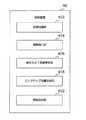
図5は、自動運転車両の制御装置の機能を説明するための機能ブロック図である。図5に示すように、制御装置40は、配車サービスを行うための機能として、認識処理部402と、撮像指示部404と、端末カメラ画像受信部406と、ピックアップ位置決定部408と、情報送信部410とを含んでいる。なお、これらの機能ブロックはハードウェアとして存在するのではない。制御装置40は、図5にブロックで示される機能を実行するようにプログラムされている。より詳しくは、記憶装置44に記憶されたプログラムがプロセッサ42で実行された場合に、プロセッサ42がこれらの機能ブロックに係る処理を実行する。制御装置40は、図5にブロックで示される機能の他にも、自動運転や先進安全のための様々な機能を有している。しかし、自動運転や先進安全については公知の技術を用いることができるので、本開示では、それらの説明は省略される。5. Function of Control Device for Self-Driving Vehicle FIG. 5 is a functional block diagram for explaining the function of the control device for the self-driving vehicle. As shown in FIG. 5, the
認識処理部402は、自動運転車両30が配車希望場所P1に接近したことを認識する認識処理を実行する。典型的には、認識処理では、乗降エリア3に自動運転車両30が進入したことを認識する。乗降エリア3の位置及び範囲は地図情報に含まれているので、GPS受信機31で取得した自動運転車両30の位置と、乗降エリア3の位置及び範囲を照らし合わせることで、乗降エリア3に自動運転車両30が進入したかどうかを判断することができる。乗降エリア3が地図情報に含まれていない場合、例えば車載カメラ36で撮像した画像から乗降エリア3の内外を区別するための情報を取得してもよい。また、インフラ施設から電波が発せられるのであれば、その電波の強度から乗降エリア3に進入したかどうかを判断してもよい。 The
認識処理部402での認識処理の他の例では、自動運転車両30が配車希望場所P1から予め定められた所定距離まで接近したことを認識する。ここでの所定距離は、自動運転車両30が備える車載カメラ36や各種センサによって待合中の利用者2の周辺環境を認識可能な距離として予め設定された距離である。配車希望場所P1は地図情報に基づき特定されているので、GPS受信機31で取得した自動運転車両30の位置から配車希望場所P1の位置までの距離を演算することで、配車希望場所P1と自動運転車両30との間の距離が所定距離に達したかどうかを判断することができる。 In another example of the recognition process by the
撮像指示部404は、認識処理において自動運転車両30が配車希望場所P1に近づいたことを認識した場合、利用者2に対して停車目標の撮像を促す撮像指示処理を実行する。典型的には、撮像指示処理では、撮像指示部404は、管理サーバ20を経由して利用者2の所持する利用者端末10に対して、端末カメラ14での撮像を促す通知を送信する。このような通知としては、「停車目標をカメラで撮ってください」とのメッセージが例示される。 When the self-driving
端末カメラ画像受信部406は、利用者端末10の端末カメラ14によって撮像された端末カメラ画像を受信する端末カメラ画像受信処理を実行する。典型的には、端末カメラ画像は、配車希望場所P1に居る利用者自身を撮像した画像である。このカメラ画像は、以下「利用者画像」と呼ばれる。利用者画像は、利用者2の一部(例えば顔)又は全身を撮像した画像である。端末カメラ画像受信処理によって受信した端末カメラ画像は、記憶装置44に記憶される。 The terminal camera
ピックアップ位置決定部408は、端末カメラ画像及び車載カメラ画像に基づいて、利用者2をピックアップするための最終的なピックアップ位置P2を決定する決定処理を実行する。典型的には、ピックアップ位置決定部408は、車載カメラ画像と端末カメラ画像との間の合致領域を探索するマッチング処理を行う。マッチング処理によって合致領域が検出された場合、ピックアップ位置決定部408は、合致領域を地図上の合致位置座標に変換する。端末カメラ画像が利用者画像である場合、合致位置座標は利用者2の位置座標に相当する。そして、ピックアップ位置決定部408は、周辺状況センサ33や車載カメラ36から得られる情報に基づいて、合致位置座標に最も近い停車可能位置をピックアップ位置P2に決定する。決定したピックアップ位置P2は、記憶装置44に記憶される。 The pickup
情報送信部410は、決定処理によって決定されたピックアップ位置P2に関する情報を、管理サーバ20を経由して利用者2の所持する利用者端末10に送信する情報通知処理を実行する。情報通知処理よって送信される情報には、決定されたピックアップ位置P2のほか、実現可能なピックアップ位置P2が見つからない場合には、その旨の情報も含まれる。送信した情報は、利用者端末10の表示装置16に表示される。 The
6.配車サービスの具体的処理
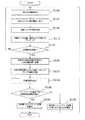
配車システム100は、利用者端末10と管理サーバ20と自動運転車両30との間で通信ネットワーク110を介した各種情報の送受信を行うことにより、利用者2に対する自動運転車両30の配車サービスを提供する。図6は、配車システムが実行する配車サービスの流れを説明するためのフローチャートである。6. Specific processing of the vehicle dispatch service The
配車サービスでは、先ず走行前準備が実行される(ステップS100)。ここでは、管理サーバ20は、利用者2の利用者端末10から通信ネットワーク110を介して配車リクエストを受信する。配車リクエストには、利用者2の希望する配車希望場所P1、目的地等が含まれている。管理サーバ20は、利用者2の周辺の自動運転車両30の中から、当該利用者2にサービスを提供する車両を選択し、選択した自動運転車両30に配車リクエストの情報を送る。 In the vehicle dispatch service, first, pre-travel preparation is executed (step S100). Here, the
配車リクエストの情報を受け取った自動運転車両30は、通常走行モードによって自律的に走行して配車希望場所P1に向かう(ステップS102)。典型的には、通常走行モードでは、制御装置40は、地図情報とセンサで取得した周囲物体の位置及び速度情報に基づいて、配車希望場所P1までの目標軌道を生成する。制御装置40は、生成した目標軌道に自動運転車両30が追従するように、自動運転車両30の走行装置37を制御する。 The self-driving
次に、認識処理によって自動運転車両30が配車希望場所P1に接近したかどうかが判定される(ステップS104)。典型的には、認識処理によって自動運転車両30が乗降エリア3に進入したかどうかが判定される。この判定は、判定が成立するまで所定の周期で行われる。その間、ステップS102において、通常走行モードによる自動運転が継続される。自動運転車両30が配車希望場所P1に接近した場合、手順は次のステップS106に進む。 Next, it is determined by the recognition process whether or not the
次のステップS106では、自動運転車両30の運転モードが通常走行モードから停車準備モードへと切り替えられる。停車準備モードでは、停車準備処理が行われる。停車準備処理については、フローチャートに沿って詳細を後述する。 In the next step S106, the driving mode of the self-driving
停車準備処理によってピックアップ位置P2が決定されると、手順は次のステップS108に進む。ステップS108では、自動運転車両30の停車制御が行われる。停車制御では、走行装置37を制御して自動運転車両30をピックアップ位置P2に停止させる。 When the pickup position P2 is determined by the stop preparation process, the procedure proceeds to the next step S108. In step S108, the stop control of the
図7は、配車サービスにおける停車準備処理の手順を説明するためのフローチャートである。自動運転車両30の運転モードが通常運転モードから停車準備モードへと切り替えられると、図7に示す停車準備処理が実行される。停車準備処理では、先ず、撮像指示処理によって利用者2に対する撮像の指示が行われる(ステップS110)。配車希望場所にいる利用者2は、利用者端末10の端末カメラ14を用いて、例えば利用者自身の顔を停車目標として撮像する。利用者端末10の制御装置15は、通信ネットワーク110を介して自動運転車両30に端末カメラ画像を送信する端末カメラ画像送信処理を実行する(ステップS112)。次のステップS114では、端末カメラ画像受信処理によって端末カメラ画像が受信される。 FIG. 7 is a flowchart for explaining the procedure of the stop preparation process in the vehicle dispatch service. When the operation mode of the
次のステップS116では、マッチング処理により、受信した端末カメラ画像と車載カメラ画像との間の合致領域が探索される。次のステップS118では、マッチング処理により、合致領域が検出されたかどうかが判定される。判定の結果、合致領域が検出されない場合、ステップS110に戻り、再び撮像指示処理が実行される。 In the next step S116, a matching region between the received terminal camera image and the vehicle-mounted camera image is searched by the matching process. In the next step S118, it is determined whether or not a matching region has been detected by the matching process. If the matching region is not detected as a result of the determination, the process returns to step S110, and the imaging instruction process is executed again.
一方、ステップS118の判定の結果、合致領域が検出された場合、処理は次のステップS120に進む。ステップS120では、検出された合致領域が地図上の合致位置座標に変換される。次のステップS122では、決定処理によって、変換された合致位置座標から近い道路上にピックアップ位置P2を決定する。次のステップS124では、ピックアップ位置P2までの目標経路が生成される。典型的には、制御装置40は、GPS受信機31で取得した自動運転車両30の現在位置からピックアップ位置P2までの目標軌道を生成する。 On the other hand, if a matching region is detected as a result of the determination in step S118, the process proceeds to the next step S120. In step S120, the detected matching area is converted into the matching position coordinates on the map. In the next step S122, the pickup position P2 is determined on the road close to the converted matching position coordinates by the determination process. In the next step S124, a target path to the pickup position P2 is generated. Typically, the
次のステップS126では、ピックアップ位置P2までの目標経路が走行可能な経路かどうかが判定される。典型的には、周辺状況センサ33や車載カメラ36から得られる乗降エリア3の周辺状況に基づいて、生成された目標経路が実現可能な経路であるかが判定される。その結果、生成された目標経路が実現できると判定された場合はステップS128に進み、実現できないと判定された場合にはステップS130へと進む。 In the next step S126, it is determined whether or not the target route to the pickup position P2 is a travelable route. Typically, it is determined whether the generated target route is a feasible route based on the peripheral condition of the boarding / alighting area 3 obtained from the
ステップS128では、情報通知処理によって、利用者2に対してピックアップ位置P2の情報が通知される。ステップS128の処理が完了すると、停車準備処理は終了される。 In step S128, the information of the pickup position P2 is notified to the user 2 by the information notification process. When the process of step S128 is completed, the stop preparation process is completed.
一方、ステップS130では、情報通知処理によって、利用者2に対してピックアップ位置P2が見つからない旨の情報が通知される。ステップS130の処理が完了すると、停車準備処理はステップS110に戻り、再び撮像指示処理が実行される。 On the other hand, in step S130, the information notification process notifies the user 2 of information that the pickup position P2 cannot be found. When the process of step S130 is completed, the stop preparation process returns to step S110, and the image pickup instruction process is executed again.
以上説明した停車準備処理によれば、乗降エリア3において端末カメラ画像と車載カメラ画像とのマッチング処理を行うことにより、現状の乗降エリア3の状況が反映された適切なピックアップ位置を決定することが可能となる。 According to the stop preparation process described above, it is possible to determine an appropriate pickup position that reflects the current situation of the boarding / alighting area 3 by performing a matching process between the terminal camera image and the vehicle-mounted camera image in the boarding / alighting area 3. It will be possible.
7.変形例
実施の形態1の配車システム100は、以下のように変形した態様を採用してもよい。7. Modification Example The
制御装置40が備える機能の一部は、管理サーバ20又は利用者端末10に配置されていてもよい。例えば、制御装置40の認識処理部402、撮像指示部404、端末カメラ画像受信部406、ピックアップ位置決定部408、又は情報送信部410は、管理サーバ20に配置されていてもよい。この場合、管理サーバ20は、必要な情報を通信ネットワーク110を介して取得すればよい。 A part of the functions included in the
端末カメラ画像に撮像する停車目標は、利用者自身に限られない。例えば、端末カメラ画像は、ランドマーク等の固定物標を停車目標として含んでいてもよい。また、端末カメラ画像と車載カメラ画像の撮像時期が同時期であれば、停車目標は人、犬、他車両等の移動物標であってもよい。 The stop target to be captured in the terminal camera image is not limited to the user himself / herself. For example, the terminal camera image may include a fixed target such as a landmark as a stop target. Further, if the terminal camera image and the in-vehicle camera image are captured at the same time, the stop target may be a moving object such as a person, a dog, or another vehicle.
端末カメラ画像には、停車目標そのものではなく、停車目標である利用者の居る位置を演算するための周辺画像が含まれていてもよい。この場合、撮像指示部404は、撮像指示処理において、例えば「カメラをゆっくり動かしながら周辺の画像を撮像してください」との通知を送信する。利用者は撮像指示に従い利用者が居る配車希望場所の周辺環境を撮像する。この端末カメラ画像は、「周辺環境画像」と呼ばれる。ピックアップ位置決定部408は、マッチング処理において周辺環境画像と車載カメラ画像との合致領域を探索し、合致領域を合致位置座標に変換する。そして、ピックアップ位置決定部408は、決定処理において、合致位置座標に基づいて利用者が居る配車希望場所の位置座標を特定し、特定された配車希望場所に近い停車可能な位置をピックアップ位置に決定する。このような処理によれば、端末カメラ画像に直接的に停車目標が撮像されていなくても、ピックアップ位置を適切に決定することができる。 The terminal camera image may include a peripheral image for calculating the position where the user is, which is the stop target, instead of the stop target itself. In this case, the image
自動運転車両30において実行される配車準備モードでは、停車準備処理において合致領域を探索し易くするために好適な自動運転車両30の車両制御も同時に実行することとしてもよい。このような処理は、例えば制御装置40の機能ブロックとして自動運転車両30の速度を制御する速度制御部を更に備えることにより実現することができる。この場合、速度制御部は、配車準備モードにおいて、自動運転車両30の最大許容速度を通常走行モード時よりも低い所定速度に制御すればよい。ここでの所定速度は、予め決められた速度(例えば15km/h未満)でもよいし、また、周辺状況センサ33等のセンサ検出可能距離を考慮して、所定速度は、例えばセンサ検出距離に対して所定の減速度で所定時間内に停車できる速度に設定してもよい。 In the vehicle allocation preparation mode executed in the
さらに、乗降エリア3内での車両の円滑な移動を担保するために、自動運転車両30の車線内での走行位置を変化させてもよい。典型的には、自動運転車両30の制御装置40は、配車準備モードにおいて、通常走行モード時よりも車線内の左寄りを走行するように目標経路を生成し、自動運転車両30を走行させる。これにより、自動運転車両30の後続車両の追い越しが容易になるので、乗降エリア3において円滑な交通を担保することができる。 Further, in order to ensure smooth movement of the vehicle in the boarding / alighting area 3, the traveling position of the
2 利用者
3 乗降エリア
4 施設
5 進入路
6 退出路
10 利用者端末
11 GPS受信機
12 入力装置
13 通信装置
14 端末カメラ
15 制御装置
16 表示装置
20 管理サーバ
22 記憶装置
30 自動運転車両
31 GPS受信機
32 地図データベース
33 周辺状況センサ
34 車両状態センサ
35 通信装置
36 車載カメラ
37 走行装置
40 制御装置
42 プロセッサ
44 記憶装置
100 配車システム
110 通信ネットワーク
151 プロセッサ
152 記憶装置
153 入出力インターフェース
402 認識処理部
404 撮像指示部
406 端末カメラ画像受信部
408 ピックアップ位置決定部
410 情報送信部2 User 3 Boarding / alighting area 4
Claims (11)
Translated fromJapanese前記自動運転車両は、周囲を撮像する車載カメラを備え、
前記制御装置は、
前記端末カメラによって前記配車希望場所から撮像された端末カメラ画像を、前記利用者端末から前記通信ネットワークを介して受信する端末カメラ画像受信部と、
前記車載カメラによって撮像された車載カメラ画像の中から前記端末カメラ画像に合致する画像領域を特定し、前記画像領域の位置座標情報に基づいて停車可能なピックアップ位置を決定するピックアップ位置決定部と、
を備えることを特徴とする自動運転車両の制御装置。It is a control device for autonomous vehicles that can be driven driverlessly and is connected to a user terminal with a terminal camera owned by the user at the desired location via a communication network.
The self-driving vehicle is equipped with an in-vehicle camera that captures the surroundings.
The control device is
A terminal camera image receiving unit that receives a terminal camera image captured by the terminal camera from the desired vehicle allocation location from the user terminal via the communication network.
A pickup position determination unit that identifies an image area that matches the terminal camera image from the in-vehicle camera image captured by the in-vehicle camera and determines a pickup position that can be stopped based on the position coordinate information of the image area.
A control device for an autonomous vehicle, which comprises.
前記ピックアップ位置決定部は、
前記車載カメラ画像の中から前記利用者画像に合致する画像領域を前記利用者の居る前記配車希望場所として特定し、
前記配車希望場所に近い停車可能な位置を前記ピックアップ位置に決定する
ように構成されることを特徴とする請求項1に記載の自動運転車両の制御装置。The terminal camera image includes a user image captured by the user himself / herself.
The pickup position determination unit
From the in-vehicle camera image, an image area matching the user image is specified as the desired vehicle allocation location where the user is located.
The control device for an autonomous driving vehicle according to claim 1, further comprising determining a stoptable position close to the desired vehicle allocation position at the pickup position.
前記ピックアップ位置決定部は、
前記車載カメラ画像の中から前記周辺環境画像に合致する画像領域を特定し、
前記画像領域の位置座標情報に基づいて前記利用者の居る前記配車希望場所を特定し、
前記配車希望場所に近い停車可能な位置を前記ピックアップ位置に決定する
ように構成されることを特徴とする請求項1に記載の自動運転車両の制御装置。The terminal camera image includes a peripheral environment image that captures the surrounding environment of the desired vehicle allocation location.
The pickup position determination unit
An image area matching the surrounding environment image is specified from the in-vehicle camera image, and the image area is specified.
Based on the position coordinate information of the image area, the desired location of the vehicle dispatch where the user is located is specified.
The control device for an autonomous driving vehicle according to claim 1, further comprising determining a stoptable position close to the desired vehicle allocation position at the pickup position.
前記自動運転車両が前記配車希望場所に接近した場合、前記利用者に対して前記端末カメラ画像の撮像を促すための通知を前記利用者端末に送信する撮像指示部と、
をさらに備えることを特徴とする請求項1から請求項3の何れか1項に記載の自動運転車両の制御装置。A recognition processing unit that recognizes that the autonomous driving vehicle has approached the desired vehicle allocation location,
When the self-driving vehicle approaches the desired vehicle allocation location, an imaging instruction unit that transmits a notification to the user terminal to urge the user to capture the terminal camera image, and an imaging instruction unit.
The control device for an autonomous driving vehicle according to any one of claims 1 to 3, further comprising.
ように構成されることを特徴とする請求項4に記載の自動運転車両の制御装置。The recognition processing unit is configured to recognize that the autonomous driving vehicle has approached the desired vehicle allocation location when the autonomous driving vehicle enters the boarding / alighting area where the user gets on and off. The control device for an autonomous driving vehicle according to claim 4, which is characterized.
前記利用者端末は、
端末カメラと、
前記利用者端末を制御する利用者端末制御装置と、を備え、
前記利用者端末制御装置は、前記端末カメラによって前記配車希望場所から撮像された端末カメラ画像を前記管理サーバに送信する端末カメラ画像送信処理を実行するようにプログラムされ、
前記自動運転車両は、
前記自動運転車両の周囲を撮像する車載カメラと、
前記自動運転車両を制御する制御装置と、を備え、
前記制御装置は、
前記端末カメラ画像を前記管理サーバから受信する端末カメラ画像受信処理と、
前記車載カメラによって撮像された車載カメラ画像の中から前記端末カメラ画像に合致する画像領域を特定し、前記画像領域の位置座標情報に基づいて停車可能なピックアップ位置を決定する決定処理と、
を実行するようにプログラムされていることを特徴とする配車システム。It consists of an autonomous driving vehicle capable of driverless driving, a user terminal owned by a user at a desired location, and a management server that communicates with the autonomous driving vehicle and the user terminal via a communication network. It is a vehicle dispatch system that is
The user terminal is
With the terminal camera
A user terminal control device for controlling the user terminal is provided.
The user terminal control device is programmed to execute a terminal camera image transmission process for transmitting a terminal camera image captured by the terminal camera from the desired vehicle allocation location to the management server.
The self-driving vehicle
An in-vehicle camera that captures the surroundings of the self-driving vehicle and
A control device for controlling the self-driving vehicle is provided.
The control device is
The terminal camera image reception process for receiving the terminal camera image from the management server, and
A determination process of identifying an image area matching the terminal camera image from the in-vehicle camera image captured by the in-vehicle camera and determining a stoptable pickup position based on the position coordinate information of the image area.
A ride-hailing system characterized by being programmed to run.
前記制御装置は、前記決定処理において、前記車載カメラ画像の中から前記利用者画像に合致する画像領域を前記利用者の居る前記配車希望場所として特定し、前記配車希望場所に近い停車可能な位置を前記ピックアップ位置に決定する
ようにプログラムされていることを特徴とする請求項8に記載の配車システム。The terminal camera image includes a user image captured by the user himself / herself.
In the determination process, the control device specifies an image area matching the user image from the in-vehicle camera image as the desired vehicle allocation location where the user is present, and a position near the desired vehicle allocation location where the vehicle can be stopped. 8. The vehicle dispatch system according to claim 8, wherein the vehicle is programmed to determine the pickup position.
前記自動運転車両が前記配車希望場所に接近したことを認識する認識処理と、
前記自動運転車両が前記配車希望場所に接近した場合、前記利用者に対して前記端末カメラ画像の撮像を促すための通知を前記利用者端末に送信する撮像指示処理と、
をさらに実行するようにプログラムされていることを特徴とする請求項8又は請求項9に記載の配車システム。The control device is
Recognition processing that recognizes that the autonomous driving vehicle has approached the desired vehicle allocation location,
When the self-driving vehicle approaches the desired vehicle allocation location, an imaging instruction process for transmitting a notification to the user terminal to urge the user to capture the terminal camera image, and an imaging instruction process.
8. The vehicle dispatch system according to claim 8, wherein the vehicle allocation system is programmed to further execute.
前記自動運転車両は、周囲を撮像する車載カメラを備え、
前記配車方法は、
前記端末カメラによって前記配車希望場所から撮像された端末カメラ画像を、前記利用者端末から前記通信ネットワークを介して受信するステップと、
前記車載カメラによって撮像された車載カメラ画像の中から前記端末カメラ画像に合致する画像領域を特定し、前記画像領域の位置座標情報に基づいて停車可能なピックアップ位置を決定するステップと、
を備えることを特徴とする自動運転車両の配車方法。It is a method of dispatching an autonomous vehicle that can be driven driverlessly and is connected to a user terminal with a terminal camera owned by a user at the desired location via a communication network.
The self-driving vehicle is equipped with an in-vehicle camera that captures the surroundings.
The vehicle allocation method is
A step of receiving a terminal camera image captured by the terminal camera from the desired vehicle allocation location from the user terminal via the communication network.
A step of identifying an image area matching the terminal camera image from the in-vehicle camera image captured by the in-vehicle camera and determining a pickup position capable of stopping based on the position coordinate information of the image area.
A method of allocating an autonomous vehicle, which is characterized by being provided with.
Priority Applications (3)
| Application Number | Priority Date | Filing Date | Title |
|---|---|---|---|
| JP2020081912AJP7294231B2 (en) | 2020-05-07 | 2020-05-07 | AUTOMATIC VEHICLE CONTROL DEVICE, VEHICLE ALLOCATION SYSTEM, AND VEHICLE ALLOCATION METHOD |
| US17/237,209US20210349457A1 (en) | 2020-05-07 | 2021-04-22 | Vehicle controller for automated driving vehicle, vehicle dispatching system, and vehicle dispatching method |
| CN202110497205.5ACN113619598B (en) | 2020-05-07 | 2021-05-07 | Control device, vehicle distribution system and vehicle distribution method for automatic driving vehicle |
Applications Claiming Priority (1)
| Application Number | Priority Date | Filing Date | Title |
|---|---|---|---|
| JP2020081912AJP7294231B2 (en) | 2020-05-07 | 2020-05-07 | AUTOMATIC VEHICLE CONTROL DEVICE, VEHICLE ALLOCATION SYSTEM, AND VEHICLE ALLOCATION METHOD |
Publications (2)
| Publication Number | Publication Date |
|---|---|
| JP2021177283Atrue JP2021177283A (en) | 2021-11-11 |
| JP7294231B2 JP7294231B2 (en) | 2023-06-20 |
Family
ID=78377969
Family Applications (1)
| Application Number | Title | Priority Date | Filing Date |
|---|---|---|---|
| JP2020081912AActiveJP7294231B2 (en) | 2020-05-07 | 2020-05-07 | AUTOMATIC VEHICLE CONTROL DEVICE, VEHICLE ALLOCATION SYSTEM, AND VEHICLE ALLOCATION METHOD |
Country Status (3)
| Country | Link |
|---|---|
| US (1) | US20210349457A1 (en) |
| JP (1) | JP7294231B2 (en) |
| CN (1) | CN113619598B (en) |
Cited By (2)
| Publication number | Priority date | Publication date | Assignee | Title |
|---|---|---|---|---|
| WO2023187890A1 (en)* | 2022-03-28 | 2023-10-05 | 本田技研工業株式会社 | Control device for mobile object, control method for mobile object, mobile object, information processing method, and program |
| WO2025120851A1 (en)* | 2023-12-08 | 2025-06-12 | 本田技研工業株式会社 | Processing system, learning method, processing method, and program |
Families Citing this family (1)
| Publication number | Priority date | Publication date | Assignee | Title |
|---|---|---|---|---|
| CN120428637A (en)* | 2025-07-08 | 2025-08-05 | 湖南大学无锡智能控制研究院 | Vehicle end and remote driving control system for surface mine operation |
Citations (5)
| Publication number | Priority date | Publication date | Assignee | Title |
|---|---|---|---|---|
| JP2019067012A (en)* | 2017-09-29 | 2019-04-25 | 日本電気株式会社 | Vehicle control device, vehicle, and automatic dispatch method |
| US20190166473A1 (en)* | 2017-11-29 | 2019-05-30 | Qualcomm Incorporated | Method and Apparatus for Requesting a Transport Vehicle from a Mobile Device |
| JP2019121049A (en)* | 2017-12-28 | 2019-07-22 | 株式会社ケイ・オプティコム | Vehicle allocation device, vehicle allocation method, and program for allocating vehicle to predetermined place desired by user |
| US20190228375A1 (en)* | 2018-01-19 | 2019-07-25 | Udelv Inc. | Delivery management system |
| JP2019219781A (en)* | 2018-06-18 | 2019-12-26 | 日産自動車株式会社 | Business vehicle operation system |
Family Cites Families (4)
| Publication number | Priority date | Publication date | Assignee | Title |
|---|---|---|---|---|
| US3655962A (en)* | 1969-04-01 | 1972-04-11 | Melpar Inc | Digital automatic speed control for railway vehicles |
| JP6852638B2 (en)* | 2017-10-10 | 2021-03-31 | トヨタ自動車株式会社 | Self-driving vehicle dispatch system, self-driving vehicle, and vehicle dispatch method |
| JP2020013474A (en)* | 2018-07-20 | 2020-01-23 | パナソニック インテレクチュアル プロパティ コーポレーション オブ アメリカPanasonic Intellectual Property Corporation of America | Information processing method |
| US20200234380A1 (en)* | 2019-01-17 | 2020-07-23 | Shriniwas Dulori | System and method for smart community |
- 2020
- 2020-05-07JPJP2020081912Apatent/JP7294231B2/enactiveActive
- 2021
- 2021-04-22USUS17/237,209patent/US20210349457A1/ennot_activeAbandoned
- 2021-05-07CNCN202110497205.5Apatent/CN113619598B/enactiveActive
Patent Citations (5)
| Publication number | Priority date | Publication date | Assignee | Title |
|---|---|---|---|---|
| JP2019067012A (en)* | 2017-09-29 | 2019-04-25 | 日本電気株式会社 | Vehicle control device, vehicle, and automatic dispatch method |
| US20190166473A1 (en)* | 2017-11-29 | 2019-05-30 | Qualcomm Incorporated | Method and Apparatus for Requesting a Transport Vehicle from a Mobile Device |
| JP2019121049A (en)* | 2017-12-28 | 2019-07-22 | 株式会社ケイ・オプティコム | Vehicle allocation device, vehicle allocation method, and program for allocating vehicle to predetermined place desired by user |
| US20190228375A1 (en)* | 2018-01-19 | 2019-07-25 | Udelv Inc. | Delivery management system |
| JP2019219781A (en)* | 2018-06-18 | 2019-12-26 | 日産自動車株式会社 | Business vehicle operation system |
Cited By (2)
| Publication number | Priority date | Publication date | Assignee | Title |
|---|---|---|---|---|
| WO2023187890A1 (en)* | 2022-03-28 | 2023-10-05 | 本田技研工業株式会社 | Control device for mobile object, control method for mobile object, mobile object, information processing method, and program |
| WO2025120851A1 (en)* | 2023-12-08 | 2025-06-12 | 本田技研工業株式会社 | Processing system, learning method, processing method, and program |
Also Published As
| Publication number | Publication date |
|---|---|
| JP7294231B2 (en) | 2023-06-20 |
| US20210349457A1 (en) | 2021-11-11 |
| CN113619598A (en) | 2021-11-09 |
| CN113619598B (en) | 2024-04-09 |
Similar Documents
| Publication | Publication Date | Title |
|---|---|---|
| US11029703B2 (en) | Systems and methods for controlling autonomous vehicles that provide a vehicle service to users | |
| CN108058713B (en) | Information display device, information display method, and recording medium for information display program | |
| US20200307648A1 (en) | Parking lot management device, parking lot management method, and storage medium | |
| US11473923B2 (en) | Vehicle dispatch system for autonomous driving vehicle and autonomous driving vehicle | |
| US20200262453A1 (en) | Pick-up management device, pick-up control method, and storage medium | |
| CN109923018B (en) | Vehicle control system, vehicle control method, and storage medium | |
| CN111986505B (en) | Control device, boarding/alighting facility, control method, and storage medium | |
| CN111376853B (en) | Vehicle control system, vehicle control method, and storage medium | |
| US20200361450A1 (en) | Vehicle control system, vehicle control method, and storage medium | |
| US20190228664A1 (en) | Vehicle calling system | |
| US20200283022A1 (en) | Vehicle control system, vehicle control method, and storage medium | |
| US20200311623A1 (en) | Parking management apparatus, method for controlling parking management apparatus, and storage medium | |
| US20230111327A1 (en) | Techniques for finding and accessing vehicles | |
| JP7468404B2 (en) | Autonomous vehicles, autonomous vehicle dispatch systems and mobile terminals | |
| CN111665835B (en) | Vehicle control system and vehicle control method | |
| JP7294231B2 (en) | AUTOMATIC VEHICLE CONTROL DEVICE, VEHICLE ALLOCATION SYSTEM, AND VEHICLE ALLOCATION METHOD | |
| CN111183082A (en) | Vehicle control device, vehicle control method, and program | |
| US20200290649A1 (en) | Vehicle control system, vehicle control method, and storage medium | |
| KR102716199B1 (en) | Automated valet parking system and control method of automated valet parking system | |
| JP7560593B2 (en) | Control system, control method, and program | |
| US20200311621A1 (en) | Management device, management method, and storage medium | |
| CN111619568A (en) | Vehicle control device, vehicle control method, and storage medium | |
| CN116774692A (en) | Control device for mobile body, control method for mobile body, information processing method, and storage medium | |
| US20240408963A1 (en) | Information processing device, information processing method, and non-temporary storage medium | |
| JP2023057852A (en) | Automatic travel system, automatic travel method and program |
Legal Events
| Date | Code | Title | Description |
|---|---|---|---|
| A621 | Written request for application examination | Free format text:JAPANESE INTERMEDIATE CODE: A621 Effective date:20220314 | |
| A977 | Report on retrieval | Free format text:JAPANESE INTERMEDIATE CODE: A971007 Effective date:20230118 | |
| A131 | Notification of reasons for refusal | Free format text:JAPANESE INTERMEDIATE CODE: A131 Effective date:20230124 | |
| A521 | Request for written amendment filed | Free format text:JAPANESE INTERMEDIATE CODE: A523 Effective date:20230322 | |
| TRDD | Decision of grant or rejection written | ||
| A01 | Written decision to grant a patent or to grant a registration (utility model) | Free format text:JAPANESE INTERMEDIATE CODE: A01 Effective date:20230509 | |
| A61 | First payment of annual fees (during grant procedure) | Free format text:JAPANESE INTERMEDIATE CODE: A61 Effective date:20230522 | |
| R151 | Written notification of patent or utility model registration | Ref document number:7294231 Country of ref document:JP Free format text:JAPANESE INTERMEDIATE CODE: R151 |