JP2021176522A - Leveraging two-dimensional digital imaging and communication in medicine imagery in three-dimensional extended reality applications - Google Patents
Leveraging two-dimensional digital imaging and communication in medicine imagery in three-dimensional extended reality applicationsDownload PDFInfo
- Publication number
- JP2021176522A JP2021176522AJP2021079620AJP2021079620AJP2021176522AJP 2021176522 AJP2021176522 AJP 2021176522AJP 2021079620 AJP2021079620 AJP 2021079620AJP 2021079620 AJP2021079620 AJP 2021079620AJP 2021176522 AJP2021176522 AJP 2021176522A
- Authority
- JP
- Japan
- Prior art keywords
- image
- headset
- image data
- pose
- surgical
- Prior art date
- Legal status (The legal status is an assumption and is not a legal conclusion. Google has not performed a legal analysis and makes no representation as to the accuracy of the status listed.)
- Granted
Links
Images


Classifications
- A—HUMAN NECESSITIES
- A61—MEDICAL OR VETERINARY SCIENCE; HYGIENE
- A61B—DIAGNOSIS; SURGERY; IDENTIFICATION
- A61B90/00—Instruments, implements or accessories specially adapted for surgery or diagnosis and not covered by any of the groups A61B1/00 - A61B50/00, e.g. for luxation treatment or for protecting wound edges
- A61B90/36—Image-producing devices or illumination devices not otherwise provided for
- A—HUMAN NECESSITIES
- A61—MEDICAL OR VETERINARY SCIENCE; HYGIENE
- A61B—DIAGNOSIS; SURGERY; IDENTIFICATION
- A61B34/00—Computer-aided surgery; Manipulators or robots specially adapted for use in surgery
- A61B34/20—Surgical navigation systems; Devices for tracking or guiding surgical instruments, e.g. for frameless stereotaxis
- G—PHYSICS
- G06—COMPUTING OR CALCULATING; COUNTING
- G06F—ELECTRIC DIGITAL DATA PROCESSING
- G06F3/00—Input arrangements for transferring data to be processed into a form capable of being handled by the computer; Output arrangements for transferring data from processing unit to output unit, e.g. interface arrangements
- G06F3/01—Input arrangements or combined input and output arrangements for interaction between user and computer
- G06F3/011—Arrangements for interaction with the human body, e.g. for user immersion in virtual reality
- G—PHYSICS
- G06—COMPUTING OR CALCULATING; COUNTING
- G06T—IMAGE DATA PROCESSING OR GENERATION, IN GENERAL
- G06T11/00—2D [Two Dimensional] image generation
- G—PHYSICS
- G06—COMPUTING OR CALCULATING; COUNTING
- G06T—IMAGE DATA PROCESSING OR GENERATION, IN GENERAL
- G06T7/00—Image analysis
- G06T7/20—Analysis of motion
- H—ELECTRICITY
- H04—ELECTRIC COMMUNICATION TECHNIQUE
- H04N—PICTORIAL COMMUNICATION, e.g. TELEVISION
- H04N13/00—Stereoscopic video systems; Multi-view video systems; Details thereof
- H04N13/10—Processing, recording or transmission of stereoscopic or multi-view image signals
- H04N13/106—Processing image signals
- H04N13/111—Transformation of image signals corresponding to virtual viewpoints, e.g. spatial image interpolation
- H04N13/117—Transformation of image signals corresponding to virtual viewpoints, e.g. spatial image interpolation the virtual viewpoint locations being selected by the viewers or determined by viewer tracking
- H—ELECTRICITY
- H04—ELECTRIC COMMUNICATION TECHNIQUE
- H04N—PICTORIAL COMMUNICATION, e.g. TELEVISION
- H04N13/00—Stereoscopic video systems; Multi-view video systems; Details thereof
- H04N13/20—Image signal generators
- H04N13/275—Image signal generators from 3D object models, e.g. computer-generated stereoscopic image signals
- H04N13/279—Image signal generators from 3D object models, e.g. computer-generated stereoscopic image signals the virtual viewpoint locations being selected by the viewers or determined by tracking
- A—HUMAN NECESSITIES
- A61—MEDICAL OR VETERINARY SCIENCE; HYGIENE
- A61B—DIAGNOSIS; SURGERY; IDENTIFICATION
- A61B17/00—Surgical instruments, devices or methods
- A61B2017/00017—Electrical control of surgical instruments
- A61B2017/00207—Electrical control of surgical instruments with hand gesture control or hand gesture recognition
- A—HUMAN NECESSITIES
- A61—MEDICAL OR VETERINARY SCIENCE; HYGIENE
- A61B—DIAGNOSIS; SURGERY; IDENTIFICATION
- A61B34/00—Computer-aided surgery; Manipulators or robots specially adapted for use in surgery
- A61B34/10—Computer-aided planning, simulation or modelling of surgical operations
- A61B2034/101—Computer-aided simulation of surgical operations
- A61B2034/102—Modelling of surgical devices, implants or prosthesis
- A—HUMAN NECESSITIES
- A61—MEDICAL OR VETERINARY SCIENCE; HYGIENE
- A61B—DIAGNOSIS; SURGERY; IDENTIFICATION
- A61B34/00—Computer-aided surgery; Manipulators or robots specially adapted for use in surgery
- A61B34/20—Surgical navigation systems; Devices for tracking or guiding surgical instruments, e.g. for frameless stereotaxis
- A61B2034/2046—Tracking techniques
- A61B2034/2048—Tracking techniques using an accelerometer or inertia sensor
- A—HUMAN NECESSITIES
- A61—MEDICAL OR VETERINARY SCIENCE; HYGIENE
- A61B—DIAGNOSIS; SURGERY; IDENTIFICATION
- A61B34/00—Computer-aided surgery; Manipulators or robots specially adapted for use in surgery
- A61B34/20—Surgical navigation systems; Devices for tracking or guiding surgical instruments, e.g. for frameless stereotaxis
- A61B2034/2046—Tracking techniques
- A61B2034/2055—Optical tracking systems
- A61B2034/2057—Details of tracking cameras
- A—HUMAN NECESSITIES
- A61—MEDICAL OR VETERINARY SCIENCE; HYGIENE
- A61B—DIAGNOSIS; SURGERY; IDENTIFICATION
- A61B34/00—Computer-aided surgery; Manipulators or robots specially adapted for use in surgery
- A61B34/20—Surgical navigation systems; Devices for tracking or guiding surgical instruments, e.g. for frameless stereotaxis
- A61B2034/2046—Tracking techniques
- A61B2034/2065—Tracking using image or pattern recognition
- A—HUMAN NECESSITIES
- A61—MEDICAL OR VETERINARY SCIENCE; HYGIENE
- A61B—DIAGNOSIS; SURGERY; IDENTIFICATION
- A61B34/00—Computer-aided surgery; Manipulators or robots specially adapted for use in surgery
- A61B34/20—Surgical navigation systems; Devices for tracking or guiding surgical instruments, e.g. for frameless stereotaxis
- A61B2034/2072—Reference field transducer attached to an instrument or patient
- A—HUMAN NECESSITIES
- A61—MEDICAL OR VETERINARY SCIENCE; HYGIENE
- A61B—DIAGNOSIS; SURGERY; IDENTIFICATION
- A61B90/00—Instruments, implements or accessories specially adapted for surgery or diagnosis and not covered by any of the groups A61B1/00 - A61B50/00, e.g. for luxation treatment or for protecting wound edges
- A61B90/06—Measuring instruments not otherwise provided for
- A61B2090/064—Measuring instruments not otherwise provided for for measuring force, pressure or mechanical tension
- A—HUMAN NECESSITIES
- A61—MEDICAL OR VETERINARY SCIENCE; HYGIENE
- A61B—DIAGNOSIS; SURGERY; IDENTIFICATION
- A61B90/00—Instruments, implements or accessories specially adapted for surgery or diagnosis and not covered by any of the groups A61B1/00 - A61B50/00, e.g. for luxation treatment or for protecting wound edges
- A61B90/36—Image-producing devices or illumination devices not otherwise provided for
- A61B2090/364—Correlation of different images or relation of image positions in respect to the body
- A61B2090/365—Correlation of different images or relation of image positions in respect to the body augmented reality, i.e. correlating a live optical image with another image
- A—HUMAN NECESSITIES
- A61—MEDICAL OR VETERINARY SCIENCE; HYGIENE
- A61B—DIAGNOSIS; SURGERY; IDENTIFICATION
- A61B90/00—Instruments, implements or accessories specially adapted for surgery or diagnosis and not covered by any of the groups A61B1/00 - A61B50/00, e.g. for luxation treatment or for protecting wound edges
- A61B90/36—Image-producing devices or illumination devices not otherwise provided for
- A61B2090/364—Correlation of different images or relation of image positions in respect to the body
- A61B2090/368—Correlation of different images or relation of image positions in respect to the body changing the image on a display according to the operator's position
- A—HUMAN NECESSITIES
- A61—MEDICAL OR VETERINARY SCIENCE; HYGIENE
- A61B—DIAGNOSIS; SURGERY; IDENTIFICATION
- A61B90/00—Instruments, implements or accessories specially adapted for surgery or diagnosis and not covered by any of the groups A61B1/00 - A61B50/00, e.g. for luxation treatment or for protecting wound edges
- A61B90/36—Image-producing devices or illumination devices not otherwise provided for
- A61B90/37—Surgical systems with images on a monitor during operation
- A61B2090/371—Surgical systems with images on a monitor during operation with simultaneous use of two cameras
- A—HUMAN NECESSITIES
- A61—MEDICAL OR VETERINARY SCIENCE; HYGIENE
- A61B—DIAGNOSIS; SURGERY; IDENTIFICATION
- A61B90/00—Instruments, implements or accessories specially adapted for surgery or diagnosis and not covered by any of the groups A61B1/00 - A61B50/00, e.g. for luxation treatment or for protecting wound edges
- A61B90/36—Image-producing devices or illumination devices not otherwise provided for
- A61B90/37—Surgical systems with images on a monitor during operation
- A61B2090/372—Details of monitor hardware
- A—HUMAN NECESSITIES
- A61—MEDICAL OR VETERINARY SCIENCE; HYGIENE
- A61B—DIAGNOSIS; SURGERY; IDENTIFICATION
- A61B90/00—Instruments, implements or accessories specially adapted for surgery or diagnosis and not covered by any of the groups A61B1/00 - A61B50/00, e.g. for luxation treatment or for protecting wound edges
- A61B90/36—Image-producing devices or illumination devices not otherwise provided for
- A61B90/37—Surgical systems with images on a monitor during operation
- A61B2090/376—Surgical systems with images on a monitor during operation using X-rays, e.g. fluoroscopy
- A61B2090/3762—Surgical systems with images on a monitor during operation using X-rays, e.g. fluoroscopy using computed tomography systems [CT]
- A—HUMAN NECESSITIES
- A61—MEDICAL OR VETERINARY SCIENCE; HYGIENE
- A61B—DIAGNOSIS; SURGERY; IDENTIFICATION
- A61B90/00—Instruments, implements or accessories specially adapted for surgery or diagnosis and not covered by any of the groups A61B1/00 - A61B50/00, e.g. for luxation treatment or for protecting wound edges
- A61B90/50—Supports for surgical instruments, e.g. articulated arms
- A61B2090/502—Headgear, e.g. helmet, spectacles
- G—PHYSICS
- G06—COMPUTING OR CALCULATING; COUNTING
- G06T—IMAGE DATA PROCESSING OR GENERATION, IN GENERAL
- G06T2200/00—Indexing scheme for image data processing or generation, in general
- G06T2200/24—Indexing scheme for image data processing or generation, in general involving graphical user interfaces [GUIs]
- G—PHYSICS
- G06—COMPUTING OR CALCULATING; COUNTING
- G06T—IMAGE DATA PROCESSING OR GENERATION, IN GENERAL
- G06T2207/00—Indexing scheme for image analysis or image enhancement
- G06T2207/30—Subject of image; Context of image processing
- G06T2207/30244—Camera pose
Landscapes
- Engineering & Computer Science (AREA)
- Health & Medical Sciences (AREA)
- Surgery (AREA)
- Life Sciences & Earth Sciences (AREA)
- Theoretical Computer Science (AREA)
- Public Health (AREA)
- General Health & Medical Sciences (AREA)
- Veterinary Medicine (AREA)
- Nuclear Medicine, Radiotherapy & Molecular Imaging (AREA)
- Biomedical Technology (AREA)
- Heart & Thoracic Surgery (AREA)
- Medical Informatics (AREA)
- Molecular Biology (AREA)
- Animal Behavior & Ethology (AREA)
- General Physics & Mathematics (AREA)
- Physics & Mathematics (AREA)
- Multimedia (AREA)
- General Engineering & Computer Science (AREA)
- Pathology (AREA)
- Oral & Maxillofacial Surgery (AREA)
- Robotics (AREA)
- Signal Processing (AREA)
- Human Computer Interaction (AREA)
- Computer Vision & Pattern Recognition (AREA)
- Manipulator (AREA)
Abstract
Description
Translated fromJapanese本開示は、医療デバイスおよびシステム、より具体的には、外科手術中のコンピュータ支援ナビゲーションに使用されるカメラ追跡システムに関する。 The present disclosure relates to medical devices and systems, more specifically camera tracking systems used for computer-aided navigation during surgery.
外科手術におけるコンピュータ支援ナビゲーションは、患者の解剖学的構造の放射線写真画像に関して、外科医に外科用器具の拡張された視覚化を実現する。ナビゲート下での手術は、通常、単一のステレオカメラシステムを使用して、ディスクまたは球のアレイを介して外科用器具の位置および向きを追跡するためのコンポーネントを含む。このシナリオでは、(1)精度、(2)堅牢性、および(3)人間工学という、最適化について共同で競合している3つのパラメータがある。 Computer-aided navigation in surgery provides surgeons with enhanced visualization of surgical instruments with respect to radiographic images of the patient's anatomy. Navigating surgery typically involves the use of a single stereo camera system to track the position and orientation of surgical instruments via an array of discs or spheres. In this scenario, there are three parameters that are jointly competing for optimization: (1) accuracy, (2) robustness, and (3) ergonomics.
既存のナビゲーションシステムを使用したナビゲート下での外科的処置は、追跡される対象がカメラシステムの追跡領域外に移動したり、介入する人員および/または機器によってカメラの画面から遮られたりすると、断続的な一時停止を引き起こすイベントを起こしやすい。ナビゲーションシステムの追跡能力を改善する必要がある。 Navigating surgical procedures using existing navigation systems are performed when the tracked subject moves out of the tracking area of the camera system or is blocked from the camera screen by intervening personnel and / or equipment. Prone to events that cause intermittent pauses. The tracking ability of the navigation system needs to be improved.
実施形態により、外科用システムが提供される。XRヘッドセットとXRヘッドセットコントローラを含む外科用システムである。XRヘッドセットは、外科的処置中に使用者によって着用されるように構成され、使用者が見るためにXR画像を表示するように構成されたシースルーの表示画面を含む。XRヘッドセットコントローラは、患者の解剖学的構造に関連する複数の二次元(「2D」)画像データを受信するように構成される。XRヘッドセットコントローラは、XRヘッドセットのポーズに基づいて、複数の2D画像データから第1の2D画像を生成するようにさらに構成される。XRヘッドセットコントローラは、XRヘッドセットのポーズに基づいて、複数の2D画像データから第2の2D画像を生成するようにさらに構成される。XRヘッドセットコントローラは、使用者の第1の眼の視野に第1の2D画像を表示し、使用者の第2の眼の視野に第2の2D画像を表示することによってXR画像を生成するようさらに構成される。 Embodiments provide a surgical system. A surgical system that includes an XR headset and an XR headset controller. The XR headset includes a see-through display screen that is configured to be worn by the user during a surgical procedure and is configured to display an XR image for the user to see. The XR headset controller is configured to receive multiple two-dimensional (“2D”) image data related to the patient's anatomy. The XR headset controller is further configured to generate a first 2D image from a plurality of 2D image data based on the pose of the XR headset. The XR headset controller is further configured to generate a second 2D image from the plurality of 2D image data based on the pose of the XR headset. The XR headset controller generates an XR image by displaying a first 2D image in the field of view of the user's first eye and displaying a second 2D image in the field of view of the user's second eye. Is further configured.
外科用システムによる関連方法および関連するコンピュータプログラム製品が開示される。 Related methods by surgical systems and related computer program products are disclosed.
以下の図面および詳細な説明を検討することにより、実施形態による他の外科用システム、方法、およびコンピュータプログラム製品が、当業者に明らかになる。このような外科用システム、方法、およびコンピュータプログラム製品すべてが、この説明に含まれ、また本開示の範囲内にあり、添付の特許請求の範囲によって保護されることが、意図されている。さらに、本明細書に開示されるすべての実施形態が別々に実装されても、任意の方法および/または組み合わせで組み合わされてもよいことが意図される。 Other surgical systems, methods, and computer program products according to embodiments will be apparent to those skilled in the art by reviewing the drawings and detailed description below. All such surgical systems, methods, and computer program products are included in this description and are within the scope of this disclosure and are intended to be protected by the appended claims. Furthermore, it is intended that all embodiments disclosed herein may be implemented separately or combined in any manner and / or combination.
本開示のさらなる理解を実現するために含まれ、かつ本願に組み込まれてその一部を構成する添付の図面は、本発明の概念の特定の非限定的な実施形態を例示する。図面にあるのは、以下の事柄である。 The accompanying drawings included to realize a further understanding of the present disclosure and which are incorporated herein by the present invention exemplify certain non-limiting embodiments of the concepts of the present invention. The following are in the drawing.
これより、本発明の概念の例示的な実施形態が示されている添付の図面を参照して、本発明の概念を以下でより十全に説明する。ただし、発明の概念は、多くの様々な形態で具体化でき、本明細書に記載される実施形態に限定されると解釈されるべきではない。むしろ、本開示が徹底的かつ完全なものになり、当業者に様々な本発明の概念の範囲を完全に伝えるように、これらの実施形態が提示されている。これらの実施形態が相互排他的ではないことにも留意されたい。1つの実施形態からのコンポーネントが、別の実施形態に存在するか、または別の実施形態で使用されると暗に想定され得る。 Hereinafter, the concept of the present invention will be more fully described below with reference to the accompanying drawings showing exemplary embodiments of the concept of the present invention. However, the concept of the invention can be embodied in many different forms and should not be construed as limited to the embodiments described herein. Rather, these embodiments are presented to make the disclosure thorough and complete and to fully convey to those skilled in the art the scope of the various concepts of the invention. It should also be noted that these embodiments are not mutually exclusive. It can be implicitly assumed that components from one embodiment exist in another embodiment or are used in another embodiment.
本明細書に開示される様々な実施形態は、外科手術の間でのコンピュータ支援ナビゲーションの改善を対象とする。エクステンデットリアリティ(XR)ヘッドセットは、外科用システムに動作可能に接続され、外科医、助手、および/または他の従事者が患者の画像を視認し、患者の画像の中から選択し、コンピュータで生成された外科用ナビゲーション情報を視認し、外科用ナビゲーション情報の中から選択し、および/または手術室内の外科用機器を制御することができるインタラクティブな環境を実現するように構成されている。以下に説明するように、XRヘッドセットは、コンピュータで生成されたXR画像によって、実世界の場面を拡張するように構成させることができる。XRヘッドセットは、使用者が組み合わせて視認するために、実世界の場面からの光が通過することを可能にするシースルーの表示画面に、コンピュータで生成されたXR画像を表示することにより、拡張現実(AR)表示環境を実現するように構成させることができる。あるいは、XRヘッドセットは、使用者がコンピュータで生成されたAR画像を表示画面上で視認している間、実世界の場面からの光が使用者により直接視認されるのを防止または実質的に防止することによって、仮想現実(VR)表示環境を実現するように構成させることができる。XRヘッドセットは、ARおよびVR表示環境の双方を提供するように構成させることができる。ある実施形態においては、高不透明度帯域と位置の揃ったXR画像にVR表示環境がもたらされ、低不透明度帯域と位置の揃ったXR画像にAR表示環境がもたらされるように、シースルーの表示画面と実世界の場面との間に配置された実質的に不透明度が異なる横方向帯域によって、ARおよびVR両方の表示環境がもたらされる。別の実施形態では、ARおよびVRの表示環境の両方が、使用者が見るXR画像と組み合わせるために実世界の場面からの光がシースルーの表示画面をどのくらい透過するかを可変的に抑制する不透明フィルタのコンピュータ調整式制御によって、もたらされている。したがって、XRヘッドセットはまた、ARヘッドセットまたはVRヘッドセットと呼ばれることもある。 The various embodiments disclosed herein are intended to improve computer-aided navigation during surgery. The Extended Reality (XR) headset is operably connected to the surgical system, allowing the surgeon, assistant, and / or other worker to view the patient's image, select from the patient's images, and generate it on a computer. It is configured to provide an interactive environment in which the surgical navigation information provided can be viewed, selected from the surgical navigation information, and / or the surgical equipment in the operating room can be controlled. As described below, XR headsets can be configured to extend real-world scenes with computer-generated XR images. The XR headset is augmented by displaying computer-generated XR images on a see-through display screen that allows light from real-world scenes to pass through for the user to view in combination. It can be configured to realize an augmented reality (AR) display environment. Alternatively, the XR headset prevents or substantially prevents the user from seeing the light from the real world scene directly while the user is viewing the computer-generated AR image on the display screen. By preventing it, it can be configured to realize a virtual reality (VR) display environment. The XR headset can be configured to provide both an AR and VR display environment. In one embodiment, the see-through display provides a VR display environment for the XR image aligned with the high opacity band and an AR display environment for the XR image aligned with the low opacity band. The substantially different opacity horizontal bands placed between the screen and the real-world scene provide both AR and VR display environments. In another embodiment, both the AR and VR display environments are opaque, variably suppressing how much light from a real-world scene passes through the see-through display screen to combine with the XR image seen by the user. It is brought about by the computer-adjusted control of the filter. Therefore, XR headsets are also sometimes referred to as AR headsets or VR headsets.
図1は、本開示のいくつかの実施形態による、外科用システム2の一実施形態を示す。整形外科用または他の外科的処置の実施前に、例えば、図10のCアーム撮像デバイス104または図11のOアーム撮像デバイス106を使用して、またはコンピュータ断層撮影(CT)画像もしくはMRIなどの別の医療撮像デバイスから、患者の計画された外科手術領域の三次元(「3D」)画像スキャンを取得することができる。このスキャンは、術前(例えば、最も一般的には処置の数週間前)または術中に行うことができる。しかし、外科用システム2の様々な実施形態にしたがって、任意の既知の3Dまたは2D画像スキャンを使用することができる。画像スキャンは、カメラ追跡システムコンポーネント6、外科用ロボット4(例えば、図1のロボット2)、撮像デバイス(例えば、Cアーム104、Oアーム106など)、および患者の画像スキャンを保存するための画像データベース950を含むことができる外科用システム900(図9)のコンピュータプラットフォーム910などの、外科用システム2と通信するコンピュータプラットフォームに送信される。コンピュータプラットフォーム910(図9)のディスプレイデバイス上で画像スキャンを概観する外科医は、患者の解剖学的構造に対する外科的処置の間に使用される外科用器具の目標のポーズを定義する外科手術計画を生成する。器具とも呼ばれる例示的な外科用器具として、ドリル、スクリュードライバ、開創器、および、スクリュー、スペーサ、椎体間固定デバイス、プレート、ロッドなどのインプラントを挙げることができるが、これらに限定されるものではない。いくつかの実施形態では、目標の平面を定義する外科手術計画は、ディスプレイデバイスに表示される3D画像スキャンで計画される。 FIG. 1 shows one embodiment of the surgical system 2 according to some embodiments of the present disclosure. Prior to performing orthopedic or other surgical procedures, for example, using the C-
本明細書で使用される場合、「ポーズ」という用語は、別の対象および/または定義された座標系に対する、ある対象(例えば、動的参照アレイ、エンドエフェクタ、外科用器具、解剖学的構造など)の位置および/または回転角度を指す。したがって、ポーズは、ある対象の別の対象に対するおよび/または定義された座標系に対する多次元的な位置のみに基づいてか、対象の別の対象に対するおよび/または定義された座標系に対する多次元的な回転角のみに基づいてか、あるいは多次元的な位置と多次元的な回転角との組み合わせに基づいて、定義され得る。したがって、「ポーズ」という用語は、位置、回転角、またはそれらの組み合わせを指すために使用される。 As used herein, the term "pause" refers to one object (eg, dynamic reference array, end effector, surgical instrument, anatomical structure) with respect to another object and / or a defined coordinate system. Etc.) position and / or rotation angle. Therefore, the pose is multidimensional based only on the multidimensional position of one object with respect to another object and / or with respect to the defined coordinate system, or with respect to another object of object and / or with respect to the defined coordinate system. It can be defined based solely on the angle of rotation, or on the combination of a multidimensional position and a multidimensional angle of rotation. Therefore, the term "pause" is used to refer to position, angle of rotation, or a combination thereof.
図1の外科用システム2は、例えば、使用するために器具を保持すること、器具を位置合わせすること、器具を使用すること、器具を誘導すること、および/または器具を位置決めすることによって、医療処置中に外科医を支援することができる。実施形態によっては、外科用システム2は、外科用ロボット4およびカメラ追跡システムコンポーネント6を含む。外科用ロボット4とカメラ追跡システムコンポーネント6とを機械的に結合する機能により、外科用システム2を単一のユニットとして操作し、移動することが可能になり、外科用システム2は、面積の小さいフットプリントを有することが可能になり、狭い通路および曲がり角を通る動きをより容易にすることが可能になり、ならびにより狭い領域内での保管を可能にすることができる。 The surgical system 2 of FIG. 1 is, for example, by holding an instrument for use, aligning the instrument, using the instrument, guiding the instrument, and / or positioning the instrument. The surgeon can be assisted during the medical procedure. In some embodiments, the surgical system 2 includes a
外科的処置は、外科用システム2を医療ストレージから医療処置室まで移動させることで開始することができる。外科用システム2は、出入口、ホール、およびエレベータを通り、医療処置室に達するように動かされ得る。医療処置室の内部で、外科用システム2は、2つの別個の異なるシステム、外科用ロボット4とカメラ追跡システムコンポーネント6とに物理的に分けられ得る。外科用ロボット4は、医療従事者を正しく補助するのに適したいずれの場所でも、患者に隣接して位置付けられ得る。カメラ追跡システムコンポーネント6は、患者の基部に、患者の肩に、または外科用ロボット4および患者の追跡部分のその時のポーズと、ポーズの動きとを追跡するのに適した他のいずれの場所にも、位置付けされ得る。外科用ロボット4およびカメラ追跡システムコンポーネント6は、オンボード電源によって電力供給させることができ、および/または外部の壁のコンセントに差し込むことができる。 The surgical procedure can be initiated by moving the surgical system 2 from the medical storage to the medical procedure room. The surgical system 2 can be moved through doorways, halls, and elevators to reach the medical procedure room. Within the medical procedure room, the surgical system 2 can be physically divided into two separate and distinct systems, the
外科用ロボット4を使用して、医療処置中に器具を保持および/または使用することによって、外科医を支援することができる。器具を正しく利用し、保持するのに、外科用ロボット4は、複数のモータ、コンピュータ、および/またはアクチュエータが正しく機能することに頼る場合がある。図1に示されるロボット本体8は、複数のモータ、コンピュータ、および/またはアクチュエータが外科用ロボット4内で固定され得る構造体として機能し得る。ロボット本体8はまた、伸縮式ロボット支持アーム16に支持を与えることができる。ロボット本体8のサイズは、取り付けられたコンポーネントを支持する強固なプラットフォームを提供することができ、かつ取り付けられたコンポーネントを動作させることができる複数のモータ、コンピュータ、および/またはアクチュエータを収容し、隠し、かつ保護することができる。 The
ロボット基部10は、外科用ロボット4の下部の支持として作用することができる。いくつかの実施形態では、ロボット基部10は、ロボット本体8を支持することができ、ロボット本体8を複数の動力付与車輪12に取り付けることができる。車輪へのこの取り付けにより、ロボット本体8が空間を効率良く動くことが可能になる。ロボット基部10は、ロボット本体8の長さおよび幅に延在し得る。ロボット基部10は、約2インチ〜約10インチの高さであり得る。ロボット基部10は、動力付与車輪12を被覆、保護、および支持することができる。 The
いくつかの実施形態では、図1に示されるように、少なくとも1つの動力付与車輪12をロボット基部10に取り付けることができる。動力付与車輪12は、ロボット基部10のいずれの場所に取り付けてもよい。それぞれの個々の動力付与車輪12は、いずれの方向にも、垂直軸を中心として回転することができる。モータは、動力付与車輪12の上に、中に、またはそれに隣接して配置され得る。このモータによって、外科用システム2は、いずれの場所にも移動し、外科用システム2を安定化させる、および/または水平にすることができる。動力付与車輪12の内部またはそれに隣接して位置するロッドは、モータによって表面に押し込められ得る。ロッドは、描かれていないが、外科用システム2を持ち上げるのに適したいずれの金属からも作られ得る。ロッドは、外科用システム2を持ち上げることができる動力付与車輪12を、患者との関係で外科用システム2の向きを水平にする、またはそうでなければ固定するのに必要ないずれの高さにも、持ち上げることができる。各車輪のロッドによって小さな接触範囲にわたって支持される、外科用システム2の重さが、外科用システム2が医療処置中に動くことを防ぐ。この堅固な位置決めは、対象および/または人が偶発的に外科用システム2を移動させることを阻止することができる。 In some embodiments, at least one
外科用システム2の移動は、ロボットレール材14を使用して容易にすることができる。ロボットレール材14は、人に、ロボット本体8をつかむことなく、外科用システム2を動かせるようにする。図1に示されるように、ロボットレール材14は、ロボット本体8の長さに延びていても、ロボット本体8よりも短くても、および/またはロボット本体8の長さより長く延びていてもよい。ロボットレール材14は、ロボット本体8に対する保護をさらに備え、物体および/または従事者がロボット本体8に接触すること、ぶつかること、または衝突することを阻止することができる。 The movement of the surgical system 2 can be facilitated by using the
ロボット本体8は、以後「スカラ」と称する水平多関節ロボットのための支持を設けることができる。スカラ24は、ロボットアームの同時再現性およびコンパクトさゆえに、外科用システム2内で使用するのに有益であり得る。スカラのコンパクトさは、医療処置の内部に追加の空間を実現することができ、それにより、医療専門家は、過度な乱雑さと制限された領域なしに、医療処置を実施することが可能になる。スカラ24は、伸縮式ロボット支持体16、ロボット支持アーム18、および/またはロボットアーム20で構成され得る。伸縮式ロボット支持体16は、ロボット本体8に沿って配置され得る。図1に示されるように、伸縮式ロボット支持体16は、スカラ24およびディスプレイ34に支持を与えることができる。いくつかの実施形態では、伸縮式ロボット支持体16は、垂直方向に伸縮することができる。伸縮式ロボット支持体16の本体は、本体に加えられる応力および重量を支持するように構成された任意の幅および/または高さとすることができる。 The robot body 8 can be provided with a support for a horizontal articulated robot, which is hereinafter referred to as a “scalar”. The scalar 24 may be useful for use within the surgical system 2 due to the simultaneous reproducibility and compactness of the robot arm. The compactness of the scalar allows for additional space within the medical procedure, which allows medical professionals to perform the medical procedure without undue clutter and confined areas. .. The scalar 24 may consist of a
いくつかの実施形態では、医療従事者は、医療従事者によって出されたコマンドを介してスカラ24を移動させることができる。コマンドは、以下にさらに詳細に説明するように、ディスプレイ34、タブレット、および/またはXRヘッドセット(例えば、図9のヘッドセット920)で受信された入力から発信させることができる。XRヘッドセットは、医療従事者がディスプレイ34またはタブレットなどの任意の他のディスプレイを参照する必要性を排除することができ、これにより、ディスプレイ34および/またはタブレットなしで、スカラ24を構成することが可能になる。コマンドは、スイッチの押し下げおよび/または複数のスイッチの押し下げによって生成されることができ、および/または以下にさらに詳細に説明するように、XRヘッドセットによって感知される手のジェスチャコマンドおよび/またはボイスコマンドに基づいて生成され得る。 In some embodiments, the healthcare professional can move the scalar 24 via a command issued by the healthcare professional. Commands can originate from inputs received on the
図5に示されるように、起動組立体60は、スイッチおよび/または複数のスイッチを含むことができる。起動組立体60は、術者がスカラ24を手で巧みに操るのを可能にする動きのコマンドをスカラ24に送信するように使用可能であり得る。1つのスイッチまたは複数のスイッチが押されると、医療従事者は、適用された手の動きを通してスカラ24を動かせるようになり得る。代替としてまたは追加として、術者は、以下に、より詳細に説明するように、XRヘッドセットによって感知されるハンドジェスチャコマンドおよび/または音声コマンドを通して、スカラ24の動きを制御することができる。さらに、動くことを求めるコマンドをスカラ24が受信していない場合、スカラ24は、従事者および/または他の物体による偶発的な移動を防ぐように、所定の位置にロックされ得る。所定の位置にロックすることにより、スカラ24は、エンドエフェクタ26が医療処置中に外科用器具を誘導することができる堅固なプラットフォームを設ける。 As shown in FIG. 5, the start-up
ロボット支持アーム18は、様々な機構によって伸縮式ロボット支持体16に接続させることができる。実施形態によっては、図1および図2で一番よく分かるが、ロボット支持アーム18は、伸縮式ロボット支持体16に対していずれの方向にも回転する。ロボット支持アーム18は、伸縮式ロボット支持体16を中心として360度回転することができる。ロボットアーム20は、ロボット支持アーム18の適切ないずれの場所にも、またロボット支持アーム18に対していずれの方向にも回転することを可能にする様々な機構によって、接続することができる。ある実施形態において、ロボットアーム20は、ロボット支持アーム18に対して360度回転することができる。この自由回転により、術者は、外科手術計画にしたがってロボットアーム20を位置決めすることができる。 The
図4および図5に示されるエンドエフェクタ26は、任意の適切な場所でロボットアーム20に取り付けられることができる。エンドエフェクタ26は、外科用ロボット4によって位置付けられたロボットアーム20のエンドエフェクタカプラ22に取り付けるように構成され得る。例示的なエンドエフェクタ26は、外科的処置が実施される解剖学的構造に対して、挿入された外科用器具の移動を誘導する管状ガイドを含む。 The
いくつかの実施形態では、動的参照アレイ52は、エンドエフェクタ26に取り付けられている。本明細書では「DRA」とも呼ばれる動的参照アレイは、患者の解剖学的構造(例えば、骨)、手術室内で従事者が装着する1つ以上のXRヘッドセット、エンドエフェクタ、外科用ロボット、ナビゲート下での外科的処置における外科用器具の上に配置され得る剛体である。カメラ追跡システムコンポーネント6または他の3D位置特定システムと組み合わせたコンピュータプラットフォーム910は、DRAのポーズ(例えば、位置および回転方向)をリアルタイムで追跡するように構成されている。DRAは、図示されたボールの配置など、基準を含み得る。DRAの3D座標のこの追跡により、外科用システム2は、図5の患者50の目標の解剖学的構造に関連する任意の多次元空間におけるDRAのポーズを判定することができる。 In some embodiments, the
図1に示されるように、光表示器28は、スカラ24の頂部に位置決めさせることができる。光表示器28は、外科用システム2がその時働いている「状態」を示すように、任意のタイプの光として照らすことができる。実施形態によっては、光は、光表示器28の周りに環を形成し得る、LED電球によって生み出され得る。光表示器28は、光表示器28の全体にわたり光を輝かせることができる完全透過性の材料を含み得る。光表示器28は、下部ディスプレイ支持体30に取り付けられ得る。下部ディスプレイ支持体30は、図2に示されるように、術者が、適切ないずれの場所にもディスプレイ34をうまく移動させるのを可能にし得る。下部ディスプレイ支持体30は、任意の好適な機構によって光表示器28に取り付けることができる。実施形態によっては、下部ディスプレイ支持体30は、光表示器28を中心として回転し得るか、または光表示器28に堅固に取り付けられ得る。上部ディスプレイ支持体32は、任意の好適な機構によって下部ディスプレイ支持体30に取り付けられることができる。 As shown in FIG. 1, the
いくつかの実施形態では、タブレットをディスプレイ34と併せて、および/またはディスプレイ34なしで使用することができる。タブレットは、ディスプレイ34の代わりに、上部ディスプレイ支持体32に配置され得、医療手術中、上部ディスプレイ支持体32から取り外し可能であり得る。さらに、タブレットは、ディスプレイ34と通信することができる。タブレットは、任意の適切な無線接続および/または有線接続によって、外科用ロボット4に接続することが可能であり得る。実施形態によっては、タブレットは、医療手術中、外科用システム2をプログラムし、および/または制御することが可能であり得る。タブレットで外科用システム2を制御する際、すべての入力コマンドおよび出力コマンドがディスプレイ34にて再現され得る。タブレットの使用により、術者は、患者50の周りを移動し、および/または外科用ロボット4まで移動する必要なしに、外科用ロボット4を操作することができるようになり得る。 In some embodiments, the tablet can be used with and / or without the
以下に説明するように、いくつかの実施形態では、外科医および/または他の従事者は、ディスプレイ34および/またはタブレットと組み合わせて使用させることができるXRヘッドセットを着用することができるか、またはXRヘッドは、ディスプレイ34および/またはタブレットの使用の必要性を排除することができる。 As described below, in some embodiments, the surgeon and / or other worker may wear an XR headset that can be used in combination with the
図3Aおよび図5に示されるように、カメラ追跡システムコンポーネント6は、有線または無線の通信ネットワークを介して外科用ロボット4と協働する。図1、図3、および図5を参照すると、カメラ追跡システムコンポーネント6は、外科用ロボット4と類似した構成要素をいくつか含み得る。例えば、カメラ本体36は、ロボット本体8に見られる機能性をもたらすことができる。ロボット本体8は、カメラ46が据え付けられる補助的な追跡バーを設けることができる。ロボット本体8内の構造もまた、カメラ追跡システムコンポーネント6を働かせるのに使用される、電子機器、通信デバイス、および電力源に支持を与えることができる。カメラ本体36は、ロボット本体8と同じ材料で作られている可能性がある。カメラ追跡システムコンポーネント6は、無線および/または有線のネットワークによってXRヘッドセット、タブレット、および/またはディスプレイ34と直接通信して、XRヘッドセット、タブレット、および/またはディスプレイ34が、カメラ追跡システムコンポーネント6の機能を制御することを可能にすることができる。 As shown in FIGS. 3A and 5, the camera
カメラ本体36は、カメラ基部38によって支持される。カメラ基部38は、ロボット基部10として機能し得る。図1の実施形態では、カメラ基部38は、ロボット基部10よりも幅が広くなり得る。カメラ基部38の幅は、カメラ追跡システムコンポーネント6が外科用ロボット4と接続するのを可能にし得る。図1に示されるように、カメラ基部38の幅は、外側ロボット基部10を固定するのに十分に広くすることができる。カメラ追跡システムコンポーネント6と外科用ロボット4とが接続されているとき、カメラ基部38の追加の幅は、外科用システム2の追加の操作性と外科用システム2の支持を可能にすることができる。 The
ロボット基部10と同様に、複数の動力付与車輪12がカメラ基部38に取り付けられ得る。動力付与車輪12は、ロボット基部10および動力付与車輪12の働きと同様に、カメラ追跡システムコンポーネント6が患者50に対して固定された向きを安定化し、水平にするかまたはそれを設定するのを可能にし得る。この安定化により、カメラ追跡システムコンポーネント6が医療処置中に動くのを防ぐことができ、補助的な追跡バーにあるカメラ46が、XRヘッドセットおよび/または外科用ロボット4に接続されたDRAの軌跡を見失わないように、かつ/または図3Aおよび図5に示されるような指示範囲56内の解剖学的構造54および/または器具58に接続された1つ以上のDRA52の軌跡を見失わないようにすることができる。追跡のこの安定性および維持は、カメラ追跡システムコンポーネント6と効果的に動作する外科用ロボット4の能力を高める。さらに、幅広のカメラ基部38は、カメラ追跡システムコンポーネント6にさらなる支持を与えることができる。具体的には、図3Aおよび図5に示されるように、幅広のカメラ基部38により、カメラ46が患者の上に配設されたときに、カメラ追跡システムコンポーネント6が転倒するのを防止することができる。 Similar to the
カメラ伸縮式支持体40は、補助的な追跡バー上のカメラ46を支持することができる。いくつかの実施形態では、伸縮式支持体40は、垂直方向にカメラ46を上げるまたは下げることができる。カメラハンドル48が、カメラ伸縮式支持体40の適切ないずれの場所にも取り付けられ、術者が、医療手術の前に、カメラ追跡システムコンポーネント6を予定の位置に動かすことを可能にするように構成され得る。実施形態によっては、カメラハンドル48は、カメラ伸縮式支持体40を上げ下げするのに使用される。カメラハンドル48は、ボタン、スイッチ、レバー、および/またはそれらの任意の組み合わせの押し下げによって、カメラ伸縮式支持体40の上昇および下降を実施することができる。 The camera
下部カメラ支持アーム42は、任意の適切な場所でカメラ伸縮式支持体40に取り付けることができ、実施形態では、図1に示されるように、下部カメラ支持アーム42は、伸縮式支持体40の周りで360度回転することができる。この自由回転により、術者は、適切ないずれの場所にでもカメラ46を位置付けることができる。下部カメラ支持アーム42は、任意の好適な機構によって伸縮式支持体40に接続することができる。下部カメラ支持アーム42を使用して、カメラ46に支持を与えることができる。カメラ46は、任意の好適な機構によって下部カメラ支持アーム42に取り付けられ得る。カメラ46は、カメラ46と下部カメラ支持アーム42との間の取り付け個所でいずれの方向にも枢動することができる。実施形態では、湾曲レール44は、下部カメラ支持アーム42上に配設させることができる。 The lower
湾曲レール44は、下部カメラ支持アーム42の任意の適切な場所に配設させることができる。図3Aに示されるように、湾曲レール44は、任意の好適な機構によって下部カメラ支持アーム42に取り付けることができる。湾曲レール44は、適切ないずれの形状であってもよく、適切な形状は、三日月形、円形、卵形、楕円形、および/またはそれらの任意の組み合わせであり得る。カメラ46は、湾曲レール44に沿って移動可能に配置され得る。カメラ46は、例えば、ローラ、ブラケット、ブレース、モータ、および/またはそれらの任意の組み合わせによって湾曲レール44に取り付けることができる。モータおよびローラは、図示されていないが、湾曲レール44に沿ってカメラ46を動かすのに使用され得る。図3Aに示されるように、医療処置中、ある物体により、カメラ46が、追跡される1つ以上のDRAを見るのを妨げられる場合、モータが、これに反応して、湾曲レール44に沿ってカメラ46を動かすことができる。このモータ駆動式の動きにより、カメラ46は、カメラ追跡システムコンポーネント6を動かすことなく、物体によってもはや邪魔されない新しい位置に移動することができる。カメラ46が1つ以上の追跡対象DRAを表示することを妨げられている間、カメラ追跡システムコンポーネント6は、停止信号を、外科用ロボット4、XRヘッドセット、ディスプレイ34、および/またはタブレットに送信することができる。停止信号は、カメラ46が追跡対象DRA52を再取得するかつ/または術者にXRヘッドセットを装着するようかつ/またはディスプレイ34および/またはタブレットを見るよう注意喚起することができるようになるまで、スカラ24が動かないようにすることができる。このスカラ24は、カメラ追跡システムがDRAの追跡を再開することができるまで、ベースおよび/またはエンドエフェクタカプラ22のさらなる移動を停止することによって、停止信号の受信に応答するように構成させることができる。 The
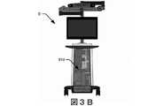
図3Bおよび図3Cは、図1の外科用システムとともに使用させることができるか、または外科用ロボットとは独立して使用させることができる、別のカメラ追跡システムコンポーネント6’の正面図および等角図を示している。例えば、カメラ追跡システムコンポーネント6’が、ロボットガイダンスの使用なしにナビゲート式外科手術を実現するのに使用され得る。図3Bおよび図3Cのカメラ追跡システムコンポーネント6’と図3Aのカメラ追跡システムコンポーネント6との違いのうちの1つは、図3Bおよび図3Cのカメラ追跡システムコンポーネント6’がコンピュータプラットフォーム910を運ぶハウジングを含むことである。コンピュータプラットフォーム910は、DRAを追跡するカメラ追跡作業を行い、ディスプレイデバイス、例えばXRヘッドセットおよび/または他のディスプレイデバイスに外科ナビゲーション情報を提供する、ナビゲーション下での外科手術を行い、また本明細書に開示されている他の計算演算を行うように構成され得る。したがって、コンピュータプラットフォーム910は、図14の1つ以上のナビゲーションコンピュータなどのナビゲーションコンピュータを含むことができる。 3B and 3C are front view and isometric views of another camera tracking system component 6'that can be used with the surgical system of FIG. 1 or independently of the surgical robot. The figure is shown. For example, camera tracking system component 6'can be used to perform navigating surgery without the use of robot guidance. One of the differences between the camera tracking system component 6'of FIGS. 3B and 3C and the camera
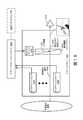
図6は、医療手術に使用される図5の外科用システムのコンポーネントのブロック図を示している。図6を参照すると、補助的な追跡バーの追跡カメラ46は、ナビゲーション視野600を有し、この場合、患者に取り付けられた参照アレイ602のポーズ(例えば、位置および向き)、外科用器具に取り付けられた参照アレイ604、およびロボットアーム20が、追跡される。追跡カメラ46は、以下に記載される動作を実行するように構成されたコンピュータプラットフォーム910を含む、図3Bおよび図3Cのカメラ追跡システムコンポーネント6’の一部とすることができる。参照アレイは、既知のパターンで光を反射することによって追跡を可能にし、それがデコードされて、外科用ロボット4の追跡サブシステムによってそれぞれのポーズを判定する。患者の参照アレイ602と補助的な追跡バーの追跡カメラ46との間の視線が(例えば、医療従事者、器具などによって)遮断された場合、外科用器具のさらなるナビゲーションを実行することができない可能性があり、応答通知は、ロボットアーム20および外科用ロボット4のさらなる移動を一時的に停止し、ディスプレイ34に警告を表示し、および/または医療従事者に可聴警告を与えることができる。ディスプレイ34は、外科医610および助手612がアクセス可能であるが、視認するには、患者から頭部の向きを逸らし、眼の焦点を異なる距離および場所に変化させる必要がある。ナビゲーションソフトウェアは、外科医からの音声指示に基づいて、技術従事者614によって制御させることができる。 FIG. 6 shows a block diagram of the components of the surgical system of FIG. 5 used in medical surgery. Referring to FIG. 6, the tracking
図7は、外科用システム2のナビゲーション機能を使用するときに、外科用ロボット4によって図5および図6のディスプレイ34に表示させることができる様々な表示画面を示している。表示画面は、展開される外科手術計画に基づいて、および/または追跡される参照アレイのポーズに基づいて、解剖学的構造に対して表示画面に位置決めされた器具のモデルのグラフィック表現がオーバーレイされた患者の放射線写真、外科的処置の異なる段階および仮想的に投影されたインプラントの寸法パラメータ(例えば、長さ、幅、および/または直径)を制御するための様々な使用者が選択可能なメニューを含むことができるが、これに限定されるものではない。 FIG. 7 shows various display screens that can be displayed on the
ナビゲート下での外科手術のために、外科的処置の術前計画、例えば、インプラントの配置、および計画された外科的処置の最中に1人または複数の使用者にナビゲーション情報を提供するためのコンピュータプラットフォーム910への計画の電子転送を可能にする、以下に記載される様々な処理コンポーネント(例えば、コンピュータプラットフォーム910)および関連付けられたソフトウェアが実現される。 For navigational surgery, to provide navigation information to one or more users during preoperative planning of surgical procedures, such as implant placement, and planned surgical procedures. Various processing components (eg, computer platform 910) and associated software described below are implemented that allow electronic transfer of plans to
ロボットナビゲーションのために、外科的処置の術前計画、例えば、インプラントの配置、および外科用ロボット4への計画の電子転送を可能にする、以下に記載される様々な処理コンポーネント(例えば、コンピュータプラットフォーム910)および関連付けられたソフトウェアが実現される。外科用ロボット4は、計画を使用して、ロボットアーム20および接続されたエンドエフェクタ26を誘導して、計画された外科的処置のステップのための患者の解剖学的構造に対する外科用器具の目標のポーズを実現する。 For robot navigation, various processing components (eg, computer platforms) described below that allow preoperative planning of surgical procedures, such as implant placement, and electronic transfer of planning to
以下の様々な実施形態は、外科医610、助手612、および/または他の医療従事者が着用できる1つ以上のXRヘッドセットを使用して、外科用ロボット、カメラ追跡システムコンポーネント6/6’、および/または手術室の他の医療機器から情報を受信し、および/またはこれらに制御コマンドを与えるための改善されたユーザインターフェイスを提供することを対象とする。 The following various embodiments use a surgical robot, camera
図8は、本開示のいくつかの実施形態にかかる、外科用ロボット4のいくつかの電気的コンポーネントのブロック図を示している。図8を参照すると、ロードセル(図示せず)は、エンドエフェクタカプラ22に加えられた力を追跡するように構成され得る。実施形態によっては、ロードセルは、複数のモータ850、851、852、853、および/または854と通信することができる。ロードセルが力を感知すると、加えられた力の程度に関する情報が、1つのスイッチアレイおよび/または複数のスイッチアレイからコントローラ846に分配され得る。コントローラ846は、ロードセルから力の情報を取り出し、それをスイッチアルゴリズムで処理することができる。スイッチアルゴリズムは、モータドライバ842を制御するのにコントローラ846によって使用される。モータドライバ842は、モータ850、851、852、853、および854のうちの1つ以上の働きを制御する。モータドライバ842は、特定のモータに、例えば、モータを通してロードセルによって測定された同じ程度の力を生み出すよう指示することができる。実施形態によっては、生み出される力は、コントローラ846によって指示される通りに、複数のモータ、例えば850〜854に由来する可能性がある。さらに、モータドライバ842は、コントローラ846から入力を受信することができる。コントローラ846は、ロードセルによって感知された力の方向に関する情報をロードセルから受信することができる。コントローラ846は、この情報を、モーションコントローラアルゴリズムを使用して処理することができる。このアルゴリズムは、特定のモータドライバ842に情報を提供するのに使用され得る。力の方向を再現するために、コントローラ846は、特定のモータドライバ842を起動および/または停止することができる。コントローラ846は、1つ以上のモータ、例えば850〜854のうちの1つ以上を制御して、ロードセルによって感知された力の方向にエンドエフェクタ26の運動を誘起することができる。この力によって制御される運動により、術者は、スカラ24およびエンドエフェクタ26を楽に、および/またはほとんど抵抗なく移動させることができる。エンドエフェクタ26の移動は、医療従事者が使用するために、エンドエフェクタ26を任意の好適なポーズ(すなわち、規定された三次元(3D)直交基準軸に対する場所および角度の向き)に位置決めするように実行させることができる。 FIG. 8 shows a block diagram of some electrical components of the
図5に最もよく例示されている起動組立体60は、エンドエフェクタカプラ22を包むブレスレットの形態をなすことができる。起動組立体60は、スカラ24のいずれの部分にでも位置し得、エンドエフェクタカプラ22の任意の部分が医療従事者によって装着され(また無線で通信する)得て、かつ/またはそれらの組み合わせであり得る。起動組立体60は、一次ボタンおよび二次ボタンを備えることができる。 The
一次ボタンを押し下げることにより、術者は、スカラ24およびエンドエフェクタカプラ22を移動させることが可能になり得る。ある実施形態によれば、所定の位置に設定されると、スカラ24およびエンドエフェクタカプラ22は、術者がスカラ24およびエンドエフェクタカプラ22を動かすように外科用ロボット4をプログラムするまで動かないようにしてもよく、または一次ボタンを使用して動かされる。例によっては、スカラ24およびエンドエフェクタカプラ22が術者のコマンドに応答するようになる前に、少なくとも2つの非隣接の一次起動スイッチの押し下げが必要となり得る。少なくとも2つの一次起動スイッチを押し下げることにより、医療処置中のスカラ24およびエンドエフェクタカプラ22の偶発的な移動を防止することができる。 By pressing down the primary button, the operator may be able to move the scalar 24 and the
一次ボタンによって起動されると、ロードセルは、術者、すなわち、医療従事者によってエンドエフェクタカプラ22に及ぼされる力の大きさおよび/または方向を測定することができる。この情報は、スカラ24およびエンドエフェクタカプラ22を移動させるために使用させることができる、スカラ24内の1つ以上のモータ、例えば850〜854のうちの1つ以上に転送させることができる。ロードセルによって測定された力の大きさおよび方向に関する情報は、1つ以上のモータ、例えば850〜854のうちの1つ以上に、ロードセルによって感知されるのと同じ方向にスカラ24およびエンドエフェクタカプラ22を移動させることができる。術者がスカラ24およびエンドエフェクタカプラ22を移動させるのと同時に、モータがスカラ24およびエンドエフェクタカプラ22を移動させるため、この力制御型の動きにより、術者は、楽に、かつ大きな労力なしに、スカラ24およびエンドエフェクタカプラ22を移動することが可能になり得る。 When activated by the primary button, the load cell can measure the magnitude and / or direction of force exerted on the
いくつかの例では、二次ボタンは、「選択」デバイスとして術者によって使用させることができる。医療手術中、外科用ロボット4は、XRヘッドセット920、ディスプレイ34および/または光表示器28によって、医療従事者に特定の状態を通知することができる。XRヘッドセット920は、それぞれ、シースルーの表示画面上に画像を表示して、シースルーの表示画面を通して見ることができる実世界の対象に重ね合わせられるエクステンデットリアリティの画像を形成するように構成されている。医療従事者は、機能、モードを選択するよう、かつ/または外科用システム2の状態を見極めるよう、外科用ロボット4によって促される可能性がある。二次ボタンを1回押すと、特定の機能、モード、および/またはXRヘッドセット920、ディスプレイ34および/または光表示器28を通して医療従事者に伝えられる認識情報を作動させることができる。さらに、迅速に連続して二次ボタンを複数回押すと、追加の機能、モード、および/またはXRヘッドセット920、ディスプレイ34および/または光表示器28を通して医療従事者に伝えられる選択情報を作動させることができる。 In some examples, the secondary button can be used by the surgeon as a "selection" device. During medical surgery, the
図8をさらに参照すると、外科用ロボット4の電気的コンポーネントは、プラットフォームサブシステム802、コンピュータサブシステム820、モーション制御サブシステム840、および追跡サブシステム830を含む。プラットフォームサブシステム802は、バッテリ806、配電モジュール804、コネクタパネル808、および充電ステーション810を含む。コンピュータサブシステム820は、コンピュータ822、ディスプレイ824、およびスピーカ826を含む。モーション制御サブシステム840は、ドライバ回路842、モータ850、851、852、853、854、安定化装置855、856、857、858、エンドエフェクタコネクタ844、およびコントローラ846を含む。追跡サブシステム830は、位置センサ832およびカメラコンバータ834を含む。外科用ロボット4はまた、取り外し可能なフットペダル880、および取り外し可能なタブレットコンピュータ890を含むことができる。 Further referring to FIG. 8, the electrical components of the
入力電力は、配電モジュール804に供給させることができる電源を介して外科用ロボット4に供給される。配電モジュール804は、入力電力を受け取り、外科用ロボット4の他のモジュール、コンポーネント、およびサブシステムに供給される様々な電源電圧を起こすように構成されている。配電モジュール804は、例えば、モータ850〜854およびエンドエフェクタカプラ844に給電するために、コンピュータ822、ディスプレイ824、スピーカ826、ドライバ842などの他の構成要素に提供され得、またカメラコンバータ834および外科用ロボット4用の他のコンポーネントに供給され得る、様々な電圧供給を、コネクタパネル808に、もたらすように構成され得る。配電モジュール804はまた、配電モジュール804が入力電力から電力を受け取らない場合、一時的な電力源としての役割を果たすバッテリ806に接続され得る。他の場合には、配電モジュール804は、バッテリ806を充電するのに役立つ場合がある。 The input power is supplied to the
コネクタパネル808は、異なるデバイスおよびコンポーネントを外科用ロボット4および/または関連付けられたコンポーネントおよびモジュールに接続するのに役立つことができる。コネクタパネル808は、様々な構成要素からのラインまたは接続を受け取る1つ以上のポートを含み得る。例えば、コネクタパネル808は、外科用ロボット4を他の機器に接地させることができる接地端子ポート、フットペダル880を接続するポート、位置センサ832、カメラコンバータ834、およびDRA追跡カメラ870を含み得る追跡サブシステム830に接続するポートを備え得る。コネクタパネル808は、コンピュータ822などの他の構成要素へのUSB通信、イーサネット通信、HDMI通信を可能にする他のポートも含み得る。いくつかの実施形態によれば、コネクタパネル808は、1つ以上のXRヘッドセット920を追跡サブシステム830および/またはコンピュータサブシステム820に動作可能に接続するための有線および/または無線インターフェイスを含むことができる。 The connector panel 808 can help connect different devices and components to the
制御パネル816は、外科用ロボット4の動作を制御し、および/または術者が観察するための外科用ロボット4からの情報を提供する、様々なボタンまたは表示器を設けることができる。例えば、制御パネル816は、外科用ロボット4の電源をオンオフするボタン、垂直柱16を上げ下げするボタン、キャスタ12に係合して外科用ロボット4が物理的に動かないようにするように設計され得る安定化装置855〜858を上げ下げするボタンを含み得る。他のボタンは、すべてのモータ電源を取り外し、機械式ブレーキを掛けて、すべての動きが起こらないようにし得る、緊急時に、外科用ロボット4を止めることができる。制御パネル816はまた、配線電力表示器またはバッテリ806の充電状態などの特定のシステムの状況を術者に通知する表示器を有することができる。いくつかの実施形態によれば、1つ以上のXRヘッドセット920は、例えばコネクタパネル808を介して通信して、外科用ロボット4の動作を制御し、および/またはXRヘッドセット920を装着している人による観察のために外科用ロボット4によって生成された情報を受信および表示することができる。 The control panel 816 may be provided with various buttons or indicators that control the movement of the
コンピュータサブシステム820のコンピュータ822は、外科用ロボット4の割り当てられた機能を動作させるためのオペレーティングシステムおよびソフトウェアを含む。コンピュータ822は、術者に情報を表示するために、他のコンポーネント(例えば、追跡サブシステム830、プラットフォームサブシステム802、および/またはモーション制御サブシステム840)からの情報を受信し、処理することができる。また、コンピュータサブシステム820は、スピーカ826を通して術者に出力を提供することができる。スピーカは、外科用ロボットの一部、XRヘッドセット920の一部、または外科用システム2の別の構成要素内であり得る。ディスプレイ824は、図1および図2に示されるディスプレイ34に対応することができる。 The
追跡サブシステム830は、位置センサ832、およびカメラコンバータ834を含むことができる。追跡サブシステム830は、図3のカメラ追跡システムコンポーネント6に対応し得る。DRA追跡カメラ870は、DRA52のポーズを判定するように、位置センサ832とともに働く。この追跡は、LEDまたは反射マーカなどのDRA52の能動的または受動的な要素の場所をそれぞれ追跡する赤外線または可視光の技術の使用を含む、本開示に矛盾しない様式で、行うことができる。 The tracking subsystem 830 can include a position sensor 832 and a camera converter 834. The tracking subsystem 830 may correspond to the camera
追跡サブシステム830およびコンピュータサブシステム820の機能的動作は、図3Aおよび図3Bのカメラ追跡システムコンポーネント6’によって運搬できるコンピュータプラットフォーム910に含めることができる。追跡サブシステム830は、追跡対象のDRAのポーズ、例えば場所および角度の向きを判定するように構成され得る。コンピュータプラットフォーム910は、判定されたポーズを使用して、予定の外科的処置中に位置決め・位置合わせされた患者の画像および/または追跡対象の解剖学的構造に対して追跡対象の器具のそれらの動きを誘導する、ナビゲーション情報を使用者に提供するように構成されている、ナビゲーションコントローラも含み得る。コンピュータプラットフォーム910は、図3Bおよび図3Cのディスプレイ上に、かつ/または1つ以上のXRヘッドセット920に情報を表示することができる。コンピュータプラットフォーム910は、外科用ロボットとともに使用される場合、コンピュータサブシステム820および図8の他のサブシステムと通信して、エンドエフェクタ26の移動を制御するように構成させることができる。例えば、以下に説明するように、コンピュータプラットフォーム910は、1つ以上の追跡されるDRAの判定されたポーズに基づいて制御される、表示されるサイズ、形状、色、および/またはポーズである、患者の解剖学的構造、外科用器具、使用者の手などのグラフィック表現を生成することができ、表示されるそのグラフィック表現を動的に修正して、判定されたポーズの経時的な変化を追跡することができる。 The functional operation of the tracking subsystem 830 and the computer subsystem 820 can be included in the
モーション制御サブシステム840は、垂直柱16、上部アーム18、下部アーム20を物理的に移動させるか、またはエンドエフェクタカプラ22を回転させるように構成させることができる。物理的な移動は、1つ以上のモータ850〜854の使用を通して行われ得る。例えば、モータ850は、垂直柱16を垂直に上げるまたは下げるように構成され得る。モータ851は、図2に示されるように、垂直柱16との係合箇所の周りに、上部アーム18を横方向に動かすように構成され得る。モータ852は、図2に示されるように、上部アーム18との係合箇所の周りに下部アーム20を横方向に動かすように構成され得る。モータ853および854は、三次元軸の周りに沿った並進の動きおよび回転をもたらすように、エンドエフェクタカプラ22を動かすように構成され得る。図9に示されるコンピュータプラットフォーム910は、エンドエフェクタカプラ22の移動を誘導するコントローラ846に制御入力を提供して、接続された受動的なエンドエフェクタを、計画された外科的処置中に手術される解剖学的構造に対して、計画されたポーズ(すなわち、定義された3D直交基準軸に対する場所および角度の向き)で位置決めすることができる。モーション制御サブシステム840は、統合された位置センサ(例えば、エンコーダ)を使用して、エンドエフェクタカプラ22および/またはエンドエフェクタ26の位置を測定するように構成させることができる。 The motion control subsystem 840 can be configured to physically move the
図9は、本開示のいくつかの実施形態にかかる、カメラ追跡システムコンポーネント6(図3A)または6’(図3B、図3C)、および/または外科用ロボット4に動作可能に接続できるコンピュータプラットフォーム910に接続された撮像デバイス(例えば、Cアーム104、Oアーム106など)を含む外科用システムのコンポーネントのブロック図を示している。これに代えて、コンピュータプラットフォーム910によって実行されるものとして本明細書に開示される少なくともいくつかの動作は、追加的または代替的に、外科用システムのコンポーネントによって実行させることができる。 FIG. 9 is a computer platform operably connected to camera tracking system components 6 (FIG. 3A) or 6'(FIGS. 3B, 3C) and / or
図9を参照すると、コンピュータプラットフォーム910は、ディスプレイ912、少なくとも1つのプロセッサ回路914(簡潔にするためにプロセッサとも呼ばれる)、コンピュータ可読プログラムコード918を内包する少なくとも1つのメモリ回路916(簡潔にするためにメモリとも呼ばれる)、および少なくとも1つのネットワークインターフェイス902(簡潔にするためにネットワークインターフェイスとも呼ばれる)を含む。ディスプレイ912は、本開示のいくつかの実施形態による、XRヘッドセット920の一部であり得る。ネットワークインターフェイス902は、図10のCアーム撮像デバイス104、図11のOアーム撮像デバイス106、別の医療撮像デバイス、患者の医療画像を内包する画像データベース950、外科用ロボット4のコンポーネント、および/または他の電子機器に接続するように構成させることができる。 Referring to FIG. 9, the
外科用ロボット4とともに使用される場合、ディスプレイ912は、図2のディスプレイ34、および/または図8のタブレット890、および/または外科用ロボット4に動作可能に接続されたXRヘッドセット920に対応することができ、ネットワークインターフェイス902は、図8のプラットフォームネットワークインターフェイス812に対応することができ、プロセッサ914は、図8のコンピュータ822に対応することができる。XRヘッドセット920のネットワークインターフェイス902は、有線ネットワーク、例えば、シンワイヤイーサネットを介して、および/または1つ以上の無線通信プロトコル、例えば、WLAN、3GPP 4Gおよび/または5G(新無線)セルラー通信規格などにしたがって、無線RF送受信リンクを介して、通信するように構成させることができる。 When used with the
プロセッサ914は、汎用および/または専用プロセッサ、例えば、マイクロプロセッサおよび/またはデジタル信号プロセッサなどの1つ以上のデータ処理回路を含むことができる。プロセッサ914は、メモリ916内のコンピュータ可読プログラムコード918を実行して、外科手術計画、ナビゲート下での外科手術、および/またはロボット外科手術のために実行されるものとして本明細書に記載される動作の一部またはすべてを含むことができる動作を実行するように構成されている。
コンピュータプラットフォーム910は、外科手術用の計画の機能性を提供するように構成することができる。プロセッサ914は、撮像デバイス104および106のうちの一方から、かつ/またはネットワークインターフェイス902を通して画像データベース950から受信した解剖学的構造、例えば椎骨の画像を、ディスプレイデバイス912に、かつ/またはXRヘッドセット920に、表示するように働くことができる。プロセッサ914は、例えば、術者が接触して予定の処置のためのディスプレイ912の場所を選択することによって、またはマウスベースのカーソルを使用して予定の処置ための場所を定義することによって、1つ以上の画像に示される解剖学的構造が、外科的処置、例えばねじの配置を経るべき場所に関する術者の定義を受信する。画像がXRヘッドセット920に表示される場合、XRヘッドセットは、着用者によって形成されたジェスチャベースのコマンドで感知するように、および/または着用者によって発せられたボイスベースのコマンドを感知するように構成させることができ、これを使用してメニュー項目間の選択を制御し、および/または以下にさらに詳述するように、XRヘッドセット920に対象がどのように表示されるかを制御することができる。 The
コンピュータプラットフォーム910は、股関節の中心、角度の中心、自然に備わっている目印(例えば、transepicondylar line、Whitesides line、後顆線など)などを決定する様々な角度の測定のような、膝の外科手術に特に有用であり得る解剖学的測定を可能にするように構成させることができる。いくつかの測定を自動とすることができる一方で、いくつかの他の測定は、人間の入力または支援を伴うことができる。コンピュータプラットフォーム910は、術者が、サイズおよび整列の選択を含む、患者のための正しいインプラントの選択を入力することを可能にするように構成させることができる。コンピュータプラットフォーム910は、CT画像または他の医療画像に対して自動または半自動(人間の入力を伴う)のセグメント化(画像処理)を行うように構成され得る。患者の外科用計画は、外科用ロボット4による検索のために、データベース950に対応することができるクラウドベースのサーバに記憶させることができる。 The
例えば、整形外科手術の間に、外科医は、コンピュータ画面(例えば、タッチスクリーン)または例えばXRヘッドセット920を介したエクステンデットリアリティ(XR)インタラクション(例えば、手のジェスチャベースのコマンドおよび/またはボイスベースのコマンド)を使用して、どの切断をするか(例えば、後部大腿骨、近位脛骨など)を選択することができる。コンピュータプラットフォーム910は、外科的処置を実行するために外科医に視覚的ガイダンスを提供するナビゲーション情報を生成することができる。外科用ロボット4とともに使用される場合、コンピュータプラットフォーム910は、外科用ロボット4がエンドエフェクタ26を目標のポーズに自動的に移動させて、外科用器具が目標の場所に整列されて解剖学的構造に対する外科的処置を実行し得るようにするガイダンスを提示することができる。 For example, during orthopedic surgery, the surgeon may use a computer screen (eg, a touch screen) or an extended reality (XR) interaction (eg, a hand gesture-based command and / or voice-based) via an
いくつかの実施形態では、外科用システム900は、2つのDRAを使用して、患者の脛骨に接続されたもの、および患者の大腿骨に接続されたものなど、患者の解剖学的構造の位置を追跡することができる。システム900は、位置合わせおよび確認のための標準のナビゲート器具(例えば、脊椎外科手術のためにGlobus ExcelsiusGPSシステムで使用されるものと同様のポインタ)を使用することができる。 In some embodiments, the
ナビゲート下での外科用で特に難しい作業は、3Dの解剖学的構造の2Dの表現であるコンピュータ画面上で、外科医が作業を実行するのに苦労する脊椎、膝、および他の解剖学的構造におけるインプラントの位置を、いかに計画するかである。システム900は、XRヘッドセット920を使用して、解剖学的構造およびインプラントデバイス候補のコンピュータで生成された三次元(3D)の表現を表示することによって、この問題に対処することが可能である。コンピュータで生成された表現は、コンピュータプラットフォーム910のガイダンスの下で、表示画面上で互いに対してスケーリングおよびポーズ決めされ、XRヘッドセット920を介して視認される間、外科医によって操作させることができる。外科医は、例えば、XRヘッドセット920によって感知されるハンドジェスチャベースのコマンドおよび/またはボイスベースのコマンドを使用して、解剖学的構造、インプラント、外科用器具などの、表示された、コンピュータで生成された表現を、操作することができる。 A particularly difficult task for surgery under navigation is the spine, knees, and other anatomy that surgeons struggle to perform on computer screens, which are 2D representations of 3D anatomy. How to plan the position of the implant in the structure.
例えば、外科医は、仮想インプラント上の表示された仮想ハンドルを視認することができ、仮想ハンドルを操作して(例えば、つかんで移動させて)、仮想インプラントを所望のポーズに移動させ、解剖学的構造のグラフィック表現に対する計画されたインプラントの配置を調整することができる。その後、外科手術の間に、コンピュータプラットフォーム910は、外科医が、インプラントを挿入するための外科手術計画に、より正確にしたがい、かつ/または解剖学的構造に対して別の外科的処置を行えるよう促進するナビゲーション情報を、XRヘッドセット920を通して表示することができる。外科的処置が骨の除去を伴う場合、骨の除去の進行、例えば切込みの深さが、XRヘッドセット920を介してリアルタイムで表示され得る。XRヘッドセット920を介して表示させることができる他の特徴として、関節運動の範囲に沿った間隙または靭帯のバランス、関節運動の範囲に沿ったインプラントの線状の接触、色または他のグラフィックレンダリングによる靭帯の緊張および/または弛緩などを挙げることができるが、これらに限定されるものではない。 For example, the surgeon can see the displayed virtual handle on the virtual implant and manipulate the virtual handle (eg, grab and move) to move the virtual implant to the desired pose and anatomically. The planned implant placement with respect to the graphic representation of the structure can be adjusted. Then, during the surgery, the
いくつかの実施形態では、コンピュータプラットフォーム910は、標準の外科用器具および/またはインプラント、例えば、後方安定化インプラントおよび十字型保持インプラント、セメント固定およびセメントレスインプラント、例えば膝関節全置換もしくは部分置換術、および/または股関節置換術、および/または外傷に関連した外科手術のために、改定されたシステムを使用することを計画するのを可能にし得る。 In some embodiments, the
自動撮像システムをコンピュータプラットフォーム910と連携して使用して、解剖学的構造の術前、術中、術後、および/またはリアルタイムの画像データを取得することができる。例示的な自動撮像システムが、図10および図11に例示されている。いくつかの実施形態では、自動撮像システムは、Cアーム104(図10)撮像デバイスまたはOアーム(登録商標)106(図11)である。(Oアーム(登録商標)は、米国コロラド州ルイスビルに事業所を置くMedtronic Navigation,Inc.が著作権を所有している)。X線システムで必要とされることがある、患者の手による頻繁な再度の位置決めを必要とすることなく、いくつかの異なる位置から患者のX線を撮像することが望ましい場合がある。Cアーム104X線診断機器は、頻繁な手作業による再度の位置決めの問題を解決することができ、外科的および他の介入処置の医療分野でよく知られている可能性がある。図10に示されるように、Cアームは、「C」という形状の対向する遠位端112で終端する細長いC形状の部材を含む。C形状の部材は、X線源114および画像受信器116に取り付けられている。アームのCアーム104内にある空間は、X線支持構造体からの干渉が実質的にない状態で医師が患者に従事する余地を設ける。 The automatic imaging system can be used in conjunction with the
Cアームは、2つの自由度における(すなわち、球面運動における2つの直交軸を中心とする)アームの回転の動きを可能にするように装着されている。Cアームは、X線支持構造体にスライド可能に据え付けられ、これにより、Cアームの曲率中心を中心とした周回回転運動が可能になり、X線源114および画像受信器116を、垂直方向にかつ/または水平方向に選択的に向けるのを可能にすることができる。Cアームはまた、横方向(すなわち、患者の幅および長さの両方に対するX線源114および画像受信器116の選択的に調節可能な位置付けを可能にする、周回方向に対して直角の方向)に回転可能であり得る。Cアームの装置の球面回転の態様により、医師は、撮像されている特定の解剖学的状況に関して決定された、最適な角度で、患者のX線を撮像することができる。 The C-arm is mounted to allow rotational movement of the arm in two degrees of freedom (ie, about two orthogonal axes in spherical motion). The C-arm is slidably mounted on the X-ray support structure, which allows for orbital rotational movement around the center of curvature of the C-arm, allowing the
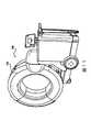
図11に示されているOアーム(登録商標)106は、例示されていない画像取り込み部分を取り囲むことができるガントリハウジング124を含む。画像取り込み部分は、X線源および/またはX線放出部分と、X線受光および/または画像受信部分とを含み、これらは、互いに約180度離れて配設され、画像取り込み部分の軌道に対してロータ(図示せず)上に据え付けられ得る。画像取り込み部分は、画像取得中に360度回転するように動作可能であり得る。画像取り込み部分は、中心点および/または軸を中心として回転することができ、患者の画像データが複数の方向から、または複数の平面で取得されることを可能にする。 The O-
ガントリハウジング124を備えたOアーム(登録商標)106は、撮像される対象の周りに位置決めするための中央開口部と、ガントリハウジング124の内部で回転可能な放射線源とを有し、放射線源は、複数の異なる投影角度から放射線を投影するように適合させることができる。検出器システムは、投射角ごとに放射線を検出して、対象の画像を、複数の投射平面から、擬似同時的に取得するように適合されている。ガントリは、カンチレバー様式で、車輪を備えた車輪付き移動式カートなどの支持構造Oアーム(登録商標)支持構造体に取り付けられ得る。位置付けユニットは、好ましくはコンピュータ化されたモーション制御システムの制御下で、ガントリを予定の位置および向きに並進させかつ/または傾斜させる。ガントリは、ガントリ上で互いに対向して配設された供給源と検出器とを含み得る。供給源および検出器は、供給源および検出器を互いに協調する状態で、ガントリの内部を中心として回転させることができるモータ付きロータに、固定され得る。供給源は、ガントリの内側に位置する目標対象の多平面撮像のために、部分的および/または完全な360度の回転にわたって、複数の位置および向きでパルス化され得る。ガントリは、ロータが回転するにしたがってロータを誘導するためのレールおよび軸受けシステムをさらに備え得、このシステムは、供給源および検出器を担持することができる。Oアーム(登録商標)106およびCアーム104の双方および/またはいずれかを自動撮像システムとして使用して、患者をスキャンし、情報を外科用システム2に送ることができる。 The O-
撮像システムによって取り込まれた画像は、XRヘッドセット920および/またはコンピュータプラットフォーム910の別のディスプレイデバイス、外科用ロボット4、および/または外科用システム900の別のコンポーネントに表示させることができる。XRヘッドセット920は、例えばコンピュータプラットフォーム910を介して、撮像デバイス104および/または106のうちの1つ以上に、かつ/または画像データベース950に接続されて、それらからの画像を表示し得る。使用者は、XRヘッドセット920を介して制御入力、例えば、ジェスチャおよび/またはボイスベースのコマンドを与えて、撮像デバイス104および/または106および/または画像データベース950のうちの1つ以上の動作を制御することができる。 The images captured by the imaging system can be displayed on another display device of the
図12は、図13に示されるXRヘッドセット920に対応し、かつ本開示のいくつかの実施形態にしたがって動作することができるXRヘッドセット1200および1210(ヘッドマウントディスプレイHMD1およびHMD2)の対を含む外科用システムの構成要素のブロック図を示している。 FIG. 12 shows a pair of
図12の例示的なシナリオを参照すると、助手612および外科医610は、双方とも、それぞれXRヘッドセット1210および1210を着用している。助手612がXRヘッドセット1210を装着することは任意である。XRヘッドセット1200および1210は、以下でさらに説明するように、装着者が外科的処置に関係する情報を見て、それと相互作用することができる、双方向の環境をもたらすように構成されている。この双方向XRベースの環境は、技術従事者614が手術室にいる必要性をなくすことができ、図6に示されるディスプレイ34の使用の必要性をなくすことができる。各XRヘッドセット1200および1210は、器具、解剖学的構造、エンドエフェクタ26、および/または他の機器に取り付けられたDRAまたは他の参照アレイの追加の追跡源を設けるように構成された1つ以上のカメラを含むことができる。図12の例では、XRヘッドセット1200は、DRAおよび他の対象を追跡するための視野(FOV)1202を有し、XRヘッドセット1210は、DRAおよび他の対象を追跡するためのFOV1202と部分的に重なるFOV1212を有し、追跡カメラ46は、DRAおよび他の対象を追跡するために、FOV1202および1212と部分的に重複する別のFOV600を有する。 With reference to the exemplary scenario of FIG. 12, the
1つ以上のカメラが、追跡される対象、例えば外科用器具に取り付けられたDRAを視認するのを妨げられているが、DRAが1つ以上の他のカメラを視野に入れている場合、追跡サブシステム830および/またはナビゲーションコントローラ828は、ナビゲーションを喪失せずにシームレスに対象を追跡し続けることができる。加えて、1つのカメラの観点からDRAの部分的なオクルージョンがあるが、DRA全体が複数のカメラ供給源を介して視認可能である場合、カメラの追跡入力を統合して、DRAのナビゲーションを続けることができる。XRヘッドセットおよび/または追跡カメラ46のうちの1つは、XRヘッドセットの別の1つでDRAを表示および追跡して、コンピュータプラットフォーム910(図9および図14)、追跡サブシステム830、および/または別のコンピューティングコンポーネントを有効にし、1つ以上の定義された座標系、例えば、XRヘッドセット1200/1210、追跡カメラ46、および/または患者、テーブル、および/または部屋に対して定義された別の座標系に対するDRAのポーズを判定することができる。 Tracking if one or more cameras are prevented from seeing what is being tracked, eg, a DRA attached to a surgical instrument, but the DRA is looking at one or more other cameras. The subsystem 830 and / or the navigation controller 828 can continue to track the target seamlessly without losing navigation. In addition, if there is a partial occlusion of the DRA in terms of one camera, but the entire DRA is visible through multiple camera sources, integrate the camera tracking inputs and continue the DRA navigation. be able to. One of the XR headsets and / or tracking
XRヘッドセット1200および1210は、神経モニタリング、顕微鏡、ビデオカメラ、および麻酔システムを含むがこれらに限定されない手術室内の様々な機器から受信されたビデオ、写真、および/または他の情報を表示するように、および/またはこれらの機器を制御するコマンドを与えるように動作可能に接続させることができる。様々な機器からのデータは、例えば、患者のバイタルサインまたは顕微鏡フィードの表示など、ヘッドセット内で処理および表示させることができる。 The
例示的なXRヘッドセットコンポーネントと、ナビゲートされた外科用、外科用ロボット、およびその他の機器への統合
図13は、本開示のいくつかの実施形態にしたがって構成されているXRヘッドセット920を示す。XRヘッドセットは、XRヘッドセットを装着者の頭に固定するように構成されたヘッドバンド1306、ヘッドバンド1306によって支持された電子部品筐体1304、および電子部品筐体1304から横方向にわたって下向きに延在する表示画面1302を含む。表示画面1302は、シースルーのLCDディスプレイデバイスか、またはディスプレイデバイスによって装着者の目に向けて投射された画像を反射する半反射レンズであり得る。ヘッドセットの片側または両側に配置された既知の間隔を空けて、例えばドットなどのDRA基準のセットがペイントされるかまたは取り付けられる。ヘッドセットのDRAは、補助的な追跡バーの追跡カメラがヘッドセット920のポーズを追跡することを可能にし、および/または別のXRヘッドセットがヘッドセット920のポーズを追跡することを可能にする。Integrating an exemplary XR headset component into a navigated surgical, surgical robot, and other device Figure 13 shows an
表示画面1302は、ディスプレイデバイスのディスプレイパネルから使用者の眼に向けて光を反射する、コンバイナとも呼ばれるシースルーの表示画面として動作する。ディスプレイパネルは、電子部品筐体と使用者の頭との間に位置し得、使用者の眼に向ける反射のために、表示画面1302に向けて仮想コンテンツを投射するように角度付けされ得る。表示画面1302が、半透明かつ半反射であることにより、使用者は、実世界の場面の使用者のビューに重ね合わされた反射仮想コンテンツを見ることができる。表示画面1302は、下部横方向帯域よりも高い不透明度を有する図示の上部横方向帯域など、様々な不透明度の領域を有し得る。表示画面1302の不透明度は、実世界の場面からの光がどれくらい使用者の眼を透過するかを調節するように、電子的に制御され得る。表示画面1302の高不透明度の構成は、実世界の場面の薄暗いビューに重ねられた高コントラストの仮想画像をもたらす。表示画面1302の低不透明度の構成は、実世界の場面のより鮮明なビューに重ねられたよりぼんやりとした仮想画像をもたらし得る。不透明度は、表示画面1302の表面に不透明な材料を適用することによって制御することができる。 The
いくつかの実施形態によれば、外科用システムは、XRヘッドセット920およびXRヘッドセットコントローラ、例えば、図14のコントローラ1430または図34のコントローラ3410を含む。XRヘッドセット920は、外科的処置の間に使用者が着用するように構成されており、XR画像を表示するように、かつ実世界の場面の少なくとも一部分が、使用者による視認のために通過できるように構成されたシースルーの表示画面1302を有する。XRヘッドセット920は、使用者がシースルーの表示画面1302を見るときに、使用者の眼のうちの少なくとも1つと実世界の場面との間に位置付けられた不透明フィルタも含む。不透明フィルタは、実世界の場面からの光に対する不透明性を与えるように構成されている。XRヘッドセットコントローラは、ナビゲーションコントローラ、例えば、図14のコントローラ828A、828B、および/または828Cと通信して、解剖学的構造に対する外科的処置中に使用者にガイダンスを提示するナビゲーションコントローラからナビゲーション情報を受信するように構成されており、シースルーの表示画面1302に表示するためのナビゲーション情報に基づいてXR画像を生成するようにさらに構成されている。 According to some embodiments, the surgical system includes an
表示画面1302の不透明度は、表示画面1302の上部から下向きの距離でより連続的に変化する不透明性を有するグラジエントとして構成させることができる。グラジエントの最も暗い点は、表示画面1302の上部に位置付けることができ、不透明な所が透明になるかまたはなくなるまで、表示画面1302でさらに沿って徐々に不透明性が低くなる。さらなる例示的な実施形態では、グラジエントは、表示画面1302のほぼ眼の中央のレベルで、約90%の不透明度から完全な透明に変化し得る。ヘッドセットが正しく較正され、位置付けられている場合、眼の中央のレベルは、使用者が真っ直ぐ外を見る場合の点に対応し、グラジエントの端は、目の「水平」線に位置し得る。グラジエントの暗い部分は、仮想コンテンツの鮮明でクリアなビジュアルを可能にし、頭上の邪魔な輝度の手術室のライトを遮断するのに役立つ。 The opacity of the
このように不透明フィルタを使用することにより、XRヘッドセット920は、表示画面1302の上部に沿って実世界の場面からの光を実質的または完全に遮断することによって、仮想現実(VR)の能力を与え、かつ表示画面1302の中央または下部に沿ってAR能力を与えることが可能になる。これにより、使用者は、必要に応じてARを半透明にできるようになり、処置の最中において患者のクリアな光学系の解剖学的構造が可能になる。表示画面1302を、より一定の不透明性バンドに代えてグラジエントとして構成することにより、着用者は、実世界の場面の輝度と、上向きのビューと下向きのビューとの間のより急速なシフト中などに、別様であれば眼を緊張させ得る被写界深度の急峻な変化を経験することなく、よりVRタイプのビューからよりARタイプのビューへとより自然な移行を経ることができるようになる。 By using an opaque filter in this way, the
ディスプレイパネルおよび表示画面1302は、広視野のシースルーXRディスプレイシステムを提供するように構成させることができる。例示的な一構成では、それらは、使用者が仮想コンテンツを視認するための55°の垂直範囲の80°の対角視野(FOV)をもたらす。他の対角FOV角度および垂直カバレッジ角度は、異なるサイズのディスプレイパネル、異なる曲率のレンズ、および/またはディスプレイパネルと湾曲する表示画面1302との間の異なる距離および角度の向きを介して設けることができる。 The display panel and
図14は、コンピュータプラットフォーム910に、Cアーム撮像デバイス104、Oアーム撮像デバイス106などの撮像デバイスのうちの1つ以上および/または画像データベース950に、および/または本開示の様々な実施形態にかかる外科用ロボット800に動作可能に接続させることができるXRヘッドセット920の電気的コンポーネントを例示している。 FIG. 14 relates to the
XRヘッドセット920は、ナビゲート下での外科的処置を実行するための改善されたヒューマンインターフェイスを提供する。XRヘッドセット920は、例えば、コンピュータプラットフォーム910を介して、ハンドジェスチャベースのコマンドおよび/または音声ベースのコマンドの識別、ディスプレイデバイス1450のXRグラフィカル対象のうちのいずれか1つ以上を含むが、これらに限定されるわけではない、機能性をもたらすように構成され得る。ディスプレイデバイス1450は、表示されたXRグラフィカル対象を表示画面1302に投影するビデオプロジェクタ、フラットパネルディスプレイなどとすることができる。使用者は、XRグラフィカル対象を、表示画面1302(図13)を介して見られる特定の実世界の対象に固定されたオーバーレイとして見ることができる。XRヘッドセット920は、追加的または代替的に、1つ以上のXRヘッドセット920に取り付けられたカメラおよび他のカメラからのビデオフィードを、表示画面1450に表示するように構成させることができる。 The
XRヘッドセット920の電気的コンポーネントは、複数のカメラ1440、マイクロフォン1442、ジェスチャセンサ1444、ポーズセンサ(例えば、慣性測定ユニット(IMU))1446、ディスプレイデバイス1450を含むディスプレイモジュール1448、および無線/有線通信インターフェイス1452を含むことができる。以下に説明するように、XRヘッドセットのカメラ1440は、可視光取り込みカメラ、近赤外線取り込みカメラ、または双方の組み合わせとすることができる。 The electrical components of the
カメラ1440は、カメラ1440の視野内部で実行される使用者の手のジェスチャの識別のために取り込むことによって、ジェスチャセンサ1444として動作するように構成させることができる。これに代えて、ジェスチャセンサ1444は、近接センサ、および/またはジェスチャセンサ1444に近接して実行される手のジェスチャを感知し、および/または物理的接触、例えばセンサまたは筐体1304をタッピングすることを感知するタッチセンサとすることができる。ポーズセンサ1446、例えばIMUは、1つ以上の定義された座標軸に沿ったXRヘッドセット920の回転および/または加速度を感知することができる多軸加速度計、傾斜センサ、および/または別のセンサを含むことができる。これらの電気的コンポーネントのいくつかまたはすべては、コンポーネント筐体1304に内包させることができるか、または腰もしくは肩などの他の箇所で着用されるように構成された別の筐体に内包させることができる。 The
上で説明したように、外科用システム2は、カメラ追跡システムコンポーネント6/6’と、コンピュータプラットフォーム910の一部とすることができる追跡サブシステム830とを含む。外科用システムは、撮像デバイス(例えば、Cアーム104、Oアーム106、および/または画像データベース950)、および/または外科用ロボット4を含むことができる。追跡サブシステム830は、解剖学的構造、エンドエフェクタ、外科用器具などに取り付けられたDRAのポーズを判定するように構成される。ナビゲーションコントローラ828は、例えば、解剖学的構造上で外科用器具を使用して、また追跡サブシステム830によって判定された解剖学的構造のポーズに基づいて、外科的処置がどこで実行されるかを定義する、図9のコンピュータプラットフォーム910によって実行される外科的計画機能からの外科手術計画に基づいて、解剖学的構造に対する外科用器具の目標のポーズを判定するように構成される。ナビゲーションコントローラ828は、さらに、外科用器具の目標のポーズ、解剖学的構造のポーズ、および外科用器具および/またはエンドエフェクタのポーズに基づいて操舵情報を生成するように構成させることができ、この場合、操舵情報は、外科手術計画を実行するために外科用器具および/または外科用ロボットのエンドエフェクタを移動させるべきである場合を示す。 As described above, the surgical system 2 includes a camera
XRヘッドセット920の電気的コンポーネントは、有線/無線インターフェイス1452を介してコンピュータプラットフォーム910の電気的コンポーネントに動作可能に接続させることができる。XRヘッドセット920の電気的コンポーネントは、例えば、様々な撮像デバイス、例えば、Cアーム撮像デバイス104、I/Oアーム撮像デバイス106、画像データベース950に、および/または有線/無線インターフェイス1452を介して他の医療機器に対して、コンピュータプラットフォーム910を介して動作可能に接続させることができるか、または直接接続させることができる。 The electrical components of the
外科用システム2は、さらに、XRヘッドセット920、コンピュータプラットフォーム910、および/または有線ケーブルおよび/または無線通信リンクで接続された別のシステムコンポーネントに常在することができる少なくとも1つのXRヘッドセットコントローラ1430(簡潔にするために「XRヘッドセットコントローラ」とも呼ばれる)を含む。様々な機能性は、XRヘッドセットコントローラ1430によって実行されるソフトウェアによって与えられている。XRヘッドセットコントローラ1430は、解剖学的構造に対する外科的処置中に使用者にガイダンスを提示するナビゲーションコントローラ828からナビゲーション情報を受信するように構成されており、シースルーの表示画面1302での投影のためのディスプレイデバイス1450での表示のために、ナビゲーション情報に基づいてXR画像を生成するように構成されている。 The surgical system 2 may further reside in the
表示画面(「シースルーの表示画面」とも呼ばれる)1302に対するディスプレイデバイス1450の構成は、XRヘッドセット920を装着している使用者が、実世界にあるように見えるXR画像を、表示画面1302を介して見るようにXR画像を表示するように構成されている。表示画面1302は、使用者の眼の前のヘッドバンド1306によって位置決めさせることができる。 The configuration of the
XRヘッドセットコントローラ1430は、表示画面1302を視認する間、使用者の頭または使用者の体の他の箇所に着用されるように構成されたハウジング内にあることができるか、または表示画面1302に通信可能に接続されている間に、表示画面1302を視認している使用者から遠隔に位置することができる。XRヘッドセットコントローラ1430は、カメラ1440、マイクロフォン142、および/またはポーズセンサ1446からの信号伝達を動作可能に処理するように構成させることができ、表示画面1302で視認する使用者のためにディスプレイデバイス1450にXR画像を表示するように接続されている。したがって、XRヘッドセット920内の回路ブロックとして例示されるXRヘッドセットコントローラ1430は、XRヘッドセット920の他の例示されるコンポーネントに動作可能に接続されているが、必ずしも共通のハウジング(例えば、図13の電子部品筐体1304)内に存在しないか、または使用者によって運搬可能ではないことを理解されたい。例えば、XRヘッドセットコントローラ1430は、ひいては図3Bおよび図3Cに示されるコンピュータ追跡システムコンポーネント6’のハウジング内に存在することができるコンピュータプラットフォーム910の内部に存在することができる。 The
XRヘッドセットを介した使用者のビューの例
XRヘッドセットの動作は、2D画像および3Dモデルの両方を表示画面1302に表示することができる。2D画像が、表示画面1302のより不透明な帯域(上部帯域)に表示され得るのが好ましく、3Dモデルが、環境領域として別に知られている、表示画面1302のより透明な帯域(下部帯域)に表示され得るのが、より好ましい。表示画面1302が終わる下部帯域の下方で、装着者は、手術室の遮るもののないビューを得る。XRコンテンツが表示画面1302に表示される場所が、流動的である可能性があることに留意されたい。コンテンツに対するヘッドセットの位置によっては、3Dコンテンツが表示される場所が不透明帯域に移動し、2Dコンテンツが表示される場所が透明帯域に置かれ、実世界に対して安定することができることがあり得る。さらに、表示画面1302全体を電子制御下で暗くして、ヘッドセットを外科手術計画では仮想現実に変換し、または医療処置の最中に完全に透明に変換することができる。上で説明したように、XRヘッドセット920および関連付けられた動作は、ナビゲートされる処置をサポートするだけでなく、ロボットにより支援される処置と組み合わせて実行させることができる。Example of user's view through XR headset The operation of the XR headset can display both a 2D image and a 3D model on the
図16は、本開示のいくつかの実施形態にかかる、医療処置中に外科用器具1602を操作している使用者にナビゲーション支援をもたらすためのXRヘッドセット920の表示画面1302を介した例示的な図を示している。図16を参照すると、外科用器具1602に接続された動的参照アレイ1630および1632がカメラ1440(図15)および/または46(図6)の視野内部になるように、外科用器具1602が追跡される解剖学的構造の近傍に来ると、器具のグラフィック表現1600は、解剖学的構造のグラフィック表現1610に関連して2Dおよび/または3D画像で表示させることができる。使用者は、表示されたグラフィック表現を使用して、器具のグラフィック表現2000から解剖学的構造のグラフィック表現1610を通って延在するものとして例示させることができる外科用器具1602の軌跡1620を調整することができる。XRヘッドセット920は、テキスト情報および他の対象1640も表示することができる。表示された表示画面を横切って延びる破線1650は、異なる不透明度のレベルの上側および下側帯域との間の例示的な分割を表す。 FIG. 16 illustrates, according to some embodiments of the present disclosure, via a
表示画面1302に表示させることができる他のタイプのXR画像(仮想コンテンツ)は、これらに限定されるものではないが、以下のいずれか1つ以上を含むことができる:
I)患者の解剖学的構造の2Dの軸方向、矢状、および/または冠状のビュー、
2)予定の追跡対象ツール対、その時の追跡対象のツールと、外科インプラント場所との重ね合わせ、
3)術前画像のギャラリー、
4)顕微鏡および他の同様のシステム、またはリモートビデオ会議からのビデオフィード、
5)オプションおよびコンフィグレーションの設定およびボタン
6)外科手術計画情報による患者の解剖学的構造体の浮遊3Dモデル、
7)浮遊する患者の解剖学的構造に対する外科用器具のリアルタイム追跡、
8)命令およびガイダンスによる患者の解剖学的構造の拡張された重ね合わせ、および
9)外科用機器の拡張されたオーバーレイ。Other types of XR images (virtual content) that can be displayed on the
I) A 2D axial, sagittal, and / or coronal view of the patient's anatomy,
2) Scheduled tracking tool pair, superposition of the tracking tool at that time and the surgical implant location,
3) Gallery of preoperative images,
4) Video feeds from microscopes and other similar systems, or remote video conferences,
5) Option and configuration settings and buttons 6) Floating 3D model of the patient's anatomy with surgical plan information,
7) Real-time tracking of surgical instruments to the floating patient's anatomy,
8) Extended overlay of the patient's anatomy with instructions and guidance, and 9) Extended overlay of surgical instruments.
追跡システムコンポーネント用のカメラの例示的な構成
図17は、本開示のいくつかの実施形態にしたがって構成された2対のステレオ追跡カメラを有する補助的な追跡バー46の例示的な構成を示している。補助的な追跡バー46は、図3A、図3B、および図3Cのカメラ追跡システムコンポーネントの一部である。一実施形態にかかる、ステレオ追跡カメラは、間隔を置いて配置された可視光取り込みカメラのステレオ対と、間隔を空けて配置された近赤外線取り込みカメラの別のステレオ対とを含む。あるいは、可視光取り込みカメラの1つのステレオ対のみ、または近赤外線取り込みカメラの1つのステレオ対のみ、補助的な追跡バー46において使用させることができる。任意の複数の近赤外線および/または可視光カメラを使用することができる。Illustrative Configuration of Cameras for Tracking System Components Figure 17 shows an exemplary configuration of an
ポーズ測定連鎖
上で説明したように、ナビゲートされた外科手術は、例えば、既知の方法で配置されたディスクまたは球などの、間隔を空けた基準を含む取り付けられたDRAのポーズを判定することなどによる、外科用器具のコンピュータビジョン追跡およびポーズ(例えば、6自由度座標系における位置および向き)の判定を含むことができる。コンピュータビジョンは、近赤外線および/または可視光を取り込むように構成された、間隔を空けて配置された追跡カメラ、例えばステレオカメラを使用する。このシナリオでは、(1)精度、(2)堅牢性、および(3)外科的処置間の人間工学という、最適化について共同で競合している3つのパラメータがある。Pose measurement chain As explained above, navigated surgery determines the pose of attached DRA containing spaced criteria, for example, discs or spheres placed in a known manner. Computer vision tracking of surgical instruments and determination of poses (eg, position and orientation in a 6-DOF coordinate system) can be included, such as. Computer vision uses spaced tracking cameras, such as stereo cameras, that are configured to capture near-infrared and / or visible light. In this scenario, there are three parameters that are jointly competing for optimization: (1) accuracy, (2) robustness, and (3) ergonomics between surgical procedures.
本開示のいくつかのさらなる態様は、1つ以上のXRヘッドセットに取り付けられた追加の追跡カメラを組み込むことによって、上記の3つのパラメータの1つ以上の最適化を改善することができる方法で測定されたポーズを組み合わせる(連鎖する)コンピュータ動作を対象とする。図17に示されるように、本開示のいくつかの実施形態にしたがって、可視光追跡カメラのステレオ対および近赤外線追跡カメラの別のステレオ対を、カメラ追跡システムコンポーネントの補助的な追跡バーに、取り付けることができる。完全に観察された、または部分的に観察された(例えば、DRAのすべてよりも少ない基準が、1対のステレオカメラによって見られる場合)DRAのポーズを分析し、観察されたポーズまたは部分的なポーズを、ナビゲート下での外科手術の間の精度、堅牢性、および/または人間工学を向上させることができる方法で組み合わせる、動作アルゴリズムが開示される。 Some further aspects of the disclosure are methods that can improve the optimization of one or more of the above three parameters by incorporating additional tracking cameras attached to one or more XR headsets. Targets computer movements that combine (chain) measured poses. As shown in FIG. 17, according to some embodiments of the present disclosure, a stereo pair of visible light tracking cameras and another stereo pair of near infrared tracking cameras are placed on the auxiliary tracking bar of the camera tracking system component. Can be attached. Analyze the poses of the DRA that are fully or partially observed (eg, if less than all of the DRA's criteria are seen by a pair of stereo cameras) and the observed poses or partials. Motion algorithms are disclosed that combine poses in a way that can improve accuracy, robustness, and / or ergonomics during navigational surgery.
上で説明したように、XRヘッドセットは、コンピュータで生成されたXR画像によって、実世界の場面を拡張するように構成させることができる。XRヘッドセットは、使用者が組み合わせて視認するために、実世界の場面からの光が通過することを可能にするシースルーの表示画面に、コンピュータで生成されたXR画像を表示することにより、XR表示環境を実現するように構成させることができる。あるいは、XRヘッドセットは、実世界の場面からの光が、表示されたXR画像の表示経路に沿って使用者により直接視認されるのを防止または実質的に防止することによって、VR表示環境を実現するように構成させることができる。XRヘッドセットは、ARおよびVR表示環境の双方を提供するように構成させることができる。ある実施形態においては、高不透明度帯域と位置の揃ったXR画像にVR表示環境がもたらされ、低不透明度帯域と位置の揃ったXR画像にAR表示環境がもたらされるように、シースルーの表示画面と実世界の場面との間に配置された実質的に不透明度が異なる横方向帯域によって、ARおよびVR両方の表示環境がもたらされる。別の実施形態では、ARおよびVRの表示環境の両方が、使用者が見るXR画像と組み合わせるために実世界の場面からの光がシースルーの表示画面をどのくらい透過するかを可変的に抑制する不透明フィルタのコンピュータ調整式制御によってもたらされている。したがって、XRヘッドセットはまた、ARヘッドセットまたはVRヘッドセットと呼ばれることもある。 As described above, XR headsets can be configured to extend real-world scenes with computer-generated XR images. XR headsets display XR images generated by a computer on a see-through display screen that allows light from real-world scenes to pass through for the user to view in combination. It can be configured to realize a display environment. Alternatively, the XR headset can provide a VR display environment by preventing or substantially preventing light from a real-world scene from being seen directly by the user along the display path of the displayed XR image. It can be configured to be realized. The XR headset can be configured to provide both an AR and VR display environment. In one embodiment, the see-through display provides a VR display environment for the XR image aligned with the high opacity band and an AR display environment for the XR image aligned with the low opacity band. The substantially different opacity horizontal bands placed between the screen and the real-world scene provide both AR and VR display environments. In another embodiment, both the AR and VR display environments are opaque, variably suppressing how much light from a real-world scene passes through the see-through display screen to combine with the XR image viewed by the user. It is brought about by the computer-adjusted control of the filter. Therefore, XR headsets are also sometimes referred to as AR headsets or VR headsets.
上でも説明したように、XRヘッドセットは、外科用器具、患者の解剖学的構造、他のXRヘッドセット、および/またはロボットエンドエフェクタに接続されたDRAの基準を追跡するように構成された近赤外線追跡カメラおよび/または可視光追跡カメラを含むことができる。XRヘッドセットで近赤外線追跡および/または可視光追跡を使用すると、単一の補助的な追跡バーのカメラが提示することができるものを超える追加の追跡ボリュームカバレッジが提示される。既存の補助的な追跡バーに近赤外線追跡カメラを追加すると、ヘッドセットの位置を可視光よりも堅牢に追跡することができるが、精度は低くなる。可視光追跡座標系および近赤外線追跡座標系を機械的に較正することにより、ステレオマッチングを使用して3DのDRA基準三角測量作業を行うように座標系を十分に位置合わせし、可視光追跡座標系と近赤外線追跡座標系との間のDRA基準のポーズを、共同で特定することができるようになる。可視光追跡座標系および近赤外線追跡座標系の両方を使用すると、(a)座標系を1つ使用すると特定されない器具を特定すること、(b)ポーズ追跡精度の向上、(c)外科用器具、患者の解剖学的構造、および/またはロボットエンドエフェクタの追跡を見失うことなく、より広い範囲の動きを可能にすること、および(d)ナビゲート下の外科用器具と同じ座標系でXRヘッドセットを自然に追跡すること、のうちのいずれか1つ以上が可能になり得る。 As also explained above, the XR headset was configured to track the criteria of DRA connected to surgical instruments, patient anatomy, other XR headsets, and / or robot end effectors. Near-infrared tracking cameras and / or visible light tracking cameras can be included. Using near-infrared tracking and / or visible light tracking with an XR headset offers additional tracking volume coverage beyond what a single auxiliary tracking bar camera can offer. Adding a near-infrared tracking camera to an existing auxiliary tracking bar can track the headset's position more robustly than visible light, but with less accuracy. By mechanically calibrating the visible light tracking coordinate system and the near infrared tracking coordinate system, the coordinate system is well aligned to perform 3D DRA reference triangulation work using stereomatching and visible light tracking coordinates. The DRA-based pose between the system and the near-infrared tracking coordinate system will be able to be jointly identified. Using both the visible light tracking coordinate system and the near infrared tracking coordinate system can be used to (a) identify instruments that are not identified by using one coordinate system, (b) improve pose tracking accuracy, and (c) surgical instruments. Allowing a wider range of movements without losing track of the patient's anatomy and / or robot end effector, and (d) the XR head in the same coordinate system as the surgical instrument under navigation. It may be possible to track one or more of the sets naturally.
3Dエクステンデットリアリティアプリケーションでの2DDICOM画像の活用
CTスキャンを表示する既存の方法は、主に従来のコンピュータモニターで表示するように設計されている。多くの場合、これらのビューには、(a)特定の視点(軸、矢状、冠状など)からのスキャンボリュームのスライス、および(b)ボリューム全体の透視レンダリング(最大強度投影、MIP、ビューなど)が含まれる。エクステンデットリアリティ(「XR」)のアプリケーションでは、これらのプロセスのいずれも、スキャンのステレオ3Dビューを提示しない。MIPビューは依然として平面への投影であるため、このビューをXRアプリケーションにドロップしても奥行きは得られない−むしろ、使用者には3D対象の画像が、仮想モニターに表示されているかのように表示される。Utilization of 2D DICOM images in 3D extended reality applications Existing methods of displaying CT scans are primarily designed to be displayed on traditional computer monitors. Often, these views include (a) slices of the scan volume from a particular viewpoint (axis, sagittal, coronal, etc.), and (b) fluoroscopic rendering of the entire volume (maximum intensity projection, MIP, view, etc.). ) Is included. In extended reality (“XR”) applications, none of these processes present a stereo 3D view of the scan. Dropping this view into an XR application does not give depth because the MIP view is still a projection onto a plane-rather, the user sees the image in 3D as if it were displayed on a virtual monitor. Is displayed.
スキャンを使用してメッシュを構築することにより、スキャンの3D表現を作成できるが、3Dメッシュの構築は脊椎の完全な構築ではなく、正しくない場合は外科医を誤解させる可能性がある。さらに、既存のDICOMレンダリングソフトウェアは、通常のモニターで表示可能な2Dディスプレイに対応しているため、スキャンからメッシュを生成するプロセスはまだ堅牢ではない。本明細書に記載の様々な実施形態は、既存のスキャンビューのみを使用する没入型XR体験を提供する。それぞれの眼に個別のMIPビューを使用することにより、スキャンの有益な3D表現をXRアプリケーションで奥行き知覚とともに表示できる。 By constructing a mesh using a scan, you can create a 3D representation of the scan, but constructing a 3D mesh is not a complete construction of the spine and can be misleading to the surgeon if incorrect. In addition, existing DICOM rendering software supports 2D displays that can be displayed on a regular monitor, so the process of generating meshes from scans is not yet robust. The various embodiments described herein provide an immersive XR experience using only existing scan views. By using a separate MIP view for each eye, a useful 3D representation of the scan can be displayed with depth perception in an XR application.
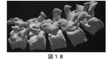
XRでは、3D対象は、対象の様々なビューを使用者のそれぞれの眼に示すことによって表示する。いくつかの例では、これは、それぞれの眼をシミュレートする仮想カメラから幾何学的表面メッシュ(例えば、図18)を表示し、次いでそれらの画像をそれぞれのディスプレイに示すことによって行われる。スキャンされた画像の場合、骨を骨ではない解剖学的構造から完全に分離することは困難であるため、3Dメッシュの構築には問題がある。誤分類があると、解剖学的構造を正確に表していない誤ったメッシュが生成される可能性がある。さらに、スキャンで表示される骨でない解剖学的構造は、任意のメッシュ生成アルゴリズムが削除する貴重な情報である。事実上、元の「グラジエント」はすべて失われ、不完全な境界のみが保持される。 In XR, a 3D object is displayed by showing various views of the object to the user's respective eyes. In some examples, this is done by displaying geometric surface meshes (eg, FIG. 18) from a virtual camera simulating each eye, and then showing those images on their respective displays. In the case of scanned images, it is difficult to completely separate bone from non-bone anatomical structures, which is problematic in constructing 3D meshes. Misclassification can result in incorrect meshes that do not accurately represent the anatomy. In addition, the non-bone anatomy displayed on the scan is valuable information that any mesh generation algorithm removes. Virtually all of the original "gradients" are lost, leaving only imperfect boundaries.
図19に示すように、不正確な可能性のあるメッシュを表示する代わりに、既存のMIPビューを使用してスキャンを3Dで表示できる。実際のスキャンを使用することにより、情報が失われることはなく、解剖学的構造の誤分類によってエラーが発生することもない。 As shown in FIG. 19, instead of displaying potentially inaccurate meshes, the existing MIP view can be used to display the scan in 3D. By using the actual scan, no information is lost and no errors are caused by misclassification of the anatomical structure.
MIPビューは、任意の視点(回転行列で定義)から生成できるため、各々の眼の視点から1つずつ個別のビューを生成することにより、スキャンのステレオビューをXRで表示できる。図20は、スキャンのステレオ対を形成する、眼に固有のビューのモックアップを示している。 Since the MIP view can be generated from an arbitrary viewpoint (defined by a rotation matrix), the stereo view of the scan can be displayed in XR by generating one individual view from the viewpoint of each eye. FIG. 20 shows a mockup of an eye-specific view that forms a stereo pair of scans.
その結果、スキャンのステレオ対をXRの3D対象であるかのように観察できる。使用者が頭や眼を動かすと、2つのMIPビューを更新して、元の2Dスキャンが世界に固定されたままの単一の3D対象のように動作するように、新しい位置を考慮することができる。 As a result, the stereo pair of scans can be observed as if they were XR 3D objects. As the user moves his head or eyes, update the two MIP views to consider the new position so that the original 2D scan behaves like a single 3D object that remains fixed in the world. Can be done.
一連の2Dスキャンから3D表面メッシュを生成すると、必然的に少なくともある程度のエラーが発生するが、生データの3D視覚化には、いくつかの利点がある。ステレオ拡張および/または仮想現実システムにより、使用者は、例えば、元のスキャンデータを奥行きを伴って見ることができる。 Generating a 3D surface mesh from a series of 2D scans will inevitably result in at least some error, but 3D visualization of raw data has several advantages. The stereo extension and / or virtual reality system allows the user to see, for example, the original scan data with depth.
3D表面メッシュは潜在的に重大なエラーを引き起こすが、他の3Dの医療画像処理技術は、優れた信頼性を提供する。例えば、解剖学的目印の位置を3Dで非常に正確に特定し、ステレオで明確に表示できる。 While 3D surface meshes potentially cause serious errors, other 3D medical imaging techniques provide excellent reliability. For example, the location of anatomical landmarks can be identified very accurately in 3D and clearly displayed in stereo.
3Dデスクトップと拡張現実システムはどちらも、オクルージョンをサポートするコンピュータグラフィックスを提示する。オクルージョンとは、1つの対象がそこから出現し、その背後にある対象を「ブロック」する機能を指す。様々な視点で2Dの画像スライスから3Dを生成する場合、自然なオクルージョンステップは、ネジ、ガイダンス矢印、インプラント、その他のユーザインターフェイス要素などの既存の3Dコンテンツでは機能しない。3D要素は、MIPコンテンツまたは既存の3Dメッシュコンテンツの見かけの深さに関係なく、2Dスキャンの前(つまり完全なオクルージョン)または2Dスキャンの後ろ(つまり非表示)のいずれかにある。いくつかの実施形態では、医療画像処理パイプラインの一部として、元の2Dドメインですべてのコンテンツの相互作用を実行することによって、オクルージョンの問題を回避することができる。このようにして、ステレオヘッドマウントディスプレイや外部モニターで適切に表示されるように、オクルージョンを事前に計算することができる。 Both 3D desktops and augmented reality systems present computer graphics that support occlusion. Occlusion refers to the ability of an object to emerge from it and "block" the object behind it. When generating 3D from 2D image slices from different perspectives, natural occlusion steps do not work with existing 3D content such as screws, guidance arrows, implants, and other user interface elements. The 3D element is either before the 2D scan (ie, full occlusion) or after the 2D scan (ie, hidden), regardless of the apparent depth of the MIP content or the existing 3D mesh content. In some embodiments, occlusion issues can be avoided by performing all content interactions in the original 2D domain as part of the medical imaging pipeline. In this way, the occlusion can be pre-calculated for proper display on a stereo head-mounted display or external monitor.
いくつかの実施形態は、既存のスキャンデータの収集および表示技術を使用して、拡張、仮想、または混合/エクステンデットリアリティ表示システムで、内側画像の3Dバージョンを表示することを可能にする。 Some embodiments make it possible to display a 3D version of the inside image in an extended, virtual, or mixed / extended reality display system using existing scan data collection and display techniques.
いくつかの実施形態は、単一の3D表面メッシュの作成において導入されたエラーを含まない元の医療画像を描写するため、生成されたメッシュよりも解剖学的構造のより正確な表現を表示する。例えば、すべての画像のグラジエントが維持される。 Some embodiments display a more accurate representation of the anatomical structure than the generated mesh in order to depict the original medical image without the errors introduced in the creation of a single 3D surface mesh. .. For example, the gradient of all images is maintained.
いくつかの実施形態では、元の2Dスキャンデータのレベルでの医療画像への修正および強化は、奥行き感および仮想オクルージョンを適切に管理することを可能にするが、表面のメッシュを介するよりも意味があり、情報が豊富な方法である。 In some embodiments, modification and enhancement to the medical image at the level of the original 2D scan data allows for proper management of depth and virtual occlusion, but is more meaningful than through a surface mesh. It is an information-rich method.
いくつかの実施形態では、既存のナビゲーションカートに精通している外科医は、DICOMスキャンのウィンドウとレベルの調整にも精通している。これらのパラメータは、表示される強度を制御するため、2D画像として表示されたときに、スキャンがどのように表示されるかを制御する。DICOMスキャンを使用してメッシュを生成する場合、表示するウィンドウとレベルについていくつかの仮定をする必要がある。その結果、メッシュが生成されると、これらの値を調整できなくなる。メッシュの構築に使用されたウィンドウとレベルはすべて固定されている。いくつかの実施形態では、外科医は、外科医が現在2Dビューで行うのと同じ方法で、3Dビューのウィンドウとレベルを動的に変更することができる。図21〜図22は、ウィンドウとレベルを変更できるXR画像の例を示している。 In some embodiments, the surgeon familiar with the existing navigation cart is also familiar with adjusting the windows and levels of DICOM scans. These parameters control how the scan is displayed when displayed as a 2D image in order to control the intensity displayed. When using DICOM scans to generate meshes, some assumptions need to be made about the windows and levels to display. As a result, once the mesh is generated, these values cannot be adjusted. All windows and levels used to build the mesh are fixed. In some embodiments, the surgeon can dynamically change the window and level of the 3D view in the same way that the surgeon currently does in the 2D view. 21 to 22 show examples of XR images whose windows and levels can be changed.
図23〜図24は、いくつかの実施形態による外科用システムによって実行されるプロセスの例を示すフローチャートである。図23〜図24は、外科用システム900のプロセッサ914によって実行されるものとして以下に説明されるが、プロセスは、外科用システム900の任意の適切なプロセッサによって実行され得る。 23-24 are flowcharts showing examples of processes performed by the surgical system according to some embodiments. 23-24 are described below as being performed by the
図23は、2D画像データを使用してXR画像を生成する操作を示している。ブロック2310で、プロセッサ914は、XRヘッドセットのポーズを生成するXRヘッドセットのポーズを追跡する。いくつかの実施形態では、外科用器具のポーズも追跡される。 FIG. 23 shows an operation of generating an XR image using 2D image data. At
ブロック2320で、プロセッサ914は、患者の解剖学的構造に関連する2D画像データを受信する。いくつかの実施形態では、2D画像データは、解剖学的構造の複数のスキャンを行う解剖学的撮像デバイスから受信される。 At block 2320,
ブロック2330で、プロセッサ914は、患者の解剖学的構造に関連する2D画像データから第1の2D画像を生成する。第1の2D画像は、XRヘッドセットのポーズに基づいている。いくつかの実施形態では、2D画像データから第1の2D画像を生成することは、解剖学的撮像デバイスによって測定された2D画像データからのデータのみを使用することを含む。追加または代替の実施形態では、複数の2D画像データから前記第1の2D画像を生成することは、前記複数の2D画像データの第1の部分を選択して、前記XRヘッドセットの前記ポーズに基づいて前記第1の2D画像を、前記第1の部分の前記2D画像データのいずれかを修正することなく形成することを含む。追加または代替の実施形態では、2D画像データから第1の2D画像を生成することは、解剖学的構造の三次元(「3D」)モデリング計算中に得られたいずれかの推定データを回避することを含む。追加または代替の実施形態では、複数の2D画像データから第1の2D画像を生成することは、複数の2D画像データから解剖学的構造の3D再構成メッシュを生成することなく、第1の2D画像を生成することを含む。 At
ブロック2340で、プロセッサ914は、患者の解剖学的構造に関連する2D画像データから第2の2D画像を生成する。第2の2D画像は、XRヘッドセットのポーズに基づいている。いくつかの実施形態では、2D画像データから第2の2D画像を生成することは、解剖学的撮像デバイスによって測定された2D画像データからのデータのみを使用することを含む。追加または代替の実施形態では、複数の2D画像データから第2の2D画像を生成することは、複数の2D画像データの第2の部分を選択して、XRヘッドセットのポーズに基づいて第2の2D画像を、第2の部分の2D画像データのいずれかを修正することなく形成することを含む。追加または代替の実施形態では、2D画像データから第2の2D画像を生成することは、解剖学的構造の3Dモデリング計算中に得られたいずれかの推定データを回避することを含む。追加または代替の実施形態では、複数の2D画像データから第2の2D画像を生成することは、複数の2D画像データから解剖学的構造の3D再構成メッシュを生成することなく、第2の2D画像を生成することを含む。 At
ブロック2350で、プロセッサ914は、使用者の第1の眼の視野に第1の2D画像を表示し、使用者の第2の眼の視野に第2の2D画像を表示することにより、XR画像を生成する。いくつかの実施形態では、XR画像は、使用者には3Dであるように見える。追加または代替の実施形態では、XR画像は、解剖学的構造に対する外科用器具のポーズに基づいた外科用器具の仮想表現を含む。 At
ブロック2360で、プロセッサ914は、XR画像のウィンドウまたはレベルを調整する。いくつかの実施形態では、XR画像のウィンドウまたはレベルは、第1の2D画像および/または第2の2D画像のウィンドウまたはレベルを調整することによって調整される。追加または代替の実施形態では、XR画像のウィンドウまたはレベルは、XR画像が使用者に表示されることに応答して、使用者からの入力に応答して調整される。 At
図24は、XRヘッドセットのポーズの変化に基づいてXR画像を調整する追加の操作を示している。ブロック2430で、プロセッサ914は、患者の解剖学的構造に関連する2D画像データから改訂された第1の2D画像を生成する。改訂された第1の2D画像は、XRヘッドセットの新たなポーズに基づいている。ブロック2440で、プロセッサ914は、患者の解剖学的構造に関連する2D画像データから改訂された第2の2D画像を生成する。改訂された2D画像は、XRヘッドセットの新たなポーズに基づいている。ブロック2450で、プロセッサ914は、使用者の第1の眼の視野に改訂された第1の2D画像を表示し、使用者の第2の眼の視野に改訂された第2の2D画像を表示することにより、XR画像を調整する。 FIG. 24 shows an additional operation of adjusting the XR image based on changes in the pose of the XR headset. At
いくつかの実施形態では、図23〜図24の操作の一部のみを実行することができ、操作は別の順序で実行することができる。追加または代替の実施形態では、外科用システム内の他の処理回路が、図23〜図24の操作の一部またはすべてを実行することができる。 In some embodiments, only some of the operations of FIGS. 23-24 can be performed, and the operations can be performed in a different order. In additional or alternative embodiments, other processing circuits within the surgical system may perform some or all of the operations of FIGS. 23-24.
さらなる定義および実施形態:
本発明の概念の様々な実施形態の上記の説明において、本明細書において使用される用語は、特定の実施形態を説明することのみを目的とし、本発明の概念を限定することを意図しないことを理解されたい。別段に定義されない限り、本明細書で使用されるすべての用語(技術用語および科学用語を含む)は、本発明の概念が属する当技術分野の当業者によって一般に理解されるのと同じ意味を有する。一般的に使用される辞書に定義されるような用語は、本明細書および関連する技術分野の文脈におけるそれらの意味に矛盾しない意味を有するものとして解釈されるべきであり、本明細書で明確にそのように定義された理想化された、または過度に形式的な意味では解釈されないことがさらに理解されよう。Further definitions and embodiments:
In the above description of various embodiments of the concept of the invention, the terms used herein are for the purpose of describing a particular embodiment only and are not intended to limit the concept of the invention. I want you to understand. Unless otherwise defined, all terms used herein, including technical and scientific terms, have the same meaning as commonly understood by one of ordinary skill in the art to which the concepts of the invention belong. .. Terms such as those defined in commonly used dictionaries should be construed as having a meaning consistent with their meaning in the context of this specification and related arts, and are defined herein. It will be further understood that it is not interpreted in such an idealized or overly formal sense.
ある要素が別の要素に対して「接続された(connected)」、「結合された(coupled)」、「応答する(responsive)」、またはそれらの変形であるように参照される場合、その要素は、他の要素に直接接続、結合、もしくは応答することができるか、または介在する要素が存在してもよい。対照的に、ある要素が別の要素に対して「直接接続された(directly connected)」、「直接結合された(directly coupled)」、「直接応答する(directly responsive)」、またはそれらの変形であるように参照される場合、介在する要素は存在しない。同様の符号は、全体を通して同様の要素を指す。さらにまた、本明細書において使用される場合、「結合された(coupled)」、「接続された(connected)」、「応答する(responsive)」、またはそれらの変形は、無線で結合、接続、または応答することを含むことができる。本明細書において使用される場合、単数形「a」、「an」、および「the」は、文脈がそうでないことを明確に示さない限り、複数形も含むことを意図している。周知の機能または構造は、簡潔さおよび/または明確さのために詳細に説明されない場合がある。「および/または」という用語は、関連する列挙された項目のうちの1つ以上のいずれかおよびすべての組み合わせを含む。 If an element is referenced to be "connected", "coupled", "responsive", or a variant of them, then that element. Can have elements that can, or intervene, directly connect to, combine, or respond to other elements. In contrast, one element is "directly connected" to another, "directly coupled", "directly respond", or a variant thereof. When referenced as it is, there are no intervening elements. Similar signs refer to similar elements throughout. Furthermore, as used herein, "coupled," "connected," "responsive," or variants thereof, are wirelessly combined, connected, and so on. Or it can include responding. As used herein, the singular forms "a," "an," and "the" are intended to include the plural unless the context explicitly indicates otherwise. Well-known functions or structures may not be described in detail for brevity and / or clarity. The term "and / or" includes any and all combinations of one or more of the related listed items.
本明細書では、第1、第2、第3などの用語を使用して様々な要素/動作を説明することがあるが、これらの要素/動作は、これらの用語によって限定されるべきではないことが理解される。これらの用語は、ある要素/動作を他の要素/動作から区別するためにのみ使用される。したがって、いくつかの実施形態における第1の要素/動作は、本発明の概念の教示から逸脱することなく、他の実施形態における第2の要素/動作と呼ぶことができる。同じ参照番号または同じ参照符号は、明細書全体を通して同じまたは類似の要素を示す。 Although various elements / actions may be described herein using terms such as first, second, and third, these elements / actions should not be limited by these terms. Is understood. These terms are used only to distinguish one element / action from another. Therefore, the first element / action in some embodiments can be referred to as the second element / action in other embodiments without departing from the teaching of the concept of the present invention. The same reference number or the same reference code indicates the same or similar elements throughout the specification.
本明細書において使用される場合、「備える(comprise)」、「備える(comprising)」、「備える(comprises)」、「含む(include)」、「含む(including)」、「含む(includes)」、「有する(have)」、「有する(has)」、「有する(having)」という用語、またはそれらの変形は、限定がなく、1つ以上の記された特徴、整数、要素、ステップ、コンポーネント、または機能を含むが、1つ以上の他の特徴、整数、要素、ステップ、コンポーネント、機能、またはそれらのグループの存在もしくは追加を排除するものではない。さらにまた、本明細書において使用される場合、ラテン語の「例えば(exempli gratia)」から派生した一般的な略語「例えば(e.g.)」は、前述の項目の全般的な例(複数可)を紹介または指定するために使用されている場合があり、かかる項目を限定することを意図するものではない。ラテン語の「すなわち(id est)」から派生した一般的な略語「すなわち(i.e.)」は、より全般的な列挙から特定の項目を指定するために使用されてもよい。 As used herein, "comprise," "comprising," "comprises," "include," "include," "includes." , "Have", "has", "having", or variants thereof, without limitation, one or more described features, integers, elements, steps, components. , Or features, but does not preclude the existence or addition of one or more other features, integers, elements, steps, components, features, or groups thereof. Furthermore, as used herein, the general abbreviation "eg (eg)" derived from the Latin word "eg (exempli gratia)" is a general example (s) of the above items. ) May be used to introduce or specify, and is not intended to limit such items. The general abbreviation "ie (ie)" derived from the Latin "ie (id est)" may be used to specify a particular item from a more general enumeration.
例示的な実施形態は、コンピュータ実装方法、装置(システムおよび/またはデバイス)、ならびに/またはコンピュータプログラム製品を示すブロック図および/またはフローチャート図を参照して、本明細書において説明される。ブロック図および/またはフローチャート図のブロック、ならびにブロック図および/またはフローチャート図におけるブロックの組み合わせは、1つ以上のコンピュータ回路によって実行されるコンピュータプログラム命令によって実装させることができることが理解される。これらのコンピュータプログラム命令を汎用コンピュータ回路、専用コンピュータ回路、および/または他のプログラム可能なデータ処理回路のプロセッサ回路に提供して機械を生成することができ、それにより、コンピュータのプロセッサおよび/または他のプログラム可能なデータ処理装置を介して実行される命令は、トランジスタ、メモリの場所に記憶された値、およびかかる回路網内の他のハードウェアコンポーネントを変換および制御して、ブロック図および/またはフローチャートブロック(複数可)において指定された機能/作用を実装し、かつそれによって、ブロック図および/またはフローチャートブロック(複数可)において指定された機能/作用を実装するための手段(機能)および/または構造を作り出す。 Exemplary embodiments are described herein with reference to block diagrams and / or flow charts showing computer mounting methods, devices (systems and / or devices), and / or computer program products. It is understood that the blocks in the block diagram and / or the flow chart and the combination of blocks in the block diagram and / or the flow chart can be implemented by computer program instructions executed by one or more computer circuits. These computer program instructions can be provided to the processor circuits of general purpose computer circuits, dedicated computer circuits, and / or other programmable data processing circuits to generate machines, thereby computer processors and / or others. Instructions executed through a programmable data processor in a block diagram and / or control transform and control transistors, values stored in memory locations, and other hardware components in such a network. Means (functions) and / for implementing the functions / actions specified in the flowchart block (s) and thereby implementing the functions / actions specified in the block diagram and / or the flow chart block (s). Or create a structure.
これらのコンピュータプログラム命令はまた、コンピュータ可読媒体に記憶された命令がブロック図および/またはフローチャートブロック(複数可)において指定された機能/作用を実装する命令を含む製造物品を製造するように、コンピュータまたは他のプログラム可能なデータ処理装置が特定の方法で機能するように指示することができる有形のコンピュータ可読媒体に記憶されてもよい。したがって、本発明の概念の実施形態は、集合的に「回路網」、「モジュール」、またはそれらの変形と称することができる、デジタル信号プロセッサなどのプロセッサで動作するハードウェアおよび/またはソフトウェア(ファームウェア、常駐ソフトウェア、マイクロコードなどを含む)で具体化させることができる。 These computer program instructions are also such that the instructions stored on a computer-readable medium produce a manufactured article containing instructions that implement the function / action specified in the block diagram and / or flowchart block (s). Alternatively, it may be stored on a tangible computer-readable medium that can instruct other programmable data processing equipment to function in a particular way. Accordingly, embodiments of the concept of the present invention are hardware and / or software (firmware) running on a processor, such as a digital signal processor, which can be collectively referred to as a "network," "module," or a variant thereof. , Including resident software, microcode, etc.).
また、いくつかの代替実装形態では、ブロックに記載されている機能/作用が、フローチャートに記載されている順序とは異なる順序で発生する場合があることにも留意されたい。例えば、連続して示されている2つのブロックは、関与する機能/作用に応じて、実際には実質的に同時に実行されてもよいか、または時にはブロックが逆の順序で実行されてもよい。さらに、フローチャートおよび/またはブロック図の所与のブロックの機能は、複数のブロックに分離されてもよく、および/またはフローチャートおよび/またはブロック図の2つ以上のブロックの機能は、少なくとも部分的に統合されてもよい。最後に、本発明の概念の範囲から逸脱することなく、図示されているブロックの間に他のブロックが追加/挿入されてもよく、および/またはブロックまたは動作が省かれてもよい。さらに、いくつかの図は、通信の主要な方向を示すために通信経路上に矢印を含んでいるが、通信は、描かれた矢印と反対の方向で発生する場合があることを理解されたい。 It should also be noted that in some alternative implementations, the functions / actions described in the blocks may occur in a different order than described in the flowchart. For example, two blocks shown in succession may actually be executed substantially simultaneously, or sometimes the blocks may be executed in reverse order, depending on the function / action involved. .. Further, the function of a given block in a flowchart and / or block diagram may be separated into multiple blocks, and / or the function of two or more blocks in a flowchart and / or block diagram may be at least partially. It may be integrated. Finally, other blocks may be added / inserted between the blocks shown and / or blocks or actions may be omitted without departing from the scope of the concept of the present invention. In addition, it should be understood that although some figures include arrows on the communication path to indicate the main direction of communication, communication may occur in the opposite direction of the drawn arrows. ..
本発明の概念の原理から実質的に逸脱することなく、実施形態に対して多くの変更および修正を行うことができる。すべてのこのような変更および修正は、本発明の概念の範囲内で本明細書に含まれることが意図されている。したがって、上で開示された発明の対象は、限定的ではなく例示的であると見なされるべきであり、付け加えられた実施形態の例は、本発明の概念の趣旨および範囲内にあるすべてのこのような修正、強化、および他の実施形態に及ぶことが意図されている。したがって、法律で許容される最大限の範囲で、本発明の概念の範囲は、以下の実施形態の例およびそれらの均等物を含む本開示の最も広い許容可能な解釈によって決定されるべきであり、前述の詳細な説明によって制限または限定されるべきではない。
Many changes and modifications can be made to embodiments without substantially departing from the principles of the concept of the present invention. All such changes and modifications are intended to be incorporated herein within the scope of the concepts of the invention. Therefore, the subject matter of the invention disclosed above should be regarded as exemplary rather than limiting, and the examples of additional embodiments are all within the spirit and scope of the concept of the invention. It is intended to extend to such modifications, enhancements, and other embodiments. Therefore, to the maximum extent permitted by law, the scope of the concept of the invention should be determined by the broadest acceptable interpretation of the present disclosure, including examples of the following embodiments and their equivalents. , Should not be restricted or limited by the detailed description above.
Claims (20)
Translated fromJapanese外科的処置中に使用者によって着用されるように構成され、前記使用者が見るためにXR画像を表示するように構成されたシースルーの表示画面を含むエクステンデットリアリティ(「XR」)ヘッドセットと、
XRヘッドセットコントローラであって、
患者の解剖学的構造に関連する複数の二次元(「2D」)画像データを受信し、
前記XRヘッドセットのポーズに基づいて、前記複数の2D画像データから第1の2D画像を生成し、
前記XRヘッドセットの前記ポーズに基づいて、前記複数の2D画像データから第2の2D画像を生成し、
前記使用者の第1の眼の視野に第1の2D画像を表示し、前記使用者の第2の眼の視野に前記第2の2D画像を表示することにより、前記XR画像を生成するように構成される、XRヘッドセットコントローラを含む、外科用システム。It ’s a surgical system,
An extended reality (“XR”) headset that includes a see-through display screen that is configured to be worn by the user during a surgical procedure and is configured to display an XR image for the user to see.
XR headset controller,
Receive multiple two-dimensional (“2D”) image data related to the patient's anatomy,
A first 2D image is generated from the plurality of 2D image data based on the pose of the XR headset.
A second 2D image is generated from the plurality of 2D image data based on the pose of the XR headset.
The XR image is generated by displaying the first 2D image in the visual field of the user's first eye and displaying the second 2D image in the visual field of the user's second eye. A surgical system, including an XR headset controller, configured in.
前記複数の2D画像データから前記第2の2D画像を生成することは、前記複数の2D画像データの第2の部分を選択して、前記XRヘッドセットの前記ポーズに基づいて前記第2の2D画像を、前記第2の部分の前記2D画像データのいずれかを修正することなく形成することを含む、請求項1に記載の外科用システム。To generate the first 2D image from the plurality of 2D image data, the first 2D image is selected based on the pose of the XR headset by selecting the first portion of the plurality of 2D image data. Including forming an image without modifying any of the 2D image data of the first portion.
Generating the second 2D image from the plurality of 2D image data selects a second portion of the plurality of 2D image data and bases the pose on the XR headset on the second 2D. The surgical system according to claim 1, wherein the image is formed without modifying any of the 2D image data of the second portion.
前記複数の2D画像データから前記第2の2D画像を生成することは、前記複数の2D画像データから前記解剖学的構造の3D再構成メッシュを生成することなく、前記第2の2D画像を生成することを含む、請求項1に記載の外科用システム。Generating the first 2D image from the plurality of 2D image data produces the first 2D image without generating a 3D reconstructed mesh of the anatomical structure from the plurality of 2D image data. Including that
Generating the second 2D image from the plurality of 2D image data generates the second 2D image without generating a 3D reconstructed mesh of the anatomical structure from the plurality of 2D image data. The surgical system according to claim 1, wherein the surgical system comprises.
前記第1の2D画像の生成に応じて、前記第1の2D画像のウィンドウまたはレベルを調整するようにさらに構成される、請求項1に記載の外科用システム。The XR headset controller
The surgical system of claim 1, further configured to adjust the window or level of the first 2D image in response to the generation of the first 2D image.
前記XR画像の生成に応じて、前記使用者からの前記入力に基づいて前記XR画像のウィンドウまたはレベルを調整するようにさらに構成される、請求項1に記載の外科用システム。The XR headset controller
The surgical system of claim 1, further configured to adjust the window or level of the XR image based on the input from the user in response to the generation of the XR image.
前記XRヘッドセットの前記ポーズの変化に応答して、前記XRヘッドセットの新たなポーズに基づいて、前記複数の2D画像データから、改訂された第1の2D画像を生成し、
前記XRヘッドセットの前記新たなポーズに基づいて、前記複数の2D画像データから改訂された第2の2D画像を生成し、
前記使用者の前記第1の眼の前記視野に前記改訂された第1の2D画像を表示し、前記使用者の前記第2の眼の前記視野に前記改訂された第2の2D画像を表示することにより、前記XR画像を調整するようにさらに構成される、請求項1に記載の外科用システム。The XR headset controller
In response to a change in the pose of the XR headset, a revised first 2D image is generated from the plurality of 2D image data based on the new pose of the XR headset.
Based on the new pose of the XR headset, a revised second 2D image is generated from the plurality of 2D image data.
The revised first 2D image is displayed in the visual field of the first eye of the user, and the revised second 2D image is displayed in the visual field of the second eye of the user. The surgical system according to claim 1, further configured to adjust the XR image.
前記XRヘッドセットコントローラは、前記解剖学的構造に対する前記外科用器具の前記ポーズに基づいて前記外科用器具の仮想表現を含むように前記XR画像を生成するようにさらに構成される、請求項7に記載の外科用システム。The camera tracking system is further configured to track the pose of the surgical instrument.
7. The XR headset controller is further configured to generate the XR image to include a virtual representation of the surgical instrument based on the pose of the surgical instrument with respect to the anatomical structure. Surgical system described in.
解剖学的撮像デバイスによる解剖学的部分の複数のスキャンとして前記複数の2D画像データを受信するようにさらに構成される、請求項1に記載の外科用システム。The XR headset controller
The surgical system of claim 1, further configured to receive the plurality of 2D image data as a plurality of scans of an anatomical portion by an anatomical imaging device.
XRヘッドセットコントローラによって、患者の解剖学的構造に関連する複数の二次元(「2D」)画像データを受信し、
前記XRヘッドセットコントローラによって、前記XRヘッドセットのポーズに基づいて、前記複数の2D画像データから第1の2D画像を生成し、
前記XRヘッドセットコントローラによって、前記XRヘッドセットの前記ポーズに基づいて、前記複数の2D画像データから第2の2D画像を生成し、
前記XRヘッドセットコントローラによって、前記使用者の第1の眼の視野に第1の2D画像を表示し、前記使用者の第2の眼の視野に前記第2の2D画像を表示することにより、前記XR画像を生成することを含む、方法。A method of operating an XR headset in a surgical system.
The XR headset controller receives multiple two-dimensional (“2D”) image data related to the patient's anatomy and receives it.
The XR headset controller generates a first 2D image from the plurality of 2D image data based on the pose of the XR headset.
The XR headset controller generates a second 2D image from the plurality of 2D image data based on the pose of the XR headset.
By displaying the first 2D image in the visual field of the user's first eye and displaying the second 2D image in the visual field of the user's second eye by the XR headset controller. A method comprising generating the XR image.
前記複数の2D画像データから前記第2の2D画像を生成することは、前記複数の2D画像データの第2の部分を選択して、前記XRヘッドセットの前記ポーズに基づいて前記第2の2D画像を、前記第2の部分の前記2D画像データのいずれかを修正することなく形成することを含む、請求項10に記載の方法。To generate the first 2D image from the plurality of 2D image data, the first 2D image is selected based on the pose of the XR headset by selecting the first portion of the plurality of 2D image data. Including forming an image without modifying any of the 2D image data of the first portion.
Generating the second 2D image from the plurality of 2D image data selects a second portion of the plurality of 2D image data and bases the pose on the XR headset on the second 2D. The method of claim 10, wherein the image is formed without modifying any of the 2D image data of the second portion.
前記複数の2D画像データから前記第2の2D画像を生成することは、前記複数の2D画像データから前記解剖学的構造の3D再構成メッシュを生成することなく、前記第2の2D画像を生成することを含む、請求項10に記載の方法。Generating the first 2D image from the plurality of 2D image data produces the first 2D image without generating a 3D reconstructed mesh of the anatomical structure from the plurality of 2D image data. Including that
Generating the second 2D image from the plurality of 2D image data generates the second 2D image without generating a 3D reconstructed mesh of the anatomical structure from the plurality of 2D image data. The method of claim 10, wherein the method comprises:
前記XRヘッドセットコントローラによって、前記XRヘッドセットの新たなポーズに基づいて、前記複数の2D画像データから改訂された第2の2D画像を生成し、
前記使用者の前記第1の眼の前記視野に前記改訂された第1の2D画像を表示し、前記使用者の前記第2の眼の前記視野に前記改訂された第2の2D画像を表示することにより、前記XRヘッドセットコントローラによって、前記XR画像を調整することをさらに含む、請求項10に記載の方法。In response to the change in the pose of the XR headset, the XR headset controller produces a revised first 2D image from the plurality of 2D image data based on the new pose of the XR headset. Generate and
The XR headset controller generates a revised second 2D image from the plurality of 2D image data based on the new pose of the XR headset.
The revised first 2D image is displayed in the visual field of the first eye of the user, and the revised second 2D image is displayed in the visual field of the second eye of the user. 10. The method of claim 10, further comprising adjusting the XR image with the XR headset controller.
前記XR画像を生成することは、前記解剖学的構造に対する前記外科用器具の前記ポーズに基づいて前記外科用器具の仮想表現の前記XR画像を生成することを含む、請求項16に記載の方法。Further including tracking the pose of the surgical instrument by the camera tracking system.
16. The method of claim 16, wherein generating the XR image comprises generating the XR image of a virtual representation of the surgical instrument based on the pose of the surgical instrument with respect to the anatomical structure. ..
XRヘッドセットコントローラによって、患者の解剖学的構造に関連する複数の二次元(「2D」)画像データを受信し、
前記XRヘッドセットコントローラによって、前記XRヘッドセットのポーズに基づいて、前記複数の2D画像データから第1の2D画像を生成し、
前記XRヘッドセットコントローラによって、前記XRヘッドセットの前記ポーズに基づいて、前記複数の2D画像データから第2の2D画像を生成し、
前記XRヘッドセットコントローラによって、前記使用者の第1の眼の視野に第1の2D画像を表示し、前記使用者の第2の眼の視野に前記第2の2D画像を表示することにより、三次元(「3D」)XR画像を生成することを含む、非一時的なコンピュータ可読媒体。A non-temporary computer-readable medium that can be executed by the processor of the XR headset controller and stores instructions for causing the XR headset controller to perform the operation.
The XR headset controller receives multiple two-dimensional (“2D”) image data related to the patient's anatomy and receives it.
The XR headset controller generates a first 2D image from the plurality of 2D image data based on the pose of the XR headset.
The XR headset controller generates a second 2D image from the plurality of 2D image data based on the pose of the XR headset.
By displaying the first 2D image in the visual field of the user's first eye and displaying the second 2D image in the visual field of the user's second eye by the XR headset controller. A non-temporary computer-readable medium that includes producing a three-dimensional (“3D”) XR image.
前記XRヘッドセットコントローラによって、解剖学的撮像デバイスにより取得される前記解剖学的構造の複数のスキャンとして前記複数の2D画像データを受信すること、
前記XRヘッドセットの前記ポーズを、カメラ追跡システムによって追跡すること、
前記カメラ追跡システムにより、外科用器具のポーズを追跡すること、
前記XR画像の生成に応じて、前記XRヘッドセットコントローラによって、前記使用者からの前記入力に基づいて、前記XR画像のウィンドウまたはレベルを調整すること、
前記XRヘッドセットの前記ポーズの変化に応答して、前記XRヘッドセットコントローラによって、前記XRヘッドセットの新たなポーズに基づいて、前記複数の2D画像データから、改訂された第1の2D画像を生成すること、
前記XRヘッドセットコントローラによって、前記XRヘッドセットの新たなポーズに基づいて、前記複数の2D画像データから改訂された第2の2D画像を生成すること、および
前記使用者の前記第1の眼の前記視野に前記改訂された第1の2D画像を表示し、前記使用者の前記第2の眼の前記視野に前記改訂された第2の2D画像を表示することにより、前記XRヘッドセットコントローラによって、前記XR画像を調整することをさらに含み、
前記複数の2D画像データから前記第2の2D画像を生成することは、前記解剖学的撮像デバイスによって測定された前記複数の2D画像データからのデータのみを使用することを含み、
前記XR画像を生成することは、前記解剖学的構造に対する前記外科用器具の前記ポーズにさらに基づいている、請求項19に記載の非一時的なコンピュータ可読媒体。
The above operation
Receiving the plurality of 2D image data as a plurality of scans of the anatomical structure acquired by the anatomical imaging device by the XR headset controller.
Tracking the pose of the XR headset with a camera tracking system,
Tracking the pose of a surgical instrument with the camera tracking system,
In response to the generation of the XR image, the XR headset controller adjusts the window or level of the XR image based on the input from the user.
In response to the change in the pose of the XR headset, the XR headset controller produces a revised first 2D image from the plurality of 2D image data based on the new pose of the XR headset. To generate,
The XR headset controller generates a revised second 2D image from the plurality of 2D image data based on the new pose of the XR headset, and the user's first eye. By displaying the revised first 2D image in the field of view and displaying the revised second 2D image in the field of view of the user's second eye, the XR headset controller. Further including adjusting the XR image,
Generating the second 2D image from the plurality of 2D image data includes using only the data from the plurality of 2D image data measured by the anatomical imaging device.
The non-transitory computer-readable medium of claim 19, wherein producing the XR image is further based on said pose of the surgical instrument relative to said anatomy.
Applications Claiming Priority (2)
| Application Number | Priority Date | Filing Date | Title |
|---|---|---|---|
| US16/869,757US11510750B2 (en) | 2020-05-08 | 2020-05-08 | Leveraging two-dimensional digital imaging and communication in medicine imagery in three-dimensional extended reality applications |
| US16/869,757 | 2020-05-08 |
Publications (2)
| Publication Number | Publication Date |
|---|---|
| JP2021176522Atrue JP2021176522A (en) | 2021-11-11 |
| JP7216768B2 JP7216768B2 (en) | 2023-02-01 |
Family
ID=75870527
Family Applications (1)
| Application Number | Title | Priority Date | Filing Date |
|---|---|---|---|
| JP2021079620AActiveJP7216768B2 (en) | 2020-05-08 | 2021-05-10 | Utilization and Communication of 2D Digital Imaging in Medical Imaging in 3D Extended Reality Applications |
Country Status (4)
| Country | Link |
|---|---|
| US (3) | US11510750B2 (en) |
| EP (1) | EP3907986A1 (en) |
| JP (1) | JP7216768B2 (en) |
| CN (1) | CN113616331A (en) |
Families Citing this family (41)
| Publication number | Priority date | Publication date | Assignee | Title |
|---|---|---|---|---|
| FR2955481B1 (en) | 2010-01-27 | 2013-06-14 | Tornier Sa | DEVICE AND METHOD FOR GLENOIDAL CHARACTERIZATION OF PROSTHETIC OR RESURFACING OMOPLATE |
| EP3057524B1 (en) | 2013-10-10 | 2019-11-20 | Imascap | Method for designing and producing a shoulder surgery guide |
| GB2536650A (en) | 2015-03-24 | 2016-09-28 | Augmedics Ltd | Method and system for combining video-based and optic-based augmented reality in a near eye display |
| US11980507B2 (en) | 2018-05-02 | 2024-05-14 | Augmedics Ltd. | Registration of a fiducial marker for an augmented reality system |
| WO2019245865A1 (en) | 2018-06-19 | 2019-12-26 | Tornier, Inc. | Mixed reality indication of points at which 3d bone and implant models collide |
| US11923084B2 (en) | 2018-09-07 | 2024-03-05 | Cilag Gmbh International | First and second communication protocol arrangement for driving primary and secondary devices through a single port |
| US20200078113A1 (en) | 2018-09-07 | 2020-03-12 | Ethicon Llc | Port presence detection system for modular energy system |
| US12144136B2 (en) | 2018-09-07 | 2024-11-12 | Cilag Gmbh International | Modular surgical energy system with module positional awareness with digital logic |
| US11804679B2 (en) | 2018-09-07 | 2023-10-31 | Cilag Gmbh International | Flexible hand-switch circuit |
| US11510720B2 (en) | 2018-09-07 | 2022-11-29 | Cilag Gmbh International | Managing simultaneous monopolar outputs using duty cycle and synchronization |
| US11766296B2 (en) | 2018-11-26 | 2023-09-26 | Augmedics Ltd. | Tracking system for image-guided surgery |
| US11018177B2 (en)* | 2019-05-29 | 2021-05-25 | Taiwan Semiconductor Manufacturing Co., Ltd. | Backside illuminated global shutter image sensor |
| US11980506B2 (en) | 2019-07-29 | 2024-05-14 | Augmedics Ltd. | Fiducial marker |
| US12178666B2 (en) | 2019-07-29 | 2024-12-31 | Augmedics Ltd. | Fiducial marker |
| USD939545S1 (en) | 2019-09-05 | 2021-12-28 | Cilag Gmbh International | Display panel or portion thereof with graphical user interface for energy module |
| US11382712B2 (en) | 2019-12-22 | 2022-07-12 | Augmedics Ltd. | Mirroring in image guided surgery |
| US11510750B2 (en)* | 2020-05-08 | 2022-11-29 | Globus Medical, Inc. | Leveraging two-dimensional digital imaging and communication in medicine imagery in three-dimensional extended reality applications |
| US11389252B2 (en) | 2020-06-15 | 2022-07-19 | Augmedics Ltd. | Rotating marker for image guided surgery |
| US20230298279A1 (en)* | 2020-06-30 | 2023-09-21 | Surgical Theater, Inc. | Augmented reality shared anchoring system and method |
| US12239385B2 (en) | 2020-09-09 | 2025-03-04 | Augmedics Ltd. | Universal tool adapter |
| US11963727B2 (en) | 2021-03-30 | 2024-04-23 | Cilag Gmbh International | Method for system architecture for modular energy system |
| US12004824B2 (en) | 2021-03-30 | 2024-06-11 | Cilag Gmbh International | Architecture for modular energy system |
| US11980411B2 (en) | 2021-03-30 | 2024-05-14 | Cilag Gmbh International | Header for modular energy system |
| US12228987B2 (en) | 2021-03-30 | 2025-02-18 | Cilag Gmbh International | Method for energy delivery for modular energy system |
| US11978554B2 (en) | 2021-03-30 | 2024-05-07 | Cilag Gmbh International | Radio frequency identification token for wireless surgical instruments |
| US11857252B2 (en) | 2021-03-30 | 2024-01-02 | Cilag Gmbh International | Bezel with light blocking features for modular energy system |
| US12235697B2 (en) | 2021-03-30 | 2025-02-25 | Cilag Gmbh International | Backplane connector attachment mechanism for modular energy system |
| US11950860B2 (en) | 2021-03-30 | 2024-04-09 | Cilag Gmbh International | User interface mitigation techniques for modular energy systems |
| US12369994B2 (en) | 2021-03-30 | 2025-07-29 | Cilag Gmbh International | Modular energy system with multi-energy port splitter for multiple energy devices |
| US12040749B2 (en) | 2021-03-30 | 2024-07-16 | Cilag Gmbh International | Modular energy system with dual amplifiers and techniques for updating parameters thereof |
| US11968776B2 (en) | 2021-03-30 | 2024-04-23 | Cilag Gmbh International | Method for mechanical packaging for modular energy system |
| US20220331051A1 (en) | 2021-04-14 | 2022-10-20 | Cilag Gmbh International | Utilizing contextual parameters of one or more surgical devices to predict a frequency interval for displaying surgical information |
| US11896445B2 (en) | 2021-07-07 | 2024-02-13 | Augmedics Ltd. | Iliac pin and adapter |
| US12150821B2 (en) | 2021-07-29 | 2024-11-26 | Augmedics Ltd. | Rotating marker and adapter for image-guided surgery |
| WO2023021448A1 (en) | 2021-08-18 | 2023-02-23 | Augmedics Ltd. | Augmented-reality surgical system using depth sensing |
| US12272056B1 (en) | 2021-09-02 | 2025-04-08 | Kentucky Imaging Technologies, LLC | Stable visualization of tubular objects by the fly-in method with applications to computed tomography colonography |
| DE102022100626B4 (en)* | 2022-01-12 | 2024-05-08 | Carl Zeiss Meditec Ag | AUTOMATED REGISTRATION OF PREOPERATIVE VOLUME IMAGE DATA USING SEARCH IMAGE |
| EP4511809A1 (en) | 2022-04-21 | 2025-02-26 | Augmedics Ltd. | Systems and methods for medical image visualization |
| US12079460B2 (en) | 2022-06-28 | 2024-09-03 | Cilag Gmbh International | Profiles for modular energy system |
| IL319523A (en) | 2022-09-13 | 2025-05-01 | Augmedics Ltd | Augmented reality eyewear for image-guided medical intervention |
| CN117017187A (en)* | 2023-09-28 | 2023-11-10 | 宁波市镇海区人民医院 | Medical electronic gastroscope system and display method |
Citations (4)
| Publication number | Priority date | Publication date | Assignee | Title |
|---|---|---|---|---|
| US20170296292A1 (en)* | 2016-04-16 | 2017-10-19 | Eitezaz MAHMOOD | Systems and Methods for Surgical Imaging |
| JP2019072262A (en)* | 2017-10-17 | 2019-05-16 | ザイオソフト株式会社 | Medical image processing device, medical image processing method, and medical image processing program |
| JP2019537481A (en)* | 2016-11-16 | 2019-12-26 | テラリコン インコーポレイテッド | System and method for three-dimensional printing, holography and virtual reality rendering from medical image processing |
| WO2020041615A1 (en)* | 2018-08-22 | 2020-02-27 | Magic Leap, Inc. | Patient viewing system |
Family Cites Families (881)
| Publication number | Priority date | Publication date | Assignee | Title |
|---|---|---|---|---|
| DE2614083B2 (en) | 1976-04-01 | 1979-02-08 | Siemens Ag, 1000 Berlin Und 8000 Muenchen | X-ray film device for the production of transverse slice images |
| US4722056A (en) | 1986-02-18 | 1988-01-26 | Trustees Of Dartmouth College | Reference display systems for superimposing a tomagraphic image onto the focal plane of an operating microscope |
| US5354314A (en) | 1988-12-23 | 1994-10-11 | Medical Instrumentation And Diagnostics Corporation | Three-dimensional beam localization apparatus and microscope for stereotactic diagnoses or surgery mounted on robotic type arm |
| US5246010A (en) | 1990-12-11 | 1993-09-21 | Biotrine Corporation | Method and apparatus for exhalation analysis |
| US5417210A (en) | 1992-05-27 | 1995-05-23 | International Business Machines Corporation | System and method for augmentation of endoscopic surgery |
| US5631973A (en) | 1994-05-05 | 1997-05-20 | Sri International | Method for telemanipulation with telepresence |
| US6963792B1 (en) | 1992-01-21 | 2005-11-08 | Sri International | Surgical method |
| US5657429A (en) | 1992-08-10 | 1997-08-12 | Computer Motion, Inc. | Automated endoscope system optimal positioning |
| US5397323A (en) | 1992-10-30 | 1995-03-14 | International Business Machines Corporation | Remote center-of-motion robot for surgery |
| WO1994024631A1 (en) | 1993-04-20 | 1994-10-27 | General Electric Company | Computer graphic and live video system for enhancing visualisation of body structures during surgery |
| US5961456A (en) | 1993-05-12 | 1999-10-05 | Gildenberg; Philip L. | System and method for displaying concurrent video and reconstructed surgical views |
| EP0699053B1 (en) | 1993-05-14 | 1999-03-17 | Sri International | Surgical apparatus |
| US5526812A (en) | 1993-06-21 | 1996-06-18 | General Electric Company | Display system for enhancing visualization of body structures during medical procedures |
| JP3378401B2 (en) | 1994-08-30 | 2003-02-17 | 株式会社日立メディコ | X-ray equipment |
| US6646541B1 (en) | 1996-06-24 | 2003-11-11 | Computer Motion, Inc. | General purpose distributed operating room control system |
| ATE228338T1 (en) | 1994-10-07 | 2002-12-15 | Univ St Louis | SURGICAL NAVIGATION ARRANGEMENT INCLUDING REFERENCE AND LOCATION SYSTEMS |
| US6978166B2 (en) | 1994-10-07 | 2005-12-20 | Saint Louis University | System for use in displaying images of a body part |
| US5882206A (en) | 1995-03-29 | 1999-03-16 | Gillio; Robert G. | Virtual surgery system |
| US5887121A (en) | 1995-04-21 | 1999-03-23 | International Business Machines Corporation | Method of constrained Cartesian control of robotic mechanisms with active and passive joints |
| US6122541A (en) | 1995-05-04 | 2000-09-19 | Radionics, Inc. | Head band for frameless stereotactic registration |
| US5649956A (en) | 1995-06-07 | 1997-07-22 | Sri International | System and method for releasably holding a surgical instrument |
| US5825982A (en) | 1995-09-15 | 1998-10-20 | Wright; James | Head cursor control interface for an automated endoscope system for optimal positioning |
| US5772594A (en) | 1995-10-17 | 1998-06-30 | Barrick; Earl F. | Fluoroscopic image guided orthopaedic surgery system with intraoperative registration |
| US5855583A (en) | 1996-02-20 | 1999-01-05 | Computer Motion, Inc. | Method and apparatus for performing minimally invasive cardiac procedures |
| SG64340A1 (en) | 1996-02-27 | 1999-04-27 | Inst Of Systems Science Nation | Curved surgical instruments and methods of mapping a curved path for stereotactic surgery |
| US6167145A (en) | 1996-03-29 | 2000-12-26 | Surgical Navigation Technologies, Inc. | Bone navigation system |
| US5792135A (en) | 1996-05-20 | 1998-08-11 | Intuitive Surgical, Inc. | Articulated surgical instrument for performing minimally invasive surgery with enhanced dexterity and sensitivity |
| US6167296A (en) | 1996-06-28 | 2000-12-26 | The Board Of Trustees Of The Leland Stanford Junior University | Method for volumetric image navigation |
| US7302288B1 (en) | 1996-11-25 | 2007-11-27 | Z-Kat, Inc. | Tool position indicator |
| US7727244B2 (en) | 1997-11-21 | 2010-06-01 | Intuitive Surgical Operation, Inc. | Sterile surgical drape |
| US9050119B2 (en) | 2005-12-20 | 2015-06-09 | Intuitive Surgical Operations, Inc. | Cable tensioning in a robotic surgical system |
| US8529582B2 (en) | 1996-12-12 | 2013-09-10 | Intuitive Surgical Operations, Inc. | Instrument interface of a robotic surgical system |
| US6205411B1 (en) | 1997-02-21 | 2001-03-20 | Carnegie Mellon University | Computer-assisted surgery planner and intra-operative guidance system |
| US6012216A (en) | 1997-04-30 | 2000-01-11 | Ethicon, Inc. | Stand alone swage apparatus |
| US5820559A (en) | 1997-03-20 | 1998-10-13 | Ng; Wan Sing | Computerized boundary estimation in medical images |
| US5911449A (en) | 1997-04-30 | 1999-06-15 | Ethicon, Inc. | Semi-automated needle feed method and apparatus |
| US6231565B1 (en) | 1997-06-18 | 2001-05-15 | United States Surgical Corporation | Robotic arm DLUs for performing surgical tasks |
| US6094625A (en)* | 1997-07-03 | 2000-07-25 | Trimble Navigation Limited | Augmented vision for survey work and machine control |
| EP2362286B1 (en) | 1997-09-19 | 2015-09-02 | Massachusetts Institute Of Technology | Robotic apparatus |
| US6226548B1 (en) | 1997-09-24 | 2001-05-01 | Surgical Navigation Technologies, Inc. | Percutaneous registration apparatus and method for use in computer-assisted surgical navigation |
| US5951475A (en) | 1997-09-25 | 1999-09-14 | International Business Machines Corporation | Methods and apparatus for registering CT-scan data to multiple fluoroscopic images |
| US5987960A (en) | 1997-09-26 | 1999-11-23 | Picker International, Inc. | Tool calibrator |
| US6228368B1 (en) | 1997-10-06 | 2001-05-08 | Loyola University Of Chicago | Papilloma virus capsomere formulations and method of use |
| CA2307877C (en) | 1997-10-30 | 2005-08-30 | The Microoptical Corporation | Eyeglass interface system |
| US6212419B1 (en) | 1997-11-12 | 2001-04-03 | Walter M. Blume | Method and apparatus using shaped field of repositionable magnet to guide implant |
| US6157853A (en) | 1997-11-12 | 2000-12-05 | Stereotaxis, Inc. | Method and apparatus using shaped field of repositionable magnet to guide implant |
| US6031888A (en) | 1997-11-26 | 2000-02-29 | Picker International, Inc. | Fluoro-assist feature for a diagnostic imaging device |
| US6165170A (en) | 1998-01-29 | 2000-12-26 | International Business Machines Corporation | Laser dermablator and dermablation |
| US6949106B2 (en) | 1998-02-24 | 2005-09-27 | Endovia Medical, Inc. | Surgical instrument |
| FR2779339B1 (en) | 1998-06-09 | 2000-10-13 | Integrated Surgical Systems Sa | MATCHING METHOD AND APPARATUS FOR ROBOTIC SURGERY, AND MATCHING DEVICE COMPRISING APPLICATION |
| US6477400B1 (en) | 1998-08-20 | 2002-11-05 | Sofamor Danek Holdings, Inc. | Fluoroscopic image guided orthopaedic surgery system with intraoperative registration |
| DE19839825C1 (en) | 1998-09-01 | 1999-10-07 | Siemens Ag | Diagnostic X=ray device |
| US6033415A (en) | 1998-09-14 | 2000-03-07 | Integrated Surgical Systems | System and method for performing image directed robotic orthopaedic procedures without a fiducial reference system |
| DE19842798C1 (en) | 1998-09-18 | 2000-05-04 | Howmedica Leibinger Gmbh & Co | Calibration device |
| WO2000021442A1 (en) | 1998-10-09 | 2000-04-20 | Surgical Navigation Technologies, Inc. | Image guided vertebral distractor |
| US8527094B2 (en) | 1998-11-20 | 2013-09-03 | Intuitive Surgical Operations, Inc. | Multi-user medical robotic system for collaboration or training in minimally invasive surgical procedures |
| US6659939B2 (en) | 1998-11-20 | 2003-12-09 | Intuitive Surgical, Inc. | Cooperative minimally invasive telesurgical system |
| US6325808B1 (en) | 1998-12-08 | 2001-12-04 | Advanced Realtime Control Systems, Inc. | Robotic system, docking station, and surgical tool for collaborative control in minimally invasive surgery |
| US7125403B2 (en) | 1998-12-08 | 2006-10-24 | Intuitive Surgical | In vivo accessories for minimally invasive robotic surgery |
| US6322567B1 (en) | 1998-12-14 | 2001-11-27 | Integrated Surgical Systems, Inc. | Bone motion tracking system |
| US6451027B1 (en) | 1998-12-16 | 2002-09-17 | Intuitive Surgical, Inc. | Devices and methods for moving an image capture device in telesurgical systems |
| US7016457B1 (en) | 1998-12-31 | 2006-03-21 | General Electric Company | Multimode imaging system for generating high quality images |
| DE19905974A1 (en) | 1999-02-12 | 2000-09-07 | Siemens Ag | Computer tomography scanning method using multi-line detector |
| US6560354B1 (en) | 1999-02-16 | 2003-05-06 | University Of Rochester | Apparatus and method for registration of images to physical space using a weighted combination of points and surfaces |
| US6778850B1 (en) | 1999-03-16 | 2004-08-17 | Accuray, Inc. | Frameless radiosurgery treatment system and method |
| US6501981B1 (en) | 1999-03-16 | 2002-12-31 | Accuray, Inc. | Apparatus and method for compensating for respiratory and patient motions during treatment |
| US6144875A (en) | 1999-03-16 | 2000-11-07 | Accuray Incorporated | Apparatus and method for compensating for respiratory and patient motion during treatment |
| US6470207B1 (en) | 1999-03-23 | 2002-10-22 | Surgical Navigation Technologies, Inc. | Navigational guidance via computer-assisted fluoroscopic imaging |
| JP2000271110A (en) | 1999-03-26 | 2000-10-03 | Hitachi Medical Corp | Medical x-ray system |
| US6565554B1 (en) | 1999-04-07 | 2003-05-20 | Intuitive Surgical, Inc. | Friction compensation in a minimally invasive surgical apparatus |
| US6594552B1 (en) | 1999-04-07 | 2003-07-15 | Intuitive Surgical, Inc. | Grip strength with tactile feedback for robotic surgery |
| US6424885B1 (en) | 1999-04-07 | 2002-07-23 | Intuitive Surgical, Inc. | Camera referenced control in a minimally invasive surgical apparatus |
| US6301495B1 (en) | 1999-04-27 | 2001-10-09 | International Business Machines Corporation | System and method for intra-operative, image-based, interactive verification of a pre-operative surgical plan |
| US6503195B1 (en) | 1999-05-24 | 2003-01-07 | University Of North Carolina At Chapel Hill | Methods and systems for real-time structured light depth extraction and endoscope using real-time structured light depth extraction |
| US6139544A (en) | 1999-05-26 | 2000-10-31 | Endocare, Inc. | Computer guided cryosurgery |
| DE19927953A1 (en) | 1999-06-18 | 2001-01-11 | Siemens Ag | X=ray diagnostic apparatus |
| US6314311B1 (en) | 1999-07-28 | 2001-11-06 | Picker International, Inc. | Movable mirror laser registration system |
| US6788018B1 (en) | 1999-08-03 | 2004-09-07 | Intuitive Surgical, Inc. | Ceiling and floor mounted surgical robot set-up arms |
| US8004229B2 (en) | 2005-05-19 | 2011-08-23 | Intuitive Surgical Operations, Inc. | Software center and highly configurable robotic systems for surgery and other uses |
| US7594912B2 (en) | 2004-09-30 | 2009-09-29 | Intuitive Surgical, Inc. | Offset remote center manipulator for robotic surgery |
| US8271130B2 (en) | 2009-03-09 | 2012-09-18 | Intuitive Surgical Operations, Inc. | Master controller having redundant degrees of freedom and added forces to create internal motion |
| US6312435B1 (en) | 1999-10-08 | 2001-11-06 | Intuitive Surgical, Inc. | Surgical instrument with extended reach for use in minimally invasive surgery |
| US8644907B2 (en) | 1999-10-28 | 2014-02-04 | Medtronic Navigaton, Inc. | Method and apparatus for surgical navigation |
| US6235038B1 (en) | 1999-10-28 | 2001-05-22 | Medtronic Surgical Navigation Technologies | System for translation of electromagnetic and optical localization systems |
| US6499488B1 (en) | 1999-10-28 | 2002-12-31 | Winchester Development Associates | Surgical sensor |
| US6379302B1 (en) | 1999-10-28 | 2002-04-30 | Surgical Navigation Technologies Inc. | Navigation information overlay onto ultrasound imagery |
| US7366562B2 (en) | 2003-10-17 | 2008-04-29 | Medtronic Navigation, Inc. | Method and apparatus for surgical navigation |
| US8239001B2 (en) | 2003-10-17 | 2012-08-07 | Medtronic Navigation, Inc. | Method and apparatus for surgical navigation |
| US20010036302A1 (en) | 1999-12-10 | 2001-11-01 | Miller Michael I. | Method and apparatus for cross modality image registration |
| US7635390B1 (en) | 2000-01-14 | 2009-12-22 | Marctec, Llc | Joint replacement component having a modular articulating surface |
| US6377011B1 (en) | 2000-01-26 | 2002-04-23 | Massachusetts Institute Of Technology | Force feedback user interface for minimally invasive surgical simulator and teleoperator and other similar apparatus |
| AU2001233019A1 (en) | 2000-01-28 | 2001-08-07 | Intersense, Inc. | Self-referenced tracking |
| US6725080B2 (en) | 2000-03-01 | 2004-04-20 | Surgical Navigation Technologies, Inc. | Multiple cannula image guided tool for image guided procedures |
| JP2003534035A (en) | 2000-03-15 | 2003-11-18 | オーソソフト インコーポレイテッド | Automatic calibration system for computer assisted surgical instruments |
| US6535756B1 (en) | 2000-04-07 | 2003-03-18 | Surgical Navigation Technologies, Inc. | Trajectory storage apparatus and method for surgical navigation system |
| US6856826B2 (en) | 2000-04-28 | 2005-02-15 | Ge Medical Systems Global Technology Company, Llc | Fluoroscopic tracking and visualization system |
| US6484049B1 (en) | 2000-04-28 | 2002-11-19 | Ge Medical Systems Global Technology Company, Llc | Fluoroscopic tracking and visualization system |
| US6856827B2 (en) | 2000-04-28 | 2005-02-15 | Ge Medical Systems Global Technology Company, Llc | Fluoroscopic tracking and visualization system |
| US6614453B1 (en) | 2000-05-05 | 2003-09-02 | Koninklijke Philips Electronics, N.V. | Method and apparatus for medical image display for surgical tool planning and navigation in clinical environments |
| US6645196B1 (en) | 2000-06-16 | 2003-11-11 | Intuitive Surgical, Inc. | Guided tool change |
| US6782287B2 (en) | 2000-06-27 | 2004-08-24 | The Board Of Trustees Of The Leland Stanford Junior University | Method and apparatus for tracking a medical instrument based on image registration |
| US6837892B2 (en) | 2000-07-24 | 2005-01-04 | Mazor Surgical Technologies Ltd. | Miniature bone-mounted surgical robot |
| US6902560B1 (en) | 2000-07-27 | 2005-06-07 | Intuitive Surgical, Inc. | Roll-pitch-roll surgical tool |
| DE10037491A1 (en) | 2000-08-01 | 2002-02-14 | Stryker Leibinger Gmbh & Co Kg | Process for three-dimensional visualization of structures inside the body |
| US6823207B1 (en) | 2000-08-26 | 2004-11-23 | Ge Medical Systems Global Technology Company, Llc | Integrated fluoroscopic surgical navigation and imaging workstation with command protocol |
| US7139418B2 (en) | 2000-09-25 | 2006-11-21 | Z-Kat, Inc. | Fluoroscopic registration artifact with optical and/or magnetic markers |
| WO2002034152A1 (en) | 2000-10-23 | 2002-05-02 | Deutsches Krebsforschungszentrum Stiftung des öffentlichen Rechts | Method, device and navigation aid for navigation during medical interventions |
| US6718194B2 (en) | 2000-11-17 | 2004-04-06 | Ge Medical Systems Global Technology Company, Llc | Computer assisted intramedullary rod surgery system with enhanced features |
| US6666579B2 (en) | 2000-12-28 | 2003-12-23 | Ge Medical Systems Global Technology Company, Llc | Method and apparatus for obtaining and displaying computed tomography images using a fluoroscopy imaging system |
| US6840938B1 (en) | 2000-12-29 | 2005-01-11 | Intuitive Surgical, Inc. | Bipolar cauterizing instrument |
| EP1364183B1 (en) | 2001-01-30 | 2013-11-06 | Mako Surgical Corp. | Tool calibrator and tracker system |
| US7220262B1 (en) | 2001-03-16 | 2007-05-22 | Sdgi Holdings, Inc. | Spinal fixation system and related methods |
| US7605826B2 (en) | 2001-03-27 | 2009-10-20 | Siemens Corporate Research, Inc. | Augmented reality guided instrument positioning with depth determining graphics |
| US7176936B2 (en) | 2001-03-27 | 2007-02-13 | Siemens Corporate Research, Inc. | Augmented reality guided instrument positioning with modulated guiding graphics |
| US6856324B2 (en) | 2001-03-27 | 2005-02-15 | Siemens Corporate Research, Inc. | Augmented reality guided instrument positioning with guiding graphics |
| US6919867B2 (en) | 2001-03-29 | 2005-07-19 | Siemens Corporate Research, Inc. | Method and apparatus for augmented reality visualization |
| FR2822674B1 (en) | 2001-04-03 | 2003-06-27 | Scient X | STABILIZED INTERSOMATIC MELTING SYSTEM FOR VERTEBERS |
| US8046057B2 (en) | 2001-04-11 | 2011-10-25 | Clarke Dana S | Tissue structure identification in advance of instrument |
| US6994708B2 (en) | 2001-04-19 | 2006-02-07 | Intuitive Surgical | Robotic tool with monopolar electro-surgical scissors |
| US8398634B2 (en) | 2002-04-18 | 2013-03-19 | Intuitive Surgical Operations, Inc. | Wristed robotic surgical tool for pluggable end-effectors |
| US7824401B2 (en) | 2004-10-08 | 2010-11-02 | Intuitive Surgical Operations, Inc. | Robotic tool with wristed monopolar electrosurgical end effectors |
| US6783524B2 (en) | 2001-04-19 | 2004-08-31 | Intuitive Surgical, Inc. | Robotic surgical tool with ultrasound cauterizing and cutting instrument |
| US6636757B1 (en) | 2001-06-04 | 2003-10-21 | Surgical Navigation Technologies, Inc. | Method and apparatus for electromagnetic navigation of a surgical probe near a metal object |
| US7607440B2 (en) | 2001-06-07 | 2009-10-27 | Intuitive Surgical, Inc. | Methods and apparatus for surgical planning |
| ES2292593T3 (en) | 2001-06-13 | 2008-03-16 | Volume Interactions Pte. Ltd. | GUIDING SYSTEM |
| US20040254454A1 (en) | 2001-06-13 | 2004-12-16 | Kockro Ralf Alfons | Guide system and a probe therefor |
| US6584339B2 (en) | 2001-06-27 | 2003-06-24 | Vanderbilt University | Method and apparatus for collecting and processing physical space data for use while performing image-guided surgery |
| AU2002322374B2 (en) | 2001-06-29 | 2006-10-26 | Intuitive Surgical, Inc. | Platform link wrist mechanism |
| US7063705B2 (en) | 2001-06-29 | 2006-06-20 | Sdgi Holdings, Inc. | Fluoroscopic locator and registration device |
| US20040243147A1 (en) | 2001-07-03 | 2004-12-02 | Lipow Kenneth I. | Surgical robot and robotic controller |
| ITMI20011759A1 (en) | 2001-08-09 | 2003-02-09 | Nuovo Pignone Spa | SCRAPER DEVICE FOR PISTON ROD OF ALTERNATIVE COMPRESSORS |
| US7708741B1 (en) | 2001-08-28 | 2010-05-04 | Marctec, Llc | Method of preparing bones for knee replacement surgery |
| US6728599B2 (en) | 2001-09-07 | 2004-04-27 | Computer Motion, Inc. | Modularity system for computer assisted surgery |
| US6587750B2 (en) | 2001-09-25 | 2003-07-01 | Intuitive Surgical, Inc. | Removable infinite roll master grip handle and touch sensor for robotic surgery |
| US6619840B2 (en) | 2001-10-15 | 2003-09-16 | Koninklijke Philips Electronics N.V. | Interventional volume scanner |
| US6839612B2 (en) | 2001-12-07 | 2005-01-04 | Institute Surgical, Inc. | Microwrist system for surgical procedures |
| EP1321105B1 (en) | 2001-12-18 | 2003-08-20 | BrainLAB AG | Superposition of patient X-ray or scanning imaging data and superficial video images |
| US20030210812A1 (en) | 2002-02-26 | 2003-11-13 | Ali Khamene | Apparatus and method for surgical navigation |
| US6947786B2 (en) | 2002-02-28 | 2005-09-20 | Surgical Navigation Technologies, Inc. | Method and apparatus for perspective inversion |
| US8996169B2 (en) | 2011-12-29 | 2015-03-31 | Mako Surgical Corp. | Neural monitor-based dynamic haptics |
| AU2003224711A1 (en) | 2002-03-19 | 2003-10-08 | Breakaway Imaging, Llc | Computer tomograph with a detector following the movement of a pivotable x-ray source |
| US20030179308A1 (en) | 2002-03-19 | 2003-09-25 | Lucia Zamorano | Augmented tracking using video, computed data and/or sensing technologies |
| AU2003224882A1 (en) | 2002-04-05 | 2003-10-27 | The Trustees Of Columbia University In The City Of New York | Robotic scrub nurse |
| US7099428B2 (en) | 2002-06-25 | 2006-08-29 | The Regents Of The University Of Michigan | High spatial resolution X-ray computed tomography (CT) system |
| US7248914B2 (en) | 2002-06-28 | 2007-07-24 | Stereotaxis, Inc. | Method of navigating medical devices in the presence of radiopaque material |
| US7630752B2 (en) | 2002-08-06 | 2009-12-08 | Stereotaxis, Inc. | Remote control of medical devices using a virtual device interface |
| US6922632B2 (en) | 2002-08-09 | 2005-07-26 | Intersense, Inc. | Tracking, auto-calibration, and map-building system |
| US7231063B2 (en) | 2002-08-09 | 2007-06-12 | Intersense, Inc. | Fiducial detection system |
| AU2003257309A1 (en) | 2002-08-13 | 2004-02-25 | Microbotics Corporation | Microsurgical robot system |
| US6892090B2 (en) | 2002-08-19 | 2005-05-10 | Surgical Navigation Technologies, Inc. | Method and apparatus for virtual endoscopy |
| US7331967B2 (en) | 2002-09-09 | 2008-02-19 | Hansen Medical, Inc. | Surgical instrument coupling mechanism |
| ES2204322B1 (en) | 2002-10-01 | 2005-07-16 | Consejo Sup. De Invest. Cientificas | FUNCTIONAL BROWSER. |
| JP3821435B2 (en) | 2002-10-18 | 2006-09-13 | 松下電器産業株式会社 | Ultrasonic probe |
| US6867753B2 (en) | 2002-10-28 | 2005-03-15 | University Of Washington | Virtual image registration in augmented display field |
| US7599730B2 (en) | 2002-11-19 | 2009-10-06 | Medtronic Navigation, Inc. | Navigation system for cardiac therapies |
| US7319897B2 (en) | 2002-12-02 | 2008-01-15 | Aesculap Ag & Co. Kg | Localization device display method and apparatus |
| US7318827B2 (en) | 2002-12-02 | 2008-01-15 | Aesculap Ag & Co. Kg | Osteotomy procedure |
| US8814793B2 (en) | 2002-12-03 | 2014-08-26 | Neorad As | Respiration monitor |
| US7386365B2 (en) | 2004-05-04 | 2008-06-10 | Intuitive Surgical, Inc. | Tool grip calibration for robotic surgery |
| US7945021B2 (en) | 2002-12-18 | 2011-05-17 | Varian Medical Systems, Inc. | Multi-mode cone beam CT radiotherapy simulator and treatment machine with a flat panel imager |
| US7505809B2 (en) | 2003-01-13 | 2009-03-17 | Mediguide Ltd. | Method and system for registering a first image with a second image relative to the body of a patient |
| US7542791B2 (en) | 2003-01-30 | 2009-06-02 | Medtronic Navigation, Inc. | Method and apparatus for preplanning a surgical procedure |
| US7660623B2 (en) | 2003-01-30 | 2010-02-09 | Medtronic Navigation, Inc. | Six degree of freedom alignment display for medical procedures |
| US6988009B2 (en) | 2003-02-04 | 2006-01-17 | Zimmer Technology, Inc. | Implant registration device for surgical navigation system |
| WO2004069040A2 (en) | 2003-02-04 | 2004-08-19 | Z-Kat, Inc. | Method and apparatus for computer assistance with intramedullary nail procedure |
| US7083615B2 (en) | 2003-02-24 | 2006-08-01 | Intuitive Surgical Inc | Surgical tool having electrocautery energy supply conductor with inhibited current leakage |
| US7570791B2 (en) | 2003-04-25 | 2009-08-04 | Medtronic Navigation, Inc. | Method and apparatus for performing 2D to 3D registration |
| JP4163991B2 (en) | 2003-04-30 | 2008-10-08 | 株式会社モリタ製作所 | X-ray CT imaging apparatus and imaging method |
| US9060770B2 (en) | 2003-05-20 | 2015-06-23 | Ethicon Endo-Surgery, Inc. | Robotically-driven surgical instrument with E-beam driver |
| US7194120B2 (en) | 2003-05-29 | 2007-03-20 | Board Of Regents, The University Of Texas System | Methods and systems for image-guided placement of implants |
| US7171257B2 (en) | 2003-06-11 | 2007-01-30 | Accuray Incorporated | Apparatus and method for radiosurgery |
| US9002518B2 (en) | 2003-06-30 | 2015-04-07 | Intuitive Surgical Operations, Inc. | Maximum torque driving of robotic surgical tools in robotic surgical systems |
| US7960935B2 (en) | 2003-07-08 | 2011-06-14 | The Board Of Regents Of The University Of Nebraska | Robotic devices with agent delivery components and related methods |
| US7042184B2 (en) | 2003-07-08 | 2006-05-09 | Board Of Regents Of The University Of Nebraska | Microrobot for surgical applications |
| AU2004203173A1 (en) | 2003-07-14 | 2005-02-03 | Sunnybrook And Women's College And Health Sciences Centre | Optical image-based position tracking for magnetic resonance imaging |
| WO2005004722A2 (en) | 2003-07-15 | 2005-01-20 | Koninklijke Philips Electronics N.V. | Computed tomography scanner with large gantry bore |
| US7313430B2 (en) | 2003-08-28 | 2007-12-25 | Medtronic Navigation, Inc. | Method and apparatus for performing stereotactic surgery |
| US7835778B2 (en) | 2003-10-16 | 2010-11-16 | Medtronic Navigation, Inc. | Method and apparatus for surgical navigation of a multiple piece construct for implantation |
| US7840253B2 (en) | 2003-10-17 | 2010-11-23 | Medtronic Navigation, Inc. | Method and apparatus for surgical navigation |
| US20050171558A1 (en) | 2003-10-17 | 2005-08-04 | Abovitz Rony A. | Neurosurgery targeting and delivery system for brain structures |
| US20050096502A1 (en) | 2003-10-29 | 2005-05-05 | Khalili Theodore M. | Robotic surgical device |
| US9393039B2 (en) | 2003-12-17 | 2016-07-19 | Brainlab Ag | Universal instrument or instrument set for computer guided surgery |
| US7466303B2 (en) | 2004-02-10 | 2008-12-16 | Sunnybrook Health Sciences Center | Device and process for manipulating real and virtual objects in three-dimensional space |
| US7774044B2 (en) | 2004-02-17 | 2010-08-10 | Siemens Medical Solutions Usa, Inc. | System and method for augmented reality navigation in a medical intervention procedure |
| US20060100610A1 (en) | 2004-03-05 | 2006-05-11 | Wallace Daniel T | Methods using a robotic catheter system |
| WO2005086062A2 (en) | 2004-03-05 | 2005-09-15 | Depuy International Limited | Registration methods and apparatus |
| US20080269596A1 (en) | 2004-03-10 | 2008-10-30 | Ian Revie | Orthpaedic Monitoring Systems, Methods, Implants and Instruments |
| US7657298B2 (en) | 2004-03-11 | 2010-02-02 | Stryker Leibinger Gmbh & Co. Kg | System, device, and method for determining a position of an object |
| JP2007529007A (en) | 2004-03-12 | 2007-10-18 | ブラッコ イメージング ソチエタ ペル アチオニ | Overlay error measurement method and measurement system in augmented reality system |
| US8475495B2 (en) | 2004-04-08 | 2013-07-02 | Globus Medical | Polyaxial screw |
| WO2005112563A2 (en) | 2004-04-13 | 2005-12-01 | The University Of Georgia Research Foundation, Inc. | Virtual surgical system and methods |
| US9681925B2 (en) | 2004-04-21 | 2017-06-20 | Siemens Medical Solutions Usa, Inc. | Method for augmented reality instrument placement using an image based navigation system |
| KR100617974B1 (en) | 2004-04-22 | 2006-08-31 | 한국과학기술원 | Laparoscopic device capable of command following |
| US7567834B2 (en) | 2004-05-03 | 2009-07-28 | Medtronic Navigation, Inc. | Method and apparatus for implantation between two vertebral bodies |
| US7379790B2 (en) | 2004-05-04 | 2008-05-27 | Intuitive Surgical, Inc. | Tool memory-based software upgrades for robotic surgery |
| US8528565B2 (en) | 2004-05-28 | 2013-09-10 | St. Jude Medical, Atrial Fibrillation Division, Inc. | Robotic surgical system and method for automated therapy delivery |
| US7974674B2 (en) | 2004-05-28 | 2011-07-05 | St. Jude Medical, Atrial Fibrillation Division, Inc. | Robotic surgical system and method for surface modeling |
| FR2871363B1 (en) | 2004-06-15 | 2006-09-01 | Medtech Sa | ROBOTIZED GUIDING DEVICE FOR SURGICAL TOOL |
| US7327865B2 (en) | 2004-06-30 | 2008-02-05 | Accuray, Inc. | Fiducial-less tracking with non-rigid image registration |
| ITMI20041448A1 (en) | 2004-07-20 | 2004-10-20 | Milano Politecnico | APPARATUS FOR THE MERGER AND NAVIGATION OF ECOGRAPHIC AND VOLUMETRIC IMAGES OF A PATIENT USING A COMBINATION OF ACTIVE AND PASSIVE OPTICAL MARKERS FOR THE LOCALIZATION OF ECHOGRAPHIC PROBES AND SURGICAL INSTRUMENTS COMPARED TO THE PATIENT |
| US7440793B2 (en) | 2004-07-22 | 2008-10-21 | Sunita Chauhan | Apparatus and method for removing abnormal tissue |
| CA2513202C (en) | 2004-07-23 | 2015-03-31 | Mehran Anvari | Multi-purpose robotic operating system and method |
| US9072535B2 (en) | 2011-05-27 | 2015-07-07 | Ethicon Endo-Surgery, Inc. | Surgical stapling instruments with rotatable staple deployment arrangements |
| GB2422759B (en) | 2004-08-05 | 2008-07-16 | Elekta Ab | Rotatable X-ray scan apparatus with cone beam offset |
| US7702379B2 (en) | 2004-08-25 | 2010-04-20 | General Electric Company | System and method for hybrid tracking in surgical navigation |
| US7555331B2 (en) | 2004-08-26 | 2009-06-30 | Stereotaxis, Inc. | Method for surgical navigation utilizing scale-invariant registration between a navigation system and a localization system |
| DE102004042489B4 (en) | 2004-08-31 | 2012-03-29 | Siemens Ag | Medical examination or treatment facility with associated method |
| US7726171B2 (en) | 2004-09-15 | 2010-06-01 | Ao Technology Ag | Device and process for calibrating geometrical measurements of surgical tools and orienting the same in space |
| WO2006038145A1 (en) | 2004-10-06 | 2006-04-13 | Philips Intellectual Property & Standards Gmbh | Computed tomography method |
| US7831294B2 (en) | 2004-10-07 | 2010-11-09 | Stereotaxis, Inc. | System and method of surgical imagining with anatomical overlay for navigation of surgical devices |
| US7983733B2 (en) | 2004-10-26 | 2011-07-19 | Stereotaxis, Inc. | Surgical navigation using a three-dimensional user interface |
| WO2006075331A2 (en) | 2005-01-13 | 2006-07-20 | Mazor Surgical Technologies Ltd. | Image-guided robotic system for keyhole neurosurgery |
| US7062006B1 (en) | 2005-01-19 | 2006-06-13 | The Board Of Trustees Of The Leland Stanford Junior University | Computed tomography with increased field of view |
| US7763015B2 (en) | 2005-01-24 | 2010-07-27 | Intuitive Surgical Operations, Inc. | Modular manipulator support for robotic surgery |
| US7837674B2 (en) | 2005-01-24 | 2010-11-23 | Intuitive Surgical Operations, Inc. | Compact counter balance for robotic surgical systems |
| US20060184396A1 (en) | 2005-01-28 | 2006-08-17 | Dennis Charles L | System and method for surgical navigation |
| WO2006086223A2 (en) | 2005-02-08 | 2006-08-17 | Blue Belt Technologies, Inc. | Augmented reality device and method |
| US7231014B2 (en) | 2005-02-14 | 2007-06-12 | Varian Medical Systems Technologies, Inc. | Multiple mode flat panel X-ray imaging system |
| EP1854303A1 (en) | 2005-02-17 | 2007-11-14 | Koninklijke Philips Electronics N.V. | Autostereoscopic display |
| US7623902B2 (en) | 2005-03-07 | 2009-11-24 | Leucadia 6, Llc | System and methods for improved access to vertebral bodies for kyphoplasty, vertebroplasty, vertebral body biopsy or screw placement |
| CA2600731A1 (en) | 2005-03-11 | 2006-09-14 | Bracco Imaging S.P.A. | Methods and apparati for surgical navigation and visualization with microscope |
| US8465771B2 (en) | 2005-03-30 | 2013-06-18 | The University Of Western Ontario | Anisotropic hydrogels |
| US8496647B2 (en) | 2007-12-18 | 2013-07-30 | Intuitive Surgical Operations, Inc. | Ribbed force sensor |
| US8375808B2 (en) | 2005-12-30 | 2013-02-19 | Intuitive Surgical Operations, Inc. | Force sensing for surgical instruments |
| US7480402B2 (en) | 2005-04-20 | 2009-01-20 | Visionsense Ltd. | System and method for producing an augmented image of an organ of a patient |
| US7720523B2 (en) | 2005-04-20 | 2010-05-18 | General Electric Company | System and method for managing power deactivation within a medical imaging system |
| US8208988B2 (en) | 2005-05-13 | 2012-06-26 | General Electric Company | System and method for controlling a medical imaging device |
| JP4999012B2 (en) | 2005-06-06 | 2012-08-15 | インチュイティブ サージカル,インコーポレイテッド | Laparoscopic ultrasonic robotic surgical system |
| US8398541B2 (en) | 2006-06-06 | 2013-03-19 | Intuitive Surgical Operations, Inc. | Interactive user interfaces for robotic minimally invasive surgical systems |
| US9289267B2 (en) | 2005-06-14 | 2016-03-22 | Siemens Medical Solutions Usa, Inc. | Method and apparatus for minimally invasive surgery using endoscopes |
| JP2007000406A (en) | 2005-06-24 | 2007-01-11 | Ge Medical Systems Global Technology Co Llc | X-ray ct method and x-ray ct apparatus |
| US7840256B2 (en) | 2005-06-27 | 2010-11-23 | Biomet Manufacturing Corporation | Image guided tracking array and method |
| US20070005002A1 (en) | 2005-06-30 | 2007-01-04 | Intuitive Surgical Inc. | Robotic surgical instruments for irrigation, aspiration, and blowing |
| US20070038059A1 (en) | 2005-07-07 | 2007-02-15 | Garrett Sheffer | Implant and instrument morphing |
| US20080302950A1 (en) | 2005-08-11 | 2008-12-11 | The Brigham And Women's Hospital, Inc. | System and Method for Performing Single Photon Emission Computed Tomography (Spect) with a Focal-Length Cone-Beam Collimation |
| US7787699B2 (en) | 2005-08-17 | 2010-08-31 | General Electric Company | Real-time integration and recording of surgical image data |
| US8800838B2 (en) | 2005-08-31 | 2014-08-12 | Ethicon Endo-Surgery, Inc. | Robotically-controlled cable-based surgical end effectors |
| US7643862B2 (en) | 2005-09-15 | 2010-01-05 | Biomet Manufacturing Corporation | Virtual mouse for use in surgical navigation |
| US20070073133A1 (en) | 2005-09-15 | 2007-03-29 | Schoenefeld Ryan J | Virtual mouse for use in surgical navigation |
| US7835784B2 (en) | 2005-09-21 | 2010-11-16 | Medtronic Navigation, Inc. | Method and apparatus for positioning a reference frame |
| US8079950B2 (en) | 2005-09-29 | 2011-12-20 | Intuitive Surgical Operations, Inc. | Autofocus and/or autoscaling in telesurgery |
| EP1946243A2 (en) | 2005-10-04 | 2008-07-23 | Intersense, Inc. | Tracking objects with markers |
| WO2007061890A2 (en) | 2005-11-17 | 2007-05-31 | Calypso Medical Technologies, Inc. | Apparatus and methods for using an electromagnetic transponder in orthopedic procedures |
| US7711406B2 (en) | 2005-11-23 | 2010-05-04 | General Electric Company | System and method for detection of electromagnetic radiation by amorphous silicon x-ray detector for metal detection in x-ray imaging |
| DE602005007509D1 (en) | 2005-11-24 | 2008-07-24 | Brainlab Ag | Medical referencing system with gamma camera |
| US8672922B2 (en) | 2005-12-20 | 2014-03-18 | Intuitive Surgical Operations, Inc. | Wireless communication in a robotic surgical system |
| US7819859B2 (en) | 2005-12-20 | 2010-10-26 | Intuitive Surgical Operations, Inc. | Control system for reducing internally generated frictional and inertial resistance to manual positioning of a surgical manipulator |
| US7689320B2 (en) | 2005-12-20 | 2010-03-30 | Intuitive Surgical Operations, Inc. | Robotic surgical system with joint motion controller adapted to reduce instrument tip vibrations |
| US8182470B2 (en) | 2005-12-20 | 2012-05-22 | Intuitive Surgical Operations, Inc. | Telescoping insertion axis of a robotic surgical system |
| US7762825B2 (en) | 2005-12-20 | 2010-07-27 | Intuitive Surgical Operations, Inc. | Electro-mechanical interfaces to mount robotic surgical arms |
| US8054752B2 (en) | 2005-12-22 | 2011-11-08 | Intuitive Surgical Operations, Inc. | Synchronous data communication |
| ES2292327B1 (en) | 2005-12-26 | 2009-04-01 | Consejo Superior Investigaciones Cientificas | MINI CAMERA GAMMA AUTONOMA AND WITH LOCATION SYSTEM, FOR INTRACHIRURGICAL USE. |
| US7930065B2 (en) | 2005-12-30 | 2011-04-19 | Intuitive Surgical Operations, Inc. | Robotic surgery system including position sensors using fiber bragg gratings |
| US7907166B2 (en) | 2005-12-30 | 2011-03-15 | Intuitive Surgical Operations, Inc. | Stereo telestration for robotic surgery |
| US20070167702A1 (en) | 2005-12-30 | 2007-07-19 | Intuitive Surgical Inc. | Medical robotic system providing three-dimensional telestration |
| EP2289455B1 (en) | 2005-12-30 | 2019-11-13 | Intuitive Surgical Operations, Inc. | Modular force sensor |
| EP1966767A2 (en) | 2005-12-31 | 2008-09-10 | BRACCO IMAGING S.p.A. | Systems and methods for collaborative interactive visualization of 3d data sets over a network ("dextronet") |
| US7533892B2 (en) | 2006-01-05 | 2009-05-19 | Intuitive Surgical, Inc. | Steering system for heavy mobile medical equipment |
| KR100731052B1 (en) | 2006-01-23 | 2007-06-22 | 한양대학교 산학협력단 | Computer Integrated Surgery Support System for Microinvasive Surgery |
| US8162926B2 (en) | 2006-01-25 | 2012-04-24 | Intuitive Surgical Operations Inc. | Robotic arm with five-bar spherical linkage |
| US8142420B2 (en) | 2006-01-25 | 2012-03-27 | Intuitive Surgical Operations Inc. | Robotic arm with five-bar spherical linkage |
| US7845537B2 (en) | 2006-01-31 | 2010-12-07 | Ethicon Endo-Surgery, Inc. | Surgical instrument having recording capabilities |
| US20110295295A1 (en) | 2006-01-31 | 2011-12-01 | Ethicon Endo-Surgery, Inc. | Robotically-controlled surgical instrument having recording capabilities |
| EP1815950A1 (en) | 2006-02-03 | 2007-08-08 | The European Atomic Energy Community (EURATOM), represented by the European Commission | Robotic surgical system for performing minimally invasive medical procedures |
| US8219178B2 (en) | 2007-02-16 | 2012-07-10 | Catholic Healthcare West | Method and system for performing invasive medical procedures using a surgical robot |
| US8219177B2 (en) | 2006-02-16 | 2012-07-10 | Catholic Healthcare West | Method and system for performing invasive medical procedures using a surgical robot |
| US8526688B2 (en) | 2006-03-09 | 2013-09-03 | General Electric Company | Methods and systems for registration of surgical navigation data and image data |
| US20070238981A1 (en) | 2006-03-13 | 2007-10-11 | Bracco Imaging Spa | Methods and apparatuses for recording and reviewing surgical navigation processes |
| US20070236514A1 (en) | 2006-03-29 | 2007-10-11 | Bracco Imaging Spa | Methods and Apparatuses for Stereoscopic Image Guided Surgical Navigation |
| WO2007113703A2 (en) | 2006-03-30 | 2007-10-11 | Koninklijke Philips Electronics N. V. | Targeting method, targeting device, computer readable medium and program element |
| US20070233238A1 (en) | 2006-03-31 | 2007-10-04 | Medtronic Vascular, Inc. | Devices for Imaging and Navigation During Minimally Invasive Non-Bypass Cardiac Procedures |
| EP2046224A2 (en) | 2006-04-12 | 2009-04-15 | NAVAB, Nassir | Virtual penetrating mirror device for visualizing of virtual objects within an augmented reality environment |
| WO2007120744A2 (en) | 2006-04-14 | 2007-10-25 | William Beaumont Hospital | Scanning slot cone-beam computed tomography and scanning focus spot cone-beam computed tomography |
| US8021310B2 (en) | 2006-04-21 | 2011-09-20 | Nellcor Puritan Bennett Llc | Work of breathing display for a ventilation system |
| US8112292B2 (en) | 2006-04-21 | 2012-02-07 | Medtronic Navigation, Inc. | Method and apparatus for optimizing a therapy |
| US7940999B2 (en) | 2006-04-24 | 2011-05-10 | Siemens Medical Solutions Usa, Inc. | System and method for learning-based 2D/3D rigid registration for image-guided surgery using Jensen-Shannon divergence |
| DE602007012852D1 (en) | 2006-05-04 | 2011-04-14 | Navab Nassir | Interactive virtual mirror device for visualizing virtual objects in endoscopic applications |
| US20090259123A1 (en) | 2006-05-16 | 2009-10-15 | Surgiceye Gmbh | Method and device for 3d acquisition, 3d visualization and computer guided surgery using nuclear probes |
| US20080004523A1 (en) | 2006-06-29 | 2008-01-03 | General Electric Company | Surgical tool guide |
| DE102006032127B4 (en) | 2006-07-05 | 2008-04-30 | Aesculap Ag & Co. Kg | Calibration method and calibration device for a surgical referencing unit |
| US20080013809A1 (en) | 2006-07-14 | 2008-01-17 | Bracco Imaging, Spa | Methods and apparatuses for registration in image guided surgery |
| DE502006005408D1 (en) | 2006-08-08 | 2009-12-31 | Brainlab Ag | Planning procedure and system for free-form implant adaptation |
| RU2452385C2 (en) | 2006-08-17 | 2012-06-10 | Конинклейке Филипс Электроникс Н.В. | Obtaining computer-tomographic images |
| DE102006041033B4 (en) | 2006-09-01 | 2017-01-19 | Siemens Healthcare Gmbh | Method for reconstructing a three-dimensional image volume |
| US8231610B2 (en) | 2006-09-06 | 2012-07-31 | National Cancer Center | Robotic surgical system for laparoscopic surgery |
| US8150498B2 (en) | 2006-09-08 | 2012-04-03 | Medtronic, Inc. | System for identification of anatomical landmarks |
| WO2008031077A2 (en) | 2006-09-08 | 2008-03-13 | Hansen Medical, Inc. | Robotic surgical system with forward-oriented field of view guide instrument navigation |
| US8532741B2 (en) | 2006-09-08 | 2013-09-10 | Medtronic, Inc. | Method and apparatus to optimize electrode placement for neurological stimulation |
| US8150497B2 (en) | 2006-09-08 | 2012-04-03 | Medtronic, Inc. | System for navigating a planned procedure within a body |
| US8248413B2 (en) | 2006-09-18 | 2012-08-21 | Stryker Corporation | Visual navigation system for endoscopic surgery |
| US20080123910A1 (en) | 2006-09-19 | 2008-05-29 | Bracco Imaging Spa | Method and system for providing accuracy evaluation of image guided surgery |
| JP5609112B2 (en) | 2006-09-25 | 2014-10-22 | メイザー ロボティックス リミテッド | How to create 3D image data |
| US8660635B2 (en) | 2006-09-29 | 2014-02-25 | Medtronic, Inc. | Method and apparatus for optimizing a computer assisted surgical procedure |
| US8052688B2 (en) | 2006-10-06 | 2011-11-08 | Wolf Ii Erich | Electromagnetic apparatus and method for nerve localization during spinal surgery |
| US20080144906A1 (en) | 2006-10-09 | 2008-06-19 | General Electric Company | System and method for video capture for fluoroscopy and navigation |
| US20080109012A1 (en) | 2006-11-03 | 2008-05-08 | General Electric Company | System, method and apparatus for tableside remote connections of medical instruments and systems using wireless communications |
| US8551114B2 (en) | 2006-11-06 | 2013-10-08 | Human Robotics S.A. De C.V. | Robotic surgical device |
| US20080108912A1 (en) | 2006-11-07 | 2008-05-08 | General Electric Company | System and method for measurement of clinical parameters of the knee for use during knee replacement surgery |
| US20080108991A1 (en) | 2006-11-08 | 2008-05-08 | General Electric Company | Method and apparatus for performing pedicle screw fusion surgery |
| US8682413B2 (en) | 2006-11-15 | 2014-03-25 | General Electric Company | Systems and methods for automated tracker-driven image selection |
| US7935130B2 (en) | 2006-11-16 | 2011-05-03 | Intuitive Surgical Operations, Inc. | Two-piece end-effectors for robotic surgical tools |
| EP2081494B1 (en) | 2006-11-16 | 2018-07-11 | Vanderbilt University | System and method of compensating for organ deformation |
| US8727618B2 (en) | 2006-11-22 | 2014-05-20 | Siemens Aktiengesellschaft | Robotic device and method for trauma patient diagnosis and therapy |
| US7835557B2 (en) | 2006-11-28 | 2010-11-16 | Medtronic Navigation, Inc. | System and method for detecting status of imaging device |
| US8320991B2 (en) | 2006-12-01 | 2012-11-27 | Medtronic Navigation Inc. | Portable electromagnetic navigation system |
| US7683331B2 (en) | 2006-12-08 | 2010-03-23 | Rush University Medical Center | Single photon emission computed tomography (SPECT) system for cardiac imaging |
| US7683332B2 (en) | 2006-12-08 | 2010-03-23 | Rush University Medical Center | Integrated single photon emission computed tomography (SPECT)/transmission computed tomography (TCT) system for cardiac imaging |
| US8556807B2 (en) | 2006-12-21 | 2013-10-15 | Intuitive Surgical Operations, Inc. | Hermetically sealed distal sensor endoscope |
| DE102006061178A1 (en) | 2006-12-22 | 2008-06-26 | Siemens Ag | Medical system for carrying out and monitoring a minimal invasive intrusion, especially for treating electro-physiological diseases, has X-ray equipment and a control/evaluation unit |
| US20080177203A1 (en) | 2006-12-22 | 2008-07-24 | General Electric Company | Surgical navigation planning system and method for placement of percutaneous instrumentation and implants |
| US20080161680A1 (en) | 2006-12-29 | 2008-07-03 | General Electric Company | System and method for surgical navigation of motion preservation prosthesis |
| US9220573B2 (en) | 2007-01-02 | 2015-12-29 | Medtronic Navigation, Inc. | System and method for tracking positions of uniform marker geometries |
| US8684253B2 (en) | 2007-01-10 | 2014-04-01 | Ethicon Endo-Surgery, Inc. | Surgical instrument with wireless communication between a control unit of a robotic system and remote sensor |
| US7987001B2 (en) | 2007-01-25 | 2011-07-26 | Warsaw Orthopedic, Inc. | Surgical navigational and neuromonitoring instrument |
| US20080183074A1 (en) | 2007-01-25 | 2008-07-31 | Warsaw Orthopedic, Inc. | Method and apparatus for coordinated display of anatomical and neuromonitoring information |
| US20080183068A1 (en) | 2007-01-25 | 2008-07-31 | Warsaw Orthopedic, Inc. | Integrated Visualization of Surgical Navigational and Neural Monitoring Information |
| US20080183188A1 (en) | 2007-01-25 | 2008-07-31 | Warsaw Orthopedic, Inc. | Integrated Surgical Navigational and Neuromonitoring System |
| US8374673B2 (en) | 2007-01-25 | 2013-02-12 | Warsaw Orthopedic, Inc. | Integrated surgical navigational and neuromonitoring system having automated surgical assistance and control |
| US8672836B2 (en) | 2007-01-31 | 2014-03-18 | The Penn State Research Foundation | Method and apparatus for continuous guidance of endoscopy |
| CA2920567C (en) | 2007-02-01 | 2019-03-05 | Ravish V. Patwardhan | Surgical navigation system for guiding an access member |
| US20090036900A1 (en) | 2007-02-02 | 2009-02-05 | Hansen Medical, Inc. | Surgery methods using a robotic instrument system |
| US8600478B2 (en) | 2007-02-19 | 2013-12-03 | Medtronic Navigation, Inc. | Automatic identification of instruments used with a surgical navigation system |
| US8233963B2 (en) | 2007-02-19 | 2012-07-31 | Medtronic Navigation, Inc. | Automatic identification of tracked surgical devices using an electromagnetic localization system |
| WO2008103383A1 (en) | 2007-02-20 | 2008-08-28 | Gildenberg Philip L | Videotactic and audiotactic assisted surgical methods and procedures |
| DE102007009017B3 (en) | 2007-02-23 | 2008-09-25 | Siemens Ag | Arrangement for supporting a percutaneous procedure |
| US10039613B2 (en) | 2007-03-01 | 2018-08-07 | Surgical Navigation Technologies, Inc. | Method for localizing an imaging device with a surgical navigation system |
| US8098914B2 (en) | 2007-03-05 | 2012-01-17 | Siemens Aktiengesellschaft | Registration of CT volumes with fluoroscopic images |
| US20080228068A1 (en) | 2007-03-13 | 2008-09-18 | Viswanathan Raju R | Automated Surgical Navigation with Electro-Anatomical and Pre-Operative Image Data |
| US8821511B2 (en) | 2007-03-15 | 2014-09-02 | General Electric Company | Instrument guide for use with a surgical navigation system |
| US20080235052A1 (en) | 2007-03-19 | 2008-09-25 | General Electric Company | System and method for sharing medical information between image-guided surgery systems |
| US8150494B2 (en) | 2007-03-29 | 2012-04-03 | Medtronic Navigation, Inc. | Apparatus for registering a physical space to image space |
| US7879045B2 (en) | 2007-04-10 | 2011-02-01 | Medtronic, Inc. | System for guiding instruments having different sizes |
| WO2009044287A2 (en) | 2007-04-16 | 2009-04-09 | The Governors Of The University Of Calgary | Methods, devices, and systems for automated movements involving medical robots |
| US8560118B2 (en) | 2007-04-16 | 2013-10-15 | Neuroarm Surgical Ltd. | Methods, devices, and systems for non-mechanically restricting and/or programming movement of a tool of a manipulator along a single axis |
| US8301226B2 (en) | 2007-04-24 | 2012-10-30 | Medtronic, Inc. | Method and apparatus for performing a navigated procedure |
| US8311611B2 (en) | 2007-04-24 | 2012-11-13 | Medtronic, Inc. | Method for performing multiple registrations in a navigated procedure |
| US8108025B2 (en) | 2007-04-24 | 2012-01-31 | Medtronic, Inc. | Flexible array for use in navigated surgery |
| US8010177B2 (en) | 2007-04-24 | 2011-08-30 | Medtronic, Inc. | Intraoperative image registration |
| US20090012509A1 (en) | 2007-04-24 | 2009-01-08 | Medtronic, Inc. | Navigated Soft Tissue Penetrating Laser System |
| US8062364B1 (en) | 2007-04-27 | 2011-11-22 | Knee Creations, Llc | Osteoarthritis treatment and device |
| DE102007022122B4 (en) | 2007-05-11 | 2019-07-11 | Deutsches Zentrum für Luft- und Raumfahrt e.V. | Gripping device for a surgery robot arrangement |
| US8057397B2 (en) | 2007-05-16 | 2011-11-15 | General Electric Company | Navigation and imaging system sychronized with respiratory and/or cardiac activity |
| US20080287771A1 (en) | 2007-05-17 | 2008-11-20 | General Electric Company | Surgical navigation system with electrostatic shield |
| US8934961B2 (en) | 2007-05-18 | 2015-01-13 | Biomet Manufacturing, Llc | Trackable diagnostic scope apparatus and methods of use |
| US20080300477A1 (en) | 2007-05-30 | 2008-12-04 | General Electric Company | System and method for correction of automated image registration |
| US20080300478A1 (en) | 2007-05-30 | 2008-12-04 | General Electric Company | System and method for displaying real-time state of imaged anatomy during a surgical procedure |
| US9096033B2 (en) | 2007-06-13 | 2015-08-04 | Intuitive Surgical Operations, Inc. | Surgical system instrument sterile adapter |
| FR2917598B1 (en) | 2007-06-19 | 2010-04-02 | Medtech | MULTI-APPLICATIVE ROBOTIC PLATFORM FOR NEUROSURGERY AND METHOD OF RECALING |
| US9468412B2 (en) | 2007-06-22 | 2016-10-18 | General Electric Company | System and method for accuracy verification for image based surgical navigation |
| GB0712690D0 (en) | 2007-06-29 | 2007-08-08 | Imp Innovations Ltd | Imagee processing |
| US8343171B2 (en) | 2007-07-12 | 2013-01-01 | Board Of Regents Of The University Of Nebraska | Methods and systems of actuation in robotic devices |
| US7834484B2 (en) | 2007-07-16 | 2010-11-16 | Tyco Healthcare Group Lp | Connection cable and method for activating a voltage-controlled generator |
| JP2009045428A (en) | 2007-07-25 | 2009-03-05 | Terumo Corp | Operating mechanism, medical manipulator and surgical robot system |
| WO2009018086A2 (en) | 2007-07-27 | 2009-02-05 | The Cleveland Clinic Foundation | Oblique lumbar interbody fusion |
| US8035685B2 (en) | 2007-07-30 | 2011-10-11 | General Electric Company | Systems and methods for communicating video data between a mobile imaging system and a fixed monitor system |
| US8328818B1 (en) | 2007-08-31 | 2012-12-11 | Globus Medical, Inc. | Devices and methods for treating bone |
| CA2737938C (en) | 2007-09-19 | 2016-09-13 | Walter A. Roberts | Direct visualization robotic intra-operative radiation therapy applicator device |
| US20090080737A1 (en) | 2007-09-25 | 2009-03-26 | General Electric Company | System and Method for Use of Fluoroscope and Computed Tomography Registration for Sinuplasty Navigation |
| US9050120B2 (en) | 2007-09-30 | 2015-06-09 | Intuitive Surgical Operations, Inc. | Apparatus and method of user interface with alternate tool mode for robotic surgical tools |
| US9522046B2 (en) | 2010-08-23 | 2016-12-20 | Gip | Robotic surgery system |
| JP2011502567A (en) | 2007-11-06 | 2011-01-27 | コーニンクレッカ フィリップス エレクトロニクス エヌ ヴィ | Nuclear medicine SPECT-CT apparatus with integrated asymmetric flat panel cone beam CT and SPECT system |
| DE102007055203A1 (en) | 2007-11-19 | 2009-05-20 | Kuka Roboter Gmbh | A robotic device, medical workstation and method for registering an object |
| US8561473B2 (en) | 2007-12-18 | 2013-10-22 | Intuitive Surgical Operations, Inc. | Force sensor temperature compensation |
| US8400094B2 (en) | 2007-12-21 | 2013-03-19 | Intuitive Surgical Operations, Inc. | Robotic surgical system with patient support |
| JP2011507581A (en) | 2007-12-21 | 2011-03-10 | コーニンクレッカ フィリップス エレクトロニクス エヌ ヴィ | Synchronous interventional scanner |
| US8864798B2 (en) | 2008-01-18 | 2014-10-21 | Globus Medical, Inc. | Transverse connector |
| EP2244784A2 (en) | 2008-01-30 | 2010-11-03 | The Trustees of Columbia University in the City of New York | Systems, devices, and methods for robot-assisted micro-surgical stenting |
| US20090198121A1 (en) | 2008-02-01 | 2009-08-06 | Martin Hoheisel | Method and apparatus for coordinating contrast agent injection and image acquisition in c-arm computed tomography |
| US8573465B2 (en) | 2008-02-14 | 2013-11-05 | Ethicon Endo-Surgery, Inc. | Robotically-controlled surgical end effector system with rotary actuated closure systems |
| US8696458B2 (en) | 2008-02-15 | 2014-04-15 | Thales Visionix, Inc. | Motion tracking system and method using camera and non-camera sensors |
| US7925653B2 (en) | 2008-02-27 | 2011-04-12 | General Electric Company | Method and system for accessing a group of objects in an electronic document |
| US20090228019A1 (en) | 2008-03-10 | 2009-09-10 | Yosef Gross | Robotic surgical system |
| US8282653B2 (en) | 2008-03-24 | 2012-10-09 | Board Of Regents Of The University Of Nebraska | System and methods for controlling surgical tool elements |
| DK2255560T3 (en) | 2008-03-28 | 2016-06-06 | ERICSSON TELEFON AB L M (publ) | Identification of a manipulated or defect base station during a handover |
| US8808164B2 (en) | 2008-03-28 | 2014-08-19 | Intuitive Surgical Operations, Inc. | Controlling a robotic surgical tool with a display monitor |
| US7843158B2 (en) | 2008-03-31 | 2010-11-30 | Intuitive Surgical Operations, Inc. | Medical robotic system adapted to inhibit motions resulting in excessive end effector forces |
| US8333755B2 (en) | 2008-03-31 | 2012-12-18 | Intuitive Surgical Operations, Inc. | Coupler to transfer controller motion from a robotic manipulator to an attached instrument |
| US7886743B2 (en) | 2008-03-31 | 2011-02-15 | Intuitive Surgical Operations, Inc. | Sterile drape interface for robotic surgical instrument |
| US9002076B2 (en) | 2008-04-15 | 2015-04-07 | Medtronic, Inc. | Method and apparatus for optimal trajectory planning |
| US9345875B2 (en) | 2008-04-17 | 2016-05-24 | Medtronic, Inc. | Method and apparatus for cannula fixation for an array insertion tube set |
| US8532734B2 (en) | 2008-04-18 | 2013-09-10 | Regents Of The University Of Minnesota | Method and apparatus for mapping a structure |
| US8169468B2 (en) | 2008-04-26 | 2012-05-01 | Intuitive Surgical Operations, Inc. | Augmented stereoscopic visualization for a surgical robot |
| US8364243B2 (en) | 2008-04-30 | 2013-01-29 | Nanosys, Inc. | Non-fouling surfaces for reflective spheres |
| US9579161B2 (en) | 2008-05-06 | 2017-02-28 | Medtronic Navigation, Inc. | Method and apparatus for tracking a patient |
| WO2009151206A1 (en) | 2008-06-09 | 2009-12-17 | (주)미래컴퍼니 | Master interface for surgical robot and control method |
| TW201004607A (en) | 2008-07-25 | 2010-02-01 | Been-Der Yang | Image guided navigation system and method thereof |
| US8054184B2 (en) | 2008-07-31 | 2011-11-08 | Intuitive Surgical Operations, Inc. | Identification of surgical instrument attached to surgical robot |
| US20100030061A1 (en) | 2008-07-31 | 2010-02-04 | Canfield Monte R | Navigation system for cardiac therapies using gating |
| US8771170B2 (en) | 2008-08-01 | 2014-07-08 | Microaccess, Inc. | Methods and apparatus for transesophageal microaccess surgery |
| JP2010035984A (en) | 2008-08-08 | 2010-02-18 | Canon Inc | X-ray imaging apparatus |
| ES2608820T3 (en) | 2008-08-15 | 2017-04-17 | Stryker European Holdings I, Llc | System and method of visualization of the inside of a body |
| US8500728B2 (en) | 2008-08-18 | 2013-08-06 | Encision, Inc. | Enhanced control systems including flexible shielding and support systems for electrosurgical applications |
| DE102008041813B4 (en) | 2008-09-04 | 2013-06-20 | Carl Zeiss Microscopy Gmbh | Method for the depth analysis of an organic sample |
| US7900524B2 (en) | 2008-09-09 | 2011-03-08 | Intersense, Inc. | Monitoring tools |
| US8165658B2 (en) | 2008-09-26 | 2012-04-24 | Medtronic, Inc. | Method and apparatus for positioning a guide relative to a base |
| US8073335B2 (en) | 2008-09-30 | 2011-12-06 | Intuitive Surgical Operations, Inc. | Operator input device for a robotic surgical system |
| WO2010041193A2 (en) | 2008-10-10 | 2010-04-15 | Koninklijke Philips Electronics N.V. | Method and apparatus to improve ct image acquisition using a displaced geometry |
| KR100944412B1 (en) | 2008-10-13 | 2010-02-25 | (주)미래컴퍼니 | Surgical slave robot |
| WO2010044852A2 (en) | 2008-10-14 | 2010-04-22 | University Of Florida Research Foundation, Inc. | Imaging platform to provide integrated navigation capabilities for surgical guidance |
| WO2010048160A2 (en) | 2008-10-20 | 2010-04-29 | The Johns Hopkins University | Environment property estimation and graphical display |
| EP2179703B1 (en) | 2008-10-21 | 2012-03-28 | BrainLAB AG | Integration of surgical instrument and display device for supporting image-based surgery |
| KR101075363B1 (en) | 2008-10-31 | 2011-10-19 | 정창욱 | Surgical Robot System Having Tool for Minimally Invasive Surgery |
| US8784385B2 (en) | 2008-10-31 | 2014-07-22 | The Invention Science Fund I, Llc | Frozen piercing implements and methods for piercing a substrate |
| US9033958B2 (en) | 2008-11-11 | 2015-05-19 | Perception Raisonnement Action En Medecine | Surgical robotic system |
| TWI435705B (en) | 2008-11-20 | 2014-05-01 | Been Der Yang | Surgical position device and image guided navigation system using the same |
| US8787520B2 (en) | 2008-11-27 | 2014-07-22 | Hitachi Medical Corporation | Radiation imaging device |
| US8483800B2 (en) | 2008-11-29 | 2013-07-09 | General Electric Company | Surgical navigation enabled imaging table environment |
| US8992580B2 (en) | 2008-12-01 | 2015-03-31 | Mazor Robotics Ltd. | Robot guided oblique spinal stabilization |
| ES2341079B1 (en) | 2008-12-11 | 2011-07-13 | Fundacio Clinic Per A La Recerca Biomedica | EQUIPMENT FOR IMPROVED VISION BY INFRARED VASCULAR STRUCTURES, APPLICABLE TO ASSIST PHYTOSCOPIC, LAPAROSCOPIC AND ENDOSCOPIC INTERVENTIONS AND SIGNAL TREATMENT PROCESS TO IMPROVE SUCH VISION. |
| US8021393B2 (en) | 2008-12-12 | 2011-09-20 | Globus Medical, Inc. | Lateral spinous process spacer with deployable wings |
| US8594841B2 (en) | 2008-12-31 | 2013-11-26 | Intuitive Surgical Operations, Inc. | Visual force feedback in a minimally invasive surgical procedure |
| US8374723B2 (en) | 2008-12-31 | 2013-02-12 | Intuitive Surgical Operations, Inc. | Obtaining force information in a minimally invasive surgical procedure |
| US8184880B2 (en) | 2008-12-31 | 2012-05-22 | Intuitive Surgical Operations, Inc. | Robust sparse image matching for robotic surgery |
| US8830224B2 (en) | 2008-12-31 | 2014-09-09 | Intuitive Surgical Operations, Inc. | Efficient 3-D telestration for local robotic proctoring |
| EP2389114A1 (en) | 2009-01-21 | 2011-11-30 | Koninklijke Philips Electronics N.V. | Method and apparatus for large field of view imaging and detection and compensation of motion artifacts |
| US8611985B2 (en) | 2009-01-29 | 2013-12-17 | Imactis | Method and device for navigation of a surgical tool |
| KR101038417B1 (en) | 2009-02-11 | 2011-06-01 | 주식회사 이턴 | Surgical Robot System and Its Control Method |
| CN102341042B (en) | 2009-03-06 | 2016-02-03 | 皇家飞利浦电子股份有限公司 | The Medical viewing system of the area-of-interest on display of medical image |
| US8120301B2 (en) | 2009-03-09 | 2012-02-21 | Intuitive Surgical Operations, Inc. | Ergonomic surgeon control console in robotic surgical systems |
| US8918207B2 (en) | 2009-03-09 | 2014-12-23 | Intuitive Surgical Operations, Inc. | Operator input device for a robotic surgical system |
| US8418073B2 (en) | 2009-03-09 | 2013-04-09 | Intuitive Surgical Operations, Inc. | User interfaces for electrosurgical tools in robotic surgical systems |
| US9737235B2 (en) | 2009-03-09 | 2017-08-22 | Medtronic Navigation, Inc. | System and method for image-guided navigation |
| US20120053597A1 (en) | 2009-03-10 | 2012-03-01 | Mcmaster University | Mobile robotic surgical system |
| US8335552B2 (en) | 2009-03-20 | 2012-12-18 | Medtronic, Inc. | Method and apparatus for instrument placement |
| CN107510506A (en) | 2009-03-24 | 2017-12-26 | 伊顿株式会社 | Utilize the surgical robot system and its control method of augmented reality |
| US20100249571A1 (en) | 2009-03-31 | 2010-09-30 | General Electric Company | Surgical navigation system with wireless magnetoresistance tracking sensors |
| US8882803B2 (en) | 2009-04-01 | 2014-11-11 | Globus Medical, Inc. | Orthopedic clamp and extension rod |
| EP2429438A1 (en) | 2009-04-24 | 2012-03-21 | Medtronic, Inc. | Electromagnetic navigation of medical instruments for cardiothoracic surgery |
| CA2876807C (en) | 2009-05-18 | 2016-07-12 | Teleflex Medical Incorporated | Method and devices for performing minimally invasive surgery |
| ES2388029B1 (en) | 2009-05-22 | 2013-08-13 | Universitat Politècnica De Catalunya | ROBOTIC SYSTEM FOR LAPAROSCOPIC SURGERY. |
| CN101897593B (en) | 2009-05-26 | 2014-08-13 | 清华大学 | A computer tomography device and method |
| WO2010136922A1 (en) | 2009-05-28 | 2010-12-02 | Koninklijke Philips Electronics N.V. | Re-calibration of pre-recorded images during interventions using a needle device |
| US8121249B2 (en) | 2009-06-04 | 2012-02-21 | Virginia Tech Intellectual Properties, Inc. | Multi-parameter X-ray computed tomography |
| DE102009025077A1 (en) | 2009-06-10 | 2010-12-16 | Karl Storz Gmbh & Co. Kg | System for orientation support and representation of an instrument in the interior of an examination object, in particular in the human body |
| WO2011013164A1 (en) | 2009-07-27 | 2011-02-03 | 株式会社島津製作所 | Radiographic apparatus |
| WO2011015957A1 (en) | 2009-08-06 | 2011-02-10 | Koninklijke Philips Electronics N.V. | Method and apparatus for generating computed tomography images with offset detector geometries |
| EP2467798B1 (en) | 2009-08-17 | 2020-04-15 | Mazor Robotics Ltd. | Device for improving the accuracy of manual operations |
| US9844414B2 (en) | 2009-08-31 | 2017-12-19 | Gregory S. Fischer | System and method for robotic surgical intervention in a magnetic resonance imager |
| EP2298223A1 (en) | 2009-09-21 | 2011-03-23 | Stryker Leibinger GmbH & Co. KG | Technique for registering image data of an object |
| US8465476B2 (en) | 2009-09-23 | 2013-06-18 | Intuitive Surgical Operations, Inc. | Cannula mounting fixture |
| WO2011038759A1 (en) | 2009-09-30 | 2011-04-07 | Brainlab Ag | Two-part medical tracking marker |
| NL1037348C2 (en) | 2009-10-02 | 2011-04-05 | Univ Eindhoven Tech | Surgical robot, instrument manipulator, combination of an operating table and a surgical robot, and master-slave operating system. |
| US8504136B1 (en) | 2009-10-06 | 2013-08-06 | University Of South Florida | See-through abdomen display for minimally invasive surgery |
| US8062375B2 (en) | 2009-10-15 | 2011-11-22 | Globus Medical, Inc. | Expandable fusion device and method of installation thereof |
| US8685098B2 (en) | 2010-06-25 | 2014-04-01 | Globus Medical, Inc. | Expandable fusion device and method of installation thereof |
| US8556979B2 (en) | 2009-10-15 | 2013-10-15 | Globus Medical, Inc. | Expandable fusion device and method of installation thereof |
| US8679183B2 (en) | 2010-06-25 | 2014-03-25 | Globus Medical | Expandable fusion device and method of installation thereof |
| US8784443B2 (en) | 2009-10-20 | 2014-07-22 | Truevision Systems, Inc. | Real-time surgical reference indicium apparatus and methods for astigmatism correction |
| US20110098553A1 (en) | 2009-10-28 | 2011-04-28 | Steven Robbins | Automatic registration of images for image guided surgery |
| USD631966S1 (en) | 2009-11-10 | 2011-02-01 | Globus Medical, Inc. | Basilar invagination implant |
| US8521331B2 (en) | 2009-11-13 | 2013-08-27 | Intuitive Surgical Operations, Inc. | Patient-side surgeon interface for a minimally invasive, teleoperated surgical instrument |
| US20120059378A1 (en) | 2009-11-25 | 2012-03-08 | James David Farrell | Efficient Sculpting System |
| US20110137152A1 (en) | 2009-12-03 | 2011-06-09 | General Electric Company | System and method for cooling components of a surgical navigation system |
| US8277509B2 (en) | 2009-12-07 | 2012-10-02 | Globus Medical, Inc. | Transforaminal prosthetic spinal disc apparatus |
| US9750465B2 (en) | 2009-12-10 | 2017-09-05 | Koninklijke Philips N.V. | Scanning system for differential phase contrast imaging |
| US8694075B2 (en) | 2009-12-21 | 2014-04-08 | General Electric Company | Intra-operative registration for navigated surgical procedures |
| US8938301B2 (en) | 2010-01-06 | 2015-01-20 | Evoke Neuroscience, Inc. | Headgear with displaceable sensors for electrophysiology measurement and training |
| US8353963B2 (en) | 2010-01-12 | 2013-01-15 | Globus Medical | Expandable spacer and method for use thereof |
| CN102711650B (en) | 2010-01-13 | 2015-04-01 | 皇家飞利浦电子股份有限公司 | Image integration based registration and navigation for endoscopic surgery |
| US9381045B2 (en) | 2010-01-13 | 2016-07-05 | Jcbd, Llc | Sacroiliac joint implant and sacroiliac joint instrument for fusing a sacroiliac joint |
| WO2011085814A1 (en) | 2010-01-14 | 2011-07-21 | Brainlab Ag | Controlling and/or operating a medical device by means of a light pointer |
| US9039769B2 (en) | 2010-03-17 | 2015-05-26 | Globus Medical, Inc. | Intervertebral nucleus and annulus implants and method of use thereof |
| US20110238080A1 (en) | 2010-03-25 | 2011-09-29 | Date Ranjit | Robotic Surgical Instrument System |
| US20140330288A1 (en) | 2010-03-25 | 2014-11-06 | Precision Automation And Robotics India Ltd. | Articulating Arm for a Robotic Surgical Instrument System |
| IT1401669B1 (en) | 2010-04-07 | 2013-08-02 | Sofar Spa | ROBOTIC SURGERY SYSTEM WITH PERFECT CONTROL. |
| WO2011127379A2 (en) | 2010-04-09 | 2011-10-13 | University Of Florida Research Foundation Inc. | Interactive mixed reality system and uses thereof |
| US8870880B2 (en) | 2010-04-12 | 2014-10-28 | Globus Medical, Inc. | Angling inserter tool for expandable vertebral implant |
| US8717430B2 (en) | 2010-04-26 | 2014-05-06 | Medtronic Navigation, Inc. | System and method for radio-frequency imaging, registration, and localization |
| IT1399603B1 (en) | 2010-04-26 | 2013-04-26 | Scuola Superiore Di Studi Universitari E Di Perfez | ROBOTIC SYSTEM FOR MINIMUM INVASIVE SURGERY INTERVENTIONS |
| CA2797302C (en) | 2010-04-28 | 2019-01-15 | Ryerson University | System and methods for intraoperative guidance feedback |
| US8842893B2 (en) | 2010-04-30 | 2014-09-23 | Medtronic Navigation, Inc. | Method and apparatus for image-based navigation |
| JP2013530028A (en) | 2010-05-04 | 2013-07-25 | パスファインダー セラピューティクス,インコーポレイテッド | System and method for abdominal surface matching using pseudo features |
| US8738115B2 (en) | 2010-05-11 | 2014-05-27 | Siemens Aktiengesellschaft | Method and apparatus for selective internal radiation therapy planning and implementation |
| DE102010020284A1 (en) | 2010-05-12 | 2011-11-17 | Siemens Aktiengesellschaft | Determination of 3D positions and orientations of surgical objects from 2D X-ray images |
| US8603077B2 (en) | 2010-05-14 | 2013-12-10 | Intuitive Surgical Operations, Inc. | Force transmission for robotic surgical instrument |
| US8883210B1 (en) | 2010-05-14 | 2014-11-11 | Musculoskeletal Transplant Foundation | Tissue-derived tissuegenic implants, and methods of fabricating and using same |
| KR101181569B1 (en) | 2010-05-25 | 2012-09-10 | 정창욱 | Surgical robot system capable of implementing both of single port surgery mode and multi-port surgery mode and method for controlling same |
| US20110295370A1 (en) | 2010-06-01 | 2011-12-01 | Sean Suh | Spinal Implants and Methods of Use Thereof |
| US8945140B2 (en) | 2010-06-18 | 2015-02-03 | Vantage Surgical Systems, Inc. | Surgical procedures using instrument to boundary spacing information extracted from real-time diagnostic scan data |
| DE102010026674B4 (en) | 2010-07-09 | 2012-09-27 | Siemens Aktiengesellschaft | Imaging device and radiotherapy device |
| US8675939B2 (en) | 2010-07-13 | 2014-03-18 | Stryker Leibinger Gmbh & Co. Kg | Registration of anatomical data sets |
| EP2593922A1 (en) | 2010-07-14 | 2013-05-22 | BrainLAB AG | Method and system for determining an imaging direction and calibration of an imaging apparatus |
| US20120035507A1 (en) | 2010-07-22 | 2012-02-09 | Ivan George | Device and method for measuring anatomic geometries |
| US8740882B2 (en) | 2010-07-30 | 2014-06-03 | Lg Electronics Inc. | Medical robotic system and method of controlling the same |
| EP3659490B1 (en) | 2010-08-20 | 2025-10-01 | Veran Medical Technologies, Inc. | Apparatus and method for four dimensional soft tissue navigation |
| JP2012045278A (en) | 2010-08-30 | 2012-03-08 | Fujifilm Corp | X-ray imaging apparatus and x-ray imaging method |
| WO2012030304A1 (en) | 2010-09-01 | 2012-03-08 | Agency For Science, Technology And Research | A robotic device for use in image-guided robot assisted surgical training |
| KR20120030174A (en) | 2010-09-17 | 2012-03-28 | 삼성전자주식회사 | Surgery robot system and surgery apparatus and method for providing tactile feedback |
| EP2431003B1 (en) | 2010-09-21 | 2018-03-21 | Medizinische Universität Innsbruck | Registration device, system, kit and method for a patient registration |
| US8679125B2 (en) | 2010-09-22 | 2014-03-25 | Biomet Manufacturing, Llc | Robotic guided femoral head reshaping |
| US8657809B2 (en) | 2010-09-29 | 2014-02-25 | Stryker Leibinger Gmbh & Co., Kg | Surgical navigation system |
| US8718346B2 (en) | 2011-10-05 | 2014-05-06 | Saferay Spine Llc | Imaging system and method for use in surgical and interventional medical procedures |
| US8526700B2 (en) | 2010-10-06 | 2013-09-03 | Robert E. Isaacs | Imaging system and method for surgical and interventional medical procedures |
| US10456209B2 (en) | 2010-10-13 | 2019-10-29 | Gholam A. Peyman | Remote laser treatment system with dynamic imaging |
| US8325873B2 (en) | 2010-10-20 | 2012-12-04 | Medtronic Navigation, Inc. | Selected image acquisition technique to optimize patient model construction |
| US9913693B2 (en) | 2010-10-29 | 2018-03-13 | Medtronic, Inc. | Error correction techniques in surgical navigation |
| EP2452649A1 (en) | 2010-11-12 | 2012-05-16 | Deutsches Krebsforschungszentrum Stiftung des Öffentlichen Rechts | Visualization of anatomical data by augmented reality |
| WO2012078989A1 (en) | 2010-12-10 | 2012-06-14 | Wayne State University | Intelligent autonomous camera control for robotics with medical, military, and space applications |
| US8876866B2 (en) | 2010-12-13 | 2014-11-04 | Globus Medical, Inc. | Spinous process fusion devices and methods thereof |
| CA2821110A1 (en) | 2010-12-13 | 2012-06-21 | Ortho Kinematics, Inc. | Methods, systems and devices for clinical data reporting and surgical navigation |
| EP3266381B1 (en) | 2010-12-22 | 2022-01-05 | ViewRay Technologies, Inc. | System and method for image guidance during medical procedures |
| EP2663252A1 (en) | 2011-01-13 | 2013-11-20 | Koninklijke Philips N.V. | Intraoperative camera calibration for endoscopic surgery |
| WO2012106310A1 (en) | 2011-02-04 | 2012-08-09 | The Penn State Research Foundation | Method and device for determining the location of an endoscope |
| US9295435B2 (en) | 2011-02-07 | 2016-03-29 | Koninklijke Philips N.V. | Image representation supporting the accurate positioning of an intervention device in vessel intervention procedures |
| WO2012112907A2 (en) | 2011-02-17 | 2012-08-23 | Dartmouth College | System and method for providing registration between breast shapes before and during surgery |
| KR101181613B1 (en) | 2011-02-21 | 2012-09-10 | 윤상진 | Surgical robot system for performing surgery based on displacement information determined by user designation and control method therefor |
| US20120226145A1 (en) | 2011-03-03 | 2012-09-06 | National University Of Singapore | Transcutaneous robot-assisted ablation-device insertion navigation system |
| US9026247B2 (en) | 2011-03-30 | 2015-05-05 | University of Washington through its Center for Communication | Motion and video capture for tracking and evaluating robotic surgery and associated systems and methods |
| US9308050B2 (en) | 2011-04-01 | 2016-04-12 | Ecole Polytechnique Federale De Lausanne (Epfl) | Robotic system and method for spinal and other surgeries |
| US20150213633A1 (en) | 2011-04-06 | 2015-07-30 | The Trustees Of Columbia University In The City Of New York | System, method and computer-accessible medium for providing a panoramic cone beam computed tomography (cbct) |
| US20120256092A1 (en) | 2011-04-06 | 2012-10-11 | General Electric Company | Ct system for use in multi-modality imaging system |
| WO2012149548A2 (en) | 2011-04-29 | 2012-11-01 | The Johns Hopkins University | System and method for tracking and navigation |
| US9265468B2 (en) | 2011-05-11 | 2016-02-23 | Broncus Medical, Inc. | Fluoroscopy-based surgical device tracking method |
| US20140096369A1 (en) | 2011-06-06 | 2014-04-10 | Ono & Co., Ltd. | Method for manufacturing registration template |
| US8498744B2 (en) | 2011-06-30 | 2013-07-30 | Mako Surgical Corporation | Surgical robotic systems with manual and haptic and/or active control modes |
| WO2013009887A1 (en) | 2011-07-11 | 2013-01-17 | Board Of Regents Of The University Of Nebraska | Robotic surgical devices, systems and related methods |
| US8818105B2 (en) | 2011-07-14 | 2014-08-26 | Accuray Incorporated | Image registration for image-guided surgery |
| DE102011079561B4 (en) | 2011-07-21 | 2018-10-18 | Siemens Healthcare Gmbh | Method and X-ray device for timely presentation of a moving section of a body, computer program and data carrier |
| US20140206994A1 (en) | 2011-07-29 | 2014-07-24 | Koninklijke Philips N.V. | Accurate visualization of soft tissue motion on x-ray |
| KR20130015146A (en) | 2011-08-02 | 2013-02-13 | 삼성전자주식회사 | Method and apparatus for processing medical image, robotic surgery system using image guidance |
| US9554866B2 (en) | 2011-08-09 | 2017-01-31 | Covidien Lp | Apparatus and method for using a remote control system in surgical procedures |
| US9123155B2 (en) | 2011-08-09 | 2015-09-01 | Covidien Lp | Apparatus and method for using augmented reality vision system in surgical procedures |
| US10866783B2 (en) | 2011-08-21 | 2020-12-15 | Transenterix Europe S.A.R.L. | Vocally activated surgical control system |
| WO2013027202A2 (en) | 2011-08-21 | 2013-02-28 | M.S.T. Medical Surgery Technologies Ltd. | Device and method for asissting laparoscopic surgery - rule based approach |
| US9427330B2 (en) | 2011-09-06 | 2016-08-30 | Globus Medical, Inc. | Spinal plate |
| US9795282B2 (en) | 2011-09-20 | 2017-10-24 | M.S.T. Medical Surgery Technologies Ltd | Device and method for maneuvering endoscope |
| US8864833B2 (en) | 2011-09-30 | 2014-10-21 | Globus Medical, Inc. | Expandable fusion device and method of installation thereof |
| US9060794B2 (en) | 2011-10-18 | 2015-06-23 | Mako Surgical Corp. | System and method for robotic surgery |
| US8894688B2 (en) | 2011-10-27 | 2014-11-25 | Globus Medical Inc. | Adjustable rod devices and methods of using the same |
| DE102011054910B4 (en) | 2011-10-28 | 2013-10-10 | Ovesco Endoscopy Ag | Magnetic end effector and means for guiding and positioning same |
| US8693730B2 (en) | 2011-11-15 | 2014-04-08 | Macdonald Dettwiler & Associates Inc. | Method of real-time tracking of moving/flexible surfaces |
| FR2983059B1 (en) | 2011-11-30 | 2014-11-28 | Medtech | ROBOTIC-ASSISTED METHOD OF POSITIONING A SURGICAL INSTRUMENT IN RELATION TO THE BODY OF A PATIENT AND DEVICE FOR CARRYING OUT SAID METHOD |
| US8938283B2 (en) | 2011-12-01 | 2015-01-20 | Neochord, Inc. | Surgical navigation for repair of heart valve leaflets |
| WO2013084221A1 (en) | 2011-12-05 | 2013-06-13 | Mazor Robotics Ltd. | Active bed mount for surgical robot |
| CN104010560A (en) | 2011-12-21 | 2014-08-27 | 皇家飞利浦有限公司 | Overlay and motion compensation of structures from volumetric modalities onto video of uncalibrated endoscope |
| KR101901580B1 (en) | 2011-12-23 | 2018-09-28 | 삼성전자주식회사 | Surgical robot and control method thereof |
| FR2985167A1 (en) | 2011-12-30 | 2013-07-05 | Medtech | ROBOTISE MEDICAL METHOD FOR MONITORING PATIENT BREATHING AND CORRECTION OF ROBOTIC TRAJECTORY. |
| CN106923903B (en) | 2011-12-30 | 2020-09-29 | 玛口外科股份有限公司 | System for image-based robotic surgery |
| US9265583B2 (en) | 2011-12-30 | 2016-02-23 | Mako Surgical Corp. | Method for image-based robotic surgery |
| KR20130080909A (en) | 2012-01-06 | 2013-07-16 | 삼성전자주식회사 | Surgical robot and method for controlling the same |
| US8891847B2 (en) | 2012-01-23 | 2014-11-18 | Medtronic Navigation, Inc. | Automatic implant detection from image artifacts |
| US20130211232A1 (en) | 2012-02-01 | 2013-08-15 | The Johns Hopkins University | Arthroscopic Surgical Planning and Execution with 3D Imaging |
| US9138297B2 (en) | 2012-02-02 | 2015-09-22 | Intuitive Surgical Operations, Inc. | Systems and methods for controlling a robotic surgical system |
| EP2816966B1 (en) | 2012-02-22 | 2023-10-25 | Veran Medical Technologies, Inc. | Steerable surgical catheter comprising a biopsy device at the distal end portion thereof |
| US9451915B1 (en) | 2012-02-29 | 2016-09-27 | Google Inc. | Performance of a diagnostic procedure using a wearable computing device |
| WO2013134782A1 (en) | 2012-03-09 | 2013-09-12 | The Johns Hopkins University | Photoacoustic tracking and registration in interventional ultrasound |
| US11207132B2 (en) | 2012-03-12 | 2021-12-28 | Nuvasive, Inc. | Systems and methods for performing spinal surgery |
| US8985803B2 (en)* | 2012-03-21 | 2015-03-24 | Microsoft Technology Licensing, Llc | Freeform-prism eyepiece with illumination waveguide |
| US8855822B2 (en) | 2012-03-23 | 2014-10-07 | Innovative Surgical Solutions, Llc | Robotic surgical system with mechanomyography feedback |
| KR101946000B1 (en) | 2012-03-28 | 2019-02-08 | 삼성전자주식회사 | Robot system and Control Method thereof for surgery |
| US8888821B2 (en) | 2012-04-05 | 2014-11-18 | Warsaw Orthopedic, Inc. | Spinal implant measuring system and method |
| US20130267838A1 (en) | 2012-04-09 | 2013-10-10 | Board Of Regents, The University Of Texas System | Augmented Reality System for Use in Medical Procedures |
| JP6338570B2 (en) | 2012-04-16 | 2018-06-06 | ニューロロジカ・コーポレーション | Imaging system with fixedly mounted reference markers |
| WO2013158640A1 (en) | 2012-04-16 | 2013-10-24 | Neurologica Corp. | Wireless imaging system |
| US20130274596A1 (en) | 2012-04-16 | 2013-10-17 | Children's National Medical Center | Dual-mode stereo imaging system for tracking and control in surgical and interventional procedures |
| CN104244800B (en) | 2012-04-19 | 2017-05-17 | 皇家飞利浦有限公司 | Guidance tools to manually steer endoscope using pre-operative and intra-operative 3d images |
| US10383765B2 (en) | 2012-04-24 | 2019-08-20 | Auris Health, Inc. | Apparatus and method for a global coordinate system for use in robotic surgery |
| US20140142591A1 (en) | 2012-04-24 | 2014-05-22 | Auris Surgical Robotics, Inc. | Method, apparatus and a system for robotic assisted surgery |
| WO2013166098A1 (en) | 2012-05-01 | 2013-11-07 | The Johns Hopkins University | Improved method and apparatus for robotically assisted cochlear implant surgery |
| KR101711358B1 (en) | 2012-05-02 | 2017-02-28 | 엠파이어 테크놀로지 디벨롭먼트 엘엘씨 | Four dimensional image registration using dynamical model for augmented reality in medical applications |
| JP2015519108A (en) | 2012-05-02 | 2015-07-09 | 医百科技股▲ふん▼有限公司 | Auxiliary guide method during intraoral surgery |
| US9125556B2 (en) | 2012-05-14 | 2015-09-08 | Mazor Robotics Ltd. | Robotic guided endoscope |
| WO2013173666A1 (en) | 2012-05-18 | 2013-11-21 | Carestream Health, Inc. | Cone beam computed tomography volumetric imaging system |
| US11871901B2 (en) | 2012-05-20 | 2024-01-16 | Cilag Gmbh International | Method for situational awareness for surgical network or surgical network connected device capable of adjusting function based on a sensed situation or usage |
| KR20130132109A (en) | 2012-05-25 | 2013-12-04 | 삼성전자주식회사 | Supporting device and surgical robot system adopting the same |
| KR101427730B1 (en) | 2012-05-25 | 2014-09-23 | 주식회사 고영테크놀러지 | Camera registration method for augmented reality of surgical navigation system |
| CN107595392B (en) | 2012-06-01 | 2020-11-27 | 直观外科手术操作公司 | Avoidance of manipulator arm collisions with patient using null space |
| EP4070755A1 (en) | 2012-06-01 | 2022-10-12 | Intuitive Surgical Operations, Inc. | Multi-port surgical robotic system architecture |
| EP3189948B1 (en) | 2012-06-22 | 2018-10-17 | Board of Regents of the University of Nebraska | Local control robotic surgical devices |
| US20130345757A1 (en) | 2012-06-22 | 2013-12-26 | Shawn D. Stad | Image Guided Intra-Operative Contouring Aid |
| JP6382802B2 (en) | 2012-06-28 | 2018-08-29 | コーニンクレッカ フィリップス エヌ ヴェKoninklijke Philips N.V. | Improving blood vessel visualization using a robot-operated endoscope |
| CN104428818A (en) | 2012-06-28 | 2015-03-18 | 皇家飞利浦有限公司 | Overlay and registration of preoperative data on live video using portable devices |
| US9408606B2 (en) | 2012-06-28 | 2016-08-09 | Ethicon Endo-Surgery, Llc | Robotically powered surgical device with manually-actuatable reversing system |
| US8880223B2 (en) | 2012-07-16 | 2014-11-04 | Florida Institute for Human & Maching Cognition | Anthro-centric multisensory interface for sensory augmentation of telesurgery |
| CN104470458B (en) | 2012-07-17 | 2017-06-16 | 皇家飞利浦有限公司 | Augmented reality imaging system for surgical instrument guidance |
| US20140022283A1 (en) | 2012-07-20 | 2014-01-23 | University Health Network | Augmented reality apparatus |
| US20140031664A1 (en) | 2012-07-30 | 2014-01-30 | Mako Surgical Corp. | Radiographic imaging device |
| KR101997566B1 (en) | 2012-08-07 | 2019-07-08 | 삼성전자주식회사 | Surgical robot system and control method thereof |
| EP2882331A4 (en) | 2012-08-08 | 2016-03-23 | Univ Nebraska | ROBOTIC SURGICAL SYSTEMS AND DEVICES, AND ASSOCIATED METHODS |
| US20120302875A1 (en) | 2012-08-08 | 2012-11-29 | Gregory Allen Kohring | System and method for inserting intracranial catheters |
| US9770305B2 (en) | 2012-08-08 | 2017-09-26 | Board Of Regents Of The University Of Nebraska | Robotic surgical devices, systems, and related methods |
| US10110785B2 (en) | 2012-08-10 | 2018-10-23 | Karl Storz Imaging, Inc. | Deployable imaging system equipped with solid state imager |
| KR102109594B1 (en) | 2012-08-15 | 2020-05-12 | 인튜어티브 서지컬 오퍼레이션즈 인코포레이티드 | Systems and methods for cancellation of joint motion using the null-space |
| HK1211820A1 (en) | 2012-08-24 | 2016-06-03 | University Of Houston | Robotic device and systems for image-guided and robot-assisted surgery |
| BR112015004353A2 (en) | 2012-08-27 | 2017-07-04 | Univ Houston | robotic device and software, system hardware and methods of use for robot-guided and image-guided surgery |
| US20140081659A1 (en) | 2012-09-17 | 2014-03-20 | Depuy Orthopaedics, Inc. | Systems and methods for surgical and interventional planning, support, post-operative follow-up, and functional recovery tracking |
| US20140080086A1 (en) | 2012-09-20 | 2014-03-20 | Roger Chen | Image Navigation Integrated Dental Implant System |
| US8892259B2 (en) | 2012-09-26 | 2014-11-18 | Innovative Surgical Solutions, LLC. | Robotic surgical system with mechanomyography feedback |
| US9563266B2 (en) | 2012-09-27 | 2017-02-07 | Immersivetouch, Inc. | Haptic augmented and virtual reality system for simulation of surgical procedures |
| US9757160B2 (en) | 2012-09-28 | 2017-09-12 | Globus Medical, Inc. | Device and method for treatment of spinal deformity |
| US20150238276A1 (en) | 2012-09-30 | 2015-08-27 | M.S.T. Medical Surgery Technologies Ltd. | Device and method for assisting laparoscopic surgery - directing and maneuvering articulating tool |
| KR102038632B1 (en) | 2012-11-06 | 2019-10-30 | 삼성전자주식회사 | surgical instrument, supporting device, and surgical robot system adopting the same |
| WO2014078425A1 (en) | 2012-11-14 | 2014-05-22 | Intuitive Surgical Operations, Inc. | Smart drapes for collision avoidance |
| EP2732761A1 (en) | 2012-11-14 | 2014-05-21 | Hill-Rom Services, Inc. | Augmented reality system in the patient care environment |
| KR102079945B1 (en) | 2012-11-22 | 2020-02-21 | 삼성전자주식회사 | Surgical robot and method for controlling the surgical robot |
| US9393361B2 (en) | 2012-12-14 | 2016-07-19 | Medtronic, Inc. | Method to determine a material distribution |
| US9008752B2 (en) | 2012-12-14 | 2015-04-14 | Medtronic, Inc. | Method to determine distribution of a material by an infused magnetic resonance image contrast agent |
| US9001962B2 (en) | 2012-12-20 | 2015-04-07 | Triple Ring Technologies, Inc. | Method and apparatus for multiple X-ray imaging applications |
| DE102012025101A1 (en) | 2012-12-20 | 2014-06-26 | avateramedical GmBH | Active positioning device of a surgical instrument and a surgical robotic system comprising it |
| US20150005784A2 (en) | 2012-12-20 | 2015-01-01 | avateramedical GmBH | Device for Supporting and Positioning of a Surgical Instrument and/or an Endoscope for Use in Minimal-Invasive Surgery and a Surgical Robotic System |
| US9002437B2 (en) | 2012-12-27 | 2015-04-07 | General Electric Company | Method and system for position orientation correction in navigation |
| US10028788B2 (en) | 2012-12-31 | 2018-07-24 | Mako Surgical Corp. | System for image-based robotic surgery |
| US8948935B1 (en) | 2013-01-02 | 2015-02-03 | Google Inc. | Providing a medical support device via an unmanned aerial vehicle |
| KR20140090374A (en) | 2013-01-08 | 2014-07-17 | 삼성전자주식회사 | Single port surgical robot and control method thereof |
| CN103969269B (en) | 2013-01-31 | 2018-09-18 | Ge医疗系统环球技术有限公司 | Method and apparatus for geometric calibration CT scanner |
| US20140221819A1 (en) | 2013-02-01 | 2014-08-07 | David SARMENT | Apparatus, system and method for surgical navigation |
| EP2951743B1 (en) | 2013-02-04 | 2020-04-29 | Children's National Medical Center | Hybrid control surgical robotic system |
| KR20140102465A (en) | 2013-02-14 | 2014-08-22 | 삼성전자주식회사 | Surgical robot and method for controlling the same |
| KR102117270B1 (en) | 2013-03-06 | 2020-06-01 | 삼성전자주식회사 | Surgical robot system and method for controlling the same |
| KR20140110620A (en) | 2013-03-08 | 2014-09-17 | 삼성전자주식회사 | surgical robot system and operating method thereof |
| KR20140110685A (en) | 2013-03-08 | 2014-09-17 | 삼성전자주식회사 | Method for controlling of single port surgical robot |
| JP6348130B2 (en) | 2013-03-11 | 2018-06-27 | アンスティテュ・オスピタロ−ユニベルシテール・ドゥ・シルルジー・ミニ−アンバシブ・ギデ・パル・リマージュ | Re-identifying anatomical locations using dual data synchronization |
| KR20140112207A (en) | 2013-03-13 | 2014-09-23 | 삼성전자주식회사 | Augmented reality imaging display system and surgical robot system comprising the same |
| KR102119534B1 (en) | 2013-03-13 | 2020-06-05 | 삼성전자주식회사 | Surgical robot and method for controlling the same |
| US9314308B2 (en) | 2013-03-13 | 2016-04-19 | Ethicon Endo-Surgery, Llc | Robotic ultrasonic surgical device with articulating end effector |
| CA2905948C (en) | 2013-03-14 | 2022-01-11 | Board Of Regents Of The University Of Nebraska | Methods, systems, and devices relating to robotic surgical devices, end effectors, and controllers |
| US9629595B2 (en) | 2013-03-15 | 2017-04-25 | Hansen Medical, Inc. | Systems and methods for localizing, tracking and/or controlling medical instruments |
| CA2906772C (en) | 2013-03-15 | 2021-09-21 | Board Of Regents Of The University Of Nebraska | Robotic surgical devices, systems and related methods |
| KR102117273B1 (en) | 2013-03-21 | 2020-06-01 | 삼성전자주식회사 | Surgical robot system and method for controlling the same |
| EP2981205A4 (en) | 2013-04-04 | 2017-02-15 | Children's National Medical Center | Device and method for generating composite images for endoscopic surgery of moving and deformable anatomy |
| US20150084990A1 (en) | 2013-04-07 | 2015-03-26 | Laor Consulting Llc | Augmented reality medical procedure aid |
| KR20140121581A (en) | 2013-04-08 | 2014-10-16 | 삼성전자주식회사 | Surgical robot system |
| KR20140123122A (en) | 2013-04-10 | 2014-10-22 | 삼성전자주식회사 | Surgical Robot and controlling method of thereof |
| US9414859B2 (en) | 2013-04-19 | 2016-08-16 | Warsaw Orthopedic, Inc. | Surgical rod measuring system and method |
| US8964934B2 (en) | 2013-04-25 | 2015-02-24 | Moshe Ein-Gal | Cone beam CT scanning |
| KR20140129702A (en) | 2013-04-30 | 2014-11-07 | 삼성전자주식회사 | Surgical robot system and method for controlling the same |
| KR102171873B1 (en) | 2013-05-08 | 2020-10-29 | 삼성전자주식회사 | Haptic glove and Surgical robot system |
| US20140364720A1 (en) | 2013-06-10 | 2014-12-11 | General Electric Company | Systems and methods for interactive magnetic resonance imaging |
| US10228242B2 (en) | 2013-07-12 | 2019-03-12 | Magic Leap, Inc. | Method and system for determining user input based on gesture |
| JP6252004B2 (en) | 2013-07-16 | 2017-12-27 | セイコーエプソン株式会社 | Information processing apparatus, information processing method, and information processing system |
| DE102013012397B4 (en) | 2013-07-26 | 2018-05-24 | Rg Mechatronics Gmbh | Surgical robot system |
| US10786283B2 (en) | 2013-08-01 | 2020-09-29 | Musc Foundation For Research Development | Skeletal bone fixation mechanism |
| KR101536115B1 (en) | 2013-08-26 | 2015-07-14 | 재단법인대구경북과학기술원 | Method for operating surgical navigational system and surgical navigational system |
| US10073515B2 (en) | 2013-09-18 | 2018-09-11 | Nanophthalmos, Llc | Surgical navigation system and method |
| US20150085970A1 (en) | 2013-09-23 | 2015-03-26 | General Electric Company | Systems and methods for hybrid scanning |
| CN105813585B (en) | 2013-10-07 | 2020-01-10 | 泰克尼恩研究和发展基金有限公司 | Needle steering by lever manipulation |
| US10561465B2 (en) | 2013-10-09 | 2020-02-18 | Nuvasive, Inc. | Surgical spinal correction |
| US9848922B2 (en) | 2013-10-09 | 2017-12-26 | Nuvasive, Inc. | Systems and methods for performing spine surgery |
| ITBO20130599A1 (en) | 2013-10-31 | 2015-05-01 | Cefla Coop | METHOD AND APPARATUS TO INCREASE THE FIELD OF VIEW IN A COMPUTERIZED TOMOGRAPHIC ACQUISITION WITH CONE-BEAM TECHNIQUE |
| EP3062876A1 (en) | 2013-10-31 | 2016-09-07 | Boston Scientific Neuromodulation Corporation | System to incorporate lead information from image |
| US9949637B1 (en) | 2013-11-25 | 2018-04-24 | Verily Life Sciences Llc | Fluorescent imaging on a head-mountable device |
| US20150146847A1 (en) | 2013-11-26 | 2015-05-28 | General Electric Company | Systems and methods for providing an x-ray imaging system with nearly continuous zooming capability |
| US10595816B2 (en) | 2013-12-20 | 2020-03-24 | Kononklijke Philips N.V. | System and method for tracking a penetrating instrument |
| US20160019715A1 (en) | 2014-07-15 | 2016-01-21 | Osterhout Group, Inc. | Content presentation in head worn computing |
| US11103122B2 (en)* | 2014-07-15 | 2021-08-31 | Mentor Acquisition One, Llc | Content presentation in head worn computing |
| WO2015110859A1 (en) | 2014-01-21 | 2015-07-30 | Trophy | Method for implant surgery using augmented visualization |
| US10772684B2 (en) | 2014-02-11 | 2020-09-15 | Koninklijke Philips N.V. | Spatial visualization of internal mammary artery during minimally invasive bypass surgery |
| DE102014203097A1 (en) | 2014-02-20 | 2015-08-20 | Siemens Aktiengesellschaft | A method of assisting navigation of an endoscopic device |
| CN106029000A (en) | 2014-02-21 | 2016-10-12 | 阿克伦大学 | Imaging and display systems for guiding medical interventions |
| JP6264087B2 (en) | 2014-02-21 | 2018-01-24 | ソニー株式会社 | Display control device, display device, and display control system |
| WO2015127464A1 (en) | 2014-02-24 | 2015-08-27 | H. Lee Moffitt Cancer Center And Research Institute, Inc. | Methods and systems for performing segmentation and registration of images using neutrosophic similarity scores |
| US9280825B2 (en) | 2014-03-10 | 2016-03-08 | Sony Corporation | Image processing system with registration mechanism and method of operation thereof |
| DE102014204702A1 (en) | 2014-03-13 | 2015-09-17 | Siemens Aktiengesellschaft | A navigation aid for introducing an elongated medical penetration element into a patient |
| EP3116432B1 (en) | 2014-03-14 | 2020-07-22 | Brainlab AG | Improved overlay of anatomical information in a microscope image |
| EP4248901A3 (en) | 2014-03-17 | 2023-11-29 | Intuitive Surgical Operations, Inc. | System and method for breakaway clutching in an articulated arm |
| US10197803B2 (en) | 2014-03-28 | 2019-02-05 | Alma Mater Studiorum—Universita' di Bologna | Augmented reality glasses for medical applications and corresponding augmented reality system |
| DE102014206004A1 (en) | 2014-03-31 | 2015-10-01 | Siemens Aktiengesellschaft | Triangulation-based depth and surface visualization |
| US11547499B2 (en) | 2014-04-04 | 2023-01-10 | Surgical Theater, Inc. | Dynamic and interactive navigation in a surgical environment |
| KR101570857B1 (en) | 2014-04-29 | 2015-11-24 | 큐렉소 주식회사 | Apparatus for adjusting robot surgery plans |
| JP2017514608A (en) | 2014-05-05 | 2017-06-08 | バイカリアス サージカル インク. | Virtual reality surgical device |
| KR102375662B1 (en) | 2014-05-09 | 2022-03-16 | 엑스-바이오메디칼 | Portable surgical methods, systems, and apparatus |
| GB201408582D0 (en) | 2014-05-14 | 2014-06-25 | Ucl Business Plc | A system and method for computer-assisted planning of a trajectory for a surgical insertion into a skull |
| US9835862B1 (en) | 2014-05-15 | 2017-12-05 | Google Llc | Graphic interface for real-time vision enhancement |
| WO2015179446A1 (en) | 2014-05-20 | 2015-11-26 | BROWND, Samuel, R. | Systems and methods for mediated-reality surgical visualization |
| US20170202624A1 (en) | 2014-06-08 | 2017-07-20 | M.S.T. Medical Surgery Technologies Ltd | Device and method for assisting laparoscopic surgery utilizing a touch screen |
| US10709509B2 (en) | 2014-06-17 | 2020-07-14 | Nuvasive, Inc. | Systems and methods for planning, performing, and assessing spinal correction during surgery |
| US20150366628A1 (en) | 2014-06-18 | 2015-12-24 | Covidien Lp | Augmented surgical reality environment system |
| WO2016005988A1 (en) | 2014-07-10 | 2016-01-14 | M.S.T. Medical Surgery Technologies Ltd. | Improved interface for laparoscopic surgeries - movement gestures |
| US20160015469A1 (en) | 2014-07-17 | 2016-01-21 | Kyphon Sarl | Surgical tissue recognition and navigation apparatus and method |
| US10416760B2 (en)* | 2014-07-25 | 2019-09-17 | Microsoft Technology Licensing, Llc | Gaze-based object placement within a virtual reality environment |
| CN112862775A (en) | 2014-07-25 | 2021-05-28 | 柯惠Lp公司 | Augmenting surgical reality environment |
| US20160027218A1 (en)* | 2014-07-25 | 2016-01-28 | Tom Salter | Multi-user gaze projection using head mounted display devices |
| WO2016014385A2 (en) | 2014-07-25 | 2016-01-28 | Covidien Lp | An augmented surgical reality environment for a robotic surgical system |
| US9707400B2 (en) | 2014-08-15 | 2017-07-18 | Medtronic, Inc. | Systems, methods, and interfaces for configuring cardiac therapy |
| US9547940B1 (en) | 2014-09-12 | 2017-01-17 | University Of South Florida | Systems and methods for providing augmented reality in minimally invasive surgery |
| JP6574939B2 (en) | 2014-09-16 | 2019-09-18 | ソニー株式会社 | Display control device, display control method, display control system, and head-mounted display |
| CN106687062B (en) | 2014-09-17 | 2019-11-22 | 直观外科手术操作公司 | System and method for controlling movement of manipulator joints using augmented Jacobian matrix |
| US20160086380A1 (en) | 2014-09-22 | 2016-03-24 | Invuity, Inc | Hyperspectral imager |
| JP6480694B2 (en) | 2014-09-30 | 2019-03-13 | 京セラ株式会社 | Surgery support device and program |
| US9486128B1 (en) | 2014-10-03 | 2016-11-08 | Verily Life Sciences Llc | Sensing and avoiding surgical equipment |
| US9833254B1 (en) | 2014-10-03 | 2017-12-05 | Verily Life Sciences Llc | Controlled dissection of biological tissue |
| EP3009097A1 (en) | 2014-10-17 | 2016-04-20 | Imactis | Method for navigating a surgical instrument |
| CA3000759A1 (en) | 2014-10-23 | 2016-04-28 | Orpyx Medical Technologies Inc. | Foot gesture-based control device |
| US10499992B2 (en) | 2014-10-30 | 2019-12-10 | Edda Technology, Inc. | Method and system for estimating a deflated lung shape for video assisted thoracic surgery in augmented and mixed reality |
| GB201501157D0 (en) | 2015-01-23 | 2015-03-11 | Scopis Gmbh | Instrument guidance system for sinus surgery |
| JP2018503416A (en) | 2014-11-18 | 2018-02-08 | コーニンクレッカ フィリップス エヌ ヴェKoninklijke Philips N.V. | User guidance system and method, use of augmented reality device |
| US10383654B2 (en) | 2014-11-20 | 2019-08-20 | Ohio State Innovation Foundation | Methods and systems for performing navigation-assisted medical procedures |
| US9839365B1 (en) | 2014-11-24 | 2017-12-12 | Verily Life Sciences Llc | Applications of vasculature mapping using laser speckle imaging |
| WO2016088130A1 (en) | 2014-12-04 | 2016-06-09 | Mazor Robotics Ltd. | Shaper for vertebral fixation rods |
| US20160166329A1 (en) | 2014-12-15 | 2016-06-16 | General Electric Company | Tomographic imaging for interventional tool guidance |
| US9298884B1 (en) | 2014-12-17 | 2016-03-29 | Vitaax Llc | Remote instruction and monitoring of health care |
| US9645379B2 (en) | 2014-12-29 | 2017-05-09 | Novartis Ag | Magnification in ophthalmic procedures and associated devices, systems, and methods |
| US10154239B2 (en) | 2014-12-30 | 2018-12-11 | Onpoint Medical, Inc. | Image-guided surgery with surface reconstruction and augmented reality visualization |
| US9538962B1 (en) | 2014-12-31 | 2017-01-10 | Verily Life Sciences Llc | Heads-up displays for augmented reality network in a medical environment |
| US9931040B2 (en) | 2015-01-14 | 2018-04-03 | Verily Life Sciences Llc | Applications of hyperspectral laser speckle imaging |
| US10013808B2 (en)* | 2015-02-03 | 2018-07-03 | Globus Medical, Inc. | Surgeon head-mounted display apparatuses |
| JP6336929B2 (en) | 2015-02-16 | 2018-06-06 | 富士フイルム株式会社 | Virtual object display device, method, program, and system |
| CN107249497B (en) | 2015-02-20 | 2021-03-16 | 柯惠Lp公司 | Operating Room and Surgical Site Awareness |
| JP2018516718A (en)* | 2015-03-01 | 2018-06-28 | アリス エムディー, インコーポレイテッドARIS MD, Inc. | Morphological diagnosis of extended reality |
| EP3265009B1 (en) | 2015-03-05 | 2023-03-29 | Atracsys Sàrl | Redundant reciprocal tracking system |
| KR101734094B1 (en) | 2015-03-09 | 2017-05-11 | 국립암센터 | Augmented Reality Image Projection System |
| US20160324580A1 (en) | 2015-03-23 | 2016-11-10 | Justin Esterberg | Systems and methods for assisted surgical navigation |
| GB2536650A (en) | 2015-03-24 | 2016-09-28 | Augmedics Ltd | Method and system for combining video-based and optic-based augmented reality in a near eye display |
| US20180168730A1 (en) | 2015-03-25 | 2018-06-21 | Zaxis Labs | System and method for medical procedure planning |
| US10499996B2 (en) | 2015-03-26 | 2019-12-10 | Universidade De Coimbra | Methods and systems for computer-aided surgery using intra-operative video acquired by a free moving camera |
| US20160287337A1 (en) | 2015-03-31 | 2016-10-06 | Luke J. Aram | Orthopaedic surgical system and method for patient-specific surgical procedure |
| US20180140362A1 (en) | 2015-04-07 | 2018-05-24 | King Abdullah University Of Science And Technology | Method, apparatus, and system for utilizing augmented reality to improve surgery |
| US10959783B2 (en) | 2015-04-15 | 2021-03-30 | Mobius Imaging, Llc | Integrated medical imaging and surgical robotic system |
| US9436993B1 (en) | 2015-04-17 | 2016-09-06 | Clear Guide Medical, Inc | System and method for fused image based navigation with late marker placement |
| US9788756B2 (en) | 2015-04-20 | 2017-10-17 | Medtronic, Inc. | Systems, devices, methods, and computer-readable storage facilitating locating an implantable medical device within a body |
| GB201506842D0 (en) | 2015-04-22 | 2015-06-03 | Ucl Business Plc And Schooling Steven | Locally rigid vessel based registration for laparoscopic liver surgery |
| US11278787B2 (en)* | 2015-04-23 | 2022-03-22 | Win Reality, Llc | Virtual reality sports training systems and methods |
| US10180404B2 (en) | 2015-04-30 | 2019-01-15 | Shimadzu Corporation | X-ray analysis device |
| US10235737B2 (en) | 2015-05-11 | 2019-03-19 | Elwha Llc | Interactive surgical drape, system, and related methods |
| US9970955B1 (en) | 2015-05-26 | 2018-05-15 | Verily Life Sciences Llc | Methods for depth estimation in laser speckle imaging |
| US10197816B2 (en) | 2015-05-26 | 2019-02-05 | Lumenis Ltd. | Laser safety glasses with an improved imaging system |
| EP3307407B1 (en)* | 2015-06-14 | 2020-09-09 | Sony Interactive Entertainment Inc. | Expanded field of view re-rendering for vr spectating |
| CA2984438A1 (en) | 2015-06-26 | 2016-12-29 | Li-Cor, Inc. | Fluorescence biopsy specimen imager and methods |
| CA2987058C (en) | 2015-07-13 | 2019-03-19 | Synaptive Medical (Barbados) Inc. | System and method for providing a contour video with a 3d surface in a medical navigation system |
| US10176642B2 (en) | 2015-07-17 | 2019-01-08 | Bao Tran | Systems and methods for computer assisted operation |
| WO2017015738A1 (en) | 2015-07-27 | 2017-02-02 | Synaptive Medical (Barbados) Inc. | Navigational feedback for intraoperative waypoint |
| DE102015215587A1 (en) | 2015-08-14 | 2017-02-16 | Nt-Trading Gmbh & Co. Kg | Method for producing a bone replacement piece |
| WO2017028916A1 (en) | 2015-08-19 | 2017-02-23 | Brainlab Ag | Reference array holder |
| US10105187B2 (en) | 2015-08-27 | 2018-10-23 | Medtronic, Inc. | Systems, apparatus, methods and computer-readable storage media facilitating surgical procedures utilizing augmented reality |
| WO2017044965A1 (en) | 2015-09-10 | 2017-03-16 | Duke University | Systems and methods for arbitrary viewpoint robotic manipulation and robotic surgical assistance |
| US10092361B2 (en) | 2015-09-11 | 2018-10-09 | AOD Holdings, LLC | Intraoperative systems and methods for determining and providing for display a virtual image overlaid onto a visual image of a bone |
| WO2017049381A1 (en) | 2015-09-24 | 2017-03-30 | Synaptive Medical (Barbados) Inc. | Motorized full field adaptive microscope |
| DK178899B1 (en) | 2015-10-09 | 2017-05-08 | 3Dintegrated Aps | A depiction system |
| CN107613897B (en) | 2015-10-14 | 2021-12-17 | 外科手术室公司 | Augmented reality surgical navigation |
| JP6712453B2 (en) | 2015-10-16 | 2020-06-24 | 富士フイルム株式会社 | Augmented reality providing system and method, information processing device, and program |
| US10195076B2 (en) | 2015-10-23 | 2019-02-05 | Eye Labs, LLC | Head-mounted device providing diagnosis and treatment and multisensory experience |
| EP3878396A1 (en) | 2015-10-23 | 2021-09-15 | Covidien LP | Surgical system for detecting gradual changes in perfusion |
| US20170119474A1 (en) | 2015-10-28 | 2017-05-04 | Endochoice, Inc. | Device and Method for Tracking the Position of an Endoscope within a Patient's Body |
| JP6636629B2 (en) | 2015-10-29 | 2020-01-29 | コーニンクレッカ フィリップス エヌ ヴェKoninklijke Philips N.V. | Remote assistance workstation, method, and system with user interface for remotely assisting spatial placement tasks via augmented reality glasses |
| GB2559090B (en) | 2015-11-03 | 2020-10-07 | Synaptive Medical Barbados Inc | Dual zoom and dual field-of-view microscope |
| AU2016102387A4 (en) | 2015-11-04 | 2019-05-02 | Illusio, Inc. | Augmented reality imaging system for cosmetic surgical procedures |
| US20180310875A1 (en) | 2015-11-05 | 2018-11-01 | Covidien Lp | System and method for detecting subsurface blood |
| WO2017079732A1 (en) | 2015-11-07 | 2017-05-11 | Ji-Xin Cheng | An intraoperative optoacoustic guide apparatus and method |
| DE102015222782A1 (en) | 2015-11-18 | 2017-05-18 | Sirona Dental Systems Gmbh | Method for visualizing a dental situation |
| ITUB20155830A1 (en) | 2015-11-23 | 2017-05-23 | R A W Srl | "NAVIGATION, TRACKING AND GUIDE SYSTEM FOR THE POSITIONING OF OPERATOR INSTRUMENTS" |
| US20170143284A1 (en) | 2015-11-25 | 2017-05-25 | Carestream Health, Inc. | Method to detect a retained surgical object |
| US10070939B2 (en) | 2015-12-04 | 2018-09-11 | Zaki G. Ibrahim | Methods for performing minimally invasive transforaminal lumbar interbody fusion using guidance |
| US10052170B2 (en) | 2015-12-18 | 2018-08-21 | MediLux Capitol Holdings, S.A.R.L. | Mixed reality imaging system, apparatus and surgical suite |
| DE102015226669B4 (en) | 2015-12-23 | 2022-07-28 | Siemens Healthcare Gmbh | Method and system for outputting augmented reality information |
| WO2017114828A1 (en) | 2015-12-29 | 2017-07-06 | Koninklijke Philips N.V. | Registration of a surgical image acquisition device using contour signatures |
| US20190000564A1 (en) | 2015-12-30 | 2019-01-03 | The Johns Hopkins University | System and method for medical imaging |
| US10426339B2 (en) | 2016-01-13 | 2019-10-01 | Novartis Ag | Apparatuses and methods for parameter adjustment in surgical procedures |
| US9925013B2 (en) | 2016-01-14 | 2018-03-27 | Synaptive Medical (Barbados) Inc. | System and method for configuring positions in a surgical positioning system |
| JP6873599B2 (en)* | 2016-01-20 | 2021-05-19 | キヤノン株式会社 | Image display device, image display system and image display method |
| WO2017127838A1 (en) | 2016-01-22 | 2017-07-27 | Nuvasive, Inc. | Systems and methods for facilitating spine surgery |
| US10842453B2 (en) | 2016-02-03 | 2020-11-24 | Globus Medical, Inc. | Portable medical imaging system |
| US11058378B2 (en) | 2016-02-03 | 2021-07-13 | Globus Medical, Inc. | Portable medical imaging system |
| US10448910B2 (en) | 2016-02-03 | 2019-10-22 | Globus Medical, Inc. | Portable medical imaging system |
| JP6040328B1 (en)* | 2016-02-10 | 2016-12-07 | 株式会社コロプラ | Video content distribution system and content management server |
| WO2017144934A1 (en) | 2016-02-26 | 2017-08-31 | Trophy | Guided surgery apparatus and method |
| AU2017224228B2 (en) | 2016-02-26 | 2022-03-24 | Think Surgical, Inc. | Method and system for guiding user positioning of a robot |
| US10788672B2 (en) | 2016-03-01 | 2020-09-29 | Mirus Llc | Augmented visualization during surgery |
| AU2017227708A1 (en) | 2016-03-01 | 2018-10-18 | ARIS MD, Inc. | Systems and methods for rendering immersive environments |
| US20190090955A1 (en) | 2016-03-01 | 2019-03-28 | Mirus Llc | Systems and methods for position and orientation tracking of anatomy and surgical instruments |
| US20170256095A1 (en) | 2016-03-02 | 2017-09-07 | Siemens Medical Solutions Usa, Inc. | Blocking screen in Augmented Reality |
| WO2017151999A1 (en) | 2016-03-04 | 2017-09-08 | Covidien Lp | Virtual and/or augmented reality to provide physical interaction training with a surgical robot |
| US9962133B2 (en) | 2016-03-09 | 2018-05-08 | Medtronic Navigation, Inc. | Transformable imaging system |
| CN111329553B (en) | 2016-03-12 | 2021-05-04 | P·K·朗 | Devices and methods for surgery |
| CA3017983A1 (en) | 2016-03-14 | 2017-09-21 | Mohamed R. Mahfouz | Ultra-wideband positioning for wireless ultrasound tracking and communication |
| CN114903591A (en) | 2016-03-21 | 2022-08-16 | 华盛顿大学 | Virtual reality or augmented reality visualization of 3D medical images |
| US10510268B2 (en) | 2016-04-05 | 2019-12-17 | Synaptive Medical (Barbados) Inc. | Multi-metric surgery simulator and methods |
| JP6698824B2 (en) | 2016-04-11 | 2020-05-27 | 富士フイルム株式会社 | Image display control device, method and program |
| RU2740259C2 (en) | 2016-04-19 | 2021-01-12 | Конинклейке Филипс Н.В. | Ultrasonic imaging sensor positioning |
| US10194990B2 (en) | 2016-04-27 | 2019-02-05 | Arthrology Consulting, Llc | Method for augmenting a surgical field with virtual guidance content |
| US10191615B2 (en) | 2016-04-28 | 2019-01-29 | Medtronic Navigation, Inc. | Method and apparatus for image-based navigation |
| US10163252B2 (en) | 2016-05-03 | 2018-12-25 | Affera, Inc. | Anatomical model displaying |
| US10578852B2 (en) | 2016-05-05 | 2020-03-03 | Robert D. Watson | Surgical stereoscopic visualization system with movable head mounted display |
| US10433915B2 (en) | 2016-05-16 | 2019-10-08 | TrackX Technology, LLC | System and method for image localization of effecters during a medical procedure |
| CN106296805B (en) | 2016-06-06 | 2019-02-26 | 厦门铭微科技有限公司 | A kind of augmented reality human body positioning navigation method and device based on Real-time Feedback |
| WO2017220165A1 (en) | 2016-06-24 | 2017-12-28 | Rwe International Se | Augmented reality system |
| CN109416841B (en) | 2016-07-11 | 2023-03-31 | 台湾骨王生技股份有限公司 | Method for enhancing image fidelity and application thereof method for surgical guidance on wearable glasses |
| US10610318B2 (en) | 2016-07-25 | 2020-04-07 | General Electric Company | Augmented reality catheter interface |
| US10398514B2 (en) | 2016-08-16 | 2019-09-03 | Insight Medical Systems, Inc. | Systems and methods for sensory augmentation in medical procedures |
| WO2018032083A1 (en) | 2016-08-17 | 2018-02-22 | Synaptive Medical (Barbados) Inc. | Methods and systems for registration of virtual space with real space in an augmented reality system |
| DE202017104953U1 (en) | 2016-08-18 | 2017-12-04 | Google Inc. | Processing fundus images using machine learning models |
| US11666407B2 (en) | 2016-09-07 | 2023-06-06 | Intellijoint Surgical Inc. | Systems and methods for surgical navigation, including image-guided navigation of a patient's head |
| KR101687821B1 (en) | 2016-09-22 | 2016-12-20 | 장원석 | Method for dental surgery using augmented reality |
| US11839433B2 (en) | 2016-09-22 | 2023-12-12 | Medtronic Navigation, Inc. | System for guided procedures |
| US9931025B1 (en) | 2016-09-30 | 2018-04-03 | Auris Surgical Robotics, Inc. | Automated calibration of endoscopes with pull wires |
| KR102265060B1 (en) | 2016-10-03 | 2021-06-16 | 버브 서지컬 인크. | Immersive 3D display for robotic surgery |
| US20180092698A1 (en) | 2016-10-04 | 2018-04-05 | WortheeMed, Inc. | Enhanced Reality Medical Guidance Systems and Methods of Use |
| US20180116732A1 (en) | 2016-10-18 | 2018-05-03 | The Board Of Trustees Of The Leland Stanford Junior University | Real-time Three Dimensional Display of Flexible Needles Using Augmented Reality |
| US10231784B2 (en) | 2016-10-28 | 2019-03-19 | Medtronic Ardian Luxembourg S.A.R.L. | Methods and systems for optimizing perivascular neuromodulation therapy using computational fluid dynamics |
| KR101837301B1 (en) | 2016-10-28 | 2018-03-12 | 경북대학교 산학협력단 | Surgical navigation system |
| US20180149776A1 (en)* | 2016-11-28 | 2018-05-31 | Microsoft Technology Licensing, Llc | Optical cross talk mitigation for light emitter |
| US10918445B2 (en) | 2016-12-19 | 2021-02-16 | Ethicon Llc | Surgical system with augmented reality display |
| US10499997B2 (en) | 2017-01-03 | 2019-12-10 | Mako Surgical Corp. | Systems and methods for surgical navigation |
| US10412377B2 (en) | 2017-01-11 | 2019-09-10 | Koninklijke Philips N.V. | Augmented display device for use in a medical imaging laboratory |
| EP4050403A1 (en) | 2017-01-30 | 2022-08-31 | Alcon Inc. | Systems and method for augmented reality ophthalmic surgical microscope projection |
| US10643360B2 (en) | 2017-02-10 | 2020-05-05 | Arizona Board Of Regents On Behalf Of Arizona State University | Real-time medical image visualization systems and related methods |
| CA2958163C (en) | 2017-02-15 | 2019-02-12 | Synaptive Medical (Barbados) Inc. | Digitally enhanced surgical instruments |
| US11158415B2 (en) | 2017-02-16 | 2021-10-26 | Mako Surgical Corporation | Surgical procedure planning system with multiple feedback loops |
| US10010379B1 (en) | 2017-02-21 | 2018-07-03 | Novarad Corporation | Augmented reality viewing and tagging for medical procedures |
| KR101891704B1 (en) | 2017-02-28 | 2018-08-24 | 메디컬아이피 주식회사 | Method and apparatus for controlling 3D medical image |
| CN110603002A (en) | 2017-03-10 | 2019-12-20 | 拜欧米特制造有限责任公司 | Augmented reality supported knee surgery |
| US20180263727A1 (en) | 2017-03-15 | 2018-09-20 | Coredent Advancements, LLC | Surgical Guide and Associated Process for Dental Implants |
| TWI634870B (en) | 2017-03-20 | 2018-09-11 | 承鋆生醫股份有限公司 | Image registration and augmented reality system and method augmented reality thereof |
| US9892564B1 (en) | 2017-03-30 | 2018-02-13 | Novarad Corporation | Augmenting real-time views of a patient with three-dimensional data |
| WO2018187626A1 (en) | 2017-04-05 | 2018-10-11 | Sensus Healthcare, Inc. | Augmented reality glasses to help doctors visualize radiation patterns and overall tumor shape/size |
| EP3609385B1 (en)* | 2017-04-14 | 2022-12-28 | Alcon Inc. | Anti-parallax correction of stereoscopic surgical images |
| EP3609424A1 (en) | 2017-04-14 | 2020-02-19 | Stryker Corporation | Surgical systems and methods for facilitating ad-hoc intraoperative planning of surgical procedures |
| DE102017108235A1 (en) | 2017-04-18 | 2018-10-18 | Bredent Medical Gmbh & Co. Kg | Glasses with at least a partially transparent screen and method of operating glasses |
| EP3612127A1 (en) | 2017-04-20 | 2020-02-26 | The Cleveland Clinic Foundation | System and method for holographic image-guided percutaneous endovascular percutaneous procedures |
| US10716643B2 (en) | 2017-05-05 | 2020-07-21 | OrbisMV LLC | Surgical projection system and method |
| WO2018213492A1 (en)* | 2017-05-16 | 2018-11-22 | Spect Inc. | Stereoscopic mobile retinal imager |
| US10667869B2 (en) | 2017-05-17 | 2020-06-02 | General Electric Company | Guidance system for needle procedures |
| US10874327B2 (en) | 2017-05-19 | 2020-12-29 | Covidien Lp | Systems and methods for tracking and imaging a treatment probe having an integrated sensor |
| US10432913B2 (en) | 2017-05-31 | 2019-10-01 | Proximie, Inc. | Systems and methods for determining three dimensional measurements in telemedicine application |
| US10610179B2 (en) | 2017-06-05 | 2020-04-07 | Biosense Webster (Israel) Ltd. | Augmented reality goggles having X-ray protection |
| EP3412242A1 (en) | 2017-06-09 | 2018-12-12 | Siemens Healthcare GmbH | Dispensing of position information relating to a medical instrument |
| US10242292B2 (en) | 2017-06-13 | 2019-03-26 | Digital Surgery Limited | Surgical simulation for training detection and classification neural networks |
| US10390891B2 (en) | 2017-06-13 | 2019-08-27 | Biosense Webster (Israel) Ltd. | Hologram lens for positioning an orthopedic implant |
| US20180360655A1 (en) | 2017-06-16 | 2018-12-20 | Michael S. Berlin | Methods and systems for oct guided glaucoma surgery |
| US11229496B2 (en) | 2017-06-22 | 2022-01-25 | Navlab Holdings Ii, Llc | Systems and methods of providing assistance to a surgeon for minimizing errors during a surgical procedure |
| US11589933B2 (en) | 2017-06-29 | 2023-02-28 | Ix Innovation Llc | Guiding a robotic surgical system to perform a surgical procedure |
| US20190008441A1 (en)* | 2017-07-10 | 2019-01-10 | VirtualMind, LLC | Diagnosing brain injury using a virtual reality system |
| US11071593B2 (en) | 2017-07-14 | 2021-07-27 | Synaptive Medical Inc. | Methods and systems for providing visuospatial information |
| US11054895B2 (en)* | 2017-07-27 | 2021-07-06 | Htc Corporation | Method of display user movement in virtual reality system and related device |
| US11166764B2 (en) | 2017-07-27 | 2021-11-09 | Carlsmed, Inc. | Systems and methods for assisting and augmenting surgical procedures |
| EP3658233A4 (en) | 2017-07-28 | 2021-01-20 | Edda Technology, Inc. | Method and system for surgical planning in a mixed reality environment |
| US11432877B2 (en)* | 2017-08-02 | 2022-09-06 | Medtech S.A. | Surgical field camera system that only uses images from cameras with an unobstructed sight line for tracking |
| EP3336848B1 (en) | 2017-08-15 | 2023-09-27 | Siemens Healthcare GmbH | Method for operating a medical imaging device and medical imaging device |
| EP3445048B1 (en) | 2017-08-15 | 2025-09-17 | Holo Surgical Inc. | A graphical user interface for a surgical navigation system for providing an augmented reality image during operation |
| EP3443923B1 (en) | 2017-08-15 | 2023-04-19 | Holo Surgical Inc. | Surgical navigation system for providing an augmented reality image during operation |
| US11432879B2 (en) | 2017-08-18 | 2022-09-06 | Siemens Healthcare Gmbh | Method and apparatus for wide area multi-body 6D pose tracking system |
| US10987016B2 (en) | 2017-08-23 | 2021-04-27 | The Boeing Company | Visualization system for deep brain stimulation |
| US10607420B2 (en) | 2017-08-30 | 2020-03-31 | Dermagenesis, Llc | Methods of using an imaging apparatus in augmented reality, in medical imaging and nonmedical imaging |
| EP3449830B1 (en) | 2017-08-31 | 2020-01-29 | Siemens Healthcare GmbH | Control of a medical imaging device |
| US10861236B2 (en) | 2017-09-08 | 2020-12-08 | Surgical Theater, Inc. | Dual mode augmented reality surgical system and method |
| JP6401841B1 (en)* | 2017-09-13 | 2018-10-10 | 株式会社コロプラ | Information processing method, computer, and program |
| US10265138B2 (en) | 2017-09-18 | 2019-04-23 | MediVis, Inc. | Methods and systems for generating and using 3D images in surgical settings |
| US10874460B2 (en) | 2017-09-29 | 2020-12-29 | K2M, Inc. | Systems and methods for modeling spines and treating spines based on spine models |
| US10806525B2 (en) | 2017-10-02 | 2020-10-20 | Mcginley Engineered Solutions, Llc | Surgical instrument with real time navigation assistance |
| EP3467785A1 (en) | 2017-10-06 | 2019-04-10 | Thomson Licensing | A method and apparatus for encoding a point cloud representing three-dimensional objects |
| JP7258873B2 (en)* | 2017-10-27 | 2023-04-17 | アルコン インコーポレイティド | OCT Image Display with Foot Pedal Control for Vitreoretinal Surgery |
| US11801098B2 (en) | 2017-10-30 | 2023-10-31 | Cilag Gmbh International | Method of hub communication with surgical instrument systems |
| US11911045B2 (en) | 2017-10-30 | 2024-02-27 | Cllag GmbH International | Method for operating a powered articulating multi-clip applier |
| JP2019082891A (en)* | 2017-10-31 | 2019-05-30 | セイコーエプソン株式会社 | Head mounted display, display control method, and computer program |
| US11272985B2 (en) | 2017-11-14 | 2022-03-15 | Stryker Corporation | Patient-specific preoperative planning simulation techniques |
| US10509463B2 (en)* | 2017-11-17 | 2019-12-17 | Microsoft Technology Licensing, Llc | Mixed reality offload using free space optics |
| US11103314B2 (en) | 2017-11-24 | 2021-08-31 | Synaptive Medical Inc. | Methods and devices for tracking objects by surgical navigation systems |
| WO2019104329A1 (en) | 2017-11-27 | 2019-05-31 | Optecks, Llc | Medical three-dimensional (3d) scanning and mapping system |
| WO2019113088A1 (en) | 2017-12-04 | 2019-06-13 | Bard Access Systems, Inc. | Systems and methods for visualizing anatomy, locating medical devices, or placing medical devices |
| US20190175059A1 (en) | 2017-12-07 | 2019-06-13 | Medtronic Xomed, Inc. | System and Method for Assisting Visualization During a Procedure |
| US20190192230A1 (en) | 2017-12-12 | 2019-06-27 | Holo Surgical Inc. | Method for patient registration, calibration, and real-time augmented reality image display during surgery |
| US10413363B2 (en) | 2017-12-15 | 2019-09-17 | Medtronic, Inc. | Augmented reality solution to optimize the directional approach and therapy delivery of interventional cardiology tools |
| US11179200B2 (en) | 2017-12-15 | 2021-11-23 | Medtronic, Inc. | Augmented reality solution to disrupt, transform and enhance cardiovascular surgical and/or procedural mapping navigation and diagnostics |
| IL311407A (en)* | 2017-12-22 | 2024-05-01 | Magic Leap Inc | Methods and system for generating and displaying 3d videos in a virtual, augmented, or mixed reality environment |
| US11058497B2 (en) | 2017-12-26 | 2021-07-13 | Biosense Webster (Israel) Ltd. | Use of augmented reality to assist navigation during medical procedures |
| US11896443B2 (en) | 2017-12-28 | 2024-02-13 | Cilag Gmbh International | Control of a surgical system through a surgical barrier |
| US11857152B2 (en) | 2017-12-28 | 2024-01-02 | Cilag Gmbh International | Surgical hub spatial awareness to determine devices in operating theater |
| US20190204599A1 (en)* | 2017-12-28 | 2019-07-04 | Microsoft Technology Licensing, Llc | Head-mounted display device with electromagnetic sensor |
| US11424027B2 (en) | 2017-12-28 | 2022-08-23 | Cilag Gmbh International | Method for operating surgical instrument systems |
| US11937769B2 (en) | 2017-12-28 | 2024-03-26 | Cilag Gmbh International | Method of hub communication, processing, storage and display |
| US11998193B2 (en) | 2017-12-28 | 2024-06-04 | Cilag Gmbh International | Method for usage of the shroud as an aspect of sensing or controlling a powered surgical device, and a control algorithm to adjust its default operation |
| US10621733B2 (en) | 2017-12-31 | 2020-04-14 | Google Llc | Enhanced visualization of breathing or heartbeat of an infant or other monitored subject |
| EP3509013A1 (en) | 2018-01-04 | 2019-07-10 | Holo Surgical Inc. | Identification of a predefined object in a set of images from a medical image scanner during a surgical procedure |
| US10535427B2 (en) | 2018-01-10 | 2020-01-14 | Medtronic, Inc. | System for planning implantation of a cranially mounted medical device |
| US11547481B2 (en) | 2018-01-11 | 2023-01-10 | Covidien Lp | Systems and methods for laparoscopic planning and navigation |
| WO2019145788A1 (en) | 2018-01-25 | 2019-08-01 | NeuroSteer Ltd. | Systems and methods for analyzing brain activity and applications pertaining to augmented reality |
| US20190239850A1 (en) | 2018-02-06 | 2019-08-08 | Steven Philip Dalvin | Augmented/mixed reality system and method for the guidance of a medical exam |
| US20190254753A1 (en) | 2018-02-19 | 2019-08-22 | Globus Medical, Inc. | Augmented reality navigation systems for use with robotic surgical systems and methods of their use |
| EP3540494B1 (en) | 2018-03-16 | 2022-11-23 | Leica Instruments (Singapore) Pte. Ltd. | Augmented reality surgical microscope and microscopy method |
| EP3773232A1 (en) | 2018-04-06 | 2021-02-17 | Medtronic, Inc. | Image-based navigation system and method of using same |
| WO2019209725A1 (en)* | 2018-04-23 | 2019-10-31 | Mako Surgical Corp. | System, method and software program for aiding in positioning of a camera relative to objects in a surgical environment |
| US10861215B2 (en)* | 2018-04-30 | 2020-12-08 | Qualcomm Incorporated | Asynchronous time and space warp with determination of region of interest |
| US10874164B1 (en)* | 2019-03-29 | 2020-12-29 | Rockwell Collins, Inc. | Dynamically tinted display visor |
| US11361513B2 (en)* | 2019-04-23 | 2022-06-14 | Valve Corporation | Head-mounted display with pass-through imaging |
| US11082659B2 (en)* | 2019-07-18 | 2021-08-03 | Microsoft Technology Licensing, Llc | Light field camera modules and light field camera module arrays |
| US10972684B1 (en)* | 2019-08-15 | 2021-04-06 | Facebook Technologies, Llc | Sparse lock-in pixels for high ambient controller tracking |
| EP4042364A4 (en)* | 2019-11-01 | 2023-11-22 | Google LLC | Light field displays incorporating eye trackers and methods for generating views for a light field display using eye tracking information |
| US20210240257A1 (en)* | 2020-01-31 | 2021-08-05 | Ati Technologies Ulc | Hiding latency in wireless virtual and augmented reality systems |
| US11625037B2 (en)* | 2020-02-13 | 2023-04-11 | Honeywell International Inc. | Methods and systems for searchlight control for aerial vehicles |
| US20210286424A1 (en)* | 2020-03-12 | 2021-09-16 | Alexandra Ivanovitch | Youth simulator methods and system |
| WO2021188926A1 (en)* | 2020-03-20 | 2021-09-23 | Magic Leap, Inc. | Systems and methods for retinal imaging and tracking |
| US11510750B2 (en)* | 2020-05-08 | 2022-11-29 | Globus Medical, Inc. | Leveraging two-dimensional digital imaging and communication in medicine imagery in three-dimensional extended reality applications |
- 2020
- 2020-05-08USUS16/869,757patent/US11510750B2/enactiveActive
- 2021
- 2021-05-07EPEP21172821.7Apatent/EP3907986A1/ennot_activeWithdrawn
- 2021-05-07CNCN202110496978.1Apatent/CN113616331A/enactivePending
- 2021-05-10JPJP2021079620Apatent/JP7216768B2/enactiveActive
- 2022
- 2022-11-08USUS18/053,441patent/US12115028B2/enactiveActive
- 2024
- 2024-10-08USUS18/908,897patent/US20250032210A1/enactivePending
Patent Citations (4)
| Publication number | Priority date | Publication date | Assignee | Title |
|---|---|---|---|---|
| US20170296292A1 (en)* | 2016-04-16 | 2017-10-19 | Eitezaz MAHMOOD | Systems and Methods for Surgical Imaging |
| JP2019537481A (en)* | 2016-11-16 | 2019-12-26 | テラリコン インコーポレイテッド | System and method for three-dimensional printing, holography and virtual reality rendering from medical image processing |
| JP2019072262A (en)* | 2017-10-17 | 2019-05-16 | ザイオソフト株式会社 | Medical image processing device, medical image processing method, and medical image processing program |
| WO2020041615A1 (en)* | 2018-08-22 | 2020-02-27 | Magic Leap, Inc. | Patient viewing system |
Also Published As
| Publication number | Publication date |
|---|---|
| US12115028B2 (en) | 2024-10-15 |
| JP7216768B2 (en) | 2023-02-01 |
| CN113616331A (en) | 2021-11-09 |
| US20250032210A1 (en) | 2025-01-30 |
| US11510750B2 (en) | 2022-11-29 |
| US20210346115A1 (en) | 2021-11-11 |
| EP3907986A1 (en) | 2021-11-10 |
| US20230087783A1 (en) | 2023-03-23 |
Similar Documents
| Publication | Publication Date | Title |
|---|---|---|
| JP7216768B2 (en) | Utilization and Communication of 2D Digital Imaging in Medical Imaging in 3D Extended Reality Applications | |
| JP7112471B2 (en) | Augmented Reality Headset with Varying Opacity for Navigated Robotic Surgery | |
| JP7135128B2 (en) | Posture Measurement Chain for Extended Reality Surgical Navigation in the Visible and Near-Infrared Spectrum | |
| JP7478106B2 (en) | Extended reality visualization of optical instrument tracking volumes for computer-assisted navigation in surgery | |
| CN113274128B (en) | Surgical systems | |
| CN113768620B (en) | Camera tracking pole for a camera tracking system for computer-assisted navigation during surgery | |
| JP7216764B2 (en) | Alignment of Surgical Instruments with Reference Arrays Tracked by Cameras in Augmented Reality Headsets for Intraoperative Assisted Navigation | |
| US12220176B2 (en) | Extended reality instrument interaction zone for navigated robotic | |
| US20250017685A1 (en) | Augmented reality headset for navigated robotic surgery | |
| CN113208727B (en) | Extended reality instrument interactive area for guided robotic surgery | |
| HK40053176A (en) | Leveraging two-dimensional digital imaging and communication in medicine imagery in three-dimensional extended reality applications | |
| HK40049294A (en) | Extended reality instrument interaction zone for navigated robotic surgery | |
| HK40049857A (en) | Pose measurement chaining for extended reality surgical navigation in visible and near infrared spectrums | |
| HK40049289A (en) | Displaying a virtual model of a planned instrument attachment to ensure correct selection of physical instrument attachment |
Legal Events
| Date | Code | Title | Description |
|---|---|---|---|
| A621 | Written request for application examination | Free format text:JAPANESE INTERMEDIATE CODE: A621 Effective date:20210510 | |
| A977 | Report on retrieval | Free format text:JAPANESE INTERMEDIATE CODE: A971007 Effective date:20220310 | |
| A131 | Notification of reasons for refusal | Free format text:JAPANESE INTERMEDIATE CODE: A131 Effective date:20220315 | |
| A601 | Written request for extension of time | Free format text:JAPANESE INTERMEDIATE CODE: A601 Effective date:20220613 | |
| A521 | Request for written amendment filed | Free format text:JAPANESE INTERMEDIATE CODE: A523 Effective date:20220915 | |
| TRDD | Decision of grant or rejection written | ||
| A01 | Written decision to grant a patent or to grant a registration (utility model) | Free format text:JAPANESE INTERMEDIATE CODE: A01 Effective date:20230110 | |
| A61 | First payment of annual fees (during grant procedure) | Free format text:JAPANESE INTERMEDIATE CODE: A61 Effective date:20230120 | |
| R150 | Certificate of patent or registration of utility model | Ref document number:7216768 Country of ref document:JP Free format text:JAPANESE INTERMEDIATE CODE: R150 |