JP2021173532A - Damaged part detector for buried pipes - Google Patents
Damaged part detector for buried pipesDownload PDFInfo
- Publication number
- JP2021173532A JP2021173532AJP2020074446AJP2020074446AJP2021173532AJP 2021173532 AJP2021173532 AJP 2021173532AJP 2020074446 AJP2020074446 AJP 2020074446AJP 2020074446 AJP2020074446 AJP 2020074446AJP 2021173532 AJP2021173532 AJP 2021173532A
- Authority
- JP
- Japan
- Prior art keywords
- setting
- display
- screen
- function
- switch
- Prior art date
- Legal status (The legal status is an assumption and is not a legal conclusion. Google has not performed a legal analysis and makes no representation as to the accuracy of the status listed.)
- Pending
Links
Images


Classifications
- G—PHYSICS
- G01—MEASURING; TESTING
- G01M—TESTING STATIC OR DYNAMIC BALANCE OF MACHINES OR STRUCTURES; TESTING OF STRUCTURES OR APPARATUS, NOT OTHERWISE PROVIDED FOR
- G01M3/00—Investigating fluid-tightness of structures
- G01M3/02—Investigating fluid-tightness of structures by using fluid or vacuum
- G01M3/04—Investigating fluid-tightness of structures by using fluid or vacuum by detecting the presence of fluid at the leakage point
- G01M3/24—Investigating fluid-tightness of structures by using fluid or vacuum by detecting the presence of fluid at the leakage point using infrasonic, sonic, or ultrasonic vibrations
- G01M3/243—Investigating fluid-tightness of structures by using fluid or vacuum by detecting the presence of fluid at the leakage point using infrasonic, sonic, or ultrasonic vibrations for pipes
- G—PHYSICS
- G01—MEASURING; TESTING
- G01D—MEASURING NOT SPECIALLY ADAPTED FOR A SPECIFIC VARIABLE; ARRANGEMENTS FOR MEASURING TWO OR MORE VARIABLES NOT COVERED IN A SINGLE OTHER SUBCLASS; TARIFF METERING APPARATUS; MEASURING OR TESTING NOT OTHERWISE PROVIDED FOR
- G01D7/00—Indicating measured values
- G01D7/002—Indicating measured values giving both analog and numerical indication
- G—PHYSICS
- G01—MEASURING; TESTING
- G01N—INVESTIGATING OR ANALYSING MATERIALS BY DETERMINING THEIR CHEMICAL OR PHYSICAL PROPERTIES
- G01N29/00—Investigating or analysing materials by the use of ultrasonic, sonic or infrasonic waves; Visualisation of the interior of objects by transmitting ultrasonic or sonic waves through the object
- G01N29/04—Analysing solids
- G01N29/043—Analysing solids in the interior, e.g. by shear waves
- G—PHYSICS
- G01—MEASURING; TESTING
- G01N—INVESTIGATING OR ANALYSING MATERIALS BY DETERMINING THEIR CHEMICAL OR PHYSICAL PROPERTIES
- G01N29/00—Investigating or analysing materials by the use of ultrasonic, sonic or infrasonic waves; Visualisation of the interior of objects by transmitting ultrasonic or sonic waves through the object
- G01N29/04—Analysing solids
- G01N29/06—Visualisation of the interior, e.g. acoustic microscopy
- G01N29/0654—Imaging
- G01N29/069—Defect imaging, localisation and sizing using, e.g. time of flight diffraction [TOFD], synthetic aperture focusing technique [SAFT], Amplituden-Laufzeit-Ortskurven [ALOK] technique
- G—PHYSICS
- G01—MEASURING; TESTING
- G01N—INVESTIGATING OR ANALYSING MATERIALS BY DETERMINING THEIR CHEMICAL OR PHYSICAL PROPERTIES
- G01N29/00—Investigating or analysing materials by the use of ultrasonic, sonic or infrasonic waves; Visualisation of the interior of objects by transmitting ultrasonic or sonic waves through the object
- G01N29/14—Investigating or analysing materials by the use of ultrasonic, sonic or infrasonic waves; Visualisation of the interior of objects by transmitting ultrasonic or sonic waves through the object using acoustic emission techniques
- G—PHYSICS
- G01—MEASURING; TESTING
- G01N—INVESTIGATING OR ANALYSING MATERIALS BY DETERMINING THEIR CHEMICAL OR PHYSICAL PROPERTIES
- G01N29/00—Investigating or analysing materials by the use of ultrasonic, sonic or infrasonic waves; Visualisation of the interior of objects by transmitting ultrasonic or sonic waves through the object
- G01N29/22—Details, e.g. general constructional or apparatus details
- G01N29/225—Supports, positioning or alignment in moving situation
- G01N29/226—Handheld or portable devices
- G—PHYSICS
- G06—COMPUTING OR CALCULATING; COUNTING
- G06Q—INFORMATION AND COMMUNICATION TECHNOLOGY [ICT] SPECIALLY ADAPTED FOR ADMINISTRATIVE, COMMERCIAL, FINANCIAL, MANAGERIAL OR SUPERVISORY PURPOSES; SYSTEMS OR METHODS SPECIALLY ADAPTED FOR ADMINISTRATIVE, COMMERCIAL, FINANCIAL, MANAGERIAL OR SUPERVISORY PURPOSES, NOT OTHERWISE PROVIDED FOR
- G06Q50/00—Information and communication technology [ICT] specially adapted for implementation of business processes of specific business sectors, e.g. utilities or tourism
- G06Q50/10—Services
- G—PHYSICS
- G01—MEASURING; TESTING
- G01H—MEASUREMENT OF MECHANICAL VIBRATIONS OR ULTRASONIC, SONIC OR INFRASONIC WAVES
- G01H11/00—Measuring mechanical vibrations or ultrasonic, sonic or infrasonic waves by detecting changes in electric or magnetic properties
- G01H11/06—Measuring mechanical vibrations or ultrasonic, sonic or infrasonic waves by detecting changes in electric or magnetic properties by electric means
- G01H11/08—Measuring mechanical vibrations or ultrasonic, sonic or infrasonic waves by detecting changes in electric or magnetic properties by electric means using piezoelectric devices
- G—PHYSICS
- G01—MEASURING; TESTING
- G01N—INVESTIGATING OR ANALYSING MATERIALS BY DETERMINING THEIR CHEMICAL OR PHYSICAL PROPERTIES
- G01N2291/00—Indexing codes associated with group G01N29/00
- G01N2291/01—Indexing codes associated with the measuring variable
- G01N2291/014—Resonance or resonant frequency
- G—PHYSICS
- G01—MEASURING; TESTING
- G01N—INVESTIGATING OR ANALYSING MATERIALS BY DETERMINING THEIR CHEMICAL OR PHYSICAL PROPERTIES
- G01N2291/00—Indexing codes associated with group G01N29/00
- G01N2291/02—Indexing codes associated with the analysed material
- G01N2291/028—Material parameters
- G01N2291/0289—Internal structure, e.g. defects, grain size, texture
- G—PHYSICS
- G01—MEASURING; TESTING
- G01N—INVESTIGATING OR ANALYSING MATERIALS BY DETERMINING THEIR CHEMICAL OR PHYSICAL PROPERTIES
- G01N2291/00—Indexing codes associated with group G01N29/00
- G01N2291/26—Scanned objects
- G01N2291/263—Surfaces
- G01N2291/2634—Surfaces cylindrical from outside
Landscapes
- Physics & Mathematics (AREA)
- General Physics & Mathematics (AREA)
- Health & Medical Sciences (AREA)
- General Health & Medical Sciences (AREA)
- Life Sciences & Earth Sciences (AREA)
- Chemical & Material Sciences (AREA)
- Analytical Chemistry (AREA)
- Biochemistry (AREA)
- Immunology (AREA)
- Pathology (AREA)
- Acoustics & Sound (AREA)
- Business, Economics & Management (AREA)
- Tourism & Hospitality (AREA)
- Engineering & Computer Science (AREA)
- Human Resources & Organizations (AREA)
- Marketing (AREA)
- Primary Health Care (AREA)
- Strategic Management (AREA)
- General Business, Economics & Management (AREA)
- Economics (AREA)
- Theoretical Computer Science (AREA)
- Geophysics And Detection Of Objects (AREA)
- Investigating Or Analyzing Materials By The Use Of Ultrasonic Waves (AREA)
- Examining Or Testing Airtightness (AREA)
- Investigating Or Analyzing Materials By The Use Of Magnetic Means (AREA)
- Measurement Of Mechanical Vibrations Or Ultrasonic Waves (AREA)
Abstract
Description
Translated fromJapaneseこの発明は、地中等に埋設されている埋設管の破損箇所を探知する装置に関するもので、特に、右利きのあるいは左利きのいずれの検査員にも対応することの出来るユニバーサルデザイン化した埋設管の破損箇所を探知するための埋設管の破損箇所探知装置に関するものである。 The present invention relates to a device for detecting a damaged part of a buried pipe buried in the ground or the like, and in particular, a universally designed buried pipe that can be used by both right-handed and left-handed inspectors. It relates to a damaged part detection device for a buried pipe for detecting a damaged part.
通常、地中等には、ガスのような気体を輸送するガス管、水や排水等の液体を輸送する水道管、下水管(排水管)、石油等を輸送する輸送管等多くの埋設管が、あるいはビル等の建造物の柱や壁等にも多くの埋設管が多数埋設されている(以下、従来例部分を除き、これらを総称して、単に、埋設管と記す。又、地中、建造物中を総称して地中等と記す)。これら埋設管は、効率的な維持管理の必要がある。 Usually, in the ground, there are many buried pipes such as gas pipes for transporting gas such as gas, water pipes for transporting liquids such as water and drainage, sewage pipes (drainage pipes), and transport pipes for transporting oil. Or, many buried pipes are buried in the pillars and walls of buildings and other structures (hereinafter, these are collectively referred to as buried pipes, except for the conventional examples). , The whole building is collectively referred to as underground etc.). These buried pipes need to be maintained efficiently.
地中等には多くの埋設管が敷設されているが、天災地変や埋設管の経年変化あるいは他企業の工事等により埋設管が破損した場合、この破損箇所から埋設管内を流れる流体(例えば、水道水等の液体あるいはガス等の気体)が、埋設管外に漏洩するという問題が発生している。そのため事故防止や補修工事のため、あるいは経済上の理由等から早急に埋設管の破損箇所を探知する必要がある。 Many buried pipes are laid in the ground, but if the buried pipe is damaged due to a natural disaster, aging of the buried pipe, or construction work by another company, the fluid flowing through the buried pipe from this damaged part (for example, water supply) There is a problem that a liquid such as water or a gas such as gas) leaks out of the buried pipe. Therefore, it is necessary to detect the damaged part of the buried pipe as soon as possible for accident prevention, repair work, or for economic reasons.
地中等に埋設されている埋設管の破損箇所(漏洩箇所)からは、種々の漏洩音が発生する。漏洩音としては、例えば、埋設管が水道管路の場合には、流水音、水勢音、衝撃音等が発生する。これら漏洩音は、漏洩個所の管内圧力の作用によって、噴射される水量あるいはガス量等と埋設管の破損箇所との摩擦により特有の可聴音となる。 Various leak sounds are generated from the damaged part (leakage part) of the buried pipe buried in the ground or the like. As the leakage sound, for example, when the buried pipe is a water pipe, a running water sound, a water force sound, an impact sound, or the like is generated. These leaked sounds become peculiar audible sounds due to friction between the amount of water or gas injected and the damaged part of the buried pipe due to the action of the pressure inside the pipe at the leaked part.
地上に伝搬する漏洩音(複合音)は、破損箇所(漏洩箇所)の発生状況、土質、埋設管の種類、埋設管内の水圧、深度(地表面からの距離)等の条件により音質がそれぞれ異なる。即ち、漏洩音(複合音)は、上記4つの要素と破損箇所の各種の条件が組み合わされることにより、その音質はそれぞれ異なるとともに、その周波数分布は一定値を示すことはない。 The sound quality of the leaked sound (composite sound) propagating to the ground differs depending on the conditions such as the occurrence of damaged parts (leakage points), soil quality, type of buried pipe, water pressure inside the buried pipe, depth (distance from the ground surface), etc. .. That is, the sound quality of the leaked sound (composite sound) is different due to the combination of the above four elements and various conditions of the damaged portion, and the frequency distribution does not show a constant value.
このような漏洩音を探知する装置としては、図15に示すように、圧電素子を内蔵したピックアップ106を有する振動検出装置102と、出力信号を電圧増幅する電圧増幅器及び出力信号から雑音を除去する複数種類の雑音除去手段を内蔵した探知装置本体104と、ヘッドフォン105と、から構成される漏洩探知装置101がある(特許文献1)。 As a device for detecting such leaked sound, as shown in FIG. 15, noise is removed from a vibration detection device 102 having a
この漏洩探知装置101を使用して埋設管90における破損箇所91を探知する方法について説明する。図15、図16に示すように、検査員116は、探知装置本体104をベルトにより身体の腰部に保持するとともに、ベルトにより首部から吊り下げる。次に、音聴スイッチ113を配設した把持部材103とピックアップ106とを接続するとともに、ケーブル114を介して把持部材103と探知装置本体104とを接続する。同様に、ヘッドフォン105と探知装置本体104とを接続する。この状態で、検査員116は、図16に示すように、探知装置本体104の表示装置115(及び各種キー(スイッチ))を上面にして探知装置本体104を身体の正面に固定し、ヘッドフォン105を頭部に装着し、ピックアップ106を地表面に接地すれば、地中からの漏洩音を捕捉し得る状態となる。 A method of detecting a damaged portion 91 in the buried pipe 90 by using the
探知装置本体104の電源をONにすると、埋設管90の破損箇所91から流出する流体による漏洩音やその他の周囲の雑音を含む振動音(漏洩音)が地中を伝播し、地表面において、ピックアップ106により捕捉される。この振動音(漏洩音)は、探知装置本体104により雑音除去や増幅を行い、ヘッドフォン105により音声出力される。なお。この雑音除去は、フィルタの周波数設定を行い、漏洩音をフィルタリングすることで行っている。 When the power of the detection device
次いで、図16に示すように、埋設管90上に沿ってピックアップ106を移動させながら漏洩音を探し、ヘッドフォン105から出力される振動音が最大となる地点を探す。この振動音が最大となる地点の直下の埋設管90上に破損箇所91が存在すると判断できる。なお、この振動音が最大となる地点を探すには、探知装置本体104の表示装置115に表示される振動検出レベルからも判断することが出来る。 Next, as shown in FIG. 16, the
しかしながら、図15、図16に示すように、探知装置本体104は、表示装置115や各種の操作用のキー(スイッチ)の配置や、把持部材103やヘッドフォン105との接続用のコネクタの配置が右利き用に設計されているという問題があった。 However, as shown in FIGS. 15 and 16, the detection device
具体的には、接続用のコネクタが右側に配置されているため、利き手が左利きの検査員116にとっては、利き手とは反対側に配置されることになり、ケーブルと検査員116の手や腕が干渉し、ケーブルの取り回しが煩雑になるとともに、探知作業の邪魔になり、操作性が悪く、作業能率が著しく低下するという問題があった。その上、操作用のキー(スイッチ)の配置が右利き用に配置されているため、利き手が左利きの検査員116にとっては、操作用のキー(スイッチ)の誤操作を行いやすいという問題もあった。また、ケーブルと検査員116の利き手とが干渉しないようにするため、接続用のコネクタが左側に配置されるように探知装置本体104を保持すると、表示装置115の表示や各種の操作用のキーが反転するため、視認性が悪いとともに、操作性も悪くなるという問題点もあった。 Specifically, since the connector for connection is located on the right side, the dominant hand is placed on the opposite side of the left-
この発明は、上記問題点を解決するためになされたもので、操作ボタンの数を可能な限り少なくして操作性を良くするとともに、右利きあるいは左利きのいずれの検査員にも対応することの出来るユニバーサルデザイン化した埋設管の埋設管の破損箇所探知装置を提供することを目的とするものである。 The present invention has been made to solve the above-mentioned problems, and it is possible to reduce the number of operation buttons as much as possible to improve operability, and to cope with both right-handed and left-handed inspectors. It is an object of the present invention to provide a device for detecting a damaged part of a buried pipe of a buried pipe having a universal design.
請求項1に係る発明は、携行可能であって、上面に表示画面と操作スイッチとを配置した操作部を有する本体と、この本体に接続された手元スイッチ付きのピックアップセンサと、本体と接続され、ピックアップセンサにより捕捉した漏洩音を聞き取るヘッドホンとからなり、本体は、漏洩音をフィルタリングする機能と、漏洩音のフィルタリングを行うフィルタの遮断周波数を設定する機能と、操作スイッチのスイッチ機能と、漏洩音をヘッドホンで聞き取り可能に処理する機能とを有する埋設管の破損箇所探知装置において、本体は、表示画面に表示される画面の向きを反転させる画面反転機能と、表示画面の向きに合わせて操作スイッチのスイッチ機能を反転させる機能と、設定内容を記憶する機能とを有し、表示画面は、起動時のみ表示される起動画面と、設定項目を表示する設定項目表示とこの設定項目表示の設定内容を表示する設定内容表示と、設定した設定内容と前記ピックアップセンサにより捕捉した漏洩音の音量レベルとを表示する通常画面とからなり、操作スイッチは、操作部に配置されている1個の確定/ESCキーと2個の選択キーとからなり、確定/ESCキーは、表示画面の通常画面と設定項目表示と設定内容表示とを切り替えるとともに、設定項目表示における設定項目と設定内容表示における設定内容とを確定し、選択キーは、表示画面の通常画面において音量レベルを調整するとともに、設定項目表示における設定項目と設定内容表示における設定内容とを選択することを特徴とする埋設管の破損箇所探知装置である。 The invention according to
請求項2に係る発明は、請求項1に係る発明において、本体は、漏洩音のフィルタリングを行わないフィルタスルー設定機能を有するものである。 The invention according to
請求項3に係る発明は、請求項1〜請求項2に記載の発明において、本体は、リミッタ設定機能を有するものである。 The invention according to
請求項1に係る発明は、上記のように構成したので、自分の利き手に合わせて画面反転することが出来るとともに、反転した画面の向きに合わせてスイッチ機能を入れ替える機能も有しているので、表示画面3に表示されている画面の読み取り及びスイッチ操作が容易になる。その上、本体2に配置されている操作スイッチ8は、1個の確定/ESCキー4と2個の選択キー5の合計3個の操作スイッチ8のみであるから、従来のように多くの操作ボタンを操作する必要もなく、非常に操作性が良くなる。 Since the invention according to
又、設定内容を記憶する機能も有しているので、フィルタの周波数帯域の設定等のように、複雑な設定項目や設定内容は、記憶させておけばよいので、現場における作業効率が良くなる。 In addition, since it also has a function to memorize the setting contents, complicated setting items and setting contents such as the setting of the frequency band of the filter can be memorized, so that the work efficiency in the field is improved. ..
さらに、必要とされるピックアップセンサ12の接続操作やヘッドホン10の接続操作及びケーブルの取り回し等の操作性が非常に良くなるとともに、ピックアップセンサ12の稼働範囲も広くなり、従来のように動きを制限されることもない。又、接続ケーブル10a、12aと検査員の手や腕が干渉することも無いので、探知作業の邪魔になることもなく、作業能率が著しく向上する。 Further, the required operability such as the connection operation of the
請求項2に係る発明は、上記のように構成したので、上記請求項1と同様な効果がある。さらに、フィルタ周波数帯域の設定のための煩雑なスイッチ操作をする必要がなくなり、現場における作業効率がさらに向上するという効果がある。 Since the invention according to
請求項3に係る発明は、上記のように構成したので、上記請求項1〜請求項2と同様な効果がある。さらに、従来、リミッタ調整が出来なかったが、本願発明の装置では、リミッタ設定機能を有しているので、適切にリミッタ調整することにより過大な入力信号に対しての制限をかけ、耳への衝撃音を低減させることが出来る。 Since the invention according to
携行可能であって、上面に表示画面と操作スイッチとを配置した操作部を有する本体と、この本体に接続された手元スイッチ付きのピックアップセンサと、本体と接続され、ピックアップセンサにより捕捉した漏洩音を聞き取るヘッドホンとからなり、本体は、漏洩音をフィルタリングする機能と、漏洩音のフィルタリングを行うフィルタの遮断周波数を設定する機能と、操作スイッチのスイッチ機能と、漏洩音をヘッドホンで聞き取り可能に処理する機能とを有する埋設管の破損箇所探知装置において、本体は、表示画面に表示される画面の向きを反転させる画面反転機能と、表示画面の向きに合わせて操作スイッチのスイッチ機能を反転させる機能と、設定内容を記憶する機能とを有し、表示画面は、起動時のみ表示される起動画面と、設定項目を表示する設定項目表示とこの設定項目表示の設定内容を表示する設定内容表示と、設定した設定内容と前記ピックアップセンサにより捕捉した漏洩音の音量レベルとを表示する通常画面とからなり、操作スイッチは、操作部に配置されている1個の確定/ESCキーと2個の選択キーとからなり、確定/ESCキーは、表示画面の通常画面と設定項目表示と設定内容表示とを切り替えるとともに、設定項目表示における設定項目と設定内容表示における設定内容とを確定し、選択キーは、表示画面の通常画面において音量レベルを調整するとともに、設定項目表示における設定項目と設定内容表示における設定内容とを選択することを特徴とする埋設管の破損箇所探知装置である。 A main body that is portable and has an operation unit with a display screen and an operation switch on the top surface, a pickup sensor with a hand switch connected to this main body, and a leaked sound that is connected to the main body and captured by the pickup sensor. The main unit consists of headphones that listen to the leaked sound, a function that filters the leaked sound, a function that sets the cutoff frequency of the filter that filters the leaked sound, a switch function of the operation switch, and the leaked sound is processed so that it can be heard by the headphones. In the device for detecting the damaged part of the buried pipe, the main body has a screen reversing function for reversing the orientation of the screen displayed on the display screen and a function for reversing the switch function of the operation switch according to the orientation of the display screen. The display screen has a start screen that is displayed only at startup, a setting item display that displays the setting items, and a setting content display that displays the setting contents of this setting item display. It consists of a normal screen that displays the set contents and the volume level of the leaked sound captured by the pickup sensor, and the operation switch is one confirmation / ESC key and two selections arranged in the operation unit. It consists of a key, and the confirm / ESC key switches between the normal screen of the display screen, the setting item display, and the setting content display, confirms the setting item in the setting item display and the setting content in the setting content display, and the selection key is This is a device for detecting a damaged part of a buried pipe, which is characterized in that the volume level is adjusted on the normal screen of the display screen and the setting item in the setting item display and the setting content in the setting content display are selected.
この発明の第1の実施例を、図1〜図14に基づいて詳細に説明する。
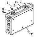
図1は、この発明による埋設管の破損箇所探知装置1の接続状態を示す模式図で、埋設管の破損箇所探知装置1は、本体2と、この本体2に手元スイッチ11を介在させて接続ケーブル12aにより接続されているピックアップセンサ12と、本体2と接続ケーブル10aを介して接続されているヘッドホン10とにより構成されている。なお、13は地表面、14は埋設管、15は埋設管14の破損箇所、16は破損箇所15から地表面13に伝搬する漏洩音の波形である。A first embodiment of the present invention will be described in detail with reference to FIGS. 1 to 14.
FIG. 1 is a schematic view showing a connection state of the buried pipe damaged
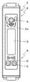
図2は、埋設管の破損箇所探知装置1の本体2を上方向から見た斜視図、図3は埋設管の破損箇所探知装置1の本体2の上面図で、本体2の操作部2aを構成している。図4は本体2の右側面図、図5は本体2の左側面図である。 FIG. 2 is a perspective view of the
図6〜図13は、本体2の表示画面3を示す図で、起動画面6と通常画面7及び通常画面7の設定項目表示7aと設定内容表示7bとが表示される。起動画面6は、図5に示す電源スイッチ9をオンした時のみ表示される。通常画面7は、設定項目表示7aに切り替えることにより各種の設定項目が表示され、選択キー5の押下げにより項目別に表示されるとともに、求める設定項目別の設定内容及び設定値が設定内容表示7bに表示される。さらに、通常画面7には、設定項目表示7a及び設定内容表示7bで設定した設定内容が表示されるのに加えて、バッテリー残量、ボーグラフで描画されるヘッドホン10の音量レベルが表示される。 6 to 13 are views showing the
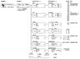
図14は、本体2の表示画面3を示す図で、起動画面6と、通常画面7と、各種設定時における設定項目表示7aと設定内容表示7b及び各設定値の一覧を示す図である。 FIG. 14 is a diagram showing a
図2〜図3に示すように、本体2の操作部2aには、表示画面3と操作スイッチ8とが配置されている。操作スイッチ8は、表示画面3の左右方向両端部(長手方向両端部)に配置されている1個の確定/ESCキー(□印スイッチ)4と2個の選択キー(▽印スイッチと△印スイッチ)5とにより構成されている。 As shown in FIGS. 2 to 3, a
本体2は、ピックアップセンサ12が捕捉した漏洩音をフィルタリングする機能と、このフィルタリングを行うフィルタの遮断周波数を操作スイッチ8のスイッチ機能により設定する機能と、表示画面3に表示される画面の向きを反転させる画面反転機能と、表示画面3の画面の向きに合わせて操作スイッチ8のスイッチ機能を反転させる機能と、設定内容を記憶する機能と、フィルタリングを行わないフィルタスルー設定機能と、リミッタ設定機能とを有している。さらに、選択キー5の押下により、通常画面7においてヘッドホン10の音量レベルを調整する機能と、設定項目表示7aにおいて設定項目別に選択するとともに、設定内容表示7bにおいて設定内容を選択する機能を有している。 The
操作スイッチ8の1個の確定/ESCキー(□印スイッチ)4は、短押しで通常画面7においては設定項目表示7aに切り替わり、設定項目表示7aにおいては設定内容表示7bに切り替わり、設定内容表示7bにおいては設定内容を確定するとともに、設定項目表示7aに切り替わり、長押しで設定項目表示7a又は設定内容表示7bから通常画面7に切り替わるように構成されている。 One confirmation / ESC key (□ mark switch) 4 of the
操作スイッチ8の2個の選択キー(▽印スイッチ及び△印スイッチ)5は、▽印スイッチあるいは△印スイッチの押下げにより、表示画面3が設定項目表示7aの場合には求める設定項目を表示する画面となる迄選択でき、表示画面3が設定内容表示7bの場合には求める設定内容を表示する画面となる迄選択できるように構成されている。表示画面3が通常画面7の場合には、ヘッドホン10の音量調整するようにも構成されている。 The two selection keys (▽ mark switch and △ mark switch) 5 of the
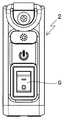
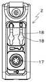
図4に示すように、電源のオン、オフを行う電源スイッチ9は、本体2の右側面(選択キー5側の側面)に取り付けられている。又、図5に示すように、本体2の左側面(確定/ESCキー4側の側面)には、ピックアップセンサ12の接続ケーブル12aのプラグを差し込むための接続コネクタ17とヘッドホン10の接続ケーブル10aのプラグを差し込むためのジャック18が取り付けられている。 As shown in FIG. 4, the
次に、この発明による埋設管の破損箇所探知装置1を用いて地中等の埋設管14の破損箇所15を探知する場合について説明する。 Next, a case where the damaged portion 15 of the buried
まず、図1、図5に示すように、ヘッドホン10の接続ケーブル10aのプラグを、本体2のジャック18に差し込んで本体2とヘッドホン10とを接続する。次いで、手元スイッチ11を介在させて本体2とピックアップセンサ12とを接続ケーブル12aにより接続する。そこで、この接続ケーブル12aのプラグを、本体2の接続コネクタ17に差し込んで本体2とピックアップセンサ12とを接続すれば埋設管の破損箇所探知装置1が組み立てられる。 First, as shown in FIGS. 1 and 5, the plug of the
この状態で、従来例の図16に示すように、検査員116は、肩掛けベルトにより本体2(図15における探知装置本体104に相当)の操作部2aを上面にして、本体2を身体の腰付近に固定する。この際、検査員116の利き手が右利きの場合には、右側の腰付近に、左利きの場合には、左側の腰付近に固定する。このとき、ピックアップセンサ12の接続ケーブル12aのプラグを差し込むための接続コネクタ17と、ヘッドホン10の接続ケーブル10aのプラグを差し込むためのジャック18とが、検査員116の正面(進行方向)側となるように、後述する設定項目(F)により、表示画面3の画面の向き(及びこの画面の向きに合わせた操作スイッチ8のスイッチ機能の向き)を設定する。 In this state, as shown in FIG. 16 of the conventional example, the
また、本体2を身体の正面(腹部付近)に固定してもよく、このときには、ピックアップセンサ12の接続ケーブル12aのプラグを差し込むための接続コネクタ17と、ヘッドホン10の接続ケーブル10aのプラグを差し込むためのジャック18とが、検査員116の利き手側となるように、後述する設定項目(F)により、表示画面3の画面の向き(及びこの画面の向きに合わせた操作スイッチ8のスイッチ機能の向き)を設定する。 Further, the
次いで、ヘッドホン10を頭部に装着し、ピックアップセンサ12を地表面13に接地すれば、地中からの漏洩音14を探知し得る状態となる。 Next, if the
次に、埋設管の破損箇所探知装置1による漏洩音の探知作業の開始にあたり、各種の設定項目がある。以下、図6〜図13、図14を参照して設定項目別に説明する。
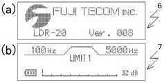
図6に示すように、(a)図は、起動時の表示画面3を示すもので、電源スイッチ9をオンすると、本体2の表示画面3には、起動画面6が表示され、その後、(b)図に示すように、通常画面7が表示される。この際、埋設管の破損箇所探知装置1を以前使用した時の設定項目及びその設定内容が保存されている場合(後述する設定項目(G)によりプリセット(設定内容が保存)されている場合)には、図6の(b)図の通常画面7には、保存されている設定項目及び設定内容が表示されるとともに、その設定で起動される。次いで、手元スイッチ11を押下すると、ヘッドホン10が可聴可能となる。Next, there are various setting items at the start of the leak sound detection work by the buried pipe
As shown in FIG. 6, FIG. 6A shows a
以下、設定項目別(A)〜(G)について説明する。
(A)まず、ヘッドホン10の音量を調整する場合には、図7に示すように、表示画面3には、通常画面7が表示されているので、2個の選択キー5の▽印スイッチあるいは△印スイッチのいずれかを押下して、ヘッドホン10の音量を調整する。この調整したヘッドホン10の音量は、通常画面7に表示される。Hereinafter, each of the setting items (A) to (G) will be described.
(A) First, when adjusting the volume of the
(B)次に、フィルタの遮断周波数を設定する場合、あるいはプリセットされている設定内容を変更する場合について説明する。図8(a)〜図8(e)、図14に示すように、本体2に内蔵されているフィルタは、ハイパスフィルタ(HPF)とローパスフィルタ(LPF)とにより構成されており、これらHPF/LPF回路のフィルタの遮断周波数の設定値(設定周波数)はいずれも8段階に設定可能である。この実施例の場合には、設定条件として「HPF設定周波数」<「LPF設定周波数」という条件があるので、合計54種類のフィルタの組み合わせを選択することが出来るように構成されている。又、狭帯域フィルタの設定も可能となっている。 (B) Next, a case of setting the cutoff frequency of the filter or a case of changing the preset setting contents will be described. As shown in FIGS. 8 (a) to 8 (e) and 14, the filter built in the
図8(a)に示す通常画面7において、本体2の操作部2aに配置されている操作スイッチ8の確定/ESCキー4(□印)を押下して設定項目表示7aに切り替える。次いで、選択キー5の▽印スイッチあるいは△印スイッチのいずれかを押下して、ローパスフィルタの遮断周波数の設定を行いたい場合は、図8(b)に示すローパスフィルタ(LPF)設定「LPF」の設定項目表示7aを、ハイパスフィルタの遮断周波数の設定を行いたい場合は、図8(c)に示すハイパスフィルタ(HPF)設定「HPF」の設定項目表示7aを、それぞれ選択する。この選択した設定項目表示7aにおいて、確定/ESCキー4(□印)を押下して図8(d)に示すローパスフィルタ(LPF)設定「LPF」の設定内容表示7bあるいは図8(e)に示すハイパスフィルタ(HPF)設定「HPF」の設定内容表示7bに切り替える。この切り替えた設定内容表示7bにおいて、選択キー5の▽印スイッチあるいは△印スイッチのいずれかを押下して、設定したい周波数を選択し、確定/ESCキー4(□印)を長押しして確定すれば設定することが出来る。 On the
(C)次に、フィルタの遮断周波数を設定せず漏洩音をそのまま聞きたい場合には、図9(a)〜図9(d)に示すように、HPF/LPF回路を通さない、即ち、フィルタリングを行わないフィルタスルー設定も可能である。図9(a)に示す通常画面7において、確定/ESCキー4(□印)を押下して設定項目表示7aに切り替え、次いで、選択キー5の▽印スイッチあるいは△印スイッチのいずれかを押下して、図9(b)に示すフィルタスルー設定「THRU」の設定項目表示7aを選択し、確定/ESCキー4(□印)を押下して、図9(c)あるいは図9(d)に示すフィルタスルー設定「THRU」の設定内容表示7bに切り替える。この切り替えた設定内容表示7bにおいて、選択キー5の▽印スイッチあるいは△印スイッチのいずれかを押下して選択し、図9(c)に示す「THRU ON」が表示された時、確定/ESCキー4(□印)を押下して確定すれば、フィルタスルーと設定され、図9(d)に示す「THRU OFF」が表示された時、確定/ESCキー4(□印)を長押しして確定すれば、HPF/LPF設定に従うことになる。 (C) Next, when it is desired to hear the leaked sound as it is without setting the cutoff frequency of the filter, as shown in FIGS. 9 (a) to 9 (d), the HPF / LPF circuit is not passed, that is, A filter-through setting that does not perform filtering is also possible. On the
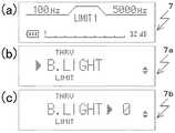
(D)夜間等のような暗所作業時に表示画面3のバックライトを点灯する場合について説明する。図10(a)に示す通常画面7において、確定/ESCキー4(□印)を押下して設定項目表示7aに切り替え、次いで、選択キー5の▽印スイッチあるいは△印スイッチのいずれかを押下して、図10(b)に示すバックライト設定「B.LIGHT」の設定項目表示7aを選択し、確定/ESCキー4(□印)を押下して、図10(c)に示すバックライト設定「B.LIGHT」の設定内容表示7bに切り替える。この切り替えた設定内容表示7bにおいて、選択キー5の▽スイッチ印あるいは△印スイッチいずれかを押下して、求める明るさ(0:オフ、1:弱、2:中、3強の4段階に調整可能となっている)を選択し、確定/ESCキー4(□印)を長押しして設定内容を確定する。 (D) A case where the backlight of the
(E)図11(a)〜図11(c)は、リミッタ調整をする場合を示している。図11(a)に示す通常画面7において、確定/ESCキー4(□印)を押下して設定項目表示7aに切り替え、次いで、選択キー5の▽印スイッチあるいは△印スイッチのいずれかを押下して、図11(b)に示すリミッタ設定「LIMIT」の設定項目表示7aを選択し、確定/ESCキー4(□印)を押下して、図11(c)に示すリミッタ設定「LIMIT」の設定内容表示7bに切り替える。この切り替えた設定内容表示7bにおいて、選択キー5の▽印スイッチあるいは△印スイッチのいずれかを押下して、求めるリミッタの設定内容(0:リミッタなし、1:リミッタ弱、2:リミッタ中、3:リミッタ強の4段階に調整可能となっている)を選択し、確定/ESCキー4(□印)を長押しして設定内容を確定する。 (E) FIGS. 11 (a) to 11 (c) show a case where the limiter is adjusted. On the
(F)次に、検査員116の利き手が、右利き、左利きに関係なく、効率よく作業できるようにするために、表示画面3の画面の向きを反転させるとともに、この向きに合せて操作スイッチ8のスイッチ機能を反転させる機能について説明する。図12(a)に示す通常画面7において、確定/ESCキー4(□印)を押下して設定項目表示7aに切り替え、次いで、選択キー5の▽印スイッチあるいは△印スイッチのいずれかを押下して、図12(c)に示す画面反転設定「REVERSE」の設定項目表示7aを選択し、確定/ESCキー4(□印)を押下して、図12(c)に示す画面反転設定「REVERSE」の設定内容表示7bに切り替える。この切り替えた設定内容表示7bにおいて、選択キー5の▽印スイッチあるいは△印スイッチのいずれかを押下して、求める表示画面3の画面の向きを選択し、確定/ESCキー4(□印)を長押しして表示画面3の画面反転表示の設定を確定する。この際、表示画面3の画面の向きに合わせて操作スイッチ8のスイッチ機能も反転するように構成されている。 (F) Next, in order to enable the dominant hand of the
このように、表示画面3の画面の向きを反転させるとともに、この向きに合せて操作スイッチ8のスイッチ機能を反転させることにより、検査員116の利き手が、右利き、左利きに関係なく、効率よく作業できるような埋設管の破損箇所探知装置が得られる。従って、検査員116が右利きあるいは左利きに関係なく、操作性の良さや作業効率の良さを損なうこともなく、ユニバーサルデザイン化した埋設管の破損箇所探知装置が得られる。 In this way, by reversing the orientation of the screen of the
(G)設定内容を保存したい場合には、図13(a)に示す通常画面7において、確定/ESCキー4(□印)を押下し、設定項目表示7aに切り替え、次いで、選択キー5の▽印スイッチあるいは△印スイッチのいずれかを押下して、図13(b)に示す画面反転起動時設定記憶「PRESET」の設定項目表示7aを選択し、確定/ESCキー4(□印)を押下し、図13(c)に示す起動時設定記憶「PRESET NO」の設定内容表示7bに切り替える。この切り替えた設定内容表示7bにおいて、選択キー5の▽印スイッチあるいは△印スイッチを押下して、図13(d)に示す起動時設定記憶「PRESET YES」の設定内容表示7bを選択し、確定/ESCキー4(□印)を長押しして確定すれば、ヘッドホン10の音量レベル、表示画面3の画面反転表示の設定(及び表示画面3の画面の向きに合わせた操作スイッチ8機能の反転設定)、フィルタ設定、フィルタスルー設定、リミッタ設定が保存される。 (G) If you want to save the setting contents, press the confirm / ESC key 4 (□ mark) on the
このように、埋設管の破損箇所探知装置1の設定を行った後は、漏洩音の探知作業を行う。従来例の図16及び図1に示すように、検査員116は本体2を身体に装着した後、電源スイッチ9をオンする。次いで、ピックアップセンサ12を地表面13に沿って移動させながら埋設管14の破損箇所15からの漏洩音を探し、ヘッドホン10から出力される漏洩音が最大となる地点を探す。この漏洩音が最大となる地点の直下の埋設管14上に破損箇所15が存在すると判断できる。 In this way, after setting the damaged
この発明による埋設管の破損箇所探知装置は、水道管やガス管、下水管等のように、地中に埋設されている埋設管の破損箇所に限らず、建造物の柱や壁の内部に埋設されている埋設管の破損箇所からの漏洩音を探知することが出来、幅広く利用可能である。 The device for detecting a damaged part of a buried pipe according to the present invention is not limited to a damaged part of a buried pipe buried in the ground such as a water pipe, a gas pipe, a sewage pipe, etc. It is possible to detect the leaking sound from the damaged part of the buried buried pipe, and it can be widely used.
1 埋設管の埋設管の破損箇所探知装置
2 埋設管の破損箇所探知装置の本体
2a 本体2の操作部
3 本体2の表示画面
4 確定/ESCキー
5 選択キー
6 表示画面3の起動画面
7 表示画面3の通常画面
7a 通常画面7の設定項目表示
7b 通常画面7の設定内容表示
8 操作スイッチ
9 電源スイッチ
10 ヘッドホン
11 手元スイッチ
12 ピックアップセンサ
14 埋設管
15 破損箇所
16 漏洩音の波形1 Damaged part of the buried pipe of the buried
Claims (3)
Translated fromJapaneseこの本体に接続された手元スイッチ付きのピックアップセンサと、
前記本体と接続され、前記ピックアップセンサにより捕捉した漏洩音を聞き取るヘッドホンとからなり、
前記本体は、
前記漏洩音をフィルタリングする機能と、
前記漏洩音のフィルタリングを行うフィルタの遮断周波数を設定する機能と、
前記操作スイッチのスイッチ機能と、
前記漏洩音を前記ヘッドホンで聞き取り可能に処理する機能と、
を有する埋設管の破損箇所探知装置において、
前記本体は、
前記表示画面に表示される画面の向きを反転させる画面反転機能と、
前記表示画面の向きに合わせて前記操作スイッチのスイッチ機能を反転させる機能と、
設定内容を記憶する機能とを有し、
前記表示画面は、起動時のみ表示される起動画面と、設定項目を表示する設定項目表示とこの設定項目表示の設定内容を表示する設定内容表示と、設定した設定内容と前記ピックアップセンサにより捕捉した漏洩音の音量レベルとを表示する通常画面とからなり、
前記操作スイッチは、前記操作部に配置されている1個の確定/ESCキーと2個の選択キーとからなり、
前記確定/ESCキーは、前記表示画面の通常画面と設定項目表示と設定内容表示とを切り替えるとともに、前記設定項目表示における設定項目と前記設定内容表示における設定内容とを確定し、
前記選択キーは、前記表示画面の通常画面において音量レベルを調整するとともに、前記設定項目表示における前記設定項目と前記設定内容表示における前記設定内容とを選択すること
を特徴とする埋設管の破損箇所探知装置。A main body that is portable and has an operation unit with a display screen and operation switches on the top surface,
A pickup sensor with a hand switch connected to this main unit,
It consists of headphones that are connected to the main unit and listen to the leaked sound captured by the pickup sensor.
The main body
The function to filter the leaked sound and
A function to set the cutoff frequency of the filter that filters the leaked sound, and
The switch function of the operation switch and
A function to process the leaked sound so that it can be heard by the headphones,
In the damaged part detection device of the buried pipe with
The main body
A screen reversing function that reverses the orientation of the screen displayed on the display screen, and
A function to invert the switch function of the operation switch according to the orientation of the display screen, and
It has a function to memorize the setting contents.
The display screen is captured by the startup screen that is displayed only at startup, the setting item display that displays the setting items, the setting content display that displays the setting contents of this setting item display, the set setting contents, and the pickup sensor. It consists of a normal screen that displays the volume level of the leaked sound and
The operation switch comprises one confirmation / ESC key and two selection keys arranged in the operation unit.
The confirm / ESC key switches between the normal screen of the display screen, the setting item display, and the setting content display, and confirms the setting item in the setting item display and the setting content in the setting content display.
The selection key adjusts the volume level on the normal screen of the display screen and selects the setting item in the setting item display and the setting content in the setting content display. Detector.
を特徴とする請求項1〜請求項2のいずれかに記載の埋設管の破損箇所探知装置。The device for detecting a damaged portion of an embedded pipe according to any one of claims 1 to 2, wherein the main body has a limiter setting function.
Priority Applications (8)
| Application Number | Priority Date | Filing Date | Title |
|---|---|---|---|
| JP2020074446AJP2021173532A (en) | 2020-04-18 | 2020-04-18 | Damaged part detector for buried pipes |
| US17/919,450US20230152180A1 (en) | 2020-04-18 | 2021-04-15 | Buried-pipe damage location detection device |
| CA3178727ACA3178727A1 (en) | 2020-04-18 | 2021-04-15 | Buried-pipe damage location detection device |
| CN202180029375.9ACN115485586A (en) | 2020-04-18 | 2021-04-15 | Device for detecting damaged portion of buried pipe |
| EP21788632.4AEP4177581A1 (en) | 2020-04-18 | 2021-04-15 | Buried-pipe damage location detection device |
| PCT/JP2021/015584WO2021210643A1 (en) | 2020-04-18 | 2021-04-15 | Buried-pipe damage location detection device |
| KR1020227035087AKR20230002383A (en) | 2020-04-18 | 2021-04-15 | Buried pipe damage detection device |
| AU2021255086AAU2021255086A1 (en) | 2020-04-18 | 2021-04-15 | Buried-pipe damage location detection device |
Applications Claiming Priority (1)
| Application Number | Priority Date | Filing Date | Title |
|---|---|---|---|
| JP2020074446AJP2021173532A (en) | 2020-04-18 | 2020-04-18 | Damaged part detector for buried pipes |
Publications (1)
| Publication Number | Publication Date |
|---|---|
| JP2021173532Atrue JP2021173532A (en) | 2021-11-01 |
Family
ID=78084570
Family Applications (1)
| Application Number | Title | Priority Date | Filing Date |
|---|---|---|---|
| JP2020074446APendingJP2021173532A (en) | 2020-04-18 | 2020-04-18 | Damaged part detector for buried pipes |
Country Status (8)
| Country | Link |
|---|---|
| US (1) | US20230152180A1 (en) |
| EP (1) | EP4177581A1 (en) |
| JP (1) | JP2021173532A (en) |
| KR (1) | KR20230002383A (en) |
| CN (1) | CN115485586A (en) |
| AU (1) | AU2021255086A1 (en) |
| CA (1) | CA3178727A1 (en) |
| WO (1) | WO2021210643A1 (en) |
Cited By (7)
| Publication number | Priority date | Publication date | Assignee | Title |
|---|---|---|---|---|
| JP2022002812A (en)* | 2017-10-13 | 2022-01-11 | 株式会社三洋物産 | Game machine |
| JP2022002813A (en)* | 2017-10-13 | 2022-01-11 | 株式会社三洋物産 | Game machine |
| JP2022033312A (en)* | 2018-02-15 | 2022-02-28 | 株式会社三洋物産 | Game machine |
| JP2022033311A (en)* | 2018-02-15 | 2022-02-28 | 株式会社三洋物産 | Game machine |
| JP2022033310A (en)* | 2018-02-15 | 2022-02-28 | 株式会社三洋物産 | Game machine |
| JP2022033309A (en)* | 2018-02-15 | 2022-02-28 | 株式会社三洋物産 | Game machine |
| JP2022033308A (en)* | 2018-02-15 | 2022-02-28 | 株式会社三洋物産 | Game machine |
Family Cites Families (29)
| Publication number | Priority date | Publication date | Assignee | Title |
|---|---|---|---|---|
| US4309576A (en)* | 1979-07-16 | 1982-01-05 | Heath Consultants Incorporated | Listening device for localizing underground water leakages |
| JP2878804B2 (en)* | 1989-09-19 | 1999-04-05 | 東京瓦斯株式会社 | Piping abnormality monitoring device |
| US5710377A (en)* | 1995-10-17 | 1998-01-20 | The United States Of America As Represented By The Administrator Of The National Aeronautics And Space Administration | Ultrasonic leak detection system |
| US6058076A (en)* | 1997-12-08 | 2000-05-02 | Komninos; Nikolaos I. | Signal detector and method for detecting signals having selected frequency characteristics |
| JP2000154888A (en)* | 1998-11-19 | 2000-06-06 | Osaka Gas Co Ltd | Probing method for piping structure and piping probing device |
| US6234021B1 (en)* | 1999-02-02 | 2001-05-22 | Csi Technology, Inc. | Enhanced detection of vibration |
| US6453247B1 (en)* | 2000-01-14 | 2002-09-17 | National Research Council Of Canada | PC multimedia-based leak detection system for water transmission and distribution pipes |
| US6982728B1 (en)* | 2000-05-18 | 2006-01-03 | Palm, Inc. | Portable electronic system having multiple display modes for reorienting the display of data on a display screen |
| US6530263B1 (en)* | 2000-09-29 | 2003-03-11 | Radcom Technologies Ltd | Method and system for localizing and correlating leaks in fluid conveying conduits |
| IL152310A (en)* | 2002-10-15 | 2010-05-17 | Magal Security Systems Ltd | System and method for detecting, locating and recognizing an approach toward an elongated installation |
| US7203322B1 (en)* | 2003-05-16 | 2007-04-10 | Metrotech Corporation | Acoustic detector with noise cancellation |
| JP4306409B2 (en)* | 2003-10-31 | 2009-08-05 | Jfeスチール株式会社 | Piping leakage position detection method and apparatus |
| JP4350740B2 (en)* | 2006-12-05 | 2009-10-21 | レノボ・シンガポール・プライベート・リミテッド | Portable electronic device, method for changing display direction of screen, program, and storage medium |
| JP5311771B2 (en)* | 2007-06-23 | 2013-10-09 | フジテコム株式会社 | Leak detection device |
| TWI329849B (en)* | 2007-07-19 | 2010-09-01 | Quanta Storage Inc | Switching device and method for a portable display product |
| CN102203850A (en)* | 2008-09-12 | 2011-09-28 | 格斯图尔泰克公司 | Orients displayed elements relative to the user |
| EP2724667B1 (en)* | 2011-06-24 | 2020-11-18 | Murata Manufacturing Co., Ltd. | Mobile apparatus with biosensors |
| US9250768B2 (en)* | 2012-02-13 | 2016-02-02 | Samsung Electronics Co., Ltd. | Tablet having user interface |
| US9804053B2 (en)* | 2012-09-28 | 2017-10-31 | Nec Corporation | Defect analysis device, defect analysis method, and program |
| US20150040027A1 (en)* | 2013-07-31 | 2015-02-05 | Yi-Chuan Cheng | Portable Device with Handedness Switching Module |
| CN104641341B (en)* | 2013-08-20 | 2018-08-21 | 华为技术有限公司 | A kind of handheld device and the method for realizing input zone position adjustment on a handheld device |
| WO2015051225A1 (en)* | 2013-10-03 | 2015-04-09 | Schlumberger Canada Limited | Pipe damage assessment system and method |
| GB2519142B (en)* | 2013-10-11 | 2016-09-28 | Univ Manchester | Signal processing system and method |
| JP6315939B2 (en)* | 2013-10-23 | 2018-04-25 | 株式会社キーエンス | Photoelectric sensor |
| JP6298270B2 (en)* | 2013-10-23 | 2018-03-20 | 株式会社キーエンス | Photoelectric sensor |
| US9869602B2 (en)* | 2014-01-15 | 2018-01-16 | Darren E. Merlob | Pipeline leak detection device and method |
| US20160162149A1 (en)* | 2014-12-05 | 2016-06-09 | Htc Corporation | Mobile electronic device, method for displaying user interface, and recording medium thereof |
| US10831355B2 (en)* | 2019-04-08 | 2020-11-10 | The Boeing Company | Systems and methods for changing orientation of visual information displayed between adjacent users |
| EP4013022A4 (en)* | 2019-08-09 | 2022-08-03 | Beijing Xiaomi Mobile Software Co., Ltd. | METHOD, APPARATUS AND DEVICE FOR SWITCHING A DISPLAY MODE AND MEDIUM |
- 2020
- 2020-04-18JPJP2020074446Apatent/JP2021173532A/enactivePending
- 2021
- 2021-04-15USUS17/919,450patent/US20230152180A1/ennot_activeAbandoned
- 2021-04-15CNCN202180029375.9Apatent/CN115485586A/enactivePending
- 2021-04-15KRKR1020227035087Apatent/KR20230002383A/ennot_activeWithdrawn
- 2021-04-15EPEP21788632.4Apatent/EP4177581A1/ennot_activeWithdrawn
- 2021-04-15WOPCT/JP2021/015584patent/WO2021210643A1/ennot_activeCeased
- 2021-04-15AUAU2021255086Apatent/AU2021255086A1/ennot_activeAbandoned
- 2021-04-15CACA3178727Apatent/CA3178727A1/enactivePending
Cited By (7)
| Publication number | Priority date | Publication date | Assignee | Title |
|---|---|---|---|---|
| JP2022002812A (en)* | 2017-10-13 | 2022-01-11 | 株式会社三洋物産 | Game machine |
| JP2022002813A (en)* | 2017-10-13 | 2022-01-11 | 株式会社三洋物産 | Game machine |
| JP2022033312A (en)* | 2018-02-15 | 2022-02-28 | 株式会社三洋物産 | Game machine |
| JP2022033311A (en)* | 2018-02-15 | 2022-02-28 | 株式会社三洋物産 | Game machine |
| JP2022033310A (en)* | 2018-02-15 | 2022-02-28 | 株式会社三洋物産 | Game machine |
| JP2022033309A (en)* | 2018-02-15 | 2022-02-28 | 株式会社三洋物産 | Game machine |
| JP2022033308A (en)* | 2018-02-15 | 2022-02-28 | 株式会社三洋物産 | Game machine |
Also Published As
| Publication number | Publication date |
|---|---|
| AU2021255086A1 (en) | 2022-10-20 |
| KR20230002383A (en) | 2023-01-05 |
| WO2021210643A1 (en) | 2021-10-21 |
| US20230152180A1 (en) | 2023-05-18 |
| CA3178727A1 (en) | 2021-10-21 |
| EP4177581A1 (en) | 2023-05-10 |
| CN115485586A (en) | 2022-12-16 |
Similar Documents
| Publication | Publication Date | Title |
|---|---|---|
| JP2021173532A (en) | Damaged part detector for buried pipes | |
| EP2028471B1 (en) | Leakage detector | |
| KR101903548B1 (en) | Hearing type water leakage detector of smart phone-base | |
| US6234021B1 (en) | Enhanced detection of vibration | |
| JPH0472537A (en) | Abnormality monitor for piping | |
| KR20050063550A (en) | Structure and method and apparatus of voice signal communication at swible mode for swible mobile phone | |
| KR102212397B1 (en) | Smart leakage detction device of portable type | |
| CN113128807A (en) | Circumferential weld risk evaluation method and device and storage medium | |
| KR20220159579A (en) | Apparatus and Method for Detecting Position of Water Leakage | |
| KR102313851B1 (en) | Water leak detection system | |
| KR20060086909A (en) | Detecting device for detecting gas or liquid leak in pipe | |
| KR200355570Y1 (en) | Multi-function device for pipe detection, leakage detection and internal inspection | |
| KR102145458B1 (en) | Leak sensing apparatus and leak sensing method using same | |
| CN112303502A (en) | Sound vibration method water leakage detection method | |
| CN105889765B (en) | A kind of strong anti-interference type based on Internet technology listens leakage device | |
| CN217130991U (en) | Anti-leakage detection device for fire-fighting pipe network | |
| KR101616224B1 (en) | Ultrasonic detector capable of visualization of defect area | |
| JPH1194684A (en) | Water pipe leakage detection device | |
| JPH0956045A (en) | Method and apparatus for identifying buried pipe | |
| JP2003194656A (en) | Water leak spot detection method of sealing works | |
| CN211399352U (en) | Water leakage detector | |
| JP3895643B2 (en) | Ultrasonic leak detector | |
| KR200354285Y1 (en) | Water leak detector | |
| JPS6243535A (en) | Method for detecting leakage of gas | |
| HK1126850B (en) | Leakage detector |