JP2021166833A - System and apparatus for assisting with submucosal dissections - Google Patents
System and apparatus for assisting with submucosal dissectionsDownload PDFInfo
- Publication number
- JP2021166833A JP2021166833AJP2021117788AJP2021117788AJP2021166833AJP 2021166833 AJP2021166833 AJP 2021166833AJP 2021117788 AJP2021117788 AJP 2021117788AJP 2021117788 AJP2021117788 AJP 2021117788AJP 2021166833 AJP2021166833 AJP 2021166833A
- Authority
- JP
- Japan
- Prior art keywords
- strip body
- tissue
- state
- traction
- engaging member
- Prior art date
- Legal status (The legal status is an assumption and is not a legal conclusion. Google has not performed a legal analysis and makes no representation as to the accuracy of the status listed.)
- Granted
Links
Images


Classifications
- A—HUMAN NECESSITIES
- A61—MEDICAL OR VETERINARY SCIENCE; HYGIENE
- A61B—DIAGNOSIS; SURGERY; IDENTIFICATION
- A61B17/00—Surgical instruments, devices or methods
- A61B17/02—Surgical instruments, devices or methods for holding wounds open, e.g. retractors; Tractors
- A—HUMAN NECESSITIES
- A61—MEDICAL OR VETERINARY SCIENCE; HYGIENE
- A61B—DIAGNOSIS; SURGERY; IDENTIFICATION
- A61B17/00—Surgical instruments, devices or methods
- A61B17/02—Surgical instruments, devices or methods for holding wounds open, e.g. retractors; Tractors
- A61B17/0218—Surgical instruments, devices or methods for holding wounds open, e.g. retractors; Tractors for minimally invasive surgery
- A—HUMAN NECESSITIES
- A61—MEDICAL OR VETERINARY SCIENCE; HYGIENE
- A61B—DIAGNOSIS; SURGERY; IDENTIFICATION
- A61B17/00—Surgical instruments, devices or methods
- A61B17/00234—Surgical instruments, devices or methods for minimally invasive surgery
- A61B2017/00238—Type of minimally invasive operation
- A61B2017/00269—Type of minimally invasive operation endoscopic mucosal resection EMR
- A—HUMAN NECESSITIES
- A61—MEDICAL OR VETERINARY SCIENCE; HYGIENE
- A61B—DIAGNOSIS; SURGERY; IDENTIFICATION
- A61B17/00—Surgical instruments, devices or methods
- A61B17/00234—Surgical instruments, devices or methods for minimally invasive surgery
- A61B2017/00292—Surgical instruments, devices or methods for minimally invasive surgery mounted on or guided by flexible, e.g. catheter-like, means
- A61B2017/00336—Surgical instruments, devices or methods for minimally invasive surgery mounted on or guided by flexible, e.g. catheter-like, means with a protective sleeve, e.g. retractable or slidable
- A—HUMAN NECESSITIES
- A61—MEDICAL OR VETERINARY SCIENCE; HYGIENE
- A61B—DIAGNOSIS; SURGERY; IDENTIFICATION
- A61B17/00—Surgical instruments, devices or methods
- A61B17/00234—Surgical instruments, devices or methods for minimally invasive surgery
- A61B2017/00292—Surgical instruments, devices or methods for minimally invasive surgery mounted on or guided by flexible, e.g. catheter-like, means
- A61B2017/0034—Surgical instruments, devices or methods for minimally invasive surgery mounted on or guided by flexible, e.g. catheter-like, means adapted to be inserted through a working channel of an endoscope
- A—HUMAN NECESSITIES
- A61—MEDICAL OR VETERINARY SCIENCE; HYGIENE
- A61B—DIAGNOSIS; SURGERY; IDENTIFICATION
- A61B17/00—Surgical instruments, devices or methods
- A61B2017/00831—Material properties
- A61B2017/00862—Material properties elastic or resilient
- A—HUMAN NECESSITIES
- A61—MEDICAL OR VETERINARY SCIENCE; HYGIENE
- A61B—DIAGNOSIS; SURGERY; IDENTIFICATION
- A61B17/00—Surgical instruments, devices or methods
- A61B2017/00831—Material properties
- A61B2017/00867—Material properties shape memory effect
- A—HUMAN NECESSITIES
- A61—MEDICAL OR VETERINARY SCIENCE; HYGIENE
- A61B—DIAGNOSIS; SURGERY; IDENTIFICATION
- A61B17/00—Surgical instruments, devices or methods
- A61B2017/00831—Material properties
- A61B2017/00946—Material properties malleable
- A—HUMAN NECESSITIES
- A61—MEDICAL OR VETERINARY SCIENCE; HYGIENE
- A61B—DIAGNOSIS; SURGERY; IDENTIFICATION
- A61B17/00—Surgical instruments, devices or methods
- A61B17/02—Surgical instruments, devices or methods for holding wounds open, e.g. retractors; Tractors
- A61B17/0218—Surgical instruments, devices or methods for holding wounds open, e.g. retractors; Tractors for minimally invasive surgery
- A61B2017/0225—Surgical instruments, devices or methods for holding wounds open, e.g. retractors; Tractors for minimally invasive surgery flexible, e.g. fabrics, meshes, or membranes
- A—HUMAN NECESSITIES
- A61—MEDICAL OR VETERINARY SCIENCE; HYGIENE
- A61B—DIAGNOSIS; SURGERY; IDENTIFICATION
- A61B17/00—Surgical instruments, devices or methods
- A61B17/064—Surgical staples, i.e. penetrating the tissue
- A61B2017/0649—Coils or spirals
Landscapes
- Health & Medical Sciences (AREA)
- Life Sciences & Earth Sciences (AREA)
- Surgery (AREA)
- Heart & Thoracic Surgery (AREA)
- Engineering & Computer Science (AREA)
- Biomedical Technology (AREA)
- Nuclear Medicine, Radiotherapy & Molecular Imaging (AREA)
- Medical Informatics (AREA)
- Molecular Biology (AREA)
- Animal Behavior & Ethology (AREA)
- General Health & Medical Sciences (AREA)
- Public Health (AREA)
- Veterinary Medicine (AREA)
- Surgical Instruments (AREA)
Abstract
Description
Translated fromJapanese (関連出願)
本出願は、2016年2月10日に出願された米国仮特許出願第62/293,505号、及び2016年1月21日に出願された米国仮特許出願第62/281,215号からの優先権を主張し、これらの両方の主題は、その全体が参照により本明細書に組み込まれる。(Related application)
This application is from US Provisional Patent Application No. 62 / 293,505 filed on February 10, 2016, and US Provisional Patent Application No. 62 / 281,215 filed on January 21, 2016. Claiming priority, both of these subjects are incorporated herein by reference in their entirety.
(技術分野)
本開示は、粘膜下層剥離術を補助するための装置、方法、及びシステムに関し、より具体的には、組織牽引装置及び使用方法に関する。(Technical field)
The present disclosure relates to devices, methods, and systems for assisting submucosal dissection, and more specifically to tissue traction devices and methods of use.
内視鏡的粘膜下層剥離術(「ESD」)は、限定されないが、初期消化管がんなどの病変を内視鏡的に剥離する内視鏡的手技である。ESDを実行する際の課題の1つは、従来の外科手術におけるような、牽引及び逆牽引を提供することができる助手の不足である。外科医の助手のように振る舞うことができる装置を提供することにより、ESDをより効率よく実施することができる。 Endoscopic submucosal dissection (“ESD”) is an endoscopic procedure that endoscopically removes lesions such as early gastrointestinal cancer. One of the challenges in performing ESD is the lack of assistants who can provide traction and reverse traction as in conventional surgery. ESD can be performed more efficiently by providing a device that can act like a surgeon's assistant.
一態様では、組織牽引装置が提供される。この組織牽引装置は、牽引細片本体を備える。牽引細片本体は、変形可能な材料から少なくとも部分的に形成される。牽引細片本体は、第1の状態と第2の状態との間で選択的に移行させられることができる。第1の状態では、牽引細片本体は、標的患者組織と係合することが可能である。第2の状態では、牽引細片本体は、標的患者組織を牽引することができる。組織牽引装置は、少なくとも1つの組織係合部材を備える。この組織係合部材は、牽引細片本体の上に配置される。 In one aspect, a tissue traction device is provided. This tissue traction device comprises a traction strip body. The traction strip body is formed at least partially from a deformable material. The traction strip body can be selectively transitioned between the first and second states. In the first state, the traction strip body is capable of engaging with the target patient tissue. In the second state, the traction strip body can traction the target patient tissue. The tissue traction device comprises at least one tissue engaging member. This tissue engaging member is placed on the traction strip body.
一態様では、粘膜下層剥離術を補助するための方法が提供される。組織牽引装置が設けられている。この組織牽引装置は、牽引細片本体を備える。牽引細片本体は、変形可能な材料から少なくとも部分的に形成される。牽引細片本体は、第1の状態と第2の状態との間で選択的に移行させられることができる。第1の状態では、牽引細片本体は、標的患者組織と係合することが可能である。第2の状態では、牽引細片本体は、標的患者組織を牽引することができる。組織牽引装置は、少なくとも1つの組織係合部材を備える。この組織係合部材は、牽引細片本体の上に配置される。組織牽引装置は、内視鏡を備える。この内視鏡は、内視鏡近位端部及び内視鏡遠位端部を有する。内視鏡は、内視鏡近位端部と内視鏡遠位端部との間の長手方向に延在する内視鏡管腔を有する。内視鏡は、患者に挿入される。内視鏡遠位端部は、標的患者組織に隣接する標的患者組織部位に位置決めされる。牽引細片本体は、第1の状態へと選択的に移行される。牽引細片本体が第1の状態にある状態で、牽引細片本体は、内視鏡管腔を通して出して、標的患者組織部位に挿入される。牽引細片本体が第1の状態にある状態で、標的患者組織は、少なくとも1つの組織係合部材と係合される。標的患者組織は、牽引細片本体を第2の状態へと選択的に移行させることによって、牽引位置へと選択的に移行される。第1の位置から第2の位置への牽引細片本体の選択的移行により、組織係合部材は、標的患者組織の当初の位置から牽引位置に標的患者組織を応答的に移行させる。 In one aspect, a method is provided to assist submucosal dissection. A tissue traction device is provided. This tissue traction device comprises a traction strip body. The traction strip body is formed at least partially from a deformable material. The traction strip body can be selectively transitioned between the first and second states. In the first state, the traction strip body is capable of engaging with the target patient tissue. In the second state, the traction strip body can traction the target patient tissue. The tissue traction device comprises at least one tissue engaging member. This tissue engaging member is placed on the traction strip body. The tissue traction device comprises an endoscope. This endoscope has a proximal end of the endoscope and a distal end of the endoscope. The endoscope has an endoscopic lumen that extends longitudinally between the proximal end of the endoscope and the distal end of the endoscope. The endoscope is inserted into the patient. The distal end of the endoscope is positioned at the target patient tissue site adjacent to the target patient tissue. The traction strip body is selectively transitioned to the first state. With the traction strip body in the first state, the traction strip body exits through the endoscopic lumen and is inserted into the target patient tissue site. With the traction strip body in the first state, the target patient tissue is engaged with at least one tissue engaging member. The target patient tissue is selectively migrated to the traction position by selectively migrating the traction strip body to the second state. Due to the selective migration of the traction strip body from the first position to the second position, the tissue engaging member responsively transitions the target patient tissue from the initial position of the target patient tissue to the traction position.
一態様では、粘膜下層剥離術を補助するためのシステムが提供される。この粘膜下層剥離術を補助するためのシステムは、組織牽引装置を備える。この組織牽引装置は、牽引細片本体を備える。この牽引細片本体は、横方向に離間された第1の端部及び第2の端部を有する。牽引細片本体は、変形可能な材料から少なくとも部分的に形成される。牽引細片本体は、第1の状態と第2の状態と間で選択的に移行させられることができる。第1の状態では、牽引細片本体は、標的患者組織と係合することが可能である。第2の状態では、牽引細片本体は、標的患者組織を牽引することができる。牽引細片本体は、少なくとも2組の組織係合部材を含む。第1の組の組織係合部材は、牽引細片本体の第1の端部の上に配置される。第2の組の組織係合部材は、牽引細片本体の第2の端部の上に配置される。組織係合部材は、バーブ、クリップ、フック、接着剤、及び他の取り付け機構のうちの少なくとも1つである。粘膜下層剥離術を補助するためのシステムは、内視鏡及び剥離器を含む。この内視鏡は、近位端部及び遠位端部を有する。内視鏡は、内視鏡近位端部と内視鏡遠位端部との間の長手方向に延在する内視鏡管腔を有する。
例えば、本願は以下の項目を提供する。
(項目1)
牽引細片本体(102)であって、前記牽引細片本体(102)は、変形可能な材料から少なくとも部分的に形成され、前記牽引細片本体(102)は、第1の状態では、前記牽引細片本体(102)が標的患者組織(T)と係合することができ、一方、第2の状態では、前記牽引細片本体(102)が前記標的患者組織(T)を牽引することができるように、前記第1の状態と前記第2の状態との間で選択的に移行させられることができる、牽引細片本体(102)と、
少なくとも1つの組織係合部材(104)であって、前記少なくとも1つの組織係合部材(104)は、前記牽引細片本体(102)の上に配置されている、少なくとも1つの組織係合部材(104)と、を備える組織牽引装置(100)。
(項目2)
前記変形可能な材料が、弾性材料であり、前記第1の状態と第2の状態との間の遷移が、加力、及び前記牽引細片本体(102)の弾性変形のうちの少なくとも一方に応答して、生じる、項目1に記載の組織牽引装置(100)。
(項目3)
前記変形可能な材料は、弾性材料、形状記憶材料、及び布材料のうちの少なくとも1つである、項目2に記載の組織牽引装置(100)。
(項目4)
前記牽引細片本体(102)は、シース送達状態へと移行させられることが可能であり、前記シース送達状態にある前記牽引細片本体(102)は、シース(1020)のシース管腔(1022)内部に配置されるための形をしている、項目3に記載の組織牽引装置(100)。
(項目5)
前記変形可能な材料が、温度応答性形状記憶材料であり、前記牽引細片本体(102)は、前記第2の状態に予め設定されているように構成され、前記牽引細片本体(102)が遷移温度範囲未満の温度にあるときには、前記牽引細片本体(102)は、前記第2の状態から前記第1の状態へと変形させられることができるように構成され、前記牽引細片本体(102)が前記遷移温度範囲超の温度にあるときには、前記牽引細片本体(102)は、前記第2の状態に自動的に戻るように構成されている、項目1に記載の組織牽引装置(100)。
(項目6)
前記変形可能な材料が、展性材料であり、展性材料から少なくとも部分的に形成された前記牽引細片本体(102)が、前記第1の状態及び第2の状態のうちの少なくとも選択された一方の状態に、選択的に変形させられ、かつ保持されることができる、項目1に記載の組織牽引装置(100)。
(項目7)
前記変形可能な材料が、フレキシブルなステンレス鋼双安定ばねバンドである、項目1に記載の組織牽引装置(100)。
(項目8)
前記第1の状態にある前記牽引細片本体(102)は、心棒(1130)の外側表面(1128)と係合するような形をしており、前記組織係合部材(104)は、前記牽引細片本体(102)が前記第1の状態にあるときには、扁平状態にあり、前記組織係合部材(104)は、前記牽引細片本体(102)が少なくとも部分的に前記第2の状態にあるときには、開いた状態にある、項目7に記載の組織牽引装置(100)。
(項目9)
前記組織係合部材(104)が、バーブ、クリップ、フック、接着剤、及び任意の他の取り付け機構のうちの少なくとも1つである、項目1に記載の組織牽引装置(100)。
(項目10)
第1の組の組織係合部材(106)は、牽引細片本体の第1の端部(108)の上に配置され、第2の組の組織係合部材(110)は、牽引細片本体の第2の端部(112)の上に配置され、前記牽引細片本体の第1の端部及び第2の端部(108及び112)は、横方向に離間されている、項目1に記載の組織牽引装置(100)。
(項目11)
前記牽引細片本体(102)は、少なくとも1つの嵌合部材(1232)を有し、前記嵌合部材(1232)は、少なくとも2つの牽引細片本体(102)を一緒に選択的に連結するように構成されている、項目1に記載の組織牽引装置(100)。
(項目12)
粘膜下層剥離術を補助するための方法であって、
組織牽引装置(100)を提供することであって、前記組織牽引装置(100)は、
牽引細片本体(102)であって、前記牽引細片本体(102)は、変形可能な材料から少なくとも部分的に形成され、前記牽引細片本体(102)は、第1の状態では、前記牽引細片本体(102)が標的患者組織(T)と係合することができ、一方、第2の状態では、前記牽引細片本体(102)が前記標的患者組織(T)を牽引することができるように、前記第1の状態と前記第2の状態との間で選択的に移行させられることができる、牽引細片本体(102)と、
少なくとも1つの組織係合部材(104)であって、前記少なくとも1つの組織係合部材(104)は、前記牽引細片本体(102)の上に配置されている、少なくとも1つの組織係合部材(104)と、
内視鏡(1334)であって、前記内視鏡(1334)は、内視鏡近位端部及び内視鏡遠位端部(1338)を有し、前記内視鏡(1334)は、前記内視鏡近位端部と前記内視鏡遠位端部(1338)との間に長手方向に延在する内視鏡管腔(1340)を有する、内視鏡(1334)と、を有する、ことと、
前記内視鏡(1334)を患者へと挿入することと、
前記標的患者組織(T)に隣接する標的患者組織部位(S)に前記内視鏡遠位端部(1338)を位置決めすることと、
前記第1の状態へと前記牽引細片本体(102)を選択的に移行させることと、
前記牽引細片本体(102)が前記第1の状態にある状態で、前記牽引細片本体(102)を、前記内視鏡管腔(1340)を通して出して、前記標的患者組織部位(S)に挿入することと、
前記牽引細片本体(102)が前記第1の状態にある状態で、前記標的患者組織(T)を少なくとも1つの組織係合部材(104)と係合させることと、 前記牽引細片本体(102)を前記第2の状態へと選択的に移行させることによって、前記標的患者組織(T)を牽引位置へと選択的に移行させることと、
前記第1の位置から前記第2の位置への前記牽引細片本体(102)の前記選択的移行により、前記組織係合部材(104)が、前記標的患者組織(T)を前記標的患者組織の当初の位置から牽引位置に応答的に移行させることと、を含む方法。
(項目13)
前記変形可能な材料は、少なくとも部分的に、弾性材料であり、前記牽引細片本体(102)は、前記第2の状態に付勢されており、前記方法は、
前記組織係合部材(104)が前記標的患者組織(T)と係合している状態で、前記標的患者組織(T)により与えられる長手方向の下方の力を利用することによって、前記牽引細片本体(102)が前記第2の状態に移行することを制限することと、
剥離器(1642)を前記標的患者組織部位(S)に提供することと、
前記牽引細片本体(102)が前記第1の状態で前記標的患者組織(T)と係合している状態で、前記標的患者組織(T)の少なくとも一部分を剥離することであって、前記標的患者組織(T)の前記剥離が、前記標的患者組織(T)により与えられる長手方向の下方の力を応答的に軽減する、ことと、
前記標的患者組織(T)により与えられる長手方向の下方の力の前記軽減を利用して、前記牽引細片本体(102)が、形状記憶材料の固有の性質に応じて、前記第2の状態に移行するように促すことと、を含む、項目12に記載の方法。
(項目14)
前記変形可能な材料は、弾性材料、形状記憶材料、及び布材料のうちの少なくとも1つであり、前記方法は、
シース(1020)を提供することであって、前記シース(1020)は、シース近位端部(1024)及びシース遠位端部(1026)を有し、前記シースは、前記シース近位端部(1024)と前記シース遠位端部(1026)との間に長手方向に延在するシース管腔(1022)を有する、ことと、
前記牽引細片本体(102)をシース送達状態へと選択的に移行させることと、
前記牽引細片本体(102)が前記シース送達状態にある状態で、前記牽引細片本体(102)を前記シース管腔(1022)の内部に配置することと、
前記シース管腔(1022)の半径方向の内向き力を利用して前記牽引細片本体(102)を前記シース送達状態に制限することと、
前記牽引細片本体(102)が前記シース送達状態にある状態で、取り付けられた牽引細片本体(102)を伴う前記シース(1020)を、前記内視鏡管腔(1340)を通して前記標的患者組織部位(S)へ前進させることと、
前記牽引細片本体(102)が前記標的患者組織部位(S)に留まっている状態で、前記標的患者組織部位(S)及び前記内視鏡(1334)のうちの少なくとも一方から前記シース(1020)を後退させることと、
前記シース(1020)の前記後退を利用して、前記牽引細片本体(102)を、前記第1の状態に応答的に移行させることと、を含む、項目13に記載の方法。
(項目15)
前記変形可能な材料が、少なくとも部分的に温度応答性形状記憶材料であり、前記牽引細片本体(102)が、前記第2の状態に予め設定され、前記方法は、
前記牽引細片本体(102)を遷移温度範囲未満の温度に選択的に冷却することと、
前記牽引細片本体(102)が前記遷移温度範囲未満の温度にある状態で、前記牽引細片本体(102)を前記第2の状態から前記第1の状態に選択的に変形させることと、
前記標的患者組織(S)における周囲熱を利用して、前記牽引細片本体(102)を前記遷移温度範囲超の温度にまで加熱することと、
前記牽引細片本体(102)が前記遷移温度範囲超の温度にある状態で、前記変形可能な材料の固有の特性を利用して、前記牽引細片本体(102)を前記第2の状態に向けて選択的に促すことと、
前記組織係合部材(104)が前記標的患者組織(T)と係合している状態で、前記標的患者組織(T)により与えられる長手方向の下方の力を利用することによって、前記牽引細片本体が、前記第2の状態に移行させられることを制限することと、
剥離器(1642)を前記標的患者組織部位(S)に提供することと、
前記牽引細片本体(102)が前記第1の状態で前記標的患者組織(T)と係合している状態で、前記標的患者組織(T)の少なくとも一部分を剥離し、前記標的患者組織(T)により与えられる長手方向の下方の力を応答的に軽減することと、
前記標的患者組織(T)により与えられる長手方向の下方の力の前記軽減を伴って、前記牽引細片本体(102)が、前記温度応答性形状記憶材料の固有の性質に応答して、前記第2の状態に移行するように促すことと、を含む、項目12に記載の方法。
(項目16)
前記変形可能な材料が、少なくとも部分的に展性材料であり、前記牽引細片本体(102)は、前記第1の状態及び第2の状態のうちの少なくとも選択された一方の状態に、選択的に変形させられ、かつ保持されることができ、前記方法は、
前記牽引細片本体(102)を前記第1の状態へと選択的に変形させることと、
剥離器(1642)を前記標的患者組織部位(S)に提供することと、
前記標的患者組織(T)の少なくとも一部分を剥離することと、
前記標的患者組織(T)が剥離されるにつれて、前記牽引細片本体(102)を前記第2の状態に選択的にかつ手動で変形させることと、
前記牽引細片本体(102)を用いて、前記剥離された標的患者組織(T)を前記牽引位置へと少なくとも部分的に促すことと、を含む、項目12に記載の方法。
(項目17)
前記変形可能な材料が、フレキシブルステンレス鋼双安定ばねバンドであり、前記牽引細片本体(102)は、前記第2の状態に付勢されており、前記方法は、
心棒(1130)の外側表面(1128)の周りに前記牽引細片本体(102)を変形させることによって、前記牽引細片本体(102)を前記第1の状態へと選択的に移行させることと、
前記フレキシブルステンレス鋼双安定ばねバンドにより与えられる半径方向の内向き力を利用して、前記牽引細片本体(102)を前記心棒(1130)の前記外側表面(1128)に制限することと、
前記牽引細片本体(102)が前記第1の状態にある状態で、取り付けられた牽引細片本体(102)を伴う前記心棒(1130)を、前記内視鏡管腔(1340)を通して前記標的患者組織(T)部位に挿入することと、
前記組織係合部材(104)が、前記標的患者組織(T)の少なくとも一部分に接触しているように、前記牽引細片本体(102)を位置決めすることと、
前記牽引細片本体(102)が前記標的患者組織(T)の少なくとも一部分に接触している状態で、前記標的患者組織部位(S)及び前記内視鏡管腔(1340)のうちの少なくとも一方から前記心棒(1130)を取り除くことと、
前記牽引細片本体(102)が前記第2の状態に向けて移行するように促すように、前記牽引細片本体(102)に選択的に力を加えることと、
前記牽引細片本体(102)が前記第1の状態にある状態で、前記標的患者組織(T)により与えられる長手方向の下方の力を利用することによって、前記牽引細片本体(102)が、前記第2の状態に移行することを制限することと、
剥離器(1642)を前記標的患者組織部位(S)に挿入することと、
前記牽引細片本体(102)が前記第1の状態で前記標的患者組織(T)と係合している状態で、前記標的患者組織(T)の少なくとも一部分を剥離し、前記標的患者組織(T)により与えられる長手方向の下方の力を応答的に軽減することと、
前記標的患者組織(T)により与えられる長手方向の下方の力の前記軽減を伴って、前記牽引細片本体(102)が、前記フレキシブルステンレス鋼双安定ばねバンドの固有の性質に応答して、前記第2の状態に移行するように促すことと、を含む、項目12に記載の方法。
(項目18)
粘膜下層剥離術を補助するためのシステムであって、
組織牽引装置(100)であって、
牽引細片本体(102)であって、前記牽引細片本体(102)は、横方向に離間された第1の端部及び第2の端部(108及び112)を有し、前記牽引細片本体(102)は、変形可能な材料から少なくとも部分的に形成され、前記牽引細片本体(102)は、第1の状態では、前記牽引細片本体(102)が標的患者組織(T)と係合することができ、一方、第2の状態では、前記牽引細片本体(102)が前記標的患者組織(T)を牽引することができるように、前記第1の状態と前記第2の状態との間で選択的に移行させられることができる、牽引細片本体(102)と、
少なくとも2組の組織係合部材(104)であって、第1の組の組織係合部材(106)は、前記牽引細片本体の第1の端部(108)の上に配置され、第2の組の組織係合部材(110)は、前記牽引細片本体の第2の端部(112)の上に配置され、前記組織係合部材(104)は、バーブ、クリップ、フック、接着剤、及び任意の他の取り付け機構のうちの少なくとも1つである、少なくとも2組の組織係合部材(104)と、を有する組織牽引装置(100)と、
内視鏡(1334)であって、前記内視鏡(1334)は、近位端部及び遠位端部(1338)を有し、前記内視鏡(1334)は、前記内視鏡近位端部と前記内視鏡遠位端部(1338)との間に長手方向に延在する内視鏡管腔(1340)を有する、内視鏡(1334)と、
剥離器(1642)と、を備える、システム。
(項目19)
前記変形可能な材料が、弾性材料であり、前記第1の状態と第2の状態との間の遷移が、加力、及び前記牽引細片本体(102)の弾性変形のうちの少なくとも一方に応答して生じる、項目18に記載の組織牽引装置(100)。
(項目20)
前記変形可能な材料が、弾性材料、形状記憶材料、及び布材料のうちの少なくとも1つであり、前記牽引細片本体(102)は、シース送達状態へと移行させられることができ、前記シース送達状態にある前記牽引細片本体(102)は、シース(1020)のシース管腔(1022)の内部に配置されるような形をしている、項目19に記載のシステム。
(項目21)
前記変形可能な材料が、温度応答性形状記憶材料であり、前記牽引細片本体(102)は、前記第2の状態に予め設定されているように構成され、前記牽引細片本体(102)が遷移温度範囲未満の温度にあるときには、前記牽引細片本体(102)は、前記第2の状態から前記第1の状態へと変形させられることができるように構成され、前記牽引細片本体(102)が前記遷移温度範囲超の温度にあるときには、前記牽引細片本体(102)は、前記第2の状態に自動的に戻るように構成されている、項目18に記載のシステム。
(項目22)
前記変形可能な材料が、展性材料であり、展性材料から少なくとも部分的に形成された前記牽引細片本体(102)が、前記第1の状態及び第2の状態のうちの少なくとも選択された一方の状態に、選択的に変形させられ、かつ保持されることができる、項目18に記載のシステム。
(項目23)
前記変形可能な材料が、フレキシブルステンレス鋼双安定ばねバンドであり、前記第1の状態にある前記牽引細片本体(102)は、心棒(1130)の外側表面(1128)と係合するような形をしており、前記組織係合部材(104)は、前記牽引細片本体(102)が前記第1の状態にあるときには、扁平状態にあり、前記組織係合部材(104)は、前記牽引細片本体(102)が少なくとも部分的に前記第2の状態にあるときには、開いた状態にある、項目18に記載のシステム。
(項目24)
前記牽引細片本体(102)が、少なくとも1つの開口部(516)を含む、項目1に記載の組織牽引装置(100)。
(項目25)
前記少なくとも1つの開口部のうちの1つ以上が、ダイアモンド形(517)である、項目24に記載の組織牽引装置(100)。
(項目26)
組織牽引装置(100)を提供することが、少なくとも1つの開口部(516)を含む牽引細片本体(102)を提供することを含む、項目12に記載の方法。
(項目27)
少なくとも1つの開口部を含む牽引細片本体(102)を提供することが、少なくとも1つのダイアモンド形開口部(517)を含む牽引細片本体(102)を提供することを含む、項目26に記載の方法。
(項目28)
前記牽引細片本体(102)が、少なくとも1つの開口部(516)を含む、項目18に記載のシステム。
(項目29)
前記少なくとも1つの開口部のうちの1つ以上が、ダイアモンド形(517)である、項目28に記載のシステム。In one aspect, a system is provided to assist submucosal dissection. The system for assisting this submucosal dissection includes a tissue traction device. This tissue traction device comprises a traction strip body. The tow strip body has a first end and a second end that are laterally spaced apart. The traction strip body is formed at least partially from a deformable material. The traction strip body can be selectively transitioned between the first and second states. In the first state, the traction strip body is capable of engaging with the target patient tissue. In the second state, the traction strip body can traction the target patient tissue. The traction strip body comprises at least two sets of tissue engaging members. The first set of tissue engaging members is placed on top of the first end of the traction strip body. The second set of tissue engaging members is placed on top of the second end of the traction strip body. The tissue engaging member is at least one of barbs, clips, hooks, adhesives, and other mounting mechanisms. Systems for assisting submucosal dissection include endoscopes and strippers. This endoscope has a proximal end and a distal end. The endoscope has an endoscopic lumen that extends longitudinally between the proximal end of the endoscope and the distal end of the endoscope.
For example, the present application provides the following items.
(Item 1)
A traction strip body (102), wherein the traction strip body (102) is at least partially formed from a deformable material, and the traction strip body (102) is, in the first state, said. The traction strip body (102) can engage the target patient tissue (T), while in the second state, the traction strip body (102) pulls the target patient tissue (T). A traction strip body (102) that can be selectively transitioned between the first state and the second state so that
At least one tissue engaging member (104), wherein the at least one tissue engaging member (104) is disposed on the traction strip body (102). (104) and a tissue traction device (100) comprising.
(Item 2)
The deformable material is an elastic material, and the transition between the first state and the second state is to at least one of the force and the elastic deformation of the traction strip body (102). The tissue traction device (100) of item 1, which occurs in response.
(Item 3)
The tissue traction device (100) according to item 2, wherein the deformable material is at least one of an elastic material, a shape memory material, and a cloth material.
(Item 4)
The traction strip body (102) can be transferred to the sheath delivery state, and the traction strip body (102) in the sheath delivery state is the sheath lumen (1022) of the sheath (1020). ) The tissue traction device (100) according to item 3, which is shaped to be placed internally.
(Item 5)
The deformable material is a temperature-responsive shape storage material, and the traction strip body (102) is configured to be preset in the second state, and the traction strip body (102) is configured. When is at a temperature below the transition temperature range, the traction strip body (102) is configured to be able to be transformed from the second state to the first state. The tissue traction device according to item 1, wherein the traction strip body (102) is configured to automatically return to the second state when (102) is at a temperature above the transition temperature range. (100).
(Item 6)
The deformable material is a malleable material, and the tow strip body (102) formed at least partially from the malleable material is selected from at least one of the first and second states. The tissue traction device (100) according to item 1, which can be selectively deformed and held in one of the states.
(Item 7)
The tissue traction device (100) according to item 1, wherein the deformable material is a flexible stainless steel bistable spring band.
(Item 8)
The traction strip body (102) in the first state is shaped so as to engage with the outer surface (1128) of the mandrel (1130), and the tissue engaging member (104) is said. When the traction strip body (102) is in the first state, it is in a flat state, and the tissue engaging member (104) is in the second state when the traction strip body (102) is at least partially in the second state. The tissue traction device (100) according to item 7, which is in an open state when the tissue is in the state of 7.
(Item 9)
The tissue traction device (100) according to item 1, wherein the tissue engaging member (104) is at least one of a barb, a clip, a hook, an adhesive, and any other attachment mechanism.
(Item 10)
The first set of tissue engaging members (106) is placed on the first end (108) of the traction strip body, and the second set of tissue engaging members (110) is the traction strip. Item 1 which is arranged on the second end portion (112) of the main body, and the first end portion and the second end portion (108 and 112) of the tow strip main body are laterally separated. The tissue traction device (100) according to.
(Item 11)
The traction strip body (102) has at least one fitting member (1232), and the fitting member (1232) selectively connects at least two traction strip bodies (102) together. The tissue traction device (100) according to item 1, which is configured as described above.
(Item 12)
A method to assist submucosal dissection,
To provide a tissue traction device (100), said tissue traction device (100).
A traction strip body (102), wherein the traction strip body (102) is at least partially formed from a deformable material, and the traction strip body (102) is, in the first state, said. The traction strip body (102) can engage the target patient tissue (T), while in the second state, the traction strip body (102) pulls the target patient tissue (T). A traction strip body (102) that can be selectively transitioned between the first state and the second state so that
At least one tissue engaging member (104), wherein the at least one tissue engaging member (104) is disposed on the traction strip body (102). (104) and
An endoscope (1334), the endoscope (1334) has a proximal end of the endoscope and a distal end of the endoscope (1338), and the endoscope (1334) is An endoscope (1334) having an endoscope lumen (1340) extending in the longitudinal direction between the proximal end of the endoscope and the distal end of the endoscope (1338). To have and
Inserting the endoscope (1334) into the patient and
Positioning the distal end of the endoscope (1338) at the target patient tissue site (S) adjacent to the target patient tissue (T)
To selectively shift the tow strip body (102) to the first state, and
With the traction strip body (102) in the first state, the traction strip body (102) is pulled out through the endoscopic lumen (1340) to the target patient tissue site (S). To insert in and
With the traction strip body (102) in the first state, engaging the target patient tissue (T) with at least one tissue engaging member (104) and the traction strip body (102). By selectively shifting 102) to the second state, the target patient tissue (T) is selectively moved to the traction position.
Due to the selective migration of the traction strip body (102) from the first position to the second position, the tissue engaging member (104) makes the target patient tissue (T) the target patient tissue. A method that includes a responsive transition from the initial position of the tow position.
(Item 13)
The deformable material is, at least in part, an elastic material, the traction strip body (102) is urged to the second state, the method.
With the tissue engaging member (104) engaged with the target patient tissue (T), the traction thinning is performed by utilizing the downward force in the longitudinal direction provided by the target patient tissue (T). Restricting the transition of the one body (102) to the second state and
To provide the stripper (1642) to the target patient tissue site (S),
The exfoliation of at least a portion of the target patient tissue (T) while the traction strip body (102) is engaged with the target patient tissue (T) in the first state. The detachment of the target patient tissue (T) responsively reduces the longitudinal downward force exerted by the target patient tissue (T).
Utilizing the reduction of the longitudinal downward force exerted by the target patient tissue (T), the traction strip body (102) is in the second state, depending on the inherent properties of the shape memory material. The method of item 12, comprising encouraging the transition to.
(Item 14)
The deformable material is at least one of an elastic material, a shape memory material, and a cloth material.
To provide a sheath (1020), the sheath (1020) has a sheath proximal end (1024) and a sheath distal end (1026), the sheath having said sheath proximal end. Having a longitudinally extending sheath lumen (1022) between (1024) and the distal end of the sheath (1026).
To selectively shift the traction strip body (102) to the sheath delivery state, and
With the traction strip body (102) in the sheath delivery state, the traction strip body (102) is arranged inside the sheath lumen (1022).
Using the radial inward force of the sheath lumen (1022) to limit the traction strip body (102) to the sheath delivery state.
With the traction strip body (102) in the sheath delivery state, the sheath (1020) with the attached traction strip body (102) is passed through the endoscopic lumen (1340) to the target patient. To advance to the tissue site (S) and
The sheath (1020) from at least one of the target patient tissue site (S) and the endoscope (1334) while the traction strip body (102) remains at the target patient tissue site (S). ) To retreat and
13. The method of item 13, wherein the retracting of the sheath (1020) is used to responsively transition the tow strip body (102) to the first state.
(Item 15)
The deformable material is, at least in part, a temperature-responsive shape memory material, the traction strip body (102) is preset in the second state, and the method.
To selectively cool the tow strip body (102) to a temperature below the transition temperature range,
In a state where the tow strip body (102) is at a temperature below the transition temperature range, the tow strip body (102) is selectively deformed from the second state to the first state.
Using the ambient heat in the target patient tissue (S), the tow strip body (102) is heated to a temperature above the transition temperature range.
With the traction strip body (102) at a temperature above the transition temperature range, the traction strip body (102) is brought into the second state by utilizing the unique properties of the deformable material. To selectively encourage them to
With the tissue engaging member (104) engaged with the target patient tissue (T), the traction thinning is performed by utilizing the downward force in the longitudinal direction provided by the target patient tissue (T). To limit the transition of one body to the second state and
To provide the stripper (1642) to the target patient tissue site (S),
With the traction strip body (102) engaged with the target patient tissue (T) in the first state, at least a part of the target patient tissue (T) is peeled off to form the target patient tissue (T). Responsibly reducing the longitudinal downward force exerted by T) and
With the reduction of the longitudinal downward force exerted by the target patient tissue (T), the traction strip body (102) responds to the inherent properties of the temperature responsive shape storage material. The method of item 12, comprising encouraging the transition to a second state.
(Item 16)
The deformable material is at least partially malleable, and the traction strip body (102) is selected for at least one of the first and second states. Can be deformed and held in a ductile manner.
To selectively deform the traction strip body (102) to the first state,
To provide the stripper (1642) to the target patient tissue site (S),
Exfoliating at least a part of the target patient tissue (T)
To selectively and manually deform the traction strip body (102) to the second state as the target patient tissue (T) is detached.
12. The method of item 12, comprising using the traction strip body (102) to at least partially urge the detached target patient tissue (T) to the traction position.
(Item 17)
The deformable material is a flexible stainless steel bistable spring band, and the traction strip body (102) is urged to the second state.
By deforming the traction strip body (102) around the outer surface (1128) of the mandrel (1130), the traction strip body (102) is selectively transferred to the first state. ,
The radial inward force provided by the flexible stainless steel bistable spring band is used to limit the traction strip body (102) to the outer surface (1128) of the mandrel (1130).
With the traction strip body (102) in the first state, the mandrel (1130) with the attached traction strip body (102) is passed through the endoscopic lumen (1340) to the target. Inserting into the patient's tissue (T) site and
Positioning the traction strip body (102) so that the tissue engaging member (104) is in contact with at least a portion of the target patient tissue (T).
At least one of the target patient tissue site (S) and the endoscopic lumen (1340) with the traction strip body (102) in contact with at least a portion of the target patient tissue (T). To remove the mandrel (1130) from
To selectively apply a force to the traction strip body (102) so as to encourage the traction strip body (102) to move toward the second state.
With the traction strip body (102) in the first state, the traction strip body (102) can be moved by utilizing the downward force in the longitudinal direction provided by the target patient tissue (T). , Restricting the transition to the second state and
Inserting the stripper (1642) into the target patient tissue site (S)
With the traction strip body (102) engaged with the target patient tissue (T) in the first state, at least a part of the target patient tissue (T) is peeled off to form the target patient tissue (T). Responsibly reducing the longitudinal downward force exerted by T) and
With the reduction of the longitudinal downward force exerted by the target patient tissue (T), the traction strip body (102) responds to the inherent properties of the flexible stainless steel bistable spring band. The method of item 12, comprising encouraging the transition to the second state.
(Item 18)
A system to assist submucosal dissection
Tissue traction device (100)
A traction strip body (102), wherein the traction strip body (102) has a first end portion and a second end portion (108 and 112) that are laterally separated from each other. The piece body (102) is formed at least partially from a deformable material, and in the first state, the traction piece body (102) is the target patient tissue (T). On the other hand, in the second state, the first state and the second state so that the traction strip body (102) can pull the target patient tissue (T). The traction strip body (102), which can be selectively transitioned to and from the state of
At least two sets of tissue engaging members (104), the first set of tissue engaging members (106), are arranged on the first end (108) of the traction strip body and the first set. Two sets of tissue engaging members (110) are placed on the second end (112) of the tow strip body, and the tissue engaging members (104) are barbs, clips, hooks, and bonded. A tissue traction device (100) having at least two sets of tissue engaging members (104), which is at least one of the agent and any other attachment mechanism.
An endoscope (1334), wherein the endoscope (1334) has a proximal end and a distal end (1338), and the endoscope (1334) is proximal to the endoscope. An endoscope (1334) having an endoscopic lumen (1340) extending longitudinally between the end and the distal end of the endoscope (1338).
A system comprising a stripper (1642).
(Item 19)
The deformable material is an elastic material, and the transition between the first state and the second state is to at least one of the force and the elastic deformation of the traction strip body (102). The tissue traction device (100) of item 18, which occurs in response.
(Item 20)
The deformable material is at least one of an elastic material, a shape memory material, and a cloth material, and the traction strip body (102) can be transitioned to a sheath delivery state, the sheath. 19. The system of item 19, wherein the traction strip body (102) in the delivered state is shaped such that it is disposed within the sheath lumen (1022) of the sheath (1020).
(Item 21)
The deformable material is a temperature-responsive shape storage material, and the traction strip body (102) is configured to be preset in the second state, and the traction strip body (102) is configured. The traction strip body (102) is configured to be able to be transformed from the second state to the first state when is at a temperature below the transition temperature range. 18. The system of item 18, wherein the traction strip body (102) is configured to automatically return to the second state when (102) is at a temperature above the transition temperature range.
(Item 22)
The deformable material is a malleable material, and the tow strip body (102) formed at least partially from the malleable material is selected from at least one of the first and second states. 18. The system of item 18, which can be selectively transformed and retained in one of the states.
(Item 23)
The deformable material is a flexible stainless steel bistable spring band, such that the traction strip body (102) in the first state engages the outer surface (1128) of the mandrel (1130). The tissue engaging member (104) is in a flat state when the traction strip body (102) is in the first state, and the tissue engaging member (104) is in the flat state. The system of item 18, which is in the open state when the traction strip body (102) is at least partially in the second state.
(Item 24)
The tissue traction device (100) according to item 1, wherein the traction strip body (102) includes at least one opening (516).
(Item 25)
The tissue traction device (100) according to item 24, wherein one or more of the at least one openings is diamond-shaped (517).
(Item 26)
12. The method of item 12, wherein providing the tissue traction device (100) comprises providing a traction strip body (102) that includes at least one opening (516).
(Item 27)
26. Item 26, wherein providing a traction strip body (102) comprising at least one opening comprises providing a traction strip body (102) comprising at least one diamond-shaped opening (517). the method of.
(Item 28)
18. The system of item 18, wherein the tow strip body (102) comprises at least one opening (516).
(Item 29)
28. The system of item 28, wherein one or more of the at least one openings is diamond-shaped (517).
よりよく理解するために、添付図面を参照することができる。 You can refer to the accompanying drawings for a better understanding.
特段の定義がなされていない限り、本明細書で使用されているすべての技術的及び科学的用語は、本開示が属する当業者により一般的に理解されている意味と同じ意味を有する。 Unless otherwise defined, all technical and scientific terms used herein have the same meaning as commonly understood by one of ordinary skill in the art to which this disclosure belongs.
本明細書で使用される場合、用語「患者」は、以下に限定されないが、ヒト、ブタ、ラット、ネズミ、イヌ、ヒツジ、ウマ、サル、類人猿、ウサギ、ウシ、農場動物、家畜等を含むいかなる有機体をも指す。 As used herein, the term "patient" includes, but is not limited to, humans, pigs, rats, mice, dogs, sheep, horses, monkeys, apes, rabbits, cows, farm animals, livestock, etc. Refers to any organism.
本明細書で使用される場合、用語「ユーザ」は、区別なく使用することができ、補助の準備をし、及び/又は手順を実行する個人を指す。 As used herein, the term "user" refers to an individual who can be used indistinguishably, prepares for assistance, and / or performs a procedure.
本明細書中で使用される場合、単数形「1つの(a)」、「1つの(an)」、及び「その(the)」は、その文脈が特段明確に示されていない限り、複数形も同様に含み得る。本明細書中で使用される場合、用語「備える(comprises)」及び/又は「備えている(comprising)」は、記載された機構、手順、操作、構成要素、及び/又は部品の存在を明示することができるが、1つ以上の他の機構、手順、操作、構成要素、及び/若しくは部品の存在又は追加を除外するものではないことをさらに理解されたい。 As used herein, the singular forms "one (a)", "one (an)", and "the" are plural unless the context is otherwise explicitly stated. Shapes can be included as well. As used herein, the terms "comprises" and / or "comprising" express the presence of the described mechanisms, procedures, operations, components, and / or components. However, it should be further understood that it does not preclude the presence or addition of one or more other mechanisms, procedures, operations, components, and / or components.
本明細書中で使用される場合、用語「及び/又は」は、関連する列挙された1つ以上の要素の任意の又はすべての組み合わせを含むことができる。 As used herein, the term "and / or" can include any or all combinations of one or more related listed elements.
本明細書中で使用される場合、「XとYとの間」などの語句は、X及びYを含むものと解釈することができる。 As used herein, terms such as "between X and Y" can be construed as including X and Y.
1つの要素が、別の要素「の上」にあり、に「取り付けられ」、に「結合され」等と引用される場合、その1つの要素は、直接他の要素の上にあり、取り付けられ、結合されることができ、若しくは接触し、又は複数の要素を介在してもよいこともまた、理解できるであろう。また、別の機構に「隣接」して配設されている構造又は機構に対する言及は、その隣接機構と重なる部分、又はその下に横たわる部分を有しないことは、当業者には理解されるであろう。 If one element is "above" another element and is quoted as "attached" to, "combined" to, etc., that one element is directly above the other element and attached. It will also be understood that they can be combined, or touched, or may intervene with multiple elements. It will also be appreciated by those skilled in the art that references to structures or mechanisms that are "adjacent" to another mechanism do not have a portion that overlaps or lies beneath that adjacent mechanism. There will be.
種々の要素を説明するため、本明細書で、用語「第1の」、「第2の」等が使用されることがあるが、これらの要素は、これらの用語により限定されるべきではないことを理解されたい。これらの用語は、単に1つの要素を別の要素と区別するために使用されているにすぎない。したがって、以降に論述される「第1の」要素もまた、本開示の教示から外れることなしに、「第2の」要素と呼ばれることもできる。一連の操作(又は手順)は、特段明示されない限り、特許請求の範囲又は図面中に提示された順序に限定されない。 The terms "first", "second", etc. may be used herein to describe the various elements, but these elements should not be limited by these terms. Please understand that. These terms are only used to distinguish one element from another. Therefore, the "first" element discussed below can also be referred to as the "second" element without departing from the teachings of the present disclosure. The series of operations (or procedures) is not limited to the scope of claims or the order presented in the drawings unless otherwise specified.
本発明は、任意の組み合わせで、以下の特徴を備え、それらから構成され、又は基本的にそれらから構成される。 The present invention, in any combination, has the following features and is composed of, or is basically composed of them.
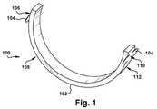
図1は、組織牽引装置100を示す。組織牽引装置100は、牽引細片本体102、及び少なくとも1つの組織係合部材104を備える。組織係合部材104は、牽引細片本体102の上に配置されている。組織係合部材104は、バーブ、クリップ、フック、接着剤、及び任意の他の取り付け機構のうちの少なくとも1つとすることができる。第1の組の組織係合部材106は、牽引細片本体第1の端部108の上に配置され、第2の組の組織係合部材110は、牽引細片本体の第2の端部112の上に配置されることができる。牽引細片本体第1の端部及び第2の端部108、112は、牽引細片本体102に沿って横方向に離間されている。用語「横方向」は、図1の配置では、実質的に水平方向を示すように本明細書で使用される。 FIG. 1 shows a
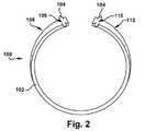
牽引細片本体102は、変形可能な材料から少なくとも部分的に形成されている。牽引細片本体は、(図1に示す)第1の状態と(図2に示す)第2の状態との間で選択的に移行させられることができる。第1の状態では、牽引細片本体102は、標的患者組織Tと係合することが可能である。標的患者組織Tとは、限定されないが、病変とすることができる。第2の状態では、牽引細片本体102は、標的患者組織Tを牽引することができる。 The
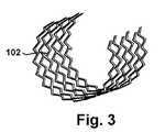
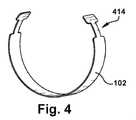
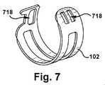
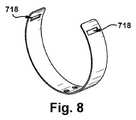
図3に示すように、牽引細片本体102は、網目状の細片としてもよい。図4に示すように、牽引細片本体102は、「細首」構造を形成するように、第1及び第2の各々の端部上に少なくとも1つの窪み414を含んでもよい。図5に示すように、牽引細片本体102は、限定されないが、ダイアモンド形の開口部517などの開口部516を含んでもよい。図6に示すように、牽引細片本体102は、限定されないが、ダイアモンド形の開口部517などの複数の窪み414及び開口部516を含んでもよい。図7〜8に示すように、牽引細片本体102は、限定されないが、鉗子の先端などのクランプ器具(図示せず)の少なくとも一部分を受容するように構成されている少なくとも1つのクランプ孔718を含んでもよい。図9に示すように、牽引細片本体102は、限定されないが、矩形の開口部919などの少なくとも1つの開口部516を含んでもよい。牽引細片本体102は、ダイアモンド形としてもよい。 As shown in FIG. 3, the traction strip
変形可能な材料は、少なくとも部分的に弾性材料であってもよい。弾性材料は、限定されないが、弾性ワイヤなどの弾性材料、布材料、及び限定されないが、ニチノールなどの形状記憶材料のうちの少なくとも1つであってもよい。そのような場合、第1の状態と第2の状態との間の遷移は、加力、及び弾性材料牽引細片本体102の弾性変形のうちの少なくとも一方に応答して生じる。変形可能な材料は、第2の状態に付勢されてもよい。ユーザは、弾性材料牽引細片本体102に力を加えて、弾性材料牽引細片本体102を、第2の状態から第1の状態に変形させることができる。加力圧を除去すると直ちに、形状記憶材料の固有の性質に応答して、弾性材料牽引細片本体102は、第1の状態から第2の状態に自動的に戻る。 The deformable material may be at least partially elastic. The elastic material may be at least one of an elastic material such as, but not limited to, an elastic wire, a cloth material, and, but not limited to, a shape memory material such as nitinol. In such a case, the transition between the first state and the second state occurs in response to the force and at least one of the elastic deformations of the elastic material
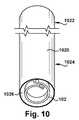
図10に示すように、弾性材料牽引細片本体102は、シース1020が提供される場合、シース送達状態へと移行させられることができる。シース送達状態にある弾性材料牽引細片本体102は、シース1020のシース管腔1022の内部に配置されるための形をしている。シース送達状態にある形状記憶材料及び布材料牽引細片本体102は、当該本体自体の上に重なるように巻かれ、シース管腔1022の直径より小さい直径を有してよい。 As shown in FIG. 10, the elastic material
図10に示すように、シース1020は、シース近位端部1024及びシース遠位端部1026を有する。シース管腔1022は、シース近位端部1024とシース遠位端部1026との間に長手方向に延在する。用語「長手方向の」は、本明細書中で使用され、「横の」方向に対して実質的に垂直な方向を示し、図10の配置では、おおよそ垂直方向として示す。 As shown in FIG. 10, the
変形可能な材料は、少なくとも部分的に温度応答性形状記憶材料であってもよい。温度応答性形状記憶材料は、限定されないが、ニチノールなどの形状記憶合金であってもよい。温度応答性形状記憶材料牽引細片本体102は、遷移温度範囲超の予め設定された形状として第2の状態へと形成されてもよい。遷移温度範囲は、温度応答性形状記憶材料を形成する金属などの材料の特定の割合に依存する。遷移温度範囲未満では、温度応答性形状記憶材料は、高延性であり、第1の状態などの所望の形状へと塑性変形され得る。遷移温度範囲超に再加熱すると直ちに、温度応答性形状記憶材料は、その予め設定された形状、例えば第2の状態に戻る。 The deformable material may be, at least in part, a temperature responsive shape memory material. The temperature-responsive shape memory material is not limited, but may be a shape memory alloy such as nitinol. The temperature responsive shape memory material
変形可能な材料は、少なくとも部分的に展性材料であってもよい。展性材料牽引細片本体102は、第1の状態及び第2の状態のうちの選択された少なくとも一方に選択的に変形され、その状態に保持されることができる。ユーザは、展性材料牽引細片本体102を第1の状態へと変形し、次いでその展性材料牽引細片本体102を第2の状態に徐々に変形することができる。ユーザは、第1の状態と第2の状態との間の任意の所望の形状で展性材料牽引細片本体102の変形を停止することができ、その結果、展性材料牽引細片本体102を、少なくとも部分的に第1の状態にあり、かつ少なくとも部分的に第2の状態にある所望の形状に保持することができる。言い換えると、展性材料牽引細片本体102は、第1の状態、第2の状態、又は第1と第2の状態の間の任意の中間的な状態に手動で変形されることができる。 The deformable material may be at least partially malleable material. The malleable material
変形可能な材料は、少なくとも部分的にフレキシブルステンレス鋼双安定ばねバンドであってもよい。この構成では、フレキシブルステンレス鋼双安定ばねバンド牽引細片本体102は、「スラップブレスレット」、又は「スラップラップ」と同じように動作することができる。スラップブレスレットは、2つの動作位置、又は2つのあるべき状態を有するステンレス鋼双安定ばねバンドを含む。第1の状態とは、細長い位置であり、例えば、フレキシブルステンレス鋼双安定ばねバンド牽引細片本体102の第1の状態である。第1の状態では、ステンレス鋼双安定ばね本体は、位置エネルギーを保持している。第2の状態は、コイルに巻いた状態であり、例えば、フレキシブルステンレス鋼双安定ばねバンド牽引細片本体102の第2の状態である。ステンレス鋼双安定ばねバンドの抵抗力に打ち克つのに十分大きい力が、ステンレス鋼双安定ばねバンドに加えられるとき、位置エネルギーにより、バンドは第1の状態から第2の状態に巻き上がることができる。 The deformable material may be at least partially flexible stainless steel bistable spring bands. In this configuration, the flexible stainless steel bistable spring band
図11に示すように、第1の状態にあるフレキシブルステンレス鋼双安定ばねバンド牽引細片本体102は、心棒1130の心棒外側表面1128と係合するための形をしている。フレキシブルステンレス鋼双安定ばねバンド牽引細片本体102が第1の状態にあるときには、フレキシブルステンレス鋼双安定ばねバンドにより与えられた半径方向の内部力が、フレキシブルステンレス鋼双安定ばねバンド牽引細片本体102を心棒の外側表面1128に制限する。心棒シース(図示せず)は、取り付けられたフレキシブルステンレス鋼双安定ばねバンド牽引細片本体102を使って、心棒1130の上方に配置されてもよく、フレキシブルステンレス鋼双安定ばねバンド牽引細片本体102を心棒の外側表面1128に制限する半径方向の内部力を与える。牽引細片本体が第1の状態にあるときに、図11の矢印で示すように、ユーザは、フレキシブルステンレス鋼双安定ばねバンド牽引細片本体102に力を加えて、フレキシブルステンレス鋼双安定ばねバンド牽引細片本体102が第2の状態に向かって移行するように促すことができる。 As shown in FIG. 11, the flexible stainless steel bistable spring band
組織係合部材104は、牽引細片本体102が第1の状態にあるときに、扁平状態にあり得る。扁平状態にある組織係合部材104は、少なくとも部分的に牽引細片本体102に接して位置決めされることができる。組織係合部材104が扁平状態にあるときに、牽引細片本体102は、標的患者組織Tを組織係合部材104に係合せずに、標的患者組織Sへと挿入されることができる。組織係合部材104は、牽引細片本体102が少なくとも部分的に第2の状態にあるときに、開いた状態にあり得る。開いた状態にある組織係合部材104は、標的患者組織Tと係合することができるように、少なくとも部分的に牽引細片本体102から離間されている。 The
図12に示すように、牽引細片本体102は、少なくとも1つの嵌合部材1232を有してもよい。嵌合部材1232は、少なくとも2つの牽引細片本体102を一緒に選択的に結合するように構成されている。少なくとも2つの牽引細片本体102と一緒の結合は、組み合わされた牽引細片本体1233の有効な幅を増加させるのに望ましい。組み合わされた牽引細片本体1233は、ある特定の状況、例えば、以下に限定されないが、標的患者組織Tがあまりに大きいため、単一の牽引細片本体102によっては牽引することができない場合には、単一の牽引細片本体102よりも一層望ましい。 As shown in FIG. 12, the
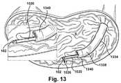
図13に示すように、牽引細片装置100は、内視鏡1334を含んでもよい。内視鏡1334は、内視鏡近位端部(図示せず)及び内視鏡遠位端部1338を有する。内視鏡1334は、内視鏡近位端部(図示せず)と内視鏡遠位端部1338との間に長手方向に延在する内視鏡管腔1340を有する。図18に示すように、取り付けられた牽引細片本体102を伴う心棒1130及び心棒シース(図示せず)のうちの少なくとも一方は、内視鏡管腔1340の直径よりも小さい直径を有するように構成されることができる。図13に示すように、シース1020は、内視鏡管腔1340の直径よりも小さい直径を有するように構成されることができる。 As shown in FIG. 13, the
以下の説明により、例示的な目的のため、シース1020及び弾性材料牽引細片本体102の使用について述べる。上述したいかなる変形可能な材料牽引細片本体102、例えば、温度応答性形状記憶材料牽引細片本体102、展性材料牽引細片本体102、及びステンレス鋼双安定ばねバンド牽引細片本体102は、一連の同様な作動で使用されることができることを理解されたい。さらに、上述したいかなる牽引細片本体102も、シース1020の使用又は不使用の場合でも、標的患者組織部位Sに送達されることができることを理解されたい。 The following description describes the use of the
上述したように、使用するときには、組織牽引装置100は、ユーザに提供される。内視鏡1334は、患者へと挿入されることができる。図13に示すように、内視鏡遠位端部1338は、標的患者組織Tに隣接する標的患者組織部位Sにおいて位置決めされる。 As mentioned above, the
弾性材料牽引細片本体102は、シース状態へと移行されることができる。弾性材料牽引細片本体102がシース管腔1026の直径よりも小さい直径を有するまで、弾性材料牽引細片本体102をそれ自体の上で回転させるユーザによって、弾性材料牽引細片本体102は、シース送達状態へと移行されることができる。弾性材料牽引細片本体102がシース送達状態にある状態で、弾性材料牽引細片本体102は、シース管腔1026の内部に配置される。シース管腔1026の半径方向の内部力は、弾性材料牽引細片本体102をシース送達状態に制限する。 The elastic material
図13に示すように、弾性材料牽引細片本体102がシース送達状態にある状態で、取り付けられた弾性材料牽引細片本体102を伴うシース1020は、内視鏡管腔1340を通って標的患者組織部位Sに進行する。図14に示すように、シース1020は、弾性材料牽引細片本体102が標的患者組織部位Sに留まっている状態で、矢印で描かれているように、標的患者組織部位S及び内視鏡1334のうちの少なくとも1つから後退されることができる。シース1020の牽引により、弾性材料牽引細片本体102が、第1の状態に応答的に移行することができる。シース管腔1026により与えられた半径方向の内部力の除去により、弾性材料牽引細片本体102が、第1の状態へと移行する(例えば、ほどく)ことができる。 As shown in FIG. 13, with the elastic material
図15に示すように、弾性材料牽引細片本体102が第1の状態にある状態で、標的患者組織Tは、少なくとも1つの組織係合部材104と係合される。限定されないが、第1の固定点P1に挿入されるバーブ、第1の固定点P1に取り付けられるクリップ、第1の固定点P1と結合されるフック、第1の固定点P1に取り付けられる接着剤、他の好適な任意の取り付け機構、又はそれらの組み合わせを含む仕組み等の第1の組の組織係合部材106は、提供されたとき、標的患者組織T上の第1の固定点P1に係合することができる。限定されないが、第2の固定点P2に挿入されるバーブ、第2の固定点P2に取り付けられるクリップ、第2の固定点P2に結合されるフック、第2の固定点P2に取り付けられる接着剤、他の好適な任意の取り付け機構、又はそれらの組み合わせを含む仕組み等の第2の組の組織係合部材110は、提供されたとき、標的患者組織Tから離れている第2の固定点P2に係合することができる。第2の固定点P2は、第1の固定点P1から横方向に離間された標的患者組織Tの上に配置されることができる。 As shown in FIG. 15, with the elastic material
図15に示すように、組織係合部材104が標的患者組織Tと係合している状態で、標的患者組織Tにより与えられた長手方向の下方の力は、図15の配置で下向きの矢印で描かれているように、弾性材料牽引細片本体102が第2の状態へ移行することを制限する。第2の組の組織係合部材110が第2の固定点P2と係合しているときには、第1の組の組織係合部材106により係合されたときの第1の固定点P1、及び第2の固定点P2の両方とも、弾性材料牽引細片本体102が第2の状態へ移行することを制限する。言い換えれば、弾性材料牽引細片本体102は、弾性材料の固有の性質のため、その第2の状態へ促されることができる。弾性材料牽引細片本体102は、標的患者組織Tの第1の固定点P1、及び/又は第2の固定点P2に係合されているため、弾性材料牽引細片本体102は、図15の実質的に上向きの矢印で描かれているように、おおよそ長手方向の上方の力を与え、その結果、係合された組織を牽引し、第2の位置に向かって移行させる。係合された組織は、周囲の患者組織に取り付けられ、その当初の位置に留まるように促される。係合された組織は、反作用力を与え、その反作用力は、図15の下向きの矢印で描かれているように、長手方向の下向きの力であり、弾性材料牽引細片本体102の長手方向の上向きの力に対抗し、係合された組織の牽引を防いでいる。この長手方向の下向きの力が、弾性材料牽引細片本体102が第2の状態に移行するのを制限している。 As shown in FIG. 15, with the
図16に示すように、剥離器1642は、標的患者組織部位Sに提供されることができる。剥離器1642は、内視鏡管腔1340を通して標的患者組織部位Sに進行することができる。弾性材料牽引細片本体102が第1の状態で標的患者組織Tと係合している状態で、標的患者組織Tの少なくとも一部分を剥離することができる。標的患者組織Tの剥離は、標的患者組織Tにより与えられた長手方向の下向きの力を応答的に軽減する。 As shown in FIG. 16, the
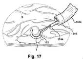
図16〜17に示すように、標的患者組織Tに取り付けられた状態で、弾性材料牽引細片本体102を第2の状態へと選択的に移行させることによって、標的患者組織Tは、牽引位置へと選択的に移行される。標的患者組織Tにより与えられた長手方向の下向きの力の軽減により、牽引細片本体102が、弾性材料の固有の性質に応答して、第2の状態に移行するように促すことができる。 As shown in FIGS. 16 to 17, the target patient tissue T is moved to the traction position by selectively shifting the elastic material
図16〜17に示すように、標的患者組織Tに取り付けられている状態で、弾性材料牽引細片本体102が第1の位置から第2の位置へ選択的に移行すると、組織係合部材104が、標的患者組織Tをその当初の位置から牽引位置まで応答的に移行させる。ユーザは、内視鏡管腔1340を通して、取り付けられ剥離された標的患者組織Tを伴う組織牽引装置100を、標的患者組織部位Sから取り除くことができる。図17に示すように、ユーザは、捕捉器具1744を使用して、内視鏡管腔1340を通して、取り付けられ剥離された標的患者組織Tを伴う組織牽引装置100を、標的患者組織部位Sから取り除くことができる。 As shown in FIGS. 16 to 17, when the elastic material traction strip
弾性材料牽引細片本体102は、シース1020のない上記で述べたように、おおよそ同様な順序で提供され、使用されることができる。しかしながら、シース1020がない場合、ユーザは、弾性材料牽引細片本体102を変形させて、弾性材料牽引細片本体102を第2の状態から第1の状態に移行させる。さらに、第1の状態にある弾性材料牽引細片本体102を使うと、弾性材料牽引細片本体102は、内視鏡管腔1340を通して出して、標的患者組織部位Sに挿入される。 The elastic material
上述のように、温度応答性形状記憶材料牽引細片本体102は、おおよそ同様な順序で提供され、使用されることができる。しかしながら、温度応答性形状記憶材料牽引細片本体102を使って、ユーザは、温度応答性形状記憶材料牽引細片本体102を遷移温度範囲未満の温度に冷却する。ひとたび温度応答性形状記憶材料牽引細片本体102が、遷移温度範囲未満の温度に冷却されると、ユーザは、温度応答性形状記憶材料牽引細片本体102を第2の状態から第1の状態に変形させる。 As mentioned above, the temperature responsive shape memory material
さらに、標的患者組織部位Sにおける温度応答性牽引細片本体102を使うと、標的患者組織部位Sにおける周囲熱は、温度応答性形状記憶材料牽引細片本体102を遷移温度範囲超の温度まで上げることができる。温度応答性形状記憶材料牽引細片本体102が、遷移温度範囲超の温度まで加熱されると、温度応答性形状記憶材料の固有の性質により、温度応答性形状記憶材料牽引細片本体102が第2の状態に向けて選択的に促される。標的患者組織Tにより与えられた長手方向の下向きの力の軽減により、温度応答性形状記憶材料牽引細片本体102が、温度応答性形状記憶材料の固有の性質に応答して、第2の状態に移行するのを促すことができる。 Further, when the temperature responsive
上述のように、展性材料牽引細片本体102は、おおよそ同様の順序で提供され、使用されることができる。しかしながら、展性材料牽引細片本体102については、ユーザは、展性材料牽引細片本体102を第1の状態に移行させるように、展性材料牽引細片本体102を変形させる。標的患者組織Tが剥離されるときに、展性材料牽引細片本体102のユーザ操作により、展性材料牽引細片本体102は、第2の状態に選択的にかつ手動で変形されることができる。 As mentioned above, the malleable material
上述のように、フレキシブルステンレス鋼双安定ばねバンド牽引細片本体102は、おおよそ同様な順序で提供され、使用されることができる。しかしながら、フレキシブルステンレス鋼双安定ばねバンド牽引細片本体102を使うと、フレキシブルステンレス鋼双安定ばねバンド牽引細片本体102は、心棒の外側表面1128の周りのフレキシブルステンレス鋼双安定ばねバンド牽引細片本体102を変形させることにより、第1の状態へと移行されることができる。フレキシブルステンレス鋼双安定ばねバンドにより与えられた半径方向の内部力が、フレキシブルステンレス鋼双安定ばねバンド牽引細片本体102を心棒の外側表面1128に制限する。図18に示すように、取り付けられたステンレス鋼双安定ばねバンド牽引細片本体102を伴う心棒1130は、内視鏡管腔1340を通して標的患者組織部位Sに挿入されることができる。 As mentioned above, the flexible stainless steel bistable spring band
フレキシブルステンレス鋼双安定ばねバンド牽引細片本体102は、組織係合部材104が、標的患者組織Tの少なくとも一部分に直接接触しているように、位置決めされている。標的患者組織Tの少なくとも一部分に直接接触している組織係合部材104を使うと、心棒1130は、標的患者組織部位S及び内視鏡管腔1340のうちの少なくとも1つから取り除かれる。 The flexible stainless steel bistable spring band
標的患者組織Tは、フレキシブルステンレス鋼双安定ばねバンド牽引細片本体102に選択的に力を加えるユーザによって、ステンレス鋼双安定ばねバンド牽引細片本体102により係合され、ステンレス鋼双安定ばねバンド牽引細片本体102を第2の状態に向けて移行するように促すことができる。フレキシブルステンレス鋼双安定ばねバンド牽引細片本体102に力を加えることにより、組織係合機構104が、扁平状態から開いた状態へ移行することができる。開いた状態にある組織係合機構104を使うと、組織係合機構104は、標的患者組織Tと係合されることができる。 The target patient tissue T is engaged by the stainless steel bistable spring band
上述のように、フレキシブルステンレス鋼双安定ばねバンド牽引細片本体102は、同様な方法で第2の状態に移行するのを制限される。標的患者組織Tにより与えられた長手方向の下向きの力の軽減により、ステンレス鋼双安定ばねバンドの固有の性質に応答して、牽引細片本体102が、第2の状態に移行するのを促すことができる。 As mentioned above, the flexible stainless steel bistable spring band
牽引組織装置100は、プラットフォーム(図示せず)を含み得ることが企図される。牽引細片本体102は、そのプラットフォームと結合されるように、かつ/又はそのプラットフォーム内にカプセル化されるように構成される。プラットフォームは、少なくとも部分的にポリマーから作製されてもよい。プラットフォームは、少なくとも1つのプラットフォーム組織係合機構(図示せず)を含んでもよい。プラットフォーム組織係合機構は、クリップ、バーブ、フック、接着剤、及び任意の他の取り付け機構のうちの少なくとも1つとしてもよい。取り付けられた牽引細片本体102を有するプラットフォームは、シース管腔1026及び内視鏡管腔1340のうちの少なくとも1つを通して管の大きさとしてもよい。 It is contemplated that the
組織係合機構104は、標的患者組織T、第1の固定点P1、及び第2の固定点P2のうちの少なくとも1つと着脱可能に係合されるように構成されてもよいことが企図される。この構成では、牽引細片本体102は、標的患者組織部位Sから標的患者組織Tを取り除く前に、標的患者組織T、第1の固定点P1、及び第2の固定点P2のうちの少なくとも1つから取り除くことができる。組織係合機構104と着脱可能に係合することにより、牽引細片本体102が、標的患者組織Tの剥離中に再度位置決めされることが可能となる。 It is contemplated that the
図19に示すように、第2の固定点P2は、第1の固定点P1から横方向に離間された標的患者組織Tの上に配置されるように示し、また上述されてきたが、第2の固定点P2、又は任意の他の固定点(複数可)はまた、あるいはこれに代えて、標的患者組織T及び第1の固定点P1のうちの少なくとも1つと対向し、かつ離間され得ることが企図される。そのような場合には、標的患者組織Tが牽引状態にある場合、第2の組の組織係合部材110は、牽引される細片本体102及び剥離される標的患者組織を第2の固定点P2に固定する。 As shown in FIG. 19, the second fixed point P2 is shown to be located on the target patient tissue T laterally spaced from the first fixed point P1 and has been described above. The fixed point P2 of 2 or any other fixed point (s) may also, or instead, face and be separated from at least one of the target patient tissue T and the first fixed point P1. Is intended. In such a case, if the target patient tissue T is in a traction state, the second set of
組織牽引装置100は、手技、例えば、以下に限定されないが、内視鏡的粘膜下層剥離術の中でユーザを補助し得ることが企図される。組織牽引装置100は、別個のユーザ操作式の組織牽引ツールを必要とすることなく露出されることができるように、内視鏡1334と無関係な病変を牽引するのに使用されることができる。 It is contemplated that the
組織牽引装置100は、内視鏡的粘膜下層剥離術などの手技の中で使用されるように記載されてきたが、組織牽引装置100は、患者から標的とされた患者組織の剥離、牽引、及び除去を含み得る任意の同様な手技の中で使用されることができることを理解されたい。 Although the
複数の変形可能な材料構成が、ある特定の性質及び使用構成を有するようにそれぞれ記載されてきたが、変形可能な様々な材料構成は、組織牽引装置100に悪影響を与えなければ、使用構成において交換可能であることを理解されたい。 Although a plurality of deformable material configurations have been described to have certain properties and usage configurations, the various deformable material configurations have been described in the usage configuration as long as they do not adversely affect the
ステンレス鋼双安定ばねバンドは、ステンレス鋼であるものとして説明されてきたが、双安定ばねバンドは、任意の適切なポリマー、任意の適切な金属、任意の他の適切な材料、又はそれらの任意の組み合わせから作製されてもよいことを理解されたい。 Stainless steel bistable spring bands have been described as being stainless steel, but bistable spring bands are any suitable polymer, any suitable metal, any other suitable material, or any of them. It should be understood that it may be made from a combination of.
本開示の態様は、上記の例の態様を参照しながら具体的に示され、説明されてきたが、様々な追加の態様が企図され得ることを、当業者であれば理解するであろう。例えば、様々な装置を使用するために上述された特定の方法は、単なる例示であり、当業者ならば、上述の装置、又はそれらの構成要素を、本明細書中で示し、かつ説明したそれらに置き換えて、ツール、一連の工程、又は手段/選択肢をいくらでも簡単に確定することができる。各図の中で明瞭さを維持しようとすると、重複して示された構成要素の特定のものは、具体的に番号付けされていないが、当業者は、番号付けされた構成要素に基づいて、番号付けされていない構成要素と関連付けられているにちがいない要素番号を悟るであろうし、同様の構成要素間の区別は、意図されておらず、図中の要素番号の有無により単純に含意されていない。説明された任意の構造及び構成要素は、単一の単位若しくはモノリシックな部分品として、一体化して形成された方がよく、又は、任意の一般品若しくは特注品の構成要素、又は/又は任意の好適な材料若しくは材料の組み合わせを含むこれらの形式のどちらかを使って、別々のサブ構成要素から作り上げた方がよいが、しかしながら、選択された材料(複数可)は、多くの適用分野に対して生体適合性を持つ必要がある。任意の望ましい構造及び構成要素は、特定の使用環境に対して望ましいように、使い捨てが可能であり、又は再利用可能であった方がよい。任意の構成要素は、材料、構成、少なくとも1つの大きさ、又はその構成要素に属する同種のものを表すためのユーザ識別可能な記号と一緒に提供された方がよく、このユーザ識別可能な記号は、特定の使用環境用の同じような構成要素の配列から1つの構成要素を選択する際にユーザを潜在的に支援する。「予め設定された」状態は、現実に操作される構造がその状態に到達する前にいつでも判定されることができ、望ましい「予め設定された」状態は、その構造が予め設定された状態に達するほんの直前に判定される。用語「実質的に」は、本明細書中で使用され、大部分、ただし必ずしも完全ではない質を表し、「実質的な」質として明示された質は、いくらかの比較的少ない非良質な要素を包含する可能性を認める。本明細書中で説明された特定の構成要素は、特定の幾何学的形状を有するように示されているが、本開示のすべての構造は任意の好適な形状、大きさ、構成、相対的な関係、断面積、又は特定の適用分野の望ましい他の任意の物理的特性を有してもよい。1つの態様又は構成を参照して説明された任意の構造又は特徴は、単一で、又は他の構造若しくは特徴と組み合わせて提供されてもよく、なぜならば、他のすべての態様に関して論述されたすべての選択肢を有するように、本明細書中で論述された態様及び構成のそれぞれについて説明することは、非現実的であるからである。任意のこれらの特徴を組み合わせる装置又は方法は、以下の特許請求の範囲及びそれらの任意の等価物を基準にして判定される場合、本開示の範囲に該当することを理解されたい。 Aspects of the present disclosure have been specifically shown and described with reference to aspects of the above examples, but those skilled in the art will appreciate that various additional aspects may be contemplated. For example, the specific methods described above for using various devices are merely exemplary, and those skilled in the art will appreciate the devices described above, or their components, as shown and described herein. You can easily determine any number of tools, sequences, or means / options by substituting for. In an attempt to maintain clarity within each figure, certain duplicated components are not specifically numbered, but those skilled in the art will be based on the numbered components. You will realize the element numbers that must be associated with the unnumbered components, and the distinction between similar components is not intended and is simply implied by the presence or absence of the element numbers in the figure. It has not been. Any of the structures and components described should be integrally formed as a single unit or monolithic component, or any general or custom component, or / or any. It is better to build from separate subcomponents using either of these forms, including suitable materials or combinations of materials, however, the materials selected (s) are for many applications. Must be biocompatible. Any desired structure and component should be disposable or reusable, as desired for a particular environment of use. Any component should be provided with a user-identifiable symbol to represent a material, composition, at least one size, or the same kind belonging to that component, this user-identifiable symbol. Potentially assists the user in selecting one component from an array of similar components for a particular usage environment. A "preset" state can be determined at any time before the actually manipulated structure reaches that state, and a desirable "preset" state is a state in which the structure is preset. Judged just before reaching. The term "substantially" is used herein to refer to a quality that is mostly, but not necessarily perfect, and the quality manifested as "substantial" quality is some relatively few non-quality elements. Recognize the possibility of including. Although the particular components described herein are shown to have a particular geometry, all structures of the present disclosure are of any suitable shape, size, configuration, relative. It may have any relationship, cross-sectional area, or any other desired physical property of a particular application. Any structure or feature described with reference to one aspect or configuration may be provided alone or in combination with other structures or features, because all other aspects have been discussed. It is impractical to describe each of the embodiments and configurations discussed herein to have all the options. It should be understood that any device or method that combines any of these features falls within the scope of the present disclosure when determined on the basis of the following claims and any equivalents thereof.
他の態様、目的、及び利点は、図面、本発明、及び添付した特許請求の範囲の調査から獲得されることができる。 Other aspects, objectives, and advantages can be obtained from the drawings, the present invention, and the appended claims.
(項目1)
牽引細片本体であって、前記牽引細片本体は、変形可能な材料から少なくとも部分的に形成され、前記牽引細片本体は、第1の状態では、前記牽引細片本体が標的患者組織と係合することができ、一方、第2の状態では、前記牽引細片本体が前記標的患者組織を牽引することができるように、前記第1の状態と前記第2の状態との間で選択的に移行させられることができる、牽引細片本体と、
少なくとも1つの組織係合部材であって、前記少なくとも1つの組織係合部材は、前記牽引細片本体の上に配置されている、少なくとも1つの組織係合部材と、を備える組織牽引装置。
(項目2)
前記変形可能な材料が、弾性材料であり、前記第1の状態と第2の状態との間の遷移は、加力、及び前記牽引細片本体の弾性変形のうちの少なくとも一方に応答して生じる、項目1に記載の組織牽引装置。
(項目3)
前記変形可能な材料は、弾性材料、形状記憶材料、及び布材料のうちの少なくとも1つである、項目2に記載の組織牽引装置。
(項目4)
前記牽引細片本体は、シース送達状態へと移行させられることが可能であり、前記シース送達状態にある前記牽引細片本体は、シースのシース管腔内部に配置されるための形をしている、項目3に記載の組織牽引装置。
(項目5)
前記変形可能な材料が、温度応答性形状記憶材料であり、前記牽引細片本体が、前記第2の状態に予め設定されているように構成され、前記牽引細片本体は、前記牽引細片本体が遷移温度範囲未満の温度にあるとき、前記第2の状態から前記第1の状態へと変形させられることが可能なように構成され、前記牽引細片本体は、前記牽引細片本体が前記遷移温度範囲を超える温度にあるとき、前記第2の状態に自動的に戻るように構成されている、項目1に記載の組織牽引装置。
(項目6)
前記変形可能な材料が、展性材料であり、展性材料から少なくとも部分的に形成された前記牽引細片本体が、前記第1の状態及び第2の状態のうちの少なくとも選択された一方の状態に、選択的に変形させられ、かつ保持されることができる、項目1に記載の組織牽引装置。
(項目7)
前記変形可能な材料が、フレキシブルなステンレス鋼双安定ばねバンドである、項目1に記載の組織牽引装置。
(項目8)
前記第1の状態にある前記牽引細片本体は、心棒の外側表面と係合するような形をしており、前記組織係合部材は、前記牽引細片本体が前記第1の状態にあるときには、扁平状態にあり、前記組織係合部材は、前記牽引細片本体が少なくとも部分的に前記第2の状態にあるときには、開いた状態にある、項目7に記載の組織牽引装置。
(項目9)
前記組織係合部材が、バーブ、クリップ、フック、接着剤、及び任意の他の取り付け機構のうちの少なくとも1つである、項目1に記載の組織牽引装置。
(項目10)
第1の組の組織係合部材は、牽引細片本体の第1の端部の上に配置され、第2の組の組織係合部材は、牽引細片本体の第2の端部の上に配置され、前記牽引細片本体の第1の端部及び第2の端部は、横方向に離間されている、項目1に記載の組織牽引装置。
(項目11)
前記牽引細片本体は、少なくとも1つの嵌合部材を有し、前記嵌合部材は、少なくとも2つの牽引細片本体を一緒に選択的に連結するように構成されている、項目1に記載の組織牽引装置。
(項目12)
粘膜下層剥離術を補助するための方法であって、
組織牽引装置を提供することであって、前記組織牽引装置は、
牽引細片本体であって、前記牽引細片本体は、変形可能な材料から少なくとも部分的に形成され、前記牽引細片本体は、第1の状態では、前記牽引細片本体が標的患者組織と係合することができ、一方、第2の状態では、前記牽引細片本体が前記標的患者組織を牽引することができるように前記第1の状態と前記第2の状態との間で選択的に移行させられることができる、牽引細片本体と、
少なくとも1つの組織係合部材であって、前記少なくとも1つの組織係合部材は、前記牽引細片本体の上に配置されている、少なくとも1つの組織係合部材と、
内視鏡であって、前記内視鏡は、内視鏡近位端部及び内視鏡遠位端部を有し、前記内視鏡は、前記内視鏡近位端部と前記内視鏡遠位端部との間に長手方向に延在する内視鏡管腔を有する、内視鏡と、を有する、ことと、
前記内視鏡を患者へと挿入することと、
前記標的患者組織に隣接する標的患者組織部位に前記内視鏡遠位端部を位置決めすることと、
前記第1の状態へと前記牽引細片本体を選択的に移行させることと、
前記牽引細片本体が前記第1の状態にある状態で、前記牽引細片本体を、前記内視鏡管腔を通して出して、前記標的患者組織部位に挿入することと、
前記牽引細片本体が前記第1の状態にある状態で、前記標的患者組織を少なくとも1つの組織係合部材と係合させることと、
前記牽引細片本体を前記第2の状態へと選択的に移行させることによって、前記標的患者組織を牽引位置へと選択的に移行させることと、
前記第1の位置から前記第2の位置への前記牽引細片本体の前記選択的移行により、前記組織係合部材が、前記標的患者組織を前記標的患者組織の当初の位置から牽引位置に応答的に移行させることと、を含む方法。
(項目13)
前記変形可能な材料は、少なくとも部分的に、弾性材料であり、前記牽引細片本体は、前記第2の状態に付勢されており、前記方法は、
前記組織係合部材が前記標的患者組織と係合している状態で、前記標的患者組織により与えられる長手方向の下方の力を利用することによって、前記牽引細片本体が前記第2の状態に移行することを制限することと、
剥離器を前記標的患者組織部位に提供することと、
前記牽引細片本体が前記第1の状態で前記標的患者組織と係合している状態で、前記標的患者組織の少なくとも一部分を剥離することであって、前記標的患者組織の前記剥離が、前記標的患者組織により与えられる長手方向の下方の力を応答的に軽減する、ことと、
前記標的患者組織により与えられる長手方向の下方の力の前記軽減を利用して、前記牽引細片本体が、形状記憶材料の固有の性質に応じて、前記第2の状態に移行するように促すことと、を含む、項目12に記載の方法。
(項目14)
前記変形可能な材料は、弾性材料、形状記憶材料、及び布材料のうちの少なくとも1つであり、前記方法は、
シースを提供することであって、前記シースは、シース近位端部及びシース遠位端部を有し、前記シースは、前記シース近位端部と前記シース遠位端部との間に長手方向に延在するシース管腔を有する、ことと、
前記牽引細片本体をシース送達状態へと選択的に移行させることと、
前記牽引細片本体が前記シース送達状態にある状態で、前記牽引細片本体を前記シース管腔の内部に配置することと、
前記シース管腔の半径方向の内向き力を利用して前記牽引細片本体を前記シース送達状態に制限することと、
前記牽引細片本体が前記シース送達状態にある状態で、取り付けられた牽引細片本体を伴う前記シースを、前記内視鏡管腔を通して前記標的患者組織部位へ前進させることと、
前記牽引細片本体が前記標的患者組織部位に留まっている状態で、前記標的患者組織部位及び前記内視鏡のうちの少なくとも一方から前記シースを後退させることと、
前記シースの前記後退を利用して、前記牽引細片本体を、前記第1の状態に応答的に移行させることと、を含む、項目13に記載の方法。
(項目15)
前記変形可能な材料が、少なくとも部分的に温度応答性形状記憶材料であり、前記牽引細片本体が、前記第2の状態に予め設定され、前記方法は、
前記牽引細片本体を遷移温度範囲未満の温度に選択的に冷却することと、
前記牽引細片本体が前記遷移温度範囲未満の温度にある状態で、前記牽引細片本体を前記第2の状態から前記第1の状態に選択的に変形させることと、
前記標的患者組織における周囲熱を利用して、前記牽引細片本体を前記遷移温度範囲超の温度にまで加熱することと、
前記牽引細片本体が前記遷移温度範囲超の温度にある状態で、前記変形可能な材料の固有の特性を利用して、前記牽引細片本体を前記第2の状態に向けて選択的に促すことと、
前記組織係合部材が前記標的患者組織と係合している状態で、前記標的患者組織により与えられる長手方向の下方の力を利用することによって、前記牽引細片本体が、前記第2の状態に移行させられることを制限することと、
剥離器を前記標的患者組織部位に提供することと、
前記牽引細片本体が、前記第1の状態で前記標的患者組織と係合している状態で、前記標的患者組織の少なくとも一部分を剥離し、前記標的患者組織により与えられる長手方向の下方の力を応答的に軽減することと、
前記標的患者組織により与えられる長手方向の下方の力の前記軽減を伴って、前記牽引細片本体が、前記温度応答性形状記憶材料の固有の性質に応答して、前記第2の状態に移行するように促すことと、を含む、項目12に記載の方法。
(項目16)
前記変形可能な材料が、少なくとも部分的に展性材料であり、前記牽引細片本体は、前記第1の状態及び第2の状態のうちの少なくとも選択された一方の状態に、選択的に変形させられ、かつ保持されることができ、前記方法は、
前記牽引細片本体を前記第1の状態へと選択的に変形させることと、
剥離器を前記標的患者組織部位に提供することと、
前記標的患者組織の少なくとも一部分を剥離することと、
前記標的患者組織が剥離されるにつれて、前記牽引細片本体を前記第2の状態に選択的にかつ手動で変形させることと、
前記牽引細片本体を用いて、前記剥離された標的患者組織を前記牽引位置へと少なくとも部分的に促すことと、を含む、項目12に記載の方法。
(項目17)
前記変形可能な材料が、フレキシブルステンレス鋼双安定ばねバンドであり、前記牽引細片本体は、前記第2の状態に付勢されており、前記方法は、
心棒の外側表面の周りに前記牽引細片本体を変形させることによって、前記牽引細片本体を前記第1の状態へと選択的に移行させることと、
前記フレキシブルステンレス鋼双安定ばねバンドにより与えられる半径方向の内向き力を利用して、前記牽引細片本体を前記心棒の前記外側表面に制限することと、
前記牽引細片本体が前記第1の状態にある状態で、取り付けられた牽引細片本体を伴う前記心棒を、前記内視鏡管腔を通して前記標的患者組織部位に挿入することと、
前記組織係合部材が、前記標的患者組織の少なくとも一部分に接触しているように、前記牽引細片本体を位置決めすることと、
前記牽引細片本体が前記標的患者組織の少なくとも一部分に接触している状態で、前記標的患者組織部位及び前記内視鏡管腔のうちの少なくとも一方から前記心棒を取り除くことと、
前記牽引細片本体が前記第2の状態に向けて移行するように促すように、前記牽引細片本体に選択的に力を加えることと、
前記牽引細片本体が前記第1の状態にある状態で、前記標的患者組織により与えられる長手方向の下方の力を利用することによって、前記牽引細片本体が、前記第2の状態に移行することを制限することと、
剥離器を前記標的患者組織部位に挿入することと、
前記牽引細片本体が前記第1の状態で前記標的患者組織と係合している状態で、前記標的患者組織の少なくとも一部分を剥離し、前記標的患者組織により与えられる長手方向の下方の力を応答的に軽減することと、
前記標的患者組織により与えられる長手方向の下方の力の前記軽減を伴って、前記牽引細片本体が、前記フレキシブルステンレス鋼双安定ばねバンドの固有の性質に応答して、前記第2の状態に移行するように促すことと、を含む、項目12に記載の方法。
(項目18)
粘膜下層剥離術を補助するためのシステムであって、
組織牽引装置であって、
牽引細片本体であって、前記牽引細片本体は、横方向に離間された第1の端部及び第2の端部を有し、前記牽引細片本体は、変形可能な材料から少なくとも部分的に形成され、前記牽引細片本体は、第1の状態では、前記牽引細片本体が標的患者組織と係合することができ、一方、第2の状態では、前記牽引細片本体が前記標的患者組織を牽引することができるように、前記第1の状態と前記第2の状態との間で選択的に移行させられることができる、牽引細片本体と、
少なくとも2組の組織係合部材であって、第1の組の組織係合部材は、前記牽引細片本体の第1の端部の上に配置され、第2の組の組織係合部材は、前記牽引細片本体の第2の端部の上に配置され、前記組織係合部材は、バーブ、クリップ、フック、接着剤、及び任意の他の取り付け機構のうちの少なくとも1つである、少なくとも2組の組織係合部材と、を有する組織牽引装置と、
内視鏡であって、前記内視鏡は、近位端部及び遠位端部を有し、前記内視鏡は、前記内視鏡近位端部と前記内視鏡遠位端部との間に長手方向に延在する内視鏡管腔を有する、内視鏡と、
剥離器と、を備えるシステム。
(項目19)
前記変形可能な材料が、弾性材料であり、前記第1の状態と第2の状態との間の遷移が、加力、及び前記牽引細片本体の弾性変形のうちの少なくとも一方に応答して生じる、項目18に記載の組織牽引装置。
(項目20)
前記変形可能な材料が、弾性材料、形状記憶材料、及び布材料のうちの少なくとも1つであり、前記牽引細片本体は、シース送達状態へと移行させられることができ、前記シース送達状態にある前記牽引細片本体は、シースのシース管腔の内部に配置されるような形をしている、項目19に記載の組織牽引装置。
(項目21)
前記変形可能な材料が、温度応答性形状記憶材料であり、前記牽引細片本体は、前記第2の状態に予め設定されているように構成され、前記牽引細片本体が遷移温度範囲未満の温度にあるときには、前記牽引細片本体は、前記第2の状態から前記第1の状態へと変形させられることができるように構成され、前記牽引細片本体が前記遷移温度範囲超の温度にあるときには、前記牽引細片本体は、前記第2の状態に自動的に戻るように構成されている、項目18に記載の組織牽引装置。
(項目22)
前記変形可能な材料が、展性材料であり、展性材料から少なくとも部分的に形成された前記牽引細片本体が、前記第1の状態及び第2の状態のうちの少なくとも選択された一方の状態に、選択的に変形させられ、かつ保持されることができる、項目18に記載の組織牽引装置。
(項目23)
前記変形可能な材料が、フレキシブルステンレス鋼双安定ばねバンドであり、前記第1の状態にある前記牽引細片本体は、心棒の外側表面と係合するような形をしており、前記組織係合部材は、前記牽引細片本体が前記第1の状態にあるときには、扁平状態にあり、前記組織係合部材は、前記牽引細片本体が少なくとも部分的に前記第2の状態にあるときには、開いた状態にある、項目18に記載の組織牽引装置。(Item 1)
A traction strip body, wherein the traction strip body is at least partially formed from a deformable material, and in the first state, the traction strip body is a target patient tissue. It can be engaged, while in the second state, the selection between the first state and the second state is such that the traction strip body can pull the target patient tissue. With the tow strip body, which can be transferred
A tissue traction device comprising at least one tissue engaging member, wherein the at least one tissue engaging member is disposed on the traction strip body.
(Item 2)
The deformable material is an elastic material, and the transition between the first state and the second state responds to a force and at least one of the elastic deformations of the traction strip body. The tissue traction device according to item 1 that occurs.
(Item 3)
The tissue traction device according to item 2, wherein the deformable material is at least one of an elastic material, a shape memory material, and a cloth material.
(Item 4)
The traction strip body can be transitioned to the sheath delivery state, and the traction strip body in the sheath delivery state is shaped to be placed inside the sheath lumen of the sheath. The tissue traction device according to item 3.
(Item 5)
The deformable material is a temperature-responsive shape storage material, the traction strip body is configured to be preset in the second state, and the traction strip body is the traction strip body. When the main body is at a temperature below the transition temperature range, the traction strip main body is configured so that it can be deformed from the second state to the first state. The tissue traction device according to item 1, which is configured to automatically return to the second state when the temperature exceeds the transition temperature range.
(Item 6)
The deformable material is a malleable material, and the traction strip body, which is at least partially formed from the malleable material, is at least one of the first and second states selected. The tissue traction device according to item 1, which can be selectively transformed and held in a state.
(Item 7)
The tissue traction device according to item 1, wherein the deformable material is a flexible stainless steel bistable spring band.
(Item 8)
The traction strip body in the first state has a shape that engages with the outer surface of the mandrel, and the tissue engaging member has the traction strip body in the first state. The tissue traction device according to item 7, wherein the tissue engaging member is sometimes in a flat state and is in an open state when the traction strip body is at least partially in the second state.
(Item 9)
The tissue traction device according to item 1, wherein the tissue engaging member is at least one of a barb, a clip, a hook, an adhesive, and any other attachment mechanism.
(Item 10)
The first set of tissue engaging members is located above the first end of the traction strip body and the second set of tissue engaging members is above the second end of the traction strip body. The tissue traction device according to item 1, wherein the first end portion and the second end portion of the traction strip main body are laterally separated from each other.
(Item 11)
Item 1. The traction strip body comprises at least one fitting member, wherein the fitting member is configured to selectively connect at least two traction strip bodies together. Tissue traction device.
(Item 12)
A method to assist submucosal dissection,
To provide a tissue traction device, said tissue traction device
A traction strip body, wherein the traction strip body is at least partially formed from a deformable material, and in the first state, the traction strip body is a target patient tissue. It can be engaged, while in the second state, it is selective between the first state and the second state so that the traction strip body can pull the target patient tissue. With the tow strip body, which can be transferred to
At least one tissue engaging member, said at least one tissue engaging member with at least one tissue engaging member disposed on the traction strip body.
An endoscope, the endoscope having a proximal end of the endoscope and a distal end of the endoscope, the endoscope having the proximal end of the endoscope and the endoscope. Having an endoscope, having an endoscopic lumen extending longitudinally between it and the distal end of the mirror, and
Inserting the endoscope into the patient and
Positioning the distal end of the endoscope at the target patient tissue site adjacent to the target patient tissue
To selectively shift the tow strip body to the first state, and
With the traction strip body in the first state, the traction strip body is pulled out through the endoscopic lumen and inserted into the target patient tissue site.
Engaging the target patient tissue with at least one tissue engaging member while the traction strip body is in the first state.
By selectively shifting the traction strip body to the second state, the target patient tissue is selectively moved to the traction position.
Due to the selective migration of the traction strip body from the first position to the second position, the tissue engaging member responds to the target patient tissue from the initial position of the target patient tissue to the traction position. And how to include.
(Item 13)
The deformable material is, at least in part, an elastic material, the traction strip body is urged to the second state, the method.
With the tissue engaging member engaged with the target patient tissue, the traction strip body is brought into the second state by utilizing the longitudinal downward force exerted by the target patient tissue. Restricting migration and
Providing a stripper to the target patient tissue site and
The detachment of the target patient tissue is to exfoliate at least a part of the target patient tissue while the traction strip body is engaged with the target patient tissue in the first state. Responsibly relieve the longitudinal downward force exerted by the target patient tissue, and
Utilizing the reduction of the longitudinal downward force exerted by the target patient tissue, the traction strip body is encouraged to transition to the second state, depending on the inherent properties of the shape memory material. The method of item 12, comprising:
(Item 14)
The deformable material is at least one of an elastic material, a shape memory material, and a cloth material.
To provide a sheath, the sheath has a proximal end of the sheath and a distal end of the sheath, and the sheath is longitudinal between the proximal end of the sheath and the distal end of the sheath. Having a sheathed lumen extending in the direction,
To selectively shift the traction strip body to the sheath delivery state, and
With the traction strip body in the sheath delivery state, the traction strip body is placed inside the sheath lumen.
Using the radial inward force of the sheath lumen to limit the traction strip body to the sheath delivery state.
With the traction strip body in the sheath delivery state, the sheath with the attached traction strip body is advanced through the endoscopic lumen to the target patient tissue site.
Retracting the sheath from at least one of the target patient tissue site and the endoscope while the traction strip body remains at the target patient tissue site.
13. The method of item 13, wherein the retracting of the sheath is used to responsively transition the traction strip body to the first state.
(Item 15)
The deformable material is, at least in part, a temperature-responsive shape memory material, the traction strip body is preset in the second state, and the method.
To selectively cool the tow strip body to a temperature below the transition temperature range,
In a state where the tow strip body is at a temperature below the transition temperature range, the tow strip body is selectively deformed from the second state to the first state.
Using the ambient heat in the target patient tissue, the traction strip body is heated to a temperature above the transition temperature range.
With the traction strip body at a temperature above the transition temperature range, the traction strip body is selectively prompted towards the second state by utilizing the unique properties of the deformable material. That and
With the tissue engaging member engaged with the target patient tissue, the traction strip body is brought into the second state by utilizing the longitudinal downward force exerted by the target patient tissue. To limit what can be migrated to
Providing a stripper to the target patient tissue site and
With the traction strip body engaged with the target patient tissue in the first state, at least a portion of the target patient tissue is detached and a longitudinal downward force exerted by the target patient tissue. Responsibly mitigate
With the reduction of the longitudinal downward force exerted by the target patient tissue, the traction strip body transitions to the second state in response to the inherent properties of the temperature responsive shape memory material. The method of item 12, comprising urging the patient to do so.
(Item 16)
The deformable material is at least partially malleable, and the traction strip body is selectively deformed into at least one of the first and second states. And can be retained, the method described above.
To selectively deform the traction strip body to the first state,
Providing a stripper to the target patient tissue site and
Exfoliating at least a portion of the target patient tissue
To selectively and manually deform the traction strip body to the second state as the target patient tissue is exfoliated.
The method of item 12, comprising using the traction strip body to at least partially urge the detached target patient tissue to the traction position.
(Item 17)
The deformable material is a flexible stainless steel bistable spring band, and the traction strip body is urged to the second state.
By deforming the traction strip body around the outer surface of the mandrel, the traction strip body is selectively transferred to the first state.
The radial inward force provided by the flexible stainless steel bistable spring band is used to limit the traction strip body to the outer surface of the mandrel.
With the traction strip body in the first state, the mandrel with the attached traction strip body is inserted into the target patient tissue site through the endoscopic lumen.
Positioning the traction strip body so that the tissue engaging member is in contact with at least a portion of the target patient tissue.
Removing the mandrel from at least one of the target patient tissue site and the endoscopic lumen while the traction strip body is in contact with at least a portion of the target patient tissue.
To selectively apply force to the traction strip body to encourage the traction strip body to transition towards the second state.
With the traction strip body in the first state, the traction strip body transitions to the second state by utilizing the longitudinal downward force exerted by the target patient tissue. To limit things and
Inserting a stripper into the target patient tissue site and
With the traction strip body engaged with the target patient tissue in the first state, at least a portion of the target patient tissue is detached and a longitudinal downward force exerted by the target patient tissue is applied. Responsive mitigation and
With the reduction of the longitudinal downward force exerted by the target patient tissue, the traction strip body returns to the second state in response to the inherent properties of the flexible stainless steel bistable spring band. 12. The method of item 12, including encouraging migration.
(Item 18)
A system to assist submucosal dissection
Tissue traction device
A traction strip body, said traction strip body having a first end portion and a second end portion laterally spaced apart, the traction strip body being at least a portion from a deformable material. In the first state, the traction strip body can engage with the target patient tissue, while in the second state, the traction strip body is said to be said. A traction strip body that can be selectively transitioned between the first state and the second state so that the target patient tissue can be pulled.
At least two sets of tissue engaging members, the first set of tissue engaging members, are located on the first end of the traction strip body, and the second set of tissue engaging members Placed on a second end of the tow strip body, the tissue engaging member is at least one of a barb, a clip, a hook, an adhesive, and any other mounting mechanism. A tissue traction device having at least two sets of tissue engaging members,
An endoscope, the endoscope having a proximal end and a distal end, the endoscope having the proximal end of the endoscope and the distal end of the endoscope. With an endoscope, which has an endoscopic lumen extending longitudinally between
A system equipped with a stripper.
(Item 19)
The deformable material is an elastic material, and the transition between the first state and the second state responds to a force and at least one of the elastic deformations of the traction strip body. The tissue traction device of item 18, which results.
(Item 20)
The deformable material is at least one of an elastic material, a shape memory material, and a cloth material, and the traction strip body can be transferred to the sheath delivery state, to the sheath delivery state. 19. The tissue traction device according to item 19, wherein the traction strip body is shaped such that it is disposed within the sheath lumen of the sheath.
(Item 21)
The deformable material is a temperature-responsive shape storage material, the traction strip body is configured to be preset in the second state, and the traction strip body is below the transition temperature range. When at temperature, the traction strip body is configured to be deformable from the second state to the first state so that the traction strip body is at a temperature above the transition temperature range. The tissue traction device according to item 18, wherein at one time, the traction strip body is configured to automatically return to the second state.
(Item 22)
The deformable material is a malleable material, and the traction strip body, which is at least partially formed from the malleable material, is at least one of the first and second states selected. The tissue traction device of item 18, which can be selectively transformed and retained in a state.
(Item 23)
The deformable material is a flexible stainless steel bistable spring band, and the traction strip main body in the first state is shaped so as to engage with the outer surface of the mandrel. The mating member is in a flat state when the traction strip body is in the first state, and the tissue engaging member is in a tissue engaging member when the traction strip body is at least partially in the second state. The tissue traction device according to item 18, which is in an open state.
Claims (20)
Translated fromJapanese横方向に離間されている一対の端部を有する変形可能な牽引細片本体であって、前記牽引細片本体は、第1の状態と第2の状態とに変形され、かつ、前記第1の状態と前記第2の状態とにおいて保持されるように構成されており、前記第1の状態では、前記牽引細片本体は、湾曲の第1の半径を画定し、かつ、組織を係合するように構成されており、前記第2の状態では、前記牽引細片本体は、湾曲の第2の半径を画定し、かつ、前記組織に力を加えることにより前記組織を牽引するように構成されている、変形可能な牽引細片本体と、A deformable traction strip body having a pair of laterally spaced ends, wherein the traction strip body is deformed into a first state and a second state, and the first state. It is configured to be held in the first state and the second state, in which the traction strip body defines a first radius of curvature and engages tissue. In the second state, the traction strip body defines a second radius of curvature and is configured to pull the tissue by applying force to the tissue. With the deformable tow strip body,
第1の組織係合部材および第2の組織係合部材であって、前記第1の組織係合部材は、前記横方向に離間されている前記一対の端部のうちの第1の端部上に配置されており、前記第2の組織係合部材は、前記横方向に離間されている前記一対の端部のうちの第2の端部上に配置されており、前記第1の組織係合部材および前記第2の組織係合部材は、前記牽引細片本体を前記組織に解放可能に固定するように構成されている、第1の組織係合部材および第2の組織係合部材とA first tissue engaging member and a second tissue engaging member, wherein the first tissue engaging member is the first end of the pair of ends that are laterally spaced apart. The second tissue engaging member is disposed above and is located on the second end of the pair of laterally spaced ends, said first structure. The engaging member and the second tissue engaging member are configured to releasably fix the traction strip body to the tissue, the first tissue engaging member and the second tissue engaging member. When
を備える、組織牽引装置。Tissue traction device.
前記牽引細片本体は、The tow strip body
前記第2の状態に予め設定されることと、To be preset in the second state and
前記牽引細片本体が遷移温度未満の温度にあるときには、前記第2の状態から前記第1の状態に変形することと、When the traction strip body is at a temperature lower than the transition temperature, the second state is transformed into the first state.
前記牽引細片本体が前記遷移温度を超える温度にあるときには、前記第2の状態に自動的に戻ることとWhen the tow strip body is at a temperature exceeding the transition temperature, it automatically returns to the second state.
を行うように構成されている、請求項1に記載の組織牽引装置。The tissue traction device according to claim 1, wherein the tissue traction device is configured to perform the above.
横方向に離間されている一対の端部を有する変形可能な牽引細片本体であって、前記変形可能な牽引細片本体は、第1の状態と第2の状態との間で移動するように構成されており、前記第1の状態では、前記牽引細片本体は、湾曲の第1の半径を画定し、かつ、心棒の外側表面を係合するように構成されており、前記第2の状態では、前記牽引細片本体は、湾曲の第2の半径を画定し、かつ、前記組織に力を加えることにより前記組織を牽引するように構成されている、変形可能な牽引細片本体と、A deformable traction strip body having a pair of laterally spaced ends so that the deformable traction strip body moves between a first state and a second state. In the first state, the traction strip body defines a first radius of curvature and is configured to engage the outer surface of the mandrel, the second. In the state of, the traction strip body is a deformable traction strip body that defines a second radius of curvature and is configured to pull the tissue by applying force to the tissue. When,
第1の組織係合部材および第2の組織係合部材であって、前記第1の組織係合部材は、前記横方向に離間されている前記一対の端部のうちの第1の端部上に配置されており、前記第2の組織係合部材は、前記横方向に離間されている前記一対の端部のうちの第2の端部上に配置されており、前記第1の組織係合部材および前記第2の組織係合部材は、前記牽引細片本体を前記組織に解放可能に固定するために、扁平状態と開いた状態との間で移動するように構成されている、第1の組織係合部材および第2の組織係合部材とA first tissue engaging member and a second tissue engaging member, wherein the first tissue engaging member is the first end of the pair of ends that are laterally spaced apart. The second tissue engaging member is disposed above and is located on the second end of the pair of laterally spaced ends, said first structure. The engaging member and the second tissue engaging member are configured to move between a flat state and an open state in order to releasably secure the traction strip body to the tissue. With the first tissue engaging member and the second tissue engaging member
を備える、組織牽引装置。Tissue traction device.
前記牽引細片本体は、The tow strip body
前記第2の状態に予め設定されることと、To be preset in the second state and
前記牽引細片本体が遷移温度未満の温度にあるときには、前記第2の状態から前記第1の状態に移動することと、When the tow strip body is at a temperature below the transition temperature, moving from the second state to the first state and
前記牽引細片本体が前記遷移温度を超える温度にあるときには、前記第2の状態に自動的に戻ることとWhen the tow strip body is at a temperature exceeding the transition temperature, it automatically returns to the second state.
を行うように構成されている、請求項11に記載の組織牽引装置。The tissue traction device according to claim 11, which is configured to perform the above.
フレキシブルなステンレス鋼の牽引細片本体であって、前記フレキシブルなステンレス鋼の牽引細片本体は、第1の状態と第2の状態とに移動され、かつ、前記第1の状態と前記第2の状態とにおいて保持されるように構成されており、前記第1の状態では、前記牽引細片本体は、湾曲の第1の半径を画定し、かつ、組織を係合するように構成されており、前記第2の状態では、前記牽引細片本体は、湾曲の第2の半径を画定し、かつ、前記組織に力を加えることにより前記組織を牽引するように構成されている、フレキシブルなステンレス鋼の牽引細片本体と、A flexible stainless steel tow strip body, the flexible stainless steel tow strip body is moved between a first state and a second state, and the first state and the second state. In the first state, the traction strip body is configured to define a first radius of curvature and engage tissue. In the second state, the traction strip body is configured to define a second radius of curvature and tow the tissue by applying force to the tissue. Stainless steel tow strip body and
少なくとも1つの組織係合部材であって、前記少なくとも1つの組織係合部材は、前記牽引細片本体を前記組織に解放可能に固定するために前記牽引細片本体が前記第2の状態にあるときには、前記牽引細片本体によって画定される長手方向軸から横方向に延在するように構成されている、少なくとも1つの組織係合部材とAt least one tissue engaging member, said at least one tissue engaging member, the traction strip body is in the second state to releasably secure the traction strip body to the tissue. Occasionally, with at least one tissue engaging member configured to extend laterally from a longitudinal axis defined by the traction strip body.
を備える、組織牽引装置。Tissue traction device.
Priority Applications (1)
| Application Number | Priority Date | Filing Date | Title |
|---|---|---|---|
| JP2023010192AJP7442701B2 (en) | 2016-01-21 | 2023-01-26 | Systems and devices to assist in submucosal dissection |
Applications Claiming Priority (5)
| Application Number | Priority Date | Filing Date | Title |
|---|---|---|---|
| US201662281215P | 2016-01-21 | 2016-01-21 | |
| US62/281,215 | 2016-01-21 | ||
| US201662293505P | 2016-02-10 | 2016-02-10 | |
| US62/293,505 | 2016-02-10 | ||
| JP2018538138AJP6916800B2 (en) | 2016-01-21 | 2017-01-19 | Systems and equipment to assist submucosal dissection |
Related Parent Applications (1)
| Application Number | Title | Priority Date | Filing Date |
|---|---|---|---|
| JP2018538138ADivisionJP6916800B2 (en) | 2016-01-21 | 2017-01-19 | Systems and equipment to assist submucosal dissection |
Related Child Applications (1)
| Application Number | Title | Priority Date | Filing Date |
|---|---|---|---|
| JP2023010192ADivisionJP7442701B2 (en) | 2016-01-21 | 2023-01-26 | Systems and devices to assist in submucosal dissection |
Publications (2)
| Publication Number | Publication Date |
|---|---|
| JP2021166833Atrue JP2021166833A (en) | 2021-10-21 |
| JP7219307B2 JP7219307B2 (en) | 2023-02-07 |
Family
ID=57915163
Family Applications (3)
| Application Number | Title | Priority Date | Filing Date |
|---|---|---|---|
| JP2018538138AActiveJP6916800B2 (en) | 2016-01-21 | 2017-01-19 | Systems and equipment to assist submucosal dissection |
| JP2021117788AActiveJP7219307B2 (en) | 2016-01-21 | 2021-07-16 | Systems and devices for assisting submucosal dissection |
| JP2023010192AActiveJP7442701B2 (en) | 2016-01-21 | 2023-01-26 | Systems and devices to assist in submucosal dissection |
Family Applications Before (1)
| Application Number | Title | Priority Date | Filing Date |
|---|---|---|---|
| JP2018538138AActiveJP6916800B2 (en) | 2016-01-21 | 2017-01-19 | Systems and equipment to assist submucosal dissection |
Family Applications After (1)
| Application Number | Title | Priority Date | Filing Date |
|---|---|---|---|
| JP2023010192AActiveJP7442701B2 (en) | 2016-01-21 | 2023-01-26 | Systems and devices to assist in submucosal dissection |
Country Status (7)
| Country | Link |
|---|---|
| US (3) | US10206669B2 (en) |
| EP (1) | EP3405118A1 (en) |
| JP (3) | JP6916800B2 (en) |
| CN (2) | CN108778150B (en) |
| AU (1) | AU2017209092B2 (en) |
| CA (1) | CA3012125C (en) |
| WO (1) | WO2017127487A1 (en) |
Families Citing this family (12)
| Publication number | Priority date | Publication date | Assignee | Title |
|---|---|---|---|---|
| AU2017209092B2 (en) | 2016-01-21 | 2019-12-05 | The Cleveland Clinic Foundation | System and apparatus for assisting with submucosal dissections |
| AU2017335994B2 (en) | 2016-09-30 | 2019-11-21 | Boston Scientific Scimed, Inc. | Tissue retraction device |
| KR102345946B1 (en) | 2017-03-29 | 2021-12-31 | 보스톤 싸이엔티픽 싸이메드 인코포레이티드 | Apparatus and method for tissue retraction |
| US11350946B2 (en) | 2017-11-08 | 2022-06-07 | Mayo Foundation For Medical Education And Research | Systems and methods for endoscopic submucosal dissection using magnetically attachable clips |
| CN111343929B (en) | 2017-11-08 | 2024-03-19 | 梅奥医学教育及研究基金会 | Systems and methods for endoscopic submucosal dissection using magnetically attachable vascular clips |
| CN110731802A (en) | 2018-07-20 | 2020-01-31 | 南微医学科技股份有限公司 | traction device |
| US11737679B2 (en) | 2019-01-08 | 2023-08-29 | Covidien Lp | Localization systems and methods of use |
| US11690679B2 (en) | 2019-01-08 | 2023-07-04 | Covidien Lp | Localization systems and methods of use |
| US12268380B2 (en) | 2020-12-22 | 2025-04-08 | Boston Scientific Medical Device Limited | Scaffold devices, systems, and methods for tissue traction |
| WO2022136983A1 (en)* | 2020-12-24 | 2022-06-30 | Boston Scientific Limited | Devices, systems, and methods for tissue traction |
| WO2022214209A1 (en)* | 2021-04-09 | 2022-10-13 | Sonnensee GmbH | Multistable element |
| WO2024162228A1 (en)* | 2023-01-31 | 2024-08-08 | 公立大学法人大阪 | Highly shape-stable wound retractor |
Citations (12)
| Publication number | Priority date | Publication date | Assignee | Title |
|---|---|---|---|---|
| JPH04507363A (en)* | 1989-08-16 | 1992-12-24 | メッドトロニック・インコーポレイテッド | Device for grasping or cutting target objects |
| JPH07171157A (en)* | 1993-12-16 | 1995-07-11 | Fuji Photo Optical Co Ltd | Auxiliary wire for abdominal operation |
| US5514076A (en)* | 1994-01-27 | 1996-05-07 | Flexmedics Corporation | Surgical retractor |
| JP2006524552A (en)* | 2003-04-25 | 2006-11-02 | タイコ・ヘルスケア・グループ・リミテッド・パートナーシップ | Surgical hand access device |
| JP2006304819A (en)* | 2005-04-26 | 2006-11-09 | Junji Imanishi | Retractor |
| JP2008155006A (en)* | 2006-11-28 | 2008-07-10 | Nobuyuki Sakurazawa | Mucosa traction implement |
| JP2008543371A (en)* | 2005-06-10 | 2008-12-04 | ウィルソン−クック・メディカル・インコーポレーテッド | Medical stapler |
| JP2009507532A (en)* | 2005-08-26 | 2009-02-26 | ローゼンブラット, ピーター エル. | System and method for soft tissue reconstruction |
| WO2009034922A1 (en)* | 2007-09-13 | 2009-03-19 | Nobuyuki Sakurazawa | Mucosal dissection auxiliary apparatus |
| JP2011217937A (en)* | 2010-04-09 | 2011-11-04 | Okamoto Kk | Elastic body for tissue binding and method for manufacturing the same |
| US8187315B1 (en)* | 2006-12-08 | 2012-05-29 | Cardica, Inc. | Partial stent for treatment of a vascular aneurysm |
| WO2014205434A2 (en)* | 2013-06-21 | 2014-12-24 | Mc10, Inc. | Band with conformable electronics |
Family Cites Families (47)
| Publication number | Priority date | Publication date | Assignee | Title |
|---|---|---|---|---|
| US5509923A (en)* | 1989-08-16 | 1996-04-23 | Raychem Corporation | Device for dissecting, grasping, or cutting an object |
| US5531664A (en)* | 1990-12-26 | 1996-07-02 | Olympus Optical Co., Ltd. | Bending actuator having a coil sheath with a fixed distal end and a free proximal end |
| US5242456A (en) | 1991-11-21 | 1993-09-07 | Kensey Nash Corporation | Apparatus and methods for clamping tissue and reflecting the same |
| US5415666A (en) | 1992-03-23 | 1995-05-16 | Advanced Surgical, Inc. | Tethered clamp retractor |
| US5512037A (en)* | 1994-05-12 | 1996-04-30 | United States Surgical Corporation | Percutaneous surgical retractor |
| CA2197614C (en) | 1996-02-20 | 2002-07-02 | Charles S. Taylor | Surgical instruments and procedures for stabilizing the beating heart during coronary artery bypass graft surgery |
| JP4299329B2 (en) | 1996-02-20 | 2009-07-22 | マッケ・カーディオバスキュラー・リミテッド・ライアビリティ・カンパニー | Surgical device to keep the heart stable during coronary bypass surgery |
| CN2302766Y (en)* | 1997-01-15 | 1999-01-06 | 丛庆文 | Digestive tract early cancer endoscopic mucosa cutting instrument |
| US6312455B2 (en) | 1997-04-25 | 2001-11-06 | Nitinol Devices & Components | Stent |
| CA2358387C (en)* | 1998-12-31 | 2007-11-13 | Jeffrey E. Yeung | Tissue fastening devices and delivery means |
| JP4507363B2 (en) | 2000-07-14 | 2010-07-21 | パナソニック株式会社 | Method for manufacturing printed wiring board |
| US20080004620A1 (en)* | 2002-12-20 | 2008-01-03 | Cithara Endoscopy, Inc., A California Corporation | Device for resection of tissue |
| US8187288B2 (en)* | 2003-03-10 | 2012-05-29 | Boston Scientific Scimed, Inc. | Re-shapeable medical device |
| JP4320207B2 (en)* | 2003-04-24 | 2009-08-26 | Hoya株式会社 | Endoscopic resection aid |
| US20040220604A1 (en)* | 2003-04-30 | 2004-11-04 | Fogarty Thomas J. | Tissue separation apparatus and method |
| TW200507792A (en)* | 2003-05-23 | 2005-03-01 | Yukinobu Takimoto | Treatment instrument for EMR, and EMR device |
| JP2005103107A (en)* | 2003-09-30 | 2005-04-21 | Shinshu Tlo:Kk | Medical gripping tool and mounting method for mounting the medical gripping tool in the body |
| US8100822B2 (en)* | 2004-03-16 | 2012-01-24 | Macroplata Systems, Llc | Anoscope for treating hemorrhoids without the trauma of cutting or the use of an endoscope |
| US20060025780A1 (en)* | 2004-07-28 | 2006-02-02 | James Oliver C | Dual endoscopic polypectomy instrument arrangement |
| JP4763307B2 (en)* | 2005-02-18 | 2011-08-31 | オリンパス株式会社 | Endoscopic treatment tool |
| JP4827440B2 (en)* | 2005-05-31 | 2011-11-30 | オリンパスメディカルシステムズ株式会社 | Submucosa peeling treatment device and system |
| US20080058840A1 (en)* | 2006-09-01 | 2008-03-06 | Albrecht Thomas E | Implantable coil for insertion into a hollow body organ |
| JP4472680B2 (en) | 2006-09-09 | 2010-06-02 | 太一 坂本 | Medical gripper and medical clip |
| JP4469381B2 (en) | 2006-11-13 | 2010-05-26 | 信行 櫻澤 | Mucosal traction tool |
| US20080221599A1 (en) | 2007-03-06 | 2008-09-11 | Starksen Niel F | Devices, methods, and kits for gastrointestinal procedures |
| US9463003B2 (en) | 2008-06-03 | 2016-10-11 | Virtual Ports Ltd. | Multi-components device, system and method for assisting minimally invasive procedures |
| US20100292540A1 (en)* | 2009-05-12 | 2010-11-18 | Hess Christopher J | Surgical retractor and method |
| US8376939B1 (en)* | 2009-08-19 | 2013-02-19 | Alberto David Leyva | Coronary artery retraction and CO2 dispensing device |
| US20110230907A1 (en)* | 2010-03-19 | 2011-09-22 | Sinocclusive Llc | Arterial tamponade device and method |
| EP2621578B1 (en)* | 2010-10-01 | 2023-11-29 | Varian Medical Systems, Inc. | Delivery catheter for delivering an implant, for example, bronchoscopically implanting a marker in a lung |
| TW201224230A (en) | 2010-10-21 | 2012-06-16 | Advanced Renewable Energy Company Llc | Intermediate materials and methods for high-temperature applications |
| US9072517B2 (en)* | 2010-11-15 | 2015-07-07 | Wake Forest University Health Sciences | Natural orifice transluminal endoscopic devices for closure of luminal perforations and associated methods |
| US8685047B2 (en)* | 2011-02-07 | 2014-04-01 | Abbott Vascular, Inc. | Scaffold device for preventing tissue trauma |
| US9149265B2 (en)* | 2011-02-26 | 2015-10-06 | Abbott Cardiovascular Systems, Inc. | Hinged tissue support device |
| US8758236B2 (en)* | 2011-05-10 | 2014-06-24 | Applied Medical Resources Corporation | Wound retractor |
| US8709034B2 (en)* | 2011-05-13 | 2014-04-29 | Broncus Medical Inc. | Methods and devices for diagnosing, monitoring, or treating medical conditions through an opening through an airway wall |
| US9220433B2 (en) | 2011-06-30 | 2015-12-29 | Biosense Webster (Israel), Ltd. | Catheter with variable arcuate distal section |
| US9724138B2 (en)* | 2011-09-22 | 2017-08-08 | Arthrex, Inc. | Intermedullary devices for generating and applying compression within a body |
| US20130085339A1 (en)* | 2011-10-04 | 2013-04-04 | Cook Medical Technologies Llc | Surgical retractor |
| EP2816963B1 (en)* | 2012-02-23 | 2021-12-01 | Boston Scientific Scimed, Inc. | Expandable endoscopic hoods |
| EP2911593B1 (en)* | 2012-10-23 | 2020-03-25 | Valtech Cardio, Ltd. | Percutaneous tissue anchor techniques |
| US20150282790A1 (en)* | 2014-04-08 | 2015-10-08 | Boston Scientific Scimed, Inc. | Endoscopic closure device |
| DE102014208264A1 (en)* | 2014-04-30 | 2015-11-05 | Tesa Se | Adhesive tape for a removable adhesive film |
| US10231718B2 (en) | 2014-05-23 | 2019-03-19 | Boston Scientific Scimed, Inc. | Tissue extraction devices and related methods |
| US10342540B2 (en) | 2015-10-15 | 2019-07-09 | Boston Scientific Scimed, Inc. | Tissue retraction devices and related methods of use |
| AU2017209092B2 (en) | 2016-01-21 | 2019-12-05 | The Cleveland Clinic Foundation | System and apparatus for assisting with submucosal dissections |
| AU2017335994B2 (en) | 2016-09-30 | 2019-11-21 | Boston Scientific Scimed, Inc. | Tissue retraction device |
- 2017
- 2017-01-19AUAU2017209092Apatent/AU2017209092B2/enactiveActive
- 2017-01-19CNCN201780015064.0Apatent/CN108778150B/enactiveActive
- 2017-01-19EPEP17702261.3Apatent/EP3405118A1/enactivePending
- 2017-01-19USUS15/409,761patent/US10206669B2/enactiveActive
- 2017-01-19CNCN202110696875.XApatent/CN113397618B/enactiveActive
- 2017-01-19WOPCT/US2017/014038patent/WO2017127487A1/ennot_activeCeased
- 2017-01-19CACA3012125Apatent/CA3012125C/enactiveActive
- 2017-01-19JPJP2018538138Apatent/JP6916800B2/enactiveActive
- 2019
- 2019-02-19USUS16/279,141patent/US20190175163A1/ennot_activeAbandoned
- 2021
- 2021-07-16JPJP2021117788Apatent/JP7219307B2/enactiveActive
- 2022
- 2022-07-27USUS17/874,379patent/US12419623B2/enactiveActive
- 2023
- 2023-01-26JPJP2023010192Apatent/JP7442701B2/enactiveActive
Patent Citations (12)
| Publication number | Priority date | Publication date | Assignee | Title |
|---|---|---|---|---|
| JPH04507363A (en)* | 1989-08-16 | 1992-12-24 | メッドトロニック・インコーポレイテッド | Device for grasping or cutting target objects |
| JPH07171157A (en)* | 1993-12-16 | 1995-07-11 | Fuji Photo Optical Co Ltd | Auxiliary wire for abdominal operation |
| US5514076A (en)* | 1994-01-27 | 1996-05-07 | Flexmedics Corporation | Surgical retractor |
| JP2006524552A (en)* | 2003-04-25 | 2006-11-02 | タイコ・ヘルスケア・グループ・リミテッド・パートナーシップ | Surgical hand access device |
| JP2006304819A (en)* | 2005-04-26 | 2006-11-09 | Junji Imanishi | Retractor |
| JP2008543371A (en)* | 2005-06-10 | 2008-12-04 | ウィルソン−クック・メディカル・インコーポレーテッド | Medical stapler |
| JP2009507532A (en)* | 2005-08-26 | 2009-02-26 | ローゼンブラット, ピーター エル. | System and method for soft tissue reconstruction |
| JP2008155006A (en)* | 2006-11-28 | 2008-07-10 | Nobuyuki Sakurazawa | Mucosa traction implement |
| US8187315B1 (en)* | 2006-12-08 | 2012-05-29 | Cardica, Inc. | Partial stent for treatment of a vascular aneurysm |
| WO2009034922A1 (en)* | 2007-09-13 | 2009-03-19 | Nobuyuki Sakurazawa | Mucosal dissection auxiliary apparatus |
| JP2011217937A (en)* | 2010-04-09 | 2011-11-04 | Okamoto Kk | Elastic body for tissue binding and method for manufacturing the same |
| WO2014205434A2 (en)* | 2013-06-21 | 2014-12-24 | Mc10, Inc. | Band with conformable electronics |
Also Published As
| Publication number | Publication date |
|---|---|
| US10206669B2 (en) | 2019-02-19 |
| CN113397618B (en) | 2024-10-25 |
| JP7219307B2 (en) | 2023-02-07 |
| JP7442701B2 (en) | 2024-03-04 |
| JP6916800B2 (en) | 2021-08-11 |
| US12419623B2 (en) | 2025-09-23 |
| CA3012125C (en) | 2021-03-09 |
| JP2023038351A (en) | 2023-03-16 |
| AU2017209092A1 (en) | 2018-08-09 |
| US20190175163A1 (en) | 2019-06-13 |
| US20220354475A1 (en) | 2022-11-10 |
| WO2017127487A1 (en) | 2017-07-27 |
| CN113397618A (en) | 2021-09-17 |
| JP2019508097A (en) | 2019-03-28 |
| CA3012125A1 (en) | 2017-07-27 |
| US20170209132A1 (en) | 2017-07-27 |
| EP3405118A1 (en) | 2018-11-28 |
| CN108778150A (en) | 2018-11-09 |
| AU2017209092B2 (en) | 2019-12-05 |
| CN108778150B (en) | 2021-07-06 |
Similar Documents
| Publication | Publication Date | Title |
|---|---|---|
| JP6916800B2 (en) | Systems and equipment to assist submucosal dissection | |
| CA2733568C (en) | Apparatus and methods for retrieving an object from a body passage | |
| US12029405B2 (en) | Devices and methods for tissue retraction | |
| JP7566068B2 (en) | Tissue Retraction Device | |
| JP2008155006A (en) | Mucosa traction implement | |
| JP2535047B2 (en) | Endoscope treatment tool | |
| JPWO2003092783A1 (en) | Indwelling tube guide device |
Legal Events
| Date | Code | Title | Description |
|---|---|---|---|
| A621 | Written request for application examination | Free format text:JAPANESE INTERMEDIATE CODE: A621 Effective date:20210716 | |
| A977 | Report on retrieval | Free format text:JAPANESE INTERMEDIATE CODE: A971007 Effective date:20220630 | |
| A131 | Notification of reasons for refusal | Free format text:JAPANESE INTERMEDIATE CODE: A131 Effective date:20220715 | |
| A521 | Request for written amendment filed | Free format text:JAPANESE INTERMEDIATE CODE: A523 Effective date:20221012 | |
| TRDD | Decision of grant or rejection written | ||
| A01 | Written decision to grant a patent or to grant a registration (utility model) | Free format text:JAPANESE INTERMEDIATE CODE: A01 Effective date:20221227 | |
| A61 | First payment of annual fees (during grant procedure) | Free format text:JAPANESE INTERMEDIATE CODE: A61 Effective date:20230126 | |
| R150 | Certificate of patent or registration of utility model | Ref document number:7219307 Country of ref document:JP Free format text:JAPANESE INTERMEDIATE CODE: R150 |