JP2021154886A - Vehicle control devices, vehicle control methods, and programs - Google Patents
Vehicle control devices, vehicle control methods, and programsDownload PDFInfo
- Publication number
- JP2021154886A JP2021154886AJP2020057286AJP2020057286AJP2021154886AJP 2021154886 AJP2021154886 AJP 2021154886AJP 2020057286 AJP2020057286 AJP 2020057286AJP 2020057286 AJP2020057286 AJP 2020057286AJP 2021154886 AJP2021154886 AJP 2021154886A
- Authority
- JP
- Japan
- Prior art keywords
- vehicle
- reference position
- type
- lane
- control device
- Prior art date
- Legal status (The legal status is an assumption and is not a legal conclusion. Google has not performed a legal analysis and makes no representation as to the accuracy of the status listed.)
- Granted
Links
Images


Classifications
- B—PERFORMING OPERATIONS; TRANSPORTING
- B60—VEHICLES IN GENERAL
- B60W—CONJOINT CONTROL OF VEHICLE SUB-UNITS OF DIFFERENT TYPE OR DIFFERENT FUNCTION; CONTROL SYSTEMS SPECIALLY ADAPTED FOR HYBRID VEHICLES; ROAD VEHICLE DRIVE CONTROL SYSTEMS FOR PURPOSES NOT RELATED TO THE CONTROL OF A PARTICULAR SUB-UNIT
- B60W60/00—Drive control systems specially adapted for autonomous road vehicles
- B60W60/001—Planning or execution of driving tasks
- B60W60/0027—Planning or execution of driving tasks using trajectory prediction for other traffic participants
- B60W60/00276—Planning or execution of driving tasks using trajectory prediction for other traffic participants for two or more other traffic participants
- B—PERFORMING OPERATIONS; TRANSPORTING
- B60—VEHICLES IN GENERAL
- B60W—CONJOINT CONTROL OF VEHICLE SUB-UNITS OF DIFFERENT TYPE OR DIFFERENT FUNCTION; CONTROL SYSTEMS SPECIALLY ADAPTED FOR HYBRID VEHICLES; ROAD VEHICLE DRIVE CONTROL SYSTEMS FOR PURPOSES NOT RELATED TO THE CONTROL OF A PARTICULAR SUB-UNIT
- B60W30/00—Purposes of road vehicle drive control systems not related to the control of a particular sub-unit, e.g. of systems using conjoint control of vehicle sub-units
- B60W30/08—Active safety systems predicting or avoiding probable or impending collision or attempting to minimise its consequences
- B60W30/095—Predicting travel path or likelihood of collision
- B60W30/0956—Predicting travel path or likelihood of collision the prediction being responsive to traffic or environmental parameters
- B—PERFORMING OPERATIONS; TRANSPORTING
- B60—VEHICLES IN GENERAL
- B60W—CONJOINT CONTROL OF VEHICLE SUB-UNITS OF DIFFERENT TYPE OR DIFFERENT FUNCTION; CONTROL SYSTEMS SPECIALLY ADAPTED FOR HYBRID VEHICLES; ROAD VEHICLE DRIVE CONTROL SYSTEMS FOR PURPOSES NOT RELATED TO THE CONTROL OF A PARTICULAR SUB-UNIT
- B60W30/00—Purposes of road vehicle drive control systems not related to the control of a particular sub-unit, e.g. of systems using conjoint control of vehicle sub-units
- B60W30/14—Adaptive cruise control
- B60W30/16—Control of distance between vehicles, e.g. keeping a distance to preceding vehicle
- B—PERFORMING OPERATIONS; TRANSPORTING
- B60—VEHICLES IN GENERAL
- B60W—CONJOINT CONTROL OF VEHICLE SUB-UNITS OF DIFFERENT TYPE OR DIFFERENT FUNCTION; CONTROL SYSTEMS SPECIALLY ADAPTED FOR HYBRID VEHICLES; ROAD VEHICLE DRIVE CONTROL SYSTEMS FOR PURPOSES NOT RELATED TO THE CONTROL OF A PARTICULAR SUB-UNIT
- B60W30/00—Purposes of road vehicle drive control systems not related to the control of a particular sub-unit, e.g. of systems using conjoint control of vehicle sub-units
- B60W30/18—Propelling the vehicle
- B60W30/18009—Propelling the vehicle related to particular drive situations
- B60W30/18163—Lane change; Overtaking manoeuvres
- G—PHYSICS
- G06—COMPUTING OR CALCULATING; COUNTING
- G06V—IMAGE OR VIDEO RECOGNITION OR UNDERSTANDING
- G06V20/00—Scenes; Scene-specific elements
- G06V20/50—Context or environment of the image
- G06V20/56—Context or environment of the image exterior to a vehicle by using sensors mounted on the vehicle
- G06V20/58—Recognition of moving objects or obstacles, e.g. vehicles or pedestrians; Recognition of traffic objects, e.g. traffic signs, traffic lights or roads
- G—PHYSICS
- G08—SIGNALLING
- G08G—TRAFFIC CONTROL SYSTEMS
- G08G1/00—Traffic control systems for road vehicles
- G08G1/16—Anti-collision systems
- G08G1/166—Anti-collision systems for active traffic, e.g. moving vehicles, pedestrians, bikes
- G—PHYSICS
- G08—SIGNALLING
- G08G—TRAFFIC CONTROL SYSTEMS
- G08G1/00—Traffic control systems for road vehicles
- G08G1/16—Anti-collision systems
- G08G1/167—Driving aids for lane monitoring, lane changing, e.g. blind spot detection
- B—PERFORMING OPERATIONS; TRANSPORTING
- B60—VEHICLES IN GENERAL
- B60W—CONJOINT CONTROL OF VEHICLE SUB-UNITS OF DIFFERENT TYPE OR DIFFERENT FUNCTION; CONTROL SYSTEMS SPECIALLY ADAPTED FOR HYBRID VEHICLES; ROAD VEHICLE DRIVE CONTROL SYSTEMS FOR PURPOSES NOT RELATED TO THE CONTROL OF A PARTICULAR SUB-UNIT
- B60W2552/00—Input parameters relating to infrastructure
- B60W2552/10—Number of lanes
- B—PERFORMING OPERATIONS; TRANSPORTING
- B60—VEHICLES IN GENERAL
- B60W—CONJOINT CONTROL OF VEHICLE SUB-UNITS OF DIFFERENT TYPE OR DIFFERENT FUNCTION; CONTROL SYSTEMS SPECIALLY ADAPTED FOR HYBRID VEHICLES; ROAD VEHICLE DRIVE CONTROL SYSTEMS FOR PURPOSES NOT RELATED TO THE CONTROL OF A PARTICULAR SUB-UNIT
- B60W2554/00—Input parameters relating to objects
- B60W2554/40—Dynamic objects, e.g. animals, windblown objects
- B60W2554/404—Characteristics
- B60W2554/4045—Intention, e.g. lane change or imminent movement
- B—PERFORMING OPERATIONS; TRANSPORTING
- B60—VEHICLES IN GENERAL
- B60W—CONJOINT CONTROL OF VEHICLE SUB-UNITS OF DIFFERENT TYPE OR DIFFERENT FUNCTION; CONTROL SYSTEMS SPECIALLY ADAPTED FOR HYBRID VEHICLES; ROAD VEHICLE DRIVE CONTROL SYSTEMS FOR PURPOSES NOT RELATED TO THE CONTROL OF A PARTICULAR SUB-UNIT
- B60W2554/00—Input parameters relating to objects
- B60W2554/40—Dynamic objects, e.g. animals, windblown objects
- B60W2554/404—Characteristics
- B60W2554/4049—Relationship among other objects, e.g. converging dynamic objects
- B—PERFORMING OPERATIONS; TRANSPORTING
- B60—VEHICLES IN GENERAL
- B60W—CONJOINT CONTROL OF VEHICLE SUB-UNITS OF DIFFERENT TYPE OR DIFFERENT FUNCTION; CONTROL SYSTEMS SPECIALLY ADAPTED FOR HYBRID VEHICLES; ROAD VEHICLE DRIVE CONTROL SYSTEMS FOR PURPOSES NOT RELATED TO THE CONTROL OF A PARTICULAR SUB-UNIT
- B60W40/00—Estimation or calculation of non-directly measurable driving parameters for road vehicle drive control systems not related to the control of a particular sub unit, e.g. by using mathematical models
- B60W40/12—Estimation or calculation of non-directly measurable driving parameters for road vehicle drive control systems not related to the control of a particular sub unit, e.g. by using mathematical models related to parameters of the vehicle itself, e.g. tyre models
- G—PHYSICS
- G06—COMPUTING OR CALCULATING; COUNTING
- G06V—IMAGE OR VIDEO RECOGNITION OR UNDERSTANDING
- G06V10/00—Arrangements for image or video recognition or understanding
- G06V10/70—Arrangements for image or video recognition or understanding using pattern recognition or machine learning
- G06V10/82—Arrangements for image or video recognition or understanding using pattern recognition or machine learning using neural networks
Landscapes
- Engineering & Computer Science (AREA)
- Automation & Control Theory (AREA)
- Transportation (AREA)
- Mechanical Engineering (AREA)
- Physics & Mathematics (AREA)
- General Physics & Mathematics (AREA)
- Multimedia (AREA)
- Theoretical Computer Science (AREA)
- Human Computer Interaction (AREA)
- Traffic Control Systems (AREA)
- Control Of Driving Devices And Active Controlling Of Vehicle (AREA)
Abstract
Description
Translated fromJapanese本発明は、車両制御装置、車両制御方法、およびプログラムに関する。 The present invention relates to vehicle control devices, vehicle control methods, and programs.
従来、周辺車両の重心やコーナー等の代表点に基づいて、車両の自動運転を行う車両制御システムが開示されている(例えば、特許文献1参照)。 Conventionally, a vehicle control system for automatically driving a vehicle based on a representative point such as a center of gravity or a corner of a peripheral vehicle has been disclosed (see, for example, Patent Document 1).
しかしながら、上記のシステムでは、車両が車線変更する場合に、滑らかに車線変更を行うことができない場合がある。 However, in the above system, when the vehicle changes lanes, it may not be possible to smoothly change lanes.
本発明は、このような事情を考慮してなされたものであり、より滑らかな車線変更を実行することができる車両制御装置、車両制御方法、およびプログラムを提供することを目的の一つとする。 The present invention has been made in consideration of such circumstances, and one of the objects of the present invention is to provide a vehicle control device, a vehicle control method, and a program capable of executing a smoother lane change.
この発明に係る車両制御装置、車両制御方法、およびプログラムは、以下の構成を採用した。
(1):車両制御装置は、車両の周辺を認識する認識部と、前記認識部により認識された車線変更先の車線に存在する第1車両の第1種別の基準位置と、前記第1車両の後方の第2車両の前記第1種別の基準位置とに基づいて、前記第1車両と前記第2車両との間にターゲット領域を設定する設定部と、前記第1車両の第2種別の基準位置と、前記第2車両の前記第2種別の基準位置とに基づいて、前記設定部により設定された前記ターゲット領域に前記車両を進入させる制御部とを備える。The vehicle control device, the vehicle control method, and the program according to the present invention have adopted the following configurations.
(1): The vehicle control device includes a recognition unit that recognizes the periphery of the vehicle, a reference position of the first type of the first vehicle existing in the lane of the lane change destination recognized by the recognition unit, and the first vehicle. A setting unit that sets a target area between the first vehicle and the second vehicle based on the reference position of the first type of the second vehicle behind the vehicle, and a second type of the first vehicle. A control unit for entering the vehicle into the target area set by the setting unit based on the reference position and the reference position of the second type of the second vehicle is provided.
(2):上記(1)の態様において、前記第1種別の基準位置は、車両の前後方向の大きさを推測するための推測情報から導出される基準位置であり、前記第2種別の基準位置は、前記推測情報とは異なる情報から導出される基準位置である。 (2): In the aspect of (1) above, the reference position of the first type is a reference position derived from the estimation information for estimating the size of the vehicle in the front-rear direction, and is the reference of the second type. The position is a reference position derived from information different from the estimated information.
(3):上記(2)の態様において、前記第1種別の基準位置は、車両の重心である。 (3): In the aspect of (2) above, the reference position of the first type is the center of gravity of the vehicle.
(4):上記(1)から(3)のいずれかの態様において、前記第2種別の基準位置は、車両の前端部または後端部から導出される基準位置である。 (4): In any of the above aspects (1) to (3), the reference position of the second type is a reference position derived from the front end portion or the rear end portion of the vehicle.
(5):上記(4)の態様において、前記前端部の基準位置または後端部の基準位置の一方または双方は、車両の発光部、反射板部またはナンバープレートに基づく基準位置である。 (5): In the aspect of (4) above, one or both of the reference position of the front end portion and the reference position of the rear end portion is a reference position based on the light emitting portion, the reflector portion or the license plate of the vehicle.
(6):上記(1)から(5)のいずれかの態様において、前記設定部は、前記車両が前記ターゲット領域付近に近づいた場合に、前記第2種別の基準位置を設定する。 (6): In any of the above aspects (1) to (5), the setting unit sets the reference position of the second type when the vehicle approaches the vicinity of the target area.
(7):上記(1)から(6)のいずれかの態様において、前記制御部は、前記車両が、前記第2車両よりも前記第1車両に接近した状態を維持しつつ、前記車両を車線変更させる。 (7): In any of the above aspects (1) to (6), the control unit uses the vehicle while maintaining a state in which the vehicle is closer to the first vehicle than the second vehicle. Change lanes.
(8):上記(1)から(7)のいずれかの態様において、前記制御部は、前記ターゲット領域を前記車両に通過させた後、前記車両の速度を前記第1車両の速度よりも相対的に遅くして、前記車両を前記ターゲット領域に進入させる。 (8): In any of the above aspects (1) to (7), the control unit makes the speed of the vehicle relative to the speed of the first vehicle after passing the target region through the vehicle. The vehicle is brought into the target area at a slower speed.
(9):この発明の一態様に係る車両制御方法は、コンピュータが、車両の周辺を認識する処理と、車線変更先の車線に存在する第1車両の第1種別の基準位置と、第1車両の後方の第2車両の前記第1種別の基準位置とに基づいて、前記第1車両と前記第2車両との間にターゲット領域を設定する処理と、前記第1車両の第2種別の基準位置と、前記第2車両の前記第2種別の基準位置とに基づいて、前記設定された前記ターゲット領域に前記車両を進入させる処理とを備える。 (9): The vehicle control method according to one aspect of the present invention includes a process in which a computer recognizes the periphery of the vehicle, a reference position of the first type of the first vehicle existing in the lane to which the lane is changed, and a first type. A process of setting a target area between the first vehicle and the second vehicle based on the reference position of the first type of the second vehicle behind the vehicle, and the second type of the first vehicle. The process includes a process of allowing the vehicle to enter the set target area based on the reference position and the reference position of the second type of the second vehicle.
(10):この発明の一態様に係るプログラムは、コンピュータに、車両の周辺を認識する処理と、車線変更先の車線に存在する第1車両の第1種別の基準位置と、第1車両の後方の第2車両の前記第1種別の基準位置とに基づいて、前記第1車両と前記第2車両との間にターゲット領域を設定する処理と、前記第1車両の第2種別の基準位置と、前記第2車両の前記第2種別の基準位置とに基づいて、前記設定された前記ターゲット領域に前記車両を進入させる処理と、を実行させる。 (10): In the program according to one aspect of the present invention, the computer recognizes the periphery of the vehicle, the reference position of the first type of the first vehicle existing in the lane to which the lane is changed, and the first vehicle. A process of setting a target area between the first vehicle and the second vehicle based on the reference position of the first type of the second vehicle behind, and a reference position of the second type of the first vehicle. And the process of entering the vehicle into the set target area based on the reference position of the second type of the second vehicle.
(1)〜(10)によれば、車両制御装置が、第1車両の第2種別の基準位置と、第2車両の第2種別の基準位置とに基づいて、ターゲット領域に車両を進入させることにより、より滑らかな車線変更を実行することができる。 According to (1) to (10), the vehicle control device causes the vehicle to enter the target area based on the second type reference position of the first vehicle and the second type reference position of the second vehicle. This makes it possible to perform smoother lane changes.
(7)によれば、車両は、第2車両よりも第1車両に接近した状態を維持しつつ、ターゲット領域に進入するため、後方の車両にとっての安心感が向上する。 According to (7), since the vehicle enters the target area while maintaining a state closer to the first vehicle than the second vehicle, the sense of security for the vehicle behind is improved.
(8)によれば、車両は、ターゲット領域を通過した後、速度を第1車両の速度よりも相対的に遅くして、車両をターゲット領域に進入することにより、より滑らかな車線変更を行うと共に、後方の車両にとってやさしい走行を行うことができる。 According to (8), after passing through the target area, the vehicle makes a smoother lane change by making the speed relatively slower than the speed of the first vehicle and entering the target area. At the same time, it is possible to carry out driving that is easy for the vehicle behind.
以下、図面を参照し、本発明の車両制御装置、車両制御方法、およびプログラムの実施形態について説明する。 Hereinafter, embodiments of the vehicle control device, vehicle control method, and program of the present invention will be described with reference to the drawings.
[全体構成]
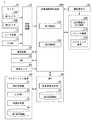
図1は、実施形態に係る車両制御装置を利用した車両システム1の構成図である。車両システム1が搭載される車両は、例えば、二輪や三輪、四輪等の車両であり、その駆動源は、ディーゼルエンジンやガソリンエンジンなどの内燃機関、電動機、或いはこれらの組み合わせである。電動機は、内燃機関に連結された発電機による発電電力、或いは二次電池や燃料電池の放電電力を使用して動作する。[overall structure]
FIG. 1 is a configuration diagram of a
車両システム1は、例えば、カメラ10と、レーダ装置12と、LIDAR(Light Detection and Ranging)14と、物体認識装置16と、通信装置20と、HMI(Human Machine Interface)30と、車両センサ40と、ナビゲーション装置50と、MPU(Map Positioning Unit)60と、運転操作子80と、自動運転制御装置100と、走行駆動力出力装置200と、ブレーキ装置210と、ステアリング装置220とを備える。これらの装置や機器は、CAN(Controller Area Network)通信線等の多重通信線やシリアル通信線、無線通信網等によって互いに接続される。なお、図1に示す構成はあくまで一例であり、構成の一部が省略されてもよいし、更に別の構成が追加されてもよい。 The
カメラ10は、例えば、CCD(Charge Coupled Device)やCMOS(Complementary Metal Oxide Semiconductor)等の固体撮像素子を利用したデジタルカメラである。カメラ10は、車両システム1が搭載される車両(以下、自車両M)の任意の箇所に取り付けられる。カメラ10は、例えば、周期的に繰り返し自車両Mの周辺を撮像する。カメラ10は、ステレオカメラであってもよい。カメラ10は、例えば、第1カメラ10Aおよび第2カメラ10Bを含む。第1カメラ10Aは、車両Mの前方を撮像する。第1カメラ10Aは、フロントウインドシールド上部やルームミラー裏面等に取り付けられる。第2カメラ10Bは、車両Mの後方を撮像する。第2カメラ10Bは、車両Mの後方を撮像可能な位置に取り付けられる。 The
レーダ装置12は、自車両Mの周辺にミリ波などの電波を放射すると共に、物体によって反射された電波(反射波)を検出して少なくとも物体の位置(距離および方位)を検出する。レーダ装置12は、自車両Mの任意の箇所に取り付けられる。レーダ装置12は、FM−CW(Frequency Modulated Continuous Wave)方式によって物体の位置および速度を検出してもよい。 The
LIDAR14は、自車両Mの周辺に光(或いは光に近い波長の電磁波)を照射し、散乱光を測定する。LIDAR14は、発光から受光までの時間に基づいて、対象までの距離を検出する。照射される光は、例えば、パルス状のレーザー光である。LIDAR14は、自車両Mの任意の箇所に取り付けられる。 The LIDAR 14 irradiates the periphery of the own vehicle M with light (or an electromagnetic wave having a wavelength close to that of light) and measures the scattered light. The
物体認識装置16は、カメラ10、レーダ装置12、およびLIDAR14のうち一部または全部による検出結果に対してセンサフュージョン処理を行って、物体の位置、種類、速度などを認識する。物体認識装置16は、認識結果を自動運転制御装置100に出力する。物体認識装置16は、カメラ10、レーダ装置12、およびLIDAR14の検出結果をそのまま自動運転制御装置100に出力してよい。車両システム1から物体認識装置16が省略されてもよい。 The
通信装置20は、例えば、セルラー網やWi−Fi網、Bluetooth(登録商標)、DSRC(Dedicated Short Range Communication)などを利用して、自車両Mの周辺に存在する他車両と通信し、或いは無線基地局を介して各種サーバ装置と通信する。 The
HMI30は、自車両Mの乗員に対して各種情報を提示すると共に、乗員による入力操作を受け付ける。HMI30は、各種表示装置、スピーカ、ブザー、タッチパネル、スイッチ、キーなどを含む。 The
車両センサ40は、自車両Mの速度を検出する車速センサ、加速度を検出する加速度センサ、鉛直軸回りの角速度を検出するヨーレートセンサ、自車両Mの向きを検出する方位センサ等を含む。 The
ナビゲーション装置50は、例えば、GNSS(Global Navigation Satellite System)受信機51と、ナビHMI52と、経路決定部53とを備える。ナビゲーション装置50は、HDD(Hard Disk Drive)やフラッシュメモリなどの記憶装置に第1地図情報54を保持している。GNSS受信機51は、GNSS衛星から受信した信号に基づいて、自車両Mの位置を特定する。自車両Mの位置は、車両センサ40の出力を利用したINS(Inertial Navigation System)によって特定または補完されてもよい。ナビHMI52は、表示装置、スピーカ、タッチパネル、キーなどを含む。ナビHMI52は、前述したHMI30と一部または全部が共通化されてもよい。経路決定部53は、例えば、GNSS受信機51により特定された自車両Mの位置(或いは入力された任意の位置)から、ナビHMI52を用いて乗員により入力された目的地までの経路(以下、地図上経路)を、第1地図情報54を参照して決定する。第1地図情報54は、例えば、道路を示すリンクと、リンクによって接続されたノードとによって道路形状が表現された情報である。第1地図情報54は、道路の曲率やPOI(Point Of Interest)情報などを含んでもよい。地図上経路は、MPU60に出力される。ナビゲーション装置50は、地図上経路に基づいて、ナビHMI52を用いた経路案内を行ってもよい。ナビゲーション装置50は、例えば、乗員の保有するスマートフォンやタブレット端末等の端末装置の機能によって実現されてもよい。ナビゲーション装置50は、通信装置20を介してナビゲーションサーバに現在位置と目的地を送信し、ナビゲーションサーバから地図上経路と同等の経路を取得してもよい。 The
MPU60は、例えば、推奨車線決定部61を含み、HDDやフラッシュメモリなどの記憶装置に第2地図情報62を保持している。推奨車線決定部61は、ナビゲーション装置50から提供された地図上経路を複数のブロックに分割し(例えば、車両進行方向に関して100[m]毎に分割し)、第2地図情報62を参照してブロックごとに推奨車線を決定する。推奨車線決定部61は、左から何番目の車線を走行するといった決定を行う。推奨車線決定部61は、地図上経路に分岐箇所が存在する場合、自車両Mが、分岐先に進行するための合理的な経路を走行できるように、推奨車線を決定する。 The
第2地図情報62は、第1地図情報54よりも高精度な地図情報である。第2地図情報62は、例えば、車線の中央の情報あるいは車線の境界の情報等を含んでいる。また、第2地図情報62には、道路情報、交通規制情報、住所情報(住所・郵便番号)、施設情報、電話番号情報などが含まれてよい。第2地図情報62は、通信装置20が他装置と通信することにより、随時、アップデートされてよい。 The
運転操作子80は、例えば、アクセルペダル、ブレーキペダル、シフトレバー、ステアリングホイール、異形ステア、ジョイスティックその他の操作子を含む。運転操作子80には、操作量あるいは操作の有無を検出するセンサが取り付けられており、その検出結果は、自動運転制御装置100、もしくは、走行駆動力出力装置200、ブレーキ装置210、およびステアリング装置220のうち一部または全部に出力される。 The driving
自動運転制御装置100は、例えば、第1制御部120と、第2制御部160とを備える。第1制御部120と第2制御部160は、それぞれ、例えば、CPU(Central Processing Unit)などのハードウェアプロセッサがプログラム(ソフトウェア)を実行することにより実現される。また、これらの構成要素のうち一部または全部は、LSI(Large Scale Integration)やASIC(Application Specific Integrated Circuit)、FPGA(Field-Programmable Gate Array)、GPU(Graphics Processing Unit)などのハードウェア(回路部;circuitryを含む)によって実現されてもよいし、ソフトウェアとハードウェアの協働によって実現されてもよい。プログラムは、予め自動運転制御装置100のHDDやフラッシュメモリなどの記憶装置(非一過性の記憶媒体を備える記憶装置)に格納されていてもよいし、DVDやCD−ROMなどの着脱可能な記憶媒体に格納されており、記憶媒体(非一過性の記憶媒体)がドライブ装置に装着されることで自動運転制御装置100のHDDやフラッシュメモリにインストールされてもよい。自動運転制御装置100は「車両制御装置」の一例である。 The automatic
図2は、第1制御部120および第2制御部160の機能構成図である。第1制御部120は、例えば、認識部130と、行動計画生成部140とを備える。第1制御部120は、例えば、AI(Artificial Intelligence;人工知能)による機能と、予め与えられたモデルによる機能とを並行して実現する。例えば、「交差点を認識する」機能は、ディープラーニング等による交差点の認識と、予め与えられた条件(パターンマッチング可能な信号、道路標示などがある)に基づく認識とが並行して実行され、双方に対してスコア付けして総合的に評価することで実現されてよい。これによって、自動運転の信頼性が担保される。 FIG. 2 is a functional configuration diagram of the
認識部130は、カメラ10、レーダ装置12、およびLIDAR14から物体認識装置16を介して入力された情報に基づいて、自車両Mの周辺にある物体の位置、および速度、加速度等の状態を認識する。物体の位置は、例えば、自車両Mの代表点(重心や駆動軸中心など)を原点とした絶対座標上の位置として認識され、制御に使用される。物体の位置は、その物体の重心やコーナー等の代表点で表されてもよいし、表現された領域で表されてもよい。物体の「状態」とは、物体の加速度やジャーク、あるいは「行動状態」(例えば車線変更をしている、またはしようとしているか否か)を含んでもよい。 The
また、認識部130は、例えば、自車両Mが走行している車線(走行車線)を認識する。例えば、認識部130は、第2地図情報62から得られる道路区画線のパターン(例えば実線と破線の配列)と、カメラ10によって撮像された画像から認識される自車両Mの周辺の道路区画線のパターンとを比較することで、走行車線を認識する。なお、認識部130は、道路区画線に限らず、道路区画線や路肩、縁石、中央分離帯、ガードレールなどを含む走路境界(道路境界)を認識することで、走行車線を認識してもよい。この認識において、ナビゲーション装置50から取得される自車両Mの位置やINSによる処理結果が加味されてもよい。また、認識部130は、一時停止線、障害物、赤信号、料金所、その他の道路事象を認識する。 Further, the
認識部130は、走行車線を認識する際に、走行車線に対する自車両Mの位置や姿勢を認識する。認識部130は、例えば、自車両Mの基準点の車線中央からの乖離、および自車両Mの進行方向の車線中央を連ねた線に対してなす角度を、走行車線に対する自車両Mの相対位置および姿勢として認識してもよい。これに代えて、認識部130は、走行車線のいずれかの側端部(道路区画線または道路境界)に対する自車両Mの基準点の位置などを、走行車線に対する自車両Mの相対位置として認識してもよい。 When recognizing the traveling lane, the
行動計画生成部140は、原則的には推奨車線決定部61により決定された推奨車線を走行し、更に、自車両Mの周辺状況に対応できるように、自車両Mが自動的に(運転者の操作に依らずに)将来走行する目標軌道を生成する。目標軌道は、例えば、速度要素を含んでいる。例えば、目標軌道は、自車両Mの到達すべき地点(軌道点)を順に並べたものとして表現される。軌道点は、道なり距離で所定の走行距離(例えば数[m]程度)ごとの自車両Mの到達すべき地点であり、それとは別に、所定のサンプリング時間(例えば0コンマ数[sec]程度)ごとの目標速度および目標加速度が、目標軌道の一部として生成される。また、軌道点は、所定のサンプリング時間ごとの、そのサンプリング時刻における自車両Mの到達すべき位置であってもよい。この場合、目標速度や目標加速度の情報は軌道点の間隔で表現される。 In principle, the action
行動計画生成部140は、目標軌道を生成するにあたり、自動運転のイベントを設定してよい。自動運転のイベントには、定速走行イベント、低速追従走行イベント、車線変更イベント、分岐イベント、合流イベント、テイクオーバーイベントなどがある。行動計画生成部140は、起動させたイベントに応じた目標軌道を生成する。 The action
行動計画生成部140は、例えば、第1設定部142と、ターゲット設定部144と、第2設定部146と、車線変更制御部148とを備える。第1設定部142は、認識部130により認識された車線変更先の車線に存在する車両の第1基準位置(第1種別の基準位置)を設定する。第1基準位置は、車両Mの前後方向の大きさを推測するための推測情報(詳細は後述)から導出される基準位置である。第1基準位置は、例えば車両の重心である。 The action
ターゲット設定部144は、第1車両の第1基準位置と、第1車両の後方の第2車両の第1基準位置とに基づいて、第1車両と第2車両との間にターゲット領域を設定する。ターゲット領域は、車両Mが車線変更行う際のターゲットである。 The
第2設定部146は、第1車両の第2基準位置(第2種別の基準位置)と、第2車両の第2基準位置とを設定する。第2基準位置は、車両Mの推測情報とは異なる第2情報から導出される基準位置である。第2基準位置は、第2車両の前端部または第1車両の後端部から導出される基準位置である。第2車両の前端部の基準位置または第1車両の後端部の基準位置の一方または双方は、第1車両または第2車両の発光部またはナンバープレートに基づく基準位置である。発光部は、テールランプや、ブレーキランプ、ライト等である。 The
車線変更制御部148は、第1車両の第2基準位置と、第2車両の第2基準位置とに基づいて、ターゲット領域に車両を進入させる。第1設定部142と、ターゲット設定部144と、第2設定部146とを合わせた機能構成は、「設定部」の一例である。車線変更制御部148は、「制御部」の一例である。 The lane
第2制御部160は、行動計画生成部140によって生成された目標軌道を、予定の時刻通りに自車両Mが通過するように、走行駆動力出力装置200、ブレーキ装置210、およびステアリング装置220を制御する。 The
第2制御部160は、例えば、取得部162と、速度制御部164と、操舵制御部166とを備える。取得部162は、行動計画生成部140により生成された目標軌道(軌道点)の情報を取得し、メモリ(不図示)に記憶させる。速度制御部164は、メモリに記憶された目標軌道に付随する速度要素に基づいて、走行駆動力出力装置200またはブレーキ装置210を制御する。操舵制御部166は、メモリに記憶された目標軌道の曲がり具合に応じて、ステアリング装置220を制御する。速度制御部164および操舵制御部166の処理は、例えば、フィードフォワード制御とフィードバック制御との組み合わせにより実現される。一例として、操舵制御部166は、自車両Mの前方の道路の曲率に応じたフィードフォワード制御と、目標軌道からの乖離に基づくフィードバック制御とを組み合わせて実行する。 The
走行駆動力出力装置200は、車両が走行するための走行駆動力(トルク)を駆動輪に出力する。走行駆動力出力装置200は、例えば、内燃機関、電動機、および変速機などの組み合わせと、これらを制御するECU(Electronic Control Unit)とを備える。ECUは、第2制御部160から入力される情報、或いは運転操作子80から入力される情報に従って、上記の構成を制御する。 The traveling driving
ブレーキ装置210は、例えば、ブレーキキャリパーと、ブレーキキャリパーに油圧を伝達するシリンダと、シリンダに油圧を発生させる電動モータと、ブレーキECUとを備える。ブレーキECUは、第2制御部160から入力される情報、或いは運転操作子80から入力される情報に従って電動モータを制御し、制動操作に応じたブレーキトルクが各車輪に出力されるようにする。ブレーキ装置210は、運転操作子80に含まれるブレーキペダルの操作によって発生させた油圧を、マスターシリンダを介してシリンダに伝達する機構をバックアップとして備えてよい。なお、ブレーキ装置210は、上記説明した構成に限らず、第2制御部160から入力される情報に従ってアクチュエータを制御して、マスターシリンダの油圧をシリンダに伝達する電子制御式油圧ブレーキ装置であってもよい。 The
ステアリング装置220は、例えば、ステアリングECUと、電動モータとを備える。電動モータは、例えば、ラックアンドピニオン機構に力を作用させて転舵輪の向きを変更する。ステアリングECUは、第2制御部160から入力される情報、或いは運転操作子80から入力される情報に従って、電動モータを駆動し、転舵輪の向きを変更させる。 The
[第1基準位置を設定する処理]
第1設定部142は、第1基準位置を設定する。まず、第1設定部142は、認識部130により認識された周辺の車両を特定し、特定した車両に対して矩形枠を関連付ける。図3は、矩形枠Bが関連付けられた車両の一例である。矩形枠Bは、車両の全体を含むように関連付けられる。[Process to set the first reference position]
The
次に、第1設定部142は、矩形枠Bに基づいて、第1基準位置を設定する。第1基準位置は、車両の前後の位置範囲を推定するための位置、または車両の前後の位置範囲を推定するための推測情報に基づく位置である。推測情報は、車両の目印となるような位置を示す情報である。第1基準位置は、重心位置や、車両の前後部の中心位置、ホイールベースの中心に基づく位置、車輪位置に基づく位置、またはこれらの情報をパラメータとして求められ位置である。以下の説明では、一例として第1基準位置は重心位置であるものとして説明する。 Next, the
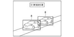
図4は、車両Mの走行する車線に隣接する車線、且つ前方に存在する車両の第1位置の一例を示す図である。図5は、車両Mの走行する車線に隣接する車線、且つ後方に存在する車両の第1位置の一例を示す図である。 FIG. 4 is a diagram showing an example of a first position of a vehicle existing in front of the lane adjacent to the lane in which the vehicle M is traveling. FIG. 5 is a diagram showing an example of a first position of a vehicle existing in a lane adjacent to and behind the lane in which the vehicle M is traveling.
[第2基準位置を設定する処理]
車両Mがターゲット領域に車線変更する場合、第2設定部146は、第2基準位置を設定する。そして、車線変更制御部148は、第2基準位置に基づいて、車両Mを車線変更させる。[Process to set the second reference position]
When the vehicle M changes lanes to the target area, the
第2設定部146は、認識部130により認識された車両の後端部を特定し、特定した後端部に対して矩形枠B1を設定する。上記の車両は、車両Mが走行する隣接車線に存在し、且つ車両Mに最も近い前方に存在する車両である。 The
図6は、後端部に設定された矩形枠B1の一例を示す図である。矩形枠B1は、後端部を含む枠である。第2設定部146は、後端部の所定の位置に第2基準位置を設定する。所定の位置とは、後端部の中心の位置や、反射板(反射板部)の位置、ライトの位置、ブレーキランプの位置、テールランプの位置、ナンバープレートの位置、これらに基づく位置など前方の車両の後端部を特定するための位置等である。なお、反射板は、反射板単体およびテールランプやウインカーの一部にある反射板も含む。 FIG. 6 is a diagram showing an example of a rectangular frame B1 set at the rear end portion. The rectangular frame B1 is a frame including the rear end portion. The
なお、第2基準位置が設定された場合であっても、第1基準位置を設定する処理は継続される。図6、および以降に示す図では、第1基準位置については図示を省略する。 Even when the second reference position is set, the process of setting the first reference position is continued. In FIG. 6 and the drawings shown thereafter, the first reference position is not shown.
第2設定部146は、認識部130により認識された車両の前端部を特定し、特定した前端部に対して矩形枠B2を設定する。上記の車両は、車両Mが走行する隣接車線に存在し、且つ車両Mに最も近い後方に存在する車両である。 The
図7は、前端部に設定された矩形枠B2の一例を示す図である。矩形枠B2は、前端部を含む枠である。第2設定部146は、前端部の所定の位置に第2基準位置を設定する。所定の位置とは、後端部の中心の位置や、反射板の位置、ライトの位置、ブレーキランプの位置、テールランプの位置、ナンバープレートの位置、これらに基づく位置等など後方の車両の後端部を特定するための位置である。なお、反射板は、反射板単体およびテールランプやウインカーの一部にある反射板も含む。 FIG. 7 is a diagram showing an example of the rectangular frame B2 set at the front end portion. The rectangular frame B2 is a frame including the front end portion. The
上記のように第2基準位置は設定される。車線変更制御部148は、第2基準位置に基づいて車両Mを車線変更させる。 The second reference position is set as described above. The lane
[第1基準位置および第2基準位置に基づいて車線変更が行われる処理]
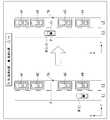
図8は、車線変更について説明するための図(その1)である。車両Mは、第1車線L1を走行し、第1車線に隣接する第2車線L2に車線変更する計画を立てている。第2車線L2において、他車両m1、他車両m2、他車両m3、他車両m4がこの順でプラスX方向に走行している。時刻tにおいて、自動運転制御装置100は、他の他車両間の領域よりも距離が長い、他車両m2と他車両m3との間に進入する計画を生成する。他車両m2と他車両m3との間の領域はターゲット領域である。[Processing in which the lane is changed based on the first reference position and the second reference position]
FIG. 8 is a diagram (No. 1) for explaining the lane change. Vehicle M is planning to drive in the first lane L1 and change lanes to the second lane L2 adjacent to the first lane. In the second lane L2, another vehicle m1, another vehicle m2, another vehicle m3, and another vehicle m4 are traveling in the plus X direction in this order. At time t, the autonomous
時刻t+1において、自動運転制御装置100は、車両Mの基準位置(例えば重心)が位置Pに合致するように車両Mを移動させる。位置Pはターゲット領域の所定位置(例えば中間または中間よりも他車両m2側の位置、位置Pn)をマイナスY方向に延在させた位置である。自動運転制御装置100は、車両Mを位置P付近に移動させた後、車両Mは他車両m3に対して、車両Mがターゲット位置Pnに進入することについて交渉する。交渉とは、車両Mが、位置P付近で方向指示器を点灯させたり、車線L2側に接近したりする行動を行うことである。 At
図9は、車線変更について説明するための図(その2)である。時刻t+2において、他車両m3が車両Mの交渉に応じて、交渉内容について承諾した場合、自動運転制御装置100は、第2設定部146により設定された第2基準位置を利用した車線変更を開始する。交渉内容について承諾したとは、他車両m3が減速したり、他車両m2が加速しても加速を行わなかったりしたことである。すなわち、他車両m2と他車両m3との距離が広がったことである。自動運転制御装置100は、他車両m2の第2基準位置と、他車両m3の第2基準位置とに基づいて、ターゲット位置Pnを決定(または修正)する。 FIG. 9 is a diagram (No. 2) for explaining the lane change. At
時刻t+3において、自動運転制御装置100は、他車両m2の第2基準位置と、他車両m3の第2基準位置と、ターゲット位置Pnとに基づいて、車両Mを第2車線L2に進入させる。時刻t+4において、自動運転制御装置100は、他車両m2の第2基準位置と、他車両m3の第2基準位置と、ターゲット位置Pnとに基づいて、ターゲット位置Pnに車両Mを移動させる。 At
第2設定部146は、所定のタイミングで他車両に対して第2基準位置を設定する。所定のタイミングとは、車両Mがターゲット領域付近に近づいたタイミングや、車両Mが車線変更を開始すると決定したタイミング、ターゲット領域が設定されたタイミング等である。ターゲット領域に近づいたとは、例えば、ターゲット領域から所定距離(数メートル)に車両Mが近づいたことである。 The
上記のように、自動運転制御装置100は、第2基準位置を利用することで、容易、かつ精度よくターゲット位置Pnに車両Mを移動させることができる。 As described above, the automatic
[ターゲット位置が設定される位置]
ここで、ターゲット位置Pnについて説明する。図10は、ターゲット位置Pnについて説明するための図である。ターゲット位置Pnは、他車両m2の後端部bと、他車両m3の前端部fとのうち、後端部bに近い位置に設定される。例えば、後端部bから所定距離後方の位置に設定される。換言すると、ターゲット位置Pnは、車両Mの基準位置とターゲット位置Pnとが合致した場合に、マージンMA1が、マージンMA2よりも短くなるように設定される。マージンMA1は、後端部bと車両Mの前端部との距離である。マージンMA1は、車速が大きくなるにつれて長くなる。例えば、マージンMA1は、車速によっては1mから3mであってもよい。また、車速が極低速であれば、30cmから50cm程度であってよい。マージンMA2は、前端部fと車両Mの後端部との距離である。[Position where target position is set]
Here, the target position Pn will be described. FIG. 10 is a diagram for explaining the target position Pn. The target position Pn is set at a position closer to the rear end portion b of the rear end portion b of the other vehicle m2 and the front end portion f of the other vehicle m3. For example, it is set at a position rearward by a predetermined distance from the rear end portion b. In other words, the target position Pn is set so that the margin MA1 is shorter than the margin MA2 when the reference position of the vehicle M and the target position Pn match. The margin MA1 is the distance between the rear end portion b and the front end portion of the vehicle M. The margin MA1 becomes longer as the vehicle speed increases. For example, the margin MA1 may be 1 m to 3 m depending on the vehicle speed. Further, if the vehicle speed is extremely low, it may be about 30 cm to 50 cm. The margin MA2 is the distance between the front end portion f and the rear end portion of the vehicle M.
上記のように、車線変更制御部148は、基準位置をターゲット位置Pnに合致させながら車線変更を行うことにより、他車両m3よりも他車両m2に接近した状態を維持しつつ、車両Mを車線変更させる。 As described above, the lane
例えば、熟練したドライバーは、視認がしやすい車両Mの前方側のマージンが短くなるように車両を制御して、車両Mが車線変更した後に少し速度を落として前走車両との距離を大きくするように車両を制御する。車両の後方車両は、このように合流がされると安心感が向上する。なぜなら、車両と後方車両との車間距離は比較的大きく確保されるためである。 For example, a skilled driver controls the vehicle so that the margin on the front side of the vehicle M, which is easy to see, is shortened, and after the vehicle M changes lanes, the speed is slightly reduced to increase the distance from the vehicle in front. Control the vehicle so that. When the vehicles behind the vehicle are merged in this way, the sense of security is improved. This is because the distance between the vehicle and the vehicle behind is relatively large.
[ターゲット位置への進入手法]
図11は、ターゲット位置への進入手法の一例について説明するため図である。車両Mは、例えば、X方向に関してターゲット領域TAの前方に位置した後(ターゲット領域TAを通過した後)、ターゲット位置Pnに進入してもよい。時刻tにおいて、車両Mは、他車両m2に近づくように移動する。時刻t+1において、X方向に関して他車両m2付近に位置する。時刻t+2において、車両Mは、他車両m2の速度に対して、相対的に遅い速度で走行して、ターゲット領域TAに進入する。[How to enter the target position]
FIG. 11 is a diagram for explaining an example of the approach method to the target position. The vehicle M may enter the target position Pn after being located in front of the target region TA in the X direction (after passing through the target region TA), for example. At time t, the vehicle M moves so as to approach the other vehicle m2. At
上記のように、車両Mは、X方向に関してターゲット領域TA(ターゲット位置Pn)を通過した後、他車両m3よりも他車両m2に近づいている状態を維持しながら車線変更する。車両Mにとって、後方よりも前方が認識しやすく、前方の車両に近づいた状態で車線変更する方が、後方の車両に近づいた状態で車線変更するよりも、容易である。更に、後方の車両は、車両Mが車線変更することを容易に認識することができたり、車両Mと後方の車両との車間距離は、車両Mと前方の車両との車間距離よりも広くなり後方の車両にとっても安心感が向上したりする。更に、車両Mがターゲット領域TAを通過して他車両m2に一旦近づくことにより、車両Mの存在と車両Mが他車両m2の後方へ車線変更することを他車両m2に認知させ、他車両m2に急な減速を行わないように注意を促すことができる。 As described above, after passing through the target region TA (target position Pn) in the X direction, the vehicle M changes lanes while maintaining a state of being closer to the other vehicle m2 than the other vehicle m3. For the vehicle M, the front is easier to recognize than the rear, and it is easier to change lanes while approaching the vehicle in front than to change lanes while approaching the vehicle behind. Further, the vehicle behind can easily recognize that the vehicle M changes lanes, and the distance between the vehicle M and the vehicle behind becomes wider than the distance between the vehicle M and the vehicle in front. It also improves the sense of security for the vehicle behind. Further, when the vehicle M passes through the target region TA and once approaches the other vehicle m2, the other vehicle m2 is made aware of the existence of the vehicle M and that the vehicle M changes lanes to the rear of the other vehicle m2, and the other vehicle m2. It is possible to call attention not to make a sudden deceleration.
[比較例]
図12は、比較例の車両Cが行う車線変更について説明するための図である。上述した図8、図9等で説明した内容との相違点を中心に説明する。比較例の車両Cは、第2基準位置を利用せずに車線変更を行うため、誤加速を行う場合がある。[Comparison example]
FIG. 12 is a diagram for explaining the lane change performed by the vehicle C of the comparative example. The differences from the contents described in FIGS. 8 and 9 described above will be mainly described. Since the vehicle C in the comparative example changes lanes without using the second reference position, erroneous acceleration may occur.
時刻tにおいて、車両Cは、ターゲット領域TAに進入することを決定し、ターゲット位置Pn方向に移動を開始した。このとき、車両Cは、他車両m1の第1基準位置と、他車両m2の第1基準位置とに基づいて移動する。 At time t, vehicle C decides to enter the target region TA and starts moving in the target position Pn direction. At this time, the vehicle C moves based on the first reference position of the other vehicle m1 and the first reference position of the other vehicle m2.
時刻t+1において、車両Cが、プラスY方向側に移動すると、車両Cに対する他車両m2の前方の視認性が低下する。このため、車両Cは、他車両m1と他車両m2とを1台の車両と認識してしまう場合がある。図13は、車両Cは、他車両m1と他車両m2とを1台の車両と認識してしまう様子の一例を示す図である。この場合、車両Cは、他車両m1と他車両m2とを1台の他車両とみなして、その他車両の重心を第1基準位置として設定する。 When the vehicle C moves in the plus Y direction at the
前述した図12の時刻t+2において、車両Cは、車両Cから最も近い前方の第1基準位置が、プラスX方向側に離れたと認識する。このため、車両Cは、前方の第1基準位置との距離を、縮めるために加速を行う。車両Cは、他車両m2との距離が下限距離に到達するまで、加速(誤加速)を行う場合がある。 At time t + 2 in FIG. 12 described above, the vehicle C recognizes that the first reference position in front of the vehicle C, which is closest to the vehicle C, is separated from the vehicle C in the plus X direction. Therefore, the vehicle C accelerates in order to reduce the distance from the first reference position in front. The vehicle C may accelerate (erroneous acceleration) until the distance from the other vehicle m2 reaches the lower limit distance.
図14は、車両Cが誤加速を行う場面の一例について説明するための図である。時刻t+X1において、車両Cは、他車両m2の第1基準位置に基づいて、第1基準位置から所定距離Lに位置するように走行する。時刻t+X2において、車両Cは、他車両m1と他車両m2とを1台の他車両とみなし、その他車両の第1基準位置から所定距離Lに位置するように誤加速を行う。 FIG. 14 is a diagram for explaining an example of a scene in which the vehicle C erroneously accelerates. At time t + X1, the vehicle C travels so as to be located at a predetermined distance L from the first reference position based on the first reference position of the other vehicle m2. At time t + X2, the vehicle C regards the other vehicle m1 and the other vehicle m2 as one other vehicle, and erroneously accelerates the vehicle so that it is located at a predetermined distance L from the first reference position of the other vehicle.
上記のように、車両Cは、本来すべきでない加速(誤加速)を行ってしまう場合がある。この場合、車両Cの乗員にとって乗り心地が低い場合がある。 As described above, the vehicle C may perform acceleration (erroneous acceleration) that should not be originally performed. In this case, the ride quality may be low for the occupants of the vehicle C.
これに対して、本実施形態では、自動運転制御装置100は、第2基準位置を利用して、車線変更することにより、より確実に前方の他車両の位置を認識して、誤加速を抑制し、滑らかに車線変更を行うことができる。この結果、自動運転制御装置100は、乗員にとっての乗り心地を向上させることができる。 On the other hand, in the present embodiment, the automatic
[フローチャート]
図15は、自動運転制御装置100により実行される処理の流れの一例を示すフローチャートである。本処理は、車両Mが車線変更を行うと決定した場合に実行される処理である。本処理の一部の処理は省略されてもよいし、適宜処理の順序は変更されてもよい。[flowchart]
FIG. 15 is a flowchart showing an example of a processing flow executed by the automatic
まず、第1設定部142は、第1基準位置を他車両に対して設定する(ステップS100)。次に、ターゲット設定部144は、第1基準位置に基づいてターゲット領域およびターゲット位置を設定する(ステップS102)。次に、車線変更制御部148は、車線変更できるタイミングであるか否を判定する(ステップS104)。車線変更できるタイミングとは、例えば、車両Mの後方の車両が車両Mの車線変更を承諾した行動を行ったことである。 First, the
車線変更できるタイミングである場合、車線変更制御部148は、車線変更先の車線に車両Mを移動させることを開始する(ステップS106)。次に、第2設定部146は、基準位置の切替タイミングであるか否かを判定する(ステップS108)。切替タイミングとは、車両Mが所定距離以上、車線変更先の車線側に移動したことタイミングや、車両Mが車線変更先の車線側に移動を開始したことタイミング、車両Mが車線変更先の車線側に移動を開始する所定時間前のタイミングである。切替タイミングである場合、第2設定部146は、前方の車両に対して第2基準位置を設定する(ステップS110)。 When it is time to change lanes, the lane
次に、ターゲット設定部144が、第2基準位置に基づいてターゲット位置を修正する(ステップS112)。次に、車線変更制御部148が、修正されたターゲット位置に基づいて車線変更を行う(ステップS114)。これにより本フローチャートの1ルーチンの処理が終了する。 Next, the
以上説明した実施形態によれば、自動運転制御装置100は、認識部130により認識された車線変更先の車線に存在する第1車両の第1種別の基準位置と、第1車両の後方の第2車両の第1種別の基準位置とに基づいて、第1車両と第2車両との間にターゲット領域を設定し、第1車両の第2種別の基準位置と、第2車両の第2種別の基準位置とに基づいて、ターゲット領域に車両を進入させることにより、より滑らかな車線変更を実行することができる。 According to the embodiment described above, the automatic
[ハードウェア構成]
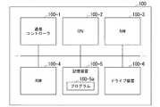
図16は、実施形態の自動運転制御装置100のハードウェア構成の一例を示す図である。図示するように、自動運転制御装置100は、通信コントローラ100−1、CPU100−2、ワーキングメモリとして使用されるRAM(Random Access Memory)100−3、ブートプログラムなどを格納するROM(Read Only Memory)100−4、フラッシュメモリやHDD(Hard Disk Drive)などの記憶装置100−5、ドライブ装置100−6などが、内部バスあるいは専用通信線によって相互に接続された構成となっている。通信コントローラ100−1は、自動運転制御装置100以外の構成要素との通信を行う。記憶装置100−5には、CPU100−2が実行するプログラム100−5aが格納されている。このプログラムは、DMA(Direct Memory Access)コントローラ(不図示)などによってRAM100−3に展開されて、CPU100−2によって実行される。これによって、第1制御部120、第2制御部160、およびこれらに含まれる機能部のうち一部または全部が実現される。[Hardware configuration]
FIG. 16 is a diagram showing an example of the hardware configuration of the automatic
上記説明した実施形態は、以下のように表現することができる。
プログラムを記憶した記憶装置と、
ハードウェアプロセッサと、を備え、
前記ハードウェアプロセッサが前記記憶装置に記憶されたプログラムを実行することにより、
車両の周辺を認識する処理と、
車線変更先の車線に存在する第1車両の第1種別の基準位置と、第1車両の後方の第2車両の前記第1種別の基準位置とに基づいて、前記第1車両と前記第2車両との間にターゲット領域を設定する処理と、
前記第1車両の第2種別の基準位置と、前記第2車両の前記第2種別の基準位置とに基づいて、前記設定された前記ターゲット領域に前記車両を進入させる処理と、を実行するように構成されている、車両制御装置。The embodiment described above can be expressed as follows.
A storage device that stores programs and
With a hardware processor,
When the hardware processor executes a program stored in the storage device,
The process of recognizing the surroundings of the vehicle and
The first vehicle and the second vehicle are based on the reference position of the first type of the first vehicle existing in the lane to be changed and the reference position of the first type of the second vehicle behind the first vehicle. The process of setting the target area with the vehicle and
Based on the second type reference position of the first vehicle and the second type reference position of the second vehicle, the process of entering the vehicle into the set target area is executed. The vehicle control device, which is configured in.
以上、本発明を実施するための形態について実施形態を用いて説明したが、本発明はこうした実施形態に何等限定されるものではなく、本発明の要旨を逸脱しない範囲内において種々の変形及び置換を加えることができる。 Although the embodiments for carrying out the present invention have been described above using the embodiments, the present invention is not limited to these embodiments, and various modifications and substitutions are made without departing from the gist of the present invention. Can be added.
1‥車両システム、100‥自動運転制御装置、120‥第1制御部、130‥認識部、140‥行動計画生成部、142‥第1設定部、144‥ターゲット設定部、146‥第2設定部、148‥車線変更制御部、160‥第2制御部1 ‥ Vehicle system, 100 ‥ Automatic driving control device, 120 ‥ 1st control unit, 130 ‥ Recognition unit, 140 ‥ Action plan generation unit, 142 ‥
Claims (10)
Translated fromJapanese前記認識部により認識された車線変更先の車線に存在する第1車両の第1種別の基準位置と、前記第1車両の後方の第2車両の前記第1種別の基準位置とに基づいて、前記第1車両と前記第2車両との間にターゲット領域を設定する設定部と、
前記第1車両の第2種別の基準位置と、前記第2車両の前記第2種別の基準位置とに基づいて、前記設定部により設定された前記ターゲット領域に前記車両を進入させる制御部と、
を備える車両制御装置。A recognition unit that recognizes the surroundings of the vehicle and
Based on the reference position of the first type of the first vehicle existing in the lane of the lane change destination recognized by the recognition unit and the reference position of the first type of the second vehicle behind the first vehicle. A setting unit that sets a target area between the first vehicle and the second vehicle,
Based on the second type reference position of the first vehicle and the second type reference position of the second vehicle, a control unit that causes the vehicle to enter the target area set by the setting unit.
Vehicle control device.
前記第2種別の基準位置は、前記推測情報とは異なる情報から導出される基準位置である、
請求項1に記載の車両制御装置。The first type reference position is a reference position derived from the estimation information for estimating the size of the vehicle in the front-rear direction, and the second type reference position is derived from information different from the estimation information. Reference position,
The vehicle control device according to claim 1.
請求項1または2に記載の車両制御装置。The reference position of the first type is the center of gravity of the vehicle.
The vehicle control device according to claim 1 or 2.
請求項1から3のうちいずれか1項に記載の車両制御装置。The second type of reference position is a reference position derived from the front end or the rear end of the vehicle.
The vehicle control device according to any one of claims 1 to 3.
請求項4に記載の車両制御装置。One or both of the reference position of the front end portion and the reference position of the rear end portion is a reference position based on the light emitting portion, the reflector portion or the license plate of the vehicle.
The vehicle control device according to claim 4.
請求項1から5のうちいずれか1項に記載の車両制御装置。The setting unit sets the reference position of the second type when the vehicle approaches the vicinity of the target area.
The vehicle control device according to any one of claims 1 to 5.
前記車両が、前記第2車両よりも前記第1車両に接近した状態を維持しつつ、前記車両を車線変更させる、
請求項1から6のうちいずれか1項に記載の車両制御装置。The control unit
The vehicle changes lanes while maintaining a state in which the vehicle is closer to the first vehicle than the second vehicle.
The vehicle control device according to any one of claims 1 to 6.
前記ターゲット領域を前記車両に通過させた後、前記車両の速度を前記第1車両の速度よりも相対的に遅くして、前記車両を前記ターゲット領域に進入させる、
請求項1から7のうちいずれか1項に記載の車両制御装置。The control unit
After passing the target region through the vehicle, the speed of the vehicle is made relatively slower than the speed of the first vehicle to allow the vehicle to enter the target region.
The vehicle control device according to any one of claims 1 to 7.
車両の周辺を認識する処理と、
車線変更先の車線に存在する第1車両の第1種別の基準位置と、第1車両の後方の第2車両の前記第1種別の基準位置とに基づいて、前記第1車両と前記第2車両との間にターゲット領域を設定する処理と、
前記第1車両の第2種別の基準位置と、前記第2車両の前記第2種別の基準位置とに基づいて、前記設定された前記ターゲット領域に前記車両を進入させる処理と、
を備える車両制御方法。The computer
The process of recognizing the surroundings of the vehicle and
The first vehicle and the second vehicle are based on the reference position of the first type of the first vehicle existing in the lane to be changed and the reference position of the first type of the second vehicle behind the first vehicle. The process of setting the target area with the vehicle and
A process of entering the vehicle into the set target area based on the reference position of the second type of the first vehicle and the reference position of the second type of the second vehicle.
A vehicle control method comprising.
車両の周辺を認識する処理と、
車線変更先の車線に存在する第1車両の第1種別の基準位置と、第1車両の後方の第2車両の前記第1種別の基準位置とに基づいて、前記第1車両と前記第2車両との間にターゲット領域を設定する処理と、
前記第1車両の第2種別の基準位置と、前記第2車両の前記第2種別の基準位置とに基づいて、前記設定された前記ターゲット領域に前記車両を進入させる処理と、
を実行させるプログラム。On the computer
The process of recognizing the surroundings of the vehicle and
The first vehicle and the second vehicle are based on the reference position of the first type of the first vehicle existing in the lane to be changed and the reference position of the first type of the second vehicle behind the first vehicle. The process of setting the target area with the vehicle and
A process of entering the vehicle into the set target area based on the reference position of the second type of the first vehicle and the reference position of the second type of the second vehicle.
A program that executes.
Priority Applications (4)
| Application Number | Priority Date | Filing Date | Title |
|---|---|---|---|
| JP2020057286AJP7431081B2 (en) | 2020-03-27 | 2020-03-27 | Vehicle control device, vehicle control method, and program |
| US17/204,970US11702079B2 (en) | 2020-03-27 | 2021-03-18 | Vehicle control method, vehicle control device, and storage medium |
| CN202410217982.3ACN118163816A (en) | 2020-03-27 | 2021-03-24 | Vehicle control device, vehicle control method and storage medium |
| CN202110316667.2ACN113511220B (en) | 2020-03-27 | 2021-03-24 | Vehicle control device, vehicle control method and storage medium |
Applications Claiming Priority (1)
| Application Number | Priority Date | Filing Date | Title |
|---|---|---|---|
| JP2020057286AJP7431081B2 (en) | 2020-03-27 | 2020-03-27 | Vehicle control device, vehicle control method, and program |
Publications (2)
| Publication Number | Publication Date |
|---|---|
| JP2021154886Atrue JP2021154886A (en) | 2021-10-07 |
| JP7431081B2 JP7431081B2 (en) | 2024-02-14 |
Family
ID=77857004
Family Applications (1)
| Application Number | Title | Priority Date | Filing Date |
|---|---|---|---|
| JP2020057286AActiveJP7431081B2 (en) | 2020-03-27 | 2020-03-27 | Vehicle control device, vehicle control method, and program |
Country Status (3)
| Country | Link |
|---|---|
| US (1) | US11702079B2 (en) |
| JP (1) | JP7431081B2 (en) |
| CN (2) | CN118163816A (en) |
Families Citing this family (2)
| Publication number | Priority date | Publication date | Assignee | Title |
|---|---|---|---|---|
| DE102020002993B4 (en)* | 2020-05-19 | 2022-11-10 | Mercedes-Benz Group AG | Method for supporting a vehicle |
| CN114348001B (en)* | 2022-01-06 | 2024-04-26 | 腾讯科技(深圳)有限公司 | Traffic simulation method, device, equipment and storage medium |
Citations (3)
| Publication number | Priority date | Publication date | Assignee | Title |
|---|---|---|---|---|
| JP2015184722A (en)* | 2014-03-20 | 2015-10-22 | アイシン・エィ・ダブリュ株式会社 | automatic operation support device, automatic operation support method and program |
| WO2017159493A1 (en)* | 2016-03-15 | 2017-09-21 | 本田技研工業株式会社 | Vehicle control system, vehicle control method, and vehicle control program |
| JP2018176761A (en)* | 2017-04-03 | 2018-11-15 | 孟重 関 | Non-physical manner vehicle connection method |
Family Cites Families (22)
| Publication number | Priority date | Publication date | Assignee | Title |
|---|---|---|---|---|
| JP6015329B2 (en)* | 2012-10-11 | 2016-10-26 | 株式会社デンソー | Convoy travel system and convoy travel device |
| US9475491B1 (en)* | 2015-06-08 | 2016-10-25 | Toyota Motor Engineering & Manufacturing North America, Inc. | Lane changing for autonomous vehicles |
| JP6657881B2 (en)* | 2015-12-04 | 2020-03-04 | 株式会社デンソー | Vehicle control device |
| CN108473140A (en)* | 2016-02-18 | 2018-08-31 | 本田技研工业株式会社 | Controller of vehicle, control method for vehicle and vehicle control program |
| CN108778879B (en)* | 2016-03-15 | 2021-07-27 | 本田技研工业株式会社 | Vehicle control system, vehicle control method, and storage medium |
| CN106218638B (en)* | 2016-08-17 | 2018-08-03 | 北方工业大学 | A Coordinated Lane Changing Control Method for Intelligent Networked Vehicles |
| JP6649512B2 (en) | 2016-12-28 | 2020-02-19 | 本田技研工業株式会社 | Vehicle control system, vehicle control method, and vehicle control program |
| JP2018195301A (en)* | 2017-05-15 | 2018-12-06 | キヤノン株式会社 | Control device and control method |
| JP6838525B2 (en)* | 2017-08-23 | 2021-03-03 | 日立Astemo株式会社 | Vehicle control device |
| US11555706B1 (en)* | 2017-09-27 | 2023-01-17 | Apple Inc. | Processing graph representations of tactical maps using neural networks |
| EP3614357B1 (en)* | 2018-08-23 | 2022-03-30 | Volkswagen AG | Vehicles, network component, apparatuses, methods and computer programs for a vehicle, for a platooning vehicle, and for a network component |
| US10793150B2 (en)* | 2018-09-14 | 2020-10-06 | Wipro Limited | Method and device for controlling vehicle based on neighboring vehicles |
| US11001256B2 (en)* | 2018-09-19 | 2021-05-11 | Zoox, Inc. | Collision prediction and avoidance for vehicles |
| JP7155991B2 (en)* | 2018-12-17 | 2022-10-19 | トヨタ自動車株式会社 | Notification device |
| JP7230596B2 (en)* | 2019-03-08 | 2023-03-01 | マツダ株式会社 | Arithmetic system for automobiles |
| US11462111B2 (en)* | 2019-04-29 | 2022-10-04 | Qualcomm Incorporated | Method and apparatus for vehicle maneuver planning and messaging |
| US11548511B2 (en)* | 2019-06-14 | 2023-01-10 | GM Global Technology Operations LLC | Method to control vehicle speed to center of a lane change gap |
| JP7365872B2 (en)* | 2019-11-26 | 2023-10-20 | 日産自動車株式会社 | Lane change support method and lane change support device |
| US11482109B2 (en)* | 2020-03-02 | 2022-10-25 | Toyota Motor Eng & Mfg North America, Inc. | Cooperative vehicle monitoring |
| US20210276551A1 (en)* | 2020-03-03 | 2021-09-09 | Honda Motor Co., Ltd. | Information processing system for movable objects and information processing method for movable objects |
| US12024207B2 (en)* | 2021-03-15 | 2024-07-02 | Ford Global Technologies, Llc | Vehicle autonomous mode operating parameters |
| US11809190B2 (en)* | 2021-04-30 | 2023-11-07 | Zoox, Inc. | Methods and systems to assess vehicle capabilities |
- 2020
- 2020-03-27JPJP2020057286Apatent/JP7431081B2/enactiveActive
- 2021
- 2021-03-18USUS17/204,970patent/US11702079B2/enactiveActive
- 2021-03-24CNCN202410217982.3Apatent/CN118163816A/enactivePending
- 2021-03-24CNCN202110316667.2Apatent/CN113511220B/enactiveActive
Patent Citations (3)
| Publication number | Priority date | Publication date | Assignee | Title |
|---|---|---|---|---|
| JP2015184722A (en)* | 2014-03-20 | 2015-10-22 | アイシン・エィ・ダブリュ株式会社 | automatic operation support device, automatic operation support method and program |
| WO2017159493A1 (en)* | 2016-03-15 | 2017-09-21 | 本田技研工業株式会社 | Vehicle control system, vehicle control method, and vehicle control program |
| JP2018176761A (en)* | 2017-04-03 | 2018-11-15 | 孟重 関 | Non-physical manner vehicle connection method |
Also Published As
| Publication number | Publication date |
|---|---|
| CN113511220B (en) | 2024-06-18 |
| JP7431081B2 (en) | 2024-02-14 |
| CN113511220A (en) | 2021-10-19 |
| US20210300374A1 (en) | 2021-09-30 |
| US11702079B2 (en) | 2023-07-18 |
| CN118163816A (en) | 2024-06-11 |
Similar Documents
| Publication | Publication Date | Title |
|---|---|---|
| JP7071250B2 (en) | Vehicle control devices, vehicle control methods, and programs | |
| JP6586685B2 (en) | Vehicle control device, vehicle control method, and program | |
| JP7112374B2 (en) | VEHICLE CONTROL DEVICE, VEHICLE CONTROL METHOD, AND PROGRAM | |
| JP7117881B2 (en) | VEHICLE CONTROL DEVICE, VEHICLE CONTROL METHOD, AND PROGRAM | |
| JP7085371B2 (en) | Vehicle control devices, vehicle control methods, and programs | |
| CN111511621B (en) | Vehicle control device, vehicle control method, and storage medium | |
| JP2019128612A (en) | Vehicle control device, vehicle control method, and program | |
| JP7225185B2 (en) | VEHICLE CONTROL DEVICE, VEHICLE CONTROL METHOD, AND PROGRAM | |
| JP7000202B2 (en) | Vehicle control systems, vehicle control methods, and programs | |
| JP7043279B2 (en) | Vehicle control systems, vehicle control methods, and programs | |
| CN112298171B (en) | Vehicle control device, vehicle control method, and storage medium | |
| CN112462751B (en) | Vehicle control device, vehicle control method and storage medium | |
| JP2021149390A (en) | Vehicle control apparatus, vehicle control method, and program | |
| JP7012693B2 (en) | Information processing equipment, vehicle systems, information processing methods, and programs | |
| JP2022088857A (en) | Vehicle control devices, vehicle control methods, and programs | |
| JP2021160399A (en) | Vehicle control devices, vehicle control methods, and programs | |
| CN113511220B (en) | Vehicle control device, vehicle control method and storage medium | |
| JP7080091B2 (en) | Vehicle control devices, vehicle control methods, and programs | |
| JP2021068014A (en) | Vehicle controller, vehicle control method and program | |
| JP7611741B2 (en) | MOBILE BODY CONTROL DEVICE, MOBILE BODY CONTROL METHOD, AND PROGRAM | |
| JP7050098B2 (en) | Vehicle control devices, vehicle control methods, and programs | |
| JP2021149201A (en) | Vehicle controller, vehicle control method, and program | |
| US20220289025A1 (en) | Mobile object control device, mobile object control method, and storage medium | |
| JP2022152206A (en) | VEHICLE CONTROL DEVICE, VEHICLE CONTROL METHOD, AND PROGRAM | |
| JP2021160385A (en) | Vehicle control device, vehicle control method, and program |
Legal Events
| Date | Code | Title | Description |
|---|---|---|---|
| A621 | Written request for application examination | Free format text:JAPANESE INTERMEDIATE CODE: A621 Effective date:20221128 | |
| A977 | Report on retrieval | Free format text:JAPANESE INTERMEDIATE CODE: A971007 Effective date:20230914 | |
| A131 | Notification of reasons for refusal | Free format text:JAPANESE INTERMEDIATE CODE: A131 Effective date:20230926 | |
| A521 | Request for written amendment filed | Free format text:JAPANESE INTERMEDIATE CODE: A523 Effective date:20231127 | |
| TRDD | Decision of grant or rejection written | ||
| A01 | Written decision to grant a patent or to grant a registration (utility model) | Free format text:JAPANESE INTERMEDIATE CODE: A01 Effective date:20240116 | |
| A61 | First payment of annual fees (during grant procedure) | Free format text:JAPANESE INTERMEDIATE CODE: A61 Effective date:20240201 | |
| R150 | Certificate of patent or registration of utility model | Ref document number:7431081 Country of ref document:JP Free format text:JAPANESE INTERMEDIATE CODE: R150 |