JP2021154170A - Automated compounding equipment for closed fluid transfer system - Google Patents
Automated compounding equipment for closed fluid transfer systemDownload PDFInfo
- Publication number
- JP2021154170A JP2021154170AJP2021109065AJP2021109065AJP2021154170AJP 2021154170 AJP2021154170 AJP 2021154170AJP 2021109065 AJP2021109065 AJP 2021109065AJP 2021109065 AJP2021109065 AJP 2021109065AJP 2021154170 AJP2021154170 AJP 2021154170A
- Authority
- JP
- Japan
- Prior art keywords
- jaws
- pair
- assembly
- gantry
- syringe
- Prior art date
- Legal status (The legal status is an assumption and is not a legal conclusion. Google has not performed a legal analysis and makes no representation as to the accuracy of the status listed.)
- Pending
Links
- 239000012530fluidSubstances0.000titleabstractdescription45
- 238000012546transferMethods0.000titleabstractdescription16
- 238000013329compoundingMethods0.000titleabstractdescription5
- 238000002360preparation methodMethods0.000claimsabstractdescription65
- 238000013519translationMethods0.000claimsabstractdescription37
- 239000003814drugSubstances0.000claimsabstractdescription31
- 229940079593drugDrugs0.000claimsdescription30
- 239000007788liquidSubstances0.000claimsdescription26
- 230000033001locomotionEffects0.000claimsdescription21
- 239000011344liquid materialSubstances0.000claimsdescription3
- 238000000034methodMethods0.000abstractdescription6
- 230000008569processEffects0.000abstractdescription3
- 239000003085diluting agentSubstances0.000description24
- 238000001802infusionMethods0.000description18
- 238000011068loading methodMethods0.000description16
- 239000007789gasSubstances0.000description9
- LFQSCWFLJHTTHZ-UHFFFAOYSA-NEthanolChemical compoundCCOLFQSCWFLJHTTHZ-UHFFFAOYSA-N0.000description8
- 238000013459approachMethods0.000description7
- 239000000126substanceSubstances0.000description7
- 238000009472formulationMethods0.000description6
- 239000000203mixtureSubstances0.000description6
- 230000000295complement effectEffects0.000description5
- 244000309464bullSpecies0.000description4
- 210000004907glandAnatomy0.000description4
- 206010028980NeoplasmDiseases0.000description3
- 230000002457bidirectional effectEffects0.000description3
- 201000011510cancerDiseases0.000description3
- 238000000605extractionMethods0.000description3
- 239000002184metalSubstances0.000description3
- 239000000243solutionSubstances0.000description3
- 238000013019agitationMethods0.000description2
- 230000008901benefitEffects0.000description2
- 230000015572biosynthetic processEffects0.000description2
- 229940127089cytotoxic agentDrugs0.000description2
- 239000002254cytotoxic agentSubstances0.000description2
- 238000002347injectionMethods0.000description2
- 239000007924injectionSubstances0.000description2
- 230000003993interactionEffects0.000description2
- 238000001990intravenous administrationMethods0.000description2
- 238000002955isolationMethods0.000description2
- 230000014759maintenance of locationEffects0.000description2
- 238000005259measurementMethods0.000description2
- 230000007246mechanismEffects0.000description2
- 238000002156mixingMethods0.000description2
- 238000012986modificationMethods0.000description2
- 230000004048modificationEffects0.000description2
- 239000002991molded plasticSubstances0.000description2
- 239000004033plasticSubstances0.000description2
- 229920001195polyisoprenePolymers0.000description2
- 238000005507sprayingMethods0.000description2
- 229920002725thermoplastic elastomerPolymers0.000description2
- 208000012266Needlestick injuryDiseases0.000description1
- 235000014676Phragmites communisNutrition0.000description1
- 229910000831SteelInorganic materials0.000description1
- 208000027418Wounds and injuryDiseases0.000description1
- 230000009471actionEffects0.000description1
- 239000000443aerosolSubstances0.000description1
- 230000000712assemblyEffects0.000description1
- 238000000429assemblyMethods0.000description1
- 230000005540biological transmissionEffects0.000description1
- 210000004204blood vesselAnatomy0.000description1
- 239000012830cancer therapeuticSubstances0.000description1
- 239000003795chemical substances by applicationSubstances0.000description1
- 238000002512chemotherapyMethods0.000description1
- 229920005556chlorobutylPolymers0.000description1
- 230000001684chronic effectEffects0.000description1
- 239000000356contaminantSubstances0.000description1
- 238000011109contaminationMethods0.000description1
- 230000008878couplingEffects0.000description1
- 238000010168coupling processMethods0.000description1
- 238000005859coupling reactionMethods0.000description1
- 238000005520cutting processMethods0.000description1
- 230000009089cytolysisEffects0.000description1
- 231100000433cytotoxicToxicity0.000description1
- 231100000599cytotoxic agentToxicity0.000description1
- 230000001472cytotoxic effectEffects0.000description1
- 230000006378damageEffects0.000description1
- 238000000354decomposition reactionMethods0.000description1
- 230000002950deficientEffects0.000description1
- 230000000994depressogenic effectEffects0.000description1
- 238000013461designMethods0.000description1
- 230000001627detrimental effectEffects0.000description1
- 201000010099diseaseDiseases0.000description1
- 208000037265diseases, disorders, signs and symptomsDiseases0.000description1
- 239000013013elastic materialSubstances0.000description1
- 238000005516engineering processMethods0.000description1
- 230000005284excitationEffects0.000description1
- 239000000835fiberSubstances0.000description1
- 239000011521glassSubstances0.000description1
- 230000036541healthEffects0.000description1
- 230000005802health problemEffects0.000description1
- 208000015181infectious diseaseDiseases0.000description1
- 208000014674injuryDiseases0.000description1
- 238000003780insertionMethods0.000description1
- 230000037431insertionEffects0.000description1
- 238000009434installationMethods0.000description1
- 230000000813microbial effectEffects0.000description1
- 238000005192partitionMethods0.000description1
- 230000000149penetrating effectEffects0.000description1
- 229920000642polymerPolymers0.000description1
- 229920001296polysiloxanePolymers0.000description1
- 239000000843powderSubstances0.000description1
- 230000000449premovementEffects0.000description1
- 238000012545processingMethods0.000description1
- 230000001681protective effectEffects0.000description1
- 239000007787solidSubstances0.000description1
- 239000007921spraySubstances0.000description1
- 239000010959steelSubstances0.000description1
- 230000001360synchronised effectEffects0.000description1
- 229920001169thermoplasticPolymers0.000description1
- 239000004416thermosoftening plasticSubstances0.000description1
- 238000009423ventilationMethods0.000description1
- -1volumeSubstances0.000description1
- 238000005303weighingMethods0.000description1
Images


Classifications
- A—HUMAN NECESSITIES
- A61—MEDICAL OR VETERINARY SCIENCE; HYGIENE
- A61M—DEVICES FOR INTRODUCING MEDIA INTO, OR ONTO, THE BODY; DEVICES FOR TRANSDUCING BODY MEDIA OR FOR TAKING MEDIA FROM THE BODY; DEVICES FOR PRODUCING OR ENDING SLEEP OR STUPOR
- A61M1/00—Suction or pumping devices for medical purposes; Devices for carrying-off, for treatment of, or for carrying-over, body-liquids; Drainage systems
- A—HUMAN NECESSITIES
- A61—MEDICAL OR VETERINARY SCIENCE; HYGIENE
- A61J—CONTAINERS SPECIALLY ADAPTED FOR MEDICAL OR PHARMACEUTICAL PURPOSES; DEVICES OR METHODS SPECIALLY ADAPTED FOR BRINGING PHARMACEUTICAL PRODUCTS INTO PARTICULAR PHYSICAL OR ADMINISTERING FORMS; DEVICES FOR ADMINISTERING FOOD OR MEDICINES ORALLY; BABY COMFORTERS; DEVICES FOR RECEIVING SPITTLE
- A61J3/00—Devices or methods specially adapted for bringing pharmaceutical products into particular physical or administering forms
- A61J3/002—Compounding apparatus specially for enteral or parenteral nutritive solutions
- B—PERFORMING OPERATIONS; TRANSPORTING
- B25—HAND TOOLS; PORTABLE POWER-DRIVEN TOOLS; MANIPULATORS
- B25J—MANIPULATORS; CHAMBERS PROVIDED WITH MANIPULATION DEVICES
- B25J15/00—Gripping heads and other end effectors
- B25J15/0033—Gripping heads and other end effectors with gripping surfaces having special shapes
- B25J15/0042—V-shaped gripping surfaces
- B—PERFORMING OPERATIONS; TRANSPORTING
- B25—HAND TOOLS; PORTABLE POWER-DRIVEN TOOLS; MANIPULATORS
- B25J—MANIPULATORS; CHAMBERS PROVIDED WITH MANIPULATION DEVICES
- B25J15/00—Gripping heads and other end effectors
- B25J15/02—Gripping heads and other end effectors servo-actuated
- B25J15/0253—Gripping heads and other end effectors servo-actuated comprising parallel grippers
- B25J15/026—Gripping heads and other end effectors servo-actuated comprising parallel grippers actuated by gears
- B—PERFORMING OPERATIONS; TRANSPORTING
- B25—HAND TOOLS; PORTABLE POWER-DRIVEN TOOLS; MANIPULATORS
- B25J—MANIPULATORS; CHAMBERS PROVIDED WITH MANIPULATION DEVICES
- B25J15/00—Gripping heads and other end effectors
- B25J15/08—Gripping heads and other end effectors having finger members
- B—PERFORMING OPERATIONS; TRANSPORTING
- B25—HAND TOOLS; PORTABLE POWER-DRIVEN TOOLS; MANIPULATORS
- B25J—MANIPULATORS; CHAMBERS PROVIDED WITH MANIPULATION DEVICES
- B25J15/00—Gripping heads and other end effectors
- B25J15/08—Gripping heads and other end effectors having finger members
- B25J15/10—Gripping heads and other end effectors having finger members with three or more finger members
- B—PERFORMING OPERATIONS; TRANSPORTING
- B25—HAND TOOLS; PORTABLE POWER-DRIVEN TOOLS; MANIPULATORS
- B25J—MANIPULATORS; CHAMBERS PROVIDED WITH MANIPULATION DEVICES
- B25J9/00—Programme-controlled manipulators
- B25J9/02—Programme-controlled manipulators characterised by movement of the arms, e.g. cartesian coordinate type
- B25J9/023—Cartesian coordinate type
- B25J9/026—Gantry-type
- B—PERFORMING OPERATIONS; TRANSPORTING
- B25—HAND TOOLS; PORTABLE POWER-DRIVEN TOOLS; MANIPULATORS
- B25J—MANIPULATORS; CHAMBERS PROVIDED WITH MANIPULATION DEVICES
- B25J9/00—Programme-controlled manipulators
- B25J9/02—Programme-controlled manipulators characterised by movement of the arms, e.g. cartesian coordinate type
- B25J9/04—Programme-controlled manipulators characterised by movement of the arms, e.g. cartesian coordinate type by rotating at least one arm, excluding the head movement itself, e.g. cylindrical coordinate type or polar coordinate type
- G—PHYSICS
- G05—CONTROLLING; REGULATING
- G05B—CONTROL OR REGULATING SYSTEMS IN GENERAL; FUNCTIONAL ELEMENTS OF SUCH SYSTEMS; MONITORING OR TESTING ARRANGEMENTS FOR SUCH SYSTEMS OR ELEMENTS
- G05B19/00—Programme-control systems
- G05B19/02—Programme-control systems electric
- G05B19/18—Numerical control [NC], i.e. automatically operating machines, in particular machine tools, e.g. in a manufacturing environment, so as to execute positioning, movement or co-ordinated operations by means of programme data in numerical form
Landscapes
- Engineering & Computer Science (AREA)
- Health & Medical Sciences (AREA)
- Robotics (AREA)
- Mechanical Engineering (AREA)
- Animal Behavior & Ethology (AREA)
- Veterinary Medicine (AREA)
- Public Health (AREA)
- General Health & Medical Sciences (AREA)
- Life Sciences & Earth Sciences (AREA)
- Heart & Thoracic Surgery (AREA)
- Pharmacology & Pharmacy (AREA)
- Medicinal Chemistry (AREA)
- Chemical & Material Sciences (AREA)
- Nutrition Science (AREA)
- General Physics & Mathematics (AREA)
- Physics & Mathematics (AREA)
- Manufacturing & Machinery (AREA)
- Automation & Control Theory (AREA)
- Human Computer Interaction (AREA)
- Vascular Medicine (AREA)
- Anesthesiology (AREA)
- Biomedical Technology (AREA)
- Hematology (AREA)
- Medical Preparation Storing Or Oral Administration Devices (AREA)
- Infusion, Injection, And Reservoir Apparatuses (AREA)
Abstract
Description
Translated fromJapanese(関連出願の相互参照)
本願は、2015年10月13日に出願された米国仮特許出願第62/240,650号の利益及び優先権を主張し、そのそれぞれの全体的な内容は参照により本明細書に援用される。(Cross-reference of related applications)
The present application claims the interests and priorities of US Provisional Patent Application No. 62 / 240,650 filed on October 13, 2015, the entire contents of which are incorporated herein by reference. ..
本開示は、概して閉鎖流体移動システム及びその関連構成部品に関し、より詳細には閉鎖システムを維持しながら、第1の容器から第2の容器への気体/液体/流体又は他の物質の移動のための設備、構成部品、及びシステムに関する。 The present disclosure relates generally to closed fluid transfer systems and related components, more specifically to the movement of gas / liquid / fluid or other substances from a first container to a second container while maintaining the closed system. Regarding equipment, components, and systems for.
1つの例では、例えばがんの治療において等、特に特定の病気の治療に有害な薬が頻繁に適用される。がん細胞を殺すためには細胞毒性薬が概して使用される。しかしながら、細胞毒性薬の使用は、がん細胞の治療において、患者と医療提供者の両者ですべての細胞に特定の危険を呈する。医療提供者に対する曝露は通常、細胞毒性薬の投与ごとでは非常に少ないが、慢性的な低用量の曝露が多大な健康問題を生じさせる場合があることを証拠は示唆している。したがって、提供者に対する曝露を大幅に削減する及び/又は排除しつつ、有害薬物の安全な処理を可能にするシステムは大いに有益であるだろう。 In one example, drugs that are particularly detrimental to the treatment of certain diseases, such as in the treatment of cancer, are frequently applied. Cytotoxic drugs are commonly used to kill cancer cells. However, the use of cytotoxic agents poses a particular risk to all cells in the treatment of cancer cells, both for patients and for healthcare providers. Exposure to health care providers is usually very low with each dose of cytotoxic drug, but evidence suggests that chronic low-dose exposure can cause significant health problems. Therefore, a system that allows safe treatment of harmful drugs while significantly reducing and / or eliminating exposure to donors would be of great benefit.
薬物は通常、気体不浸透性の液体シール又はストッパで蓋をされたガラス又はプラスチックのバイアルで供給される。一部の例では、バイアル内容物は固形の粉体であり、これにより混合(例えば、再構成)のために液体を注入する必要がある。追加の内容物(例えば、液体)のバイアルの中への注入は、シール又はストッパに圧力を与える圧力の増加を生じさせる。バイアルは液体及び気体に対して密封されることを意図されているが、気相の薬物分子は、注入針が引き抜かれるにつれストッパの側面の回りで、又はストッパを通して漏れる又は通過する場合があり、提供者又は臨床医に危険を呈する。 The drug is usually delivered in a glass or plastic vial covered with a gas-impermeable liquid seal or stopper. In some examples, the vial contents are solid powders, which require the injection of liquid for mixing (eg, reconstitution). Injecting additional contents (eg, liquid) into a vial causes an increase in pressure that puts pressure on the seal or stopper. Although the vial is intended to be sealed against liquids and gases, gas phase drug molecules may leak or pass around the sides of the stopper or through the stopper as the injection needle is withdrawn. Present a risk to the donor or clinician.
したがって、エアロゾルの漏れ、針の引き抜き時の漏れ/噴霧、又は流出の可能性により、偶発的な気相薬物の放出を防ぐための手段が必要とされる。 Therefore, measures are needed to prevent accidental release of gas phase drugs due to aerosol leaks, leaks / sprays during needle withdrawal, or potential spills.
このようにして、従来のシリンジと、バイアル、患者I.V.(静脈内)セット、又はI.V.バッグの内の1つとの間での漏れ又は流出なく及び閉鎖システム外の物質に対する液体の曝露なく気体/流体/液体又は他の物質を移動することができる新しい設備、構成部品、及びシステムに対する必要性が存在する。したがって、医療従事者は、潜在的に危険な液体等を含む流体物質をより安全に使用する及び処理することができてよい。 In this way, conventional syringes and vials, patient I. V. (Intravenous) set, or I. V. Needs for new equipment, components, and systems capable of moving gas / fluid / liquid or other substances without leakage or spills to and from one of the bags and without exposure of the liquid to substances outside the closed system. There is sex. Thus, healthcare professionals may be able to use and treat fluid substances, including potentially dangerous liquids, more safely.
本開示は、閉鎖システムを維持しながら第1の容器から第2の容器への流体/物質の移動のための設備、構成部品、及びシステムに関する。 The present disclosure relates to equipment, components, and systems for the transfer of fluids / substances from a first container to a second container while maintaining a closed system.
本開示の態様に従って、液状材料及び非液状材料の内の1つを含むバイアルから薬剤溶液を形成するための自動又は半自動の調製システムが提供される。調製システムは3つの運動軸を提供するように構成されたフレームを含む。フレームは、各スタッドがそれぞれの第1の軸に沿って伸長する複数の垂直スタッドと、それぞれの第1のストリンガがそれぞれの第2の軸に沿って伸長する、選択された垂直スタッドの間で伸長し、選択された垂直スタッドを相互接続する複数の第1のストリンガであって、それぞれの第2の軸が第1の軸に直交する、複数の第1のストリンガと、それぞれの第2のストリンガがそれぞれの第3の軸に沿って伸長し、選択された垂直スタッド及び選択された第1のストリンガとの間で伸長し、選択された垂直スタッド及び選択された第1のストリンガを相互接続する複数の第2のストリンガであって、それぞれの第3の軸が第1の軸に直交し、第2の軸に直交する、第2のストリンガと、を含む。 According to aspects of the present disclosure, an automated or semi-automatic preparation system for forming drug solutions from vials containing one of liquid and non-liquid materials is provided. The preparation system includes a frame configured to provide three axes of motion. The frame is between a plurality of vertical studs, each stud extending along its first axis, and a selected vertical stud, each first stringer extending along its second axis. A plurality of first stringers that extend and interconnect selected vertical studs, each with a second axis orthogonal to the first axis, and a second with each. Stringers extend along their respective third axes and extend between selected vertical studs and selected first stringers, interconnecting selected vertical studs and selected first stringers. Includes a second stringer, each of which has a third axis orthogonal to the first axis and orthogonal to the second axis.
調製システムは、複数の第1のストリンガの内の少なくとも1つの上で並進可能に支持されるガントリアセンブリと、ガントリアセンブリに動作可能なように接続されるガントリ並進アセンブリであって、ガントリ並進アセンブリの作動が、ガントリアセンブリを、複数の第1のストリンガの内の少なくとも1つに沿って、第2の軸に平行な方向で並進させる、ガントリ並進アセンブリと、回転板アセンブリとをさらに含む。回転板アセンブリは、ガントリアセンブリ上で並進可能に支持されるプラットフォームと、プラットフォーム上で支持される回転板ギアであって、回転板ギアの回転軸が第1の軸に平行な方向で伸長する、回転板ギアと、回転板ギアから垂れ下がり、回転板ギアに回転できないように接続されたレール列であって、第1の軸に平行な方向で伸長するレール列と、レール列上で並進可能に支持されるキャリッジとを含む。 The preparation system is a gantry assembly that is operably supported on at least one of a plurality of first stringers and a gantry translation assembly that is operably connected to the gantry assembly. The operation further includes a gantry translation assembly and a rotating plate assembly that translate the gantry assembly along at least one of the plurality of first stringers in a direction parallel to the second axis. The rotating plate assembly is a platform supported translatably on the gantry assembly and a rotating plate gear supported on the platform, in which the rotating shaft of the rotating plate gear extends in a direction parallel to the first axis. A rotary plate gear, a rail row that hangs down from the rotary plate gear and is connected to the rotary plate gear so that it cannot rotate, and a rail row that extends in a direction parallel to the first axis and can be translated on the rail row. Includes a supported carriage.
ガントリ並進アセンブリは、フレーム上で回転可能に支持されたねじガントリ棒であって、ガントリアセンブリのナット構造と螺合係合しているねじガントリ棒と、第1の方向及び第2の方向でねじガントリ棒を回転するためのねじガントリ棒に接続されたガントリ並進モータとを含んでよい。動作中、第1の方向でのガントリ並進モータの回転は、ガントリアセンブリを第1の方向で並進させてよく、第2の方向でのガントリ並進モータの回転はガントリアセンブリを第2の方向で並進させてよい。 The gantry translational assembly is a threaded gantry rod rotatably supported on the frame with a threaded gantry rod that is screw-engaged with the nut structure of the gantry assembly and threaded in the first and second directions. A screw for rotating the gantry rod may include a gantry translation motor connected to the gantry rod. During operation, rotation of the gantry translation motor in the first direction may translate the gantry assembly in the first direction, and rotation of the gantry translation motor in the second direction translates the gantry assembly in the second direction. You may let me.
ガントリアセンブリは、ねじガントリ棒を回転可能に受け入れるように構成されたナット構造を含んでよい。 The gantry assembly may include a nut structure configured to rotatably accept a threaded gantry rod.
ガントリ並進モータは、フレーム上で支持されてよい。 The gantry translational motor may be supported on the frame.
回転板並進アセンブリは、ガントリアセンブリ上で回転可能に支持されたねじ回転板棒であって、回転板アセンブリのナット構造と螺合係合しているねじ回転板棒と、第1の方向及び第2の方向でねじ回転板棒を回転させるためにねじ回転板棒に接続された回転板並進モータとを含んでよい。動作中、第1の方向での回転板並進モータの回転は、回転板アセンブリを第1の方向で並進させてよく、第2の方向での回転板並進モータの回転は、回転板アセンブリを第2の方向で並進させてよい。 The rotary plate translation assembly is a screw rotary plate rod rotatably supported on the gantry assembly with a screw rotary plate rod that is screw-engaged with the nut structure of the rotary plate assembly in a first direction and a first position. It may include a rotary plate translation motor connected to the screw rotary plate rod to rotate the screw rotary plate rod in two directions. During operation, rotation of the rotary plate translation motor in the first direction may translate the rotary plate assembly in the first direction, and rotation of the rotary plate translational motor in the second direction may translate the rotary plate assembly into a first direction. It may be translated in two directions.
回転板アセンブリは、ねじ回転板棒を回転可能に受け入れるように構成されたナット構造を含んでよい。 The rotating plate assembly may include a nut structure configured to rotatably accept the threaded rotating plate rod.
回転板並進モータは、ガントリアセンブリ上で支持されてよい。 The rotating plate translation motor may be supported on the gantry assembly.
ガントリアセンブリは、その上に支持された回転板回転モータを含んでよく、回転板回転モータは回転板ギアに動作可能なように接続されて、回転板ギアを第1の方向及び第2の方向で回転させてよい。 The gantry assembly may include a rotary plate rotary motor supported on it, the rotary plate rotary motor is operably connected to the rotary plate gear, and the rotary plate gear is connected in the first direction and the second direction. You may rotate it with.
回転板アセンブリは、キャリッジとの作動連通するキャリッジモータを含んでよく、キャリッジモータの作動は、レール列に沿ったキャリッジの並進を生じさせる。 The rotating plate assembly may include a carriage motor that communicates with the carriage, and the actuation of the carriage motor results in translation of the carriage along the rail train.
回転板アセンブリは、キャリッジ上に支持される構成部品ホルダを含んでよい。構成部品ホルダは、固定され、離間したジョーの第1の対であってよく、第1のジョー及び第2のジョーを含むジョーの第1の対と、固定され、離間したジョーの第2の対であって、第1のジョー及び第2のジョーを含む第2の対のジョーとを有するグリッパを含んでよい。ジョーの第1の対は、ジョーの第2の対に対して並進可能であってよい。ジョーの第1の対の第1のジョーは、ジョーの第2の対の間に入れられてよく、ジョーの第2の対の第2のジョーは、ジョーの第1の対の間に入れられてよい。 The turntable assembly may include a component holder supported on the carriage. The component holder may be the first pair of fixed and separated jaws, the first pair of jaws including the first jaw and the second jaw, and the second pair of fixed and separated jaws. A pair may include a gripper having a first jaw and a second pair of jaws including a second jaw. Joe's first pair may be translatable with respect to Joe's second pair. The first Joe in Joe's first pair may be placed between Joe's second pairs, and the second Joe in Joe's second pair may be placed between Joe's first pairs. May be
グリッパの動作は、ジョーの第1の対の第1のジョーとジョーの第2の対の第1のジョーとの間に位置する第1の把持位置、ジョーの第1の対の第2のジョーとジョーの第2の対の第1のジョーとの間に位置する第2の把持位置、及びジョーの第1の対の第2のジョーとジョーの第2の対の第2のジョーとの間に位置する第3の把持位置で構成部品を把持するためにジョーの第2の対に対するジョーの第1の対の並進を含んでよい。 The operation of the gripper is the first gripping position located between the first jaw of the first pair of jaws and the first jaw of the second pair of jaws, the second of the first pair of jaws. A second grip position located between Joe and Joe's second pair of first jaws, and Joe's first pair of second jaws and Joe's second pair of second jaws. A translation of the first pair of jaws relative to a second pair of jaws may be included to grip the component at a third gripping position located between.
本開示の別の態様によると、薬剤溶液の形成のために液状材料又は非液状材料の内の1つを含むバイアルを選択的に固定するための自動又は半自動の調製システムのための構成部品ホルダが提供される。構成部品ホルダは、下部平歯車と、下部平歯車と駆動関係にある第1のモータであって、第1のモータの作動が構成部品ホルダを回転させる第1のモータと、下部平歯車上で支持される上部平歯車と、上部平歯車上で並進可能に支持されるジョーの対であって、下部平歯車の反対の側面で、各ジョーがその並列表面でV字形の凹部を画定し、V字形の凹部が、ジョーの対が互いに向かって並進するにつれ、互いに向かって接近するジョーの対とを含み、第2のモータが、1対のジョーと駆動関係にあり、第2のモータの作動が、ジョーの対を互いに対して並進させる。 According to another aspect of the present disclosure, a component holder for an automatic or semi-automatic preparation system for selectively fixing a vial containing one of a liquid or non-liquid material for the formation of a drug solution. Is provided. The component holder is a lower spur gear and a first motor that is driven by the lower spur gear, and the operation of the first motor rotates the component holder on the first motor and the lower spur gear. A pair of supported upper spur gears and jaws translatably supported on the upper spur gear, on opposite sides of the lower spur gear, each jaw defining a V-shaped recess on its parallel surface. A V-shaped recess contains a pair of jaws that approach each other as the pair of gears translate toward each other, and the second motor is in a driving relationship with the pair of jaws and is of the second motor. The actuation translates the pairs of jaws relative to each other.
ジョーの対の第1のジョーは、複数の隙間を画定する複数の離間した壁によって画定されてよく、ジョーの対の第2のジョーは、複数の隙間を画定する複数の離間した壁によって画定されてよい。 The first jaw of a pair of jaws may be defined by a plurality of separated walls defining a plurality of gaps, and the second jaw of a pair of jaws may be defined by a plurality of separated walls defining a plurality of gaps. May be done.
動作中、ジョーの対の互いに向かう接近時、第1のジョーの壁は第2のジョーの隙間に進入してよく、第2のジョーの壁は第1のジョーの隙間に進入してよい。 During operation, when a pair of jaws approach each other, the wall of the first jaw may enter the gap of the second jaw and the wall of the second jaw may enter the gap of the first jaw.
第1のジョーの壁はそのV字形の凹部を画定してよく、第2のジョーの壁はそのV字形の凹部を画定してよい。 The wall of the first jaw may define its V-shaped recess and the wall of the second jaw may define its V-shaped recess.
第1のジョーはその上で支持された第1の把持ブロックを含んでよく、第2のジョーはその上に支持された第2の把持ブロックを含んでよく、各把持ブロックはそれぞれのV字形の凹部を画定する。 The first jaw may include a first gripping block supported on it, a second jaw may include a second gripping block supported on it, and each gripping block has its own V-shape. Define a recess in the.
第1の把持ブロックのV字形の凹部は第1のジョーのV字形の凹部と整列され、位置合わせされてよく、第2の把持ブロックのV字形の凹部は第2のジョーのV字形の凹部と整列され、位置合わせされてよい。 The V-shaped recess of the first grip block may be aligned and aligned with the V-shaped recess of the first jaw, and the V-shaped recess of the second grip block is the V-shaped recess of the second jaw. May be aligned and aligned with.
構成部品ホルダは、上部平歯車の上で支持された平行した離間したレールの対をさらに含んでよく、ジョーの対はレールの対の上で並進可能に支持される。 The component holder may further include a pair of parallel, spaced rails supported on the top spur gear, and the pair of jaws is rotatably supported on the pair of rails.
構成部品ホルダは、下部平歯車の中心回転軸上で回転できないように支持されたピニオンギアであって、上部平歯車の中心回転軸を通して伸長するピニオンギアと、ジョーの対のそれぞれから伸長するラックであって、各ラックがピニオンギアと噛みあっているラックとをさらに含んでよい。 The component holder is a pinion gear supported so as not to rotate on the central rotation axis of the lower spur gear, and the pinion gear extending through the central rotation axis of the upper spur gear and the rack extending from each of the pair of jaws. It may further include a rack in which each rack meshes with the pinion gear.
動作中、第1の方向での下部平歯車の回転は、ピニオンギアを第1の方向で回転させて、ジョーの対を互いに対して第1の方向で移動させ、第2の方向での下部平歯車の回転は、ピニオンギアを第2の方向で回転させて、ジョーの対を互いに対して第2の方向で移動させ、第1の方向及び第2の方向は互いに対して反対である。 During operation, the rotation of the lower spur gear in the first direction causes the pinion gear to rotate in the first direction, moving the pair of jaws in the first direction with respect to each other, and the lower part in the second direction. The rotation of the spur gear rotates the pinion gear in the second direction, moving the pair of jaws in the second direction with respect to each other, and the first and second directions are opposite to each other.
本開示のさらなる態様によると、薬剤溶液の形成のために構成部品を選択的に固定するための自動又は半自動の調製システムのための構成部品ホルダが提供される。構成部品ホルダは、プラットフォームと、プラットフォーム上で回転可能に支持された平歯車であって、中心回転軸を画定する平歯車と、平歯車と駆動関係にあるモータであって、モータの作動が構成部品ホルダを中心回転軸の回りで回転させる、モータと、それぞれが平歯車上で枢動可能に支持された対向するジョーの対であって、中心回転軸を横切る鏡映関係で、各ジョーがその並列表面にV字形の凹部を画定する対向するジョーの対と、平歯車上で支持された直立材の対であって、直立材の対の第1の直立材が、そのV字形の凹部に反対側の側面で対向するジョーの対の第1のジョーに隣接して位置し、直立材の対の第2の直立材が、そのV字形の凹部の反対側の側面で対向するジョーの対の第2のジョーに隣接して位置する直立材の対と、直立材の対のそれぞれと、ジョーの対のそれぞれ1つとの間に配置された付勢部材であって、ジョーの対を互いに向かって動かす付勢部材とを含む。 According to a further aspect of the present disclosure, a component holder for an automatic or semi-automatic preparation system for selectively fixing components for the formation of a drug solution is provided. The component holder is a platform, a spur gear rotatably supported on the platform, a spur gear that defines a central rotation axis, and a motor that is driven by the spur gear, and the operation of the motor constitutes the operation of the spur gear. A pair of motors that rotate the component holder around the central rotation axis and opposing jaws, each pivotally supported on a spur gear, with each jaw in a mirrored relationship across the central rotation axis. A pair of opposing jaws defining a V-shaped recess on the parallel surface and a pair of upright members supported on the spur gear, the first upright member of the pair of upright members is the V-shaped recess. The second upright member of the pair of upright members is located adjacent to the first jaw of the pair of jaws facing each other on the opposite side surface, and the second upright member of the pair of upright members is on the opposite side surface of the V-shaped recess. An urging member arranged between each pair of upright members, each pair of upright members, and one pair of jaws located adjacent to the second jaw of the pair, and the pair of jaws. Includes urging members that move towards each other.
ジョーの対のそれぞれはそこから突出するギア特徴を含んでよく、各ギア特徴は互いと噛みあっており、それによりジョーの対の内の一方の作動は、ジョーの対の内の他方の付随する作動を生じさせる。 Each of the jaw pairs may include gear features that project from it, and each gear feature meshes with each other so that the operation of one of the jaw pairs is associated with the other of the jaw pairs. Produces an action.
ジョーの対のそれぞれのピボット軸は、中心回転軸に垂直に伸長してよい。 Each pivot axis of a pair of jaws may extend perpendicular to the central axis of rotation.
構成部品ホルダは、プラットフォームのフロアで摺動可能に支持され、1対のジョーの間に位置する鋸歯形状のカップをさらに含んでよい。 The component holder may further include a serrated cup that is slidably supported on the platform floor and is located between a pair of jaws.
鋸歯形状のカップの中心軸は、中心回転軸と整列されてよい。 The central axis of the serrated cup may be aligned with the central axis of rotation.
構成部品ホルダは、プラットフォームから鋸歯形状のカップを動かすための付勢部材をさらに含んでよい。 The component holder may further include an urging member for moving the serrated cup from the platform.
構成部品ホルダは、プラットフォームから伸長し、その中に、ボアの表面に形成された長手方向に伸長する導流路を有するボアを画定するシュラウドをさらに含んでよく、鋸歯形状のカップはシュラウドのボアに摺動可能に受け入れられ、鋸歯形状のカップは、その表面から放射状に突出し、シュラウドの導流路に摺動可能に常駐する少なくとも1つのタブを含む。 The component holder may further include a shroud extending from the platform and defining a bore having a longitudinally extending conduction channel formed on the surface of the bore, the serrated cup having a shroud bore. Slidably accepted, the serrated cup comprises at least one tab that projects radially from its surface and is slidably resident in the shroud's guide channel.
シュラウドは、平歯車に回転できないように固定されてよい。 The shroud may be fixed to the spur gear so that it cannot rotate.
本発明は、好ましい実施形態の説明で、及び添付の図を参照して以下により詳細に説明される。 The present invention will be described in more detail below with reference to preferred embodiments and with reference to the accompanying figures.
以下では、本発明の好ましい実施形態は、以下の添付の図を参照し、詳細に説明される。 Hereinafter, preferred embodiments of the present invention will be described in detail with reference to the accompanying figures below.
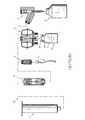
図1〜図13を参照すると、先行技術に係る閉鎖流体移動システムは概して100として示され、概してシリンジ又は任意の雄ルアーロック接続点に流体接続するモジュール/アダプタと、I.V.ラインに直接的に流体接続する患者プッシュモジュール/アダプタと、有害薬物等の形をとる流体/液体を保管する/含むバイアル/容器に流体接続する少なくとも1つのモジュール/アダプタと、I.V.バッグに流体接続するモジュール/アダプタとを含む。上記のモジュール/アダプタのそれぞれは、類似する数字が類似する要素を特定する添付の図に関して以下により詳細に説明される。 With reference to FIGS. 1 to 13, prior art closed fluid transfer systems are generally shown as 100, with modules / adapters that fluidly connect to a syringe or any male luer lock connection point, and I.D. V. Patient push modules / adapters that are fluid-connected directly to the line, and at least one module / adapter that fluid-connects to vials / containers that store / contain fluids / liquids in the form of harmful drugs, etc. V. Includes modules / adapters that fluidly connect to the bag. Each of the above modules / adapters is described in more detail below with respect to the accompanying figures that identify elements with similar numbers.
システムは、従来のシリンジと、患者I.V.セット、バイアル、又はI.V.バッグの内の1つとの間で、漏れる又は流出することなく、及び気体/流体/液体若しくは他の物質の、閉鎖システム外の場所若しくは物質への曝露なしに、液体を移動することができる「閉鎖」流体移動システムである。閉鎖流体移動システムの1つの目的は、医療従事者が、潜在的に有害な液状薬物等を含む液体形態の薬を安全に使用し、取り扱うことを可能にすることである。 The system consists of a conventional syringe and patient I. V. Set, vial, or I. V. A liquid can be transferred to and from one of the bags without leaking or spilling, and without exposure of the gas / fluid / liquid or other substance to a location or substance outside the closed system. A "closed" fluid transfer system. One purpose of the closed fluid transfer system is to allow healthcare professionals to safely use and handle liquid drugs, including potentially harmful liquid drugs and the like.
閉鎖流体移動システム100は、従来の無針注射器「I」の形の第1の流体容器と、患者I.V.セット、バイアル「V」、又はI.V.バッグの形の第2の流体容器/導管のとの間に閉鎖流体接続を提供するように構造化されるシリンジアダプタ11(図1〜図4を参照)を含む。流体移動は、必要に応じて患者プッシュアダプタ15(図1及び図8〜図11を参照)の1つをI.V.セットに、バイアルアダプタ13(図1及び図5〜図7を参照)をバイアルに、又はI.V.バッグアダプタ17(図1及び図12〜図13を参照)をI.V.バッグに最初に接続することによって達成される。各アダプタ13、15、17は、弾性シール23によって一端で閉じられた内部内腔21を画定する同一の雄ステム19を備える。シリンジアダプタ11は雄ステム19に結合され、それによってシリンジ「I」からの又はシリンジ「I」への流体の流れを可能にする。 The closed
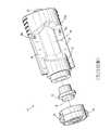
ここで特に図1〜図7を参照すると、閉鎖流体移動システム100は、シリンジアダプタ11を含む。シリンジアダプタ11は、そこを通る流体の流れを可能にするために開放状態となる、又は流体の流れを防ぐために閉鎖状態となる場合がある弁のタイプである。開放状態及び閉鎖状態は、シリンジアダプタ11によって決定された特定の順序で発生する。 Here, particularly with reference to FIGS. 1-7, the closed
シリンジアダプタ11は、ハウジング25、従来の中空金属針27、シャトル29、及びカラー31である4つの主要パーツから成る。ハウジング25は、末端部33、及び近端部35、長手方向軸37、遠位開口部39、並びに雄ステム19が中に受け入れられる雌空洞41を有する概して円筒形状である。ハウジング25は、2つのハウジング側面部分つまり半分43、45、及び側面部分43、45の間に部分的に嵌るハウジング基部47を有するように形成されてよい。側面部分43,45は、ハウジング末端部33で始まり、ハウジング25の中に延在する対向長穴49、51(図2及び図4を参照)を画定する。以下に詳細に説明される目的のために、長穴49、51のそれぞれ1つ(又は長穴51、49のそれぞれ1つ)にそれぞれ固定される、任意の雄ステム19のそれぞれのガイドピン53、55及びガイド面57、59を受け入れる長穴49、51。 The
中空の金属針27は、図3及び図4に見られるように、先の尖った先端61、先端部開口部63、近端部開口部65、及び針開口部63、65の間で従来の針27を通る流体の流れを可能にする内腔67を有する従来の針である。針27が、市販されている従来の18ゲージ鋼「鉛筆先端」針(18ゲージは針27の外径を指す)となることが想定される。従来の鉛筆先端針27は、先の尖った先端61からわずかに間隔を置いて配置された開口部63を有するきわめて鋭い先端61を有する。鉛筆先端針27は、流体の送達又は抽出のために患者の血管を貫通するためにシリンジとともに従来使用されるタイプ及びサイズである。 As can be seen in FIGS. 3 and 4, the
針27は、基部47の内側において固定位置関係でハウジング25の中に取り付けられ、針27の先端61はハウジング25の末端部33の方を指す/方に伸長する。この設計の優位点は、針27、及び具体的には針27のきわめて鋭い針の先端61がハウジング25の中に完全に封入され、ユーザとの接触から完全に保護されている点である。このようにして、ユーザの針刺しの結果としてのケガの可能性は大幅に削減されてきた、及び/又は排除されてきた。 The
ハウジング基部47は、ハウジング25内で回転可能に支持される。ハウジング基部47は、従来の無針注射器の送達端部を受け入れるために設けられた従来のルアーコネクタ69を有する外側を含む。内腔71は、ルアーコネクタ69と針27の近位開口部65との間の基部47を通って延在し、針先端開口部63とルアーコネクタ69との間の流体の流れを可能にする。 The
シリンジアダプタ11のハウジング25及びハウジング基部47は互いに協調して、それによりシリンジアダプタ11がシリンジ「I」から偶発的に又は不注意で切断し得ないようにするラチェット機構を提供する。特に、図3に見られるように、ラチェット機構は、ハウジング25の内面に形成された複数のリブ25a、及びハウジング基部47で支持された少なくとも1つの弾性フィンガ47aを含み、これによりハウジング基部47は、シリンジアダプタ11がシリンジ11に接続されるときにハウジング25に対して固定位置に保持され、シリンジアダプタ11が不注意で又は偶発的にシリンジ「I」から切断されている場合、ハウジング25に対して自由に回転する。このようにして、シリンジアダプタ11とシリンジ11との間の閉鎖システムはよりうまく維持される。 The
概して、動作中、シリンジアダプタ11がシリンジ「I」に接続されるとき、ハウジング基部47の少なくとも1つの弾性フィンガ47aは、ハウジング基部47のハウジング25に対する回転が抑制され、シリンジアダプタ11がシリンジ「I」に安全に接続され得るように、ハウジングのリブ25aと係合する。さらに、シリンジ「I」に対するシリンジアダプタ11の不注意な回転又は偶発的な回転があり、シリンジ「I」からシリンジアダプタ11を分離し、したがって閉鎖システムを破壊する傾向がある場合、各弾性フィンガ47aは、ハウジング25aのリブの上及びリブ25aを横切って滑り、ハウジング基部47がハウジング25に対して回転し、このようにして閉鎖システムを維持できるようにする。 Generally, during operation, when the
シリンジ「I」をシリンジアダプタ11から意図的に分離することが所望される場合、ユーザは、ルアーコネクタ69の近くでハウジング25を放射状に内向きに押し込み、ハウジング25の内面に形成された少なくとも1つの歯(不図示)をハウジング基部47の外面に形成されたそれぞれの切欠き47bと係合させてよい。次いで、ハウジング25の少なくとも1つの歯(不図示)がハウジング基部47のそれぞれの切欠き47bと係合した状態で、ユーザはシリンジ「I」に対してシリンジアダプタ11を回転して、シリンジ「I」をハウジング基部47のルアーコネクタ69から分離してよい。 If it is desired to intentionally separate the syringe "I" from the
シャトル29は、少なくとも以下の重要な目的のために設けられる。第1に、シャトル29は、シリンジアダプタ11がアダプタ13、15、17に結合されていないときに汚染物がハウジング25に進入できないように、ハウジング25の空洞41を閉じるためにハウジング25の遠位開口部39を横切るシャトル遠位シール73を支持する。第2に、シャトル29は、シール73が無菌であることを確実にするために、使用前に遠位シール73をアルコールで容易に拭き取ることができるように、ハウジング25の遠位開口部39を横切る位置でシャトル遠位シール73を支持する。本開示に従って、及び恒例により、(例えば図5に見られるように、及び以下により詳細に説明されるように)雄ステム19のシール23は、シール23と73との間の隣接部の無菌性を確実にするために、シリンジアダプタ11に結合される前にアルコール又は他の微生物因子で拭き取られる。最後に、シャトル29は、閉鎖状態にあるときシリンジアダプタ11の外部での流体の流れを妨げるために針27に流体密封のエンクロージャを提供する。 The
図3及び図4に示されるように、シャトル29はそれぞれ遠位の及び近位の環状フランジ75、77、並びにフランジ75、77の間の、そこを通るシャトル内腔81を画定する中間本体部分79を含む。遠位フランジ75は遠位シール73を支持し、遠位フランジ75上に据え付けられたバレル83は遠位フランジ75に遠位シール73を保持する。シャトル近位フランジ77は近位シール85を支持する。 As shown in FIGS. 3 and 4, the
図3及び図4に示されるように、針27の先端61はシャトル内腔81の中に伸長し、近位シール85は針27の回りで流体密封シールを形成する。閉鎖状態では、シリンジアダプタ11がシリンジ「I」に流体接続されると、針先端61及び開口部63はシャトル内腔81の中にあり、シール73、85が、流体がシャトル内腔81から出るのを妨げる As shown in FIGS. 3 and 4, the
各シール23、73は概して円板状であり、本明細書で後述されるように、シール23、73がともに保持されるとき互いに当接するそれぞれ外向きの突出部87、89(つまり、凸面)を含む。シール23、73、及び85はポリイソプレンから作られ、シール23及び73は、互いとの当接時にその元の凸状の外形を保持する又はその元の凸状の外形に戻るように設計される。言い換えると、シール23、73は弾性材料から製作され、その元の凸状の外形を保持すること又は凸状の形状に戻ることを望む傾向があるので、シール23、73が互いと当接するとき、シール23、73間の実質的に連続する界面が確立され、維持される。シール23及び73はポリイソプレンから作られることが好まれるが、シール23、73が、熱可塑性エラストマ(TPE)、シリコーン、より具体的には、ハロブチルポリイソプレン、クロロブチル、熱可塑性加硫物(TPV)、任意の他の弾性ポリマー、又はその任意の組合せから作られてよいことが意図され、本開示の範囲内にある。 Each of the
シャトル29の中間部分79は、ハウジング25の中での軸37に沿った軸方向の移動のためにカラー31のカラー端部壁93のカラー開口部91に乗る。バレル83は概して円筒形状であり、カラー31の内径にわずかに満たない外径を有して、バレル83及びシャトル29がカラー31の内部で往復移動できるようにする。 The
ばね95が設けられ、部分的にバレル83の中でカラー31の端壁93及び遠位フランジ75を押す。ばね95は、シャトル29の遠位シール73が、上述された理由のためにハウジング25の開口部39を覆う又は開口部39を横切って広がるように、ハウジング25の末端部33に向かってシャトル29を付勢する。バレル83とカラー31の端壁93との間でのばねにより付勢された接触は、ハウジング25の近端部35に向かうシャトル29の内向きの移動を制限し、シャトル29の近位フランジ77とカラー31の端壁93との間の接触はハウジング25の末端部33に向かうシャトル29の外向きの移動を制限する。 A
シャトル29の遠位シール73は、ハウジング25に接触せず、シャトル29によってだけ支持され、ハウジング25から間隔をおいて配置されたカラー31の中で移動する。以下により十分に説明されるように、シャトル29は、使用中任意の雄ステム19のシール23によって接触されると、ハウジング25の近端部35に向かって軸方向に押される。 The
図2〜図4を続けて参照すると、当接するシール23、73が、針27の針先端61によって以後に貫通できるように、及び針27が雄ステム19の内腔21に進入して、シリンジアダプタ11を通る流体経路を開くことができるように、カラー31及びハウジング25は協調して、雄ステム19及び(例えば、図8に見られる)そのシール23をシャトル29の遠位シール73と当接した状態で保持する。確立されたシール23、73の間の隣接部は、シャトル29の遠位シール73はハウジング25の遠位開口部39のための閉鎖であり、シャトル29の遠位シール73を、使用前のアルコールによる拭取りに便利な位置に置く。シール23、73間の隣接部は、2つのシール23、73が1つとして機能し、針27によってともに貫通できることを保証する。もしシール23、73がシャトル29の内腔81の外部に延在する針先端開口部63と分離していたとすれば、液体はハウジング25の空洞41の中に漏れる場合があり、これは閉鎖システムを提供する目的に反する。 With reference to FIGS. 2 to 4, the abutting
ここで図3〜図4を参照すると、カラー31は概して、ハウジング25の空洞41の形状に対応する円筒形状である。カラー31は近端壁93、及び近端部壁93から延在する側壁97を含む。 Here, referring to FIGS. 3 to 4, the
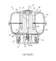
ここで図1及び図5〜図7を参照すると、閉鎖流体移動システム100のバイアルアダプタ13はより詳細に説明される。概して、バイアルアダプタ13は、抽出される液体「L」を保持する、又はその中に液体が送達されるバイアル、ボトル、又は他の容器「V」のネック「N」に接続する。便宜上、これらの容器は、集合的に用語「バイアル」により参照される。バイアルアダプタ13は、必要に応じて、市販されているバイアルに付着するためのサイズ及び構成で提供されてよい。 Here, with reference to FIGS. 1 and 5-7, the
図5〜図7に示されるように、バイアルアダプタ13は、基部201、(上述されたように、シール23を支持する雄ステム19を含み、ガイドピン53、55を含む)アダプタサポート203、スパイク205、及び膨張チャンバ207を含む。バイアルアダプタ13は、末端部及び近端部209、211を含む。 As shown in FIGS. 5-7, the
図6及び図7に最もよく示されるように、基部201は実質的にボール形であり、その上でアダプタサポート203を受け入れる、及び/又はアダプタサポート203を据え付けるように構成される。バイアルアダプタ13は、基部201の内側リム及び外側リムに据え付けられた、ブラダ277及び半透明カバー215を含む環状体形の膨張チャンバ207を含む。基部201の外側環状リムとカバー215の外側環状リムとの間に取り込まれた第1の環状リム、及び基部201の内側環状リムとカバー215の内側環状リムとの間に取り込まれた第2の環状リムを含む実質的にU字形の半径方向の断面を有するブラダ227。 As best shown in FIGS. 6 and 7, the
バイアルアダプタ13の基部201は、バイアル「V」のネック「N」が中に受け入れられる、その近端部211に沿った円形の開口部217を含む。リテーナ219は、バイアル「V」のネック「N」が開口部217の中に挿入されると、バイアルアダプタ13の基部201を接続して恒久的な接続部を形成するために、開口部217の外周の回りに設けられる。 The
図7で見られるように、スパイク205は、基部201の近端部211から離れて伸長し、バイアル「V」のネック「N」が基部201の開口部217に挿入されるときにバイアル「V」に設けられた隔壁「S」を貫通するように構成された先端221を含む。スパイク205は、バイアル「V」の中に伸長するのに十分な長さを有する。スパイク205は好ましくはプラスチックから作られるが、スパイク205は好ましくは、スパイク205がバイアル「V」の隔壁「S」を貫通する能力を支援するために金属製の貫通部材つまりハイポチューブ205aを支持してよいことが予想される。 As seen in FIG. 7, the
図7に見られるように、スパイク205及びアダプタサポート203は、2つのダクト223、225を画定する。第1のダクト225は、スパイク205の先端221と雄ステム19の内腔21との間に伸長し、バイアル「V」と雄ステム19との間で流体の流れを可能にするために設けられる。上述されたように、針27の先端61の開口部63は、シリンジアダプタ11が開放状態にあるときにダクト223を通して液体を抽出する又は送達するために内腔21の中に伸長する。第2のダクト225は、環状体形状のブラダ227が空気を抜かれるとき、スパイク205の先端221と、膨張チャンバ207の中に画定されたチャンバ207の第1の空洞207aとの間に伸長する。膨張チャンバ207のチャンバ207aは、空気又は他の気体がシリンジアダプタ11に付着されるシリンジ「I」から雄ステム19及びダクト223の中に注入されるとき、ブラダ227の移動時に膨張する。 As seen in FIG. 7, the
ここで図1及び図8〜図11を参照すると、閉鎖流体移動システム100の患者プッシュアダプタ15がより詳細に説明される。一般的に、患者プッシュアダプタ15は患者I.V.セットの管類に接続し、患者プッシュアダプタ15に付着されたシリンジ「I」から患者へ直接的に液体の送達を可能にする。 Here, with reference to FIGS. 1 and 8-11, the
患者プッシュアダプタ15は、それぞれ末端部及び近端部303、305を有する本体301を含む。患者プッシュアダプタ15の本体301は、好ましくは上下続きの成形プラスチックパーツである。患者プッシュアダプタ15の末端部303は、内腔21を横切って支持されるシール23を有し、その外面から放射状に外向きに突出するガイドピン53、55を有し、その外面から放射状に外向きに突出するガイド面57、59を有する、内腔21を画定する雄ステム19を含む。患者プッシュアダプタ15の近端部305は、患者I.V.セット「IV」(図1を参照)の結合するルアーコネクタを受け入れるように構成された従来のルアーコネクタ307を含む。内腔21は、本体301を通って、シール23とルアーコネクタ307との間で伸長し、患者プッシュアダプタ15が、上述されたように、シリンジアダプタ11に適切に接続されるとき、針27の先端61の開口部63とルアーコネクタ307との間の流体の流れを可能にする。 The
図8〜図10を参照すると、シリンジアダプタ11の長穴49、51の中に画定されたそれぞれの相補的な戻り止め又は凹部、つまりより詳細には、シリンジアダプタ11のハウジング25の半分43、45の内面に形成された適切なサイズに作られた環状リブ49a(図3を参照)をスナップ嵌合係合するように構成される、少なくとも1つの突起57a、59aが患者プッシュアダプタ15のそれぞれの誘導面57、59から突出してよいことが意図される。突起57a、59a、及びシリンジアダプタ11の長穴49、51又は環状リブ49a(図3及び図4を参照)に画定された相補的な戻り止め又は凹部の相互作用は、ユーザに、患者プッシュアダプタ15及びシステムアダプタ11が適切に且つ完全に互いに接続されている旨の可聴フィードバック及び/又は触覚フィードバックを与える。 8-10, respectively, each complementary detent or recess defined in the
患者プッシュアダプタ15のガイド面57、59は、ユーザが患者プッシュアダプタ15を把持し、I.V.セットの従来のルアーに対して患者プッシュアダプタ15を回転させるための便利且つ快適な表面を提供する。 The guide surfaces 57, 59 of the
ここで図1及び図12〜図13を参照し、本開示の閉鎖流体移動システム100のI.V.バッグアダプタ17はより詳細に説明される。一般的に、I.V.アダプタ17は、液体を従来のI.V.袋「B」(図1を参照すること)に送達する又は従来のI.V.袋「B」から抽出することを可能にする。また、I.V.袋アダプタ17は、シリンジ「I」又は他のソースからI.V.バッグの中に空気を送達して、I.V.バックからその液体内容物をより急速に流し出すことを可能にする、換気のソースとしても使用できるだろう。 Here, with reference to FIGS. 1 and 12 to 13, I.I. of the closed
I.V.バッグアダプタ17は、それぞれの末端部及び近端部403、405を有する本体401、並びに本体401から伸長するスパイク407を含む。I.V.バッグアダプタ17の末端部403は、内腔21を画定し、内腔21全体で支持されたシール23を有し、その外面から放射状に外向きに突出するガイドピン51、53を有し、その外面から放射状に外向きに伸長するガイド面57、59を有する雄ステム19を含む。I.V.バッグアダプタ17の本体401は、好ましくは上下続きの成形プラスチックパーツである。本体I.V.バッグアダプタ17の近端部405は、液体がI.V.バッグ「B」から中に滴下する従来の輸液チャンバ(不図示)の従来の先細雄コネクタ(不図示)を受け入れる従来のポート409を含む。スパイク407は、I.V.バッグ「B」の従来のポート(不図示)の中への挿入のために末端部と近端部403、405との間で先細にされる。 I. V. The
I.V.バッグアダプタ17の本体401は、2つのダクト411,413を含む。第1のダクト411は、本来、I.V.バッグアダプタ17がI.V.バッグ「B」に付着されるとき、I.V.バッグ「B」の中になるだろうスパイク407の開口部415に伸長するスパイク407を通る内腔21の伸長部である。第2のダクト413は、輸液チャンバ(不図示)への付着のために、スパイク407の第2の開口部417とポート409との間で伸長する。上述されたように、針27の先端61の開口部63は、I.V.バッグアダプタ17がシリンジアダプタ11に適切に接続されるとき、雄ステム19の内腔21の中に伸長して、シリンジアダプタ11が開放状態にある間にダクト411を通って液体(又は気体)を抽出する又は送達する。 I. V. The
本開示によると、シリンジアダプタ11以外の構成部品は、気体をI.V.バッグ「B」に送達するためにI.V.バッグアダプタ17の雄ステム19に接続できるだろう。ダクト411を通って送達される液体薬剤は、I.V.バッグ「B」の内容物と混合されてよい。I.V.バッグ「B」内の液体はポート409を通ってI.V.バッグ「B」を出て、患者への送達のために輸液チャンバの中に入ってよい。 According to the present disclosure, the components other than the
図12及び図15を参照すると、シリンジアダプタ11の長穴49、51に画定されたそれぞれの相補的な戻り止め又は凹部、つまりより詳細にはシリンジアダプタ11のハウジング25の半分43、45の内面に形成された適切なサイズに作られた環状導流路49a(図3を参照)をスナップ嵌合係合するように構成される、少なくとも1つの突起57a、59aが、I.V.バッグアダプタ17のそれぞれのガイド面57、59の表面から突出してよいことが意図される。突起57a、59a、及びシリンジアダプタ11の長穴49、51又は環状リブ49a(図3及び図4を参照)に画定された相補的戻り止め又は凹部の相互作用は、ユーザに、I.V.バッグアダプタ17及びシリンジアダプタ11が適切に且つ完全に互いに接続されている旨の可聴フィードバック及び/又は触覚フィードバックを与える。 With reference to FIGS. 12 and 15, the respective complementary detents or recesses defined in the slotted
シリンジアダプタ11、バイアルアダプタ13、患者プッシュアダプタ15、I.V.バッグアダプタ17を含む閉鎖流体移動システム100の構成及び動作の詳細な説明については、その全体の内容が参照により本明細書に援用される、米国特許第9,107,809号が参照されてよい。
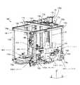
ここで図14〜図26を参照すると、本開示に従って、本開示のシリンジ、バイアル、I.V.セット、及びI.V.バッグを使用し、有害な薬を自動的に又は半自動的に調製するための調製システム1000が提供され、以下に説明される。 Here, with reference to FIGS. 14-26, according to the present disclosure, the syringes, vials, I.S. V. Set and I. V. A
調製システム1000は、図14に見られるように、少なくとも以下のサブシステム及び/又はステーション、つまり少なくとも1つのグリッパ(G)、構成部品ホルダ又は装填トレイ(CH)、回転ステーション(RS)、シリンジアダプタステーション(SAS)、計量又は再構成ステーション(W/RS)、輸液バッグステーション(IBS)、希釈液バッグステーション(DBS)、拭取りステーション(WS)、及び移動ステーション(TS)を含む。調製システム1000は、閉鎖システム移動装置(CSTD)と見なされてよい。 The
本開示の閉鎖システム移動装置(CSTD)は、がん治療の配合で使用される潜在的に有害な薬物の安全な移動のために作り出されてきた。CSTDは、ヘルスケア提供者を薬物に曝露することなくバイアルとシリンジとIVバッグとの間で薬物移動を行うための手段を提供する。 The Closed System Mobile Devices (CSTDs) of the present disclosure have been created for the safe transfer of potentially harmful drugs used in cancer therapeutic formulations. CSTD provides a means for drug transfer between vials and syringes and IV bags without exposing the healthcare provider to the drug.
CSTDの初期の概念は、CSTD技術を自動化された/ロボット用途に適用する可能性を含んでいた。この用途では、CSTD、バイアル、シリンジ等は標準的な調剤フードに導入され、次いで自動又は半自動の調製システムが、患者への投与に適切な薬物を作成するために必要とされる動き、混合等を提供するだろう。係る手法の主要な目的は、自動化された又は半自動化された方法により提供される信頼性、精度、及び再現性であろう。さらに、調製システムはマルチフード環境に適用され、スループットを改善し、追加人員、特に医師及び薬理学者が手洗い消毒し、正装する必要性を削減することができるであろう。 Early concepts of CSTD included the possibility of applying CSTD technology to automated / robotic applications. In this application, CSTDs, vials, syringes, etc. are introduced into standard dispensing hoods, and then automatic or semi-automatic preparation systems are required to create the appropriate drug for administration to the patient, movement, mixing, etc. Will provide. The main purpose of such a method would be the reliability, accuracy, and reproducibility provided by an automated or semi-automated method. In addition, the preparation system could be applied in a multi-food environment to improve throughput and reduce the need for additional personnel, especially doctors and pharmacologists, to hand wash and disinfect and dress up.
調製システム1000は、例えばクラス2A II BSC(フード)等、工学的制御の制約をもって動作することを目的とする。このタイプのフードの特徴は、天井に取り付けられたHEPAフィルタから発する垂直に下方への空気流を提供することである。調製システム1000は、構造物であり、例えば接合、構成部品のそれぞれの表面等のそのステーションのそれぞれを横切る『第1の空気(firstair)』流を最大限にする又は確立するために配置される。 The
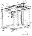
ここで図14〜図16を参照すると、調製システム1000は、それぞれがそれぞれの「C」軸に沿って伸長する複数のスタッド又はポスト1102a〜1102d、それぞれがそれぞれの「A」軸に沿って伸長し、選択されたポスト1102a〜1102dを相互に接続複数の第1のストリンガ又はレール1104a〜1104d、及びそれぞれがそれぞれの「B」軸に沿って伸長し、選択されたポスト1102a〜1102dを相互接続する複数の第2のストリンガ又はレール1106a〜1106dから構成された実質的に小個室の構成を有するフレーム1100を含む。フレーム1100は、デカルト水平面での調製システム1000の多様な構成部品の動きを支持するための構造を提供する。フレーム1100は上部から底部への明らかな空気流を促進するように構成される。一方、フレーム1100はフード(不図示)の中に配置される。 With reference to FIGS. 14-16, the
調製システム1000は、「A」軸に沿った並進のために、フレーム1100の上部の第1のストリンガ又はレール1104b、1104cの上に摺動可能に支持されたガントリアセンブリ1110を含む。ガントリアセンブリ1110は、軸受、低摩擦スライド等によって上部の第1のストリンガ又はレール1104b、1104cの上に支持されてよい。ガントリアセンブリ1110と上部の第1のストリンガ又はレール1104b、1104cとの間で摺動支持を提供できる任意の構造又は装置が利用され得ることが意図される。 The
フレーム1100は、ガントリアセンブリ1110を、「A」軸の方向で、フレーム1100の上部の第1のストリンガつまりレール1104b、1104cに沿って並進させるように構成されたガントリ並進アセンブリ1108を含む。ガントリ並進アセンブリ1108は、フレーム1100の上部の第2のストリンガつまりレール1106b、1106cの間で回転可能に支持され、それぞれの「A」軸に沿って伸長するねじガントリ棒(例えば、ねじ)1108aを含む。ガントリ並進アセンブリ1108は、モータ1108bがねじガントリ棒1108aを第1の方向及び第2の方向で(例えば、時計回りに及び反時計回りに)回転させるようにねじガントリ棒1108aに接続されたモータ1108bをさらに含む。 The
ガントリアセンブリ1110は、それぞれがそれぞれの「B」軸に沿って伸長するレール1112a、1112bの対を含む。ガントリアセンブリ1110は、そこを通して(例えば、ボールねじ構造又は構成)ガントリ並進アセンブリ1108のねじガントリ棒1108aを螺合可能に受け入れる少なくとも1つのねじ付きナット構造1114aをさらに含む。動作中、ガントリ並進アセンブリ1108のモータ1108bがねじガントリ棒1108aを回転させると、ガントリアセンブリ1110は「A」軸の方向でフレーム1100の上部の第1のストリンガつまりレール1104b、1104cに沿って並進させられる。 The
調製システム1000は、「B」軸に沿った並進のために、ガントリアセンブリ1110のレール1112a、1112bに摺動可能に支持された回転板アセンブリ1120を含む。回転板アセンブリ1120は、軸受、低摩擦スライド等によってガントリアセンブリ1110の1112a、1112bの上に支持されてよい。回転板アセンブリ1120と1112a、1112bとの間で摺動支持を提供できる任意の構造又は装置が利用され得ることが意図される。 The
ガントリアセンブリ1110は、回転板アセンブリ1120を、「B」軸の方向で、ガントリアセンブリ1110のレール1112a、1112bに沿って並進させるように構成された回転板並進アセンブリ1118を含む。回転板並進アセンブリ1118は、ガントリアセンブリ1110のレール1112bの上で回転可能に支持され、それぞれの「B」軸に沿って伸長するねじ回転板棒(例えば、ねじ)1118aを含む。回転板並進アセンブリ1118は、モータ1118bがねじ回転板棒1118aを第1の方向及び第2の方向で(例えば、時計回りに及び反時計回りに)回転させるようにねじ回転板棒1118に接続されたモータ1118bをさらに含む。 The
回転板アセンブリ1120は、ガントリアセンブリ1110のレール1112a、1112bの上に支持されたプラットフォーム1122を含む。回転板アセンブリ1120は、そこを通って(例えば、ボールねじ構造又は構成)回転板並進アセンブリ1118のねじ回転板棒1118aを螺合可能に受け入れる少なくとも1つのねじ付きナット構造(不図示)をさらに含む。動作中、回転板並進アセンブリ1118のモータ1118bがねじ回転板棒1118aを回転させると、回転板アセンブリ1120は、軸「B」方向でガントリアセンブリ1110のレール1112a、1112bに沿って並進させられる。 The
回転板アセンブリ1120は、プラットフォーム1122上で回転可能に支持された平歯車1124を含み、平歯車1124の回転軸はそれぞれの「C」軸で伸長する。回転板アセンブリ1120は、平歯車1124から垂れ下がり、平歯車1124に回転できないように接続されたレール列1126をさらに含み、レール列1126はそれぞれの「C」軸に沿って伸長する。また、回転板アセンブリ1120は、第1のモータ1128aが平歯車1124を第1の方向及び第2の方向で(例えば、時計回りに及び反時計回りに)回転させるように、平歯車1124と駆動係合する第1のモータ1128aを含む。レール列1126が平歯車1124に回転できないように接続されるので、第1のモータ1128aは平歯車1124を回転させると、レール列1126も付随して回転される。 Rotating
具体的には、レール列1126は、DCブラシ歯車モータ1128aを介して回転を与えられる。第1のモータ1128aの逆転は、例えば、一方が+12VDCを提供し、他方が‐12VDCを提供する反対の極性の電源に作用するリレーのコンピュータ制御によって達成される。さらに、以後のプログラム実行の前に完全な回転(又は必要とされる若しくは所望される回転の完了)を保証するためにリードスイッチが設けられることが意図される。レール列1126の回転は、平歯車つまりブルギア1124を駆動する第1のモータ1128aに取り付けられたピニオンギア(不図示)を介して提供される。上述されたように、レール列1126は平歯車1124の中心を通って垂れ下がり、4点接触薄壁セクション軸受によって支持される。 Specifically, the
調製システム1000は、回転板アセンブリ1120のレール列1126上で並進可能に支持されたキャリッジ1130を含む。レール列1126に沿ったキャリッジ1130の並進は、レール列1126を通って伸長し、キャリッジ1130(例えば、ボールねじ構造又は構成)に固定されたねじ付きナット構造(不図示)と螺合可能に係合するねじ棒(不図示)を駆動する回転板アセンブリ1120の第2のモータ1128bによって達成される。 The
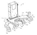
調製システム1000は、キャリッジ1130に固定されたグリッパ(G)を含む。グリッパ(G)は、構成部品ホルダ(CH)に保持された配合構成部品を把持し、調製システム1000のステーションから又は構成部品ホルダ(CH)から配合構成部品を取り外し、次いで配合構成部品を調製システム1000の別のステーションに設置することを担う。また、グリッパ(G)はステーションから構成部品ホルダ(CH)に配合構成部品を戻すことも担う。グリッパ(G)は、サブアセンブリ、具体的にはバイアル(V)及びバイアルアダプタ13サブアセンブリ(例えば、バイアルアセンブリ)並びにシリンジ「I」及びシリンジアダプタ11サブアセンブリ(例えば、シリンジアセンブリ)の組付け及び分解を達成することもさらに担う。 The
図17及び図18を参照すると、グリッパ(G)は、その(ジョー1132の第1の対の内の1つのジョーがジョー1134の第2の対の間に置かれ、ジョー1134の第2の対の第2のジョーがジョー1132の第1の対の間に置かれる、固定された対向したジョー1132の第1の対、及び並進可能な対向したジョー1134の第2の対を含む)雌雄両性のジョー1131を介して4つの構成部品に適応できる2つのジョーを含む。グリッパ(G)は、ジョー1131がつねに固定された中心面で開閉するように2つのラック歯車及びピニオンを介して調整されるジョー1131を特徴づける。 With reference to FIGS. 17 and 18, the gripper (G) is a second pair of
図18に示されるように、グリッパ(G)は、ジョー1132の第1の対及びジョー1134の第2の対を互いに対して並進させて、第1の把持位置(G1)、第2の把持位置(G2)、及び第3の把持位置(G3)の内の1つで構成部品(例えば、シリンジ「I」、バイアル「V」、シリンジアダプタ11、バイアルアダプタ13等)を把持することによって機能する。第1の把持位置(G1)は、ジョー1132の第1の対の第1のジョー1132aと、ジョー1134の第2の対の第1のジョー1134aとの間に位置してよく、第2の把持位置(G2)は、ジョー1132の第1の対の第1の対の第1のジョー1132aとジョー1134の第2の対の第2のジョー1134bとの間に位置してよく、第3の把持位置(G3)は、ジョー1132の第1の対の第2のジョー1132bとジョー1134の第2の対の第2のジョー1134bとの間に位置してよい。 As shown in FIG. 18, the gripper (G) translates the first pair of
ほんの一例として、グリッパ(G)の第1の把持位置(G1)は、シリンジ「I」を把持するために使用されてよく、グリッパ(G)の第2の把持位置(G2)は、バイアルアダプタ13を把持するために使用されてよく、グリッパ(G)の第3の把持位置(G3)は、シリンジアダプタ11を把持するために使用されてよい。 As just one example, the first grip position (G1) of the gripper (G) may be used to grip the syringe "I" and the second grip position (G2) of the gripper (G) is the vial adapter. It may be used to grip the 13 and the third grip position (G3) of the gripper (G) may be used to grip the
例えば、把持位置(G1)はシリンジ「I」の下部範囲だけではなくシリンジ「I」のヘッド、つまり上部範囲も把持するために使用でき、このようにしてより多くの柔軟性を提供する等、グリッパ(G)は、構成が把持位置のそれぞれの複数の使用を可能にする雌雄両性として構成される。グリッパ(G)のジョー1131は、例えばDestaco Robohandマニピュレータ等の、モータ等によって作動されてよい。グリッパ(G)のジョー1131は、測定及びエラートラッピングを提供するようにさらに構成される。例えば、水平線形電位差計1136aは、正しい直径が把持されることを保証するために、例えばシリンジ「I」及びバイアル「V」等の構成部品の直径の測定を提供する。一方、垂直線形電位差計1136bは、バイアルアダプタ13から突出する隆起した特徴又はリブの位置決めのために提供される。 For example, the grip position (G1) can be used to grip not only the lower range of the syringe "I" but also the head of the syringe "I", i.e. the upper range, thus providing more flexibility, etc. The gripper (G) is configured as an amphoteric configuration that allows multiple uses of each of the grip positions. The gripper (G)
使用中、キャリッジ1130、及び同様にグリッパ(G)は、第2のモータ1128bの作動時にレール列1126の長さに沿って並進可能であり、キャリッジ1130及びグリッパ(G)は、第1のモータ1128aの作動時、レール列1126の長手方向軸の回りで回転可能である。 In use, the
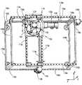
ここで図14及び図19を参照すると、調製システム1000は、調製システム1000の配合サイクルで活用される可動構成部品を保持するように構成されるフレーム1100に固定された構成部品ホルダ又は装填トレイ(CH)を含む。可動構成部品は、図1及び図14に示されるように、バイアル「V」、バイアルアダプタ13、シリンジ「I」、及びシリンジアダプタ11を含む。バイアルアダプタ13は、バイアル「V」の20mmネックを収容するようなサイズで作られてよい。バイアルアダプタ13は、装填トレイ(CH)内の凹部(不図示)でステージングされる、又は保持され、これによりバイアルアダプタ13の保護カバーは装填トレイ(CH)の上部壁の真下に常駐し、バイアルアダプタ13の垂直並進時にバイアルアダプタ13のカバーを取り去る又は取り外すように構成される。 With reference to FIGS. 14 and 19, the
装填トレイ(CH)はその中に、可動構成部品を選択的に保持するために形成された凹部を含む。例えば、装填トレイ(CH)は、シリンジ「I」を保持するように構成された凹部1142a、及びバイアル「V」を保持するように構成された凹部1142bを含んでよい。装填トレイ(CH)の凹部1142a、1142bはV字形の外形を有するように構成され、可動構成部品の異なる直径をその中に収容するためにそれぞれのリーフスプリング1143a、1143bを備えてよい。 The loading tray (CH) includes a recess formed therein to selectively hold the movable component. For example, the loading tray (CH) may include a
装填トレイ(CH)は、4つのポスト等を介してフレーム1100の下部の第1のストリンガつまりレール1104aの上での支持又はステージングのために構成されてよく、下部の第1のストリンガつまりレール1104aへ/からの繰り返される接続切断のためにばねで留められたプランジャ及び戻り止め特徴1144を含んでよい。 The loading tray (CH) may be configured for support or staging on the lower first stringer or
ここで図14及び図20A〜図20Bを参照すると、調製システム1000は、フレーム1100に(例えば、フレーム1100のフロアに)固定された回転ステーション(RS)を含む。回転ステーション(RS)は、選択された可動構成部品の組付け及び分解のための固締機能を提供し、シリンジアダプタ11との接続のためにバイアルアダプタ13を漸次的に導入するための回転機能を提供する。 With reference to FIGS. 14 and 20A-20B, the
回転ステーション(RS)は、その間に小さい垂直軸方向隙間を取り付けられる2つのブルギアつまり平歯車1152a、1152bを含む。下部平歯車1152aは、例えば双方向DC歯車モータ等の第1のモータ1154aによって駆動され、回転ステーション(RS)のジョー1156、1158の対の開放及び閉鎖のためにピニオン1152a1及びラック1156e、1158eの対を駆動する働きをする。ジョー1156、1158の対は、レール1159a、1159bを介して上部平歯車1152b上で並進可能に支持される。第1のモータ1154aの双方向性は、2つの反対の極性の電源の間の切替えにより提供される。 The rotary station (RS) includes two bull gears or
動作中、第1のモータ1154aの第1の作動は、下部平歯車1152aを第1の方向で回転させ、同様にピニオン1152a1の第1の方向での付随する回転を引き起こす。ピニオン1152a1は第1の方向で回転され、ピニオン1152a1はジョー1156、1158の対のラック1156e、1158eの対に作用して、ラック1156e、1158eの対を第1の方向で(互いに反対に)軸に沿って摺動させる。ラック1156e、1158eの対が第1の方向で摺動するにつれ、ジョー1156、1158の対は互いに向かって近づく(例えばジョーの対を閉じる)。第1のモータ1154aの(第1の作動に反対の)第2の作動は、下部平歯車1152aを(第1の方向に反対の)第2の方向で回転させ、同様にピニオン1152a1の第2の方向での付随する回転を引き起こす結果となる。ピニオン1152a1が第2の方向で回転されるにつれ、ピニオン1152a1はジョー1156、1158の対のラック1156e、1158eの対に作用して、ラック1156e、1158eの対を(互いに反対の)第2の方向で軸方向に摺動させる。ラック1156e、1158eの対が第2の方向で摺動するにつれ、ジョー1156、1158の対は互いから分離する(例えば、ジョーの対を開放する)。 During operation, the first actuation of the
上部平歯車1152bは、回転ステーション全体の回転を担う。上部平歯車1152bは、第1のモータ1154aの率よりも高い比率を有する、例えばDC歯車モータ等の第2のモータ1154bによって駆動される。したがって、ジョー1156、1158の対は、回転歯車又は上部平歯車1152bをバックドライブすることなく開閉できる。 The
第1のモータ1154aのジョーは、第2のモータ1154bの回転よりも速い速度で動作し、これにより回転ステーション(RS)の回転中、トルクはジョートランスミッションで維持され、ジョー又は第1のモータ1154aの磁場は第2の又は回転モータ1154bの速度で滑るにすぎない。 The jaws of the
ジョー1156、1158の対は、上部バイアル位置及び下部バイアル位置を画定する、通過するフィンガ/壁で構成され、収容できるバイアルの直径及び長さの範囲を広げる。具体的には、各ジョー1156、1158は、それぞれ複数の離間した平行な壁1156a、1158aを含み、第1のジョー1156の壁1156aは、第2のジョー1158の壁1158aの間に画定された隙間と位置合わせ又は整列される。このようにして、ジョー1156、1158の対が互いに向かって近づけられると、それぞれの壁1156a、1158aは互いとかみ合う又は入れ子になる。第1のジョー1156の壁1156aは、実質的にV字形又は先細り、集中する外形つまり凹部1156bを画定し、第2のジョー1158の壁1158aは、実質的にV字形又は先細り、集中する外形つまり凹部1158bを画定し、凹部1156b、1158bは互いに対向する関係にあり、このようにして下部バイアル位置を画定する。 The pair of
各ジョー1156、1158は、それぞれの上部把持ブロック1156c、1158cを支持する。各把持ブロック1156c、1158cは、ジョー1156、1158の対のそれぞれの壁1156b、1158bの後端部の近くに位置する。各把持ブロック1156c、1158cは、それぞれ実質的にV字形又は先細り、集中する外形つまり凹部1156d、1158dを画定し、凹部1156d、1158dは互いに対向する関係にあり、凹部1156d、1158dは、壁1156a、1158aによって画定された凹部1156b、1158bと位置合わせされ、このようにして上部バイアル位置を画定する。 The
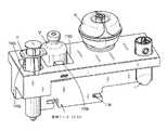
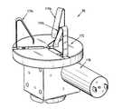
ここで図14及び図21A〜図21Cを参照すると、調製システム1000は、フレーム1100に固定されたシリンジアダプタステーション(SAS)を含む。シリンジアダプタステーション(SAS)は、ブルギアつまり平歯車1162をその上で回転可能に支持するプラットフォーム1161を含む。シリンジアダプタステーション(SAS)は、ばねで留められた垂直ジョー1164、1166の対をさらに含み、垂直ジョー1164、1166はそこから突出するそれぞれの歯車装置1164a、1166aによって同期されて、シリンジアダプタ11の把持を調整する。ジョー1164、1166の対は、平歯車1162から突出するそれぞれのサポート1164b、1166bによって平歯車1162上で枢動可能に支持される。ジョー1164、1166の対は、平歯車1162から突出するそれぞれの直立材1164c、1166cの間に配置される。各ジョー1164、1166は、その端部に形成され、シリンジアダプタ11を少なくとも部分的に取り囲むように構成され、大きさにされた、それぞれ実質的にV字形の切欠きつまり凹部1164d、1166dを含む。それぞれの付勢部材1164e、1166eの対は、それぞれのジョー1164、1166とそれぞれの直立材1164c、1166cとの間に配置される。 With reference to FIGS. 14 and 21A-21C, the
シリンジアダプタステーション(SAS)は、プラットフォーム1161のフロアで摺動可能に支持され、ジョー1164、1166の対の間に位置する鋸歯形状のカップ1168aを含む。付勢部材1168bは、ジョー1164、1166の対に向かって、及びプラットフォーム1161の中から鋸歯形状のカップ1168aを動かすために提供される。鋸歯形状のカップ1168aは、その表面から放射状に突出し、ハウジングつまりシュラウド1169の導流路つまり溝1169aに摺動可能に常駐する少なくとも1つのタブ1168cを含み、ハウジング1169は平歯車1162に固定される。 The syringe adapter station (SAS) is slidably supported on the floor of
動作中、シリンジアダプタ11及びシリンジ「I」の互いに対する組付けのために、シリンジアダプタ11は最初に、シリンジアダプタ11のルアーコネクタ69(図1〜図4)がプラットフォーム1161から離れて突出するように、シリンジアダプタステーション(SAS)のジョー1164、1166の対の間で保持される。シリンジアダプタ11は、シリンジアダプタ11が単一方向だけで回転し得るように、鋸歯形状のカップ1168aに据え付けられる。次に、シリンジ「I」は、グリッパ(G)によって装填トレイ(CH)から拾い上げられ、シリンジ「I」のルアーコネクタがシリンジアダプタ11のルアーコネクタ69と軸に沿って整列されるまでガントリアセンブリ69によってシリンジアダプタステーション(SAS)に向かって近づけられ、シリンジアダプタ11が鋸歯形状のカップ1168aに対して押しつけられ、シリンジアダプタ11に向かって前へ進められる。 During operation, for assembling the
モータ1167a(例えば、双方向歯車モータ)は、次いでピニオンギア1167bを介して(第1の方向で)平歯車1161を回転させて、シリンジアダプタ11をシリンジ「I」に対して回転させる。シリンジアダプタ11が平歯車1162に対して回転するのを鋸歯形状のカップ1168aが妨げている状態で、シリンジアダプタ11がシリンジ「I」に対して回転されると、そのルアーコネクタ間の接続が達成され、それによってシリンジアダプタ11及びシリンジ「I」を組み付ける。組付け中、鋸歯形状のカップ1168aは、シリンジアダプタ11の端部に設けられた表面特徴の上で上下に動く。 The
いったんシリンジアダプタ11及びシリンジ「I」が組み付けられると、平歯車1162は平歯車1162を回転させることによって反対方向で回転される。組み付けられたシリンジアダプタ11及びシリンジ「I」が反対方向で回転されると、グリッパ(G)がシリンジ「I」から切り離された状態で、鋸歯形状のカップ1168aはシリンジアダプタ11の端部に設けられた特徴と係合して、それによってシリンジアダプタ11のバイアルアダプタ13、I.V.アダプタ15、又はI.V.不良アダプタ17への後の組付けのために、組み付けられたシリンジアダプタ11及びシリンジ「I」に向きを与える。 Once the
ここで図14及び図22を参照すると、調製システム1000は、フレーム1100に固定された再構成ステーション(W/RS)を含む。再構成ステーション(W/RS)は、凍結乾燥薬物の溶解のための攪拌を提供する。動作中、再構成ステーション(W/RS)は、他の配合が調製システム1000で進行中である間に作動されてよい。 With reference to FIGS. 14 and 22, the
再構成ステーション(W/RS)は、回転板の第1の表面に少なくとも3つのリーフスプリング1174a〜1174cを支持する回転板1172を含む。リーフスプリング1174a〜1174cは、回転板1172の回転中心軸の回りで放射状に配置される。各リーフスプリング1174a〜1174cは、回転板1172に固定され、回転板1172から離れて伸長する脚部分、及びそれぞれの脚の自由端から、回転板1172の中心回転軸に向かって伸長するアーム部分を含む。リーフスプリング1174a〜1174cは、その間に多様な直径のバイアルを安定させ、選択的に保持するために機能する。 The reconstruction station (W / RS) includes a
再構成ステーション(W/RS)は、例えば歯車装置(例えば、ウォームギア)等を通して回転板1172を駆動するためのプログラム可能なリレーを介したモータ1176のオン−オフ励振時に、回転板1172、及び同様にその上に支持されたバイアル「V」に攪拌を提供するために回転板1172と作動係合するモータ1176を含む。 The reconstruction station (W / RS) is capable of rotating the
ここで図14及び図23を参照すると、調製システム1000は、フレーム1100に固定された輸液バッグステーション(IBS)を含む。輸液バッグステーション(IBS)は、輸液バッグの管が調製システム1000の可動部品から離れて突出するように、フレーム1100に位置決めされる。 With reference to FIGS. 14 and 23, the
輸液バッグステーション(IBS)は、その位置決めのために戻り止め1184の中に嵌るトレイ1182を含む。輸液バッグステーション(IBS)は、I.V.バッグアダプタ17の外形に相補的である形状及び/又は構成を有するバッグアダプタブロック1186をさらに含む。I.V.バッグアダプタ17及びI.V.バッグ(不図示)は、片手で輸液バッグステーション(IBS)の中に装填する及び取り外すことができ、輸液バッグステーション(IBS)のばねで留められたアーム1188によって定位置に保持される。トレイ1182はサブトレイ1182aを含み、これにより所望される場合、サブトレイ1182aは水平面から曲げることができる。 The infusion bag station (IBS) includes a
ここで図14及び図24を参照すると、調製システム1000は、フレーム1100に固定された希釈液バッグステーション(DBS)を含む。希釈液バッグステーション(DBS)は、希釈液バッグが調製システム1000の可動部品から離れて突出するようにフレーム1100に位置決めされる。 With reference to FIGS. 14 and 24, the
希釈液バッグステーション(DBS)は、凍結乾燥薬物の再構成のための液体の希釈液バッグ(不図示)からの抽出のために希釈液バッグをステージングする。希釈液バッグステーション(DBS)は輸液バッグステーション(IBS)と同様に構成されるが、そのトレイ1182から伸長する垂直アーム1192をさらに備える。希釈液バッグステーション(DBS)の垂直アーム1192は、(希釈液バッグに含まれる)希釈液が垂直アーム1192から突出する水平フィンガ1192aの対を経由してシリンジ「I」を介して引き出される間にシリンジアダプタ11の保持を提供するように構成される。具体的には、I.V.バッグアダプタ17が希釈液バッグ(不図示)に及びシリンジアダプタ11に流体接続された状態で、並びに(前進位置に配置されたそのプランジャを有する)シリンジ「I」が同じシリンジアダプタ11に流体接続された状態で、プランジャが引き抜かれると、流体又は希釈液は、希釈液バッグからI.V.バッグアダプタ17及びシリンジアダプタ11を通してシリンジ「I」の中に引き出される。 The Diluent Bag Station (DBS) stages the diluent bag for extraction from the liquid diluent bag (not shown) for the reconstruction of the lyophilized drug. The diluent bag station (DBS) is configured similar to the infusion bag station (IBS), but further comprises a
希釈液バッグステーション(DBS)の垂直アーム1192は、シリンジ「I」、シリンジアダプタ11、及びそのアセンブリと係合するためにばねで留められてよい。垂直アーム1192は、シリンジ及びシリンジアダプタアセンブリの希釈液バッグステーション(DBS)への及び希釈液バッグステーション(DBS)からの装填及び取外しを可能にするために、グリッパ(G)のジョー1132、1134と係合するための特徴をさらに備える。 The
ここで図14及び図25を参照すると、調製システム1000は、フレーム1100に固定された拭取りステーション(WS)を含む。拭取りステーション(WS)は、互いに対する組付けの前に、バイアルアダプタ13及びシリンジアダプタ11のグランド又はシールにアルコール拭取り繊維(不図示)を提供するように構成される。この手順は、無菌パーツ処理と一貫しており、感染及び汚染からの追加の保護を提供する。 With reference to FIGS. 14 and 25, the
拭取りステーション(WS)は、基部1202と、基部1202の上で支持されたソレノイド/ばねアセンブリ1204と、基部1202の上で支持され、ソレノイド/ばねアセンブリ1204に動作可能なように接続されたスイングアーム1206と、アルコールポンプ及び散布システム(不図示)と、ソレノイド/ばねアセンブリ1204の第1の側面に隣接した基部1202上で回転可能に支持されたテープ送りリール1208と、ソレノイド/ばねアセンブリ1204の第2の側面に隣接した基部1202上で回転可能に支持された巻取りリール1210と、を含む。 The wiping station (WS) is a swing that is operably connected to the
拭取りステーション(WS)は、スイングアーム1206のランディングの回りで、テープ送りリール1208から巻き取りリール1210へ伸長するテープ(不図示)を含む。拭取りステーション(WS)は、巻取りリール1210の回転及びテープ送りリール1208からのテープの引出しを引き起こすために巻取りリール1210に動作可能なように接続されたモータ1212をさらに含む。 The wiping station (WS) includes tape (not shown) extending from
動作中、アルコールポンプ及び散布システム(不図示)によって、テープがアルコールで湿った状態で、スイングアーム1206のランディングの領域で、バイアルアダプタ13又はシリンジアダプタ11はグリッパ(G)によって装填トレイ(CH)から拾い上げられ、そのシールがスイングアーム1206のランディングに近接するように、ガントリアセンブリ1110によって拭取りステーション(WS)に向かって近づけられる。バイアルアダプタ13又はシリンジアダプタ11のシールがスイングアーム1206のランディングに近接した状態で、ソレノイド/ばねアセンブリ1204のソレノイドは、スイングアーム1206を移動させ、同様にアルコールで湿ったテープをシールと接触させるために作動される。その後、巻取りリール1210はシールを横切ってアルコールで湿ったテープを引き出し、シールを殺菌するために回転される。プロセスは、バイアルアダプタ13又はシリンジアダプタ11の他方のために繰り返される。 During operation, the
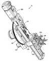
ここで図14及び図26を参照すると、調製システム1000は、フレーム1100に固定された移動ステーション(TS)を含む。移動ステーション(TS)は、シリンジ「I」とバイアル「V」との間での流体の移動を提供する。移動ステーション(TS)は、固定フレーム1226a上で支持されたブルギアつまり平歯車1224と動作可能なように係合された、例えば双方向歯車モータ等の第1のモータ1222aを介した水平軸の回りの回転のために構成される。移動ステーション(TS)は、シリンジ「I」のプランジャ及びプランジャフランジとの選択的な係合のためにばねで留められたジョー1228a、1228bの対をさらに含む。第1のジョー1228aは固定フレーム1226aに接続され、第2のジョー1228bは可動フレーム1226bに接続され、可動フレーム1226bは、ジョー1228a、1228bの対を近づける及び/又は分離するために固定フレーム1226aに並進可能に接続される。ジョー1228a、1228bの対は、異なる体積のシリンジを収容する最小限の努力で移動するように設計された線形ベアリングに取り付けられてよい。 With reference to FIGS. 14 and 26, the
移動ステーション(TS)は、第2のジョー1228bと螺合係合しているねじ棒1223と駆動係合している第2のモータ1222bを含んでよく、第2のモータ1222bによるねじ棒1223の回転は、第1のジョー1228aに対する第2のジョー1228bの並進を生じさせる。 The mobile station (TS) may include a
移動ステーション(S)の機能及び動作のより詳細な説明については、米国特許第9,107,809号が参照され、その全体的な内容は参照により本明細書に以前に援用された。 For a more detailed description of the function and operation of the mobile station (S), US Pat. No. 9,107,809 has been referenced, the entire contents of which have been previously incorporated herein by reference.
本開示の調製システム1000の動作は、多様な薬物、体積、希釈液、速度等の配合を提供する能力によりきわめて柔軟性がある。調製システム1000は、薬物の調製のための3つの基本的なルーチン、すなわちシリンジ「I」から用量をプッシュすること、輸液バッグ(不図示)の中に用量を注入すること、及び凍結乾燥薬物を再構成することを実行できる。 The operation of the
本開示に従って、用量をプッシュするためのルーチンは以下のステップを含む。
1.回転ステーション(RS)にバイアル「V」を持ち込む。具体的には、グリッパ(G)のジョー1132、1134の対はバイアル「V」のネックと係合し、装填トレイ(CH)からバイアル「V」を取り外し、バイアル「V」を回転ステーション(RS)に提示し、回転ステーション(RS)のジョー1156、1158の対はバイアル「V」の本体で閉じる。グリッパ(G)のジョー1132、1134の対は、次いでバイアル「V」を解放し、ホームポジションに戻る。
2.バイアルアダプタ13をバイアル「V」に組み付ける。グリッパ(G)のジョー1132、1134の対は、次いで例えばバイアルアダプタ13の基部201とカバー215との間のバイアルアダプタ13の一部分の回りで等その「赤道」の回りで、バイアルアダプタ13を掴み、バイアル「V」の上にバイアルアダプタ13を位置決めし、(例えば、バイアルアダプタ13及びバイアル「V」を近づけることによって)下降運動でバイアルアダプタ13及びバイアル「V」をともに押してバイアルアセンブリを形成し、次いでバイアルアダプタ13を解放する。グリッパ(G)は、次いでその垂直線形電位差計1136bの先端をバイアルアダプタ13の肩部に当てるためにそれ自体を位置決めする。回転は、バイアルアセンブリ上での回転ステーション(RS)によって開始され、これによって電位差計1136bはバイアルアダプタ13での特徴の上昇を検知し、回転を休止し、これによりバイアルアダプタ13はここでシリンジアダプタ11への係合のために配向される。バイアルアセンブリは保持ステーションに設置され、グリッパ(G)はホームポジションに戻る。
3.シリンジアダプタ11をシリンジアダプタステーション(SAS)に持ち込む。グリッパ(G)のジョー1132、1134の対は、シリンジアダプタ11の上部の外径と係合し、シリンジアダプタ11を下降運動によってシリンジアダプタステーション(SAS)の中に置き(例えば近づけられる)、このようにしてジョー1164、1166の対がシリンジアダプタ11の外径と係合するように、シリンジアダプタステーション(SAS)のジョー1164、1166の対を変位させる。グリッパ(G)は、次いでシリンジアダプタ11を解放し、ホームポジションに戻る。
4.シリンジ「I」をシリンジアダプタ11に組み付ける。グリッパ(G)のジョー1132、1134の対は、次いで装填トレイ(CH)にあらかじめ装填されているシリンジ「I」の本体及びフランジと係合する。グリッパ(G)は、次いでシリンジ「I」を持ち上げ、シリンジ「I」を垂直軸の回りで回転させ、シリンジ「I」を移動ステーション(TS)に提示し、シリンジ「I」のプランジャはシリンジ「I」を空気で事前に充填するために引っ込められる。グリッパ(G)は、次いでシリンジ「I」をシリンダアダプタステーション(SAS)に持ち込み、シリンジ「I」はその間でのルアー特徴の組付けを達成してシリンジアセンブリを形成するために、シリンジアダプタ11の同時回転で下方に移動される(例えば、近づけられる)。回転は次いで逆転して、バイアルアセンブリのバイアルアダプタ13との接続のためにシリンジアセンブリを配向する。シリンジアセンブリは次いで保持ステーションに設置され、グリッパ(G)はホームポジションに戻される。
5.組付け。グリッパ(G)のジョー1132、1134の対は、次いで保持ステーションからバイアルアセンブリを把持し、バイアルアセンブリを回転ステーション(RS)に戻し、回転ステーション(RS)のジョー1156、1158の対は次いで閉じ、グリッパ(G)のジョー1132、1134の対は解放する。グリッパ(G)のジョー1132、1134の対は、次いでシリンジアセンブリを取り、シリンジアセンブリをバイアルアセンブリの上に位置決めする。拭取りステーション(WS)は次いで係合されて、そのスイングアーム1206を外に振って、バイアルアセンブリ及びシリンジアセンブリの曝露されたグランド又はシールと係合する。特に、アルコールは拭取りステーション(WS)のテープ(不図示)の上にくみ上げられ、テープは前進し、それぞれのバイアルアセンブリ及びシリンジアセンブリの2つの曝露されたグランド又はシールは次いで互いに近接され、テープによって拭き取られる/消毒される。スイングアーム1206は、次いで後退する。バイアルアセンブリ及びシリンジアセンブリは次いでともに垂直に押されて、完全なアセンブリ(例えば、すべてが互いに機械的に連通及び流体連通しているシリンジ「I」、シリンジアダプタ11、バイアルアダプタ13、バイアル「V」)を作り出す。
6.流体移動。グリッパ(G)のジョー1132、1134の対は、次いで完全なアセンブリを把持し、グリッパ(G)は次いでその中でのステージングのために完全なアセンブリを移動ステーション(TS)に持ち込む。グリッパ(G)は、次いで完全なアセンブリを解放し、後退する。事前移動、完全なアセンブリを見るためにフレーム1100に取り付けられた調製システムのカメラ(不図示)は、流体移動ステップを写真で記録する。(シリンジ「I」に含まれる)事前充填空気は、シリンジ「I」のプランジャの前進を介してバイアルアダプタ13の膨張チャンバの中に押し込まれる。移動ステーション(TS)は反転され、(バイアル「V」に含まれる)薬物は、シリンジ「I」のプランジャの伸長又は後退によってシリンジ「I」の中に引き込まれる。移動ステーション(TS)は、その後逆転し、カメラは移動状態を記録する。
7.分解。グリッパ(G)のジョー1132、134の対は次いで、再び本体によって及びそのシリンジ「I」のフランジによって完全なアセンブリと係合し、完全なアセンブリを回転ステーション(RS)に設置し、回転ステーション(RS)では、回転ステーション(RS)のジョー1156、1158の対は完全なアセンブリのバイアル「V」の外径と係合する。グリッパ(G)のジョー1132、1134の対がシリンジアセンブリと係合した状態で、シリンジアダプタステーション(SAS)のジョー1164、1166の対はシリンジ「I」のルアーネックと係合し、シリンジアセンブリは次いでバイアルアセンブリから引き離される。グリッパ(G)は、次いでシリンジアセンブリを装填トレイ(CH)のシリンジステーションに送達する。グリッパ(G)のジョー1132、1134の対は、次いでシリンジアセンブリから外れ、グリッパ(G)は次いで回転ステーション(RS)に戻り、グリッパ(G)のジョー1132、1134の対はバイアルアセンブリと係合する。回転ステーション(RS)のジョー1156、1158は開き、グリッパ(G)は次いでバイアルアセンブリを装填トレイ(CH)のバイアルステーションに戻す。According to the present disclosure, the routine for pushing a dose comprises the following steps:
1. 1. Bring the vial "V" to the rotating station (RS). Specifically, a pair of gripper (G)
2. Assemble the
3. 3. Bring the
4. Assemble the syringe "I" to the
5. Assembly. The pair of
6. Fluid movement. A pair of gripper (G)
7. Disassembly. The pair of
本開示は、輸液バッグ(不図示)での使用又は輸液バッグ(不図示)との使用のためのルーチンを意図する。輸液バッグルーチンは、上述されたステップ7が以下のステップで置き換えられる点を例外とし、上述されたプッシュルーチンと同様である。
8.点滴。グリッパ(G)のジョー1132、1134の対は、再び本体及びそのシリンジ「I」のフランジによって完全なアセンブリと係合し、完全なアセンブリを回転ステーション(RS)に設置し、回転ステーション(RS)のジョー1156、1158の対は完全アセンブリのバイアル「V」の外径と係合する。グリッパ(G)のジョー1132、1134の対がシリンジアセンブリと係合した状態で、シリンジアダプタステーション(SAS)のジョー1164、1166の対はシリンジ「I」のルアーネックと係合し、シリンジアセンブリは次いで互いからアセンブリを分離するために、バイアルアセンブリから引き離される。グリッパ(G)は、次いでシリンジアセンブリ及びバイアルアセンブリを互いから分離し、シリンジアセンブリを輸液バッグステーション(IBS)に持ち込んで、シリンジアセンブリをI.V.バッグアダプタ17の上に鉛直に下方に移動させる(例えば、近づける)ことによって、I.V.バッグアダプタ17と係合する。グリッパ(G)のジョー1132、1134の対は、次いで外れ、シリンジ「I」のプランジャを通りすぎて上方に移動し、次いでシリンジ「I」の内容物をI.V.バッグ(B)の中に移動するためにプランジャの上部に対してプッシュする。グリッパ(G)のジョー1132、1134は、次いでシリンジアセンブリと再係合し、アセンブリは、ステップ7でのように取り外される。The present disclosure is intended for routine use with an infusion bag (not shown) or with an infusion bag (not shown). The infusion bag routine is similar to the push routine described above, with the exception that step 7 described above is replaced by the following steps.
8. Intravenous drip. The pair of
本開示は、再構成のルーチンを意図する。再構成ルーチンは、上述されたステップ1から3を含む。しかしながら、上記ステップ4で説明されるように、事前充填を行う代わりに、再構成ステップは以下のステップを含む。
9.シリンジ構成部品を組み付ける。シリンジ「I」は、装填トレイ(CH)からグリッパ(G)のジョー1132、1134の対によって把持され、上記ステップ4と同様に、シリンジアダプタ11に係合される。
10.希釈液をプルする。グリッパ(G)はシリンジアセンブリを希釈液バッグステーション(DBS)に持ち込んで、シリンジアセンブリを希釈液バッグアダプタ17に向かって下降運動(接近)で移動させることによって(I.V.バッグアダプタ17に類似した又は同一の)希釈液バッグアダプタと係合する。グリッパ(G)のジョー1132、1134の対は、シリンジアダプタを変位させ、プロセスでアームを安定させる。グリッパ(G)のジョー1132、1134の対は、次いでシリンジ「I」を解放し、グリッパ(G)のジョー1132、1134の対は、バレルグリップがグリッパ(G)の第1の把持位置(G1)にある状態でシリンジ「I」のプランジャと係合する。希釈液はシリンジ「I」内で、そのプランジャを引き抜くことによって上方に引き出され、グリッパ(G)のジョー1132、1134の対は次いでプランジャを解放し、シリンジアセンブリのバレル及びシリンジ「I」のフランジを再係合する。グリッパ(G)のジョー1132、1134の対の内側への動きはシリンジアダプタを変位させ、シリンジアセンブリが引き抜かれるように、アームを安定させる。
11.希釈液をプッシュする。グリッパ(G)は、次いでバイアルアセンブリが再構成ステーション(W/RS)にある間にシリンジアセンブリをバイアルアセンブリの上に位置決めする。拭取りは、上記5に説明されたのと同様に、それぞれのバイアルアセンブリ及びシリンジアセンブリの2つの曝露されたグランド又はシールに対して拭取りステーション(WS)によって行われる。この点で、再構成ルーチンは、シリンジ「I」の事前充填空気が、それが存在しないために交換されないことを例外とし、上述されたようにステップ6及びステップ7に進む。The present disclosure is intended as a reconstruction routine. The reconstruction routine comprises
9. Assemble the syringe components. The syringe "I" is gripped from the loading tray (CH) by a pair of gripper (G)
10. Pull the diluent. The gripper (G) brings the syringe assembly to the diluent bag station (DBS) and moves the syringe assembly toward the
11. Push the diluent. The gripper (G) then positions the syringe assembly onto the vial assembly while the vial assembly is at the reconstruction station (W / RS). Wiping is performed by a wiping station (WS) on the two exposed glands or seals of each vial assembly and syringe assembly, as described in 5 above. In this regard, the reconstruction routine proceeds to steps 6 and 7 as described above, with the exception that the prefilled air in syringe "I" is not replaced due to its absence.
本開示によると、フード内配合のための調製システム1000が提供される。調製システム1000は、薬物、特に腫瘍学の化学療法で使用される薬物の一部等の特に危険な薬物の配合に対する自動化された手法を提供する。調製システム1000は、オペレータと薬物との間に隔離の改善を提供するために、HEPAの洗浄された生物学的安全キャビネット等、工学制御の制限の中でバイアル、I.V.バッグ等中の薬物を処理して、オペレータと薬物との間の隔離の改善を提供できる。調製システム1000は、需要の増大及び逼迫した経済の理由から高速で、正確、信頼性があり、且つ再現性のある配合をさらに提供する。 According to the present disclosure, a
本明細書に開示された実施形態に多様な修正が加えられ得ることが理解される。したがって、上記説明は制限的として解釈されるべきではなく、単に好ましい実施形態の例示として解釈されるべきである。当業者は、それに添付される特許請求の範囲の範囲及び精神の中でその他の修正を予想する。 It is understood that various modifications can be made to the embodiments disclosed herein. Therefore, the above description should not be construed as restrictive, but merely as an example of a preferred embodiment. Those skilled in the art anticipate other modifications in the scope and spirit of the claims attached thereto.
Claims (9)
Translated fromJapanese3つの運動軸を提供するように構成されたフレームであって、
各スタッドがそれぞれの第1の軸に沿って伸長する複数の垂直スタッドと、
選択された垂直スタッドの間で伸長し、かつ前記選択された垂直スタッドを相互接続する複数の第1のストリンガであって、各々の第1のストリンガはそれぞれの第2の軸に沿って伸長し、各々の第2の軸は前記第1の軸に直交する、複数の第1のストリンガと、
選択された第1のストリンガの間で伸長し、かつ前記選択された前記第1のストリンガを相互接続する複数の第2のストリンガであって、各々の第2のストリンガはそれぞれの第3の軸に沿って伸長し、各々の第3の軸は前記第1の軸および前記第2の軸に直交する、複数の第2のストリンガと、
を備える前記フレームと、
前記複数の第1のストリンガの内の少なくとも1つで並進可能に支持されたガントリアセンブリと、
前記ガントリアセンブリに動作可能なように接続されたガントリ並進アセンブリであって、前記ガントリ並進アセンブリの作動が、ガントリアセンブリを、前記第2の軸に平行な方向で前記複数の第1のストリンガの内の前記少なくとも1つに沿って並進させる、ガントリ並進アセンブリと、
回転板アセンブリであって、
ガントリアセンブリで並進可能に支持されるプラットフォームと、
前記プラットフォーム上で支持された回転板ギアであって、前記回転板ギアの回転軸が前記第1の軸に平行な方向で伸長する、前記回転板ギアと、
前記回転板ギアから垂れ下がり、前記回転板ギアに回転できないように接続されるレール列であって、前記第1の軸に平行な方向で伸長する前記レール列と、
前記レール列の上で並進可能に支持されるキャリッジと
前記キャリッジと作動連動するキャリッジモータであって、前記キャリッジモータの作動により前記キャリッジが前記レール列に沿って並進するように構成される、キャリッジモータと
前記キャリッジ上に支持される構成部品ホルダであって、前記構成部品ホルダはグリッパを備え、前記グリッパは:
固定し離間したジョーの第1の対であって、前記ジョーの第1の対が第1のジョーおよび第2のジョーを備える、ジョーの第1の対;および
固定し離間したジョーの第2の対であって、前記ジョーの第2の対が第1のジョーおよび第2のジョーを備える、ジョーの第2の対;
を有し、
前記ジョーの第1の対は前記ジョーの第2の対に対し移動可能であり、
前記ジョーの第1の対の前記第1のジョーは、前記ジョーの第2の対の間に入れられ、前記ジョーの第2の対の前記第2のジョーは、前記ジョーの第1の対の間に入れられる、
ことを特徴とする構成部品ホルダ、
を含む回転板アセンブリと
を備える、自動又は半自動の調製システム。An automated or semi-automatic preparation system for forming drug solutions from vials containing one of liquid and non-liquid materials, said preparation system.
A frame configured to provide three axes of motion,
With multiple vertical studs, each stud extending along its first axis,
A plurality of first stringers that extend between selected vertical studs and interconnect the selected vertical studs, each first stringer extending along its own second axis. , Each second axis is orthogonal to the first axis, with a plurality of first stringers,
A plurality of second stringers that extend between the selected first stringers and interconnect the selected first stringers, each second stringer having its own third axis. With a plurality of second stringers extending along, each third axis is orthogonal to the first axis and the second axis.
The frame comprising
With a gantry assembly translatably supported by at least one of the plurality of first stringers.
A gantry translation assembly operably connected to the gantry assembly, wherein the actuation of the gantry translation assembly causes the gantry assembly to be among the plurality of first stringers in a direction parallel to the second axis. With a gantry translation assembly, which translates along at least one of the above.
It is a rotating plate assembly,
A platform that is translatably supported by the gantry assembly,
A rotary plate gear supported on the platform, wherein the rotary shaft of the rotary plate gear extends in a direction parallel to the first axis.
A rail row that hangs down from the rotary plate gear and is connected to the rotary plate gear so as not to rotate, and extends in a direction parallel to the first axis.
A carriage rotatably supported on the rail row and a carriage motor that is actuated and interlocked with the carriage so that the carriage is translated along the rail row by the operation of the carriage motor. A component holder supported on the motor and the carriage, wherein the component holder includes a gripper, and the gripper is:
The first pair of fixed and separated jaws, the first pair of said jaws comprising the first and second jaws; and the second pair of fixed and separated jaws. A second pair of jaws, wherein the second pair of the jaws comprises a first jaw and a second jaw;
Have,
The first pair of the jaws is movable with respect to the second pair of the jaws.
The first pair of the jaws is placed between the second pairs of the jaws, and the second pair of the second pair of the jaws is the first pair of the jaws. Can be put in between
The component holder, which is characterized by
An automatic or semi-automatic preparation system, including a rotating plate assembly.
前記フレーム上で回転可能に支持されたねじガントリ棒であって、前記ガントリアセンブリのナット構造と螺合係合している、ねじガントリ棒と、
前記ねじガントリ棒を、第1の方向及び第2の方向で回転させるためにねじガントリ棒に接続されたガントリ並進モータと
を含み、
前記第1の方向での前記ガントリ並進モータの回転が、前記ガントリアセンブリを第1の方向で並進させ、
前記第2の方向での前記ガントリ並進モータの回転が、前記ガントリアセンブリを第2の方向で並進させる、
請求項1に記載の調製システム。The gantry translation assembly
A threaded gantry rod rotatably supported on the frame and screw-engaged with the nut structure of the gantry assembly.
Includes a gantry translation motor connected to the threaded gantry bar to rotate the threaded gantry bar in the first and second directions.
The rotation of the gantry translation motor in the first direction translates the gantry assembly in the first direction.
The rotation of the gantry translation motor in the second direction translates the gantry assembly in the second direction.
The preparation system according to claim 1.
前記ガントリアセンブリ上で回転可能に支持されるねじ回転板棒であって、前記回転板アセンブリのナット構造と螺合係合する、前記ねじ回転板棒と、
第1の方向及び第2の方向で前記ねじ回転板棒を回転させるために、前記ねじ回転板棒に接続された回転板並進モータと
を含み、
前記第1の方向での前記回転板並進モータの回転が、前記回転板アセンブリを第1の方向で並進させ、
前記第2の方向での前記回転板並進モータの回転が、前記回転板アセンブリを第2の方向で並進させる、
請求項1に記載の調製システム。The rotating plate assembly
A screw rotary plate rod that is rotatably supported on the gantry assembly and that screw-engages with the nut structure of the rotary plate assembly.
Including a rotary plate translation motor connected to the screw rotary plate bar to rotate the screw rotary plate bar in the first direction and the second direction.
The rotation of the rotary plate translation motor in the first direction translates the rotary plate assembly in the first direction.
The rotation of the rotary plate translation motor in the second direction translates the rotary plate assembly in the second direction.
The preparation system according to claim 1.
ジョーの前記第1の対の前記第1のジョーと、ジョーの前記第2の対の前記第1のジョーとの間に位置する第1の把持位置で、
ジョーの前記第1の対の前記第2のジョーと、ジョーの前記第2の対の前記第1のジョーとの間に位置する第2の把持位置で、及び
ジョーの前記第1の対の前記第2のジョーと、ジョーの前記第2の対の前記第2のジョーとの間に位置する第3の把持位置で、
構成部品を把持するために、ジョーの前記第2の対に対するジョーの前記第1の対の並進を含む、請求項1に記載の調製システム。The operation of the gripper
At the first gripping position located between the first jaw of the first pair of jaws and the first jaw of the second pair of jaws.
At a second grip position located between the second jaw of the first pair of jaws and the first jaw of the second pair of jaws, and of the first pair of jaws. At a third grip position located between the second jaw and the second pair of jaws.
The preparation system of claim 1, comprising translating the first pair of jaws relative to the second pair of jaws to grip the components.
Applications Claiming Priority (3)
| Application Number | Priority Date | Filing Date | Title |
|---|---|---|---|
| US201562240650P | 2015-10-13 | 2015-10-13 | |
| US62/240,650 | 2015-10-13 | ||
| JP2018519008AJP2018530396A (en) | 2015-10-13 | 2016-10-13 | Automatic compounding equipment for closed fluid transfer systems. |
Related Parent Applications (1)
| Application Number | Title | Priority Date | Filing Date |
|---|---|---|---|
| JP2018519008ADivisionJP2018530396A (en) | 2015-10-13 | 2016-10-13 | Automatic compounding equipment for closed fluid transfer systems. |
Publications (1)
| Publication Number | Publication Date |
|---|---|
| JP2021154170Atrue JP2021154170A (en) | 2021-10-07 |
Family
ID=58517872
Family Applications (2)
| Application Number | Title | Priority Date | Filing Date |
|---|---|---|---|
| JP2018519008APendingJP2018530396A (en) | 2015-10-13 | 2016-10-13 | Automatic compounding equipment for closed fluid transfer systems. |
| JP2021109065APendingJP2021154170A (en) | 2015-10-13 | 2021-06-30 | Automated compounding equipment for closed fluid transfer system |
Family Applications Before (1)
| Application Number | Title | Priority Date | Filing Date |
|---|---|---|---|
| JP2018519008APendingJP2018530396A (en) | 2015-10-13 | 2016-10-13 | Automatic compounding equipment for closed fluid transfer systems. |
Country Status (8)
| Country | Link |
|---|---|
| US (1) | US10894317B2 (en) |
| EP (1) | EP3362114B1 (en) |
| JP (2) | JP2018530396A (en) |
| AU (1) | AU2016339958B2 (en) |
| CA (1) | CA3001858C (en) |
| IL (1) | IL258626B (en) |
| MX (1) | MX2018004626A (en) |
| WO (1) | WO2017066406A1 (en) |
Families Citing this family (16)
| Publication number | Priority date | Publication date | Assignee | Title |
|---|---|---|---|---|
| WO2009140511A1 (en) | 2008-05-14 | 2009-11-19 | J&J Solutions, Inc. | Systems and methods for safe medicament transport |
| AU2016323793B2 (en) | 2015-09-17 | 2021-03-11 | J&J SOLUTIONS, INC. d/b/a Corvida Medical | Medicament vial assembly |
| CA3001858C (en) | 2015-10-13 | 2021-03-23 | J&J SOLUTIONS, INC. d/b/a Corvida Medical | Automated compounding equipment for closed fluid transfer system |
| US10500110B2 (en)* | 2017-06-20 | 2019-12-10 | Tyler Taschner | Wheelchair loading system |
| CA3095744C (en)* | 2018-04-05 | 2023-04-04 | Becton Dickinson and Company Limited | Assembly fixture device for attachment of vial adapter to drug vial |
| IL268368B2 (en)* | 2019-07-30 | 2023-11-01 | Equashield Medical Ltd | Ingredients for open systems of liquid drug delivery and a robotic system that utilizes them |
| DE102020202941A1 (en) | 2020-03-06 | 2021-09-09 | B. Braun Melsungen Aktiengesellschaft | Coupling element and coupling system for a closed fluid transfer system |
| DE102020202939A1 (en) | 2020-03-06 | 2021-09-09 | B. Braun Melsungen Aktiengesellschaft | Coupling element for a closed fluid transfer system, mating coupling element for such a coupling element and coupling system |
| DE102020202935A1 (en) | 2020-03-06 | 2021-09-09 | B. Braun Melsungen Aktiengesellschaft | Coupling element for a closed fluid transfer system, mating coupling element for such a coupling element and coupling system |
| US11590666B1 (en)* | 2020-03-27 | 2023-02-28 | Mckesson Corporation | Apparatuses and systems for the automated retrieval and transport of articles |
| US11813605B2 (en) | 2020-06-30 | 2023-11-14 | University Of Washington | Fluid transfer system for applications including stabilizing biological fluids |
| US12029704B2 (en) | 2020-08-28 | 2024-07-09 | Omnicell, Inc. | Medication dosing systems and methods |
| CA203910S (en)* | 2021-06-03 | 2023-05-30 | Macdonald Dettwiler & Associates Inc | Robotic end effector and end of arm tool |
| CA203911S (en)* | 2021-06-03 | 2023-05-31 | Macdonald Dettwiler & Associates Inc | Robotic end effector and end of arm tool |
| NL2030240B1 (en)* | 2021-12-22 | 2023-06-29 | Rheavita Bv | Device and method for freeze-drying liquid-containing composition |
| JP2025509154A (en) | 2022-03-08 | 2025-04-11 | エクアシールド メディカル リミテッド | Fluid transfer station in a robotic pharmaceutical preparation system |
Citations (3)
| Publication number | Priority date | Publication date | Assignee | Title |
|---|---|---|---|---|
| US4466770A (en)* | 1981-08-20 | 1984-08-21 | General Electric Company | Robotic machine |
| EP2759498A1 (en)* | 2012-03-14 | 2014-07-30 | Advanced Manufacture Technology Center, China Academy of Machinery Science & Technology | Automated yarn capturing machine and automated yarn capturing method |
| WO2015017858A1 (en)* | 2013-08-02 | 2015-02-05 | J&J SOLUTIONS, INC. d.b.a CORVIDA MEDICAL | Compounding systems and methods for safe medicament transport |
Family Cites Families (201)
| Publication number | Priority date | Publication date | Assignee | Title |
|---|---|---|---|---|
| US2530230A (en) | 1948-07-24 | 1950-11-14 | Frank J Cozzoli | Combined filling and sealing machine |
| US3270996A (en) | 1965-12-01 | 1966-09-06 | United Carr Inc | Coat hook and attachment |
| US3706305A (en) | 1971-03-03 | 1972-12-19 | Harold J Berger | Combination blood sampling vacuum syringe centrifuge container and specimen cup |
| US4180070A (en) | 1977-08-29 | 1979-12-25 | Abbott Laboratories | Disposable double vial syringe |
| US4201208A (en) | 1977-11-30 | 1980-05-06 | Abbott Laboratories | Sterile connecting device |
| EP0050466A1 (en) | 1980-10-22 | 1982-04-28 | The Duriron Company, Inc. | Rotary valve actuator |
| US4752292A (en) | 1983-01-24 | 1988-06-21 | Icu Medical, Inc. | Medical connector |
| US5688254A (en) | 1983-01-24 | 1997-11-18 | Icu Medical, Inc. | Medical connector |
| SE434700B (en) | 1983-05-20 | 1984-08-13 | Bengt Gustavsson | DEVICE FOR AIRED TRANSFER OF SUBSTANCE FROM A KERLE TO ANOTHER |
| US4579380A (en)* | 1983-12-06 | 1986-04-01 | Carnegie-Mellon University | Servo robot gripper |
| IT1173370B (en) | 1984-02-24 | 1987-06-24 | Erba Farmitalia | SAFETY DEVICE TO CONNECT A SYRINGE TO THE MOUTH OF A BOTTLE CONTAINING A DRUG OR A TUBE FOR DISPENSING THE SYRINGE DRUG |
| FR2575734B1 (en) | 1985-01-08 | 1989-11-17 | Pechiney Aluminium | REGULATED FLOW DISPENSING DEVICE OF A FLUIDISABLE POWDER MATERIAL |
| JPS6383290U (en)* | 1986-11-18 | 1988-06-01 | ||
| US5211638A (en) | 1988-01-25 | 1993-05-18 | Baxter International Inc. | Pre-slit injection site |
| CA1335167C (en) | 1988-01-25 | 1995-04-11 | Steven C. Jepson | Pre-slit injection site and associated cannula |
| EP0544653B1 (en) | 1988-01-25 | 1996-06-05 | Baxter International Inc. | Injection site |
| US5100394A (en) | 1988-01-25 | 1992-03-31 | Baxter International Inc. | Pre-slit injection site |
| US5135489A (en) | 1988-01-25 | 1992-08-04 | Baxter International Inc. | Pre-slit injection site and tapered cannula |
| US5964785A (en) | 1988-01-25 | 1999-10-12 | Baxter International Inc. | Bayonet look cannula for pre-slit y-site |
| CA1330412C (en) | 1988-07-08 | 1994-06-28 | Steven C. Jepson | Pre-slit injection site and tapered cannula |
| IE62767B1 (en) | 1989-03-17 | 1995-02-22 | Baxter Int | Pre-slit injection site and tapered cannula |
| FR2661046B1 (en) | 1990-04-12 | 1992-08-14 | Sauer Eric | INTERCONNECTION DEVICE FOR CONNECTING TWO UNDENUDED ELECTRIC CABLES. |
| US5409453A (en) | 1992-08-12 | 1995-04-25 | Vidamed, Inc. | Steerable medical probe with stylets |
| DE4122050C2 (en) | 1991-07-03 | 1996-05-30 | Gore W L & Ass Gmbh | Antenna arrangement with supply line for medical heat application in body cavities |
| CA2124822C (en) | 1991-12-18 | 2007-07-03 | George A. Lopez | Medical valve |
| WO1993020768A1 (en) | 1992-04-13 | 1993-10-28 | Ep Technologies, Inc. | Steerable microwave antenna systems for cardiac ablation |
| US5314466A (en) | 1992-04-13 | 1994-05-24 | Ep Technologies, Inc. | Articulated unidirectional microwave antenna systems for cardiac ablation |
| US5389086A (en) | 1992-07-06 | 1995-02-14 | Sterling Winthrop Inc. | Safety cannula |
| US5405340A (en) | 1992-10-07 | 1995-04-11 | Abbott Laboratories | Threaded securing apparatus for flow connectors |
| WO1994023775A1 (en) | 1993-03-23 | 1994-10-27 | Abbott Laboratories | Securing collar for cannula connector |
| US5312377A (en) | 1993-03-29 | 1994-05-17 | Dalton Michael J | Tapered luer connector |
| CA2124970A1 (en) | 1993-06-29 | 1994-12-30 | R. Hayes Helgren | Pointed adapter for blunt entry device |
| US5445630A (en) | 1993-07-28 | 1995-08-29 | Richmond; Frank M. | Spike with luer fitting |
| US5431201A (en)* | 1993-12-03 | 1995-07-11 | Technology 2000 Incororated | Robotic admixture system |
| DE69528063T2 (en) | 1994-06-24 | 2003-06-05 | Icu Medical, Inc. | DEVICE FOR TRANSMITTING A LIQUID AND METHOD FOR APPLICATION |
| US5549566A (en) | 1994-10-27 | 1996-08-27 | Abbott Laboratories | Valved intravenous fluid line infusion device |
| US5545152A (en) | 1994-10-28 | 1996-08-13 | Minimed Inc. | Quick-connect coupling for a medication infusion system |
| US5520666A (en) | 1994-12-06 | 1996-05-28 | Abbott Laboratories | Valved intravenous fluid line connector |
| JPH08182742A (en) | 1994-12-28 | 1996-07-16 | Otsuka Pharmaceut Factory Inc | Infusion container |
| US5785682A (en) | 1995-03-22 | 1998-07-28 | Abbott Laboratories | Pre-filled syringe drug delivery system |
| SE509950C2 (en) | 1995-05-02 | 1999-03-29 | Carmel Pharma Ab | Device for the administration of toxic liquid |
| DE69635423T2 (en) | 1995-05-04 | 2006-06-08 | Sherwood Services Ag | THERMAL SURGERY SYSTEM WITH COLD ELECTRIC TIP |
| US5810768A (en) | 1995-06-07 | 1998-09-22 | Icu Medical, Inc. | Medical connector |
| US5807345A (en) | 1995-06-30 | 1998-09-15 | Abbott Laboratories | Luer cap for terminally sterilized syringe |
| US5702374A (en) | 1995-11-14 | 1997-12-30 | Abbott Laboratories | Male luer connector assembly |
| US5738663A (en) | 1995-12-15 | 1998-04-14 | Icu Medical, Inc. | Medical valve with fluid escape space |
| US5685842A (en) | 1996-04-22 | 1997-11-11 | Abbott Laboratories | Drug delivery system and method |
| US5776176A (en) | 1996-06-17 | 1998-07-07 | Urologix Inc. | Microwave antenna for arterial for arterial microwave applicator |
| US5861021A (en) | 1996-06-17 | 1999-01-19 | Urologix Inc | Microwave thermal therapy of cardiac tissue |
| US5800486A (en) | 1996-06-17 | 1998-09-01 | Urologix, Inc. | Device for transurethral thermal therapy with cooling balloon |
| SE9604162D0 (en) | 1996-11-13 | 1996-11-13 | Astra Ab | membrane |
| US6245048B1 (en) | 1996-12-16 | 2001-06-12 | Icu Medical, Inc. | Medical valve with positive flow characteristics |
| WO1998026835A1 (en) | 1996-12-16 | 1998-06-25 | Icu Medical, Inc. | Positive flow valve |
| US5954104A (en) | 1997-02-28 | 1999-09-21 | Abbott Laboratories | Container cap assembly having an enclosed penetrator |
| US5924584A (en) | 1997-02-28 | 1999-07-20 | Abbott Laboratories | Container closure with a frangible seal and a connector for a fluid transfer device |
| US5957898A (en) | 1997-05-20 | 1999-09-28 | Baxter International Inc. | Needleless connector |
| EP0923391B1 (en) | 1997-05-20 | 2006-08-09 | Baxter International Inc. | Needleless connector |
| US5989237A (en) | 1997-12-04 | 1999-11-23 | Baxter International Inc. | Sliding reconstitution device with seal |
| WO1999029415A1 (en) | 1997-12-08 | 1999-06-17 | Institut Für Umwelttechnologie Und Umweltanalytik E.V. (Iuta) - Institut An Der Gerhard-Mercator-Universität- Gesamthochschule In Duisburg | Device for automated production of cytostatic and/or antibiotic applications |
| US6003566A (en)* | 1998-02-26 | 1999-12-21 | Becton Dickinson And Company | Vial transferset and method |
| US6382442B1 (en) | 1998-04-20 | 2002-05-07 | Becton Dickinson And Company | Plastic closure for vials and other medical containers |
| US6221065B1 (en) | 1998-04-03 | 2001-04-24 | Filtertek Inc. | Self-priming needle-free “Y”-adapter |
| GB9809536D0 (en) | 1998-05-06 | 1998-07-01 | Microsulis Plc | Sensor positioning |
| US6522930B1 (en) | 1998-05-06 | 2003-02-18 | Atrionix, Inc. | Irrigated ablation device assembly |
| US6635055B1 (en) | 1998-05-06 | 2003-10-21 | Microsulis Plc | Microwave applicator for endometrial ablation |
| WO1999061093A1 (en) | 1998-05-29 | 1999-12-02 | Lynn Lawrence A | Luer receiver and method for fluid transfer |
| US7358505B2 (en) | 1998-09-15 | 2008-04-15 | Baxter International Inc. | Apparatus for fabricating a reconstitution assembly |
| US20050137566A1 (en) | 2003-12-23 | 2005-06-23 | Fowles Thomas A. | Sliding reconstitution device for a diluent container |
| US6726672B1 (en) | 1998-09-28 | 2004-04-27 | Icu Medical, Inc. | Intravenous drug access system |
| US6113068A (en) | 1998-10-05 | 2000-09-05 | Rymed Technologies | Swabbable needleless injection port system having low reflux |
| US6394983B1 (en) | 1998-10-28 | 2002-05-28 | Abbott Laboratories | Cap and luer connector for a fluid transfer device |
| SE518200C2 (en) | 1999-01-07 | 2002-09-10 | Tetra Laval Holdings & Finance | Safety arrangements in the opening device for packaging containers |
| GB9904373D0 (en) | 1999-02-25 | 1999-04-21 | Microsulis Plc | Radiation applicator |
| US6887235B2 (en) | 1999-03-24 | 2005-05-03 | Micrus Corporation | Variable stiffness heating catheter |
| US6161049A (en) | 1999-03-26 | 2000-12-12 | Urologix, Inc. | Thermal therapy catheter |
| GB9907014D0 (en) | 1999-03-27 | 1999-05-19 | Smithkline Beecham Biolog | Novel device |
| US6706022B1 (en) | 1999-07-27 | 2004-03-16 | Alaris Medical Systems, Inc. | Needleless medical connector with expandable valve mechanism |
| US6135168A (en)* | 1999-12-22 | 2000-10-24 | Industrial Technology Research Institute | Standard mechanical interface wafer pod gas filling system |
| US6139534A (en) | 2000-01-24 | 2000-10-31 | Bracco Diagnostics, Inc. | Vial access adapter |
| WO2001060235A2 (en) | 2000-02-18 | 2001-08-23 | Fogarty Thomas J M D | Improved device for accurately marking tissue |
| US6695817B1 (en) | 2000-07-11 | 2004-02-24 | Icu Medical, Inc. | Medical valve with positive flow characteristics |
| SE517084C2 (en) | 2000-08-10 | 2002-04-09 | Carmel Pharma Ab | Procedures and devices for aseptic preparation |
| US7316669B2 (en) | 2002-08-22 | 2008-01-08 | Baxa Corporation | Protective cap for medical male luer fittings |
| JP2002126094A (en) | 2000-10-24 | 2002-05-08 | Terumo Corp | Connector system |
| US6595964B2 (en) | 2000-12-22 | 2003-07-22 | Baxter International Inc. | Luer activated thread coupler |
| US7470258B2 (en) | 2001-03-13 | 2008-12-30 | Mdc Investment Holdings, Inc. | Pre-filled safety vial injector |
| GB0110443D0 (en) | 2001-04-28 | 2001-06-20 | Owen Mumford Ltd | Improvements relating to syringe holders |
| JP3606237B2 (en) | 2001-07-25 | 2005-01-05 | 日産自動車株式会社 | Internal combustion engine |
| US6745998B2 (en) | 2001-08-10 | 2004-06-08 | Alaris Medical Systems, Inc. | Valved male luer |
| US7044441B2 (en) | 2001-08-10 | 2006-05-16 | Cardinal Health 303, Inc. | Valved male luer connector having sequential valve timing |
| US6605576B2 (en) | 2001-09-20 | 2003-08-12 | Y. S. Creation Co. Ltd. | Artificial nail remover |
| US6715520B2 (en) | 2001-10-11 | 2004-04-06 | Carmel Pharma Ab | Method and assembly for fluid transfer |
| US6939350B2 (en) | 2001-10-22 | 2005-09-06 | Boston Scientific Scimed, Inc. | Apparatus for supporting diagnostic and therapeutic elements in contact with tissue including electrode cooling device |
| US7128739B2 (en) | 2001-11-02 | 2006-10-31 | Vivant Medical, Inc. | High-strength microwave antenna assemblies and methods of use |
| US6706040B2 (en) | 2001-11-23 | 2004-03-16 | Medlennium Technologies, Inc. | Invasive therapeutic probe |
| US6875205B2 (en) | 2002-02-08 | 2005-04-05 | Alaris Medical Systems, Inc. | Vial adapter having a needle-free valve for use with vial closures of different sizes |
| US8562583B2 (en) | 2002-03-26 | 2013-10-22 | Carmel Pharma Ab | Method and assembly for fluid transfer and drug containment in an infusion system |
| US6660527B2 (en) | 2002-03-28 | 2003-12-09 | David Karl Stroup | Fluid-transfer collection assembly and method of using the same |
| US7744581B2 (en) | 2002-04-08 | 2010-06-29 | Carmel Pharma Ab | Device and method for mixing medical fluids |
| USD488867S1 (en) | 2002-04-16 | 2004-04-20 | Sam Chau | Plug for medical bayonet connectors and drug infusion ports |
| US7197363B2 (en) | 2002-04-16 | 2007-03-27 | Vivant Medical, Inc. | Microwave antenna having a curved configuration |
| JP4414238B2 (en) | 2002-04-16 | 2010-02-10 | ビバント メディカル,インコーポレイティド | Positioning element having a tip that is energized |
| US7244249B2 (en) | 2002-05-08 | 2007-07-17 | Cardinal Health 303, Inc. | Needle-free medical connector with expandable valve mechanism and method of fluid flow control |
| US6874522B2 (en) | 2002-06-18 | 2005-04-05 | Baxter International Inc. | Luer-actuated solution path connector with membrane and container using the connector and a method for establishing fluid communication with the container |
| SE523001C2 (en) | 2002-07-09 | 2004-03-23 | Carmel Pharma Ab | Coupling component for transmitting medical substances, comprises connecting mechanism for releasable connection to second coupling component having further channel for creating coupling, where connecting mechanism is thread |
| US7753085B2 (en)* | 2002-12-03 | 2010-07-13 | Forhealth Technologies, Inc. | Automated drug preparation apparatus including automated drug reconstitution |
| US6915823B2 (en) | 2002-12-03 | 2005-07-12 | Forhealth Technologies, Inc. | Automated apparatus and process for reconstitution and delivery of medication to an automated syringe preparation apparatus |
| US7140592B2 (en) | 2002-12-31 | 2006-11-28 | Cardinal Health 303, Inc. | Self-sealing male Luer connector with biased valve plug |
| US6871838B2 (en) | 2003-04-03 | 2005-03-29 | B. Braun Medical Inc. | Injection port valve |
| US7040598B2 (en) | 2003-05-14 | 2006-05-09 | Cardinal Health 303, Inc. | Self-sealing male connector |
| US20040249235A1 (en) | 2003-06-03 | 2004-12-09 | Connell Edward G. | Hazardous material handling system and method |
| US7025389B2 (en) | 2003-06-06 | 2006-04-11 | Baxter International Inc. | Method and device for transferring fluid |
| FR2856660A1 (en) | 2003-06-30 | 2004-12-31 | Biodome | CONNECTION DEVICE BETWEEN A CONTAINER AND A CONTAINER AND READY-TO-USE ASSEMBLY COMPRISING SUCH A DEVICE |
| US7311703B2 (en) | 2003-07-18 | 2007-12-25 | Vivant Medical, Inc. | Devices and methods for cooling microwave antennas |
| GB0320415D0 (en) | 2003-08-30 | 2003-10-01 | Shimadzu Res Lab Europe Ltd | Analysis of macromolecules |
| US20060129109A1 (en) | 2003-10-28 | 2006-06-15 | Scott Randall Shaw | Reconnectable disconnect device for fluid transfer line |
| IN2014MN00187A (en) | 2003-10-30 | 2015-08-21 | Teva Medical Ltd | |
| DE102004005435B3 (en) | 2004-02-04 | 2005-09-15 | Haindl, Hans, Dr. | Medical transfer device |
| US7228879B2 (en)* | 2004-05-12 | 2007-06-12 | Fluid Management, Inc. | Apparatus for dispensing paint and stain samples and methods of dispensing paint and stain samples |
| US20060161115A1 (en) | 2004-11-05 | 2006-07-20 | Fangrow Thomas F | Soft-grip medical connector |
| JP4307362B2 (en) | 2004-11-10 | 2009-08-05 | パナソニック株式会社 | Semiconductor device, lead frame, and lead frame manufacturing method |
| US7192423B2 (en) | 2004-11-17 | 2007-03-20 | Cindy Wong | Dispensing spike assembly with removable indicia bands |
| ES2557778T3 (en) | 2004-11-24 | 2016-01-28 | Group Ab Shl | Injection device |
| US7645274B2 (en) | 2004-12-10 | 2010-01-12 | Cardinal Health 303, Inc. | Self-sealing male luer connector with multiple seats |
| US7651481B2 (en) | 2004-12-30 | 2010-01-26 | CareFusion 303 Inc. | Self-sealing male connector device with collapsible body |
| US7396051B2 (en) | 2005-01-14 | 2008-07-08 | Baxa Corporation | Swabable fluid connectors and fluid connector pairs |
| US7510545B2 (en) | 2005-02-09 | 2009-03-31 | B. Braun Medical Inc. | Needleless access port valves |
| US7114701B2 (en) | 2005-03-02 | 2006-10-03 | B. Braun Medical, Inc. | Needleless access port valves |
| US7615035B2 (en) | 2005-03-24 | 2009-11-10 | B. Braun Medical Inc. | Needleless access port valves |
| US7314061B2 (en) | 2005-03-25 | 2008-01-01 | B. Braun Medical Inc. | Needleless access port valves |
| US7998134B2 (en) | 2007-05-16 | 2011-08-16 | Icu Medical, Inc. | Medical connector |
| US7503908B2 (en) | 2005-07-22 | 2009-03-17 | B. Braun Medical Inc. | Needleless access port valves |
| WO2007015233A1 (en) | 2005-08-01 | 2007-02-08 | Medimop Medical Projects Ltd | Liquid drug delivery system |
| CA2625824C (en) | 2005-10-30 | 2013-12-17 | Medimop Medical Projects Ltd | Needleless additive control valve |
| AU2006348410B2 (en) | 2005-11-07 | 2011-12-15 | Industrie Borla S.P.A. | Vented safe handling vial adapter |
| US20070101772A1 (en) | 2005-11-08 | 2007-05-10 | Duncan Anna K | Laundry Appliance |
| US7766897B2 (en) | 2006-01-02 | 2010-08-03 | Carefusion 303, Inc. | Protective priming cap for self-sealing male Luer valve |
| US7613360B2 (en) | 2006-02-01 | 2009-11-03 | Honeywell International Inc | Multi-spectral fusion for video surveillance |
| US7591449B2 (en) | 2006-02-14 | 2009-09-22 | B. Braun Medical Inc. | Needleless access port valves |
| WO2007101772A1 (en) | 2006-03-07 | 2007-09-13 | Novo Nordisk A/S | A drug mixing device |
| CA2647184C (en) | 2006-04-12 | 2014-09-23 | Icu Medical, Inc. | Vial adaptors and vials for regulating pressure |
| US7547300B2 (en) | 2006-04-12 | 2009-06-16 | Icu Medical, Inc. | Vial adaptor for regulating pressure |
| AU2007253822B2 (en) | 2006-05-16 | 2013-03-14 | Hospira, Inc. | Injection device and method of assembly and activation |
| US8211082B2 (en) | 2006-06-19 | 2012-07-03 | Nipro Corporation | Drug solution preparing kit |
| US7670326B2 (en) | 2006-09-25 | 2010-03-02 | Teva Medical Ltd.. | Syringe adapter element in drug mixing system |
| US8167863B2 (en) | 2006-10-16 | 2012-05-01 | Carefusion 303, Inc. | Vented vial adapter with filter for aerosol retention |
| US7753338B2 (en) | 2006-10-23 | 2010-07-13 | Baxter International Inc. | Luer activated device with minimal fluid displacement |
| ES2322493T3 (en) | 2006-10-31 | 2009-06-22 | Codan Holding Gmbh | POSITIVE LUER-LOCK CONNECTION THAT IS NOT DISCONNECTABLE. |
| WO2008057361A2 (en) | 2006-11-02 | 2008-05-15 | Inviro Medical Devices, Ltd. | Interchangeable retractable needle syringe with safety filling cannula |
| CA2668981C (en)* | 2006-11-09 | 2016-10-04 | Intelligent Hospital Systems Ltd. | Control of fluid transfer operations |
| US7900659B2 (en) | 2006-12-19 | 2011-03-08 | Carefusion 303, Inc. | Pressure equalizing device for vial access |
| US7883499B2 (en) | 2007-03-09 | 2011-02-08 | Icu Medical, Inc. | Vial adaptors and vials for regulating pressure |
| US7942860B2 (en) | 2007-03-16 | 2011-05-17 | Carmel Pharma Ab | Piercing member protection device |
| KR101507841B1 (en) | 2007-04-23 | 2015-04-07 | 플라스트메드 리미티드 | Method and apparatus for contamination-free transfer of a hazardous drug |
| JP5179573B2 (en) | 2007-05-08 | 2013-04-10 | カルメル ファルマ アクチボラゲット | Fluid transfer device |
| US8070189B2 (en) | 2007-06-20 | 2011-12-06 | Carefusion 303, Inc. | Safety luer connection |
| US8287513B2 (en) | 2007-09-11 | 2012-10-16 | Carmel Pharma Ab | Piercing member protection device |
| WO2009035384A1 (en) | 2007-09-11 | 2009-03-19 | Carmel Pharma Ab | Attachable filter device |
| JP5329546B2 (en) | 2007-09-17 | 2013-10-30 | カルメル ファルマ アクチボラゲット | Bag connector |
| CA2715894C (en) | 2008-02-18 | 2014-10-14 | Icu Medical, Inc. | Vial adaptor |
| US8251346B2 (en) | 2008-03-04 | 2012-08-28 | Infusion Innovations, Inc. | Devices, assemblies, and methods for controlling fluid flow |
| CA2717754C (en) | 2008-03-04 | 2017-06-06 | Infusion Innovations, Inc. | Devices, assemblies, and methods for controlling fluid flow |
| US20090243281A1 (en) | 2008-03-28 | 2009-10-01 | Icu Medical Inc. | Connectors having features to facilitate or hamper tightening and/or loosening |
| US20090270832A1 (en) | 2008-04-23 | 2009-10-29 | Baxter International Inc. | Needleless port assembly for a container |
| EP2298406B1 (en) | 2008-05-02 | 2014-07-02 | Terumo Kabushiki Kaisha | Connector assembly |
| WO2009140511A1 (en) | 2008-05-14 | 2009-11-19 | J&J Solutions, Inc. | Systems and methods for safe medicament transport |
| US8075550B2 (en) | 2008-07-01 | 2011-12-13 | Carmel Pharma Ab | Piercing member protection device |
| US7905873B2 (en) | 2008-07-03 | 2011-03-15 | Baxter International Inc. | Port assembly for use with needleless connector |
| US8172823B2 (en) | 2008-07-03 | 2012-05-08 | Baxter International Inc. | Port assembly for use with needleless connector |
| US20100036330A1 (en) | 2008-08-11 | 2010-02-11 | Baxter International Inc. | Needleless connector with displacement correction |
| US8062280B2 (en) | 2008-08-19 | 2011-11-22 | Baxter Healthcare S.A. | Port assembly for use with needleless connector |
| EP2326935A4 (en) | 2008-08-26 | 2012-09-26 | Infusion Innovations Inc | Finger swipe fluid-transfer collection assembly and method of using the same |
| US20100055668A1 (en) | 2008-08-29 | 2010-03-04 | Infusion Innovations, Inc. | Fluid-Transfer Collection Assembly Including Breakable Vial and Method of Using Same |
| WO2010025282A2 (en) | 2008-08-29 | 2010-03-04 | Infusion Innnovations, Inc | Check valve-less fluid-transfer collection assembly and method of using the same |
| US7762524B2 (en) | 2008-10-20 | 2010-07-27 | Baxter International Inc. | Barrier assembly for use with needleless connector |
| US20100106129A1 (en) | 2008-10-24 | 2010-04-29 | Baxter International Inc. | Controlled force mechanism for a fluid connector |
| US8523838B2 (en) | 2008-12-15 | 2013-09-03 | Carmel Pharma Ab | Connector device |
| US8790330B2 (en) | 2008-12-15 | 2014-07-29 | Carmel Pharma Ab | Connection arrangement and method for connecting a medical device to the improved connection arrangement |
| US20100160889A1 (en) | 2008-12-22 | 2010-06-24 | Baxter International Inc. | Vial access spike assembly |
| WO2010099000A2 (en) | 2009-02-24 | 2010-09-02 | Teva Medical Ltd. | Vial adapter assembly in drug mixing system |
| US8864725B2 (en) | 2009-03-17 | 2014-10-21 | Baxter Corporation Englewood | Hazardous drug handling system, apparatus and method |
| FR2944302B1 (en) | 2009-04-09 | 2015-04-10 | Fimurex | ELEMENT PROVIDING THE BONDING OF METALLIC FRONTS OR WELDED TREILLIS TO BE BORN IN CONCRETE |
| JP5636645B2 (en) | 2009-07-03 | 2014-12-10 | ニプロ株式会社 | Chemical liquid transfer device |
| US8281807B2 (en) | 2009-08-31 | 2012-10-09 | Medrad, Inc. | Fluid path connectors and container spikes for fluid delivery |
| FR2958625B1 (en) | 2010-04-07 | 2012-09-07 | Isp System | DEVICE FOR PREPARING A SYRINGE. |
| FR2959879B1 (en) | 2010-05-04 | 2013-07-05 | Nexter Munitions | ELECTRICAL CONNECTOR SEALED FOR THE CROSSING OF A WALL. |
| FR2959878B1 (en) | 2010-05-05 | 2012-08-03 | Airbus Operations Sas | ELECTRIC BATTERY, ESPECIALLY FOR AIRCRAFT |
| FR2959877B1 (en) | 2010-05-06 | 2013-06-14 | Renault Sa | METHOD OF MANUFACTURING A STACK ACTUATOR WITH ALTERNATE ELECTRODE LAYER LAYERS AND PIEZOELECTRIC MATERIAL |
| FR2959880B1 (en) | 2010-05-07 | 2013-12-13 | Cilas | LASER CAVITY WITH POLARIZED CENTRAL EXTRACTION FOR COHERENT COUPLING OF INTRACAVITY INTENSIVE BEAMS |
| MX348044B (en) | 2010-05-27 | 2017-05-25 | J&J Solutions Inc | Closed fluid transfer system. |
| US8865070B2 (en) | 2010-08-30 | 2014-10-21 | Paolo Giribona | Machine for the production of pharmaceutical products |
| ES2540256T3 (en) | 2010-12-14 | 2015-07-09 | Stryker Trauma Sa | Fixing clamp |
| US8603047B2 (en) | 2010-12-15 | 2013-12-10 | Infusion Innovations | Devices, assemblies and methods for controlling fluid flow |
| US8807177B2 (en) | 2011-05-18 | 2014-08-19 | Saverio Roberto Strangis | Automated syringe filler and loading apparatus |
| CN103007371A (en) | 2011-09-22 | 2013-04-03 | 深圳市卫邦科技有限公司 | Quantitative suction device for dispensing, and automatic dispensing system applying same |
| WO2014007694A1 (en)* | 2012-07-04 | 2014-01-09 | Husqvarna Ab | Calibration of cutting height for a robotic mower |
| CN202825572U (en) | 2012-09-17 | 2013-03-27 | 山东开泰抛丸机械有限公司 | Mechanical arm workpiece clamping device for shot-blast process of complex structure |
| GB2518845A (en) | 2013-10-01 | 2015-04-08 | Cosmetic Warriors Ltd | Composition |
| CN104029025B (en) | 2014-06-11 | 2017-01-11 | 浙江理工大学 | Five-axis linkage numerical-control machine tool |
| AU2016323793B2 (en) | 2015-09-17 | 2021-03-11 | J&J SOLUTIONS, INC. d/b/a Corvida Medical | Medicament vial assembly |
| CA3001858C (en) | 2015-10-13 | 2021-03-23 | J&J SOLUTIONS, INC. d/b/a Corvida Medical | Automated compounding equipment for closed fluid transfer system |
- 2016
- 2016-10-13CACA3001858Apatent/CA3001858C/enactiveActive
- 2016-10-13AUAU2016339958Apatent/AU2016339958B2/ennot_activeCeased
- 2016-10-13WOPCT/US2016/056776patent/WO2017066406A1/ennot_activeCeased
- 2016-10-13MXMX2018004626Apatent/MX2018004626A/enunknown
- 2016-10-13USUS15/767,438patent/US10894317B2/enactiveActive
- 2016-10-13EPEP16856161.1Apatent/EP3362114B1/enactiveActive
- 2016-10-13JPJP2018519008Apatent/JP2018530396A/enactivePending
- 2018
- 2018-04-11ILIL258626Apatent/IL258626B/enunknown
- 2021
- 2021-06-30JPJP2021109065Apatent/JP2021154170A/enactivePending
Patent Citations (3)
| Publication number | Priority date | Publication date | Assignee | Title |
|---|---|---|---|---|
| US4466770A (en)* | 1981-08-20 | 1984-08-21 | General Electric Company | Robotic machine |
| EP2759498A1 (en)* | 2012-03-14 | 2014-07-30 | Advanced Manufacture Technology Center, China Academy of Machinery Science & Technology | Automated yarn capturing machine and automated yarn capturing method |
| WO2015017858A1 (en)* | 2013-08-02 | 2015-02-05 | J&J SOLUTIONS, INC. d.b.a CORVIDA MEDICAL | Compounding systems and methods for safe medicament transport |
Also Published As
| Publication number | Publication date |
|---|---|
| EP3362114A1 (en) | 2018-08-22 |
| US10894317B2 (en) | 2021-01-19 |
| EP3362114A4 (en) | 2019-09-25 |
| AU2016339958B2 (en) | 2021-03-18 |
| IL258626B (en) | 2022-04-01 |
| CA3001858C (en) | 2021-03-23 |
| EP3362114B1 (en) | 2024-03-27 |
| US20180297193A1 (en) | 2018-10-18 |
| MX2018004626A (en) | 2018-08-01 |
| AU2016339958A1 (en) | 2018-04-26 |
| JP2018530396A (en) | 2018-10-18 |
| IL258626A (en) | 2018-06-28 |
| WO2017066406A1 (en) | 2017-04-20 |
| CA3001858A1 (en) | 2017-04-20 |
Similar Documents
| Publication | Publication Date | Title |
|---|---|---|
| JP2021154170A (en) | Automated compounding equipment for closed fluid transfer system | |
| US10632044B2 (en) | Compounding systems and methods for safe medicament transport | |
| CN109758667B (en) | Medicament device | |
| JP2019088811A (en) | Controlled non-separating filling apparatus and method | |
| CA3180788A1 (en) | Improved components of a fluid transfer apparatus | |
| SG192311A1 (en) | Adaptor with injection device for coupling to a medical container | |
| US20160206510A1 (en) | Assembly Comprising an Adaptor for Coupling with a Medical Container and a Blister | |
| WO2014210418A1 (en) | Sterility retaining medical connector assembly and method | |
| CN223112012U (en) | Radiopharmaceutical dispensing and injection device | |
| US20250288744A1 (en) | Syringe With Integrated Easy-Open Cap | |
| WO2023249861A1 (en) | Syringe with integrated easy-open cap | |
| NZ755632B2 (en) | Component holder for medicament solution preparation system | |
| NZ755641B2 (en) | Compounding systems and methods for safe medicament transport |
Legal Events
| Date | Code | Title | Description |
|---|---|---|---|
| A621 | Written request for application examination | Free format text:JAPANESE INTERMEDIATE CODE: A621 Effective date:20210630 | |
| A977 | Report on retrieval | Free format text:JAPANESE INTERMEDIATE CODE: A971007 Effective date:20220228 | |
| A131 | Notification of reasons for refusal | Free format text:JAPANESE INTERMEDIATE CODE: A131 Effective date:20220308 | |
| A521 | Request for written amendment filed | Free format text:JAPANESE INTERMEDIATE CODE: A523 Effective date:20220607 | |
| A02 | Decision of refusal | Free format text:JAPANESE INTERMEDIATE CODE: A02 Effective date:20220621 |