JP2021149311A - Security system - Google Patents
Security systemDownload PDFInfo
- Publication number
- JP2021149311A JP2021149311AJP2020046731AJP2020046731AJP2021149311AJP 2021149311 AJP2021149311 AJP 2021149311AJP 2020046731 AJP2020046731 AJP 2020046731AJP 2020046731 AJP2020046731 AJP 2020046731AJP 2021149311 AJP2021149311 AJP 2021149311A
- Authority
- JP
- Japan
- Prior art keywords
- information
- unit
- camera
- target person
- warning
- Prior art date
- Legal status (The legal status is an assumption and is not a legal conclusion. Google has not performed a legal analysis and makes no representation as to the accuracy of the status listed.)
- Granted
Links
Images


Landscapes
- Closed-Circuit Television Systems (AREA)
- Alarm Systems (AREA)
Abstract
Translated fromJapaneseDescription
Translated fromJapanese本発明は、セキュリティシステムに関する。 The present invention relates to a security system.
特許文献1には、各住居に取り付けられて操作部とカメラとをそれぞれ有する複数のドアベルと、複数のドアベルと通信可能な制御部と、を備えたドアベルシステムが開示されている。特許文献1の制御部は、各ドアベルの位置情報と、カメラによって撮像された画像とを取得し、位置情報と画像に基づいて対象物に関する対象物情報を生成し、対象物情報を特定のユーザに関連付けられた外部機器に送信するように構成されている。 Patent Document 1 discloses a doorbell system including a plurality of doorbells attached to each residence and each having an operation unit and a camera, and a control unit capable of communicating with the plurality of doorbells. The control unit of Patent Document 1 acquires the position information of each doorbell and the image captured by the camera, generates the object information about the object based on the position information and the image, and obtains the object information by a specific user. It is configured to send to an external device associated with.
特許文献1の構成によれば、例えば、対象物情報として不審者に関する不審者情報を生成して特定のユーザに知らせることにより、地域の防犯力の向上に寄与することができる。ところで、不審者情報を特定のユーザに発報する際の誤報防止策には改善の余地がある。 According to the structure of Patent Document 1, for example, by generating suspicious person information about a suspicious person as object information and notifying a specific user, it is possible to contribute to the improvement of crime prevention power in the area. By the way, there is room for improvement in measures to prevent false alarms when issuing suspicious person information to a specific user.
そこで、本発明は、対象者を検知して通報する際の誤報を防止可能なセキュリティシステムを提供することを目的とする。 Therefore, an object of the present invention is to provide a security system capable of preventing false alarms when detecting and reporting a target person.
上記目的を達成するために、本発明のセキュリティシステムは、
少なくとも一つのカメラと、
前記少なくとも一つのカメラと通信可能な制御部と、管理者が視認可能な表示装置とを有する親機と、
を備えたセキュリティシステムであって、
前記制御部は、
前記少なくとも一つのカメラによって撮像された画像に基づいて対象者を検知する検知部と、
検知された前記対象者に関する対象者情報を生成するとともに、前記対象者情報に基づいて警告情報を生成する情報生成部と、
を有し、
前記制御部は、
前記情報生成部で生成した前記対象者情報を予備発報として前記表示装置に表示させ、
前記管理者から前記予備発報に対する確定操作が入力された場合または前記予備発報の表示から所定時間内に前記管理者からのキャンセル操作が入力されなかった場合には、前記警告情報を所定の端末機器に送信して前記警告情報を前記所定の端末機器から発報させる、
ように構成されている。In order to achieve the above object, the security system of the present invention
With at least one camera
A master unit having a control unit capable of communicating with at least one camera and a display device visible to the administrator.
It is a security system equipped with
The control unit
A detector that detects the target person based on the image captured by at least one camera, and
An information generation unit that generates target person information regarding the detected target person and also generates warning information based on the target person information.
Have,
The control unit
The target person information generated by the information generation unit is displayed on the display device as a preliminary alarm.
If the administrator inputs a confirmation operation for the preliminary alert, or if the cancel operation from the administrator is not input within a predetermined time from the display of the preliminary alert, the warning information is given as a predetermined value. It is transmitted to the terminal device to issue the warning information from the predetermined terminal device.
It is configured as follows.
上記構成によれば、カメラで撮像された画像から異常行動者等の対象者を検知した場合には、ユーザによる確定操作を受けてから又はユーザによるキャンセル操作がないことを確認してから所定の端末機器からの警告情報の発報を行う。そのため、警告情報を当該端末機器から発報する際の誤報を防止することができる。 According to the above configuration, when a target person such as an abnormal behavior person is detected from an image captured by a camera, it is determined after receiving a confirmation operation by the user or after confirming that there is no cancellation operation by the user. Issue warning information from the terminal device. Therefore, it is possible to prevent false alarms when issuing warning information from the terminal device.
また、本発明のセキュリティシステムにおいて、
前記少なくとも一つのカメラが搭載された位置から所定範囲内に配置され、前記親機と通信可能な少なくとも一つの子機をさらに備え、
前記所定の端末機器は、前記少なくとも一つのカメラ、前記少なくとも一つの子機、および前記親機または前記少なくとも一つの子機に関連付けられたユーザの保有する端末機器の少なくとも一つであってもよい。Further, in the security system of the present invention,
It is further provided with at least one slave unit which is arranged within a predetermined range from the position where the at least one camera is mounted and can communicate with the master unit.
The predetermined terminal device may be at least one of the at least one camera, the at least one slave unit, and the terminal device owned by the user associated with the master unit or the at least one slave unit. ..
警告情報を発報する端末機器としては、上記に挙げられたものを用いることが好ましい。これにより、警告情報をカメラや子機の周辺にいる歩行者や居住者等の然るべき人々に適切に知らせることができる。 As the terminal device for issuing warning information, it is preferable to use the ones listed above. As a result, the warning information can be appropriately notified to appropriate people such as pedestrians and residents around the camera and the slave unit.
また、本発明のセキュリティシステムにおいて、
前記少なくとも一つのカメラと前記少なくとも一つの子機とが単一のセキュリティポールに一体的に搭載され、
前記所定の端末機器は、前記少なくとも一つの子機であってもよい。Further, in the security system of the present invention,
The at least one camera and the at least one slave unit are integrally mounted on a single security pole.
The predetermined terminal device may be the at least one slave unit.
上記構成によれば、対象者を撮像したカメラが設置されたセキュリティポール自体に搭載された子機から警告情報を適時に発報することができる。 According to the above configuration, warning information can be issued in a timely manner from a slave unit mounted on the security pole itself in which a camera that captures an image of the target person is installed.
また、本発明のセキュリティシステムにおいて、
前記制御部は、前記対象者情報に基づいて、前記対象者の現在位置を特定し、前記現在位置から所定範囲内の前記所定の端末機器に対して前記警告情報を送信するように構成されていてもよい。Further, in the security system of the present invention,
The control unit is configured to identify the current position of the target person based on the target person information and transmit the warning information to the predetermined terminal device within a predetermined range from the current position. You may.
上記構成によれば、対象者の近傍にいる人々に警告情報を適切に知らせることができる。 According to the above configuration, warning information can be appropriately notified to people in the vicinity of the target person.
また、本発明のセキュリティシステムにおいて、
前記セキュリティポールは、警告灯をさらに有し、
前記警告情報の発報は、前記警告灯の点灯により実行されてもよい。Further, in the security system of the present invention,
The security pole further has a warning light
The issuing of the warning information may be executed by turning on the warning light.
上記構成によれば、容易且つ適切に警告情報を発報することができる。 According to the above configuration, warning information can be easily and appropriately issued.
また、本発明のセキュリティシステムにおいて、
前記子機とは離隔して配置されたスピーカ又は第二警告灯をさらに備え、
前記制御部は、前記警告情報を前記スピーカ又は前記第二警告灯から発報するように構成されていてもよい。Further, in the security system of the present invention,
Further equipped with a speaker or a second warning light arranged apart from the slave unit,
The control unit may be configured to issue the warning information from the speaker or the second warning light.
上記構成によれば、対象者の近傍にいる人々に警告情報を適切に知らせることができる。 According to the above configuration, warning information can be appropriately notified to people in the vicinity of the target person.
また、本発明のセキュリティシステムにおいて、
前記制御部は、前記画像から特定の人物の行動情報を検出する行動認識部と、前記特定の人物の骨格情報を検出する骨格推定部と、をさらに有し、
前記情報生成部は、前記行動情報および前記骨格情報に基づいて前記対象者情報を生成するように構成されていてもよい。Further, in the security system of the present invention,
The control unit further includes an action recognition unit that detects behavior information of a specific person from the image, and a skeleton estimation unit that detects skeleton information of the specific person.
The information generation unit may be configured to generate the target person information based on the behavior information and the skeleton information.
上記構成によれば、対象者の検出の際に、行動情報に加えて骨格情報を用いることで、その人物の行動を正確に把握できる。 According to the above configuration, when the target person is detected, the behavior of the person can be accurately grasped by using the skeleton information in addition to the behavior information.
本発明によれば、対象者を検知して通報する際の誤報を防止可能なセキュリティシステムを提供することができる。 According to the present invention, it is possible to provide a security system capable of preventing false alarms when detecting and reporting a target person.
以下、本発明の実施形態に係るセキュリティシステムの一例について、図面を参照して説明する。
図1は、実施形態に係るセキュリティシステム1の構成を示す図である。図1に示すように、セキュリティシステム1は、複数のセキュリティポール10と、親機20と、を少なくとも備えている。各セキュリティポール10は、カメラ110と子機120(端末機器の一例)とを少なくとも有している。親機20は、ネットワークNを介してセキュリティポール10のカメラ110及び子機120に通信可能に接続される。セキュリティシステム1は、ネットワークNを介して、セキュリティポール10及び親機20に通信可能に接続される携帯端末30(端末機器の一例)や、IPカメラ40をさらに備えている。なお、ネットワークNとしては、例えば、インターネット、無線LAN(Local Area Network)、WiFi等のネットワーク通信手段を用いることが可能である。Hereinafter, an example of the security system according to the embodiment of the present invention will be described with reference to the drawings.
FIG. 1 is a diagram showing a configuration of a security system 1 according to an embodiment. As shown in FIG. 1, the security system 1 includes at least a plurality of
セキュリティポール10は、地域の安全性の向上を目的に設けられたポールであり、所定の地域(例えば、市、町、村等)の各所に設置される。例えば、セキュリティポール10は、各地域における道路、駅前、バス停、公園内、学校内、集合住宅、商店街、病院、ショッピングモール、スポーツ施設等の人の往来が比較的多い複数の箇所に設置される。セキュリティポール10はそれぞれ、そのセキュリティポール10を特定する固有情報(例えば、ポールID等の識別情報)を有している。 The
カメラ110は、セキュリティポール10の周辺の映像(画像、音声を含む)を撮像するための撮像機器である。カメラ110で撮像された映像は、ネットワークNを介して親機20に送信される。カメラ110は、そのカメラ110を特定する固有情報(例えば、カメラID、IPアドレス等の識別情報)を有している。 The
子機120は、ユーザ(例えば、通行人、学生、居住者、来訪者等)が親機20側の対応者(例えば、管理者)と通話するための機器である。子機120で取得される子機120側の各種情報は、ネットワークNを介して親機20に送信される。子機120は、その子機120を特定する固有情報(例えば、子機ID等の識別情報)を有している。 The
親機20は、各セキュリティポール10から離隔した場所、例えば警備会社、警察署等のセキュリティ管理室Rに設置されている。親機20は、例えばパーソナルコンピュータ等で構成される機器である。親機20は、表示装置201と、通話部202と、操作部203と、を有している。表示装置201は、液晶ディスプレイ、有機ELディスプレイ等で構成されている。通話部202は、スピーカ及びマイクで構成されている。操作部203は、例えば、親機20の筐体上に設けられた押下式のボタン、あるいはタッチスクリーン式の表示装置201上に表示されるタッチボタンで構成されている。親機20は、その親機20を特定する固有情報(例えば、親機ID等の識別情報)を有している。 The
携帯端末30は、セキュリティポール10が設置された所定の地域の居住者、就業者等が所有する機器である。携帯端末30は、例えば、スマートフォン、タブレットコンピュータ、その他の携帯情報機器である。各携帯端末30は、その携帯端末30の所有者(居住者、就業者等)及び所有者の住居や就業先に対応付けられている。携帯端末30は、その携帯端末30を特定する固有情報(例えば、携帯端末ID等の識別情報)を有している。 The
IPカメラ40は、所定の地域における特定の建物41に設置される撮像機器であり、建物周辺の映像(画像、音声を含む)を撮像する。IPカメラ40は、セキュリティポール10から離隔した場所の建物41に設置されている。建物41としては、例えば、美術館、デパートメントストア、コンビニエンスストア等の建物が挙げられる。IPカメラ40は、設置されている建物41とIPカメラ40のIPアドレスとが対応付けられている。IPカメラ40で撮像された映像は、ネットワークNを介して親機20に送信される。IPカメラ40には、スピーカ401と、警告灯402(第二警告灯の一例)と、が接続されている。スピーカ401及び警告灯402は、IPカメラ40のカメラ制御部(図示省略)によって制御される。スピーカ401及び警告灯402は、親機20の親機制御部210からIPカメラ40のカメラ制御部に送信される制御信号に基づいて制御される。なお、スピーカ401及び警告灯402は、IPカメラ40から独立して個別に特定の建物に設けられていてもよい。 The
図2は、セキュリティポール10の構成を示す図である。図2に示すように、セキュリティポール10は、カメラ110及び子機120の他に、本体部100と、非常ボタン130と、拡声スピーカ140と、警告灯150と、を備えている。 FIG. 2 is a diagram showing the configuration of the
本体部100は、例えば柱状のポールで形成されている。本体部100には、カメラ110、子機120、非常ボタン130、拡声スピーカ140、および警告灯150が取り付けられている。 The
カメラ110は、例えば本体部100の頂部に取り付けられている。カメラ110は、例えば、ルータやハブを介してネットワークNに接続されるウェブカメラとして構成してもよいし、IPカメラで構成してもよい。また、カメラ110は、人感センサから出力される検出信号に基づいて起動するように構成してもよい。 The
子機120は、子機カメラ121と、呼出ボタン122と、通話部123と、を有している。子機カメラ121は、子機120を使用するユーザの画像を撮像可能である。呼出ボタン122は、セキュリティ管理室Rを呼び出すために操作するボタンである。通話部123は、マイクとスピーカで構成され、ユーザがセキュリティ管理室Rの対応者と通話するために用いられる。子機カメラ121で撮像された画像及び通話部123で取得された音声は、ネットワークNを介してセキュリティ管理室Rの親機20に送信される。 The
非常ボタン130は、例えば通行人等が危険を感じた際に操作するボタンである。非常ボタン130は、例えば子機120の子機制御部(図示省略)に接続されている。非常ボタン130の操作に伴って出力される非常信号は、子機120を介してセキュリティ管理室Rの親機20に送信される。 The
拡声スピーカ140は、非常ボタン130が操作された際に、警報を音声として発報する。拡声スピーカ140は、子機120の子機制御部に接続されており、子機制御部からの制御信号にしたがって動作する。拡声スピーカ140は、親機20の親機制御部210(図3参照)と接続されて、親機制御部210からの制御信号にしたがって動作してもよい。 The
警告灯150は、例えば回転灯で構成されており、非常ボタン130が操作された際、あるいは危険状況が発生した際に、警報を光として発報する。警告灯150は、子機120の子機制御部に接続されている。警告灯150は、子機制御部からの制御信号にしたがって動作する。警告灯150は、親機20の親機制御部210と接続されて、親機制御部210からの制御信号にしたがって動作してもよい。 The
図3は、親機20の機能ブロック図である。図3に示すように、親機20は、表示装置201と、通話部202と、操作部203と、記憶部204と、親機制御部210(制御部の一例)と、を備えている。親機制御部210は、検知部211と、行動認識部212と、骨格推定部213と、情報生成部214と、を有している。 FIG. 3 is a functional block diagram of the
表示装置201は、ネットワークNを介して、セキュリティポール10、携帯端末30、およびIPカメラ40等から送信される情報を表示可能である。通話部202は、子機120側と通話するために用いられる。操作部203は、セキュリティ管理室Rにいる管理者が各種事象に対応する際などに操作する。 The
記憶部204には、例えば、セキュリティポール10のポールIDとそのセキュリティポール10が設置されている位置に関する位置情報とが対応付けて記憶されている。記憶部204には、例えば、各セキュリティポール10に設けられているカメラ110及び子機120の固有情報(カメラID,IPアドレス及び子機ID)とカメラ110及び子機120の位置情報とが対応付けて記憶されている。記憶部204には、例えば、携帯端末30の携帯端末IDとその所有者及び所有者の住居とが対応付けて記憶されている。記憶部204には、例えば、IPカメラ40のIPアドレスとIPカメラ40が設置されている建物41の位置情報とが対応付けて記憶されている。 In the
さらに、記憶部204には、例えば、セキュリティポール10のカメラ110で撮像された画像情報がカメラIDと対応付けて記憶されている。記憶部204には、子機120の子機カメラ121で撮像された画像情報及び子機120の通話部123で取得された音声情報が子機IDと対応付けて記憶されている。記憶部204には、IPカメラ40で撮像された画像情報がIPアドレスと対応付けて記憶されている。 Further, in the
親機制御部210は、親機20の各部の動作を制御するための制御部であり、例えば1以上のプロセッサと1以上のメモリを含む少なくとも一つのマイクロコントローラと、トランジスタ等のアクティブ素子及びパッシブ素子を含むその他電子回路を含んでもよい。プロセッサは、例えば、CPU、MPU、GPU及び/又はTPUである。CPUは、複数のCPUコアによって構成されてもよい。GPUは、複数のGPUコアによって構成されてもよい。メモリは、ROMと、RAMを含む。ROMには、居室親機制御プログラムが記憶されてもよい。RAMには、居室親機制御プログラムが一時的に記憶されてもよい。プロセッサは、記憶装置又はROMに記憶された居室親機制御プログラムから指定されたプログラムをRAM上に展開し、RAMとの協働で各種処理を実行するように構成されてもよい。また、親機制御部210は、ASICやFPGA等の集積回路(ハードウェア資源)によって構成されてもよい。さらに、親機制御部210は、少なくとも一つのマイクロコントローラと集積回路との組み合わせによって構成されてもよい。 The master
親機制御部210の検知部211は、カメラ110によって撮像された画像に基づいて特定の対象者を検知する。特定の対象者には、暴動などの異常行動をする人物、所定の範囲を何度も行き来する人物、所定の場所に居据わる人物、集団行動する人物、拳銃等の凶器を所持する人物などが含まれる。例えば、検知部211は、カメラ110によって撮像された人物の行動に関する情報や、人体骨格に関する情報などに基づいて特定の対象者を検知する。
なお、検知部211は、カメラ110によって撮像された人物の中から特定の対象者を顔認証により検知してもよい。この場合の特定の対象者には、要注意人物(例えば、不審人物や危険人物等として予め登録されている対象者が含まれる。The
The
行動認識部212は、カメラ110によって撮像された画像から、その画像に映る特定の人物の行動に関する行動情報を検出する。 The
骨格推定部213は、カメラ110によって撮像された画像から、その画像に映る特定の人物の人体骨格に関する情報を検出する。具体的には、骨格推定部213は、撮像画像に基づいて、特定の人物の骨格及び関節を推定する。骨格推定部213は、例えば、既存の骨格トラッキング技術を利用して、対象者の骨格及び関節を推定する。親機制御部210は、骨格推定部213で推定した骨格情報を、行動認識部212で検出された行動情報と対応付けて記憶部204に記憶させる。なお、骨格推定部213は、対象人物の骨格及び関節のうちの一方を骨格情報として推定するようにしてもよい。 The
情報生成部214は、検知部211の検知結果に基づいて、検知された対象者に関する対象者情報を生成する。対象者情報は、例えば、「検知された対象者は登録されている要注意人物である。」、「検知された対象者は異常な行動をする危険人物である。」、「検知された対象者は拳銃を所持する危険人物である。」等の文字情報として生成される。 The
情報生成部214は、生成された対象者情報に基づいて、所定の地域内に居る人物に向けて警戒を促す警告情報を生成する。警告情報は、例えば、「この周辺に不審(危険)な人物がいます。ご注意ください。」、「ここは危険です。避難してください。」等の警告メッセージとして生成される。あるいは、情報生成部214は、生成された対象者情報に基づいて、対象者に対する警告情報を生成する。この場合の警告情報は、例えば、「あなたの行動は監視されています。」、「その行動を続けると警察(あるいは警備会社)に通報します。」、「警察(あるいは警備会社)に通報しました。」等の警告メッセージとして生成される。 The
親機制御部210は、セキュリティポール10、携帯端末30、およびIPカメラ40等の対象機器を制御するための制御信号を所定の対象機器に送信可能である。例えば、親機制御部210は、所定の条件下で、警告情報を発報させるための発報信号を所定の対象機器に送信する。親機制御部210は、例えば、発報信号を子機120に送信して、通話部123のスピーカから音声により警告情報を発報させ得る。親機制御部210は、例えば、発報信号を拡声スピーカ140に送信して、拡声スピーカ140から音声により警告情報を発報させ得る。親機制御部210は、例えば、発報信号を警告灯150に送信して、警告灯150の点灯により警告情報を発報させ得る。親機制御部210は、例えば、発報信号を携帯端末30に送信して、携帯端末30の警告アラームにより警告情報を発報させ得る。親機制御部210は、例えば、発報信号をIPカメラ40に送信して、スピーカ401から音声により又は警告灯402から点灯により警告情報を発報させ得る。 The master
次に、セキュリティシステム1の動作例について図4及び図5を参照して説明する。図4は、セキュリティシステム1の動作例を説明するためのフローチャートである。
図4に示すように、各セキュリティポール10のカメラ110は、撮像されたセキュリティポール10周辺の映像(画像、音声を含む)を、ネットワークNを介して、セキュリティ管理室Rの親機20へ送信する(ステップS10)。Next, an operation example of the security system 1 will be described with reference to FIGS. 4 and 5. FIG. 4 is a flowchart for explaining an operation example of the security system 1.
As shown in FIG. 4, the
各カメラ110から映像を受信すると、親機20の親機制御部210は、受信された各映像をカメラ110とそれぞれ対応付けて記憶部204に記憶する(ステップS11)。親機制御部210は、受信された各カメラ110の映像を表示装置201に例えばマルチ画面として一覧的に表示してもよい。一覧的に表示される各画面には、対応するセキュリティポール10の設置場所や撮像日時等の情報を表示してもよい。 When the video is received from each
次に、親機制御部210の検知部211は、各カメラ110で撮像された画像を解析し、画像に映る人物の中に警戒すべき特定の対象者が存在するか否かを判定する(ステップS12)。特定の対象者の検知は、例えば、行動認識部212によって検出される人物の行動情報と、骨格推定部213によって検出される骨格情報に基づいて、対象人物の動作及び行動を判定することにより実行される。これにより、異常な行動をとっている人物、例えば、拳銃等を所持している人物等を検知することができる。特定の対象者の検知はこの例に限られず、例えば、各カメラ110で撮像された画像に映る人物の顔認証を行い、要注意人物としてあらかじめ記憶部204に登録されている対象者と一致する人物を認証することで検知してもよい。 Next, the
ステップS12において、撮像画像中に特定の対象者が存在しないと判定された場合(ステップS12のNo)、親機制御部210は、ステップS12に戻って次の画像の判定を継続する。 If it is determined in step S12 that a specific target person does not exist in the captured image (No in step S12), the master
一方、ステップS12において、撮像画像中に特定の対象者が存在すると判定された場合(ステップS12のYes)、親機制御部210は、情報生成部214において、判定された対象者に関する対象者情報を生成する(ステップS13)。例えば、撮像画像中に拳銃を所持している人物が検知された場合、情報生成部214は、対象者情報の一部として「対象者は拳銃を所持する危険人物である。」という文字情報を生成する。 On the other hand, when it is determined in step S12 that a specific target person exists in the captured image (Yes in step S12), the master
次に、親機制御部210は、情報生成部214において生成された対象者情報を、カメラ110によって撮像された対象者の画像とともに、予備発報として、親機20の表示装置201に表示する(ステップS14)。予備発報とは、所定の地域内に居る人物に向けて警告情報を発報する前に、セキュリティ管理室Rの対応者に対象者情報を確認させるために親機20の表示装置201に表示することを意味する。 Next, the master
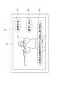
図5は、親機20の表示装置201に表示される予備発報画面の一例を示す図である。図5に示すように、表示装置201には予備発報として、情報生成部214によって生成された対象者情報と、カメラ110によって撮像された対象者221の画像が表示される。例えば、撮像画像中に拳銃を所持している人物が検知された場合、親機制御部210は、図5に示すように、対象者情報として、対象者221が拳銃を構えている画像と、情報生成部214で生成された「対象者は拳銃を所持する危険人物である。」という文字情報222と、を表示装置201に表示する。表示装置201には画像だけを表示してもよいし、画像と同時に取得された音声を含む画像を表示してもよい。表示装置201に表示される画像は静止画であっても動画であってもよい。加えて、親機制御部210は、この状況に対して警告情報を発報するか否かを選択することが可能な選択ボタンを表示装置201に表示する。具体的には、表示装置201には、警告情報を発報することを選択するための警告ボタン223と、警告情報の発報をキャンセルするためのキャンセルボタン224が表示される。警告ボタン223には、例えば「警告する」と表示される。一方、キャンセルボタン224には、例えば「警告しない」と表示される。 FIG. 5 is a diagram showing an example of a preliminary alarm screen displayed on the
ステップS14で表示装置201に予備発報が表示されると、親機制御部210は、表示された選択ボタン(警告ボタン223、キャンセルボタン224)のうち警告ボタン223が選択されたか否かを判定する(ステップS15)。 When the preliminary alert is displayed on the
ステップS15において、警告ボタン223が選択されたと判定された場合(ステップS15のYes)、すなわち、セキュリティ管理室Rの対応者が警告すべきと判断して警告ボタン223を押下した場合、親機制御部210は、特定の対象者を撮像したカメラ110が搭載されているセキュリティポール10に、ネットワークNを介して、警告情報を発報させるための発報信号を送信する(ステップS16)。 In step S15, when it is determined that the
親機20から発報信号を受信すると、セキュリティポール10の子機120は、例えば、通話部123のスピーカから警告情報を音声として発報する(ステップS17)。例えば、子機120は、「この周辺に不審(危険)な人物がいます。ご注意ください。」あるいは「ここは危険です。避難してください。」等の警告メッセージをその周辺に居る人たちに向けて発報する。このとき、子機120は、通話部123からの音声発報に加えて、警告灯150の点灯により警告情報を発報してもよい。 When the alarm signal is received from the
一方、ステップS15において、警告ボタン223が選択されなかった場合(ステップS15のNo)、親機制御部210は、キャンセルボタン224が選択されたか否かを判定する(ステップS18)。 On the other hand, when the
ステップS18において、キャンセルボタン224が選択されたと判定された場合(ステップS18のYes)、すなわち、セキュリティ管理室Rの対応者が警告しなくてもよいと判断してキャンセルボタン224を押下した場合、親機制御部210は、ステップS12に戻って画像の判定を継続する。 In step S18, when it is determined that the cancel
一方、ステップS18において、キャンセルボタン224が選択されなかったと判定された場合(ステップS18のNo)、親機制御部210は、表示装置201に予備発報が表示されてから所定時間(例えば、30秒)が経過したか否かを判定する(ステップS19)。 On the other hand, when it is determined in step S18 that the cancel
ステップS19において、所定時間が経過していないと判定された場合(ステップS19のNo)、親機制御部210は、ステップS15に戻って各処理を繰り返す。 If it is determined in step S19 that the predetermined time has not elapsed (No in step S19), the master
一方、ステップS19において、所定時間が経過したと判定された場合(ステップS19のYes)、親機制御部210は、処理をステップS16へと移行する。すなわち、親機制御部210は、特定の対象者を撮像したカメラ110が搭載されているセキュリティポール10に、ネットワークNを介して、警告情報を発報させるための発報信号を送信する(ステップS16)。その後、親機20から発報信号を受信したセキュリティポール10の子機120は、通話部123のスピーカから警告情報を音声として発報する(ステップS17)。 On the other hand, if it is determined in step S19 that the predetermined time has elapsed (Yes in step S19), the master
以上説明したように、本実施形態に係るセキュリティシステム1は、カメラ110と、カメラ110に通信可能に接続された親機制御部210および管理者が視認可能な表示装置201を有する親機20と、を備えている。そして、親機制御部210は、カメラ110によって撮像された画像に基づいて対象者を検知する検知部211と、検知された対象者に関する対象者情報を生成するとともに、対象者情報に基づいて警告情報を生成する情報生成部214と、を備えている。親機制御部210は、情報生成部214で生成した対象者情報を予備発報として表示装置201に表示させ、管理者から予備発報に対する確定操作が入力された場合または予備発報の表示から所定時間内に管理者からのキャンセル操作が入力されなかった場合には、警告情報を所定の端末機器に送信して当該警告情報を所定の端末機器から発報させるように構成されている。この構成によれば、カメラ110で撮像された画像から異常行動者等の特定の対象者が検知された場合には、先ず、親機20の表示装置201に対象者情報を予備発報し、警告すべきとの判断を示す管理者による所定の確定操作があったこと又は警告しないとの判断を示す管理者による所定のキャンセル操作がなかったことを確認した後に、所定の端末機器からの警告情報の発報を行う。このように、本実施形態においては、警告情報が端末機器から発報される前に、予備発報において管理者により警告すべきか否かが判断されるので、警告情報を端末機器から発報する際の誤報を抑制することができる。 As described above, the security system 1 according to the present embodiment includes a
本実施形態に係るセキュリティシステム1は、カメラ110が搭載された位置から所定範囲内に配置されて親機20と通信可能な子機120をさらに備えている。そして、警告情報が発報される端末機器は、カメラ110、子機120、および子機120に関連付けられたユーザの保有する携帯端末30等のいずれかであればよい。これにより、カメラ110や子機120周辺の歩行者、あるいは周辺の居住者や就業者等の然るべき人々に警告情報を適切に知らせることができる。 The security system 1 according to the present embodiment further includes a
本実施形態に係るセキュリティシステム1において、カメラ110と子機120とが単一のセキュリティポール10に一体的に搭載されている。この構成によれば、カメラ110と子機120との搭載位置が同一箇所となるため、検知された対象者に最も近いセキュリティポール10から警告情報を適時に発報することができる。 In the security system 1 according to the present embodiment, the
本実施形態に係るセキュリティシステム1において、親機制御部210は、警戒すべき特定の対象者を撮像したカメラ110等の位置情報に基づいて、その対象者の現在位置を特定し、現在位置から所定範囲内の所定の端末機器に対して警告情報を送信するように構成されている。この構成によれば、警戒すべき特定の対象者の近くにいる人々だけでなく、もう少し広範囲にいる人々に対しても警告情報を適切に知らせることができる。 In the security system 1 according to the present embodiment, the master
本実施形態に係るセキュリティシステム1において、セキュリティポール10は、警告灯150をさらに有し、警告情報の発報は、警告灯150の点灯により実行される。この構成によれば、対象者の近傍にいる人々に警告情報を視覚的に知らせることができるとともに、対象者に対しても視覚的な警告メッセージを与えることができる。 In the security system 1 according to the present embodiment, the
本実施形態に係るセキュリティシステム1において、子機120とは離隔して配置されたスピーカ401又は警告灯402をさらに備え、親機制御部210は、警告情報をスピーカ401又は警告灯402から発報するように構成されている。この構成によれば、セキュリティポール10(子機120)が設置されていない場所に対象者が移動した場合にも、例えば、その場所にある建物41に設置されたスピーカ401又は警告灯402により、対象者の近傍にいる人々に警告情報を適切に知らせることができる。 In the security system 1 according to the present embodiment, the
本実施形態に係るセキュリティシステム1において、親機制御部210は、カメラ110で撮像された画像から特定の人物の行動情報を検出する行動認識部212と、特定の人物の骨格情報を検出する骨格推定部213とをさらに備えている。そして、情報生成部214は、行動情報及び骨格情報に基づいて対象者情報を生成するように構成されている。この構成によれば、警戒すべき特定の対象者を検出する際に、例えば所定の場所に居据わるという行動情報に加えて、例えば拳銃を構えるという骨格情報を用いることで、その人物の行動をさらに正確に把握することができる。 In the security system 1 according to the present embodiment, the master
なお、親機制御部210は、ステップS16において発報信号を送信する場合に、例えば、検知された特定の対象者を撮像したカメラ110のカメラID及び/又はそのカメラ110が搭載されているセキュリティポール10のポールIDに基づいて、特定の対象者の現在位置を判断し、判断された現在位置から所定範囲内(例えば、半径数百m以内)に設置されているセキュリティポール10に対して発報信号を送信するようにしてもよい。 When the master
あるいは、親機制御部210は、特定の対象者を撮像したカメラ110や当該カメラ110が搭載されているセキュリティポール10の位置を特定し、特定されたカメラ110及びセキュリティポール10が設置されている地域の居住者や就業者等が所有する携帯端末30に対して発報信号を送信するようにしてもよい。 Alternatively, the master
親機制御部210は、セキュリティポール10に搭載されているカメラ110で撮像された画像に代えてまたは当該撮像画像に加えて、IPカメラ40で撮像された画像を解析し、IPカメラ40の撮像画像に映る人物の中に警戒すべき特定の対象者が存在するか否かを判定するようにしてもよい。この場合、親機制御部210は、予備発報に対する対応者の応答操作に応じて、IPカメラ40に発報信号を送信して、IPカメラ40に接続されているスピーカ401又は警告灯402から、音声又は点灯により警告情報を発報させてもよい。さらに、親機制御部210は、セキュリティポール10のカメラ110の撮像画像に基づいて検知された特定の対象者の現在位置から所定範囲内にIPカメラ40が設置されている場合には、セキュリティポール10だけではなくIPカメラ40にも発報信号を送信し、IPカメラ40のスピーカ401又は警告灯402から警告情報を発報してもよい。 The master
親機制御部210は、セキュリティポール10が設置された敷地内を移動可能な移動体(例えば、ドローン、航空機、自動運転車、ロボットなど)に搭載されたカメラで撮像された画像に基づいて、異常行動者等の対象者を検知するようにしてもよい。 The master
親機制御部210は、セキュリティポール10の非常ボタン130が押された場合、非常ボタン130の操作に伴って出力される非常信号から非常ボタン130が操作されたセキュリティポール10の位置を特定し、そのセキュリティポール10のカメラ110で撮像された画像に基づいて、予備発報するか否か及び警告情報を発報するか否かを判断するようにしてもよい。 When the
なお、本発明は、上述した実施形態に限定されず、適宜、変形、改良等が自在である。その他、上述した実施形態における各構成要素の材質、形状、寸法、数値、形態、数、配置場所等は、本発明を達成できるものであれば任意であり、限定されない。 The present invention is not limited to the above-described embodiment, and can be freely modified, improved, and the like as appropriate. In addition, the material, shape, size, numerical value, form, number, arrangement location, etc. of each component in the above-described embodiment are arbitrary and are not limited as long as the present invention can be achieved.
1:セキュリティシステム、10:セキュリティポール、20:親機、30:携帯端末(端末機器の一例)、40:IPカメラ、100:本体部、110:カメラ、120:子機(端末機器の一例)、121:子機カメラ、122:呼出ボタン、123:通話部、130:非常ボタン、140:拡声スピーカ、150:警告灯、201:表示装置、202:通話部、203:操作部、204:記憶部、210:親機制御部、211:検知部、212:行動認識部、213:骨格推定部、214:情報生成部、221:対象者、222:文字情報、223:警告ボタン、224:キャンセルボタン、401:スピーカ、402:警告灯(第二警告灯の一例)、N:ネットワーク、R:セキュリティ管理室 1: Security system, 10: Security pole, 20: Master unit, 30: Mobile terminal (example of terminal device), 40: IP camera, 100: Main unit, 110: Camera, 120: Slave unit (example of terminal device) , 121: Slave camera, 122: Call button, 123: Call unit, 130: Emergency button, 140: Loudspeaker, 150: Warning light, 201: Display device, 202: Call unit, 203: Operation unit, 204: Memory Unit, 210: Master unit control unit, 211: Detection unit, 212: Action recognition unit, 213: Skeleton estimation unit, 214: Information generation unit, 221: Target person, 222: Character information, 223: Warning button, 224: Cancel Button, 401: Speaker, 402: Warning light (an example of the second warning light), N: Network, R: Security management room
Claims (7)
Translated fromJapanese前記少なくとも一つのカメラと通信可能な制御部と、管理者が視認可能な表示装置とを有する親機と、
を備えたセキュリティシステムであって、
前記制御部は、
前記少なくとも一つのカメラによって撮像された画像に基づいて対象者を検知する検知部と、
検知された前記対象者に関する対象者情報を生成するとともに、前記対象者情報に基づいて警告情報を生成する情報生成部と、
を有し、
前記制御部は、
前記情報生成部で生成した前記対象者情報を予備発報として前記表示装置に表示させ、
前記管理者から前記予備発報に対する確定操作が入力された場合または前記予備発報の表示から所定時間内に前記管理者からのキャンセル操作が入力されなかった場合には、前記警告情報を所定の端末機器に送信して前記警告情報を前記所定の端末機器から発報させる、
ように構成されている、セキュリティシステム。With at least one camera
A master unit having a control unit capable of communicating with at least one camera and a display device visible to the administrator.
It is a security system equipped with
The control unit
A detector that detects the target person based on the image captured by at least one camera, and
An information generation unit that generates target person information regarding the detected target person and also generates warning information based on the target person information.
Have,
The control unit
The target person information generated by the information generation unit is displayed on the display device as a preliminary alarm.
If the administrator inputs a confirmation operation for the preliminary alert, or if the cancel operation from the administrator is not input within a predetermined time from the display of the preliminary alert, the warning information is given as a predetermined value. It is transmitted to the terminal device to issue the warning information from the predetermined terminal device.
A security system that is configured to.
前記所定の端末機器は、前記少なくとも一つのカメラ、前記少なくとも一つの子機、および前記親機または前記少なくとも一つの子機に関連付けられたユーザの保有する端末機器の少なくとも一つである、請求項1に記載のセキュリティシステム。It is further provided with at least one slave unit which is arranged within a predetermined range from the position where the at least one camera is mounted and can communicate with the master unit.
The predetermined terminal device is at least one of the at least one camera, the at least one slave unit, and the terminal device owned by the user associated with the master unit or the at least one slave unit. The security system according to 1.
前記所定の端末機器は、前記少なくとも一つの子機である、請求項2に記載のセキュリティシステム。The at least one camera and the at least one slave unit are integrally mounted on a single security pole.
The security system according to claim 2, wherein the predetermined terminal device is at least one slave unit.
前記警告情報の発報は、前記警告灯の点灯により実行される、請求項3に記載のセキュリティシステム。The security pole further has a warning light
The security system according to claim 3, wherein the warning information is issued by turning on the warning light.
前記制御部は、前記警告情報を前記スピーカ又は前記第二警告灯から発報するように構成されている、請求項3または4に記載のセキュリティシステム。Further equipped with a speaker or a second warning light arranged apart from the security pole,
The security system according to claim 3 or 4, wherein the control unit is configured to issue the warning information from the speaker or the second warning light.
前記情報生成部は、前記行動情報及び前記骨格情報に基づいて前記対象者情報を生成するように構成されている、請求項1から6のいずれか一項に記載のセキュリティシステム。The control unit further includes an action recognition unit that detects behavior information of a specific person from the image, and a skeleton estimation unit that detects skeleton information of the specific person.
The security system according to any one of claims 1 to 6, wherein the information generation unit is configured to generate the target person information based on the behavior information and the skeleton information.
Priority Applications (1)
| Application Number | Priority Date | Filing Date | Title |
|---|---|---|---|
| JP2020046731AJP7463143B2 (en) | 2020-03-17 | 2020-03-17 | Security Systems |
Applications Claiming Priority (1)
| Application Number | Priority Date | Filing Date | Title |
|---|---|---|---|
| JP2020046731AJP7463143B2 (en) | 2020-03-17 | 2020-03-17 | Security Systems |
Publications (2)
| Publication Number | Publication Date |
|---|---|
| JP2021149311Atrue JP2021149311A (en) | 2021-09-27 |
| JP7463143B2 JP7463143B2 (en) | 2024-04-08 |
Family
ID=77851433
Family Applications (1)
| Application Number | Title | Priority Date | Filing Date |
|---|---|---|---|
| JP2020046731AActiveJP7463143B2 (en) | 2020-03-17 | 2020-03-17 | Security Systems |
Country Status (1)
| Country | Link |
|---|---|
| JP (1) | JP7463143B2 (en) |
Cited By (1)
| Publication number | Priority date | Publication date | Assignee | Title |
|---|---|---|---|---|
| CN117671906A (en)* | 2024-01-15 | 2024-03-08 | 广东耀邦新能源股份有限公司 | A control method, device, equipment and storage medium for a simulation monitoring device |
Citations (3)
| Publication number | Priority date | Publication date | Assignee | Title |
|---|---|---|---|---|
| JP2011013828A (en)* | 2009-06-30 | 2011-01-20 | Secom Co Ltd | Security system |
| JP2011165054A (en)* | 2010-02-12 | 2011-08-25 | Secom Co Ltd | Security system |
| JP6525229B1 (en)* | 2019-01-25 | 2019-06-05 | 株式会社 テクノミライ | Digital search security system, method and program |
- 2020
- 2020-03-17JPJP2020046731Apatent/JP7463143B2/enactiveActive
Patent Citations (3)
| Publication number | Priority date | Publication date | Assignee | Title |
|---|---|---|---|---|
| JP2011013828A (en)* | 2009-06-30 | 2011-01-20 | Secom Co Ltd | Security system |
| JP2011165054A (en)* | 2010-02-12 | 2011-08-25 | Secom Co Ltd | Security system |
| JP6525229B1 (en)* | 2019-01-25 | 2019-06-05 | 株式会社 テクノミライ | Digital search security system, method and program |
Cited By (1)
| Publication number | Priority date | Publication date | Assignee | Title |
|---|---|---|---|---|
| CN117671906A (en)* | 2024-01-15 | 2024-03-08 | 广东耀邦新能源股份有限公司 | A control method, device, equipment and storage medium for a simulation monitoring device |
Also Published As
| Publication number | Publication date |
|---|---|
| JP7463143B2 (en) | 2024-04-08 |
Similar Documents
| Publication | Publication Date | Title |
|---|---|---|
| JP6126778B2 (en) | Fire alarm equipment support system | |
| KR101245165B1 (en) | Crime prevention security system | |
| KR100769562B1 (en) | Emergency alarm system and method in surveillance area | |
| JP2018507500A (en) | Pre-intrusion detection system using SMS notification service, and rescue signal notification system and method | |
| CA2941457A1 (en) | System arm notification based on ble position | |
| JP4668014B2 (en) | Security status notification device, security status notification method, and computer program for causing computer to execute security status notification method | |
| KR101878309B1 (en) | Safe warning apparatus and safe warning system comprising the same | |
| JP7463143B2 (en) | Security Systems | |
| US20210304586A1 (en) | Security System And Method Thereof | |
| JP2024029185A (en) | Disaster prevention support system | |
| JP6322304B2 (en) | Fire alarm equipment support system | |
| JP7437986B2 (en) | security system | |
| JP7398300B2 (en) | security system | |
| JP2006323490A (en) | Emergency call system | |
| JP7108425B2 (en) | doorbell system | |
| KR101600401B1 (en) | monitor camera system linkaged with emergency bell including interphone | |
| JP7432325B2 (en) | Disaster prevention support system and fire detector | |
| TWM617671U (en) | Radar monitoring device and monitoring equipment | |
| JP6228254B2 (en) | Fire alarm equipment support system | |
| KR101779338B1 (en) | A emergency situation remote surveillance system using portable terminal | |
| JP2018032423A (en) | Support system of fire disaster notification facility | |
| KR101634927B1 (en) | Emergency call system having general call function | |
| US20180350215A1 (en) | Multi-functional network camera control apparatus | |
| JP6825154B1 (en) | Notification system for buildings | |
| JP5363230B2 (en) | Security system |
Legal Events
| Date | Code | Title | Description |
|---|---|---|---|
| A621 | Written request for application examination | Free format text:JAPANESE INTERMEDIATE CODE: A621 Effective date:20221207 | |
| A977 | Report on retrieval | Free format text:JAPANESE INTERMEDIATE CODE: A971007 Effective date:20231122 | |
| A131 | Notification of reasons for refusal | Free format text:JAPANESE INTERMEDIATE CODE: A131 Effective date:20240109 | |
| A521 | Request for written amendment filed | Free format text:JAPANESE INTERMEDIATE CODE: A523 Effective date:20240205 | |
| TRDD | Decision of grant or rejection written | ||
| A01 | Written decision to grant a patent or to grant a registration (utility model) | Free format text:JAPANESE INTERMEDIATE CODE: A01 Effective date:20240326 | |
| A61 | First payment of annual fees (during grant procedure) | Free format text:JAPANESE INTERMEDIATE CODE: A61 Effective date:20240327 | |
| R150 | Certificate of patent or registration of utility model | Ref document number:7463143 Country of ref document:JP Free format text:JAPANESE INTERMEDIATE CODE: R150 |