JP2021145906A - Portable electrocardiographic device and electrocardiographic measurement system - Google Patents
Portable electrocardiographic device and electrocardiographic measurement systemDownload PDFInfo
- Publication number
- JP2021145906A JP2021145906AJP2020048879AJP2020048879AJP2021145906AJP 2021145906 AJP2021145906 AJP 2021145906AJP 2020048879 AJP2020048879 AJP 2020048879AJP 2020048879 AJP2020048879 AJP 2020048879AJP 2021145906 AJP2021145906 AJP 2021145906A
- Authority
- JP
- Japan
- Prior art keywords
- electrocardiographic
- lead
- induction
- measurement
- waveform
- Prior art date
- Legal status (The legal status is an assumption and is not a legal conclusion. Google has not performed a legal analysis and makes no representation as to the accuracy of the status listed.)
- Granted
Links
Images


Classifications
- A—HUMAN NECESSITIES
- A61—MEDICAL OR VETERINARY SCIENCE; HYGIENE
- A61B—DIAGNOSIS; SURGERY; IDENTIFICATION
- A61B5/00—Measuring for diagnostic purposes; Identification of persons
- A61B5/24—Detecting, measuring or recording bioelectric or biomagnetic signals of the body or parts thereof
- A61B5/25—Bioelectric electrodes therefor
- A61B5/279—Bioelectric electrodes therefor specially adapted for particular uses
- A61B5/28—Bioelectric electrodes therefor specially adapted for particular uses for electrocardiography [ECG]
- A61B5/282—Holders for multiple electrodes
- A—HUMAN NECESSITIES
- A61—MEDICAL OR VETERINARY SCIENCE; HYGIENE
- A61B—DIAGNOSIS; SURGERY; IDENTIFICATION
- A61B5/00—Measuring for diagnostic purposes; Identification of persons
- A61B5/02—Detecting, measuring or recording for evaluating the cardiovascular system, e.g. pulse, heart rate, blood pressure or blood flow
- A61B5/024—Measuring pulse rate or heart rate
- A61B5/02438—Measuring pulse rate or heart rate with portable devices, e.g. worn by the patient
- A—HUMAN NECESSITIES
- A61—MEDICAL OR VETERINARY SCIENCE; HYGIENE
- A61B—DIAGNOSIS; SURGERY; IDENTIFICATION
- A61B5/00—Measuring for diagnostic purposes; Identification of persons
- A61B5/24—Detecting, measuring or recording bioelectric or biomagnetic signals of the body or parts thereof
- A61B5/316—Modalities, i.e. specific diagnostic methods
- A61B5/318—Heart-related electrical modalities, e.g. electrocardiography [ECG]
- A61B5/332—Portable devices specially adapted therefor
- A—HUMAN NECESSITIES
- A61—MEDICAL OR VETERINARY SCIENCE; HYGIENE
- A61B—DIAGNOSIS; SURGERY; IDENTIFICATION
- A61B5/00—Measuring for diagnostic purposes; Identification of persons
- A61B5/24—Detecting, measuring or recording bioelectric or biomagnetic signals of the body or parts thereof
- A61B5/316—Modalities, i.e. specific diagnostic methods
- A61B5/318—Heart-related electrical modalities, e.g. electrocardiography [ECG]
- A61B5/339—Displays specially adapted therefor
- A—HUMAN NECESSITIES
- A61—MEDICAL OR VETERINARY SCIENCE; HYGIENE
- A61B—DIAGNOSIS; SURGERY; IDENTIFICATION
- A61B5/00—Measuring for diagnostic purposes; Identification of persons
- A61B5/24—Detecting, measuring or recording bioelectric or biomagnetic signals of the body or parts thereof
- A61B5/316—Modalities, i.e. specific diagnostic methods
- A61B5/318—Heart-related electrical modalities, e.g. electrocardiography [ECG]
- A61B5/346—Analysis of electrocardiograms
- A61B5/349—Detecting specific parameters of the electrocardiograph cycle
- A61B5/352—Detecting R peaks, e.g. for synchronising diagnostic apparatus; Estimating R-R interval
- A—HUMAN NECESSITIES
- A61—MEDICAL OR VETERINARY SCIENCE; HYGIENE
- A61B—DIAGNOSIS; SURGERY; IDENTIFICATION
- A61B5/00—Measuring for diagnostic purposes; Identification of persons
- A61B5/72—Signal processing specially adapted for physiological signals or for diagnostic purposes
- A61B5/7271—Specific aspects of physiological measurement analysis
- A61B5/7282—Event detection, e.g. detecting unique waveforms indicative of a medical condition
- A—HUMAN NECESSITIES
- A61—MEDICAL OR VETERINARY SCIENCE; HYGIENE
- A61B—DIAGNOSIS; SURGERY; IDENTIFICATION
- A61B5/00—Measuring for diagnostic purposes; Identification of persons
- A61B5/74—Details of notification to user or communication with user or patient; User input means
- A61B5/742—Details of notification to user or communication with user or patient; User input means using visual displays
- A61B5/743—Displaying an image simultaneously with additional graphical information, e.g. symbols, charts, function plots
- A—HUMAN NECESSITIES
- A61—MEDICAL OR VETERINARY SCIENCE; HYGIENE
- A61B—DIAGNOSIS; SURGERY; IDENTIFICATION
- A61B5/00—Measuring for diagnostic purposes; Identification of persons
- A61B5/74—Details of notification to user or communication with user or patient; User input means
- A61B5/746—Alarms related to a physiological condition, e.g. details of setting alarm thresholds or avoiding false alarms
- A—HUMAN NECESSITIES
- A61—MEDICAL OR VETERINARY SCIENCE; HYGIENE
- A61B—DIAGNOSIS; SURGERY; IDENTIFICATION
- A61B5/00—Measuring for diagnostic purposes; Identification of persons
- A61B5/0002—Remote monitoring of patients using telemetry, e.g. transmission of vital signals via a communication network
- A61B5/0004—Remote monitoring of patients using telemetry, e.g. transmission of vital signals via a communication network characterised by the type of physiological signal transmitted
- A61B5/0006—ECG or EEG signals
- G—PHYSICS
- G16—INFORMATION AND COMMUNICATION TECHNOLOGY [ICT] SPECIALLY ADAPTED FOR SPECIFIC APPLICATION FIELDS
- G16H—HEALTHCARE INFORMATICS, i.e. INFORMATION AND COMMUNICATION TECHNOLOGY [ICT] SPECIALLY ADAPTED FOR THE HANDLING OR PROCESSING OF MEDICAL OR HEALTHCARE DATA
- G16H50/00—ICT specially adapted for medical diagnosis, medical simulation or medical data mining; ICT specially adapted for detecting, monitoring or modelling epidemics or pandemics
- G16H50/20—ICT specially adapted for medical diagnosis, medical simulation or medical data mining; ICT specially adapted for detecting, monitoring or modelling epidemics or pandemics for computer-aided diagnosis, e.g. based on medical expert systems
Landscapes
- Health & Medical Sciences (AREA)
- Life Sciences & Earth Sciences (AREA)
- Engineering & Computer Science (AREA)
- Animal Behavior & Ethology (AREA)
- Public Health (AREA)
- Pathology (AREA)
- Physics & Mathematics (AREA)
- Biomedical Technology (AREA)
- Heart & Thoracic Surgery (AREA)
- Medical Informatics (AREA)
- Molecular Biology (AREA)
- Surgery (AREA)
- Veterinary Medicine (AREA)
- General Health & Medical Sciences (AREA)
- Biophysics (AREA)
- Cardiology (AREA)
- Physiology (AREA)
- Artificial Intelligence (AREA)
- Computer Vision & Pattern Recognition (AREA)
- Psychiatry (AREA)
- Signal Processing (AREA)
- Nuclear Medicine, Radiotherapy & Molecular Imaging (AREA)
- Radiology & Medical Imaging (AREA)
- Measurement And Recording Of Electrical Phenomena And Electrical Characteristics Of The Living Body (AREA)
Abstract
Translated fromJapaneseDescription
Translated fromJapanese本発明は、日常生活等における心電波形測定が可能な携帯型の心電装置及びこれを含む心電計測システムに関する。 The present invention relates to a portable electrocardiographic device capable of measuring an electrocardiographic waveform in daily life and the like, and an electrocardiographic measurement system including the portable electrocardiographic device.
日常生活における胸部の痛みや動悸などの異常発生時に、すぐに心電波形を測定可能な携帯型の心電測定装置(以下、「携帯型心電装置」ともいう)が提案されている。医師等においては、家庭や外出先等で動悸等の症状が起きた際に当該心電装置によって測定された心電波形のデータ等に基づいて、心疾患の早期発見や適切な治療行為を施すことが可能になる。 A portable electrocardiographic measuring device (hereinafter, also referred to as “portable electrocardiographic device”) has been proposed, which can immediately measure an electrocardiographic waveform when an abnormality such as chest pain or palpitation occurs in daily life. Doctors, etc., perform early detection of heart disease and appropriate treatment based on the electrocardiographic waveform data measured by the electrocardiographic device when symptoms such as palpitation occur at home or on the go. Will be possible.
従来、このような携帯型心電装置において、心電波形を記録する方法(誘導法、誘導種別)については、国際的に取り決めがあり、複数種の誘導法を用いる誘導法が広く用いられている。この国際的な取り決めに基づく誘導法には、6種の四肢誘導と6種の胸部誘導が含まれており、適切な誘導法を用いて心電波形を検出・記録することになる。 Conventionally, in such a portable electrocardiographic device, there is an international agreement on a method of recording an electrocardiographic waveform (induction method, induction type), and an induction method using a plurality of types of induction methods is widely used. There is. Guidance methods based on this international agreement include six types of limb leads and six types of chest leads, and electrocardiographic waveforms will be detected and recorded using appropriate guidance methods.
その中で、正電極を含む接触部を被検者の左手に押し当てるI誘導と呼ばれる誘導法と
、正電極を含む接触部を被検者の左胸部に押し当てるV4誘導と呼ばれる誘導法に関して、心電波形などの測定結果を表示部に見易く表示する技術が公知となっている(例えば、特許文献1を参照)。この技術においては、より詳細には、I誘導で測定する際には表示
部に横方向に測定結果を表示し、V4誘導で測定する際には表示部に縦方向に測定結果を表示する。Among them, regarding the induction method called I lead in which the contact portion including the positive electrode is pressed against the left hand of the subject and the induction method called V4 lead in which the contact portion including the positive electrode is pressed against the left chest of the subject. , A technique for displaying measurement results such as an electrocardiographic waveform on a display unit in an easy-to-see manner is known (see, for example, Patent Document 1). In this technique, more specifically, the measurement result is displayed in the horizontal direction on the display unit when the measurement is performed by the I lead, and the measurement result is displayed in the vertical direction on the display unit when the measurement is performed by the V4 lead.
しかしながら、上記の従来技術では、心電波形の測定時において、心電波形の状態に応じた最適な誘導法が用いられているとは限らず、心電波形の品質や解析結果の精度が低下する場合があった。 However, in the above-mentioned prior art, when measuring an electrocardiographic waveform, the optimum induction method according to the state of the electrocardiographic waveform is not always used, and the quality of the electrocardiographic waveform and the accuracy of the analysis result are deteriorated. There was a case.
上記のような課題に鑑み、本発明は、心電波形を測定する際に、心電波形の状態に応じた最適な誘導法を用いて測定することを可能とし、心電測定の精度を向上させる技術を提供することを目的とする。 In view of the above problems, the present invention makes it possible to measure an electrocardiographic waveform by using an optimum induction method according to the state of the electrocardiographic waveform, and improve the accuracy of the electrocardiographic measurement. The purpose is to provide the technology to make it.
上記の課題を解決するための本発明は、複数種の誘導法を用いて心電波形を測定可能な携帯型心電装置であって、
被検者の身体の所定箇所に当接させて心電波形を測定する電極部と、
前記心電波形の測定時における誘導法に応じて、前記電極部によって測定された前記心電波形を解析する解析部と、
前記電極部において測定された前記心電波形と、前記誘導法と、前記解析部によって前記心電波形が解析された解析結果と、が関連付けて保存される記憶部と、
前記解析結果または測定された前記心電波形の状態が所定の条件を満たす場合に、前記心電波形の測定時における誘導法とは異なる所定の誘導法による再測定を使用者に促す再
測定促進部と、
を備える、携帯型心電装置である。The present invention for solving the above problems is a portable electrocardiographic device capable of measuring an electrocardiographic waveform using a plurality of types of induction methods.
An electrode part that measures the electrocardiographic waveform by contacting it with a predetermined part of the subject's body,
An analysis unit that analyzes the electrocardiographic waveform measured by the electrode unit according to the induction method at the time of measuring the electrocardiographic waveform, and an analysis unit.
A storage unit in which the electrocardiographic waveform measured at the electrode unit, the induction method, and the analysis result obtained by analyzing the electrocardiographic waveform by the analysis unit are stored in association with each other.
When the analysis result or the measured state of the electrocardiographic waveform satisfies a predetermined condition, the remeasurement promotion prompts the user to remeasure by a predetermined induction method different from the induction method at the time of measuring the electrocardiographic waveform. Department and
It is a portable electrocardiographic device equipped with.
ここで、特定の誘導法によって心電波形を測定した場合に、必ずしも解析結果や心電波形の状態に対して最適な誘導法によって、測定が行われていない場合がある。このように、最適な誘導法によって測定が行われていない場合には、解析結果の精度も低下する。これに対し、本発明においては、解析結果や心電波形の状態が所定の条件を満たした場合には、再測定促進部が、誘導法を最適なものに変えた上での再測定を促すことにした。これによれば、当所測定時に用いられた誘導法が最適でない場合にも、誘導法を最適化した上で、再測定を行うことが可能となる。その結果、解析結果の精度を向上させることが可能となる。
ここで、使用者は、携帯型心電装置を操作する者をいう。Here, when the electrocardiographic waveform is measured by a specific induction method, the measurement may not always be performed by the optimum induction method for the analysis result or the state of the electrocardiographic waveform. As described above, when the measurement is not performed by the optimum induction method, the accuracy of the analysis result is also lowered. On the other hand, in the present invention, when the analysis result or the state of the electrocardiographic waveform satisfies a predetermined condition, the remeasurement promotion unit prompts the remeasurement after changing the induction method to the optimum one. It was to be. According to this, even if the induction method used at the time of our measurement is not optimal, it is possible to perform remeasurement after optimizing the induction method. As a result, it is possible to improve the accuracy of the analysis result.
Here, the user means a person who operates a portable electrocardiographic device.
また、本発明においては、前記再測定促進部は、前記再測定時に設定されるべき前記誘導法を表示する表示手段を有するようにしてもよい。この場合には、例えば、複数種の誘導法に関連づけられた発光部が装置本体に設けられており、再測定時に設定されるべき誘導法に関連付けられた発光部を発光させるようにしてもよい。あるいは、文字を表示可能な表示手段において直接、再測定時に設定されるべき誘導法を表示してもよい。これによれば、使用者がより容易に、再測定時に設定されるべき誘導法を認識することが可能である。 Further, in the present invention, the remeasurement promotion unit may have a display means for displaying the guidance method to be set at the time of the remeasurement. In this case, for example, a light emitting unit associated with a plurality of types of induction methods may be provided in the main body of the apparatus, and the light emitting unit associated with the induction method to be set at the time of remeasurement may be made to emit light. .. Alternatively, the guidance method to be set at the time of remeasurement may be displayed directly on the display means capable of displaying characters. According to this, the user can more easily recognize the guidance method to be set at the time of remeasurement.
また、本発明においては、前記表示手段には、さらに前記所定の条件が満たされたことが表示されるようにしてもよい。これによれば、使用者がより容易に、再測定時に設定されるべき誘導法が選択された理由を認識することが可能である。 Further, in the present invention, the display means may further display that the predetermined conditions are satisfied. This allows the user to more easily recognize why the guidance method to be set at the time of remeasurement was selected.
また、本発明においては、前記心電波形を前記複数種の誘導法のうちいずれの誘導法によって測定するかを設定する設定部をさらに備え、
前記測定時及び前記再測定時には、使用者が前記設定部によって前記誘導法を設定するようにしてもよい。これによれば、使用者が自らの意志により、測定時または再測定時に用いる誘導法を選択することが可能となる。Further, the present invention further includes a setting unit for setting which of the plurality of induction methods is used to measure the electrocardiographic waveform.
At the time of the measurement and the remeasurement, the user may set the guidance method by the setting unit. According to this, the user can select the guidance method to be used at the time of measurement or remeasurement at his / her own will.
また、本発明においては、前記測定時における誘導法は、12誘導法におけるI誘導で
あり、
前記所定の条件は、前記解析結果において不整脈が認められた場合であり、
前記所定の誘導法は、12誘導法におけるV4誘導であることとしてもよい。Further, in the present invention, the induction method at the time of the measurement is the I lead in the 12-lead method.
The predetermined condition is when an arrhythmia is found in the analysis result.
The predetermined induction method may be V4 induction in the 12-induction method.
ここで、12誘導法におけるI誘導によっては、不整脈を特徴づける波形を検知しづら
く、V4誘導によって測定することでより精度よく不整脈の解析を行うことができることが分かっている。すなわち、I誘導による心電波形は、R波形の間隔に基づく不整脈検出
が比較的容易だが、R波形以外の波形形状に基づく不整脈は検出しづらい。一方、I誘導
以外の誘導法(例えば、V4誘導)による心電波形を用いれば、波形リズム以外の不整脈の検出をより精度よく行うことができる。よって、本発明においては、測定時にI誘導を
用いて心電波形を測定し、解析結果において不整脈が認められた場合に、再測定促進部は、V4誘導を用いて再測定を促進することとした。これによれば、より精度よく、不整脈の診断を行うことが可能となる。Here, it is known that it is difficult to detect the waveform that characterizes the arrhythmia by the I lead in the 12-lead method, and the arrhythmia can be analyzed more accurately by measuring by the V4 lead. That is, in the electrocardiographic waveform by lead I, it is relatively easy to detect an arrhythmia based on the interval of the R waveform, but it is difficult to detect an arrhythmia based on a waveform shape other than the R waveform. On the other hand, if an electrocardiographic waveform by an induction method other than lead I (for example, lead V4) is used, arrhythmia other than the waveform rhythm can be detected more accurately. Therefore, in the present invention, the electrocardiographic waveform is measured by using the I lead at the time of measurement, and when an arrhythmia is found in the analysis result, the remeasurement promotion unit promotes the remeasurement by using the V4 lead. bottom. According to this, it becomes possible to diagnose arrhythmia more accurately.
また、本発明においては、前記測定時における誘導法は、12誘導法におけるI誘導で
あり、
前記所定の条件は、前記解析結果において心房細動が認められた場合であり、
前記所定の誘導法は、12誘導法におけるV1誘導であることとしてもよい。Further, in the present invention, the induction method at the time of the measurement is the I lead in the 12-lead method.
The predetermined condition is when atrial fibrillation is observed in the analysis result.
The predetermined induction method may be V1 induction in the 12-induction method.
ここで、12誘導法におけるI誘導によっては、心房細動を特徴づける波形を検知しづ
らく、V1誘導によって測定することでより精度よく心房細動の解析を行うことができることが分かっている。すなわち、心房細動の特徴にはRR間隔不規則、P波消失、F波形出現があるが、RR間隔不規則以外の特徴はI誘導による心電波形では捉えにくく、V1
誘導による心電波形では捉えやすい。よって、本発明においては、測定時にI誘導を用い
て心電波形を測定し、解析結果において心房細動が認められた場合に、再測定促進部は、V1誘導を用いて再測定を促進することとした。これによれば、より精度よく、心房細動の診断を行うことが可能となる。Here, it is known that it is difficult to detect the waveform that characterizes atrial fibrillation by the I lead in the 12-lead method, and it is possible to analyze atrial fibrillation more accurately by measuring by the V1 lead. That is, the characteristics of atrial fibrillation include irregular RR interval, disappearance of P wave, and appearance of F waveform, but features other than irregular RR interval are difficult to capture in the electrocardiographic waveform by lead I, and V1
It is easy to catch in the induced electrocardiographic waveform. Therefore, in the present invention, the electrocardiographic waveform is measured by using the I lead at the time of measurement, and when atrial fibrillation is observed in the analysis result, the remeasurement promotion unit promotes the remeasurement by using the V1 lead. I decided. According to this, it becomes possible to diagnose atrial fibrillation more accurately.
また、本発明においては、前記測定時における誘導法は、12誘導法におけるI誘導で
あり、
前記所定の条件は、前記解析結果において波形品質の不良が認められた場合であり、
前記所定の誘導法は、12誘導法におけるV1誘導またはV4誘導であることとしてもよい。Further, in the present invention, the induction method at the time of the measurement is the I lead in the 12-lead method.
The predetermined condition is a case where poor waveform quality is found in the analysis result.
The predetermined induction method may be V1 induction or V4 induction in the 12-induction method.
ここで、12誘導法におけるI誘導によっては、心電波形の波形品質の不良を検知しづ
らく、V1誘導またはV4誘導によって測定することでより精度よく心電波形の波形品質の不良の解析を行うことができることが分かっている。よって、本発明においては、測定時にI誘導を用いて心電波形を測定し、解析結果において波形品質の不良が認められた場
合に、再測定促進部は、V1誘導またはV4誘導を用いて再測定を促進することとした。これによれば、より精度よく、心電波形の波形品質の不良を検出することが可能となる。Here, it is difficult to detect the defect of the waveform quality of the electrocardiographic waveform by the I lead in the 12-lead method, and the defect of the waveform quality of the electrocardiographic waveform is analyzed more accurately by measuring by the V1 lead or the V4 lead. I know I can. Therefore, in the present invention, the electrocardiographic waveform is measured using the I lead at the time of measurement, and when a poor waveform quality is found in the analysis result, the remeasurement promotion unit remeasures using the V1 lead or the V4 lead. It was decided to promote the measurement. According to this, it becomes possible to detect the defect of the waveform quality of the electrocardiographic waveform more accurately.
また、本発明は、被検者の身体の所定箇所に当接させて心電波形を検出する電極部が設けられた携帯型心電装置と、前記携帯型心電装置と通信可能に設けられた携帯通信端末と、を備え、複数種の誘導法を用いて心電波形を測定可能な心電計測システムであって、
前記心電波形の測定時における誘導法に応じて、前記電極部によって測定された前記心電波形を解析する解析部と、
前記電極部において測定された前記心電波形と、前記誘導法と、前記解析部によって前記心電波形が解析された解析結果と、が関連付けて保存される記憶部と、
前記解析結果または測定された前記心電波形の状態が所定の条件を満たす場合に、前記心電波形の測定時における誘導法とは異なる所定の誘導法による再測定を使用者に促す再測定促進部と、
をさらに備える、心電計測システムであってもよい。
ここで、使用者は、心電計測システムを操作する者をいう。Further, the present invention is provided so as to be able to communicate with a portable electrocardiographic device provided with an electrode portion for detecting an electrocardiographic waveform in contact with a predetermined portion of the body of a subject and the portable electrocardiographic device. It is an electrocardiographic measurement system that is equipped with a mobile communication terminal and can measure electrocardiographic waveforms using multiple types of induction methods.
An analysis unit that analyzes the electrocardiographic waveform measured by the electrode unit according to the induction method at the time of measuring the electrocardiographic waveform, and an analysis unit.
A storage unit in which the electrocardiographic waveform measured at the electrode unit, the induction method, and the analysis result obtained by analyzing the electrocardiographic waveform by the analysis unit are stored in association with each other.
When the analysis result or the measured state of the electrocardiographic waveform satisfies a predetermined condition, the remeasurement promotion prompts the user to remeasure by a predetermined induction method different from the induction method at the time of measuring the electrocardiographic waveform. Department and
It may be an electrocardiographic measurement system further provided with.
Here, the user means a person who operates an electrocardiographic measurement system.
また、本発明は、前記再測定促進部は、
前記携帯型心電装置と、前記携帯通信端末のいずれかに設けられ、
前記再測定時に設定されるべき前記誘導法を表示する表示手段を有することを特徴とする、上記の心電計測システムであってもよい。
これによれば、使用者は、再測定時に用いられるべき誘導法について表示手段を用いて認識することが可能である。また、表示手段が携帯通信端末に設けられている場合には、携帯端末の高性能なディスプレイを用いて、再測定時に用いられるべき誘導法について表示することが可能となる。Further, in the present invention, the remeasurement promoting unit is
Provided in either the portable electrocardiographic device or the portable communication terminal,
The electrocardiographic measurement system may be characterized in that it has a display means for displaying the guidance method to be set at the time of the remeasurement.
According to this, the user can recognize the induction method to be used at the time of remeasurement by using the display means. Further, when the display means is provided in the mobile communication terminal, it is possible to display the guidance method to be used at the time of remeasurement by using the high-performance display of the mobile terminal.
また、本発明は、前記表示手段には、さらに前記所定の条件が満たされたことが表示されることを特徴とする、上記の心電計測システムであってもよい。
これによれば、使用者は、所定の条件について表示手段を用いて認識することが可能である。また、表示手段が携帯通信端末に設けられている場合には、携帯端末の高性能なディスプレイを用いて、所定の条件について表示することが可能となる。Further, the present invention may be the above-mentioned electrocardiographic measurement system, wherein the display means further displays that the predetermined condition is satisfied.
According to this, the user can recognize a predetermined condition by using the display means. Further, when the display means is provided in the mobile communication terminal, it is possible to display a predetermined condition by using the high-performance display of the mobile terminal.
また、本発明は、前記心電波形を前記複数種の誘導法のうちいずれの誘導法によって測定するかを設定する設定部をさらに備え、
前記測定時及び前記再測定時には、使用者が前記設定部によって前記誘導法を設定することを特徴とする、上記の心電計測システムであってもよい。
そうすれば、測定時及び再測定時に用いる誘導法を設定することが可能となる。また、設定部が携帯通信端末に備えられている場合には、携帯端末を用いて遠隔的に、測定時及び再測定時に用いる誘導法を設定することが可能となる。Further, the present invention further includes a setting unit for setting which of the plurality of induction methods is used to measure the electrocardiographic waveform.
The electrocardiographic measurement system may be characterized in that the user sets the guidance method by the setting unit at the time of the measurement and the remeasurement.
Then, it becomes possible to set the induction method to be used at the time of measurement and at the time of remeasurement. Further, when the setting unit is provided in the mobile communication terminal, it is possible to remotely set the guidance method to be used at the time of measurement and remeasurement by using the mobile terminal.
また、本発明は、前記測定時における誘導法は、12誘導法におけるI誘導であり、
前記所定の条件は、前記解析結果において不整脈が認められた場合であり、
前記所定の誘導法は、12誘導法におけるV4誘導であることを特徴とする、上記の心電計測システムであってもよい。Further, in the present invention, the induction method at the time of the measurement is I-lead in the 12-lead method.
The predetermined condition is when an arrhythmia is found in the analysis result.
The predetermined induction method may be the above-mentioned electrocardiographic measurement system, characterized in that it is V4 induction in the 12-lead method.
また、本発明は、前記測定時における誘導法は、12誘導法におけるI誘導であり、
前記所定の条件は、前記解析結果において心房細動が認められた場合であり、
前記所定の誘導法は、12誘導法におけるV1誘導であることを特徴とする、上記の心電計測システムであってもよい。Further, in the present invention, the induction method at the time of the measurement is I-lead in the 12-lead method.
The predetermined condition is when atrial fibrillation is observed in the analysis result.
The predetermined induction method may be the above-mentioned electrocardiographic measurement system, which is the V1 induction in the 12-lead method.
また、本発明は、前記測定時における誘導法は、12誘導法におけるI誘導であり、
前記所定の条件は、前記解析結果において波形品質の不良が認められた場合であり、
前記所定の誘導法は、12誘導法におけるV1誘導またはV4誘導であることを特徴とする、上記の心電計測システムであってもよい。Further, in the present invention, the induction method at the time of the measurement is I-lead in the 12-lead method.
The predetermined condition is a case where poor waveform quality is found in the analysis result.
The predetermined induction method may be the above-mentioned electrocardiographic measurement system characterized by being V1 lead or V4 lead in the 12-lead method.
また、上記の心電計測システムにおける前記表示手段が前記携帯通信端末に設けられた場合に、本発明は、前記表示手段が前記再測定時に設定されるべき前記誘導法を表示するように、前記携帯通信端末を制御する、プログラムであってもよい。 Further, when the display means in the electrocardiographic measurement system is provided in the mobile communication terminal, the present invention is described so that the display means displays the guidance method to be set at the time of the remeasurement. It may be a program that controls a mobile communication terminal.
また、上記の心電計測システムにおける前記表示手段が前記携帯通信端末に設けられた場合に、本発明は、前記表示手段が前記所定の条件が満たされたことを表示するように、前記携帯通信端末を制御する、プログラムであってもよい。 Further, when the display means in the electrocardiographic measurement system is provided in the mobile communication terminal, the present invention presents the mobile communication so that the display means displays that the predetermined condition is satisfied. It may be a program that controls the terminal.
また、上記の心電計測システムにおける前記設定部が前記携帯通信端末に設けられた場合には、本発明は、前記測定時及び前記再測定時に、使用者が前記設定部によって前記誘導法を設定可能となるように、前記携帯通信端末を制御する、プログラムであってもよい。 Further, when the setting unit in the electrocardiographic measurement system is provided in the mobile communication terminal, the present invention sets the guidance method by the setting unit at the time of the measurement and the remeasurement. It may be a program that controls the mobile communication terminal so as to be possible.
なお、本発明においては、上記の課題を解決するための手段は、可能な限り組み合わせて使用することが可能である。 In the present invention, the means for solving the above problems can be used in combination as much as possible.
本発明によれば、心電波形を測定する際に、心電波形の状態に応じた最適な誘導法を用いて測定することを可能とし、心電測定の精度を向上させることが可能となる。 According to the present invention, when measuring an electrocardiographic waveform, it is possible to measure using an optimum induction method according to the state of the electrocardiographic waveform, and it is possible to improve the accuracy of the electrocardiographic measurement. ..
以下、本発明の具体的な実施形態について図面に基づいて説明する。
<実施形態1>
以下に、本発明の実施形態の一例について説明する。但し、この実施形態に記載されている構成部品の寸法、材質、形状、その相対配置などは、特に記載がない限りは、この発明の範囲をそれらのみに限定する趣旨のものではない。Hereinafter, specific embodiments of the present invention will be described with reference to the drawings.
<
An example of the embodiment of the present invention will be described below. However, unless otherwise specified, the dimensions, materials, shapes, relative arrangements, and the like of the components described in this embodiment are not intended to limit the scope of the present invention to those.
(携帯型心電装置の構成)
図1(A)〜(F)は本実施形態に係る携帯型心電装置100の構成の一例を示す図である。図1(A)は、携帯型心電装置100を前面から見た図である。図1(B)は、携帯型心電装置100を下方から見た図である。図1(C)は、携帯型心電装置100を上方から見た図である。図1(D)は、携帯型心電装置100の前面から見た左側面を示す図である。図1(E)は、携帯型心電装置100の前面から見た右側面を示す図である。図1(F)は、携帯型心電装置100を背面から見た図である。上下方向は、図1(A)に示す姿勢の携帯型心電装置100に対して、紙面上での上下方向を意味する。(Configuration of portable electrocardiographic device)
1 (A) to 1 (F) are diagrams showing an example of the configuration of the portable
図1(A)〜(F)に示すように、携帯型心電装置100の本体1は、角を丸めた略四角柱形状であって前面及び背面間が扁平に形成されている。携帯型心電装置100の底部には、第1電極2が設けられている。携帯型心電装置100の上部には、前面から見て左側に第2電極3、同右側に第3電極4が設けられている。携帯型心電装置100の上部は、被検者の右手人差し指が当接しやすいように滑らかに湾曲する形状となっている。 As shown in FIGS. 1A to 1F, the
携帯型心電装置100の本体1の前面には、測定通知LED5と異常波検出LED6が上下に並んで配置されている。測定通知LED5は、心電波形の計測時に点灯あるいは明滅する発光素子である。異常波形検出LED6は、計測された心電波形に関し、異常波形が検出された際に点灯する発光素子である。異常波形検出LED6の点灯を通じて、心電波形の測定データから検出された異常波形の有無が被検者に通知される。 A
携帯型心電装置100の本体1の、前面から見て左側面には、電源スイッチ7、電源LED8、BLE通信ボタン9、通信LED10、メモリ残表示LED11、電池交換LED12が上下に並んで配置されている。電源スイッチ7は、携帯型心電装置100の電源を投入するための押下スイッチであり、電源LED8は電源投入時に点灯する発光素子で
ある。BLE通信ボタン9は、BLE(Bluetooth(登録商標) Low Energy)方式に準拠した機器との通信を機能させるための操作部品であり、通信LED10は、通信時に点灯する発光素子である。なお、携帯型心電装置100の備える通信機能は、BLE方式に限られず、赤外線通信、超音波による情報伝送などの無線通信方法、ケーブル又はコネクタ等を介して接続される有線通信方式であってもよい。メモリ残表示LED11は、後述するメモリ部の空き容量の状態を示す発光素子である。電池交換LED12は、携帯型心電装置100の備える電源(バッテリ)の電力が所定値を下回ったときに点灯し、電池交換を促す発光素子である。A
携帯型心電装置100の本体1の前面から見て右側面には、誘導種別設定入力部13と、誘導種別表示LED14が配置されている。誘導種別表示LED14は、複数種の誘導法のうちいずれの誘導法によって心電波形を検出するかを表示する。誘導種別表示LED14は、I誘導の表示LED14a、II誘導の表示LED14b、III誘導の表示LED14c、V1誘導の表示LED14d、V2誘導の表示LED14e、V3誘導の表示LED14f、V4誘導の表示LED14g、V5誘導の表示LED14h、V6誘導の表示LED14iから構成される。本体1の右側面には、表示LED14a〜14iの近傍に、各誘導法を示す表示が設けられている。誘導種別設定入力部13は、押下によって誘導種別が切り替わるボタンである。例えば、携帯型心電装置100の電源投入時には、初期設定としてI誘導が設定されており、I誘導の表示LED14aが点灯しているが、誘導
種別設定入力部13のボタンを選択して押下することにより、II誘導が設定され、II誘導の表示LED14bが点灯する。同様に、誘導種別設定入力部13のボタンを押下するごとに、III誘導、V1誘導、V2誘導、V3誘導、V4誘導、V5誘導、V6誘導と設定
される誘導種別が順次切り替わり、対応する誘導種別表示LED14c〜14iが順次点灯する。そして、誘導種別表示LED14及び誘導種別設定入力部13が、本発明の設定部に対応する。
誘導種別表示LEDは、上述のように誘導種別ごとにLEDを設ける場合に限られず、誘導種別ごとに異なる色で発光する一つのLEDを設け、LEDの発光色によって誘導種別を区別するようにしてもよい。A guidance type setting
The guidance type display LED is not limited to the case where the LED is provided for each guidance type as described above, and one LED that emits light in a different color for each guidance type is provided so that the guidance type can be distinguished by the emission color of the LED. May be good.
また、携帯型心電装置100の本体1の背面には、着脱可能な電池カバー13が設けられている。 Further, a
ここで、心電測定において、例えば、I誘導測定が行われる場合には、携帯型心電装置
100を右手で把持しつつ、本体1の底部に設けられた第1電極2を左手掌に接触させる。携帯型心電装置100を把持する際には、右手の人差し指の先端部を第2電極3に接触させ、右手の人差し指の中節を第3電極4に接触させる。被検者は、例えば、第2電極3、第3電極4が設けられた本体の上部側から、底部に設けられた第1電極2を左手掌方向の押し当てる方向に押圧しながら心電測定を行う。ここでは、右手の人差し指の先端部及び中節並びに左手掌が、本発明の、被検者の身体の所定箇所に対応する。Here, in the electrocardiographic measurement, for example, when the I-lead measurement is performed, the
心電測定において、II誘導測定が行われる場合には、携帯型心電装置100を右手で把持しつつ、本体1の底部に設けられた第1電極2を左大腿部(又は左足首)に接触させる。携帯型心電装置100を把持する際には、右手の人差し指の先端部を第2電極3に接触させ、右手の人差し指の中節を第3電極4に接触させる。ここでは、右手の人差し指の先端部及び中節並びに左大腿部(又は左足首)が、本発明の、被検者の身体の所定箇所に対応する。 In the electrocardiographic measurement, when the II lead measurement is performed, the
また、心電測定において、III誘導測定が行われる場合には、携帯型心電装置100を
左手で把持しつつ、本体の底部に設けられた第1電極2を左大腿部(又は左足首)に接触せる。携帯型心電装置100を左手で把持する際には、左手の人差し指の先端部を第3電
極4に接触させ、左手の人差し指の中節を第2電極3に接触させる。被検者は、例えば、第2電極3、第3電極4が設けられた本体の上部側から、底部に設けられた第1電極2を左大腿部(又は左足首)方向の押し当てる方向に押圧しながら心電測定を行う。ここでは、左手の人差し指の先端部及び中節並びに左大腿部(又は左足首)が、本発明の被検者身体の所定箇所に対応する。Further, in the electrocardiographic measurement, when the lead III measurement is performed, the
また、心電測定においてV4誘導測定が行われる場合では、被検者は、例えば、携帯型心電装置100を右手で把持しつつ、本体1の底部に設けられた第1電極2を、左胸部の心窩部やや左方・乳頭下方の皮膚に接触させる。携帯型心電装置100を把持する際には、右手の人差し指を第2電極3に接触させ、右手人差し指の中節を第3電極4に接触させる。そして、第2電極3、第3電極4が設けられた本体1の上部側から、底部に設けられた第1電極2を、測定部位方向に押し当てる方向に押圧しながら心電測定が行われる。ここでは、右手の人差し指の先端部及び中節並びに左胸部の心窩部やや左方・乳頭下方の皮膚が、本発明の被検者身体の所定箇所に対応する。 Further, in the case where the V4 lead measurement is performed in the electrocardiographic measurement, the subject holds the portable
(携帯型心電装置の構成)
次に、携帯型心電装置100の構成を説明する。図2は、本実施形態に係る携帯型心電装置100の構成の一例を示す機能ブロック図である。(Configuration of portable electrocardiographic device)
Next, the configuration of the portable
図2に示すように、携帯型心電装置100は、電極部101と、アンプ部102と、AD(Analog to Digital)変換部103と、制御部104と、タイマ部105を含んで構
成される。また、携帯型心電装置100の構成には、メモリ部106と、表示部107と、操作部108と、電源部109と、通信部110が含まれる。制御部104と、タイマ部105と、メモリ部106と、表示部107と、操作部108と、電源部109と、通信部110とは相互に接続されている。As shown in FIG. 2, the portable
電極部101は、一対の測定電極として機能する第1電極2及び第3電極4と、GND電極として機能する第2電極3を備える。被検者の皮膚に接触された電極部101を通じて、所定期間内における心電波形が検出される。電極部101の各電極で検出された心電波形は、それぞれ、当該電極部に接続されるアンプ部102に入力される。アンプ部102では、電極部101で検出された信号が増幅されてAD変換部103に出力される。AD変換部103では、アンプ部102を通じて増幅された心電波形の検出信号がデジタル変換されて制御部104に出力される。 The
制御部104は、携帯型心電装置100の制御を司るCPU等のプロセッサであり、メモリ部106に記憶されたプログラムを実行することにより、誘導種別の設定、誘導法に応じた心電波形の測定及び解析等の各種処理が実行される。ここでは、誘導法に応じた心電波形の解析処理を実行する制御部104が、本発明の解析部に対応する。 The
タイマ部105は、制御部104からの指示を受け付け、心電波形の測定に係る各種時間又は期間をカウントする手段である。 The
メモリ部106は、ROM(Read Only Memory)及びRAM(Random Access Memory)などの主記憶装置の他、例えばフラッシュメモリなどの長期記憶媒体を含んで構成される。メモリ部106には、心電波形の測定及び解析に係る各種プログラム、異常波形等を検出するための各種の情報が記憶される。ここでは、メモリ部106が、本発明の記憶部に対応する。 The
表示部107は、心電波形の測定に係る各種の情報を表示する手段である。表示部107には、測定通知LED5、異常波形検出LED6電源LED8、通信LED10、メモ
リ残表示LED11、電池交換LED12、誘導種別表示LED14が含まれる。表示部107は、液晶ディスプレイ等の画像・映像により各種の情報を表示する手段を含んでもよい。The
操作部108は、被検者又は使用者からの操作入力を受け付ける手段である。操作部108には、電源スイッチ7、BLE通信ボタン9、誘導種別設定入力部13が含まれる。電源部109は、携帯型心電装置100を機能させるための電力を供給する手段であり、バッテリや2次電池等が含まれる。通信部110は、スマートフォン200といった機器との間で信号の送受信を司る通信インターフェィスである。通信部110の提供する通信機能としてBLE通信が例示できるが、他の公知の無線通信方式、有線通信方式が採用できる。 The
(スマートフォン)
図3は、スマートフォン200の構成を示すブロック図である。後述するように、スマートフォン200は、携帯型心電装置100と連携して心電計測システムを構成する。
スマートフォン200は、制御部201と、タッチパネルディスプレイ202、スピーカ等の音声出力部203、メモリ部204、マイク等の音声入力部205、ボタン等の操作部206、電源部207、携帯型心電装置100との間でBLE通信等の方式による信号の送受信を司る通信インターフェースである通信部208を備える。制御部201において、メモリ部204に記憶されたプログラムを実行することにより、誘導種別の設定、心電波形及び解析結果の表示、保存等の各種処理が実行される。携帯型心電装置100と通信可能に設けられた携帯通信端末の一例であるスマートフォン200としては公知の構成を採用することができるので、詳述しない。ここでは、スマートフォン200のメモリ部204が、本発明の記憶部に対応する。(smartphone)
FIG. 3 is a block diagram showing the configuration of the
The
(基本的な心電測定処理)
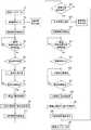
図4は、携帯型心電装置100を用いた心電波形測定処理のうち基本的な心電波形測定処理の手順を示すフローチャートである。
まず、携帯型心電装置100の電源スイッチ7を押下することにより電源をONする(ステップS1)。このとき、電源LED8が点灯し、電源がONになっていることを表示する。(Basic electrocardiographic measurement processing)
FIG. 4 is a flowchart showing a basic procedure of the electrocardiographic waveform measurement process in the electrocardiographic waveform measurement process using the portable
First, the power is turned on by pressing the
次に、被検者又は使用者が、誘導種別設定入力部13により、測定を行う誘導種別を入力する(ステップS2)。例えば、被検者がV4誘導による心電波形の測定を行うとすると、初期設定でI誘導の表示LED14aが点灯している状態から、誘導種別設定入力部
13のボタンを6回押下すると、誘導種別がII、IIIと順次切り替わって、V4誘導の表
示LED14gが点灯して、V4誘導による心電測定が設定されていることを表示する(ステップS2−1)。Next, the subject or the user inputs the guidance type to be measured by the guidance type setting input unit 13 (step S2). For example, if the subject measures the electrocardiographic waveform by V4 lead, pressing the button of the lead type setting
V4誘導では、第2電極3に右手の人差し指の先端部を接触させ、第3電極4に右手人差し指の中節を接触させる。そして、第1電極2を、左胸部の心窩部やや左方・乳頭下方の皮膚に接触させる。各電極2、3、4を介して取得された電気信号をアンプ部102で増幅し、AD変換部103でデジタル変換し、接触状態検出信号を生成する。このようにして生成された接触状態検出信号を制御部104に送信し、被検者と各電極2、3、4との接触状態を検出する(ステップS3)。 In the V4 lead, the tip of the index finger of the right hand is brought into contact with the
制御部104は、電極接触状態が維持されて所定時間が経過したか否かを判断する(ステップS4)。
ステップS4において、Noと判断された場合には、ステップS4を繰り返す。
ステップS4において、Yesと判断された場合には、制御部104は誘導種別を判定
する(ステップS5)。The
If No is determined in step S4, step S4 is repeated.
If it is determined to be Yes in step S4, the
ステップS2において、V4誘導が設定されている場合には、制御部104は、ステップS5において、誘導種別がV4誘導であると判定し、ステップS17に進み、V4誘導による心電波形の測定を開始する。 When V4 lead is set in step S2, the
制御部104は、タイマ部105で、測定開始からの時間をカウントし、所定の測定時間を経過したか否かを判断する(ステップS18)。
ステップS18でNoの場合には、ステップS17に戻り、心電波形の測定を継続する。
ステップS18でYesの場合には、制御部104はV4誘導による心電波形の解析を行う(ステップS19)。心電波形の解析が終了すると、測定通知LED5を点灯し、測定終了が被検者に通知される。
誘導法により、心電波形を特定するパラメータの特徴が異なるため、取得したい情報に適した心電波形データが得られる誘導法を設定することが望ましい。また、心電波形データの解析において誘導法に応じた心電波形解析を行うことにより、最適な心電波形解析が可能となる。The
If No in step S18, the process returns to step S17 and the measurement of the electrocardiographic waveform is continued.
In the case of Yes in step S18, the
Since the characteristics of the parameters that specify the electrocardiographic waveform differ depending on the induction method, it is desirable to set an induction method that can obtain electrocardiographic waveform data suitable for the information to be acquired. Further, by performing the electrocardiographic waveform analysis according to the induction method in the analysis of the electrocardiographic waveform data, the optimum electrocardiographic waveform analysis becomes possible.
図5に代表的な心電波形パラメータを示す。P波について、P波高さ及びP波幅、Q波について、Q波高さ、P波及びQ波について、PQ時間、R波について、R波高さ、S波について、S波高さ、Q波、R波及びS波について、QRS幅、T波について、T波高さ及びT波幅、Q波及びT波について、QT時間、U波について、U波高さ及びU波幅がそれぞれ定義されている。これらの心電図各部の一つ又は複数の数値若しくは一つ又は複数の数値に基づいて算出される値を心電図の波形を特定するパラメータとして用いることができる。 FIG. 5 shows typical electrocardiographic waveform parameters. About P wave, P wave height and P wave width, about Q wave, about Q wave height, about P wave and Q wave, about PQ time, about R wave, about R wave height, about S wave, about S wave height, Q wave, R wave And S wave, QRS width, T wave, T wave height and T wave width, Q wave and T wave, QT time, U wave, U wave height and U wave width are defined, respectively. One or more numerical values of each part of these electrocardiograms or a value calculated based on one or more numerical values can be used as a parameter for specifying the waveform of the electrocardiogram.
図6は、代表的な誘導種別の心電波形を示す。図6(A)は、I誘導、図6(B)はII
誘導、図6(C)はIII誘導、図6(D)はV1誘導、図6(E)はV2誘導、図6(F
)はV3誘導、図6(G)はV4誘導、図6(H)はV5誘導、図6(I)はV6誘導、図6(J)はaVR誘導、図6(K)はaVL誘導、図6(L)はaVF誘導により測定された心電波形である。FIG. 6 shows an electrocardiographic waveform of a typical induction type. FIG. 6 (A) is lead I, and FIG. 6 (B) is II.
Lead, FIG. 6 (C) is lead III, FIG. 6 (D) is lead V1, FIG. 6 (E) is lead V2, and FIG. 6 (F).
) Is V3 lead, FIG. 6 (G) is V4 lead, FIG. 6 (H) is V5 lead, FIG. 6 (I) is V6 lead, FIG. 6 (J) is aVR lead, and FIG. 6 (K) is aVL lead. FIG. 6 (L) is an electrocardiographic waveform measured by aVF induction.
図6(A)に示すように、I誘導による心電波形はピーク値が高いR波形の間隔で不規
則脈波であるか否かの大まかな判定は可能である。しかし、I誘導による心電波形は波高
値が小さく、P波やF波(不規則な基線の同様)はノイズに埋もれやすい。そこで、図5にしめすような代表的な心電波形パラメータを測定するには、V4誘導のようにPQRSTの形状が大きい誘導法による心電波形データを収集することにより最適な心電測定が可能となる。
また、誘導法に応じた心電波形解析の例としては、V4誘導はSTの変化を捉えやすいので、ST昇降の判定も行うが、V4誘導以外の誘導法では、STの変化が捉えにくいので、ST昇降の判定はせずに、その他の判定を行うようにしてもよいが、これに限られない。As shown in FIG. 6A, it is possible to roughly determine whether or not the electrocardiographic waveform by lead I is an irregular pulse wave at intervals of the R waveform having a high peak value. However, the ECG waveform by lead I has a small peak value, and the P wave and F wave (similar to the irregular baseline) are easily buried in noise. Therefore, in order to measure the typical electrocardiographic waveform parameters shown in FIG. 5, the optimum electrocardiographic measurement can be performed by collecting the electrocardiographic waveform data by the induction method having a large PQRST shape such as V4 lead. It becomes.
In addition, as an example of electrocardiographic waveform analysis according to the induction method, since the V4 lead can easily detect the change in ST, the ST ascending / descending determination is also performed. , ST elevating and lowering may not be determined, but other determinations may be made, but the present invention is not limited to this.
心電波形の解析が終了すると、制御部104は、V4誘導による心電波形と解析結果を関連付けてメモリ部106の所定領域に保存する(ステップS20)。
そして、制御部104は、心電波形を解析した結果を表示する(ステップS21)。具体的には、心電波形を解析した結果、異常波形を検出した場合には、異常波形検出LED6を点灯させ、被検者に異常波形が検出されたことを通知する。
心電波形の解析結果が表示されて、心電測定処理が終了すると、被検者又は使用者が電源スイッチ7を再度押下することにより、電源がOFFされる。心電波形の解析結果表示
から、電源スイッチ7が操作されることなく所定時間が経過した場合に、電源がOFFになるようにしてもよい。When the analysis of the electrocardiographic waveform is completed, the
Then, the
When the analysis result of the electrocardiographic waveform is displayed and the electrocardiographic measurement process is completed, the power is turned off by the subject or the user pressing the
上述の例では、ステップS2において、誘導種別としてV4誘導が設定された場合について説明したが、ステップS2において、誘導種別としてI誘導が設定された場合にも、
制御部104は同様の手順で処理を実行する。すなわち、I誘導による心電波形を測定し
(ステップS6)、所定の測定時間の経過を待って(ステップS7)、I誘導の心電波形
解析を行い(ステップS8)、I誘導による心電波形と解析結果をメモリ部106の所定
領域に保存する(ステップS9)。そして、心電波形に異常が検出された場合には、異常検出LED6を点灯させて解析結果を表示して(ステップS10)、心電測定処理を終了し、電源スイッチ7の押下により電源がOFFされる(ステップS41)。In the above example, the case where the V4 lead is set as the lead type in step S2 has been described, but also when the I lead is set as the lead type in step S2.
The
図4では、ステップS2において、I誘導及びV4誘導以外に、V1誘導が設定された
場合の処理(ステップS12〜ステップS16)、V6誘導が設定された場合の処理(ステップS22〜ステップS26)についても記載しているが、I誘導及びV4誘導につい
て説明した処理と同様であるので説明は省略する。図4では、記載を省略している他の誘導種別、すなわちV2誘導、V3誘導、V5誘導についても、I誘導及びV4誘導につい
て説明した処理と同様であるので説明は省略する。In FIG. 4, in step S2, in addition to the I lead and the V4 lead, the process when the V1 lead is set (steps S12 to S16) and the process when the V6 lead is set (steps S22 to S26). However, since it is the same as the process described for the I lead and the V4 lead, the description will be omitted. In FIG. 4, other induction types, that is, V2 lead, V3 lead, and V5 lead, which are omitted from the description, are the same as the processes described for the I lead and the V4 lead, and thus the description thereof will be omitted.
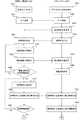
(異なる誘導法による心電波形の再測定を追加する処理)
以下に、図7を参照して、携帯型心電装置100を用いた心電波形測定処理のうち、異なる誘導法による心電波形の再測定を追加する処理について説明する。
図4に示す心電波形測定処理と同様の手順については、同様の符号を用いて詳細な説明を省略する。(Process to add remeasurement of electrocardiographic waveform by different induction method)
Hereinafter, among the electrocardiographic waveform measurement processes using the portable
For the same procedure as the electrocardiographic waveform measurement process shown in FIG. 4, detailed description will be omitted using the same reference numerals.
ステップS1からステップS10については、図4に示す心電波形測定処理と同様である。ここでは、ステップS2において、誘導種別としてI誘導が設定されている例につい
て説明する。Steps S1 to S10 are the same as the electrocardiographic waveform measurement process shown in FIG. Here, an example in which I lead is set as the lead type in step S2 will be described.
ステップS6及びステップS7においてI誘導による心電波形測定が行われ、ステップ
S8において心電波形が解析される。そして、ステップS9において、I誘導による心電
波形と解析結果がメモリ部106の所定領域に保存される。ステップS8において、I誘
導による心電波形に異常がある場合には、ステップS10において、異常波検出LED6を点灯させる。ステップS8において、I誘導による心電波形に異常がない場合には、ス
テップS10において、測定解析結果を表示する。解析結果に異常がない旨は、異常波検出LED6を点灯させない、又は、異常波検出LED6を、解析結果に異常がある場合とは異なる態様で点灯又は点滅させることに表示する。ここでは、異常波検出LED6は、本発明の表示手段に対応する。The electrocardiographic waveform measurement by lead I is performed in steps S6 and S7, and the electrocardiographic waveform is analyzed in step S8. Then, in step S9, the electrocardiographic waveform by lead I and the analysis result are stored in a predetermined area of the
ここでは、次のステップS31において、制御部104が、心電波形解析の結果、I誘
導による心電波形に異常があるか否かを判定する。ここで、心電波形解析の結果、心電波形に異常があるか否かは、心電波形の解析結果が所定の条件を満たすか否かによって判断する。所定の条件とは、例えば、不整脈が認められる、心房細動が認める、波形品質の不良が認められる等の条件である。このような条件を満たす場合に、制御部104は、心電波形に異常があると判断する。
ステップS31において、Noと判断された場合には、心電測定処理を終了し、電源スイッチ7の押下により電源がOFFされる(ステップS41)。
ステップS31において、Yesと判断された場合には、ステップS32に進む。Here, in the next step S31, the
If No is determined in step S31, the electrocardiographic measurement process is terminated, and the power is turned off by pressing the power switch 7 (step S41).
If it is determined to be Yes in step S31, the process proceeds to step S32.
I誘導では、ピーク値が高いR波形の間隔により、不規則脈波であるか否かの大まかな
判定が可能である(図6(A)参照)。しかし、I誘導では、図5に示す心電波形の代表
的なパラメータであるPQRST波の大きさが小さく最適な解析が難しい。そのため、このまま心電波形測定を終了すれば、I誘導による簡易的な心電波形測定で終了することと
なり、より精度の高い心電波形測定や解析ができない。そこで、I誘導による心電波形測
定において、不整脈のような異常な心電波形が検出された場合、又は、波形品質が不良である場合には、別の誘導法による心電波形測定を促すために、制御部104は、追加で実施する誘導法に対応する誘導種別表示LED14を点滅させる(ステップS32)。このように、心電波形に異常があるか否かを判断し、異常があると判断した場合に、再測定を促す誘導種別LED14を点滅させる処理を行う制御部104が、本発明の再測定促進部に対応する。In the I lead, it is possible to roughly determine whether or not the pulse wave is an irregular pulse wave by the interval of the R waveform having a high peak value (see FIG. 6 (A)). However, in the I lead, the magnitude of the PQRST wave, which is a typical parameter of the electrocardiographic waveform shown in FIG. 5, is small, and optimum analysis is difficult. Therefore, if the electrocardiographic waveform measurement is completed as it is, the simple electrocardiographic waveform measurement by the I lead will be completed, and more accurate electrocardiographic waveform measurement and analysis cannot be performed. Therefore, if an abnormal electrocardiographic waveform such as an arrhythmia is detected in the electrocardiographic waveform measurement by lead I, or if the waveform quality is poor, the electrocardiographic waveform measurement by another lead method is promoted. In addition, the
例えば、心電波形パターンをより的確に把握し解析したい場合には、V4誘導による心電波形の再測定を追加することとして、対応する表示LED14gを点滅させる。このようにして、V4誘導による再測定が設定された後の、ステップS33〜ステップS35の処理は、図4のステップS3〜ステップS5と同様であり、ステップS36〜ステップS41の処理は、図4のステップS17〜ステップS21及びステップS11と同様である。 For example, when it is desired to more accurately grasp and analyze the electrocardiographic waveform pattern, the
I誘導による心電波形測定に追加する誘導法は上述のV4誘導に限られず、種々の誘導
法を設定することができる。例えば、ステップS8における心電波形の解析の結果、制御部104が心房細動(AF)の可能性があると判定した場合には、I誘導では心房細動の
判定をより確実にすることが難しく、P波やF波(不規則な基線の同様)の有無を確認することが好ましい。このときには、ステップS32において、V1誘導による心電波形の再測定を追加する。V1誘導による心電波形は、図6(D)に例示される波形であるため、P波やF波が把握しやすいV1誘導を追加して再測定させることで心房細動の有無の判定に、より有益な心電波形データを収集することができる。The induction method to be added to the electrocardiographic waveform measurement by lead I is not limited to the above-mentioned V4 lead, and various induction methods can be set. For example, if the
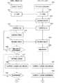
(携帯型心電装置とスマートフォンとが連携した基本的な心電測定処理)
図8及び図9は、携帯型心電装置100と、スマートフォン200等のBLE方式の通信機能を搭載した端末とがBLE通信しながら基本的な心電波形を測定する手順を説明するフローチャートであり、図8及び図9は、一連の手順を示す。(Basic electrocardiographic measurement processing in which a portable electrocardiogram and a smartphone are linked)
8 and 9 are flowcharts illustrating a procedure for measuring a basic electrocardiographic waveform while BLE communication is performed between the portable
まず、携帯型心電装置100の電源スイッチ7を押下することにより電源をONする(ステップS301)。一方、スマートフォン200では、心電測定用のアプリを開く(ステップS401)。被検者のIDの登録等は、上述の初期設定の際に完了しているものとして説明する。 First, the power is turned on by pressing the
次に、携帯型心電装置100とスマートフォン200との間で、所定の手順に従ってBLE接続を行う(ステップS302、ステップS402)。
携帯型心電装置100とスマートフォン200との間で、BLE接続が確立されると、スマートフォン200は携帯型心電装置100に対して、通信開始要求を送信する(ステップS403)。Next, a BLE connection is made between the portable
When the BLE connection is established between the portable
次に、スマートフォン200は、制御部201が誘導種別の入力を受け付ける(ステップS404)。図10(A)は、被検者又は使用者がスマートフォン200で、誘導種別設定を入力する際のタッチパネルディスプレイ202の表示例である。タッチパネルディスプレイ202には、誘導種別設定画面2021には、文字とともに、複数種誘導法のうち、設定すべき誘導法を選択するボタン2022が表示されている。誘導種別を選択するボタン2022は、複数種の誘導法に対応したボタンを含む。すなわち、ボタン2022は、I誘導を設定するボタン2022a、II誘導を設定するボタン2022b、III誘導を
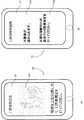
設定するボタン2022c、V1誘導を設定するボタン2022d、V2誘導を設定するボタン2022e、V3誘導を設定するボタン2022f、V4誘導を設定するボタン2022g、V5誘導を設定するボタン2022h、V6誘導を設定するボタン2022iを含む。各ボタン2022a〜2022iには、各誘導法に関連した表示がなされている。例えば、被検者又は使用者が、V4誘導による心電測定を選択する場合には、タッチパネルディスプレイ202のボタン2022gに触れる。V4誘導が設定されると、タッチパネルディスプレイ202には、図10(B)に示すように、設定された誘導法に応じて、被検者が、携帯型心電装置100の電極2を接触させるべき位置(測定部位)を、図と文字を用いて説明する案内画面2023を表示する。ここでは、V4誘導に応じた案内画面を例示しているが、被検者又は使用者が選択可能な誘導法に対して、同様の案内画面を表示することができる。設定された誘導種別に応じて電極2を接触させる測定部位を、スマートフォン200のタッチパネルディスプレイ202に表示することにより、被検者が正確な位置に電極2を接触させることができる。このような案内画面2023により、被検者に測定部位を案内することにより、より確実に、最適な誘導を設定することができ、正確な心電波形の測定が可能となる。ここでは、ボタン2022a〜2022iを含むボタン2022は、本発明の設定部に対応する。Next, in the
ステップS404において設定された誘導種別はスマートフォン200から、携帯型心電装置100に送信される。携帯型心電装置100は、誘導種別を受信し(ステップS303)、メモリ部106の所定領域に保存する。 The guidance type set in step S404 is transmitted from the
次に、携帯型心電装置100では、制御部104は、電極接触状態を検出する(ステップS304)。
具体的には、携帯型心電装置100によりV4誘導測定を行う場合には、第2電極3に右手の人差し指の先端部を接触させ、第3電極4に右手人差し指の中節を接触させる。そして、第1電極2を、左胸部の心窩部やや左方・乳頭下方の皮膚に接触させる。また、携帯型心電装置100によりI誘導測定を行う場合には、第2電極3に右手の人差し指の先端部を接触させ、第3電極4に右手人差し指の中節を接触させる。そして、第1電極2に左手掌を接触させる。このように、被検者は、設定された誘導種別に応じた測定部位に各電極2、3、4を接触させる。各電極2、3、4を介して取得された電気信号をアンプ部102で増幅し、AD変換部でデジタル変換し、接触状態検出信号を生成する。このようにして生成された接触状態検出信号を制御部104に送信し、被検者と各電極2、3、4との接触状態を検出する。Next, in the portable
Specifically, when the V4 induction measurement is performed by the portable
携帯型心電装置100では、電極接触状態を示す情報を、スマートフォン200に送信する(ステップS305)。スマートフォン200は電極接触状態を示す情報を受信すると(ステップS405)、電極接触状態をタッチパネルディスプレイ202等に表示し(ステップS406)、各電極2、3、4に正常に接触していることを被検者に知らせる。 The portable
制御部104は、電極接触状態が維持されて所定時間が経過したか否かを判断する(ステップS306)。
ステップS306において、Noと判断された場合には、ステップS304に戻る。
ステップS306において、Yesと判断された場合には、制御部104は、設定された誘導種別に応じた心電測定を開始する(ステップS307)。The
If No is determined in step S306, the process returns to step S304.
If it is determined to be Yes in step S306, the
心電測定が開始されると、携帯型心電装置100はスマートフォン200との間でストリーミング通信を行い、誘導種別情報と心電波形情報と測定時間情報をスマートフォン200に送信する(ステップS308)。測定時間情報は、タイマ部105でカウントされている、心電測定開始からの経過時間に関する情報であり、ここでは、心電測定開始からの経過時間を、所定時間から減算した、残りの測定時間を示す情報である。携帯型心電装
置100から心電測定開始からの経過時間の情報をスマートフォン200に送信し、スマートフォン200側で所定時間からの減算処理を行ってもよい。一方、スマートフォン200では、携帯型心電装置100から誘導種別情報、心電波形情報及び測定時間情報を受信する(ステップS407)。When the electrocardiographic measurement is started, the portable
スマートフォン200では、タッチパネルディスプレイ202に誘導種別、心電波形及び測定時間を表示する(ステップS408)。これにより、誘導種別と、心電測定が正常に行われていることと、残りの測定時間が被検者に報知される。
タッチパネルディスプレイ202に表示された誘導種別を、被検者に正しい測定姿勢を指導するのに利用することができる。また、タッチパネルディスプレイ202に、被検者が意図していた誘導法と異なる誘導種別が表示された場合には、正しい測定姿勢での再度の測定を促すことができる。In the
The guidance type displayed on the
心電波形の測定が開始されてから所定の測定時間(例えば30秒)が経過したか否かを判断する(ステップS309)。
ステップS309において、Noと判断された場合には、ステップS307に戻り、心電測定を継続する。
ステップS309において、Yesと判断された場合には、制御部104は、設定された所定の誘導法に応じた心電波形の解析を行う(ステップS310)。設定された所定の誘導法に応じて、心電波形を解析することにより、精度のよい解析が可能となる。It is determined whether or not a predetermined measurement time (for example, 30 seconds) has elapsed since the measurement of the electrocardiographic waveform was started (step S309).
If No is determined in step S309, the process returns to step S307 and the electrocardiographic measurement is continued.
If it is determined to be Yes in step S309, the
制御部104は、心電波形の解析中に、スマートフォン200に対して、心電波形の解析中であることを示す情報を送信する(ステップS311)。スマートフォン200は、携帯型心電装置100から、心電波形の解析中であることを示す情報を受信すると(ステップS409)、心電波形の解析中であることを示す情報をタッチパネルディスプレイ202に表示する(ステップS410)。 During the analysis of the electrocardiographic waveform, the
心電波形の解析が終了すると、制御部104は、誘導種別、心電波形及び解析結果を関連付けてメモリ部106の所定領域に保存する(ステップS312)。誘導種別を心電波形及び解析結果と関連付けてメモリ部106の所定領域に保存しておくことにより、医師が心電波形を読み出して診断等に利用する場合に、有用な情報を提供することができる。互いに関連付けられた誘導種別、心電波形及び解析結果を携帯型心電装置100のメモリ部106に保存せずに、スマートフォン200側にのみ保存するようにしてもよい。また、誘導種別、心電波形及び解析結果のいずれかのみを携帯型心電装置100のメモリ部106に保存するようにしてもよい。
心電波形の解析により、異常波が検出された場合には、制御部104は、異常波検出LED13を点滅させて、被検者に異常波検出を通知するようにしてもよい。When the analysis of the electrocardiographic waveform is completed, the
When an abnormal wave is detected by the analysis of the electrocardiographic waveform, the
また、心電波形の解析が終了すると、制御部104は、高速のデータ通信により解析結果をスマートフォン200に送信する(ステップS314)。このとき、スマートフォン200では、携帯型心電装置100から送信された解析結果を受信し(ステップS411)、解析結果、すなわち、心電測定結果が正常で問題がなかったのか、異常波形が検出されたのかをタッチパネルディスプレイ202に表示する(ステップS412)。 When the analysis of the electrocardiographic waveform is completed, the
そして、携帯型心電装置100に未送信の心電波形データ、誘導種別判定結果データ、解析結果がある場合には、制御部104は、高速のデータ通信により、これらの情報を、新しいものから順にスマートフォン200に送信する(ステップS315)。このとき、スマートフォン200では、未送信の心電波形データ、誘導種別データ、解析結果を携帯型心電装置100から受信し(ステップS413)、メモリ部204の所定領域に保存する。そして、スマートフォン200では、最新の心電波形と心電測定結果が正常であった
か異常波が検出されたか等の解析結果をタッチパネルディスプレイ202に表示する(ステップS414)。Then, when the portable
携帯型心電装置100において、未送信の心電波形データ、誘導種別判定結果データ、解析結果の送信が完了すると(ステップS316)、スマートフォン200から送信される通信終了要求(ステップS415)に応じて、BLE通信を切断する(ステップS317)。携帯型心電装置100におけるBLE通信の切断に対応して、スマートフォン200側でもBLE通信が切断される(ステップS416)。 When the transmission of the untransmitted electrocardiographic waveform data, the induction type determination result data, and the analysis result is completed in the portable electrocardiographic device 100 (step S316), in response to the communication end request (step S415) transmitted from the
BLE通信を切断した後に、携帯型心電装置100では、電源スイッチ7がOFFされる(ステップS318)。電源スイッチ7は、BLE切断後、所定の時間の経過により制御部104が自動的にOFFにしてもよいし、被検者又は使用者による電源スイッチ7の押下によるOFFにしてもよい。一方、スマートフォン200では、BLE通信を切断した後に、アプリを閉じる(ステップS417)。このようにして、携帯型心電装置100におけるスマートフォン200と連携した心電測定が終了する。 After disconnecting the BLE communication, the
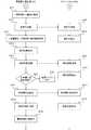
(携帯型心電装置とスマートフォンとが連携して異なる誘導法による心電波形の再測定を追加する処理)
図11及び図12は、携帯型心電装置100と、スマートフォン200等のBLE方式の通信機能を搭載した端末とがBLE通信しながら一つの誘導法による心電波形を測定し、その後異なる誘導法による心電波形を測定する手順を説明するフローチャートであり、図11及び図12は、一連の手順を示す。図8及び図9に示す、基本的な心電波形測定処理と共通する処理については、同じ符号を用いて詳細な説明を省略する。(Processing in which a portable electrocardiographic device and a smartphone work together to add remeasurement of the electrocardiographic waveform by different induction methods)
11 and 12 show that the portable
まず、携帯型心電装置100におけるステップS301及びステップS302と、スマートフォン200におけるステップS401〜ステップS403の処理は、図8に示す場合と同様であるので説明は省略する。 First, since the processes of steps S301 and S302 in the portable
続いて、スマートフォン200は、制御部201が誘導種別の入力を受け付ける(ステップS604)。このとき、スマートフォン200では、I誘導が選択され、入力される
。このとき、被検者又は使用者がスマートフォン200のタッチパネルディスプレイ202で、I誘導を設定するボタン2022aに触れる。I誘導が設定されると、タッチパネルディスプレイ202には、図13(A)に示すように、設定されたI誘導に応じて、被検
者が、携帯型心電装置100の電極2を接触させるべき位置(測定部位)を、図と文字を用いて説明する案内画面2024を表示する。ここでは、V4誘導に応じた案内画面を例示しているが、被検者又は使用者が選択可能な誘導法に対して、同様の案内画面を表示することができる。設定された誘導種別に応じて電極2を接触させる測定部位を、スマートフォン200のタッチパネルディスプレイ202に表示することにより、被検者が正確な位置に電極2を接触させることができる。このような案内画面2023により、被検者に測定部位を案内することにより、より確実に、最適な誘導を設定することができ、正確な心電波形の測定が可能となる。ここでは、ボタン2022a〜2022iを含むボタン2022は、本発明の設定部に対応する。Subsequently, in the
ステップS604において設定された誘導種別はスマートフォン200から、携帯型心電装置100に送信される。携帯型心電装置100は、誘導種別を受信し(ステップS503)、メモリ部106の所定領域に保存する。 The guidance type set in step S604 is transmitted from the
次に、携帯型心電装置100では、制御部104は、電極接触状態を検出する(ステップS504)。
具体的には、携帯型心電装置100によりI誘導測定を行う場合には、第2電極3に右
手の人差し指の先端部を接触させ、第3電極4に右手人差し指の中節を接触させる。そして、第1電極2に左手掌を接触させる。このように、被検者は、設定された誘導種別に応じた測定部位に各電極2、3、4を接触させる。各電極2、3、4を介して取得された電気信号をアンプ部102で増幅し、AD変換部でデジタル変換し、接触状態検出信号を生成する。このようにして生成された接触状態検出信号を制御部104に送信し、被検者と各電極2、3、4との接触状態を検出する。Next, in the portable
Specifically, when the I-lead measurement is performed by the portable
携帯型心電装置100では、電極接触状態を示す情報を、スマートフォン200に送信する(ステップS505)。スマートフォン200は電極接触状態を示す情報を受信すると(ステップS605)、電極接触状態をタッチパネルディスプレイ202等に表示し(ステップS606)、各電極2、3、4に正常に接触していることを被検者に知らせる。 The portable
制御部104は、電極接触状態が維持されて所定時間が経過したか否かを判断する(ステップS506)。
ステップS506において、Noと判断された場合には、ステップS504に戻る。
ステップS506において、Yesと判断された場合には、制御部104は、設定されたI誘導による心電測定を開始する(ステップS507)。The
If No is determined in step S506, the process returns to step S504.
If it is determined to be Yes in step S506, the
心電測定が開始されると、携帯型心電装置100はスマートフォン200との間でストリーミング通信を行い、I誘導であることを示す誘導種別情報と心電波形情報と測定時間
情報をスマートフォン200に送信する(ステップS508)。測定時間情報は、タイマ部105でカウントされている、心電測定開始からの経過時間に関する情報であり、ここでは、心電測定開始からの経過時間を、所定時間から減算した、残りの測定時間を示す情報である。携帯型心電装置100から心電測定開始からの経過時間の情報をスマートフォン200に送信し、スマートフォン200側で所定時間からの減算処理を行ってもよい。一方、スマートフォン200では、携帯型心電装置100から誘導種別情報、心電波形情報及び測定時間情報を受信する(ステップS607)。When the electrocardiographic measurement is started, the portable
スマートフォン200では、タッチパネルディスプレイ202に誘導種別、心電波形及び測定時間を表示する(ステップS608)。これにより、誘導種別がI誘導であること
と、心電測定が正常に行われていることと、残りの測定時間が被検者に報知される。In the
心電波形の測定が開始されてから所定の測定時間(例えば30秒)が経過したか否かを判断する(ステップS509)。
ステップS509において、Noと判断された場合には、ステップS507に戻り、心電測定を継続する。
ステップS509において、Yesと判断された場合には、制御部104は、設定された所定の誘導法に応じた心電波形の解析を行う(ステップS510)。設定されたI誘導
に応じて、心電波形を解析することにより、精度のよい解析が可能となる。It is determined whether or not a predetermined measurement time (for example, 30 seconds) has elapsed since the measurement of the electrocardiographic waveform was started (step S509).
If No is determined in step S509, the process returns to step S507 and the electrocardiographic measurement is continued.
If it is determined to be Yes in step S509, the
制御部104は、心電波形の解析中に、スマートフォン200に対して、心電波形の解析中であることを示す情報を送信する(ステップS511)。スマートフォン200は、携帯型心電装置100から、心電波形の解析中であることを示す情報を受信すると(ステップS609)、心電波形の解析中であることを示す情報をタッチパネルディスプレイ202に表示する(ステップS610)。 During the analysis of the electrocardiographic waveform, the
心電波形の解析が終了すると、制御部104は、I誘導である誘導種別、心電波形及び
解析結果を関連付けてメモリ部106の所定領域に保存する(ステップS512)。誘導種別を心電波形及び解析結果と関連付けてメモリ部106の所定領域に保存しておくことにより、医師が心電波形を読み出して診断等に利用する場合に、有用な情報を提供するこ
とができる。互いに関連付けられた誘導種別、心電波形及び解析結果を携帯型心電装置100のメモリ部106に保存せずに、スマートフォン200側にのみ保存するようにしてもよい。また、誘導種別、心電波形及び解析結果のいずれかのみを携帯型心電装置100のメモリ部106に保存するようにしてもよい。
心電波形の解析により、異常波が検出された場合には、制御部104は、異常波検出LED13を点滅させて、被検者に異常波検出を通知するようにしてもよい。When the analysis of the electrocardiographic waveform is completed, the
When an abnormal wave is detected by the analysis of the electrocardiographic waveform, the
また、心電波形の解析が終了すると、制御部104は、高速のデータ通信により解析結果をスマートフォン200に送信する(ステップS514)。このとき、スマートフォン200では、携帯型心電装置100から送信された解析結果を受信し(ステップS611)、解析結果、すなわち、心電測定結果が正常で問題がなかったのか、異常波形が検出されたのかをタッチパネルディスプレイ202に表示する(ステップS612)。 When the analysis of the electrocardiographic waveform is completed, the
制御部104は、心電波形解析の結果、I誘導による心電波形に異常があるか否かを判
定する(ステップS515)。
ステップS515において、Noと判断された場合には、心電測定処理を終了し、電源スイッチ7の押下により電源がOFFされる(ステップS516)。
ステップS515において、Yesと判断された場合、すなわち、I誘導による心電波
形に異常が認められた場合には、制御部104は、より正確な誘導法で心電測定を行うために別誘導法による再測定の追加をスマートフォン200に送信する(ステップS517)。As a result of the electrocardiographic waveform analysis, the
If No is determined in step S515, the electrocardiographic measurement process is terminated, and the power is turned off by pressing the power switch 7 (step S516).
If it is determined to be Yes in step S515, that is, if an abnormality is found in the electrocardiographic waveform due to lead I, the
ステップS515でI誘導による心電波形に異常があると判定された場合に、タッチパ
ネルディスプレイ202に表示された解析結果の例を図13(B)に示す。ここでは、タッチパネルディスプレイ202には、I誘導による心電波形の解析結果が表示されている
。タッチパネルディスプレイ202には、「不整脈が認められます。」という解析結果表示2025と、「正確な診断のため追加でV4誘導測定を行ってください。」との、異なる誘導法での心電波形の再測定を促す表示2026がなされている。このように、心電波形に異常があるか否かを判断し、異常があると判断した場合に、別の誘導法による再測定の追加をスマートフォン200に送信し、タッチパネルディスプレイ202に異なる誘導法での心電波形の再測定を促す表示2026を行わせる制御部104が、本発明の再測定促進部に対応する。また、ここでは、異なる誘導法での心電波形の再測定を促す表示2026を行うタッチパネルディスプレイ202が、本発明の表示手段に対応する。FIG. 13 (B) shows an example of the analysis result displayed on the
図6(A)に示すように、I誘導による心電波形は、ピーク値が高いR波形の間隔で不
規則脈波であるかどうかの大まかな判定はできる。しかし、図5に示す代表的な心電波形パラメータのRQRST波の大きさが小さく最適な解析が難しい。そのため、このまま心電波形測定を終了すれば、I誘導による簡易的な心電波形測定で終了することとなり、よ
り精度の高い心電波形測定や解析ができない。そこで、I誘導による心電波形測定におい
て、不整脈のような異常な心電波形が検出された場合、又は、波形品質が不良である場合には、図13(B)に示すように、スマートフォン200のタッチパネルディスプレイ202に別の誘導法による心電波形測定を促す表示2026を行う(ステップS613)。ここでは、心電波形パターンをより的確に把握し解析するために、V4誘導による心電測定を行うように促している。As shown in FIG. 6A, it is possible to roughly determine whether or not the electrocardiographic waveform by lead I is an irregular pulse wave at intervals of the R waveform having a high peak value. However, the magnitude of the RQRST wave of the typical electrocardiographic waveform parameter shown in FIG. 5 is small, and optimum analysis is difficult. Therefore, if the electrocardiographic waveform measurement is completed as it is, the simple electrocardiographic waveform measurement by the I lead will be completed, and more accurate electrocardiographic waveform measurement and analysis cannot be performed. Therefore, when an abnormal electrocardiographic waveform such as an arrhythmia is detected in the electrocardiographic waveform measurement by lead I, or when the waveform quality is poor, as shown in FIG. 13B, the
図13(B)に示す、別の誘導法による心電波形測定を促す表示2026がなされたタッチパネルディスプレイ202に被検者又は使用者が触れると、図10(A)に示す誘導種別設定画面2021が表示される。被検者又は使用者がV4誘導を設定するボタン2022gに触れることにより、別の誘導法であるV4誘導による心電波形の再測定を追加することに対する被検者又は使用者の同意(OK)が取得される(ステップS614)。こ
れを受けて、スマートフォン200からは、別誘導種別の情報としてV4誘導であることを示す情報が、携帯型心電装置100に送信される。また、被検者又は使用者が、誘導種別設定画面2021のV4誘導を設定するボタン2022gに触れると、タッチパネルディスプレイ202には、図10(B)に示すように、設定された誘導法に応じて、被検者が、携帯型心電装置100の電極2を接触させるべき位置(測定部位)を、図と文字を用いて説明する案内画面2023が表示される。これにより、被検者は正確な位置に電極2を接触させることができ、正確な心電波形の測定が可能となる。When the subject or the user touches the
携帯型心電装置100が、別誘導測定の情報を受信する(ステップ518)。
以降は、別の誘導法として設定されたV4誘導による心電測定が行われる。ステップS519以降の処理手順は、図8及び図9に示したステップS304及びステップS405以降の処理手順と同じであるから説明を省略する。The portable
After that, electrocardiographic measurement by V4 lead, which is set as another lead method, is performed. Since the processing procedure after step S519 is the same as the processing procedure after step S304 and step S405 shown in FIGS. 8 and 9, the description thereof will be omitted.
I誘導による心電波形測定に追加する誘導法は上述のV4誘導に限られず、種々の誘導
法を設定することができる。例えば、ステップS518における心電波形の解析の結果、制御部104が心房細動(AF)の可能性があると判定した場合には、I誘導では心房細
動の判定をより確実にすることが難しく、P波やF波(不規則な基線の同様)の有無を確認することが好ましい。このときには、ステップS32において、V1誘導による心電波形の再測定を追加する。V1誘導による心電波形は、図6(D)に例示される波形であるため、P波やF波が把握しやすいV1誘導を追加して再測定させることで心房細動の有無の判定に、より有益な心電波形データを収集することができる。The induction method to be added to the electrocardiographic waveform measurement by lead I is not limited to the above-mentioned V4 lead, and various induction methods can be set. For example, if the
このようにして、一つの誘導法による心電測定に追加して別の誘導法による心電波形の再測定を行うことができる。これにより、心電波形パターンを正確に測定でき、正確な診断のために有益な情報を収集することができる。I誘導による心電側測定にV4誘導によ
る心電波形の再測定を追加する例と、I誘導による心電測定にV1誘導による心電波形の
再測定を追加する例について説明したが、I誘導による心電測定に追加して心電波形の再
測定を行う場合の誘導法はこれらに限られない。また、初めに心電測定する際の誘導法と、心電波形の再測定を追加する場合の誘導法との組み合わせもこれらに限られない。一つの誘導法による心電測定において、波形品質が悪い、ノイズが多い、波形パターンが不明瞭である等の理由により、制度の良い解析が望めない場合には、それを補完する特性を有する心電波形の測定が可能な誘導法による心電波形の再測定を追加することにより、心電測定の精度を向上させることができる。In this way, in addition to the electrocardiographic measurement by one induction method, the electrocardiographic waveform can be remeasured by another induction method. As a result, the electrocardiographic waveform pattern can be accurately measured, and useful information can be collected for accurate diagnosis. An example of adding the remeasurement of the electrocardiographic waveform by the V4 lead to the electrocardiographic side measurement by the I lead and an example of adding the remeasurement of the electrocardiographic waveform by the V1 lead to the electrocardiographic measurement by the I lead have been described. The induction method when re-measuring the electrocardiographic waveform in addition to the electrocardiographic measurement by is not limited to these. Further, the combination of the induction method when first measuring the electrocardiogram and the induction method when adding the remeasurement of the electrocardiographic waveform is not limited to these. In electrocardiographic measurement by one induction method, if a good systematic analysis cannot be expected due to poor waveform quality, noisy noise, unclear waveform pattern, etc., a heart with characteristics that complement it. The accuracy of the electrocardiographic measurement can be improved by adding the remeasurement of the electrocardiographic waveform by the induction method capable of measuring the radio wave shape.
1 :携帯型心電装置本体
2,3,4:電極
13 :誘導種別設定入力部
14 :誘導種別表示LED
100 :携帯型心電装置
200 :スマートフォン
202 :タッチパネルディスプレイ
1: Portable electrocardiographic device
100: Portable electrocardiographic device 200: Smartphone 202: Touch panel display
Claims (17)
Translated fromJapanese被検者の身体の所定箇所に当接させて心電波形を測定する電極部と、
前記心電波形の測定時における誘導法に応じて、前記電極部によって測定された前記心電波形を解析する解析部と、
前記電極部において測定された前記心電波形と、前記誘導法と、前記解析部によって前記心電波形が解析された解析結果と、が関連付けて保存される記憶部と、
前記解析結果または測定された前記心電波形の状態が所定の条件を満たす場合に、前記心電波形の測定時における誘導法とは異なる所定の誘導法による再測定を使用者に促す再測定促進部と、
を備えることを特徴とする携帯型心電装置。A portable electrocardiographic device that can measure electrocardiographic waveforms using multiple types of induction methods.
An electrode part that measures the electrocardiographic waveform by contacting it with a predetermined part of the subject's body,
An analysis unit that analyzes the electrocardiographic waveform measured by the electrode unit according to the induction method at the time of measuring the electrocardiographic waveform, and an analysis unit.
A storage unit in which the electrocardiographic waveform measured at the electrode unit, the induction method, and the analysis result obtained by analyzing the electrocardiographic waveform by the analysis unit are stored in association with each other.
When the analysis result or the measured state of the electrocardiographic waveform satisfies a predetermined condition, the remeasurement promotion prompts the user to remeasure by a predetermined induction method different from the induction method at the time of measuring the electrocardiographic waveform. Department and
A portable electrocardiographic device characterized by being equipped with.
前記再測定時に設定されるべき前記誘導法を表示する表示手段を有することを特徴とする、請求項1に記載の携帯型心電装置。The remeasurement promotion unit
The portable electrocardiographic device according to claim 1, further comprising a display means for displaying the guidance method to be set at the time of the remeasurement.
前記測定時及び前記再測定時には、使用者が前記設定部によって前記誘導法を設定することを特徴とする、請求項1から3のいずれか一項に記載の携帯型心電装置。Further, a setting unit for setting which of the plurality of induction methods is used to measure the electrocardiographic waveform is provided.
The portable electrocardiographic device according to any one of claims 1 to 3, wherein the user sets the guidance method by the setting unit at the time of the measurement and the remeasurement.
前記所定の条件は、前記解析結果において不整脈が認められた場合であり、
前記所定の誘導法は、12誘導法におけるV4誘導であることを特徴とする、請求項1から4のいずれか一項に記載の携帯型心電装置。The induction method at the time of the measurement is the I lead in the 12-lead method.
The predetermined condition is when an arrhythmia is found in the analysis result.
The portable electrocardiographic device according to any one of claims 1 to 4, wherein the predetermined induction method is V4 induction in the 12-lead method.
前記所定の条件は、前記解析結果において心房細動が認められた場合であり、
前記所定の誘導法は、12誘導法におけるV1誘導であることを特徴とする、請求項1から4のいずれか一項に記載の携帯型心電装置。The induction method at the time of the measurement is the I lead in the 12-lead method.
The predetermined condition is when atrial fibrillation is observed in the analysis result.
The portable electrocardiographic device according to any one of claims 1 to 4, wherein the predetermined induction method is V1 induction in the 12-lead method.
前記所定の条件は、前記解析結果において波形品質の不良が認められた場合であり、
前記所定の誘導法は、12誘導法におけるV1誘導またはV4誘導であることを特徴とする、請求項1から4のいずれか一項に記載の携帯型心電装置。The induction method at the time of the measurement is the I lead in the 12-lead method.
The predetermined condition is a case where poor waveform quality is found in the analysis result.
The portable electrocardiographic device according to any one of claims 1 to 4, wherein the predetermined induction method is V1 induction or V4 induction in the 12-lead method.
前記心電波形の測定時における誘導法に応じて、前記電極部によって測定された前記心電波形を解析する解析部と、
前記電極部において測定された前記心電波形と、前記誘導法と、前記解析部によって前記心電波形が解析された解析結果と、が関連付けて保存される記憶部と、
前記解析結果または測定された前記心電波形の状態が所定の条件を満たす場合に、前記心電波形の測定時における誘導法とは異なる所定の誘導法による再測定を使用者に促す再測定促進部と、
をさらに備えることを特徴とする心電計測システム。A portable electrocardiographic device provided with an electrode portion for detecting an electrocardiographic waveform in contact with a predetermined portion of the subject's body, and a portable communication terminal provided so as to be able to communicate with the portable electrocardiographic device. It is an electrocardiographic measurement system that can measure electrocardiographic waveforms using multiple types of induction methods.
An analysis unit that analyzes the electrocardiographic waveform measured by the electrode unit according to the induction method at the time of measuring the electrocardiographic waveform, and an analysis unit.
A storage unit in which the electrocardiographic waveform measured at the electrode unit, the induction method, and the analysis result obtained by analyzing the electrocardiographic waveform by the analysis unit are stored in association with each other.
When the analysis result or the measured state of the electrocardiographic waveform satisfies a predetermined condition, the remeasurement promotion prompts the user to remeasure by a predetermined induction method different from the induction method at the time of measuring the electrocardiographic waveform. Department and
An electrocardiographic measurement system characterized by being further equipped with.
前記携帯型心電装置と、前記携帯通信端末のいずれかに設けられ、
前記再測定時に設定されるべき前記誘導法を表示する表示手段を有することを特徴とする、請求項8に記載の心電計測システム。The remeasurement promotion unit
Provided in either the portable electrocardiographic device or the portable communication terminal,
The electrocardiographic measurement system according to claim 8, further comprising a display means for displaying the guidance method to be set at the time of the remeasurement.
前記測定時及び前記再測定時には、使用者が前記設定部によって前記誘導法を設定することを特徴とする、請求項8から10のいずれか一項に記載の心電計測システム。Further, a setting unit for setting which of the plurality of induction methods is used to measure the electrocardiographic waveform is provided.
The electrocardiographic measurement system according to any one of claims 8 to 10, wherein the user sets the guidance method by the setting unit at the time of the measurement and the remeasurement.
前記所定の条件は、前記解析結果において不整脈が認められた場合であり、
前記所定の誘導法は、12誘導法におけるV4誘導であることを特徴とする、請求項8から11のいずれか一項に記載の心電計測システム。The induction method at the time of the measurement is the I lead in the 12-lead method.
The predetermined condition is when an arrhythmia is found in the analysis result.
The electrocardiographic measurement system according to any one of claims 8 to 11, wherein the predetermined induction method is V4 induction in the 12-lead method.
前記所定の条件は、前記解析結果において心房細動が認められた場合であり、
前記所定の誘導法は、12誘導法におけるV1誘導であることを特徴とする、請求項8から11のいずれか一項に記載の心電計測システム。The induction method at the time of the measurement is the I lead in the 12-lead method.
The predetermined condition is when atrial fibrillation is observed in the analysis result.
The electrocardiographic measurement system according to any one of claims 8 to 11, wherein the predetermined induction method is V1 induction in the 12-lead method.
前記所定の条件は、前記解析結果において波形品質の不良が認められた場合であり、
前記所定の誘導法は、12誘導法におけるV1誘導またはV4誘導であることを特徴とする、請求項8から11のいずれか一項に記載の心電計測システム。The induction method at the time of the measurement is the I lead in the 12-lead method.
The predetermined condition is a case where poor waveform quality is found in the analysis result.
The electrocardiographic measurement system according to any one of claims 8 to 11, wherein the predetermined induction method is V1 induction or V4 induction in the 12-lead method.
前記表示手段が前記再測定時に設定されるべき前記誘導法を表示するように、前記携帯通信端末を制御する、プログラム。The display means in the electrocardiographic measurement system of claim 9 is provided in the mobile communication terminal.
A program that controls the mobile communication terminal so that the display means displays the guidance method to be set at the time of the remeasurement.
前記表示手段が前記所定の条件が満たされたことを表示するように、前記携帯通信端末を制御する、プログラム。The display means in the electrocardiographic measurement system of claim 10 is provided in the mobile communication terminal.
A program that controls the mobile communication terminal so that the display means displays that the predetermined condition is satisfied.
前記測定時及び前記再測定時に、使用者が前記設定部によって前記誘導法を設定可能となるように、前記携帯通信端末を制御する、プログラム。
The setting unit in the electrocardiographic measurement system of claim 11 is provided in the mobile communication terminal.
A program that controls the mobile communication terminal so that the user can set the guidance method by the setting unit at the time of the measurement and the remeasurement.
Priority Applications (5)
| Application Number | Priority Date | Filing Date | Title |
|---|---|---|---|
| JP2020048879AJP7501018B2 (en) | 2020-03-19 | 2020-03-19 | Portable electrocardiogram device and electrocardiogram measuring system |
| PCT/JP2021/009346WO2021187247A1 (en) | 2020-03-19 | 2021-03-09 | Portable electrocardiographic device, electrocardiogram measurement system, and program |
| CN202180017823.3ACN115209807A (en) | 2020-03-19 | 2021-03-09 | Portable electrocardiograph, electrocardiographic measurement system, and program |
| DE112021000556.1TDE112021000556T5 (en) | 2020-03-19 | 2021-03-09 | PORTABLE ECTROCARDIOGRAPHIC DEVICE, ECTROCARDIOGRAM MEASUREMENT SYSTEM AND PROGRAM |
| US17/932,159US20230011154A1 (en) | 2020-03-19 | 2022-09-14 | Portable electrocardiographic device, electrocardiogram measurement system, and non-transitory recording medium having program recorded therein |
Applications Claiming Priority (1)
| Application Number | Priority Date | Filing Date | Title |
|---|---|---|---|
| JP2020048879AJP7501018B2 (en) | 2020-03-19 | 2020-03-19 | Portable electrocardiogram device and electrocardiogram measuring system |
Publications (3)
| Publication Number | Publication Date |
|---|---|
| JP2021145906Atrue JP2021145906A (en) | 2021-09-27 |
| JP2021145906A5 JP2021145906A5 (en) | 2023-03-29 |
| JP7501018B2 JP7501018B2 (en) | 2024-06-18 |
Family
ID=77768219
Family Applications (1)
| Application Number | Title | Priority Date | Filing Date |
|---|---|---|---|
| JP2020048879AActiveJP7501018B2 (en) | 2020-03-19 | 2020-03-19 | Portable electrocardiogram device and electrocardiogram measuring system |
Country Status (5)
| Country | Link |
|---|---|
| US (1) | US20230011154A1 (en) |
| JP (1) | JP7501018B2 (en) |
| CN (1) | CN115209807A (en) |
| DE (1) | DE112021000556T5 (en) |
| WO (1) | WO2021187247A1 (en) |
Families Citing this family (1)
| Publication number | Priority date | Publication date | Assignee | Title |
|---|---|---|---|---|
| JP7396010B2 (en)* | 2019-12-12 | 2023-12-12 | オムロンヘルスケア株式会社 | Electrocardiogram waveform measuring device, information management system, control method for electrocardiographic waveform measuring device, and program |
Citations (8)
| Publication number | Priority date | Publication date | Assignee | Title |
|---|---|---|---|---|
| JP2002125948A (en)* | 2000-10-27 | 2002-05-08 | Matsushita Electric Ind Co Ltd | Portable biometric device |
| JP2005000468A (en)* | 2003-06-13 | 2005-01-06 | Omron Healthcare Co Ltd | Electrocardiograph and its displaying method |
| JP2006061494A (en)* | 2004-08-27 | 2006-03-09 | Omron Healthcare Co Ltd | Portable type electrocardiograph |
| JP2007195690A (en)* | 2006-01-25 | 2007-08-09 | Matsushita Electric Works Ltd | Portable electrocardiograph |
| JP2010166961A (en)* | 2009-01-20 | 2010-08-05 | Parama Tec:Kk | Electrocardiograph |
| JP2014223184A (en)* | 2013-05-16 | 2014-12-04 | 株式会社デンソー | Electrocardiograph |
| JP2015020050A (en)* | 2013-07-20 | 2015-02-02 | 株式会社Cu | Electrocardiograph |
| JP2018161324A (en)* | 2017-03-27 | 2018-10-18 | 日本光電工業株式会社 | Portable medical measurement device and medical measurement program |
Family Cites Families (4)
| Publication number | Priority date | Publication date | Assignee | Title |
|---|---|---|---|---|
| CN101467879B (en)* | 2007-12-26 | 2012-11-21 | 深圳迈瑞生物医疗电子股份有限公司 | Method and device for processing multi-lead synchronized electrocardiosignal |
| JP5659271B2 (en)* | 2013-06-12 | 2015-01-28 | フクダ電子株式会社 | Biological information processing apparatus, exercise electrocardiogram inspection system, and biological information processing program |
| CN105852845A (en)* | 2016-03-26 | 2016-08-17 | 深圳市前海安测信息技术有限公司 | Wearable 12-lead remote electrocardiograph monitoring device as well as application system and method thereof |
| CN106725427B (en)* | 2016-12-16 | 2024-05-14 | 东莞广州中医药大学中医药数理工程研究院 | Multi-conductive electrocardio electrode connecting device |
- 2020
- 2020-03-19JPJP2020048879Apatent/JP7501018B2/enactiveActive
- 2021
- 2021-03-09DEDE112021000556.1Tpatent/DE112021000556T5/enactivePending
- 2021-03-09CNCN202180017823.3Apatent/CN115209807A/enactivePending
- 2021-03-09WOPCT/JP2021/009346patent/WO2021187247A1/ennot_activeCeased
- 2022
- 2022-09-14USUS17/932,159patent/US20230011154A1/enactivePending
Patent Citations (8)
| Publication number | Priority date | Publication date | Assignee | Title |
|---|---|---|---|---|
| JP2002125948A (en)* | 2000-10-27 | 2002-05-08 | Matsushita Electric Ind Co Ltd | Portable biometric device |
| JP2005000468A (en)* | 2003-06-13 | 2005-01-06 | Omron Healthcare Co Ltd | Electrocardiograph and its displaying method |
| JP2006061494A (en)* | 2004-08-27 | 2006-03-09 | Omron Healthcare Co Ltd | Portable type electrocardiograph |
| JP2007195690A (en)* | 2006-01-25 | 2007-08-09 | Matsushita Electric Works Ltd | Portable electrocardiograph |
| JP2010166961A (en)* | 2009-01-20 | 2010-08-05 | Parama Tec:Kk | Electrocardiograph |
| JP2014223184A (en)* | 2013-05-16 | 2014-12-04 | 株式会社デンソー | Electrocardiograph |
| JP2015020050A (en)* | 2013-07-20 | 2015-02-02 | 株式会社Cu | Electrocardiograph |
| JP2018161324A (en)* | 2017-03-27 | 2018-10-18 | 日本光電工業株式会社 | Portable medical measurement device and medical measurement program |
Also Published As
| Publication number | Publication date |
|---|---|
| US20230011154A1 (en) | 2023-01-12 |
| WO2021187247A1 (en) | 2021-09-23 |
| JP7501018B2 (en) | 2024-06-18 |
| DE112021000556T5 (en) | 2022-12-29 |
| CN115209807A (en) | 2022-10-18 |
Similar Documents
| Publication | Publication Date | Title |
|---|---|---|
| US7310550B2 (en) | Electrocardiograph and display method for electrocardiograph | |
| US20230000418A1 (en) | Portable electrocardiograph, electrocardiograph system, and non-transitory recording medium having program recorded therein | |
| JP4467308B2 (en) | ECG chart apparatus and method thereof | |
| CN109561862B (en) | Fatigue judging device, fatigue judging method, fatigue judging program, and biological information measuring device | |
| CN113261972B (en) | Electrocardiogram detection device, circuit and method | |
| JP2012532740A (en) | Handheld electrocardiograph | |
| US20170156615A1 (en) | Disposable heart monitoring system, apparatus and method | |
| JP2007195690A (en) | Portable electrocardiograph | |
| WO2021187247A1 (en) | Portable electrocardiographic device, electrocardiogram measurement system, and program | |
| US20220354435A1 (en) | Electrocardiographic waveform measurement device, information management system, electrocardiographic waveform measurement device control method, and non-transitory recording medium including program recorded therein | |
| WO2021182446A1 (en) | Mobile electrocardiographic device and electrocardiogram measuring system | |
| JP7439527B2 (en) | Portable electrocardiogram device and biological information management system | |
| KR20040072553A (en) | Electrocardiogram measuring necklace and portable electrocardiogram measuring system | |
| JP3132458U (en) | Portable weak signal recording device | |
| US12029569B2 (en) | Portable electrocardiographic waveform measurement device, information management system, method of controlling portable electrocardiographic waveform measurement device, and non-transitory recording medium including program recorded therein | |
| US20160045122A1 (en) | Device and method for recording physiological signal | |
| JP2021145906A5 (en) | ||
| CN114599284B (en) | Biological information management system and biological information management method | |
| CN114599285A (en) | Portable ECG | |
| CN114554960B (en) | ECG measuring device | |
| KR20050008972A (en) | portable apparatus with a bio-measurement instrument | |
| WO2008120950A1 (en) | Apparatus and methods for single-channel portable wireless ecg monitoring device | |
| JP2021078880A (en) | Biological information measurement device, biological information management system, and method for controlling biological information measurement device | |
| JP2017047025A (en) | Electrocardiographic waveform and body fat percentage measurement system | |
| TW201414453A (en) | Method and device for dynamically acquiring ECG signal |
Legal Events
| Date | Code | Title | Description |
|---|---|---|---|
| A621 | Written request for application examination | Free format text:JAPANESE INTERMEDIATE CODE: A621 Effective date:20230130 | |
| A521 | Request for written amendment filed | Free format text:JAPANESE INTERMEDIATE CODE: A523 Effective date:20230320 | |
| A131 | Notification of reasons for refusal | Free format text:JAPANESE INTERMEDIATE CODE: A131 Effective date:20240220 | |
| A521 | Request for written amendment filed | Free format text:JAPANESE INTERMEDIATE CODE: A523 Effective date:20240419 | |
| TRDD | Decision of grant or rejection written | ||
| A01 | Written decision to grant a patent or to grant a registration (utility model) | Free format text:JAPANESE INTERMEDIATE CODE: A01 Effective date:20240507 | |
| A61 | First payment of annual fees (during grant procedure) | Free format text:JAPANESE INTERMEDIATE CODE: A61 Effective date:20240520 | |
| R150 | Certificate of patent or registration of utility model | Ref document number:7501018 Country of ref document:JP Free format text:JAPANESE INTERMEDIATE CODE: R150 |