JP2021142328A - Information processing system, information processor, operation device, and accessory equipment - Google Patents
Information processing system, information processor, operation device, and accessory equipmentDownload PDFInfo
- Publication number
- JP2021142328A JP2021142328AJP2021083068AJP2021083068AJP2021142328AJP 2021142328 AJP2021142328 AJP 2021142328AJP 2021083068 AJP2021083068 AJP 2021083068AJP 2021083068 AJP2021083068 AJP 2021083068AJP 2021142328 AJP2021142328 AJP 2021142328A
- Authority
- JP
- Japan
- Prior art keywords
- controller
- main body
- body device
- information processing
- unit
- Prior art date
- Legal status (The legal status is an assumption and is not a legal conclusion. Google has not performed a legal analysis and makes no representation as to the accuracy of the status listed.)
- Ceased
Links
Images


Classifications
- A—HUMAN NECESSITIES
- A63—SPORTS; GAMES; AMUSEMENTS
- A63F—CARD, BOARD, OR ROULETTE GAMES; INDOOR GAMES USING SMALL MOVING PLAYING BODIES; VIDEO GAMES; GAMES NOT OTHERWISE PROVIDED FOR
- A63F13/00—Video games, i.e. games using an electronically generated display having two or more dimensions
- A63F13/20—Input arrangements for video game devices
- A63F13/24—Constructional details thereof, e.g. game controllers with detachable joystick handles
- A—HUMAN NECESSITIES
- A63—SPORTS; GAMES; AMUSEMENTS
- A63F—CARD, BOARD, OR ROULETTE GAMES; INDOOR GAMES USING SMALL MOVING PLAYING BODIES; VIDEO GAMES; GAMES NOT OTHERWISE PROVIDED FOR
- A63F13/00—Video games, i.e. games using an electronically generated display having two or more dimensions
- A63F13/20—Input arrangements for video game devices
- A63F13/23—Input arrangements for video game devices for interfacing with the game device, e.g. specific interfaces between game controller and console
- A—HUMAN NECESSITIES
- A63—SPORTS; GAMES; AMUSEMENTS
- A63F—CARD, BOARD, OR ROULETTE GAMES; INDOOR GAMES USING SMALL MOVING PLAYING BODIES; VIDEO GAMES; GAMES NOT OTHERWISE PROVIDED FOR
- A63F13/00—Video games, i.e. games using an electronically generated display having two or more dimensions
- A63F13/20—Input arrangements for video game devices
- A63F13/21—Input arrangements for video game devices characterised by their sensors, purposes or types
- A63F13/214—Input arrangements for video game devices characterised by their sensors, purposes or types for locating contacts on a surface, e.g. floor mats or touch pads
- A63F13/2145—Input arrangements for video game devices characterised by their sensors, purposes or types for locating contacts on a surface, e.g. floor mats or touch pads the surface being also a display device, e.g. touch screens
- A—HUMAN NECESSITIES
- A63—SPORTS; GAMES; AMUSEMENTS
- A63F—CARD, BOARD, OR ROULETTE GAMES; INDOOR GAMES USING SMALL MOVING PLAYING BODIES; VIDEO GAMES; GAMES NOT OTHERWISE PROVIDED FOR
- A63F13/00—Video games, i.e. games using an electronically generated display having two or more dimensions
- A63F13/20—Input arrangements for video game devices
- A63F13/22—Setup operations, e.g. calibration, key configuration or button assignment
- A—HUMAN NECESSITIES
- A63—SPORTS; GAMES; AMUSEMENTS
- A63F—CARD, BOARD, OR ROULETTE GAMES; INDOOR GAMES USING SMALL MOVING PLAYING BODIES; VIDEO GAMES; GAMES NOT OTHERWISE PROVIDED FOR
- A63F13/00—Video games, i.e. games using an electronically generated display having two or more dimensions
- A63F13/20—Input arrangements for video game devices
- A63F13/23—Input arrangements for video game devices for interfacing with the game device, e.g. specific interfaces between game controller and console
- A63F13/235—Input arrangements for video game devices for interfacing with the game device, e.g. specific interfaces between game controller and console using a wireless connection, e.g. infrared or piconet
- A—HUMAN NECESSITIES
- A63—SPORTS; GAMES; AMUSEMENTS
- A63F—CARD, BOARD, OR ROULETTE GAMES; INDOOR GAMES USING SMALL MOVING PLAYING BODIES; VIDEO GAMES; GAMES NOT OTHERWISE PROVIDED FOR
- A63F13/00—Video games, i.e. games using an electronically generated display having two or more dimensions
- A63F13/25—Output arrangements for video game devices
- A63F13/26—Output arrangements for video game devices having at least one additional display device, e.g. on the game controller or outside a game booth
- A—HUMAN NECESSITIES
- A63—SPORTS; GAMES; AMUSEMENTS
- A63F—CARD, BOARD, OR ROULETTE GAMES; INDOOR GAMES USING SMALL MOVING PLAYING BODIES; VIDEO GAMES; GAMES NOT OTHERWISE PROVIDED FOR
- A63F13/00—Video games, i.e. games using an electronically generated display having two or more dimensions
- A63F13/25—Output arrangements for video game devices
- A63F13/28—Output arrangements for video game devices responding to control signals received from the game device for affecting ambient conditions, e.g. for vibrating players' seats, activating scent dispensers or affecting temperature or light
- A63F13/285—Generating tactile feedback signals via the game input device, e.g. force feedback
- A—HUMAN NECESSITIES
- A63—SPORTS; GAMES; AMUSEMENTS
- A63F—CARD, BOARD, OR ROULETTE GAMES; INDOOR GAMES USING SMALL MOVING PLAYING BODIES; VIDEO GAMES; GAMES NOT OTHERWISE PROVIDED FOR
- A63F13/00—Video games, i.e. games using an electronically generated display having two or more dimensions
- A63F13/30—Interconnection arrangements between game servers and game devices; Interconnection arrangements between game devices; Interconnection arrangements between game servers
- A63F13/31—Communication aspects specific to video games, e.g. between several handheld game devices at close range
- A—HUMAN NECESSITIES
- A63—SPORTS; GAMES; AMUSEMENTS
- A63F—CARD, BOARD, OR ROULETTE GAMES; INDOOR GAMES USING SMALL MOVING PLAYING BODIES; VIDEO GAMES; GAMES NOT OTHERWISE PROVIDED FOR
- A63F13/00—Video games, i.e. games using an electronically generated display having two or more dimensions
- A63F13/80—Special adaptations for executing a specific game genre or game mode
- A63F13/843—Special adaptations for executing a specific game genre or game mode involving concurrently two or more players on the same game device, e.g. requiring the use of a plurality of controllers or of a specific view of game data for each player
- A—HUMAN NECESSITIES
- A63—SPORTS; GAMES; AMUSEMENTS
- A63F—CARD, BOARD, OR ROULETTE GAMES; INDOOR GAMES USING SMALL MOVING PLAYING BODIES; VIDEO GAMES; GAMES NOT OTHERWISE PROVIDED FOR
- A63F13/00—Video games, i.e. games using an electronically generated display having two or more dimensions
- A63F13/90—Constructional details or arrangements of video game devices not provided for in groups A63F13/20 or A63F13/25, e.g. housing, wiring, connections or cabinets
- A63F13/92—Video game devices specially adapted to be hand-held while playing
- A—HUMAN NECESSITIES
- A63—SPORTS; GAMES; AMUSEMENTS
- A63F—CARD, BOARD, OR ROULETTE GAMES; INDOOR GAMES USING SMALL MOVING PLAYING BODIES; VIDEO GAMES; GAMES NOT OTHERWISE PROVIDED FOR
- A63F13/00—Video games, i.e. games using an electronically generated display having two or more dimensions
- A63F13/90—Constructional details or arrangements of video game devices not provided for in groups A63F13/20 or A63F13/25, e.g. housing, wiring, connections or cabinets
- A63F13/98—Accessories, i.e. detachable arrangements optional for the use of the video game device, e.g. grip supports of game controllers
- G—PHYSICS
- G06—COMPUTING OR CALCULATING; COUNTING
- G06F—ELECTRIC DIGITAL DATA PROCESSING
- G06F1/00—Details not covered by groups G06F3/00 - G06F13/00 and G06F21/00
- G06F1/16—Constructional details or arrangements
- G06F1/1601—Constructional details related to the housing of computer displays, e.g. of CRT monitors, of flat displays
- G06F1/1607—Arrangements to support accessories mechanically attached to the display housing
- G—PHYSICS
- G06—COMPUTING OR CALCULATING; COUNTING
- G06F—ELECTRIC DIGITAL DATA PROCESSING
- G06F1/00—Details not covered by groups G06F3/00 - G06F13/00 and G06F21/00
- G06F1/16—Constructional details or arrangements
- G06F1/1613—Constructional details or arrangements for portable computers
- G06F1/1633—Constructional details or arrangements of portable computers not specific to the type of enclosures covered by groups G06F1/1615 - G06F1/1626
- G06F1/1662—Details related to the integrated keyboard
- G06F1/1671—Special purpose buttons or auxiliary keyboards, e.g. retractable mini keypads, keypads or buttons that remain accessible at closed laptop
- G—PHYSICS
- G06—COMPUTING OR CALCULATING; COUNTING
- G06F—ELECTRIC DIGITAL DATA PROCESSING
- G06F1/00—Details not covered by groups G06F3/00 - G06F13/00 and G06F21/00
- G06F1/16—Constructional details or arrangements
- G06F1/1613—Constructional details or arrangements for portable computers
- G06F1/1633—Constructional details or arrangements of portable computers not specific to the type of enclosures covered by groups G06F1/1615 - G06F1/1626
- G06F1/1684—Constructional details or arrangements related to integrated I/O peripherals not covered by groups G06F1/1635 - G06F1/1675
- G—PHYSICS
- G06—COMPUTING OR CALCULATING; COUNTING
- G06F—ELECTRIC DIGITAL DATA PROCESSING
- G06F3/00—Input arrangements for transferring data to be processed into a form capable of being handled by the computer; Output arrangements for transferring data from processing unit to output unit, e.g. interface arrangements
- G06F3/01—Input arrangements or combined input and output arrangements for interaction between user and computer
- G06F3/011—Arrangements for interaction with the human body, e.g. for user immersion in virtual reality
- G—PHYSICS
- G06—COMPUTING OR CALCULATING; COUNTING
- G06F—ELECTRIC DIGITAL DATA PROCESSING
- G06F3/00—Input arrangements for transferring data to be processed into a form capable of being handled by the computer; Output arrangements for transferring data from processing unit to output unit, e.g. interface arrangements
- G06F3/01—Input arrangements or combined input and output arrangements for interaction between user and computer
- G06F3/017—Gesture based interaction, e.g. based on a set of recognized hand gestures
- G—PHYSICS
- G06—COMPUTING OR CALCULATING; COUNTING
- G06F—ELECTRIC DIGITAL DATA PROCESSING
- G06F3/00—Input arrangements for transferring data to be processed into a form capable of being handled by the computer; Output arrangements for transferring data from processing unit to output unit, e.g. interface arrangements
- G06F3/01—Input arrangements or combined input and output arrangements for interaction between user and computer
- G06F3/02—Input arrangements using manually operated switches, e.g. using keyboards or dials
- G—PHYSICS
- G06—COMPUTING OR CALCULATING; COUNTING
- G06F—ELECTRIC DIGITAL DATA PROCESSING
- G06F3/00—Input arrangements for transferring data to be processed into a form capable of being handled by the computer; Output arrangements for transferring data from processing unit to output unit, e.g. interface arrangements
- G06F3/01—Input arrangements or combined input and output arrangements for interaction between user and computer
- G06F3/03—Arrangements for converting the position or the displacement of a member into a coded form
- G06F3/0304—Detection arrangements using opto-electronic means
- G—PHYSICS
- G06—COMPUTING OR CALCULATING; COUNTING
- G06F—ELECTRIC DIGITAL DATA PROCESSING
- G06F3/00—Input arrangements for transferring data to be processed into a form capable of being handled by the computer; Output arrangements for transferring data from processing unit to output unit, e.g. interface arrangements
- G06F3/01—Input arrangements or combined input and output arrangements for interaction between user and computer
- G06F3/03—Arrangements for converting the position or the displacement of a member into a coded form
- G06F3/033—Pointing devices displaced or positioned by the user, e.g. mice, trackballs, pens or joysticks; Accessories therefor
- G06F3/0338—Pointing devices displaced or positioned by the user, e.g. mice, trackballs, pens or joysticks; Accessories therefor with detection of limited linear or angular displacement of an operating part of the device from a neutral position, e.g. isotonic or isometric joysticks
- G—PHYSICS
- G06—COMPUTING OR CALCULATING; COUNTING
- G06F—ELECTRIC DIGITAL DATA PROCESSING
- G06F3/00—Input arrangements for transferring data to be processed into a form capable of being handled by the computer; Output arrangements for transferring data from processing unit to output unit, e.g. interface arrangements
- G06F3/01—Input arrangements or combined input and output arrangements for interaction between user and computer
- G06F3/03—Arrangements for converting the position or the displacement of a member into a coded form
- G06F3/033—Pointing devices displaced or positioned by the user, e.g. mice, trackballs, pens or joysticks; Accessories therefor
- G06F3/0346—Pointing devices displaced or positioned by the user, e.g. mice, trackballs, pens or joysticks; Accessories therefor with detection of the device orientation or free movement in a 3D space, e.g. 3D mice, 6-DOF [six degrees of freedom] pointers using gyroscopes, accelerometers or tilt-sensors
- G—PHYSICS
- G06—COMPUTING OR CALCULATING; COUNTING
- G06F—ELECTRIC DIGITAL DATA PROCESSING
- G06F3/00—Input arrangements for transferring data to be processed into a form capable of being handled by the computer; Output arrangements for transferring data from processing unit to output unit, e.g. interface arrangements
- G06F3/14—Digital output to display device ; Cooperation and interconnection of the display device with other functional units
- G06F3/1423—Digital output to display device ; Cooperation and interconnection of the display device with other functional units controlling a plurality of local displays, e.g. CRT and flat panel display
- G—PHYSICS
- G08—SIGNALLING
- G08C—TRANSMISSION SYSTEMS FOR MEASURED VALUES, CONTROL OR SIMILAR SIGNALS
- G08C17/00—Arrangements for transmitting signals characterised by the use of a wireless electrical link
- G08C17/02—Arrangements for transmitting signals characterised by the use of a wireless electrical link using a radio link
- G—PHYSICS
- G08—SIGNALLING
- G08C—TRANSMISSION SYSTEMS FOR MEASURED VALUES, CONTROL OR SIMILAR SIGNALS
- G08C19/00—Electric signal transmission systems
- A—HUMAN NECESSITIES
- A63—SPORTS; GAMES; AMUSEMENTS
- A63F—CARD, BOARD, OR ROULETTE GAMES; INDOOR GAMES USING SMALL MOVING PLAYING BODIES; VIDEO GAMES; GAMES NOT OTHERWISE PROVIDED FOR
- A63F2300/00—Features of games using an electronically generated display having two or more dimensions, e.g. on a television screen, showing representations related to the game
- A63F2300/10—Features of games using an electronically generated display having two or more dimensions, e.g. on a television screen, showing representations related to the game characterized by input arrangements for converting player-generated signals into game device control signals
- A63F2300/1068—Features of games using an electronically generated display having two or more dimensions, e.g. on a television screen, showing representations related to the game characterized by input arrangements for converting player-generated signals into game device control signals being specially adapted to detect the point of contact of the player on a surface, e.g. floor mat, touch pad
- A63F2300/1075—Features of games using an electronically generated display having two or more dimensions, e.g. on a television screen, showing representations related to the game characterized by input arrangements for converting player-generated signals into game device control signals being specially adapted to detect the point of contact of the player on a surface, e.g. floor mat, touch pad using a touch screen
- A—HUMAN NECESSITIES
- A63—SPORTS; GAMES; AMUSEMENTS
- A63F—CARD, BOARD, OR ROULETTE GAMES; INDOOR GAMES USING SMALL MOVING PLAYING BODIES; VIDEO GAMES; GAMES NOT OTHERWISE PROVIDED FOR
- A63F2300/00—Features of games using an electronically generated display having two or more dimensions, e.g. on a television screen, showing representations related to the game
- A63F2300/20—Features of games using an electronically generated display having two or more dimensions, e.g. on a television screen, showing representations related to the game characterised by details of the game platform
- A63F2300/204—Features of games using an electronically generated display having two or more dimensions, e.g. on a television screen, showing representations related to the game characterised by details of the game platform the platform being a handheld device
- G—PHYSICS
- G06—COMPUTING OR CALCULATING; COUNTING
- G06F—ELECTRIC DIGITAL DATA PROCESSING
- G06F1/00—Details not covered by groups G06F3/00 - G06F13/00 and G06F21/00
- G06F1/16—Constructional details or arrangements
- G06F1/1613—Constructional details or arrangements for portable computers
- G06F1/1633—Constructional details or arrangements of portable computers not specific to the type of enclosures covered by groups G06F1/1615 - G06F1/1626
- G06F1/1662—Details related to the integrated keyboard
- G06F1/1669—Detachable keyboards
- Y—GENERAL TAGGING OF NEW TECHNOLOGICAL DEVELOPMENTS; GENERAL TAGGING OF CROSS-SECTIONAL TECHNOLOGIES SPANNING OVER SEVERAL SECTIONS OF THE IPC; TECHNICAL SUBJECTS COVERED BY FORMER USPC CROSS-REFERENCE ART COLLECTIONS [XRACs] AND DIGESTS
- Y02—TECHNOLOGIES OR APPLICATIONS FOR MITIGATION OR ADAPTATION AGAINST CLIMATE CHANGE
- Y02D—CLIMATE CHANGE MITIGATION TECHNOLOGIES IN INFORMATION AND COMMUNICATION TECHNOLOGIES [ICT], I.E. INFORMATION AND COMMUNICATION TECHNOLOGIES AIMING AT THE REDUCTION OF THEIR OWN ENERGY USE
- Y02D10/00—Energy efficient computing, e.g. low power processors, power management or thermal management
Landscapes
- Engineering & Computer Science (AREA)
- Multimedia (AREA)
- Theoretical Computer Science (AREA)
- Human Computer Interaction (AREA)
- General Engineering & Computer Science (AREA)
- Physics & Mathematics (AREA)
- General Physics & Mathematics (AREA)
- Computer Hardware Design (AREA)
- Computer Networks & Wireless Communication (AREA)
- Casings For Electric Apparatus (AREA)
- Position Input By Displaying (AREA)
- Input From Keyboards Or The Like (AREA)
- Charge And Discharge Circuits For Batteries Or The Like (AREA)
- Switch Cases, Indication, And Locking (AREA)
- Calculators And Similar Devices (AREA)
- Secondary Cells (AREA)
- Telephone Set Structure (AREA)
- Pinball Game Machines (AREA)
- Power Sources (AREA)
- Details Of Connecting Devices For Male And Female Coupling (AREA)
- User Interface Of Digital Computer (AREA)
- Mounting Components In General For Electric Apparatus (AREA)
- Hardware Redundancy (AREA)
- Switches With Compound Operations (AREA)
Abstract
Description
Translated fromJapanese本発明は、情報処理システム、情報処理装置、操作装置、および、付属機器に関する。 The present invention relates to an information processing system, an information processing device, an operating device, and an accessory device.
従来、表示部および操作部を備える携帯型の情報処理装置がある(例えば、特許文献1参照)。 Conventionally, there is a portable information processing device including a display unit and an operation unit (see, for example, Patent Document 1).
情報処理装置を複数の態様で利用することが望まれる。 It is desirable to use the information processing device in a plurality of modes.
それ故、本発明の目的は、複数の態様で利用することが可能な情報処理装置を提供することである。また、本発明の別の目的は、新規な情報処理装置を提供することである。 Therefore, an object of the present invention is to provide an information processing apparatus that can be used in a plurality of aspects. Another object of the present invention is to provide a novel information processing apparatus.
上記の課題を解決すべく、本発明は、以下の構成を採用した。 In order to solve the above problems, the present invention has adopted the following configuration.
本発明は、本体装置と、第1操作装置と、第2操作装置とを含む情報処理システムである。本体装置は、表示手段を備える。第1操作装置は、本体装置に着脱可能であり、当該本体装置に装着されているか否かにかかわらず、当該第1操作装置に対する操作を示す第1操作データを当該本体装置に送信する。第2操作装置は、本体装置に着脱可能であり、当該本体装置に装着されているか否かにかかわらず、当該第2操作装置に対する操作を示す第2操作データを当該本体装置に送信する。本体装置は、第1操作装置から送信された第1操作データおよび第2操作装置から送信された第2操作データに基づく所定の情報処理の実行結果を表示手段に表示する。 The present invention is an information processing system including a main body device, a first operating device, and a second operating device. The main body device includes display means. The first operating device is removable from the main body device, and transmits first operation data indicating an operation on the first operating device to the main body device regardless of whether or not the first operating device is attached to the main body device. The second operating device is removable from the main body device, and transmits second operation data indicating an operation on the second operating device to the main body device regardless of whether or not the second operating device is attached to the main body device. The main unit displays the execution result of predetermined information processing based on the first operation data transmitted from the first operation device and the second operation data transmitted from the second operation device on the display means.
第1操作装置は、第1入力部および第2入力部を備えてもよい。第2操作装置は、第1入力部と同種の第3入力部、および、第2入力部と同種の第4入力部を備えてもよい。 The first operating device may include a first input unit and a second input unit. The second operating device may include a third input unit of the same type as the first input unit and a fourth input unit of the same type as the second input unit.
第1入力部の入力機構と第3入力部の入力機構とは実質的に同一であってもよい。第2入力部の入力機構と第4入力部の入力機構とは実質的に同一であってもよい。 The input mechanism of the first input unit and the input mechanism of the third input unit may be substantially the same. The input mechanism of the second input unit and the input mechanism of the fourth input unit may be substantially the same.
第1入力部の形状と第3入力部の形状とは実質的に同一であってもよい。第2入力部の形状と第4入力部の形状とは実質的に同一であってもよい。 The shape of the first input unit and the shape of the third input unit may be substantially the same. The shape of the second input unit and the shape of the fourth input unit may be substantially the same.
第1操作装置および第2操作装置が本体装置から外されている状態において、第1操作装置をある向きに向けた状態における第1入力部と第2入力部の位置関係は、第2操作装置をある向きに向けた状態における第3入力部と第4入力部の位置関係と同じであってもよい。 The positional relationship between the first input unit and the second input unit when the first operation device and the second operation device are removed from the main body device and the first operation device is oriented in a certain direction is the second operation device. It may be the same as the positional relationship between the third input unit and the fourth input unit in a state where the third input unit and the fourth input unit are oriented in a certain direction.
第1操作装置および第2操作装置が本体装置に装着された状態において、第1入力部と第2入力部の位置関係は、第3入力部と第4入力部の位置関係と逆であってもよい。 When the first operating device and the second operating device are mounted on the main body device, the positional relationship between the first input unit and the second input unit is opposite to the positional relationship between the third input unit and the fourth input unit. May be good.
第1入力部および第3入力部は、方向入力を受け付ける方向入力部であってもよい。 The first input unit and the third input unit may be directional input units that accept directional input.
方向入力部は、所定の方向に傾倒またはスライド可能な操作部材を有していてもよい。 The direction input unit may have an operating member that can be tilted or slid in a predetermined direction.
第2入力部および第4入力部は、押下可能なボタンであってもよい。 The second input unit and the fourth input unit may be pressable buttons.
第1操作装置は、自身のハウジングの所定面が本体装置の所定面に対向する状態で一体的に当該本体装置に装着されてもよい。 The first operating device may be integrally mounted on the main body device in a state where a predetermined surface of its own housing faces the predetermined surface of the main body device.
第1操作装置は、本体装置における左右の側面のうちの一方の側面に対向する状態で一体的に当該本体装置に装着されてもよい。第2操作装置は、本体装置における左右の側面のうちの他方の側面に対向する状態で当該本体装置に装着されてもよい。 The first operating device may be integrally mounted on the main body device in a state of facing one of the left and right side surfaces of the main body device. The second operating device may be attached to the main body device in a state of facing the other side surface of the left and right side surfaces of the main body device.
第1操作装置は、所定面に設けられ、ユーザに所定の情報を報知するための発光部を備えてもよい。 The first operating device may be provided on a predetermined surface and may include a light emitting unit for notifying the user of predetermined information.
第1操作装置は、所定面に設けられる操作部を備えてもよい。 The first operating device may include an operating unit provided on a predetermined surface.
第1操作装置の4つの側面のうちの第1の側面と隣接する側面との接続部分は、当該第1の側面の反対側の側面である第2の側面と隣接する側面との接続部分よりも丸みを帯びた形状に形成されてもよい。第2操作装置の4つの側面のうちの第3の側面と隣接する側面との接続部分は、当該第3の側面の反対側の側面である第4の側面と隣接する側面との接続部分よりも丸みを帯びた形状に形成されてもよい。 The connecting portion between the first side surface and the adjacent side surface of the four side surfaces of the first operating device is from the connecting portion between the second side surface and the adjacent side surface, which is the side surface opposite to the first side surface. May also be formed in a rounded shape. The connecting portion between the third side surface and the adjacent side surface of the four side surfaces of the second operating device is from the connecting portion between the fourth side surface and the adjacent side surface, which is the side surface opposite to the third side surface. May also be formed in a rounded shape.
第1操作装置の第2の側面が本体装置における4つの側面のうちの第5の側面に対向する状態で、当該第1操作装置が当該本体装置に装着されてもよい。第2操作装置の第4の側面が本体装置における第5の側面の反対側の第6の側面に対向する状態で、当該第2操作装置が当該本体装置に装着されてもよい。 The first operating device may be attached to the main body device in a state where the second side surface of the first operating device faces the fifth side surface of the four side surfaces of the main body device. The second operating device may be attached to the main body device in a state where the fourth side surface of the second operating device faces the sixth side surface opposite to the fifth side surface of the main body device.
第2操作装置は、第1操作装置が有していない第1の機能を有する入力部を備えてもよい。 The second operating device may include an input unit having a first function that the first operating device does not have.
第2操作装置は、第1の機能を有する入力部として撮像装置を備えてもよい。 The second operating device may include an imaging device as an input unit having the first function.
第2操作装置は、第1の機能を有する入力部としてボタンを備えてもよい。 The second operating device may include a button as an input unit having the first function.
第1操作装置は、第1の機能とは異なる第2の機能を有する入力部を備えてもよい。第2操作装置は、第2の機能を有する入力部を備えてもよい。 The first operating device may include an input unit having a second function different from the first function. The second operating device may include an input unit having a second function.
第1操作装置は、所定数の種類の機能を有する1以上の入力部を備えてもよい。第2操作装置は、所定数とは異なる数の種類の機能を有する1以上の入力部を備えてもよい。 The first operating device may include one or more input units having a predetermined number of types of functions. The second operating device may include one or more input units having a number of types of functions different from a predetermined number.
第1操作装置が本体装置に装着されている場合、当該本体装置と当該第1操作装置との間で行われる通信は、第1の通信方式による通信であり、第1操作装置が本体装置から外されている場合、当該本体装置と当該第1操作装置との間で行われる通信は、第1の通信方式とは異なる第2の通信方式による通信であってもよい。 When the first operating device is attached to the main body device, the communication performed between the main body device and the first operating device is communication by the first communication method, and the first operating device is from the main body device. When removed, the communication performed between the main body device and the first operating device may be communication by a second communication method different from the first communication method.
第1操作装置が本体装置から外されている場合、当該本体装置と当該第1操作装置との間で行われる通信は無線通信であってもよい。 When the first operating device is removed from the main body device, the communication performed between the main body device and the first operating device may be wireless communication.
第1操作装置が本体装置に装着されている場合、当該本体装置と当該第1操作装置との間で行われる通信は有線通信であってもよい。 When the first operating device is attached to the main body device, the communication performed between the main body device and the first operating device may be wired communication.
本体装置と第1操作装置との間の有線通信は、当該本体装置の第1端子と当該第1操作装置の第2端子とが電気的に接続されることによって形成される有線通信路を介した通信であってもよい。 Wired communication between the main body device and the first operating device is via a wired communication path formed by electrically connecting the first terminal of the main body device and the second terminal of the first operating device. Communication may be performed.
第1操作装置が本体装置に装着されている場合、当該本体装置の第1端子と当該第1操作装置の第2端子とが電気的に接続され、本体装置と第1操作装置との間の通信、および、本体装置から第1操作装置に対する給電は、第1端子および第2端子を介して行われてもよい。 When the first operating device is attached to the main body device, the first terminal of the main body device and the second terminal of the first operating device are electrically connected, and between the main body device and the first operating device. Communication and power supply from the main body device to the first operating device may be performed via the first terminal and the second terminal.
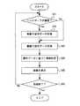
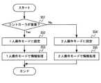
情報処理システムは、第1操作装置が本体装置に装着されたことを検知する第1検知手段と、第2操作装置が本体装置に装着されたことを検知する第2検知手段とを備えてもよい。本体装置は、第1検知手段および第2検知手段による検知結果に基づいて、第1操作装置と第2操作装置との組を設定してもよい。 The information processing system may include a first detecting means for detecting that the first operating device is attached to the main body device and a second detecting means for detecting that the second operating device is attached to the main body device. good. The main body device may set a pair of the first operating device and the second operating device based on the detection results by the first detecting means and the second detecting means.
本体装置は、第1操作装置および第2操作装置の両方が装着された場合、装着中の第1操作装置および第2操作装置を同じ組として設定してもよい。 When both the first operating device and the second operating device are mounted on the main body device, the mounted first operating device and the second operating device may be set as the same set.
第1操作装置および第2操作装置が本体装置から外されている状態において、同じ組に設定されている第1操作装置および第2操作装置からそれぞれ操作データを受信した場合、本体装置は、受信した2つの操作データを1組として所定の情報処理を実行してもよい。 When the first operation device and the second operation device are removed from the main body device and the operation data is received from the first operation device and the second operation device set in the same set, the main body device receives the operation data. Predetermined information processing may be executed by using the two operation data as a set.
本体装置は、第1操作装置が装着されるときに当該第1操作装置のハウジングと係合する第1係合部と、第2操作装置が装着されるときに当該第2操作装置のハウジングと係合する第2係合部とが形成されたハウジングを備えてもよい。 The main body device includes a first engaging portion that engages with the housing of the first operating device when the first operating device is mounted, and a housing of the second operating device when the second operating device is mounted. A housing may be provided in which a second engaging portion to be engaged is formed.
第1操作装置は、本体装置の第1係合部と係合する第3係合部が形成されたハウジングを備えてもよい。第2操作装置は、本体装置の第2係合部と係合する第4係合部が形成されたハウジングを備えてもよい。 The first operating device may include a housing in which a third engaging portion that engages with the first engaging portion of the main body device is formed. The second operating device may include a housing in which a fourth engaging portion that engages with the second engaging portion of the main body device is formed.
本体装置は、情報処理の実行結果を、表示手段と、本体装置とは別体の表示装置とのいずれかに選択的に出力してもよい。 The main unit may selectively output the execution result of information processing to either the display means or the display device separate from the main unit.
また、本発明の他の一例は、第1着脱機構、第2着脱機構、および、表示手段を備える情報処理装置であってもよい。第1着脱機構は、第1操作装置と着脱可能である。第2着脱機構は、第2操作装置と着脱可能である。情報処理装置は、第1操作装置および第2操作装置が情報処理装置に装着されているか否かにかかわらず当該第1操作装置および当該第2操作装置から送信される操作データに基づく所定の情報処理の結果を表示手段に表示する。 Further, another example of the present invention may be an information processing device including a first attachment / detachment mechanism, a second attachment / detachment mechanism, and a display means. The first attachment / detachment mechanism is detachable from the first operation device. The second attachment / detachment mechanism is detachable from the second operation device. The information processing device has predetermined information based on the operation data transmitted from the first operation device and the second operation device regardless of whether the first operation device and the second operation device are attached to the information processing device. The processing result is displayed on the display means.
本発明の他の一例は、本体装置と、第1操作装置とを含む情報処理システムである。
本体装置は、表示手段と、第1操作装置のハウジングと係合する本体側係合部が形成されたハウジングとを備える。第1操作装置は、本体側係合部によって本体装置に対して着脱可能に係合される。Another example of the present invention is an information processing system including a main body device and a first operating device.
The main body device includes a display means and a housing in which a main body side engaging portion that engages with the housing of the first operating device is formed. The first operating device is detachably engaged with the main body device by the main body side engaging portion.
第1操作装置は、本体側係合部と係合する操作装置側係合部が形成されたハウジングを備えてもよい。 The first operating device may include a housing in which an operating device-side engaging portion that engages with the main body-side engaging portion is formed.
本体側係合部は、本体装置のハウジングの面に沿って設けられる第1スライド部材であってもよい。第1操作装置は、第1スライド部材に対してスライド可能かつ着脱可能に係合する第2スライド部材を備えてもよい。第1スライド部材と第2スライド部材とによってスライド機構が形成されてもよい。 The main body side engaging portion may be a first slide member provided along the surface of the housing of the main body device. The first operating device may include a second slide member that is slidably and detachably engaged with the first slide member. A slide mechanism may be formed by the first slide member and the second slide member.
第1スライド部材は、所定方向にスライド可能に第2スライド部材を係合し、当該所定方向の一端から第2スライド部材を挿入および離脱することが可能に形成されてもよい。 The first slide member may be formed so that the second slide member can be slidably engaged in a predetermined direction and the second slide member can be inserted and detached from one end in the predetermined direction.
第1スライド部材は、本体装置の上下方向に沿って設けられ、その上端から第2スライド部材を挿入および離脱することが可能に形成されてもよい。 The first slide member may be provided along the vertical direction of the main body device and may be formed so that the second slide member can be inserted and removed from the upper end thereof.
第1スライド部材は、本体装置のハウジングの面の所定方向において略全体にわたって設けられてもよい。 The first slide member may be provided substantially entirely in a predetermined direction on the surface of the housing of the main body device.
第1スライド部材は、凹型の断面形状を有してもよい。第2スライド部材は、凸型の断面形状を有してもよい。 The first slide member may have a concave cross-sectional shape. The second slide member may have a convex cross-sectional shape.
第1操作装置は、本体装置と通信を行うための端子を備えてもよい。本体装置は、ハウジングにおいて、第1操作装置が装着された場合に第1操作装置の端子と接続可能な位置に端子を備えてもよい。 The first operating device may include a terminal for communicating with the main body device. The main body device may be provided with terminals at positions in the housing that can be connected to the terminals of the first operating device when the first operating device is mounted.
第1操作装置は、所定面に設けられる入力部を備えてもよい。 The first operating device may include an input unit provided on a predetermined surface.
本発明の他の一例は、本体装置と、当該本体装置に着脱可能な操作装置とを含む情報処理システムである。本体装置は、表示手段を備える。操作装置が本体装置に装着されている場合に当該本体装置と当該操作装置との間で行われる通信は、第1の通信方式による通信である。操作装置が本体装置から外されている場合に当該本体装置と当該操作装置との間で行われる通信は、第1の通信方式とは異なる第2の通信方式による通信である。 Another example of the present invention is an information processing system including a main body device and an operation device that can be attached to and detached from the main body device. The main body device includes display means. When the operating device is attached to the main body device, the communication performed between the main body device and the operating device is communication by the first communication method. The communication performed between the main body device and the operation device when the operation device is removed from the main body device is a communication by a second communication method different from the first communication method.
本体装置および操作装置は、第1通信方式として有線通信を行ってもよい。 The main body device and the operation device may perform wired communication as the first communication method.
操作装置が本体装置に装着されている場合、本体装置の第1端子と操作装置の第2端子とが、互いに当接することによって電気的に接続されてもよい。 When the operating device is attached to the main body device, the first terminal of the main body device and the second terminal of the operating device may be electrically connected by being in contact with each other.
本体装置および操作装置は、第2通信方式として無線通信を行ってもよい。 The main body device and the operating device may perform wireless communication as the second communication method.
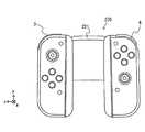
本発明の他の一例は、本体装置と、第1操作装置と、第2操作装置と、付属機器とを含む情報処理システムである。第1操作装置は、本体装置に着脱可能であり、かつ、付属機器に着脱可能である。第2操作装置は、本体装置に着脱可能であり、かつ、付属機器に着脱可能である。本体装置は、表示手段を備え、第1操作装置および第2操作装置に対する操作に基づく所定の情報処理の実行結果を表示手段に表示する。付属機器は、第1操作装置および第2操作装置を同時に装着可能である。 Another example of the present invention is an information processing system including a main body device, a first operating device, a second operating device, and an accessory device. The first operating device can be attached to and detached from the main body device and can be attached to and detached from the accessory device. The second operating device can be attached to and detached from the main body device and can be attached to and detached from the accessory device. The main body device includes display means, and displays the execution result of predetermined information processing based on the operation on the first operation device and the second operation device on the display means. The accessory device can be equipped with the first operating device and the second operating device at the same time.
付属機器は、当該付属機器に給電された電力を用いて、当該付属機器に装着された第1操作装置および/または第2操作装置に対する充電を行う充電手段を備えてもよい。 The accessory device may include a charging means for charging the first operating device and / or the second operating device mounted on the accessory device by using the electric power supplied to the accessory device.
第1操作装置は、付属機器の中央よりも左側に装着されてもよい。第2操作装置は、付属機器の中央よりも右側に装着されてもよい。 The first operating device may be mounted on the left side of the center of the accessory device. The second operating device may be mounted on the right side of the center of the accessory device.
付属機器は、左側に設けられる第1グリップ部と、右側に設けられる第2グリップ部とを備えてもよい。 The accessory device may include a first grip portion provided on the left side and a second grip portion provided on the right side.
第1グリップ部は、第1操作装置が装着される部分よりも左側に設けられてもよい。第2グリップ部は、第2操作装置が装着される部分よりも右側に設けられてもよい。 The first grip portion may be provided on the left side of the portion where the first operating device is mounted. The second grip portion may be provided on the right side of the portion where the second operating device is mounted.
第1操作装置が付属機器に装着されている場合、本体装置と当該第1操作装置との間で行われる通信は無線通信であってもよい。第2操作装置が付属機器に装着されている場合、本体装置と当該第2操作装置との間で行われる通信は無線通信であってもよい。 When the first operating device is attached to the accessory device, the communication performed between the main body device and the first operating device may be wireless communication. When the second operating device is attached to the accessory device, the communication performed between the main body device and the second operating device may be wireless communication.
第1操作装置は、所定の基準姿勢から第1の方向に傾いた状態で付属機器に装着されてもよい。第2操作装置は、所定の基準姿勢から第1の方向とは反対の方向に傾いた状態で付属機器に装着されてもよい。 The first operating device may be attached to the accessory device in a state of being tilted in the first direction from a predetermined reference posture. The second operating device may be attached to the accessory device in a state of being tilted in a direction opposite to the first direction from a predetermined reference posture.
本体装置は、第1操作装置と第2操作装置との少なくともいずれかが付属機器に装着されている場合に、装着されている操作装置からの操作データ、および/または、操作データから得られる情報を補正して所定の情報処理を実行してもよい。 When at least one of the first operating device and the second operating device is attached to the accessory device, the main unit has operation data from the attached operating device and / or information obtained from the operating data. May be corrected to execute predetermined information processing.
本体装置は、操作データのうち方向入力部のデータを補正してもよい。 The main unit may correct the data of the direction input unit among the operation data.
本発明の他の一例は、第1操作装置および第2操作装置と着脱可能な付属機器である。
第1操作装置は、付属機器とは別体の本体装置に着脱可能である。第2操作装置は、本体装置に着脱可能である。本体装置は、表示手段を備え、第1操作装置および第2操作装置に対する操作に基づく所定の情報処理の実行結果を表示手段に表示する。付属機器は、第1操作装置を着脱可能に係合する第1係合部と、第2操作装置を着脱可能に係合する第2係合部とを備える。Another example of the present invention is an accessory device that can be attached to and detached from the first operating device and the second operating device.
The first operating device can be attached to and detached from the main body device separate from the accessory device. The second operating device is removable from the main body device. The main body device includes display means, and displays the execution result of predetermined information processing based on the operation on the first operation device and the second operation device on the display means. The accessory device includes a first engaging portion that detachably engages the first operating device and a second engaging portion that detachably engages the second operating device.
本発明の他の一例は、本体装置と、第1操作装置と、第2操作装置とを含むゲームシステムである。本体装置は、表示手段を備える。第1操作装置は、本体装置に着脱可能である。第2操作装置は、本体装置に着脱可能である。少なくとも第1操作装置および第2操作装置が本体装置から外されている場合に 、当該第1操作装置および当該第2操作装置はそれぞれ、当該第1操作装置および当該第2操作装置に対する操作を示す操作データを、無線通信により、本体装置に送信する。 Another example of the present invention is a game system including a main body device, a first operating device, and a second operating device. The main body device includes display means. The first operating device is removable from the main body device. The second operating device is removable from the main body device. When at least the first operating device and the second operating device are removed from the main body device, the first operating device and the second operating device indicate operations on the first operating device and the second operating device, respectively. The operation data is transmitted to the main unit by wireless communication.
本発明の他の一例は、手持ち型の情報処理装置である。情報処理装置は、表示手段を有する本体部と、第1操作部と、第2操作部とを含み、当該第1操作部と当該第2操作部のいずれかに対する操作に応じて所定の情報処理を行う。第1操作部は、本体部に着脱可能である。第2操作部は、本体部に着脱可能である。本体装置は、第1操作部と第2操作部が本体部から外されている場合に、少なくとも第1操作部と第2操作部のいずれかに対する操作を示す操作データに基づいて所定の情報処理を行い、当該情報処理の結果を表示手段に表示させる。 Another example of the present invention is a handheld information processing device. The information processing device includes a main body unit having a display means, a first operation unit, and a second operation unit, and predetermined information processing is performed according to an operation on either the first operation unit or the second operation unit. I do. The first operation unit is removable from the main body. The second operation unit is removable from the main body. When the first operation unit and the second operation unit are removed from the main body unit, the main unit device performs predetermined information processing based on operation data indicating an operation for at least one of the first operation unit and the second operation unit. Is performed, and the result of the information processing is displayed on the display means.
第1操作部と第2操作部が本体部に装着されている場合、ユーザの一方の手で当該第1操作部を操作し、他方の手で当該第2操作部を操作することが可能なように、当該第1操作部と当該第2操作部とが配置されていてもよい。 When the first operation unit and the second operation unit are attached to the main body unit, it is possible to operate the first operation unit with one hand of the user and operate the second operation unit with the other hand. As described above, the first operation unit and the second operation unit may be arranged.
また、本発明の別の一例は、上記情報処理システムにおける情報処理装置、操作装置、または、付属機器であってもよい。また、本発明の別の一例は、上記情報処理システムにおいて実行される方法であってもよい。また、本発明の別の一例は、上記情報処理システムまたは情報処理装置において実行される処理のいくつかをコンピュータに実行させる(換言すれば、情報処理システムまたは情報処理装置における各手段のいくつかとしてコンピュータを機能させる)情報処理プログラムであってもよい。 Further, another example of the present invention may be an information processing device, an operating device, or an accessory device in the information processing system. Further, another example of the present invention may be a method executed in the above information processing system. Further, another example of the present invention causes a computer to execute some of the processes executed in the information processing system or the information processing apparatus (in other words, as some of the means in the information processing system or the information processing apparatus). It may be an information processing program (which makes a computer function).
本発明によれば、情報処理装置および/または情報処理システムを複数の態様で利用することが可能となる。 According to the present invention, the information processing apparatus and / or the information processing system can be used in a plurality of aspects.
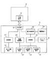
以下、本実施形態の一例に係る情報処理システム、情報処理装置、操作装置、および、付属機器について説明する。本実施形態においては、情報処理システムは、情報処理装置1と、クレードル5とを含む(図9参照)。本実施形態における情報処理装置1は、本体装置2とコントローラ3および4とが着脱可能であり、コントローラ3および4を本体装置2と別体として利用することができる(図2参照)。また、情報処理装置1は、本体装置2に画像を表示する態様と、テレビ等の他の表示装置に画像を表示させる態様との両方の利用態様が可能である。前者の態様において、情報処理装置1は、携帯型装置(例えば、携帯ゲーム機)として利用され、後者の態様において、情報処理装置1は、据置型装置(例えば、据置型ゲーム機)として利用される。 Hereinafter, the information processing system, the information processing device, the operating device, and the accessory devices according to an example of the present embodiment will be described. In this embodiment, the information processing system includes an
[1.システムの外観構成]
[1−1.情報処理装置の構成]
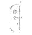
図1は、本実施形態における情報処理装置1の一例を示す図である。図1に示すように、情報処理装置1は、本体装置2と、左コントローラ3と、右コントローラ4とを含む。本体装置2は、ディスプレイ12を備え、情報処理装置1における各種の処理を実行する装置である。また、コントローラ3および4は、ユーザが入力を行うための操作部を備える装置である。[1. System appearance configuration]
[1-1. Information processing device configuration]
FIG. 1 is a diagram showing an example of the
図2は、本体装置2から各コントローラ3および4を外した状態の一例を示す図である。図1および図2に示すように、各コントローラ3および4は、本体装置2に着脱可能である。左コントローラ3は、本体装置2の左側(図1に示すx軸正方向側)に装着することができる。右コントローラ4は、本体装置2の右側(図1に示すx軸負方向側)に装着することができる。なお、以下において、左コントローラおよび右コントローラの総称として「コントローラ」と記載することがある。以下、本体装置2および各コントローラ3および4の具体的な構成の一例について説明する。 FIG. 2 is a diagram showing an example of a state in which the
[1−1−1.本体装置の構成]
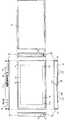
図3は、本体装置の一例を示す六面図である。図3に示すように、本体装置2は、略板状のハウジング11を備える。本実施形態において、ハウジング11の主面(換言すれば、表側の面、すなわち、ディスプレイ12が設けられる面)は、大略的には矩形形状である。本実施形態においては、ハウジング11は、横長の形状である。つまり、本実施形態においては、ハウジング11の主面の長手方向(すなわち、図1に示すx軸方向)を横方向(左右方向とも言う)とし、当該主面の短手方向(すなわち、図1に示すy軸方向)を縦方向(上下方向とも言う)とし、主面に垂直な方向(すなわち、図1に示すz軸方向)を奥行き方向(前後方向とも言う)とする。なお、本体装置2は、本体装置2が横長となる向きで利用されることも可能であるし、本体装置2が縦長となる向きで利用されることも可能である。[1-1-1. Main unit configuration]
FIG. 3 is a six-view view showing an example of the main body device. As shown in FIG. 3, the
なお、ハウジング11の形状および大きさは任意である。例えば、他の実施形態においては、ハウジング11は、ユーザが把持しやすくするための突起部やグリップ部を有していてもよい。 The shape and size of the
(ハウジング11の主面に設けられる構成)
図3に示すように、本体装置2は、ハウジング11の主面に設けられるディスプレイ12を備える。ディスプレイ12は、本体装置2が取得または生成した画像(静止画であってもよいし、動画であってもよい)を表示する。本実施形態においては、ディスプレイ12は液晶表示装置(LCD)であるとするが、任意の種類の表示装置であってよい。(Structure provided on the main surface of the housing 11)
As shown in FIG. 3, the
また、本体装置2は、ディスプレイ12の画面上にタッチパネル13を備える。本実施形態においては、タッチパネル13は、マルチタッチ入力が可能な方式(例えば、静電容量方式)のものである。ただし、タッチパネル13は、任意の種類のものであってよく、例えば、シングルタッチ入力が可能な方式(例えば、抵抗膜方式)のものであってもよい。 Further, the
本体装置2は、ハウジング11の内部においてスピーカ(すなわち、図11に示すスピーカ88)を備えている。図3に示すように、ハウジング11の主面にはスピーカ孔11aおよび11bが形成される。スピーカ88の出力音はこれらのスピーカ孔11aおよび11bから出力される。本実施形態では、本体装置2は2つのスピーカを備えており、左スピーカおよび右スピーカのそれぞれの位置に各スピーカ孔が設けられる。左スピーカ用のスピーカ孔11aは、ディスプレイ12の左側に形成される。右スピーカ用のスピーカ孔11bは、ディスプレイ12の右側に形成される。 The
また、本体装置2は、ハウジング11の内部において環境光センサ(すなわち、図11に示す環境光センサ94)を備えている。図3に示すように、ハウジング11の主面には、ハウジング11の外部の光を環境光センサ94に入力するための窓部14が設けられる。窓部14は、例えば、光を透過する透明な部材、あるいは、環境光センサ94が検知可能な所定波長の光を透過するフィルタ部材によって形成される。 Further, the
なお、スピーカ孔11aおよび11b、ならびに、窓部14の位置、形状、および数は任意である。例えば、他の実施形態においては、各スピーカ孔11aおよび11bはハウジング11の側面あるいは背面に形成されてもよい。また、窓部14は、本実施形態においてはディスプレイ12よりも左下の位置に設けられるが、ハウジング11の主面における他の位置に設けられてもよいし、ハウジング11の側面に設けられてもよい。 The positions, shapes, and numbers of the speaker holes 11a and 11b and the
(ハウジング11の左側面に設けられる構成)
図3に示すように、本体装置2は、ハウジング11の左側面において左レール部材15を備える。左レール部材15は、左コントローラ3を本体装置2に着脱可能に装着するための部材である。左レール部材15は、ハウジング11の左側面において、上下方向に沿って延びるように設けられる。左レール部材15は、左コントローラ3のスライダ(すなわち、図5に示すスライダ40)と係合可能な形状を有している。詳細は後述するが、左レール部材15とスライダ40とによってスライド機構が形成される。このスライド機構によって、左コントローラ3を本体装置2に対してスライド可能かつ着脱可能に装着することができる。(Structure provided on the left side surface of the housing 11)
As shown in FIG. 3, the
本実施形態においては、左レール部材15は、溝を有する形状である。換言すれば、左レール部材15の断面(具体的には、上下方向に垂直な断面)は、凹型の形状を有する。より具体的には、左レール部材15の断面は、断面の端部が外側から中央への方向を向く形状である。したがって、左レール部材15に係合したスライダ40は、スライド方向(換言すれば、左レール部材15が延びる方向)に垂直な向きに関しては固定されて外れないようになっている(後述する図7参照)。 In the present embodiment, the
図3に示すように、左レール部材15には、係合穴16が形成される。係合穴16は、左コントローラ3が本体装置2に装着された場合に、スライダ40に設けられる突起部41と対向する位置に設けられる。係合穴16の具体的な位置は任意である。本実施形態においては、係合穴16は、左レール部材15の底面(換言すれば、左レール部材15が有する溝の底面)に設けられる。また、係合穴16は、上記突起部(すなわち、図5に示す突起部41)が係合可能な形状に形成される。詳細は後述するが、左コントローラ3が本体装置2に装着された場合には、突起部41が係合穴16に挿入されて係合することによって、左コントローラ3が本体装置2に固定される。なお、他の実施形態においては、左レール部材15に突起部が設けられ、スライダ40に係合穴が設けられてもよい。 As shown in FIG. 3, the
また、本体装置2は左側端子17を備える。左側端子17は、本体装置2が左コントローラ3と有線通信を行うための端子である。左側端子17は、左コントローラ3が本体装置2に装着された場合に、左コントローラ3の端子(図5に示す端子42)と接触する位置に設けられる。左側端子17の具体的な位置は任意である。本実施形態においては、図3に示すように、左側端子17は、左レール部材15の底面に設けられる。また、本実施形態においては、左側端子17は、左レール部材15の底面における下側の端部付近に設けられる。左側端子17は、上記係合穴16よりも下側(換言すれば、左レール部材15にスライダ40を挿入する方向を基準としたときの奥側)に設けられる。 Further, the
ハウジング11の左側面には、ストッパー18が設けられる。図3に示すように、ストッパー18は、左レール部材15の端部付近(本実施形態においては、下端付近)に設けられる。ストッパー18は、左レール部材15が有する溝の内部に設けられる。詳細は後述するが、ストッパー18は、左レール部材15に係合されたスライダ40のスライド移動を停止するために設けられる。 A
(ハウジング11の右側面に設けられる構成)
図3に示すように、ハウジング11の右側面には、左側面に設けられる構成と同様の構成が設けられる。すなわち、本体装置2は、ハウジング11の右側面において右レール部材19を備える。右レール部材19は、ハウジング11の右側面において、上下方向に沿って延びるように設けられる。右レール部材19は、右コントローラ4のスライダ(すなわち、図6に示すスライダ62)と係合可能な形状を有している。詳細は後述するが、右レール部材19とスライダ62とによってスライド機構が形成される。このスライド機構によって、右コントローラ4を本体装置2に対してスライド可能かつ着脱可能に装着することができる。(Structure provided on the right side of the housing 11)
As shown in FIG. 3, the right side surface of the
本実施形態においては、右レール部材19は、左レール部材15と同様の形状を有する。すなわち、右レール部材19は、左レール部材15と同様の断面形状となる溝を有する形状である。ただし、右レール部材19は、左レール部材15と全く同じ形状である必要はない。例えば、他の実施形態においては、右コントローラ4のスライダ62が左レール部材15に係合できないように(および/または、左コントローラ3のスライダ40が右レール部材19に係合できないように)、左レール部材15の溝と右レール部材19の溝とで大きさおよび/または形状が異なっていてもよい。 In the present embodiment, the
図3に示すように、右レール部材19には、係合穴20が形成される。係合穴20は、右コントローラ4が本体装置2に装着された場合に、スライダ62に設けられる突起部63と対向する位置に設けられる。係合穴20の具体的な位置は任意である。本実施形態においては、係合穴20は、右レール部材19の底面(換言すれば、右レール部材19が有する溝の底面)に設けられる。係合穴20は、上記突起部(すなわち、図6に示す突起部63)が係合可能な形状に形成される。詳細は後述するが、右コントローラ4が本体装置2に装着された場合には、突起部63が係合穴20に挿入されて係合することによって、右コントローラ4が本体装置2に固定される。なお、他の実施形態においては、右レール部材19に突起部が設けられ、スライダ62に係合穴が設けられてもよい。 As shown in FIG. 3, an engaging
また、本体装置2は右側端子21を備える。右側端子21は、本体装置2が右コントローラ4と有線通信を行うための端子である。右側端子21は、右コントローラ4が本体装置2に装着された場合に、右コントローラ4の端子(図6に示す端子64)と接触する位置に設けられる。右側端子21の具体的な位置は任意である。本実施形態においては、図3に示すように、右側端子21は、右レール部材19の底面に設けられる。また、本実施形態においては、右側端子21は、右レール部材19の底面における下側の端部付近に設けられる。右側端子21は、上記係合穴20よりも下側(換言すれば、右レール部材19にスライダ62を挿入する方向を基準としたときの奥側)に設けられる。 Further, the
ハウジング11の右側面には、ストッパー22が設けられる。図3に示すように、ストッパー22は、右レール部材19の端部付近(本実施形態においては、下端付近)に設けられる。ストッパー22は、右レール部材19が有する溝の内部に設けられる。詳細は後述するが、ストッパー22は、右レール部材19に係合されたスライダ62のスライド移動を停止するために設けられる。 A
上記のように、本実施形態においては、本体装置2のハウジング11には、左レール部材15および右レール部材19が設けられている。このように、ハウジング11は、コントローラを装着することを前提とした構成となっている。なお、上記各レール部材15および19の位置、形状、および大きさは任意である。例えば、他の実施形態においては、各レール部材15および19は、ハウジング11の主面および/または裏面における左右の端部にそれぞれ設けられてもよい。また、本体装置2と各コントローラ3および4を着脱可能に装着するための機構は任意であり、本実施形態におけるスライダ機構とは異なるスライダ機構が用いられてもよいし、スライダ機構とは異なる機構が用いられてもよい。 As described above, in the present embodiment, the
(ハウジング11の上側面に設けられる構成)
図3に示すように、本体装置2は第1スロット23を備える。第1スロット23は、ハウジング11の上側面に設けられる。第1スロット23は、第1の種類の記憶媒体を装着可能な形状を有する。なお、本実施形態においては、第1スロット23の開口部には開閉可能な蓋部が設けられており、蓋部を開けた状態において、第1スロット23に第1の種類の記憶媒体を挿入することができる。第1の種類の記憶媒体は、例えば、情報処理装置1およびそれと同種の情報処理装置に専用の記憶媒体(例えば、専用メモリカード)である。第1の種類の記憶媒体は、例えば、本体装置2で利用されるデータ(例えば、アプリケーションのセーブデータ等)、および/または、本体装置2で実行されるプログラム(例えば、アプリケーションのプログラム等)を記憶するために用いられる。(Structure provided on the upper side surface of the housing 11)
As shown in FIG. 3, the
また、本体装置2は、電源ボタン28を備える。図3に示すように、電源ボタン28は、ハウジング11の上側面に設けられる。電源ボタン28は、本体装置2の電源のオン/オフを切り替えるためのボタンである。なお、本実施形態においては、電源ボタン28によって、オンモードとスリープモードとを切り替えることができるものとする。ここで、オンモードは、例えば、ディスプレイ12の画面表示が行われるモードであり、スリープモードは、例えば、ディスプレイ12の画面表示が休止されるモードである。また、スリープモードにおいては、ディスプレイ12の画面表示が休止されることとともに(または代えて)、実行中のアプリケーションにおける所定の処理(例えば、ゲームアプリケーションにおけるゲーム処理)が休止されてもよい。本体装置2は、電源ボタン24に対して長押し操作が行われた場合(具体的には、電源ボタン24が所定時間以上押下し続けられた場合)、本体装置2の電源のオン/オフを切り替える処理を実行する。一方、電源ボタン24に対して短押し操作が行われた場合(具体的には、電源ボタン24が上記所定時間よりも短い時間だけ押下された場合)、本体装置2は、オンモードとスリープモードとを切り替える処理を実行する。 Further, the
上記のように、本実施形態においては、電源ボタン28は、電源のオン/オフの切り替えと、オンモードとスリープモードの切り替えとを行うことができる。なお、他の実施形態においては、電源のオン/オフの切り替えの切り替え機能のみ、あるいは、オンモードとスリープモードの切り替え機能のみを有するボタンが本体装置2に設けられてもよい。 As described above, in the present embodiment, the
本体装置2は、音声入出力端子(具体的には、イヤホンジャック)25を備える。すなわち、本体装置2は、音声入出力端子25にマイクやイヤホンを装着することができる。図3に示すように、音声入出力端子25は、ハウジング11の上側面に設けられる。 The
本体装置2は、音量ボタン26aおよび26bを備える。図3に示すように、音量ボタン26aおよび26bは、ハウジング11の上側面に設けられる。音量ボタン26aおよび26bは、本体装置2によって出力される音量を調整する指示を行うためのボタンである。すなわち、音量ボタン26aは、音量を下げる指示を行うためのボタンであり、音量ボタン26bは、音量を上げる指示を行うためのボタンである。 The
また、ハウジング11には、排気孔11cが形成される。図3に示すように、排気孔11cは、ハウジング11の上側面に形成される。排気孔11cは、ハウジング11の内部で発生した熱をハウジング11の外部へ排気する(換言すれば、放出する)ために形成される。 Further, an
(ハウジング11の下側面に設けられる構成)
本体装置2は下側端子27を備える。下側端子27は、本体装置2が、後述するクレードル5と通信を行うための端子である。図3に示すように、下側端子27は、ハウジング11の下側面に設けられる。詳細は後述するが、本体装置2がクレードル5に装着された場合に、下側端子27は、クレードル5の端子(図10に示す本体端子73)に接続される。本実施形態において、下側端子27は、USBコネクタ(より具体的には、メス側コネクタ)である。(Structure provided on the lower side surface of the housing 11)
The
また、本体装置2は第2スロット24を備える。本実施形態においては、第2スロット24は、ハウジング11の下側面に設けられる。ただし、他の実施形態においては、第2スロット24は第1スロット23とは同じ面に設けられてもよい。第2スロット24は、第1の種類とは異なる第2の種類の記憶媒体を装着可能な形状を有する。なお、本実施形態においては、第2スロット24の開口部には開閉可能な蓋部が設けられており、蓋部を開けた状態において、第2スロット24に第2の種類の記憶媒体を挿入することができる。第2の種類の記憶媒体は、例えば、汎用の記憶媒体であってもよく、例えば、SDカードであってもよい。第2の種類の記憶媒体は、例えば、第1の種類の記憶媒体と同様、本体装置2で利用されるデータ(例えば、アプリケーションのセーブデータ等)、および/または、本体装置2で実行されるプログラム(例えば、アプリケーションのプログラム等)を記憶するために用いられる。 Further, the
また、ハウジング11には、吸気孔11dが形成される。図3に示すように、吸気孔11dは、ハウジング11の下側面に形成される。吸気孔11dは、ハウジング11の外部の空気をハウジング11の内部へ吸気する(換言すれば、導入する)ために形成される。本実施形態においては、排気孔11cが形成される面の反対側の面に吸気孔11dが形成されるので、ハウジング11内部の放熱を効率良く行うことができる。 Further, an
また、本体装置2は、ハウジングを立てて載置するためのスタンド部材29を備える。図3に示すように、スタンド部材29は、ハウジング11の下側面に設けられる。スタンド部材29は、軸部29aでハウジング11に対して回転可能に接続されている。図3においては、スタンド部材29はハウジング11に収納された状態である。 Further, the
図4は、本体装置2を立てて載置した様子の一例を示す図である。なお、図4においては、本図を用いて説明するポイント部分の構成を見やすくする目的で、本体装置2における当該構成以外の他のいくつかの構成については省略して表している。ここで、上記スタンド部材29の棒状の部分は、軸部29aを軸として回転することによって、ハウジング11から突出した状態となる。したがって、スタンド部材29をハウジング11から突出した状態とすることによって、図4に示すように、本体装置2を立てて載置することができる。なお、本体装置2を立てて載置するための機構は、図3に示すスタンド部材29に限らず、任意である。 FIG. 4 is a diagram showing an example of a state in which the
以上に説明した、ハウジング11に設けられる各構成要素(具体的には、ボタン、スロット、端子等)の形状、数、および、設置位置は任意である。例えば、他の実施形態においては、電源ボタン28および各スロット23および24のうちのいくつかは、ハウジング11の他の側面あるいは背面に設けられてもよい。また、他の実施形態においては、本体装置2は、上記各構成要素のうちいくつかを備えていない構成であってもよい。 The shape, number, and installation position of each component (specifically, buttons, slots, terminals, etc.) provided in the
[1−1−2.左コントローラの構成]
図5は、左コントローラ3の一例を示す六面図である。図5に示すように、左コントローラ3は、略板状のハウジング31を備える。本実施形態において、ハウジング31の主面(換言すれば、表側の面、すなわち、図1に示すz軸負方向側の面)は、大略的には矩形形状である。また、本実施形態においては、ハウジング31は、縦長の形状、すなわち、上下方向(すなわち、図1に示すy軸方向)に長い形状である。なお、左コントローラ3は、本体装置2から外された状態において、縦長となる向きで把持されることも可能であるし(図18参照)、横長となる向きで把持されることも可能である(図16参照)。なお、ハウジング31の形状は任意であり、他の実施形態においては、ハウジング31は略板状でなくてもよい。また、ハウジング31は、矩形形状でなくてもよく、例えば半円状の形状等であってもよい。また、ハウジング31は、縦長の形状でなくてもよい。[1-1-2. Left controller configuration]
FIG. 5 is a six-view view showing an example of the
ハウジング31の上下方向の長さは、本体装置2のハウジング11の上下方向の長さとほぼ同じである。また、ハウジング31の厚さ(すなわち、前後方向の長さ、換言すれば、図1に示すz軸方向の長さ)は、本体装置2のハウジング11の厚さとほぼ同じである。したがって、左コントローラ3が本体装置2に装着された場合(図1参照)には、ユーザは、本体装置2と左コントローラ3とを一体の装置のような感覚で把持することができる。 The vertical length of the
また、図5に示すように、ハウジング31の主面は、左側の角部分が、右側の角部分よりも丸みを帯びた形状になっている。すなわち、ハウジング31の上側面と左側面との接続部分、および、ハウジング31の下側面と左側面との接続部分は、その上側面と右側面との接続部分、および、その下側面と右側面との接続部分に比べて、丸くなっている(換言すれば、面取りにおけるRが大きい)。したがって、左コントローラ3が本体装置2に装着された場合(図1参照)には、情報処理装置1の左側が丸みを帯びた形状となるので、ユーザにとって持ちやすい形状となる。 Further, as shown in FIG. 5, the main surface of the
左コントローラ3は、アナログスティック32を備える。図5に示すように、アナログスティック32は、ハウジング31の主面に設けられる。アナログスティック32は、方向を入力することが可能な方向入力部の一例である。アナログスティック32は、ハウジング31の主面に平行な全方向(すなわち、上下左右および斜め方向を含む、360°の方向)に傾倒可能なスティック部材を有する。ユーザは、スティック部材を傾倒することによって傾倒方向に応じた方向の入力(および、傾倒した角度に応じた大きさの入力)が可能である。なお、方向入力部は、十字キーまたはスライドスティック等であってもよい。スライドスティックは、ハウジング31の主面に平行な全方向にスライド可能なスティック部材を有する入力部であり、ユーザは、スティック部材をスライドすることによってスライド方向に応じた入力(および、スライド量に応じた大きさの入力)が可能である。また、本実施形態においては、スティック部材を(ハウジング31に垂直な方向に)押下する入力が可能である。すなわち、アナログスティック32は、スティック部材の傾倒方向および傾倒量に応じた方向および大きさの入力と、スティック部材に対する押下入力とを行うことが可能な入力部である。 The
左コントローラ3は、4つの操作ボタン33〜36(具体的には、右方向ボタン33、下方向ボタン34、上方向ボタン35、および、左方向ボタン36)を備える。図5に示すように、これら4つの操作ボタン33〜36は、ハウジング31の主面においてアナログスティック32の下側に設けられる。なお、本実施形態においては、左コントローラ3の主面に設けられる操作ボタンを4つとするが、操作ボタンの数は任意である。これらの操作ボタン33〜36は、本体装置2で実行される各種プログラム(例えば、OSプログラムやアプリケーションプログラム)に応じた指示を行うために用いられる。なお、本実施形態においては、各操作ボタン33〜36は方向入力を行うために用いられてもよいことから、各操作ボタン33〜36を、右方向ボタン33、下方向ボタン34、上方向ボタン35、および、左方向ボタン36と呼んでいる。ただし、各操作ボタン33〜36は、方向入力以外の指示を行うために用いられてもよい。 The
また、左コントローラ3は録画ボタン37を備える。図5に示すように、録画ボタン37は、ハウジング31の主面に設けられ、より具体的には、主面における右下領域に設けられる。録画ボタン37は、本体装置2のディスプレイ12に表示される画像を保存する指示を行うためのボタンである。例えば、ディスプレイ12にゲーム画像が表示されている場合において、ユーザは、録画ボタン37を押下することによって、押下された時点で表示されているゲーム画像を、例えば本体装置2の記憶部に保存することができる。 Further, the
また、左コントローラ3は−(マイナス)ボタン47を備える。図5に示すように、−ボタン47は、ハウジング31の主面に設けられ、より具体的には、主面における右上領域に設けられる。−ボタン47は、本体装置2で実行される各種プログラム(例えば、OSプログラムやアプリケーションプログラム)に応じた指示を行うために用いられる。−ボタン47は、例えば、ゲームアプリケーションにおいてセレクトボタン(例えば、選択項目の切り替えに用いられるボタン)として用いられる。 Further, the
左コントローラ3の主面に設けられる各操作部(具体的には、アナログスティック32および上記各ボタン33〜37,47)は、左コントローラ3が本体装置2に装着される場合、情報処理装置1を把持するユーザの例えば左手の親指によって操作される(図14参照)。また、左コントローラ3が本体装置2から外された状態で使用される場合、上記各操作部は、左コントローラ3を把持するユーザの例えば左右の手の親指で操作される(図15参照)。具体的には、この場合、アナログスティック32はユーザの左手の親指で操作され、各操作ボタン33〜36はユーザの右手の親指で操作される。 Each operation unit (specifically, the
左コントローラ3は第1Lボタン38を備える。また、左コントローラ3はZLボタン39を備える。これらの操作ボタン38および39は、上記操作ボタン33〜36と同様、本体装置2で実行される各種プログラムに応じた指示を行うために用いられる。図5に示すように、第1Lボタン38は、ハウジング31の側面のうちの左上部分に設けられる。また、ZLボタン39は、ハウジング31の側面から裏面にかけての左上部分(厳密には、ハウジング31を表側から見たときの左上部分)に設けられる。つまり、ZLボタン39は、第1Lボタン38の後側(図1に示すz軸正方向側)に設けられる。本実施形態においては、ハウジング31の左上部分が丸みを帯びた形状であるので、第1Lボタン38およびZLボタン39は、ハウジング31の当該左上部分の丸みに応じた丸みを帯びた形状を有する。 The
左コントローラ3が本体装置2に装着される場合、第1Lボタン38およびZLボタン39は、情報処理装置1における左上部分に配置されることになる(図1参照)。したがって、情報処理装置1を把持するユーザは、左手の人差し指や中指で第1Lボタン38およびZLボタン39を操作することができる(図14参照)。 When the
図5に示すように、ハウジング31の裏面のうちでZLボタン39が設けられる部分(より具体的には、ZLボタン39の周囲の少なくとも一部)は、ハウジング31の他の部分に比べて突起している。また、ZLボタン39は、ハウジング31の裏面における当該他の部分に対して突起して設けられる。したがって、左コントローラ3が装着された本体装置2を、左コントローラ3の裏面が水平な載置面に対向する向きで載置面に載置した場合、ハウジング31の突起した部分が載置面に当接する。その結果、情報処理装置1は、本体装置2の上側が下側よりもやや高くなるように載置される。上記のように情報処理装置1が載置された場合、ユーザにとってはディスプレイ12が見やすくなる。 As shown in FIG. 5, the portion of the back surface of the
なお、他の実施形態においては、左コントローラ3が装着された本体装置2を、左コントローラ3の裏面が水平な載置面に対向する向きで載置面に載置した場合、ZLボタン39が載置面に当接してもよい。ここで、本実施形態においては、ZLボタン39は、主に上下方向(y軸方向)に押下可能である。つまり、ZLボタン39は、主に上下方向に移動するようにハウジング31に対して支持される。したがって、上記のようにZLボタン39が載置面に当接するように情報処理装置1が載置された場合であっても、ZLボタン39には主に前後方向(z軸方向)に力が加わるので、ZLボタン39は押下されにくい。つまり、情報処理装置1が上記のように載置された場合であっても、ZLボタン39が誤って押下される可能性が小さい。 In another embodiment, when the
また、他の実施形態においては、ZLボタン39は、ハウジング31の裏面から突起しないように形成されてもよい。例えば、ZLボタン39は、ハウジング31の側面に設けられてもよい。また例えば、ハウジング31の裏面のうちでZLボタン39が設けられる部分が他の部分に比べて凹んで形成される(すなわち、他の部分よりも薄く形成される)ことによって、ZLボタン39が当該他の部分よりも突起しないように形成されてもよい。 Further, in another embodiment, the
左コントローラ3は、上述のスライダ40を備えている。図5に示すように、スライダ40は、ハウジング31の右側面において、上下方向に延びるように設けられる。スライダ40は、本体装置2の左レール部材15(より具体的には、左レール部材15の溝)と係合可能な形状を有している。具体的には、スライダ40の断面(具体的には、上下方向に垂直な断面)は、凸型の形状を有する。より具体的には、スライダ40の断面は、左レール部材15の断面形状に応じたT字形状を有する(図7参照)。したがって、左レール部材15に係合したスライダ40は、スライド方向(換言すれば左レール部材15が延びる方向)に垂直な向きに関しては固定されて外れないようになっている(後述する図7参照)。 The
また、図5に示すように、スライダ40には、突起部41が設けられる。突起部41は、左コントローラ3が本体装置2に装着された場合に、上記係合穴16に挿入される位置に配置される。突起部41の具体的な位置は任意である。本実施形態においては、突起部41は、スライダ40の装着面に設けられる。なお、スライダ40の装着面とは、左コントローラ3が本体装置2に装着された場合に左レール部材15の底面に対向する面である。また、突起部41は、左レール部材15の係合穴16に係合可能な形状に形成される。 Further, as shown in FIG. 5, the
本実施形態においては、突起部41は、スライダ40の内部側から外部側に向けて付勢されている。したがって、突起部41に対してスライダ40の外部側から内部側への力を加えることで、突起部41はスライダ40の内部に向けて移動する(すなわち、スライダ40の内側へ引っ込む)。上記のように突起部41を付勢するための構成は任意である。例えば、本実施形態においては、突起部41は、スライダ40の内部において弾性体に接続されており、スライダ40に形成された孔から突起部41の一部がスライダ40の装着面に対して突出した状態で配置されている。なお、他の実施形態においては、突起部41はスライダ40に対して固定的に設けられてもよい。 In the present embodiment, the
また、左コントローラ3は、左コントローラ3が本体装置2と有線通信を行うための端子42を備える。端子42は、左コントローラ3が本体装置2に装着された場合に、本体装置2の左側端子17(図3)と接触する位置に設けられる。端子42の具体的な位置は任意である。本実施形態においては、図5に示すように、端子42は、スライダ40の装着面に設けられる。また、本実施形態においては、端子42は、スライダ40の装着面における下側の端部付近に設けられる。端子42は、上記突起部41よりも下側(換言すれば、スライダ40を左レール部材15に挿入する場合における先端側)に設けられる。 Further, the
また、左コントローラ3は、第2Lボタン43および第2Rボタン44を備える。これらのボタン43および44は、他の操作ボタン33〜36と同様、本体装置2で実行される各種プログラムに応じた指示を行うために用いられる。図5に示すように、第2Lボタン43および第2Rボタン44は、スライダ40の装着面に設けられる。第2Lボタン43は、スライダ40の装着面において、上下方向(図1に示すy軸方向)に関する中央よりも上側に設けられる。第2Rボタン44は、スライダ40の装着面において、上下方向に関する中央よりも下側に設けられる。第2Lボタン43および第2Rボタン44は、左コントローラ3が本体装置2に装着されている状態では押下することができない位置に配置されている。つまり、第2Lボタン43および第2Rボタン44は、左コントローラ3を本体装置2から外した場合において用いられるボタンである。第2Lボタン43および第2Rボタン44は、例えば、本体装置2から外された左コントローラ3を把持するユーザの左右の手の人差し指または中指で操作される(図16参照)。 Further, the
左コントローラ3は、通知用LED45を備える。通知用LED45は、ユーザに対して所定の情報を通知するための通知部である。通知用LED45によって通知される情報は任意である。本実施形態においては、通知用LED45は、本体装置2が複数のコントローラと通信を行う場合に、各コントローラを識別する情報をユーザに示す。具体的には、左コントローラ3は、通知用LED45として、本体装置2が同時に通信可能な左コントローラの数(ここでは、4つ)のLEDを備える。そして、4つのLEDのうち、そのコントローラに付された番号に応じたLEDが点灯する。これによれば、通知用LED45によって上記番号をユーザに通知することができる。 The
他の実施形態においては、通知用LED45は、左コントローラ3と本体装置2との通信に関する状態をユーザに通知してもよい。例えば、本体装置2との通信が確立している場合に通知用LED45が点灯してもよい。また、本実施形態においては、通知用LED45として機能するLED(換言すれば、発光部)の数を4つとするが、当該LEDの数は任意である。 In another embodiment, the
本実施形態においては、通知用LED45は、図5に示すように、スライダ40の装着面に設けられる。このように、通知用LED45は、左コントローラ3が本体装置2に装着されている状態では見えない位置に配置されている。つまり、通知用LED45は、左コントローラ3を本体装置2から外した場合において用いられる。 In the present embodiment, the
左コントローラ3は、ペアリングボタン46を備える。本実施形態において、ペアリングボタン46は、左コントローラ3と本体装置2との無線通信に関する設定(ペアリングとも言う)処理を指示するため、および、左コントローラ3のリセット処理を指示するために用いられる。なお、他の実施形態においては、ペアリングボタン46は、上記設定処理およびリセット処理のいずれか一方の機能のみを有するものであってもよい。 The
すなわち、ペアリングボタン46に対して短押し操作が行われた場合(具体的には、ペアリングボタン46が所定時間よりも短い時間だけ押下された場合)、左コントローラ3は、上記設定処理を実行する。なお、上記設定処理の詳細については後述する。 That is, when a short press operation is performed on the pairing button 46 (specifically, when the
また、ペアリングボタン46に対して長押し操作が行われた場合(具体的には、ペアリングボタン46が上記所定時間以上押し続けられた場合)、左コントローラ3は、リセット処理を実行する。リセット処理は、左コントローラ3の状態をリセットする処理であり、例えば左コントローラ3がフリーズした場合(例えば、本体装置2が左コントローラ3からのデータを取得できなくなった場合等)に実行すべき処理である。リセット処理の具体的な内容は任意であるが、リセット処理は、例えば、左コントローラ3の電源を一端オフにして再度オンにする処理、本体装置2との通信を一端切断して再開する処理、通信開始時に実行する処理を再度実行する処理、および/または、上記設定処理であってもよい。上記ペアリングボタン46によって、本実施形態においては、左コントローラ3が何らかの理由でフリーズした場合であっても、左コントローラ3を利用可能な状態にリセットすることができる。 Further, when the
本実施形態においては、ペアリングボタン46は、図5に示すように、スライダ40の装着面に設けられる。このように、ペアリングボタン46は、左コントローラ3が本体装置2に装着されている状態では見えない位置に配置されている。つまり、ペアリングボタン46は、左コントローラ3を本体装置2から外した場合において用いられる。本実施形態においては、ペアリングボタン46は、左コントローラ3を本体装置2から外した状態で押下されると想定され、左コントローラ3が本体装置2に装着される状態では押下される可能性は低いと想定される。そのため、左コントローラ3が本体装置2に装着される状態でペアリングボタン46が誤操作されることを抑止するべく、ペアリングボタン46は上記の位置に配置される。 In the present embodiment, the
なお、本実施形態において、スライダ40の装着面に設けられるボタン(具体的には、第2Lボタン43、第2Rボタン44、およびペアリングボタン46)は、当該装着面に対して突出しないように設けられる。すなわち、上記ボタンの上面(換言すれば押下面)は、スライダ40の装着面と同じ面に配置されるか、あるいは、装着面よりも凹んだ位置に配置される。これによれば、スライダ40が本体装置2の左レール部材15に装着された状態において、スライダ40を左レール部材15に対してスムーズにスライドさせることができる。 In the present embodiment, the buttons provided on the mounting surface of the slider 40 (specifically, the
[1−1−3.右コントローラの構成]
図6は、右コントローラ4の一例を示す六面図である。図6に示すように、右コントローラ4は、略板状のハウジング51を備える。本実施形態において、ハウジング51の主面(換言すれば、表側の面、すなわち、図1に示すz軸負方向側の面)は、大略的には矩形形状である。また、本実施形態においては、ハウジング51は、縦長の形状、すなわち、上下方向に長い形状である。なお、右コントローラ4は、本体装置2から外された状態において、縦長となる向きで把持されることも可能であるし(図18参照)、横長となる向きで把持されることも可能である(図16参照)。[1-1-3. Right controller configuration]
FIG. 6 is a six-view view showing an example of the
右コントローラ4のハウジング51は、左コントローラ3のハウジング31と同様、その上下方向の長さは、本体装置2のハウジング11の上下方向の長さとほぼ同じであり、その厚さは、本体装置2のハウジング11の厚さとほぼ同じである。したがって、右コントローラ4が本体装置2に装着された場合(図1参照)には、ユーザは、本体装置2と右コントローラ4とを一体の装置のような感覚で把持することができる。 Similar to the
また、図6に示すように、ハウジング51の主面は、右側の角部分が、左側の角部分よりも丸みを帯びた形状になっている。すなわち、ハウジング51の上側面と右側面との接続部分、および、ハウジング51の下側面と右側面との接続部分は、その上側面と左側面との接続部分、および、その下側面と左側面との接続部分に比べて、丸くなっている(換言すれば、面取りにおけるRが大きい)。したがって、右コントローラ4が本体装置2に装着された場合(図1参照)には、情報処理装置1の右側が丸みを帯びた形状となるので、ユーザにとって持ちやすい形状となる。 Further, as shown in FIG. 6, the main surface of the
右コントローラ4は、左コントローラ3と同様、方向入力部としてアナログスティック52を備える。本実施形態においては、アナログスティック52は、左コントローラ3のアナログスティック32と同じ構成である。また、右コントローラ4は、左コントローラ3と同様、4つの操作ボタン53〜56(具体的には、Aボタン53、Bボタン54、Xボタン55、および、Yボタン56)を備える。本実施形態においては、これら4つの操作ボタン53〜56は、左コントローラ3の4つの操作ボタン33〜36と同じ機構である。図6に示すように、これらアナログスティック52および各操作ボタン53〜56は、ハウジング51の主面に設けられる。なお、本実施形態においては、右コントローラ4の主面に設けられる操作ボタンを4つとするが、操作ボタンの数は任意である。 Like the
ここで、本実施形態においては、右コントローラ4における2種類の操作部(アナログスティックおよび操作ボタン)の位置関係は、左コントローラ3におけるこれら2種類の操作部の位置関係とは反対になっている。すなわち、右コントローラ4においては、アナログスティック52は各操作ボタン53〜56の上方に配置されるのに対して、左コントローラ3においては、アナログスティック32は各操作ボタン33〜36の下方に配置される。詳細は後述するが、このような配置によって、左右のコントローラ3および4を本体装置2から外して使用する場合に似たような操作感覚で使用することができる。 Here, in the present embodiment, the positional relationship between the two types of operation units (analog stick and operation button) in the
また、右コントローラ4は、+(プラス)ボタン57を備える。図6に示すように、+ボタン57は、ハウジング51の主面に設けられ、より具体的には、主面の左上領域に設けられる。+ボタン57は、他の操作ボタン53〜56と同様、本体装置2で実行される各種プログラム(例えば、OSプログラムやアプリケーションプログラム)に応じた指示を行うために用いられる。+ボタン57は、例えば、ゲームアプリケーションにおいてスタートボタン(例えば、ゲーム開始の指示に用いられるボタン)として用いられる。 Further, the
右コントローラ4は、ホームボタン58を備える。図6に示すように、ホームボタン58は、ハウジング51の主面に設けられ、より具体的には、主面の左下領域に設けられる。ホームボタン58は、本体装置2のディスプレイ12に所定のメニュー画面を表示させるためのボタンである。メニュー画面は、例えば、本体装置2において実行可能な1以上のアプリケーションのうちからユーザが指定したアプリケーションを起動することが可能な画面である。メニュー画面は、例えば、本体装置2の起動時に表示されてもよい。本実施形態においては、本体装置2においてアプリケーションが実行されている状態(すなわち、当該アプリケーションの画像がディスプレイ12に表示されている状態)において、ホームボタン58が押下されると、所定の操作画面がディスプレイ12に表示されてもよい(このとき、操作画面に代えてメニュー画面が表示されてもよい)。なお、操作画面は、例えば、アプリケーションを終了してメニュー画面をディスプレイ12に表示させる指示、および、アプリケーションを再開する指示等を行うことが可能な画面である。 The
右コントローラ4の主面に設けられる各操作部(具体的には、アナログスティック52および上記各ボタン53〜59)は、右コントローラ4が本体装置2に装着される場合、情報処理装置1を把持するユーザの例えば右手の親指によって操作される(図14参照)。また、右コントローラ4が本体装置2から外された状態で使用される場合、上記各操作部は、右コントローラ4を把持するユーザの例えば左右の手の親指で操作される(図15参照)。具体的には、この場合、アナログスティック52はユーザの左手の親指で操作され、各操作ボタン53〜56はユーザの右手の親指で操作される。 Each operation unit (specifically, the
右コントローラ4は第1Rボタン60を備える。また、右コントローラ4はZRボタン61を備える。図6に示すように、第1Rボタン60は、ハウジング51の側面のうちの右上部分に設けられる。また、ZRボタン61は、ハウジング51の側面から裏面にかけての右上部分(厳密には、ハウジング51を表側から見たときの右上部分)に設けられる。つまり、ZRボタン61は、第1Rボタン60の後側(図1に示すz軸正方向側)に設けられる。本実施形態においては、ハウジング51の右上部分が丸みを帯びた形状であるので、第1Rボタン60およびZRボタン61は、ハウジング51の当該右上部分の丸みに応じた丸みを帯びた形状を有する。 The
右コントローラ4が本体装置2に装着される場合、第1Rボタン60およびZRボタン61は、情報処理装置1における右上部分に配置されることになる(図1参照)。したがって、情報処理装置1を把持するユーザは、右手の人差し指や中指で第1Rボタン60およびZRボタン61を操作することができる(図15参照)。 When the
図6に示すように、右コントローラ4におけるZRボタン61は、左コントローラ3におけるZLボタン39と同様、ハウジング51から突起して設けられる。すなわち、ハウジング51の裏面のうちでZRボタン61が設けられる部分(より具体的には、ZRボタン61の周囲の少なくとも一部)は、ハウジング51の他の部分に比べて突起している。また、ZRボタン61は、ハウジング51の裏面における当該他の部分に対して突起して設けられる。したがって、右コントローラ4が本体装置2に装着される場合も、左コントローラ3が本体装置2に装着される場合と同様、右コントローラ4の裏面が水平な載置面に対向する向きで本体装置2を載置面に載置すると、ハウジング51の突起した部分が載置面に当接する。その結果、本体装置2の上側が下側よりもやや高くなるように載置されるので、ユーザにとってはディスプレイ12が見やすくなる。 As shown in FIG. 6, the
なお、本実施形態においては、右コントローラ4におけるZRボタン61は、左コントローラ3におけるZLボタン39と同様、主に上下方向(y軸方向)に押下可能である。したがって、ZRボタン61が載置面に当接するように情報処理装置1が載置された場合であっても、ZLボタン39と同様に、ZRボタン61は押下されにくく、誤って押下される可能性が小さい。なお、他の実施形態においては、ハウジング51の裏面がZRボタン61よりも突起するようにハウジング51が形成されてもよい。また、他の実施形態においては、ZRボタン61は、左コントローラ3におけるZLボタン39と同様、ハウジング51の裏面から突起しないように形成されてもよい。 In the present embodiment, the
また、本実施形態においては、第1Lボタン38の形状と第1Rボタン60の形状とは左右対称にはならず、ZLボタン39の形状とZRボタン61の形状とは左右対称の形状にはなっていない。ただし、他の実施形態においては、第1Lボタン38の形状と第1Rボタン60の形状とは左右対称であってもよく、ZLボタン39の形状とZRボタン61の形状とは左右対称であってもよい。 Further, in the present embodiment, the shape of the
右コントローラ4は、左コントローラ3と同様のスライダ機構を備えている。すなわち、右コントローラ4は、上述のスライダ62を備えている。図6に示すように、スライダ62は、ハウジング51の左側面において、上下方向に延びるように設けられる。スライダ62は、本体装置2の右レール部材19(より具体的には、右レール部材19の溝)と係合可能な形状を有している。具体的には、スライダ62の断面(具体的には、上下方向に垂直な断面)は、凸型の形状を有する。より具体的には、スライダ62の断面は、右レール部材19の断面形状に応じたT字形状を有する(図7参照)。したがって、右レール部材19に係合したスライダ62は、スライド方向(換言すれば右レール部材19が延びる方向)に垂直な向きに関しては固定されて外れないようになっている(図7参照)。 The
また、スライダ62には、突起部63が設けられる。突起部63は、右コントローラ4が本体装置2に装着された場合に、上記係合穴20に挿入される位置に配置される。突起部63の具体的な位置は任意である。本実施形態においては、突起部63は、スライダ62の装着面に設けられる。なお、スライダ62の装着面とは、右コントローラ4が本体装置2に装着された場合に右レール部材19の底面に対向する面である。また、突起部63は、右レール部材19の係合穴20に係合可能な形状に形成される。 Further, the
本実施形態においては、右コントローラ4の突起部63は、左コントローラ3の突起部41と同様、スライダ62の内部側から外部側に向けて付勢されている。したがって、突起部63に対してスライダ62の外部側から内部側への力を加えることで、突起部63はスライダ62の内部に向けて移動する(すなわち、スライダ62の内側へ引っ込む)。なお、上記のように突起部63を付勢するための構成は任意であり、上記左コントローラ3の突起部41と同様の構成であってもよい。 In the present embodiment, the protrusion 63 of the
また、右コントローラ4は、右コントローラ4が本体装置2と有線通信を行うための端子64を備える。端子64は、右コントローラ4が本体装置2に装着された場合に、本体装置2の右側端子21(図3)と接触する位置に設けられる。端子64の具体的な位置は任意である。本実施形態においては、図6に示すように、端子64は、スライダ62の装着面に設けられる。本実施形態においては、端子64は、スライダ62の装着面における下側の端部付近に設けられる。端子64は、上記突起部63よりも下側(換言すれば、スライダ62を右レール部材19に挿入する場合における先端側)に設けられる。 Further, the
また、右コントローラ4は、左コントローラ3と同様、第2Lボタン65および第2Rボタン66を備える。これらのボタン65および66は、他の操作ボタン53〜56と同様、本体装置2で実行される各種プログラムに応じた指示を行うために用いられる。図6に示すように、第2Lボタン65および第2Rボタン66は、スライダ62の装着面に設けられる。第2Lボタン65は、スライダ62の装着面において、上下方向(図1に示すy軸方向)に関する中央よりも下側に設けられる。第2Rボタン66は、スライダ62の装着面において、上下方向に関する中央よりも上側に設けられる。第2Lボタン65および第2Rボタン66は、左コントローラ3の第2Lボタン43および第2Rボタン44と同様、右コントローラ4が本体装置2に装着されている状態では押下することができない位置に配置されており、右コントローラ4を本体装置2から外した場合において用いられるボタンである。第2Lボタン65および第2Rボタン66は、例えば、本体装置2から外された右コントローラ4を把持するユーザの左右の手の人差し指または中指で操作される(図16参照)。 Further, the
右コントローラ4は、通知用LED67を備える。通知用LED67は、左コントローラ3の通知用LED45と同様、ユーザに対して所定の情報を通知するための通知部である。また、右コントローラ4は、通知用LED67として、左コントローラ3と同様に4つのLEDを備え、4つのLEDのうち、当該右コントローラ4に付された番号に応じたLEDが点灯する。本実施形態においては、通知用LED67は、通知用LED45と同様、スライダ62の装着面に設けられる(図6)。このように、通知用LED67は、右コントローラ4が本体装置2に装着されている状態では見えない位置に配置されており、右コントローラ4を本体装置2から外した場合において用いられる。 The
右コントローラ4は、ペアリングボタン69を備える。ペアリングボタン69は、左コントローラ3のペアリングボタン46と同様、右コントローラ4と本体装置2との無線通信に関する設定(ペアリングとも言う)処理を指示するため、および、右コントローラ4のリセット処理を指示するために用いられる。上記設定処理およびリセット処理については、左コントローラ3におけるこれらの処理と同様であるので、詳細な説明を省略する。また、本実施形態においては、ペアリングボタン69は、図6に示すように、スライダ62の装着面に設けられる。つまり、ペアリングボタン69は、左コントローラ3のペアリングボタン46と同様の理由で、右コントローラ4が本体装置2に装着されている状態では見えない位置に配置されている。 The
また、右コントローラ4においても左コントローラ3と同様、スライダ62の装着面に設けられるボタン(具体的には、第2Lボタン65、第2Rボタン66、およびペアリングボタン69)は、当該装着面に対して突出しないように設けられる。これによって、スライダ62が本体装置2の右レール部材19に装着された状態において、スライダ62を右レール部材19に対してスムーズにスライドさせることができる。 Further, also in the
また、ハウジング51の下側面には、窓部68が設けられる。詳細は後述するが、右コントローラ4は、赤外撮像部(図12に示す赤外撮像部123)を備えており、赤外撮像部123によってユーザの手の動きおよび/またはジェスチャなどを検出する。窓部68は、ハウジング51の内部に配置される赤外撮像部123のカメラが右コントローラ4の周囲を撮像するために設けられる。窓部68は、赤外撮像部123のカメラのレンズを保護するためのものであり、当該カメラが検知する波長の光を透過する材質(例えば、透明な材質)で構成される。なお、窓部68は、ハウジング51に形成された孔であってもよい。なお、本実施形態においては、カメラが検知する光(本実施形態においては、赤外光)以外の波長の光の透過を抑制するフィルタ部材を赤外撮像部123自身が有する。ただし、他の実施形態においては、上記窓部がフィルタの機能を有していてもよい。 Further, a
なお、上記各コントローラ3および4において、ハウジング31または51に設けられる各構成要素(具体的には、スライダ、スティック、ボタン、およびLED等)の形状、数、および、設置位置は任意である。例えば、他の実施形態においては、各コントローラ3および4は、アナログスティックとは別の種類の方向入力部を備えていてもよい。また、スライダ40または62は、本体装置2に設けられるレール部材15または19の位置に応じた位置に配置されてよく、例えば、ハウジング31または51の主面または裏面に配置されてもよい。また、他の実施形態においては、コントローラ3および4は、上記各構成要素のうちいくつかを備えていない構成であってもよい。 In each of the
[1−1−4:装着動作]
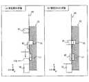
次に、図7および図8を参照して、本体装置2に対してコントローラを着脱する動作について説明する。なお、以下では、左コントローラ3を本体装置2に対して着脱する動作を例として説明するが、右コントローラ4を本体装置2に対して着脱する動作も左コントローラ3の場合と同様に行うことが可能である。[1-1-4: Mounting operation]
Next, the operation of attaching / detaching the controller to / from the
左コントローラ3を本体装置2に装着する場合、ユーザは、まず、左コントローラ3のスライダ40の下端を、本体装置2の左レール部材15の溝へ、左レール部材15の上端から挿入する。図7は、左レール部材15とスライダ40とが係合する様子の一例を示す図である。なお、図7では、図面を見やすくする目的で、本体装置2の構成を点線で示している。図7に示すように、スライダ40の凸型の断面が左レール部材15の凹型の断面(換言すれば、左レール部材15の溝)に係合する(嵌合するとも言える)ように、スライダ40は左レール部材15へ挿入される。 When the
スライダ40の下端を左レール部材15の溝へ挿入した後、ユーザは、さらに奥へスライダ40を左レール部材15の溝へ挿入する。すなわち、ユーザは、本体装置2に対して下方へ左コントローラ3をスライド移動させる。そして、スライダ40の下端が本体装置2のストッパー18の位置に到達するまで左コントローラ3を下方へスライド移動させると、左コントローラ3は本体装置2に固定される。 After inserting the lower end of the
図8は、スライダ40が左レール部材15に固定される前後の様子の一例を示す図である。なお、図8においては、左レール部材15については、前後方向(z軸方向)に垂直な断面を示している。また、図8においては、説明対象となる構成要素を見やすくする目的で、図3等とは構成要素の位置関係および大きさ等を変更して示している。 FIG. 8 is a diagram showing an example of the state before and after the
図8(a)に示すように、左コントローラ3が本体装置2に完全に装着されていない状態(すなわち、スライダ40の下端が本体装置2のストッパー18に達していない状態)においては、スライダ40の突起部41は、レール部材15の底面に当たってスライダ40の内側へ収納された状態となっている。 As shown in FIG. 8A, in the state where the
図8(a)に示す状態の後、スライダ40が左レール部材15の奥側へスライド移動されると、スライダ40の下端が本体装置2のストッパー18の位置に達する(図8(b)参照)。このとき、図8(b)に示すように、スライダ40の突起部41は、左レール部材15の係合穴16に対向する位置となる。そのため、突起部41は、スライダ40の装着面から突出し、係合穴16に挿入された状態となる。これによって、突起部41が係合穴16に係合するので、ある程度の力を加えても外れない程度に、左コントローラ3が本体装置2に固定される(換言すれば、スライダ40が左レール部材15に固定される)。 After the state shown in FIG. 8A, when the
また、左コントローラ3が本体装置2に固定された状態においては、図8(b)に示すように、スライダ40の端子42は、左レール部材15の左側端子17に対向する位置となる。そのため、端子42と左側端子17とが接続される。これによって、左コントローラ3と本体装置2との有線通信(換言すれば、端子同士が物理的に接続されることによって行われる通信)が可能となる。また、本体装置2から左コントローラ3への給電が可能となる。 Further, in the state where the
なお、コントローラ側の端子(すなわち、端子42)と本体装置側の端子(すなわち、左側端子17)とのいずれか一方または両方は、それが設置される面から(少しだけ)突出して設けられる。本実施形態においては、図8(a)に示すように、本体装置側の左側端子17は、設置される面(すなわち、左レール部材15の底面)からやや突出して設けられる。また、突出して設けられる端子の接点となる金属部分17aは、設置される面に近づく方向に変形可能である。したがって、端子同士が接触する場合には、図8(b)に示すように、一方の端子は、他方の端子から押される力を受け、突出する方向に付勢される。その結果、端子同士を確実に接触させることができる。 In addition, either one or both of the terminal on the controller side (that is, the terminal 42) and the terminal on the main body device side (that is, the left side terminal 17) is provided so as to project (slightly) from the surface on which it is installed. In the present embodiment, as shown in FIG. 8A, the
また、本実施形態においては、本体装置2の左側端子17は、係合穴16よりも下側に設けられる。また、左コントローラ3の端子42は、突起部41よりも下側に設けられる。したがって、スライダ40を左レール部材15に挿入する際には、突起部41が左側端子17に接触することはなく、突起部41によって左側端子17が傷つけられる可能性を低減することができる。 Further, in the present embodiment, the
左コントローラ3を本体装置2から外す場合、ユーザは、左コントローラ3を本体装置2の上方へスライド移動させる。なお、左コントローラ3が本体装置2に装着された状態では、上記突起部41と係合穴16とによって左コントローラ3が本体装置2に固定されている。ただし、左コントローラ3を上方にスライド移動させるための一定以上の力を加えることで、突起部41が係合穴16の位置からずれ、その結果、固定状態が解除される。したがって、固定状態が解除された後は、左コントローラ3をさらに上方へスライド移動させることによって、本体装置2から左コントローラ3を外すことができる。 When the
なお、他の実施形態においては、左コントローラ3は、突起部41をスライダ40の内側へ収納される操作を行うことができる機構を備えていてもよい。左コントローラ3は、例えば、左コントローラ3に設けられた所定のボタンをユーザが押下することに応じて、突起部41がスライダ40の内側へ収納される機構を有してもよい。これによれば、ユーザは、上記操作を行うことによって、突起部41によって左コントローラ3が本体装置2に固定される状態を容易に解除することができる。 In another embodiment, the
以上のように、本実施形態においては、レール部材およびスライダによるスライド機構によって、コントローラ3および4を本体装置2に着脱可能に装着することができる。スライド機構によれば、スライド方向以外の方向についてはコントローラ3および4を本体装置2に対して比較的強固に固定することができる。そのため、コントローラ3および4が本体装置2に装着された情報処理装置1をユーザが把持する際に、コントローラ3および4がぐらつくことが少なく、把持しやすい情報処理装置1を提供することができる。また、本実施形態においては、突起部および係合穴の構成によって、スライド方向についてもある程度コントローラ3および4を本体装置2に固定することができる。これによっても、本体装置2に装着されたコントローラ3および4のぐらつきを低減することができ、把持しやすい情報処理装置1を提供することができる。 As described above, in the present embodiment, the
[1−2.クレードルの構成]
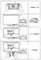
図9は、本実施形態における情報処理システムの一例の全体構成を示す図である。上述のように、情報処理システムは、上記情報処理装置1と、クレードル5とを含む。図9に示すように、クレードル5は、情報処理装置1を載置することが可能である。また、クレードル5は、ディスプレイ12とは別体の外部表示装置の一例であるテレビ6と通信可能である(有線通信であってもよいし、無線通信であってもよい)。詳細は後述するが、情報処理装置1をクレードル5に載置した場合、情報処理システムは、情報処理装置1が取得または生成した画像をテレビ6に表示することができる。また、詳細は後述するが、本実施形態においては、クレードル5は、載置された情報処理装置1を充電する機能と、ハブ装置(具体的には、USBハブ)の機能を有する。[1-2. Cradle configuration]
FIG. 9 is a diagram showing an overall configuration of an example of an information processing system according to the present embodiment. As described above, the information processing system includes the
図10は、クレードル5の一例の外観構成を示す図である。クレードル5は、情報処理装置1を着脱可能に載置する(装着するとも言える)ことが可能なハウジングを有する。本実施形態においては、図10に示すように、ハウジングは、溝71aが形成される第1支持部71と、略平面状の第2支持部72とを有する。 FIG. 10 is a diagram showing an external configuration of an example of the
図10に示すように、第1支持部71に形成される溝71aは、情報処理装置1の下側部分の形状に応じた形状を有する。具体的には、溝71aは、情報処理装置1の下側部分を挿入可能な形状であり、より具体的には、情報処理装置1の下側部分と略一致する形状である。したがって、情報処理装置1の下側部分を溝71aに挿入することによって、情報処理装置1をクレードル5に載置することができる。また、第2支持部72は、その下側部分が溝71aに挿入された情報処理装置1の表面(すなわち、ディスプレイ12が設けられる面)を支持する。この第2支持部72によって、クレードル5は、情報処理装置1をより安定的に支持することができる。なお、図10に示すハウジングの形状は一例であり、他の実施形態においては、クレードル5のハウジングは、情報処理装置1を載置することが可能な任意の形状であってよい。 As shown in FIG. 10, the
なお、図10においては、情報処理装置1は、クレードル5に対して、本体装置2の主面(すなわち、ディスプレイ12の面)が第2支持部72に対向する向きに載置される。ただし、本実施形態においては、情報処理装置1は、クレードル5に対して、本体装置2の裏面が第2支持部72に対向する向きに載置されることも可能である。つまり、本実施形態においては、ユーザは、表向き(すなわち、ディスプレイ12が見える向き)にして情報処理装置1をクレードル5に載置することも可能であるし、裏向き(すなわち、ディスプレイ12が隠れる向き)にして情報処理装置1をクレードル5に載置することも可能である。 In FIG. 10, the
図10に示すように、また、クレードル5は、クレードル5が情報処理装置1と通信を行うための本体端子73を備える。図10に示すように、本体端子73は、第1支持部71に形成される溝71aの底面に設けられる。より具体的には、本体端子73は、情報処理装置1がクレードル5に装着される場合に、情報処理装置1の下側端子27が接触する位置に設けられる。本実施形態においては、本体端子73は、USBコネクタ(より具体的には、オス側コネクタ)である。なお、上述のように、本実施形態においては、情報処理装置1を表向きにしても裏向きにしてもクレードル5に装着することができる。したがって、情報処理装置1の下側端子27およびクレードル5の本体端子73は、奥行き方向(すなわち、図1に示すz軸方向)に関して対称な形状を有し、奥行き方向に関して2種類の向きのうちどちらの向きで接続されても通信可能である。 As shown in FIG. 10, the
図10に示すように、クレードル5は、スリープボタン74を備える。スリープボタン74は、クレードル5に装着された本体装置2のオンモードとスリープモードとを切り替えるためのボタンである。なお、他の実施形態においては、スリープボタン74は、本体装置2のオンモードとスリープモードとを切り替える機能に加えて(または代えて)、本体装置2の電源のオン/オフを切り替える機能を有していてもよい。 As shown in FIG. 10, the
なお、本実施形態においては、スリープボタン74は、第1支持部71の前側の面に設けられる。スリープボタンボタン74は、情報処理装置1が装着された状態で押下可能な任意の位置に設けられてもよい。例えば、スリープボタン74は、クレードル5のハウジングの側面、あるいは、第2支持部72の背面に設けられてもよい。 In this embodiment, the
また、本実施形態において、スリープボタン74は発光部(具体的にはLED)を有する。スリープボタン74の発光部は、クレードル5に装着された本体装置2の状態をユーザに通知するために用いられる。つまり、発光部は、クレードル5に装着された本体装置2の状態に応じて発光状態(換言すれば、点灯状態)が変化する。例えば、本実施形態においては、クレードル5に装着された本体装置2がオンモードである場合には、発光部は点灯し、当該本体装置2がスリープモードまたは電源オフの状態である場合には、発光部は消灯する。また、ユーザに対して通知すべき情報(例えば、プログラムのアップデートの情報や、お知らせや、広告等)を本体装置2が有する場合、発光部は点滅する。なお、上記発光部は、スリープボタン74に設けられなくてもよく、例えば、クレードル5のハウジングの任意の位置に設けられてもよい。 Further, in the present embodiment, the
図10では図示しないが、クレードル5は、ハウジングの背面に端子(本実施形態においては、複数の端子。具体的には、図13に示すモニタ用端子132、電源端子134、および拡張用端子137)を有する。これらの端子の詳細については後述する。 Although not shown in FIG. 10, the
以上に説明した、クレードル5に設けられる各構成要素(具体的には、ハウジング、端子、ボタン等)の形状、数、および、設置位置は任意である。例えば、他の実施形態においては、ハウジングは、情報処理装置1を支持可能な他の形状を有していてもよい。また、ハウジングに設けられる端子のいくつかは、ハウジングの前側の面に設けられてもよい。また、他の実施形態においては、クレードル5は、上記各構成要素のうちいくつかを備えていない構成であってもよい。 The shape, number, and installation position of each component (specifically, housing, terminals, buttons, etc.) provided in the
[2.各装置の内部構成]
[2−1.本体装置2の内部構成]
図11は、本体装置2の内部構成の一例を示すブロック図である。本体装置2は、図3に示す構成の他、図11に示す各構成要素81〜98を備える。これらの構成要素81〜98のいくつかは、電子部品として電子回路基板上に実装されてハウジング11内に収納されてもよい。[2. Internal configuration of each device]
[2-1. Internal configuration of main unit 2]
FIG. 11 is a block diagram showing an example of the internal configuration of the
(情報処理の実行に関する構成)
本体装置2は、CPU(Central Processing Unit)81を備える。CPU81は、本体装置2において実行される各種の情報処理を実行する情報処理部である。CPU81は、自身がアクセス可能な記憶部(具体的には、フラッシュメモリ84等の内部記憶媒体、あるいは、各スロット23および24に装着される外部記憶媒体等)に記憶される情報処理プログラムを実行することによって、各種の情報処理を実行する。(Configuration related to information processing execution)
The
本体装置2は、自身に内蔵される内部記憶媒体の一例として、フラッシュメモリ84およびDRAM(Dynamic Random Access Memory)85を備える。フラッシュメモリ84およびDRAM85は、CPU81に接続される。フラッシュメモリ84は、主に、本体装置2に保存される各種のデータ(プログラムであってもよい)を記憶するために用いられるメモリである。DRAM85は、情報処理において用いられる各種のデータを一時的に記憶するために用いられるメモリである。 The
本体装置2は、第1スロットインターフェース(以下、「I/F」と略記する。)91を備える。また、本体装置2は、第2スロットI/F92を備える。各スロットI/F91および92は、CPU81に接続される。第1スロットI/F91は、第1スロット23に接続され、第1スロット23に装着された第1の種類の記憶媒体(例えばSDカード)に対するデータの読み出しおよび書き込みを、CPU81の指示に応じて行う。第2スロットI/F92は、第2スロット24に接続され、第2スロット24に装着された第2の種類の記憶媒体(例えば、専用メモリカード)に対するデータの読み出しおよび書き込みを、CPU81の指示に応じて行う。 The
CPU81は、上記の各メモリ84および85ならびに上記各記憶媒体との間でデータを適宜読み出したり書き込んだりして、上記の情報処理を実行する。 The
(通信に関する構成)
本体装置2は、ネットワーク通信部82を備える。ネットワーク通信部82は、CPU81に接続される。ネットワーク通信部82は、ネットワークを介して外部の装置と通信(具体的には、無線通信)を行う。本実施形態においては、ネットワーク通信部82は、例えばWi−Fiの認証を受けた通信モジュールであり、無線LANを介して外部装置と通信を行う。なお、他の実施形態においては、本体装置2は、無線LANに接続して通信を行う機能に加えて(または代えて)、モバイル通信網(換言すれば、携帯電話通信網)に接続して通信を行う機能を有していてもよい。(Communication configuration)
The
本体装置2は、コントローラ通信部83を備える。コントローラ通信部83は、CPU81に接続される。コントローラ通信部83は、各コントローラ3および/または4と無線通信を行う。本体装置2と各コントローラとの通信方式は任意であるが、本実施形態においては、コントローラ通信部83は、各コントローラとの間で、Bluetooth(登録商標)の規格に従った通信を行う。 The
CPU81は、上述の左側端子17、右側端子21、および、下側端子27に接続される。CPU81は、左コントローラ3と有線通信を行う場合、左側端子17を介して左コントローラ3へデータを送信する。また、CPU81は、右コントローラ4と有線通信を行う場合、右側端子21を介して右コントローラ4へデータを送信する。また、CPU81は、クレードル5と通信を行う場合、下側端子27を介してクレードル5へデータを送信する。 The
このように、本実施形態においては、本体装置2は、左右のコントローラ3および4との間で、有線通信と無線通信との両方を行うことができる。なお、有線通信と無線通信とを切り替える処理については後述する。 As described above, in the present embodiment, the
また、本体装置2は、複数の左コントローラと同時に(換言すれば、並行して)通信を行うことができる。また、本体装置2は、複数の右コントローラと同時に(換言すれば、並行して)通信を行うことができる。したがって、ユーザは、複数の左コントローラおよび複数の右コントローラを用いて情報処理装置1に対する入力を行うことができる。 Further, the
(本体装置2に対する入出力に関する構成)
本体装置2は、タッチパネル13の制御を行う回路であるタッチパネルコントローラ86を備える。タッチパネルコントローラ86は、タッチパネル13に接続され、また、CPU81に接続される。タッチパネルコントローラ86は、タッチパネル13からの信号に基づいて、例えばタッチ入力が行われた位置を示すデータを生成してCPU81へ出力する。(Configuration related to input / output to main unit 2)
The
また、上述のディスプレイ12は、CPU81に接続される。CPU81は、(例えば上記の情報処理の実行によって)生成した画像、および/または、外部から取得した画像をディスプレイ12に表示する。 Further, the
本体装置2は、コーデック回路87およびスピーカ(具体的には左スピーカおよび右スピーカ)88を備える。コーデック回路87は、スピーカ88および音声入出力端子25に接続されるとともに、CPU81に接続される。コーデック回路87は、スピーカ88および音声入出力端子25に対する音声データの入出力を制御する回路である。すなわち、コーデック回路87は、CPU81から音声データを受け取った場合、当該音声データに対してD/A変換を行って得られる音声信号をスピーカ88または音声入出力端子25へ出力する。これによって、スピーカ88、あるいは、音声入出力端子25に接続された音声出力部(例えばイヤホン)から音が出力される。また、コーデック回路87は、音声入出力端子25から音声信号を受け取った場合、音声信号に対してA/D変換を行い、所定の形式の音声データをCPU81へ出力する。 The
また、上述の音量ボタン26(具体的には、図3に示す音量ボタン26aおよび26b)は、CPU81に接続される。CPU81は、音量ボタン26に対する入力に基づいて、スピーカ88または上記音声出力部から出力される音量を制御する。 Further, the above-mentioned volume buttons 26 (specifically, the volume buttons 26a and 26b shown in FIG. 3) are connected to the
本体装置2は、加速度センサ89を備える。本実施形態においては、加速度センサ89は、所定の3軸(例えば、図1に示すxyz軸)方向に沿った直線加速度の大きさを検出する。なお、加速度センサ89は、1軸方向あるいは2軸方向の加速度を検出するものであってもよい。 The
また、本体装置2は、角速度センサ90を備える。本実施形態においては、角速度センサ90は、所定の3軸(例えば、図1に示すxyz軸)回りの角速度を検出する。なお、角速度センサ90は、1軸回りあるいは2軸回りの角速度を検出するものであってもよい。 Further, the
上記の加速度センサ89および角速度センサ90は、CPU81に接続され、加速度センサ89および角速度センサ90の検出結果は、CPU81へ出力される。CPU81は、上記の加速度センサ89および角速度センサ90の検出結果に基づいて、本体装置2の動きおよび/または姿勢に関する情報を算出することが可能である。 The
(電力に関する構成)
本体装置2は、電力制御部97およびバッテリ98を備える。電力制御部97は、バッテリ98およびCPU81に接続される。また、図示しないが、電力制御部97は、本体装置2の各部(具体的には、バッテリ98の電力の給電を受ける各部、左側端子17、および、右側端子21)に接続される。電力制御部97は、CPU81からの指令に基づいて、バッテリ98から上記各部への電力供給を制御する。また、電力制御部97は、電源ボタン28に接続される。電力制御部97は、電源ボタン28に対する入力に基づいて、上記各部への電力供給を制御する。すなわち、電力制御部97は、電源ボタン28に対して電源をオフする操作が行われた場合、上記各部の全部または一部への電力供給を停止し、電源ボタン28に対して電源をオンする操作が行われた場合、電力制御部97は、上記各部の全部または一部への電力供給を開始する。また、電力制御部97は、電源ボタン28に対してスリープモードに切り替える指示が行われた場合、ディスプレイ12を含む一部の構成に対する電力供給を停止し、電源ボタン28に対してオンモードに切り替える指示が行われた場合、当該構成に対する電力供給を開始する。また、電力制御部97は、電源ボタン28に対する入力を示す情報(具体的には、電源ボタン28が押下されているか否かを示す情報)をCPU81へ出力する。(Structure related to electric power)
The
また、バッテリ98は、下側端子27に接続される。外部の充電装置(例えば、クレードル5)が下側端子27に接続され、下側端子27を介して本体装置2に電力が供給される場合、供給された電力がバッテリ98に充電される。なお、本実施形態においては、本体装置2のバッテリ98の充電容量は、後述する各コントローラ3および4が備えるバッテリよりも充電容量が大きい。 Further, the
(その他の構成)
本体装置2は、磁界の強さおよび/または向きを検出する磁力センサ(磁気センサとも言う)93を備える。磁力センサ93はCPU81に接続され、磁力センサ93の検出結果はCPU81へ出力される。本実施形態において、磁力センサ93は、情報処理装置1に装着される保護カバー(不図示)の開閉を検出するために用いられる。例えば、保護カバーには磁石が設けられており、CPU81は、磁力センサ93による検出結果に基づいて、保護カバーが本体装置2の主面を覆う状態となったことを検出する。なお、CPU81は、当該状態を検出した場合、例えばディスプレイ12の表示をオフにする。(Other configurations)
The
本体装置2は、本体装置2の周囲の環境光の強さを検出する環境光センサ94を備える。環境光センサ94はCPU81に接続され、環境光センサ94の検出結果はCPU81へ出力される。本実施形態において、環境光センサ94は、ディスプレイ12の輝度を調節するために用いられる。すなわち、CPU81は、環境光センサ94の検出結果に基づいて、ディスプレイ12の輝度を制御する。 The
本体装置2は、本体装置2内部の熱を放熱するための冷却ファン96を備える。冷却ファン96が動作することによって、ハウジング11の外部の空気が吸気孔11dから導入されるとともに、ハウジング11内部の空気が排気孔11cから放出されることで、ハウジング11内部の熱が放出される。冷却ファン96はCPU81に接続され、冷却ファン96の動作はCPU81によって制御される。また、本体装置2は、本体装置2内の温度を検出する温度センサ95を備える。温度センサ95はCPU81に接続され、温度センサ95の検出結果はCPU81へ出力される。CPU81は、温度センサ95の検出結果に基づいて、冷却ファン96の動作を制御する。 The
[2−2.左コントローラ3の内部構成]
図12は、情報処理装置1の内部構成の一例を示すブロック図である。なお、情報処理装置1のうちの本体装置2に関する内部構成の詳細については、図11で示しているので、図12では省略している。[2-2. Internal configuration of left controller 3]
FIG. 12 is a block diagram showing an example of the internal configuration of the
(通信に関する構成)
左コントローラ3は、本体装置2との間で通信を行う通信制御部101を備える。図12に示すように、通信制御部101は、上述の端子42を含む各構成要素に接続される。本実施形態においては、通信制御部101は、端子42を介した有線通信と、端子42を介さない無線通信との両方で本体装置2と通信を行うことが可能である。通信制御部101は、左コントローラ3が本体装置2に対して行う通信方法を制御する。すなわち、左コントローラ3が本体装置2に装着されている場合、通信制御部101は、端子42を介して本体装置2と通信を行う。また、左コントローラ3が本体装置2から外されている場合、通信制御部101は、本体装置2(具体的には、コントローラ通信部83)との間で無線通信を行う。コントローラ通信部83と通信制御部101との間の無線通信は、Bluetooth(登録商標)の規格に従って行われる。(Communication configuration)
The
また、左コントローラ3は、例えばフラッシュメモリ等のメモリ102を備える。上記通信制御部101は、例えばマイコン(マイクロプロセッサとも言う)で構成され、メモリ102に記憶されるファームウェアを実行することによって各種の処理を実行する。 Further, the
(入力に関する構成)
左コントローラ3は、各ボタン103(具体的には、ボタン33〜39,43,および44)を備える。また、左コントローラ3は、上述のアナログスティック(図12では「スティック」と記載する)32を備える。各ボタン103およびアナログスティック32は、自身に対して行われた操作に関する情報を、適宜のタイミングで繰り返し通信制御部101へ出力する。(Configuration related to input)
The
左コントローラ3は、加速度センサ104を備える。本実施形態においては、加速度センサ104は、所定の3軸(例えば、図1に示すxyz軸)方向に沿った直線加速度の大きさを検出する。なお、加速度センサ104は、1軸方向あるいは2軸方向の加速度を検出するものであってもよい。 The
左コントローラ3は、角速度センサ105を備える。本実施形態においては、角速度センサ105は、所定の3軸(例えば、図1に示すxyz軸)回りの角速度を検出する。なお、角速度センサ105は、1軸回りあるいは2軸回りの角速度を検出するものであってもよい。 The
加速度センサ104および角速度センサ105は、通信制御部101に接続される。加速度センサ104および角速度センサ105の検出結果は、適宜のタイミングで繰り返し通信制御部101へ出力される。 The
通信制御部101は、各入力部(具体的には、各ボタン103、アナログスティック32、各センサ104および105)から、入力に関する情報(具体的には、操作に関する情報、または、センサによる検出結果)を取得する。通信制御部101は、取得した情報(または取得した情報に所定の加工を行った情報)を含む操作データを本体装置2へ送信する。なお、操作データは、所定時間に1回の割合で繰り返し送信される。なお、入力に関する情報が本体装置2へ送信される間隔は、各入力部について同じであってもよいし、同じでなくてもよい。 The communication control unit 101 receives information related to input (specifically, information related to operation or detection result by the sensor) from each input unit (specifically, each
上記操作データが本体装置2へ送信されることによって、本体装置2は、左コントローラ3に対して行われた入力を知ることができる。すなわち、本体装置2は、各ボタン103およびアナログスティック32に対する操作を、操作データに基づいて判別することができる。また、本体装置2は、左コントローラ3の動きおよび/または姿勢に関する情報を、操作データ(具体的には、各センサ104および105の検出結果)に基づいて算出することができる。 By transmitting the operation data to the
(出力に関する構成)
上述した通知用LED45は、通信制御部101に接続される。本実施形態においては、通知用LED45は、本体装置2からの指令によって制御される。すなわち、通信制御部101は、本体装置2からの上記指令を受け取ると、当該指令に従って通知用LED45の点灯を制御する制御信号を通知用LED45へ出力する。(Configuration related to output)
The
左コントローラ3は、振動によってユーザに通知を行うための振動子107を備える。本実施形態においては、振動子107は、本体装置2からの指令によって制御される。すなわち、通信制御部101は、本体装置2からの上記指令を受け取ると、当該指令に従って振動子107を駆動させる。ここで、左コントローラ3は増幅器106を備える。通信制御部101は、上記指令を受け取ると、指令に応じた制御信号を増幅器106へ出力する。増幅器106は、通信制御部101からの制御信号を増幅して、振動子107を駆動させるための駆動信号を生成して振動子107へ与える。これによって振動子107が動作する。 The
(電力に関する構成)
左コントローラ3は、電力供給部108を備える。本実施形態において、電力供給部108は、バッテリと、電力制御回路とを有する。図示しないが、電力制御回路は、バッテリに接続されるとともに、左コントローラ3の各部(具体的には、バッテリの電力の給電を受ける各部)に接続される。電力制御回路は、バッテリから上記各部への電力供給を制御する。(Structure related to electric power)
The
また、バッテリは、端子42に接続される。詳細は後述するが、本実施形態においては、左コントローラ3が本体装置2に装着される場合、所定の条件下で、バッテリは、端子42を介して本体装置2からの給電によって充電される。 The battery is also connected to the terminal 42. Although details will be described later, in the present embodiment, when the
[2−3.右コントローラ4の内部構成]
(通信に関する構成)
図12に示すように、右コントローラ4は、本体装置2との間で通信を行う通信制御部111を備える。また、右コントローラ4は、通信制御部111に接続されるメモリ112を備える。通信制御部111は、上述の端子64を含む各構成要素に接続される。通信制御部111およびメモリ112は、左コントローラ3の通信制御部101およびメモリ102と同様の機能を有する。したがって、通信制御部111は、端子64を介した有線通信と、端子64を介さない無線通信(具体的には、Bluetooth(登録商標)の規格に従った通信)との両方で本体装置2と通信を行うことが可能であり、右コントローラ4が本体装置2に対して行う通信方法を制御する。[2-3. Internal configuration of right controller 4]
(Communication configuration)
As shown in FIG. 12, the
(入力に関する構成)
右コントローラ4は、左コントローラ3の各入力部と同様の各入力部(具体的には、各ボタン113、アナログスティック52、加速度センサ114、および、角速度センサ115)を備える。これらの各入力部については、左コントローラ3の各入力部と同様の機能を有し、同様に動作する。(Configuration related to input)
The
(出力に関する構成)
右コントローラ4の通知用LED67は、左コントローラ3の通知用LED45と同様に動作する。すなわち、通信制御部111は、本体装置2からの指令を受け取ると、当該指令に従って通知用LED67の点灯を制御する制御信号を通知用LED67へ出力する。(Configuration related to output)
The notification LED 67 of the
また、右コントローラ4は、振動子117および増幅器116を備える。振動子117および増幅器116は、左コントローラ3の振動子107および増幅器106と同様に動作する。すなわち、通信制御部111は、本体装置2からの指令に従って、増幅器116を用いて振動子117を動作させる。 Further, the
(電力に関する構成)
右コントローラ4は、電力供給部118を備える。電力供給部118は、左コントローラ3の電力供給部108と同様の機能を有し、同様に動作する。すなわち、電力供給部118は、バッテリから給電を受ける各部への電力供給を制御する。また、右コントローラ4が本体装置2に装着される場合、所定の条件下で、バッテリは、端子64を介して本体装置2からの給電によって充電される。(Structure related to electric power)
The
(その他の構成)
右コントローラ4は、NFC通信部122を備える。NFC通信部122は、NFC(Near Field Communication)の規格に基づく近距離無線通信を行う。NFC通信部122は、いわゆるNFCリーダ・ライタの機能を有する。例えば、NFC通信部122は、近距離無線通信に用いられるアンテナと、当該アンテナから送出すべき信号(電波)を生成する回路(例えばNFCチップ)とを有する。なお、近距離無線通信は、NFCの規格に基づくものに限らず、任意の近接通信(非接触通信とも言う)であってもよい。近接通信には、例えば、一方の装置からの電波によって(例えば電磁誘導によって)他方の装置に起電力を発生させる通信方式が含まれる。(Other configurations)
The
また、右コントローラ4は、赤外撮像部123を備える。赤外撮像部123は、右コントローラ4の周囲を撮像する赤外線カメラを有する。本実施形態においては、赤外撮像部123は、ユーザの手を撮像するために用いられる。情報処理装置1は、撮像された手の情報(例えば、位置、大きさ、および形状等)に基づいて、当該手による入力(例えばジェスチャ入力等)を判別する。また、赤外撮像部123は、赤外線を照射する照射部を有する。照射部は、例えば、赤外線カメラが画像を撮像するタイミングと同期して、赤外線を照射する。照射部によって照射された赤外線が物体(例えば、ユーザの手)によって反射され、当該反射された赤外線が赤外線カメラによって受光されることで、赤外線の画像が取得される。これによって、より鮮明な赤外線画像を得ることができる。本実施形態においては、赤外線カメラを有する赤外撮像部123が用いられるが、なお、他の実施形態においては、撮像手段として、赤外線カメラに代えて可視光カメラ(可視光イメージセンサを用いたカメラ)が用いられてもよい。 Further, the
右コントローラ4は、処理部121を備える。処理部121は、通信制御部111に接続されるとともに、NFC通信部122に接続される。処理部121は、本体装置2からの指令に応じて、NFC通信部122に対する管理処理を実行する。例えば、処理部121は、本体装置2からの指令に応じてNFC通信部122の動作を制御する。また、処理部121は、NFC通信部122の起動を制御したり、通信相手(例えば、NFCタグ)に対するNFC通信部122の動作(具体的には、読み出しおよび書き込み等)を制御したりする。また、処理部121は、上記通信相手に送信されるべき情報を通信制御部111を介して本体装置2から受信してNFC通信部122へ渡したり、上記通信相手から受信された情報をNFC通信部122から取得して通信制御部111を介して本体装置2へ送信したりする。 The
また、処理部121は、本体装置2からの指令に応じて赤外撮像部123に対する管理処理を実行する。例えば、処理部121は、赤外撮像部123に撮像動作を行わせたり、撮像結果に基づく情報(撮像画像の情報、あるいは、当該情報から算出される情報等)を取得して通信制御部111を介して本体装置2へ送信したりする。 In addition, the
[2−4.クレードル5の内部構成]
図13は、クレードル5の内部構成の一例を示すブロック図である。なお、図13において、本体装置2に関する内部構成の詳細については、図11で示しているので、省略している。[2-4. Internal configuration of cradle 5]
FIG. 13 is a block diagram showing an example of the internal configuration of the
(画像変換に関する構成)
図13に示すように、クレードル5は、変換部131およびモニタ用端子132を備える。変換部131は、上述の本体端子73およびモニタ用端子132と接続される。変換部131は、本体装置2から受信した画像(映像とも言える)および音声に関する信号の形式を、テレビ6へ出力する形式へと変換する。ここで、本実施形態においては、本体装置2は、ディスプレイポート信号(すなわち、DisplayPortの規格に従った信号)として画像および音声の信号をクレードル5へ出力する。また、本実施形態においては、クレードル5とテレビ6との間の通信は、HDMI(登録商標)の規格に基づく通信が用いられる。すなわち、上記モニタ用端子132は、HDMI端子であり、クレードル5とテレビ6はHDMIケーブルによって接続される。以上より、変換部131は、本体装置2から本体端子73を介して受信されるディスプレイポート信号(具体的には、映像および音声を表す信号)を、HDMI信号へ変換する。変換されたHDMI信号は、モニタ用端子132を介してテレビ6へ出力される。(Structure related to image conversion)
As shown in FIG. 13, the
また、クレードル5は、クレードル5における各種の情報処理を実行する処理部135を備える。処理部135は、上述のスリープボタン74に接続され、また、接続処理部136(詳細は後述する)を介して本体端子73に接続される。処理部135は、スリープボタン74に対する操作を検出し、当該操作が行われたことを本体装置2へ通知する。本体装置2は、上記通知を受け取った場合、自身のオンモードとスリープモードとを切り替える。このように、本実施形態においては、本体装置2がクレードル5に装着される場合にスリープボタン74が押下されることに応じて、情報処理装置1のオンモードとスリープモードとが切り替えられる。 Further, the
(充電に関する構成)
クレードル5は、電力制御部133および電源端子134を備える。電源端子134は、図示しない充電装置(例えば、ACアダプタ等)を接続するための端子である。本実施形態においては、電源端子134にACアダプタが接続されており、クレードル5には商用電源が供給されているものとする。(Configuration related to charging)
The
電力制御部133は、クレードル5に対して本体装置2が装着された場合、電源端子134からの電力を本体端子73を介して本体装置2へ供給する。これによって、上述したように、本体装置2のバッテリ98が充電される。 When the
なお、本実施形態においては、電源端子134は、情報処理装置1の下側端子27と同じ形状のコネクタ(すなわち、メス側のUSB端子)である。したがって、本実施形態においては、上記充電装置をクレードル5に接続して、クレードル5を介して情報処理装置1を充電することも可能であるし、当該充電装置を本体装置2に直接接続して情報処理装置1を充電することも可能である。 In the present embodiment, the
(その他の構成)
また、クレードル5は、接続処理部136および拡張用端子137を備える。拡張用端子137は、他の装置を接続するための端子である。本実施形態においては、クレードル5は、拡張用端子137として、複数(より具体的には3つ)のUSB端子を備える。接続処理部136は、本体端子73および各拡張用端子137に接続される。接続処理部136は、USBハブとしての機能を有し、例えば、拡張用端子137に接続された装置と、本体端子73に接続された本体装置2との間の通信を管理する(すなわち、ある装置からの信号を他の装置へ適宜分配して送信する)。上記のように、本実施形態においては、情報処理装置1は、クレードル5を介して他の装置との通信を行うことが可能である。なお、接続処理部136は、通信速度を変換したり、拡張用端子137に接続された装置に対する電力供給を行ったりすることが可能であってもよい。(Other configurations)
Further, the
[3.情報処理システムにおける動作の概要]
以上に説明したように、本実施形態における情報処理装置1については、左右のコントローラ3および4が着脱可能である。また、情報処理装置1は、クレードル5に装着することによってテレビ6に画像(および音声)を出力可能である。したがって、以下に説明するような種々の利用態様で情報処理装置1を利用することができる。以下、主な利用態様における情報処理システムの動作を説明する。[3. Overview of operations in information processing systems]
As described above, with respect to the
[3−1.コントローラを本体装置に装着して利用する態様]
図14は、各コントローラ3および4を本体装置2に装着した状態(「装着状態」と呼ぶ)で情報処理装置1を利用する様子の一例を示す図である。図14に示すように、各コントローラ3および4を本体装置2に装着する場合には、情報処理装置1を携帯機器(例えば、携帯型ゲーム機)として利用することができる。[3-1. A mode in which the controller is attached to the main unit and used]
FIG. 14 is a diagram showing an example of using the
装着状態においては、本体装置2と各コントローラ3および4との通信は、有線通信(すなわち、互いに接続される各装置の端子を介した通信)によって行われる。すなわち、本体装置2は、自身に装着された各コントローラ3および4から操作データを受信して、受信された操作データに基づいて(具体的には、操作データを入力として用いて)情報処理を実行する。 In the mounted state, the communication between the
なお、他の実施形態においては、装着状態において、本体装置2とコントローラとの間で無線通信が行われてもよい。ここで、装着状態においては本体装置2とコントローラとの間の距離が近すぎることから、無線通信がうまく行われない可能性がある。これに対して、本実施形態においては、装着状態においては本体装置2とコントローラとの間で有線通信を行うことによって、通信の確実性を向上することができる。 In another embodiment, wireless communication may be performed between the
なお、装着状態においては、左コントローラ3の4つの操作ボタン33〜36は、方向入力(換言すれば、方向指示)を行うために用いられてもよい。このとき、ユーザは、アナログスティック32を用いて方向入力を行うことも可能であるし、操作ボタン33〜36を用いて方向入力を行うことも可能である。ユーザは、好みに合った操作手段を用いて方向入力を行うことができるので、操作性を向上することができる。ただし、各操作ボタンがどのような指示に用いられるかは、本体装置2において実行されるプログラムによって自由に決められてよい。 In the mounted state, the four
また、本実施形態においては、左コントローラ3と右コントローラ4とでは、アナログスティックと4つの操作ボタン(すなわち、A、B、X、Yボタン)との配置が逆になっている。つまり、装着状態においては、左コントローラ3においてはアナログスティック32が4つの操作ボタン33〜36よりも上側に配置されるのに対して、右コントローラ4においては4つの操作ボタン53〜56がアナログスティック52よりも上側に配置される。したがって、図14に示すように、左右の両手を同じ高さにして(換言すれば、上下方向に関して同じ位置にして)情報処理装置1を把持した場合、一方の手についてはアナログスティックが操作しやすい位置となり、他方の手については4つの操作ボタンが操作しやすい位置となる。つまり、本実施形態においては、アナログスティックおよび4つの操作ボタンを操作しやすい情報処理装置を提供することができる。 Further, in the present embodiment, in the
なお、詳細は後述するが、左コントローラおよび/または右コントローラとして、本実施形態とは異なる構成(例えば、異なる機能を有する構成、あるいは、操作部の配置が異なる構成等)を有するコントローラが用意されてもよい(後述する“[5−1.他の種類のコントローラ]”参照)。このとき、本実施形態における左コントローラ3および/または右コントローラ4に代えて、他の構成の左コントローラおよび/または右コントローラを本体装置2に装着することによって、本実施形態(すなわち、図14に示す情報処理装置1)とは操作感覚が異なる情報処理装置を提供することも可能である。 Although details will be described later, as a left controller and / or a right controller, a controller having a configuration different from that of the present embodiment (for example, a configuration having a different function, a configuration having a different arrangement of operation units, etc.) is prepared. It may be used (see “[5-1. Other types of controllers]” described later). At this time, instead of the
[3−2.1組のコントローラを外して利用する態様]
上述のように、本実施形態においては、左右のコントローラ3および4を本体装置2から外した状態(「離脱状態」と呼ぶ)で情報処理装置1を利用することも可能である。離脱状態で情報処理装置1を利用する場合の態様としては、1人のユーザが2つのコントローラ3および4を用いる態様と、2人のユーザがコントローラを1つずつ用いる態様という2つの態様が少なくとも考えられる。[Aspects for removing and using 3.2.1 sets of controllers]
As described above, in the present embodiment, it is also possible to use the
(1人のユーザが2つのコントローラを用いる態様)
図15は、離脱状態において、1人のユーザが2つのコントローラ3および4を把持して情報処理装置1を利用する様子の一例を示す図である。図15に示すように、離脱状態においては、ユーザは、1組2つのコントローラ3および4を左右の手にそれぞれ持って操作を行うことができる。(A mode in which one user uses two controllers)
FIG. 15 is a diagram showing an example of a state in which one user holds two
なお、本実施形態においては、コントローラが備える加速度センサおよび/または角速度センサの検出結果に基づいて、コントローラの動きおよび/または姿勢に関する情報を算出可能である。したがって、情報処理装置1は、コントローラ自体を動かす操作を入力として受け付けることができる。ユーザは、コントローラが備える操作部(操作ボタンおよびアナログスティック)に対する操作だけでなく、コントローラ自体を動かす操作を行うことができる。つまり、本実施形態においては、情報処理装置1は、携帯型機器でありながら、(ディスプレイを動かすことなく)コントローラを動かす操作をユーザに提供することができる。また、情報処理装置1は、携帯型機器でありながら、ディスプレイ12から離れた場所でユーザが操作を行うことが可能な情報処理装置を提供することができる。 In this embodiment, information on the movement and / or posture of the controller can be calculated based on the detection results of the acceleration sensor and / or the angular velocity sensor included in the controller. Therefore, the
なお、情報処理装置1は、離脱状態に限らず装着状態においても、本体装置2が備える加速度センサ89および/または角速度センサ90の検出結果に基づいて、情報処理装置1の動きおよび/または姿勢に関する情報を算出可能である。 The
離脱状態においては、本体装置2と各コントローラ3および4との通信は、無線通信によって行われる。すなわち、本体装置2は、自身との無線通信が確立した(ペアリングが行われた)各コントローラ3および4から操作データを受信して、受信された操作データに基づいて(具体的には、操作データを入力として用いて)情報処理を実行する。 In the detached state, communication between the
本実施形態においては、無線通信の場合、本体装置2は、通信相手となる2つのコントローラを区別する。すなわち、本体装置2は、受信された操作データが左コントローラ3からのものであるか右コントローラ4からのものであるかを識別する。コントローラを区別する方法については後述する。 In the present embodiment, in the case of wireless communication, the
(2人のユーザが1つずつコントローラを用いる態様)
図16は、離脱状態において、2人のユーザが1つずつコントローラを把持して情報処理装置1を利用する様子の一例を示す図である。図16に示すように、離脱状態においては、2人のユーザが操作を行うことが可能であり、具体的には、一方のユーザ(「第1のユーザ」と呼ぶ)が左コントローラ3を用いて操作を行うとともに、他方のユーザ(「第2のユーザ」と呼ぶ)が右コントローラ4を用いて操作を行うことが可能である。情報処理装置1は、例えば、左コントローラ3に対する操作に基づいて仮想空間における第1のオブジェクト(例えばプレイヤキャラクタ)の動作を制御し、右コントローラ4に対する操作に基づいて仮想空間における第2のオブジェクトの動作を制御する情報処理を実行する。なお、図16に示す態様においても図15に示す態様と同様、ユーザは、コントローラが備える操作部に対する操作、および/または、コントローラ自体を動かす操作が可能である。(A mode in which two users use one controller each)
FIG. 16 is a diagram showing an example of how two users hold the controller one by one and use the
また、本実施形態においては、右コントローラ4におけるアナログスティック52と各操作ボタン53〜56との位置関係は、左コントローラ3におけるこれら2種類の操作部の位置関係とは反対になっている。したがって、例えば図16に示すように、2人のユーザが左コントローラ3と右コントローラ4とを同じ向きで把持した場合、上記2種類の操作部の位置関係は、2つのコントローラで同じになる。つまり、本実施形態においては、ユーザは、上記2種類の操作部に関して、本体装置2から外した左コントローラ3と右コントローラ4とを同じような操作感覚で使用することができる。これによって、コントローラの操作性を向上することができる。 Further, in the present embodiment, the positional relationship between the
また、離脱状態においては、左コントローラ3の4つの操作ボタン33〜36は、右コントローラ4の4つの操作ボタン53〜56と同じ機能として用いられてもよい(換言すれば、同じ指示を行うために用いられてもよい)。具体的には、右方向ボタン33はYボタン56と同じ機能として用いられ、下方向ボタン34はXボタン55と同じ機能として用いられ、上方向ボタン35はBボタン54と同じ機能として用いられ、左方向ボタン36はAボタン53と同じ機能として用いられてもよい。このように、本実施形態においては、装着状態と離脱状態とで、操作ボタン33〜36の機能が変更されてもよい。ただし、各操作ボタンがどのような指示に用いられるかは、本体装置2において実行されるプログラムによって自由に決められてよい。 Further, in the detached state, the four
なお、図16においては、情報処理装置1は、ディスプレイ12の表示領域を2つに分割し、分割された一方の表示領域に第1のユーザのための画像(例えば、第1オブジェクトを含む画像)を表示し、分割された他方の表示領域に第2のユーザのための画像(例えば、第2オブジェクトを含む画像)を表示する。ただし、情報処理装置1において実行されるアプリケーションによっては、情報処理装置1は、ディスプレイ12の表示領域を分割することなく、2人のユーザのための画像(例えば、第1オブジェクトおよび第2オブジェクトの両方を含む画像)を表示するようにしてもよい。 In FIG. 16, the
また、図16に示す態様においても図15に示す態様と同様、本体装置2と各コントローラ3および4との通信は、無線通信によって行われる。このとき、本体装置2は、通信相手となるコントローラを区別する。 Further, in the mode shown in FIG. 16, as in the mode shown in FIG. 15, communication between the
(その他の態様)
また、本実施形態においては、右コントローラ4は、赤外撮像部123を備えている。したがって、右コントローラ4を本体装置2から外した状態において、情報処理装置1は、赤外撮像部123による撮像結果(検出結果とも言う)に基づく情報処理を実行してもよい。この情報処理の例としては、例えば次に示す処理が考えられる。(Other aspects)
Further, in the present embodiment, the
例えば、操作部を備えるアタッチメント(以下、「拡張コントローラ」と呼ぶ)が右コントローラ4に装着される場合、本体装置2は、赤外撮像部123による撮像結果に基づいて、当該操作部に対する操作を検出することができる。したがって、本体装置2は、撮像結果を用いることによって、上記操作部に対する操作に応じた情報処理を実行することができる。 For example, when an attachment provided with an operation unit (hereinafter referred to as an “extended controller”) is attached to the
具体的には、上記拡張コントローラは、右コントローラ4に着脱可能であり、例えばボタンおよびスティック等の可動式の操作部を備える。また、拡張コントローラは、操作部が操作されたことに応じて移動(ここでは、回転を含む意味である)する可動部を、ハウジングの内部に備える。可動部は、例えば、操作部であるボタンの押下に応じて移動するように構成された部材である。ここで、拡張コントローラは、赤外撮像部123がハウジング内部の上記可動部を撮像可能となるように、右コントローラ4に装着される。例えば、拡張コントローラのハウジングには窓部が設けられており、拡張コントローラが右コントローラ4に装着された状態において、赤外撮像部123は当該窓部を介して上記可動部を撮像可能である。上記において、本体装置2は、赤外撮像部123による撮像画像における上記可動部の位置および/または姿勢に基づいて、拡張コントローラの操作部に対する操作を判別することができる。したがって、本体装置2は、撮像画像を用いることによって、上記操作部に対する操作に応じた情報処理を実行してもよい。 Specifically, the expansion controller can be attached to and detached from the
また、本体装置2は、赤外撮像部123による撮像結果に基づいて、ユーザの手によるジェスチャ入力を検出し、ジェスチャ入力に応じた情報処理を実行してもよい。例えば、ユーザは、右コントローラ4を一方の手で把持して、赤外撮像部123の赤外線カメラによって他方の手を撮像する。なお、本実施形態においては、赤外線カメラは、右コントローラ4の下向きを撮像するように配置されている。そのため、ユーザは、右コントローラ4の下方に他方の手を配置して、ジェスチャ入力を行う。本体装置2は、撮像結果に基づく情報を右コントローラ4から取得して、ユーザによるジェスチャ入力を判別する。そして、本体装置2は、ジェスチャ入力に基づく情報処理を実行する。 Further, the
ここで、ジェスチャ入力は、ユーザが操作する(動かす)操作対象物によって行われる任意の入力であってよい。操作対象物は、ユーザの体(手や顔等のように体の一部であってもよいし、体全体であってもよい)であってもよいし、ユーザが把持する物体であってもよいし、その両方であってもよい。情報処理装置1は、操作対象物の形状をジェスチャ入力として認識してもよいし、操作対象物の位置、向き、および/または動きをジェスチャ入力として認識してもよいし、これらの組み合わせをジェスチャ入力として認識してもよい。例えば、ユーザは、手の形状、手の動き、(右コントローラ4を基準とした)手の位置、手の向き(姿勢)等によってジェスチャ入力を行うことができる。 Here, the gesture input may be an arbitrary input performed by an operation object operated (moved) by the user. The operation target may be a user's body (a part of the body such as a hand or a face, or the entire body), or an object grasped by the user. It may be both or both. The
また、赤外撮像部123は、ジェスチャ入力を判別することと共に(または代えて)、所定のマーカに対する右コントローラ4の位置および/または向きを算出することのために用いられてもよい。例えば、ユーザは、所望の位置(例えば、ディスプレイ12の周囲またはテレビ6の周囲の位置)にマーカを配置しておき、赤外線カメラがマーカを撮像可能な範囲で右コントローラ4を動かす操作を行う。なお、マーカは、例えば赤外線を反射する材質で構成されてもよい。このとき、情報処理装置1は、赤外撮像部123による撮像結果に基づいて、マーカに対する右コントローラ4の位置および/または向きを算出することができる。さらに、情報処理装置1は、算出された情報を、ユーザの操作入力として用いて情報処理を実行することができる。
また、本体装置2は、赤外撮像部123によってユーザの手(具体的には手の静脈)を撮像することによって、撮像画像に基づいてユーザの認証(具体的には静脈認証)を行うことも可能である。さらに、本体装置2は、赤外撮像部123によってユーザの手を撮像することによって、ユーザの脈拍を測定することも可能である。すなわち、本体装置2は、ユーザの手に照射された赤外線の反射波を赤外撮像部123によって検出する場合、反射波の変化に基づいてユーザの脈拍を算出することができる。 Further, the
なお、上記においては、右コントローラ4が本体装置2から外された場合について赤外撮像部123が用いられる場合を例として説明した。ここで、情報処理装置1は、右コントローラ4が本体装置2に装着されている場合においても、赤外撮像部123による撮像結果に基づく情報処理を実行することが可能である。 In the above description, the case where the
また、本実施形態においては、本体装置2に入力部(具体的には、タッチパネル13、加速度センサ89、および角速度センサ90等)が備えられている。そのため、ユーザは、コントローラ3および4を外した状態で、本体装置2のみを用いることも可能である。これによれば、ユーザは、軽量化した状態で情報処理装置1を利用することができる。 Further, in the present embodiment, the
また、本実施形態においては、左コントローラ3および右コントローラ4のいずれか一方を本体装置2から外し、他方を本体装置2に装着した状態で、情報処理装置1を利用することも可能である。このとき、本体装置2は、上記一方のコントローラとの間では無線通信を行い、上記他方のコントローラとの間では有線通信を行うようにしてもよい。 Further, in the present embodiment, it is also possible to use the
[3−3.3つ以上のコントローラを利用する態様]
上述のように、本実施形態においては、本体装置2は、複数の左コントローラと通信可能である。また、本体装置2は、複数の右コントローラと通信可能である。したがって、本実施形態においては、3つ以上のコントローラを同時に用いることが可能である。[Aspects in which 3 to 3.3 or more controllers are used]
As described above, in the present embodiment, the
図17は、3つ以上のコントローラを用いる場合における利用態様の一例を示す図である。図17においては、2つの左コントローラ3aおよび3bと、2つの右コントローラ4aおよび4bという、合計4つのコントローラが用いられる場合を例示している。なお、ここでは、各コントローラは本体装置2から外されているものとする。このように4つのコントローラが用いられる場合、4人のユーザが1人につき1つのコントローラを利用する態様(図17(a))と、2人のユーザが1人につき2つのコントローラ(具体的には、左右1組のコントローラ)を利用する態様(図17(b))とが少なくとも考えられる。 FIG. 17 is a diagram showing an example of a usage mode when three or more controllers are used. FIG. 17 illustrates a case where a total of four controllers, two
(1人のユーザが1つのコントローラを利用する態様)
図17(a)においては、4つのコントローラ3a,3b,4a,および4bが、ユーザ1人につき1つ用いられる。つまり、本実施形態においては、4つのコントローラが用意される場合には、ユーザAからユーザDという4人のユーザがコントローラを用いて操作を行うことが可能である。情報処理装置1は、例えば、各コントローラに対する操作に基づいて、そのコントローラに対応するオブジェクトの動作を制御する情報処理を実行する。なお、図17に示す各利用態様においても図15および図16に示す利用態様と同様、各ユーザは、コントローラが備える操作部に対する操作、および/または、コントローラ自体を動かす操作が可能である。(A mode in which one user uses one controller)
In FIG. 17A, four
図17(a)において、本体装置2は、4つのコントローラ3a,3b,4a,および4bとそれぞれ無線通信を行う。ここで、本実施形態において、本体装置2は、4つのコントローラ3a,3b,4a,および4bを区別する。すなわち、本体装置2は、受信された操作データが4つのうちどのコントローラからのものであるかを識別する。なお、図17(a)の場合においては、本体装置2は、左コントローラ3aと左コントローラ3bとを区別し、また、右コントローラ4aと右コントローラ4bとを区別する。なお、各コントローラを区別する方法については後述する。 In FIG. 17A, the
(1人のユーザが1組のコントローラを利用する態様)
図17(b)においては、4つのコントローラ3a,3b,4a,および4bが、ユーザ1人につき1組用いられる。すなわち、ユーザAが左コントローラ3aおよび右コントローラ4aの1組のコントローラを用い、ユーザBが左コントローラ3bおよび右コントローラ4bの1組のコントローラを用いる。このように、本実施形態においては、4つのコントローラが用意される場合には、2人のユーザがそれぞれ1組のコントローラ(コントローラのセットとも言える)を操作することが可能である。(A mode in which one user uses one set of controllers)
In FIG. 17B, one set of four
情報処理装置1は、1組のコントローラから受信される2つの操作データを1組として、情報処理を実行する。例えば、情報処理装置1は、1組のコントローラに対する操作に基づいて、当該1組のコントローラに対応するオブジェクトの動作を制御する情報処理を実行する。具体的には、左コントローラ3aおよび右コントローラ4aに対する操作に基づいて、第1のオブジェクトの動作が制御され、左コントローラ3bおよび右コントローラ4bに対する操作に基づいて、第2のオブジェクトの動作が制御される。 The
ここで、本実施形態においては、図17(b)に示す利用態様において、本体装置2は、1人のユーザが利用する左コントローラと右コントローラとの組を設定する。本体装置2は、設定された組に含まれる2つのコントローラからの各操作データを、1組として用いて(例えば、1つの操作対象を制御するための操作データとして用いて)情報処理を実行する。 Here, in the present embodiment, in the usage mode shown in FIG. 17B, the
コントローラの組を設定する方法はどのような方法であってもよいが、本実施形態においては、本体装置2に左右のコントローラを装着することによって組の設定を行う。すなわち、本体装置2は、同時に装着された左コントローラおよび右コントローラを、1組のコントローラとして設定する。例えば、図17(b)に示すコントローラの組を設定する場合、ユーザは、まず左コントローラ3aおよび右コントローラ4aを本体装置2に装着し、これらの2つの左コントローラ3aおよび右コントローラ4aを本体装置2から外した後、別の左コントローラ3bおよび右コントローラ4bを本体装置2に装着する。これによって、左コントローラ3aおよび右コントローラ4aの組と、左コントローラ3bおよび右コントローラ4bの組とを本体装置2において設定(登録とも言える)することができる。なお、組を設定する処理の詳細については後述する。 Any method may be used to set the set of controllers, but in the present embodiment, the set is set by mounting the left and right controllers on the
なお、3つ以上のコントローラを用いる場合には、図17に示す利用態様の他にも、種々の態様で情報処理システムを利用することが可能である。例えば、あるユーザが左右のコントローラからなる1組のコントローラを用い、他のユーザが1つのコントローラを用いる態様で情報処理システムを利用することが可能である。また例えば、あるユーザが本体装置2に装着されたコントローラを用い、他のユーザが本体装置2から外されたコントローラを用いることも可能である。 When three or more controllers are used, the information processing system can be used in various modes other than the usage mode shown in FIG. For example, it is possible for a user to use a set of controllers including left and right controllers and to use an information processing system in a manner in which another user uses one controller. Further, for example, it is possible for a certain user to use a controller mounted on the
[3−4.テレビに表示して利用する態様]
上述のように、本実施形態においては、情報処理装置1をクレードル5に装着する場合、情報処理装置1は、画像(および音声)をクレードル5を介してテレビ6に出力することができる。図18は、テレビに画像を表示する場合における利用態様の一例を示す図である。図18に示すように、本実施形態における情報処理システムは、テレビ6を表示装置(および音声出力装置)として用いることができる。[3-4. Display on TV for use]
As described above, in the present embodiment, when the
[3−4−1.テレビに画像を表示する場合の動作]
図19は、テレビに画像を表示する場合における動作の流れの一例を示す図である。以下では、情報処理装置1を携帯機器として利用する態様から、据置機器として(すなわち、テレビ6を表示装置として用いて)利用する態様へと切り替える際の動作について説明する。なお、ここでは、クレードル5はテレビ6に予め接続されているものとする。また、クレードル5の電源端子134には、図示しない充電装置(例えば、ACアダプタ)が接続されており、クレードル5には商用電源が供給されているものとする。[3-4-1. Operation when displaying an image on a TV]
FIG. 19 is a diagram showing an example of an operation flow when displaying an image on a television. Hereinafter, an operation when switching from a mode in which the
まず、ユーザは、情報処理装置1を携帯機器として、すなわち、クレードルに装着されない状態で利用している(図19に示す(1))。この状態において、据置機器として情報処理装置1を利用する態様へと切り替える場合、ユーザは、情報処理装置1をクレードル5に装着する(図19に示す(2))。これによって、情報処理装置1の下側端子27とクレードル5の本体端子73とが接続される。このとき、各コントローラ3および4が装着された状態の情報処理装置1がクレードル5に装着されてもよいし、各コントローラ3および4が外された状態の情報処理装置1(すなわち、本体装置2)がクレードル5に装着されてもよい。 First, the user uses the
なお、詳細は後述するが、本実施形態においては、情報処理装置1がクレードル5に装着されたことを検知すると、情報処理装置1は、ディスプレイ12の表示を停止する。このように、本実施形態においては、クレードル5に装着された状態では本体装置2のディスプレイ12は使用されないものとする。なお、他の実施形態においては、クレードル5に装着された状態であっても本体装置2はディスプレイ12に画像を表示するようにしてもよい。本実施形態においては、情報処理装置1がクレードル5から外されたことを検知すると、情報処理装置1は、ディスプレイ12の表示を開始する。 Although details will be described later, in the present embodiment, when it is detected that the
上述のように、本実施形態においては、情報処理装置1を表向きにしても裏向きにしてもクレードル5に装着することができる。そのため、ユーザは、自由な向きで情報処理装置1を載置することができるので、クレードル5に対する装着が容易になる。 As described above, in the present embodiment, the
なお、他の実施形態においては、クレードル5は、情報処理装置1を裏向きで(すなわち、ディスプレイ12が第2支持部72に対向して隠れる向きで)支持し、表向き(すなわち、ディスプレイ12が隠れない向きで)では支持できないようにしてもよい。ここで、本実施形態においては、情報処理装置1がクレードル5に載置された場合、ディスプレイ12の表示が停止される。このとき、ディスプレイ12の表示停止は、本来は情報処理装置1によって意図された動作であるにも関わらず、ユーザは、ディスプレイ12の表示停止を故障や不具合と勘違いしてしまうおそれがある。これに関して、情報処理装置1が表向きではクレードル5に載置されることができないようにすることで、上記のようなユーザの勘違いを抑止することができる。 In another embodiment, the
本実施形態においては、情報処理装置1がクレードル5に装着されたことを検知すると、クレードル5は、情報処理装置1に対する充電を開始する。すなわち、処理部135は、情報処理装置1がクレードル5に装着されたことを検知すると、電源端子134からの電力を本体装置2へ供給する動作を電力制御部133に指示する。電力制御部133がこの動作を開始することによって、クレードル5による本体装置2への充電が開始される。すなわち、本体装置2においては、クレードル5から下側端子27を介して供給される電力によってバッテリ98が充電される。 In the present embodiment, when it is detected that the
また、クレードル5による本体装置2への充電が行われている場合において、本体装置2にコントローラ(具体的には、左コントローラ3および/または右コントローラ4)が装着されている状態であれば、本体装置2は、自身に装着されているコントローラに対して充電を行う。すなわち、上記の場合において、本体装置2の電力制御部97は、クレードル5から下側端子27を介して供給される電力を、本体装置2に装着されているコントローラに対応する端子(具体的には、左側端子17および/または右側端子21)を介して当該コントローラへ供給する。これによって、コントローラの充電が行われる。すなわち、左コントローラ3が充電される場合には、端子42を介して供給される電力によって、電力供給部108のバッテリが充電される。また、右コントローラ4が充電される場合には、端子64を介して供給される電力によって、電力供給部118のバッテリが充電される。 Further, when the
なお、他の実施形態においては、クレードル5は、所定の条件下で本体装置2に対する充電を行うようにしてもよい。例えば、クレードル5の電力制御部133は、クレードル5に装着された本体装置2のバッテリ98の残量が所定量以下であることを条件として充電を行うようにしてもよい。これと同様に、本体装置2は、所定の条件下でコントローラに対する充電を行うようにしてもよい。例えば、本体装置2の電力制御部97は、本体装置2に装着されたコントローラのバッテリの残量が所定量以下であることを条件として充電を行うようにしてもよい。 In another embodiment, the
また、上記の充電に関する動作に関しては、情報処理装置1の電源がオフである場合であっても実行されてもよい。つまり、情報処理装置1の電源がオフである状態でクレードル5に装着された場合でも、クレードル5は情報処理装置1に対する充電(すなわち、本体装置2および/またはコントローラに対する充電)を行ってもよい。 Further, the above-mentioned operation related to charging may be executed even when the power of the
さらに、他の実施形態においては、本体装置2は、自身がクレードル5に装着されていない場合において、コントローラに対して充電を行うようにしてもよい。これによれば、本体装置2のバッテリ98の電力が十分にあるにもかかわらず、コントローラのバッテリの電力がないことによってユーザが遊べなくなってしまう可能性を低減することができる。ここで、上述のように、本実施形態においては、本体装置2のバッテリ98は、コントローラのバッテリよりも充電容量が大きい。これによれば、上記の可能性をより低減することができる。 Further, in another embodiment, the
また、情報処理装置1がクレードル5に装着されると、所定の条件下で、情報処理装置1は、テレビ6に画像(および音声)を出力し、画像(および音声)をテレビ6から出力させる(図19に示す(3))。すなわち、情報処理装置1は、出力すべき画像および音声のデータを、所定の条件下でクレードル5へ送信する。なお、「出力すべき画像および音声」とは、本実施形態においては、情報処理装置1がクレードル5に装着される時点で実行されていたプログラム(例えば、OSプログラムあるいはアプリケーションプログラム)によって生成または取得される画像および音声である。例えば、上記時点でゲームアプリケーションが実行されていた場合、情報処理装置1は、当該ゲームアプリケーションによって生成される画像および音声のデータをクレードル5へ出力する。また例えば、インターネットから動画を取得して再生するアプリケーションが上記時点で実行されていた場合、情報処理装置1は、当該アプリケーションによって取得される画像および音声のデータをクレードル5へ送信する。 When the
なお、出力すべき画像および音声がクレードル5へ送信されるための条件(「画像出力条件」と呼ぶ)は任意であるが、本実施形態における画像出力条件は、以下の(条件1)〜(条件3)を満たすことである。
(条件1)クレードル5がテレビ6に接続されていること
(条件2)クレードル5に電力が供給されていること
(条件3)クレードル5が正規品(あるいは純正品)であること(換言すれば、クレードル5が、情報処理装置1の製造者によって許可されたものであること)
上記3つの条件が満たされる場合、情報処理装置1は、画像出力条件が満たされると判断する。この場合、情報処理装置1は、出力すべき画像および音声をクレードル5へ送信する。なお、他の実施形態においては、情報処理装置1は、上記(条件1)〜(条件3)のうちのいずれか1つまたは2つの条件を画像出力条件として用いてもよいし、これらの条件に加えて(または代えて)他の条件を画像出力条件として用いてもよい。The conditions for transmitting the image and sound to be output to the cradle 5 (referred to as "image output conditions") are arbitrary, but the image output conditions in the present embodiment are as follows (condition 1) to (condition 1). Condition 3) is satisfied.
(Condition 1) The
When the above three conditions are satisfied, the
クレードル5は、情報処理装置1から画像および音声のデータを受信すると、当該画像および音声のデータをテレビ6へ送信する。これによって、上記「出力すべき画像および音声」がテレビ6から出力される(図19に示す(3))。テレビ6から画像および音声が出力される状態になると、ユーザは、コントローラを用いて操作を行うことができる(図19に示す(4))。 When the
なお、情報処理装置1のディスプレイ12に画像が表示されていない状態においては(すなわち、電源がオフである状態、あるいは、スリープモードの状態においては)、情報処理装置1をクレードル5に装着してもテレビ6に画像は表示されない。 In the state where the image is not displayed on the
また、本実施形態においては、上記の画像出力条件が満たされない場合であっても、クレードル5に装着されている間、情報処理装置1はディスプレイ12による画像表示を停止する。ただし、他の実施形態においては、画像出力条件が満たされない場合には、情報処理装置1は、ディスプレイ12による画像表示を再開してもよい。 Further, in the present embodiment, even if the above image output condition is not satisfied, the
以上のように、本実施形態においては、情報処理装置1のディスプレイ12に画像が表示されている状態において、情報処理装置1をクレードル6に装着することによって、画像の表示先をディスプレイ12からテレビ6へと切り替えることができる。つまり、本実施形態においては、ユーザは、情報処理装置1をクレードル6に載置するだけで表示先を容易に(かつ、シームレスに)切り替えることができる。 As described above, in the present embodiment, when the image is displayed on the
なお、上記のように、本実施形態においては、情報処理装置1を、ディスプレイ12に画像を表示する利用態様と、テレビ6に画像を表示する利用態様とで利用可能である。ここで、本実施形態においては、情報処理装置1は、これらの2種類の利用態様に応じて、動作モードを変更する。すなわち、情報処理装置1は、携帯モードと据置モードという2種類のモードで少なくとも動作可能である。詳細は後述するが、携帯モードにおいては、情報処理装置1におけるいくつかの機能が制限される。なお、動作モードの切り替えについては後述する(“[3−5.動作モードの変更]”、“[4−3.モード設定処理]”参照)。 As described above, in the present embodiment, the
なお、他の実施形態においては、情報処理装置1は、テレビ6と直接(すなわち、クレードル6を介さずに)通信を行うことが可能であってもよい。このとき、情報処理装置1は、画像および/または音声をテレビ6へ直接送信してもよい。なお、情報処理装置1とテレビ6との通信方法は任意であり、例えば、ケーブル(例えば、HDMIケーブル)による有線通信であってもよいし、無線通信であってもよい。また、情報処理装置1がテレビ6と直接通信を行う場合、クレードル6は、例えば情報処理装置1を充電する用途で用いられてもよい。さらにこの場合においても上記実施形態と同様、情報処理装置1は、クレードル6に装着されていることを少なくとも条件として、画像および/または音声をテレビ6へ送信するようにしてもよい。 In another embodiment, the
[3−4−2.テレビに画像を表示する場合の利用態様]
テレビ6から画像および音声が出力される場合において、ユーザは、コントローラを用いて操作を行うことができる(図19に示す(4))。ここで、上記の場合、本体装置2がクレードル5に装着されているので、各コントローラ3および4が本体装置2に装着された状態では各コントローラ3および4が使いにくい。そのため、上記の場合、ユーザは、本体装置2から外されたコントローラを用いて操作を行うようにしてもよい。例えば、ユーザは、左コントローラ3および/または右コントローラ4を必要に応じて本体装置2から外して操作を行う。ここで、本実施形態においては、各コントローラ3および4は、本体装置2の上方へスライドさせることによって本体装置2から外すことができる。そのため、ユーザは、本体装置2がクレードル5に装着されたままの状態で、各コントローラ3および4を本体装置2から外すことができ、便利である。[3-4-2. Usage when displaying images on a TV]
When the image and sound are output from the
なお、本体装置2に装着される各コントローラ3および4以外の他のコントローラが本体装置2と無線通信可能である場合には、当該他のコントローラが用いられてもよい。 If a controller other than the
また、テレビ6に画像を表示する利用態様において、本体装置2から外されたコントローラが用いられる場合には、当該コントローラと本体装置2との通信は、無線通信によって行われる。 Further, in the usage mode of displaying an image on the
表示装置としてテレビ6が用いられる場合の利用態様は、ディスプレイ12に代えてテレビ6が用いられる点を除いて、上記“[3−2.1組のコントローラを外して利用する態様]”および“[3−3.3つ以上のコントローラを利用する態様]”で述べた利用態様と同様である。つまり、本実施形態においては、表示装置としてテレビ6が用いられる場合にもディスプレイ12が用いられる場合と同様、1人のユーザが1組のコントローラを用いて操作を行うことが可能であるし(図18参照)、2人のユーザが1つずつコントローラを用いて操作を行うことも可能である。また、左コントローラ3および右コントローラ4以外の他のコントローラが用意される場合には、3人以上のユーザが1つずつコントローラを用いて操作を行うことも可能であるし、2人以上のユーザが1組ずつのコントローラを用いて操作を行うことも可能である。 When the
[3−5.動作モードの変更]
上記のように、本実施形態においては、情報処理装置1を、ディスプレイ12に画像を表示する利用態様と、テレビ6に画像を表示する利用態様とで利用可能である。ここで、本実施形態においては、情報処理装置1は、これらの2種類の利用態様に応じて、動作モードを変更する。すなわち、情報処理装置1は、携帯モードと据置モードという2種類のモードで少なくとも動作可能である。[3-5. Change operation mode]
As described above, in the present embodiment, the
携帯モードは、情報処理装置1が携帯型機器として利用される際のモードである。携帯モードにおいては、情報処理装置1が取得または生成した画像は、ディスプレイ12に表示される。また、情報処理装置1が取得または生成した音声は、スピーカ88から出力される。また、携帯モードにおいては、情報処理装置1は、以下の(a)および(b)のように設定が変更される。 The portable mode is a mode when the
(a)本体装置2の処理能力を制限する設定
本実施形態においては、携帯モードにおいて、CPU81の動作可能なクロック周波数の範囲が制限される。ここで、本実施形態においては、本体装置2において実行されるプログラムによって、CPU81の動作可能なクロック周波数を所定の範囲内で指定することが可能である。携帯モードにおいては、プログラムが指定可能なクロック周波数の範囲が、据置モードにおいて指定可能な範囲よりも制限される。例えば、据置モードにおいては指定可能な範囲がX1[Hz]以下の範囲であるのに対して、携帯モードにおいては、指定可能な範囲がX2(<X1)[Hz]に制限される。なお、本体装置2がCPUに加えてGPU(Graphics Processing Unit)を備える場合には、CPUおよび/またはGPUの処理能力(すなわち、クロック周波数)の範囲が制限されてもよい。
また、本実施形態においては、携帯モードにおいては、画像の描画能力(生成能力とも言える)が制限される。具体的には、携帯モードにおいては、本体装置2によって生成される画像の解像度(換言すれば、画素数)が、据置モードにおいて生成される画像の解像度よりも低くなる。
上記(a)の制限によって、携帯モードにおいては、本体装置2において実行される処理量が制限されるので、本体装置2における発熱および消費電力を抑えることができる。(A) Setting to limit the processing capacity of the
Further, in the present embodiment, the drawing ability (which can be said to be the generation ability) of the image is limited in the portable mode. Specifically, in the portable mode, the resolution of the image generated by the main unit 2 (in other words, the number of pixels) is lower than the resolution of the image generated in the stationary mode.
Due to the limitation of (a) above, in the portable mode, the amount of processing executed by the
(b)冷却ファン96の動作を制限する設定
本実施形態においては、携帯モードにおいて、冷却ファン96の動作が制限される。具体的には、携帯モードにおいて冷却ファン96が駆動可能な回転数(換言すれば、回転速度)は、据置モードにおいて駆動可能な最大の回転数よりも低く制限される。例えば、携帯モードにおいては、冷却ファン96は、上記最大の回転数よりも小さい所定の回転数以下で動作するように制限される。
上記(b)の制限によって、冷却ファン96の動作音を低減することができる。ここで、携帯モードにおいては、ユーザが本体装置2を自身の近くで使用することが想定される。これに関して、本実施形態においては、携帯モードにおいては冷却ファン96の動作音を低減することができるので、ユーザが動作音をうるさく感じる可能性を低減することができる。(B) Setting for restricting the operation of the cooling
By the limitation of (b) above, the operating noise of the cooling
一方、据置モードは、情報処理装置1が据置型機器として利用される際のモードである。据置モードにおいては、情報処理装置1が取得または生成した画像は、テレビ6に表示される。また、情報処理装置1が取得または生成した音声は、テレビ6が有するスピーカから出力される。また、据置モードにおいては、携帯モードにおける機能の抑制が解除される。すなわち、据置モードにおいては、上記(a)および(b)の制限は解除される。したがって、据置モードにおいては、情報処理装置1におけるプログラムは、CPU81の処理能力をより高い範囲で利用することが可能である。また、情報処理装置1は、携帯モードよりも高解像度の画像をテレビ6に表示することが可能である。また、情報処理装置1は、冷却ファン96による冷却を携帯モードよりも効果的に行うことができる。 On the other hand, the stationary mode is a mode when the
本実施形態においては、携帯モードと据置モードとの切替は、次のようにして行われる。すなわち、情報処理装置1がクレードル5に装着され、かつ、上述の画像出力条件が満たされた場合、情報処理装置1は、動作モードを据置モードに設定する。一方、情報処理装置1がクレードル5から外された場合、情報処理装置1は、動作モードを携帯モードに設定する。なお、動作モードの切り替えについては後述する(図24参照)。 In the present embodiment, switching between the portable mode and the stationary mode is performed as follows. That is, when the
なお、携帯モードと据置モードとにおける設定の違いは、上記に限らず、任意である。例えば、他の実施形態においては、情報処理装置1は、携帯モードにおいて上記(a)および(b)のうち一方のみの制限を加えるようにしてもよい。また例えば、他の実施形態においては、情報処理システムは、ネットワーク(例えばインターネット)を介した外部の装置との通信方法を、携帯モードと据置モードとで異ならせる(換言すれば、切り替える)ようにしてもよい。例えば、上記ネットワークに接続して通信を行う機能を有する所定のネットワーク接続機器がクレードル5に接続されている場合を考える。この場合において、携帯モードにおいては、情報処理装置1は、ネットワーク通信部82を用いて上記ネットワークとの通信を行うようにしてもよい。一方、据置モードにおいては、情報処理装置1は、上記クレードル5およびネットワーク接続機器を介して上記ネットワークとの通信を行うようにしてもよい。 The difference in settings between the portable mode and the stationary mode is not limited to the above, and is arbitrary. For example, in another embodiment, the
また例えば、情報処理装置1において実行されるアプリケーションにおいて、携帯モードと据置モードとの間で、当該アプリケーションにおける設定が変更されてもよい。例えば、ゲームアプリケーションにおいて、携帯モードと据置モードとの間で、ゲームの内容(例えばゲームのルール、および、操作方法等)が変更されてもよい(図25参照)。 Further, for example, in an application executed by the
なお、上記の動作モード(携帯モードおよび据置モード)と、上述したオンモードおよびスリープモードとは、異なるレベルである。つまり、動作モードが携帯モードである状態において、本体装置2がオンモードとなる場合もあるしスリープモードとなる場合もある。また、動作モードが据置モードである状態において、本体装置2がオンモードとなる場合もあるしスリープモードとなる場合もある。 The operation mode (portable mode and stationary mode) described above and the on mode and sleep mode described above are at different levels. That is, in the state where the operation mode is the portable mode, the
[4.情報処理システムにおける処理の具体例]
次に、情報処理システムが上述の動作を行う際に実行されるいくつかの処理について、より詳細な具体例を説明する。[4. Specific examples of processing in information processing systems]
Next, more detailed specific examples will be described with respect to some processes executed when the information processing system performs the above-mentioned operations.
[4−1.登録処理]
上述のように、本実施形態においては、本体装置2と各コントローラ3および4との間で通信が行われる。そのため、本体装置2は、自身との通信を行うコントローラを識別するべく、コントローラを登録するための登録処理を実行する。なお、本体装置2と一緒に提供(具体的には、販売)されるコントローラについては、提供時に本体装置2において登録済みであってもよい。[4-1. registration process]
As described above, in the present embodiment, communication is performed between the
図20は、本体装置2において実行される登録処理の流れの一例を示すフローチャートである。本実施形態においては、登録処理は、本体装置2に対してコントローラが装着されたことに応じて実行される。すなわち、本体装置2は、左コントローラ3または右コントローラ4が装着されたことを検知し、装着が検知されたことに応じて、図20に示す登録処理の実行を開始する。 FIG. 20 is a flowchart showing an example of the flow of registration processing executed in the
コントローラが本体装置2に装着されたことを検知する方法は任意である。例えば、検知方法は、本体装置2および/またはコントローラの端子に含まれる所定のピンにおける信号状態(例えば、電圧状態)に基づく方法であってもよい。また例えば、検知方法は、自機に対して他の装置の端子が接続されたことを機械的に検知する方法であってもよい。また、本体装置2およびコントローラのそれぞれ上記の検知機能を有していてもよいし、いずれか一方のみが検知機能を有していてもよい。いずれか一方のみが検知機能を有する場合には、当該一方の装置は、接続が検知されたことを他方の装置へ必要に応じて通知してもよい。 The method of detecting that the controller is attached to the
なお、図20に示すフローチャート(後述する図23〜図27におけるフローチャートについても同様)における各ステップの処理は、単なる一例に過ぎず、同様の結果が得られるのであれば、各ステップの処理順序を入れ替えてもよいし、各ステップの処理に加えて(または代えて)別の処理が実行されてもよい。また、本実施形態では、上記フローチャートの各ステップの処理を本体装置2のCPU81が実行するものとして説明するが、上記フローチャートにおける一部のステップの処理を、CPU81以外のプロセッサや専用回路が実行するようにしてもよい。また、本体装置2において実行される処理の一部は、本体装置2と通信可能な他の情報処理装置(例えば、本体装置2とネットワークを介して通信可能なサーバ)によって実行されてもよい。すなわち、図20,図23〜図27に示す各処理は、本体装置2を含む複数の情報処理装置が協働することによって実行されてもよい。 The processing of each step in the flowchart shown in FIG. 20 (the same applies to the flowcharts of FIGS. 23 to 27 described later) is merely an example, and if the same result can be obtained, the processing order of each step may be changed. It may be replaced, or another process may be executed in addition to (or instead of) the process of each step. Further, in the present embodiment, the processing of each step of the above flowchart will be described as being executed by the
図20に示す登録処理においては、まずステップS1において、CPU81は、本体装置2に装着されたことが検知されたコントローラが、登録済みであるか否かを判定する。ここで、本実施形態においては、本体装置2は、自身において登録されたコントローラを示す登録情報を自身の記憶部(例えばフラッシュメモリ84)に記憶する。ステップS1の判定は、この登録情報に基づいて行われる。 In the registration process shown in FIG. 20, first, in step S1, the
図21は、登録情報の一例を示す図である。本実施形態においては、図21に示すように、登録情報は、番号情報、識別情報、および無線通信情報を関連付けた情報である。番号情報は、登録されたコントローラに付される番号である。コントローラにおける上述の通知用LEDは、この番号に基づく値を表すように制御されてもよい。 FIG. 21 is a diagram showing an example of registration information. In the present embodiment, as shown in FIG. 21, the registration information is information in which number information, identification information, and wireless communication information are associated with each other. The number information is a number assigned to the registered controller. The notification LED described above in the controller may be controlled to represent a value based on this number.
識別情報は、コントローラに対して固有に付される値(例えば、ID)を示す情報である。この識別情報によって、コントローラを一意に識別することができる。ここで、本実施形態においては、識別情報は、左コントローラであるか右コントローラであるかを示す情報を含む。つまり、本体装置2は、コントローラが左コントローラであるか右コントローラであるかを、当該コントローラに付された識別情報に基づいて判定することができる。なお、他の実施形態においては、識別情報は、左コントローラであるか右コントローラであるかを示す情報を含んでいなくてもよい。このとき、登録情報には、左コントローラであるか右コントローラであるかを示す情報が(識別情報とは別に)含まれていてもよい。なお、CPU81は、コントローラから識別情報を取得する際、左側端子17と右側端子21とのどちらを介して識別情報を取得したかによって、当該識別情報が示すコントローラが左コントローラであるか右コントローラであるかを判別することができる。 The identification information is information indicating a value (for example, ID) uniquely assigned to the controller. The controller can be uniquely identified by this identification information. Here, in the present embodiment, the identification information includes information indicating whether the controller is the left controller or the right controller. That is, the
無線通信情報は、本体装置2との無線通信に関する接続設定(すなわち、ペアリング)が済んでいるか否かを示す。すなわち、本体装置2とコントローラとのペアリングが完了している場合、当該コントローラに関する無線通信情報として「設定済」を示す情報が記憶される。一方、本体装置2とコントローラとのペアリングが完了していない場合、当該コントローラに関する無線通信情報として「未設定」を示す情報が記憶される。なお、本体装置2は、(登録情報とは別に)無線通信の接続設定に関する情報を記憶しておき、一度ペアリングを行ったコントローラについては再度ペアリングを行わなくてもよいようにしてもよい。 The wireless communication information indicates whether or not the connection setting (that is, pairing) related to wireless communication with the
なお、上記登録情報は、ユーザの指示に応じてその一部が削除されたり、変更されたりしてもよい。例えば、本体装置2は、ユーザの指示に応じて、指定されたコントローラに関する情報を削除してもよいし、コントローラに付された番号を変更してもよい。 A part of the registration information may be deleted or changed according to the instruction of the user. For example, the
図20の説明に戻り、上記ステップS1において、CPU81はまず、装着が検知されたコントローラから識別情報を取得する。なお、コントローラのメモリ(例えば、メモリ102または112)には、自身に付された識別情報が予め記憶されているものとする。コントローラは、自身が本体装置2に接続されたことに応じて、または、CPU81からの要求に応じて、自身の識別情報を本体装置2へ送信する。CPU81は、装着が検知されたコントローラが登録済みであるか否かの判定を、取得された識別情報が登録情報に含まれているか否かによって行う。ステップS1の判定結果が否定である場合、ステップS2の処理が実行される。一方、ステップS1の判定結果が肯定である場合、ステップS2の処理がスキップされてステップS3の処理が実行される。 Returning to the description of FIG. 20, in step S1, the
ステップS2において、CPU81は、装着が検知されたコントローラについて登録を行う。すなわち、CPU81は、当該コントローラについての番号情報、識別情報、および、無線通信情報を関連付けて登録情報に追加するように、記憶部に記憶される登録情報を更新する。番号情報としては、例えば、登録済みの他のコントローラに対して設定されていない番号を示す情報が設定される。識別情報としては、上記ステップS1でコントローラから取得された識別情報が設定される。無線通信情報としては、この時点ではペアリングが行われていないので、「未設定」を示す情報が設定される。ステップS2の次にステップS3の処理が実行される。 In step S2, the
ステップS3において、CPU81は、本体装置2に左右の両方のコントローラが装着されているか否かを判定する。すなわち、本体装置2に左コントローラ3および右コントローラ4が装着されていることが現時点で検知されるか否かを判定する。ステップS3の判定結果が肯定である場合、ステップS4の処理が実行される。一方、ステップS3の判定結果が否定である場合、ステップS4の処理がスキップされて、CPU81は、登録処理を終了する。 In step S3, the
ステップS4において、CPU81は、本体装置2に装着されている左コントローラ3および右コントローラ4を1つの組として設定する。ここで、本実施形態においては、本体装置2は、左コントローラおよび右コントローラの組を示す組情報を記憶部(例えばフラッシュメモリ84)に記憶する。 In step S4, the
図22は、組情報の一例を示す図である。本実施形態においては、図22に示すように、組情報は、左識別情報と右識別情報とを関連付けた情報である。左識別情報は、登録されているコントローラ(換言すれば、登録情報に含まれる識別情報が示すコントローラ)のうち、組として設定されている左コントローラの識別情報である。右識別情報は、登録されているコントローラ(換言すれば、登録情報に含まれる識別情報が示すコントローラ)のうち、組として設定されている右コントローラの識別情報である。また、組情報において関連付けられている左識別情報および右識別情報が、左右のコントローラからなる組を示す。 FIG. 22 is a diagram showing an example of group information. In the present embodiment, as shown in FIG. 22, the set information is information in which the left identification information and the right identification information are associated with each other. The left identification information is the identification information of the left controller set as a set among the registered controllers (in other words, the controller indicated by the identification information included in the registration information). The right identification information is the identification information of the right controller set as a set among the registered controllers (in other words, the controller indicated by the identification information included in the registration information). Further, the left identification information and the right identification information associated in the set information indicate a set consisting of the left and right controllers.
上記ステップS4においては、CPU81はまず、本体装置2に装着されている左右のコントローラの識別情報を取得する。なお、上記ステップS1で識別情報が取得されているコントローラについては再度識別情報を取得しなくてもよい。次に、CPU81は、取得された左右のコントローラの識別情報を関連付けて組情報に追加する。すなわち、CPU81は、取得された2つの識別情報の組を組情報(正確には更新前の組情報)に追加するように、組情報を更新する。このとき、上記記憶部には、更新後の組情報が記憶される。なお、2つの識別情報の組を示す情報がすでに組情報に含まれている場合は、CPU81は組情報の更新を行わなくてもよい。また、2つの識別情報のうち一方を含む組を示す情報が組情報にすでに含まれている場合、CPU81は、当該組を組情報から削除する。これによって、今回設定される組に含まれるコントローラのうち一方を含む組は、設定が削除される(すなわち、組情報から削除される)。ステップS4の後、CPU81は登録処理を終了する。 In step S4, the
以上のように、本実施形態においては、本体装置2にコントローラが装着されたことに応じて、当該コントローラが本体装置2に登録される。これによれば、ユーザは、コントローラの登録作業を容易に行うことができる。また、本実施形態においては、本体装置2とコントローラとが有線通信を行う場合に登録処理が実行されるので、本体装置2がコントローラから情報(具体的には、識別情報)を取得できない可能性を低減でき、登録が失敗する可能性を低減することができる。 As described above, in the present embodiment, the controller is registered in the
また、本実施形態においては、左右両方のコントローラが本体装置2に装着されることに応じて、これら2つのコントローラが組として設定される。ユーザは、組として利用したい2つのコントローラを本体装置2に装着すればよいので、わかりやすく容易な操作で組を設定することができる。 Further, in the present embodiment, these two controllers are set as a set according to the fact that both the left and right controllers are mounted on the
なお、詳細は後述するが、本実施形態においては、左右のコントローラを同時に装着可能な付属機器(図31参照)が用意されてもよい。このとき、付属機器に対して左右両方のコントローラが装着された場合においても、左右両方のコントローラが本体装置2に装着された場合と同様、本体装置2は、これら2つのコントローラを組として設定する。このような組の設定処理の詳細については、後述する“[5−2.コントローラに対する付属機器]”にて説明する。 Although details will be described later, in the present embodiment, an accessory device (see FIG. 31) to which the left and right controllers can be mounted at the same time may be prepared. At this time, even when both the left and right controllers are attached to the accessory devices, the
なお、本体装置2は、上記実施形態のように、本体装置2に同時に装着されている2つのコントローラを1組として設定してもよいし、上記実施形態とは異なり、同時には装着されていない2つのコントローラを1組として設定してもよい。例えば、本体装置2は、自身に最後に装着された左コントローラと、自身に最後に装着された右コントローラとを1組として設定してもよい。 The
なお、他の実施形態においては、組を設定する方法は任意であり、他の方法によってコントローラの組が設定されてもよい。例えば、本体装置2は、所定の期間内に所定の操作が行われる2つのコントローラを同じ組として設定してもよい。具体的には、本体装置2は、所定の条件が満たされたことに応じて(例えば、組を設定する指示がユーザから受け付けたことに応じて)、所定の操作を行う旨の通知をユーザに対して行う。そして、本体装置2は、通信中の2以上のコントローラのうち、当該通知から所定の期間内に当該所定の操作が行われた2つのコントローラを、1組のコントローラとして設定する。なお、上記「所定の操作」は、例えば、Aボタンを押下する操作であってもよいし、2つのコントローラをぶつける操作(この操作は、例えば加速度センサの検出結果に基づいて判別することができる)であってもよい。 In other embodiments, the method of setting the set is arbitrary, and the set of controllers may be set by another method. For example, the
[4−2.無線設定処理]
上述のように、本実施形態においては、本体装置2と各コントローラ3および4との間で無線通信が行われることがある。そのため、本実施形態においては、情報処理装置1は、本体装置2とコントローラとの間で無線通信を行うための設定(ペアリングとも言う)を行う。なお、本体装置2と一緒に提供(具体的には、販売)されるコントローラについては、提供時に無線通信の設定が完了していてもよい。[4-2. Wireless setting process]
As described above, in the present embodiment, wireless communication may be performed between the
本実施形態においては、本体装置2は、コントローラとの間で無線通信に関する設定を行うための無線設定処理を実行する。図23は、本体装置2において実行される無線設定処理の流れの一例を示すフローチャートである。本実施形態においては、無線設定処理は、本体装置2からコントローラが外されたことに応じて実行される。すなわち、本体装置2は、左コントローラ3または右コントローラ4が外されたことを検知し、外されたこと(「離脱」と呼ぶ)が検知されたことに応じて、図23に示す無線設定処理の実行を開始する。なお、本体装置2からのコントローラの離脱を検知する方法は任意であるが、例えば、本体装置2に対するコントローラの装着を検知する方法と同様の方法でよい。 In the present embodiment, the
無線設定処理においては、まずステップS11において、CPU81は、本体装置2からの離脱が検知されたコントローラについて、無線通信のペアリングが完了しているか否かを判定する。この判定は、上述の登録情報を用いて行われる。すなわち、離脱が検知されたコントローラに関して、登録情報に含まれる無線通信情報が「設定済」を示す場合、CPU81は、無線通信のペアリングが完了していると判定する。一方、離脱が検知されたコントローラに関して、登録情報に含まれる無線通信情報が「未設定」を示す場合、CPU81は、無線通信のペアリングが完了していないと判定する。ステップS11の判定結果が否定である場合、ステップS12の処理が実行される。一方、ステップS11の判定結果が肯定である場合、ステップS12の処理がスキップされて、CPU81は無線設定処理を終了する。 In the wireless setting process, first, in step S11, the
ステップS12において、CPU81は、離脱が検知されたコントローラとの無線通信を可能とするためのペアリング処理を実行する。本実施形態におけるペアリング処理は、従来のBluetooth(登録商標)の規格に従った通信技術におけるペアリング処理と同様であってよい。なお、詳細は後述するが、本実施形態においては、コントローラは、本体装置2から外されたことに応じてペアリング処理を実行する。これによって、本体装置2と上記コントローラとの間でペアリングが行われ、無線通信が確立する。ステップS12の次にステップS13が実行される。 In step S12, the
ステップS13において、CPU81は、離脱が検知されたコントローラとのペアリングが成功したか否かを判定する。なお、ステップS13の処理は、ステップS12の処理後、予め定められた所定時間が経過したタイミングで実行される。ステップS13の判定結果が肯定である場合、ステップS14の処理が実行される。一方、ステップS13の判定結果が否定である場合、ステップS14の処理がスキップされて、CPU81は、無線設定処理を終了する。 In step S13, the
ステップS14において、CPU81は、登録情報を更新する。すなわち、離脱が検知されたコントローラについて、登録情報に含まれている無線通信情報を「設定済」を示す内容に変更する。ステップS14の後、CPU81は、無線設定処理を終了する。 In step S14, the
本実施形態においては、上記無線設定処理に関して、コントローラ3および4も本体装置2と同様の処理(「コントローラ側の無線設定処理」と呼ぶ)を実行する。具体的には、コントローラは、自身が装着された本体装置の識別情報と、当該本体装置とのペアリングが完了しているか否かを示す無線通信情報とを関連付けた登録情報を記憶部(例えばメモリ102または112)に記憶しておく。コントローラ(具体的には、通信制御部101または111)は、本体装置2から外されたことに応じて、当該本体装置2とのペアリングが完了しているか否かを判定する。ペアリングが完了していない場合、コントローラは、ペアリング処理を実行する。さらに、コントローラは、ペアリングが成功したか否かを判定し、ペアリングが成功した場合、上記登録情報を更新する。このように、本実施形態においては、本体装置2からコントローラが外された場合、本体装置2およびコントローラにおいてペアリング処理が実行されるので、ペアリングが成功して無線通信が確立することになる。 In the present embodiment, with respect to the wireless setting process, the
以上のように、本実施形態においては、本体装置2からコントローラが外されることに応じて、本体装置2とコントローラとの間の無線通信に関する設定処理が実行され、無線通信が確立する。ここで、本実施形態においては、コントローラが本体装置2に装着された状態では有線通信が行われ、コントローラが本体装置2から外された状態において無線通信が行われる。したがって、コントローラが本体装置2から外された場合に設定処理を実行することで、適切なタイミングで無線通信を確立することができる。なお、本実施形態においては、コントローラが本体装置2に最初に装着された場合に当該コントローラの登録が行われるので、コントローラが本体装置2から最初に外される場合に上記設定処理が実行されることになる。これによれば、「登録済みのコントローラが本体装置2から外された状態である場合に無線通信が確立していない」という状況が生じる可能性を低減することができ、ユーザにとって使いやすい情報処理装置1を提供することができる。また、本実施形態によれば、ユーザは、コントローラを本体装置2から外すことによって、上記設定処理を情報処理装置1に容易に行わせることができる。 As described above, in the present embodiment, when the controller is removed from the
なお、情報処理装置1において上記無線通信に関する設定処理が実行される条件は、任意であり、本体装置2からコントローラが外されることに限らない。例えば、他の実施形態においては、本体装置2にコントローラが装着されたことに応じて上記設定処理が実行されてもよい。また例えば、他の実施形態においては、ユーザから指示があったことに応じて上記設定処理が実行されてもよい。具体的には、本体装置2は、ユーザから所定の指示があったことに応じて上記無線設定処理(図23)を実行してもよい。この所定の指示は、メニュー画面において表示される所定の項目をユーザが選択することによって行われてもよいし、本体装置2に設けられる所定のボタンを押下することによって行われてもよい。また、コントローラは、ユーザから所定の指示があったことに応じて、上記「コントローラ側の無線設定処理」を実行してもよい。この所定の指示は、コントローラに設けられる所定のボタンを押下することによって行われてもよい。 The conditions for executing the setting process related to the wireless communication in the
また、本実施形態においては、コントローラが本体装置2から外された場合、本体装置2およびコントローラは、当該コントローラと本体装置2とのペアリングが完了しているか否かを判定し、ペアリングが完了していない場合にペアリング処理が実行された。ここで、他の実施形態においては、本体装置2およびコントローラは、コントローラが本体装置2から外された場合には、上記の判定を行うことなく、ペアリング処理を実行するようにしてもよい。 Further, in the present embodiment, when the controller is removed from the
(コントローラにおける動作)
本実施形態において、コントローラは、本体装置2に装着されている場合、当該本体装置2を通信対象とする。すなわち、この場合、コントローラは、装着されている本体装置2へ有線通信で操作データを送信する。一方、本体装置2に装着されていない場合、コントローラは、ペアリングが完了している本体装置2があれば、当該本体装置2を通信対象とする。すなわち、この場合、コントローラは、ペアリングが完了している本体装置2へ無線通信で操作データを送信する。このように、本実施形態においては、コントローラは、本体装置2に装着されているか否かにかかわらず、操作データを本体装置2へ送信する。なお、本実施形態において、ペアリングが完了している本体装置2が複数存在する場合、コントローラは、所定の条件を満たす1つの本体装置を通信対象とする。所定の条件は任意であるが、例えば、「最後にペアリングが行われた本体装置であること」であってもよい。なお、本体装置2に装着されていない場合において、ペアリングが完了している本体装置2がなければ、コントローラは、操作データの送信を行わない。(Operation in controller)
In the present embodiment, when the controller is attached to the
また、コントローラは、通信可能な本体装置2がある場合、所定時間間隔に1回の割合で、通信対象となる本体装置2へ操作データを繰り返し送信する。ここで、通信可能な本体装置2が存在しない場合(すなわち、通信対象となっている本体装置2の電源がオフになった場合、または、スリープモードとなった場合)、コントローラは、本体装置2への操作データの送信を停止する。また、通信可能な本体装置2が新たに発生した場合(すなわち、通信対象となっている本体装置2の電源がオンになった場合、または、オンモードとなった場合)、コントローラは、本体装置2への操作データの送信を再開する。 Further, when there is a
[4−3.モード設定処理]
上述のように、本実施形態においては、情報処理装置1は、携帯モードと据置モードとで動作する。そのため、情報処理装置1は、携帯モードと据置モードとの間で動作モードを切り替える処理(「モード設定処理」と呼ぶ)を実行する。[4-3. Mode setting process]
As described above, in the present embodiment, the
図24は、本体装置2において実行されるモード設定処理の流れの一例を示すフローチャートである。本実施形態においては、本体装置2の電源がオンである間、図24に示すステップS21〜S29の一連の処理が繰り返し実行される。なお、本実施形態においては、処理開始時(すなわち、電源オン時)においては、本体装置2の動作モードは携帯モードに設定されているものとする。 FIG. 24 is a flowchart showing an example of the flow of the mode setting process executed in the
モード設定処理においては、まずステップS21において、CPU81は、本体装置2がクレードル5に装着されたか否かを判定する。なお、本体装置2がクレードル5に装着されたことを検知する方法は任意である。例えば、CPU81は、本体装置2および/またはクレードル5の端子に含まれる所定のピンにおける信号状態(例えば、電圧状態)に基づいて、上記の検知を行ってもよい。ステップS21の判定結果が肯定である場合、ステップS22の処理が実行される。一方、ステップS21の判定結果が否定である場合、ステップS21の処理が再度実行される。つまり、動作モードが携帯モードであって、本体装置2がクレードル5に装着されていない間、CPU81はステップS21の処理を繰り返し実行する。ステップS21の処理は、例えば、所定時間に1回の割合で実行される。 In the mode setting process, first, in step S21, the
ステップS22において、CPU81は、ディスプレイ12の表示をオフにする。具体的には、CPU81は、ディスプレイ12への給電を停止する。また、CPU81は、ディスプレイ12への画像データの出力を停止する。ステップS22の次に、ステップS23の処理が実行される。 In step S22, the
上記のように、本体装置2においては、本体装置2がクレードル5に装着された段階で、ディスプレイ12における画像表示がオフにされる。なお、他の実施形態においては、本体装置2は、上記の段階ではディスプレイ12における画像表示をオフにせず(すなわち、画像表示を継続し)、本体装置2からテレビ6へ画像が出力される段階で、ディスプレイ12における画像表示をオフにするようにしてもよい。また、他の実施形態においては、本体装置2は、本体装置2からテレビ6へ画像が出力される場合であってもディスプレイ12における画像表示をオフにせず、ディスプレイ12とテレビ6との両方に画像を表示するようにしてもよい。このとき、クレードル5は、本体装置2を装着した状態でディスプレイ12が視認可能であるように構成されてもよい。また、本体装置2は、2種類の画像を生成し、テレビ6とディスプレイ12とに異なる画像を表示させるようにしてもよい。 As described above, in the
ステップS23において、CPU81は、上述の画像出力条件が満たされるか否かを判定する。すなわち、CPU81は、上述の(条件1)〜(条件3)が満たされるか否かを判定する。なお、これらの(条件1)〜(条件3)は、クレードル5から取得される情報に基づいて判定することができる。具体的には、「(条件1)クレードル5がテレビ6に接続されていること」については、CPU81は、テレビ6に接続されているか否かを示す情報をクレードル5から取得し、取得した情報に基づいて判定を行うことができる。また、「(条件2)クレードル5に電力が供給されていること」については、CPU81は、電源端子134からクレードル5に電力が供給されているか否かを示す情報をクレードル5から取得し、取得した情報に基づいて判定を行うことができる。また、「(条件3)クレードル5が正規品であること」については、CPU81は、正規品であることを判別可能な所定の情報を取得し、取得した情報に基づいて判定を行うことができる。なお、この所定の情報は、例えば、クレードルに付された識別情報であってもよいし、正規品であれば所定の内容を示す情報(換言すれば、正規品でなければ異なる内容を示す情報)であってもよい。CPU81は、所定のタイミングで上記の情報をクレードル5から取得し、取得した情報に基づいて画像出力条件が満たされるか否かを判定する。所定のタイミングは任意であるが、例えば、本体装置2がクレードル5に装着されたことに応じたタイミングであってもよいし、ステップS23の実行タイミングであってもよい。 In step S23, the
ステップS23の判定結果が肯定である場合、後述するステップS25の処理が実行される。一方、ステップS23の判定結果が否定である場合、ステップS24の処理が実行される。なお、この場合、ユーザが情報処理装置1をクレードル5に装着したにもかかわらず、テレビ6には画像が表示されないこととなる。したがって、情報処理装置1は、テレビ6に画像が表示されない旨をユーザに通知してもよい。例えば、情報処理装置1は、スピーカ88から音声を出力したり、ディスプレイ12に画像を表示したりすることによって通知を行ってもよい。また例えば、クレードル5が通知用の発光部(例えばスリープボタン74が有するLED)を有するのであれば、情報処理装置1は、当該発光部を制御することによって通知を行うようにしてもよい。また、クレードル5に通知用の発光部が設けられる場合、情報処理装置1は、動作モードが携帯モードか据置モードかを示すように当該発光部を制御してもよい。 If the determination result in step S23 is affirmative, the process of step S25, which will be described later, is executed. On the other hand, if the determination result in step S23 is negative, the process in step S24 is executed. In this case, even though the user attaches the
ステップS24において、CPU81は、本体装置2がクレードル5から外されたか否かを判定する。ステップS24の判定結果が肯定である場合、後述するステップS29の処理が実行される。一方、ステップS24の判定結果が否定である場合、上記ステップS23の処理が再度実行される。つまり、本体装置2がクレードル5に装着された状態で、かつ、画像出力条件が満たされない間、CPU81は、ステップS23およびS24の一連の処理を繰り返し実行する。これらの一連の処理は、例えば、所定時間に1回の割合で繰り返し実行される。 In step S24, the
ステップS25において、CPU81は、画像をテレビ6へ出力する。すなわち、CPU81は、上述の「出力すべき画像および音声」のデータを下側端子27を介してクレードル5へ出力する。クレードル5は、上記データをテレビ6へ転送する。すなわち、上記データは、クレードル5の変換部131によって形式が変換され、モニタ用端子132を介してテレビ6へ出力される。これによって、テレビ6において画像および音声が出力される。ステップS25の処理以降、CPU81は、画像をテレビ6へ出力する処理を繰り返し実行する。この処理は、情報処理装置1が画像の表示を終了する(例えば、情報処理装置1の電源がオフにされたり、情報処理装置1がスリープモードになったりする)まで、あるいは、動作モードが携帯モードに変更されるまで継続される。ステップS25の次に、ステップS26の処理が実行される。 In step S25, the
ステップS26において、CPU81は、動作モードを据置モードに変更する。すなわち、CPU81は、上記“[3−5.動作モードの変更]”で述べたように、携帯モードにおける本体装置2の機能制限を解除するように、本体装置2の設定を変更する。ステップS26の次にステップS27の処理が実行される。 In step S26, the
ステップS27において、CPU81は、本体装置2がクレードル5から外されたか否かを判定する。ステップS27の判定結果が肯定である場合、ステップS28の処理が実行される。一方、ステップS27の判定結果が否定である場合、ステップS27の処理が再度実行される。つまり、動作モードが据置モードである間、CPU81はステップS27の処理を繰り返し実行する。ステップS27の処理は、例えば、所定時間に1回の割合で実行される。 In step S27, the
ステップS28において、CPU81は、動作モードを携帯モードに変更する。すなわち、CPU81は、上記“[3−5.動作モードの変更]”で述べたように、本体装置2の機能を制限するように本体装置2の設定を変更する。また、CPU81は、テレビ6への画像出力を停止する。ステップS28の次にステップS29の処理が実行される。 In step S28, the
ステップS29において、CPU81は、画像をディスプレイ12に出力する。すなわち、CPU81は、上述の「出力すべき画像」をディスプレイ12に表示させる。また、CPU81は、「出力すべき音声」をスピーカ88(または音声入出力端子25)から出力する。ステップS29の処理以降、CPU81は、画像をディスプレイ12へ出力する処理を繰り返し実行する。ステップS29の次に、ステップS21の処理が再度実行される。 In step S29, the
以上のように、本実施形態においては、情報処理装置1は、ディスプレイ12に画像を表示する携帯モードと、テレビ6に画像を表示する据置モードとを切り替えることができる。ここで、動作モードを据置モードに変更するための条件(換言すれば、画像出力条件)は、任意である。例えば、上記条件は、次に示すものであってもよい。 As described above, in the present embodiment, the
他の実施形態においては、画像出力条件は、「テレビ6へ画像を出力する旨のユーザ指示があったこと」という条件を含んでいてもよい。例えば、クレードル5は、情報処理装置1が取得または生成した画像をテレビ6に出力する指示を行うための出力指示ボタンを備えていてもよい。このとき、情報処理装置1は、「情報処理装置1がクレードル5に装着された状態で、出力指示ボタンが押下されたこと」を上記画像出力条件の1つとして用いてもよい。 In another embodiment, the image output condition may include the condition that "the user has instructed to output the image to the
また、他の実施形態においては、画像出力条件は、「テレビ6がクレードル5からの画像を表示可能であること」という条件を含んでいてもよい。この条件は、具体的には、テレビ6の電源がオンであり、かつ、入力切替の設定が、クレードル5からの入力画像を表示する設定となっていることである。上記条件を含む画像出力条件を用いることによって、情報処理装置1からクレードル5を介して画像が出力されるものの、テレビ6において画像が表示されない状況を抑止することができる。 Further, in another embodiment, the image output condition may include the condition that "the
上記においてさらに、情報処理装置1は、テレビ6の電源をオンにする制御、および/または、クレードル5からの入力を表示するように入力切替の設定を変更する制御を、テレビ6に対して行うようにしてもよい。これによれば、ユーザは、上記条件(すなわち、テレビ6がクレードル5からの画像を表示可能であること)を満たすようにテレビ6を操作する必要がなく、画像をテレビ6に容易に表示させることができる。なお、情報処理装置1は、例えば、テレビ6への制御信号(例えば、HDMIの規格におけるCECコマンド)をクレードル5に送信させることによって、上記の制御を行うことができる。 Further, in the above, the
また、情報処理装置1は、画像出力条件を、ユーザからの指示に応じて変更するようにしてもよい。例えば、情報処理装置1は、所定の設定変更用画面において、画像出力条件として、複数種類の条件を提示し、そのうち1種類の条件をユーザに選択させるようにしてもよい。これによれば、ユーザは、自分の利用の仕方にあった条件を選択することができるので、便利である。 Further, the
また例えば、クレードル5が上記の出力指示ボタンを備える場合、情報処理システムは、出力指示ボタンを切替式のボタンとすることによって、上記条件をユーザが変更することができるようにしてもよい。すなわち、クレードル5の出力指示ボタンは、押下されることによって、第1の状態と第2の状態とが切り替わるものであってもよい。このとき、情報処理装置1は、出力指示ボタンが第1の状態である場合、テレビ6へ画像を出力する旨のユーザ指示があると判断し、出力指示ボタンが第2の状態である場合、テレビ6へ画像を出力する旨のユーザ指示がないと判断する。これによれば、ユーザは、出力指示ボタンを第1の状態にしたままとすることによって、本体装置2がクレードルに装着されたことに応じて(一定条件下で)テレビ6に画像を出力させることが可能になる。 Further, for example, when the
また、上記においては、情報処理装置1は、ユーザが単に充電を行うために情報処理装置1をクレードル5に装着したのか、それとも、テレビ6に画像を表示させるために情報処理装置1をクレードル5に装着したのかの判断を、上記ユーザ指示の有無によって行っていると言える。ここで、他の実施形態においては、情報処理装置1は、他の方法で上記の判断を行ってもよい。 Further, in the above, the
例えば、情報処理装置1は、アプリケーションの実行に関する情報処理装置1の状態に基づいて上記判断を行ってもよい。ここで、「アプリケーションの実行に関する情報処理装置1の状態」とは、例えば、情報処理装置1においてアプリケーションが実行中であるか否かに関する状態、または、実行中のアプリケーションによって生成または取得される画像がディスプレイ12に表示されているか否かに関する状態である。具体的には、情報処理装置1は、アプリケーションが実行中である場合、または、実行中のアプリケーションによって生成または取得される画像がディスプレイ12に表示されている場合、ユーザはテレビ6に画像を表示させるために情報処理装置1をクレードル5に装着したと判断してもよい。したがって、上記の場合、情報処理装置1は、画像出力条件が満たされることを条件としてテレビ6へ画像を出力してもよい。つまり、画像出力条件は、「アプリケーションが実行中である、または、実行中のアプリケーションによって生成または取得される画像がディスプレイ12に表示されていること」という条件を含んでいてもよい。 For example, the
また、他の実施形態においては、情報処理装置1は、自身の電源がオフにされた時の動作モードを記憶部(例えばフラッシュメモリ84)に記憶するようにしてもよい。このとき、情報処理装置1は、自身の電源がオンされた場合、上記記憶部に記憶されている動作モードが携帯モードを示す場合、上記モード設定処理をステップS21から実行し、上記記憶部に記憶されている動作モードが据置モードを示す場合、上記モード設定処理をステップS27から実行してもよい。これによれば、情報処理装置1は、電源オフ時の動作モードを、次の電源オン時に引き継ぐことができる。 Further, in another embodiment, the
[4−4.動作モードに応じた情報処理を実行する例]
上述のように、本実施形態においては、情報処理装置1は、携帯モードと据置モードとを含む動作モードのいずれかで動作する。したがって、情報処理装置1においては、本体装置2で実行される各種プログラム(例えば、OSプログラムやアプリケーションプログラム)によって実行される情報処理は、携帯モードと据置モードとで処理内容が異なるものであってもよい。以下、動作モードに応じて異なる処理を実行する情報処理の例について説明する。[4-4. Example of executing information processing according to the operation mode]
As described above, in the present embodiment, the
図25は、本体装置2において実行される情報処理の流れの一例を示すフローチャートである。図25に示す一連の情報処理は、例えば、情報処理装置1が実行可能なプログラム(例えば、アプリケーションプログラム、または、OSプログラム)をCPU81が実行することによって行われる。例えば、実行されるプログラムがアプリケーションプログラムの場合、アプリケーションプログラムを起動する旨のユーザ指示に応じて、図25に示す一連の情報処理が開始される。また例えば、実行されるプログラムがOSプログラムの場合、本体装置2の電源がオンになったことに応じて、図25に示す一連の情報処理が開始される。 FIG. 25 is a flowchart showing an example of the flow of information processing executed in the
図25に示す一連の情報処理においては、まずステップS31において、CPU81は、各コントローラから操作データを取得する。例えば、CPU81は、有線通信であるか無線通信であるかによらず、通信可能な各コントローラから操作データを取得してもよい。なお、本体装置2は、有線通信を行うコントローラと、無線通信を行うコントローラとについて、略同じ頻度で操作データを取得するようにしてもよい。これによれば、通信方法によるコントローラの差がないので、コントローラの操作性を向上することができる。上記ステップS31の次に、ステップS32の処理が実行される。 In the series of information processing shown in FIG. 25, first, in step S31, the
また、上記一連の情報処理に係るプログラムによっては、CPU81は、所定の条件を満たすコントローラから操作データを取得し、当該条件を満たさないコントローラから操作データを取得しないようにしてもよい。例えば、上記所定の条件は、通信に関する条件であってもよい。すなわち、CPU81は、本体装置2と有線通信を行うコントローラから操作データを取得し、本体装置2と無線通信を行うコントローラからは操作データを取得しないようにしてもよい。また例えば、上記所定の条件は、コントローラが有する機能に関する条件であってもよい。すなわち、CPU81は、所定の機能を有するコントローラ(例えば、アナログスティックを有するコントローラ、NFC通信機能を有するコントローラ、あるいは、加速度センサを有するコントローラ等)から操作データを取得し、当該所定の機能を有しないコントローラからは操作データを取得しないようにしてもよい。また、通信可能であっても操作データを取得しないコントローラが存在する場合、本体装置2は、実行中のプログラムにおいては当該コントローラが利用できない旨をユーザに通知するようにしてもよい。 Further, depending on the program related to the above series of information processing, the
なお、他の実施形態においては、CPU81は、所定の条件を満たさないコントローラから操作データを取得しないことに代えて、所定の条件を満たさないコントローラから取得した操作データを、後述のステップS33またはS34の処理において用いないようにしてもよい。 In another embodiment, the
ステップS32において、CPU81は、情報処理装置1の動作モードが携帯モードであるか否か(すなわち、携帯モードであるか、据置モードであるか)を判定する。ここで、情報処理装置1は、現在の動作モードを示す情報を所定の記憶部(例えば、フラッシュメモリ84)に記憶している。ステップS32の判定は、この情報に基づいて行われる。ステップS32の判定結果が肯定である場合(すなわち、動作モードが携帯モードである場合)、ステップS33の処理が実行される。一方、ステップS32の判定結果が否定である場合(すなわち、動作モードが据置モードである場合)、ステップS34の処理が再度実行される。 In step S32, the
ステップS33においては、CPU81は、携帯モードにおける設定に従って、操作データに基づく情報処理を実行する。上述のように、携帯モードにおいては、本体装置2の処理能力が制限される。すなわち、このような制限下で、CPU81は情報処理を実行する。例えば、CPU81は、ステップS31で取得された操作データを入力とする所定の処理(例えば、ゲーム処理)を実行し、処理結果を表す画像を生成してディスプレイ12に表示する。ステップS33の次に、後述するステップS35の処理が実行される。 In step S33, the
一方、ステップS34においては、CPU81は、据置モードにおける設定に従って、操作データに基づく情報処理を実行する。上述のように、据置モードにおいては、本体装置2の処理能力の制限が解除される。例えば、CPU81は、ステップS31で取得された操作データを入力とする所定の処理(例えば、ゲーム処理)を実行し、処理結果を表す画像を生成してテレビ6に表示する。ステップS33の次に、後述するステップS35の処理が実行される。 On the other hand, in step S34, the
また、上記一連の情報処理に係るプログラムによっては、CPU81は、上記ステップS33およびS34で実行される上記所定の処理の内容を動作モードによって異なるようにしてもよい。例えば、上記プログラムがゲームプログラムである場合(すなわち、ゲームアプリケーションが実行される場合)、情報処理装置1は、ゲーム内容を動作モードによって異なるようにしてもよい。具体的には、プレイ可能なステージが携帯モードと据置モードとで異なっていてもよいし、携帯モードでのみプレイ可能なステージが用意されたり、据置モードでのみプレイ可能なステージが用意されたりしてもよい。また、ゲームのモードが携帯モードと据置モードとで異なっていてもよい。 Further, depending on the program related to the series of information processing, the
また例えば、画面表示に関する設定を変更可能である場合において、情報処理装置1は、画面表示に関する設定を動作モードによって異なるようにしてもよい。なお、「画面表示に関する設定」とは、例えば、メニュー画面におけるアイコンの大きさに関する設定、ゲーム空間を表す画像と共に表示される各種の情報(例えば、プレイヤキャラクタの状態を表す画像、および、マップの画像等)に関する設定である。したがって、例えば、携帯モードにおいては、画面サイズが小さいと考えられるディスプレイ12に画像が表示されるので、アイコン等のマークが、表示画像(換言すれば、表示画面)に対して相対的に大きく表示され、据置モードにおいては、画面サイズが大きいと考えられるテレビ6に画像が表示されるので、当該マークが、表示画像に対して相対的に小さく表示されてもよい。 Further, for example, when the setting related to the screen display can be changed, the
ステップS35において、CPU81は、図25に示す一連の情報処理を終了するか否かを判定する。この判定は、例えば、ユーザによる終了指示があったか否かによって行われる。ステップS35の判定結果が否定である場合、ステップS31の処理が再度実行される。以降、ステップS35で一連の情報処理を終了すると判定されるまで、ステップS31〜S35の一連の処理が繰り返し実行される。一方、ステップS35の判定結果が肯定である場合、CPU81は、図25に示す一連の情報処理を終了する。 In step S35, the
以上のように、本実施形態においては、情報処理装置1は、OSまたはアプリケーションにおいて、動作モードに応じた処理を実行するようにしてもよい。これによれば、例えば、動作モード毎に異なる楽しみ(例えば、ゲームステージあるいはゲームモード)をユーザに与えることができる。また例えば、動作モードに応じて自動的に設定(例えば、画面表示に関する設定)を変更することによって、ユーザが設定を変更する手間を省くことができる。 As described above, in the present embodiment, the
[4−5.コントローラの装着状態に応じた情報処理を実行する例]
上述のように、本実施形態においては、情報処理装置1は、コントローラを本体装置2から外した状態と装着した状態との両方で利用することが可能である。したがって、情報処理装置1においては、本体装置2で実行される各種プログラム(例えば、OSプログラムやアプリケーションプログラム)によって実行される情報処理は、本体装置2に対するコントローラの装着状態(すなわち、装着されているか、それとも、外されているか)に応じて処理内容が異なるものであってもよい。以下、コントローラの装着状態に応じた情報処理の例について説明する。[4-5. Example of executing information processing according to the mounting state of the controller]
As described above, in the present embodiment, the
図26は、本体装置2において実行される情報処理の流れの一例を示すフローチャートである。図26に示す一連の情報処理は、図25に示す一連の処理と同様、例えば、情報処理装置1が実行可能なアプリケーションプログラム、あるいは、OSプログラムによって実行される。図26に示す一連の情報処理も、図25に示す一連の処理と同様、アプリケーションプログラムを起動する旨のユーザ指示に応じて開始されたり、あるいは、本体装置2の電源がオンになったことに応じて開始されたりする。 FIG. 26 is a flowchart showing an example of the flow of information processing executed in the
図26に示す一連の情報処理においては、まずステップS41において、CPU81は、コントローラが本体装置2に装着されているか否かを判定する。本実施形態においては、CPU81は、左右のコントローラ3および4のそれぞれについて、本体装置2に装着されているか否かを判定する。左右のコントローラ3および4のいずれか一方でも本体装置2に装着されていると判定された場合、ステップS41の判定結果は肯定となる。一方、左右のコントローラ3および4が共に本体装置2から外されている場合、ステップS41の判定結果は否定となる。ステップS41の判定結果が肯定である場合、ステップS42の処理が実行される。一方、ステップS41の判定結果が否定である場合、後述するステップS43の処理が実行される。 In the series of information processing shown in FIG. 26, first, in step S41, the
ステップS42において、CPU81は、本体装置2に装着されているコントローラから有線で操作データを取得する。すなわち、CPU81は、左側端子17および右側端子21を介して受信される操作データを取得する。なお、左右のコントローラ3および4のいずれか一方のみが装着されている場合には、CPU81は、当該一方のコントローラに対応する端子からのみ操作データを取得する。なお、取得された操作データは、所定の記憶部(例えば、DRAM85)に記憶される。ステップS42の次にステップS43の処理が実行される。 In step S42, the
ステップS43において、CPU81は、本体装置2から外されているコントローラから無線で操作データを取得する。すなわち、CPU81は、コントローラ通信部83を介して受信される操作データを取得する。なお、ステップS43の時点で無線通信可能なコントローラ(換言すれば、本体装置2へ操作データを送信しているコントローラ)が存在しない場合には、コントローラ通信部83において操作データが受信されないので、CPU81は、ステップS43の処理をスキップしてもよい。ステップS43の次にステップS44の処理が実行される。 In step S43, the
ステップS44において、CPU81は、ステップS42およびS43で取得された操作データに基づく所定の情報処理を実行する。なお、上記情報処理の内容は任意である。例えば、実行中のプログラムがOSプログラムである場合、CPU81は、メニュー画面上でカーソルを操作データに基づいて移動させたり、ユーザが選択したアプリケーションを操作データに基づいて特定し、特定されたアプリケーションを起動したりする処理を実行してもよい。また、実行中のプログラムがアプリケーションプログラムである場合、CPU81は、操作データをアプリケーションの入力として用いて、アプリケーションに応じた処理を実行してもよい。ステップS44の次にステップS45の処理が実行される。 In step S44, the
ステップS45において、CPU81は、ステップS44の情報処理の結果を表す画像を表示装置(ディスプレイ12またはテレビ6)に出力する。例えば、実行中のプログラムがOSプログラムである場合、上記のメニュー画面が表示装置に表示される。また例えば、実行中のプログラムがアプリケーションプログラムである場合、アプリケーションにおける画像(例えば、ゲームアプリケーションにおけるゲーム画像)が表示装置に表示される。ステップS45の次にステップS46の処理が実行される。 In step S45, the
ステップS46において、CPU81は、図26に示す一連の情報処理を終了するか否かを判定する。この判定は、例えば、ユーザによる終了指示があったか否かによって行われる。ステップS46の判定結果が否定である場合、ステップS41の処理が再度実行される。以降、ステップS46で一連の情報処理を終了すると判定されるまで、ステップS41〜S46の一連の処理が繰り返し実行される。一方、ステップS46の判定結果が肯定である場合、CPU81は、図26に示す一連の情報処理を終了する。 In step S46, the
上記のように、本実施形態においては、本体装置2は、コントローラの装着状態に応じて、実行する処理の内容を変化させる。すなわち、本体装置2は、コントローラが装着されていない場合には、有線通信による操作データを取得する処理をスキップする。これによれば、本体装置2において実行される処理を簡易化することができる。 As described above, in the present embodiment, the
なお、図26に示す一連の処理においては、本体装置2は、コントローラの装着状態にかかわらず、無線通信による操作データを取得する処理(ステップS43)を実行した。ここで、本体装置2において実行されるアプリケーションによっては、ステップS41の判定結果が肯定となる場合(すなわち、本体装置2にコントローラが装着されている場合)には、ステップS43の処理が実行されなくてもよい。つまり、本体装置2は、実行中のアプリケーションによっては、コントローラが装着されている場合には、装着されているコントローラからのみ操作データを受け付け、装着されていない他のコントローラからの(無線通信による)操作データを受け付けないようにしてもよい。 In the series of processes shown in FIG. 26, the
図27は、本体装置2において実行される情報処理の流れの一例を示すフローチャートである。図27に示す一連の情報処理は、図25に示す一連の処理と同様、例えば、情報処理装置1が実行可能なアプリケーションプログラム、あるいは、OSプログラムによって実行される。図27に示す一連の情報処理も、図25に示す一連の処理と同様、アプリケーションプログラムを起動する旨のユーザ指示に応じて開始されたり、あるいは、本体装置2の電源がオンになったことに応じて開始されたりする。 FIG. 27 is a flowchart showing an example of the flow of information processing executed in the
図27に示す一連の情報処理においては、まずステップS51において、CPU81は、コントローラが本体装置2に装着されているか否かを判定する。本実施形態においては、CPU81は、左右のコントローラ3および4が共に本体装置2に装着されているか、それとも、左右のコントローラ3および4の少なくとも一方が本体装置2から外されているかを判定する。ただし、他の実施形態においては、CPU81は、左右のコントローラ3および4の少なくとも一方が本体装置2に装着されているか、それとも、左右のコントローラ3および4が共に本体装置2から外されているかを判定してもよい。ステップS51の判定結果が肯定である場合、ステップS52の処理が実行される。一方、ステップS51の判定結果が否定である場合、ステップS54の処理が実行される。 In the series of information processing shown in FIG. 27, first, in step S51, the
ステップS52において、CPU81は、情報処理の操作モードを1人操作モードに設定する。つまり、ステップS52が実行される場合、本体装置2にコントローラが装着されている状態であるので、装着されたコントローラを用いて1人のユーザが操作を行うと想定するものである。1人操作モードは、例えば、1つの操作対象が登場するモードである。例えば、ゲームプログラムにおいては、CPU81は、1つのプレイヤキャラクタが登場するゲームを開始する。また、画面に表示されるカーソルを用いて操作を行うアプリケーションにおいては、CPU81は、1つのカーソルを表示する。ステップS52の次にステップS53の処理が実行される。 In step S52, the
ステップS53において、CPU81は、1人操作モードで所定の処理を実行する。すなわち、CPU81は、左右のコントローラ3および4から操作データを取得し、操作データに基づいて所定の処理を実行する。なお、上記所定の処理の内容は任意である。ここで、1人操作モードでは、2つのコントローラ3および4から取得された操作データに基づいて、1つの操作対象(例えば、1つのプレイヤキャラクタや1つのカーソル)を制御する。なお、ステップS53においては、上記所定の処理が繰り返し実行される。また、上記所定の処理を終了する条件が満たされた場合(例えば、アプリケーションを終了するユーザ指示があった場合)、CPU81は、ステップS53の処理を終了し、図27に示す一連の情報処理を終了する。 In step S53, the
一方、ステップS54において、CPU81は、情報処理の操作モードを2人操作モードに設定する。つまり、ステップS54が実行される場合、本体装置2から(少なくとも1つの)コントローラが外されている状態であるので、外されたコントローラをあるユーザが用い、もう一つのコントローラを別のユーザが用いる、すなわち、合計2人のユーザが操作を行うと想定するものである。2人操作モードは、例えば、2つの操作対象が登場するモードである。例えば、ゲームプログラムにおいては、CPU81は、2つのプレイヤキャラクタが登場するゲームを開始する。また、画面に表示されるカーソルを用いて操作を行うアプリケーションにおいては、CPU81は、2つのカーソルを表示する。ステップS54の次にステップS55の処理が実行される。 On the other hand, in step S54, the
ステップS55において、CPU81は、2人操作モードで所定の処理を実行する。すなわち、CPU81は、左右のコントローラ3および4から操作データを取得し、操作データに基づいて所定の処理を実行する。なお、上記所定の処理の内容は任意である。ここで、2人操作モードでは、左コントローラ3から取得された操作データに基づいて、第1の操作対象(例えば、1つのプレイヤキャラクタや1つのカーソル)を制御し、右コントローラ4から取得された操作データに基づいて、第1の操作対象とは異なる第2の操作対象を制御する。なお、ステップS55においてはステップS53と同様、上記所定の処理が繰り返し実行される。また、上記所定の処理を終了する条件が満たされた場合(例えば、アプリケーションを終了するユーザ指示があった場合)、CPU81は、ステップS55の処理を終了し、図27に示す一連の情報処理を終了する。 In step S55, the
上記のように、本実施形態においては、プログラムが起動された場合、コントローラの装着状態が検知され、装着状態に応じて操作モードが設定される(ステップS52,S54)。これによれば、ユーザが操作モードを選択しなくても自動的に適切な操作モードが選択されるので、ユーザの手間を省くことができる。 As described above, in the present embodiment, when the program is started, the mounting state of the controller is detected, and the operation mode is set according to the mounting state (steps S52 and S54). According to this, since the appropriate operation mode is automatically selected without the user selecting the operation mode, the user's trouble can be saved.
なお、図27においては、本体装置2は、プログラムの実行開始時(ステップS51)において、コントローラの装着状態を判定した。ここで、他の実施形態においては、本体装置2は、プログラムの実行中における所定のタイミングでコントローラの装着状態を判定してもよい。そして、コントローラの装着状態が変更されたことに応じて、本体装置2は操作モードを変更するようにしてもよい。なお、上記所定のタイミングは任意である。例えば、ゲームアプリケーションを実行する場合、本体装置2は、1回のゲームが終了したタイミングで、コントローラの装着状態を判定してもよいし、ユーザから所定の指示があったタイミングで、コントローラの装着状態を判定してもよい。 In FIG. 27, the
また、図27においては、本体装置2は、コントローラの装着状態に応じて操作するユーザの人数を変更するようにした。ここで、コントローラの装着状態に応じて変更する処理の内容は任意である。例えば、他の実施形態においては、コントローラに対する操作の解釈(具体的には、本体装置2による解釈)を、コントローラの装着状態に応じて変更するようにしてもよい。具体的には、左コントローラ3が本体装置2に装着されている場合、CPU81は、アナログスティック32を上方向(すなわち、図1に示すy軸方向)に傾ける操作を、上方向の入力であると解釈してもよい。一方、左コントローラ3が本体装置2に外されている場合、CPU81は、(コントローラが図16に示すように横持ちで把持されることを想定して、)アナログスティック32を上方向に傾ける操作を、左方向の入力であると解釈してもよい。 Further, in FIG. 27, the
なお、図25〜図27に示した3種類の一連の処理は、それぞれ、本体装置2における任意の局面で実行されてよい。すなわち、これら3種類の一連の処理は、それぞれ別の局面で(すなわち、それぞれ異なるプログラムが実行される場合に)実行されてもよい。また、これら一連の処理のうち2つまたは3つが同時に(例えば、単一のプログラムにおいて)実行されてもよい。例えば、本体装置2は、あるアプリケーションを実行する際に、図26および図27の処理を組み合わせた処理を実行してもよい。具体的には、図27に示すステップS53およびS55において、CPU81は、図26に示すステップS41〜S43の処理によって取得された操作データに基づいて上記の所定の処理を実行するようにしてもよい。 In addition, each of the three types of series of processes shown in FIGS. 25 to 27 may be executed at an arbitrary aspect in the
[5.情報処理システムに含まれる他の装置]
[5−1.他の種類のコントローラ]
上述のように、本実施形態においては、各コントローラ3および4は、本体装置2に着脱可能である。したがって、図5に示す左コントローラ3とは別の左コントローラを用意し、当該別の左コントローラを本体装置2に装着することも可能である。また、図6に示す右コントローラ4とは別の右コントローラを用意し、当該別の右コントローラを本体装置2に装着することも可能である。つまり、本実施形態においては、本体装置2に装着するコントローラを付け替えて利用することも可能である。[5. Other devices included in the information processing system]
[5-1. Other types of controllers]
As described above, in the present embodiment, the
図28および図29は、左コントローラの他の一例を示す図である。図28に示す左コントローラ201は、図5に示す左コントローラ3と比べて、各操作ボタン33〜36に代えて十字キー202を備える構成である。また、図29に示す左コントローラ203は、図5に示す左コントローラ3と比べて、アナログスティック32に代えて十字キー204を備える構成である。このように、別のコントローラは、図5および図6に示すコントローラ3および4とは異なる機能を有していてもよい。このように、情報処理システムは、各コントローラ3および4に加えて(または代えて)、各コントローラ3および4とは異なる機能を有する別のコントローラを含んでいてもよい。 28 and 29 are views showing another example of the left controller. Compared to the
また、図30は、図1とは異なる右コントローラを装着した情報処理装置の一例を示す図である。図30においては、図6に示す右コントローラ4に代えて、別の右コントローラ205が本体装置2に装着されている。右コントローラ205においては、図6に示す右コントローラ4と比べて、アナログスティック52と4つの操作ボタン53〜56との配置が逆になっている。したがって、図30に示す情報処理装置1’は、アナログスティックおよび4つの操作ボタンについては、左右のコントローラの間で配置が対象になっている。つまり、本実施形態においては、本体装置2に装着するコントローラを取り替えることによって、情報処理装置1における操作部の配置を変更することができる。このように、情報処理システムは、各コントローラ3および4に加えて(または代えて)、各コントローラ3および4とは異なる配置を有する別のコントローラを含んでいてもよい。 Further, FIG. 30 is a diagram showing an example of an information processing device equipped with a right controller different from that of FIG. In FIG. 30, another
以上のように、本実施形態においては、機能および/または配置が異なる複数種類のコントローラが用意されてもよい。このとき、ユーザは、複数種類のコントローラを本体装置2に対して適宜付け替えて使用することができる。これによれば、ユーザの好み、あるいは、情報処理装置1で実行するアプリケーションの内容等に応じて操作装置(すなわち、コントローラ)を変更することが可能な携帯機器を提供することができる。 As described above, in the present embodiment, a plurality of types of controllers having different functions and / or arrangements may be prepared. At this time, the user can appropriately replace and use a plurality of types of controllers with respect to the
[5−2.コントローラに対する付属機器]
また、情報処理装置1は、本体装置2から外されたコントローラ3および4を装着するための付属機器を含んでいてもよい。図31は、コントローラを装着可能な付属機器の一例を示す図である。図31に示すように、付属機器の一例である拡張グリップ210は、ユーザがそれを用いて操作を行うための付属機器である。拡張グリップ210は、ハウジング211を備える。ハウジング211は、左コントローラ3を装着可能であり、また、右コントローラ4を装着可能である。したがって、拡張グリップ210によって、ユーザは、本体装置2から外した2つのコントローラ3および4を一体として把持して操作を行うことができる。[5-2. Accessories for the controller]
Further, the
なお、拡張グリップ210は、コントローラを装着するための機構として、本体装置2が有する機構(具体的には、左レール部材15、係合穴16、ストッパー18、右レール部材19、係合穴20、および、ストッパー22)と同様の機構を有している。したがって、本体装置2に装着する場合と同様にして、コントローラ3および4を拡張グリップ210に装着することができる。 The
図31に示すように、拡張グリップ210は、ユーザが把持するためのグリップ部を有する。具体的には、拡張グリップ210は、左右方向(図31に示すx軸方向)に関する中央よりも左側において左コントローラ3を装着する。また、拡張グリップ210は、左コントローラ3が装着される部分よりも左側(換言すれば、左右方向に関して外側)に、左グリップ部212を備える。また、拡張グリップ210は、左右方向に関する中央よりも右側において右コントローラ4を装着する。また、拡張グリップ210は、右コントローラ4が装着される部分よりも右側(換言すれば、左右方向に関して外側)に、右グリップ部213を備える。したがって、ユーザは、各グリップ部212および213を把持することによって、拡張グリップ210に装着された各コントローラ3および4を容易に操作することができる。 As shown in FIG. 31, the
また、図示しないが、拡張グリップ210は、自身に装着された左コントローラ3の端子42と接続可能な位置に、本体装置2の左側端子17と同様の左側端子を有する。また、拡張グリップ210は、自身に装着された右コントローラ4の端子64と接続可能な位置に、本体装置2の右側端子21と同様の右側端子を有する。したがって、拡張グリップ210に各コントローラ3および4が装着された場合、拡張グリップ210と各コントローラ3および4とは電気的に接続される。したがって、コントローラと拡張グリップ210とが接続された場合、両者の間での通信および電力供給が可能となる。 Further, although not shown, the
さらに、図示しないが、拡張グリップ210は、クレードル5の電源端子134と同様の電源端子を備える。したがって、拡張グリップ210は、図示しない充電装置(例えば、ACアダプタ等)を電源端子に接続することによって充電装置から電源端子を介して給電を受けることができる。このとき、拡張グリップ210は、電源端子から供給される電力を、左側端子および右側端子を介して左コントローラ3および右コントローラ4へ供給する。したがって、拡張グリップ210を充電装置に接続することによって、拡張グリップ210に装着された左コントローラ3および右コントローラ4を充電することができる。 Further, although not shown, the
上記のように、拡張グリップ210は、自身に装着されたコントローラを充電する機能を有する。すなわち、拡張グリップ210は、当該拡張グリップ210に給電された電力を用いて、当該拡張グリップ210に装着されたコントローラに対する充電を行う充電手段(すなわち、電源端子、および、左側端子または右側端子)を備える。これによれば、拡張グリップに装着された状態で、コントローラに対する充電を行うことができる。これによって、コントローラの利便性を向上することができる。 As described above, the
ただし、他の実施形態においては、拡張グリップ210は、充電機能を有していなくてもよい。このとき、拡張グリップ210は、端子等の電子部材を備えていなくてもよい。電子部材を備えていない構成とすることで、拡張グリップ210の構成を簡易化することができる。 However, in other embodiments, the
また、各コントローラ3および4が拡張グリップ210に装着された場合、各コントローラ3および4と本体装置2との間では、(各コントローラ3および4が本体装置2から外された場合と同様の)無線通信が行われる。つまり、拡張グリップ210に装着された状態においても、各コントローラ3および4は本体装置2との通信を行うことが可能である。 Further, when the
具体的には、本実施形態においては、コンローラは、他の装置に対する装着に関する装着情報を本体装置2へ送信する。装着情報は、例えば、コントローラが他の装置に装着されている場合には、装着先の装置(および/または装置の種類)を示し、コントローラが他の装置に装着されていない場合には、装着されていないことを示す情報である。この装着情報は、例えば操作データとともに(または操作データに含めて)送信されてもよい。 Specifically, in the present embodiment, the controller transmits mounting information regarding mounting to another device to the
上記より、コントローラは、自身が拡張グリップ210に装着されたことを検知すると、拡張グリップ210に装着されたことの通知を無線通信によって本体装置2に送信する。具体的には、コントローラは、装着先が拡張グリップ210であることを示す装着情報を本体装置2へ送信する。 From the above, when the controller detects that it is attached to the
なお、コントローラが装着先の装置を判別する方法は任意である。本実施形態においては、コントローラは、他の装置に装着されたことに応じて装着先(ここでは、拡張グリップ210)から、装着先の装置を示す識別情報を取得する。識別情報は、例えば、装置毎に付される識別情報(より具体的には、装置に固有の識別情報)である。なお、本実施形態においては、この識別情報には装置の種類を示す情報が含まれており、識別情報から装置の種類を特定することが可能であるものとする。コントローラは、上記識別情報に基づいて、装着先の装置が拡張グリップ210であること、すなわち、自身が拡張グリップ210に装着されたことを判断(検知とも言える)する。なお、コントローラが拡張グリップ210から外された場合には、コントローラは、拡張グリップ210から外されたことの通知を無線通信によって本体装置2に送信する。すなわち、コントローラは、自身が他の装置に装着されていないことを示す装着情報を本体装置2へ送信する。 The method by which the controller determines the mounting destination device is arbitrary. In the present embodiment, the controller acquires identification information indicating the device to be mounted from the mounting destination (here, the expansion grip 210) according to the fact that the controller is mounted to another device. The identification information is, for example, identification information attached to each device (more specifically, identification information unique to the device). In the present embodiment, the identification information includes information indicating the type of the device, and it is possible to specify the type of the device from the identification information. Based on the above identification information, the controller determines (which can be said to be detection) that the device to be mounted is the
ここで、本体装置2は、コントローラに対する操作の解釈を、コントローラの装着先の装置に応じて変更するようにしてもよい。すなわち、本体装置2は、コントローラからの操作データに基づいて入力内容(換言すれば、ユーザの指示内容)を特定する方法を、装着先の装置に応じて変更してもよい。例えば、図31に示す例では、左右のコントローラ3および4は、上下方向に関してやや傾いた状態で拡張グリップ210に装着される。そのため、例えば拡張グリップ210を基準とした真上方向(図31に示すy軸正方向)にアナログスティックを傾けても、コントローラを基準とした真上方向に傾けたことにはならない。したがって、本体装置2は、コントローラが拡張グリップ210に装着される場合には、拡張グリップ210に装着されていない場合(例えば、本体装置2に装着されている場合)とは、アナログスティックに対する方向入力の解釈を変更する必要がある。例えば、本体装置2は、アナログスティックがどの方向に傾けられた場合に真上方向の入力が行われたと解釈するか、を変更する必要がある。 Here, the
以上より、本体装置2は、コントローラの装着先が拡張グリップ210である場合、アナログスティックに対する方向入力の解釈を、装着先が本体装置2である場合と比べて変更する。具体的には、コントローラの装着先が拡張グリップ210である場合、本体装置2は、操作データが示すアナログスティックの傾倒方向を、所定の角度だけ回転させる補正を加える。なお、所定の角度は、例えば、本体装置2に装着される場合におけるコントローラの姿勢を基準としたときの、拡張グリップ210に装着される場合におけるコントローラの傾き角度である。所定の角度は、拡張グリップ210の構造に基づいて予め設定しておくことができる。本体装置2は、補正後の傾倒方向を、ユーザが入力した方向として取り扱う、すなわち、補正後の傾倒方向を入力として情報処理を実行する。これによって、拡張グリップ210を基準とした真上方向にアナログスティックを傾けた場合に、真上方向が入力方向であるとして取り扱われるので、適切に情報処理が実行されることになる。 From the above, when the mounting destination of the controller is the
また、本体装置2は、コントローラの装着先が拡張グリップ210である場合、コントローラが備える加速度センサおよび角速度センサの検出結果の値を補正する。すなわち、本体装置2は、加速度センサの検出結果である加速度の方向を、コントローラの前後方向(図1に示すz軸方向)を軸とした回転方向に上記所定の角度だけ回転させる補正を加える。また、本体装置2は、角速度センサの検出結果である角速度の回転軸を、コントローラの前後方向(図1に示すz軸方向)を軸とした回転方向に上記所定の角度だけ回転させる補正を加える。そして、本体装置2は、補正後の加速度および/または角速度の値に基づいて、コントローラ(換言すれば、拡張グリップ210)の動きおよび/または姿勢を算出する。 Further, when the attachment destination of the controller is the
なお、本体装置2は、加速度センサおよび角速度センサの検出結果の値を補正せずにコントローラの動きおよび/または姿勢を算出し、算出した動きおよび/または姿勢を補正するようにしてもよい。すなわち、本体装置2は、加速度センサおよび/または角速度センサの検出結果に基づいて動きを算出する場合、算出した動きの方向を、コントローラの前後方向を軸とした回転方向に上記所定の角度だけ回転させる補正を加える。また、本体装置2は、加速度センサおよび/または角速度センサの検出結果に基づいて姿勢を算出する場合、算出した姿勢を、コントローラの前後方向を軸とした回転方向に所定の角度だけ回転させる補正を加える。 The
以上のように、本実施形態においては、左コントローラ3は、所定の基準姿勢(すなわち、左コントローラ3の上下方向が拡張グリップ210の上下方向と一致する姿勢。左コントローラ3が本体装置2に装着される場合の姿勢とも言える。)から第1の方向に傾いた状態で拡張グリップ210に装着される(図31参照)。また、右コントローラ4は、所定の基準姿勢(すなわち、右コントローラ4の上下方向が拡張グリップ210の上下方向と一致する姿勢)から第1の方向とは反対の方向に傾いた状態で拡張グリップ210に装着される。これによれば、コントローラを操作しやすい傾きで付属機器に装着することができる。 As described above, in the present embodiment, the
また、本実施形態においては、本体装置2は、左コントローラ3および右コントローラ4との少なくともいずれかが拡張グリップ210に装着されている場合に、装着されているコントローラからの操作データ、および/または、操作データから得られる情報を補正して所定の情報処理を実行する。例えば、本体装置2は、上記所定の基準姿勢に対するコントローラの傾きを修正するように補正処理を行う。より具体的には、本体装置2は、拡張グリップ210に装着されたコントローラに対する所定の操作を行った場合における前記情報処理の処理結果が、上記所定の基準姿勢である状態でコントローラに対して当該所定の操作を行った場合における処理結果と略同じになるように、補正処理を行う。これによれば、コントローラを所定の基準姿勢よりも傾けて付属機器に対して装着する場合でも、装着しない場合(あるいは、本体装置2に装着される場合)と同じように操作を行うことができるので、付属機器に装着されたコントローラの操作性を向上することができる。 Further, in the present embodiment, when at least one of the
さらに、本実施形態においては、本体装置2は、操作データのうち、方向入力部(すなわち、アナログスティック)に対する操作を示すデータを補正する。これによれば、コントローラを所定の基準姿勢よりも傾けて付属機器に対して装着する場合と、装着しない場合(あるいは、本体装置2に装着される場合)との間で、アナログスティックに対する操作感覚を同じにすることができる。 Further, in the present embodiment, the
また、本実施形態においては、拡張グリップ210に対して左右両方のコントローラ3および4が装着された場合においても、左右両方のコントローラ3および4が本体装置2に装着された場合と同様、これら2つのコントローラが1つの組として設定される。具体的には、左右のコントローラのうち一方が拡張グリップ210に装着された状態で、他方が拡張グリップ210に装着されたことの通知を新たに受信した場合、本体装置2は、上記一方および他方の2つのコントローラを組として設定する。これによれば、ユーザは、1組に設定したい2つのコントローラを本体装置2に装着しなくても、拡張グリップ210に装着することによって、組の設定を行うことができる。 Further, in the present embodiment, even when both the left and
なお、他の実施形態においては、拡張グリップ210は、本体装置2との間で無線通信を行うことが可能な通信部を備えていてもよい。このとき、拡張グリップ210は、自身に装着された各コントローラ3および4から操作データを取得し、取得した操作データを上記通信部を介して本体装置2へ送信してもよい。 In another embodiment, the
なお、本体装置2は、自身に装着可能なコントローラと無線通信を行うだけでなく、自身に装着することができない装置(例えば、上記拡張グリップ210)と無線通信を行うようにしてもよい。例えば、本体装置2は、自身に装着することができない操作装置から操作データを無線通信によって受信し、操作データに基づいて情報処理を実行するようにしてもよい。これによれば、より多くの種類の操作装置を用いて本体装置2に対する操作を行うことができる。 The
また、拡張グリップ210は、操作部(例えば、ボタン、および、アナログスティック等)を備えていてもよい。これによれば、拡張グリップ210によって、コントローラを用いた操作をより多彩なものにすることができる。なお、上記操作部に対する操作を示す情報は、拡張グリップ210に装着されるコントローラ(複数のコントローラが装着される場合には、いずれか1つのコントローラでよい)に取得され、当該コントローラから本体装置2へ送信されてもよい。このとき、上記情報は、例えばコントローラの操作データとともに(または操作データに含めて)送信されてもよい。また、拡張グリップ210が本体装置2との間で無線通信を行うことが可能な通信部を備える場合には、上記操作部に対する操作を示す情報は、拡張グリップ210から本体装置2へ直接(すなわち、コントローラを介さずに)送信されてもよい。 Further, the
なお、上記拡張グリップのような付属操作装置は、グリップ部を備えていない構成であってもよい。このとき、付属操作装置は、各コントローラのハウジングをグリップ部として用いる構成であってもよい。図32は、付属操作装置の他の一例を示す図である。図32において、アタッチメント220は、図31に示す拡張グリップ210と同様、左コントローラ3を装着可能であり、また、右コントローラ4を装着可能であるハウジング221を有する。なお、アタッチメント220におけるコントローラを装着するための機構は、拡張グリップ210と同様である。 The accessory operating device such as the expansion grip may not have a grip portion. At this time, the accessory operating device may be configured to use the housing of each controller as a grip portion. FIG. 32 is a diagram showing another example of the accessory operating device. In FIG. 32, the
ここで、図32に示すアタッチメント220は、グリップ部を有していない。そのため、ユーザは、アタッチメント220に装着された左コントローラ3および右コントローラ4を把持する。これによっても、ユーザは、本体装置2から外した2つのコントローラ3および4を一体として把持することができる。 Here, the
[5−3.本体装置に対する付属機器]
また、情報処理システムは、本体装置2を装着可能な付属機器を含んでもよい。以下に説明する、付属機器の一例である付属HMD機器は、本体装置2を装着することによっていわゆるHMD(ヘッドマウントディスプレイ)として利用することができるものである。[5-3. Accessories for the main unit]
Further, the information processing system may include an accessory device to which the
図33は、本体装置2を装着可能な付属HMD機器の一例を示す図である。図33に示す付属HMD機器230は、ハウジング231と、ベルト232aおよび232bとを備える。ベルト232aの一端は、ハウジング231の一端に取り付けられており、ベルト232bの一端は、ハウジング231の他端に取り付けられている。また、図示しないが、ベルト232aの他端は、ベルト232bの他端と着脱可能に接続することが可能である。したがって、ベルト232aおよびベルト232bをユーザの頭に巻き付けた状態で、2つのベルト232aおよび232bを接続することで、ハウジング231をユーザの頭に装着することができる。なお、付属HMD機器230をユーザの頭に装着するための機構は任意である。 FIG. 33 is a diagram showing an example of an attached HMD device to which the
図33に示すように、ハウジング231には、2つの開口部231aが形成される。開口部231aは、ハウジング231をユーザの頭に装着した場合においてユーザの目の位置に対向する位置に設けられる。また、図示しないが、付属HMD機器230は、各開口部231aに設けられるレンズを備える。 As shown in FIG. 33, the
さらに、図33に示すように、ハウジング231には、本体装置2を装着可能な(挿入可能とも言える)挿入口231bが形成される。つまり、本体装置2を挿入口231bに挿入することによって、本体装置2を付属HMD機器230に装着することができる。また、ディスプレイ12が開口部231aの方を向くように本体装置2を装着した場合、開口部231aからレンズを介してディスプレイ12を視認することが可能である。つまり、ハウジング231は、本体装置2のディスプレイ12をユーザが視認可能となるように、ディスプレイ12を支持する。 Further, as shown in FIG. 33, the
以上の構成によって、ユーザは、本体装置2を装着した付属HMD機器230を頭に装着することによって、ディスプレイ12の画像を視認することができる。つまり、本体装置2が装着された付属HMD機器230は、いわゆるHMDとしての機能を有する。なお、付属HMD機器230は、ディスプレイ12の画像の視野角をレンズによって拡大し、広い視野角の画像をユーザに提供するようにしてもよい。これによって、画像を見るユーザの没入感を高めることができる。なお、このとき、本体装置2は、レンズを介したときに適切な画像が視認されるように、ディスプレイ12に表示される画像に対して所定の変換処理を行うようにしてもよい。 With the above configuration, the user can visually recognize the image of the
なお、本実施形態においては、本体装置2は、加速度センサ89および角速度センサ90を備え、これらのセンサの検出結果に基づいて、自身の動きおよび/または姿勢を算出することができる。したがって、本体装置2は、自身を装着した付属HMD機器230の動きおよび/または姿勢を算出し、動きおよび/または姿勢に応じた所定の処理を行うことができる。なお、所定の処理は、例えば、ディスプレイ12に表示される画像を生成するための仮想カメラを、付属HMD機器230の動きおよび/または姿勢に基づいて制御する処理であり、より具体的には、仮想カメラの視線方向を姿勢に応じて変化させる処理等である。 In the present embodiment, the
ここで、他の実施形態において、本体装置2が、自身の動きおよび/または姿勢するためのセンサ(例えば、加速度センサおよび/または角速度センサ)を有しない場合には、付属HMD機器230が当該センサを備えていてもよい。このとき、付属HMD機器230は、上記センサの検出結果(または検出結果に所定の加工を加えた情報)を本体装置2へ送信してもよい。本体装置2は、付属HMD機器230から送信されてくる情報に基づいて付属HMD機器230の動きおよび/または姿勢を算出してもよい。 Here, in another embodiment, if the
また、本実施形態においては、各コントローラ3および4は、本体装置2から外された状態でも用いることができる。そのため、本体装置2を付属HMD機器230に装着した状態においても、コントローラ3および4を操作装置として用いることができる。すなわち、ユーザは、本体装置2を装着した付属HMD機器230を頭に装着した状態において、コントローラを手で操作することができる。 Further, in the present embodiment, the
以上のように、本実施形態における情報処理装置1は、上記の付属HMD機器230を用いることによって、HMDとして利用する態様も可能である。このとき、本実施形態においては、本体装置2からコントローラを外すことができるので、ユーザの頭に装着する装置を軽くすることができる。また、外したコントローラを用いてユーザに操作を行わせることもできる。 As described above, the
[6.本実施形態の作用効果および変形例]
以上に説明した本実施形態においては、情報処理装置1は、本体装置2と、左コントローラ(第1操作装置とも言う)3と、右コントローラ(第2操作装置とも言う)4とを含む。このように、情報処理装置1は、複数の装置を含むので、情報処理システムと言うこともできる。本体装置は、表示手段(すなわち、ディスプレイ12)を備える。左コントローラ3は、本体装置2に着脱可能であり、右コントローラ4は、本体装置2に着脱可能である(図2)。左コントローラ3は、本体装置2に装着されているか否かにかかわらず、当該左コントローラ3に対する操作を示す第1操作データを当該本体装置2に送信する。右コントローラ4は、本体装置2に装着されているか否かにかかわらず、当該右コントローラ4に対する操作を示す第2操作データを当該本体装置2に送信する。本体装置は、左コントローラ3から送信された第1操作データおよび右コントローラ4から送信された第2操作データに基づく所定の情報処理(ステップS44)の実行結果を前記表示手段に表示する(ステップS45)。このように、本体装置2は、左コントローラ3および右コントローラ4が本体装置2に装着されている場合に、当該左コントローラ3および当該右コントローラ4に対する操作に基づく画像を表示手段に表示可能である(図14)。また、本体装置2は、左コントローラ3および右コントローラ4が本体装置2から外されている場合に、当該左コントローラ3および右コントローラ4に対する操作に基づく画像を表示手段に表示可能である(図15)。[6. Action effect and modification example of this embodiment]
In the present embodiment described above, the
上記によれば、情報処理装置1は、各コントローラ3および4を本体装置2に装着した態様と、各コントローラ3および4を本体装置から外した態様との両方で利用することができる。これによれば、1つの情報処理装置1で複数種類の利用態様が可能となるので、より多くのシーンで情報処理装置1を利用することができる。 According to the above, the
上記において「操作に基づく画像」とは、操作に基づく情報処理によって取得された画像(例えば、インターネットから情報を取得して閲覧するためのアプリケーションに対する操作によって取得された画像)であってもよいし、操作に基づく情報処理によって生成された画像(例えば、ゲームアプリケーションに対するゲーム操作に応じて生成されたゲーム画像)であってもよい。 In the above, the "operation-based image" may be an image acquired by information processing based on the operation (for example, an image acquired by an operation on an application for acquiring and viewing information from the Internet). , An image generated by information processing based on the operation (for example, a game image generated in response to a game operation for a game application).
上記において、本体装置2は、左コントローラ3および右コントローラ4が本体装置2に装着される態様と、左コントローラ3および右コントローラ4が本体装置2から外される態様とで利用することができればよく、特定の条件下で両方の態様が利用可能である必要はない。例えば、本体装置2において実行される所定のアプリケーションにおいては、上記2つの態様のうち1つの態様のみが利用可能であってもよい。つまり、本体装置2においては、左コントローラ3および右コントローラ4が本体装置2に装着される態様でのみ利用可能なアプリケーションが実行されてもよいし、左コントローラ3および右コントローラ4が本体装置2から外される態様でのみ利用可能なアプリケーションが実行されてもよい。 In the above, the
また、上記において、本体装置2は、表示手段に代えて、情報処理手段(例えば、CPU81)を備える構成であってもよい。 Further, in the above, the
また、左コントローラ3は、第1入力部(例えば、アナログスティック32)および第2入力部(例えば、操作ボタン33〜36)を備える。右コントローラ4は、第1入力部と同種の第3入力部(例えば、アナログスティック52)、および、第2入力部と同種の第4入力部(例えば、操作ボタン53〜56)を備える。 Further, the
なお、「入力部」とは、ユーザの入力を表す情報を出力する、および/または、ユーザの入力を算出(または推測)可能な情報を出力する、任意の手段である。入力部は、例えば、ボタン、アナログスティック等の方向入力部、タッチパネル、マイク、カメラ、および、コントローラの動き等を算出可能なセンサ(例えば、加速度センサ、および、角速度センサ)等である。 The "input unit" is an arbitrary means for outputting information representing the user's input and / or outputting information capable of calculating (or guessing) the user's input. The input unit is, for example, a directional input unit such as a button or an analog stick, a touch panel, a microphone, a camera, and a sensor (for example, an acceleration sensor and an angular velocity sensor) capable of calculating the movement of a controller.
上記によれば、左コントローラ3および右コントローラ4は、同種の入力部を2つ備える。したがって、上記の入力部を用いることによって、ユーザは、2つのコントローラを同等に利用することができる。例えば、1人のユーザがコントローラを用いる場合、2つのうちどちらを用いても同様の操作を行うことができるので、便利である。また例えば、2人のユーザが1つずつコントローラを用いることも可能であり、便利である。 According to the above, the
上記において、「入力部が同種である」とは、2つの入力部が全く同じ物である場合に限らず、2つの入力部が同種の機能および/または用途を有する場合を含む意味である。例えば、第1入力部が、上下左右に傾倒可能なアナログスティックである場合、第3入力部は、上下左右にスライド可能なスライドスティックであってもよいし、上下左右の入力が可能な十字キーであってもよい。 In the above, "the input units are of the same type" means not only the case where the two input units are exactly the same, but also the case where the two input units have the same type of function and / or use. For example, when the first input unit is an analog stick that can be tilted up / down / left / right, the third input unit may be a slide stick that can slide up / down / left / right, or a cross key that can input up / down / left / right. It may be.
上記実施形態においては、上記第1入力部の入力機構と上記第3入力部の入力機構(例えば、操作ボタン33と操作ボタン53、あるいは、アナログスティック32とアナログスティック52)とは実質的に同一である。また、上記第2入力部の入力機構と上記第4入力部の入力機構とは実質的に同一である。これによれば、2つのコントローラには、同じような操作感覚で操作することができる入力部が2種類存在することになる。そのため、ユーザは、2つのコントローラを同じような操作感覚で使用することができ、各コントローラの操作性を向上することができる。 In the above embodiment, the input mechanism of the first input unit and the input mechanism of the third input unit (for example, the
上記実施形態においては、上記第1入力部の形状と前記第3入力部の形状とは実質的に同一である。また、上記第2入力部の形状と上記第4入力部の形状とは実質的に同一である。これによれば、2つのコントローラには、同じような操作感覚で操作することができる入力部が2種類存在することになる。そのため、ユーザは、2つのコントローラを同じような操作感覚で使用することができ、各コントローラの操作性を向上することができる。 In the above embodiment, the shape of the first input unit and the shape of the third input unit are substantially the same. Further, the shape of the second input unit and the shape of the fourth input unit are substantially the same. According to this, the two controllers have two types of input units that can be operated with the same operation feeling. Therefore, the user can use the two controllers with the same operation feeling, and the operability of each controller can be improved.
また、左コントローラ3および右コントローラ4が本体装置2から外されている状態において、左コントローラ3をある向きに向けた状態における第1入力部と第2入力部の位置関係は、右コントローラ4をある向きに向けた状態における第3入力部と第4入力部の位置関係と同じになる。例えば、図16および図17に示すように、左コントローラ3の左側面をユーザの手前側に向け、右コントローラ4の右側面をユーザの手前側に向けた場合を考える。この場合、第1入力部(すなわち、アナログスティック32)と第2入力部(すなわち、各操作ボタン33〜36)の位置関係は、第3入力部(すなわち、アナログスティック52)と第4入力部(すなわち、各操作ボタン53〜56)の位置関係と同じになる。 Further, in the state where the
上記によれば、ユーザは、左コントローラ3と右コントローラ4とを同じような操作感覚で用いることができる。これによって、コントローラの操作性を向上することができる。例えば、図16に示す例においては、ユーザは、2つのコントローラのいずれを用いる場合においても、左手でアナログスティックを操作し、右手で操作ボタンを操作することができる。 According to the above, the user can use the
また、左コントローラ3および右コントローラ4が本体装置2に装着された状態において、上記第1入力部(すなわち、アナログスティック32)と上記第2入力部(すなわち、各操作ボタン33〜36)の位置関係は、上記第3入力部(すなわち、アナログスティック52)と上記第4入力部(すなわち、各操作ボタン53〜56)の位置関係と逆になる(図1参照)。 Further, when the
上記によれば、各コントローラ3および4を本体装置2に装着した場合において、各コントローラ3および4を左右の手で1つずつ把持したとすれば、ユーザは左手と右手とで異なる入力部を操作しやすくなる。これによって、コントローラを装着した状態における情報処理装置1の操作性を向上することができる。 According to the above, when each of the
ここで、仮に、上記第1入力部と上記第2入力部の位置関係と、上記第3入力部と上記第4入力部の位置関係とを同じにした構成を想定する。この構成においても、ユーザは、左右のコントローラを同じ操作感覚で操作を行おうとする(例えば、左手でアナログスティックを操作し、右手で操作ボタンを操作する)と考えられる。このとき、コントローラが本実施形態と同様の形状(すなわち、一方の側面が丸みを帯びた形状)である場合には、一方のコントローラは、丸みを帯びた側面が上側となるように把持され、他方のコントローラは、丸みを帯びた側面が下側となるように把持される。つまり、上記の構成では、本体装置2から外したコントローラを把持する場合において、丸みを帯びた側面の向きが、一方のコントローラと他方のコントローラとで逆向きになるので、コントローラを把持する適切な向きがユーザにとってわかりにくくなるという問題がある。 Here, it is assumed that the positional relationship between the first input unit and the second input unit and the positional relationship between the third input unit and the fourth input unit are the same. Also in this configuration, it is considered that the user tries to operate the left and right controllers with the same operation feeling (for example, the analog stick is operated with the left hand and the operation buttons are operated with the right hand). At this time, when the controller has a shape similar to that of the present embodiment (that is, a shape in which one side surface is rounded), one controller is gripped so that the rounded side surface is on the upper side. The other controller is gripped with the rounded sides facing down. That is, in the above configuration, when gripping the controller removed from the
さらに、上記の構成において、各コントローラにサブボタン(上記実施形態では、上述の第2Lボタンおよび/または第2Rボタン)を設けるとすれば、一方のコントローラについては、(本実施形態と同様に)丸みを帯びた側面にサブボタンを設け、他方のコントローラについては、丸みを帯びた側面の反対側の側面にサブボタンを設ける構成となる。しかしながら、この構成では、一方のコントローラについては、本体装置2にコントローラを装着した状態においてもサブボタンが露出するので、当該状態においてサブボタンが誤操作されてしまうおそれがあるという問題がある。 Further, in the above configuration, if each controller is provided with a sub button (in the above embodiment, the above-mentioned second L button and / or the second R button), one controller is provided (similar to the present embodiment). A sub-button is provided on the rounded side surface, and the other controller is provided with a sub-button on the side surface opposite to the rounded side surface. However, in this configuration, with respect to one controller, since the sub button is exposed even when the controller is attached to the
これに対して、本実施形態によれば、上記第1入力部と上記第2入力部の位置関係と、上記第3入力部と上記第4入力部の位置関係とを逆にする構成を採用することによって、上記の2つの問題を抑制することができる。 On the other hand, according to the present embodiment, a configuration is adopted in which the positional relationship between the first input unit and the second input unit and the positional relationship between the third input unit and the fourth input unit are reversed. By doing so, the above two problems can be suppressed.
上記実施形態においては、第1入力部および第3入力部は、方向入力を受け付ける方向入力部である。より具体的には、方向入力部は、所定方向に傾倒可能またはスライド可能な操作部材(例えば、スティック部材)を有するものであってもよい。これによれば、ユーザは、左コントローラ3または右コントローラ4を用いて方向入力を行うことができる。 In the above embodiment, the first input unit and the third input unit are directional input units that accept directional input. More specifically, the direction input unit may have an operating member (for example, a stick member) that can be tilted or slid in a predetermined direction. According to this, the user can input the direction using the
上記実施形態においては、第2入力部および第4入力部は、押下可能なボタンである。これによれば、ユーザは、左コントローラ3または右コントローラ4を用いてボタン入力を行うことができる。 In the above embodiment, the second input unit and the fourth input unit are buttons that can be pressed. According to this, the user can perform button input using the
上記実施形態においては、コントローラは、自身のハウジングの所定面(例えば、左コントローラ3の場合、右側面)が本体装置2の所定面に対向する状態で一体的に当該本体装置2に装着される(図2参照)。これによれば、コントローラが本体装置2に装着された状態では、ユーザは、コントローラと本体装置とを一体として取り扱うことができ、操作性を向上することができる。 In the above embodiment, the controller is integrally mounted on the
上記実施形態においては、左コントローラ3は、本体装置2における左右の側面のうちの一方の側面(具体的には、左側面)に対向する状態で当該本体装置2に装着される。右コントローラ4は、本体装置2における左右の側面のうちの他方の側面(すなわち、右側面)に対向する状態で当該本体装置2に装着される。これによれば、ユーザは、本体装置2に装着された2つのコントローラを左右の手で操作することができるので、操作性の良い情報処理装置1を提供することができる。 In the above embodiment, the
また、コントローラは、上記所定面に設けられ、ユーザに所定の情報を報知するための発光部(例えば、左コントローラ3の場合、通知用LED45)を備える。これによれば、コントローラを用いて所定の情報(例えば、情報処理装置1の状態)をユーザに通知することができる。 Further, the controller is provided on the predetermined surface and includes a light emitting unit (for example, in the case of the
なお、発光部は、本体装置2とコントローラとの通信に関する状態を通知するものであってもよい。例えば、上記実施形態においては、通知用LEDは、通信の結果コントローラに付される番号(より具体的には、上述の番号情報により示される番号)を通知する。また例えば、通知用LEDは、情報処理装置1とコントローラとの間で行われる無線通信に関する状態を通知するものであってもよい。具体的には、通知用LEDは、その時点で無線通信が可能であるか否かを通知してもよいし、ペアリング済みであるか否かを通知してもよい。 The light emitting unit may notify the state related to the communication between the
また、コントローラは、上記所定面に設けられる操作部(例えば、左コントローラ3の場合、第2Lボタン43および第2Rボタン44)を備える。なお、「操作部」とは、例えば、ボタンやスティック等、ユーザによって操作される任意の入力部を意味する。上記によれば、本体装置2からコントローラを外した場合に、本体装置2に当該コントローラを装着している場合よりも多くの操作部が利用可能となる。したがって、コントローラを本体装置2から外した場合でも多様な操作をユーザに行わせやすくなり、コントローラの操作性を向上することができる。 Further, the controller includes an operation unit (for example, in the case of the
なお、他の実施形態においては、本体装置2は、左コントローラ3または右コントローラ4が装着される被装着面(すなわち、本体装置2の左側面または右側面)に設けられる操作部(例えば、ボタン)を備えていてもよい。なお、操作部は、特定の機能を有するボタンであってもよく、具体的には、電源ボタン、ホームボタン、またはスリープボタンであってもよい。例えば、上記実施形態において、電源ボタン28が本体装置2の左側面または右側面に設けられてもよい。このとき、左コントローラ3または右コントローラ4が装着された状態では、電源ボタン28は操作されないので、ユーザの誤操作を抑止することができる。なお、本体装置2の側面に操作部が設けられる場合、当該操作部は、レール部材に設けられてもよいし、レール部材以外のハウジングの部分に設けられてもよい。 In another embodiment, the
なお、上記操作部と同じ機能を有する操作部が左コントローラ3および/または右コントローラ4に設けられてもよい。例えば、他の実施形態においては、電源ボタン28と同じ機能を有する電源ボタンが左コントローラ3および/または右コントローラ4に設けられてもよい。これによれば、左コントローラ3および右コントローラ4が装着された状態であっても、ユーザは上記入力部による機能を利用することができる。 An operation unit having the same function as the operation unit may be provided on the
また、他の実施形態においては、本体装置2は、左コントローラ3または右コントローラ4が装着される被装着面(すなわち、本体装置2の左側面または右側面)に設けられ、他の装置を接続するための端子を備えていてもよい。例えば、上記実施形態において、第1スロット23および/または第2スロット24(換言すれば、スロットに設けられる端子)は、本体装置2の左側面または右側面に設けられてもよい。これによれば、コントローラを本体装置2に装着した状態においては、コントローラによって端子を保護することができる。また、本体装置2の左側面または右側面にスロットが設けられる場合には、コントローラを本体装置2に装着した状態において、スロットに挿入された装置(例えばカード記憶媒体)が本体装置2から外れることを防止することができる。 Further, in another embodiment, the
上記実施形態においては、左コントローラ3の4つの側面のうちの第1の側面(すなわち、左側面)と隣接する側面(すなわち、上側面および下側面)との接続部分(すなわち、左上部分および左下部分)は、当該第1の側面の反対側の側面である第2の側面(すなわち、右側面)と隣接する側面(すなわち、上側面および下側面)との接続部分(すなわち、右上部分および右下部分)よりも丸みを帯びた形状に形成される(図5参照)。また、右コントローラ4の4つの側面のうちの第3の側面(すなわち、右側面)と隣接する側面(すなわち、上側面および下側面)との接続部分は、当該第3の側面の反対側の側面である第4の側面(すなわち、左側面)と隣接する側面(すなわち、上側面および下側面)との接続部分よりも丸みを帯びた形状に形成される(図6参照)。このように、一方について丸みを帯びた形状とすることで、本体装置2から外した状態において、コントローラを把持する向きをユーザにわかりやすくすることができる。また、本体装置2から外した状態においてコントローラを持ちやすくすることができる。 In the above embodiment, the connection portion (that is, the upper left portion and the lower left portion) between the first side surface (that is, the left side surface) and the adjacent side surface (that is, the upper side surface and the lower side surface) of the four side surfaces of the
さらに、上記実施形態においては、左コントローラ3の上記第2の側面が本体装置2における4つの側面のうちの第5の側面(すなわち、左側面)に対向する状態で、当該左コントローラ3が当該本体装置2に装着される(図2参照)。また、右コントローラ4の上記第4の側面が本体装置2における第5の側面の反対側の第6の側面(すなわち、右側面)に対向する状態で、当該右コントローラ4が当該本体装置2に装着される(図2参照)。 Further, in the above embodiment, the
上記によれば、各コントローラ3および4が本体装置2に装着された場合(図1参照)には、情報処理装置1の外観形状は、左右の端部が丸みを帯びた形状となるので、ユーザにとって持ちやすい形状となる。また、左コントローラ3は左側が右側よりも丸みを帯びた形状となるのに対して、右コントローラ4は右側が左側よりも丸みを帯びた形状となる(図5および図6)。このように、左コントローラ3と右コントローラ4とで異なる概観形状となるので、ユーザが本体装置2にコントローラを装着する際に左右を間違える可能性を低減することができる。 According to the above, when the
上記実施形態においては、右コントローラ4は、左コントローラ3が有していない第1の機能を有する入力部(上記実施形態においては、+ボタン57、ホームボタン58、赤外撮像部123)を備える。換言すれば、上記実施形態においては、左コントローラ3は、所定数(上記実施形態においては、9つのボタン、アナログスティック32、加速度センサ104、および角速度センサ105の13個)の種類の機能を有する1以上の入力部を備える。これに対して、右コントローラ4は、上記所定数とは異なる数(上記実施形態においては、11個のボタン、アナログスティック52、加速度センサ114、角速度センサ115、および、赤外撮像部123の15個)の種類の機能を有する1以上の入力部を備える。このように、一方のコントローラに他方のコントローラにはない機能を含ませることによって、(両方のコントローラに同じ機能を含ませる場合に比べて)コントローラの構成を簡易化することができる。 In the above embodiment, the
なお、上記「第1の機能を有する入力部」は、撮像装置(例えば、赤外撮像部123)であってもよいし、ボタンであってもよい。ボタンは、例えば、特定の機能を有するボタン(例えば、電源ボタンやホームボタン)であってもよい。 The "input unit having the first function" may be an imaging device (for example, an infrared imaging unit 123) or a button. The button may be, for example, a button having a specific function (for example, a power button or a home button).
上記実施形態においては、左コントローラ3は、上記第1の機能とは異なる第2の機能を有する入力部(上記実施形態においては、例えば、アナログスティック32、および、各ボタン33〜38)を備えており、右コントローラ4は、当該第2の機能を有する入力部(上記実施形態においては、例えば、アナログスティック52、および、各ボタン53〜56,60,61)を備える。これによれば、第2の機能については、ユーザは両方のコントローラにおいて利用することができるので、操作性を向上することができるとともに、第1の機能については、一方のコントローラにおいて省略することによって、コントローラの構成を簡易化することができる。 In the above embodiment, the
上記実施形態においては、コントローラが本体装置2に装着されている場合、当該本体装置2と当該コントローラとの間で行われる通信は、第1の通信方式による通信(具体的には、有線通信)であり、コントローラが本体装置2から外されている場合、当該本体装置2と当該コントローラとの間で行われる通信は、第1の通信方式とは異なる第2の通信方式による通信(具体的には、無線通信)である。これによれば、コントローラが本体装置2に装着されている場合と外されている場合とで通信方式を変更することによって、いずれの場合でも通信を行うことができる。また、コントローラが本体装置2に装着された場合には有線通信によって容易に通信を行うことができるとともに、コントローラが本体装置2から外された場合であっても無線通信によって両者が通信を行うことができる。 In the above embodiment, when the controller is mounted on the
上記実施形態においては、本体装置とコントローラとの間の有線通信は、当該本体装置2の第1端子(具体的には、左側端子17または右側端子21)と当該コントローラの第2端子(具体的には、端子42または64)とが電気的に接続されることによって形成される有線通信路を介した通信である。このように、本明細書において、有線通信とは、装置と装置とをコードで接続することによって行われる通信を意味するとともに、一方の装置の端子(例えば、コネクタ)と他方の装置の端子(例えば、コネクタ)とを接続することによって行われる通信を意味する。 In the above embodiment, the wired communication between the main body device and the controller is performed by the first terminal (specifically, the
上記実施形態においては、コントローラが本体装置2に装着されている場合、本体装置2の第1端子(すなわち、左側端子17または右側端子19)とコントローラの第2端子(すなわち、端子42または64)とが、互いに当接することによって電気的に接続される。これによれば、コントローラが本体装置2に装着されている場合には、接続された端子を介して有線通信および/または給電を行うことができる。 In the above embodiment, when the controller is mounted on the
上記実施形態においては、コントローラが本体装置2に装着されている場合、当該本体装置2の上記第1端子と当該コントローラの上記第2端子とが電気的に接続され、本体装置2とコントローラとの間の通信、および、本体装置2からコントローラに対する給電は、上記第1端子および第2端子を介して行われる。これによれば、コントローラを充電する機会を増やすことができ、コントローラが電池切れとなる可能性を低減することができる。また、ユーザが情報処理装置1を一体の携帯機器として利用するべく、コントローラを本体装置2に装着する場合には、意識せずともコントローラの充電を行うことができる。したがって、上記の場合にユーザがコントローラを充電する作業を別途行わなくてもよいので、ユーザの手間を省くことができる。 In the above embodiment, when the controller is mounted on the
上記実施形態においては、情報処理装置1は、左コントローラ3が本体装置2に装着されたことを検知する第1検知手段(例えば、ステップS3を実行するCPU81)と、右コントローラ4が本体装置2に装着されたことを検知する第2検知手段(例えば、ステップS3を実行するCPU81)とを備える。本体装置2は、第1検知手段および第2検知手段による検知結果に基づいて、左コントローラと右コントローラとの組を設定する(ステップS4参照)。これによれば、ユーザは、1組として利用したい2つのコントローラを本体装置2に装着するという、わかりやすく容易な操作によって組を設定することができる。 In the above embodiment, the
上記実施形態においては、本体装置2は、左コントローラ3および右コントローラ4の両方が装着された場合、装着中の左コントローラ3および右コントローラ4を同じ組として設定する(ステップS3,S4参照)。これによれば、ユーザは、わかりやすい操作によってコントローラの組を設定することができる。 In the above embodiment, when both the
なお、上記第1検知手段および第2検知手段は、コントローラが本体装置2に装着されたことを同時に検知してもよいし、しなくてもよい。つまり、本体装置2に対して同時には装着されていない2つのコントローラを1組として設定してもよい。 The first detection means and the second detection means may or may not simultaneously detect that the controller is attached to the
また、本体装置2は、2組のコントローラから受信した操作データに基づいて所定の情報処理を実行してもよい。例えば、本体装置2は、第1の組に設定されている左コントローラおよび右コントローラからそれぞれ操作データを受信し、かつ、第2の組に設定されている左コントローラおよび右コントローラからそれぞれ操作データを受信する。また、本体装置2は、第1の組に設定されている各コントローラから受信した各操作データを1組とし、かつ、第2の組に設定されている各コントローラから受信した各操作データを1組として所定の情報処理を実行する。これによれば、情報処理装置は、複数のコントローラからの各操作データを、設定された組毎に区別して利用することができる。 Further, the
上記実施形態においては、左コントローラ3および右コントローラ4が本体装置2から外されている状態において、同じ組に設定されている左コントローラ3および右コントローラ4からそれぞれ操作データを受信した場合、本体装置2は、受信した2つの操作データを1組として所定の情報処理を実行する(図17(b)参照)。これによれば、ユーザは、1組に設定されたコントローラを用いた操作を行うことができる。例えば、ユーザは、1組のコントローラを用いて1つのオブジェクトを操作することができる。 In the above embodiment, when the
上記実施形態においては、本体装置2は、左コントローラ3のハウジング(具体的には、ハウジング31に設けられたスライダ40)と係合する第1係合部(着脱機構とも言える。具体的には、左レール部材15)と、右コントローラ4のハウジング(具体的には、ハウジング51に設けられたスライダ62)と係合する第2係合部(具体的には、右レール部材19)とが形成されたハウジング11を備える。 In the above embodiment, the
上記において、第1係合部および第2係合部は、コントローラのハウジング(ハウジングに設けられる部材を含む意味である)に係合するものであり、コントローラのコネクタに係合するものではない。つまり、本実施形態において、本体装置2は、コントローラとコネクタ同士を接続する方法とは異なる、係合部をコントローラに係合する方法によって、コントローラと着脱可能に構成される(係合する方法と、コネクタを接続する方法との両方が同時に用いられてもよい)。これによれば、本体装置2とコントローラとをしっかりと接続することができる。 In the above, the first engaging portion and the second engaging portion engage with the housing of the controller (meaning including the member provided in the housing), and do not engage with the connector of the controller. That is, in the present embodiment, the
なお、他の実施形態においては、本体装置2は、コントローラのハウジングと係合する係合部を1つのみ備えていてもよいし、3つ以上の係合部を備えていてもよい。 In another embodiment, the
上記実施形態においては、左コントローラ3は、本体装置2の第1係合部と係合する第3係合部(具体的には、スライダ40)が形成されたハウジング31を備える。右コントローラ4は、本体装置2の第2係合部と係合する第4係合部(具体的には、スライダ62)が形成されたハウジング51を備える。これによれば、コントローラ側においても、本体装置2側の係合部と係合する部材が設けられるので、本体装置2とコントローラとをよりしっかりと接続することができる。 In the above embodiment, the
上記実施形態においては、本体装置2は、情報処理の実行結果を、表示手段(ディスプレイ12)と、本体装置2とは別体の表示装置(テレビ6)とのいずれかに選択的に出力する(図24参照)。これによれば、本体装置2の表示手段に画像を表示する態様と、本体装置2とは別体の表示装置に画像を表示する態様という、2通りの利用態様が可能となる。 In the above embodiment, the
上記実施形態においては、本体装置2の係合部は、本体装置2のハウジング11の面に沿って設けられるレール部材(第1スライド部材とも言う)である。また、コントローラは、レール部材に対してスライド可能かつ着脱可能に係合するスライダ(第2スライド部材とも言う)を備える。上記実施形態においては、上記レール部材とスライダとによってスライド機構が形成される(図7参照)。これによれば、スライド機構によって、本体装置2とコントローラとをしっかりと固定することができるとともに、コントローラの着脱を容易に行うことができる。 In the above embodiment, the engaging portion of the
上記実施形態においては、レール部材は、所定方向(具体的には、図1に示すy軸方向)にスライド可能にスライダを係合し、当該所定方向の一端からスライダを挿入および離脱することが可能に形成される(図2参照)。これによって、コントローラを本体装置2に対して上記一端から容易に着脱することができる。 In the above embodiment, the rail member may slidably engage the slider in a predetermined direction (specifically, the y-axis direction shown in FIG. 1), and insert and detach the slider from one end in the predetermined direction. It is formed as possible (see FIG. 2). As a result, the controller can be easily attached to and detached from the one end of the
さらに、上記実施形態においては、レール部材は、本体装置2の上下方向に沿って設けられ、その上端からスライダを挿入および離脱することが可能に形成される(図2参照)。これによれば、本体装置2を立てて載置している状態のままで、コントローラを本体装置2に対して着脱することができるので、利便性を向上することができる。例えば、本実施形態においては、本体装置2をクレードル5に対して装着している状態のまま、コントローラを本体装置2に対して着脱することもできる。 Further, in the above embodiment, the rail member is provided along the vertical direction of the
上記実施形態においては、本体装置2に設けられるスライド部材は、本体装置2のハウジング11の面の所定方向(具体的には、上下方向)において略全体(例えば、本体装置2のハウジング11の長さに対するスライド部材の長さが少なくとも8割以上)にわたって設けられる(図3参照)。これによれば、本体装置2にコントローラが装着された状態において、本体装置2の上記面の略全体にわたってコントローラが接続されるので、コントローラを本体装置2に対してしっかりと接続することができる。 In the above embodiment, the slide member provided in the
上記実施形態においては、本体装置2の第1スライド部材(すなわち、レール部材)は、凹型の断面形状を有し、コントローラの第2スライド部材(すなわち、スライダ)は、凸型の断面形状を有する。なお、他の実施形態においては、本体装置2の第1スライド部材が凸型の断面形状を有し、コントローラの第2スライド部材が凹型の断面形状を有していてもよい。 In the above embodiment, the first slide member (that is, the rail member) of the
上記実施形態においては、コントローラは、本体装置2と通信を行うための端子(例えば、端子42または64)を備える。本体装置2は、ハウジング11において、コントローラが装着された場合に当該コントローラの端子と接続可能な位置に端子(すなわち、左側端子17また右側端子21)を備える。これによれば、コントローラが本体装置2に装着された場合には端子同士が接続され、有線での通信が可能となる。 In the above embodiment, the controller includes terminals (for example,
また、上記実施形態においては、情報処理装置1は、ゲームアプリケーションを実行することが可能なゲームシステムであると言うことができる。ここで、少なくとも左コントローラ3および右コントローラ4が本体装置2から外されている場合(換言すれば、2つのコントローラがともに本体装置2から外されている場合)、当該左コントローラ3および当該右コントローラ4はそれぞれ、当該左コントローラ3および当該右コントローラ4に対する操作を示す操作データを、無線通信により本体装置2に送信する。このように、上記実施形態においては、2つのコントローラを外した状態で利用することができる、新規なゲームシステムを提供することができる。 Further, in the above embodiment, it can be said that the
また、上記実施形態においては、情報処理装置1は、表示手段(すなわち、ディスプレイ2)を有する本体部(すなわち、本体装置2)と、第1操作部(すなわち、左コントローラ3)と、第2操作部(すなわち、右コントローラ4)とを含み、当該第1操作部と当該第2操作部のいずれかに対する操作に応じて所定の情報処理を行う手持ち型の情報処理装置であると言うことができる。ここで、本体装置2は、第1操作部と第2操作部が本体部から外されている場合に、少なくとも第1操作部と第2操作部のいずれかに対する操作を示す操作データに基づいて所定の情報処理を行い、当該情報処理の結果を表示手段に表示させる。このように、上記実施形態においては、2つの操作部を外した状態で利用することができる、新規な情報処理装置を提供することができる。 Further, in the above embodiment, the
また、上記において、第1操作部および第2操作部は、第1操作部が本体部に装着されている場合、ユーザ(すなわち、情報処理装置を把持するユーザ)の一方の手で当該第1操作部を操作し、他方の手で当該第2操作部を操作することが可能なように配置されている(図14参照)。これによれば、操作部を本体部に装着した態様と、本体部から外した態様との両方で利用可能な、新規な情報処理装置を提供することができる。 Further, in the above, when the first operation unit is attached to the main body, the first operation unit and the second operation unit are the first with one hand of the user (that is, the user who holds the information processing device). It is arranged so that the operation unit can be operated and the second operation unit can be operated with the other hand (see FIG. 14). According to this, it is possible to provide a new information processing device that can be used in both a mode in which the operation unit is attached to the main body and a mode in which the operation unit is removed from the main body.
また、本実施形態における情報処理システムは、本体装置2と、当該本体装置2に着脱可能なコントローラ(具体的には、左コントローラ3および右コントローラ4。操作装置とも言う)を含む。本体装置2は、ディスプレイ12(表示手段とも言う)を備える。本体装置2は、コントローラが本体装置2に装着されている場合、当該コントローラに対する操作に基づく画像をディスプレイ12に表示可能である。また、本体装置2は、コントローラが本体装置2から外されている場合、当該コントローラに対する操作に基づく画像を、本体装置2とは別体の外部表示装置(具体的には、テレビ6)に表示可能である。なお、上記において、本体装置に着脱可能なコントローラは、1つであってもよいし、複数であってもよい。 Further, the information processing system in the present embodiment includes a
上記によれば、情報処理装置1は、コントローラを本体装置2に装着した態様と、コントローラを本体装置から外した態様との両方で利用することができる。これによれば、1つの情報処理装置1で複数種類の利用態様が可能となるので、より多くのシーンで情報処理装置1を利用することができる。また、上記によれば、コントローラを本体装置2はから外した場合には、表示装置として外部表示装置を用いることができる。そのため、ユーザは、例えば、外部表示装置としてディスプレイ12よりも画面サイズが大きい表示装置を用意しておくことによって、より大きな画面に画像を表示させることができる。 According to the above, the
上記実施形態においては、情報処理システムは、テレビ6と通信可能であり、本体装置2を着脱可能なクレードル5(付加装置とも言う)をさらに含む。本体装置2は、自身のクレードル5に対する装着を検出し、コントローラに対する操作に基づく画像をディスプレイ12に表示するか、テレビ6に表示するかを、少なくとも検出結果に基づいて決定する(ステップS21,S25,S29)。上記によれば、本体装置2は、クレードル5に装着されたか否かに基づいて、画像の表示先を決定することができる。 In the above embodiment, the information processing system further includes a cradle 5 (also referred to as an additional device) that can communicate with the
なお、上記において、画像の表示先を決定する方法は任意である。上記実施形態のように、本体装置2は、本体装置2がクレードル5に装着されていることを少なくとも条件として、表示先をテレビ6に決定してもよい。また、他の実施形態においては、本体装置2は、本体装置2がクレードル5に装着された場合に、表示先をテレビ6に決定してもよい。つまり、本体装置2は、本体装置2がクレードル5に装着されたことに応じて、クレードル5を介してテレビ6へ画像を出力してもよい。 In the above, the method of determining the display destination of the image is arbitrary. As in the above embodiment, the
また、他の実施形態においては、本体装置2は、テレビ6と直接通信可能であってもよい。例えば、本体装置2とテレビ6とが無線通信を行うことが可能であってもよい。この場合であっても上記実施形態と同様、本体装置2は、本体装置2のクレードル5に対する装着状態に基づいて画像の表示先を決定してもよい。 Further, in another embodiment, the
また、付加装置(例えば、クレードル)は、本体装置2を着脱可能な任意の付加装置であってよい。付加装置は、本実施形態のように、本体装置2に対する充電を行う機能を有していてもよいし、有していなくてもよい。 Further, the additional device (for example, a cradle) may be any additional device to which the
上記実施形態においては、クレードル5は、自身に装着されたことを少なくとも条件として本体装置2と通信可能となる。本体装置2は、コントローラに対する操作に基づく画像をテレビ6に表示すると決定した場合、クレードル5を介してテレビ6へ当該画像を出力する。上記によれば、本体装置2は、クレードル5を介してテレビ6へ画像を出力することによって、テレビ6に画像を表示させることができる。これによれば、本体装置2は、テレビ6と通信を行う機能を有する必要がないので、本体装置2の構成を簡易化することができる。 In the above embodiment, the
また、上記実施形態における情報処理システムは、本体装置2と、左コントローラ3(第1操作装置とも言う)と、右コントローラ4(第2操作装置とも言う)と、付属機器(例えば、拡張グリップ210またはアタッチメント220)とを含む。左コントローラ3は、本体装置2に着脱可能であり、かつ、付属機器に着脱可能である。右コントローラ4は、本体装置2に着脱可能であり、かつ、付属機器に着脱可能である。本体装置2は、ディスプレイ12(表示手段とも言う)を備え、左コントローラ3および右コントローラ4に対する操作に基づく所定の情報処理の実行結果をディスプレイ12に表示する。付属機器は、左コントローラ3および右コントローラ4を同時に装着可能である(図31参照)。上記によれば、ユーザは、付属機器を用いることによって、本体装置2から外した2つのコントローラ3および4を一体として把持することができる。すなわち、本体装置2から外した場合におけるコントローラの操作性を向上することができる。 Further, the information processing system in the above embodiment includes a
上記実施形態においては、左コントローラ3は、付属機器の中央よりも左側に装着され、右コントローラ4は、付属機器の中央よりも右側に装着される(図31、図32参照)。これによれば、ユーザは、付属機器に装着された左コントローラ3を左手で操作し、当該付属機器に装着された右コントローラ4を右手で操作することができる。つまり、付属機器に装着されていない場合と同様の操作を行うことができるので、操作性の良い付属機器を提供することができる。 In the above embodiment, the
上記実施形態においては、付属機器は、左側に設けられる第1グリップ部(すなわち、左グリップ部212)と、右側に設けられる第2グリップ部(すなわち、右グリップ部213)とを備える。これによれば、ユーザは、左右の手でそれぞれのグリップ部を把持して各コントローラを操作することができるので、操作性の良い付属機器を提供することができる。 In the above embodiment, the accessory device includes a first grip portion (that is, a left grip portion 212) provided on the left side and a second grip portion (that is, a right grip portion 213) provided on the right side. According to this, since the user can operate each controller by grasping each grip portion with his / her left and right hands, it is possible to provide an accessory device having good operability.
上記実施形態においては、第1グリップ部は、左コントローラ3が装着される部分よりも左側に設けられる。また、第2グリップ部は、右コントローラ4が装着される部分よりも右側に設けられる(図31参照)。これによれば、ユーザは、各グリップ部を把持することによって、付属機器に装着された各コントローラ3および4を容易に操作することができる。 In the above embodiment, the first grip portion is provided on the left side of the portion where the
上記実施形態は、情報処理装置を複数の態様で利用すること等を目的として、例えば、ゲーム装置等の情報処理装置、ゲームシステム等の情報処理システムに利用することが可能である。 The above-described embodiment can be used for, for example, an information processing device such as a game device or an information processing system such as a game system for the purpose of using the information processing device in a plurality of modes.
1 情報処理装置
2 本体装置
3 左コントローラ
4 右コントローラ
5 クレードル
6 テレビ
11 ハウジング
12 ディスプレイ
15 左レール部材
17 左側端子
19 右レール部材
21 右側端子
27 下側端子
40,62 スライダ
42,64 端子
73 本体端子
81 CPU
83 コントローラ通信部
101,111 通信制御部1
83 Controller communication unit 101,111 Communication control unit
Claims (2)
Translated fromJapanese前記ゲームコントローラは、
前記ゲームコントローラの主面に設けられる方向入力部と、
前記主面に設けられる第1操作ボタンと、
前記主面に対する第1側面に設けられる第2操作ボタンと、
前記主面に対する第2側面から突出して設けられ、前記本体装置側スライド部材に対して所定のスライド方向にスライド可能に係合することが可能なコントローラ側スライド部材とを備え、
前記コントローラ側スライド部材の前記スライド方向における一端と他端とのうちで、前記一端から前記コントローラ側スライド部材を前記本体装置側スライド部材に対して挿入することによって、前記ゲームコントローラは前記本体装置に対して装着されることが可能であり、
前記ゲームコントローラは、
前記コントローラ側スライド部材から突出可能に設けられ、前記コントローラ側スライド部材が前記本体装置側スライド部材に対して挿入された場合に、当該本体装置側スライド部材に係合することで前記ゲームコントローラを前記本体装置に固定する突起部と、
ユーザが押下可能なボタンを含み、当該ボタンが前記ユーザに操作されることによって前記突起部を前記コントローラ側スライド部材の内側へ収納し、それにより、当該突起部によって前記ゲームコントローラが前記本体装置に固定される状態を解除する解除機構とを備え、
前記コントローラ側スライド部材は、
前記コントローラ側スライド部材の前記一端の端部付近に設けられ、前記本体装置と電気的に接続可能な少なくとも1つの端子を備え、
前記ゲームコントローラは、
前記コントローラ側スライド部材のうち、前記ゲームコントローラが前記本体装置に装着された場合に前記本体装置側スライド部材に対向する装着面に設けられる第3操作ボタンおよび第4操作ボタンと、
前記装着面に設けられる、ユーザに情報を報知するための発光部と、
少なくとも前記方向入力部、前記第1操作ボタン、および、前記第2操作ボタンに対する操作を表す情報を前記端子を介して前記本体装置へ送信する通信部とを備える、ゲームコントローラ。A game controller that can execute game processing and can be attached to a main unit having a slide member on the main unit side.
The game controller
A direction input unit provided on the main surface of the game controller and
The first operation button provided on the main surface and
A second operation button provided on the first side surface with respect to the main surface,
The controller side slide member is provided so as to project from the second side surface with respect to the main surface and can be slidably engaged with the main body device side slide member in a predetermined slide direction.
By inserting the controller-side slide member into the main body device-side slide member from one end and the other end of the controller-side slide member in the slide direction, the game controller is inserted into the main body device. Can be attached to
The game controller
The game controller is provided so as to be projectable from the controller-side slide member, and when the controller-side slide member is inserted into the main body device-side slide member, the game controller is engaged by engaging with the main body device-side slide member. The protrusions that are fixed to the main unit and
A button that can be pressed by a user is included, and when the button is operated by the user, the protrusion is housed inside the slide member on the controller side, whereby the game controller is brought into the main body device by the protrusion. Equipped with a release mechanism that releases the fixed state,
The controller-side slide member is
It is provided near the end of the one end of the controller-side slide member, and includes at least one terminal that can be electrically connected to the main body device.
The game controller
Among the controller-side slide members, a third operation button and a fourth operation button provided on the mounting surface facing the main body device-side slide member when the game controller is mounted on the main body device.
A light emitting unit provided on the mounting surface for notifying the user of information,
A game controller including at least the direction input unit, the first operation button, and a communication unit that transmits information indicating an operation for the second operation button to the main body device via the terminal.
The game controller according to claim 1 or 2, further comprising a fifth operation button provided behind the second operation button when the game controller is viewed from the main surface side.
Priority Applications (1)
| Application Number | Priority Date | Filing Date | Title |
|---|---|---|---|
| JP2022211612AJP7482208B2 (en) | 2015-06-12 | 2022-12-28 | Information processing system, information processing device, operation device, and accessory device |
Applications Claiming Priority (3)
| Application Number | Priority Date | Filing Date | Title |
|---|---|---|---|
| JP2015119707 | 2015-06-12 | ||
| JP2015119707 | 2015-06-12 | ||
| JP2016123227AJP6886778B2 (en) | 2015-06-12 | 2016-06-22 | Information processing system, information processing device, operation device, and accessories |
Related Parent Applications (1)
| Application Number | Title | Priority Date | Filing Date |
|---|---|---|---|
| JP2016123227ADivisionJP6886778B2 (en) | 2015-06-12 | 2016-06-22 | Information processing system, information processing device, operation device, and accessories |
Related Child Applications (1)
| Application Number | Title | Priority Date | Filing Date |
|---|---|---|---|
| JP2022211612ADivisionJP7482208B2 (en) | 2015-06-12 | 2022-12-28 | Information processing system, information processing device, operation device, and accessory device |
Publications (1)
| Publication Number | Publication Date |
|---|---|
| JP2021142328Atrue JP2021142328A (en) | 2021-09-24 |
Family
ID=56117608
Family Applications (28)
| Application Number | Title | Priority Date | Filing Date |
|---|---|---|---|
| JP2016114667AActiveJP6635597B2 (en) | 2015-06-12 | 2016-06-08 | Information processing system and operation device |
| JP2016114670AActiveJP6612183B2 (en) | 2015-06-12 | 2016-06-08 | Game controller |
| JP2016114669AActiveJP6083884B2 (en) | 2015-06-12 | 2016-06-08 | Support device, charging device, and operation system |
| JP2016114671AActiveJP6074534B2 (en) | 2015-06-12 | 2016-06-08 | Game controller |
| JP2016114668AActiveJP6121034B2 (en) | 2015-06-12 | 2016-06-08 | Game controller |
| JP2016123230AActiveJP6683549B2 (en) | 2015-06-12 | 2016-06-22 | Information processing system, information processing device, operating device, and auxiliary equipment |
| JP2016123229AActiveJP6700114B2 (en) | 2015-06-12 | 2016-06-22 | Information processing system, information processing device, operating device, and auxiliary equipment |
| JP2016123227AActiveJP6886778B2 (en) | 2015-06-12 | 2016-06-22 | Information processing system, information processing device, operation device, and accessories |
| JP2016123228AActiveJP6601914B2 (en) | 2015-06-12 | 2016-06-22 | Information processing system, information processing device, operation device, and accessory device |
| JP2016233836AActiveJP6172778B2 (en) | 2015-06-12 | 2016-12-01 | Support device, charging device, and operation system |
| JP2016240882AActiveJP6580023B2 (en) | 2015-06-12 | 2016-12-13 | Game controller |
| JP2017062651APendingJP2017148526A (en) | 2015-06-12 | 2017-03-28 | Game controller |
| JP2017127616AActiveJP6482038B2 (en) | 2015-06-12 | 2017-06-29 | Support device, charging device, and operation system |
| JP2017173117AActiveJP6233943B1 (en) | 2015-06-12 | 2017-09-08 | Support device, charging device, and operation system |
| JP2017237482AActiveJP6289724B1 (en) | 2015-06-12 | 2017-12-12 | Charging device and system |
| JP2018169859AActiveJP6647358B2 (en) | 2015-06-12 | 2018-09-11 | Support device |
| JP2019101136AActiveJP6628460B2 (en) | 2015-06-12 | 2019-05-30 | Game controller set |
| JP2019134754AActiveJP6712668B2 (en) | 2015-06-12 | 2019-07-22 | Information processing system, information processing device, operating device, and auxiliary equipment |
| JP2019154420AActiveJP6799120B2 (en) | 2015-06-12 | 2019-08-27 | Game controller |
| JP2020003537AActiveJP6839309B2 (en) | 2015-06-12 | 2020-01-14 | Support device |
| JP2020095601AActiveJP6869401B2 (en) | 2015-06-12 | 2020-06-01 | Information processing system, information processing device, operation device, and accessories |
| JP2020133724AActiveJP6857770B2 (en) | 2015-06-12 | 2020-08-06 | Game controller |
| JP2020192584APendingJP2021037325A (en) | 2015-06-12 | 2020-11-19 | Game controller |
| JP2021083068ACeasedJP2021142328A (en) | 2015-06-12 | 2021-05-17 | Information processing system, information processor, operation device, and accessory equipment |
| JP2022211640AActiveJP7427762B2 (en) | 2015-06-12 | 2022-12-28 | game controller |
| JP2022211612AActiveJP7482208B2 (en) | 2015-06-12 | 2022-12-28 | Information processing system, information processing device, operation device, and accessory device |
| JP2024008495AActiveJP7659095B2 (en) | 2015-06-12 | 2024-01-24 | Game controller set and system |
| JP2025052968APendingJP2025092577A (en) | 2015-06-12 | 2025-03-27 | Game Controller |
Family Applications Before (23)
| Application Number | Title | Priority Date | Filing Date |
|---|---|---|---|
| JP2016114667AActiveJP6635597B2 (en) | 2015-06-12 | 2016-06-08 | Information processing system and operation device |
| JP2016114670AActiveJP6612183B2 (en) | 2015-06-12 | 2016-06-08 | Game controller |
| JP2016114669AActiveJP6083884B2 (en) | 2015-06-12 | 2016-06-08 | Support device, charging device, and operation system |
| JP2016114671AActiveJP6074534B2 (en) | 2015-06-12 | 2016-06-08 | Game controller |
| JP2016114668AActiveJP6121034B2 (en) | 2015-06-12 | 2016-06-08 | Game controller |
| JP2016123230AActiveJP6683549B2 (en) | 2015-06-12 | 2016-06-22 | Information processing system, information processing device, operating device, and auxiliary equipment |
| JP2016123229AActiveJP6700114B2 (en) | 2015-06-12 | 2016-06-22 | Information processing system, information processing device, operating device, and auxiliary equipment |
| JP2016123227AActiveJP6886778B2 (en) | 2015-06-12 | 2016-06-22 | Information processing system, information processing device, operation device, and accessories |
| JP2016123228AActiveJP6601914B2 (en) | 2015-06-12 | 2016-06-22 | Information processing system, information processing device, operation device, and accessory device |
| JP2016233836AActiveJP6172778B2 (en) | 2015-06-12 | 2016-12-01 | Support device, charging device, and operation system |
| JP2016240882AActiveJP6580023B2 (en) | 2015-06-12 | 2016-12-13 | Game controller |
| JP2017062651APendingJP2017148526A (en) | 2015-06-12 | 2017-03-28 | Game controller |
| JP2017127616AActiveJP6482038B2 (en) | 2015-06-12 | 2017-06-29 | Support device, charging device, and operation system |
| JP2017173117AActiveJP6233943B1 (en) | 2015-06-12 | 2017-09-08 | Support device, charging device, and operation system |
| JP2017237482AActiveJP6289724B1 (en) | 2015-06-12 | 2017-12-12 | Charging device and system |
| JP2018169859AActiveJP6647358B2 (en) | 2015-06-12 | 2018-09-11 | Support device |
| JP2019101136AActiveJP6628460B2 (en) | 2015-06-12 | 2019-05-30 | Game controller set |
| JP2019134754AActiveJP6712668B2 (en) | 2015-06-12 | 2019-07-22 | Information processing system, information processing device, operating device, and auxiliary equipment |
| JP2019154420AActiveJP6799120B2 (en) | 2015-06-12 | 2019-08-27 | Game controller |
| JP2020003537AActiveJP6839309B2 (en) | 2015-06-12 | 2020-01-14 | Support device |
| JP2020095601AActiveJP6869401B2 (en) | 2015-06-12 | 2020-06-01 | Information processing system, information processing device, operation device, and accessories |
| JP2020133724AActiveJP6857770B2 (en) | 2015-06-12 | 2020-08-06 | Game controller |
| JP2020192584APendingJP2021037325A (en) | 2015-06-12 | 2020-11-19 | Game controller |
Family Applications After (4)
| Application Number | Title | Priority Date | Filing Date |
|---|---|---|---|
| JP2022211640AActiveJP7427762B2 (en) | 2015-06-12 | 2022-12-28 | game controller |
| JP2022211612AActiveJP7482208B2 (en) | 2015-06-12 | 2022-12-28 | Information processing system, information processing device, operation device, and accessory device |
| JP2024008495AActiveJP7659095B2 (en) | 2015-06-12 | 2024-01-24 | Game controller set and system |
| JP2025052968APendingJP2025092577A (en) | 2015-06-12 | 2025-03-27 | Game Controller |
Country Status (6)
| Country | Link |
|---|---|
| US (9) | US10583356B2 (en) |
| EP (17) | EP3461541B1 (en) |
| JP (28) | JP6635597B2 (en) |
| CN (10) | CN111135555B (en) |
| ES (11) | ES2826923T3 (en) |
| WO (1) | WO2016199887A1 (en) |
Families Citing this family (125)
| Publication number | Priority date | Publication date | Assignee | Title |
|---|---|---|---|---|
| KR102462043B1 (en)* | 2009-10-16 | 2022-11-03 | 가부시키가이샤 한도오따이 에네루기 켄큐쇼 | Semiconductor device |
| WO2015006680A1 (en)* | 2013-07-11 | 2015-01-15 | Clamcase, Llc | Apparatus and method for controller accessory |
| EP3221017B1 (en) | 2014-11-18 | 2020-06-03 | Razer (Asia-Pacific) Pte Ltd. | Gaming controller for mobile device and method of operating a gaming controller |
| US11045723B1 (en) | 2014-11-18 | 2021-06-29 | Razer (Asia-Pacific) Pte. Ltd. | Gaming controller for mobile device and method of operating a gaming controller |
| US10610776B2 (en) | 2015-06-12 | 2020-04-07 | Nintendo Co., Ltd. | Supporting device, charging device and controller system |
| JP6635597B2 (en)* | 2015-06-12 | 2020-01-29 | 任天堂株式会社 | Information processing system and operation device |
| JP6693795B2 (en) | 2016-04-11 | 2020-05-13 | ホシデン株式会社 | Waterproof electronic components |
| US20170340957A1 (en)* | 2016-05-24 | 2017-11-30 | Jesse Cochenour | Cross platform controller |
| USD819696S1 (en) | 2016-08-30 | 2018-06-05 | Nintendo Co., Ltd. | Computer |
| US10512837B2 (en)* | 2016-09-16 | 2019-12-24 | Franklin Maldonado | Portable entertainment system |
| JP6300384B1 (en)* | 2016-12-21 | 2018-03-28 | 任天堂株式会社 | Attachment and operation system |
| US10092829B2 (en) | 2016-10-06 | 2018-10-09 | Nintendo Co., Ltd. | Attachment |
| JP6877995B2 (en) | 2016-12-27 | 2021-05-26 | 任天堂株式会社 | Vibration control system, vibration control device, vibration control program and vibration control method |
| JP6383815B2 (en)* | 2017-01-06 | 2018-08-29 | 任天堂株式会社 | GAME SYSTEM, GAME DEVICE, AND GAME CONTROLLER |
| JP1585832S (en)* | 2017-01-10 | 2017-09-11 | ||
| JP6854132B2 (en)* | 2017-01-10 | 2021-04-07 | 任天堂株式会社 | Information processing system, information processing device, information processing program, and information processing method |
| JP6931285B2 (en) | 2017-01-11 | 2021-09-01 | 任天堂株式会社 | Attachment for game controller |
| JP6912889B2 (en)* | 2017-01-12 | 2021-08-04 | 任天堂株式会社 | Game system and game controller |
| JP6905341B2 (en)* | 2017-01-12 | 2021-07-21 | 任天堂株式会社 | Operation system, game system and game controller |
| IT201700020955A1 (en)* | 2017-02-24 | 2018-08-24 | Xplored S R L | METHOD AND APPARATUS FOR CHECKING VIDEO GAMES |
| WO2018158847A1 (en)* | 2017-02-28 | 2018-09-07 | 株式会社ソニー・インタラクティブエンタテインメント | Information processing device and software processing method |
| JP6594920B2 (en)* | 2017-03-01 | 2019-10-23 | 任天堂株式会社 | GAME SYSTEM, GAME DEVICE, GAME PROGRAM, AND GAME PROCESSING METHOD |
| US10806997B2 (en)* | 2017-03-02 | 2020-10-20 | Tablet Console Games Inc. | Universal game controller/console |
| US20180250588A1 (en)* | 2017-03-02 | 2018-09-06 | Jayme Winick | Universal game controller/console |
| JP6151468B1 (en)* | 2017-03-31 | 2017-06-21 | 任天堂株式会社 | Attached equipment |
| EP3609587B1 (en) | 2017-04-12 | 2023-08-02 | Nike Innovate C.V. | Wearable article with removable module |
| US11666105B2 (en)* | 2017-04-12 | 2023-06-06 | Nike, Inc. | Wearable article with removable module |
| US11494986B2 (en)* | 2017-04-20 | 2022-11-08 | Samsung Electronics Co., Ltd. | System and method for two dimensional application usage in three dimensional virtual reality environment |
| US10297090B2 (en) | 2017-06-12 | 2019-05-21 | Nintendo Co., Ltd. | Information processing system, apparatus and method for generating an object in a virtual space |
| US10195529B2 (en) | 2017-06-12 | 2019-02-05 | Nintendo Co. Ltd. | Systems and methods of providing emergent interactions in virtual worlds |
| CN109478363A (en) | 2017-06-21 | 2019-03-15 | 深圳市大疆创新科技有限公司 | Method and apparatus related to a convertible remote control |
| JP6544869B2 (en) | 2017-07-27 | 2019-07-17 | 任天堂株式会社 | Game system, accessory, game program, game device, game processing method, and cardboard member |
| CN207149060U (en)* | 2017-08-17 | 2018-03-27 | 深圳市大疆创新科技有限公司 | For controlling the remote control of unmanned plane |
| JP6755224B2 (en) | 2017-08-28 | 2020-09-16 | 任天堂株式会社 | Game systems, game programs, game devices, and game processing methods |
| JP2019046156A (en)* | 2017-09-01 | 2019-03-22 | エレコム株式会社 | pointing device |
| JP6230747B1 (en)* | 2017-09-22 | 2017-11-15 | 任天堂株式会社 | Attachment for game controller |
| GB2567634B (en)* | 2017-10-17 | 2021-08-25 | Sony Interactive Entertainment Inc | Input apparatus and method |
| JP6736606B2 (en)* | 2017-11-01 | 2020-08-05 | 株式会社ソニー・インタラクティブエンタテインメント | Information processing apparatus and operation signal providing method |
| JP6682079B2 (en) | 2017-11-01 | 2020-04-15 | 株式会社ソニー・インタラクティブエンタテインメント | Information processing apparatus and signal conversion method |
| JP7042061B2 (en) | 2017-11-10 | 2022-03-25 | 株式会社バンダイナムコエンターテインメント | Operation input system, operation input device and game system |
| CN109935996B (en)* | 2017-12-15 | 2022-01-25 | 富士康(昆山)电脑接插件有限公司 | Sliding rail connector |
| CN108176047A (en)* | 2017-12-28 | 2018-06-19 | 努比亚技术有限公司 | A kind of game control method, terminal and computer readable storage medium |
| JP7081922B2 (en)* | 2017-12-28 | 2022-06-07 | 株式会社バンダイナムコエンターテインメント | Programs, game consoles and methods for running games |
| JP7081921B2 (en) | 2017-12-28 | 2022-06-07 | 株式会社バンダイナムコエンターテインメント | Programs and game equipment |
| JP6703015B2 (en)* | 2018-01-16 | 2020-06-03 | 任天堂株式会社 | Case |
| JP6353994B1 (en) | 2018-01-17 | 2018-07-04 | 任天堂株式会社 | Information processing system, information processing program, information processing method, and information processing apparatus |
| JP7071134B2 (en)* | 2018-01-22 | 2022-05-18 | 株式会社コーエーテクモゲームス | Information processing device, operation control program and operation control method |
| CN108417963A (en)* | 2018-02-05 | 2018-08-17 | 南昌黑鲨科技有限公司 | A kind of input equipment for intelligent terminal |
| JP7212450B2 (en)* | 2018-02-07 | 2023-01-25 | 任天堂株式会社 | Auxiliary Equipment, Stereoscopic Image Display System, and Stereoscopic Image Display Device |
| JP7060910B2 (en) | 2018-02-27 | 2022-04-27 | 任天堂株式会社 | Game controller |
| USD997911S1 (en)* | 2018-03-01 | 2023-09-05 | Festool Gmbh | Remote control |
| JP6511178B1 (en)* | 2018-03-02 | 2019-05-15 | 任天堂株式会社 | Power-on device |
| JP2019170025A (en)* | 2018-03-22 | 2019-10-03 | 株式会社椿本チエイン | Charge and discharge device and server |
| CN108445970B (en)* | 2018-03-30 | 2021-02-19 | 联想(北京)有限公司 | Assembled electronic device and information processing method |
| JP2019185484A (en)* | 2018-04-12 | 2019-10-24 | 日本電信電話株式会社 | Pseudo force sensation presenting device |
| CN108594938B (en)* | 2018-04-24 | 2021-06-25 | 徐文娟 | Expansion equipment and mobile combination equipment of mobile terminal |
| CN108854057B (en)* | 2018-05-31 | 2021-04-23 | 杭州流形科技有限公司 | Game machine structure |
| USD870113S1 (en)* | 2018-10-30 | 2019-12-17 | Stoneage, Inc. | Remote controller |
| TWI694354B (en)* | 2019-01-15 | 2020-05-21 | 和碩聯合科技股份有限公司 | Input device and notebook computer |
| CN109568945A (en)* | 2019-01-23 | 2019-04-05 | 深圳市利达成科技有限公司 | The method of synchronous configuration, synchronous device, storage medium and the processor configured |
| CN109746070A (en)* | 2019-02-15 | 2019-05-14 | 孔令阔 | SLAB Super Lab and SLAB Experiment Host Components |
| JP6975191B2 (en)* | 2019-02-27 | 2021-12-01 | 任天堂株式会社 | Game programs, game devices, game systems, and game methods |
| CN110124304B (en)* | 2019-03-29 | 2020-09-08 | 华为技术有限公司 | Control method and device of gamepad |
| JP7317559B2 (en)* | 2019-04-18 | 2023-07-31 | キヤノン株式会社 | Electronics |
| US11559742B2 (en) | 2019-05-23 | 2023-01-24 | Nintendo Co., Ltd. | Computer-readable non-transitory storage medium having game program stored therein, game system, game apparatus control method, and game apparatus |
| JP6666504B1 (en)* | 2019-06-20 | 2020-03-13 | 任天堂株式会社 | Device, system, game system, and device set |
| JP6666505B1 (en) | 2019-06-20 | 2020-03-13 | 任天堂株式会社 | Input device |
| CN110545640B (en)* | 2019-08-19 | 2020-09-15 | 武汉市圣祥电子科技有限公司 | Hand-held terminal for camera shooting |
| GB2586789A (en)* | 2019-08-30 | 2021-03-10 | Sony Interactive Entertainment Inc | Controlling data processing |
| JP6670030B1 (en)* | 2019-08-30 | 2020-03-18 | 任天堂株式会社 | Peripheral device, game controller, information processing system, and information processing method |
| US10868436B1 (en)* | 2019-10-02 | 2020-12-15 | Kingston Technology Corporation | Mobile device gaming accessory with swappable battery packs and wireless charging |
| JP7534587B2 (en)* | 2019-12-12 | 2024-08-15 | 株式会社デンソーウェーブ | Air conditioning controller and air conditioning device |
| US11458386B2 (en)* | 2020-02-14 | 2022-10-04 | Valve Corporation | Controller with adjustable features |
| JP7203785B2 (en) | 2020-03-31 | 2023-01-13 | 株式会社ソニー・インタラクティブエンタテインメント | input device |
| CN115279468B (en) | 2020-03-31 | 2025-08-15 | 索尼互动娱乐股份有限公司 | Input device |
| TWI784277B (en)* | 2020-05-29 | 2022-11-21 | 寶德科技股份有限公司 | Game controller |
| JP7457905B2 (en)* | 2020-06-04 | 2024-03-29 | 株式会社リコー | Operation expansion device, image forming device |
| US11705762B2 (en)* | 2020-06-25 | 2023-07-18 | Sony Interactive Entertainment LLC | Method for game console operation based on detection of change in controller state |
| JP7030160B2 (en)* | 2020-07-08 | 2022-03-04 | 株式会社バンダイ | Game device peripherals, game devices and game programs |
| JP7300425B2 (en)* | 2020-07-08 | 2023-06-29 | 株式会社バンダイ | Toy sets and game systems |
| AU2020101534A4 (en) | 2020-07-28 | 2020-09-10 | Razer (Asia-Pacific) Pte. Ltd. | Extendable cover for a portable electronic device |
| TWI777230B (en) | 2020-08-28 | 2022-09-11 | 寶德科技股份有限公司 | Mobile dock |
| TWI751688B (en)* | 2020-09-11 | 2022-01-01 | 寶德科技股份有限公司 | Game controller |
| CN114159774B (en)* | 2020-09-11 | 2025-06-24 | 宝德科技股份有限公司 | Game controllers |
| EP4217821A1 (en)* | 2020-09-25 | 2023-08-02 | Apple Inc. | User interfaces associated with remote input devices |
| USD1053950S1 (en)* | 2020-09-29 | 2024-12-10 | Takumi Saito | Remote control for gaming |
| TWI768538B (en)* | 2020-11-11 | 2022-06-21 | 寶德科技股份有限公司 | Gaming controller |
| CN114470738A (en)* | 2020-11-11 | 2022-05-13 | 宝德科技股份有限公司 | Game Controller |
| WO2022107259A1 (en) | 2020-11-18 | 2022-05-27 | 任天堂株式会社 | Information processing system, controller, information processing method, and information processing program |
| CN116490842A (en) | 2020-11-18 | 2023-07-25 | 任天堂株式会社 | Information processing system, controller, information processing method, and information processing program |
| JP7610618B2 (en) | 2020-12-10 | 2025-01-08 | 任天堂株式会社 | Information processing system, controller, information processing method, and information processing program |
| KR20220101485A (en) | 2021-01-11 | 2022-07-19 | 삼성전자주식회사 | Display device and operating method for the same |
| WO2022185965A1 (en)* | 2021-03-02 | 2022-09-09 | 株式会社ソニー・インタラクティブエンタテインメント | Input device and control system |
| WO2022222044A1 (en)* | 2021-04-20 | 2022-10-27 | 深圳市金拓达科技有限公司 | Game stand |
| JP7031777B1 (en) | 2021-04-23 | 2022-03-08 | 住友電装株式会社 | Electric unit and mounting method |
| KR20220165566A (en)* | 2021-06-08 | 2022-12-15 | 엘지전자 주식회사 | A display device |
| JP7643946B2 (en)* | 2021-06-11 | 2025-03-11 | 株式会社デンソーテン | Information processing device, information processing method, and information processing program |
| CN113377319B (en)* | 2021-07-01 | 2021-12-24 | 深圳市宏铨煋科技有限公司 | Double-source liquid crystal display device with same screen display |
| CN113471738B (en)* | 2021-07-16 | 2023-11-03 | 北京晶品特装科技股份有限公司 | Quick-change device and assembly method thereof |
| CN113771760B (en)* | 2021-09-10 | 2023-06-30 | 科莱德(惠州)电子有限公司 | Automatic positioning voice recognition device |
| JP7594680B2 (en)* | 2021-09-21 | 2024-12-04 | 株式会社ソニー・インタラクティブエンタテインメント | Input device with variable grip |
| JP7594679B2 (en)* | 2021-09-21 | 2024-12-04 | 株式会社ソニー・インタラクティブエンタテインメント | Input device with variable grip |
| CN118524882A (en)* | 2021-09-24 | 2024-08-20 | 贝尔金国际股份有限公司 | Game controller system and related method |
| JP7072111B1 (en) | 2021-10-21 | 2022-05-19 | PayPay株式会社 | Service providers, service delivery methods, and programs |
| CN114247129A (en)* | 2021-12-13 | 2022-03-29 | 深圳市致尚科技股份有限公司 | Game machine |
| CN114546047A (en)* | 2022-02-22 | 2022-05-27 | 广州市唯图新电子科技有限公司 | Paperless conference terminal |
| JP7609817B2 (en)* | 2022-02-28 | 2025-01-07 | 株式会社ポケモン | Program, method, information processing device, and system |
| CN219398928U (en)* | 2022-04-18 | 2023-07-25 | 广州小鸡快跑网络科技有限公司 | Game paddle with movable interface |
| WO2023228383A1 (en)* | 2022-05-26 | 2023-11-30 | 任天堂株式会社 | Input device and electronic equipment set |
| TWI882230B (en)* | 2022-06-01 | 2025-05-01 | 寶德科技股份有限公司 | Game controller |
| TWI846071B (en)* | 2022-09-28 | 2024-06-21 | 寶德科技股份有限公司 | Control assembly for portable electronic device |
| US20240114284A1 (en)* | 2022-10-04 | 2024-04-04 | Sane Products Inc. | Earphone |
| WO2023203803A1 (en)* | 2022-11-11 | 2023-10-26 | 任天堂株式会社 | Cover and system comprising cover |
| JPWO2023195197A1 (en)* | 2022-11-11 | 2023-10-12 | ||
| JP7448057B2 (en)* | 2022-12-14 | 2024-03-12 | オムロン株式会社 | Cradle and payment terminal equipment |
| WO2024158074A1 (en)* | 2023-01-27 | 2024-08-02 | 엘지전자 주식회사 | Portable controller |
| TWI826324B (en)* | 2023-05-19 | 2023-12-11 | 寶德科技股份有限公司 | Control grip kit for mobile phones |
| WO2024252502A1 (en)* | 2023-06-05 | 2024-12-12 | パナソニックIpマネジメント株式会社 | Electronic device |
| WO2025027802A1 (en)* | 2023-08-01 | 2025-02-06 | 任天堂株式会社 | Game device and game system |
| CN120643901A (en) | 2023-08-01 | 2025-09-16 | 任天堂株式会社 | Game controller |
| CN120283215A (en)* | 2023-08-01 | 2025-07-08 | 任天堂株式会社 | Input device and system |
| WO2025074508A1 (en)* | 2023-10-03 | 2025-04-10 | 任天堂株式会社 | Peripheral device |
| WO2025074515A1 (en)* | 2023-10-03 | 2025-04-10 | 任天堂株式会社 | Game apparatus |
| WO2025088788A1 (en)* | 2023-10-27 | 2025-05-01 | 株式会社ソニー・インタラクティブエンタテインメント | Operation device |
| CN120714225A (en)* | 2023-11-09 | 2025-09-30 | 任天堂株式会社 | Game controllers, game controller sets, and systems |
Citations (3)
| Publication number | Priority date | Publication date | Assignee | Title |
|---|---|---|---|---|
| JP2004313492A (en)* | 2003-04-17 | 2004-11-11 | Hori Co Ltd | Controller for video game machine |
| JP2007289529A (en)* | 2006-04-26 | 2007-11-08 | Sony Computer Entertainment Inc | Game controller |
| US20120271967A1 (en)* | 2011-04-20 | 2012-10-25 | Hirschman Jonathan | Multi-configuration computer |
Family Cites Families (245)
| Publication number | Priority date | Publication date | Assignee | Title |
|---|---|---|---|---|
| US3850271A (en)* | 1973-09-29 | 1974-11-26 | Vahle Kg P | Third rail for current consumers with large current requirement and high speed |
| JPS54112123A (en) | 1978-02-23 | 1979-09-01 | Sony Corp | Display unit |
| JPS562185A (en) | 1979-06-22 | 1981-01-10 | Toshiba Corp | Apparatus for stamping and delivering bundle of paper sheet |
| JPS6121034U (en) | 1984-07-11 | 1986-02-06 | 三洋電機株式会社 | Cassette type tape recorder switching device |
| JPS6353873A (en) | 1986-08-22 | 1988-03-08 | キヤノン株式会社 | Contact terminal device |
| JPS6437986A (en)* | 1987-08-05 | 1989-02-08 | Takara Co Ltd | Pocket type game computer |
| US5276733A (en) | 1989-06-16 | 1994-01-04 | Canon Kabushiki Kaisha | System utilizing portable device |
| US5052937A (en) | 1990-03-27 | 1991-10-01 | Glen Bryan D | Baseboard with movable electrical outlet |
| US5046739A (en) | 1990-10-31 | 1991-09-10 | Dynasound Organizer, Inc. | Ergonomic handle for game controller |
| JPH04255510A (en) | 1991-02-01 | 1992-09-10 | Honda Motor Co Ltd | Machining method around the valve seat of an internal combustion engine |
| JPH04126443U (en)* | 1991-05-09 | 1992-11-18 | 三菱電機株式会社 | In-vehicle radio equipment |
| EP0522330B1 (en) | 1991-06-18 | 1998-04-15 | Canon Kabushiki Kaisha | Camera-integrated video recorder apparatus |
| JPH0677387A (en) | 1992-08-27 | 1994-03-18 | Babcock Hitachi Kk | Nc programming apparatus for printed board |
| DE69331535T2 (en) | 1992-09-11 | 2002-08-22 | Canon K.K., Tokio/Tokyo | Computing device |
| JPH0677387U (en)* | 1993-03-31 | 1994-10-28 | ミツミ電機株式会社 | Remote control device |
| US5477415A (en) | 1993-11-12 | 1995-12-19 | Texas Instruments Incorporated | Automatic computer docking station having a motorized tray, cammed side connectors, motorized side connectors, and locking and unlocking guide pins |
| JP2604748Y2 (en) | 1993-11-16 | 2000-06-05 | 株式会社セガ・エンタープライゼス | Operation panel for game consoles |
| JPH07155465A (en) | 1993-12-03 | 1995-06-20 | Sega Enterp Ltd | Video game controls |
| JP3054306B2 (en) | 1994-02-04 | 2000-06-19 | キヤノン株式会社 | Notebook PC and battery case |
| JP3628358B2 (en)* | 1994-05-09 | 2005-03-09 | 株式会社ソニー・コンピュータエンタテインメント | Game console controller |
| JP4036246B2 (en)* | 1994-08-02 | 2008-01-23 | 任天堂株式会社 | Game console operating device |
| CN2211084Y (en) | 1994-11-15 | 1995-10-25 | 郑秋豪 | Detachable video game console keyboard |
| JP2003236246A (en)* | 1995-05-10 | 2003-08-26 | Nintendo Co Ltd | Operating device for game machine |
| US5702305A (en) | 1996-02-15 | 1997-12-30 | Motorola | Electronic game system |
| GB2310481B (en)* | 1996-02-22 | 1999-05-05 | Top Game & Company Ltd | Controller for a video game console |
| ES2231856T3 (en)* | 1996-03-05 | 2005-05-16 | Sega Enterprises, Ltd. | CONTROLLER AND EXTENSION UNIT FOR THE CONTROLLER. |
| JP3028834U (en)* | 1996-03-08 | 1996-09-13 | 科鋒実業有限公司 | Video game playstation controller |
| JP3994112B2 (en)* | 1996-12-27 | 2007-10-17 | 株式会社バンダイ | cartridge |
| JPH1139063A (en)* | 1997-07-23 | 1999-02-12 | Canon Inc | Electronics |
| US6720949B1 (en)* | 1997-08-22 | 2004-04-13 | Timothy R. Pryor | Man machine interfaces and applications |
| JPH1176617A (en)* | 1997-09-04 | 1999-03-23 | Sega Enterp Ltd | Remote control device |
| US6512511B2 (en) | 1998-07-20 | 2003-01-28 | Alphagrip, Inc. | Hand grippable combined keyboard and game controller system |
| US6257984B1 (en)* | 1999-09-27 | 2001-07-10 | Howard Gershon | Video game cap |
| US20010003708A1 (en)* | 1999-12-10 | 2001-06-14 | Takuya Aizu | Entertainment system, entertainment apparatus, recording medium, and program |
| US6580420B1 (en) | 2000-03-15 | 2003-06-17 | Yanqing Wang | Convertible computer input device |
| JP3356757B2 (en)* | 2000-07-07 | 2002-12-16 | コナミ株式会社 | Game console controller |
| US6946988B2 (en) | 2000-11-10 | 2005-09-20 | Simple Devices | Detachable remote controller for an electronic entertainment device and a method for using the same |
| JP2002182856A (en) | 2000-12-15 | 2002-06-28 | Mitsumi Electric Co Ltd | Controller having holding mechanism |
| US20020119819A1 (en) | 2001-02-28 | 2002-08-29 | Kunzle Adrian E. | Systems and methods wherein a portion of landscape information is provided to a remote player device |
| US20030100340A1 (en) | 2001-03-16 | 2003-05-29 | Cupps Bryan T. | Novel personal electronics device with thermal management |
| US6788285B2 (en) | 2001-04-10 | 2004-09-07 | Palmone, Inc. | Portable computer with removable input mechanism |
| US6530838B2 (en)* | 2001-04-18 | 2003-03-11 | Mobilink Telecom Co., Ltd. | Game pad connectable to personal portable terminal |
| US6795304B1 (en) | 2001-04-27 | 2004-09-21 | Palmone, Inc. | Keyboard sled with rotating screen |
| US20030171146A1 (en)* | 2001-05-15 | 2003-09-11 | Umrao Mayer | Quick passing feature for sports video games |
| TW587901U (en) | 2001-06-01 | 2004-05-11 | Inventec Corp | Heat dissipation structure for electronic component |
| US6530570B2 (en)* | 2001-06-14 | 2003-03-11 | Man To Ku | Handheld case gripper |
| JP2003018275A (en)* | 2001-07-04 | 2003-01-17 | Hori Co Ltd | Extended controller to be used in combination with mobile telephone set |
| KR100436429B1 (en)* | 2001-09-06 | 2004-06-16 | 주식회사 이오리스 | Joystick for mobile telephone terminal |
| JP3442758B2 (en) | 2001-10-26 | 2003-09-02 | コナミ株式会社 | GAME DEVICE, GAME DEVICE CONTROL METHOD, AND PROGRAM |
| JP3857566B2 (en)* | 2001-10-30 | 2006-12-13 | インターナショナル・ビジネス・マシーンズ・コーポレーション | Notebook computer |
| US20030109314A1 (en) | 2001-12-06 | 2003-06-12 | Man To Ku | Handheld case gripper |
| US7095442B2 (en) | 2002-01-31 | 2006-08-22 | Hewlett-Packard Development Company, L.P. | Method and apparatus for capturing an image |
| JP3089139U (en) | 2002-04-08 | 2002-10-11 | 盈彬 呉 | Wireless transmission light gun for home video game console |
| JP2004038332A (en) | 2002-06-28 | 2004-02-05 | Toshiba Corp | Information processing equipment |
| JP3866163B2 (en) | 2002-07-01 | 2007-01-10 | アルプス電気株式会社 | Game console controller |
| US20040082361A1 (en) | 2002-10-18 | 2004-04-29 | Bala Rajagopalan | Handeld, portable electronic computing and communication device and methods for using the same |
| JP2004146986A (en) | 2002-10-23 | 2004-05-20 | Toya Kensetsu Kogyo:Kk | Portable game machine |
| US6989818B2 (en)* | 2002-11-07 | 2006-01-24 | Electro Source, Inc. | Input controller for a game system having a combination move feature |
| JP2004201728A (en)* | 2002-12-24 | 2004-07-22 | Mitsumi Electric Co Ltd | Controller |
| JP3665063B2 (en) | 2003-01-09 | 2005-06-29 | シャープ株式会社 | Thin display device and method for removing display unit |
| TWM242791U (en) | 2003-01-17 | 2004-09-01 | Asustek Comp Inc | Wireless remote controller accommodated in the PCMCIA slot of notebook computer |
| JP2004336723A (en)* | 2003-04-17 | 2004-11-25 | Sharp Corp | Terminal device, center device, communication system, control method of terminal device, control method of center device, terminal device control program, center device control program, and recording medium recording the program |
| US8493326B2 (en)* | 2003-05-09 | 2013-07-23 | Microsoft Corporation | Controller with removably attachable text input device |
| US7402100B2 (en) | 2003-10-21 | 2008-07-22 | Mattel, Inc. | Hand held electrical device and method for using the same |
| DE10330773A1 (en)* | 2003-07-08 | 2005-04-28 | Glenn Rolus Borgward | Input device for portable digital computers and portable digital computers with variable mouse |
| US7107018B2 (en) | 2003-09-12 | 2006-09-12 | Motorola, Inc. | Communication device having multiple keypads |
| GB2411452C (en) | 2004-08-06 | 2008-03-17 | Simon Richard Daniel | Flat and collapsible mouse |
| JP4457885B2 (en)* | 2004-12-22 | 2010-04-28 | パナソニック電工株式会社 | Switch with dimming function |
| JP4203476B2 (en) | 2005-01-24 | 2009-01-07 | シャープ株式会社 | Portable information device |
| US20060279039A1 (en) | 2005-03-10 | 2006-12-14 | Vector Products, Inc. | Grip accessory device for a portable video game |
| US20080214305A1 (en)* | 2005-05-13 | 2008-09-04 | David Ralph Addington | System and method for interfacing a simulation device with a gaming device |
| JP4849829B2 (en)* | 2005-05-15 | 2012-01-11 | 株式会社ソニー・コンピュータエンタテインメント | Center device |
| CN100434131C (en)* | 2005-07-07 | 2008-11-19 | 技嘉科技股份有限公司 | a game controller |
| JP2007025060A (en) | 2005-07-13 | 2007-02-01 | Toshiba Corp | Information processing apparatus and video signal output control method |
| JP2007021065A (en)* | 2005-07-21 | 2007-02-01 | Aruze Corp | Controller for portable game console |
| JP4805633B2 (en) | 2005-08-22 | 2011-11-02 | 任天堂株式会社 | Game operation device |
| JP4262726B2 (en) | 2005-08-24 | 2009-05-13 | 任天堂株式会社 | Game controller and game system |
| US20070045392A1 (en) | 2005-08-29 | 2007-03-01 | Youens John E | Modular keyboard system |
| US8308563B2 (en)* | 2005-08-30 | 2012-11-13 | Nintendo Co., Ltd. | Game system and storage medium having game program stored thereon |
| JP4907128B2 (en)* | 2005-08-30 | 2012-03-28 | 任天堂株式会社 | Game system and game program |
| US20070178966A1 (en)* | 2005-11-03 | 2007-08-02 | Kip Pohlman | Video game controller with expansion panel |
| JP2007127935A (en)* | 2005-11-07 | 2007-05-24 | Funai Electric Co Ltd | Light guide and display of electronic device state |
| US20070111801A1 (en) | 2005-11-11 | 2007-05-17 | Adimos Systems Ltd. | Method, apparatus and system for transmitting and receiving media data |
| US20070131727A1 (en) | 2005-12-14 | 2007-06-14 | Martuccio Michael C | Gaming device harness |
| US7833097B1 (en) | 2005-12-19 | 2010-11-16 | Kyocera Corporation | Game pad controller and system for portable communication device |
| JP5204381B2 (en)* | 2006-05-01 | 2013-06-05 | 任天堂株式会社 | GAME PROGRAM, GAME DEVICE, GAME SYSTEM, AND GAME PROCESSING METHOD |
| JP2007213121A (en) | 2006-02-07 | 2007-08-23 | Sony Corp | Mobile type electronic equipment and cradle unit |
| WO2007095314A2 (en) | 2006-02-14 | 2007-08-23 | Jakks Pacific, Inc. | Portable interactive game device with separate console for enhanced features and alternate display capability |
| JP5089060B2 (en)* | 2006-03-14 | 2012-12-05 | 株式会社ソニー・コンピュータエンタテインメント | Entertainment system and game controller |
| US20070293318A1 (en) | 2006-03-27 | 2007-12-20 | Splitfish Gameware Inc. | Video game controller |
| JP4989105B2 (en) | 2006-05-09 | 2012-08-01 | 任天堂株式会社 | Game controller |
| JP4749245B2 (en)* | 2006-06-13 | 2011-08-17 | 株式会社オリンピア | Game machine |
| US7684185B2 (en) | 2006-07-03 | 2010-03-23 | Apple Inc. | Integrated monitor and docking station |
| JP5134224B2 (en)* | 2006-09-13 | 2013-01-30 | 株式会社バンダイナムコゲームス | GAME CONTROLLER AND GAME DEVICE |
| KR20080024679A (en)* | 2006-09-14 | 2008-03-19 | 삼성전자주식회사 | Portable composite device and its power control method |
| US8143848B2 (en)* | 2006-10-13 | 2012-03-27 | Nyko Technologies, Inc. | Video game controller charging system having a docking structure |
| JP5153122B2 (en)* | 2006-11-15 | 2013-02-27 | 任天堂株式会社 | GAME PROGRAM AND GAME DEVICE |
| JP2007103380A (en) | 2006-11-29 | 2007-04-19 | Nintendo Co Ltd | Operating device for game machine and hand-held game machine |
| US8457769B2 (en)* | 2007-01-05 | 2013-06-04 | Massachusetts Institute Of Technology | Interactive audio recording and manipulation system |
| CN201015711Y (en)* | 2007-02-05 | 2008-02-06 | 周建正 | WII game machine tennis racket handle |
| CN101332363B (en)* | 2007-06-29 | 2012-06-20 | 鸿富锦精密工业(深圳)有限公司 | Game machine controller |
| EP2018030A1 (en) | 2007-07-18 | 2009-01-21 | Blue Bee Limited | A docking station and a kit for a personal electronic device |
| TWI341482B (en) | 2007-07-30 | 2011-05-01 | Asustek Comp Inc | Electronic apparatus with game keypad |
| JP5265159B2 (en) | 2007-09-11 | 2013-08-14 | 株式会社バンダイナムコゲームス | Program and game device |
| US20090069096A1 (en)* | 2007-09-12 | 2009-03-12 | Namco Bandai Games Inc. | Program, information storage medium, game system, and input instruction device |
| WO2009036375A1 (en) | 2007-09-14 | 2009-03-19 | Panasonic Avionics Corporation | Portable user control device and method for vehicle information systems |
| US8143850B2 (en) | 2007-09-17 | 2012-03-27 | Teknocreations, Inc. | Inductive charger battery replacement system and device |
| JP2009075861A (en)* | 2007-09-20 | 2009-04-09 | Panasonic Corp | Input device and input system |
| US20090093307A1 (en) | 2007-10-08 | 2009-04-09 | Sony Computer Entertainment America Inc. | Enhanced game controller |
| US20090111508A1 (en) | 2007-10-29 | 2009-04-30 | Wang-Hung Yeh | Handheld communication device having dual operating modes |
| JP5202013B2 (en) | 2008-02-06 | 2013-06-05 | 三洋電機株式会社 | Charging stand |
| US8087115B2 (en) | 2008-04-25 | 2012-01-03 | Elemental Tools, Llc | Apparatus having one or more removable tools |
| US20090291760A1 (en) | 2008-05-22 | 2009-11-26 | Bennett Hepburn | Video Gaming Controller Bay for Mobile Devices |
| US20100064883A1 (en) | 2008-06-10 | 2010-03-18 | Deshko Gynes | Compact modular wireless control devices |
| CN101601931B (en)* | 2008-06-11 | 2012-12-19 | 鸿富锦精密工业(深圳)有限公司 | Handheld game device |
| JP2010000257A (en) | 2008-06-20 | 2010-01-07 | Namco Bandai Games Inc | Game controller case, game controller case set, program, and information storage medium |
| JP5520457B2 (en) | 2008-07-11 | 2014-06-11 | 任天堂株式会社 | GAME DEVICE AND GAME PROGRAM |
| US8384565B2 (en) | 2008-07-11 | 2013-02-26 | Nintendo Co., Ltd. | Expanding operating device and operating system |
| JP5325492B2 (en)* | 2008-08-04 | 2013-10-23 | 株式会社タイトー | Video game device, video posting device |
| JP5501582B2 (en)* | 2008-08-04 | 2014-05-21 | 株式会社タイトー | Mounting unit |
| US8939838B2 (en) | 2008-09-30 | 2015-01-27 | Apple Inc. | Accessory for playing games with a portable electronic device |
| US8957835B2 (en)* | 2008-09-30 | 2015-02-17 | Apple Inc. | Head-mounted display apparatus for retaining a portable electronic device with display |
| JP4255510B1 (en) | 2008-10-24 | 2009-04-15 | 任天堂株式会社 | Extended operation unit |
| KR20100054032A (en) | 2008-11-13 | 2010-05-24 | 삼성전자주식회사 | Remote controller and operating method thereof, image display apparatus controlled by remote controller |
| US8057309B1 (en) | 2008-12-18 | 2011-11-15 | Hasbro, Inc. | Versatile toy capable of activating electronics and launching components thereof |
| US20100178981A1 (en) | 2009-01-13 | 2010-07-15 | Holcomb Paul L | Weighted accessory for game controller |
| US8153881B2 (en) | 2009-02-20 | 2012-04-10 | Activision Publishing, Inc. | Disc jockey video game and controller |
| US8608564B2 (en) | 2009-04-21 | 2013-12-17 | Nyko Technologies, Inc. | Connector for video game controller, and video game controller including the same |
| US20100304873A1 (en) | 2009-05-28 | 2010-12-02 | Lipa Markowitz | Bowling Ball and Football Game Controller |
| JP2010277508A (en)* | 2009-06-01 | 2010-12-09 | Sony Computer Entertainment Inc | Operation device |
| JP5227910B2 (en)* | 2009-07-21 | 2013-07-03 | 株式会社コナミデジタルエンタテインメント | Video game apparatus, game image display method, and game image display program |
| US8777741B2 (en)* | 2009-09-10 | 2014-07-15 | Nintendo Co., Ltd. | Illumination device |
| JP5294085B2 (en)* | 2009-11-06 | 2013-09-18 | 日本電気株式会社 | Information processing apparatus, accessory apparatus thereof, information processing system, control method thereof, and control program |
| CA2783774A1 (en) | 2009-12-20 | 2011-06-23 | Keyless Systems Ltd. | Features of a data entry system |
| KR101154636B1 (en) | 2010-02-03 | 2012-06-08 | 닌텐도가부시키가이샤 | Display device, game system, and game method |
| JP4798809B1 (en)* | 2010-11-01 | 2011-10-19 | 任天堂株式会社 | Display device, game system, and game processing method |
| US20110216495A1 (en) | 2010-03-04 | 2011-09-08 | Keith Bernard Marx | Docking system for electronic devices |
| US8858329B2 (en) | 2010-03-22 | 2014-10-14 | Christine Hana Kim | Apparatus and method for using a dedicated game interface on a wireless communication device with projector capability |
| US8497659B2 (en) | 2010-03-23 | 2013-07-30 | Nyko Technologies, Inc. | Video game controller charging system |
| US20110260969A1 (en)* | 2010-04-21 | 2011-10-27 | Brandon Workman | Removably attachable controller for portable electronic devices |
| JP5550433B2 (en) | 2010-04-22 | 2014-07-16 | 任天堂株式会社 | Operating device and information processing system |
| JP5662696B2 (en)* | 2010-04-30 | 2015-02-04 | 株式会社ソニー・コンピュータエンタテインメント | Controller support device and controller support system |
| US8988869B2 (en)* | 2010-05-20 | 2015-03-24 | Nec Corporation | Portable device |
| RU2010131174A (en) | 2010-07-26 | 2012-02-10 | Алексей Владимирович Лысенко (RU) | DEVICE FOR TYPING AND ENTERING SYMBOLS IN PORTABLE COMMUNICATION MEANS |
| US20130225288A1 (en)* | 2010-08-09 | 2013-08-29 | Roman Levin | Mobile gaming platform system and method |
| US8469815B2 (en)* | 2010-08-10 | 2013-06-25 | Imation Corp. | Video game accessory |
| US20120058821A1 (en)* | 2010-09-04 | 2012-03-08 | Cheng Uei Precision Industry Co., Ltd. | Projecting handheld game console and operating method thereof |
| TW201216123A (en)* | 2010-10-08 | 2012-04-16 | Primax Electronics Ltd | Separatable game controller |
| KR101364826B1 (en)* | 2010-11-01 | 2014-02-20 | 닌텐도가부시키가이샤 | Operating apparatus and operating system |
| TWI440496B (en)* | 2010-11-01 | 2014-06-11 | Nintendo Co Ltd | Controller device and controller system |
| TWI434717B (en)* | 2010-11-01 | 2014-04-21 | Nintendo Co Ltd | Display device, game system, and game process method |
| JP5837325B2 (en)* | 2010-11-01 | 2015-12-24 | 任天堂株式会社 | Operating device and operating system |
| US8810536B2 (en) | 2010-11-05 | 2014-08-19 | William James McDermid | Tablet computer input device |
| US10909564B2 (en)* | 2010-11-17 | 2021-02-02 | PicScore, Inc. | Fast and versatile graphical scoring device and method |
| JP5122659B2 (en) | 2011-01-07 | 2013-01-16 | 任天堂株式会社 | Information processing program, information processing method, information processing apparatus, and information processing system |
| CN102606855B (en) | 2011-01-21 | 2015-11-25 | 富泰华工业(深圳)有限公司 | Base and use the electronic equipment assembly of this base |
| JP5379176B2 (en) | 2011-01-25 | 2013-12-25 | 株式会社ソニー・コンピュータエンタテインメント | Portable electronic devices |
| JP5840844B2 (en)* | 2011-02-01 | 2016-01-06 | 株式会社ソニー・コンピュータエンタテインメント | Controller support device and controller charging system |
| US20120196680A1 (en) | 2011-02-02 | 2012-08-02 | Joshua Provitt | Compact game controller |
| US8298084B2 (en)* | 2011-02-03 | 2012-10-30 | Edmond Yee | Multi-player game controller system with combinable hand-held game controllers |
| JP5792971B2 (en) | 2011-03-08 | 2015-10-14 | 任天堂株式会社 | Information processing system, information processing program, and information processing method |
| JP5161338B2 (en)* | 2011-05-09 | 2013-03-13 | 株式会社ソニー・コンピュータエンタテインメント | keyboard |
| US8882597B2 (en)* | 2011-05-25 | 2014-11-11 | Sony Computer Entertainment America Llc | Hybrid separable motion controller |
| US8740708B2 (en) | 2011-05-27 | 2014-06-03 | Performance Designed Products Llc | Gun handle attachment for game controller |
| JP5755943B2 (en) | 2011-06-03 | 2015-07-29 | 任天堂株式会社 | Information processing program, information processing apparatus, information processing system, and information processing method |
| JP2012249923A (en)* | 2011-06-06 | 2012-12-20 | Sony Computer Entertainment Inc | Controller device |
| JP2013020500A (en)* | 2011-07-12 | 2013-01-31 | Lenovo Singapore Pte Ltd | Cooling system, portable type information apparatus, external device, temperature control method for portable information apparatus, and computer executable program |
| US9914060B1 (en) | 2011-07-15 | 2018-03-13 | Bryan Corigliano | Controller docking device for portable electronics and method of use |
| JP5392863B2 (en)* | 2011-09-05 | 2014-01-22 | 任天堂株式会社 | Peripheral device, information processing system, and connection method of peripheral device |
| CN202342834U (en)* | 2011-09-19 | 2012-07-25 | 深圳市迪瑞德科技有限公司 | Game handle of mobile device applicable to touch screen operation |
| CN202259500U (en)* | 2011-09-28 | 2012-05-30 | 深圳市安保科技有限公司 | SPO2Two-in-one device for blood oxygen detection and mobile battery |
| CN103049041A (en)* | 2011-10-12 | 2013-04-17 | 鸿富锦精密工业(深圳)有限公司 | Gamepad and component of tablet computer |
| WO2013056107A1 (en) | 2011-10-14 | 2013-04-18 | Ergotron, Inc. | Tablet storage device |
| WO2013059759A1 (en)* | 2011-10-21 | 2013-04-25 | Gamestop, Inc. | Wireless controller |
| US9138640B2 (en) | 2011-10-26 | 2015-09-22 | David Baum | Electronic device gaming system |
| US20130120258A1 (en) | 2011-11-16 | 2013-05-16 | Daryl D. Maus | Multi-touch input device |
| US9116555B2 (en) | 2011-11-23 | 2015-08-25 | Sony Computer Entertainment America Llc | Gaming controller |
| US9459457B2 (en) | 2011-12-01 | 2016-10-04 | Seebright Inc. | Head mounted display with remote control |
| US9407100B2 (en)* | 2011-12-20 | 2016-08-02 | Wikipad, Inc. | Mobile device controller |
| WO2013095703A1 (en) | 2011-12-20 | 2013-06-27 | Wikipad, Inc. | Game controller |
| US8529357B2 (en) | 2011-12-20 | 2013-09-10 | Wikipad, Inc. | Combination tablet computer and game controller with flexible bridge section |
| US9126119B2 (en) | 2012-06-12 | 2015-09-08 | Wikipad, Inc. | Combination computing device and game controller with flexible bridge section |
| JPWO2013103082A1 (en) | 2012-01-06 | 2015-05-11 | ソニー株式会社 | External structure and electronic equipment |
| US20130221923A1 (en)* | 2012-02-23 | 2013-08-29 | Whalen Furniture Manufacturing Inc. | Universal charging system and battery pack for video game controllers |
| KR200462443Y1 (en)* | 2012-03-15 | 2012-09-11 | 정승철 | Game pad for mobile terminal |
| US9216349B2 (en)* | 2012-04-05 | 2015-12-22 | Michael Paul South | Gripping controllers for portable computing devices |
| WO2013157054A1 (en)* | 2012-04-20 | 2013-10-24 | 任天堂株式会社 | Game system and game controller |
| CA2775338C (en)* | 2012-04-25 | 2014-04-08 | Fulcrum Environmental Solutions Inc. | Processing unit and method for separating hydrocarbons from feedstock material |
| US8842423B2 (en) | 2012-06-15 | 2014-09-23 | Blackberry Limited | Cover for a portable electronic device |
| US20130341214A1 (en)* | 2012-06-20 | 2013-12-26 | Zagg Intellectual Property Holding Co., Inc. | Gaming accessory for a portable electronic device, gaming systems and methods |
| CN202817305U (en) | 2012-07-25 | 2013-03-20 | 名硕电脑(苏州)有限公司 | An angle-adjustable connecting module |
| CN202860081U (en)* | 2012-08-21 | 2013-04-10 | 高博 | Mobile phone game controller |
| JP2014041528A (en)* | 2012-08-23 | 2014-03-06 | Sharp Corp | Terminal device and electric apparatus |
| CN202817828U (en)* | 2012-09-13 | 2013-03-20 | 名硕电脑(苏州)有限公司 | Wireless charging device |
| JP6051016B2 (en)* | 2012-10-30 | 2016-12-21 | 任天堂株式会社 | Information processing system, game system, and information processing apparatus |
| US20140247246A1 (en)* | 2012-11-15 | 2014-09-04 | Daryl D Maus | Tactile to touch input device |
| HK1184322A2 (en) | 2012-11-23 | 2014-01-17 | Phonejoy Solutions Limited | A handheld apparatus for communicating control signals to an information processing device |
| US20140374457A1 (en) | 2012-12-19 | 2014-12-25 | Brian Piccolo | Adjustable game controller neck supporter |
| US20140200085A1 (en) | 2013-01-14 | 2014-07-17 | William Bares | Game controller hand grip for coupling with associated support apparatus |
| US8858335B2 (en)* | 2013-01-18 | 2014-10-14 | Microsoft Corporation | Reconfigurable clip-on modules for mobile computing devices |
| US9529447B2 (en) | 2013-01-18 | 2016-12-27 | Microsoft Technology Licensing, Llc | Removable input module |
| US9176538B2 (en) | 2013-02-05 | 2015-11-03 | Microsoft Technology Licensing, Llc | Input device configurations |
| WO2014133558A1 (en) | 2013-02-28 | 2014-09-04 | Wikipad, Inc. | Combination tablet computer and game controller with flexible bridge section |
| US8905845B2 (en)* | 2013-03-13 | 2014-12-09 | Bby Solutions, Inc. | Gaming controller system |
| TWI565504B (en)* | 2013-03-15 | 2017-01-11 | 新力電腦娛樂(美國)責任有限公司 | Gaming controller |
| JP6132613B2 (en)* | 2013-03-25 | 2017-05-24 | ツインバード工業株式会社 | Fan |
| JP5937998B2 (en)* | 2013-04-10 | 2016-06-22 | 株式会社ユニバーサルエンターテインメント | Game machine |
| EP2796965B1 (en)* | 2013-04-22 | 2019-12-18 | Immersion Corporation | Gaming device having a haptic enabled trigger |
| GB201310373D0 (en)* | 2013-06-11 | 2013-07-24 | Sony Comp Entertainment Europe | Head-Mountable Apparatus and systems |
| WO2015006680A1 (en)* | 2013-07-11 | 2015-01-15 | Clamcase, Llc | Apparatus and method for controller accessory |
| WO2015013601A1 (en)* | 2013-07-25 | 2015-01-29 | Immersa Labs, Inc. | Game controller for a portable computing device |
| SE540658C2 (en) | 2013-07-31 | 2018-10-09 | Vaederstad Holding Ab | Holder for a tablet |
| JP2015041465A (en)* | 2013-08-21 | 2015-03-02 | 三菱化学株式会社 | Connector and lighting system |
| TWM470688U (en)* | 2013-08-22 | 2014-01-21 | Alcor Micro Corp | Control handle combined with electronic device |
| JP5668114B2 (en) | 2013-09-04 | 2015-02-12 | 株式会社東芝 | Electronics |
| TWM474553U (en)* | 2013-10-25 | 2014-03-21 | Acer Inc | Game controller |
| US9529194B2 (en) | 2013-11-21 | 2016-12-27 | Samsung Electronics Co., Ltd. | Head-mounted display apparatus |
| CN103736275B (en)* | 2013-12-13 | 2016-10-26 | 青岛歌尔声学科技有限公司 | Electronic device stand and be provided with the Multifunctional gamepad of described support |
| GB2522008B (en)* | 2013-12-20 | 2017-06-28 | Sony Interactive Entertainment Inc | Videogame controller, system and entertainment device |
| CN203816200U (en)* | 2014-01-08 | 2014-09-10 | 余招某 | A gamepad with a support structure |
| CN104645613A (en)* | 2015-02-05 | 2015-05-27 | 陈强 | Hidden game pad and intelligent mobile phone with hidden game pad |
| JP5926773B2 (en) | 2014-06-26 | 2016-05-25 | 任天堂株式会社 | Peripheral device, information processing system, and connection method of peripheral device |
| TWM494020U (en) | 2014-07-04 | 2015-01-21 | Dexin Corp | Control handle capable of being combined with portable electronic device |
| CN204147522U (en)* | 2014-07-14 | 2015-02-11 | 艾芮克股份有限公司 | Telescopic structure of control device |
| CN204246818U (en)* | 2014-08-11 | 2015-04-08 | 宝德科技股份有限公司 | Control handle capable of combining with portable electronic device |
| CN104307172B (en)* | 2014-10-16 | 2017-07-28 | 英业达科技有限公司 | Game console external member |
| CN104258565B (en)* | 2014-10-16 | 2017-05-17 | 英业达科技有限公司 | Game controller suite |
| CN104436646A (en)* | 2014-10-22 | 2015-03-25 | 英业达科技有限公司 | Combined type signal input module and combined type signal input handle |
| CN204182121U (en)* | 2014-11-12 | 2015-03-04 | 青岛歌尔声学科技有限公司 | There is the Multifunctional gamepad of removable electronic device support |
| CN104353239A (en)* | 2014-11-12 | 2015-02-18 | 青岛歌尔声学科技有限公司 | Multifunctional gamepad with detachable electronic equipment bracket |
| EP3221017B1 (en)* | 2014-11-18 | 2020-06-03 | Razer (Asia-Pacific) Pte Ltd. | Gaming controller for mobile device and method of operating a gaming controller |
| CN204208280U (en)* | 2014-11-25 | 2015-03-18 | 上海星融实业股份有限公司 | A kind of Bluetooth gamepad used on mobile terminals |
| US9711980B2 (en)* | 2014-11-25 | 2017-07-18 | Microsoft Technology Licensing, Llc | Charging device for removable input modules |
| CN104383683A (en)* | 2014-11-27 | 2015-03-04 | 英业达科技有限公司 | Electronic device and signal input hand shank thereof |
| CN104368149A (en)* | 2014-11-28 | 2015-02-25 | 英业达科技有限公司 | Electronic device and signal input handle thereof |
| CN204380232U (en)* | 2015-01-12 | 2015-06-10 | 深圳市申江科技开发有限公司 | Game paddle |
| JP6327669B2 (en) | 2015-02-10 | 2018-05-23 | 任天堂株式会社 | Attached equipment, information processing system, information processing apparatus, information processing program, operation determination method, and processing execution method |
| US20160360644A1 (en) | 2015-06-08 | 2016-12-08 | Arctec Mobile Inc. | Heat Dissipation in a Mobile Device to Enable High-Performance Desktop Functionality |
| US10610776B2 (en) | 2015-06-12 | 2020-04-07 | Nintendo Co., Ltd. | Supporting device, charging device and controller system |
| JP6635597B2 (en)* | 2015-06-12 | 2020-01-29 | 任天堂株式会社 | Information processing system and operation device |
| CN205375273U (en) | 2015-11-24 | 2016-07-06 | 深圳市爱坤电子科技有限公司 | Panel computer based on dismantled and assembled game paddle of wireless 2. 4G |
| US10198074B2 (en) | 2016-02-18 | 2019-02-05 | Immersion Corporation | Haptically-enabled modular peripheral device assembly |
| US10092829B2 (en) | 2016-10-06 | 2018-10-09 | Nintendo Co., Ltd. | Attachment |
| JP6153238B1 (en) | 2016-10-06 | 2017-06-28 | 任天堂株式会社 | Attachment and operation system |
| US20180250588A1 (en) | 2017-03-02 | 2018-09-06 | Jayme Winick | Universal game controller/console |
- 2016
- 2016-06-08JPJP2016114667Apatent/JP6635597B2/enactiveActive
- 2016-06-08JPJP2016114670Apatent/JP6612183B2/enactiveActive
- 2016-06-08JPJP2016114669Apatent/JP6083884B2/enactiveActive
- 2016-06-08JPJP2016114671Apatent/JP6074534B2/enactiveActive
- 2016-06-08JPJP2016114668Apatent/JP6121034B2/enactiveActive
- 2016-06-10CNCN201911413752.XApatent/CN111135555B/enactiveActive
- 2016-06-10EPEP18206637.3Apatent/EP3461541B1/enactiveActive
- 2016-06-10ESES17188271Tpatent/ES2826923T3/enactiveActive
- 2016-06-10ESES16173839.8Tpatent/ES2683569T3/enactiveActive
- 2016-06-10EPEP16173840.6Apatent/EP3106213B1/enactiveActive
- 2016-06-10EPEP17191339.5Apatent/EP3275516B1/enactiveActive
- 2016-06-10CNCN202110358173.0Apatent/CN113041606B/enactiveActive
- 2016-06-10EPEP16173839.8Apatent/EP3103529B1/enactiveActive
- 2016-06-10EPEP20178570.6Apatent/EP3733254B1/enactiveActive
- 2016-06-10ESES21165282Tpatent/ES2919675T3/enactiveActive
- 2016-06-10CNCN202010092531.3Apatent/CN111309148B/enactiveActive
- 2016-06-10CNCN202110579650.6Apatent/CN113244633B/enactiveActive
- 2016-06-10EPEP20154678.5Apatent/EP3666351B1/enactiveActive
- 2016-06-10WOPCT/JP2016/067337patent/WO2016199887A1/ennot_activeCeased
- 2016-06-10EPEP16173837.2Apatent/EP3103528B1/enactiveActive
- 2016-06-10ESES20154678Tpatent/ES2864576T3/enactiveActive
- 2016-06-10CNCN202210150769.6Apatent/CN114602161A/enactivePending
- 2016-06-10EPEP16173842.2Apatent/EP3103531B1/enactiveActive
- 2016-06-10EPEP16173845.5Apatent/EP3103534B1/enactiveActive
- 2016-06-10ESES16173840.6Tpatent/ES2693896T3/enactiveActive
- 2016-06-10ESES16173837Tpatent/ES2712467T3/enactiveActive
- 2016-06-10EPEP16173964.4Apatent/EP3103535B1/enactiveActive
- 2016-06-10EPEP16173843.0Apatent/EP3103532B1/enactiveActive
- 2016-06-10USUS15/179,022patent/US10583356B2/enactiveActive
- 2016-06-10EPEP16173844.8Apatent/EP3103533B1/enactiveActive
- 2016-06-10CNCN201910481000.0Apatent/CN110280015B/enactiveActive
- 2016-06-10ESES16173842Tpatent/ES2823024T3/enactiveActive
- 2016-06-10EPEP23161231.8Apatent/EP4212221A1/enactivePending
- 2016-06-10EPEP17188271.5Apatent/EP3269434B1/enactiveActive
- 2016-06-10CNCN201910977032.XApatent/CN110559650B/enactiveActive
- 2016-06-10EPEP21165282.1Apatent/EP3858451B1/enactiveActive
- 2016-06-10EPEP20217192.2Apatent/EP3824981A1/enactivePending
- 2016-06-10ESES16173841.4Tpatent/ES2682986T3/enactiveActive
- 2016-06-10CNCN201680002061.9Apatent/CN106537295B/enactiveActive
- 2016-06-10ESES16173964.4Tpatent/ES2683255T3/enactiveActive
- 2016-06-10CNCN202210134332.3Apatent/CN114602160A/enactivePending
- 2016-06-10ESES16173844Tpatent/ES2847649T3/enactiveActive
- 2016-06-10ESES17191339Tpatent/ES2797127T3/enactiveActive
- 2016-06-10EPEP16173841.4Apatent/EP3103530B1/enactiveActive
- 2016-06-10CNCN202010116452.1Apatent/CN111330264B/enactiveActive
- 2016-06-22JPJP2016123230Apatent/JP6683549B2/enactiveActive
- 2016-06-22JPJP2016123229Apatent/JP6700114B2/enactiveActive
- 2016-06-22JPJP2016123227Apatent/JP6886778B2/enactiveActive
- 2016-06-22JPJP2016123228Apatent/JP6601914B2/enactiveActive
- 2016-11-04USUS15/344,208patent/US10543423B2/enactiveActive
- 2016-11-04USUS15/344,276patent/US10010789B2/enactiveActive
- 2016-12-01JPJP2016233836Apatent/JP6172778B2/enactiveActive
- 2016-12-13JPJP2016240882Apatent/JP6580023B2/enactiveActive
- 2017
- 2017-01-27USUS15/418,426patent/US10118093B2/enactiveActive
- 2017-03-28JPJP2017062651Apatent/JP2017148526A/enactivePending
- 2017-06-29JPJP2017127616Apatent/JP6482038B2/enactiveActive
- 2017-09-08JPJP2017173117Apatent/JP6233943B1/enactiveActive
- 2017-12-12JPJP2017237482Apatent/JP6289724B1/enactiveActive
- 2018
- 2018-09-11JPJP2018169859Apatent/JP6647358B2/enactiveActive
- 2019
- 2019-05-30JPJP2019101136Apatent/JP6628460B2/enactiveActive
- 2019-07-22JPJP2019134754Apatent/JP6712668B2/enactiveActive
- 2019-08-01USUS16/529,532patent/US11110344B2/enactiveActive
- 2019-08-27JPJP2019154420Apatent/JP6799120B2/enactiveActive
- 2020
- 2020-01-07USUS16/735,838patent/US20200139232A1/ennot_activeAbandoned
- 2020-01-14JPJP2020003537Apatent/JP6839309B2/enactiveActive
- 2020-06-01JPJP2020095601Apatent/JP6869401B2/enactiveActive
- 2020-08-06JPJP2020133724Apatent/JP6857770B2/enactiveActive
- 2020-11-19JPJP2020192584Apatent/JP2021037325A/enactivePending
- 2021
- 2021-05-17JPJP2021083068Apatent/JP2021142328A/ennot_activeCeased
- 2021-07-07USUS17/369,672patent/US20210402288A1/ennot_activeAbandoned
- 2022
- 2022-02-05USUS17/665,503patent/US11951386B2/enactiveActive
- 2022-12-28JPJP2022211640Apatent/JP7427762B2/enactiveActive
- 2022-12-28JPJP2022211612Apatent/JP7482208B2/enactiveActive
- 2024
- 2024-01-24JPJP2024008495Apatent/JP7659095B2/enactiveActive
- 2024-03-06USUS18/597,140patent/US20240278112A1/enactivePending
- 2025
- 2025-03-27JPJP2025052968Apatent/JP2025092577A/enactivePending
Patent Citations (3)
| Publication number | Priority date | Publication date | Assignee | Title |
|---|---|---|---|---|
| JP2004313492A (en)* | 2003-04-17 | 2004-11-11 | Hori Co Ltd | Controller for video game machine |
| JP2007289529A (en)* | 2006-04-26 | 2007-11-08 | Sony Computer Entertainment Inc | Game controller |
| US20120271967A1 (en)* | 2011-04-20 | 2012-10-25 | Hirschman Jonathan | Multi-configuration computer |
Also Published As
Similar Documents
| Publication | Publication Date | Title |
|---|---|---|
| JP6869401B2 (en) | Information processing system, information processing device, operation device, and accessories |
Legal Events
| Date | Code | Title | Description |
|---|---|---|---|
| A621 | Written request for application examination | Free format text:JAPANESE INTERMEDIATE CODE: A621 Effective date:20210616 | |
| A977 | Report on retrieval | Free format text:JAPANESE INTERMEDIATE CODE: A971007 Effective date:20220701 | |
| A131 | Notification of reasons for refusal | Free format text:JAPANESE INTERMEDIATE CODE: A131 Effective date:20220705 | |
| A601 | Written request for extension of time | Free format text:JAPANESE INTERMEDIATE CODE: A601 Effective date:20220824 | |
| A521 | Request for written amendment filed | Free format text:JAPANESE INTERMEDIATE CODE: A523 Effective date:20221102 | |
| A01 | Written decision to grant a patent or to grant a registration (utility model) | Free format text:JAPANESE INTERMEDIATE CODE: A01 Effective date:20221205 | |
| A045 | Written measure of dismissal of application [lapsed due to lack of payment] | Free format text:JAPANESE INTERMEDIATE CODE: A045 Effective date:20230424 |