Movatterモバイル変換


[0]ホーム

URL:


JP2021130303A - Liquid container and its manufacturing method - Google Patents

Liquid container and its manufacturing method
Download PDF

Info

Publication number
JP2021130303A
JP2021130303AJP2020196187AJP2020196187AJP2021130303AJP 2021130303 AJP2021130303 AJP 2021130303AJP 2020196187 AJP2020196187 AJP 2020196187AJP 2020196187 AJP2020196187 AJP 2020196187AJP 2021130303 AJP2021130303 AJP 2021130303A
Authority
JP
Japan
Prior art keywords
tube
groove
liquid
liquid container
storage bag
Prior art date
Legal status (The legal status is an assumption and is not a legal conclusion. Google has not performed a legal analysis and makes no representation as to the accuracy of the status listed.)
Granted
Application number
JP2020196187A
Other languages
Japanese (ja)
Other versions
JP7512177B2 (en
JP2021130303A5 (en
Inventor
武志 蜷川
Takeshi Ninagawa
武志 蜷川
Current Assignee (The listed assignees may be inaccurate. Google has not performed a legal analysis and makes no representation or warranty as to the accuracy of the list.)
Canon Inc
Original Assignee
Canon Inc
Priority date (The priority date is an assumption and is not a legal conclusion. Google has not performed a legal analysis and makes no representation as to the accuracy of the date listed.)
Filing date
Publication date
Application filed by Canon IncfiledCriticalCanon Inc
Priority to US17/171,904priorityCriticalpatent/US11554589B2/en
Publication of JP2021130303ApublicationCriticalpatent/JP2021130303A/en
Priority to US18/154,690prioritypatent/US11787191B2/en
Publication of JP2021130303A5publicationCriticalpatent/JP2021130303A5/ja
Application grantedgrantedCritical
Publication of JP7512177B2publicationCriticalpatent/JP7512177B2/en
Activelegal-statusCriticalCurrent
Anticipated expirationlegal-statusCritical

Links

Images

Landscapes

Abstract

Translated fromJapanese

【課題】一体成型可能で、インクの供給性も改善される保持部材を備えた液体収容体を提供する。【解決手段】液体収容体は、カセットと、前記カセットに載置され、液体吐出装置から吐出される液体を収容する液体収納袋と、前記液体収容袋の一端の開口部分に備えられた接続部材と、前記接続部材に接続され、前記液体収容袋内方の中ほどに延在する連結部材と、前記連結部材と接続されたスペーサー部とを備えた保持部材と、前記接続部材と前記スペーサー部とに取り付けられ、前記液体収納袋から液体を導出するチューブと、を備えた液体収納容器であって、前記スペーサー部は、前記チューブの一端側が嵌合される主溝と、前記主溝に連通する補助溝と、を有しており、前記主溝の内側面と嵌合された前記チューブの外側面との間に一部非接触空間を構成しており、前記補助溝は前記非接触空間と連通している。【選択図】図4[Problem] To provide a liquid container with a holding member that can be molded as a single unit and improves ink supply. [Solution] The liquid container is a liquid container that includes a cassette, a liquid storage bag that is placed on the cassette and that stores liquid to be ejected from a liquid ejection device, a connection member provided at an opening at one end of the liquid storage bag, a linking member that is connected to the connection member and extends to the middle inside the liquid storage bag, and a holding member that includes a spacer portion connected to the linking member, and a tube that is attached to the connection member and the spacer portion and that draws liquid from the liquid storage bag, the spacer portion having a main groove into which one end of the tube is fitted and an auxiliary groove that communicates with the main groove, and a partial non-contact space is formed between the inner surface of the main groove and the outer surface of the tube that is fitted thereto, and the auxiliary groove communicates with the non-contact space. [Selected Figure] Figure 4

Description

Translated fromJapanese

本発明は液体収容体とその製造方法に関する。 The present invention relates to a liquid container and a method for producing the same.

従来、液体吐出装置に搭載され、液体吐出装置から吐出される液体を収容する液体収容体が広く利用されている。特許文献1に開示された液体収容体は、液体を収容する液体収容袋と、液体収容袋の内部空間に設けられ、第1の端部と第2の端部とを有する2つのチューブと、液体収容袋の開口部に取り付けられた接続部材と、を有している。チューブの第1の端部は液体収容袋の内部空間に開口し、第2の端部は接続部材に接続されている。液体収容体はさらに、内部空間に設けられたチューブの保持部材を有している。チューブの第1の端部は保持部材に形成されたノズルに係止されている。 Conventionally, a liquid container mounted on a liquid discharge device and accommodating a liquid discharged from the liquid discharge device has been widely used. The liquid container disclosed inPatent Document 1 includes a liquid storage bag for storing a liquid, two tubes provided in the internal space of the liquid storage bag and having a first end portion and a second end portion. It has a connecting member attached to the opening of the liquid storage bag. The first end of the tube opens into the interior space of the liquid storage bag and the second end is connected to the connecting member. The liquid container also has a tube holding member provided in the interior space. The first end of the tube is locked to a nozzle formed in the holding member.

特開2019−107823号公報JP-A-2019-107823

特許文献1に記載された保持部材は2つの部材からなっている。これは、保持部材をモールドで作成する際に、型とノズルの干渉を避けるためであると考えられる。そのため、この保持部材は2つの部材を別々の型で製作し、その後それらを合体する必要があり、製造コストが増加する可能性がある。
本発明は、保持部材に対するチューブの取り付け箇所の構造を変更することで、一体成型可能で、インクの供給性も改善される保持部材を備えた液体収容体を提供することを目的とする。また、液体収容体に使用される保持部材を一体成型するための製造方法を提供することを目的とする。
The holding member described inPatent Document 1 is composed of two members. It is considered that this is to avoid interference between the mold and the nozzle when the holding member is manufactured by molding. Therefore, this holding member requires that the two members be manufactured in separate molds and then combined, which may increase the manufacturing cost.
An object of the present invention is to provide a liquid container provided with a holding member that can be integrally molded and has improved ink supply by changing the structure of a tube attachment portion with respect to the holding member. Another object of the present invention is to provide a manufacturing method for integrally molding a holding member used for a liquid container.

本発明は、液体収容体液体吐出装置に搭載され、前記液体吐出装置から吐出される液体を収容する液体収容体と、液体収容体に備えられた保持部材の製法に関する。液体収容体は、カセットと、前記カセットに載置され、液体吐出装置から吐出される液体を収容する液体収納袋と、前記液体収容袋の一端の開口部分に備えられた接続部材と、前記接続部材に接続され、前記液体収容袋内方の中ほどに延在する連結部材と、前記連結部材と接続されたスペーサー部とを備えた保持部材と、前記接続部材と前記スペーサー部とに取り付けられ、前記液体収納袋から液体を導出するチューブと、を備えた液体収納容器であって、前記スペーサー部は、前記チューブの一端側が嵌合される主溝と、前記主溝に連通する補助溝と、を有しており、前記主溝の内側面と嵌合された前記チューブの外側面との間に一部非接触空間を構成しており、前記補助溝は前記非接触空間と連通している。
また、液体収容体を構成する保持部材の製造方法は、カセットと、前記カセットに載置され、液体吐出装置から吐出される液体を収容する液体収納袋と、前記液体収容袋の一端の開口部分に備えられた接続部材と、前記接続部材に接続され、前記液体収容袋内方の中ほどに延在する連結部材と、前記連結部材と接続されたスペーサー部とを備えた保持部材と、前記接続部材と前記スペーサー部とに取り付けられ、前記液体収納袋から液体を導出するチューブと、を備えた液体収容体を構成する保持部材の製造方法であって、前記保持部材の前記スペーサー部の一方の側面に対して前記チューブの一端側が嵌合される主溝と、前記主溝に連通する補助溝、及び前記接続部材の一方の側面を構成する壁部を備えた第1の型と、前記保持部材の前記スペーサー部の他方の側面に対して前記チューブの一端側が嵌合される主溝と、前記主溝に連通する補助溝、及び前記接続部材の他方の側面を構成する壁部を備えた第2の型と、が用いられ、さらに、前記第1の型と第2の型の前記壁部のうち前記主溝を形成する壁部が、前記主溝の延在方向に垂直の断面が直角もしくは鈍角を構成する側面の組み合わせを有する壁部となっている。
The present invention relates to a liquid container mounted on a liquid discharge device and containing a liquid discharged from the liquid discharge device, and a method for manufacturing a holding member provided in the liquid container. The liquid container includes a cassette, a liquid storage bag that is placed on the cassette and stores the liquid discharged from the liquid discharge device, and a connecting member provided in an opening at one end of the liquid storage bag. A holding member connected to the member and extending in the middle of the liquid storage bag, a holding member including a spacer portion connected to the connecting member, and attached to the connecting member and the spacer portion. A liquid storage container including a tube for drawing out a liquid from the liquid storage bag, wherein the spacer portion includes a main groove into which one end side of the tube is fitted and an auxiliary groove communicating with the main groove. , A part of the non-contact space is formed between the inner surface of the main groove and the outer surface of the fitted tube, and the auxiliary groove communicates with the non-contact space. There is.
Further, the method of manufacturing the holding member constituting the liquid container is a cassette, a liquid storage bag placed on the cassette and containing the liquid discharged from the liquid discharge device, and an opening portion at one end of the liquid storage bag. A holding member including a connecting member provided in the above, a connecting member connected to the connecting member and extending in the middle of the liquid storage bag, and a spacer portion connected to the connecting member. A method for manufacturing a holding member including a connecting member, a tube attached to the spacer portion and a tube for drawing out a liquid from the liquid storage bag, and one of the spacer portions of the holding member. A first mold provided with a main groove in which one end side of the tube is fitted with respect to the side surface of the tube, an auxiliary groove communicating with the main groove, and a wall portion forming one side surface of the connecting member. A main groove in which one end side of the tube is fitted to the other side surface of the spacer portion of the holding member, an auxiliary groove communicating with the main groove, and a wall portion forming the other side surface of the connecting member are provided. The second mold and the second mold are used, and further, among the wall portions of the first mold and the second mold, the wall portion forming the main groove has a cross section perpendicular to the extending direction of the main groove. Is a wall portion having a combination of side surfaces forming a right angle or an blunt angle.

本発明によれば、保持部材に対するチューブの取り付け箇所の構造を変更することで、一体成型可能で、インクの供給性も改善される保持部材を備えた液体収容体を提供することができる。また、液体収容体に使用される保持部材を一体成型するための製造方法を提供することができる。 According to the present invention, by changing the structure of the attachment portion of the tube with respect to the holding member, it is possible to provide a liquid container provided with the holding member which can be integrally molded and the ink supply property is also improved. Further, it is possible to provide a manufacturing method for integrally molding the holding member used for the liquid container.

本発明の液体収容体が搭載された液体吐出装置の斜視図である。It is a perspective view of the liquid discharge device on which the liquid container of this invention is mounted.(a)は本発明の一実施形態に係る液体収容体の斜視図、(b)は液体収容体の概略分解斜視図である。(A) is a perspective view of a liquid container according to an embodiment of the present invention, and (b) is a schematic exploded perspective view of the liquid container.(a)は図2に示す液体収容体の側断面図であり、(b)は保持部材と接続部材を分解して示す概略図、(c)は図3(a)におけるA領域を拡大して示す概略図である。(A) is a side sectional view of the liquid container shown in FIG. 2, (b) is a schematic view showing the holding member and the connecting member in an exploded manner, and (c) is an enlarged view of region A in FIG. 3 (a). It is a schematic diagram which shows.図2に示す液体収容体の保持部材と接続部材を示す上面図であり、(b)は保持部材と接続部材を分解して示す概略図、(c)は図4(a)におけるB領域を拡大して示す概略図である。2 is a top view showing a holding member and a connecting member of the liquid container shown in FIG. 2, FIG. 2B is a schematic view showing the holding member and the connecting member in an exploded manner, and FIG. 2C is a region B in FIG. 4A. It is a schematic diagram shown in an enlarged manner.は図3(c)に示す保持部材の一構成例のC-C断面図、(b)は図3(c)に示す保持部材の一構成例のD-D断面図、(c)は図8(a)に示される保持部材のE-E断面図、(d)は保持部材の別の構成例を示す断面図である。3C is a cross-sectional view taken along the line CC of a configuration example of the holding member shown in FIG. 3C, FIG. 8 (a) is a cross-sectional view taken along the line EE of the holding member, and FIG. 8D is a cross-sectional view showing another configuration example of the holding member.は図3(c)のF-F断面図である。Is a cross-sectional view taken along the line FF in FIG. 3 (c).(a)ないし(c)は本発明が適用された保持部材の別の構成例をしめす概略断面図である。(A) to (c) are schematic cross-sectional views showing another configuration example of the holding member to which the present invention is applied.比較例の液体収容体の保持部材の製造方法を示す側断面図である。It is a side sectional view which shows the manufacturing method of the holding member of the liquid container of the comparative example.図3及び図4に示す液体収容体の保持部材の製造方法を示す側断面図である。3 is a side sectional view showing a method of manufacturing a holding member for the liquid container shown in FIGS. 3 and 4.

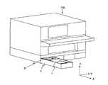
以下、本発明の実施形態について図面を参照して説明する。以下の説明において、液体吐出装置としてはインクジェットプリンタを、液体としてはインクを適用して説明する。しかし、これらの具体例には限定されない。以下の図面中に示される矢印Xの方向(X方向)は、液体収容体1の液体吐出装置100への着脱時に、液体収容体1が液体吐出装置100に対して進退する方向である。矢印Yの方向(Y方向)は液体収容体1の幅方向であり、矢印Zの方向(Z方向)は液体収容体1の厚さ方向である。X方向とY方向とZ方向は互いに直交している。ここで、液体収容体1が液体吐出装置100に搭載された状態を搭載状態と呼ぶ。液体収容体1は厚さ方向が鉛直方向と一致する向きで液体吐出装置100に搭載されるため、搭載状態でZ方向は鉛直方向に一致する。 Hereinafter, embodiments of the present invention will be described with reference to the drawings. In the following description, an inkjet printer will be applied as the liquid ejection device, and ink will be applied as the liquid. However, it is not limited to these specific examples. The direction of the arrow X (X direction) shown in the following drawings is the direction in which theliquid container 1 moves forward and backward with respect to theliquid discharge device 100 when theliquid container 1 is attached to and detached from theliquid discharge device 100. The direction of the arrow Y (Y direction) is the width direction of theliquid container 1, and the direction of the arrow Z (Z direction) is the thickness direction of theliquid container 1. The X, Y, and Z directions are orthogonal to each other. Here, the state in which theliquid container 1 is mounted on theliquid discharge device 100 is referred to as a mounted state. Since theliquid container 1 is mounted on theliquid discharge device 100 in a direction in which the thickness direction coincides with the vertical direction, the Z direction coincides with the vertical direction in the mounted state.

図1は、本発明の一実施形態に係る液体収容体1が搭載された液体吐出装置100の斜視図である。液体吐出装置100は記録ヘッド、記録媒体の収容部、記録媒体の搬送機構(これらは図示せず)などを備えている。液体吐出装置100にはカセット2に収容された液体収容体1が搭載される。液体収容体1は液体吐出装置100の記録ヘッドから吐出されるインクを収容している。本実施形態では、それぞれがシアン(C)、マゼンタ(M)、イエロー(Y),黒(K)のインクを収容する4つの液体収容体1が液体吐出装置100に搭載される。4つの液体収容体1の大きさは同じであるが、例えば黒インクの液体収容体1を他の色のインクの液体収容体1より大きくしてもよい。液体収容体1が収容されたカセット2は液体吐出装置100に対して着脱可能に、X方向に進退する。 FIG. 1 is a perspective view of aliquid discharge device 100 on which aliquid container 1 according to an embodiment of the present invention is mounted. Theliquid discharge device 100 includes a recording head, a recording medium accommodating portion, a recording medium transport mechanism (these are not shown), and the like. Theliquid container 1 housed in thecassette 2 is mounted on theliquid discharge device 100. Theliquid container 1 contains ink discharged from the recording head of theliquid discharge device 100. In the present embodiment, fourliquid containers 1 each containing cyan (C), magenta (M), yellow (Y), and black (K) inks are mounted on theliquid ejection device 100. The size of the fourliquid containers 1 is the same, but for example, theliquid container 1 of black ink may be larger than theliquid container 1 of inks of other colors. Thecassette 2 in which theliquid container 1 is housed moves back and forth in the X direction so as to be detachable from theliquid discharge device 100.

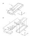
図2(a)は液体収容体1の斜視図、図2(b)は液体収容体1の組立手順を示す分解斜視図である。図3(a)は液体収容体1の側面図、図3(b)は内部構造物の組立手順を示す液体収容体1の分解斜視図、図3(c)は図3(a)のA部拡大図である。図4(a)は液体収容体1の上面図、図4(b)はチューブの取付方法を示す液体収容体1の分解斜視図、図4(c)は図4(a)のB部拡大図である。 FIG. 2A is a perspective view of theliquid container 1, and FIG. 2B is an exploded perspective view showing an assembly procedure of theliquid container 1. 3 (a) is a side view of theliquid container 1, FIG. 3 (b) is an exploded perspective view of theliquid container 1 showing an assembly procedure of the internal structure, and FIG. 3 (c) is A of FIG. 3 (a). It is a part enlarged view. 4 (a) is a top view of theliquid container 1, FIG. 4 (b) is an exploded perspective view of theliquid container 1 showing a method of attaching a tube, and FIG. 4 (c) is an enlarged view of part B of FIG. 4 (a). It is a figure.

図2においては、保持部材4は後述する通り、連結部材7とスペーサー部材6とを備えて構成されるが、これらを省略して保持部材4として示している。また、インクを導出するためのチューブ5も省略している。
図2に示される通り、液体収容体1は、インクを収容する液体収容袋3を有している。液体収容袋3は可撓性を有する材料から形成されている。液体収容袋3の内部空間には袋内から記録ヘッドに対してインクを導出するチューブ(不図示)と保持部材4とが設けられている。ここで、チューブの数は限定されず、少なくとも1つ設けられていればよいが、本実施形態では例えば図3(a)ないし(c)に示されるように2つのチューブが設けられている。以下、これらのチューブを第1のチューブ5A、第2のチューブ5Bという。第1のチューブ5Aと第2のチューブ5Bは、インクが流通するインク流路を形成する。第1及び第2のチューブ5A,5Bは、エラストマーなどの弾性を有する材料で形成されている。第1のチューブ5Aと第2のチューブ5Bはそれぞれ、第1の端部51と第2の端部52とを有し、後述するスペーサー部6と接続部材8との間を概ねX方向に延びて配設されている。第1及び第2のチューブ5A,5Bの第1の端部51は詳細は後述するが、スペーサー部6に設けられた溝の部分に対して嵌め合わされて取り付けられ、液体収容袋3の内部空間31に開口している。また、第2の端部52は接続部材8に接続されている。なお、Z方向からみた場合には、第1の端部51の開口部分は液体収容袋3のほぼ中央部に位置している。さらに、搭載状態では、第1のチューブ5Aの第1の端部51は内部空間31の上部に位置し、第2のチューブ5Bの第1の端部51は内部空間31の下部に位置している。本実施形態で使用されるインクは沈降成分(例えば顔料)を含んでおり、時間の経過とともに、液体収容袋3の上部では沈降成分の濃度が低くなり、下部では沈降成分の濃度が高まることになる。そのため、インクの供給(導出)時には第1のチューブ5Aから濃度の低いインクが、第2のチューブ5Bから濃度の高いインクが同時に供給(導出)されることになり、液体収容体1から供給されるインクの濃度が平均化され、記録品質の経時的な変化が抑制される。
In FIG. 2, as will be described later, the holdingmember 4 includes a connectingmember 7 and aspacer member 6, but these are omitted and shown as the holdingmember 4. Further, thetube 5 for deriving the ink is also omitted.
As shown in FIG. 2, theliquid container 1 has aliquid storage bag 3 for storing ink. Theliquid storage bag 3 is made of a flexible material. In the internal space of theliquid storage bag 3, a tube (not shown) for drawing out ink from the inside of the bag to the recording head and a holdingmember 4 are provided. Here, the number of tubes is not limited, and at least one tube may be provided, but in the present embodiment, for example, two tubes are provided as shown in FIGS. 3 (a) to 3 (c). Hereinafter, these tubes will be referred to as afirst tube 5A and asecond tube 5B. Thefirst tube 5A and thesecond tube 5B form an ink flow path through which ink flows. The first andsecond tubes 5A and 5B are made of an elastic material such as an elastomer. Thefirst tube 5A and thesecond tube 5B each have afirst end portion 51 and asecond end portion 52, and extend between thespacer portion 6 and the connectingmember 8 described later in the X direction, respectively. Are arranged. Thefirst end 51 of the first andsecond tubes 5A and 5B will be described in detail later, but is fitted and attached to the groove portion provided in thespacer portion 6 and is attached to the internal space of theliquid storage bag 3. It is open to 31. Further, thesecond end portion 52 is connected to the connectingmember 8. When viewed from the Z direction, the opening portion of thefirst end portion 51 is located substantially at the center of theliquid storage bag 3. Further, in the mounted state, thefirst end 51 of thefirst tube 5A is located above theinternal space 31, and thefirst end 51 of thesecond tube 5B is located below theinternal space 31. There is. The ink used in the present embodiment contains a settling component (for example, a pigment), and as time passes, the concentration of the settling component decreases in the upper part of theliquid storage bag 3, and the concentration of the settling component increases in the lower part. Become. Therefore, when the ink is supplied (derived out), the low-concentration ink is simultaneously supplied (derived out) from thefirst tube 5A and the high-concentration ink is simultaneously supplied (derived out) from thesecond tube 5B, and is supplied from theliquid container 1. The density of the ink is averaged, and changes in recording quality over time are suppressed.

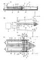
図3(a)ないし(c)に示される通り、保持部材4は、搭載状態で液体収容袋3の上面32と下面33との間に介在するスペーサー部6と、スペーサー部6に接続され、搭載状態でチューブ5A,5Bと同じ方向(X方向)に延びる連結部7と、を有している。保持部材4は、ポリエチレン、ポリプロピレンなどの合成樹脂からなり、後述するようにモールドによって一体成型される。 As shown in FIGS. 3A to 3C, the holdingmember 4 is connected to aspacer portion 6 interposed between theupper surface 32 and thelower surface 33 of theliquid storage bag 3 and thespacer portion 6 in the mounted state. It has a connectingportion 7 extending in the same direction (X direction) as thetubes 5A and 5B in the mounted state. The holdingmember 4 is made of a synthetic resin such as polyethylene or polypropylene, and is integrally molded by a mold as described later.

図3、図4に示される通り、スペーサー部6は、X方向の中心線に関し、X−Z面においてもX−Y面においてもほぼ対称である。スペーサー部6は、図3(c)に示されるようにY方向からみて三角形状の前方部61と矩形形状の後方部62とを有する五角形形状を有し、図4(c)に示されるようにZ方向からみて概ね矩形形状を有している。図3(c)に示されるように前方部61の高さ(Z方向寸法)は後方部62に向けて大きくなっており、後方部62の高さ(Z方向寸法)はほぼ一定である。また、図5(a)に示すように、前方部61は、Z方向の中心から離れるに従い幅(Y方向寸法)が小さくなるテーパ形状を有している。換言すれば、前方部61は、図3(c)に示される通りX方向においては後方部62から離れる方向に下り傾斜となっており、図5(a)に示される通りY方向においてX方向中心線からY方向に離れる方向に下り傾斜となっている。図3(c)に示す通り後方部62の高さは保持部材4の中で最も高く、搭載時に後方部62の底部64は液体収容袋3の下面33に当接している。後方部62の頂部63は、液体収容袋3のインク残量によっては、液体収容袋3の上面32に当接していなくてもよい。しかし、インクが消費されて液体収容袋3が収縮すると、後方部62の頂部63は液体収容袋3の上面32に当接する。スペーサー部6は液体収容袋3のインク残量に拘わらず、液体収容袋3の中央部で一定の高さを確保する。すなわち、スペーサー部6は液体収容袋3の中央部に一定の空間を確保する。図3(a)に破線Sで示すように、インクが消費されると液体収容袋3の上面32が下面33に接近し、最後には下面33に密着して、インクを導出することができなくなる。後述のように、第1及び第2のチューブ5A,5Bの第1の端部51はスペーサー部6に嵌合支持されるように構成されているため、第1の端部51の周囲にはスペーサー部6によって空間が確保されることになり、最後までインクを導出することが可能になる。このように、スペーサー部6はインク残量が少なくなっても第1の端部51の周囲を閉塞してしまうようなことにはならずインクを導出することを可能とし、インクの利用効率を高める。 As shown in FIGS. 3 and 4, thespacer portion 6 is substantially symmetrical with respect to the center line in the X direction in both the XY plane and the XY plane. Thespacer portion 6 has a pentagonal shape having atriangular front portion 61 and a rectangularrear portion 62 when viewed from the Y direction as shown in FIG. 3 (c), as shown in FIG. 4 (c). It has a substantially rectangular shape when viewed from the Z direction. As shown in FIG. 3C, the height (Z-direction dimension) of thefront portion 61 increases toward therear portion 62, and the height (Z-direction dimension) of therear portion 62 is substantially constant. Further, as shown in FIG. 5A, thefront portion 61 has a tapered shape in which the width (dimension in the Y direction) decreases as the distance from the center in the Z direction increases. In other words, thefront portion 61 is inclined downward in the X direction as shown in FIG. 3 (c) in a direction away from therear portion 62, and is inclined in the X direction in the Y direction as shown in FIG. 5 (a). The slope is downward in the direction away from the center line in the Y direction. As shown in FIG. 3C, the height of therear portion 62 is the highest among the holdingmembers 4, and thebottom portion 64 of therear portion 62 is in contact with thelower surface 33 of theliquid storage bag 3 when mounted. The top 63 of therear portion 62 may not be in contact with theupper surface 32 of theliquid storage bag 3 depending on the remaining amount of ink in theliquid storage bag 3. However, when the ink is consumed and theliquid storage bag 3 contracts, the top 63 of therear portion 62 comes into contact with theupper surface 32 of theliquid storage bag 3. Thespacer portion 6 secures a constant height at the central portion of theliquid storage bag 3 regardless of the remaining amount of ink in theliquid storage bag 3. That is, thespacer portion 6 secures a certain space in the central portion of theliquid storage bag 3. As shown by the broken line S in FIG. 3A, when the ink is consumed, theupper surface 32 of theliquid storage bag 3 approaches thelower surface 33, and finally adheres to thelower surface 33, and the ink can be derived. It disappears. As will be described later, since thefirst end 51 of the first andsecond tubes 5A and 5B is configured to be fitted and supported by thespacer 6, the periphery of the first end 51 A space is secured by thespacer portion 6, and the ink can be drawn out to the end. In this way, thespacer portion 6 does not block the periphery of thefirst end portion 51 even when the remaining amount of ink is low, and makes it possible to draw out the ink, thereby improving the ink utilization efficiency. Increase.

図3に示されるように、スペーサー部6は、上下方向(Z方向)に延びX方向に互いに並行して設けられた複数の壁65を有している。複数の壁65の間には液体収容袋3の内部空間31に連通する溝66A(図4(c)参照)、66Bが形成されている。図4(c)に示すように、溝はX方向にスペーサー部6を貫通する主溝66A(以下で第1の主溝という)と、第1の主溝66Aと直交しY方向に延びる複数の補助溝66B(以下で第1の補助溝という)と、を有している。そして、第1の補助溝66Bは第1の主溝66AのY方向両側に設けられている。また、図4(c)で示されるスペーサー部6は、図5(a)に示されるように、その裏面側も同様の溝構造を有しており、第1の主溝66Aの裏側に破線で示すように第1の主溝より幅の広い主溝67A(以下で第2の主溝という)を有している。さらに第2の主溝67Aと直交しY方向に延びる複数の補助溝67B(以下で第2の補助溝という)を有しており、第2の補助溝67Bは第2の主溝67AのY方向両側に設けられている(なお、第2の主溝67A、第2の補助溝67Bは図中破線で仮想的に示している)。インク残量が減少し、液体収容袋3の上面32がスペーサー部6に密着した場合も、インクは第1の主溝66Aと第1の補助溝66Bからスペーサー部6の内部に流入する。また、液体収容袋3の下面33側に対してもスペーサー部6に設けられた第2の主溝67Aと第2の補助溝67Bによってスペーサー部6の内部にインクが良好に流入する。これらの第1の主溝66A、第2の主溝67Aと第1の補助溝66B、第2の補助溝67Bはインクの利用効率を有効に高める。
スぺーサー部6の構成について図6(図3(c)のE-E断面図)を用いてさらに説明する。なお、説明を簡単にするためスぺーサー部6の上方側の第1の主溝66A、第1の補助溝66B、チューブ5Aを用いて説明する。第1の主溝66Aは、溝を構成する側面と底面に相当する側面との間(便宜的に角部6Cと称する)の角度がほぼ直角となっている。溝が角部6Cを備えることによって、溝に取り付けられたチューブ(一般にチューブは円柱形であることを前提として)は、図6に示すように角部6Cに対して接触しない非接触空間66Cを構成する。そして、例えばインクは第1の補助溝66Bから第1の主溝66Aの角部6Cに構成された非接触空間66Cに流入し、この非接触空間66Cをインクが流れてチューブ5Aの第1の端部51側に移動することができ、第1の補助溝66Bの間に残ってしまうインクを極めて少なくすることができ、インクの使用効率を向上させることができる。しかし、角部6Cが直角ではなく、チューブと同程度の曲率を有する曲面である場合、角部6Cに相当する領域には非接触空間66Cが構成されないため、第1の補助溝66Bから第1の主溝66Aに流れたインクはチューブ5Aによって堰き止めてしまう。そのため、インクの移動ができなくなり、第1の補助溝66Bの間に残ってしまうインクが増えインクの使用効率が低減してしまう。
角部6Cを含む主溝の構成は、例えば図7(a)ないし(c)に示されるような構成としてもよい。すなわち、図7(a)は溝の底面に相当する側面に凸部を設けた構成、図7(b)は溝の底面に相当する側面に凹部を設けた構成となっている。このような構成とすることでチューブの可撓性によってチューブが溝に沿って変形してしまい非接触空間66Cが実質的になくなってしまうことが抑制でき、角部6Cにインクが流れる非接触空間66Cを確実に構成することができる。また、実質的なチューブの変形がない場合には図7(c)に示すように角部6Cを鈍角によって構成し、溝の底面を多角にすることも可能である。なお、角部6Cを鋭角で構成することが可能であることは言うまでもない。しかし、後述する保持部材4の簡便な製造方法を考慮すると、型抜きが容易にできる例えば直角以上の鈍角であることが好ましい。
As shown in FIG. 3, thespacer portion 6 has a plurality ofwalls 65 extending in the vertical direction (Z direction) and provided in parallel with each other in the X direction.Grooves 66A (see FIG. 4C) and 66B communicating with theinternal space 31 of theliquid storage bag 3 are formed between the plurality ofwalls 65. As shown in FIG. 4 (c), the grooves are amain groove 66A (hereinafter referred to as a first main groove) penetrating thespacer portion 6 in the X direction, and a plurality of grooves extending in the Y direction orthogonal to the firstmain groove 66A.Auxiliary groove 66B (hereinafter referred to as a first auxiliary groove). The firstauxiliary groove 66B is provided on both sides of the firstmain groove 66A in the Y direction. Further, as shown in FIG. 5A, thespacer portion 6 shown in FIG. 4C has a similar groove structure on the back surface side thereof, and a broken line is formed on the back side of the firstmain groove 66A. As shown by, it has amain groove 67A (hereinafter referred to as a second main groove) wider than the first main groove. Further, it has a plurality ofauxiliary grooves 67B (hereinafter referred to as second auxiliary grooves) orthogonal to the secondmain groove 67A and extending in the Y direction, and the secondauxiliary groove 67B is Y of the secondmain groove 67A. It is provided on both sides in the direction (note that the secondmain groove 67A and the secondauxiliary groove 67B are virtually shown by broken lines in the figure). Even when the remaining amount of ink decreases and theupper surface 32 of theliquid storage bag 3 comes into close contact with thespacer portion 6, the ink flows into thespacer portion 6 from the firstmain groove 66A and the firstauxiliary groove 66B. Further, with respect to thelower surface 33 side of theliquid storage bag 3, ink is satisfactorily flowed into thespacer portion 6 by the secondmain groove 67A and the secondauxiliary groove 67B provided in thespacer portion 6. These firstmain groove 66A, secondmain groove 67A, firstauxiliary groove 66B, and secondauxiliary groove 67B effectively enhance the ink utilization efficiency.
The configuration of thespacer unit 6 will be further described with reference to FIG. 6 (E-E cross-sectional view of FIG. 3C). For the sake of simplicity, the firstmain groove 66A, the firstauxiliary groove 66B, and thetube 5A on the upper side of thespacer portion 6 will be used. In the firstmain groove 66A, the angle between the side surface forming the groove and the side surface corresponding to the bottom surface (referred to as acorner portion 6C for convenience) is substantially a right angle. By providing the groove with thecorner 6C, the tube attached to the groove (assuming the tube is generally cylindrical) provides anon-contact space 66C that does not contact thecorner 6C as shown in FIG. Constitute. Then, for example, the ink flows from the firstauxiliary groove 66B into thenon-contact space 66C formed in thecorner portion 6C of the firstmain groove 66A, and the ink flows through thenon-contact space 66C to thefirst tube 5A. The ink can be moved to theend portion 51 side, the amount of ink remaining between the firstauxiliary grooves 66B can be extremely reduced, and the ink usage efficiency can be improved. However, when thecorner portion 6C is not a right angle and has a curved surface having a curvature similar to that of the tube, thenon-contact space 66C is not formed in the region corresponding to thecorner portion 6C, so that the firstauxiliary groove 66B to the first The ink flowing into themain groove 66A is blocked by thetube 5A. Therefore, the ink cannot be moved, the amount of ink remaining between the firstauxiliary grooves 66B increases, and the ink usage efficiency decreases.
The configuration of the main groove including thecorner portion 6C may be, for example, the configuration shown in FIGS. 7A to 7C. That is, FIG. 7A has a configuration in which a convex portion is provided on a side surface corresponding to the bottom surface of the groove, and FIG. 7B has a configuration in which a concave portion is provided on the side surface corresponding to the bottom surface of the groove. With such a configuration, it is possible to prevent the tube from being deformed along the groove due to the flexibility of the tube and substantially eliminating thenon-contact space 66C, and the non-contact space through which ink flows in thecorner portion 6C. The 66C can be reliably configured. Further, when there is no substantial deformation of the tube, thecorner portion 6C may be formed with an obtuse angle as shown in FIG. 7C, and the bottom surface of the groove may be polygonal. Needless to say, thecorner portion 6C can be configured with an acute angle. However, considering a simple manufacturing method of the holdingmember 4 described later, it is preferable that the obtuse angle is, for example, an obtuse angle of at least a right angle, which enables easy die cutting.

図3、図4に示されるように、本実施形態では保持部材4は、連結部7とスペーサー部6とを一体成型によって構成されている。連結部7はスペーサー部6に接続された五角形形状の遷移部71と、遷移部71に接続されX方向に延びる軸部72と、から構成されている。軸部72のY−Z断面はX方向にほぼ一定である。連結部7は、スペーサー部6と反対側の端部41に設けられた係止部73によって、接続部材8に係止接続されている。接続部材8は連結部7(保持部材4)との対向部に円柱状の係止突起81(図3(b)参照)を有し、連結部7の係止部73は係止突起81に係止されている。係止部73は上面または下面に係止突起81と嵌合する開口74を有し、開口74を係止突起81に挿入、嵌合させることで保持部材4の端部41を接続部材8に支持させることができる。 As shown in FIGS. 3 and 4, in the present embodiment, the holdingmember 4 is formed by integrally molding the connectingportion 7 and thespacer portion 6. The connectingportion 7 is composed of apentagonal transition portion 71 connected to thespacer portion 6 and ashaft portion 72 connected to thetransition portion 71 and extending in the X direction. The YY cross section of theshaft portion 72 is substantially constant in the X direction. The connectingportion 7 is locked and connected to the connectingmember 8 by a locking portion 73 provided at anend portion 41 opposite to thespacer portion 6. The connectingmember 8 has a columnar locking projection 81 (see FIG. 3B) at a portion facing the connecting portion 7 (holding member 4), and the locking portion 73 of the connectingportion 7 is formed on the lockingprojection 81. It is locked. The locking portion 73 has anopening 74 on the upper surface or the lower surface that fits with the lockingprotrusion 81, and by inserting and fitting theopening 74 into the lockingprotrusion 81, theend portion 41 of the holdingmember 4 is attached to the connectingmember 8. Can be supported.

図3(a)に示されるように、接続部材8は、液体収容袋3の開口部34に取り付けられている。また、図4(b)に示されるように、接続部材8は、第1のチューブ5Aの第2の端部52が取り付けられる第1のノズル82Aと、第2のチューブ5Bの第2の端部52が取り付けられる第2のノズル82Bと、を有している。第1及び第2のチューブ5A,5Bの第2の端部52それぞれを第1及び第2のノズル82A,82Bに装着することによって、第1及び第2のチューブ5A,5Bが第1及び第2のノズル82A,82Bと接続される。第1のノズル82Aと第2のノズル82Bは接続部材8の内部流路83と連通しており、第1のチューブ5Aから流入したインクと第2のチューブ5Bから流入したインクは内部流路83で合流する。接続部材8の第1及び第2のノズル82A,82Bと反対側の面には、液体吐出装置100に接続される、インクの供給口84が設けられている。図4(a)のC-C断面図を図5(c)に示す。図5(c)に示されるように、第1のノズル82Aと第2のノズル82Bと係止突起81はZ方向に同じ高さに設けられ、係止突起81が第1のノズル82Aと第2のノズル82Bの間に位置している。図2に示すように、接続部材8は把持部材9に収容されている。把持部材9は回転可能な取っ手91(図1参照)とガイド部(図示せず)とを有しており、取っ手91をつかみながらカセット2の対応するガイド部(図示せず)に沿って液体収容体1を出し入れすることができる。 As shown in FIG. 3A, the connectingmember 8 is attached to theopening 34 of theliquid storage bag 3. Further, as shown in FIG. 4B, the connectingmember 8 has afirst nozzle 82A to which thesecond end 52 of thefirst tube 5A is attached and a second end of thesecond tube 5B. It has asecond nozzle 82B to which theportion 52 is attached. By attaching thesecond end 52 of the first andsecond tubes 5A and 5B to the first andsecond nozzles 82A and 82B, respectively, the first andsecond tubes 5A and 5B become the first and second tubes. It is connected to thenozzles 82A and 82B of 2. Thefirst nozzle 82A and thesecond nozzle 82B communicate with theinternal flow path 83 of the connectingmember 8, and the ink flowing in from thefirst tube 5A and the ink flowing in from thesecond tube 5B are in theinternal flow path 83. Meet at. Anink supply port 84 connected to theliquid ejection device 100 is provided on the surface of the connectingmember 8 opposite to the first andsecond nozzles 82A and 82B. A cross-sectional view taken along the line CC of FIG. 4 (a) is shown in FIG. 5 (c). As shown in FIG. 5C, thefirst nozzle 82A, thesecond nozzle 82B, and the lockingprojection 81 are provided at the same height in the Z direction, and the lockingprojection 81 is provided with thefirst nozzle 82A and thefirst nozzle 82A. It is located between thenozzles 82B of 2. As shown in FIG. 2, the connectingmember 8 is housed in the gripping member 9. The gripping member 9 has a rotatable handle 91 (see FIG. 1) and a guide portion (not shown), and while grasping thehandle 91, a liquid is formed along the corresponding guide portion (not shown) of thecassette 2. Thehousing 1 can be taken in and out.

前述したとおり保持部材4のスペーサー部6には、第1のチューブ5Aの第1の端部51が嵌合する第1の主溝66Aと、第2のチューブ5Bの第1の端部51が嵌合する第2の主溝67Aと、を有している。図3(c)のD-D断面を図5(a)に示す。図5(a)に示すように、搭載状態において、第1の主溝66Aはスペーサー部6の上部に、第2の主溝67Aはスペーサー部6の下部に設けられている。第1及び第2の主溝66A,67Aの設置位置は特に限定されないが、好ましくは、第1の主溝66Aは液体収容袋3の上面32に最も近接する第1の頂部68Aに、第2の主溝67Aは液体収容袋3の下面33に最も近接する第2の頂部68Bに設けられる。これらの位置ではスペーサー部6の高さ(Z方向寸法)が高いため、第1及び第2の主溝66A,67Aの深さを確保することが容易である。 As described above, thespacer portion 6 of the holdingmember 4 has a firstmain groove 66A into which thefirst end portion 51 of thefirst tube 5A fits and afirst end portion 51 of thesecond tube 5B. It has a secondmain groove 67A to be fitted and a secondmain groove 67A. The DD cross section of FIG. 3 (c) is shown in FIG. 5 (a). As shown in FIG. 5A, the firstmain groove 66A is provided in the upper part of thespacer portion 6 and the secondmain groove 67A is provided in the lower part of thespacer portion 6 in the mounted state. The installation positions of the first and secondmain grooves 66A and 67A are not particularly limited, but preferably, the firstmain groove 66A is located on the first top 68A closest to theupper surface 32 of theliquid storage bag 3. Themain groove 67A is provided on the second top 68B closest to thelower surface 33 of theliquid storage bag 3. Since the height of the spacer portion 6 (dimension in the Z direction) is high at these positions, it is easy to secure the depths of the first and secondmain grooves 66A and 67A.

第1及び第2のチューブ5A,5Bは接続部材8と保持部材4のスペーサー部6とによって保持される。第1及び第2のチューブ5A,5Bを安定して保持するため、第1及び第2のチューブ5A,5Bは第1の端部51で第1及び第2の溝66A,67Aと嵌合することが好ましい。しかし、嵌合する位置は第1の端部51に限定されず、第2の端部以外の部位であればよい。例えば、第1及び第2のチューブ5A,5Bの第1の端部51を含む端部領域が第1及び第2の主溝66A,67Aから片持ち梁状にX方向に突き出していてもよい。しかし、最も安定的に保持され、インクの取り出し位置が不安定にならない取り付けは、第1及び第2のチューブ5A,5Bの第1の端部51を第1及び第2の溝66A,67Aと嵌合することである。 The first andsecond tubes 5A and 5B are held by the connectingmember 8 and thespacer portion 6 of the holdingmember 4. In order to stably hold the first andsecond tubes 5A and 5B, the first andsecond tubes 5A and 5B are fitted with the first andsecond grooves 66A and 67A at thefirst end 51. Is preferable. However, the fitting position is not limited to thefirst end portion 51, and may be any portion other than the second end portion. For example, the end region including thefirst end 51 of the first andsecond tubes 5A and 5B may protrude in the X direction from the first and secondmain grooves 66A and 67A in a cantilever shape. .. However, in the mounting where the ink is held most stably and the ink ejection position is not unstable, thefirst end 51 of the first andsecond tubes 5A and 5B is connected to the first andsecond grooves 66A and 67A. It is to fit.

第1のチューブ5Aと第2のチューブ5Bはそれぞれ、少なくともその外径以上の長さの部分が、第1の主溝66Aと第2の主溝67Aに嵌合していることが好ましい。図3(c)に示すように、第1のチューブ5Aの外径をD1、第2のチューブ5Bの外径をD2、第1のチューブ5Aの第1の主溝66Aに挿入される長さをL1、第2のチューブ5Bの第2の主溝67Aに挿入される長さをL2とする。この場合、L1≧D1且つL2≧D2であることが好ましい。また、図5(a)に示すように、第1及び第2のチューブ5A,5Bは、少なくともその外径の1/2以上の高さの部分が第1の主溝66Aと第2の主溝67Aに嵌合していることが好ましい。すなわち、第1のチューブ5Aの第1の主溝66Aに挿入される深さをH1、第2のチューブ5Bの第2の主溝67Aに挿入される深さをH2とすると、H1≧D1/2且つH2≧D2/2であることが好ましい。外径D1,D2は、図5(b)に示す通り、第1及び第2のチューブ5A,5Bの第1及び第2の主溝66A,67Aに嵌合していない部分の寸法で定義される。あるいは第1及び第2のチューブ5A,5Bが第1及び第2の主溝66A,67Aに嵌合する前の状態で定義してもよい。すなわち、何もストレスのかかっていない状態のチューブの外径をD1,D2とする。第1及び第2のチューブ5A,5Bは第1及び第2の主溝66A,67Aの底部まで挿入されることが好ましい。この場合、深さH1,H2は実質的に、第1及び第2の主溝66A,67Aの深さに一致する。さらに、第1の主溝66Aの幅は第1のチューブ5Aの外径未満であり、第2の主溝67Aの幅は第2のチューブ5Bの外径未満であることが好ましい。すなわち、図5(a)に示すように、第1の主溝66Aの幅をW1、第2の主溝67Aの幅をW2とすると、D1>W1且つD2>W2であることが好ましい。換言すれば、第1のチューブ5Aは第1の主溝66Aで圧縮され、第2のチューブ5Bは第2の主溝67Aで圧縮された状態で取り付けられていることが好ましい。第1及び第2のチューブ5A,5Bと第1及び第2の主溝66A,67Aとの間の摩擦力によって、第1及び第2のチューブ5A,5Bが第1及び第2の主溝66A,67Aにしっかりと固定される。 It is preferable that at least a portion having a length equal to or larger than the outer diameter of thefirst tube 5A and thesecond tube 5B is fitted into the firstmain groove 66A and the secondmain groove 67A, respectively. As shown in FIG. 3C, the outer diameter of thefirst tube 5A is D1, the outer diameter of thesecond tube 5B is D2, and the length inserted into the firstmain groove 66A of thefirst tube 5A. Is L1, and the length inserted into the secondmain groove 67A of thesecond tube 5B is L2. In this case, it is preferable that L1 ≧ D1 and L2 ≧ D2. Further, as shown in FIG. 5A, in the first andsecond tubes 5A and 5B, the portion having a height of at least 1/2 or more of the outer diameter thereof is the firstmain groove 66A and the secondmain groove 66A. It is preferably fitted in thegroove 67A. That is, assuming that the depth inserted into the firstmain groove 66A of thefirst tube 5A is H1 and the depth inserted into the secondmain groove 67A of thesecond tube 5B is H2, H1 ≧ D1 / 2 and H2 ≧ D2 / 2 are preferable. As shown in FIG. 5B, the outer diameters D1 and D2 are defined by the dimensions of the portions of the first andsecond tubes 5A and 5B that are not fitted into the first and secondmain grooves 66A and 67A. NS. Alternatively, it may be defined in a state before the first andsecond tubes 5A and 5B are fitted into the first and secondmain grooves 66A and 67A. That is, the outer diameters of the tubes in a state where no stress is applied are D1 and D2. The first andsecond tubes 5A and 5B are preferably inserted up to the bottom of the first and secondmain grooves 66A and 67A. In this case, the depths H1 and H2 substantially correspond to the depths of the first and secondmain grooves 66A and 67A. Further, the width of the firstmain groove 66A is preferably less than the outer diameter of thefirst tube 5A, and the width of the secondmain groove 67A is preferably less than the outer diameter of thesecond tube 5B. That is, as shown in FIG. 5A, assuming that the width of the firstmain groove 66A is W1 and the width of the secondmain groove 67A is W2, it is preferable that D1> W1 and D2> W2. In other words, it is preferable that thefirst tube 5A is compressed in the firstmain groove 66A and thesecond tube 5B is attached in a compressed state in the secondmain groove 67A. Due to the frictional force between the first andsecond tubes 5A, 5B and the first and secondmain grooves 66A, 67A, the first andsecond tubes 5A, 5B are made into the first and secondmain grooves 66A. , 67A is firmly fixed.

上記条件の少なくともいずれか、好ましくはすべてを満たすことで、第1及び第2のチューブ5A,5Bが第1及び第2の主溝66A,67Aに安定して保持され、第1及び第2のチューブ5A,5Bが第1及び第2の主溝66A,67Aから脱落しにくくなる。一例では、第1のチューブ5A及び第2のチューブ5Bの外径D1,D2は6mm、内径は4mmである。第1の主溝66Aの幅W1は3mm、第2の主溝67Aの幅W2は4mmである。また、第1及び第2の主溝66A,67Aの深さは6mm、第1及び第2のチューブ5A,5Bが第1及び第2の主溝66A,67Aに挿入される長さL1,L2は6mmである。なお、第1の主溝66Aの幅W1が第1のチューブ5Aの外径D1と同じであっても、第1のチューブ5Aが第1の溝67Aの側面に接して摩擦を生じている状態であれば、第1のチューブ5Aは第1の溝67Aに保持される。第2の主溝67Aの幅W2と第2のチューブ5Bの外径D2との関係も同様である。すなわち、第1の溝67Aの幅W1は第1のチューブ5Aの外径以下であり、第2の溝67Bの幅W2は第2のチューブ5Bの外径以下であればよい。 By satisfying at least one of the above conditions, preferably all of them, the first andsecond tubes 5A and 5B are stably held in the first and secondmain grooves 66A and 67A, and the first andsecond tubes 5A and 5B are held in the first and secondmain grooves 66A and 67A. Thetubes 5A and 5B are less likely to fall out of the first and secondmain grooves 66A and 67A. In one example, the outer diameters D1 and D2 of thefirst tube 5A and thesecond tube 5B are 6 mm, and the inner diameter is 4 mm. The width W1 of the firstmain groove 66A is 3 mm, and the width W2 of the secondmain groove 67A is 4 mm. The depths of the first and secondmain grooves 66A and 67A are 6 mm, and the lengths L1 and L2 into which the first andsecond tubes 5A and 5B are inserted into the first and secondmain grooves 66A and 67A. Is 6 mm. Even if the width W1 of the firstmain groove 66A is the same as the outer diameter D1 of thefirst tube 5A, thefirst tube 5A is in contact with the side surface of thefirst groove 67A to cause friction. If so, thefirst tube 5A is held in thefirst groove 67A. The relationship between the width W2 of the secondmain groove 67A and the outer diameter D2 of thesecond tube 5B is also the same. That is, the width W1 of thefirst groove 67A may be equal to or less than the outer diameter of thefirst tube 5A, and the width W2 of thesecond groove 67B may be equal to or less than the outer diameter of thesecond tube 5B.

前述したとおり、本実施形態で使用されるインクは沈降成分を含んでおり、時間の経過とともに、液体収容袋3の上部では沈降成分の濃度が低くなり、下部では沈降成分の濃度が高まる。そして、上述したインクを導出するチューブの配置によれば、第1のチューブ5Aは比較的沈降成分の少ないインクを吸い込み、第2のチューブ5Bは比較的沈降成分の多いインクを吸い込む。その際に、沈降成分の濃度の増加を抑制するためには第2のチューブ5Bからより多くのインクを吸い込むことが好ましい。このため、図5(a)で示すように、本実施形態では、第2のチューブ5Bの最小流路断面積を第1のチューブ5Aの最小流路断面積より大きくなるようにしている。具体的には、第2のチューブ5Bの第2の主溝67Aに嵌合する部分の流路断面積SBが、第1のチューブ5Aの第1の主溝66Aに嵌合する部分の流路断面積SAより大きくされている。これによって、第2のチューブ5Bの流路抵抗が第1のチューブ5Aの流路抵抗より小さくなり、沈降成分の濃度の高いインクを吸い込みやすくなる。このため、沈降成分の濃度が高い液体収容袋3の下層のインクを効率よく第2のチューブ5Bへ導くことができる。図5(a)に示される形態では、第1のチューブ5Aと第2のチューブ5Bが同一の外径と同一の肉厚を有したものが用いられている。そして、第1の主溝66A、第2の主溝67Aの深さH1、H2が同一、第2の主溝67Aの幅W2が第1の主溝66Aの幅W1より大きく、第2のチューブ5Bの外径より小さい寸法が選定されている。この形態では、第1及び第2のチューブ5A,5Bとして同じチューブを使用することができるため、生産管理上有利である。なお、図5(d)に示すような構成も可能である。すなわち、スペーサー部6の第1の主溝66Aと第2の主溝67Aの幅Wと深さHを同一とし、第1及び第2のチューブ5A,5Bの外径が同一のものを使用する。この場合には、第2のチューブ5Bの肉厚t2が第1のチューブ5Aの肉厚t1より小さい(第2のチューブ5Bの内径が第1のチューブ5Aの内径より大きく)種類のチューブを選定することによって、チューブの流路断面積の関係がSB>SAを満たすため、所望の効果が期待できる。図5(d)では、第1の溝66Aと第2の溝67Aの幅を同じものとしたが、チューブの流路断面積がSB>SAの関係を満たす限り異なる幅であっていてもよい。第1及び第2の溝66A,67Aの幅と深さは、第1及び第2のチューブ5A,5Bが完全に閉塞されない限り適宜変更することができる。また、第2のチューブ5Bにより多くのインクを流すため、第2のチューブ5Bの外径を第1のチューブ5Aの外径より大きくしてもよい。 As described above, the ink used in the present embodiment contains a settling component, and with the passage of time, the concentration of the settling component decreases in the upper part of theliquid storage bag 3, and the concentration of the settling component increases in the lower part. Then, according to the arrangement of the tubes for drawing out the ink described above, thefirst tube 5A sucks the ink having a relatively small settling component, and thesecond tube 5B sucks the ink having a relatively large settling component. At that time, in order to suppress the increase in the concentration of the sedimentation component, it is preferable to suck in more ink from thesecond tube 5B. Therefore, as shown in FIG. 5A, in the present embodiment, the minimum flow path cross-sectional area of thesecond tube 5B is made larger than the minimum flow path cross-sectional area of thefirst tube 5A. Specifically, the flow path cross-sectional area SB of the portion of thesecond tube 5B that fits into the secondmain groove 67A is the flow path of the portion that fits into the firstmain groove 66A of thefirst tube 5A. It is larger than the cross-sectional area SA. As a result, the flow path resistance of thesecond tube 5B becomes smaller than the flow path resistance of thefirst tube 5A, and it becomes easy to suck the ink having a high concentration of the sedimentation component. Therefore, the ink in the lower layer of theliquid storage bag 3 having a high concentration of the sedimented component can be efficiently guided to thesecond tube 5B. In the form shown in FIG. 5A, thefirst tube 5A and thesecond tube 5B have the same outer diameter and the same wall thickness. The depths H1 and H2 of the firstmain groove 66A and the secondmain groove 67A are the same, the width W2 of the secondmain groove 67A is larger than the width W1 of the firstmain groove 66A, and the second tube. Dimensions smaller than the outer diameter of 5B are selected. In this form, the same tubes can be used as the first andsecond tubes 5A and 5B, which is advantageous in terms of production control. The configuration shown in FIG. 5 (d) is also possible. That is, the width W and depth H of the firstmain groove 66A and the secondmain groove 67A of thespacer portion 6 are the same, and the outer diameters of the first andsecond tubes 5A and 5B are the same. .. In this case, select a type of tube in which the wall thickness t2 of thesecond tube 5B is smaller than the wall thickness t1 of thefirst tube 5A (the inner diameter of thesecond tube 5B is larger than the inner diameter of thefirst tube 5A). By doing so, the relationship of the flow path cross-sectional area of the tube satisfies SB> SA, so that a desired effect can be expected. In FIG. 5D, the widths of thefirst groove 66A and thesecond groove 67A are the same, but the widths may be different as long as the flow path cross-sectional area of the tube satisfies the relationship of SB> SA. .. The width and depth of the first andsecond grooves 66A, 67A can be appropriately changed as long as the first andsecond tubes 5A, 5B are not completely closed. Further, in order to allow more ink to flow through thesecond tube 5B, the outer diameter of thesecond tube 5B may be larger than the outer diameter of thefirst tube 5A.

本実施形態によれば、保持部材4は一体成型に適した構成となっているため、保持部材4の製造プロセスが簡略化される。この点について本実施形態を比較例と対比して説明する。図8(a)は比較例の保持部材104の側面図を示している。比較例では、第1及び第2のチューブ5A,5Bの第1の端部51を保持する追加のノズル10A,10Bがスペーサー部6に設けられている。追加のノズル10A,10Bは図3(b)に示されている接続部材8の第1及び第2のノズル82A,82Bと同様の構成を有している。第1及び第2のチューブ5A,5Bを追加のノズル10A,10Bにかぶせるように装着することによって、第1及び第2のチューブ5A,5Bをスペーサー部6に保持させることができる。
図8(b)は、比較例の保持部材104を射出成型によって作成する状況を示している。保持部材4は、上型M101と下型M102とを有するモールドで作成される。スペーサー部6の主溝66Aと補助溝66Bは上型M101と下型M102によって形成することができる。しかし、追加のノズル10A,10Bが上型M101及び下型M102と干渉するため、実際には図6(b)に示すモールドでは、比較例の保持部材104を形成することができない。そのため、図6(c)に示すように、保持部材104をスペーサー部106と連結部107とに分割し、それぞれを別の型で作成する必要がある。連結部107は専用の上型M103と下型M104で作成する。スペーサー部106も専用の上型M105と下型M106で作成するが、追加のノズル10A,10Bの型抜きのため、横方向にスライドする型M107が必要となる。さらに、このようにして作成したスペーサー部106と連結部107とを接合するため、スペーサー部106と連結部107の双方に嵌合部を設ける必要がある。この様に、比較例の保持部材104を作成するには、スペーサー部106と連結部107を別々の型で作成し、さらにそれらを一体化する必要があり、製造プロセスが複雑化する。
According to the present embodiment, since the holdingmember 4 has a structure suitable for integral molding, the manufacturing process of the holdingmember 4 is simplified. This point will be described in comparison with the comparative example of the present embodiment. FIG. 8A shows a side view of the holdingmember 104 of the comparative example. In the comparative example,additional nozzles 10A and 10B for holding thefirst end 51 of the first andsecond tubes 5A and 5B are provided in thespacer portion 6. Theadditional nozzles 10A and 10B have the same configuration as the first andsecond nozzles 82A and 82B of the connectingmember 8 shown in FIG. 3B. By mounting the first andsecond tubes 5A and 5B so as to cover theadditional nozzles 10A and 10B, the first andsecond tubes 5A and 5B can be held by thespacer portion 6.
FIG. 8B shows a situation in which the holdingmember 104 of the comparative example is produced by injection molding. The holdingmember 4 is made of a mold having an upper mold M101 and a lower mold M102. Themain groove 66A and theauxiliary groove 66B of thespacer portion 6 can be formed by the upper mold M101 and the lower mold M102. However, since theadditional nozzles 10A and 10B interfere with the upper die M101 and the lower die M102, the holdingmember 104 of the comparative example cannot be actually formed by the mold shown in FIG. 6B. Therefore, as shown in FIG. 6C, it is necessary to divide the holdingmember 104 into aspacer portion 106 and a connectingportion 107, and to prepare each of them with a different mold. The connectingportion 107 is created by the dedicated upper mold M103 and lower mold M104. Thespacer portion 106 is also made of the dedicated upper die M105 and lower die M106, but the die M107 that slides in the lateral direction is required for die cutting of theadditional nozzles 10A and 10B. Further, in order to join thespacer portion 106 and the connectingportion 107 thus created, it is necessary to provide fitting portions on both thespacer portion 106 and the connectingportion 107. As described above, in order to prepare the holdingmember 104 of the comparative example, it is necessary to prepare thespacer portion 106 and the connectingportion 107 in separate molds, and further integrate them, which complicates the manufacturing process.

図9は、本実施形態の保持部材4を、上型M1と下型M2を有するモールドで、射出成型によって形成する状況を示している。比較例と異なり、スペーサー部6に追加のノズル10A,10Bが設けられていない。このため、保持部材4の全体を一対の上型M1と下型M2で製作することができる。保持部材4の接続部材8側の端部41は上方または下方に開口しているため、端部41の開口74の型抜きも下型M2によって行うことができる。追加のノズル10A,10Bが不要であるため、比較例と比べて圧力損失が低減し、インクの吸い込み効率が向上する効果も得られる。なお、第1の主溝66A、第2の主溝67Aの角部6Cの構成に関しては前述したように型抜きができる角度で構成されている。 FIG. 9 shows a situation in which the holdingmember 4 of the present embodiment is formed by injection molding with a mold having an upper mold M1 and a lower mold M2. Unlike the comparative example, thespacer portion 6 is not provided with theadditional nozzles 10A and 10B. Therefore, the entire holdingmember 4 can be manufactured by a pair of upper mold M1 and lower mold M2. Since theend 41 on the connectingmember 8 side of the holdingmember 4 is opened upward or downward, the lower die M2 can also be used for die cutting of theopening 74 of theend 41. Since theadditional nozzles 10A and 10B are not required, the pressure loss is reduced and the ink suction efficiency is improved as compared with the comparative example. Thecorners 6C of the firstmain groove 66A and the secondmain groove 67A are configured at an angle that allows die cutting as described above.

液体収容体1は以下の手順で製造することができる。まず、上述の手順によって一体の保持部材4を形成する。次に、図2(b)、図3(b)の手順P1に示すように、保持部材4を接続部材8に取り付ける。次に、図3(b)、図4(b)の手順P2に示すように、第1及び第2のチューブ5A,5Bの第2の端部52を接続部材8に取り付ける。次に、図3(b)、図4(b)の手順P3に示すように、第1及び第2のチューブ5A,5Bの第1の端部51を、スペーサー部6の第1及び第2の溝67A,67Bに嵌合させ、第1及び第2のチューブ5A,5Bを保持部材4に保持させる。第1及び第2のチューブ5A,5Bを保持部材4にしっかりと保持させるためには、手順P2の後に手順P3を実施するほうが好ましいが、手順P3の後に手順P2を実施してもよい。その後、図2(b)、図3(b)の手順P4に示すように、接続部材8を把持部材9に取り付ける。以上で、保持部材4と、接続部材8と、保持部材4と接続部材8とで保持された第1及び第2のチューブ5A,5Bと、把持部材9の組立体が完成する。そして、図2(b)の手順P5に示すように、保持部材4と第1及び第2のチューブ5A,5Bを、第1の端部51が液体収容袋3の内部空間31に開口するように、液体収容袋3の内部空間31に設置する。その後、液体収容袋3の接続部材8が取り付けられた開口部34を封止する。以上の工程によって液体収容体1が完成する。液体収容体1を液体吐出装置100に搭載するには、図2(b)の手順P6に示すように、液体収容体1をカセット2に取り付ける。そして、液体収容体1が取り付けられたカセット2をX方向にスライドさせて液体吐出装置100に搭載する。 Theliquid container 1 can be manufactured by the following procedure. First, the integrated holdingmember 4 is formed by the above procedure. Next, as shown in the procedure P1 of FIGS. 2 (b) and 3 (b), the holdingmember 4 is attached to the connectingmember 8. Next, as shown in procedure P2 of FIGS. 3 (b) and 4 (b), thesecond end 52 of the first andsecond tubes 5A and 5B is attached to the connectingmember 8. Next, as shown in the procedure P3 of FIGS. 3 (b) and 4 (b), thefirst end 51 of the first andsecond tubes 5A and 5B is attached to the first andsecond spacers 6. The first andsecond tubes 5A and 5B are held by the holdingmember 4 by being fitted into thegrooves 67A and 67B of the above. In order to firmly hold the first andsecond tubes 5A and 5B to the holdingmember 4, it is preferable to carry out the procedure P3 after the procedure P2, but the procedure P2 may be carried out after the procedure P3. After that, as shown in the procedure P4 of FIGS. 2B and 3B, the connectingmember 8 is attached to the gripping member 9. This completes the assembly of the holdingmember 4, the connectingmember 8, the first andsecond tubes 5A and 5B held by the holdingmember 4 and the connectingmember 8, and the gripping member 9. Then, as shown in the procedure P5 of FIG. 2B, the holdingmember 4 and the first andsecond tubes 5A and 5B are opened so that thefirst end portion 51 opens into theinternal space 31 of theliquid storage bag 3. It is installed in theinternal space 31 of theliquid storage bag 3. After that, theopening 34 to which the connectingmember 8 of theliquid storage bag 3 is attached is sealed. Theliquid container 1 is completed by the above steps. In order to mount theliquid container 1 on theliquid discharge device 100, theliquid container 1 is attached to thecassette 2 as shown in the procedure P6 of FIG. 2 (b). Then, thecassette 2 to which theliquid container 1 is attached is slid in the X direction and mounted on theliquid discharge device 100.

1 液体収容体
3 液体収容袋
4 保持部材
6 スペーサー部
7 連結部材
51,52 第1及び第2の端部
5A,5B 第1及び第2のチューブ
66A,67A 第1及び第2の溝
66B,67B 第1及び第2の補助溝
66C 非接触空間
8 接続部材
1Liquid container 3Liquid storage bag 4Holding member 6Spacer part 7Connecting members 51, 52 First and second ends 5A, 5B First andsecond tubes 66A, 67A First andsecond grooves 66B, 67B 1st and 2ndauxiliary grooves66C Non-contact space 8 Connecting member

Claims (24)

Translated fromJapanese
カセットと、
前記カセットに載置され、液体吐出装置から吐出される液体を収容する液体収納袋と、
前記液体収容袋の一端の開口部分に備えられた接続部材と、
前記接続部材に接続され、前記液体収容袋内方の中ほどに延在する連結部材と、前記連結部材と接続されたスペーサー部とを備えた保持部材と、
前記接続部材と前記スペーサー部とに取り付けられ、前記液体収納袋から液体を導出するチューブと、
を備えた液体収納容器であって、
前記スペーサー部は、前記チューブの一端側が嵌合される主溝と、前記主溝に連通する補助溝と、を有しており、前記主溝の内側面と嵌合された前記チューブの外側面との間に一部非接触空間を構成しており、前記補助溝は前記非接触空間と連通している、液体収容体。
With a cassette
A liquid storage bag placed on the cassette and containing the liquid discharged from the liquid discharge device, and
A connecting member provided in an opening at one end of the liquid storage bag,
A holding member having a connecting member connected to the connecting member and extending in the middle of the liquid storage bag, and a spacer portion connected to the connecting member.
A tube attached to the connecting member and the spacer portion to draw a liquid from the liquid storage bag,
It is a liquid storage container equipped with
The spacer portion has a main groove into which one end side of the tube is fitted and an auxiliary groove communicating with the main groove, and the outer surface of the tube fitted with the inner surface of the main groove. A liquid container that partially forms a non-contact space with and communicates with the non-contact space.
前記非接触空間は、少なくとも前記チューブが嵌合される前記溝の開口に対して対向した領域に構成される、請求項1に記載の液体収容体。 The liquid container according to claim 1, wherein the non-contact space is formed in at least a region facing the opening of the groove into which the tube is fitted. 前記溝の前記非接触空間を構成する部分は、前記溝の延在方向に垂直の断面に関して、直角もしくは鈍角を構成する内側面の組み合わせを有する、請求項1または2のいずれか1項に記載の液体収容体。 The portion of the groove that constitutes the non-contact space has a combination of inner surfaces that form a right angle or an obtuse angle with respect to a cross section perpendicular to the extending direction of the groove, according to any one of claims 1 or 2. Liquid container. 前記保持部材は、前記連結部材と前記スペーサー部とが一体的に構成されている、請求項1に記載の液体収容体。 The liquid container according to claim 1, wherein the holding member is integrally formed with the connecting member and the spacer portion. 前記液体収容袋は可撓性を有しており、前記スペーサー部は前記液体収容体が前記液体吐出装置に搭載された状態で、前記液体収容袋の上面と下面との間に介在する、請求項1に記載の液体収容体。 The liquid storage bag is flexible, and the spacer portion is interposed between the upper surface and the lower surface of the liquid storage bag with the liquid container mounted on the liquid discharge device. Item 2. The liquid container according to item 1. 前記主溝は前記スペーサー部の一面側に第1の溝、前記一面と異なる他面側に第2の溝を備えており、
前記チューブは前記第1の溝と嵌合する第1のチューブと、前記第2の溝と嵌合する第2のチューブを備えている、請求項1に記載の液体収容体。
The main groove is provided with a first groove on one surface side of the spacer portion and a second groove on the other surface side different from the one surface.
The liquid container according to claim 1, wherein the tube includes a first tube that fits into the first groove and a second tube that fits into the second groove.
前記液体収容体が液体吐出装置に搭載された状態で、前記第1の溝は前記スペーサー部の上部に位置し、前記第2の溝部は前記スペーサー部の下部に位置する、請求項6に記載の液体収容体。 The sixth aspect of the present invention, wherein the first groove is located in the upper part of the spacer portion and the second groove portion is located in the lower part of the spacer portion in a state where the liquid container is mounted on the liquid discharge device. Liquid container. 前記スペーサー部は、前記液体収納袋の上面に最も近接する第1の頂部と、前記下面に最も近接する第2の頂部とを有し、前記第1の溝は前記第1の頂部に設けられ、前記第2の溝は前記第2の頂部に設けられている、請求項5または6のいずれか1項に記載の液体収容体。 The spacer portion has a first top portion closest to the upper surface of the liquid storage bag and a second top portion closest to the lower surface portion, and the first groove is provided on the first top portion. The liquid container according to any one of claims 5 or 6, wherein the second groove is provided on the second top. 前記チューブは、前記主溝に対して、その外径以上の長さの部分で嵌合している、請求項1に記載の液体収容体。 The liquid container according to claim 1, wherein the tube is fitted to the main groove at a portion having a length equal to or larger than the outer diameter thereof. 前記チューブは、その外径の1/2以上の部分が前記主溝に対して嵌合している、請求項9に記載の液体収容体。 The liquid container according to claim 9, wherein a portion of the tube having an outer diameter of ½ or more is fitted to the main groove. 前記第1の溝の幅は前記第1のチューブの外径以下であり、前記第2の溝の幅は前記第2のチューブの外径以下である、請求項6に記載の液体収容体。 The liquid container according to claim 6, wherein the width of the first groove is equal to or less than the outer diameter of the first tube, and the width of the second groove is equal to or less than the outer diameter of the second tube. 前記第1のチューブと前記第2のチューブは同一の外径と肉厚を有し、前記第2の溝の幅は前記第1の溝の幅より大きく、前記第2のチューブの外径より小さい、請求項6に記載の液体収容体。 The first tube and the second tube have the same outer diameter and wall thickness, and the width of the second groove is larger than the width of the first groove and is larger than the outer diameter of the second tube. The small liquid container according to claim 6. 前記第2のチューブの前記第2の溝に嵌合する部分の流路断面積は、前記第1のチューブの前記第1の溝に嵌合する部分の流路断面積より大きい、請求項6に記載の液体収容体。 6. The flow path cross-sectional area of the portion of the second tube that fits into the second groove is larger than the flow path cross-sectional area of the portion of the first tube that fits into the first groove. The liquid container described in. 前記第1のチューブと前記第2のチューブは同一の外径を有し、前記第2のチューブは前記第1のチューブより肉厚が小さく、前記第1の溝と前記第2の溝の幅は同じである、請求項6に記載の液体収容体。 The first tube and the second tube have the same outer diameter, the second tube is thinner than the first tube, and the width of the first groove and the second groove is wide. The liquid container according to claim 6, wherein is the same. 液体吐出装置に搭載され、前記液体吐出装置から吐出される液体を収容する液体収容体であって、
液体を収容する液体収容袋と、前記液体収容袋の内部空間に設けられ、第1の端部が前記内部空間に開口する少なくとも一つのチューブと、前記液体収容袋の開口部に取り付けられ、前記少なくとも一つのチューブの第2の端部が接続された接続部材と、前記接続部材に支持され、前記内部空間に設けられ、前記少なくとも一つのチューブを保持する保持部材と、を有し、
前記保持部材は、前記少なくとも一つのチューブの前記第2の端部以外の部位が嵌合する少なくとも一つの溝を有しており、
前記溝は、溝が延在する方向に垂直の断面が角部を有する形状である、液体収容体。
A liquid container mounted on a liquid discharge device and containing a liquid discharged from the liquid discharge device.
A liquid storage bag for containing a liquid, at least one tube provided in the internal space of the liquid storage bag and having a first end opening into the internal space, and an opening of the liquid storage bag are attached to the above. It has a connecting member to which a second end of at least one tube is connected, and a holding member supported by the connecting member and provided in the internal space to hold the at least one tube.
The holding member has at least one groove into which a portion other than the second end of the at least one tube fits.
The groove is a liquid container having a shape in which a cross section perpendicular to the direction in which the groove extends has a corner.
前記保持部材は、連結部材とスペーサー部とを備えており、
前記スペーサー部は前記液体収容体が前記液体吐出装置に搭載された状態で、前記液体収容袋の上面と下面との間に、前記液体収納袋の上面に最も近接する第1の頂部と、前記下面に最も近接する第2の頂部とを有して配されており、
前記第1の頂部に第1のチューブの一端側が嵌合される第1の主溝と、前記第1の主溝に連通する第2の補助溝と、
前記第2の頂部に第2のチューブの一端側が嵌合される第2の主溝と、前記第2の主溝に連通する第2の補助溝と、を有している、請求項15に記載の液体収容体。
The holding member includes a connecting member and a spacer portion.
The spacer portion has a first top portion closest to the upper surface of the liquid storage bag between the upper surface and the lower surface of the liquid storage bag and the said spacer portion in a state where the liquid container is mounted on the liquid discharge device. Arranged with a second top closest to the bottom surface
A first main groove in which one end side of the first tube is fitted to the first top portion, and a second auxiliary groove communicating with the first main groove.
15. The liquid container described.
前記チューブは、前記主溝に対して、その外径以上の長さの部分で嵌合している、請求項16に記載の液体収容体。 The liquid container according to claim 16, wherein the tube is fitted to the main groove at a portion having a length equal to or larger than the outer diameter thereof. 前記チューブは、その外径の1/2以上の部分が前記主溝に対して嵌合している、請求項16に記載の液体収容体。 The liquid container according to claim 16, wherein a portion of the tube having an outer diameter of ½ or more is fitted to the main groove. 前記第1の溝の幅は前記第1のチューブの外径以下であり、前記第2の溝の幅は前記第2のチューブの外径以下である、請求項16に記載の液体収容体。 The liquid container according to claim 16, wherein the width of the first groove is equal to or less than the outer diameter of the first tube, and the width of the second groove is equal to or less than the outer diameter of the second tube. 前記第1のチューブと前記第2のチューブは同一の外径と肉厚を有し、前記第2の溝の幅は前記第1の溝の幅より大きく、前記第2のチューブの外径より小さい、請求項16に記載の液体収容体。 The first tube and the second tube have the same outer diameter and wall thickness, and the width of the second groove is larger than the width of the first groove and is larger than the outer diameter of the second tube. The small liquid container according to claim 16. 前記第2のチューブの前記第2の溝に嵌合する部分の流路断面積は、前記第1のチューブの前記第1の溝に嵌合する部分の流路断面積より大きい、請求項16に記載の液体収容体。 16. The flow path cross-sectional area of the portion of the second tube that fits into the second groove is larger than the flow path cross-sectional area of the portion of the first tube that fits into the first groove. The liquid container described in. 前記第1のチューブと前記第2のチューブは同一の外径を有し、前記第2のチューブは前記第1のチューブより肉厚が小さく、前記第1の溝と前記第2の溝の幅は同じである、請求項16に記載の液体収容体。 The first tube and the second tube have the same outer diameter, the second tube is thinner than the first tube, and the width of the first groove and the second groove is wide. The liquid container according to claim 16, wherein is the same. カセットと、
前記カセットに載置され、液体吐出装置から吐出される液体を収容する液体収納袋と、
前記液体収容袋の一端の開口部分に備えられた接続部材と、
前記接続部材に接続され、前記液体収容袋内方の中ほどに延在する連結部材と、前記連結部材と接続されたスペーサー部とを備えた保持部材と、
前記接続部材と前記スペーサー部とに取り付けられ、前記液体収納袋から液体を導出するチューブと、
を備えた液体収容体を構成する保持部材の製造方法であって、
前記保持部材の前記スペーサー部の一方の側面に対して前記チューブの一端側が嵌合される主溝と、前記主溝に連通する補助溝、及び前記接続部材の一方の側面を構成する壁部を備えた第1の型と、
前記保持部材の前記スペーサー部の他方の側面に対して前記チューブの一端側が嵌合される主溝と、前記主溝に連通する補助溝、及び前記接続部材の他方の側面を構成する壁部を備えた第2の型と、が用いられ、さらに、
前記第1の型と第2の型の前記壁部のうち前記主溝を形成する壁部が、前記主溝の延在方向に垂直の断面が直角もしくは鈍角を構成する側面の組み合わせを有する壁部となっている、液体収容体を構成する保持部材の製造方法。
With a cassette
A liquid storage bag placed on the cassette and containing the liquid discharged from the liquid discharge device, and
A connecting member provided in an opening at one end of the liquid storage bag,
A holding member having a connecting member connected to the connecting member and extending in the middle of the liquid storage bag, and a spacer portion connected to the connecting member.
A tube attached to the connecting member and the spacer portion to draw a liquid from the liquid storage bag,
It is a method of manufacturing a holding member constituting a liquid container provided with
A main groove in which one end side of the tube is fitted to one side surface of the spacer portion of the holding member, an auxiliary groove communicating with the main groove, and a wall portion forming one side surface of the connecting member. The first mold provided and
A main groove in which one end side of the tube is fitted to the other side surface of the spacer portion of the holding member, an auxiliary groove communicating with the main groove, and a wall portion forming the other side surface of the connecting member. The second mold provided is used, and further
Of the wall portions of the first mold and the second mold, the wall portion forming the main groove has a combination of side surfaces whose cross section perpendicular to the extending direction of the main groove forms a right angle or an obtuse angle. A method of manufacturing a holding member that constitutes a liquid container, which is a part.
前記保持部材は、前記第1の型と第2の型を用いてモールド一体成型される、請求項23に記載の液体収容体を構成する保持部材の製造方法。 The method for manufacturing a holding member constituting a liquid container according to claim 23, wherein the holding member is integrally molded with a mold using the first mold and the second mold.
JP2020196187A2020-02-192020-11-26 Liquid container and manufacturing method thereofActiveJP7512177B2 (en)

Priority Applications (2)

Application NumberPriority DateFiling DateTitle
US17/171,904US11554589B2 (en)2020-02-192021-02-09Liquid container and method of manufacturing the same
US18/154,690US11787191B2 (en)2020-02-192023-01-13Liquid container and method of manufacturing the same

Applications Claiming Priority (2)

Application NumberPriority DateFiling DateTitle
JP20200264852020-02-19

Publications (3)

Publication NumberPublication Date
JP2021130303Atrue JP2021130303A (en)2021-09-09
JP2021130303A5 JP2021130303A5 (en)2023-09-28
JP7512177B2 JP7512177B2 (en)2024-07-08

Family

ID=77551870

Family Applications (1)

Application NumberTitlePriority DateFiling Date
JP2020196187AActiveJP7512177B2 (en)2020-02-192020-11-26 Liquid container and manufacturing method thereof

Country Status (1)

CountryLink
JP (1)JP7512177B2 (en)

Citations (2)

* Cited by examiner, † Cited by third party
Publication numberPriority datePublication dateAssigneeTitle
JP2018065373A (en)*2016-10-172018-04-26セイコーエプソン株式会社Liquid storage body
JP2019198990A (en)*2018-05-152019-11-21セイコーエプソン株式会社Manufacturing method for liquid storage body and reproduced liquid storage body

Patent Citations (2)

* Cited by examiner, † Cited by third party
Publication numberPriority datePublication dateAssigneeTitle
JP2018065373A (en)*2016-10-172018-04-26セイコーエプソン株式会社Liquid storage body
JP2019198990A (en)*2018-05-152019-11-21セイコーエプソン株式会社Manufacturing method for liquid storage body and reproduced liquid storage body

Also Published As

Publication numberPublication date
JP7512177B2 (en)2024-07-08

Similar Documents

PublicationPublication DateTitle
JP6385163B2 (en) Liquid storage container and liquid discharge device
JP3745161B2 (en) Liquid storage container
KR102010121B1 (en)Method for manufacturing liquid-ejecting head
WO2017213213A1 (en)Ink refill container and ink refill system
US6893120B2 (en)Multi-color ink reservoirs for ink jet printers
JP2012020496A (en)Liquid storage container and liquid injection system
CN107128075A (en)Liquid supplying apparatus and liquid injection system
JP2007196650A (en) ink cartridge
JP2021130303A (en) Liquid container and its manufacturing method
US11787191B2 (en)Liquid container and method of manufacturing the same
CN112571971A (en)Ink storage bin, continuous ink supply system and printer
US11932021B2 (en)Recording apparatus and tank
US20220339945A1 (en)Liquid container and liquid ejection apparatus
JP2022103841A (en) Liquid containment and liquid discharge device
JP2018069692A (en) Liquid ejector
JP2017149010A (en)Recording device
US8287109B2 (en)Ink housing container and method for manufacturing the same
US20250010633A1 (en)Liquid ejection head and printing apparatus
US20230347652A1 (en)Container having side wall formed with recessed portion positioned above liquid supply opening
US11820148B2 (en)Liquid storage body and liquid ejection apparatus
CN211808466U (en)Ink-injection cylinder, ink tank and ink-jet printer
CN211808467U (en)Ink-injection cylinder, ink tank and ink-jet printer
US20250010626A1 (en)Cartridge and liquid ejection apparatus
JP2007196649A (en) ink cartridge
CN207955027U (en)Ink-jet printer

Legal Events

DateCodeTitleDescription
A521Request for written amendment filed

Free format text:JAPANESE INTERMEDIATE CODE: A523

Effective date:20230920

A621Written request for application examination

Free format text:JAPANESE INTERMEDIATE CODE: A621

Effective date:20230920

A131Notification of reasons for refusal

Free format text:JAPANESE INTERMEDIATE CODE: A131

Effective date:20240312

A521Request for written amendment filed

Free format text:JAPANESE INTERMEDIATE CODE: A523

Effective date:20240326

TRDDDecision of grant or rejection written
A01Written decision to grant a patent or to grant a registration (utility model)

Free format text:JAPANESE INTERMEDIATE CODE: A01

Effective date:20240528

A61First payment of annual fees (during grant procedure)

Free format text:JAPANESE INTERMEDIATE CODE: A61

Effective date:20240626


[8]ページ先頭

©2009-2025 Movatter.jp