Movatterモバイル変換


[0]ホーム

URL:


JP2021129982A - Stent - Google Patents

Stent
Download PDF

Info

Publication number
JP2021129982A
JP2021129982AJP2021022109AJP2021022109AJP2021129982AJP 2021129982 AJP2021129982 AJP 2021129982AJP 2021022109 AJP2021022109 AJP 2021022109AJP 2021022109 AJP2021022109 AJP 2021022109AJP 2021129982 AJP2021129982 AJP 2021129982A
Authority
JP
Japan
Prior art keywords
stent
main body
axial direction
gastrointestinal tract
wire rod
Prior art date
Legal status (The legal status is an assumption and is not a legal conclusion. Google has not performed a legal analysis and makes no representation as to the accuracy of the status listed.)
Pending
Application number
JP2021022109A
Other languages
Japanese (ja)
Inventor
知明 横田
Tomoaki Yokota
知明 横田
Current Assignee (The listed assignees may be inaccurate. Google has not performed a legal analysis and makes no representation or warranty as to the accuracy of the list.)
SB Kawasumi Laboratories Inc
Original Assignee
Kawasumi Laboratories Inc
Priority date (The priority date is an assumption and is not a legal conclusion. Google has not performed a legal analysis and makes no representation as to the accuracy of the date listed.)
Filing date
Publication date
Application filed by Kawasumi Laboratories IncfiledCriticalKawasumi Laboratories Inc
Publication of JP2021129982ApublicationCriticalpatent/JP2021129982A/en
Pendinglegal-statusCriticalCurrent

Links

Images

Landscapes

Abstract

To provide a stent capable of suppressing deviation from a detention site caused by movement of a biological lumen to the axial direction.SOLUTION: A stent 1 detained in a biological lumen includes a stent body part 2 formed cylindrically. The stent body part 2 is constituted expandably/contractively in a radial direction approximately orthogonal to the axial direction, and the outer peripheral surface of the stent body part 2 is tilted so that the outer diameter is expanded from a prescribed position used as a reference when detaining the stent to a detention site in the biological lumen toward at least furthermore one side in the axial direction than the prescribed position.SELECTED DRAWING: Figure 1

Description

Translated fromJapanese

本発明は、ステントに関する。 The present invention relates to a stent.

従来から、食道、胃、十二指腸、小腸、大腸、胆管を含む消化器系管腔(以下、「消化管」と称する)などの生体管腔に生じた狭窄部又は閉塞部に留置され、病変部位を拡径して生体管腔の開存状態を維持するステントが知られている(例えば、特許文献1参照)。 Conventionally, it has been placed in a stenosis or obstruction in a living lumen such as the esophagus, stomach, duodenum, small intestine, large intestine, and gastrointestinal lumen including the bile duct (hereinafter referred to as "digestive tract"), and the lesion site. There are known stents that maintain the patency of the living lumen by expanding the diameter of the stent (see, for example, Patent Document 1).

特許第4651943号公報Japanese Patent No. 4651943

この種のステントには、留置部位からの逸脱を抑制するために、円筒状の胴体部の端部に、胴体部よりも径を広げたフレア部が設けられることもある。しかし、消化管に留置されるステントにおいては、例えば、腸管のぜん動運動などによってステントが留置部位から逸脱する事象が生じうる。 In this type of stent, a flare portion having a diameter wider than that of the fuselage portion may be provided at the end portion of the cylindrical body portion in order to suppress deviation from the indwelling site. However, in a stent placed in the gastrointestinal tract, an event may occur in which the stent deviates from the placement site due to, for example, peristaltic movement of the intestinal tract.

そこで、本発明はこのような問題に鑑みてなされたものであり、消化管のぜん動運動などによる留置部位からの逸脱を抑制できるステントを提供することを目的とする。 Therefore, the present invention has been made in view of such a problem, and an object of the present invention is to provide a stent capable of suppressing deviation from the indwelling site due to peristaltic movement of the gastrointestinal tract.

本発明の一態様は、生体管腔内に留置されるステントであって、筒状に形成されたステント本体部を備える。ステント本体部は、軸方向に略直交する径方向に拡縮可能に構成され、ステント本体部の外周面は、生体管腔の留置部位に対して当該ステントを留置する際の基準となる所定位置から所定位置よりも軸方向の少なくとも一方側に向かって外径が拡径するように傾斜する。 One aspect of the present invention is a stent that is placed in a living lumen and includes a tubular stent body. The stent main body is configured to be expandable and contractible in the radial direction substantially orthogonal to the axial direction, and the outer peripheral surface of the stent main body is from a predetermined position that serves as a reference when the stent is placed with respect to the placement site of the biological lumen. It is inclined so that the outer diameter increases toward at least one side in the axial direction from the predetermined position.

本発明によれば、生体管腔の軸方向への運動(例えば、消化管のぜん動運動など)に起因する留置部位からの逸脱を抑制できる。 According to the present invention, deviation from the indwelling site due to axial movement of the living lumen (for example, peristaltic movement of the digestive tract) can be suppressed.

本実施形態のステントの構成例を示す斜視図である。It is a perspective view which shows the structural example of the stent of this embodiment.(a)は図1の正面図であり、(b)は図1の側面図である。(A) is a front view of FIG. 1, and (b) is a side view of FIG.ぜん動運動に伴うステントの動きを説明する図である。It is a figure explaining the movement of the stent accompanying the peristaltic movement.ステント本体部の変形例を示す図である。It is a figure which shows the deformation example of the stent main body part.

以下、本発明の実施形態について図面を参照して説明する。
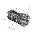
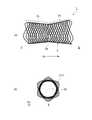
図1は、本発明の一実施形態に係るステント1の構成例を示す斜視図である。図2(a)は、図1の正面図であり、図2(b)は、図1の側面図である。図面において、ステント1の軸方向Axを矢印で示す。また、軸方向Axに略直交する方向を径方向と定義する。また、図面においてステント1の一方側を符号Fで示し、ステント1の他方側を符号Bで示す。
Hereinafter, embodiments of the present invention will be described with reference to the drawings.
FIG. 1 is a perspective view showing a configuration example of astent 1 according to an embodiment of the present invention. 2 (a) is a front view of FIG. 1, and FIG. 2 (b) is a side view of FIG. 1. In the drawings, the axial direction Ax of thestent 1 is indicated by an arrow. Further, a direction substantially orthogonal to the axial direction Ax is defined as a radial direction. Further, in the drawings, one side of thestent 1 is indicated by reference numeral F, and the other side of thestent 1 is indicated by reference numeral B.

ステント1は、生体管腔内の狭窄部位や閉塞部位等の病変部位に留置され、これらの病変部位を拡張させるために適用される。本実施形態では、例えば、生体管腔のうち、ぜん動運動を生じる消化管10にステントが導入される例(図3)を説明する。 Thestent 1 is placed at a lesion site such as a stenosis site or an occlusion site in a living lumen, and is applied to dilate these lesion sites. In this embodiment, for example, an example (FIG. 3) in which a stent is introduced into thegastrointestinal tract 10 that causes peristalsis in the living lumen will be described.

図1、図2(a)に示すように、ステント1は、筒状に形成されたステント本体部2を備える。ステント本体部2の内周または外周の少なくとも一方には、例えば、フッ素樹脂やポリエステル樹脂等で形成された管状の被膜(不図示)が取り付けられていてもよい。なお、以下の説明では、ステント1の一例として、ステント本体部2の周面に被膜を有しないベアステントの構成例を示す。 As shown in FIGS. 1 and 2 (a), thestent 1 includes a stentmain body 2 formed in a tubular shape. A tubular coating (not shown) formed of, for example, a fluororesin or a polyester resin may be attached to at least one of the inner circumference and the outer circumference of the stentmain body 2. In the following description, as an example of thestent 1, a configuration example of a bare stent having no coating on the peripheral surface of the stentmain body 2 will be shown.

ステント本体部2の全体形状は、軸方向Axにおいて中央部2aがくびれた筒状をなしている。ステント本体部2の外周面は、中央部2aから軸方向Axの両側に向けてそれぞれ外径がテーパー状に拡径するように傾斜している。 The overall shape of the stentmain body 2 is a tubular shape in which thecentral portion 2a is constricted in the axial direction Ax. The outer peripheral surface of the stentmain body 2 is inclined so that the outer diameter is tapered from thecentral portion 2a toward both sides in the axial direction Ax.

筒状のステント本体部2は、上記の全体形状に倣った形状の内部空間2bを有する。ステント本体部2の内部空間2bは、図2(b)に示すように、軸方向Axの一方から他方に連通し、ステント1が消化管10に留置されたときに消化管10を流れる物が通過可能な流路を構成する。 Thetubular stent body 2 has aninternal space 2b having a shape that conforms to the overall shape described above. As shown in FIG. 2B, theinternal space 2b of the stentmain body 2 communicates with one of the axial axes to the other, and when thestent 1 is placed in thegastrointestinal tract 10, an object flowing through thegastrointestinal tract 10 flows. It constitutes a passable flow path.

なお、消化管10を流れる物は、例えば、全く消化が行われていない摂取された直後の食物、食物が消化管10を通ることで分解処理された物、消化管10を通っても消化されなかった物(例えば、便等)などを含み、物質の状態は問わない。 The substances flowing through thedigestive tract 10 are, for example, foods that have not been digested at all immediately after ingestion, substances that have been decomposed by passing the food through thedigestive tract 10, and digested even if they pass through thedigestive tract 10. The state of the substance does not matter, including things that did not exist (for example, stool, etc.).

ステント本体部2は、拡張状態の形状が記憶されたいわゆる自己拡張型の構成であって、径方向内側に収縮した収縮状態から径方向外側に拡張する拡張状態へと拡縮可能である。本実施形態のステント1は、図示しないカテーテルを用いて、径方向内側に収縮された状態(不図示)で消化管10内に導入される。ステント本体部2は、例えば、軸方向Axに引っ張られることで径方向内側に収縮しながら軸方向Axに伸長するように構成されている。また、ステント本体部2は、例えば、収縮状態から解放されることで径方向外側に拡張しながら軸方向Axに短縮するように構成されている。なお、カテーテルから放出されたステント1を、ステント1の内側からバルーン(不図示)を拡張させて押圧することで径方向外側に拡張させてもよい。 The stentmain body 2 has a so-called self-expanding structure in which the shape of the expanded state is stored, and can be expanded or contracted from a contracted state contracted inward in the radial direction to an expanded state expanded outward in the radial direction. Thestent 1 of the present embodiment is introduced into thegastrointestinal tract 10 in a state of being contracted inward in the radial direction (not shown) using a catheter (not shown). The stentmain body 2 is configured to extend in the axial direction Ax while contracting inward in the radial direction by being pulled in the axial direction Ax, for example. Further, the stentmain body 2 is configured to be shortened in the axial direction Ax while expanding outward in the radial direction by being released from the contracted state, for example. Thestent 1 released from the catheter may be expanded radially outward by expanding and pressing a balloon (not shown) from the inside of thestent 1.

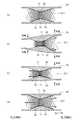
図3(a)は、本実施形態のステント1が消化管10の病変部位11に留置された状態を模式的に示す図である。ステント1の留置時には、ステント本体部2の外周面によって留置部位(消化管10の病変部位11)の内面が径方向外側に押圧され、消化管10を閉塞するように内側に窄まった病変部位11が径方向外側に押し広げられる。 FIG. 3A is a diagram schematically showing a state in which thestent 1 of the present embodiment is placed at thelesion site 11 of thegastrointestinal tract 10. When thestent 1 is placed, the inner surface of the placement site (lesion site 11 of the gastrointestinal tract 10) is pressed radially outward by the outer peripheral surface of thestent body 2, and the lesion site is narrowed inward so as to block thegastrointestinal tract 10. 11 is pushed outward in the radial direction.

ステント本体部2の中央部2aは、消化管10の留置部位に対してステント1を留置する際の位置の基準となり、ステント1の留置の際には消化管10の留置部位(病変部位11)に合致するように配置される。ステント本体部2の中央部2aは、狭窄した病変部位11を押し広げることが可能な拡張力を有しており、病変部位11を外周面で押し広げることで消化管10を流れる物が通過可能な流路を確保する機能を担う。 Thecentral portion 2a of the stentmain body 2 serves as a reference for the position when thestent 1 is placed with respect to the indwelling site of thegastrointestinal tract 10, and when thestent 1 is placed, the indwelling site of the gastrointestinal tract 10 (lesion site 11). It is arranged to match. Thecentral portion 2a of the stentmain body 2 has an expanding force capable of expanding the narrowedlesion site 11, and by expanding thelesion site 11 on the outer peripheral surface, an object flowing through thedigestive tract 10 can pass through. Responsible for the function of securing a proper flow path.

また、ステント本体部2において、中央部2aから端部にかけてのテーパー状の部分(一方側の部分2c、他方側の部分2d)は、消化管10を流れる物が通過可能な流路を確保するとともに、消化管10のぜん動運動に応じて弾性変形し、留置部位からのステント1の逸脱を抑制する機能を担う。上記の一方側の部分2c、他方側の部分2dは、中央部2aよりも大きな拡張力を有し、端部に向かうほどその拡張力は大きくなる。留置部位からのステント1の逸脱抑制の機能については後述する。 Further, in the stentmain body 2, the tapered portion (oneside portion 2c, theother side portion 2d) from thecentral portion 2a to the end portion secures a flow path through which an object flowing through thedigestive tract 10 can pass. At the same time, it elastically deforms in response to the peristaltic movement of thegastrointestinal tract 10 and has a function of suppressing the deviation of thestent 1 from the indwelling site. The one-sidedportion 2c and the other-sided portion 2d have a larger expanding force than thecentral portion 2a, and the expanding force increases toward the end portion. The function of suppressing the deviation of thestent 1 from the indwelling site will be described later.

上記のステント本体部2は、金属素線からなる線材を格子状に編み込んで構成されてもよい。あるいは、ステント本体部2は、例えば、Ni−Ti合金製の原料パイプから、骨格に相当する部分を除いた残りの全ての部分をレーザ等によって削り取る手法で製造されてもよい。なお、ステント本体部2は、セラミックや樹脂などの金属材料以外の材料で構成されてもよい。 The stentmain body 2 may be formed by weaving a wire rod made of a metal wire in a grid pattern. Alternatively, thestent body 2 may be manufactured, for example, from a Ni—Ti alloy raw material pipe by scraping off all remaining portions except the portion corresponding to the skeleton with a laser or the like. The stentmain body 2 may be made of a material other than a metal material such as ceramic or resin.

図1、図2では、線材を格子状に編み込んでステント本体部2が構成されている例を示す。この線材の材料としては、例えば、Ni−Ti合金、ステンレス鋼、チタン合金などに代表される公知の金属又は金属合金等が挙げられる。また、ステント本体部2の線材にはX線造影性を有する合金材料を用いてもよく、あるいはX線造影性を有する合金材料で形成されたマーカ片(不図示)を線材に適宜取り付けてもよい。これらの場合、ステント1の位置を体外から確認できるようになる。 1 and 2 show an example in which a wire rod is woven in a grid pattern to form a stentmain body 2. Examples of the material of this wire rod include known metals or metal alloys typified by Ni—Ti alloy, stainless steel, titanium alloy and the like. Further, an alloy material having X-ray contrast property may be used for the wire rod of the stentmain body 2, or a marker piece (not shown) formed of the alloy material having X-ray contrast property may be appropriately attached to the wire rod. good. In these cases, the position of thestent 1 can be confirmed from outside the body.

また、ステント本体部2を構成する材料としてNi−Ti合金を用いる場合、ステント本体部2を拡張状態の形状に整えた後、所定の熱処理を施すことにより、その形状をステント本体部2に記憶させることができる。 Further, when a Ni—Ti alloy is used as the material constituting the stentmain body 2, the shape is stored in the stentmain body 2 by subjecting the stentmain body 2 to an expanded shape and then performing a predetermined heat treatment. Can be made to.

ステント本体部2の線材の編組には公知の方法を採用することができる。図1、図2の例では、ステント本体部2は複数の線材を螺旋状に編み込む方法で構成される。なお、ステント本体部2は、複数の線材を交互にかみ合わせてフェンス状に編み込む方法で構成されてもよい。 A known method can be adopted for braiding the wire rod of the stentmain body 2. In the examples of FIGS. 1 and 2, the stentmain body 2 is configured by a method of weaving a plurality of wire rods in a spiral shape. The stentmain body 2 may be configured by alternately engaging a plurality of wire rods and knitting them into a fence shape.

また、ステント本体部2は、一方側の端部から中央部2aまでの部分2cと、中央部から他方側の端部までの部分2dを別々に製造し、これらの部分2c、2dを接続することで構成されてもよい。図1、図2の例では、一方側の端部から中央部2aまでの部分2cと、中央部2aから他方側の端部までの部分2dとをそれぞれ同じ編み込み方法で製造し、これらの2部品を対向させて接続することでステント本体部2が構成されている。そのため、図1、図2の例では、ステント本体部2の一方側の部分2cと他方側の部分2dとは、線材の螺旋の巻回方向が同じである。 Further, the stentmain body 2 separately manufactures aportion 2c from one end to thecentral portion 2a and aportion 2d from the central portion to the other end, and connects theseportions 2c and 2d. It may be composed of. In the examples of FIGS. 1 and 2, theportion 2c from the one-sided end to thecentral portion 2a and theportion 2d from thecentral portion 2a to the other-side end are manufactured by the same knitting method, and these 2 The stentmain body 2 is configured by connecting the parts so as to face each other. Therefore, in the examples of FIGS. 1 and 2, the winding direction of the spiral of the wire rod is the same for the one-sided portion 2c and the other-sided portion 2d of the stentmain body portion 2.

次に、図3を参照して、ぜん動運動を行う消化管10に留置されたステント1の動きを説明する。図3(a)に示すように、ステント本体部2の中央部2aは消化管10の病変部位11に臨んでいる。また、ステント1の一方側は消化管10の上流側(口側)に臨み、ステント1の他方側は消化管10の下流側(肛門側)に臨むように配置されている。 Next, with reference to FIG. 3, the movement of thestent 1 placed in thegastrointestinal tract 10 that performs peristaltic movement will be described. As shown in FIG. 3A, thecentral portion 2a of the stentmain body 2 faces thelesion site 11 of thegastrointestinal tract 10. Further, one side of thestent 1 faces the upstream side (oral side) of thegastrointestinal tract 10, and the other side of thestent 1 faces the downstream side (anal side) of thegastrointestinal tract 10.

消化管10のぜん動運動では、上流側での収縮と、その下流側での弛緩が同時に起こる。この動作が上流側から下流側に向けて起こることで、消化管10を流れる物が下流側に送られる。 In the peristaltic movement of thegastrointestinal tract 10, contraction on the upstream side and relaxation on the downstream side occur at the same time. When this operation occurs from the upstream side to the downstream side, the thing flowing through thedigestive tract 10 is sent to the downstream side.

図3(b)は、図3(a)の状態からステント1の上流側で消化管10が収縮し、ステントの下流側で消化管10が弛緩した状態を示している。図3(b)において、消化管10が収縮する上流側では、消化管10によるステント1への押圧力が強まるので、図3(a)と比べてステント1の一方側の部分2cが径方向内側に向けて変形する。これにより、ステント本体部2の中央部2aから一方側の端部への外周面の軸方向Axに対する傾きは収縮前よりも小さくなる。 FIG. 3B shows a state in which thegastrointestinal tract 10 contracts on the upstream side of thestent 1 and thegastrointestinal tract 10 relaxes on the downstream side of thestent 1 from the state of FIG. 3 (a). In FIG. 3B, since the pressing force of thegastrointestinal tract 10 on thestent 1 is increased on the upstream side where thegastrointestinal tract 10 contracts, theportion 2c on one side of thestent 1 is radial as compared with FIG. 3A. Deforms inward. As a result, the inclination of the outer peripheral surface from thecentral portion 2a of the stentmain body 2 to the one-sided end with respect to the axial direction Ax becomes smaller than that before contraction.

一方、図3(b)において消化管10が弛緩する下流側では、消化管10によるステント1への押圧力が弛緩前よりも弱まる。そのため、図3(a)と比べてステント1の拡張力によってステントの他方側の部分2dが径方向外側に向けて広がるように変形し、ステント本体部2の他方側の部分2dではその外周面の軸方向Axに対する傾きに沿って下流側に向かう力が作用する。 On the other hand, on the downstream side where thegastrointestinal tract 10 relaxes in FIG. 3B, the pressing force of thegastrointestinal tract 10 on thestent 1 is weaker than before the relaxation. Therefore, as compared with FIG. 3A, the expanding force of thestent 1 deforms theother side portion 2d of the stent so as to expand outward in the radial direction, and theother side portion 2d of the stentmain body 2 is the outer peripheral surface thereof. A force acts toward the downstream side along the inclination of the axial direction Ax.

図3(b)の状態では、ステント1に下流側に向かう力が作用する一方、ステントの上流側は収縮によって強く押圧されてその外周面の軸方向Axに対する傾きも小さくなる。そのため、上流側から下流側に向けてステント1が動きやすくなる。これにより、図3(a)から図3(b)に示すように、ステント1は下流側に向けて摺動しうる。 In the state of FIG. 3B, a force acting toward the downstream side acts on thestent 1, while the upstream side of the stent is strongly pressed by contraction and the inclination of the outer peripheral surface with respect to the axial direction Ax becomes small. Therefore, thestent 1 can easily move from the upstream side to the downstream side. As a result, as shown in FIGS. 3 (a) to 3 (b), thestent 1 can slide toward the downstream side.

図3(c)は、図3(b)の状態からステント1の上流側では収縮していた消化管10が広がる一方、ステントの下流側では消化管10が収縮する過程を示している。なお、図3(c)において消化管10が収縮している部位よりもさらに下流側では、図示を省略するが消化管10が弛緩する。 FIG. 3C shows a process in which thegastrointestinal tract 10 contracted on the upstream side of thestent 1 expands from the state of FIG. 3B, while thegastrointestinal tract 10 contracts on the downstream side of the stent. Although not shown, thegastrointestinal tract 10 relaxes further downstream than the site where thegastrointestinal tract 10 contracts in FIG. 3 (c).

図3(c)において、消化管10が収縮する下流側では、消化管10によるステント1への押圧力が強まるので、図3(b)と比べてステント1の他方側の部分2dが径方向内側に向けて変形する。これにより、ステント本体部2の中央部2aから他方側の端部への外周面の軸方向Axに対する傾きは収縮前よりも小さくなる。 In FIG. 3C, the pressing force of thegastrointestinal tract 10 on thestent 1 is increased on the downstream side where thegastrointestinal tract 10 contracts, so that theother side portion 2d of thestent 1 is in the radial direction as compared with FIG. 3B. Deforms inward. As a result, the inclination of the outer peripheral surface from thecentral portion 2a of the stentmain body 2 to the other end in the axial direction Ax becomes smaller than that before contraction.

一方、図3(c)において消化管10が広がる上流側では、消化管10が収縮していたときよりもステント1への押圧力が弱まる。そのため、ステント1の拡張力によってステントの一方側の部分2cが径方向外側に向けて広がるように変形し、ステント本体部2の一方側の部分2cではその外周面の軸方向Axに対する傾きに沿って上流側に向かう力が作用する。 On the other hand, on the upstream side where thegastrointestinal tract 10 spreads in FIG. 3C, the pressing force on thestent 1 is weaker than when thegastrointestinal tract 10 is contracting. Therefore, the expanding force of thestent 1 deforms the one-sided portion 2c of the stent so as to expand outward in the radial direction, and the one-sided portion 2c of the stentmain body 2 is along the inclination of the outer peripheral surface with respect to the axial Ax. A force acts toward the upstream side.

図3(c)の状態では、ステント1に上流側に向かう力が作用する一方、ステントの下流側は収縮によって強く押圧されてその外周面の傾きも小さくなる。そのため、図3(b)とは逆に、下流側から上流側に向けてステント1が動きやすくなる。これにより、図3(b)から図3(c)に示すように、ステント1は上流側に向けて摺動しうる。 In the state of FIG. 3C, a force acting toward the upstream side acts on thestent 1, while the downstream side of the stent is strongly pressed by contraction and the inclination of the outer peripheral surface thereof becomes small. Therefore, contrary to FIG. 3B, thestent 1 tends to move from the downstream side to the upstream side. As a result, as shown in FIGS. 3 (b) to 3 (c), thestent 1 can slide toward the upstream side.

図3(d)は、ステント1の下流側において、収縮していた消化管10が広がった状態を示している。 FIG. 3D shows a state in which the contractedgastrointestinal tract 10 is expanded on the downstream side of thestent 1.

図3(c)の説明で述べたように、ステント1に上流側に向かう力が作用することでステント1は上流側に向けて摺動する。一方、図3(d)では、ステント1の下流側では収縮していた消化管10が広がるにつれてステント1への押圧力が弱まる。すると、ステント1の拡張力によってステントの他方側の部分2dが径方向外側に向けて広がるように変形し、ステント本体部2の他方側の部分2dではその外周面の軸方向Axに対する傾きに沿って下流側に向かう力(破線の矢印)が作用する。これにより、ステント1は上流側には徐々に動きにくくなる。場合によっては、消化管10の下流側が広がることで、ステント1が下流側に戻るように摺動することもある。その結果として、消化管10の内側に突出する病変部位11にステント本体部2の中央部2aが合致する状態でステント1は安定する。 As described in the description of FIG. 3C, thestent 1 slides toward the upstream side due to the action of a force toward the upstream side on thestent 1. On the other hand, in FIG. 3D, the pressing force on thestent 1 weakens as thegastrointestinal tract 10 contracted on the downstream side of thestent 1 expands. Then, the expanding force of thestent 1 deforms theother side portion 2d of the stent so as to expand outward in the radial direction, and theother side portion 2d of the stentmain body portion 2 is along the inclination of the outer peripheral surface with respect to the axial direction Ax. A force toward the downstream side (dashed arrow) acts. As a result, thestent 1 gradually becomes difficult to move upstream. In some cases, the extension of the downstream side of thegastrointestinal tract 10 may cause thestent 1 to slide so as to return to the downstream side. As a result, thestent 1 is stabilized in a state where thecentral portion 2a of the stentmain body 2 is aligned with thelesion site 11 protruding inward of thegastrointestinal tract 10.

以上のように、消化管10に留置されたステント1は、消化管10のぜん動運動に伴って、図3(a)から図3(d)の変化を繰り返す。
ステント1は、上流側に向かう力と下流側に向かう力によって、一方側の部分2cと他方側の部分2dの外周面に沿って移動する。そして、消化管10の内側に突出する病変部位11にステント本体部2の中央部2aが合致する状態でステント1は安定する。
また、例えば、消化管10がぜん動運動以外の分節運動や振子運動などを行った場合にも、ステント1は、上記と同様に、上流側に向かう力と下流側に向かう力によって、一方側の部分2cと他方側の部分2dの外周面に沿って移動する。
As described above, thestent 1 placed in thegastrointestinal tract 10 repeats the changes of FIGS. 3 (a) to 3 (d) with the peristaltic movement of thegastrointestinal tract 10.
Thestent 1 moves along the outer peripheral surfaces of the one-sided portion 2c and the other-sided portion 2d by the force toward the upstream side and the force toward the downstream side. Then, thestent 1 is stabilized in a state where thecentral portion 2a of the stentmain body 2 is aligned with thelesion site 11 protruding inward of thegastrointestinal tract 10.
Further, for example, when thegastrointestinal tract 10 performs a segmental movement or a pendulum movement other than the peristaltic movement, thestent 1 is unilaterally subjected to a force toward the upstream side and a force toward the downstream side in the same manner as described above. It moves along the outer peripheral surfaces of theportion 2c and theother portion 2d.

以下、本実施形態のステントの効果を述べる。
本実施形態のステント1は、筒状に形成されたステント本体部2を備える。ステント本体部2は、軸方向Axに略直交する径方向に拡縮可能に構成され、ステント本体部2の外周面は、生体管腔(消化管10)の留置部位(病変部位11)に対して当該ステント1を留置する際の基準となる所定位置(中央部2a)から所定位置よりも軸方向の少なくとも一方側に向かって外径が拡径するように傾斜している。
ステント1の一方側を消化管10の上流側に臨むように留置した場合、消化管10の軸方向への運動(例えば、ぜん動運動など)によってステント1の一方側の部分2cに臨む消化管10が収縮した状態から広がると、ステント1の拡張力によってステント1の一方側の部分2cが径方向外側に向けて広がるように変形し、その外周面の軸方向Axに対する傾きに沿ってステント1には一方側(上流側)に向かう力が作用する。したがって、消化管10の軸方向への運動でステント1が下流側に摺動しても、一方側の部分2cに臨む消化管が広がったときにステント1が上流側に摺動するので、留置部位からのステント1の逸脱を抑制できる。
Hereinafter, the effect of the stent of this embodiment will be described.
Thestent 1 of the present embodiment includes a stentmain body 2 formed in a tubular shape. The stentmain body 2 is configured to be expandable and contractible in the radial direction substantially orthogonal to the axial direction Ax, and the outer peripheral surface of the stentmain body 2 is relative to the indwelling site (lesion site 11) of the biological lumen (gastrointestinal tract 10). Thestent 1 is inclined so that the outer diameter increases from a predetermined position (central portion 2a), which is a reference when thestent 1 is placed, toward at least one side in the axial direction from the predetermined position.
When one side of thestent 1 is placed so as to face the upstream side of thegastrointestinal tract 10, thegastrointestinal tract 10 faces theportion 2c on one side of thestent 1 by axial movement of the gastrointestinal tract 10 (for example, peristaltic movement). When thestent 1 expands from the contracted state, oneside portion 2c of thestent 1 is deformed so as to expand radially outward due to the expanding force of thestent 1, and thestent 1 is formed along the inclination of the outer peripheral surface with respect to the axial direction Ax. A force acts toward one side (upstream side). Therefore, even if thestent 1 slides downstream due to the axial movement of thegastrointestinal tract 10, thestent 1 slides upstream when the gastrointestinal tract facing theportion 2c on one side expands. The deviation of thestent 1 from the site can be suppressed.

また、本実施形態において、ステント本体部2の外周面は、所定位置から所定位置よりも軸方向の両側に向かって外径が拡径するように傾斜している。
これにより、消化管10の軸方向への運動によってステント1が多少留置部位から下流側あるいは上流側に摺動しても、ステント1の所定位置を中心とした両側の傾斜に沿ってステント1が留置部位(狭窄した病変部位11)に合うように消化管10内を自然に動く。したがって、ステント1の所定位置が留置部位の中央に合致するようにステント1の位置が調整されるので、ステント1を留置部位に適正に留置しやすくなる。そのため、ステント1を留置する際の施術者の負荷を大きく低減しうる。
Further, in the present embodiment, the outer peripheral surface of the stentmain body 2 is inclined so that the outer diameter increases from the predetermined position toward both sides in the axial direction from the predetermined position.
As a result, even if thestent 1 slides slightly downstream or upstream from the indwelling site due to the axial movement of thegastrointestinal tract 10, thestent 1 moves along the inclination of both sides around the predetermined position of thestent 1. It moves naturally in thegastrointestinal tract 10 so as to fit the indwelling site (narrowed lesion site 11). Therefore, since the position of thestent 1 is adjusted so that the predetermined position of thestent 1 coincides with the center of the indwelling site, it becomes easy to properly place thestent 1 in the indwelling site. Therefore, the load on the practitioner when placing thestent 1 can be greatly reduced.

また、本実施形態の構成では、上記のようにステント1を留置部位に適正に留置しやすくなるので、留置部位をカバーするためにステント1の軸方向長さを必要以上に長くしなくて済む。つまり、本実施形態の構成によれば、病変部位を越えてステント1が健常な部位に配置される部分を減らすことができるので、狭窄症に付随しないステント1の内腔閉鎖や健常部位の損傷の可能性を低減させることも容易となる。 Further, in the configuration of the present embodiment, since thestent 1 can be properly placed in the indwelling site as described above, it is not necessary to lengthen the axial length of thestent 1 more than necessary in order to cover the indwelling site. .. That is, according to the configuration of the present embodiment, since the portion where thestent 1 is arranged in the healthy region beyond the lesion site can be reduced, the lumen closure of thestent 1 not associated with stenosis and the damage of the healthy site can be reduced. It is also easy to reduce the possibility of

本発明は、上記実施形態に限定されることなく、本発明の趣旨を逸脱しない範囲において、種々の改良並びに設計の変更を行ってもよい。 The present invention is not limited to the above-described embodiment, and various improvements and design changes may be made without departing from the spirit of the present invention.

本発明において、ステント本体部2の中央部2aよりも軸方向の一方側の部分と他方側の部分との間では線材の編み方が異なっていてもよい。例えば、軸方向の一方側の部分と他方側の部分の間で、外周面の傾斜の大きさや軸方向の長さを相違させてもよい。また、軸方向の一方側の部分は、中央部から一方側に向かって外径がテーパー状に拡径するように形成し、軸方向の他方側の部分は円筒状に形成してもよい。さらに、例えば、病変部位11の大きさ(特に、軸方向の長さ)等に応じて、一方側の部分2cと他方側の部分2dとの間に径方向の長さが一定の円筒状の部分を設けてもよい。 In the present invention, the method of knitting the wire rod may be different between the portion on one side and the portion on the other side in the axial direction from thecentral portion 2a of the stentmain body portion 2. For example, the magnitude of the inclination of the outer peripheral surface and the length in the axial direction may be different between the portion on one side in the axial direction and the portion on the other side. Further, the portion on one side in the axial direction may be formed so that the outer diameter is tapered from the central portion to one side, and the portion on the other side in the axial direction may be formed in a cylindrical shape. Further, for example, a cylindrical shape having a constant radial length between the one-sided portion 2c and the other-sided portion 2d, depending on the size of the lesion site 11 (particularly, the axial length) and the like. A portion may be provided.

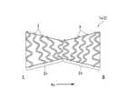
また、図4に示すように、ステント本体部2を線材で螺旋状に編組するときに、一方側の部分2cと他方側の部分2dの間で線材の巻回方向を異ならせてもよい。図4に示すステント1aでも、上記実施形態と同様に、ステント本体部2は、軸方向Axにおいて中央部2aがくびれた筒状をなしている。この図4のステント1aでは、山部と谷部とが交互に形成されるように屈曲させながら線材3を螺旋状に巻回してステント本体部2が形成されている。一方側の部分2cでは線材3が時計回り(または半時計回り)に螺旋状に巻回され、他方側の部分2dでは線材3が反時計回り(または時計回り)に螺旋状に巻回されている。
上記のようにステント本体部2の線材3の巻回方向を異ならせると、ぜん動運動によって縮径される際に、一方側の部分2cに生じる捻れと他方側の部分2dに生じる捻れが互いに打ち消しあう。これにより、図4の構成によればステント1aの留置部位からの逸脱をより一層抑制できる。
Further, as shown in FIG. 4, when the stentmain body 2 is spirally braided with a wire rod, the winding direction of the wire rod may be different between the one-sided portion 2c and the other-sided portion 2d. In thestent 1a shown in FIG. 4, similarly to the above embodiment, the stentmain body 2 has a tubular shape in which thecentral portion 2a is constricted in the axial direction Ax. In thestent 1a of FIG. 4, thewire rod 3 is spirally wound to form the stentmain body 2 while bending so that the peaks and valleys are alternately formed. In the oneside portion 2c, thewire rod 3 is spirally wound clockwise (or counterclockwise), and in theother side portion 2d, thewire rod 3 is spirally wound counterclockwise (or clockwise). There is.
When the winding direction of thewire rod 3 of the stentmain body 2 is different as described above, the twist generated in the oneside portion 2c and the twist generated in theother side portion 2d cancel each other out when the diameter is reduced by the peristaltic motion. match. Thereby, according to the configuration of FIG. 4, the deviation of thestent 1a from the indwelling site can be further suppressed.

さらに、ステント本体部2の両端に消化管10における当該ステント1の留置位置を固定する位置固定部(図示略)が設けられてもよい。
位置固定部は、例えば、ステント本体部2よりも径が大きい形状、具体的には、軸方向の端部側に向かうにつれて径が広がるフレア形状に形成されてもよい。位置固定部により消化管10におけるステント1の両端の位置が固定された状態となるため、消化管10の軸方向への運動(例えば、ぜん動運動など)によってステント1に下流側や上流側に摺動する力が加わってもステント1を留置部位から逸脱させにくくすることができる。さらに、ステント1の軸方向の端部を固定することにより、消化管10の軸方向への運動に応じたステント本体部2全体の軸方向への摺動をより適正に行うことができる。
なお、位置固定部は、ステント本体部2の両端のうちいずれか一方(例えば、下流側)にのみ設けられていてもよい。
また、位置固定部の形状は、例えば、軸方向に径が一定の円筒状に形成されてもよいし、消化管10の内壁に係止されるように鉤状(バーブ)に形成されてもよい。
Further, position fixing portions (not shown) for fixing the indwelling position of thestent 1 in thegastrointestinal tract 10 may be provided at both ends of the stentmain body portion 2.
The position fixing portion may be formed, for example, in a shape having a diameter larger than that of the stentmain body portion 2, specifically, a flare shape in which the diameter increases toward the end side in the axial direction. Since the positions of both ends of thestent 1 in thegastrointestinal tract 10 are fixed by the position fixing portion, thestent 1 is slid downstream or upstream by the axial movement of the gastrointestinal tract 10 (for example, peristaltic movement). Even if a moving force is applied, it is possible to make it difficult for thestent 1 to deviate from the indwelling site. Further, by fixing the axial end portion of thestent 1, the entire stentmain body portion 2 can be more appropriately slid in the axial direction in response to the axial movement of thegastrointestinal tract 10.
The position fixing portion may be provided only on one of both ends (for example, the downstream side) of the stentmain body portion 2.
Further, the shape of the position fixing portion may be formed in a cylindrical shape having a constant diameter in the axial direction, or may be formed in a hook shape (barb) so as to be locked to the inner wall of thedigestive tract 10. good.

また、本発明のステント1は、軸方向への運動を行う消化管10に適用することができるだけでなく、例えば、拍動する動脈などにも適用することができる。さらに、本発明のステント1は、生体管腔内の流体の流れに起因して軸方向への運動が生じ得る他の生体管腔にも適用することができる。 Further, thestent 1 of the present invention can be applied not only to thegastrointestinal tract 10 that moves in the axial direction, but also to, for example, a pulsating artery. Further, thestent 1 of the present invention can be applied to other living lumens where axial movement may occur due to the flow of fluid in the living lumen.

加えて、今回開示された実施形態は、全ての点で例示であって制限的なものではないと考えられるべきである。本発明の範囲は、上記した説明ではなくて特許請求の範囲によって示され、特許請求の範囲と均等の意味及び範囲内での全ての変更が含まれることが意図される。 In addition, the embodiments disclosed this time should be considered to be exemplary and not restrictive in all respects. The scope of the present invention is shown by the scope of claims rather than the above description, and is intended to include all modifications within the meaning and scope equivalent to the scope of claims.

1、1a…ステント、2…ステント本体部、2a…中央部、2c…一方側の部分、2d…他方側の部分、3…線材、10…消化管(生体管腔)、11…病変部位

1, 1a ... stent, 2 ... stent body, 2a ... central part, 2c ... one side part, 2d ... other side part, 3 ... wire rod, 10 ... digestive tract (living lumen), 11 ... lesion site

Claims (5)

Translated fromJapanese
生体管腔内に留置されるステントであって、
筒状に形成されたステント本体部を備え、
前記ステント本体部は、
軸方向に略直交する径方向に拡縮可能に構成され、
前記ステント本体部の外周面は、前記生体管腔の留置部位に対して当該ステントを留置する際の基準となる所定位置から前記所定位置よりも軸方向の少なくとも一方側に向かって外径が拡径するように傾斜する
ステント。
A stent that is placed in the lumen of a living body.
Equipped with a tubular stent body,
The stent body is
It is configured to be expandable and contractible in the radial direction, which is approximately orthogonal to the axial direction.
The outer diameter of the outer peripheral surface of the stent main body expands from a predetermined position that serves as a reference when the stent is placed with respect to the placement site of the biological lumen toward at least one side in the axial direction from the predetermined position. A stent that tilts to a diameter.
前記ステント本体部の外周面は、前記所定位置から前記所定位置よりも軸方向の両側に向かって外径が拡径するように傾斜する
請求項1に記載のステント。
The stent according to claim 1, wherein the outer peripheral surface of the stent main body is inclined so that the outer diameter increases from the predetermined position toward both sides in the axial direction from the predetermined position.
前記ステントは、線材を編組して筒形状に形成されてなり、
前記所定位置よりも軸方向の一方側の部分と他方側の部分とは前記線材の編み方が異なる
請求項1または請求項2に記載のステント。
The stent is formed by braiding a wire rod into a tubular shape.
The stent according to claim 1 or 2, wherein the wire rod is knitted differently from the portion on one side and the portion on the other side in the axial direction from the predetermined position.
前記ステントは、前記線材を螺旋状に巻回して筒形状に形成されてなり、
前記一方側の部分と前記他方側の部分とは前記線材の巻回方向が異なる
請求項3に記載のステント。
The stent is formed by spirally winding the wire rod into a tubular shape.
The stent according to claim 3, wherein the winding direction of the wire rod is different between the one-sided portion and the other-sided portion.
前記ステント本体部の軸方向先端に、前記生体管腔における当該ステントの留置位置を固定する位置固定部を更に備える
請求項1に記載のステント。
The stent according to claim 1, further comprising a position fixing portion for fixing the indwelling position of the stent in the living lumen at the axial tip of the stent main body portion.
JP2021022109A2020-02-192021-02-15 StentPendingJP2021129982A (en)

Applications Claiming Priority (2)

Application NumberPriority DateFiling DateTitle
JP20200257882020-02-19

Publications (1)

Publication NumberPublication Date
JP2021129982Atrue JP2021129982A (en)2021-09-09

Family

ID=77551686

Family Applications (1)

Application NumberTitlePriority DateFiling Date
JP2021022109APendingJP2021129982A (en)2020-02-192021-02-15 Stent

Country Status (1)

CountryLink
JP (1)JP2021129982A (en)

Citations (8)

* Cited by examiner, † Cited by third party
Publication numberPriority datePublication dateAssigneeTitle
JP2003527924A (en)*2000-03-272003-09-24ネオヴァスク メディカル リミテッド Stenosis implant
US20070179590A1 (en)*2005-12-292007-08-02Wenfeng LuHybrid intraluminal device with varying expansion force
JP2009513200A (en)*2005-10-292009-04-02ペーエヌエヌ メディカル エスアー Stent having a fixed portion
JP2010094510A (en)*2008-10-162010-04-30Taewoong Medical Co LtdMethod of manufacturing bent-deformable stent, and the stent
JP2011509758A (en)*2008-01-172011-03-31ボストン サイエンティフィック サイムド,インコーポレイテッド Stent with anti-migration feature
JP2011200661A (en)*2001-08-272011-10-13Synecor LlcDevice for inducing weight loss
US20160015533A1 (en)*2013-03-152016-01-21Children's Medical Center CorporationMethods and apparatuses for treating vessels
WO2019086684A1 (en)*2017-11-032019-05-09Ceroflo LimitedAn expandable stent and a method for promoting a natural intracranial angiogenesis process, and use of the expandable stent in the method for promoting a natural intracranial angiogenesis process

Patent Citations (8)

* Cited by examiner, † Cited by third party
Publication numberPriority datePublication dateAssigneeTitle
JP2003527924A (en)*2000-03-272003-09-24ネオヴァスク メディカル リミテッド Stenosis implant
JP2011200661A (en)*2001-08-272011-10-13Synecor LlcDevice for inducing weight loss
JP2009513200A (en)*2005-10-292009-04-02ペーエヌエヌ メディカル エスアー Stent having a fixed portion
US20070179590A1 (en)*2005-12-292007-08-02Wenfeng LuHybrid intraluminal device with varying expansion force
JP2011509758A (en)*2008-01-172011-03-31ボストン サイエンティフィック サイムド,インコーポレイテッド Stent with anti-migration feature
JP2010094510A (en)*2008-10-162010-04-30Taewoong Medical Co LtdMethod of manufacturing bent-deformable stent, and the stent
US20160015533A1 (en)*2013-03-152016-01-21Children's Medical Center CorporationMethods and apparatuses for treating vessels
WO2019086684A1 (en)*2017-11-032019-05-09Ceroflo LimitedAn expandable stent and a method for promoting a natural intracranial angiogenesis process, and use of the expandable stent in the method for promoting a natural intracranial angiogenesis process

Similar Documents

PublicationPublication DateTitle
CN101484089B (en)Flexible stent
CN110063825B (en)Endoluminal device
JP7459421B2 (en) Digestive tract stents
KR20120018772A (en) Flexible devices
CN112672718B (en)Support frame
JP7267245B2 (en) stent
JP2011504407A (en) Cylindrical stent
JP6155765B2 (en) Gastrointestinal stent
JP7409585B2 (en) stent
JP2021153895A (en)Stent
JP7658053B2 (en) Stents
JP2021129982A (en) Stent
JP6901869B2 (en) Covered stent
JP7490922B2 (en) Stents
JPWO2020045315A1 (en) Gastrointestinal stent
JP7448294B2 (en) stent
KR20220010814A (en)Stent
JP6855679B2 (en) Gastrointestinal stent
JP7646967B2 (en) Stents
JP7567115B2 (en) Stents
JPWO2020013209A1 (en) Stent
JP4835113B2 (en) Stent
JP7722796B2 (en) stents
WO2022181661A1 (en)Stent
JP2023118339A (en)stent

Legal Events

DateCodeTitleDescription
A625Written request for application examination (by other person)

Free format text:JAPANESE INTERMEDIATE CODE: A625

Effective date:20240117

A977Report on retrieval

Free format text:JAPANESE INTERMEDIATE CODE: A971007

Effective date:20240925

A131Notification of reasons for refusal

Free format text:JAPANESE INTERMEDIATE CODE: A131

Effective date:20241029

A601Written request for extension of time

Free format text:JAPANESE INTERMEDIATE CODE: A601

Effective date:20241219

A521Request for written amendment filed

Free format text:JAPANESE INTERMEDIATE CODE: A523

Effective date:20250218

A131Notification of reasons for refusal

Free format text:JAPANESE INTERMEDIATE CODE: A131

Effective date:20250527


[8]ページ先頭

©2009-2025 Movatter.jp