JP2021129684A - Golf club head - Google Patents
Golf club headDownload PDFInfo
- Publication number
- JP2021129684A JP2021129684AJP2020025926AJP2020025926AJP2021129684AJP 2021129684 AJP2021129684 AJP 2021129684AJP 2020025926 AJP2020025926 AJP 2020025926AJP 2020025926 AJP2020025926 AJP 2020025926AJP 2021129684 AJP2021129684 AJP 2021129684A
- Authority
- JP
- Japan
- Prior art keywords
- plane
- head
- golf club
- face
- club head
- Prior art date
- Legal status (The legal status is an assumption and is not a legal conclusion. Google has not performed a legal analysis and makes no representation as to the accuracy of the status listed.)
- Granted
Links
- 230000005484gravityEffects0.000claimsabstractdescription113
- 239000007769metal materialSubstances0.000claimsdescription38
- 239000000463materialSubstances0.000claimsdescription31
- 239000011347resinSubstances0.000claimsdescription18
- 229920005989resinPolymers0.000claimsdescription18
- 238000011156evaluationMethods0.000description25
- 238000000034methodMethods0.000description24
- 230000000694effectsEffects0.000description21
- 230000000052comparative effectEffects0.000description13
- 229910001069Ti alloyInorganic materials0.000description9
- 239000000835fiberSubstances0.000description8
- 230000001965increasing effectEffects0.000description8
- 230000003014reinforcing effectEffects0.000description8
- 229910045601alloyInorganic materials0.000description7
- 239000000956alloySubstances0.000description7
- 230000002238attenuated effectEffects0.000description7
- 229910052751metalInorganic materials0.000description6
- 239000002184metalSubstances0.000description6
- 238000012986modificationMethods0.000description5
- 230000004048modificationEffects0.000description5
- 229910001040Beta-titaniumInorganic materials0.000description4
- 229910001080W alloyInorganic materials0.000description4
- 239000000853adhesiveSubstances0.000description4
- 230000001070adhesive effectEffects0.000description4
- 230000033228biological regulationEffects0.000description4
- 229920000049Carbon (fiber)Polymers0.000description3
- 239000004917carbon fiberSubstances0.000description3
- VNWKTOKETHGBQD-UHFFFAOYSA-NmethaneChemical compoundCVNWKTOKETHGBQD-UHFFFAOYSA-N0.000description3
- 230000002093peripheral effectEffects0.000description3
- 229910000838Al alloyInorganic materials0.000description2
- 229910000883Ti6Al4VInorganic materials0.000description2
- 238000010586diagramMethods0.000description2
- 238000005259measurementMethods0.000description2
- 239000010935stainless steelSubstances0.000description2
- 229910001220stainless steelInorganic materials0.000description2
- 229910001240Maraging steelInorganic materials0.000description1
- 229910000861Mg alloyInorganic materials0.000description1
- 240000007594Oryza sativaSpecies0.000description1
- 235000007164Oryza sativaNutrition0.000description1
- RTAQQCXQSZGOHL-UHFFFAOYSA-NTitaniumChemical compound[Ti]RTAQQCXQSZGOHL-UHFFFAOYSA-N0.000description1
- 230000005540biological transmissionEffects0.000description1
- 239000004927claySubstances0.000description1
- 238000007796conventional methodMethods0.000description1
- 238000012937correctionMethods0.000description1
- 230000007423decreaseEffects0.000description1
- 238000013461designMethods0.000description1
- 230000002708enhancing effectEffects0.000description1
- 238000002474experimental methodMethods0.000description1
- 238000010030laminatingMethods0.000description1
- 235000009566riceNutrition0.000description1
- 229910052719titaniumInorganic materials0.000description1
- 239000010936titaniumSubstances0.000description1
- 238000003466weldingMethods0.000description1
- 239000002023woodSubstances0.000description1
Images


Landscapes
- Golf Clubs (AREA)
Abstract
Description
Translated fromJapanese本発明はゴルフクラブヘッドに関する。 The present invention relates to a golf club head.
ゴルフクラブヘッドでボールを打球した際のボールの方向性の向上を図ることが飛距離を向上させる上で有利であり、そのためには、ゴルフクラブヘッドの重心点回りの慣性モーメントを確保することが重要である。
特許文献1には、中空状の金属製のヘッド本体のクラウン部およびサイド部に開口部を設け、それら開口部を繊維強化樹脂製のカバー体で閉じたゴルフクラブヘッドが提案されている。
このゴルフクラブヘッドでは、ゴルフクラブヘッドの重心点に近い箇所に小さい比重のカバー体を配置すると共に、重心点から離れた箇所に比重の大きな金属製のヘッド本体の部分を配置することで慣性モーメントの向上が図られている。Improving the directionality of the ball when hit with the golf club head is advantageous in improving the flight distance, and for that purpose, it is necessary to secure the moment of inertia around the center of gravity of the golf club head. is important.
In this golf club head, a cover body having a small specific gravity is placed near the center of gravity of the golf club head, and a metal head body having a large specific gravity is placed away from the center of gravity to provide a moment of inertia. Is being improved.
しかしながら、上記従来技術では、カバー体が剛性および弾性率が金属材料よりも小さい繊維強化樹脂を用いていることから、ゴルフクラブヘッドを金属材料のみで構成した場合に比較して、打球時に発生する打球音が低音となり心地よい打球音を得る上で不利がある。
本発明は、このような事情に鑑みてなされたものであり、その目的は、慣性モーメントの向上を図りつつ心地よい打球音を得る上で有利なゴルフクラブヘッドを提供することにある。However, in the above-mentioned conventional technique, since the cover body uses a fiber reinforced resin having a rigidity and an elastic modulus smaller than those of the metal material, the golf club head is generated at the time of hitting the ball as compared with the case where the golf club head is made of only the metal material. The hitting sound becomes a low tone, which is disadvantageous in obtaining a comfortable hitting sound.
The present invention has been made in view of such circumstances, and an object of the present invention is to provide a golf club head which is advantageous in obtaining a comfortable hitting sound while improving the moment of inertia.
上記目的を達成するために、本発明は、上下の高さを有して左右に延在するフェース部と、前記フェース部の上部から後方に延在するクラウン部と、前記フェース部の下部から後方に延在するソール部と、前記クラウン部と前記ソール部の間で前記フェース部のトウ側縁とヒール側縁との間をフェースバックを通って延在するサイド部とが金属材料で形成されその内部が空間とされる中空状のヘッド本体と、前記クラウン部、前記サイド部、前記ソール部の少なくとも1箇所に形成された開口部を前記ヘッド本体の外側から閉塞する繊維強化樹脂材料からなるカバー体と、を備える中空状のゴルフクラブヘッドであって、前記ゴルフクラブヘッドを水平面に対して予め定められたライ角およびロフト角通りに設置した基準状態において、フェース面の中心点を通る法線を含みかつ前記水平面と直交する平面で前記ヘッド本体を破断した断面をフェース中心基準断面とし、前記基準状態で、前記水平面および前記フェース中心基準断面と直交しリーディングエッジ26に当接する平面を第1平面とし、前記第1平面と平行し前記フェースバックの外面に当接する平面を第2平面としたとき、前記第1平面と前記第2平面との距離をヘッド最大幅Mとし、前記第1平面と前記第2平面とを結ぶ寸法の1/2の位置で前記第1平面および前記第2平面と平行する平面を中心面とし、前記中心面から前記フェース部側に前記ヘッド最大幅Mの1/4離間した位置で前記中心面と平行する平面を第3平面とし、前記中心面から前記フェースバック側に前記ヘッド最大幅Mの1/4離間した位置で前記中心面と平行する平面を第4平面としたとき、前記第3平面と前記第4平面とで区画された第1範囲内に前記カバー体が位置し、前記中心面と平行し前記カバー体の最も前記フェース部寄りの縁部を通る平面を第5平面とし、前記中心面と平行し前記カバー体の最も前記フェースバック寄りの縁部を通る平面を第6平面としたとき、前記第5平面と前記第6平面とで区画された第2範囲のほぼ中央位置において前記カバー体が前記開口部を介して前記空間に対向する前記カバー体の内面の部分を前記空間側から支持する金属材料からなるリブが前記開口部を横切るようにトウヒール方向に延在して形成されていることを特徴とする。
また、本発明は、前記リブが前記カバー体を支持している部分のトウヒール方向の寸法は、前記カバー体のトウヒール方向の寸法の全長とほぼ同じであることを特徴とする。
また、本発明は、前記リブは、前記カバー体の前記内面から前記ヘッド本体が前記空間に対向する前記ヘッド本体の内面に連続して延在形成され、前記リブは、前記カバー体の前記内面および前記ヘッド本体の前記内面からなる前記ゴルフクラブヘッドの内面の全周の80%以上にわたって延在形成されていることを特徴とする。
また、本発明は、前記ヘッド本体のうち、前記クラウン部と前記サイド部との境の全長にわたって帯状に延在する境界部が形成され、前記境界部は、前記ヘッド本体を構成する金属材料で形成されていることを特徴とする。
また、本発明は、前記境界部のうち、前記第1範囲内の部分は、前記境界部に隣接する前記クラウン部および前記サイド部の肉厚よりも大きな寸法の肉厚で形成された厚肉部で構成されていることを特徴とする。
また、本発明は、前記ゴルフクラブヘッドのヘッド質量は、210g以下であり、前記基準状態で前記ゴルフクラブヘッドの重心点を通り前記水平面に直交する垂直な直線を回転軸とする慣性モーメントの大きさをMI(g・cm2)とするとき、前記慣性モーメントMIが6200g・cm2以下であることを特徴とする。
また、本発明は、前記ゴルフクラブヘッドのヘッド体積が500cc以下であり、前記ヘッド最大幅Mが130mm以下であることを特徴とする。
また、本発明は、前記ヘッド本体のうち、前記第1平面と前記第3平面とで区画される第3範囲に位置する部分と、前記第4平面から前記フェースバックまでの第4範囲に位置する部分との少なくとも一方の部分に、前記第1範囲に位置する部分の比重よりも比重の大きな材料で形成された大比重部を設けたことを特徴とする。
また、本発明は、上下の高さを有して左右に延在するフェース部と、前記フェース部の上部から後方に延在するクラウン部と、前記フェース部の下部から後方に延在するソール部と、前記クラウン部と前記ソール部の間で前記フェース部のトウ側縁とヒール側縁との間をフェースバックを通って延在するサイド部とが金属材料で形成されその内部が空間とされる中空状のヘッド本体と、前記クラウン部、前記サイド部、前記ソール部の少なくとも1箇所に形成された開口部を前記ヘッド本体の外側から閉塞する繊維強化樹脂材料からなるカバー体と、を備える中空状のゴルフクラブヘッドであって、前記ゴルフクラブヘッドを水平面に対して予め定められたライ角およびロフト角通りに設置した基準状態において、フェース面の中心点を通る法線を含みかつ前記水平面と直交する平面で前記ヘッド本体を破断した断面をフェース中心基準断面とし、前記基準状態で、前記水平面および前記フェース中心基準断面と直交しリーディングエッジ26に当接する平面を第1平面とし、前記第1平面と平行し前記フェースバックの外面に当接する平面を第2平面としたとき、前記第1平面と前記第2平面との距離をヘッド最大幅とし、前記第1平面と前記第2平面とを結ぶ寸法の1/2の位置で前記第1平面および前記第2平面と平行する平面を中心面とし、前記中心面から前記フェース部側に前記ヘッド最大幅Mの1/4離間した位置で前記中心面と平行する平面を第3平面とし、前記中心面から前記フェースバック側に前記ヘッド最大幅Mの1/4離間した位置で前記中心面と平行する平面を第4平面としたとき、前記第3平面と前記第4平面とで区画された第1範囲内に前記カバー体が位置し、前記ヘッド本体のうち、前記第4平面から前記フェースバックまでの第4範囲に位置する部分に、前記第4範囲を除く残りの部分の比重よりも比重の大きな材料で形成された大比重部を設けたことを特徴とする。
また、本発明は、前記ヘッド本体のうち前記第4範囲に位置する部分の比重を後部比重Gaとし、前記ヘッド本体のうち前記第1平面と前記第3平面とで区画された第3範囲に位置する部分の比重を前部比重Gbとし、前記ヘッド本体のうち前記第1範囲に位置する部分の比重を中間部比重Gcとしたとき、以下の式(1)が満たされることを特徴とする。
Ga>Gb>Gc……(1)In order to achieve the above object, the present invention presents the present invention from a face portion having a vertical height and extending to the left and right, a crown portion extending from the upper portion to the rear of the face portion, and a lower portion of the face portion. A sole portion extending rearward and a side portion extending between the crown portion and the sole portion and between the toe side edge and the heel side edge of the face portion through the face back are formed of a metal material. From a hollow head body whose inside is a space, and a fiber-reinforced resin material that closes openings formed at at least one of the crown portion, the side portion, and the sole portion from the outside of the head body. A hollow golf club head including a cover body, which passes through the center point of the face surface in a reference state in which the golf club head is installed according to a predetermined lie angle and loft angle with respect to a horizontal plane. A cross section obtained by breaking the head body in a plane including a normal line and orthogonal to the horizontal plane is defined as a face center reference cross section, and a plane perpendicular to the horizontal plane and the face center reference cross section and abutting on the leading
Further, the present invention is characterized in that the dimension of the portion where the rib supports the cover body in the toe heel direction is substantially the same as the total length of the dimension of the cover body in the toe heel direction.
Further, in the present invention, the ribs are formed so as to extend continuously from the inner surface of the cover body to the inner surface of the head body whose head body faces the space, and the ribs are formed on the inner surface of the cover body. The golf club head is formed so as to extend over 80% or more of the entire circumference of the inner surface of the golf club head, which is composed of the inner surface of the head body.
Further, in the present invention, in the head body, a boundary portion extending in a band shape over the entire length of the boundary between the crown portion and the side portion is formed, and the boundary portion is made of a metal material constituting the head body. It is characterized in that it is formed.
Further, in the present invention, the portion within the first range of the boundary portion is formed with a wall thickness larger than the wall thickness of the crown portion and the side portion adjacent to the boundary portion. It is characterized by being composed of parts.
Further, in the present invention, the head mass of the golf club head is 210 g or less, and the magnitude of the moment of inertia having a vertical straight line passing through the center of gravity of the golf club head and orthogonal to the horizontal plane in the reference state as the rotation axis is large. When the value is MI (g · cm2 ), the moment of inertia MI is 6200 g · cm2 or less.
Further, the present invention is characterized in that the head volume of the golf club head is 500 cc or less, and the maximum head width M is 130 mm or less.
Further, the present invention is located in a portion of the head body located in a third range partitioned by the first plane and the third plane, and in a fourth range from the fourth plane to the face back. It is characterized in that a large specific gravity portion formed of a material having a specific gravity larger than the specific gravity of the portion located in the first range is provided in at least one portion of the portion to be formed.
Further, the present invention has a face portion having a vertical height and extending to the left and right, a crown portion extending rearward from the upper part of the face portion, and a sole extending rearward from the lower portion of the face portion. The portion and the side portion extending between the crown portion and the sole portion through the face back between the toe side edge and the heel side edge of the face portion are formed of a metal material, and the inside thereof is a space. A hollow head body to be formed, and a cover body made of a fiber-reinforced resin material that closes openings formed at at least one of the crown portion, the side portion, and the sole portion from the outside of the head body. A hollow golf club head including a normal line passing through a center point of a face surface in a reference state in which the golf club head is installed according to a predetermined lie angle and loft angle with respect to a horizontal plane. The cross section obtained by breaking the head body in a plane orthogonal to the horizontal plane is defined as the face center reference cross section, and in the reference state, the plane perpendicular to the horizontal plane and the face center reference cross section and abutting on the leading
Further, in the present invention, the specific gravity of the portion of the head body located in the fourth range is defined as the rear specific density Ga, and the head main body is divided into a third range divided by the first plane and the third plane. When the specific gravity of the located portion is the front specific density Gb and the specific gravity of the portion of the head body located in the first range is the intermediate specific density Gc, the following equation (1) is satisfied. ..
Ga>Gb> Gc …… (1)
本発明によれば、比重の軽いカバー体がゴルフクラブヘッドの重心点から近い箇所に配置されると共に、カバー体よりも比重の重い金属材料で形成されたヘッド本体の部分が重心点から遠い箇所に配置されることにより、ゴルフクラブヘッドの慣性モーメントMIを確保でき、打球の方向性の向上を図る上で有利となる。
さらに、カバー体よりも剛性が高いリブによってカバー体を支持することでカバー体を補強し、これにより、カバー体の剛性および弾性率を高めたのと同様の効果を発揮することができる。
したがって、金属材料からなるヘッド本体よりも剛性、弾性率が低いカバー体で開口部を閉塞する構造であるにも拘らず、打球時に発生する打球音を高音とすることができ、心地よい打球音を得る上で有利となる。
また、本発明によれば、比重の軽いカバー体がゴルフクラブヘッドの重心点から近い箇所に配置されると共に、カバー体よりも比重の重い材料で形成された大比重部が重心点から遠い箇所に配置されることにより、ゴルフクラブヘッドの慣性モーメントMIを確保でき、打球の方向性の向上を図る上で有利となる。
さらに、打球時の振動起点となるフェース部から最も離れたフェースバック寄りの箇所に大比重部を設けたので、打球時に発生する振動がヘッド本体の部分を介して重量物である大比重部に伝わる過程において、いわゆる、マスダンパー機能と同様の作用が発生し、振動が減衰され、振動のうち、より低周波数の振動成分が減衰されやすくなることから、打球音は低音の成分が減衰される一方、高音の成分はそれほど減衰されない。
したがって、金属材料からなるヘッド本体よりも剛性、弾性率が低いカバー体で開口部を閉塞する構造であるにも拘らず、打球時に発生する打球音を高音とすることができ、心地よい打球音を得る上で有利となる。According to the present invention, a cover body having a light specific gravity is arranged near the center of gravity of the golf club head, and a portion of the head body made of a metal material having a heavier specific gravity than the cover body is located far from the center of gravity. By arranging the golf club head in, the moment of inertia MI of the golf club head can be secured, which is advantageous in improving the directionality of the hit ball.
Further, the cover body is reinforced by supporting the cover body with ribs having higher rigidity than the cover body, whereby the same effect as increasing the rigidity and elastic modulus of the cover body can be exhibited.
Therefore, despite the structure in which the opening is closed with a cover body having a lower rigidity and elastic modulus than the head body made of a metal material, the hitting sound generated at the time of hitting can be made high-pitched, and a comfortable hitting sound can be produced. It is advantageous to obtain.
Further, according to the present invention, a cover body having a light specific gravity is arranged near the center of gravity of the golf club head, and a large specific gravity portion made of a material having a heavier specific gravity than the cover body is located far from the center of gravity. By arranging the golf club head in, the moment of inertia MI of the golf club head can be secured, which is advantageous in improving the directionality of the hit ball.
Furthermore, since the large specific gravity part is provided at the position closest to the face back, which is the starting point of vibration at the time of hitting the ball, the vibration generated at the time of hitting the ball passes through the part of the head body to the large specific gravity part which is a heavy object. In the process of transmission, the same action as the so-called mass damper function occurs, the vibration is attenuated, and the lower frequency vibration component of the vibration is more likely to be attenuated, so that the bass component of the hitting sound is attenuated. On the other hand, the treble component is not so attenuated.
Therefore, despite the structure in which the opening is closed with a cover body having a lower rigidity and elastic modulus than the head body made of a metal material, the hitting sound generated at the time of hitting can be made high-pitched, and a comfortable hitting sound can be produced. It is advantageous to obtain.
(第1の実施の形態)
次に本発明の実施の形態について説明する。
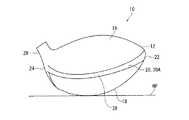
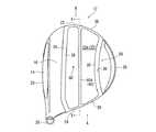
図1〜図8に示すように、本実施の形態において、ゴルフクラブヘッド10は、中空のウッド型ゴルフクラブヘッド(ドライバー)であり、ヘッド本体12と、カバー体46(図2)とを備えている。なお、図3ではカバー体46の図示を省略した。(First Embodiment)
Next, an embodiment of the present invention will be described.
As shown in FIGS. 1 to 8, in the present embodiment, the
ヘッド本体12は、金属材料により構成される。
前記金属材料としては、例えばステンレス鋼、マルエージング鋼、純チタン、チタン合金又はアルミニウム合金等の1種又は2種以上が用いられる。
ヘッド本体12は、フェース部14と、クラウン部16と、ソール部18と、サイド部20とを含んで構成されている。
フェース部14は、上下の高さを有して左右に延在している。
クラウン部16は、フェース部14の上部から後方に延在している。
ソール部18は、フェース部14の下部から後方に延在している。
サイド部20は、クラウン部16とソール部18の間でフェース部14のトウ22側縁とヒール24側縁との間をフェースバック28を通って延在している。
図4に示すように、ヘッド本体12は、フェース部14とクラウン部16とソール部18とサイド部20で囲まれた内部が空間13とされ中空状(中空構造)を呈している。
フェース部14の外側に露出する外面がボールを打撃するフェース面14Aであり、フェース部14の空間13に面した内面がフェース内面14Bとなっている。
クラウン部16の外側に露出する外面がクラウン面16Aであり、クラウン部16の空間13に面した内面がクラウン内面16Bである。
ソール部18の外側に露出する外面がソール面18Aであり、ソール部18の空間13に面した内面がソール内面18Bである。
サイド部20の外側に露出する外面がサイド面20Aであり、サイド部20の空間13に面した内面がサイド内面20Bである。
なお、以下では、クラウン面16A、ソール面18A、サイド面20Aを総称してヘッド本体12の外面といい、クラウン内面16B、ソール内面18B、サイド内面20Bを総称してヘッド本体12の内面という。
図中、符号26はリーディングエッジを示す。The
As the metal material, for example, one kind or two or more kinds such as stainless steel, maraging steel, pure titanium, titanium alloy or aluminum alloy are used.
The
The
The
The
The
As shown in FIG. 4, the head
The outer surface exposed to the outside of the
The outer surface exposed to the outside of the
The outer surface exposed to the outside of the
The outer surface exposed to the outside of the
In the following, the crown surface 16A, the
In the figure,
図1〜図3に示すように、クラウン部16には、フェース面14A側でかつヒール24寄りの位置にシャフトSに接続するホーゼル29が設けられ、ホーゼル29にシャフトSが接続されることでゴルフクラブが構成される。 As shown in FIGS. 1 to 3, the
図5〜図7に示すように、ヘッド本体12のうち、トウ22側およびヒール24側においてクラウン部16とサイド部20との境にそれぞれ帯状の境界部30が設けられており、それら2つの境界部30はヘッド本体12を構成する金属材料で形成されている。
境界部30は、ヘッド本体12の外面よりもカバー体46の厚さTc分ヘッド本体12の内部に変位した箇所に設けられている。As shown in FIGS. 5 to 7, in the
The
図4〜図8に示すように、ヘッド本体12のうち、クラウン部16、サイド部20、ソール部18の少なくとも1箇所に開口部32が形成されている。
本実施の形態では、クラウン部16に第1開口部32Aが形成され、トウ22側のサイド部20からトウ22側のソール部18にわたって第2開口部32Bが形成され、ヒール24側のサイド部20からヒール24側のソール部18にわたって第3開口部32Cが形成されている。
すなわち、第1開口部32Aと第2開口部32Bとがトウ22側の境界部30で分離され、第1開口部32Aと第3開口部32Cとがヒール24側の境界部30で分離されている。
そして、各開口部32A〜32Cは後述する2つのカバー体46によって閉塞される。
図4〜図8に示すように、各開口部32A〜32Cの縁部に沿って後述するカバー体46を取り付ける取り付け部34が形成されている。
図5,図10に示すように、取り付け部34は、縦板部36と、横板部38と、境界部30とを備え、ヘッド本体12の内側に窪む凹部状に形成されている。
縦板部36は、ヘッド本体12の外面からヘッド本体12の内側にカバー体46の厚さTc分突出している。
横板部38は、縦板部36の先端に接続され、したがって、ヘッド本体12の外面からヘッド本体12の内側にカバー体46の厚さTc分変位した箇所で、各開口部32A〜32Cのフェース部14側、および、フェースバック28側の縁部に沿って延在している。
境界部30は、トウ22側、ヒール24側において、フェース部14側およびトウ22側の横板部38を接続している。
したがって、カバー体46が縦板部36の内側にはまり込んで各開口部32A〜32Cを閉塞した状態で、カバー体46が外側に露出するカバー体46の外面とヘッド本体12の外面との段差を生じないように図られている。As shown in FIGS. 4 to 8,
In the present embodiment, the
That is, the
Then, each of the
As shown in FIGS. 4 to 8, a mounting
As shown in FIGS. 5 and 10, the mounting
The
The
The
Therefore, in a state where the
図4〜図8、図10に示すように、カバー体46が各開口部32A〜32Cを介して空間13に対向するカバー体46の内面の部分を空間13側から支持する金属材料からなるリブ40が各開口部32A〜32Cを横切るようにトウヒール方向に延在して形成されている。
リブ40の長さは後述するように規定されるが、図9(A)に示す例では、リブ40は、ヘッド本体12の内面の全周にわたって形成されている。
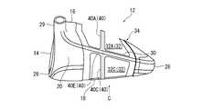
具体的に説明すると、図5〜図8に示すように、リブ40は、第1開口部32Aを横切る第1リブ部40Aと、第2開口部32Bを横切る第2リブ部40Bと、第3開口部32Cを横切る第3リブ部40Cと、ソール部18の内面に沿って延在する第4リブ部40Dと、トウ22側およびヒール24側の境界部30の部分に設けられた第5リブ部40Eとを含んで構成されている。
また、本実施の形態では、第1リブ部40A、第2リブ部40B、第3リブ部40C、第4リブ部40D、第5リブ部40Eは、ヘッド本体12を構成する金属材料と同一の金属材料で形成されている。As shown in FIGS. 4 to 8 and 10, ribs made of a metal material that support the inner surface portion of the
The length of the
Specifically, as shown in FIGS. 5 to 8, the
Further, in the present embodiment, the
図10に示すように、リブ40は断面がT字状を呈しており、支持壁部42と、補強壁部44とを備えている。
支持壁部42は、第1〜第3リブ部40A〜40Cにおいては、カバー体46が空間13に対向するカバー体46の内面に重ね合わされる箇所であり帯板状を呈している。また、支持壁部42は第4リブ部40Dにおいてはソール部18のソール内面18Bに接合される箇所であり帯板状を呈している。また、支持壁部42は第5リブ部40Eにおいては境界部30の部分で形成されている。
カバー体46の内面に重ね合わされる支持壁部42の外面は、ヘッド本体12の外面よりもカバー体46の厚さTc分ヘッド本体12の内部に変位した箇所に設けられている。
したがって、第1リブ部40Aと境界部30とが交差する箇所では、支持壁部42の外面と境界部30の外面とが同一面上に位置し、第2リブ部40Bと境界部30とが交差する箇所では、支持壁部42の外面と境界部30の外面とが同一面上に位置し、第3リブ部40Cと境界部30とが交差する箇所では、支持壁部42の外面と境界部30の外面とが同一面上に位置している。
また、境界部30と横板部38とが交差する箇所では、支持壁部42の外面と横板部38の外面とが同一面上に位置している。
補強壁部44は、支持壁部42の延在方向と直交する幅方向の中央で支持壁部42が空間13に対向する支持壁部42の内面から支持壁部42の全長にわたって空間13側に突出している。As shown in FIG. 10, the
In the first to
The outer surface of the
Therefore, at the intersection of the
Further, at the intersection of the
The reinforcing
本実施の形態では、リブ40の寸法は以下のようになっている。
リブ40の高さHは、2mm以上10mm以下である。
ここでリブ40の高さHは、カバー体46の内面およびソール部18の内面に重ね合わされる支持壁部42の面から補強壁部44の先端までの寸法であり、また、境界部30の外面から補強壁部44の先端までの寸法である。
また、支持壁部42および補強壁部44の厚さDは、0.5mm以上3mm以下である。
また、リブ40の幅W、すなわち、支持壁部42の幅Wは、2mm以上10mm以下である。
高さH、厚さD、幅Wがそれぞれ下限値を下回ると、リブ40によって後述するカバー体46およびヘッド本体12の強度、剛性を高める効果が低く打球音を高音とする効果が低下する。
また、高さH、厚さD、幅Wがそれぞれ上限値を上回ると、リブ40の重量が重くなりすぎて、ヘッド本体12の軽量化を図る効果が低下する。In the present embodiment, the dimensions of the
The height H of the
Here, the height H of the
The thickness D of the
Further, the width W of the
When the height H, the thickness D, and the width W are below the lower limit values, the
Further, when the height H, the thickness D, and the width W each exceed the upper limit values, the weight of the
カバー体46は、第1〜第3開口部32A〜32Cをヘッド本体12の外側から閉塞するものであり、繊維強化樹脂材料で構成されている。繊維強化樹脂材料として、軽量で強度に優れる炭素繊維強化樹脂など従来公知の様々な繊維強化樹脂材料が使用可能である。
また、カバー体46の材料は、本体12の比重より軽いものであれば良く、金属であれば、マグネシウム合金、アルミ合金、チタン合金なども使用可能である。
なお、繊維強化樹脂材料の場合、繊維強化樹脂は繊維方向と繊維直交方向で強度が異なる異方性を有しているため、繊維方向を互いに異ならせた複数の層を積層させることでなるべく強度が等方性に近づくように構成され、カバー体46の強度、剛性の向上が図られている。
カバー体46は、均一の肉厚で形成されることが一般的だが偏肉でも良い。
カバー体46は、第1〜第3開口部32A〜32Cを閉塞した状態でヘッド本体12の外面と連続する形状で形成され、したがって、ヘッド本体12の外面とカバー体46の外面とによって、ゴルフクラブヘッド10の外面が構成されている。The
Further, the material of the
In the case of a fiber-reinforced resin material, since the fiber-reinforced resin has anisotropy in which the strength differs in the fiber direction and the fiber orthogonal direction, the strength is as high as possible by laminating a plurality of layers having different fiber directions. Is configured to be close to isotropic, and the strength and rigidity of the
The
The
本実施の形態では、カバー体46は、第1開口部32Aのトウ22側の半部と、第2開口部32Bとを閉塞するトウ側カバー体46Aと、第1開口部32Aのヒール24側の半部と、第3開口部32Cとを閉塞するヒール側カバー体46Bとの2つのカバー体46で構成されている。
図2に示すように、ヘッド本体12のクラウン部16側において、トウ側カバー体46Aとヒール側カバー体46Bとは、フェース部14とフェースバック28とを結ぶ方向に沿って延在するカバー接合部47を介して接合されている。
なお、トウ側カバー体46Aとヒール側カバー体46Bとが一体的に構成されていてもよいことは無論である。
カバー体46は、その内面がヘッド本体12の外側から取り付け部34の横板部38の外面および境界部30の外面、リブ40の支持壁部42の外面に重ね合わされ、カバー体46が縦板部36の内側にはまり込んで各開口部32A〜32Cを閉塞した状態で、接着やカシメなど従来公知の結合方法で取り付け部34および各リブ40の支持壁部42に取り付けられ(一体的に結合され)、これによりゴルフクラブヘッド10が組み立てられる。そして、ヘッド本体12の外面およびカバー体46の外面には適宜塗装がなされ、デザイン性が高められる。In the present embodiment, the
As shown in FIG. 2, on the
Needless to say, the toe
The inner surface of the
次に、ゴルフクラブヘッド10の各部の規定について詳細に説明する前に、フェース面14Aの中心点Pcの規定方法について説明する。
フェース面14Aの中心点Pcは、フェース面14Aの幾何学的中心であり、中心点Pcの規定方法としては以下に例示する第1の規定方法、第2の規定方法を含め従来公知のさまざまな方法が採用可能である。Next, before explaining the definition of each part of the
The center point Pc of the
[A]フェース面14Aの中心点Pcの第1の規定方法:
フェース面14Aと他のゴルフクラブヘッド10の部分との境目が明確である場合、言い換えると、フェース面14Aの周縁が稜線によって特定される場合における中心点Pcの規定方法である。この場合はフェース面14Aが明瞭に定義されることになる。
図11〜図14はフェース面14Aの中心点Pcの規定方法を示す説明図である。[A] First method for defining the center point Pc of the
When the boundary between the
11 to 14 are explanatory views showing a method of defining the center point Pc of the
(1)まず、図11に示すように、ライ角およびフェース角が規定値となるように水平面HP上にゴルフクラブヘッド10を載置する。このときのゴルフクラブヘッド10の状態を基準状態とする。なお、ライ角およびフェース角の設定値は、例えば製品カタログに記載された値である。(1) First, as shown in FIG. 11, the
(2)次にクラウン部16及びソール部18を結ぶ方向における仮中心点c0を求める。
すなわち、図11に示すように、トウ22およびヒール24を結ぶ水平面HPと平行な線(以下水平線という)の概略中心点と交差する垂線f0を引く。
この垂線f0とフェース面14Aの上縁とが交差するa0点と、垂線f0とフェース面14Aの下縁とが交差するb0点の中点を仮中心点c0とする。(2) Next, the temporary center point c0 in the direction connecting the
That is, as shown in FIG. 11, a perpendicular line f0 that intersects the approximate center point of a line parallel to the horizontal plane HP connecting the
The midpoint between the a0 point where the perpendicular line f0 and the upper edge of the
(3)次に図12に示すように仮中心点c0を通る水平線g0を引く。
(4)次に図13に示すように水平線g0とフェース面14Aのトウ22側の縁とが交差するd0点と、水平線g0とフェース面14Aのヒール24側の縁とが交差するe0点の中点を仮中心点c1とする。(3) Next, as shown in FIG. 12, a horizontal line g0 passing through the temporary center point c0 is drawn.
(4) Next, as shown in FIG. 13, at the d0 point where the horizontal line g0 and the edge of the
(5)次に図14に示すように仮中心点c1を通る垂線f1を引き、この垂線f1とフェース面14Aの上縁とが交差するa1点と、垂線f1とフェース面14Aの下縁とが交差するb1点の中点を仮中心点c2とする。
ここで、仮中心点c1とc2とが合致したならばその点をフェース面14Aの中心点Pcとして規定する。
仮中心点c1とc2が合致しなければ、(2)乃至(5)の手順を繰り返す。
なお、フェース面14Aは曲面を呈しているため、水平線g0の中点、垂線f0、f1の中点を求める場合の水平線g0の長さ、垂線f0、f1の長さはフェース面14Aの曲面に沿った長さを用いるものとする。
そして、フェースセンターラインCLは、中心点Pcを通りかつトウ22−ヒール24方向と直交する方向に延在する直線で定義される。(5) Next, as shown in FIG. 14, a perpendicular line f1 passing through the temporary center point c1 is drawn, and the perpendicular line f1 and the upper edge of the
Here, if the temporary center points c1 and c2 match, that point is defined as the center point Pc of the
If the temporary center points c1 and c2 do not match, the steps (2) to (5) are repeated.
Since the
The face center line CL is defined by a straight line that passes through the center point Pc and extends in a direction orthogonal to the toe 22-
[B]フェース面14Aの中心点Pcの第2の規定方法:
次に、フェース面14Aの周縁と他のゴルフクラブヘッド10の部分との間が曲面で接続されておりフェース面14Aが明瞭に定義できない場合の中心点Pcの定義を説明する。[B] A second method for defining the center point Pc of the
Next, the definition of the center point Pc when the peripheral edge of the
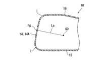
図15に示すように、ゴルフクラブヘッド10は中空であり、符号G0はゴルフクラブヘッド10の重心点を示し、符号Lpは重心点G0とフェース面上重心点FGとを結ぶ直線であり、言い換えると、直線Lpは重心点G0を通るフェース面14Aの垂線(法線)である。
すなわち、ゴルフクラブヘッド10の重心点G0をフェース面14Aに投影した点がフェース面上重心点FGである。
ここで、図16に示すように、重心点G0とフェース面上重心点FGとを結ぶ直線Lpを含む多数の平面H1、H2、H3、…、Hnを考える。As shown in FIG. 15, the
That is, the point where the center of gravity point G0 of the
Here, as shown in FIG. 16, consider a large number of planes H1, H2, H3, ..., Hn including a straight line Lp connecting the center of gravity point G0 and the center of gravity point FG on the face surface.
ゴルフクラブヘッド10を各平面H1、H2、H3、…、Hnに沿って破断したときの断面において、図17に示されるように、ゴルフクラブヘッド10の外面の曲率半径r0を測定する。
曲率半径r0の測定に際して、フェース面14A上のフェースライン、パンチマーク等が無いものとして扱う。
曲率半径r0は、フェース面14Aの中心点Pcから外方向(図17における上方向、下方向)に向かって連続的に測定される。
そして、測定において曲率半径r0が最初に所定の値以下となる部分をフェース面14Aの周縁を表わす輪郭線Iとして定義する。
所定の値は例えば200mmである。
多数の平面H1、H2、H3、…、Hnに基づいて決定された輪郭線Iによって囲まれた範囲が、図16、図17に示すように、フェース面14Aとして定義される。As shown in FIG. 17, the radius of curvature r0 of the outer surface of the
When measuring the radius of curvature r0, it is treated as if there is no face line, punch mark, etc. on the
The radius of curvature r0 is continuously measured from the center point Pc of the
Then, in the measurement, the portion where the radius of curvature r0 is first or less than a predetermined value is defined as the contour line I representing the peripheral edge of the
The predetermined value is, for example, 200 mm.
A range surrounded by contour lines I determined based on a number of planes H1, H2, H3, ..., Hn is defined as the
次に、図18に示すように、ライ角およびフェース角が規定値となるように水平な地面上(水平面HP)にゴルフクラブヘッド10を載置する。
直線LTは、フェース面14Aのトウ22側点PTを通過して鉛直方向に延在する。
直線LHは、フェース面14Aのヒール24側点PHを通過して鉛直方向に延在する。
直線LCは、直線LTおよび直線LHと平行である。直線LCと直線LTとの距離は、直線LCと直線LHとの距離と等しい。
符号Puは、フェース面14Aの上側点を示し、符号Pdはフェース面14Aの下側点である。上側点Puおよび下側点Pdは、いずれも直線LCと輪郭線Iとの交点である。
中心点Pcは、上側点Puと下側点Pdとを結ぶ線分の中点で定義される。Next, as shown in FIG. 18, the
The straight line LT passes through the
The straight line LH passes through the
The straight line LC is parallel to the straight line LT and the straight line LH. The distance between the straight line LC and the straight line LT is equal to the distance between the straight line LC and the straight line LH.
Reference numeral Pu indicates an upper point of the
The center point Pc is defined by the midpoint of the line segment connecting the upper point Pu and the lower point Pd.
(フェース中心基準断面Pfc)
次に、ゴルフクラブヘッド10の各部の規定について詳細に説明する。
まず、ゴルフクラブヘッド10のフェース中心基準断面Pfcについて規定する。
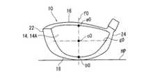
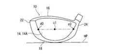
図1〜図3に示すように、ゴルフクラブヘッド10を水平面HPに対して予め定められたライ角およびロフト角通りに設置した基準状態とする。
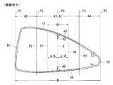
図1に示すように、フェース面14Aの中心点Pcを通る法線を含みかつ水平面HPと直交する平面Xでヘッド本体12を破断した断面をフェース中心基準断面Pfcとする。言い換えると、フェース中心基準断面Pfcは、基準状態において、フェースセンターラインCLを含みかつ水平面HPと直交する平面Xでヘッド本体12を破断した断面である。(Face center reference cross section Pfc)
Next, the provisions of each part of the
First, the face center reference cross section Pfc of the
As shown in FIGS. 1 to 3, the
As shown in FIG. 1, a cross section obtained by breaking the
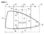
(第1〜第6平面P1〜P6、中心面P0、第1範囲A1、第2範囲A2、ヘッド最大幅M)
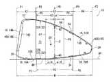
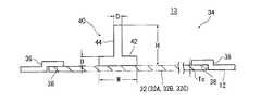
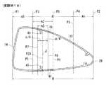
図4に示すように、ゴルフクラブヘッド10の基準状態で、水平面HPおよびフェース中心基準断面Pfcと直交しリーディングエッジ26に当接する平面を第1平面P1とする。
なお、図4では、ソール部18側に位置するカバー体46を図示するため、フェース中心基準断面Pfcに対してトウヒール方向に変位した箇所の断面を示している。
第1平面P1と平行しフェースバック28の外面に当接する平面を第2平面P2とする。
ヘッド本体12を平面視したときに、第1平面P1と第2平面P2との距離をヘッド最大幅Mとする。
第1平面P1と第2平面P2とを結ぶ寸法の1/2の位置で第1平面P1および第2平面P2と平行する平面を中心面P0とする。
中心面P0からフェース部14側にヘッド最大幅Mの1/4離間した位置で中心面P0と平行する平面を第3平面P3とする。
中心面P0からフェースバック28側にヘッド最大幅Mの1/4離間した位置で中心面P0と平行する平面を第4平面P4とする。
第3平面P3と第4平面P4とで区画された範囲を第1範囲A1とする。
中心面P0と平行しカバー体46の最もフェース部14寄りの縁部を通る平面を第5平面P5とする。
中心面P0と平行しカバー体46の最もフェースバック28寄りの縁部を通る平面を第6平面P6とする。
第5平面P5と第6平面P6とで区画された範囲を第2範囲A2とする。(1st to 6th planes P1 to P6, central surface P0, 1st range A1, 2nd range A2, head maximum width M)
As shown in FIG. 4, in the reference state of the
In addition, in FIG. 4, since the
The plane parallel to the first plane P1 and abutting on the outer surface of the face back 28 is referred to as the second plane P2.
When the
The plane parallel to the first plane P1 and the second plane P2 at a position halved in the dimension connecting the first plane P1 and the second plane P2 is defined as the central plane P0.
A plane parallel to the central surface P0 at a position separated from the central surface P0 on the
A plane parallel to the center plane P0 at a position separated from the center plane P0 on the face back 28 side by 1/4 of the maximum head width M is referred to as a fourth plane P4.
The range partitioned by the third plane P3 and the fourth plane P4 is defined as the first range A1.
The plane parallel to the central surface P0 and passing through the edge of the
The plane parallel to the central surface P0 and passing through the edge of the
The range partitioned by the fifth plane P5 and the sixth plane P6 is defined as the second range A2.
本実施の形態では、カバー体46は、第1範囲A1内に位置する。
カバー体46が第1範囲A1内に位置していると、後述するゴルフクラブヘッド10の慣性モーメントMIを確保する上で有利となる。
これは、重心点G0から近い箇所に比重が軽いカバー体46が位置し、重心点G0から遠い箇所に比重が重いヘッド本体12の部分が位置するためである。
一方、カバー体46が第1範囲A1外に位置していると、慣性モーメントMIを確保する上で不利となる。
これは、重心点G0から遠い箇所に比重が軽いカバー体46が位置し、重心点G0から近い箇所に比重が重いヘッド本体12の部分が位置するためである。
なお、ゴルフクラブヘッド10の慣性モーメントMIの測定方法については後述する。In the present embodiment, the
When the
This is because the
On the other hand, if the
This is because the
The method of measuring the moment of inertia MI of the
また、本実施の形態では、第2範囲A2のほぼ中央位置においてリブ40が開口部32を横切るようにトウヒール方向に延在して形成されている。
このようにすることで、リブ40によってカバー体46が補強され、カバー体46の強度、剛性が高められることから打球音が高音となりやすく、心地よい打球音を得る上で有利となる。
また、第2範囲A2のほぼ中央位置とは、以下のように規定される。
すなわち、第2範囲A2の寸法をαとし、第2範囲A2の中央位置βからフェース部14方向にα/4離間した位置を通り中央面P0と平行な平面を第7平面P7とし、第2範囲A2の中央位置からフェースバック28方向にα/4離間した位置を通り中央面P0と平行な平面を第8平面P8とすると、第7平面P7と第8平面P8とで区画される第5範囲A5を第2範囲A2のほぼ中央位置と規定する。
なお、本実施の形態では、クラウン部16側における第2範囲A2と、ソール部18側における第2範囲A2の位置が一致した場合について説明したが、クラウン部16側とソール部18側とでそれら2つの第2範囲A2の位置が一致しない場合は、少なくとも一方の第2範囲A2のほぼ中央位置(第5範囲A5)にリブ40が形成されていればよい。Further, in the present embodiment, the
By doing so, the
Further, the substantially central position of the second range A2 is defined as follows.
That is, the dimension of the second range A2 is α, and the plane parallel to the central surface P0 passing through the position α / 4 away from the central position β of the second range A2 in the
In the present embodiment, the case where the positions of the second range A2 on the
また、リブ40がカバー体46を支持している部分のトウヒール方向の寸法(トウヒール方向に沿った寸法)は、カバー体46のトウヒール方向の寸法(トウヒール方向に沿った寸法)の全長とほぼ同じであることがカバー体46の強度、剛性を確保する上で好ましく、打球音を高音にする上で有利となる。
すなわち、図38を流用して説明すると、図38(A)に示すように、リブ40がカバー体46を支持している部分のトウヒール方向の寸法(Lth1+Lth2+Lth3)は、カバー体46のトウヒール方向の寸法の全長(Lc1)の70%以上あることが好ましい。
すなわち、ソール部18に設けられたリブ40が、カバー体46を支持している部分とカバー体を支持していない部分に分かれる場合は、カバー体46を支持していない部分のリブ40は、カバー体46を支持している部分のリブ40とは別に扱われ、トウヒール方向の寸法の全長に対するリブ40の割合の計算に含まれない。
図38(B)に示すように、リブ40がカバー体46を支持している部分のトウヒール方向の寸法(Lth1+Lth2+Lth3)が、カバー体46のトウヒール方向の寸法の全長(Lc1)の70%未満であると、カバー体46の強度、剛性を確保する効果が低下し、打球音を高音にする効果が低下する。Further, the dimension in the toe heel direction (dimension along the toe heel direction) of the portion where the
That is, to explain by diverting FIG. 38, as shown in FIG. 38 (A), the dimensions (Lth1 + Lth2 + Lth3) of the portion where the
That is, when the
As shown in FIG. 38 (B), the dimension in the toe heel direction (Lth1 + Lth2 + Lth3) of the portion where the
さらに、リブ40は、カバー体46の内面からヘッド本体12が空間13に対向するヘッド本体12の内面に連続して延在形成され(図9(A)参照)、リブ40は、カバー体46の内面およびヘッド本体12の内面からなるゴルフクラブヘッド10の内面の全周(言い換えるとリブ40の延在方向に沿ったゴルフクラブヘッド10の内面の全周)の80%以上にわたって延在形成されていると、打球音を高音にする上でより有利となる。
これは、リブ40によってカバー体46とヘッド本体12の双方の強度、剛性が高められるからである。
したがって、リブ40の長さがゴルフクラブヘッド10の内面の全周の80%を下回ると、カバー体46とヘッド本体12の双方の強度、剛性を確保する効果が低下し、打球音を高音にする効果が低下する。
なお、実際のゴルフクラブヘッド10の形状では、クラウン部16とサイド部20との間の境界部30の部分において、ヘッド本体12の内面の曲面の曲率が局所的に大きくなることから、製造上リブ40を形成することは難しい場合がある。そのため、リブ40をゴルフクラブヘッド10の内面の全周の100%にわたって形成できない場合もある。Further, the
This is because the
Therefore, if the length of the
In the actual shape of the
また、ヘッド本体12のうち、クラウン部16とサイド部20との境の全長にわたって帯状に延在する境界部30が形成され、境界部30は、ヘッド本体12を構成する金属材料で形成されている。
したがって、境界部30は、その延在方向の中間で分断されることがないように形成されている。
このようにクラウン部16とサイド部20との境の全長にわたって境界部30が形成されることにより、ヘッド本体12の強度、剛性が確保されるため、ヘッド本体12の強度、剛性が高められ、打球音を高音にする上でより有利となる。
なお、境界部30の幅は、1mm以上であることがヘッド本体12の強度、剛性が高める上で有利であり、境界部30の幅が1mm未満であると、ヘッド本体12の強度、剛性を高める効果が低下する。Further, in the head
Therefore, the
By forming the
It is advantageous that the width of the
また、図9(B)に示すように、境界部30のうち、第1範囲A1内の部分は、境界部30に隣接するクラウン部16およびサイド部20の肉厚よりも大きな寸法の肉厚で形成された厚肉部31で構成されていると、ゴルフクラブヘッド10の慣性モーメントMIを確保し、また、ヘッド本体12の強度、剛性を確保する上でより有利となる。
これは、重心点G0からなるべく離れた箇所に重量を有する部分を配置することで慣性モーメントMIを確保する上で有利となるためである。
なお、厚肉部31の厚さは、1mm以上あればよく、2mm以上5mm以下であればより好ましい。
厚肉部31の厚さが2mm以上5mm以下であれば、ゴルフクラブヘッド10の重量増を抑制しつつゴルフクラブヘッド10の慣性モーメントMIを確保し、また、ヘッド本体12の強度、剛性を確保する上でより有利となる。
厚肉部31の厚さが上記範囲を下回ると、上記効果が低下し、厚肉部31の厚さが上記範囲を上回ると、ゴルフクラブヘッド10の重量が過剰となる。
また、厚肉部31の長さは、10mm以上あればよく、20mm以上50mm以下であればより好ましい。
厚肉部31の長さが20mm以上50mm以下であれば、ゴルフクラブヘッド10の重量増を抑制しつつゴルフクラブヘッド10の慣性モーメントMIを確保し、また、ヘッド本体12の強度、剛性を確保する上でより有利となる。
厚肉部31の長さが上記範囲を下回ると、上記効果が低下し、厚肉部31の長さが上記範囲を上回ると、ゴルフクラブヘッド10の重量が過剰となる。Further, as shown in FIG. 9B, the portion of the
This is because it is advantageous to secure the moment of inertia MI by arranging the portion having the weight as far as possible from the center of gravity point G0.
The thickness of the thick portion 31 may be 1 mm or more, and more preferably 2 mm or more and 5 mm or less.
When the thickness of the thick portion 31 is 2 mm or more and 5 mm or less, the moment of inertia MI of the
If the thickness of the thick portion 31 is less than the above range, the above effect is reduced, and if the thickness of the thick portion 31 exceeds the above range, the weight of the
Further, the length of the thick portion 31 may be 10 mm or more, more preferably 20 mm or more and 50 mm or less.
When the length of the thick portion 31 is 20 mm or more and 50 mm or less, the moment of inertia MI of the
If the length of the thick portion 31 is less than the above range, the above effect is reduced, and if the length of the thick portion 31 exceeds the above range, the weight of the
また、ゴルフクラブヘッド10のヘッド質量は、210g以下であり、基準状態でゴルフクラブヘッド10の重心点G0を通り水平面HPに直交する垂直な直線を回転軸とする慣性モーメントの大きさをMI(g・cm2)とするとき、慣性モーメントMIが6200g・cm2以下である。
なお、ヘッド質量は、180g以上205g以下の範囲が好ましい。
ヘッド質量が上記範囲内であると、慣性モーメントMIを確保して打球の方向性の向上を図る上で有利となる。
ヘッド質量が上記範囲を下回ると、ヘッド重量が小さいため、慣性モーメントMIが小さくなり、打球の方向性を向上する効果が低下する。
ヘッド重量が上記範囲を上回ると、ヘッド重量が大きいため、スイング速度が低下し飛距離を確保する効果が低下する。
また、ゴルフクラブヘッド10の慣性モーメントMIは、5000g・cm2以上6000g・cm2以下であることが好ましい。
慣性モーメントMIが上記範囲内であると、打球の方向性の向上を図る上で有利となる。
慣性モーメントMIが上記範囲を下回ると、打球の方向性の向上を図る効果が低下する。
なお、英国のR&Aゴルフ規則で定められた慣性モーメントMIの上限値は5900g・cm2+100g・cm2である。Further, the head mass of the
The head mass is preferably in the range of 180 g or more and 205 g or less.
When the head mass is within the above range, it is advantageous in securing the inertial moment MI and improving the directionality of the hit ball.
When the head mass is less than the above range, the head weight is small, so that the moment of inertia MI is small, and the effect of improving the directionality of the hit ball is reduced.
When the head weight exceeds the above range, the head weight is large, so that the swing speed is lowered and the effect of securing the flight distance is lowered.
In addition, the moment of inertia MI of the
When the moment of inertia MI is within the above range, it is advantageous in improving the directionality of the hit ball.
When the moment of inertia MI is less than the above range, the effect of improving the directionality of the hit ball is reduced.
In addition, the upper limit of the British R & A Rules of Golf moment of inertia MI defined in is5900g · cm 2 + 100g · cm 2.
また、ゴルフクラブヘッド10のヘッド体積が500cc以下であり、ヘッド最大幅Mが130mm以下である。
また、ヘッド体積は440cc以上470cc以下の範囲であり、ヘッド最大幅Mは120mm以上127mm以下の範囲であることが好ましい。
ヘッド本体12の体積が上記範囲内であると、慣性モーメントMIを確保する上で有利となる。
ヘッド本体12の体積が上記範囲を下回ると、慣性モーメントMIを確保する効果が低下する。
なお、上記英国のR&Aゴルフ規則で定められたヘッド本体12の体積の上限値は470ccである。
また、ヘッド幅最大値Mが上記範囲内であると、慣性モーメントMIを確保する上で有利となる。
ヘッド幅最大値Mが上記範囲を下回ると、慣性モーメントMIを確保する効果が低下する。
なお、上記英国のR&Aゴルフ規則で定められたヘッド最大幅Mの上限値は127mmである。Further, the head volume of the
Further, it is preferable that the head volume is in the range of 440 cc or more and 470 cc or less, and the maximum head width M is in the range of 120 mm or more and 127 mm or less.
When the volume of the
If the volume of the
The upper limit of the volume of the
Further, when the maximum head width value M is within the above range, it is advantageous in securing the moment of inertia MI.
When the maximum head width value M is less than the above range, the effect of securing the moment of inertia MI is reduced.
The upper limit of the head maximum width M defined by the R & A Rules of Golf in the United Kingdom is 127 mm.
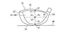
図4に示すように、ヘッド本体12のうち、第1平面P1と第3平面P3とで区画される第3範囲A3に位置する部分と、第4平面P4からフェースバック28までの第4範囲A4に位置する部分との少なくとも一方の部分に、第3平面P3と第4平面P4とで区画される第1範囲A1に位置する部分の比重よりも比重の大きな(金属)材料で形成された大比重部48を設けると、重心点G0からより離間した箇所の重量を増加させることができるため、慣性モーメントMIを確保する上で有利となる。
この場合、ヘッド本体12のうち大比重部48を除く部分と、大比重部48とをそれぞれ比重の異なる金属材料で構成すればよく、このような金属材料として従来公知の様々な金属材料が使用可能である。
例えば、ヘッド本体12のうち大比重部48を除く部分をチタン合金(比重4.4)で構成し、フェースバック28に大比重部48としてステンレス(比重7.8)あるいはタングステン合金(比重9〜18)を設けても良い。
あるいは、ヘッド本体12のうち大比重部48を除く部分をチタン合金(比重4.4)で構成し、フェース部14をβチタン(比重4.8)で構成してもよい。
なお、大比重部48は、例えば、フェース部14を構成する部分48Aであり、あるいは、フェースバック28を構成する部分48Bである。As shown in FIG. 4, a portion of the
In this case, the portion of the
For example, the portion of the
Alternatively, the portion of the
The large
ここで、図19〜図22を参照して、ゴルフクラブヘッド10の慣性モーメントMIの測定方法について詳細に説明する。
ここで、図19は、ゴルフクラブヘッド10の慣性モーメント測定器を示す模式的斜視図である。慣性モーメントMIは、図19に示す慣性モーメント測定器60により測定される。Here, a method of measuring the moment of inertia MI of the
Here, FIG. 19 is a schematic perspective view showing a moment of inertia measuring instrument of the
慣性モーメント測定器60は、測定部62、演算部64、スタートレバー66、表示部68、操作ボタン69を備え、測定部62の上に慣性モーメントMIの測定対象物が載置され、スタートレバー66を手で摘んで変位させた後、手を放して捩れ振動させ、この時の捩れ振動の周期を測ることによって演算部64を通して慣性モーメントMIを測定し、表示部68に慣性モーメントMIの数値を表示する装置である。
なお、慣性モーメント測定器60として、Inertia Dynamics社製、慣性モーメント測定器 Model MOI−005−014が例示される。このような慣性モーメント測定器は公知のものであればよく、本発明において、特に制限されない。The moment of
As the moment of
図20(A)に示すように、慣性モーメント測定器60に治具70を固定して、治具70の慣性モーメントIaを測定する。
次いで、図20(B)に示すように、治具70の上面部72にゴルフクラブヘッド10のソール部18を固定して、ゴルフクラブヘッド10および治具70の合計の慣性モーメントIbを測定する。次に、得られた各慣性モーメントIa、Ibから、(Ib−Ia)よりゴルフクラブヘッド10の慣性モーメントMIを得る。
なお、通常の慣性モーメント測定器60では、上記Iaの数値は、操作ボタン69を駆使し一連の手順によって自動的に風袋引きをされ、(Ib−Ia)の数値が表示される。As shown in FIG. 20 (A), the
Next, as shown in FIG. 20 (B), the
In the normal moment of
なお、ゴルフクラブヘッド10と治具70とを固定するためには、例えば、両面テープ、粘土等の粘着体による固定、接着剤による固定、または磁力を用いた固定などが挙げられる。
固定は、ゴルフクラブヘッド10のソール部18が治具70の上面部72に固定される。しかしながら、ソール部18が凸の曲面を有していれば、上面部72は凸の曲面に合致するような凹の曲面であることが好ましく、ソール部18が平面であれば、上面部72は平面であることが好ましい。つまり、固定する両面が合致することが好ましい。
ゴルフクラブヘッド10のソール部18が曲面である場合には、粘着体(図示せず)をソール部18及び上面部72に合致するように設け、ゴルフクラブヘッド10を固定する。この場合、粘着体のように接着剤などの固定手段の内質量を有するものは、治具の一部に含まれ、風袋引きにおいては治具と同様に風袋として引かれることは言うまでもない。In order to fix the
For fixing, the
When the
ゴルフクラブヘッド10は、図21(A)に示すゴルフクラブヘッド10の重心点G0を通り、水平面HPに直交する第1の直線Vと、図21(B)に示す慣性モーメント測定器60の捩れ振動の回転軸Rとが、図21(C)に示すように一致もしくは概ね一致するように慣性モーメント測定器60に固定されることが好ましい。
概ね一致とは、回転軸Rが水平面HPを通る点と第1の直線Vが水平面HPを通る点pとのなす距離が3mm以内、好ましくは2mm以内、より好ましくは1mm以内とすることである。
この範囲内にゴルフクラブヘッド10のソール部18を固定することによって、より正確にゴルフクラブヘッド10の慣性モーメントMIを測定することが可能になる。The
Approximately the same means that the distance between the point where the rotation axis R passes through the horizontal plane HP and the point p where the first straight line V passes through the horizontal plane HP is within 3 mm, preferably within 2 mm, and more preferably within 1 mm. ..
By fixing the
また、回転軸Rが水平面HPを通る点と第1の直線Vが水平面HPを通る点pとのなす距離を上記範囲内とする必要は必ずしもなく、この距離を知り、自動的に風袋引きをして得られた(Ib−Ia)の数値からゴルフクラブヘッド10の質量にこの距離の自乗を掛けた積を減算することによって補正することができる。
この補正方法によってゴルフクラブヘッド10の慣性モーメントMIを得てもよい。このように、ゴルフクラブヘッド10の慣性モーメントMIの測定方法については、特に限定されない。Further, it is not always necessary that the distance between the point where the rotation axis R passes through the horizontal plane HP and the point p where the first straight line V passes through the horizontal plane HP is within the above range. It can be corrected by subtracting the product of the mass of the
The moment of inertia MI of the
慣性モーメント測定器60の回転軸R及びこの回転軸Rがソール部18を通る点は、慣性モーメント測定器60により定められるものである。回転軸Rは鉛直または概ね鉛直になることが好ましい。
ここで、概ね鉛直とは、鉛直方向に対する傾きが2°以内、好ましくは1°以内のことである。回転軸Rを鉛直または概ね鉛直に設定するためには、慣性モーメント測定器60に設けられた水準器部分を目安に測定器の水平を調整すること、又は測定器を水平に調整された平面板上に設置すること等が考えられる。
上記範囲内に設定することによって、ゴルフクラブヘッド10の重心Gを通り水平面HPに直交する第1の直線Vを第1の回転軸とする回転軸回りの慣性モーメントMIをより正確に測定することができる。The rotation axis R of the moment of
Here, the term "vertical" means that the inclination with respect to the vertical direction is within 2 °, preferably within 1 °. In order to set the rotation axis R vertically or substantially vertically, adjust the level of the measuring instrument with reference to the spirit level provided in the moment of
By setting within the above range, the moment of inertia MI around the rotation axis with the first straight line V passing through the center of gravity G of the
また、治具70の上面部72によって支持された平面は水平または概ね水平になることが好ましい。本発明における概ね水平とは、水平面HPに対する傾きが2°以内、好ましくは1°以内のことである。
上記範囲内に設定することによって、ゴルフクラブヘッド10の慣性モーメントMIをより正確に測定することができる。Further, it is preferable that the plane supported by the
By setting within the above range, the moment of inertia MI of the
また、治具70は、治具自体の重心位置が回転軸Rに一致もしくは概ね一致するように慣性モーメント測定器60に装着されることが好ましい。概ね一致とは、図22に示すように治具70の重心位置をCとすると、重心位置Cと回転軸Rとの距離δを2mm以内、好ましくは1mm以内とすることである。
治具70の重心位置Cを上記範囲内に設定することによって、ゴルフクラブヘッド10の慣性モーメントMIをより正確に測定することができる。Further, it is preferable that the
By setting the position C of the center of gravity of the
以上説明したように本実施の形態によれば、図4に示すように、金属材料で形成された中空状のヘッド本体12に形成された開口部32をヘッド本体12の外側から繊維強化樹脂材料からなるカバー体46で閉塞し、第5平面P5と第6平面P6とで区画された第2範囲A2のほぼ中央位置においてカバー体46が開口部32を介して空間13に対向するカバー体46の内面の部分を空間13側から支持する金属材料からなるリブ40を開口部32を横切るようにトウヒール方向に延在して形成した。
したがって、カバー体46がゴルフクラブヘッド10の重心点G0から近い箇所に配置されると共に、カバー体46よりも比重の重い金属材料で形成されたヘッド本体12の部分が重心点G0から遠い箇所に配置されることにより、ゴルフクラブヘッド10の慣性モーメントMIを確保でき、打球の方向性の向上を図る上で有利となる。
さらに、カバー体46よりも剛性が高いリブ40によってカバー体46を支持することでカバー体46を補強し、これにより、カバー体46の剛性および弾性率を高めたのと同様の効果を発揮することができる。
したがって、金属材料からなるヘッド本体12よりも剛性、弾性率が低いカバー体46で開口部32を閉塞する構造であるにも拘らず、打球時に発生する打球音を高音とすることができ、心地よい打球音を得る上で有利となる。As described above, according to the present embodiment, as shown in FIG. 4, the
Therefore, the
Further, the
Therefore, despite the structure in which the
以下、本発明の実験例について説明する。
図23〜図28は、本発明に係るゴルフクラブヘッド10の実験結果を示す図である。
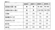
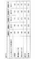
試料となるゴルフクラブヘッド10を各実験例毎に作成し、以下の4つの評価項目を測定し指数(評価点)を求めると共に、4つの指数の合計点を求めた。
なお、以下の実験例では、ゴルフクラブヘッド10としてドライバーを実験対象とした。Hereinafter, experimental examples of the present invention will be described.
23 to 28 are diagrams showing the experimental results of the
A
In the following experimental example, a driver was used as the
(1)打球音
20人の被験者について実際にゴルフボールを各実験例のゴルフクラブヘッド10を用いて打撃した場合の打球音を指数で評価した。
比較例に相当する実験例の指数を100とし指数が大きいほど打球音が高音で心地良く、評価が良いことを示す。
打球音の評価は、1本のゴルフクラブヘッド10について20人のゴルファーがゴルフボールを実際に10打ずつ打撃してその平均値を求めた。(1) Hitting sound The hitting sound when a golf ball was actually hit by using the
The index of the experimental example corresponding to the comparative example is set to 100, and the larger the index is, the higher the hitting sound is and the more comfortable the hitting sound is, and the better the evaluation is.
In the evaluation of the hitting sound, 20 golfers actually hit the
(2)飛距離ばらつき
20人の被験者について実際にゴルフボールを各実験例のゴルフクラブヘッド10を用いて打撃した場合の飛距離のばらつきを指数で評価した。
ここで、飛距離のばらつきは以下のようにして求める。
飛距離の最大値と最小値の差分を飛距離のばらつきとして求める。
20人の被験者について各実験例のゴルフクラブを用いて飛距離ばらつきの評価データをそれぞれ求め、各ゴルフクラブのそれぞれについて20人の飛距離ばらつきの評価データの平均値を求めた。
そして、比較例に相当する実験例の評価データの平均値を100とし、比較例以外の実験例を指数(比較例に相当する実験例の評価データの平均値/比較例以外の実験例の評価データの平均値)×100)によって評価した。即ち、指数が高いほど飛距離ばらつきが少なく優れている。(2) Variation in flight distance The variation in flight distance when a golf ball was actually hit using the
Here, the variation in flight distance is obtained as follows.
The difference between the maximum value and the minimum value of the flight distance is calculated as the variation of the flight distance.
The evaluation data of the flight distance variation was obtained for each of the 20 subjects using the golf clubs of each experimental example, and the average value of the evaluation data of the flight distance variation of 20 persons was obtained for each of the golf clubs.
Then, the average value of the evaluation data of the experimental examples corresponding to the comparative examples is set to 100, and the experimental examples other than the comparative examples are indexed (the average value of the evaluation data of the experimental examples corresponding to the comparative examples / the evaluation of the experimental examples other than the comparative examples. It was evaluated by the average value of the data) × 100). That is, the higher the index, the smaller the variation in flight distance and the better.
(3)左右のばらつき
20人の被験者について実際にゴルフボールを各実験例のゴルフクラブヘッド10を用いて打撃した場合の左右のばらつきを指数で評価した。
ここで、左右のばらつきは以下のようにして求める。
すなわち、打球フィールドに目標点を設定してゴルファーが目標点に向かって打球する。そして打球する地点と目標点を結んだ直線と、打球されたボールが停止した点までの距離を方向ブレ幅(ヤード)として記録する。
目標飛球線Lgに対して右方向のずれ量を正(+)の値で、左方向へのずれ量を負(−)の値で表示しており、何れの値も10球の測定値を算術平均した値を左右のばらつきの評価データとして求めた。
ここでは、20人の被験者について各実験例のゴルフクラブを用いて左右のばらつきの評価データをそれぞれ求め、各ゴルフクラブのそれぞれについて20人の左右のばらつきの評価データの平均値を求めた。そして、比較例に相当する実験例の評価データの平均値を100とし、比較例以外の実験例を指数((比較例に相当する実験例の評価データの平均値/比較例以外の実験例の評価データの平均値)×100)によって評価した。即ち、指数が高いほど左右のばらつきが少なく優れている。(3) Left-right variation The left-right variation when a golf ball was actually hit by the
Here, the left-right variation is obtained as follows.
That is, a target point is set in the hitting field and the golfer hits the ball toward the target point. Then, the distance between the straight line connecting the hitting point and the target point and the stopping point of the hit ball is recorded as the directional blur width (yard).
The amount of deviation to the right with respect to the target flight line Lg is indicated by a positive (+) value, and the amount of deviation to the left is indicated by a negative (-) value. Was calculated as the evaluation data of the left-right variation.
Here, the evaluation data of the left-right variation was obtained for each of the 20 subjects using the golf clubs of each experimental example, and the average value of the evaluation data of the left-right variation of 20 subjects was obtained for each of the golf clubs. Then, the average value of the evaluation data of the experimental examples corresponding to the comparative examples is set to 100, and the experimental examples other than the comparative examples are indexed ((the average value of the evaluation data of the experimental examples corresponding to the comparative examples / the experimental examples other than the comparative examples). It was evaluated by the average value of the evaluation data) × 100). That is, the higher the index, the less the left-right variation is and the better.
(4)耐久性
シャフトに固定したゴルフクラブヘッド10のフェース面14Aにエアキャノンにてゴルフボールを繰り返して当て、フェース部14の変形や破損が生じるまでに要した打撃回数を計測し、打撃回数を指数化した。ボールスピードは50m/sとした。打点位置はフェース面14Aの中心点Pcとした。
この場合、比較例に相当する実験例のゴルフクラブヘッド10の測定結果を100とした指数で示した。指数が大きいほど評価が良いことを示す。(4) Durability The golf ball is repeatedly hit on the
In this case, the measurement result of the
(5)合計点
上述した打球音、飛距離ばらつき、左右のばらつき、耐久性の4つの指数を合計したものを合計点とした。
比較例に相当する実験例の合計点を400とし合計点が大きいほど評価が良いことを示す。(5) Total score The total score is the sum of the above-mentioned four indexes of hitting sound, flight distance variation, left-right variation, and durability.
The total score of the experimental examples corresponding to the comparative examples is set to 400, and the larger the total score, the better the evaluation.
以下実験例のゴルフクラブヘッド10について説明する。
なお、実験例で使用したゴルフクラブヘッド10は、ドライバーであり、各実験例で規定したパラメータを除き以下の条件を共通としている。
ヘッド本体12の材料:チタン合金 Ti-8Al-1Mo-1V
フェース14の材料:Ti-6Al-4V
カバー体46の材料:CFRP(炭素繊維強化樹脂)
カバー体46の厚さTc:0.6mm
ただし、実験例2〜20においては、フェースバック28に大比重部48としてステンレス合金(比重7.8)質量30gを設けたものとした。
ロフト角 10.5°
ライ角 59°
ヘッド体積 460ccThe
The
Material of head body 12: Titanium alloy Ti-8Al-1Mo-1V
Material of cover body 46: CFRP (carbon fiber reinforced resin)
However, in Experimental Examples 2 to 20, it was assumed that the face back 28 was provided with a stainless alloy (specific gravity 7.8) mass of 30 g as the large
Loft angle 10.5 °
Rye angle 59 °
Head volume 460cc
(条件1)
各実験例について、図23に示すように、請求項1で規定する条件を変更した。
なお、請求項2〜8で規定する条件は以下のように一定条件とした。
すなわち、請求項2で規定するリブ40がカバー体46を支持している部分のトウヒール方向の寸法は、カバー体46のトウヒール方向の寸法の全長とほぼ同じであるという規定を満たしておらず、具体的には、リブ40がカバー体46を支持している部分のトウヒール方向の寸法は、カバー体46のトウヒール方向の寸法の全長の60%であり、好ましい70%を下回っている。
すなわち、図38(B)に示すように、リブ40がカバー体46を支持している部分のトウヒール方向の寸法(Lth1+Lth2+Lth3)は、カバー体46のトウヒール方向の寸法の全長(Lc1)の70%を下回っている。
また、請求項3で規定するリブ40は、カバー体46の内面およびヘッド本体12の内面からなるゴルフクラブヘッド10の内面の全周の80%以上にわたって延在形成されているという規定を満たしておらず、具体的には、リブ40はゴルフクラブヘッド10の内面の全周の70%にわたって延在形成されている。
なお、リブ40の寸法は、以下の通りであり、実験例1を除く全実験例で同一とする。
リブ40の高さH:5mm
リブ40の厚さD:1mm
リブ40の幅 W:5mm
また請求項4で規定する境界部30については幅5mmで形成されているものとした。
請求項5で規定する厚肉部31(図9(B))はその厚さが3mmで長さ50mmで形成されているものとした。
請求項6で規定するヘッド質量は200gとし、慣性モーメントMIは5500g・cm2とし、いずれも規定内とした。
請求項7で規定するヘッド体積は460ccとし、ヘッド最大幅Mは125mmとし、いずれも規定内とした。
請求項8で規定する大比重部48は、フェースバック28側にステンレス合金を配置した。(Condition 1)
As shown in FIG. 23, the conditions specified in
The conditions specified in claims 2 to 8 are fixed as follows.
That is, the dimension in the toe-heel direction of the portion where the
That is, as shown in FIG. 38 (B), the dimension in the toe heel direction (Lth1 + Lth2 + Lth3) of the portion where the
Further, the
The dimensions of the
Height of rib 40 H: 5 mm
Width of rib 40 W: 5 mm
Further, it is assumed that the
The thick portion 31 (FIG. 9 (B)) specified in claim 5 is assumed to have a thickness of 3 mm and a length of 50 mm.
The head mass specified in claim 6 was 200 g, and the moment of inertia MI was 5500 g · cm2 , both of which were within the specified range.
The head volume specified in claim 7 was 460 cc, and the maximum head width M was 125 mm, both of which were within the specified range.
In the large
実験例1は、比較例に相当するものであり、図示を省略するが、ヘッド本体12の全体が金属材料(チタン合金)で構成され、開口部32やカバー体46を有さず、リブ40も形成されていない一般的なゴルフクラブヘッド(ドライバー)である。 Experimental Example 1 corresponds to a comparative example, and although not shown, the
実験例2は、図29に示すように、請求項1で規定するカバー体46が第1範囲A1からフェース部14側に外れた箇所に位置しており、本発明の範囲外である。
なお、請求項1で規定するリブ40は、第2範囲A2のほぼ中央位置に位置している(第5範囲A5内に位置している)。
なお、図29に示すように、ヘッド本体12のフェース部14側は開口を形成しており、フェース部14は溶接等で接合される。したがって、開口部32およびカバー体46は、フェース部14を除く範囲に設けられることになる。
なお、実験例を示す図29−図37においては、図面の簡略化を図るため、ヘッド本体12の取り付け部34の形状(縦板部36,横板部38)は図示を省略している。In Experimental Example 2, as shown in FIG. 29, the
The
As shown in FIG. 29, the
In FIGS. 29-37 showing an experimental example, the shapes (
実験例3は、図30に示すように、請求項1で規定するカバー体46が第1範囲A1からフェースバック28側に外れた箇所に位置しており、本発明の範囲外である。
なお、請求項1で規定するリブ40は、第2範囲A2のほぼ中央位置に位置している(第5範囲A5内に位置している)。In Experimental Example 3, as shown in FIG. 30, the
The
実験例4は、図31に示すように、請求項1で規定するカバー体46が第1範囲A1内に位置しているが、請求項1で規定するリブ40は、第2範囲A2のほぼ中央位置からフェース部14側に外れた箇所(第5範囲A5から外れた箇所)に位置しており、本発明の範囲外である。 In Experimental Example 4, as shown in FIG. 31, the
実験例5は、図32に示すように、請求項1で規定するカバー体46が第1範囲A1内に位置しているが、請求項1で規定するリブ40は、第2範囲A2のほぼ中央位置からフェースバック28側に外れた箇所(第5範囲A5から外れた箇所)に位置しており、本発明の範囲外である。 In Experimental Example 5, as shown in FIG. 32, the
実験例6は、図33に示すように、請求項1で規定するカバー体46が第1範囲A1内に位置しており、請求項1で規定するリブ40は、第2範囲A2のほぼ中央位置に位置しており(第5範囲A5内に位置しており)、本発明の範囲内である。 In Experimental Example 6, as shown in FIG. 33, the
したがって、図23に示すように、耐久性については実験例3が実験例6を若干上回っているものの、請求項1の規定を満たす実験例6は、打球音、飛距離ばらつき、左右のばらつき、耐久性、合計点が本発明の範囲外である実験例1−5を上回っている。 Therefore, as shown in FIG. 23, although Experimental Example 3 slightly exceeds Experimental Example 6 in terms of durability, Experimental Example 6 satisfying the provision of
(条件2)
図24に示すように、請求項1で規定する条件をその規定範囲内で一定条件とすると共に、請求項2で規定する条件を変更し、請求項3−8で規定する条件は一定条件とした。
すなわち、図4に示すように、請求項1で規定するカバー体46が第1範囲A1内に位置しており、請求項1で規定するリブ40は、第2範囲A2のほぼ中央位置に位置しており(第5範囲A5内に位置しており)、本発明の範囲内である。
また、請求項3で規定するリブ40は、カバー体46の内面およびヘッド本体12の内面からなるゴルフクラブヘッド10の内面の全周の100%にわたって延在形成されている。
また請求項4で規定する境界部30については幅5mmで形成されているものとした。
請求項5で規定する厚肉部31(図9(B))はその厚さが3mmで長さ50mmで形成されているものとした。
請求項6で規定するヘッド質量は200gとし、慣性モーメントMIは5500g・cm2とし、いずれも規定内とした。
請求項7で規定するヘッド体積は460ccとし、ヘッド最大幅Mは125mmとし、いずれも規定内とした。
請求項8で規定する大比重部48は、フェースバック28側にステンレス合金を配置した。
図24に示すように、実験例7は、請求項2で規定するリブ40がカバー体46を支持している部分のトウヒール方向の寸法は、カバー体46のトウヒール方向の寸法の全長とほぼ同じであるという規定を満たしていない。
具体的には、リブ40がカバー体46を支持している部分のトウヒール方向の寸法は、カバー体46のトウヒール方向の寸法の全長の66%であり、好ましい70%を下回っている。
すなわち、図38(B)に示すように、リブ40がカバー体46を支持している部分のトウヒール方向の寸法(Lth1+Lth2+Lth3)は、カバー体46のトウヒール方向の寸法の全長(Lc1)の70%を下回っている。
実験例8は、請求項2で規定するリブ40がカバー体46を支持している部分のトウヒール方向の寸法は、カバー体46のトウヒール方向の寸法の全長とほぼ同じであるという規定を満たしている。
具体的には、リブ40がカバー体46を支持している部分のトウヒール方向の寸法は、カバー体46のトウヒール方向の寸法の全長の75%であり、70%を上回っている。
すなわち、図38(A)に示すように、リブ40がカバー体46を支持している部分のトウヒール方向の寸法(Lth1+Lth2+Lth3)は、カバー体46のトウヒール方向の寸法の全長(Lc1)の70%を上回っている。(Condition 2)
As shown in FIG. 24, the conditions specified in
That is, as shown in FIG. 4, the
Further, the
Further, it is assumed that the
The thick portion 31 (FIG. 9 (B)) specified in claim 5 is assumed to have a thickness of 3 mm and a length of 50 mm.
The head mass specified in claim 6 was 200 g, and the moment of inertia MI was 5500 g · cm2 , both of which were within the specified range.
The head volume specified in claim 7 was 460 cc, and the maximum head width M was 125 mm, both of which were within the specified range.
In the large
As shown in FIG. 24, in Experimental Example 7, the dimension in the toe heel direction of the portion where the
Specifically, the dimension in the toe-heel direction of the portion where the
That is, as shown in FIG. 38 (B), the dimension in the toe heel direction (Lth1 + Lth2 + Lth3) of the portion where the
Experimental Example 8 satisfies the provision that the dimension in the toe-heel direction of the portion where the
Specifically, the dimension of the portion where the
That is, as shown in FIG. 38 (A), the dimension in the toe heel direction (Lth1 + Lth2 + Lth3) of the portion where the
したがって、耐久性については実験例7が実験例8を若干上回っているものの、請求項1、2の規定を全て満たす実験例8は、カバー体46の強度、剛性を確保する上で有利となるため、打球音を高音とする効果が確保され、打球音、飛距離ばらつき、左右のばらつき、合計点が本発明の範囲内ではあるが請求項2の規定を満たさない実験例7をほぼ上回っている。 Therefore, although Experimental Example 7 slightly exceeds Experimental Example 8 in terms of durability, Experimental Example 8 satisfying all the provisions of
(条件3)
図25に示すように、請求項1、請求項2で規定する条件をその規定範囲内で一定条件とすると共に、請求項3で規定する条件を変更し、請求項4−8で規定する条件は一定条件とした。
すなわち、図4に示すように、請求項1で規定するカバー体46が第1範囲A1内に位置しており、請求項1で規定するリブ40は、第2範囲A2のほぼ中央位置に位置しており(第5範囲A5内に位置しており)、本発明の範囲内である。
また、請求項2で規定するリブ40がカバー体46を支持している部分のトウヒール方向の寸法は、カバー体46のトウヒール方向の寸法の全長とほぼ同じである(70%)とし、規定内とした。
また請求項4で規定する境界部30については幅5mmで形成されているものとした。
請求項5で規定する厚肉部31(図9(B))はその厚さが3mmで長さ50mmで形成されているものとした。
請求項6で規定するヘッド質量は200gとし、慣性モーメントMIは5500g・cm2とし、いずれも規定内とした。
請求項7で規定するヘッド体積は460ccとし、ヘッド最大幅Mは125mmとし、いずれも規定内とした。
請求項8で規定する大比重部48は、フェースバック28側にステンレス合金を配置した。
図25、図38(A)に示すように、実験例9は、請求項3で規定するリブ40の長さをゴルフクラブヘッド10の内面の全周の75%とし、80%以上という規定を満たしていない。
実験例10は、図38(B)に示すように、請求項3で規定するリブ40の長さをゴルフクラブヘッド10の内面の全周の85%とし、80%以上という規定を満たしている。(Condition 3)
As shown in FIG. 25, the conditions specified in
That is, as shown in FIG. 4, the
Further, the dimension in the toe heel direction of the portion where the
Further, it is assumed that the
The thick portion 31 (FIG. 9 (B)) specified in claim 5 is assumed to have a thickness of 3 mm and a length of 50 mm.
The head mass specified in claim 6 was 200 g, and the moment of inertia MI was 5500 g · cm2 , both of which were within the specified range.
The head volume specified in claim 7 was 460 cc, and the maximum head width M was 125 mm, both of which were within the specified range.
In the large
As shown in FIGS. 25 and 38 (A), in Experimental Example 9, the length of the
In Experimental Example 10, as shown in FIG. 38 (B), the length of the
したがって、請求項1、2、3の規定を全て満たす実験例10は、カバー体46の強度、剛性を確保する上でより有利となるため、打球音を高音とする効果が確保され、打球音、飛距離ばらつき、左右のばらつき、耐久性、合計点が請求項3の規定を満たさない実験例9を上回っている。 Therefore, Experimental Example 10 satisfying all the provisions of
(条件4)
図26に示すように、請求項1−3で規定する条件をその規定範囲内で一定条件とすると共に、請求項4、5で規定する条件を変更し、請求項6−8で規定する条件は一定条件とした。
すなわち、図4に示すように、請求項1で規定するカバー体46が第1範囲A1内に位置しており、請求項1で規定するリブ40は、第2範囲A2のほぼ中央位置に位置しており(第5範囲A5内に位置しており)、本発明の範囲内である。
また、請求項2で規定するリブ40がカバー体46を支持している部分のトウヒール方向の寸法は、カバー体46のトウヒール方向の寸法の全長とほぼ同じである(70%)とし、規定内とした。
また、請求項3で規定するリブ40の長さをゴルフクラブヘッド10の内面の全周の100%として、規定内とした。
請求項6で規定するヘッド質量は200gとし、慣性モーメントMIは5500g・cm2とし、いずれも規定内とした。
請求項7で規定するヘッド体積は460ccとし、ヘッド最大幅Mは125mmとし、いずれも規定内とした。
請求項8で規定する大比重部48は、フェースバック28側にステンレス合金を配置した。
図39に示すように、実験例11は、請求項4で規定する境界部(金属部)30が無く、かつ、請求項5で規定する厚肉部31が無く、請求項4,5の規定を満たしていない。
実験例12は、請求項4で規定する境界部30の幅が5mmで存在し、請求項5で規定する厚肉部31の厚さが0.5mm、長さが50mmとなっており、請求項4の規定を満たしているものの、請求項5で規定する厚肉部31の厚さは1mm未満である。
実験例13は、請求項4で規定する境界部30の幅が5mmで存在し、請求項5で規定する厚肉部31の厚さが3mm、長さが50mmとなっており、請求項4、5の規定を満たしている。(Condition 4)
As shown in FIG. 26, the conditions specified in claims 1-3 are set to constant conditions within the specified range, and the conditions specified in
That is, as shown in FIG. 4, the
Further, the dimension in the toe heel direction of the portion where the
Further, the length of the
The head mass specified in claim 6 was 200 g, and the moment of inertia MI was 5500 g · cm2 , both of which were within the specified range.
The head volume specified in claim 7 was 460 cc, and the maximum head width M was 125 mm, both of which were within the specified range.
In the large
As shown in FIG. 39, in Experimental Example 11, there is no boundary portion (metal portion) 30 specified in
In Experimental Example 12, the width of the
In Experimental Example 13, the width of the
したがって、請求項1−5の規定を全て満たす実験例13は、境界部30および厚肉部31が規定を満たしていることから、ヘッド本体12の強度を確保しつつ、慣性モーメントMIを確保する上でより有利となるため、打球音、飛距離ばらつき、左右のばらつき、耐久性、合計点が請求項4、5の規定を満たさない実験例11、12を上回っている。 Therefore, in Experimental Example 13 that satisfies all the provisions of claims 1-5, since the
(条件5)
図27に示すように、請求項1−5、8で規定する条件をその規定範囲内で一定条件とすると共に、請求項6、7で規定する条件を変更した。
すなわち、図4に示すように、請求項1で規定するカバー体46が第1範囲A1内に位置しており、請求項1で規定するリブ40は、第2範囲A2のほぼ中央位置に位置しており(第5範囲A5内に位置しており)、本発明の範囲内である。
また、請求項2で規定するリブ40がカバー体46を支持している部分のトウヒール方向の寸法は、カバー体46のトウヒール方向の寸法の全長とほぼ同じである(70%)とし、規定内とした。
また、請求項3で規定するリブ40の長さをゴルフクラブヘッド10の内面の全周の100%として、規定内とした。
請求項4で規定する境界部30は幅5mmとして規定内とした。
請求項5で規定する厚肉部31は厚さ3mm、長さ50mmとして、規定内とした。
請求項8で規定する大比重部48は、フェースバック28側にステンレス合金を配置した。(Condition 5)
As shown in FIG. 27, the conditions specified in claims 1-5 and 8 are set to constant conditions within the specified range, and the conditions specified in claims 6 and 7 are changed.
That is, as shown in FIG. 4, the
Further, the dimension in the toe heel direction of the portion where the
Further, the length of the
The
The thick portion 31 specified in claim 5 has a thickness of 3 mm and a length of 50 mm, and is within the specified range.
In the large
図27に示すように、実験例14は、請求項6で規定するヘッド質量は175g、慣性モーメントMIは4500g・cm2とし、規定内としたが、好ましいヘッド質量180〜205g、慣性モーメントMI5000〜6000g・cm2からは外れた値とした。
また、請求項7で規定するヘッド体積460ccとし、ヘッド最大幅Mは125mmとし規定内とし、好ましいヘッド体積440〜470cc、ヘッド最大幅120〜127mmの範囲内とした。
実験例15は、請求項6で規定するヘッド質量は200g、慣性モーメントMIは4400g・cm2とし、規定内とし、好ましいヘッド質量180〜205gの範囲内であるが、好ましい慣性モーメントMI5000〜6000g・cm2からは外れた値とした。。
また、請求項7で規定するヘッド体積420ccとし、ヘッド最大幅Mは118mmとし規定内とし、好ましいヘッド体積440〜470cc、ヘッド最大幅120〜127mmの範囲外とした。
た。
また、実験例16は、請求項6で規定するヘッド質量は200g、慣性モーメントMIは5500g・cm2とし、規定内とし、好ましいヘッド質量180〜205gの範囲内であり、好ましい慣性モーメントMI5000〜6000g・cm2の範囲内とした。
また、請求項7で規定するヘッド体積460ccとし、ヘッド最大幅Mは125mmとし規定内とし、好ましいヘッド体積440〜470cc、ヘッド最大幅120〜127mmの範囲内とした。As shown in FIG. 27, in Experimental Example 14, the head mass specified in claim 6 was 175 g and the moment of inertia MI was 4500 g · cm2 , which was within the specified range, but the preferable head mass was 180 to 205 g and the moment of inertia MI was 50000. The value deviated from 6000 g · cm2.
Further, the head volume specified in claim 7 is 460 cc, the maximum head width M is 125 mm, which is within the specified range, and the preferable head volume is 440 to 470 cc, and the maximum head width is 120 to 127 mm.
In Experimental Example 15, the head mass specified in claim 6 is 200 g and the moment of inertia MI is 4400 g · cm2 , which is within the specified range and is in the range of a preferable head mass of 180 to 205 g, but a preferable moment of inertia MI of 5000 to 6000 g. The value deviated fromcm 2. ..
Further, the head volume specified in claim 7 is 420 cc, the maximum head width M is 118 mm, which is within the specified range, and the preferable head volume is 440 to 470 cc, and the maximum head width is 120 to 127 mm.
rice field.
Further, in Experimental Example 16, the head mass specified in claim 6 is 200 g, the moment of inertia MI is 5500 g · cm2 , and the value is within the specified range, and the preferable head mass is in the range of 180 to 205 g, and the preferred moment of inertia MI is 5000 to 6000 g. -It was within the range ofcm 2.
Further, the head volume specified in claim 7 is 460 cc, the maximum head width M is 125 mm, which is within the specified range, and the preferable head volume is 440 to 470 cc, and the maximum head width is 120 to 127 mm.
したがって、請求項1−7の規定を全て満たす実験例16は、ヘッド質量、慣性モーメントMI、ヘッド体積、ヘッド最大幅が規定を満たしていることから、慣性モーメントMIを確保する上でより有利となるため、打球音については請求項6または請求項7の規定を満たさない実験例14,15と同等以上であり、飛距離ばらつき、左右のばらつき、耐久性、合計点は請求項6または請求項7の規定を満たさない実験例14,15を上回っている。 Therefore, Experimental Example 16 satisfying all the provisions of claims 1-7 is more advantageous in securing the moment of inertia MI because the head mass, the moment of inertia MI, the head volume, and the maximum width of the head satisfy the provisions. Therefore, the hitting sound is equal to or higher than that of Experimental Examples 14 and 15 that do not satisfy the provisions of claim 6 or 7, and the flight distance variation, left-right variation, durability, and total points are claimed 6 or claim 7. It exceeds the experimental examples 14 and 15 that do not satisfy the provision of 7.
(条件6)
図28に示すように、請求項1−8のうち、請求項1で規定する条件をその規定範囲内で変更すると共に、請求項2−8で規定する条件を規定内で一定条件とした。
また、請求項2で規定するリブ40がカバー体46を支持している部分のトウヒール方向の寸法は、カバー体46のトウヒール方向の寸法の全長とほぼ同じである(70%)とし、規定内とした。
また、請求項3で規定するリブ40の長さをゴルフクラブヘッド10の内面の全周の100%として、規定内とした。
請求項4で規定する境界部30は幅5mmとして規定内とした。
請求項5で規定する厚肉部31は厚さ3mm、長さ50mmとして、規定内とした。
請求項6で規定するヘッド質量は200gとし、慣性モーメントMIは5500g・cm2とし、いずれも規定内とした。
請求項7で規定するヘッド体積は460ccとし、ヘッド最大幅Mは125mmとし、いずれも規定内とした。
請求項8で規定する大比重部48は、フェースバック28側にステンレス合金を配置した。
したがって、以下の実験例17〜20は全て請求項1−8の規定を満たしている。
図34に示すように、実験例17は、カバー体46が中央面P0と第4平面P4との間に位置している。
また、第2範囲A2の中央位置βからフェース部14方向にα/4離間した位置を通り中央面P0と平行な平面を第7平面P7とし、第2範囲A2の中央位置βからフェースバック28方向にα/4離間した位置を通り中央面P0と平行な平面を第8平面P8とすると、中央面P0と平行し中央位置βに位置する平面P20と第8平面P8とで区画される範囲のほぼ中央に(第5範囲A5内に)リブ40が位置している。(Condition 6)
As shown in FIG. 28, among claims 1-8, the conditions specified in
Further, the dimension in the toe heel direction of the portion where the
Further, the length of the
The
The thick portion 31 specified in claim 5 has a thickness of 3 mm and a length of 50 mm, and is within the specified range.
The head mass specified in claim 6 was 200 g, and the moment of inertia MI was 5500 g · cm2 , both of which were within the specified range.
The head volume specified in claim 7 was 460 cc, and the maximum head width M was 125 mm, both of which were within the specified range.
In the large
Therefore, the following Experimental Examples 17 to 20 all satisfy the provisions of claims 1-8.
As shown in FIG. 34, in Experimental Example 17, the
Further, the plane passing through the position α / 4 separated from the central position β of the second range A2 in the
図35に示すように、実験例18は、カバー体46が中央面P0と第3平面P3との間に位置している。
また、第2範囲A2の中央位置βからフェース部14方向にα/4離間した位置を通り中央面P0と平行な平面を第7平面P7とし、第2範囲A2の中央位置βからフェースバック28方向にα/4離間した位置を通り中央面P0と平行な平面を第8平面P8とすると、中央面P0と平行し中央位置βに位置する平面P20と第7平面P7とで区画される範囲のほぼ中央に(第5範囲A5内に)リブ40が位置している。As shown in FIG. 35, in Experimental Example 18, the
Further, the plane passing through the position α / 4 separated from the central position β of the second range A2 in the
図36に示すように、実験例19は、カバー体46が、中央面P0をフェース部14側にM/8分平行移動させた第10平面P10と、中央面P0をフェースバック28側にM/8分平行移動させた第11平面P11との間に位置している。
また、第2範囲A2の中央位置βからフェース部14方向にα/4離間した位置を通り中央面P0と平行な平面を第7平面P7とし、第2範囲A2の中央位置βからフェースバック28方向にα/4離間した位置を通り中央面P0と平行な平面を第8平面P8とすると、第7平面P7と第8平面P8とで区画される範囲のほぼ中央に(第5範囲A5内に)リブ40が位置している。As shown in FIG. 36, in Experimental Example 19, the
Further, the plane passing through the position α / 4 separated from the central position β of the second range A2 in the
図37に示すよう、実験例20は、カバー体46が第5平面P5と第6平面P6との間に位置している。
また、第2範囲A2の中央位置βからフェース部14方向にα/4離間した位置を通り中央面P0と平行な平面を第7平面P7とし、第2範囲A2の中央位置βからフェースバック28方向にα/4離間した位置を通り中央面P0と平行な平面を第8平面P8とすると、第7平面P7と第8平面P8とで区画される範囲のほぼ中央に(第5範囲A5内に)リブ40が位置している。As shown in FIG. 37, in Experimental Example 20, the
Further, the plane passing through the position α / 4 separated from the central position β of the second range A2 in the
したがって、請求項1−8の規定を全て満たす実験例17〜20は、慣性モーメントMIを確保すると共に、打球音を高音とする上で有利となることから、打球音、飛距離ばらつき、左右のばらつき、耐久性、合計点が他の実験例1〜16をほぼ上回っている。 Therefore, Experimental Examples 17 to 20 satisfying all the provisions of claims 1-8 are advantageous in securing the moment of inertia MI and making the hitting sound high-pitched, so that the hitting sound, the flight distance variation, and the left and right are left and right. The variation, durability, and total score are almost higher than those of other Experimental Examples 1 to 16.
(変形例)
図40は、第1の実施の形態の変形例を示す。
この変形例では、リブ40に加えて、カバー体40を支持する支持板部60が別に設けられている。
支持板部60は、ヘッド本体12と同じ金属材料で形成されている。
支持板部60は、カバー体46が第1開口部32Aを介して空間13に対向するカバー体46の内面の部分を空間13側から支持するものである。
支持板部60は、第1開口部32Aを横切るようにフェース部14とフェースバック28とを結ぶ方向に沿って延在して形成されている、
カバー体46の内面に重ね合わされる支持板部60の外面は、ヘッド本体12の外面よりもカバー体46の厚さTc分ヘッド本体12の内部に変位した箇所に設けられている。
支持板部60の両端は、横板部38に接続され、支持板部60と横板部38とが交差する箇所では、支持板部60の外面と横板部38の外面とが同一面上に位置している。(Modification example)
FIG. 40 shows a modified example of the first embodiment.
In this modification, in addition to the
The
The
The
The outer surface of the
Both ends of the
カバー体46は、その内面がヘッド本体12の外側から取り付け部34の横板部38の外面および境界部30の外面、リブ40の支持壁部42の外面、支持板部60の外面に重ね合わされ、カバー体46が縦板部36の内側にはまり込んで各開口部32A〜32Cを閉塞した状態で、接着やカシメなど従来公知の結合方法で取り付け部34および各リブ40の支持壁部42並びに支持板部60に取り付けられ(一体的に結合され)、これによりゴルフクラブヘッド10が組み立てられる。
このような変形例によれば、支持壁部60によってヘッド本体12の剛性が高められるため、打球時に発生する打球音を高音とする上でより有利となり、心地よい打球音を得る上でより有利となる。
なお、本例では、支持板部60が、第1開口部32Aのトウヒール方向のほぼ中央に1つ設けられている場合について示したが、支持板部60をトウヒール方向に間隔をおいて複数設けても良い。The inner surface of the
According to such a modification, since the rigidity of the
In this example, one
(第2の実施の形態)
次に図41を参照して第2の実施の形態について説明する。
なお、以下の実施の形態では、第1の実施の形態と同様の部分、部材については第1の実施の形態と同一の符号を付してその説明を省略する。
第2の実施の形態は、リブ40を省略すると共に、フェースバック28側に大比重部50を設けた点が第1の実施の形態と異なっている。(Second Embodiment)
Next, a second embodiment will be described with reference to FIG. 41.
In the following embodiments, the same parts and members as those in the first embodiment are designated by the same reference numerals as those in the first embodiment, and the description thereof will be omitted.
The second embodiment is different from the first embodiment in that the
図40に示すように、ゴルフクラブヘッド10Aは、第1の実施の形態と同様に構成されたヘッド本体12Aと、カバー体46とを備えており、ヘッド本体12Aには、第1の実施の形態と同様の開口部32(第1〜第3開口部32A〜32C)が設けられている。
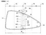
ゴルフクラブヘッドの10Aの基準状態で、水平面HPおよびフェース中心基準断面Pfcと直交しリーディングエッジ26に当接する平面を第1平面P1とし、第1平面P1と平行しフェースバック28の外面に当接する平面を第2平面P2とし、ヘッド本体12Aを平面視したときに、第1平面P1と第2平面P2との距離をヘッド最大幅Mとする。
第1平面P1と第2平面P2とを結ぶ寸法の1/2の位置で第1平面P1および第2平面P2と平行する平面を中心面P0とする。
中心面P0からフェース部側にヘッド最大幅Mの1/4離間した位置で中心面P0と平行する平面を第3平面P3とする。
中心面P0からフェースバック28側にヘッド最大幅Mの1/4離間した位置で中心面P0と平行する平面を第4平面P4とする。
第3平面P3と第4平面P4とで区画された第1範囲A1内にカバー体46が位置している。
ヘッド本体12Aのうち、第4平面P4からフェースバック28までの第4範囲A4に位置する部分に、第4範囲A4を除く残りの部分の比重よりも比重の大きな(金属)材料で形成された大比重部50が設けられている。
例えば、大比重部50はタングステン合金(比重12)で構成されており、大比重部50を除くヘッド本体12Aはチタン合金(比重4.4)で構成されている。As shown in FIG. 40, the
In the reference state of 10A of the golf club head, the plane that is orthogonal to the horizontal plane HP and the face center reference cross section Pfc and abuts on the leading
The plane parallel to the first plane P1 and the second plane P2 at a position halved in the dimension connecting the first plane P1 and the second plane P2 is defined as the central plane P0.
The plane parallel to the central surface P0 at a position separated from the central surface P0 on the face portion side by 1/4 of the maximum head width M is referred to as a third plane P3.
A plane parallel to the center plane P0 at a position separated from the center plane P0 on the face back 28 side by 1/4 of the maximum head width M is referred to as a fourth plane P4.
The
The portion of the
For example, the large
第2の実施の形態によれば、金属材料で形成された中空状のヘッド本体12に形成された開口部32をヘッド本体12の外側から繊維強化樹脂材料からなるカバー体46で閉塞した。
したがって、カバー体46がゴルフクラブヘッド10の重心点G0から近い箇所に配置されると共に、カバー体46よりも比重の重い金属材料で形成された大比重部50が重心点G0から遠いヘッド本体12の箇所に配置されることにより、ゴルフクラブヘッド10の慣性モーメントMIを確保でき、打球の方向性の向上を図る上で有利となる。
さらに、打球時の振動起点となるフェース部14から最も離れたフェースバック28寄りの箇所に大比重部50を設けたので、打球時に発生する振動がヘッド本体12Aの部分を介して重量物である大比重部50に伝わる過程において、いわゆる、マスダンパー機能と同様の作用が発生し、振動が減衰される。
この際、振動のうち、より低周波数の振動成分が減衰されやすくなることから、打球音は低音の成分が減衰される一方、高音の成分はそれほど減衰されない。
したがって、金属材料からなるヘッド本体12Aよりも剛性、弾性率が低いカバー体46で開口部32を閉塞する構造であるにも拘らず、打球時に発生する打球音を高音とすることができ、心地よい打球音を得る上で有利となる。According to the second embodiment, the
Therefore, the
Further, since the large
At this time, since the lower frequency vibration component of the vibration is more likely to be attenuated, the bass component is attenuated in the hitting sound, while the treble component is not so attenuated.
Therefore, despite the structure in which the
次に図42を参照して第2の実施の形態の変形例について説明する。
変形例では、フェースバック28に大比重部50を設けることに加えて、フェース部14にも大比重部52を設けた点が第2の実施の形態と異なっている。
すなわち、フェース部14の大部分(あるいは全部)を、βチタンDAT55G(比重4.7)を用いた大比重部52で構成した。
したがって、タングステン合金(比重12)からなる大比重部50と、βチタンDAT55G(比重4.7)からなる大比重部52とを除く残りのヘッド本体12の部分はチタン合金(比重4.4)で構成されている
すなわち、ヘッド本体12のうち第4範囲A4に位置する部分の比重を後部比重Gaとし、ヘッド本体12のうち第1平面P1と第3平面P3とで区画された第3範囲A3に位置する部分の比重を前部比重Gbとし、ヘッド本体12のうち第1範囲A1に位置する部分の比重を中間部比重Gcとしたとき、以下の式(1)が満たされている。
Ga>Gb>Gc……(1)
このような構成とすれば、第2の実施の形態の効果に加え、重心点G0から離れた箇所に大比重部50,52の2つの大比重部を配置するので、慣性モーメントMIをより大きく確保する上で有利となるという効果が奏される。Next, a modified example of the second embodiment will be described with reference to FIG. 42.
In the modified example, in addition to providing the large
That is, most (or all) of the
Therefore, the remaining
Ga>Gb> Gc …… (1)
With such a configuration, in addition to the effect of the second embodiment, the two large
以下、第2の実施の形態およびその変形例を反映した実験例のゴルフクラブヘッド10について説明する。
なお、実験例のヘッド本体12Aは第1の実施の形態と同様に以下のように作成した。
ヘッド本体12の材料:チタン合金 Ti-8Al-1Mo-1V
フェース14の材料:Ti-6Al-4V
カバー体46の材料:CFRP(炭素繊維強化樹脂)
カバー体46の厚さTc:0.6mm
大比重部50の材料:タングステン合金(比重12)質量60gを設けたものとした。
大比重部52の材料:βチタンDAT55G(比重4.7)質量58gを設けたものとした。
ロフト角 10.5°
ライ角 59°
ヘッド体積 460ccHereinafter, the
The
Material of head body 12: Titanium alloy Ti-8Al-1Mo-1V
Material of cover body 46: CFRP (carbon fiber reinforced resin)
The material of the large specific gravity portion 50: a tungsten alloy (specific gravity 12) having a mass of 60 g was provided.
The material of the large specific gravity portion 52: β titanium DAT55G (specific gravity 4.7) having a mass of 58 g was provided.
Loft angle 10.5 °
Rye angle 59 °
Head volume 460cc
図43に示すように、比較例である実験例1と、請求項9の規定を満たす実験例21と、請求項10の規定を満たす実験例22とについて実験を行った。
図41に示すように、請求項9の規定を満たす実験例21は、慣性モーメントMIを確保すると共に、打球音を高音とする上で有利となるため、打球音、飛距離ばらつき、左右のばらつき、耐久性、合計点が本発明の範囲外である実験例1を上回っている。
また、請求項10の規定を満たす実験例22は、慣性モーメントMIを確保する上でより有利となるため、実験例21よりも打球音、飛距離のばらつき、左右のばらつきの評価がより高くなり合計点も高くなっている。As shown in FIG. 43, experiments were conducted on Experimental Example 1 which is a comparative example, Experimental Example 21 which satisfies the provision of claim 9, and Experimental Example 22 which satisfies the provision of
As shown in FIG. 41, Experimental Example 21 satisfying the provision of claim 9 is advantageous in securing the moment of inertia MI and making the hitting sound high-pitched, so that the hitting sound, the flight distance variation, and the left-right variation , Durability, and total score exceed Experimental Example 1, which is outside the scope of the present invention.
Further, since Experimental Example 22 satisfying the provision of
10、10A ゴルフクラブヘッド
12、12A ヘッド本体
13 空間
14 フェース部
16 クラウン部
18 ソール部
20 サイド部
22 トウ
24 ヒール
26 リーディングエッジ
28 フェースバック
29 ホーゼル
30 境界部
31 厚肉部
32 開口部
32A 第1開口部
32B 第2開口部
32C 第3開口部
34 取り付け部
40 リブ
40A 第1リブ部
40B 第2リブ部
40C 第3リブ部
40D 第4リブ部
40E 第5リブ部
42 支持壁部
44 補強壁部
46 カバー体
46A トウ側カバー体
46B ヒール側カバー体
48 大比重部
50 大比重部
52 大比重部
Pfc フェース中心基準断面
P0 中心面
P1 第1平面
P2 第2平面
P3 第3平面
P4 第4平面
P5 第5平面
P6 第6平面
A1 第1範囲
A2 第2範囲
A3 第3範囲
A4 第4範囲
HP 水平面
M ヘッド最大幅10, 10A
上記目的を達成するために、本発明は、上下の高さを有して左右に延在するフェース部と、前記フェース部の上部から後方に延在するクラウン部と、前記フェース部の下部から後方に延在するソール部と、前記クラウン部と前記ソール部の間で前記フェース部のトウ側縁とヒール側縁との間をフェースバックを通って延在するサイド部とが金属材料で形成されその内部が空間とされる中空状のヘッド本体と、前記クラウン部、前記サイド部、前記ソール部の少なくとも1箇所に形成された開口部を前記ヘッド本体の外側から閉塞する繊維強化樹脂材料からなるカバー体と、を備える中空状のゴルフクラブヘッドであって、前記ゴルフクラブヘッドを水平面に対して予め定められたライ角およびロフト角通りに設置した基準状態において、フェース面の中心点を通る法線を含みかつ前記水平面と直交する平面で前記ヘッド本体を破断した断面をフェース中心基準断面とし、前記基準状態で、前記水平面および前記フェース中心基準断面と直交しリーディングエッジに当接する平面を第1平面とし、前記第1平面と平行し前記フェースバックの外面に当接する平面を第2平面としたとき、前記第1平面と前記第2平面との距離をヘッド最大幅Mとし、前記第1平面と前記第2平面とを結ぶ寸法の1/2の位置で前記第1平面および前記第2平面と平行する平面を中心面とし、前記中心面から前記フェース部側に前記ヘッド最大幅Mの1/4離間した位置で前記中心面と平行する平面を第3平面とし、前記中心面から前記フェースバック側に前記ヘッド最大幅Mの1/4離間した位置で前記中心面と平行する平面を第4平面としたとき、前記第3平面と前記第4平面とで区画された第1範囲内に前記カバー体が位置し、前記中心面と平行し前記カバー体の最も前記フェース部寄りの縁部を通る平面を第5平面とし、前記中心面と平行し前記カバー体の最も前記フェースバック寄りの縁部を通る平面を第6平面としたとき、前記第5平面と前記第6平面とで区画された第2範囲のほぼ中央位置において前記カバー体が前記開口部を介して前記空間に対向する前記カバー体の内面の部分を前記空間側から支持する金属材料からなるリブが前記開口部を横切るようにトウヒール方向に延在して形成されており、前記リブは、前記ヘッド本体と一体に設けられ、かつ、前記リブの金属材料は前記ヘッド本体の金属材料と同一であり、前記リブはトウヒール方向に延在してその延在方向の両端が前記開口部の縁に接続され、前記リブは、断面がT字状を呈しており、支持壁部と、補強壁部とを備え、前記支持壁部は、前記カバー体が前記空間に対向する前記カバー体の内面に重ね合わされ、前記補強壁部は、前記支持壁部の延在方向と直交する幅方向の中央で前記支持壁部が前記空間に対向する前記支持壁部の内面から前記支持壁部の全長にわたって前記空間側に突出していることを特徴とする。
また、本発明は、前記リブが前記カバー体を支持している部分のトウヒール方向の寸法は、前記カバー体のトウヒール方向の寸法の全長とほぼ同じであることを特徴とする。
また、本発明は、前記リブは、前記カバー体の前記内面から前記ヘッド本体が前記空間に対向する前記ヘッド本体の内面に連続して延在形成され、前記リブは、前記カバー体の前記内面および前記ヘッド本体の前記内面からなる前記ゴルフクラブヘッドの内面の全周の80%以上にわたって延在形成されていることを特徴とする。
また、本発明は、前記ヘッド本体のうち、前記クラウン部と前記サイド部との境の全長にわたって帯状に延在する境界部が形成され、前記境界部は、前記ヘッド本体を構成する金属材料で形成されていることを特徴とする。
また、本発明は、前記境界部のうち、前記第1範囲内の部分は、前記境界部に隣接する前記クラウン部および前記サイド部の肉厚よりも大きな寸法の肉厚で形成された厚肉部で構成されていることを特徴とする。
また、本発明は、前記ゴルフクラブヘッドのヘッド質量は、210g以下であり、前記基準状態で前記ゴルフクラブヘッドの重心点を通り前記水平面に直交する垂直な直線を回転軸とする慣性モーメントの大きさをMI(g・cm2)とするとき、前記慣性モーメントMIが6200g・cm2以下であることを特徴とする。
また、本発明は、前記ゴルフクラブヘッドのヘッド体積が500cc以下であり、前記ヘッド最大幅Mが130mm以下であることを特徴とする。
また、本発明は、前記ヘッド本体のうち、前記第1平面と前記第3平面とで区画される第3範囲に位置する部分と、前記第4平面から前記フェースバックまでの第4範囲に位置する部分との少なくとも一方の部分に、前記第1範囲に位置する部分の比重よりも比重の大きな材料で形成された大比重部を設けたことを特徴とする。
また、本発明は、上下の高さを有して左右に延在するフェース部と、前記フェース部の上部から後方に延在するクラウン部と、前記フェース部の下部から後方に延在するソール部と、前記クラウン部と前記ソール部の間で前記フェース部のトウ側縁とヒール側縁との間をフェースバックを通って延在するサイド部とが金属材料で形成されその内部が空間とされる中空状のヘッド本体と、前記クラウン部、前記サイド部、前記ソール部の少なくとも1箇所に形成された開口部を前記ヘッド本体の外側から閉塞する繊維強化樹脂材料からなるカバー体と、を備える中空状のゴルフクラブヘッドであって、前記ゴルフクラブヘッドを水平面に対して予め定められたライ角およびロフト角通りに設置した基準状態において、フェース面の中心点を通る法線を含みかつ前記水平面と直交する平面で前記ヘッド本体を破断した断面をフェース中心基準断面とし、前記基準状態で、前記水平面および前記フェース中心基準断面と直交しリーディングエッジに当接する平面を第1平面とし、前記第1平面と平行し前記フェースバックの外面に当接する平面を第2平面としたとき、前記第1平面と前記第2平面との距離をヘッド最大幅Mとし、前記第1平面と前記第2平面とを結ぶ寸法の1/2の位置で前記第1平面および前記第2平面と平行する平面を中心面とし、前記中心面から前記フェース部側に前記ヘッド最大幅Mの1/4離間した位置で前記中心面と平行する平面を第3平面とし、前記中心面から前記フェースバック側に前記ヘッド最大幅Mの1/4離間した位置で前記中心面と平行する平面を第4平面としたとき、前記第3平面と前記第4平面とで区画された第1範囲内に前記カバー体が位置し、前記ヘッド本体のうち、前記第4平面から前記フェースバックまでの第4範囲に位置する部分に、前記第4範囲を除く残りの部分の比重よりも比重の大きな材料で形成された大比重部を設け、前記ヘッド本体のうち前記第4範囲に位置する部分の比重を後部比重Gaとし、前記ヘッド本体のうち前記第1平面と前記第3平面とで区画された第3範囲に位置する部分の比重を前部比重Gbとし、前記ヘッド本体のうち前記第1範囲に位置する部分の比重を中間部比重Gcとしたとき、以下の式(1)が満たされる、ことを特徴とするゴルフクラブヘッド。
Ga>Gb>Gc……(1)In order to achieve the above object, the present invention presents the present invention from a face portion having a vertical height and extending to the left and right, a crown portion extending from the upper portion to the rear of the face portion, and a lower portion of the face portion. A sole portion extending rearward and a side portion extending between the crown portion and the sole portion and between the toe side edge and the heel side edge of the face portion through the face back are formed of a metal material. From a hollow head body whose inside is a space, and a fiber-reinforced resin material that closes openings formed at at least one of the crown portion, the side portion, and the sole portion from the outside of the head body. A hollow golf club head including a cover body, which passes through the center point of the face surface in a reference state in which the golf club head is installed according to a predetermined lie angle and loft angle with respect to a horizontal plane. The cross section of the head body broken along the plane including the normal line and orthogonal to the horizontal plane is defined as the face center reference cross section, and the plane perpendicular to the horizontal plane and the face center reference cross section and abutting the leading edge in the reference state is the first. When one plane is defined and the plane parallel to the first plane and abutting on the outer surface of the face back is the second plane, the distance between the first plane and the second plane is defined as the maximum head width M, and the first plane is defined as the first plane. The first plane and the plane parallel to the second plane are set as the center plane at a position halved in the dimension connecting the plane and the second plane, and the head maximum width M is from the center plane to the face portion side. A plane parallel to the central surface at a position separated by 1/4 is set as a third plane, and a plane parallel to the central surface is provided on the face back side from the central surface at a position separated by 1/4 of the maximum width M of the head. When the fourth plane is used, the cover body is located within the first range partitioned by the third plane and the fourth plane, parallel to the central surface, and the edge of the cover body closest to the face portion. When the plane passing through the portion is the fifth plane and the plane parallel to the center plane and passing through the edge of the cover body closest to the face back is the sixth plane, the fifth plane and the sixth plane are A rib made of a metal material that supports an inner surface portion of the cover body facing the space through the opening at a substantially central position of the partitioned second range from the space side provides the opening. It is formed so as to extend in the toe heel direction so as to cross thehead body, the rib is provided integrally with the head body, and the metal material of the rib is the same as the metal material of the head body. The bush extends in the toe heel direction and both ends in the extending direction are connected to the edge of the opening, and the rib has a T-shaped cross section and includes a support wall portion and a reinforcing wall portion. The support wall portion is superposed on the inner surface of the cover body whose cover body faces the space, and the reinforcing wall portion is the support wall at the center in the width direction orthogonal to the extending direction of the support wall portion. The portion is characterizedin that the portion projects from the inner surface of the support wall portion facing the space toward the space side over the entire length of the support wall portion.
Further, the present invention is characterized in that the dimension of the portion where the rib supports the cover body in the toe heel direction is substantially the same as the total length of the dimension of the cover body in the toe heel direction.
Further, in the present invention, the ribs are formed so as to extend continuously from the inner surface of the cover body to the inner surface of the head body whose head body faces the space, and the ribs are formed on the inner surface of the cover body. The golf club head is formed so as to extend over 80% or more of the entire circumference of the inner surface of the golf club head, which is composed of the inner surface of the head body.
Further, in the present invention, in the head body, a boundary portion extending in a band shape over the entire length of the boundary between the crown portion and the side portion is formed, and the boundary portion is made of a metal material constituting the head body. It is characterized in that it is formed.
Further, in the present invention, the portion within the first range of the boundary portion is formed with a wall thickness larger than the wall thickness of the crown portion and the side portion adjacent to the boundary portion. It is characterized by being composed of parts.
Further, in the present invention, the head mass of the golf club head is 210 g or less, and the magnitude of the moment of inertia having a vertical straight line passing through the center of gravity of the golf club head and orthogonal to the horizontal plane in the reference state as the rotation axis is large. When the value is MI (g · cm2 ), the moment of inertia MI is 6200 g · cm2 or less.
Further, the present invention is characterized in that the head volume of the golf club head is 500 cc or less, and the maximum head width M is 130 mm or less.
Further, the present invention is located in a portion of the head body located in a third range partitioned by the first plane and the third plane, and in a fourth range from the fourth plane to the face back. It is characterized in that a large specific gravity portion formed of a material having a specific gravity larger than the specific gravity of the portion located in the first range is provided in at least one portion of the portion to be formed.
Further, the present invention has a face portion having a vertical height and extending to the left and right, a crown portion extending rearward from the upper part of the face portion, and a sole extending rearward from the lower portion of the face portion. The portion and the side portion extending between the crown portion and the sole portion through the face back between the toe side edge and the heel side edge of the face portion are formed of a metal material, and the inside thereof is a space. A hollow head body to be formed, and a cover body made of a fiber-reinforced resin material that closes openings formed at at least one of the crown portion, the side portion, and the sole portion from the outside of the head body. A hollow golf club head including a normal line passing through a center point of a face surface in a reference state in which the golf club head is installed according to a predetermined lie angle and loft angle with respect to a horizontal plane. The cross section obtained by breaking the head body in a plane orthogonal to the horizontal plane is defined as the face center reference cross section, and in the reference state, the plane perpendicular to the horizontal plane and the face center reference cross section and abutting on the leading edge is defined as the first plane. When the plane parallel to the one plane and abutting on the outer surface of the face back is the second plane, the distance between the first plane and the second plane is the maximum head width M, and the first plane and the second plane are The first plane and the plane parallel to the second plane are set as the central plane at the position of 1/2 of the dimension connecting the two, and the position separated from the central plane by the face portion side by 1/4 of the maximum width M of the head. When the plane parallel to the central plane is the third plane and the plane parallel to the central plane at a position separated from the central plane by 1/4 of the maximum width M of the head is the fourth plane. The cover body is located in the first range partitioned by the third plane and the fourth plane, and the portion of the head body located in the fourth range from the fourth plane to the face back. A large specific gravity portion made of a material having a specific gravity larger than that of the remaining portion excluding the fourth range is provided, and the specific gravity of the portion of thehead body located in the fourth range is defined as the rear specific gravity Ga. The specific gravity of the portion of the head body located in the third range divided by the first plane and the third plane is defined as the front specific gravity Gb, and the specific gravity of the portion of the head body located in the first range. The golf club head is characterized in that the following equation (1) is satisfied, where is defined as the intermediate specific gravity Gc.
Ga>Gb> Gc …… (1)
Claims (10)
Translated fromJapanese前記クラウン部、前記サイド部、前記ソール部の少なくとも1箇所に形成された開口部を前記ヘッド本体の外側から閉塞する繊維強化樹脂材料からなるカバー体と、
を備える中空状のゴルフクラブヘッドであって、
前記ゴルフクラブヘッドを水平面に対して予め定められたライ角およびロフト角通りに設置した基準状態において、フェース面の中心点を通る法線を含みかつ前記水平面と直交する平面で前記ヘッド本体を破断した断面をフェース中心基準断面とし、
前記基準状態で、前記水平面および前記フェース中心基準断面と直交しリーディングエッジに当接する平面を第1平面とし、前記第1平面と平行し前記フェースバックの外面に当接する平面を第2平面としたとき、前記第1平面と前記第2平面との距離をヘッド最大幅Mとし、
前記第1平面と前記第2平面とを結ぶ寸法の1/2の位置で前記第1平面および前記第2平面と平行する平面を中心面とし、前記中心面から前記フェース部側に前記ヘッド最大幅Mの1/4離間した位置で前記中心面と平行する平面を第3平面とし、前記中心面から前記フェースバック側に前記ヘッド最大幅Mの1/4離間した位置で前記中心面と平行する平面を第4平面としたとき、前記第3平面と前記第4平面とで区画された第1範囲内に前記カバー体が位置し、
前記中心面と平行し前記カバー体の最も前記フェース部寄りの縁部を通る平面を第5平面とし、前記中心面と平行し前記カバー体の最も前記フェースバック寄りの縁部を通る平面を第6平面としたとき、前記第5平面と前記第6平面とで区画された第2範囲のほぼ中央位置において前記カバー体が前記開口部を介して前記空間に対向する前記カバー体の内面の部分を前記空間側から支持する金属材料からなるリブが前記開口部を横切るようにトウヒール方向に延在して形成されている、
ことを特徴とするゴルフクラブヘッド。A face portion having a vertical height and extending to the left and right, a crown portion extending rearward from the upper part of the face portion, a sole portion extending rearward from the lower portion of the face portion, and the crown portion. A hollow head in which a metal material is formed between the sole portion and a side portion extending between the toe side edge and the heel side edge of the face portion through a face back, and the inside thereof is a space. With the main body
A cover body made of a fiber-reinforced resin material that closes openings formed at at least one of the crown portion, the side portion, and the sole portion from the outside of the head body.
A hollow golf club head equipped with
In a reference state in which the golf club head is installed according to a predetermined lie angle and loft angle with respect to the horizontal plane, the head body is broken at a plane including a normal passing through the center point of the face surface and orthogonal to the horizontal plane. The cross section is used as the face center reference cross section.
In the reference state, the plane orthogonal to the horizontal plane and the face center reference cross section and in contact with the leading edge was designated as the first plane, and the plane parallel to the first plane and in contact with the outer surface of the face back was designated as the second plane. When, the distance between the first plane and the second plane is defined as the maximum head width M.
The first plane and the plane parallel to the second plane are set as the central plane at a position halved in the dimension connecting the first plane and the second plane, and the head is located on the face side from the central plane. A plane parallel to the central surface at a position significantly separated by 1/4 of M is defined as a third plane, and parallel to the central surface at a position separated from the central surface by 1/4 of the maximum head width M on the face back side. When the plane to be used is the fourth plane, the cover body is located within the first range partitioned by the third plane and the fourth plane.
The plane parallel to the central surface and passing through the edge portion of the cover body closest to the face portion is defined as the fifth plane, and the plane parallel to the central surface and passing through the edge portion of the cover body closest to the face back portion is the fifth plane. When the number of planes is 6, the portion of the inner surface of the cover body facing the space through the opening at a substantially central position of the second range partitioned by the fifth plane and the sixth plane. A rib made of a metal material that supports the space side extends in the toe heel direction so as to cross the opening.
A golf club head that features that.
ことを特徴とする請求項1記載のゴルフクラブヘッド。The dimension in the toe-heel direction of the portion where the rib supports the cover body is substantially the same as the total length of the dimension in the toe-heel direction of the cover body.
The golf club head according to claim 1.
前記リブは、前記カバー体の前記内面および前記ヘッド本体の前記内面からなる前記ゴルフクラブヘッドの内面の全周の80%以上にわたって延在形成されている、
ことを特徴とする請求項1または2記載のゴルフクラブヘッド。The rib is formed so as to extend continuously from the inner surface of the cover body to the inner surface of the head body in which the head body faces the space.
The rib is formed so as to extend over 80% or more of the entire circumference of the inner surface of the golf club head including the inner surface of the cover body and the inner surface of the head body.
The golf club head according to claim 1 or 2.
前記境界部は、前記ヘッド本体を構成する金属材料で形成されている、
ことを特徴とする請求項1から3の何れか1項記載のゴルフクラブヘッド。In the head body, a boundary portion extending in a band shape over the entire length of the boundary between the crown portion and the side portion is formed.
The boundary portion is formed of a metal material constituting the head body.
The golf club head according to any one of claims 1 to 3, wherein the golf club head is characterized by the above.
ことを特徴とする請求項4記載のゴルフクラブヘッド。The portion of the boundary portion within the first range is composed of a thick portion formed with a wall thickness larger than the wall thickness of the crown portion and the side portion adjacent to the boundary portion. ,
The golf club head according to claim 4.
前記基準状態で前記ゴルフクラブヘッドの重心点を通り前記水平面に直交する垂直な直線を回転軸とする慣性モーメントの大きさをMI(g・cm2)とするとき、前記慣性モーメントMIが6200g・cm2以下である、
ことを特徴とする請求項1から5の何れか1項記載のゴルフクラブヘッド。The head mass of the golf club head is 210 g or less, and the head mass is 210 g or less.
When the magnitude of the moment of inertia with the vertical straight line passing through the center of gravity of the golf club head and orthogonal to the horizontal plane as the rotation axis in the reference state is MI (g · cm2 ), the moment of inertia MI is 6200 g · · cm2 or less,
The golf club head according to any one of claims 1 to 5, wherein the golf club head.
前記ヘッド最大幅Mが130mm以下である、
ことを特徴とする請求項1から6の何れか1項記載のゴルフクラブヘッド。The head volume of the golf club head is 500 cc or less, and the head volume is 500 cc or less.
The maximum head width M is 130 mm or less.
The golf club head according to any one of claims 1 to 6, wherein the golf club head.
ことを特徴とする請求項1から7の何れか1項記載のゴルフクラブヘッド。At least one of the portion of the head body located in the third range partitioned by the first plane and the third plane and the portion located in the fourth range from the fourth plane to the face back. A large specific gravity portion made of a material having a specific gravity larger than that of the portion located in the first range is provided in the portion.
The golf club head according to any one of claims 1 to 7.
前記クラウン部、前記サイド部、前記ソール部の少なくとも1箇所に形成された開口部を前記ヘッド本体の外側から閉塞する繊維強化樹脂材料からなるカバー体と、
を備える中空状のゴルフクラブヘッドであって、
前記ゴルフクラブヘッドを水平面に対して予め定められたライ角およびロフト角通りに設置した基準状態において、フェース面の中心点を通る法線を含みかつ前記水平面と直交する平面で前記ヘッド本体を破断した断面をフェース中心基準断面とし、
前記基準状態で、前記水平面および前記フェース中心基準断面と直交しリーディングエッジに当接する平面を第1平面とし、前記第1平面と平行し前記フェースバックの外面に当接する平面を第2平面としたとき、前記第1平面と前記第2平面との距離をヘッド最大幅Mとし、
前記第1平面と前記第2平面とを結ぶ寸法の1/2の位置で前記第1平面および前記第2平面と平行する平面を中心面とし、前記中心面から前記フェース部側に前記ヘッド最大幅Mの1/4離間した位置で前記中心面と平行する平面を第3平面とし、前記中心面から前記フェースバック側に前記ヘッド最大幅Mの1/4離間した位置で前記中心面と平行する平面を第4平面としたとき、前記第3平面と前記第4平面とで区画された第1範囲内に前記カバー体が位置し、
前記ヘッド本体のうち、前記第4平面から前記フェースバックまでの第4範囲に位置する部分に、前記第4範囲を除く残りの部分の比重よりも比重の大きな材料で形成された大比重部を設けた、
ことを特徴とするゴルフクラブヘッド。A face portion having a vertical height and extending to the left and right, a crown portion extending rearward from the upper part of the face portion, a sole portion extending rearward from the lower portion of the face portion, and the crown portion. A hollow head in which a metal material is formed between the sole portion and a side portion extending between the toe side edge and the heel side edge of the face portion through a face back, and the inside thereof is a space. With the main body
A cover body made of a fiber-reinforced resin material that closes openings formed at at least one of the crown portion, the side portion, and the sole portion from the outside of the head body.
A hollow golf club head equipped with
In a reference state in which the golf club head is installed according to a predetermined lie angle and loft angle with respect to the horizontal plane, the head body is broken at a plane including a normal passing through the center point of the face surface and orthogonal to the horizontal plane. The cross section is used as the face center reference cross section.
In the reference state, the plane orthogonal to the horizontal plane and the face center reference cross section and in contact with the leading edge was designated as the first plane, and the plane parallel to the first plane and in contact with the outer surface of the face back was designated as the second plane. When, the distance between the first plane and the second plane is defined as the maximum head width M.
The first plane and the plane parallel to the second plane are set as the central plane at a position halved in the dimension connecting the first plane and the second plane, and the head is located on the face side from the central plane. A plane parallel to the central surface at a position significantly separated by 1/4 of M is defined as a third plane, and parallel to the central surface at a position separated from the central surface by 1/4 of the maximum head width M on the face back side. When the plane to be used is the fourth plane, the cover body is located within the first range partitioned by the third plane and the fourth plane.
A large specific density portion formed of a material having a specific density larger than the specific gravity of the remaining portion excluding the fourth range is provided in a portion of the head body located in the fourth range from the fourth plane to the face back. Provided
A golf club head that features that.
前記ヘッド本体のうち前記第1平面と前記第3平面とで区画された第3範囲に位置する部分の比重を前部比重Gbとし、
前記ヘッド本体のうち前記第1範囲に位置する部分の比重を中間部比重Gcとしたとき、
以下の式(1)が満たされる、
ことを特徴とする請求項9記載のゴルフクラブヘッド。
Ga>Gb>Gc……(1)The specific gravity of the portion of the head body located in the fourth range is defined as the rear specific density Ga.
The specific gravity of the portion of the head body located in the third range partitioned by the first plane and the third plane is defined as the front specific density Gb.
When the specific gravity of the portion of the head body located in the first range is the intermediate specific density Gc,
The following equation (1) is satisfied,
9. The golf club head according to claim 9.
Ga>Gb> Gc …… (1)
Priority Applications (1)
| Application Number | Priority Date | Filing Date | Title |
|---|---|---|---|
| JP2020025926AJP6795776B1 (en) | 2020-02-19 | 2020-02-19 | Golf club head |
Applications Claiming Priority (1)
| Application Number | Priority Date | Filing Date | Title |
|---|---|---|---|
| JP2020025926AJP6795776B1 (en) | 2020-02-19 | 2020-02-19 | Golf club head |
Publications (2)
| Publication Number | Publication Date |
|---|---|
| JP6795776B1 JP6795776B1 (en) | 2020-12-02 |
| JP2021129684Atrue JP2021129684A (en) | 2021-09-09 |
Family
ID=73544761
Family Applications (1)
| Application Number | Title | Priority Date | Filing Date |
|---|---|---|---|
| JP2020025926AActiveJP6795776B1 (en) | 2020-02-19 | 2020-02-19 | Golf club head |
Country Status (1)
| Country | Link |
|---|---|
| JP (1) | JP6795776B1 (en) |
Citations (9)
| Publication number | Priority date | Publication date | Assignee | Title |
|---|---|---|---|---|
| CN201020216Y (en)* | 2006-11-28 | 2008-02-13 | 复盛股份有限公司 | Golf club head with tuning fork structure |
| JP2008200339A (en)* | 2007-02-21 | 2008-09-04 | Yokohama Rubber Co Ltd:The | Golf club head and golf club |
| JP2010005312A (en)* | 2008-06-30 | 2010-01-14 | Globeride Inc | Golf club |
| US20100261549A1 (en)* | 2008-03-28 | 2010-10-14 | Bridgestone Sports Co., Ltd | Golf club head |
| JP2012239765A (en)* | 2011-05-23 | 2012-12-10 | Bridgestone Sports Co Ltd | Golf club head |
| JP2016052392A (en)* | 2014-09-03 | 2016-04-14 | ダンロップスポーツ株式会社 | Golf club head |
| JP5952655B2 (en)* | 2012-06-28 | 2016-07-13 | ダンロップスポーツ株式会社 | Golf club head and manufacturing method thereof |
| KR20190034570A (en)* | 2016-07-26 | 2019-04-02 | 카스턴 매뉴팩츄어링 코오포레이숀 | Golf club head with rib and related method |
| KR20190100002A (en)* | 2018-02-19 | 2019-08-28 | 스미토모 고무 고교 가부시키가이샤 | Golf club head |
- 2020
- 2020-02-19JPJP2020025926Apatent/JP6795776B1/enactiveActive
Patent Citations (9)
| Publication number | Priority date | Publication date | Assignee | Title |
|---|---|---|---|---|
| CN201020216Y (en)* | 2006-11-28 | 2008-02-13 | 复盛股份有限公司 | Golf club head with tuning fork structure |
| JP2008200339A (en)* | 2007-02-21 | 2008-09-04 | Yokohama Rubber Co Ltd:The | Golf club head and golf club |
| US20100261549A1 (en)* | 2008-03-28 | 2010-10-14 | Bridgestone Sports Co., Ltd | Golf club head |
| JP2010005312A (en)* | 2008-06-30 | 2010-01-14 | Globeride Inc | Golf club |
| JP2012239765A (en)* | 2011-05-23 | 2012-12-10 | Bridgestone Sports Co Ltd | Golf club head |
| JP5952655B2 (en)* | 2012-06-28 | 2016-07-13 | ダンロップスポーツ株式会社 | Golf club head and manufacturing method thereof |
| JP2016052392A (en)* | 2014-09-03 | 2016-04-14 | ダンロップスポーツ株式会社 | Golf club head |
| KR20190034570A (en)* | 2016-07-26 | 2019-04-02 | 카스턴 매뉴팩츄어링 코오포레이숀 | Golf club head with rib and related method |
| KR20190100002A (en)* | 2018-02-19 | 2019-08-28 | 스미토모 고무 고교 가부시키가이샤 | Golf club head |
Also Published As
| Publication number | Publication date |
|---|---|
| JP6795776B1 (en) | 2020-12-02 |
Similar Documents
| Publication | Publication Date | Title |
|---|---|---|
| US12048866B2 (en) | Club heads having reinforced club head faces and related methods | |
| JP5813805B2 (en) | Golf club head | |
| US7390271B2 (en) | Golf club head | |
| US10751587B2 (en) | Club heads having reinforced club head faces and related methods | |
| US20210154535A1 (en) | Club heads having reinforced club head faces and related methods | |
| JP5616037B2 (en) | Golf club head | |
| JP4247838B2 (en) | Composite metal wood club | |
| JP5681045B2 (en) | Golf club head | |
| US20010007837A1 (en) | Golf club head | |
| US9468818B2 (en) | Wood-type golf club head | |
| JP2016002136A (en) | Golf club head | |
| JP5459432B1 (en) | Golf club head | |
| US20120225734A1 (en) | Golf club head and golf club using the same | |
| US20240131402A1 (en) | Multi-material golf club head with balanced performance characteristics | |
| JP2013027564A (en) | Golf club head and method for evaluating the same | |
| US9457242B2 (en) | Golf club head | |
| JP6795776B1 (en) | Golf club head | |
| WO2016196645A1 (en) | Club heads having reinforced club head faces and related methods | |
| JP5152431B1 (en) | Golf club head | |
| US7500925B2 (en) | Golf club and method of designing hollow golf club head | |
| JP7004927B2 (en) | Golf club head and golf club set | |
| JP4340561B2 (en) | Golf club head and golf club having the same | |
| US11213727B2 (en) | Golf club head | |
| JP6741955B2 (en) | Golf club head and golf club set | |
| JP6232696B2 (en) | Golf club head |
Legal Events
| Date | Code | Title | Description |
|---|---|---|---|
| A621 | Written request for application examination | Free format text:JAPANESE INTERMEDIATE CODE: A621 Effective date:20200618 | |
| A871 | Explanation of circumstances concerning accelerated examination | Free format text:JAPANESE INTERMEDIATE CODE: A871 Effective date:20200618 | |
| A975 | Report on accelerated examination | Free format text:JAPANESE INTERMEDIATE CODE: A971005 Effective date:20200730 | |
| A131 | Notification of reasons for refusal | Free format text:JAPANESE INTERMEDIATE CODE: A131 Effective date:20200804 | |
| A521 | Request for written amendment filed | Free format text:JAPANESE INTERMEDIATE CODE: A523 Effective date:20200925 | |
| TRDD | Decision of grant or rejection written | ||
| A01 | Written decision to grant a patent or to grant a registration (utility model) | Free format text:JAPANESE INTERMEDIATE CODE: A01 Effective date:20201013 | |
| A61 | First payment of annual fees (during grant procedure) | Free format text:JAPANESE INTERMEDIATE CODE: A61 Effective date:20201026 | |
| R150 | Certificate of patent or registration of utility model | Ref document number:6795776 Country of ref document:JP Free format text:JAPANESE INTERMEDIATE CODE: R150 | |
| S531 | Written request for registration of change of domicile | Free format text:JAPANESE INTERMEDIATE CODE: R313531 | |
| R350 | Written notification of registration of transfer | Free format text:JAPANESE INTERMEDIATE CODE: R350 | |
| R250 | Receipt of annual fees | Free format text:JAPANESE INTERMEDIATE CODE: R250 | |
| R250 | Receipt of annual fees | Free format text:JAPANESE INTERMEDIATE CODE: R250 |