JP2021129443A - motor - Google Patents
motorDownload PDFInfo
- Publication number
- JP2021129443A JP2021129443AJP2020023395AJP2020023395AJP2021129443AJP 2021129443 AJP2021129443 AJP 2021129443AJP 2020023395 AJP2020023395 AJP 2020023395AJP 2020023395 AJP2020023395 AJP 2020023395AJP 2021129443 AJP2021129443 AJP 2021129443A
- Authority
- JP
- Japan
- Prior art keywords
- magnetic flux
- range
- waveform
- circumferential direction
- phase
- Prior art date
- Legal status (The legal status is an assumption and is not a legal conclusion. Google has not performed a legal analysis and makes no representation as to the accuracy of the status listed.)
- Granted
Links
- 230000004907fluxEffects0.000claimsabstractdescription110
- 230000007423decreaseEffects0.000claimsdescription20
- 238000004804windingMethods0.000claimsdescription19
- 230000008859changeEffects0.000claimsdescription5
- 239000000696magnetic materialSubstances0.000claimsdescription4
- 239000004020conductorSubstances0.000abstractdescription21
- 230000000052comparative effectEffects0.000description16
- 230000002093peripheral effectEffects0.000description6
- 229910000831SteelInorganic materials0.000description3
- 238000010586diagramMethods0.000description3
- 239000010959steelSubstances0.000description3
- XEEYBQQBJWHFJM-UHFFFAOYSA-NIronChemical compound[Fe]XEEYBQQBJWHFJM-UHFFFAOYSA-N0.000description2
- 238000013459approachMethods0.000description2
- 238000005452bendingMethods0.000description2
- 230000000694effectsEffects0.000description2
- 238000003780insertionMethods0.000description2
- 230000037431insertionEffects0.000description2
- 239000000463materialSubstances0.000description2
- 230000009471actionEffects0.000description1
- 239000000853adhesiveSubstances0.000description1
- 230000001070adhesive effectEffects0.000description1
- 230000008094contradictory effectEffects0.000description1
- 230000003247decreasing effectEffects0.000description1
- 230000006872improvementEffects0.000description1
- 230000003993interactionEffects0.000description1
- 229910052742ironInorganic materials0.000description1
- 238000010030laminatingMethods0.000description1
- 230000005415magnetizationEffects0.000description1
- 238000012986modificationMethods0.000description1
- 230000004048modificationEffects0.000description1
Images


Landscapes
- Permanent Field Magnets Of Synchronous Machinery (AREA)
- Iron Core Of Rotating Electric Machines (AREA)
Abstract
Description
Translated fromJapanese本開示は、モータに関する。 The present disclosure relates to a motor.
下記特許文献1には、ステータへ通電がなされることでロータが回転するモータ(回転電機)が開示されている。この文献に記載されたモータでは、ロータの内周部にリング形状のマグネット(永久磁石)が設けられている。そして、このマグネットの径方向かつ中心方向に設定された集束軸に沿った方向へ集束するように、磁化容易軸が傾斜して配向されている。これにより、モータのトルクを大きくすること等が可能となっている。
ところで、上記特許文献1に記載された構成は、モータのトルクを大きくするという観点では有用な構成ではある。しかしながら、ステータコアの径方向外側の面又は径方向内側の面に沿って導線部が並んで配置された構成(ティースレスの構成)のモータに上記特許文献1に記載されたマグネットの構成を適用すると、トルクリップルを低減するという観点で改善が望まれる場合がある。 By the way, the configuration described in
本開示は上記事実を考慮し、トルクリップルを抑制することができるティースレス構造のモータを得ることが目的である。 In consideration of the above facts, an object of the present disclosure is to obtain a motor having a teethless structure capable of suppressing torque ripple.
上記課題を解決するモータは、磁性材料を用いて環状に形成されたステータコア(32)と、導電性の巻線を用いて形成されていると共に前記ステータコアに支持されかつ前記ステータコアの径方向外側の面又は径方向内側の面に沿って周方向に並んで配置された導線部(34A)を有するコイル(34)と、を備えたステータ(22)と、前記導線部と径方向に対向して配置されたマグネット(30)を有し、前記コイルに通電されることで回転するロータ(20)と、を備え、前記マグネットにおける前記導線部と対向する面における表面磁束密度を回転電機角0°から360°の範囲で測定した波形についてFFT解析を行い、5次の波形に対する位相と7次の波形に対する位相とが逆位相となるように、前記マグネット内の磁束が設定されている。 A motor that solves the above problems is formed by using a stator core (32) formed in an annular shape using a magnetic material and a conductive winding, and is supported by the stator core and radially outside the stator core. A stator (22) including a coil (34) having a conducting wire portion (34A) arranged side by side in the circumferential direction along a surface or an inner surface in the radial direction, and a stator (22) facing the conducting wire portion in the radial direction. A rotor (20) having an arranged magnet (30) and rotating by energizing the coil is provided, and the surface magnetic flux density on the surface of the magnet facing the conducting wire portion is set to a rotating electric machine angle of 0 °. FFT analysis is performed on the waveform measured in the range of 360 °, and the magnetic flux in the magnet is set so that the phase for the fifth-order waveform and the phase for the seventh-order waveform are opposite to each other.
この様に構成することで、トルクリップルを抑制することができる。 With this configuration, torque ripple can be suppressed.
図1〜図3を用いて実施形態に係るモータについて説明する。 The motor according to the embodiment will be described with reference to FIGS. 1 to 3.
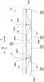
図1及び図2に示されるように、本実施形態のモータ10は、車両用空調装置の一部を構成するファンを回転させるために用いられるアウタロータ型のモータ(ブラシレスモータ)である。このモータ10は、回転軸12を回転させるモータ本体14と、モータ本体14への通電を制御することにより回転軸12の回転を制御する図示しない制御部と、モータ本体14及び制御部を支持するセンタピース18と、を備えている。なお、図中に適宜示す矢印Z方向、矢印R方向及び矢印C方向は、回転軸12の回転軸方向一方側、回転径方向外側及び回転周方向一方側をそれぞれ示すものとする。また以下、単に軸方向、径方向、周方向を示す場合は、特に断りのない限り、回転軸12の回転軸方向、回転径方向、回転周方向を示すものとする。 As shown in FIGS. 1 and 2, the
モータ本体14は、回転軸12と、ロータ20と、ステータ22と、を主要な要素として構成されている。 The
図1に示されるように、回転軸12は、円柱状の鋼材を用いて形成されている。この回転軸12は、センタピース18に固定された一対のベアリング26によって回転自在に支持されている。 As shown in FIG. 1, the rotating
ロータ20は、軸方向他方側が開放された有底円筒状に形成されたロータハウジング28にマグネット30が固定されることによって構成されている。ロータハウジング28は、円板状に形成された底壁28Aと、底壁28Aの径方向外側の端から軸方向他方側へ屈曲して延びる円筒状の周壁28Bと、を備えている。底壁28Aの中心部には、回転軸12が挿入される挿入部28Cが設けられている。回転軸12が挿入部28Cに圧入されることで、ロータハウジング28と回転軸12とが一体回転可能に結合されている。 The
マグネット30は、ロータハウジング28の周壁28Bの径方向内側の面に接着剤等を介して固定されている。また、マグネット30は、当該マグネット30の軸方向の中心とステータコア32の径方向外側の部分32Aの軸方向の中心とが一致した状態で、ステータ22と径方向に対向して配置されている。 The
図1及び図2に示されるように、ステータ22は、環状に形成されたステータコア32と、ステータコア32の径方向外側の部分32Aに固定されたコイルとしての環状のコイル体34と、を含んで構成されている。 As shown in FIGS. 1 and 2, the
ステータコア32は、磁性材料である鉄や鋼の板材を用いて所定の形状に形成された複数のコアシート36が軸方向に積層されて一体化されること等によって形成されている。ここで、複数のコアシート36は、一例としてその一部が互いに凹凸嵌合されることにより一体化されている。 The
図1に示されるように、ステータコア32の径方向外側の部分32Aの軸方向への厚み寸法は、ステータコア32の径方向の中心部32Bの軸方向への厚み寸法よりも厚くなっている。これにより、ステータコア32の径方向外側の部分32Aとステータコア32の径方向の中心部32Bとの境目における軸方向一方側及び軸方向他方側には、それぞれ軸方向に高さの差を有する段差が形成されている。なお、この段差が形成されていない構成としてもよい。 As shown in FIG. 1, the axial thickness dimension of the radially
また、ステータコア32の径方向の中心部32Bには、センタピース18に形成されたステータコア支持部18Aが挿入される支持孔32Dが形成されている。そして、センタピース18に形成されたステータコア支持部18Aがステータコア32の支持孔32Dに挿入されることで、ステータコア32(ステータ22)のセンタピース18に対する周方向への位置決めがなされる。また、ステータコア32(ステータ22)は、ステータコア支持部18Aに圧入等により固定されている。 Further, a
コイル体34は、巻線としての複数の導線40がステータコア32の径方向外側の部分32Aを覆う形状に湾曲及び屈曲されること等により形成されている。なお、本実施形態では、一例として、U相、V相、W相をそれぞれ構成する3本の導線40を所謂波巻することでコイル体34が形成されている。また、3本の導線40は、図示しない制御部に接続されている。これにより、コイル体34(3本の導線40)への通電が制御部によって制御されるようになっている。 The
ここで、U相、V相、W相をそれぞれ構成する3本の導線40においてステータコア32の径方向外側の部分32Aにおける径方向外側の面32A0に沿って配置される部分を導線部34Aと呼ぶ。図2に示されるように、導線部34Aは、軸方向にのびる導線40の一部が周方向に配列される(本実施形態では7列で配列される)ことにより構成されており、U相の導線部34A、V相の導線部34A及びW相の導線部34Aは、周方向に沿ってこの順で配列されている。また、U相の導線部34A、V相の導線部34A及びW相の導線部34Aは、周方向に隙間なく配列されている。これにより、各々の導線部34Aの間にステータコア32の一部等の導線間部材が設けられていない構成となっている。このような構造を「ティースレス構造」と呼ぶ。 Here, in the three
図1に示されるように、U相、V相、W相をそれぞれ構成する3本の導線40においてステータコア32の径方向外側の部分32Aにおける軸方向一方側の面32A1に沿って配置される部分を第1コイルエンド34Bと呼ぶ。さらに、U相、V相、W相をそれぞれ構成する3本の導線40においてステータコア32の径方向外側の部分32Aにおける軸方向他方側の面32A2に沿って配置される部分を第2コイルエンド34Cと呼ぶ。 As shown in FIG. 1, a portion of the three
ところで、モータ10のトルクを大きくするという観点では、マグネット30とコイル体34との相互作用による巻線鎖交磁束密度を大きくすることが重要である。また、ティースレス構造のモータ10では、当該モータ10のインダクタンスを所望のインダクタンスとすることと巻線鎖交磁束の歪を低減することとの互いに背反する要求を満足させつつ、トルクリップルを低減できることが望ましい。さらに、トルクリップルを抑制するという観点では、上記巻線鎖交磁束密度の波形(回転電機角0°から360°の範囲で測定した波形)を正弦波に沿う波形とすることが重要である。以下、本実施形態のティースレス構造のモータ10に対応したトルクリップルを抑制するためのロータ20の構成について説明する。 By the way, from the viewpoint of increasing the torque of the
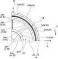
図2及び図3に示されるように、本実施形態のロータ20では、磁極中心Pにおいて径方向内側がN極とされた一対のマグネット30Nと、磁極中心Pにおいて径方向内側がS極とされた一対のマグネット30Sと、を備えている。一対のマグネット30N、30Sは、径方向を厚み方向として周方向に延在する板状に形成されている。磁極中心Pにおいて径方向内側がN極とされた一対のマグネット30Nは、磁極中心Pにおいて互いに周方向に当接している。また、磁極中心Pにおいて径方向内側がS極とされた一対のマグネット30Sは、磁極中心Pにおいて互いに周方向に当接している。さらに、磁極中心Pにおいて径方向内側がN極とされた一対のマグネット30Nと、磁極中心Pにおいて径方向内側がS極とされた一対のマグネット30Sと、は周方向に間隔をあけて配列されている。なお、本実施形態のマグネット30は、一例として残留磁束密度Brが1.0T以上であり、保磁力bHcが400kA/m以上となっている。 As shown in FIGS. 2 and 3, in the
ここで、図3に示されるように、磁極中心Pにおいて径方向内側がN極とされた一対のマグネット30Nは、磁極中心P側の端部30N1と磁極中心Pとは反対側の端部30N2とで磁化容易軸が異なる方向に向いている。具体的には、一対のマグネット30Nでは、磁極中心Pとは反対側の端部30N2から磁極中心P側の端部30N1へ向かうにつれて径方向外側から内側へ円弧状の線を描くような磁力線となるように磁化容易軸が設定されている。 Here, as shown in FIG. 3, a pair of
また、磁極中心Pにおいて径方向内側がS極とされた一対のマグネット30Sでは、磁極中心P側の端部30S1から磁極中心Pとは反対側の端部30S2へ向かうにつれて径方向内側から外側へ円弧状の線を描くような磁力線となるように磁化容易軸が設定されている。 Further, in the pair of
なお、一対のマグネット30N、30Sにおける径方向内側の面において磁力線と周方向とのなす角度を極集中配向角度θ1と呼ぶ。また、一対のマグネット30N、30Sにおける径方向外側の面において磁力線と周方向とのなす角度を極間配向角度θ2と呼ぶ。 The angle formed by the magnetic field lines and the circumferential direction on the inner surface of the pair of
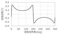
図4には、1極対のマグネット30(一対のN極のマグネット30N及び一対のS極のマグネット30S)の径方向内側の面における表面磁束密度を回転電機角0°から360°の範囲で測定した波形が示されている。 In FIG. 4, the surface magnetic flux density on the radial inner surface of the 1-pole pair of magnets 30 (a pair of N-
この図に示されるように、回転電機角が0°から180°の範囲では、すなわち、磁極中心Pにおいて径方向内側がN極とされた一対のマグネット30Nと対応する範囲においては、0°から90°へ向かうにつれて表面磁束密度が増加し、90°から180°へ向かうにつれて表面磁束密度が減少する。 As shown in this figure, in the range of the rotating electric machine angle from 0 ° to 180 °, that is, in the range corresponding to the pair of
詳述すると、本実施形態では、回転電機角が0°から30°の範囲においては、0°から30°へ向かうにつれて表面磁束密度が増加する。また、回転電機角が30°から60°の範囲においては30°から60°へ向かうにつれて表面磁束密度がほぼ変化しない。さらに、回転電機角が60°から90°の範囲においては30°から60°の範囲に対して急激に表面磁束密度が増加する。 More specifically, in the present embodiment, the surface magnetic flux density increases from 0 ° to 30 ° in the range of the rotary electric machine angle of 0 ° to 30 °. Further, in the range where the rotary electric machine angle is in the range of 30 ° to 60 °, the surface magnetic flux density hardly changes as it goes from 30 ° to 60 °. Further, when the rotary electric machine angle is in the range of 60 ° to 90 °, the surface magnetic flux density increases sharply in the range of 30 ° to 60 °.
回転電機角が90°から120°の範囲においては90°から120°へ向かうにつれて表面磁束密度が減少する。また、回転電機角が120°から150°の範囲においては120°から150°へ向かうにつれて表面磁束密度がほぼ変化しない。さらに、回転電機角が150°から180°の範囲においては120°から150°の範囲に対して急激に表面磁束密度が増加する。 In the range of the rotary electric machine angle of 90 ° to 120 °, the surface magnetic flux density decreases from 90 ° to 120 °. Further, in the range of the rotary electric machine angle of 120 ° to 150 °, the surface magnetic flux density hardly changes as it goes from 120 ° to 150 °. Further, when the rotary electric machine angle is in the range of 150 ° to 180 °, the surface magnetic flux density increases sharply in the range of 120 ° to 150 °.
回転電機角が180°から360°の範囲では、すなわち、磁極中心Pにおいて径方向内側がS極とされた一対のマグネット30Sと対応する範囲においては、180°から270°へ向かうにつれて表面磁束密度が減少し、270°から360°へ向かうにつれて表面磁束密度が増加する。 In the range where the rotary electric machine angle is from 180 ° to 360 °, that is, in the range corresponding to the pair of
詳述すると、本実施形態では、回転電機角が180°から210°の範囲においては、180°から210°へ向かうにつれて表面磁束密度が減少する。また、回転電機角が210°から240°の範囲においては210°から240°へ向かうにつれて表面磁束密度がほぼ変化しない。さらに、回転電機角が240°から270°の範囲においては210°から240°の範囲に対して急激に表面磁束密度が減少する。 More specifically, in the present embodiment, the surface magnetic flux density decreases from 180 ° to 210 ° in the range of the rotary electric machine angle of 180 ° to 210 °. Further, in the range of the rotary electric machine angle of 210 ° to 240 °, the surface magnetic flux density hardly changes as it goes from 210 ° to 240 °. Further, in the range of the rotary electric machine angle of 240 ° to 270 °, the surface magnetic flux density sharply decreases with respect to the range of 210 ° to 240 °.
回転電機角が270°から300°の範囲においては270°から300°へ向かうにつれて表面磁束密度が増加する。また、回転電機角が300°から330°の範囲においては300°から330°へ向かうにつれて表面磁束密度が変化しない。さらに、回転電機角が330°から360°の範囲においては300°から330°の範囲に対して急激に表面磁束密度が増加する。 When the rotary electric machine angle is in the range of 270 ° to 300 °, the surface magnetic flux density increases from 270 ° to 300 °. Further, in the range of the rotary electric machine angle of 300 ° to 330 °, the surface magnetic flux density does not change from 300 ° to 330 °. Further, when the rotary electric machine angle is in the range of 330 ° to 360 °, the surface magnetic flux density increases sharply in the range of 300 ° to 330 °.
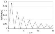
図5には、図4に示された表面磁束密度の波形についてFFT解析を行った結果のグラフが示されている。この図に示された1次、5次及び7次の磁束成分に着目して比較したものを以下の表1に示す。 FIG. 5 shows a graph of the results of FFT analysis of the waveform of the surface magnetic flux density shown in FIG. Table 1 below shows a comparison focusing on the first-order, fifth-order, and seventh-order magnetic flux components shown in this figure.

表1に示されるように、表面磁束密度の5次の波形に対する位相は8.65°であり、7次の波形に対する位相は190.5°である。そして、5次の波形に対する位相と7次の波形に対する位相とが逆位相となるようにすると共に、5次の波形に対する磁束成分と7次の波形に対する磁束成分との差分を小さくすることで、6次の誘起電圧歪を小さくすることが可能となり、トルクリップルを低減できることが実験及び解析により得られた。 As shown in Table 1, the phase of the surface magnetic flux density with respect to the fifth-order waveform is 8.65 °, and the phase with respect to the seventh-order waveform is 190.5 °. Then, the phase for the 5th-order waveform and the phase for the 7th-order waveform are made to have opposite phases, and the difference between the magnetic flux component for the 5th-order waveform and the magnetic flux component for the 7th-order waveform is reduced. Experiments and analyzes have shown that the sixth-order induced voltage distortion can be reduced and the torque ripple can be reduced.
なお、「表面磁束密度の5次の波形に対する位相と7次の波形に対する位相とが逆位相となる」とは、「表面磁束密度の5次の波形に対する位相から7次の波形に対する位相を引いた値の絶対値が、90°を超え270°未満の値となること」と対応する。そして、表面磁束密度の5次の波形に対する位相から7次の波形に対する位相を引いた値の絶対値が180°に近い値となっているほど、トルクリップルを効果的に低減できることが実験及び解析によりわかっている。本実施形態では、5次の波形に対する位相から7次の波形に対する位相を引いた値の絶対値が181.8°となっている。 In addition, "the phase of the surface magnetic flux density with respect to the 5th order waveform and the phase with respect to the 7th order waveform are opposite phases" means that "the phase of the surface magnetic flux density with respect to the 5th order waveform is subtracted from the phase with respect to the 7th order waveform". The absolute value of the value is more than 90 ° and less than 270 °. " Experiments and analyzes show that the closer the absolute value of the surface magnetic flux density to the fifth-order waveform minus the phase for the seventh-order waveform is, the more effectively the torque ripple can be reduced. I know by. In the present embodiment, the absolute value of the value obtained by subtracting the phase for the 7th-order waveform from the phase for the 5th-order waveform is 181.8 °.
また、「表面磁束密度の5次の波形に対する磁束成分と7次の波形に対する磁束成分との差分を小さくする」とは、「表面磁束密度の5次の波形に対する磁束成分から7次の波形に対する磁束成分を引いた値の絶対値が、1次の波形に対する磁束成分に対して10%以下にする」と対応する。そして、本実施形態では、表面磁束密度の5次の波形に対する磁束成分から7次の波形に対する磁束成分を引いた値の絶対値が、1次の波形に対する磁束成分に対して8.5%となっている。 Further, "reducing the difference between the magnetic flux component for the 5th order waveform of the surface magnetic flux density and the magnetic flux component for the 7th order waveform" means "from the magnetic flux component for the 5th order waveform of the surface magnetic flux density to the 7th order waveform". The absolute value of the value obtained by subtracting the magnetic flux component should be 10% or less of the magnetic flux component with respect to the primary waveform. " Then, in the present embodiment, the absolute value of the value obtained by subtracting the magnetic flux component for the 7th order waveform from the magnetic flux component for the 5th order waveform of the surface magnetic flux density is 8.5% with respect to the magnetic flux component for the 1st order waveform. It has become.
なお、本実施形態では、極集中配向角度θ1及び極間配向角度θ2を主要なパラメータとしてマグネット30の磁束等を設定することで、表面磁束密度の5次の波形に対する位相から7次の波形に対する位相を引いた値の絶対値が180°に近づくように、かつ5次の波形に対する磁束成分から7次の波形に対する磁束成分を引いた値の絶対値が1次の波形に対する磁束成分に対して10%以下となるようにした。 In the present embodiment, by setting the magnetic flux of the
(本実施形態の作用並びに効果)
次に、本実施形態の作用並びに効果について説明する。(Action and effect of this embodiment)
Next, the operation and effect of this embodiment will be described.
図1及び図2に示されるように、本実施形態のモータ10では、ステータ22のコイル体34への通電が制御部によって制御されると、コイル体34が磁束(磁界)を発する。これにより、ロータ20が回転軸12と共に回転する。 As shown in FIGS. 1 and 2, in the
ここで、本実施形態では、表面磁束密度の5次の波形に対する位相から7次の波形に対する位相を引いた値の絶対値が180°に近づくように、かつ5次の波形に対する磁束成分から7次の波形に対する磁束成分を引いた値の絶対値が1次の波形に対する磁束成分に対して10%以下となるようにマグネット30の磁束を設定している。これにより、図6に示されるように、巻線鎖交磁束密度の波形(回転電機角0°から360°の範囲で測定した波形)を正弦波に近づけることができる。これにより、モータ10のトルクリップルを低減することができる。また、上記のような設定とすることにより、制御部によるコイル体34への通電の制御性を確保することができる。 Here, in the present embodiment, the absolute value of the value obtained by subtracting the phase for the 7th-order waveform from the phase for the 5th-order waveform of the surface magnetic flux density approaches 180 °, and 7 from the magnetic flux component for the 5th-order waveform. The magnetic flux of the
図7には、図6に示された巻線鎖交磁束密度の波形についてFFT解析を行った結果のグラフが示されている。この図に示された1次、5次及び7次の磁束成分に着目して比較したものを以下の表2に示す。 FIG. 7 shows a graph of the results of FFT analysis of the waveform of the winding interlinkage magnetic flux density shown in FIG. Table 2 below shows a comparison focusing on the first-order, fifth-order, and seventh-order magnetic flux components shown in this figure.
この表によれば、トルクリップルの大きさに起因する(6次の誘起電圧歪に起因する)と考えられる巻線鎖交磁束密度の5次及び7次の磁束成分の値を1次の磁束成分の値に対して十分に小さく(上記の例では5%未満)できている。これは、巻線鎖交磁束密度の5次及び7次の磁束成分が互いに打ち消し合うことで、6次の誘起電圧歪を小さくできているものと考えられる。 According to this table, the values of the 5th and 7th order magnetic flux components of the winding interlinkage magnetic flux density, which are considered to be due to the magnitude of the torque ripple (due to the 6th order induced voltage distortion), are the primary magnetic flux. It is sufficiently small (less than 5% in the above example) with respect to the value of the component. It is considered that this is because the 5th and 7th order magnetic flux components of the winding interlinkage magnetic flux density cancel each other out to reduce the 6th order induced voltage distortion.
(第1比較例)
図8には、第1比較例に係るモータの表面磁束密度を示す図4に対応するグラフが示されている。この例では、回転電機角が0°から180°の範囲では、すなわち、磁極中心Pにおいて径方向内側がN極とされた一対のマグネット30Nと対応する範囲においては、0°から90°へ向かうにつれて、表面磁束密度が、増加、減少、増加の順で変化するようになっている。また、90°から180°へ向かうにつれて、表面磁束密度が、減少、増加、減少の順で変化するようになっている。(First comparative example)
FIG. 8 shows a graph corresponding to FIG. 4, which shows the surface magnetic flux density of the motor according to the first comparative example. In this example, in the range of the rotating electric machine angle from 0 ° to 180 °, that is, in the range corresponding to the pair of
また、回転電機角が180°から360°の範囲では、すなわち、磁極中心Pにおいて径方向内側がS極とされた一対のマグネット30Sと対応する範囲においては、180°から270°へ向かうにつれて、表面磁束密度が、減少、増加、減少の順で変化するようになっている。また、270°から360°へ向かうにつれて、表面磁束密度が、増加、減少、増加の順で変化するようになっている。 Further, in the range of the rotating electric machine angle from 180 ° to 360 °, that is, in the range corresponding to the pair of
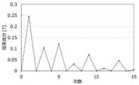
図9には、図8に示された表面磁束密度の波形についてFFT解析を行った結果のグラフが示されている。この図に示された1次、5次及び7次の磁束成分に着目して比較したものを以下の表3に示す。 FIG. 9 shows a graph of the results of FFT analysis of the waveform of the surface magnetic flux density shown in FIG. Table 3 below shows a comparison focusing on the first-order, fifth-order, and seventh-order magnetic flux components shown in this figure.
表3に示されるように、表面磁束密度の5次の波形に対する位相は7.21°であり、7次の波形に対する位相は6.94°である。そして、この比較例では、表面磁束密度の5次の波形に対する位相と7次の波形に対する位相とが同位相となっている。なお、「表面磁束密度の5次の波形に対する位相と7次の波形に対する位相とが同位相となっている」とは、「表面磁束密度の5次の波形に対する位相から7次の波形に対する位相を引いた値の絶対値が、90°を超え270°未満の範囲とは異なる値となること」対応する。 As shown in Table 3, the phase of the surface magnetic flux density with respect to the fifth-order waveform is 7.21 °, and the phase with respect to the seventh-order waveform is 6.94 °. In this comparative example, the phase of the surface magnetic flux density with respect to the fifth-order waveform and the phase with respect to the seventh-order waveform are in phase. In addition, "the phase of the surface magnetic flux density with respect to the 5th order waveform and the phase with respect to the 7th order waveform are in phase" means "the phase of the surface magnetic flux density with respect to the 5th order waveform to the 7th order waveform". The absolute value of the value obtained by subtracting is different from the range of more than 90 ° and less than 270 °. "
そして、以上説明した第1比較例に係るモータでは、図10に示されるように、巻線鎖交磁束密度の波形(回転電機角0°から360°の範囲で測定した波形)が、前述の本実施形態の波形(図6参照)と比べて正弦波から乖離した波形となっている。この波形及びこの波形をFFT解析した結果のグラフを示す図11、並びに、図11に示された1次、5次及び7次の磁束成分に着目して比較した以下の表4からもわかるように、トルクリップルの大きさに起因する(6次の誘起電圧歪に起因する)と考えられる巻線鎖交磁束密度の5次及び7次の磁束成分の値を1次の磁束成分の値に対して小さくことが難しく、第1比較例に係るモータでは、トルクリップルを効果的に抑制することが難しい。 Then, in the motor according to the first comparative example described above, as shown in FIG. 10, the waveform of the winding interlinkage magnetic flux density (the waveform measured in the range of the rotary electric machine angle of 0 ° to 360 °) is described above. The waveform deviates from the sine wave as compared with the waveform of the present embodiment (see FIG. 6). As can be seen from FIG. 11 showing this waveform and the graph of the result of FFT analysis of this waveform, and Table 4 below comparing the first-order, fifth-order, and seventh-order magnetic flux components shown in FIG. In addition, the values of the 5th and 7th order magnetic flux components of the winding interlinkage magnetic flux density, which are considered to be due to the magnitude of the torque ripple (due to the 6th order induced voltage distortion), are changed to the values of the 1st order magnetic flux components. On the other hand, it is difficult to make it small, and it is difficult to effectively suppress the torque ripple in the motor according to the first comparative example.
(第2比較例)
図12には、第2比較例に係るモータの表面磁束密度を示す図4に対応するグラフが示されている。この例では、回転電機角が0°から180°の範囲では、すなわち、磁極中心Pにおいて径方向内側がN極とされた一対のマグネット30Nと対応する範囲においては、0°から90°へ向かうにつれて、表面磁束密度が、増加した後に減少するようになっている。また、90°から180°へ向かうにつれて、表面磁束密度が、増加した後に減少するようになっている。(Second comparative example)
FIG. 12 shows a graph corresponding to FIG. 4, which shows the surface magnetic flux density of the motor according to the second comparative example. In this example, in the range of the rotating electric machine angle from 0 ° to 180 °, that is, in the range corresponding to the pair of
また、回転電機角が180°から360°の範囲では、すなわち、磁極中心Pにおいて径方向内側がS極とされた一対のマグネット30Sと対応する範囲においては、180°から270°へ向かうにつれて、表面磁束密度が、減少した後に増加するようになっている。また、270°から360°へ向かうにつれて、表面磁束密度が、減少した後に増加するようになっている。 Further, in the range of the rotating electric machine angle from 180 ° to 360 °, that is, in the range corresponding to the pair of
図13には、図12に示された表面磁束密度の波形についてFFT解析を行った結果のグラフが示されている。この図に示された1次、5次及び7次の磁束成分に着目して比較したものを以下の表5に示す。 FIG. 13 shows a graph of the results of FFT analysis of the waveform of the surface magnetic flux density shown in FIG. Table 5 below shows a comparison focusing on the first-order, fifth-order, and seventh-order magnetic flux components shown in this figure.
表3に示されるように、表面磁束密度の5次の波形に対する位相は−3.66°であり、7次の波形に対する位相は5.2°である。そして、この比較例では、表面磁束密度の5次の波形に対する位相と7次の波形に対する位相とが同位相となっている。 As shown in Table 3, the phase of the surface magnetic flux density with respect to the fifth-order waveform is -3.66 °, and the phase with respect to the seventh-order waveform is 5.2 °. In this comparative example, the phase of the surface magnetic flux density with respect to the fifth-order waveform and the phase with respect to the seventh-order waveform are in phase.
そして、以上説明した第2比較例に係るモータでは、図14に示されるように、巻線鎖交磁束密度の波形(回転電機角0°から360°の範囲で測定した波形)が、前述の本実施形態の波形(図6参照)と比べて正弦波から乖離した波形となっている。この波形及びこの波形をFFT解析した結果のグラフを示す図15、並びに、図15に示された1次、5次及び7次の磁束成分に着目して比較した以下の表6からもわかるように、トルクリップルの大きさに起因する(6次の誘起電圧歪に起因する)と考えられる巻線鎖交磁束密度の5次及び7次の磁束成分の値を1次の磁束成分の値に対して小さくことが難しく、第2比較例に係るモータでは、トルクリップルを効果的に抑制することが難しい。 Then, in the motor according to the second comparative example described above, as shown in FIG. 14, the waveform of the winding interlinkage magnetic flux density (the waveform measured in the range of the rotary electric machine angle of 0 ° to 360 °) is described above. The waveform deviates from the sine wave as compared with the waveform of the present embodiment (see FIG. 6). As can be seen from FIG. 15 showing this waveform and the graph of the result of FFT analysis of this waveform, and Table 6 below comparing the first-order, fifth-order, and seventh-order magnetic flux components shown in FIG. In addition, the values of the 5th and 7th order magnetic flux components of the winding interlinkage magnetic flux density, which are considered to be due to the magnitude of the torque ripple (due to the 6th order induced voltage distortion), are changed to the values of the 1st order magnetic flux components. On the other hand, it is difficult to make it small, and it is difficult to effectively suppress the torque ripple in the motor according to the second comparative example.
以上の第1比較例に係るモータ及び第2比較例に係るモータの結果からもわかるように、図1〜図3に示された本実施形態のモータ10のように構成することで、トルクリップルを効果的に低減できることがわかる。 As can be seen from the results of the motor according to the first comparative example and the motor according to the second comparative example, the torque ripple is configured like the
なお、本実施形態では、図4に示されるように、表面磁束密度が、回転電機角の30°から60°の範囲、120°から150°の範囲、210°から240°の範囲、300°から330°の範囲においてほぼ変化しないように構成した例について説明したが、本発明はこれに限定されない。例えば、表面磁束密度が、回転電機角が30°から60°の範囲においては30°から60°へ向かうにつれて増加するように、回転電機角が120°から150°の範囲においては120°から150°へ向かうにつれて90°から120°の範囲に対して緩やかに減少するように、回転電機角が210°から240°の範囲においては210°から240°へ向かうにつれて減少するように、回転電機角が300°から330°の範囲においては300°から330°へ向かうにつれて270°から300°の範囲に対して緩やかに増加するように設定してもよい。 In the present embodiment, as shown in FIG. 4, the surface magnetic flux density is in the range of 30 ° to 60 °, the range of 120 ° to 150 °, the range of 210 ° to 240 °, and 300 ° of the rotary electric machine angle. Although an example is described in which the structure is configured so as to be substantially unchanged in the range of 330 ° to 330 °, the present invention is not limited thereto. For example, the surface magnetic flux density increases from 30 ° to 60 ° in the range of the rotary machine angle of 30 ° to 60 °, and from 120 ° to 150 in the range of the rotary machine angle of 120 ° to 150 °. The rotary machine angle decreases gradually from 90 ° to 120 ° as it goes to °, and decreases from 210 ° to 240 ° in the range of 210 ° to 240 °. In the range of 300 ° to 330 °, it may be set to gradually increase with respect to the range of 270 ° to 300 ° as it goes from 300 ° to 330 °.
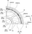
また、図3に示されるように、本実施形態のモータ10では、磁極中心Pにおいて径方向内側がN極とされた一対のマグネット30Nと、磁極中心Pにおいて径方向内側がS極とされた一対のマグネット30Sと、が周方向に間隔をあけて配列されている。すなわち、本実施形態のモータ10では、周方向に隣り合う一対の磁極中心P(周方向に隣り合うN極の磁極中心P及びS極の磁極中心P)の間の周方向の中央において、マグネット30Nとマグネット30Sとが周方向に離間している。この構成は、図16に示されるように、ロータハウジング28の一部(周壁28B)を磁路として用いることができることを前提とした構成である。例えば、ロータハウジング28の一部(周壁28B)を磁路として用いることができない構成においては、図17に示されるように、磁極中心Pにおいて径方向内側がN極とされた一対のマグネット30Nと、磁極中心Pにおいて径方向内側がS極とされた一対のマグネット30Sと、の間に隙間埋め用の磁石や磁性鋼板等の磁性体50を設ければよい。或いは、磁極中心Pにおいて径方向内側がN極とされた一対のマグネット30Nと、磁極中心Pにおいて径方向内側がS極とされた一対のマグネット30Sと、を周方向に当接させた構成とすればよい。なお、ロータハウジング28の一部(周壁28B)の寸法公差とマグネット30の寸法公差を考慮すると、マグネット30間に隙間を設けた構成のほうが良い。 Further, as shown in FIG. 3, in the
また、図3に示されるように、本実施形態のモータ10では、磁極中心Pにおいて径方向内側がN極とされた一対のマグネット30Nを磁極中心Pにおいて互いに周方向に当接させると共に、磁極中心Pにおいて径方向内側がS極とされた一対のマグネット30Sを磁極中心Pにおいて互いに周方向に当接させた例について説明したが、本発明はこれに限定されない。例えば、図18に示されるように、磁極中心Pにおいて径方向内側がN極とされた一対のマグネット30Nを磁極中心Pにおいて互いに周方向に離間させると共に、磁極中心Pにおいて径方向内側がS極とされた一対のマグネット30Sを磁極中心Pにおいて互いに周方向に離間させた構成としてもよい。この場合、極集中配向角度θ1を図3に示された例よりも大きく設定することで、磁極中心における磁束密度が低下することを抑制することができる。その結果、この構成が適用されたモータの高トルク化が妨げられることを抑制することができる。なお、図18に示された例では、N極のマグネット30NとS極のマグネット30Sとを周方向に当接させている。 Further, as shown in FIG. 3, in the
また、図2に示されるように、本実施形態のモータ10では、導線部34Aを径方向に1層とした構成について説明したが、本発明はこれに限定されない。例えば、図19に示されるように、導線部34Aを径方向に2層等の複層にした構成としてもよい。 Further, as shown in FIG. 2, in the
また、図20に示されるように、周方向に隣り合う導線部34A間に隙間が設けられた構成としてもよい。さらに、図21に示されるように、U相の導線部34A、V相の導線部34A及びW相の導線部34Aの周方向への配列順序を図2とは異なる順序に配列してもよい。 Further, as shown in FIG. 20, a gap may be provided between the
なお、図1〜図7及び図16〜図21の構成は、アウタロータ型のモータだけではなく図22に示されたインナロータ型のモータ52にも適用できる。なお、インナロータ型のモータ52において前述のモータ10と対応する部材及び部分には、前述のモータ10と対応する部材及び部分と同じ符号を付している。 The configurations of FIGS. 1 to 7 and 16 to 21 can be applied not only to the outer rotor type motor but also to the inner
以上、本開示の一実施形態について説明したが、本開示は、上記に限定されるものでなく、その主旨を逸脱しない範囲内において上記以外にも種々変形して実施することが可能であることは勿論である。 Although one embodiment of the present disclosure has been described above, the present disclosure is not limited to the above, and various modifications other than the above can be carried out within a range not deviating from the gist thereof. Of course.
10 モータ、20 ロータ、30 マグネット、32 ステータコア、34 コイル体(コイル)、34A 導線部、40 導線(巻線)、52 モータ、P 磁極中心
10 motors, 20 rotors, 30 magnets, 32 stator cores, 34 coil bodies (coils), 34A conductors, 40 conductors (windings), 52 motors, P pole center
Claims (4)
Translated fromJapanese前記導線部と径方向に対向して配置されたマグネット(30)を有し、前記コイルに通電されることで回転するロータ(20)と、
を備え、
前記マグネットにおける前記導線部と対向する面における表面磁束密度を回転電機角0°から360°の範囲で測定した波形についてFFT解析を行い、5次の波形に対する位相と7次の波形に対する位相とが逆位相となるように、前記マグネット内の磁束が設定されたモータ。A stator core (32) formed in an annular shape using a magnetic material, and a stator core (32) formed by using a conductive winding and supported by the stator core and on a radial outer surface or a radial inner surface of the stator core. A stator (22) including a coil (34) having a conducting wire portion (34A) arranged side by side in the circumferential direction along the stator (22).
A rotor (20) having a magnet (30) arranged so as to face the conducting wire portion in the radial direction and rotating when the coil is energized.
With
FFT analysis is performed on the waveform of the magnet whose surface magnetic flux density on the surface facing the conducting wire portion is measured in the range of the rotary electric machine angle of 0 ° to 360 °, and the phase for the fifth-order waveform and the phase for the seventh-order waveform are obtained. A motor in which the magnetic flux in the magnet is set so as to have the opposite phase.
回転電機角が30°から60°の範囲においては30°から60°へ向かうにつれて変化しない又は増加するように、
回転電機角が60°から90°の範囲においては30°から60°の範囲に対してより増加するように、
回転電機角が90°から120°の範囲においては90°から120°へ向かうにつれて減少するように、
回転電機角が120°から150°の範囲においては120°から150°へ向かうにつれて変化しない又は90°から120°の範囲に対して緩やかに減少するように、
回転電機角が210°から240°の範囲においては210°から240°へ向かうにつれて変化しない又は減少するように、
回転電機角が240°から270°の範囲においては210°から240°の範囲に対してより減少するように、
回転電機角が270°から300°の範囲においては270°から300°へ向かうにつれて増加するように、
回転電機角が300°から330°の範囲においては300°から330°へ向かうにつれて変化しない又は270°から300°の範囲に対して緩やかに増加するように、
前記マグネット内の磁束が設定された請求項1に記載のモータ。The surface magnetic flux density
In the range of 30 ° to 60 °, the rotary electric machine angle does not change or increases as it goes from 30 ° to 60 °.
The rotary machine angle increases more in the range of 60 ° to 90 ° than in the range of 30 ° to 60 °.
In the range of 90 ° to 120 °, the rotary machine angle decreases from 90 ° to 120 °.
The rotary machine angle does not change from 120 ° to 150 ° in the range of 120 ° to 150 °, or gradually decreases with respect to the range of 90 ° to 120 °.
The rotary machine angle does not change or decreases from 210 ° to 240 ° in the range of 210 ° to 240 °.
In the range of 240 ° to 270 °, the rotary machine angle is more reduced than in the range of 210 ° to 240 °.
In the range of 270 ° to 300 °, the rotary machine angle increases from 270 ° to 300 °.
In the range of 300 ° to 330 °, the rotary machine angle does not change from 300 ° to 330 °, or gradually increases in the range of 270 ° to 300 °.
The motor according to claim 1, wherein the magnetic flux in the magnet is set.
周方向に隣り合う一対の磁極中心(P)の間の周方向の中央において、一対の前記マグネットが周方向に離間している請求項1又は請求項2記載のモータ。The rotor is configured to include a plurality of the magnets arranged side by side in the circumferential direction.
The motor according to claim 1 or 2, wherein the pair of magnets are separated in the circumferential direction at the center in the circumferential direction between a pair of magnetic pole centers (P) adjacent to each other in the circumferential direction.
周方向に隣り合う一対の磁極中心において、一対の前記マグネットが周方向に離間している請求項1又は請求項2記載のモータ。
The rotor is configured to include a plurality of the magnets arranged side by side in the circumferential direction.
The motor according to claim 1 or 2, wherein the pair of magnets are separated from each other in the circumferential direction at the centers of a pair of magnetic poles adjacent to each other in the circumferential direction.
Priority Applications (1)
| Application Number | Priority Date | Filing Date | Title |
|---|---|---|---|
| JP2020023395AJP7400521B2 (en) | 2020-02-14 | 2020-02-14 | Motor manufacturing method |
Applications Claiming Priority (1)
| Application Number | Priority Date | Filing Date | Title |
|---|---|---|---|
| JP2020023395AJP7400521B2 (en) | 2020-02-14 | 2020-02-14 | Motor manufacturing method |
Publications (2)
| Publication Number | Publication Date |
|---|---|
| JP2021129443Atrue JP2021129443A (en) | 2021-09-02 |
| JP7400521B2 JP7400521B2 (en) | 2023-12-19 |
Family
ID=77489179
Family Applications (1)
| Application Number | Title | Priority Date | Filing Date |
|---|---|---|---|
| JP2020023395AActiveJP7400521B2 (en) | 2020-02-14 | 2020-02-14 | Motor manufacturing method |
Country Status (1)
| Country | Link |
|---|---|
| JP (1) | JP7400521B2 (en) |
Cited By (4)
| Publication number | Priority date | Publication date | Assignee | Title |
|---|---|---|---|---|
| JP2021169035A (en)* | 2020-04-22 | 2021-10-28 | 株式会社三洋物産 | Pachinko machine |
| JP2021169037A (en)* | 2020-04-28 | 2021-10-28 | 株式会社三洋物産 | Game machine |
| JP2021169036A (en)* | 2020-04-28 | 2021-10-28 | 株式会社三洋物産 | Pachinko machine |
| WO2024182513A1 (en)* | 2023-03-01 | 2024-09-06 | Milwaukee Electric Tool Corporation | Hydraulic tool with outer rotor electric motor |
Citations (1)
| Publication number | Priority date | Publication date | Assignee | Title |
|---|---|---|---|---|
| JPH04207948A (en)* | 1990-11-30 | 1992-07-29 | Mitsubishi Kasei Corp | Motor |
- 2020
- 2020-02-14JPJP2020023395Apatent/JP7400521B2/enactiveActive
Patent Citations (1)
| Publication number | Priority date | Publication date | Assignee | Title |
|---|---|---|---|---|
| JPH04207948A (en)* | 1990-11-30 | 1992-07-29 | Mitsubishi Kasei Corp | Motor |
Cited By (4)
| Publication number | Priority date | Publication date | Assignee | Title |
|---|---|---|---|---|
| JP2021169035A (en)* | 2020-04-22 | 2021-10-28 | 株式会社三洋物産 | Pachinko machine |
| JP2021169037A (en)* | 2020-04-28 | 2021-10-28 | 株式会社三洋物産 | Game machine |
| JP2021169036A (en)* | 2020-04-28 | 2021-10-28 | 株式会社三洋物産 | Pachinko machine |
| WO2024182513A1 (en)* | 2023-03-01 | 2024-09-06 | Milwaukee Electric Tool Corporation | Hydraulic tool with outer rotor electric motor |
Also Published As
| Publication number | Publication date |
|---|---|
| JP7400521B2 (en) | 2023-12-19 |
Similar Documents
| Publication | Publication Date | Title |
|---|---|---|
| JP2021129443A (en) | motor | |
| JP3205336U (en) | Single-phase motor and electric device having the same | |
| US10447102B2 (en) | Permanent magnet electrical machines and methods of assembling the same | |
| CN102468695B (en) | Stator core | |
| JP5248751B2 (en) | Slotless permanent magnet type rotating electrical machine | |
| US20180159387A1 (en) | Rotating electric machine with a stator closed notches and, more particularly variable-reluctance synchronous electric machine assisted by permanent magnets | |
| JP2016214070A (en) | Single-phase motor and electric apparatus having the same | |
| JP6723490B1 (en) | Rotating machine rotor | |
| GB2484162A (en) | Dynamo-electric machine with rotor magnet adjustable shunt | |
| CN103872868A (en) | Multi-gap type rotary electric machine | |
| JP5920637B2 (en) | Rotating electrical machine rotor | |
| US20100253178A1 (en) | Permanent-magnet synchronous motor | |
| US20230253838A1 (en) | Electric motor | |
| US20190140500A1 (en) | Permanent magnet motor | |
| WO2021131071A1 (en) | Hybrid-field double-gap synchronous machine and drive system | |
| JP2012182945A (en) | Rotary electric machine | |
| JP6201405B2 (en) | Rotating electric machine | |
| JP2019187132A (en) | Motor and brushless wiper motor | |
| JP2018160956A (en) | Brushless motor | |
| EP4152568A1 (en) | Rotor and electric motor | |
| JP2020129861A (en) | Rotating electric machine stator | |
| JP7562024B1 (en) | Rotating electric machine and method for driving the rotating electric machine | |
| JP2012060709A (en) | Permanent magnet motor | |
| JP4767358B1 (en) | Permanent magnet type rotating electric machine | |
| WO2021131199A1 (en) | Motor |
Legal Events
| Date | Code | Title | Description |
|---|---|---|---|
| A621 | Written request for application examination | Free format text:JAPANESE INTERMEDIATE CODE: A621 Effective date:20221214 | |
| A977 | Report on retrieval | Free format text:JAPANESE INTERMEDIATE CODE: A971007 Effective date:20230810 | |
| A131 | Notification of reasons for refusal | Free format text:JAPANESE INTERMEDIATE CODE: A131 Effective date:20230815 | |
| A521 | Request for written amendment filed | Free format text:JAPANESE INTERMEDIATE CODE: A523 Effective date:20230921 | |
| A131 | Notification of reasons for refusal | Free format text:JAPANESE INTERMEDIATE CODE: A131 Effective date:20231003 | |
| A521 | Request for written amendment filed | Free format text:JAPANESE INTERMEDIATE CODE: A523 Effective date:20231030 | |
| TRDD | Decision of grant or rejection written | ||
| A01 | Written decision to grant a patent or to grant a registration (utility model) | Free format text:JAPANESE INTERMEDIATE CODE: A01 Effective date:20231107 | |
| A61 | First payment of annual fees (during grant procedure) | Free format text:JAPANESE INTERMEDIATE CODE: A61 Effective date:20231120 | |
| R151 | Written notification of patent or utility model registration | Ref document number:7400521 Country of ref document:JP Free format text:JAPANESE INTERMEDIATE CODE: R151 |