JP2021126812A - Image forming device - Google Patents
Image forming deviceDownload PDFInfo
- Publication number
- JP2021126812A JP2021126812AJP2020022344AJP2020022344AJP2021126812AJP 2021126812 AJP2021126812 AJP 2021126812AJP 2020022344 AJP2020022344 AJP 2020022344AJP 2020022344 AJP2020022344 AJP 2020022344AJP 2021126812 AJP2021126812 AJP 2021126812A
- Authority
- JP
- Japan
- Prior art keywords
- size
- dial
- unit
- sheet
- rotation
- Prior art date
- Legal status (The legal status is an assumption and is not a legal conclusion. Google has not performed a legal analysis and makes no representation as to the accuracy of the status listed.)
- Pending
Links
Images


Landscapes
- Accessory Devices And Overall Control Thereof (AREA)
- Sheets, Magazines, And Separation Thereof (AREA)
- Position Input By Displaying (AREA)
- User Interface Of Digital Computer (AREA)
Abstract
Translated fromJapaneseDescription
Translated fromJapanese本発明は、シート補給部に載置されるシートのサイズの表示を切り替えるためのダイヤルを備える画像形成装置に関する。 The present invention relates to an image forming apparatus including a dial for switching the display of the size of a seat placed on the seat replenishment unit.
画像形成装置が、シートカセットまたは手差しトレイなどのシート補給部に載置されるシートのサイズを複数の候補から選択して表示する機構を備える場合がある。この場合、前記シートのサイズの表示を切り替えるための操作部として、回転式のダイヤルが採用されることが考えられる。前記ダイヤルの採用は、ユーザーが操作しやすいというメリットがある。 The image forming apparatus may include a mechanism for selecting and displaying the size of a sheet placed on a sheet replenishing unit such as a sheet cassette or a manual feed tray from a plurality of candidates. In this case, it is conceivable that a rotary dial is adopted as an operation unit for switching the display of the size of the sheet. Adoption of the dial has an advantage that it is easy for the user to operate.
例えば、前記ダイヤルと円筒状のインジケーター部とを有する部材が、ロータリースイッチの回転軸に装着されることが知られている(例えば、特許文献1参照)。この場合、前記シートの複数のサイズを表す文字が、前記インジケーター部の外周面に予め印字されている。 For example, it is known that a member having the dial and a cylindrical indicator portion is mounted on the rotating shaft of a rotary switch (see, for example, Patent Document 1). In this case, characters representing a plurality of sizes of the sheet are pre-printed on the outer peripheral surface of the indicator unit.
ところで、前記シートのサイズを表す文字が、前記ダイヤルに連動する前記インジケーター部に予め印字されている場合、前記シートのサイズの表示の選択の自由度が低い。 By the way, when the character indicating the size of the sheet is pre-printed on the indicator unit linked to the dial, the degree of freedom in selecting the display of the size of the sheet is low.
本発明の目的は、シート補給部に載置されるシートのサイズの表示をダイヤルによって切り替えることができ、さらに前記シートのサイズの表示の選択の自由度が高い画像形成装置を提供することにある。 An object of the present invention is to provide an image forming apparatus capable of switching the display of the size of a sheet mounted on a seat replenishment unit by a dial and further having a high degree of freedom in selecting the display of the size of the sheet. ..
本発明の一の局面に係る画像形成装置は、シート補給部と、サイズ表示部と、ダイヤルと、回転検出部と、入力操作部と、サイズ設定部と、表示制御部と、を備える。前記シート補給部は、プリント部に供給されるシートが載置される。前記サイズ表示部は、前記シート補給部に載置される前記シートのサイズを表示する。前記ダイヤルは、所定の回転位置に回転させる操作が行われることにより、前記サイズ表示部に表示させるシートサイズを選択する。前記回転検出部は、前記ダイヤルの前記回転位置を検出する。前記入力操作部は、ユーザーによる情報入力の操作を受け付ける。前記サイズ設定部は、前記入力操作部を通じて入力される複数のサイズ情報を前記ダイヤルの前記複数の回転位置に対応付けて設定する。前記表示制御部は、複数の前記サイズ情報のうち前記回転検出部により検出される前記回転位置に対応する1つを前記サイズ表示部に表示させる。 The image forming apparatus according to one aspect of the present invention includes a seat supply unit, a size display unit, a dial, a rotation detection unit, an input operation unit, a size setting unit, and a display control unit. A sheet supplied to the printing unit is placed on the sheet replenishing unit. The size display unit displays the size of the sheet placed on the sheet replenishment unit. The dial selects the sheet size to be displayed on the size display unit by performing an operation of rotating the dial to a predetermined rotation position. The rotation detection unit detects the rotation position of the dial. The input operation unit accepts an operation for inputting information by the user. The size setting unit sets a plurality of size information input through the input operation unit in association with the plurality of rotation positions of the dial. The display control unit causes the size display unit to display one of the plurality of size information corresponding to the rotation position detected by the rotation detection unit.
本発明によれば、シート補給部に載置されるシートのサイズの表示をダイヤルによって切り替えることができ、さらに前記シートのサイズの表示の選択の自由度が高い画像形成装置を提供することが可能になる。 According to the present invention, it is possible to provide an image forming apparatus in which the display of the size of a sheet mounted on the seat replenishment unit can be switched by a dial and the degree of freedom in selecting the display of the size of the sheet is high. become.
以下、図面を参照しながら、本発明の実施形態について説明する。なお、以下の実施形態は、本発明を具体化した一例であって、本発明の技術的範囲を限定するものではない。 Hereinafter, embodiments of the present invention will be described with reference to the drawings. The following embodiments are examples that embody the present invention, and do not limit the technical scope of the present invention.
図1に示されるように、実施形態に係る画像形成装置10は、シートに画像を形成するプリント装置4を備える。プリント装置4は、電子写真方式またはインクジェット方式などの所定の方式で前記シートに画像を形成する。 As shown in FIG. 1, the
画像形成装置10の本体部1は、プリント装置4を内包する筐体を成している。本体部1の上面は、画像形成後の前記シートを受ける排出トレイ101を形成している。なお、プリント装置4は画像形成装置10のプリント部である。 The main body 1 of the
画像形成装置10は、それぞれプリント装置4に供給される前記シートが載置されるシートカセット2および手差しトレイ3をさらに備える。 The
シートカセット2は、本体部1に対して引き出し可能である。手差しトレイ3は、本体部1の前面パネル12の開口を開閉可能に設けられた外装カバーを兼ねる。なお、シートカセット2および手差しトレイ3は、それぞれシート補給部の一例である。 The sheet cassette 2 can be pulled out with respect to the main body 1. The
また、画像形成装置10は、本体部1の上面に配置された主操作装置801および主表示装置802を備える。主操作装置801は、ユーザーによる情報入力の操作を受け付ける装置である。主操作装置801は入力操作部の一例である。 Further, the
例えば、主操作装置801は、文字入力が可能なタッチパネルまたは操作キーを含む。主表示装置802は、プリント条件の設定のためのメニュー画面または画像形成装置10の状態を表示する。 For example, the
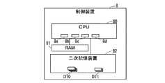
画像形成装置10は、プリント装置4および主表示装置802などを制御する制御装置8をさらに備える。図2に示されるように、制御装置8は、CPU(Central Processing Unit)80、RAM(Random Access Memory)81および二次記憶装置82などを備える。 The
CPU80は、予め二次記憶装置82に記憶されたコンピュータープログラムを実行することにより、前記プリント処理に関する各種のデータ処理、および、各種の電気機器の制御を実行する。 The
CPU80は、前記コンピュータープログラムを実行することにより実現される処理モジュールとして、主制御部8aおよびプリント制御部8bなどを含む。主制御部8aは、主表示装置802の制御、および、主操作装置801に対する操作に応じて各種の処理を開始させる開始制御などを実行する。プリント制御部8bは、プリント装置4を制御することにより、プリント装置4にプリント処理を実行させる。 The
二次記憶装置82は、コンピューター読み取り可能な不揮発性の記憶装置である。二次記憶装置82は、CPU80により実行されるプログラムおよびCPU80により参照される各種のデータを記憶する。例えば、フラッシュメモリーまたはハードディスクドライブの一方または両方が、二次記憶装置82として採用される。 The
RAM81は、揮発性の記憶装置である。RAM81は、CPU80が実行するプログラムおよびCPU80が前記プログラムを実行する過程で出力および参照するデータを一次記憶する。RAM81は、二次記憶装置82よりも高速なデータアクセスが可能な記憶装置である。 The
なお、が、MPU(Micro Processing Unit)またはDSP(Digital Signal Processor)などの他のプロセッサーによって実現されてもよい。また、制御装置8の一部または全部が、ASIC(Application Specific Integrated Circuit)などの回路によって実現されることも考えられる。 However, may be realized by another processor such as MPU (Micro Processing Unit) or DSP (Digital Signal Processor). It is also conceivable that a part or all of the
画像形成装置10は、手差しトレイ3なに載置される前記シートのサイズを複数の候補から選択して表示するサイズ表示装置5をさらに備える。サイズ表示装置5は、本体部1の前面パネル12における手差しトレイ3の横に設けられている。即ち、サイズ表示装置5は、手差しトレイ3に対応して設けられている。 The
図3に示されるように、サイズ表示装置5は、前記シートのサイズの表示を切り替えるための操作部として、回転式のダイヤル51を備える。ダイヤル51の採用は、ユーザーが操作しやすいというメリットがある。 As shown in FIG. 3, the
ところで、前記シートのサイズを表す文字が、ダイヤル51に連動するインジケーター部に予め印字されている場合がある。この場合、前記シートのサイズの表示の選択の自由度が低い。 By the way, characters indicating the size of the sheet may be pre-printed on the indicator unit linked to the
一方、サイズ表示装置5は、以下に示されるように、前記シートのサイズの表示の選択の自由度を高めるための構成を備える。以下、その構成について説明する。 On the other hand, the
[サイズ表示装置5の構成]
図3〜5に示されるように、サイズ表示装置5は、ダイヤル51と、パネル表示装置52と、ロータリースイッチ53とを備える。ダイヤル51は、回転可能に支持されている。[Configuration of size display device 5]
As shown in FIGS. 3 to 5, the
ロータリースイッチ53は、スイッチ本体53aおよび回転軸53bを有する。回転軸53bは、スイッチ本体53aに対して予め定められた複数の回転位置のいずれかに選択的に回転可能である。 The
ダイヤル51は、連結部材55を介してロータリースイッチ53の回転軸53bに連結されている。即ち、ダイヤル51は、連結部材55および回転軸53bと一体に構成されている。ダイヤル51が回転操作を受けて回転することにより、ロータリースイッチ53の回転軸53bが回転する。 The
ロータリースイッチ53は、回転軸53bと連結されていることにより、回転操作が加えられることによって予め定められた複数の回転位置のいずれかへ選択的に回転可能に支持されている。 Since the
ダイヤル51の回転中心線L0は、前面パネル12に直交する直線である(図5参照)。即ち、ダイヤル51は、正面から見て時計回りおよび反時計回りに回転可能に支持されている。 The rotation center line L0 of the
スイッチ本体53aは、回転軸53bの向きを検出する回路、即ち、ダイヤル51の前記回転位置を検出する回路を備える。なお、ロータリースイッチ53は、ダイヤル51の前記回転位置を検出する回転検出部の一例である。 The
ダイヤル51の正面の内側の部分には、円形の開口であるダイヤル開口51aが形成されている。従って、ダイヤル51は、正面から見て環状に形成されている。 A
パネル表示装置52は、例えば液晶表示装置または有機EL表示装置などのパネル状の表示装置である。パネル表示装置52は、手差しトレイ3に載置される前記シートのサイズを表示するサイズ表示部の一例である。 The
パネル表示装置52は、ダイヤル51の内側の領域に設けられている。パネル表示装置52は、その画面がダイヤル51のダイヤル開口51aから露出する状態で配置されている。 The
本実施形態において、パネル表示装置52は、ダイヤル51の内側の領域において一定の向きで固定されている。即ち、ダイヤル51が回転してもパネル表示装置52は回転しない。 In this embodiment, the
具体的には、ロータリースイッチ53のスイッチ本体53aが電子基板54に実装されており、パネル表示装置52は、複数の支柱57を介して電子基板54に固定されている。 Specifically, the
また、パネル表示装置52は、パネル表示装置52の周囲におけるダイヤル51のダイヤル開口51aの隙間を覆うカバー部材56と一体に構成されている。 Further, the
図4は、カバー部材56が省略されたサイズ表示装置5の正面図である。図4に示されるように、連結部材55には、支柱57が貫通する貫通穴55aが形成されている。貫通穴55aは、回転中心線L0を中心とする円弧状に形成されている。これにより、ダイヤル51の回転に連動して連結部材55が回転する場合に、支柱57が連結部材55と干渉しない。 FIG. 4 is a front view of the
CPU80は、前記コンピュータープログラムを実行することにより実現される前記処理モジュールとして、表示制御部8cおよびサイズ設定部8dをさらに含む(図2参照)。 The
サイズ設定部8dは、それぞれ前記シートのサイズを表す複数のサイズ情報DT1を設定し、二次記憶装置82に記録する(図2参照)。サイズ設定部8dは、主操作装置801に対する操作に従って、複数のサイズ情報DT1をダイヤル51の複数の前記回転位置、即ち、ロータリースイッチ53の回転軸53bの複数の向きに対応付けて設定する。 The
例えば、ダイヤル51がとり得る複数の前記回転位置がN通りである場合に、それぞれ前記シートのサイズを表すN個よりも多い複数のサイズ候補情報DT0が、二次記憶装置82に予め記憶されている(図2参照)。なお、Nは2以上の整数である。 For example, when the plurality of rotation positions that the
サイズ設定部8dは、主操作装置801に対するサイズ選択操作に従って、複数のサイズ候補情報DT0の中からN個のサイズ情報DT1を選択する。 The
また、本実施形態において、サイズ設定部8dは、主操作装置801に対するモード選択操作に従って、N個のサイズ情報DT1をN通りのダイヤル51の前記回転位置に対応付けるときの動作モードとして、自動割り当てモードおよび手動割り当てモードの一方を選択する。 Further, in the present embodiment, the
サイズ設定部8dは、前記自動割り当てモードが選択される場合、N個のサイズ情報DT1が表す前記シートのサイズの順序が予め定められたN通りの前記回転位置の順序と一致するように、自動的にN個のサイズ情報DT1をN通りの前記回転位置に対応付ける。 When the automatic allocation mode is selected, the
例えば、ダイヤル51がとり得る複数の前記回転位置が、反時計回りに最後まで回転されたときの第1回転位置から時計周りに最後まで回転されたときの第5回転位置までの5通りであり、5通りの前記視線の予め定められた順序が、ダイヤル51が前記第1回転位置から時計周りに順番に回転されるときの前記回転位置の順序であるとする。 For example, there are five possible rotation positions of the
また、A3、B4、A4、B5およびA5の5個のサイズ情報DT1が、ダイヤル51の前記回転位置との関係を指定されることなく設定されたとする。この場合、サイズ設定部8dは、5個のサイズ情報DT1が表す前記シートのサイズの昇順が5通りの前記回転位置の順序と一致するように、自動的に5個のサイズ情報DT1をN通りの前記回転位置に対応付ける。 Further, it is assumed that the five size information DT1s A3, B4, A4, B5 and A5 are set without specifying the relationship with the rotation position of the
具体的には、サイズ情報DT1のA5、B5、A4、B4およびA3が、それぞれダイヤル51の第1回転位置、第2回転位置、第3回転位置、第4回転位置および第5回転位置に対応付けられる。なお、複数のサイズ候補情報DT0は、それぞれが表す前記シートのサイズの大小関係の情報を含む。 Specifically, A5, B5, A4, B4 and A3 of the size information DT1 correspond to the first rotation position, the second rotation position, the third rotation position, the fourth rotation position and the fifth rotation position of the
一方、サイズ設定部8dは、前記手動割り当てモードが選択される場合、N個のサイズ情報DT1とダイヤル51のN通りの前記回転位置との対応関係を、ユーザーによる主操作装置801に対する操作に従って設定する。 On the other hand, when the manual allocation mode is selected, the
表示制御部8cは、サイズ設定部8dによって予め設定される複数のサイズ情報DT1のうち、ロータリースイッチ53により検出されるダイヤル51の前記回転位置に対応する1つをパネル表示装置52に表示させる。 The
即ち、表示制御部8cは、ロータリースイッチ53の検出状態の変化に応じて、表示制御部8cにおけるサイズ情報DT1の表示状態を切り替える。従って、ダイヤル51がユーザーの操作によって所定角度ずつ回転するごとに、パネル表示装置52に表示されるサイズ情報DT1が順次切り替わる。 That is, the
ユーザーは、パネル表示装置52に表示されるサイズ情報DT1が手差しトレイ3に載置される前記シートのサイズと一致するように、ダイヤル51を操作する。 The user operates the
サイズ情報DT1が前記自動割り当てモードの下で設定されている場合、ダイヤル51が所定角度ずつ回転するごとに、サイズ情報DT1の表示が、前記シートのサイズの昇順または降順で切り替わる。そのため、ユーザーは、ダイヤル51をいずれの方向へ回転すれば目的のサイズ情報DT1がパネル表示装置52に表示されるのかを容易に把握できる。 When the size information DT1 is set under the automatic allocation mode, the display of the size information DT1 is switched in ascending or descending order of the size of the sheet each time the
また、プリント制御部8bは、前記シートが手差しトレイ3からプリント装置4へ供給される場合に、ロータリースイッチ53により検出されるダイヤル51の前記回転位置に対応するサイズ情報DT1に応じてプリント装置4を制御する。 Further, the
例えば、プリント制御部8bは、ダイヤル51の前記回転位置に対応するサイズ情報DT1に応じて、プリント装置4による1ページごとのプリント処理の開始および終了のタイミング、および、前記シートへの画像のプリント範囲などを制御する。 For example, the
画像形成装置10が採用されることにより、手差しトレイ3に載置される前記シートのサイズの表示をダイヤル51によって切り替えることができる。さらに、サイズ設定部8dは、ダイヤル51の操作により選択可能な複数のサイズ情報DT1をユーザーの操作に従って設定することができる。そのため、前記シートのサイズの表示の選択の自由度が高い。 By adopting the
なお、画像形成装置10が、手差しトレイ3に載置された前記シートのサイズを検出するサイズ検出センサーを備えていてもよい。例えば、前記サイズ検出センサーは、手差しトレイ3において前記シートの幅方向に移動可能に設けられた一対のサイドカーソルの位置を検出するセンサーである。 The
前記一対のサイドカーソルは、ユーザーの操作により、手差しトレイ3に載置される前記シートの両側端に沿う位置に配置される。この場合、ロータリースイッチ53に基づく前記シートの検出サイズと前記サイズ検出センサーに基づく前記シートの検出サイズとが一致しない不一致状態が生じ得る。 The pair of side cursors are arranged at positions along both side edges of the sheet placed on the
前記不一致状態が生じた場合に、表示制御部8cが、主表示装置802を通じてエラー通知を出力することが考えられる。また、前記不一致状態が生じた場合に、プリント制御部8bが、ロータリースイッチ53および前記サイズ検出センサーの検出結果のうち、予め定められた一方、または、前記エラー通知に応じたユーザーの操作により選択される一方に対応するサイズ情報DT1に応じて、プリント装置4を制御することが考えられる。 When the mismatch state occurs, it is conceivable that the
[応用例]
パネル表示装置52が、ダイヤル51の内側の領域において、ダイヤル51と一体に構成されることも考えられる。この場合、ダイヤル51が回転するときに、パネル表示装置52はダイヤル51とともに回転する。[Application example]
It is also conceivable that the
また、画像形成装置10において、サイズ表示装置5が、シートカセット2に対応して設けられてもよい。また、画像形成装置10が、シートカセット2および手差しトレイ3に対応する2つのサイズ表示装置5を備えることも考えられる。 Further, in the
また、パネル表示装置52が、例えばダイヤル51に隣接した位置など、ダイヤル51の内側の領域以外に設けられることも考えられる。 It is also conceivable that the
また、サイズ設定部8dが、主操作装置801に対する操作に従って、複数のサイズ情報DT1と複数の前記回転位置との対応付けを任意に変更することも考えられる。 It is also conceivable that the
1 :本体部
2 :シートカセット
3 :手差しトレイ
4 :プリント装置
5 :サイズ表示装置
8 :制御装置
8a :主制御部
8b :プリント制御部
8c :表示制御部
8d :サイズ設定部
10 :画像形成装置
12 :前面パネル
51 :ダイヤル
51a :ダイヤル開口
52 :パネル表示装置
53 :ロータリースイッチ
53a :スイッチ本体
53b :回転軸
54 :電子基板
55 :連結部材
55a :貫通穴
56 :カバー部材
57 :支柱
80 :CPU
81 :RAM
82 :二次記憶装置
101 :排出トレイ
801 :主操作装置
802 :主表示装置1: Main body 2: Sheet cassette 3: Manual feed tray 4: Printing device 5: Size display device 8:
81: RAM
82: Secondary storage device 101: Discharge tray 801: Main operation device 802: Main display device
Claims (4)
Translated fromJapanese前記シート補給部に載置される前記シートのサイズを表示するサイズ表示部と、
所定の回転位置に回転させる操作が行われることにより、前記サイズ表示部に表示させるシートサイズを選択するダイヤルと、
前記ダイヤルの前記回転位置を検出する回転検出部と、
ユーザーによる情報入力の操作を受け付ける入力操作部と、
前記入力操作部を通じて入力される複数のサイズ情報を前記ダイヤルの複数の前記回転位置に対応付けて設定するサイズ設定部と、
複数の前記サイズ情報のうち前記回転検出部により検出される前記回転位置に対応する1つを前記サイズ表示部に表示させる表示制御部と、を備える画像形成装置。The sheet replenishment section where the sheet supplied to the print section is placed,
A size display unit that displays the size of the sheet placed on the sheet replenishment unit, and
A dial for selecting the sheet size to be displayed on the size display unit by performing an operation of rotating to a predetermined rotation position, and
A rotation detection unit that detects the rotation position of the dial, and
An input operation unit that accepts user information input operations,
A size setting unit that sets a plurality of size information input through the input operation unit in association with the plurality of rotation positions of the dial, and a size setting unit.
An image forming apparatus including a display control unit for displaying one of the plurality of size information corresponding to the rotation position detected by the rotation detection unit on the size display unit.
Priority Applications (1)
| Application Number | Priority Date | Filing Date | Title |
|---|---|---|---|
| JP2020022344AJP2021126812A (en) | 2020-02-13 | 2020-02-13 | Image forming device |
Applications Claiming Priority (1)
| Application Number | Priority Date | Filing Date | Title |
|---|---|---|---|
| JP2020022344AJP2021126812A (en) | 2020-02-13 | 2020-02-13 | Image forming device |
Publications (1)
| Publication Number | Publication Date |
|---|---|
| JP2021126812Atrue JP2021126812A (en) | 2021-09-02 |
Family
ID=77487589
Family Applications (1)
| Application Number | Title | Priority Date | Filing Date |
|---|---|---|---|
| JP2020022344APendingJP2021126812A (en) | 2020-02-13 | 2020-02-13 | Image forming device |
Country Status (1)
| Country | Link |
|---|---|
| JP (1) | JP2021126812A (en) |
- 2020
- 2020-02-13JPJP2020022344Apatent/JP2021126812A/enactivePending
Similar Documents
| Publication | Publication Date | Title |
|---|---|---|
| EP2642244B1 (en) | Surface texture measurement device | |
| JPH0226223B2 (en) | ||
| JP6561855B2 (en) | Electronic equipment, electronic equipment control program | |
| JP2005502276A5 (en) | ||
| US20130335767A1 (en) | Input apparatus, image forming apparatus using the same and method thereof | |
| CN106990683A (en) | Printing apparatus, image reading apparatus, method of producing printed matter | |
| JP2021126812A (en) | Image forming device | |
| JP2007310050A (en) | Operation device and image forming apparatus | |
| JP4016380B2 (en) | Electronics | |
| JP2009244924A (en) | Electronic apparatus | |
| US10148832B2 (en) | Image forming apparatus with projector to display an image to be printed and related method | |
| JP2017033066A (en) | Display control device and display control program | |
| JPH0580703A (en) | Electronics | |
| JP6380338B2 (en) | Display input device and image forming apparatus having the same | |
| JP2017182192A (en) | Operation device | |
| CN113580786A (en) | Multifunctional integrated machine | |
| JP5598401B2 (en) | Operating device | |
| JP2006024144A (en) | Operation display device of touch panel type | |
| JP2008078045A (en) | Dial switch, electronic equipment, and camera | |
| JP2004210443A (en) | Paper sheet size setting device | |
| JP6636477B2 (en) | Operating device, image processing device, and control program | |
| JP2016115293A (en) | Operation display device and image forming apparatus including the same | |
| JP2017010156A (en) | Input device and electronic apparatus having input device | |
| JP2023081513A (en) | Display device, image forming device and display control method | |
| JP4132801B2 (en) | Image forming apparatus |