JP2021126163A - Image processing device and image processing method - Google Patents
Image processing device and image processing methodDownload PDFInfo
- Publication number
- JP2021126163A JP2021126163AJP2020020892AJP2020020892AJP2021126163AJP 2021126163 AJP2021126163 AJP 2021126163AJP 2020020892 AJP2020020892 AJP 2020020892AJP 2020020892 AJP2020020892 AJP 2020020892AJP 2021126163 AJP2021126163 AJP 2021126163A
- Authority
- JP
- Japan
- Prior art keywords
- image
- separated
- radiation
- separated image
- processing
- Prior art date
- Legal status (The legal status is an assumption and is not a legal conclusion. Google has not performed a legal analysis and makes no representation as to the accuracy of the status listed.)
- Granted
Links
Images


Landscapes
- Apparatus For Radiation Diagnosis (AREA)
Abstract
Translated fromJapaneseDescription
Translated fromJapanese本発明は、放射線画像を処理する画像処理装置および画像処理方法に関する。 The present invention relates to an image processing apparatus and an image processing method for processing a radiographic image.
現在、X線による医療画像診断や非破壊検査に用いる撮影装置として、半導体材料によって形成された平面検出器(Flat Panel Detector、以下FPDと略す)を用いた放射線撮像装置が普及している。このような放射線撮像装置は、例えば医療画像診断においては、一般撮影のような静止画撮影や、透視撮影のような動画撮影のためのデジタル撮像装置として用いられている。 Currently, a radiation imaging device using a plane detector (Flat Panel Detector, hereinafter abbreviated as FPD) made of a semiconductor material is widely used as an imaging device used for medical image diagnosis and non-destructive inspection by X-rays. Such a radiation imaging device is used, for example, in medical image diagnosis as a digital imaging device for still image photography such as general photography and moving image photography such as fluoroscopy.
FPDを用いた撮影方法のひとつに、エネルギーサブトラクションがある。エネルギーサブトラクションでは、管電圧の異なるX線を照射するなどしてエネルギーの異なる画像を複数枚取得し、それらを演算することで、例えば骨画像と軟部組織画像に分離するなどの処理を行うことができる(特許文献1)。 Energy subtraction is one of the imaging methods using FPD. In energy subtraction, it is possible to acquire a plurality of images with different energies by irradiating X-rays with different tube voltages and calculate them to perform processing such as separating into a bone image and a soft tissue image, for example. Yes (Patent Document 1).
FPDを用いてIVR(画像下治療:Interventional Radiology)を行うときは、血管に造影剤が注入される。また、IVRでは、カテーテルやガイドワイヤーを血管内に挿入し、ステントやコイルを留置するなどの処置が行われる。IVRでは、FPDを用いて得られたX線画像を観察することにより造影剤や医療用デバイスの位置と形状を確認しながら上記のような処置が行われるが、X線画像における軟部組織や骨のコントラストが視認性を低下させることがある。エネルギーサブトラクションを用いてX線画像から軟部組織や骨の画像を分離し、それらのコントラストを除去することにより、造影剤や医療用デバイスの視認性が向上する可能性がある。しかしながら、エネルギーサブトラクションを用いて軟部組織や骨を分離すると、ノイズが増えてしまうという課題がある。 When performing IVR (Interventional Radiology) using FPD, a contrast medium is injected into the blood vessels. In IVR, a catheter or a guide wire is inserted into a blood vessel, and a stent or a coil is placed. In IVR, the above treatment is performed while confirming the position and shape of the contrast medium and medical device by observing the X-ray image obtained by using the FPD, but the soft tissue and bone in the X-ray image are performed. Contrast may reduce visibility. Separating soft tissue and bone images from X-ray images using energy subtraction and removing their contrast may improve the visibility of contrast media and medical devices. However, there is a problem that noise increases when soft tissues and bones are separated by using energy subtraction.
本発明は、エネルギーサブトラクション処理により得られる画像におけるノイズを低減する技術を提供する。 The present invention provides a technique for reducing noise in an image obtained by energy subtraction processing.
本発明の一態様による画像処理装置は以下の構成を備える。すなわち、
互いに異なるエネルギーの放射線により取得された第1の放射線画像と第2の放射線画像から、エネルギーサブトラクション処理により第1の分離画像と第2の分離画像を生成する第1生成手段と、
前記エネルギーサブトラクション処理が適用されていない放射線画像に基づく第3の放射線画像から、所定の制約条件を用いて、前記第1の分離画像または前記第2の分離画像に対応する疑似的な分離画像を生成する第2生成手段と、
前記第1の分離画像、前記第2の分離画像、前記第1の分離画像と前記第2の分離画像を合成した第3の分離画像の少なくともいずれかと、前記疑似的な分離画像とを合成して合成画像を生成する合成手段と、
前記第1の分離画像と前記第2の分離画像のうちの少なくとも一方に基づいて前記合成手段における前記合成の合成比率を決定する決定手段と、を備える。The image processing apparatus according to one aspect of the present invention has the following configurations. That is,
A first generation means for generating a first separated image and a second separated image by energy subtraction processing from a first radiation image and a second radiation image acquired by radiation of different energies.
From the third radiographic image based on the radiographic image to which the energy subtraction processing is not applied, a pseudo separated image corresponding to the first separated image or the second separated image is obtained by using predetermined constraints. The second generation means to generate and
At least one of the first separated image, the second separated image, the third separated image obtained by combining the first separated image and the second separated image, and the pseudo separated image are combined. And the compositing means to generate a compositing image
A determination means for determining the synthesis ratio of the synthesis in the synthesis means based on at least one of the first separated image and the second separated image is provided.
本発明によれば、エネルギーサブトラクション処理により得られる画像のノイズを低減することができる。 According to the present invention, it is possible to reduce the noise of the image obtained by the energy subtraction processing.
以下、添付図面を参照して実施形態を詳しく説明する。尚、以下の実施形態は特許請求の範囲に係る発明を限定するものではない。実施形態には複数の特徴が記載されているが、これらの複数の特徴の全てが発明に必須のものとは限らず、また、複数の特徴は任意に組み合わせられてもよい。さらに、添付図面においては、同一若しくは同様の構成に同一の参照番号を付し、重複した説明は省略する。 Hereinafter, embodiments will be described in detail with reference to the accompanying drawings. The following embodiments do not limit the invention according to the claims. Although a plurality of features are described in the embodiment, not all of the plurality of features are essential to the invention, and the plurality of features may be arbitrarily combined. Further, in the attached drawings, the same or similar configurations are given the same reference numbers, and duplicate explanations are omitted.
なお、以下では、放射線としてX線を用いた放射線撮像システムについて説明するが、これに限られるものではない。本発明における放射線には、放射線崩壊によって放出される粒子(光子を含む)の作るビームであるα線、β線、γ線などの他に、同程度以上のエネルギーを有するビーム、例えば粒子線、宇宙線なども、含まれるものとする。 In the following, a radiation imaging system using X-rays as radiation will be described, but the present invention is not limited to this. The radiation in the present invention includes beams having the same or higher energy, for example, particle beams, in addition to α rays, β rays, γ rays, etc., which are beams produced by particles (including photons) emitted by radiation decay. Cosmic rays, etc. shall also be included.
(第1実施形態)
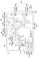
図1は、第1実施形態に係る放射線撮像システムの構成例を示すブロック図である。第1実施形態の放射線撮像システムは、X線発生装置101、X線制御装置102、制御用コンピュータ103、X線撮像装置104を備える。(First Embodiment)
FIG. 1 is a block diagram showing a configuration example of a radiation imaging system according to the first embodiment. The radiation imaging system of the first embodiment includes an
X線発生装置101はX線を曝射する。X線制御装置102は、X線発生装置101によるX線の曝射を制御する。制御用コンピュータ103は、X線撮像装置104を制御して、X線撮像装置104により撮像された放射線画像(以下、X線画像(画像情報))を取得する。制御用コンピュータ103は、X線撮像装置104から取得したX線画像に対して後述する画像処理を施す。X線撮像装置104は、X線を可視光に変換する蛍光体105と、可視光を検出する二次元検出器106で構成される。二次元検出器106は、X線量子を検出する画素20をX列×Y行のアレイ状に配置したセンサであり、画像情報を出力する。 The
図14は、制御用コンピュータ103のハードウエア構成例を示すブロック図である。CPU141は、ROM142またはRAM143に格納されたプログラムを実行することにより制御用コンピュータ103の各種動作を制御する。例えば、CPU141は、X線制御装置102(X線発生装置101)によるX線の照射およびX線撮像装置104によるX線画像の撮像動作を制御する。また、CPU141は、後述する種々の信号処理および画像処理を実現する。なお、後述される信号処理および画像処理の動作は、その一部あるいは全体が専用のハードウエアにより実現されてもよい。ROM142は、CPU141により実行されるプログラムや各種データを格納する。RAM143は、CPU141が処理を実行する際に発生する中間データなどを記憶する作業エリアを提供する。二次記憶装置144は、処理対象の放射線画像(X線画像)を格納する。また、二次記憶装置144は制御プログラムを格納する。二次記憶装置144に格納されているプログラムは必要に応じてRAM143に展開され、CPU141により実行される。 FIG. 14 is a block diagram showing a hardware configuration example of the
ディスプレイ145は、CPU141の制御下で各種表示を行う。操作部146は、例えばキーボード、ポインティングデバイスを含み、ユーザによる各種入力を受け付ける。インターフェース147は、X線制御装置102、X線撮像装置104などの外部機器と制御用コンピュータ103を接続する。バス148は、上述した各部を通信可能に接続する。 The
図2は、二次元検出器106が備える画素20の等価回路図である。画素20は、光電変換素子201と、出力回路部202とを含む。光電変換素子201は、典型的にはフォトダイオードでありうる。出力回路部202は、増幅回路部204、クランプ回路部206、サンプルホールド回路部207、選択回路部208を含む。 FIG. 2 is an equivalent circuit diagram of the
光電変換素子201は、電荷蓄積部を含み、該電荷蓄積部は、増幅回路部204のMOSトランジスタ204aのゲートに接続されている。MOSトランジスタ204aのソースは、MOSトランジスタ204bを介して電流源204cに接続されている。MOSトランジスタ204aと電流源204cとによってソースフォロア回路が構成されている。MOSトランジスタ204bは、そのゲートに供給されるイネーブル信号ENがアクティブレベルになるとオンしてソースフォロア回路を動作状態にするイネーブルスイッチである。 The
図2に示す例では、光電変換素子201の電荷蓄積部およびMOSトランジスタ204aのゲートが共通のノードを構成していて、このノードは、該電荷蓄積部に蓄積された電荷を電圧に変換する電荷電圧変換部として機能する。即ち、電荷電圧変換部には、該電荷蓄積部に蓄積された電荷Qと電荷電圧変換部が有する容量値Cとによって定まる電圧V(=Q/C)が現れる。電荷電圧変換部は、リセットスイッチ203を介してリセット電位Vresに接続されている。リセット信号PRESがアクティブレベルになると、リセットスイッチ203がオンして、電荷電圧変換部の電位がリセット電位Vresにリセットされる。 In the example shown in FIG. 2, the charge storage unit of the
クランプ回路部206は、リセットした電荷電圧変換部の電位に応じて増幅回路部204によって出力されるノイズをクランプ容量206aによってクランプする。つまり、クランプ回路部206は、光電変換素子201で光電変換により発生した電荷に応じてソースフォロア回路から出力された信号から、このノイズをキャンセルするための回路である。このノイズはリセット時のkTCノイズを含む。クランプは、クランプ信号PCLをアクティブレベルにしてMOSトランジスタ206bをオン状態にした後に、クランプ信号PCLを非アクティブレベルにしてMOSトランジスタ206bをオフ状態にすることによってなされる。クランプ容量206aの出力側は、MOSトランジスタ206cのゲートに接続されている。MOSトランジスタ206cのソースは、MOSトランジスタ206dを介して電流源206eに接続されている。MOSトランジスタ206cと電流源206eとによってソースフォロア回路が構成されている。MOSトランジスタ206dは、そのゲートに供給されるイネーブル信号EN0がアクティブレベルになるとオンしてソースフォロア回路を動作状態にするイネーブルスイッチである。 The
光電変換素子201で光電変換により発生した電荷に応じてクランプ回路部206から出力される信号は、光信号として、光信号サンプリング信号TSがアクティブレベルになることによってスイッチ207Saを介して容量207Sbに書き込まれる。電荷電圧変換部の電位をリセットした直後にMOSトランジスタ206bをオン状態とした際にクランプ回路部206から出力される信号は、クランプ電圧である。このノイズ信号は、ノイズサンプリング信号TNがアクティブレベルになることによってスイッチ207Naを介して容量207Nbに書き込まれる。このノイズ信号には、クランプ回路部206のオフセット成分が含まれる。スイッチ207Saと容量207Sbによって信号サンプルホールド回路207Sが構成され、スイッチ207Naと容量207Nbによってノイズサンプルホールド回路207Nが構成される。サンプルホールド回路部207は、信号サンプルホールド回路207Sとノイズサンプルホールド回路207Nとを含む。 The signal output from the
駆動回路部が行選択信号をアクティブレベルに駆動すると、容量207Sbに保持された信号(光信号)がMOSトランジスタ208Saおよび行選択スイッチ208Sbを介して信号線21Sに出力される。また、同時に、容量207Nbに保持された信号(ノイズ)がMOSトランジスタ208Naおよび行選択スイッチ208Nbを介して信号線21Nに出力される。MOSトランジスタ208Saは、信号線21Sに設けられた不図示の定電流源とソースフォロア回路を構成する。同様に、MOSトランジスタ208Naは、信号線21Nに設けられた不図示の定電流源とソースフォロア回路を構成する。MOSトランジスタ208Saと行選択スイッチ208Sbによって信号用選択回路部208Sが構成され、MOSトランジスタ208Naと行選択スイッチ208Nbによってノイズ用選択回路部208Nが構成される。選択回路部208は、信号用選択回路部208Sとノイズ用選択回路部208Nとを含む。 When the drive circuit unit drives the row selection signal to the active level, the signal (optical signal) held in the capacitance 207Sb is output to the
画素20は、隣接する複数の画素20の光信号を加算する加算スイッチ209Sを有してもよい。加算モード時には、加算モード信号ADDがアクティブレベルになり、加算スイッチ209Sがオン状態になる。これにより、隣接する画素20の容量207Sbが加算スイッチ209Sによって相互に接続されて、光信号が平均化される。同様に、画素20は、隣接する複数の画素20のノイズを加算する加算スイッチ209Nを有してもよい。加算スイッチ209Nがオン状態になると、隣接する画素20の容量207Nbが加算スイッチ209Nによって相互に接続されて、ノイズが平均化される。加算部209は、加算スイッチ209Sと加算スイッチ209Nを含む。 The
画素20は、感度を変更するための感度変更部205を有してもよい。画素20は、例えば、第1感度変更スイッチ205aおよび第2感度変更スイッチ205'a、並びにそれらに付随する回路素子を含みうる。第1変更信号WIDEがアクティブレベルになると、第1感度変更スイッチ205aがオンして、電荷電圧変換部の容量値に第1付加容量205bの容量値が追加される。これによって画素20の感度が低下する。第2変更信号WIDE2がアクティブレベルになると、第2感度変更スイッチ205'aがオンして、電荷電圧変換部の容量値に第2付加容量205'bの容量値が追加される。これによって画素20の感度が更に低下する。このように画素20の感度を低下させる機能を追加することによって、より大きな光量を受光することが可能となり、ダイナミックレンジを広げることができる。第1変更信号WIDEがアクティブレベルになる場合には、イネーブル信号ENwをアクティブレベルにして、MOSトランジスタ204aに変えてMOSトランジスタ204'aをソースフォロア動作させてもよい。 The
X線撮像装置104は、以上のような画素回路の出力を読み出し、不図示のAD変換器でデジタル値に変換した後、制御用コンピュータ103に画像を転送する。 The
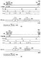
次に本実施形態の放射線撮像システムの動作(X線撮像装置104の駆動)について説明する。図3は、第1実施形態に係るX線撮像装置104の駆動タイミングを示す図である。図3(a)では、横軸を時間として、X線の曝射、同期信号、光電変換素子201のリセット、サンプルホールド回路207および信号線21からの画像の読み出しのタイミングを示している。 Next, the operation of the radiation imaging system of the present embodiment (driving the X-ray imaging apparatus 104) will be described. FIG. 3 is a diagram showing the drive timing of the
まず、光電変換素子201のリセットを行ってから、X線を曝射する。X線の管電圧は理想的には矩形波となるが、管電圧の立ち上がりと立下りには有限の時間がかかる。特に、パルスX線で曝射時間が短い場合は、管電圧はもはや矩形波とはみなせず、図3(a)に示すような波形となる。すなわち、X線の立ち上がり期、安定期、立下り期でX線のエネルギーが異なる。 First, the
そこで、立ち上がり期のX線301が曝射された後に、ノイズサンプルホールド回路207Nでサンプリングを行い、さらに安定期のX線302が曝射された後に信号サンプルホールド回路207Sでサンプリングを行う。その後、信号線21Nと信号線21Sの差分を画像として読み出す。このとき、ノイズサンプルホールド回路207Nには立ち上がり期のX線301の信号(R1)が保持され、信号サンプルホールド回路207Sには立ち上がり期のX線301の信号と安定期のX線302の信号の和(R1+B)が保持されている。従って、X線撮像装置104からは安定期のX線302の信号(B)に対応した画像304が読み出される。Therefore, after the
次に、立下り期のX線303の曝射と、画像304の読み出しとが完了してから、再び信号サンプルホールド回路207Sでサンプリングを行う。その後、光電変換素子201のリセットを行い、再びノイズサンプルホールド回路207Nでサンプリングを行い、信号線21Nと信号線21Sの差分を画像として読み出す。このとき、ノイズサンプルホールド回路207NにはX線が曝射されていない状態の信号が保持される。また、信号サンプルホールド回路207Sには立ち上がり期のX線301の信号と安定期のX線302と立下り期のX線303の信号の和(R1+B+R2)が保持されている。従って、X線撮像装置104からは、立ち上がり期のX線301の信号と安定期のX線302の信号と立下り期のX線303の信号に対応した画像306が読み出される。その後、画像306と画像304の差分を計算することで、立ち上がり期のX線301と立下り期のX線303の和(R1+R2)に対応した画像305が得られる。Next, after the exposure of the
サンプルホールド回路207及び光電変換素子201のリセットを行うタイミングは、X線発生装置101からX線の曝射が開始されたことを示す同期信号307を用いて決定される。X線の曝射開始を検出する方法としては、X線発生装置101の管電流を測定し、電流値が予め設定された閾値を上回るか否かを判定する構成が好適に用いられる。また、光電変換素子201のリセットが完了した後、画素20を繰り返して読み出し、画素値が予め設定された閾値を上回るか否かを判定する構成も好適に用いられる。さらには、X線撮像装置104に二次元検出器106とは異なるX線検出器を内蔵し、その測定値が予め設定された閾値を上回るか否かを判定する構成も好適に用いられる。いずれの方式の場合も、同期信号307の入力から予め指定した時間が経過した後に、信号サンプルホールド回路207Sのサンプリング、ノイズサンプルホールド回路207Nのサンプリング、光電変換素子201のリセットを行う。 The timing for resetting the
以上のようにして、パルスX線の安定期に対応した画像304と、立ち上がり期と立下り期の和に対応した画像305を得る。二枚の画像を形成する際に曝射されたX線のエネルギーが異なるため、画像間で演算を行うことでエネルギーサブトラクション処理を行うことができる。 As described above, the image 304 corresponding to the stable period of the pulse X-ray and the image 305 corresponding to the sum of the rising period and the falling period are obtained. Since the energies of the X-rays exposed when forming the two images are different, the energy subtraction processing can be performed by performing the calculation between the images.
図3(b)に、第1実施形態に係る放射線撮像システムにおいてエネルギーサブトラクションを行った場合の駆動タイミングを示す。図3(a)とは、X線の管電圧を能動的に切り替えている点が異なる。 FIG. 3B shows the drive timing when energy subtraction is performed in the radiation imaging system according to the first embodiment. It differs from FIG. 3A in that the X-ray tube voltage is actively switched.
まず、光電変換素子201のリセットを行ってから、低エネルギーのX線401を曝射する。その後、ノイズサンプルホールド回路207Nでサンプリングを行ってから、管電圧を切り替えて高エネルギーのX線402が曝射された後に、信号サンプルホールド回路207Sでサンプリングを行う。その後、管電圧を切り替えて低エネルギーのX線403の曝射を行う。さらに、信号線21Nと信号線21Sの差分を画像として読み出す。このとき、ノイズサンプルホールド回路207Nには低エネルギーのX線401の信号(R1)が保持され、信号サンプルホールド回路207Sには低エネルギーのX線401の信号と高エネルギーのX線402の信号の和(R1+B)が保持されている。従って、X線撮像装置104からは、高エネルギーのX線402の信号(B)に対応した画像404が読み出される。First, the
次に、低エネルギーのX線403の曝射と、画像404の読み出しとが完了してから、再び信号サンプルホールド回路207Sでサンプリングを行う。その後、光電変換素子201のリセットを行い、再びノイズサンプルホールド回路207Nでサンプリングを行い、信号線21Nと信号線21Sの差分を画像として読み出す。このとき、ノイズサンプルホールド回路207NにはX線が曝射されていない状態の信号が保持され、信号サンプルホールド回路207Sには低エネルギーのX線401の信号と高エネルギーのX線402と低エネルギーのX線403の信号の和(R1+B+R2)が保持されている。従って、X線撮像装置104からは低エネルギーのX線401の信号と高エネルギーのX線402の信号と低エネルギーのX線403の信号に対応した画像406が読み出される。その後、画像406と画像404の差分を計算することで、低エネルギーのX線401と低エネルギーのX線403の和(R1+R2)に対応した画像405が得られる。同期信号407については、図3(a)と同様である。このように、管電圧を能動的に切り替えながら画像を取得することで、図3(a)の方法に比べて低エネルギーと高エネルギーの画像の間のエネルギー差をより大きくすることが出来る。Next, after the exposure of the low-energy X-ray 403 and the reading of the
次に、図4を参照して、本実施形態のエネルギーサブトラクション処理について説明する。本実施形態におけるエネルギーサブトラクション処理は、補正処理、信号処理、画像処理の3段階に分かれている。以下、各段階の処理を説明する。 Next, the energy subtraction processing of the present embodiment will be described with reference to FIG. The energy subtraction processing in the present embodiment is divided into three stages of correction processing, signal processing, and image processing. The processing of each stage will be described below.
・補正処理の説明
図4(a)は、本実施形態に係るエネルギーサブトラクション処理における補正処理のブロック図を示す。まず、X線撮像装置104にX線を曝射せずに撮像を行い、図3(a)または図3(b)に示した駆動で画像を取得する。このとき2枚の画像が読み出されるが、1枚目の画像をF_ODD、2枚目の画像をF_EVENとする。F_ODDとF_EVENは、X線撮像装置104の固定パターンノイズ(FPN)に対応する画像である。次に、被写体がない状態でX線撮像装置104にX線を曝射して撮像を行い、図3(a)または図3(b)に示した駆動で画像を取得する。このとき2枚の画像が読み出されるが、1枚目の画像をW_ODD、2枚目の画像をW_EVENとする。W_ODDとW_EVENは、X線撮像装置104のFPNとX線による信号の和に対応する画像である。従って、W_ODDからF_ODDを、W_EVENからF_EVENを減算することで、X線撮像装置104のFPNが除去された画像WF_ODDとWF_EVENが得られる。これをオフセット補正と呼ぶ。-Explanation of correction processing FIG. 4A shows a block diagram of correction processing in the energy subtraction processing according to the present embodiment. First, an image is taken without exposing the X-ray
WF_ODDは安定期のX線302(または高エネルギーのX線402)に対応する画像である。また、WF_EVENは、立ち上がり期のX線301、安定期のX線302、立下り期のX線303の和(または、低エネルギーのX線401と403、および高エネルギーのX線402の和)に対応する画像である。従って、WF_EVENからWF_ODDを減算することで、立ち上がり期のX線301と立下り期のX線303の和に対応する画像が得られる。立ち上がり期のX線301と立下り期のX線303のエネルギーは、安定期のX線302のエネルギーに比べて低い。従って、WF_EVENからWF_ODDを減算することで、被写体がない場合の低エネルギー画像W_Lowが得られる。また、WF_ODDから、被写体がない場合の高エネルギー画像W_Highが得られる。これを色補正と呼ぶ。 WF_ODD is an image corresponding to X-ray 302 (or high-energy X-ray 402) in the stable period. WF_EVEN is the sum of
次に、被写体がある状態でX線撮像装置104にX線を曝射して撮像を行い、図3(a)または図3(b)に示した駆動で画像を取得する。このとき2枚の画像が読み出されるが、1枚目の画像をX_ODD、2枚目の画像をX_EVENとする。被写体がない場合と同様の減算を行うことで、被写体がある場合の低エネルギー画像X_Lowと、被写体がある場合の高エネルギー画像X_Highが得られる。 Next, an image is taken by exposing the X-ray
ここで、被写体の厚みをd、被写体の線減弱係数をμ、被写体がない場合の画素20の出力をI0、被写体がある場合の画素20の出力をIとすると、以下の式(1)が成り立つ。
(1)式を変形すると、以下の式(2)が得られる。式(2)の右辺は被写体の減弱率を示す。被写体の減弱率は0〜1の間の実数である。
従って、被写体がある場合の低エネルギー画像X_Lowを、被写体がない場合の低エネルギー画像W_Lowで除算することで、低エネルギーにおける減弱率の画像Lが得られる。同様に、被写体がある場合の高エネルギー画像X_Highを、被写体がない場合の高エネルギー画像W_Highで除算することで、高エネルギーにおける減弱率の画像Hが得られる。これをゲイン補正と呼ぶ。 Therefore, by dividing the low-energy image X_Low when there is a subject by the low-energy image W_Low when there is no subject, an image L with an attenuation rate at low energy can be obtained. Similarly, by dividing the high-energy image X_High when there is a subject by the high-energy image W_High when there is no subject, an image H having an attenuation rate at high energy can be obtained. This is called gain correction.
・信号処理の説明
図4(b)に、エネルギーサブトラクション処理における信号処理のブロック図を示す。信号処理では、図4(a)に示した補正処理によって得られた低エネルギーにおける減弱率の画像Lと高エネルギーにおける減弱率の画像Hから、分離画像を求める。ここでは、分離画像の一例として、骨の厚さの画像B(骨画像Bともいう)と軟部組織の厚さの画像S(軟部組織画像Sともいう)を求める場合を説明する。-Explanation of signal processing Fig. 4 (b) shows a block diagram of signal processing in energy subtraction processing. In the signal processing, a separated image is obtained from the image L of the attenuation rate at low energy and the image H of the attenuation rate at high energy obtained by the correction process shown in FIG. 4 (a). Here, as an example of the separated image, a case where an image B of the bone thickness (also referred to as a bone image B) and an image S of the thickness of the soft tissue (also referred to as a soft tissue image S) are obtained will be described.
まず、X線フォトンのエネルギーをE、エネルギーEにおけるフォトン数をN(E)、骨の厚さをB、軟部組織の厚さをS、エネルギーEにおける骨の線減弱係数をμB(E)、エネルギーEにおける軟部組織の線減弱係数をμS(E)、減弱率をI/I0とすると、以下の式(3)が成り立つ。
エネルギーEにおけるフォトン数N(E)は、X線のスペクトルである。X線のスペクトルは、シミュレーション又は実測により得られる。また、エネルギーEおける骨の線減弱係数μB(E)とエネルギーEおける軟部組織の線減弱係数μS(E)は、NISTなどのデータベースから得られる。すなわち、任意の骨の厚さB、軟部組織の厚さS、X線のスペクトルN(E)における減弱率I/I0を計算することが可能である。The photon number N (E) at the energy E is an X-ray spectrum. The X-ray spectrum can be obtained by simulation or actual measurement. Further, the linear attenuation coefficient μB (E) of bone in energy E and the linear attenuation coefficient μS (E) of soft tissue in energy E can be obtained from a database such as NIST. That is, it is possible to calculate an arbitrary bone thickness B, soft tissue thickness S, and attenuation rate I / I0 in the X-ray spectrum N (E).
ここで、低エネルギーのX線におけるスペクトルをNL(E)、高エネルギーのX線におけるスペクトルをNH(E)とすると、以下の式(4)が成り立つ。
式(4)の非線形連立方程式を解くことで、骨の厚みBと軟部組織の厚みSを求めることができる。非線形連立方程式を解く代表的な方法として、ニュートンラフソン法を用いた場合について説明する。まず、ニュートンラフソン法の反復回数をm、m回目の反復後の骨の厚みをBm、m回目の反復後の軟部組織の厚みをSmとしたとき、m回目の反復後の高エネルギーの減弱率をHm、m回目の反復後の低エネルギーの減弱率Lmを、以下の式(5)で表す。
また、厚みが微小に変化したときの減弱率の変化率を、以下の式(6)で表す。
このとき、m+1回目の反復後の骨の厚みBm+1と軟部組織の厚みSm+1を、高エネルギーの減弱率Hと低エネルギーの減弱率Lを用いて、以下の式(7)で表す。
2×2の行列の逆行列は、行列式をdetとすると、クラメルの公式より以下の式(8)で表される。
従って、式(7)に式(8)を代入すると、以下の式(9)が求まる。
このような計算を繰り返すことで、m回目の反復後の高エネルギーの減弱率Hmと実測した高エネルギーの減弱率Hの差分が限りなく0に近づいていく。低エネルギーの減弱率Lについても同様である。これによって、m回目の反復後の骨の厚みBmが骨の厚みBに収束し、m回目の軟部組織の厚みSmが軟部組織の厚みSに収束する。以上のようにして、式(4)に示した非線形連立方程式を解くことができる。従って、全ての画素について式(4)を計算することで、低エネルギーにおける減弱率の画像Lと高エネルギーにおける減弱率の画像Hから、骨の厚さの画像B、軟部組織の厚さの画像Sを得ることができる。By repeating such a calculation,the difference between the high energy attenuation rate H m after the mth repetition and the measured high energy attenuation rate H approaches 0 as much as possible. The same applies to the low energy attenuation rate L. As a result, the bone thickness Bm after the m-th repetition converges to the bone thickness B, and the m-th soft tissue thickness Sm converges to the soft tissue thickness S. As described above, the nonlinear simultaneous equations shown in Eq. (4) can be solved. Therefore, by calculating the equation (4) for all the pixels, from the image L of the attenuation rate at low energy and the image H of the attenuation rate at high energy, the image B of the bone thickness and the image of the thickness of the soft tissue S can be obtained.
なお、本実施形態では分離画像の例として、骨の厚さBと軟部組織の厚さSの画像を算出する例を示したが、本実施形態はこのような形態に限定されない。例えば、分離画像として水の厚さWと造影剤の厚さIを算出してもよい。すなわち、任意の二種類の物質の厚さに分解してもよい。また、図4(a)の補正処理によって得られた低エネルギーにおける減弱率の画像Lと高エネルギーにおける減弱率の画像Hから、実効原子番号Zの画像と面密度Dの画像を分離画像として求めてもよい。実効原子番号Zとは混合物の等価的な原子番号のことであり、面密度Dとは被写体の密度[g/cm3]と被写体の厚み[cm]の積である。当然のことながら、低エネルギー画像と高エネルギー画像に対して、これ以外の演算を行って分離画像を生成してもよい。すなわち、本発明の信号処理は、低エネルギー画像と高エネルギー画像を演算すること(エネルギーサブトラクション処理)で、エネルギーサブトラクション画像を生成する処理であるといえる。本明細書では、エネルギーサブトラクション画像と分離画像は同義であるとする。In the present embodiment, as an example of the separated image, an example of calculating an image of the bone thickness B and the soft tissue thickness S is shown, but the present embodiment is not limited to such an embodiment. For example, the thickness W of water and the thickness I of the contrast medium may be calculated as separated images. That is, it may be decomposed into the thicknesses of any two kinds of substances. Further, the image of the effective atomic number Z and the image of the surface density D are obtained as separated images from the image L of the attenuation rate at low energy and the image H of the attenuation rate at high energy obtained by the correction process of FIG. 4A. You may. The effective atomic number Z is the equivalent atomic number of the mixture, and the surface density D isthe product of the density of the subject [g / cm 3 ] and the thickness of the subject [cm]. As a matter of course, the low-energy image and the high-energy image may be subjected to other calculations to generate a separated image. That is, it can be said that the signal processing of the present invention is a process of generating an energy subtraction image by calculating a low energy image and a high energy image (energy subtraction processing). In the present specification, the energy subtraction image and the separated image are synonymous.
また、本実施形態では、ニュートンラフソン法を用いて非線形連立方程式を解く例を示したが、このような形態に限定されるものではない。例えば、最小二乗法や二分法などの反復解法を用いてもよい。また、本実施形態では非線形連立方程式を反復解法で解いていたが、このような形態に限定されるものではない。様々な組み合わせの高エネルギーの減弱率Hと低エネルギーの減弱率Lに対する骨の厚みBや軟部組織の厚みSを事前に求めてテーブルを生成し、このテーブルを参照することで骨の厚みBや軟部組織の厚みSを高速に求める構成を用いても良い。 Further, in the present embodiment, an example of solving a nonlinear simultaneous equation using the Newton-Raphson method is shown, but the present invention is not limited to such an embodiment. For example, iterative solutions such as the least squares method and the dichotomy method may be used. Further, in the present embodiment, the nonlinear simultaneous equations are solved by the iterative method, but the present invention is not limited to such a form. Bone thickness B and soft tissue thickness S with respect to various combinations of high-energy attenuation rate H and low-energy attenuation rate L are obtained in advance to generate a table, and by referring to this table, bone thickness B and bone thickness B and A configuration may be used in which the thickness S of the soft tissue is obtained at high speed.
・表示用画像処理の説明
図4(c)に、エネルギーサブトラクション処理に係る表示用画像処理のブロック図を示す。表示用画像処理では、上述した信号処理によって得られた分離画像を用いて表示用の画像を生成する。例えば図4(b)に示した信号処理によって得られた骨画像Bに対して後処理を行うなどして、表示用画像を生成する。生成された表示用画像は、例えば、ディスプレイ145に表示される。そのような後処理としては、対数変換やダイナミックレンジ圧縮などが用いられ得る。なお、後処理の種類や強度をパラメータとして入力することで、処理の内容を切り替えてもよい。-Explanation of display image processing FIG. 4 (c) shows a block diagram of display image processing related to energy subtraction processing. In the display image processing, an image for display is generated using the separated image obtained by the above-mentioned signal processing. For example, a display image is generated by performing post-processing on the bone image B obtained by the signal processing shown in FIG. 4 (b). The generated display image is displayed on the
以上、エネルギーサブトラクション処理について説明した。なお、以下では、エネルギーサブトラクション処理における信号処理と表示用画像処理を総称して画像処理という。以下の実施形態では、上述した画像処理において、蓄積画像を用いてノイズを効果的に低減する構成が説明される。まず、本実施形態が用いる蓄積画像について説明する。上述したように、本実施形態では、1回のX線の照射に対して、X線の照射中と照射終了後のタイミングを含む複数のタイミングのサンプルホールドにより取得された複数の放射線画像から高エネルギー画像と低エネルギー画像が生成される。例えば、X線の照射終了後のタイミングで取得されるX線画像が蓄積画像として用いられ得る。図5は、本実施形態に係る蓄積画像を取得するための補正処理を実現する構成の一例を示すブロック図である。ディスプレイ145に表示するための画像としては、エネルギー分解能を持たない画像、すなわち既存の放射線撮像システムで撮影した画像と互換性のある画像である、蓄積画像Aも好適に用いられる。蓄積画像Aは、例えば図5で示すように、画像XF_EVENを画像WF_EVENで除算することにより生成される。画像XF_EVENおよび画像WF_EVENは図4(a)で説明したとおりである。すなわち、画像XF_EVENは、被写体がある場合の立ち上がり期のX線301、安定期のX線302、立下り期のX線303の和に対応する。画像WF_EVENは、被写体がない場合の立ち上がり期のX線301、安定期のX線302、立下り期のX線303の和に対応する。 The energy subtraction processing has been described above. In the following, signal processing and display image processing in energy subtraction processing are collectively referred to as image processing. In the following embodiments, in the above-mentioned image processing, a configuration for effectively reducing noise by using an accumulated image will be described. First, the stored image used in this embodiment will be described. As described above, in the present embodiment, one X-ray irradiation is high from a plurality of radiographic images acquired by sample holding at a plurality of timings including the timings during and after the X-ray irradiation. Energy and low energy images are generated. For example, an X-ray image acquired at the timing after the end of X-ray irradiation can be used as an accumulated image. FIG. 5 is a block diagram showing an example of a configuration for realizing a correction process for acquiring the stored image according to the present embodiment. As the image to be displayed on the
なお、蓄積画像Aは、高エネルギーにおける減弱率の画像Hと低エネルギーのおける減弱率の画像Lに係数をかけて加算することにより生成されてもよい。例えば、蓄積画像Aは、式(10)を用いて生成され得る。なお、蓄積画像Aの算出において、一方の係数を0、他方の係数を1としてもよく、画像Hまたは画像Lそのものが蓄積画像Aとして用いられ得る。すなわち、エネルギーサブトラクション処理の対象となる画像と撮影タイミングが実質的に同じであって、エネルギーサブトラクション処理が適用されていない画像が蓄積画像Aとして用いられ得る。
図6に、蓄積画像Aと骨画像Bの一例を示す。通常の人体は、軟部組織と骨のみで構成されている。図1に示した放射線撮像システムを用いてIVR(画像下治療)を行うときは、血管に造影剤が注入される。また、カテーテルやガイドワイヤーを血管内に挿入し、ステントやコイルを留置するなどの処置が行われる。IVRでは、造影剤や医療用デバイスの位置と形状を確認しながら処置が行われる。従って、エネルギーサブトラクション処理を用いて造影剤や医療用デバイスのみの画像を分離する、又は、軟部組織や骨などの背景(画像)を除去することで、視認性を向上させることが望まれる。 FIG. 6 shows an example of the accumulated image A and the bone image B. The normal human body is composed only of soft tissues and bones. When performing IVR (interventional radiology) using the radiography imaging system shown in FIG. 1, a contrast medium is injected into a blood vessel. In addition, a catheter or guide wire is inserted into the blood vessel, and a stent or coil is placed. In IVR, treatment is performed while confirming the position and shape of the contrast medium and medical device. Therefore, it is desired to improve visibility by separating images of only contrast media and medical devices by using energy subtraction processing, or by removing backgrounds (images) such as soft tissues and bones.
図6(a)に示すように、通常の放射線撮像システムと互換性のある画像、すなわち蓄積画像Aでは、軟部組織が見えてしまう。一方、図6(b)に示されるように、本実施形態に係る放射線撮像システムにおける骨画像Bでは、軟部組織のコントラストを除去することができる。また、造影剤の主成分はヨウ素であり、医療用デバイスの主成分はステンレス等の金属である。いずれも、骨の主成分であるカルシウムよりも原子番号が大きいため、骨画像Bには、骨と造影剤と医療用デバイスが表示される。本願の発明者らが検討を行ったところ、高エネルギー画像Hと低エネルギー画像Lを水画像Wと造影剤画像Iに分離するなどしても、造影剤画像Iに骨と造影剤と医療用デバイスが表示されることが確認された。他の二物質の組み合わせであっても同様である。また、低エネルギーのX線と高エネルギーのX線の管電圧やフィルタを変えても同様である。いずれの場合にも、骨画像Bには、骨と造影剤と医療用デバイスが表示されることが確認された。 As shown in FIG. 6A, the soft tissue is visible in the image compatible with the normal radiation imaging system, that is, the accumulated image A. On the other hand, as shown in FIG. 6B, in the bone image B in the radiation imaging system according to the present embodiment, the contrast of the soft tissue can be removed. The main component of the contrast medium is iodine, and the main component of the medical device is a metal such as stainless steel. Since all of them have an atomic number larger than that of calcium, which is the main component of bone, bone, a contrast medium, and a medical device are displayed on the bone image B. As a result of examination by the inventors of the present application, even if the high-energy image H and the low-energy image L are separated into a water image W and a contrast medium image I, the contrast medium image I has bones, a contrast medium, and medical use. It was confirmed that the device was displayed. The same applies to the combination of the other two substances. The same applies even if the tube voltage and filter of low-energy X-rays and high-energy X-rays are changed. In each case, it was confirmed that the bone image B displayed the bone, the contrast medium, and the medical device.
胸部のIVRを行うときの肺野部分などのように、軟部組織のコントラストが視認性を低下させている場合は、本実施形態に係る放射線撮像システムにおける骨画像Bを表示することで、造影剤や医療用デバイスの視認性が向上する可能性がある。しかしながら、骨画像Bは蓄積画像Aよりもノイズが大きくなり、画質が劣化するという課題がある。そこで、本実施形態では、骨画像Bのノイズ低減を行う。ノイズ低減には、エネルギーサブトラクション処理による分離後の画像についてノイズ低減処理を行う構成と、エネルギーサブトラクション処理による分離前の画像についてノイズ低減処理を行う構成が考えられる。 When the contrast of the soft tissue reduces the visibility, such as in the lung field when performing IVR of the chest, the contrast agent is displayed by displaying the bone image B in the radiation imaging system according to the present embodiment. And may improve the visibility of medical devices. However, the bone image B has a problem that the noise becomes larger than that of the accumulated image A and the image quality deteriorates. Therefore, in the present embodiment, the noise of the bone image B is reduced. For noise reduction, a configuration in which noise reduction processing is performed on the image after separation by energy subtraction processing and a configuration in which noise reduction processing is performed on the image before separation by energy subtraction processing can be considered.
図7(a)に、エネルギーサブトラクション処理による分離後の画像にノイズ低減処理を行う画像処理のブロック図を示す。まずブロックMD1において、図4(b)の画像処理と同様の手順で、低エネルギー画像Lと高エネルギー画像Hから、骨画像Bと軟部組織画像Sを求め、さらに骨画像Bと軟部組織画像Sを加算した厚み画像Tを生成する。そしてブロックF1において、厚み画像Tに対してノイズ低減を目的としたフィルタ処理を施し、フィルタ処理後の厚み画像T'を生成する。ブロックF1のフィルタ処理には、ガウシアンフィルタやメディアンフィルタなどの空間方向のフィルタ、イプシロンフィルタやラプラシアンフィルタ等の構造保存型の空間方向のフィルタ、リカーシブフィルタ等の時間方向のフィルタなどが好適に用いられ得る。 FIG. 7A shows a block diagram of image processing in which noise reduction processing is performed on an image after separation by energy subtraction processing. First, in the block MD1, the bone image B and the soft tissue image S are obtained from the low energy image L and the high energy image H by the same procedure as the image processing of FIG. 4B, and further, the bone image B and the soft tissue image S are obtained. Is added to generate a thickness image T. Then, in the block F1, the thickness image T is subjected to a filter process for the purpose of noise reduction, and the thickness image T'after the filter process is generated. For the filter processing of the block F1, a spatial filter such as a Gaussian filter or a median filter, a structure-preserving spatial filter such as an epsilon filter or a Laplacian filter, a temporal filter such as a recursive filter, etc. are preferably used. obtain.
次にブロックMD2において、フィルタ処理後の厚み画像T'と上述の蓄積画像Aから、ノイズ低減された骨画像B'を生成する。蓄積画像Aは、骨と軟部組織のみで構成されているという仮定(制約条件)の下、蓄積画像AにおけるスペクトルをNA(E)、軟部組織の厚みをS、骨の厚みをBとすると、以下の式(11)が成り立つ。
ここで骨の厚みと軟部組織の厚みの和をTとすると、T=B+Sより、式(11)を変形して以下の式(12)が成り立つ。
式(12)に、ある画素における蓄積画像の画素値Aと厚みTを代入して非線形方程式を解くことで、ある画素における骨の厚みBを求めることが可能である。このとき、厚みTの代わりに、フィルタ処理後の厚みT'を代入して式(12)を解くと、骨の厚みB'が得られる。厚み画像Tは蓄積画像Aと比較して連続性が高いため、高周波成分が含まれない。従って、フィルタ処理を行ってノイズを除去しても、信号成分が失われにくい。このようにしてノイズ低減された厚み画像T'と、元々ノイズが少ない蓄積画像Aを用いることで、ノイズ低減された骨画像B'を得ることができる。同様に、式(11)をB=T−Sを用いて変形することで、ノイズ低減された軟部組織画像S'を得ることも可能である。さらに、合成された画像Tを用いたがこれに限られるものではない。例えば、MD1で生成される軟部組織画像SをブロックF1でノイズ低減して得られる、ノイズ低減された軟部組織画像S'の画素値を式(11)に代入することでノイズ低減された骨画像B'を得るようにしてもよい。また、MD1で生成される骨画像BをブロックF1でノイズ低減して得られる、ノイズ低減された骨画像B'の画素値を式(11)に代入することでノイズ低減された軟部組織画像S'を得るようにしてもよい。 By substituting the pixel value A and the thickness T of the accumulated image in a certain pixel into the equation (12) and solving the nonlinear equation, it is possible to obtain the bone thickness B in a certain pixel. At this time, by substituting the filter-processed thickness T'instead of the thickness T and solving the equation (12), the bone thickness B'is obtained. Since the thickness image T has higher continuity than the accumulated image A, it does not contain high frequency components. Therefore, even if the noise is removed by performing the filtering process, the signal component is not easily lost. By using the thickness image T'with noise reduction in this way and the accumulated image A with originally low noise, a bone image B'with noise reduction can be obtained. Similarly, by modifying the equation (11) using B = TS, it is possible to obtain a noise-reduced soft tissue image S'. Further, the synthesized image T is used, but the present invention is not limited to this. For example, the noise-reduced bone image by substituting the pixel value of the noise-reduced soft tissue image S', which is obtained by noise-reducing the soft tissue image S generated by MD1 in the block F1, into the equation (11). You may try to get B'. Further, the noise-reduced soft tissue image S is obtained by substituting the pixel value of the noise-reduced bone image B', which is obtained by noise-reducing the bone image B generated by MD1 in the block F1, into the equation (11). You may try to get'.
次に、エネルギーサブトラクション処理による分離前の画像にノイズ低減処理を行う画像処理の構成について説明する。図7(b)に、分離前の画像にノイズ低減処理を行う画像処理のブロック図を示す。ブロックF2とブロックF3は、低エネルギー画像Lと高エネルギー画像Hに対して、それぞれノイズ低減を目的としたフィルタ処理を施し、ノイズ低減された低エネルギー画像L'と、ノイズ低減された高エネルギー画像H'を生成する。フィルタ処理には、例えば、ガウシアンフィルタやメディアンフィルタなどの空間方向のフィルタ、イプシロンフィルタやラプラシアンフィルタ等の構造保存型の空間方向のフィルタ、リカーシブフィルタ等の時間方向のフィルタなどが用いられ得る。ブロックMD1では、図4(b)と同様の手順で、ノイズ低減された低エネルギー画像L'とノイズ低減された高エネルギー画像H'から、ノイズ低減された骨画像B'が得られる。 Next, the configuration of image processing that performs noise reduction processing on the image before separation by energy subtraction processing will be described. FIG. 7B shows a block diagram of image processing in which noise reduction processing is performed on the image before separation. In the block F2 and the block F3, the low-energy image L and the high-energy image H are filtered for the purpose of noise reduction, respectively, and the noise-reduced low-energy image L'and the noise-reduced high-energy image L'are applied. Generate H'. For the filter processing, for example, a spatial filter such as a Gaussian filter or a median filter, a structure-preserving spatial filter such as an epsilon filter or a Laplacian filter, a temporal filter such as a recursive filter, or the like can be used. In the block MD1, the noise-reduced bone image B'is obtained from the noise-reduced low-energy image L'and the noise-reduced high-energy image H'in the same procedure as in FIG. 4 (b).
図7(a)のように二物質分離(エネルギーサブトラクション処理)のブロックであるMD1の後にフィルタを適用するノイズ低減処理では、二物質分離に伴うノイズが低減される。一方、図7(b)のように二物質分離のブロックであるMD1の前にフィルタを適用するノイズ低減処理では、X線の量子ノイズが低減される。二物質分離に伴うノイズとX線の量子ノイズとが独立であれば、これらのノイズ低減処理を二重にかけることで、さらにノイズを低減できる可能性がある。 In the noise reduction process in which the filter is applied after MD1 which is a block of the two-substance separation (energy subtraction process) as shown in FIG. 7A, the noise associated with the two-substance separation is reduced. On the other hand, in the noise reduction process in which a filter is applied before MD1 which is a block for separating two substances as shown in FIG. 7B, quantum noise of X-rays is reduced. If the noise associated with the separation of two substances and the quantum noise of X-rays are independent, there is a possibility that the noise can be further reduced by performing these noise reduction processes twice.
そこで本願の発明者らが検討を行ったところ、蓄積画像Aの標準偏差σA、すなわちX線の量子ノイズと、骨画像Bの標準偏差σB、すなわち骨画像Bのノイズは、比例係数εBを用いて、以下の式(13)で表されることが判明した。
さらに、本願の発明者らの検討により、比例係数εBは、式(14)で近似できることが判明した。
比例係数εBは、二物質分離に伴うノイズの増加率を示し、低エネルギーのX線におけるスペクトルNL(E)、高エネルギーのX線におけるスペクトルNH(E)、高エネルギーと低エネルギーの出力の比、物質の種類などによって決まる。しかしながら、X線の線量には依存しない。すなわち、二物質分離に伴うノイズの増加率と、X線の量子ノイズは、独立であると考えられる。また、本願の発明者らがさらに検討を行ったところ、空間周波数f(f>0)におけるX線の量子ノイズの標準偏差σA(f)と、空間周波数f(f>0)における骨画像のノイズの標準偏差σB(f)の間には、以下の式(15)が成り立つことが判明した。
式(15)における比例定数εBは、空間周波数によらず一定であった。従って、二物質分離に伴うノイズとX線の量子ノイズとは、各空間周波数f(f>0)において独立であると言える。以上のことから、二物質分離に伴うノイズの低減処理と、X線の量子ノイズの低減処理を二重にかけることで、さらにノイズを低減できる可能性があることが分かった。The proportionality constant ε B in the equation (15) was constant regardless of the spatial frequency. Therefore, it can be said that the noise associated with the separation of two substances and the quantum noise of X-rays are independent at each spatial frequency f (f> 0). From the above, it was found that there is a possibility that the noise can be further reduced by performing the noise reduction processing associated with the separation of the two substances and the X-ray quantum noise reduction processing in duplicate.
図8(a)に、本実施形態に係る画像処理のブロック図を示す。図8(a)では、二物質分離前の画像と二物質分離後の画像にノイズ低減処理が行われている。まずブロックF2とブロックF3において、図7(b)と同様に、エネルギーサブトラクション処理を適用する前の画像である低エネルギー画像Lと高エネルギー画像Hに対して、それぞれノイズ低減を目的としたフィルタ処理を施す。これにより、ノイズ低減された低エネルギー画像L'と、ノイズ低減された高エネルギー画像H'が生成される。ブロックMD1では、図7(a)と同様に、ノイズ低減された低エネルギー画像L'とノイズ低減された高エネルギー画像H'から、ノイズ低減された骨画像B'とノイズ低減された軟部組織画像S'を求める。こうして、ノイズ低減された骨画像B'とノイズ低減された軟部組織画像S'の和の画像、すなわちノイズ低減された厚み画像T'が生成される。 FIG. 8A shows a block diagram of image processing according to the present embodiment. In FIG. 8A, noise reduction processing is performed on the image before the separation of the two substances and the image after the separation of the two substances. First, in the blocks F2 and F3, as in FIG. 7B, the low-energy image L and the high-energy image H, which are the images before the energy subtraction processing is applied, are filtered for the purpose of noise reduction, respectively. To give. As a result, a noise-reduced low-energy image L'and a noise-reduced high-energy image H'are generated. In the block MD1, similarly to FIG. 7A, the noise-reduced low-energy image L'and the noise-reduced high-energy image H'are changed to the noise-reduced bone image B'and the noise-reduced soft tissue image. Find S'. In this way, a sum image of the noise-reduced bone image B'and the noise-reduced soft tissue image S', that is, the noise-reduced thickness image T'is generated.
続いて、ブロックF1が、ノイズ低減された厚み画像T'に対してノイズ低減を目的としたフィルタ処理を施すことにより、二重にノイズ低減された厚み画像T''が生成される。次に、図7(a)と同様に、ブロックMD2が、二重にノイズ低減された厚み画像T''と蓄積画像Aとから、二重にノイズ低減された骨画像B''を生成する。なお、図7(a)により上述したように、二重にノイズ低減された厚み画像T''と蓄積画像Aとから、二重にノイズ低減された軟部組織画像S''を生成するようにしてもよい。或いは、二重にノイズ低減された骨画像B''と蓄積画像Aとから、二重にノイズ低減された軟部組織画像S''を生成するようにしてもよい。また、二重にノイズ低減された軟部組織画像S''と蓄積画像Aとから、二重にノイズ低減された骨画像B''が生成されるようにしてもよい。 Subsequently, the block F1 performs a filter process for noise reduction on the noise-reduced thickness image T', so that a double noise-reduced thickness image T'is generated. Next, as in FIG. 7A, the block MD2 generates a doubly noise-reduced bone image B ″ from the doubly noise-reduced thickness image T'' and the accumulated image A. .. As described above with reference to FIG. 7A, a doubly noise-reduced soft tissue image S'' is generated from the doubly noise-reduced thickness image T'' and the accumulated image A. You may. Alternatively, a doubly noise-reduced soft tissue image S'' may be generated from the doubly noise-reduced bone image B ″ and the accumulated image A. Further, a doubly noise-reduced bone image B ″ may be generated from the doubly noise-reduced soft tissue image S ″ and the accumulated image A.
なお、図8(a)のように二重にノイズ低減を行うときは、二物質分離を行うブロックMD1の前に適用するフィルタのブロックF2及びF3と、ブロックMD1の後に適用するフィルタのブロックF1との、種類や強度を同時に最適化する必要がある。二つのフィルタを単独に最適化した結果が最適とは限らないからである。例えば、時間方向のフィルタ又は空間方向のフィルタを二重にかけると、X線の量子ノイズと二物質分離に伴うノイズの増加率が独立ではなくなり、二つのノイズ低減の効果が積算されなくなる場合がある。従って、例えば、二物質分離を行うブロックMD1の前に適用されるフィルタであるブロックF2及びF3では、時間方向のフィルタを適用し、MD1の後に適用するフィルタのブロックF1では空間方向のフィルタを適用する構成を用いることができる。当然のことながら、ブロックF2及びF3において空間方向のフィルタを適用し、ブロックF1において時間方向のフィルタを適用するようにしてもよい。 When double noise reduction is performed as shown in FIG. 8A, blocks F2 and F3 of the filter applied before the block MD1 for separating the two substances and block F1 of the filter applied after the block MD1 are used. It is necessary to optimize the type and strength at the same time. This is because the result of optimizing the two filters independently is not always optimal. For example, if a time-direction filter or a spatial-direction filter is applied twice, the quantum noise of X-rays and the noise increase rate due to the separation of two substances are not independent, and the effects of the two noise reductions may not be integrated. be. Therefore, for example, the time direction filter is applied to the blocks F2 and F3 which are the filters applied before the block MD1 which separates the two substances, and the spatial direction filter is applied to the block F1 of the filter applied after the MD1. Can be used. As a matter of course, the spatial filter may be applied in the blocks F2 and F3, and the temporal filter may be applied in the block F1.
なお、空間方向のフィルタまたは時間方向のいずれかのフィルタを二重にかける構成も採用可能であり、その場合には両者のカーネルの大きさ、フィルタ係数の大きさを異ならせることが好ましい。例えば、空間方向のフィルタを二重にかける場合は、ブロックF1のフィルタのカーネルを、ブロックF2、F3のカーネルより大きくする構成が好ましい。例えば、厚み画像Tは、蓄積画像Aや高エネルギー画像H、低エネルギー画像Lに比べて空間における連続性が高いためである。また、時間方向のフィルタを二重にかける場合、ブロックF1のフィルタ係数を、ブロックF2,F3のフィルタのフィルタ係数より大きくする構成が好ましい。例えば、厚み画像Tは、蓄積画像Aや高エネルギー画像H、低エネルギー画像Lに比べて時間変化が小さいためである。 It is also possible to adopt a configuration in which either the spatial filter or the temporal filter is applied twice, and in that case, it is preferable to make the size of the kernels and the size of the filter coefficients of both different. For example, when the spatial filter is applied twice, it is preferable that the kernel of the filter of the block F1 is larger than the kernel of the blocks F2 and F3. For example, the thickness image T has higher continuity in space than the stored image A, the high energy image H, and the low energy image L. Further, when the time direction filter is applied twice, it is preferable that the filter coefficient of the block F1 is larger than the filter coefficient of the filter of the blocks F2 and F3. For example, the thickness image T has a smaller time change than the stored image A, the high energy image H, and the low energy image L.
また、ブロックF1において、時間方向のフィルタと空間方向のフィルタの両方を適用する構成や、ブロックF2及びF3において時間方向のフィルタと空間方向のフィルタの両方を同時に適用する構成としてもよい。いずれの構成でも、空間方向または時間方向のフィルタが二物質分離のブロックMD1の前後で二重に適用される場合は、MD1の後のフィルタのブロックF1におけるフィルタの係数またはカーネルをより大きくする構成が好適に用いられ得る。 Further, the block F1 may be configured to apply both the temporal filter and the spatial filter, or the blocks F2 and F3 may be configured to apply both the temporal filter and the spatial filter at the same time. In either configuration, if the spatial or temporal filter is applied doubly before and after the two-material separation block MD1, the filter coefficient or kernel in block F1 of the filter after MD1 is increased. Can be preferably used.
さらに、ブロックF2とブロックF3のフィルタ処理を蓄積画像に基づいて制御するようにしてもよい。図8(b)に、本実施形態に係る画像処理のブロック図を示す。ブロックF2及びF3において、図8(a)と同様に、低エネルギー画像Lと高エネルギー画像Hに対して、それぞれノイズ低減を目的としたフィルタ処理を施し、ノイズ低減された低エネルギー画像L'と、ノイズ低減された高エネルギー画像H'を生成する。このフィルタ処理として、イプシロンフィルタやラプラシアンフィルタ等の構造保存型フィルタが好適に用いられる。イプシロンフィルタやラプラシアンフィルタは、画素値から被写体の構造を判定してフィルタの係数を変えることで、構造を保存したままノイズ低減を行うことができる。しかしながら、低エネルギー画像Lや高エネルギー画像Hには、X線の量子ノイズが含まれるため、線量が低くなるとノイズと構造の判定が困難となり、ノイズ低減効果が得にくくなるという課題がある。そこで、よりノイズの少ない蓄積画像Aの画素値から被写体の構造を判定してフィルタの係数を変えつつ、低エネルギー画像Lや高エネルギー画像Hにフィルタを適用する構成が好適に用いられる。例えば、蓄積画像Aから検出される構造のエッジ部を維持するようにブロックF2,ブロックF3のノイズ低減処理を制御することで、低エネルギー画像Lと高エネルギー画像Hにおけるエッジ部が維持される。ブロックMD1以降の処理は、図8(a)と同様である。 Further, the filter processing of the block F2 and the block F3 may be controlled based on the accumulated image. FIG. 8B shows a block diagram of image processing according to the present embodiment. In the blocks F2 and F3, similarly to FIG. 8A, the low-energy image L and the high-energy image H are filtered for the purpose of noise reduction, respectively, and the noise-reduced low-energy image L'is obtained. , Generates a noise-reduced high-energy image H'. As this filter processing, a structure-preserving filter such as an epsilon filter or a Laplacian filter is preferably used. The epsilon filter and the Laplacian filter can reduce noise while preserving the structure by determining the structure of the subject from the pixel values and changing the coefficient of the filter. However, since the low-energy image L and the high-energy image H contain X-ray quantum noise, there is a problem that when the dose is low, it becomes difficult to determine the noise and the structure, and it becomes difficult to obtain the noise reduction effect. Therefore, a configuration is preferably used in which the structure of the subject is determined from the pixel value of the stored image A with less noise, the coefficient of the filter is changed, and the filter is applied to the low-energy image L or the high-energy image H. For example, by controlling the noise reduction processing of the blocks F2 and F3 so as to maintain the edge portion of the structure detected from the accumulated image A, the edge portion in the low energy image L and the high energy image H is maintained. The processing after the block MD1 is the same as in FIG. 8A.
なお、図8(b)では、ブロックF2とブロックF3に供給される蓄積画像を、図8(a)においてブロックMD2へ供給される蓄積画像Aと同じものとしたがこれに限られない。すなわち、ブロックF2とブロックF3に供給される蓄積画像は、ブロックMD2へ供給される蓄積画像Aと異なっていてもよい。例えば、ブロックMD2には、式(10)により生成された蓄積画像Aが供給され、ブロックF2,F3の制御には高エネルギーにおける減弱率の画像Hが用いられるようにしてもよい。また、ブロックF2とブロックF3は互いに異なるフィルタであってもよい。 In FIG. 8B, the stored images supplied to the blocks F2 and F3 are the same as the stored images A supplied to the block MD2 in FIG. 8A, but the storage image is not limited to this. That is, the stored image supplied to the block F2 and the block F3 may be different from the stored image A supplied to the block MD2. For example, the stored image A generated by the equation (10) may be supplied to the block MD2, and the image H having an attenuation rate at high energy may be used to control the blocks F2 and F3. Further, the block F2 and the block F3 may be filters different from each other.
以上のように、第1実施形態によれば、エネルギーサブトラクション処理により得られる分離画像のノイズの増加を抑制することができる。例えば、骨画像Bにおけるノイズの増加を抑制しつつ軟部組織を除去した画像を生成することができる。このような画像を表示することで、軟部組織のコントラストの視認性を低下させている場合に、造影剤や医療用デバイスの視認性が向上する。 As described above, according to the first embodiment, it is possible to suppress an increase in noise of the separated image obtained by the energy subtraction processing. For example, it is possible to generate an image in which soft tissue is removed while suppressing an increase in noise in the bone image B. By displaying such an image, the visibility of the contrast medium or the medical device is improved when the visibility of the contrast of the soft tissue is lowered.
なお、上記実施形態では、分離画像として骨画像Bと軟組織画像Sを取得したが、これに限られるものではない。例えば、分離画像として、実効原子番号Zと面密度Dを用いてもよい。この場合、2つの分離画像の和の画像は、厚み画像とは別のものとなる。また、分離画像に対するノイズ低減処理を、分離画像の和(T)に対して行っているが、これに限られるものではなく、いずれか一方の分離画像(BまたはS)に対して行うようにしてもよいことは上述したとおりである。例えば、図8(a)において、ブロックMD1で得られた軟部組織画像S'を用いるようにすれば、ブロックMD2の処理により、蓄積画像Aとノイズ低減された軟組織画像S''からノイズ低減された骨画像B''を得ることができる。また、ブロックMD2の処理において、B=T−Sを用いて式(11)を変形することにより、ノイズ低減された軟組織画像S''が得られることになる。また、MD1では、B,Sを生成し、それらの和からTを得たが、2つのエネルギーの画像から直接Tを生成するようにしてもよい。 In the above embodiment, the bone image B and the soft tissue image S are acquired as the separated images, but the present invention is not limited to this. For example, the effective atomic number Z and the surface density D may be used as the separated image. In this case, the sum image of the two separated images is different from the thickness image. Further, the noise reduction processing for the separated image is performed on the sum (T) of the separated images, but the present invention is not limited to this, and the noise reduction processing is performed on one of the separated images (B or S). It may be as described above. For example, in FIG. 8A, if the soft tissue image S'obtained in the block MD1 is used, noise is reduced from the accumulated image A and the noise-reduced soft tissue image S'' by the processing of the block MD2. A bone image B'' can be obtained. Further, in the processing of the block MD2, by modifying the equation (11) using B = TS, a soft tissue image S'' with reduced noise can be obtained. Further, in MD1, B and S are generated and T is obtained from the sum of them, but T may be generated directly from the images of the two energies.
(第2実施形態)
第1実施形態では、軟部組織のコントラストが造影剤や医療用デバイスの視認性を低下させている場合に、軟部組織のコントラストを除去して、それらの視認性を向上する構成を説明した。第2実施形態では、骨のコントラストが造影剤や医療用デバイスの視認性を低下させている場合に、それらの視認性を向上させる構成を説明する。(Second Embodiment)
In the first embodiment, when the contrast of the soft tissue reduces the visibility of the contrast medium or the medical device, the contrast of the soft tissue is removed to improve the visibility thereof. In the second embodiment, when the contrast of the bone reduces the visibility of the contrast medium and the medical device, a configuration for improving the visibility of the contrast medium and the medical device will be described.
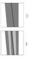
図9に軟部組織画像と厚み画像の例を示す。第1実施形態では、蓄積画像Aの代わりに骨画像Bを表示することで、軟部組織のコントラストを除去していた。従って、蓄積画像Aの代わりに軟部組織画像Sを表示することで、骨のコントラストを除去することができると期待される。しかしながら本願の発明者らが四肢のファントムの軟部組織画像Sを観察したところ、図9(a)に示されるように、軟部組織の厚みの減少として骨が視認できてしまうことが判明した。これは、骨の厚みの分だけ、軟部組織の厚みが減少するためである。また、骨画像Bと軟部組織画像Sの和の画像、すなわち厚み画像Tを観察したところ、図9(b)に示されるように、骨のコントラストが消えて視認できなくなることが判明した。これは、骨が存在する領域における軟部組織の厚みの減少が、骨の厚みを加算することで相殺されるためである。 FIG. 9 shows an example of a soft tissue image and a thickness image. In the first embodiment, the contrast of the soft tissue is removed by displaying the bone image B instead of the accumulated image A. Therefore, it is expected that the bone contrast can be removed by displaying the soft tissue image S instead of the accumulated image A. However, when the inventors of the present application observed the soft tissue image S of the phantom of the limbs, it was found that the bone was visible as a decrease in the thickness of the soft tissue as shown in FIG. 9 (a). This is because the thickness of the soft tissue is reduced by the thickness of the bone. Further, when the sum image of the bone image B and the soft tissue image S, that is, the thickness image T was observed, it was found that the contrast of the bone disappeared and became invisible as shown in FIG. 9B. This is because the decrease in soft tissue thickness in the area where the bone is present is offset by adding the bone thickness.
さらに本願の発明者らが調査したところ、人体の骨の中には海綿骨や骨髄など、カルシウムを含まない領域が存在するものの、それらの内部は有機物で満たされている(気体で満たされていない)ことがわかった。すなわち、人体を一方向に投影したときの厚みは、連続的であると言える。そのため、ファントムだけでなく人体であっても、厚み画像Tを表示することで、骨のコントラストを除去することができる。なお、肺や消化器官のように気体を含みうる領域では、そのような厚みの連続性が成立しないことがある点に注意が必要である。また、乾燥人骨ファントムでは、海綿骨や骨髄の内部は空洞である(気体で満たされている)こと、鳥類など骨の内部が空洞になっている生物がいることについても、注意が必要である。 Furthermore, as a result of investigation by the inventors of the present application, although there are calcium-free regions such as cancellous bone and bone marrow in the bones of the human body, their interiors are filled with organic substances (filled with gas). No) turned out. That is, it can be said that the thickness when the human body is projected in one direction is continuous. Therefore, not only the phantom but also the human body can remove the contrast of the bone by displaying the thickness image T. It should be noted that such thickness continuity may not be established in regions that can contain gas, such as the lungs and digestive organs. It is also important to note that in dried human bone phantoms, the cancellous bone and bone marrow are hollow (filled with gas), and some organisms such as birds have hollow bones. ..
図10に、蓄積画像と厚み画像の一例を示す。四肢に造影剤が注入されたとき、図10(a)に示されるように、蓄積画像Aでは骨と造影剤の両方のコントラストが視認できる。一方で、造影剤の主成分はヨウ素であり、骨の主成分であるカルシウムよりも原子番号が大きい。このため、図10(b)に示されるように、厚み画像Tにおいて骨のコントラストは消えるが、造影剤のコントラストは残る。従って、下肢のIVRにおいて造影剤が大腿骨の皮質骨部分に重なる部分など、骨のコントラストが視認性を低下させている場合には、放射線撮像システムにおける厚み画像Tを表示することで、造影剤の視認性が向上する。 FIG. 10 shows an example of the accumulated image and the thickness image. When the contrast medium is injected into the limbs, as shown in FIG. 10A, the contrast between both the bone and the contrast medium can be visually recognized in the accumulated image A. On the other hand, the main component of the contrast medium is iodine, which has an atomic number higher than that of calcium, which is the main component of bone. Therefore, as shown in FIG. 10B, the contrast of the bone disappears in the thickness image T, but the contrast of the contrast medium remains. Therefore, when the contrast of the bone is reduced in visibility, such as in the IVR of the lower limbs where the contrast medium overlaps the cortical bone portion of the femur, the contrast medium is displayed by displaying the thickness image T in the radiation imaging system. Visibility is improved.
しかしながら、厚み画像Tは蓄積画像Aよりもノイズが大きくなり、画質が劣化するという課題がある。第1実施形態で説明した構成(二重にノイズ低減処理を行う構成)によりノイズ低減処理された厚み画像Tが得られるが、第2実施形態では、蓄積画像Aとの合成により厚み画像Tのノイズ低減を行う。 However, the thickness image T has a problem that the noise becomes larger than that of the accumulated image A and the image quality deteriorates. A noise-reduced thickness image T can be obtained by the configuration described in the first embodiment (a configuration in which noise reduction processing is performed doubly), but in the second embodiment, the thickness image T is combined with the accumulated image A. Reduce noise.
本願の発明者らが四肢のファントムや動物の四肢の骨付き肉などを撮影し、図4(b)のような二物質分離を行って、骨画像B及び軟部組織画像Sを観察したところ、いくつかの特徴があることが判明した。
(1)骨がある領域には、軟部組織もある。
(2)軟部組織がある領域の多くには、骨がない。
(3)骨があるときは、一定以上の厚みがある。When the inventors of the present application photographed the phantoms of the limbs and the bone-in flesh of the limbs of animals, separated the two substances as shown in FIG. 4B, and observed the bone image B and the soft tissue image S. It turned out to have some features.
(1) In the area where the bone is located, there is also soft tissue.
(2) Many areas with soft tissue are boneless.
(3) When there is bone, it has a certain thickness or more.
特徴(3)より、骨の有無を判定する閾値をBthとしたとき、Bthを上回るか否かで、ある領域に骨があるか否かを判定することが可能である。第2実施形態では、骨の有無によって処理を切り替えることで、厚み画像Tのノイズを低減する。From the feature (3), when the threshold value for determining the presence or absence of bone is Bth , it is possible to determine whether or not there is bone in a certain region depending on whether or not it exceedsB th. In the second embodiment, the noise of the thickness image T is reduced by switching the processing depending on the presence or absence of bone.
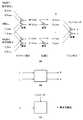
図11(a)に、第2実施形態に係る画像処理のブロック図を示す。まずブロックMD1では、図4(b)と同様の手順で、低エネルギー画像Lと高エネルギー画像Hから、骨画像Bと軟部組織画像Sを求め、さらに骨画像Bと軟部組織画像Sを加算した厚み画像Tを生成する。 FIG. 11A shows a block diagram of image processing according to the second embodiment. First, in the block MD1, the bone image B and the soft tissue image S were obtained from the low energy image L and the high energy image H in the same procedure as in FIG. 4B, and the bone image B and the soft tissue image S were further added. A thickness image T is generated.
ブロックMD3では、蓄積画像Aから所定の制約条件を適用することにより疑似的な分離画像を生成する。本実施形態では、制約条件として、骨の厚みが0であるという仮定を用いて、疑似的な分離画像としての軟部組織画像を生成する。すなわち、ブロックMD3は、蓄積画像Aを用いて、骨の厚みが0であると仮定したときの厚み画像tを以下のようにして生成する。なお、蓄積画像Aは第1実施形態で説明したとおりである。まず、式(11)にB=0、t=B+S=Sを代入すると、式(16)が成り立つ。
式(16)に、ある画素における蓄積画像Aの画素値を代入して非線形方程式を解くことで、骨の厚みが0であると仮定したときの厚みtを求めることが可能である。骨の厚みが0であると仮定したときの厚み画像tは、元々ノイズが少ない蓄積画像Aを用いて求めたものであるため、厚み画像Tと比較してノイズが非常に小さい。 By substituting the pixel value of the accumulated image A in a certain pixel into the equation (16) and solving the nonlinear equation, it is possible to obtain the thickness t when the bone thickness is assumed to be 0. Since the thickness image t when the bone thickness is assumed to be 0 is originally obtained by using the accumulated image A having less noise, the noise is very small as compared with the thickness image T.
ブロックMD4では、図4(b)と同様の手順で、低エネルギー画像Lと高エネルギー画像Hから、骨画像Bを生成する。なお、ブロックMD1で生成される骨画像Bを用いるようにしてもよい。 In the block MD4, the bone image B is generated from the low energy image L and the high energy image H in the same procedure as in FIG. 4 (b). The bone image B generated by the block MD1 may be used.
ブロックSELは、骨画像Bの画素値に基づいて骨の有無の判定を行い、その判定結果に従って厚み画像Tと厚み画像tのいずれかを選択し、ノイズ低減された厚み画像T'として出力する。厚み画像T'は、厚み画像Tと厚み画像tとから生成された合成画像である。本実施形態では、ブロックMD4で生成された骨画像Bの画素値が骨の有無を判定する閾値Bthを上回る場合は、ブロックSELは骨があると判定し、厚み画像Tの画素値をノイズ低減後の厚み画像T'の画素値とする。他方、骨画像Bの画素値が閾値Bthを下回る場合は、ブロックSELは、骨が存在しないと判定し、骨の厚みが0であると仮定したときの厚み画像tの画素値をノイズ低減後の厚み画像T'の画素値とする。以上のような構成により、骨がない領域におけるノイズを大幅に低減することが可能である。また、特徴(2)より、軟部組織がある領域の大部分は骨がない領域である。従って、厚み画像T'の多くの領域でノイズを大幅に低減することができる。The block SEL determines the presence or absence of bone based on the pixel value of the bone image B, selects either the thickness image T or the thickness image t according to the determination result, and outputs the noise-reduced thickness image T'. .. The thickness image T'is a composite image generated from the thickness image T and the thickness image t. In the present embodiment, when the pixel value of the bone image B generated by the block MD4exceeds the threshold Bth for determining the presence or absence of bone, the block SEL determines that there is bone and makes the pixel value of the thickness image T noise. Let it be the pixel value of the thickness image T'after reduction. On the other hand, when the pixel value of the bone image Bis less than the threshold Bth , the block SEL determines that the bone does not exist and reduces the pixel value of the thickness image t when it is assumed that the bone thickness is 0. Let it be the pixel value of the later thickness image T'. With the above configuration, it is possible to significantly reduce noise in the boneless region. Further, from the feature (2), most of the region with soft tissue is a region without bone. Therefore, noise can be significantly reduced in many regions of the thickness image T'.
図10(b)で説明した通り、厚み画像Tにおいて骨のコントラストは消えるが、造影剤のコントラストは残る。しかしながら、図10(a)の蓄積画像Aと比較すると、造影剤のコントラストが低下しているという課題があることが分かる。また、厚み画像Tは蓄積画像Aと比較してノイズが増加する。このため、下肢の末梢の血管など、血管径が細く造影剤の濃度が薄くなる部分において、造影剤のコントラストがノイズに埋もれて見えなくなるリスクがある。 As described in FIG. 10B, the contrast of the bone disappears in the thickness image T, but the contrast of the contrast medium remains. However, as compared with the accumulated image A of FIG. 10A, it can be seen that there is a problem that the contrast of the contrast medium is lowered. Further, the thickness image T has increased noise as compared with the accumulated image A. For this reason, there is a risk that the contrast of the contrast medium will be buried in noise and disappear in the portion where the blood vessel diameter is small and the concentration of the contrast medium is low, such as the peripheral blood vessels of the lower limbs.
第2実施形態の構成(図11(a))によれば、末梢の血管などの造影剤の濃度が薄い部分においては、二物質分離時の骨画像Bの画素値が骨の有無を判定する閾値Bthを下回り、骨がないと判定される。従って、骨の厚みが0であると仮定したときの厚み画像tの画素値が選択され、蓄積画像Aと同等のコントラストとノイズを保つことができる。一方、造影剤の濃度が濃い部分においては、二物質分離時の骨画像Bの画素値が、骨の有無を判定する閾値Bthを上回り、骨があると判定される。この場合は厚み画像Tの画素値が選択され、造影剤のコントラスト低下とノイズの増加が起こり、蓄積画像Aと比較して視認性が低下する可能性がある。しかしながら、そもそも造影剤の濃度が濃いため、視認できなくなるリスクは低いと考えられる。従って、ノイズ低減後の厚み画像T'を表示することで、造影剤の視認性が向上する。According to the configuration of the second embodiment (FIG. 11A), the pixel value of the bone image B at the time of separation of the two substances determines the presence or absence of bone in a portion where the concentration of the contrast medium is low, such as a peripheral blood vessel. It is judged that there is no bone below the threshold value Bth. Therefore, the pixel value of the thickness image t when the bone thickness is assumed to be 0 is selected, and the contrast and noise equivalent to those of the accumulated image A can be maintained. On the other hand, in the portion where the concentration of the contrast medium is high, the pixel value of the bone image B at the time of separation of the two substancesexceeds the threshold value Bth for determining the presence or absence of bone, and it is determined that there is bone. In this case, the pixel value of the thickness image T is selected, the contrast of the contrast medium is lowered, the noise is increased, and the visibility may be lowered as compared with the accumulated image A. However, since the concentration of the contrast medium is high in the first place, it is considered that the risk of becoming invisible is low. Therefore, by displaying the thickness image T'after noise reduction, the visibility of the contrast medium is improved.
図11(b)は、第2実施形態に係る画像処理の他の構成例を示すブロック図である。ブロックMD1、MD3、MD4、SELについては、図11(a)と同様である。図11(b)の画像処理では、ブロックF4において、ブロックMD4により求めた骨画像Bに対してノイズ低減を目的としたフィルタ処理を施し、ノイズ低減された骨画像B'を生成する。フィルタ処理には、ガウシアンフィルタやメディアンフィルタなどの空間方向のフィルタ、イプシロンフィルタやラプラシアンフィルタ等の構造保存型の空間方向のフィルタ、リカーシブフィルタ等の時間方向のフィルタなどを好適に用い得る。ブロックSELには、骨画像Bの代わりにノイズ低減された骨画像B'が入力される。ブロックSELに入力される骨画像のノイズが低減されているため、骨の有無の判定精度を向上させることができる。 FIG. 11B is a block diagram showing another configuration example of image processing according to the second embodiment. The blocks MD1, MD3, MD4, and SEL are the same as those in FIG. 11A. In the image processing of FIG. 11B, in the block F4, the bone image B obtained by the block MD4 is subjected to a filter processing for the purpose of noise reduction to generate a noise-reduced bone image B'. For the filter processing, a spatial filter such as a Gaussian filter or a median filter, a structure-preserving spatial filter such as an epsilon filter or a Laplacian filter, a temporal filter such as a recursive filter, or the like can be preferably used. A noise-reduced bone image B'is input to the block SEL instead of the bone image B. Since the noise of the bone image input to the block SEL is reduced, the accuracy of determining the presence or absence of bone can be improved.
図12は、第2実施形態に係る画像処理のさらに他の構成例を示すブロック図である。ブロックMD1、MD3、MD4、F4は、図11(b)と同様である。図12の画像処理では、骨の有無を判定する閾値Bthが複数設定されている。そしてブロックADDにおいて、厚み画像Tの画素値と、骨の厚みが0であると仮定したときの厚み画像tの画素値とを合成して、ノイズ低減後の厚み画像T'の画素値を決定する。ここで合成の重み(合成比率)は、骨画像Bの画素値と、骨の有無を判定する複数の閾値Bthとから決定される。例えば、ノイズ低減後の厚み画像T'の画素値は以下の式(17)で表される。
図11(a)、(b)に示した画像処理では、骨の境界部分でノイズが不連続に切り替わるが、図12に示した画像処理では、ノイズが連続的に切り替わるため、違和感を生じにくい。なお、図12では、図11(b)の構成においてブロックSELをブロックADDで置き換えた構成を示したが、図11(a)のブロックSELをブロックADDで置き換えてもよい(すなわち、ブロックF4が省略されてもよい)。 In the image processing shown in FIGS. 11A and 11B, the noise is discontinuously switched at the boundary portion of the bone, but in the image processing shown in FIG. 12, the noise is continuously switched, so that a sense of discomfort is unlikely to occur. .. Although FIG. 12 shows a configuration in which the block SEL is replaced with the block ADD in the configuration of FIG. 11B, the block SEL of FIG. 11A may be replaced with the block ADD (that is, the block F4 may be replaced with the block ADD). May be omitted).
なお、図11(a)の構成において、B>Bthの場合は合成画像(ブロックSELの出力)における疑似的な分離画像tの合成比を第1の値(0)、B≦Bthの場合は合成画像における疑似的な分離画像tの合成比を第2の値(1)としている。ここで、第1の値=0、第2の値=1に限られるものではなく、例えば、第1の値=0.2、第2の値=0.8などとしてもよい。図11(b)の構成についても同様である。また、図12の構成では、骨画像B'の画素値が第1の閾値(Bth0)から第2の閾値(Bth1)へ変化するに従って、疑似的な分離画像tの合成画像(ブロックADDの出力)における比率を第1の値から第2の値へ変化させている。ここで、図12では、第1の値=1、第2の値=0を例示しているが、これに限られるものではなく、例えば、第1の値=0.8、第2の値=0.2などとしてもよい。In the configuration of FIG. 11A, when B> Bth , the composite ratio of the pseudo separated image t in the composite image (output of the block SEL) is the first value (0), and B ≦ Bth . In the case, the composite ratio of the pseudo separated image t in the composite image is set to the second value (1). Here, the present invention is not limited to the first value = 0 and the second value = 1, and may be, for example, the first value = 0.2, the second value = 0.8, and the like. The same applies to the configuration of FIG. 11B. Further, in the configuration of FIG. 12, as the pixel value of the bone imageB'changes from the first threshold value (B th0) to the second threshold value (Bth1 ), a composite image (block ADD) of the pseudo separated image t The ratio in (output) is changed from the first value to the second value. Here, in FIG. 12, the first value = 1 and the second value = 0 are illustrated, but the present invention is not limited to this, and for example, the first value = 0.8 and the second value. = 0.2 and the like may be set.
なお、第2実施形態では、2つの分離画像(B,S)を合成した画像T(和の画像)と、分離画像(S)に対応する疑似的な分離画像tとの合成比率を、分離画像(B)の画素値と閾値との比較により決定したが、これに限られない。例えば、2つの分離画像とそれらを合成した画像の少なくとも1つ(B、S、Tの少なくとも1つ)と、これら2つの分離画像のいずれかに対応する疑似画像との合成比率を、2つの分離画像の少なくとも一方かの画素値と閾値との比較に基づいて決定してもよい。 In the second embodiment, the composite ratio of the image T (Japanese image) obtained by synthesizing the two separated images (B, S) and the pseudo separated image t corresponding to the separated image (S) is separated. It was determined by comparing the pixel value of the image (B) with the threshold value, but the present invention is not limited to this. For example, the composition ratio of at least one of the two separated images and the combined image (at least one of B, S, and T) and the pseudo image corresponding to one of these two separated images is set to two. It may be determined based on the comparison between the pixel value of at least one of the separated images and the threshold value.
(第3実施形態)
第3実施形態では、第1実施形態と同様に、胸部のIVRを行うときの肺野部分などのように軟部組織のコントラストが視認性を低下させている場合に、ノイズ低減した骨画像Bを表示することで、造影剤や医療用デバイスの視認性を向上させる。第3実施形態では、第2実施形態で説明した、ノイズ低減された厚み画像を用いることで、第1実施形態よりもノイズ低減された骨画像を得る。なお、以下では、ノイズ低減された厚み画像を生成する構成として図12の構成を適用した例が示されるが、図11(a)、図11(b)の構成が用いられてもよい。(Third Embodiment)
In the third embodiment, as in the first embodiment, when the contrast of the soft tissue reduces the visibility, such as the lung field portion when performing IVR of the chest, the bone image B with reduced noise is obtained. The display improves the visibility of contrast media and medical devices. In the third embodiment, the noise-reduced thickness image described in the second embodiment is used to obtain a bone image with noise reduced as compared with the first embodiment. In the following, an example in which the configuration of FIG. 12 is applied as a configuration for generating a noise-reduced thickness image is shown, but the configurations of FIGS. 11 (a) and 11 (b) may be used.
図13(a)に、第3実施形態に係る画像処理のブロック図を示す。ブロックMD1、MD3、MD4、F4、ADDについては、図12と同様である。また、ブロックF1、F2、F3、MD2については、図8(a)と同様である。これによって、二重にノイズ低減された厚み画像T''がブロックADDに供給されることで、三重にノイズ低減された厚み画像T'''が得られる。ブロックMD2は、三重にノイズ低減された厚み画像T'''を用いることで、三重にノイズ低減された骨画像B'''を生成する。結果、第1実施形態(図8(a))の画像処理よりもノイズが低減された画像が得られることになり、造影剤や医療用デバイスの視認性がさらに向上する。 FIG. 13A shows a block diagram of image processing according to the third embodiment. The blocks MD1, MD3, MD4, F4, and ADD are the same as in FIG. The blocks F1, F2, F3, and MD2 are the same as those in FIG. 8A. As a result, the thickness image T ″ with double noise reduction is supplied to the block ADD, so that the thickness image T'''' with triple noise reduction can be obtained. The block MD2 generates a triple-noise-reduced bone image B'''by using a triple-noise-reduced thickness image T''''. As a result, an image with noise reduced as compared with the image processing of the first embodiment (FIG. 8A) can be obtained, and the visibility of the contrast medium and the medical device is further improved.
図13(b)は、第3実施形態に係る画像処理の他の構成例を示すブロック図である。ブロックMD1、MD3、MD4、F4、ADD、ブロックF1、F2、F3、MD2については、図13(a)と同様である。図13(b)では、ブロックF5が、蓄積画像Aに対してノイズ低減を目的としたフィルタ処理を施し、ノイズ低減された蓄積画像A'が生成される。ノイズ低減された蓄積画像A'を蓄積画像Aの代わりにブロックMD3とブロックMD2に入力することで、図13(a)の画像処理からさらにノイズが低減され、造影剤や医療用デバイスの視認性が向上する。 FIG. 13B is a block diagram showing another configuration example of image processing according to the third embodiment. The blocks MD1, MD3, MD4, F4, ADD, blocks F1, F2, F3, and MD2 are the same as in FIG. 13 (a). In FIG. 13B, the block F5 performs a filter process on the stored image A for the purpose of noise reduction, and the noise-reduced stored image A'is generated. By inputting the noise-reduced stored image A'into the block MD3 and the block MD2 instead of the stored image A, the noise is further reduced from the image processing of FIG. 13 (a), and the visibility of the contrast medium and the medical device is further reduced. Is improved.
なお、第1〜第3実施形態では、画像処理として蓄積画像Aや骨画像Bや厚み画像Tを表示するための処理を行っているが、本発明はこのような形態に限定されない。高エネルギー画像Hや軟部組織画像Sを表示するようにしてもよい。また、図3(b)に示したタイミングチャートで得られた画像や、図4(a)に示した補正で得られた画像や、図4(b)に示した画像処理で得られた画像を用いてもよい。また、これらの画像に対する後処理として、対数変換やダイナミックレンジ圧縮を示したが、本発明はこのような形態に限定されない。リカーシブフィルタ等の時間方向のフィルタや、ガウシアンフィルタ等の空間方向のフィルタをかけるなどしてよい。すなわち、本実施形態における画像処理とは、撮影後又は補正後又は画像処理後の画像に対して任意の演算を行う処理であると言える。 In the first to third embodiments, processing for displaying the accumulated image A, the bone image B, and the thickness image T is performed as the image processing, but the present invention is not limited to such a form. A high-energy image H or a soft tissue image S may be displayed. Further, the image obtained by the timing chart shown in FIG. 3 (b), the image obtained by the correction shown in FIG. 4 (a), and the image obtained by the image processing shown in FIG. 4 (b). May be used. In addition, logarithmic conversion and dynamic range compression have been shown as post-processing for these images, but the present invention is not limited to such a form. A time-direction filter such as a recursive filter or a spatial-direction filter such as a Gaussian filter may be applied. That is, it can be said that the image processing in the present embodiment is a process of performing an arbitrary calculation on the image after shooting, correction, or image processing.
なお、第1〜第3実施形態では、X線撮像装置104は蛍光体を用いた間接型の放射線センサとしたが、このような形態に限定されない。例えばCdTe等の直接変換材料を用いた直接型の放射線センサを用いてもよい。また、第1〜第3実施形態ではX線発生装置101の受動的な管電圧変化を利用するか(図3(a))、能動的に管電圧を切り替える(図3(b))などしていたが、このような形態に限定されない。X線発生装置101のフィルタを時間的に切り替えるなどして、X線撮像装置104に曝射される放射線のエネルギーを変化させてもよい。 In the first to third embodiments, the
さらに、第1〜第3実施形態ではX線撮像装置104に曝射される放射線のエネルギーを変化させることで、エネルギーサブトラクションを行っていたがこのような形態に限定されない。例えば、二次元検出器106(センサ)を2枚積層することで、前面のセンサと背面のセンサで検出する放射線のスペクトルを変化させる方式が用いられてもよい。また、放射線量子の個数をエネルギー別にカウントする、フォトンカウンティング方式のセンサを用いることで、互いにエネルギーが異なる複数の画像を取得するなどしてもよい。 Further, in the first to third embodiments, energy subtraction is performed by changing the energy of the radiation exposed to the
また、第1〜第3実施形態では、放射線撮影システムの制御用コンピュータ103を用いてエネルギーサブトラクション処理を行っていたが、このような形態に限定されない。制御用コンピュータ103で取得した画像を別のコンピュータに転送して、エネルギーサブトラクション処理を行ってもよい。例えば、取得した画像を医療用のPACSを介して別のパソコン(画像ビューア)に転送し、エネルギーサブトラクション処理を行ってから表示する構成が好適に用いられる。すなわち、上記各実施形態では、互いにエネルギーが異なる放射線画像をエネルギーサブトラクション処理に提供できればよく、互いにエネルギーが異なる放射線画像を取得するための方法は、上記実施形態に限定されるものではない。 Further, in the first to third embodiments, the energy subtraction process is performed by using the
(その他の実施例)
本発明は、上述の実施形態の1以上の機能を実現するプログラムを、ネットワーク又は記憶媒体を介してシステム又は装置に供給し、そのシステム又は装置のコンピュータにおける1つ以上のプロセッサーがプログラムを読出し実行する処理でも実現可能である。また、1以上の機能を実現する回路(例えば、ASIC)によっても実現可能である。(Other Examples)
The present invention supplies a program that realizes one or more functions of the above-described embodiment to a system or device via a network or storage medium, and one or more processors in the computer of the system or device reads and executes the program. It can also be realized by the processing to be performed. It can also be realized by a circuit (for example, ASIC) that realizes one or more functions.
発明は上記実施形態に制限されるものではなく、発明の精神及び範囲から離脱することなく、様々な変更及び変形が可能である。従って、発明の範囲を公にするために請求項を添付する。 The invention is not limited to the above embodiments, and various modifications and modifications can be made without departing from the spirit and scope of the invention. Therefore, a claim is attached to make the scope of the invention public.
101:X線発生装置、102:X線制御装置、103:制御用コンピュータ、104:X線発生装置101: X-ray generator, 102: X-ray control device, 103: control computer, 104: X-ray generator
Claims (18)
Translated fromJapanese前記エネルギーサブトラクション処理が適用されていない放射線画像に基づく第3の放射線画像から、所定の制約条件を用いて、前記第1の分離画像または前記第2の分離画像に対応する疑似的な分離画像を生成する第2生成手段と、
前記第1の分離画像、前記第2の分離画像、前記第1の分離画像と前記第2の分離画像を合成した第3の分離画像の少なくともいずれかと、前記疑似的な分離画像とを合成して合成画像を生成する合成手段と、
前記第1の分離画像と前記第2の分離画像のうちの少なくとも一方に基づいて前記合成手段における前記合成の合成比率を決定する決定手段と、を備えることを特徴とする画像処理装置。A first generation means for generating a first separated image and a second separated image by energy subtraction processing from a first radiation image and a second radiation image acquired by radiation of different energies.
From the third radiographic image based on the radiographic image to which the energy subtraction processing is not applied, a pseudo separated image corresponding to the first separated image or the second separated image is obtained by using predetermined constraints. The second generation means to generate and
At least one of the first separated image, the second separated image, the third separated image obtained by combining the first separated image and the second separated image, and the pseudo separated image are combined. And the compositing means to generate a compositing image
An image processing apparatus comprising: a determination means for determining a composition ratio of the composition in the composition means based on at least one of the first separation image and the second separation image.
前記決定手段は、前記第2の分離画像に基づいて前記第3の分離画像と前記疑似的な分離画像との合成比率を決定することを特徴とする請求項1に記載の画像処理装置。Further provided with an acquisition means for acquiring the third separated image by synthesizing the first separated image and the second separated image.
The image processing apparatus according to claim 1, wherein the determination means determines a composite ratio of the third separated image and the pseudo separated image based on the second separated image.
前記第2生成手段は、前記第2の物質の厚みを0と仮定することを前記所定の制約条件として用いて前記疑似的な分離画像を生成することを特徴とする請求項1または2に記載の画像処理装置。The first separated image is a thickness image of the first substance, and the second separated image is a thickness image of the second substance.
The second generation means according to claim 1 or 2, wherein the pseudo-separated image is generated by using the assumption that the thickness of the second substance is 0 as the predetermined constraint condition. Image processing equipment.
前記決定手段は、前記第1処理手段によるノイズ低減処理の後の前記第2の分離画像に基づいて前記合成比率を決定することを特徴とする請求項1乃至7のいずれか1項に記載の画像処理装置。A first processing means for applying noise reduction processing to the second separated image is further provided.
The determination means according to any one of claims 1 to 7, wherein the determination means determines the synthesis ratio based on the second separated image after the noise reduction processing by the first processing means. Image processing device.
前記画像処理装置は、前記合成画像と前記第3の放射線画像に基づいて、前記第1の分離画像または前記第2の分離画像に対応する画像を生成する第3生成手段をさらに備えることを特徴とする請求項1乃至11のいずれか1項に記載の画像処理装置。The synthesizing means synthesizes the third separated image and the pseudo separated image to generate the composite image.
The image processing apparatus further includes a third generation means for generating an image corresponding to the first separated image or the second separated image based on the composite image and the third radiation image. The image processing apparatus according to any one of claims 1 to 11.
前記照射終了後のタイミングで取得される放射線画像が前記第3の放射線画像として用いられることを特徴とする請求項1乃至13のいずれか1項に記載の画像処理装置。The first radiation image and the second radiation image from a plurality of radiation images acquired by sample holding at a plurality of timings including the timing during and after the irradiation for one irradiation. Is generated,
The image processing apparatus according to any one of claims 1 to 13, wherein a radiation image acquired at a timing after the end of irradiation is used as the third radiation image.
前記エネルギーサブトラクション処理が適用されていない放射線画像に基づく第3の放射線画像から、所定の制約条件を用いて、前記第1の分離画像または前記第2の分離画像に対応する疑似的な分離画像を生成する第2生成工程と、
前記第1の分離画像、前記第2の分離画像、前記第1の分離画像と前記第2の分離画像を合成した第3の分離画像の少なくともいずれかと、前記疑似的な分離画像とを合成して合成画像を生成する合成工程と、
前記第1の分離画像と前記第2の分離画像のうちの少なくとも一方に基づいて、前記合成工程における前記合成の合成比率を決定する決定工程と、を備えることを特徴とする画像処理方法。A first generation step of generating a first separated image and a second separated image by energy subtraction processing from a first radiation image and a second radiation image acquired by radiation of different energies.
From the third radiographic image based on the radiographic image to which the energy subtraction processing is not applied, a pseudo separated image corresponding to the first separated image or the second separated image is obtained by using predetermined constraints. The second generation process to generate and
At least one of the first separated image, the second separated image, the third separated image obtained by combining the first separated image and the second separated image, and the pseudo separated image are combined. And the compositing process to generate a compositing image
An image processing method comprising: a determination step of determining a synthesis ratio of the synthesis in the synthesis step based on at least one of the first separated image and the second separated image.
Priority Applications (3)
| Application Number | Priority Date | Filing Date | Title |
|---|---|---|---|
| JP2020020892AJP7425619B2 (en) | 2020-02-10 | 2020-02-10 | Image processing device and image processing method |
| PCT/JP2021/004897WO2021162026A1 (en) | 2020-02-10 | 2021-02-10 | Image processing device and image processing method |
| US17/868,942US12217401B2 (en) | 2020-02-10 | 2022-07-20 | Image processing apparatus, image processing method, and storage medium |
Applications Claiming Priority (1)
| Application Number | Priority Date | Filing Date | Title |
|---|---|---|---|
| JP2020020892AJP7425619B2 (en) | 2020-02-10 | 2020-02-10 | Image processing device and image processing method |
Publications (3)
| Publication Number | Publication Date |
|---|---|
| JP2021126163Atrue JP2021126163A (en) | 2021-09-02 |
| JP2021126163A5 JP2021126163A5 (en) | 2023-02-03 |
| JP7425619B2 JP7425619B2 (en) | 2024-01-31 |
Family
ID=77487179
Family Applications (1)
| Application Number | Title | Priority Date | Filing Date |
|---|---|---|---|
| JP2020020892AActiveJP7425619B2 (en) | 2020-02-10 | 2020-02-10 | Image processing device and image processing method |
Country Status (1)
| Country | Link |
|---|---|
| JP (1) | JP7425619B2 (en) |
Cited By (1)
| Publication number | Priority date | Publication date | Assignee | Title |
|---|---|---|---|---|
| WO2025203020A1 (en)* | 2024-03-26 | 2025-10-02 | Mazor Robotics Ltd. | System and method to generate image visualization |
Citations (8)
| Publication number | Priority date | Publication date | Assignee | Title |
|---|---|---|---|---|
| JPH03133430A (en)* | 1989-10-19 | 1991-06-06 | Fuji Photo Film Co Ltd | Abnormal shadow detector |
| JPH03263982A (en)* | 1989-10-19 | 1991-11-25 | Fuji Photo Film Co Ltd | Method and apparatus for displaying energy subtraction picture |
| JP2004000609A (en)* | 2002-05-15 | 2004-01-08 | Ge Medical Systems Global Technology Co Llc | Computer assisted diagnosis by multiple energy image |
| JP2010005252A (en)* | 2008-06-30 | 2010-01-14 | Fujifilm Corp | Energy subtraction processing apparatus, method, and program |
| JP2014151009A (en)* | 2013-02-08 | 2014-08-25 | Toshiba Corp | Medical diagnostic apparatus and image processing apparatus |
| US20160213344A1 (en)* | 2015-01-22 | 2016-07-28 | Samsung Electronics Co., Ltd. | X-ray imaging apparatus, image processing apparatus and image processing method |
| JP2019068953A (en)* | 2017-10-06 | 2019-05-09 | キヤノン株式会社 | Image processing device, image processing method, and program |
| JP2019068952A (en)* | 2017-10-06 | 2019-05-09 | キヤノン株式会社 | Image processing device, image processing method, and program |
- 2020
- 2020-02-10JPJP2020020892Apatent/JP7425619B2/enactiveActive
Patent Citations (8)
| Publication number | Priority date | Publication date | Assignee | Title |
|---|---|---|---|---|
| JPH03133430A (en)* | 1989-10-19 | 1991-06-06 | Fuji Photo Film Co Ltd | Abnormal shadow detector |
| JPH03263982A (en)* | 1989-10-19 | 1991-11-25 | Fuji Photo Film Co Ltd | Method and apparatus for displaying energy subtraction picture |
| JP2004000609A (en)* | 2002-05-15 | 2004-01-08 | Ge Medical Systems Global Technology Co Llc | Computer assisted diagnosis by multiple energy image |
| JP2010005252A (en)* | 2008-06-30 | 2010-01-14 | Fujifilm Corp | Energy subtraction processing apparatus, method, and program |
| JP2014151009A (en)* | 2013-02-08 | 2014-08-25 | Toshiba Corp | Medical diagnostic apparatus and image processing apparatus |
| US20160213344A1 (en)* | 2015-01-22 | 2016-07-28 | Samsung Electronics Co., Ltd. | X-ray imaging apparatus, image processing apparatus and image processing method |
| JP2019068953A (en)* | 2017-10-06 | 2019-05-09 | キヤノン株式会社 | Image processing device, image processing method, and program |
| JP2019068952A (en)* | 2017-10-06 | 2019-05-09 | キヤノン株式会社 | Image processing device, image processing method, and program |
Cited By (1)
| Publication number | Priority date | Publication date | Assignee | Title |
|---|---|---|---|---|
| WO2025203020A1 (en)* | 2024-03-26 | 2025-10-02 | Mazor Robotics Ltd. | System and method to generate image visualization |
Also Published As
| Publication number | Publication date |
|---|---|
| JP7425619B2 (en) | 2024-01-31 |
Similar Documents
| Publication | Publication Date | Title |
|---|---|---|
| JP7373323B2 (en) | Image processing device, radiation imaging system, image processing method and program | |
| JP7054329B2 (en) | Image processing equipment, image processing methods and programs | |
| JP7352687B2 (en) | Radiography system, radiography control device and method | |
| JP6882135B2 (en) | Image processing equipment, image processing methods and programs | |
| JP7080025B2 (en) | Information processing equipment, information processing methods and programs | |
| JP7161297B2 (en) | Radiation imaging system, image processing device, imaging control device and its operation method, program | |
| WO2020095578A1 (en) | Information processing device and method, and radiography system | |
| WO2022071024A1 (en) | Image processing device, image processing method, and program | |
| JP2020203083A (en) | Radiation imaging apparatus and radiation imaging system | |
| JP7425619B2 (en) | Image processing device and image processing method | |
| WO2021162026A1 (en) | Image processing device and image processing method | |
| US20230401677A1 (en) | Image processing apparatus, radiation imaging system, image processing method, and non-transitory computer-readable storage medium | |
| JP7431602B2 (en) | Image processing device and image processing method | |
| JP2009240420A (en) | Radiographic image processing apparatus | |
| WO2022181022A1 (en) | Image processing device and method, radiography system, and program | |
| JP2022134547A (en) | Image processing device, radiation imaging system, image processing method and program | |
| JP2025023667A (en) | IMAGE PROCESSING APPARATUS, RADIATION IMAGING SYSTEM, IMAGE PROCESSING METHOD, AND PROGRAM |
Legal Events
| Date | Code | Title | Description |
|---|---|---|---|
| RD01 | Notification of change of attorney | Free format text:JAPANESE INTERMEDIATE CODE: A7421 Effective date:20210103 | |
| A521 | Request for written amendment filed | Free format text:JAPANESE INTERMEDIATE CODE: A523 Effective date:20210113 | |
| A521 | Request for written amendment filed | Free format text:JAPANESE INTERMEDIATE CODE: A523 Effective date:20230126 | |
| A621 | Written request for application examination | Free format text:JAPANESE INTERMEDIATE CODE: A621 Effective date:20230126 | |
| TRDD | Decision of grant or rejection written | ||
| A01 | Written decision to grant a patent or to grant a registration (utility model) | Free format text:JAPANESE INTERMEDIATE CODE: A01 Effective date:20231222 | |
| A61 | First payment of annual fees (during grant procedure) | Free format text:JAPANESE INTERMEDIATE CODE: A61 Effective date:20240119 | |
| R151 | Written notification of patent or utility model registration | Ref document number:7425619 Country of ref document:JP Free format text:JAPANESE INTERMEDIATE CODE: R151 |