JP2021125863A - Wireless communication relay device for smart meter - Google Patents
Wireless communication relay device for smart meterDownload PDFInfo
- Publication number
- JP2021125863A JP2021125863AJP2020020513AJP2020020513AJP2021125863AJP 2021125863 AJP2021125863 AJP 2021125863AJP 2020020513 AJP2020020513 AJP 2020020513AJP 2020020513 AJP2020020513 AJP 2020020513AJP 2021125863 AJP2021125863 AJP 2021125863A
- Authority
- JP
- Japan
- Prior art keywords
- antenna
- wireless communication
- meter
- smart meter
- relay device
- Prior art date
- Legal status (The legal status is an assumption and is not a legal conclusion. Google has not performed a legal analysis and makes no representation as to the accuracy of the status listed.)
- Granted
Links
- 238000004891communicationMethods0.000titleclaimsabstractdescription128
- 239000002184metalSubstances0.000claimsabstractdescription27
- 229910052751metalInorganic materials0.000claimsabstractdescription27
- 229920005989resinPolymers0.000claimsdescription3
- 239000011347resinSubstances0.000claimsdescription3
- 238000010248power generationMethods0.000description8
- 238000010586diagramMethods0.000description7
- 238000007789sealingMethods0.000description6
- 239000010408filmSubstances0.000description5
- 230000005540biological transmissionEffects0.000description4
- 239000004020conductorSubstances0.000description4
- 230000005404monopoleEffects0.000description4
- 238000009434installationMethods0.000description3
- 238000000034methodMethods0.000description3
- 239000000853adhesiveSubstances0.000description2
- 230000001070adhesive effectEffects0.000description2
- 230000001771impaired effectEffects0.000description2
- RYGMFSIKBFXOCR-UHFFFAOYSA-NCopperChemical compound[Cu]RYGMFSIKBFXOCR-UHFFFAOYSA-N0.000description1
- 229910052802copperInorganic materials0.000description1
- 239000010949copperSubstances0.000description1
- 230000000694effectsEffects0.000description1
- 238000004519manufacturing processMethods0.000description1
- 238000005259measurementMethods0.000description1
- 238000012986modificationMethods0.000description1
- 230000004048modificationEffects0.000description1
- 229920003002synthetic resinPolymers0.000description1
- 239000000057synthetic resinSubstances0.000description1
- 239000010409thin filmSubstances0.000description1
Images


Classifications
- Y—GENERAL TAGGING OF NEW TECHNOLOGICAL DEVELOPMENTS; GENERAL TAGGING OF CROSS-SECTIONAL TECHNOLOGIES SPANNING OVER SEVERAL SECTIONS OF THE IPC; TECHNICAL SUBJECTS COVERED BY FORMER USPC CROSS-REFERENCE ART COLLECTIONS [XRACs] AND DIGESTS
- Y02—TECHNOLOGIES OR APPLICATIONS FOR MITIGATION OR ADAPTATION AGAINST CLIMATE CHANGE
- Y02E—REDUCTION OF GREENHOUSE GAS [GHG] EMISSIONS, RELATED TO ENERGY GENERATION, TRANSMISSION OR DISTRIBUTION
- Y02E60/00—Enabling technologies; Technologies with a potential or indirect contribution to GHG emissions mitigation
- Y—GENERAL TAGGING OF NEW TECHNOLOGICAL DEVELOPMENTS; GENERAL TAGGING OF CROSS-SECTIONAL TECHNOLOGIES SPANNING OVER SEVERAL SECTIONS OF THE IPC; TECHNICAL SUBJECTS COVERED BY FORMER USPC CROSS-REFERENCE ART COLLECTIONS [XRACs] AND DIGESTS
- Y04—INFORMATION OR COMMUNICATION TECHNOLOGIES HAVING AN IMPACT ON OTHER TECHNOLOGY AREAS
- Y04S—SYSTEMS INTEGRATING TECHNOLOGIES RELATED TO POWER NETWORK OPERATION, COMMUNICATION OR INFORMATION TECHNOLOGIES FOR IMPROVING THE ELECTRICAL POWER GENERATION, TRANSMISSION, DISTRIBUTION, MANAGEMENT OR USAGE, i.e. SMART GRIDS
- Y04S40/00—Systems for electrical power generation, transmission, distribution or end-user application management characterised by the use of communication or information technologies, or communication or information technology specific aspects supporting them
- Y04S40/12—Systems for electrical power generation, transmission, distribution or end-user application management characterised by the use of communication or information technologies, or communication or information technology specific aspects supporting them characterised by data transport means between the monitoring, controlling or managing units and monitored, controlled or operated electrical equipment
- Y04S40/126—Systems for electrical power generation, transmission, distribution or end-user application management characterised by the use of communication or information technologies, or communication or information technology specific aspects supporting them characterised by data transport means between the monitoring, controlling or managing units and monitored, controlled or operated electrical equipment using wireless data transmission
Landscapes
- Remote Monitoring And Control Of Power-Distribution Networks (AREA)
- Radio Relay Systems (AREA)
Abstract
Description
Translated fromJapanese本発明は、スマートメータ用の無線通信中継装置に関する。 The present invention relates to a wireless communication relay device for a smart meter.
需要家の消費電力を計測する電力量計は、検針の自動化等の要請により、検針員による検針を必要とするアナログ方式の旧電力量計から、計測結果を電力会社に送信できるスマートメータに置き換えられている。
スマートメータには、有線通信機能を有するものや無線通信機能を有するものがある。無線通信機能を有するスマートメータは、例えばマルチホップ無線方式や1:N無線方式による無線通信を行う。
マルチホップ無線方式は、スマートメータ自身が中継器の役割を果たし、スマートメータ同士がリレー方式によって短距離で通信路を形成しあうことにより、広範囲の通信ネットワークを形成する方式である。1:N無線方式は、携帯電話事業者等の通信事業者が提供する無線データ通信サービスを利用する方式である。The watt-hour meter that measures the power consumption of consumers has been replaced with a smart meter that can send the measurement results to the electric power company from the old analog watt-hour meter that requires meter reading by meter readers at the request of automation of meter reading. Has been done.
Some smart meters have a wired communication function and some have a wireless communication function. A smart meter having a wireless communication function performs wireless communication by, for example, a multi-hop wireless system or a 1: N wireless system.
The multi-hop wireless system is a system in which the smart meters themselves play the role of a repeater, and the smart meters form a communication path over a short distance by the relay system to form a wide-range communication network. The 1: N wireless system is a system that uses a wireless data communication service provided by a communication carrier such as a mobile phone carrier.
旧電力量計から置き換えられたスマートメータは、通常、旧電力量計と同じ場所に設置される。しかし、旧電力量計は無線通信機能を有していないために無線通信に適さない場所に設置されていることがある。スマートメータが無線通信に適さない場所に設置されると電波(電磁波)が弱められてしまい、無線通信が不安定になってしまう恐れがある。
例えば、多くの建物が密集する都市部において、マルチホップ無線方式を行うスマートメータが金属製の収納ボックス内に設置されると、建物や収納ボックスによって電波が弱められてしまい無線通信が不安定になってしまう恐れがある。
また、山間の地において、1:N無線方式による無線通信を行うスマートメータが金属製のキャビネット内に設置されると、基地局からの距離が遠いことから電波が弱められ、キャビネットによってさらに電波が弱められてしまうことから、無線通信が不安定になってしまう恐れがある。A smart meter that replaces the old watt-hour meter is usually installed in the same place as the old watt-hour meter. However, the old watt-hour meter may be installed in a place unsuitable for wireless communication because it does not have a wireless communication function. If the smart meter is installed in a place unsuitable for wireless communication, radio waves (electromagnetic waves) may be weakened and wireless communication may become unstable.
For example, in an urban area where many buildings are densely packed, if a smart meter that uses a multi-hop wireless system is installed in a metal storage box, the radio waves will be weakened by the building or storage box, and wireless communication will become unstable. There is a risk of becoming.
In addition, when a smart meter that performs wireless communication by the 1: N wireless method is installed in a metal cabinet in a mountainous area, the radio wave is weakened because the distance from the base station is long, and the cabinet further emits radio waves. Since it is weakened, there is a risk that wireless communication will become unstable.
スマートメータによる無線通信を安定させるため、スマートメータと通信の相手先機器との間に中継装置を配置する技術が提案されている。例えば、特許文献1には、スマートメータと電力管理装置との間に中継装置を配置し、スマートメータと電力管理装置との間の無線通信を安定させている。また、特許文献2には、コードレステレフォンのメインセット(親機)とサブセット(子機)との間に伝送手段を配置し、通信を安定させている。特許文献2において、伝送手段は、親機側のアンテナ、及び整合回路のセットと、子機側のアンテナ、及び整合回路のセットと、両整合回路を接続する給電線と、を備えている。 In order to stabilize wireless communication by a smart meter, a technique of arranging a relay device between the smart meter and the communication partner device has been proposed. For example, in
特許文献2の伝送手段において、子機側のアンテナの設置場所は、コードレスタイプの子機が室内の様々な場所で使用されることから制限を受ける。従って、特許文献1の中継装置に換えて特許文献2の伝送手段を用いたとしても、スマートメータ側のアンテナについては設置場所に制限を受けることになり、通信が不安定になってしまう恐れがある。
本発明は、このような事情に鑑みてなされたものであり、その目的は、金属製箱体の内部に設置されたスマートメータと相手先機器との間の通信を安定させることにある。In the transmission means of
The present invention has been made in view of such circumstances, and an object of the present invention is to stabilize communication between a smart meter installed inside a metal box and a destination device.
上記課題を解決するために、本発明は、金属製箱体の内部に設置されてメータ内アンテナを介した無線通信によって相手先機器との間で情報を送受信するスマートメータに用いられ、前記スマートメータと前記相手先機器との間の無線通信を中継する中継装置であって、前記金属製箱体の内部において前記スマートメータが備えたハウジングに配置され、前記メータ内アンテナとの間で無線通信を行う内部アンテナと、前記金属製箱体の外部に設置され、前記相手先機器との間で無線通信を行う外部アンテナと、前記内部アンテナと前記外部アンテナとの間を通信可能に接続する通信ケーブルと、を備えたことを特徴とする。 In order to solve the above problems, the present invention is used for a smart meter installed inside a metal box and transmitting and receiving information to and from a partner device by wireless communication via an antenna in the meter. A relay device that relays wireless communication between the meter and the other party's device, is arranged in a housing provided with the smart meter inside the metal box body, and wirelessly communicates with the antenna in the meter. Communication that connects the internal antenna for wireless communication between the internal antenna and the external antenna, which is installed outside the metal box and performs wireless communication with the other party's device, and the internal antenna and the external antenna so as to be communicable. It is characterized by being equipped with a cable.
本発明によれば、金属製箱体の内部に設置されたスマートメータと相手先機器との間の通信を安定させることができる。 According to the present invention, it is possible to stabilize the communication between the smart meter installed inside the metal box and the destination device.
<中継装置の概要>
以下、本発明の実施形態について、図面を参照して説明する。図1は第一実施形態の無線通信中継装置1を説明するブロック図である。
図1に示す無線通信中継装置1は、金属製のキャビネット120(金属製箱体)の内部に設置されてメータ内アンテナ112を介した無線通信によって基地局130(相手先機器)との間で情報を送受信するスマートメータ110に用いられ、スマートメータ110と基地局130との間の無線通信を中継するための装置である。
無線通信中継装置1は、スマートメータ110が備えたハウジング113に配置され、メータ内アンテナ112との間で無線通信を行う内部アンテナ2と、キャビネット120の外部に設置され、基地局130との間で無線通信を行う外部アンテナ3と、内部アンテナ2と外部アンテナ3との間を通信可能に接続する通信ケーブル4とを備えたことを特徴としている。<Overview of relay device>
Hereinafter, embodiments of the present invention will be described with reference to the drawings. FIG. 1 is a block diagram illustrating a wireless
The wireless
The wireless
この無線通信中継装置1において、内部アンテナ2は、スマートメータ110のハウジング113に配置されているため、金属製のキャビネット120の影響を受けることなく、メータ内アンテナ112との間で無線通信を行うことができる。
一方、外部アンテナ3は、キャビネット120の外部に設置されているため、金属製のキャビネット120の影響を受けることなく、基地局130との間で無線通信を行うことができる。
さらに、内部アンテナ2と外部アンテナ3との間を通信ケーブル4によって接続しているため、金属製のキャビネット120の影響を受けずに、内部アンテナ2と外部アンテナ3との間で通信を行わせることができる。
その結果、スマートメータ110が金属製のキャビネット120内に収容されていても、スマートメータ110と基地局130との間の通信を安定させることができる。In this wireless
On the other hand, since the external antenna 3 is installed outside the
Further, since the
As a result, even if the
<第一実施形態>
以下、第一実施形態の無線通信中継装置1について詳細に説明するが、先にスマートメータ110について説明する。
図1に示すスマートメータ110は、需要家における消費電力を計測し、計測値をデジタル変換するメータ本体111と、メータ本体111に対して電気的に接続され、デジタル変換された計測値を表示する表示部115と、メータ本体111に対して電気的に接続され、無線通信を行うために電波(電磁波)の送受信を行うメータ内アンテナ112と、メータ本体111、表示部115、及びメータ内アンテナ112を収容したハウジング113と、を備えている。<First Embodiment>
Hereinafter, the wireless
The
本実施形態のスマートメータ110は1:N無線方式による通信を行うものであるため、メータ内アンテナ112は通信事業者が所有する基地局130(相手先機器)と通信可能に構成されている。例えば、通信事業者が800MHz帯の周波数を使用している場合には、当該周波数の電波を送受信できる構成を備えている。
メータ内アンテナ112が送受信可能な電波の種類は無線通信の相手先機器に応じて定められる。本実施形態において、メータ内アンテナ112は、通信ユニットUN内に配置されている。通信ユニットUNは、メータ本体111に対してモジュラーケーブルによって着脱自在に接続されている。
スマートメータ110は、基地局130、及び通信ネットワークNWを通じて、ヘッドエンドシステム140(サーバ)との間で情報を送受信する。Since the
The type of radio waves that can be transmitted and received by the
The
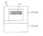
図2は、スマートメータ110の正面図である。図2に示すように、ハウジング113は、ハウジング本体113aと、ハウジング本体113aに対して着脱自在なカバー部材113bとを備えている。
ハウジング本体113aの上部は直方体形状をしており、メータ本体111が収納されている。表示部115は、ハウジング本体113aの上部正面側に取り付けられている。ハウジング本体113aの下部には通信ユニットUN(メータ内アンテナ112)及び各種の端子等が収納されており、カバー部材113bによって覆われている。
なお、カバー部材113bは、ハウジング本体113aの下部開口に対して着脱自在ではあるが封印具によって封印されている。すなわち、通信ユニットUNは、封印具によってハウジング113内に封印されている。FIG. 2 is a front view of the
The upper part of the
The
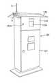
図3は屋外に設置されたキャビネット120に無線通信中継装置1を取り付けた状態を説明する図、図4はキャビネット120内に収納されたスマートメータ110、及び内部アンテナ2を説明する図である。
図3に示すキャビネット120は、公園、広場、施設内の空き地などの屋外に設置される。このキャビネット120は、縦長直方体形状の金属製箱体であって、正面上部が金属製の蓋体122によって開閉自在なキャビネット本体121と、キャビネット本体121の上部に取り付けられた金属製の切妻屋根123とを備えている。
図4に示すように、スマートメータ110は、支持板124を介してキャビネット本体121内の上部に取り付けられている。スマートメータ110の測定値は、キャビネット120正面上部の蓋体122に設けた覗き窓122aを通してキャビネット120の外から視認できる。また、封印具取付装置122bには電力会社の封印具が設置されているため、蓋体122の開閉は電力会社以外の者には行えない。FIG. 3 is a diagram illustrating a state in which the wireless
The
As shown in FIG. 4, the
次に、無線通信中継装置1について説明する。図1にて説明したように、無線通信中継装置1は、内部アンテナ2、外部アンテナ3、及び通信ケーブル4を備えている。
内部アンテナ2は、スマートメータ110のメータ内アンテナ112と無線通信を行うものであるため、メータ内アンテナ112と同じ周波数帯(例えば800MHz帯)の電波を送受信可能に構成されている。内部アンテナ2の種類は、電波を送受信できればどのようなものであってもよいが、キャビネット120内の限られたスペースに収納することを考慮すると、ダイポールアンテナ、モノポールアンテナ、又はループアンテナが好ましい。
図4に示すように、本実施形態では、内部アンテナ2をモノポールアンテナによって構成している。この内部アンテナ2は、扁平な長方形状のアンテナ本体2aと、アンテナ本体2aの一端側の表面に設けられ、通信ケーブル4に接続される接続コネクタ2bと、接続コネクタ2b、及び通信ケーブル4の端部をカバーするコネクタカバー2cと、を備えている。
内部アンテナ2(アンテナ本体2a)は、ハウジング113の側面に配置されている。例えば、内部アンテナ2をカバー部材113b左側面(所定位置)に対して両面テープによって左側方から貼設している。
なお、内部アンテナ2のハウジング113への取り付けは両面テープに限られない。例えば、接着剤によって貼り付けてもよいし、結束バンドによって固定してもよい。Next, the wireless
Since the
As shown in FIG. 4, in the present embodiment, the
The internal antenna 2 (
The attachment of the
図1に示すように、外部アンテナ3は通信事業者が所有する基地局130と無線通信を行うものであるため、基地局130やメータ内アンテナ112と同じ周波数帯の電波を送受信可能に構成されている。
図3に示すように、本実施形態において、外部アンテナ3は、キャビネット120の屋根123に取り付けられているが、キャビネット120の外部であればキャビネット120の屋根123に限られない。例えば、家屋の屋根、ビル等の建物の屋上、或いは支柱に取り付けてもよい。
外部アンテナ3の種類は、電波を送受信できればどのようなものであってもよいが、キャビネット120の屋根123に取り付けることを考慮すると、モノポールアンテナ(ホイップアンテナ)が好ましい。また、外部アンテナ3を建物の屋根123や支柱に取り付ける時には、遠距離の無線通信に適していることから、八木アンテナやダイポールアンテナが好ましい。As shown in FIG. 1, since the external antenna 3 wirelessly communicates with the
As shown in FIG. 3, in the present embodiment, the external antenna 3 is attached to the
The type of the external antenna 3 may be any type as long as it can transmit and receive radio waves, but a monopole antenna (whipped antenna) is preferable in consideration of mounting on the
通信ケーブル4は、内部アンテナ2と外部アンテナ3との間を通信可能に接続し、各アンテナ2、3の間で高周波電力を伝送するための電線(給電線)である。本実施形態では、例えばインピーダンス値が50オームの同軸ケーブルが用いられており、その長さは内部アンテナ2から外部アンテナ3までの距離に応じて定められる。
例えば、外部アンテナ3をキャビネット120の屋根123に取り付ける時において、通信ケーブル4の長さは2m乃至5m程度に定められる。また、外部アンテナ3を建物の屋根や支柱に取り付ける時には、通信ケーブル4の長さは10m以上に定められる。The
For example, when the external antenna 3 is attached to the
なお、通信ケーブル4と各アンテナ2、3との接続点(給電点)では、マッチングが図られている。具体的には、通信ケーブル4から見た時の各アンテナ2、3側のインピーダンス値を通信ケーブル4のインピーダンス値(本実施形態では50オーム)に一致させており、通信ケーブル4と各アンテナ2、3の間でエネルギーの反射が無いように接続している。図示は省略するが、整合回路を設けてインピーダンス値を一致させてもよい。
また、通信ケーブル4は、内部アンテナ2と外部アンテナ3との間で高周波電力を伝送できれば同軸ケーブルに限られない。例えば、通信ケーブル4としてフィーダー線を用いてもよい。Matching is achieved at the connection points (feeding points) between the
Further, the
図1、図3、及び図4に示すように、本実施形態の無線通信中継装置1では、キャビネット120内の内部アンテナ2はスマートメータ110のハウジング113に配置されており、メータ内アンテナ112との間で高い効率で無線通信を行う。また、キャビネット120外の外部アンテナ3はキャビネット120に影響されることなく、基地局130との間で無線通信を行う。さらに、通信ケーブル4は、内部アンテナ2と外部アンテナ3との間、言い換えればキャビネット120の内側と外側の間において、キャビネット120に影響されることなく高周波電力を伝送する。
従って、本実施形態の無線通信中継装置1を使用することにより、キャビネット120が金属製であってもキャビネット120に影響されることなく、キャビネット120内のスマートメータ110とキャビネット120外の基地局130(相手先機器)との間の通信を安定して行わせることができる。As shown in FIGS. 1, 3, and 4, in the wireless
Therefore, by using the wireless
<第二実施形態>
前述の第一実施形態において、無線通信中継装置1が取り付けられるスマートメータ110(キャビネット120)は、公園、広場、施設内の空き地等に設置されていたが、本発明に係る無線通信中継装置1は、他の場所(例えば、図5に示す野立て太陽光発電施設200)に設置されたスマートメータ110にも取り付けることができる。
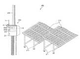
野立て太陽光発電施設200(以下、発電施設200)の殆んどは、周りに民家が無い山間の地で基地局からの距離が遠い所に施設されている。以下、発電施設200について説明する。図5は、発電施設200を説明する斜視図である。<Second embodiment>
In the first embodiment described above, the smart meter 110 (cabinet 120) to which the wireless
Most of the field solar power generation facilities 200 (hereinafter referred to as power generation facilities 200) are installed in mountainous areas where there are no private houses around them and are far from the base station. Hereinafter, the
発電施設200は、太陽光パネル210と、メータボックス220と、を備えている。
太陽光パネル210は、複数の薄膜型の太陽電池を直列に接続した板状のユニットを複数備えており、各ユニットを直列及び並列に接続したものである。本実施形態では、太陽光パネル210をフレーム211によって設置している。太陽光パネル210が発電した直流は接続箱や集電盤を経て高電圧化され、パワーコンディショナーにて交流に変換された後、電力系統に送られる。
発電施設200において、スマートメータ110は、パワーコンディショナーと電力系統の間に配置される。本実施形態のスマートメータ110は1:N無線方式による通信を行うものであるので、図1にて説明したように、メータ内アンテナ112は通信事業者が所有する基地局130と通信可能に構成されている。The
The
In the
メータボックス220は、スマートメータ110を収納するための金属製箱体であり、支柱230における高さ方向の途中に取り付けられている。
メータボックス220は、直方体形状の金属製箱体であって、正面上部が金属製の蓋体222によって開閉自在なボックス本体221を備えている。蓋体222には覗き窓222aが設けられている。覗き窓222aを通じてスマートメータ110の測定値をメータボックス220の外から視認できる。また、封印具取付装置222bには電力会社の封印具が設置されているため、蓋体222の開閉は電力会社以外の者には行えない。
メータボックス220(スマートメータ110)に対し、図1にて説明した無線通信中継装置1を取り付けることにより、基地局130との間の通信を安定して行わせることができる。
この場合において、メータボックス220内のスマートメータ110に対しては、図4にて説明したように、内部アンテナ2(アンテナ本体2a)をハウジング113の側面に配置する。また、図5に示すように、外部アンテナ3はメータボックス220の上面に設置する。そして、内部アンテナ2と外部アンテナ3との間を通信ケーブル4によって接続する。The
The
By attaching the wireless
In this case, with respect to the
<第三実施形態>
前述の第一実施形態において、内部アンテナ2はモノポールアンテナによって構成されており、両面テープによってハウジング113に貼設されていたが、この構成に限定されるものではない。
図6(a)乃至(c)は、内部アンテナ2Aをフィルムアンテナによって構成した第三実施形態の無線通信中継装置1の要部(内部アンテナ2A)を説明する図である。
図6(a)に示すように、第三実施形態の内部アンテナ2Aは、電気絶縁性を有する合成樹脂製のベースフィルム21と、ベースフィルム21に形成された金属製(例えば銅製)の導体パターン22と、導体パターン22と通信ケーブル4とを電気的に接続した接点23と、を備えている。接点23の表面は、電気絶縁性を有する部材で覆われている。
なお、第三実施形態の無線通信中継装置1において、他の構成は第一実施形態の無線通信中継装置1と同じであるため、説明は省略する。<Third Embodiment>
In the first embodiment described above, the
6 (a) to 6 (c) are diagrams for explaining a main part (
As shown in FIG. 6A, the
Since the other configurations of the wireless
内部アンテナ2Aは、図6(b)に示すカバー部材113b表面の所定領域に貼設される。内部アンテナ2Aの貼設は、両面テープによって行ってもよいし、接着剤によって行ってもよい。
図6(c)に示すように、内部アンテナ2Aをカバー部材113bに予め貼設しておくことにより、内部アンテナ2Aの取り付けは、既設のカバー部材113bに換えて内部アンテナ2Aを貼設したカバー部材113bをハウジング本体113aに対して取り付けるだけ済む。
従って、第三実施形態の無線通信中継装置1では、設置の容易化が図れる。The
As shown in FIG. 6C, by attaching the
Therefore, the wireless
<第四実施形態>
前述の第三実施形態では、内部アンテナ2Aをフィルムアンテナによって構成し、カバー部材113b表面の所定領域に貼設していたが、この構成に限定されない。
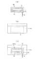
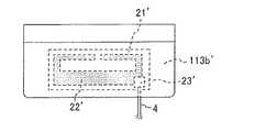
図7は、第四実施形態を説明する図であり、内部アンテナ21’を一体成型した専用のカバー部材113b’を説明する図である。
このカバー部材113b’は、カバー部材113b’を製造する過程で導体パターン22’を備えた内部アンテナ21’を樹脂内に一体成型して隠蔽し、さらに導体パターン22’に対して電気的に接続された通信ケーブル4用の接点23’をカバー部材113b’の内表面(裏面)に一体化したものである。接点23’の表面は、電気絶縁性を有する部材で覆われている。
カバー部材113b’では、内部アンテナ21’や接点23’がメータ外部から見えないように隠蔽されているため、美観が損なわれない。さらに、接点23’がカバー部材113b’の内表面に一体化されているため、通信ケーブル4を取り外す場合には、カバー部材113b’を脱着する必要があり、悪意のある第三者が接点23’から通信ケーブル4を容易に取り外す不都合を有効に防止できる。
万一、上記の第三者が接点23’から通信ケーブル4を取り外したとしても、ハウジング本体113aに対してカバー部材113b’の脱着を感知する接点が備えられており、脱着情報が無線通信によってヘッドエンドシステム140(サーバー)に蓄積されるため追跡調査も容易に行える。<Fourth Embodiment>
In the third embodiment described above, the
FIG. 7 is a diagram for explaining the fourth embodiment, and is a diagram for explaining a dedicated cover member 113b'in which the internal antenna 21'is integrally molded.
The cover member 113b'conceals the internal antenna 21' provided with the conductor pattern 22'in the resin in the process of manufacturing the
In the
Even if the above-mentioned third party removes the
<変形例>
前述の各実施形態において、スマートメータ110は1:N無線方式による通信を行うものであったが、本発明は1:N無線方式のスマートメータ110に限定されるものではない。例えば、マルチホップ通信方式のスマートメータにも適用できる。
マルチホップ通信方式のスマートメータに適用する時には、各スマートメータに対して上述の無線通信中継装置1を取り付ければよい。この場合、一のスマートメータを基準にすると、通信可能範囲に設置された他のスマートメータが通信の相手先機器に対応する。
なお、マルチホップ通信方式のスマートメータでは、例えば920MHz帯の周波数が使用される。このため、無線通信中継装置1が備える内部アンテナ2、2A、及び外部アンテナ3は、920MHz帯の周波数によって電波を送受信可能なものが用いられる。<Modification example>
In each of the above-described embodiments, the
When applied to a multi-hop communication type smart meter, the above-mentioned wireless
In the multi-hop communication type smart meter, for example, a frequency in the 920 MHz band is used. Therefore, the
[本発明の実施態様例と作用、効果のまとめ]
<第一の実施態様>
本態様に係る無線通信中継装置1は、キャビネット120(金属製箱体)の内部に設置されてメータ内アンテナ112を介した無線通信によって通信事業者の基地局130や他のスマートメータ(相手先機器)との間で情報を送受信するスマートメータ110に用いられ、スマートメータ110と基地局130等との間の無線通信を中継する装置であり、キャビネット120の内部においてスマートメータ110が備えたハウジング113に配置され、メータ内アンテナ112との間で無線通信を行う内部アンテナ2、2Aと、キャビネット120の外部に設置され、基地局130等との間で無線通信を行う外部アンテナ3と、内部アンテナ2等と外部アンテナ3との間を通信可能に接続する通信ケーブル4と、を備えたことを特徴とする。
本態様に係る無線通信中継装置1によれば、内部アンテナ2等とメータ内アンテナ112との間、外部アンテナ3と基地局130との間、及び内部アンテナ2、2Aと外部アンテナ3との間のそれぞれにおいて、金属製のキャビネット120の影響を受けることなく通信を行うことができる。
その結果、スマートメータ110と基地局130等との間の通信を安定させることができる。[Summary of Examples of Embodiments of the Present Invention, Actions, and Effects]
<First embodiment>
The wireless
According to the wireless
As a result, communication between the
<第二の実施態様>
本態様に係る無線通信中継装置1において、スマートメータ110は、ハウジング本体113aと共にハウジング113の一部を構成し、且つハウジング本体113aに対して着脱自在なカバー部材113bを備えており、内部アンテナ2Aは、カバー部材113bに貼設されたフィルムアンテナによって構成されていることを特徴とする。
本態様に係る無線通信中継装置1によれば、内部アンテナ2Aをカバー部材113bに予め貼設しておくことにより、内部アンテナ2Aの取り付けは、既設のカバー部材113bに換えて内部アンテナ2Aを貼設したカバー部材113bをハウジング本体113aに対して取り付けるだけ済むため、設置の容易化が図れる。<Second embodiment>
In the wireless
According to the wireless
<第三の実施態様>
本態様に係る無線通信中継装置1において、スマートメータ110は、ハウジング本体113aと共にハウジング113の一部を構成し、且つハウジング本体113aに対して着脱自在な樹脂製のカバー部材113b’を備えており、内部アンテナ21’はカバー部材113b’内に一体成型され、且つ内部アンテナ21’と通信ケーブル4との接点23’をカバー部材113b’の内表面側に設けたことを特徴とする。
本態様に係る無線通信中継装置1によれば、内部アンテナ21’をカバー部材113b’内に一体成型し、且つ接点23’をカバー部材113b’の内表面側に設けたので、悪意のある第三者が接点23’から通信ケーブル4を取り外そうとしても、この行為を有効に防止できる。
また、内部アンテナ21’がカバー部材113b’内に一体成型され、且つ接点23’がカバー部材113b’の内表面側に設けられているので、美観を損なわない。<Third embodiment>
In the wireless
According to the wireless
Further, since the internal antenna 21'is integrally molded in the cover member 113b'and the contact 23' is provided on the inner surface side of the
1…無線通信中継装置、2、2A…内部アンテナ、3…外部アンテナ、4…通信ケーブル、110…スマートメータ、111…メータ本体、112…メータ内アンテナ、113…ハウジング、115…表示部、120…キャビネット、130…基地局1 ... Wireless communication relay device, 2, 2A ... Internal antenna, 3 ... External antenna, 4 ... Communication cable, 110 ... Smart meter, 111 ... Meter body, 112 ... In-meter antenna, 113 ... Housing, 115 ... Display, 120 ... cabinet, 130 ... base station
Claims (3)
Translated fromJapanese前記金属製箱体の内部において前記スマートメータが備えたハウジングに配置され、前記メータ内アンテナとの間で無線通信を行う内部アンテナと、
前記金属製箱体の外部に設置され、前記相手先機器との間で無線通信を行う外部アンテナと、
前記内部アンテナと前記外部アンテナとの間を通信可能に接続する通信ケーブルと、
を備えたことを特徴とする無線通信中継装置。It is used in a smart meter that is installed inside a metal box and transmits and receives information to and from the other party device by wireless communication via an antenna inside the meter, and wireless communication between the smart meter and the other party device. It is a wireless communication relay device that relays
An internal antenna, which is arranged in a housing provided with the smart meter inside the metal box and performs wireless communication with the antenna in the meter,
An external antenna installed outside the metal box and performing wireless communication with the other party's device,
A communication cable that connects the internal antenna and the external antenna so that they can communicate with each other.
A wireless communication relay device characterized by being equipped with.
前記内部アンテナは、前記カバー部材に貼設されたフィルムアンテナによって構成されていることを特徴とする請求項1に記載の無線通信中継装置。The smart meter constitutes a part of the housing together with the housing body, and includes a cover member that can be attached to and detached from the housing body.
The wireless communication relay device according to claim 1, wherein the internal antenna is composed of a film antenna attached to the cover member.
前記内部アンテナは、前記カバー部材内に一体成型され、
前記内部アンテナと前記通信ケーブルとの接点を、前記カバー部材の内表面側に設けたことを特徴とする請求項1に記載の無線通信中継装置。The smart meter constitutes a part of the housing together with the housing body, and includes a resin cover member that is removable from the housing body.
The internal antenna is integrally molded in the cover member.
The wireless communication relay device according to claim 1, wherein the contact point between the internal antenna and the communication cable is provided on the inner surface side of the cover member.
Priority Applications (1)
| Application Number | Priority Date | Filing Date | Title |
|---|---|---|---|
| JP2020020513AJP7434977B2 (en) | 2020-02-10 | 2020-02-10 | Wireless communication relay device for smart meters |
Applications Claiming Priority (1)
| Application Number | Priority Date | Filing Date | Title |
|---|---|---|---|
| JP2020020513AJP7434977B2 (en) | 2020-02-10 | 2020-02-10 | Wireless communication relay device for smart meters |
Publications (2)
| Publication Number | Publication Date |
|---|---|
| JP2021125863Atrue JP2021125863A (en) | 2021-08-30 |
| JP7434977B2 JP7434977B2 (en) | 2024-02-21 |
Family
ID=77459644
Family Applications (1)
| Application Number | Title | Priority Date | Filing Date |
|---|---|---|---|
| JP2020020513AActiveJP7434977B2 (en) | 2020-02-10 | 2020-02-10 | Wireless communication relay device for smart meters |
Country Status (1)
| Country | Link |
|---|---|
| JP (1) | JP7434977B2 (en) |
Citations (5)
| Publication number | Priority date | Publication date | Assignee | Title |
|---|---|---|---|---|
| JP2001168786A (en)* | 1999-12-09 | 2001-06-22 | Astel Kyushu Corp | Repeater for phs |
| JP2003319447A (en)* | 2002-04-18 | 2003-11-07 | Denso Corp | Communication facility |
| JP2011081518A (en)* | 2009-10-05 | 2011-04-21 | Panasonic Electric Works Co Ltd | Remote meter reading device |
| JP2019009698A (en)* | 2017-06-27 | 2019-01-17 | 株式会社長谷工コーポレーション | Indoor wireless system and installation method thereof |
| US20190214705A1 (en)* | 2018-01-11 | 2019-07-11 | Schneider Electric Industries Sas | Wireless communicating electrical device and electrical enclosure comprising this electrical device |
- 2020
- 2020-02-10JPJP2020020513Apatent/JP7434977B2/enactiveActive
Patent Citations (5)
| Publication number | Priority date | Publication date | Assignee | Title |
|---|---|---|---|---|
| JP2001168786A (en)* | 1999-12-09 | 2001-06-22 | Astel Kyushu Corp | Repeater for phs |
| JP2003319447A (en)* | 2002-04-18 | 2003-11-07 | Denso Corp | Communication facility |
| JP2011081518A (en)* | 2009-10-05 | 2011-04-21 | Panasonic Electric Works Co Ltd | Remote meter reading device |
| JP2019009698A (en)* | 2017-06-27 | 2019-01-17 | 株式会社長谷工コーポレーション | Indoor wireless system and installation method thereof |
| US20190214705A1 (en)* | 2018-01-11 | 2019-07-11 | Schneider Electric Industries Sas | Wireless communicating electrical device and electrical enclosure comprising this electrical device |
Also Published As
| Publication number | Publication date |
|---|---|
| JP7434977B2 (en) | 2024-02-21 |
Similar Documents
| Publication | Publication Date | Title |
|---|---|---|
| US11917519B2 (en) | Wireless sensor system, method and apparatus with switch and outlet control | |
| US8467734B2 (en) | Wireless transceiver within an electrical receptacle system | |
| US6492897B1 (en) | System for coupling wireless signals to and from a power transmission line communication system | |
| US20180131440A1 (en) | Antenna installation including an antenna line device controllable over a wireless interface | |
| KR20140092401A (en) | Wireless communication apparatus, wireless communication system having same, and power consumption management apparatus | |
| WO2015122157A1 (en) | Flow rate measurement device and wireless communication device | |
| US20050268322A1 (en) | Apparatus and method for utilizing a pre-existing power grid to provide internet access to a home or office or the like | |
| JP7132988B2 (en) | housing | |
| JP2021125863A (en) | Wireless communication relay device for smart meter | |
| JP5346222B2 (en) | Remote meter reading system | |
| JPH08125433A (en) | Repeater for in-building radio communication | |
| US9300030B2 (en) | Small-cell antenna arrangement | |
| JP2007166418A (en) | Receptacle device | |
| CN210518308U (en) | Wireless public network signal transmission device and power distribution network terminal system | |
| GB2327566A (en) | Method of Orienting an Antenna | |
| CN216649686U (en) | Emergency communication device | |
| JP4524964B2 (en) | Wireless circuit | |
| JP2015211274A (en) | Communication device and distribution board using the same | |
| JP6256878B2 (en) | Internal device for distribution board and distribution board using the same | |
| CN212137904U (en) | Bluetooth WiFi device | |
| CN219227741U (en) | Wireless transmission device | |
| CN110661544B (en) | Wireless public network signal transmission device and power distribution network terminal system | |
| RU82338U1 (en) | ELECTRIC ENERGY METER | |
| JP2002245581A (en) | Automatic meter reading system and antenna device | |
| JPS623950Y2 (en) |
Legal Events
| Date | Code | Title | Description |
|---|---|---|---|
| A621 | Written request for application examination | Free format text:JAPANESE INTERMEDIATE CODE: A621 Effective date:20221222 | |
| A977 | Report on retrieval | Free format text:JAPANESE INTERMEDIATE CODE: A971007 Effective date:20230929 | |
| A131 | Notification of reasons for refusal | Free format text:JAPANESE INTERMEDIATE CODE: A131 Effective date:20231017 | |
| A521 | Request for written amendment filed | Free format text:JAPANESE INTERMEDIATE CODE: A523 Effective date:20231122 | |
| TRDD | Decision of grant or rejection written | ||
| A01 | Written decision to grant a patent or to grant a registration (utility model) | Free format text:JAPANESE INTERMEDIATE CODE: A01 Effective date:20240109 | |
| A61 | First payment of annual fees (during grant procedure) | Free format text:JAPANESE INTERMEDIATE CODE: A61 Effective date:20240122 | |
| R150 | Certificate of patent or registration of utility model | Ref document number:7434977 Country of ref document:JP Free format text:JAPANESE INTERMEDIATE CODE: R150 |