JP2021124241A - Air conditioning system - Google Patents
Air conditioning systemDownload PDFInfo
- Publication number
- JP2021124241A JP2021124241AJP2020017847AJP2020017847AJP2021124241AJP 2021124241 AJP2021124241 AJP 2021124241AJP 2020017847 AJP2020017847 AJP 2020017847AJP 2020017847 AJP2020017847 AJP 2020017847AJP 2021124241 AJP2021124241 AJP 2021124241A
- Authority
- JP
- Japan
- Prior art keywords
- indoor
- temperature
- set temperature
- unit
- air conditioning
- Prior art date
- Legal status (The legal status is an assumption and is not a legal conclusion. Google has not performed a legal analysis and makes no representation as to the accuracy of the status listed.)
- Pending
Links
Images


Classifications
- F—MECHANICAL ENGINEERING; LIGHTING; HEATING; WEAPONS; BLASTING
- F24—HEATING; RANGES; VENTILATING
- F24F—AIR-CONDITIONING; AIR-HUMIDIFICATION; VENTILATION; USE OF AIR CURRENTS FOR SCREENING
- F24F11/00—Control or safety arrangements
- F24F11/30—Control or safety arrangements for purposes related to the operation of the system, e.g. for safety or monitoring
- F24F11/32—Responding to malfunctions or emergencies
- F24F11/38—Failure diagnosis
- F—MECHANICAL ENGINEERING; LIGHTING; HEATING; WEAPONS; BLASTING
- F24—HEATING; RANGES; VENTILATING
- F24F—AIR-CONDITIONING; AIR-HUMIDIFICATION; VENTILATION; USE OF AIR CURRENTS FOR SCREENING
- F24F11/00—Control or safety arrangements
- F24F11/30—Control or safety arrangements for purposes related to the operation of the system, e.g. for safety or monitoring
- F24F11/49—Control or safety arrangements for purposes related to the operation of the system, e.g. for safety or monitoring ensuring correct operation, e.g. by trial operation or configuration checks
- F—MECHANICAL ENGINEERING; LIGHTING; HEATING; WEAPONS; BLASTING
- F24—HEATING; RANGES; VENTILATING
- F24F—AIR-CONDITIONING; AIR-HUMIDIFICATION; VENTILATION; USE OF AIR CURRENTS FOR SCREENING
- F24F11/00—Control or safety arrangements
- F24F11/62—Control or safety arrangements characterised by the type of control or by internal processing, e.g. using fuzzy logic, adaptive control or estimation of values
- F24F11/63—Electronic processing
- F24F11/64—Electronic processing using pre-stored data
Landscapes
- Engineering & Computer Science (AREA)
- Chemical & Material Sciences (AREA)
- Combustion & Propulsion (AREA)
- Mechanical Engineering (AREA)
- General Engineering & Computer Science (AREA)
- Signal Processing (AREA)
- Physics & Mathematics (AREA)
- Fuzzy Systems (AREA)
- Mathematical Physics (AREA)
- Health & Medical Sciences (AREA)
- Biomedical Technology (AREA)
- Air Conditioning Control Device (AREA)
Abstract
Translated fromJapaneseDescription
Translated fromJapanese本発明は、制御装置を備える空気調和システムに関する。 The present invention relates to an air conditioning system including a control device.
従来、制御装置を備える空気調和システムが知られている。空気調和システムにおいて、冷房時に室内が適切に冷却されない不冷状態が発生したり、暖房時に室内が適切に加熱されない不暖状態が発生したりして、利用者からクレームが寄せられる場合がある。特許文献1には、利用者からのクレームと、地域の予想温度とに基づいて、クレームが発生し易い時間帯を特定しようとする空調制御支援装置が開示されている。具体的には、特許文献1は、1日のうち空調が不調となって利用者からクレームが発生し易い時間帯を、過去のクレーム履歴と、室外温度と、設定温度と、天気予報とを用いて予測する。予測結果は、室内を適切な温度に調整するための制御情報として利用される。 Conventionally, an air conditioning system including a control device is known. In an air conditioning system, a user may complain because an uncooled state occurs in which the room is not properly cooled during cooling, or an unheated state occurs in which the room is not properly heated during heating.
しかしながら、特許文献1に開示された空調制御支援装置は、過去のクレーム履歴及び天気予報といった空調系統とは異なる外部情報を用いて空調の不調を予測し、予測結果を制御情報として利用している。即ち、特許文献1は、空調の不調を予測するために必要な情報の収集が煩雑である。 However, the air conditioning control support device disclosed in
本発明は、上記のような課題を解決するためになされたもので、空調の不調を予測するために必要な情報の収集が簡便な空気調和システムを提供するものである。 The present invention has been made to solve the above problems, and provides an air conditioning system in which it is easy to collect information necessary for predicting an air conditioning malfunction.
本発明に係る空気調和システムは、室外に設けられる室外機と、室外機に接続され、複数の空調対象空間の空気を、設定された設定温度になるようにそれぞれ調整する複数の室内機と、空調対象空間の室内温度を検出する室内温度検出部と、室外機及び室内機の動作を制御する制御装置と、を備え、制御装置は、室内温度検出部によって検出された室内温度と設定温度とに基づいて、室内温度が設定温度に到達するまでの設定温度到達時間を算出する算出手段と、複数の室内機を、算出手段によって算出された設定温度到達時間の順に並べたリストを出力する出力手段と、を有する。 The air conditioning system according to the present invention includes an outdoor unit provided outdoors, a plurality of indoor units connected to the outdoor unit, and a plurality of indoor units connected to the outdoor unit to adjust the air in a plurality of air-conditioned spaces so as to reach a set set temperature. It includes an indoor temperature detector that detects the indoor temperature of the air-conditioned space and a control device that controls the operation of the outdoor unit and the indoor unit. The control device includes the indoor temperature and the set temperature detected by the indoor temperature detector. Outputs a calculation means that calculates the set temperature arrival time until the room temperature reaches the set temperature, and a list of a plurality of indoor units arranged in the order of the set temperature arrival time calculated by the calculation means. Means and.
本発明によれば、出力手段は、複数の室内機を、室内温度と設定温度とに基づいて算出された設定温度到達時間の順に並べたリストを出力する。ここで、設定温度到達時間は、室内温度と設定温度という空調系統の情報である。このように、本発明は、外部情報ではなく空調系統の情報を用いて、空調の不調を予測する。従って、空調の不調を予測するために必要な情報の収集が簡便である。 According to the present invention, the output means outputs a list in which a plurality of indoor units are arranged in the order of the set temperature arrival time calculated based on the indoor temperature and the set temperature. Here, the set temperature arrival time is information on the air conditioning system, that is, the room temperature and the set temperature. As described above, the present invention uses the information of the air conditioning system instead of the external information to predict the malfunction of the air conditioning. Therefore, it is easy to collect the information necessary for predicting the malfunction of the air conditioner.
以下、本発明の空気調和システムの実施の形態について、図面を参照しながら説明する。なお、本発明は、以下に説明する実施の形態によって限定されるものではない。また、図1を含め、以下の図面では各構成部材の大きさの関係が実際のものとは異なる場合がある。また、以下の説明において、本発明の理解を容易にするために方向を表す用語を適宜用いるが、これは本発明を説明するためのものであって、これらの用語は本発明を限定するものではない。方向を表す用語としては、例えば、「上」、「下」、「右」、「左」、「前」又は「後」等が挙げられる。 Hereinafter, embodiments of the air conditioning system of the present invention will be described with reference to the drawings. The present invention is not limited to the embodiments described below. Further, in the following drawings including FIG. 1, the relationship between the sizes of the constituent members may differ from the actual one. Further, in the following description, terms indicating directions are appropriately used in order to facilitate understanding of the present invention, but these terms are for explaining the present invention and these terms limit the present invention. is not it. Examples of the term indicating the direction include "top", "bottom", "right", "left", "front", "rear", and the like.
実施の形態1.
図1は、実施の形態1に係る空気調和システム1を示す模式図である。図1に示すように、空気調和システム1は、室外機2と、複数の室内機3と、表示装置5と、制御装置4とを備えている。室外機2は、室外に設けられるものである。複数の室内機3は、室外機2に接続され、複数の空調対象空間の空気を、設定された設定温度になるようにそれぞれ調整する。本実施の形態1では、室外機2が1台である場合について例示しているが、室外機2は複数台であってもよい。また、本実施の形態1では、室内機3が4台である場合について例示しているが、室内機3は1台〜3台であってもよく、5台以上であってもよい。
FIG. 1 is a schematic view showing an
図2は、実施の形態1に係る空気調和システム1を示す回路図である。図2に示すように、室外機2には、例えば圧縮機11、流路切替装置12、室外熱交換器13、室外送風機14、室外膨張部15、アキュムレータ19及び電磁弁20が設けられている。各室内機3には、例えばそれぞれ室内膨張部16、室内熱交換器17、室内送風機18及び室内温度検出部7が設けられている。 FIG. 2 is a circuit diagram showing an
圧縮機11、流路切替装置12、室外熱交換器13、室外膨張部15、複数の室内膨張部16及び複数の室内熱交換器17が冷媒配管6aにより接続されて冷媒回路6が構成されている。ここで、流路切替装置12と室内熱交換器17とはガス管21によって接続されており、室外膨張部15と室内膨張部16とは液管22によって接続されている。 The
圧縮機11は、低温且つ低圧の状態の冷媒を吸入し、吸入した冷媒を圧縮して高温且つ高圧の状態の冷媒にして吐出するものである。流路切替装置12は、冷媒回路6において冷媒が流れる方向を切り替えるものであり、例えば四方弁である。室外熱交換器13は、例えば室外空気と冷媒との間で熱交換するものである。室外熱交換器13は、冷房運転時には凝縮器として作用し、暖房運転時には蒸発器として作用する。室外送風機14は、室外熱交換器13に室外空気を送る機器である。 The
室外膨張部15は、冷媒を減圧して膨張する減圧弁又は膨張弁である。室外膨張部15は、例えば開度が調整される電子式膨張弁である。アキュムレータ19は、圧縮機11の吸入側に設けられており、ガス状態の冷媒のみが圧縮機11に流入するように、圧縮機11に吸入される冷媒のうち液状態の冷媒を貯留するものである。電磁弁20は、圧縮機11が停止した場合等に吐出側と吸入側との圧力差をなくして均圧化するものである。 The
それぞれの室内膨張部16は、冷媒を減圧して膨張する減圧弁又は膨張弁である。それぞれの室内膨張部16は、例えば開度が調整される電子式膨張弁である。それぞれの室内熱交換器17は、例えば室内空気と冷媒との間で熱交換するものである。それぞれの室内熱交換器17は、冷房運転時には蒸発器として作用し、暖房運転時には凝縮器として作用する。それぞれの室内送風機18は、室内熱交換器17に室内空気を送る機器である。なお、冷媒は、フロン、代替フロン又は二酸化炭素等が用いられる。それぞれの室内温度検出部7は、室内機3の吸込口(図示せず)に設けられ、空調対象空間の室内温度を検出するものである。 Each
なお、本実施の形態1では、各室内機3に室内膨張部16が設けられた上で、室外機2に室外膨張部15が設けられている場合について例示しているが、室外膨張部15が省略されてもよい。この場合、各室内膨張部16は、室外機2に設けられてもよい。 In the first embodiment, the case where the
(運転モード、冷房運転)
次に、空気調和システム1の運転モードについて説明する。先ず、冷房運転について説明する。冷房運転において、圧縮機11に吸入された冷媒は、圧縮機11によって圧縮されて高温且つ高圧のガス状態で吐出する。圧縮機11から吐出された高温且つ高圧のガス状態の冷媒は、流路切替装置12を通過して、凝縮器として作用する室外熱交換器13に流入し、室外熱交換器13において、室外送風機14によって送られる室外空気と熱交換されて凝縮して液化する。凝縮された液状態の冷媒は、室外膨張部15に流入し、室外膨張部15において膨張及び減圧されて低温且つ低圧の気液二相状態の冷媒となる。(Operation mode, cooling operation)
Next, the operation mode of the
そして、気液二相状態の冷媒は、液管22を流れてそれぞれの室内膨張部16に流入する。冷媒は、それぞれの室内膨張部16において膨張及び減圧されて、蒸発器として作用するそれぞれの室内熱交換器17に流入する。冷媒は、それぞれの室内熱交換器17において、それぞれの室内送風機18によって送られる室内空気と熱交換されて蒸発してガス化する。このとき、室内空気が冷やされ、各空調対象空間において冷房が実施される。蒸発した低温且つ低圧のガス状態の冷媒は、ガス管21及び流路切替装置12を通過して、圧縮機11に吸入される。 Then, the gas-liquid two-phase state refrigerant flows through the
(運転モード、暖房運転)
次に、暖房運転について説明する。暖房運転において、圧縮機11に吸入された冷媒は、圧縮機11によって圧縮されて高温且つ高圧のガス状態で吐出する。圧縮機11から吐出された高温且つ高圧のガス状態の冷媒は、流路切替装置12及びガス管21を通過して、凝縮器として作用するそれぞれの室内熱交換器17に流入する。冷媒は、それぞれの室内熱交換器17において、それぞれの室内送風機18によって送られる室内空気と熱交換されて凝縮して液化する。このとき、室内空気が暖められ、各空調対象空間において暖房が実施される。凝縮された液状態の冷媒は、液管22をとおったのち、それぞれの室内膨張部16に流入し、それぞれの室内膨張部16において膨張及び減圧されて低温且つ低圧の気液二相状態の冷媒となる。(Operation mode, heating operation)
Next, the heating operation will be described. In the heating operation, the refrigerant sucked into the
そして、気液二相状態の冷媒は、室外膨張部15に流入し、室外膨張部15において膨張及び減圧される。冷媒は、その後、蒸発器として作用する室外熱交換器13に流入し、室外熱交換器13において、室外送風機14によって送られる室外空気と熱交換されて蒸発してガス化する。蒸発した低温且つ低圧のガス状態の冷媒は、流路切替装置12を通過して、圧縮機11に吸入される。 Then, the gas-liquid two-phase state refrigerant flows into the
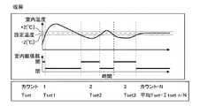
図3は、実施の形態1に係る室内温度制御について説明するグラフである。図3において、横軸は時間を示し、縦軸は空調対象空間の室内温度を示す。図3に示すように、空気調和システム1の温度制御は、設定温度に対して所定の上限値及び下限値が設けられている。例えば、上限値は設定温度より2℃高く、下限値は設定温度より2℃低い。室内機3に吸い込まれる空気の温度である室内温度が、上限値より高いか又は下限値より低いとき、制御装置4は、室内送風機18を駆動し、且つ、室内熱交換器17に冷媒が流れるように制御する。これをサーモオンと呼称する。これにより、空調対象空間の空気を加熱又は冷却して、室内温度が設定温度の上限値以下且つ下限値以上となる。 FIG. 3 is a graph illustrating indoor temperature control according to the first embodiment. In FIG. 3, the horizontal axis represents time and the vertical axis represents the indoor temperature of the air-conditioned space. As shown in FIG. 3, the temperature control of the
一方、室内機3に吸い込まれる空気の温度である室内温度が、上限値以下且つ下限値以上のとき、制御装置4は、室内送風機18を停止し、且つ、室内熱交換器17に冷媒が流れないように制御する。これをサーモオフと呼称する。このとき、制御装置4は、室内送風機18のみを駆動してもよい。また、制御装置4は、サーモオンのとき室内膨張部16を開き、サーモオフのとき室内膨張部16を閉じてもよい(図5参照)。ここで、室内温度が設定温度に到達するまでの時間を設定温度到達時間Tsetとする。なお、具体的には、設定温度到達時間Tsetは、上限値から外れた室内温度が上限値に戻るまでの時間であり、下限値から外れた室内温度が、下限値に戻るまでの時間である。 On the other hand, when the indoor temperature, which is the temperature of the air sucked into the
(表示装置5)
表示装置5は、例えばビル等の建物の管理室等に設けられており、空気調和システム1の各情報を表示するものである。表示装置5は、例えば液晶ディスプレイであるが、そのほかのものでもよい。また、表示装置5は、管理室ではなく別の場所に設けられてもよく、空調対象空間等に設けられてもよい。(Display device 5)
The
(制御装置4)
制御装置4は、室外機2及び室内機3の動作を制御するものであり、専用のハードウェア又は記憶装置に格納されるプログラムを実行するCPU(Central Processing Unit、中央処理装置、処理装置、演算装置、マイクロプロセッサ、マイクロコンピュータ又はプロセッサともいう)で構成される。制御装置4が専用のハードウェアである場合、制御装置4は、例えば、単一回路、複合回路、ASIC(Application Specific Integrated Circuit)、FPGA(Field−Programmable Gate Array)、又は、これらを組み合わせたものが該当する。制御装置4が実現する各機能部のそれぞれを、個別のハードウェアで実現してもよいし、各機能部を一つのハードウェアで実現してもよい。(Control device 4)
The
制御装置4がCPUの場合、制御装置4が実行する各機能は、ソフトウェア、ファームウェア、又はソフトウェアとファームウェアとの組み合わせにより実現される。ソフトウェア及びファームウェアはプログラムとして記述される。CPUは、プログラムを読み出して実行することにより、各機能を実現する。なお、制御装置4の機能の一部を専用のハードウェアで実現し、一部をソフトウェア又はファームウェアで実現するようにしてもよい。 When the
図4は、実施の形態1に係る制御装置4を示す機能ブロック図である。図4に示すように、制御装置4は、記憶手段31と、判定手段32と、算出手段33と、書込手段34と、出力手段35とを有している。なお、本実施の形態1は、制御装置4が室外機2に接続されている場合について例示しているが、制御装置4は室外機2内に設けられてもよい。 FIG. 4 is a functional block diagram showing the
(記憶手段31)
記憶手段31は、空気調和システム1が必要とする情報を記憶するものである。記憶手段31は、ハードディスクとして構成されてもよいし、データを一時的に記憶することができるランダムアクセスメモリ(RAM)等の揮発性記憶手段として構成されてもよい。また、記憶手段31は、データを長期的に記憶することができるフラッシュメモリ等の不揮発性記憶手段として構成されてもよい。なお、記憶手段31は、制御装置4が備えるものではなく、空気調和システム1の室内機3に設けられたメモリでもよいし、ネットワークを介して制御システム1外部のネットワーク上のクラウドサーバ等でもよい。記憶手段31は、設定温度と、時間閾値と、温度閾値とを記憶している。なお、制御装置4は、室内機3の運転が開始された際、運転開始時刻を記憶手段31に記憶する。(Memory means 31)
The storage means 31 stores information required by the
記憶手段31は、制御装置4によって遠隔収集された空気調和システム1の遠隔監視データを記憶する。遠隔監視データとして、任意の場所の温度、圧力、各室内機3の運転時間、設定温度が上限値以下及び下限値以上であるときの時間、設定温度到達時間Tset、サーモオンの発生回数又は1日の設定温度到達時間Tsetの平均値等が挙げられる。 The storage means 31 stores the remote monitoring data of the
(判定手段32)
判定手段32は、室内温度検出部7によって検出された室内温度と、記憶手段31に記憶された設定温度との温度差が、記憶手段31に記憶された温度閾値以下であるかを判定するものである。ここで、温度閾値は、予め設定されたものであり、上限値と設定温度との差、又は下限値と設定温度との差である。(Determining means 32)
The determination means 32 determines whether the temperature difference between the indoor temperature detected by the indoor
(算出手段33)
算出手段33は、室内温度検出部7によって検出された室内温度と設定温度とに基づいて、室内温度が設定温度に到達するまでの設定温度到達時間Tsetを算出するものである。具体的には、算出手段33は、判定手段32によって温度差が温度閾値以下であると判定された場合、設定温度到達時間Tsetを算出する。設定温度到達時間Tsetは、前述の如く、上限値又は下限値から外れた室内温度が上限値又は下限値に到達するまでの時間である。本実施の形態1のように複数の室内機3が設けられている場合、制御装置4は、各室内機3の設定温度到達時間Tsetを収集する。(Calculation means 33)
The calculation means 33 calculates the set temperature arrival time Tset until the room temperature reaches the set temperature based on the room temperature and the set temperature detected by the room
図5は、実施の形態1に係る暖房運転時の膨張部の動作を示すグラフである。図5の上図において、横軸は時間を示し、縦軸は室内温度を示す。図5の下部において、横軸は時間を示し、縦軸は室内膨張部16の開閉指令状態を示す。算出手段33は、1台の室内機3における複数の設定温度到達時間Tsetの平均値を算出する。先ず、暖房運転について説明する。図5に示すように、算出手段33は、1カウント目のTset1、2カウント目のTset2、3カウント目のTset3、・・・Nカウント目のTsetnを算出する。算出手段33は、Tset1からTsetnまでを全て加算した上で、カウントNで除算する。これにより、算出手段33は、平均値を算出する。制御装置4は、サーモオンのとき室内膨張部16を開き、サーモオフのとき室内膨張部16を閉じる。 FIG. 5 is a graph showing the operation of the expansion portion during the heating operation according to the first embodiment. In the upper view of FIG. 5, the horizontal axis represents time and the vertical axis represents room temperature. In the lower part of FIG. 5, the horizontal axis represents time, and the vertical axis represents the open / close command state of the
図6は、実施の形態1に係る冷房運転時の膨張部の動作を示すグラフである。図6の上図において、横軸は時間を示し、縦軸は室内温度を示す。図6の下部において、横軸は時間を示し、縦軸は室内膨張部16の開閉指令状態を示す。次に、冷房運転について説明する。図6に示すように、算出手段33は、1カウント目のTset1、2カウント目のTset2、3カウント目のTset3、・・・Nカウント目のTsetnを算出する。算出手段33は、Tset1からTsetnまでを全て加算した上で、カウントNで除算する。これにより、算出手段33は、平均値を算出する。制御装置4は、サーモオンのとき室内膨張部16を開き、サーモオフのとき室内膨張部16を閉じる。 FIG. 6 is a graph showing the operation of the expansion portion during the cooling operation according to the first embodiment. In the upper view of FIG. 6, the horizontal axis represents time and the vertical axis represents room temperature. In the lower part of FIG. 6, the horizontal axis represents time, and the vertical axis represents the open / close command state of the
図7は、実施の形態1に係る暖房運転時の膨張部の動作不良を示すグラフである。図7の上図は、室内膨張部16の動作が正常である場合について示し、図7の下図は、室内膨張部16の動作が不良である場合について示す。図7の上図上段において、横軸は時間を示し、縦軸は室内温度を示す。図7の上図下段において、横軸は時間を示し、縦軸は室内膨張部16の開閉指令状態を示す。図7の下図上段において、横軸は時間を示し、縦軸は室内温度を示す。図7の下図下段において、横軸は時間を示し、縦軸は室内膨張部16の開閉指令状態を示す。ここで、室内膨張部16が動作不良を起こしている場合について説明する。図7の上図に示すように、室内膨張部16の動作が正常である場合、制御装置4は、サーモオンのとき室内膨張部16を開き、サーモオフのとき室内膨張部16を閉じる。これに対し、図7の下図に示すように、室内膨張部16の動作が不良である場合、制御装置4は、サーモオフのとき室内膨張部16を閉じるよう指示しても、室内膨張部16が反応せず閉じない。このため、冷媒回路6に冷媒が流れず、室内機3が暖房運転しない。従って、室内温度が下がり続ける。 FIG. 7 is a graph showing a malfunction of the expansion portion during the heating operation according to the first embodiment. The upper figure of FIG. 7 shows the case where the operation of the
(書込手段34)
書込手段34は、算出手段33によって算出された設定温度到達時間Tsetが、記憶手段31に記憶された時間閾値を超えた場合、室内機3をリストに書き込むものである。図7に示すように、室内膨張部16が動作不良を起こしている場合、室内温度が下がり続けるため、設定温度到達時間Tsetが長くなる。書込手段34は、設定温度到達時間Tsetが時間閾値を超えた場合、室内機3をリストに書き込む。ここで、リストは、不調の兆しがある室内機3が並べられたものである。なお、本実施の形態1では、設定温度到達時間Tsetとして平均値を用いている場合について例示する。(Writing means 34)
The writing means 34 writes the
(出力手段35)
出力手段35は、複数の室内機3を、算出手段33によって算出された設定温度到達時間Tsetの順に並べたリストを出力する。具体的には、出力手段35は、リストを表示装置5に表示させる。このとき、出力手段35は、リストを保守サービス会社に送信してもよい。これにより、空気調和システム1が各空調対象空間に対し適切な温度調整を行うことができる。なお、出力手段35は、設定温度到達時間Tsetが時間閾値を超えていなくても、複数の室内機3を、設定温度到達時間Tsetの順に並べたリストを出力してもよい。また、出力手段35は、算出手段33によって算出された設定温度到達時間Tsetが、予め設定された時間閾値を超えた場合、発報するものであってもよい。(Output means 35)
The output means 35 outputs a list in which the plurality of
図8は、実施の形態1に係る制御装置4の動作を示すフローチャートである。次に、制御装置4の動作について説明する。図8に示すように、制御装置4は、先ず、室内機3の運転開始時刻を記憶手段31に記録する(ステップST1)。次に、判定手段32は、室内温度検出部7によって検出された室内温度と設定温度との温度差を計測し(ステップST2)、温度差が温度閾値以下であるかを判定する(ステップST3)。温度差が温度閾値より大きい場合(ステップST3のNO)、ステップST2に戻る。温度差が温度閾値以下の場合(ステップST3のYES)、算出手段33は、設定温度到達時間Tsetを算出する(ステップST4)。 FIG. 8 is a flowchart showing the operation of the
そして、書込手段34は、算出された設定温度到達時間Tsetが時間閾値より大きいかを判定する(ステップST5)。設定温度到達時間Tsetが時間閾値以下の場合(ステップST5のNO)、ステップST4に戻る。一方、設定温度到達時間Tsetが時間閾値より大きい場合(ステップST5のYES)、書込手段34は、設定温度到達時間Tsetが時間閾値より大きい室内機3をリストに書き込む(ステップST6)。制御装置4は、各室内機3の設定温度到達時間Tsetを収集する(ステップST7)。出力手段35は、複数の室内機3を、設定温度到達時間Tsetの順に並べたリストを表示装置5に出力する(ステップST8)。制御装置4は、リストを保守サービス会社に送信する(ステップST9)。 Then, the writing means 34 determines whether the calculated set temperature arrival time Tset is larger than the time threshold value (step ST5). When the set temperature arrival time Tset is equal to or less than the time threshold value (NO in step ST5), the process returns to step ST4. On the other hand, when the set temperature arrival time Tset is larger than the time threshold value (YES in step ST5), the writing means 34 writes the
本実施の形態1によれば、出力手段35は、複数の室内機3を、室内温度と設定温度とに基づいて算出された設定温度到達時間Tsetの順に並べたリストを出力する。ここで、設定温度到達時間Tsetは、室内温度と設定温度という空調系統の情報である。このように、本実施の形態1は、外部情報ではなく空調系統の情報を用いて、空調の不調を予測する。従って、空調の不調を予測するために必要な情報の収集が簡便である。 According to the first embodiment, the output means 35 outputs a list in which a plurality of
原則として、室内機3が設置されたのちに室内機3の設置環境が変わることはない。このため、設置環境下におかれた室内機3の設定温度到達時間Tsetは、ほぼ一定となる傾向がある。利用者において、設定温度到達時間Tsetが長いことは、空調対象空間が所望の環境温度となっていない時間が長いことを意味する。このため、設定温度到達時間Tsetが長い場合、利用者からのクレームが発生する蓋然性がある。本実施の形態1は、管理者がリストを参照することによって、状況を確認する室内機3に優先順位を付けることができる。従って、管理者は、優先順位が高い室内機3から順に状況を確認し、状況によって修理等の対応を行うことができる。また、制御装置4がリストを保守サービス会社に送信することによって、保守サービス会社がリストを参照して空気調和システム1に対し適切な保全を行うことができる。 As a general rule, the installation environment of the
また、出力手段35は、算出手段33によって算出された設定温度到達時間Tsetが、予め設定された時間閾値を超えた場合、発報するものであってもよい。これにより、管理者は、設定温度到達時間Tsetが長く利用者からのクレームが発生する蓋然性がある室内機3を把握することができる。従って、管理者は、修理等の対応を直ちに行うことができる。この場合、室内機3は1台であってもよい。 Further, the output means 35 may issue a report when the set temperature arrival time Tset calculated by the calculation means 33 exceeds a preset time threshold value. As a result, the administrator can grasp the
(変形例)
変形例において、算出手段33は、設定温度到達時間Tsetを、室内機3の運転時間で除算した割合を算出する。通例、割合は40%以下である。即ち、割合が40%を超えた場合、室内機3の空調能力の低下又は空調負荷の増加が発生していると推定することができる。書込手段34は、例えば、割合が40%を超えた場合、室内機3をリストに書き込む。これにより、管理者は、室内機3の空調能力の低下又は空調負荷の増加が発生している可能性があることを認識することができる。(Modification example)
In the modified example, the calculation means 33 calculates the ratio of the set temperature arrival time Tset divided by the operating time of the
実施の形態2.
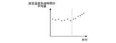
図9は、実施の形態2に係る設定温度到達時間Tsetの平均値を示すグラフである。本実施の形態2は、出力手段35が平均値を一日に一度出力する点で実施の形態1と相違する。本実施の形態2では、実施の形態1と共通する部分は同一の符号を付して説明を省略し、実施の形態1との相違点を中心に説明する。
FIG. 9 is a graph showing an average value of the set temperature arrival time Tset according to the second embodiment. The second embodiment is different from the first embodiment in that the output means 35 outputs the average value once a day. In the second embodiment, the parts common to the first embodiment are designated by the same reference numerals, the description thereof will be omitted, and the differences from the first embodiment will be mainly described.
図9において、横軸は日付を示し、縦軸は設定温度到達時間Tsetの平均値を示す。出力手段35は、設定温度到達時間Tsetの平均値を一日に一度表示装置5に出力し、図9に示すようなグラフを作成する。そして、出力手段35は、平均値が予め定められた平均閾値を上回った場合、発報するものである。図9に示すように、設定温度到達時間Tsetの平均値が、ある日を境に高くなっている傾向がみられる場合、ある日を境に室内機3が不調となった可能性が高い。このように、管理者は、設定温度到達時間Tsetの時間推移を認識することによって、室内機3の不調を直ちに把握することができる。 In FIG. 9, the horizontal axis represents the date, and the vertical axis represents the average value of the set temperature arrival time Tset. The output means 35 outputs the average value of the set temperature arrival time Tset to the
ここで、制御装置4が一年をとおして設定温度到達時間Tsetの平均値を記憶手段31に記憶している場合について例示する。管理者は、昨年度の夏季の平均値と今年度の夏季の平均値とを比べ、今年度の夏季の平均値が長い場合、扉又は窓等を開けたまま空調している可能性があることを把握することができる。また、管理者は、昨年度の夏季の平均値と今年度の夏季の平均値とを比べ、今年度の夏季の平均値が長い場合、冷房しても冷え難い状況が発生している可能性があることを把握することができる。この場合、管理者は、保守サービス会社に状況を確認し、保守サービス会社における積極的な保全を促すことができる。 Here, a case where the
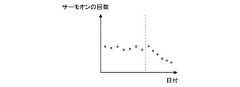
実施の形態3.
図10は、実施の形態3に係るサーモオンの回数を示すグラフである。本実施の形態3は、出力手段35がサーモオンの回数を一日に一度出力する点で実施の形態1と相違する。本実施の形態3では、実施の形態1と共通する部分は同一の符号を付して説明を省略し、実施の形態1との相違点を中心に説明する。
FIG. 10 is a graph showing the number of thermoons according to the third embodiment. The third embodiment is different from the first embodiment in that the output means 35 outputs the number of thermoons once a day. In the third embodiment, the parts common to the first embodiment are designated by the same reference numerals, the description thereof will be omitted, and the differences from the first embodiment will be mainly described.
図10において、横軸は日付を示し、縦軸はサーモオンの回数を示す。出力手段35は、サーモオンの回数を一日に一度表示装置5に出力し、図10に示すようなグラフを作成する。そして、出力手段35は、予め設定された期間においてカウントされたサーモオンの回数が予め定められたオン回数閾値を下回った場合、発報するものである。図10に示すように、サーモオンの回数が、ある日を境に少なくなっている傾向がみられる場合、ある日を境に室内機3が不調となった可能性が高い。サーモオンの回数が少ないということは、室内温度が設定温度から逸脱した場合に制御装置4がサーモオンを指示しても、空気調和システム1のいずれかの機器に異常が生じ、サーモオンしていない蓋然性が高いことが考えられる。このように、管理者は、サーモオンの回数の時間推移を認識することによって、室内機3の不調を直ちに把握することができる。 In FIG. 10, the horizontal axis represents the date and the vertical axis represents the number of thermoons. The output means 35 outputs the number of thermo-ons to the
実施の形態4.
図11は、実施の形態4に係る室内機3の運転回数を示すグラフである。本実施の形態4は、出力手段35が室内機3の運転回数を一日に一度出力する点で実施の形態1と相違する。本実施の形態4では、実施の形態1と共通する部分は同一の符号を付して説明を省略し、実施の形態1との相違点を中心に説明する。
FIG. 11 is a graph showing the number of operations of the
図11において、横軸は日付を示し、縦軸は室内機3の運転回数を示す。出力手段35は、室内機3の運転回数を一日に一度表示装置5に出力し、図11に示すようなグラフを作成する。そして、出力手段35は、設定温度到達時間Tsetが時間閾値を超え、且つ、室内機3の運転回数が予め定められた運転回数閾値を下回った場合、発報するものである。図11に示すように、室内機3の運転回数が、ある日を境に少なくなっている傾向がみられる場合、ある日を境に室内機3が不調となった可能性が高い。 In FIG. 11, the horizontal axis represents the date and the vertical axis represents the number of times the
室内膨張部16が正常である場合、空気調和システム1において、設定温度到達時間Tsetは30分以内であり、室内機3に設けられた室内膨張部16の一日の動作回数は5回以上である。これに対し、室内膨張部16に異常が発生して本来の空調能力が発揮されない場合、設定温度到達時間Tsetが伸び、且つ室内膨張部16の動作回数も減少する。管理者は、設定温度到達時間Tset及び室内機3の運転回数を認識することによって、室内機3の不調を直ちに把握することができる。 When the
1 空気調和システム、2 室外機、3 室内機、4 制御装置、5 表示装置、6 冷媒回路、6a 冷媒配管、7 室内温度検出部、11 圧縮機、12 流路切替装置、13 室外熱交換器、14 室外送風機、15 室外膨張部、16 室内膨張部、17 室内熱交換器、18 室内送風機、19 アキュムレータ、20 電磁弁、21 ガス管、22 液管、31 記憶手段、32 判定手段、33 算出手段、34 書込手段、35 出力手段。 1 Air conditioning system, 2 Outdoor unit, 3 Indoor unit, 4 Control device, 5 Display device, 6 Refrigerant circuit, 6a Refrigerant piping, 7 Indoor temperature detector, 11 Compressor, 12 Flow path switching device, 13 Outdoor heat exchanger , 14 outdoor blower, 15 outdoor expansion part, 16 indoor expansion part, 17 indoor heat exchanger, 18 indoor blower, 19 accumulator, 20 electromagnetic valve, 21 gas pipe, 22 liquid pipe, 31 storage means, 32 judgment means, 33 calculation Means, 34 writing means, 35 output means.
Claims (9)
Translated fromJapanese前記室外機に接続され、複数の空調対象空間の空気を、設定された設定温度になるようにそれぞれ調整する複数の室内機と、
前記空調対象空間の室内温度を検出する室内温度検出部と、
前記室外機及び前記室内機の動作を制御する制御装置と、を備え、
前記制御装置は、
前記室内温度検出部によって検出された前記室内温度と前記設定温度とに基づいて、前記室内温度が前記設定温度に到達するまでの設定温度到達時間を算出する算出手段と、
複数の前記室内機を、前記算出手段によって算出された前記設定温度到達時間の順に並べたリストを出力する出力手段と、を有する
空気調和システム。The outdoor unit installed outdoors and
A plurality of indoor units connected to the outdoor unit and adjusting the air in a plurality of air-conditioned spaces so as to reach a set set temperature.
An indoor temperature detection unit that detects the indoor temperature of the air-conditioned space,
A control device for controlling the operation of the outdoor unit and the indoor unit is provided.
The control device is
A calculation means for calculating the set temperature arrival time until the indoor temperature reaches the set temperature based on the indoor temperature and the set temperature detected by the indoor temperature detection unit.
An air conditioning system including an output means for outputting a list of a plurality of the indoor units arranged in the order of the set temperature arrival time calculated by the calculation means.
前記算出手段によって算出された前記設定温度到達時間が、予め設定された時間閾値を超えた場合、前記室内機を前記リストに書き込む書込手段を更に有する
請求項1記載の空気調和システム。The control device is
The air conditioning system according to claim 1, further comprising a writing means for writing the indoor unit to the list when the set temperature arrival time calculated by the calculation means exceeds a preset time threshold value.
前記室内温度検出部によって検出された前記室内温度と前記設定温度との温度差が、予め設定された温度閾値以下であるかを判定する判定手段を更に有し、
前記算出手段は、前記判定手段によって前記温度差が前記温度閾値以下であると判定された場合、前記設定温度到達時間を算出する
請求項1又は2記載の空気調和システム。The control device is
Further, it has a determination means for determining whether the temperature difference between the indoor temperature and the set temperature detected by the indoor temperature detection unit is equal to or less than a preset temperature threshold value.
The air conditioning system according to claim 1 or 2, wherein the calculation means calculates the set temperature arrival time when the determination means determines that the temperature difference is equal to or less than the temperature threshold value.
1台の前記室内機における複数の前記設定温度到達時間の平均値を算出する
請求項1〜3のいずれか1項に記載の空気調和システム。The calculation means is
The air conditioning system according to any one of claims 1 to 3, which calculates an average value of a plurality of set temperature arrival times in one indoor unit.
前記平均値が予め定められた平均閾値を上回った場合、発報するものである
請求項4記載の空気調和システム。The output means
The air conditioning system according to claim 4, wherein when the average value exceeds a predetermined average threshold value, an alarm is issued.
前記設定温度到達時間を、前記室内機の運転時間で除算した割合を算出する
請求項1〜5のいずれか1項に記載の空気調和システム。The calculation means is
The air conditioning system according to any one of claims 1 to 5, which calculates a ratio obtained by dividing the set temperature arrival time by the operating time of the indoor unit.
前記室内温度検出部によって検出された前記室内温度と前記設定温度との温度差が、予め設定された温度閾値より大きい場合に、前記室内機を運転するサーモオンを行うものであり、
前記出力手段は、
予め設定された期間においてカウントされた前記サーモオンの回数が予め定められたオン回数閾値を下回った場合、発報するものである
請求項1〜6のいずれか1項に記載の空気調和システム。The control device is
When the temperature difference between the indoor temperature and the set temperature detected by the indoor temperature detection unit is larger than the preset temperature threshold value, the thermo-on for operating the indoor unit is performed.
The output means
The air conditioning system according to any one of claims 1 to 6, which issues a notification when the number of times of the thermo-on counted in a preset period falls below a predetermined on-number-of-times threshold value.
前記室内温度検出部によって検出された前記室内温度と前記設定温度との温度差が、予め設定された温度閾値より大きい場合に、前記室内機を運転するものであり、
前記出力手段は、
前記算出手段によって算出された前記設定温度到達時間が、予め設定された時間閾値を超え、且つ、前記室内機の運転回数が予め定められた運転回数閾値を下回った場合、発報するものである
請求項1〜7のいずれか1項に記載の空気調和システム。The control device is
The indoor unit is operated when the temperature difference between the indoor temperature and the set temperature detected by the indoor temperature detection unit is larger than a preset temperature threshold value.
The output means
When the set temperature arrival time calculated by the calculation means exceeds a preset time threshold value and the number of operations of the indoor unit falls below a predetermined operation number threshold value, an alarm is issued. The air conditioning system according to any one of claims 1 to 7.
前記室外機に接続され、空調対象空間の空気を、設定された設定温度になるように調整する室内機と、
前記空調対象空間の室内温度を検出する室内温度検出部と、
前記室外機及び前記室内機の動作を制御する制御装置と、を備え、
前記制御装置は、
前記室内温度検出部によって検出された前記室内温度と前記設定温度とに基づいて、前記室内温度が前記設定温度に到達するまでの設定温度到達時間を算出する算出手段と、
前記算出手段によって算出された前記設定温度到達時間が、予め設定された時間閾値を超えた場合、発報する出力手段と、を有する
空気調和システム。The outdoor unit installed outdoors and
An indoor unit that is connected to the outdoor unit and adjusts the air in the air-conditioned space so that it reaches the set temperature.
An indoor temperature detection unit that detects the indoor temperature of the air-conditioned space,
A control device for controlling the operation of the outdoor unit and the indoor unit is provided.
The control device is
A calculation means for calculating the set temperature arrival time until the indoor temperature reaches the set temperature based on the indoor temperature and the set temperature detected by the indoor temperature detection unit.
An air conditioning system including an output means for issuing a report when the set temperature arrival time calculated by the calculation means exceeds a preset time threshold value.
Priority Applications (2)
| Application Number | Priority Date | Filing Date | Title |
|---|---|---|---|
| JP2020017847AJP2021124241A (en) | 2020-02-05 | 2020-02-05 | Air conditioning system |
| PCT/JP2020/019607WO2021157105A1 (en) | 2020-02-05 | 2020-05-18 | Air conditioning system |
Applications Claiming Priority (1)
| Application Number | Priority Date | Filing Date | Title |
|---|---|---|---|
| JP2020017847AJP2021124241A (en) | 2020-02-05 | 2020-02-05 | Air conditioning system |
Publications (1)
| Publication Number | Publication Date |
|---|---|
| JP2021124241Atrue JP2021124241A (en) | 2021-08-30 |
Family
ID=77199779
Family Applications (1)
| Application Number | Title | Priority Date | Filing Date |
|---|---|---|---|
| JP2020017847APendingJP2021124241A (en) | 2020-02-05 | 2020-02-05 | Air conditioning system |
Country Status (2)
| Country | Link |
|---|---|
| JP (1) | JP2021124241A (en) |
| WO (1) | WO2021157105A1 (en) |
Citations (3)
| Publication number | Priority date | Publication date | Assignee | Title |
|---|---|---|---|---|
| JPH11316043A (en)* | 1998-05-07 | 1999-11-16 | Mitsubishi Electric Building Techno Service Co Ltd | Abnormality detector for air conditioner |
| JP2010038471A (en)* | 2008-08-06 | 2010-02-18 | Daikin Ind Ltd | Air conditioner management device and air conditioner management method |
| JP2010210121A (en)* | 2009-03-09 | 2010-09-24 | Mitsubishi Electric Corp | Air conditioner |
- 2020
- 2020-02-05JPJP2020017847Apatent/JP2021124241A/enactivePending
- 2020-05-18WOPCT/JP2020/019607patent/WO2021157105A1/ennot_activeCeased
Patent Citations (3)
| Publication number | Priority date | Publication date | Assignee | Title |
|---|---|---|---|---|
| JPH11316043A (en)* | 1998-05-07 | 1999-11-16 | Mitsubishi Electric Building Techno Service Co Ltd | Abnormality detector for air conditioner |
| JP2010038471A (en)* | 2008-08-06 | 2010-02-18 | Daikin Ind Ltd | Air conditioner management device and air conditioner management method |
| JP2010210121A (en)* | 2009-03-09 | 2010-09-24 | Mitsubishi Electric Corp | Air conditioner |
Also Published As
| Publication number | Publication date |
|---|---|
| WO2021157105A1 (en) | 2021-08-12 |
Similar Documents
| Publication | Publication Date | Title |
|---|---|---|
| KR102129297B1 (en) | Air conditional and method for controlling the same | |
| JP4088671B2 (en) | Refrigeration air conditioner | |
| EP3457053B1 (en) | Managing high pressure events in air conditioners | |
| JP5642227B2 (en) | Air conditioner and air conditioner monitoring system | |
| JP6952882B2 (en) | Air conditioner | |
| JP4811077B2 (en) | Air conditioning system | |
| CN111780361B (en) | Air conditioner | |
| JP2018071955A (en) | Air-conditioner | |
| JP2013002749A (en) | Air conditioning device | |
| JP2015148394A (en) | Compressor deterioration diagnostic device and compressor deterioration diagnostic method | |
| JP2009243842A (en) | Operation method of multiple-type air conditioner and outdoor unit | |
| JP2021124241A (en) | Air conditioning system | |
| KR100630831B1 (en) | Emergency operation method when room temperature sensor breakdown of air conditioner | |
| KR102390900B1 (en) | Multi-type air conditioner and control method for the same | |
| EP1677058A2 (en) | Method of controlling over-load cooling operation of air conditioner | |
| JP6719651B2 (en) | Refrigeration cycle system and communication traffic adjustment method | |
| KR20100069404A (en) | Air conditioner and control method thereof | |
| CN113587212A (en) | One-driving-two air conditioner outdoor unit structure, air conditioner and control method thereof | |
| EP4116633A1 (en) | Air conditioner | |
| JP2016030068A (en) | Refrigeration system | |
| KR20210102736A (en) | Server and contrl method thereof | |
| JP4290025B2 (en) | Air conditioning refrigeration apparatus and control method of air conditioning refrigeration apparatus | |
| KR100706207B1 (en) | Operation control method of multi air conditioner system | |
| KR100630833B1 (en) | Emergency operation in case of failure of evaporator temperature sensor of air conditioner | |
| JP7068537B1 (en) | Air conditioner and control method |
Legal Events
| Date | Code | Title | Description |
|---|---|---|---|
| A621 | Written request for application examination | Free format text:JAPANESE INTERMEDIATE CODE: A621 Effective date:20230123 | |
| A131 | Notification of reasons for refusal | Free format text:JAPANESE INTERMEDIATE CODE: A131 Effective date:20231031 | |
| A521 | Request for written amendment filed | Free format text:JAPANESE INTERMEDIATE CODE: A523 Effective date:20231220 | |
| A131 | Notification of reasons for refusal | Free format text:JAPANESE INTERMEDIATE CODE: A131 Effective date:20240326 | |
| A02 | Decision of refusal | Free format text:JAPANESE INTERMEDIATE CODE: A02 Effective date:20240625 |