JP2021119396A - Flexible camera lens design - Google Patents
Flexible camera lens designDownload PDFInfo
- Publication number
- JP2021119396A JP2021119396AJP2021070910AJP2021070910AJP2021119396AJP 2021119396 AJP2021119396 AJP 2021119396AJP 2021070910 AJP2021070910 AJP 2021070910AJP 2021070910 AJP2021070910 AJP 2021070910AJP 2021119396 AJP2021119396 AJP 2021119396A
- Authority
- JP
- Japan
- Prior art keywords
- lens
- lens element
- digital camera
- cavity
- camera according
- Prior art date
- Legal status (The legal status is an assumption and is not a legal conclusion. Google has not performed a legal analysis and makes no representation as to the accuracy of the status listed.)
- Granted
Links
Images


Classifications
- G—PHYSICS
- G02—OPTICS
- G02B—OPTICAL ELEMENTS, SYSTEMS OR APPARATUS
- G02B13/00—Optical objectives specially designed for the purposes specified below
- G02B13/001—Miniaturised objectives for electronic devices, e.g. portable telephones, webcams, PDAs, small digital cameras
- G—PHYSICS
- G02—OPTICS
- G02B—OPTICAL ELEMENTS, SYSTEMS OR APPARATUS
- G02B13/00—Optical objectives specially designed for the purposes specified below
- G02B13/001—Miniaturised objectives for electronic devices, e.g. portable telephones, webcams, PDAs, small digital cameras
- G02B13/0015—Miniaturised objectives for electronic devices, e.g. portable telephones, webcams, PDAs, small digital cameras characterised by the lens design
- G02B13/002—Miniaturised objectives for electronic devices, e.g. portable telephones, webcams, PDAs, small digital cameras characterised by the lens design having at least one aspherical surface
- G02B13/004—Miniaturised objectives for electronic devices, e.g. portable telephones, webcams, PDAs, small digital cameras characterised by the lens design having at least one aspherical surface having four lenses
- G—PHYSICS
- G02—OPTICS
- G02B—OPTICAL ELEMENTS, SYSTEMS OR APPARATUS
- G02B13/00—Optical objectives specially designed for the purposes specified below
- G02B13/001—Miniaturised objectives for electronic devices, e.g. portable telephones, webcams, PDAs, small digital cameras
- G02B13/0055—Miniaturised objectives for electronic devices, e.g. portable telephones, webcams, PDAs, small digital cameras employing a special optical element
- G02B13/0065—Miniaturised objectives for electronic devices, e.g. portable telephones, webcams, PDAs, small digital cameras employing a special optical element having a beam-folding prism or mirror
- G—PHYSICS
- G02—OPTICS
- G02B—OPTICAL ELEMENTS, SYSTEMS OR APPARATUS
- G02B13/00—Optical objectives specially designed for the purposes specified below
- G02B13/001—Miniaturised objectives for electronic devices, e.g. portable telephones, webcams, PDAs, small digital cameras
- G02B13/009—Miniaturised objectives for electronic devices, e.g. portable telephones, webcams, PDAs, small digital cameras having zoom function
- G—PHYSICS
- G02—OPTICS
- G02B—OPTICAL ELEMENTS, SYSTEMS OR APPARATUS
- G02B13/00—Optical objectives specially designed for the purposes specified below
- G02B13/02—Telephoto objectives, i.e. systems of the type + - in which the distance from the front vertex to the image plane is less than the equivalent focal length
- G—PHYSICS
- G02—OPTICS
- G02B—OPTICAL ELEMENTS, SYSTEMS OR APPARATUS
- G02B27/00—Optical systems or apparatus not provided for by any of the groups G02B1/00 - G02B26/00, G02B30/00
- G02B27/01—Head-up displays
- G02B27/0149—Head-up displays characterised by mechanical features
- G—PHYSICS
- G02—OPTICS
- G02B—OPTICAL ELEMENTS, SYSTEMS OR APPARATUS
- G02B7/00—Mountings, adjusting means, or light-tight connections, for optical elements
- G02B7/02—Mountings, adjusting means, or light-tight connections, for optical elements for lenses
- G02B7/021—Mountings, adjusting means, or light-tight connections, for optical elements for lenses for more than one lens
- G—PHYSICS
- G02—OPTICS
- G02B—OPTICAL ELEMENTS, SYSTEMS OR APPARATUS
- G02B7/00—Mountings, adjusting means, or light-tight connections, for optical elements
- G02B7/02—Mountings, adjusting means, or light-tight connections, for optical elements for lenses
- G02B7/04—Mountings, adjusting means, or light-tight connections, for optical elements for lenses with mechanism for focusing or varying magnification
- G02B7/08—Mountings, adjusting means, or light-tight connections, for optical elements for lenses with mechanism for focusing or varying magnification adapted to co-operate with a remote control mechanism
- G—PHYSICS
- G02—OPTICS
- G02B—OPTICAL ELEMENTS, SYSTEMS OR APPARATUS
- G02B7/00—Mountings, adjusting means, or light-tight connections, for optical elements
- G02B7/02—Mountings, adjusting means, or light-tight connections, for optical elements for lenses
- G02B7/04—Mountings, adjusting means, or light-tight connections, for optical elements for lenses with mechanism for focusing or varying magnification
- G02B7/09—Mountings, adjusting means, or light-tight connections, for optical elements for lenses with mechanism for focusing or varying magnification adapted for automatic focusing or varying magnification
- G—PHYSICS
- G03—PHOTOGRAPHY; CINEMATOGRAPHY; ANALOGOUS TECHNIQUES USING WAVES OTHER THAN OPTICAL WAVES; ELECTROGRAPHY; HOLOGRAPHY
- G03B—APPARATUS OR ARRANGEMENTS FOR TAKING PHOTOGRAPHS OR FOR PROJECTING OR VIEWING THEM; APPARATUS OR ARRANGEMENTS EMPLOYING ANALOGOUS TECHNIQUES USING WAVES OTHER THAN OPTICAL WAVES; ACCESSORIES THEREFOR
- G03B17/00—Details of cameras or camera bodies; Accessories therefor
- G03B17/02—Bodies
- G03B17/12—Bodies with means for supporting objectives, supplementary lenses, filters, masks, or turrets
- G—PHYSICS
- G03—PHOTOGRAPHY; CINEMATOGRAPHY; ANALOGOUS TECHNIQUES USING WAVES OTHER THAN OPTICAL WAVES; ELECTROGRAPHY; HOLOGRAPHY
- G03B—APPARATUS OR ARRANGEMENTS FOR TAKING PHOTOGRAPHS OR FOR PROJECTING OR VIEWING THEM; APPARATUS OR ARRANGEMENTS EMPLOYING ANALOGOUS TECHNIQUES USING WAVES OTHER THAN OPTICAL WAVES; ACCESSORIES THEREFOR
- G03B17/00—Details of cameras or camera bodies; Accessories therefor
- G03B17/02—Bodies
- G03B17/17—Bodies with reflectors arranged in beam forming the photographic image, e.g. for reducing dimensions of camera
- G—PHYSICS
- G03—PHOTOGRAPHY; CINEMATOGRAPHY; ANALOGOUS TECHNIQUES USING WAVES OTHER THAN OPTICAL WAVES; ELECTROGRAPHY; HOLOGRAPHY
- G03B—APPARATUS OR ARRANGEMENTS FOR TAKING PHOTOGRAPHS OR FOR PROJECTING OR VIEWING THEM; APPARATUS OR ARRANGEMENTS EMPLOYING ANALOGOUS TECHNIQUES USING WAVES OTHER THAN OPTICAL WAVES; ACCESSORIES THEREFOR
- G03B17/00—Details of cameras or camera bodies; Accessories therefor
- G03B17/55—Details of cameras or camera bodies; Accessories therefor with provision for heating or cooling, e.g. in aircraft
- G—PHYSICS
- G03—PHOTOGRAPHY; CINEMATOGRAPHY; ANALOGOUS TECHNIQUES USING WAVES OTHER THAN OPTICAL WAVES; ELECTROGRAPHY; HOLOGRAPHY
- G03B—APPARATUS OR ARRANGEMENTS FOR TAKING PHOTOGRAPHS OR FOR PROJECTING OR VIEWING THEM; APPARATUS OR ARRANGEMENTS EMPLOYING ANALOGOUS TECHNIQUES USING WAVES OTHER THAN OPTICAL WAVES; ACCESSORIES THEREFOR
- G03B30/00—Camera modules comprising integrated lens units and imaging units, specially adapted for being embedded in other devices, e.g. mobile phones or vehicles
- H—ELECTRICITY
- H04—ELECTRIC COMMUNICATION TECHNIQUE
- H04N—PICTORIAL COMMUNICATION, e.g. TELEVISION
- H04N23/00—Cameras or camera modules comprising electronic image sensors; Control thereof
- H04N23/45—Cameras or camera modules comprising electronic image sensors; Control thereof for generating image signals from two or more image sensors being of different type or operating in different modes, e.g. with a CMOS sensor for moving images in combination with a charge-coupled device [CCD] for still images
- H—ELECTRICITY
- H04—ELECTRIC COMMUNICATION TECHNIQUE
- H04N—PICTORIAL COMMUNICATION, e.g. TELEVISION
- H04N23/00—Cameras or camera modules comprising electronic image sensors; Control thereof
- H04N23/50—Constructional details
- H04N23/54—Mounting of pick-up tubes, electronic image sensors, deviation or focusing coils
- H—ELECTRICITY
- H04—ELECTRIC COMMUNICATION TECHNIQUE
- H04N—PICTORIAL COMMUNICATION, e.g. TELEVISION
- H04N23/00—Cameras or camera modules comprising electronic image sensors; Control thereof
- H04N23/50—Constructional details
- H04N23/55—Optical parts specially adapted for electronic image sensors; Mounting thereof
- H—ELECTRICITY
- H04—ELECTRIC COMMUNICATION TECHNIQUE
- H04N—PICTORIAL COMMUNICATION, e.g. TELEVISION
- H04N23/00—Cameras or camera modules comprising electronic image sensors; Control thereof
- H04N23/57—Mechanical or electrical details of cameras or camera modules specially adapted for being embedded in other devices
- H—ELECTRICITY
- H04—ELECTRIC COMMUNICATION TECHNIQUE
- H04N—PICTORIAL COMMUNICATION, e.g. TELEVISION
- H04N23/00—Cameras or camera modules comprising electronic image sensors; Control thereof
- H04N23/58—Means for changing the camera field of view without moving the camera body, e.g. nutating or panning of optics or image sensors
Landscapes
- Physics & Mathematics (AREA)
- General Physics & Mathematics (AREA)
- Optics & Photonics (AREA)
- Engineering & Computer Science (AREA)
- Multimedia (AREA)
- Signal Processing (AREA)
- Aviation & Aerospace Engineering (AREA)
- Human Computer Interaction (AREA)
- Lenses (AREA)
- Studio Devices (AREA)
- Structure And Mechanism Of Cameras (AREA)
- Lens Barrels (AREA)
- Cameras In General (AREA)
- Blocking Light For Cameras (AREA)
- Camera Bodies And Camera Details Or Accessories (AREA)
- Details Of Cameras Including Film Mechanisms (AREA)
Abstract
Description
Translated fromJapanese 〔関連出願の参照〕
本出願は2017年2月23日に出願された米国仮特許出願第62/462,438号、2017年3月30日に出願された米国仮特許出願第62/478,783号、および2017年4月9日に出願された米国仮特許出願第62/483,422号の利益を主張するものであり、これらはすべて参照により本明細書に組み込まれる。[Refer to related applications]
This application is filed on February 23, 2017, U.S. Provisional Patent Application No. 62 / 462,438, U.S. Provisional Patent Application No. 62 / 478,783, filed on March 30, 2017, and 2017. It claims the interests of US Provisional Patent Application No. 62 / 483,422 filed on April 9, all of which are incorporated herein by reference.
〔技術分野〕
本開示の主題は一般に、デジタルカメラの分野に関する。〔Technical field〕
The subject matter of this disclosure generally relates to the field of digital cameras.
〔背景技術〕
デュアルアパーチャズームカメラ(デュアルカメラとも呼ばれる)として、一方のカメラ(サブカメラとも呼ばれる)がワイドFOV(ワイドサブカメラ:Wide sub-camera)を有し、他方のカメラが狭いFOV(テレサブカメラ:Tele sub-camera)を有するタイプが知られている。[Background technology]
As a dual aperture zoom camera (also called a dual camera), one camera (also called a sub camera) has a wide sub-camera (wide sub-camera) and the other camera has a narrow FOV (tele sub camera: Tele). A type having a sub-camera) is known.
国際特許公開WO2016/024192はその全体が参照により本明細書に組み込まれるが、コンパクトカメラの高さを低減する「屈曲式カメラモジュール」(単に「屈曲式カメラ」とも呼ばれる)を開示している。屈曲式カメラでは、スマートフォン裏面に垂直な方向からスマートフォン裏面に平行な方向に光伝播方向を傾斜させるために、光路屈曲素子(以下、OPFE(optical path folding element)と呼ぶ)、例えばプリズムまたはミラー(以下、総称して反射素子と呼ぶ)が追加される。屈曲式カメラがデュアルアパーチャカメラの一部である場合、これは、1つのレンズアセンブリ(例えば、テレ(Tele)レンズ)を通る屈曲した光路を提供する。このようなカメラは、本明細書では「屈曲式レンズデュアルアパーチャカメラ」と呼ばれる。一般に、屈曲式カメラは、例えば、トリプルアパーチャカメラにおける2つの「屈曲していていない」(直立した)カメラモジュールと共に、マルチアパーチャカメラに含まれてもよい。 International Patent Publication WO 2016/024192, which is incorporated herein by reference in its entirety, discloses a "flexible camera module" (also simply referred to as a "flexible camera") that reduces the height of a compact camera. In a bending camera, an optical path bending element (hereinafter referred to as OPFE (optical path folding element)), for example, a prism or a mirror (hereinafter referred to as an OPFE (optical path folding element)) is used to incline the light propagation direction from a direction perpendicular to the back surface of the smartphone to a direction parallel to the back surface of the smartphone. Hereinafter, they are collectively referred to as a reflecting element). If the bendable camera is part of a dual aperture camera, it provides a bent light path through one lens assembly (eg, a Tele lens). Such cameras are referred to herein as "flexible lens dual aperture cameras." In general, a bendable camera may be included in a multi-aperture camera, for example, along with two "non-bent" (upright) camera modules in a triple aperture camera.
〔発明の概要〕
屈曲式カメラの小さな高さは、それを含むホスト装置(例えば、スマートフォン、タブレット、ラップトップ又はスマートテレビ)をできるだけ薄くすることを可能にするために重要である。カメラの高さは、工業デザインによって制限されることが多い。対照的に、レンズの光学的開口を増大させると、センサに到達する光の量が増大し、カメラの光学特性が改善される。[Outline of Invention]
The small height of the bendable camera is important to allow the host device (eg, smartphone, tablet, laptop or smart TV) containing it to be as thin as possible. The height of the camera is often limited by industrial design. In contrast, increasing the optical aperture of a lens increases the amount of light that reaches the sensor and improves the optical properties of the camera.
したがって、所与のカメラ高さおよび/またはレンズモジュール高さに対してレンズ光学開口の高さが最大である屈曲式カメラが必要であり、これを有することが有利であろう。 Therefore, it would be advantageous to have a bendable camera with the maximum lens optical aperture height relative to a given camera height and / or lens module height.
現在開示されている主題のいくつかの態様によれば、第1の光軸を有するN個(N≧3)のレンズエレメントLiを含む光学レンズモジュール、イメージセンサ、および、被写体と前記レンズエレメントとの間に屈曲した光路を提供する光路屈曲素子(OPFE)とを備えたデジタルカメラであって、各レンズエレメントはそれぞれ前面S2i−1および後面S2iを含み、Sk(ただし1≦k≦2N)で表されるレンズエレメントの表面に関し、それぞれのレンズエレメントの表面Skはクリアな高さ値CH(Sk)を有し、表面S1のクリアな高さ値CH(S1)は、表面S2〜Skのそれぞれのクリアな高さ値よりも大きい。According to some aspects of the subject matter presently disclosed, an optical lens module comprising lens elements Li of N (N ≧ 3) having a first optical axis, the image sensor, and, subject to the lens element includes a digital camera and a, respectively each lens element front S2i-1 and the rear surface S2i having an optical path bending element to provide an optical path that is bent (OPFE) between, S k(provided that 1 ≦ k relates ≦ 2N) surface of the lens element represented by the surfaceS k of each lens element has a clear height values CH(S k), the surfaceS 1 of the clear height values CH(S 1) It is greater than the respective clear height values of the
例示的な実施形態では、前記N個のレンズエレメントは、軸対称を有する。 In an exemplary embodiment, the N lens elements are axisymmetric.
例示的な実施形態では、CH(S1)≧1.1×CH(S2)である。In an exemplary embodiment, CH (S1 ) ≧ 1.1 × CH (S2 ).
例示的な実施形態では、3≦k≦2Nにおいて、CH(S1)≧1.2xCH(Sk)である。In an exemplary embodiment, the 3 ≦ k ≦ 2N, aCH (S 1) ≧ 1.2xCH ( S k).
例示的な実施形態では、前記デジタルカメラが全トラック長TTLおよび後焦点距離BFLに関し、BFL≧0.3×TTLである。 In an exemplary embodiment, the digital camera has a total track length TTL and a back focal length BFL with BFL ≧ 0.3 × TTL.
例示的な実施形態では、前記L1は、グラスからなる。In an exemplary embodiment, the L1 is made of glass.
例示的な実施形態では、前記L1は、プラスチックからなる。In an exemplary embodiment, the L1 is made of plastic.
例示的な実施形態では、前記Liは、任意の2≦i≦Nにおいてプラスチックからなる。In an exemplary embodiment, the Li is made of plastic in any 2 ≦ i ≦ N.
例示的な実施形態では、前記光学レンズモジュールが前方開口レンズモジュールである。 In an exemplary embodiment, the optical lens module is a front aperture lens module.
例示的な実施形態では、CH(S1)<7mmである。In an exemplary embodiment, CH (S1 ) <7 mm.
いくつかの例示的な実施形態では、それぞれのレンズエレメントの表面Skは、クリアアパーチャ値CA(Sk)を有する。例示的な実施形態では、表面S1のクリアアパーチャ値CA(S1)が表面S2〜S2Nのそれぞれのクリアアパーチャ値よりも大きい。また、例示的な実施形態では、CA(S1)がクリアアパーチャ値CA(S2N)に等しく、CA(S1)は2≦k≦2N−1においてCA(Sk)よりも大きい。In some exemplary embodiments, the surface Sk of each lens element has a clear aperture value CA (Sk). In an exemplary embodiment, the surfaceS 1 of the clear aperture value CA(S 1) is greater than the respective clearing aperture value of the
例示的な実施形態では、CA(S1)がCH(S1)に実質的に等しい。In an exemplary embodiment, CA (S1 ) is substantially equal to CH (S1).
例示的な実施形態では、CA(S1)>=1.1xCA(S2)。In an exemplary embodiment, CA (S1 )> = 1.1xCA (S2 ).
例示的な実施形態では、3≦k≦2Nにおいて、CA(S1)>=1.2xCH(Sk)である。In an exemplary embodiment, the 3 ≦ k ≦2N, a CA (S 1)> = 1.2xCH (S k).
例示的な実施形態では、少なくとも2つのレンズエレメントがそれらの高さHLよりも大きい幅WLを有する。In the exemplary embodiment, it has a larger width WL of at least two lens elements than their height HL.
いくつかの例示的な実施形態では、前記光学レンズモジュールには、前記複数のレンズエレメントを保持するキャビティが設けられ、前記キャビティは、第1のレンズエレメントL1が配置される第1の部分と、他のレンズエレメントの少なくとも1つが配置される第2の部分とを有し、前記第1の部分の高さは、前記第2の部分の高さよりも高い。In some exemplary embodiments, wherein the optical lens module, the cavity for holding a plurality of lens elements is provided, the cavity has a first portion where the first lens element L1 is arranged The first portion has a second portion on which at least one of the other lens elements is arranged, and the height of the first portion is higher than the height of the second portion.
いくつかの例示的な実施形態では、前記光学レンズモジュールには、レンズエレメントL2〜LNの少なくとも2つを保持するキャビティが設けられ、前記第1のレンズエレメントL1は、前記光学レンズモジュールの外に配設される。In some exemplary embodiments, wherein the optical lens module, a lens element L2 ~L cavity for holding at least twoN are provided, wherein the first lens element L1, the optical lens module It is arranged outside the lens.
いくつかの例示的な実施形態では、前記イメージセンサが矩形センサまたは円形センサである。 In some exemplary embodiments, the image sensor is a rectangular sensor or a circular sensor.
いくつかの例示的な実施形態では、N≦6である。 In some exemplary embodiments, N ≦ 6.
本開示の主題の一態様によれば、上述の実施形態のいずれかのカメラを備えるデジタルデュアルカメラであって、当該カメラが、テレ(Tele)画像を提供するように構成されたテレサブカメラ、およびワイド(Wide)画像を提供するように構成されたワイドサブカメラである、デジタルデュアルカメラが提供される。 According to one aspect of the subject matter of the present disclosure, a digital dual camera comprising any of the cameras of the embodiments described above, wherein the camera is a telesub camera configured to provide a tele image. And a digital dual camera, which is a wide subcamera configured to provide wide images.
本開示の主題のいくつかの態様によれば、第1の光軸を有するN個(N≧3)のレンズエレメントLiを含む光学レンズモジュールと、イメージセンサと、被写体とレンズエレメントとの間において屈曲した光路を提供する、第1の光軸に対して傾斜した反射素子と、を備えるデジタルカメラが提供される。ここで、各レンズエレメントはそれぞれ前面S2i−1および後面S2iを含み、Sk(ただし1≦k≦2N)で表されるレンズエレメントの表面に関し、それぞれのレンズエレメントの表面はクリアアパーチャ値CA(Sk)を有し、2≦k≦2Nにおいて、クリアアパーチャ値CA(S1)はCA(Sk)よりも大きい。According to some aspects of the disclosed subject matter, between the optical lens module comprising lens elements Li of N (N ≧ 3) having a first optical axis, and the image sensor, the object and the lens element Provided is a digital camera comprising a reflective element that is tilted with respect to a first optical axis, which provides a bent optical path. Here, each lens element including a front S2i-1 and the rear surface S2i respectively, S k(provided that 1 ≦ k ≦ 2N) relates surface of the lens element represented by the surface of each lens element is clear aperture value It has CA (Sk ), and in 2 ≦ k ≦ 2N, the clear aperture value CA (S1 ) is larger than CA (Sk).
例示的な実施形態では、CA(S1)≧1.1×CA(S2)である。In an exemplary embodiment, CA (S1 ) ≧ 1.1 × CA (S2 ).
例示的な実施形態では、CA(S1)≧1.2×CH(Sk)である(ただし3≦k≦2N)。In an exemplary embodiment, CA (S1 ) ≧ 1.2 × CH (Sk ) (where 3 ≦ k ≦ 2N).
いくつかの例示的な実施形態では、前記光学レンズモジュールが前記複数のレンズエレメントを保持するキャビティを含み、前記第1の光軸に直交する軸に沿って測定される前記キャビティの高さは、前記第1の光軸に沿って可変である。 In some exemplary embodiments, the optical lens module comprises a cavity holding the plurality of lens elements, and the height of the cavity measured along an axis orthogonal to the first optical axis is such that the height of the cavity is measured. It is variable along the first optical axis.
いくつかの例示的な実施形態では、前記キャビティには、前記第1のレンズエレメントL1が位置する第1の部分と、他のレンズエレメントのうちの少なくとも1つが位置する第2の部分とが設けられており、前記第1の部分における前記高さは、前記第2の部分における前記高さよりも高い。In some exemplary embodiments, the cavity has a first portion where the first lens element L1 is positioned, and at least one second portion located of the other lens elements The height in the first portion is higher than the height in the second portion.
いくつかの例示的な実施形態では、前記光学レンズモジュールが、レンズエレメントL2〜LNのうちの少なくとも2つを保持するキャビティが設けられたレンズ鏡筒(単に「鏡筒」)を更に備え、レンズエレメントL1は、前記鏡筒の外に配設される。In some exemplary embodiments, the optical lens module further comprises a lens barrel cavity for holding at least two are provided among the lens elements L2 ~LN a (simply "barrel") , The lens element L1 is arranged outside the lens barrel.
本開示の主題の別の態様によれば、上述のカメラはテレ画像を提供するように構成されたテレサブカメラであり、デュアルカメラにおいてワイド画像を提供するように構成されたワイドサブカメラと共に含まれる。 According to another aspect of the subject matter of the present disclosure, the above-mentioned camera is a telesub camera configured to provide a tele image and is included with a wide sub camera configured to provide a wide image in a dual camera. Is done.
本開示の主題の別の態様によれば、第1の光軸に沿って対称性を有するN個(N≧3)のレンズエレメントと、イメージセンサと、被写体と前記イメージセンサとの間に屈曲光路を提供するように動作する反射素子と、複数のレンズエレメントが保持されるキャビティが設けられた鏡筒とを備えるデジタルカメラであって、第1の光軸に直交する軸に沿って測定されるキャビティの高さが、第1の光軸に沿って可変であり、前記キャビティが、第1のレンズエレメントL1が配置される第1の部分と、他のレンズエレメントの少なくとも1つが配置される第2の部分とを備え、の前記第1の部分の高さH1が、前記第2の部分の高さH2よりも高く、H1>1.1×H2である、デジタルカメラが提供される。According to another aspect of the subject matter of the present disclosure, N (N ≧ 3) lens elements having symmetry along the first optical axis, an image sensor, and bending between the subject and the image sensor. A digital camera including a reflecting element that operates to provide an optical path and a lens barrel provided with a cavity in which a plurality of lens elements are held, and is measured along an axis orthogonal to the first optical axis. the height of the cavity that is variable along the first optical axis, said cavity, a first portion where the first lens element L1 is disposed, at least one of the other lens elements are arranged A digital camera comprising a second portion, wherein the height H1 of the first portion is higher thanthe height H 2of the second portion, and H 1 > 1.1 × H2. Is provided.
本明細書に開示された主題の別の態様によれば、第1の光軸に沿った軸対称性を有するN(≧3)個のレンズエレメントL1〜LNと、イメージセンサと、被写体と前記イメージセンサとの間に屈曲光路を提供するように作動する反射素子と、L2〜LNの少なくとも2つのレンズエレメントLが保持されているキャビティが設けられた鏡筒とを備えたデジタルカメラであって、レンズエレメントL1が前記鏡筒の外に配設されているデジタルカメラが提供される。According to another aspect of the subject matter disclosed herein, and N (≧ 3) pieces of lens elements L1 ~LN having axial symmetry along the first optical axis, and the image sensor, the object digital equipped with a reflective element which operates to provide a bent optical path between said image sensor and a lens barrel in which at least two lens elements L is a cavity which is retained provided the L2 ~LN a camera, a digital camera lens element L1 is disposed outside the barrel is provided.
例示的な実施形態では、LNが前記鏡筒の外に配設されている。In an exemplary embodiment, the LN is disposed outside the lens barrel.
本開示の主題のいくつかの態様によれば、壁に囲まれたキャビティが設けられた鏡筒と、N個のレンズエレメントL1〜LNと、を備え、N≧3であり、前記レンズエレメントL1は、前記キャビティによって完全に囲まれていない部分を有し、前記キャビティの前記壁は、レンズエレメントL1の中心を前記第1の光軸に位置合わせしている、光学レンズモジュールが提供される。According to some aspects of the disclosed subject matter includes a barrel having a cavity surrounded by walls is provided, and N of the lens elements L1 ~LN, a, a N ≧ 3, the lens element L1 has a portion that is not completely surrounded by said cavity, the wall of the cavity, the center of the lens elements L1 is aligned with the first optical axis, an optical lens module Provided.
例示的な実施形態では、レンズエレメントLNは、前記キャビティによって完全には取り囲まれていない部分を有しており、前記キャビティの壁は、前記レンズエレメントLNの中心を前記第1の光軸に整列させる。In an exemplary embodiment, the lens element LN has a portion that is not completely surrounded by the cavity, and the wall of the cavity iscentered on the lens element L N with the first optical axis. Align to.
例示的な実施形態では、前記壁の端部および前記レンズエレメントL1の端部の少なくとも一方が、前記壁の端部が当該レンズエレメントL1の少なくとも一部のためのストップとして作用することによって、レンズエレメントL1の中心を前記第1の光軸に実質的に位置合わせするように、成形される。In an exemplary embodiment, by at least one end portion and an end portion of the lens elements L1 of said wall, an end portion of the wall acts as a stop for at least a portion of the lens elements L1 , so as to substantially aligned with the center of the lens elements L1 to the first optical axis, it is formed.
例示的な実施形態では、レンズエレメントL1の第1の部分は前記壁の端部と端部の間のキャビティに位置しており、当該レンズエレメントL1の第2の部分は、当該キャビティの外に位置しており、前記レンズエレメントL1の前記第1の光軸に沿った前記第2の部分の厚さは、当該レンズエレメントL1の前記第1の光軸に沿った前記第1の部分の厚さよりも大きい。In an exemplary embodiment, the first portion of the lens element L1 is located in the cavity between the end portion and the end portion of the wall, the second portion of the lens element L1 is, of the cavity located outside, the lens element thickness of said first of said second portion along the optical axis of the L1, the first along the first optical axis of the lens elements L1 It is larger than the thickness of the part.
例示的な実施形態では、前記壁の前記端部の断面は階段形状を有する。 In an exemplary embodiment, the cross section of the end of the wall has a staircase shape.
例示的な実施形態では、レンズエレメントL1の前記端部の断面は階段形状を有する。In an exemplary embodiment, the cross-section of said end portion of the lens element L1 has a stepped shape.
例示的な実施形態では、前記壁の前記端部の断面が傾斜した形状を有する。 In an exemplary embodiment, the cross section of the end of the wall has an inclined shape.
例示的な実施形態では、前記壁の前記端部が面取り部を含む。 In an exemplary embodiment, the end of the wall includes a chamfered portion.
例示的な実施形態では、レンズモジュールがレンズを保護するためのカバーをさらに備え、カバーはレンズエレメントL1を覆う。In the exemplary embodiment, further comprising a cover for the lens module to protect the lens cover covers the lens elements L1.
例示的な実施形態では、前記カバーがレンズエレメントL1を越えた端点を有する。In the exemplary embodiment, it has an end point of the cover exceeds the lens elements L1.
例示的な実施形態では、前記カバーがレンズエレメントL1の機械的部分への光の侵入を阻止する。In an exemplary embodiment, the cover prevents the light from entering the mechanical portion of the lens elements L1.
本開示の主題のいくつかの態様によれば、複数N≧3のレンズエレメントLiを備える光学レンズモジュールが提供され、ここで、1≦i≦Nであり、各レンズエレメントはそれぞれの前面S2i−1およびそれぞれの後面S2iを備え、Sk(ただし、1≦k≦2N)で表されるレンズエレメントの表面に関し、それぞれのレンズエレメントの表面Skはクリアアパーチャ値CA(Sk)を有し、CA(S1)はCA(S2N)に実質的に等しく、2≦k≦2N−1において、CA(S1)はCA(Sk)より大きい。According to some aspects of the disclosed subject matter, multiple N ≧ 3 optical lens module comprising lens elements Li of is provided wherein, 1 ≦ i is ≦ N, each lens element each front S2i-1 and comprises a respective rear surfaceS 2i,S k (however, 1 ≦ k ≦ 2N) relates surface of the lens element represented by the surfaceS k of each lens element clear aperture value CA(S k) CA (S1 ) is substantially equal to CA (S2N ), and in 2 ≦ k ≦ 2N-1, CA (S1 ) is greater than CA (Sk).
本開示の主題のいくつかの態様によれば、複数N≦3のレンズエレメントLiを備える光学レンズモジュールが提供され、各レンズエレメントはそれぞれの前面S2i−1およびそれぞれの後面S2iを備え、レンズエレメント表面はSk(ただし、1≦k≦2N)と記され、各レンズエレメント表面はクリアアパーチャ値CA(Sk)を有し、2≦k≦2NにおいてCA(S1)はCA(Sk)より大きい。According to some aspects of the disclosed subject matter, there is provided an optical lens module comprising lens elements Li of the plurality N ≦ 3, each lens element has a respective front S2i-1 and each of the rear surface S2i , the lens element surfaceS k (however, 1 ≦ k ≦ 2N) and marked, each lens element surface has a clear aperture value CA(S k), in2 ≦ k ≦ 2N CA (S 1) is CA Greater than (Sk).
本開示の主題のいくつかの態様によれば、イメージセンサと、被写体とイメージセンサとの間に屈曲光路を提供するように動作する反射素子と、上述の光学レンズモジュールとを備えるデジタルカメラが提供される。 According to some aspects of the subject matter of the present disclosure, a digital camera comprising an image sensor, a reflective element operating to provide a bent optical path between the subject and the image sensor, and the optical lens module described above. Will be done.
本開示の主題の別の態様によれば、鏡筒高さHと、N個(N≧3)のレンズエレメントL1〜LNとを有する鏡筒を備え、レンズエレメントL1の高さHL1は、HL1≧Hを満たすか、または満たす光学レンズモジュールが提供される。例示的な実施形態ではHLN≧Hである。また例示的な実施形態では、HLN=HL1である。According to another aspect of the presently disclosed subject matter, the barrel height H, N pieces comprising a barrel having a lens element L1 ~LN of (N ≧ 3), the lens elements L1 of the height HL1 is provided with an optical lens module that satisfies or satisfiesHL1 ≧ H. In an exemplary embodiment,HLN ≥ H. In the exemplaryembodiment, aH LN= HL1.
本開示の主題の別の態様によれば、N個(N≧3)のレンズエレメントL1〜LNを含み、それぞれのレンズエレメントLiは1≦i≦Nの高さHLiを有し、HL1≧HLN>HL2である光学レンズモジュールが提供される。According to another aspect of the presently disclosed subject matter includes a
例示的な実施形態では、3≦i≦N−1において、HL1>HLiである。In an exemplary embodiment, HL1 > HLi in 3 ≦ i ≦ N-1.
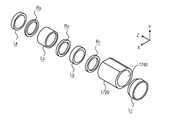
本開示の主題の別の態様によれば、N個のレンズエレメントのうちの第1のレンズエレメントL1を、鏡筒の被写体側から当該鏡筒に挿入するステップと、前記第1のレンズエレメントL1を前記鏡筒に固定するステップと、前記鏡筒の像側から、残りのレンズエレメントL2〜LNおよびレンズ同士を離隔するスペーサR1〜RNを、R1,L2,・・・,RN−1,LNの順に挿入するステップと、レンズエレメントLNをレンズモジュールに固定するステップとを含む、光学レンズモジュールを組み立てるための一方法が提供される。According to another aspect of the presently disclosed subject matter, the step of inserting the first lens element L1 of the N lens elements, to the barrel from the subject side of the lens barrel, the first lens element a step of securing the L1 in the lens barrel, from the image side of the lens barrel, the
本開示の主題の別の態様によれば、携帯電子機器のハウジング内に内蔵された内部デジタルカメラを備える携帯電子機器が提供され、当該デジタルカメラは、上述の態様のいずれか1つによるか、または上述の光学レンズモジュールのいずれかを備える。 According to another aspect of the subject matter of the present disclosure, a portable electronic device comprising an internal digital camera built within the housing of the portable electronic device is provided, the digital camera according to any one of the above aspects. Alternatively, it includes any of the optical lens modules described above.
本開示の主題の別の態様によれば、少なくとも1つのワイドサブカメラと少なくとも1つのテレサブカメラとを備える複合式のアパーチャカメラが提供され、これは、上述の態様のいずれか1つに従うか、または上述の光学レンズモジュールのいずれかを備える。 According to another aspect of the subject matter of the present disclosure, a composite aperture camera comprising at least one wide sub camera and at least one tele sub camera is provided, which follows any one of the above aspects. , Or any of the optical lens modules described above.
本開示の主題の別の態様によれば、反射素子はデジタルカメラの視野(FOV)の位置を移動させ、複数の隣接する重なり合わないまたは部分的に重なり合う画像を複数のそれぞれの位置で取り込むために、1つまたは2つの軸の周りで回転させることができる回転反射素子であり、デジタルカメラは複数の画像から、デジタルカメラのFOVより大きい全体画像FOVを有する合成画像を生成するように構成される。 According to another aspect of the subject matter of the present disclosure, the reflective element moves the position of the field of view (FOV) of the digital camera to capture multiple adjacent, non-overlapping or partially overlapping images at each of the plurality of positions. In addition, a rotating reflector that can be rotated around one or two axes, the digital camera is configured to generate a composite image from multiple images that has an overall image FOV that is greater than the FOV of the digital camera. NS.
いくつかの例示的な実施形態では上記の態様によるデジタルカメラが1つまたは2つの軸の周りの回転運動を回転反射素子に適用するように構成されたアクチュエータをさらに備え、アクチュエータは要求されたズーム倍率に対応する領域をカメラに走査させるようにアクチュエータを制御するように構成されたコントローラに動作可能に接続され、この領域はデジタルカメラのFOVよりも大きく、各画像が走査された領域内の異なる位置で取り込まれる複数の画像を取り込む。 In some exemplary embodiments, the digital camera according to the above embodiment further comprises an actuator configured to apply rotational motion around one or two axes to the rotational reflector, the actuator being the required zoom. Operatively connected to a controller configured to control the actuator to cause the camera to scan the area corresponding to the magnification, this area is larger than the FOV of the digital camera and each image is different within the scanned area. Capture multiple images captured at position.
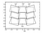
例示的な実施形態では、合成画像のサイズが4つのテレ(Tele)画像のステッチングによって生成される。 In an exemplary embodiment, the size of the composite image is generated by stitching four Tele images.
例示的な実施形態では、合成画像のサイズが6つのテレ画像のステッチングによって生成される。 In an exemplary embodiment, the size of the composite image is generated by stitching six teleimages.
例示的な実施形態では、合成画像のサイズが9つのテレ画像のステッチングによって生成される。 In an exemplary embodiment, the size of the composite image is generated by stitching nine teleimages.
例示的な実施形態では、複数の画像の合成サイズが合成画像のサイズよりも大きい。 In an exemplary embodiment, the composite size of the plurality of images is larger than the size of the composite image.
〔図面の簡単な説明〕
本明細書に開示される実施形態の非限定的な例は、この段落の後に列挙される、本明細書に添付される図面を参照して以下に記載される。図面および説明は本明細書に開示された実施形態を明確にし、明確にすることを意図しており、決して限定するものとみなされるべきではない。異なる図面における同様の要素は、同様の数字によって示されてもよい。図面中の要素は、必ずしも一定の縮尺で描かれていない。[Simple description of drawings]
Non-limiting examples of embodiments disclosed herein are described below with reference to the drawings attached herein, which are listed after this paragraph. The drawings and descriptions are intended to clarify and clarify the embodiments disclosed herein and should by no means be considered limiting. Similar elements in different drawings may be represented by similar numbers. The elements in the drawing are not always drawn to a certain scale.
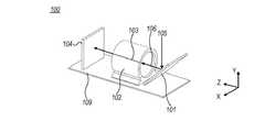
図1Aは、公知の屈曲式カメラの一例の概略等角図である。 FIG. 1A is a schematic isometric view of an example of a known bending camera.
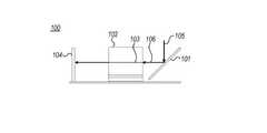
図1Bは、図1Aのカメラの側面図である。 FIG. 1B is a side view of the camera of FIG. 1A.
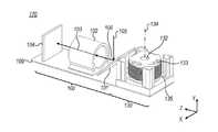
図1Cは、屈曲したテレ(Tele)サブカメラおよびワイドサブカメラを備える既知のカメラの一例の概略等角図である。 FIG. 1C is a schematic isometric view of an example of a known camera with a bent Tele subcamera and a wide subcamera.
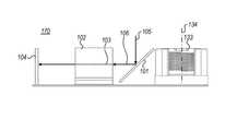
図1Dは、図1Cのカメラの側面図である。 FIG. 1D is a side view of the camera of FIG. 1C.
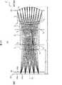
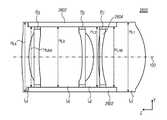
図2Aは、本開示の主題のいくつかの例によるレンズエレメントの一実施形態を、光線とともに模式的に示す模式図である。 FIG. 2A is a schematic diagram schematically showing an embodiment of a lens element according to some examples of the subject matter of the present disclosure, together with light rays.
図2Bは、図2Aのレンズエレメントの別の模式図である。 FIG. 2B is another schematic view of the lens element of FIG. 2A.
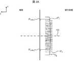
図3Aは、本開示の主題のいくつかの例による、レンズエレメントの凸面に衝突する光線のインパクトポイントの模式図、および平面P上のインパクトポイントの直交投影の模式図である。 FIG. 3A is a schematic diagram of the impact points of light rays colliding with the convex surface of the lens element and a schematic diagram of orthogonal projection of the impact points on the plane P, according to some examples of the subject matter of the present disclosure.
図3Bは、本開示の主題のいくつかの例による、レンズエレメントの凹面に衝突する光線のインパクトポイントの模式図、および平面P上のインパクトポイントの直交投影の模式図である。 FIG. 3B is a schematic diagram of the impact points of light rays colliding with the concave surface of the lens element and a schematic diagram of orthogonal projection of the impact points on the plane P, according to some examples of the subject matter of the present disclosure.
図4は、本開示の主題のいくつかの例による、平面P上のインパクトポイントの直交投影、およびクリアな高さ(clear hight)値(CH)の概略図である。 FIG. 4 is a schematic representation of an orthogonal projection of an impact point on a plane P and a clear hight value (CH), according to some examples of the subject matter of the present disclosure.
図5は、本開示の主題のいくつかの例による、平面P上のインパクトポイントの直交投影、およびクリアアパーチャ値(CA)の概略図である。 FIG. 5 is a schematic view of the orthogonal projection of the impact point on the plane P and the clear aperture value (CA) according to some examples of the subject matter of the present disclosure.
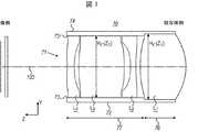
図6は、本開示の主題のいくつかの例による、レンズエレメントを保持するための光学レンズモジュールの側面図の概略図である。 FIG. 6 is a schematic side view of an optical lens module for holding a lens element, according to some examples of the subject matter of the present disclosure.
図7は、本開示の主題の他の例による、レンズエレメントを保持するための光学レンズモジュールの側面図の概略図である。 FIG. 7 is a schematic side view of an optical lens module for holding a lens element according to another example of the subject matter of the present disclosure.
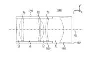
図8は、本開示の主題による、複数のレンズエレメントを備える光学レンズモジュールの一例の概略図である。 FIG. 8 is a schematic view of an example of an optical lens module including a plurality of lens elements according to the subject matter of the present disclosure.
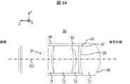
図9Aは、本開示の主題による、複数のレンズエレメントを備える光学レンズモジュールの別の例の概略図である。 FIG. 9A is a schematic representation of another example of an optical lens module with a plurality of lens elements according to the subject matter of the present disclosure.
図9Bは、図9Aの例の変形を示す。 FIG. 9B shows a modification of the example of FIG. 9A.
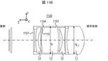
図10は、本開示の主題による、複数のレンズエレメントを備える光学レンズモジュールの別の例の概略図である。 FIG. 10 is a schematic representation of another example of an optical lens module comprising a plurality of lens elements according to the subject matter of the present disclosure.
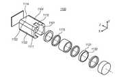
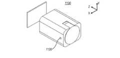
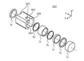
図11Aは、本開示の主題による、鏡筒および鏡筒内への挿入前の複数のレンズエレメントの等角図の概略図である。 FIG. 11A is a schematic view of the lens barrel and a plurality of lens elements before insertion into the lens barrel according to the subject matter of the present disclosure.
図11Bは、平面Y−Zに沿った、図11Aの例の断面図を示す。 FIG. 11B shows a cross-sectional view of the example of FIG. 11A along planes YY.
図11Cは、平面X−Zに沿った図11Aの例の断面図を示す。 FIG. 11C shows a cross-sectional view of an example of FIG. 11A along planes XX.
図11Dは、図11Aの例の正面図を示す。 FIG. 11D shows a front view of the example of FIG. 11A.
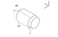
図11Eは、鏡筒内にレンズエレメントを挿入した後の図11Aの例の別の等角図を示す。 FIG. 11E shows another isometric view of the example of FIG. 11A after inserting the lens element into the lens barrel.
図11Fは、レンズエレメントの正面図の概略図である。 FIG. 11F is a schematic front view of the lens element.
図12は、図11A〜図11Eの光学レンズモジュールの製造プロセスの概略図である。 FIG. 12 is a schematic view of the manufacturing process of the optical lens module of FIGS. 11A to 11E.
図13Aは、複数のレンズエレメントの等角図の概略図である。 FIG. 13A is a schematic view of an isometric view of a plurality of lens elements.
図13Bは、図13Aの複数のレンズエレメントと鏡筒とを備える光学レンズモジュールの等角図の概略図である。 FIG. 13B is a schematic view of an isometric view of an optical lens module including the plurality of lens elements and a lens barrel of FIG. 13A.
図13Cは、図13Aの複数のレンズエレメントと鏡筒とを備える光学レンズモジュールのさらに別の概略図である。 FIG. 13C is still another schematic view of an optical lens module including the plurality of lens elements and lens barrels of FIG. 13A.
図14は、本開示の主題のいくつかの例による、4つのテレ画像をまとめて取り込んでステッチングして生成されたステッチ画像の概略図である。 FIG. 14 is a schematic view of a stitched image generated by capturing and stitching four teleimages together, according to some examples of the subject matter of the present disclosure.
図15は、本開示の主題のいくつかの例による、6つのテレ画像をまとめて取り込んでステッチングして生成されたステッチ画像の概略図である。 FIG. 15 is a schematic view of a stitched image generated by capturing and stitching six teleimages together, according to some examples of the subject matter of the present disclosure.
図16は、本開示の主題のいくつかの例による、9つのテレ画像をまとめて取り込んでステッチングして生成されたステッチ画像の概略図である。 FIG. 16 is a schematic view of a stitched image generated by capturing and stitching nine teleimages together, according to some examples of the subject matter of the present disclosure.
図17Aは、本開示の主題による、レンズエレメントを有する鏡筒の別の実施形態の等角図を示す。 FIG. 17A shows an isometric view of another embodiment of a lens barrel having a lens element according to the subject matter of the present disclosure.
図17Bは、図17Aの鏡筒およびレンズエレメントの側面図である。 FIG. 17B is a side view of the lens barrel and lens element of FIG. 17A.
図17Cは、図17Bのレンズエレメントの分解図を示す。 FIG. 17C shows an exploded view of the lens element of FIG. 17B.
図17Dは、本開示の主題による、レンズエレメントを有する別の鏡筒の側面切断図を示す。 FIG. 17D shows a side cut view of another lens barrel with a lens element according to the subject matter of the present disclosure.
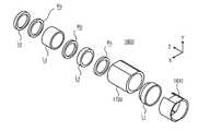
図18Aは、本開示の主題による、鏡筒およびレンズエレメントを有するレンズモジュールのさらに別の実施形態の等角図を示す。 FIG. 18A shows an isometric view of yet another embodiment of a lens module having a lens barrel and a lens element according to the subject matter of the present disclosure.
図18Bは、図18Aのレンズモジュールの側面切断図を示す。 FIG. 18B shows a side cut view of the lens module of FIG. 18A.
図18Cは、図18Bのレンズモジュールの分解図を示す。 FIG. 18C shows an exploded view of the lens module of FIG. 18B.
図19Aは、本開示の主題による、バレルおよびレンズエレメントを有するレンズモジュールのさらに別の実施形態のサイドカット図を示す。 FIG. 19A shows a side-cut view of yet another embodiment of a lens module having a barrel and a lens element according to the subject matter of the present disclosure.
図19Bは、図19Aのレンズモジュールの分解図を示す。 FIG. 19B shows an exploded view of the lens module of FIG. 19A.
図20は、本開示の主題による、レンズエレメントを有する鏡筒のさらに別の実施形態の側面切断図を示す。 FIG. 20 shows a side cut view of yet another embodiment of a lens barrel having a lens element according to the subject matter of the present disclosure.
図21Aは、本開示の主題の別の例による、光線を示すレンズエレメントの別の実施形態の模式図である。 FIG. 21A is a schematic representation of another embodiment of a lens element exhibiting light rays, according to another example of the subject matter of the present disclosure.
図21Bは、図21Aのレンズエレメントの別の模式図である。 21B is another schematic view of the lens element of FIG. 21A.
図22は、図21Aおよび図21Bのレンズエレメントを保持するための光学レンズモジュールの側面概略図である。 FIG. 22 is a side schematic view of the optical lens module for holding the lens elements of FIGS. 21A and 21B.
図23は、図21Aおよび図21Bのレンズエレメントを保持するための別の光学レンズモジュールの側面概略図である。 FIG. 23 is a side schematic view of another optical lens module for holding the lens elements of FIGS. 21A and 21B.
図24は、本開示の主題による、複数のレンズエレメントを備える光学レンズモジュールのさらに別の例の概略図である。 FIG. 24 is a schematic representation of yet another example of an optical lens module comprising a plurality of lens elements according to the subject matter of the present disclosure.
図25Aは、本開示の主題による、別の光学レンズモジュールの等角図の概略図である。 FIG. 25A is a schematic of an isometric view of another optical lens module according to the subject matter of the present disclosure.
図25Bは、平面Y−Zに沿った、図25Aのレンズモジュールの断面図を示す。 FIG. 25B shows a cross-sectional view of the lens module of FIG. 25A along the plane YZ.
図25Cは、平面X−Zに沿った、図25Aのレンズモジュールの断面図を示す。 FIG. 25C shows a cross-sectional view of the lens module of FIG. 25A along planes XX.
図25Dは、鏡筒内にレンズエレメントを挿入した後の、図25Aのレンズモジュールの別の等角図を示す。 FIG. 25D shows another isometric view of the lens module of FIG. 25A after inserting the lens element into the lens barrel.
図26Aは、本開示の主題による、鏡筒およびレンズエレメントを有するレンズモジュールのさらに別の実施形態の等角図を示す。 FIG. 26A shows an isometric view of yet another embodiment of a lens module having a lens barrel and a lens element according to the subject matter of the present disclosure.
図26Bは、図26Aのレンズモジュールの側面切断図を示す。 FIG. 26B shows a side cut view of the lens module of FIG. 26A.
図26Cは、図26Bのレンズモジュールの分解図を示す。 FIG. 26C shows an exploded view of the lens module of FIG. 26B.
図27Aは、本開示の主題による、レンズモジュールのさらに別の実施形態の等角図を示す。 FIG. 27A shows an isometric view of yet another embodiment of the lens module according to the subject matter of the present disclosure.
図27Bは、図27Aのレンズモジュールの分解図を示す。 27B shows an exploded view of the lens module of FIG. 27A.
〔発明を実施するための形態〕
以下の詳細な説明では、完全な理解を提供するために、多数の特定の詳細が記載される。しかしながら、ここに開示された主題は、これらの特定の詳細なしに実施されてもよいことが当業者によって理解されるのであろう。他の例では、本開示の主題を曖昧にしないように、周知の方法は詳細に説明されていない。[Mode for carrying out the invention]
In the detailed description below, a number of specific details are provided to provide a complete understanding. However, it will be appreciated by those skilled in the art that the subject matter disclosed herein may be practiced without these particular details. In other examples, well-known methods are not described in detail so as not to obscure the subject matter of the present disclosure.
明確にするために、別個の実施形態の文脈で説明される、現在開示されている主題の特定の特徴は、単一の実施形態において組み合わせて提供されてもよいことが理解される。反対に、単一の実施形態の文脈で説明されている簡略化のために、現在開示されている主題事項の様々な特徴は別個に、または任意の適切な組み合わせで提供されてもよい。 For clarity, it is understood that the particular features of the currently disclosed subject matter, described in the context of separate embodiments, may be provided in combination in a single embodiment. Conversely, for the simplifications described in the context of a single embodiment, the various features of the currently disclosed subject matter may be provided separately or in any suitable combination.
本明細書で開示される「処理ユニット」というタームは例えば、様々なデータ処理動作を実行することができるコンピュータメモリ(例えば、デジタル信号プロセッサ(DSP)、マイクロコントローラ、フィールドプログラマブルゲートアレイ(FPGA)、特定用途向け集積回路(ASIC)など)に動作可能に接続されたコンピュータ処理装置を含む、データ処理回路を有する任意の種類の電子デバイスを含むように広く解釈されるべきである。 The term "processing unit" disclosed herein refers to, for example, a computer memory capable of performing various data processing operations (eg, a digital signal processor (DSP), a microcontroller, a field programmable gate array (FPGA), etc. It should be broadly interpreted to include any type of electronic device that has a data processing circuit, including a computer processing device operably connected to an application specific integrated circuit (ASIC), etc.
さらに、明確にするために、用語「実質的に」は、本明細書では許容範囲内の値の変動の可能性を暗示するために使用される。一例によれば、本明細書で使用される「実質的に」というタームは、任意の指定された値から10%までの範囲で上回るか下回る変動が可能なことを意味すると解釈されるべきである。別の例によれば、本明細書で使用される「実質的に」というタームは、任意の指定された値から5%までの範囲で上回るか下回る変動が可能なことを意味すると解釈されるべきである。さらなる例によれば、本明細書で使用される用語「実質的に」は、任意の指定された値から2.5%までの範囲で上回るか下回る変動が可能なことを意味すると解釈されるべきである。 Further, for clarity, the term "substantially" is used herein to imply possible fluctuations in values within acceptable limits. As an example, the term "substantially" as used herein should be construed to mean that any specified value can vary above or below within a range of up to 10%. be. According to another example, the term "substantially" as used herein is construed to mean that any specified value can vary above or below within a range of up to 5%. Should be. According to a further example, the term "substantially" as used herein is construed to mean that any specified value can vary above or below within a range of up to 2.5%. Should be.
図1Aおよび図1Bは、例えばテレ(Tele)カメラとして動作することができる公知のデジタル屈曲式カメラ100を示す。デジタルカメラ100は、第1の反射素子(例えば、ミラーまたはプリズム、および「光路屈曲素子」(OPFE)とも呼ばれる)101と、複数のレンズエレメント(この図では見えないが、例えば、図2Aおよび図2Bでは見える)と、イメージセンサ104とを備える。レンズエレメント(及び鏡筒、光学レンズモジュール)は、第1の光軸103に沿って軸対称であってもよい。レンズエレメントの少なくともいくつかは、「鏡筒」102と呼ばれる構造によって保持することができる。光学レンズモジュールは、レンズエレメントと鏡筒とを備える。鏡筒は、光軸103に沿って長手方向の対称性を有することができる。図1A〜図1Dにおいて、この鏡筒の断面は円形である。しかし、これは必須ではなく、他の形状を使用することができる。 1A and 1B show a known
被写体(図示せず)からイメージセンサ104への光線の経路は、光路(光路の一部を表す光路105および106を参照)を定義する。 The path of the light beam from the subject (not shown) to the
OPFE101は、プリズムまたはミラーであってもよい。図1Aに示すように、OPFE101は、光軸103に対して傾斜したミラーとすることができる。他の場合(図示せず、例えばPCT/IB2017/052383を参照)、OPFE101は、光軸103に対して傾斜した裏面を有するプリズムとすることができる。OPFEは、第1の光路105から第2の光路106への光路を屈曲させる。光路106は、光軸103に実質的に平行である。したがって、光路は「屈曲光路」(光路105および106によって示される)と呼ばれ、カメラ100は「屈曲式カメラ」と呼ばれる。レンズモジュールは、複数のレンズエレメントを備える。 OPFE101 may be a prism or a mirror. As shown in FIG. 1A, the
特に、いくつかの例では、OPFE101が光軸103に対して実質的に450で傾斜することができる。図1Aにおいても、OPFE101は、光路105に対して実質的に450で傾斜している。In particular, in some instances, can OPFE101 is inclined at substantially 450 with respect to the
いくつかの既知の例では、イメージセンサ104が光軸103に実質的に垂直なX−Y平面内にある。しかしながら、これは限定的なものではなく、イメージセンサ104は異なる向きを有することができる。例えば、国際公開第2016/024192号パンフレットに記載されているように、イメージセンサ104は、XZ平面内にあることができる。この場合、追加のOPFEを使用して、光線をイメージセンサ104に向けて反射することができる。 In some known examples, the
いくつかの例によれば、イメージセンサ104は、長方形の形状を有する。いくつかの例によれば、イメージセンサ104は、円形の形状を有する。しかしながら、これらの実施例は限定的なものではない。 According to some examples, the
様々な例では、カメラ100が当技術分野で知られているように、基板109、例えばプリント回路基板(PCB)上に取り付けることができる。 In various examples, the
2つのサブカメラ、例えば、通常のワイドサブカメラ130およびテレサブカメラ100は、デジタルカメラ170(デュアルカメラまたはデュアルアパーチャカメラとも呼ばれる)に含まれてもよい。可能な構成を、図1Cおよび図1Dを参照して説明する。この例では、テレサブカメラ1Aおよび図1Bを参照して説明したカメラによるものである。したがって、テレサブカメラ100の構成要素は図1Aおよび図1Bと同じ参照番号を有し、再び説明しない。 Two sub-cameras, such as the normal
ワイドカメラ130は、開口132(カメラの物体側を示す)と、Y方向に対称(および光)軸134を有する光学レンズモジュール133(または「ワイドレンズモジュール」)と、ワイドイメージセンサ135とを含むことができる。ワイドサブカメラはワイド画像提供するように構成されたワイドレンズモジュールを備え、ワイドサブカメラはワイド視野(FOVW)を有し、テレサブカメラはFOVWよりも狭いテレ視野(FOVT)を有する。特に、他の例では、複数の広いサブカメラおよび/または複数のテレサブカメラを、単一のデジタルカメラに組み込み、動作させることができる。The
一例によれば、X−Z平面内にワイドイメージセンサがあり、イメージセンサ104(この例では、TeLeイメージセンサである)が光軸103に実質的に垂直なX−Y平面内にある。 According to one example, there is a wide image sensor in the XY plane and the image sensor 104 (in this example, the TeLe image sensor) is in the XY plane substantially perpendicular to the
図1A〜図1Dの例では、カメラ100が様々な処理動作、例えばテレ画像およびワイド画像を融合出力画像に処理することを実行するための1つまたは複数の適切に構成されたプロセッサ(図示せず)を備える処理ユニットをさらに含む(または動作可能に接続される)ことができる。 In the example of FIGS. 1A-1D, one or more well-configured processors (shown) for the
処理ユニットは、デジタルカメラと共に動作する専用のハードウェア(HW)及びソフトウェア(SW)を含むことができる。あるいはカメラがインストールされる電子デバイス(例えば、そのネイティブCPU)のプロセッサはデジタルカメラに関連する様々な処理動作(テレ画像およびワイド画像を出力画像に処理することを含むが、これらに限定されない)を実行するように適合され得る。 The processing unit can include dedicated hardware (HW) and software (SW) that work with the digital camera. Alternatively, the processor of the electronic device on which the camera is installed (eg, its native CPU) performs various processing operations associated with the digital camera, including, but not limited to, processing teleimages and wide images into output images. Can be adapted to perform.
ここで、本開示の主題のいくつかの例による光線で示されるレンズエレメントを有するレンズモジュール200の模式図を示す図2Aおよび図2Bに注目する。レンズモジュール200は、鏡筒なしで示されている。図2Aはレンズモジュール200の光線追跡を示し、図2Bは、より明確にするためにレンズエレメントのみを示す。さらに、両方の図は、イメージセンサ202および光学素子205を示す。 Here, attention is focused on FIGS. 2A and 2B showing a schematic diagram of a
レンズモジュール200は、N個(複数)のレンズエレメントLi(ここで、「i」は1〜Nの整数)を含み、L1は被写体側に最も近いレンズエレメントであり、LNは画像側、すなわち、イメージセンサが配置されている側に最も近いレンズエレメントである。この順番は、本明細書に開示されるすべてのレンズおよびレンズエレメントに当てはまる。レンズエレメントLiは例えば、図1Aおよび図1Bに示されるカメラ100のレンズエレメントとして、または図1Cおよび図1Dのテレサブカメラ100のレンズエレメントとして使用することができる。図示のように、N個のレンズエレメントは、光軸103に沿って軸対称である。The
図2Aおよび図2Bの例では、Nは4に等しい。しかし、これは限定的なものではなく、異なる数のレンズエレメントを使用することができる。いくつかの例によれば、Nは3以上である。例えば、Nは、3、4、5、6または7に等しくてもよい。 In the examples of FIGS. 2A and 2B, N is equal to 4. However, this is not limited and different numbers of lens elements can be used. According to some examples, N is 3 or greater. For example, N may be equal to 3, 4, 5, 6 or 7.
図2Aおよび図2Bの例では、レンズエレメントの表面のいくつかは凸面として表され、いくつかは凹面として表される。しかしながら、図2Aおよび図2Bに図示したものに限定されるものではなく、用途、所望の光パワーなどの様々な要因に応じて、凸面および/または凹面の異なる組み合わせを使用することができる。 In the examples of FIGS. 2A and 2B, some of the surfaces of the lens element are represented as convex and some are represented as concave. However, it is not limited to those shown in FIGS. 2A and 2B, and different combinations of convex and / or concave surfaces can be used depending on various factors such as application, desired optical power, and the like.
光線(OPFE101のような反射素子によって反射された後)は、レンズエレメントLiを通過し、イメージセンサ202上に画像を形成する。図2Aおよび図2Bの例では、光線が光学素子205(前面205aおよび後面205bを含み、例えばカットオフフィルターであってもよい)を通過した後、イメージセンサ202に入射する。しかし、これに限定されるものではなく、いくつかの例では光学素子205は存在しない。光学素子205は、例えば、赤外線(IR)フィルタ、及び/又はガラス画像センサダストカバーであってもよい。(After being reflected by the reflective elements, such as OPFE101) light passes through the lens elementL i, to form an image on the
それぞれのレンズエレメントLiはそれぞれの前面S2i−1(インデックス「2i−1」は前面の数である)と、それぞれの後面S2i(インデックス「2i」は後面の数である)とを含み、ここで「i」は1からNの間の整数である。この番号付け規則は、説明全体を通して使用される。あるいは本明細書を通して行われるように、レンズ表面は「Sk」としてマークされ、kは1〜2Nの範囲内である。前面および後面は、場合によっては非球面であってもよい。しかし、これに限定されない。Each lens elementLi includes each front surface S2i-1 (index "2i-1" is the number of front surfaces) and each rear surface S2i (index "2i" is the number of rear surfaces). , Where "i" is an integer between 1 and N. This numbering rule is used throughout the description. Alternatively, as is done throughout this specification, the lens surface is marked as "Sk", k is in the range of 1 to 2N. The front and rear surfaces may be aspherical in some cases. However, it is not limited to this.
本明細書で使用されるように、各レンズエレメントの「前面」というタームはカメラの入口(カメラ被写体側)により近くに位置するレンズエレメントの表面を指し、「後面」というタームは、イメージセンサ(カメラ像側)により近くに位置するレンズエレメントの表面を指す。 As used herein, the term "front" of each lens element refers to the surface of the lens element located closer to the entrance (camera subject side) of the camera, and the term "rear" refers to the image sensor ( Refers to the surface of the lens element located closer to the camera image side).
以下に説明するように、1≦k≦2Nにおいてクリアな高さ(clear height)値CH(Sk)およびクリアアパーチャ値CA(Sk)を、各レンズエレメントの各々の表面Skに対して規定することができる。As described below, the clear height in the 1 ≦ k ≦ 2N the (clear height) value CH(S k) and clear aperture value CA(S k), with respect to the surfaceS k of each of the lens elements Can be specified.
また、例えば図6に示すように、レンズエレメントLi毎に高さ(HLi、1≦i≦N)が規定されている。HLiはそれぞれのレンズエレメントLiについて、レンズエレメントの光軸に垂直な軸に沿って測定されたレンズエレメントLiの最大高さに対応する(図6の例ではHLiが光軸103に垂直な光路105に沿って測定される)。所与のレンズエレメントについて、高さは、この所与のレンズエレメントの前面および後面の透明な高さ値CHおよびクリアアパーチャ値CAよりも大きいか、または等しい。典型的には、軸対称レンズエレメントの場合、HLiは図11Fに見られるように、レンズエレメントLiの径である。典型的には、軸対称レンズエレメントの場合、HLi=max{CA(S2i−1)、CA(S2i)}+機械部分サイズとなる。機械部分およびその特性を以下に定義する(図11E、11Fおよび17A〜D)。HLiに対する機械部分サイズの寄与は、典型的には200μm〜1000μmである。For example, as shown in FIG. 6, the height for each lens elementL i (H Li, 1 ≦ i ≦ N) is specified. HLi for each of the lens elements Li, corresponding to the maximum height of the lens element Li, measured along an axis perpendicular to the optical axis of the lens element (the
また、図6にも示すように、レンズ鏡筒には高さHが規定されている。レンズモジュールの光軸に垂直な任意の軸Aについて、径DAは、レンズモジュールの軸Aに沿って測定された最大間隔として定義される。HはすべてのDAsの最小値として定義され、図6の例ではHはレンズモジュールの光軸103に対して垂直であり、光路105に対して平行である軸に沿って測定された鏡筒の最大高さに対応する。Further, as shown in FIG. 6, the height H is defined for the lens barrel. About an axis A perpendicular optionally to the optical axis of the lens module, the diameter DA is defined as the maximum distance measured along the axis A of the lens module. H is defined as the minimum of all DA s, in the example of FIG. 6 H is perpendicular to the
また、図7にも示すように、鏡筒のキャビティには高さHCが規定されている。HCは、レンズモジュールの光軸に垂直な軸に沿って測定されたキャビティ鏡筒の高さに対応する(図7ではHCが光軸103に垂直な光路105に沿って測定される)。キャビティ鏡筒が軸対称であるいくつかの例では、HCはキャビティ鏡筒の内径である。Further, as shown in FIG. 7, the heightHC is defined in the cavity of the lens barrel. HC, the lens corresponds to the height of the measured cavity barrel along an axis perpendicular to the optical axis of the module (in FIG. 7 HC is measured along the vertical
本開示の主題のいくつかの例によれば、被写体側に最も近いレンズエレメントL1は、他のレンズエレメントの各々の高さよりも高い。非限定的な例が図6に示されており、ここで、HL1は、HL2、HL3、およびHL4よりも大きい。According to some examples of the presently disclosed subject matter, the lens elements L1 closest to the object side is higher than the height of each of the other lens elements. Non-limiting examples are shown in Figure 6,where, H L1is greater than HL2, H L3, andH L4.
本開示の主題のいくつかの例によれば、被写体側に最も近いレンズエレメントL1およびイメージセンサに最も近いレンズエレメントLNは、実質的に高さが等しく、他のレンズエレメントのそれぞれの高さよりも高い。非限定的な例が図21Bに示されており、ここで、HL1はHL5に等しく、HL2、HL3、およびHL4より大きい。According to some examples of the presently disclosed subject matter, the nearest lens element LN to the nearest lens element L1 and the image sensor on the object side is substantially equal height, each of the high of the other lens elements Higher than that. Non-limiting examples are shown in FIG. 21B, largerwhere, H L1 equalsH L5, H L2, H L3 , andH L4.
図3A、図3B、図4に示すように、表面Skを通過する光線(1≦k≦2N)はそれぞれインパクトポイントIPに当たる。光線が表面S1からレンズモジュール200に入り、表面S2からS2Nに連続的に通過する。一部の光線は任意の面Skに衝突するが、イメージセンサ202に到達することはできない/到達しない。所与の面Skについて、イメージセンサ202上に画像を形成することができる光線のみが、複数のインパクトポイントIPを形成すると考えられる。CH(Sk)は、平面P上のすべてのインパクトポイントIPの直交射影IPorthが2つの平行な線の間に位置するように、2つのできるだけ近い平行な線の間の間隔として規定される(図4の線400および401を参照)(図3Aおよび図3Bでは、平面Pは平面X−Yに平行であり、光軸103に直交する)。CH(Sk)は、表面Sk(前面および後面、1≦k≦2N)ごとに規定することができる。Figure 3A, as shown FIG. 3B, in FIG. 4, the surfaceS k a passing beam (1 ≦ k ≦ 2N) respectively strikes the impact point IP. Light enters from the surfaceS 1 in the
CH(Sk)の規定は、イメージセンサ上に画像を「形成することができる」光線を指すので、現在撮像されている被写体に依存しない。したがって、現在撮像されている被写体が光を生成しない黒い背景に位置する場合であっても、画像を形成するためにイメージセンサに「到達することができる」任意の光線(例えば、黒い背景とは対照的に、光を放出する背景によって放出される光線)を指すので、定義は、この黒い背景を指さない。The CH (Sk ) definition refers to a ray that can "form" an image on the image sensor and is therefore independent of the subject currently being imaged. Thus, any light beam that can "reach" the image sensor to form an image (eg, a black background), even if the subject currently being imaged is located on a black background that does not produce light. In contrast, the definition does not refer to this black background, as it refers to the rays emitted by the background that emits light).
例えば、図3Aは、光軸103.に直交する平面P上の2つのインパクトポイントIP1およびIP2の直交投影IPorth,1、IPorth,2を示す。例えば、図3Aでは、面Skは凸状である。For example, FIG. 3A shows the
図3Bは、平面P上の2つのインパクトポイントIP3およびIP4の直交投影IPorth,3、IPorth,4を示す。例えば、図3Bでは、面Skは凹状である。FIG. 3B shows two impact points IP3 and IP4 orthogonal projections IPorth, 3 and IPorth, 4 on the plane P. For example, in FIG. 3B, the surfaceSk is concave.
図4において、平面P上の面Skの全てのインパクトポイントIPの直交射影IPのorthは、平行な線400と401との間に位置する。したがって、CH(Sk)は、線400と線401との間の距離である。In FIG. 4,orth all impact point IP orthogonal projection IP of surfaceS k in the plane P is located between the
図5に注目する。本開示の主題によれば、クリアアパーチャCA(Sk)は円の径として、所与の面Sk(1≦k≦2N)ごとに定義され、ここで、円は光軸103に直交し、平面P上のすべてのインパクトポイントのすべての直交投影IPorthを取り囲む平面P内に位置する最小の円であり、CH(Sk)に関して上述したように、CA(Sk)の定義は、現在撮像されている被写体にも依存しないことに留意されたい。Pay attention to FIG. According to the subject matter of the present disclosure, as the diameter of the clear aperture CA (Sk) is a circle, is defined for each given surfaceS k (1 ≦ k ≦ 2N ), where the circle is orthogonal to the
図5に示すように、平面P上の全てのインパクトポイントIPの外接直交射影IPorthは、円500である。この円500の径がCA(Sk)を規定する。As shown in FIG. 5, the circumscribed orthogonal projection IPorth of all impact point IPs on the plane P is a
詳細な光学データおよび表面データは図2Aおよび図2Bのレンズエレメントの例については表1および表2に、図6〜図9のレンズエレメントの例については表3および表4に、図20のレンズエレメントの例については表5および表6に、図21A〜21Bのレンズエレメントの例については表7および表8に示す(下記参照)。これらの実施例に提供される値は単なる例示であり、他の実施例によれば、他の値を使用することができる。 Detailed optical and surface data are shown in Tables 1 and 2 for examples of the lens elements of FIGS. 2A and 2B, in Tables 3 and 4 for examples of the lens elements of FIGS. 6-9, and the lens of FIG. Examples of elements are shown in Tables 5 and 6, and examples of lens elements in FIGS. 21A-21B are shown in Tables 7 and 8 (see below). The values provided in these examples are merely examples, and other values may be used according to other examples.
以下の表では曲率半径(「R」)、レンズエレメントの厚さ(「厚さ」)、およびクリアアパーチャ(「CA」)の単位はミリメートルで表される。 In the table below, the units of radius of curvature (“R”), lens element thickness (“thickness”), and clear aperture (“CA”) are expressed in millimeters.
表1、表3および表5および表7の‘0’の行は、被写体(図では見えない)に関連するパラメータを記述し、被写体は、無限距離であると考えられる、システムから1kmに配置されている。 The '0' row in Tables 1, 3 and 5 and 7 describes the parameters associated with the subject (not visible in the figure) and the subject is located 1 km from the system, which is considered to be infinite distance. Has been done.
表1〜表4の‘1’〜‘8’の行は、表面S1〜S8のパラメータをそれぞれ記述している。表5〜8の‘1’〜‘10’の行は、表面S1〜S10のパラメータをそれぞれ記述している。Row of the table of 1 to Table 4 '1'~'8' describe the parameters of the
表1および表3の‘9’、‘10’および‘11’の行、ならびに表5および表7の‘11’、‘12’および‘13’の行は、それぞれ、光学素子205の表面205a、205bおよびイメージセンサ202の表面202aのパラメータを表す。 The rows '9', '10' and '11' in Tables 1 and 3 and the rows '11', '12' and '13' in Tables 5 and 7, respectively, are the
表1、表3および表5の‘i’(表1および表3における1と10の間のi、および表5における1と12の間のi)において、厚さは、光軸103に沿って測定される表面Siと表面Si+1との間の間隔(Z軸と一致する)に対応する。In the'i'of Tables 1, 3 and 5 (i between 1 and 10 in Tables 1 and 3 and i between 1 and 12 in Table 5), the thickness is along the
表1および表3の‘11’の行(表5および表7の‘13’の行)では、これが最後の表面202aに対応するので、厚さはゼロに等しい。 In the '11' row of Tables 1 and 3 (the '13' row of Tables 5 and 7), the thickness is equal to zero as this corresponds to the
「BK7」、「K26R」、「EP6000」および「H−ZK3」は当業者に公知であり、例として言及される従来の材料である。 "BK7", "K26R", "EP6000" and "H-ZK3" are conventional materials known to those skilled in the art and referred to as examples.
「BK7」は、おおよその以下のパラメータによって特徴付けられる:
屈折率1.5168、アッベ数64.16733。"BK7" is characterized by the following parameters:
Refractive index 1.5168, Abbe number 64.16733.
「K26R」はゼオン(株)製の材料であり、以下の近似パラメータを特徴とする:
屈折率1.534809、アッベ数55.663857。"K26R" is a material manufactured by Zeon Corporation and features the following approximate parameters:
Refractive index 1.534809, Abbe number 55.663857.
「EP6000」は三菱製の材料であり、おおよその以下のパラメータによって特徴付けられる:
屈折率1.6397、アッベ数23.5288。"EP6000" is a material made by Mitsubishi and is characterized by the following approximate parameters:
Refractive index 1.6397, Abbe number 23.5288.
「H−ZK3」は、おおよその以下のパラメータによって特徴付けられるガラスの一種である:
屈折率1.5891、アッベ数61.25。"H-ZK3" is a type of glass characterized by the following approximate parameters:
Refractive index 1.5891, Abbe number 61.25.
表7において、各表面材料の特性を、屈折率として「Nd」、アッベ数として「Vd」で示す。 In Table 7, the characteristics of each surface material are shown by "Nd" as the refractive index and "Vd" as the Abbe number.
各表面Skの表面形状の式(kが1〜2Nの場合)は、次式で表される:Formula (when k is 1 to 2N) of the surface shape of the surfaceS k is expressed by the following equation:

ここで、上記の式中の「Z」は光軸103に沿って測定された表面Skのプロファイルの位置であり(z軸と一致し、Z=0は表面Skとz軸とのプロファイルの交点に対応する)、「R」は(光軸103に垂直な軸に沿って測定された)光軸103からの距離であり、「k」は円錐係数であり、c=1/Rであり、Rは曲率半径であり、An(nは1から7)は、表面Skごとに表2および表4に与えられる係数である。rの最大値「max r」はD/2に等しい。Here, "Z" is coincident with the position of the profile of the measured surface Sk along the optical axis 103 (z-axis, the profile of the Z = 0 is surface Sk and z-axis in the above formula (Corresponding to the intersection of), "R" is the distance from the optical axis 103 (measured along the axis perpendicular to the optical axis 103), "k" is the curvature of the cone, and c = 1 / R. There, R is the radius ofcurvature, a n (n is 1-7) is a coefficient given in Table 2 and Table 4 for each surfaceS k. The maximum value "max r" of r is equal to D / 2.
図2Aおよび図2Bの例では、以下の光学特性が達成される:
TTL=13.6mm
BFL=4.93mm
EFL(有効焦点距離)=13.8mm
CA(S1)=CH(S1)=5mm
CA(S2)=CH(S2)=4.4mm
kが3〜8の場合、CA(Sk)≦3.8mm、CH(Sk)≦CA(Sk)である
f/#=2.76
焦点距離L1:f1=5.57mm、f1/EFL=0.4
センサ対角線(SD)5.86mm、最終面のクリアアパーチャCA(S2N)=3.8mm、CA(S2N)/SDL=0.65。In the examples of FIGS. 2A and 2B, the following optical properties are achieved:
TTL = 13.6mm
BFL = 4.93 mm
EFL (effective focal length) = 13.8 mm
CA (S1 ) = CH (S1 ) = 5 mm
CA (S2 ) = CH (S2 ) = 4.4 mm
When k is3~8, CA (S k) ≦ 3.8mm, CH (S k) is≦ CA (S k) f / # = 2.76
Focal length L1 : f1 = 5.57 mm, f1 / EFL = 0.4
Sensor diagonal (SD) 5.86mm, clear aperture CA (S 2N ) = 3.8 mm on thefinal surface, CA (S 2N ) / SDL = 0.65.
図6の例では、以下の光学特性が達成される:
TTL=11.1mm
BFL=4.3mm
EFL(有効焦点距離)=11.2mm
CA(S1)=CH(S1)=4.32mm
CA(S2)=CH(S2)=3.52mm
k=3〜8の場合、CA(Sk)≦3.2mm、CH(Sk)≦CA(Sk)。
f/#=2.5
焦点距離L1:f1=4.54mm、f1/EFL=0.4
センサ対角線(SD)5.24mm、最終面のクリアアパーチャCA(S2N)=3.2mm、CA(S2N)/SDL=0.61。In the example of FIG. 6, the following optical properties are achieved:
TTL = 11.1mm
BFL = 4.3 mm
EFL (effective focal length) = 11.2 mm
CA (S1 ) = CH (S1 ) = 4.32 mm
CA (S2 ) = CH (S2 ) = 3.52 mm
Fork = 3~8, CA (S k ) ≦ 3.2mm, CH (S k) ≦ CA (S k).
f / # = 2.5
Focal length L1 : f1 = 4.54 mm, f1 / EFL = 0.4
Sensor diagonal (SD) 5.24mm, clear aperture CA (S 2N ) = 3.2 mm on thefinal surface, CA (S 2N ) / SDL = 0.61.
図20の例では、以下の光学特性が達成される:
TTL=15mm
BFL=6.9mm
EFL=16mm
CA(S1)=CH(S1)=5.92mm
CA(S2)=CH(S2)=5.1mm
kが3〜10の場合、CA(Sk)≦4.0mm、CH(Sk)≦CA(Sk)である。
f/#=2.7
焦点距離L1:f1=8.1mm、f1/EFL=0.506
センサ対角線(SD)mm、最終面のクリアアパーチャCA(S2N)=3.52mm、CA(S2N)/SDL=0.6。In the example of FIG. 20, the following optical properties are achieved:
TTL = 15mm
BFL = 6.9 mm
EFL = 16mm
CA (S1 ) = CH (S1 ) = 5.92 mm
CA (S2 ) = CH (S2 ) = 5.1 mm
When k is 3-10, aCA (S k) ≦ 4.0mm, CH (S k) ≦ CA (S k).
f / # = 2.7
Focal length L1 : f1 = 8.1 mm, f1 / EFL = 0.506
Sensor diagonal (SD) mm, the final surface of the clear apertureCA (S 2N) = 3.52mm, CA (S 2N) /SDL=0.6.
図21Aおよび図21Bの例では、以下の光学特性が達成される:
TTL=7.78mm
BFL=3.23mm
EFL(有効焦点距離)=7.97mm
CA(S1)=CH(S1)=3.6mm
CA(S2)=CH(S2)=3.45mm
kが3〜8の場合、CA(Sk)≦3.4mm、CH(Sk)≦CA(Sk)である。
CA(S2N−1)=3.36mm、CH(S2N−1)=2.842mm
CA(S2N)=3.6mm、CH(S2N−1)=3.064mm
f/#=2.2
焦点距離L1:f1=3.972mm、f1/EFL=0.498
センサ対角線(SD)5.86mm、CA(S2N)/SD=0.615
本出願において、および上記の特性のために、以下の記号および略語が使用され、それらの全ては、当該技術分野において公知の用語である:
TTL: 「総トラック長」(total track length)はシステムが無限遠物体距離に合焦されたときに、第1のレンズエレメントL1の前面S1の点とイメージセンサとの間の、光軸と並行する軸に沿って測定された最大距離として定義される。
BFL: 「焦点後方距離」(focal back length)はシステムが無限遠物体距離に合焦されたときに、最後のレンズエレメントLNの後面S2Nの点とイメージセンサとの間の、第1の光軸と並行する軸に沿って測定された最小距離として定義される。
EFL: L1〜LNをアセンブリしたレンズモジュールの有効焦点距離。
f/#: f数、開口絞りの直径に対するEFLの比。
開口絞り: 光学システムを通過する光量を制限する開口。In the examples of FIGS. 21A and 21B, the following optical properties are achieved:
TTL = 7.78mm
BFL = 3.23 mm
EFL (effective focal length) = 7.97 mm
CA (S1 ) = CH (S1 ) = 3.6 mm
CA (S2 ) = CH (S2 ) = 3.45 mm
When k is 3-8, aCA (S k) ≦ 3.4mm, CH (S k) ≦ CA (S k).
CA (S2N-1) = 3.36 mm, CH (S2N-1) = 2.842 mm
CA (S2N ) = 3.6 mm, CH (S2N-1 ) = 3.064 mm
f / # = 2.2
Focal length L1 : f1 = 3.972 mm, f1 / EFL = 0.498
Sensor diagonal (SD) 5.86 mm, CA (S2N ) / SD = 0.615
The following symbols and abbreviations are used in this application and for the above properties, all of which are terms known in the art:
TTL: "total track length" (total track length) when the system is focused on an infinite object distance, between the first lens point and the image sensor of the front S1 of the element L1 of the optical axis Defined as the maximum distance measured along an axis parallel to.
BFL: The "focal back length" is the first between the point of the rear surfaceS2Nof the last lens element LN and the image sensor when the system is focused on the infinity object distance. It is defined as the minimum distance measured along an axis parallel to the optical axis.
EFL: Effective focal length of the lens module assembled fromL 1 toL N.
f / #: number of f, ratio of EFL to diameter of aperture stop.
Aperture Aperture: An aperture that limits the amount of light that passes through an optical system.
図2Aおよび図2Bの例では、CA(S1)=CH(S1)のケースを示す。同様の場合、CA(S1)は、例えば5%までの差異を伴って、CH(S1)に実質的に等しくてもよい。In the examples of FIGS. 2A and 2B, the case of CA (S1 ) = CH (S1 ) is shown. In the same case, CA (S1 ) may be substantially equal toCH (S 1 ) with a difference of up to 5%, for example.
また、第1面S1の手前には、「開口絞り」206(レンズアパーチャを規定する)が配置されている。開口絞りは、例えば、機械部分であってもよい。第1面S1に、またはその前に配置された開口絞りを有するレンズモジュールは、当技術分野では「前方開口レンズ」として知られている。レンズモジュール200は、前方開口レンズである。Further, the front of the first surface S1, "aperture stop" 206 (defining the lens aperture) is disposed. The aperture stop may be, for example, a mechanical part. The first surface S1, or a lens module having arranged the aperture stop in front thereof is known as "forward aperture lens" in the art. The
他の例では、当該開口絞りが異なる位置または表面に配置されてもよいことに留意されたい。このとき、第1面S1については、この条件が成り立たなくてもよい。例えば(この例は限定ではない)、開口絞りは、第2の面S2に配置することができる。ここで、CA(S2)=CH(S2)である。同様の場合、CA(S2)は、例えば5%までの差異を伴って、CH(S2)に実質的に等しくてもよい。Note that in other examples, the aperture diaphragm may be located at a different position or surface. At this time, the first surface S1, this condition may not hold. For example (this example is not a limitation), the aperture stop may be disposed on the second surface S2. Here, CA (S2 ) = CH (S2 ). In the same case, CA (S2 ) may be substantially equal toCH (S 2 ) with a difference of up to 5%, for example.
本開示の主題のいくつかの例によれば、レンズエレメントL1(被写体側に最も近い)の表面S1のCH(S1)が、複数のレンズエレメントの他のすべての表面Skの各CH(Sk)よりも大きく、2≦k≦2Nで複数のレンズエレメントを備える光学レンズモジュールが提供される。According to some examples of the presently disclosed subject matter, the lens elements L1 of CH (S1) the surface S1 of the(closest to the object side), the other all surfaces Sk of the plurality of lens elements An optical lens module that is larger than CH (Sk ) and includes a plurality of lens elements with 2 ≦ k ≦ 2N is provided.
例えば、N=4である場合(図2A、図2B、および図6)、CH(S1)は、CH(S2)、CH(S3)、CH(S4)、CH(S5)、CH(S6)、CH(S7)、およびCH(S8)よりも大きい。これは、Nが異なる値であっても適用される。For example, when N = 4 (FIGS. 2A, 2B, and 6), CH (S1 ) is CH (S2 ), CH (S3 ), CH (S4 ), CH (S5 ). , CH (S6 ), CH (S7 ), and CH (S8 ). This applies even if N is a different value.
例えば、N=4である場合(図2A、図2B、および図6)、CH(S2)は、CH(S3)、CH(S4)、CH(S5)、CH(S6)、CH(S7)、およびCH(S8)よりも大きい。これは、Nが異なる値であっても適用される。For example, when N = 4 (FIGS. 2A, 2B, and 6), CH (S2 ) is CH (S3 ), CH (S4 ), CH (S5 ), CH (S6 ). , CH (S7 ), and CH (S8 ). This applies even if N is a different value.
例えば、N=5(図20)の場合、CH(S1)がCH(S2)、CH(S3)、CH(S4)、CH(S5)、CH(S6)、CH(S7)、CH(S8)、CH(S9)およびCH(S10)より大きい。これは、Nが異なる値であっても適用される。For example, when N = 5 (FIG. 20), CH (S1 ) is CH (S2 ), CH (S3 ), CH (S4 ), CH (S5 ), CH (S6 ), CH ( Larger than S7 ), CH (S8 ), CH (S9 ) and CH (S10). This applies even if N is a different value.
例えば、N=5(図20)の場合、CH(S2)は、CH(S3)、CH(S4)、CH(S5)、CH(S6)、CH(S7)、CH(S8)、CH(S9)、およびCH(S10)よりも大きい。これは、Nが異なる値であっても適用される。For example, when N = 5 (FIG. 20), CH (S2 ) is CH (S3 ), CH (S4 ), CH (S5 ), CH (S6 ), CH (S7 ), CH. Greater than (S8 ), CH (S9 ), and CH (S10). This applies even if N is a different value.
いくつかの例によれば、CH(S1)≧X×CH(S2)であり、ここで、Xは、範囲[1.01;2]内の任意の値(例えばX=1.1またはこの範囲内の任意の他の値)である。According to some examples, CH (S1 ) ≥ X × CH (S2 ), where X is any value within the range [1.01; 2] (eg X = 1.1). Or any other value within this range).
いくつかの例によれば、以下の条件が満たされる:
CH(S1)≧1.1×CH(S2)、および
CH(S1)≧1.2×CH(Sk)は、他のすべての表面Skのそれぞれについて、3≦k≦2Nである。According to some examples, the following conditions are met:
CH (S 1) ≧ 1.1 × CH (S 2), andCH (S 1) ≧ 1.2 × CH (S k) , for each of all the
いくつかの例によれば、以下の条件が満たされる:
CH(S1)≧1.45×CH(Sk)、全ての他の表面Skの各々について、3≦k≦2Nである。According to some examples, the following conditions are met:
CH (S 1) ≧ 1.45 × CH (S k), for each of all the other surfacesS k, a 3 ≦ k ≦ 2N.
いくつかの例によれば、以下の条件が満たされる:
CH(S2)≧1.1×CH(Sk)、表面Skの各々について、3≦k≦2Nである。According to some examples, the following conditions are met:
CH (S 2) ≧ 1.1 × CH (S k), for each of the surfaceS k, a 3 ≦ k ≦ 2N.
いくつかの例によれば、以下の条件が満たされる:
CH(S1)≧X×CH(S2)、および
CH(S1)≧Y×CH(Sk)は、他の全ての表面Skのそれぞれについて、3≦k≦2Nであり、Y>Xである。いくつかの例ではXは範囲[1.01;2]の任意の値とすることができ、Yは範囲[1.01;2]の任意の値とすることができる。According to some examples, the following conditions are met:
CH (S 1) ≧ X × CH (S 2), andCH (S 1) ≧ Y × CH (S k) , for each of all the other surfacesS k, a 3 ≦ k ≦ 2N, Y > X. In some examples, X can be any value in the range [1.01; 2] and Y can be any value in the range [1.01; 2].
いくつかの例によれば、以下の条件が満たされる:
CH(S2)≧Y×CH(Sk)は、他の全ての表面Skのそれぞれについて、3≦k≦2Nであり、Y>Xである。いくつかの例では、Yは、[1.01;2]の範囲の任意の値であり得る。According to some examples, the following conditions are met:
CH (S 2) ≧ Y × CH (S k) , for each of all the other surfacesS k, a 3 ≦ k ≦ 2N, a Y> X. In some examples, Y can be any value in the range [1.01; 2].
いくつかの例によれば、レンズエレメントL1の表面S1のCA(S1)は、他のレンズエレメントの全ての面SkそれぞれのCA(Sk)よりも大きく、2≦k≦2Nである。いくつかの例によれば、レンズエレメントL1の表面S2のCA(S2)は、3≦k≦2NであるCA(Sk)よりも大きい。According to some examples, the lens elementsL 1 of the surfaceS 1 of the CA(S 1) is larger than all of the surfaceS k each CA of the other lens elements(S k), 2 ≦ k ≦ 2N Is. According to some examples, the CA (S2 ) on the surface S2of the lens element L 1 is larger than theCA (S k ) where 3 ≦ k ≦ 2N.
例えば、N=4である場合(図2Aおよび図2B)、CA(S1)は、CA(S2)、CA(S3)、CA(S4)、CA(S5)、CA(S6)、CA(S7)、およびCA(S8)よりも大きい。これは、Nが異なる値であっても適用される。For example, when N = 4 (FIGS. 2A and 2B), CA (S1 ) is CA (S2 ), CA (S3 ), CA (S4 ), CA (S5 ), CA (S).6 ), CA (S7 ), and larger thanCA (S 8). This applies even if N is a different value.
いくつかの例によれば、CA(S1)≧X×CA(S2)であり、ここで、Xは、範囲[1.01;2]内の任意の値(X=1.1またはこの範囲内の任意の他の値など)である。According to some examples, CA (S1 ) ≧ X × CA (S2 ), where X is any value within the range [1.01; 2] (X = 1.1 or Any other value within this range, etc.).
いくつかの例によれば、以下の条件が満たされる:
CA(S1)≧1.1×CA(S2)、および
CA(S1)≧1.2×CA(Sk)は、他の全ての表面Skのそれぞれについて、3≦k≦2Nである。According to some examples, the following conditions are met:
CA (S 1) ≧ 1.1 × CA (S 2), andCA (S 1) ≧ 1.2 × CA (S k) , for each of all the
いくつかの例によれば、以下の条件が満たされる:
CA(S1)>=1.45×CA(Sk)、他の全ての表面Skのそれぞれについて、3≦k≦2Nである。According to some examples, the following conditions are met:
CA (S 1)> = 1.45 × CA (S k), for each of all the other surfacesS k, a 3 ≦ k ≦ 2N.
いくつかの例によれば、以下の条件が満たされる:
CA(S2)>=1.1×CA(Sk)、表面Skの各々について、3≦k≦2Nである。According to some examples, the following conditions are met:
CA (S 2)> = 1.1 × CA (S k), for each of the surfaceS k, a 3 ≦ k ≦ 2N.
いくつかの例によれば、以下の条件が満たされる:
Y×CA(S1)≧X×CA(S2)、および
CA(S1)≧Y×CA(Sk)は、他のすべての表面Skのそれぞれについて、3≦k≦2Nであり、Y>Xである。いくつかの例では、Xは、範囲[1.01;2]のうちの任意の値とすることができ、Yは、範囲[1.01;2]のうちの任意の値とすることができる。According to some examples, the following conditions are met:
Y × CA (S 1) ≧ X × CA (S 2), andCA (S 1) ≧ Y × CA (S k) , for each of all the other surface Sk, a 3 ≦ k ≦ 2N, Y> X. In some examples, X can be any value in the range [1.01; 2] and Y can be any value in the range [1.01; 2]. can.
いくつかの例によれば、CA(S1)は実質的にCA(S2N)に等しく、複数のレンズエレメントの他のすべての表面SkのそれぞれのCA(Sk)よりも大きく、2≦k≦2N−1である。例えば、N=5である場合(図21Aおよび図21B)、CA(S1)=CA(S10)は、CA(S2)、CA(S3)、CA(S4)、CA(S5)、CA(S6)、CA(S7)、CA(S8)およびCA(S9)よりも大きい。同様の場合、CA(S1)は、CA(S10)に実質的に等しく、例えば5%までの差があってもよい。According to some examples, CA(S 1) is substantially CA equal to(S 2N), each of the CA(S k) greater than all other surfaceS k of the plurality of lens elements, 2 ≦ k ≦ 2N-1. For example, when N = 5 (FIGS. 21A and 21B), CA (S1 ) = CA (S10 ) means CA (S2 ), CA (S3 ), CA (S4 ), CA (S).5 ), CA (S6 ), CA (S7 ), CA (S8 ) and CA (S9 ). In the same case, CA (S1 ) is substantially equal to CA (S10 ), with a difference of up to 5%, for example.
いくつかの例によれば、以下の条件が満たされる:
CA(S1)≧1.05×CA(S2)、および
CA(S1)≧1.1×CA(Sk)は、他のすべての表面Skのそれぞれについて、3≦k≦2N−1である。According to some examples, the following conditions are met:
CA (S 1) ≧ 1.05 × CA (S 2), andCA (S 1) ≧ 1.1 × CA (S k) , for each of all the
いくつかの例によれば、以下の条件が満たされる:
BFL≧X×TTL
上記の式では、Xは[0.2;0.5]の範囲内の任意の値である。いくつかの例によれば、X=0.3またはX=0.4であり、ここでTTLおよびBFLは上記で定義されている。According to some examples, the following conditions are met:
BFL ≧ X × TTL
In the above equation, X is any value within the range [0.2; 0.5]. According to some examples, X = 0.3 or X = 0.4, where TTL and BFL are defined above.
図2Aおよび図2Bにおいて、BFLは、面S8の中心とイメージセンサ202との間で測定される。2A and 2B, BFL is measured between the center and the
図2Aおよび図2Bにおいて、TTLは、面Skの中心とイメージセンサ202との間で測定される。2A and 2B, TTL is measured between the center and the
このようなBFLとTTLの相対値の構成により、イメージセンサ上に形成される画像の画質を向上させることができる。 With such a configuration of relative values of BFL and TTL, the image quality of the image formed on the image sensor can be improved.
他の表面に対してより大きいCH値またはCA値を有する前面を有するレンズエレメントL1を使用することは、カメラまたはテレサブカメラのイメージセンサによって感知され得る入射光の量を増大させるのに役立ち得る。The use of the lens element L1 having a front face having a larger CH values or CA values for the other surface serves to increase the amount of incident light that can be sensed by the camera or tele sub image sensor of the camera obtain.
有利には、f/#(f数)は、3未満であり得る。 Advantageously, f / # (f number) can be less than three.
有利には、S1および/またはS2は、球形であり得る。Advantageously, S1 and / or S2 can be spherical.
有利には、最後のレンズエレメントのクリアアパーチャCA(S2N)と、センサ対角線(SD)との間の比率が、0.8または0.7または0.65未満であってもよい。Advantageously, the ratio between the clear aperture CA (S2N ) of the last lens element and the sensor diagonal (SD) may be less than 0.8 or 0.7 or 0.65.
有利には、TTLはEFLよりも小さくてもよい。 Advantageously, the TTL may be smaller than the EFL.
ここに開示される主題(表1〜4)のいくつかの例によれば、全てのレンズエレメントL1〜LNは、プラスチック素材で作られてもよい。本開示の主題(表5〜6)のいくつかの例によれば、レンズエレメントL1はガラス材料から作製されてもよく、レンズエレメントL2〜LNはプラスチック材料から作製されてもよい。しかし、これに限定されるものではなく、レンズエレメントL1〜LNは、全て、プラスチック又はガラス材のいずれかで作ることができる。レンズエレメント材料(プラスチックまたはガラス)の選択は、様々な光学的および機械的要求によって影響される。例えば、当技術分野で知られているように、異なる材料(ガラスおよび/またはプラスチック)は異なる屈折率を有し、ガラスは、通常、プラスチックよりも高い屈折率選択範囲を有する。例えば、異なる材料は異なるアッベ数を有し、ガラスは、典型的にはプラスチックよりも高いアッベ数選択範囲を有する。3つの材料、屈折率、およびアッベ数についての例が上記に与えられており、数百の材料のうち、対応するアッベ数および屈折率が利用可能である。例えば、プラスチックレンズエレメントの表面形状は多くの係数を有する多項式(表1〜表6の例では4〜7)によって近似されても形状、一方、ガラスレンズエレメントの表面形状は成形されたときに同様の方法で近似されても形状、または研磨されたときに球形(表5〜6の例では0係数)に限定されてもよい。この制限は、当技術分野で知られている製造限界から生じる。例えば、ガラスレンズエレメントの最小厚さは、当技術分野で知られているように、プラスチックエレメントの最小厚さよりも小さくすることができる。例えば、図13A〜図13Cに示すように、ガラスレンズエレメントを非円形に切断(またはダイシングまたはスライス)することができる。According to some examples of the subject matter (Tables 1-4) disclosed herein, all of the lens elements L1 ~LN may be made of plastic material. According to some examples of the subject matter of the present disclosure (Table 5-6), the lens elements L1 may be made of a glass material, the lens element L2 ~LN may be fabricated from a plastic material. However, the present invention is not limited to this, the lens elements L1 ~LN can all be made of either plastic or glass material. The choice of lens element material (plastic or glass) is influenced by various optical and mechanical requirements. For example, as is known in the art, different materials (glass and / or plastic) have different indices of refraction, and glass typically has a higher index of refraction selection than plastics. For example, different materials have different Abbe numbers, and glass typically has a higher Abbe number selection than plastics. Examples for the three materials, the index of refraction, and the Abbe number are given above, and of the hundreds of materials, the corresponding Abbe number and index of refraction are available. For example, the surface shape of a plastic lens element can be approximated by a polynomial with many coefficients (4-7 in the examples in Tables 1-6), while the surface shape of a glass lens element is similar when molded. It may be approximated by the method of the above, or may be limited to a shape or a spherical shape (0 coefficient in the examples of Tables 5 to 6) when polished. This limitation arises from manufacturing limits known in the art. For example, the minimum thickness of a glass lens element can be less than the minimum thickness of a plastic element, as is known in the art. For example, as shown in FIGS. 13A-13C, the glass lens element can be cut (or diced or sliced) into a non-circular shape.
いくつかの例によれば、イメージセンサに当たる光を増大させるために、少なくとも第1のレンズエレメントの寸法を増大させることができるという事実に加えて、レンズエレメントを保持する鏡筒はモジュールの高さ(図中の軸Yに対応する、鏡筒の光軸に垂直な軸に沿った)を可能な限り低く維持できるようにしながらも、外部応力に対して機械的に弾性を有していなければならない。これは、例えば、スマートフォンのようなコンピュータ化された装置の限られた利用可能な空間(例えば、厚さ)内にカメラを適合させることが望まれる場合に有利である。 According to some examples, in addition to the fact that at least the dimensions of the first lens element can be increased to increase the light that hits the image sensor, the lens barrel that holds the lens element is the height of the module. (Along the axis perpendicular to the optical axis of the lens barrel, which corresponds to the axis Y in the figure) can be kept as low as possible, but it must be mechanically elastic against external stress. It doesn't become. This is advantageous when it is desired to fit the camera within the limited available space (eg, thickness) of a computerized device such as a smartphone.
これらの矛盾する要件に対処するように設計された光学レンズモジュールの例を、図6〜図11、図13、図17〜図19および図22〜図25を参照して説明する。光学レンズモジュールは、図6〜図11、図13、図17〜図19および図22〜図25を参照して説明した例に限定されない。 Examples of optical lens modules designed to address these conflicting requirements will be described with reference to FIGS. 6-11, 13, 17-19 and 22-25. The optical lens module is not limited to the examples described with reference to FIGS. 6 to 11, 13, 17, 19 and 22 to 25.
図6に示す例では、光学レンズモジュール60の鏡筒64が、壁62によって囲まれたキャビティ61を含む。この例では、レンズエレメントの第1のサブセットはキャビティ内に保持され、レンズエレメントの第2のサブセットは鏡筒の外部に配置される。 In the example shown in FIG. 6, the lens barrel 64 of the
特に、図6に示す実施形態によれば、レンズエレメントL2〜LNはキャビティ61内に保持され、レンズエレメントL1は鏡筒64の外部に配置される(すなわち、レンズエレメントL1はキャビティ61内にはない)。レンズエレメントL1は、接着剤などの任意の適切な機械的連結によって、鏡筒64に取り付けることができる。In particular, according to the embodiment shown in FIG. 6, the lens element L2 ~LN is held in the
他の例では、レンズエレメントL1〜Li(1<i<N)が(キャビティ61の外に)鏡筒64の外部に配置され、レンズエレメントLi〜LNはキャビティ61内に保持される。In another example, (outside of the cavity 61) lens elementsL 1 ~L i (1 <i <N) is arranged on the outside of the lens barrel 64, the lens elementL i ~LN is held in the
図6の実施例ではレンズエレメントL1がキャビティ61の外部に配置されているので、レンズエレメントL1の高さHL1は鏡筒64の高さH(鏡筒64の対向する壁の外面間の軸Yに沿って測定される)に実質的に等しいか、またはそれよりも大きくすることができる。レンズエレメントL2〜LNまでのHL2〜HLNまでの高さは、鏡筒64の高さHよりも小さくすることができる。例えば、レンズ60の数値(非限定的)は、以下の値を有し得る:HL1=4.82mm、HL2=HL3=HL4=3.7mm。Since the lens elements L1 in the embodiment of FIG. 6 are arranged outside the
次に、光学レンズモジュール70の別の例を示す図7に注目する。 Next, pay attention to FIG. 7, which shows another example of the
この例では、光学レンズモジュール70が鏡筒74を備える。鏡筒74は、壁72によって取り囲まれたキャビティ71を備えている。図7に示す実施例によれば、レンズエレメントL1〜LNは、全てキャビティ71内に配置することができる。In this example, the
いくつかの例によれば、(内側部分73の間の)光軸103に直交する軸に沿って測定されるキャビティ71の高さHCは、光軸103に沿って可変である。According to some examples, the height HC of the
図7ではキャビティ71の高さHCが軸Yに沿って測定され、Z軸に沿った位置ごとに、高さHCはこの例では軸Yに沿った壁72の内側部分73間の間隔に対応し、キャビティ筒軸対称である場合にはHCがキャビティ鏡筒の内径である。図7の実施例では、キャビティ高さHCはZ軸に沿って可変であり、換言すれば、HC(Z)は定数機能ではない。In FIG. 7, the height HC of the cavity 71 is measured along the axis Y, and for each position along the Z axis, the height HC is the spacing between the inner portions 73 of the wall 72 along the axis Y in this example. Corresponding to,HC is the inner diameter of the cavity barrel when the cavity is axisymmetric. In the embodiment of FIG. 7, the cavity height HC is variable along the Z-axis, in other words, H C(Z) is not a constant function.
いくつかの実施例によれば、キャビティ71は、第1のレンズエレメントL1が配置される第1の部分76と、他のレンズエレメント(L2〜LN)のうちの少なくとも一部が配置される第2の部分77とを含む。According to some embodiments, the
この実施形態によれば、キャビティ71の第1の部分76の高さHC(Z1)は、キャビティ71の第2の部分77の高さHC(Z2)よりも大きい。その結果、第1レンズエレメントL1(上述したように、概して大きな寸法である)はキャビティ71の第1部分76内に配置され、他のレンズエレメントの少なくともいくつかはキャビティ71の第2部分77内に配置される。According to this embodiment, the heightHC (Z1 ) of the first portion 76 of the
この例によれば、キャビティ77の第1の部分76の高さHC(Z1)は第1のレンズエレメントL1の高さHL1に適合するように設計され、キャビティ71の第2の部分77の高さHC(Z2)は他のレンズエレメントL2の〜L4の高さHL2、HL3、およびHL4に適合するように設計される(この例ではHL2=HL3=HL4)。According to this example, the heightH C(Z 1) of the first portion 76 of the cavity 77 is designed to fit the heightH L1 of the first lens elementL 1, a
光軸103に沿ったキャビティ71の高さの変化は、例えば、異なる厚さを有する壁72を使用することによって得ることができる。図7に示すように、壁72は、第2の部分77よりも第1の部分76の方が薄い厚さを有する。他の例では壁72が一定の厚さを有するが、階段状の形状を有する。 The change in height of the
ここで、複数のレンズエレメントL1〜LNを含む光学レンズモジュールの様々な例(図8〜図13および図17〜図19参照)について説明する。これらの光学レンズモジュールは、上述のカメラまたは光学設計の例のいずれにおいても使用することができる。これらの例(図8〜図13および図17〜図19参照)では、レンズエレメントの寸法間の関係が上述の例(例えば、図2A〜図5および表1〜表6参照)のいずれかに従うことができ、したがって、再び説明しない。The following describes various examples of an optical lens module including a plurality of
いくつかの例によれば、レンズエレメントL1の高さは、レンズエレメントL2〜LNのそれぞれの高さよりも大きい(図8〜図13および図17〜19)。既に上述したように、他の関係を定義することができる(これらの定義は例えば、レンズエレメントのクリアアパーチャ及び/又はクリアな高さの間の関係に依存することができる)。According to some examples, the height of thelens element L 1is larger than the height of each of the lens elements L 2 to LN (FIGS. 8 to 13 and 17 to 19). As already mentioned above, other relationships can be defined (these definitions can depend, for example, on the relationship between the clear aperture and / or clear height of the lens element).
ここで、複数のレンズエレメントL1〜LNを含む光学レンズモジュール80の一例を示す図8に注目する。この例では、4つのレンズエレメントL1〜L4が描かれている。この例では、光学レンズモジュール80が鏡筒84を備える。鏡筒は、壁82によって取り囲まれたキャビティ81を有する。レンズエレメントL2〜LNの少なくとも幾つかは、キャビティ81内に配置されている。Attention is now directed to FIG 8 shows an example of an
キャビティ81内にあるレンズエレメントは、光軸103と実質的に整列した中心を有する。レンズエレメントの中心はレンズエレメント全体の物理的中心(レンズエレメントの光学部分および機械的部分を含む、例えば、物理的中心がレンズエレメントの全高HLの中心に位置することができる図11Fを参照されたい)として、またはレンズエレメントの光学部分のみの中心(例えば、光学中心がレンズエレメントの光学高Hoptの中心に位置することができる図11Fを参照されたい)として定義することができる。一般に、レンズエレメントの物理的中心は、レンズエレメントの光学部分の中心(光学中心)と一致する。軸対称レンズエレメントの場合、Hoptは、それぞれのレンズエレメントの正面および後面のクリアアパーチャの最大限として定義される。The lens element within the
この実施形態では、壁82の端部83がレンズエレメントL1の少なくとも一部のためのストッパとして作用するように形成されている。In this embodiment, it is formed so as to act as a stop for the
特に、レンズエレメントL1は、機械的ストップとして作用する壁の先端83によって、Y−Z平面内で移動することが防止される。壁82の端部83に対して適切な形状および適切な寸法を選択し、同様に、端部83の形状に適合するようにレンズエレメントLの一部を1に成形することによって、レンズエレメントL1の中心を光軸103と実質的に整列させることができる。In particular, the lens elements L1 is by the wall of the
図8の例では、壁82の先端83の断面は階段状である。 In the example of FIG. 8, the cross section of the
レンズエレメントL1の極端部分85(この部分はレンズエレメントの厚さの一部である)は、キャビティ81内に配置されている。いくつかの例では、この極値部分85がレンズエレメントL1の後面に対応する。The
レンズエレメントL1の主要部分86(この部分はレンズエレメントの厚さの一部である)は、キャビティ81の外部に配置されている。いくつかの例では、光軸103に沿って測定された極値部分85の厚さは光軸103に沿って測定された主要部分86の厚さ未満である。レンズエレメントL1の端部85は、壁82の間でブロックされている。特に、壁82の端部83の階段形状は、レンズエレメントL1の端部85の部分87に適合するか、または嵌合するように作られ、部分87はまた、断面において階段形状を有する。図8から明らかなように、端部83の段付き形状は、レンズエレメントL1の部分87の段付き形状と嵌合する。したがって、レンズエレメントL1がY−Z平面内を移動することが防止され、レンズエレメントL1の中心を光軸103に合わせて維持することができる。The
図9Aは、光学レンズモジュールの他の例を示す図である。この例では、壁92の先端93の断面は傾斜した形状を有する。具体的には、先端93は、面取り部として形成することができる。レンズエレメントL1の極端部分95(この部分はレンズエレメントの幅内で考慮される)は、光学レンズモジュール90の鏡筒94のキャビティ91内に配置される。いくつかの例では、極値部分95がレンズエレメントL1の後面に対応する。レンズエレメントL1の主要部分96(この部分はレンズエレメントの厚さの一部である)は、キャビティ91の外部に配置される。レンズエレメントL1の端部95は、壁92の端部93によってY−Z平面内で移動することが防止されている。FIG. 9A is a diagram showing another example of the optical lens module. In this example, the cross section of the
具体的には、壁92の先端93の傾斜形状は、レンズエレメントL1の先端部分95の部分97に適合するか、または嵌合するように作られ、部分97はまた、断面において傾斜形状を有する。図9Aから明らかなように、端部93の傾斜形状は、部分97の傾斜形状と適合する。したがって、レンズエレメントL1がY−Z平面内を移動することが防止され、レンズエレメントL1の中心を光軸103に合わせて維持することができる。Specifically, the inclined shape of the
図9Bは、図9Aの変形例を示す。この例では、レンズエレメントL1の一部分98がキャビティ内に配置されている。この一部分98は、レンズエレメントL1の主要部分またはレンズエレメントL1全体に対応することができる。壁92の端部93は図9Aの例のように、断面が傾斜した形状を有するが、この例では傾斜がレンズエレメントL1の側面に沿ってさらに延在する。部分98の部分97は壁92の端部93と接触しており、また、端部93の傾斜形状と一緒に嵌合する傾斜形状の断面を有している。したがって、レンズエレメントL1の一部分98は、Y−Z平面内で移動することが防止される。FIG. 9B shows a modification of FIG. 9A. In this example, a
図10は、他の例を説明するための図である。この実施形態では、レンズエレメントL1の極値部分1005(この部分はレンズエレメントの幅の一部である)はキャビティ1001内に位置し、レンズエレメントL1の主要部分1006(この部分はレンズエレメントの幅の一部である)はキャビティ1001の外部に位置する。いくつかの例では、極値部分1005がレンズエレメントL1の後面に対応する。FIG. 10 is a diagram for explaining another example. In this embodiment, the
いくつかの例では、光軸103に沿って測定された極値部分1005の厚さは光軸103に沿って測定された主要部分1006の厚さ未満である。 In some examples, the thickness of the
レンズエレメントL1の端部1005は、壁1002の間でブロックされている。具体的には、壁1002の先端1003と接触する先端部分1005の部分1007は、階段形状を有する。壁1002の端部1003は、部分1007が端部1003によってブロックされ、Y−Z平面内で移動するのを防止されるので、端部1005のストッパとして作用する。したがって、レンズエレメントL1がY−Z平面内を移動することが防止され、レンズエレメントL1の中心を光軸103に合わせて維持することができる。
この例では、壁1002の形状は均一であり得る。具体的には、壁1002の四肢の形状は図8、図9および図9Aに記載された例とは反対に、壁1002の他の部分の形状と同一であってもよく、レンズエレメントの一部のみが先端1003に適合するように成形される必要がある。 In this example, the shape of the
図10の例のいくつかの変形例によれば、レンズエレメントL1の主要部分はキャビティ内に配置され(図10のような末端部分だけでなく)、壁の末端(図10の符号1009参照)は階段状を有するレンズエレメントL1の一部に一致する。したがって、レンズエレメントL1は、Y−Z平面内で移動することが防止される。According to some variations of the example of FIG. 10, the major portion of the lens element L1 is disposed in the cavity (well-terminal portion as in FIG. 10), the wall end (
次に、図11A〜図11Eに注目する。 Next, pay attention to FIGS. 11A to 11E.
いくつかの例によれば、光学レンズモジュール1100は、レンズエレメントL1〜LNと、鏡筒1114とを備えることができる。鏡筒1114は、壁1102によって囲まれたキャビティ1101を備える。N個のレンズエレメントL1〜LNがキャビティ1101内に配置されている。この例では、Nは4に等しい。光学レンズモジュールは、2つの隣接するレンズエレメントの各々の間に存在することができるストップ1115をさらに備えることができる。ストップ1115は、環状形状を有することができる。これらのストップ1115はレンズエレメントをそれらの必要な位置に維持し、レンズエレメント間の必要な距離を維持するために有用である。According to some examples, the
例えば、鏡筒1114の対向する壁1104の外面1103の間(例えば、鏡筒1114の対称軸に直交する軸Yに沿って)で測定することができる鏡筒1114の高さはHに等しく、図11A〜図11Eの例ではレンズエレメントL1の高さHL1がHに実質的に等しいか、またはHよりも大きくすることができ、したがって、レンズエレメントL1はレンズエレメントL1の保護および機械的支持を提供する光学レンズモジュール内に配置されながら、大きな高さを有することができる(したがって、集光面の増大から利益を得る)。これにより、レンズエレメントL1の中心を光軸103に合わせて維持することができる。For example, the height of the
また、レンズエレメントは、光学部分と機械的部分とを有するのが一般的である。機械的部分は、光線を透過させるために使用されないレンズエレメントの部分である。これは、例えば、レンズエレメントL2が光学部分1130及び機械的部分1131を含む図11Aに見られる。これは、図11Fにも示されている。Further, the lens element generally has an optical portion and a mechanical portion. The mechanical part is the part of the lens element that is not used to transmit light rays. This, for example, the lens elementL 2 is seen in Figure 11A that includes the
いくつかの例によれば、光学部分の高さ(図11FのHoptを参照)とレンズエレメントの高さ(図11FのHLを参照)との比率は、レンズエレメントL2〜LNのそれぞれよりも、レンズエレメントL1のほうが大きい。According to some examples, the ratio between the height of the optical portion (seeH opt in Figure 11F) and the lens element height (seeH L in FIG. 11F), the
図に示すように、鏡筒1114は、鏡筒1114の対向する壁1111のうちの2つにスロット1110を備えることができる。これは、レンズエレメントL1が鏡筒と実質的に同じ高さであること、または鏡筒よりも高い高さを有すること、および他のレンズエレメントの高さよりも高い高さを有することを可能にする。特に、レンズエレメントL1はスロット1110に接することができ、またはレンズエレメントL1の少なくとも一部は、スロット1110を通って突出することができる。As shown in the figure, the
ここで、図11A〜図11Eの光学レンズモジュールの製造方法の一例を説明する図12に注目する。この方法は、キャビティを画定する壁を備える筒を提供するステップ1200を含むことができる。鏡筒は、少なくとも2つの対向する壁にすでにスロットを備えることができる。あるいは、この方法には、鏡筒の少なくとも2つの対向する壁にスロットを形成するステップを含むことができる。 Here, attention will be paid to FIG. 12, which describes an example of a method for manufacturing the optical lens module of FIGS. 11A to 11E. The method can include
該方法は、鏡筒のキャビティ内にレンズエレメントL1〜LNを挿入するステップ1201を含むことができる。一般に、像側に最も近いレンズエレメントLNは、最初に挿入されるレンズエレメントである。レンズエレメントLNは他のレンズエレメントのためのキャビティの片側のストップとして作用するように、接着剤のような締結材を使用して鏡筒に締結することができる。The method may include the
いくつかの例によれば、図11Aにおいて先述したように、ストップが、レンズエレメント間のキャビティ内に挿入される。したがって、レンズエレメントは、キャビティ内に積み重ねられる。レンズエレメントがそれらの位置から移動するのを防止するために、該方法はレンズエレメントL1〜LNをキャビティ内に維持するために、少なくともレンズエレメントL1を固定するステップ1202を含むことができる。これは、キャビティ内に、例えば、鏡筒の壁に存在する適合されたスルーホール1120を通して、締結材料(例えば、接着剤)を注入することによって実行され得る。したがって、接着剤は、レンズエレメントL1を壁の内面に固定する。これらのステップの後、必要であれば、該スルーホールを塞ぐことができる。According to some examples, as previously mentioned in FIG. 11A, the stop is inserted into the cavity between the lens elements. Therefore, the lens elements are stacked in the cavity. For the lens element is prevented from moving from their position, the method in order to maintain the lens elements L1 ~LN in the cavity can include a
したがって、図11A〜図11Eに示すレンズモジュールの構造はレンズエレメントL1が鏡筒の高さ(または鏡筒の高さよりも高い高さを有することができる)であり、依然として鏡筒の壁の内面に固定することができる(レンズエレメントL1が鏡筒の外にあり、鏡筒の壁の端部のみに固定されている図6のようにではない)ので、製造プロセスに関しても好都合である。Accordingly, the structure of the lens module shown in FIG 11A~ Figure 11E is a lens element L1 is the barrel height (or may have a height greater than the height of the lens barrel), still in the barrel wall (located outside of the lens element L1 is a lens barrel, so not be as shown in Figure 6 which is fixed only to the end portion of the wall of the barrel) which can be fixed to the inner surface, so it is also advantageous for the production process ..
次に、複数のレンズエレメント1381を備える光学レンズモジュール1380の一例を示す図13Aに注目する。光学レンズモジュール1380は、鏡筒1314を備える。レンズエレメントの少なくともいくつかは、鏡筒1314内に配置することができる。 Next, focus on FIG. 13A, which shows an example of an
いくつかの例によれば、レンズエレメントの少なくとも一部は断面(平面X−Yにおいて、光学レンズモジュールに直交し、一般に光軸と一致する)が円形でない形状(プロファイル)を有することができる。特に、例えば図13Aに示されるように、少なくともいくつかのレンズエレメントは、それらの高さHL(軸Yに沿って測定される)よりも大きい幅WL(軸Xに沿って測定される)を有する。高さHLは、レンズエレメント(機械部分を含む)の全高に対応することができる。いくつかの実施形態では、レンズモジュール1380内のレンズエレメントが軸Yの周りおよび/または軸Xの周りに対称性を有することができる。According to some examples, at least a portion of the lens element can have a non-circular shape (profile) in cross section (in planes XY, orthogonal to the optical lens module and generally aligned with the optical axis). In particular, for example, as shown in FIG. 13A, at least some of the lens elements, as measured along the large width WL (axis X than their height HL (measured along the axis Y) ). The heightHL can correspond to the total height of the lens element (including the mechanical part). In some embodiments, the lens elements within the
いくつかの例によれば、WLはHLよりも実質的に大きい(例えば少なくとも10%以上の割合で、ただしこれらの値に限らない)。According to some examples, WL is substantially larger than HL (at a rate of for example at least 10% or more, but not limited to these values).
いくつかの例によれば、レンズエレメントの少なくとも一部は、断面におけるそれらの輪郭が直線部分を有する側面を含むように成形される。プロファイルの他の側面は例えば、湾曲していてもよい。これは例えば図13Aに見ることができ、断面におけるこれらのレンズエレメントの輪郭の一対の端部1350(この例では2つの端部)は軸Xに沿った実質的に直線である。結果として、これらのレンズエレメントの端部の少なくともいくつかは、(平面X−Zにおいて)平坦な表面である。図13Aでは、断面におけるこれらのレンズエレメントの輪郭の他の一対の端部1351が曲線である。 According to some examples, at least some of the lens elements are molded so that their contours in cross section include sides with straight sections. Other sides of the profile may be curved, for example. This can be seen, for example, in FIG. 13A, where the pair of ends 1350 (two ends in this example) of the contours of these lens elements in cross section are substantially straight along axis X. As a result, at least some of the ends of these lens elements are flat surfaces (in planes XX). In FIG. 13A, the other pair of
いくつかの例によれば、鏡筒1314は、レンズエレメントの形状に適合するように成形される。したがって、鏡筒1314は、断面が(鏡筒内に配置された)レンズエレメントのプロファイルと同様のプロファイルを有する壁を有することができる。 According to some examples, the
例えば楕円形の輪郭のような(しかし、それに限定されない)他の形状および輪郭を、レンズエレメント(鏡筒も)に使用することができることに留意されたい。 Note that other shapes and contours, such as, but not limited to, elliptical contours, can be used for the lens element (also the lens barrel).
図13A〜図13Cを参照して説明した構成は特に、鏡筒の所与の高さに対して、イメージセンサによって受け取られる光量を増加させることを可能にする。 The configuration described with reference to FIGS. 13A-13C makes it possible, in particular, to increase the amount of light received by the image sensor for a given height of the lens barrel.
図13Bに示す例では、物体側に最も近いレンズエレメントであるレンズエレメントL1が鏡筒1314の外部に配置されている。レンズエレメントL1が鏡筒の外側に配置される例は例えば図6に関連して説明されており、レンズエレメントL1の主要部(レンズエレメントの厚さに沿って測定される)が鏡筒1314の外側に配置される例は、上述されている(例えば図8〜図11Eを参照)。これらの例を参照して説明した特徴の少なくとも一部は図13Bの例で使用することができるため、説明を省略する。In the example shown in FIG. 13B, the lens elements L1 is disposed outside the
図13Cに示されている実施形態では、被写体側に最も近いレンズエレメントであるレンズエレメントL1も鏡筒1314内に配置されている。レンズエレメントL1が鏡筒内に配置される例は例えば図7に関して説明されており、レンズエレメントL1の主要部(レンズエレメントの厚さに沿って測定される)が鏡筒内に配置される例は上述されている(例えば、図8、図9A、および図10の記載を参照)。これらの例を参照して説明した特徴の少なくとも一部は図13Aおよび図13Cの例で使用することができるため、説明を省略する。In the embodiment shown in FIG. 13C, also the lens elements L1 is a lens closest element to the object side is arranged in a
ここで、図17A〜図17Dに注目する。図17Aは、レンズモジュール1700の等角図を示す。図17Bは、レンズモジュール1700の側面図を示す。図17Cは、レンズ1700の分解図を示す。レンズモジュール1700は、レンズ200と同様の光学設計を有することができる。レンズモジュール1700は、鏡筒1720を含む。レンズモジュール1700はさらに、レンズエレメントL1〜LNを含む。ここで、Nは、レンズモジュール200と同様に、通常3〜7の範囲にある。レンズモジュール1700の非限定的な例では、N=4である。レンズモジュール1700は鏡筒1720の外部に部分的に配置または配置された第1のレンズエレメントL1を有し、一方、レンズエレメントL2〜LNは、鏡筒の内部に完全に配置される。L1は図17Aに明確に示されているが、他のレンズエレメントはこの図には示されていないが、図17Bに示されている。レンズモジュール1700は、全てのレンズエレメントL1〜LNについて軸対称となる軸として機能する光軸103を有する。それぞれのレンズエレメントLiは、Y軸に沿って規定された高さHLiを有する。レンズエレメントL1は「階段形状」を有してもよく、すなわち、高さHL1を有する前部と、高さHL1Bを有する後部とが、HL1>HL1Bとなる。レンズモジュール1700はさらに、スペーサR1〜RN−1を含む。それぞれのスペーサRiは、レンズエレメントLiとLi+1との間に配置されている。いくつかの実施形態では、1つ以上のスペーサR1〜RN−1を、開口絞りとして使用することができる。Here, attention is paid to FIGS. 17A to 17D. FIG. 17A shows an isometric view of the
鏡筒1720は、当技術分野において知られているように、例えば、プラスチック射出成形を使用して不透明プラスチックから作製することができる。鏡筒1720は、光軸103に沿って軸対称であり得るキャビティ1740を有する。キャビティ1740は形態1700(図17B)におけるように、円筒の形状を有してよい。他の形態では、キャビティ1740が円錐、一連の円筒などの他の軸対称形状を有してよい(図17D参照)。キャビティ1740の軸対称精度は当技術分野で知られているように、組み立て精度にとって重要である。いくつかの形態では、軸対称歪みの公差が10μm、5μm、または1μmより小さくてもよい。 The
レンズエレメントLiは、当技術分野で知られているように、プラスチック射出成形によって製造することができる。レンズエレメントLiは当技術分野で知られているように、ガラスから作製することができる。それぞれのレンズエレメントLiは形態200について上述したように、前面(S2i−1)および裏面(S2i)を有する。各面Sk(3≦k≦2N)は、光学的に活性な部分と非活性な部分である機械部分(図11Fで説明)とを有していてもよい。当該機械部分は、成形・組立段階でレンズエレメントを取り扱う際に用いてもよい。いくつかの例では機械部分の大きさは100μm〜500μm程度であってもよい。例えば、S1の機械部分には符号1751が付されている。L1における被写体側に最も近い点は、符号1752で示されている。Lens element Li, as is known in the art, can be produced by plastic injection molding. Lens element Li, as is known in the art, it can be made of glass. As each of the lens elementsL i described above for
図17Dは単一の違いを有するレンズモジュール1700に類似するレンズモジュール1701を示し、キャビティ1742を有する鏡筒2722が、キャビティ1740を有する鏡筒1720から代わって設けられている。キャビティ1742はレンズエレメントごとにサイズを増加させた一連の筒形状を有し、図17DのようにHL1B≦HL2≦HL3≦HL4<HL1となっている。この特徴は、鏡筒1720のより容易な成形、および/または、レンズエレメントL1〜L4およびスペーサR1〜R3のより容易な組立を可能にする。他の形態としては、レンズエレメントの数は、上述の4個とは異なってもよい。レンズモジュール1700の数値(非限定的)例は、以下の値を有し得る:HL1=4.9mm、HL1B=3.65mm、HL2=3.7mm、HL3=3.8mm、HL4=3.9mm。FIG. 17D shows a
レンズモジュール1700(または1701)の組み立ては、以下のステップで行うことができる:
(ステップ1) 鏡筒1720の被写体側からレンズエレメントLを1挿入する。L1は、双方のエレメントの軸対称性のために、鏡筒1720に対して位置合わせされてもよい。
(ステップ2) L1を鏡筒1720に接着する。接着は、鏡筒1722の最前面である表面1722上の接着剤を使用して行うことができる。
(ステップ3) 鏡筒の像側から他のエレメントをR1、L2、…、RN−1、LNの順に差し込む。ここで、L2〜LNおよびR1〜RN−1について、すべての素子の軸対称性のために、鏡筒1720に対して位置合わせされてもよい。
(ステップ4) 鏡筒1720にレンズエレメントLNを接着する。例えば、鏡筒1722の内面である表面1724に接着することができるが、これに限定されない。Assembly of the lens module 1700 (or 1701) can be done in the following steps:
(Step 1) the lens element L from the object side of the
(Step 2) L1 is adhered to the
(Step 3) Insert other elements in the order of R1 , L2 , ...,RN-1 , LN from the image side of the lens barrel.Here,
(Step 4) The lens element LN is adhered to the
ここで、図18A〜図18Cに注目する。図18Aは、追加のカバー1830を有することを除いて、レンズモジュール1700に類似するレンズモジュール1800の等角図を示す。他のすべての部品(鏡筒、レンズエレメント、光軸)はレンズモジュール1700と同様であり、同じ番号および名称を有する。図18Bは、レンズモジュール1800の断面を示す。図18Cは、レンズモジュール1800の分解図を示す。カバー1830は例えば、プラスチック射出成形によって、不透明なプラスチックから作製されてもよい。カバー1830は、レンズエレメントL1の上部に配置されている。いくつかの実施形態では、OPFEから到達する光の光線が機械部分1751に到達することをカバー1830が防ぐように、カバー1830が機械部分1751を光学的に覆ってもよい。いくつかの実施形態では、カバー1830がL1上の点1752よりも被写体に近い点1831を有することができる。これは、レンズモジュール1800を取り扱う際や組み立てる際に保護して、レンズエレメントL1が偶発的に他の被写体に触れる危険性を最小限に抑えるために重要である。Here, attention is paid to FIGS. 18A to 18C. FIG. 18A shows an isometric view of a
レンズモジュール1800の組み立てプロセスは、第5のステップを追加した上記レンズモジュール1700の組み立てプロセスと同様であってもよい:
(ステップ5) カバー1830を位置決めし、それを鏡筒1720に対してあるいはL1に対して接着する。一例では、接着が表面1724上で行われてもよい。The assembly process of the
(Step 5) to position the
図19Aおよび図19Bは、鏡筒1920が鏡筒1720から代わることを除き、レンズモジュール1800と同様のレンズモジュール1900を示す。鏡筒1920への変更は、以下に詳述する(レンズモジュール1800に対する)異なる組立工程を可能にする。図19Aはレンズ1900の断面を示し、図19Bは、異なる組み立て方向による、分解図でのレンズモジュール1900を示す。 19A and 19B show a
レンズモジュール1900の集合体は、以下のステップで行うことができる:
(ステップ1) 鏡筒1820の被写体側から、レンズエレメントLNを挿入する。
(ステップ2) RN−1、LN−1、…、R1、L1の順に鏡筒の被写体側から他のエレメントを差し込む。
(ステップ3) レンズエレメントL1を、鏡筒1820に(非限定的な例として面1724上に)接着する。
(ステップ4) カバー1730を位置決めし、それを鏡筒1820に対してあるいはL1に対して接着する。一例では、接着が表面1724上で行われてもよい。The assembly of
(Step 1) The lens element L N is inserted from the subject side of the lens barrel 1820.
(Step 2) Insert other elements from the subject side of the lens barrel in the order of RN-1 , LN-1 , ..., R1 , L1.
(Steps 3) lens elementsL 1, (on the
(Step 4) to position the cover 1730, to adhere it to orL 1 with respect to the barrel 1820. In one example, the adhesion may be on the
本開示の主題はまた、上述の例のいずれかを使用して、イメージセンサ上に画像を形成する方法を企図する。 The subject matter of the present disclosure also contemplates a method of forming an image on an image sensor using any of the above examples.
本開示の主題はまた、上記の実施例のいずれかによって記載されるような明細書に従う光学レンズモジュールを製造する方法を意図する。 The subject matter of the present disclosure is also intended a method of manufacturing an optical lens module according to the specification as described by any of the above embodiments.
いくつかの例によれば、デジタルカメラは、携帯電子機器(スマートフォン、ポータブルコンピュータ、時計、アイウェアなどであるが、これらに限定されない)のハウジング内に内蔵し得る。 According to some examples, digital cameras can be built into the housing of portable electronic devices such as, but not limited to, smartphones, portable computers, watches, eyewear, and the like.
いくつかの例によれば、(上記の様々な例で説明したように)レンズエレメントを伴う光学レンズモジュールは、デジタルカメラ、またはテレサブカメラ、またはデジタルカメラの複数のテレサブカメラに内蔵することができる。このデジタルカメラはさらに、1つ以上のワイドサブカメラを含むことができる。 According to some examples, an optical lens module with a lens element (as described in the various examples above) is built into a digital camera, or telesub camera, or multiple telesub cameras of a digital camera. Can be done. The digital camera can further include one or more wide sub cameras.
屈曲式カメラを使用して、カメラの素子の高さを低減することができる。上述したように、これは、例えば、限られた空間のみが利用可能である場合にカメラの内蔵を容易にすることができる。 A bendable camera can be used to reduce the height of the camera elements. As mentioned above, this can facilitate the incorporation of the camera, for example, when only limited space is available.
上述の例の少なくともいくつかによれば、提案された解決策は、カメラ開口を通る入射光を増加させることによって画質を向上させることができる。これは、(被写体側の)第1のレンズエレメントとイメージセンサとの間の(Z軸に沿った)距離の増加にもかかわらず、拡大されたズーム倍率を得るために使用されるより長いEFLが実現される結果として達成され得る。 According to at least some of the above examples, the proposed solution can improve image quality by increasing the incident light through the camera aperture. This is the longer EFL used to obtain a magnified zoom magnification despite the increased distance (along the Z axis) between the first lens element (on the subject side) and the image sensor. Can be achieved as a result of being realized.
さらに、上記の例の少なくともいくつかによれば、提案された解決策は、限られた利用可能な高さに適合しながらレンズエレメントをしっかりと保持することができる光学レンズモジュールを提供することができる。 Moreover, according to at least some of the above examples, the proposed solution can provide an optical lens module that can hold the lens element firmly while adapting to the limited available height. can.
また、上記の例の少なくとも一部によれば、光学レンズモジュールの鏡筒の所定の高さに対して、センサによって集光される光量が増加される。 Further, according to at least a part of the above example, the amount of light collected by the sensor is increased with respect to a predetermined height of the lens barrel of the optical lens module.
上で説明したように、レンズモジュール(それぞれが前面および読取面を有する複数のレンズエレメントを備えるレンズモジュール)に組み込まれたレンズエレメントL1を使用すると、他の面に対してより大きいCH(クリアな高さ)値またはより大きいCA(クリアアパーチャ)値を有する前面はレンズ鏡筒に入る入射光を増大させるのに役立ち、カメラのイメージセンサ(例えば、デュアルアパーチャカメラのテレサブカメラ)によって感知することができる。より多くの光がセンサに到達することができるので、このような構成は、レンズモジュールの焦点距離を増大させることを可能にする。As described above, the lens module using the lens element L1 incorporated in (each lens module comprising a plurality of lens elements having front and reading surface) greater than CH (clear to the other side The front with a high CA (clear aperture) value or a larger CA (clear aperture) value helps increase the incident light entering the lens barrel and is sensed by the camera's image sensor (eg, the telesub camera of a dual aperture camera). be able to. Such a configuration makes it possible to increase the focal length of the lens module, as more light can reach the sensor.
焦点距離とそれぞれの視野との間には負の相関が存在することが知られており、焦点距離が長くなるにつれて視野は小さくなる。したがって、所与のカメラにおける所与の焦点距離への増加は画像解像度を増加させることを可能にするが、より高い解像度の画像はカメラセンサのより小さい領域上に形成される。言い換えれば、2つのレンズ(一方は焦点距離が長い)を用いて同じ距離から同じ物体の画像を取り込むとき、長い焦点距離を有するレンズモジュールは、短い焦点距離を有するレンズモジュールと比較して、より高い空間解像度を有するより小さい画像をセンサ上に生成する。したがって、より大きな焦点距離の利点は、より小さなサイズの画像の欠点を伴う。 It is known that there is a negative correlation between the focal length and each field of view, and the field of view becomes smaller as the focal length increases. Thus, an increase to a given focal length in a given camera makes it possible to increase the image resolution, but higher resolution images are formed on a smaller area of the camera sensor. In other words, when capturing an image of the same object from the same distance using two lenses (one with a longer focal length), a lens module with a longer focal length is more than a lens module with a shorter focal length. Generate a smaller image on the sensor with high spatial resolution. Therefore, the advantage of a larger focal length is accompanied by the drawback of a smaller size image.
従って、現在開示されている主題のいくつかの例は、上記に開示されているようなデジタルカメラを含んでおり、:
第1の光軸に沿って対称性を有するN個のレンズエレメントLi(レンズモジュール)であって、各レンズエレメントはそれぞれの前面S2i−1と、それぞれの後面S2iとを備え、ここで、iは1とNとの間であり、Nは3以上であり、表面S1または表面S1のクリアアパーチャ値のクリアな高さ値は表面S2からS2Nの各表面のクリアな高さ値またはクリアアパーチャ値よりも大きい、レンズエレメントLi(レンズモジュール)を備える。Therefore, some examples of subjects currently disclosed include digital cameras as disclosed above, and:
N lens elements Li (lens module) having symmetry along the first optical axis, and each lens element has its own front surface S2i-1 and its respective rear surface S2i. in, i is between 1 and N, N is 3 or more, the surface S1 or clear height value of the clear aperture value of the surface S1 is high clear of the surface from the surface S2 S2NIt is equipped with a lens element Li (lens module) that is larger than the threshold value or the clear aperture value.
デジタルカメラは、イメージセンサと、回転反射素子またはOPFE(ミラーまたはプリズムなど)とをさらに備える。回転反射素子は、被写体とレンズエレメントとの間に屈曲光路を提供するように第1の光軸に対して傾斜しており、1つまたは2つの軸の周りで回転することができる。 Digital cameras further include an image sensor and a rotational reflector or OPFE (such as a mirror or prism). The rotating reflector is tilted with respect to a first optical axis to provide a bent optical path between the subject and the lens element and can rotate around one or two axes.
このような回転反射素子の例は例えば、共同所有の国際特許出願PCT/IB2017/052383に開示されており、これは、2つの軸の周りの反射素子の回転を可能にするように設計されたデジタルカメラのアクチュエータを記載している。例えば、図1A〜図1F、図2および図3、ならびに1つまたは2つの軸の周りのプリズムの回転を可能にするアクチュエータの設計を示すPCT/IB2017/052383のそれぞれの説明を参照されたい。 An example of such a rotary reflector is disclosed, for example, in the co-owned international patent application PCT / IB2017 / 052383, which is designed to allow rotation of the reflector around two axes. Describes the actuator of a digital camera. See, for example, FIGS. 1A-1F, 2 and 3, and the respective description of PCT / IB2017 / 052383 showing the design of an actuator that allows the rotation of the prism around one or two axes.
1つまたは2つの軸の周りの反射素子の回転は、カメラFOVの位置を移動させ、各位置において、様々な部分において、デジタルカメラの解像度を有する画像においてシーンが捕捉される。このようにして、隣接する重なり合わない(または部分的に重なり合う)カメラFOVの複数の画像がキャプチャされ、互いにステッチされて、デジタルカメラFOVよりも大きいFOVの全体画像領域を有するステッチされた(「合成」とも呼ばれる)画像を形成する。 Rotation of the reflective element around one or two axes moves the position of the camera FOV, and at each position, at various parts, the scene is captured in an image with digital camera resolution. In this way, multiple images of adjacent non-overlapping (or partially overlapping) camera FOVs were captured and stitched together to have the entire image area of the FOV larger than the digital camera FOV ("" Form an image (also called "composite").
いくつかの例では、デジタルカメラが、テレ画像にテレ画像解像度を提供するように構成された屈曲式テレカメラとすることができ、屈曲式テレカメラはテレイメージセンサを備え、そのテレレンズアセンブリは、テレ視野(視野T)を特徴とする。In some examples, the digital camera can be a bendable telecamera configured to provide teleimage resolution for the teleimage, the bendable telecamera is equipped with a teleimage sensor, and its telelens assembly , Features a telephoto field of view (field of viewT ).
いくつかの例によれば、屈曲式テレカメラは、テレ画像解像度よりも小さいワイド画像解像度を有するワイド画像を提供する少なくとも1つの追加の直立ワイドカメラを備えた複合式のアパーチャデジタルカメラに内蔵される。ワイドカメラは、ワイド画像センサと、ワイド視野(FOVW)を有するワイドレンズモジュールとを備え、FOVTはFOVWよりも小さい。ここで、回転反射素子の回転は、FOVWに対してFOVTを移動させる。According to some examples, the bendable telecamera is built into a composite aperture digital camera with at least one additional upright wide camera that provides a wide image with a wide image resolution smaller than the teleimage resolution. NS. The wide camera includes a wide image sensor and a wide lens module havinga wide field of view (FOV W), and the FOV T is smaller than theFOV W. Here, the rotation of the rotation reflecting element moves theFOV T with respect tothe FOV W.
共同所有の国際特許出願PCT/IB2016/056060およびPCT/IB2016/057366の説明は、調節可能テレ視野を有するテレカメラを含む。PCT/IB2016/056060およびPCT/IB2016/057366に記載されているように、1つまたは2つの軸を中心とする反射素子の回転は、ワイドFOV(FOVW)に対するテレFOV(FOVT)の位置を移動させ、それぞれの位置において、(FOVW内での)シーンがより高い解像度で「テレイメージ」内にキャプチャされる。PCT/IB2016/056060およびPCT/IB2016/057366に開示されているいくつかの例によれば、隣接して重なり合わない(または部分的に重なり合う)テレFOVの複数のテレ画像が、キャプチャされ、ステッチされて(「合成」とも呼ばれる)、FOVTよりも大きいFOVの全画像領域を有するテレ画像を形成する。いくつかの例によれば、このステッチされたテレ画像は、ワイドカメラによって生成されたワイド画像と融合される。Descriptions of the co-owned international patent applications PCT / IB2016 / 056060 and PCT / IB2016 / 057366 include telecameras with adjustable telefield. As described in PCT / IB2016 / 056060 and PCT / IB2016 / 057366, the rotation of the reflecting element around one or two axes is the position of the teleFOV (FOVT) relative to the wide FOV (FOV W). At each position, thescene (within the FOV W ) is captured in the "teleimage" with higher resolution. According to some examples disclosed in PCT / IB2016 / 056060 and PCT / IB2016 / 057366, multiple teleimages of adjacent, non-overlapping (or partially overlapping) teleFOVs are captured and stitched. is (also referred to as "synthetic") forms a tele image having a total image area of the larger FOV than FOVT. According to some examples, this stitched teleimage is fused with the wide image produced by the wide camera.
いくつかの例によれば、デジタルカメラは、デジタルカメラの動作を制御するように構成されたコンピュータ処理装置(例えば、カメラCPU)をさらに備えるか、またはコンピュータ処理装置に動作可能に接続される。デジタルカメラは、回転反射素子のアクチュエータに動作可能に接続されるコントローラを備えることができる。このコントローラは、回転反射素子を回転させるためのその動作を制御するように構成されている。 According to some examples, the digital camera further comprises a computing device (eg, a camera CPU) configured to control the operation of the digital camera, or is operably connected to the computer processing device. A digital camera can include a controller operably connected to an actuator of a rotational reflector. This controller is configured to control its operation for rotating the rotational reflector.
コンピュータ処理装置はあるズーム倍率を有する画像を要求するコマンドに応答し、要求されたズームを有する画像を提供するためにデジタルカメラの動作を制御することができる。PCT/IB2016/056060およびPCT/IB2016/057366に記載されているように、いくつかの例ではユーザインターフェース(例えば、コンピュータ処理装置によって実行される)は要求されたズーム倍率を示すユーザコマンドの入力を可能にするように構成することができる。コンピュータ処理装置はコマンドを処理し、要求されたズームを有する画像をキャプチャするための適切な命令をデジタルカメラに提供するように構成することができる。 The computing device can respond to a command requesting an image with a certain zoom factor and control the operation of the digital camera to provide the image with the requested zoom. As described in PCT / IB2016 / 056060 and PCT / IB2016 / 057366, in some examples the user interface (eg, performed by a computer processor) inputs a user command indicating the requested zoom factor. It can be configured to allow. The computing device can be configured to process commands and provide the digital camera with the appropriate commands to capture the image with the requested zoom.
場合によっては、要求されたズーム倍率がFOVWとFOVTとの間の値である場合、コンピュータ処理装置は要求されたズーム倍率に対応するシーンの部分領域がスキャンされ、各テレ解像度を有し、部分領域の一部を覆う複数の部分的に重なり合うまたは重なり合わないテレ画像がキャプチャされるように、反射素子のアクチュエータに反射素子を移動させるように(アクチュエータのコントローラに命令を与えることによって)構成することができる。コンピュータ処理装置はデジタルカメラのFOVTよりも大きいFOV及びテレ解像度を有するステッチされた画像(合成画像)を形成するために、キャプチャされた複数の画像を一緒にステッチするように更に構成されることができる。任意選択的に、ステッチされた画像は、その後、ワイド画像と融合されることができる。Sometimes, if the requested zoom ratio is a value between the FOVW and FOVT, the computer processor partial region of the scene corresponding to the requested zoom magnification is scanned, have the tele resolution Move the reflector to the actuator of the reflector (by commanding the actuator controller) so that multiple partially overlapping or non-overlapping teleimages covering a portion of the partial area are captured. Can be configured. For computer processing apparatus for forming a stitched image (composite image) has a larger FOV and the telephoto resolution than FOVT of the digital camera, being further configured to stitch the captured multiple images were combined Can be done. Optionally, the stitched image can then be fused with the wide image.
図14は、4枚のテレ画像をステッチして生成されるステッチ画像の一例を示す模式図である。図14において、1401はFOVWを示し、1403はFOVWの中心のFOVTを示し、1405は要求ズーム倍率の大きさを示す。図示の例では、4つの部分的に重なり合うテレ画像(1407)が取り込まれる。FIG. 14 is a schematic view showing an example of a stitch image generated by stitching four teleimages. In FIG. 14, 1401 indicates the FOVW , 1403 indicatesthe FOV T at the center of the FOVW , and 1405 indicates the magnitude of the required zoom magnification. In the illustrated example, four partially overlapping teleimages (1407) are captured.
特に、キャプチャされたテレ画像(1407)の全体の面積は、要求されたズーム画像(1405)の面積よりも大きい。キャプチャされたテレ画像の中央部分はステッチ画像1405を生成するために(例えば、ステッチ画像の生成の一部としてコンピュータ処理装置によって)抽出される。これは、1つの画像によってカバーされる画像領域から異なる画像によってカバーされる画像領域への遷移に起因する画像の不自然さの影響を低減するのに役立つ。 In particular, the total area of the captured teleimage (1407) is larger than the area of the requested zoom image (1405). The central portion of the captured teleimage is extracted to generate the stitch image 1405 (eg, by a computing device as part of the stitch image generation). This helps reduce the effect of image unnaturalness due to the transition from the image area covered by one image to the image area covered by different images.
図15は、6枚のテレ画像をステッチすることにより生成されるステッチ画像の一例を示す模式図である。図16は、9枚のテレ画像をステッチすることにより生成されるステッチ画像の一例を示す模式図である。図14を参照して説明したのと同じ原理が、図15および図16にも当てはまる。特に、ステッチして得られる出力画像は、単一の画像比率とは異なる幅対高さ比率を有することができる。例えば、図15に示すように、単一の画像は3:4の割合であるのに対して、ステッチされた出力画像は9:16の割合を有することができる。 FIG. 15 is a schematic view showing an example of a stitch image generated by stitching six teleimages. FIG. 16 is a schematic view showing an example of a stitch image generated by stitching nine teleimages. The same principles described with reference to FIG. 14 also apply to FIGS. 15 and 16. In particular, the output image obtained by stitching can have a width-to-height ratio that is different from a single image ratio. For example, as shown in FIG. 15, a single image can have a ratio of 3: 4, while a stitched output image can have a ratio of 9:16.
画像のステッチ自体は当技術分野で周知であり、したがって、これ以上詳細には説明しないことに留意されたい。 It should be noted that the stitching of the image itself is well known in the art and therefore will not be described in any further detail.
図20は、N個のレンズエレメントLi(ここで、「i」は1とNとの間の整数である)を含む、2000と符号付けしたレンズモジュールの別の例示的な実施形態を示す。図20の例では、Nは5である。例えば、L1はガラス製である。レンズモジュール200を参照した上記の説明はレンズモジュール2000についても当てはまり、Nを4から5に変更する必要がある。FIG. 20 showsanother exemplary embodiment of a lens module labeled 2000, including N lens elements Li (where "i" is an integer between 1 and N). .. In the example of FIG. 20, N is 5. For example, L1 is made of glass. The above description with reference to the
場合によっては、センサに当たる光を増加させるために、最初と最後のレンズエレメントの両方の寸法を増加させることができる。このような場合に対処するように設計された光学レンズモジュールの例を図21〜図26に示す。 In some cases, the dimensions of both the first and last lens elements can be increased to increase the light that hits the sensor. Examples of optical lens modules designed to handle such cases are shown in FIGS. 21 to 26.
図21A〜図21Bは、N個のレンズエレメントLiを含む2100と番号付けされたレンズモジュールの別の例示的な実施形態を示す。図21A〜図21Bの例では、Nは5である。レンズモジュール2100は、HL1=HLNの特性を有する。図21A〜図21Bでは、レンズモジュール2100が鏡筒なしで示されている。図21Aはレンズモジュール2100の光線追跡を示し、図21Bは、より明確にするためにレンズエレメントのみを示す。さらに、両方の図は、イメージセンサ202および光学素子205を示す。Figure 21A~ Figure 21B illustrates another exemplary embodiment of the 2100 and numbered lens module including N of the lens elementL i. In the example of FIGS. 21A to 21B, N is 5. Lens module2100, having the characteristics ofH L1= HLN. In FIGS. 21A-21B, the
図22は、レンズモジュール2100のレンズエレメントを保持するための、2200と符号付けされた例示的なレンズモジュールを側面図で概略的に示す。レンズモジュール2200は、壁2206によって囲まれたキャビティ2204を有する鏡筒2202を備える。レンズモジュール2200では、レンズエレメントの第1のサブセットがキャビティ内に保持され、レンズエレメントの第2のサブセットが鏡筒の外側(外側)に配置される。具体的には、レンズエレメントL2〜LN−1はキャビティ2204内に保持され、レンズエレメントL1およびLNは鏡筒2202の外側に配置される(すなわち、レンズエレメントL1およびLNはキャビティ2204内にはない)。レンズエレメントL1およびLNは、接着剤などの任意の適切な機械的連結によって、外筒2202に取り付ける(固定して取り付ける)ことができる。FIG. 22 schematically shows an exemplary lens module, coded as 2200, for holding the lens element of the
レンズモジュール2200ではレンズエレメントL1およびLNがキャビティ2204の外部に配置されるので、レンズエレメントL1およびLNの高さHL1およびHLNはそれぞれ、鏡筒2202の高さ(鏡筒2202の対向する壁の外面間の軸Yに沿って測定される)に実質的に等しくなり得る。レンズエレメントL2〜LN−1の高さHL2〜HLN−1は、鏡筒2202の高さHよりも小さくすることができ、Hで表記される。例えば、レンズモジュール2200の数値(非限定的)は、HL1=HL5=4mm、HL2=HL3=HL4=3.6mmの値を有する。Since the
図23は、図21A〜図21Bのレンズエレメントを保持するための、2300と符号付けされた別の光学レンズモジュールの側面図の概略図である。レンズモジュール2300は、壁2306によって囲まれたキャビティ2304を有する鏡筒2302を備える。レンズモジュール2300では、全てのレンズエレメントL1,LNがキャビティ内に保持(配置)されている。例示的に、レンズモジュール2300において、光軸103に直交する軸Yに沿って測定されたキャビティ2304の高さHCは光軸103(すなわち、Z軸)に沿って可変である。Z軸に沿ったそれぞれの位置について、キャビティ高さHCはこの実施形態では軸Yに沿った壁2306の内側部分2308間の間隔に対応し、換言すれば、HC(Z)は定数機能ではない。FIG. 23 is a schematic side view of another optical lens module coded 2300 for holding the lens elements of FIGS. 21A-21B. The
図示の実施形態によれば、キャビティ2304は、第1のレンズエレメントL1が配置される第1の部分2310と、他のレンズエレメント(L2〜LN−1)が配置される第2の部分2312と、最後のレンズエレメントLNが配置される第3の部分2314とを備える。この実施形態によれば、第1の部分2310の高さHC(Z1)および第3の部分2314のHC(Z3)は、第2(中央)部分2312の高さH(Z2)よりも大きい。その結果、第1のレンズエレメントL1および最後のレンズエレメントLN(一般に、上述のように、より大きな寸法である)はキャビティ2304の第1の部分2310および第3の部分2314(それぞれ)内にそれぞれ配置され、他のレンズエレメントの少なくともいくつかはキャビティ2304の第2の部分2312内に配置される。According to the illustrated embodiment, the
この例によれば、第1の部分2310の高さHC(Z1)は、第1のレンズエレメントL1の高さHL1に適合するように設計され、第2の部分2312の高さHC(Z2)は、レンズエレメントL2、L3、L4の高さHL2、HL3、HL4(この例ではHL2=HL3=HL4)に適合するように設計され、第3の部分2314の高さHC(Z3)は最後のレンズエレメントL5の高さHL5に適合するように設計される。According to this example, the height of the first portion 2310H C(Z 1) is designed to fit the first lens elementL 1 of the heightH L1, the height of the second portion 2312 HC(Z 2) (in this exampleH L2 = H L3 = H L4 ) heightHL2,HL3,HL4 of the lens elementL2, L 3,L 4 are designed to fit, the height of the third portion 2314H C(Z 3) is designed to conform to the heightH L5 of the last lens elementL 5.
光軸103に沿ったキャビティ2304の高さの違いは、例えば、壁2306の厚さを変えることによって実現し得る。図23に示されるように、壁2306は、第2の部分2312よりも第1の部分2310および第3の部分2314においてより薄い厚さを有する。他の例では壁2306が一定の厚さを有する可能性があるが、階段状の形状を有してもよい。 The difference in height of the
図24は、図21Aおよび図21Bのレンズエレメントを保持するための、2400と符号付けされた別の例示的な光学レンズモジュールの側面図の概略図である。レンズモジュール2400は、壁2406によって囲まれたキャビティ2404を有する鏡筒2402を備える。この実施形態では、レンズエレメントL2〜LN−1がキャビティ2404内に配置されている。レンズエレメントL1およびLNはキャビティ2404内に位置する第1の部分と、キャビティ2404外に位置する第2の部分とを有し、これは、図10AのレンズエレメントL1と同様である。レンズエレメントL1のエッジ2408およびレンズエレメントLNのエッジ2410は階段状である。壁2406はレンズエレメントL1およびLNの中心が光軸103と整列して維持され得るように、エッジ2408および2410を整列させる。FIG. 24 is a schematic side view of another exemplary optical lens module, coded 2400, for holding the lens elements of FIGS. 21A and 21B. The
ここで、図25A〜図25Dに注目する。 Here, attention is paid to FIGS. 25A to 25D.
図25Aはレンズ鏡筒2502を有する別の例示的な光学レンズモジュール2500の分解等角図であり、鏡筒に挿入する前に複数のレンズエレメントL1〜LN(本例ではN=4)を示す概略図である。図25Bは平面Y−Zに沿ったレンズモジュール2500の断面図を示し、図25Cは平面X−Zに沿ったレンズモジュール2500の断面図を示し、図25Dは、レンズエレメントを鏡筒に挿入した後のレンズモジュール2500の別の等角図を示す。FIG. 25A is an exploded isometric view of another exemplary optical lens module 2500 having a
鏡筒2502は、壁2506によって囲まれたキャビティ2504を備える。レンズエレメントL1〜LNは、キャビティ2504内に配置される。レンズモジュール2500はさらに、スペーサR1〜RN−1を含む。それぞれのスペーサRiは、レンズエレメントLiとLi+1との間に配置されている。いくつかの実施形態では、1つ以上のスペーサR1〜RN−1を開口絞りとして使用することができる。スペーサR1〜RN−1は環状の形状を有することができる。The
鏡筒2502の高さHは例えば、鏡筒2502の対向する壁2512の外面間で(例えば、光軸103に直交する軸Yに沿って)測定される。図25A〜図25Dの例では、レンズエレメントL1の高さHL1およびレンズエレメントLNの高さHLNが実質的にH以上とすることができ、したがって、レンズエレメントL1およびLNはレンズエレメントL1およびLNのための保護および機械的支持を提供する光学レンズモジュール内に配置されながら、大きな高さを有することができる(したがって、集光面の増大から利益を得る)。これにより、レンズエレメントL1およびLNの中心を光軸103に合わせて維持することができる。The height H of the
上記の図11A〜図11Fと同様に、各レンズエレメントは、光学部分および機械部分を有する。いくつかの例によれば、レンズエレメントL1およびLNについては、光学部分の高さ(図11FのHoptを参照)とレンズエレメントの高さ(図11FのHLを参照)との比率がレンズエレメントL2〜LN−1のそれぞれに比べ、大きい。Similar to FIGS. 11A-11F above, each lens element has an optical portion and a mechanical portion. According to some examples, the lens elementsL 1 andL N, the ratio between the height of the optical portion (seeH opt in Figure 11F) and the lens element height (seeH L in FIG. 11F) There compared to each of the
図に示すように、鏡筒2502はその2つの端部、すなわち被写体側に近く、像側に近い端部に、鏡筒2502の上壁および下壁にスロット2510を備えることができる。これにより、レンズエレメントL1および/またはLNは実質的に鏡筒の高さであるか、または鏡筒の高さよりも高い高さを有し、他のレンズエレメントの高さよりも高い高さを有することが可能になる。特に、レンズエレメントL1および/またはLNはスロット2510に接することができ、またはレンズエレメントL1および/またはLNの少なくとも一部は、スロット2510を通って突出することができる。As shown in the figure, the
したがって、図25A〜図25Dに示すレンズの構造は、レンズエレメントL1およびLNが鏡筒の高さ(または鏡筒の高さよりも高い高さを有することができる)であってもよく、依然として鏡筒の壁の内面に固定することができるので、製造プロセスの観点からも好都合である。Accordingly, the structure of the lens of FIG. 25A~ Figure 25D may be a lens element L1 and LN is the height of the lens barrel (or may have a height greater than the height of the lens barrel), Since it can still be fixed to the inner surface of the lens barrel wall, it is also convenient from the viewpoint of the manufacturing process.
レンズモジュール2500の組み立ては、以下のステップを用いて行うことができる:
(ステップ1) 鏡筒2502の像側からレンズエレメントLNを挿入する。LNは双方のエレメントの軸対称性のために、鏡筒2502に位置合わせされてもよい。
(ステップ2) L1を鏡筒2502に固定的に取り付ける(例えば、接着する)。
(ステップ3) 鏡筒2502の被写体側から他のエレメントをRN−1、LN−1、…、R2、L1の順に差し込む。L1〜LN−1およびR1〜RN−1は、すべてのエレメントの軸対称性のために、鏡筒2502に位置合わせされてもよい。
(ステップ4) LNを鏡筒2502に固定的に取り付ける(例えば、接着する)。Assembly of the lens module 2500 can be done using the following steps:
(Step 1) The lens element L N is inserted from the image side of the
(Step 2) L1 is fixedly attached to the lens barrel 2502 (for example, adhered).
(Step 3) Insert other elements from the subject side of the
(Step 4) LN is fixedly attached to the lens barrel 2502 (for example, adhered).
一形態としては、鏡筒2502の孔2514(図25D)を使用して、接着剤を挿入して、ステップ2およびステップ4でレンズエレメントL1およびLNを固定することができる。As one form, it is possible to use holes 2514 (FIG. 25D) of the
次に、図26A〜図26Cに注目する。図26Aは、2600と符号付けされた別の例示的なレンズモジュールの等角図を示す。図26Bは、レンズモジュール2600の側面図を示す。レンズモジュール2600は、キャビティ2604を有する鏡筒2602と、複数のレンズエレメントL1〜LNとを備える。Nは、通常、3〜7の範囲である。レンズ2600の非限定的な例では、N=4である。レンズモジュール2600は鏡筒2602の外部に部分的に配置または配置された第1のレンズエレメントL1およびLNを有し、一方、レンズエレメントL2〜LN−1は、鏡筒内に完全に配置される。L1およびLNは図26Aに明確に示されているが、他のレンズエレメントはこの図には示されていないが、図26Bに示されている。前の例と同様に、光軸103は、全てのレンズエレメントL1〜LNに対して軸対称軸として機能する。それぞれのレンズエレメントLiは、Y軸に沿って規定された高さHLiを有する。レンズエレメントL1およびLNは「階段形状」を有してもよく、すなわち、HL1>HL1BおよびHLN>HLNBとなるように、高さHL1(HLN)を有する前部および高さHL1B(HLNB)を有する後部を有してもよい。レンズモジュール2600はさらに、スペーサR1〜RN−1を含むことができる。それぞれのスペーサRiは、レンズエレメントLiとLi+1との間に配置されている。いくつかの実施形態では、1つ以上のスペーサR1〜RN−1を開口絞りとして使用することができる。いくつかの形態では、いくつかの隣接するレンズエレメントがそれらの間にスペーサを有さなくてもよい。Next, pay attention to FIGS. 26A to 26C. FIG. 26A shows an isometric view of another exemplary lens module coded as 2600. FIG. 26B shows a side view of the
キャビティ2604は例えば、不透明なプラスチックから作製され得、図17A〜図17Eのキャビティ1720のように、光軸103に沿って軸対称であり得る。例示的な実施形態では、キャビティ2604が形態1700(図17B)のような円筒の形状を有することができる。他の例示的な実施形態では、キャビティ2604が円錐、一連の円筒などの他の軸対称形状を有する可能性がある。 The
図26Cは単一の違いを有するレンズモジュール2600に類似するレンズモジュール2601を示し、キャビティ2624を有する鏡筒2622が、鏡筒2602をキャビティ2624から代わって設けられている。キャビティ2624はレンズエレメントごとにサイズを増加させる一連の円筒形状を有し、図17Dに見られるように、HL1B≦HL2≦HL3≦H4<HLNB<HL1=HLNとなっている。この特徴は、鏡筒2620のより容易な成形、および/または、レンズエレメントL1〜L4およびスペーサR1〜R3のより容易な組立を可能にする。他の実施形態では、レンズエレメントの数が上述のように4つと異なってもよい。FIG. 26C shows a
レンズモジュール2400(または2401)の組み立て、特に、鏡筒内へのレンズエレメント挿入の順序は、上記のレンズモジュール1700の組み立てステップ(図17A〜図17D)と同様であってもよい。 The order of assembling the lens module 2400 (or 2401), particularly inserting the lens element into the lens barrel, may be the same as the assembly step of the lens module 1700 (FIGS. 17A to 17D).
次に、図27に注目する。図27はレンズモジュール2500と同様のレンズモジュール2700の等角図を示すが、レンズモジュールはレンズ1800のカバー1830と同様の追加のカバー2730を有し、同様の組み立て工程を有する点が異なる。 Next, pay attention to FIG. 27. FIG. 27 shows an isometric view of the
特に明記しない限り、選択のための選択肢のリストの最後の2つのメンバー間の発現「および/または」の使用はリストされた選択肢のうちの1つまたは複数の選択が適切であり、行われ得ることを示す。 Unless otherwise stated, the use of expression "and / or" between the last two members of the list of choices for selection may be made with one or more selections of the listed choices appropriate. Show that.
特許請求の範囲または明細書が「a」または「an」要素に言及する場合、そのような言及は、その要素のうちの1つのみが存在すると解釈されるべきではないことを理解されたい。 If the claims or specification refer to an "a" or "an" element, it should be understood that such reference should not be construed as having only one of those elements.
本明細書において言及される全ての特許および特許出願は、それぞれの個々の特許または特許出願が参照により本明細書に組み込まれるように具体的かつ個別に示されたのと同じ程度まで、参照によりその全体が本明細書に組み込まれる。さらに、本出願における任意の参考文献の引用または識別は、そのような参考文献が本開示の先行技術として利用可能であることを容認するものとして解釈されるべきではない。 All patents and patent applications referred to herein are by reference to the extent that each individual patent or patent application is specifically and individually indicated to be incorporated herein by reference. The whole is incorporated herein. Moreover, any citation or identification of any reference in this application should not be construed as acknowledging that such a reference is available as prior art in the present disclosure.
Claims (24)
Translated fromJapaneseb) イメージセンサ;
c) 第1の光路から第2の光路への屈曲した光路を提供するように動作する光路屈曲素子(OPFE);および
d) 複数のレンズエレメントが保持されるキャビティが設けられた鏡筒;
を備え、
前記キャビティの前記第1の光路に沿った高さは、前記第1の光軸に沿って可変であり、
前記キャビティが、前記N個のレンズエレメントのうちの第1のレンズエレメントL1が配置される第1の部分と、残りのレンズエレメントのうちの前記イメージセンサに近い位置にある第Nのレンズエレメントが少なくとも配置される第2の部分とを有し、
前記キャビティの前記第1の部分の高さH1は、当該キャビティの前記第2の部分の高さH2よりも大きく、H1>1.1×H2であり、
前記N個のレンズエレメントの各レンズエレメントはそれぞれ前面S2i−1および後面S2iを含み、Sk(ただし1≦k≦2N)で表されるレンズエレメントの表面に関し、それぞれのレンズエレメントの表面Skはクリアな高さ値CH(Sk)を有し、
表面S1のクリアな高さ値CH(S1)は、表面S2〜Skのそれぞれのクリアな高さ値よりも大きい、デジタルカメラ。a) N (N ≧ 3) lens elements having symmetry along the first optical axis;
b) Image sensor;
c) Optical path bending element (OPFE) that operates to provide a curved optical path from the first optical path to the second optical path; and d) A lens barrel provided with a cavity in which a plurality of lens elements are held;
With
The height of the cavity along the first optical path is variable along the first optical axis.
The cavity, the first portion and the N-th lens element which is located closer to the image sensor of the remaining lens elements first lens element L1 is placed among the N number of the lens element Has at least a second part in which
The height H 1 of the first portion of the cavity is larger thanthe height H 2 of the second portion of the cavity, H 1 > 1.1 × H2 .
Wherein comprises N lenses each lens element respectively front S2i-1 and the rear surface S2i of the element relates to the surface of the lens element represented by S k(provided that 1 ≦ k ≦ 2N), the surface of each of the lens elementsSk has a clear height value CH (Sk ) and has a clear height value CH (Sk).
SurfaceS 1 of the clear height values CH(S 1) is greater than the respective clear height values of the surfaceS 2 to Sk, the digital camera.
前記キャビティの壁は、前記レンズエレメントL1の中心を前記第1の光軸に整列させる、請求項1に記載のデジタルカメラ。The lens element L1 has a portion that is not completely surrounded by the cavity.
The digital camera according to claim1 , wherein the wall of the cavity aligns the center of the lens element L1 with the first optical axis.
前記キャビティの壁は、前記レンズエレメントLNの中心を前記第1の光軸に整列させる、請求項10に記載のデジタルカメラ。The lens element LN has a portion that is not completely surrounded by the cavity.
The digital camera according to claim 10, wherein the wall of the cavityaligns the center of the lens element LN with the first optical axis.
CA(S2N)≦CA(S1)
である、請求項1に記載のデジタルカメラ。Wherein each lens element respectively frontS 2i-1 and the rear surfaceS 2i, relates surfaces of the lens element represented byS k (provided that 1 ≦ k ≦ 2N), the surfaceS k of each lens element, clear aperture value has CA(S k), in 2 ≦ k ≦ 2N, CA ( S 1) is greater than the CA(S k),
CA (S2N ) ≤ CA (S1 )
The digital camera according to claim 1.
The digital camera according to claim 22, wherein CH (S1) <7 mm.
Priority Applications (2)
| Application Number | Priority Date | Filing Date | Title |
|---|---|---|---|
| JP2022074175AJP7364737B2 (en) | 2017-02-23 | 2022-04-28 | Flexible camera lens design |
| JP2023173377AJP2023171944A (en) | 2017-02-23 | 2023-10-05 | Flexible camera lens design |
Applications Claiming Priority (7)
| Application Number | Priority Date | Filing Date | Title |
|---|---|---|---|
| US201762462438P | 2017-02-23 | 2017-02-23 | |
| US62/462,438 | 2017-02-23 | ||
| US201762478783P | 2017-03-30 | 2017-03-30 | |
| US62/478,783 | 2017-03-30 | ||
| US201762483422P | 2017-04-09 | 2017-04-09 | |
| US62/483,422 | 2017-04-09 | ||
| JP2019546222AJP6898460B2 (en) | 2017-02-23 | 2018-02-18 | Flexible camera lens design |
Related Parent Applications (1)
| Application Number | Title | Priority Date | Filing Date |
|---|---|---|---|
| JP2019546222ADivisionJP6898460B2 (en) | 2017-02-23 | 2018-02-18 | Flexible camera lens design |
Related Child Applications (1)
| Application Number | Title | Priority Date | Filing Date |
|---|---|---|---|
| JP2022074175ADivisionJP7364737B2 (en) | 2017-02-23 | 2022-04-28 | Flexible camera lens design |
Publications (2)
| Publication Number | Publication Date |
|---|---|
| JP2021119396Atrue JP2021119396A (en) | 2021-08-12 |
| JP7307763B2 JP7307763B2 (en) | 2023-07-12 |
Family
ID=63252479
Family Applications (4)
| Application Number | Title | Priority Date | Filing Date |
|---|---|---|---|
| JP2019546222AActiveJP6898460B2 (en) | 2017-02-23 | 2018-02-18 | Flexible camera lens design |
| JP2021070910AActiveJP7307763B2 (en) | 2017-02-23 | 2021-04-20 | Folded camera lens design |
| JP2022074175AActiveJP7364737B2 (en) | 2017-02-23 | 2022-04-28 | Flexible camera lens design |
| JP2023173377APendingJP2023171944A (en) | 2017-02-23 | 2023-10-05 | Flexible camera lens design |
Family Applications Before (1)
| Application Number | Title | Priority Date | Filing Date |
|---|---|---|---|
| JP2019546222AActiveJP6898460B2 (en) | 2017-02-23 | 2018-02-18 | Flexible camera lens design |
Family Applications After (2)
| Application Number | Title | Priority Date | Filing Date |
|---|---|---|---|
| JP2022074175AActiveJP7364737B2 (en) | 2017-02-23 | 2022-04-28 | Flexible camera lens design |
| JP2023173377APendingJP2023171944A (en) | 2017-02-23 | 2023-10-05 | Flexible camera lens design |
Country Status (7)
| Country | Link |
|---|---|
| US (9) | US11347016B2 (en) |
| EP (4) | EP3579040B1 (en) |
| JP (4) | JP6898460B2 (en) |
| KR (8) | KR102212611B1 (en) |
| CN (6) | CN110058372B (en) |
| IL (3) | IL290630B2 (en) |
| WO (1) | WO2018154421A1 (en) |
Families Citing this family (52)
| Publication number | Priority date | Publication date | Assignee | Title |
|---|---|---|---|---|
| KR101634516B1 (en) | 2013-06-13 | 2016-06-28 | 코어포토닉스 리미티드 | Dual aperture zoom digital camera |
| US9857568B2 (en) | 2013-07-04 | 2018-01-02 | Corephotonics Ltd. | Miniature telephoto lens assembly |
| JP2016523389A (en) | 2013-07-04 | 2016-08-08 | コアフォトニクス リミテッド | Compact telephoto lens assembly |
| US9392188B2 (en) | 2014-08-10 | 2016-07-12 | Corephotonics Ltd. | Zoom dual-aperture camera with folded lens |
| CN112433331B (en) | 2015-01-03 | 2022-07-08 | 核心光电有限公司 | Miniature telephoto lens module and camera using the same |
| KR102212611B1 (en) | 2017-02-23 | 2021-02-05 | 코어포토닉스 리미티드 | Folded camera lens designs |
| GB201703356D0 (en) | 2017-03-02 | 2017-04-19 | Cambridge Mechatronics Ltd | SMA actuator for zoom camera OIS |
| DE102017204035B3 (en)* | 2017-03-10 | 2018-09-13 | Fraunhofer-Gesellschaft zur Förderung der angewandten Forschung e.V. | A multi-aperture imaging apparatus, imaging system, and method of providing a multi-aperture imaging apparatus |
| DE102017206429A1 (en)* | 2017-04-13 | 2018-10-18 | Fraunhofer-Gesellschaft zur Förderung der angewandten Forschung e.V. | A multi-aperture imaging apparatus, imaging system, and method of providing a multi-aperture imaging apparatus |
| CN116908987A (en) | 2017-05-12 | 2023-10-20 | 台湾东电化股份有限公司 | Optical mechanism |
| JP2020509420A (en) | 2017-07-07 | 2020-03-26 | コアフォトニクス リミテッド | Bend camera prism design to prevent stray light |
| IL314519A (en) | 2017-07-23 | 2024-09-01 | Corephotonics Ltd | Compact folded lenses with a large entry key |
| US10462370B2 (en) | 2017-10-03 | 2019-10-29 | Google Llc | Video stabilization |
| US11333955B2 (en)* | 2017-11-23 | 2022-05-17 | Corephotonics Ltd. | Compact folded camera structure |
| EP3759538A4 (en) | 2018-03-02 | 2021-05-05 | Corephotonics Ltd. | DESIGN OF SPACING ELEMENTS TO REDUCE PARASITIC LIGHT |
| US10171738B1 (en) | 2018-05-04 | 2019-01-01 | Google Llc | Stabilizing video to reduce camera and face movement |
| KR20250048118A (en) | 2018-05-14 | 2025-04-07 | 코어포토닉스 리미티드 | Folded camera lens designs |
| CN108957689B (en)* | 2018-06-08 | 2020-12-15 | 玉晶光电(厦门)有限公司 | Optical imaging lens |
| WO2020073735A1 (en)* | 2018-10-09 | 2020-04-16 | 宁波舜宇光电信息有限公司 | Integrated lens barrel, optical lens, camera module, and assembly method |
| US11336830B2 (en) | 2019-01-03 | 2022-05-17 | Corephotonics Ltd. | Multi-aperture cameras with at least one two state zoom camera |
| KR20250051137A (en)* | 2019-02-25 | 2025-04-16 | 코어포토닉스 리미티드 | Multi-aperture cameras with at least one two state zoom camera |
| KR102260376B1 (en)* | 2019-06-18 | 2021-06-03 | 삼성전기주식회사 | Folded module and portable electronic device including the same |
| WO2021033047A1 (en) | 2019-08-21 | 2021-02-25 | Corephotonics Ltd. | Low total track length for large sensor format |
| US11803034B2 (en) | 2019-08-30 | 2023-10-31 | Samsung Electro-Mechanics Co., Ltd. | Optical imaging system including six lenses of +---++, or seven lenses of --+-++-, +-+--++, -++-+-- or -++-++- refractive powers |
| US12072609B2 (en) | 2019-09-24 | 2024-08-27 | Corephotonics Ltd. | Slim pop-out cameras and lenses for such cameras |
| US11656538B2 (en) | 2019-11-25 | 2023-05-23 | Corephotonics Ltd. | Folded zoom camera module with adaptive aperture |
| KR102450923B1 (en) | 2019-12-31 | 2022-10-06 | 삼성전기주식회사 | Lens assembly |
| US11689708B2 (en) | 2020-01-08 | 2023-06-27 | Corephotonics Ltd. | Multi-aperture zoom digital cameras and methods of using same |
| TWI750615B (en) | 2020-01-16 | 2021-12-21 | 大立光電股份有限公司 | Image capturing optical lens assembly, imaging apparatus and electronic device |
| US20210255427A1 (en)* | 2020-02-18 | 2021-08-19 | Facebook Technologies, Llc | Stop-in-front or stop-near-front lens assembly |
| US11770609B2 (en) | 2020-05-30 | 2023-09-26 | Corephotonics Ltd. | Systems and methods for obtaining a super macro image |
| KR102765964B1 (en)* | 2020-07-22 | 2025-02-07 | 코어포토닉스 리미티드 | Folded camera lens design |
| US11190689B1 (en) | 2020-07-29 | 2021-11-30 | Google Llc | Multi-camera video stabilization |
| CN119414645A (en) | 2020-07-31 | 2025-02-11 | 核心光电有限公司 | camera |
| EP4182748A1 (en)* | 2020-08-04 | 2023-05-24 | Huawei Technologies Co., Ltd. | Compact imaging apparatus comprising a folded wide angle imaging lens system |
| EP4127788A4 (en) | 2020-09-18 | 2024-06-19 | Corephotonics Ltd. | Pop-out zoom camera |
| US12271105B2 (en)* | 2020-11-05 | 2025-04-08 | Corephotonics Ltd. | Scanning Tele camera based on two prism field of view scanning |
| KR20250008791A (en) | 2020-12-01 | 2025-01-15 | 코어포토닉스 리미티드 | Folded camera with continuously adaptive zoom factor |
| KR102696960B1 (en)* | 2020-12-26 | 2024-08-19 | 코어포토닉스 리미티드 | Video support in a multi-aperture mobile camera with a scanning zoom camera |
| CN117425062A (en) | 2021-01-25 | 2024-01-19 | 核心光电有限公司 | Lens system for compact digital camera |
| WO2022200965A1 (en)* | 2021-03-22 | 2022-09-29 | Corephotonics Ltd. | Folded cameras with continuously adaptive zoom factor |
| US12007671B2 (en)* | 2021-06-08 | 2024-06-11 | Corephotonics Ltd. | Systems and cameras for tilting a focal plane of a super-macro image |
| KR20240012438A (en) | 2021-06-23 | 2024-01-29 | 코어포토닉스 리미티드 | Compact folded tele camera |
| US11985401B2 (en) | 2021-07-12 | 2024-05-14 | Samsung Electro-Mechanics Co., Ltd. | Camera module and electronic device |
| KR102685591B1 (en) | 2021-09-23 | 2024-07-15 | 코어포토닉스 리미티드 | Large aperture continuous zoom folded telecamera |
| CN119414565A (en) | 2021-11-02 | 2025-02-11 | 核心光电有限公司 | Camera module and mobile device |
| CN120315167A (en) | 2021-12-14 | 2025-07-15 | 核心光电有限公司 | Large aperture compact scan telephoto camera |
| KR20230096698A (en) | 2021-12-23 | 2023-06-30 | 삼성전자주식회사 | Terminal Operating Method For Get High Resolution Picture And Terminal Of Thereof |
| WO2023135432A1 (en)* | 2022-01-13 | 2023-07-20 | Cambridge Mechatronics Limited | Actuator assembly |
| US12348870B2 (en) | 2022-04-09 | 2025-07-01 | Corephotonics Ltd. | Spin-out 360-degree camera for smartphone |
| TWI843144B (en) | 2022-07-08 | 2024-05-21 | 大立光電股份有限公司 | Photographing optical lens assembly, image capturing unit and electronic device |
| US12368960B2 (en) | 2022-08-05 | 2025-07-22 | Corephotonics Ltd. | Systems and methods for zoom digital camera with automatic adjustable zoom field of view |
Citations (8)
| Publication number | Priority date | Publication date | Assignee | Title |
|---|---|---|---|---|
| JPS6370211A (en)* | 1986-09-11 | 1988-03-30 | Canon Inc | Optical element made of plastic |
| JP2005173191A (en)* | 2003-12-11 | 2005-06-30 | Olympus Corp | Optical path bending optical system |
| JP2006195139A (en)* | 2005-01-13 | 2006-07-27 | Ricoh Co Ltd | Lens fixing structure |
| JP2008191423A (en)* | 2007-02-05 | 2008-08-21 | Sharp Corp | Lens unit, camera module, and imaging apparatus provided with the camera module |
| JP2009216941A (en)* | 2008-03-10 | 2009-09-24 | Tamron Co Ltd | Bending variable power optical system |
| JP2013105049A (en)* | 2011-11-15 | 2013-05-30 | Sharp Corp | Lens holder and imaging apparatus having the same |
| JP2014142542A (en)* | 2013-01-25 | 2014-08-07 | Nidec Sankyo Corp | Lens unit and manufacturing method for lens unit |
| US20160291295A1 (en)* | 2014-08-10 | 2016-10-06 | Corephotonics Ltd. | Zoom dual-aperture camera with folded lens |
Family Cites Families (545)
| Publication number | Priority date | Publication date | Assignee | Title |
|---|---|---|---|---|
| US2106752A (en) | 1934-12-03 | 1938-02-01 | Sheet Polarizer Company Inc | Field divider |
| US2354503A (en) | 1941-12-01 | 1944-07-25 | Taylor Taylor & Hobson Ltd | Optical objective of the telephoto type |
| US2378170A (en) | 1943-06-25 | 1945-06-12 | Eastman Kodak Co | Telephoto lens |
| US2441093A (en) | 1946-07-22 | 1948-05-04 | Eastman Kodak Co | Telephoto lens |
| US3388956A (en) | 1963-04-10 | 1968-06-18 | Voigtlaender Ag | Photographic telephoto lenses of high telephoto power |
| DE1447278A1 (en) | 1964-06-20 | 1968-12-19 | Voigtlaender Ag | Tele-anastigmat of medium light intensity with a large telephoto effect |
| US3558218A (en) | 1967-12-01 | 1971-01-26 | Polaroid Corp | Three-element telephoto objective lens |
| JPS5116135B2 (en) | 1972-05-10 | 1976-05-21 | ||
| US3942876A (en) | 1972-09-07 | 1976-03-09 | Ponder & Best, Inc. | Telephoto lens |
| JPS5327421A (en) | 1976-08-26 | 1978-03-14 | Asahi Optical Co Ltd | Small telephotographic lens |
| DE2960776D1 (en) | 1978-05-31 | 1981-11-26 | Michael Stanley Bingley | Method of making silicone-containing lubricating oils |
| JPS54157620A (en) | 1978-06-01 | 1979-12-12 | Konishiroku Photo Ind Co Ltd | Photographic telephoto lens |
| US4199785A (en) | 1979-01-05 | 1980-04-22 | Honeywell Inc. | Electronic zoom system |
| JPS55163510A (en) | 1979-06-06 | 1980-12-19 | Nippon Kogaku Kk <Nikon> | Telephoto lens |
| JPS5850509A (en) | 1981-09-21 | 1983-03-25 | Ricoh Co Ltd | small telephoto lens |
| JPS59121015A (en) | 1982-12-28 | 1984-07-12 | Nippon Kogaku Kk <Nikon> | Close-range corrected photographic lens |
| JPS59191146A (en) | 1983-04-13 | 1984-10-30 | Hitachi Ltd | Optical scanner |
| JPS6165212A (en)* | 1984-09-07 | 1986-04-03 | Fuji Xerox Co Ltd | Image forming lens of copying machine |
| JPH0690350B2 (en) | 1986-12-15 | 1994-11-14 | 富士写真光機株式会社 | camera |
| DE58902538D1 (en) | 1988-05-19 | 1992-12-03 | Siemens Ag | METHOD FOR OBSERVING A SCENE AND DEVICE FOR IMPLEMENTING THE METHOD. |
| JPH0233117A (en)* | 1988-07-22 | 1990-02-02 | Ricoh Co Ltd | Lens optical axis adjustment device |
| US5000551A (en) | 1989-06-05 | 1991-03-19 | Nikon Corporation | Zoom lens |
| DE3927334C1 (en) | 1989-08-18 | 1991-01-10 | Messerschmitt-Boelkow-Blohm Gmbh, 8012 Ottobrunn, De | |
| JP2703105B2 (en) | 1989-10-20 | 1998-01-26 | 富士写真フイルム株式会社 | Image stabilization device |
| US5032917A (en) | 1990-03-12 | 1991-07-16 | Rca Licensing Corporation | Video signal blending apparatus |
| JPH0443773A (en) | 1990-06-11 | 1992-02-13 | Matsushita Electric Ind Co Ltd | Arithmetic circuit |
| JP3261152B2 (en) | 1991-03-13 | 2002-02-25 | シャープ株式会社 | Imaging device having a plurality of optical systems |
| US5394520A (en) | 1991-09-26 | 1995-02-28 | Hughes Aircraft Company | Imaging apparatus for providing a composite digital representation of a scene within a field of regard |
| US5657402A (en) | 1991-11-01 | 1997-08-12 | Massachusetts Institute Of Technology | Method of creating a high resolution still image using a plurality of images and apparatus for practice of the method |
| JP3103166B2 (en) | 1991-11-26 | 2000-10-23 | 富士写真光機株式会社 | Macro lens with a long exit pupil |
| US5327291A (en) | 1992-03-30 | 1994-07-05 | Polaroid Corporation | Compact objective lens |
| US5248971A (en) | 1992-05-19 | 1993-09-28 | Mandl William J | Method and apparatus for multiplexed oversampled analog to digital modulation |
| JPH0659195A (en) | 1992-08-07 | 1994-03-04 | Fuji Photo Optical Co Ltd | Optical system device for endoscope |
| JPH06165212A (en) | 1992-11-26 | 1994-06-10 | Sanyo Electric Co Ltd | Integrated circuit for video signal processing |
| JPH06177706A (en) | 1992-12-08 | 1994-06-24 | Sony Corp | Signal processing unit |
| KR940017747A (en) | 1992-12-29 | 1994-07-27 | 에프. 제이. 스미트 | Image processing device |
| US5682198A (en) | 1993-06-28 | 1997-10-28 | Canon Kabushiki Kaisha | Double eye image pickup apparatus |
| US6128416A (en) | 1993-09-10 | 2000-10-03 | Olympus Optical Co., Ltd. | Image composing technique for optimally composing a single image from a plurality of digital images |
| JP3355787B2 (en) | 1994-05-20 | 2002-12-09 | ソニー株式会社 | Optical axis correction mechanism |
| JP3358639B2 (en) | 1994-05-31 | 2002-12-24 | 京セラ株式会社 | Camera focus control method |
| JPH07333505A (en) | 1994-06-10 | 1995-12-22 | Canon Inc | Imaging device |
| US6714665B1 (en) | 1994-09-02 | 2004-03-30 | Sarnoff Corporation | Fully automated iris recognition system utilizing wide and narrow fields of view |
| CA2155719C (en) | 1994-11-22 | 2005-11-01 | Terry Laurence Glatt | Video surveillance system with pilot and slave cameras |
| JP3210242B2 (en) | 1995-03-06 | 2001-09-17 | 川崎製鉄株式会社 | Graphite-containing amorphous refractories |
| JPH08271976A (en) | 1995-03-29 | 1996-10-18 | Canon Inc | camera |
| US6104432A (en) | 1995-11-10 | 2000-08-15 | Sony Corporation | Compact image pickup lens system for a video camera |
| US5768443A (en) | 1995-12-19 | 1998-06-16 | Cognex Corporation | Method for coordinating multiple fields of view in multi-camera |
| JP3851677B2 (en) | 1996-02-06 | 2006-11-29 | オリンパス株式会社 | Zoom lens |
| US5982951A (en) | 1996-05-28 | 1999-11-09 | Canon Kabushiki Kaisha | Apparatus and method for combining a plurality of images |
| US5926190A (en) | 1996-08-21 | 1999-07-20 | Apple Computer, Inc. | Method and system for simulating motion in a computer graphics application using image registration and view interpolation |
| JPH10126796A (en) | 1996-09-12 | 1998-05-15 | Eastman Kodak Co | Digital camera for dynamic and still images using dual mode software processing |
| JP3676524B2 (en) | 1996-10-25 | 2005-07-27 | ペンタックス株式会社 | prism |
| US5960218A (en) | 1997-02-18 | 1999-09-28 | Mobi Corporation | Dual focal length camera |
| US5940641A (en) | 1997-07-10 | 1999-08-17 | Eastman Kodak Company | Extending panoramic images |
| JPH1195105A (en) | 1997-07-22 | 1999-04-09 | Nikon Corp | Focusing method of variable power optical system |
| US6148120A (en) | 1997-10-30 | 2000-11-14 | Cognex Corporation | Warping of focal images to correct correspondence error |
| JP3811281B2 (en) | 1997-12-10 | 2006-08-16 | オリンパス株式会社 | Zoom lens barrel |
| US6268611B1 (en) | 1997-12-18 | 2001-07-31 | Cellavision Ab | Feature-free registration of dissimilar images using a robust similarity metric |
| JPH11223771A (en) | 1998-02-06 | 1999-08-17 | Nikon Corp | Variable focal length lens system |
| JP3695119B2 (en) | 1998-03-05 | 2005-09-14 | 株式会社日立製作所 | Image synthesizing apparatus and recording medium storing program for realizing image synthesizing method |
| US6147702A (en)* | 1998-04-17 | 2000-11-14 | Intel Corporation | Calibration of digital cameras |
| US6208765B1 (en) | 1998-06-19 | 2001-03-27 | Sarnoff Corporation | Method and apparatus for improving image resolution |
| US6611289B1 (en) | 1999-01-15 | 2003-08-26 | Yanbin Yu | Digital cameras using multiple sensors with multiple lenses |
| US6195209B1 (en) | 1999-05-04 | 2001-02-27 | U.S. Precision Lens Incorporated | Projection lenses having reduced lateral color for use with pixelized panels |
| US20020075258A1 (en)* | 1999-05-12 | 2002-06-20 | Imove Inc. | Camera system with high resolution image inside a wide angle view |
| US20020063711A1 (en) | 1999-05-12 | 2002-05-30 | Imove Inc. | Camera system with high resolution image inside a wide angle view |
| US6738073B2 (en) | 1999-05-12 | 2004-05-18 | Imove, Inc. | Camera system with both a wide angle view and a high resolution view |
| US6346950B1 (en) | 1999-05-20 | 2002-02-12 | Compaq Computer Corporation | System and method for display images using anamorphic video |
| US7038716B2 (en) | 1999-07-30 | 2006-05-02 | Pixim, Inc. | Mobile device equipped with digital image sensor |
| US7015954B1 (en) | 1999-08-09 | 2006-03-21 | Fuji Xerox Co., Ltd. | Automatic video system using multiple cameras |
| US6650368B1 (en) | 1999-10-26 | 2003-11-18 | Hewlett-Packard Development Company, Lp. | Digital camera and method of enhancing zoom effects |
| US6643416B1 (en) | 1999-11-30 | 2003-11-04 | Eastman Kodak Company | Method for determining necessary resolution for zoom and crop images |
| US20020005902A1 (en) | 2000-06-02 | 2002-01-17 | Yuen Henry C. | Automatic video recording system using wide-and narrow-field cameras |
| US7002583B2 (en) | 2000-08-03 | 2006-02-21 | Stono Technologies, Llc | Display of images and image transitions |
| US6778207B1 (en) | 2000-08-07 | 2004-08-17 | Koninklijke Philips Electronics N.V. | Fast digital pan tilt zoom video |
| US6741250B1 (en) | 2001-02-09 | 2004-05-25 | Be Here Corporation | Method and system for generation of multiple viewpoints into a scene viewed by motionless cameras and for presentation of a view path |
| JP4278879B2 (en) | 2001-02-27 | 2009-06-17 | 株式会社オートネットワーク技術研究所 | Vehicle periphery visual recognition device |
| US7346217B1 (en) | 2001-04-25 | 2008-03-18 | Lockheed Martin Corporation | Digital image enhancement using successive zoom images |
| GB0116877D0 (en) | 2001-07-10 | 2001-09-05 | Hewlett Packard Co | Intelligent feature selection and pan zoom control |
| JP2003057546A (en) | 2001-08-20 | 2003-02-26 | Pentax Corp | Zoom lens system |
| US6747813B2 (en)* | 2001-09-17 | 2004-06-08 | Olympus Corporation | Optical system and imaging device |
| US6680748B1 (en) | 2001-09-27 | 2004-01-20 | Pixim, Inc., | Multi-mode camera and method therefor |
| JP2003107370A (en)* | 2001-09-27 | 2003-04-09 | Fuji Photo Optical Co Ltd | Manufacturing method of tip optical component of endoscope |
| US20030093805A1 (en) | 2001-11-15 | 2003-05-15 | Gin J.M. Jack | Dual camera surveillance and control system |
| US7339621B2 (en) | 2001-12-13 | 2008-03-04 | Psion Teklogix Systems, Inc. | Imager output signal processing |
| JP3503941B2 (en) | 2002-02-04 | 2004-03-08 | 富士写真光機株式会社 | 3-group zoom lens |
| JP4198449B2 (en) | 2002-02-22 | 2008-12-17 | 富士フイルム株式会社 | Digital camera |
| JP2003298920A (en) | 2002-03-29 | 2003-10-17 | Fuji Photo Film Co Ltd | Digital camera |
| JP4657564B2 (en) | 2002-04-30 | 2011-03-23 | イーストマン コダック カンパニー | Electronic still camera and image processing method |
| GB2388265B (en) | 2002-04-30 | 2005-10-12 | Hewlett Packard Co | Improvements in and relating to processing of images |
| CA2386560A1 (en) | 2002-05-15 | 2003-11-15 | Idelix Software Inc. | Controlling optical hardware and dynamic data viewing systems with detail-in-context viewing tools |
| JP3870124B2 (en) | 2002-06-14 | 2007-01-17 | キヤノン株式会社 | Image processing apparatus and method, computer program, and computer-readable storage medium |
| US6839067B2 (en) | 2002-07-26 | 2005-01-04 | Fuji Xerox Co., Ltd. | Capturing and producing shared multi-resolution video |
| JP2004260787A (en)* | 2002-09-09 | 2004-09-16 | Rohm Co Ltd | Image sensor module |
| US20040061788A1 (en) | 2002-09-26 | 2004-04-01 | Logitech Europe S.A. | Multiple mode capture button for a digital camera |
| JP4481560B2 (en) | 2002-10-08 | 2010-06-16 | オリンパス株式会社 | Lens barrel |
| GB2394852B (en) | 2002-10-31 | 2006-12-20 | Hewlett Packard Co | Image capture systems using motion detection |
| JP2004334185A (en) | 2003-04-18 | 2004-11-25 | Canon Inc | Zoom lens |
| CN1574894A (en) | 2003-06-02 | 2005-02-02 | 宾得株式会社 | Multiple-focal imaging device, and a mobile device having the multiple-focal-length imaging device |
| US7596284B2 (en) | 2003-07-16 | 2009-09-29 | Hewlett-Packard Development Company, L.P. | High resolution image reconstruction |
| US6924948B2 (en) | 2003-08-21 | 2005-08-02 | Arc Design, Inc. | Multifocal lens system for digital cameras |
| US7619683B2 (en) | 2003-08-29 | 2009-11-17 | Aptina Imaging Corporation | Apparatus including a dual camera module and method of using the same |
| JP4276914B2 (en)* | 2003-09-18 | 2009-06-10 | オリンパス株式会社 | Vibration wave linear motor and driving method thereof |
| JP2005099265A (en) | 2003-09-24 | 2005-04-14 | Fujinon Corp | Imaging apparatus, imaging method, and range finding method |
| JP2005134486A (en) | 2003-10-28 | 2005-05-26 | Ricoh Co Ltd | Color image reading lens, color image reading lens unit, color image reading apparatus, and image forming apparatus |
| EP1536633A1 (en) | 2003-11-27 | 2005-06-01 | Sony Corporation | Photographing apparatus and method, supervising system, program and recording medium |
| JP2005208194A (en) | 2004-01-21 | 2005-08-04 | Konica Minolta Photo Imaging Inc | Photographing apparatus |
| JP2005215473A (en) | 2004-01-30 | 2005-08-11 | Sekinosu Kk | Projection lens device |
| US7221524B2 (en)* | 2004-01-30 | 2007-05-22 | Fujifilm Corporation | Lens unit and compact image pickup module |
| KR20050090780A (en) | 2004-03-10 | 2005-09-14 | 삼성전자주식회사 | Image photographing apparatus |
| WO2006040687A2 (en) | 2004-07-19 | 2006-04-20 | Grandeye, Ltd. | Automatically expanding the zoom capability of a wide-angle video camera |
| US6980379B1 (en) | 2004-07-19 | 2005-12-27 | Microalign Technologies, Inc. | Flat wide-angle objective |
| US20060017834A1 (en)* | 2004-07-23 | 2006-01-26 | Konica Minolta Opto, Inc. | Imaging optical system and imaging lens device |
| JP4684597B2 (en) | 2004-08-13 | 2011-05-18 | Hoya株式会社 | Lens control device |
| US7916180B2 (en) | 2004-08-25 | 2011-03-29 | Protarius Filo Ag, L.L.C. | Simultaneous multiple field of view digital cameras |
| US7564019B2 (en) | 2005-08-25 | 2009-07-21 | Richard Ian Olsen | Large dynamic range cameras |
| US20060054782A1 (en) | 2004-08-25 | 2006-03-16 | Olsen Richard I | Apparatus for multiple camera devices and method of operating same |
| JP2006154702A (en)* | 2004-10-29 | 2006-06-15 | Konica Minolta Opto Inc | Variable power optical system, imaging lens device and digital apparatus |
| US9155483B2 (en) | 2004-12-03 | 2015-10-13 | The Invention Science Fund I, Llc | Vision modification with reflected image |
| US7688364B2 (en) | 2004-12-10 | 2010-03-30 | Ambarella, Inc. | Decimating and cropping based zoom factor for a digital camera |
| KR100636969B1 (en) | 2004-12-30 | 2006-10-19 | 매그나칩 반도체 유한회사 | ISP built-in image sensor and dual camera system |
| US7573514B2 (en) | 2005-02-03 | 2009-08-11 | Eastman Kodak Company | Digital imaging system with digital zoom warning |
| US7663662B2 (en) | 2005-02-09 | 2010-02-16 | Flir Systems, Inc. | High and low resolution camera systems and methods |
| US7561191B2 (en) | 2005-02-18 | 2009-07-14 | Eastman Kodak Company | Camera phone using multiple lenses and image sensors to provide an extended zoom range |
| US20060187322A1 (en) | 2005-02-18 | 2006-08-24 | Janson Wilbert F Jr | Digital camera using multiple fixed focal length lenses and multiple image sensors to provide an extended zoom range |
| US7236306B2 (en) | 2005-02-18 | 2007-06-26 | Eastman Kodak Company | Digital camera using an express zooming mode to provide expedited operation over an extended zoom range |
| US7256944B2 (en) | 2005-02-18 | 2007-08-14 | Eastman Kodak Company | Compact image capture assembly using multiple lenses and image sensors to provide an extended zoom range |
| US7206136B2 (en) | 2005-02-18 | 2007-04-17 | Eastman Kodak Company | Digital camera using multiple lenses and image sensors to provide an extended zoom range |
| JP2006238325A (en) | 2005-02-28 | 2006-09-07 | Canon Inc | Camera system |
| JP4641203B2 (en) | 2005-03-07 | 2011-03-02 | 株式会社リコー | Lens barrel, camera using the lens barrel, and portable information terminal device |
| JP4731977B2 (en)* | 2005-04-22 | 2011-07-27 | キヤノン株式会社 | Optical equipment |
| JP4794912B2 (en) | 2005-06-02 | 2011-10-19 | キヤノン株式会社 | Zoom lens and imaging apparatus having the same |
| WO2006137253A1 (en) | 2005-06-22 | 2006-12-28 | Matsushita Electric Industrial Co., Ltd. | Image forming device, and image forming method |
| US7424218B2 (en) | 2005-07-28 | 2008-09-09 | Microsoft Corporation | Real-time preview for panoramic images |
| JP4573725B2 (en) | 2005-08-01 | 2010-11-04 | イーストマン コダック カンパニー | Imaging apparatus having a plurality of optical systems |
| JP4573724B2 (en) | 2005-08-01 | 2010-11-04 | イーストマン コダック カンパニー | Imaging apparatus having a plurality of optical systems |
| US7964835B2 (en) | 2005-08-25 | 2011-06-21 | Protarius Filo Ag, L.L.C. | Digital cameras with direct luminance and chrominance detection |
| JP2007133096A (en) | 2005-11-09 | 2007-05-31 | Konica Minolta Opto Inc | Imaging optical system, imaging lens device, and digital equipment |
| US7822330B2 (en) | 2005-11-14 | 2010-10-26 | Nikon Corporation | Image blur correction device and camera |
| US8238695B1 (en) | 2005-12-15 | 2012-08-07 | Grandeye, Ltd. | Data reduction techniques for processing wide-angle video |
| JP2007164065A (en) | 2005-12-16 | 2007-06-28 | Konica Minolta Opto Inc | Lens unit and imaging apparatus |
| US20070177025A1 (en) | 2006-02-01 | 2007-08-02 | Micron Technology, Inc. | Method and apparatus minimizing die area and module size for a dual-camera mobile device |
| JP4669047B2 (en) | 2006-02-06 | 2011-04-13 | ノキア コーポレイション | Method and device for position detection in an imaging system |
| EP1984774A4 (en) | 2006-02-06 | 2010-11-24 | Nokia Corp | OPTICAL IMAGE STABILIZER WITH A CARDANPRISMA |
| JP4579842B2 (en) | 2006-02-06 | 2010-11-10 | イーストマン コダック カンパニー | Imaging device |
| JP2007212601A (en)* | 2006-02-08 | 2007-08-23 | Ricoh Co Ltd | Lens unit, lens barrel, optical device, image reading unit, scanner device, and image forming apparatus |
| US9182228B2 (en) | 2006-02-13 | 2015-11-10 | Sony Corporation | Multi-lens array system and method |
| JP2007219199A (en) | 2006-02-17 | 2007-08-30 | Konica Minolta Opto Inc | Lens unit, imaging device and manufacturing method of lens |
| JP4622882B2 (en) | 2006-02-21 | 2011-02-02 | カシオ計算機株式会社 | Digital camera |
| JP4916198B2 (en) | 2006-03-20 | 2012-04-11 | 株式会社リコー | Zoom lens, imaging device having zoom lens, camera device, and portable information terminal device |
| JP4905653B2 (en) | 2006-03-28 | 2012-03-28 | ペンタックスリコーイメージング株式会社 | Medium telephoto lens system |
| JP2007279137A (en)* | 2006-04-03 | 2007-10-25 | Matsushita Electric Ind Co Ltd | Optical element, optical element module including the same, and optical apparatus including the same |
| JPWO2007114024A1 (en)* | 2006-04-03 | 2009-08-13 | 株式会社ニコン | Projection optical system, exposure apparatus, and device manufacturing method |
| JP2007310343A (en) | 2006-04-17 | 2007-11-29 | Sharp Corp | Lens barrel, lens barrel assembling method, and camera module |
| US7773121B1 (en) | 2006-05-03 | 2010-08-10 | The United States Of America As Represented By The Administrator Of The National Aeronautics And Space Administration | High-resolution, continuous field-of-view (FOV), non-rotating imaging system |
| JP2007306282A (en) | 2006-05-11 | 2007-11-22 | Citizen Electronics Co Ltd | The camera module |
| KR100749337B1 (en) | 2006-06-13 | 2007-08-14 | 삼성전자주식회사 | Method and apparatus for photographing using a mobile communication terminal having a plurality of camera lenses |
| US7737379B2 (en) | 2006-07-19 | 2010-06-15 | Witdouck Calvin J | System and method for sorting larvae cocoons |
| US8189100B2 (en) | 2006-07-25 | 2012-05-29 | Qualcomm Incorporated | Mobile device with dual digital camera sensors and methods of using the same |
| US7756330B2 (en) | 2006-07-27 | 2010-07-13 | Eastman Kodak Company | Producing an extended dynamic range digital image |
| US20080030592A1 (en) | 2006-08-01 | 2008-02-07 | Eastman Kodak Company | Producing digital image with different resolution portions |
| US7667762B2 (en) | 2006-08-01 | 2010-02-23 | Lifesize Communications, Inc. | Dual sensor video camera |
| KR100900486B1 (en) | 2006-09-04 | 2009-06-03 | 삼성테크윈 주식회사 | Optical module for imaging device and imaging device having same |
| JP2008076485A (en) | 2006-09-19 | 2008-04-03 | Konica Minolta Opto Inc | Lens barrel and imaging apparatus |
| JP4956343B2 (en) | 2006-09-25 | 2012-06-20 | 富士フイルム株式会社 | Bifocal imaging optical system and imaging device |
| US7515345B2 (en) | 2006-10-09 | 2009-04-07 | Drs Sensors & Targeting Systems, Inc. | Compact objective lens assembly |
| KR20080032759A (en) | 2006-10-10 | 2008-04-16 | 삼성전기주식회사 | Lens barrel of camera module and laser device to assemble it |
| JP2008096584A (en) | 2006-10-10 | 2008-04-24 | Nikon Corp | camera |
| KR101278239B1 (en)* | 2006-10-17 | 2013-06-24 | 삼성전자주식회사 | Dual lens optical system and Dual lens camera comprising the same |
| JP2008102427A (en) | 2006-10-20 | 2008-05-01 | Tamron Co Ltd | Optical apparatus and imaging apparatus |
| JP2008111876A (en) | 2006-10-27 | 2008-05-15 | Sony Corp | The camera module |
| JP4448844B2 (en) | 2006-11-22 | 2010-04-14 | 富士フイルム株式会社 | Compound eye imaging device |
| US7533819B2 (en) | 2007-01-31 | 2009-05-19 | Symbol Technologies, Inc. | Dual camera assembly for an imaging-based bar code reader |
| JP4917060B2 (en)* | 2007-02-26 | 2012-04-18 | Hoya株式会社 | Imaging unit and portable electronic device |
| US7978239B2 (en) | 2007-03-01 | 2011-07-12 | Eastman Kodak Company | Digital camera using multiple image sensors to provide improved temporal sampling |
| US7676146B2 (en) | 2007-03-09 | 2010-03-09 | Eastman Kodak Company | Camera using multiple lenses and image sensors to provide improved focusing capability |
| US7729602B2 (en) | 2007-03-09 | 2010-06-01 | Eastman Kodak Company | Camera using multiple lenses and image sensors operable in a default imaging mode |
| US7859588B2 (en) | 2007-03-09 | 2010-12-28 | Eastman Kodak Company | Method and apparatus for operating a dual lens camera to augment an image |
| US7683962B2 (en) | 2007-03-09 | 2010-03-23 | Eastman Kodak Company | Camera using multiple lenses and image sensors in a rangefinder configuration to provide a range map |
| JP2008243515A (en)* | 2007-03-27 | 2008-10-09 | Clarion Co Ltd | Vehicular camera-integrated light unit |
| EP2149067A1 (en) | 2007-04-19 | 2010-02-03 | D.V.P. Technologies Ltd. | Imaging system and method for use in monitoring a field of regard |
| TWI332584B (en) | 2007-04-25 | 2010-11-01 | Largan Precision Co Ltd | Optical lens system for taking image |
| US7918398B2 (en) | 2007-06-04 | 2011-04-05 | Hand Held Products, Inc. | Indicia reading terminal having multiple setting imaging lens |
| JP2008304708A (en) | 2007-06-07 | 2008-12-18 | Konica Minolta Opto Inc | Zoom lens and imaging apparatus |
| JP5347337B2 (en)* | 2007-06-21 | 2013-11-20 | コニカミノルタ株式会社 | Zoom lens and imaging device |
| TWI351530B (en) | 2007-07-05 | 2011-11-01 | Largan Precision Co Ltd | Inverse telephoto with correction lenses |
| TWI354820B (en) | 2007-08-14 | 2011-12-21 | Largan Precision Co Ltd | Optical lens system for taking image |
| KR100921146B1 (en) | 2007-08-21 | 2009-10-12 | 엘지이노텍 주식회사 | Lens module |
| JP4947423B2 (en) | 2007-08-29 | 2012-06-06 | コニカミノルタオプト株式会社 | Imaging lens |
| US8390729B2 (en) | 2007-09-05 | 2013-03-05 | International Business Machines Corporation | Method and apparatus for providing a video image having multiple focal lengths |
| EP2037306A1 (en)* | 2007-09-12 | 2009-03-18 | Fujinon Corporation | Imaging lens and imaging apparatus |
| US20090086074A1 (en) | 2007-09-27 | 2009-04-02 | Omnivision Technologies, Inc. | Dual mode camera solution apparatus, system, and method |
| US7710665B2 (en) | 2007-11-08 | 2010-05-04 | Samsung Electro-Mechanics Co., Ltd. | Imaging optical system |
| US20090122195A1 (en) | 2007-11-09 | 2009-05-14 | Van Baar Jeroen | System and Method for Combining Image Sequences |
| US20090128644A1 (en) | 2007-11-15 | 2009-05-21 | Camp Jr William O | System and method for generating a photograph |
| TWI361914B (en) | 2007-11-16 | 2012-04-11 | Largan Precision Co Ltd | Optical lens system for taking image |
| US9118850B2 (en) | 2007-11-27 | 2015-08-25 | Capso Vision, Inc. | Camera system with multiple pixel arrays on a chip |
| JP2009134175A (en) | 2007-11-30 | 2009-06-18 | Olympus Imaging Corp | Image forming optical system |
| CN101821658B (en) | 2007-12-04 | 2014-02-26 | 黑眼睛光学有限公司 | Zoom lens and camera system |
| US8310587B2 (en) | 2007-12-04 | 2012-11-13 | DigitalOptics Corporation International | Compact camera optics |
| KR100956250B1 (en) | 2007-12-10 | 2010-05-06 | 삼성전기주식회사 | Wafer scale lens assembly manufacturing method and wafer scale lens assembly manufactured thereby |
| TWI354821B (en) | 2007-12-18 | 2011-12-21 | Largan Precision Co Ltd | Optical lens system for taking image |
| EP2223173B1 (en) | 2007-12-19 | 2013-09-04 | Heptagon Micro Optics Pte. Ltd. | Camera device and manufacturing methods therefor |
| WO2009084192A1 (en)* | 2007-12-28 | 2009-07-09 | Panasonic Corporation | Lens barrel and lens support structure |
| US8824833B2 (en) | 2008-02-01 | 2014-09-02 | Omnivision Technologies, Inc. | Image data fusion systems and methods |
| TWI361915B (en) | 2008-02-18 | 2012-04-11 | Largan Precision Co Ltd | Optical lens system for taking image |
| US8115825B2 (en) | 2008-02-20 | 2012-02-14 | Apple Inc. | Electronic device with two image sensors |
| TWI361913B (en) | 2008-02-27 | 2012-04-11 | Largan Precision Co Ltd | Optical lens system for taking image |
| TWI361903B (en) | 2008-02-27 | 2012-04-11 | Largan Precision Co Ltd | Optical lens system for taking image |
| CN101276415A (en) | 2008-03-03 | 2008-10-01 | 北京航空航天大学 | Device and method for realizing multi-resolution image acquisition with multiple fixed-focus cameras |
| JP2009258286A (en) | 2008-04-15 | 2009-11-05 | Konica Minolta Opto Inc | Imaging lens, imaging unit, and mobile terminal |
| CN101576642B (en) | 2008-05-06 | 2013-04-24 | 鸿富锦精密工业(深圳)有限公司 | Spacing ring and lens module with spacing ring |
| US8866920B2 (en) | 2008-05-20 | 2014-10-21 | Pelican Imaging Corporation | Capturing and processing of images using monolithic camera array with heterogeneous imagers |
| FI20085510L (en) | 2008-05-28 | 2009-11-29 | Valtion Teknillinen | A zoom-camera arrangement comprising several sub-cameras |
| KR100962970B1 (en) | 2008-06-19 | 2010-06-10 | 엘지이노텍 주식회사 | Imaging lens |
| CN101620307A (en)* | 2008-07-02 | 2010-01-06 | 鸿富锦精密工业(深圳)有限公司 | Lens module and camera module |
| US8134589B2 (en) | 2008-07-17 | 2012-03-13 | Eastman Kodak Company | Zoom by multiple image capture |
| KR101477178B1 (en) | 2008-07-17 | 2014-12-29 | 삼성전자주식회사 | A portable terminal having a dual camera and a photographing method using the same |
| GB2462095A (en) | 2008-07-23 | 2010-01-27 | Snell & Wilcox Ltd | Processing of images to represent a transition in viewpoint |
| US8237807B2 (en) | 2008-07-24 | 2012-08-07 | Apple Inc. | Image capturing device with touch screen for adjusting camera settings |
| CN101634738A (en) | 2008-07-25 | 2010-01-27 | 鸿富锦精密工业(深圳)有限公司 | Lens module and camera module |
| TWI395992B (en) | 2008-07-25 | 2013-05-11 | Largan Precision Co | Four-piece optical lens system for taking image |
| JP5137729B2 (en) | 2008-07-31 | 2013-02-06 | 株式会社オプトロジック | Zoom lens |
| JP5483842B2 (en) | 2008-08-06 | 2014-05-07 | キヤノン株式会社 | Imaging device |
| JP5304117B2 (en) | 2008-09-05 | 2013-10-02 | コニカミノルタ株式会社 | Imaging lens, imaging device, and portable terminal |
| US8049979B2 (en) | 2008-09-08 | 2011-11-01 | Panasonic Corporation | Lens barrel and imaging device |
| CN102150078B (en) | 2008-09-10 | 2013-09-04 | 松下电器产业株式会社 | Camera body and imaging device |
| US8823859B2 (en)* | 2008-10-08 | 2014-09-02 | Olympus Corporation | Image pickup unit, optical unit, and manufacturing method for the image pickup unit |
| TWI384254B (en) | 2008-10-16 | 2013-02-01 | Largan Precision Co Ltd | Optical lens system for taking image |
| CN101394487B (en) | 2008-10-27 | 2011-09-14 | 华为技术有限公司 | Image synthesizing method and system |
| TWI379102B (en) | 2008-11-20 | 2012-12-11 | Largan Precision Co Ltd | Optical lens system for taking image |
| JP5230376B2 (en) | 2008-11-28 | 2013-07-10 | 三星電子株式会社 | Imaging apparatus and imaging method |
| TWI388878B (en) | 2008-12-01 | 2013-03-11 | Largan Precision Co Ltd | Optical lens system for taking image |
| TWI382199B (en) | 2008-12-16 | 2013-01-11 | Largan Precision Co Ltd | Optical lens system for taking image |
| JP5201679B2 (en) | 2008-12-25 | 2013-06-05 | 株式会社オプトロジック | Imaging lens |
| JP5300467B2 (en) | 2008-12-26 | 2013-09-25 | キヤノン株式会社 | Optical system and optical apparatus having the same |
| US7826149B2 (en) | 2008-12-27 | 2010-11-02 | Largan Precision Co., Ltd. | Optical lens system for taking image |
| JP2010164841A (en) | 2009-01-16 | 2010-07-29 | Sharp Corp | Imaging module, image capturing apparatus and optical equipment |
| TWI394979B (en) | 2009-01-22 | 2013-05-01 | Largan Precision Co Ltd | Photographing optical lens assembly |
| TWI406004B (en) | 2009-02-19 | 2013-08-21 | Largan Precision Co Ltd | Imaging optical lens assembly |
| TWI406005B (en) | 2009-02-24 | 2013-08-21 | Asia Optical Co Inc | Small-sized zoom lens and image pickup device with the same |
| CN101833157A (en) | 2009-03-13 | 2010-09-15 | 鸿富锦精密工业(深圳)有限公司 | Camera module |
| US8542287B2 (en) | 2009-03-19 | 2013-09-24 | Digitaloptics Corporation | Dual sensor camera |
| WO2010116368A1 (en) | 2009-04-07 | 2010-10-14 | Nextvision Stabilized Systems Ltd | Methods for compensating for light distortions related noise in a camera system having multiple image sensors |
| US8553106B2 (en) | 2009-05-04 | 2013-10-08 | Digitaloptics Corporation | Dual lens digital zoom |
| TWI395990B (en) | 2009-05-11 | 2013-05-11 | Largan Precision Co Ltd | Optical lens system for taking image |
| CN102447836A (en) | 2009-06-16 | 2012-05-09 | 英特尔公司 | Camera applications in a handheld device |
| TWI404972B (en) | 2009-06-19 | 2013-08-11 | Largan Precision Co | Optical lens system for taking image |
| TWI401466B (en) | 2009-06-19 | 2013-07-11 | Largan Precision Co | Optical lens system for taking image |
| CN102461157B (en) | 2009-06-22 | 2016-01-20 | 豪威科技有限公司 | The exercisable system and method for imageing sensor in many video standards |
| KR20110002630A (en) | 2009-07-02 | 2011-01-10 | 삼성전자주식회사 | Camera operation method and device of mobile terminal |
| TWI421557B (en) | 2009-07-14 | 2014-01-01 | Largan Precision Co Ltd | Camera lens system |
| JP2011027926A (en)* | 2009-07-23 | 2011-02-10 | Hitachi Maxell Ltd | Driving device, image capturing apparatus, and electronic apparatus |
| JP4873054B2 (en)* | 2009-07-27 | 2012-02-08 | コニカミノルタホールディングス株式会社 | Molded lens |
| DE102009028861B4 (en) | 2009-08-25 | 2015-03-05 | Trimble Jena Gmbh | Measuring device with reduced amount of stray light and manufacturing method for this |
| JP5671684B2 (en) | 2009-08-31 | 2015-02-18 | パナソニックIpマネジメント株式会社 | Lens barrel, imaging device, and portable terminal device |
| KR101617289B1 (en) | 2009-09-30 | 2016-05-02 | 엘지전자 주식회사 | Mobile terminal and operation control method thereof |
| JP5405360B2 (en) | 2009-10-06 | 2014-02-05 | 富士フイルム株式会社 | Imaging lens and imaging apparatus |
| US8320051B2 (en)* | 2009-10-13 | 2012-11-27 | Panasonic Corporation | Zoom lens system, imaging device and camera |
| JP5515643B2 (en)* | 2009-11-04 | 2014-06-11 | コニカミノルタ株式会社 | Lens unit, imaging apparatus using the same, and method of assembling lens unit |
| US8248523B2 (en) | 2009-11-05 | 2012-08-21 | Flextronics Ap, Llc | Camera module with fold over flexible circuit and cavity substrate |
| US8559118B2 (en) | 2009-11-18 | 2013-10-15 | DigitalOptics Corporation Europe Limited | Fixed focal length optical lens architecture providing a customized depth of focus optical system |
| EP2502410B1 (en) | 2009-11-19 | 2019-05-01 | eSight Corporation | A method for augmenting sight |
| EP2502115A4 (en) | 2009-11-20 | 2013-11-06 | Pelican Imaging Corp | CAPTURE AND IMAGE PROCESSING USING A MONOLITHIC CAMERAS NETWORK EQUIPPED WITH HETEROGENEOUS IMAGERS |
| KR20110058094A (en) | 2009-11-25 | 2011-06-01 | 삼성전기주식회사 | Lens Assembly and Camera Module Using the Same |
| US8400555B1 (en) | 2009-12-01 | 2013-03-19 | Adobe Systems Incorporated | Focused plenoptic camera employing microlenses with different focal lengths |
| US20110128288A1 (en) | 2009-12-02 | 2011-06-02 | David Petrou | Region of Interest Selector for Visual Queries |
| JP2011128445A (en) | 2009-12-18 | 2011-06-30 | Sony Corp | Zoom lens and image pickup apparatus |
| JP2011138047A (en)* | 2009-12-28 | 2011-07-14 | Olympus Imaging Corp | Image pickup apparatus having optical path reflecting zoom lens |
| JP2011141396A (en) | 2010-01-06 | 2011-07-21 | Tamron Co Ltd | Imaging lens, camera module, and imaging apparatus |
| JP5363354B2 (en) | 2010-01-12 | 2013-12-11 | 富士フイルム株式会社 | Imaging lens, imaging optical system, imaging device |
| CN102906763A (en) | 2010-01-28 | 2013-01-30 | 美国路通创新科技公司 | Document Imaging System with Capture Scanner and PC-based Processing Software |
| WO2011104518A1 (en) | 2010-02-26 | 2011-09-01 | Cambridge Mechatronics Limited | Sma actuation apparatus |
| JP5445235B2 (en) | 2010-03-09 | 2014-03-19 | ソニー株式会社 | Image processing apparatus, image processing method, and program |
| CN102193162A (en) | 2010-03-16 | 2011-09-21 | 大立光电股份有限公司 | Zooming shooting module |
| JP2011205374A (en) | 2010-03-25 | 2011-10-13 | Fujifilm Corp | Display apparatus |
| JP4783465B1 (en) | 2010-03-26 | 2011-09-28 | 富士フイルム株式会社 | Imaging device and display device |
| US8456518B2 (en) | 2010-03-31 | 2013-06-04 | James Cameron & Vincent Pace | Stereoscopic camera with automatic obstruction removal |
| US20110242342A1 (en) | 2010-04-05 | 2011-10-06 | Qualcomm Incorporated | Combining data from multiple image sensors |
| US8547389B2 (en) | 2010-04-05 | 2013-10-01 | Microsoft Corporation | Capturing image structure detail from a first image and color from a second image |
| TWI406027B (en) | 2010-04-08 | 2013-08-21 | Largan Precision Co Ltd | Imaging lens assembly |
| KR101161951B1 (en) | 2010-04-15 | 2012-07-04 | 삼성전기주식회사 | Plastic lens, lens module, and lens injection mold |
| US8446484B2 (en) | 2010-04-21 | 2013-05-21 | Nokia Corporation | Image processing architecture with pre-scaler |
| US20130250150A1 (en) | 2010-05-03 | 2013-09-26 | Michael R. Malone | Devices and methods for high-resolution image and video capture |
| US9369621B2 (en) | 2010-05-03 | 2016-06-14 | Invisage Technologies, Inc. | Devices and methods for high-resolution image and video capture |
| JP5498259B2 (en) | 2010-05-24 | 2014-05-21 | 株式会社タムロン | High magnification zoom lens |
| TWI401485B (en) | 2010-06-10 | 2013-07-11 | Largan Precision Co Ltd | Imaging optical lens assembly |
| US8780463B2 (en) | 2010-06-24 | 2014-07-15 | Ricoh Company, Ltd. | Image-forming lens, and imaging apparatus and information device using the image-forming lens |
| US8896655B2 (en) | 2010-08-31 | 2014-11-25 | Cisco Technology, Inc. | System and method for providing depth adaptive video conferencing |
| TWI431352B (en) | 2010-09-15 | 2014-03-21 | Largan Precision Co Ltd | Optical imaging lens assembly |
| JP5609467B2 (en) | 2010-09-15 | 2014-10-22 | 株式会社リコー | Imaging apparatus and imaging method |
| TWI434096B (en) | 2010-09-16 | 2014-04-11 | Largan Precision Co Ltd | Optical imaging lens system |
| US8780251B2 (en) | 2010-09-20 | 2014-07-15 | Canon Kabushiki Kaisha | Image capture with focus adjustment |
| US20120075489A1 (en) | 2010-09-24 | 2012-03-29 | Nishihara H Keith | Zoom camera image blending technique |
| JP2012068510A (en) | 2010-09-24 | 2012-04-05 | Hoya Corp | Photographic optical system and photographic device |
| CN103403600B (en)* | 2010-09-28 | 2015-11-25 | 亚太光电股份有限公司 | Optical module |
| US20120075518A1 (en) | 2010-09-29 | 2012-03-29 | Hoya Corporation | Imaging unit |
| TWI435135B (en) | 2010-10-06 | 2014-04-21 | Largan Precision Co Ltd | Optical lens system |
| US8339714B2 (en) | 2010-10-13 | 2012-12-25 | Olympus Imaging Corp. | Zoom lens and imaging apparatus incorporating the same |
| US20140192238A1 (en) | 2010-10-24 | 2014-07-10 | Linx Computational Imaging Ltd. | System and Method for Imaging and Image Processing |
| US10663714B2 (en)* | 2010-10-28 | 2020-05-26 | Endochoice, Inc. | Optical system for an endoscope |
| JP5804878B2 (en) | 2010-11-01 | 2015-11-04 | キヤノン株式会社 | Zoom lens and imaging apparatus having the same |
| US9204026B2 (en) | 2010-11-01 | 2015-12-01 | Lg Electronics Inc. | Mobile terminal and method of controlling an image photographing therein |
| JP5719148B2 (en) | 2010-11-10 | 2015-05-13 | キヤノン株式会社 | Imaging apparatus, control method therefor, and program |
| CN102466865B (en) | 2010-11-15 | 2014-06-04 | 大立光电股份有限公司 | Optical imaging lens group |
| CN102466867B (en) | 2010-11-19 | 2014-11-05 | 大立光电股份有限公司 | Optical camera lens group |
| WO2012069491A1 (en) | 2010-11-23 | 2012-05-31 | Umicore | Super wide angle lens arrangement for infrared applications |
| WO2012075250A1 (en) | 2010-12-01 | 2012-06-07 | Magna Electronics Inc. | System and method of establishing a multi-camera image using pixel remapping |
| TWI418877B (en) | 2010-12-15 | 2013-12-11 | Largan Precision Co | Imagery optical system |
| KR20120068177A (en) | 2010-12-17 | 2012-06-27 | 삼성전기주식회사 | Lens assembly |
| US8274552B2 (en) | 2010-12-27 | 2012-09-25 | 3Dmedia Corporation | Primary and auxiliary image capture devices for image processing and related methods |
| US10200671B2 (en) | 2010-12-27 | 2019-02-05 | 3Dmedia Corporation | Primary and auxiliary image capture devices for image processing and related methods |
| JP2012141442A (en) | 2010-12-28 | 2012-07-26 | Sony Corp | Lens protection device, lens unit, and image pickup apparatus |
| US8803990B2 (en) | 2011-01-25 | 2014-08-12 | Aptina Imaging Corporation | Imaging system with multiple sensors for producing high-dynamic-range images |
| KR101262470B1 (en) | 2011-01-31 | 2013-05-08 | 엘지이노텍 주식회사 | Lens assembly and camera module |
| US8520080B2 (en) | 2011-01-31 | 2013-08-27 | Hand Held Products, Inc. | Apparatus, system, and method of use of imaging assembly on mobile terminal |
| JP5802401B2 (en)* | 2011-02-22 | 2015-10-28 | オリンパス株式会社 | Lens frame and lens assembly |
| JP5814566B2 (en) | 2011-02-28 | 2015-11-17 | オリンパス株式会社 | IMAGING DEVICE, IMAGING METHOD, AND IMAGING DEVICE CONTROL PROGRAM |
| US20120229663A1 (en) | 2011-03-08 | 2012-09-13 | Spectral Instruments Imaging , Llc | Imaging system having primary and auxiliary camera systems |
| US8976466B2 (en) | 2011-03-11 | 2015-03-10 | Olympus Corporation | Imaging optical system and imaging apparatus using the same |
| JP5708097B2 (en) | 2011-03-18 | 2015-04-30 | 株式会社リコー | Imaging apparatus, imaging method, and imaging program |
| JP2012203234A (en) | 2011-03-25 | 2012-10-22 | Konica Minolta Advanced Layers Inc | Imaging optical system, imaging apparatus and digital instrument |
| US9172856B2 (en) | 2011-03-29 | 2015-10-27 | Microsoft Technology Licensing, Llc | Folded imaging path camera |
| CN102739949A (en) | 2011-04-01 | 2012-10-17 | 张可伦 | Control method for multi-lens camera and multi-lens device |
| TWI429979B (en) | 2011-04-13 | 2014-03-11 | Largan Precision Co Ltd | Optical image lens assembly |
| CN102147519B (en) | 2011-04-20 | 2013-01-09 | 中国科学院光电技术研究所 | Wide-angle and long-rear working distance full-color objective lens of aerial survey camera |
| EP2523450B1 (en) | 2011-05-10 | 2014-05-14 | HTC Corporation | Handheld electronic device with dual image capturing method and computer program product |
| US8553129B2 (en) | 2011-05-10 | 2013-10-08 | Htc Corporation | Handheld electronic device with two lens modules, dual image capturing method applying for the handheld electronic device, and computer program product for load into the handheld electronic device |
| KR101224790B1 (en) | 2011-06-14 | 2013-01-21 | 삼성전기주식회사 | Image Photographing Device |
| JP2013003754A (en) | 2011-06-15 | 2013-01-07 | Tokai Rika Co Ltd | Input device |
| JP5766523B2 (en) | 2011-06-15 | 2015-08-19 | 株式会社ディスコ | Image-side telecentric objective lens and laser processing equipment |
| US8605199B2 (en) | 2011-06-28 | 2013-12-10 | Canon Kabushiki Kaisha | Adjustment of imaging properties for an imaging assembly having light-field optics |
| JP5821356B2 (en) | 2011-07-15 | 2015-11-24 | ミツミ電機株式会社 | Lens drive device |
| US9270875B2 (en) | 2011-07-20 | 2016-02-23 | Broadcom Corporation | Dual image capture processing |
| CN103502868B (en) | 2011-07-25 | 2016-01-20 | 富士胶片株式会社 | Imaging lens and imaging device provided with the imaging lens |
| KR20130025137A (en) | 2011-09-01 | 2013-03-11 | 삼성전자주식회사 | Panoramic imaging lens and panoramic imaging system using the same |
| KR101653846B1 (en)* | 2011-10-07 | 2016-09-02 | 이선구 | aspheric lens. |
| KR101301314B1 (en) | 2011-10-10 | 2013-08-29 | 삼성전기주식회사 | The imaging lens unit |
| EP2592823A3 (en) | 2011-10-12 | 2013-06-19 | Canon Kabushiki Kaisha | Image-capturing device |
| WO2013058111A1 (en) | 2011-10-20 | 2013-04-25 | コニカミノルタアドバンストレイヤー株式会社 | Image-capturing lens |
| CN104105991B (en) | 2011-10-24 | 2017-06-30 | 数位光学Mems有限公司 | The Liar of the lens focused on five attached forward directions |
| JP2013096853A (en)* | 2011-11-01 | 2013-05-20 | Omron Corp | Displacement sensor |
| JP5809936B2 (en) | 2011-11-08 | 2015-11-11 | オリンパス株式会社 | Imaging device |
| JP5884421B2 (en) | 2011-11-14 | 2016-03-15 | ソニー株式会社 | Image processing apparatus, image processing apparatus control method, and program |
| JP5741395B2 (en) | 2011-11-16 | 2015-07-01 | コニカミノルタ株式会社 | Imaging device |
| US8619148B1 (en) | 2012-01-04 | 2013-12-31 | Audience, Inc. | Image correction after combining images from multiple cameras |
| JP5871623B2 (en) | 2012-01-11 | 2016-03-01 | キヤノン株式会社 | Zoom lens and imaging apparatus having the same |
| JP2013143753A (en) | 2012-01-12 | 2013-07-22 | Olympus Corp | Imaging apparatus |
| JP5871630B2 (en) | 2012-01-23 | 2016-03-01 | キヤノン株式会社 | Zoom lens and imaging apparatus having the same |
| US9348120B2 (en)* | 2012-01-23 | 2016-05-24 | Flir Systems Trading Belgium Bvba | LWIR imaging lens, image capturing system having the same, and associated method |
| KR20130090225A (en) | 2012-02-03 | 2013-08-13 | 삼성전자주식회사 | Method of changing an operation mode of a camera image sensor |
| GB2499200B (en) | 2012-02-07 | 2014-12-17 | Canon Kk | Method and device for transitioning between an image of a first video sequence and an image for a second video sequence |
| KR101932717B1 (en) | 2012-02-13 | 2018-12-26 | 삼성전자주식회사 | Imaging lens system |
| KR101964297B1 (en) | 2012-02-16 | 2019-04-01 | 엘지이노텍 주식회사 | Imaging lens |
| US8866943B2 (en) | 2012-03-09 | 2014-10-21 | Apple Inc. | Video camera providing a composite video sequence |
| US9459430B2 (en)* | 2012-03-20 | 2016-10-04 | Microsoft Technology Licensing, Llc | Wide-angle depth imaging lens construction |
| US20130258044A1 (en) | 2012-03-30 | 2013-10-03 | Zetta Research And Development Llc - Forc Series | Multi-lens camera |
| JP2013238848A (en) | 2012-04-20 | 2013-11-28 | Hoya Corp | Imaging apparatus |
| TWI460465B (en) | 2012-04-20 | 2014-11-11 | Largan Precision Co Ltd | Optical image lens system |
| KR101422910B1 (en) | 2012-04-30 | 2014-07-23 | 삼성전기주식회사 | Optical system for camera |
| CN102722321A (en) | 2012-05-22 | 2012-10-10 | 中兴通讯股份有限公司 | Method and device for switching between double cameras |
| US8953084B2 (en) | 2012-05-30 | 2015-02-10 | Digimarc Corporation | Plural focal-plane imaging |
| JP5828039B2 (en) | 2012-06-11 | 2015-12-02 | 株式会社ソニー・コンピュータエンタテインメント | Image generating apparatus and image generating method |
| CN104395805B (en)* | 2012-06-18 | 2017-03-08 | 夏普株式会社 | Camera assembly, it is mounted with the electronic equipment of this camera assembly and the manufacture method of this camera assembly |
| TWI443399B (en)* | 2012-06-20 | 2014-07-01 | Young Optics Inc | Projection device and lens module |
| JP6444733B2 (en) | 2012-07-12 | 2018-12-26 | ソニー株式会社 | Image blur correction apparatus, image blur correction method, and imaging apparatus |
| KR101941248B1 (en) | 2012-07-23 | 2019-04-10 | 삼성전자주식회사 | Zoom lens and imaging apparatus employing the same |
| TWI449944B (en)* | 2012-07-24 | 2014-08-21 | Largan Precision Co Ltd | Wide-angle optical lens assembly |
| KR102051501B1 (en) | 2012-07-26 | 2019-12-03 | 엘지이노텍 주식회사 | Camera module |
| KR102012749B1 (en) | 2012-08-16 | 2019-08-21 | 엘지이노텍 주식회사 | Optical system |
| JP5854227B2 (en) | 2012-08-28 | 2016-02-09 | ソニー株式会社 | Imaging lens and imaging apparatus |
| TWI438520B (en) | 2012-10-02 | 2014-05-21 | Largan Precision Co Ltd | Photographing lens assembly |
| CN102902139B (en)* | 2012-10-22 | 2015-08-12 | 东莞宇龙通信科技有限公司 | A kind of imaging device visual field expanding system and method and mobile phone |
| EP2915325A4 (en) | 2012-10-31 | 2016-06-01 | Invisage Technologies Inc | IMAGE AND VIDEO CAPTURE WITH EXTENDED FIELD OF VISION |
| WO2014076959A1 (en) | 2012-11-16 | 2014-05-22 | パナソニック株式会社 | Camera drive device |
| JP5963360B2 (en) | 2012-11-21 | 2016-08-03 | カンタツ株式会社 | Imaging lens |
| JP5808311B2 (en) | 2012-11-28 | 2015-11-10 | キヤノン株式会社 | Zoom lens and imaging apparatus having the same |
| TWI449948B (en)* | 2012-11-30 | 2014-08-21 | Largan Precision Co Ltd | Image capturing optical lens assembly |
| CN103852851A (en) | 2012-12-06 | 2014-06-11 | 玉晶光电(厦门)有限公司 | Imaging lens capable of eliminating stray light |
| CN103024272A (en) | 2012-12-14 | 2013-04-03 | 广东欧珀移动通信有限公司 | Dual-camera control device, method, system and mobile terminal for mobile terminal |
| US9568713B2 (en) | 2013-01-05 | 2017-02-14 | Light Labs Inc. | Methods and apparatus for using multiple optical chains in parallel to support separate color-capture |
| KR101452084B1 (en) | 2013-01-22 | 2014-10-16 | 삼성전기주식회사 | Subminiature optical system and portable device having the same |
| JP6116261B2 (en)* | 2013-01-28 | 2017-04-19 | キヤノン株式会社 | Barrier device, lens barrel, and imaging device including the same |
| US20140313316A1 (en) | 2013-01-30 | 2014-10-23 | SeeScan, Inc. | Adjustable variable resolution inspection systems and methods using multiple image sensors |
| US20190215440A1 (en) | 2018-01-10 | 2019-07-11 | Duelight Llc | Systems and methods for tracking a region using an image sensor |
| JP6048882B2 (en) | 2013-02-28 | 2016-12-21 | 株式会社オプトロジック | Imaging lens |
| WO2014152855A2 (en) | 2013-03-14 | 2014-09-25 | Geerds Joergen | Camera system |
| US9851803B2 (en) | 2013-03-15 | 2017-12-26 | Eyecam, LLC | Autonomous computing and telecommunications head-up displays glasses |
| TWI476435B (en) | 2013-03-20 | 2015-03-11 | Largan Precision Co Ltd | Imaging lens assembly |
| CN205281004U (en) | 2013-03-25 | 2016-06-01 | 富士胶片株式会社 | Pick -up lens and image pick -up device equipped with same |
| JP5886230B2 (en) | 2013-03-29 | 2016-03-16 | 富士フイルム株式会社 | Imaging lens and imaging device provided with imaging lens |
| JP6000179B2 (en) | 2013-03-29 | 2016-09-28 | 富士フイルム株式会社 | Imaging lens and imaging device provided with imaging lens |
| JP2014209163A (en) | 2013-03-29 | 2014-11-06 | 富士フイルム株式会社 | Imaging lens and imaging apparatus including the same |
| TWI461779B (en) | 2013-04-25 | 2014-11-21 | Largan Precision Co Ltd | Imaging lens assembly |
| JP6214206B2 (en) | 2013-05-13 | 2017-10-18 | キヤノン株式会社 | Imaging apparatus, control method, and program |
| KR20140135909A (en)* | 2013-05-16 | 2014-11-27 | 주식회사 테크웍스플러스 | Camera module assembly |
| JP6100089B2 (en) | 2013-05-17 | 2017-03-22 | キヤノン株式会社 | Image processing apparatus, image processing method, and program |
| DE102013209829B4 (en) | 2013-05-27 | 2016-04-28 | Fraunhofer-Gesellschaft zur Förderung der angewandten Forschung e.V. | Optical structure with webs disposed thereon and method of making the same |
| JP6136588B2 (en) | 2013-05-31 | 2017-05-31 | ソニー株式会社 | Zoom lens and imaging device |
| US10168882B2 (en) | 2013-06-09 | 2019-01-01 | Apple Inc. | Device, method, and graphical user interface for switching between camera interfaces |
| KR101634516B1 (en) | 2013-06-13 | 2016-06-28 | 코어포토닉스 리미티드 | Dual aperture zoom digital camera |
| TWI546570B (en) | 2013-07-01 | 2016-08-21 | 台灣東電化股份有限公司 | Optical anti-shake apparatus with switchable light path |
| JP2016523389A (en) | 2013-07-04 | 2016-08-08 | コアフォトニクス リミテッド | Compact telephoto lens assembly |
| CN104297887A (en) | 2013-07-17 | 2015-01-21 | 玉晶光电(厦门)有限公司 | Photographic lens and gasket for same |
| FR3009395B1 (en) | 2013-07-31 | 2016-12-23 | Dxo Labs | DEVICE FOR SHOOTING WITH A PLURALITY OF CAMERA MODULES |
| JP6103503B2 (en) | 2013-07-31 | 2017-03-29 | パナソニックIpマネジメント株式会社 | Imaging device |
| US9285566B2 (en) | 2013-08-08 | 2016-03-15 | Apple Inc. | Mirror tilt actuation |
| WO2015024136A1 (en)* | 2013-08-20 | 2015-02-26 | Optotune Ag | Optical zoom lens with two liquid lenses |
| WO2015041496A1 (en) | 2013-09-23 | 2015-03-26 | 엘지이노텍 주식회사 | Camera module and manufacturing method for same |
| US9615012B2 (en) | 2013-09-30 | 2017-04-04 | Google Inc. | Using a second camera to adjust settings of first camera |
| WO2015056105A1 (en) | 2013-10-14 | 2015-04-23 | Mobileye Vision Technologies Ltd. | Forward-facing multi-imaging system for navigating a vehicle |
| KR101580382B1 (en) | 2013-10-14 | 2015-12-24 | 삼성전기주식회사 | Lens module |
| CN105830425A (en)* | 2013-10-18 | 2016-08-03 | 泽莱特科股份有限公司 | Methods and apparatus for capturing and/or combining images |
| US9736365B2 (en) | 2013-10-26 | 2017-08-15 | Light Labs Inc. | Zoom related methods and apparatus |
| CN103576290B (en)* | 2013-10-30 | 2016-01-06 | 宁波舜宇车载光学技术有限公司 | A kind of wide-angle lens |
| US9223118B2 (en) | 2013-10-31 | 2015-12-29 | Apple Inc. | Small form factor telephoto camera |
| US9344626B2 (en) | 2013-11-18 | 2016-05-17 | Apple Inc. | Modeless video and still frame capture using interleaved frames of video and still resolutions |
| KR102109936B1 (en) | 2013-11-21 | 2020-05-13 | 삼성전자주식회사 | Photographing lens and photographing apparatus |
| KR20150062803A (en) | 2013-11-29 | 2015-06-08 | 삼성전자주식회사 | Zoom lens and photographing lens having the same |
| CN104680501B (en) | 2013-12-03 | 2018-12-07 | 华为技术有限公司 | The method and device of image mosaic |
| US9215377B2 (en) | 2013-12-04 | 2015-12-15 | Nokia Technologies Oy | Digital zoom with sensor mode change |
| US9894287B2 (en) | 2013-12-06 | 2018-02-13 | Huawei Device (Dongguan) Co., Ltd. | Method and apparatus for acquiring a high dynamic image using multiple cameras |
| CN105340267A (en) | 2013-12-06 | 2016-02-17 | 华为终端有限公司 | Method for generating picture and twin-lens device |
| KR101916355B1 (en) | 2013-12-06 | 2018-11-07 | 후아웨이 디바이스 (둥관) 컴퍼니 리미티드 | Photographing method of dual-lens device, and dual-lens device |
| EP3067746B1 (en) | 2013-12-06 | 2019-08-21 | Huawei Device Co., Ltd. | Photographing method for dual-camera device and dual-camera device |
| CN103698876B (en) | 2013-12-17 | 2016-02-03 | 中山联合光电科技有限公司 | A kind of mobile lens |
| JP6214379B2 (en) | 2013-12-17 | 2017-10-18 | キヤノン株式会社 | Optical equipment |
| JP6198616B2 (en) | 2014-01-22 | 2017-09-20 | Hoya株式会社 | Lens barrel |
| CN103760656B (en)* | 2014-01-23 | 2015-08-05 | 苏州久易光电科技有限公司 | The optical axis degree method of testing of lens driver |
| US9538096B2 (en) | 2014-01-27 | 2017-01-03 | Raytheon Company | Imaging system and methods with variable lateral magnification |
| KR102128468B1 (en) | 2014-02-19 | 2020-06-30 | 삼성전자주식회사 | Image Processing Device and Method including a plurality of image signal processors |
| US9946047B2 (en) | 2014-03-04 | 2018-04-17 | Largan Precision Co., Ltd. | Annual optical spacer, image lens system, and mobile terminal |
| US9316810B2 (en) | 2014-03-07 | 2016-04-19 | Apple Inc. | Folded telephoto camera lens system |
| US9557627B2 (en) | 2014-03-07 | 2017-01-31 | Apple Inc. | Folded camera lens systems |
| CN103841404A (en) | 2014-03-18 | 2014-06-04 | 江西省一元数码科技有限公司 | Novel three-dimensional image shooting module |
| US20150271471A1 (en) | 2014-03-19 | 2015-09-24 | Htc Corporation | Blocking detection method for camera and electronic apparatus with cameras |
| US9383550B2 (en) | 2014-04-04 | 2016-07-05 | Qualcomm Incorporated | Auto-focus in low-profile folded optics multi-camera system |
| KR101771778B1 (en) | 2014-04-11 | 2017-08-25 | 삼성전기주식회사 | Camera module |
| CN105024516B (en) | 2014-04-30 | 2017-12-01 | 光宝电子(广州)有限公司 | Voice coil motor array module |
| US9726846B2 (en) | 2014-05-06 | 2017-08-08 | Genius Electronic Optical Co., Ltd. | Dual-shot injection molded optical components |
| CN105556935B (en) | 2014-05-15 | 2019-04-19 | 华为技术有限公司 | Method and terminal for multi-frame noise reduction |
| US20150334309A1 (en) | 2014-05-16 | 2015-11-19 | Htc Corporation | Handheld electronic apparatus, image capturing apparatus and image capturing method thereof |
| US9360671B1 (en) | 2014-06-09 | 2016-06-07 | Google Inc. | Systems and methods for image zoom |
| US9549107B2 (en)* | 2014-06-20 | 2017-01-17 | Qualcomm Incorporated | Autofocus for folded optic array cameras |
| US9386222B2 (en) | 2014-06-20 | 2016-07-05 | Qualcomm Incorporated | Multi-camera system using folded optics free from parallax artifacts |
| KR20160000759A (en) | 2014-06-25 | 2016-01-05 | 삼성전자주식회사 | Slim telephoto lens system |
| WO2016004115A1 (en) | 2014-07-01 | 2016-01-07 | Apple Inc. | Mobile camera system |
| TWI510804B (en) | 2014-08-01 | 2015-12-01 | Largan Precision Co Ltd | Image capturing optical lens group, image capturing device and electronic device |
| TWI518360B (en)* | 2014-08-26 | 2016-01-21 | 大立光電股份有限公司 | Image taking optical lens group, image capturing device, and electronic device |
| JP2016057468A (en) | 2014-09-10 | 2016-04-21 | Hoya株式会社 | Bending imaging device |
| CN105467563B (en) | 2014-09-11 | 2019-02-22 | 玉晶光电(厦门)有限公司 | The small-sized narrow visual field optical imaging lens of portable equipment |
| JP6524414B2 (en) | 2014-09-12 | 2019-06-05 | パナソニックIpマネジメント株式会社 | Lens barrel |
| CN108924428A (en) | 2014-09-30 | 2018-11-30 | 华为技术有限公司 | A kind of Atomatic focusing method, device and electronic equipment |
| WO2016056060A1 (en) | 2014-10-07 | 2016-04-14 | 株式会社日立製作所 | Computer and vector setting method |
| US9476744B2 (en) | 2014-10-08 | 2016-10-25 | Dieterich Standard, Inc. | Integrated orifice plate assembly |
| DE102014220585A1 (en) | 2014-10-10 | 2016-04-14 | Conti Temic Microelectronic Gmbh | Stereo camera for vehicles |
| KR101659167B1 (en) | 2014-10-16 | 2016-09-22 | 삼성전기주식회사 | Optical system |
| US10125840B2 (en) | 2014-10-17 | 2018-11-13 | Continental Automotive Systems, Inc. | Air spring hybrid piston assembly |
| CN104297906A (en) | 2014-10-20 | 2015-01-21 | 宁波舜宇车载光学技术有限公司 | Optical lens |
| CN105589182B (en)* | 2014-10-24 | 2018-02-02 | 玉晶光电(厦门)有限公司 | The electronic installation of this camera lens of optical imaging lens and application |
| KR102287013B1 (en) | 2014-11-25 | 2021-08-06 | 삼성디스플레이 주식회사 | Thin film transistor, organic light emitting diode display including the same and manufacuring method thereof |
| US10634867B2 (en) | 2014-11-28 | 2020-04-28 | Samsung Electro-Mechanics Co., Ltd. | Camera module |
| WO2016100756A1 (en)* | 2014-12-17 | 2016-06-23 | The Lightco Inc. | Methods and apparatus for implementing and using camera devices |
| CN104407432A (en)* | 2014-12-19 | 2015-03-11 | 中山联合光电科技有限公司 | High-low-temperature resistant high-resolution optical system capable of being used at daytime and night |
| US9286680B1 (en) | 2014-12-23 | 2016-03-15 | Futurewei Technologies, Inc. | Computational multi-camera adjustment for smooth view switching and zooming |
| KR101544792B1 (en) | 2014-12-30 | 2015-08-18 | 주식회사 세코닉스 | Iris lens system |
| US9800798B2 (en) | 2015-02-13 | 2017-10-24 | Qualcomm Incorporated | Systems and methods for power optimization for imaging devices with dual cameras |
| TWI534467B (en) | 2015-02-17 | 2016-05-21 | 大立光電股份有限公司 | Photographing system, image capturing unit and electronic device |
| KR20160115359A (en) | 2015-03-27 | 2016-10-06 | 주식회사 옵트론텍 | Optical device with self aligning of optical axis |
| CN112394467B (en)* | 2015-04-16 | 2023-06-09 | 核心光电有限公司 | Autofocus and Optical Image Stabilization in a Compact Folding Camera |
| JP6401103B2 (en) | 2015-04-20 | 2018-10-03 | 富士フイルム株式会社 | Endoscope objective lens and endoscope |
| US9817213B2 (en) | 2015-04-23 | 2017-11-14 | Apple Inc. | Camera lens system with five lens components |
| US9485432B1 (en) | 2015-04-29 | 2016-11-01 | Uurmi Systems Private Limited | Methods, systems and apparatuses for dual-camera based zooming |
| TWI585485B (en) | 2015-05-19 | 2017-06-01 | 先進光電科技股份有限公司 | Optical image capturing system |
| US20160353012A1 (en) | 2015-05-25 | 2016-12-01 | Htc Corporation | Zooming control method for camera and electronic apparatus with camera |
| KR101883033B1 (en) | 2015-05-27 | 2018-07-27 | 삼성전기주식회사 | Lens module |
| CN110687655B (en) | 2015-05-28 | 2022-10-21 | 核心光电有限公司 | Bi-directional stiffness for optical image stabilization and auto-focus in dual aperture digital cameras |
| KR102060259B1 (en) | 2015-06-24 | 2019-12-27 | 코어포토닉스 리미티드 | Low profile tri-axis actuator for folded lens camera |
| US10873686B2 (en)* | 2015-06-30 | 2020-12-22 | Rosmeount Inc. | Explosion-proof thermal imaging system |
| TWI583989B (en)* | 2015-07-02 | 2017-05-21 | 先進光電科技股份有限公司 | Optical image capturing system |
| TWI585451B (en)* | 2015-07-02 | 2017-06-01 | 先進光電科技股份有限公司 | Optical image capturing system |
| CN106709899B (en) | 2015-07-15 | 2020-06-02 | 华为终端有限公司 | Method, device and equipment for calculating relative positions of two cameras |
| JP6460934B2 (en) | 2015-07-22 | 2019-01-30 | 富士フイルム株式会社 | Imaging lens and imaging apparatus |
| KR102494776B1 (en) | 2015-08-04 | 2023-02-02 | 엘지이노텍 주식회사 | Image pickup lens |
| CN105425369A (en)* | 2015-08-10 | 2016-03-23 | 玉晶光电(厦门)有限公司 | Optical Imaging Lens |
| TWI598626B (en)* | 2015-09-03 | 2017-09-11 | 先進光電科技股份有限公司 | Optical image capturing system |
| EP3474070B1 (en) | 2015-09-06 | 2020-06-24 | Corephotonics Ltd. | Auto focus and optical image stabilization with roll compensation in a compact folded camera |
| EP3353711A1 (en) | 2015-09-23 | 2018-08-01 | Datalogic USA, Inc. | Imaging systems and methods for tracking objects |
| WO2017052383A1 (en) | 2015-09-23 | 2017-03-30 | Aker Subsea As | Subsea pump system |
| US10382698B2 (en) | 2015-09-30 | 2019-08-13 | Apple Inc. | Mobile zoom using multiple optical image stabilization cameras |
| KR101813329B1 (en) | 2015-10-13 | 2017-12-28 | 삼성전기주식회사 | Optical Imaging System |
| TWI585455B (en) | 2015-10-20 | 2017-06-01 | 大立光電股份有限公司 | Image capturing lens system, image capturing apparatus and electronic device |
| US10185123B2 (en) | 2015-10-22 | 2019-01-22 | Apple Inc. | Lens system |
| CN105487191B (en)* | 2015-12-29 | 2019-10-18 | 宁波舜宇光电信息有限公司 | Camera module group lens and camera module and its assemble method |
| KR102650547B1 (en)* | 2015-11-02 | 2024-03-26 | 삼성전자주식회사 | Optical lens assembly and apparatus having the same and method of forming an image |
| TWI622794B (en) | 2015-12-01 | 2018-05-01 | 先進光電科技股份有限公司 | Optical image capturing system |
| KR102570101B1 (en) | 2015-12-04 | 2023-08-23 | 삼성전자주식회사 | Lens assembly and electronic device including the same |
| JP6478903B2 (en) | 2015-12-21 | 2019-03-06 | カンタツ株式会社 | Imaging lens |
| JP2017116679A (en) | 2015-12-22 | 2017-06-29 | 株式会社タムロン | Zoom lens and imaging apparatus |
| KR102369223B1 (en) | 2015-12-29 | 2022-03-02 | 코어포토닉스 리미티드 | Dual-aperture zoom digital camera with automatic adjustable tele field of view |
| TWI581001B (en) | 2016-01-11 | 2017-05-01 | Tan Cian Technology Co Ltd | The zoom mechanism of the zoom lens |
| CN105657290A (en) | 2016-01-29 | 2016-06-08 | 宇龙计算机通信科技(深圳)有限公司 | Dual-camera based scanning method and device |
| KR101632168B1 (en) | 2016-02-03 | 2016-06-22 | 주식회사 싸인텔레콤 | The apparatus of smart camera with lidar senser module |
| TWI620950B (en)* | 2016-03-30 | 2018-04-11 | 先進光電科技股份有限公司 | Optical image capturing system |
| KR20170112491A (en) | 2016-03-31 | 2017-10-12 | 엘지전자 주식회사 | Mobile terminal and method for controlling the same |
| WO2017199556A1 (en) | 2016-05-17 | 2017-11-23 | 富士フイルム株式会社 | Stereo camera and stereo camera control method |
| TWI567693B (en) | 2016-05-17 | 2017-01-21 | 緯創資通股份有限公司 | Method and system for generating depth information |
| TWI646352B (en)* | 2016-07-06 | 2019-01-01 | 先進光電科技股份有限公司 | Optical imaging system (3) |
| TWI652503B (en)* | 2016-07-06 | 2019-03-01 | 先進光電科技股份有限公司 | Optical imaging system |
| TWI626467B (en) | 2016-07-21 | 2018-06-11 | 先進光電科技股份有限公司 | Optical image capturing system |
| US10802251B2 (en) | 2016-08-23 | 2020-10-13 | Largan Precision Co., Ltd. | Photographing optical lens assembly, image capturing apparatus and electronic device |
| CN106526788B (en) | 2016-08-25 | 2020-05-01 | 玉晶光电(厦门)有限公司 | Optical imaging lens |
| TWM533229U (en)* | 2016-08-26 | 2016-12-01 | Largan Precision Co Ltd | Optical path folding element, imaging lens module and electronic device |
| TWI616677B (en)* | 2016-09-13 | 2018-03-01 | 先進光電科技股份有限公司 | Optical image capturing system |
| KR102815108B1 (en)* | 2016-09-21 | 2025-06-04 | 삼성전자주식회사 | Optical lens assembly and electronic apparatus having the same |
| JP2018059969A (en) | 2016-10-03 | 2018-04-12 | Hoya株式会社 | Imaging optical system |
| TWI628461B (en)* | 2016-10-19 | 2018-07-01 | 先進光電科技股份有限公司 | Optical image capturing system |
| US10317645B2 (en) | 2016-11-28 | 2019-06-11 | Samsung Electro-Mechanics Co., Ltd. | Optical imaging system |
| TWI639863B (en)* | 2017-01-04 | 2018-11-01 | 先進光電科技股份有限公司 | Optical image capturing system |
| TWI642987B (en)* | 2017-01-04 | 2018-12-01 | 先進光電科技股份有限公司 | Optical image capturing system |
| TWI641890B (en)* | 2017-01-05 | 2018-11-21 | 先進光電科技股份有限公司 | Optical image capturing system |
| US10884321B2 (en) | 2017-01-12 | 2021-01-05 | Corephotonics Ltd. | Compact folded camera |
| CN106680974B (en) | 2017-02-17 | 2022-06-10 | 浙江舜宇光学有限公司 | camera lens |
| US10334149B2 (en) | 2017-02-23 | 2019-06-25 | Qualcomm Incorporated | Adjustment for cameras for low power mode operation |
| KR102212611B1 (en) | 2017-02-23 | 2021-02-05 | 코어포토닉스 리미티드 | Folded camera lens designs |
| KR102530535B1 (en) | 2017-03-15 | 2023-05-08 | 코어포토닉스 리미티드 | Cameras with panoramic scanning range |
| KR102426728B1 (en) | 2017-04-10 | 2022-07-29 | 삼성전자주식회사 | Method and electronic device for focus control |
| CA3065546A1 (en) | 2017-06-02 | 2018-12-06 | Owl Labs, Inc. | Wide angle lens and camera system for peripheral field of view imaging |
| TWI631382B (en) | 2017-07-19 | 2018-08-01 | 大立光電股份有限公司 | Photographing lens assembly, imaging apparatus and electronic device |
| IL314519A (en) | 2017-07-23 | 2024-09-01 | Corephotonics Ltd | Compact folded lenses with a large entry key |
| KR102449876B1 (en) | 2017-09-20 | 2022-09-30 | 삼성전자주식회사 | Optical lens assembly and electronic device including same |
| US11493670B2 (en) | 2017-10-09 | 2022-11-08 | Iphysicist Ltd. | Lens design with tolerance of fabrication errors |
| US11333955B2 (en) | 2017-11-23 | 2022-05-17 | Corephotonics Ltd. | Compact folded camera structure |
| US11029496B2 (en) | 2017-12-21 | 2021-06-08 | Apple Inc. | Folded lens system |
| CN113568251B (en) | 2018-02-12 | 2022-08-30 | 核心光电有限公司 | Digital camera and method for providing focus and compensating for camera tilt |
| TWI664468B (en) | 2018-05-21 | 2019-07-01 | 大立光電股份有限公司 | Photographing optical lens assembly, imaging apparatus and electronic device |
| TWI684024B (en) | 2018-07-04 | 2020-02-01 | 大立光電股份有限公司 | Photographing optical lens assembly, imaging apparatus and electronic device |
| JP7191599B2 (en) | 2018-09-07 | 2022-12-19 | キヤノン株式会社 | optical equipment |
| US11336830B2 (en) | 2019-01-03 | 2022-05-17 | Corephotonics Ltd. | Multi-aperture cameras with at least one two state zoom camera |
| KR20250051137A (en) | 2019-02-25 | 2025-04-16 | 코어포토닉스 리미티드 | Multi-aperture cameras with at least one two state zoom camera |
| CN111198436B (en) | 2020-02-26 | 2025-04-04 | 浙江舜宇光学有限公司 | Optical imaging lens |
| TWI742675B (en) | 2020-05-20 | 2021-10-11 | 大立光電股份有限公司 | Imaging optical lens assembly, image capturing unit and electronic device |
| TWM602642U (en) | 2020-07-30 | 2020-10-11 | 大立光電股份有限公司 | Imaging lens set and smart phone |
| CN111929821B (en) | 2020-09-03 | 2022-07-12 | 诚瑞光学(苏州)有限公司 | Image pickup optical lens |
| CN111929854B (en) | 2020-10-13 | 2020-12-11 | 瑞泰光学(常州)有限公司 | Image pickup optical lens |
- 2018
- 2018-02-18KRKR1020197012251Apatent/KR102212611B1/enactiveActive
- 2018-02-18CNCN201910325083.4Apatent/CN110058372B/enactiveActive
- 2018-02-18ILIL290630Apatent/IL290630B2/enunknown
- 2018-02-18KRKR1020257023840Apatent/KR20250111748A/enactivePending
- 2018-02-18JPJP2019546222Apatent/JP6898460B2/enactiveActive
- 2018-02-18WOPCT/IB2018/050988patent/WO2018154421A1/ennot_activeCeased
- 2018-02-18CNCN201880002129.2Apatent/CN109313319B/enactiveActive
- 2018-02-18KRKR1020247014467Apatent/KR102837310B1/enactiveActive
- 2018-02-18KRKR1020197002282Apatent/KR102211704B1/enactiveActive
- 2018-02-18USUS16/077,477patent/US11347016B2/enactiveActive
- 2018-02-18EPEP19171030.0Apatent/EP3579040B1/enactiveActive
- 2018-02-18EPEP25159871.0Apatent/EP4560375A3/enactivePending
- 2018-02-18KRKR1020197002285Apatent/KR102211711B1/enactiveActive
- 2018-02-18KRKR1020217002972Apatent/KR102354134B1/enactiveActive
- 2018-02-18EPEP18758282.0Apatent/EP3436861B1/enactiveActive
- 2018-02-18CNCN201910374178.5Apatent/CN110161648B/enactiveActive
- 2018-02-18KRKR1020187024707Apatent/KR101963547B1/enactiveActive
- 2018-02-18ILIL302577Apatent/IL302577A/enunknown
- 2018-02-18KRKR1020227001629Apatent/KR20220013000A/ennot_activeCeased
- 2018-02-18CNCN202110693745.0Apatent/CN113341529B/enactiveActive
- 2018-02-18CNCN202110693744.6Apatent/CN113341528B/enactiveActive
- 2018-02-18EPEP19170136.6Apatent/EP3553580B1/enactiveActive
- 2018-02-18CNCN202310021116.2Apatent/CN115857135A/enactivePending
- 2018-04-29ILIL259033Apatent/IL259033B/enunknown
- 2019
- 2019-01-19USUS16/252,608patent/US10571644B2/enactiveActive
- 2019-01-20USUS16/252,660patent/US10534153B2/enactiveActive
- 2019-04-24USUS16/392,754patent/US10670827B2/enactiveActive
- 2020
- 2020-04-17USUS16/851,475patent/US11347020B2/enactiveActive
- 2021
- 2021-04-20JPJP2021070910Apatent/JP7307763B2/enactiveActive
- 2022
- 2022-02-05USUS17/665,495patent/US11668894B2/enactiveActive
- 2022-04-28JPJP2022074175Apatent/JP7364737B2/enactiveActive
- 2023
- 2023-05-10USUS18/314,866patent/US12345943B2/enactiveActive
- 2023-07-12USUS18/350,773patent/US12066683B2/enactiveActive
- 2023-10-05JPJP2023173377Apatent/JP2023171944A/enactivePending
- 2025
- 2025-05-27USUS19/218,688patent/US20250284086A1/enactivePending
Patent Citations (8)
| Publication number | Priority date | Publication date | Assignee | Title |
|---|---|---|---|---|
| JPS6370211A (en)* | 1986-09-11 | 1988-03-30 | Canon Inc | Optical element made of plastic |
| JP2005173191A (en)* | 2003-12-11 | 2005-06-30 | Olympus Corp | Optical path bending optical system |
| JP2006195139A (en)* | 2005-01-13 | 2006-07-27 | Ricoh Co Ltd | Lens fixing structure |
| JP2008191423A (en)* | 2007-02-05 | 2008-08-21 | Sharp Corp | Lens unit, camera module, and imaging apparatus provided with the camera module |
| JP2009216941A (en)* | 2008-03-10 | 2009-09-24 | Tamron Co Ltd | Bending variable power optical system |
| JP2013105049A (en)* | 2011-11-15 | 2013-05-30 | Sharp Corp | Lens holder and imaging apparatus having the same |
| JP2014142542A (en)* | 2013-01-25 | 2014-08-07 | Nidec Sankyo Corp | Lens unit and manufacturing method for lens unit |
| US20160291295A1 (en)* | 2014-08-10 | 2016-10-06 | Corephotonics Ltd. | Zoom dual-aperture camera with folded lens |
Also Published As
Similar Documents
| Publication | Publication Date | Title |
|---|---|---|
| JP6898460B2 (en) | Flexible camera lens design |
Legal Events
| Date | Code | Title | Description |
|---|---|---|---|
| A621 | Written request for application examination | Free format text:JAPANESE INTERMEDIATE CODE: A621 Effective date:20210507 | |
| A871 | Explanation of circumstances concerning accelerated examination | Free format text:JAPANESE INTERMEDIATE CODE: A871 Effective date:20210507 | |
| A131 | Notification of reasons for refusal | Free format text:JAPANESE INTERMEDIATE CODE: A131 Effective date:20210727 | |
| A521 | Request for written amendment filed | Free format text:JAPANESE INTERMEDIATE CODE: A523 Effective date:20211027 | |
| A02 | Decision of refusal | Free format text:JAPANESE INTERMEDIATE CODE: A02 Effective date:20220105 | |
| A521 | Request for written amendment filed | Free format text:JAPANESE INTERMEDIATE CODE: A523 Effective date:20220428 | |
| C60 | Trial request (containing other claim documents, opposition documents) | Free format text:JAPANESE INTERMEDIATE CODE: C60 Effective date:20220428 | |
| A521 | Request for written amendment filed | Free format text:JAPANESE INTERMEDIATE CODE: A821 Effective date:20220428 | |
| A911 | Transfer to examiner for re-examination before appeal (zenchi) | Free format text:JAPANESE INTERMEDIATE CODE: A911 Effective date:20220712 | |
| C21 | Notice of transfer of a case for reconsideration by examiners before appeal proceedings | Free format text:JAPANESE INTERMEDIATE CODE: C21 Effective date:20220719 | |
| A912 | Re-examination (zenchi) completed and case transferred to appeal board | Free format text:JAPANESE INTERMEDIATE CODE: A912 Effective date:20220826 | |
| C211 | Notice of termination of reconsideration by examiners before appeal proceedings | Free format text:JAPANESE INTERMEDIATE CODE: C211 Effective date:20220830 | |
| C22 | Notice of designation (change) of administrative judge | Free format text:JAPANESE INTERMEDIATE CODE: C22 Effective date:20230131 | |
| C13 | Notice of reasons for refusal | Free format text:JAPANESE INTERMEDIATE CODE: C13 Effective date:20230404 | |
| A521 | Request for written amendment filed | Free format text:JAPANESE INTERMEDIATE CODE: A523 Effective date:20230424 | |
| A61 | First payment of annual fees (during grant procedure) | Free format text:JAPANESE INTERMEDIATE CODE: A61 Effective date:20230630 | |
| R150 | Certificate of patent or registration of utility model | Ref document number:7307763 Country of ref document:JP Free format text:JAPANESE INTERMEDIATE CODE: R150 |