JP2021118848A - Devices and methods for lenticular tissue removal - Google Patents
Devices and methods for lenticular tissue removalDownload PDFInfo
- Publication number
- JP2021118848A JP2021118848AJP2021012341AJP2021012341AJP2021118848AJP 2021118848 AJP2021118848 AJP 2021118848AJP 2021012341 AJP2021012341 AJP 2021012341AJP 2021012341 AJP2021012341 AJP 2021012341AJP 2021118848 AJP2021118848 AJP 2021118848A
- Authority
- JP
- Japan
- Prior art keywords
- incision
- lens
- shaft
- incision element
- surgical device
- Prior art date
- Legal status (The legal status is an assumption and is not a legal conclusion. Google has not performed a legal analysis and makes no representation as to the accuracy of the status listed.)
- Granted
Links
Images


Classifications
- A—HUMAN NECESSITIES
- A61—MEDICAL OR VETERINARY SCIENCE; HYGIENE
- A61F—FILTERS IMPLANTABLE INTO BLOOD VESSELS; PROSTHESES; DEVICES PROVIDING PATENCY TO, OR PREVENTING COLLAPSING OF, TUBULAR STRUCTURES OF THE BODY, e.g. STENTS; ORTHOPAEDIC, NURSING OR CONTRACEPTIVE DEVICES; FOMENTATION; TREATMENT OR PROTECTION OF EYES OR EARS; BANDAGES, DRESSINGS OR ABSORBENT PADS; FIRST-AID KITS
- A61F9/00—Methods or devices for treatment of the eyes; Devices for putting in contact-lenses; Devices to correct squinting; Apparatus to guide the blind; Protective devices for the eyes, carried on the body or in the hand
- A61F9/007—Methods or devices for eye surgery
- A61F9/00736—Instruments for removal of intra-ocular material or intra-ocular injection, e.g. cataract instruments
- A61F9/00763—Instruments for removal of intra-ocular material or intra-ocular injection, e.g. cataract instruments with rotating or reciprocating cutting elements, e.g. concentric cutting needles
- A—HUMAN NECESSITIES
- A61—MEDICAL OR VETERINARY SCIENCE; HYGIENE
- A61B—DIAGNOSIS; SURGERY; IDENTIFICATION
- A61B17/00—Surgical instruments, devices or methods
- A61B17/22—Implements for squeezing-off ulcers or the like on inner organs of the body; Implements for scraping-out cavities of body organs, e.g. bones; for invasive removal or destruction of calculus using mechanical vibrations; for removing obstructions in blood vessels, not otherwise provided for
- A61B17/22004—Implements for squeezing-off ulcers or the like on inner organs of the body; Implements for scraping-out cavities of body organs, e.g. bones; for invasive removal or destruction of calculus using mechanical vibrations; for removing obstructions in blood vessels, not otherwise provided for using mechanical vibrations, e.g. ultrasonic shock waves
- A—HUMAN NECESSITIES
- A61—MEDICAL OR VETERINARY SCIENCE; HYGIENE
- A61B—DIAGNOSIS; SURGERY; IDENTIFICATION
- A61B17/00—Surgical instruments, devices or methods
- A61B17/32—Surgical cutting instruments
- A—HUMAN NECESSITIES
- A61—MEDICAL OR VETERINARY SCIENCE; HYGIENE
- A61B—DIAGNOSIS; SURGERY; IDENTIFICATION
- A61B17/00—Surgical instruments, devices or methods
- A61B17/32—Surgical cutting instruments
- A61B17/3205—Excision instruments
- A61B17/32056—Surgical snare instruments
- A—HUMAN NECESSITIES
- A61—MEDICAL OR VETERINARY SCIENCE; HYGIENE
- A61B—DIAGNOSIS; SURGERY; IDENTIFICATION
- A61B17/00—Surgical instruments, devices or methods
- A61B17/34—Trocars; Puncturing needles
- A61B17/3468—Trocars; Puncturing needles for implanting or removing devices, e.g. prostheses, implants, seeds, wires
- A—HUMAN NECESSITIES
- A61—MEDICAL OR VETERINARY SCIENCE; HYGIENE
- A61B—DIAGNOSIS; SURGERY; IDENTIFICATION
- A61B18/00—Surgical instruments, devices or methods for transferring non-mechanical forms of energy to or from the body
- A61B18/04—Surgical instruments, devices or methods for transferring non-mechanical forms of energy to or from the body by heating
- A61B18/08—Surgical instruments, devices or methods for transferring non-mechanical forms of energy to or from the body by heating by means of electrically-heated probes
- A61B18/082—Probes or electrodes therefor
- A—HUMAN NECESSITIES
- A61—MEDICAL OR VETERINARY SCIENCE; HYGIENE
- A61B—DIAGNOSIS; SURGERY; IDENTIFICATION
- A61B34/00—Computer-aided surgery; Manipulators or robots specially adapted for use in surgery
- A61B34/30—Surgical robots
- A—HUMAN NECESSITIES
- A61—MEDICAL OR VETERINARY SCIENCE; HYGIENE
- A61F—FILTERS IMPLANTABLE INTO BLOOD VESSELS; PROSTHESES; DEVICES PROVIDING PATENCY TO, OR PREVENTING COLLAPSING OF, TUBULAR STRUCTURES OF THE BODY, e.g. STENTS; ORTHOPAEDIC, NURSING OR CONTRACEPTIVE DEVICES; FOMENTATION; TREATMENT OR PROTECTION OF EYES OR EARS; BANDAGES, DRESSINGS OR ABSORBENT PADS; FIRST-AID KITS
- A61F9/00—Methods or devices for treatment of the eyes; Devices for putting in contact-lenses; Devices to correct squinting; Apparatus to guide the blind; Protective devices for the eyes, carried on the body or in the hand
- A61F9/007—Methods or devices for eye surgery
- A61F9/00736—Instruments for removal of intra-ocular material or intra-ocular injection, e.g. cataract instruments
- A61F9/00754—Instruments for removal of intra-ocular material or intra-ocular injection, e.g. cataract instruments for cutting or perforating the anterior lens capsule, e.g. capsulotomes
- A—HUMAN NECESSITIES
- A61—MEDICAL OR VETERINARY SCIENCE; HYGIENE
- A61F—FILTERS IMPLANTABLE INTO BLOOD VESSELS; PROSTHESES; DEVICES PROVIDING PATENCY TO, OR PREVENTING COLLAPSING OF, TUBULAR STRUCTURES OF THE BODY, e.g. STENTS; ORTHOPAEDIC, NURSING OR CONTRACEPTIVE DEVICES; FOMENTATION; TREATMENT OR PROTECTION OF EYES OR EARS; BANDAGES, DRESSINGS OR ABSORBENT PADS; FIRST-AID KITS
- A61F9/00—Methods or devices for treatment of the eyes; Devices for putting in contact-lenses; Devices to correct squinting; Apparatus to guide the blind; Protective devices for the eyes, carried on the body or in the hand
- A61F9/007—Methods or devices for eye surgery
- A61F9/008—Methods or devices for eye surgery using laser
- A61F9/00825—Methods or devices for eye surgery using laser for photodisruption
- A—HUMAN NECESSITIES
- A61—MEDICAL OR VETERINARY SCIENCE; HYGIENE
- A61B—DIAGNOSIS; SURGERY; IDENTIFICATION
- A61B17/00—Surgical instruments, devices or methods
- A61B2017/00831—Material properties
- A61B2017/00867—Material properties shape memory effect
- A—HUMAN NECESSITIES
- A61—MEDICAL OR VETERINARY SCIENCE; HYGIENE
- A61B—DIAGNOSIS; SURGERY; IDENTIFICATION
- A61B17/00—Surgical instruments, devices or methods
- A61B2017/00831—Material properties
- A61B2017/00876—Material properties magnetic
- A—HUMAN NECESSITIES
- A61—MEDICAL OR VETERINARY SCIENCE; HYGIENE
- A61B—DIAGNOSIS; SURGERY; IDENTIFICATION
- A61B17/00—Surgical instruments, devices or methods
- A61B17/22—Implements for squeezing-off ulcers or the like on inner organs of the body; Implements for scraping-out cavities of body organs, e.g. bones; for invasive removal or destruction of calculus using mechanical vibrations; for removing obstructions in blood vessels, not otherwise provided for
- A61B2017/22079—Implements for squeezing-off ulcers or the like on inner organs of the body; Implements for scraping-out cavities of body organs, e.g. bones; for invasive removal or destruction of calculus using mechanical vibrations; for removing obstructions in blood vessels, not otherwise provided for with suction of debris
- A—HUMAN NECESSITIES
- A61—MEDICAL OR VETERINARY SCIENCE; HYGIENE
- A61B—DIAGNOSIS; SURGERY; IDENTIFICATION
- A61B17/00—Surgical instruments, devices or methods
- A61B17/32—Surgical cutting instruments
- A61B2017/32006—Surgical cutting instruments with a cutting strip, band or chain, e.g. like a chainsaw
- A—HUMAN NECESSITIES
- A61—MEDICAL OR VETERINARY SCIENCE; HYGIENE
- A61B—DIAGNOSIS; SURGERY; IDENTIFICATION
- A61B18/00—Surgical instruments, devices or methods for transferring non-mechanical forms of energy to or from the body
- A61B18/04—Surgical instruments, devices or methods for transferring non-mechanical forms of energy to or from the body by heating
- A61B18/12—Surgical instruments, devices or methods for transferring non-mechanical forms of energy to or from the body by heating by passing a current through the tissue to be heated, e.g. high-frequency current
- A61B18/14—Probes or electrodes therefor
- A61B2018/1405—Electrodes having a specific shape
- A61B2018/1407—Loop
- A61B2018/141—Snare
- A—HUMAN NECESSITIES
- A61—MEDICAL OR VETERINARY SCIENCE; HYGIENE
- A61B—DIAGNOSIS; SURGERY; IDENTIFICATION
- A61B34/00—Computer-aided surgery; Manipulators or robots specially adapted for use in surgery
- A61B34/30—Surgical robots
- A61B2034/301—Surgical robots for introducing or steering flexible instruments inserted into the body, e.g. catheters or endoscopes
- A—HUMAN NECESSITIES
- A61—MEDICAL OR VETERINARY SCIENCE; HYGIENE
- A61F—FILTERS IMPLANTABLE INTO BLOOD VESSELS; PROSTHESES; DEVICES PROVIDING PATENCY TO, OR PREVENTING COLLAPSING OF, TUBULAR STRUCTURES OF THE BODY, e.g. STENTS; ORTHOPAEDIC, NURSING OR CONTRACEPTIVE DEVICES; FOMENTATION; TREATMENT OR PROTECTION OF EYES OR EARS; BANDAGES, DRESSINGS OR ABSORBENT PADS; FIRST-AID KITS
- A61F9/00—Methods or devices for treatment of the eyes; Devices for putting in contact-lenses; Devices to correct squinting; Apparatus to guide the blind; Protective devices for the eyes, carried on the body or in the hand
- A61F9/007—Methods or devices for eye surgery
- A61F9/008—Methods or devices for eye surgery using laser
- A61F2009/00861—Methods or devices for eye surgery using laser adapted for treatment at a particular location
- A61F2009/0087—Lens
- A—HUMAN NECESSITIES
- A61—MEDICAL OR VETERINARY SCIENCE; HYGIENE
- A61F—FILTERS IMPLANTABLE INTO BLOOD VESSELS; PROSTHESES; DEVICES PROVIDING PATENCY TO, OR PREVENTING COLLAPSING OF, TUBULAR STRUCTURES OF THE BODY, e.g. STENTS; ORTHOPAEDIC, NURSING OR CONTRACEPTIVE DEVICES; FOMENTATION; TREATMENT OR PROTECTION OF EYES OR EARS; BANDAGES, DRESSINGS OR ABSORBENT PADS; FIRST-AID KITS
- A61F9/00—Methods or devices for treatment of the eyes; Devices for putting in contact-lenses; Devices to correct squinting; Apparatus to guide the blind; Protective devices for the eyes, carried on the body or in the hand
- A61F9/007—Methods or devices for eye surgery
- A61F9/008—Methods or devices for eye surgery using laser
- A61F2009/00885—Methods or devices for eye surgery using laser for treating a particular disease
- A61F2009/00887—Cataract
- A61F2009/00889—Capsulotomy
Landscapes
- Health & Medical Sciences (AREA)
- Surgery (AREA)
- Life Sciences & Earth Sciences (AREA)
- Engineering & Computer Science (AREA)
- Veterinary Medicine (AREA)
- Public Health (AREA)
- Heart & Thoracic Surgery (AREA)
- Biomedical Technology (AREA)
- Nuclear Medicine, Radiotherapy & Molecular Imaging (AREA)
- Animal Behavior & Ethology (AREA)
- General Health & Medical Sciences (AREA)
- Ophthalmology & Optometry (AREA)
- Molecular Biology (AREA)
- Medical Informatics (AREA)
- Vascular Medicine (AREA)
- Physics & Mathematics (AREA)
- Optics & Photonics (AREA)
- Otolaryngology (AREA)
- Plasma & Fusion (AREA)
- Robotics (AREA)
- Pathology (AREA)
- Mechanical Engineering (AREA)
- Orthopedic Medicine & Surgery (AREA)
- Prostheses (AREA)
- Surgical Instruments (AREA)
Abstract
Translated fromJapaneseDescription
Translated fromJapanese関連出願の相互参照
この出願は、「白内障手術での繊維切断を用いたレンズ分断(又は分裂又は破砕;フラグメンテーション;fragmentation)のための方法とデバイス」と題された2014年9月17日に出願された米国仮出願番号第62/051396号、および「眼の手術での内部からの介入嚢間分裂、修復、および摘出のための方法とデバイス」と題された2015年1月5日に出願された米国仮出願番号第62/099590号から優先権を主張し、全ての目的のためこれら全てが参照することにより本明細書に組み込まれる。Cross-reference to related applications This application was filed on September 17, 2014, entitled "Methods and Devices for Lens Fragmentation (or Fragmentation) Using Fiber Cutting in Cataract Surgery". US Provisional Application No. 62/051396, and "Internal Intervention in Eye Surgery Methods and Devices for Intercapsular Division, Repair, and Removal" filed on January 5, 2015. Priority is claimed from US Provisional Application No. 62/099590, which is incorporated herein by reference in all of them for all purposes.
本発明は概して外科用デバイスに関し、より具体的には眼の手術でのレンズ状又は他の組織の摘出に関する。 The present invention relates generally to surgical devices, and more specifically to the removal of lenticular or other tissue in eye surgery.
従来の眼の手術のあるタイプは、レンズ状組織および固形の眼の目的物、例えば眼内レンズ等を、当該組織等が眼から摘出され得るように片に砕くことを必要とする。白内障手術(cataract surgery)のためのレンズ摘出は、米国のみで年間3百万を超えるケースを有する最も一般的な外来患者の外科領域の1つである。レンズは水晶体嚢と呼ばれる解剖学的構造内に存在し、(水晶体嚢と角膜との間に位置付けられた)前房からガラス体の空間を離す。ガラス体の空間と前房との間にて流体連通させることは望ましくなく、レンズの摘出工程の間、水晶体嚢の後面の完全性を維持するための注意が必要である。しかしながら、水晶体嚢は薄い繊細な組織から成っている。その結果、医者は、水晶体嚢への意図しないダメージを回避するためにレンズ状組織を除去する際に極度の注意を払わなければならない。更に処置が複雑になると、レンズは略変形状の切開を通じて水晶体嚢の前面から典型的には除去される。処置および処理から生じる切開部分は裂嚢(capsulorhexis)と呼ばれる。典型的には、裂嚢は2.8〜3mm径を超えない。概して、白内障手術およびレンズを治療する他の外科的処置は角膜のエッジに小さな切開部を形成することで実施され、前房および水晶体嚢の前面へ接近(又はアクセス;access)する。裂嚢を実施した後、次いでその開口部がレンズへの外科的アクセスのため活用され得る。 Some types of conventional eye surgery require lenticular tissue and solid eye objects, such as an intraocular lens, to be crushed into pieces so that the tissue or the like can be removed from the eye. Lens removal for cataract surgery is one of the most common outpatient surgical areas in the United States alone, with over 3 million cases annually. The lens resides within an anatomical structure called the capsular bag, separating the vitreous space from the anterior chamber (located between the capsular bag and the cornea). Fluid communication between the vitreous space and the anterior chamber is not desirable and care must be taken to maintain the integrity of the posterior surface of the capsular bag during the lens extraction process. However, the capsular bag is made up of thin, delicate tissue. As a result, physicians must take extreme care when removing lenticular tissue to avoid unintended damage to the capsular bag. As the procedure becomes more complex, the lens is typically removed from the anterior surface of the capsular bag through a substantially deformed incision. The incision that results from the procedure and treatment is called the capsulorhexis. Typically, the fissure does not exceed a diameter of 2.8-3 mm. In general, cataract surgery and other surgical procedures to treat the lens are performed by making a small incision at the edge of the cornea, approaching (or accessing) the anterior chamber and anterior surface of the capsular bag. After performing the fissure, the opening can then be utilized for surgical access to the lens.
白内障手術の間におけるレンズ摘出のための一般的な使用方法は、レンズを砕くために超音波エネルギーを使用し、その後レンズ片を吸引する超音波水晶体乳化吸引術(phacoemulsification)である。レンズ破砕および摘出の他の方法は、レンズを破片に砕き、次いで眼の内部からのアプローチにて角膜中の切開部を通じて摘出するための、フック又はナイフ(又はメス;knives)等の機械器具、又はレーザー等のエネルギー供給器具の使用を含む。 A common use for lens removal during cataract surgery is phacoemulsification, which uses ultrasonic energy to break the lens and then aspirates the lens piece. Other methods of lens crushing and removal include mechanical instruments such as hooks or knives (or knives) for breaking the lens into pieces and then removing it through an incision in the cornea with an approach from inside the eye. Or including the use of energy supply equipment such as knives.
しかしながら、既存の機器および技術はレンズの十分な厚さの分断を確保していない。これらの技術は眼の前面からのレンズへの接近であり、その結果機械器具による切開力は制限され、十分な厚さの断片化を達成するにはしばしば不十分である。更に、角膜のエッジの切開部を通じた外科的アプローチにより、機械器具が、裂嚢により規定された平面に略平行な角度で供される。その結果、従来の外科用スネア、ループ、又はワイヤー回復ツールは、分断又は摘出を行うためにレンズの周りで輪状にされるデバイスに位置付けられない。更に、そのような従来の機器がレンズの周りで輪状にされるとしても、スネアのワイヤーは、所定位置に移動する際に過剰に水晶体嚢に破砕力を加える虞がある。エネルギー供給機器は、水晶体嚢等の他の繊細な解剖学的構造に物理的に近接するレンズの所定部分を切断する能力に関して制限される。例えば、レーザーが水晶体嚢の後端に近接近状態にあり、それにより完全に砕かれず、二次的技術を注意深く用いて砕く必要があるレンズを残存させることになるため、レーザーはレンズの後端を切断するために概して使用されない。 However, existing equipment and technology do not ensure sufficient thickness division of the lens. These techniques are the approach to the lens from the front of the eye, which limits the incision force of the mechanical instrument and is often insufficient to achieve sufficient thickness fragmentation. In addition, a surgical approach through the incision at the edge of the cornea provides the mechanical instrument at an angle approximately parallel to the plane defined by the fissure. As a result, conventional surgical snares, loops, or wire recovery tools are not positioned in devices that are ringed around the lens to perform fragmentation or extraction. Moreover, even if such conventional equipment is looped around the lens, the snare wire can exert excessive crushing force on the capsular bag as it moves into place. Energy supply equipment is limited with respect to the ability to cut a predetermined portion of the lens that is physically close to other delicate anatomical structures such as the capsular bag. For example, the laser is at the posterior end of the lens because the laser is in close proximity to the posterior end of the capsular bag, which leaves the lens in a state where it is not completely crushed and needs to be crushed using secondary techniques carefully. Generally not used to cut the lens.
これら理由のため、超音波水晶体乳化吸引術はレンズ除去の最も一般的な方法となっている。しかしながら、超音波水晶体乳化吸引術は特有の欠点を有する。流体および物質が水晶体嚢と前房から吸引されるため、塩類等の他の流体が一定容積又は一定圧を維持するために吸い込まれる(inspirated)。吸引間での眼内の流体流れは、角膜内皮(corneal endothelium)等の眼内の組織に有害な影響を与え得る乱流を形成し得る。超音波水晶体乳化吸引術で使用される超音波エネルギーは眼の組織に特有の負の結果を生じさせ得る。更に、超音波水晶体乳化吸引術は、高価で大きな主たる装置を要し、超音波水晶体乳化吸引術を行う場所を制限する。 For these reasons, phacoemulsification has become the most common method of lens removal. However, phacoemulsification has its own drawbacks. As fluids and substances are aspirated from the capsular bag and anterior chamber, other fluids such as salts are inspired to maintain a constant volume or pressure. Intraocular fluid flow between aspirations can form turbulence that can have a detrimental effect on intraocular tissues such as the corneal endothelium. The ultrasonic energy used in phacoemulsification can produce negative consequences specific to eye tissue. In addition, phacoemulsification requires an expensive and large main device, limiting the location of phacoemulsification.
本開示は、レンズ状組織を除去するための既存技術が概して煩雑で効率的でないという認識している。更に、既存技術での水晶体嚢を損傷させるリスクを克服するために、レンズは完全に破砕させ又は溶かさず、臨床的に望ましいものよりも大きな寸法の1つ以上の破片を残存させる。 The present disclosure recognizes that existing techniques for removing lenticular tissue are generally cumbersome and inefficient. In addition, to overcome the risk of damaging the capsular bag in existing techniques, the lens is not completely crushed or melted, leaving one or more debris larger than clinically desirable.
その結果として、本開示は、レンズを効果的に小さな片に破砕し、当該片を捕捉するデバイスおよび方法を供する。そのようなデバイスおよび方法は、任意には眼の外科手術のための他のデバイス又は方法に補完する又は置換する。そのような方法および相互作用(又はインタフェース;interface)は、水晶体嚢等の眼の組織への損傷のリスクを減じ、より効率的な外科的技能を形成する。 As a result, the present disclosure provides devices and methods for effectively crushing a lens into smaller pieces and capturing the pieces. Such devices and methods optionally complement or replace other devices or methods for eye surgery. Such methods and interactions (or interfaces) reduce the risk of damage to eye tissues such as the capsular bag and form more efficient surgical skills.
ある態様では、外科用デバイスは、ルーメンを有するシャフト;および要素のより大きい部分がルーメンの遠位端部から外側に延在する収容位置から配備位置まで移動可能な要素を有して成る。ルーメンはシャフトを通じるように規定されている。収容位置から配備位置までの動きが、要素の第1脚をシャフトの遠位端部に対して遠位側に前進させ、かつ要素の第2脚をシャフトの遠位端部に対して近位側に移動させる。 In some embodiments, the surgical device comprises a shaft with lumens; and an element that is movable from a containment position to a deployment position where a larger portion of the element extends outward from the distal end of the lumen. The lumen is specified to pass through the shaft. The movement from the containment position to the deployment position advances the first leg of the element distal to the distal end of the shaft and the second leg of the element proximal to the distal end of the shaft. Move to the side.
ある態様では、(水晶体嚢、水晶体嚢内のレンズ、および角膜を含む)人の眼の外科手術のためのデバイスは、ルーメンを有するチューブ;および少なくとも第1形状と第2形状との間で変化するように構成された切開要素を有して成る。ルーメンは、チューブを通じるように規定されている。第2形状は外周を有し、切開要素はルーメンの遠位端部から延在しており、第1形状は水晶体嚢の前面にある裂嚢を通じて挿入する寸法となっており、裂嚢の径はレンズの径よりも小さく、切開要素が第2形状を有する際に、切開要素がその外周内にレンズの少なくとも一部を含むように、切開要素が、レンズと水晶体嚢との間で移動するよう第1形状から第2形状へ変化可能であり、および切開要素がレンズに切断力を加えるために第2形状から第3形状に変化可能である。 In some embodiments, the device for surgery of the human eye (including the capsular bag, the lens within the capsular bag, and the cornea) is a tube with lumens; and at least varies between the first and second shapes. It consists of an incision element configured as such. Lumens are specified to pass through tubes. The second shape has an outer circumference, the incision element extends from the distal end of the lumen, and the first shape is sized to be inserted through the capsular capsule in front of the capsular bag, the diameter of the capsular bag. Is smaller than the diameter of the lens, and when the incision element has a second shape, the incision element moves between the lens and the capsular bag so that the incision element contains at least a portion of the lens within its perimeter. The first shape can be changed to the second shape, and the incision element can be changed from the second shape to the third shape in order to apply a cutting force to the lens.
ある態様では、眼の外科手術のためのデバイスは、ルーメンを有するシャフト;ルーメン中に少なくとも部分的に位置付けられた内側回転要素;ルーメン中に少なくとも部分的に位置付けられ、内側回転要素とシャフトとの間に半径方向に位置付けられた外側回転要素;外側回転要素の遠位端部から遠位側に延在する第1の複数のストラップ;内側回転要素の遠位端部から遠位側に延在する第2の複数のストラップ;およびストラップの各々の遠位端部に接続された先端部(又はチップ;tip)を有して成る。ルーメンは、シャフトを通じるように規定されている。第1の複数のストラップの各々が円周方向にて相互に離隔し、第2の複数のストラップの各々が円周方向にて相互に離隔し、第1の複数のストラップおよび第2の複数のストラップが閉鎖位置から開口位置に移動可能であり、第1の複数のストラップおよび第2の複数のストラップの少なくとも一方が開口位置で他方に対して回転可能である。 In some embodiments, the device for ocular surgery is a shaft with a lumen; a medial rotating element at least partially positioned in the lumen; at least partially positioned in the lumen, with the medial rotating element and the shaft. Radially positioned lateral rotating element between; first plurality of straps extending distally from the distal end of the lateral rotating element; extending distally from the distal end of the medial rotating element It consists of a second plurality of straps; and a tip (or tip) connected to the distal end of each of the straps. Lumens are specified to pass through the shaft. Each of the first plurality of straps is separated from each other in the circumferential direction, each of the second plurality of straps is separated from each other in the circumferential direction, and the first plurality of straps and the second plurality of straps are separated from each other. The straps are movable from the closed position to the open position, and at least one of the first plurality of straps and the second plurality of straps is rotatable with respect to the other at the open position.
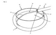
図1を参照すると、眼1の標準的な組織は、角膜2、水晶体嚢6、および水晶体嚢6内のレンズ8を含む。切開部4は角膜2の端部(又はエッジ;edge)に形成され、外科医は水晶体嚢6に裂嚢工程を実施し、水晶体嚢6の前面に裂嚢10をもたらす。裂嚢10は、任意の適当な手段、例えば外科用メスを用いた切開、フェムトセカンドレーザ又は他のエネルギー系カッターを用いたエネルギーの適用、ロボット又は自動制御下での切開、又は任意の他の適当な手段で実施され得る。裂嚢10は約2.0〜8.0mmの径で裂かれ(tore)得る又は切られ得る。他の態様によれば、裂嚢10は2.0mmよりも小さな径で形成され得る。具体的には、(下記で詳述するが)レンズ8の片はより小さな径の裂嚢10を通じて摘出され得る程十分に寸法が小さい。裂嚢10は、一般的に実施されているようにミクロ鉗子等の独立した一式の器具を用いて形成され得る。代替的には、機構および切断用工具(tool)が裂嚢を容易にする又は完全に実施するために本明細書に記載された外科用デバイス40内に組み込まれ得る。例えば、切断用工具40が裂嚢を実施し得るように、ミクロ鉗子がシャフト12の遠位端部に加えられ得る。他の例として、1つよりも多いブレード、角膜切開刃(keratome)、フック、レーザー、切除用エネルギー適用器等が、外科手術の間の使用のためシャフト12の遠位端部内に組み込まれ又は当該遠位端部と関連され得る。例えば、延在する先端部(又はチップ;tip)が、シャフト12に取り付けられ、本明細書に記載するように分断工程間にレンズ8を回転させるために使用され得る。使用者が新たな位置にレンズ8を回転させ、異なる角度からレンズ8を切開し得るように、延在する先端部は、レンズ8内に貫通(又は突刺し;pierce)可能な鋭利なチップであり得る。ある態様によれば、裂嚢を行うために外科医により使用される任意の独立した切断用工具は、角膜2中の切開部4外で除去される。図3を参照すると、次いでシャフト12は角膜2の切開部3を通じて挿入される。図3から分かるように、シャフト12の遠位端部は裂嚢10から離隔した裂嚢10の上方(すなわち裂嚢10の前方)に位置付けられるが、眼1の外側から見るように裂嚢10の周囲内に位置付けられる。図1に示すように、角膜2の切開部3を通じたシャフト12の挿入の際、シャフト12は裂嚢10の端部により規定された平面に略平行である。ある態様では、切開(又は切断又は区分;sectioning)要素16の遠位端部は、第1の挿入形態でシャフト12の遠位端部の外側に延在する。当該態様では、引張状態の(緊密な又は小さな;tight)半径方向への屈曲部24がシャフト12の外側に位置付けられ得る。当該屈曲部24は近位方向に向かって少なくとも部分的に既に曲げられている。このため、切開要素16が超弾性材料から製造されている態様でさえ、第1の挿入形態から第2の捕捉形態への変移の間に、切開要素16の第2脚16が屈曲される角度が減じられる。更に、小さなスペースが、切開要素16の全てを保持する場合よりも切開要素16の一部を保持するためのシャフト12のルーメン(又は内腔;lumen)14内に必要とされ、それによりシャフト12の径をより小さくし得る。シャフト12は、シャフト12を通るように規定されたルーメン14を含む。ある態様によれば、シャフト12は曲面状先端部を有する卵型の断面のチューブである。卵型の断面は角膜の切開部4を通じて眼1内に挿入され得るシャフト12の能力を高める。更に、多数の切開要素がある場合では、当該多数の切開要素は卵型の断面シャフト12のルーメン14内により容易に側部同士が対向するよう配置され得る。代替的には、シャフト12は、円形断面又は任意の他の適当な形状の断面を有してよい。切開要素16の近位端部はシャフト12のルーメン14を通じて延在する。代替的には、切開要素16の全体が第1の挿入形態のシャフト12のルーメン14内に位置付けられる。代替的には、各切開要素16が最初に第1の挿入形態にある1つよりも多い切開要素16が活用される。明確のため特定の態様に関して単一の切開要素16を記載するが、任意の適当な数の切開要素16がレンズ除去工程で供され使用され、かつ本明細書でのデバイスおよび方法が任意の特定の数の切開要素16の使用に限定されないことは下記の更なる記載を鑑みれば自明であろう。 With reference to FIG. 1, the standard tissue of the eye 1 includes the
ある態様によれば、切開要素16は第1端部18および第2端部20を含む。図16〜22に関して下記により詳細に説明するが、切開要素16の端部18、20の一方はシャフト12に対して移動可能であり得るが、切開要素16の端部18、20の他方はシャフト12に対して固定され得る。例えば、切開要素16の第2端部20はシャフト12に対して固定され、切開要素16の第1端部18はシャフト12に対して摺動可能であり得る。第2端部20は、圧着、溶着、接着、機械的インターロック(又は相互連結;interlock)、又は任意の他の適当な構造若しくは方法により、シャフト12又は他の構造体に接続され得る。ある態様では、切開要素16は、円形、楕円又は他の傷付けない(atraumatic)断面を有するワイヤーである。他の態様では、切開要素16はストラップである。本明細書で使用する場合、長手方向から見た際に、ストラップは厚みよりも幅の広い構造体である。 According to some embodiments, the
切開要素16の遠位端部が遠位方向にシャフト12の外側に延在する第1の挿入形態では、切開要素16は、眼1を損傷させることなく標準的な角膜の切開部4を通過する寸法および形状を有する。角膜の切開部4は、概して3.5mm以下であり、小さなナイフで形成される。従って、シャフト12の外径は有利には3.5mm以下である。異なる寸法の切開部4が使用される場合、シャフト12の異なる外径が使用され、5mm以下の直線長さの切開部4を形成することが最も望ましいことに留意されたい。他の態様では、シャフト12が切開部4を通じて挿入される際に切開要素16がシャフト12の内径内にあるように、切開要素16は、シャフト12のルーメン14内に完全に位置付けられ、次いで眼内で一旦シャフト12の外側に延在される。代替的には、追加のコンポーネントが角膜の切開部4を通じた挿入の間切開要素16を覆うために使用され得る。例えば、テーパー片が角膜の切開部4を通じた挿入を助力するように、シャフト12の端部からより小さな断面にむかって漸次先細となるテーパー片が、シャフト12の遠位端部に位置付けられ得る。
又、テーパー片は、挿入の間切開要素16を拘束するために切開要素16を覆い得る。切開要素16が切開部4を一旦通過する場合、テーパー片は、切開要素16が延在可能である又は破って開けることが可能であるスリットを前部に更に有し得る。In a first insertion mode in which the distal end of the
Also, the taper piece may cover the
ある態様によれば、切開要素16は、ニッケル−チタン合金等の可撓性又は超弾性材から製造され、それにより切開要素16が角膜の切開部4を通じて眼内に挿入される際に切開要素16を屈曲させ、撓ませることが可能である。これらの態様では、切開要素16の収縮形状(又は締付け形状又は絞り形状;constricted shape)が角膜の切開部4よりも1よりも大きい次元(又は寸法;dimensions)で大きくなり、シャフト12が裂嚢10に向かって移動する際に切開部4を通過するように撓む。代替的には、切開要素16は、第1の挿入形態を有さず、レンズ8と係合するために後に利用されるのと同じ形態で切開部4を通じて挿入され得る。そのような態様では、切開要素16は角膜の切開部4を通過する際に圧縮し、次いで切開要素16が眼1に一旦入ると再拡大する。更に他の態様では、切開要素16は第1の挿入形態を有さず、レンズ8と係合するために後に利用されるものよりも大きな形態で切開部4を通じて挿入され得る。更に他の態様では、切開要素16は、任意の多くの方法で角膜の切開部4を通じて引っ掛けられ、回転され、又は挿入され得る。 According to some embodiments, the
図4を参照すると、切開要素16又は要素はシャフト12のルーメン14に対して遠位側に押される。上記のとおり、切開要素16の他方の脚18がシャフト12のルーメン14に対して遠位側に押されるように、切開要素16の一方の脚20は固定され得る。その結果として、切開要素は第1の挿入形態から第2の捕捉形態に移動(又は変化;move)する。 Referring to FIG. 4, the
切開要素16は、任意の適当な材料から製造され得る。例えば、上記のとおり、ニッケル−チタン合金等の形状記憶材料が、高弾性量で、切開要素16が第2の捕捉形態である所定形状に変化できるように使用され得る。一態様では、ニッケルチタン合金はその超弾性条件で使用され得る。ニッケルチタン合金は、第1の挿入形態から第2の捕捉形態に変化するためにその結晶構造を変換する。他の態様では、室温よりも高いが体温より低い遷移温度に到達する際に、切開要素16は第1の挿入形態から第2の捕捉形態に変化するように設定された形状のニッケル−チタン合金から製造される。これにより、ニッケル−チタン合金から製造される切開要素16は、収縮形状を保持するように遷移温度未満の室温で眼に進入し得る。切開要素16が眼内に位置付けられ、体温まで暖められる際に、ニッケル−チタン合金は遷移温度よりも暖かくなり、所定の第2の捕捉形態に戻り始める。この形状変化は、外科医が切開要素を水晶体嚢6内に設け、かつ輪がレンズを通じて切開面を規定できるように形状変化の間切開要素を方向付けることが可能な一定期間にわたり生じ得る。ある態様では、ニッケル−チタン合金が考慮され得る。代替的には、任意の他の多くの生体適合性材料が考慮されてよい。切開要素16の遷移温度が、室温よりも高く水晶体嚢6の組織又は眼1の他の組織を損傷する温度未満となるように選択され得る場合、ステンレス等は外科用デバイス40により積極的に暖められ得る。形状記憶プラスチック等の他の形状記憶材料がニッケルチタン合金の代わりに利用され得る。代替的には、ステンレス鋼、チタン、シリコーン、ポリイミド、PEBAX(登録商標)ポリエーテルブロックアミド、ナイロン、ポリカーボネート、又は任意の他の適当な材料等の他に任意の多くの生体適合性材料が考慮され得る。更に、端部同士接続された若しくは積層状態の多数の材料、又は同心チューブ材が使用され得る。 The
図1および4を参照すると、第2の捕捉形態では、切開要素16は具体的にはレンズ捕捉のための形状となっている。ある態様によれば、第2の捕捉形態は、例えば切開要素を形成するための弾性又は超弾性材の使用を通じて、要素16の予め調整された形状(又はプリセットされた形状;preset shape)である。 Referring to FIGS. 1 and 4, in the second capture mode, the
図4から最も明らかなように、第2捕捉形態では、切開要素16は概してレンズ8の断面のような形状であり、水晶体嚢6内のレンズ8を囲む形状および寸法である不規則なループに近似する。上記のとおり、ある態様では、切開要素16は円形ワイヤーの全長から形成される。切開要素16の第2の捕捉形態は結合ポイント22を有し、切開要素16の第1脚18と第2脚20は一体的に後方で結合し、閉鎖ループに近似する外周を有する形状が形成される。“結合(又は接合又は併合;merging)”は切開要素16の第1脚18と第2脚20を互いに近接するように設けることを指す。結合ポイント22はシャフト12の遠位端部に又は当該遠位端部に近接して設けられ得る。第2の捕捉形態では、切開要素は結合ポイント22に遠位して延在する遠位部28および結合ポイント22に近位して延在する近位部26を含む。この典型的な態様での結合ポイント22は、レンズ表面の上方で、水晶体嚢6の上部の裂嚢10により規定された円形内に位置付けられる。ある態様では、切開要素16の近位部26は図1に示すように引張状態の(緊密な又は小さな;tight)半径方向屈曲部24を含み得る。切開要素16の第2脚20が結合ポイント22から近位側に延在するように、引張状態の半径方向屈曲部24は切開要素16の第2脚20を近位側に屈曲する。代替的には、切開要素16は、そのような鋭い半径方向の屈曲部無しでこのパス(又は経路;path)変移を達成するための異なるパスをとってもよい。例えば、湾曲又は往復運動等の図1の法平面の外側に位置するパスが、切開要素16の近位部26の全屈曲半径を減じるために組み入れられ得る。これは、下記で述べるように切開要素16を、他のより小さな収縮形態に形状変更可能に改善する。 As is most apparent from FIG. 4, in the second capture mode, the
上記のように、第1脚18および/または第2脚20はシャフト12のルーメン14の外側に押される一方、他方の脚はシャフトに対して固定される。代替的には、切開要素16の両方の脚18、20がシャフト12に対して移動可能であり、シャフト12のルーメン14に対して摺動するように構成される。代替的には、シャフト12が摺動コンポーネントであり得る一方切開要素16は固定されている。脚18、20がルーメン14から外側に向かって押される際、切開要素16は第2捕捉形態に変移する。切開要素16が変移するにつれ、引張状態の半径方向屈曲部24により、切開要素の近位部が、水晶体嚢6に向かって一方向に、ルーメン12の長手中央線の一方の側から離れた位置にあるシャフト12の遠位端部からルーメン12の長手中央線の一方の側へと近位して延在することが可能である。このようにして、図1に示すように切開要素16は裂嚢10を通じて下方向に向かって延在し、裂嚢10の径よりも大きい水晶体嚢6内の全長に拡大することが可能である。ある態様によれば、引張状態の半径方向屈曲部24は、図1に示すようにシャフト12の長手中央線に対してかつ遠位方向に対して少なくとも120度の角度を有する第2脚20をもたらす。第2の捕捉形態にある切開要素16の遠位部28および近位部の両方は、(水晶体嚢を過剰に引き延ばす又は水晶体嚢の組織の内面を損傷させる水晶体裂部又は孔部等の)損傷を生じさせることなく水晶体嚢6に進入するために、なだらかに湾曲し、水晶体嚢6の水平側部(又は横断側部;lateral sides)の寸法および形状に概して近似する。 As described above, the
ある態様では、図2を参照すると、第2捕捉形態の切断要素16の形状は上部のレンズ表面に対して概して平坦又は水平な平面を形成する。正確な位置付けである図1および3を参照すると、切開要素16は、裂嚢10を通じて水晶体嚢6内で開くように保持される。切開要素16の拡大が続くと、切断要素が水晶体嚢とレンズとの間の空間を横断するように切開要素16により形成された平面が回転(又は旋回;rotated)され得る。平面はシャフト12のルーメン14の長手軸を含む。代替的には、第2の捕捉形態の切開要素16の形状は単一平面にはないより三次元の形状である。例えば、切開要素16は平坦面の内側と外側に往復(又は振動;oscillate)し、又は一方向若しくは別方向に平面の外側に実質的に湾曲し得る。下記で詳述するように、回転は使用者によるシャフト12又は外科デバイス40の手動回転により為され得る又は外科的デバイス40内の一体化機構により為され得る。図4を参照すると、切開要素16は第1の挿入形態から第2の捕捉形態までの経路のほとんどを進み、レンズ8に対して部分的に回転される。切開要素16は、形状面が主として垂直に又は他の任意の多くの角度となるように回転され得る。そのような回転を形成するための機構および方法については下記でより詳細に説明する。更に、様々な角度に回転する多数の切開要素16が使用され得る。他の態様では、切開要素16が第2の捕捉形態に変移するまで回転は生じない。ある態様では、切開要素16が第2の捕捉形態に変移する間に回転が開始する。例えば、切開要素16内の開口領域46が、5〜6mmのコード(又は翼弦;chord)が近位部26と遠位部28における2つのポイント間の開口領域46を横切るように延在する寸法にまで拡大すると、回転が開始し得る。別例として、コード(又は翼弦;chord)が5〜6mmよりも長い又は短い際に、回転が開始し得る。 In some embodiments, referring to FIG. 2, the shape of the cutting
ある態様では、図1に示すように、切開要素16の第2の捕捉形態は、7.0mm〜15.0mmの幅および3.0〜10.0mmの高さを有する概して卵型形状であり得る。他の態様では、切開要素16は4.0mm〜20.0mmの幅および1.0〜15.0mmの高さであり得る。ある態様では、切開要素16の第2捕捉形態の寸法は特定の領域で又は全外形に沿ってレンズの寸法よりも意図して小さくてよい。この事はレンズ8に近接したまま水晶体嚢6との相互作用を減じる能力を改善し得る。例えば、切開要素16の第2の捕捉形態は12.0mmの幅および4.0mmの高さであってよい。水晶体嚢6の後面を損傷させる虞を減じ得る楕円の高さに沿った干渉を保ちつつ楕円の幅にある切開要素16とレンズ8との間のクリアランスを可能にし得る。すなわち、切開要素16がレンズ8の最も厚い部分を取り囲む位置への移動よりむしろレンズ8の一部と係合するための切開要素16の第2の捕捉形態を構成することで、切開要素16の第2の捕捉形態がレンズ8の最厚部を取り囲むことができる形態よりも、切開要素16の寸法はより小さくされ、切開要素16は水晶体嚢6のより小さな部分と係合する。他の態様では、切開要素16の第2の捕捉形態は、レンズ8の周りに概して特定のクリアランスを有するように予め規定される。ある態様では、切開要素16の第2の捕捉形態は略楕円とは異なる形状を有する。 In some embodiments, as shown in FIG. 1, the second capture form of the
切開要素16は、当該要素が水晶体嚢を損傷させることを更に抑制する特徴又は形状を有し得る。例えば、ある態様では、切開要素16は水晶体嚢6を引き裂く又は損傷させる虞を減じるため十分な径の丸みのあるワイヤーである。丸みのあるワイヤーの径は0.004インチ〜0.012インチであり得るが、0.001インチ〜0.030インチ等、過剰な圧が水晶体嚢6にかかることを抑制する任意の寸法であってよい。代替的には、切開要素16の外形は、大きな幅又は高さである卵型であってよく、又はより大きな表面領域にわたり水晶体嚢6に切開要素16の力を更に分配するためにストラップ状であってよく、それにより切開要素により水晶体嚢6にかかる高圧力の領域が減じられる又は除かれる。 The
ある態様では、切開要素16の外面の一部はデバイスの特定の態様を改善するために被覆され得る。例えば、下記にてより詳細に記載するが、切開要素16は水晶体嚢6とレンズ8との間の空間を横断する。切開要素16がこれら解剖学的構造間で移動する際、より親水性又は疎水性表面を有することは有利であり、そのため切開要素16は自由に回転し移動する。ある態様では、切開要素16はフッ素重合体等、例えばPTFEの疎水性材で被覆され得る。被覆は浸漬(又はディップ;dip)コーティング、プラズマ蒸着プロセス、熱収縮スリーブ、または任意の他の適切な方法を通じて加えられ得る。コーティングは、切開要素16をより自由に移動させることができるために、切開要素16とレンズ8および/または水晶体嚢6との間の摩擦を低減し得る。摩擦を減じるための他の方法は、機械的摩耗、プラズマ処理、または任意の他の適当な方法を使用することを含み得る。代替的には、切開要素16は、処置中に供されるように構成された活性薬剤等の他の材料で被覆されてもよい。例えば、トリアムシノロンのようなステロイドを切開要素16の表面に加えて、処置中にそのような切開要素を眼内に放出させる。他の任意の多くのコーティングおよび薬剤が検討され得る。 In some embodiments, a portion of the outer surface of the
切開要素16は、任意の他の適当な形状又は材料で構成され得る。典型的な態様では、切開要素16は丸みを帯びたワイヤーである。ワイヤーは、レンズ8と水晶体嚢6との間の空間を鈍く(又は鋭くなく;bluntly)横断するように構成される。ワイヤーは、切開要素16の長さに沿って様々な寸法又は直径を有することが可能である。代替的には、切開要素16は、任意の多くの他の多くの外形を有し得る。例えば、切開要素16は、チューブ、リボン、ストラップ、六角形の外形を有するワイヤー、または任意の他の多くの適当な形状とすることができる。更に、切開要素16の外形は、その長さに沿って変化し得る。例えば、切開要素16は、水晶体嚢6に対するダメージが特定の懸念事項から成る場合その外形に沿って1つ以上のパッド(又は詰まった;padded)領域を含み得る。パッド領域は、特に限定されるものではないが、切開要素16の適切な領域に接着または被覆されたシリコーンのような軟質エラストマー材料等の異なる材料を含み得る。パッド付き領域は、より大きな領域にわたって力を分配し、水晶体嚢6に対してより軟らかく、より傷のない界面(又は相互作用;interface)を供し得る。他の態様では、パッド領域は、ある領域における切開要素の幾何学的形状の変化である。例えば、同じ材料で構成されていても広げられる又は拡大される領域は、より大きな領域に力を分配する。さらに、切開要素の剛性または可撓性は、特定の領域での材料厚さ又はワイヤー径を変えることで切開要素16にわたり変化し得る。代替的には、スリーブ又は他の材料を切開要素16に加えて、特定の領域において局所的に剛性が高められ得る。更に他の態様では、切開要素16は、その長さに沿ってある領域でその可撓性または剛性を変化させる切れ目またはリブを有し得る。 The
他の態様では、第2の捕捉形態における切開要素16の形状は予め決定されていない。その代わりに、第2の捕捉形態における切開要素16の形状は、レンズ8と係合する切開要素16の材料または幾何学的特性によって規定される。切開要素16が水晶体嚢4内にあり完全に開放されているときでさえ、水晶体嚢6に最小限の力が加えられるように、切開要素16は、レンズ8に係合するための回転が可能となる十分な剛性を維持しながらその長さに沿って十分に可撓性、弾性、軟性を有し、鈍く(blunt)あり得る。他の態様では、切開要素16が水晶体嚢6に過度の力を供しないように、切片要素16は、十分に柔らかく、十分に大きい直径のシリコーン等の軟質エラストマーであり得る。更に他の態様では、水晶体嚢6に加えられる力がより大きい領域に分散され、それにより引裂き圧力を低減し得るように、切開要素16は特定の部分およびエッジに沿って十分に鈍くあり得る。更に他の実施形態では、切開要素16は、複数の要素、例えばチェーン状構造の連結から構成され、それにより複数の要素間の柔軟な移動が可能となる。さらに他の態様では、切開要素16は、その可撓性を局所的に増加させ得るその長さの部分に沿ったスリットを有し得る。例えば、切開要素16は、水晶体嚢6が切開要素16と接触し得る領域にその長さに沿って切欠部を有するチューブを含み得、それによりこれらの領域はより可撓性を有し、その結果、水晶体嚢6に過剰な力がかからない傾向にし得る。更に他の態様では、第2の捕捉形態の切開要素16の一部分は予め定められた形状ではなく、切開要素16の他の部分は予め定められた形状である。例えば、レンズの前方の切開要素16の一部分は、切開要素16を眼に導くのを助力する所定の形状に設定された形状である形状記憶の丸みのあるワイヤーから製造され得る。例えば、そのような部分は、近位部26の引張状態の半径方向屈曲部24を含み得る。レンズ8の後方にある切開要素16の一部分は、眼の形状により容易に適合する、異なるより可撓性のある材料から製造され得る。このようにして、引張状態の半径方向屈曲部を含む、裂嚢を通じた切開要素の挿入を可能とする第2の捕捉形態の切開要素16の一部はレンズ8の前方にあり、水晶体嚢6と接触する第2の捕捉形態の切開要素16の一部は、水晶体嚢6を損傷させにくい場合でさえより可撓性のある材料から構成されている。 In another aspect, the shape of the
ある態様では、追加のガイドチューブまたはコンポーネントは、切開要素16の経路を、裂嚢10を通じておよび/またはレンズ8の周りに位置合わせ又は方向づけ得る。例えば、第2の捕捉形態の切開要素16が予め定められた形状を有していない場合、案内(又はガイド又は誘導;guiding)要素が、切開要素を特定の形状に拘束するために、切開要素16の遠位部28または近位部26の領域に沿って存在し得る。チューブは、結合ポイント22から遠位部28の方向に延在し、チューブは、水晶体嚢6内に挿入しレンズ4の周りに位置する間に、多かれ少なかれ所望の経路を進む(又は従う;follow)ように、可撓性の切開要素16を同心円状に拘束し得る。 次いで、案内チューブを引っ込めて、可撓性案内要素16がレンズ4の周りに位置付けられ得る。 In some embodiments, an additional guide tube or component may align or orient the path of the
更に他の態様では、第2の捕捉形態の切開要素16の所定の形状は、外科処置の任意の工程の間に形成され得る。例えば、外科医は、レンズ8または水晶体嚢4等の眼の解剖学的特徴を測定するために画像技術を使用し得る。外科医は、この情報を使用して、切開要素の形状を変更し得る。あるいは、成形ダイ又は自動ワイヤー形成機械加工等の一片の装置を、測定データと共に使用して、第2の捕捉形態における切開要素16の形状を変えることができ得る。一態様では、外科医は、OCT等のイメージングモダリティ(imaging modality)を使用してレンズ8の測定を行い、次いで、この情報が、患者用のカスタムの切開要素16を形成する自動ワイヤー形成ステーションに供される。更に他の態様では、外科医は、切開要素16の少なくとも一部分が眼内にある間に、切開要素16を追加又はその形状を変更し得る。例えば、外科医は、切開要素16を水晶体嚢6内に配置し始め、その形状が改善され得ることを決定し得る。次いで、外科医は、鉗子等の別個の器具を眼に挿入する、又はシャフト12に関連する一体化された器具を使用して、切開要素16の形状を追加または変更し得る。 In yet another aspect, the predetermined shape of the
ある態様によれば、少なくともある領域で、レンズ8と水晶体嚢6との間に空間が形成されるように、裂嚢10の形成後に水晶体嚢6間に流体が導入される。これは、流体切開、加水切開(hydro dissection)、またはスペース形成と呼ぶことができる。ある態様によれば、流体は、第2の捕捉形態の切開要素16が水晶体嚢6内で回転し、レンズ8を取り囲むための空間を形成する。典型的な態様では、粘弾性ヒアルロン酸または生理食塩水等の流体が、これらの材料が眼科手術中に一般に使用され、眼内で十分に許容され、容易に入手可能であるため注入され得る。染色流体、ステロイド等の医薬液体、薬物負荷の流体、生体吸収性流体、潤滑剤、ヒドロゲル、マイクロスフェア、粉末物質、蛍光コントラスト、液体フォーム、または任意の他の適当な流体等の、1つ以上の他のまたは追加の流体を導入し得る。更に、空気、酸素、アルゴン、窒素等の、1つ以上のガスが追加的にまたは代わりに導入され得る。代替的には、他の態様では、レンズ8と水晶体嚢6との間に流体空間が必要でなくてもよく、切開要素16がレンズ8の周りを回転する際に、切開要素16によりレンズ8と水晶体嚢4の機械的切開又は鈍的切開が行われてよい。流体切開および鈍的切開は、互いに組み合わせて、または別々に実施され得る。別個の器具を使用して、カニューレまたは針を通して流体は水晶体嚢6に注入され得る。他の態様によれば、切開要素16等の外科用デバイス40の要素に流体切開のための設備(provisions)を組み込むことができる。例えば、切開要素16は、流体の通過を可能にするその長さに沿って複数の孔を有する可撓性チューブとして製造され得る。そのような態様では、流体は、切開要素16のルーメン内に導入され、次いで、複数の孔から流出させ得る。これは、切開要素16を通って流体が連続的にまたは切開が必要とされる個別の時点で導入され得るので、水晶体嚢6とレンズ8との間を通過する切開要素16の能力を改善し得る。更に他の態様では、流体注入は、外科用デバイス40の他の態様に組み込まれてもよい。例えば、流体は、シャフト12のルーメン14を介して送達されてもよい。あるいは、シャフト12とは別個のコンポーネント、伸縮チューブまたは他のチューブ等をシャフト12に接続して、流体の導入を供し得る。ある態様では、シャフト12または要素16等のデバイスのコンポーネントを通して注入される流体は、他の外科的目的のために使用され得る。例えば、別個のカニューレを必要とせずに、または粘弾性物質を必要とせずに、眼1のチャンバーを維持するために、流体がシャフト12を通して注入され得る。灌注(又は洗浄;irrigation)および吸引は、単一のコンポーネントまたは複数の別個のコンポーネントを通じて達成され得る。例えば、生理食塩水等の流体は、上述したように、切開要素16の一態様のルーメンを通して眼内に灌注され、シャフト12のルーメンを通して吸引され得る。他の灌注または吸引技術がある態様に従い実施され得る。 According to some embodiments, fluid is introduced between the
図5を参照すると、切開要素16は、第2の捕捉形態にまで完全に延在されており、シャフト12の長手軸の周りで回転され、および/または水晶体嚢6に過度の力を加えることなく切開要素16がレンズ8を取り囲む水晶体嚢6内の位置へと回転され又は移動されている。次いで、シャフト12のルーメン14を通じて脚部18、20の一方または両方を引っ込める等して、切開要素16の脚部18、20の一方又は両方に張力をかけることで、切開要素16がレンズ8を切断するために使用される。切開要素16は、レンズ8を圧縮して切断するために、第1形態から第2形態へと切開要素16を拡張するために、上述とは反対の態様で移動され得る。切開要素16が引っ張られると、小さな直径の切開要素16の小さな表面領域を横切るレンズ8に加えられる力に起因して、切開要素16はレンズ8に内向きの力を生じさせ、レンズ8の切断および/または分断を開始する。切開要素16は、レンズ8が部分的に又は完全に分断されるまで引っ張られ続ける。ある態様では、レンズ8が完全に分断されるまで、切開要素16に張力がかけられる。他の態様では、切開要素16の張力は、レンズ8を部分的に破断するのみであり、レンズ8の残りの部分は、切開要素の使用を繰り返すことによって、または追加の工具を用いて破断され得る。図6を参照すると、分断されたレンズ8が水晶体嚢6内に示されている。断面は主に垂直であるが、任意の角度および向きが切開要素16の切断経路のため存在してもよいことを理解されよう。図7では、水晶体嚢が除去されたレンズが示されている。 Referring to FIG. 5, the
ある態様では、手術デバイス40は、後述するように、複数の切開要素16を組み込んで、一度に多数のレンズ断片を形成し得る。例えば、多数の切開要素16は、レンズ8を多数の断片に切断することが可能なメッシュを形成し得る。切開要素16は、交差十字パターンを形成するように互いに傾斜角または鋭角であり得る。他の態様では、外科用デバイス40は、レンズ8上で連続的に使用されてよい。例えば、単一の部分が形成された後、レンズ8(または切開要素16)を90度回転させて、第1の断面が配備するデバイス面に対して垂直とされ得る。次いで、上記のように切開要素16が、水晶体嚢6内に再挿入され、2つのレンズ断片を横切って新しい部分を形成して、合計で4つの断片を生成するために使用され得る。このプロセスは、任意の所望のサイズの任意の数のレンズ断片を作成するのに必要な回数繰り返され得る。レンズ片の最終的な所望のサイズは、眼1からの摘出方法に依存し得る。ある態様では、水晶体超音波乳化吸引が、レンズ片を除去するために水晶体嚢6内で追加的に使用され得る。これは、完全なレンズの断片化が表面積を増大させ、水晶体超音波乳化吸引によって乳化されるべき断片の寸法を減少させるため、困難または注意深さが必要な白内障において特に有用であり得る。他の態様では、下記に説明するように、レンズ断片を摘出され得る。 In some embodiments, the
ある態様では、僅かな圧力下で水晶体嚢6内に流体を導入することによってレンズ片を水晶体嚢6外へ押し出し得る。レンズを摘出するための他の工具および方法が利用され得るように、流体の流れおよび/または圧力により、レンズ片が眼1の前房に移動され得る。例えば、鉗子または把持工具を使用して、レンズ片をつかみ、それによりレンズ片が角膜切開部4を通じて眼1外へ引き出され得る。ある態様では、レンズ片を捕り、眼1外へレンズ片を外部に引き出すために、切開要素16が使用され得る。切開要素16は、第2の捕捉形態に戻され、レンズ断片の周りに配置され得る。次に、レンズ8が切開要素内に保持されるがレンズ断片が切断されなくなるまで、切開要素16は引っ張られる、又は閉じられ得る。次いで、レンズ片は切開要素16で眼1外へ引き出され得る。レンズ8が切開要素16により切断されないことを保証するために、より大きな表面を有しレンズ片を切断するのではなくレンズ片を把握するパッド、ストラップ、またはストリップ等の追加のコンポーネントが使用され得る。これらのコンポーネントは、シャフト12から延ばすことができ、または切開部4を通じて眼内1に挿入され、切開要素16に取り付けられる別のコンポーネントであり得る。 In some embodiments, the lens piece can be pushed out of the
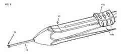
図8〜9を参照すると、外科用デバイス40の一態様は、シャフト12の遠位端から延在する2つの切開要素16を含み、ハンドル機構42がシャフト12の近位端に取り付けられている。 図15に示すように、シャフト12の遠位端に第1の挿入形態の2つの切開要素16が示されている。ハンドル42は、後述するように2つの切開要素16に接続されている長手方向に摺動可能な2つの摺動部(又はスライダー;slider)を有する。この初期形態の摺動部は、後退された近位位置にある。シャフト12および第1の挿入形態の切開要素16は、上述のように、角膜内の切開部4を通じて、裂嚢10に向かって挿入される。本明細書で使用される用語「ハンドル」は、外科医による手による把持および動作のために構成されたハンドルと、外科手術用ロボットに連結(又は接続;couple)されロボット制御および動作のために構成されたロボットハンドルとの両方を含む。 Referring to FIGS. 8-9, one aspect of the
図16〜17を参照すると、外科用デバイス40のハンドル42の一態様が切開要素16の第1の挿入形態に対応する形態の切断面で示されている。摺動部44がハンドル42の上面に沿って摺動可能である。フィンガー48は、摺動部44からハンドル42の上面のスロットを通じてハンドル42内に延在する。フィンガー48は、フィンガー48に近接して配置され、フィンガー48に対して長手方向に固定されるがフィンガー48に対して軸方向に自由に回転し得るらせん状カム50または他のカム構造に連結される。これは、係合ピン、カラー、または他の適当な機構を通じて機械的に実施され得る。らせん状カム50の表面には、カム経路52が規定されている。らせん状カム50は、らせん状カム50を長手方向に摺動させるが、実質的に半径方向には移動させないハンドル42の内部のチャンバー内に閉じ込められている。ノーズ(又は突出部又は鼻部;nose)56は、フィンガー48から遠位側に延在し、フィンガー48に対して回転可能である。ノーズ56は、らせん状カム50に回転可能に固定されているのが有利である。ある態様では、ノーズ56は、単にらせん状カム50の遠位端である。引込(又は後退;retraction)ばね58が、フィンガー48とハンドル42の外側の前方通路60との間に配置され、第1の挿入形態に向かってフィンガー48を押すように作用する。引込ばね58の近位端は、ノーズ56の中心に配置され、ノーズ56と係合され得る。切開要素16の第1脚部18の近位端は、例えば、ノーズの周りを包囲(又は巻付け;wrapping)、摩擦接合、溶接、はんだ付け、または圧力接合等の任意の適当な方法でノーズ16に固定され得る。あるいは、第1脚部18の近位端は、フィンガー48に固定され得る。カムポスト62は、ハンドル42内に規定されおよび/またはハンドル42に対して固定され、カム経路52と係合する。らせん状カム50がハンドル42の残部に対して移動する際、カムポスト62はハンドル42の同じ場所にとどまる。2つの切開要素16が使用される場合、上述の2つのそのようなアセンブリ(摺動部44、フィンガー48、カム50、ノーズ56、引込みバネ58および切開要素16の第1脚部18への接続部)は、ハンドル42内にて側同士で利用される。そのようなアセンブリは、互いに同一であってよく、互いに横断方向にて鏡像の関係であってよく、実質的に同じアセンブリが2つの別個のセクション要素16を以下に説明するように動作可能にする他の方法で互いに異なっていてよい。摺動部44a、44bおよび切開要素16の動作の説明は特に明記しない限り、摺動部44および切開要素16の両方で同じであり、当該2つの動作説明は、特に明記しない限り置き換え可能である。 With reference to FIGS. 16-17, one aspect of the
図10に示すように、切開要素16の一方は、対応する摺動部44bを遠位方向に摺動させることによって第2の捕捉形態に変移される。第1脚部18がハンドル42内の移動要素と共に移動し回転するように構成されている一方、切開要素16の一方の脚部20は、シャフト12、ハンドル42、第1脚部、又はハンドル42に対して固定された他の構造に接続され、固定位置に維持される。上記のとおり、第1脚部18はノーズ56に取り付けられている。図18に示すように、摺動部44が遠位側に移動すると、フィンガー48が引込みばね58を圧縮し、ノーズ56を遠位側に移動させ、らせん状カム50を遠位に引っ張る。引込みばね58が圧縮され、フィンガー48に近位力を供する。使用者が摺動部44を解放する場合、摺動部44、摺動部44、フィンガー48、およびフィンガー48に並進的に固定された機構は、摺動部44の初期位置に向かって遠位側に押し込まれる。摺動部44が遠位側に前進すると、らせん状カム50はハンドル42内で平行移動する。カムパス52とカムポスト62との間の係合がらせん状カム50の回転を生じさせないように、カムパス52は、摺動部44のこの第1区分の動作の間に実質的に長手方向にあり得る。したがって、切開要素16は、シャフト12の長手軸に対して実質的に同じ回転方向を維持する。摺動部44が遠位方向に前進すると、摺動部44が切開要素の第1脚部18を遠位側に押す。その結果、図1〜4に関して上述したのと同じ方法で、切開要素16が第2の捕捉形態に形状を変える。 As shown in FIG. 10, one of the
図11に示すように、摺動部44は、切開要素16が第2の捕捉形態に形状(又は状態;shape)を変えた後、遠位に更に前進され得る。カムパス52は、図18〜20に示すように、らせん状カムを回転させるためにカムポスト62と係合する。摺動部44の遠位側への動作量がらせん状カム50の回転量を制御する。このようにして、摺動部4の直線運動が切開要素16の回転運動に変換される。らせん状カム50とノーズ56は互いに回転可能に固定されるため、らせん状カム50の回転は、ノーズ56の回転、それにより第2の捕捉形態の切開要素16の回転を生じさせる。切開要素16が回転し、切開要素16の形状によって規定された平面がこれに対応して回転する。切開要素16は、裂嚢10のエッジにより規定される平面に実質的に平行であり得る初期位置から、垂直方向から約0〜40度以内の位置まで回転される。この回転の間、切開要素16は水晶体嚢6とレンズ8との間を移動し、切開要素16の縁内の開口領域46のレンズ8を捕捉する。切開要素16は、実質的に水晶体嚢6および/もしくはレンズ8と係合しない、又はレンズ8と水晶体嚢6のいずれかと係合するように構成され得る。あるいは、水晶体嚢6とレンズ8の間に鈍い(又は鋭くない;blunt)切開を生じさせてよい。 As shown in FIG. 11, the sliding
図20に示すように、摺動部44が完全に前方に移動され、らせん状カム50および切開要素16の回転が完了する。切開要素16は、水晶体嚢6内でレンズ8を取り囲み、図4〜5に関して上述したように、レンズ8に対して内向きの切断力を加えるように構成される。 As shown in FIG. 20, the sliding
図12〜13を参照すると、図9〜11および16〜20に関して上述したのと同じ方法で、第2切開要素16を第2の捕捉形態に配備(又は展開又は活動又は活性;deploy)し、レンズ8を取り囲む位置に回転させ得る。図14に示すように、切開要素16が引っ張られるまたは閉じられる際に、切開要素16がレンズ8を3つの部分的または完全に別々の断片に切断するように、両切開要素16がレンズ8と係合する。図21に示すように、引張は、摺動部44を近位側に摺動させることによって供され、それにより各切開要素16の第1脚部18を近位側に引いて当該第1脚部18に張力を供することにより供され得る。ある態様では、引込みばね58によりフィンガー48に加えられる近位力は、使用者による追加の力をかけることなくレンズ8を切断するのに十分に大きくあり得る。他の態様では、使用者は、レンズ8を分断する追加の力を供する。これは、特に注意深さまたは困難な白内障のために必要であり得る。ある態様では、各切開要素16は、他の切開要素16から離間したラインに沿ってレンズ8の後面と係合し、実質的に同じラインに沿ってレンズ8の前面と係合する。 With reference to FIGS. 12-13, the
図22では、摺動部44は元の位置に戻るように近位側に移動される。切開要素16は元の挿入平面に戻るよう回転され、次いでシャフト12に向かって後退される。図15を参照すると、切開要素16は、レンズを切断した後、初期形態に実質的に戻り得る。らせん状カム50のカムパス52は、図示するように閉ループであり得る。あるいは、カムパス52は、摺動部44が完全に遠位側に移動し、次いで元の位置にカムパスを動かすために近位側に移動される必要がある一方向経路であってよい。ある態様では、一方向ラッチまたはレバーが、らせん状カム50がある方向に回転または移動することを抑制するカムムパス52内に組み込まれてもよく、カムパス52とは別個の位置に又はカムパス52全体に沿って含まれ得る。 In FIG. 22, the sliding
ある態様によれば、切開要素16は、上述のように異なる摺動部44a、44bに連結される各切開要素16ではなく、単一の摺動部44の動作と同期して動くように構成され得る。その場合、切開要素16は、同時に開いて回転するように構成され得る。あるいは、切開要素16の回転は、一方の切開要素16が最初に開き、他方の切開要素16の前に最初に回転するようにずれ調整(staggered)され得る。これは、異なるカムパス52とカムポスト62を各切開要素16と関連させることにより為され得る。更に別の態様では、2つの摺動部44a、44bは、左側摺動部44bが両方の摺動部44を前方に移動させるが、右側の摺動部44aは右側の摺動部44aを前方にのみ動かす(またはその逆)ように構成することが可能である。右側摺動部44aは、摺動部44a、44bの両方を後方に移動させ、左側摺動部44bは左側摺動部44bのみを後方に移動させるように構成されてよい。したがって、使用者は、摺動部44a、44bを独立してまたは同期して動かすかを決定し得る。 According to one embodiment, the
ある態様によれば、切開要素16は同じ方向に回転される。例えば、第1切開要素16が開き、次いで時計回りの方向に水晶体嚢6内に回転される。その際、第2切開要素16が開き、水晶体嚢6内に時計方向に回転する。この態様では、第1切開要素16は垂直面から10〜40度超えた角度まで回転し、第2切開要素16は垂直面から10〜40度より小さい角度まで回転し得る。 According to some embodiments, the
更に他の態様では、切開要素16を配備するために1つ以上の追加のまたは異なる機構が使用され得る。例えば、スクロールホイール前進機構または他の回転機構が切開要素16の一方又は両方を配備するために使用され得る。ある態様では、ギア、目盛り付滑車又は任意の他の多くのコンポーネントの使用を通じて、所定量の使用者相互作用のコンポーネントを動かすことによって切開要素16を大きくまたは小さく移動させるように、使用者による動作が、切開要素16の動作挙動に対して大きく又は小さくなるよう調整される。ある態様では、外科用デバイス40の特定の部分は、モータ、リニアモータ、空気圧、水圧、磁石等のコンポーネントを通して機械的に動力供給され得る。外科用デバイス40は、1つ以上のより大きなロボットアセンブリの一部として組み込まれ得る。例えば、白内障処置を行うために構成されているロボットデバイスは、外科手術デバイス40の一態様を含み得る。これにより、外科医は、記載された方法の一部をロボット制御で行うことができ得る。ある態様では、これにより、強膜を通じて水晶体嚢6に接近する等の代替の技術および方法が可能になる。ある態様では、少なくとも、角膜切開部4を通じて裂嚢10に向かってルーメン14を有するシャフト12を挿入し、切開要素16をルーメン14の遠位端外へ延在させて、切開要素16を、裂嚢10を通じてシャフト12の軸から離れるように屈曲させ、裂嚢10よりも大きな寸法に拡大させ、レンズ8の少なくとも一部を捕捉することが、ロボット制御下で行われる。 In yet another aspect, one or more additional or different mechanisms may be used to deploy the
ある態様では、切開要素16は、最初に水晶体嚢6内に設けられる際ループに近似させる必要はない。例えば、切開要素16は、ループを形成するために切開要素16自身上で折りたたむことなくシャフト12から水晶体嚢6内に供される丸みのあるワイヤーの単一片であり得る。そのような態様では、切開要素16の遠位先端は、眼1内の組織に対する穿刺または損傷を防止するために鈍い(又は鋭くない;blunt)。切開要素16の遠位先端が水晶体嚢6の壁に到達すると、切開要素16は、その構造内の予め規定された屈曲部を用いて、または水晶体嚢6の内面に沿ってたどることによって屈曲するよう構成され得る。次いで、切開要素16は、レンズ8の外周の近傍に到達するよう水晶体8と水晶体嚢6との間の空間を横切り得る。次いで、切開要素16は、水晶体嚢6の上部内の使用者の視野に戻り、使用者は把持器等のハンドル42上の機構又は完全に別の工具を用いて切開要素16を把握することができる。この時点で、切開要素16は水晶体嚢6内のレンズ8を取り囲み、ループに近似する。切断要素16の一方又は両端部が引張され、および/または引かれると、内側切断力がレンズ8に加えられ、レンズ8が分断される。この態様の切開要素16は、切開要素16が必要に応じて屈曲してレンズ8の周りをたどることができるが、組織内にずれることなく依然としてレンズ8の周りの適当なパスを進むように、他の断面よりも容易に特定の方向に優先的に曲げることを可能にする断面を有してよい。これは、特定の平面につき優先的に曲がる「I」ビーム等の好ましい曲げモーメント断面の使用を含み得る。あるいは、曲げを可能にする切欠きを備えたチューブが、この平面に切込みを設けることによって特定の平面で曲がるように構成されてよい。したがって、切開要素16は、主として遠近法でレンズ8の周りで屈曲し得る。これにより、切開要素16が水晶体嚢6およびレンズ8に対して所望の一般的パスを横切る能力が改善される。ある態様では、切開要素16は、その遠位先端が任意の所定のパスに移動するために拘束されないよう全体的に可撓性を有し得る。遠位先端部は、外部の電磁場で力を加えることができる磁石または電磁コンポーネントを含むように構成され得る。その際、切開要素16が所望のパスに沿って水晶体嚢6の周りで案内され得るように、外部装置が切開要素16の遠位先端部の位置を制御するために使用され得る。この態様では、任意の数の異なるパスまたは分裂面が考慮され得る。外科用デバイス40は、水晶体嚢6を損傷しない切開要素16の遠位先端のための所望の経路を形成するために、様々な撮像モダリティ(modality)を組み込み得る。 In some embodiments, the
ある態様では、切開要素16は、複数の部分および/または複数のループに分岐(bifurcate)し得る。例えば、初期の形態では、切開要素16は、上述したような形状および外形を有し得る。しかしながら、第2の捕捉形態に変移される際に、切開要素16は、その長さに沿って、それぞれがレンズ8の全体または一部を取り囲む、同じまたは類似の形状、または異なる形状を有し得る2つの要素に分岐し得る。これにより、2つの別個の切開要素16を使用することなく、切開要素16がレンズ8を多数の断片に切断することが可能となる。 In some embodiments, the
ある態様では、切開要素16の一方または両方は、レンズ8の鈍的切開または分断を助力するために、1つ以上のタイプのエネルギーを適用するように構成され得る。例えば、切開要素16の一方または両方は、電流が流れる際に熱くなる電気抵抗ワイヤーの使用により加熱されるように構成された1つ以上の部分を含み得る。温度が上昇すると、水晶体嚢6とレンズ8との分離が改善され、また、レンズ8を切断する際の助けとなり得る。あるいは、ラジオ周波数アブレーション(又は切除又は焼灼;ablation)、電気アブレーション、超音波振動エネルギー等の任意の多くの他の様式(又はモダリティ;modality)を使用することができる。 In some embodiments, one or both of the
ある態様では、ハンドル42は流体送達機構を組み込み得る。例えば、上述のように、切開要素16またはシャフト12は、各コンポーネントを通じた流体の注入を可能にし得る。ハンドル42は、チューブ、一体化コネクタ等を介して外部流体源にこれらのコンポーネントを接続する流体通路および通路を含み得る。あるいは、ハンドル42は、シャフト12を通じて流体を押し出す内圧注入システムを含み得る。流体は、ピストンを有するシリンダ内に保持されてよく、ピストンは、ハンドル42内の作動コンポーネントにより前方に押される。例えば、別の摺動部またはボタンがピストンに接続され、摺動部が使用者により動かされると、ピストンが移動してシリンダから注入システム内に流体を放出するように配置され得る。これにより、使用者は、水晶体嚢6とレンズ8との間に空間を形成する等の処置中の特定の時間に、切開要素16、シャフト12、または任意の他のハンドル42のコンポーネントを通じた流体の供給を制御することが可能となり得る。あるいは、外科用デバイス40は、デバイスの通常作動中の一定の期間中に外科用デバイス40によって流体が自動的に注入されるように構成され得る。例えば、ばねは、らせん状カム50がその経路を通って移動するときに、ピストンがある量の流体を放出するように、ピストンに力を供するよう構成され得る。 In some embodiments, the
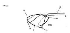
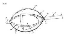
図23を参照すると、切開要素16の代替態様が側面図として示される。2つの切開要素16はシャフト12の遠位端部から延在する。この態様では、切開要素16は、上述のようにレンズ8の側部の周りではなく、レンズ8の遠位端8aにて開始するレンズ8の周りにループするように配置されている。切開要素16は、シャフト12の遠位端からレンズ8の遠位端8aに向かって遠位に、かつ水晶体嚢6中に一度で拡張され得る。切開要素16は、あらかじめ規定された形状を有するように構成され、水晶体嚢に過剰な力をかけることなくレンズ8を回ることを可能にするように湾曲したループのワイヤーに近似し得る。これは、切開要素16が送達デバイスから延在される際に様々な三次元形状を形成する前後の湾曲および側部同士の屈曲を含み得る。水晶体嚢に進入してレンズ8を捕捉するために、切開要素16は、それらが拡張する際に異なる形状となるように構成される。これらの切開要素16は、平面ではなく、図23に示すように、第2の形態においてシャフト12から下方に湾曲している。多数の切開要素16が使用される場合、各々は、他の切開要素16とは異なる程度に湾曲するように構成され得る。切開要素16の一方の端部は延在され得る一方、他方の端部は送達デバイスに相対的に固定されたままである、または両方の端部が上述のように同時に延在され得る。上述のように、切開要素は、その長さに沿って様々な外形(又は輪郭;profiles)、材料、又は可撓性を有し得る。 With reference to FIG. 23, an alternative aspect of the
切開要素16の1つは、水晶体嚢とレンズ8との間の空間を横断するように延在され、次いでレンズ8の周りで下方にかつ近位に移動され得る。第2の切開要素16が図示するように延在され、任意の数の他の切開要素16が使用され得る。ある態様では、2つの切開要素16がレンズを4つの別個の片にスライスすることができるように交差する分断平面を形成するために、前方に延在する切開要素16が上述のように側方に延在する切開要素16と共に使用され得る。更に、分断面は、互いに任意の多くの角度であり得、切開要素16は、前方延在態様および側方延在態様の組み合わせなど、任意の多くの方向からレンズ8の周りに延在することができる。 One of the
図24を参照すると、別の代替態様が上面図として示されている。この態様では、切開要素16の1つは、その露出長さの少なくとも一部に沿って保持(retention)バッグ70に取り付けられる。保持バッグ70は、ポリエステル、高密度ポリエチレン、低密度ポリエチレン、または任意の他の適当なプラスチック等の薄いポリマー材から製造され得る。あるいは、保持バッグは、小さなワイヤステンレス鋼編組(又は束ね帯又はブレイズ;braid)、ニッケル−チタン合金編組、または任意の他の適当な材料などのメッシュから構成され得る。保持バッグ70は、切開要素16の一部分に接続され、キャビティ(又は空洞;cavity)を形成し、それにより、切開要素16は、保持バッグ70を開閉する開放形態と収縮形態の間で変化することができる。ある態様では、保持バッグ70を有する切開要素16が、収縮形状にされ、切開部4を通じて患者の眼1内に設置され得る。保持バッグ70は、切開部を通って眼1内に挿入される間、シャフト12のルーメン14に隠され得る。次いで、切開要素16は、上述のように、裂嚢10に供され、レンズ8の周囲の水晶体嚢6内に挿入され得る。ある態様では、保持バッグ70は、レンズ8の外形またはレンズ断片等の所定の形状を有し得る。切開要素16がレンズ8の周りでループすると、保持バッグ70が切開要素16に続き、レンズ8が保持バッグ70により形成されたキャビティ内に入る。ある態様では、切開要素16は、レンズ8全体がその周囲に至るまで保持バッグ70内にすくい上げられるように移動され得る。次いで、切開要素16は、保持バッグ70を閉じ、レンズ8を封入する収縮形状に変更される。次いで、保持バッグ70は、切開部4を介して眼1外へ引き出される。レンズ8は、除去時に角膜の切開部4の長さを通過するように折り畳まれて絞られる(又は押しつぶされる;squeeze)。回収バッグ70は、回収バッグ70の摩擦係数を低下させるなどにより切開部4から除去する能力を高めるために、任意の適当な方法で被覆され得る。他の態様では、追加のツールまたはコンポーネントが、レンズ8の剛性に応じてレンズ8を更に分断するために使用され得る。例えば図24に示すように、多数の切開要素16が、保持バッグ70内でレンズ8を分断するために水晶体嚢内に挿入され得る。これらの追加の切開要素16は、保持バッグ70が位置付けられるのと同時に位置付けられ得る、又は保持バッグ70は水晶体嚢からレンズ8を除去した後であってレンズ8が眼1から除去される前に導入され得る。 With reference to FIG. 24, another alternative embodiment is shown as a top view. In this aspect, one of the
他の態様では、一旦レンズ8が保持バッグ70内にあると他の分断様式が使用され得る。例えば、一旦レンズ8が保持バッグ70により捕捉されると、超音波エネルギーまたは超音波水晶体乳化吸引術がレンズ8の分断のために保持バッグ内で使用され得る。これは、シャフト12の遠位端から保持バッグ70内への伸縮プローブ(telescoping probes)の使用を含み得る。あるいは、デブリーダ(debriders)、オーガ(augers)などの機械的器具が、眼球1から狭い角膜の切開部4を通じて分断されたレンズが引き出されるように、十分にレンズ8を分断するために使用され得る。 In another aspect, another partitioning mode may be used once the
更に他の態様では、本明細書に記載の保持バッグ70は、眼1からレンズ片を除去するために、レンズ8が分断された後に利用される回収デバイスとして使用され得る。例えば、 図1に示すデバイスは、レンズ8を任意の数の断片に切断するために使用され得る。1つ以上の断片は、通常の器具で角膜切開部4を通じて回収することが困難であるように、十分に大きくてよい。保持バッグ70は、水晶体嚢内でレンズ片を捕捉する、または前房内に浮遊させて、角膜切開部4外へレンズ片を引き出すために使用され得る。更に、保持バッグ70は、流体または小さな物体の通路を可能とする切欠き又はバッグ内に開口部を有し得る。例えば、保持バッグ70は、レンズ断片を保持しながら水様液(humor)流体または粘弾性流体が開口部を透過することを可能にするメッシュまたは編組体であり得る。 In yet another aspect, the holding
図25〜29を参照すると、眼1からレンズ片8fを除去するための外科用デバイス80の別態様が示されている。外科用デバイス80は、外側回転要素82aおよび内側回転要素82bを含む。要素82a、82bは、シャフト12の長手軸を規定し得る中心軸に沿って同心円状に配置される。図25を参照すると、外科用デバイス80は、最初は図1に示すように標準的な角膜切開部4を通じて挿入され得るように、十分に小さいデバイスの外形を有する第1形態となっている。外側回転要素82aおよび内側回転要素82bは、ウィンドウ84により周方向に分離されたストラップ82を生成するために、それらの長さに沿って切断されたチューブであり得る。外側回転要素82aは、角膜の切開部に適合可能な適当な寸法である外径を有し得る。任意の外径は目標の切開長さに応じて考慮され得るが、当該外径は理想的には0.015〜0.060である。内側回転要素82bは、外側回転要素82aの内径内に同心円状に適合するような大きさの外径を有し得る。外側回転要素82aおよび内側回転要素82bのチューブは、ストラップ82およびウィンドウ84を形成するために、レーザー切断され、機械加工され、化学エッチング、一体溶接され、または任意の適当な方法で製造され得る。ストラップ82は、後述するように、要素82a、82bを収縮させる力が加えられた際にレンズ8fを切断しない任意の適当な幅を有するように寸法づけされ得る。ストラップ82の幅は、範囲外の幅を有してもよいが、0.004〜0.050であり得る。 With reference to FIGS. 25-29, another aspect of the surgical device 80 for removing the lens piece 8f from the eye 1 is shown. The surgical device 80 includes an outer
外側回転要素82aおよび内側回転要素82bは、プッシュロッド等の別個のコンポーネントで、又は眼内への挿入中に外科用デバイス80を外装する追加の外側チューブで外側回転要素82aを拘束することで、外科用装置80の遠位先端を前方に押し込むような第2の捕捉形態に収縮され得る。あるいは、外科用デバイス80は、収縮要素が不要であり、外科用デバイス80が角膜切開部4を通じて挿入される際に撓むように十分な可撓性を有する。遠位先端部86は、外側回転要素82aおよび内側回転要素82bのそれぞれの遠位端に接続され得、接眼構造に接触するために角膜切開部および鈍い表面に円滑な挿入を供する。遠位先端部86は、PEBAX(登録商標)ポリエーテルブロックアミド、ポリウレタン、熱可塑性エラストマー等の軟質ポリマーから構成され得る。あるいは、遠位先端部86は、ステンレス鋼またはチタン等の金属のような硬い材料、または生体適合性のある非金属物質から構成されてよい。あるいは、遠位先端部86は鋭利であってよく、先に切開部4を形成することなく、外科用デバイス80が眼1内に挿入され得る。鋭利な遠位先端部86は切開部を形成する。外側回転要素82aおよび内側回転要素82bが超弾性材料からなる場合、第1形態から第2形態への移行は、材料の相変化を含み得る。 The outer
有利には、ストラップ82は、一旦外科用デバイス80が眼1の前眼房内に入るように、所定の開口形状を有するように構成される。外科用デバイス80は、要素が所定の開口形状に戻るように開放される。これは、超弾性状態のニッケル−チタン合金等の形状記憶材を使用して達成することができ、拘束要素が一旦開放されると、この形状記憶材料は、図26に示す開口した外形に形状が戻され得る。あるいは、ニッケル−チタン合金は、デバイスが眼中に挿入され、ニッケル−チタン合金の転移温度を超える体温に加熱されると、各ストラップ82を開いた形状に戻し得る。あるいは、外科用デバイス80が第2の形態の開口形状が望まれる箇所にあると、加熱要素を外科用デバイス80に接続して、外科用デバイス80をさらに高い転移温度を超えた温度で加熱することができる。他の態様では、外側回転要素82aおよび内側回転要素82bは、任意の数の材料から構成され得る。例えば、ステンレス鋼、チタン、プラスチック等の弾性材料が使用され得る。変形は弾性回復のための歪み限度を下回る。あるいは、ストラップ82の一部または全部は、回転要素82a、82bの部分とは追加的に異なり得る多数の材料から構成され得る。例えば、ストラップ82は、ニッケル−チタン合金から製造され、ステンレス鋼からなる回転要素に取り付けられ得る。図25〜29に示す態様では、2つの回転要素82a、82bの各々は2つのストラップ82を含む。しかしながら、任意の他の適当な数のストラップ82が各回転要素82a、82bの一部として含まれ、任意の適当な数の回転要素82a、82bが供され得る。例えば、デバイスは、それぞれが1つのストラップ82のみを含む4つの同心円状に積み重ねる回転要素82a、82bを含み得る。この態様では、ストラップ82が全て一体的に集められるように回転され、角膜の切開部4にてデバイスの交差する外形(又は輪郭;profile)が更に減じられ得る。ある態様では、ストラップ82の所定形状は初期形態であり、ストラップは第2形態に向かって外側に曲げられる(又は屈曲される;flexed)。 Advantageously, the
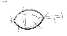
図26を参照すると、第2形態では、回転要素82a、82bは平面を規定し、レンズの断片を受容するために開口した中央領域を囲み、デバイスによりループされ得る。図27を参照すると、外科用デバイス80は、レンズ片8fを取り囲むように動かされる。図28を参照すると、内側回転要素82aと外側回転要素82bは互いに約90度回転される。外科用デバイス80は第3の回転形態にある。第3の形態を達成するために、回転要素82a、82bの一方または両方が回転され得る。例えば、外側回転要素82bの近位端に取り付けられたチューブ88および/または内側回転要素82aの近位端に取り付けられたチューブ90が、回転要素82a、82bを第3の形態に回転させるために回転される。他の態様では、回転要素82a、82bは、互いに任意の他の適当な角度に回転され得る。第3の形態では、内側回転要素82aおよび外側回転要素82bは、レンズ断片8fを取り囲むケージに近似する。 Referring to FIG. 26, in the second embodiment, the
図29を参照すると、ストラップ82は、レンズ片8fの周りで締め付けられる(又は収縮される又は絞られる;constrict)ように動かされる。ある態様では、ストラップ82を締め付けるために、外側シースまたはプッシュロッドおよびプルロッド等の締め付け要素が使用され得る。他の態様では、ストラップを第2の形態に拡張するための機構または方法が逆転される。例えば、ストラップ82が超弾性である場合、ストラップ82は冷却されてよく、又は初期形状に向かう相転移を通じて機械的に付勢され得る。他の態様では、回転要素82a、82bは、角膜の切開部4を通じて引っ張られるにつれて収縮する。ストラップ82およびレンズ8が引き出される際に切開部4の寸法に適合するように、切開部4は、ストラップ82およびレンズ8を絞(又は圧迫し;squeeze)および圧縮する。更に、レンズ片8fを眼1から取り除くのを助力するために、他のコンポーネントおよび機構が組み込まれ得る。例えば、圧縮ばね、空気圧機構、電動機構等が、眼1からレンズ片8fを引き出すために外科用デバイス80に組み込まれ得る、又は外科用デバイス80と共に使用され得る。ある態様では、ストラップ82は、レンズ断片8fに切断してよく、またはレンズを更に分断してよい。 Referring to FIG. 29, the
ある態様では、ストラップ82は、上述したように、除去バッグを除去するために組み込まれ又は取り付けられ得る。1つ以上の回転要素82a、82bにある2つ以上のストラップ82の間に、バッグが存在し得る。開口形態では、レンズ断片8fは同様に、内側回転要素82aおよび外側回転要素82bの中央領域内に配置され得る。内側回転要素82aおよび外側回転要素82bが第3の形態に移ると、バッグも同様に移動されレンズ片を捕捉する。 In some embodiments, the
他の態様では、図25〜29のデバイスが任意の他の適当な方法で構成され得る。例えば、回転要素82a、82bは、遠位端で接続されず、代わりに開口ケージを形成し得る。ある態様では、回転要素82a、82bは、同心円状に並べられなくてよく、またはワイヤーまたはビームなどの非管状(非チューブ状;non-tubular)構造から構成されてよい。 In another aspect, the device of FIGS. 25-29 may be configured by any other suitable method. For example, the
図30を参照すると、別態様が示される。単一シャフト12ではなく、第1供給(又は送達;delivery)チューブ12aおよび第2供給チューブ12bが供される。各チューブはチューブを通るルーメンを含み、切開要素16は、閉鎖形状を形成するために各供給チューブ12a、12bの自由端を通じて延在する。切開要素16は、上記態様のいずれかに関して上述したのと同じ特性を有し得る。使用時に、切開要素16の近位セグメントがレンズ8の近位端の周りで回転可能となるように、第2供給チューブ12bは、近位側に(図30に示すように右側に)戻されるように屈曲される。2つの供給チューブ12a、12bの自由端が裂嚢10の径よりも小さい距離分相互に離隔され得る。したがって、供給チューブ12a、12bは、可撓性の切開要素16をレンズへと供することを可能とし、当該切開要素16が上述のようにレンズ8に対して回転し、レンズの少なくとも一部を取り囲むことを可能とする。超弾性を有する切開要素16ではなく単に可撓性を有する切開要素16の使用は、デバイスの構成を単純化し得る。供給チューブ12a、12bの一方または両方は、図1に示される切開要素16の異なる態様の少なくとも一部と同じ方法で形作られ得る。例えば、第2の供給チューブ12bは、図1の態様にて、切開要素16自体により作られる引張状態の半径方向屈曲部24を含み得る。上述のように、切開要素16は、小さな開口の初期形状から大きな開口の捕捉形状に拡張可能であり得る。例えば、初期形状として、切開要素16は、供給チューブ12a、12bの端部間に実質的に直線に延在し、その後、切開要素16の追加部分が、図30の湾曲した捕捉形状を形成するために、供給チューブ12a、12bの一方または両方の端部から押し出され得る。図30の態様は実質的に上記のように動作される。 With reference to FIG. 30, another aspect is shown. Instead of the
上記態様のいずれかにて、真空吸引は、シャフト12のルーメン14または内側回転要素12a等のデバイス40、80の特定の要素に組み込まれ得る。真空吸引は、レンズの小さな断片を吸引するために、または動作中にレンズ断片を適所に保持するために使用され得る。 In any of the above embodiments, the vacuum suction may be incorporated into a particular element of the
様々な方法およびデバイスの態様が、特定のバージョンを参照して本明細書で詳細に説明されているが、他のバージョン、態様、使用方法、およびこれらの組み合わせも可能であることを理解されよう。したがって、本発明の精神および範囲は、本明細書に含まれる態様の記載に限定されるべきではない。更に、様々な態様および説明は、特定の解剖学的位置、種、または外科的処置を特定し得るが、これらの態様は、他の場所、種、および外科的処置に適用されることを理解されよう。 Although various methods and aspects of the device are described in detail herein with reference to specific versions, it will be appreciated that other versions, aspects, usages, and combinations thereof are also possible. .. Therefore, the spirit and scope of the invention should not be limited to the description of aspects contained herein. Further, it is understood that various aspects and descriptions may identify a particular anatomical location, species, or surgical procedure, but these aspects apply to other locations, species, and surgical procedures. Will be done.
Claims (29)
Translated fromJapaneseルーメンを有するシャフト;および
要素のより大きい部分がルーメンの遠位端部から外側に延在する収容位置から配備位置まで移動可能な要素
を有して成り、
ルーメンがシャフトを通じるように規定され、
収容位置から配備位置までの動きが、要素の第1脚をシャフトの遠位端部に対して遠位側に前進させ、かつ要素の第2脚をシャフトの遠位端部に対して近位側に移動させる、外科用デバイス。It ’s a surgical device,
A shaft with a lumen; and a larger portion of the element having an element that is movable from a containment position to a deployment position that extends outward from the distal end of the lumen.
Lumens are specified to pass through the shaft,
The movement from the containment position to the deployment position advances the first leg of the element distal to the distal end of the shaft and the second leg of the element proximal to the distal end of the shaft. A surgical device that moves to the side.
人の眼が水晶体嚢、水晶体嚢内のレンズ、および角膜を含み、
ルーメンを有するチューブ;および
少なくとも第1形状と第2形状との間で変化するように構成された切開要素
を有して成り、
ルーメンはチューブを通じるように規定され、
第2形状は外周を有し、切開要素はルーメンの遠位端部から延在しており、
第1形状は水晶体嚢の前面にある裂嚢を通じて挿入する寸法となっており、裂嚢の径はレンズの径よりも小さく、
切開要素が第2形状を有する際に、切開要素がその外周内にレンズの少なくとも一部を含むように、切開要素が、レンズと水晶体嚢との間で移動するよう第1形状から第2形状へ変化可能であり、および
切開要素がレンズに切断力を加えるために第2形状から第3形状に変化可能である、デバイス。A device for human eye surgery
The human eye contains the capsular bag, the lens within the capsular bag, and the cornea,
It consists of a tube with lumens; and an incision element configured to vary between at least the first and second shapes.
Lumens are specified to pass through tubes,
The second shape has an outer circumference, the incision element extends from the distal end of the lumen,
The first shape is sized to be inserted through the fissure in front of the capsular bag, and the diameter of the fissure is smaller than the diameter of the lens.
When the incision element has a second shape, the first to second shapes move the incision element between the lens and the capsular bag so that the incision element contains at least a portion of the lens within its perimeter. A device that is variable to and the incision element is variable from a second shape to a third shape to apply a cutting force to the lens.
ルーメンを有するシャフト;
ルーメン中に少なくとも部分的に位置付けられた内側回転要素;
ルーメン中に少なくとも部分的に位置付けられ、内側回転要素とシャフトとの間に半径方向に位置付けられた外側回転要素;
外側回転要素の遠位端部から遠位側に延在する第1の複数のストラップ;
内側回転要素の遠位端部から遠位側に延在する第2の複数のストラップ;および
ストラップの各々の遠位端部に接続された先端部
を有して成り、
ルーメンは、シャフトを通じるように規定され、
第1の複数のストラップの各々が円周方向にて相互に離隔し、
第2の複数のストラップの各々が円周方向にて相互に離隔し、
第1の複数のストラップおよび第2の複数のストラップが閉鎖位置から開口位置に移動可能であり、
第1の複数のストラップおよび第2の複数のストラップの少なくとも一方が開口位置で他方に対して回転可能である、デバイス。A device for eye surgery
Shaft with lumens;
Inner rotating element positioned at least partially in the lumen;
Outer rotating element located at least partially in the lumen and radially located between the inner rotating element and the shaft;
First plurality of straps extending distally from the distal end of the lateral rotating element;
A second plurality of straps extending distally from the distal end of the medial rotating element; and having a tip connected to each distal end of the strap.
Lumens are specified to pass through the shaft,
Each of the first plurality of straps is separated from each other in the circumferential direction.
Each of the second plurality of straps is separated from each other in the circumferential direction.
The first plurality of straps and the second plurality of straps can be moved from the closed position to the open position.
A device in which at least one of the first plurality of straps and the second plurality of straps is rotatable relative to the other at the opening position.
角膜を切開すること;
水晶体嚢の前面に裂嚢を形成すること;
角膜中の切開部を通じて裂嚢に向かって、ルーメンを有するシャフトを挿入すること;
ルーメンの遠位端部の外側にワイヤーを延在させること
を含み、
ルーメンは、シャフトを通じるように規定され、
延在部が、ワイヤーを、裂嚢を通じてシャフトの軸から離れるように屈曲させ、裂嚢よりも大きな寸法に拡大させ、およびレンズの少なくとも一部を捕捉させる、方法。A surgical procedure for treating the cornea, the capsular bag, and the eye with a lens within the capsular bag.
Making an incision in the cornea;
Forming a fissure in front of the capsular bag;
Inserting a shaft with lumens through the incision in the cornea towards the fissure;
Including extending the wire to the outside of the distal end of the lumen,
Lumens are specified to pass through the shaft,
A method in which the extension bends the wire through the fissure away from the axis of the shaft, magnifies it to a size larger than the fissure, and captures at least a portion of the lens.
Applications Claiming Priority (5)
| Application Number | Priority Date | Filing Date | Title |
|---|---|---|---|
| US201462051396P | 2014-09-17 | 2014-09-17 | |
| US62/051,396 | 2014-09-17 | ||
| US201562099590P | 2015-01-05 | 2015-01-05 | |
| US62/099,590 | 2015-01-05 | ||
| JP2017534905AJP6917305B2 (en) | 2014-09-17 | 2015-09-17 | Device for lenticular tissue removal |
Related Parent Applications (1)
| Application Number | Title | Priority Date | Filing Date |
|---|---|---|---|
| JP2017534905ADivisionJP6917305B2 (en) | 2014-09-17 | 2015-09-17 | Device for lenticular tissue removal |
Publications (2)
| Publication Number | Publication Date |
|---|---|
| JP2021118848Atrue JP2021118848A (en) | 2021-08-12 |
| JP7113099B2 JP7113099B2 (en) | 2022-08-04 |
Family
ID=55453678
Family Applications (2)
| Application Number | Title | Priority Date | Filing Date |
|---|---|---|---|
| JP2017534905AActiveJP6917305B2 (en) | 2014-09-17 | 2015-09-17 | Device for lenticular tissue removal |
| JP2021012341AActiveJP7113099B2 (en) | 2014-09-17 | 2021-01-28 | Devices and methods for lenticular tissue removal |
Family Applications Before (1)
| Application Number | Title | Priority Date | Filing Date |
|---|---|---|---|
| JP2017534905AActiveJP6917305B2 (en) | 2014-09-17 | 2015-09-17 | Device for lenticular tissue removal |
Country Status (12)
| Country | Link |
|---|---|
| US (5) | US9775743B2 (en) |
| EP (2) | EP3193795B1 (en) |
| JP (2) | JP6917305B2 (en) |
| KR (2) | KR102564232B1 (en) |
| CN (2) | CN112826657B (en) |
| AU (2) | AU2015317532B2 (en) |
| BR (1) | BR112017005315B1 (en) |
| CA (1) | CA2961649C (en) |
| ES (1) | ES2861025T3 (en) |
| IL (1) | IL251069B (en) |
| RU (2) | RU2703694C2 (en) |
| WO (1) | WO2016044672A1 (en) |
Cited By (1)
| Publication number | Priority date | Publication date | Assignee | Title |
|---|---|---|---|---|
| JP7720496B1 (en)* | 2025-03-05 | 2025-08-07 | 医療法人社団澄隆会 | Ophthalmic Devices |
Families Citing this family (35)
| Publication number | Priority date | Publication date | Assignee | Title |
|---|---|---|---|---|
| US10463534B2 (en) | 2013-05-31 | 2019-11-05 | The Regents Of The University Of Colorado, A Body Corporate | Devices and methods for creating a predictable capsulorhexis of specific diameter |
| US9629747B2 (en) | 2014-09-17 | 2017-04-25 | Iantech, Inc. | Devices and methods for cutting lenticular tissue |
| CN112826657B (en)* | 2014-09-17 | 2023-10-17 | 卡尔蔡司白内障医疗技术公司 | Device and method for removing lens tissue |
| WO2016061511A1 (en)* | 2014-10-17 | 2016-04-21 | Optimedica Corporation | Laser eye surgery lens fragmentation |
| DE102015002729A1 (en)* | 2015-02-27 | 2016-09-01 | Carl Zeiss Meditec Ag | Ophthalmic laser therapy device and method for generating corneal access incisions |
| US10624785B2 (en) | 2016-01-30 | 2020-04-21 | Carl Zeiss Meditec Cataract Technology Inc. | Devices and methods for ocular surgery |
| AU2017232627B2 (en)* | 2016-03-17 | 2021-07-29 | Carl Zeiss Meditec Cataract Technology Inc. | Devices and methods for cutting lenticular tissue |
| WO2017195912A1 (en)* | 2016-05-10 | 2017-11-16 | 강성용 | Lenticule separation tool for smile operation |
| ES2899994T3 (en) | 2016-08-02 | 2022-03-15 | Alcon Inc | Improving the performance of a capsulotomy device |
| CA3041813A1 (en)* | 2016-10-26 | 2018-05-03 | Carl Zeiss Meditec Cataract Technology Inc. | Methods and devices for cutting a lens in an eye |
| US11278450B2 (en) | 2017-05-04 | 2022-03-22 | Carl Zeiss Meditec Cataract Technology Inc. | Devices and methods for ocular surgery |
| US11331217B2 (en)* | 2017-05-25 | 2022-05-17 | Michael Schaller | Devices and methods for creating a capsulorhexis |
| US11744732B2 (en)* | 2017-10-19 | 2023-09-05 | Amo Development, Llc | Medication-coated patient interface device for ophthalmic laser surgery |
| USD846738S1 (en)* | 2017-10-27 | 2019-04-23 | Glaukos Corporation | Implant delivery apparatus |
| JP7312177B2 (en)* | 2017-12-14 | 2023-07-20 | カール・ツァイス・メディテック・キャタラクト・テクノロジー・インコーポレイテッド | Apparatus and method for ophthalmic surgery |
| US10292862B1 (en)* | 2018-05-03 | 2019-05-21 | Richard Mackool | Ophthalmic surgical instruments and methods of use thereof |
| US10441462B1 (en) | 2018-05-03 | 2019-10-15 | Richard Mackool | Ophthalmic surgical instruments and methods of use thereof |
| KR102782862B1 (en) | 2018-06-05 | 2025-03-19 | 칼 짜이스 메디텍 캐터랙트 테크놀로지 인크. | Ophthalmic Microsurgical Instruments, Systems and Methods of Use |
| WO2019236016A1 (en)* | 2018-06-08 | 2019-12-12 | Erakguen Ethem Tansu | Surgical lasso device designed for sutureless scleral intraocular lens fixation |
| EP3826596A4 (en) | 2018-07-24 | 2022-08-17 | Johnson & Johnson Surgical Vision, Inc. | SURGICAL INSTRUMENTS FOR EYE SURGERY |
| JP7434340B2 (en) | 2019-02-01 | 2024-02-20 | カール・ツァイス・メディテック・キャタラクト・テクノロジー・インコーポレイテッド | Ophthalmic cutting instrument with integrated suction pump |
| EP3934597A4 (en)* | 2019-03-04 | 2022-11-23 | Mor Research Applications Ltd. | CAPSULE PROTECTION DEVICES AND METHODS IN CATARACT SURGERY |
| US11850188B2 (en) | 2019-04-01 | 2023-12-26 | Amo Development, Llc | Corneal lenticule extraction tool |
| KR20220010739A (en) | 2019-05-17 | 2022-01-26 | 칼 짜이스 메디텍 캐터랙트 테크놀로지 인크. | Ophthalmic Cutting Instrument with Integral Suction Pump |
| CA3142864A1 (en) | 2019-06-07 | 2020-12-10 | Carl Zeiss Meditec Cataract Technology Inc. | Multi-stage trigger for ophthalmology cutting tool |
| US11007079B1 (en) | 2019-12-02 | 2021-05-18 | Richard Mackool | Ophthalmic surgical instruments and snares thereof |
| US10485700B1 (en)* | 2019-06-24 | 2019-11-26 | Richard Mackool | Ophthalmic surgical instruments and snares thereof |
| US11259961B2 (en)* | 2019-07-22 | 2022-03-01 | Iantrek, Inc. | Methods and devices for increasing aqueous drainage of the eye |
| US10639195B1 (en) | 2019-08-19 | 2020-05-05 | Richard Mackool | Capsular retractors |
| KR102188958B1 (en) | 2020-08-24 | 2020-12-09 | 주식회사 이지엔도서지컬 | Basket actuator and surgical device comprising the same |
| CA3231671A1 (en) | 2021-09-10 | 2023-03-16 | Iantrek, Inc. | Methods and devices for increasing aqueous drainage of the eye |
| US11642246B1 (en) | 2021-12-06 | 2023-05-09 | Jon Gordon Dishler | Vibrating surgical instrument |
| US11432960B1 (en) | 2022-02-01 | 2022-09-06 | Accuvision Designs, LLC | Ophthalmic medical instrument with illuminated snare |
| WO2023239765A2 (en)* | 2022-06-07 | 2023-12-14 | Roswell Park Cancer Institute Corporation Health Research, Inc. | Mechanical displacement devices, systems, and methods to enhance extraction of surgical specimens |
| KR102791309B1 (en)* | 2022-07-01 | 2025-04-08 | 한정모 | Lens cutting device using a plurality of wires |
Citations (5)
| Publication number | Priority date | Publication date | Assignee | Title |
|---|---|---|---|---|
| JPH02164360A (en)* | 1988-10-24 | 1990-06-25 | Heinz J Smirmaul | Operative instrument for eye |
| JP3069723U (en)* | 1999-10-07 | 2000-06-30 | 秀雄 木村 | Loop cutter |
| WO2007011302A1 (en)* | 2005-07-18 | 2007-01-25 | Phacotreat Ab | Methods and devices for eye surgery |
| WO2014035862A1 (en)* | 2012-08-28 | 2014-03-06 | The Regents Of The University Of Colorado, A Body Corporate | Ophthalmic surgical device with adjustable filament and method of use |
| JP2017529213A (en)* | 2014-09-17 | 2017-10-05 | イアンテック・インコーポレイテッドIanTech,Inc. | Devices and methods for lenticular tissue removal |
Family Cites Families (86)
| Publication number | Priority date | Publication date | Assignee | Title |
|---|---|---|---|---|
| US1891054A (en) | 1931-03-28 | 1932-12-13 | Louis K Pitman | Surgical instrument |
| US3882872A (en) | 1970-01-05 | 1975-05-13 | Nicholas G Douvas | Method and apparatus for cataract surgery |
| US3973568A (en) | 1972-01-21 | 1976-08-10 | Iglesias Jose J | Stabilized cutting loop for resectoscope with unimpaired vision of the operative field |
| US3903892A (en)* | 1973-05-17 | 1975-09-09 | Olympus Optical Co | Forceps means for removing cellular tissue from the body cavities |
| US3908661A (en) | 1974-01-31 | 1975-09-30 | Steven G Kramer | Surgical instruments |
| US4367744A (en) | 1980-12-29 | 1983-01-11 | Sole Gary M | Medical instrument, and method of utilizing same |
| US4888015A (en) | 1982-08-20 | 1989-12-19 | Domino Rudolph S | Method of replacing an eye lens |
| US4538611A (en)* | 1983-06-13 | 1985-09-03 | Kelman Charles D | Surgical instrument and method of cutting a lens of an eye |
| US4732150A (en) | 1984-06-14 | 1988-03-22 | Keener Jr Gerald T | Process for cataract extraction |
| US4693245A (en) | 1985-10-01 | 1987-09-15 | Pao David S C | Nucleus splitter |
| US4791924A (en) | 1987-06-02 | 1988-12-20 | Kelman Charles D | Lens forceps and method of use thereof |
| US4766897A (en) | 1987-06-16 | 1988-08-30 | Heinz Smirmaul | Capsulectomy surgical instrument |
| DE3816059A1 (en) | 1988-05-11 | 1989-11-23 | Mathias Zirm | EYE SURGICAL INSTRUMENT |
| US4960418A (en) | 1989-04-20 | 1990-10-02 | Tennant Jerald L | Surgical instrument and method for cutting the lens of an eye |
| US4950272A (en) | 1989-06-19 | 1990-08-21 | Smirmaul Heinz J | Surgical instrument and method for removing the lens of an eye |
| FR2655836A1 (en)* | 1989-12-15 | 1991-06-21 | Cabantous Michel | Device for sectioning the nucleus of the crystalline lens in a cataract operation |
| US5222959A (en) | 1990-07-17 | 1993-06-29 | Anis Aziz Y | Removal of tissue |
| US5171314A (en)* | 1990-07-24 | 1992-12-15 | Andrew Surgical, Inc. | Surgical snare |
| US5201741A (en)* | 1990-07-24 | 1993-04-13 | Andrew Surgical, Inc. | Surgical snare with shape memory effect wire |
| RU2068251C1 (en)* | 1990-09-20 | 1996-10-27 | Санкт-Петербургский филиал Межотраслевого научно-технического комплекса "Микрохирургия глаза" | Microsurgical spatula |
| US5222960A (en) | 1990-10-05 | 1993-06-29 | Poley Brooks J | Cracking and rotating cataract for removal from eye |
| US5242449A (en) | 1991-04-23 | 1993-09-07 | Allergan, Inc. | Ophthalmic instrument |
| US5123906A (en) | 1991-06-20 | 1992-06-23 | Kelman Charles D | Surgical toroidal snare |
| US5147369A (en) | 1991-07-01 | 1992-09-15 | Wagner Michael A | Forceps and method for nuclear fragment removal |
| US5156607A (en) | 1991-09-25 | 1992-10-20 | Peter G. Kansas | Manual small incision cataract extraction method and instrument |
| US5437678A (en) | 1992-11-30 | 1995-08-01 | Neomedix Corporation | Ophthalmic lens removal method and apparatus |
| CN2192307Y (en)* | 1994-03-31 | 1995-03-22 | 龚永祥 | Small-slot trap type crystal nucleus cutter |
| US5728117A (en) | 1997-03-11 | 1998-03-17 | Lash; Roger S. | Retractable capsulorrehexis instument |
| US5893862A (en) | 1997-04-10 | 1999-04-13 | Pratt; Arthur William | Surgical apparatus |
| US6120496A (en)* | 1998-05-05 | 2000-09-19 | Scimed Life Systems, Inc. | Surgical method and apparatus for positioning a diagnostic or therapeutic element within the body and coupling device for use with same |
| DE19828677A1 (en) | 1998-05-20 | 2000-04-20 | Hans Reinhard Koch | Operating system, in particular ophthalmic operating system |
| RU2143253C1 (en) | 1998-05-26 | 1999-12-27 | Межотраслевой научно-технический комплекс "Микрохирургия глаза" | Device for fragmentation of eye lens nucleus |
| US6976957B1 (en) | 1998-06-22 | 2005-12-20 | Origin Medsystems, Inc. | Cannula-based surgical instrument and method |
| DK199801308A (en) | 1998-10-14 | 2000-04-15 | Lego As | Cogwheel drive with end stop and overload protection |
| US6419639B2 (en) | 1999-08-05 | 2002-07-16 | National Institute Of Health | Laparoscopic SAC holder assembly |
| IL134370A0 (en)* | 2000-02-03 | 2001-04-30 | Cutmed Ltd | A medical instrument for use in cataract surgery and a method for use thereof |
| US6379370B1 (en)* | 2000-02-18 | 2002-04-30 | Matthew Feinsod | Incising apparatus for use in cataract surgery |
| US6551326B1 (en) | 2000-04-17 | 2003-04-22 | Anthony Y. Van Heugten | Capsulorrhexis device |
| US20040116950A1 (en) | 2000-11-28 | 2004-06-17 | The Regents Of The University Of Michigan | Instrument and method for creating an intraocular incision |
| WO2003022174A2 (en) | 2001-09-07 | 2003-03-20 | Siepser Steven B | Intraocular lens extracting device |
| US6743228B2 (en)* | 2001-09-12 | 2004-06-01 | Manoa Medical, Inc. | Devices and methods for tissue severing and removal |
| US6554843B1 (en) | 2001-10-15 | 2003-04-29 | Universal Optical Co., Ltd. | Cataract instrument |
| RU31105U1 (en) | 2003-01-30 | 2003-07-20 | Кировская клиническая офтальмологическая больница | Device for fragmentation of the nucleus of the natural lens of the eye |
| JP2006518646A (en)* | 2003-02-20 | 2006-08-17 | マノア メディカル, インコーポレイテッド | Bendable cutting device |
| US20040220604A1 (en) | 2003-04-30 | 2004-11-04 | Fogarty Thomas J. | Tissue separation apparatus and method |
| US7632294B2 (en) | 2003-09-29 | 2009-12-15 | Promethean Surgical Devices, Llc | Devices and methods for spine repair |
| MX2007007163A (en) | 2004-12-21 | 2007-08-14 | Becton Dickinson Co | Syringe assembly having disabling mechanism. |
| GB0506795D0 (en)* | 2005-04-04 | 2005-05-11 | Agt Energy Ltd | Wax-containing materials |
| JP4834337B2 (en)* | 2005-07-06 | 2011-12-14 | 千寿製薬株式会社 | Anterior lens capsule cutter |
| US8679097B2 (en) | 2005-12-20 | 2014-03-25 | Orthodynamix Llc | Method and devices for minimally invasive arthroscopic procedures |
| JP5312951B2 (en) | 2006-01-26 | 2013-10-09 | ウェイク・フォレスト・ユニヴァーシティ・ヘルス・サイエンシズ | Medical tools and related methods to facilitate deep endothelial corneal transplantation |
| US20080086148A1 (en)* | 2006-10-04 | 2008-04-10 | Endogastric Solutions, Inc. | Assemblies for deploying fasteners in tissue and snares for use in such assemblies |
| US8235978B2 (en) | 2007-11-01 | 2012-08-07 | Valens Associated Inc. | Thermal capsulotomy tool and system |
| US8657813B2 (en)* | 2008-01-14 | 2014-02-25 | Valens Associated Inc. | Circular thermal capsulotomy tool and system |
| US8464430B2 (en)* | 2008-02-07 | 2013-06-18 | Beaver-Visitec International (Us), Inc. | Retractable safety knife |
| US10166317B2 (en) | 2008-06-26 | 2019-01-01 | Surgical Design Corporation | Surgical hand piece with dual lumen work tip for use with infusion cannula |
| US9125720B2 (en) | 2008-10-13 | 2015-09-08 | Alcon Research, Ltd. | Capsularhexis device with flexible heating element |
| US8157797B2 (en) | 2009-01-12 | 2012-04-17 | Alcon Research, Ltd. | Capsularhexis device with retractable bipolar electrodes |
| CN102365058A (en)* | 2009-02-06 | 2012-02-29 | 奥林巴斯医疗株式会社 | handling tools |
| US8814854B2 (en)* | 2009-06-03 | 2014-08-26 | Alcon Research, Ltd. | Capsulotomy repair device and method for capsulotomy repair |
| US20100312252A1 (en)* | 2009-06-03 | 2010-12-09 | Guangyao Jia | Capsularhexis device with flexible heating element having an angled transitional neck |
| CN201500225U (en)* | 2009-09-07 | 2010-06-09 | 中山大学中山眼科中心 | Device for manufacturing anterior capsule nozzles |
| US9241755B2 (en)* | 2010-05-11 | 2016-01-26 | Alcon Research, Ltd. | Capsule polishing device and method for capsule polishing |
| WO2011155922A1 (en) | 2010-06-07 | 2011-12-15 | Mynosys Cellular Devices, Inc. | Ophthalmic surgical device for accessing tissue and for performing a capsulotomy |
| US9113862B2 (en) | 2010-09-30 | 2015-08-25 | Ethicon Endo-Surgery, Inc. | Surgical stapling instrument with a variable staple forming system |
| WO2012048348A1 (en) | 2010-10-08 | 2012-04-12 | Prywes Arnold S | Apparatus and method for performing ocular surgery |
| US20120172905A1 (en) | 2010-12-30 | 2012-07-05 | Kimberly-Clark, Inc. | Tissue Removal Apparatus and Method of Manufacturing Same |
| US20130018385A1 (en)* | 2011-07-11 | 2013-01-17 | Boston Scientific Scimed, Inc. | Polypectomy Snare Device |
| US20130023894A1 (en) | 2011-07-22 | 2013-01-24 | Rafic Saleh | Surgical retrieval apparatus and method with semi-rigidly extendable and collapsable basket |
| US9561034B2 (en) | 2011-11-01 | 2017-02-07 | Zipline Medical, Inc. | Surgical incision and closure apparatus |
| CN102512284B (en)* | 2011-12-09 | 2013-12-25 | 中国人民解放军第三军医大学第二附属医院 | Annular bladder cutting device for cataract operation |
| US9381033B2 (en) | 2012-04-30 | 2016-07-05 | Joseph Guo | Method and apparatus for thread transection of a ligament |
| US9549849B2 (en)* | 2012-09-13 | 2017-01-24 | Alcon Research, Ltd. | Systems and methods for reinjection of processed vitreous humor |
| US10624784B2 (en) | 2012-09-18 | 2020-04-21 | Liviu B. Saimovici | Cataract removal device and integrated tip |
| KR101400701B1 (en) | 2012-10-19 | 2014-05-30 | 주식회사 루시드코리아 | Guiding apparatus for continuous curvilinear capsulorhexis |
| US9095367B2 (en) | 2012-10-22 | 2015-08-04 | Ethicon Endo-Surgery, Inc. | Flexible harmonic waveguides/blades for surgical instruments |
| US9211203B2 (en) | 2012-12-20 | 2015-12-15 | Abbott Cardiovascular Systems, Inc. | Hinge for medical device |
| US10463534B2 (en) | 2013-05-31 | 2019-11-05 | The Regents Of The University Of Colorado, A Body Corporate | Devices and methods for creating a predictable capsulorhexis of specific diameter |
| CN105451669A (en) | 2013-06-20 | 2016-03-30 | 波士顿科学国际有限公司 | Supported retrieval device and related methods of use |
| CA2854507C (en) | 2013-06-21 | 2017-01-03 | Peter Triebel | An apparatus for performing ophthalmic surgery using a contact element |
| US9867735B2 (en) | 2014-03-10 | 2018-01-16 | Katena Products, Inc. | Opthalmic device for cell removal |
| US10231718B2 (en) | 2014-05-23 | 2019-03-19 | Boston Scientific Scimed, Inc. | Tissue extraction devices and related methods |
| WO2016036406A1 (en) | 2014-09-04 | 2016-03-10 | Alcon Pharmaceuticals Ltd. | Surgical hand piece for cataract removal |
| US9629747B2 (en) | 2014-09-17 | 2017-04-25 | Iantech, Inc. | Devices and methods for cutting lenticular tissue |
| GB201418368D0 (en) | 2014-10-16 | 2014-12-03 | Creo Medical Ltd | Surgical snare |
| ES2846755T3 (en) | 2015-05-28 | 2021-07-29 | Page Surgical Innovations Llc | Capsular tension ring inserter and method |
- 2015
- 2015-09-17CNCN202110028051.5Apatent/CN112826657B/enactiveActive
- 2015-09-17EPEP15841181.9Apatent/EP3193795B1/enactiveActive
- 2015-09-17KRKR1020227035604Apatent/KR102564232B1/enactiveActive
- 2015-09-17KRKR1020177009882Apatent/KR102455953B1/enactiveActive
- 2015-09-17CNCN201580059712.3Apatent/CN107072814B/enactiveActive
- 2015-09-17EPEP21152604.1Apatent/EP3881809B1/enactiveActive
- 2015-09-17RURU2017112959Apatent/RU2703694C2/enactive
- 2015-09-17WOPCT/US2015/050820patent/WO2016044672A1/enactiveApplication Filing
- 2015-09-17USUS14/857,518patent/US9775743B2/enactiveActive
- 2015-09-17AUAU2015317532Apatent/AU2015317532B2/enactiveActive
- 2015-09-17BRBR112017005315-2Apatent/BR112017005315B1/enactiveIP Right Grant
- 2015-09-17ESES15841181Tpatent/ES2861025T3/enactiveActive
- 2015-09-17JPJP2017534905Apatent/JP6917305B2/enactiveActive
- 2015-09-17RURU2019132037Apatent/RU2019132037A/enunknown
- 2015-09-17CACA2961649Apatent/CA2961649C/enactiveActive
- 2017
- 2017-03-09ILIL251069Apatent/IL251069B/enunknown
- 2017-08-28USUS15/688,024patent/US10463535B2/enactiveActive
- 2019
- 2019-05-17USUS16/415,986patent/US10463536B2/enactiveActive
- 2019-09-09USUS16/564,551patent/US10517758B1/enactiveActive
- 2019-11-21USUS16/690,881patent/US11723803B2/enactiveActive
- 2020
- 2020-01-02AUAU2020200023Apatent/AU2020200023B2/enactiveActive
- 2021
- 2021-01-28JPJP2021012341Apatent/JP7113099B2/enactiveActive
Patent Citations (5)
| Publication number | Priority date | Publication date | Assignee | Title |
|---|---|---|---|---|
| JPH02164360A (en)* | 1988-10-24 | 1990-06-25 | Heinz J Smirmaul | Operative instrument for eye |
| JP3069723U (en)* | 1999-10-07 | 2000-06-30 | 秀雄 木村 | Loop cutter |
| WO2007011302A1 (en)* | 2005-07-18 | 2007-01-25 | Phacotreat Ab | Methods and devices for eye surgery |
| WO2014035862A1 (en)* | 2012-08-28 | 2014-03-06 | The Regents Of The University Of Colorado, A Body Corporate | Ophthalmic surgical device with adjustable filament and method of use |
| JP2017529213A (en)* | 2014-09-17 | 2017-10-05 | イアンテック・インコーポレイテッドIanTech,Inc. | Devices and methods for lenticular tissue removal |
Cited By (1)
| Publication number | Priority date | Publication date | Assignee | Title |
|---|---|---|---|---|
| JP7720496B1 (en)* | 2025-03-05 | 2025-08-07 | 医療法人社団澄隆会 | Ophthalmic Devices |
Also Published As
Similar Documents
| Publication | Publication Date | Title |
|---|---|---|
| JP6917305B2 (en) | Device for lenticular tissue removal | |
| US11813142B2 (en) | Devices and methods for cutting lenticular tissue | |
| JP7079732B2 (en) | How to cut the device and lens tissue | |
| HK1237244B (en) | Devices for the removal of lenticular tissue |
Legal Events
| Date | Code | Title | Description |
|---|---|---|---|
| A521 | Request for written amendment filed | Free format text:JAPANESE INTERMEDIATE CODE: A523 Effective date:20210226 | |
| A621 | Written request for application examination | Free format text:JAPANESE INTERMEDIATE CODE: A621 Effective date:20210226 | |
| A711 | Notification of change in applicant | Free format text:JAPANESE INTERMEDIATE CODE: A712 Effective date:20210415 | |
| A131 | Notification of reasons for refusal | Free format text:JAPANESE INTERMEDIATE CODE: A131 Effective date:20220105 | |
| A521 | Request for written amendment filed | Free format text:JAPANESE INTERMEDIATE CODE: A523 Effective date:20220401 | |
| TRDD | Decision of grant or rejection written | ||
| A01 | Written decision to grant a patent or to grant a registration (utility model) | Free format text:JAPANESE INTERMEDIATE CODE: A01 Effective date:20220628 | |
| A61 | First payment of annual fees (during grant procedure) | Free format text:JAPANESE INTERMEDIATE CODE: A61 Effective date:20220725 | |
| R150 | Certificate of patent or registration of utility model | Ref document number:7113099 Country of ref document:JP Free format text:JAPANESE INTERMEDIATE CODE: R150 | |
| R250 | Receipt of annual fees | Free format text:JAPANESE INTERMEDIATE CODE: R250 |